1993 toyota paseo l4-1497cc 1.5l dohc...
TRANSCRIPT
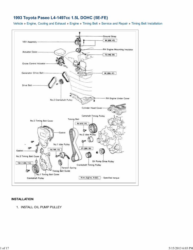
1993 Toyota Paseo L4-1497cc 1.5L DOHC (5E-FE)
Vehicle » Engine, Cooling and Exhaust » Engine » Timing Belt » Service and Repair » Timing Belt Installation
INSTALLATION
INSTALL OIL PUMP PULLEY1.
1 of 17 5/15/2013 6:03 PM
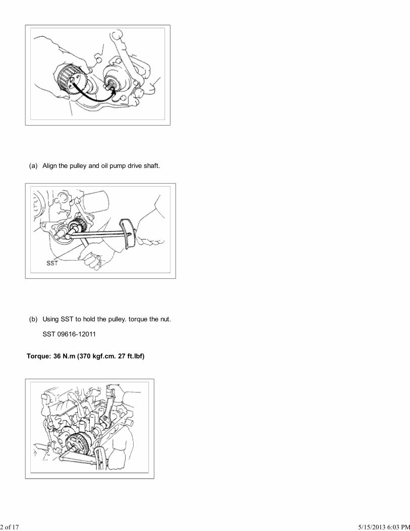
(a) Align the pulley and oil pump drive shaft.
(b) Using SST to hold the pulley. torque the nut.
SST 09616-12011
Torque: 36 N.m (370 kgf.cm. 27 ft.lbf)
2 of 17 5/15/2013 6:03 PM
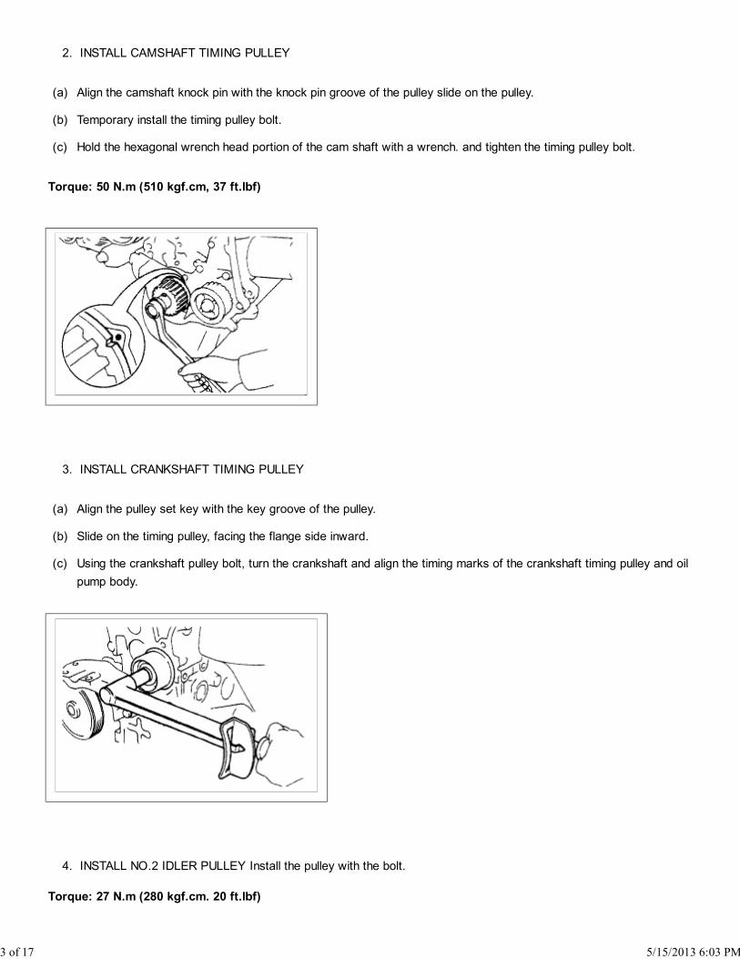
INSTALL CAMSHAFT TIMING PULLEY2.
(a) Align the camshaft knock pin with the knock pin groove of the pulley slide on the pulley.
(b) Temporary install the timing pulley bolt.
(c) Hold the hexagonal wrench head portion of the cam shaft with a wrench. and tighten the timing pulley bolt.
Torque: 50 N.m (510 kgf.cm, 37 ft.lbf)
INSTALL CRANKSHAFT TIMING PULLEY3.
(a) Align the pulley set key with the key groove of the pulley.
(b) Slide on the timing pulley, facing the flange side inward.
(c) Using the crankshaft pulley bolt, turn the crankshaft and align the timing marks of the crankshaft timing pulley and oil
pump body.
INSTALL NO.2 IDLER PULLEY Install the pulley with the bolt.4.
Torque: 27 N.m (280 kgf.cm. 20 ft.lbf)
3 of 17 5/15/2013 6:03 PM

HINT: Remove any oil or water on the idler pulley and keep it clean.
TEMPORARILY INSTALL NO.1 IDLER PULLEY AND TENSION SPRING5.
(a) Install the pulley with the bolt. Do not tighten the bolt yet.
(b) Pry the pulley toward the left as far as it will go and temporarily tighten the bolt.
HINT: Remove any oil or water on the idler pulley and keep it clean.
TEMPORARILY INSTALL TIMING BELT6.
NOTICE: The engine should be cold.
Install the timing belt on the crankshaft timing, oil pump, No.1 idler and No.2 idler pulleys.
HINT: If reusing timing belt, align the points marked during removal and install the belt with the arrow pointing in the
direction of engine revolution.
4 of 17 5/15/2013 6:03 PM
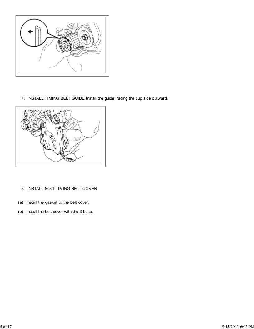
INSTALL TIMING BELT GUIDE Install the guide, facing the cup side outward.7.
INSTALL NO.1 TIMING BELT COVER8.
(a) Install the gasket to the belt cover.
(b) Install the belt cover with the 3 bolts.
5 of 17 5/15/2013 6:03 PM
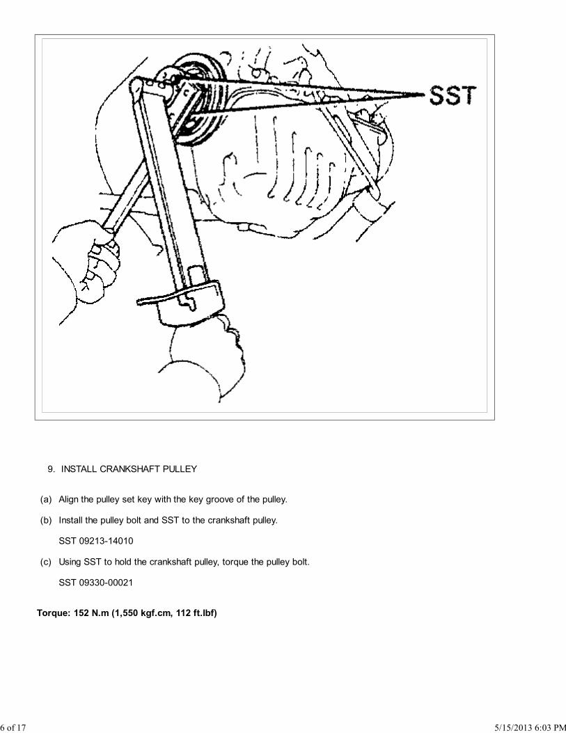
INSTALL CRANKSHAFT PULLEY9.
(a) Align the pulley set key with the key groove of the pulley.
(b) Install the pulley bolt and SST to the crankshaft pulley.
SST 09213-14010
(c) Using SST to hold the crankshaft pulley, torque the pulley bolt.
SST 09330-00021
Torque: 152 N.m (1,550 kgf.cm, 112 ft.lbf)
6 of 17 5/15/2013 6:03 PM

(d) With A/C and/or PS: Install the No.2 crankshaft pulley with the 4 bolts.
Torque: 19 N.m (195 kgf.cm, 14 ft.lbf)
SET NO.1 CYLINDER TO TDC/COMPRESSION10.
(a) Turn the crankshaft pulley. and align its groove with timing mark "0" of the No.1 timing belt cover.
7 of 17 5/15/2013 6:03 PM
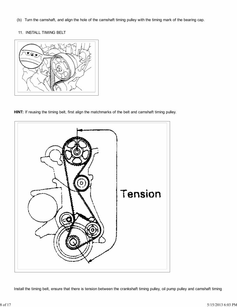
(b) Turn the camshaft, and align the hole of the camshaft timing pulley with the timing mark of the bearing cap.
INSTALL TIMING BELT11.
HINT: If reusing the timing belt, first align the matchmarks of the belt and camshaft timing pulley.
Install the timing belt, ensure that there is tension between the crankshaft timing pulley, oil pump pulley and camshaft timing
8 of 17 5/15/2013 6:03 PM
pulley.
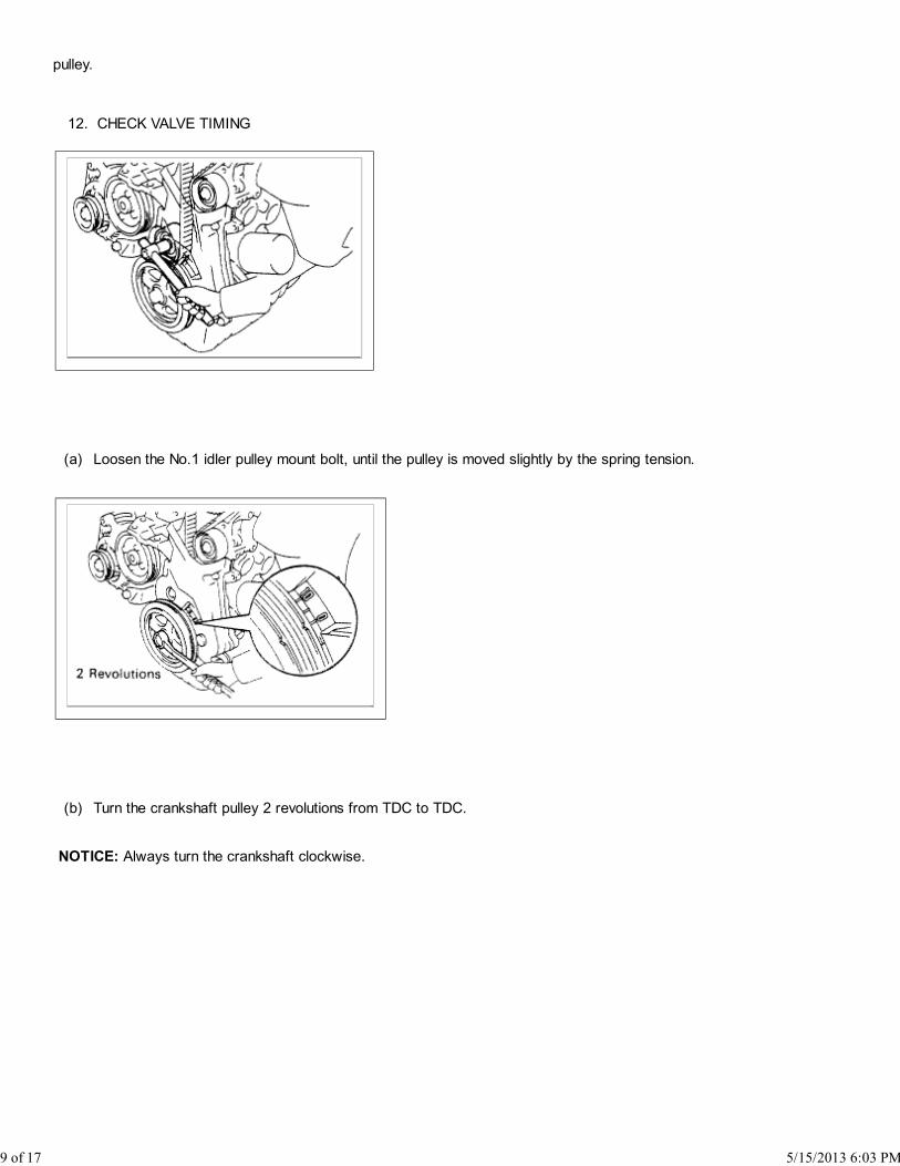
CHECK VALVE TIMING12.
(a) Loosen the No.1 idler pulley mount bolt, until the pulley is moved slightly by the spring tension.
(b) Turn the crankshaft pulley 2 revolutions from TDC to TDC.
NOTICE: Always turn the crankshaft clockwise.
9 of 17 5/15/2013 6:03 PM
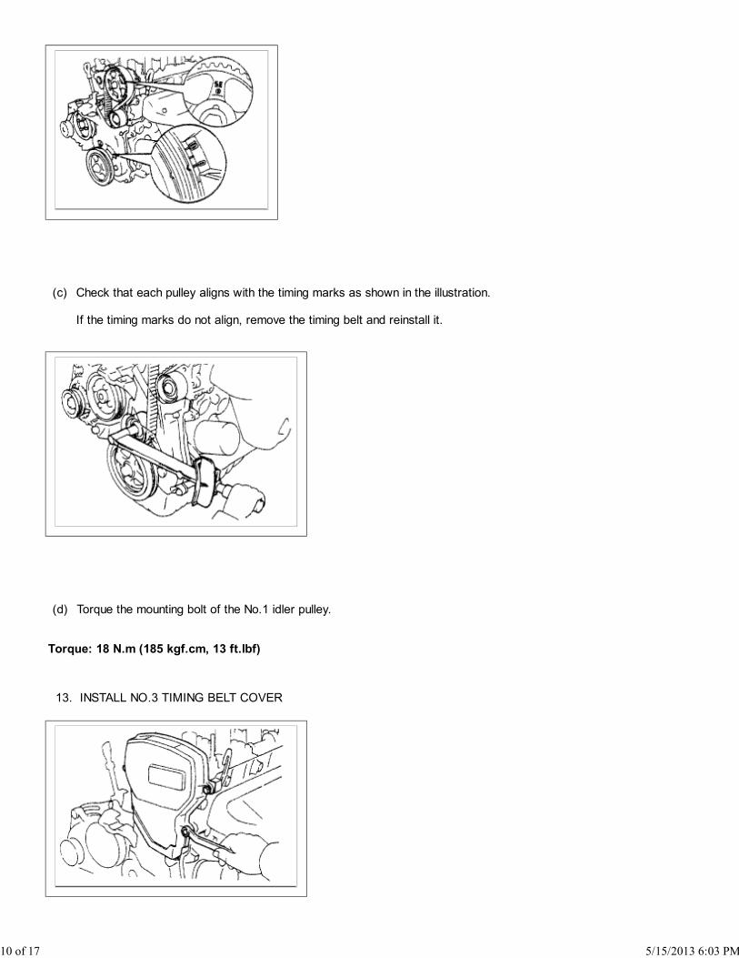
(c) Check that each pulley aligns with the timing marks as shown in the illustration.
If the timing marks do not align, remove the timing belt and reinstall it.
(d) Torque the mounting bolt of the No.1 idler pulley.
Torque: 18 N.m (185 kgf.cm, 13 ft.lbf)
INSTALL NO.3 TIMING BELT COVER13.
10 of 17 5/15/2013 6:03 PM

INSTALL NO.2 TIMING BELT COVER14.
(a) Install the gasket to the belt cover.
(b) Install the belt cover with the 4 bolts.
INSTALL CYLINDER HEAD COVER15.
(a) Apply seal packing to the cylinder head as shown in the illustration.
Seal packing: Part No.08826-00080 or equivalent
(b) Install the gasket to the cylinder head cover.
(c) Install the cylinder head cover with the 5 seal washers and cap nuts.
Torque: 6.9 N.m (70 kgf.cm, 61 in.lbf)
11 of 17 5/15/2013 6:03 PM

(d) Install the oil filler cap.
INSTALL SPARK PLUGS16.
(a) Using a 16 mm plug wrench, install the 4 spark plugs.
Torque: 18 N.m (180 kgf.cm, 13 ft.lbf)
(b) Connect the high-tension cords as shown.
(c) Install the cord support bolt to the cylinder head cover.
INSTALL RH ENGINE MOUNTING INSULATOR17.
12 of 17 5/15/2013 6:03 PM
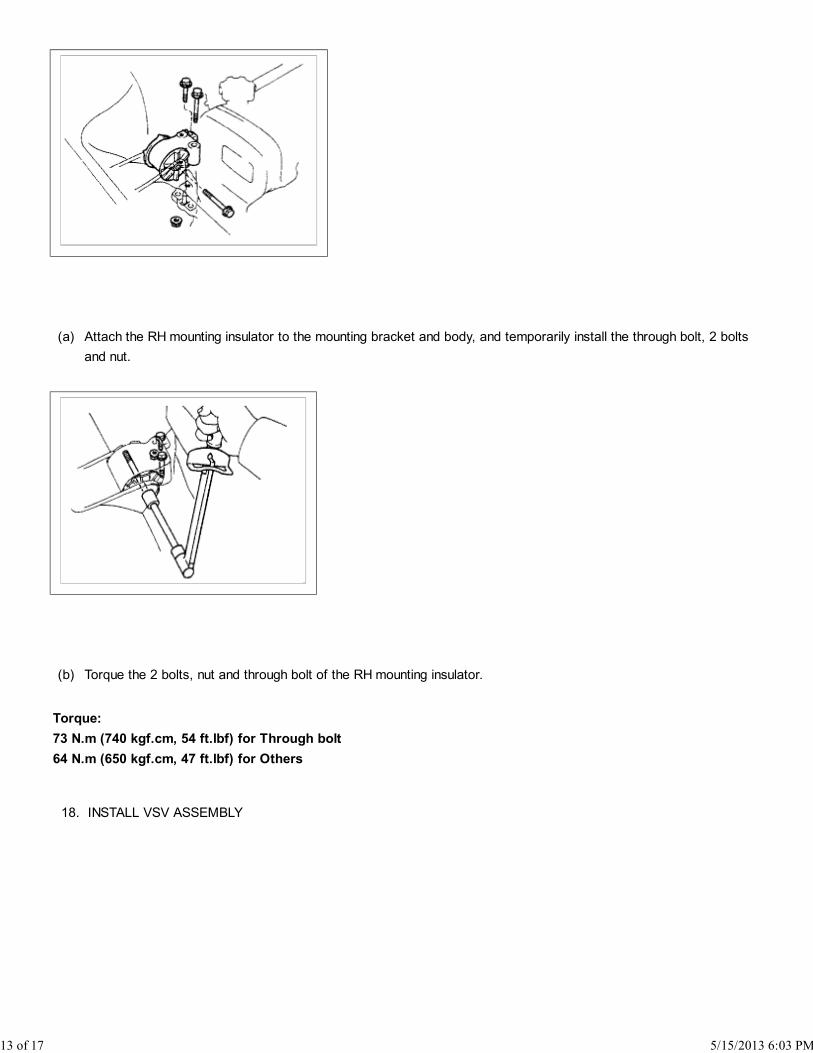
(a) Attach the RH mounting insulator to the mounting bracket and body, and temporarily install the through bolt, 2 bolts
and nut.
(b) Torque the 2 bolts, nut and through bolt of the RH mounting insulator.
Torque:
73 N.m (740 kgf.cm, 54 ft.lbf) for Through bolt
64 N.m (650 kgf.cm, 47 ft.lbf) for Others
INSTALL VSV ASSEMBLY18.
13 of 17 5/15/2013 6:03 PM
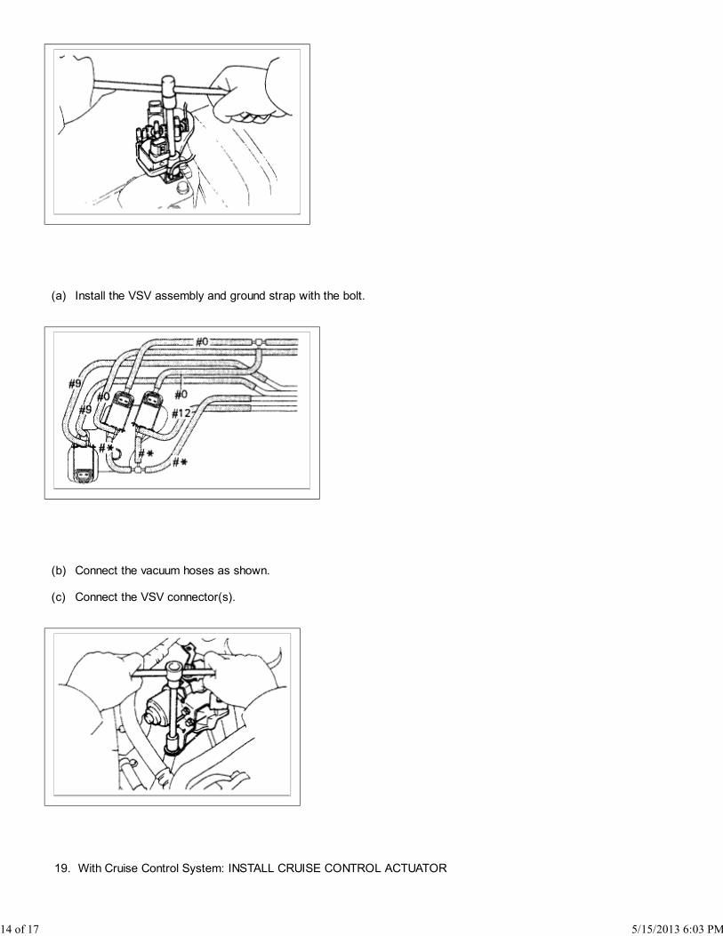
(a) Install the VSV assembly and ground strap with the bolt.
(b) Connect the vacuum hoses as shown.
(c) Connect the VSV connector(s).
With Cruise Control System: INSTALL CRUISE CONTROL ACTUATOR19.
14 of 17 5/15/2013 6:03 PM
(a) Install the actuator with the 3 bolts.
(b) Connect the actuator connector.
(c) Install the actuator cover.
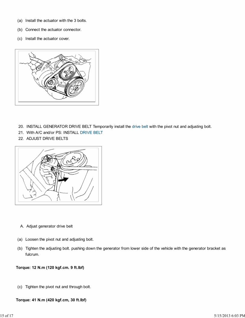
INSTALL GENERATOR DRIVE BELT Temporarily install the drive belt with the pivot nut and adjusting bolt.20.
With A/C and/or PS: INSTALL DRIVE BELT21.
ADJUST DRIVE BELTS22.
Adjust generator drive beltA.
(a) Loosen the pivot nut and adjusting bolt.
(b) Tighten the adjusting bolt. pushing down the generator from lower side of the vehicle with the generator bracket as
fulcrum.
Torque: 12 N.m (120 kgf.cm. 9 ft.lbf)
(c) Tighten the pivot nut and through bolt.
Torque: 41 N.m (420 kgf.cm, 30 ft.lbf)
15 of 17 5/15/2013 6:03 PM

(d) Check the belt tension.
Without A/C: Adjust PS pump drive beltB.
(a) Loosen the bolts A and B.
(b) Tighten the bolt B. pushing up the PS pump with the pump bracket lower end as fulcrum.
Torque: 39 N.m (400 kgf.cm. 29 ft.lbf)
(c) Tighten the bolt A.
Torque: 43 N.m (440 kgf.cm, 32 ft.lbf)
(d) Check the belt tension.
With A/C: Adjust PS pump drive beltC.
16 of 17 5/15/2013 6:03 PM

(a) Loosen the bolts A and B.
(b) Loosen the lock nuts D and E.
(c) Adjust the adjusting bolt F so that its protrusion above nut C is + 0 mm (0 in.) .
(d) Fix nut C using lock nut D.
(e) Turn the adjusting bolt F to push up the pump and adjust the belt tension to the specified value.
(f) Tighten the bolts A and B.
Torque:
43 N.m (440 kgf.cm, 32 ft.lbf) for Bolt A
39 N.m (400 kgf.cm, 29 ft.lbf) for Bolt B
(g) Loosen the adjusting bolt F by 4 or 5 turns.
NOTICE: Check that there is a gap of 5 mm (0.20 in.) or more between the tip of the nut C and the PS pump body.
(h) Fix the adjusting bolt F with the lock nut E.
(i) Check the belt tension.
Without P/S: Adjust A/C compressor drive beltD.
(a) Loosen the idler mounting nut.
(b) Turn the adjusting bolt and belt tension to the specified value.
(c) Tighten the idler mounting nut.
INSTALL RH ENGINE UNDER COVER23.
CONNECT NEGATIVE TERMINAL CABLE TO BATTERY24.
17 of 17 5/15/2013 6:03 PM