1995: coproduction of ammonia and methanol
TRANSCRIPT
Coproduction of Ammonia andMethanol
Coproduction of methanol can be introduced into an ammonia plant to produce a high-qualitymethanol product without reduction in operability or specific energy consumption. In our facility,a 10% increase in total tonnage has been obtained compared to an all ammonia operation. It hasproven to be easy to switch between various mixes of the two products, which can increase the
operation profitability.
V. Larry Shields and Niels R. UdengaardHaldor Tops0e, Inc., Houston, TX 77058
Bob BrinkerTerra International, Inc., Woodward, OH 73801
Introduction
In mid 1992, Terra International Inc. (Til) commis-sioned Haldor Tops0e Inc. to conduct a feasibilitystudy to evaluate Tops0e's methanolation technol-
ogy for use in the coproduction of methanol andammonia in an existing fluor designed 1400 STPDammonia plant in Woodward, OK. At that time, theprice of ammonia was low compared to methanol andthe differential between the two was expected toincrease further. The results of the feasibility studyindicated that a methanol production rate of 400 STPDwas achievable at an attractive installed cost. The lowcost was due in part to the fluor design, i.e., high-pres-sure methanation, high-pressure CO2 removal and twoseparate synthesis gas compressors, and in partbecause methanation technology is based on a oncethrough methanol reactor eliminating the need for arecycle compressor.
Process Chemistry
Methanol is produced from the reaction of hydrogenwith carbon monoxide or with carbon dioxide over acopper based catalyst as shown in the following reac-tions:
2 H2 + CO = CH3OH + Heat3 H2 + CO2 = CH3OH + H2O + Heat
Since these reactions are reversible, the concentrationof methanol in the reaction product is limited by equi-librium considerations. In general, methanol produc-tion is favored by high pressures and low tempera-tures. Small amounts of byproducts are also produced.The byproducts are light ends such as dimethyl etherand acetone, as well as heavy ends such as ethanol andbutanol. These byproducts and water are removedfrom methanol by distillation. Straight chain higherhydrocarbon waxes may also be produced if iron cont-amination, such as rust and mill scale, is present.
Nitrogen in the feed gas to a methanol reactor doesnot enter into any reactions as it passes over amethanol catalyst.
Process Description
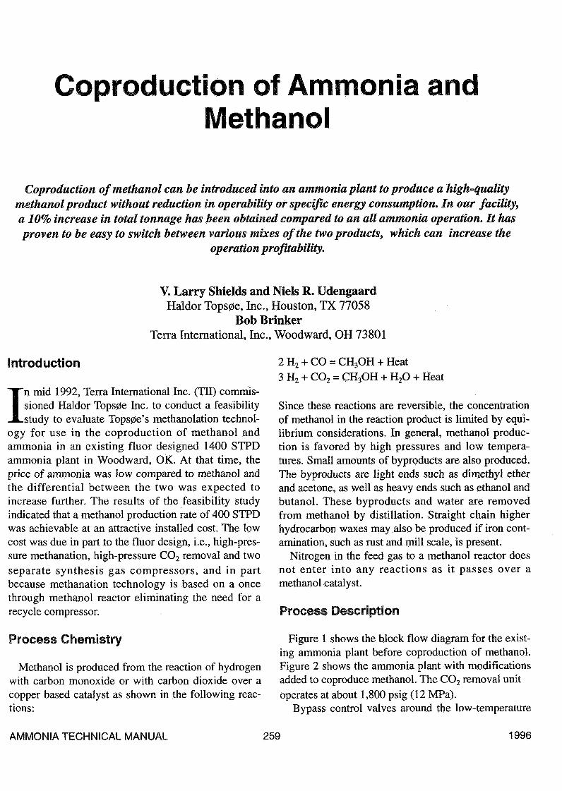
Figure 1 shows the block flow diagram for the exist-ing ammonia plant before coproduction of methanol.Figure 2 shows the ammonia plant with modificationsadded to coproduce methanol. The CO2 removal unitoperates at about 1,800 psig (12 MPa).
Bypass control valves around the low-temperature
AMMONIA TECHNICAL MANUAL 259 1996
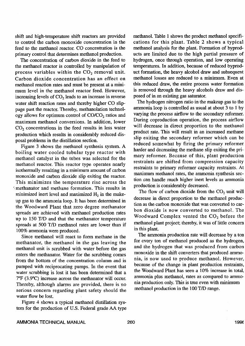
shift and high-temperature shift reactors are providedto control the carbon monoxide concentration in thefeed to the methanol reactor. CO concentration is theprimary control that determines methanol production.
The concentration of carbon dioxide in the feed tothe methanol reactor is controlled by manipulation ofprocess variables within the CO2 removal unit.Carbon dioxide concentration has an effect onmethanol reaction rates and must be present at a mini-mum level in the methanol reactor feed. However,increasing levels of CO2 leads to an increase in reversewater shift reaction rates and thereby higher CO slip-page past the reactor. Thereby, methanolation technol-ogy allows for optimum control of CO/CO2 ratios andmaximum methanol conversions. In addition, lowerCO2 concentrations in the feed results in less waterproduction which results in considerably reduced dis-posal problems in the distillation section.
Figure 3 shows the methanol synthesis system. Aboiling water cooled tubular type reactor withmethanol catalyst in the tubes was selected for themethanol reactor. This reactor type operates nearlyisothermally resulting in a minimum amount of carbonmonoxide and carbon dioxide slip exiting the reactor.This minimizes the temperature rise across the
'methanator and methane formation. This results inminimized inert level and maximized H2 in the make-up gas to the ammonia loop. It has been determined inthe Woodward Plant that zero degree methanatorspreads are achieved with methanol production ratesup to 150 T/D and that the methanator temperaturespreads at 500 T/D methanol rates are lower than if100% ammonia were produced.
Since methanol will react to form methane in themethanator, the methanol in the gas leaving themethanol unit is scrubbed with water before the gasenters the methanator. Water for the scrubbing comesfrom the bottom of the concentration column and ispumped with reciprocating pumps. In the event thatwater scrubbing is lost it has been determined that a7°F (3.9°C) increase across the methanator will occur.Thereby, although alarms are provided, there is noserious concern regarding plant safety should thewater flow be lost.
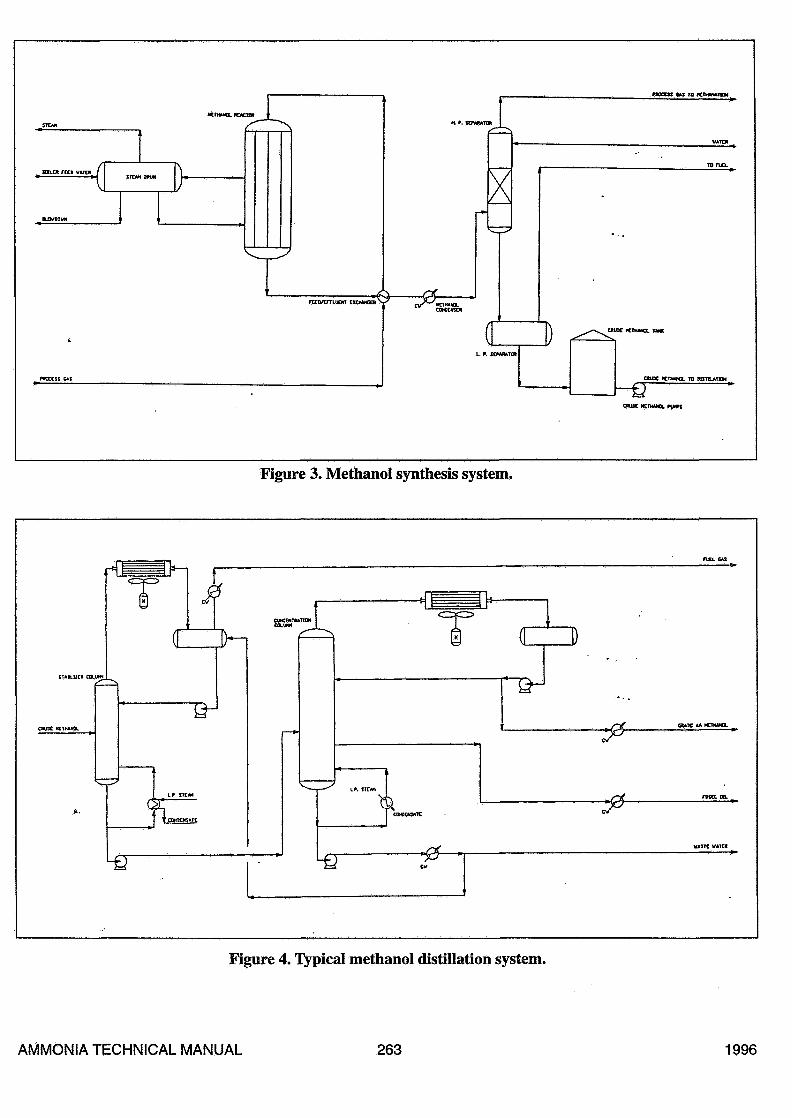
Figure 4 shows a typical methanol distillation sys-tem for the production of U.S. Federal grade AA type
methanol. Table 1 shows the product methanol specifi-cations for this plant. Table 2 shows a typicalmethanol analysis for the plant. Formation of byprod-ucts are limited due to the high partial pressure ofhydrogen, once through operation, and low operatingtemperatures. In addition, because of reduced byprod-uct formation, the heavy alcohol draw and subsequentmethanol losses are reduced to a minimum. Even atthis reduced draw, the entire process water formationis removed through the heavy alcohols draw and dis-posed of in an existing gas saturator.
The hydrogen nitrogen ratio in the makeup gas to theammonia loop is controlled as usual at about 3 to 1 byvarying the process airflow to the secondary reformer.During coproduction operation, the process airflowwill decrease in direct proportion to the methanolproduct rate. This will result in an increased methaneslip exiting the secondary reformer which can bereduced somewhat by firing the primary reformerharder and decreasing the methane slip exiting the pri-mary reformer. Because of this, plant productionrestraints are shifted from compression capacityrestraints to primary reformer capacity restraints. Atmaximum methanol rates, the ammonia synthesis sec-tion can handle much higher inert levels as ammoniaproduction is considerably decreased.
The flow of carbon dioxide from the CO2 unit willdecrease in direct proportion to the methanol produc-tion as the carbon monoxide that was converted to car-bon dioxide is now converted to methanol. TheWoodward Complex vented the CO2 before themethanol plant project; thereby, it was of little concernin this plant.
The ammonia production rate will decrease by a tonfor every ton of methanol produced as the hydrogen,and the hydrogen that was produced from carbonmonoxide in the shift converters that produced ammo-nia, is now used to produce methanol. However,because of the change in plant production restraints,the Woodward Plant has seen a 10% increase in total,ammonia plus methanol, rates as compared to ammo-nia production only. This is true even with minimummethanol production in the 100 T/D range.
AMMONIA TECHNICAL MANUAL 260 1996
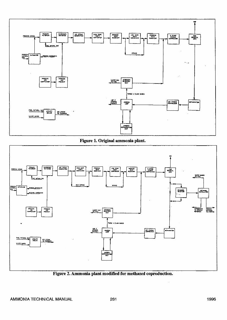
Figure I. Original ammonia plant.
Figure 2. Ammonia plant modified for methanol coproduction.
AMMONIA TECHNICAL MANUAL 261 1996

Table 1. Product Ammonia Specifications
TEST
Methanol, wt. % min.Water, ppm max.Ethanol, ppm max.Acetone, ppm max.Acidity (acetic acid), ppm max.Alkalinity (ammonia), ppm max.Iron, ppm max.Nonvolatiles, mg/100 mLmax.Permanganate, minutes min.Color, PT-CO max.Specific gravity @ 25°C, max.Initial boiling point °CDistillation range, °C, max.Dry point, °COdorAppearanceHydrocarbonsCarbonizables, PT-CO max.
METHOD
ASTM E-346ASTME-1064ASTM E-346ASTMD-1612ASTM D-1613ASTMD-1614ASTM E-394ASTM D-1353ASTM E-1363ASTM D-1209ASTM D-891ASTM D-1 078ASTM D-1 078ASTM D-1 078ASTM D-1 296ASTM E-346ASTM D-1 722ASTM E-346
SPECIFICATION
99.9500203030300.0515050.789364.7 ± 0.21.063.7-65.7CharacteristicClearPass/Fail30
Table 2. Typical Methanol Analysis for the Plant
1000 Terra Driva
Woodward. OK 73B01
<405) 256-8651
CERTIFICATE OF ANALYSIS
ANAL. SPECIFICATION
MMumH
Water
Ethanol
Ante»
AcMtytAoalieAcH)
AkaMy (Ammonia)
Iron
Non Voulues
PennanganaiB
Color
SpedfoerrÄy
IBP
tssaaion R«ra«
Drv Point
(Mar
Appearance
Hftoxmxa
Careordzable»
ASTME-M«
ASTME-10M
ASTME-3M
ASTMD-1612
ASTMD-1813
A8TMO-UM
ASTME-3M
ASTM D-1353
ASTME-13«3
ASTMD-1209
ASTMD-8B1
ASTMD-1078
ASTMD-1078
ASTM D-1078
ASTM D-129»
ASTME-34«
ASTMD-1722
ASTME-3«
GW
QW
GW
GW
QW
GW
SW
GW
GW
GW
GW
GW
GW
GW
GW
GW
GW
GW
S«.8wl%rr*.
SOOppffifnax.
20 ppm max
30 ppm max
30 ppm max
30 ppm max.
.05 ppm max.
1 mortOOmlfnax.
SO rotate inta.
SPT-COmax.
0.7BI3a25Cinax
«4.7 O tl- 3.
1.0 C max
65.7 C
Characteristic
Clear
PASS/FAIL
30 PT-CO MAX.
m.M38.T
3.17
0.97
ig.a
2.16
<0.01
0.1
90«
<5
0.78S5
«4.7
02
M.9
CHAR.
CLEAR
PASS
<5comments: AU. TEST RESULTS WITHIN SPECIFICATION
AMMONIA TECHNICAL MANUAL 262 1996
•ƒ STEM tftUN l
i f. ay««*!» j
L. f. ICPMUTOt
«UK ICTMMOL TAW
CBUX KTWQ. KI 9HTJLAIKK
Figure 3. Methanol synthesis system.
O D
(2Lf 1 OPHtCHtfcTÇ
Figure 4. Typical methanol distillation system.
AMMONIA TECHNICAL MANUAL 263 1996
Project Schedule
Process design for the methanol system began inSeptember, 1992. Tie-ins were made during a planned1992 turnaround such that the methanol plant could bestarted without the need to shut the ammonia plantdown at a later date. Detailed engineering did not startuntil February, 1993. Mechanical completion was inearly April, 1994. Procurement of the longest deliveryitem, the methanol reactor, took about 13 months.
Haldor Tops0e handled all process design for theproject, Terra International handled all project man-agement activities, and the Benham Group of Tulsa,OK handled the engineering construction package.The project was built on a very fast track schedule andas such had its share of problems. However, the pro-ject was started without incident, without the need toshut down the ammonia plant, within a 14 month timeframe and was delivered on time on budget.
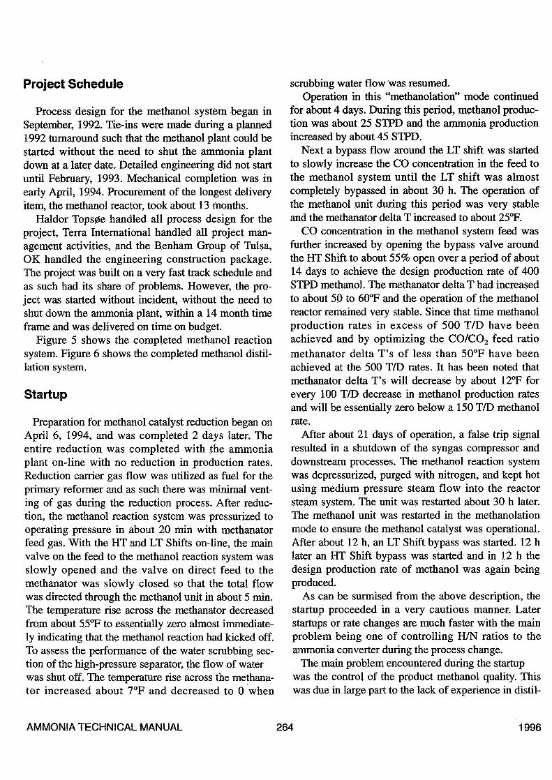
Figure 5 shows the completed methanol reactionsystem. Figure 6 shows the completed methanol distil-lation system.
Startup
Preparation for methanol catalyst reduction began onApril 6, 1994, and was completed 2 days later. Theentire reduction was completed with the ammoniaplant on-line with no reduction in production rates.Reduction carrier gas flow was utilized as fuel for theprimary reformer and as such there was minimal vent-ing of gas during the reduction process. After reduc-tion, the methanol reaction system was pressurized tooperating pressure in about 20 min with methanatorfeed gas. With the HT and LT Shifts on-line, the mainvalve on the feed to the methanol reaction system wasslowly opened and the valve on direct feed to themethanator was slowly closed so that the total flowwas directed through the methanol unit in about 5 min.The temperature rise across the methanator decreasedfrom about 55°F to essentially zero almost immediate-ly indicating that the methanol reaction had kicked off.To assess the performance of the water scrubbing sec-tion of the high-pressure separator, the flow of waterwas shut off. The temperature rise across the methana-tor increased about 7°F and decreased to 0 when
scrubbing water flow was resumed.Operation in this "methanolation" mode continued
for about 4 days. During this period, methanol produc-tion was about 25 STPD and the ammonia productionincreased by about 45 STPD.
Next a bypass flow around the LT shift was startedto slowly increase the CO concentration in the feed tothe methanol system until the LT shift was almostcompletely bypassed in about 30 h. The operation ofthe methanol unit during this period was very stableand the methanator delta T increased to about 25°F.
CO concentration in the methanol system feed wasfurther increased by opening the bypass valve aroundthe HT Shift to about 55% open over a period of about14 days to achieve the design production rate of 400STPD methanol. The methanator delta T had increasedto about 50 to 60°F and the operation of the methanolreactor remained very stable. Since that time methanolproduction rates in excess of 500 T/D have beenachieved and by optimizing the CO/CO2 feed ratiomethanator delta T's of less than 50°F have beenachieved at the 500 T/D rates. It has been noted thatmethanator delta T's will decrease by about 12°F forevery 100 T/D decrease in methanol production ratesand will be essentially zero below a 150 T/D methanolrate.
After about 21 days of operation, a false trip signalresulted in a shutdown of the syngas compressor anddownstream processes. The methanol reaction systemwas depressurized, purged with nitrogen, and kept hotusing medium pressure steam flow into the reactorsteam system. The unit was restarted about 30 h later.The methanol unit was restarted in the methanolationmode to ensure the methanol catalyst was operational.After about 12 h, an LT Shift bypass was started. 12 hlater an HT Shift bypass was started and in 12 h thedesign production rate of methanol was again beingproduced.
As can be surmised from the above description, thestartup proceeded in a very cautious manner. Laterstartups or rate changes are much faster with the mainproblem being one of controlling H/N ratios to theammonia converter during the process change.
The main problem encountered during the startupwas the control of the product methanol quality. Thiswas due in large part to the lack of experience in distil-
AMMONIA TECHNICAL MANUAL 264 1996

Figure 5. Methanol reaction system.
Figure 6. Methanol distillation system.
AMMONIA TECHNICAL MANUAL 265 1996
lation operation by ammonia plant operators.However, all off-spec product was rerun without amajor reduction in production rate.
Controllability
The rate of methanol production is easily controlledby manipulating the bypass valves around either theLT shift or the HT shift. The changes in productionrate occur almost immediately as does the change inmethanator delta T. The change in steam productionfrom methanol reactor lags slightly.
On-spec methanol product has been produced fromthe beginning, and the frequency of reran has steadilydiminished as the operators gain experience in operat-ing the distillation system. Today, reruns have beenalmost totally eliminated as operational control is suchthat on-spec product can be produced over a widerange of distillation capacity, 100 T/D in excess of 500T/D rates.
The addition of the methanol production systemdoes not affect the controllability of the ammonia pro-duction facilities.
Energy Consumption
The overall specific energy consumption per ton ofproduct, either ammonia or methanol has improved
slightly, 0.1 to 0.15 MMBtu (0.11 to 0.16 GJ)/ST, ascompared to an all ammonia operation.
Conclusion
This project has demonstrated that coproduction ofmethanol can be introduced into an ammonia plant toproduce a high quality methanol product withoutreduction in operability or specific energy consump-tion. In the Woodward facility a 10% increase in totaltonnage has been obtained compared to an all ammo-nia operation. In addition, it has proven to be veryeasy to switch between various mixes of the two prod-ucts. This can lead to an increase in the profitability ofthe operation by taking advantage of disparity in theselling price between ammonia and methanol andbetween product inventories.
The coproduction of methanol and ammonia can beintroduced into any ammonia plant with relativelyminor modifications to the syngas compressor trainand the replacement of the low-pressure methanationsystem with a high-pressure methanation system.
DISCUSSIONS. Stalin, SPIC: I guess you will reduce the air to thesecondary reformer after incorporating the methanolplant. As far as the ammonia plant is concerned, doesit not increase the methane slip from the secondaryreformer and reduce the hydrogen efficiency?Shields: Are you talking about reduced emissionsfrom the plant in general?Stalin: No. What I mean is once you incorporate themethanol plant with the ammonia plant, you do notneed that much process air to be added to the sec-ondary reformer. Because of the reduced air flow tothe secondary reformer, there will be more methaneslip from the secondary reformer. I wonder if thehydrogen efficiency of the plant will come down?Brinker: Yes, the air is considerably reduced and the
methane slip out of the reformer did increase to about1.2% out of the secondary reformer. Of course, that isconcentrated up to higher inerts going into the ammo-nia loop. We have an ammonia loop that is capable ofmaking 1,550 to 1,600 ton/d with upwards of 20 to22% total inerts. We really had no problem with thosehigher inert levels producing at that sort of ammoniaproduction. As far as total energy efficiency, the totalconsumption was a little bit less at 0.1-0.15MMBtU/ST in our particular plant.Stalin: With reduction of process air to the secondaryreformer, the steam generated from the waste heatboiler would have come down. Does it not affect thesteam balance of the plant?
AMMONIA TECHNICAL MANUAL 266 1996
Brinker: Not really. The total steam make wasreduced. Our auxiliary boiler, which was a Borne firedboiler, actually reduced firing and steam reductionfrom 190,000 Ib to say 130 M. However, as you know,the main reason for that is we lost some steam produc-tion on the secondary waste heat boiler, but we alsodidn't need as much horsepower for compressing air.The total steam balance stayed fairly close to thesame.Stalin: You mentioned that there is reduction of ener-gy by 0.1 to 0.15 G.cal per ton of product. How doyou apportion the energy reduction between ammoniaand methanol plants?Brinker: We really don't do that. We just take the totalproduction of ammonia and methanol which weachieved in this particular plant to about a 10% totalincrease. We used to make 1,500 tons a day, and wemight make 1,650 right now, total ammonia plusmethanol. We charge the same amount to ammoniaand to methanol. There may be a bigger effect onammonia. Methanol may be the more expensive of thetwo products, but we found no easy way to separatethe cost of the two products. We say they cost thesame to produce.Stalin: After the methanolation section, you are recov-ering the methanol by absorbing into the water, how-ever, there will even then be a trace of methanol goingalong with the main process gas. Does it not get sepa-rated later, perhaps in the intercoolers of the syngascompressors or at some other point? Will it createsome problem of wastewater disposal?Brinker: Larry can answer that. Now, the process isthe gas as it leaves the methanol unit and the methanolseparator goes straight to a methanator. After theprocess, we have seen no residual methanol at all.Shields: We scrub methanol with water, so there isessentially no methanol going to the methanator. Allthe byproducts are going into distillation, and thebyproducts from distillation are the light ends whichare fuel gas. They are burned in a separate burner inthe auxiliary boiler. The fusel oil and the wastewaterare recycled through a saturator to the primaryreformer.
Stalin: About the wastewater which you are recover-ing from the separators after the intercoolers of thesyngas compressor, any residual methanol along withthe process gas will get condensed in the ammoniaplant and may create wastewater disposal problems.Shields: You're talking about the normal ammoniaplant condensâtes which are handled in the same way.There is no difference.Brinker: The actual condensate has considerably lessmethanol in it. We completely bypass the low shiftconverter, which does make some amount of methanolin the low shift. So, our total amount of methanol tothe process condensate stripper has been nearly elimi-nated with this process. Overall, our total emissionshave been reduced from the plant which will bereported on SARA emissions.Luc Guns, BASF: In your conclusion you mentionedthat this was adaptable to any ammonia plant. How doyou intend to tackle the problem that exists when youhave syngas with a high CO/CO2 content in a carbonsteel compressor?Brinker: We have investigated that with studies andhad numerous discussions with Dresser Rand. Noproblem has arisen in that aspect. At Woodward, ourplant is different. Before it goes into compression, allwater is removed. So, it is different, and if you go intoa compressor with CO and CO2> water is present.Shields: If we are operating with CO2 concentrationdown to 1/2%, that is not a very aggressive system.Guns: When it's completely dry, I agree.Max Appl, BASF (Retired): To what extent did youhave to modify the high-pressure part of the compres-sor to cope with the reduced load for the compressor?Brinker: We didn't modify it. We modified it back in1984, when they went to a S200 basket. The wheelwas also modified at that time. In this particular pro-ject we never modified the wheel. It's working alright.We have no problem with it from making say 1,100 to1,500 tons.Appl: I would say that's about borderline.Brinker: All kickbacks remain closed. It has not pre-sented a problem, and we did not modify it.
AMMONIA TECHNICAL MANUAL 267 1996