1999 nissan quest
TRANSCRIPT

Foreword
Welcome to the growing family of newNISSAN owners. This vehicle is deliveredto you with confidence. It was producedusing the latest techniques and strict qualitycontrol.
This manual was prepared to help youunderstand the operation and maintenanceof your vehicle so that you may enjoy manymiles of driving pleasure. Please readthrough this manual before operating yourvehicle.
A separate Warranty Information andMaintenance Log Booklet explains de-tails about the warranties covering yourvehicle and vehicle maintenance sched-ules. Additionally, a separate CustomerCare/Lemon Law Booklet will explainhow to resolve any concerns you mayhave with your vehicle, as well as clarifyyour rights under your state’s lemon law.
Your NISSAN dealership knows your ve-hicle best. When you require any service orhave any questions, they will be glad toassist you with the extensive resourcesavailable to them.
READ FIRST — THEN DRIVE SAFELYBefore driving your vehicle read this own-er’s manual carefully. This will ensure famil-iarity with controls and maintenance re-quirements, assisting you in the safeoperation of your vehicle.
WARNINGIMPORTANT SAFETY INFORMATIONREMINDERS FOR SAFETY!Follow these important driving rules tohelp ensure a safe and complete tripfor you and your passengers:● NEVER drive under the influence of
alcohol or drugs.● ALWAYS observe posted speed lim-
its and never drive too fast for con-ditions.
● ALWAYS use your seat belts andappropriate child restraint systems.Pre-teen children should be seatedin the rear seat.
● ALWAYS provide information aboutthe proper use of vehicle safety fea-tures to all occupants of the vehicle.
● ALWAYS review this Owner’s Manualfor important safety information.
MODIFICATION OF YOUR VEHICLEThis vehicle should not be modified.Modification could affect its perfor-mance, safety or durability, and mayeven violate governmental regulations.In addition, damage or performanceproblems resulting from modificationsmay not be covered under NISSANwarranties.
WHEN READING THE MANUAL
This manual includes information for alloptions available on this model. Therefore,you may find some information that doesnot apply to your vehicle.
All information, specifications and illustra-tions in this manual are those in effect at thetime of printing. NISSAN reserves the rightto change specifications or design withoutnotice and without obligation.
The inside pages of this manual containa minimum of 50% recycled fibers,including 10% post-consumer fibers.
Z X

You will see various symbols in this manual.They are used in the following ways:
WARNING
This is used to indicate the presence ofa hazard that could cause death orserious personal injury. To avoid orreduce the risk, the procedures mustbe followed precisely.
CAUTION
This is used to indicate the presence ofa hazard that could cause minor ormoderate personal injury or damage toyour vehicle. To avoid or reduce therisk, the procedures must be followedcarefully.
If you see this symbol, it means ‘‘Do not dothis’’ or ‘‘Do not let this happen.’’
© 1998 NISSAN NORTH AMERICA, INC.GARDENA, CALIFORNIA
All rights reserved. No part of this Owner’sManual may be reproduced or stored in aretrieval system, or transmitted in any form, orby any means, electronic, mechanical, photo-copying, recording or otherwise, without theprior written permission of Nissan NorthAmerica, Inc., Gardena, California
The inside pages of this manual containa minimum of 50% recycled fibers,including 10% post-consumer fibers.
APD1005
IMPORTANT INFORMATIONABOUT THIS MANUAL
Z X

Welcome To The World Of NISSAN
Your new NISSAN is the result of our dedicationto produce the finest in safe, reliable and eco-nomical transportation. Your vehicle is the prod-uct of a successful worldwide company thatmanufactures cars and trucks in over 17 coun-tries and distributes them in 170 nations.
NISSAN vehicles are designed and manufacturedby Nissan Motor Co., Ltd. which was founded inTokyo, Japan in 1933, and NISSAN affiliates world-wide, collectively growing to become the fifth largestautomaker in the world. In addition to cars andtrucks, NISSAN also makes textile machinery, fork-lift trucks, marine engines, boats and other products.
NISSAN has made a substantial and growinginvestment in North America, starting with theopening of Nissan Motor Corporation U.S.A. in1960 and continuing with the production of somecars and trucks at one of the world’s mostmodern manufacturing facilities, Nissan Motor
Manufacturing Corporation U.S.A. in Smyrna,Tennessee, vehicle styling at Nissan DesignInternational in San Diego, California, and engi-neering at Nissan Research and Development inFarmington Hills, Michigan.
NISSAN and its dealers employ about 60,000Americans.
NISSAN is also a substantial contributor to theCanadian economy. Nissan Canada Inc., its sup-pliers and over 150 dealers employ approxi-mately 4,500 people. These include companyemployees and the staffs of NISSAN dealers allacross Canada. In addition, many Canadianswork for companies that supply NISSAN andNISSAN dealers with materials and servicesranging from the operation of port facilities andtransportation services, to the supply of lubri-cants, parts and accessories.
NISSAN pioneered the use of electronics andcomputers in automobiles, and has led the indus-try in improving both performance and fuel effi-ciency through new engine designs and the useof synthetic materials to reduce vehicle weight.The company has also developed ways to buildquality into its vehicles at each stage of theproduction process, both through extensive useof automation and — most importantly —through an awareness that people are the cen-tral element in quality control.
From the time the parts arrived from our suppli-ers until you took delivery of your new NISSAN,dozens of checks were made to ensure that onlythe best job was being done in producing anddelivering your vehicle. NISSAN also takes greatcare to ensure that when you take your NISSANto your dealer for maintenance, the service techni-cian will perform his work according to the qualitystandards that have been established by thefactory.
Safety has also been built into your NISSAN. Asyou know, seat belts are an integral part of thesafety systems that will help protect you and yourpassengers in the event of a sudden stop or anaccident. We urge you to use the seat belts everytime you drive the vehicle.
The NISSAN story of growth and achievementreflects our major goal: to provide you, ourcustomer, with a vehicle that is built with qualityand craftsmanship — a product that we can beproud to build and you can be proud to own.
AFW0001
Z X

NISSAN CUSTOMER CARE PROGRAMNISSAN CARES ...
Both NISSAN and your NISSAN dealer are dedicated to serving all your automotive needs. Your satisfaction with your vehicle and yourNISSAN dealer are our primary concerns. Your NISSAN dealer is always available to assist you with all your automobile sales and serviceneeds.
However, if there is something that yourNISSAN dealer cannot assist you with oryou would like to provide NISSAN directlywith comments or questions, please con-tact our (NISSAN’s) Consumer Affairs De-partment using our toll-free number:
For U.S. mainland and Alaskacustomers
1-800-NISSAN-1(1-800-647-7261)
For Hawaii customers(808) 836-0888 (Oahu Number)
For Canada customers1-800-387-0122
The Consumer Affairs Department will askfor the following information:— Your name, address, and telephonenumber— Vehicle identification number (on dash-board)— Date of purchase— Current odometer reading— Your NISSAN dealer’s name— Your comments or questions
OR
you may write to NISSAN with the information
on the left at:
For U.S. mainland and Alaska custom-ers
Nissan North America, Inc.Consumer Affairs DepartmentP.O. Box 191Gardena, California 90248-0191
For Hawaii customersNissan Motor Corporation in Hawaii2880 Kilihau St.Honolulu, Hawaii 96819
For Canada customersNissan Canada Inc.5290 Orbitor DriveMississauga, Ontario L4W 4Z5
We appreciate your interest in NISSAN and thank you for buying a quality NISSAN vehicle.
Z X

Z X

Table ofContents
Seats, restraints and supplemental air bag systems
Instruments and controls
Pre-driving checks and adjustments
Heater, air conditioner and audio systems
Starting and driving
In case of emergency
Appearance and care
Do-it-yourself
Maintenance
Technical and consumer information
Index
1
2
3
4
5
6
7
8
9
10
11

1 Seats, restraints and supplemental airbag systems
Seats ......................................................................1-2Manual front seat adjustment.................................1-3Power front seat adjustment (if so equipped)........1-4Head restraints .......................................................1-6Armrests .................................................................1-6Underseat storage tray (if so equipped) ................1-7Tabletop seats........................................................1-7Flexible seating ...................................................1-8Sliding three-passenger seat ...............................1-15Supplemental restraint system (supplementalair bag system).....................................................1-19Supplemental air bag system...............................1-22Warning labels......................................................1-24Supplemental air bag warning light......................1-24Seat belts .............................................................1-26Precautions on seat belt usage ...........................1-26Child safety...........................................................1-27Pregnant women ..................................................1-28Injured persons ....................................................1-28Three-point type with retractor .............................1-29Three-point type seat belt with retractor forsecond row bucket seats .....................................1-32
Three passenger bench seat in the secondrow position ..........................................................1-35Three-passenger bench seat ...............................1-37Two-point type without retractor (center ofthree-passenger bench seat) ...............................1-38Seat belt extenders ..............................................1-40Seat belt maintenance .........................................1-40Child restraints .....................................................1-41Front facing installation at three-passengerbench seat center position...................................1-43Rear facing installation at three-passengerbench seat center position...................................1-44Front facing installation at second and thirdrow outboard positions.........................................1-45Rear facing installation at second and thirdrow outboard positions.........................................1-48Child restraint with top tether strap......................1-51Installation on second row bench or bucketseat.......................................................................1-52Installation on three-passenger bench seat insecond row...........................................................1-54
Z X

Installation on three-passenger bench seat inthird row................................................................1-56Integrated child safety seats (if so equipped)......1-61Seats/floor mats ...................................................1-68Seating arrangements..........................................1-68Floor mat positioning............................................1-69Seven passenger seating ....................................1-69Three-passenger bench seat in storageposition .................................................................1-69
Five passenger seating........................................1-70Five passenger seating with cargo room.............1-71Three-passenger bench seat in fully forwardposition .................................................................1-71Floor mat positioning aid......................................1-72Seat positions.......................................................1-73With second row bench seat................................1-73With second row bucket seats .............................1-77
Z X

WARNING● Do not ride in a moving vehicle when
the seatback is reclined. This can bedangerous. The shoulder belt willnot be against your body. In an acci-dent you could be thrown into it andreceive neck or other serious inju-ries. You could also slide under thelap belt and receive serious internalinjuries.
● For most effective protection whenthe vehicle is in motion, the seatshould be upright. Always sit wellback in the seat and adjust the seatbelt properly. See ‘‘Precautions onSeat Belt Usage’’ later in this sec-tion.
ARS1131
SEATS
1-2 Seats, restraints and supplemental air bag systems
Z X

MANUAL FRONT SEATADJUSTMENT
WARNING● Do not adjust the driver’s seat while
driving. The seat may move sud-denly and could cause loss of con-trol of the vehicle.
● After adjustment, gently rock in theseat to make sure it is securelylocked.
Forward and backwardRotate the lever up while you slide the seatforward or backward to the desired position.Release the lever to lock the seat in position.
RecliningTo recline the seatback, pull the lever up andlean back. To bring the seatback forwardagain, pull the lever up and move your bodyforward. The seatback moves forward. Re-lease the lever to lock the seatback in position.
ARS1211
Seats, restraints and supplemental air bag systems 1-3
Z X

POWER FRONT SEATADJUSTMENT (if so equipped)
WARNING● Do not adjust the driver’s seat while
driving. The seat may move sud-denly and could cause loss of con-trol of the vehicle.
● Do not leave children unattended in-side the vehicle. They could unknow-ingly activate switches or controls.Unattended children could becomeinvolved in serious accidents.
For memory seat and mirror informationsee ‘‘Memory driver seat and mirrors’’ in the‘‘Pre-driving checks and adjustments’’ sec-tion.
Operating tips● The motor has an auto-reset overload
protection circuit. If the motor stops dur-ing operation, wait 30 seconds, then re-activate the switch.
● Do not operate the power support seatfor a long period of time when the engineis off. This discharges the battery.
Forward and backward adjustmentTo move the seat forward, push the powerslide switch forward. To move the seatbackward, push the power slide switchbackward. Release the switch to stop themovement of the seat.
RecliningTo recline the seat back, push the powerrecliner switch backward. To return to amore upright position, push the power re-cliner switch forward. Release the switch tostop the movement of the seatback.
ARS1212
1-4 Seats, restraints and supplemental air bag systems
Z X

Seat height adjustmentTo raise the height of the seat, lift the powerseat height switch and release it when thedesired position is reached. To lower theheight of the seat, push the power seatheight switch down and release it when thedesired position is reached.
Lumbar supportThe lumbar support provides lower backsupport to the driver. Move the lever up ordown to adjust the seat lumbar area.
ARS1120 ARS1158 ARS1121
Seats, restraints and supplemental air bag systems 1-5
Z X

HEAD RESTRAINTSTo raise the head restraint, pull it up. Tolower, push in the release button and pushthe head restraint down.
The head restraints on the two-passengerbench seat equipped with the integratedchild safety seats, are not adjustable orremovable.
Adjust the head restraints so the top is levelwith the tops of your ears.
WARNING
Head restraints should be adjustedproperly as they may provide signifi-cant protection against injury in an ac-cident. Do not remove them. Check theadjustment after someone else usesthe seat.
Some seat arrangements may require re-moval of the head restraints when the seatis in a storage position and not to be used bypassengers.
ARMRESTS
To use the armrests on any seat, pull themdown to the resting position.
PD1176M ARS1130 ARS1137
1-6 Seats, restraints and supplemental air bag systems
Z X

UNDERSEAT STORAGE TRAY(if so equipped)Some front passenger seats have an under-seat storage tray.
TABLETOP SEATS
The second and third row seats convert intotabletops with built-in cupholders. To usethe tabletop seats, lift up on the seatbackrelease lever and fold the seatback forward.
WARNING● Never place hard items such as cof-
fee mugs or drinking glasses on thetabletop seats when the vehicle ismoving. Any item can become a pro-jectile inside a vehicle involved in acollision. To help prevent personalinjury, never leave loose items onthe folded-down tabletop seats whenthe vehicle is moving.
● Do not use the tabletop and cupholder feature while the vehicle is inmotion unless you are properlyseated with your seat belt on.
ARS1157
ARS1138
Seats, restraints and supplemental air bag systems 1-7
Z X
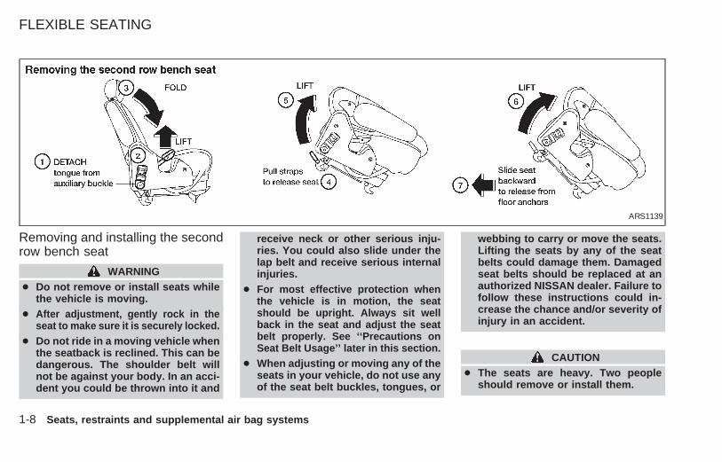
Removing and installing the secondrow bench seat
WARNING● Do not remove or install seats while
the vehicle is moving.● After adjustment, gently rock in the
seat to make sure it is securely locked.● Do not ride in a moving vehicle when
the seatback is reclined. This can bedangerous. The shoulder belt willnot be against your body. In an acci-dent you could be thrown into it and
receive neck or other serious inju-ries. You could also slide under thelap belt and receive serious internalinjuries.
● For most effective protection whenthe vehicle is in motion, the seatshould be upright. Always sit wellback in the seat and adjust the seatbelt properly. See ‘‘Precautions onSeat Belt Usage’’ later in this section.
● When adjusting or moving any of theseats in your vehicle, do not use anyof the seat belt buckles, tongues, or
webbing to carry or move the seats.Lifting the seats by any of the seatbelts could damage them. Damagedseat belts should be replaced at anauthorized NISSAN dealer. Failure tofollow these instructions could in-crease the chance and/or severity ofinjury in an accident.
CAUTION● The seats are heavy. Two people
should remove or install them.
ARS1139
FLEXIBLE SEATING
1-8 Seats, restraints and supplemental air bag systems
Z X

● Do not sit in seats that have beenremoved from the vehicle. They maytip over and you could be injured.
1. Detach the single window seat belttongue from the auxiliary buckle mountedto the side of the seat and store thetongue out of the way. For detailed infor-mation, see ‘‘Two buckle seat belt sys-tem for the second row bench seat’’ laterin this section.
2. Lift up the recliner lever.
3. Fold the seatback fully forward.
4. Unlock the seat legs at the two rear floorlatch levers by pulling up on the twostraps.
5. Lift the back of the seat.
6. Slide the seat rearward off the front an-chor positions.
Installing the second row benchseat
Clean the area around the seat leg flooranchors before installing the seat.
1. With the seatback fully folded, place theseat behind the floor anchors and catchthe seat leg hooks into each floor anchor.
2. Push down on the back of the seat tosecure the two rear floor latches.
3. Lift up the recliner lever and raise theseatback.
4. Rock the seat back and forth to be sure
all four seat legs are securely latched.
5. Insert the single window seat belt tongueinto the auxiliary buckle mounted to theside of the seat.
ARS1140
Seats, restraints and supplemental air bag systems 1-9
Z X

Removing second row bucket seats
WARNING● Do not remove or install seats while
the vehicle is moving.● After adjustment, gently rock in the
seat to make sure it is securelylocked.
● Do not ride in a moving vehicle whenthe seatback is reclined. This can bedangerous. The shoulder belt willnot be against your body. In an acci-dent you could be thrown into it andreceive neck or other serious inju-ries. You could also slide under thelap belt and receive serious internalinjuries.
● For most effective protection whenthe vehicle is in motion, the seatshould be upright. Always sit wellback in the seat and adjust the seatbelt properly. See ‘‘Precautions onSeat Belt Usage’’ later in this section.
● When adjusting or moving any of theseats in your vehicle, do not use anyof the seat belt buckles, tongues, orwebbing to carry or move the seats.Lifting the seats by any of the seatbelts could damage them. Damagedseat belts should be replaced at yourNISSAN dealer. Failure to followthese instructions could increase thechance and/or severity of injury in anaccident.
CAUTION● The seats are heavy. Two people
should remove or install them.● Do not sit in seats that have been
removed from the vehicle. They maytip over and you could be injured.
1-10 Seats, restraints and supplemental air bag systems
Z X
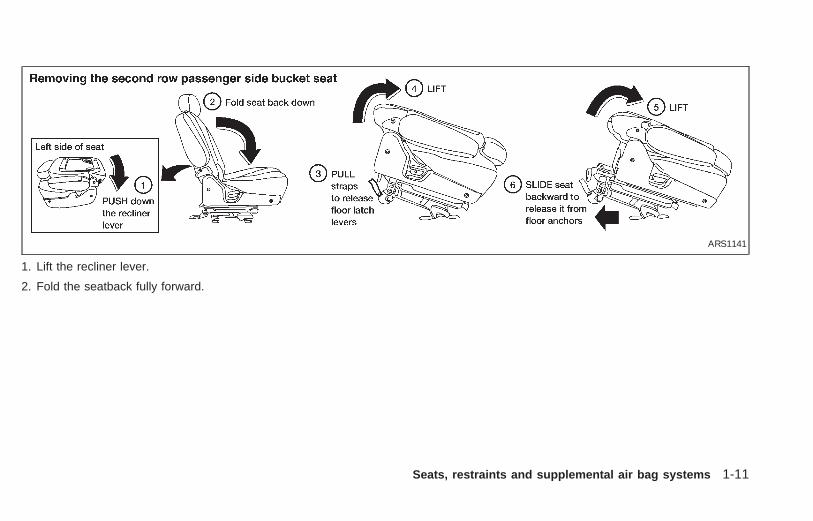
1. Lift the recliner lever.
2. Fold the seatback fully forward.
ARS1141
Seats, restraints and supplemental air bag systems 1-11
Z X
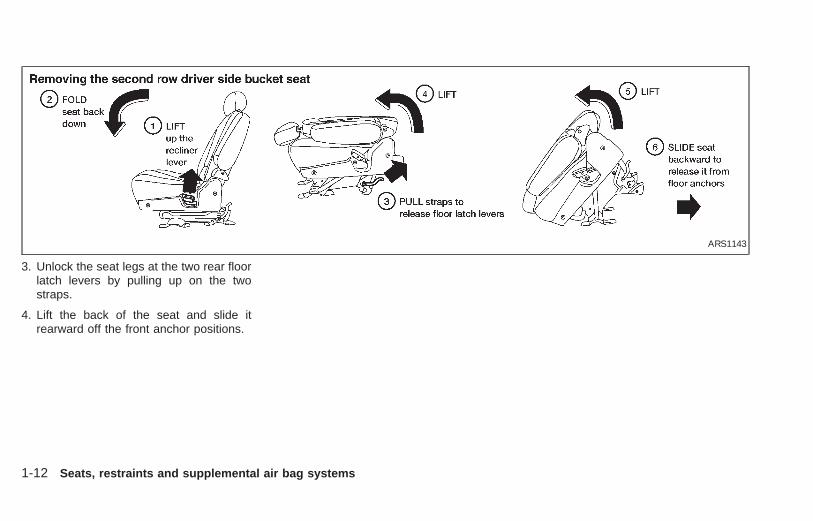
3. Unlock the seat legs at the two rear floorlatch levers by pulling up on the twostraps.
4. Lift the back of the seat and slide itrearward off the front anchor positions.
ARS1143
1-12 Seats, restraints and supplemental air bag systems
Z X

Installing the bucket seats
Clean the area around the seat leg flooranchors before installing the seat.
1. With the seatback fully folded, place theseat behind the floor anchors and slideseat leg hooks so they catch into eachfloor anchor.
2. Push down on the rear of the seat tosecure the two rear floor latches.
3. Lift the recliner lever and raise the seat-back.
4. Rock the seat back and forth to be sure itis securely latched.
The second row bucket seats are notinterchangeable. If you are having diffi-culty installing the seats, you may havethem in the wrong location.
ARS1142
Seats, restraints and supplemental air bag systems 1-13
Z X

Second row passenger side bucketseatThe bucket seat near the passenger sidesliding door can be moved forward to alloweasier entry and exit for third seat passen-gers.
There is also a lever behind the bucket seatwhich allow third seat passengers to movethe bucket seat forward without help fromanother passenger.
ARS1144 ARS1145
1-14 Seats, restraints and supplemental air bag systems
Z X

SLIDING THREE-PASSENGERSEAT
RecliningTo recline the three-passenger seat, lift upon the lever and lean back until the desiredposition is reached. To bring the seatbackforward, pull the lever up and lean yourbody forward.
Some three-passenger seats do not havethe recline feature.
WARNING● Do not recline the seatback while the
vehicle is moving.● Do not ride in a moving vehicle when
the seatback is reclined. This can bedangerous. The shoulder belt willnot be against your body. In an acci-dent you could be thrown into it andreceive neck or other serious inju-ries. You could also slide under thelap belt and receive serious internalinjuries.
● For most effective protection whenthe vehicle is in motion, the seatshould be upright. Always sit wellback in the seat and adjust the seatbelt properly. See ‘‘Precautions onSeat Belt Usage’’ later in this section.
● After adjustment, gently rock in theseat to be sure both sides are se-curely locked.
APD0852
Seats, restraints and supplemental air bag systems 1-15
Z X

Sliding the three-passenger seatBefore sliding the seat, fasten the centerbelt tongue to the center buckle and removethe appropriate floor mats.
1. Lift the seat cushion release lever.
2. Lift the seat cushion up into the lockedposition.
3. Lift the slide release lever and grasp thebar under the seat in the center.
4. Slide the seat until locked at a passengerseating position or a storage position.After the seat starts moving, release theslide lever. The seat latches at the nextlatching position. Continue to lift andrelease the slide lever until the desiredposition is obtained.
To lower the cushion, the seat must belocked at a passenger seating position. Liftthe seat cushion release lever and lower thecushion until locked.
The seat cushion cannot be lowered in astorage position. This prevents a pas-senger from using a seat or seat belt thatis out of a seating position.APD0853
1-16 Seats, restraints and supplemental air bag systems
Z X

The seating system allows great flexibility.Proper usage is important to your safety.
WARNING● Do not slide the seat while the ve-
hicle is moving.● After adjustment, gently rock in the
seat to be sure it is securely locked.● After sliding the seat, check that both
sides of the seat are locked securelyby attempting to move each side ofthe seat forward and backward. Thismust be done before the vehicle is
put into motion in order to preventunintended movement of the seat andpassenger injuries.
● Do not attempt to use the seatsplaced into a storage position forpassengers because in this positionthe seat belts will not protect theoccupants. Be sure to use the properseat belts for each seat location.Improper seat belt usage will in-crease the risk of severe injury in anaccident.
● When the vehicle is being used tocarry cargo, properly secure all cargoto help prevent it from sliding or shift-ing. Do not place cargo higher thanthe seatbacks. In a sudden stop orcollision, unsecured cargo couldcause personal injury.
● Be careful not to damage the seatbelt. Never allow anyone to ride in thecargo area or on a seat that is in astorage position. It is not designedfor passengers. They could be in-jured in sudden braking or a collision.
● To prevent luggage or packagesfrom sliding forward during braking,
do not stack anything in the cargoarea higher than the seatbacks.
● It is extremely dangerous to ride in acargo area inside of a vehicle. In acollision, people riding in these ar-eas are more likely to be seriouslyinjured or killed.
● Do not allow people to ride in anyarea of your vehicle that is notequipped with seats and seat belts.
● Be sure everyone in your vehicle isin a seat and using a seat belt prop-erly.
● Be sure to replace and repositionfloor mats as discussed in ‘‘Floormat positioning’’ in this section.
● The three-passenger sliding benchseat is not intended to be removedfrom the vehicle by consumers.However, if it must be removed, havea qualified person remove it. Thatperson should refer to the instruc-tions in the Service Manual. Whenseat is reinstalled, the attachingbolts must be tightened to the appro-priate torque specifications. Failure
ARS1196
Seats, restraints and supplemental air bag systems 1-17
Z X

to follow these instructions couldincrease the chance and/or severityof injury in an accident.
Cleaning the seat tracksThe seat tracks for the three-passengersliding bench seat should be cleaned peri-odically with a high-powered vacuumcleaner. Dirty seat tracks may reduce thesliding ability of the seat. A wet cleansingagent may be used if necessary, but theseat tracks must be thoroughly dried.
Use a cloth wrapped around a screwdriver(or similar object) to clean the seat tracks.Do not use your fingers to clean debris fromthe tracks.
Do not apply any type of lubricant to theseat tracks.
CAUTIONNever insert fingers into the seat trackrails. The rails may be sharp and couldcause injury.
1-18 Seats, restraints and supplemental air bag systems
Z X

This Supplemental Restraint System de-scription contains important informationconcerning the special driver and passen-ger supplemental air bag. The Supplemen-tal Restraint System Air Bags can helpreduce impact force to the driver and frontpassenger in certain frontal collisions. Thesupplemental air bags are designed tosupplement the crash protection providedby the seat belts and are not a substitutefor the seat belts. The seat belts shouldalways be correctly worn and the driver andfront passenger seated a suitable distancefrom the steering wheel and instrumentpanel. (See ‘‘Seat belts’’ for instructions andprecautions on seat belt usage later in thissection.)
The supplemental air bags operate onlywhen the ignition switch is in the ON orSTART position.
WARNING● The supplemental air bag ordinarily
will not inflate in the event of a sideimpact, rear impact, roll over, or lowerseverity frontal collision. Always wearyour seat belts to help reduce the riskor severity of injury in various kindsof accidents.
● The seat belts and the supplementalair bag are most effective when you aresitting back and upright in the seat.Supplemental air bags inflate withgreat force. If you are unrestrained,leaning forward, sitting sideways, you
are at greater risk of injury or death ina crash and may also receive seriousor fatal injuries from the supplementalair bag if you are up against it when itinflates.
● Always sit back against the seatbackand as far away as practical from thesteering wheel or instrument panel.Always use the seatbelts.
● Keep hands on the outside of thesteering wheel. Placing them insidethe steering wheel rim could increasethe risk that they are injured when thesupplemental air bag inflates.
ARS1132
SUPPLEMENTAL RESTRAINTSYSTEM (supplemental air bagsystem)
Seats, restraints and supplemental air bag systems 1-19
Z X

ARS1133 ARS1041
ARS1042
1-20 Seats, restraints and supplemental air bag systems
Z X

WARNING● Never let children ride unrestrained.
Do not attempt to hold them in yourlap or arms. Some examples of dan-gerous riding positions are shown inthe previous illustrations.
● Children may be severly injured orkilled when the supplemental air baginflates if they are not properly re-strained.
● Never install a rear-facing child re-straint in the front seat. An inflatingsupplemental air bag could seri-ously injure or kill your child. See‘‘Child restraints’’ later in this sec-tion for details.
ARS1043
ARS1044
ARS1045
ARS1046
Seats, restraints and supplemental air bag systems 1-21
Z X

The driver supplemental air bag is located inthe center of the steering wheel. The frontpassenger supplemental air bag is mounted inthe dashboard above the glove box.
These systems are designed to meet optionalcertification requirements under U.S. regula-tions. They are also permitted in Canada. Theoptional certification allows air bags to bedesigned to inflate somewhat less forcefullythan previously. However, all of the infor-mation, cautions and warnings in thismanual still apply and must be followed.
The supplemental air bag system is designedto inflate in higher severity frontal collisions,
although it may inflate if the forces in anothertype of collision are similar to those of a higherseverity frontal impact. It may not inflate incertain frontal collisions. Vehicle damage (orlack of it) is not always an indication of propersupplemental air bag system operation.
When the supplemental air bag inflates, afairly loud noise may be heard, followed bythe release of smoke. This smoke is notharmful and does not indicate a fire, butcare should be taken not to unintentionallyinhale it, as it may cause irritation andchoking. Those with a history of a breathingcondition should get fresh air promptly.
The supplemental air bags, along with theuse of seat belts, help to cushion the impactforce on the face and chest of the occupant.They can help save lives and reduce seri-ous injuries. However, an inflating supple-mental air bag may cause facial abrasionsor other injuries. Supplemental air bags donot provide restraint to the lower body.
Seat belts should be correctly worn and thedriver and passenger seated upright as faraway as practical from the steering wheel orinstrument panel. Since the supplemental airbag inflates quickly in order to help protectthe occupant, the force of the supplementalair bag inflating can increase the risk of injuryif the occupant is too close to or is against thesupplemental air bag module during inflation.
The supplemental air bag deflates quicklyafter a collision. The supplemental airbags operate only when the ignitionswitch is in the ON or START position.
ARS1122
SUPPLEMENTAL AIR BAGSYSTEM
1-22 Seats, restraints and supplemental air bag systems
Z X

WARNING● Do not place any objects on the
steering wheel pad or the instrumentpanel. Also, do not place any objectsbetween any occupant and the steer-ing wheel or instrument panel. Suchobjects may become dangerous pro-jectiles and cause injury if thesupplemental air bag inflates.
● Right after inflation, several supple-mental air bag system componentswill be hot. Do not touch them; youmay severely burn yourself.
● No unauthorized changes should bemade to any components or wiringof the supplemental air bag system.This is to prevent accidental inflationof the supplemental air bag or dam-age to the supplemental air bag sys-tem.
● Do not make unauthorized changesto your vehicles electrical system,suspension system or front endstructure. This could affect properoperation of the supplemental airbag system.
● Tampering with the supplemental airbag system may result in seriouspersonal injury. Tampering includeschanges to the steering wheel andthe instrument panel assembly byplacing material over the steeringwheel pad and above the instrumentpanel, or by installing additional trimmaterial around the supplemental airbag system.
● Work around and on the supplemen-tal air bag system should be done byan authorized NISSAN dealer. Instal-lation of electrical equipment shouldalso be done by an authorized NIS-SAN dealer. The yellow Supplemen-tal Restraint System (SRS) wiringshould not be modified or discon-nected. Unauthorized electrical testequipment and probing devicesshould not be used on the supple-mental air bag system.
● The SRS wiring harnesses are cov-ered with yellow insulation eitherjust before the harness connectorsor over the complete harness foreasy identification.
When selling your vehicle, we request thatyou inform the buyer about the supplementalair bag system and guide the buyer to theappropriate sections in this owner’s manual.
Seats, restraints and supplemental air bag systems 1-23
Z X

Warning labels about the supplemental airbag system are placed in the vehicle asshown in the illustration.
The supplemental air bag warning light,displaying in the instrument panel,monitors the circuits of the supplemental airbag system. The circuits monitored by thesupplemental air bag warning light includethe diagnosis sensor unit, supplemental airbag modules and all related wiring.
When the ignition key is in the ON or STARTposition, the supplemental air bag warninglight illuminates for about 7 seconds andthen turns off. This means the system isoperational.
ARS1123 APD0554
WARNING LABELS SUPPLEMENTAL AIR BAGWARNING LIGHT
1-24 Seats, restraints and supplemental air bag systems
Z X
If any of the following conditions occur, thesupplemental air bag needs servicing andshould be taken to your nearest authorizedNISSAN dealer:
1. The supplemental air bag light does notcome on and remain on for 7 secondsand then go off as described.
2. The supplemental air bag light flashesintermittently, or remains on after 7 sec-onds.
3. The supplemental air bag light does notcome on at all.
Under these conditions, the SupplementalRestraint System Air Bag may not operateproperly. It must be checked and repaired.Take your vehicle to the nearest authorizedNISSAN dealer.
WARNING
If the supplemental air bag warninglight is on, it could mean that thesupplemental air bag system will notoperate in an accident.
Repair and replacement procedureThe supplemental air bag modules are de-signed to inflate on a one-time-only basis.As a reminder, unless it is damaged, thesupplemental air bag light remains illumi-nated after inflation has occurred. Repairand replacement of the supplemental airbag system should be done only by anauthorized NISSAN dealer.
To ensure long-term functioning, thesupplemental air bag system must beinspected 10 years after the date ofmanufacture as noted on the certifica-tion label located on the driver side frontpillar.
When maintenance work is required on thevehicle, the supplemental air bag systemand related parts should be pointed out tothe person conducting the maintenance.The ignition key should always be in theLOCK position when working under thehood or inside the vehicle.
WARNING● Once the supplemental air bag in-
flates, the supplemental air bagmodule will not function again andshould be replaced by an authorizedNISSAN dealer. The supplemental airbag module cannot be repaired.
● The supplemental air bag systemshould be inspected by an autho-rized NISSAN dealer if there is anydamage to the front end portion ofthe vehicle.
● If you need to dispose of a supple-mental air bag or scrap the vehicle,contact an authorized NISSAN dealer.Correct supplemental air bag dis-posal procedures are set forth in theappropriate NISSAN Service Manual.Incorrect disposal procedures couldcause personal injury.
Seats, restraints and supplemental air bag systems 1-25
Z X

PRECAUTIONS ON SEAT BELTUSAGE
Your chances of being injured or killed in anaccident and/or the severity of injury may begreatly reduced if you are wearing your seatbelt and it is properly adjusted. NISSANstrongly encourages you and all of yourpassengers to buckle up every time youdrive, even if your seating position includesa supplemental air bag.
Most U.S. States and Canadian prov-inces or territories require that seat beltsbe worn at all times when a vehicle isbeing driven. WARNING
● Every person who drives or rides inthis vehicle should use a seat belt atall times. Children should be prop-erly restrained and, if appropriate, ina child restraint.
● The belt should be adjusted to a snugfit. Failure to do so may reduce theeffectiveness of the entire restraintsystem and increase the chance orseverity of injury in an accident. Seri-ous injury or death can occur if theseat belt is not worn properly.
● Always route the shoulder belt overyour shoulder and across your chest.Never run the belt behind your back,under your arm or across your neck.The belt should be away from yourface and neck, but not falling off yourshoulder.
● Position the lap belt as low and snugas possible AROUND THE HIPS,NOT THE WAIST. A lap belt worn toohigh could increase the risk of inter-nal injuries in an accident.
ARS1134
SEAT BELTS
1-26 Seats, restraints and supplemental air bag systems
Z X

● Be sure the seat belt tongue is se-curely fastened to the proper buckle.
● Do not wear the belt inside out ortwisted. Doing so may reduce itseffectiveness.
● Do not allow more than one personto use the same seat belt.
● Never carry more people in the ve-hicle than there are seat belts.
● If the seat belt warning light glowscontinuously while the ignition isturned ON with all doors closed andall seat belts fastened, it may indi-cate a malfunction in the system.Have the system checked by an au-thorized NISSAN dealer.
● All seat belt assemblies, includingretractors and attaching hardware,should be inspected by an authorizedNISSAN dealer after any collision.NISSAN recommends that all seat
belt assemblies in use during a colli-sion be replaced unless the collisionwas minor and the belts show nodamage and continue to operateproperly. Seat belt assemblies not inuse during a collision should also beinspected and replaced if either dam-age or improper operation is noted.
CHILD SAFETYChildren need adults to help protect them.They need to be properly restrained.The proper restraint depends on thechild’s size. Generally, infants up to about
ARS1047 ARS1050 ARS1049
Seats, restraints and supplemental air bag systems 1-27
Z X
1 year and less than 20 pounds (9 kg)should be placed in rear facing child re-straints. Forward facing child restraintsare available for children who outgrow rearfacing child restraints.
WARNINGInfants and children need special pro-tection. The vehicle’s seat belts maynot fit them properly. The shoulder beltmay come too close to the face or neck.The lap belt may not fit over their smallhip bones. In an accident an improperlyfitting seat belt could cause serious orfatal injury. Always use appropriatechild restraints.
All US States and Canadian provinces re-quire the use of approved child restraints forinfants and small children. See ‘‘Child re-straints’’ later in this section.
In addition, there are many types of childrestraints available for larger children whichshould be used for maximum protection.
NISSAN recommends that all preteensand children be restrained in the rearseat if possible. According to accidentstatistics, children are safer when prop-
erly restrained in the rear seat than in thefront seat.
This is especially important because yourvehicle has a supplemental restraint sys-tem (Air bag system) for the front passen-ger (For precautions, see ‘‘Supplementalrestraint system’’ earlier in this section).
Infants and small childrenNISSAN recommends that infants and smallchildren be placed in a child restraint thatcomplies with the Federal Motor VehicleSafety Standards or Canadian Motor Ve-hicle Safety Standards. You should choosea child restraint that fits your vehicle andalways follow the manufacturer’s instruc-tions for installation and use.
Larger childrenChildren who are too large for child re-straints should be seated and restrained bythe seat belts which are provided.
If the child’s seating position has a shoulderbelt that fits close to the face or neck, the useof a booster seat (commercially available)may help overcome this. The booster seatshould raise the child so the shoulder belt isproperly positioned across the top, middleportion of the shoulder and the lap belt is low
on the hips. The booster seat should fit thevehicle seat and have a label certifying thatit complies with Federal Motor VehicleSafety Standards or Canadian Motor Ve-hicle Safety Standards. Once the child hasgrown enough so the shoulder belt is nolonger on or near the face and neck, use theshoulder belt without the booster seat.
WARNING
Never let a child stand or kneel on anyseat and do not allow a child in thecargo areas while the vehicle is mov-ing. The child could be seriously in-jured or killed in an accident.
PREGNANT WOMENNISSAN recommends that pregnant womenuse seat belts. Contact your doctor for spe-cific recommendations. The lap belt shouldbe worn snug and positioned as low aspossible around the hips, not the waist.
INJURED PERSONSNISSAN recommends injured persons useseat belts, depending on the injury. Checkwith your doctor for specific recommenda-tions.
1-28 Seats, restraints and supplemental air bag systems
Z X

THREE-POINT TYPE WITHRETRACTOR
WARNING● Every person who drives or rides in
this vehicle should use a seat belt atall times.
● Do not ride in a moving vehicle whenthe seatback is reclined. This can bedangerous. The shoulder belt will notbe against your body. In an accident
you could be thrown into it and re-ceive neck or other serious injuries.You could also slide under the lap beltand receive serious internal injuries.
● For most effective protection whenthe vehicle is in motion, the seatshould be upright. Always sit wellback in the seat and adjust the seatbelt properly.
Fastening the seat belts1. Adjust the seat.
2. Slowly pull the seat belt out of the retrac-tor and insert the tongue into the buckleuntil it clicks.
The retractor is designed to lock duringa sudden stop or on impact. A slowpulling motion permits the seat belt tomove, and allows you some freedom ofmovement in the seat.
ARS1159 ARS1160 ARS1161
Seats, restraints and supplemental air bag systems 1-29
Z X

3. Position the lap belt portion low andsnug on the hips as shown.
4. Pull the shoulder belt portion toward theretractor to take up extra slack.
The front seat passenger seat belt and rearthree-point seat belts have a cinchingmechanism for child restraint installation. It isreferred to as the automatic locking mode.
When the automatic locking mode is acti-vated, the seat belt cannot be withdrawnagain until the seat belt tongue is detachedfrom the buckle and fully retracted. Refer to
‘‘Child restraints’’ later in this section formore information.
The automatic locking mode should beused only for child restraint installation.During normal seat belt use by a passen-ger, the locking mode should not beactivated. If it is activated, it may causeuncomfortable seat belt tension.
Unfastening the seat beltsTo unfasten the seat belt, press the buttonon the buckle. The seat belt automaticallyretracts.
Checking seat belt operation(Three-point type seat belt withretractor)Seat belt retractors are designed to lockseat belt movement:
1) when the seat belt is pulled quickly fromthe retractor, and
2) when the vehicle slows down rapidly.
ARS1162 ARS1054
1-30 Seats, restraints and supplemental air bag systems
Z X

To increase your confidence in the seatbelts, check their operation as follows.
● Grasp the shoulder belt and pull quicklyforward. The retractor should lock andrestrict further belt movement.
If the retractor does not lock during thischeck or if you have any questions aboutbelt operation, see an authorized NISSANdealer.
Shoulder belt height adjustmentThe shoulder belt anchor height should beadjusted to the position best for you (See‘‘Precautions on seat belt usage’’ earlier inthis section.). To adjust, press the releasebutton and move the shoulder belt anchor tothe desired position so the belt passes overthe center of the shoulder. The belt shouldbe away from your face and neck, but notfalling off your shoulder. Release the buttonto lock the shoulder belt anchor into position.
WARNING● After adjustment, release the button
and try to move the shoulder beltanchor up and down to make sure itis securely fixed in position.
● The shoulder belt height should beadjusted to the position best for you.Failure to do so may reduce theeffectiveness of the entire restraintsystem and increase the chance orseverity of injury in an accident.
APD0831
Seats, restraints and supplemental air bag systems 1-31
Z X

THREE-POINT TYPE SEAT BELTWITH RETRACTOR FOR SECONDROW BUCKET SEATS
WARNING● Every person who drives or rides in
this vehicle should use a seat belt atall times.
● Do not ride in a moving vehicle whenthe seatback is reclined. This can bedangerous. The shoulder belt will
not be against your body. In an acci-dent you could be thrown into it andreceive neck or other serious inju-ries. You could also slide under thelap belt and receive serious internalinjuries.
● For most effective protection whenthe vehicle is in motion, the seatshould be upright. Always sit wellback in the seat and adjust the seatbelt properly.
Fastening the seat belt1. Adjust the seat.
2. Slowly pull the seat belt out of the retrac-tor and insert the tongue into the buckleuntil it clicks.
The retractor is designed to lock duringa sudden stop or on impact. A slowpulling motion permits the seat belt tomove, and allows you some freedom ofmovement in the seat.
3. Position the lap belt portion low on thehips as shown.
4. Pull the shoulder belt portion toward theretractor to take up extra slack.
ARS1083 APD0830
1-32 Seats, restraints and supplemental air bag systems
Z X
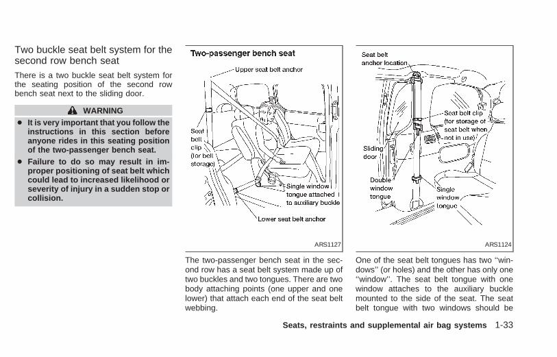
Two buckle seat belt system for thesecond row bench seatThere is a two buckle seat belt system forthe seating position of the second rowbench seat next to the sliding door.
WARNING● It is very important that you follow the
instructions in this section beforeanyone rides in this seating positionof the two-passenger bench seat.
● Failure to do so may result in im-proper positioning of seat belt whichcould lead to increased likelihood orseverity of injury in a sudden stop orcollision.
The two-passenger bench seat in the sec-ond row has a seat belt system made up oftwo buckles and two tongues. There are twobody attaching points (one upper and onelower) that attach each end of the seat beltwebbing.
One of the seat belt tongues has two ‘‘win-dows’’ (or holes) and the other has only one‘‘window’’. The seat belt tongue with onewindow attaches to the auxiliary bucklemounted to the side of the seat. The seatbelt tongue with two windows should be
ARS1127 ARS1124
Seats, restraints and supplemental air bag systems 1-33
Z X

positioned properly and fastened to thebuckle mounted in the middle of the seat.
When the two buckle seat belt system is notin use, the webbing can be secured with theseat belt clip. The seat belt clip should notbe used with a child seat or during seat beltusage. The seat belt clip opening shouldface the front of the vehicle.
A twisted belt may prevent the retractorfrom working properly. If the two buckle seatbelt system is twisted, disengage the singlewindow tongue from the auxiliary buckle onthe side of the seat, remove the twist andreinstall the tongue into the auxiliary buckleuntil you hear a snap and feel the latchengage.
Both tongues must be attached to theirappropriate buckles whenever someoneis riding in that seating position. If thetongue are released to allow a third rowpassenger to enter or exit, the tonguesmust be reattached.
When the two-passenger bench seat is re-moved from the vehicle, you must detachthe single window tongue from the auxiliarybuckle.
If the three-passenger bench seat ismoved up to the second row position, theoutside passenger (near the passengerside sliding door) only needs to use thedouble window tongue and the standardbuckle. Because the three-passengerbench seat is wider and closer to thepassenger side sliding door, the singlewindow seat belt tongue and the auxiliarybuckle are not necessary.
ARS1126
1-34 Seats, restraints and supplemental air bag systems
Z X

CAUTION
Third row passengers must be verycareful when exiting because of theauxiliary seat belt. It is important tostep over the seat belt guide and beltwebbing to avoid tripping.
Unfastening the seat belts
To unfasten the seat belt, press the buttonon the buckle. The seat belt automaticallyretracts.
Checking seat belt operation(Three-point type seat belt withretractor)Seat belt retractors are designed to lockseat belt movement:
1) when the seat belt is pulled quickly fromthe retractor, and
2) when the vehicle slows down rapidly.
To increase your confidence in the seatbelts, check their operation as follows.
● Grasp the shoulder belt and pull quicklyforward. The retractor should lock andrestrict further belt movement.
If the retractor does not lock during thischeck or if you have any questions aboutseat belt operation, see an authorized NIS-SAN dealer.
THREE PASSENGER BENCHSEAT IN THE SECOND ROWPOSITION
Fastening the seat beltsWhen the three-passenger bench seat ismoved up to the second row position,the passenger, on the passenger side,only needs to use the double windowtongue and the standard buckle. Be-cause the three-passenger bench seat iswider and closer to the passenger sidesliding doors, the single window seatbelt tongue and the auxilliary buckle arenot necessary.
1. Adjust the seat.
ARS1125
Seats, restraints and supplemental air bag systems 1-35
Z X

2. Slowly pull the seat belt out of the retrac-tor and insert the tongue into the buckleuntil it snaps.
3. Position the passenger side shoulder beltin the shoulder belt retainer.
4. Position the lap belt portion low on thehips as shown.
5. Pull the shoulder belt portion toward theretractor to take up extra slack.
ARS1213 ARS1197 ARS1084
1-36 Seats, restraints and supplemental air bag systems
Z X
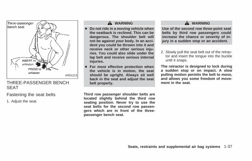
THREE-PASSENGER BENCHSEAT
Fastening the seat belts1. Adjust the seat.
WARNING● Do not ride in a moving vehicle when
the seatback is reclined. This can bedangerous. The shoulder belt willnot be against your body. In an acci-dent you could be thrown into it andreceive neck or other serious inju-ries. You could also slide under thelap belt and receive serious internalinjuries.
● For most effective protection whenthe vehicle is in motion, the seatshould be upright. Always sit wellback in the seat and adjust the seatbelt properly.
Third row passenger shoulder belts arelocated slightly behind the third rowseating position. Never try to use theseat belts for the second row passen-gers which are in front of the three-passenger bench seat.
WARNINGUse of the second row three-point seatbelts by third row passengers couldincrease the chance or severity of in-jury in a sudden stop or an accident.
2. Slowly pull the seat belt out of the retrac-tor and insert the tongue into the buckleuntil it snaps.
The retractor is designed to lock duringa sudden stop or on impact. A slowpulling motion permits the belt to move,and allows you some freedom of move-ment in the seat.
ARS1213
Seats, restraints and supplemental air bag systems 1-37
Z X

3. Position the lap belt portion low on thehips as shown.
4. Pull the shoulder belt portion toward theretractor to take up extra slack.
TWO-POINT TYPE WITHOUTRETRACTOR (Center of three-passenger bench seat)
Selecting correct set of beltsThe seat belt tongues must be fastened intothe seat belt buckles as illustrated above.
WARNINGAny rear seat belt tongue will connectto any seat belt buckle; therefore, it isimportant to follow the illustrationabove. Failure to do so could increasethe chance and/or severity of injury inan accident.
ARS1084 APD0162
1-38 Seats, restraints and supplemental air bag systems
Z X

Fastening the seat belt1. Insert the tongue into the buckle until it
clicks.
2. Tighten the belt by pulling the free end ofthe belt away from the tongue, then pullthe belt clip to take up the slack.
3. Position the lap belt low on the hips asshown.
ARS1055 ARS1115 ARS1076
Seats, restraints and supplemental air bag systems 1-39
Z X

4. Loosen the belt by holding the tongue ata right angle to the belt, then pull on thebelt.
Unfastening the belts
To unfasten the belt, press the button on thebuckle.
SEAT BELT EXTENDERS
If, because of body size or driving position,it is not possible to properly fit the front seatlap belts and fasten them, an extender isavailable which is compatible with the in-stalled seat belts. The extender adds ap-proximately 8 inches (200 mm) of lengthand may be used for either the driver or frontpassenger seating position. See an autho-
rized NISSAN dealer for assistance if theextender is required.
WARNING
● Only NISSAN seat belt extenders,made by the same company whichmade the original equipment seatbelts, should be used with NISSANseat belts.
● Persons who can use the standardseat belt should not use an extender.Such unnecessary use could resultin serious personal injury in theevent of an accident.
SEAT BELT MAINTENANCE
● To clean the seat belt webbings, applya mild soap solution or any solution rec-ommended for cleaning upholstery orcarpet. Then wipe with a cloth and allowthe seat belts to dry in the shade. Do notallow the seat belts to retract until theyare completely dry.
● If dirt builds up in the shoulder beltguide of the seat belt anchors, the seatbelts may retract slowly. Wipe the shoul-der belt guide with a clean, dry cloth.
ARS1057 ARS1058
1-40 Seats, restraints and supplemental air bag systems
Z X

● Periodically check to see that the seatbelt and the metal components suchas buckles, tongues, retractors, flexiblewires and anchors work properly. If looseparts, deterioration, cuts or other dam-age on the webbing is found, the entireseat belt assembly should be replaced.
WARNING● Infants and small children should
always be placed in an appropriatechild restraint system while riding inthe vehicle. Failure to use a childrestraint can result in serious injuryor death.
● Infants and small children shouldnever be carried on your lap. It is notpossible for even the strongest adultto resist the forces of a severe acci-dent. The child could be crushedbetween the adult and parts of thevehicle. Also, do not put the sameseat belt around both your child andyourself.
● Never install a rear-facing child re-straint in the front seat. An inflating airbag could seriously injure or kill yourchild. A rear-facing child restraintmust only be used in the rear seat.
● NISSAN recommends that the childrestraint be installed in a rear seat.According to accident statistics,children are safer when properly re-strained in a rear seat than in a frontseat.
● An improperly installed child re-straint could lead to serious injury inan accident.
● In general, child restraint systemsare designed to be installed with alap belt or the lap portion of a three-point type seat belt.
Child restraints for infants and children ofvarious sizes are offered by several manu-facturers. When selecting any child re-straint, keep the following points in mind:
1) Choose only a restraint with a label cer-tifying that it complies with Federal MotorVehicle Safety Standard 213 or Cana-dian Motor Vehicle Safety Standard 213.
2) Check the child restraint in your vehicleto be sure it is compatible with the vehi-cle’s seat and seat belt system. Choosea child restraint that meets the guidelinesof the Society of Automotive Engineersrecommended practice J1819 for childseat installation.
3) If the child restraint is compatible withyour vehicle, place your child in the childrestraint and check the various adjust-ments to be sure the child restraint is
CHILD RESTRAINTS
Seats, restraints and supplemental air bag systems 1-41
Z X

compatible with your child. Always followall recommended procedures.
All U.S. states and some provinces orterritories of Canada require that infantsand small children be restrained in ap-proved child restraints at all times whilethe vehicle is being operated.
WARNING● Improper use of a child restraint can
result in increased injuries for boththe infant or child and other occu-pants in the vehicle.
● Follow all of the child restraintmanufacturer’s instructions for in-stallation and use. When purchasinga child restraint, be sure to selectone which will fit your child andvehicle. It may not be possible toproperly install some types of childrestraints in your vehicle.
● If the child restraint is not anchoredproperly, the risk of a child beinginjured in a collision or a suddenstop greatly increases.
● Adjustable seatbacks should be po-sitioned to fit the child restraint, butas upright as possible.
● After attaching the child restraint,test it before you place the child in it.Tilt it from side to side. Try to tug itforward and check to see if the beltholds the restraint in place. If therestraint is not secure, tighten thebelt as necessary, or put the restraintin another seat and test it again.
● For a front facing child restraint, ifthe seat position where it is installedhas a three-point type lap/shoulderbelt, check to make sure the shoul-der belt does not go in front of thechild’s face or neck. If it does, putthe shoulder belt behind the childrestraint. If you must install a frontfacing child restraint in the frontseat, see ‘‘Installation on front pas-senger seat’’ later in this section.
● When your child restraint is not inuse, keep it secured with a seat beltto prevent it from being thrownaround in case of a sudden stop oraccident.
CAUTIONRemember that a child restraint left in aclosed vehicle can become very hot.Check the seating surface and bucklesbefore placing your child in the childrestraint.
1-42 Seats, restraints and supplemental air bag systems
Z X
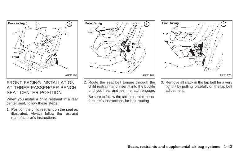
FRONT FACING INSTALLATIONAT THREE-PASSENGER BENCHSEAT CENTER POSITIONWhen you install a child restraint in a rearcenter seat, follow these steps:
1. Position the child restraint on the seat asillustrated. Always follow the restraintmanufacturer’s instructions.
2. Route the seat belt tongue through thechild restraint and insert it into the buckleuntil you hear and feel the latch engage.
Be sure to follow the child restraint manu-facturer’s instructions for belt routing.
3. Remove all slack in the lap belt for a verytight fit by pulling forcefully on the lap beltadjustment.
ARS1168 ARS1169 ARS1170
Seats, restraints and supplemental air bag systems 1-43
Z X

4. Before placing the child in the child re-straint, use force to tilt the child restraintfrom side to side, and tug it forward tomake sure it is securely in place.
5. If it is not secure, try to tighten the beltagain, or put the restraint in another seat.
6. Check to make sure the child restraint isproperly secured prior to each use.
REAR FACING INSTALLATIONAT THREE-PASSENGER BENCHSEAT CENTER POSITIONWhen you install a child restraint in a rearcenter seat, follow these steps:
1. Position the child restraint on the seat asillustrated. Always follow the restraintmanufacturer’s instructions.
2. Route the seat belt tongue through thechild restraint and insert it into the buckleuntil you hear and feel the latch engage.
Be sure to follow the child restraint manu-facturer’s instructions for belt routing.
ARS1171 ARS1172 ARS1173
1-44 Seats, restraints and supplemental air bag systems
Z X

3. Remove all slack in the lap belt for a verytight fit by pulling forcefully on the lap beltadjustment.
4. Before placing the child in the child re-straint, use force to tilt the child restraintfrom side to side, and tug it forward tomake sure it is securely in place.
5. If it is not secure, try to tighten the beltagain, or put the restraint in another seat.
6. Check to make sure the child restraint isproperly secured prior to each use.
FRONT FACING INSTALLATIONAT SECOND AND THIRD ROWOUTBOARD POSITIONSThe following instructions apply to secondrow bucket seats, the second row benchseat and the outboard positions of the three-passenger bench seat.
WARNINGWhen installing a child restraint in thetwo-passenger bench seat, if it isplaced in the seating position next tothe passenger side sliding door, besure both the auxiliary buckle and mainbuckle are properly fastened. Failure todo so could increase the chance and/orseverity of injury in an accident.
ARS1174 ARS1175
Seats, restraints and supplemental air bag systems 1-45
Z X

WARNING● The three-point belt in your vehicle
is equipped with an automatic lock-ing mode retractor which must beused when installing a child re-straint.
● Failure to use the retractor’s lockingmode will result in the child restraintnot being properly secured. The seatcould tip over or otherwise be unse-cured and cause injury to the child ina sudden stop or collision.
When you install a child restraint in a rearoutboard seat, follow these steps:
1. Position the child restraint on the seat.Always follow the restraint manufactur-er’s instructions.
2. Route the seat belt tongue through thechild restraint and insert it into the buckleuntil you hear and feel the latch engage.
Be sure to follow the child restraint manu-facturer’s instructions for belt routing.
ARS1176 ARS1177
1-46 Seats, restraints and supplemental air bag systems
Z X

3. Pull on the shoulder belt until all of thebelt is fully extended. At this time, the beltretractor is in the automatic locking mode(child restraint mode). It reverts back toemergency locking mode when the belt isfully retracted.
4. Allow the belt to retract. Pull up on theshoulder belt to remove any slack in thebelt.
5. Before placing the child in the child re-straint, use force to tilt the child restraintfrom side to side, and tug it forward tomake sure it is securely held in place.
6. Check that the retractor is in the auto-matic locking mode by trying to pull morebelt out of the retractor. If you cannot pullany more belt webbing out of the retrac-tor, the belt is in the automatic lockingmode.
7. Check to make sure the child restraint isproperly secured prior to each use. If thebelt is not locked, repeat steps 3 through6.
ARS1178 ARS1179 ARS1180
Seats, restraints and supplemental air bag systems 1-47
Z X
After the child restraint is removed and theseat belt is fully retracted (for the passengerside of the two-passenger bench seat, theauxilliary buckle must also be released), theautomatic locking mode (child restraintmode) is canceled.
REAR FACING INSTALLATIONAT SECOND AND THIRD ROWOUTBOARD POSITIONSThe following instructions apply to secondrow bucket seats, the second row benchseat and the outboard positions of the three-passenger bench seat.
WARNINGWhen installing a child restraint in thetwo-passenger bench seat, if it isplaced in the seating position next tothe passenger side sliding door, besure both the auxiliary buckle and mainbuckle are properly fastened. Failure todo so could increase the chance and/orseverity of injury in an accident.
WARNING● The three-point belt in your vehicle
is equipped with an automatic lock-ing mode retractor which must beused when installing a child re-straint.
● Failure to use the retractor’s lockingmode will result in the child restraintnot being properly secured. The seatcould tip over or otherwise be unse-cured and cause injury to the child ina sudden stop or collision.
1-48 Seats, restraints and supplemental air bag systems
Z X

When you install a child restraint in a rearoutboard seat, follow these steps:
1. Position the child restraint on the seat.Always follow the restraint manufactur-er’s instructions.
2. Route the seat belt tongue through thechild restraint and insert it into the buckleuntil you hear and feel the latch engage.
Be sure to follow the child restraint manu-facturer’s instructions for belt routing.
3. Pull on the shoulder belt until all of thebelt is fully extended. At this time, the beltretractor is in the automatic locking mode(child restraint mode). It reverts back toemergency locking mode when the belt isfully retracted.
ARS1181 ARS1182 ARS1183
Seats, restraints and supplemental air bag systems 1-49
Z X

4. Allow the belt to retract. Pull up on theshoulder belt to remove any slack in thebelt.
5. Before placing the child in the child re-straint, use force to tilt the child restraintfrom side to side, and tug it forward tomake sure it is securely held in place.
6. Check that the retractor is in the auto-matic locking mode by trying to pull morebelt out of the retractor. If you cannot pullany more belt webbing out of the retrac-tor, the belt is in the automatic lockingmode.
7. Check to make sure the child restraint isproperly secured prior to each use. If thebelt is not locked, repeat steps 3 through6.
After the child restraint is removed and theseat belt is fully retracted (for the passengerside of the two-passenger bench seat, theauxilliary buckle must also be released), theautomatic locking mode (child restraintmode) is canceled.
ARS1184 ARS1185
1-50 Seats, restraints and supplemental air bag systems
Z X

A child restraint anchored with a top tetherstrap can be installed on the second rowbench seat, second row bucket seat, orthree-passenger bench seat in the secondor third row. The chart indicates where thetether strap must be attached and the sec-tion of this manual that contains the instruc-tions for tethering.
Seat type Position Tether to Reference
Bucket seat Second row; center ofseat
Anchor bracket onback of bucket seat
Page 1-52, Tetheringto second row benchor bucket seat
Two passenger benchseat
Second row; outboardseating positions
Anchor bracket onback of second rowbench seat
Page 1-52, Tetheringto second row benchor bucket seat
Two-passenger benchseat with integratedchild safety seat
Second row; driverside seating position
Anchor bracket onback of second rowbench seat
Page 1-52, Tetheringto second row benchor bucket seat
Two-passenger benchseat with integratedchild safety seat
Second row; passen-ger side seating posi-tion
CANNOT BE
TETHERED —
Three-passengerbench seat
Second row; outboardseating position
Tongue of third rowlap/shoulder belt di-rectly behind the childseat position
Page 1-54, Tetheringto lap/shoulder belttongue
Three-passengerbench seat
Second row; centerseating position
CANNOT BE
TETHERED—
Three-passengerbench seat
Third row; outboardor center seating posi-tion
*Floor anchor directlybehind child seat posi-tion
Page 1-56, Tetheringto floor
* The parcel shelf (if so equipped) must be removed prior to tethering the child seat.
CHILD RESTRAINT WITH TOPTETHER STRAP
Seats, restraints and supplemental air bag systems 1-51
Z X

INSTALLATION ON SECONDROW BENCH OR BUCKET SEATA child restraint with a top tether strap maybe placed on the second row bench orbucket seats. Once the child restraint isproperly secured to the seat (see ‘‘Frontfacing installation at second and third rowoutboard positions’’ earlier in this section),follow the directions to attach the tetherstrap to the tether strap anchor bracket, orthe third row lap/shoulder belt tongue (lo-cated on the same side of the vehicle as thechild restraint).
Tethering to second row bench orbucket seat
To attach a tether strap to a second rowbench or bucket seat:
1. Route the tether strap under the headrestraint and between the head restraintsupports.
● The head restraint on the second rowbucket seat with the integrated child seatis not adjustable, but there is an openingunder the head restraint to route thetether strap through. Gently lift the headrestraint and route the tether strap under
the center of the head restraint through tothe back side of the seat.
APD0839
1-52 Seats, restraints and supplemental air bag systems
Z X

2. Hook the tether strap into the slot in theanchor bracket on the second row seat(located on the lower back of the seat, inline with the head restraint).
ARS1194 ARS1193 ARS1199
Seats, restraints and supplemental air bag systems 1-53
Z X

3. Tighten the tether strap to remove anyslack.
4. Before placing the child in the child re-straint, use force to tilt the child restraintfrom side to side, and tug it forward tomake sure it is securely held in place.
5. Check to make sure the child restraint isproperly secured prior to each use. If notsecure, repeat steps two through four.
INSTALLATION ON THREE-PASSENGER BENCH SEAT INSECOND ROW
WARNINGA third seat occupant should never sitat a seating location where the lap/shoulder belt is being used to attachthe child seat. Occupants should sit atlocations where seat belts can be used.Remember to always wear your seatbelt.
A child restraint with a top tether strap maybe placed at the outboard positions on thethree-passenger bench seat when the benchseat is in the second row location. Once thechild restraint is properly secured to the seat(see ‘‘Front facing installation at second andthird row outboard positions’’ earlier in thissection), follow the directions to attach thetether strap to the third row lap/shoulder belttongue (located on the same side of thevehicle as the child restraint).
ARS1192 APD0839
1-54 Seats, restraints and supplemental air bag systems
Z X

Tethering to lap/shoulder belt tongue
To attach a tether strap to a third rowlap/shoulder belt:
1. Route the tether strap under the headrestraint and between the head restraintsupports.
2. Hook the tether strap into the large holeon the tongue of the third row lap/shoulder belt (located near the upper andlower rear corners of the vehicle).
3. Adjust the tether strap until the hook isabout one foot behind the seatback.
4. Pull on the third row shoulder belt until allof the belt is fully extended. At this time,the belt retractor is in the automatic lock-ing mode (child restraint mode).
5. Allow the belt to retract. Tighten thetether strap to remove any slack.
6. Before placing the child in the child re-straint, use force to tilt the child restraintfrom side to side, and tug it forward tomake sure it is securely held in place.
7. Check that the retractor is in the automaticlocking mode by trying to pull more beltout of the retractor. If you cannot pull any
more belt webbing out of the retractor, thebelt is in the automatic locking mode.
8. Check to make sure the child restraint isproperly secured prior to each use. If thebelt is not locking, repeat steps 4 through7.
APD0835 ARS1198
Seats, restraints and supplemental air bag systems 1-55
Z X

INSTALLATION ON THREE-PASSENGER BENCH SEAT INTHIRD ROWA child restraint with a top tether strap maybe placed on the three-passenger benchseat when the bench seat is in the third rowlocation. Once the child restraint is properlysecured to the seat (see ‘‘Front facing in-stallation at second and third row outboardpositions’’ or ‘‘Front facing installation atthree-passenger bench seat center posi-tion’’ earlier in this section), follow the direc-tions to attach the tether strap to one of theanchor point locations.
Tethering to floorWhen installing a child restraint on thethree-passenger bench seat in the third rowposition, first install the floor anchor bracket(available at an authorized NISSAN dealer)to the provided anchor point.
Bracket part #88894-89900
To gain access to an anchor point, cut alongthe perforated floor carpeting of the cargoarea.Installing the anchor bracket requires re-moving the bolt already installed at theanchor point and using a metric bolt of thedimensions listed below:
Bolt diameter: 8.0 mmBolt length: at least 1.18 in (30 mm)Thread pitch: 1.25 mm
WARNING● Bolts should be installed at all times
to prevent the possibility of exhaustfumes entering the passenger com-partment through the holes.
● Child restraint anchor points are de-signed to withstand only those loadsimposed by correctly fitted child re-straints. Under no circumstancesare they to be used for adult seatbelts or harnesses.
● The parcel shelf (if so equipped)must be removed from the vehicle ifinstalling a child restraint on thethree-passenger bench seat that re-quires the use of a top tether strapthat is anchored to the vehicle floor.Failure to remove the parcel shelfcan increase the severity of injury tothe child in an accident.
Latch the tether strap hook onto the appro-priate anchor bracket. The tether strapshould be secured to the floor anchorbracket which provides the straightest in-stallation.
ARS1200
1-56 Seats, restraints and supplemental air bag systems
Z X
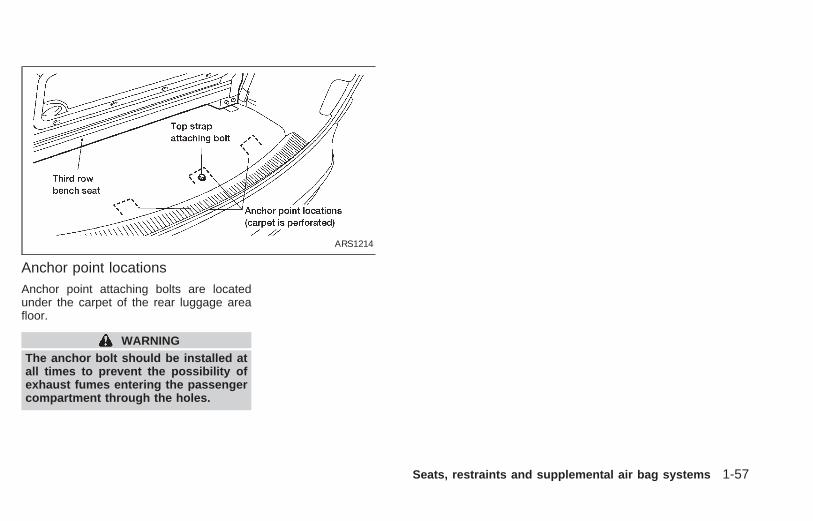
Anchor point locationsAnchor point attaching bolts are locatedunder the carpet of the rear luggage areafloor.
WARNINGThe anchor bolt should be installed atall times to prevent the possibility ofexhaust fumes entering the passengercompartment through the holes.
ARS1214
Seats, restraints and supplemental air bag systems 1-57
Z X

Installation on front passenger seatWARNING
● Never install a rear-facing child re-straint in the front passenger seat.Supplemental air bags inflate withgreat force. A rear-facing child re-straint could be struck by the supple-mental air bag in a crash and couldseriously injure or kill your child.
● NISSAN recommends that child re-straints be installed in the rear seat.However, if you install a forward-
facing child restraint in the front pas-senger seat, move the passengerseat to the rearmost position.
● A child restraint with a top strapshould not be used in the front pas-senger seat.
● The three-point belt in your vehicleis equipped with an automatic lock-ing mode retractor which must beused when installing a child re-straint.
● Failure to use the retractor’s lockingmode will result in the child restraintnot being properly secured. The seatcould tip over or otherwise be unse-cured and cause injury to the child ina sudden stop or collision.
ARS1135
1-58 Seats, restraints and supplemental air bag systems
Z X

If you must install a child restraint in the frontseat, follow these steps:
1. Position the child restraint on the frontpassenger seat. It should be placed ina forward-facing direction only. Movethe seat to the rearmost position. Alwaysfollow the child restraint manufacturer’sinstructions. Child restraints for infantsmust be used in the rear-facing direc-tion and therefore must not be used inthe front seat.
2. Route the seat belt tongue through thechild restraint and insert it into the buckleuntil you hear and feel the latch engage.
Be sure to follow the child restraint manu-facturer’s instructions for belt routing.
3. Pull on the shoulder belt until all of thebelt is fully extended. At this time, the beltretractor is in the automatic locking mode(child restraint mode). It reverts back toemergency locking mode when the belt isfully retracted.
ARS1163 ARS1164 ARS1165
Seats, restraints and supplemental air bag systems 1-59
Z X

4. Allow the belt to retract. Pull up on the beltto remove any slack in the belt.
5. Before placing the child in the child re-straint, use force to tilt the child restraintfrom side to side, and tug it forward tomake sure it is securely held in place.
6. Check that the retractor is in the automaticlocking mode by trying to pull more beltout of the retractor. If you cannot pull anymore belt webbing out of the retractor, thebelt is in the automatic locking mode.
7. Check to make sure the child restraint isproperly secured prior to each use. If thelap belt is not locked, repeat steps 3through 6.
After the child restraint is removed and theseat belt is fully retracted, the automaticlocking mode (child restraint mode) is can-celed.
ARS1166 ARS1167
1-60 Seats, restraints and supplemental air bag systems
Z X

INTEGRATED CHILD SAFETYSEATS (if so equipped)
WARNING
● Failure to follow the instructions forthe use of these integrated childsafety seats can result in your childstriking the vehicle’s interior duringa sudden stop or crash, causing theinjury or death of your child.
● Improper use of a child restraint canincrease the risk or severity of injuryfor both the child and other occu-pants of the vehicle.
All U.S. states and Canadian provincesrequire that infants and small children berestrained in approved child restraints atall times while the vehicle is being oper-ated.
The optional second row bench seat con-tains two integrated child safety seats.These seats are designed for use only bychildren who weigh between 22 and 60pounds (10-27 kg) and whose height is 45inches (1145 mm) or less and who arecapable of sitting upright alone.
In addition, these integrated child safetyseats must only be used by children whomeet the following requirements:
● AGE:At least one year old
● SEATED HEIGHT:Top of child’s shoulders must be belowthe shoulder harness openings of theintegrated child seat.
Children smaller than these requirementsshould be restrained in an appropriate sepa-rate child restraint. Children larger than theserequirements should also be restrained in anappropriate separate child restraint or in theappropriate vehicle seat belt system. Referto ‘‘Child Restraints’’ and ‘‘Precautions OnSeat Belt Usage’’ in this section for importantchild safety information.
Seats, restraints and supplemental air bag systems 1-61
Z X

Using the Integrated Child SafetySeats
WARNING:● Never use the vehicle seat belts to
restrain a child in an integrated child
safety seat. Use only the shoulder-harness and belt buckle which ispart of the integrated child safetyseat. Never use the integrated childsafety seat as a booster cushionwith the vehicle seat belts.
● Before placing the child in the inte-grated child safety seat, confirm thatthe bench seatback is securelylocked and the seatback release le-ver is in full down position.
● Always make sure the integratedchild safety seat belts are properlypositioned on your child. The childshould sit straight up and backagainst the bench seat. The shoulderharnesses should be centered overthe shoulders and fastened with thechest clip. The belt buckle should bebetween the legs and latched to theshoulder belt tongue. Snugly adjustthe belts around your child. Failureto properly position the child canincrease the risk or severity of injuryto the child in an accident.
CAUTIONRemember that the interior of a closedvehicle can become very hot when leftin direct sunlight. Check the seatingsurface and buckles before placingyour child in the integrated child safetyseat.
ARS1215
1-62 Seats, restraints and supplemental air bag systems
Z X

Securing the childBefore using the integrated child safetyseats, carefully read the shoulder har-ness, seatback release, and integratedchild safety seat cushion labels.
The following steps apply to both the leftand right integrated child safety seats.
1. Be sure your child meets all of the re-quired age, weight and height require-ments for the safe use of the integratedchild safety seat.
2. Be sure the second row bench seat issecurely latched to the floor of the ve-hicle. Refer to ‘‘Flexible seating’’ in thischapter for proper seat installation proce-dures.
3. Be sure the second row bench seatbackis locked by grasping it and trying to rockit back and forth. Also, check that theseatback release lever is in the full downposition. 4. Pull the cushion release strap and lower
the intregrated child safety seat cushioncompletely.
NOTE: The head restraints on the pas-senger bench seat equipped with theintegrated child safety seats, are notadjustable or removable.
ARS1201
Seats, restraints and supplemental air bag systems 1-63
Z X

5. If connected, separate the two halves ofthe shoulder harness from the beltbuckle. Also if connected, disconnect thechest clip and lay the shoulder harnesshalves aside.
6. Place the child on the integrated childsafety seat. Place the belt buckle be-tween the child’s legs.
APD0814 APD0815 APD0816
1-64 Seats, restraints and supplemental air bag systems
Z X

7. Place the left shoulder harness over thechild’s left shoulder. Insert the left shoulderharness tongue into the left side of the beltbuckle. Confirm that the left shoulder har-ness tongue indicator is green. The shoul-der harness tongues only fit into the propersides of the belt buckle.
8. Place the right shoulder harness over thechild’s right shoulder. Insert the right shoul-der harness tongue into the right side of thebelt buckle. Confirm that the right shoulderharness tongue indicator is green. Theshoulder harness tongues only fit into theproper sides of the belt buckle.
9. Fasten the two halves of the chest clipand confirm that the chest clip indicator isgreen. Adjust the chest clip (slightly lowerthan the child’s shoulders) so it comfort-ably holds the shoulder harness in positi-ton on the child’s shoulders.
WARNING● Shoulder harness tongues and chest
clips are equipped with visual indica-tors to confirm proper and securelatching. For the safety of the childand occupants of the vehicle, all indi-
cators must show green before oper-ating the vehicle.
● If the shoulder harness is unfas-tened or not fastened properly, thechild could be seriously injured.
10. Grasp the right shoulder harness abovethe chest clip and pull until the harnessfully extends and a click is heard. At thistime, the harness retractor is in theautomatic locking mode (child restraintmode). With the child sitting properly(straight up and back) in the integratedchild safety seat, allow the right shoul-
APD0817 APD0818 APD0819
Seats, restraints and supplemental air bag systems 1-65
Z X

der harness to retract over the rightshoulder and securely restrain the child.A clicking sound is heard as the har-ness retracts, indicating that the retrac-tor is in the automatic locking mode. Besure the left shoulder harness is alsoproperly positioned over the child’s leftshoulder.
11. Check that the shoulder harness is inthe automatic locking mode by trying topull the shoulder harness out of theretractor. If you cannot pull any of theshoulder harness webbing out of theretractor, the shoulder harness is in theautomatic locking mode. If the shoulderharness is not locked, repeat step 10. If,after repeated attempts, the integratedchild safety seat shoulder harness can-not be placed in the automatic lockingmode, do not use the integrated childsafety seat and have it inspected by anauthorized NISSAN dealer.
To cancel the automatic locking mode, un-buckle the chest clip and both shoulderharness tongues. Allow the shoulder har-nesses to retract completely. The automaticlocking mode is now canceled and the
shoulder harness retractor is in the emer-gency locking mode.
WARNING
The automatic locking mode (child re-straint mode) must be reactivated eachtime you place a child in the integratedchild safety seats.
In addition to the automatic locking retrac-tors, the integrated child safety seat shoul-der harnesses are equipped with emer-gency locking retractors. The automaticlocking mode is best to use, especially forchildren who need help staying properlypositioned in the seat and its harnesses (forexample, children who are younger andsmaller), because the belts are alwayslocked. In the emergency locking mode, theshoulder belts only lock in a sudden stop oraccident, allowing a child more freedom ofmovement. Use the emergency lockingmode only if you judge your child able toremain properly positioned in the integratedchild safety seat.
Removing the child1. Release the chest clip.
2. Release the left and right shoulder har-
ness tongues from the belt buckle bypressing the red belt buckle button.
3. Move the left and right shoulder har-nesses aside and assist the child fromthe integrated child safety seat.
Storing the Integrated Child SafetySeat
1. Be sure the shoulder harnesses are fullyretracted and resting inside the inte-grated child safety seat recess. It is notnecessary to reconnect the shoulder har-nesses and belt buckle prior to storingthe integrated child safety seat.
2. While holding onto, but not pulling, thecushion release strap, rotate the cushionupward until it fits flush with the secondrow seat back cushion and locks intoposition.
3. Be sure the integrated child safety seat islocked in the stowed position by graspingthe safety seat cushion and attempting tolower it without pulling the cushion re-lease strap. If the integrated child safetyseat is not locked in the stowed position,repeat steps one through three.
1-66 Seats, restraints and supplemental air bag systems
Z X

Integrated Child Safety Seat main-tenance
● To clean the shoulder harnesses and beltbuckle webbing, apply a mild soap solu-tion or any solution recommended forcleaning upholstery or carpets. Thenbrush the webbing, wipe it with a clothand allow it to dry in the shade. Do notallow the shoulder harnesses to retractuntil they are completely dry.
● The integrated child safety seats clothremovable pads may be cleaned withmild soap and water. The cloth remov-able pads are attached to the seats withfastener strips, and may be easily re-moved. The pads are machine washable.Fo best results, machine wash in coldwater in the gentle cycle. Tumble dry onlow heat. Do not use chlorine bleach, anddo not dry clean.
CAUTIONFailure to follow the washing instruc-tions provided on the cloth removablepads may result in premature wear ordamage.
● Periodically inspect the belt and metalcomponents of the integrated child safetyseats, such as the buckles, tongues,shoulder harness webbings, and latchingindicators. Periodically check the func-tion of the integrated child safety seatshoulder harness retractor functions. Ifloose parts, deterioration, cuts, frays,malfunctions or other damage to the beltwebbings or metal parts are found, seean authorized NISSAN dealer for repairs.
Inspection after an accidentIf your vehicle was involved in an accident,before using the integrated child safetyseats, all related components should beinspected for damage by an authorized NIS-SAN dealer. Damage to the integrated childsafety seat or related components must berepaired.
Seats, restraints and supplemental air bag systems 1-67
Z X
SEATING ARRANGEMENTSMany different arrangements for passengerseating or cargo hauling are available asyou will see in the following illustrations. Thesecond row seats may be removed and thethird row seat may be moved forward to thesecond row seating position. The secondand third row seats have an optional fold-down table-top feature. This offers a varietyof uses for the vehicle when moving orstopped.
The illustrations shown reflect the differentseating positions available.
Before you begin to arrange the seats inyour vehicle, read all of the cautions andwarnings in this chapter, including thefollowing section on the removable floormats. Also observe any labels that are inthe vehicle.
WARNING● While the vehicle is in motion, pas-
sengers should always be seated ina forward facing direction in a seatwhich is properly secured and ad-justed. Seat belts should always beused. Sitting without a seat belt in aseat that is not properly secured inone of the locations shown in thischapter, or in a place without a seatand seat belt can result in personalinjury in a sudden stop or collision.
● Do not ride in a moving vehicle whenthe seatback is reclined. This can bedangerous. The shoulder belt willnot be against your body. In an acci-dent, you could be thrown into it andreceive neck or other serious inju-ries. You could also slide under thelap belt and receive serious internalinjuries.
● For the most effective protectionwhen the vehicle is in motion, theseat should be upright. Always sitwell back in the seat and adjust theseat belt properly.
● It is extremely dangerous to ride in acargo area inside of a vehicle. In acollision, people riding in these ar-eas are more likely to be seriouslyinjured or killed.
● Do not allow people to ride in anyarea of your vehicle that is notequipped with seats and seat belts.
● Be sure everyone in your vehicle isin a seat and using a seat belt prop-erly.
● Do not place hard items such ascoffee mugs or drinking glasses onthe tabletop seats when the vehicleis moving. Any item can become aprojectile inside a vehicle involved ina collision. To help prevent personalinjury, never leave loose items onthe fold-down tabletop seats whenthe vehicle is moving.
SEATS/FLOOR MATS
1-68 Seats, restraints and supplemental air bag systems
Z X

SEVEN PASSENGER SEATING
Removable floor matsWhenever you remove the mats for any reason, the mats must bereinstalled before passengers ride in your vehicle. The floor matsare specifically designed to keep objects out of the seat tracks. Thecargo mat is reversible.
THREE-PASSENGER BENCH SEAT IN STORAGEPOSITION
CAUTIONIt is important to replace the floor mats whenever they areremoved for any reason. The floor mats are intended to helpprevent the possibility that high heeled shoes or similarobjects might become stuck in the seat tracks. Failure toreplace the floor mats might result in personal injury.
Be sure to keep the seat tracks clear of debris by cleaning themperiodically.Review the following illustrations so you will know the proper way toplace the floor mats with the various seating arrangements availablein your vehicle.
ARS1216 ARS1217
FLOOR MAT POSITIONING
Seats, restraints and supplemental air bag systems 1-69
Z X

FIVE PASSENGER SEATING
ARS1218 ARS1219
1-70 Seats, restraints and supplemental air bag systems
Z X

FIVE PASSENGER SEATING WITH CARGO ROOMThe step mat is not used in this seating configuration.
THREE-PASSENGER BENCH SEAT IN FULLYFORWARD POSITIONThe step mat is not used in this seating configuration.
ARS1220 ARS1221
Seats, restraints and supplemental air bag systems 1-71
Z X

FLOOR MAT POSITIONING AID
Positioning pins are attached to three of thefloor mats. The cargo mat and front mats donot have pins. However, the driver’s frontfloor mat has a grommet which is placed
over the floor mat positioning bracket lo-cated at the base of the driver’s seat.
Push the positioning pins into the seattracks to ensure correct installation, thenstraighten the mats as necessary.
The step mat has holes in addition to pins.When the mats are arranged properly, thepositioning pins of the two mats on eitherside of the step mat should fit through theholes in the step mat and into the seat track.
WARNING● No occupant should ride in a vehicle
seat unless it is in a normal ridingarrangement and the seat belts areproperly used.
● It is extremely dangerous to ride in acargo area inside of a vehicle. In acollision, people riding in these ar-eas are more likely to be seriouslyinjured or killed.
● Properly secure all cargo to helpprevent it from sliding or shifting. Donot place cargo higher than the seat-backs. In a sudden stop or collision,unsecured cargo could cause per-sonal injury.
● Do not allow people to ride in anyarea of the vehicle that is notequipped with seats and seat belts.
● Be sure everyone in your vehicle isin a seat and is using a seat beltproperly.
● Failure to follow proper seating in-structions in this section could re-sult in serious personal injury in anaccident or during a sudden stop.
APD0083
1-72 Seats, restraints and supplemental air bag systems
Z X

WITH SECOND ROW BENCHSEATThe most common seating arrangement forseven passengers is with the three-passenger bench seat in seating position#1. This provides more leg room for thepassengers sitting in the third row.
When more cargo area room is necessary,the three-passenger sliding bench seat canbe moved to seating position #2 or #3. Thisseating arrangement provides less leg roomfor third row passengers, but more cargoroom.
APD0096 ARS1204
SEAT POSITIONS
Seats, restraints and supplemental air bag systems 1-73
Z X
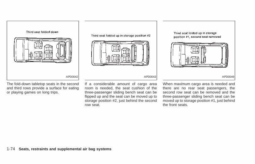
The fold-down tabletop seats in the secondand third rows provide a surface for eatingor playing games on long trips.
If a considerable amount of cargo arearoom is needed, the seat cushion of thethree-passenger sliding bench seat can beflipped up and the seat can be moved up tostorage position #2, just behind the secondrow seat.
When maximum cargo area is needed andthere are no rear seat passengers, thesecond row seat can be removed and thethree-passenger sliding bench seat can bemoved up to storage position #1, just behindthe front seats.
APD0042 APD0043 APD0049
1-74 Seats, restraints and supplemental air bag systems
Z X

The second row bench seat can be foldeddown to serve as a tabletop for passengerssitting in the three-passenger bench seat.
The second and third row bench seats canbe folded down to tabletops.
To increase cargo area space, the secondrow bench seat can be removed and thethree-passenger sliding seat can be movedup to the second row position.
APD0044 APD0045 APD0046
Seats, restraints and supplemental air bag systems 1-75
Z X

The third seat can be folded down into atabletop.
With the third seat folded down and thesecond seat removed, cargo can be placedin between the front seats and the third rowseat. People should not be allowed toride in areas meant for cargo. Passen-gers should always be properly re-strained in seat belts.
The second row seat can be folded downand the third row seat can be moved justbehind it in a storage position.
APD0047 APD0048 APD0050
1-76 Seats, restraints and supplemental air bag systems
Z X

WITH SECOND ROW BUCKETSEATSThe normal seating arrangement for sevenpassengers is with the three-passengerbench seat in seating position #1. Thisprovides more leg room for the passengerssitting in the third row.
When one passenger in the three-passenger bench seat would like more legroom, one of the second row bucket seatscan be removed.
APD0128 ARS1195
Seats, restraints and supplemental air bag systems 1-77
Z X

When more cargo area room is necessary,the three-passenger sliding bench seat canbe moved to seating position #2 or #3. Thisseating arrangement provides less leg roomfor third row passengers, but more cargoroom.
If passengers in the three-passenger benchseat would like more leg room, both secondrow bucket seats can be removed. Thefloor area should never be used by pas-sengers. Passengers should always beproperly restrained by seat belts.
ARS1205 APD0053
1-78 Seats, restraints and supplemental air bag systems
Z X

2 Instruments and controls
Meters and gauges ................................................2-3Speedometer and odometer ..................................2-4Tachometer ............................................................2-4Engine coolant temperature gauge........................2-4Fuel gauge .............................................................2-5Warning/indicator lights and chimes ......................2-6Theft warning (if so equipped) .............................2-10Windshield wiper and washer switch...................2-12Rear window wiper and washer switches............2-13Rear window defogger switch..............................2-13Headlight control switch .......................................2-13Daytime running light system (Canada only).......2-14Autolamp switch (if so equipped).........................2-14Turn signal switch .............................................2-15Cornering light ......................................................2-15Instrument brightness control...............................2-16Hazard warning flasher switch.............................2-16Cigarette lighter and ashtray (accessory) ............2-17Rear power point..................................................2-18Cup holder............................................................2-18Map pockets .........................................................2-20Overhead storage compartment ..........................2-20
Power windows ....................................................2-21Automatic power window switch ..........................2-21Sunroof (if so equipped).......................................2-22Manual vent windows...........................................2-23Power vent windows (if so equipped) ..................2-23Interior lights.........................................................2-24Luggage compartment lights................................2-24Personal reading light ..........................................2-24Map lights .............................................................2-25Illuminated entry system ......................................2-25Storage compartment for garage doortransmitter (if so equipped) ..................................2-25Integrated HomeLinkT universal transceiver(if so equipped) ....................................................2-27Programming the HomeLinkT universaltransceiver ............................................................2-27Operating the transceiver.....................................2-28Programming problem diagnosis .........................2-28Rolling codes........................................................2-29Clearing the programming information.................2-30If your vehicle is ever stolen ................................2-30
Z X

AIC1055
2-2 Instruments and controls
Z X

AIC1094
METERS AND GAUGES
Instruments and controls 2-3
Z X
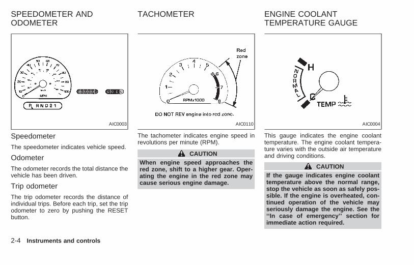
SpeedometerThe speedometer indicates vehicle speed.
OdometerThe odometer records the total distance thevehicle has been driven.
Trip odometerThe trip odometer records the distance ofindividual trips. Before each trip, set the tripodometer to zero by pushing the RESETbutton.
The tachometer indicates engine speed inrevolutions per minute (RPM).
CAUTIONWhen engine speed approaches thered zone, shift to a higher gear. Oper-ating the engine in the red zone maycause serious engine damage.
This gauge indicates the engine coolanttemperature. The engine coolant tempera-ture varies with the outside air temperatureand driving conditions.
CAUTIONIf the gauge indicates engine coolanttemperature above the normal range,stop the vehicle as soon as safely pos-sible. If the engine is overheated, con-tinued operation of the vehicle mayseriously damage the engine. See the‘‘In case of emergency’’ section forimmediate action required.
AIC0003 AIC0110 AIC0004
SPEEDOMETER ANDODOMETER
TACHOMETER ENGINE COOLANTTEMPERATURE GAUGE
2-4 Instruments and controls
Z X

This gauge indicates the approximate fuellevel in the tank.
The gauge may move slightly during brak-ing, turning, acceleration, or going up ordown hills.
The gauge needle remains in approximatelythe same position even when the ignitionkey is turned OFF.
The low fuel warning light comes on whenthe amount of fuel in the tank is getting low.
Refill the fuel tank before the gaugeregisters E (empty).
CAUTION● If the vehicle is driven with the fuel
level very low, the malfunction indi-cator light may come on. Refuel assoon as possible. After driving for awhile, the light should remain off. Ifthe light remains on, have the ve-hicle inspected by an authorizedNISSAN dealer.
For additional information, see the‘‘Malfunction indicator light (MIL)’’ laterin this section.
AIC0005
FUEL GAUGE
Instruments and controls 2-5
Z X

Checking bulbsApply the parking brake, fasten seat belts,and turn the ignition key to ON without start-ing the engine. The following lights come onand stay on until the engine is started:
, , ,
The following lights come on briefly andthen go off:
ABS or , ,
If any light fails to come on, it mayindicate a burned-out bulb or an opencircuit in the electrical system. Have the
system repaired promptly.
Engine oil pressure warninglight
This light warns of low engine oil pressure. Ifthe light flickers or comes on during normaldriving, pull off the road in a safe area, stopthe engine immediately and call an autho-rized NISSAN dealer.
The oil pressure warning light is notdesigned to indicate a low oil level. Usethe dipstick to check the oil level. See‘‘Engine oil’’ in the ‘‘Do-it-yourself’’ sectionof this manual.
CAUTION
Running the engine with the oil pres-sure warning light on could cause seri-ous damage to the engine almost im-mediately. Turn off the engine as soonas it is safe to do so.
Charge warning lightIf the light comes on while the engine isrunning, it may indicate something wrongwith the charging system. Turn the engineoff and check the generator belt. If the belt isloose, broken, missing, or if the light re-
AIC1093
WARNING/INDICATORLIGHTS AND CHIMES
2-6 Instruments and controls
Z X

mains on, see an authorized NISSANdealer immediately.
CAUTIONDo not continue driving if the belt isloose, broken or missing.
Low fuel warning lightThis light comes on when the fuel level inthe fuel tank is getting low. Refuel as soonas it is convenient, preferably before the fuelgauge reaches E (Empty). There will be asmall reserve of fuel in the tank when thefuel gauge needle reaches E (Empty).
Door ajar warning lightThis light comes on when any of the doorsare not closed securely while the ignitionkey is ON.
Seat belt warning light andchime
The light and chime remind you to fastenyour seat belts. If the driver’s seat belt isNOT securely fastened when the ignitionkey is turned to ON or START, the chimesounds for approximately 6 seconds andthe light illuminates.
Refer to ‘‘Seat belts’’ in the ‘‘Seats, re-straints and supplemental air bag systems’’section of this manual for precautions onseat belt usage.
Supplemental air bagwarning light
When the ignition key is in the ON or STARTposition, the supplemental air bag warninglight illuminates for about 7 seconds and thenturns off. This means the Air Bag Supple-mental Restraint System is operational.
If any of the following conditions occur, thesupplemental air bag system needs servic-ing and your vehicle should be taken to anauthorized NISSAN dealer:
1. The supplemental air bag warning lightdoes not come on for 7 seconds and thenturn off as described above.
2. The supplemental air bag warning lightflashes intermittently, or remains on after7 seconds.
3. The supplemental air bag warning lightdoes not come on at all.
Under these conditions, the Air Bag Supple-mental restraint system may not functionproperly. For additional details, see ‘‘Supple-
mental restraint system’’ in the ‘‘Seats, re-straints and supplemental air bag systems’’section of this manual.
WARNING
If the supplemental air bag warninglight is on, it could mean that thesupplemental air bag will not operate inan accident.
Low washer fluid warninglight
This light comes on when the washer fluid isat a low level. Add washer fluid as neces-sary. See the ‘‘Do-it-yourself’’ section of thismanual.
Brake warning light
This light functions for both the parkingbrake and the foot brake systems.
When the ignition key is in the ON position,the light comes on when the parking brakeis applied, and also warns of a low brakefluid level. If the light comes on while theengine is running with the parking brake notapplied, stop the vehicle and perform thefollowing:
Instruments and controls 2-7
Z X

1. Check the brake fluid level. Add brake fluidas necessary. See ‘‘Brake fluid’’ in the‘‘Do-it-yourself’’ section of this manual.
2. If the brake fluid level is correct, have thewarning system checked by an autho-rized NISSAN dealer.
WARNING
● Your brake system may not be work-ing properly if the warning light ison. Driving could be dangerous. Ifyou judge it to be safe, drive care-fully to the nearest service stationfor repairs. Otherwise, have your ve-hicle towed.
● Pressing the brake pedal with theengine stopped and/or low brakefluid level may increase your stop-ping distance and braking will re-quire greater pedal effort as well aspedal travel.
● If the brake fluid level is below theminimum mark on the brake fluidreservoir, do not drive until the brakesystem has been checked at an au-thorized NISSAN dealer.
ABS or Anti-lock brakewarning light
If the light comes on while the engine isrunning, it may indicate something is wrongwith the anti-lock portion of the brake sys-tem. Have the system checked by an autho-rized NISSAN dealer.
If a malfunction occurs in the system, theanti-lock function turns off, but the brakescontinue to operate normally.
If the light comes on while you are driv-ing, contact an authorized NISSANdealer for repair.
Overdrive off indicator light
This light comes on during driving when theoverdrive switch is pressed to prevent over-drive operation.
The O/D OFF indicator light comes on fortwo seconds each time the ignition key isturned ON. This shows the light is function-ing properly.
If the O/D OFF indicator light blinks forapproximately 8 seconds after coming on for2 seconds, have an authorized NISSAN
dealer check the transmission and repair it ifnecessary.
The automatic transmission is equippedwith an electronic Fail-Safe mode. This sys-tem allows the vehicle to be driven even inthe event of damage to the electrical cir-cuits. If this occurs, the gears automaticallyengage and lock into third gear.
NOTE: See ‘‘Fail-safe’’ in the ‘‘Starting anddriving’’ section of this manual before visit-ing an authorized NISSAN dealer.
Turn signal/hazard indicatorlights
The appropriate light flashes when the turnsignal lever is activated.
Both lights flash when the hazard switch isturned on.
High beam indicator light
This light comes on when the headlight highbeam is on and goes out when the lowbeam is selected.
Cruise indicator light
The light comes on while the vehicle speed iscontrolled by the cruise control system. If the
2-8 Instruments and controls
Z X

CRUISE indicator blinks, have the systemchecked by an authorized NISSAN dealer.
Key reminder chimeThe chime sounds if the driver’s door isopened while the key is left in the ignitionswitch. Remove the key and take it with youwhen leaving the vehicle.
Light reminder chimeA chime sounds when the driver’s door isopened if the headlight control switch isturned on (ignition switch is turned OFF).
The chime will not sound when the Auto-lamp (if so equipped) shut-off delay is acti-vated. Refer to the ‘‘Autolamp Switch’’ in-structions later in this section.
Turn the headlight control switch to OFFwhen you leave the vehicle.
Brake pad wear warningThe disc brake pads have audible wearwarnings. When a brake pad requires re-placement, it makes a high pitched scrapingsound when the vehicle is in motion whetheror not the brake pedal is depressed. Havethe brakes checked as soon as possible ifthe warning sound is heard.
Malfunction indicator light(MIL)
If the malfunction indicator light comes onsteady or blinks while the engine is running,it may indicate a potential emission controlproblem.
The malfunction indicator light may alsocome on steady or blink if the fuel filler caphas not been closed tightly or if the fuel tankis nearly empty. Check to make sure thefuel cap is secure and that you have at leastthree gallons (14 liters) of fuel in the fueltank.
After driving for a while, the light shouldremain off if no other potential emissioncontrol system problem exists.
Operation
The malfunction indicator light will come onin one of two ways:
● Malfunction indicator light on steady - Anemission control system malfunction hasbeen detected. Have the vehicle in-spected by an authorized NISSANdealer. You do not need to have yourvehicle towed to the dealer.
● Malfunction indicator light blinking - Anengine misfire has been detected whichmay damage the emission control sys-tem. To reduce or avoid emission controlsystem damage:a) do not drive at speeds above 45 MPH
(72 km/h).b) avoid hard acceleration or decelera-
tion.c) avoid steep uphill grades.d) if possible, reduce the amount of cargo
being hauled or towed.
The malfunction indicator light may stopblinking and come on steady. Have thevehicle inspected by an authorized NISSANdealer. You do not need to have your ve-hicle towed to the dealer.
CAUTIONContinued vehicle operation withouthaving the emission control systemchecked and repaired as necessarycould lead to poor driveability, reducedfuel economy, and possible damage tothe emission control system.
Instruments and controls 2-9
Z X

The theft warning system provides audioand visual alarm signals if parts of thevehicle are disturbed.
How to activate the theft warningsystem
1. Close all windows.
2. Remove the key from the ignition switch.
3. Close all doors and the hood.
4. Push the button on the multi-remotecontroller. All doors lock. The hazardlights flash twice and the horn beepsonce to indicate all doors are locked.
● When the button is pushed with alldoors locked, the hazard lights flashtwice and the horn beeps once as areminder that the doors are alreadylocked.
The horn may or may not beep once.Refer to ‘‘silencing the horn beep fea-ture’’ later in this section.
The system can be activated even if thewindows are open.
5. Confirm that the SECURITY indicatorlight comes on. The SECURITY lightglows for about 30 seconds and thenbegins to flash once every three seconds.The system is now activated. If, duringthis 30-second time period, the door isunlocked by the key or the multi-remotecontroller, or the ignition key is turned toACC or ON, the system will not activate.
If the key is turned slowly when lockingthe door, the system may not activate.Furthermore, if the key is turned exces-sively to the unlock position, the systemmay be deactivated when the key is re-moved. If the indicator light fails to glowfor 30 seconds, unlock the door onceand lock it again.
Even when the driver and/or passengersare in the vehicle, the system will acti-vate with all doors, hood and trunk lidlocked and ignition key off. Turn theignition key to ACC or ON to turn thesystem off.
Theft warning system operation
The theft warning system emits the follow-ing alarm:
● The headlights and tail lights flash andthe horn sounds intermittently. In addi-tion, the starter motor does not operate.
● The alarm automatically turns off aftertwo to three minutes. However, the alarmreactivates if the vehicle is tampered withagain. The alarm can be shut off byunlocking a door with the key or bypressing the button on the multi-remote controller.
The alarm is activated when:
● a door is unlocked or opened withoutusing the key or the multi-remote control-ler. This includes unlocking the doorswith the inside door lock switch.
● the hood is opened.
IC0005
THEFT WARNING(if so equipped)
2-10 Instruments and controls
Z X

● the ignition is placed into the ACC, ON,or START position without the key in theignition.
How to stop the alarmThe alarm stops only by unlocking a doorwith the key or by pressing the button onthe multi-remote controller. The alarm doesnot stop if the ignition key is turned to theACC or ON position.
Silencing the horn beep featureIf desired, the horn beep feature can bedeactivated using the multi-remote control-ler. The instructions are on the back of themulti-remote controller.
To deactivate: Press and hold the andbuttons for at least two seconds.
The hazard lights will quickly flash threetimes to confirm that the horn beep featurehas been deactivated.
To activate: Press and hold the andbuttons for at least two seconds once
more.
The hazard lights will quickly flash threetimes to confirm that the horn beep featurehas been reactivated.
Deactivating the horn feature does not si-lence the horn if the alarm is triggered.
If the system does not operate as de-scribed above, have it checked by anauthorized NISSAN dealer.
AIC1037
Instruments and controls 2-11
Z X

To operate the wipers intermittently, adjustthe knob between the S (slow) and F (fast)positions. For continuous operation, selectLO or HI.
To operate the washer, press on the end ofthe wiper knob. For more washer fluid, pushand hold the end of the wiper knob. Thewipers cycle a few times when the washer isactivated. The washer operates in any ofthe wiper positions.
CAUTIONThe following could damage thewasher system:● Do not operate the washer continu-
ously for more than 30 seconds.● Do not operate the washer if the
reservoir tank is empty.
WARNINGIn freezing temperatures the washersolution may freeze on the windshield
and obscure your vision, which maylead to an accident. Warm the wind-shield with the defroster before youwash the windshield.
AIC0561 AIC0559
WINDSHIELD WIPER ANDWASHER SWITCH
2-12 Instruments and controls
Z X

Push and hold the rear washer switch tooperate the rear washer. The wiper cyclescontinuously until the switch is released.
Push the rear wiper switch to operate thewiper. The wiper cycles intermittently. Pushagain to cancel.
CAUTION● Do not operate the washer continu-
ously for more than 30 seconds.● Do not operate the washer if the
reservoir tank is empty.
To defog the rear window glass, start theengine and push the switch on. The indica-tor light on the switch comes on. Push theswitch again to turn the defogger off.The rear window defogger switch is alsoused to defrost, defog, or de-ice the poweroutside heated mirrors (if so equipped).It automatically turns off in approximately 15minutes.
CAUTIONWhen cleaning the inner side of thewindow, be careful not to scratch ordamage the rear window defogger.
LightingTurn the dial to the position:
The front parking, side marker, tail, licenseplate and instrument lights come on.
Turn the dial to the position:
Headlights come on and all of the previouslylisted lights remain on.
To select the high beam, push the turn signallever away from you. The lever latches inplace. Pull it back to select the low beam.
To turn the interior lights on push the head-light switch. The interior lights come on.
AIC1056 AIC1057 AIC1073
REAR WINDOW WIPER ANDWASHER SWITCHES
REAR WINDOW DEFOGGERSWITCH
HEADLIGHT CONTROLSWITCH
Instruments and controls 2-13
Z X

Push the headlight switch again to turn theinterior lights off.
DAYTIME RUNNING LIGHTSYSTEM (Canada only)The headlights automatically illuminate at areduced intensity when the engine is startedwith the parking brake released. The day-time running lights operate with the head-light switch in the OFF position or in the
position. Turn the headlight switch tothe position for full illumination whendriving at night.
If the parking brake is applied before theengine is started, the daytime running lightsdo not illuminate. The daytime running lightsilluminate once the parking brake is released.The daytime running lights will remain on untilthe ignition switch is turned OFF.
WARNINGWhen the daytime running light systemis active, tail lights on your vehicle willnot be on. It is necessary at dusk toturn on your headlights. Failure to doso could cause an accident injuringyourself and others.
The autolamp system allows the headlightsto be set so they turn on and off automati-cally. The autolamp system can turn on theheadlights automatically when it is dark,turn off the headlights when it is light, andkeep the headlights on for up to threeminutes after you turn the key to OFF.
To set the autolamp system:
1. Make sure the headlight switch is in theAUTO1 or AUTO2 position.
2. Turn the ignition key to ON.
3. The autolamp system automatically turnsthe headlights on and off.
Shut-off delayThe length of time the headlights stay onafter the ignition is turned to OFF dependson whether the switch is in the AUTO1 orAUTO2 position. If the switch is in theAUTO1 position, then the headlights stay onfor less than 1 minute after the ignition isturned OFF. If the switch is in the AUTO2position, the headlights stay on approxi-mately 3 minutes after the ignition is turnedOFF.
To turn the autolamp system off, turn theswitch to the OFF, , or position.AIC1058
AUTOLAMP SWITCH(if so equipped)
2-14 Instruments and controls
Z X

Be sure you do not put anything on topof the photo sensor located in the top leftside of the instrument panel. The photosensor controls the autolamp; if it iscovered, the photo sensor reacts as if itis dark out and the headlights will illumi-nate.
Turn signalMove the lever up or down to signal theturning direction. When the turn is com-pleted, the turn signal cancels automati-cally.
Lane change signalTo indicate a lane change, move the leverup or down to the point where the lightbegins to flash, but the lever does not latch.
Passing signalPulling the lever toward you turns the head-light high beam on. Release it and theheadlight high beam goes off.
The cornering light provides additional illu-mination toward the turning direction. Thelight on the turning direction side comes onwhen a turn is signaled with the headlightson.
AIC1087 AIC0560 AIC0102
TURN SIGNAL SWITCH CORNERING LIGHT
Instruments and controls 2-15
Z X

The instrument brightness control operateswhen the light switch is in the or
position, or when the autolamp systemis operating.
Pressing the side of the switch bright-ens the instrument panel lights; pressing the
side of the switch dims the instrumentpanel lights.
Push the (hazard) switch to warn otherdrivers when you must stop or park underemergency conditions. All turn signal lightsflash. Press the switch again to turn thehazard warning flashers off.
WARNING● When stalled or stopped on the road-
way under emergency conditions,move the vehicle well off the road.
● Do not use the switch while movingon the highway unless unusual cir-cumstances force you to drive so
slowly that your vehicle might be-come a hazard to other traffic.
● Turn signals do not work when thehazard warning flasher lights are on.
The flashers can be actuated with the igni-tion switch either OFF or ON.
Some state laws may prohibit the use ofthe hazard warning flasher switch whiledriving.
AIC1059 AIC1060
INSTRUMENT BRIGHTNESSCONTROL
HAZARD WARNING FLASHERSWITCH
2-16 Instruments and controls
Z X
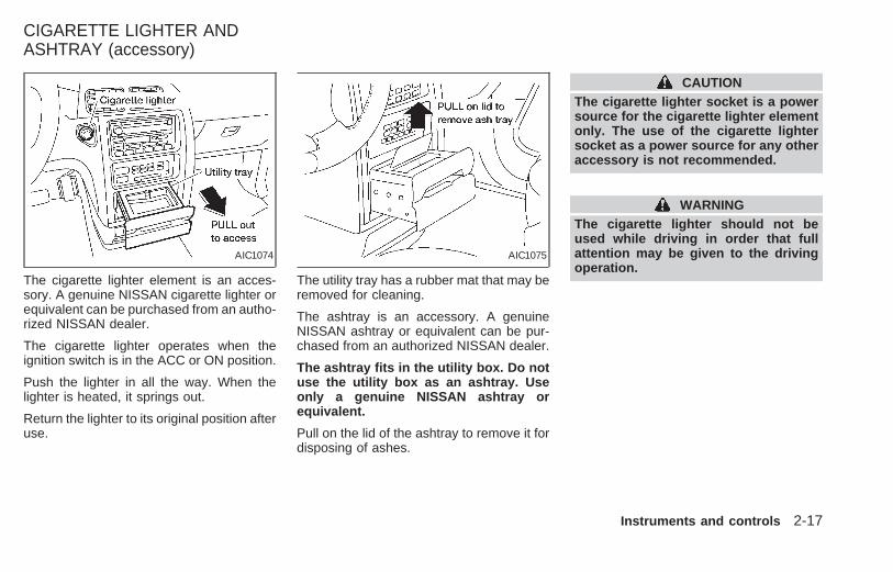
The cigarette lighter element is an acces-sory. A genuine NISSAN cigarette lighter orequivalent can be purchased from an autho-rized NISSAN dealer.
The cigarette lighter operates when theignition switch is in the ACC or ON position.
Push the lighter in all the way. When thelighter is heated, it springs out.
Return the lighter to its original position afteruse.
The utility tray has a rubber mat that may beremoved for cleaning.
The ashtray is an accessory. A genuineNISSAN ashtray or equivalent can be pur-chased from an authorized NISSAN dealer.
The ashtray fits in the utility box. Do notuse the utility box as an ashtray. Useonly a genuine NISSAN ashtray orequivalent.
Pull on the lid of the ashtray to remove it fordisposing of ashes.
CAUTIONThe cigarette lighter socket is a powersource for the cigarette lighter elementonly. The use of the cigarette lightersocket as a power source for any otheraccessory is not recommended.
WARNINGThe cigarette lighter should not beused while driving in order that fullattention may be given to the drivingoperation.
AIC1074 AIC1075
CIGARETTE LIGHTER ANDASHTRAY (accessory)
Instruments and controls 2-17
Z X

The rear power point is located on thedriver’s side trim panel of the second rowseat behind the side door. Open the coverto gain access to the power point.
Use the power point to plug in electricalequipment such as a cellular telephone, CBradio, etc. Follow the installation instruc-tions included with your electrical equip-ment.
When not in use, always close the powerpoint cover.
CAUTIONWhen using the power point:● Maximum load of any electrical
equipment should not exceed 10amps.
● Be sure to turn off any electricalequipment when not in use. Leavingelectrical equipment on for extendedperiods can discharge your battery.
To use the cup holder, pull out. To store thecup holder, push it back in.
The cup holder can be adjusted to fit smallercups by pushing the arms in. The arms havethree detents and then return to the fullyopen position.
WARNINGThe driver should not pull out the cupholder or remove or insert cups into thecup holder while driving in order thatfull attention may be given to the driv-ing operation.
AIC1064 AIC1065
REAR POWER POINT CUP HOLDER
2-18 Instruments and controls
Z X

CAUTION● Avoid abrupt starting and braking
when the cup holder is being used toprevent spilling the drink. If the liq-uid is hot, it can scald you or yourpassenger.
● Use only soft cups in the cup holder.Hard objects can injure you in anaccident.
Second row cup holderVehicles equipped with second row bucketseats have a cup holder attached to the sideof the seat.
Vehicles equipped with a second row benchseat have a cup holder attached to the frontcenter of the seat.
Pull the cup holder out from the seat to useit.
The cup holder can be adjusted to fit smallercups by pushing in the arms. The arms havethree detents and then return to the fullyopen position.
AIC1076 AIC1077
Instruments and controls 2-19
Z X

A map pocket is located on the right handside of the instrument panel and on the backof the passenger seat. The map pocketscan be used to store maps.
Some vehicles are equipped with an over-head storage compartment. Push to openthe storage compartment. Push again toclose the storage compartment.
AIC1078 ARS1249 AIC1095
MAP POCKETS OVERHEAD STORAGECOMPARTMENT
2-20 Instruments and controls
Z X

WARNING● Make sure that all passengers have
their hands, etc. inside the vehiclebefore closing the windows. Use thewindow lock switch to prevent unex-pected use of the power windows.
● Do not leave children unattended in-side the vehicle. They could unknow-ingly activate switches or controlsand become trapped in a window.Unattended children could becomeinvolved in serious accidents.
The main switch (on the driver side) opensor closes the driver’s, and passenger’s win-dows, and (if so equipped) rear vent win-dows.
To open the window, press the switch down.To close the window, lift the switch up.
The power windows operate when the igni-tion key is in the ON position, or for 15minutes after the ignition key is turned to theOFF position. If the driver’s or passenger’sdoor is opened during this 15 minute period,power to the windows is cancelled.
AUTOMATIC POWER WINDOWSWITCHTo fully open the driver side window, pressdown firmly on the switch and release it; youdo not need to hold the switch down. Thewindow automatically opens all the way.
The automatic feature can be interruptedbefore the window is fully open by brieflylifting up on the switch as the window movesdown.
AIC1079 AIC1080
POWER WINDOWS
Instruments and controls 2-21
Z X

Locking passenger’s windowWhen the power window lock-out button ispushed in, the passenger’s window cannotbe opened or closed. Push the power win-dow lock-out button again to cancel thisfeature.
The passenger side switch opens or closesthe passenger window only. To open thewindow, press the switch down. To closethe window, lift the switch up.
The sunroof operates when the ignition keyis in the ON position, or for 15 minutes afterthe ignition key is turned to the OFF posi-tion. If the driver’s or passenger’s door isopened during this 15 minute period, powerto the sunroof is cancelled.
NOTE:If the battery is discharged or is discon-nected, the sunroof may not operate cor-rectly, and must be reset.
To reset a fully or partially open sunroof:
1. Push and hold the UP/CLOSE side of thesunroof switch until the sunroof closes,
and tilts up to the fully open position, thenrelease the switch.
2. Push and hold the DOWN/OPEN side ofthe switch until the sunroof lowers com-pletely. The sunroof is now reset andshould operate correctly.
To reset a fully or partially tilted, or closedsunroof:
1. Push and hold the UP/CLOSE side of thesunroof switch until the sunroof stopstilting up, then release the switch.
2. Push and hold the DOWN/OPEN side ofthe switch until the sunroof lowers com-pletely. The sunroof is now reset andshould operate correctly.
Sliding the sunroof
To open the roof, push and hold the OPENside of the switch.
To close the roof, push and hold the CLOSEside.
Tilting the sunroofTo tilt up, first close the sunroof, then push theUP side of the switch. To close the sunroof,push the DOWN side of the switch.
AIC1081 AIC1066
SUNROOF (if so equipped)
2-22 Instruments and controls
Z X

Sun shadeOpen and close the sun shade by sliding itforward or backward. The shade openswhen the sunroof opens, but it must beclosed manually.
WARNING● In an accident you could be thrown
from the vehicle through an opensunroof. Always use seat belts andchild restraints.
● Do not allow anyone to stand up orextend any portion of their body out ofthe opening while the vehicle is inmotion or while the sunroof is closing.
CAUTION● Remove water drops, snow, ice or
sand from the sunroof before opening.● Do not place any heavy object on the
sunroof or surrounding area.
To open the manual vent windows, pull therear portion of the latch toward you until itreleases. To lock the window in the openposition, push the latch rearward until youhear it latch. To close the windows, pull thelatch toward you and push the rear portionof the latch toward the rear of the vehicleuntil you feel it latch.
Use the vent window switches on the driv-er’s side window controls to open and closethe power vent windows. To open one of thepower vent windows, press the switchdown. To close the window, lift the switchup.
The power vent windows operate when theignition key is in the ON position, or for 15minutes after the ignition key is turned to theOFF position. If the driver’s or passenger’sdoor is opened during this 15 minute period,power to the vent windows is cancelled.
AIC0111 AIC1067
MANUAL VENT WINDOWS POWER VENT WINDOWS(if so equipped)
Instruments and controls 2-23
Z X
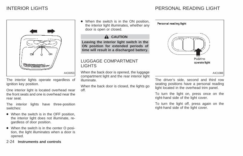
The interior lights operate regardless ofignition key position.
One interior light is located overhead nearthe front seats and one is overhead near therear seat.
The interior lights have three-positionswitches:
● When the switch is in the OFF position,the interior light does not illuminate, re-gardless of door position.
● When the switch is in the center O posi-tion, the light illuminates when a door isopened.
● When the switch is in the ON position,the interior light illuminates, whether anydoor is open or closed.
CAUTIONLeaving the interior light switch in theON position for extended periods oftime will result in a discharged battery.
LUGGAGE COMPARTMENTLIGHTSWhen the back door is opened, the luggagecompartment light and the rear interior lightilluminate.
When the back door is closed, the lights gooff.
The driver’s side, second and third rowseating positions have a personal readinglight located in the overhead trim panel.
To turn the light on, press once on theright-hand side of the light cover.
To turn the light off, press again on theright-hand side of the light cover.
AIC0053 AIC1088
INTERIOR LIGHTS PERSONAL READING LIGHT
2-24 Instruments and controls
Z X

To turn on the map lights, press theswitches. To turn them off, press theswitches again.
The interior lights, the cargo light, the glovebox light, the stepwell lights near the slidingdoors and on the front doors, and the foot-well lights near the driver’s and front pas-senger’s feet illuminate when the front orsliding doors are opened. Once the doorsare closed, these lights gradually dim to offwithin 30 seconds or turn off immediatelywhen the key is turned to the ON position.
Battery saverIf the vehicle doors are not fully closed andthe interior lights remain illuminated, theyeventually turn off automatically to preventthe battery from becoming discharged. If theinterior lights are left in the ON position, withall doors closed, they will automatically turnoff after approximately 30 minutes. Lightsthat illuminate when the front or slidingdoors are opened turn off after approxi-mately 30 minutes. Lights that illuminatewhen the back door is opened turn off afterapproximately 60 minutes. Vanity mirrorlights are not part of the battery saversystem.
If the personal reading lights are left on afterthe key is removed from the ignition, theywill automatically turn off after approxi-mately 30 minutes.
Some vehicles are equipped with an addi-tional storage compartment in the map lightunit. This storage compartment has beenspecially designed to hold some garagedoor transmitters. Some transmitters maynot fit. When properly installed, the garagedoor transmitter can be activated while it iswithin the storage compartment.
AIC1097 AIC1089
MAP LIGHTS ILLUMINATED ENTRYSYSTEM
STORAGE COMPARTMENTFOR GARAGE DOORTRANSMITTER (if so equipped)
Instruments and controls 2-25
Z X

To install your transmitter, follow the num-bered instructions in the illustrations.
Once the garage door transmitter is in-stalled, close the storage compartmentdoor. Press the button on the center of thestorage compartment door to operate thegarage door transmitter.
AIC1090 AIC1091 AIC1092
2-26 Instruments and controls
Z X
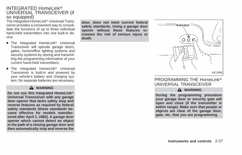
The Integrated HomeLinkT Universal Trans-ceiver provides a convenient way to consoli-date the functions of up to three individualhand-held transmitters into one built-in de-vice.
● The Integrated HomeLinkT UniversalTransceiver will operate garage doors,gates, home/office lighting systems andsecurity systems by storing and transmit-ting the programming information of yourcurrent hand-held transmitters.
● The Integrated HomeLinkT UniversalTransceiver is built-in and powered byyour vehicle’s battery and charging sys-tem. No separate batteries are necessary.
WARNINGDo not use this Integrated HomeLink TUniversal Transceiver with any garagedoor opener that lacks safety stop andreverse features as required by federalsafety standards (these standards be-came effective for models manufac-tured after April 1, 1982). A garage dooropener which cannot detect an objectin the path of a closing garage door andthen automatically stop and reverse the
door, does not meet current federalsafety standards. Using a garage dooropener without these features in-creases the risk of serious injury ordeath.
PROGRAMMING THE HomeLinkTUNIVERSAL TRANSCEIVER
WARNINGDuring the programming procedureyour garage door or security gate willopen and close (if the transmitter iswithin range). Make sure that people orobjects are clear of the garage door,gate, etc. that you are programming.
AIC1069
INTEGRATED HomeLinkTUNIVERSAL TRANSCEIVER (ifso equipped)
Instruments and controls 2-27
Z X

Your vehicle’s engine should be turnedoff while programming your transmit-ter. The Integrated HomeLink T Univer-sal Transceiver may not work witholder garage door openers that do notmeet current Federal Consumer SafetyStandards.
1. Test the Integrated HomeLinkT UniversalTransceiver by pressing any button. Thered indicator light should come on. If youhave previously programmed a buttonproceed to step 3.
2. Clear all channels on the IntegratedHomeLinkT Universal Transceiver byholding down both outside buttons (#1 ) until the red light begins to flashrapidly (approximately 20 seconds).Then release both buttons.
3. Select which of the three IntegratedHomeLinkT Universal Transceiver but-tons you want to program.
4. Hold your hand-held transmitter againstthe bottom surface of the IntegratedHomeLinkT Universal Transceiver sothat you can still see the red indicatorlight.
5. Press the desired button until the redindicator light flashes slowly. Do not re-lease the button. Continue holding andpress the hand-held transmitter buttonthrough step 6.
6. Hold down both buttons until the redindicator light on the IntegratedHomeLinkT Universal Transceiverflashes rapidly (This may take 1 to 90seconds). Then release both buttons.The rapid flashing means that the trans-ceiver has been successfully pro-grammed to match your hand-held trans-mitter. You can now use the IntegratedHomeLinkT Universal Transceiver in-stead of your hand-held transmitter.
Note to Canadian users:
Prior to 1992, D.O.C. regulations requiredmany hand-held transmitters to stop trans-mitting after one or two seconds, eventhough you continue to hold down the but-ton. If you think you have one of thesehand-held transmitters, you should pressand re-press the transmitter button every 2seconds without ever releasing the Inte-grated HomeLinkT Universal Transceiverbutton. The indicator light on the IntegratedHomeLinkT Universal Transceiver should
blink rapidly indicating a successful pro-gramming procedure. If it returns to the slowblink of program mode, continue to periodi-cally reactivate your hand-held transmitteruntil a successful programming procedureis indicated by the rapidly flashing indicatorlight.
OPERATING THE TRANSCEIVERTo operate, simply press the appropriatebutton on the Integrated HomeLinkT Univer-sal Transceiver. The red indicator light illu-minates while the signal is being transmit-ted. The effective transmission range of theIntegrated HomeLinkT Universal Trans-ceiver may differ from your hand-held trans-mitter.
PROGRAMMING PROBLEMDIAGNOSISBe sure to keep your original hand-heldtransmitter for possible reprogramming ifnecessary.
● Make sure batteries in the hand-heldtransmitter are fully charged.
● Hold your hand-held transmitter againstthe bottom surface of the IntegratedHomeLinkT Universal Transceiver so
2-28 Instruments and controls
Z X

that you can still see the red indicatorlight.
● Hold buttons for duration of the program-ming without interruption.
● Rotate your hand-held transmitter end-over-end and program again. For bestresults, place the end opposite the bat-tery compartment against the IntegratedHomeLinkT Universal Transceiver whenprogramming.
ROLLING CODESIf your hand held transmitter appears totrain to the Integrated HomeLinkT UniversalTransceiver, but does not open your garagedoor, and your garage door opener wasmanufactured after 1995, your garage dooropener may have a Code Protected orRolling Code feature. This type of systemwill change the code of your garage dooropener every time you open or close yourgarage door.
To determine if you have one of thesesystems, depress the button on the Inte-grated HomeLinkT Universal Transceiver
that you have just programmed. If the LEDon the HomeLinkT Universal Transceiverflashes rapidly for 1 to 2 seconds, thenremains on, your garage door opener has arolling code system.
To operate your rolling code garage dooropener from your Integrated HomeLinkTUniversal Transceiver, follow these steps:
1. Program your hand held transmitter tothe Integrated HomeLinkT UniversalTransceiver by following the proceduresoutlined previously (if not yet pro-grammed).
2. Program your garage door opener re-ceiver to recognize the IntegratedHomeLinkT Universal Transceiver (TheIntegrated HomeLinkT Universal Trans-ceiver follows the same procedure totrain to the receiver as your hand heldtransmitter did when it was first installed):
a) Remove the cover panel from yourgarage door opener receiver. The re-ceiver should be located by the ga-rage door opener motor.
b) Locate the training button on the ga-rage door opener receiver. The exactlocation and color of the button may
AIC1070
Instruments and controls 2-29
Z X
vary by garage door opener brand. Ifyou have difficulty locating the trainingbutton, reference your garage dooropener manual. If you have difficultyprogramming your garage dooropener equipped with a rolling codesystem to recognize the IntegratedHomeLinkT Universal Transceiver withthe Rolling Code feature, call NISSANConsumer Affairs Department.
c) Press the training button on the ga-rage door opener receiver for 1 to 2seconds.
d) Return to the Integrated HomeLinkTUniversal Transceiver in the vehicle,and depress the programmedHomeLinkT button for the duration ofthe fast blink on the IntegratedHomeLinkT Universal Transceiver (1to 2 seconds). Release the button,and repress to confirm that the systemhas trained.
e) Your garage door opener should nowrecognize your Integrated HomeLinkTUniversal Transceiver. You may useeither your Integrated HomeLinkT Uni-versal Transceiver or your original
hand held transmitter to open yourgarage door.
CLEARING THE PROGRAMMINGINFORMATION
Should you sell your vehicle, be sure toclear the channels of the IntegratedHomeLinkT Universal Transceiver. To clearthe channels, simultaneously hold down theoutside two buttons (#1 & #3) until the redindicator light begins to flash rapidly (ap-proximately 20 seconds). This will clear allthree buttons. Individual buttons cannot becleared, but can be reprogrammed at anytime by following the programming proce-dures described previously.
IF YOUR VEHICLE IS EVERSTOLENIf your vehicle has been stolen, you shouldchange the codes of any device that wasprogrammed into the Integrated HomeLinkTUniversal Transceiver as soon as possible.Consult the owners manual of each device,or call the manufacturer or dealer of thosedevices.
When your vehicle is recovered, you willhave to reprogram the Integrated
HomeLink T Universal Transceiver withyour new transmitter information.
FFC Notice:
This device complies with FCC rules part15. Operation is subject to the followingtwo conditions: (1) This device may notcause harmful interference and (2) Thisdevice must accept any interference thatmay be received, including interferencethat may cause undesired operation.
The transmitter has been tested andcomplies with FCC and DOC/MDC rules.Changes or modifications not expresslyapproved by the party responsible forcompliance could void the user’s author-ity to operate the device.
DOC: ISTC 1763K1313
FCC I.D.: CB2V67690
2-30 Instruments and controls
Z X

3 Pre-driving checks and adjustments
Key .........................................................................3-2Door locks ..............................................................3-2Manual door lock....................................................3-3Child safety sliding door lock .................................3-6Power door lock (if so equipped) ...........................3-7Multi-remote control system (if so equipped).........3-9Battery replacement .............................................3-11Illuminated entry system ......................................3-12Hood release........................................................3-12Glove box .............................................................3-13Front seat convenience net .................................3-14Rear door lock......................................................3-15Cargo net (if so equipped) ...................................3-16
Parcel shelf (if so equipped) ................................3-17Luggage rack (if so equipped) .............................3-19Fuel filler lid and cap............................................3-20Tilting steering wheel ...........................................3-21Memory driver seat and mirrors (if soequipped) .............................................................3-21Multi-remote controller system entry....................3-21Memory driver seat and mirror buttons................3-22Outside mirror control...........................................3-23Outside mirrors.....................................................3-24Inside mirror .........................................................3-24Vanity mirror .........................................................3-24
Z X

A key number plate is supplied with yourkey. Record the key number and keep it in asafe place (such as your wallet), NOT INTHE CAR. A key number plate is suppliedwith your key. Keep the plate in a safeplace. NISSAN does not record key num-bers so it is very important to keep track ofyour key number plate.A key number is necessary only when youhave lost all vehicle keys and do not haveone to duplicate. If you still have a key, thiskey can be duplicated by an authorizedNISSAN dealer or locksmith shop.
Two keys are supplied with your vehicle —one has a plastic head and one is all metal.Both keys perform the same functions.
WARNING● Always have the doors locked while
driving. Along with the use of seatbelts, this provides greater safety inthe event of an accident by helping toprevent persons from being thrownfrom the vehicle. This also helps keepchildren and others from unintention-ally opening the doors, and will helpkeep out intruders.
● Before opening any door, alwayslook for and avoid oncoming traffic.
● Do not leave children unattended in-side the vehicle. They could unknow-ingly activate switches or controls.Unattended children could becomeinvolved in serious accidents.
CAUTION● Always use the door handle to open
or close the sliding doors. Do notattempt to open or close the doorsby merely placing your hand on thedoor edge or door slide roller, as thismay cause injury.
APD1042
KEY DOOR LOCKS
3-2 Pre-driving checks and adjustments
Z X
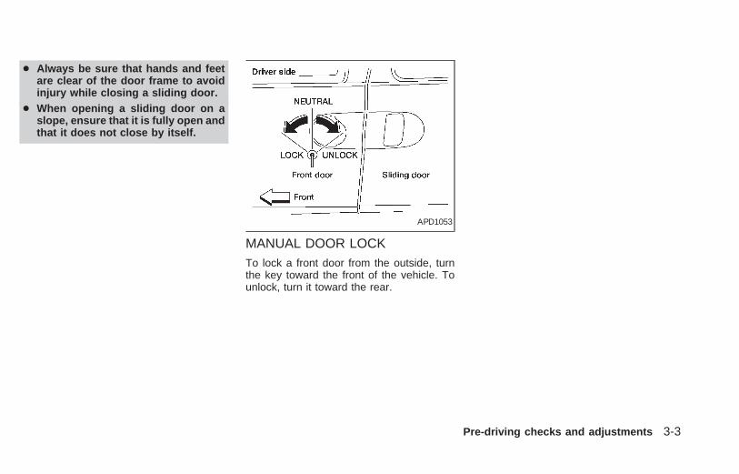
● Always be sure that hands and feetare clear of the door frame to avoidinjury while closing a sliding door.
● When opening a sliding door on aslope, ensure that it is fully open andthat it does not close by itself.
MANUAL DOOR LOCKTo lock a front door from the outside, turnthe key toward the front of the vehicle. Tounlock, turn it toward the rear.
APD1053
Pre-driving checks and adjustments 3-3
Z X

Locking the doors without the key
To lock a front door from inside the vehicle,push the door lock knob in, then close thedoor.
When locking the door this way, be certainnot to leave the key inside the vehicle.
APD1054
3-4 Pre-driving checks and adjustments
Z X
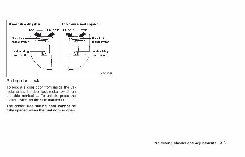
Sliding door lock
To lock a sliding door from inside the ve-hicle, press the door lock rocker switch onthe side marked L. To unlock, press therocker switch on the side marked U.
The driver side sliding door cannot befully opened when the fuel door is open.
APD1055
Pre-driving checks and adjustments 3-5
Z X

CHILD SAFETY SLIDING DOORLOCK
Child safety locking helps prevent doorsfrom being opened accidentally, especiallywhen small children are in the vehicle.
When the lever is in the LOCK position,the sliding doors can be opened onlyfrom the outside.
APD1056
3-6 Pre-driving checks and adjustments
Z X

POWER DOOR LOCK(if so equipped)Operating the lock-unlock switch locks orunlocks all doors.
If the power door lock switch is pressedwhen a sliding door is open, the sliding doorautomatically locks when it is closed.
APD1074 APD1075
Pre-driving checks and adjustments 3-7
Z X

To lock all doors from inside the vehicle,push the door lock knob in, then close thedoor. When locking the doors this way, becertain not to leave the key inside the ve-hicle. All doors automatically unlock if thekey is in the ignition and a door is open.
Selective unlockTurning the door key one time to the rear ofthe vehicle unlocks the corresponding door.From that position, returning the key toNeutral (where the key can only be removedand inserted) and turning it to the rear againwithin 5 seconds unlocks all doors. Turningthe door key to the front of the vehicle locksall doors. The selective unlock function andlocking all doors can be operated from thedriver, passenger and rear door.
APD1054 APD1057
3-8 Pre-driving checks and adjustments
Z X

It is possible to lock/unlock all doors, turnthe interior lights on or off, and activate thepanic alarm by using the remote controllerfrom outside the vehicle.
Be sure to remove the key from thevehicle before locking the doors andleaving it.
The remote controller can operate at adistance of approximately 30 ft (10 m) fromthe vehicle. The effective distance dependson the conditions around the vehicle.
As many as four remote controllers can beused with one vehicle. For more informationconcerning the purchase and use of addi-tional remote controllers, contact an autho-rized NISSAN dealer.
CAUTIONListed below are conditions or occur-rences which will damage the remotecontroller:● Do not allow the remote controller to
become wet.● Do not drop the remote controller.● Do not strike the remote controller
sharply against another object.
● Do not place the remote controllerfor an extended period in an areawhere temperatures exceed 140°F(60°C).
Locking doors
1. Close all doors.
2. Push the button on the multi-remotecontroller.
3. All doors lock.
4. The parking lights flash twice and thehorn chirps once to verify all doors arelocked.
Unlocking doorsFor memory seat and mirror informationsee ‘‘Memory driver seat and mirrors’’ laterin this section.
1. Push the button on the multi-remotecontroller. Only the driver door unlocks.Parking lights flash once.
2. The interior lights come on and stay onfor 30 seconds.
3. Push the button on the multi-remotecontroller again within five seconds. The
passenger door, sliding doors, and therear door unlock.
The interior lights can be turned off withoutwaiting 30 seconds by either turning theignition to ON or locking the doors with themulti-remote controller.
Using the panic alarmIf you are near your vehicle and feel threat-ened, you may activate the panic alarm tocall attention as follows:
1. Push and hold the button on theremote controller for at least one fullsecond.
2. The theft warning alarm (horn) soundsand the headlights and tail lights flash for30 seconds.
3. The panic alarm stops when:
● it has run for 30 seconds, or
● the or the button is pressed, or
● the button is released and re-pushed.
MULTI-REMOTE CONTROLSYSTEM (if so equipped)
Pre-driving checks and adjustments 3-9
Z X

Silencing the horn beep featureIf desired, the horn beep feature can bedeactivated using the multi-remote control-ler. The instructions are on the back of themulti-remote controller.
To deactivate: Press and hold the andbuttons for at least two seconds.
The hazard lights will quickly flash threetimes to confirm that the horn beep featurehas been deactivated.
To activate: Press and hold the andbuttons for at least two seconds
once more.
The hazard lights will quickly flash threetimes to confirm that the horn beep featurehas been reactivated.
Deactivating the horn feature does not si-lence the horn if the alarm is triggered.
AIC1037
3-10 Pre-driving checks and adjustments
Z X

Replace the battery as follows:1. Open the lid using a coin.2. Replace the battery with a new one.
Insert the batteries as illustrated above.Recommended battery: PanasonicCR2025, 3V or equivalent.
3. Close the lid securely.
4. Press the button, then the buttontwo or three times to check the multi-remote controller operation.
If the batteries are removed for any rea-son other than replacement, performstep 4.● An improperly disposed battery can
hurt the environment. Always conformto local regulations for battery disposal.
● The multi-remote controller is water-resistant; however, if it does get wet,immediately wipe completely dry.
● The operational range of the multi-remote controller extends to approxi-mately 30 ft (10 m) from the vehicle.This range may vary with conditions.
FCC Notice:Changes or modifications not expresslyapproved by the manufacturer for com-pliance could void the user’s authority tooperate the equipment.This device complies with part 15 of theFCC Rules and RSS-210 of IndustryCanada.Operation is subject to the following twoconditions: (1) This device may notcause harmful interference, and (2) thisdevice must accept any interference re-ceived, including interference that maycause undesired operation of the device.
APD1087
BATTERY REPLACEMENT
Pre-driving checks and adjustments 3-11
Z X

The interior lights, the cargo light, the glovebox light, the stepwell lights near the slidingdoors and on the front doors, and the foot-well lights near the driver’s and front pas-senger’s feet illuminate when the front orsliding doors are opened. Once the doorsare closed, these lights gradually dim to offwithin 30 seconds or turn off immediatelywhen the key is turned to the ON position.
Battery saverIf the vehicle doors are not fully closed andthe interior lights remain illuminated, theyeventually turn off automatically to preventthe battery from becoming discharged. If theinterior lights are left in the ON position, withall doors closed, they will automatically turnoff after approximately 30 minutes. Lightsthat illuminate when the front or slidingdoors are opened turn off after approxi-mately 30 minutes. Lights that illuminatewhen the back door is opened turn off afterapproximately 60 minutes. Vanity mirrorlights are not part of the battery saversystem.
If the personal reading lights are left on afterthe key is removed from the ignition, theywill automatically turn off after approxi-mately 30 minutes.
1. Pull the hood lock release handle s1located below the instrument panel; thehood then springs up slightly.
2. Pull up on the lever s2 at the front of thehood and raise the hood.
3. Insert the support rod s3 into the slot onthe underside of the hood.
4. When closing the hood, reset the supportrod to its original position, lower the hoodto approximately 12 inches above thelatch and release it. This allows properengagement of the hood latch.
APD1064
ILLUMINATED ENTRYSYSTEM
HOOD RELEASE
3-12 Pre-driving checks and adjustments
Z X

WARNING● Make sure the hood is completely
closed and latched before driving.Failure to do so could cause thehood to fly open and result in anaccident.
● If you see steam or smoke comingfrom the engine compartment, toavoid injury do not open the hood.
Open the glove box by pulling the handle.
CAUTIONKeep glove box lid closed while drivingto prevent injury in an accident or asudden stop.
APD0601
GLOVE BOX
Pre-driving checks and adjustments 3-13
Z X

The front seat convenience net keeps smallpackages in the front passenger compart-ment from moving around while the vehicleis in motion.
To install the convenience net, attach thefour hooks to the four slots in the base of thefront seats.
To remove the convenience net, detach thefour hooks from four slots in the base of thefront seats.
When not in use, the convenience net canbe stored in the passenger side underseatstorage tray (if so equipped). See ‘‘Under-seat storage tray’’ in the ‘‘Seats, restraintsand supplemental air bag systems’’ section.
APD1086
FRONT SEAT CONVENIENCENET
3-14 Pre-driving checks and adjustments
Z X
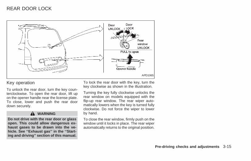
Key operation
To unlock the rear door, turn the key coun-terclockwise. To open the rear door, lift upon the opener handle near the license plate.To close, lower and push the rear doordown securely.
WARNINGDo not drive with the rear door or glassopen. This could allow dangerous ex-haust gases to be drawn into the ve-hicle. See ‘‘Exhaust gas’’ in the ‘‘Start-ing and driving’’ section of this manual.
To lock the rear door with the key, turn thekey clockwise as shown in the illustration.
Turning the key fully clockwise unlocks therear window on models equipped with theflip-up rear window. The rear wiper auto-matically lowers when the key is turned fullyclockwise. Do not force the wiper to lowerby hand.
To close the rear window, firmly push on thewindow until it locks in place. The rear wiperautomatically returns to the original position.
APD1065
REAR DOOR LOCK
Pre-driving checks and adjustments 3-15
Z X

The cargo net keeps packages in the cargoarea from moving around while the vehicleis in motion.
To install the cargo net, attach the fourloops to the four retainers.
To remove the cargo net, detach the fourloops from the cargo net retainers.
WARNING
● Properly secure all cargo to helpprevent it from sliding or shifting. Donot place cargo higher than the seat-backs. In a sudden stop or collision,unsecured cargo could cause per-sonal injury.
● Be sure to secure all four loops ontothe retainers. The cargo restrainedby the net must not exceed 50 lbs.(22.7 kg) or the net may not staysecured.
APD1067
CARGO NET(if so equipped)
3-16 Pre-driving checks and adjustments
Z X

WARNING● Before using the parcel shelf, the
three-passenger bench seat must bein the third row position, and the
seat back must be upright.● After adjusting the parcel shelf to the
desired height, make sure the lockknob is securely latched.
● Properly secure all packages underthe parcel shelf net to prevent themfrom sliding or shifting. Do not placepackages higher than the three-passenger bench seat back. In asudden stop or collision, unsecuredpackages could cause personal in-jury.
● Be sure to secure all three parcelshelf net loops onto the retainerslocated on the bottom side of theparcel shelf. The packages placedon the parcel shelf and restrained bythe parcel shelf net must not exceed30 pounds (13.6 kg), or the parcelshelf may not remain secure.
● Do not allow people or pets on orunder the parcel shelf.
● The parcel shelf must be removedfrom the vehicle if installing a childrestraint on the three-passengerbench seat that requires the use of atop tether strap that is anchored tothe vehicle floor. Failure to removethe parcel shelf can increase theseverity of injury to the child in anaccident.
APD1071
PARCEL SHELF (if soequipped)
Pre-driving checks and adjustments 3-17
Z X

The parcel shelf allows for additional stor-age for packages.
Do not load more than 30 pounds (13.6 kg)on the parcel shelf. The parcel shelf can beinstalled at two different heights and in astorage position.
To install the parcel shelf:
● Position the right side of the parcel shelfin to one of the shelf positions on the rightside luggage compartment trim panel.
● Position the left side of the parcel shelfinto the matching position (same height)on the left side luggage compartment trimpanel.
● Slide the parcel shelf lock knob fully tothe left side (latch in green dot position).
● Turn the parcel shelf lock knob clock-wise until securely locked.
The parcel shelf is also equipped with aparcel shelf net to keep packages on theparcel shelf from moving around while thevehicle is in motion.
The parcel shelf net is permanently at-tached to the back side of the parcel shelf.
Pull the parcel shelf net over the packages
and attach the three loops to the threeretainers on the bottom side of the parcelshelf. Make sure the parcel shelf is securelylocked before covering the packages withthe parcel shelf net.
To remove the parcel shelf:
● Unlock the parcel shelf net.
● Remove all packages from the parcelshelf.
● Turn the parcel shelf lock knob counterclockwise until loose (maximum twoturns).
● Slide the parcel shelf lock knob fully tothe right side (unlatch in red dot posi-tion).
● Remove the parcel shelf from the leftside luggage compartment trim panel,then the right side luggage compartmenttrim panel and reposition the parcel shelfwhere desired.
Put the parcel shelf in the floor storageposition when the parcel shelf is not used orrequired.
APD1073
3-18 Pre-driving checks and adjustments
Z X
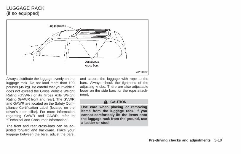
Always distribute the luggage evenly on theluggage rack. Do not load more than 100pounds (45 kg). Be careful that your vehicledoes not exceed the Gross Vehicle WeightRating (GVWR) or its Gross Axle WeightRating (GAWR front and rear). The GVWRand GAWR are located on the Safety Com-pliance Certification Label (located on thedriver’s door pillar). For more informationregarding GVWR and GAWR, refer to‘‘Technical and Consumer Information’’.
The front and rear cross-bars can be ad-justed forward and backward. Place yourluggage between the bars, adjust the bars,
and secure the luggage with rope to thebars. Always check the tightness of theadjusting knobs. There are also adjustableloops on the side bars for the rope attach-ment.
CAUTIONUse care when placing or removingitems from the luggage rack. If youcannot comfortably lift the items ontothe luggage rack from the ground, usea ladder or stool.
APD1072
LUGGAGE RACK(if so equipped)
Pre-driving checks and adjustments 3-19
Z X
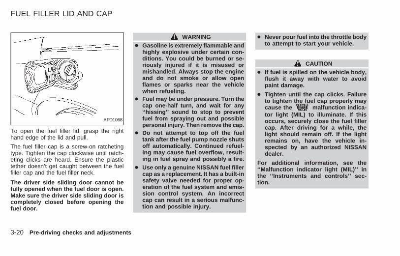
To open the fuel filler lid, grasp the righthand edge of the lid and pull.
The fuel filler cap is a screw-on ratchetingtype. Tighten the cap clockwise until ratch-eting clicks are heard. Ensure the plastictether doesn’t get caught between the fuelfiller cap and the fuel filler neck.
The driver side sliding door cannot befully opened when the fuel door is open.Make sure the driver side sliding door iscompletely closed before opening thefuel door.
WARNING● Gasoline is extremely flammable and
highly explosive under certain con-ditions. You could be burned or se-riously injured if it is misused ormishandled. Always stop the engineand do not smoke or allow openflames or sparks near the vehiclewhen refueling.
● Fuel may be under pressure. Turn thecap one-half turn, and wait for any‘‘hissing’’ sound to stop to preventfuel from spraying out and possiblepersonal injury. Then remove the cap.
● Do not attempt to top off the fueltank after the fuel pump nozzle shutsoff automatically. Continued refuel-ing may cause fuel overflow, result-ing in fuel spray and possibly a fire.
● Use only a genuine NISSAN fuel fillercap as a replacement. It has a built-insafety valve needed for proper op-eration of the fuel system and emis-sion control system. An incorrectcap can result in a serious malfunc-tion and possible injury.
● Never pour fuel into the throttle bodyto attempt to start your vehicle.
CAUTION● If fuel is spilled on the vehicle body,
flush it away with water to avoidpaint damage.
● Tighten until the cap clicks. Failureto tighten the fuel cap properly maycause the malfunction indica-tor light (MIL) to illuminate. If thisoccurs, securely close the fuel fillercap. After driving for a while, thelight should remain off. If the lightremains on, have the vehicle in-spected by an authorized NISSANdealer.
For additional information, see the‘‘Malfunction indicator light (MIL)’’ inthe ‘‘Instruments and controls’’ sec-tion.
APD1068
FUEL FILLER LID AND CAP
3-20 Pre-driving checks and adjustments
Z X

Push the lock lever down and adjust thesteering wheel up or down to the desiredposition. Pull the lock lever up firmly to lockthe steering wheel in place.
Gently pull down on the wheel to make sureit is properly locked.
WARNINGDo not adjust the steering wheel whiledriving. You could lose control of yourvehicle and cause an accident.
The memory driver seat and mirror functionprovides a convenient way to recall a driv-er’s seat and outside mirror positions. Un-locking the doors using the multi-remotecontroller, or by pressing the memory seatposition 1 or position 2 button activates thememory driver seat and mirrors.
Multi-remote controller system entry
Pressing the button on the multi-remote controller unlocks the driver’s door,and recalls the memory settings for bothoutside mirrors and driver’s seat for thatmemory position. Two multi-remote control-lers are delivered with the vehicle. They canbe programmed with the same memorydriver’s seat and mirror positions, or eachone can be programmed separately. Onemulti-remote controller can be programmedfor memory driver’s seat and mirror position1, and the other for memory driver’s seatand mirror position 2.
APD1051 APD1062 APD1063
TILTING STEERING WHEEL MEMORY DRIVER SEAT ANDMIRRORS (if so equipped)
Pre-driving checks and adjustments 3-21
Z X

Memory Driver Seat and MirrorButtonsThe memory seat and mirror buttons arelocated on the driver door. Pressing thememory driver seat and mirror position 1 orposition 2 button will recall the memory set-tings for both outside mirrors and driver seatfor that memory seat position, provided thevehicle is in P (Park) or N (Neutral). For easyvehicle exit, press memory driver seat andmirror position 1 and position 2 buttons to-gether to move the driver seat fully rearwardand fully downward. This function is presetand cannot be changed.
Programming Memory Positions1. Move the driver seat and outside mirrors
to the desired position using the manualcontrols.
2. Push and hold the memory seat andmirror position 1 or position 2 button forat least 3 seconds.
● The indicator light will illuminate and re-main illuminated until the position is pro-grammed.
● After the position has been programmedthe indicator light will flash to indicate theposition is set.
The driver seat and/or outside mirrors mustbe adjusted before programming position 1or position 2.
Programming a multi-remote con-troller
1. Move the driver seat and outside mirrorsby pressing the desired position 1 orposition 2 button.
2. Press and hold the same (position 1 orposition 2) button.
3. Within 10 seconds press the button onthe multi-remote controller.
The controller is now programmed for that(position 1 or position 2) button.
After the multi-remote controller has beenprogrammed, the memory seat and mirrorbutton indicator light will flash to indicate thecontroller is programmed. If the memoryseat button is pressed and held the indicatorlight will remain illuminated for as long asthe button is held or 10 seconds which everis shorter.
To remove a multi-remote controller fromthe memory seat system press and holdboth memory seat and mirror position but-tons 1 and 2 and then press the buttonon the multi-remote controller.
3-22 Pre-driving checks and adjustments
Z X

Electric control typeThe outside mirrors operate only when theignition switch is in the ACC or ON position.
Move the switch to select the right or leftside mirror, then adjust using the controllever.
WARNINGObjects viewed in the outside mirror onthe passenger side are closer than theyappear. Be careful when moving to theright. Using only this mirror could
cause an accident. Use the inside mir-ror or glance over your shoulder toproperly judge distances to other ob-jects.
The electric control type outside mirrors canbe heated to defrost, defog, or de-ice forimproved visibility. Press the rear windowdefogger switch to activate the heating func-tion. Press the switch again to deactivate, orthe heating function will automatically turnoff after approximately 15 minutes.
Manual control typeThe outside mirror can be moved in anydirection for a better rear view.
WARNINGObjects viewed in the outside mirror onthe passenger side are closer than theyappear. Be careful when moving to theright. Using only this mirror couldcause an accident. Use the inside mir-ror or glance over your shoulder toproperly judge distances to other ob-jects.
APD1052 PD1183M
OUTSIDE MIRROR CONTROL
Pre-driving checks and adjustments 3-23
Z X

Push the outside mirrors backward to foldthem.
The night position reduces glare from theheadlights of vehicles behind you at night.
WARNINGUse the night position only when nec-essary, because it reduces rear viewclarity.
Your vehicle may be equipped with a driveror passenger side vanity mirror. If the vanitymirror on your vehicle has a cover, accessthe mirror by pulling the sun visor down andlifting the cover up. Some vanity mirrorsilluminate when the mirror cover is opened.
M008 PD1006M AIC0563
OUTSIDE MIRRORS INSIDE MIRROR VANITY MIRROR
3-24 Pre-driving checks and adjustments
Z X
4 Heater, air conditioner and audio systems
Ventilators ..............................................................4-2Heater and air conditioner (manual) ......................4-3Controls ..................................................................4-3Heater operation ....................................................4-4Air conditioner operation ........................................4-5Air flow charts.........................................................4-7Heater and air conditioner (automatic)(if so equipped) ....................................................4-11Automatic operation .............................................4-12Air control buttons ................................................4-12English/metric mode.............................................4-13Rear seat air conditioner (if so equipped) ...........4-14Controls ................................................................4-14Audio system........................................................4-16AM-FM radio with cassette player .......................4-16Radio operation....................................................4-16
Tuning ..................................................................4-17Adjusting tone quality and speaker balance........4-19Cassette tape operation.......................................4-20AM-FM radio with cassette player andcompact disc player .............................................4-22Radio operation....................................................4-22Tuning ..................................................................4-23Adjusting tone quality and speaker balance........4-25Cassette tape operation.......................................4-26Compact disc (CD) player operation....................4-28Antenna ................................................................4-29Compact disc (CD) player (if so equipped) .........4-30Steering wheel controls........................................4-32Rear audio controls ..............................................4-33CB radio or car phone..........................................4-34
Z X

Center ventilatorsOpen, close and adjust the air flow directionof ventilators.
Side ventilators
Open, close and adjust the air flow directionof ventilators.
: This symbol indicates a vent is closedwhen the vent switch is moved down.
: This symbol indicates a vent is openwhen the vent switch is moved up.
AHA1056 AHA1055
VENTILATORS
4-2 Heater, air conditioner and audio systems
Z X

WARNING
● The air conditioner cooling functionoperates only when the engine isrunning.
● Do not leave children, unreliableadults, or pets alone in your vehicle.On hot, sunny days, temperatures ina closed vehicle could quickly be-come high enough to cause severeor possibly fatal injuries to people oranimals.
● Do not use the MAX (recirculation)mode for long periods as it maycause the interior air to become staleand the windows to fog up.
● Positioning of the heater and air con-ditioner controls should not be donewhile driving, in order that full atten-tion may be given to the drivingoperation.
The cabin air filter (if so equipped) requiresperiodic maintenance. See the ‘‘Do it your-self’’ section for additional information.
CONTROLS
Fan control dial
This dial controls fan speed.
Temperature control dial
This dial allows you to adjust the tempera-ture of the outlet air.
Air control dial
This dial allows you to select the air flowoutlets.
Air flows mainly from center and sideventilators.
Air flows from center and side ventila-tors and the front and rear foot outlets.
Air flows mainly from the front andrear foot outlets.
Air flows from defroster outlets andthe front and rear foot outlets.
Air flows mainly from defroster outlets.
MAXA/C Air flows mainly from center and side
ventilators.
AHA1135
HEATER AND AIRCONDITIONER (manual)
Heater, air conditioner and audio systems 4-3
Z X

OFF positionThe OFF position shuts off the air supply toall outlets and stops all fan operations. Usethe OFF position to prevent cold air fromentering the passenger compartment undercold outside conditions before the engine iswarmed up.
MAX A/C PositionInterior air is recirculated inside the vehicle.
Turn the air control dial to the MAX A/Cposition when driving on a dusty road orto help keep out traffic fumes.
Turn the air control dial to the MAX A/Cposition for improved air conditioner perfor-mance under high temperature and high hu-midity conditions.
CAUTIONDo not use MAX A/C for long periods asit may cause the interior air to becomestale and the windows to fog up.
Air conditioner buttonStart the engine, move the fan control dial tothe desired (one to four) position, select anair control position and push the air condi-
tioner button to turn on the air conditioner.The indicator light comes on when the airconditioner is operating. To stop the air con-ditioner, push the button again; the indicatorlight goes off.
The air conditioner cooling function op-erates only when the engine is running.
HEATER OPERATION
HeatingThis mode is used to direct most of the hotair to the front and rear floor outlets. Rearpassenger heat is provided by the frontsystem through floor outlets located underboth front seats.
1. Move the air control dial to the po-sition.
2. Turn the fan control dial to select speed.
3. Move the temperature control dial to thedesired position.
VentilationThis mode directs air to the side and centervents.
1. Move the air control dial to the po-sition.
2. Turn the fan control dial to select speed.
3. Move the temperature control dial to thedesired position.
Defrosting or defogging
This mode is used to defrost/defog thewindows.
1. Move the air control dial to the po-sition.
2. Turn the fan control dial to select speed.
3. Move the temperature control dial to thedesired position.
When the position is selected, theair conditioner automatically turns on(however, the indicator light will not illu-minate) if the outside temperature ismore than 45°F (7°C). This dehumidifiesthe air which helps defog the windshield.The air recirculation mode automaticallyturns off, allowing outside air to be drawninto the passenger compartment whichhelps defog the windshield.
4-4 Heater, air conditioner and audio systems
Z X

Operating Tips
Clear snow and ice from the wiper bladesand air inlet in front of the windshield.This improves defrosting/defogging op-eration.
Bi-level heating/cooling
The bi-level mode directs air to the side andcenter vents and to the front and rear flooroutlets.
Bi-level is also a cooling mode when highsun load conditions are present with cooltemperatures.
With the A/C system in operation, this modecan be used to cool the passenger’s ordriver’s feet under high temperature condi-tions.
With the A/C system in operation under hightemperature conditions, improved coolingcan be obtained by moving the air controldial to the MAX A/C position.
1. Move the air control dial to the po-sition.
2. Turn the fan control dial to the desiredposition.
3. Move the temperature control dial to thedesired position.
Heating and defogging
This mode heats the interior and defogs thewindshield. This mode directs air to thedefroster and the front and rear floor outlets.Rear passenger heat is provided by thefront system through floor outlets locatedunder both front seats.
1. Move the air control dial to the po-sition.
2. Turn the fan control dial to the desiredposition.
3. Move the temperature control dial to thedesired position.
When the position is selected, theair conditioner automatically turns on(however, the indicator light will not illu-minate) if the outside temperature ismore than 45°F (7°C). This dehumidifiesthe air which helps defog the windshield.The air recirculation mode automaticallyturns off, allowing outside air to be drawninto the passenger compartment whichhelps defog the windshield.
Operating tips● Clear snow and ice from the wiper
blades and air inlet in front of thewindshield. This improves heater op-eration.
● To defog the side windows more effec-tively when in bi-level or ventilationmode, close the center vent and directthe side vents toward the side windows.
● A slight delay may be experienced whenchanging air control buttons. This is not aproblem, it is only the system motors andsolenoids switching from one outlet toanother.
AIR CONDITIONER OPERATIONStart the engine, move the fan control dial tothe desired (one to four) position, and selectan air control position before pushing in theair conditioner button to activate the airconditioner. When the air conditioner is on,cooling and dehumidifying functions areadded to the heater operation.
WARNINGThe air conditioner cooling function op-erates only when the engine is running.
Heater, air conditioner and audio systems 4-5
Z X

NOTE: When switching air flow outlets, theA/C system remains activated unless theA/C button is pressed to the OFF position.The indicator light on the A/C button re-mains illuminated unless the button ispressed to the OFF position, or the OFF aircontrol position is selected.
Cooling
This mode is used to cool and dehumidify.
1. Move the air control dial to the po-sition.
2. Turn the fan control dial to select speed.
3. Push the air conditioner button. The indi-cator light comes on.
4. Move the temperature control dial to thedesired position.
● For quick cooling when the outside tem-perature is high, move the air control dialto the MAX A/C position. Be sure toreturn the air control dial to the po-sition for normal cooling.
● Opening the windows helps to vent heatbuildup when parked in the sun.
Dehumidified heatingThis mode is used to heat and dehumidify.
1. Move the air control dial to the po-sition.
2. Turn the fan control dial to select speed.
3. Push the air conditioner button. The indi-cator light comes on.
4. Move the temperature control dial to thedesired position.
Dehumidified defoggingThis mode is used to defog the windowsand dehumidify.
1. Move the air control dial to the po-sition.
2. Turn the fan control dial to the desiredspeed.
3. Move the temperature control dial to thedesired position.
When the position is selected, theair conditioner automatically turns on(however, the indicator light will not illu-minate) if the outside temperature ismore than 45°F (7°C). This dehumidifiesthe air which helps defog the windshield.
The air recirculation mode automaticallyturns off, allowing outside air to be drawninto the passenger compartment whichhelps defog the windshield.
Operating tips● Keep windows and sun roof closed while
the air conditioner is in operation.
● After parking in the sun, drive for two orthree minutes with the windows open tovent hot air from the passenger compart-ment. Then, close the windows. Thisallows the air conditioner to cool theinterior more quickly.
● The air conditioning system should beoperated for about ten minutes atleast once a month. This helps pre-vent damage to the system due to lackof lubrication.
● If the engine coolant temperature gaugeexceeds the H (hot) position, turn the airconditioner off. See ‘‘If your vehicle over-heats’’ in the ‘‘In case of emergency’’section for additional information.
4-6 Heater, air conditioner and audio systems
Z X

AIR FLOW CHARTSThe following charts show the button anddial positions for MAXIMUM AND QUICKheating, cooling or defrosting.
AHA1136
Heater, air conditioner and audio systems 4-7
Z X

AHA1137 AHA1138
4-8 Heater, air conditioner and audio systems
Z X

AHA1139 AHA1140
Heater, air conditioner and audio systems 4-9
Z X

AHA1141
4-10 Heater, air conditioner and audio systems
Z X

WARNING● The air conditioner cooling function
operates only when the engine isrunning.
● Do not leave children, unreliableadults, or pets alone in your vehicle.On hot, sunny days, temperatures ina closed vehicle could quickly be-come high enough to cause severeor possibly fatal injuries to people oranimals.
● Do not use the MAX mode for longperiods as it may cause the interior
air to become stale and the windowsto fog up.
● Positioning of the heater and air con-ditioner controls should not be donewhile driving, in order that full atten-tion may be given to the drivingoperation.
The cabin air filter (if so equipped) requiresperiodic maintenance. See the ‘‘Do it your-self’’ section for additional information.
The Electronic Automatic TemperatureControl (EATC) is located at the center ofthe instrument panel, below the radio. The
EATC operates only when the ignition isturned to the ON position.
The EATC maintains the temperature youselect and controls the airflow for your com-fort. It also allows you to override the auto-matic operation with manual function selec-tor buttons.
To turn the EATC on, push either the AU-TOMATIC button or any of the six functionselector buttons: , , , ,
or MAX. To turn the EATC off, pressthe OFF button.
When you select AUTOMATIC, the systemdetermines fan speed, airflow location anddischarge air temperature. When one of thefunction selector buttons is pressed, yourselection determines airflow location only.Fan speed and discharge air temperatureremain automatic. You can override fanspeed by rotating the vertical thumbwheel
located at the extreme right of thecontrol panel.
The display window indicates the status ofthe system. It shows the selected tempera-ture and AUTO when in the AUTOMATICmode. It also indicates manual (thumb-wheel) control of the fan speed when a
is shown.
AHA1142
HEATER AND AIR CONDITIONER(automatic) (if so equipped)
Heater, air conditioner and audio systems 4-11
Z X

AUTOMATIC OPERATIONPush the AUTOMATIC button and select thedesired temperature. The selected tempera-ture and AUTO show in the display window.The EATC heats or cools to achieve the settemperature.
When in AUTOMATIC and weather conditionsrequire heat, air is sent to the floor. However,a feature is included in the EATC to preventblowing cold air to the floor if the enginecoolant is not warm enough to allow heating.In three or four minutes the fan speed gradu-ally increases and airflow changes to the floor.
If unique conditions exist, such as windowfogging, the five override buttons allow spe-cific airflow selection. The thumbwheel al-lows you to adjust the fan speed to suit yourneeds.
Temperature selectionThe TEMP button on the left side ofthe control panel is for temperature selec-tion. The side lowers the set tempera-ture, and the side raises the set tem-perature. Press and hold either side of thebutton to rapidly change the temperaturesetting in one degree increments to either65°F (18°C) or 85°F (29°C). If you want
continuous maximum cooling, push theside of the TEMP button until 60°F
(16°C) shows in the display window. TheEATC cools at maximum and disregards the60°F (16°C) setting until a warmer tempera-ture is selected. If you want continuousmaximum heating, push the side of theTEMP button until 90°F (32°C) shows in thedisplay window. The EATC provides maxi-mum heat regardless of the 90°F (32°C)setting until a cooler temperature is se-lected.
Fan speed and thumbwheelYour EATC automatically adjusts the fanspeed to the existing conditions. To controlthe fan speed yourself, use the thumbwheellocated at the extreme right side of theEATC control panel. Using the thumbwheelcancels the automatic fan speed control,and causes a to appear in the displaywindow. Rotate the thumbwheel up for HIspeeds and down for LO speeds.
To return to auto fan control, press theAUTOMATIC button.
AIR CONTROL BUTTONSYour EATC has five buttons which allow youto make special selections. The buttons are
grouped in the middle of the EATC paneland allow you to determine airflow location.Pressing any of the air control buttonschanges airflow location only, and does notaffect the ability of the system to controltemperature or fan speed. Return to fullyautomatic operation by pushing the AUTO-MATIC button.
Push this button for airflow to the front andrear floor outlets and windshield at the sametime. The indicator light comes on,and the display window shows the set tem-perature.
Press this button to obtain maximum airflowto the windshield. Adjust the temperaturesetting as required for defrosting. The
indicator light comes on, and thedisplay window shows the set temperature.When the outside temperature is about45°F (7°C) or above, the air is dehumidifiedto prevent window fogging.
Push this button to select airflow through
4-12 Heater, air conditioner and audio systems
Z X

the instrument panel registers. Theindicator light comes on, and thedisplay window shows the set tem-
perature. The EATC heats the air if theselected temperature is warmer than theoutside air coming into the vehicle. How-ever, the air is not cooled regardless of thetemperature setting, unless the A/C buttonis selected.
Push this button to get air from the front andrear floor outlets and instrument panel ven-tilators at the same time. The indicatorlight comes on and the display windowshows the set temperature. The EATCheats the air if the selected temperature iswarmer than the outside air coming into thevehicle. However, the air is not cooled re-gardless of the temperature setting, unlessthe A/C button is selected.
Push this button to direct airflow to the frontand rear floor outlets. The indicatorlight comes on, and the display windowshows the set temperature. The EATCheats the air if the selected temperature iswarmer than the outside air coming into the
vehicle. However, the air is not cooled re-gardless of the temperature setting, unlessthe A/C button is selected.
Press the MAX button to choose air recircu-lation. In this mode the EATC system recir-culates the air inside the vehicle rather thandrawing air from outside. Air is distributedthrough the instrument panel ventilatorssimilar to mode. Use this mode to rap-idly cool the inside of the vehicle, or todehumidify the air inside the vehicle.
Activate the air conditioner in any of theoverride modes listed above by pressing theA/C button. The A/C indicator light comeson to verify activation, and cooled air flowsfrom the vents. Fan speed continues to becontrolled by the EATC unless the fanspeed thumbwheel is used to override.
ENGLISH/METRIC MODESwitch from English to metric temperaturedisplay by simultaneously pressing the
and A/C buttons and holding thethumbwheel in upper position (HI) for onesecond.
AHA1143
Heater, air conditioner and audio systems 4-13
Z X
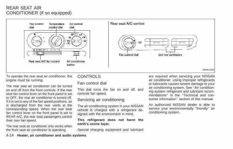
To operate the rear seat air conditioner, theengine must be running.
The rear seat air conditioner can be turnedon and off from the front controls. If the rearseat fan control lever on the front panel is setto OFF, the rear air conditioner is turned off.If it is set to any of the fan speed positions, airis discharged from the rear vents at thecorresponding speed. When the rear seatfan control lever on the front panel is set toREAR A/C, the rear seat passengers controltheir own fan speed.
The rear seat air conditioner only works whenthe front seat air conditioner is operating.
CONTROLS
Fan control dial
This dial turns the fan on and off, andcontrols fan speed.
Servicing air conditioning
The air conditioning system in your NISSANvehicle is charged with a refrigerant de-signed with the environment in mind.
This refrigerant does not harm theearth’s ozone layer.
Special charging equipment and lubricant
are required when servicing your NISSANair conditioner. Using improper refrigerantsor lubricants causes severe damage to yourair conditioning system. See ‘‘Air condition-ing system refrigerant and lubricant recom-mendations’’ in the ‘‘Technical and con-sumer information’’ section of this manual.
An authorized NISSAN dealer is able toservice your environmentally ‘‘friendly’’ airconditioning system.
AHA1144
REAR SEAT AIRCONDITIONER (if so equipped)
4-14 Heater, air conditioner and audio systems
Z X

WARNINGThe air conditioner system containsrefrigerant under high pressure. Toavoid personal injury, any air condi-tioner service should be done by anexperienced technician with properequipment.
Heater, air conditioner and audio systems 4-15
Z X

AM-FM RADIO WITH CASSETTEPLAYER
RADIO OPERATIONTo turn the radio on, turn the ignition key toACC or ON. If you listen to the radio with the
engine not running, turn the key to the ACCposition.
Radio reception is affected by station signalstrength, distance from radio transmitter,buildings, bridges, mountains, and otherexternal influences. Intermittent changes in
reception quality normally are caused byexternal influences.
Using a cellular phone in or near thevehicle may influence radio receptionquality.
Push the VOL knob to turn the radio on.Push the VOL knob once more to turn theradio OFF.
Turn the knob to raise or lower volume. Ifthe knob is set above a certain volume leveland the ignition is turned off, the volume willcome back on at a nominal listening levelwhen the ignition is turned back on.
MUTE buttonPush the MUTE button to mute out theradio.
Clock operationThe clock is on in the display regardless ofwhat mode, media, or function the radio is inas long as the ignition is in ACC or ON.
Clock setPress the RDS/CLK button until SELECTHOURS is displayed then use the SEL
buttons to change the hour, pressthe RDS/CLK button again until SELECT
AHA1057
AUDIO SYSTEM
4-16 Heater, air conditioner and audio systems
Z X

MINS is displayed then use the SELbuttons to change the minutes.
The display will return to clock priority modein 10 seconds or press the RDS/CLK buttonto return to the clock display.
Selecting the desired bandPush the AM or FM buttons to change to AMor FM band reception.
The FM stereo indicator, ST illuminates duringFM stereo reception. When the stereo broad-cast signal is weak, the radio automaticallychanges from stereo to monaural reception.
TUNING
WARNING
The radio should not be tuned whiledriving in order that full attention maybe given to the driving operation.
Auto setPress the AUTO button while listening to theradio to activate the auto set feature. WhenAUTO is depressed for less than 5 seconds,the display window momentarily indicatesAUTO ON, and the radio seeks the first sixstrong stations for the respective band. The
first six strong stations are then stored inorder in memory buttons one through six.
Only stations in the selected band are set,and the station seek begins from the lastfrequency stored in memory button six. IfAM, FM, SCAN, TUNE, SEEK, AUTO or amemory button is pushed while auto set isoperating, auto set is canceled and AUTOOFF shows in the display window.
Auto load
Press the AUTO button for longer than 5seconds while listening to the radio to acti-vate the auto load feature. When AUTO isdepressed for longer than 5 seconds, thedisplay window momentarily indicatesAUTO LOAD, and the radio seeks the firstsix strong stations for every band. The firstsix strong stations are then stored in orderin memory buttons one through six for eachband (AM, FM1, and FM2).
Tune buttons
Use the or buttons for manualtuning. To move quickly through the chan-nels, hold either of the tune buttons downfor more than 0.5 seconds.
SEEK tuning
Push the SEEK or buttons to find thenext broadcast station. Pushing theSEEKS up and button SEEKS down.Pushing the button again continues the SEEKfunction. Once the highest broadcast stationis reached, the radio continues in the SEEKmode at the lowest station. Once the lowestbroadcast station is reached, the radio con-tinues in the SEEK mode at the higheststation.
SCAN tuning
Push the SCAN tuning button, SCAN illumi-nates in the display. SCAN tuning beginsfrom low to high frequencies and stops ateach broadcasting station for 5 seconds.Pushing the button again during this 5 sec-ond period stops SCAN tuning and remainstuned to that station.
Heater, air conditioner and audio systems 4-17
Z X
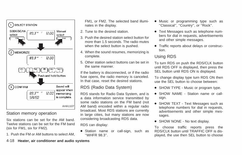
Station memory operation
Six stations can be set for the AM band.Twelve stations can be set for the FM band(six for FM1, six for FM2).
1. Push the FM or AM buttons to select AM,
FM1, or FM2. The selected band illumi-nates in the display.
2. Tune to the desired station.
3. Push the desired station select button formore than 1.5 seconds. The radio muteswhen the select button is pushed.
4. When the sound resumes, memorizing iscomplete.
5. Other station select buttons can be set inthe same manner.
If the battery is disconnected, or if the radiofuse opens, the radio memory is canceled.In that case, reset the desired stations.
RDS (Radio Data System)
RDS stands for Radio Data System, and isa data information service transmitted bysome radio stations on the FM band (notAM band) encoded within a regular radiobroadcast. Most RDS stations are currentlyin large cities, but many stations are nowconsidering broadcasting RDS data.
RDS can display:
● Station name or call-sign, such as‘‘WHFR 98.3’’.
● Music or programming type such as‘‘Classical’’, ‘‘Country’’, or ‘‘Rock’’.
● Text Messages such as telephone num-bers for dial in requests, advertisementsand other simple messages.
● Traffic reports about delays or construc-tion.
Using RDS
To turn RDS on push the RDS/CLK buttonuntil RDS OFF is displayed, then press theSEL button until RDS ON is displayed.
To change display type turn RDS ON thenuse the SEL button to choose between:
● SHOW TYPE - Music or program type.
● SHOW NAME - Station name or call-sign.
● SHOW TEXT - Text Messages such astelephone numbers for dial in requests,advertisements and other simple mes-sages.
● SHOW NONE - No text display.
To choose traffic reports press theRDS/CLK button until TRAFFIC OFF is dis-played, the use then SEL button to choose
AHA1107
4-18 Heater, air conditioner and audio systems
Z X

TRAFFIC ON, then use the seek or scancontrol to look for a station that may transmittraffic reports, the radio will display a‘‘TRAF’’ icon to show it is in traffic mode andtuned to a station that may transmit trafficreports. If the radio searches through thewhole band and then returns to the previousstation it was originally playing there are nostations in the area that are transmittingtraffic reports.
If a cassette or compact disc is being playedwhile the traffic option is on and the stationpreviously tuned into displays a traffic bul-letin the radio will pause the cassette orcompact disc and broadcast the bulletin,then resume playing the cassette or com-pact disc.
Using RDS to search for program-ming typeCertain areas have a limited number ofstations that transmit RDS. Many stationstransmit call letters and frequencies only.Searching or scanning by program typemay yield a limited number of selections.
Press the RDS/CLK button until FINDCLASSIC is displayed, then use the SELbutton to choose between CLASSIC,
COUNTRY, INFO, JAZZ, OLDIES, R&B,RELIGUS (Religious), ROCK, SOFT andTOP40. When you have chosen a programtype, use the SEEK, SCAN, or AUTOSETcontrols to look for a station transmitting thatkind of program. If the radio searchesthrough the whole band and then returns tothe previous station it was originally playingthere are no stations in the area that aretransmitting that type of programming.
Adjusting tone quality and speakerbalance
Bass
Bass control allows you to adjust the lower,bass frequencies to your preference.
Push the BASS button and the setting indi-cator bar appears in the display window.Pressing the SELECT button either or
increases or decreases the level ofbass, as indicated by the number of barsegments showing in the display window.
Following bass adjustment, the display win-dow shows the current setting for threeseconds, then returns to the display prior toadjustment.
Treble
Treble control allows you to adjust thehigher, treble frequencies to your prefer-ence.
Push the TREB button and the setting indi-cator bar appears in the display window.Pressing the SELECT button either or
increases or decreases the level ofbass, as indicated by the number of barsegments showing in the display window.
Following bass adjustment, the display win-dow shows the current setting for threeseconds, then returns to the display prior toadjustment.
BalanceBalance control allows you to adjust thesound distribution between the right and leftspeakers.
Push the BAL button and the setting indica-tor bar appears in the display window. Pressthe SELECT button to shift the soundto the right speakers. The single indicatorbar moves to the right of the display win-dow. Press the SELECT button to shiftthe sound to the left speakers. The singleindicator bar moves to the left of the display
Heater, air conditioner and audio systems 4-19
Z X

window. When the indicator bar is in thecenter position the sound is equally distrib-uted between the right and left speakers.
Following balance adjustment, the displaywindow shows the current setting for threeseconds, then returns to the display prior toadjustment.
FaderFader control allows you to adjust sounddistribution between the front and rearspeakers.
Push the FADE button and the setting indi-cator bar appears in the display window.Press the SELECT button to shift thesound to the front speakers. The singleindicator bar moves to the right of the dis-play window. Press the SELECT button
to shift the sound to the rear speakers.The single indicator bar moves to the left ofthe display window. When the indicator baris in the center position the sound is equallydistributed between the front and rearspeakers.
Following fader adjustment, the display win-dow shows the current setting for threeseconds, then returns to the display prior toadjustment.
COMP button
Press this button to activate the compres-sion function. This reduces the dynamicrange, which provides the listener with amore consistent level of volume. The dis-play window shows a C when the COMPbutton is pushed.
CASSETTE TAPE OPERATION
Turn the ignition to ACC or ON, and care-fully insert a cassette tape into the tapedoor. The cassette tape automatically pullsinto the player and begins to play.
When a casssette is inserted into the audiosystem, the word TAPE and a cassette sidesymbol (either one or two) illuminates in thedisplay.
If the radio is already operating it automati-cally turns off and the cassette tape beginsto play. The cassette tape automaticallychanges direction to play the other sidewhen the first side is complete.
Precautions on cassette player op-eration● To maintain good quality sound, Nis-
san recommends using cassette tapes
of 60 minutes or shorter in length.
● Cassette tapes should be removedfrom the player when not in use. Storecassettes in their protective cases andaway from direct sunlight, heat, dust,moisture, and magnetic sources.
● Direct sunlight can cause the cassetteto become deformed. The use of de-formed cassettes may cause the cas-sette to jam in the player.
● Do not use cassettes with loose labelswhich are peeling and loose. If usedthe label could jam in the player.
● If a cassette has loose tape, insert apencil through one of the cassettehubs and rewind the tape firmlyaround the hubs. Loose tape maycause tape jamming and waveringsound quality.
● Over a period of time, the playbackhead, capstan and pinch roller maycollect a tape coating residue as thetape is played. This residue accumu-lation can cause weak or waveringsound, and should be removed peri-odically with a head cleaning tape. Ifthe residue is not removed periodi-
4-20 Heater, air conditioner and audio systems
Z X

cally, the player may need to be dis-assembled for cleaning.
REW and FF
Push the REW or FF button for the desireddirection.
The FF or REW symbol illuminates in thedisplay.
To stop the FF or REW function, press theFF or REW button again or the TAPE but-ton.
Automatic Music Search (AMS)
Pushing the seek button while playing acassette tape activates the Automatic MusicSearch (AMS) mode. Press SEEK torewind the tape to the previous selection, orpress SEEK to forward the tape to thenext selection.
This system searches for the blank intervalsbetween selections. If there is a blank inter-val within one program or there is no intervalbetween programs, the system may notstop in the desired or expected location.
Changing the direction of tape play
Push the SIDE 1-2 select button to switchsides on the tape. The display will changefrom TAPE 1 PLAY to TAPE 2 PLAY.
Playing and stopping the cassettetape
Push the TAPE button while the cassettetape is playing to stop the tape. Push thebutton again to play the tape.
Dolby NR (noise reduction)
Push the button for Dolby NR encodedtapes to reduce high frequency tape noise.When activated, a appears in the dis-play window.
Dolby NR is manufactured under licensefrom Dolby Laboratories Licensing Corpora-tion. ‘‘Dolby NR’’ and the double-D symbolare trademarks of Dolby Laboratories Li-censing Corporation.
Metal or chrome tape usage
The cassette player is automatically set tohigh performance play when playing a metalor chrome tape.
Ejecting the cassette tape
Push the EJ button. The cassette tapeautomatically comes out.
Heater, air conditioner and audio systems 4-21
Z X

AM-FM RADIO WITH CASSETTEPLAYER AND COMPACT DISCPLAYER
RADIO OPERATION
To turn the radio on, turn the ignition key toACC or ON. If you listen to the radio with theengine not running, turn the key to the ACCposition.
Radio reception is affected by station signalstrength, distance from radio transmitter,
buildings, bridges, mountains, and otherexternal influences. Intermittent changes inreception quality normally are caused byexternal influences.
Using a cellular phone in or near thevehicle may influence radio receptionquality.
Push the VOL knob to turn the radio on.Push the VOL knob once more to turn theradio OFF.
The control buttons are illuminated whenthe parking lamps or headlamps are on.Only the text for the active controls willilluminate for each specific type of media.No bulbs or lights have malfunctioned. Forexample when a cassette tape is beingplayed, SHUFFLE will not illuminate.
Turn the knob to raise or lower volume. Ifthe knob is set above a certain volume leveland the ignition is turned off, the volume willcome back on at a nominal listening levelwhen the ignition is turned back on.
Clock operationThe clock is on in the display regardless ofwhat mode, media, or function the radio is inas long as the ignition is in ACC or ON.
AHA1058
4-22 Heater, air conditioner and audio systems
Z X
Clock setPress the RDS/CLK button until SELECTHOURS is displayed then use the SEL
buttons to change the hour, pressthe RDS/CLK button again until SELECTMINS is displayed then use the SEL
buttons to change the minutes.The display will return to the previous radiostation, tape or CD that was being playedprevious to setting the clock in 7 seconds oryou may press the RDS/CLK button until theprevious display appears.
Selecting the desired bandPush the AM buttons to change to AM bandor push the FM button to change to FM1 orFM2 band reception.
The FM stereo indicator, ST illuminatesduring FM stereo reception. When the ste-reo broadcast signal is weak, the radioautomatically changes from stereo to mon-aural reception.
TUNING
WARNING
The radio should not be tuned whiledriving in order that full attention maybe given to the driving operation.
Auto set
Press the AUTO button while listening to theradio to activate the auto set feature. WhenAUTO is depressed for less than 5 seconds,the display window momentarily indicatesAUTO ON, and the radio seeks the first sixstrong stations for the respective band. Thefirst six strong stations are then stored inorder in memory buttons one through six.
Only stations in the selected band are set,and the station seek begins from the lastfrequency stored in memory button six. IfAM, FM, SCAN, TUNE, SEEK, AUTO or amemory button is pushed while auto set isoperating, auto set is canceled and AUTOOFF shows in the display window.
Auto loadPress the AUTO button for longer than 5seconds while listening to the radio to acti-
vate the auto load feature. When AUTO isdepressed for longer than 5 seconds, thedisplay window momentarily indicatesAUTO LOAD, and the radio seeks the firstsix strong stations for every band. The firstsix strong stations are then stored in orderin memory buttons one through six for eachband (AM, FM1, and FM2).
Tune buttons
Use the or buttons for manualtuning. To move quickly through the chan-nels, hold either of the tune buttons downfor more than 0.5 seconds.
SEEK tuning
Push the SEEK or buttons to find thenext broadcast station. Pushing theSEEKS up and button SEEKS down.Pushing the button again continues the SEEKfunction. Once the highest broadcast stationis reached, the radio continues in the SEEKmode at the lowest station. Once the lowestbroadcast station is reached, the radio con-tinues in the SEEK mode at the higheststation.
Heater, air conditioner and audio systems 4-23
Z X

SCAN tuning
Push the SCAN tuning button, SCAN illumi-nates in the display. SCAN tuning beginsfrom low to high frequencies and stops ateach broadcasting station for 5 seconds.Pushing the button again during this 5 sec-ond period stops SCAN tuning and remainstuned to that station.
Station memory operation
Six stations can be set for the AM band.Twelve stations can be set for the FM band(six for FM1, six for FM2).
1. Push the FM or AM buttons to select AM,
FM1, or FM2. The selected band illumi-nates in the display.
2. Tune to the desired station.
3. Push the desired station select button formore than 1.5 seconds. The radio muteswhen the select button is pushed.
4. When the sound resumes, memorizing iscomplete.
5. Other station select buttons can be set inthe same manner.
If the battery is disconnected, or if the radiofuse opens, the radio memory is canceled.In that case, reset the desired stations.
RDS (Radio Data System)
RDS stands for Radio Data System, and isa data information service transmitted bysome radio stations on the FM band (notAM band) encoded within a regular radiobroadcast. Most RDS stations are currentlyin large cities, but many stations are nowconsidering broadcasting RDS data.
RDS can display:
● Station name or call-sign, such as‘‘WHFR 98.3’’.
AHA1108
4-24 Heater, air conditioner and audio systems
Z X

● Music or programming type such as‘‘Classical’’, ‘‘Country’’, or ‘‘Rock’’.
● Text Messages such as telephone num-bers for dial in requests, advertisementsand other simple messages.
● Traffic reports about delays or construc-tion.
Using RDS
To turn RDS on push the RDS/CLK buttonuntil RDS OFF is displayed, then press theSEL button until RDS ON is displayed.
To change display type turn RDS ON thenuse the SEL button to choose between:
● SHOW TYPE - Music or program type.
● SHOW NAME - Station name or call-sign.
● SHOW TEXT - Text Messages such astelephone numbers for dial in requests,advertisements and other simple mes-sages.
● SHOW NONE - No text display.
To choose traffic reports press theRDS/CLK button until TRAFFIC OFF is dis-played, the use then SEL button to choose
TRAFFIC ON, then use the seek or scancontrol to look for a station that may transmittraffic reports, the radio will display a‘‘TRAF’’ icon to show it is in traffic mode andtuned to a station that may transmit trafficreports. If the radio searches through thewhole band and then returns to the previousstation it was originally playing there are nostations in the area that are transmittingtraffic reports.
If a cassette or compact disc is being playedwhile the traffic option is on and the stationpreviously tuned into displays a traffic bul-letin the radio will pause the cassette orcompact disc and broadcast the bulletin,then resume playing the cassette or com-pact disc.
Using RDS to search for program-ming typeCertain areas have a limited number ofstations that transmit RDS. Many stationstransmit call letters and frequencies only.Searching or scanning by program typemay yield a limited number of selections.
Press the RDS/CLK button until FINDCLASSIC is displayed, then use the SELbutton to choose between CLASSIC,
COUNTRY, INFO, JAZZ, OLDIES, R&B,RELIGUS (Religious), ROCK, SOFT andTOP40. When you have chosen a programtype, use the SEEK, SCAN, or AUTOSETcontrols to look for a station transmitting thatkind of program. If the radio searchesthrough the whole band and then returns tothe previous station it was originally playingthere are no stations in the area that aretransmitting that type of programming.
Adjusting tone quality and speakerbalance
Bass
Bass control allows you to adjust the lower,bass frequencies to your preference.
Push the BASS button and the setting indi-cator bar appears in the display window.Pressing the SELECT button either or
increases or decreases the level ofbass, as indicated by the number of barsegments showing in the display window.
Following bass adjustment, the display win-dow shows the current setting for threeseconds, then returns to the display prior toadjustment.
Heater, air conditioner and audio systems 4-25
Z X
Treble
Treble control allows you to adjust thehigher, treble frequencies to your prefer-ence.
Push the TREB button and the setting indi-cator bar appears in the display window.Pressing the SELECT button either
increases or decreases the level ofbass, as indicated by the number of barsegments showing in the display window.
Following bass adjustment, the display win-dow shows the current setting for threeseconds, then returns to the display prior toadjustment.
BalanceBalance control allows you to adjust thesound distribution between the right and leftspeakers.
Push the BAL button and the setting indica-tor bar appears in the display window. Pressthe SELECT button to shift the soundto the right speakers. The single indicatorbar moves to the right of the display win-dow. Press the SELECT button to shiftthe sound to the left speakers. The singleindicator bar moves to the left of the display
window. When the indicator bar is in thecenter position the sound is equally distrib-uted between the right and left speakers.
Following balance adjustment, the displaywindow shows the current setting for threeseconds, then returns to the display prior toadjustment.
FaderFader control allows you to adjust sounddistribution between the front and rearspeakers.
Push the FADE button and the setting indi-cator bar appears in the display window.Press the SELECT button to shift thesound to the front speakers. The singleindicator bar moves to the right of the dis-play window. Press the SELECT button
to shift the sound to the rear speakers.The single indicator bar moves to the left ofthe display window. When the indicator baris in the center position the sound is equallydistributed between the front and rearspeakers.
Following fader adjustment, the display win-dow shows the current setting for threeseconds, then returns to the display prior toadjustment.
COMP button
Press this button to activate the compres-sion function. This reduces the dynamicrange, which provides the listener with amore consistent level of volume. The dis-play window shows COMP when the COMPbutton is pushed.
CASSETTE TAPE OPERATION
Turn the ignition to ACC or ON, and care-fully insert a cassette tape into the tapedoor. The cassette tape automatically pullsinto the player and begins to play.
When a casssette is inserted into the audiosystem, the word TAPE illuminates in thedisplay to inform you that there is a tape inthe radio.
If the radio is already operating it automati-cally turns off the CD or radio station and thecassette tape begins to play and TAPE 1PLAY is displayed. TAPE 1 PLAY indicatesside 1 is playing on the tape currenty. Thecassette tape automatically changes direc-tion to play the other side when the first sideis complete and will display TAPE 2 PLAY.
4-26 Heater, air conditioner and audio systems
Z X

Precautions on cassette player op-eration
● To maintain good quality sound, Nis-san recommends using cassettetapes of 60 minutes or shorter inlength.
● Cassette tapes should be removedfrom the player when not in use. Storecassettes in their protective casesand away from direct sunlight, heat,dust, moisture, and magneticsources.
● Direct sunlight can cause the cassetteto become deformed. The use of de-formed cassettes may cause the cas-sette to jam in the player.
● Do not use cassettes with loose labelswhich are peeling and loose. If usedthe label could jam in the player.
● If a cassette has loose tape, insert apencil through one of the cassettehubs and rewind the tape firmlyaround the hubs. Loose tape maycause tape jamming and waveringsound quality.
● Over a period of time, the playback
head, capstan and pinch roller maycollect a tape coating residue as thetape is played. This residue accumu-lation can cause weak or waveringsound, and should be removed peri-odically with a head cleaning tape. Ifthe residue is not removed periodi-cally, the player may need to be dis-assembled for cleaning.
REW and FF
Push the REW or FF button for the desireddirection.
When REW is pushed TAPE 1 REW illumi-nates on the display (TAPE 2 REW willilluminate if on side 2). When FF is pushedTAPE 2 FF illuminates on the display (TAPE2 FF will illuminate if on side 2). To stop theFF or REW function, press the FF or REWbutton again or the TAPE button.
Automatic Music Search (AMS)Pushing the seek button while playing acassette tape activates the Automatic MusicSearch (AMS) mode. Press SEEK torewind the tape to the previous selection, orpress SEEK to forward the tape to thenest selection.
This system searches for the blank intervalsbetween selections. If there is a blank inter-val within one program or there is no intervalbetween programs, the system may notstop in the desired or expected location.
Changing the direction of tape play
Push the SIDE 1-2 select button to switchsides on the tape. The display will changefrom TAPE 1 PLAY to TAPE 2 PLAY.
Playing and stopping the cassettetape
Push the CD, AM, or FM button while thecassette tape is playing to stop the tape.Push the button again to play the tape.
Dolby NR (noise reduction)
Push the button for Dolby NR encodedtapes to reduce high frequency tape noise.When activated, a appears in the dis-play window.
Dolby NR is manufactured under licensefrom Dolby Laboratories Licensing Corpora-tion. ‘‘Dolby NR’’ and the double-D symbolare trademarks of Dolby Laboratories Li-censing Corporation.
Heater, air conditioner and audio systems 4-27
Z X

Metal or chrome tape usageThe cassette player is automatically set tohigh performance play when playing a metalor chrome tape.
Ejecting the cassette tapePush the EJ button. The cassette tapeautomatically come out.
Turn the ignition key to the ACC or ONposition and carefully insert the compactdisc into the slot with the label side up. Thecompact disc is automatically pulled into theslot and starts to play.
If the radio or cassette tape is alreadyoperating, it automatically turns off and thecompact disc begins to play.
CAUTION
Do not force the compact disc into theslot. This could damage the player.
TAPE/CD buttonWhen the CD side of the TAPE/CD button ispushed with the compact disc loaded andthe tape or the radio playing, the tape orradio turns off and the compact disc start toplay.
FF and REW buttonWhen the FF or REW button is pushedwhile the compact disc is playing, the com-pact disc plays at an increased speed whilefast forwarding or rewinding. When the but-ton is released, the compact disc returns tonormal play speed.
SEEK or buttonWhen the SEEK button is pushed while thecompact disc is playing, the next selectionfollowing the present one starts to play fromthe beginning. Push the SEEK button sev-eral times to skip several selections. Eachtime the button is pushed, the CD advancesone additional selection. The number appearsin the display window. (When the last selec-tion on the compact disc is skipped, the firstselection is played.)When the SEEK button is pushed, the se-lection being played returns to the beginning.Push the SEEK button several times to skipback several selections. Each time the buttonis pushed, the CD moves back one selection.
SHUFFLE buttonWhen the SHUFFLE button is pressed thetracks on the CD are played at random, notfollowing the sequence on the compact disc.The same program may be repeated twice.
CD eject buttonWhen the EJ button is pushed with a com-pact disc loaded, the compact disc ejects.
COMPACT DISC (CD) PLAYEROPERATION
4-28 Heater, air conditioner and audio systems
Z X

When the EJ button is pushed while thecompact disc is playing, the disc ejects andthe system turns off.
If the compact disc ejects and is not re-moves within 10 seconds, it is pulled backinto the slot.
DISC indicator lightDISC illuminates when a compact disc isloaded into the player.
CAUTION● During cold weather or rainy days,
the player may malfunction due tothe humidity. If this occurs, removethe CD and dehumidify or ventilatethe player completely.
● The player may skip while driving onrough roads.
● The CD player sometimes cannotfunction when the compartment tem-perature is extremely high. Decreasethe temperature before use.
● Do not expose the CD to direct sun-light.
The manual antenna on your vehicle remainsin the up position at all times. The antennacannot be shortened, but can be removed.When you need to remove the antenna, turnthe antenna rod counterclockwise.
To install the antenna rod, turn the antennaclockwise. Tighten the antenna rod to speci-fication using a suitable tool such as aopen-end wrench. The antenna rod tighten-ing specification is 3.4 - 3.6 Nzm (30 - 32in-lb). Do not use pliers to tighten the an-tenna as they can leave marks on the an-tenna surface. The antenna rod can not behand tightened to the proper specification.
CAUTIONAlways properly tighten the antennarod during installation or the antennarod may break during vehicle operation.
ANTENNA
Heater, air conditioner and audio systems 4-29
Z X

COMPACT DISC (CD) PLAYER(if so equipped)
NOTE: Audio control features include com-mand buttons for CD players which can beinstalled as optional equipment to upgradethe audio system. A CD player is not in-cluded with this system, but can be pur-chased as an option at any time. Consultwith an authorized NISSAN dealer for fea-ture availability.
The compact disc player consists of twomain components; the 6 CD magazine andthe CD changer. Both components are lo-
cated on the center instrument panel con-sole, below the ashtray.
How to load the CD magazine
To load the magazine with CDs, first pushthe button on the CD changer to ejectthe magazine, then remove the magazinefrom the changer. The inside of the CDmagazine contains six shelves, one foreach CD to be loaded. Carefully slide a CD(label side up) onto one of the shelves andpush it in. Repeat as desired, loading up tosix CDs.
CD magazine insert
Once the desired number of CDs are loadedinto the magazine, insert the magazine backinto the CD changer.
With the ignition switch OFF, the CD maga-zine loads into the CD changer. Once theignition switch is turned to ACC or ON, theaudio system returns to its previous mode.
With the ignition switch in the ACC or ONposition, the CD magazine loads into theCD changer and begins play with disc one,track one.
CD
Push this button to switch from radio or tapemode to CD mode. CD play begins auto-matically if at least one disc is loaded in themagazine. The display window shows theCD number for three seconds, then the tracknumber for three seconds, then displaysboth together for the remainder of the track.
If the CD button is pushed while in the radioor tape mode, and there are no CDs loadedin the magazine, the display window flashesa NO DISC message for 4 seconds.
AHA1064
4-30 Heater, air conditioner and audio systems
Z X

SEEK
Push SEEK to select the previoustrack number, or push SEEK to selectthe next track number. After the last track ona disc, pushing SEEK selects the firsttrack of the same disc.
TUNE DISCS
Push TUNE DISCS to select the pre-vious CD in the magazine. Push TUNEDISCS to select the next CD in themagazine.
SCANPush this button to audition the first 10seconds of each track on a disc. At the endof the disc, the SCAN function continueswith the first track on the same disc. Thedisplay window flashes the track numberbeing auditioned during the SCAN function.
REWPress this button to reverse the CD mecha-nism and move back to a previous point onthe disc. If held for less than three seconds,this button causes the CD to reverse atthree times the normal play speed. If heldfor more than three seconds, the CD re-
verses at 10 times the normal play speed.
The mechanism reverses to the beginningof track 1 and begins play if the button isheld continuously. The volume decreasesand the display window shows the elapsedtime during the entire fast reverse period.
FF
Press this button to advance the CD mecha-nism and move ahead on the disc. If held forless than three seconds, this button causesthe CD to advance at three times the normalplay speed. If held for more than threeseconds, the CD advances at 10 times thenormal play speed.
The volume decreases and the display win-dow shows the elapsed time during theentire fast forward period.
COMP
Press this button to activate the compres-sion function. This function reduces thedynamic range of the CD program material,which provides the listener with a moreconsistent level of volume. The display win-dow shows a C or COMP (dual media radio)when the compression button is pushed.
SHUFFLEPress this button to randomly select the playorder of the tracks on a CD. When all tracksof one CD have been played, the systemchanges to the next CD in the magazineand proceeds to play the tracks in a ran-domly selected order. The shuffle featureremains in effect until turned off by pressingthe SHUFFLE button again.
When the shuffle function is activated,SHUFFLE illuminates in the display.
Heater, air conditioner and audio systems 4-31
Z X

STEERING WHEEL CONTROLSThe radio controls mounted on the right sideof the steering wheel provide convenientaccess to three commonly used functions:
VOL, VOL, and NEXT. Use theNEXT button to select the next pre-programmed station (AM/FM), the next se-lection on the tape, or the next selection onthe CD.
AHA1063
4-32 Heater, air conditioner and audio systems
Z X

REAR AUDIO CONTROLS
Radio features controlled by the rear seatremote control (if so equipped) are listedbelow:
● Volume: −/+
● Media select: AM/FM, tape, CD, or CDchanger.
● Speakers ON/OFF
● Mem: proceed to the next preset station(AM/FM).
● Seek: b c
Push the Memory three and Memory fivebuttons on the front radio controls simulta-neously to turn the rear controls on. Pushthem again to turn the rear audio controls off.
The (headphones symbol) illuminatesin the front display when the rear audiocontrols are on. Two headphone jacks areprovided so two rear seat passengers maylisten to the audio system privately.
The rear volume controls can only increasethe volume to the level at which the frontradio volume control is set.
Headphones are not included with the ve-hicle. Most portable radio headphones workwith the rear audio controls.
For vehicles equipped with the premiumAM-FM radio with cassette player and com-pact disc player and 6 disc CD player, if therear passengers turn off the rear speakersand are using headphones they maychoose to listen to a different media than thefront passengers. The rear passengers canlisten to the radio while the front passengerscan listen to the same thing, a cassettetape, CD, or the CD changer. The radio willgo into DUAL PLAY mode and the rear
AHA1060
Heater, air conditioner and audio systems 4-33
Z X

passengers can use the rear controls tochange media.
VOLUME buttonThe VOLUME button allows the rear pas-sengers to adjust the headphone volumelevel.
MEDIA buttonThe MEDIA button allows the rear passen-ger to change between AM, FM1, FM2,TAPE, CD, & CD DJ.
MEM buttonIn AM, FM1, or FM2 mode the MEM buttonallows the rear passenger to successivelyaccess memory preset station 1 through 6.
In CD DJ mode the MEM button allows therear passengers to select other compactdiscs in the CD changer.
SEEK buttonIn AM, FM1, or FM2 mode the SEEK
and button allows the rear pas-sengers to find the next radio station up ordown the station band frequency.
In TAPE mode the SEEK andbutton allows the rear passengers use Au-
tomatic Music Search (AMS) to find the nextor previous song on the cassette.
In CD mode the SEEK and buttonallows the rear passengers to find the nextor previous selection on the CD.
In CD DJ mode the SEEK andbutton allows the rear passengers to findthe next or previous selection on the CD.
For vehicles equipped with the AM-FM radiowith cassette player, when the rear seatcontrols are on, push the SPKRS ON-OFFbutton to turn all speakers off. Push again toturn all speakers on.
For vehicles equipped with the premiumAM-FM radio with cassette player and com-pact disc player and 6 disc CD player, whenthe rear seat controls are on, push theSPKRS ON-OFF button to turn the rearspeakers off. Push again to turn the rearspeakers on.
If the rear audio system was on when theignition was turned OFF, the audio system‘‘remembers’’ and the rear system is still onwhen the engine is started again. The sys-tem also ‘‘remembers’’ if the speakers wereON or OFF. Therefore, the speakers mayhave to be turned on again by pressing the
SPKRS ON-OFF button or turning the rearaudio controls off.
Microphone installed modelIf equipped with a genuine NISSAN cellularphone, your NISSAN features a non-directional microphone in the steering col-umn cover, so it is not necessary to look ator speak directly into the microphone whencalling.
To do so could detract from the drivingoperation and cause an accident.
See the manual for car phone operation.
Pre-wired and antenna for phoneinstalled modelSome models are pre-wired to accept thegenuine NISSAN cellular phone.
In addition, the same model has the phoneantenna built into the rear glass window.
When installing a CB ham radio, a carphone or other transmitters in your NISSAN,be sure to observe the following cautions,otherwise the new equipment may ad-versely affect the MFI (Multiport Fuel Injec-tion) system and other electronic parts.
CB RADIO OR CAR PHONE
4-34 Heater, air conditioner and audio systems
Z X

CAUTION● Keep the antenna as far away as
possible from the electronic controlunit (including the radio).
● Also keep the antenna wire morethan 8 inches (20 cm) away from theMultiport Electronic Fuel Injection(MFI) harness. Do not route the an-tenna wire next to any harness.
● Adjust the antenna standing-waveratio as recommended by the manu-facturer.
● Connect the ground wire from theCB radio chassis to the body.
● For details, consult an authorizedNISSAN dealer.
AHA1049
Heater, air conditioner and audio systems 4-35
Z X

MEMO
4-36 Heater, air conditioner and audio systems
Z X

5 Starting and driving
Precautions when starting and driving...................5-2Exhaust gas (carbon monoxide) ............................5-2Three way catalyst .................................................5-2Avoiding collision and rollover................................5-3Drinking alcohol/drugs and driving.........................5-3Ignition switch.........................................................5-4Before starting the engine......................................5-5Driving with an automatic transmission .................5-5Overdrive switch.....................................................5-7Starting the engine.................................................5-8
Parking brake operation.........................................5-9Cruise control (if so equipped)...............................5-9Break-in schedule ................................................5-11Increasing fuel economy ......................................5-12Parking/parking on hills ........................................5-13Power steering system.........................................5-14Brake system........................................................5-14Anti-lock brake system (ABS) (if so equipped)....5-15Cold weather driving ............................................5-16
Z X

WARNINGDo not leave children, unreliableadults, or pets alone in your vehicle.They could accidently injure them-selves or others through inadvertentoperation of the vehicle. Also, on hot,sunny days, temperatures in a closedvehicle could quickly become highenough to cause severe or possiblyfatal injuries to people or animals.
EXHAUST GAS(Carbon Monoxide)
WARNINGDo not breathe exhaust gases; theycontain colorless and odorless carbonmonoxide. Carbon monoxide is dan-gerous. It can cause unconsciousnessor death.● If you suspect that exhaust fumes
are entering the vehicle, drive withall windows fully open, and have thevehicle inspected immediately.
● Do not run the engine in closedspaces such as a garage for anylonger than is absolutely necessary.
● Do not park the vehicle with the en-gine running for any extended lengthof time.
● Keep the rear door and flip-up rearwindow closed while driving, other-wise exhaust gases could be drawninto the passenger compartment. Ifyou must drive in this manner forsome reason, take the followingsteps.1. Open all the windows.2. Set the air recirculate switch to off
and the fan control dial at four(high) to circulate the air.
● If electrical wiring or other cableconnections must pass to a trailerthrough a seal on the body, followthe manufacturer’s recommendationto prevent carbon monoxide entryinto the vehicle.
● The exhaust system and bodyshould be inspected by a qualifiedmechanic whenever:a. The vehicle is raised for service.
b. You suspect that exhaust fumesare entering into the passengercompartment.
c. You notice a change in the soundof the exhaust system.
d. You have had an accident involv-ing damage to the exhaust system,underbody, or rear of the vehicle.
THREE WAY CATALYSTThe three way catalyst is an emission con-trol device installed in the exhaust system.Exhaust gases in the three way catalyst areburned at high temperatures to help reducepollutants.
WARNING● The exhaust gas and the exhaust
system are very hot. Keep people orflammable materials away from theexhaust pipe.
● Do not stop or park the vehicle overflammable materials such as drygrass, waste paper or rags. Theymay ignite and cause a fire.
PRECAUTIONS WHENSTARTING AND DRIVING
5-2 Starting and driving
Z X

CAUTION● Do not use leaded gasoline. Depos-
its from leaded gasoline will seri-ously reduce the three way cata-lyst’s ability to help reduce exhaustpollutants.
● Keep your engine tuned up. Malfunc-tions in the ignition, fuel injection, orelectrical systems can cause over-rich fuel flow into the catalyst, caus-ing it to overheat. Do not keep driv-ing if the engine misfires, or ifnoticeable loss of performance orother unusual operating conditionsare detected. Have the vehicle in-spected promptly by an authorizedNISSAN dealer.
● Avoid driving with an extremely lowfuel level. Running out of fuel couldcause the engine to misfire, damag-ing the three way catalyst.
● Do not race the engine while warm-ing it up.
● Do not push or tow your vehicle tostart the engine.
AVOIDING COLLISION ANDROLLOVER
WARNINGFailure to operate this vehicle in a safeand prudent manner may result in lossof control or an accident.
Be alert and drive defensively at all times.Obey all traffic regulations. Avoid excessivespeed, high speed cornering, or suddensteering maneuvers, because these drivingpractices could cause you to lose control ofyour vehicle. As with any vehicle, loss ofcontrol could result in a collision withother vehicles or objects, or cause thevehicle to roll over, particularly if thevehicle slides sideways. Be attentive at alltimes, and avoid driving when tired. Neverdrive when under the influence of alcohol ordrugs (including prescription or over-the-counter drugs which may cause drowsi-ness). Always wear your seat belt as out-lined in the ‘‘Seat belts’’ section of thismanual, and also instruct your passengersto do so.
WARNINGNever drive under the influence of alco-hol or drugs. Alcohol in the blood-stream reduces coordination, delaysreaction time and impairs judgement.Driving after drinking alcohol increasesthe likelihood of being involved in anaccident injuring yourself and others.Additionally, if you are injured in anaccident alcohol can increase the se-verity of the injury.
NISSAN is committed to safe driving. How-ever, you must choose not to drive underthe influence of alcohol. Every year thou-sands of people are injured or killed inalcohol related accidents. Although the locallaws vary on what is considered to belegally intoxicated, the fact is alcohol affectsall people differently and most people un-derestimate the effects of alcohol.
Remember, drinking and driving don’t mix!
And that’s true for drugs, too (over thecounter, prescription, and illegal drugs).Don’t drive if your ability to operate yourvehicle is impaired by alcohol, drugs, orsome other physical condition.
DRINKING ALCOHOL/DRUGSAND DRIVING
Starting and driving 5-3
Z X

The ignition switch includes an anti-theftsteering lock device. The key can only beremoved when the ignition switch in theLOCK position.
The ignition lock is designed so the keycannot be turned to LOCK and removeduntil the shift lever is moved to the P (Park)position.
The shift lever is designed so it cannot bemoved out of P (Park) and into any of theother gear positions if the ignition key isturned to LOCK, or if the key is removedfrom the switch.
The shift lever can be moved out of P(Park) only after the ignition switch is inthe ON position, and the foot brake pedalis depressed.
To lock the steering wheel, remove thekey. To unlock the steering wheel, insertthe key and turn it gently while rotatingthe steering wheel slightly right and left.
WARNING
Never remove the key while driving. Ifthe key is removed, the steering wheelwill lock. This may cause the driver tolose control of the vehicle and couldresult in serious vehicle damage orpersonal injury.
Key positions
LOCK (Normal parking position)
OFF
The engine can be turned off without lockingthe steering wheel, if the key is left in theignition.
ACC (Accessories)
This position activates electrical accesso-ries such as the radio when the engine isnot running.
ON (Normal operating position)
This position turns on the ignition systemand the electrical accessories.
START
This position activates the starter motor,which starts the engine.
ASD0560
IGNITION SWITCH
5-4 Starting and driving
Z X
● Make sure the area around the vehicle isclear.
● Maintenance items listed here should bechecked periodically (for example, eachtime you check engine oil).
● Check that all windows and lights areclean.
● Visually inspect tires for their appearanceand condition. Also check tires for properinflation.
● Lock all doors.
● Position seat and adjust head restraints.
● Adjust inside and outside mirrors.
● Fasten seat belts and ask all passengersto do likewise.
● Check the operation of warning lightswhen key is turned to the ON position.See ‘‘Warning/Indicator lights and chimes’’in the ‘‘Instrument and controls’’ section.
WARNING
● Do not depress the accelerator pedalwhile shifting from P (Park) or N(Neutral) to: R (Reverse), D (Drive),2 or 1. Always depress the brakepedal until shifting is completed.Failure to do so could cause you tolose control and have an accident.
● Cold engine idle speed is high, souse caution when shifting into a for-ward or reverse gear before the en-gine has warmed up.
● Never shift to P (Park) or R (Reverse)while the vehicle is moving. Thiscould cause an accident.
CAUTION
● When stopping the vehicle on anuphill grade, do not hold the vehicleby depressing the accelerator pedal.The foot brakes should be used forthis purpose.
● On slippery roads, do not downshift.This may cause a loss of control.
The automatic transmission in your vehicleis electronically controlled by a transmissioncontrol module to produce maximum powerand smooth operation.
Shown on the following pages are the rec-ommended operating procedures for thistransmission. Follow these procedures formaximum vehicle performance and drivingenjoyment.
Starting the vehicle
● After starting the engine, fully depress thefoot brake pedal before shifting the selec-tor lever to the R (Reverse), N (Neutral),D (Drive), 2 or 1 position. Be sure thevehicle is at a complete stop before at-tempting to shift the selector lever.
This automatic transmission is designedso the foot brake pedal MUST be de-pressed before shifting from P (Park) toany other position while the ignitionswitch is ON.
The selector lever cannot be moved outof P (Park) and into any of the other gearpositions if the ignition key is turned toACC, LOCK, or if the key is removedfrom the switch.
BEFORE STARTING THEENGINE
DRIVING WITH ANAUTOMATIC TRANSMISSION
Starting and driving 5-5
Z X

The shift lever can be moved if the igni-tion switch is in the ACC position. Thisallows the vehicle to be moved if thebattery is discharged.1. Keep the foot brake pedal depressed and
shift into a driving gear.2. Release the parking brake and foot
brake, then gradually start the vehicle inmotion.
Shifting with automatic transmission
P (Park):
Use this selector position when the vehicleis parked or when starting the engine. Al-ways be sure the vehicle is at a completestop. For maximum safety, depress thebrake pedal, pull the lever toward you, andmove the lever to the P (Park) position.Apply the parking brake. When parking on ahill, apply the parking brake first, then shiftthe lever into the P (Park) position.
Shifting from P (Park)If the ignition switch is in the ON positionand the foot brake pedal is depressed, butthe shift lever still cannot be moved out of P(Park), follow these instructions:
1. Shut the engine off and remove the key.
2. Apply the parking brake.
3. Reinsert the ignition key and turn it clock-wise to the first position (ACC).
4. Depress the brake pedal, move the gear-shift lever to N (Neutral).
5. Start the engine.
R (Reverse):
Use this position to back up. Always be surethe vehicle is completely stopped. Depressthe brake pedal, then pull the shift levertoward you and move it to the R (Reverse)position.
ASD0552
5-6 Starting and driving
Z X

N (Neutral):
Neither forward nor reverse gear is en-gaged. The engine can be started in thisposition. You may shift to N (Neutral) andrestart a stalled engine while the vehicle ismoving.
D (Drive):
Use this position for all normal forwarddriving.
2 (Second gear):
Use for hill climbing or engine braking ondownhill grades.
Do not downshift into 2 at speeds above 63MPH (100 km/h). Do not exceed 63 MPH(100 km/h) in 2.
1 (Low gear):
Use 1 when climbing steep hills slowly ordriving slowly through deep snow, sand ormud, or for maximum engine braking onsteep downhill grades.
Do not exceed 38 MPH (60 km/h) in 1.
Do not shift into 1 at speeds above 38 MPH(60 km/h).
Accelerator downshiftIn D position
For rapid passing or hill climbing, fully depressthe accelerator pedal to the floor. This shifts thetransmission down into third gear, second gearor first gear, depending on the vehicle speed.
Fail-safeWhen the Fail-safe operation occurs, thenext time the key is turned to the ONposition, the O/D OFF light blinks for ap-proximately 8 seconds after coming on for 2seconds. While the vehicle can be drivenunder these circumstances, please notethat the gears in the automatic transmissionwill be locked in 3rd gear.
NOTE: If the vehicle is driven under extremeconditions, such as excessive wheel spinningand subsequent hard braking, the Fail-safesystem may be activated. This will occur evenif all electrical circuits are functioning properly.In this case, turn the ignition key OFF and waitfor 3 seconds. Then turn the key back to theON position. The vehicle should return to itsnormal operating condition. If it does not re-turn to its normal operating condition, have anauthorized NISSAN dealer check the trans-mission and repair, if necessary.
OVERDRIVE SWITCH
Each time your vehicle is started, the trans-mission is automatically ‘‘reset’’ to overdriveON.
ON: For normal driving the overdriveswitch is engaged. The transmissionis upshifted into overdrive as thevehicle speed increases.
The overdrive does not engage until theengine has reached operating tempera-ture.
OFF: For driving up and down long slopeswhere engine ‘‘braking’’ is neces-sary, push the overdrive switch
ASD0561
Starting and driving 5-7
Z X

once. The O/D OFF indicator lightilluminates at this time. When cruis-ing at a low speed or climbing agentle slope, you may feel uncom-fortable shift shocks as the transmis-sion shifts between 3rd gear andoverdrive repeatedly. In this case,press the overdrive switch.
When driving conditions change, press theoverdrive switch to turn the overdrive on.The O/D OFF indicator light goes out.
Remember not to drive at high speeds forextended periods of time with the O/D OFFlight illuminated. This reduces the fueleconomy.
1. Apply the parking brake.
2. Move the selector lever to P (Park) or N(Neutral) (P is recommended).
The shift selector lever cannot bemoved out of P and into any of theother gear positions under the follow-ing conditions:
● The ignition key is turned to theOFF position.
● The ignition key is turned to the ONposition without depressing thefoot brake pedal.
The starter will not operate if the shiftselector lever is in one of the drivingpositions.
3. Crank the engine with your foot off theaccelerator pedal by turning the ignitionkey to START. Release the key when theengine starts. If the engine starts, butfails to run, repeat the above procedure.
— If the engine is very hard to start inextremely cold or hot weather, de-press the accelerator pedal to thefloor and hold it to help start theengine.
— In the summer, when restarting theengine within 30 minutes after it hasbeen stopped, keep the acceleratorpedal slightly depressed while start-ing.
CAUTIONDo not operate the starter for more than15 seconds at a time. If the engine doesnot start, turn the key off and wait 10seconds before cranking again, other-wise the starter could be damaged.
4. Warm-up
Allow the engine to idle for at least 30seconds after starting. Drive at moderatespeeds for a short distance first, espe-cially in cold weather.
STARTING THE ENGINE
5-8 Starting and driving
Z X

WARNING● Be sure the parking brake is fully
released before driving. Failure to doso can cause brake failure and leadto an accident.
● Do not release the parking brakefrom outside the vehicle.
● Do not use the gearshift in place ofthe parking brake. When parking, besure the parking brake is fully en-gaged.
● Do not leave children unattended in avehicle. They could release the park-ing brake and cause an accident. To apply: Firmly depress the parking brake.
To release:
1. Firmly apply the foot brake.
2. Move the shift selector lever to the P(Park) position.
3. Press and release the parking brakepedal completely.
4. Before driving, be sure the brake warninglight goes out.
WARNINGDo not use the cruise control whendriving under the following conditions:● it is not possible to keep the vehicle
at a set speed.● in heavy traffic or in traffic that var-
ies in speed.● on winding or hilly roads.● on slippery roads (rain, snow, ice,
etc.).● in very windy areas.Doing so could cause a loss of vehiclecontrol and result in an accident.
ASD1017
PARKING BRAKEOPERATION
CRUISE CONTROL (if soequipped)
Starting and driving 5-9
Z X

The cruise control allows driving at speedsbetween 30 and 90 MPH (48 and 144 km/h)without keeping your foot on the acceleratorpedal.
To turn the cruise control on, push theCRUISE CONT main switch. The indicatorlight on the switch comes on.
To set at cruising speed, accelerate yourvehicle to the desired speed, push theCOAST/SET switch and release it. TheCRUISE light in the instrument clustercomes on. Take your foot off the acceleratorpedal. Your vehicle maintains the setspeed.
● To pass another vehicle, depress theaccelerator pedal. When you release thepedal, the vehicle returns to the previ-ously set speed.
● The vehicle may not maintain the setspeed when going up or down steep hills.If this happens, drive without the cruisecontrol.
To cancel the preset speed, follow any ofthese three methods.
a) Push the CANCEL button; the CRUISElight in the instrument panel goes out.
b) Tap the brake pedal; the CRUISE lightgoes out.
c) Push the cruise control OFF switch. Boththe ON indicator and CRUISE lights go out.
● If you depress the brake pedal whilepushing the RES/ACCEL switch, theRES/ ACCEL function is cancelled.
In order for the RES/ACCEL switch tooperate, the COAST/SET must be usedto re-engage the system.
● The cruise control automatically cancelsif the vehicle slows down more than 5MPH (8 km/h) below the set speed.
ASD1016
5-10 Starting and driving
Z X

● Move the selector lever to N (Neutral).The CRUISE light goes out.
To reset at a faster cruising speed, useone of the following three methods:
a) Depress the accelerator pedal. When thevehicle attains the desired speed, pushand release the COAST/SET switch.
b) Push and hold the RES/ACCEL switch.When the vehicle attains the speed youdesire, release the switch.
c) Push and release the RES/ACCELswitch. Each time you do this, the setspeed increases by about 1 MPH (1.6km/h).
To reset at a slower cruising speed, useone of the following three methods.
a) Lightly tap the brake pedal. When thevehicle attains the desired speed, pushthe COAST/SET switch and release it.
b) Push and hold the COAST/SET switch.Release the switch when the vehicleslows down to the desired speed.
c) Push and release the COAST/SETswitch. Each time you do this, the set
speed decreases by about 1 MPH (1.6km/h).
To resume the preset speed, push andrelease the RES/ACCEL switch. The ve-hicle resumes the last set cruising speedwhen the vehicle speed is over 30 MPH (48km/h).
Precautions● If the cruise control system malfunctions,
it cancels automatically. The CRUISElight in the instrument panel then blinks towarn the driver.
● When the CRUISE light blinks, turn theCRUISE CONT main switch OFF andhave the system checked by an autho-rized NISSAN dealer.
● The CRUISE light in the instrument panelmay blink when the CRUISE CONT mainswitch is turned ON while pushing eitherthe RES/ACCEL, COAST/SET, or theCANCEL switch (located on the steeringwheel). To properly set the cruise controlsystem, perform the steps in the orderindicated.
During the first 1,000 miles (1,600 km),follow these recommendations for the futurereliability and fuel economy of your newvehicle. Failure to follow these recommen-dations may result in vehicle damage orshortened engine life.
● Do not drive over 55 MPH (90 km/h) anddo not run the engine over 4,000 RPM.Avoid driving for long periods at constantspeed, either fast or slow.
● Do not accelerate at full throttle in anygear.
● Avoid quick starts.
● Avoid hard braking as much as possible.
● Do not tow a trailer for the first 500 miles(800 km).
BREAK-IN SCHEDULE
Starting and driving 5-11
Z X

● Accelerate slowly and smoothly. Main-tain cruising speeds with a constant ac-celerator position.
● Drive at moderate speeds on the high-way. Driving at high speed lowers fueleconomy.
● Avoid unnecessary stopping and brak-ing. Maintain a safe distance behindother vehicles.
● Use a proper gear range which suits roadconditions. On level roads, shift into highgear as soon as possible.
● Avoid unnecessary engine idling.
● Keep your engine tuned up.
● Follow the recommended periodic main-tenance schedule.
● Keep the tires inflated at the correctpressure. Low tire pressure increasestire wear and wastes fuel.
● Keep the wheels in correct alignment.Improper alignment causes not only tirewear but also lower fuel economy.
● Air conditioner operation lowers fueleconomy. Use the air conditioner onlywhen necessary.
● When cruising at highway speeds, it ismore economical to use the air condi-tioner and leave the windows closed toreduce drag.
SD1001M
INCREASING FUELECONOMY
5-12 Starting and driving
Z X

WARNINGDo not park the vehicle over flammablematerials such as dry grass, waste pa-per or rags. They may ignite and causea fire.
1. Firmly apply the parking brake.
2. Move the selector lever to the P (Park)position.
WARNING● Safe parking procedures require that
both the parking brake be set andthe transmission placed into P (Park)position. Failure to do so couldcause the vehicle to move unexpect-edly or roll away and result in anaccident. Make sure the shift leverhas been pushed up as far as it cango and cannot be moved withoutpulling it towards you.
● Never leave the engine running whilethe vehicle is unattended.
● Do not leave children unattended in-side the vehicle. They could unknow-ingly activate switches or controls.Unattended children could becomeinvolved in serious accidents.
3. To help prevent the vehicle from rollinginto the street when parked on a slopingdriveway, it is a good practice to turn thewheels as illustrated.
● HEADED DOWNHILL WITH CURB: s1
Turn the wheels toward the curb andmove the vehicle forward until the curbside wheel gently touches the curb.
● HEADED UPHILL WITH CURB: s2
Turn the wheels away from the curb andmove the vehicle back until the curb sidewheel gently touches the curb.
● HEADED UPHILL OR DOWNHILL, NOCURB: s3
Turn the wheels toward the side of theroad so the vehicle will move away fromthe center of the road if it moves.
4. Turn the ignition key to the LOCK posi-tion and remove the key.
ASD0007
PARKING/PARKING ON HILLS
Starting and driving 5-13
Z X

The power assisted steering is designed touse a hydraulic pump, driven by the engine,to aid steering.
If the engine stops or the drive belt breaks,you still have control of the vehicle. How-ever, much greater steering effort isneeded, especially in sharp turns and at lowspeeds.
WARNINGIf the engine is not running or is turnedoff while driving, the power assist forthe steering will not work. Steering willbe much harder to operate.
The brake system has two separate hydrau-lic circuits. If one circuit develops a problemyou will still have braking at two wheels.
Vacuum assisted brake
The brake booster aids braking by usingengine vacuum. If the engine stops, you canstop the vehicle by depressing the brakepedal. However, greater foot pressure onthe brake pedal is required to stop thevehicle, and stopping distance is longer.
Wet brakes
When the vehicle is washed or driventhrough water, the brakes may get wet. As aresult, your braking distance is longer andthe vehicle may pull to one side duringbraking.
To dry the brakes, drive the vehicle at a safespeed while lightly pressing the brake pedalto heat up the brakes. Do this until thebrakes return to normal. Avoid driving thevehicle at high speeds until the brakesfunction correctly.
Using the brakes
Avoid resting your foot on the brake pedalwhile driving. This overheats the brakes,wears out the brake linings and pads faster
and reduces fuel economy.
To help save the brakes and to prevent thebrakes from overheating, reduce speed anddownshift to a lower gear before going downa slope or long grade. Overheated brakesmay reduce braking performance and couldresult in loss of vehicle control.
WARNING● While driving on a slippery surface,
be careful when braking, accelerat-ing or downshifting. Abrupt brakingactions or sudden accelerationcould cause the wheels to skid andresult in an accident.
● If the engine is not running or isturned off while driving, the powerassist for the brakes will not work.Braking will be harder.
POWER STEERING SYSTEM BRAKE SYSTEM
5-14 Starting and driving
Z X

The anti-lock brake system controls thebrakes at each wheel so the wheels do notlock when braking abruptly or when brakingon slippery surfaces. The system detects therotation speed at each wheel and varies thebrake fluid pressure to prevent each wheelfrom locking and sliding. By preventing wheellockup, the system helps the driver maintainsteering control and helps to minimize swerv-ing and spinning on slippery surfaces.
Using the system
Depress the brake pedal and hold it down.
WARNINGDo not pump the brake pedal. Doing somay result in increased stopping dis-tances.
Normal operationThe anti-lock brake system does not operateat speeds below 3 to 6 MPH (5 to 10 km/h).(The speeds vary according to road condi-tions.) When the anti-lock system senses oneor more wheels are close to locking up, theactuator (under the hood) rapidly applies andreleases hydraulic pressure (like pumping thebrakes very quickly). While the actuator is
working, you may feel a pulsation in the brakepedal and hear a noise or vibration from theactuator under the hood. This is normal andindicates the anti-lock system is working prop-erly. However, the pulsation may indicate roadconditions are hazardous and extra care isrequired while driving.
Self-test featureThe anti-lock brake system consists of elec-tronic sensors, electric pumps, and hydraulicsolenoids controlled by a computer.
The computer has a built-in diagnosticfeature that tests the system each timeyou start the engine and move the ve-hicle at a low speed in forward or reverse.
When the self-test occurs, you may hear a‘‘clunk’’ noise and/or feel a pulsation in thebrake pedal. This is normal and is not anindication of any malfunction. If the com-puter senses any malfunction, it switchesthe anti-lock brake system OFF and turnson the ABS brake warning light in the dash-board. The brake system then operatesnormally, but without anti-lock assistance.
If the light comes on during the self-test, orwhile driving, take the vehicle to an authorizedNISSAN dealer for repair.
WARNINGThe anti-lock brake system is a sophis-ticated device, but it cannot preventaccidents resulting from careless ordangerous driving techniques. It canhelp maintain vehicle control duringbraking on slippery surfaces, but re-member that the stopping distance onslippery surfaces will be longer than onnormal surfaces, even with the anti-lock system. Stopping distances mayalso be longer on rough, gravel orsnow covered roads, or if you are usingtire chains. Always maintain a safe dis-tance from the vehicle in front of you.Ultimately, the responsibility for safetyof self and others rests in the hands ofthe driver.Tire type and condition of tires mayalso affect braking effectiveness.● When replacing tires, install the
specified size of tires on all fourwheels.
ANTI-LOCK BRAKE SYSTEM(ABS) (if so equipped)
Starting and driving 5-15
Z X

● When installing a spare tire, makesure it is the proper size and type asspecified on the tire placard. For tireplacard location information, refer to‘‘Tire placard’’ in the Owner’sManual index.
● Refer to ‘‘Wheels and tires’’ in the‘‘Do-it-yourself’’ section of thismanual.
Freeing a frozen door lock
To prevent a door lock from freezing, applyde-icer or glycerin through the key hole. Ifthe lock becomes frozen, heat the key be-fore inserting it in the key hole.
Anti-freeze
In the winter, when it is anticipated that thetemperature will drop below 32°F (0°C),check the anti-freeze (ethylene glycol base)to assure proper winter protection. For de-tails, see ‘‘Engine cooling system’’ in the‘‘Do-it-yourself’’ section of this manual.
BatteryIf the battery is not fully charged duringextremely cold weather conditions, the bat-tery fluid may freeze and damage the bat-tery. To maintain maximum efficiency, thebattery should be checked regularly. Fordetails, see ‘‘Battery’’ in the ‘‘Do-it-yourself’’section of this manual.
Draining of coolant waterIf the vehicle is to be left outside withoutanti-freeze, drain the cooling system byopening the drain valves located under theradiator and on the engine block. Refill
before operating the vehicle. See ‘‘Chang-ing engine coolant’’ in the ‘‘Do-it-yourself’’section of this manual.
Tire equipment1. SUMMER tires are of a tread design to
provide superior performance on drypavement. However, the performance ofthese tires is substantially reduced insnowy and icy conditions. If you operateyour vehicle on snowy or icy roads, NIS-SAN recommends using MUD & SNOWor ALL SEASON tires on all four wheels.Please consult your NISSAN dealer forthe tire type, size, speed rating and avail-ability information.
2. For additional traction on icy roads, stud-ded tires may be used. However, someCanadian provinces and U.S. states pro-hibit their use. Check local, state and pro-vincial laws before installing studded tires.
Skid and traction capabilities of studdedsnow tires, on wet or dry surfaces, maybe poorer than that of non-studded snowtires.
3. Tire chains may be used. Make sure theyare of proper size for the tires on yourvehicle and are installed according to the
COLD WEATHER DRIVING
5-16 Starting and driving
Z X

chain manufacturer’s suggestions. In ad-dition, drive at a reduced speed, other-wise, your vehicle may be damagedand/or vehicle handling and performancemay be adversely affected.
Tire chainsUse of tire chains may be prohibited accord-ing to location. Check the local laws beforeinstalling tire chains. When installing tirechains, make sure they are of proper sizefor the tires on your vehicle and are installedaccording to the chain manufacturer’s sug-gestions. Use only SAE Class ‘‘S’’ chains.Other types may damage your vehicle. Usechain tensioners when recommended bythe tire chain manufacturer to ensure a tightfit. Loose end links of the tire chain must besecured or removed to prevent the possibil-ity of whipping action damage to the fendersor undercarriage. If possible, avoid fullyloading your vehicle when using tire chains.In addition, drive at a reduced speed. Do notexceed the maximum speed suggested bychain manufacturer. Otherwise, your ve-hicle may be damaged and/or vehicle han-dling and performance may be adverselyaffected.
Never install tire chains on T-type and smallsize spare tires. Do not use tire chains ondry roads.
Special winter equipment
It is recommended that the following itemsbe carried in the vehicle during winter:
1. A scraper and stiff-bristled brush to re-move ice and snow from the windowsand wiper blades.
2. A sturdy, flat board to be placed underthe jack to give it firm support.
3. A shovel to dig the vehicle out of snow-drifts.
4. Extra window washer fluid to refill thereservoir tank.
Driving on snow or ice
WARNING● Wet ice (32°F, 0°C and freezing rain),
very cold snow or ice can be slickand very hard to drive on. The ve-hicle will have a lot less traction or‘‘grip’’ under these conditions. Try toavoid driving on wet ice until theroad is salted or sanded.
● Whatever the condition, drive withcaution. Accelerate and slow downwith care. If accelerating or down-shifting too fast, the drive wheelswill lose even more traction.
● Allow more stopping distance underthese conditions. Braking should bestarted sooner than on dry pave-ment.
● Allow greater following distances onslippery roads.
● Watch for slippery spots (glare ice).These may appear on an otherwiseclear road in shaded areas. If a patchof ice is seen ahead, brake beforereaching it. Try not to brake whileactually on the ice, and avoid anysudden steering maneuvers.
● Do not use the cruise control onslippery roads.
● Snow can trap dangerous exhaustgases under your vehicle. Keepsnow clear of the exhaust pipe andfrom around your vehicle.
Starting and driving 5-17
Z X

Engine block heater (if so equipped)
An engine block heater to assist extremecold temperature starting is availablethrough an authorized NISSAN dealer.
WARNING
Do not use your heater with an un-grounded electrical system or two-pronged (cheater) adapters. You can beinjured by an electrical shock if you usean ungrounded connection.
5-18 Starting and driving
Z X

6 In case of emergency
Flat tire ...................................................................6-2Jump starting..........................................................6-8Push starting ........................................................6-10If your vehicle overheats ......................................6-10
After an accident ..................................................6-11Tow truck towing ..................................................6-12Vehicle recovery (freeing a stuck vehicle) ...........6-14
Z X

If you have a flat tire, follow the instructionsbelow:Stopping the vehicle1. Safely move the vehicle off the road and
away from traffic.2. Turn on the hazard warning flashers.3. Park on a level surface and apply the
parking brake. Move the gearshift leverto the P (Park) position.
4. Turn off the engine.5. Raise the hood to warn other traffic, and
to signal professional road assistancepersonnel that you need assistance.
6. Have all passengers get out of the ve-hicle and stand in a safe place, awayfrom traffic and clear of the vehicle.
WARNING● Make sure the parking brake is se-
curely applied and the automatictransmission is shifted into P (Park).
● Never change tires when the vehicleis on a slope, ice or slippery areas.This is hazardous.
● Never change tires if oncoming traf-fic is close to your vehicle. Wait forprofessional road assistance.
Getting the tools and spare tireRemove the jack jack storage bag locatedunder the third row seat.
1. Locate the cut in the carpet for the hexnut in the the cargo area. The hex nut isused to lower and raise the spare tirelocated underneath the vehicle.
2. Place the lug wrench over the hex nutand turn counterclockwise until the cableextends completely. The spare tire hexnut rachets when the cable is fully ex-tended.
ACE1025
ACE1026
FLAT TIRE
6-2 In case of emergency
Z X

3. Carefully slide the tire from under therear of the vehicle.
4. Stand the tire up to easily remove theretainer.
Blocking wheelsPlace suitable blocks at both the front andback of the wheel diagonally opposite theflat tire. This prevents the vehicle from roll-ing when it is jacked up.
WARNINGBe sure to block the wheel as the ve-hicle may move and result in personalinjury.
ACE0006 ACE0014 CE1003M
In case of emergency 6-3
Z X

Removing wheel coverRemove the jack rod from the jack storagebag. For wheel cover removal, place thescrewdriver tip of the jack rod between thewheel cover and the edge of the rim. Pushand twist gently.
CAUTIONDo not use your hands to pry off wheelcaps or wheel covers. Doing so couldresult in personal injury.
Removing wheel capFor cap removal, place the screwdriver tipof the jack rod into the indentation betweenthe cap and the wheel. Push and twistgently.
ACE1023 ACE1022 ACE1021
6-4 In case of emergency
Z X

Jacking up vehicle and removingtireCarefully read the caution label attachedto the jack body and the following in-structions.
1. Loosen each wheel nut one or two turnsby turning counterclockwise with the lugwrench. Do not remove the wheel nutsuntil the tire is off the ground.
2. Place the jack directly under the jack-uppoint as illustrated above so the top ofthe jack contacts the vehicle at thejack-up point. Align the center of both
the jack head and the notch at thejack-up point as shown. Also fit thenotched portion of the vehicle in thegroove of the jack head as shown.
The jack should be used on level, firmground.
3. Carefully raise the vehicle until the tireclears the ground. To lift the vehicle,securely hold the jack lever and rod withboth hands as shown above. Removethe wheel nuts, and then remove the tire.
WARNING● Never get under the vehicle while it
is supported only by the jack.● Use the jack provided with your ve-
hicle. Do not use the jack providedwith your vehicle on other vehicles.The jack is designed only for liftingyour vehicle during a tire change.
● Use the correct jack-up points; neveruse any other part of the vehicle forjack support.
ACE1030 ACE1031
In case of emergency 6-5
Z X

● Never jack up the vehicle more thannecessary.
● Never use blocks on or under thejack.
● Do not start or run engine whilevehicle is on the jack as it may causethe vehicle to move.
● Do not allow passengers to stay inthe vehicle while it is on the jack.
● Never run the engine with the wheelsoff of the ground. It may cause thevehicle to move.
Installing wheelThe T-type spare tire is designed foremergency use. See specific instruc-tions under the heading ‘‘Wheels andtires’’ in the ‘‘Do-it-yourself’’ section ofthis manual.
1. Clean any mud or dirt from the surfacebetween the wheel and hub.
2. Carefully put the wheel on and tightenthe lug nuts finger tight.
3. With the lug wrench, tighten the lug nutsalternately and evenly until they are tight.
4. Lower the vehicle slowly until the tiretouches the ground. Then, with the lugwrench, tighten the lug nuts securely inthe sequence as illustrated. Lower thevehicle completely.
WARNING
● Incorrect wheel nuts or improperlytightened wheel nuts can cause thewheel to become loose or come off.This could cause an accident.
● Do nut use oil or grease on the wheelstuds or nuts. This could cause thenuts to become loose.
As soon as possible, tighten the lug nutsto the specified torque with a torquewrench.
Lug nut tightening torque:72 to 87 ft-lb (98 to 118 N zm)
Adjust tire pressure to the COLD pres-sure.
COLD pressure:
After the vehicle has been parked forthree hours or more or driven less than 1mile (1.6 km).
CE1003
6-6 In case of emergency
Z X

COLD tire pressures are shown on thetire placard affixed to the inside of theglove box.
Retighten the lug nuts when the vehiclehas been run for 600 miles (1,000 km)after installing the aluminum wheel.
5. Securely store the jacking equipment inthe vehicle.
Stowing the spare tire or flat tire
1. To raise the tire to the stowed position,install the retainer through the wheel
center and turn the wheel lug wrenchclockwise until the tire is raised to itsoriginal position underneath the vehicle.
The spare tire hex nut ratchets whenthe tire is raised. It won’t allow you toover-tighten.
2. Check for proper seating against under-body supports. If necessary, loosen tire,reposition and retighten.
WARNING● Always make sure that the spare tire
and jacking equipment are properlysecured after use. Such items canbecome dangerous projectiles in anaccident or sudden stop.
● The T-type spare tire is designed foremergency use. See specific instruc-tions under the heading ‘‘Wheelsand tires’’ in the ‘‘Do-it-yourself’’section of this manual.ACE1025
In case of emergency 6-7
Z X

To start your engine with a booster battery,the instructions and precautions below mustbe followed.
WARNING● If done incorrectly, jump starting can
lead to a battery explosion, resultingin severe injury or death. It couldalso damage your vehicle.
● Explosive hydrogen gas is alwayspresent in the vicinity of the battery.Keep all sparks and flames awayfrom the battery.
● Do not allow battery fluid to comeinto contact with eyes, skin, cloth orpainted surfaces. Battery fluid is acorrosive sulfuric acid solutionwhich can cause severe burns. If thefluid should come into contact withanything, immediately flush the con-tacted area with water.
● Keep battery out of the reach ofchildren.
● The booster battery must be rated at12 volts. Use of an improper ratedbattery can damage your vehicle.
● Whenever working on or near a bat-tery, always wear suitable eye pro-tectors (for example, goggles or in-dustrial safety spectacles) andremove rings, metal bands, or anyother jewelry. Do not lean over whenjump starting.
● Do not attempt to jump start a frozenbattery. It could explode and causeserious injury.
● Your vehicle has an automatic en-gine cooling fan. It could come on atany time. Keep hands and other ob-jects away from it.
JUMP STARTING
6-8 In case of emergency
Z X

Always follow the instructions below.Failure to do so could result in damageto the charging system and cause per-sonal injury.
1. If the booster battery is in another ve-hicle, position the two vehicles to bringtheir batteries close to each other.
Do not allow the two vehicles to touch.
2. Apply the parking brake. Move the gear-shift lever to the P (Park) position. Switchoff all unnecessary electrical systems(lights, heater, air conditioner, etc.).
3. Remove vent caps on the battery (if soequipped). Cover the battery with an oldcloth to reduce explosion hazard.
4. Connect jumper cables in the sequenceas illustrated.
CAUTION● Always connect positive (+) to posi-
tive (+) and negative (−) to bodyground (for example, the strutmounting bolt, etc. — not to thebattery).
● Make sure that cables do not touchmoving parts in the engine compart-ment and that clamps do not contactany other metal.
5. Start the engine of the other vehicle andlet it run for a few minutes.
6. Keep the engine speed of the other ve-hicle at about 2,000 RPM, and start theengine of the vehicle being jump started.
CAUTIONDo not keep the starter motor engagedfor more than 10 seconds. If the enginedoes not start right away, turn the keyoff and wait 3 to 4 seconds beforetrying again.
7. After starting your engine, carefully dis-connect the negative cable and then thepositive cable.
8. Replace the vent caps (if so equipped).Be sure to dispose of the cloth used tocover the vent holes as it may be con-taminated with corrosive acid.
ACE1009
In case of emergency 6-9
Z X
CAUTIONAutomatic transmission models can-not be push or tow started. This maycause transmission or other vehicledamage.
If your vehicle is overheating (indicated byan extremely high temperature gauge read-ing), or if you feel a lack of engine power,detect abnormal noise, etc., take the follow-ing steps:
WARNING
● Do not continue to drive if your ve-hicle overheats. Doing so couldcause a vehicle fire.
● To avoid the danger of beingscalded, never remove the radiatorcap while the engine is still hot.When the radiator cap is removed,pressurized hot water will spurt out,possibly causing serious injury.
● Do not open the hood if steam iscoming out.
1. Move the vehicle safely off the road,apply the parking brake and move thegearshift lever to the P (Park) position.
Do not stop the engine.
2. Turn off the air conditioner switch. Openall the windows, move the temperaturecontrol dial to warm and fan control knobto four.
3. If engine overheating is caused by climb-ing a long hill on a hot day, run the engineat a fast idle (approximately 1,500 RPM)until the temperature gauge indicationreturns to normal.
4. Get out of the vehicle. Look and listen forsteam or coolant escaping from the ra-diator before opening the hood. Wait untilno steam or coolant can be seen beforeproceeding.
5. Open the hood.
WARNINGIf steam or water is coming from theengine, stand clear to prevent gettingburned.
6. Visually check if the cooling fan is run-ning. The radiator hoses and radiatorshould not leak water. If coolant is leak-ing or the cooling fan does not run, stopthe engine.
PUSH STARTING IF YOUR VEHICLEOVERHEATS
6-10 In case of emergency
Z X

WARNING● Be careful not to allow your hands,
hair or clothing to come into contactwith, or to get caught in, the runningfan, belts, or motor fan.
● The fan motor may start at any timewhen the coolant temperature is high.
7. After the engine cools down completely,check the coolant level in the reservoirtank with the engine running. Add coolantto the reservoir tank, if necessary. Haveyour vehicle repaired at an authorizedNISSAN dealer. Inertia fuel shut-off switch
When the vehicle is involved in a collision,the inertia fuel shutoff switch is designed toautomatically stop the flow of fuel to theengine. The impact forces needed to triggerthe switch do not have to be great. Parkinglot bumping or road impacts (such as drivingover potholes) may trigger the switch.
Once the inertia fuel shutoff switch is trig-gered, it must be reset before the enginecan be started. If your engine cranks butdoes not start after a collision, take thefollowing steps to correctly reset the switch:
1. Turn the key in the ignition to OFF.2. Check under the vehicle for leaking fuel.3. If you do not see or smell fuel, push down
the red reset button on the inertia fuelshut-off switch.
4. Turn the ignition key ON for a few sec-onds, then turn it OFF.
5. Check under the vehicle again for leakingfuel. If you see or smell fuel, do not startyour vehicle again. If no fuel is detected,try to start your vehicle again.
WARNINGIf you see or smell fuel, do not reset theswitch or try to start your vehicle. Youcould injure yourself or others. Have allthe passengers get out of the vehicleand call the local fire department or atowing service.
ACE1020
AFTER AN ACCIDENT
In case of emergency 6-11
Z X

When towing your vehicle, U.S. States, Ca-nadian Provinces and local regulations fortowing must be followed. Incorrect towingequipment could damage your vehicle.Towing instructions are available from anauthorized NISSAN dealer. Local serviceoperators are generally familiar with theapplicable laws and procedures for towing.To assure proper towing and to preventaccidental damage to your vehicle, NISSANrecommends that you have a service opera-tor tow your vehicle. It is advisable to havethe service operator carefully read the fol-lowing precautions.
WARNING● Never ride in a vehicle that is being
towed.● Never get under your vehicle after it
has been lifted by a tow truck.
CAUTION● When towing, make sure that the
transmission, axles, steering systemand powertrain are in working con-dition. If any unit is damaged, dolliesmust be used.
● Never use a tow bar that attaches tothe bumper when you tow your ve-hicle. It may damage the bumper andcause damage to the transmission.
● When towing with the front wheelson dollies:Turn the ignition key to the OFFposition and secure the steeringwheel in a straight-ahead positionwith a rope or similar device. Neverplace the ignition key in the LOCKposition. This will result in damageto the steering lock mechanism.Move the gearshift lever to the N(Neutral) position.
● When towing with the rear wheels onthe ground, release the parkingbrake.
● Attach safety chains for all towing.
TOW TRUCK TOWING
6-12 In case of emergency
Z X

NISSAN recommends that your vehicle betowed with the driving (front) wheels off theground as illustrated.
● Speed: Below 60 MPH (97 km/h)
● Distance: Less than 500 miles (800 km)
ACE1029
In case of emergency 6-13
Z X

CAUTION
Never tow the vehicle with the rearwheels raised (with the front wheels onthe ground) as this may cause seriousand expensive damage to the transmis-sion. If it is necessary to tow the vehiclewith the rear wheels raised, always usetowing dollies under the front wheels.
● If you have to tow the vehicle withfour wheels on ground, observe thefollowing restricted towing speedsand distances:● Speed: Below 30 MPH (50 km/h)● Distance: Less than 40 miles
(65 km)
● Never tow the vehicle from the rear(i.e., backward) with four wheels onthe ground as this may cause seri-ous and expensive damage to thetransmission.
● Do not tow with a sling type truck,either from the front or the rear. Itmay cause body damage.
● Never utilize the rear tie down brack-ets or slots to tow another vehicle asthis may cause body damage.
VEHICLE RECOVERY (freeing astuck vehicle)● Tow chains or cables must only be at-
tached to the main structual members ofthe vehicle.
● Pulling devices should be routed so theydo not touch any part of the suspension,steering, brake or cooling systems.
● Always pull the cable straight out fromthe front or rear of the vehicle. Never pullthe vehicle at an angle.
● Pulling devices such as ropes or canvasstraps are not recommended for use invehicle towing or recovery.
● Stand clear of a stuck vehicle.
WARNINGDo not spin your tires at high speed.This could cause them to explode andresult in serious injury. Parts of yourvehicle could also overheat and bedamaged.
6-14 In case of emergency
Z X

7 Appearance and care
Cleaning exterior and interior.................................7-2 Corrosion protection...............................................7-4
Z X

In order to maintain the appearance of yourvehicle, it is important to take proper care ofit.
In the following cases, please wash yourvehicle as soon as possible to protect thepaint surface:
● after a rainfall to prevent possible dam-age from acid rain.
● after driving on coastal roads.
● when contaminants such as soot, birddroppings, tree sap, metal particles orbugs get on the paint surface.
● when dust or mud builds up on the surface.
Whenever possible, store or park your ve-hicle inside a garage or in a covered area.
When it is necessary to park outside, park ina shady area or protect the vehicle with abody cover.
Be careful not to scratch the paint sur-face when putting on or removing a bodycover.
WashingWash dirt off with a wet sponge and plentyof water. Clean the vehicle thoroughly usinga mild soap, a special vehicle soap orgeneral purpose dishwashing liquid mixedwith clean, lukewarm (never hot) water.
CAUTION● Do not use strong household soap,
strong chemical detergents, gaso-line or solvents.
● Do not wash the vehicle in directsunlight or while the vehicle body ishot, as the surface may become wa-terspotted.
● Avoid using tight-napped or roughcloths such as washing mitts. Caremust be taken when removingcaked-on dirt or other foreign sub-stances so the paint surface is notscratched or damaged.
Rinse the vehicle thoroughly with plenty ofclean water.
Inside flanges, seams and folds on thedoors, hatches and hood are particularlyvulnerable to the effects of road salt. There-fore, these areas must be regularly cleaned.Take care that the drain holes in the loweredge of the door are open. Spray waterunder the body and in the wheel wells toloosen the dirt and wash away road salt.
A damp chamois can be used to dry thevehicle to avoid water spots.
WaxingRegular waxing protects the paint surfaceand helps retain new vehicle appearance.After waxing, polishing is recommended toremove built-up residue and to avoid a‘‘weathered’’ appearance.
An authorized NISSAN dealer can assist
AI1002M
CLEANING EXTERIOR ANDINTERIOR
7-2 Appearance and care
Z X

you in choosing the proper product.
● Wax your vehicle only after a thoroughwashing. Follow the instructions suppliedwith the wax.
● Do not use a wax containing any abra-sives, cutting compounds or cleanersthat may damage the vehicle finish.
● If the surface does not polish easily, usea ‘‘road tar’’ remover and wax again.
Machine compounding or aggressive pol-ishing on a base coat/clear coat paint finishmay dull the finish or leave swirl marks.
Removing spotsRemove tar and oil spots, industrial dust,insects, and tree sap as quickly as possiblefrom the surface of the paint to avoid lastingdamage or staining. Special cleaning prod-ucts are available at an authorized NISSANdealer or any automotive accessory store.
UnderbodyIn areas where road salt is used in winter,the underbody must be cleaned regularly.This prevents dirt and salt from building upand causing underbody and suspensioncorrosion. Before the winter period and
again in the spring, the underseal must bechecked and, if necessary, re-treated.
Cleaning glass
Use glass cleaner to remove smoke anddust film from the glass surfaces. It is nor-mal for glass to become coated with a filmafter the vehicle is parked in the hot sun.Glass cleaner and a soft cloth easily removethis film.
CAUTION
When cleaning the inside of the win-dow, do not use sharp-edged tools,abrasive cleaners or chlorine-baseddisinfectant cleaners. They could dam-age the rear window defogger.
Cleaning aluminum alloy wheels
Wash regularly, especially during wintermonths in areas where road salt is used.Salt could discolor the wheel if not removed.
Chrome partsClean all chrome parts regularly with anon-abrasive chrome polish to maintain thefinish.
Cleaning interior
Occasionally remove loose dust from theinterior trim, plastic parts and seats using avacuum cleaner or soft brush. Wipe thevinyl and leather surfaces with a clean, softcloth dampened in mild soap solution, thenwipe clean with a dry, soft cloth. Beforeusing any fabric protector, read the manu-facturer’s recommendations. Some fabricprotectors contain chemicals that may stainor bleach the seat material.
CAUTION
● Never use benzine, thinner, or anysimilar material.
● Leather seats should be regularlycoated with a leather wax like saddlesoap. Never use car wax.
● Never use fabric protectors unlessrecommended by the manufacturer.
Front floor mat positioning aidThis model includes a front floor matbracket to act as a floor mat positioning aid.NISSAN floor mats, specially designed foryour vehicle, incorporate grommets. To in-
Appearance and care 7-3
Z X

stall, simply position the mat using the floormat bracket hook through the floor matgrommet hole while centering the mat in thefootwell.
Periodically check to make certain the matis properly positioned.
Floor matsThe use of genuine NISSAN floor mats canextend the life of your vehicle carpet andmake it easier to clean the interior. Nomatter what mats are used, be sure theyare fitted for your vehicle and are prop-erly positioned in the footwell to preventinterference with pedal operation. Matsshould be maintained with regular cleaningand replaced if they become excessivelyworn.
Seat beltsThe seat belts can be cleaned by wipingthem with a sponge dampened in a mildsoap solution. Allow the belts to dry com-pletely before using them.
WARNINGDo not allow wet belts to roll up in theretractor. NEVER use bleach, dye, orchemical solvents since these may se-verely weaken the seat belt webbing.
Most common factors contributingto vehicle corrosion:
1. The accumulation of moisture-retainingdirt and debris in body panel sections,cavities, and other areas.
2. Damage to paint and other protectivecoatings caused by gravel and stonechips or minor traffic accidents.
Environmental factors influence therate of corrosion.
Moisture
Accumulation of sand, dirt and water on thevehicle body underside can accelerate cor-rosion. Wet floor coverings do not dry com-pletely inside the vehicle, and should beremoved for drying to avoid floor panelcorrosion.
Relative humidity
Corrosion will be accelerated:
● in areas of high relative humidity.
● in areas where the temperatures stayabove freezing.
● where atmospheric pollution exists.
CORROSION PROTECTION
7-4 Appearance and care
Z X
● where road salt is used.
Temperature
A temperature increase accelerates the rateof corrosion to those parts which are notwell ventilated.
Air pollution
Industrial pollution, the presence of salt inthe air in coastal areas, or heavy road saltuse accelerates the corrosion process.Road salt also accelerates the disintegra-tion of paint surfaces.
To protect your vehicle from corro-sion:● wash and wax your vehicle often to keep
the vehicle clean.
● always check for minor damage to thepaint and repair it as soon as possible.
● keep drain holes at the bottom of thedoors open to avoid water accumulation.
● check the underbody for accumulation ofsand, dirt or salt. If present, wash withwater as soon as possible.
CAUTION
● NEVER remove dirt, sand or otherdebris from the passenger compart-ment by washing it out with a hose.Remove dirt with a vacuum cleaneror broom.
● Never allow water or other liquids tocome in contact with electronic com-ponents inside the vehicle.
Appearance and care 7-5
Z X

MEMO
7-6 Appearance and care
Z X
8 Do-it-yourself
Maintenance precautions .......................................8-2Engine compartment check locations ....................8-3Engine cooling system ...........................................8-4Checking engine coolant level ...............................8-4Changing engine coolant .......................................8-5Engine oil ...............................................................8-5Checking engine oil level .......................................8-5Changing engine oil ...............................................8-6Changing engine oil filter .......................................8-7Automatic transmission fluid (ATF) ........................8-8Temperature conditions for checking ATF.............8-8Power steering fluid................................................8-9Brake fluid ............................................................8-10Window washer fluid ............................................8-10Battery ..................................................................8-11Jump starting........................................................8-12
Drive belts ............................................................8-12Spark plug replacement .......................................8-12Air cleaner housing filter ......................................8-13Cabin air filter .......................................................8-14Wiper blades ........................................................8-17Parking brake check.............................................8-19Brake pedal ..........................................................8-19Brake booster .......................................................8-20Fuses and fusible links.........................................8-20Light bulbs............................................................8-22Headlights ............................................................8-22Bulb replacement .................................................8-23Wheels and tires ..................................................8-27Types of tires........................................................8-28Tire chains............................................................8-29
Z X

When performing any inspection or mainte-nance work on your vehicle, always takecare to prevent serious accidental injury toyourself or damage to the vehicle. Thefollowing are general precautions whichshould be closely observed.
WARNING
● Park the vehicle on a level surface,apply the parking brake securely andblock the wheels to prevent the ve-hicle from moving. Move the gear-shift lever to N (neutral).
● Be sure the ignition key is OFF whenperforming any replacement or re-pair.
● Be sure to turn the ignition key to theOFF or LOCK position. When the igni-tion key is in the ON or ACC position,the cooling fan may start to operatesuddenly even when the engine is notrunning. To avoid injury always dis-connect the negative battery cablebefore working near the fan.
● If you must work with the engine run-ning, keep your hands, clothing, hairand tools away from moving fans,belts and any other moving parts.
● It is advisable to remove ties and anyjewelry, such as rings, watches, etc.before working on your vehicle.
● Always wear eye protection when-ever you work on your vehicle.
● If you must run the engine in anenclosed space such as a garage, besure there is proper ventilation forexhaust gases.
● Never get under the vehicle while itis supported only by a jack. If it isnecessary to work under the vehicle,support it with safety stands.
● Keep smoking materials, flame andsparks away from fuel and the bat-tery.
● On gasoline engine models with themultiport fuel injection (MFI) system,the fuel filter or fuel lines should beserviced by an authorized NISSANdealer because the fuel lines areunder high pressure even when theengine is off.
CAUTION● Do not work under the hood while
the engine is hot. Turn off the engineand wait until it cools down.
● Never connect or disconnect eitherthe battery or any transistorizedcomponent connector while the igni-tion is ON.
● Avoid contact with used engine oil.Improperly disposed motor oil and/or other vehicle fluids can hurt theenvironment. Always conform to lo-cal regulations for disposal of ve-hicle fluid.
This ‘‘Do-it-yourself’’ section gives instruc-tions regarding only those items which arerelatively easy for an owner to perform.
You should be aware that incomplete orimproper servicing may result in operatingdifficulties or excessive emissions, andcould affect your warranty coverage. If indoubt about any servicing, have it doneby an authorized NISSAN dealer.
MAINTENANCEPRECAUTIONS
8-2 Do-it-yourself
Z X

ADI1082
ENGINE COMPARTMENTCHECK LOCATIONS
Do-it-yourself 8-3
Z X

The engine cooling system is filled at thefactory with a high-quality, year-round, anti-freeze coolant solution. The anti-freeze so-lution contains rust and corrosion inhibitors,therefore additional engine cooling systemadditives are not necessary.
CAUTIONWhen adding or replacing coolant, besure to use only Genuine NISSAN Anti-freeze Coolant or equivalent with theproper mixture ratio of 50% anti-freezeand 50% demineralized water or dis-tilled water. The use of other types ofcoolant solutions may damage the en-gine cooling system.
Outside tempera-ture down to
GenuineNISSAN
Anti-freezeCoolant orequivalent
Demineral-ized or Dis-tilled water
°C °F
−35 −30 50% 50%
WARNING● Never remove the radiator cap when
the engine is hot. Wait until the en-gine and radiator cool down. Seriousburns could be caused by high pres-sure fluid escaping from the radiator.
● The radiator is equipped with a pres-sure cap. Use only a genuine NISSANcap as a replacement.
CHECKING ENGINE COOLANTLEVEL
With coolant reservoirCheck the coolant level in the reservoir tankwhen the engine is cold. If the coolant levelis below MIN, add coolant up to the MAXlevel. If the reservoir tank is empty, checkthe coolant level in the radiator when theengine is cold. If there is insufficient cool-ant in the radiator, fill the radiator withcoolant up to the filler opening and also addit to the reservoir tank up to the MAX level.
ADI1083
ENGINE COOLING SYSTEM
8-4 Do-it-yourself
Z X

If the cooling system frequently requirescoolant, have it checked by an autho-rized NISSAN dealer.
CHANGING ENGINE COOLANTAn authorized NISSAN dealer can changethe engine coolant. The service procedureis found in NISSAN’s service manual.
Improper servicing can result in reducedheater performance and engineoverheating.
WARNING● To avoid danger of being scalded,
never change the coolant when theengine is hot.
● Never remove the radiator cap whenthe engine is hot. Serious burnscould be caused by high pressurefluid escaping from the radiator.
CHECKING ENGINE OIL LEVEL1. Park the vehicle on a level surface and
apply the parking brake.
2. Start the engine and let it idle until itreaches operating temperature.
3. Turn the engine off. Wait a few minutesfor the oil to drain back into the oilpan.
4. Remove the dipstick and wipe it clean.Reinsert it all the way.
5. Remove the dipstick again and check theoil level. It should be between the H(High) and L (Low) marks. If the oil levelis below the L (Low) mark, remove the oilfiller cap and pour recommended oilthrough the opening. Do not overfill.
6. Recheck the oil level with the dipstick.
It is normal to add some oil between oilmaintenance intervals or during thebreak-in period, depending on the sever-ity of operating conditions.
ADI1084 ADI0009
ENGINE OIL
Do-it-yourself 8-5
Z X

CAUTIONOil level should be checked regu-larly. Operating with an insufficientamount of oil can damage the en-gine, and such damage is not cov-ered by warranty.
CHANGING ENGINE OIL1. Park the vehicle on a level surface and
apply the parking brake.
2. Start the engine and let it idle until itreaches operating temperature, then turnit off.
3. Remove the oil filler cap.
4. Place a large drain pan under the drainplug.
5. Remove the drain plug with a wrench andcompletely drain the oil.
If the oil filter is to be changed, removeand replace it at this time. See ‘‘Chang-ing engine oil filter’’ later in this section.
WARNING● Be careful not to burn yourself, as
the engine oil is hot.● Prolonged and repeated contact with
used engine oil may cause skin can-cer.
● Try to avoid direct skin contact withused oil. If skin contact is made,wash thoroughly with soap or handcleaner as soon as possible.
● Keep used engine oil out of reach ofchildren.
Waste oil must be disposed of properly.Check your local regulations.
6. Clean and re-install the drain plug with anew washer. Securely tighten the drainplug with a wrench.
ADI0057
8-6 Do-it-yourself
Z X

Drain plug tightening torque:22 to 29 ft-lb(29 to 39 N zm)
Do not use excessive force.
7. Refill the engine with a recommended oilthrough the oil filler opening then installthe oil filler cap securely.See the ‘‘Technical and consumer infor-mation’’ section for drain and refill capac-ity.The drain and refill capacity depends onthe oil temperature and drain time. Usethese specifications for reference only.Always use the dipstick to determinewhen the proper amount of oil is in theengine.
8. Start the engine. Check for leakagearound the drain plug. Correct as re-quired.
9. Turn the engine off and wait severalminutes. Check the oil level with thedipstick. Add engine oil if necessary.
CHANGING ENGINE OIL FILTER1. Park the vehicle on a level surface and
apply the parking brake.
2. Turn the engine off.
3. Place a large drain pan under the oilfilter.
4. Loosen the oil filter with an oil filterwrench. Then, remove the oil filter byturning it by hand.
CAUTIONBe careful not to burn yourself, as theengine oil may be hot.
5. Wipe the engine oil filter mounting sur-face with a clean rag. Be sure to removeany old rubber gasket remaining on themounting surface of the engine.
6. Coat the rubber gasket on the new filterwith clean engine oil.
7. Screw the oil filter in until a slight resis-tance is felt, then tighten additionallymore than 2/3 turn.
8. Start the engine and check for leakagearound the oil filter. Correct as required.
9. Turn the engine off and wait severalminutes. Check the oil level. Add engineoil if necessary.
ADI0010
Do-it-yourself 8-7
Z X

WARNING
● When engine is running, keephands, jewelry and clothing awayfrom any moving parts such as cool-ing fan and drive belt.
● Automatic transmission fluid is poi-sonous and should be stored care-fully in marked containers out of thereach of children.
TEMPERATURE CONDITIONSFOR CHECKING ATF● Check the fluid level using the HOT
range on the dipstick after the followingconditions have been met:
— The engine is warmed up to operatingtemperature.
— The vehicle is driven at least 15 minutes.
— The automatic transmission fluid iswarmed to between 150°F and 170°F(66°C and 77°C).
● The fluid can be checked at fluid tem-peratures of 70°F to 95°F (21°C to 35°C)using the COLD range on the dipstickafter the engine is warmed up and beforedriving. However, the fluid should bere-checked using the HOT range.
1. Park the vehicle on a level surface andset the parking brake.
2. Start the engine, then move the shiftselector lever through the range of gears,ending in P (Park).
3. Check the fluid level with the engineidling.
4. Remove the dipstick and wipe it cleanwith a lint-free cloth.
5. Reinsert the dipstick into the chargingpipe as far as it goes.
6. Remove the dipstick and note the read-ing. If the level is at the low side of eitherrange, add fluid through the chargingpipe.
ADI0582ADI1085
AUTOMATIC TRANSMISSIONFLUID (ATF)
8-8 Do-it-yourself
Z X

CAUTIONDO NOT OVERFILL.Use ONLY Nissan Matic ‘D’ (Continen-tal U.S. and Alaska) or Genuine NissanAutomatic Transmission Fluid(Canada). Dexron TM III/Mercon TM orequivalent may also be used. Outsidethe continental United States andAlaska contact a Nissan dealership formore information regarding suitablefluids, including recommendedbrand(s) of Dexron TM III/Mercon TM.
NOTE:
If the vehicle has been driven for a longtime at high speeds, or in city traffic inhot weather, or if it is being used to pulla trailer, the accurate fluid level cannotbe read. You should wait until the fluidhas cooled down (about 30 minutes).
Check the fluid level in the reservoir.
The fluid level should be checked by lookingat the MAX and MIN lines at fluid tempera-tures of 32°F to 86°F (0°C to 30°C).
If the fluid is below the MIN line, add auto-matic transmission fluid type F up to theMAX line.
CAUTION● Do not overfill.● The recommended fluid is type F
automatic transmission fluid orequivalent.
ADI1086
POWER STEERING FLUID
Do-it-yourself 8-9
Z X
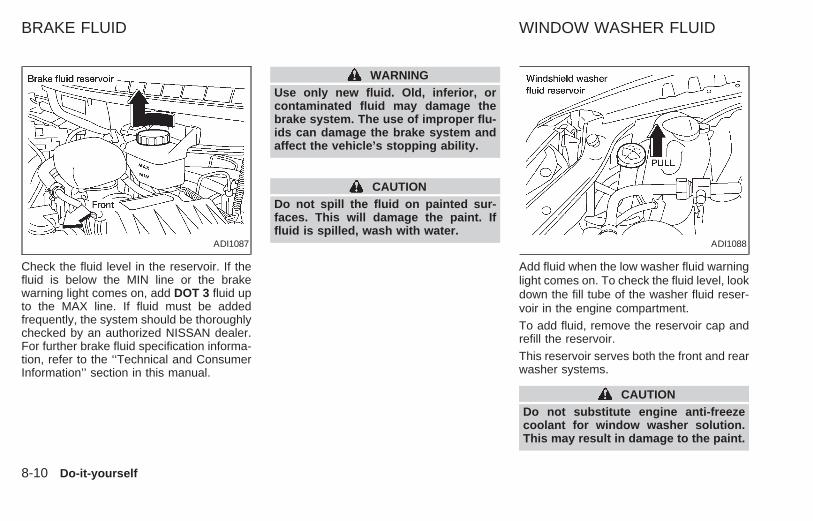
Check the fluid level in the reservoir. If thefluid is below the MIN line or the brakewarning light comes on, add DOT 3 fluid upto the MAX line. If fluid must be addedfrequently, the system should be thoroughlychecked by an authorized NISSAN dealer.For further brake fluid specification informa-tion, refer to the ‘‘Technical and ConsumerInformation’’ section in this manual.
WARNINGUse only new fluid. Old, inferior, orcontaminated fluid may damage thebrake system. The use of improper flu-ids can damage the brake system andaffect the vehicle’s stopping ability.
CAUTIONDo not spill the fluid on painted sur-faces. This will damage the paint. Iffluid is spilled, wash with water.
Add fluid when the low washer fluid warninglight comes on. To check the fluid level, lookdown the fill tube of the washer fluid reser-voir in the engine compartment.To add fluid, remove the reservoir cap andrefill the reservoir.This reservoir serves both the front and rearwasher systems.
CAUTIONDo not substitute engine anti-freezecoolant for window washer solution.This may result in damage to the paint.
ADI1087 ADI1088
BRAKE FLUID WINDOW WASHER FLUID
8-10 Do-it-yourself
Z X

● Keep the battery surface clean and dry.Any corrosion should be washed off witha solution of baking soda and water.
● Make certain the terminal connectionsare clean and securely tightened.
● If the vehicle is not to be used for 30 daysor longer, disconnect the negative (−)battery terminal cable to prevent dis-charging.
WARNING● Do not expose the battery to flames
or electrical sparks. Hydrogen gasgenerated by battery action is explo-sive. Do not allow battery fluid tocontact your skin, eyes, fabrics, orpainted surfaces. After touching abattery or battery cap, do not touchor rub your eyes. Thoroughly washyour hands. If the acid contacts youreyes, skin or clothing, immediatelyflush with water for at least 15 min-utes and seek medical attention
● When working on or near a battery,always wear suitable eye protectionand remove all jewelry.
● Keep the battery out of the reach ofchildren.
Check the fluid level in each cell. It shouldbe between the MAX and MIN lines.
If it is necessary to add fluid, add onlydistilled water to bring the level to the indi-cator in each filler opening. Do not overfill.
1. Remove the cell plugs using a suitabletool.
2. Add distilled water up to the MAX level.
3. Tighten cell plugs.
ADI0037
BATTERY
Do-it-yourself 8-11
Z X
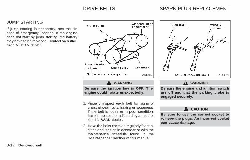
JUMP STARTINGIf jump starting is necessary, see the ‘‘Incase of emergency’’ section. If the enginedoes not start by jump starting, the batterymay have to be replaced. Contact an autho-rized NISSAN dealer.
WARNINGBe sure the ignition key is OFF. Theengine could rotate unexpectedly.
1. Visually inspect each belt for signs ofunusual wear, cuts, fraying or looseness.If the belt is loose or in poor condition,have it replaced or adjusted by an autho-rized NISSAN dealer.
2. Have the belts checked regularly for con-dition and tension in accordance with themaintenance schedule found in the‘‘Maintenance’’ section of this manual.
WARNINGBe sure the engine and ignition switchare off and that the parking brake isengaged securely.
CAUTIONBe sure to use the correct socket toremove the plugs. An incorrect socketcan cause damage.
ADI0060 ADI0061
DRIVE BELTS SPARK PLUG REPLACEMENT
8-12 Do-it-yourself
Z X

Platinum-tipped spark plugIt is not necessary to replace platinum-tipped spark plugs as frequently as conven-tional type spark plugs because they lastmuch longer. Follow the maintenanceschedule, but do not reuse the spark plugsby cleaning or regapping.
● Always replace spark plugs with rec-ommended or equivalent ones.
1. Disconnect the spark plug cables fromthe spark plugs.
When disconnecting, always hold the boots,not the cables.
2. Remove the spark plugs with a sparkplug socket. The plug socket has a rub-ber seal that holds the spark plug so itdoes not fall when it is pulled out. Makesure each spark plug is snugly fitted intothe plug socket.
3. Fit the new plugs, one at a time, into thespark plug socket and install them. Useonly the specified spark plugs. Turneach plug several full turns by hand, thentighten with the spark plug socket to thecorrect torque. Do not overtighten.
Spark plug tightening torque:14 to 22 ft-lb (20 to 29 N zm)
4. Holding the boot, re-connect each hightension cable to its proper spark plug bypushing it on until you feel a snap.
The filter should not be cleaned and reused.Replace it according to the maintenanceintervals shown in the ‘‘Maintenance’’ sec-tion of this manual. When replacing thefilter, unclip the four clamps and remove thefilter. Wipe the inside of the air cleanerhousing and the cover with a damp clothwhen replacing filter.
ADI1100 ADI0579
AIR CLEANER HOUSINGFILTER
Do-it-yourself 8-13
Z X

WARNING● Operating the engine with the air
cleaner off can cause you or othersto be burned. The air cleaner notonly cleans the air, it stops flame ifthe engine backfires. If it isn’t thereand the engine backfires, you couldbe burned. Don’t drive with it off, andbe careful working on the enginewith the air cleaner off.
● Never pour fuel into the throttle bodyor attempt to start the engine withthe air cleaner removed. Doing socould result in serious injury.
CABIN AIR FILTERThe cabin air filter restricts the entry ofairborne dust and pollen particles and re-duces some objectionable outside odors.The filter is located just in front of thewindshield under the cowl cover on thepassenger side of the vehicle.
To replace the filter, perform the followingprocedure.
1. Remove the windshield wiper arms.
● Lift the wiper arm away from the wind-shield surface until the wiper is perpen-dicular to the windshield.
● Lift and remove the wiper arm, whileholding the small retaining clip at thebase of wiper arm outward.
2. Remove the cowl cover.
● Remove the six screws.
● Open the hood.
ADI1103 ADI1104
8-14 Do-it-yourself
Z X

● Remove the four plastic screws from theforward edge of the cowl cover.
● Remove the four plastic screw anchors.
● Disconnect the windshield washer hoseat the passenger side rear corner of theengine compartment.
● Push the windshield washer hose andthe grommet through the sheet metalhole.
● Lift the cowl cover and remove it fromthe vehicle.
3. Locate the cabin air filter on the passen-ger side of the vehicle.
● Remove the four screws from the cabinair filter cover.
● Remove the cabin air filter cover.
ADI1105 ADI1106 ADI1107
Do-it-yourself 8-15
Z X

● Remove the cabin air filter element bypulling forward on the top surface of thefilter and lifting.
4. Install the new cabin air filter elementinto the filter retaining frame, ensure thatyou insert the three retaining tabs in thebottom of the filter frame.
5. Install the filter top cover and the fourscrews.
6. Feed the windshield washer hose fromthe cowl cover through the hole in thesheet metal.
● Ensure that you fully seat the rubbergrommet into the sheet metal hole.
7. Reconnect the windshield washer hose.
8. Position the cowl cover in place.
9. Reinstall the four screw anchors and thefour screws.
10. Close the hood.
11. Install the six screws in the cowl cover.
12. Install the windshield wiper arms.
● Push the wiper arm downward onto thewiper arm pivot until the small retainingclip snaps into the locked position.
● Lower the wiper arm blade onto thewindshield surface.ADI1108 ADI1109
8-16 Do-it-yourself
Z X

CLEANINGIf your windshield is not clear after using thewindshield washer or if the wiper bladechatters when running, wax or other mate-rial may be on the blade or windshield.
Clean the outside of the windshield with awasher solution or a mild detergent. Yourwindshield is clean if beads do not formwhen rinsing with clear water.
Clean the blade by wiping it with a clothsoaked in a washer solution or a mild deter-gent. Then, rinse the blade with clear water.If your windshield is still not clear after
cleaning the blades and using the wipers,replace the blades.
REPLACEMENT
1. Lift the wiper arm away from the wind-shield.
2. Push the tab, then move the wiper bladedown the wiper arm to remove.
3. Remove the wiper blade.
4. Insert the new wiper blade onto the wiperarm until it clicks into place.
CAUTION
● After wiper blade replacement, re-turn the wiper arm to its originalposition: Otherwise it may be dam-aged when the engine hood isopened.
● Make sure the wiper blade contactsthe glass, otherwise the arm may bedamaged from wind pressure.
ADI1022
WIPER BLADES
Do-it-yourself 8-17
Z X

Rear wiper blade replacement1. Lift the wiper arm away from the wind-
shield.
2. Push the tab, then move the wiper bladedown the wiper arm to remove.
3. Insert a new wiper blade onto the wiperarm and press down until the blade clicksinto place.
ADI1114
8-18 Do-it-yourself
Z X

From the released position, push the park-ing brake foot lever down. If the number ofclicks is out of the range listed above, seean authorized NISSAN dealer.
With the engine running, check the distancebetween the upper surface of the pedal andthe floor. If it is out of the range shownabove, see an authorized NISSAN dealer.
Self-adjusting brakes
Your vehicle is equipped with self-adjustingbrakes.
The front disc-type brakes self-adjust everytime the brake pedal is applied. The reardrum-type brakes also self-adjust everytime the brake pedal is applied. If the brakepedal goes down farther than normal, seean authorized NISSAN dealer.
WARNING
See an authorized NISSAN dealer andhave it checked if the brake pedalheight does not return to normal.
Brake pad wear indicators
The disc pads on your vehicle have audiblewear indicators. When a brake pad requiresreplacement, it makes a high pitched scrap-ing or screeching sound when the vehicle isin motion whether or not the brake pedal isdepressed. Have the brakes checked assoon as possible if the wear indicator soundis heard.
Under some driving or climate conditions,occasional brake squeak, squeal or othernoise may be heard. Occasional brakenoise during light to moderate stops is nor-mal and does not affect the function orperformance of the brake system.
The rear drum brakes (if so equipped) donot have audible wear indicators. If you everhear an unusually loud noise from the reardrum brakes, have them inspected as soonas possible by an authorized NISSANdealer.
ADI1089 ADI0027
PARKING BRAKE CHECK BRAKE PEDAL
Do-it-yourself 8-19
Z X

Proper brake inspection intervals shouldbe followed. For more information regard-ing brake inspections, see the appropriatemaintenance schedule information in the‘‘Maintenance’’ section of this manual.
Check the brake booster function as fol-lows:
1. With the engine off, press and releasethe brake pedal several times. Whenbrake pedal movement (distance oftravel) remains the same from one pedalapplication to the next, continue on to thenext step.
2. While depressing the brake pedal, startthe engine. The pedal height should dropa little.
3. With the brake pedal depressed, turn theengine off. Keep the pedal depressed forabout 30 seconds; the pedal heightshould not change.
4. Run the engine for one minute withoutdepressing the brake pedal, then turn itoff. Depress the brake pedal severaltimes. The pedal travel distance will de-crease gradually with each depressionas the vacuum is released from thebooster.
If the brakes do not operate properly, see anauthorized NISSAN dealer.
Engine compartment(headlight fuses)
CAUTION
Never use a fuse of a higher amperagerating than that specified on the fusebox cover. This could damage the elec-trical system or cause a fire.
If a headlight does not come on, check foran open fuse:
The left headlight (driver’s side) and rightheadlight (passenger side) fuses are lo-
ADI1090
BRAKE BOOSTER FUSES AND FUSIBLE LINKS
8-20 Do-it-yourself
Z X

cated in the left-hand fuse box, near theradiator cap.
1. Turn the headlight switch to the OFFposition.
2. Open the engine hood.
3. Remove the fuse box cover.
4. Remove the fuse with the fuse pullerattached to the passenger compartmentfuse box cover.
5. If the fuse is open, replace it with a newfuse.
6. If a new fuse opens again, have theelectrical system checked and repairedby an authorized NISSAN dealer.
If the electrical equipment does not operateand fuses are in good condition, check thefusible links. If any of these fusible links aremelted, replace only with genuine NISSANparts.
If the new fusible link melts again, have thesystem checked and repaired by an autho-rized NISSAN dealer.
Passenger compartment
CAUTION
Never use a fuse of a higher amperagerating than that specified on the fusebox cover. This could damage the elec-trical system or cause a fire.
If the electrical equipment does not operate,check for an open fuse:
1. Remove the key from the ignition.
2. Open the fuse box cover. Refer to thefuse label on the fuse box cover to locate
the fuse in question.
3. Remove the fuse with the fuse puller.
4. If the fuse is open, replace it with a newfuse.
5. If a new fuse opens again, have theelectrical system checked and repairedby an authorized NISSAN dealer.
ADI0580
Do-it-yourself 8-21
Z X

HEADLIGHTSThe headlight is a semi-sealed beam typewhich uses a replaceable headlight (halo-gen) bulb. A bulb can be replaced frominside the engine compartment without re-moving the headlight assembly.
CAUTION● High pressure halogen gas is sealed
inside the halogen bulb. The bulbmay break if the glass envelope isscratched or the bulb is dropped.
● When handling the bulb, do nottouch the glass envelope.
Removing the headlight bulb1. Disconnect the negative (-) battery cable.
2. Disconnect the electrical connector fromthe rear end of the bulb.
3. Turn the bulb retaining ring counterclock-wise until it is free from the headlightreflector, then remove it.
4. Remove the headlight bulb by pulling itstraight out. Do not shake or rotate thebulb when removing it.
Replacing the headlight bulb1. Insert the bulb into the headlight reflector
with the flat side of the plastic base facingupward.
2. Install the bulb retaining ring and turn itclockwise until it stops.
3. Push the electrical connector into thebulb plastic base until it snaps and stops.
CAUTIONDO NOT TOUCH THE BULB.● Use the same number and wattage
as originally installed:Wattage 65/55Bulb no. 9007 (HB5)
● Aiming is not necessary after replac-ing the bulb. When aiming adjust-ment is necessary, contact yourNISSAN dealer.
● Do not leave the bulb out of theheadlight reflector for a long periodof time as dust, moisture and smokemay enter the headlight body andaffect the performance of the head-light.
AEL076-A
LIGHT BULBS
8-22 Do-it-yourself
Z X

BULB REPLACEMENT
Item Wattage (W) Bulb No.
Headlight assembly
High/Low 65/55 9007 (HB5)
Front turn signal light 8.25/27 3157
Front combination light:
Front side marker light 3.8 194
Parking/Cornering 8.25/27 3157
Rear combination light:
Turn signal 27 3156
Stop/Tail 8.25/27 3157
Rear side marker light 3.8 194
Back-up light 27 3156
License plate light 3.8 194
High-mounted stop light 12.8 912
Interior lights 12 211-2
Personal reading light 10 578
Luggage compartment light 12 211-2
Steplight 3.8 194
Spotlight 10 578
Do-it-yourself 8-23
Z X

Replacement proceduresAll lights (except for headlights) are eithertype A, B, C or D. When replacing a bulb,first remove the lens and/or cover.
ADI1094
ADI1093
8-24 Do-it-yourself
Z X

ADI1122
Do-it-yourself 8-25
Z X

ADI1096
8-26 Do-it-yourself
Z X

If you have a flat tire, see the ‘‘In case ofemergency’’ section of this manual.
Maximum inflation pressure
Do not exceed the maximum inflation pres-sure shown on the side wall of the tire.
Tire inflation pressure
Periodically check the tire pressure (includ-ing the spare). Incorrect tire pressure mayadversely affect tire life and vehicle han-dling. Tire pressure should be checkedwhen tires are COLD. Tires are consideredCOLD after the vehicle has been parked forADI1095
DI1033M
WHEELS AND TIRES
Do-it-yourself 8-27
Z X

three or more hours, or driven less than 1mile (1.6 km). COLD tire pressures areshown on the tire placard affixed to theglove box door.
WARNING
● Improperly inflated tires can fail sud-denly and cause an accident.
● The vehicle capacity weight is indi-cated on the tire placard. Do not loadyour vehicle beyond this capacity.Overloading your vehicle may resultin reduced tire life, unsafe operatingconditions due to premature tire fail-ure, or unfavorable handling charac-teristics and could also lead to aserious accident. Loading beyondthe specified capacity may also re-sult in failure of other vehicle com-ponents.
● Before taking a long trip, or wheneveryou have loaded your vehicle heavily,use a tire pressure gauge to ensurethat the tire pressure is at the speci-fied level.
● Do not drive your vehicle over 85MPH (140 km/h) unless it is equippedwith high speed capability tires.Driving faster than 85 MPH (140km/h) may result in tire failure, lossof control and possible injury.
Types of tires
WARNINGWhen changing or replacing tires, besure all four tires are of the same type(i.e., Summer, All Season or Snow) andconstruction. An authorized NISSANdealer may be able to help you withinformation about tire type, size, speedrating and availability. Replacementtires may have a lower speed ratingthan the factory equipped tires, andmay not match the potential maximumvehicle speed. Never exceed the maxi-mum speed rating of the tire.
All Season tiresNISSAN specifies All Season tires to pro-vide good performance all year, includingsnowy and icy road conditions. All Season
Tires are identified by ‘‘ALL SEASON’’and/or ‘‘M&S’’ on the tire sidewall. Snowtires have better snow traction than AllSeason tires and may be more appropriatein some areas.
Snow tiresIf snow tires are needed, it is necessary toselect tires equivalent in size and load ratingto the original equipment tires. If you do not,it can adversely affect the safety and han-dling of your vehicle.
Generally, snow tires have lower speedratings than factory equipped tires and maynot match the potential maximum vehiclespeed. Never exceed the maximum speedrating of the tire.
If you operate your vehicle in snowy or icyconditions, NISSAN recommends the use ofsnow or all season tires on all four wheels.
For additional traction on icy roads, studdedtires may be used. However, some U.S.states and Canadian provinces prohibit theiruse. Check local, state and provincial lawsbefore installing studded tires. Skid andtraction capabilities of studded snow tireson wet or dry surfaces may be poorer thanthat of non-studded snow tires.
8-28 Do-it-yourself
Z X

Tire chainsUse of tire chains may be prohibited accord-ing to location. Check the local laws beforeinstalling tire chains. When installing tirechains, make sure they are of proper sizefor the tires on your vehicle and are installedaccording to the chain manufacturer’s sug-gestions. Use only SAE Class ‘‘S’’ chains.Other types may damage your vehicle. Usechain tensioners when recommended bythe tire chain manufacturer to ensure a tightfit. Loose end links of the tire chain must besecured or removed to prevent the possibil-ity of whipping action damage to the fendersor undercarriage. If possible, avoid fullyloading your vehicle when using tire chains.In addition, drive at a reduced speed. Do notexceed maximum speed suggested by thechain manufacturer. Otherwise, your ve-hicle may be damaged and/or vehicle han-dling and performance may be adverselyaffected.
Never install tire chains on T-type and smallsize spare tires. Do not use tire chains ondry roads.
Tire rotationNISSAN recommends rotating the tiresevery 7,500 miles (12,000 km).
Tighten wheel nuts to 72 to 87 ft-lb (98 to118 Nzm).
See ‘‘Flat tire’’ in the ‘‘In case of emergency’’section for tire replacing procedures.
WARNING● After rotating the tires, adjust the tire
pressure.● Retighten the lug nuts after the
wheels have been run for the first600 miles (1,000 km) (also in cases ofa flat tire, etc.).
● Do not include the T-type spare tireor any other small size spare tire inthe tire rotation.
ADI0656
Do-it-yourself 8-29
Z X

Tire wear and damage
WARNING● Tires should be periodically in-
spected for wear, cracking, bulging,or objects caught in the tread. Ifexcessive wear, cracks, bulging, ordeep cuts are found, the tire shouldbe replaced.
● The original tires have a built-intread wear indicator. When the wearindicator is visible, the tire should bereplaced.
● Improper service for a T-type sparetire may result in serious personalinjury. If it is necessary to repair theT-type spare tire, contact an autho-rized NISSAN dealer.
Changing tires and wheelsWhen replacing a tire, use the same size,tread design, speed rating and load carryingcapacity as originally equipped. Recom-mended types and sizes are shown in‘‘Wheels and tires’’ in the ‘‘Technical andconsumer information’’ section of this manual.
WARNING● The use of tires other than those
recommended or the mixed use oftires of different brands, construction(bias, bias-belted or radial), or treadpatterns can adversely affect the ride,braking, handling, ground clearance,body-to-tire clearance, snow chainclearance, speedometer calibration,headlight aim and bumper height.Some of these effects may lead toaccidents and could result in seriouspersonal injury.
● If the wheels are changed for anyreason, always replace with wheelswhich have the same offset dimen-sion. Wheels of a different offsetcould cause early tire wear, possiblydegraded vehicle handling character-istics and/or interference with thebrake discs/drums. Such interferencecan lead to decreased braking effi-ciency and/or early brake pad/shoe wear.
● Do not install a deformed wheel ortire even if it has been repaired. Suchwheels or tires could have structuraldamage and could fail without warn-ing.
● The use of retread tires is not recom-mended.
Wheel balanceUnbalanced wheels may affect vehicle han-dling and tire life. Even with regular use,wheels can get out of balance. Therefore,they should be balanced as required.
Wheel balance service should be performedwith the wheels off the vehicle. Spin balanc-ing the front wheels on the vehicle couldlead to transmission damage.
DI1035M
8-30 Do-it-yourself
Z X
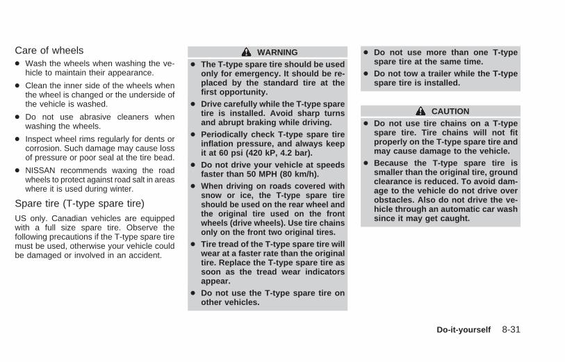
Care of wheels● Wash the wheels when washing the ve-
hicle to maintain their appearance.
● Clean the inner side of the wheels whenthe wheel is changed or the underside ofthe vehicle is washed.
● Do not use abrasive cleaners whenwashing the wheels.
● Inspect wheel rims regularly for dents orcorrosion. Such damage may cause lossof pressure or poor seal at the tire bead.
● NISSAN recommends waxing the roadwheels to protect against road salt in areaswhere it is used during winter.
Spare tire (T-type spare tire)US only. Canadian vehicles are equippedwith a full size spare tire. Observe thefollowing precautions if the T-type spare tiremust be used, otherwise your vehicle couldbe damaged or involved in an accident.
WARNING● The T-type spare tire should be used
only for emergency. It should be re-placed by the standard tire at thefirst opportunity.
● Drive carefully while the T-type sparetire is installed. Avoid sharp turnsand abrupt braking while driving.
● Periodically check T-type spare tireinflation pressure, and always keepit at 60 psi (420 kP, 4.2 bar).
● Do not drive your vehicle at speedsfaster than 50 MPH (80 km/h).
● When driving on roads covered withsnow or ice, the T-type spare tireshould be used on the rear wheel andthe original tire used on the frontwheels (drive wheels). Use tire chainsonly on the front two original tires.
● Tire tread of the T-type spare tire willwear at a faster rate than the originaltire. Replace the T-type spare tire assoon as the tread wear indicatorsappear.
● Do not use the T-type spare tire onother vehicles.
● Do not use more than one T-typespare tire at the same time.
● Do not tow a trailer while the T-typespare tire is installed.
CAUTION● Do not use tire chains on a T-type
spare tire. Tire chains will not fitproperly on the T-type spare tire andmay cause damage to the vehicle.
● Because the T-type spare tire issmaller than the original tire, groundclearance is reduced. To avoid dam-age to the vehicle do not drive overobstacles. Also do not drive the ve-hicle through an automatic car washsince it may get caught.
Do-it-yourself 8-31
Z X

MEMO
8-32 Do-it-yourself
Z X

9 Maintenance
General maintenance.............................................9-2Outside the vehicle ................................................9-2Inside the vehicle ...................................................9-3Under the hood and vehicle...................................9-4
Periodic maintenance schedules ...........................9-5Schedule one .........................................................9-5Schedule two..........................................................9-5Explanation of maintenance items.......................9-10
Z X

Your new NISSAN has been designed tohave minimum maintenance requirementswith longer service intervals to save youboth time and money. However, some day-to-day and regular maintenance is essentialto maintain your NISSAN’s good mechani-cal condition, as well as its emission andengine performance.
It is the owner’s responsibility to make surethe specified maintenance, as well as gen-eral maintenance, is performed.
As the vehicle owner, you are the only onewho can ensure that your vehicle receivesproper maintenance. You are a vital link inthe maintenance chain.
General maintenance
General maintenance includes those itemswhich should be checked during normalday-to-day operation of the vehicle. Theyare essential if your vehicle is to continue tooperate properly. It is your responsibility toperform these maintenance proceduresregularly as prescribed.
These checks or inspections can be doneby yourself, a qualified technician or, if youprefer, an authorized NISSAN dealer.
Periodic maintenanceThe maintenance items listed under ‘‘Peri-odic Maintenance’’ in this section must beserviced at regular intervals.
However, under severe driving conditions,additional or more frequent maintenance isrequired.
Where to go for serviceIf maintenance service is required or yourvehicle appears to malfunction, have thesystems checked and tuned by an autho-rized NISSAN dealer.
NISSAN technicians are well-trained spe-cialists who are kept up to date with thelatest service information through technicalbulletins, service tips, and in-dealershiptraining programs. They are completelyqualified to work on NISSAN vehicles be-fore they work on your vehicle, rather thanafter they have worked on it.
You can be confident that an authorizedNISSAN dealer’s service department per-forms the best job to meet the maintenancerequirements on your vehicle — in a reliableand economic way.
During the normal day-to-day operation ofthe vehicle, general maintenance should beperformed regularly as prescribed in thissection. If you detect any unusual sounds,vibrations or smells, be sure to check for thecause or have an authorized NISSANdealer do it promptly. In addition, you shouldnotify an authorized NISSAN dealer if youthink repairs are required.
When performing any checks or mainte-nance work, closely observe the precau-tions in the ‘‘Do-it-yourself’’ section of thismanual.
Additional information on the followingitems with an ‘‘*’’ can be found in the‘‘Do-it- yourself’’ section of this manual.
OUTSIDE THE VEHICLEThe maintenance items listed here shouldbe performed from time to time, unlessotherwise specified.
Tires* — Check the pressure with a gaugeperiodically when at a service station, in-cluding the spare, and adjust to the speci-fied pressure if necessary. Check carefullyfor damage, cuts or excessive wear.
Wheel nuts* — When checking the tires,
GENERAL MAINTENANCE
9-2 Maintenance
Z X

make sure no wheel nuts are missing, andcheck for any loose wheel nuts. Tighten ifnecessary.
Tire rotation* — Tires should be rotatedevery 7,500 miles (12,000 km).
Wheel alignment and balance — If thevehicle should pull to either side while driv-ing on a straight and level road, or if youdetect uneven or abnormal tire wear, theremay be a need for a wheel alignment.
If the steering wheel or seat vibrates atnormal highway speeds, wheel balancingmay be needed.
Windshield wiper blades* — Check forcracks or wear if they do not wipe properly.
Doors and hood — Check that all doorsand the hood operate properly. Also ensurethat all latches lock securely. Lubricatehinges, latches, rollers and links if neces-sary. Make sure the secondary latch keepsthe hood from opening when the primarylatch is released.
When driving in areas using road salt orother corrosive materials, check lubricationfrequently.
INSIDE THE VEHICLE
The maintenance items listed here shouldbe checked on a regular basis, such aswhen performing periodic maintenance,cleaning the vehicle, etc.
Additional information on the followingitems with an ‘‘*’’ is found in the ‘‘Do-it-yourself’’ section of this manual.
Lights* — Make sure the headlights, stoplights, tail lights, turn signal lights, and otherlights are all operating properly and installedsecurely. Also check headlight aim.
Warning lights and buzzers/chimes —Make sure all warning lights andbuzzers/chimes are operating properly.
Windshield wiper and washer* — Checkthat the wipers and washer operate properlyand that the wipers do not streak.
Windshield defroster — Check that the aircomes out of the defroster outlets properlyand in sufficient quantity when operating theheater or air conditioner.
Steering wheel — Check for changes inthe steering conditions, such as excessivefreeplay, hard steering or strange noises.
Seats — Check seat position controls suchas seat adjusters, seatback recliner, etc. toensure they operate smoothly and alllatches lock securely in every position.Check that the head restraints move up anddown smoothly and the locks hold securelyin all latched positions. Check that the seatleg latches lock securely in every anchorposition for the folding down rear seat anddetachable rear seat (if so equipped).
Seat belts — Check that all parts of the seatbelt system (e.g. buckles, anchors, adjust-ers and retractors) operate properly andsmoothly, and are installed securely. Checkthe belt webbing for cuts, fraying, wear ordamage.
Accelerator pedal — Check the pedal forsmooth operation and make sure the pedaldoes not catch or require uneven effort.Keep the floor mat away from the pedal.
Brakes — Check that the brakes do not pullthe vehicle to one side when applied.
Brake pedal and booster* — Check thepedal for smooth operation and make sure ithas the proper distance under it when de-pressed fully. Check the brake booster func-
Maintenance 9-3
Z X

tion. Be certain to keep the floor mat awayfrom the pedal.
Parking brake* — Check that the pedal isadjusted to specification and confirm thatyour vehicle is held securely on a fairlysteep hill with only the parking brake ap-plied.
Automatic transmission ‘‘Park’’ mecha-nism — On a fairly steep hill check that yourvehicle is held securely with the selectorlever in the P (Park) position without apply-ing any brakes.
UNDER THE HOOD ANDVEHICLEThe maintenance items listed here shouldbe checked periodically, for example, eachtime you check the engine oil or refuel.
Additional information on the followingitems with an ‘‘*’’ is found in the ‘‘Do-it-yourself section’’ of this manual.
Windshield washer fluid* — Check thatthere is adequate fluid in the reservoir.
Engine coolant level* — Check the cool-ant level when the engine is cold.
Radiator and hoses — Check the front of
the radiator and clean off any dirt, insects,leaves, etc., that may have accumulated.Make sure the hoses have no cracks, de-formation, rot, or loose connections.
Brake fluid level* — Make sure the brakefluid level is between the MIN and MAXlines on the reservoir.
Battery* — Check the fluid level in eachcell. It should be between the MAX and MINlines.
Engine drive belts* — Make sure the drivebelts are not frayed, worn, cracked or oily.
Engine oil level* — Check the level afterparking the vehicle on a level surface withthe engine off. Wait a few minutes for the oilto drain back into the oil pan.
Power steering fluid level* and lines —Check the level when the fluid is cold withthe engine off. Check the lines for properattachment, leaks, cracks, etc.
Automatic transmission fluid level* —Check the level after putting the selectorlever in P (Park) with the engine idling atoperating temperature.
Exhaust system — Make sure there are nocracks, holes, loose joints or supports. If the
sound of the exhaust seems unusual orthere is a smell of exhaust fumes, immedi-ately have the exhaust system inspected byan authorized NISSAN dealer. See the car-bon monoxide warning in the ‘‘Starting anddriving’’ section of this manual.
Underbody — The underbody is frequentlyexposed to corrosive substances such asthose used on icy roads or to control dust. Itis very important to remove these sub-stances from the underbody, otherwise rustmay form on the floor pan, frame, fuel linesand exhaust system. At the end of winter,the underbody should be thoroughly flushedwith plain water, in those areas where mudand dirt may have accumulated. See the‘‘Appearance and care’’ section of thismanual.
Fluid leaks — Check under the vehicle forfuel, oil, water or other fluid leaks after thevehicle has been parked for a while. Waterdripping from the air conditioner after use isnormal. If you should notice any leaks or ifgasoline fumes are evident, check for thecause and have it corrected immediately byan authorized NISSAN dealer.
9-4 Maintenance
Z X

To ensure smooth, trouble-free, safe andeconomical driving, NISSAN provides twoperiodic maintenance schedules that maybe used, depending upon the conditions inwhich you usually drive. These schedulescontain both distance and time intervals, upto 60,000 miles (96,000 km)/48 months. Formost people, the odometer reading indi-cates when service is needed. However, ifyou drive very little, your vehicle should beserviced at the regular time intervals shownin the schedules. After 60,000 miles(96,000 km)/48 months, continue peri-odic maintenance at the samemileage/time intervals.
SCHEDULE ONEFollow Periodic Maintenance Schedule Oneif your driving habits frequently include oneor more of the following driving conditions:
● Repeated short trips of less than 5miles (8 km).
● Repeated short trips of less than 10miles (16 km) with outside tempera-tures below freezing.
● Operating the vehicle in hot weatherduring stop-and-go ‘‘rush hour’’ traf-fic.
● Extensive idling and/or low speeddriving for long distances, such aspolice, taxi or door-to-door deliveryuse.
● Driving in dusty conditions.
● Driving on rough, muddy, or saltspread roads.
● Towing a trailer, using a camper or acar-top carrier.
SCHEDULE TWO
Follow Periodic Maintenance Schedule Twoif none of the driving conditions shown inSchedule One apply to your driving habits.
PERIODIC MAINTENANCESCHEDULES
Maintenance 9-5
Z X

Schedule OneAbbreviations: R = Replace I = Inspect. Correct or replace if necessary. [ ]: At the mileage intervals only
MAINTENANCE OPERATION MAINTENANCE INTERVAL
Perform at number of miles,kilometers or months,whichever comes first.
Miles × 1,000 3.75 7.511.25 15 18.75 22.526.25 30 33.75 37.541.25 45 48.75 52.556.25 60
(km × 1,000) (6) (12) (18) (24) (30) (36) (42) (48) (54) (60) (66) (72) (78) (84) (90) (96)
Months 3 6 9 12 15 18 21 24 27 30 33 36 39 42 45 48
Emission control system maintenance
Drive belts See NOTE (1). I*
Air cleaner filter See NOTE (2). [R] [R]
EVAP vapor lines I* I*
Fuel lines I* I*
Fuel filter See NOTE (3)*.
Engine coolant Replace every 30,000 miles (48,000 km) or 36 months.*
Engine oil R R R R R R R R R R R R R R R R
Engine oil filter R R R R R R R R R R R R R R R R
Spark plugs (Use PLATINUM-TIPPED type) Replace every 105,000 miles (168,000 km).
Timing belt Replace every 105,000 miles (168,000 km).
NOTE: (1) After 60,000 miles (96,000 km) or 48 months, inspect every 15,000 miles (24,000 km) or 12 months.(2) If operating mainly in dusty conditions, more frequent maintenance may be required.(3) If vehicle is operated under extremely adverse weather conditions or in areas where ambient temperatures are either extremely low or
extremely high, the filters might become clogged. In such an event, replace them immediately.* Maintenance items and intervals with an ‘‘*’’ are recommended by NISSAN for reliable vehicle operation. The owner need not perform
such maintenance in order to maintain the emission warranty or manufacturer recall liability. Other maintenance items and intervalsare required.
9-6 Maintenance
Z X

Abbreviations: R = Replace I = Inspect. Correct or replace if necessary.
MAINTENANCE OPERATION MAINTENANCE INTERVAL
Perform at number of miles,kilometers or months, whichevercomes first.
Miles × 1,000 7.5 15 22.5 30 37.5 45 52.5 60
(km × 1,000) (12) (24) (36) (48) (60) (72) (84) (96)
Months 6 12 18 24 30 36 42 48
Chassis and body maintenance
Brake lines & cables I I I I
Brake pads, rotors, drums & linings I I I I I I I I
Automatic transmission fluid See NOTE (1). I I I I
Steering gear & linkage, axle & suspension parts I I I I I I I I
Exhaust system I I I I I I I I
Drive shaft boots I I I I I I I I
Cabin air filter (if so equipped) See NOTE (3). R R R R
Supplemental air bag system See NOTE (2).
NOTE: (1) If towing a trailer, using a camper or a car-top carrier, or driving on rough or muddy roads, change (not just inspect) fluid at every30,000 miles (48,000 km) or 24 months.
(2) Inspect the supplemental air bag system 10 years after the date of manufacture noted on the F.M.V.S.S. certification label.(3) If operating mainly in dusty conditions, more frequent maintenance may be required.
Maintenance 9-7
Z X

Schedule TwoAbbreviations: R = Replace I = Inspect. Correct or replace if necessary. [ ]: At the mileage intervals only
MAINTENANCE OPERATION MAINTENANCE INTERVAL
Perform at number of miles,kilometers or months, whichever comes first.
Miles × 1,000 7.5 15 22.5 30 37.5 45 52.5 60
(km × 1,000) (12) (24) (36) (48) (60) (72) (84) (96)
Months 6 12 18 24 30 36 42 48
Emission control system maintenance
Drive belts See NOTE (1). I*
Air cleaner housing filter [R] [R]
EVAP vapor lines I* I*
Fuel lines I* I*
Fuel filter See NOTE (2)*.
Engine coolant Replace every 30,000 miles (48,000 km) or 36 months.*
Engine oil R R R R R R R R
Engine oil filter R R R R R R R R
Spark plugs (Use PLATINUM-TIPPED) Replace every 105,000 miles (168,000 km).
Timing belt Replace every 105,000 miles (168,000 km).
NOTE: (1) After 60,000 miles (96,000 km) or 48 months, inspect every 15,000 miles (24,000 km) or 12 months.(2) If vehicle is operated under extremely adverse weather conditions or in areas where ambient temperatures are either extremely low or
extremely high, the filters might become clogged. In such an event, replace them immediately.* Maintenance items and intervals with an ‘‘*’’ are recommended by NISSAN for reliable vehicle operation. The owner need not perform
such maintenance in order to maintain the emission warranty or manufacturer recall liability. Other maintenance items and intervalsare required.
9-8 Maintenance
Z X

Abbreviations: R = Replace I = Inspect. Correct or replace if necessary.
MAINTENANCE OPERATION MAINTENANCE INTERVAL
Perform at number of miles, kilome-ters or months, whichever comesfirst.
Miles × 1,000(km × 1,000)Months
7.5(12)
6
15(24)12
22.5(36)18
30(48)24
37.5(60)30
45(72)36
52.5(84)42
60(96)48
Chassis and body maintenance
Brake lines & cables I I I I
Brake pads, rotors, drums & linings I I I I
Automatic transmission fluid I I I I
Steering gear & linkage, axle & suspension parts I I
Exhaust system See NOTE (1). I I
Drive shaft boots I I I I
Cabin air filter (if so equipped) See NOTE (3). R R R R
Supplemental air bag system See NOTE (2).
NOTE: (1) After 60,000 miles (96,000 km) or 48 months, inspect every 15,000 miles (24,000 km) or 12 months.(2) Inspect the supplemental air bag system 10 years after the date of manufacture as noted on the F.M.V.S.S. certification label.(3) If operating mainly in dusty conditions, more frequent maintenance may be required.
Maintenance 9-9
Z X

Additional information on the followingitems with an ‘‘*’’ is found in the ‘‘Do-it-yourself operations’’ section of thismanual.
Emission control systemmaintenance
Drive belts* — Check drive belts for wear,fraying or cracking and also for proper ten-sion. Replace any damaged drive belts.
Engine air cleaner filter — Under normaldriving conditions, the air cleaner filter shouldbe replaced in accordance with the mainte-nance schedule. However, driving the vehiclein dusty areas may cause rapid clogging ofthe element. Consequently, the element mayhave to be replaced more frequently.
Evap vapor lines — Check vapor lines andconnections for leaks, looseness or deterio-ration. If leaks are found, replace them.
Fuel lines — Check the fuel hoses, pipingand connections for leaks, looseness ordeterioration. Replace any damaged parts.
Fuel filter — If the vehicle is operated underextremely adverse weather conditions or inareas where ambient temperatures are ei-ther extremely low or extremely high, the
filter might become clogged. In such anevent, replace the filter immediately.
Engine coolant* — Changing engine cool-ant can be performed by your NISSANdealer or procedures can be found in theService Manual. Improper air relief afterchanging coolant can result in reducedheater performance and overheating.
Engine oil & oil filter* — Under normaldriving conditions, the engine oil and oil filtershould be replaced in accordance with themaintenance schedule. However, under se-vere driving conditions, they may have to bereplaced more frequently.
Spark plugs* — Replace with new plugshaving the correct heat range.
Timing belt — Replace the timing belt fordriving the camshaft.
Chassis and body maintenanceBrake lines & cables — Check the brakelines and hoses (including brake boostervacuum hoses, connections & check valve)and parking brake cables for proper attach-ment, leaks, cracks, chafing, abrasion, de-terioration, etc.
Brake pads, rotors, drums & linings —Check these and the other brake compo-nents for wear, deterioration and leaks. Un-der severe driving conditions, they mayhave to be inspected more frequently.
Automatic transmission fluid* — Checkthe fluid level and visually inspect for signsof leakage.
Under severe driving conditions, the fluidshould be replaced at the specified interval.
Steering gear & linkage, axle & suspen-sion parts, and drive shaft boots — Checkfor damage, looseness and leakage of oil orgrease. Under severe driving conditions, theymay have to be inspected more frequently.
Exhaust system — Visually check the ex-haust pipes, muffler, and hangers for properattachment, leaks, cracks, chafing, abra-sion, deterioration, etc. Under severe driv-ing conditions, inspection should be per-formed more frequently.
Supplemental air bag system — Checkthe supplemental air bag system compo-nents for proper attachment, damage, de-formities, cracks, rust, etc. Work around andon the supplemental air bag system shouldbe done by an authorized NISSAN dealer.
EXPLANATION OFMAINTENANCE ITEMS
9-10 Maintenance
Z X

Cabin air filter — Under normal drivingconditions, the cabin air filter should bereplaced in accordance with the mainte-nance schedule. However, driving the ve-hicle in dusty areas may cause rapid clog-ging of the element. Consequently, theelement may have to be replaced morefrequently.
Maintenance 9-11
Z X

MEMO
9-12 Maintenance
Z X

10 Technical and consumer information
Capacities and recommended fuel/lubricants......10-2Fuel recommendation...........................................10-2Engine oil and oil filter recommendation..............10-4Recommended SAE viscosity number.................10-6Air conditioner system refrigerant andlubricant recommendations ..................................10-6Engine ..................................................................10-7Wheel/tire size......................................................10-8Dimensions and weights ......................................10-8Registering your vehicle in another country ........10-9Vehicle identification ............................................10-9Vehicle identification number (VIN) plate.............10-9Vehicle identification number(chassis number)..................................................10-9
Engine serial number .........................................10-10F.M.V.S.S. certification label ..............................10-10Emission control information label .....................10-10Tire placard ........................................................10-11Air conditioner specification label.......................10-11Installing the license plate..................................10-11Vehicle loading information................................10-12Trailer towing......................................................10-13Uniform tire quality grading................................10-18Emission control system warranty .....................10-19Reporting safety defects (US only) ....................10-19Readiness for inspection/maintenance (I/M)test (US only) .....................................................10-20
Z X

The following are approximate capacities. The actual refill capacities may be a littledifferent. When refilling, follow the procedure instructed in the ‘‘Do-it-yourself’’section to determine the proper refill capacity.
Capacity (Approximate)Recommended Fluids & LubricantsUS
measureImp
measure Liter
Fuel 20 gal 16-5/8gal 75.7 Unleaded gasoline with an octane rating of
at least 87 AKI (RON 91)(1)Engine oil (7)
Drain and refillWith oil filter change 4-1/4 qt 3-1/2 qt 4.0 ● API Certification Mark (2) (3)
● API grade SG/SH, Energy Conserving II orAPI grade SJ, Energy Conserving (2) (3)
● ILSAC grade GF-II (2) (3)Without oil filter change 3-7/8 qt 3-1/8 qt 3.6
Cooling systemWith reservoir tank 11-1/4 qt 9-3/8 qt 10.6 50% Genuine NISSAN Anti-freeze Coolant
or equivalent50% Demineralized water or Distilled waterReservoir 1-1/8 qt 1 qt 1.1
Automatic transaxle fluid 10 qt 8-1/4 qt 9.4NISSAN matic ‘D’ (Continental U.S. andAlaska) or Genuine Nissan Automatic Trans-mission Fluid (Canada).(4)
Power steering fluid Refill to the proper oil levelaccording to the instructionsin the ‘‘Do-it-yourself’’ section.
Type F automatic transmission fluid orequivalent
Brake fluid Genuine NISSAN Brake Fluid(5) or equivalentDOT 3 (US FMVSS No. 116)
Multi-purpose grease — — — NLGI No. 2 (Lithium complex)Air conditioning system refrig-erant — — — HFC-134a (R-134a)(6)
(1): For further details, see ‘‘Fuel recommendation’’.(2): For further detail, see ‘‘Engine oil and oil filter recomendations.’’(3): For further details, see ‘‘Recommended SAE engine oil viscosity’’.(4): DexronT III/MerconT or equivalent may also be used. Outside the Continental United States and Alaska contact
a NISSAN dealership for more information regarding suitable fluids, including recommended brand(s) ofDexronT III/MerconT Automatic Transmission Fluid.
(5): Available in mainland U.S.A. through an authorized NISSAN dealer.(6): For further details, see ‘‘Air conditioner specification label’’.(7): For further details, see ‘‘Changing engine oil.’’
FUEL RECOMMENDATIONYour vehicle is designed to operate onunleaded gasoline with an octane ratingof at least 87 AKI (Anti-Knock Index)number (Research octane number 91).
CAUTION● Using a fuel other than that specified
could adversely affect the emissioncontrol devices and systems, andcould also affect warranty coverage.
● Under no circumstances should aleaded gasoline be used, since thiswill damage the three way catalyst.
Reformulated gasolineSome fuel suppliers are now producing re-formulated gasolines. These gasolines arespecially designed to reduce vehicle emis-sions. NISSAN supports efforts towardscleaner air and suggests that you use refor-mulated gasoline when available.
CAPACITIES AND RECOMMENDEDFUEL/LUBRICANTS
10-2 Technical and consumer information
Z X

Gasoline containing oxygenates
Some fuel suppliers sell gasoline containingoxygenates such as ethanol, MTBE andmethanol with or without advertising theirpresence. NISSAN does not recommendthe use of fuels of which the oxygenatecontent and the fuel compatibility for yourNISSAN cannot be readily determined. If indoubt, ask your service station manager.
If you use oxygenate-blend gasoline, pleasetake the following precautions as the usageof such fuels may cause vehicle perfor-mance problems and/or fuel system dam-age.
● The fuel should be unleaded and havean octane rating no lower than thatrecommended for unleaded gasoline.
● If an oxygenate-blend, excepting amethanol blend, is used, it shouldcontain no more than 10% oxygenate.(MTBE may, however, be added up to15%.)
● If a methanol blend is used, it shouldcontain no more than 5% methanol(methyl alcohol, wood alcohol). Itshould also contain a suitable amountof appropriate cosolvents and corro-
sion inhibitors. If not properly formu-lated with appropriate cosolvents andcorrosion inhibitors, such methanolblends may cause fuel system dam-age and/or vehicle performance prob-lems. At this time, sufficient data isnot available to ensure that all metha-nol blends are suitable for use inNISSAN vehicles.
If any undesirable driveability problemssuch as engine stalling and difficult hot-starting are experienced after usingoxygenate-blend fuels, immediately changeto a non-oxygenate fuel or a fuel with a lowblend of MTBE.
Take care not to spill gasoline duringrefueling. Gasoline containing oxygen-ates can cause paint damage.
Aftermarket fuel additives
NISSAN does not recommend the use ofany fuel additives (i.e.: fuel injector cleaner,octane booster, intake valve deposit remov-ers, etc.) which are sold commercially.Many of these additives intended for gum,varnish or deposit removal may containactive solvents or similar ingredients that
can be harmful to the fuel system andengine.
Octane rating tips
In most parts of North America, you shoulduse unleaded gasoline with an octane ratingof at least 87 AKI (Anti-Knock Index) num-ber. However, you may use unleaded gaso-line with an octane rating as low as 85 AKI(Anti-Knock Index) in high altitude areas(over 4,000 ft [1,219 m]) such as: Colorado,Montana, New Mexico, Utah, Wyoming,northeastern Nevada, southern Idaho,western South Dakota, western Nebraska,and the part of Texas which is directly southof New Mexico.
Using unleaded gasoline with an octanerating lower than stated above can causepersistent, heavy ‘‘spark knock.’’ (‘‘Sparkknock’’ is a metallic rapping noise.) Ifsevere, this can lead to engine damage. Ifyou detect a persistent heavy sparkknock even when using gasoline of thestated octane rating, or if you hear steadyspark knock while holding a steadyspeed on level roads, have an authorizedNISSAN dealer correct the condition.Failure to correct the condition is misuse
Technical and consumer information 10-3
Z X

of the vehicle, for which NISSAN is notresponsible.
Incorrect ignition timing may result in sparkknock, after-run, and/or overheating, whichmay cause excessive fuel consumption orengine damage. If any of the above symp-toms are encountered, have your vehiclechecked at an authorized NISSAN dealer orother competent service facility.
However, now and then you may noticelight spark knock for a short time whileaccelerating or driving up hills. This isno cause for concern, because you getthe greatest fuel benefit when there islight spark knock for a short time underheavy engine load.
ENGINE OIL AND OIL FILTERRECOMMENDATION
Selecting the correct oil
It is essential to choose engine oil with thecorrect quality and viscosity to ensure sat-isfactory engine life and performance. NIS-SAN recommends the use of a low frictionoil (energy conserving oil) in order to im-prove fuel economy and conserve energy.Oils which do not have the specified qualitylabel should not be used as they couldcause engine damage.
Only those engine oils with the AmericanPetroleum Institute (API) CERTIFICATIONMARK on the front of the container shouldbe used. This type of oil supersedes theexisting API SG, SH, or SJ and EnergyConserving II categories.
If you cannot find engine oil with the APICERTIFICATION MARK, use an API gradeSG/SH, Energy Conserving II or API gradeSJ, Energy Conserving oil. An oil with asingle designation SG or SH, or in combi-nation with other categories (for example,SG/CC or SG/CD) may also be used if one
ATI0507
10-4 Technical and consumer information
Z X

with the API CERTIFICATION MARK can-not be found. An ILSAC grade GF-II oil canalso be used.
Mineral based or synthetic type oils may beused in your NISSAN vehicle. These oilsmust, however, meet the API quality andSAE viscosity ratings specified for your ve-hicle. Do not mix mineral based and syn-thetic type oils in the engine.
Oil additivesNISSAN does not recommend the use of oiladditives. The use of an oil additive is notnecessary when the proper oil type is usedand maintenance intervals are followed.
Oil which may contain foreign matter or hasbeen previously used should not be used.
Oil viscosityThe engine oil viscosity or thicknesschanges with temperature. Because of this,it is important to select the engine oil viscos-ity based on the temperatures at which thevehicle will be operated before the next oilchange. The chart ‘‘Recommended SAEviscosity number’’ shows the recommendedoil viscosities for the expected ambient tem-peratures. Choosing an oil viscosity other
than that recommended could cause seri-ous engine damage.
Selecting the correct oil filterYour new NISSAN vehicle is equipped witha high- quality genuine NISSAN oil filter.When replacing, use a genuine NISSAN oilfilter or its equivalent for the reason de-scribed in ‘‘Change intervals’’.
Change intervalsThe oil and oil filter change intervals for yourengine are based on the use of the specifiedquality oils and filters. Oil and filter otherthan the specified quality, or oil and filterchange intervals longer than recommendedcould reduce engine life. Damage to theengine caused by improper maintenance oruse of incorrect oil and filter quality and/orviscosity is not covered by the new NISSANvehicle warranties.
Your engine was filled with a high qualityengine oil when it was built. You do not haveto change the oil before the first recom-mended change interval. Oil and filterchange intervals depend upon how you useyour vehicle. Operation under the followingconditions may require more frequent oiland filter changes:
— repeated short distance driving at coldoutside temperatures,
— driving in dusty conditions,
— extensive idling,
— towing a trailer.
Technical and consumer information 10-5
Z X

RECOMMENDED SAEVISCOSITY NUMBER
● SAE 5W-30 viscosity oil is preferredfor all temperatures. SAE 10W-30 vis-cosity oil may be used if the ambienttemperature is above 0°F (-18°C).
AIR CONDITIONER SYSTEMREFRIGERANT AND LUBRICANTRECOMMENDATIONSThe air conditioning system in thisNISSAN vehicle must be charged withthe refrigerant HFC-134a (R-134a) andthe lubricant, NISSAN type ‘‘PAG F’’ orthe exact equivalents.
CAUTIONUse of any other refrigerant or lubricantwill cause severe damage and you willneed to replace your vehicle’s entire airconditioning system.
The refrigerant HFC-134a (R-134a) in yourNISSAN vehicle does not harm the earth’sozone layer. Although this refrigerant doesnot affect the earth’s atmosphere, certaingovernment regulations require the recov-ery and recycling of any refrigerant duringautomative air conditioning system service.An authorized NISSAN dealer has thetrained technicians and equipment neededto recover and recycle your air conditioningsystem refrigerant.
Contact an authorized NISSAN dealer whenservicing your air conditioning system.
ATI0509
10-6 Technical and consumer information
Z X

Model VG33EType Gasoline, 4-cycleCylinder arrangement 6-cylinder, V slanted at 60°Bore × Stroke in (mm) 3.602 × 3.274 (91.5 × 83.0)Displacement cu in (cm3) 199.84 (3,275)Firing order 1,2,3,4,5,6* (See illustration below)Idle speed rpm
See the ‘‘Important Vehicle Information’’ label on the underside of the hood.Ignition timing degree (B.T.D.C.)at idle speed degree/rpmCO percentage at idle speed[No air] %Spark plug
Hot PFR4G-11Standard PFR5G-11Cold PFR6G-11
Camshaft operation Timing belt** (See note below)Drive belts[Width × Length] in (mm)
Generator belt 0.7008 × 33.66 (17.80 × 855)Air conditioner compressor 0.5606 × 46.65 (14.24 × 1,185)Power steering pump 0.5606 × 40.74 (14.24 × 1,035)
**NOTE: Periodic maintenance is necessary. Refer to the appropriate periodicmaintenance schedule in Chapter 8.
The spark ignition system of this vehicle meets all requirements of theCanadian Interference-Causing Equipment Regulations.
ENGINE
Technical and consumer information 10-7
Z X

Road wheel Steel 5.5JJ × 15
Aluminum 6JJ × 156.5JJ x 156JJ x 16
Offset in (mm) 1.77 (45)
Tire size Conventional P215/70R15 97 S
Painted cast aluminum P215/70R15 97 S
Machined cast aluminum P225/60R16 97 T
Spare T125/90D16P215/70R15 97 S
Overall length in (mm) 194.8 (4,949)
Overall width in (mm) 74.9 (1,903)
Overall height in (mm) 67.3 (1,710)
Front tread in (mm) 63.4 (1,610)
Rear tread in (mm) 63.4 (1,610)
Wheelbase in (mm) 112.2 (2,850)
Gross vehicle weightrating lb (kg)
See the ‘‘F.M.V.S.S. certification label’’on the left center pillar.
Gross axle weight rating
Front lb (kg)
Rear lb (kg)
WHEEL/TIRE SIZE DIMENSIONS AND WEIGHTS
10-8 Technical and consumer information
Z X

When planning to travel in another coun-try, you should first find out if the fuelavailable is suitable for your vehicle’s en-gine.Using fuel with an octane/cetane rating thatis too low may cause engine damage. Allgasoline vehicles must be operated withunleaded gasoline. Therefore, avoid takingyour vehicle to areas where appropriate fuelis not available.When transferring the registration ofyour vehicle to another country, state,province or district, it may be necessary tomodify the vehicle to meet local laws andregulations.The laws and regulations for motor vehicleemission control and safety standards varyaccording to the country, state, province ordistrict. Therefore, vehicle specificationsmay differ.When any vehicle is to be taken intoanother country, state, province or dis-trict and registered, its modifications,transportation, and registration are theresponsibility of the user. NISSAN is notresponsible for any inconvenience thatmay result.
VEHICLE IDENTIFICATIONNUMBER (VIN) PLATEThe vehicle identification number plate isattached to the upper portion of the dash-board on the driver’s side. This number isthe identification for your vehicle and isused in the vehicle registration.
VEHICLE IDENTIFICATIONNUMBER (chassis number)
ATI0563 ATI1021
REGISTERING YOUR VEHICLEIN ANOTHER COUNTRY
VEHICLE IDENTIFICATION
Technical and consumer information 10-9
Z X
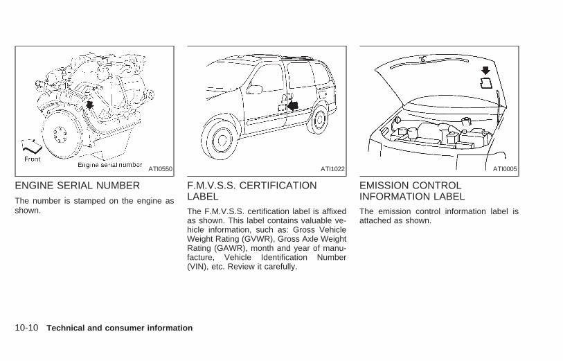
ENGINE SERIAL NUMBER
The number is stamped on the engine asshown.
F.M.V.S.S. CERTIFICATIONLABELThe F.M.V.S.S. certification label is affixedas shown. This label contains valuable ve-hicle information, such as: Gross VehicleWeight Rating (GVWR), Gross Axle WeightRating (GAWR), month and year of manu-facture, Vehicle Identification Number(VIN), etc. Review it carefully.
EMISSION CONTROLINFORMATION LABELThe emission control information label isattached as shown.
ATI0550 ATI1022 ATI0005
10-10 Technical and consumer information
Z X

TIRE PLACARDThe cold tire pressure is shown on the tireplacard affixed to the inside of the glovebox.
AIR CONDITIONERSPECIFICATION LABELThe air conditioner specification label isattached as shown.
Have your front license plate installed byyour NISSAN dealer.
ATI0561 ATI1023
ATI0564
INSTALLING THE LICENSEPLATE
Technical and consumer information 10-11
Z X

WARNING
● It is extremely dangerous to ride in acargo area inside of a vehicle. In acollision, people riding in these ar-eas are more likely to be seriouslyinjured or killed.
● Do not allow people to ride in anyarea of your vehicle that is notequipped with seats and seat belts.
● Be sure everyone in your vehicle is ina seat and using a seat belt properly.
Terms
It is important to familiarize yourself with thefollowing terms before loading your vehicle:
● Curb Weight (actual weight of your ve-hicle) - vehicle weight including: standardand optional equipment, fluids, emergencytools, and spare tire assembly. This weightdoes not include passengers and cargo.
● GVW (Gross Vehicle Weight) - curbweight plus the combined weight of pas-sengers and cargo.
● GVWR (Gross Vehicle Weight Rating) -maximum total weight (load) limit speci-fied for the vehicle.
● GAWR (Gross Axle Weight Rating) -maximum weight (load) limit specified forthe front or rear axle.
● Gross combined weight - GVW plus thetotal weight of the trailer and all its cargo.
Determining Vehicle Load Capacity
The load capacity of this vehicle is deter-mined by weight, not by available cargospace. For example, a luggage rack, bikecarrier, cartop carrier or similar equipmentdoes not increase load carrying capacity ofyour vehicle.
To determine vehicle load capacity:
Vehicle weight can be determined by usinga commercial-grade scale, found at placessuch as a truck stop, gravel quarry, grainelevator, or a scrap metal recycling facility.
1) Determine the curb weight of your vehicle.
2) Compare the curb weight amount to theGVWR specified for your vehicle to de-termine how much more weight yourvehicle can carry.
3) After loading (cargo & passengers), re-weigh your vehicle to determine if eitherGVWR or GAWR for your vehicle is
exceeded. If GVWR is exceeded, re-move cargo as necessary. If either thefront or rear GAWR is exceeded, shiftthe load or remove cargo as necessary.
Loading Tips● The GVW must not exceed GVWR or
GAWR specified on the F.M.V.S.S. Cer-tification Label.
● Do not load the front and rear axle to theGAWR. Doing so will exceed the GVWR.
WARNING● Properly secure all cargo to help pre-
vent it from sliding or shifting. Do notplace cargo higher than the seat-backs. In a sudden stop or collision,unsecured cargo could cause per-sonal injury.
● Do not load your vehicle any heavierthan the GVWR or the maximumfront and rear GAWRs. If you do,parts on your vehicle can break, or itcan change the way your vehiclehandles. This could result in loss ofcontrol and cause personal injury.
VEHICLE LOADINGINFORMATION
10-12 Technical and consumer information
Z X

● Overloading can shorten the life ofyour vehicle. Failures caused byoverloading are not covered by yourwarranty.
Your new vehicle was designed to be usedprimarily to carry passengers and cargo.Remember that towing a trailer places ad-ditional loads on your vehicle’s engine, drivetrain, steering, braking and other systems.
A NISSAN Trailer Towing Guide (U.S. only)contains information on your vehicle’s trailertowing ability and the special equipmentrequired, and may be obtained from anauthorized NISSAN dealer.
Do not tow a trailer if your vehicle is a cargovan model.
Maximum load limits
Maximum trailer loads
Never allow the total trailer load to exceed3,500 lbs (1,588 kg). The total trailer loadequals trailer weight plus its cargo weight.Towing loads greater than 3,500 lbs (1,588kg) or using improper towing equipmentcould adversely affect vehicle handling,braking and performance.
● All towing above 1,000 lbs (454 kg) re-quires the use of trailer brakes.
● NISSAN recommends the use of a tan-dem axle trailer whenever towing above3,000 lbs (1,361 kg).
● A sway control device is recommendedfor all towing above 2,000 lbs (907 kg).Sway control devices are not offered byNISSAN. See a professional trailer/hitchoutlet for a properly designed sway con-trol device for your trailer.
The Gross Combined Weight should notexceed 8,000 lbs (3,628 kg). The GrossCombined Weight is the total weight of thetow vehicle with all occupants, cargo andfuel tanks, PLUS the total weight of thetrailer and all its cargo. This weight should
TI1011M
TRAILER TOWING
Technical and consumer information 10-13
Z X

be properly distributed. For more informa-tion regarding vehicle and trailer loading,refer to The NISSAN Towing Guide, avail-able from an authorized NISSAN dealer.
WARNINGVehicle damage and/or personal injuryresulting from improper towing proce-dures is not covered by NISSAN war-ranties. Information on trailer towingand required towing equipment shouldbe obtained from dealers who special-ize in providing trailers or other towingequipment.
Tongue load:
Keep the tongue load between 9 and 11%of the total trailer load. If the tongue loadbecomes excessive, rearrange cargo to al-low for proper tongue load.
Maximum gross vehicle weight/maximumgross axle weight
The gross vehicle weight of the towingvehicle must not exceed the gross vehicleweight rating (GVWR) shown on theF.M.V.S.S. certification label. The gross ve-hicle weight equals the combined weight ofthe unloaded vehicle, passengers, luggage,hitch, trailer tongue load and any otheroptional equipment. In addition, front or reargross axle weight must not exceed thegross axle weight rating (GAWR) shown onthe F.M.V.S.S. certification label.
TOWING LOAD/SPECIFICATION CHART
UNIT: lb (kg)
MAXIMUMTOWING LOAD
3,500 (1,588)
MAXIMUMTONGUE LOAD
350 (159)
Trailer hitchChoose a proper hitch for your vehicle andtrailer. A genuine NISSAN trailer hitch isavailable from your NISSAN dealer(Canada only). Make sure the trailer hitch issecurely attached to the vehicle to helpavoid personal injury or property damagedue to sway caused by crosswinds, roughroad surfaces or passing trucks.
CAUTION● Do not use axle-mounted hitches.● The hitch should not be attached to
or affect the operation of the impact-absorbing bumper.
● Do not modify the vehicle exhaustsystem, brake system, etc. when thehitch is installed.
TI1012M
10-14 Technical and consumer information
Z X

● To reduce the possibility of addi-tional damage if your vehicle isstruck from the rear, where practicalremove the hitch when not in use.Remove the receiver when not inuse. After the hitch is removed, sealthe bolt holes to prevent exhaustfumes, water or dust from enteringthe passenger compartment.
● Regularly check that all hitch mount-ing bolts are securely mounted.
Tire pressures● When towing a trailer, inflate the vehicle
tires to the recommended cold tire pres-sure indicated on the tire placard (locatedon the inside of the glove box lid).
● Trailer tire condition, size, load rating andproper inflation pressure should be inaccordance with the trailer and tiremanufacturer’s specifications.
Safety chainAlways use suitable safety chains betweenyour vehicle and the trailer. Safety chainsshould be crossed and should be attachedto the hitch, not to the vehicle bumper or
axle. Be sure to leave enough slack in thechains to permit turning corners.
Trailer lightsTrailer lights should comply with Federaland/or local regulations. When wiring thevehicle for towing, connect the stop and taillight pickup into the vehicle electrical circuit.
Class I Trailer Tow electrical wiring providestwo circuits (right and left hand) to operatetrailer stop/turn tail lamps. Each individualstop/turn circuit will operate only one com-bination stop/turn light bulb (#1157, 3157,2357, or 3357) on the trailer. Never addmore than one trailer light bulb to onecircuit.
Technical and consumer information 10-15
Z X

Trailer Tow Harness and Module(if so equipped)
The trailer tow module on your vehicle al-lows turn/stop lamp control of a trailer beingtowed by your NISSAN.
The trailer tow module includes:
● trailer tow module which draws powerfrom the vehicle stop lamp fuse
● one subharness containing a SAE J1239specified connector
To use the tow harness:
1) Remove the connector cap from thevehicle harness, located behind the rearbumper. Store the connector cap in ve-hicle glove box for reinstallation.
2) Connect the tow harness to the vehicleharness located behind the rear bumper.
3) Connect the tow harness connector(SAE J1239) to your trailer.
4) Confirm proper vehicle and trailerstop/turn lamp operation.
5) When towing is completed, disconnectthe tow harness from the trailer and thevehicle. Store the tow harness in theglove box. Reinstall the connector cap tothe vehicle harness.
If you need further assistance in wiringa trailer to your NISSAN, contact an autho-rized NISSAN dealer.
Always confirm proper vehicle andtrailer stop/turn lamp operation everytime the trailer light circuits are con-nected for use.
ATI0555
10-16 Technical and consumer information
Z X

Trailer brakes
If your trailer is equipped with a brakingsystem, make sure it conforms to Federaland/or local regulations and it is properlyinstalled.
WARNING
Never connect a trailer brake systemdirectly to the vehicle brake system.
Pre-towing tips
● Be certain your vehicle maintains a levelposition when a loaded and/or unloadedtrailer is hitched. Do not drive the vehicleif it has an abnormal nose-up or nose-down condition; check for impropertongue load, overload, worn suspensionor other possible causes of either condi-tion.
● Always secure items in the trailer toprevent load shift while driving.
● Be certain your rear view mirrors conformto all federal, state or local regulations. Ifnot, install any mirrors required for towingbefore driving the vehicle.
Trailer towing tips
In order to gain skill and an understandingof the vehicle’s behavior, you should prac-tice turning, stopping and backing up in anarea which is free from traffic. Steering,stability, and braking performance aresomewhat different than under normal driv-ing conditions.
● Always secure items in the trailer toprevent load shift while driving.
● Avoid abrupt starts, acceleration or stops.
● Avoid sharp turns or lane changes.
● Always drive your vehicle at a moderatespeed.
● Always block the wheels on both vehicleand trailer when parking. Parking on aslope is not recommended; however, ifyou must do so, first block the wheelsand apply the parking brake, and thenmove the transmission shift selector le-ver into the P (Park) position. If you movethe shift selector lever to the P (Park)position before blocking the wheels andapplying the parking brake, transmissiondamage could occur.
● When going down a hill, shift into a lower
gear and use the engine braking effect.When ascending a long grade, downshiftthe transmission to a lower gear andreduce speed to reduce chances of en-gine overloading and/or overheating.
● If the engine coolant rises to an ex-tremely high temperature when the airconditioning system is on, turn the airconditioner off. Coolant heat can be ad-ditionally vented by opening the win-dows, switching the fan control dial tohigh and setting the temperature controldial to the WARM position.
● Trailer towing requires more fuel thannormal circumstances.
● Avoid towing a trailer for the first 500miles (800 km) of the vehicle’s life.
● Have your vehicle serviced more oftenthan at intervals specified in the recom-mended Maintenance Schedule.
● When making a turn, your trailer wheelswill be closer to the inside of the turn thanyour vehicle wheels. To compensate forthis, make a larger than normal turningradius during the turn.
● Crosswinds and rough roads adversely
Technical and consumer information 10-17
Z X

affect vehicle/trailer handling, possiblycausing vehicle sway. When beingpassed by larger vehicles, be preparedfor possible changes in crosswinds thatcould affect vehicle handling. If swayingdoes occur, firmly grip the steeringwheel, steer straight ahead, and immedi-ately (but gradually) reduce vehiclespeed. This combination helps to stabi-lize the vehicle. Never increase speed.
● Be careful when passing other vehicles.Passing while towing a trailer requiresconsiderably more distance than normalpassing. Remember the length of thetrailer must also pass the other vehiclebefore you can safely change lanes.
● To maintain engine braking efficiencyand electrical charging performance, donot use overdrive.
● Avoid holding the brake pedal down toolong or too frequently. This could causethe brakes to overheat, resulting in re-duced braking efficiency.
When towing a trailer, change fluid in thetransmission more frequently. For addi-tional information see the ‘‘Mainte-nance’’ section earlier in this manual.
Department of Transportation (DOT) Qual-ity Grades: All passenger car tires mustconform to Federal Safety Requirements inaddition to these grades.
TreadwearTreadwear grade is a comparative ratingbased on tire wear rate when tested undercontrolled conditions on specified govern-ment test courses. For example, a tiregraded 150 would wear one and a half(1-1/2) times as well on the governmentcourse as a tire graded 100. However,relative tire performance depends on actualdriving conditions, and may vary signifi-cantly, due to variations in driving habits,service practices and differences in roadcharacteristics and climate.
Traction AA, A, B and CThe traction grades, from highest to lowest,are AA, A, B, and C. Those grades repre-sent the tire’s ability to stop on wet pave-ment as measured under controlled condi-tions, on specified government test surfacesof asphalt and concrete. A tire marked Cmay have poor traction performance.
WARNINGThe traction grade assigned to your ve-hicle tires is based on straight-aheadbraking traction tests, and does not in-clude acceleration, cornering, hydro-planing, or peak traction characteristics.
Temperature A, B and CTemperature grades are A (the highest), B,and C. They represent a tire’s resistance toheat build-up, and its ability to dissipateheat when tested under controlled condi-tions on a specified indoor laboratory testwheel. Sustained high temperature cancause tire material to degenerate, reducingtire life. Excessive temperatures can lead tosudden tire failure. Grade C corresponds toa performance level which all passenger cartires must meet under the Federal MotorVehicle Safety Standard No. 109. Grades Aand B represent higher levels of perfor-mance on laboratory test wheels than theminimum required by law.
UNIFORM TIRE QUALITYGRADING
10-18 Technical and consumer information
Z X

WARNINGThe temperature grade for this tire isestablished for a tire that is properlyinflated and not overloaded. Excessivespeed, under inflation, or excessiveloading, either separately or in combi-nation, can cause heat build-up andpossible tire failure.
Your NISSAN is covered by the followingemission warranties:
For US1) Emission Defects Warranty
2) Emission Performance Warranty
For CanadaEmission Control System Warranty
Details of these warranties may be foundwith other vehicle warranties in your War-ranty Information and Maintenance LogBooklet that comes with your NISSAN. Ifyou did not receive a Warranty Informationand Maintenance Log Booklet, or it hasbecome lost, you may obtain a replacementby writing to:
● Nissan North America, Inc.Consumer Affairs DepartmentP.O. Box 191Gardena, CA 90248-0191
● Nissan Canada Inc.5290 Orbitor DriveMississauga, Ontario, L4W 4Z5
If you believe that your vehicle has a defectwhich could cause a crash or could causeinjury or death, you should immediatelyinform the National Highway Traffic SafetyAdministration (NHTSA) in addition to no-tifying NISSAN.
If NHTSA receives similar complaints, itmay open an investigation, and if it findsthat a safety defect exists in a group ofvehicles, it may order a recall and remedycampaign. However, NHTSA cannot be-come involved in individual problems be-tween you, your dealer, or NISSAN.
To contact NHTSA, you may either call theAuto Safety Hotline toll-free at 1- 800-424-9393 (or 366-0123 in the Washington, D.C.area) or write to: NHTSA, U.S. Depart-ment of Transportation, Washington, D.C.20590. You can also obtain other informa-tion about motor vehicle safety from theHotline.
You may notify NISSAN by contacting ourConsumer Affairs Department, toll-free, at1-800-NISSAN-1.In Hawaii, call (808) 836-0888.
EMISSION CONTROLSYSTEM WARRANTY
REPORTING SAFETYDEFECTS (US only)
Technical and consumer information 10-19
Z X

Due to legal requirements in some statesand Canadian Provinces, your vehicle maybe required to be in the ready condition foran Inspection/Maintenance (I/M) test of theemission control system.
The vehicle is set to the ready conditionwhen it is driven through certain driving pat-terns. Usually, the ready condition can beobtained by ordinary usage of the vehicle.
If a powertrain system component is repairedor the battery is disconnected, the vehiclemay be reset to a not ready condition. Beforetaking the I/M test, drive the vehicle throughthe following pattern to set the vehicle to theready condition. If you cannot or do not wantto perform the driving pattern, an authorizedNISSAN dealer can conduct it for you.
WARNINGAlways drive the vehicle in a safe man-ner according to traffic conditions andobey all traffic laws.
1. Start the engine when the engine coolanttemperature gauge needle points to C.Allow the engine to idle until the gaugeneedle points between the C and H (nor-mal operating temperature).
2. Accelerate the vehicle to 55 MPH (88km/h), then quickly release the accelera-tor pedal completely and keep it releasedfor at least 6 seconds.
3. Quickly depress the accelerator pedal fora moment, then drive the vehicle at aspeed of 53 to 60 MPH (86 to 96 km/h)for at least 5 minutes.
4. Stop the vehicle.
5. Accelerate the vehicle to 35 mph (55km/h) and maintain the speed for 20seconds.
6. Repeat steps four through five at leastthree times.
7. Accelerate the vehicle to 55 mph (88km/h) and maintain the speed for at least3 minutes.
8. Stop the vehicle and turn the engine off.
9. Repeat steps one through eight at leastone more time.
If step one through seven are interrupted,repeat the preceding step. Any safe drivingmode is acceptable between steps. Do notstop the engine until step seven is com-pleted.
READINESS FORINSPECTION/MAINTENANCE(I/M) TEST (US only)
10-20 Technical and consumer information
Z X

A Genuine NISSAN Service Manual is the bestsource of service and repair information foryour vehicle. Filled with wiring diagrams, illus-trations and step-by-step diagnostic and ad-justment procedures, this manual is the sameone used by the factory trained techniciansworking at an authorized NISSAN dealership.Also available are Genuine NISSAN Owner’sManuals.For current pricing and availability of a Genu-ine NISSAN Service Manual or Genuine NIS-SAN Owner’s Manual, contact:
In the USA:See an authorized NISSAN dealer or contact:
Dyment Distribution Services20770 Westwood Dr.Strongsville OH 44136
In a hurry? Call 1-800-247-5321 and chargeyour purchase to Visa/Master Card.
In Canada:To purchase a copy of a Genuine NISSANService Manual or Owner’s Manual pleasecontact your nearest NISSAN Dealer. For thephone number and location of a NISSANDealer in your area call the NISSAN Satisfac-tion Center at 1-800-387-0122 and a bilingualNISSAN representative will assist you.Also available are Genuine NISSAN Serviceand Owner’s Manuals for older NISSAN mod-els.
Technical and consumer information 10-21
Z X

MEMO
10-22 Technical and consumer information
Z X

11 Index
A
After an accident........................................ 6-11Air bag (See supplemental restraintsystem) ...................................................... 1-19Air bag warning light.................................. 1-24Air cleaner housing filter............................ 8-13Air conditioner
Air conditioner operation ........................ 4-5Air conditioner service .......................... 4-14Air conditioner specification label ....... 10-11Air conditioner system refrigerant andlubrication recommendations................ 10-6Heater and air conditioner (automatic)(if so equipped)..................................... 4-11Heater and air conditioner (manual)....... 4-3Rear seat air conditioner ...................... 4-14
Air filterCabin air filter ....................................... 8-14
Air flow charts .............................................. 4-7Alarm system (See theft warning) ............. 2-10Anchor point locations ............................... 1-57Anti-lock brake system (ABS).................... 5-15Anti-lock brake warning light ....................... 2-8Armrests....................................................... 1-6Ashtray (See cigarette lighter andashtray) ...................................................... 2-17
Audio systemAM-FM radio with cassette player........ 4-16AM-FM radio with cassette player andcompact disc player.............................. 4-22Compact disc (CD) player........... 4-28, 4-30
Autolamp switch......................................... 2-14Automatic
Automatic power window switch .......... 2-21Automatic transmission fluid (ATF) ........ 8-8Driving with automatic transmission....... 5-5Transmission selector lever lockrelease .................................................... 5-6
B
Battery........................................................ 8-11Before starting the engine ........................... 5-5Brake
Anti-lock brake system (ABS) .............. 5-15Brake booster ....................................... 8-20Brake fluid ................................... 10-2, 8-10Brake light (See stop light) ................... 8-23Brake pedal .......................................... 8-19Brake system........................................ 5-14Brake warning light ................................. 2-7Brake wear indicators............................. 2-9Parking brake check............................. 8-19Parking brake operation ......................... 5-9
Self-adjusting brakes ............................ 8-19Break-in schedule ...................................... 5-11Bulb check/instrument panel ....................... 2-6Bulb replacement....................................... 8-23
C
Cabin air filter ............................................ 8-14Capacities and recommended fuel/lubricants.................................................... 10-2Cargo net ................................................... 3-16Cargo (See vehicle loadinginformation) .............................................. 10-12Cassette player (See audio system) ......... 4-16CB radio or car phone ............................... 4-33Check engine indicator light(See malfunction indicator light) .................. 2-9Child restraint with top tether strap ........... 1-51Child restraints........................................... 1-41Child safety sliding door lock....................... 3-6Cigarette lighter (accessory) andashtray ....................................................... 2-17Cleaning exterior and interior ...................... 7-2Clock................................................. 4-16, 4-22Cold weather driving.................................. 5-16Compact disc (CD) player................ 4-28, 4-30
Z X

ControlsAudio controls (rear) ............................. 4-33Audio controls (steering wheel) ............ 4-32Heater and air conditioner controls(automatic)............................................ 4-11Heater and air conditioner controls(manual).................................................. 4-3Rear seat air conditioner controls ........ 4-14
CoolantCapacities and recommended fuel/lubricants .............................................. 10-2Changing engine coolant........................ 8-5Checking engine coolant level ............... 8-4Engine coolant temperature gauge ........ 2-4
Cornering light ........................................... 2-15Corrosion protection .................................... 7-4Cruise control............................................... 5-9Cup holder ................................................. 2-19
D
Daytime running light system(Canada only) ............................................ 2-14Defogger switch
Rear window defogger switch .............. 2-13Dimensions and weights............................ 10-8Door ajar warning light ................................ 2-7Door locks.................................................... 3-2Drive belts.................................................. 8-12
DrivingCold weather driving............................. 5-16Driving with automatic transmission....... 5-5Precautions when starting and driving ... 5-2
E
Economy - fuel........................................... 5-12Emission control information label........... 10-10Emission control system warranty........... 10-19Engine
Before starting the engine ...................... 5-5Capacities and recommended fuel/lubricants .............................................. 10-2Changing engine coolant........................ 8-5Changing engine oil................................ 8-6Changing engine oil filter........................ 8-7Checking engine coolant level ............... 8-4Checking engine oil level ....................... 8-5Engine compartment check locations .... 8-3Engine coolant temperature gauge ........ 2-4Engine cooling system ........................... 8-4Engine oil ................................................ 8-5Engine oil and oil filterrecommendation ................................... 10-4Engine oil pressure warning light ........... 2-6Engine oil viscosity ............................... 10-5Engine serial number ......................... 10-10Starting the engine ................................. 5-8
Exhaust gas (Carbon monoxide)................. 5-2
F
Five passenger seating ............................. 1-70Five passenger seating with cargo room .. 1-71Flashers (See hazard warning flasherswitch)........................................................ 2-16Flat tire......................................................... 6-2Flexible seating............................................ 1-8Floor mat positioning........................ 1-69, 1-72Floor mat positioning aid ........................... 1-72Fluid
Automatic transmission fluid (ATF) ........ 8-8Brake fluid ................................... 10-2, 8-10Capacities and recommended fuel/lubricants .............................................. 10-2Engine coolant........................................ 8-4Engine oil ................................................ 8-5Power steering fluid ...................... 10-2, 8-9Window washer fluid ............................ 8-10
F.M.V.S.S. certification label ................... 10-10Front seat convenience net ....................... 3-14Fuel
Capacities and recommended fuel/lubricants .............................................. 10-2Fuel economy ....................................... 5-12Fuel filler lid and cap ............................ 3-20Fuel filler lid lock opener lever ............. 3-20Fuel gauge.............................................. 2-5Fuel octane rating................................. 10-3Fuel recommendation........................... 10-2
Fuses ......................................................... 8-20
11-2
Z X

G
GaugeEngine coolant temperature gauge ........ 2-4Fuel gauge.............................................. 2-5Odometer................................................ 2-4Speedometer .......................................... 2-4Tachometer............................................. 2-4Trip odometer ......................................... 2-4
General maintenance .................................. 9-2Glove box................................................... 3-13
H
Hazard warning flasher switch .................. 2-16Head restraints ............................................ 1-6Headlight control switch............................. 2-13Headlights .................................................. 8-22Heater
Heater and air conditioner (automatic)(if so equipped)..................................... 4-11Heater and air conditioner (manual)....... 4-3Rear seat air conditioner ...................... 4-14
Homelink TransceiverIntegrated HomeLinkT UniversalTransceiver (If so equipped) ................ 2-27
Hood release ............................................. 3-12
I
Ignition switch .............................................. 5-4Important vehicle information label.......... 10-10Increasing fuel economy............................ 5-12Indicator lights and chimes (See warning/indicator lights and chimes)......................... 2-6Inertial fuel shut off switch......................... 6-11Inside mirror............................................... 3-24Instrument brightness control .................... 2-16Integrated child safety seats...................... 1-61Integrated HomeLinkT Universal Transceiver(If so equipped).......................................... 2-27Interior lights .............................................. 2-24
J
Jump starting...................................... 6-8, 8-12
K
Key............................................................... 3-2Keyless entry system (See multi-remotecontrol system) ............................................ 3-9
L
LabelsAir conditioner specification label ....... 10-11Emission control information label...... 10-10
Engine serial number ......................... 10-10F.M.V.S.S. certification label .............. 10-10Vehicle identification number (VIN) ...... 10-9Vehicle identification number (VIN)plate ...................................................... 10-9Warning labels (for SRS) ..................... 1-24
License plateInstalling the license plate .................. 10-11
LightAir bag warning light............................. 1-24Brake light (See stop light) ................... 8-23Bulb check/instrument panel .................. 2-6Bulb replacement.................................. 8-23Cornering light ...................................... 2-15Headlight control switch ....................... 2-13Headlights............................................. 8-22Interior lights ......................................... 2-24Light bulbs ............................................ 8-22Luggage compartment lights ................ 2-24Map lights ............................................. 2-25Warning/indicator lights and chimes ...... 2-6
LockChild safety sliding door lock ................. 3-6Door locks............................................... 3-2Fuel filler lid lock opener lever ............. 3-20Power door lock...................................... 3-7Rear door lock ...................................... 3-15
Luggage compartment lights ..................... 2-24Luggage rack ............................................. 3-19Luggage (See vehicle loadinginformation ............................................... 10-12
11-3
Z X

M
MaintenanceGeneral maintenance ............................. 9-2Inside the vehicle.................................... 9-3Maintenance precautions ....................... 8-2Outside the vehicle................................. 9-2Periodic maintenance schedules............ 9-5Seat belt maintenance.......................... 1-40Under the hood and vehicle ................... 9-4
Malfunction indicator light ............................ 2-9Manual front seat adjustment ...................... 1-3Manual vent windows ................................ 2-23Map lights .................................................. 2-25Map pockets .............................................. 2-20Mirror
Inside mirror.......................................... 3-24Outside mirror control ........................... 3-23Outside mirrors ..................................... 3-24Vanity mirror ......................................... 3-24
Multi-remote control system ........................ 3-9
O
Odometer ..................................................... 2-4Oil
Capacities and recommended fuel/lubricants .............................................. 10-2Changing engine oil................................ 8-6Changing engine oil filter........................ 8-7Checking engine oil level ....................... 8-5
Engine oil ................................................ 8-5Engine oil and oil filterrecommendation ................................... 10-4Engine oil viscosity ............................... 10-5
Outside mirror control ................................ 3-23Outside mirrors .......................................... 3-24Overdrive switch .......................................... 5-7Overhead storage compartment................ 2-20Overheat
If your vehicle overheats ...................... 6-10Owner’s manual order form..................... 10-21
P
Parcel shelf ................................................ 3-17Parking
Parking brake check............................. 8-19Parking brake operation ......................... 5-9Parking/parking on hills ........................ 5-13
Periodic maintenance schedules................. 9-5Personal reading light................................ 2-24Power
Power door lock...................................... 3-7Power steering fluid ...................... 10-2, 8-9Power support front seat ........................ 1-4Power vent windows............................. 2-23Power windows..................................... 2-21
PrecautionsMaintenance precautions ....................... 8-2Precautions on seat belt usage............ 1-26Precautions when starting and driving ... 5-2
Push starting.............................................. 6-10
R
RadioAM-FM radio with cassette player........ 4-16AM-FM radio with cassette player andcompact disc player.............................. 4-22CB radio or car phone.......................... 4-34
Readiness for inspection maintenance(I/M) test................................................... 10-20Rear door................................................... 3-15Rear door lock ........................................... 3-15Rear power point ....................................... 2-18Rear seat air conditioner ........................... 4-14Rear window defogger switch ................... 2-13Rear window wiper and washerswitches ..................................................... 2-13Refrigerant recommendation ..................... 10-6Registering your vehicle in anothercountry ....................................................... 10-9Remote keyless entry system(See multi-remote control system) .............. 3-9Removing and installing the second rowbench seat ................................................... 1-8Reporting safety defects (USA)............... 10-19
S
SafetyChild safety sliding door lock ................. 3-6Reporting safety defects (USA).......... 10-19
Seat beltPrecautions on seat belt usage............ 1-26
11-4
Z X

Seat belt extenders .............................. 1-40Seat belt maintenance.......................... 1-40Seat belts.............................................. 1-26Three-point type with retractor .... 1-29, 1-32Two-point type without retractor ........... 1-38
Seat belt warning light ................................. 2-7Seat positions ............................................ 1-73Seating arrangements ............................... 1-68Seats
Five passenger seating ........................ 1-70Five passenger seating with cargoroom...................................................... 1-71Flexible seating....................................... 1-8Integrated child safety seats ................ 1-61Manual front seat adjustment................. 1-3Power support front seat ........................ 1-4Seat positions ....................................... 1-73Second row bench seat........................ 1-73Second row bucket seats ..................... 1-77Seven passenger seating..................... 1-69Sliding three-passenger seat................ 1-15Three-passenger bench seat in fullyforward position .................................... 1-71Three-passenger bench seat in storageposition ................................................. 1-69
Seats/floor mats......................................... 1-68Selector lever lock release .......................... 5-6Self-adjusting brakes ................................. 8-19Service manual order form ...................... 10-21Seven passenger seating .......................... 1-69Shifting
Automatic transmission .......................... 5-6
Shift lock release ......................................... 5-6Sliding three-passenger seat..................... 1-15Spark plug replacement............................. 8-12Speedometer ............................................... 2-4Spotlights (See map lights) ....................... 2-25SRS warning label ..................................... 1-24Starting
Before starting the engine ...................... 5-5Jump starting................................. 6-8, 8-12Precautions when starting and driving ... 5-2Push starting......................................... 6-10Starting the engine ................................. 5-8
SteeringPower steering fluid ...................... 10-2, 8-9Tilting steering wheel............................ 3-21
Stop light.................................................... 8-23Storage
Overhead storage compartment........... 2-20Under seat storage tray.......................... 1-7
Storage compartment for garage doortransmitter .................................................. 2-25Sun shade.................................................. 2-23Sunroof ...................................................... 2-22Supplemental restraint system
Information and warning labels ............ 1-24Switch
Autolamp switch ................................... 2-14Automatic power window switch .......... 2-21Hazard warning flasher switch ............. 2-16Headlight control switch ....................... 2-13Ignition switch ......................................... 5-4Overdrive switch ..................................... 5-7
Rear window defogger switch .............. 2-13Rear window wiper and washerswitches ................................................ 2-13Turn signal switch................................. 2-15Windshield wiper and washer switch ... 2-12
T
Tabletop seats ............................................. 1-7Tachometer.................................................. 2-4Theft warning ............................................. 2-10Three way catalyst....................................... 5-2Three-passenger bench seat..................... 1-37Three-passenger bench seat in fullyforward position ......................................... 1-71Three-passenger bench seat in storageposition....................................................... 1-69Tilting steering wheel................................. 3-21Timing belt ................................................. 10-7Tire
Flat tire.................................................... 6-2Spare tire .............................................. 8-31Tire chains ............................................ 8-29Tire placard......................................... 10-11Tire pressure .......................................... 5-6Tire pressure ........................................ 8-27Tire rotation .......................................... 8-29Tool kit .................................................... 6-2Types of tires........................................ 8-28Uniform tire quality grading ................ 10-18Wheels and tires ......................... 10-8, 8-27
11-5
Z X

Wheel/tire size ...................................... 10-8Towing
Tow truck towing .................................. 6-12Towing load/specification chart .......... 10-14Trailer towing ...................................... 10-13
TransceiverIntegrated HomeLinkT UniversalTransceiver (If so equipped) ................ 2-27
TransmissionAutomatic transmission fluid (ATF) ........ 8-8Driving with automatic transmission....... 5-5Selector lever lock release ..................... 5-6
Travel (See registering your vehicle inanother country)......................................... 10-9Trip odometer .............................................. 2-4Tuning............................................... 4-17, 4-23Turn signal switch...................................... 2-15
U
Under seat storage tray............................... 1-7Uniform tire quality grading ..................... 10-18
V
Vanity mirror .............................................. 3-24Vehicle dimensions and weights ............... 10-8Vehicle identification .................................. 10-9Vehicle identification number (VIN) ........... 10-9Vehicle identification number (VIN)(chassis number) ....................................... 10-9
Vehicle identification number (VIN) plate .. 10-9Vehicle loading information ..................... 10-12Vehicle recovery ........................................ 6-14Ventilators .................................................... 4-2
W
WarningAir bag warning light............................. 1-24Hazard warning flasher switch ............. 2-16Theft warning........................................ 2-10Warning labels (for SRS) ..................... 1-24Warning/indicator lights and chimes ...... 2-6
Weights (See dimensions and weights) .... 10-8Wheels and tires .............................. 10-8, 8-27Wheel/tire size ........................................... 10-8When traveling or registering your vehicle inanother country.......................................... 10-9Window washer fluid.................................. 8-10Windows
Locking passengers’ windows.............. 2-22Manual vent windows ........................... 2-23Power vent windows............................. 2-23Power windows..................................... 2-21
Windshield wiper and washer switch ........ 2-12Wiper
Rear window wiper and washerswitches ................................................ 2-13Windshield wiper and washer switch ... 2-12Wiper blades......................................... 8-17
11-6
Z X

Recommended fuel:Unleaded gasoline, at least 87 AKI number(RON 91).For further details such as gasohol, see‘‘Fuel recommendation’’ in the ‘‘Technicaland consumer information’’ section.
Recommended engine oil:● API Certification Mark● API SG/SH, Energy Conserving II or API
grade SJ Energy Conserving● ILSAC grade GF-IISee ‘‘Engine oil and oil filter recommenda-tion’’ in the ‘‘Technical and consumer infor-mation’’ section.
Cold tire pressure:See tire placard affixed to the glove com-partment lid.
Recommended new vehiclebreak-in procedure:During the first 1,000 miles (1,600 km) ofvehicle use, follow the recommendationsoutlined in the “Break-in schedule’’ informa-tion found in the “Starting and Driving” sec-tion of this Owner’s Manual. Follow theserecommendations for the future reliabilityand economy of your new vehicle. Failure tofollow these recommendations may result invehicle damage or shortened engine life. AGS1013
GAS STATION INFORMATION QUICK REFERENCE
Z X