1gr-fe engine mechanical – engine unit · 1gr-fe engine mechanical – engine unit em–201 em...
TRANSCRIPT
1GR-FE ENGINE MECHANICAL – ENGINE UNIT EM–201
M
EDISASSEMBLYHINT:• Thoroughly clean all parts to be assembled.• Before installing the parts, apply new engine oil to all
sliding and rotating surfaces.• Replace all gaskets, O-rings and oil seals with new parts.1. REMOVE ENGINE HANGERS
(a) Remove the 2 bolts and engine hanger No. 1.(b) Remove the 2 bolts and engine hanger No. 2.
2. REMOVE OIL LEVEL GAGE GUIDE(a) Remove the bolt, then pull out the oil level gauge
guide.(b) Remove the O-ring from the oil level gauge guide.
3. REMOVE CYLINDER BLOCK WATER DRAIN COCK SUB-ASSEMBLY(a) Remove the 2 water drain cocks.
4. REMOVE VVT SENSOR(a) Remove the 2 bolts, then remove the 2 VVT
sensors.
5. REMOVE CRANKSHAFT POSITION SENSOR(a) Remove the bolt, then remove the crankshaft
position sensor.
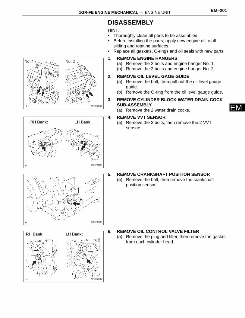
6. REMOVE OIL CONTROL VALVE FILTER(a) Remove the plug and filter, then remove the gasket
from each cylinder head.
No. 1 No. 2
A072941E02
RH Bank: LH Bank:
G036794E01
G036795E01
LH Bank:RH Bank:
A072942E02
EM–202 1GR-FE ENGINE MECHANICAL – ENGINE UNIT
EM
7. REMOVE CYLINDER HEAD COVER SUB-ASSEMBLY(a) Remove the 10 bolts, 3 seal washers and 2 nuts,
then remove the cylinder head cover.(b) Remove the gasket from the cylinder head cover.
8. REMOVE CYLINDER HEAD COVER SUB-ASSEMBLY LH(a) Remove the 10 bolts, 3 seal washers and 2 nuts,
then remove the cylinder head cover.(b) Remove the gasket from the cylinder head cover.(c) Remove the ventilation valve from the cylinder head
cover.
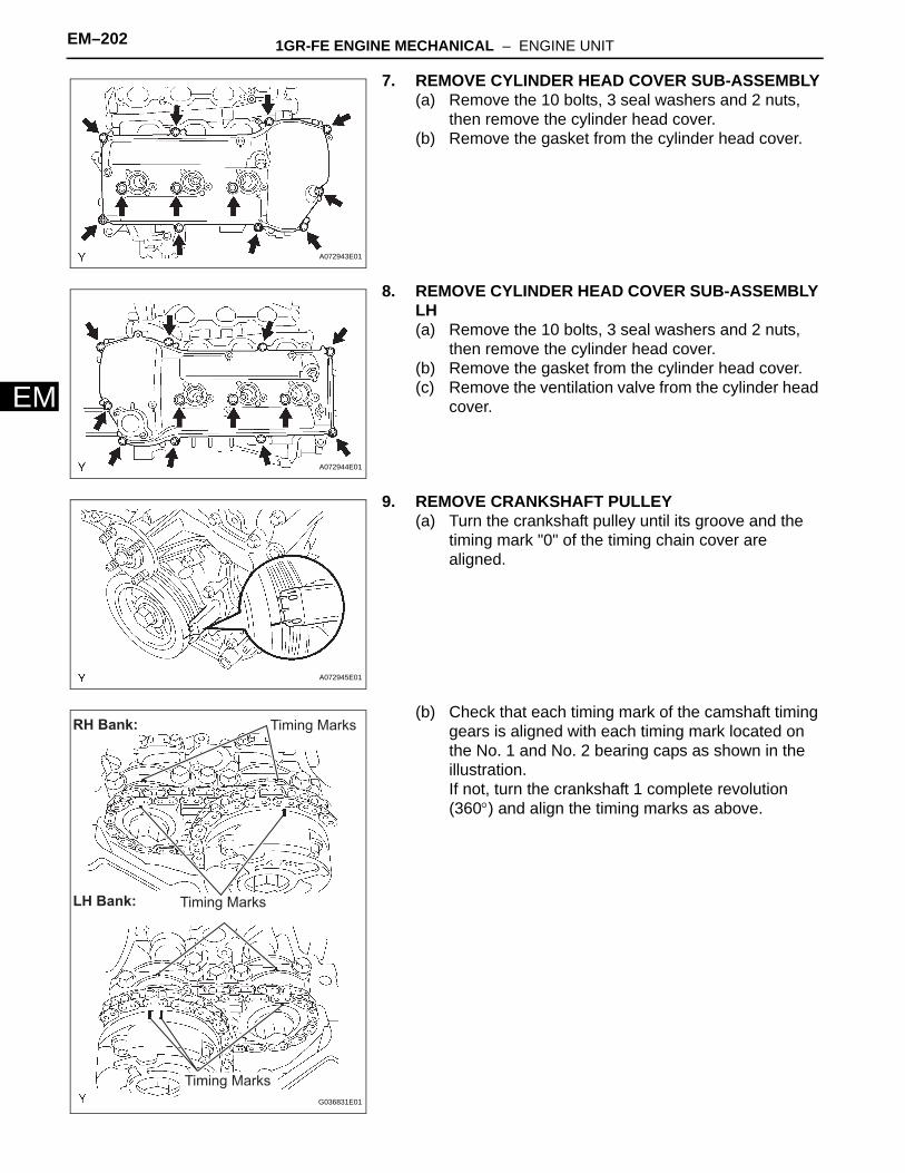
9. REMOVE CRANKSHAFT PULLEY(a) Turn the crankshaft pulley until its groove and the
timing mark "0" of the timing chain cover are aligned.
(b) Check that each timing mark of the camshaft timing gears is aligned with each timing mark located on the No. 1 and No. 2 bearing caps as shown in the illustration.If not, turn the crankshaft 1 complete revolution (360°) and align the timing marks as above.
A072943E01
A072944E01
A072945E01
RH Bank:
LH Bank:
Timing Marks
Timing Marks
Timing Marks
G036831E01
1GR-FE ENGINE MECHANICAL – ENGINE UNIT EM–203
M
E(c) Using SST, fix the pulley and loosen the pulley bolt.SST 09213-54015 (91651-60855), 09330-00021
(d) Using the pulley set bolt and SST, remove the crankshaft pulley.SST 09950-50013 (09951-05010, 09952-05010,
09953-05020, 09954-05030)10. REMOVE OIL PAN DRAIN PLUG
(a) Remove the drain plug and gasket.
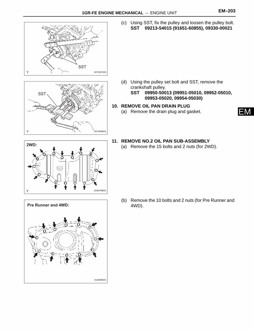
11. REMOVE NO.2 OIL PAN SUB-ASSEMBLY(a) Remove the 15 bolts and 2 nuts (for 2WD).
(b) Remove the 10 bolts and 2 nuts (for Pre Runner and 4WD).
SSTA072947E02
SST
A072948E01
2WD:
G036799E01
Pre Runner and 4WD:
A118006E01

EM–204 1GR-FE ENGINE MECHANICAL – ENGINE UNIT
EM
(c) Insert the blade of SST between the oil pan and oil pan No. 2, then cut off applied sealer and remove the oil pan No. 2.SST 09032-00100NOTICE:• Be careful not to damage the contact surface
of the oil pan and oil pan No. 2.• Be careful not to damage the oil pan No. 2
flange.
12. REMOVE OIL STRAINER SUB-ASSEMBLY(a) Remove the 2 nuts, then remove the oil strainer and
gasket (for 2WD).
(b) Remove the 2 nuts, then remove the oil strainer and gasket (for Pre Runner and 4WD).
13. REMOVE OIL PAN SUB-ASSEMBLY(a) Remove the 17 bolts and 2 nuts (for 2WD).
SST
A072950E02
2WD:
G036832E01
Pre Runner and 4WD:
A072951E02
2WD:
G036798E02
1GR-FE ENGINE MECHANICAL – ENGINE UNIT EM–205
M
E(b) Remove the 17 bolts and 2 nuts (for Pre Runner and 4WD).
(c) Using a screwdriver, remove the oil pan by prying between the oil pan and cylinder block in the sequence shown.NOTICE:Be careful not to damage the contact surfaces of the cylinder block and oil pan.
(d) Remove the O-ring from the oil pump.
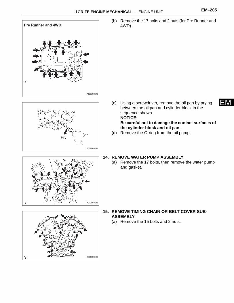
14. REMOVE WATER PUMP ASSEMBLY(a) Remove the 17 bolts, then remove the water pump
and gasket.
15. REMOVE TIMING CHAIN OR BELT COVER SUB-ASSEMBLY(a) Remove the 15 bolts and 2 nuts.
Pre Runner and 4WD:
A122289E01
Pry
G036806E01
A072954E01
G036855E03

EM–206 1GR-FE ENGINE MECHANICAL – ENGINE UNIT
EM
(b) Remove the timing chain cover by prying between the timing chain cover, cylinder head and cylinder block with a screwdriver.NOTICE:Be careful not to damage the contact surfaces of the timing chain cover, cylinder block and cylinder head.
(c) Remove the O-ring from the LH cylinder head.
16. REMOVE NO.1 CHAIN TENSIONER ASSEMBLYNOTICE:• Never rotate the crankshaft with the chain
tensioner removed.• When rotating the camshaft with the timing chain
removed, rotate the crankshaft counterclockwise 40° from the TDC first.
(a) While turning the stopper plate of the tensioner upward, push in the plunger of the chain tensioner as shown in the illustration.
(b) While turning the stopper plate of the tensioner downward, insert a bar of φ 3.5 mm (0.138 in.) into the holes in the stopper plate and tensioner to fix the stopper plate.
(c) Remove the 2 bolts, then remove the chain tensioner.
17. REMOVE CHAIN TENSIONER SLIPPER18. REMOVE IDLE SPROCKET ASSEMBLY
(a) Using a 10 mm hexagon wrench, remove the idle gear shaft No. 2, idle gear No. 1 and idle gear shaft No. 1.
19. REMOVE NO.2 CHAIN VIBRATION DAMPER(a) Remove the 2 chain vibration dampers No. 2.
20. REMOVE CHAIN SUB-ASSEMBLY21. REMOVE CRANKSHAFT TIMING GEAR OR
SPROCKET
G036859E01
Stopper PlateStopper Plate
Push
A072958E02
G036860E01
G036844E01
1GR-FE ENGINE MECHANICAL – ENGINE UNIT EM–207
M
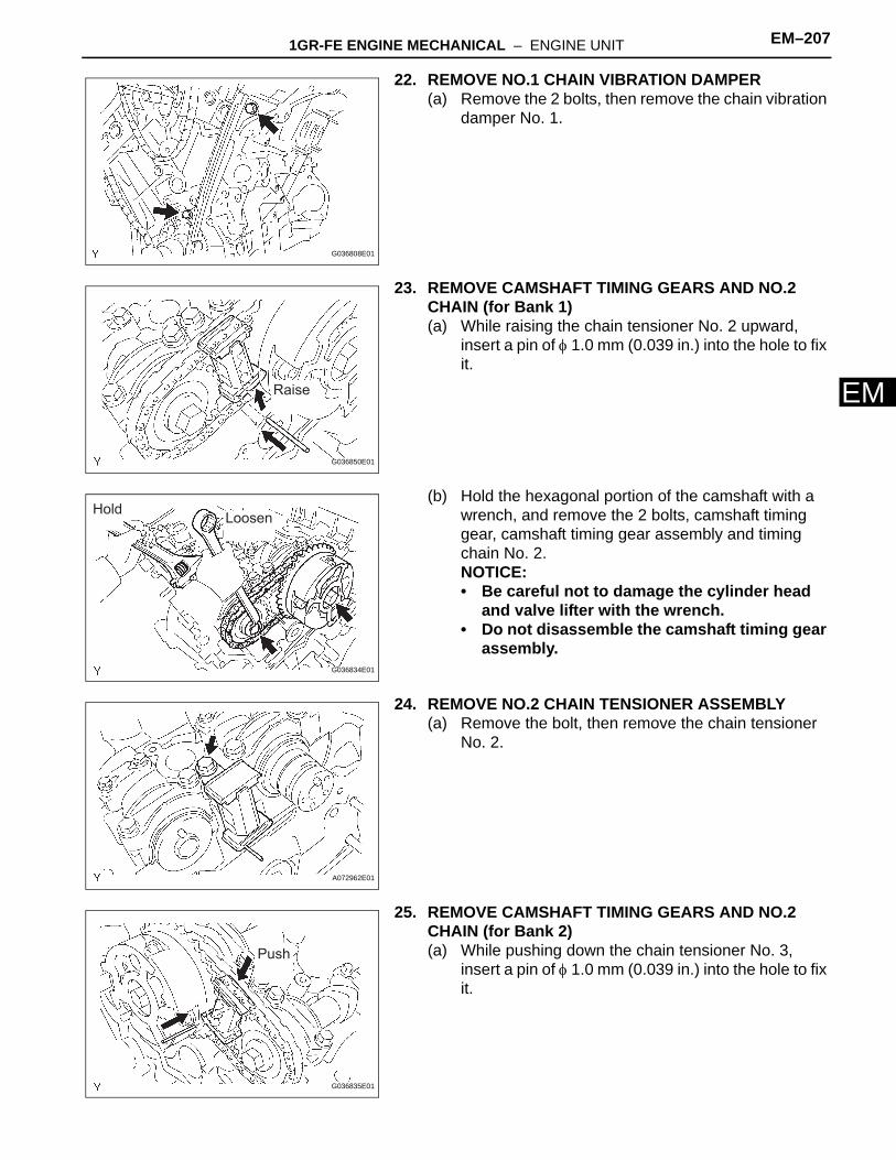
E22. REMOVE NO.1 CHAIN VIBRATION DAMPER(a) Remove the 2 bolts, then remove the chain vibration
damper No. 1.
23. REMOVE CAMSHAFT TIMING GEARS AND NO.2 CHAIN (for Bank 1)(a) While raising the chain tensioner No. 2 upward,
insert a pin of φ 1.0 mm (0.039 in.) into the hole to fix it.
(b) Hold the hexagonal portion of the camshaft with a wrench, and remove the 2 bolts, camshaft timing gear, camshaft timing gear assembly and timing chain No. 2.NOTICE:• Be careful not to damage the cylinder head
and valve lifter with the wrench.• Do not disassemble the camshaft timing gear
assembly.
24. REMOVE NO.2 CHAIN TENSIONER ASSEMBLY(a) Remove the bolt, then remove the chain tensioner
No. 2.
25. REMOVE CAMSHAFT TIMING GEARS AND NO.2 CHAIN (for Bank 2)(a) While pushing down the chain tensioner No. 3,
insert a pin of φ 1.0 mm (0.039 in.) into the hole to fix it.
G036808E01
Raise
G036850E01
HoldLoosen
G036834E01
A072962E01
Push
G036835E01
EM–208 1GR-FE ENGINE MECHANICAL – ENGINE UNIT
EM
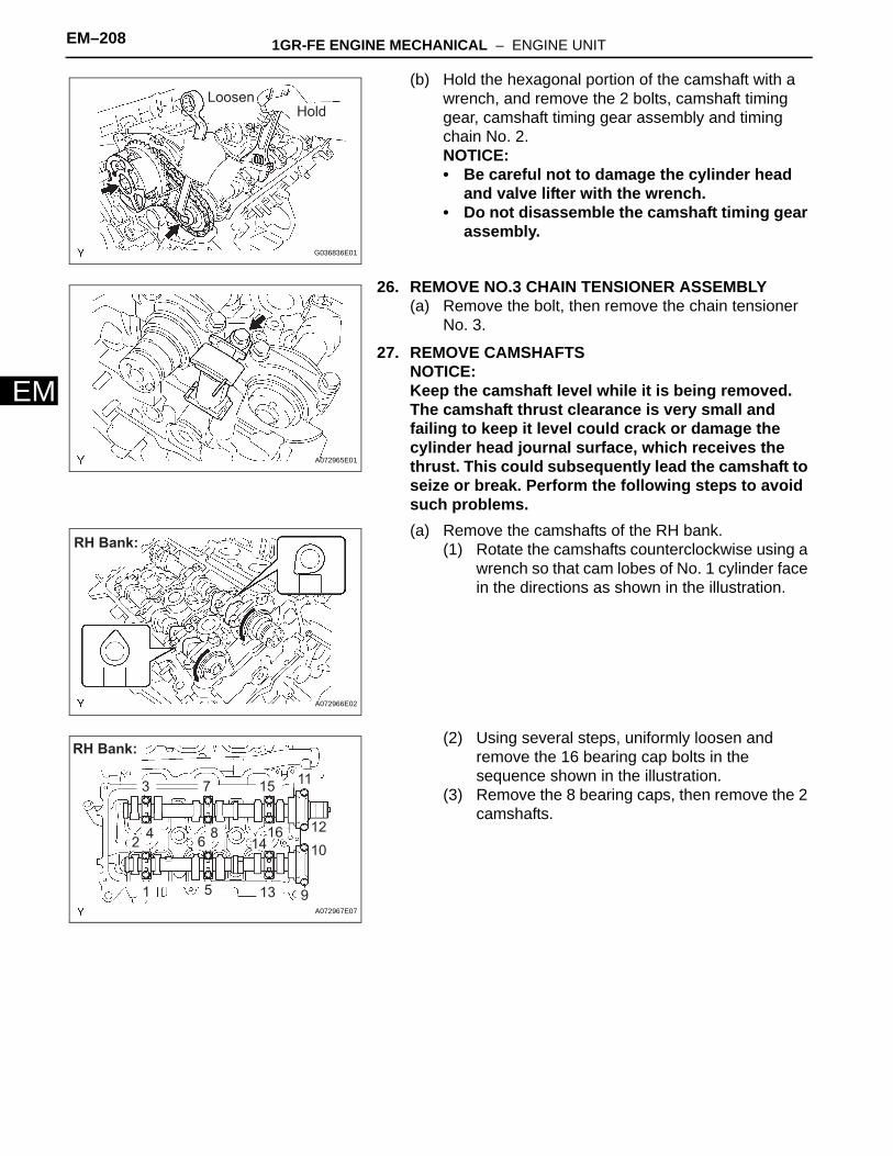
(b) Hold the hexagonal portion of the camshaft with a wrench, and remove the 2 bolts, camshaft timing gear, camshaft timing gear assembly and timing chain No. 2.NOTICE:• Be careful not to damage the cylinder head
and valve lifter with the wrench.• Do not disassemble the camshaft timing gear
assembly.
26. REMOVE NO.3 CHAIN TENSIONER ASSEMBLY(a) Remove the bolt, then remove the chain tensioner
No. 3.
27. REMOVE CAMSHAFTSNOTICE:Keep the camshaft level while it is being removed. The camshaft thrust clearance is very small and failing to keep it level could crack or damage the cylinder head journal surface, which receives the thrust. This could subsequently lead the camshaft to seize or break. Perform the following steps to avoid such problems.(a) Remove the camshafts of the RH bank.
(1) Rotate the camshafts counterclockwise using a wrench so that cam lobes of No. 1 cylinder face in the directions as shown in the illustration.
(2) Using several steps, uniformly loosen and remove the 16 bearing cap bolts in the sequence shown in the illustration.
(3) Remove the 8 bearing caps, then remove the 2 camshafts.
LoosenHold
G036836E01
A072965E01
RH Bank:
A072966E02
1
2
3
46
7
8
5 9
10
11
12
14
15
13
16
RH Bank:
A072967E07
1GR-FE ENGINE MECHANICAL – ENGINE UNIT EM–209
M
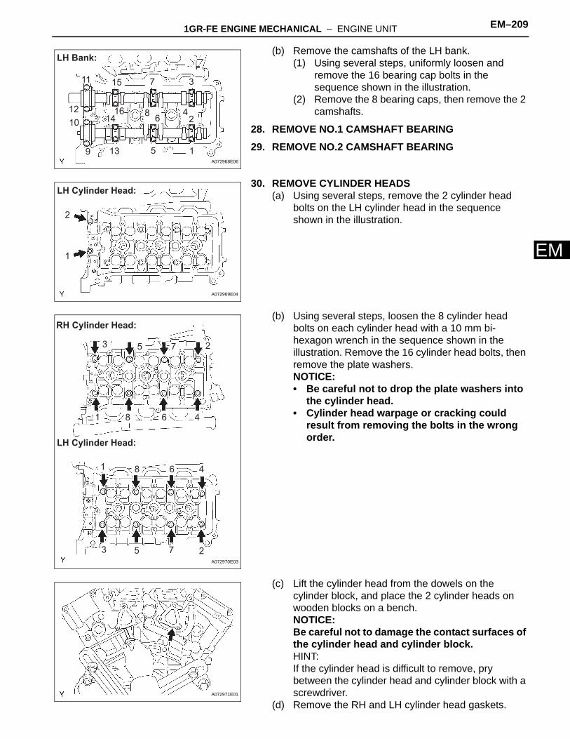
E(b) Remove the camshafts of the LH bank.(1) Using several steps, uniformly loosen and
remove the 16 bearing cap bolts in the sequence shown in the illustration.
(2) Remove the 8 bearing caps, then remove the 2 camshafts.
28. REMOVE NO.1 CAMSHAFT BEARING29. REMOVE NO.2 CAMSHAFT BEARING
30. REMOVE CYLINDER HEADS(a) Using several steps, remove the 2 cylinder head
bolts on the LH cylinder head in the sequence shown in the illustration.
(b) Using several steps, loosen the 8 cylinder head bolts on each cylinder head with a 10 mm bi-hexagon wrench in the sequence shown in the illustration. Remove the 16 cylinder head bolts, then remove the plate washers.NOTICE:• Be careful not to drop the plate washers into
the cylinder head.• Cylinder head warpage or cracking could
result from removing the bolts in the wrong order.
(c) Lift the cylinder head from the dowels on the cylinder block, and place the 2 cylinder heads on wooden blocks on a bench.NOTICE:Be careful not to damage the contact surfaces of the cylinder head and cylinder block.HINT:If the cylinder head is difficult to remove, pry between the cylinder head and cylinder block with a screwdriver.
(d) Remove the RH and LH cylinder head gaskets.
3
64
7
9
8
5
2
1
10
11
12
13
14
15
16
LH Bank:
A072968E06
LH Cylinder Head:
2
1
A072969E04
1
3 5 27
6 4
1
8
8
25
46
73
RH Cylinder Head:
LH Cylinder Head:
A072970E03
A072971E01
EM–210 1GR-FE ENGINE MECHANICAL – ENGINE UNIT
EM
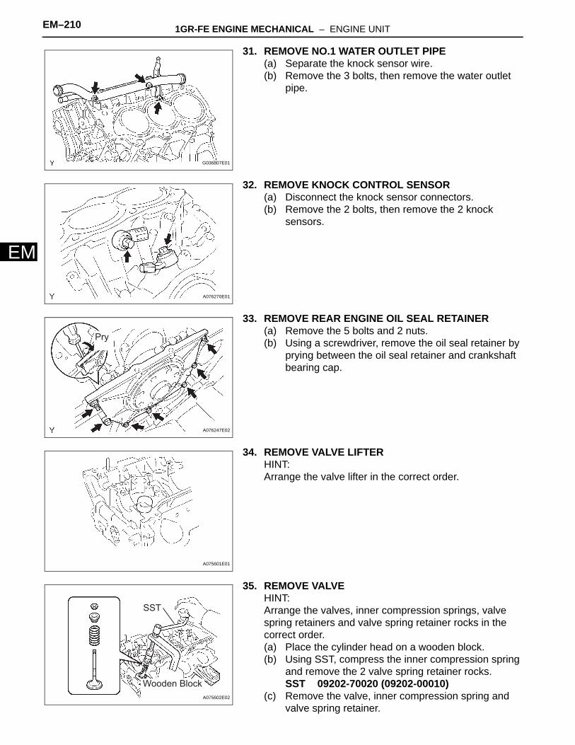
31. REMOVE NO.1 WATER OUTLET PIPE(a) Separate the knock sensor wire.(b) Remove the 3 bolts, then remove the water outlet
pipe.
32. REMOVE KNOCK CONTROL SENSOR(a) Disconnect the knock sensor connectors.(b) Remove the 2 bolts, then remove the 2 knock
sensors.
33. REMOVE REAR ENGINE OIL SEAL RETAINER(a) Remove the 5 bolts and 2 nuts.(b) Using a screwdriver, remove the oil seal retainer by
prying between the oil seal retainer and crankshaft bearing cap.
34. REMOVE VALVE LIFTERHINT:Arrange the valve lifter in the correct order.
35. REMOVE VALVEHINT:Arrange the valves, inner compression springs, valve spring retainers and valve spring retainer rocks in the correct order.(a) Place the cylinder head on a wooden block.(b) Using SST, compress the inner compression spring
and remove the 2 valve spring retainer rocks.SST 09202-70020 (09202-00010)
(c) Remove the valve, inner compression spring and valve spring retainer.
G036807E01
A076270E01
Pry
A076247E02
A075601E01
SST
Wooden Block
A075602E02
1GR-FE ENGINE MECHANICAL – ENGINE UNIT EM–211
M
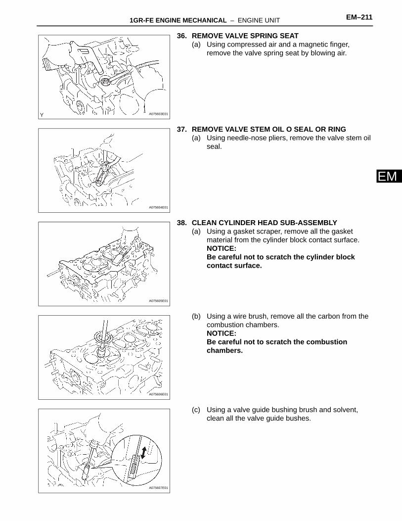
E36. REMOVE VALVE SPRING SEAT(a) Using compressed air and a magnetic finger,
remove the valve spring seat by blowing air.
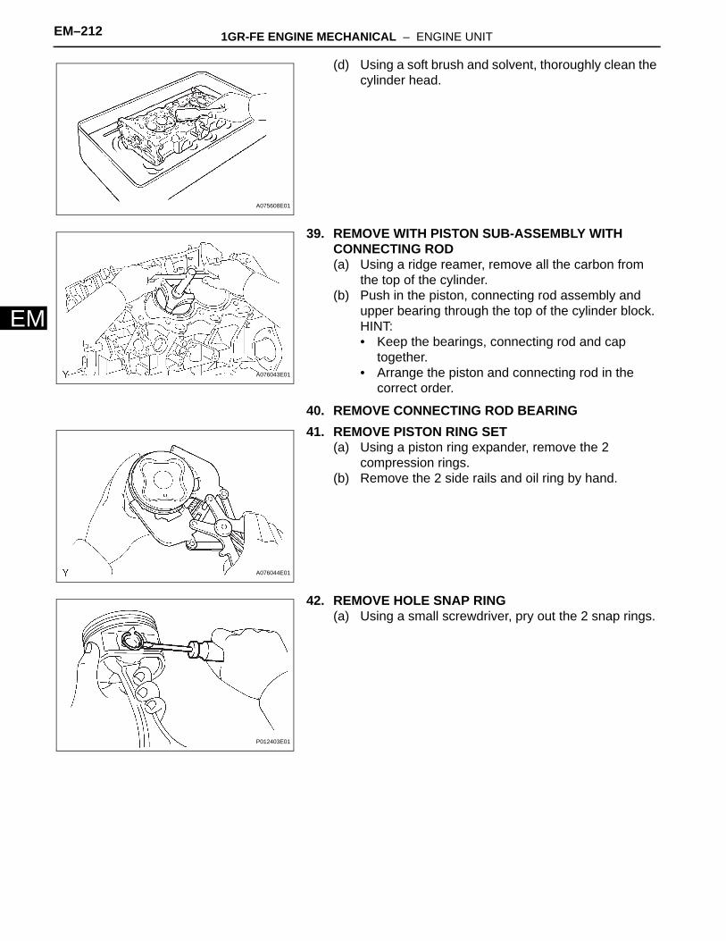
37. REMOVE VALVE STEM OIL O SEAL OR RING(a) Using needle-nose pliers, remove the valve stem oil
seal.
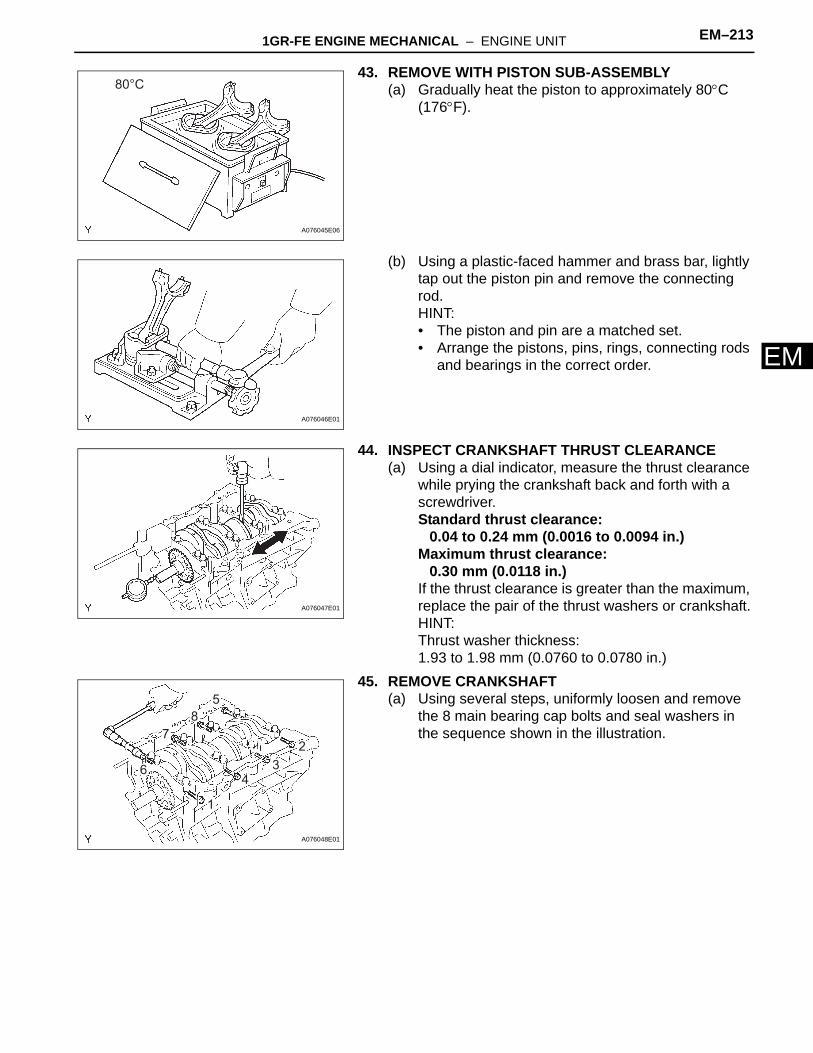
38. CLEAN CYLINDER HEAD SUB-ASSEMBLY(a) Using a gasket scraper, remove all the gasket
material from the cylinder block contact surface.NOTICE:Be careful not to scratch the cylinder block contact surface.
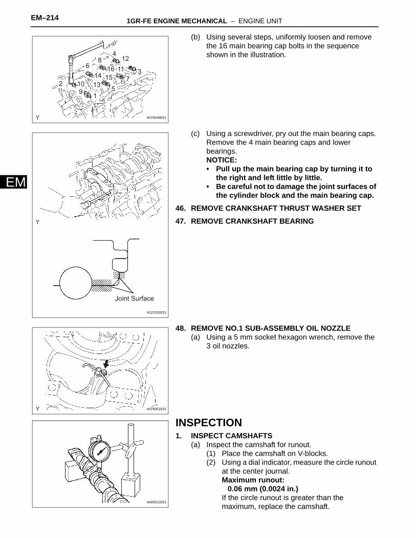
(b) Using a wire brush, remove all the carbon from the combustion chambers.NOTICE:Be careful not to scratch the combustion chambers.
(c) Using a valve guide bushing brush and solvent, clean all the valve guide bushes.
A075603E01
A075604E01
A075605E01
A075606E01
A075607E01
EM–212 1GR-FE ENGINE MECHANICAL – ENGINE UNIT
EM
(d) Using a soft brush and solvent, thoroughly clean the cylinder head.
39. REMOVE WITH PISTON SUB-ASSEMBLY WITH CONNECTING ROD(a) Using a ridge reamer, remove all the carbon from
the top of the cylinder.(b) Push in the piston, connecting rod assembly and
upper bearing through the top of the cylinder block.HINT:• Keep the bearings, connecting rod and cap
together.• Arrange the piston and connecting rod in the
correct order.
40. REMOVE CONNECTING ROD BEARING41. REMOVE PISTON RING SET
(a) Using a piston ring expander, remove the 2 compression rings.
(b) Remove the 2 side rails and oil ring by hand.
42. REMOVE HOLE SNAP RING(a) Using a small screwdriver, pry out the 2 snap rings.
A075608E01
A076043E01
A076044E01
P012403E01
1GR-FE ENGINE MECHANICAL – ENGINE UNIT EM–213
M
E43. REMOVE WITH PISTON SUB-ASSEMBLY(a) Gradually heat the piston to approximately 80°C
(176°F).
(b) Using a plastic-faced hammer and brass bar, lightly tap out the piston pin and remove the connecting rod.HINT:• The piston and pin are a matched set.• Arrange the pistons, pins, rings, connecting rods
and bearings in the correct order.
44. INSPECT CRANKSHAFT THRUST CLEARANCE(a) Using a dial indicator, measure the thrust clearance
while prying the crankshaft back and forth with a screwdriver.Standard thrust clearance:
0.04 to 0.24 mm (0.0016 to 0.0094 in.)Maximum thrust clearance:
0.30 mm (0.0118 in.)If the thrust clearance is greater than the maximum, replace the pair of the thrust washers or crankshaft.HINT:Thrust washer thickness:1.93 to 1.98 mm (0.0760 to 0.0780 in.)
45. REMOVE CRANKSHAFT(a) Using several steps, uniformly loosen and remove
the 8 main bearing cap bolts and seal washers in the sequence shown in the illustration.
80°C
A076045E06
A076046E01
A076047E01
6
1
7
8
5
2
34
A076048E01
EM–214 1GR-FE ENGINE MECHANICAL – ENGINE UNIT
EM
(b) Using several steps, uniformly loosen and remove the 16 main bearing cap bolts in the sequence shown in the illustration.
(c) Using a screwdriver, pry out the main bearing caps. Remove the 4 main bearing caps and lower bearings.NOTICE:• Pull up the main bearing cap by turning it to
the right and left little by little.• Be careful not to damage the joint surfaces of
the cylinder block and the main bearing cap.46. REMOVE CRANKSHAFT THRUST WASHER SET47. REMOVE CRANKSHAFT BEARING
48. REMOVE NO.1 SUB-ASSEMBLY OIL NOZZLE(a) Using a 5 mm socket hexagon wrench, remove the
3 oil nozzles.
INSPECTION1. INSPECT CAMSHAFTS
(a) Inspect the camshaft for runout.(1) Place the camshaft on V-blocks.(2) Using a dial indicator, measure the circle runout
at the center journal.Maximum runout:
0.06 mm (0.0024 in.)If the circle runout is greater than the maximum, replace the camshaft.
1
3
2 109
4
5
6
7
8
13
14
12
11
15
16
A076049E01
Joint Surface
A121032E01
A076051E01
A005912E01
1GR-FE ENGINE MECHANICAL – ENGINE UNIT EM–215
M
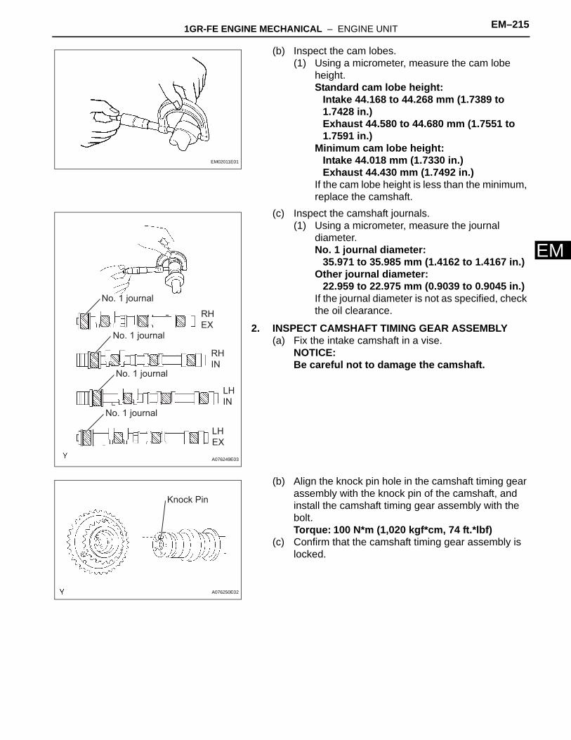
E(b) Inspect the cam lobes.(1) Using a micrometer, measure the cam lobe
height.Standard cam lobe height:
Intake 44.168 to 44.268 mm (1.7389 to 1.7428 in.)Exhaust 44.580 to 44.680 mm (1.7551 to 1.7591 in.)
Minimum cam lobe height:Intake 44.018 mm (1.7330 in.)Exhaust 44.430 mm (1.7492 in.)
If the cam lobe height is less than the minimum, replace the camshaft.
(c) Inspect the camshaft journals.(1) Using a micrometer, measure the journal
diameter.No. 1 journal diameter:
35.971 to 35.985 mm (1.4162 to 1.4167 in.)Other journal diameter:
22.959 to 22.975 mm (0.9039 to 0.9045 in.)If the journal diameter is not as specified, check the oil clearance.
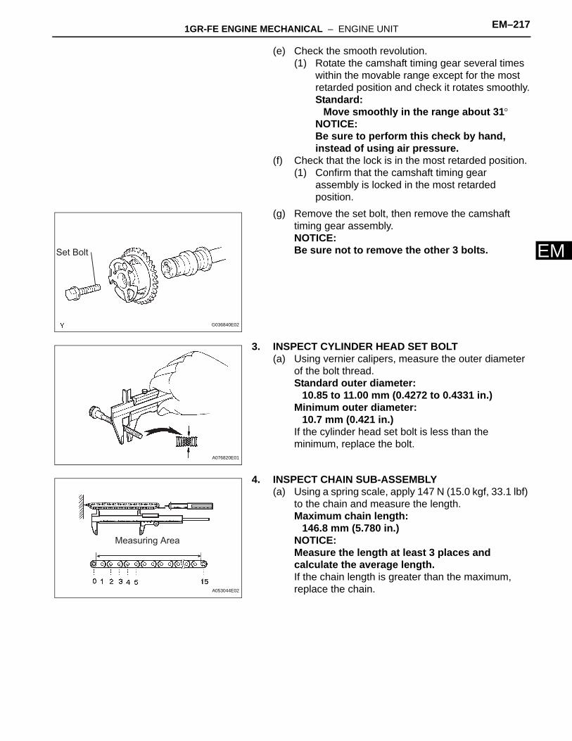
2. INSPECT CAMSHAFT TIMING GEAR ASSEMBLY(a) Fix the intake camshaft in a vise.
NOTICE:Be careful not to damage the camshaft.
(b) Align the knock pin hole in the camshaft timing gear assembly with the knock pin of the camshaft, and install the camshaft timing gear assembly with the bolt.Torque: 100 N*m (1,020 kgf*cm, 74 ft.*lbf)
(c) Confirm that the camshaft timing gear assembly is locked.
EM02011E01
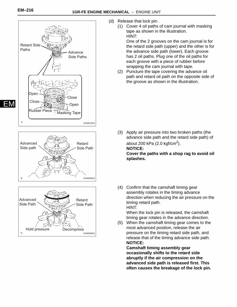
No. 1 journal
RH
EX
RH
IN
LH
IN
LH
EX
No. 1 journal
No. 1 journal
No. 1 journal
A076249E03
Knock Pin
A076250E02
EM–216 1GR-FE ENGINE MECHANICAL – ENGINE UNIT
EM
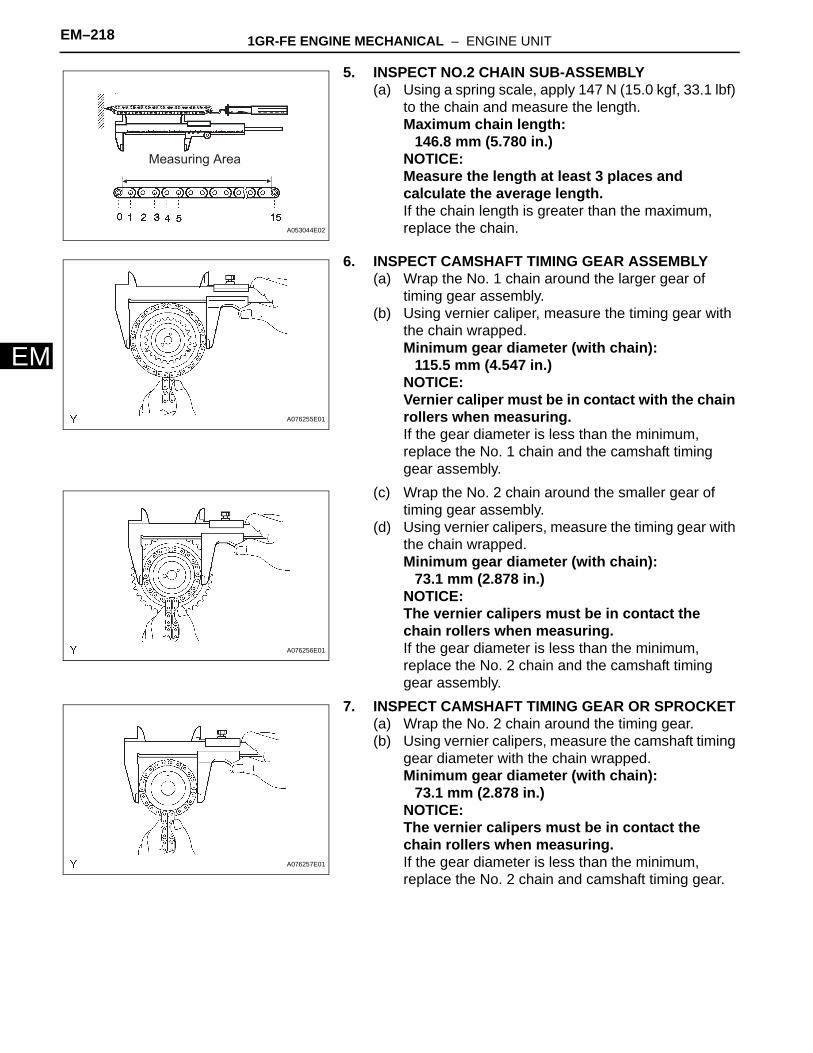
(d) Release that lock pin.(1) Cover 4 oil paths of cam journal with masking
tape as shown in the illustration.HINT:One of the 2 grooves on the cam journal is for the retard side path (upper) and the other is for the advance side path (lower). Each groove has 2 oil paths. Plug one of the oil paths for each groove with a piece of rubber before wrapping the cam journal with tape.
(2) Puncture the tape covering the advance oil path and retard oil path on the opposite side of the groove as shown in the illustration.
(3) Apply air pressure into two broken paths (the advance side path and the retard side path) of about 200 kPa (2.0 kgf/cm2).NOTICE:Cover the paths with a shop rag to avoid oil splashes.
(4) Confirm that the camshaft timing gear assembly rotates in the timing advance direction when reducing the air pressure on the timing retard path.HINT:When the lock pin is released, the camshaft timing gear rotates in the advance direction.
(5) When the camshaft timing gear comes to the most advanced position, release the air pressure on the timing retard side path, and release that of the timing advance side path.NOTICE:Camshaft timing assembly gear occasionally shifts to the retard side abruptly if the air compression on the advanced side path is released first. This often causes the breakage of the lock pin.
Retard Side
PathsAdvance
Side Paths
CloseClose
Open
Open
Rubber PieceMasking Tape
G036837E02
Advanced
Side pathRetard
Side Path
G036838E02
Advanced
Side PathRetard
Side Path
DecompressHold pressureG036839E02
1GR-FE ENGINE MECHANICAL – ENGINE UNIT EM–217
M
E(e) Check the smooth revolution.(1) Rotate the camshaft timing gear several times
within the movable range except for the most retarded position and check it rotates smoothly.Standard:
Move smoothly in the range about 31°NOTICE:Be sure to perform this check by hand, instead of using air pressure.
(f) Check that the lock is in the most retarded position.(1) Confirm that the camshaft timing gear
assembly is locked in the most retarded position.
(g) Remove the set bolt, then remove the camshaft timing gear assembly.NOTICE:Be sure not to remove the other 3 bolts.
3. INSPECT CYLINDER HEAD SET BOLT(a) Using vernier calipers, measure the outer diameter
of the bolt thread.Standard outer diameter:
10.85 to 11.00 mm (0.4272 to 0.4331 in.)Minimum outer diameter:
10.7 mm (0.421 in.)If the cylinder head set bolt is less than the minimum, replace the bolt.
4. INSPECT CHAIN SUB-ASSEMBLY(a) Using a spring scale, apply 147 N (15.0 kgf, 33.1 lbf)
to the chain and measure the length.Maximum chain length:
146.8 mm (5.780 in.)NOTICE:Measure the length at least 3 places and calculate the average length.If the chain length is greater than the maximum, replace the chain.
Set Bolt
G036840E02
A076820E01
Measuring Area
A053044E02
EM–218 1GR-FE ENGINE MECHANICAL – ENGINE UNIT
EM
5. INSPECT NO.2 CHAIN SUB-ASSEMBLY(a) Using a spring scale, apply 147 N (15.0 kgf, 33.1 lbf)
to the chain and measure the length.Maximum chain length:
146.8 mm (5.780 in.)NOTICE:Measure the length at least 3 places and calculate the average length.If the chain length is greater than the maximum, replace the chain.
6. INSPECT CAMSHAFT TIMING GEAR ASSEMBLY(a) Wrap the No. 1 chain around the larger gear of
timing gear assembly.(b) Using vernier caliper, measure the timing gear with
the chain wrapped.Minimum gear diameter (with chain):
115.5 mm (4.547 in.)NOTICE:Vernier caliper must be in contact with the chain rollers when measuring.If the gear diameter is less than the minimum, replace the No. 1 chain and the camshaft timing gear assembly.
(c) Wrap the No. 2 chain around the smaller gear of timing gear assembly.
(d) Using vernier calipers, measure the timing gear with the chain wrapped.Minimum gear diameter (with chain):
73.1 mm (2.878 in.)NOTICE:The vernier calipers must be in contact the chain rollers when measuring.If the gear diameter is less than the minimum, replace the No. 2 chain and the camshaft timing gear assembly.
7. INSPECT CAMSHAFT TIMING GEAR OR SPROCKET(a) Wrap the No. 2 chain around the timing gear.(b) Using vernier calipers, measure the camshaft timing
gear diameter with the chain wrapped.Minimum gear diameter (with chain):
73.1 mm (2.878 in.)NOTICE:The vernier calipers must be in contact the chain rollers when measuring.If the gear diameter is less than the minimum, replace the No. 2 chain and camshaft timing gear.
Measuring Area
A053044E02
A076255E01
A076256E01
A076257E01
1GR-FE ENGINE MECHANICAL – ENGINE UNIT EM–219
M
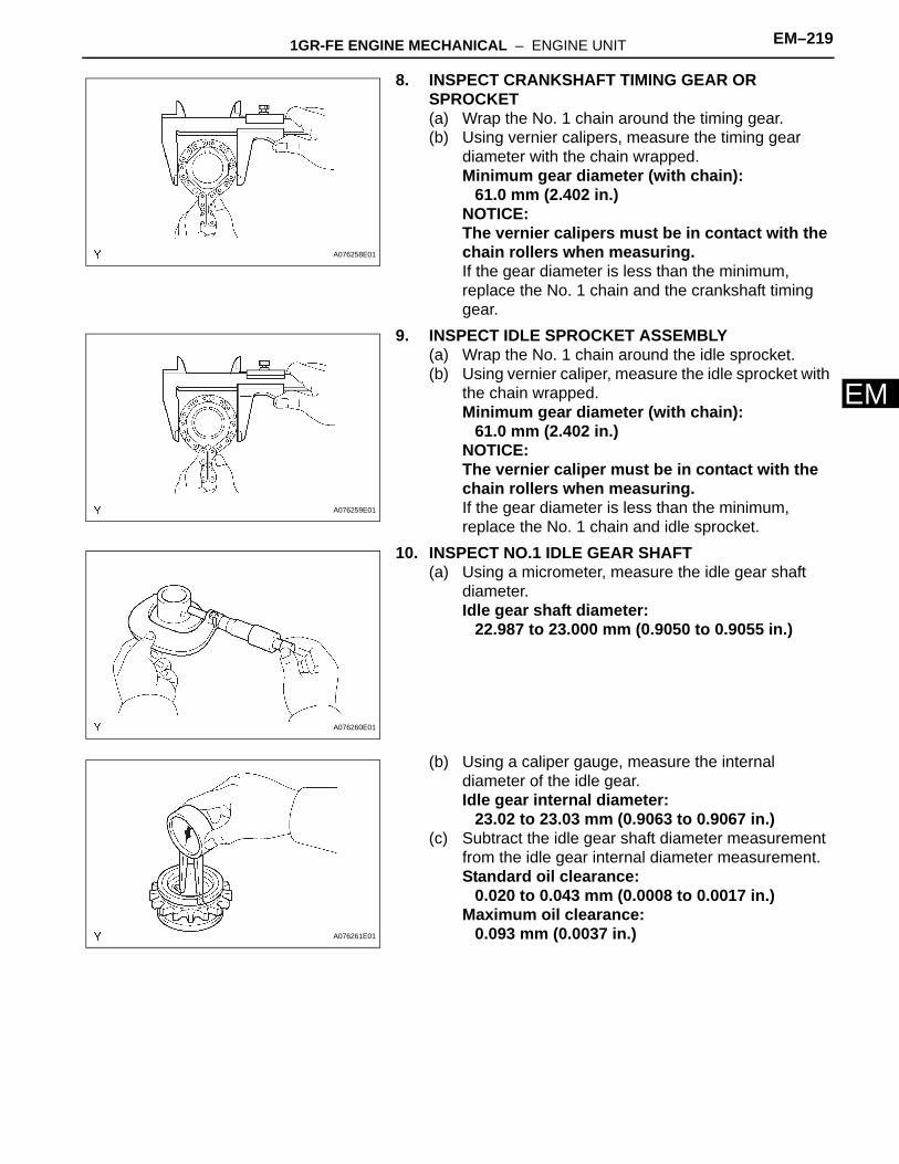
E8. INSPECT CRANKSHAFT TIMING GEAR OR SPROCKET(a) Wrap the No. 1 chain around the timing gear.(b) Using vernier calipers, measure the timing gear
diameter with the chain wrapped.Minimum gear diameter (with chain):
61.0 mm (2.402 in.)NOTICE:The vernier calipers must be in contact with the chain rollers when measuring.If the gear diameter is less than the minimum, replace the No. 1 chain and the crankshaft timing gear.
9. INSPECT IDLE SPROCKET ASSEMBLY(a) Wrap the No. 1 chain around the idle sprocket.(b) Using vernier caliper, measure the idle sprocket with
the chain wrapped.Minimum gear diameter (with chain):
61.0 mm (2.402 in.)NOTICE:The vernier caliper must be in contact with the chain rollers when measuring.If the gear diameter is less than the minimum, replace the No. 1 chain and idle sprocket.
10. INSPECT NO.1 IDLE GEAR SHAFT(a) Using a micrometer, measure the idle gear shaft
diameter.Idle gear shaft diameter:
22.987 to 23.000 mm (0.9050 to 0.9055 in.)
(b) Using a caliper gauge, measure the internal diameter of the idle gear.Idle gear internal diameter:
23.02 to 23.03 mm (0.9063 to 0.9067 in.)(c) Subtract the idle gear shaft diameter measurement
from the idle gear internal diameter measurement.Standard oil clearance:
0.020 to 0.043 mm (0.0008 to 0.0017 in.)Maximum oil clearance:
0.093 mm (0.0037 in.)
A076258E01
A076259E01
A076260E01
A076261E01
EM–220 1GR-FE ENGINE MECHANICAL – ENGINE UNIT
EM
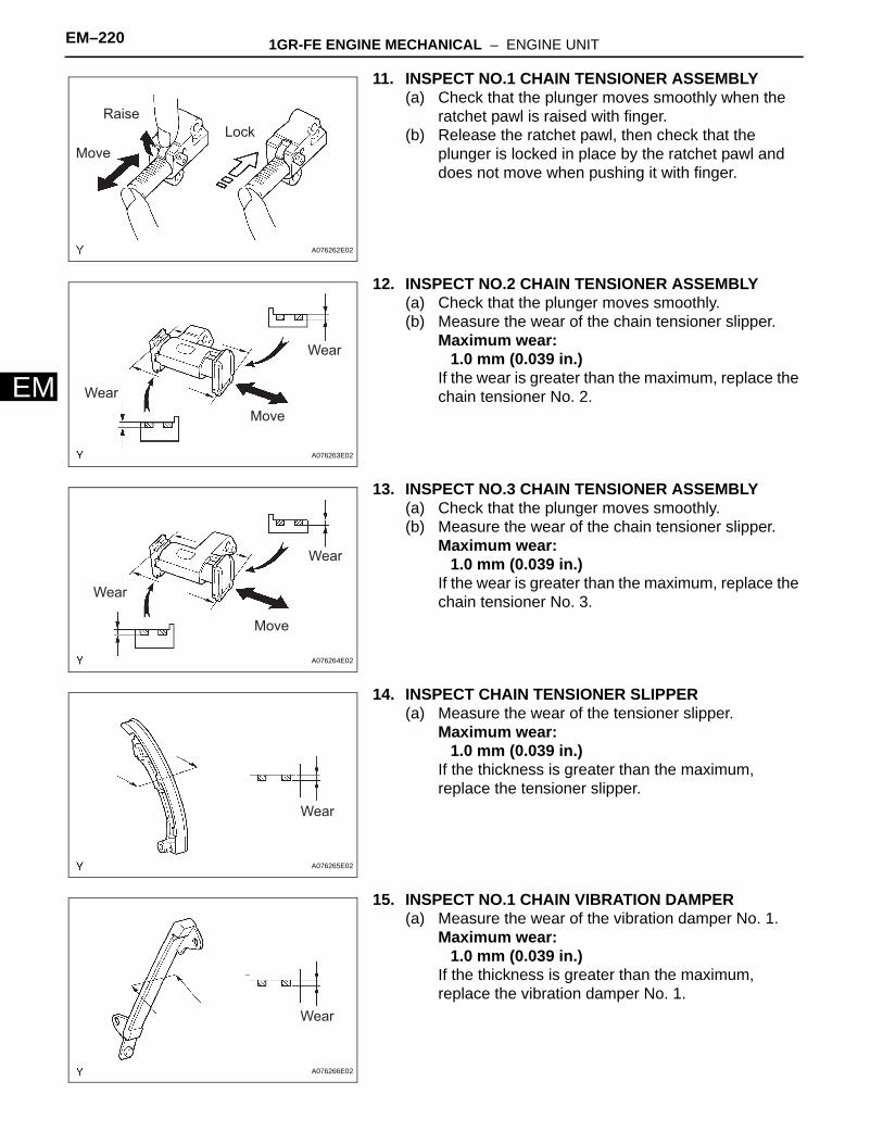
11. INSPECT NO.1 CHAIN TENSIONER ASSEMBLY(a) Check that the plunger moves smoothly when the
ratchet pawl is raised with finger.(b) Release the ratchet pawl, then check that the
plunger is locked in place by the ratchet pawl and does not move when pushing it with finger.
12. INSPECT NO.2 CHAIN TENSIONER ASSEMBLY(a) Check that the plunger moves smoothly.(b) Measure the wear of the chain tensioner slipper.
Maximum wear:1.0 mm (0.039 in.)
If the wear is greater than the maximum, replace the chain tensioner No. 2.
13. INSPECT NO.3 CHAIN TENSIONER ASSEMBLY(a) Check that the plunger moves smoothly.(b) Measure the wear of the chain tensioner slipper.
Maximum wear:1.0 mm (0.039 in.)
If the wear is greater than the maximum, replace the chain tensioner No. 3.
14. INSPECT CHAIN TENSIONER SLIPPER(a) Measure the wear of the tensioner slipper.
Maximum wear:1.0 mm (0.039 in.)
If the thickness is greater than the maximum, replace the tensioner slipper.
15. INSPECT NO.1 CHAIN VIBRATION DAMPER(a) Measure the wear of the vibration damper No. 1.
Maximum wear:1.0 mm (0.039 in.)
If the thickness is greater than the maximum, replace the vibration damper No. 1.
Raise
Move
Lock
A076262E02
Move
Wear
Wear
A076263E02
Move
Wear
Wear
A076264E02
Wear
A076265E02
Wear
A076266E02

1GR-FE ENGINE MECHANICAL – ENGINE UNIT EM–221
M
E16. INSPECT NO.2 CHAIN VIBRATION DAMPER(a) Measure the wear of the vibration damper No. 2 .
Maximum wear:1.0 mm (0.039 in.)
If the thickness is greater than the maximum, replace the vibration damper No. 2.
17. INSPECT CYLINDER HEAD SUB-ASSEMBLY(a) Inspect the cylinder head for warpage.
(1) Using a precision straight edge and feeler gauge, measure the warpage on the cylinder block side and the intake and exhaust sides.Maximum warpage:
0.10 mm (0.0039 in.)If the warpage is greater than the maximum, replace the cylinder head.
(b) Inspect the cylinder head for crack.(1) Using a dye penetrant, check the combustion
chamber, intake ports, exhaust ports and cylinder block surface for cracks.If cracked, replace the cylinder head.
Wear
A076267E02
Cylinder Block Side:
Intake Manifold Side:
Exhaust Manifold Side:
A075609E03
A075610E01
EM–222 1GR-FE ENGINE MECHANICAL – ENGINE UNIT
EM
18. CLEAN VALVE(a) Using a gasket scraper, chip off any carbon from the
valve head.(b) Using a wire brush, thoroughly clean the valve.
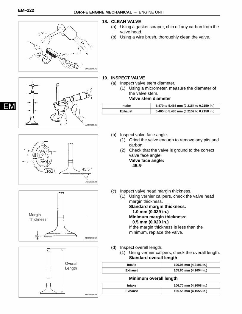
19. INSPECT VALVE(a) Inspect valve stem diameter.
(1) Using a micrometer, measure the diameter of the valve stem.Valve stem diameter
(b) Inspect valve face angle.(1) Grind the valve enough to remove any pits and
carbon.(2) Check that the valve is ground to the correct
valve face angle.Valve face angle:
45.5°
(c) Inspect valve head margin thickness.(1) Using vernier calipers, check the valve head
margin thickness.Standard margin thickness:
1.0 mm (0.039 in.)Minimum margin thickness:
0.5 mm (0.020 in.)If the margin thickness is less than the minimum, replace the valve.
(d) Inspect overall length.(1) Using vernier calipers, check the overall length.
Standard overall length
Minimum overall length
EM00580E01
A032770E01
Intake 5.470 to 5.485 mm (0.2154 to 0.2159 in.)
Exhaust 5.465 to 5.480 mm (0.2152 to 0.2158 in.)
45.5 °
A075611E03
Margin
Thickness
EM00181E02
Overall
Length
EM02534E08
Intake 106.95 mm (4.2106 in.)
Exhaust 105.80 mm (4.1654 in.)
Intake 106.70 mm (4.2008 in.)
Exhaust 105.55 mm (4.1555 in.)
1GR-FE ENGINE MECHANICAL – ENGINE UNIT EM–223
M
EIf the overall length is less than the minimum, replace the valve.
(e) Inspect valve stem tip.(1) Check the surface of the valve stem tip for
wear.NOTICE:Do not grind to less than the minimum length.If the valve stem tip is worn, resurface the tip with a grinder or replace the valve.
20. CLEAN VALVE SEAT(a) Using a 45° carbide cutter, resurface the valve
seats.(b) Clean the valve seats.
21. INSPECT VALVE SEAT(a) Apply a light coat of prussian blue (or white lead) to
the valve face.(b) Lightly press the valve against the valve seat.
NOTICE:Do not rotate the valve.
(c) Check the valve face and seat according to the following procedure.(1) If blue appears 360° around the face, the valve
is concentric.If not, replace the valve.
(2) If the blue appears 360° around the valve seat, the guide and face are concentric.If not, resurface the valve seat.
(3) Check that the seat is in contact with the middle of the valve face with the following width.Standard width:
1.0 to 1.4 mm (0.039 to 0.055 in.)22. INSPECT INNER COMPRESSION SPRING
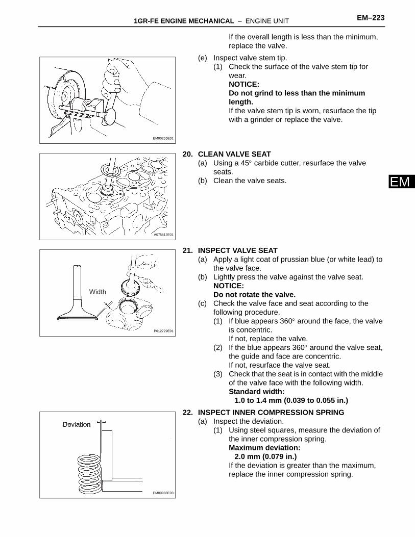
(a) Inspect the deviation.(1) Using steel squares, measure the deviation of
the inner compression spring.Maximum deviation:
2.0 mm (0.079 in.)If the deviation is greater than the maximum, replace the inner compression spring.
EM00255E01
A075612E01
Width
P012729E01
EM00988E03
EM–224 1GR-FE ENGINE MECHANICAL – ENGINE UNIT
EM
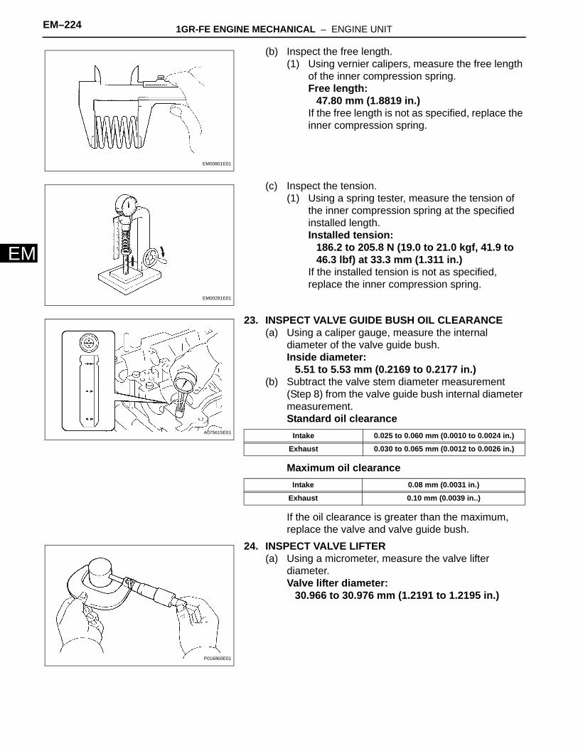
(b) Inspect the free length.(1) Using vernier calipers, measure the free length
of the inner compression spring.Free length:
47.80 mm (1.8819 in.)If the free length is not as specified, replace the inner compression spring.
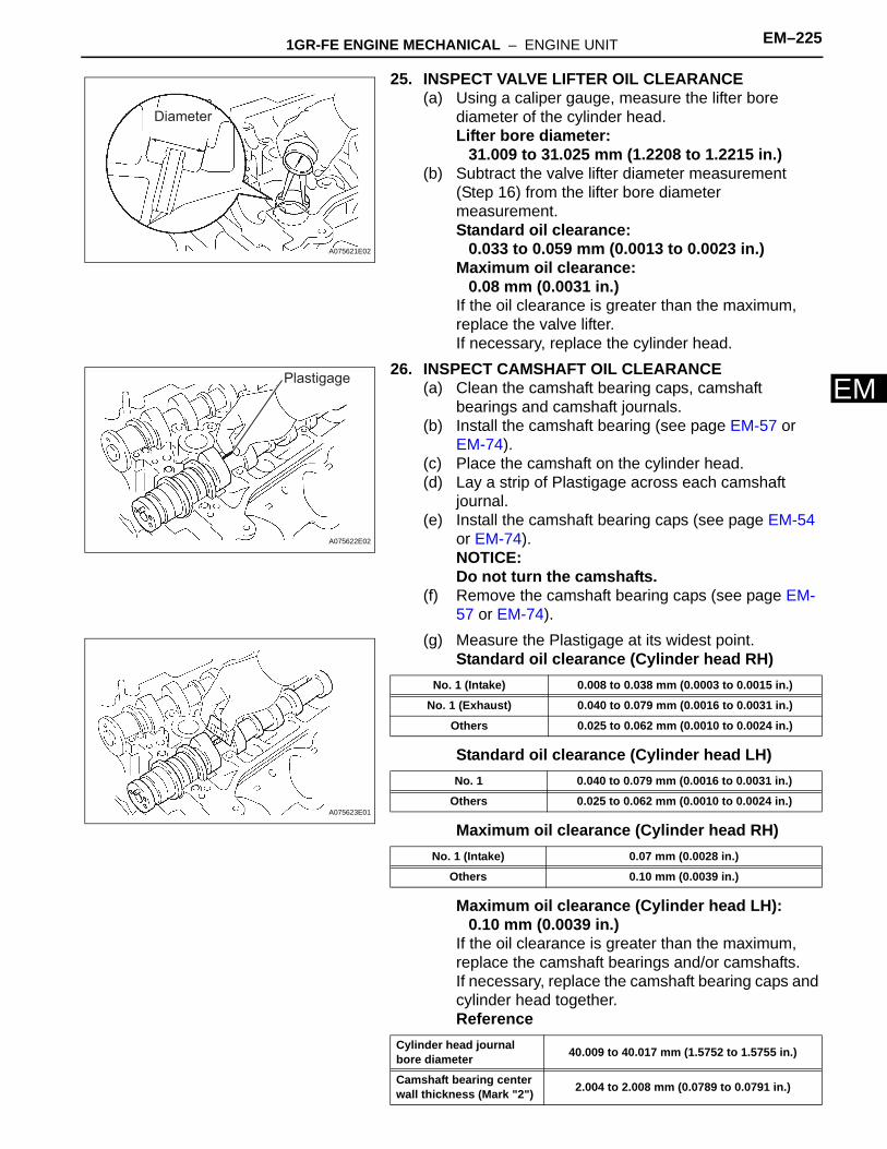
(c) Inspect the tension.(1) Using a spring tester, measure the tension of
the inner compression spring at the specified installed length.Installed tension:
186.2 to 205.8 N (19.0 to 21.0 kgf, 41.9 to 46.3 lbf) at 33.3 mm (1.311 in.)
If the installed tension is not as specified, replace the inner compression spring.
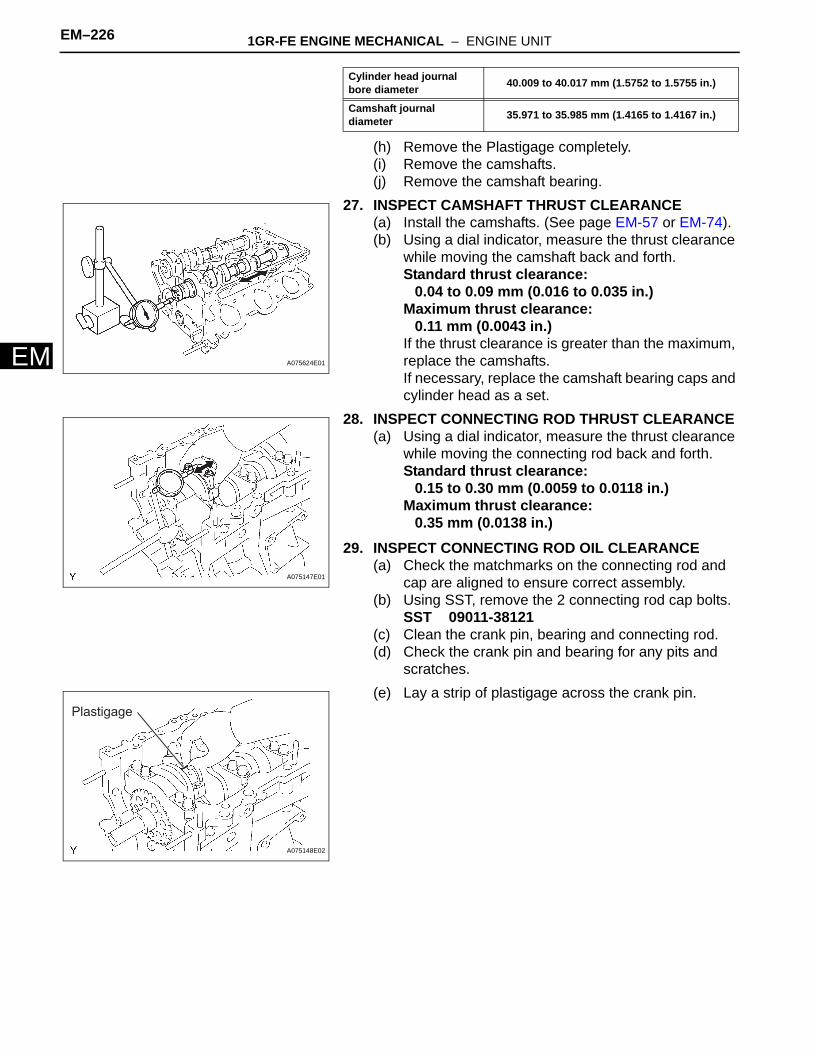
23. INSPECT VALVE GUIDE BUSH OIL CLEARANCE(a) Using a caliper gauge, measure the internal
diameter of the valve guide bush.Inside diameter:
5.51 to 5.53 mm (0.2169 to 0.2177 in.)(b) Subtract the valve stem diameter measurement
(Step 8) from the valve guide bush internal diameter measurement.Standard oil clearance
Maximum oil clearance
If the oil clearance is greater than the maximum, replace the valve and valve guide bush.
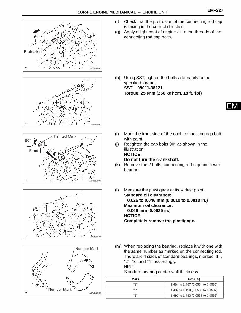
24. INSPECT VALVE LIFTER(a) Using a micrometer, measure the valve lifter
diameter.Valve lifter diameter:
30.966 to 30.976 mm (1.2191 to 1.2195 in.)
EM00801E01
EM00281E01
A075615E01 Intake 0.025 to 0.060 mm (0.0010 to 0.0024 in.)
Exhaust 0.030 to 0.065 mm (0.0012 to 0.0026 in.)
Intake 0.08 mm (0.0031 in.)
Exhaust 0.10 mm (0.0039 in..)
P016860E01
1GR-FE ENGINE MECHANICAL – ENGINE UNIT EM–225
M
E25. INSPECT VALVE LIFTER OIL CLEARANCE(a) Using a caliper gauge, measure the lifter bore
diameter of the cylinder head.Lifter bore diameter:
31.009 to 31.025 mm (1.2208 to 1.2215 in.)(b) Subtract the valve lifter diameter measurement
(Step 16) from the lifter bore diameter measurement.Standard oil clearance:
0.033 to 0.059 mm (0.0013 to 0.0023 in.)Maximum oil clearance:
0.08 mm (0.0031 in.)If the oil clearance is greater than the maximum, replace the valve lifter.If necessary, replace the cylinder head.
26. INSPECT CAMSHAFT OIL CLEARANCE(a) Clean the camshaft bearing caps, camshaft
bearings and camshaft journals.(b) Install the camshaft bearing (see page EM-57 or
EM-74).(c) Place the camshaft on the cylinder head.(d) Lay a strip of Plastigage across each camshaft
journal.(e) Install the camshaft bearing caps (see page EM-54
or EM-74).NOTICE:Do not turn the camshafts.
(f) Remove the camshaft bearing caps (see page EM-57 or EM-74).
(g) Measure the Plastigage at its widest point.Standard oil clearance (Cylinder head RH)
Standard oil clearance (Cylinder head LH)
Maximum oil clearance (Cylinder head RH)
Maximum oil clearance (Cylinder head LH):0.10 mm (0.0039 in.)
If the oil clearance is greater than the maximum, replace the camshaft bearings and/or camshafts.If necessary, replace the camshaft bearing caps and cylinder head together.Reference
Diameter
A075621E02
Plastigage
A075622E02
A075623E01
No. 1 (Intake) 0.008 to 0.038 mm (0.0003 to 0.0015 in.)
No. 1 (Exhaust) 0.040 to 0.079 mm (0.0016 to 0.0031 in.)
Others 0.025 to 0.062 mm (0.0010 to 0.0024 in.)
No. 1 0.040 to 0.079 mm (0.0016 to 0.0031 in.)
Others 0.025 to 0.062 mm (0.0010 to 0.0024 in.)
No. 1 (Intake) 0.07 mm (0.0028 in.)
Others 0.10 mm (0.0039 in.)
Cylinder head journal bore diameter 40.009 to 40.017 mm (1.5752 to 1.5755 in.)
Camshaft bearing center wall thickness (Mark "2") 2.004 to 2.008 mm (0.0789 to 0.0791 in.)
EM–226 1GR-FE ENGINE MECHANICAL – ENGINE UNIT
EM
(h) Remove the Plastigage completely.(i) Remove the camshafts.(j) Remove the camshaft bearing.
27. INSPECT CAMSHAFT THRUST CLEARANCE(a) Install the camshafts. (See page EM-57 or EM-74).(b) Using a dial indicator, measure the thrust clearance
while moving the camshaft back and forth.Standard thrust clearance:
0.04 to 0.09 mm (0.016 to 0.035 in.)Maximum thrust clearance:
0.11 mm (0.0043 in.)If the thrust clearance is greater than the maximum, replace the camshafts.If necessary, replace the camshaft bearing caps and cylinder head as a set.
28. INSPECT CONNECTING ROD THRUST CLEARANCE(a) Using a dial indicator, measure the thrust clearance
while moving the connecting rod back and forth.Standard thrust clearance:
0.15 to 0.30 mm (0.0059 to 0.0118 in.)Maximum thrust clearance:
0.35 mm (0.0138 in.)29. INSPECT CONNECTING ROD OIL CLEARANCE
(a) Check the matchmarks on the connecting rod and cap are aligned to ensure correct assembly.
(b) Using SST, remove the 2 connecting rod cap bolts.SST 09011-38121
(c) Clean the crank pin, bearing and connecting rod.(d) Check the crank pin and bearing for any pits and
scratches.(e) Lay a strip of plastigage across the crank pin.
Camshaft journal diameter 35.971 to 35.985 mm (1.4165 to 1.4167 in.)
Cylinder head journal bore diameter 40.009 to 40.017 mm (1.5752 to 1.5755 in.)
A075624E01
A075147E01
Plastigage
A075148E02
1GR-FE ENGINE MECHANICAL – ENGINE UNIT EM–227
M
E(f) Check that the protrusion of the connecting rod cap is facing in the correct direction.
(g) Apply a light coat of engine oil to the threads of the connecting rod cap bolts.
(h) Using SST, tighten the bolts alternately to the specified torque.SST 09011-38121Torque: 25 N*m (250 kgf*cm, 18 ft.*lbf)
(i) Mark the front side of the each connecting cap bolt with paint.
(j) Retighten the cap bolts 90° as shown in the illustration.NOTICE:Do not turn the crankshaft.
(k) Remove the 2 bolts, connecting rod cap and lower bearing.
(l) Measure the plastigage at its widest point.Standard oil clearance:
0.026 to 0.046 mm (0.0010 to 0.0018 in.)Maximum oil clearance:
0.066 mm (0.0025 in.)NOTICE:Completely remove the plastigage.
(m) When replacing the bearing, replace it with one with the same number as marked on the connecting rod. There are 4 sizes of standard bearings, marked "1 ", "2", "3" and "4" accordingly.HINT:Standard bearing center wall thickness
Protrusion
A075149E02
A075150E01
90°
90°Front
Painted Mark
A075151E03
A075152E02
Number Mark
Number Mark
A075153E02
Mark mm (in.)
"1" 1.484 to 1.487 (0.0584 to 0.0585)
"2" 1.487 to 1.490 (0.0585 to 0.0587)
"3" 1.490 to 1.493 (0.0587 to 0.0588)
EM–228 1GR-FE ENGINE MECHANICAL – ENGINE UNIT
EM
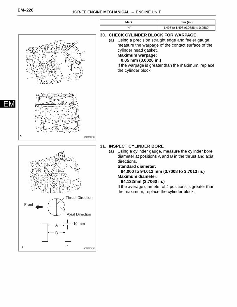
30. CHECK CYLINDER BLOCK FOR WARPAGE(a) Using a precision straight edge and feeler gauge,
measure the warpage of the contact surface of the cylinder head gasket.Maximum warpage:
0.05 mm (0.0020 in.)If the warpage is greater than the maximum, replace the cylinder block.
31. INSPECT CYLINDER BORE(a) Using a cylinder gauge, measure the cylinder bore
diameter at positions A and B in the thrust and axial directions.Standard diameter:
94.000 to 94.012 mm (3.7008 to 3.7013 in.)Maximum diameter:
94.132mm (3.7060 in.)If the average diameter of 4 positions is greater than the maximum, replace the cylinder block.
"4" 1.493 to 1.496 (0.0588 to 0.0589)
Mark mm (in.)
A076052E01
Thrust Direction
Axial Direction
10 mmA
B
Front
A092877E02
1GR-FE ENGINE MECHANICAL – ENGINE UNIT EM–229
M
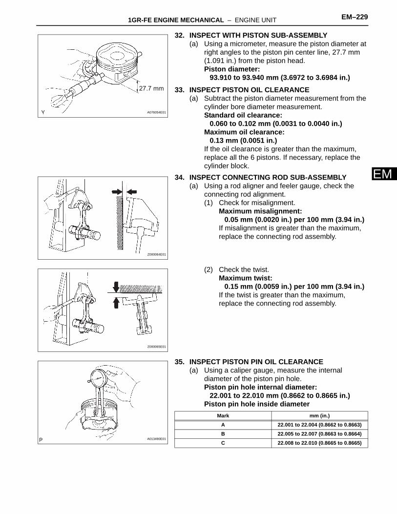
E32. INSPECT WITH PISTON SUB-ASSEMBLY(a) Using a micrometer, measure the piston diameter at
right angles to the piston pin center line, 27.7 mm (1.091 in.) from the piston head.Piston diameter:
93.910 to 93.940 mm (3.6972 to 3.6984 in.)33. INSPECT PISTON OIL CLEARANCE
(a) Subtract the piston diameter measurement from the cylinder bore diameter measurement.Standard oil clearance:
0.060 to 0.102 mm (0.0031 to 0.0040 in.)Maximum oil clearance:
0.13 mm (0.0051 in.)If the oil clearance is greater than the maximum, replace all the 6 pistons. If necessary, replace the cylinder block.
34. INSPECT CONNECTING ROD SUB-ASSEMBLY(a) Using a rod aligner and feeler gauge, check the
connecting rod alignment.(1) Check for misalignment.
Maximum misalignment:0.05 mm (0.0020 in.) per 100 mm (3.94 in.)
If misalignment is greater than the maximum, replace the connecting rod assembly.
(2) Check the twist.Maximum twist:
0.15 mm (0.0059 in.) per 100 mm (3.94 in.)If the twist is greater than the maximum, replace the connecting rod assembly.
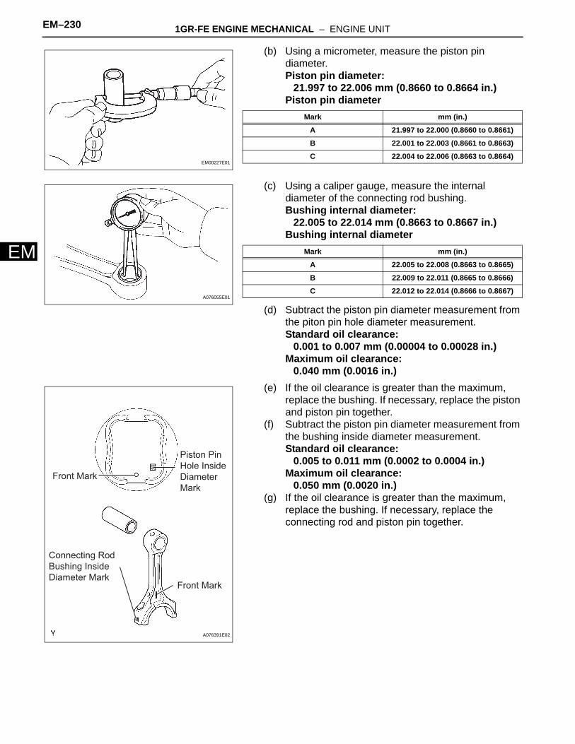
35. INSPECT PISTON PIN OIL CLEARANCE(a) Using a caliper gauge, measure the internal
diameter of the piston pin hole.Piston pin hole internal diameter:
22.001 to 22.010 mm (0.8662 to 0.8665 in.)Piston pin hole inside diameter
27.7 mm
A076054E01
Z000064E01
Z000065E01
A013490E01
Mark mm (in.)
A 22.001 to 22.004 (0.8662 to 0.8663)
B 22.005 to 22.007 (0.8663 to 0.8664)
C 22.008 to 22.010 (0.8665 to 0.8665)
EM–230 1GR-FE ENGINE MECHANICAL – ENGINE UNIT
EM
(b) Using a micrometer, measure the piston pin diameter.Piston pin diameter:
21.997 to 22.006 mm (0.8660 to 0.8664 in.)Piston pin diameter
(c) Using a caliper gauge, measure the internal diameter of the connecting rod bushing.Bushing internal diameter:
22.005 to 22.014 mm (0.8663 to 0.8667 in.)Bushing internal diameter
(d) Subtract the piston pin diameter measurement from the piton pin hole diameter measurement.Standard oil clearance:
0.001 to 0.007 mm (0.00004 to 0.00028 in.)Maximum oil clearance:
0.040 mm (0.0016 in.)(e) If the oil clearance is greater than the maximum,
replace the bushing. If necessary, replace the piston and piston pin together.
(f) Subtract the piston pin diameter measurement from the bushing inside diameter measurement.Standard oil clearance:
0.005 to 0.011 mm (0.0002 to 0.0004 in.)Maximum oil clearance:
0.050 mm (0.0020 in.)(g) If the oil clearance is greater than the maximum,
replace the bushing. If necessary, replace the connecting rod and piston pin together.
EM00227E01
Mark mm (in.)
A 21.997 to 22.000 (0.8660 to 0.8661)
B 22.001 to 22.003 (0.8661 to 0.8663)
C 22.004 to 22.006 (0.8663 to 0.8664)
A076055E01
Mark mm (in.)
A 22.005 to 22.008 (0.8663 to 0.8665)
B 22.009 to 22.011 (0.8665 to 0.8666)
C 22.012 to 22.014 (0.8666 to 0.8667)
Front Mark
Piston Pin
Hole Inside
Diameter
Mark
Front Mark
Connecting Rod
Bushing Inside
Diameter Mark
A076391E02
1GR-FE ENGINE MECHANICAL – ENGINE UNIT EM–231
M
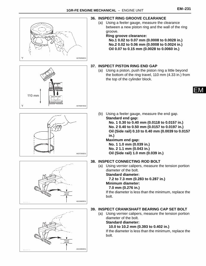
E36. INSPECT RING GROOVE CLEARANCE(a) Using a feeler gauge, measure the clearance
between a new piston ring and the wall of the ring groove.Ring groove clearance:
No.1 0.02 to 0.07 mm (0.0008 to 0.0028 in.)No.2 0.02 to 0.06 mm (0.0008 to 0.0024 in.)Oil 0.07 to 0.15 mm (0.0028 to 0.0060 in.)
37. INSPECT PISTON RING END GAP(a) Using a piston, push the piston ring a little beyond
the bottom of the ring travel, 110 mm (4.33 in.) from the top of the cylinder block.
(b) Using a feeler gauge, measure the end gap.Standard end gap:
No. 1 0.30 to 0.40 mm (0.0118 to 0.0157 in.)No. 2 0.40 to 0.50 mm (0.0157 to 0.0197 in.)Oil (Side rail) 0.10 to 0.40 mm (0.0039 to 0.0157 in.)
Maximum end gap:No. 1 1.0 mm (0.039 in.)No. 2 1.1 mm (0.043 in.)Oil (Side rail) 1.0 mm (0.039 in.)
38. INSPECT CONNECTING ROD BOLT(a) Using vernier calipers, measure the tension portion
diameter of the bolt.Standard diameter:
7.2 to 7.3 mm (0.283 to 0.287 in.)Minimum diameter:
7.0 mm (0.276 in.)If the diameter is less than the minimum, replace the bolt.
39. INSPECT CRANKSHAFT BEARING CAP SET BOLT(a) Using vernier calipers, measure the tension portion
diameter of the bolt.Standard diameter:
10.0 to 10.2 mm (0.393 to 0.402 in.)If the diameter is less than the minimum, replace the bolt.
A076056E01
110 mm
A076057E02
A037355E01
A015065E01
A015065E01
EM–232 1GR-FE ENGINE MECHANICAL – ENGINE UNIT
EM
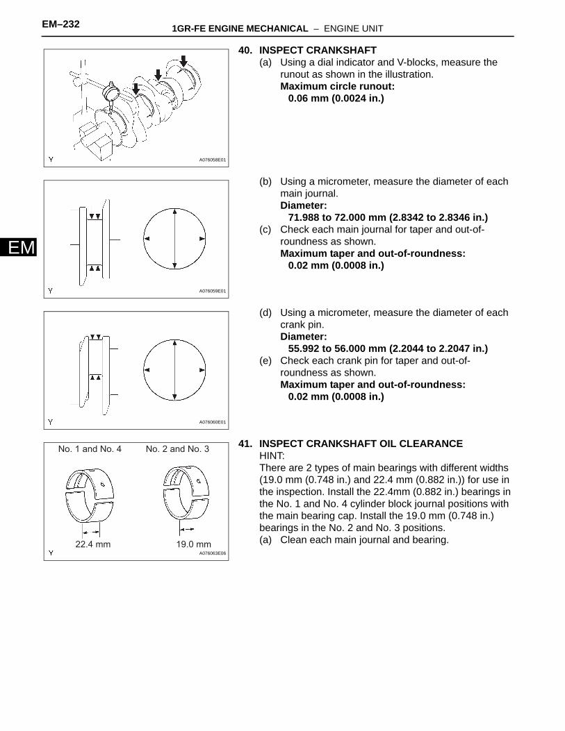
40. INSPECT CRANKSHAFT(a) Using a dial indicator and V-blocks, measure the
runout as shown in the illustration.Maximum circle runout:
0.06 mm (0.0024 in.)
(b) Using a micrometer, measure the diameter of each main journal.Diameter:
71.988 to 72.000 mm (2.8342 to 2.8346 in.)(c) Check each main journal for taper and out-of-
roundness as shown.Maximum taper and out-of-roundness:
0.02 mm (0.0008 in.)
(d) Using a micrometer, measure the diameter of each crank pin.Diameter:
55.992 to 56.000 mm (2.2044 to 2.2047 in.)(e) Check each crank pin for taper and out-of-
roundness as shown.Maximum taper and out-of-roundness:
0.02 mm (0.0008 in.)
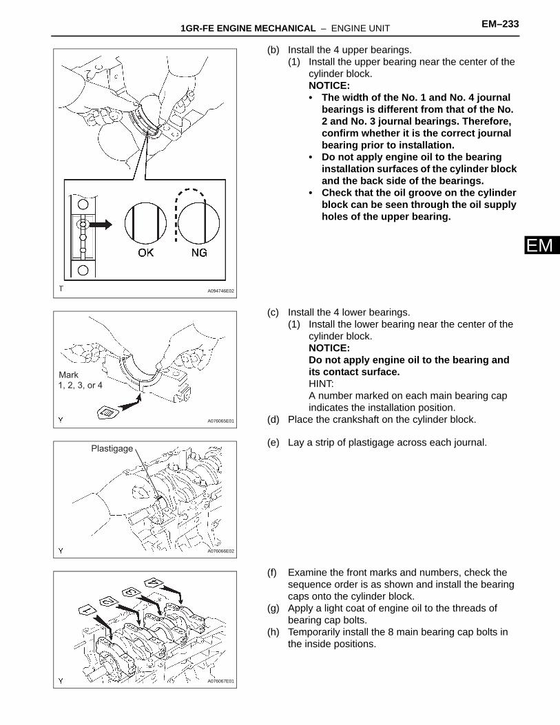
41. INSPECT CRANKSHAFT OIL CLEARANCEHINT:There are 2 types of main bearings with different widths (19.0 mm (0.748 in.) and 22.4 mm (0.882 in.)) for use in the inspection. Install the 22.4mm (0.882 in.) bearings in the No. 1 and No. 4 cylinder block journal positions with the main bearing cap. Install the 19.0 mm (0.748 in.) bearings in the No. 2 and No. 3 positions.(a) Clean each main journal and bearing.
A076058E01
A076059E01
A076060E01
No. 1 and No. 4 No. 2 and No. 3
19.0 mm22.4 mmA076063E06
1GR-FE ENGINE MECHANICAL – ENGINE UNIT EM–233
M
E(b) Install the 4 upper bearings.(1) Install the upper bearing near the center of the
cylinder block.NOTICE:• The width of the No. 1 and No. 4 journal
bearings is different from that of the No. 2 and No. 3 journal bearings. Therefore, confirm whether it is the correct journal bearing prior to installation.
• Do not apply engine oil to the bearing installation surfaces of the cylinder block and the back side of the bearings.
• Check that the oil groove on the cylinder block can be seen through the oil supply holes of the upper bearing.
(c) Install the 4 lower bearings.(1) Install the lower bearing near the center of the
cylinder block.NOTICE:Do not apply engine oil to the bearing and its contact surface.HINT:A number marked on each main bearing cap indicates the installation position.
(d) Place the crankshaft on the cylinder block.
(e) Lay a strip of plastigage across each journal.
(f) Examine the front marks and numbers, check the sequence order is as shown and install the bearing caps onto the cylinder block.
(g) Apply a light coat of engine oil to the threads of bearing cap bolts.
(h) Temporarily install the 8 main bearing cap bolts in the inside positions.
A094746E02
Mark1, 2, 3, or 4
A076065E01
Plastigage
A076066E02
A076067E01
EM–234 1GR-FE ENGINE MECHANICAL – ENGINE UNIT
EM
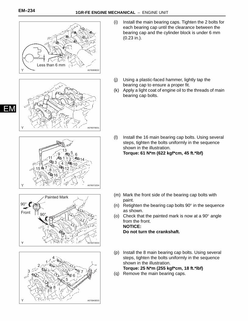
(i) Install the main bearing caps. Tighten the 2 bolts for each bearing cap until the clearance between the bearing cap and the cylinder block is under 6 mm (0.23 in.).
(j) Using a plastic-faced hammer, lightly tap the bearing cap to ensure a proper fit.
(k) Apply a light coat of engine oil to the threads of main bearing cap bolts.
(l) Install the 16 main bearing cap bolts. Using several steps, tighten the bolts uniformly in the sequence shown in the illustration.Torque: 61 N*m (622 kgf*cm, 45 ft.*lbf)
(m) Mark the front side of the bearing cap bolts with paint.
(n) Retighten the bearing cap bolts 90° in the sequence as shown.
(o) Check that the painted mark is now at a 90° angle from the front.NOTICE:Do not turn the crankshaft.
(p) Install the 8 main bearing cap bolts. Using several steps, tighten the bolts uniformly in the sequence shown in the illustration.Torque: 25 N*m (255 kgf*cm, 18 ft.*lbf)
(q) Remove the main bearing caps.
Less than 6 mmA076069E02
A076070E01
715
1 23 4
65
8
9
14
13
10
11
12
16
A076071E04
Painted Mark
Front
90°
90°
A076072E03
3 7
12
4
56
8
A075843E03
1GR-FE ENGINE MECHANICAL – ENGINE UNIT EM–235
M
E(r) Measure the Plastigage at its widest point.Standard oil clearance:
0.018 to 0.030 mm (0.0007 to 0.0012 in.)Maximum clearance:
0.046 mm (0.0018 in.)If the oil clearance is greater than the maximum, replace the bearings. If necessary, replace the crankshaft.NOTICE:Completely remove the plastigage.
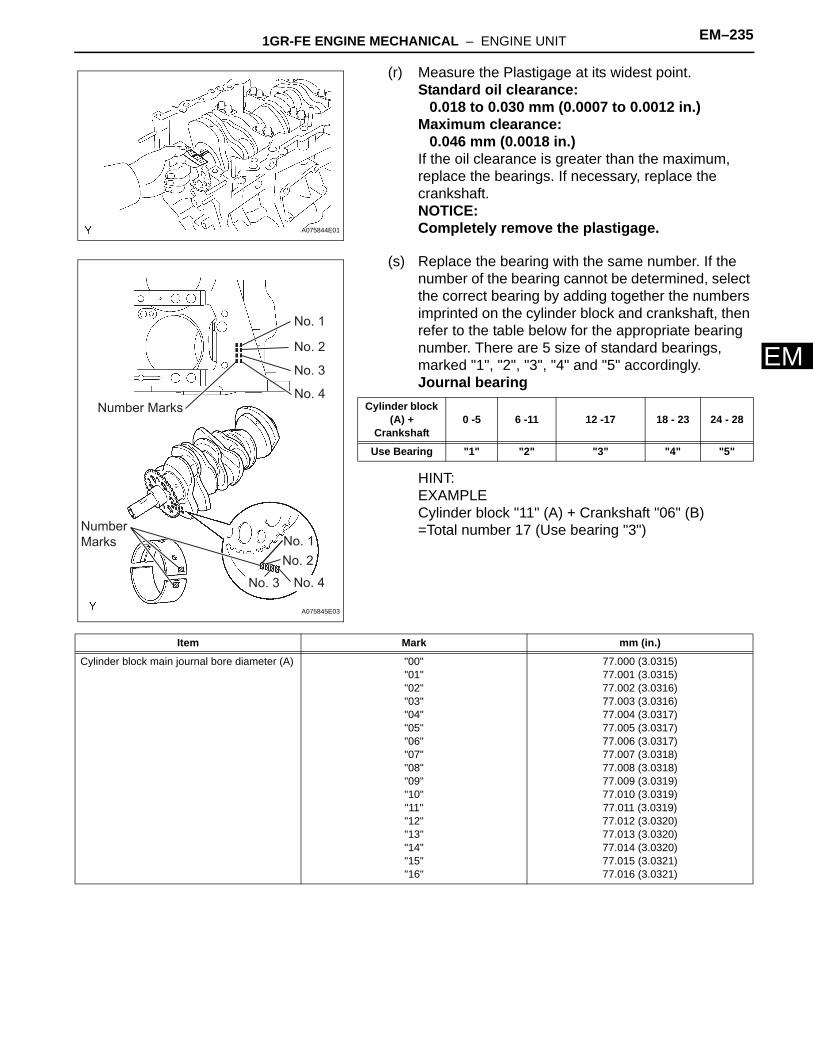
(s) Replace the bearing with the same number. If the number of the bearing cannot be determined, select the correct bearing by adding together the numbers imprinted on the cylinder block and crankshaft, then refer to the table below for the appropriate bearing number. There are 5 size of standard bearings, marked "1", "2", "3", "4" and "5" accordingly.Journal bearing
HINT:EXAMPLECylinder block "11" (A) + Crankshaft "06" (B)=Total number 17 (Use bearing "3")
A075844E01
Number Marks
Number
Marks
No. 1
No. 1
No. 2
No. 2
No. 3
No. 3
No. 4
No. 4
A075845E03
Cylinder block (A) +
Crankshaft0 -5 6 -11 12 -17 18 - 23 24 - 28
Use Bearing "1" "2" "3" "4" "5"
Item Mark mm (in.)
Cylinder block main journal bore diameter (A) "00""01""02""03""04""05""06""07""08""09""10""11""12""13""14""15""16"
77.000 (3.0315)77.001 (3.0315)77.002 (3.0316)77.003 (3.0316)77.004 (3.0317)77.005 (3.0317)77.006 (3.0317)77.007 (3.0318)77.008 (3.0318)77.009 (3.0319)77.010 (3.0319)77.011 (3.0319)77.012 (3.0320)77.013 (3.0320)77.014 (3.0320)77.015 (3.0321)77.016 (3.0321)
EM–236 1GR-FE ENGINE MECHANICAL – ENGINE UNIT
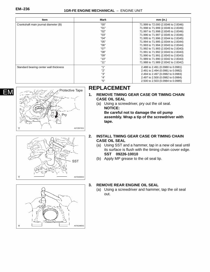
EMREPLACEMENT1. REMOVE TIMING GEAR CASE OR TIMING CHAIN
CASE OIL SEAL(a) Using a screwdriver, pry out the oil seal.
NOTICE:Be careful not to damage the oil pump assembly. Wrap a tip of the screwdriver with tape.
2. INSTALL TIMING GEAR CASE OR TIMING CHAIN CASE OIL SEAL(a) Using SST and a hammer, tap in a new oil seal until
its surface is flush with the timing chain cover edge.SST 09226-10010
(b) Apply MP grease to the oil seal lip.
3. REMOVE REAR ENGINE OIL SEAL(a) Using a screwdriver and hammer, tap the oil seal
out.
Crankshaft main journal diameter (B) "00""01""02""03""04""05""06""07""08""09""10""11"
71.999 to 72.000 (2.8346 to 2.8346)71.998 to 71.999 (2.8346 to 2.8346)71.997 to 71.998 (2.8345 to 2.8346)71.996 to 71.997 (2.8345 to 2.8346)71.995 to 71.996 (2.8344 to 2.8345)71.994 to 71.995 (2.8344 to 2.8344)71.993 to 71.994 (2.8343 to 2.8344)71.992 to 71.993 (2.8343 to 2.8343)71.991 to 71.992 (2.8343 to 2.8343)71.990 to 71.991 (2.8343 to 2.8343)71.989 to 71.990 (2.8342 to 2.8343)71.988 to 71.989 (2.8342 to 2.8342)
Standard bearing center wall thickness "1""2""3""4""5"
2.488 to 2.491 (0.0980 to 0.0981)2.491 to 2.494 (0.0981 to 0.0982)2.494 to 2.497 (0.0982 to 0.0983)2.497 to 2.500 (0.0982 to 0.0984)2.500 to 2.503 (0.0984 to 0.0985)
Item Mark mm (in.)
Protective Tape
Pry
A072957E01
SST
A076300E02
A076248E02