1mrs751249-men microscada issue date: 29.02.00 … · 1mrs751249-men connecting lonworks ® devices...
TRANSCRIPT

1MRS751249-MENIssue date: 29.02.00
Program revision: 8.4.3
Documentation version: A
Copyright © 2000 ABB Substation Automation Oy.All rights reserved.
MicroSCADAConnecting LONWORKS
®
Devices to MicroSCADA
Notice 1
The information in this document is subject to change without notice and should notbe construed as a commitment by ABB. ABB assumes no responsibility for any errorthat may occur in this document.
Notice 2
This document version complies with the program revision 8.4.3.
Notice 3
Additional information such as Release Notes and Last Minute Remarks can be foundon the program distribution media.
Trademarks
Microsoft is a trademark of Microsoft Corporation.
Windows NT is a trademark of Microsoft Corporation.
LONWORKS is a registered trademark of Echelon Corporation.
Other brand or product names are trademarks or registered trademarks of their respective holders.
All Microsoft products referenced in this document are either trademarks or registered trademarks of Microsoft.

MicroSCADA Connecting LONWORKS®
Devices to MicroSCADAConfiguration Manual
1MRS751249-MEN
ABB Automation
Related SYS 500 and MicroSCADA Technology Manuals
The following SYS 500 manuals are published with this software release:
Installation 1MRS751254-MEN
Picture Editing 1MRS751255-MEN
Visual SCIL User Interface Design 1MRS751256-MEN
Visual SCIL Objects 1MRS751257-MEN
System Management 1MRS751258-MUM
The following MicroSCADA technology manuals are published with this softwarerelease:
Connecting LONWORKS Devices to MicroSCADA 1MRS751249-MEN
System Configuration 1MRS751248-MEN
System Objects 1MRS751252-MEN
Application Objects 1MRS751253-MEN
Programming Language SCIL 1MRS751250-MEN
Status Codes 1MRS751251-MEN

1MRS751249-MEN Connecting LONWORKS®
Devices to MicroSCADAConfiguration Manual
MicroSCADA
ABB Automation
Contents
Page
1 Introduction...................................................................................... 1
1.1 About this Chapter .................................................................................1
1.2 Other Material Required.........................................................................2
1.3 Communication......................................................................................2
1.3.1 LONWORKS Communication is Considered if: ...............................4
1.3.2 Communication ...............................................................................4
1.3.3 Benefits of Using LonTalk Protocol in ABB Station AutomationSystems: .........................................................................................4
1.4 Device Types.........................................................................................5
1.5 Restrictions In LONWORKS Network ....................................................5
1.6 Description of the System......................................................................6
1.6.1 Small Substations............................................................................6
1.6.2 Medium-Sized Substations..............................................................7
1.6.3 Big Substations ...............................................................................7
2 Safety Information ........................................................................... 9
2.1 Backup Copies ......................................................................................9
2.2 Fatal Errors............................................................................................9
3 Instructions .................................................................................... 11
3.1 Hardware Installation ...........................................................................11
3.1.1 Transceiver Card Installation .........................................................11
3.1.2 I/O Address of the PCLTA Card ....................................................12
3.2 Software Installation ............................................................................14
3.2.1 Complementary Software ..............................................................14
3.3 Device Driver .......................................................................................15
3.3.1 Installation .....................................................................................15
3.3.2 MicroSCADA Device Driver Configuration .....................................15
3.3.3 Device Driver Start-Up...................................................................17
3.4 System Configuration Basics in LONWORKS Network........................19
3.4.1 LONWORKS Network ...................................................................19

MicroSCADA Connecting LONWORKS®
Devices to MicroSCADAConfiguration Manual
1MRS751249-MEN
ABB Automation
3.5 Preparatpry Operations and Off-line Engineering ................................ 20
3.5.1 How to Prepare the PCLTA Card for Communication ................... 20
3.5.2 How to Change the PCLTA Card Address .................................... 23
3.5.3 LON Node Address and Service Pin Method ................................ 24
3.5.4 How to Save a Configuration from a Former Release ................... 24
3.5.5 How to Create a New Configuration.............................................. 24
3.5.6 Default Configuration .................................................................... 24
3.5.7 Taking Lines and Stations In Use or Out of Use in PC-NET.......... 25
3.5.8 LSG Device .................................................................................. 25
3.5.9 LON Star Coupler ......................................................................... 26
3.5.10 LON Clock Master ..................................................................... 26
3.5.11 How to Change the Station Address of a SPACOM Relay ......... 26
3.5.12 How to Check and Change the Address of a REx Device.......... 27
3.6 Object Types....................................................................................... 29
3.7 Online Configuration............................................................................ 32
3.7.1 Signal Engineering on Station Level ............................................. 33
3.7.2 LON Configuration Attributes ........................................................ 33
3.7.3 LON Star Coupler Configuration ................................................... 35
3.7.4 Network Variable Configuration..................................................... 39
3.7.5 Extended Address Table............................................................... 42
3.7.6 Engineering Rex Devices.............................................................. 46
3.7.6.1 Send General Object Handling Command ............................ 48
3.7.6.2 Send Event History Start Time.............................................. 49
3.7.7 Engineering LMK Devices............................................................. 50
3.7.8 Engineering SPA Devices ............................................................. 53
3.7.9 LON Clock Master Configuration................................................... 59
3.8 Signal Data Transfer from LON Network Tool ..................................... 67
3.9 Optimising the Configuration ............................................................... 74
3.9.1 Multiple PC-NETs ......................................................................... 74
3.9.2 Timeout Setting............................................................................. 75
3.9.3 Priority Setting: SPA Device Connected Through an LSG Device. 75
3.10 Event Filtering Between RED500 Devices and MicroSCADA ........... 75
3.11 Testing the Communication (MicroSCADA - REx Device) ................ 75
4 Technical Description.................................................................... 77
4.1 Functional Description......................................................................... 77

1MRS751249-MEN Connecting LONWORKS®
Devices to MicroSCADAConfiguration Manual
MicroSCADA
ABB Automation
4.1.1 Summary of the LonTalk Protocol Based Functions ......................77
4.1.2 Vertical Communication.................................................................77
4.1.3 Summary of the PC-NET Function ................................................78
4.1.4 Summary of the PCLTA Card Function .........................................78
4.1.5 Summary of the Transceiver Module RER 107 Function ...............78
4.1.6 Summary of the Star-coupler RER 111 Functions .........................78
4.1.6.1 PCLTA Card Configuration....................................................79
4.1.6.2 Default Values.......................................................................79
4.1.6.3 Delete Function.....................................................................83
4.1.6.4 Cut, Copy and Paste Functions.............................................83
4.1.6.5 Preview Function...................................................................83
4.1.6.6 Configuration of the Station Types ........................................84
4.1.7 Signal Engineering ........................................................................84
4.2 Design .................................................................................................86
4.2.1 Introduction ...................................................................................86
4.2.2 System Design ..............................................................................86
4.2.3 Communication Design .................................................................87
4.2.3.1 PC-NET.................................................................................87
4.2.3.2 PC LonTalk Adapter..............................................................88
4.2.3.3 Master Devices .....................................................................88
4.2.3.4 Subnets.................................................................................88
4.2.3.5 Lines .....................................................................................88
4.2.3.6 LSG Device...........................................................................88
4.2.3.7 Fibre Optic Interface..............................................................89
4.2.3.8 The Router Option Card ........................................................89
4.2.3.9 LON® Clock Master, SLCM Option Card................................89
4.2.3.10 The Transceiver Module RER 107......................................90
4.2.4 System Configuration Tool Design ................................................90
4.2.4.1 Base System and PC-NET Configuration ..............................90
4.2.4.2 DNP V3.00 Slave Support.....................................................93
4.2.4.3 System Configuration Methods .............................................93
4.2.4.4 PCLTA Card Initialisation ......................................................94
5 Glossary ......................................................................................... 95
5.1 Definitions and Abbreviations ..............................................................95

MicroSCADA Connecting LONWORKS®
Devices to MicroSCADAConfiguration Manual
1MRS751249-MEN
ABB Automation
Index
Customer Feedback
1MRS751249-MEN Connecting LONWORKS®
Devices to MicroSCADAConfiguration Manual
MicroSCADA1 Introduction
ABB Automation 1
1 Introduction
This manual is designed for the project engineers to guide through the installation andconfiguration procedures, which are needed, when a device that uses LonTalk®1
protocol is connected to MicroSCADA.
The specific set up and configuration instructions are found in chapter three. Thischapter offers important background information and may also be used as a guidewhen designing new systems. Technical information concerning design andfunctionality is found in chapter four and chapter five offers a glossary of the essentialterminology.
1.1 About this Chapter
This chapter contains a basic description of the systems that are handled in this manualand an overall information on the material that may be required during theconfiguration work.
1.2 Other Material Required
• Other manuals needed during the installation and configuration work.
1.3 Communication
• LONWORKS® network.
• LonTalk® protocol.
1.4 Device Types
1.5 Restrictions In LONWORKS Network
1.6 Description of the System
• Small Substations.
• Medium-Sized Substations.
• Big Substations.
1 LonTalk and LONWORKS are trademarks of Echelon Corporation registered in theUnited States and other countries.
MicroSCADA1 Introduction
Connecting LONWORKS®
Devices to MicroSCADAConfiguration Manual
1MRS751249-MEN
ABB Automation2
1.2 Other Material Required
• Hardware installation:
Transceivers: LONWORKS®
SMX™ TRANSCEIVER InstallationInstructions (followed with the transceiver package)
LSG device: SPA-ZC 100 LON®2/SPA gateway Installation Manual
REF 54_: RE_ 54_ Protection, Monitoring and Control
Unpacking & Mounting Manual
• Software installation:
LNT 505: Installation and Commissioning Manual
(CAP 505: Installation and Commissioning Manual)
• Instructions for using the software tools:
LNT 505 tool: Operator’s Manual
(CAP 505 tool: Operator’s Manual)
• Configuration:
MicroSCADA: System Configuration manual
System Objects manual
LSG device: SPA-ZC 100/102 LON®/SPA gateway ProgrammingManual
LNT 505 Operator’s Manual
REF 54_: REF 54_ Protection, Monitoring and Control
Operator’s Manual
1.3 Communication
The name LON stands for Local Operating Network, which specifies that it isintended for short-range communication. Typically LONWORKS communication is usedwhen a set of devices physically located near to each other require communicationwith each other, transferring relatively small amounts of data.
The substation communication network is built up by means of a fibre optic starconnection. The fibre optic cables are connected to the devices using fibre opticconverters, RER 103 modules. The interface between RER 103 module and the deviceis RS485 or RS232 depending on the device to be connected.
2 LON is a trademark of Echelon Corporation registered in theUnited States and othercountries.

1MRS751249-MEN Connecting LONWORKS®
Devices to MicroSCADAConfiguration Manual
MicroSCADA1 Introduction
ABB Automation 3
LONWORKS device bus is a peer-to-peer bus, where all the nodes (e.g. protectionterminals) in the system can talk to each other, hence horizontal communication onstation level is enabled. Other types of media may also be connected to the network,e.g. TP (Twisted Pair), by means of option cards in the star-coupler RER 111.
When connecting LONWORKS network to some other system another communicationmethod may be used.
LONWORKS Network
In LONWORKS network the communication means is LonTalk protocol. LONWORKS
technology has been designed for communication in distributed control networks.
These networks are typically characterised by:
• Short messages (few data bytes).
• Variety of communication media.
• Relatively low bandwidth but usually short response time.
• Very low interface cost per node.
• Integration of multi vendor equipment.
• Low maintenance and support costs.
With the LONWORKS communication technology it is possible to build a protection andcontrol system including more than one higher level devices, which receive statusvalues, measurements and time-tagged events from the bay level devices.
LonTalk Protocol
LonTalk protocol is used in the ABB substation automation system in two differentlevels:
• At station level as the communication protocol between protection and controldevices (i.e. in horizontal communication).
• Up to higher level systems, e.g. MicroSCADA (i.e. in vertical communication).
Facts About LonTalk Protocol:
• Communication is fast: 1.25 Mbits/s.
• LonTalk protocol is an open (non ABB) protocol.
• It is a peer-to-peer protocol, which enables horizontal (relay-to-relay)communication.
MicroSCADA1 Introduction
Connecting LONWORKS®
Devices to MicroSCADAConfiguration Manual
1MRS751249-MEN
ABB Automation4
1.3.1 LONWORKS Communication is Considered if:
• Building a new station with units which have LONWORKS network interface.
• Horizontal communication is needed.
• Big amount of data is to be transferred (disturbance recordings etc.).
• Fast response times are required.
• Systems are big.
1.3.2 Communication
The MicroSCADA base system communicates with devices which use LonTalkprotocol through the PC-NET and a LONWORKS network interface card. The interfacecard can be a PCLTA (PC LonTalk Adapter) card for a PC or a PCCLON-1 card(formerly PCMCIA) for a laptop. Only PCLTA card is handled in this manual.
1.3.3 Benefits of Using LonTalk Protocol in ABB Station Automation
Systems:
• Direct communication between all devices in the system.
• Support of multiple monitoring devices on the higher level.
• Communication between bay level devices and the network control centre (viagateway) is independent of communication between bay level devices and thelocal substation computer (SMS, SCS).
• Distribution of control functions from a single unit (e.g. RTU) to severalintelligent multi function terminals at the bay level.
• Improved response times.
• Possibility for redundant system implementations.
• Higher availability and reliability of the system.
LONWORKS network is an open interoperable solution utilised in many applicationareas, with world-wide support for system integrators. Several LONWORKS technologycompatible devices from other vendors can be found on the market to extend thefunctions of our protection and control systems (e.g. sensors, transducers, I/Omodules, access control devices, supervision equipment).
The technology enables integration of ABB distribution automation systems withLONWORKS technology based industrial control networks, and building automationnetworks. Power utilities and grid operators can extend our protection and controlsystems in substations to support several additional functions like collecting

1MRS751249-MEN Connecting LONWORKS®
Devices to MicroSCADAConfiguration Manual
MicroSCADA1 Introduction
ABB Automation 5
information from energy metering devices or from environment monitoringequipment.
1.4 Device Types
MicroSCADA recognises the following device types in LONWORKS network:
REx A REx device is a unit communicating with MicroSCADA withvertical communication as defined in LON® ApplicationsGuidelines (e.g. REF54x protection terminal).
SPA A SPA device is a SPACOM module connected to LONWORKS
network via a protocol converter. The converter is called LSGdevice.
LMK An LMK device comprises all types of devices, except SPA andREx devices, connected to LONWORKS network using the standardLONWORKS network interface, e.g. an LSG device or a WeidmüllerI/O device.
1.5 Restrictions In LONWORKS Network
Maximum...:
• Nine option cards per star-coupler (RER 111).
• Two routers for a star-coupler (RER 111).
• Three star-coupler levels (RER 111).
• Four lines to MicroSCADA (through PCLTA cards).
• 30 nodes per line.
• 120 REF terminals for one MicroSCADA base system.
• 255 subnets (according to LonTalk protocol).
• 127 nodes per one subnet (LonTalk protocol).
!These are the maximum values, not recommended values!In some cases the recommendation is lower to ensure sufficient functionality of thenetwork.

MicroSCADA1 Introduction
Connecting LONWORKS®
Devices to MicroSCADAConfiguration Manual
1MRS751249-MEN
ABB Automation6
1.6 Description of the System
1.6.1 Small Substations
Small substations, especially in rural areas, usually require only one higher leveldevice - a gateway which provides a communication link to the network controlcentre. The use of the LONWORKS technology does not change this fact.
The protection and control functions can be performed in bay level devices.
In many of RTU -based systems a central unit was used to perform the controlfunctions since older communication technologies could not guarantee requiredresponse times. Only protection functions were distributed to the bay level. Now thathigh speed communication is utilised a full featured RTU becomes obsolete since allcontrol functions can be easily distributed to bay level devices. Only a simple gatewayfrom the LONWORKS network to remote control protocol is required.
Gateway
LON Network
Protection and control devices
Interface to NetworkControl Center
Figure 1. The structure of a small substation
A gateway in this kind of a system must be especially reliable and capable ofoperating without problems for several years in demanding conditions. Very often aPC is not considered to be reliable enough to be used as a gateway.
In most cases all control operations are initiated remotely from the network controlcentre - even if there is maintenance personnel at the substation. Only if thecommunication with the network control centre does not work the operations areperformed locally at the substation.
1MRS751249-MEN Connecting LONWORKS®
Devices to MicroSCADAConfiguration Manual
MicroSCADA1 Introduction
ABB Automation 7
1.6.2 Medium-Sized Substations
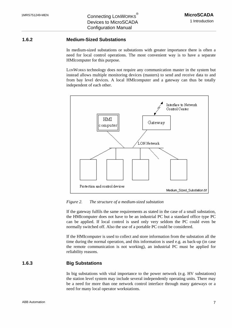
In medium-sized substations or substations with greater importance there is often aneed for local control operations. The most convenient way is to have a separateHMIcomputer for this purpose.
LONWORKS technology does not require any communication master in the system butinstead allows multiple monitoring devices (masters) to send and receive data to andfrom bay level devices. A local HMIcomputer and a gateway can thus be totallyindependent of each other.
Figure 2. The structure of a medium-sized substation
If the gateway fulfils the same requirements as stated in the case of a small substation,the HMIcomputer does not have to be an industrial PC but a standard office type PCcan be applied. If local control is used only very seldom the PC could even benormally switched off. Also the use of a portable PC could be considered.
If the HMIcomputer is used to collect and store information from the substation all thetime during the normal operation, and this information is used e.g. as back-up (in casethe remote communication is not working), an industrial PC must be applied forreliability reasons.
1.6.3 Big Substations
In big substations with vital importance to the power network (e.g. HV substations)the station level system may include several independently operating units. There maybe a need for more than one network control interface through many gateways or aneed for many local operator workstations.

MicroSCADA1 Introduction
Connecting LONWORKS®
Devices to MicroSCADAConfiguration Manual
1MRS751249-MEN
ABB Automation8
Figure 3. The structure of a big substation
In addition to LONWORKS network an Ethernet network may be used forcommunication between HMIcomputers and gateways.
1MRS751249-MEN Connecting LONWORKS®
Devices to MicroSCADAConfiguration Manual
MicroSCADA2 Safety Information
ABB Automation 9
2 Safety Information
This chapter gives information about prevention of hazards.
2.1 Backup Copies
Taking backup copies is suggested before making any changes, especially changesthat might have side effects. Software and data need to be copied to another place,usually to a backup tape. A DAT tape is commonly used.
Backup copy facilitates restoration of the application software in case of disk crash, orother serious failure when stored data is lost. It is therefore recommended that backupcopies are taken regularly.
There should be at least two system backup copies and two application copies. A newbackup is copied over the oldest backup. This way there is always the latest versionleft, even if the backup procedure fails.
Detailed information on how to take backup copies should be delivered to thecustomer with the application.
System Backup
Usually a system backup is taken after the application is made. It should be takenagain when changes are made to MicroSCADA system. For example, if the driverconfiguration or the network set-up is changed.
Application Backup
Application backup is also taken at the same time with system backup, after theapplication is made. It should be taken again when changes are made to theapplication, for example if pictures or databases are edited or new pictures are added.
2.2 Fatal Errors
A fatal error is an error that causes a break-down or a locked situation in theMicroSCADA program execution.
Handling
In case of a fatal error:
1 Write down possible MicroSCADA error messages.
2 Shut down the MicroSCADA main program. If this cannot be done in theMicroSCADA Control Panel, try to end the task in the Task Manager of theWindows NT™3.
3 Windows NT is a trademark of Microsoft Corporation.

MicroSCADA2 Safety Information
Connecting LONWORKS®
Devices to MicroSCADAConfiguration Manual
1MRS751249-MEN
ABB Automation10
3 Shutting down base system computers by switching off the power might damagethe files.
4 In Windows NT, the data kept in the main memory at the moment of a fatal error isplaced into drwtsn32.log file. It is placed into the system folder, for exampleWinnt. Analyse and copy the data in it.
5 Restart the system.
Report the program break-down together with possible MicroSCADA error messagesand the information from drwtsn32.log file to the MicroSCADA supplier.
Status Codes
Error messages in SCIL are called status codes. The list of status codes and shortexplanations are in the Status Codes manual.
1MRS751249-MEN Connecting LONWORKS®
Devices to MicroSCADAConfiguration Manual
MicroSCADA3 Instructions
ABB Automation 11
3 Instructions
Introduction
From the MicroSCADA viewpoint, the installation and configuration of devices thatuse LonTalk protocol consists of three phases:
• Hardware installation of the network interface card (i.e. PCLTA card) and thetransceiver card, and possible I/O address setting for the PCLTA card.
• Software installation (Device driver, PC-NET and configuration tools).
• Configuration.
!
3.1 Hardware Installation
To enable communication with LONWORKS network the network interface, i.e. theLonTalk Adapter, is required. It may be a PCLTA card (an ISA-bus card) for a PCwith two slots for transceiver cards or a PCCLON-1 card for a laptop, or it may be anSLTA card as an option card in a star coupler or as a stand alone unit.
3.1.1 Transceiver Card Installation
Before the PCLTA card is installed, the transceiver cards (one or two) have to beinstalled on it. The type definition for the cards supplied by ABB SubstationAutomation Oy is RER 107 for the transceiver card and RER 109 for the PCLTA card.The transceiver module is powered from the PCLTA card.
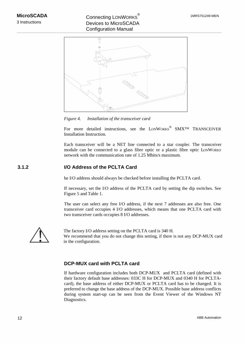
Plug the transceiver into the SMX connector of the PCLTA card as shown in Figure 4.
If the CAP 505 or LNT 505 configuration tools are installed on the same computer asthe MicroSCADA base system, please note that the configuration tools, when they arein use, reserve one channel from the PCLTA card.
MicroSCADA3 Instructions
Connecting LONWORKS®
Devices to MicroSCADAConfiguration Manual
1MRS751249-MEN
ABB Automation12
Figure 4. Installation of the transceiver card
For more detailed instructions, see the LONWORKS®
SMX™ TRANSCEIVERInstallation Instruction.
Each transceiver will be a NET line connected to a star coupler. The transceivermodule can be connected to a glass fibre optic or a plastic fibre optic LONWORKS
network with the communication rate of 1.25 Mbits/s maximum.
3.1.2 I/O Address of the PCLTA Card
he I/O address should always be checked before installing the PCLTA card.
If necessary, set the I/O address of the PCLTA card by setting the dip switches. SeeFigure 5 and Table 1.
The user can select any free I/O address, if the next 7 addresses are also free. Onetransceiver card occupies 4 I/O addresses, which means that one PCLTA card withtwo transceiver cards occupies 8 I/O addresses.
!DCP-MUX card with PCLTA card
If hardware configuration includes both DCP-MUX and PCLTA card (defined withtheir factory default base addresses: 033C H for DCP-MUX and 0340 H for PCLTA-card), the base address of either DCP-MUX or PCLTA card has to be changed. It ispreferred to change the base address of the DCP-MUX. Possible base address conflictsduring system start-up can be seen from the Event Viewer of the Windows NTDiagnostics.
The factory I/O address setting on the PCLTA card is 340 H.We recommend that you do not change this setting, if there is not any DCP-MUX cardin the configuration.

1MRS751249-MEN Connecting LONWORKS®
Devices to MicroSCADAConfiguration Manual
MicroSCADA3 Instructions
ABB Automation 13
Transceiver
Transceiver
Channel A
I/O address
Channel B
1
0
9 8 7 6 5 4 3 X X X
1 1 0 1 0 0 0 X
Figure 5. Setting the I/O address on the PCLTA card
Table 1. The dip switch values on the PCLTA card
Switch 9 8 7 6 5 4 3
Value/H 200 100 80 40 20 10 8
Note down the selected I/O address. This will be needed during the driverconfiguration. Use Table 2.
See also the example of the PCLTA card information in Table 3.
Table 2. The PCLTA card information needed during system configuration
CardNo.
Channel I/O Address
/H
Device Number
= n
Device Name
= LONPn
NETLine
Number0 A
B1 A
B
!If the Echelon driver is used, the device name and number are not according to Table3.
Default value for a NET line is n+1, but we recommend that you use value 5 for thefirst LON line, 6 for the second and so on.

MicroSCADA3 Instructions
Connecting LONWORKS®
Devices to MicroSCADAConfiguration Manual
1MRS751249-MEN
ABB Automation14
The I/O address of Channel B is automatically set to be the Channel A I/O address +4.
Table 3. An example of the PCLTA card information
Card No. Channel I/O Address
/H
Device No=n
DeviceName
=LONPn
NET LineNumber
0 A 340 0 LONP0 5B (344) 1 LONP1 6
1 A 350 2 LONP2 7B (354) 3 LONP3 8
The NET Line numbering is started from 5 to leave the lines 1 to 4 free for the COMports.
Install the PCLTA card into a free ISA-card slot in the base system computer. Followthe instructions supplied with the card.
3.2 Software Installation
From the MicroSCADA software installation package, the following programs areneeded:
• Workstation.
• System Base Software.
• System Base Tools.
• Echelon PCLTA driver.
• PC-NET.
The software installation procedure is described in the SYS 500 Installation manual.
3.2.1 Complementary Software
LSG Device Configuration Software
For LSG device configuration, the LON Network Tool and the NetAgent are needed.They are included in the LNT 505 software package, available from ABB SubstationAutomation Oy.
Install the LNT 505 software package according to the instructions in the LNT 505Installation and Commissioning Manual.
User instructions can be found in the LNT 505 Operator’s manual.
PCLTA Card Configuration Software
CAP 505 tool can be used for configuring the PCLTA card, but we recommend thatyou use the System Configuration tool in the MicroSCADA Tool Manager.

1MRS751249-MEN Connecting LONWORKS®
Devices to MicroSCADAConfiguration Manual
MicroSCADA3 Instructions
ABB Automation 15
If needed, CAP 505 can be installed according to the instructions in the CAP 505Installation and Commissioning Manual, available from ABB Substation AutomationOy. User instructions can be found in the CAP 505 Operator’s manual.
3.3 Device Driver
To enable communication through the PCLTA card, the device driver must beinstalled and configured.
3.3.1 Installation
If the Echelon device driver is used, it can be installed via Windows NT ControlPanel, whereas MicroSCADA device driver MiSCLONP is installed viaMicroSCADA Control Panel. The installation of the MicroSCADA device driver isdescribed in the SYS 500 Installation manual and the installation of the Echelondevice drive (recommended) in the documentation available from EchelonCorporation.
!The Neuron Chip of the PCLTA card must also be configured. This is declared insection 3.5.1.
3.3.2 MicroSCADA Device Driver Configuration
The PCLTA card device driver (MiSCLONP) is configured using a specialconfiguration tool in MicroSCADA Control Panel. See the instructions in the SYS 500Installation manual (Managing Device Drivers).
If there is a PCLTA driver already configured in your system, the driver version canbe checked as described in the SYS 500 Installation manual.
!
During device driver configuration, the I/O base address of the card is requested. Thisaddress must be the same as the address physically set on the card. See section 3.1.2.
By default, the NET line number of the transceiver card is the device number plus 1,but we recommend that you start LON line numbering from number 5 and continueupwards.
MicroSCADA3 Instructions
Connecting LONWORKS®
Devices to MicroSCADAConfiguration Manual
1MRS751249-MEN
ABB Automation16
PCLTA Card Settings:
Card Number:
Number of the PCLTA card. It is recommended that you set the first card as cardnumber 0 and the second card as card number 1.
Type of Card:
The type of the PCLTA card. The following types are supported:
• PCLTA Single Channel, if you have installed one transceiver card.
• PCLTA Dual Channel, if you have installed two transceiver cards.
Transceiver Card Settings:
During the device driver configuration, each transceiver is given a device number.
Device Number:
Each channel is seen as a device with a device number. It is recommended that youset channel A on card 0 as device 0 and channel B as device 1 (Use channelnumbers 2 and 3 on card 1).
This way channel A on card 0 will be NET line number 1, by default, and otherchannels will be NET line numbers 2, 3 and 4.
!
I/O Port Address:
The I/O base address of the card. This must be the same as the address physicallyset on the card (340H at delivery, see section 3.1.2). The recommendation is 340H.If the card has two channels, channel B is automatically given an I/O base addresswhich is the channel A address + 4.
IRQ Level:
The interrupt level used by the channel. This must be unique among all devices inthe computer. Permitted values are 5, 9, 10, 11, 12, and 15.
However, we recommend that you use line numbers 5, 6, 7 and 8 to leave the linenumbers 1, 2, 3 and 4 for the COM ports.
1MRS751249-MEN Connecting LONWORKS®
Devices to MicroSCADAConfiguration Manual
MicroSCADA3 Instructions
ABB Automation 17
The user can check the free IRQ levels in the Windows NT Diagnostics tool underResources.
Clock Select:
The Neuron clock rate for the channel. The value should be set at 10 MHz.
Uplink Buffers:
The number of uplink buffers used by the channel. The default value 20 isrecommended.
Downlink Buffers:
Number of downlink buffers used by the channel. The default value 20 isrecommended.
DL Priority Buffers:
The number of downlink priority buffers used by the channel. The default value 20is recommended.
Flush cancel at init:
If this option is checked (= default), the device driver will issue theniFLUSH_CANCEL command to the network interface after reset. This means thatthe network interface is reset into NORMAL state and can participate in networktransactions. If no niFLUSH_CANCEL command is issued, the network interfaceremains in a FLUSH state, which means that it ignores all incoming messages andprevents all outgoing messages.
If Channel B and another PCLTA card are present, configure them in the same way aschannel A.
!Reboot the system to make the settings take effect.
3.3.3 Device Driver Start-Up
If you are configuring the driver for the first time, it does not start automatically afterbooting, but must be started manually and tested. This helps to avoid problems caused
Please, note that the IRQ level must be different for each channel.

MicroSCADA3 Instructions
Connecting LONWORKS®
Devices to MicroSCADAConfiguration Manual
1MRS751249-MEN
ABB Automation18
by incorrect configuration settings. If the settings do not cause any conflicts, you canconfigure automatic start-up for the driver. Please, see instructions in the SYS 500Installation manual (Managing Device Drivers).

1MRS751249-MEN Connecting LONWORKS®
Devices to MicroSCADAConfiguration Manual
MicroSCADA3 Instructions
ABB Automation 19
3.4 System Configuration Basics in LONWORKS Network
In MicroSCADA, the LONWORKS network and device configuration is done with theSystem Configuration tool, which is situated in the Tool Manager SystemConfiguration page. More information about the System Configuration tool can befound in the MicroSCADA System Configuration manual.
The MicroSCADA System Objects manual should also be available during theconfiguration work.
In addition to the System Configuration tool in MicroSCADA, the LNT 505 software(LON Network Tool and NetAgent) is needed for configuring and binding the LSGdevices. This part of the configuration work is described in the LNT 505 andLON®/SPA Gateway manuals.
If transceivers other than RER 107 are used, the user will probably need to configurethe PCLTA card for the transceivers. For further information, please refer to thePCLTA card and transceiver card documentation.
For more detailed technical and functional information, please refer to chapter four.
3.4.1 LONWORKS Network
Each communicating device in the network is a LONWORKS node identified by a nodenumber and subnet number. These numbers are configured and stored in the devices.
Create an outline of your system configuration or a table that includes the followinginformation:
• The node numbers and station addresses of the base system and NETs.
• Application numbers and possible names.
• NET line numbers.
• Station numbers (in NET and in the base system if different) and station addresses(slave numbers) of all devices.

MicroSCADA3 Instructions
Connecting LONWORKS®
Devices to MicroSCADAConfiguration Manual
1MRS751249-MEN
ABB Automation20
Basesystem 1
Node Number: 9Station Address: 209
Link1= Integrated link
Apl 1
Line13 = Integrated link
Communication Unit 3Node Number: 3Station Addres: 203
1 2 3 4 5 6 7 8
Serial lines (COM ports) and LONWORKS lines
Figure 6. An example of a configuration with one PC-NET in a base system
3.5 Preparatpry Operations and Off-line Engineering
This section describes how to use the System Configuration tool to make thepreparatory operations and offline configuration for the system that you have installed.
3.5.1 How to Prepare the PCLTA Card for Communication
To enable communication with LONWORKS devices, the Neuron ship of the PCLTAcard must be prepared. This is done using the System Configuration tool. If the cardhas already been used in a LONWORKS network, no initialisation is needed.
!When the System Configuration tool is opened, only the MicroSCADA Configurationobject exists.
To create a LON line:
1 From the menu bar choose Configuration > Open Active.
The Open Active command opens the default configuration that is saved in theSysconf.ini file. The default Sysconf.ini file, which is included in the configurationtool, includes an Object tree with Link 3 (INTEGRATED) and Node 3 (NET).
2 From the Object tree, select Node 3(NET) and from the menu bar, choose Object >New (or Ctrl+N on the keyboard). See Figure 7.
Before the PCLTA card can be prepared, a LONWORKS communication line (a LONline) must be created (or existing) and the PC-NET must be started as described in thissection.

1MRS751249-MEN Connecting LONWORKS®
Devices to MicroSCADAConfiguration Manual
MicroSCADA3 Instructions
ABB Automation 21
Figure 7. Adding a new line in the configuration tree
3 Select LON Line and click Insert.
4 Enter a line number (5 recommended for the first LON line) and click OK.
!
To change the IU attribute value:
1 From the menu bar choose Configuration > Open Active (if it is not already open).
2 In the Configuration tree select a LON line. See Figure 8.
Figure 8. Selecting a LON line in the configuration tree
3 In the Attribute tree double-click the text Basic Line Attributes. See Figure 9.
Figure 9. Line 5 (LON) attribute groups
The PCLTA card can be initialised only if the LON line IU (In Use) attribute value is0 (Not In Use).
MicroSCADA3 Instructions
Connecting LONWORKS®
Devices to MicroSCADAConfiguration Manual
1MRS751249-MEN
ABB Automation22
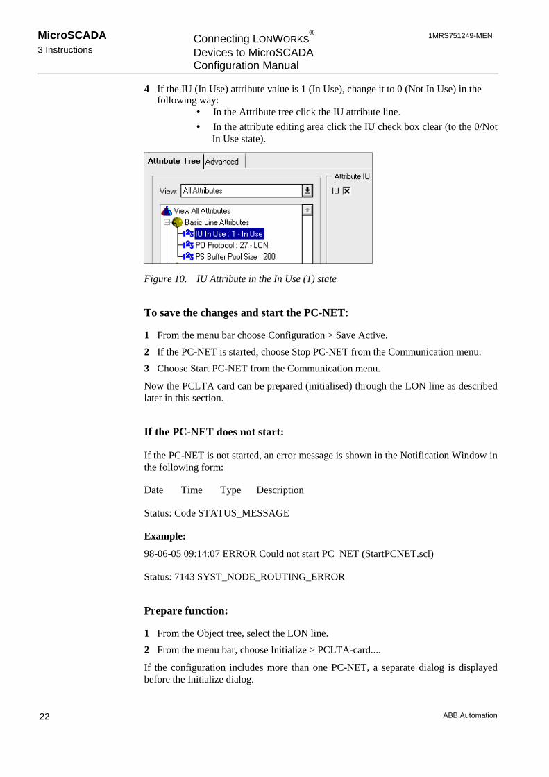
4 If the IU (In Use) attribute value is 1 (In Use), change it to 0 (Not In Use) in thefollowing way:
• In the Attribute tree click the IU attribute line.
• In the attribute editing area click the IU check box clear (to the 0/NotIn Use state).
Figure 10. IU Attribute in the In Use (1) state
To save the changes and start the PC-NET:
1 From the menu bar choose Configuration > Save Active.
2 If the PC-NET is started, choose Stop PC-NET from the Communication menu.
3 Choose Start PC-NET from the Communication menu.
Now the PCLTA card can be prepared (initialised) through the LON line as describedlater in this section.
If the PC-NET does not start:
If the PC-NET is not started, an error message is shown in the Notification Window inthe following form:
Date Time Type Description
Status: Code STATUS_MESSAGE
Example:
98-06-05 09:14:07 ERROR Could not start PC_NET (StartPCNET.scl)
Status: 7143 SYST_NODE_ROUTING_ERROR
Prepare function:
1 From the Object tree, select the LON line.
2 From the menu bar, choose Initialize > PCLTA-card....
If the configuration includes more than one PC-NET, a separate dialog is displayedbefore the Initialize dialog.

1MRS751249-MEN Connecting LONWORKS®
Devices to MicroSCADAConfiguration Manual
MicroSCADA3 Instructions
ABB Automation 23
If the configuration includes only one PC-NET, the Initialize dialog is displayed.
3 Select the device that you want to prepare and Operation Mode Prepare. ClickInitialize.
When the Prepare function has run successfully, the following message appears:
Figure 11. Message about successful Prepare function
4 Click OK and exit the configuration program by clicking Cancel in theconfiguration menu.
!The PCLTA card is ready to communicate with LONWORKS devices. The settings thatwere made are described in Chapter 4.
3.5.2 How to Change the PCLTA Card Address
1 From the menu bar, choose Initialize > PCLTA-card.
2 Click Change Address on.
3 Change the address (subnet and node number of the selected device).
4 Click Initialize.
The address of the PCLTA card channel is changed and the Nettools.ini file is updated(if it exists in the system).
!
If multiple PCLTA card channels are being initialised, the PC-NET should bestopped and started again by choosing Communication > Stop PC-NET andCommunication > Start PC-NET before starting the initialisation of the next PCLTAcard channel.
To set the PCLTA card to communication mode again, the Prepare method should beused after the Change Address operation.
MicroSCADA3 Instructions
Connecting LONWORKS®
Devices to MicroSCADAConfiguration Manual
1MRS751249-MEN
ABB Automation24
3.5.3 LON Node Address and Service Pin Method
When Neuron 3150 chips are shipped from the manufacturer they are assigned aunique, 6-byte identifier, the Neuron ID). Each LON-node has a service pin, whichcan be pressed to make the Neuron chip to transmit a Service Pin Message containingthis Neuron ID. This information may be used by the network management device toinstall the node (assign the node its logical node address).
Normally, the node installation procedure goes as follows:
1 Start the Install Node command of the device that is responsible of networkmanagement functions (usually the master node). This function asks you to pressthe service pin of the node that is being installed.
2 Press the service pin of the node (SLCM card, for example).
3 When the network manager node receives the Service Pin Message, it will set theaddress of the node.
The node address is stored to the Neuron chip internal EEPROM memory (in thedomain table) and usually to the node list of the network manager node as well.
3.5.4 How to Save a Configuration from a Former Release
If a configuration from a former MicroSCADA release is read in the SystemConfiguration tool, it can be saved with the Configuration - Save Active command. Itwill be saved in the default files Sysconf.ini and Signals.ini.
The configuration is available, when MicroSCADA or subsequent sys_bascon.com(sys_bascon$com) template is taken in use.
3.5.5 How to Create a New Configuration
From the menu bar, choose Configuration > New.
This command opens a configuration that is delivered with the System Configurationtool. This configuration includes an Object tree with Link 3 (INTEGRATED) andNode 3 (NET).
If there is an other configuration open in the tool, all the configuration data will becleared from the tool. To save the configuration, the Sysconf.ini and Signals.ini filesin the sys/active/sys_ folder should be copied or renamed.
The new configuration can be saved with the Configuration > Save Active command.If the Link object and/or the NET Node object are not present, the PC-NET does notstart up successfully. Therefore it is not possible to save this kind of invalidconfiguration with the Save > Active command.
MicroSCADA must be restarted to take the new configuration in use.
3.5.6 Default Configuration
The default configuration is stored in a configuration file called Sysconf.ini.

1MRS751249-MEN Connecting LONWORKS®
Devices to MicroSCADAConfiguration Manual
MicroSCADA3 Instructions
ABB Automation 25
To open the default configuration file:
From the menu bar, choose Configuration > Open Active.
The default configuration is loaded in the tool. The tool is opened in offline mode,which is shown in the status bar.
To save a configuration as the default configuration:
From the menu bar, choose Configuration > Save Active.
This command saves the configuration currently open in the tool as the defaultconfiguration in the Sysconf.ini file. The configuration can be saved at any time andthis can be done in both online and offline mode.
!
3.5.7 Taking Lines and Stations In Use or Out of Use in PC-NET
When taking LONWORKS lines and stations in use in the PC-NET, it is essential thatthe line is taken in use before any station (on that specific line) is taken in use.Likewise, all stations must be taken out of use before the line is taken out of use.
3.5.8 LSG Device
Before an LSG device (LON/SPA gateway) can be used in a MicroSCADAconfiguration, the subnet and node numbers of the device have to be configured usingthe LNT 505 program. The subnet and node numbers are set using the LSGConfiguration tool and the Service Pin method. See section 3.5.3.
!Configuration using the LON Network Tool is described in the LNT 505 Operator’sManual and the SPA-ZC 100/102 LON®/SPA Gateway Programming Manual.
MicroSCADA sees the LSG device as a special version of an LMK device . Thereforethe rest of the configuration work should be done using the System Configuration toolin the MicroSCADA Tool Manager.
In online mode, only the objects that are in use are saved with the Configuration >Save Active command.
When using LON Network Tool, the LSG CFG tool should be used in integrated modeonly (not in standalone mode).

MicroSCADA3 Instructions
Connecting LONWORKS®
Devices to MicroSCADAConfiguration Manual
1MRS751249-MEN
ABB Automation26
3.5.9 LON Star Coupler
LON Star Coupler is seen in the LON line as an LMK station with LMK specificattributes.
To add a LON Star Coupler into your configuration, use the System Configurationtool in offline mode:
1 From the object tree, select the LON line where you want to add the device.
2 Choose Object > New… from the menu bar.
3 Select LON Star Coupler and click Insert.
4 Enter the number that you have planned for this device and click OK.
Figure 12. LON Star Coupler in the configuration tree
To save the configuration:
5 From the menu bar, choose Configuration > Save Active.
For further instructions, see section 3.7.3.
Router option card
The Service Pin produces a service-pin message, which is used by the networkmanagement device, to install and configure the router option card. When you pressand release the service pin, the router generates a message to both sides of it. Eachside of the router must be installed and configured separately. See also section 3.7.3.
For detailed configuration instructions, please refer to LNT 505 and RER 111manuals.
3.5.10 LON Clock Master
SLCM option card includes an internal clock and an application program, which usesthe internal clock to generate various kinds of synchronisation messages and signals,in order to synchronise other devices in the LONWORKS network.
In the System Configuration tool, LON Clock Master is created as a special version ofan LMK device. More information can be found in section 3.7.9.
3.5.11 How to Change the Station Address of a SPACOM Relay
If several SPACOM relays situate in the same configuration, the addresses of therelays should be changed (factory setting for all of them is 99). In some relays, it is not

1MRS751249-MEN Connecting LONWORKS®
Devices to MicroSCADAConfiguration Manual
MicroSCADA3 Instructions
ABB Automation 27
possible to change the address from the front panel but it must be done with SCILcommands the following way:#SET STA1:SSA=99; DEFAULT VALUE#SET STA1:SSM=(“WV200:11:”); SENDS THE STATION ADDRESS 11 TO THE RELAY#SET STA1:SSA=11; TELLS THE RELAY’S ADDRESS TO MicroSCADA#SET STA1:SSM=(“WV151:1:”); STORES THE ADDRESS TO THE RELAY EEPROM (~5 s)
3.5.12 How to Check and Change the Address of a REx Device
The node, subnet and unit numbers of the REx device are needed when configuringthe system for communication. This instruction concerns REF Terminals made byABB Substation Automation Oy.
1 Press any button on the HMI of the device to turn on the backlight.
• In idle mode the MIMIC configuration picture is shown in the main window.
• In the help window some help messages are shown.
2 Press and hold E for at least 2 seconds to enter the MAIN MENU.
• A password is required. The factory setting for the password is 3.
3 Select the password using the up and down arrows and press E briefly.
4 In the MAIN MENU use the up and down arrows to select Communic.lib. Openthe library with the right arrow.
SPA address:
1 In the Communication library, select SPA using the up and down arrows and openthe SPA library with the right arrow.
2 Check the address and change it, if necessary. Note down the address.
To change the address:
1. Select the SPA address using the up and down arrows and press E.
2. Change the address with the arrow keys.
3. Press E to confirm the setting.
3 Return to the previous menu using the left arrow.
Subnet and Node Number:
1 Select LON and use the right arrow to open the library. Check the Subnet numberand the Node number. If necessary, change the address as described earlier, andwrite it down.
2 Press the left arrow repeatedly until you get back to the MAIN MENU.
3 Press E for 2 seconds.
4 Press E to confirm the settings or C to cancel them.
Now you should be in the MIMIC picture again.

MicroSCADA3 Instructions
Connecting LONWORKS®
Devices to MicroSCADAConfiguration Manual
1MRS751249-MEN
ABB Automation28
! The communication protocol can also be checked and changed in the Communicationlibrary of the protection terminal.

1MRS751249-MEN Connecting LONWORKS®
Devices to MicroSCADAConfiguration Manual
MicroSCADA3 Instructions
ABB Automation 29
3.6 Object Types
Integrated link
Parent Object: MicroSCADA Configuration
Link number range: 1-20
If you choose Configuration > New from the menu bar, a default configuration thatincludes an integrated link is opened to the System Configuration tool.
NET Node
Parent Object: Link (Integrated)
NET Node number range: 1-99
Figure 13. Adding a NET Node
Line
Parent object: Node (NET)
Line number range: 1-12
Recommendation:
• SPA lines: 1 to 4
• LON lines: 5 to 12
! We recommend that you start the LON line numbering from number 5 upwards. Thisreduces the modifications that are required, if the COM ports are taken in use later on.

MicroSCADA3 Instructions
Connecting LONWORKS®
Devices to MicroSCADAConfiguration Manual
1MRS751249-MEN
ABB Automation30
Figure 14. Select the line type and click Insert
Stations in LON lines
Figure 15. Station type selection dialog in a LON line
REX Station
Parent object: Line (LON)
Station number range: 1-2000
LMK Station
Parent object: Line (LON)
Station number range: 1-2000
Recommendation: 10, 20, 30 etc.

1MRS751249-MEN Connecting LONWORKS®
Devices to MicroSCADAConfiguration Manual
MicroSCADA3 Instructions
ABB Automation 31
LON Clock Master
Parent object: Line (LON)
Station number range: 1-2000
Figure 16. Entering the device number for a new LON Clock Master device
LON Star Coupler
Parent object: Line (LON)
Station number range: 1-2000
SPA Station in a LON Line
Parent object: LMK Station
Station number range: 1-2000
Recommendation:
• LMK Station number 10: SPA Station numbers 11, 12, 13 etc.
• LMK Station number 20: SPA Station numbers 21, 22, 23 etc.

MicroSCADA3 Instructions
Connecting LONWORKS®
Devices to MicroSCADAConfiguration Manual
1MRS751249-MEN
ABB Automation32
3.7 Online Configuration
The online configuration is the current configuration in the MicroSCADA system.
Loading:
To load the current MicroSCADA system configuration in the tool, chooseConfiguration > Open Online.
This changes the System Configuration tool to online mode.
Under MicroSCADA Configuration node there is a node called Station TypeDefinitions. See Figure 17. This object includes all different station types and itappears, when MicroSCADA Configuration node is expanded . Deletion of this objectis not possible.
Figure 17. Station type definitions in an online configuration
Saving:
The online configuration can be saved using the menu bar command Configuration> Save Active.

1MRS751249-MEN Connecting LONWORKS®
Devices to MicroSCADAConfiguration Manual
MicroSCADA3 Instructions
ABB Automation 33
This action overrides the current active configuration in the System Configuration tooland saves the online configuration as the default configuration. Please, notice that if,for some reason, e.g. some stations do not communicate in online mode, they areremoved from the active configuration.
!If the Link object and/or the NET Node object are not present, the PC-NET would notstart up successfully. Therefore it is not possible to save this kind of invalidconfiguration with the Save > Active command.
3.7.1 Signal Engineering on Station Level
Figure 18. Signal engineering is started with the menu bar command Tools > SignalEngineering…
To edit signal information:
1 In the Object Tree, select the station to be engineered.
2 From the menu bar, choose Tools > Signal Engineering....See Figure 18.
The configuration page that is opened includes all signal information for the selectedstation.
3.7.2 LON Configuration Attributes
If a LON line is selected in the configuration tree in the System Configuration tool, theLON configuration attributes can be seen in the Advanced page. The Configurationattributes are called Network Variable Configuration (NV) attributes and ExtendedAddress Table (XA) attributes. Editing and adding of indices can be managed usingthe NC Editor for NV attributes and XA Editor for XA attributes.
NV Network Variable
Network variables are used to deliver small data items such as measurement values,status changes, interlocking data, blocking signals, alarms and events. Networkvariables are addressed using network variable selectors.
If the menu bar command Configuration > Save Active is selected, the configurationmust include a Link object and a NET Node object related to that Link.

MicroSCADA3 Instructions
Connecting LONWORKS®
Devices to MicroSCADAConfiguration Manual
1MRS751249-MEN
ABB Automation34
XA Extended Address table
Using this attribute, the LONWORKS device address table configuration can be read andwritten.
More profound description of these attributes can be found in the System Objectsmanual.
If LON Configuration attributes were defined in the System Configuration tool, theyare automatically set during PC-NET start-up via the System Configuration toolinterpreter mechanism. When the System Configuration tool is set to online mode,these and XA attribute indices are read from the MicroSCADA system.
Figure 19. Advanced page of a LON line
If a line is selected from the Extended Address Table, the corresponding lines areshown coloured in the Network Variable Configuration table and vice versa. SeeFigure 19.
Add...
When Add... is clicked in the Network Variable Configuration table or in the ExtendedAddress Table, the relevant editor opens and the index is calculated automatically asthe first free index on that LON line.
Edit...
When Edit... is clicked in the Network Variable Configuration table or in the ExtendedAddress Table, or a line in the index list is double-clicked, the relevant editor opens.
1MRS751249-MEN Connecting LONWORKS®
Devices to MicroSCADAConfiguration Manual
MicroSCADA3 Instructions
ABB Automation 35
The element values are assigned into the corresponding text fields. Editing can becancelled with Cancel button and accepted with OK button.
Delete
When an index line is selected and the Delete button is clicked in the NetworkVariable Configuration table or in the Extended Address Table, a caution dialog withthe text ”Do you really want to delete the selected network variable configurationindex?” or ”Do you really want to delete the selected extended address table index?” isdisplayed. Clicking Yes deletes the selected index. Clicking No cancels the deleteoperation. Only one index can be deleted at a time.
Calculate
When all LMK stations are installed in the configuration tree or some changes havebeen made, this function can be used to calculate automatically all the XA indices.The node and subnet numbers are fetched from the configuration tree and the timersget their default values.
3.7.3 LON Star Coupler Configuration
Device configuration can be done, when the active configuration is opened in onlinemode.
1 From the menu bar, choose Configuration > Open Online.
2 From the object tree, select the star coupler that you want to configure. See Figure12.
3 From the menu bar, choose Tools > LON Star Coupler Configuration….
The device configuration page opens, if the connection to the selected LON StarCoupler is established. See Figure 20. If no connection is established, an error dialogis shown. In this case, check that your configuration data includes correct sub net andnode numbers and then try again.
The LON Star Coupler device configuration page is divided in three sections: GeneralInformation, Network Variable Configuration and Address Table. See Figure 20. Theinformation is updated in each and every section, if Refres button in the bottom of thepage is clicked.

MicroSCADA3 Instructions
Connecting LONWORKS®
Devices to MicroSCADAConfiguration Manual
1MRS751249-MEN
ABB Automation36
Figure 20. LON Star Coupler Configuration page
4 To edit the configuration information, select the row item that you want to edit andclick Edit or alternatively double-click the row item.
The appropriate edit dialog opens.
General Information Dialog
The General Information dialog displays and allows editing of LON Star Couplersettings. See Figure 21. The information that is displayed in this dialog is read fromthe neuron chip of the selected LON Star Coupler device. General information isdivided into address, timing and hardware information categories.
Change of address information, i.e. subnet and node number, and clicking Sendupdates the domain table of LON Star Coupler device.
Note that in order to have connection to the star coupler after the change operation, thevalues of NET attributes SN (= subnet number) and NN (= node number) has to bechanged to the same as the values that were typed in the General Information dialog.This is done automatically by the tool, if Yes button is clicked in the dialog that opensafter the change operation.
If an error occurs during sending the information, a message is displayed with thereceived status code and status message.

1MRS751249-MEN Connecting LONWORKS®
Devices to MicroSCADAConfiguration Manual
MicroSCADA3 Instructions
ABB Automation 37
Figure 21. Edit dialog for general information of a LON Star Coupler
Network Variable Configuration Editor Dialog
The Network Variable Configuration Editor dialog displays and allows editing of theLON Star Coupler network variable configuration entry. The information displayed inthis dialog is read from the neuron chip of the selected LON Star Coupler device.Network variable information includes index, network variable priority bit, direction,NV selector, turnaround bit, service type (acknowledged, unacknowledged/repeated,unacknowledged), authentication bit and address table index. See more information insection 3.7.4.
Figure 22. Network Variable Configuration Editor dialog for a LON Star Couplerdevice
Updating the information and clicking Send updates the network variableconfiguration entry that is stored to the neuron chip of the LON Star Coupler device.Note that the indices and NV selector values have relationship to the firmware that isstored in the LON Star Coupler device.

MicroSCADA3 Instructions
Connecting LONWORKS®
Devices to MicroSCADAConfiguration Manual
1MRS751249-MEN
ABB Automation38
If an error occurs during the send operation to the device, a message is displayed tothe user. In the case of successful send operation, the editor dialog is closed and thecontents of the Network Variable Configuration section is refreshed by reading allnetwork variable configuration information from the device.
Address Table Editor Dialog
The address table information dialog displays and allows editing of LON Star Coupleraddress table entry. The information displayed in this dialog is read from the neuronchip of LON Star Coupler device. Address table information includes index, servicetype (unbound address table entry, turnaround address, subnet or node address,broadcast address), group address bit, group size, domain index bit, node or membernumber, repetition timer, retry count, group message receive timer, transmit timeoutand subnet or group number. See more information in sections 3.7.4 and 3.7.5.
Figure 23. LON Star Coupler Address Table Editor dialog
Updating the information and clicking Send updates the address table entry definitionto the neuron chip of the LON Star Coupler device.
Note that e.g. the indices have relationship to the firmware that is stored to the LONStar Coupler device. If an error occurs during sending of address table entry to thedevice, an information message is displayed to the user. In the case of successful sendoperation, the dialog is closed and the content of the address table is refreshed byreading all the address table entries from the LON Star Coupler device.

1MRS751249-MEN Connecting LONWORKS®
Devices to MicroSCADAConfiguration Manual
MicroSCADA3 Instructions
ABB Automation 39
3.7.4 Network Variable Configuration
Each LON line acts as an interface to the LONWORKS device bus. Using the NC Editor,it is possible to write the network variable indices from 0 to 4095 for each LON line.
We recommend that you use the NC Editor in the default mode and let the SystemConfiguration tool enter the default values in most of the fields. However, it ispossible to change the default values using the advanced mode in the NC Editor.
NC Editor, Default Mode
Figure 24. NC Editor in default mode
In default mode you have to configure the following fields:
• NV Index.
• NV Selector.
• Service Type.
• Address Table Index.
• XA Index.
All the unavailable fields are given the default values by the System Configurationtool.
In this editor it is not possible to enter values which are out of the ranges. Theconfiguration tool also checks that the entered NV and XA indices are free. If theentered index value is already in use, the tool informs the user, that the configurationalready includes an entry with the same index, and the editor stays open.

MicroSCADA3 Instructions
Connecting LONWORKS®
Devices to MicroSCADAConfiguration Manual
1MRS751249-MEN
ABB Automation40
NV Selector
Network variables are addressed using network variable selectors. The selector is a14-bit number in the range 0 H to 3FFF H (0 to 16383).
The decimal value of the NV Selector changes automatically when the hexadecimalvalue is changed.
Table 4. NC Editor value ranges
Range
NV Index 0 to 4095
NV Selector 0 to 3FFF (hex)
Service type AcknowledgedUnacknowledged/RepeatedUnacknowledged
Address table Index 0 to 15
XA Index 0 to 255Default 150 to 14 not recommended!
!
Service types:
• Acknowledged:
When a message is sent to a node or a group of nodes, individualacknowledgements are expected from each receiver. If the acknowledgements arenot all received, the sender times out and retries the transaction.
• Unacknowledged/Repeated:
The message is sent to a node or a group of nodes multiple times and no responseis expected. This is typically used when multicasting to a large group of nodes. Inthis situation the traffic generated by all the responses would otherwise overloadthe network.
• Unacknowledged:
The message is sent once to a node or a group of nodes and no response isexpected. This is typically used when the highest attainable transmission rate isrequired or large amounts of data are to be transferred. When using this service,the application must not be sensitive to the occasional loss of a message.
XA index values from 0 to 14 are reserved for the Neuron Chip. Some of themmight be available, but to ensure that the Neuron Chip does not overwrite theinformation that you have entered, we recommend that you start the XA Indexnumbering from 15 upwards.
1MRS751249-MEN Connecting LONWORKS®
Devices to MicroSCADAConfiguration Manual
MicroSCADA3 Instructions
ABB Automation 41
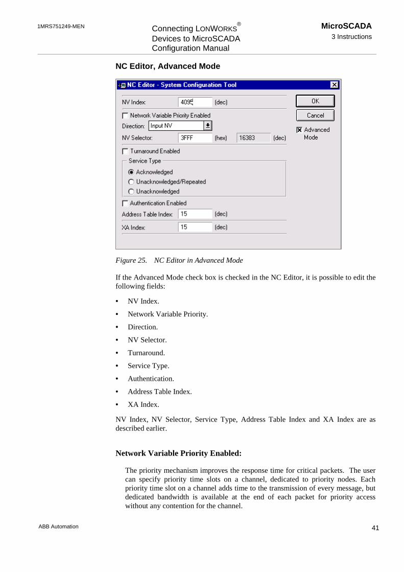
NC Editor, Advanced Mode
Figure 25. NC Editor in Advanced Mode
If the Advanced Mode check box is checked in the NC Editor, it is possible to edit thefollowing fields:
• NV Index.
• Network Variable Priority.
• Direction.
• NV Selector.
• Turnaround.
• Service Type.
• Authentication.
• Address Table Index.
• XA Index.
NV Index, NV Selector, Service Type, Address Table Index and XA Index are asdescribed earlier.
Network Variable Priority Enabled:
The priority mechanism improves the response time for critical packets. The usercan specify priority time slots on a channel, dedicated to priority nodes. Eachpriority time slot on a channel adds time to the transmission of every message, butdedicated bandwidth is available at the end of each packet for priority accesswithout any contention for the channel.
MicroSCADA3 Instructions
Connecting LONWORKS®
Devices to MicroSCADAConfiguration Manual
1MRS751249-MEN
ABB Automation42
Direction:
• Input Network Variable.
• Output Network Variable.
In the LonTalk protocol terminology an input network variable is a variable, whichis received by the node and an output network variable is a variable, which is sentfrom the node.
Turnaround Enabled:
This field is checked if the NV is a turnaround network variable. This means that itis bound to another network variable on the same node. If turnaround is enabled,the node sends back the opposite object with the same selector.
Authentication Enabled:
Authenticated messages allow the receivers to determine whether the sender isauthorised to send that message. By checking this field, it is possible to preventunauthorised access to, or control of, nodes and their applications.
Please, note that the used network variable indices are the same as the ones defined inLON Points for LMK devices in LMK Configuration tool and the ones defined inLON/SPA Analog Inputs for SPA devices in SPA Configuration tool.
Example:
LMK Device 70 could contain a LON Point:#set sta70:slp1=(3,70,"SPAC SNVT_ALARM",88,1); where 70 = network variableindex
SPA Device 72 could contain SPA Points:#set sta72:ssp1=(22,71,5,"L1_CUR_I1",0,1,0) ; where 71 = network variable index#set sta72:ssp2=(22,72,5,"I0_CUR_I4",0,2,0) ; where 72 = network variable index
3.7.5 Extended Address Table
The LON address table configuration can be managed using Extended Address Tableattribute. This attribute is indexed in the similar way as the NV attribute.

1MRS751249-MEN Connecting LONWORKS®
Devices to MicroSCADAConfiguration Manual
MicroSCADA3 Instructions
ABB Automation 43
XA Editor, Default Mode
Figure 26. Default values in the XA Editor
In the default mode the user can enter the following values:
• XA Index.
• Node or Member Number.
• Subnet or Group Number.
Table 5. XA Editor value ranges in the default mode
Value range
XA Index 0 to 255Default 150 to 14 NOT recommended!
Node or Member Number 0 to 127
Subnet or Group Number 0 to 255
In this editor it is not possible to enter values which are out of the ranges. Theconfiguration tool also checks that the entered XA index is free. If the entered indexvalue is already in use, the tool informs the user, that the configuration alreadyincludes an entry with the same index, and the editor stays open.
MicroSCADA3 Instructions
Connecting LONWORKS®
Devices to MicroSCADAConfiguration Manual
1MRS751249-MEN
ABB Automation44
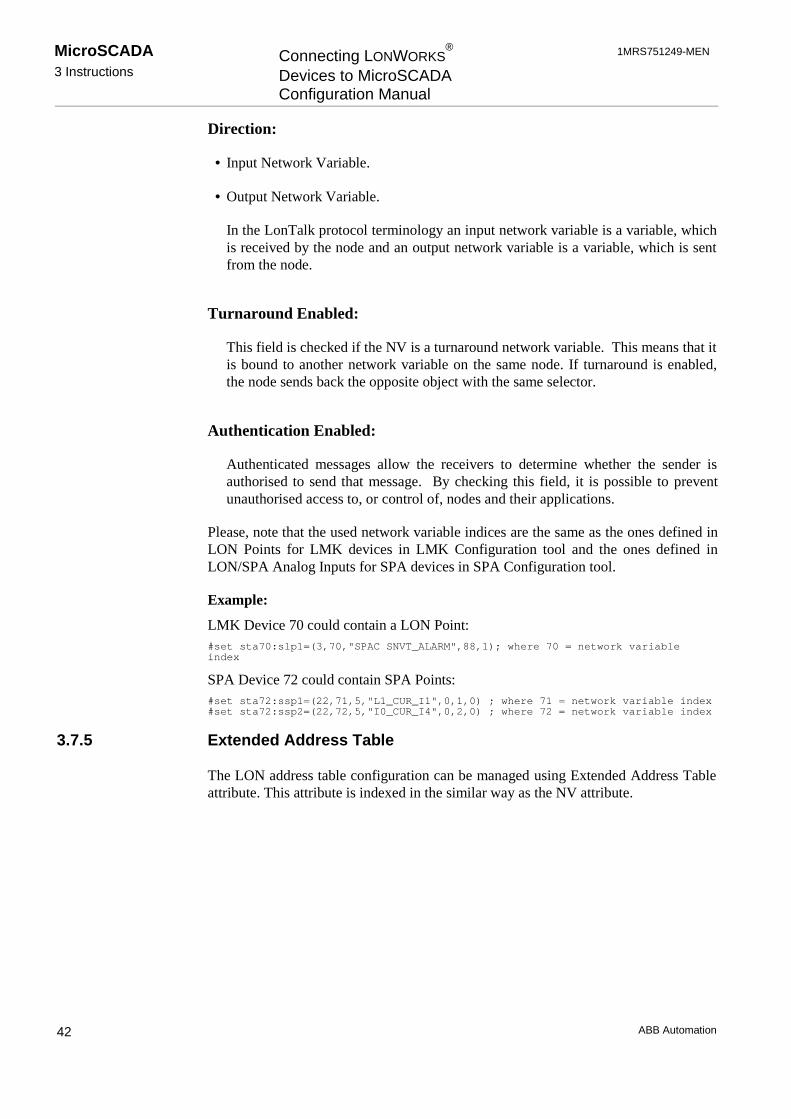
XA Editor, Advanced Mode
Figure 27. XA Editor in the advanced mode
XA Index, Node or Member Number and Subnet or Group Number ranges are asdescribed earlier.
XA Index:
When a new XA index is added to the Extended Address Table, it gets the first freeindex value on the line. Please, note that the values 0 to 14 are reserved for the NeuronChip.
!Value range: 0 to 255
Default value: 15
Recommended value range: 15 to 255
To avoid the loss of the set values, we recommend that you start the XA Indexnumbering from 15 and continue upwards.

1MRS751249-MEN Connecting LONWORKS®
Devices to MicroSCADAConfiguration Manual
MicroSCADA3 Instructions
ABB Automation 45
Address Entry Enabled / Group Address Enabled:
The Address Entry Enabled and the Group Address Enabled are mutual exclusive. Thedefault setting is the Address Entry Enabled and Subnet or Node Address.
Address Entry Enabled:
• If the Unbound Address Table Entry is selected, the Domain Index Enabled checkbox and the Node or Member Number field become unavailable and the latter getsthe default value 0.
• If the Turnaround Address is selected, the Domain Index Enabled check box andthe Node or Member Number field become unavailable and the latter gets thedefault value 1.
• If the Subnet and Node Address is selected, the Domain Index Enabled check boxand the Node or Member Number field are available.
• If the Broadcast Address is selected, the Domain Index Enabled check box and theNode or Member Number field are available. All nodes listen to subnet 0. Thismeans that when subnet 0 is broadcast, it is received by all the LONWORKS devices
Group Address Enabled:
If the group address is enabled, the Group Size text box can be entered a value in therange 0 to 127.
Domain Index Enabled:
Checking the check box enables the domain index. Domain is the top level of theaddressing hierarchy. If different network applications are implemented on a sharedcommunication medium, different domain identifiers can be used to keep theapplications completely separate. A single node can be a member of up to twodomains.
Node or Member Number:
Range: 0 to 127
Repetition Interval Time:
The time interval between the messages sent with the unacknowledged repeatedservice. See Table 6.
Retry Count:
Range: 0 to 15
Default: 3
MicroSCADA3 Instructions
Connecting LONWORKS®
Devices to MicroSCADAConfiguration Manual
1MRS751249-MEN
ABB Automation46
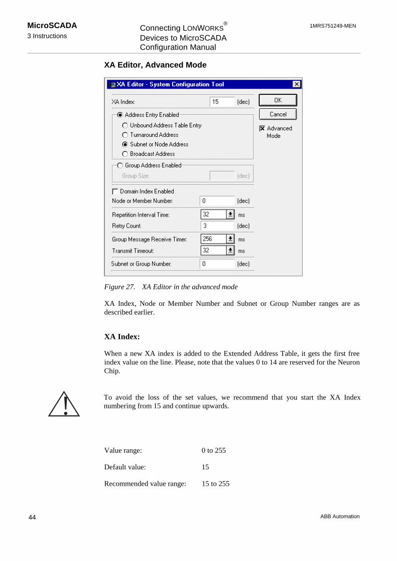
Group Message Receiver Timer:
Receive timeout for group messages. See Table 6.
Transmit Timeout:
Timeout between retries. See Table 6.
Table 6. Time ranges and default values in the XA Editor Advanced Mode
Range/ms Default Value/ms
Repetition Interval Time 16, 24, 32, 48, 64, 96, 128,192, 256, 384, 512, 768, 1024,1536, 2048, 3072
32
Group Message ReceiveTimer
128, 192, 256, 384, 512, 768,1024, 1536, 2048, 3072, 4096,6144, 8192, 12288, 16384,24576
256
Transmit Timeout 16, 24, 32, 48, 64, 96, 128,192, 256, 384, 512, 768, 1024,1536, 2048, 3072
32
3.7.6 Engineering Rex Devices
In a REx device, the SPA point attribute defines the binary output objects (SPAcommands) as SPA points to the NET. It ties together the SPA commandidentifications and the corresponding process objects.
A unique SPA point number is assigned for each SPA point, when a new SPA point isadded. Numbering is started from number 1 and increased with one up to 65535. Thismeans that the REx Configuration tool is responsible for taking care of the uniquenessof the SPA point numbers.
Adding SPA points
Adding a SPA point for a REx device is performed via Add... button of the SPAPoints page. Clicking Add opens a definition dialog and the SPA point informationcan be entered.
During add operation, the Channel 1 element value is copied automatically intoChannel 2, if the text field Channel 2 is focused. This mechanism is also validbetween the Data 1 and Data 2 element values.
Each SPA point consists of 8 elements of data. Element 1 is assigned to fixed number10. Number 10 identifies the type information of a SPA point belonging to a RExdevice.
1MRS751249-MEN Connecting LONWORKS®
Devices to MicroSCADAConfiguration Manual
MicroSCADA3 Instructions
ABB Automation 47
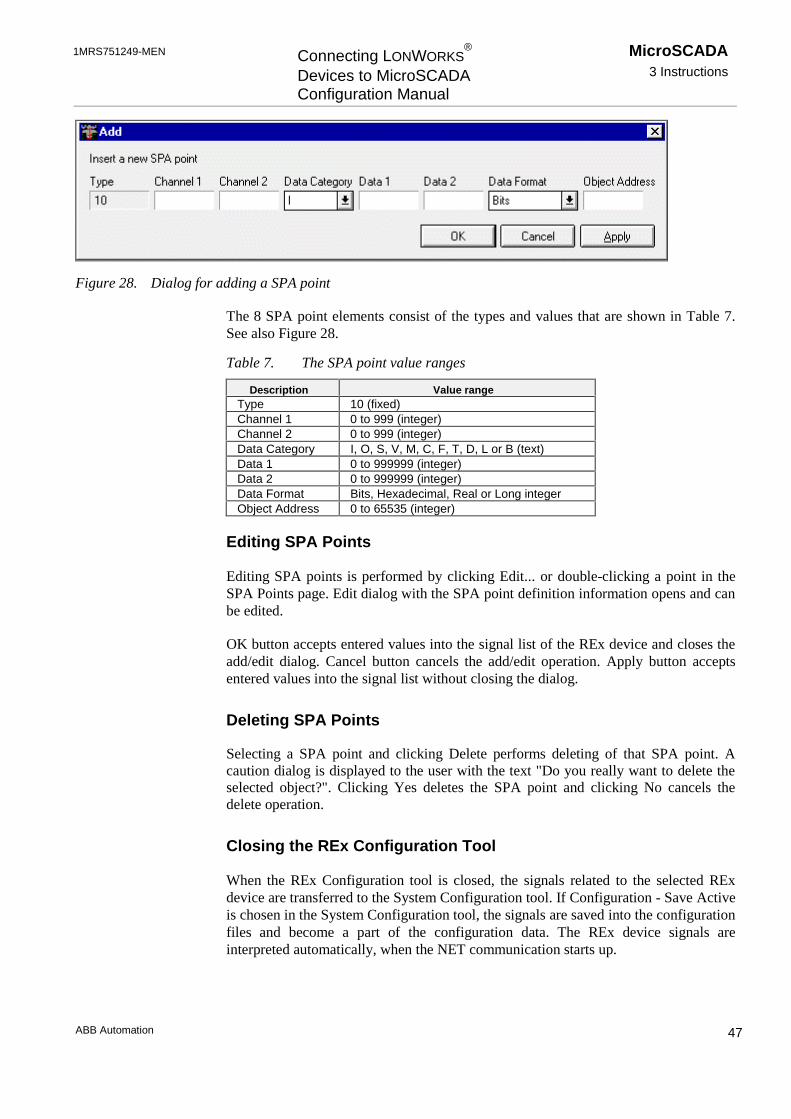
Figure 28. Dialog for adding a SPA point
The 8 SPA point elements consist of the types and values that are shown in Table 7.See also Figure 28.
Table 7. The SPA point value ranges
Description Value rangeType 10 (fixed)Channel 1 0 to 999 (integer)Channel 2 0 to 999 (integer)Data Category I, O, S, V, M, C, F, T, D, L or B (text)Data 1 0 to 999999 (integer)Data 2 0 to 999999 (integer)Data Format Bits, Hexadecimal, Real or Long integerObject Address 0 to 65535 (integer)
Editing SPA Points
Editing SPA points is performed by clicking Edit... or double-clicking a point in theSPA Points page. Edit dialog with the SPA point definition information opens and canbe edited.
OK button accepts entered values into the signal list of the REx device and closes theadd/edit dialog. Cancel button cancels the add/edit operation. Apply button acceptsentered values into the signal list without closing the dialog.
Deleting SPA Points
Selecting a SPA point and clicking Delete performs deleting of that SPA point. Acaution dialog is displayed to the user with the text "Do you really want to delete theselected object?". Clicking Yes deletes the SPA point and clicking No cancels thedelete operation.
Closing the REx Configuration Tool
When the REx Configuration tool is closed, the signals related to the selected RExdevice are transferred to the System Configuration tool. If Configuration - Save Activeis chosen in the System Configuration tool, the signals are saved into the configurationfiles and become a part of the configuration data. The REx device signals areinterpreted automatically, when the NET communication starts up.

MicroSCADA3 Instructions
Connecting LONWORKS®
Devices to MicroSCADAConfiguration Manual
1MRS751249-MEN
ABB Automation48
SCIL commands
The SCIL commands which are automatically constructed from the REx devicesignals can be located by choosing Configuration - Preview... from the SystemConfiguration tool.
The SCIL commands from the NET part of the configuration could be as follows:#set sta1:ssp1=(10,120,120,"V",6,6,2,1)#set sta1:ssp10=(10,123,123,"V",7,7,2,10)#set sta1:ssp11=(10,123,123,"V",11,11,2,11)#set sta1:ssp12=(10,123,123,"V",10,10,2,12)#set sta1:ssp13=(10,123,123,"V",6,6,2,13)#set sta1:ssp14=(10,123,123,"V",7,7,2,14)#set sta1:ssp15=(10,123,123,"V",11,11,2,15)#set sta1:ssp16=(10,123,123,"V",10,10,2,16)#set sta1:ssp2=(10,120,120,"V",7,7,2,2)#set sta1:ssp3=(10,120,120,"V",11,11,2,3)#set sta1:ssp4=(10,120,120,"V",10,10,2,4)#set sta1:ssp5=(10,122,122,"V",6,6,2,5)#set sta1:ssp6=(10,122,122,"V",7,7,2,6)#set sta1:ssp7=(10,122,122,"V",11,11,2,7)#set sta1:ssp8=(10,122,122,"V",10,10,2,8)#set sta1:ssp9=(10,123,123,"V",6,6,2,9)
3.7.6.1 Send General Object Handling Command
This command is available in the System Configuration tool, when the tool is used inonline mode and a REx device is selected from the Object tree.
1 Select a REx device in the object tree.
2 From the menu bar, select Tools > Send General Object Handling Command....See Figure 29.
Figure 29. Send General Ogject Handling Command is selected from the Toolsmenu
The General Object Handling Command dialog is opened. See Figure 30.
3 Enter the appropriate values and click Send.
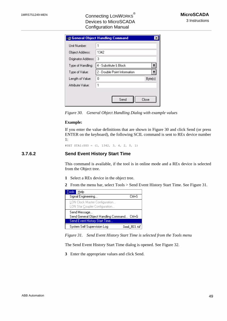
1MRS751249-MEN Connecting LONWORKS®
Devices to MicroSCADAConfiguration Manual
MicroSCADA3 Instructions
ABB Automation 49
Figure 30. General Object Handling Dialog with example values
Example:
If you enter the value definitions that are shown in Figure 30 and click Send (or pressENTER on the keyboard), the following SCIL command is sent to REx device number1:#SET STA1:SGO = (1, 1342, 3, 4, 2, 0, 1)
3.7.6.2 Send Event History Start Time
This command is available, if the tool is in online mode and a REx device is selectedfrom the Object tree.
1 Select a REx device in the object tree.
2 From the menu bar, select Tools > Send Event History Start Time. See Figure 31.
Figure 31. Send Event History Start Time is selected from the Tools menu
The Send Event History Start Time dialog is opened. See Figure 32.
3 Enter the appropriate values and click Send.

MicroSCADA3 Instructions
Connecting LONWORKS®
Devices to MicroSCADAConfiguration Manual
1MRS751249-MEN
ABB Automation50
Figure 32. The dialog for sending event history start time information
After a succesfull send operation, the HS attribute value is changed in the Attributetree. This attribute is described in the System Objects manual.
3.7.7 Engineering LMK Devices
Managing the LMK device signals means that in the System Configuration tool, adevice of the type LMK is selected. Signal Information shows the number of the LONpoints defined for this device number. By selecting Tools _ Signal Engineering fromthe menu bar the LMK Configuration tool opens and signals dedicated to the deviceare assigned into the list of signals.
In an LMK station, the LON point attribute ties together the LON Network Variableindices with the process objects in the MicroSCADA process database. A unique LONpoint number assigns each LON point in the NET, when a new LON Point is added.Numbering is started from number 1 and increased with one until 4095 is reached. Inthis case, the LMK Configuration tool is responsible for taking care of the uniquenessof the LON point numbers.
Each LON point consists of 6-7 elements of data. Element 1 is assigned for the pointtype information. This field cannot be edited. Possible point types and their values arethe following:
• Digital Input (6).
• Analog Input (2).
• Digital Output (4).
• Analog Output (5).
• Structure Input (3).
Numbers 2, 3, 4, 5 and 6 identify the type information of a LON point belonging to anLMK station.

1MRS751249-MEN Connecting LONWORKS®
Devices to MicroSCADAConfiguration Manual
MicroSCADA3 Instructions
ABB Automation 51
Adding LON Points
Adding a LON point for an LMK device is performed via Add... button in the LONPoints page. The LON Point definition dialog opens. It shows a list of the possibleLON point types. See Figure 33.
Figure 33. LON point types
Selecting a LON point type and clicking OK opens the definition dialog.
Depending on the LON point type, the user interface of the add (and edit) dialog maybe different (Figure 34).
Figure 34. The LON point definition dialog for Analog Inputs
OK button accepts the entered values to the signal list of the LMK device and closesthe Add dialog (Figure 34.). Clicking Cancel closes the dialog without adding theentered values to the signal list. Clicking Apply adds the entered values to the signallist without closing the LON point definition dialog.
Base type element
LON Base Type element of the LON point definition is selected from the drop-downlist, where the text strings represent the following values:
• Unsigned 16 (1)
• Signed 16 (2)
• Unsigned 8 (3)

MicroSCADA3 Instructions
Connecting LONWORKS®
Devices to MicroSCADAConfiguration Manual
1MRS751249-MEN
ABB Automation52
• Signed 8 (4)
• Signed 32 (5)
• Float iee754 (7)
• Structure (8)
SNVT type
A node may be installed in a network and logically connected to other nodes vianetwork variables as long as the data types match. A list of all the available SNVTsand details of their definitions are provided in The Master SNVT List, which isavailable in the Internet.
Default:
Alarm state SNVT_alarm type 88
The different LON point types have the following value ranges:
Digital Input
Table 8. Element value ranges for the digital Inputs
Element Description Value range1 Definition 6 (fixed)2 (Network Variable) Index 0 to 4095 (integer)3 (LON) Base Type 1 to 8 (integer)4 Text max. of 30 characters (text)5 (SNVT) Type (integer)6 (Process) Object Address 0 to 65535 (integer)
Analog Input
Table 9. Element value ranges for the Analog Inputs
Element Description Value range1 Definition 2 (fixed)2 (Network Variable) Index 0 to 4095 (integer)3 (LON) Base Type 1 to 8 (integer)4 Text max. of 30 characters (text)5 (SNVT) Type (integer)6 (Process) Object Address 0 to 65535 (integer)7 Dead Band 0 to 0.9999 (real)
Digital Output
Table 10. Element value ranges for the Digital Outputs
Element Description Value range1 Definition 4 (fixed)2 (Network Variable) Index 0 to 4095 (integer)3 (LON) Base Type 1 to 8 (integer)4 Text max. of 30 characters (text)
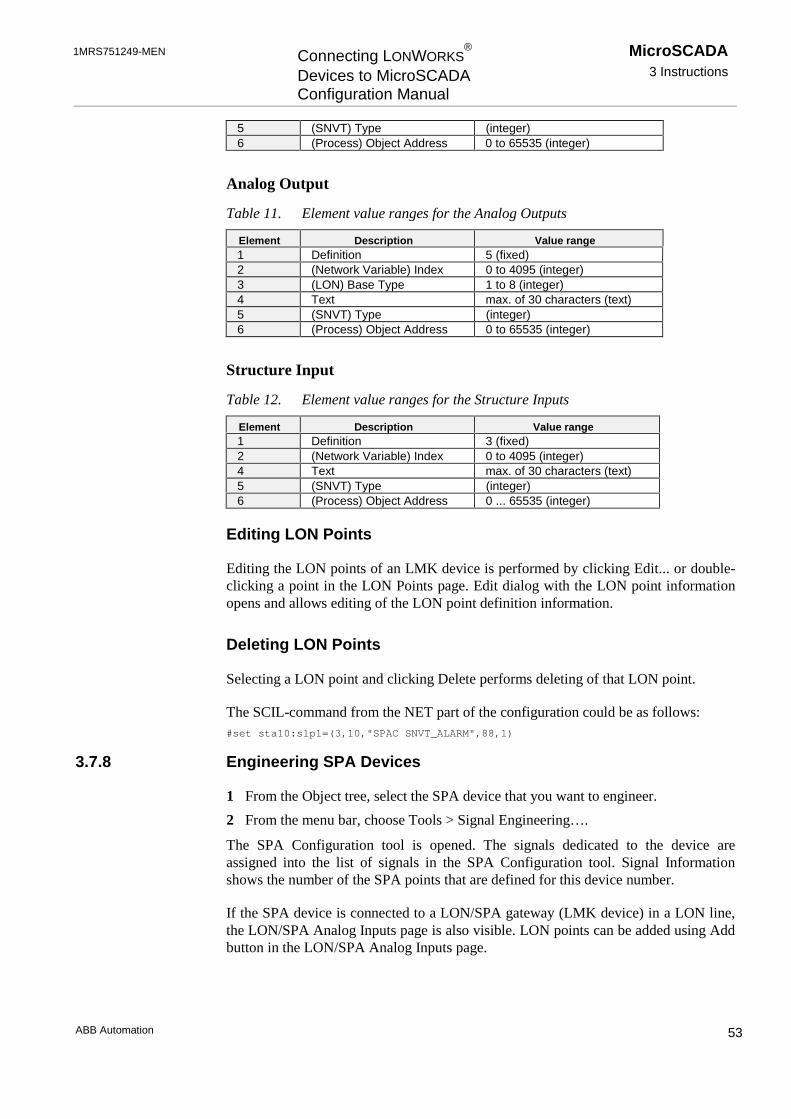
1MRS751249-MEN Connecting LONWORKS®
Devices to MicroSCADAConfiguration Manual
MicroSCADA3 Instructions
ABB Automation 53
5 (SNVT) Type (integer)6 (Process) Object Address 0 to 65535 (integer)
Analog Output
Table 11. Element value ranges for the Analog Outputs
Element Description Value range1 Definition 5 (fixed)2 (Network Variable) Index 0 to 4095 (integer)3 (LON) Base Type 1 to 8 (integer)4 Text max. of 30 characters (text)5 (SNVT) Type (integer)6 (Process) Object Address 0 to 65535 (integer)
Structure Input
Table 12. Element value ranges for the Structure Inputs
Element Description Value range1 Definition 3 (fixed)2 (Network Variable) Index 0 to 4095 (integer)4 Text max. of 30 characters (text)5 (SNVT) Type (integer)6 (Process) Object Address 0 ... 65535 (integer)
Editing LON Points
Editing the LON points of an LMK device is performed by clicking Edit... or double-clicking a point in the LON Points page. Edit dialog with the LON point informationopens and allows editing of the LON point definition information.
Deleting LON Points
Selecting a LON point and clicking Delete performs deleting of that LON point.
The SCIL-command from the NET part of the configuration could be as follows:#set sta10:slp1=(3,10,"SPAC SNVT_ALARM",88,1)
3.7.8 Engineering SPA Devices
1 From the Object tree, select the SPA device that you want to engineer.
2 From the menu bar, choose Tools > Signal Engineering….
The SPA Configuration tool is opened. The signals dedicated to the device areassigned into the list of signals in the SPA Configuration tool. Signal Informationshows the number of the SPA points that are defined for this device number.
If the SPA device is connected to a LON/SPA gateway (LMK device) in a LON line,the LON/SPA Analog Inputs page is also visible. LON points can be added using Addbutton in the LON/SPA Analog Inputs page.

MicroSCADA3 Instructions
Connecting LONWORKS®
Devices to MicroSCADAConfiguration Manual
1MRS751249-MEN
ABB Automation54
Adding SPA Points
Adding a SPA point for a SPA device is performed via Add... button in the SPAPoints page. The SPA Point definition dialog is opened. It shows the list of thepossible SPA point types. See Figure 35.
Each SPA point consists of 6-11 elements of data. Element 1 is assigned for the pointtype information. This field cannot be edited.
Figure 35. The SPA point types
Selecting a point type and clicking OK opens the add dialog. Depending on the SPApoint type, the user interface of this dialog may vary. See Figure 36.
Figure 36. The SPA point definition dialog for Digital Inputs
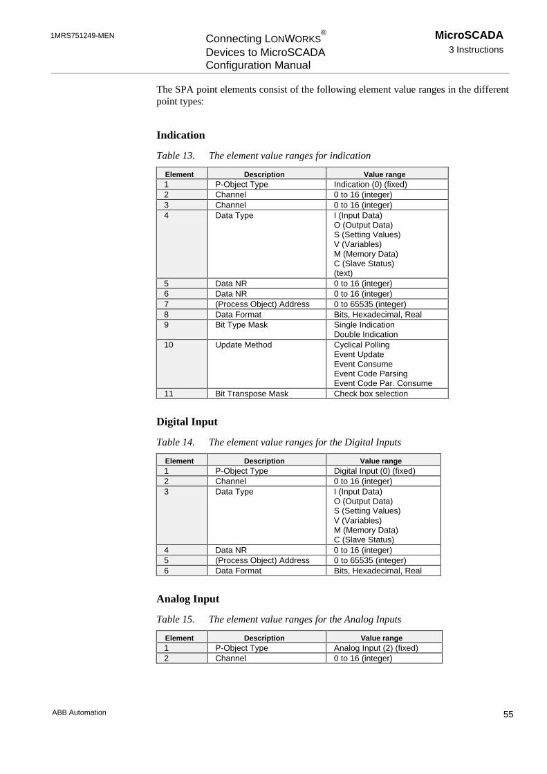
1MRS751249-MEN Connecting LONWORKS®
Devices to MicroSCADAConfiguration Manual
MicroSCADA3 Instructions
ABB Automation 55
The SPA point elements consist of the following element value ranges in the differentpoint types:
Indication
Table 13. The element value ranges for indication
Element Description Value range1 P-Object Type Indication (0) (fixed)2 Channel 0 to 16 (integer)3 Channel 0 to 16 (integer)4 Data Type I (Input Data)
O (Output Data)S (Setting Values)V (Variables)M (Memory Data)C (Slave Status)(text)
5 Data NR 0 to 16 (integer)6 Data NR 0 to 16 (integer)7 (Process Object) Address 0 to 65535 (integer)8 Data Format Bits, Hexadecimal, Real9 Bit Type Mask Single Indication
Double Indication10 Update Method Cyclical Polling
Event UpdateEvent ConsumeEvent Code ParsingEvent Code Par. Consume
11 Bit Transpose Mask Check box selection
Digital Input
Table 14. The element value ranges for the Digital Inputs
Element Description Value range1 P-Object Type Digital Input (0) (fixed)2 Channel 0 to 16 (integer)3 Data Type I (Input Data)
O (Output Data)S (Setting Values)V (Variables)M (Memory Data)C (Slave Status)
4 Data NR 0 to 16 (integer)5 (Process Object) Address 0 to 65535 (integer)6 Data Format Bits, Hexadecimal, Real
Analog Input
Table 15. The element value ranges for the Analog Inputs
Element Description Value range1 P-Object Type Analog Input (2) (fixed)2 Channel 0 to 16 (integer)

MicroSCADA3 Instructions
Connecting LONWORKS®
Devices to MicroSCADAConfiguration Manual
1MRS751249-MEN
ABB Automation56
Element Description Value range3 Data Type I (Input Data)
O (Output Data)S (Setting Values)V (Variables)M (Memory Data)C (Slave Status)(text)
4 Data NR 0 to 16 (integer)5 (Process Object) Address 0 to 65535 (integer)6 Data Format Bits, Hexadecimal, Real7 Dead Band 0 to 65537 (real)
Digital Output
Table 16. The element value ranges for the Digital Outputs
Element Description Value range1 P-Object Type Digital Setpoint (3) (fixed)2 Channel 0 to 16 (integer)3 Data Type I (Input Data)
O (Output Data)S (Setting Values)V (Variables)M (Memory Data)C (Slave Status)(text)
4 Data NR 0 to 16 (integer)5 (Process Object) Address 0 to 65535 (integer)6 Data Format Bits, Hexadecimal, Real
Analog Output
Table 17. The element value ranges for the Analog Outputs
Element Description Value range1 P-Object Type Analog Setpoint (4) (fixed)2 Channel 0 to 16 (integer)3 Data Type I (Input Data)
O (Output Data)S (Setting Values)V (Variables)M (Memory Data)C (Slave Status)(text)
4 Data NR 0 to 16 (integer)5 (Process Object) Address 0 to 65535 (integer)6 Data Format Bits, Hexadecimal, Real
Object Command
Table 18. The element value ranges for the object commands
Element Description Value range1 P-Object Type Object Command (5) (fixed)2 Channel 0 to 16 (integer)

1MRS751249-MEN Connecting LONWORKS®
Devices to MicroSCADAConfiguration Manual
MicroSCADA3 Instructions
ABB Automation 57
Element Description Value range3 Data Type I (Input Data)
O (Output Data)S (Setting Values)V (Variables)M (Memory Data)C (Slave Status)
4 Data NR 0 to 16 (integer)5 (Process Object) Address 0 to 65535 (integer)6 Data Format Bits, Hexadecimal, Real
Pulse Counter
Table 19. The element value ranges for the pulse counter
Element Description Value range1 P-Object Type Pulse Counter (6) (fixed)2 Channel 0 to 16 (integer)3 Data Type I (Input Data)
O (Output Data)S (Setting Values)V (Variables)M (Memory Data)C (Slave Status)
4 Data NR 0 to 16 (integer)5 (Process Object) Address 0 to 65535 (integer)6 Data Format Bits, Hexadecimal, Real7 Dead Band 0 to 65537 (real)
Editing SPA points
Editing a SPA point of a SPA device is performed by clicking Edit... or double-clicking a point in the SPA Points page. Edit dialog opens and allows editing of theSPA point definition information.
The Data Type element is selected from the drop-down list, where the text stringsrepresent the following characters: Input Data (I), Output Data (O), Setting Values (S),Variables (V), Memory Data (M) and Slave Status (C).
Data Format element is selected from the drop-down list, where the text stringsrepresent the following values: Bits (1), Hexadecimal (2) and Real (3). Depending onthe SPA point type; the user interface of this edit dialog may vary. See Figure 36.
OK button accepts entered values to the signal list and closes the edit dialog. Cancelbutton cancels the edit operation. Apply button accepts entered values to the signal listwithout closing the dialog.
Deleting SPA points
Selecting a SPA point and clicking Delete performs deleting of that SPA point. Acaution text appears. If you click Yes, the selected data elements are deleted. If youclick No, the delete operation is cancelled.

MicroSCADA3 Instructions
Connecting LONWORKS®
Devices to MicroSCADAConfiguration Manual
1MRS751249-MEN
ABB Automation58
LON POINTS
The LON point attribute ties together the LON Network Variable indices with theprocess objects in the MicroSCADA process database. A unique LON point numberassigns each LON point in the NET. Numbering is started from 1 and increased withone until 4095 is reached.
Adding LON Points
If Add... is clicked in the LON/SPA Analog Inputs page, the LON Point add dialogopens for the LON/SPA Analog Inputs. See Figure 37.
Figure 37. LON/SPA Analog Inputs page. Click Add… to create a new LON point.
Table 20. Element value ranges for the LON/SPA Analog Input
Element Description Value range1 Definition Analog Input (2) (fixed)2 (Network Variable) Index 0 to 4095 (integer)3 (LON) Base Type Drop down list. See the text
later.4 Text max. of 30 characters (text)5 (SNVT) Type (integer)6 (Process) Object Address 0 to 65535 (integer)7 Dead Band 0 to 65535 (real)
Editing LON/SPA Analog Inputs
Editing a LON point of a SPA device, which has LON/SPA Analog Inputs isperformed by clicking Edit... or double-clicking a point in the LON/SPA AnalogInputs page. The Edit dialog opens and allows changes to the LON point definitioninformation.
The LON Base Type element of the LON point definition is displayed/selected from adrop-down list, where the text strings represent the following values: unsigned 16 (1),
1MRS751249-MEN Connecting LONWORKS®
Devices to MicroSCADAConfiguration Manual
MicroSCADA3 Instructions
ABB Automation 59
signed 16 (2), unsigned 8 (3), signed 8 (4), signed 32 (5), float iee754 (7) andStructure (8).
The SCIL-commands from the NET part of the configuration could be as follows:#set sta71:ssp1=(0,1,3,"I",2,3,1,1,63,0,3)#set sta71:sed1=(0,1,3,2,2,1,2,2,1,3,3,4,0) ; Event to Data#set sta71:ssp2=(5,2,2,"V",1,1,1,1)#set sta71:ssp3=(5,2,2,"V",2,2,1,2)#set sta71:ssp4=(5,2,2,"V",3,3,1,3)#set sta71:ssp5=(5,2,2,"V",4,4,1,4)#set sta72:ssp1=(22,71,5,"L1_CUR_I1",0,1,0) ; LON/SPA Analog Input#set sta72:ssp2=(22,72,5,"I0_CUR_I4",0,2,0) ; LON/SPA Analog Input
3.7.9 LON Clock Master Configuration
See also information in section 3.5.10.
To start the configuration:
1 Open the configuration in online mode.
2 From the menu bar choose Tools - LON Clock Master Configuration.…
LON Clock Master Configuration page opens. See Figure 38. The information that isshown in this page is read from the Neuron Chip of the LON Clock Master device.Clicking the Refresh button on the bottom of the page updates the information.
Please note that it is not possible to add or delete configuration objects in the LONClock Master Configuration page.
There are two ways to change the settings:
• Double-click the row item that you want to edit.
• Alternatively, select the item that you want to edit and click the Edit button in thesame section of the page.
The appropriate configuration page opens and you can change the settings.
After selecting some Address Table entry, all the related entries in Network VariableConfiguration become selected. Relationship is found from the Index element of theAddress Table and the Address Table Index element of the Network VariableConfiguration entry.
Please, note that multiple related entries may exist in Network Variable Configurationrelated to one entry in Address Table. If selected entry in Network VariableConfiguration includes value 15 in Address Table, no entry should be selected inAddress Table, because value 15 means that it is not associated to Address Table.

MicroSCADA3 Instructions
Connecting LONWORKS®
Devices to MicroSCADAConfiguration Manual
1MRS751249-MEN
ABB Automation60
Figure 38. LON Clock Master Configuration
General Information Page
Subnet and Node Number:
Subnet and Node numbers were set, when you created the LON Clock Master devicewith the System Configuration tool in offline mode. In this editor you can change theaddress, if it is needed. See Figure 39. If you change any other information thanSubnet and Node Number, please, fill in the pre-set Subnet and Node values.
!
Subnet Number
Range: 0 ... 255
If you change the Subnet or Node number, change also the configuration data, in orderto have connection to this LON Clock Master again. You have to change the attributevalues of the NET attributes SN (subnet number) and NN (node number) to equal withthe values that were entered in this General Information page.

1MRS751249-MEN Connecting LONWORKS®
Devices to MicroSCADAConfiguration Manual
MicroSCADA3 Instructions
ABB Automation 61
Node Number
Range: 0 ... 127
Warning Interval:
Range: 30 ... 100 ms
Default: 30 ms
Delay Compensation
Range: ������������� V
Default value: �� V
Time Zone
Range: -127.59 ... +127.59 UTC
Default value: 0.00 UTC

MicroSCADA3 Instructions
Connecting LONWORKS®
Devices to MicroSCADAConfiguration Manual
1MRS751249-MEN
ABB Automation62
Figure 39. LON Clock Master General Information editor
Parameter information
The configured parameter information is read from the LON Clock Master into theSystem Configuration tool, if the configuration is opened in online mode.
Time Settings
LON Clock Master’s internal clock is adjusted to the UTC time by receiving a timemessage and a second pulse from GPS receiver device.
NV_time
LON Clock Master’s internal clock can be adjusted to the UTC time by receiving asecond or a minute pulse from other time references than GPS (e.g. DCF77). Whenthere is no time message available from time reference, the user given time can bedelivered through the LONWORKS device bus by using network variables.
Accuracy: 10 ... 100 ms

1MRS751249-MEN Connecting LONWORKS®
Devices to MicroSCADAConfiguration Manual
MicroSCADA3 Instructions
ABB Automation 63
Synchronisation using SNVT_time_stamp
Network variable of type SNVT_time_stamp is broadcast to the network by a clockmaster node. The nodes that own this type of network variable receive the time in thenetwork variable and synchronise the internal real-time clocks accordingly.
SNVT_time_stamp contains year, month, day, hour, minute and second. It may beexpected that in the best case the real-time clocks of the clock master node and theother nodes are synchronised to each other with the accuracy of 10...100 ms, if theclock master node attempts to send the SNVT_time_stamp exactly when the fullsecond is elapsing.
Accuracy: 10 ... 100 ms(Strongly dependent on the network load and the input load of thesynchronised nodes.)
Synchronisation using NV_clock_warning and NV_clock
Network variables NV_clock_warning and NV_clock messages are broadcast to theLONWORKS network by a clock master node once a second, one after another, with thedelay of 30...100 milliseconds.
When a node receives the NV_clock_warning it must stop sending other than highpriority messages and start waiting for NV_clock. The time received in NV_clock isused to adjust the real-time clock of the node.
The length of time interval between NV_clock_warning and NV_clock message isuser configurable and it is given in network variable nv_warn_interval.
Accuracy: 1 ... 5 ms(Provided that after broadcasting NV_clock_warning all systemnodes will suspend transmission of normal priority messages,otherwise may be more than 5 ms.)
VATS pulse based synchronisation
!VATS pulse based synchronisation uses the common NV_clock_warning message ofthe previously defined method. After some delay there will be a synchronisation pulsetransmitted in the preamble of a data package. This pulse (predefined length min.�� V�� PD[�� ��� V�� FDQ� EH� GHWHFWHG� E\� WKH� KDUGZDUH� DGGHG� IRU� WKLV� SXUSRVH�� 7KHdetection of the pulse occurs in the master end and in the slave end of the LONWORKS
device bus. After the pulse has been broadcast, a clock message including the master’s
Please note that the REF 5xx relays do not support the VATS based synchronisationmethods yet.
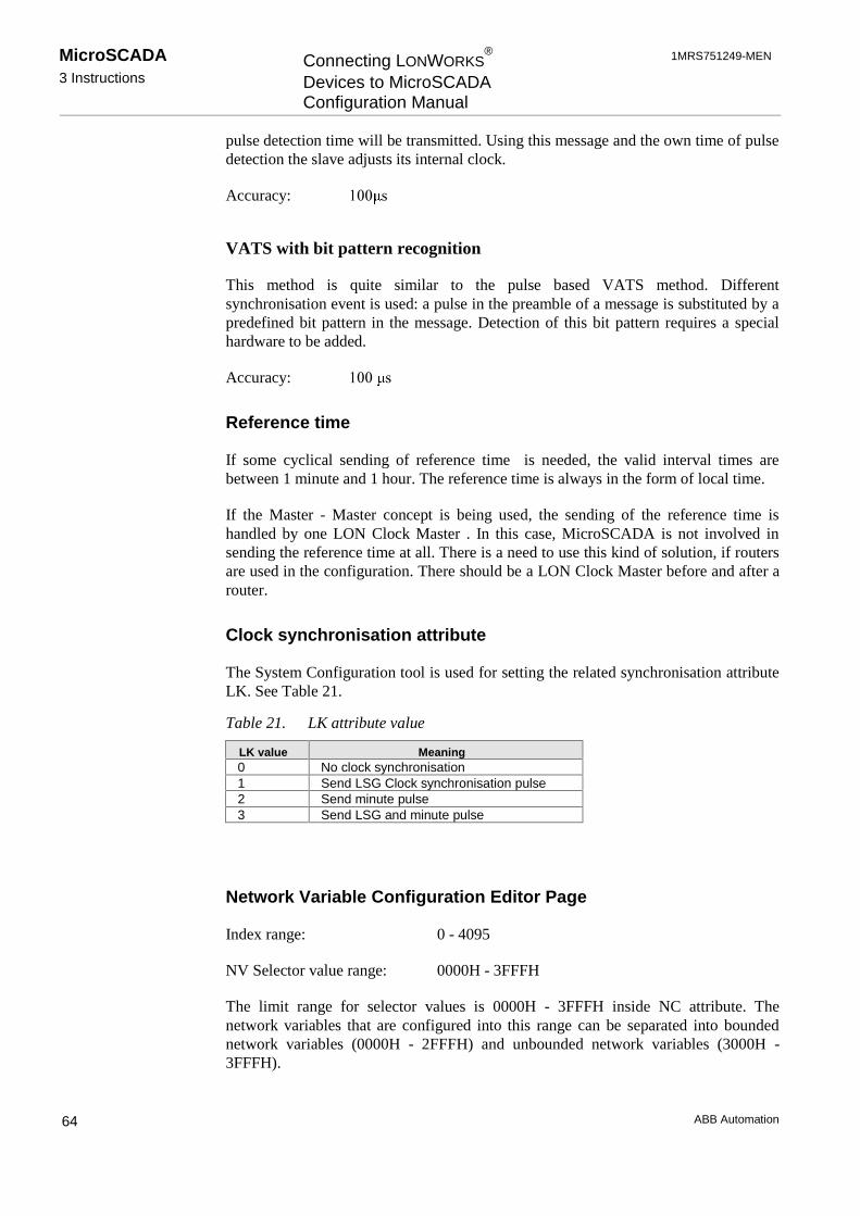
MicroSCADA3 Instructions
Connecting LONWORKS®
Devices to MicroSCADAConfiguration Manual
1MRS751249-MEN
ABB Automation64
pulse detection time will be transmitted. Using this message and the own time of pulsedetection the slave adjusts its internal clock.
Accuracy: ��� V
VATS with bit pattern recognition
This method is quite similar to the pulse based VATS method. Differentsynchronisation event is used: a pulse in the preamble of a message is substituted by apredefined bit pattern in the message. Detection of this bit pattern requires a specialhardware to be added.
Accuracy: ���� V
Reference time
If some cyclical sending of reference time is needed, the valid interval times arebetween 1 minute and 1 hour. The reference time is always in the form of local time.
If the Master - Master concept is being used, the sending of the reference time ishandled by one LON Clock Master . In this case, MicroSCADA is not involved insending the reference time at all. There is a need to use this kind of solution, if routersare used in the configuration. There should be a LON Clock Master before and after arouter.
Clock synchronisation attribute
The System Configuration tool is used for setting the related synchronisation attributeLK. See Table 21.
Table 21. LK attribute value
LK value Meaning0 No clock synchronisation1 Send LSG Clock synchronisation pulse2 Send minute pulse3 Send LSG and minute pulse
Network Variable Configuration Editor Page
Index range: 0 - 4095
NV Selector value range: 0000H - 3FFFH
The limit range for selector values is 0000H - 3FFFH inside NC attribute. Thenetwork variables that are configured into this range can be separated into boundednetwork variables (0000H - 2FFFH) and unbounded network variables (3000H -3FFFH).

1MRS751249-MEN Connecting LONWORKS®
Devices to MicroSCADAConfiguration Manual
MicroSCADA3 Instructions
ABB Automation 65
Figure 40. LON Clock Master Network Variable Configuration Editor
Bounded network variable
During the start-up of PC-NET, the initial state of a bounded network variable is readthrough NV Poll LON network management command, if the Diagnostic Interval (DI)attribute of station with type LMK is higher than 0. It is also possible to configure thebackground network variable polling mechanism into PC-NET by defining the intervaltime in minutes to the Consistency Check Time (CT) attribute of station with typeLMK. See Figure 41.
! Small interval time increases the LON load, because of the repeating collections of theNV Poll commands in that LON line. Value 0 in CT attribute disables this mechanism.

MicroSCADA3 Instructions
Connecting LONWORKS®
Devices to MicroSCADAConfiguration Manual
1MRS751249-MEN
ABB Automation66
Figure 41. It is possible to configure the background network variable pollingmechanism into PC-NET by defining the interval time in minutes to theConsistency Check Time (CT) attribute of an LMK station
Unbounded network variable
If unbounded network variables are defined into PC-NET, their initial state is not readduring PC-NET start-up in spite of the station’s DI attribute value. The networkvariable update is occurred to the unbounded network variable only if the device itselfsends NV Update LON network management command. As a default, when networkvariables are included into the neuron chips of the LON devices, the default selectorvalues are usually located inside unbounded network variable range. This means thatduring LON configuration engineering the selector values has to be configured insidebounded network variable range with System Configuration Tool or LON NetworkTool inside the neuron chip of a LON device. These definitions have to be consistentwith the contents of the NC attribute of the LON line.
For further information, see the text earlier in this section (Direction and NV Selector)and the descriptions in section 3.7.4 Network Variable Configuration.

1MRS751249-MEN Connecting LONWORKS®
Devices to MicroSCADAConfiguration Manual
MicroSCADA3 Instructions
ABB Automation 67
Address Table Editor Page
Figure 42. LON Clock Master Address Table Editor
Index range: 0 ... 14
Node or Member Number range: 0 ... 127
Subnet or Group Number range: 0 ... 255
See Figure 42. Further information can be found in section 3.7.5 Extended AddressTable.
3.8 Signal Data Transfer from LON Network Tool
t is possible to transfer signal engineering data from LON Network Tool to SystemConfiguration tool. Only the information that is needed for vertical communication istransferred. To start the data transfer:
1 From your configuration, select a LON line.
2 From the menu bar, choose Configuration > LON Network Variables. See Figure43.
3 Select Import Single Node or Import Multiple Nodes.

MicroSCADA3 Instructions
Connecting LONWORKS®
Devices to MicroSCADAConfiguration Manual
1MRS751249-MEN
ABB Automation68
Figure 43. Single node data transfer will be started from LON Network Tool
Importing of single node means that the data is read from a certain LON node only(e.g. from file S001N001.lon). Importing of multiple nodes means that data is readfrom certain specified LON nodes or from all LON nodes that are included into aLON Network Tool project (e.g. all files with .lon extension). The LON file is selectedby using the File Chooser. See Figure 44.
Figure 44. The file to be imported can be chosen from the File Chooser (shownabove) that opens automatically, when Configuration > LON NetworkVariables > Import Single Node (or Import Multiple Nodes) is selectedfrom the menu bar.
Importing a single node
If a Single Node is going to be imported, the exported LON file is selected by usingthe File Chooser. See Figure 44.

1MRS751249-MEN Connecting LONWORKS®
Devices to MicroSCADAConfiguration Manual
MicroSCADA3 Instructions
ABB Automation 69
When an appropriate LON file with the .lon extension is opened, a dialog withinformation about the incoming data is shown. See Figure 45. Clicking Import startsimporting of a single node.
Figure 45. Clock Master device with node number 126 and subnet number 1 will beimported from LON Network Tool to MicroSCADA System Configurationtool
Example:
Before data importation, the LON line is selected from the Object tree. See Figure 46.
Figure 46. Object tree before the Single Node is imported
A LON/SPA Gateway with two child objects (two SPACOM devices) is importedfrom LNT (LON Network Tool). The object information is shown in the importdialog.

MicroSCADA3 Instructions
Connecting LONWORKS®
Devices to MicroSCADAConfiguration Manual
1MRS751249-MEN
ABB Automation70
Figure 47. Object data in the Single Node import dialog
When the import button is clicked in the import dialog, the data is transferred to theSystem Configuration tool. The new object with its child objects is shown in theobject tree.
Figure 48. After the import operation, there is a new LMK station with two childobjects in the Object tree
The imported configuration data can be seen and edited if the device is selected fromthe Object tree and Tools > Signal engineering is chosen from the menu bar.
Figure 49. LON Point information for LMK device number 99
Figure 50 LON/SPA Analog Input information for SPA device number 101

1MRS751249-MEN Connecting LONWORKS®
Devices to MicroSCADAConfiguration Manual
MicroSCADA3 Instructions
ABB Automation 71
The LON line number 3 imported information can be seen and edited, if thementioned line is selected from the Object tree and the Advanced page is clickedvisible.
Figure 51. New entries for Network Variables and Extended Address Table for LON line number 3
Importing Multiple Nodes
If Multiple Nodes are going to be imported, the LON file is selected by using the FileChooser. See Figure 44. When an appropriate LON file folder is selected, a dialog thatshows the incoming data is displayed. See Figure 53. Clicking Import starts importingof multiple nodes (click of Cancel closes the dialog without importing any data).
When the import operation is completed, the signal information can be seen in theSystem Configuration tool, if Tools > Signal Information is selected from the menubar.
Example:
Before data importation, the LON line is selected from the Object tree. See Figure 52.
Figure 52. The Object tree before multiple nodes have been imported
Two REx devices, a LON/SPA Gateway with two child objects (two SPACOMdevices) and four LON Clock Masters are imported from LNT (LON Network Tool).The object information is shown in the import dialog. See Figure 53.

MicroSCADA3 Instructions
Connecting LONWORKS®
Devices to MicroSCADAConfiguration Manual
1MRS751249-MEN
ABB Automation72
Figure 53. Multiple LON files are imported to the System Configuration tool whenthe Import button is clicked
When the import button is clicked in the import dialog, the data is transferred to theSystem Configuration tool. The new objects with the possible child objects are shownin the object tree.
Figure 54. The Object tree after multiple LON files have been imported
The imported configuration data can be seen and edited if the device is selected fromthe Object tree and Tools > Signal engineering is chosen from the menu bar.
Figure 55. LON Point data for the imported LON Clock Master device number 3

1MRS751249-MEN Connecting LONWORKS®
Devices to MicroSCADAConfiguration Manual
MicroSCADA3 Instructions
ABB Automation 73
Figure 56. LON Point data for the imported LMK device number 99
Figure 57. LON/SPA Analog Input data for the imported SPA device number 101
Figure 58. LON Point data for the imported LON Clock Master device number 125
The LON line number 3 imported information can be seen and edited, if thementioned line is selected from the Object tree and the Advanced page is clickedvisible.

MicroSCADA3 Instructions
Connecting LONWORKS®
Devices to MicroSCADAConfiguration Manual
1MRS751249-MEN
ABB Automation74
Figure 59. Network Variables and Extended Address table for LON line number 3
3.9 Optimising the Configuration
3.9.1 Multiple PC-NETs
f multiple PC-NETs are included into the configuration, a delay time between startingeach PC-NETs.exe program is included during the start-up of the system. If there is nodelay, the PC-NETs do not communicate successfully.
The delay parameter can be found in the menu bar via Settings - Environment.... Thedefault value is 1 s. The value can be changed from 1 s up to 60 s.
!The parameter value is stored into the permanent configuration file SysConf.ini withthe key name PCNET_Start_Delay. The delay time is utilised by the StartPCNET.sclprogram assigned into the folder \sc\STOOL\SysConf.
If you change this parameter value, the configuration has to be saved.

1MRS751249-MEN Connecting LONWORKS®
Devices to MicroSCADAConfiguration Manual
MicroSCADA3 Instructions
ABB Automation 75
3.9.2 Timeout Setting
The SYS:BTI setting must always be high enough in relation to the STAnn:SRTsetting.
One tested configuration is:
TI = 60s and RT = 5 ... 20 s
If the RT setting is too high it may cause a failure in answering transparent SPAcommand (error 152). This happens if the SPA message through an LSG device failsand TI time elapses before a new SPA message has been sent.
3.9.3 Priority Setting: SPA Device Connected Through an LSG Device
If the priority setting is used when connecting a SPA device through an LSG devicethe setting must be as follows:
The first high-priority DI must be DI[15] (where 15 is the network variable) and thenext high-priority DIs must have smaller indices in numerical order; i.e. DI[14],DI[13] etc.
The same rule goes with the digital outputs.
3.10 Event Filtering Between RED500 Devices and MicroSCADA
It is recommended to mask out unnecessary events in the bay unit to reduce thebusload.
Event client (MicroSCADA) orders the events from the relay according to event filterSTA’n’:SEF. In the relay the event filter refers to the corresponding event mask, whichdefines the events that are sent to the particular event client.
!
3.11 Testing the Communication (MicroSCADA - REx Device)
There are different methods for testing the communication between MicroSCADA andREx devices:
In the System Configuration tool:
• In online mode choose the REx device (Station) to be tested.
• Choose Tools - Send Message... from the menu bar.
In MicroSCADA, the event filter (EF attribute) must be defined before setting thestation in use.

MicroSCADA3 Instructions
Connecting LONWORKS®
Devices to MicroSCADAConfiguration Manual
1MRS751249-MEN
ABB Automation76
The Send Message dialog opens.
• Click Send RF, or write SPA message RF: and click Send. See Figure 60.
If you get an identification to your message in the text field Reply from SPA, thecommunication is OK.
Figure 60. Testing communication with the System Configuration tool
Example 1:
Reply to the RF: message from a REF terminal:
<1D:REF543 :2A, when the station/node number is 1 and the terminal is REF 543.
It is also possible to test the connection to a SPA device the similar way:
Example 2:
Reply to the RF: message from a SPA device:
<11D:SPTO 1D2:07, when the station number is 11 and the SPA module is SPTO1D2
It is also possible to test the connection to an LMK device by sending the node statuspoll.
In the Test Dialog:
1 Enter the following text on the command line:#SET STA<station number>:SSM=“RF:”
2 Press ENTER.
3 Read the value in a field with the notation STA<station number>:SSM.
In the REx tool picture:
1 Select SPA MESSAGE.
2 Enter the following command on the line SEND MESSAGE:
RF:
The identification of the relay should appear on the next line.

1MRS751249-MEN Connecting LONWORKS®
Devices to MicroSCADAConfiguration Manual
MicroSCADA4 Technical Description
ABB Automation 77
4 Technical Description
4.1 Functional Description
4.1.1 Summary of the LonTalk Protocol Based Functions
The LonTalk protocol is a peer-to-peer protocol, which enables all devices connectedto the network talking to each other. Network nodes are identified by their own subnetand node number.
The LonTalk protocol supports two types of application layer objects: networkvariables and explicit messages.
• Network variables are used to deliver small data items like measurement values,status changes, interlocking data, blocking signals, alarms and events.
• Explicit messages are used to transfer longer pieces of information like packedsequences of events and explicit read and write messages to access device data.
SPA-bus messages can also be sent transparently in explicit messages in order totransfer e.g. device parameters.
In a system supported by a high performance peer-to-peer communication network,data acquisition can be handled efficiently and reliably. Bay level devices canspontaneously transmit measured process values, status changes and events to multiplehigher level devices. Higher level devices can read and write memorised values,settings and other parameter data from bay level devices when required. Additionally,the LONWORKS device bus enables implementation of distributed control algorithmsand distributed fault localisation algorithms. Bay level devices can communicatedirectly with each other, in order to transfer e.g. interlocking information between baycontrollers and blocking signals between protection relays.
4.1.2 Vertical Communication
In ABB station automation systems the following data is sent spontaneously from baylevel devices to higher level devices:
• Measurement values.
• Status of the circuit breakers and isolators.
• Time-tagged alarms and events.
• Fault currents at the time of a relay trip.
• Distance to the fault location.
• Other recorded data related to the detected fault.
All this information can also be explicitly requested by higher level devices.
The following information is transmitted to higher level devices only upon request:
• Setting values and other parameters.

MicroSCADA4 Technical Description
Connecting LONWORKS®
Devices to MicroSCADAConfiguration Manual
1MRS751249-MEN
ABB Automation78
• Disturbance recordings.
Higher level devices transmit the following data to lower level devices:
• Control commands.
• Setting values and other parameters.
• Clock synchronisation.
• Interrogation requests.
4.1.3 Summary of the PC-NET Function
The task of the PC-NET is to convert the external protocols, used for communicatingwith process units, such as relays and RTUs, to the ACP protocol which is usedbetween PC-NET and the MicroSCADA base system. PC-NET also supports anumber of slave protocols, which may be used for connecting to a higher level system.
4.1.4 Summary of the PCLTA Card Function
The PCLTA card acts as a LONWORKS network interface for the PC-based hosts.
4.1.5 Summary of the Transceiver Module RER 107 Function
The RER 107 transceiver module acts as an interfacing unit between the PCLTA cardand the fibre-optic LONWORKS network. The module converts the data signal from thePCLTA card to an optical signal and vice versa.
4.1.6 Summary of the Star-coupler RER 111 Functions
The LONWORKS technology based star-coupler RER 111 is a device which enables theinterconnection of various modules using the LONWORKS communication bus.
The RER 111 provides a star connection point where other LONWORKS technology-based devices can be connected. This is achieved by using five types of cards that canbe connected within the nine slots provided. Each option card has a different rolewithin a LONWORKS network.
• The fibre optic option card provides three fibre optic transceiver pairs for thefollowing optional connection types:
• The interconnection of the bay level devices.
• Connection between two RER 111 units equipped with a fibre optic optioncard.
• Connection between the RER 111 unit and higher level devices, e.g.MicroSCADA.
• The RS-485 option card is used for connecting a device using an RS-485 interfaceto the LONWORKS network. This card also comprises a fibre optic transceiver pair.

1MRS751249-MEN Connecting LONWORKS®
Devices to MicroSCADAConfiguration Manual
MicroSCADA4 Technical Description
ABB Automation 79
• The SLTA option card provides an RS-232 interface for the network. It may be aninterconnection between higher level devices (e.g. monitoring terminals, PCs etc.)and the LONWORKS network, or it may be a connection between RER 111 unitsusing a fibre optic transceiver pair.
• The router option card connects two different communication channels and passesLonTalk messages between them. One channel is the open collector bus of a RER111 unit while the other can be either fibre optic or transformer isolated twistedpair with a speed of 78 kbit/s or 1.25 Mbit/s speed (TP/XF-78 or TP/XF-1250).The router option card also provides a means of dividing a system into multiplesub-systems.
• The double connection option card can be used for connecting devices togetherwith double connections. It can be used for connecting two fibre optic transceiverpairs to any device supporting double connection (e.g. in HSB systems). If a faultoccurs in one fibre optic connection, the other can still receive and transmit data tothe device.
• The SLCM option card provides a connection from time reference to theLONWORKS network. The SLCM option card includes an internal clock and anapplication program, which uses the internal clock to generate various kind ofsynchronisation messages and signals in order to synchronise other devices in theLONWORKS network.
4.1.6.1 PCLTA Card Configuration
The System Configuration tool includes a mechanism for configuring the transceiverof the PCLTA card. This operation is usually done only once, i.e. when a new PCLTAcard is installed in a computer. If the transceiver becomes unable to communicate at alater date, it must be reconfigured.
The System Configuration tool also includes a mechanism for changing the node andsubnet number of the PCLTA card. This is done if there is a need to rearrange theaddresses of the system. The mechanism is compatible with the LON Network Tool.This means that the System Configuration tool verifies that the parameter file(Nettools.ini) of the LON Network Tool is consistent with the address settings madeby the System Configuration tool.
4.1.6.2 Default Values
Link
If a valid link object number is entered, this new object becomes a child object of theMicroSCADA Configuration. During the addition of this new object, its attributes aregiven the following default values:
LT Link Type: "INTEGRATED"SC Start Command: "\sc\prog\pc_net\pc_nets.exe"CX Comment Text: ""

MicroSCADA4 Technical Description
Connecting LONWORKS®
Devices to MicroSCADAConfiguration Manual
1MRS751249-MEN
ABB Automation80
Node
If a valid node object number is entered as an object number, this new object becomesa child object of a Link [INTEGRATED]. During the addition of this new object, itsattributes are given the following default values:
LI Link Number Number of the parent object Link [INTEGRATED], e.g. 1NN LAN Node Name ""NT Node Type "NET"RN Routing Node 0SA Station Address 203DI Diagnostic Interval 0DT Diagnostic Time-out 60CX Comment Text ""
LON Line
During the addition of a new LON Line object, its attributes are given the followingdefault values:
IU In Use 0PO Protocol 27PS Buffer Pool Size 50SD System Device Name "LONP0", where 0 = line number - 1.
For NET line numbers higher than four (4) the defaultvalue is "LONP0". (Possibilities for the MiscLONPdevice drivers are LONP0, LONP1, LONP2 and LONP3only.)
TI Time-out Length 7LK Link Type 0PD Repeat Time Delay 7MI Message Identification 6101, where 6101 = 6100 + line numberMS Message System 1 (current application number)
SPA Line
During the addition of a new SPA Line object, its attributes are given the followingdefault values:
IU In Use 0PO Protocol 14PS Buffer Pool Size 50BR Baud Rate 9600PY Parity 2SB Stop Bits 1RD Receiver Data Bit Count 7TD Transmitter Data Bit Count 7DE CTS Delay 500LK Link Type 0HT Header Time-out 1200RL Retry Limit 2PP Polling Period 10PD Polling Delay 7MI Message Identification 6102, where 6102 = 6100 + line numberMS Message System 1 (current application number)

1MRS751249-MEN Connecting LONWORKS®
Devices to MicroSCADAConfiguration Manual
MicroSCADA4 Technical Description
ABB Automation 81
REX Station
If a valid REX Station object number is entered, this new object becomes a childobject of a Line [LON].
During the addition of a new REx station object, its attributes are given the followingdefault values:
IU In Use 0LI Link Number 1 (number of the parent object Line [LON])NN Node Number 1 (station number)SN Subnet Number 1UN Unit Number 1 (station number)UT Unit Type 0ST Station Type "REX" (type of the new station object)ND Node Number 1 (parent object number of the Line [LON])TT Translation Type "EXTERNAL"TN Translated Object Number 1 (station number)AL Allocation 0AS Allocating Application 0SC Session Nack Time-out 500SI Session Idle Time-out 5000SK Session Keep alive Time-out 60000SR Session Retransmit Time-out 2000SS Session in Sequence Response
Delay500
SH Session Setup Handling 0 (Not Configured)Possibility to configure session with orwithout downloading the substitutioninformation for the station.
RQ Receive Quota 10TQ Transmit Quota 10RT Reply Time-out: 20EF Event Filter Number 0HI Historical Events 0HS Event History Start Time (78-01-01 00:00:00, 0)RM Running Mode 7MI Message Identification 1001, where 1001 = 1000 + station numberMS Message System 1 (current application number)CX Comment Text ""GO General Object Handling
Command− This attribute offers the possibility to send a
command to the relay unit in the on-linemode.
− The attribute is not shown in the attribute listand the information is not saved in apermanent configuration file of the SystemConfiguration tool.
− The errors that may occur during sending ofthese attribute values to the PC-NET arehandled in the System Configuration tool.
LMK Station (in a LON Line)
During the addition of a new LMK station object, its attributes are given the followingdefault values:
IU In Use 0LI Link Number 1 ( number of the parent object Line [LON])NN Node Number 2 (station number)

MicroSCADA4 Technical Description
Connecting LONWORKS®
Devices to MicroSCADAConfiguration Manual
1MRS751249-MEN
ABB Automation82
SN Subnet Number 1UT Unit Type 3ST Station Type "LMK" (type of the new station object)ND Node Number 1 (parent object number of the Line [LON])TT Translation Type "EXTERNAL"TN Translated Object Number 2 (station number)AL Allocation 0AS Allocating Application 0CT Consistency Check Time 0DI Diagnostic Interval 0RT Reply Time-out 5000MI Message Identification 1002, where 1002 = 1000 + station numberMS Message System 1 (current application number)CX Comment Text ""
SPA Station in a LON Line
If a valid SPA Station object number is entered, this new object becomes a childobject of a Line [LON]. During addition of this new SPA station object, its attributesare given the following default values:
IU In Use 0LI Link Number 1 ( number of the parent object Line [LON])SA Station Address 3 ( station number)UT Unit Type 3RL Router LMK 2 (number of the parent object Station [LMK])ST Station Type "SPA" (type of the new station object)ND Node Number 1 (parent object number of the Line [LON])TT Translation Type "EXTERNAL"TN Translated Object Number 3 (station number)AL Allocation 0AS Allocating Application 0UP Update Points 0RT Reply Time-out 60EC Event to Data Consistency Check
Period20
EP Event Poll Priority Class 1MI Message Identification 1003, where 1003 = 1000 + station numberMS Message System 1 (current application number)CX Comment Text ""
SPA Station in a SPA Line
If a valid SPA Station object number is entered, this new object becomes a childobject of a Line [SPA]. During the addition of a new SPA station object, its attributesare given the following default values:
IU In Use: 0LI Link Number 2 ( number of the parent object Line [SPA])SA Station Address 4 ( station number)UT Unit Type 0ST Station Type "SPA" (type of the new station object)ND Node Number 1 (parent object number of the Line [SPA])TT Translation Type "EXTERNAL"TN Translated Object Number 4 (station number)AL Allocation: 0AS Allocating Application: 0UP Update Points 0RT Reply Time-out 60

1MRS751249-MEN Connecting LONWORKS®
Devices to MicroSCADAConfiguration Manual
MicroSCADA4 Technical Description
ABB Automation 83
EC Event to Data Consistency CheckPeriod
20
EP Event Poll Priority Class 1MI Message Identification 1004, where 1004 = 1000 + station numberMS Message System 1 (current application number)CX Comment Text ""
4.1.6.3 Delete Function
Deleting a configuration object means that the user navigates at the top of some treeleaf, and selects delete operation. The selected item becomes deleted.
Before the delete operation occurs, a caution dialog is displayed with the text "Do youreally want to delete the selected object?" and Yes and No buttons. Clicking Yesdeletes the selected object and clicking No cancels the delete operation. If the object tobe deleted includes user-defined SCIL-programs or signals, those are deleted as well.
4.1.6.4 Cut, Copy and Paste Functions
It is possible to cut, copy and paste the already defined objects in the configurationtree. Configuration object is copied into clipboard when selecting Edit and Copy orCut. When Cut operation is selected, the copied object is also deleted from theconfiguration tree. Cutting of an object is not possible, if the selected object containschild objects. Information assigned into clipboard includes object attributes, values,user-defined SCIL-programs and signals.
Clipboard can contain only one configuration object information. This means thatwhen e.g. some LON Line is copied, the stations allocated into that line are notcopied. Hence the stations have to be copied separately. When a new object is copiedinto clipboard, previous information located there is lost. Clipboard is also cleared,when the System Configuration tool is closed.
Pasting occurs when selecting first the object, which will include pasteable object andselecting Edit - Paste from the menubar. During paste operation some attributes areautomatically set, these attributes depend on the copied configuration object. If pasteoperation is not possible a notification dialog with text "It is impossible to paste thecopied object from clipboard under selected object." and OK button is displayed to theuser.
4.1.6.5 Preview Function
When Configuration - Preview is selected from the menu barof the SystemConfiguration Tool, the interpreter part of the tool constructs SCIL -commands fromcurrent configuration files. This is the same operation, which is activated during thestart-up of MicroSCADA, when new sys_bascon.com template is used. Output of thepreview functionality is also a SCIL-program, which includes base system object
Delete operation is not allowed for the MicroSCADA Configuration object (the mainobject) or configuration objects which include child objects.

MicroSCADA4 Technical Description
Connecting LONWORKS®
Devices to MicroSCADAConfiguration Manual
1MRS751249-MEN
ABB Automation84
commands and NET object commands for configuring MicroSCADA. This output isseen in read-only mode in the SCIL Editor and it can be copied/printed. Wheninterpretation of this preview functionality is finished a notification dialog with text"This preview functionality includes interpreted SCIL-commands for base system andNET objects based on current configuration files." and OK button is displayed to theuser.
4.1.6.6 Configuration of the Station Types
Together with System Configuration Tool a new sys_bascon.com template isdelivered. This new template modifies the contents of station types (STY:B) thefollowing way:
Number Station Type Description CX NA DB3 "ANSI X3-28" STA STA4 "SPIDER RTUs" RTU RTU5 "SINDAC (ADLP80 S)" SIN SIN6 "P214" PCL PCL7 "SINDAC (ADLP180)" SID SID8 "PAC-5" PAC PAC9 "SATTCON/COMLI" SAT SAT17 "LON" REX REX20 "LCU 500" LCU LCU21 "SPACOM" SPA SPA22 "S.P.I.D.E.R/RP570" SPI STA23 "LonMark" LMK REX24 "Ademco" ADE STA25 "Procontic / RCOM" PCO STA26 "Westinghouse" WES STA27 "Alpha Meter" ATR STA28 "PLC" PLC RTU29 "IEC" IEC IEC
In the System Configuration tool there is a view called "All Attributes" for eachstation type. This view includes two categories: "Basic Attributes" and "MiscellaneousStation Type Attributes". System Configuration Tool displays following informationabout the station types:
View: All Attributes ModifiableBasic Attributes
NA Type Name NoDB Database Interface No
Miscellaneous Station Type AttributesCX Comment Text YesCT Cause of Transmission Yes
4.1.7 Signal Engineering
System Configuration Tool is integrated to subtools for handling signal informationfor devices. For each REX, LMK and SPA device type there exists a correspondingconfiguration tool for managing SPA points, LON points and Event to Datainformation. These subtools can be launched from the Advanced page of REX, LMKor SPA station using Edit... button. Advanced page also includes number of signals forthe selected station.

1MRS751249-MEN Connecting LONWORKS®
Devices to MicroSCADAConfiguration Manual
MicroSCADA4 Technical Description
ABB Automation 85
Subtools integrated into System Configuration Tool are:
Tool: Configuration objects:REX Configuration Tool SPA Points for REX devicesLMK Configuration Tool LON Points for LMK devicesSPA Configuration Tool SPA Points for SPA devices on LON and SPA lines, Event
to Data for SPA devices
Transferring signal information from subtool is occurred, when Configuration -Update is selected from the subtools menubar. Information is also transferred toSystem Configuration Tool, when Configuration - Exit is selected. In each of thesetools there is a possibility to cut, copy and paste signal information. Each of thesetools handles signals dedicated to selected station number selected in configurationtree of the System Configuration Tool. Station number can be found also from theDevice Number list in subtool. Signals belonging to a station are listed into subtoolpage(s). Depending on the station type; the page name, the number of pages and thenumber of columns can vary. Managing the signals is performed via Add..., Edit... andDelete buttons of the page(s). Add and Edit operations open the signal add/edit dialogfor entering/changing signal information. Depending on the station type; the userinterface of this add/edit dialog may be different. Before delete operation is occurred,a caution dialog is displayed for the user to cancel the operation.
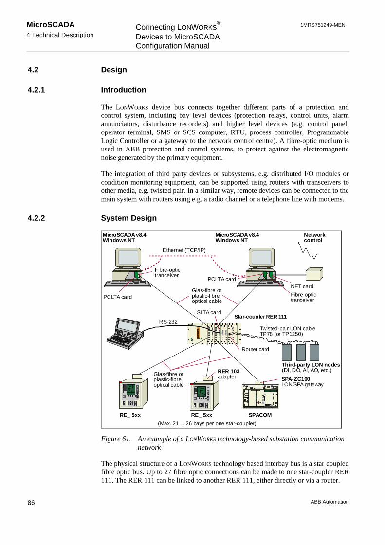
MicroSCADA4 Technical Description
Connecting LONWORKS®
Devices to MicroSCADAConfiguration Manual
1MRS751249-MEN
ABB Automation86
4.2 Design
4.2.1 Introduction
The LONWORKS device bus connects together different parts of a protection andcontrol system, including bay level devices (protection relays, control units, alarmannunciators, disturbance recorders) and higher level devices (e.g. control panel,operator terminal, SMS or SCS computer, RTU, process controller, ProgrammableLogic Controller or a gateway to the network control centre). A fibre-optic medium isused in ABB protection and control systems, to protect against the electromagneticnoise generated by the primary equipment.
The integration of third party devices or subsystems, e.g. distributed I/O modules orcondition monitoring equipment, can be supported using routers with transceivers toother media, e.g. twisted pair. In a similar way, remote devices can be connected to themain system with routers using e.g. a radio channel or a telephone line with modems.
4.2.2 System Design
O
I
SPAC 331 C
C
E
F
I
0
PCLTA card
Fibre-optictranceiver
MicroSCADA v8.4Windows NT
Ethernet (TCP/IP)
MicroSCADA v8.4Windows NT
Networkcontrol
NET card
Fibre-optictranceiver
PCLTA card
Star-coupler RER 111
Twisted-pair LON cableTP78 (or TP1250)
Third-party LON nodes(DI, DO, AI, AO, etc.)RER 103
adapter SPA-ZC100LON/SPA gateway
Glas-fibre orplastic-fibreoptical cable
Glas-fibre orplastic-fibreoptical cable
RE_ 5xx RE_ 5xx SPACOM
C
E
F
I
0
RS-232
(Max. 21 ... 26 bays per one star-coupler)
Router card
SLTA card
Figure 61. An example of a LONWORKS technology-based substation communicationnetwork
The physical structure of a LONWORKS technology based interbay bus is a star coupledfibre optic bus. Up to 27 fibre optic connections can be made to one star-coupler RER111. The RER 111 can be linked to another RER 111, either directly or via a router.
1MRS751249-MEN Connecting LONWORKS®
Devices to MicroSCADAConfiguration Manual
MicroSCADA4 Technical Description
ABB Automation 87
A fibre optic transceiver RER 107 is used for the connection between a PCLTA cardand the star-coupler. A fibre optic connection unit RER 103 is needed for connecting aRE_54_ series terminal to the network.
The following modules are usually needed when building a network, which uses theLonTalk protocol:
• RER 103 - Interface module for the RE_ 5_ _ series devices.
• RER 107 - SMX fibre optic transceiver for the PCLTA card.
• RER 109 - PCLTA card.
• RER 111 - Star-coupler with the following option cards:
• SFIBERFibre optic option card, glass fibre or plastic fibre connection.
• SRS485RS485 option card.
• SREDUDouble connection option card, glass fibre or plastic fibre connection.
• SSLTASLTA option card (serial LonTalk adapter).
• SROUTRouter option card.
• SLCMLON Clock Master card.
• SPA-ZC 100/102 - LSG device.
4.2.3 Communication Design
4.2.3.1 PC-NET
PC-NET is communication software which runs on the main processor of a WindowsNT computer in parallel with the base system. The PC-NET software can use theserial line COM ports of the PC and the optical lines of the PCLTA card ascommunication channels.
PC-NET supports the following protocols:
• ACP (the MicroSCADA internal protocol).
• LonTalk.
• SPA.
• IEC 870-5-101 master and slave.
• IEC 870-5-103 master.
• IEC 1107.
• RP570 master and slave.
• RP571 master.

MicroSCADA4 Technical Description
Connecting LONWORKS®
Devices to MicroSCADAConfiguration Manual
1MRS751249-MEN
ABB Automation88
• ADLP80 slave.
• LCU 500.
4.2.3.2 PC LonTalk Adapter
PC-NET uses an ISA bus card called PCLTA (PC LonTalk Adapter) from EchelonCorporation as a direct communication channel to the LONWORKS technology basedinterbay bus. One PCLTA card can have 1 or 2 channels (i.e. communication lines).
4.2.3.3 Master Devices
LONWORKS technology-based bay level devices from ABB typically support two ormore master devices simultaneously at the station level. This means thatconfigurations with the independent MicroSCADA-based station control system (SYS500) and the NCC gateway (COM 500) are possible.
4.2.3.4 Subnets
A LONWORKS technology-based network may be divided into segments called subnets.Subnets can be connected together with or without routers. For performance reasons, itis recommended that not more than approximately 25 high performance devicesshould be connected to one subnet.
When connecting the PC-NET to a LONWORKS technology-based network, onechannel of the PCLTA card should be reserved for each subnet.
4.2.3.5 Lines
The LONWORKS communication channel corresponds to a line in the PC-NET.
Currently, one PC-NET supports up to 8 lines. Since 2 PCLTA cards, with 2 channelseach, can be installed in one base system computer, only four LONWORKS channels canbe used in one base system.
4.2.3.6 LSG Device
The LSG device, type designation SPA-ZC 100/102, is a connection module fordevices including the SPA-bus interface.
For interfacing to a LONWORKS network, the device includes a fibre optic transmitterand receiver for glass core or plastic core fibre optic cables.
Each communication channel occupies one IRQ level on the base system computer,and LNT 505 occupies one communication channel.

1MRS751249-MEN Connecting LONWORKS®
Devices to MicroSCADAConfiguration Manual
MicroSCADA4 Technical Description
ABB Automation 89
For a SPA-bus interface the module includes a 9-pin male D-connector. The signaltypes used are RS-232, RS-485 or logic/TTL. The voltage levels used are +5V, +8Vand +12V.
The SPA-bus device to which this module is connected can be any protective relay,control module or alarm annunciator, which has an interface for the SPA-bus. TheSPA interface type (signal type and voltage level) is selected with DIP-switcheslocated between the D9-connector and fibre optic connectors.
4.2.3.7 Fibre Optic Interface
The fibre optic LONWORKS bus can be implemented using either glass core or plasticcore fibre optic cables depending on the cost, physical distance and performancerequirements. When a device is not transmitting, no light is sent to the fibre.
4.2.3.8 The Router Option Card
The Router option card connects two different communication channels and passesLonTalk messages between them. One channel is the open collector bus of the RER111 unit, while the other can be fibre optic or transformer isolated twisted pair with aspeed of 78 kbit/s or 1.25 Mbit/s.
The router option card can be used for improving network performance by dividing alarge communication network into smaller sub-groups of nodes, or as a mediaconverter to twisted pair media.
4.2.3.9 LON® Clock Master, SLCM Option Card
The LON® Clock Master (SLCM option card for the RER 111 unit) is designed to beused as a part of a communication system with LONWORKS data communication. TheSLCM is a RER 111 compatible option card and connection on LONWORKS networkis provided by other RER 111 option cards.
The SLCM option card, when integrated within the RER 111 unit, provides aconnection from a clock reference device to the LONWORKS network. The SLCMoption card includes an internal clock and an application program. The program usesthe internal clock to generate various kinds of synchronisation messages and signals inorder to synchronise other devices on the LONWORKS network.
According to the configuration, the internal real time clock is adjusted and one ormore of five synchronisation methods are sequentially accomplished. Configurationcan be set via LonTalk protocol.
For more information:
• SLCM Option card for LON® Star Coupler RER 111, Technical reference manual.
• SLCM Option card for LON® Star Coupler RER 111, Buyers guide TOB.

MicroSCADA4 Technical Description
Connecting LONWORKS®
Devices to MicroSCADAConfiguration Manual
1MRS751249-MEN
ABB Automation90
4.2.3.10 The Transceiver Module RER 107
The communication speed of the RER 107 is 1.25 Mbits/s. The transceiver module isprovided with a LED which flashes when a message is being received from the fibreoptic cable.
4.2.4 System Configuration Tool Design
4.2.4.1 Base System and PC-NET Configuration
The configuration tool manages the base system and PC-NET configuration data forthe following single computer/application system configuration:
• Several PC-NETs in the base system.
• 1-8 lines in the PC-NET with LonTalk and/or SPA protocol.
• REX devices connected to a LONWORKS line.
• LMK devices connected to a LONWORKS line.
• SPA devices connected to a LONWORKS line through an LSG device.
• SPA devices connected to a SPA line.
• All station type definitions (STY objects).
One PC-NET in the base system
The configuration tool configures the LIN and NOD base system objects needed forthe PC-NET. The PC-NET initialisation file pc_net.cf1 is also updated automatically.
All configurable attributes of the LIN:B object and the NOD:B object can be changedfrom the configuration tool.
Before signal information between devices and the MicroSCADA process databasehas been established, LONWORKS points and SPA points have to be defined. Thepurpose of these points is to provide routing mechanism between network variableindices and process database addresses.
LSG devices must be used when connecting SPACOM relays to the LONWORKS
device bus. To build up a valid LONWORKS configuration, the address tables andbindings have to be created between LSG devices and node objects using theconfiguration tool.
User-defined SCIL programs can be attached to each station. Each program receivesas an input parameter its environment, which in station level is a station number.Furthermore from station level, user-defined SCIL programs can also be attached toNET links, i.e. Lines. In the Line level environment parameters are NET and Linenumbers. Also NET Nodes can contain user-defined SCIL programs. In NET Nodelevel environment parameter is NET Number.

1MRS751249-MEN Connecting LONWORKS®
Devices to MicroSCADAConfiguration Manual
MicroSCADA4 Technical Description
ABB Automation 91
Several PC-NET Support
When PC-NET is started or stopped and multiple PC-NET communication software isincluded into configuration, it is possible to identifity, in a separate dialog, the PC-NET , which the operation is applied to.
PC-NETs are numbered in a list. The net that has the lowest NET node numberreceives the number 1. The NET node number is also displayed in this list. Oneselected item in the list could, for example, be PC-NET 1 in Node 3.
Before the dialog is displayed, the PC-NETs, which can be started and stopped, arechecked. If e.g. PC-NET 1 in Node 3 is already running, it is not included into the list,if Communication - Start PC-NET... is selected from the menu bar.
Each PC-NET configuration can be previewed separately. This is done viaConfiguration - Preview - PC-NET... In the case of several PC-NETs, a selectiondialog is opened. This dialog lists all the PC-NETs that are included in the currentconfiguration in the tool.
The System Configuration tool saves constructed NET specific SCIL -statements withthe name sys_net’node_number’, where node number refers to the NET node numberof the PC-NET. If, for example, the configuration includes two PC-NETs assigned toNET nodes 3 and 4, the files which include their constructed SCIL -statements arenamed sys_net3.scl and sys_net4.scl.
If several PC-NETs are included into configuration, a separate dialog is displayed toidentify into which PC-NET the selected LONWORKS channel is connected to.
General mechanism for the base system configuration at system start-up
The base system objects, depending on the configuration entered in the configurationtool, are created when the base system starts. In the SYS_BASCON.COM file there isa call to a procedure which configures the base system objects.
General mechanisms for automatic starting and configuration of the PC-NETs
The System Configuration tool creates procedures for automatic start-up andconfiguration of the PC-NET(s). The automatic starting/configuration can be switchedon or off. The PC-NET can be started and stopped manually in online mode.
The automatic starting and configuration of the PC-NET works in the following way:
• A command procedure SYS_INIT_1:C is connected to the event channelAPL_INIT_1:A as the first secondary object. If the list of the secondary objects isfull, the last one is removed and a warning is generated (notify window, log file).
• The command procedure SYS_INIT_1:C calls a text file (StartPCNET.scl) whichstarts the PC-NET. The program in the text file first updates the sys_/pc_net.cf1file and then starts the PC-NET by setting the corresponding base system linkobject type to "INTEGRATED.

MicroSCADA4 Technical Description
Connecting LONWORKS®
Devices to MicroSCADAConfiguration Manual
1MRS751249-MEN
ABB Automation92
For each PC-NET found from the permanent configuration file SysConf.ini located infolder \sc\sys\active\sys_, the following information is found out to fulfill the contentsof the pc_net.cf1 file:
Source: Key name: Example:Station address (PC-NET) SysConf.ini local_node.sa 204 (NOD4:BSA)Node number (PC-NET) SysConf.ini local_node.nn 4 (NOD4)Station address (base system) sys_bascon.com ext_node(1).sa 209 (SYS:BSA)Node number (base system) sys_bascon.com ext_node(1).nn 9 (SYS:BND)Node number (application) sys_bascon.com ext_apl(1).nn 9 (SYS:BND)Application number sys_bascon.com ext_apl(1).an 1 (APL:BAN)
• The PC-NET sends a system message to the application when it is started. Thismessage is received by a process object to which an event channel,SYS_NET’net_number’D:A, is connected. This event channel calls a commandprocedure SYS_NET’net_number’D:C. If the process object exists (e.g. created byLIB5xx) and has an event channel connected to it, all objects connected to thatevent channel are moved to the SYS_NET’net_number’D:A event channel assecondary objects. In other cases, the tool automatically creates a process objectSYS_NETD:P(’net_number’), to which the event channelSYS_NET’net_number’D:A is connected.
• The command procedure SYS_NET’net_number’D:C checks the message comingfrom the PC-NET and if this is the start message (10001), the PC-NET isconfigured according to the information entered in the tool.
All error messages which occur during the start-up or configuration of the PC-NETare shown in the Notification window and logged in a log file, which can be viewed inthe configuration tool.
Online monitoring of the base system and the NET configuration
The online configuration can be read into the tool by selecting Configuration/OpenOnline. Reading the online configuration sets the tool in online mode. Online modeincludes the following functions:
• Diagnostic counters of the links.
• Diagnostic counters of the NET lines.
• Diagnostic counters of the stations.
• Starting/stopping of the PC-NET.
• PCLTA initialisation/LON address setting.
The following information is read from the online configuration:
• Station type definitions, STYn:B (where n = 3 .. 9, 17, 20 .. 29).
• Integrated link between base system and PC-NET, LINn:B and base system linksof the type LAN and RAM.
• PC-NET node object, NODn:B.
• PC-NET lines with protocol: LonTalk, SPA, IEC 870-5-101/103 and DNP V3.00Slave.

1MRS751249-MEN Connecting LONWORKS®
Devices to MicroSCADAConfiguration Manual
MicroSCADA4 Technical Description
ABB Automation 93
• Lines with protocol: ANSI X3.28 XF, RAM, ASCII, RP570M/RP571M andRP570S.
• Stations of the type REX, LMK, SPA, LON Clock Master, IEC, SPI and RTU.
• LON and SPA-points for REX, LMK and SPA devices.
4.2.4.2 DNP V3.00 Slave Support
Online Engineering Functionality
When a DNP line or station is selected in the object tree, the related attributes areshown in the attribute tree on the right hand side of System Configuration tool. If theconfiguration includes several lines of this same DNP type, the attribute tree is notcollapsed during change operation into similar DNP line type (with a different linenumber or a different NET node number).
Online Diagnostics
When a DNP line or station is selected in the object tree in online mode, the attributearea includes a Diagnostic Counters tab. This tab includes DNP 3.0 specific diagnosticcounter names and related values. The values are updated during 2 seconds intervaltime, if this tab is selected. Following diagnostic counter names and their indices aredisplayed in this tab:
Index 1 = Transmitted Telegrams Index 12 = Parity Errors
Index 2 = Failed Transmissions Index 13 = Overrun Errors
Index 4 = Transmitted Commands Index 14 = Check Sum Errors
Index 5 = Transmitted Replies Index 15 = Framing Errors
Index 11 = Received Messages Index 16 = Buffer Overflow Errors
4.2.4.3 System Configuration Methods
The following System Configuration methods are used to read configurationinformation from active configuration file. These methods are ordinary SCIL-filesadded with certain amount of parameters. The functions are used internally by SystemConfiguration Tool and system start-up methods related to it.

MicroSCADA4 Technical Description
Connecting LONWORKS®
Devices to MicroSCADAConfiguration Manual
1MRS751249-MEN
ABB Automation94
These files are all located in \sc\Stool\SysConf\ folder. They can also be found byusing sys_tool logical path. Each function has an argument called Object Type. Thisargument can have following values and meanings:
Value Meaning
"BASE_SYSTEM_LINK" A LINK object located in the base system (LINn:Bxx)
"BASE_SYSTEM_NODE" A NODE object located in the base system (NODn:Bxx)
"BASE_SYSTEM_STATION" A STATION object located in the base system (STAb:Bxx)
"BASE_SYSTEM_STATION_TYPE" A STATION TYPE object located in the base system(STYb:Bxx)
"NET_STATION" A NET STATION object located in NET (STAn:Sxx)
"NET_LINK" A NET LINK object located in NET (NETn:Sxxy)
n = Any valid number for the current object typexx = Any valid two character attribute convention for the current object typey = Any valid line number for the current NET LINK object
4.2.4.4 PCLTA Card Initialisation
Prepare function
When preparing the PCLTA card, the configuration program makes the followingsettings:
comm_type 1 Single-Ended
comm_pin_dir 0x0E Direct Mode - Single-Ended
direct_param_struct Collision detection
comm_clock 0 (8:1)
input_clock 5 10.0 MHz
LON Bit Rate 1.25 Mb/s
The program performs a reset operation to implement the settings.
The PCLTA card address is read but not changed by the program. The factory settingis subnet 1 / node 109, but for MicroSCADA, this address is not significant.
Address setting
If there is a need to change the PCLTA card address, the new address is written intothe Neuron chip domain. If the LON Network Tool is installed, the address is alsoupdated in the Nettools.ini file (Windows system folder).
The configuration program performs the following operations:
1. The new address is sent to the Neuron chip domain.2. If the address was successfully received, the Neuron chip is set to configured
online state.3. The program checks whether the whole operation was successful and carries out a
reset operation.

1MRS751249-MEN Connecting LONWORKS®
Devices to MicroSCADAConfiguration Manual
MicroSCADA5 Glossary
ABB Automation 95
5 Glossary
This section describes terminology and defines words used in this document. Thesame words may have quite different meanings in other circumstances; theseexplanations refer only to this document and the systems described in this document.
5.1 Definitions and Abbreviations
Application
An application contains all the data and tools which are needed for the supervision andcontrol of a system. It contains supervisory pictures, event lists, alarm lists, event andalarm printouts, reports on a daily, weekly and monthly basis, etc. It stores actualvalues, which are essential to allow the supervisory staff to monitor the current state ofthe system. Likewise, it stores data and performs calculations for reports. Theapplication may also contain automatic functions which carry out not only simpleroutine tasks, such as verifying user authorisations and printing out reports, but alsooperational sequences which are activated, for instance, in fault situations.
Attribute
Individual data items which form part of an object are called attributes. Each objecthas a set of attributes that store information and describe the qualities of the object.The attributes contain, for instance, measured values, texts, program lines, time stampsetc., depending on which object type is concerned.
Collision detection
Collision detection is used optionally in our systems. It is not mandatory for alldevices connected to the system to support collision detection. This would not bepossible for some devices which interface with specific network media. Collisiondetection should be used by devices which send time-critical messages, e.g.interlocking data or blocking signals. Collision detection, together with priority slotassignment, is used to guarantee deterministic transfer of these messages especially inhigh load situations. If a collision occurs and is detected, the transmitting nodes willterminate transmission and start waiting for their time slot within the next packetcycle. This allows the retransmission of a priority message to be started immediatelywithin the next packet cycle. It is then extremely unlikely that a collision will occurwith this message.
Communication channel
A physical connection layer established for communication between devices, specifiedby the medium being used, transmission speed and other timing parameters.
MicroSCADA5 Glossary
Connecting LONWORKS®
Devices to MicroSCADAConfiguration Manual
1MRS751249-MEN
ABB Automation96
Configuration properties
Configuration properties contain configuration and parametrisation data, used tocustomise and optimise the behaviour of a node or a particular application in the node.Configuration properties are represented either by network variables (configurationnetwork variables) or by configuration parameters. The latter can be accessed usingthe LonTalk file transfer protocol or memory read and write messages.
Explicit message
An application layer object containing a maximum of 229 bytes of data. Explicitmessages are used to transfer longer pieces of information such as packed sequencesof events and explicit read and write messages to access device data. SPA-busmessages can also be sent transparently in explicit messages to transfer e.g. deviceparameters.
Gateway
See LSG device.
Horizontal communication
Direct communication between bay level devices, for example REF54x protectionterminals.
Interoperability
A property which ensures that different devices (from the same or differentmanufacturers) which communicate with one another can be integrated into the samenetwork without any need for the customisation of device-specific features.
ISO
International Standardisation Organisation.
LAN
Local area network. Workstations and communication units can be connected to thebase system via a LAN.
LMK
LONMARK device. See LMK device.

1MRS751249-MEN Connecting LONWORKS®
Devices to MicroSCADAConfiguration Manual
MicroSCADA5 Glossary
ABB Automation 97
LMK device
An LMK device comprises all types of devices, with the exception of SPA and REXdevices, which are connected to a LONWORKS network using the standard LONWORKS
network interface, e.g. an LSG device or a Weidmüller I/O device.
LON
See LONWORKS network.
LONMARK
See LONMARK Interoperability Association.
LONMARK device bus
A LONMARK device bus is a peer-to-peer bus, in which all nodes (e.g. protectionterminals) in the system can talk to each other. This allows horizontal communicationat station level.
LONMARK Interoperability Association
An independent world-wide industry association, which facilitates the developmentand implementation of open, interoperable LONWORKS technology based controlproducts and systems. The LONMARK association includes manufacturers, end-usersand integrators of LONWORKS products. The association establishes guidelines such as“L ONMARK Application Layer Interoperability Guidelines”, defines standardfunctional profiles of control devices and certifies products on compliance withinteroperability guidelines.
LONMARK compliance
Conformance to LONMARK interoperability guidelines. On the application layerinteroperability between LONWORKS technology-based products is facilitated throughthe use of SNVTs and LONMARK objects.
LONMARK object
A set of one or more network variables implemented as SNVTs with definitionsrelating to the behaviour of the object and the network variable values, as well as tothe set of configuration properties. LONMARK functional profiles serve as classes forLONMARK objects.
LON/SPA Gateway
See LSG device.

MicroSCADA5 Glossary
Connecting LONWORKS®
Devices to MicroSCADAConfiguration Manual
1MRS751249-MEN
ABB Automation98
LonTalk protocol
The communication protocol used in LONWORKS networks. The LonTalk protocol isan open protocol Which follows the reference model for open system interconnection(OSI) designed by the International Standardisation Organisation (ISO). The LonTalkprotocol is a CSMA-type protocol (Carrier Sense Multiple Access) with a built-inpredictive collision avoidance algorithm and optional collision detection. The collisionavoidance algorithm is based on synchronised random selection of the time slot by allnodes which are ready to transmit. The number of randomised slots can bedynamically increased when a higher network load is predicted by the protocol.
LONWORKS network
“Local Operating Network”. (The abbreviation LON is used in some documents, butshould not be used as a separate word.) A network based on LONWORKS technology.Intended for short-range communication; typically used when a set of devices locatedphysically close to one another need to communicate with one another.
LONWORKS technology
Communication technology developed by Echelon Corporation.
LONWORKS technology-based system
A system that uses the LonTalk protocol as a communication protocol in some or allparts of the system. The communication network is based on LONWORKS technology.
LSG
See LSG device.
LSG device
A protocol converter. Carries out conversions between the SPA protocol and theLonTalk protocol. This means that SPACOM relays can be connected to theLONWORKS network.
MMI
Man Machine Interface.
Network variable
An application layer data object, containing a maximum of 31 bytes of data. Networkvariables are used to deliver small data items such as measurement values, statuschanges, interlocking data, blocking signals, alarms and events. Network variables are

1MRS751249-MEN Connecting LONWORKS®
Devices to MicroSCADAConfiguration Manual
MicroSCADA5 Glossary
ABB Automation 99
addressed using network variable selectors. A selector is a 14-bit number in the range0 to 12287 (2FFFH).
Neuron chip
An 8-bit microcontroller with a communication interface, manufactured by Motorolaand Toshiba. The LonTalk protocol is implemented in firmware. In simple devices theNeuron chip can execute both the protocol firmware and an application program. Incomplex devices (e.g. PC-based) an application program is run in the hostmicroprocessor, while the Neuron chip is used only as a LonTalk protocol processor.
Node
A device in a subnet, e.g. REF Protection Terminal.
Node number
A unique identifier of the node within a subnet.
NV
See Network variable.
Object
The data in the process and report databases is organised into objects. These areentities containing sets of different kind of data. The objects have logical names andthey are able to communicate with each other according to the rules defined byapplication programming.
OSI
Open system interconnection.
PCLTA
PC LonTalk Adapter. See also PCLTA card.
PCLTA card
LONWORKS network interface card for a PC. An ISA bus card with slots for twotransceiver cards for optical connections to the network.

MicroSCADA5 Glossary
Connecting LONWORKS®
Devices to MicroSCADAConfiguration Manual
1MRS751249-MEN
ABB Automation100
Priority slots
Dedicated time windows to be used for transmitting emergency messages. Eachconfigured time slot is exclusively assigned to a selected node. A maximum of 255priority time slots can be configured in the LonTalk protocol. Each device whichtransmits time-critical data, such as interlocking/blocking messages or clocksynchronisation messages, must be assigned as a priority slot to enable prioritisedaccess to the communication medium.
Process Unit
An interface between the process and the MicroSCADA system.
REX device
A unit which communicates verticallay with MicroSCADA, as defined in the LONApplications Guidelines (e.g. a REF54x protection terminal).
Router
A router is a device equipped with two network interfaces. It is capable ofinterconnecting two different communication channels. These channels may usedifferent network media, different network speeds and timing parameters or may beused by different subsystems identified by subnet numbers.
RTS
Request to send.
RTU
Remote terminal unit.
SCIL
Supervisory Control Implementation Language. SCIL is a picture and object oriented,high level language for application programming in MicroSCADA. SCIL is used inpictures and in command procedures. SCIL expressions and conditions are also usedin datalog objects and time channels.
SCPT
Standard Configuration Property Type. The definition of an SCPT includes unit,range, resolution and data format. SCPTs are listed in “The SCPT Master List”, whichis updated by Echelon Corp. and includes configuration property types commonlyagreed on by a large number of manufacturers.
1MRS751249-MEN Connecting LONWORKS®
Devices to MicroSCADAConfiguration Manual
MicroSCADA5 Glossary
ABB Automation 101
SI/SD information
Self Identification / Self Documentation information, which is stored as an ASCII textarray in a node’s memory and contains information about the node and its networkvariables.
SLTA
Serial LonTalk Adapter. An option card with a serial interface for the star-couplerRER 111. Enables serial line connection (e.g. RS-232) to the LONWORKS network.
SPA device
A SPACOM module connected to the LONWORKS network via a protocol converter.The converter is called an LSG device.
Star-coupler
A star-coupler (RER 111) is a device which provides connectivity to 3 or moredevices with fibre optic interfaces. Each external interface of the star-coupler is a fibreoptic transmitter-receiver pair, internally connected to a common bus. The star-coupleritself does not contain a network node but its operation is restricted to the physicallayer of the protocol. A signal provided to the receiver of one external connection isforwarded to the transmitters of all remaining external connections.
Subnet
Part of a network. A network may include several subnets separated from each othersby star-couplers. For example, HV (high voltage) devices may constitute one subnetand a group of MV (medium voltage) devices another one.
SNVT
Standard Network Variable Types (SNVTs) facilitate interoperability by providing awell-defined interface for communication between nodes made by differentmanufacturers. A node may be installed in a network and logically connected to othernodes via network variables as long as the data types match. The definition of anSNVT includes unit, range, resolution and data format. SNVTs are listed in “TheSNVT Master List and Programmer’s Guide”. This list is updated by EchelonCorporation and includes network variable types, which are commonly agreed on by alarge number of manufacturers.
Vertical communication
Communication between bay level devices and higher level devices, for examplebetween a REF54x Protection Terminal and MicroSCADA.


1MRS751249-MEN Connecting LONWORKS®
Devices to MicroSCADAConfiguration Manual
MicroSCADAIndex
ABB Automation
Index
Page
A
Address...............................................................................................................22, 23, 25, 44Address Table Editor............................................................................................................66Address table information ....................................................................................................37Advanced page .....................................................................................................................85Application...........................................................................................................................95Attribute ...............................................................................................................................95Authentication ......................................................................................................................41Automatic start-up of the PC-NET.......................................................................................91
B
Back up copies .......................................................................................................................9Base address conflicts ..........................................................................................................12Bay level devices..................................................................................................................86Big substations .......................................................................................................................7Bounded network variable....................................................................................................64Buffers..................................................................................................................................16Bus .......................................................................................................................................86
C
Card Number ........................................................................................................................15Clock (internal) ....................................................................................................................79Clock Select .........................................................................................................................16Collision detection................................................................................................................95Communication ........................................................................................................4, 96, 101Communication channel.......................................................................................................95Communication rate .............................................................................................................12Configuration .................................................................................................................14, 18Configuration data................................................................................................................90Configuration properties ......................................................................................................96Configuration tool ................................................................................................................15Control Panel........................................................................................................................15Copy.....................................................................................................................................83CSMA type protocol ............................................................................................................98CT attribute ..........................................................................................................................64Cut........................................................................................................................................83
D
Data transfer ...................................................................................................................66, 77DCP-MUX ...........................................................................................................................12Default configuration ...........................................................................................................23Default values.......................................................................................................................80Delay Compensation ............................................................................................................60Delete function .....................................................................................................................83Device bus............................................................................................................................97Device driver ........................................................................................................................15Device Driver
Start-up...........................................................................................................................17

MicroSCADAIndex
Connecting LONWORKS®
Devices to MicroSCADAConfiguration Manual
1MRS751249-MEN
ABB Automation
Device Number ....................................................................................................................16Device types...........................................................................................................................5DI .........................................................................................................................................74DI attribute..................................................................................................................... 64, 65Dip switch values.................................................................................................................13Direction ..............................................................................................................................41DNP .....................................................................................................................................93Domain ................................................................................................................................44Double connection card .......................................................................................................79Driver configuration ............................................................................................................15Dual Channel .......................................................................................................................16
E
Echelon device driver ..........................................................................................................15Edit.......................................................................................................................................83EF attribute ..........................................................................................................................74Error message ................................................................................................................ 21, 92Event filtering ......................................................................................................................74Event History Start Time .....................................................................................................48Explicit message ............................................................................................................ 77, 96Extended Address Table ................................................................................................ 33, 41
F
Factory setting .....................................................................................................................25Fatal error ..............................................................................................................................9Flush cancel .........................................................................................................................17FLUSH state ........................................................................................................................17
G
General Information dialog..................................................................................................35General Information Page ....................................................................................................59General Object Handling Command....................................................................................47Group Message Receiver Timer ..........................................................................................45
H
Higher level devices.............................................................................................................86HS ........................................................................................................................................49
I
I/O address ...........................................................................................................................12I/O Port Address ..................................................................................................................16Importing Multiple Nodes....................................................................................................70Importing of multiple nodes.................................................................................................67Importing of single node......................................................................................................67Initialisation .........................................................................................................................19Initialize ......................................................................................................................... 21, 22Installation and configuration (phases) ................................................................................11Integrated link......................................................................................................................28IRQ Level ............................................................................................................................16
L
LAN .....................................................................................................................................96Line................................................................................................................................ 28, 88Link.......................................................................................................................... 19, 23, 80LMK ................................................................................................................................5, 29LMK Configuration tool ......................................................................................................49LMK device ................................................................................................................... 24, 97LMK device signals .............................................................................................................49

1MRS751249-MEN Connecting LONWORKS®
Devices to MicroSCADAConfiguration Manual
MicroSCADAIndex
ABB Automation
LMK station ...................................................................................................................49, 82LNT 505...............................................................................................................................18Local Operating Network.....................................................................................................98LON .................................................................................................................................2, 98LON address table configuration .........................................................................................41LON Clock Master .........................................................................................................25, 63
Parameter information ...................................................................................................61LON Configuration attributes ..............................................................................................33LON line...............................................................................................................................38LON Line .............................................................................................................................80LON Network Tool ........................................................................................................14, 18
Data transfer to SC tool..................................................................................................66LON point ......................................................................................................................50, 57LON points...........................................................................................................................49LON Star Coupler ..........................................................................................................25, 34LON Star Coupler device configuration page ......................................................................34LON/SPA Analog Inputs .....................................................................................................57LON® Clock Master ............................................................................................................89LON-node ............................................................................................................................23LonTalk Adapter ..................................................................................................................11LonTalk protocol........................................................................................................3, 77, 98LONWORKS communication ...............................................................................................2LONWORKS device bus .................................................................................................3, 86LSG ......................................................................................................................................14LSG device...........................................................................................24, 74, 88, 90, 98, 101
M
Manuals required....................................................................................................................2Master...................................................................................................................................88Maximum values....................................................................................................................5Medium-sized substations ......................................................................................................7MiSCLONP..........................................................................................................................15Mode ..............................................................................................................................24, 33Modules................................................................................................................................87
N
NC attribute..........................................................................................................................63Bounded network variable..............................................................................................63
NC Editor .............................................................................................................................38NET Node ............................................................................................................................28NetAgent ........................................................................................................................14, 18Nettools.ini ...........................................................................................................................22Network interface.................................................................................................................11Network variable............................................................................................................77, 98Network Variable Configuration Editor.........................................................................36, 63Network Variable Priority....................................................................................................40Neuron chip..........................................................................................................................99Neuron Chip .........................................................................................................................15Neuron clock rate .................................................................................................................16Neuron ID.............................................................................................................................23Neuron ship ..........................................................................................................................19Node...................................................................................................................19, 23, 80, 99Node number......................................................................................................18, 26, 44, 59Notification Window............................................................................................................21NV..................................................................................................................................32, 99
Bounded network variable..............................................................................................64NV attribute..........................................................................................................................32

MicroSCADAIndex
Connecting LONWORKS®
Devices to MicroSCADAConfiguration Manual
1MRS751249-MEN
ABB Automation
NV Poll command ...............................................................................................................64NV Selector .........................................................................................................................39NV Update command ..........................................................................................................65NV_time ..............................................................................................................................61
O
Object...................................................................................................................................99Object Type .........................................................................................................................93Online ..................................................................................................................................31Online configuration ............................................................................................................92Option card ..........................................................................................................................78OSI.......................................................................................................................................98
P
Paste.....................................................................................................................................84PCLTA.............................................................................................................................4, 99PCLTA card................................................................................................. 11, 12, 78, 79, 88
Communication ..............................................................................................................15Settings ...........................................................................................................................15
PCLTA card address............................................................................................................94PCLTA card configuration ..................................................................................................14PCLTA card information .....................................................................................................14PCLTA-card ........................................................................................................................22PC-NET ............................................................................................................. 78, 87, 88, 91
Multiple PC-NETs..........................................................................................................73Multiple PC-NETs..........................................................................................................91Start delay ......................................................................................................................73
Prepare function............................................................................................................. 19, 21Prepare function settings......................................................................................................94Preview function..................................................................................................................84Priority .................................................................................................................................74Priority time slot ................................................................................................................100Programs ..............................................................................................................................14Protocol converter................................................................................................................98Protocols ..............................................................................................................................87
R
REF Terminals.....................................................................................................................26Reference time .....................................................................................................................63Repetition Interval Time......................................................................................................44RER 103 ..............................................................................................................................87RER 107 ........................................................................................................................ 78, 90RER 111 ..............................................................................................................................78Restrictions ............................................................................................................................5Retry Count..........................................................................................................................44REx ........................................................................................................................................5REX .....................................................................................................................................29REx device...........................................................................................................................26REX device........................................................................................................................100REx station...........................................................................................................................81Router .................................................................................................................... 79, 86, 100Router option card ...............................................................................................................89Routers
LON Clock Master .........................................................................................................63RT setting.............................................................................................................................74
S
SCIL commands ..................................................................................................................47
1MRS751249-MEN Connecting LONWORKS®
Devices to MicroSCADAConfiguration Manual
MicroSCADAIndex
ABB Automation
SCIL program.......................................................................................................................84SCPT ..................................................................................................................................100Selector.................................................................................................................................99Send Event History Start Time.............................................................................................48Send General Object Handling Command ...........................................................................47Send Message dialog............................................................................................................75Serial LonTalk Adapter ......................................................................................................101Service pin............................................................................................................................23Service Pin ...........................................................................................................................25Service Pin Message.............................................................................................................23Service Pin method...............................................................................................................24Service types ........................................................................................................................39
Acknowledged.................................................................................................................39Unacknowledged ............................................................................................................39Unacknowledged/Repeated ............................................................................................39
Service-pin message.............................................................................................................25Signal engineering................................................................................................................85
Data transfer from LNT..................................................................................................66Single Channel .....................................................................................................................16SLCM...................................................................................................................................89SLCM option card..........................................................................................................25, 79SLTA..................................................................................................................................101SLTA card............................................................................................................................79Small substations....................................................................................................................6SNVT ...........................................................................................................................51, 101Software ...............................................................................................................................14Software installation.............................................................................................................14SPA ..................................................................................................................................5, 30SPA address .........................................................................................................................26SPA Configuration tool ........................................................................................................52SPA device .........................................................................................................................101SPA Line ..............................................................................................................................80SPA point .................................................................................................................45, 53, 56SPA points............................................................................................................................46SPA station.....................................................................................................................82, 83SPA-bus message .................................................................................................................77SPACOM relays...................................................................................................................25STAnn
SRT setting......................................................................................................................74Star Coupler
Configuration .................................................................................................................25Star-coupler ..................................................................................................................78, 101Station ............................................................................................................................29, 81Station Address ....................................................................................................................26Station number .....................................................................................................................29Station Type .........................................................................................................................31Station Type Definitions ......................................................................................................31Station types ...................................................................................................................84, 85Status Code...........................................................................................................................21Status codes..........................................................................................................................10Status Message .....................................................................................................................21Subnet...........................................................................................................................88, 101Subnet number .........................................................................................................18, 26, 59Subtools................................................................................................................................85Synchronisation..............................................................................................................62, 79SYS
BTI setting ......................................................................................................................74

MicroSCADAIndex
Connecting LONWORKS®
Devices to MicroSCADAConfiguration Manual
1MRS751249-MEN
ABB Automation
Sys_bascon.com template ....................................................................................................84Sysconf.ini ..................................................................................................................... 19, 23System configuration ...........................................................................................................18System Configuration methods............................................................................................93System Configuration tool ...................................................................................................19System start-up ....................................................................................................................91
T
Testing .................................................................................................................................74TI .........................................................................................................................................74time ......................................................................................................................................79Time Zone............................................................................................................................60Transceiver .............................................................................................................. 18, 78, 87Transceiver card
Settings ...........................................................................................................................16Transceiver card (installation) .............................................................................................11Transmit Timeout ................................................................................................................45Turnaround ..........................................................................................................................41Type of Card ........................................................................................................................16
U
Unbounded network variables .............................................................................................65User-defined SCIL programs...............................................................................................90UTC time .............................................................................................................................61
V
VATS with bit pattern recognition.......................................................................................63
W
Warning Interval ..................................................................................................................60
X
XA .......................................................................................................................................33XA attribute .........................................................................................................................32XA index..............................................................................................................................43

1MRS751249-MEN Connecting LONWORKS®
Devices to MicroSCADAConfiguration Manual
MicroSCADACustomer Feedback
ABB Automation
Customer Feedback
About This Chapter
This chapter contains information on how to send customer feedback and how to gettechnical support from the SA Help Desk.
Customer Feedback Database
Customer Feedback is a Lotus Notes database, using which ABB companies canreport errors, make improvement proposals and queries related to productsmanufactured by ABB Substation Automation Oy. Customer Feedback database isconnected to the change management system of ABB Substation Automation Oy,which handles all error corrections and improvements made to the products.
Please note that the Customer Feedback database is primarily intended for writingreports about released products. If you are using for example a beta release in a pilotproject, this should be clearly stated.
Writing A Customer Feedback Report
When writing a Customer Feedback report, the following general instructions shouldbe taken in consideration:
• Write the report in English.
• Write only one error report, query or improvement proposal in a CustomerFeedback report.
• If you are reporting an error, try to isolate the error as well as possible. Describethe sequence of events and actions that lead to the error. If any error messages orother debug information is provided by the system, please write it down. Includealso information of the system, e.g. a system diagram, revision information andconfiguration data.
• If you are making an improvement proposal, try to describe how the improvedfunction should work and avoid providing solutions. Information about theimportance of the improvement, e.g. number of projects that require theimprovement, helps us to make the decision whether and when the improvementshould be implemented.
To make a Customer Feedback report, select Feedback Report from the Create menu.This opens an empty Customer Feedback document. Fill out the fields listed below. Aquestion mark next to a field provides help for filling out the field.
1 Subject. This should contain a short description of the issue. A more detaileddescription can be given in the Description of Feedback field below.
2 Type of Feedback: Comment/Improvement, Query or Complaint/Error.
3 Customer Information.

MicroSCADACustomer Feedback
Connecting LONWORKS®
Devices to MicroSCADAConfiguration Manual
1MRS751249-MEN
ABB Automation
4 Reporting Information. This should contain detailed information of the product thereport is about.
5 The person who you want to send the feedback to and whether you want to get areply from that person.
6 Information related to internal handling of the report (not obligatory).
7 Category.
You can issue the report by clicking the Issue Feedback button. This will send thereport to the selected person and change its status to “in progress”.
Actions
When ABB Substation Automation Oy receives a Customer Feedback report, it isanalysed by a sales person or a representative of the technical support. The analysermay ask for additional information in order to completed the analysis. After the reporthas been analysed, one of the following actions is taken:
• In case of a clear error, the report is moved to the change management system ofABB Substation Automation Oy. In this system, the error is analysed in detail andcorrected in a future patch release or major release depending on the severity andimpact of the error.
• In case of an improvement proposal, the report is also moved to the changemanagement system, where it is taken as a requirement to future releases.
• In case of a query, an answer is provided.
When Customer Feedback reports are handled in the change management system, theoutcome can be one of the following:
No Actions It is decided that the reportrequires no further action. If, forexample, the problem is caused bya configuration error, it belongs tothis category.
Will be implemented in patch/current release This result means that thecorrection or new feature will beavailable in the next officialprogram release.
Moved to future release This result means that the newfeature will be available in somenew program release in the nearfuture.
SA Help Desk
ABB Substation Automation Oy provides a technical support service called SA HelpDesk to support local engineering centres in their system projects. The purpose of SAHelp Desk is to provide support for urgent issues such as:
• Year 2000 issues.
• High-priority issues concerning systems at customers’ sites.

1MRS751249-MEN Connecting LONWORKS®
Devices to MicroSCADAConfiguration Manual
MicroSCADACustomer Feedback
ABB Automation
For other kind of technical support, please use the Customer Feedback database. SAHelp Desk is available every day from 06:00 to 21:00 Central European Time.
SA Help Desk can be contacted by telephone. The number is:
+358 50 334 1900