1nanog 25 © 2001, cisco systems, inc. all rights reserved. deploying tight-sla services on an ip...
TRANSCRIPT

1NANOG 25 © 2001, Cisco Systems, Inc. All rights reserved.© 2001, Cisco Systems, Inc. All rights reserved.© 2001, Cisco Systems, Inc. All rights reserved.
Deploying Tight-SLA services on an IP
Backbone
Clarence Filsfils – [email protected]
222Clarence Filsfils – Nanog 25 © 2002, Cisco Systems, Inc. All rights reserved.
Objective
• To present design & deployment good practices to enable tight SLAs to be offered
– when to use what and how
– validation results
– operational guidelines
– deployment experience
• Focus on the backbone design
333Clarence Filsfils – Nanog 25 © 2002, Cisco Systems, Inc. All rights reserved.
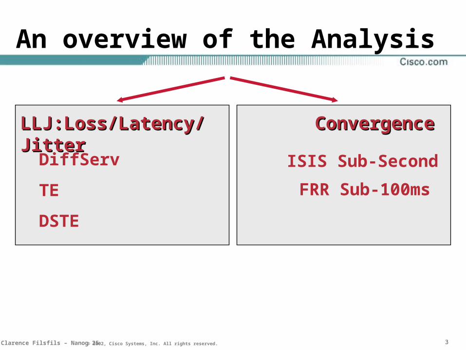
An overview of the Analysis
LLJ:Loss/Latency/JitterLLJ:Loss/Latency/Jitter ConvergenceConvergence
DiffServ
TE
DSTE
ISIS Sub-Second
FRR Sub-100ms

444Clarence Filsfils – Nanog 25 © 2002, Cisco Systems, Inc. All rights reserved.
Further information
• “Engineering a Multiservice IP backbone to support tight SLAs”, Computer Networks Special Edition on the New Internet Architecture
• Full-Day Tutorial
–RIPE41, APRICOT 2002: www.ibb.net/~filsfils
• Low-Level Design Guides, Validation Results

555Clarence Filsfils – Nanog 25 © 2002, Cisco Systems, Inc. All rights reserved.
Agenda
• Introduction and Introduction and SLASLA
• Sub-Second IGP Convergence
• Backbone Diffserv Design
• Conclusion

666Clarence Filsfils – Nanog 25 © 2002, Cisco Systems, Inc. All rights reserved.
Typical Core Per Class SLA Characteristics
ClassThrough
-put
Avail-ability
Lossrate
Delay Jitter
VoIP Bus ?BE
Typically more Classes at the Edge
999Clarence Filsfils – Nanog 25 © 2002, Cisco Systems, Inc. All rights reserved.
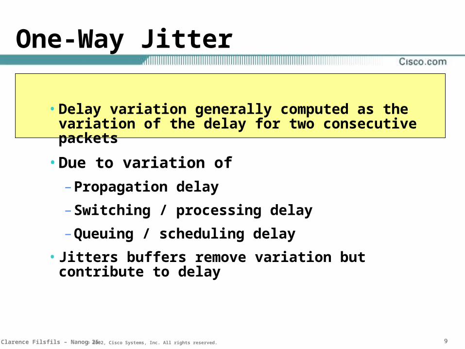
One-Way Jitter
• Delay variation generally computed as the variation of the delay for two consecutive packets
• Due to variation of
– Propagation delay
– Switching / processing delay
– Queuing / scheduling delay
• Jitters buffers remove variation but contribute to delay
101010Clarence Filsfils – Nanog 25 © 2002, Cisco Systems, Inc. All rights reserved.
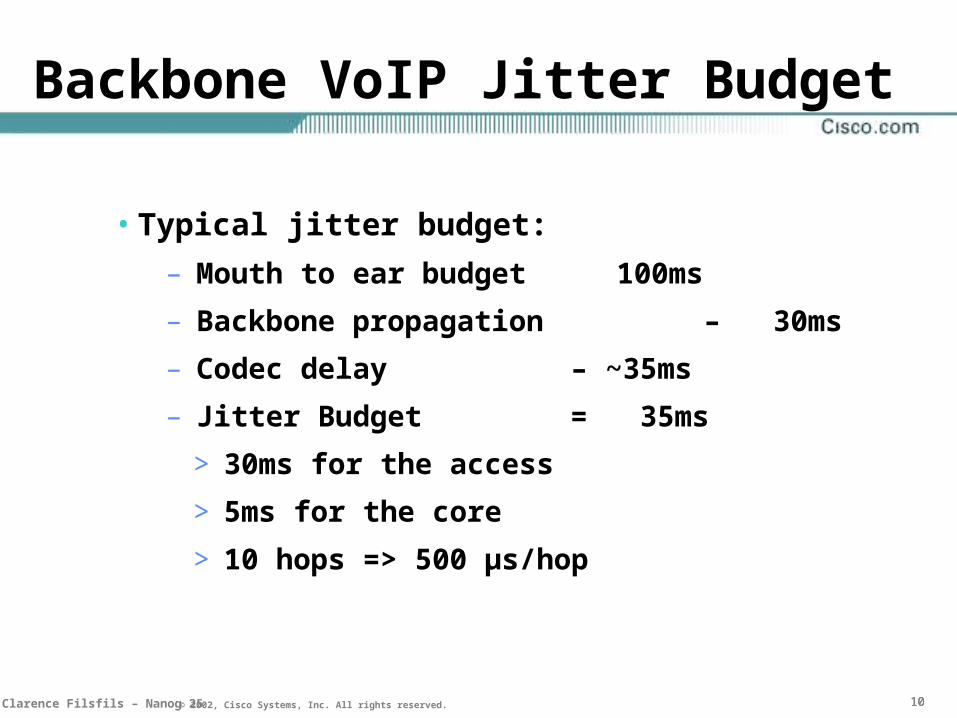
Backbone VoIP Jitter Budget
• Typical jitter budget:
– Mouth to ear budget 100ms
– Backbone propagation – 30ms
– Codec delay – ~35ms
– Jitter Budget = 35ms
> 30ms for the access
> 5ms for the core
> 10 hops => 500 µs/hop

151515Clarence Filsfils – Nanog 25 © 2002, Cisco Systems, Inc. All rights reserved.
Per flow sequence preservation
• Best-practise IP Design: per-flow loadbalacing!
• Re-ordering Impact on Service Perception
– Long-Lived TCP: degraded goodput
– Real-time video: loss rate += OOS_rate
– VoIP: jitter

161616Clarence Filsfils – Nanog 25 © 2002, Cisco Systems, Inc. All rights reserved.
Re-ordering Impact on Service
• [LAOR01]: “Results show that packet reordering, by at least three packet locations, of only a small percentage of packets in the backbone link can cause a significant degradation of applications throughput. Long flows are affected the most. Due to the potential effect, minimizing packet reordering, as well as mitigating its effect algorithmically, should be considered”.
Server to Multiple Clients
0
20
40
60
80
100
0.01% 0.10% 1.00% 10.00%
100.00%
Rate of packets reordered
Pew
rcen
tag
e o
f ap
pli
cati
osn
thro
ug
hp
ut
Linux 15ms
Unix 15 ms
Linux 35ms
Unix 35ms

171717Clarence Filsfils – Nanog 25 © 2002, Cisco Systems, Inc. All rights reserved.
Loss of Connectivity / Convergence
• Incentive to reduce the loss of connectivity (LoC)
• Availability
– 99.999% per day 0.9sec of downtime
• VoIP
– 40msec LoC: glitch
– 1, 2 sec LoC: call drop

181818Clarence Filsfils – Nanog 25 © 2002, Cisco Systems, Inc. All rights reserved.
How to specify the target for the metric
• SLA statistical definitions do matter
– min/avg/max versus percentile
– Measured time interval…
• SLAs definitions today tend to be loose
– averaged over a month
– averaged over many POP-to-POP pairs (temptation to add short pairs to reduce average…)
• IP Performance Metrics IETF WG

191919Clarence Filsfils – Nanog 25 © 2002, Cisco Systems, Inc. All rights reserved.
Optimizing the IP Infrastructure
• Loss, Latency, Jitter: iif Demand < Offer
– OverProvisioned Backbone
– Differentiated Services
– Capacity Planning
– TE and DS-TE
• Loss of connectivity due to link/node failure– IGP Convergence
– MPLS FRR Protection

202020Clarence Filsfils – Nanog 25 © 2002, Cisco Systems, Inc. All rights reserved.
Agenda
• Introduction and SLA
• Sub-Second Sub-Second IGP ConvergenceIGP Convergence
• Backbone Diffserv Design
• Conclusion

212121Clarence Filsfils – Nanog 25 © 2002, Cisco Systems, Inc. All rights reserved.
Loss of Connectivity
• IGP Backbone Convergence:
– the time it takes for connectivity to be restored upon link/node failure/addition for an IP flow starting on an edge access router and ending on another edge access router, excluding any variation of BGP routes.
• For this session, IGP = ISIS

222222Clarence Filsfils – Nanog 25 © 2002, Cisco Systems, Inc. All rights reserved.
Historical ISIS Convergence
• 10 to 30 seconds
• Not excellent
• In the past, focus has been more on stability than on fast convergence
– typical trade-off

232323Clarence Filsfils – Nanog 25 © 2002, Cisco Systems, Inc. All rights reserved.
What this presentation will explain
• ISIS Convergence in 1 or 2 second is conservative
IGP Backbone Convergence
0
1000
2000
3000
4000
5000
6000
7000
8000
9000
default fast isis
ms
24NANOG 25 © 2001, Cisco Systems, Inc. All rights reserved.© 2001, Cisco Systems, Inc. All rights reserved.© 2001, Cisco Systems, Inc. All rights reserved.
Link-State protocol overview
24

252525Clarence Filsfils – Nanog 25 © 2002, Cisco Systems, Inc. All rights reserved.
An example network
12
5
5
12
7 3
3
4
3
4
8
2
3
3
3
H
E
D
F
G
B
A
C
S0
S1
S2S3

262626Clarence Filsfils – Nanog 25 © 2002, Cisco Systems, Inc. All rights reserved.
The Final SPT rooted at A
5
3
3
38
2
3
A: oif null, Cost 0
S0
S3B: oif so, Cost 3
C: oif so & s3, Cost 6 D: oif s3, Cost 3E: oif so, Cost 11
F: oif so & s3, Cost 8
G: oif so & s3, Cost 13

272727Clarence Filsfils – Nanog 25 © 2002, Cisco Systems, Inc. All rights reserved.
12
5
5
12
7 3
3
4
3
4
8
2
3ED
F
G
B
A
C
S0
S1
S2 S
3
5
3
3
38
2
3
A: oif null, Cost 0
S0
S3B: oif so, Cost 3
C: oif so & s3, Cost 6 D: oif s3, Cost 3E: oif so, Cost 11
F: oif so & s3, Cost 8
G: oif so & s3, Cost 13
5
3
4
8
2
3
A: oif null, Cost 0
S1
S3B: oif s1, Cost 4
C: oif s3, Cost 6D: oif s3, Cost 3E: oif s1 &
s3, Cost 12
F: oif s3, Cost 8
G: oif s3, Cost 13
282828Clarence Filsfils – Nanog 25 © 2002, Cisco Systems, Inc. All rights reserved.
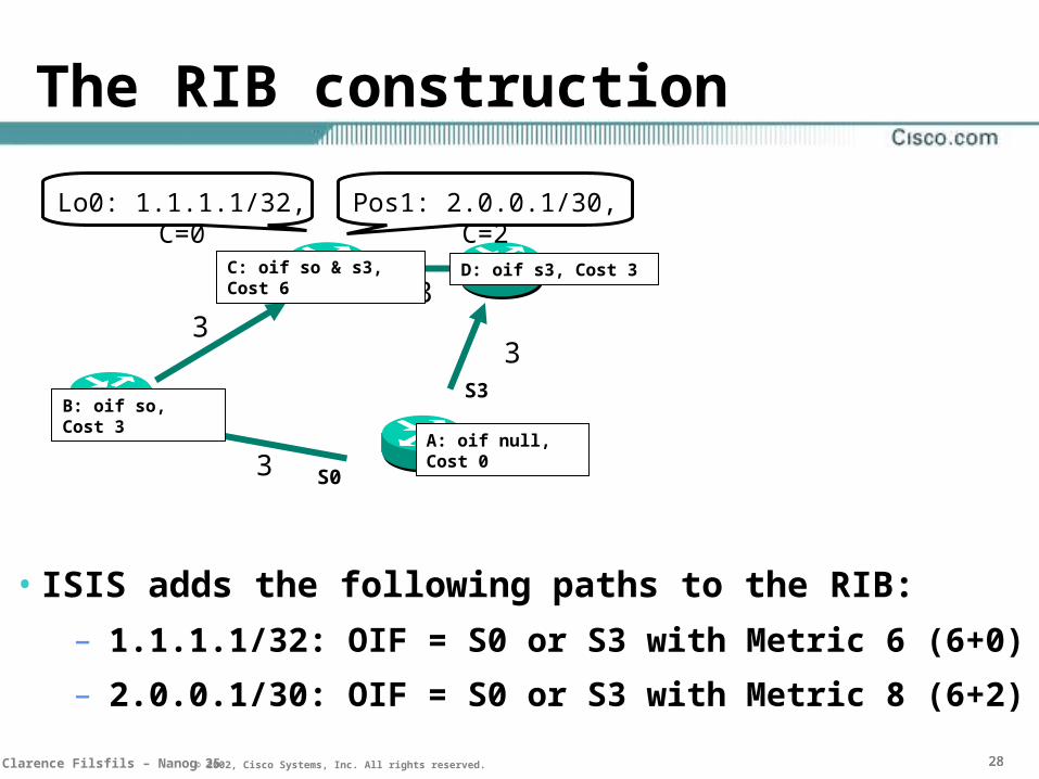
The RIB construction
• ISIS adds the following paths to the RIB:
– 1.1.1.1/32: OIF = S0 or S3 with Metric 6 (6+0)
– 2.0.0.1/30: OIF = S0 or S3 with Metric 8 (6+2)
3
3
33
A: oif null, Cost 0
S0
S3B: oif so, Cost 3
C: oif so & s3, Cost 6 D: oif s3, Cost 3
Lo0: 1.1.1.1/32, C=0 Pos1: 2.0.0.1/30, C=2
292929Clarence Filsfils – Nanog 25 © 2002, Cisco Systems, Inc. All rights reserved.
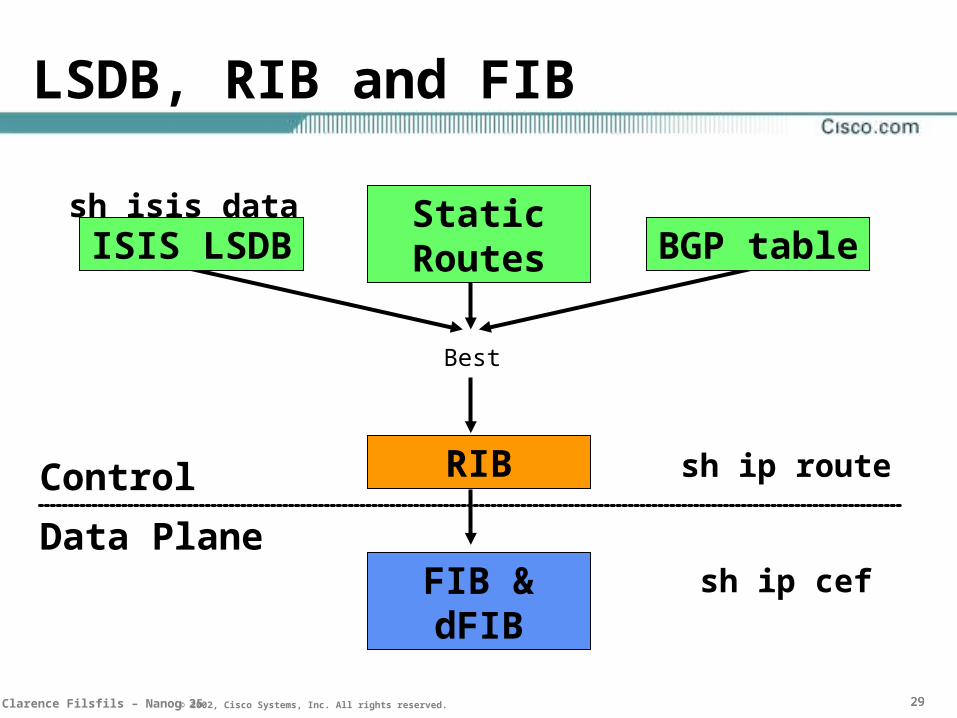
LSDB, RIB and FIB
Best
FIB & dFIB
sh ip route
sh ip cef
sh isis data
Control
Data Plane
RIB
Static RoutesISIS LSDB BGP table
30NANOG 25 © 2001, Cisco Systems, Inc. All rights reserved.© 2001, Cisco Systems, Inc. All rights reserved.© 2001, Cisco Systems, Inc. All rights reserved.
SPF optimisations
30

313131Clarence Filsfils – Nanog 25 © 2002, Cisco Systems, Inc. All rights reserved.
SPF Optimizations
• Most Basic Implementation
– Any change (link, node, leave)
recompute the whole SPT and the whole RIB
• Optimization 1: decouple SPT and RIB
– If any topology change (node, link)
recompute SPT and the RIB
– If only a leave change (IP prefix)
keep the SPT, just update the RIB for the nodes whose leaves have changed
Called “SPF”
Called “PRC”

323232Clarence Filsfils – Nanog 25 © 2002, Cisco Systems, Inc. All rights reserved.
PRC
• PRC here consists in just adding 65.1.1.1/32 in the RIB. The SPT is not affected.
S0
S1
S2S3
Cost: 0, NH: --A
Cost: 3, NH: BB
Cost: 11, NH: BE
Cost: 8, NH: D, BF
Cost: 13, NH: DG
Cost: 6, NH: D, BC Cost: 3, NH: DD
Int lo 0: 65.1.1.1/32
333333Clarence Filsfils – Nanog 25 © 2002, Cisco Systems, Inc. All rights reserved.
Incremental-SPF
• Optimization 2
• When the topology has changed, instead of building the whole SPT from scratch just fix the part of the SPT that is affected
• Only the leaves of the nodes re-analyzed during that process are updated in the RIB

343434Clarence Filsfils – Nanog 25 © 2002, Cisco Systems, Inc. All rights reserved.
Incremental-SPF
S0
S1
S2S3
Cost: 0, NH: --A
Cost: 3, NH: BB
Cost: 11, NH: BE
Cost: 8, NH: D, BF
Cost: 13, NH: DG
Cost: 6, NH: D, BC Cost: 3, NH: DD
C-G link is down. C-G link was not used in SPT anyway, therefore there is no need to run SPF.

353535Clarence Filsfils – Nanog 25 © 2002, Cisco Systems, Inc. All rights reserved.
Incremental-SPF
S0
S1
S2S3
Cost: 0, NH: --A
Cost: 3, NH: BB
Cost: 11, NH: BE
Cost: 13, NH: DG
Cost: 6, NH: D, BC Cost: 3, NH: DD
F reports a new neighbor. The SPT need only to be extended behind F. There is no need for router A to recompute the whole SPTRouter A will compute SPF from node F
Cost: 8, NH: D, BF
H

363636Clarence Filsfils – Nanog 25 © 2002, Cisco Systems, Inc. All rights reserved.
Incremental-SPF
• More information is kept in the SPT
–Parents list
–Neighbors list
• Based on the changed information, the SPT is “modified” in order to reflect the changes
373737Clarence Filsfils – Nanog 25 © 2002, Cisco Systems, Inc. All rights reserved.
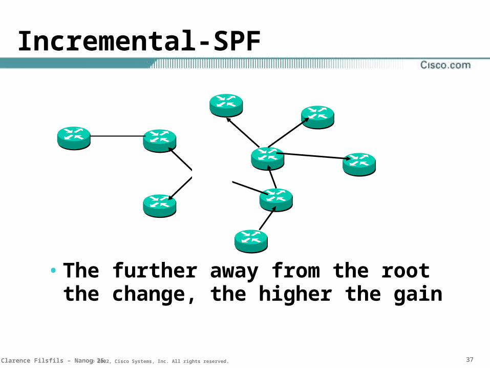
Incremental-SPF
• The further away from the root the change, the higher the gain

383838Clarence Filsfils – Nanog 25 © 2002, Cisco Systems, Inc. All rights reserved.
SPF, PRC, I-SPF: summary
• Only a leaf change
– PRC
• Graph impacted
– normal-SPF: recompute the full SPT and hence reinserts all the ISIS routes in the RIB
– I-SPF: only recomputes the part of the SPT that is affected. Only the leaves from that part are affected.
39NANOG 25 © 2001, Cisco Systems, Inc. All rights reserved.© 2001, Cisco Systems, Inc. All rights reserved.© 2001, Cisco Systems, Inc. All rights reserved.
Topology and Leaf Optimizations
39

404040Clarence Filsfils – Nanog 25 © 2002, Cisco Systems, Inc. All rights reserved.
Parallel point-to-point adjacencies
7 3
3
4
38
3E
D
B
A
C
S0
S1
S2S3
LSP BIS: 3 AIS: 4 AIS: 3 CIS: 8 E
LSP AIS: 3 BIS: 4 BIS: 7 CIS: 3 D
• Only best parallel adjacency is reported

414141Clarence Filsfils – Nanog 25 © 2002, Cisco Systems, Inc. All rights reserved.
P2P mode for back-to-back GE
• No DIS election
• No CSNP transmission
• No Pseudo-node and extra link
Pseudonode
Rtr-A Rtr-B Rtr-A Rtr-B
interface fastethernet1/0
isis network point-to-point
Rtr-A Rtr-B
424242Clarence Filsfils – Nanog 25 © 2002, Cisco Systems, Inc. All rights reserved.
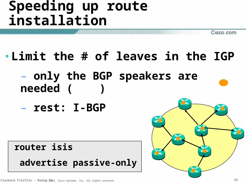
Speeding up route installation
• Limit the # of leaves in the IGP
– only the BGP speakers are needed ( )
– rest: I-BGP
router isis
advertise passive-only
43NANOG 25 © 2001, Cisco Systems, Inc. All rights reserved.© 2001, Cisco Systems, Inc. All rights reserved.© 2001, Cisco Systems, Inc. All rights reserved.
SPF, PRC and LSP-genExponential BackOff
Timers
43

444444Clarence Filsfils – Nanog 25 © 2002, Cisco Systems, Inc. All rights reserved.
Backoff timer algorithm
• IS-IS throttles it main events
– SPF computation
– PRC computation
– LSP generation
• Throttling slows down convergence
• Not throttling can cause melt-downs
• The scope is to react fast to the first events but, under constant churn, slow down to avoid to collapse

454545Clarence Filsfils – Nanog 25 © 2002, Cisco Systems, Inc. All rights reserved.
Backoff timer algorithm
• Maximum interval: Maximum amount of time the router will wait between consecutives executions
• Initial delay: Time the router will wait before starting execution
• Incremental interval: Time the router will wait between consecutive execution. This timer is variable and will increase until it reaches Maximum-interval
spf-interval <Max> [<Init> <Inc>]

464646Clarence Filsfils – Nanog 25 © 2002, Cisco Systems, Inc. All rights reserved.
spf-interval 10 100 1000
• Then 8000ms
• Then maxed at 10sec
• 20s without Trigger is required before resetting the SPF timer to 100ms
E1Event1
E2 E3 E4
SPF
100ms
SPF
1000ms 2000ms
SPF
4000ms
E5 E6 E7
474747Clarence Filsfils – Nanog 25 © 2002, Cisco Systems, Inc. All rights reserved.
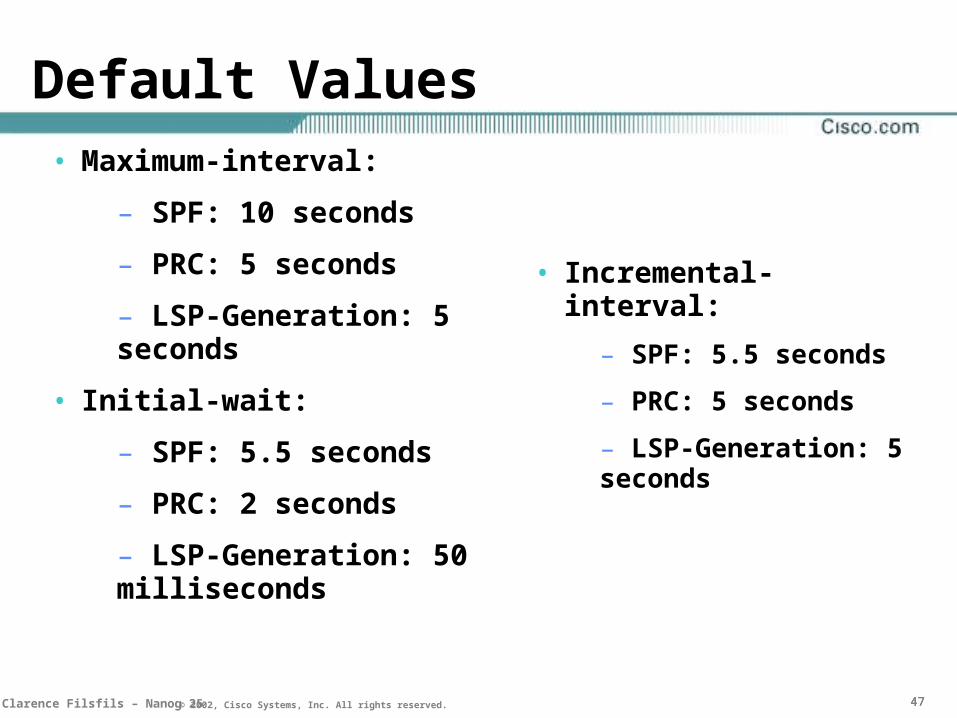
Default Values• Maximum-interval:
– SPF: 10 seconds
– PRC: 5 seconds
– LSP-Generation: 5 seconds
• Initial-wait:
– SPF: 5.5 seconds
– PRC: 2 seconds
– LSP-Generation: 50 milliseconds
• Incremental-interval:
– SPF: 5.5 seconds
– PRC: 5 seconds
– LSP-Generation: 5 seconds

484848Clarence Filsfils – Nanog 25 © 2002, Cisco Systems, Inc. All rights reserved.
Two-Way Connectivity Check
• For propagating Bad News, 1! LSP is enough
E B
F
LSP LSP
494949Clarence Filsfils – Nanog 25 © 2002, Cisco Systems, Inc. All rights reserved.
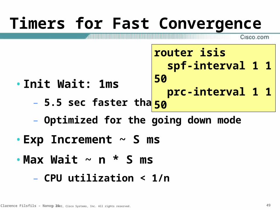
Timers for Fast Convergence
• Init Wait: 1ms
– 5.5 sec faster than default reaction!
– Optimized for the going down mode
• Exp Increment ~ S ms
• Max Wait ~ n * S ms
– CPU utilization < 1/n
router isis spf-interval 1 1 50 prc-interval 1 1 50
505050Clarence Filsfils – Nanog 25 © 2002, Cisco Systems, Inc. All rights reserved.
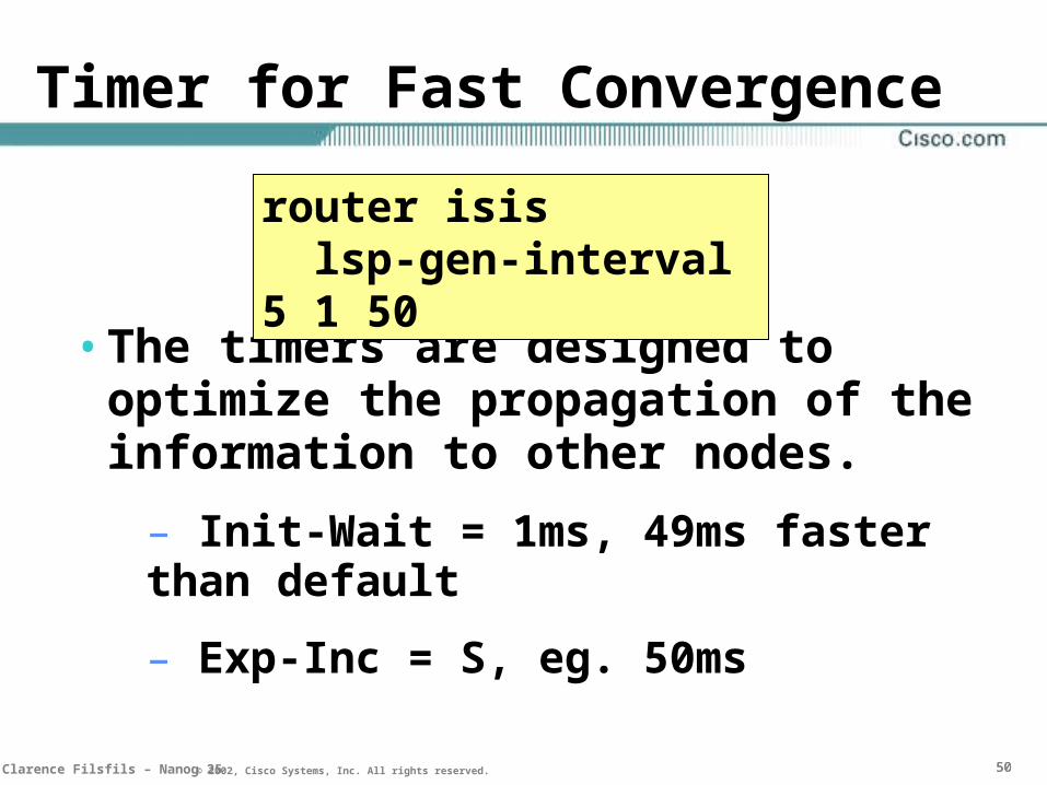
Timer for Fast Convergence
• The timers are designed to optimize the propagation of the information to other nodes.
– Init-Wait = 1ms, 49ms faster than default
– Exp-Inc = S, eg. 50ms
router isis lsp-gen-interval 5 1 50

53NANOG 25 © 2001, Cisco Systems, Inc. All rights reserved.© 2001, Cisco Systems, Inc. All rights reserved.© 2001, Cisco Systems, Inc. All rights reserved.
LSP Pacing and Flooding
53

545454Clarence Filsfils – Nanog 25 © 2002, Cisco Systems, Inc. All rights reserved.
LSP Pacing and Flooding
• Pacing:– Default: 33msecs inter-LSP gap
– backoff protection
– full database download
– suggest to keep the default
• Flooding– flood/SPF trade-off
Int pos x/x isis lsp-interval <>
55NANOG 25 © 2001, Cisco Systems, Inc. All rights reserved.© 2001, Cisco Systems, Inc. All rights reserved.© 2001, Cisco Systems, Inc. All rights reserved.
Link Protocol Properties
55

565656Clarence Filsfils – Nanog 25 © 2002, Cisco Systems, Inc. All rights reserved.
Link Protocol Properties
• Link Failure Detection
– the faster and more reliable, the better
• Dampening flapping links
– Fast signalling of a Down information
– Stable signalling of an UP information
– Freeze a flapping link in Down status

575757Clarence Filsfils – Nanog 25 © 2002, Cisco Systems, Inc. All rights reserved.
POS – Detection of a link failure
• Pos delay trigger line:
– hold time before reacting to a line alarm
– default is: immediate reaction
• Pos delay trigger path:
– hold time before reacting to a path alarm
– default is: no reaction
• Carrier-delay
– hold time between the end of the pos delay holdtime and the bring down of the IOS interface
– default: 2000 msec
585858Clarence Filsfils – Nanog 25 © 2002, Cisco Systems, Inc. All rights reserved.
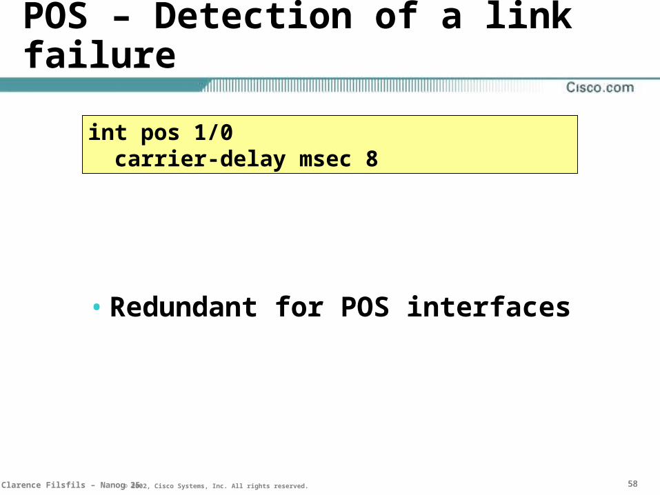
POS – Detection of a link failure
• Redundant for POS interfaces
int pos 1/0 carrier-delay msec 8

595959Clarence Filsfils – Nanog 25 © 2002, Cisco Systems, Inc. All rights reserved.
POS – Detection of a link failure
R1-ADM--PROTECTED_SONET_net--ADM-R2
• Should delay a little to allow for SONET protection. Suggestion: 60msec
int pos 1/0 carrier-delay msec 8 pos delay triggers line 60 pos delay triggers path 60

606060Clarence Filsfils – Nanog 25 © 2002, Cisco Systems, Inc. All rights reserved.
POS – Detection of a link failure
R1-ADM--UNprotected_SONET_net--ADM-R2
• Should react as fast possible
– line default ok
– path default not ok
int pos 1/0 carrier-delay msec 8 pos delay triggers line 0 pos delay triggers path 0
616161Clarence Filsfils – Nanog 25 © 2002, Cisco Systems, Inc. All rights reserved.
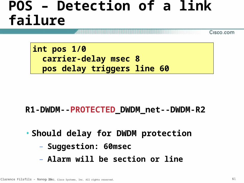
POS – Detection of a link failure
R1-DWDM--PROTECTED_DWDM_net--DWDM-R2
• Should delay for DWDM protection
– Suggestion: 60msec
– Alarm will be section or line
int pos 1/0 carrier-delay msec 8 pos delay triggers line 60

626262Clarence Filsfils – Nanog 25 © 2002, Cisco Systems, Inc. All rights reserved.
POS – Detection of a link failure
R1-DWDM--UNPROTECTED_DWDM_net--DWDM-R2
• Should react asap
– line: default ok
– path: not needed: default ok
int pos 1/0 carrier-delay msec 8 pos delay triggers line 0

636363Clarence Filsfils – Nanog 25 © 2002, Cisco Systems, Inc. All rights reserved.
POS – Bringing a down link back up
• Upon alarm clearance, POS Driver will wait 10seconds + <Carrier-Delay> before turning the interface back up, hence before triggering ISIS convergence
646464Clarence Filsfils – Nanog 25 © 2002, Cisco Systems, Inc. All rights reserved.
POS – Best for Convergence
• Very fast Link failure detection
– no need to tune the ISIS hello/holdtime
• Native anti-flap property of POS
– down info is signalled very fast
– up info is confirmed for 10s before relaying to interface

656565Clarence Filsfils – Nanog 25 © 2002, Cisco Systems, Inc. All rights reserved.
Other types of Links
• Link Failure Detection
– If the native mode is too slow or if the link has no failure detection capability
– ISIS Hello/Holdtime tuning
• Interface Dampening
– New feature to provide same Dampening capability as BGP to the generic Interface (applies to all types of interfaces)

666666Clarence Filsfils – Nanog 25 © 2002, Cisco Systems, Inc. All rights reserved.
Fast Hello’s
• Fast hello’s allow a dead timer of 1 second
• POS much faster/reliable
• Only useful when layer1/2 can’t help!
int serial0
isis hello-interval minimal
isis hello-multiplier 4
67NANOG 25 © 2001, Cisco Systems, Inc. All rights reserved.© 2001, Cisco Systems, Inc. All rights reserved.© 2001, Cisco Systems, Inc. All rights reserved.
Operating this Design
67

71NANOG 25 © 2001, Cisco Systems, Inc. All rights reserved.© 2001, Cisco Systems, Inc. All rights reserved.© 2001, Cisco Systems, Inc. All rights reserved.
ISIS Fast Convergence Design
71

727272Clarence Filsfils – Nanog 25 © 2002, Cisco Systems, Inc. All rights reserved.
Design Tips
• POS as link type
–Do not tune ISIS hello’s and LSP-interval
• Design to minimize ISIS nodes, links, prefixes
• Optimization: PRC, I-SPF, Flooding, Parallel adjacencies, p2p GE
• SPF, PRC, LSP-Gen timers router isis spf-interval 1 1 50 prc-interval 1 1 50 lsp-gen-interval 5 1 50
int pos 1/0 carrier-delay msec 8 pos delay trigger …
73NANOG 25 © 2001, Cisco Systems, Inc. All rights reserved.© 2001, Cisco Systems, Inc. All rights reserved.© 2001, Cisco Systems, Inc. All rights reserved.
Test Results
73

747474Clarence Filsfils – Nanog 25 © 2002, Cisco Systems, Inc. All rights reserved.
Test Scenari
• 12.0(19)S
• Carrier-delay configured to 8ms
• SPF, PRC, LSP-Gen Timers
– Default Timers
– Fast ISIS Configuration

757575Clarence Filsfils – Nanog 25 © 2002, Cisco Systems, Inc. All rights reserved.
ISIS: 1200 Nodes, 4000 Leaves
BGP: 144000 prefixes
Agilent:
• A-B & B->A
• 10000 pps
• accuracy: 0.1ms
1200 Nodes4000 prefixes

767676Clarence Filsfils – Nanog 25 © 2002, Cisco Systems, Inc. All rights reserved.
A
B
10000pps 10000pps
ISIS: 1200 Nodes, 4000 Leaves
BGP: 144000 prefixes
Agilent:
• A-B & B->A
• 10000 pps
• accuracy: 0.1ms

777777Clarence Filsfils – Nanog 25 © 2002, Cisco Systems, Inc. All rights reserved.
ais
ISIS: 1200 Nodes, 4000 Leaves
BGP: 144000 prefixes
Agilent:
• A-B & B->A
• 10000 pps
• accuracy: 0.1ms
787878Clarence Filsfils – Nanog 25 © 2002, Cisco Systems, Inc. All rights reserved.
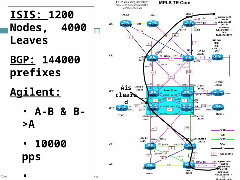
Ais cleared
ISIS: 1200 Nodes, 4000 Leaves
BGP: 144000 prefixes
Agilent:
• A-B & B->A
• 10000 pps
• accuracy: 0.1ms
797979Clarence Filsfils – Nanog 25 © 2002, Cisco Systems, Inc. All rights reserved.
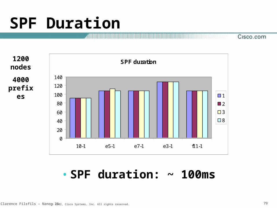
SPF Duration
• SPF duration: ~ 100ms
1200 nodes
4000 prefixes
SPF duration
0
20
40
60
80
100
120
140
10-1 e5-1 e7-1 e3-1 f11-1
1
2
3
8
808080Clarence Filsfils – Nanog 25 © 2002, Cisco Systems, Inc. All rights reserved.
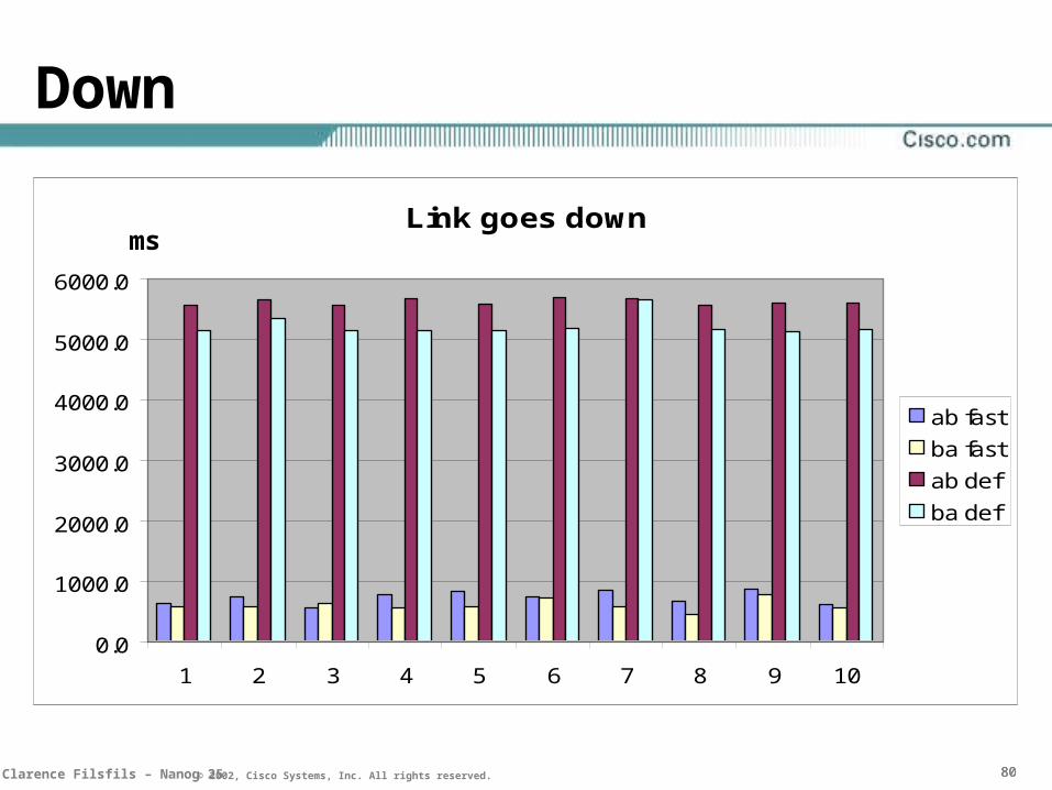
Down
Link goes down
0.0
1000.0
2000.0
3000.0
4000.0
5000.0
6000.0
1 2 3 4 5 6 7 8 9 10
ab fast
ba fast
ab def
ba def
ms

818181Clarence Filsfils – Nanog 25 © 2002, Cisco Systems, Inc. All rights reserved.
Carrier-Delay
• Graph from Iain
ISIS A->B 12.0(18)ST down event - AVG
0
500
1000
1500
2000
2500
3000
1
carrier delay ms
ms
ec
0ms
8ms
12ms
16ms
50ms
2000ms

828282Clarence Filsfils – Nanog 25 © 2002, Cisco Systems, Inc. All rights reserved.

838383Clarence Filsfils – Nanog 25 © 2002, Cisco Systems, Inc. All rights reserved.
0
50
100
150
200
250
300
350
400
450
500
ISIS-NH A->B ISIS-LNE A->B BGP1 A->B BGP2 A->B BGP3 A->B
Average [ms] Std-dev [ms]
Convergence
• 500 ISIS n
• 1000 ISIS p
• 80000 BGP p
• Accuracy: 0.1 ms
• 10 iterations

84NANOG 25 © 2001, Cisco Systems, Inc. All rights reserved.© 2001, Cisco Systems, Inc. All rights reserved.© 2001, Cisco Systems, Inc. All rights reserved.
Conclusion
84

858585Clarence Filsfils – Nanog 25 © 2002, Cisco Systems, Inc. All rights reserved.
Conclusion
• IGP convergence needs to be optimized for Tight-SLA Services
• New development speed up convergence without stability compromise
• Test results indicate that sub-second convergence is realistic
• For sub-100ms Convergence, local action based on precomputed tables might be required

868686Clarence Filsfils – Nanog 25 © 2002, Cisco Systems, Inc. All rights reserved.
Agenda
• Introduction and SLA
• Sub-Second IGP Convergence
• BackbBackbone one Diffserv Diffserv DesignDesign
• Conclusion
87NANOG 25 © 2001, Cisco Systems, Inc. All rights reserved.© 2001, Cisco Systems, Inc. All rights reserved.© 2001, Cisco Systems, Inc. All rights reserved.
OverProvisioned Backbone
DiffServ with a single class!
888888Clarence Filsfils – Nanog 25 © 2002, Cisco Systems, Inc. All rights reserved.
The Key is OverProvisioningOffer must be higher than Demand
• The service that traffic receives is dependent upon the ratio of traffic load to available capacity
• More Bandwidth (offer) than traffic (demand) means
– Low loss
– Low Latency
– Low Jitter
• Refs: [ROBERTS], [CHARNY], [BONALD]

898989Clarence Filsfils – Nanog 25 © 2002, Cisco Systems, Inc. All rights reserved.
Over-Provisioned Backbone
• A simple rule of design:
95-Percentile (5-min average Load) <= 50% Link
which means
OverProvisioning (OP) > 2
909090Clarence Filsfils – Nanog 25 © 2002, Cisco Systems, Inc. All rights reserved.
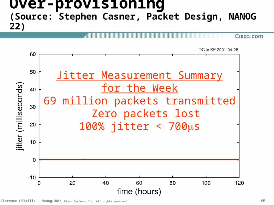
Over-provisioning(Source: Stephen Casner, Packet Design, NANOG 22)
Jitter Measurement Summaryfor the Week
69 million packets transmitted Zero packets lost100% jitter < 700s
919191Clarence Filsfils – Nanog 25 © 2002, Cisco Systems, Inc. All rights reserved.
Drawback
• Risk related to provisioning failure
• Fate Sharing!
– No isolation between VPN, VoIP, Internet
• Expensive
– design for the aggregate!

929292Clarence Filsfils – Nanog 25 © 2002, Cisco Systems, Inc. All rights reserved.
Provisioning failure
• Capacity planning failures
– Small overprovisioning ratio: 2 vs 16
• Unexpected traffic demands
• Network failure situations
• Bandwidth unavailability
• Internet DoS Attack
FATE SHARING: Internet affects VoIP

939393Clarence Filsfils – Nanog 25 © 2002, Cisco Systems, Inc. All rights reserved.
99.99%
“Not every week is like this”(Source: Stephen Casner, Packet Design, NANOG 22)
949494Clarence Filsfils – Nanog 25 © 2002, Cisco Systems, Inc. All rights reserved.
Recommendation: use DiffServ!
• Higher Availability of SLA
– Higher overprovisioning ratio (4 and more)
– Service Isolation
• Cheaper
– Overprovisioning per Class!
• Mature Technology

959595Clarence Filsfils – Nanog 25 © 2002, Cisco Systems, Inc. All rights reserved.
Service Isolation
• DiffServ Per-Hop Behavior
– Expedited Forwarding
>Low-latency/jitter scheduler (often a PQ)
– Assured Forwarding
>Bandwidth allocation and Multi-level Congestion avoidance (RED)
DSCPDSCP ECNECN
969696Clarence Filsfils – Nanog 25 © 2002, Cisco Systems, Inc. All rights reserved.
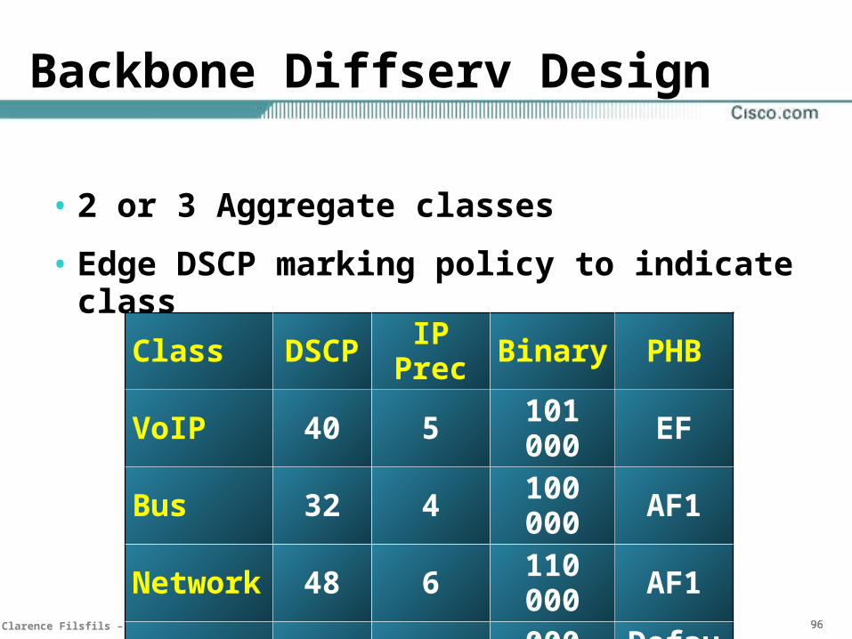
Backbone Diffserv Design
• 2 or 3 Aggregate classes
• Edge DSCP marking policy to indicate class
ClassDSC
PIP Prec Binary PHB
VoIP 40 5 101 000 EFBus 32 4 100 000 AF1Network 48 6 110 000 AF1
BE 0 0 000 000Defaul
t
979797Clarence Filsfils – Nanog 25 © 2002, Cisco Systems, Inc. All rights reserved.
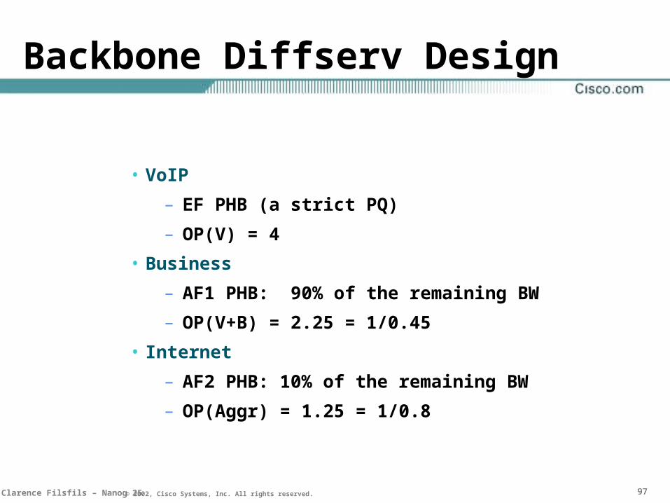
• VoIP
– EF PHB (a strict PQ)
– OP(V) = 4
• Business
– AF1 PHB: 90% of the remaining BW
– OP(V+B) = 2.25 = 1/0.45
• Internet
– AF2 PHB: 10% of the remaining BW
– OP(Aggr) = 1.25 = 1/0.8
Backbone Diffserv Design
989898Clarence Filsfils – Nanog 25 © 2002, Cisco Systems, Inc. All rights reserved.
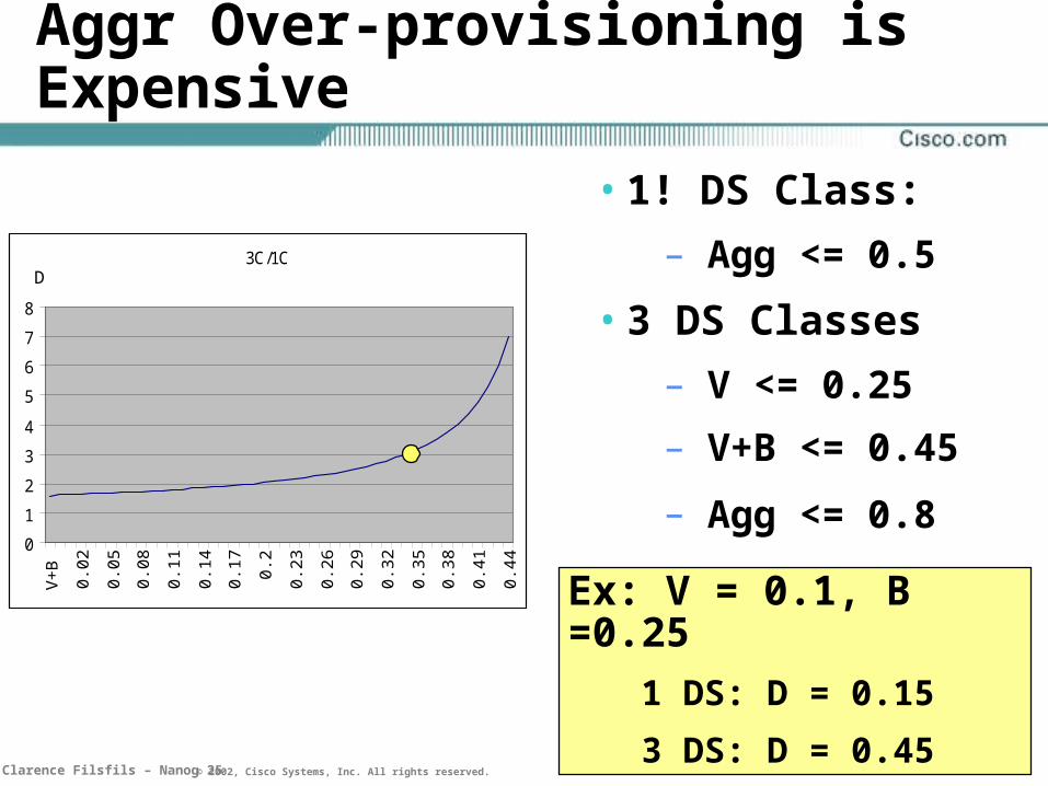
Aggr Over-provisioning is Expensive
• 1! DS Class:
– Agg <= 0.5
• 3 DS Classes
– V <= 0.25
– V+B <= 0.45
– Agg <= 0.8
3C/1C
0
1
2
3
4
5
6
7
8
V+
B
0.02
0.05
0.08
0.11
0.14
0.17 0.
2
0.23
0.26
0.29
0.32
0.35
0.38
0.41
0.44
Ex: V = 0.1, B =0.25
1 DS: D = 0.15
3 DS: D = 0.45
D
999999Clarence Filsfils – Nanog 25 © 2002, Cisco Systems, Inc. All rights reserved.
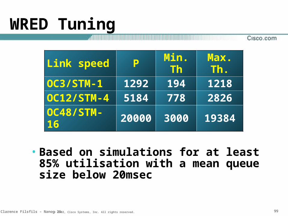
Link speed PMin. Th
Max. Th.
OC3/STM-1 1292 194 1218OC12/STM-4 5184 778 2826OC48/STM-16
20000 3000 19384
WRED Tuning
• Based on simulations for at least 85% utilisation with a mean queue size below 20msec
105105105Clarence Filsfils – Nanog 25 © 2002, Cisco Systems, Inc. All rights reserved.
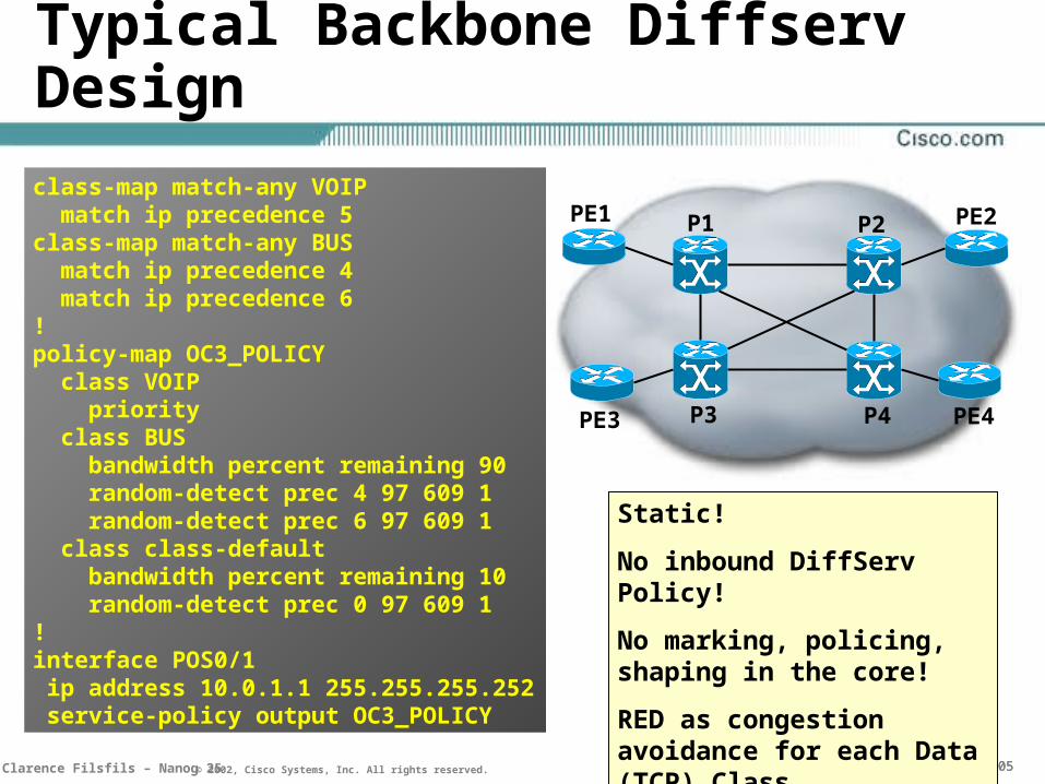
Typical Backbone Diffserv Design
class-map match-any VOIP match ip precedence 5class-map match-any BUS match ip precedence 4 match ip precedence 6!policy-map OC3_POLICY class VOIP priority class BUS bandwidth percent remaining 90 random-detect prec 4 97 609 1 random-detect prec 6 97 609 1 class class-default bandwidth percent remaining 10 random-detect prec 0 97 609 1! interface POS0/1 ip address 10.0.1.1 255.255.255.252 service-policy output OC3_POLICY
PE1
PE3 PE4
PE2
P3
P1 P2
P4
Static!
No inbound DiffServ Policy!
No marking, policing, shaping in the core!
RED as congestion avoidance for each Data (TCP) Class

106106106Clarence Filsfils – Nanog 25 © 2002, Cisco Systems, Inc. All rights reserved.
Provisioning is simple
• Same as ISIS, OSPF
• Configuration is done once and then it remains static

107107107Clarence Filsfils – Nanog 25 © 2002, Cisco Systems, Inc. All rights reserved.
Capacity Planning
• Aggregate Based
– DiffServ Isolation – risk hedging
• Per-Class Based
– OP per link/class
– Traffic Matrix per Class
– Better network utilization
• Significant edge qos deployment over last 24 months contribute to better NMS support for QoS

108108108Clarence Filsfils – Nanog 25 © 2002, Cisco Systems, Inc. All rights reserved.
Mature Technology
• EF: jitter due to non-EF
• AF: accuracy of BW allocation
• AF: latency as a function of AF load
• Even the rare cases are dealt with
109109109Clarence Filsfils – Nanog 25 © 2002, Cisco Systems, Inc. All rights reserved.
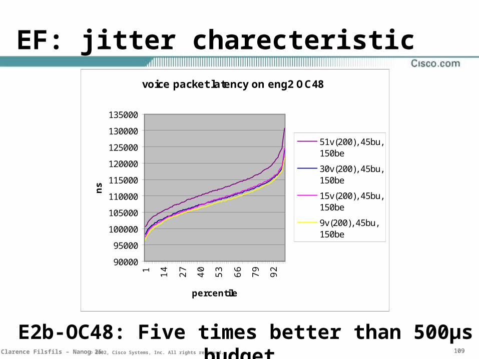
EF: jitter charecteristicvoice packet latency on eng2 OC48
90000
95000
100000
105000
110000
115000
120000
125000
130000
135000
1 14 27 40 53 66 79 92
percentile
ns
51v(200), 45bu,150be
30v(200), 45bu,150be
15v(200), 45bu,150be
9v(200), 45bu,150be
E2b-OC48: Five times better than 500µs budget
110110110Clarence Filsfils – Nanog 25 © 2002, Cisco Systems, Inc. All rights reserved.
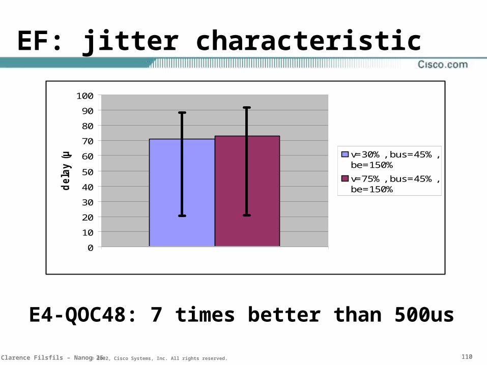
EF: jitter characteristic
E4-QOC48: 7 times better than 500us
0
10
20
30
40
50
60
70
80
90
100
1
dela
y (
µs)
v=30%, bus=45%,be=150%
v=75%, bus=45%,be=150%
111111111Clarence Filsfils – Nanog 25 © 2002, Cisco Systems, Inc. All rights reserved.
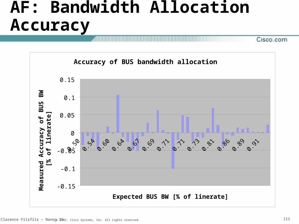
AF: Bandwidth Allocation Accuracy
Accuracy of BUS bandwidth allocation
-0.15
-0.1
-0.05
0
0.05
0.1
0.15
0.50
0.54
0.60
0.64
0.67
0.69
0.71
0.71
0.73
0.81
0.86
0.89
0.91
Expected BUS BW [% of linerate]
Me
as
ure
d A
cc
ura
cy
of
BU
S B
W
[% o
f li
ne
rate
]

112112112Clarence Filsfils – Nanog 25 © 2002, Cisco Systems, Inc. All rights reserved.
AF: Latency = f(load)
Latency in business class on OC48 with IMIX
100
1000
10000
100000
1000000
70 100 130 160 190 220 250
business load ratio
Max
late
ncy
(u
s)

113113113Clarence Filsfils – Nanog 25 © 2002, Cisco Systems, Inc. All rights reserved.
Rx (rx-cos) side of i/p line card Tx side (tx-cos) of o/p line card
E2: 128 fromfab Qs
CEF
InputPorts
OutputPorts
E2: 2048 tofab VOQs
16x16x8 16x8
Optimised for even rare/corner-cases
Cro
ssbar S
witch
Fab
ric

117NANOG 25 © 2001, Cisco Systems, Inc. All rights reserved.© 2001, Cisco Systems, Inc. All rights reserved.© 2001, Cisco Systems, Inc. All rights reserved.
Capacity Planning and Monitoring

119119119Clarence Filsfils – Nanog 25 © 2002, Cisco Systems, Inc. All rights reserved.
Capacity Planning and Monitoring
• A number of tools exist for capacity planning:
–Per link statistics
–Core traffic matrices
–Active SLA monitoring

120120120Clarence Filsfils – Nanog 25 © 2002, Cisco Systems, Inc. All rights reserved.
• packets and bytes through the class
• packets random-dropped
• packets forced-dropped
• no-buffer drops
• ignores
Link statistics
121121121Clarence Filsfils – Nanog 25 © 2002, Cisco Systems, Inc. All rights reserved.
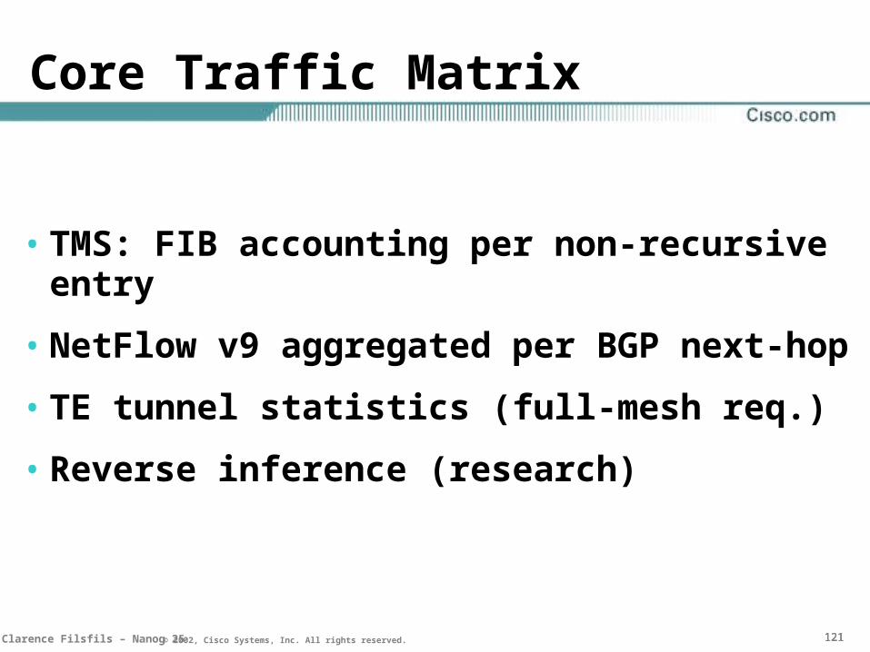
Core Traffic Matrix
• TMS: FIB accounting per non-recursive entry
• NetFlow v9 aggregated per BGP next-hop
• TE tunnel statistics (full-mesh req.)
• Reverse inference (research)

123123123Clarence Filsfils – Nanog 25 © 2002, Cisco Systems, Inc. All rights reserved.
IPPM Infrastructure
POP1 POP3
POP2
POP4
PEPE
PEPE
PEPE
PP
Shadow Router
SLA probes
Ie. SAA

124NANOG 25 © 2001, Cisco Systems, Inc. All rights reserved.© 2001, Cisco Systems, Inc. All rights reserved.© 2001, Cisco Systems, Inc. All rights reserved.
MPLS-based Technologies
TE, DS-TE, FRR

125125125Clarence Filsfils – Nanog 25 © 2002, Cisco Systems, Inc. All rights reserved.
TE and SLA’s
• TE allows for the routing based on constraints other than shortest-path
– bandwidth availability
– propagation latency
• DS-TE allows this for the aggregate and at least one additional class-type
126126126Clarence Filsfils – Nanog 25 © 2002, Cisco Systems, Inc. All rights reserved.
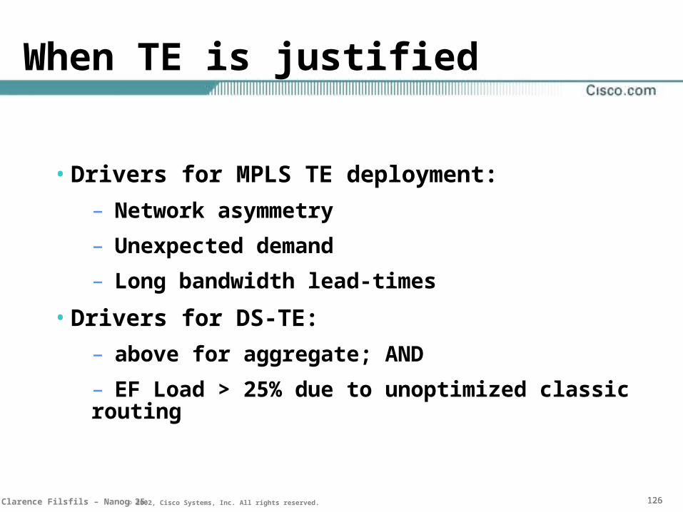
When TE is justified
• Drivers for MPLS TE deployment:
– Network asymmetry
– Unexpected demand
– Long bandwidth lead-times
• Drivers for DS-TE:
– above for aggregate; AND
– EF Load > 25% due to unoptimized classic routing
127127127Clarence Filsfils – Nanog 25 © 2002, Cisco Systems, Inc. All rights reserved.
MPLS FRR
• Link/Node Local Protection
– Pre-established and pre-computed
– Requires MPLS TE deployment
• When sub-second convergence is not enough, but 50ms is required

128NANOG 25 © 2001, Cisco Systems, Inc. All rights reserved.© 2001, Cisco Systems, Inc. All rights reserved.© 2001, Cisco Systems, Inc. All rights reserved.
Tight-SLA IP BackboneConclusion
Clarence Filsfils - [email protected]

129129129Clarence Filsfils – Nanog 25 © 2002, Cisco Systems, Inc. All rights reserved.
An overview of the Analysis
LLJ:Loss/Latency/JitterLLJ:Loss/Latency/Jitter ConvergenceConvergence
DiffServ: likely a Must - EF(jitter) < 50us - AF: 99.95% accuracy, 160us latency
More Assurance, Cheaper
TE: if asymetric topology, unexpected growth, long lead times
DS-TE: if TE and EF utilization per link risks to be too high
ISIS Sub-Second: Likely a Must
MPLS FRR: for <100ms