1u5793 pressure diferential gauge usbr1055
TRANSCRIPT
•: UNITED STATES DEPARTMENT OF THE INTERIOR•. BUREAU OF RECLAMATION
PROCEDURE FORUSBR 1055-89
CALIBRATING DIFFERENTIAL PRESSURE TRANSDUCERS
INTRODUCTION
Thisprocedure is under the jurisdiction of the Geotechnical Services Branch, code D-3760, Research and Laboratory ServicesDivision, Denver Office, Denver, Colorado. The procedure is issued under the fixed designation USBR 1055. The number immediatelyfollowing the designation indicates the year of acceptance or the year of last revision.
1. Scope ® ®
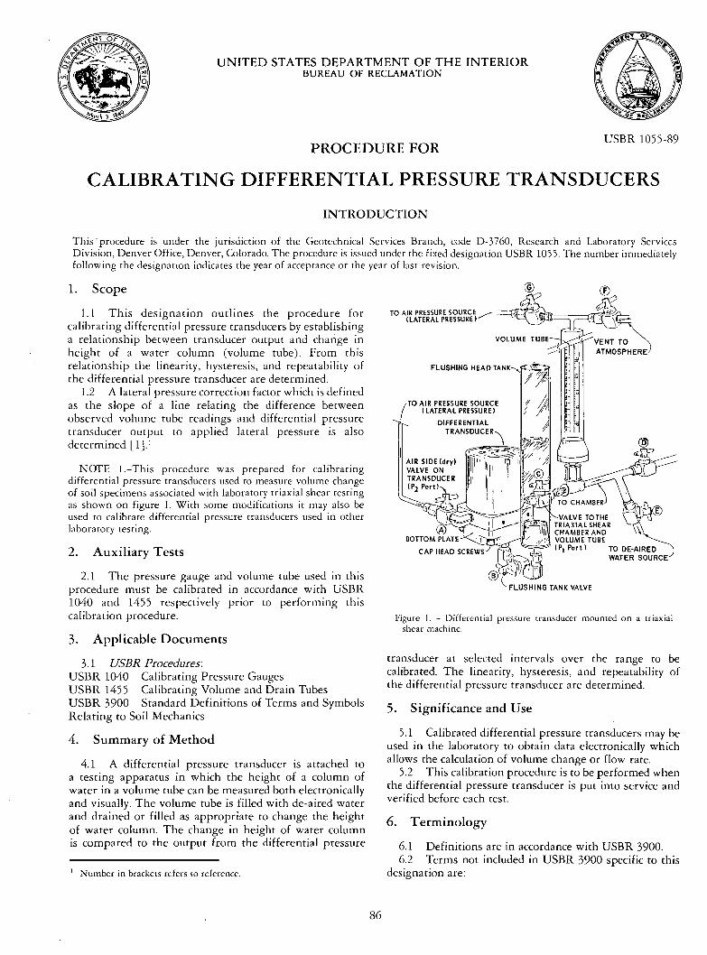
1.1 This designation outlines the procedure forcalibrating differential pressure transducers by establishinga relationship between transducer output and change inheight of a water column (volume tube). From thisrelationship the linearity, hysteresis, and repeatability ofthe differential pressure transducer are determined.
1.2 A lateral pressure correction factor which is definedas the slope of a line relating the difference betweenobserved volume tube readings and differential pressuretransducer output to applied lateral pressure is alsodetermined [1]. 1
TO AIR PRESSURE SOURCE( LATERAL PRESSURE)
VOLUME
NOTE 1.-This procedure was prepared for calibratingdifferential pressure transducers used to measure volume changeof soil specimens associated with laboratory triaxial shear testingas shown on figure 1. With some modifications it may also beused to calibrate differential pressure transducers used in otherlaboratory testing.
2. Auxiliary Tests
2.1 The pressure gauge and volume tube used in thisprocedure must be calibrated in accordance with USBR1040 and 1455 respectively prior to performing thiscalibration procedure.
3. Applicable Documents
3.1 USBR Procedures:USBR 1040 Calibrating Pressure GaugesUSBR 1455 Calibrating Volume and Drain TubesUSBR 3900 Standard Definitions of Terms and SymbolsRelating to Soil Mechanics
4. Summary of Method
4.1 A differential pressure transducer is attached toa testing apparatus in which the height of a column ofwater in a volume tube can be measured both electronicallyand visually. The volume tube is filled with de-aired waterand drained or filled as appropriate to change the heightof water column. The change in height of water columnis compared to the output from the differential pressure
I Number in brackets refers to reference.
Figure 1. - Differential pressure transducer mounted on a triaxialshear machine.
transducer at selected intervals over the range to becalibrated. The linearity, hysteresis, and repeatability ofthe differential pressure transducer are determined.
5. Significance and Use
5.1 Calibrated differential pressure transducers may beused in the laboratory to obtain data electronically whichallows the calculation of volume change or flow rate.
5.2 This calibration procedure is to be performed whenthe differential pressure transducer is put into service andverified before each test.
6. Terminology
6.1 Definitions are in accordance with USBR 3900.6.2 Terms not included in USBR 3900 specific to this
designation are:
86

USBR 1055
6.2.1 Lioea;it):-The variation of transducer outputfrom a straight line. In this procedure, measurements areobtained using a series of reference pressures (water columnheights) applied over the total rated capacity of thedifferential pressure transducer.
6.2.2 Repeatabiliry.-The maximum differencebetween transducer outputs for repeated pressures (watercolumn heights) under identical loading and environmentalconditions.
6.2.3 Hysteresis.-The maximum difference betweentransducer output for the same applied pressure; onereading obtained by decreasing the pressure from the uppercalibration limit (not to exceed the transducer ratedcapacity) to zero, and the other by increasing the pressurefrom zero to the upper calibration limit.
6.2.4 Rated Capac#y.-The maximum differentialpressure the transducer is designed to meast, re.
7. Apparatus
7.1 Differential Pressure Transducer.-A differentialpressure transducer, as shown on figure 2, of sufficientrange and accuracy for its intended laboratory testingapplication.
7.2 PressureGauge.-A bourdon tube air pressure gaugehaving a range equal to or greater than that of thedifferential pressure transducer to be calibrated. The gaugemust have a current calibration accompanied with acertificate of traceability.
7.3 Pressure Source.-An air pressure source capableof delivering and maintaining pressure up to the maximumrated pressure of the transducer.
7.4 Digital Voltmecer.-A voltmeter having a digitaldisplay of the electrical signal being sent from the signal
Pl PORT
l'i- , II lhI, II /ll II I ,OT .00YI , 11 I
i I I I
••BOTTOM
PLATE
CAPSULE
MODIFICATION: DRILL AND TAPFOR •'- NPT
Figure 2. - Cutaway view of differential pressure transducer.
conditioner which can be read accurately to the nearest1 millivolt.
7.5 Head Tank and Volume Tube.-A head tank andvolume tube as shown on figure 1. The volume tube shouldbe graduated to be read to the nearest 0.01 inch over therange of typical use.
7.6 De-aired Wacer.-De-aired water, as described insubparagraph 8.1, is used for performing the calibrationof the differential pressure transducer.
7.7 Vacuum Pump.-A hand-held vacuum pump usedto remove entrapped air from the system.
7.8 Signal Conditioner.-A signal conditioner must bet, sed to make the differential pressure transducer outputcompatible with the readout system.
7.9 Miscellaneous Equipment.-Appropriate size valvesand pipe fittings used to attach the differential pressuretransducer to the testing apparatt,s.
8. Reagentsand Materials
8.1 De-aired water that is free of acids, alkalies, oroils, and is suitable for drinking should be used forcalibrating the differential pressure transducer.
9. Precautions
9.1 Safety Precautions:9.l.l Ensure that all electrical wiring is properly
connected.9.1.2 Examine the differential presst, re transducer
body for burrs and sharp edges.9.1.3 This procedure involves the use of compressed
air. Appropriate precautions must be taken.9.2 Technical Precautions:
9.2.l Modifications to the procedure (outlined in par.12) are required for calibration of differential pressuretransducers used in applications other than on the triaxialshear assembly shown on figure l. (See note 2.)
9.2.2 Use the same electrical cables for calibratingthe transducer and for performing a test. A different cablelength will change the resistance of the circuit and willresult in a change in calibration.
9.2.3 It is recommended that the serial number beused for identification. If the transdt,cer must be marked,use extreme care. Use an indelible marking pencil ratherthan a scribe to mark on the transducer body.
9.2.4 The transducer must be stored in a suitablebox or case when not in use.
10. Calibration and Standardization
10. I Verify that the pressure gauge and the voh,metube used are currently calibrated in accordance with USBR1040 and 1455 respectively. If the calibration is not current,perform the calibration before using the equipment forthis procedure.
10.2 Verify that the readout system is currentlycalibrated. If the calibration is not current, it is to becalibrated in accordance with the manufacturer's guidelines.A voltmeter may be used as the readout system for this
87

USBR 1055
calibration procedure. At the Bureau's Denver Office, acomputer is used to accept the output signal from the signalconditioner and convert it into a transducer measurement.
11. Conditioning
11.1 Perform this calibration procedure in an areaisolated from wide temperature variations and electricalpower surges.
11.2 To ensure stability allow all electronic equipmentto warm up a minimum 30 minutes before use.
11.3 Place the differential pressure transducer, pressuregauge, volume tube, and electronic equipment in theenvironment in which they are to be calibrated at least24 hours prior to time of calibration.
12. Procedure
NOTE 2.-The following procedure is for calibration of a dif-ferential pressure transducer mounted on a triaxial shear assemblyas shown on figure 1. Generally, the calibration procedureoutlinedin this designation can be used for calibrating differential pressuretransducers used for other applications; however, modificationsto the procedure presented here may be necessary.
12.1 All data are to be recorded on the "DifferentialPressure Transducer Calibration Sheet" as shown onfigure 3.
12.2 Locate and record the rated capacity, serial numberand manufacturer of the differential pressure transducer.
12.3 Record the water column height differential forwhich the differential pressure transducer is to be calibratedas the CR (Calibration range). (For the example used inthis procedurethe value is 30.00 inches.)
12.4 Close the valve between the differentialpressuretransducer and the volume tube. Open the valve on the"dry" side to the differentialpressure transducer so thatthe "dry" side is open to atmospheric pressure.
12.5 Close the valve from the volume tube to thetriaxial shear chamber (valve D off fig. 1) and fill thevolume tube with de-aired water by opening valve E tothe de-airedwatersource. (At least fillto the 10-inch (254-ram) level for a 32-inch (813-mm) volume tube.)
12.6 Close the valve from the flushing tank to thedifferentialpressure transducer (valve B on fig. 1) andfill the flushingtank aboutone-halffullwithde-airedwater.
12.7 Remove the bottom plate on the differentialpressure transducer by unscrewingthe cap head screwsthat hold the bottomplate to the bodyof the transducer.
12.8 Open valve B to the flushingtank and allowwaterto cover the exposedcapsule.
12.9 Leave the flushing tank valve slightly open. Ifthe flushing tank valve is not left slightly open, whilethe bottom plate is being placed, damage may occur tothe capsule.
12.10 Fill the cavity in the bottomplate with deairedwater. Securely place the bottom plate back onto thedifferentialpressure transducer while being careful not toentrap air.
12.11 Open the valves that connect the flushingtankand volume tube to the differentialpressuretransducer.
12.12 Secure the rubber stopper attached to the handheld vacuum/pressure pump to the top of the flushingtank and pump de-aired water from the flushing tankthrough the transducer into the volume tube and back intothe flushing tank.
12.13 Close both the flushing tank and volume tubevalves.
NOTE 3.-Use extreme caution when flushing the system. Aflushing pressure greater than 10 lbf/in 2 (70 kPa) can damagethe measuring capsule inside the differential pressure transducer.
12.14 Using appropriate cables, connect a voltmeterand signal conditioner to the pressure transducer.
12.15 Activate the voltmeter and select a range capableof measuring at least 5-volts d.c.
12.16 Disconnect the lateral pressure air hose whichruns from the triaxial shear assembly control panel to thetop of the volume tube. Open the valve at the top of thevolume tube (valve F on fig. 1) so the top of the volumetube is open to atmospheric pressure.
NOTE 4.-If the lateral pressure hose is not disconnected fromthe control panel, the regulator often allows a small amountof air to leak through it, and the differential pressure transducerwill function erratically. The transducer output will not stabilizebecause the applied pressure is unsteady.
12.17 Open the valves from the transducer to theflushing tank and volume tube and slowly drain water inthe volume tube to the 30.00-inch mark on the volumetube. Close the flushing tank valve.
12.18 Read and record the voltmeter output as theVoltage output at minimum volume tube height. Thevoltmeter should register 1.0004-0.004 volts. If it does not,adjust the zero screw on the differential pressure transduceruntil the correct reading is obtained. The zero screw onthe differential pressure transducer adjusts the gain onthe amplifier.
12.19 Open the valve to the de-aired water supply(valve E on fig. 1) to fill the volume tube with de-airedwater to the 0.00-inch mark on the scale; close the valveand read and record the voltmeter output as the Voltageoutput at maximum volume cube height. The voltmetershould read 4.0004-0.004 volts. If it does not, adjust thespan screw on the differential pressure transducer.
12.20 Repeat subparagraphs 12.17 through 12.19 untilthe desired values are obtained.
12.21 If more than five trials are necessary to obtainthe desired values, the unit should be examined for leaksor entrapped air and this portion of the procedure repeated.
12.22 Determine the linearity, hysteresis, andrepeatability.
12.22.1 Fill the volume tube to the 0.00-inch markingon the scale by opening the valve to the de-aired watersupply (valve E).
12.22.2 Close valve E and record the volume tubereading and the differential pressure transducer output asthe Volume tube water column height, in and Pressuretransduceroutput, V, under the "Decreasing head" sectionas shown on figure 3.
88

USBR 1055
%2366 (10-86)Bureau of Reclamation
MANUFACTURER
ExampleRATED CAPACITY
50.0CALIBRATIONPERFORMED BY DATE
DIFFERENTIAL PRESSURE TRANSDUCERCALIBRATION SHEET
SERIAL NO.I
CR (Calibrationrange)
COMPUTED BY DATE
30.0CHECKED BY
Designation USBR 105S-_89
inch of H20
DATE
(a) VOLTAGE OUTPUT AT MINIMUM VOLUME TUBE HEIGHT(b) VOLTAGE OUTPUT AT MAXIMUM VOLUME TUBE HEIGHT(c) DIFFERENCE IN VOLTAGE OUTPUT (a).(b)(d) SLOPE OF CALIBRATION LINE = (CR)/(C)(e) (CR) - (d)(a)
DECREASING HEAD
PRESSUREVOLUME TUBE PRESSURE TRANSDUCER
WATER COLUMN TRANSDUCER OUTPUT
HEIGHT OUTPUT (Inch of H20)(in) (V) .(1) (2) = (d)(2) + (e)
(3)Trial No. I
0.00 3.999 0.015.00 3.499 5.01
I0.00 2.998 10.0215.00 2.499 15.0120.O0 I . 998 20.02
25.00 I .501 24.99
30. O0 O. 999 30.0 I
Trial No. 2O. O0 4. 003 -0.03
5. O0 3. 500 5. O0
I0.00 2.999 I0.01
15.00 2.499 15.0120.00 2. 003 19.97
25.00 ] .501 24.99
30. O0 O. 999 30.01
vvvin/V
4 0 in
INCREASING HEADPRESSUREVOLUME TUBE PRESSURE TRANSDUCER
WATER COLUMN TRANSDUCE R OUTPUTHEIGHT OUTPUT (Inch of H20)
(in) (V)(4) (5) = (d)(5) + (e)
(6)
O. O0 4. 003 -0.035.00 3. 502 4.98
I0.00 3.00l 9.9915.00 2.501 14.99
20.O0 I . 999 20.0 I
25.00 I .501 24.9930. O0 O. 999 :30.0 I
0.00 3.999 0.015.00 3.500 5.00
I0.00 3.001 9.99
15.00 2.502 14.98
20. O0 2. O01 19.9925,00 I .499 25.0130. O0 O. 999 30.01
LINEARITY% ERROR
HYSTERESIS% ERROR
REPEATABILITY%ERROR
(3) 1st - (3)2ndlx 100-- E•T I
Trial No. I0.03 0.13 0.130.03 0. 10 0.03
0.100.07
O. 07
O. 03
0.03O. O0
0.07 0.03 O. 170.03 0.00 0.00
0.03 0.00 0.00
Trial No. 2
0.10 0.130.00 0.000.03 0.070.03 0. 10O. I0 0.07
0.03 0.07
0.03 0.00
ACCEPT []
REJECT []
REMARKS:
Figure 3. - Differential pressure transducer calibration sheet --example.
89
USBR 1055
12.22.3 Open the valve to the flushing tank and allowwater in the volume tube to drain 5.00 inches (127 mm)and close the valve.
12.22.4 Repeat subparagraphs 12.22.2 and 12.22.3for the full range to be calibrated.
12.22.5 Open the valve to the water source (valveE) and allow the water level to rise in the volume tube5.00 inches.
12.22:6 Record the volume tube reading and thedifferential pressure transducer output as the Volume tube
water column height, in, and Pressure transducer output,
V, under the "Increasing head" section as shown on figure 3.12.22.7 Repeat subparagraphs 12.22.5 and 12.22.6
until the water level in the volume tube is elevated tothe 0.00-inch mark on the scale.
12.22.8 Repeat subparagraphs 12.22.1 through12.22.7 to obtain a second set of readings.
12.22.9 Calculate and record the Pressure transducer
output, Inch ofH20, for each pressure (volume tube watercolumn height, in) increment as shown on figure 3.
12.22.10 Calculate the differential pressure trans-ducer linearity, hysteresis, and repeatability for eachpressure (volume tube water column height, in) increment.
12.22.11 Evaluate the values of error obtained. Ifthe percent error for linearity, hysteresis, or repeatabilitydoes not fall within the tolerances specified by themanufacturer, the calibration procedure is to be repeated.If the differential pressure transducer still does not meetspecified requirements, it is to be rejected for laboratory
use.12.23 Determine the lateral pressure correction factor.
NOTE 5.-Specimen volume change during laboratory testingof soil, e.g., triaxial shear or back pressure permeability, can bemeasured by determining the amount of water entering or leavinga confining pressure cell. Research performed in the Bureau'sGeotechnical Services Branch, Research and Laboratory ServicesDivision, Denver Office, Denver, Colorado, demonstrated' thefeasibility of using a differential pressure transducer for soilspecimen volume change measurement [1 ]. To •tccurately measurespecimen volume change using a differential pressure transducer,the response of the differential pressure transducer to varyingapplied lateral pressures must be determined. This relationshipis used to determine a lateral pressure correction factor.
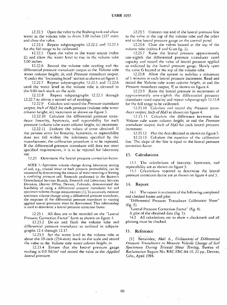
12.23.1 All data are to be recorded on the "LateralPressure Correction Factor" form as shown on figure 4.
12.23.2 De-air and flush the volume tube anddifferential pressure transducer as outlined in subpara-graphs 12.4 through 12.17.
12.23.3 Set the water level in the volume tube atabout the 10-inch (254-mm) mark on the scale and recordthe value as the Volume tube water column height, in.
12.23.4 Ensure that the lateral pressure gaugereading is 0.0 lbf/in2 and record the value as the Appliedlateralpressure.
12.23.5 Connect one end of the lateral pressure lineto the valve at the top of the volume tube and the otherend to the lateral pressure gauge on the control panel.
12.23.6 Close the valves located at the top of thevolume tube (valves F and G on fig. 1).
12.23.7 Raise the lateral pressure approximatelyone-eighth the differential pressure transducer ratedcapacity and record the value of lateral pressure appliedas indicated by the lateral pressure gauge. Slowly openthe valve G located at the top of the volume tube.
12.23.8 Allow the system to stabilize a minimumof 5 minutes at each lateral pressure increment. Read andrecord the Volume.tube water column height, in and thePressure transducer output, V, as shown on figure 4.
12.23.9 Raise the lateral pressure in increments of•/pproximately one-eighth the differential pressuretransducer rated capacity and repeat subparagraph 12.23.8for the full range to be calibrated.
12.23.10 Calculate and record the Pressure trans-
ducer output, Inch ofH20 as shown on figure 4.12.23.11 Calculate the difference between the
Volume tube water COMlnn height, in and the Pressuretransducer output, Inch of 1-120 for each lateral pressureincrement.
12.23.12 Plot the data obtained as shown on figure 5.12.23.13 Calculate the equation of the calibration
line. The slope of the-line is equal to the lateral pressurecorrection factor.
13. Calculations
13.1 The calculations of linearity, hysteresis, andrepeatability are as shown on figure 3.
13.2 Calculations required to determine the lateralpressure correction factor are as shown on figure 4 and 5.
14. Report
14.1 The report is to consist of the following completedand checked forms and plot:
"Differential-Pressure Transducer Calibration Sheet"(fig. 3).
"Lateral Pressure Correction Factor" (fig. 4).A plot of the obtained data (fig. 5).14.2 All calculations are to show a checkmark and all
plotting must be checked.
15. Reference
[ 1 ] Benavidez, Abel A., Utilization/of DifferentialPressure Transducers to Measure Volume Change of SoilSpecimens During Triaxial Shear Testing, Bureau ofReclamation Report No. REC-ERC-84-10, 22 pp., Denver,Colo., April 1984.
90

USBR 1055
(I)APPLIEDLATE RALPRESSURE
°-,•..O
0.0
LATERALPRESSURE CORRECTION FACTOR
(2)VOLUME TUBE
WATER COLUMN
HEIGHT(In)
10.00
(3)PRESSURE
TRANSDUCEROUTPUT
(V)
2 • 999
25.0 10.00 2.994
.50.0 10.01 2.987
7,5.0 10.03 2.980
100.0 10.04 2.973
175.0 10.09
(4)- (d')(3) + (e')PRESSURE
TRANSDUCE ROUTPUT
(inch of H20)
I0.01 0.01
10.06 0.06
10.13 0.12
10.20 0.17
10.27 0.23
2.952
125.0 10.05 2.967 10.33 0.28
150.0 10.07 2.959 10.41 0.34
10.48 0,39
200.0 I0.11 10.55 0.442.945
DetllprlitlonUSBR 10SS-.•_•
(6)ORDERED PAIRS
(1) (5)
0.0 0.01
25.0 0.06
.50.0 0. 12
75.0 0. 17
100.0 0.23
12.5.0 0.28
150.0 0.34
175.0 0.39
2O0.0 0.44
• Valuta obtainedfromdifferentialprmuretransducercalibration.
(d) - - 10.00
(e)- 40.00
Figure 4. - Lateral pressure correction factor --example.
Y
z.zy-mx.b
Assume- b-0. then y- ml
re-y/x-0.44/ZCO- 0.0022Coilbro•ion line eq•mtion: y-OOOZZz
...... L•ll z• 4,4 • 69o 1•7 i,s ,m3 ii,i i.w,, •LATERAL P•ESSU•
Figure 5. - Plot of lateral pressure correction factor -- example.
91