1vlac ro ~~~~mr~l~
TRANSCRIPT

F36P
1VLAC RO ~~~~MR~L~ INTERNAL OPERATIONS MANUAL
PRELIMINARY PRAFT O~$,C~IPTIO~N FOR INTERNAL USE ONLY
,
DIGITAL EQUIPMENT CORPORATION • MAYNARD, MASSACHUSETTS
MACRO
ASSEMBLY PROGRAM
INTERNAL OPERATIONS MANUAL
Prepared by: Robert A. Saunders

Introduction
Input Tape Handler
Initial ization and Title Sequence
Reset Sequence
Symbol Generator
Symbol Processor
Storage Words
CONTENTS
SECTION 1
SECTION 2
3
5
5
6
7
7
8
11
11
Location Assignments ....... 0 • 0 • 0 •• , • • • • • • • • • • • • • • • • • • • • • • • • • • • • • • • • • • • • • • • • 11
Variables and Symbol Definition .. 0 ........... 0.............................. 12
Pseudo-instructions
Constants
SECTION 3
Macro Instructions
~Aacro Instruction Tab les ... " ........ 0 0 • 0 0 •••••••• 0 ••••••••••••••••••••••••••
/\A.a c ro Ins t ru c t ion De fin i t ion s .. 0 0 , • • • • 0 • • • • • 0 , • • 0 • • • • • • • • • • • • • • • • • • • • • • • • • • • •
Macro Instruction Usage ....... , 0 ••• 0 •••••••••••••••••••••••••••••••••••••••
~Aacros Within Macros GO C CI • ~ • • .. 0 " 0 0 "" • ~ :) I!') • 8 G Q () • • • 3 II 0 e • 8 • • • • • • • • • • • • • I. • • • • • • • • •
SECTION 4
Error Alarms
14
17
19
19
20
22
24
25
29
29
Start Over Sequence .......... ,., ...................... 0 • • • • • • • • • • • • • • • • • • • 29
Symbol Package .......... 0 •••••••••••••••• 0 ••• 0 • • • • • • • • • • • • • • • • • • • • • • • • • • • 29
Conclusion 33
APPENDIX 1
Macro Program Listing 35
APPENDIX 2
Macro Instruction Example 105

INTRODUCTION
MACRO FlO-DEC is based on MACRO III, an assembly program for the TX-O computer at
the Massachusetts Institute of Technology 0 The TX-O was built at Lihcoln Laboratory and
is now on loan to the Electrical Engineering Department at MIT. Since the PDP-l is very
similar in its logical design to the TX-O, it was thought worthwhile to prepare a version of
the MACRO assembly program for use on the PDP-l. The program was written in MACRO
language, and originally was assembled on the TX-O. An elementary version of DDT
(see DECUS distribution MIT -2) was also prepared and was used in debugging MACRO. The
present version incorporates a number of improvements over the original, and has been in
use in its present form for several months at MIT.
The program is a two-pass assembler, with a macro-instruction facility which generctes
words from encoded stored model statements. With one minor exception, it is a linear scan
character processor, exam in ing each character once in order on each pass. In order to
reduce wear and tear on input-output equipment, both input and output are buffered. The
tape reading routine has an optional parity check, but except for this, and stripping the
parity bits, the tape handl ing routines are essentially transparent to the rest of the program.
'Ne shall begin our discussion with an investigation of these routines.
3

4
SECTION
INPUT TAPE HANDLER
Each time the main program requires a character, rch is called. Characters are stored three
to a word, and fwd is a counter which indicates which of the three characters is to be read
out next. When a word is exhausted, the next is picked up at rc8, and saved in fwb. --- ---
Normally, control drops through the tests immediately following, fwd is reset to 3, and the
next character is stripped off at rc 1. The character is saved in.!! rcp, and the AC. The
subroutine then returns to the main program.
When the last word is fetched, special treatment is necessary, for as will be seen later, it
may not have three characters in it. The precise number is to be found in nfc, from which
fwd is set when the program reaches rc3.
The next time through rc8, it wi II be found that no more words remain in the buffer, and
control passes to rfb. The buffer indices are reset, and the program commences reading.
Tape will be read until a stop code is encountered, a carriage return is encountered during
filling the last 24 words of buffer, or a parity error is found. Deletes are filtered out, but
all other characters are stored. Sense switch 6 is examined to see if parity is to be checked,
and if it is off, parity is checked. The character is planted in a rotate instruction, which
rotates according to the number of ones in the instruction. Thus, executing this on a word
of alternate ones and zeroes generates a parity. If an error is found, a diagnostic is printed,
and the character as read is displayed in the 10. The type symbol subroutine (tys) is used
for typing. Continue causes the character to be accepted by going to rfa. Start ignores
the character by returning to the read instruction (rf2). Note that the action on Start, if
not otherwise conditioned by the test word, is determined by~. This will be dealt with in
detail later.
The characters are assembled into words directly into storage. The previous contents of the
buffer words are lost by being shifted off the end of the word at rf3. Next we check for
whether the remaining stop conditions are met. Stop codes go to rf6, where the last word has
its characters correctly aligned for the readout routine. The end checks are set up, and
control returned to rc8. If the buffer is within 24 (octal) words of being full, rf4
is set to exit to rf6 on the next carriage return. Since, in the usual MACRO-language
5
typescript, the next character after a carriage return is almost always an ignored tab, no great
harm will be done if the reader cannot stop before the next character.
INITIALIZATION AND TITLE SEQUENCE
From ps2 to pte is initialization for starting or continuing a pass. Complete discussion of the
initialization will mostly be confined to a general description, with specifics being related
at the initialized routines.
The initial entry to the program is at ps5. The program stops at ps 1-1, and on Continue goes
through ps 1, which sets for Pass 1; np 1, which sets up to begin a pass; and through np2, which
sets up to begin processing a single tape. At np2 is a sequence which detects whether there
is a tape in the reader and the reader is turned on. An rpa is given without a wait, and if no
character has appeared in the 10 within about 80 milliseconds, the reader is assumed to be not
ready and the program stops. When the reader is ready, the tape reading routine is initialized
such that the buffer will appear completely empty, and tape will be read as soon as rch is
called.
At pte, flag 5 is off iff (if and only if) a title is to be punched. If it is off, some blank tape
is fed before anything else is done. Next the characters comprising the title are read. Lead
ing stop codes are ignored; and also leading spaces, to prevent blank tape from being consider
ed as spaces in the event that parity is not being checked. Leading carriage returns are also
ignored. The first non-ignored character sets Hag 6, so that spaces will no longer be ignored;
and if the character is a middle dot, flag 5 is set to discontinue punching the title. The
character is typed with completion requested but no in-out wait, and if the character is to be
punched, this is done whi Ie the typewriter is typing. It has been found empirically that six
I ines can be punched during typing one character with negl igible I ikel ihood of the typewriter
completion appearing before punching is done.
The carriage return following the title is detected at pt5, and when it has been found, pass 1
or pass 2 is typed out, followed by punching the input routine, if this is necessary. The
input routine on the MACRO tape, as read into storage, is used as data. Some more
tape is fed, and control passes to .rst.
6

RESET SEQUENCE
The terminating character switches determine MACRO's treatment of the terminating characters
tab, comma, equals, slash, and left parenthesis. The macro-instruction definition indicator
mii determines the setting of these switches. If mii is on (-0), these switches are set to
appropriate parts of the macro-instruction definition routine.
Indicators for each word are reset at rsk and rsw. At rsk, the left and right parenthesis switch
es are reset, and the dummy-symbol pushdown counter prs is set to 00 At rsw I the accumulated
word value wrd is zeroed; the polysyllabic word indicator ~is turned off by clearing flag 5;
the temporary storage nsm, asa, and ~ is cleared (these are used by the slash routine for
determining the symbolic location after a location assignment); the defined indicator def is
turned on; and the dummy symbol indicator, flag 6, which is used by the macro definition
routines, is turned off. At sp, the indicators for each syllable are cleared: the sign of the
next syllable is set positive, the symbol letter indicator is cleared, and so are the overbar
indicator, the syllable value num, the symbol storage sym, and the character counter chc.
Control then falls into the main character processing loop, which begins at ~:
SYMBOL GENERATOR
There are three kinds of symbols which are developed in the main character loop: integers,
pseudo-instructions, and "symbols," which term we shall reserve for sequences of one, two,
or three letters or numerals containing at least one letter 0 Letters and numerals are dispatched
on at !:.., and go to 2 and ~ respectively. Numerals are combined into ~ at~. The current
radix control at ~ multipl ies the preceding digits by eight or ten for octal or decimal. So
that 777777 (octal) yields minus rather than plus zero, a check at n3 does a special treatment
of zero. Letters turn on the letter indicator let and also letters-in-upper liu if in upper case. -- ---Letter and number flow combines at In where the character count chc is stepped and the first
-- ---three characters are combined into a symbol sym at g. If a fourth character is encountered,
~is checked; if a letter has occurred, it is a pseudo-instruction, and otherwise it is merely
a number of four or more digits. Pseudo-instructions cause the P-I name to be saved in api
for error printing purposes, and reset various indicators preparatory to picking up possible
arguments. Additional characters are read until a break character (space, plus, minus, tab,
or carriage return) is encountered, which ends the pseudo-instruction name, and the second
three characters are saved in syn. At the break character, control is transferred to search
7
for the pseudo-instruction name at spm.
SYMBOL PROCESSOR
Symbols are combined by addition or subtraction as indicated by plus or minus signs, which
go to f and ~ on dispatching. All routines which are called at the end of a symbol go to evl,
which evaluates any symbol and performs the indicated arithmetic.
The symbol system is based on the idea that a symbol will be defined relatively infrequently,
but will be used quite often. It is reasonable to spend a relatively long time defining a
symbol if this will make it possible to evaluate it quickly. The symbol table is therefore kept
sorted at all times, and a binary or logarithmic search is used to evaluate symbols. For those
not famil iar with the idea, the remainder of this paragraph is devoted to a discussion of the
principle. Consider a dictionary, in which it is desired to locate a word, say pen. First
look in the center of the book, and determine whether the word found there is before pen,
after pen, or pen itself. If the word is before pen, which is I ikely to be the case, look next
in the center of the back half of the book. Suppose the word found to be tree. Now pen is
known to be before tree, so we next look in the center of the preceding quarter. The process
is repeated, dividing the word list by two each time until the word is found. It is apparent
that if there are two to the nth words, a maximum of n lookups are required, and the average
number will be n-1.
To secure an alphabetic ordering of the symbol table, it is necessary to modify the codes of
the letters so that the concise code is converted to alphabetic order. The easiest way to do
this is by "inverting the zone bits," i.e., complementing the highest bit of each character if
the next highest is a 1. This is done at the permute zone bits subroutine per, which also
complements the sign bit. The transformation is reciprocal, i. e., permuting a permuted
C:"n"IbOI Iln_nern"lllt.c~c: it Thic: fort ic: IIC:COrl hy the corror nrint routinco <J/I.I • v •• ,., •••• VI"' .... '.., II. II •• ..., t __ I • .." """..., ....... "-"1 IIoJ Ii" ................ ,' I •• 1' ...... ~
Returning to evl, we see the symbol permuted, followed by a check of the macro-instruction
indicator mii. If it is on, control is transferred to wsp to check for dummy symbols. If it is
off, .!.:! is checked; if it is on, a symbol table search is necessary, otherwise the number
(integer) is combined into wrd. It is also combined into amn, which accumulates the numeric
part, if any, of a word for determining the new symbol ic location in the event of a location
ass ignment.
8

Location assignments are also dealt with at ~~ where the symbol, if any, to be used in a
symbolic location is determired, There is a three state indicator ~~~, which is initially + 0,
and is set to + 1 after the first symbol of a word, and to -1 after any other symbol, It is also
set to - 1 in the event of a symbol preceded by a minus sign, for such a symbol cannot be the
symbolic port of a symbolic location, Further discussion of this point will be postponed until
a complete investigation of location assignments"
The logcrithmic search begifls at e20 There is a shift counter...!2. which constructs the repeated
increments to the address in the symbol table 0 The table is stored from register 7750 down,
with the symbols in even-numbered reg isters and val ues in the next higher odd-numbered
registers, Register 7750 is called ~ow and contains lac the lowest address in the symbol table,
T~e first location examined is that contained in low, and hence the lowest entry in the table.
Succeeding addresses are computed as necessary, but the contents thereof are not examined
until it is determined that the address does in fact lie in the symbol table, The decision as to
whether to go up or down is seen to involve the overflow indicator (initially cleared at
e2+ 2) _ This is Q consequence of the fact that the symbols can assume all possible arithmetic
values_ Here the reason for complementing the sign bit becomes apparent 0 The table is
arranged in numeri ca I order, with the most negative number, orig ifla II y the sma II est positive
number! at the bottom, It will be seen that if an overflow occurred, the sign of the result
will be exactly the opposite of what it should be to move the search in the correct direction.
Thus we do a skip on no overflow, and overflow causes a complement 0 Next we do a three
way branch to move the search UP, down, or exit on finding the symbol in the table, The
remaining portion of the routine at eqt is related to variables and will be discussed later.
It will be seen that the maximum size of the symbol table must be a power of 2, since the
shift counter is halved at each iteration and the search must always move an integral number
of registe r ,_ The maximum corresponding to the initial value of the shift counter will never
be real ized '1'1 practice, for the symbol table would first coil ide with the top of the macro
instruction or constant table, The top of the latter tobles is kept in register hih, and a
col! ision results in an alarm of storage capacity exceeded,
Also in evl is a subroutine ed whose purpose is to frustrate the PDP circuitry that filters out --- --
minus zeroes on addition _ Additions to wrd are done throug!l i-his subroutine" This assures
that when on expression such as (777776+ 1) appears in a source program, minus'ero and
"'0 t P II.J ~ z e tOw I II be the res U Ito
9

10

SECTION 2
STORAGE WORDS
The storage word term ination routine places words in the punch buffer, counts the location
counter and determines when punching should take place. Control is passed to the punch rou
tine on Pass 2 whenever the location gets to a multiple of 100. This results in convenient
sized binary blocks. There is a subroutine sch which checks ~ and chc to see whether any
thing occurred since the last tab, carriage return or other terminator; if something has, the
next instruction is skipped; otherwise the terminator is redundant and is ignored, since the
next instruction returns control to r.
This routine is used as a subroutine by the macro-instruction processor and constant routine.
LOCATION ASSIGNMENTS
The location assignment character <I> enters at b. If preceded by a word terminator, it de
notes the beginning of a comment, and control passes to itc to ignore characters until the
next tab or carriage return. Otherwise, evl is ca lied and the new location is set up. First
the symboiic iocation is constructed according to the following rule: A symbolic location
exists if the location can be expressed as symbo I + number, where th.e number may be o. In
the event that the assignment is expressed as the sum of symbols, the old symbolic location,
if any, is retained. If the assignment is purely numeric, asi is turned off (-0) and asm and
ami are cleared, since asa and ~ will contain zero. Otherwise, the alarm symbol indi
cator is left on (+0), and asm contains the symbolic part of the location, and ami the
numeric part.
If, on Pass 1, a location assignment contains an undefined symbol, the location is considered
indefinite, which fact is denoted by a negative number in loc. If the location is definite,
loc is set from wrd at bnp. The location is taken modulo machine size, while the sign bit is
preserved to retain whether or not the location is definite.
On Pass 2, an undefined symbol in a location assignment causes an alarm, but the location
does not become indefinite, for the undefined symbol is simply ignored. If the assignment is
defined, or on recovery from an alarm stop, wrd is taken modulo machine size and compared
11
with loc, If the two are identical, it is not necessary to start a new block, and the routine
exits to b",p, if they are different, control passes to pun, with the new location saved in wrd
wh i I e pun uses the old one to punch out the block.
At El!~.f the location is compared with the block origin to determine whether there are any
words in the punch buffer. if there are not, it exits at once to bnp to set up the next block.
It also exits if the punch indicator pun is off. If punching is to be done, the first and last ad
dress me punched, followed by the contents of the punch buffer, fol iowed by a checksum
which is the sum of all other words in the block. Register ~ is a counter which counts through
the buffer I and the checksum is kept in ck 1. Punching of each word is done by a subroutine
E~b which displays the origin of each block in the AC as punching is done, enabling the oper
ator to observe the progress of the assembly. Five lines of blank tape are punched at the
beginring of each block.
After the block is completed, the new block origin is taken from wrd, where it was saved,
and put into org 0 The punch buffer index ts is reset, and the routine normally exits to rnw.
VARIABLES AND SYMBOL DEFINITiON
There are three basic ways to define symbols in MACRO: by parameter assignment, by ad
dress tag, and by variable definition. The appearance of a comma directs control to the
address tag routine. If the location is indefinite, the routine exits at once; otherwise, evl IS
called 0 if the word preceding the comma is defined, its value is compared with the location
counter; if they differ I an error is flagged at mdt. The symbol field on the error printout
contains the tag if the tag consisted of one symbol; otherwise sym is cleared before the error
is called, After retufl", or if the definition was correct, the new symbolic location is
determil1ed. In the event that the tag was polysyllabic, the old symbolic location is re-
taired 0
Should the word preceding the comma be undefined, the routine exits at once if the tag was
polysyllabic; otherwise the symbol is defined at vsm, and the new symbolic location is deter
mined as before 0
Parameter assignments go to the parameter assignment routine at the occurrence of the equal
12

root bear an overbar, l.f these requirements are met, the symbol is saved in scn (which is also
used by the macro-instruction processor), and the terminating character switches (bt for bar
(slash) l .9~ for equal sign, ct for comma, .!! for tab and carriage return) are set so that any ter
minator other than tab or cr causes an alarm. The routine then exits to rnw to await the
expression for the value.
When the terminator occurs, the routine exits in the event nothing has appeared; and other
wise calls evl, If it is well defined, control passes to q2 which saves the value, and then sets
up indicators so that evl may be used to determine whether the symbol on the left of the equal
sign was defined 0 If it was, the new value replaces the old one. If it was not, it is defined
by vsm and the routine goes to reset. If the expression on the right was undefined, the
attempted defin ition is ignored on Pass 1, and causes an error comment on Pass 2.
Variables are handled at evl by a variety of routines. The logic is that we must first have a
symbol 0 If the symbol is defined, nothing further is done unless it has an overbar. If it is
defined as -0, on Pass 1 we act as if it were really undefined and exit, and on Pass 2 we re
define it to the correct value which is the sum of the variables origin (as determined by the
location of the pseudo- instruction variab les on Pass 1) and the variab les counter I wh ich
counts the different variables as they are defined. If it is defined as other than -0, on
Pass 1 we give an error alarm (for this implies it was defined in a conflicting manner else
where) I and on Pass 2 we ignore it, assuming that a previous occurrence has caused it to be
defined correctlyo Thus, on Pass 1, we go defining all variables as -0, and on Pass 2 we
redefine them to their correct values as they occur? The scheme avoids requiring a separate
list of variables, as they are stored in the main symbol table at all times, but has the dis- I
advantage that the first appearance must have an overbar, or the variable will be incorrect
I y eva luated as -0.
The actual defining of symbols is handled by the vsm routine. Since the symbol table is
maintained sorted at all times, vsm must locate the correct place for the new symbol and
move all lower symbols d:)wn two registers to make room for it. The routine starts at the
bottom of the symbol table and works its way up, using the overflow indicator in the same
way that it is used in the logarithm ic search, At the outset a check is made to see whether
all of storage has been used; if it has, an err'Of comment is made.
13
PSEUDO-!NSTRU( nONS
The pseudo-instruction system uses a form of list structure in the principal table, which begins
at mai. There are two relevant registers, mai and psi, which contain indices to the table. --- --- --
From mai-f-l to npi-l are the system pseudo-instructions arranged in a three-entry table. The
first two entries are the name of the pseudo- instruction and the last is the location to which
control is to be transfer~'ed in the event one is found. Index psi is a pointer to the last pseudo
instruction name in the table 0 If there are macro-instructions defined, it points to the last
macro name. At npi the macro storage begins. Each macro block begins with three registers,
of which again the first two contain the name, but the third entry is now a pointer back to
the beginning of the previous macro or pseudo name. These po inters contain law in the in
struction part, and the negative sign is used to distinguish these pointers from pseudo
instruction locations. These considerations dictate the form of the search for the pseudo or
macro name.
First we load the 1-0 with mdi, which is an indicator which is on (negative) if this name is
that of a macro-instruction to be defined. Then we look at the last name defined, via the
po inter psi 0 !f the first three characters match, the second three are checked. If these
match also, we either go to the mdm alarm if we are trying to define a macro of this name, or
go to the appropriate routine 0 If the sign of the pointer is negative, we have a macro name,
compute tile beginning of the macro information storage and go to mac. If it is positive, the
pointer addresses the location containing the location to which control is to be transferred.
If the first three match but the second three do not, it is recorded in flag 2 that at least one
approximation to the correct name has been found, and the location is retained in sp5. The
search is continued until either the correct name is found or the table is exhausted. If no
name is found, and the name being searched is the name of a macro being defined, controi
passes to dmi, define macro instruction; if an approximation has been found, we go to the ap
propriate routine as before. If all the preceding fail, the name is undefined and causes an
alarm at 'p~.
The va r ious pseude= ins~ruc Hens are fa iii y straightforward in the ir execution. Charae ter and
Flexo treat their arguments in an obvious manner. Text checks rqc, which is negative in the
14

which is saved in t2. Register tl counts the characters in each word. Until the terminating
character is matched, complete words are sent to the storage word routine, or to the storage
word part of the macro processor if in a macro definition. When the terminator is matched, the
last word is filled out with zeros (spaces) as necessary, and after it is disposed of, the routine
exits through the storage word routine to ~.
The pseudo-instruction Repeat sets all terminating switches to illegal format except comma, tab,
and carriage return and then exits to pick up the count. The term ination of the count goes to
rql, which checks definiteness and for a positive or zero count. If all is well, the pointers for
the readout of the flexo I ist are saved in private temporary storage, and carriage returns are
arranged to trap. The routine exits to reset. Each succeeding carriage return is counted until
the count runs out; until it does, the flexo pointers are restored to their old values and the
character reader re-reads the characters. When the count runs out, the carriage return switch
is restored and the routine exits. The reason Text is not allowed in a Repeat is to ensure that
all characters required by the Repeat are in storage. Otherwise, rfb might have stopped read
ing tape on a carriage return in the Text (and therefore, inside the RepeatL and the trick of
restoring the po inters wou Id not work.
Start causes a complaint if it occurs in a repeat or macro definition and otherwise sets the
terminating switches to pick up the starting address. The address termination returns to ..:'
where on Pass 1 the program is stopped ready to begin Pass 2, and on Pass 2, if everything is
definite, the address is saved and the punch buffer dumped. The origin for a continuation
tape is set up from loc, and the program stops. Continue punches a start block if pch is on,
preceded and followed by some blank tape. The program again stops, and Continue begins
Pass 1 anew retaining all symbol definitions. The contents of soy control action on Start.
The variables pseudo-instruction is considered illegal if in a macro definition or in a region
of indefin ite location. Because of lim ited storage, variabl es may be used onl yonce. If re
peated usage were allowed, two entries would be required for each use; as it is, the two
numbers are kept in val and va2 which are the beginning of, and the first free register after, -- --
the variab les storage. AI though a count of variab les is kept on Pass 2, it is necessary to
record the first free register, because in the event that the operator should desire to repeat
Pass 2, the variables count would be zero as all variables would be correctly defined on the
15
first Pass 2. On Pass 2, a check is made to see that the pseudo-instruction location agrees with
that found on Pass 1, and if it does not, there is an alarm. If all is well, a location assignment
is simulated to leave room for the variables, and the program continues.
The pseudo-instruction dimension causes symbols to be defined as variables, with the variables
counter being advanced according to the size of the array. Term inating switches are set up so
that ,commas are ignored, left parens save the symbol in ten (and check flag 5 to make sure
only one symbol appeared), and right parens do all the work. The array size is evaluated and
checked for defini teness. The saved symbo I is then looked up. On Pass 1 contro I goes to di3
wh ich, if the symbol is undefined, defines it as -0. On Pass 2, the correct defin ition is con
structed. On both passes, the variables counter is suitably advanced and the routine exits.
The terminators are restored when a carriage return or tab is encountered.
The pseudo-instruction constants is quite similar to variables in its operation. The values of
the constants are stored in order in the macro-instruction table above the last macro defini
tion, starting at a register whose address is kept in~. On Pass 1, the location is advanced
according to the total usage of parenthesis operators, whether or not any identical constants
occur, and the location of the beginning of the constants storage is saved in the first entry of
the constants origin table. On Pass 2, the stored constants are dumped into the punch buffer
via the storage word routine. There is no ambiguity as to how far to advance the location
counter, as the number of parentheses, which is kept in nca, must be the same on both
passes. The number or different constant values is determined by nco, which will generally
be less than nca. Storing the constants on top of the macro definitions has both advantages
and disadvantages. The primary advantage is economy of space in the assembler, for all of
the available table space must be used before the tables collide, and any saving in one table
is automatically available to the others. The major disadvantage is that an unnecessarily
large block of space may be reserved for constants in the assembled program. To avoid this,
it would be necessary to save the values of constants on both Pass 1 and Pass 2, leaving one
register in the reserved storage area for each constant which is undefined at its appearance on
Pass 1, plus whatever is required for the defined ones. Since in general there will be con
stants used before all the macros are defined, putting the constants on top of the macro table
is not feasible in this scheme. The constants are placed in the constants table by the con
stant table search routine which wiii be discussed iater.
16

Although it is not done here, it is quite possible to check for agreement of location of the
pseudo-instruction constants on Pass 1 and Pass 2. If they disagree, it is clear that the result
on the assembled program would be disagreeable, as all preceding constant syllables would
have been incorrectly assembled. It should be pointed out that the second entry in the cor
table is set up on Pass 2 and is used only by the symbol package for printing out the constants
areas.
CONSTANTS
Constants syllables are enclosed in parentheses. Left parentheses norma Ily go to .i.e., and
right parens go to !:.! from which they go to .p unless there is no matching left paren, In
which case control goes to ilf. There is a four entry table (cvl-cv4) in which are stored the
macro-instruction dummy symbol pushdown counter (described later), wrd, the sign preceding
the left paren, and whether wrd is defined. There is a subroutine pi which handles the
indices on the cv tables which is called here to move the pointers up one level. If the table
overflows, control goes to tmc for an alarm. The first left paren saves all the terminating
character switches in private temporary storage and sets them to go to the constant evaluating
routine or ilf. In either case, control then goes to rsw to reset all storage associated with
words and syllables. The value of the constant is then accumulated.
Right parens now go to rp, which evaluates the constant, and if not in a macro definition,
calls co which files the constant in the constant list and returns the location in which it will
be stored. The appropriate sign is applied, and the value is added to the previous value of
wrd. Again pi is called, this time to move the pointers down one level. The indicators for -- -syllables are then reset, and if the routine was entered from a right paren, the routine exits
to process the next character in sequence. The word terminators comma, tab and cr also
enter at rp, but when finished they go around again until the level is reduced to zero. The
check for carriage retum at rp3 is a patch that was put in to fix a bug in the repeat logic.
When the level is reduced to zero, the term inating character switches are restored to their
original values and the routine exits to the appropriate switch.
The co routine is straightforward. The constants appearance counter nca is stepped, and on
Pass 1 the routine exits at once return ing -0. On Pass 2 def is checked, and if any undefined
17

symbols appeared, an alarm is flagged. The search for a matching constant begins at the bot
tom of the constant table, to which con points. If a matching value is found, at co6 the
position in the table is found, added to the current constant origin, and returned as the value
of the syllable. If the search is exhausted unsuccessfully, the pointer to the top of the table
nco is increased by one and, if there is any storage left, the new constant is added to the
list. The value of the syllable is then constructed as before.
There is a fairly large amount of initialization for the constants routines at np 1. The top of
the macro instruction I ist is used to determ ine con, and nco po ints to it unti I there are con
stants in the table. The constants appearance counter ~ is cleared, and the constant ori
gin indices are set to zero. The pseudo-instruction constants also clears nca and nco and -- --advances the constant origin indices.
18
SECTION 3
MACRO iNSTRUCT,ONS
The macro instruction facility in MACRO is both the strongest and weakest part of the program.
It is the strongest in the sense that it is thot part of the program which contributes most toward
ease of programming, especially in setting up tables of specialized format. It is the weakest
in that it is quite inflexible and does not incorporate any of the more significant improvements
in assembler technology that have occurred since the logic was first written in 19570
There are two frequently used ways of organizing macro instruction storage: either the input
characters comprising the definition are stored away, with dummy symbols usually marked in
some special way, or the input characters are partially assembled, and the assembled words
are stored with provision for inserting the dummy symbol values when the macro is used. The
first scheme requires a relatively large amount of storage for macro definitions and has con
siderable complication in the treatment of dummy symbols if macro calls are permitted within
macro defi n i tions. However, the rest of the assembl er can be used as a subrouti ne when the
macro is called, and considerable flexibility is available in the use of dummy symbols, since
an entire character string can be inserted as, say, part of a macro to print a message on the
on-line typewriter. The second scheme realizes some economies in macro instruction storage,
particularly if macro calls within macro definitions are relatively infrequent, and has a
slightly less involved treatment of dummy symbols. The principal disadvantage is that dummy
symbols can not supply other than numerica I va I ues to the compiled instructions without a
large amount of involved coding 0 It is the second scheme which is used here.
Before delVing into the mechanics of macro operation, we should consider some implications
of macro calls within macros. Firstly, a macro definition within a macro definition is not
allowed. Macro calls within macro definitions are allowed, and dummy symbols from the
definition are allowed to be used in the macro call, A macro call cannot have any effect
on the macro being defined except possibly to insert additional storage words into the def
inition, Thus it is not possIble to have a macro call a macro which does nothing but, say,
double an argument of the first macrou Calling a macro within a macro definition causes
t"'e data for the called macro to be re-copied into the data for the macro being defined,
19

with no change except such as may be required for the proper translation of dummy symbols.
With this background, we can examine the macro processor in detail .
MACRO INSTRUCTION TABLES
The best place to start is with an examination of the macro-instruction table structure. The
principal table is mai" After the pseudo-instruction data, the first word is a code word con
sisting of code bits which are read from left to right. The other entities in the table are
identified by these bits 0 The code combinations are as follows:
o denotes a storage word 0
10 denotes a dummy symbol specification.
110 denotes a constant.
1110 denotes a dummy symbol parameter assignment.
1111 marks the end of the macro definition.
Subsidiary combinations are used after these identifiers as necessary.
The 'order of entities is as follows: First wi II appear any relevant dummy symbol specifications.
Next will appear one of the other entities, with which all of the dummy symbol specifications
are associated 0 Parameter assignments and storage words are the lowest order, and they may
incl ude constants 0 If a storage word or parameter assignment contains constants, and both the
word or assignment and the constants contain dummy symbols, the dummy symbols within each
constant appear first, followed by the constant designator, followed by dummy symbols for
the word or assignment, followed by the word or assignment data.
Each dummy symbol specification code bit pair is immediately followed by seven more bits
which specify the dummy symbol sign and the dummy symbol number. The six bits for the
number are written in reverse order. A!! these bits are written into the table by seQ and
scz, store code bit one and store code bit zero. The writing of the dummy symbol specifi
cation uses an additional routine wro which calls sco and scz. There is a corresponding
routine ~ which reads dummy symbol specifications.
Storage words store one additional bit which is zero or one depending on whether the word
is zero or non~zero, respectively. If the word is non-zero, it is stored in the macro instruction
table 0
20

Constants and parameter assignments are very similar in that both have associated a value
and a dummy symbol number. The val ue is treated as it is in storage words. The dummy
symbol number is treated as in dummy symbol specifications, except that the sign bit is
used to tell whether this is a new dummy symbol (denoted by a 0) or a redefinition of an
old one (denoted by a 1). Constants behave like parameter assignments in that their effect
is to define a new dummy symbol whose value will ultimately be the location of the stored
constant.
The net result in the mai table is an assortment of codewords and value words. The type of
any particular word is determined by the preceding codeword in an el ementary manner: the
first word is a codeword, in which one writes bits until it is full; then one starts on a new
codeword. Any value words which occur in the meantime are stored in order after the code
word, and the new codeword is put in the next available space. As there are routines for
writing code bits, so is there a routine for testing them: tcb, which is used when a macro is
ca II ed. Its operation wi II be considered later.
Also used by the macro processor is a set of erasable tables. First there is dsm, the dummy
symbol table, which has the flexo codes of defined dummy symbols. Each dummy symbol
has a number which is its position in this table. Dummy symbols are numbered sequentially
in order of definition starting with R, which is always defined and is dummy symbol number 1 .
Next there is dss, the dummy symbol specification table, which is used when defining a new
macro-instruction in terms of an old one. The ~th entry in dss , gives the dummy symbol in
the macro being defined corresponding to dummy symbol '2.. in the one previousl y defined.
The first entry is always 1, since dummy symbol R always transforms into itself. An entry
of -0 means that there is no dummy symbol in the new definition corresponding to one in the
old definition because the value of the old dummy symbol has been determined by some means;
for example, if first A had been defined, and second had been defined as first 1, there is no
dummy symbol in second corresponding to A in first, because A now has a definite value,
i 0 eo, 1.
Next in the list is dsv, the dummy symbol value table. It contains the values of all the dummy
symbols when a macro instruction is used.
21

Finally there is pdl, the dummy symbol pushdown list. The pdl table is used to ensure that
the order of dummy symbols fed into the mai table corresponds to that described above.
Pointers to this list occur in cv]. As constant levels build up because of left parentheses,
pointers in cvl mark the beginning of each level. When left parentheses reduce the level,
all the dummy symbol specifications down to the next level are stored and a constant assign
ment defines a single dummy symbol on the lower level whose value is the loca~ion of the
constant. The dummy symbol specifications in pdl are stored by prs, prepare specifications;
and all specifications at anyone level are stored in mai by ~, store specifications.
Since we have doubtless by now left the reader in a sea of confusion, without further ado
we will enter into a description of how all this is done in the hope that some clarity may
yet be ach ieved 0 The reader is advised to construct some macro definitions and examine
the resul ting mai tabl e in an actual assembl y for further examples of how all of this works.
An example is given here in Appendix 20
MACRO INSTRUCTION DEFINITIONS
The appearance of the pseudo-instruction define marks the beginning of a macro definition.
Control passes to dfn, where the first test is for whether a macro definition is already in
progress. If it is not, terminating switches are set so that equals and comma are illegal,
slash for anything other than a comment is illegal, and tab or carriage returns other than
redundant ones are illegal. The location counter is saved in ~ and zeroed. The symbol ic
location is killed, and the macro define indicator mdi is turned on. The macro instruction
pointer is boosted to leave room for the pseudo-instruction information, and the routine
exits to ~ to await the name of the macro being defined. When this has been read and
checked for multiple definition (see Search for Pseudo-instruction), control passes to dmi .
Here the name and other pseudo-instruction data is set up, but psi is not stepped as yet as
recursive definitions are not allowed. The macro define indicator is turned off, and the
macroinstruction indicator is turned on. The dummy symbol counter is set to zero, the
specification pushdown counter is set to zero, and the terminators are set to pick up
dummy symbols. Dummy symbols terminated by tab and carriage return go to pdl and pds,
respectivel y. Checks are made to see that legitimate dummy symbols are used, and if all
is well, the dummy symbol is filed in the dummy symbol table at dd. The last dummy
22

symbol, followed by a carriage return, sets the define exit to go to reset terminating character
switches. It is possible to check for duplicately defined dummy symbols, but it is not done
in th is version of the program.
Reset terminating character switches sets the switches to go to the appropriate macro definition.
routines. Dummy symbols appearing in expressions are detected at wsp, which is logically
part of evl. Search for dummy symbol sds is called after the sign is set up, and the next
instruction is skipped iff the symbol is defined. Subroutine E: enters the specification for
the dummy symbol in the dummy symbol pushdown list.
Storage word terminators (tab and :..r) go to sw. If there are undefined symbols in the word,
there is an alarm, otherwise, the alarm location and location counter are stepped and control
goes to~, wh i ch stores the dummy symbols from the pushdown list, and then to smb to store
the word after the code bits are written. Final exit is to rnw. Register tea is a temporary
for subroutine exit addresses (hence the name) .
The equal sign in a dummy symbol parameter assignment goes to da. I f the symbol to the
left of the equal sign is in good order it is saved in ten and the terminators are set to pick
up the expression for the value. The terminator traps to dal where the usual checks are
made. The saved symboi is then looked up in the dummy symbol table. If it is defined,
a negative sign is attached to flag this as a redefinition; otherwise dd is called to define
a new dummy symbol. Note that sds returns the dummy symbol in the 10 where it is used
by dd. Next~p is called, which writes the appropriate entries in the mai table. Final
ex it is to rs t to res e t th e te rm i na to rs .
Constants in a macro definition go to JJ: and ~ as before, but are treated differently at
~. Instead of calling co, control passes to rp8, which first calls ~c to write a constant
entry in the mai table, and then defines a new dummy symbol (whose flexo name is zero)
whose number is used to complete the entry in the mai table. A specification for the newly
created dummy symbol is written on the specification pushdown list, from which it will be
filed in the mai table preceding the entry for the entity in which the constant has been used.
After this, we go back to rp5 to move the pointers and restore the terminators if necessary.
The macro definition is ended by the pseudo-instruction terminate. This is illegal if not
23

in a macro definition. The location counter is restored, the symbolic location cleared,
.nd the macro~instruction indicator turned off. The pseudo-instruction index is set to
include the new definition, and four ones written into the codeword. The last codeword
is rotated around into the correct position and stored in the mai table. The routine then
exits to rst to set the terminating characters to normal assembl y position.
To conclude this part of the macro definition procedure, let us turn to the code bit routines.
The two entries sco and scz both save the return address, and save the bit to be stored in
~ which cannot be in use at the same time. The bit counter ~ is stepped, and until it
overflows, control goes to sc4 where the new bit is added to the current codeword which
is stored in sew 0 When a codeword overflows, it is stored in the mai table at sc3, and then
sm, store word in mai is called. It does not store anything useful, however; it merely is
used to locate the point in the mai table at which the NEXT codeword will be stored. The
reason for th is is of course that the codeword must precede any va I ue words wh i ch may be
associated with it. The lio i sc3 makes the code bit routine transparent to the 10, which
fact is used by ~.
MACRO INSTRUCTION USAGE
We will defer until later any discussion of macro calls within a macro definition. Assume
a macro has been called, and mii is off 0 The pseudo-instruction search routine goes to
~, where the address of the first word of macro data, as determined by spm, is saved
in ~I which is the general pointer for reading out of the mai table 0 The terminating
switches are set to pick up the arguments (if any)! and the dsv table is cleared .Control
now passes to ~ to pick up the arguments.
Commas terminating arguments go to ae 1, from whence evl is called, and if the argument
is defined, its value is stored in the dsv table at ae4. The routine exits at ae6 until the
last argument is terminated, when control passes to al1'l"'.
Assemble macro-instruction into program (~) reads and dispatches on the principal code
bits. The code bit tester returns to one after the call if the codebit is a one, and goes to
the address in the AC if the codebit is a zero. Stordge words go to awm. There are two
nested subroutines here: rw, read word, which gets the next word out of the mai table;
24

and~, which checks the zero-nonzero codebit and calls rw if necessary. Note that rw
leaves the number in the AC, the 10 f and in ~. It is added into wrd by the ed add routine,
and if not in a macro definition, the complete word is filed in the punch buffer by the stor
age word routine.
Dummy symbol specifications go to.5::' where the dummy symbol number is read. The sign
bit is saved in ~ and used to set up the sign operation at as6. When not in a macro def
inition, the dummy symbol value is read next and added into wrd by ed. The routine then
exits to am 1 to read the next principal code bits.
Constants go to~, where the value word is read and, if mii (which ~ returns in the 10)
is off, ~ is ca II ed and the location of the s,tored constant put in wrd. The new dummy
symbol which represents this constant is then stored in the dsv table. The routine then
exits to ami, which clears wrd. The expression in which the constant syllable was used
will have a dummy symbol specification for the associated dummy symbol, and it is by this
means that the correct value of the constant syllable will appear in the expression. This
obtains complete generality with respect to usage of dummy symbols within and without
constant syllables of arbitrary depth.
MACROS WITHIN MACROS
We are now prepared to deal with the question of macro calls within macro definitions.
The macro being defined will in general have associated dummy symbols. The index to
these symbols is saved in dsl as soon as control gets to mac. In addition to clearing the
dsvtable, we now clear the dss table in order to make the routines work in the event of
unsuppl ied arguments, which are taken as zero. Now the arguments are picked up. These
may contain dummy symbols, which by the time the terminator occurs, wi II have been en
tered on the pushdown I ist and wi II have set the dummy symbol i ndi cator. If th is has oc
urred, a new dummy symbol will be defined which represents the argument dummy symbol or
symbols, and a parameter assignment will be written into the mai table to signify this fact
by the routi ne at ae7 . Furthermore, the number of th is dummy symbol as it wi II be used
in the macro being defined is entered in the dss table in the position corresponding to the
dummy symbol used in the previously defined macro. If an argument contains no dummy
25

symbols, the dss entry is made -0 to signify that no new dummy symbol need be included
when reading specifications for old ones. The old dummy symbol may be said to be
inactive 0 Constant syllables appearing in arguments are treated as elsewhere: a new
dummy symbol is defined whose val ue wi" be that of the constant. Th is is taken care
of by the ~ and.!:£.. routines as we have seen before. Note that this is done whether
or not the constant syllable contains dummy symbols. After the arguments are completed,
control goes to am as usua I .
At~, we insure that the specification pointer is reset and start reading codebits. Storage
words go to mw instead of tb3 after reading out of mai, and thus get stored back into mai
for the new definition. Arguments, after reading the sign and dummy symbol number, go
through as8 instead of skipping to as5 and examine the dss entry. If it is zero, there is
no new dummy symbol to worry about and the dummy symbol value is picked up as usual.
If it is not zero, there is a dummy symbol, which has the proper sign applied and then is
entered on the pushdown I ist. I f the dummy symbol number is 1, then the va I ue is added
into wrd, as this is the onl y way that the location counter as used in the macro being de
fined can get into the macro being read. If it is anything else, the dummy symbol value
must not be added in at this point, for it will be included when the macro being defined
is ultimately used. To see this, recall that 1) if the argument included dummy symbols,
a dummy symbol assignment was written which included the value, and 2) if the argument
di d not i ncl ude dummy symbols, the dss entry is zero and the va I ue wi II be added here.
Constants go to ~, where, after reading the value! we call mc to rewrite the value for
the new definition and then go to ac 1 0 Here we read the associated dummy symbol
number which we will then look up in dss. If the sign is positive, this is a new dummy
symbol and dd is called; the new dummy symbol number is then entered in the dss table.
If the sign is negative this is a dummy symbol redefinition and the old dss entry is ex
amined to determine whether this dummy symbol was active before 0 If it was, nothing
more need be done, as the old dss entry is correct; if it was not, a new dummy symbol
must be defined 0 In any case we leave cc with an active dummy symbol. The new dummy
symbol number is then written in the mai table to complete the constant entry, and we
return to ami 0 It would appear that the dummy symbol value should be entered in the
26

dsv tabl e, but in fact th is is not necessary, as the dummy symbol wi II be referred to onl y
once in whatever the constant is used in, and this reference will not refer to the dsv table
since the corresponding dss entry is not 0 or 1. (See discussion of as above for elaboration
of this point.)
Dummy symbol assignments read the dummy symbol value from the mai table, then enter
it in the dsv table 0 If the dummy symbol defined includes no dummy symbols in its value,
we go to aa 1 where we clear the associated dss entry to signify this. If it does, we call
~ as was done with constants to activate a suitable dummy symbol. A pardmeter assignment
for this dummy symbol is then written into the mai table, and the routine exits to ami.
Encountering the code for the end of the macro definition restores the dummy symbol counter
dsk to its old value, effectively undefining all dummy symbols associated with the called
macro 0 Control then passes to rst to reset and continue with the definition 0
27

28

SECTION 4
ERROR ALARMS
We have seen that a fairly large amount of error checking is done during the assembly pro
cess, and we should consider briefly the diagnostic routine. Most errors transfer control to
an appropriate calling routine which determines the point to which to return, the particu
lar routine to which to go, and the name of the error 0 The error routine proper has two
entries, one for errors which print in the fifth field of the error listing and one for those
which do not. The return point is put into sov and the name of the error picked up and
printed out 0 Next the absolute location is printed if definite, or ind is printed if it is not.
Next the alarm symbol indicator is tested, and if there is a symbol ic location it is printed.
Next the last pseudo-instruction used is printed. If there is a fifth field, it is printed at
also Completion of an alarm printout is followed by a carriage return. Next the test word
is checked to see whether immediate continuation is desired, and if it is not the machine is
stopped 0 Continuation returns to the appropriate routine. There is some extra coding to
make sure that the columns line up correctly if the symbolic location or api fields are
vacant 0
START OVER SEQUENCE
The first rcutine in the program is the sequence that determines action on depressing the
start key 0 We have seen that sov contains the address to which control is transferred on
Start unless test word switch 0 is on. If it is on, the switches are placed in the 10 and the
first five registers of temporary storage are set in order to 1 or -0 depending on whether
the associated switch is 1 or O. If the continue pass bit was on, control g08S to np2,
otherwise r.ontrol goes to ps 1 or ps4 for Pass 1 or Pass 2, respectively.
SYMBOL PACKAGE
The symbol package is a six I ink chain. The routines sit in the temporary tables and use
appropriate parts of the main program as necessary 0 The first I ink is symbol punch. If sense
switch 1 is off or gets turned off, the routine exits to the input routine to read in the next
I ink. If it is on, we first feed some tape and then I isten for characters from the on-I ine type
writer. These are punched by the title puncher in the main program which returns control
29

to Is. A tab termination goes to .!.:? which I istens for ~ or ~ for symbols or macros. If
symbols are to be punched sps-l will have imp sps which will punch the symbol table and
then go to the macro puncher if flag 5 is off signfying macros are wanted too. If just macros
are wanted, we go at once to the macro routine.
Both the symbol and macro punchers use the end subroutine which copies the appropriate
storage into the punch buffer and transfers control to pun+6 when the buffer is fu II or the
end of the macro or symbol table is reached. When punching a block is done, control returns
to pcb+ 1. Flag 4 gets set on the last block, and finding it on causes the subroutine to exit
through psx.
The macro punch will punch macros only if some have been defined. If some have, end is
called. At the end of the job some blank tape is fed, followed by punching a start block.
Some more tape is fed, and the routine goes back to the input routine.
The next link contains a text printing subroutine, the initial symbol table, and the con
stants area printer which will run if either switch 2 or switch 3 is on. A pointer to the
cor table is checked to see whether any constants areas were designated, and if none were,
the routine exits to the input routine. Otherwise, pss is checked, and constants origins
are dumped on Pass 1, and the entire cor table on Pass 2. Flag 5 is used as a pass
indi cator. When fin ished I contro I returns to the input routine.
The alphabetic symbol print is the next link, which runs if sense switch 2 is on. It uses
the symbol table and text printer which remain in storage from the preceding I ink. Since
the symbol table is ordered alphabetically I the logic is simple enough. Each symbol is looked
for in the initial symbol table, and if it is not there, it is printed ouL When done, the head
ing for numeric symbol print is written if switch 3 is on, and then control goes back to the
input routine,
The numeric symbol print is the most complex part of the symbol package. A floor register
(tl) and a ceiling register (0 are kept, with the floor initially containing zero. Successive
passes are made through the symbol table comparing the value words with the floor and ceil ing.
If a symbol is less than the floor, it is discarded, and if it is equal, it is printed out if not in
the initial symbol table, If it is larger than the floor, it is compared with the ceiling and if
it is greater, it is discarded. If it is less, the ceiling is set from the symbol value. Thus at
the end of each pass t the floor represents the value of the symbols just printed, and the cei i ing
30

represents the value of the symbol or symbols next in I ine to be printed. Therefore, the
ceiling is moved into the floor and the ceiling is set to -0 (777777), and the process is repeated
until -0 is found in the floor, wh ich insures that a I i symbols have been printed.
Now let us follow the coding. Pointers to the initial symbol table sy3 and sy4 are set up,
the ceiling (!) is zeroed, and a carriage return typed. We then drop into the main loop.
The cei I ing is moved to the floor, -0 put into the ceil ing, and the symbol table pointers
initialized. Now we start comparing values with the floor. Note that overflow will be a
problem, for either number can vary over the whole range of values from 0 to 777777.
Thus a simple subtraction will not yield a meaningful difference. Furthermore, it turns out
not to be convenient to use the overflow indicator, which is better suited for use when
the range of values is from 400000 (smallest) to 377777 (largest). Therefore we proceed
in the following way. The numbers are xor'ed and the sign of the result examined. If it is
positive, the numbers are of the same sign and a meaningful subtraction can be performed,
and this is done at sql. If it is negative, the number with the negative sign is the larger.
In either event, going to syi discards the number, while going to sq2 starts doing pre
cisely the same sort of comparison with the ceiling. Identity between the floor and value
goes to syc where the check against the initial symbol table is made.
At syc the symbol location is put into syz for printing purposes. Now the value is com
pared with the value of the present symbol on the initial symbol list. If they are equal, the
symbols are compared "at syf, and if these are equal also, this is an initial symbol and con-
trol passes to syi. If the initial symbol value is less than or equal to the symbol table value,
the initial symbol table pointers are moved upward until this is no longer true. Note that the
initial symbol table is arranged in numerical order. Thus it is not necessary to compare the
symbol table symbol with all the initial symbols, bu"t only with the next one which it is expected
that will be found.
At syi the main symbol table pointers are moved up. When the top of the symbol table is
reached, the floor is checked for -0, and when this is found, the routine exits to the input
routine after waiting for the last carriage return.
The next link in the chain is restore, called by sense switch 4. This routine resets the macro
instruction indices, then uses vsm and the initial symbol table to reconstruct the initial
symbol table from scratch. When this is done, we go once again to the input routine to read
the last I ink.
31

The final routine determines where to return control in the main program after the symbol pack-
age is done. If restore was run, control goes to ps5. Otherwise, pss and flag 6 are
checked to return control to the appropriate place in the start routine, ready to begin or con
tinue the assembly.
32

CONCLUSION
This completes our discussion of the MACRO assembly program. The version described here
does not use sequence break and will run on any PDP-l. Enterprising programmers may wish
to make changes to the routine to incorporate sequence break or make other improvements.
It is hoped that this memo will facilitate this. We strongly suggest that no fundamental
changes be incorporated, particularly those affecting the source language, for source
language compatibility, and to a lesser extent, operating compatibility, are desirable goals.
However, this should not be interpreted as rul ing out any changes. We recognize that the
program is not in any sense ideal or perfect. Nonetheless, it will give satisfactory service
for its intended purpose.
33

34

APPENDIX 1
MACRO PROGRAM LISTING
35

36
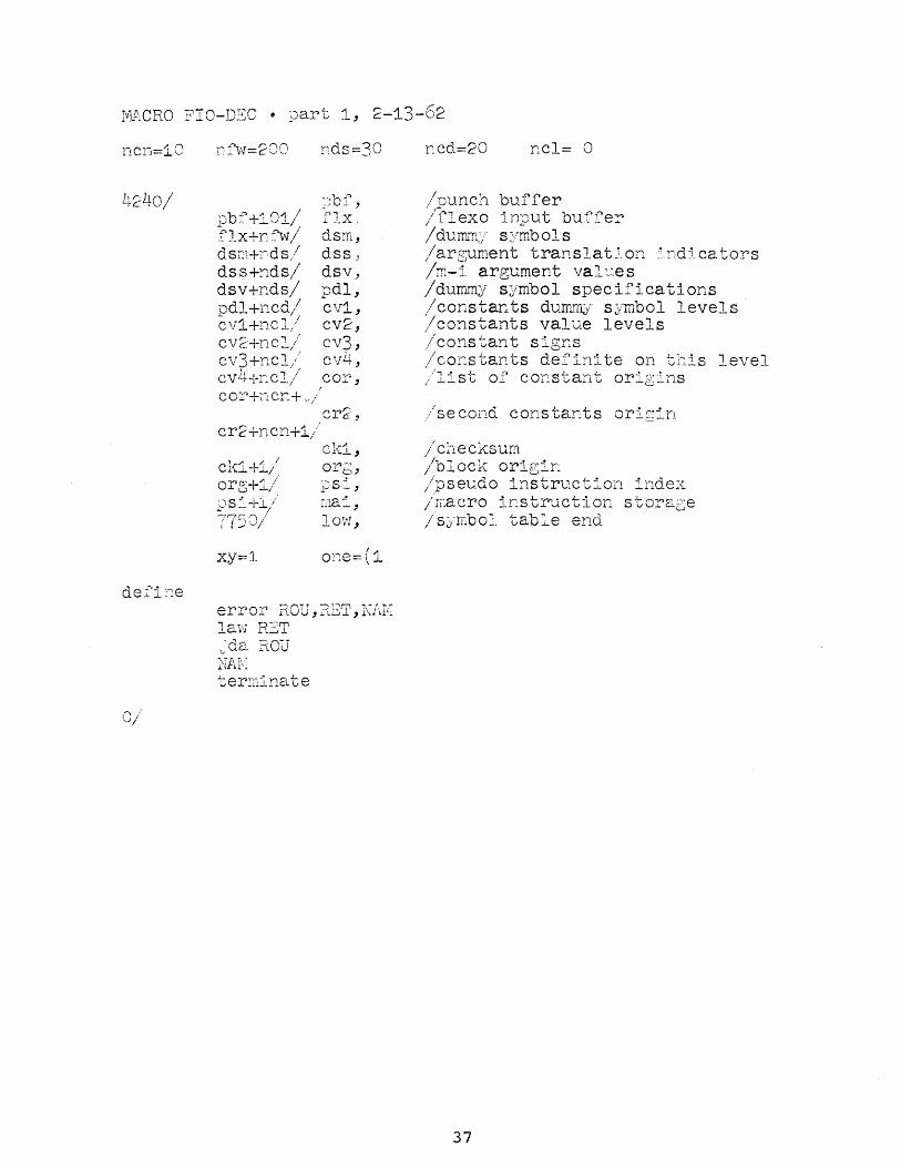
MACRO FIO-DSC • part 1, 2-13-62
ncn=10
',r;ilo / '-tc:.. /
def'ine
."'\ :' '0/
'-.b ."+'1 rVI /1
;_' J. -'- .... /....!...
"i'""'lx+nfw/ dsr'l+~~;ds / ds;+~dS/ dsv+nds/ ~~QJ l+li CO~ / 1'-' J. - -,
(;'11+1'1cl!/
nds=30
)bf, fIx., dsm, dss _~
dsv,_ pdl, cv1, cv2, cv3, cv4, cor,
I
c.or'+l'l cY'_+.;_/
err. '''''en+'1 ;' ell ~ .... .J../
c.k1+i/ org+1/ pSi+1,/ rn,c-.'"~ / { I >~'/
xy=l
cr2,
ck1, orb, pSl, ma:', low,
one=(1
error ROU,RET,NfJ( law R2:T .. 'da HOD NAI< ter~11inate
nc.d=20 Dcl= 0
/punch buffer / flexo input buffer Id1 'm""'; ,. s··mb 0' s / v. ll~lt_./ •. Y l~ -L
/argument translat50n ~!ndica tors /m-::t argument val1..~es /dummy symbol specifications /constants dUffifflJ/ s~/mbol levels /eonstants value levels :./ cons tan t signs /co~stants definite on this level jlist of constant origins
/seeond constants orig:'n
/ cl1.ecksum /1~oioc1.r ori 0'~ y, -'- n. -b.l..~-
/pse1;.do instruction index ;~a0ro -.L·ns~r"c~l·O~ ~~o-_~~/e / J.l~ 'V _. V V. v 1.:. ..... ~ ....... --."
/ sj·m.boJ. table end
37

/start
sov,
so1,
s04,
over entry
lat sma jmp xy
swap init s03,pss
ril is clc spi law 1
s03, d&..c xy
s05,
index s03,(dac pss+5,s04 lac npa. sma jmp np~
lac pss spa jmp psi jr;:p ps4
38

/reset terminating character switches
rst, lattJ rsk rsI, dap rsx
lio mii ini t bs, row,_, init ct,c . init dtb+57, lp spi
. jmp rsm dio mdi init bt,b init qt, q law tab jmp rsi
rsm, 'init bt,df2 init qt,da law sw
rSi, dap tt rsx, jmp xy
/reset to convert next word
rsk, rnw, init Ipi,cv1
init prs,pdl i~1t rt,ilf
rsw, dzm wrd elf 5 /syl dzm nsm dzm amn d:.:.;r;l asa elf 6 /dsi law 1 dae dar la\v r
rss, 110 (opr
sp, dio sgn dap spx dzm let elf 4 /liu dzm ovb dzm num dzm sym dzm cha
spx, jmp xy
39
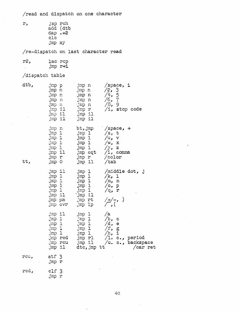
/read and dispatch on one character
r, jsp rch add (dtb dap .+2 clc jrnp xy
Ire-dispatch on last character read
r2, lac rcp jrnp r+1
/dispatch table
dtb, jmp p jmp n /space, 1 jmp n jmp n /2, 3 jmp n jmp n /4, 5 jmp n jrnp n /6, 7 jmp n jmp n 18, 9 Jmp il jmp r Ii, stop code jmp 11 jmp il jmp il jmp il
jmp n bt, jmp . /space, + jmp 1 jrnp 1 Is, t jmp 1 jmp 1 /u, v jmp 1 jrnp 1 Iw, x jmp 1 jmp 1 /y, z jmp il jmp cqt Ii, comma jmp r jmp r Icolor
tt, jmp 0 jmp 11 /tab
jmp il jmp 1 /middle dot, ~
J jrnp 1 jrnp 1 /k, 1 jmp 1 jrnp 1 1m, n jrnp 1 jmp 1 /0, p jmp 1 jmp 1 Iq, r jrnp i1 -jmp 11 jmp pm jrnp rt 7,-' ) jmp OVr jmp 1p , ( jmp il jmp 1 la jmp 1 jmp , /b, c ...L
jrnp 1 jmp 1 Id, e jmp 1 jmp 1 If, g jmp 1 jrnp 1 Ih, i jmp rcd jmp r1 /1. c. , period jmp rcu jmp 11 /u. c., backspace jmp 11 dtc,jmp tt /car ret
rcu, stf 3 jmp r
rcd, clf 3 .!-- r J lUJ:J
40

Icase dependent characters
cqt, szf 3 qt, jmp q ct, jmp c
pm, szf 3 jmp p jmp m
Iprocess alphabetic or numeric character
"I, dac let szf 3 Icas stf 4 !liu jmp In
12, lac sym ral 6s ior t dac sym jmp r
n, law 17 and t dac ti
n2 .. lac num ra1 3s xct .+1
ni, xx /opr=octal .. add num=decimal dac num add ti sza jrnp n3 lac ti xor num
n3, dac num
In, idx chc sub (3 spq jmp 12 lac let sma jmp r dzm num dzm let dzm chc stf 5 /syl lac sym dac api
41

/read three more characters for p-i or m-i
ln4,
lac t dac syn setup t1,3 jsp rch
sza i ,-jep s-om sad (54 ,jmlJ spm sad (36 ,-1mp s l)Ill sad ( ;~/7 ,_:~mp SiJD1
sad ( ~r~ .... J~
jmp rCfl+1
lSP t1 jmp .+2 Jnp rcl-:+l lac syn ral 6s ior t dac syn jmp rch+i
lover bar indicator
ovr, law 1 dcc oVb jrnp r
/space
/minus
/tab
/tcolor change
42

/search for pseudo or macro instruction
spm, clf 2 lac psi 110 mdi
sp2, dap spi lac sym
~pi, sad • jmp sp3 idx spi
sp7, idx spi lac i spi spa
sp3,
sp5,
'sp4,
jmp sp2 law i 5 add spi sas (sad mai-2 jrnp sp2 spi jmp drni szf 2 jmp sp4 jmp ipi
stf 2 idx spi dap sp5 lac syn
sas • jmp sp7 spi jmp mdm
idx sp5 dap sp8 lac i sp5 sma
sp8, jmp 1 • idx sp5 jmp mac
43

/address tag routine (comma)
c, lac loc spa jmp rnw jsp evl /def in 10 on return spi jmp c1 lac loc sad wrd jmp c2 szf 5 /syl dzm sym .jsp mdt:
c2, szf 5 jmp rnw
c3, dzm asi dzm amI move sym, asm jrop rnw
c1, szf 5 iron v ~ rnw lac loc dac t3 jsp vsm jmp c3
44

/parameter assignment (equal sign)
q,
qq,
lac let szf 5 jsp ipa sza i jsp ipa lac ovb sza jsp ipa lio sym dio scn init bt,ilf dap qt dap ct init tt,qq jrnp rnw
jsp sch jrnp rst jsp evl spi i jmp q2 spq jrnp rst jsp usq
q2, 110 scn dio sym move wrd,scn clc dac let law 1 dac def jsp evl lac def spq jmp q1 lac scn dac i ea jmp rst
" ql, move scn, t3 jsp vsm
sch,
jmp rst
dap sck szf 5 jmp .+3 lac chc szm idx sck
sck, jmp xy
/syl
/def in io pssin ac
/syl
45

levaluate syllable and accumulate word value
evl, dap ex lac sym jda per dac sym lac mii spa jmp wsp
ev2, lac let spa jmp el add nurn
sga, xct sgn add anm dac anm
en, lac num sgn, xx
jda ed
evx, lac pss 110 def
ex, jmp . ndf, clc
dac def dac t3 jda ed lio sym dio Ius lac ovb sub pss sas one jmp evx jsp vsm idx vct jmp evx
e1, lac sgn sad ( opr jmp eli
e12; law i 1 dac nsm jmp e2
ell, lac nsm szm .!...,...,,~ e12 lif +1 "";UJ.tJ
sza jmp e2 lif -1 law 1 dac nsm mO\le sym, asa
46

/evaluate symbol (logB:~ithmiC search)
.e2" law 4000 dac t1 clo lac low jmp e1+1
edn" lac (sub dip e1 lac t1 rar is dac t1 sad (1 jmp ndf lac ea
e1, t1 dac ea sub low spa jmp eup lac ea sub (lac low-1 srna+sza-skp jmp edn
ea" lac • sub syrn szo cma sma+sza-skp jmp edn
.eqt" sza jmp eup idx ea lac i ea dac num lac ovb sza i jmp en lac num lio pss cma sza jmp evk spi jmp ndv lac vct add vc1 dac num dac i ea idx vet jmp en
47

eup, lac (add jmp edn+l
ndv, clc dac der move sym,lus jmp en
evk, spi i jmp en move sym,lus error alu, en, flex mdv
ed, 0 dap edx lac ed add wrd sza jmp ed1 lac ed xor wrd
ed1, dac wrd edx, jmp xy
48

/insert symbol in symbpl table
vsm, dap vsx law i 2 add low dac low dap vi add one sad hili jsp sce clo
vSi, lac vi dap v2 add one dap v4 add one dap vi add one dap v3 sas (lio low+~ jmp vs2
vs3, lac sym dac i v2 lac t3 dac i v4
vsx, jmp xy
vs2, lac i vi sub sym szo cma spq-i jmp vs3
vi, lio xy /10w+2+1 v2, dio xy /loW+I v3, lio xy /1 ow+3+I v4, dio xy /low+1+1
jmp vsi
49

/pseudo-1nstruction repeat
rpt, lac rqc spa jsp irp init bt,:L.lf dap qt · init ct, rq1 dap tt jmp rsk
rq1, jsp evl spi
rq2,
rq3,
rq4,
jsp usr lac wrd spq jmp rq4 cma dac rqc init dtc,rq2 move fwd,rqx move rc8,rqy move fwb,rqz jmp rst
count rqc,rq3 init dtc,tt jrnp tt
move rqx, fwd move rqy,rc8 move rqz,fwb jmp tt
sza jmp jsp sas jmp jmp
irp rch (77 rch+1 rst
irp, error aIm, rq4+2, flex ilr
rqc, 0 rqx, 0 rqy, 0 rqz, 0

/pseudo-instruction character
ch, jsp rch 11Q ~rar 6s sad 51 jrnp chi /r 110 ~~r sad 4 jmp chi /m lio ch2 sas (43 jsp 11f /1
chi, dio ch3 jsp rch
ch2, ral 6s ch3, xx
dac nurn jrnp r
/pseudo-instruct1on f1exo
fx, dzm num setup t1,3 jsp rch lac num ral 65 ior t dac num count t1,rch+1 jrnp r
51

/pseudo-instruction text
txt, lac rqc spa jsp ilf load txv;.law txq init txx,rch+l jsp rch dac t2
txq, dzmwrd setup tl,3
txw, jsp rch sad t2 jrnp txk
txa, lac wrd ral 6s ior t dac wrd isp tl
txx., jmp xy
txv, xx dap bs lio mii spi jmp mw jmp tb3
txk, load txv,law rnw init txx,txa init bs,rnw lac t1 sad (-3 jmp rnw dzm t jmp txa
52

/syllable separation charact-ers (plus, minus, space)
p, jsp sch· -jmp r
m, jsp ev1 stf 5 lac t lio (opr sza i jmp m1 szf i 3 110 (cma
mi, law r jmp sp
/relative address
rl, la'c chc lio sgn sma
r13,
lio (opr dio r13 lac loc
xx add wrd dac wrd stf 5 lac mil sma jmp r rir 9s law 10 rcr 3s jda pr jmp r
/syl
syllable (.)
/opr or cma
/syl
53

/storage word termination characters tab and carr ret)
tab, jsp sch jmp rnw jsp evl spi+sma-skp jsp ust
tb3, idx aml
tb4, idx loc tb2, lac wrd ts, dac •
idx ts lac loc dac wrd and (77 szm jmp bs lac pss spq jmp bnp jrnp pun
/location assignment termination character
b1, lac der sma jmp bnp lac (400000 jmp b3
b, jsp sch jmp itc
. jsp evl lac nsm sad (-1 jmp bal dzm asi lio (-0 sza i dio asi move asa, asm move amn, am1
bal, lac pss spq jrnp b1 lac der spq jmp usb
b5, law 7777 and wrd dac wrd sad loc jrnp bs
start

Macro FlO-DEC part 2
/punch binary block
pun, lac org sad loc jmp bnp lac pch spq jmp bnp cli repeat 5, ppa lac org add (dio dac ck1 jda pnb lac loc add (dio jda pnb . load t,dac pbf
pub, lac i t jda pnb lac i t add cld dac cld idx t sas ts jmp pub lac ckl add loc add (dio jda pnb
/form origin-for next block
bnp, lac wrd and (407777 dac org
b3, dac 10c init ts, pbf
bs, jmp •
loc, 0
55
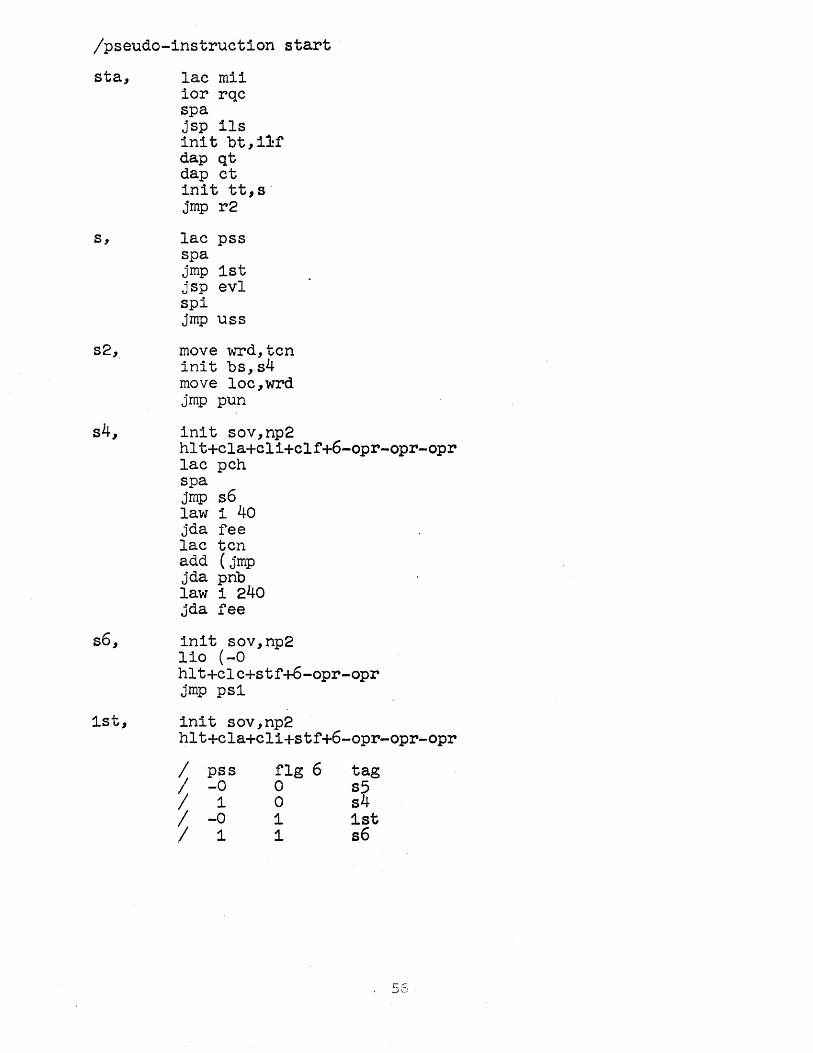
/pseudo-1nstruct1on start
sta,
s,
s6,
1st,
lac mi1 ior rqc spa jsp 11s in1t bt,i~f dap qt dap ct 1nit tt,s' jmp r2
lac pss spa jmp 1st jsp evl spi jmp uss
move ~Td, tcn init bs,s4 move loc,wrd jmp pun
init sov,np2 hlt+cla+c1i+clf+6-opr-opr-opr lac pch spa jmp s6 law 1 40 jda fee lac tcn add (jmp jda pnb law 1 240 jda fee
in1t sov,np2 110 (-0 hlt+clc+stf+6-opr-opr jmp psl
in1t sov,np2 hlt+cla+cli+stf+6-opr-opr-opr
;1 pss
-0 I 1
~ -~
f1g 6 o o 1 1
tag s5 s4 1st s6

/init1alize for new pass
ps2, law 1 dac pss dac pch dac tit move ini,inp
ps4, move psb,ps1 lac mai
ps5, ps3,
move psa, rnai jmp np1
move mai,p$a move psi,psb
55, init sov,ps2 clc dac pss hlt+c1 i+clf+6-opr.opr
psi, clc dac pss dac pch law 1 dac ini move psi,psb lac rnai dac psa·
np1, dac hih add (sad-lac+1 dac con dac neo dzm nea dzm as1 law 4 dac org dac loc law 1 dac mii dzm vai dzm vet load ni, opr init cn6,cor in1t cn7,er2
~7
/in1t1al entry

np2, load t, -4000 rpa-i spi 1 jmp .+5 isp t jmp .-3 hlt+clc+c11-opr-opr jmp np2 dzm api dzm fwd init ts pbf init rc8,flx+nfw+2 dzm rqc-init dtc,tt clc+clf 7+cli-opr-opr add pss add pch add tit sas (3 stf 5

pte,
ptl,
pta,
pt1,
pt2,
pt3,
pt6,
pt7,
pt5,
and punch title
law i 40 .. szf 1 5 jda fee jmp ptl+i
lot i jsp rch . sad (13 jrnp rch+1 sza jmp pto szf i 6 jrnp rch+1 sad (77 jmp pt5 stf 6 sad (40 stf 5 ral is add (ftp dap pt2 dap pt3 idx pt3
110 t iot 4003 szf 5 jrnp ptl
lac • repeat 3, jda pt6 lae • repeat 3, jda pt6 jrnp ptl
0 dap pt7 lac pt6 eli rel 6s ppa jrnp · szf 1 6 jrnp ptl+i dzrn tit
jayne on typewriter
/stop code
/tyo with nac but no ioh .
59

/print pass 1 and 2
pps, jsp spc lac (723554 jda tys . . jsp spc lac (flex pas
/punch
jda tys ·-..,yo jsp spc law 1 add pss jda tys law 3477 jda tys
input routine
law i 1 add pss add pch spq jmp rst
pf2, law i 40 jda fee lac inp spq jmp rst
pi2, load pt6,dio 7751
/ 1
/black
pi3, lac pt6 jda pnb lac i pt6 jda pnb index pt6,(dio 7776,p13 lac (jmp 7751 jda pnb dzm inp jmp pf2
spc, dap .+3 cli tyo ~mp ,
/lc"red, -
carret
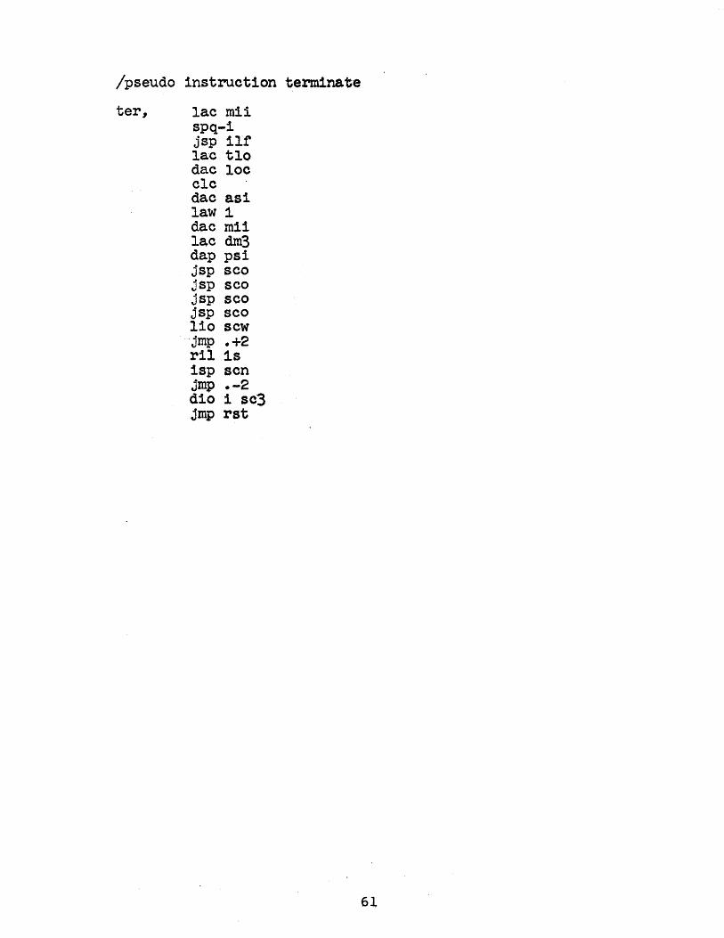
/pseudo instruction terminate
ter, lac mii spq-i jsp ilf lac tlo dac loc clc dac asi law 1 dac mii lac dm3 dap psi jsp sco jsp sco jsp seo jsp seo lio sew 'jrnp .+2 ril is isp sen jmp .-2 di0 1 sc3 jmp rst
6l

/pseudo instruction define
dfn, lac mii spq jsp ilf la.w ill' dap qt dap ct law df1 dap tt law df2 dap bt 1io loc dio tlo dzrn Icc clc dac asi dac mdi idx rnai dap drn3 idx mai dap dm1 idx rnai dap dm2 sub low sma jmp sce jrnp rnw
df1, jsp sch jrnp r jsp ilf
if2, jsp sch jmp itc jsp ilf
62

/define macro instructiop
dmi, lio sym dm3, dio •
lio syn dm1, dio •
clc+clf 4~opr /11u clf 5 '!syl dac mii dzm sym dzm sew law 1 dac mdi lac psi
dm2, dac . idx mai dap sc3 law i 23 dac scn init prs, pdl init dsk,. dsm+1 init ddx, rsk init ct, pd1 init tt, pds jrnp r2
/pick up dummy symbol
pds, law rst Itab dap ddx lac chc spq jrnp rst
pd1, lac sym /c~mma jda per dae sym szf 5. Isyl jmp pd2-1 lac let sza i jmp pd2-1
/liu szf i 4 jsp ids
pd2, lio sym jmp dd+l
63

/search for dummy symbol
sds, 0 dap sdx dap sdy idx sdy 1nit sd1,dsm
sd2, lac sds sd1, sad xy
jmp sd4 index sd1,dsk,sd2 lio sds
eWe, jmp xy
sd4, lac sd1 SUD (sad dsm-1
sdy, jmp xy
/def1ne new dummy symbol
dd, dap ddx dio 1 dsk idx dsk sad (sad dsm+nds-1 jsp tmp sub (sad dsm
ddx, jmp •
/macro instruction constant
mc, dap tea dzm num stf 6 jsp ss jSp sco jsp sco
: ;.
mea., law smb jmp scz
/ds1
/macro .instruction storage word
SW, jsp sch jmp rnw jsp evl sma+spi-skp .jsp usm
swE, law rnw mw, dap tea
1dx aml idx loc law mca jmp ss
64

/dumrny symbol assignment
da, szf i 4 /liu jsp ilf szf 5 /syl jsp ipa lac sym jda per dac ten init bt,ilf .dap qt dap ct init tt,da1 .Jmp- rnw
·da1, jsp seh 'jmp rnw jsp evl sma+spi-skp jsp usd
da3, lac ten jda sds jmp dab add (400000
daa, jda mp jrnp rst
mp, 0 dap mpx jsp ss jsp seo jsp seo jsp seo jsp scz init tea,mp1 jmp smb
mp1, lac mp jda wro
mpx, jmp xy
dab, law daa lif under jmp dd
65
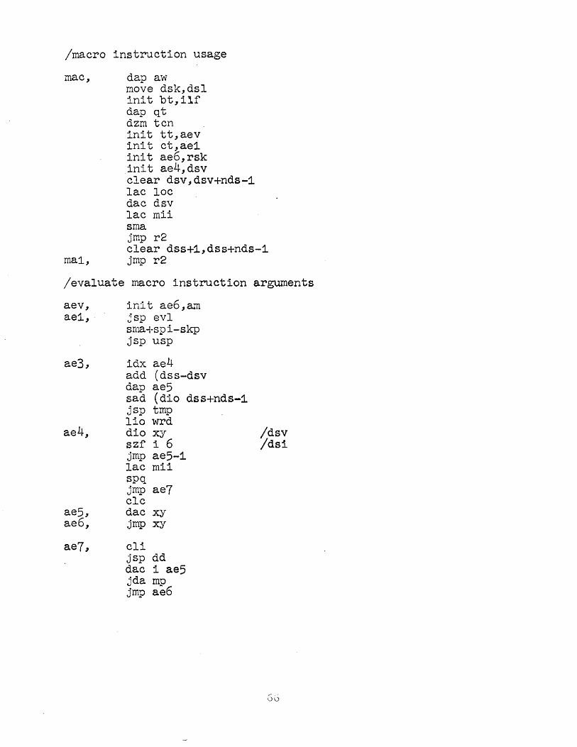
/macro instruction usage
mac, dap aw move dsk,dsl init bt,ilf dap qt dzm tcn init tt,aev init ct,ae1 init ae6,rsk init ae4,dsv clear dsv,dsv+nds-1 lac loc dac dsv lac mii sma jmp r2 clear dss+1,dss+nds-1
mai, jmp r2
/evaluate macro instruction arguments
aev, init ae6,am ae1, jsp evl
sma+spi-skp jsp usp
ae3,
ae4,
ae5, ae6,
idx ae4 add (dss-dsv dap ae5 sad (dio dss+nds-1 jsp tmp lio wrd dio xy szf i 6 jmp ae5-1 lac mii spq jmp ae7 clc dac xy jmp xy
ae7, eli jsp dd dac i ae5 jda mp jmp ae6
!dsv !dsi
G0

/assemble M-I into program
am,
ami,
am5,
lac pss dac def in it prs,pdl clf 6 · dzm wrd lawawm jda tc law as jda tc law ac jda tc law aa jda tc lac dsl. dap dsk jmp rst
/ds1
/assemble M-I storage word into progr. ·or mal
awm, law aw3
ar, dap ary law ar5 jda tc law an
rw, aw,
rw.x,
dap rwx lio xy idx aw dio t iac t jmp xy
an, jda eO. ar5, lio mi1 ary, jmp xy
aw3, law ami spi jmp rnw dap bs . jmp tb3
/ma1
.67
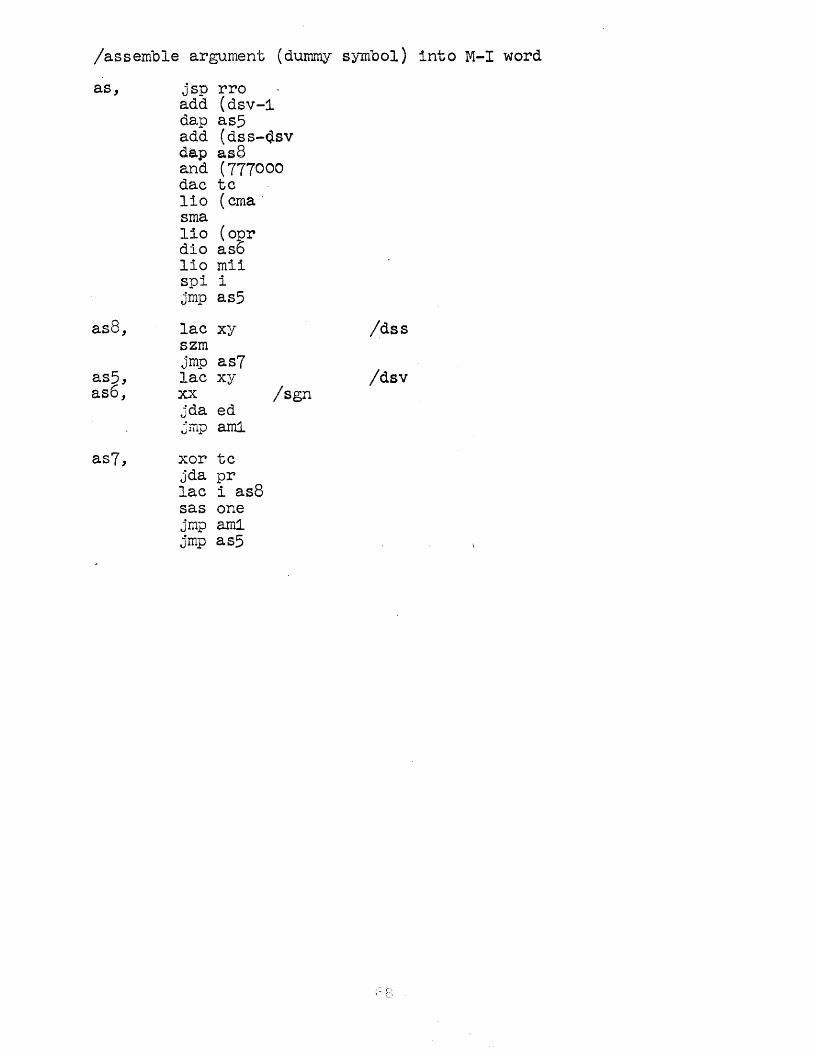
/assemble argument (dummy symbol) into M-I word
as, jsp rro . add (dsv-1 dap as5
asS,
as5, as6,
as7,
add (dss-Q.sv dap as8 and (777000 dac tc lio (cma· sma 110 (opr dio aso lio mii spi i jmp as5
lac xy szm jmp as7 lac xy xx jda ed ~lTlP ami
xor tc jda pr lac i as8 sas one jmp ami jmp as5
/sgn
/dss
/dsv
,- r:
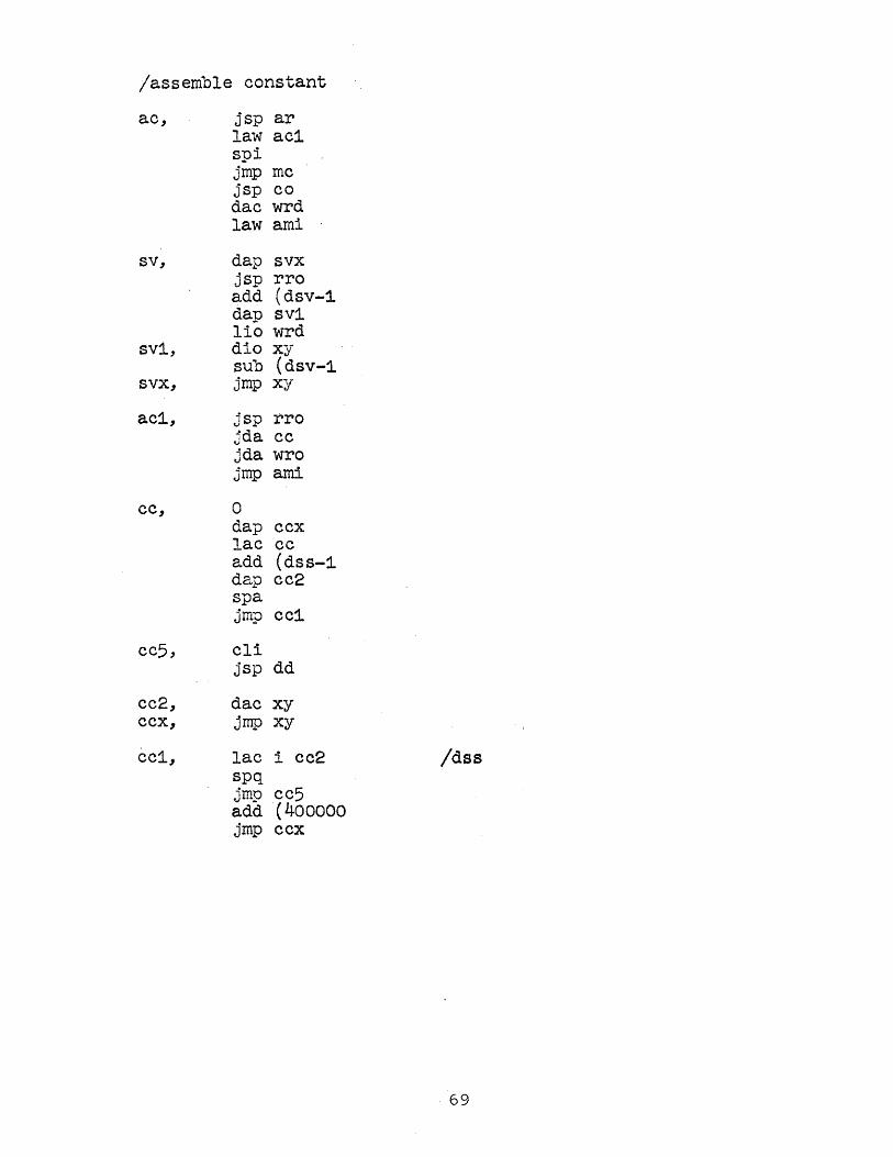
/assemble constant
ac, jsp ar lavl ac1 spi jmp me jsp co dae wrd law ami
sv, dap svx jsp rro add (dsv-1 dap sv1 lio wrd
sv1, dio xy sub (dsv-1
svx, jmp xy
ac1, jsp rro jda cc jda wro jmp ami
ec, 0 dap ccx lac cc add (dss-1 dap cc2 spa jmp cc1
cc5, cli jsp dd
cc2, dac xy ccx, jmp xy
ce1, lac i cc2 idss spq jmp cc5 add (400000 jmp ccx
69
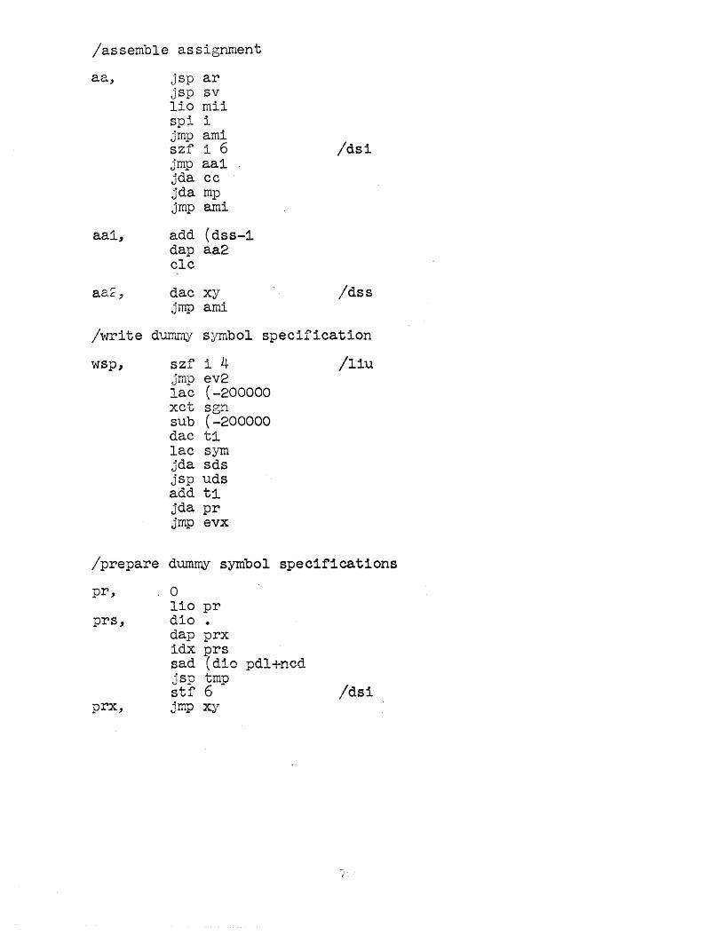
/assemble assignment
aa, jsp ar jsp sv lio mii spi i jmp ami szf i 6 /ds1 jmp aal jda cc jda mp jmp ami
aal, add (dss-1 dap aa2 clc
aat, dac xy /dss jrnp ami
/write durnrny symbol specification
wsp,
/prepare
pr,
prx,
szf i 4 /liu jmp ev2 lac (-200000 xct sgn sub (-200000 dac tl lac sym jda sds jsp uds add t1. jda pr jmp evx
dummy symbol specifications
o lio pr dio • dap prx idx prs sad (dio pdl+ncd jsp tmp stf 6 jmp xy
Idsi

/store dummy symbol specification
ss, dap ssx lac prs dap sst lac i Ip1. dap prs · sub one dap ssl jmp ss2
ss3, jsp seo jsp scz
ssl, lac xy /pdl jda wro
5s2, index ss1,sst,ss3
ssx, jmp xy
sst, lac xy
/store word in rnai
smb, lac 'to.J'rd sza jmp sm7 lac tea jmp sez
sm7, jsp seo lio wrd lac tea
sm, dap SffiX idx mai dio i mai lio pss spi i jmp sm2 dae hih sad low jsp see
sm2, cIa smx, jrnp •
71
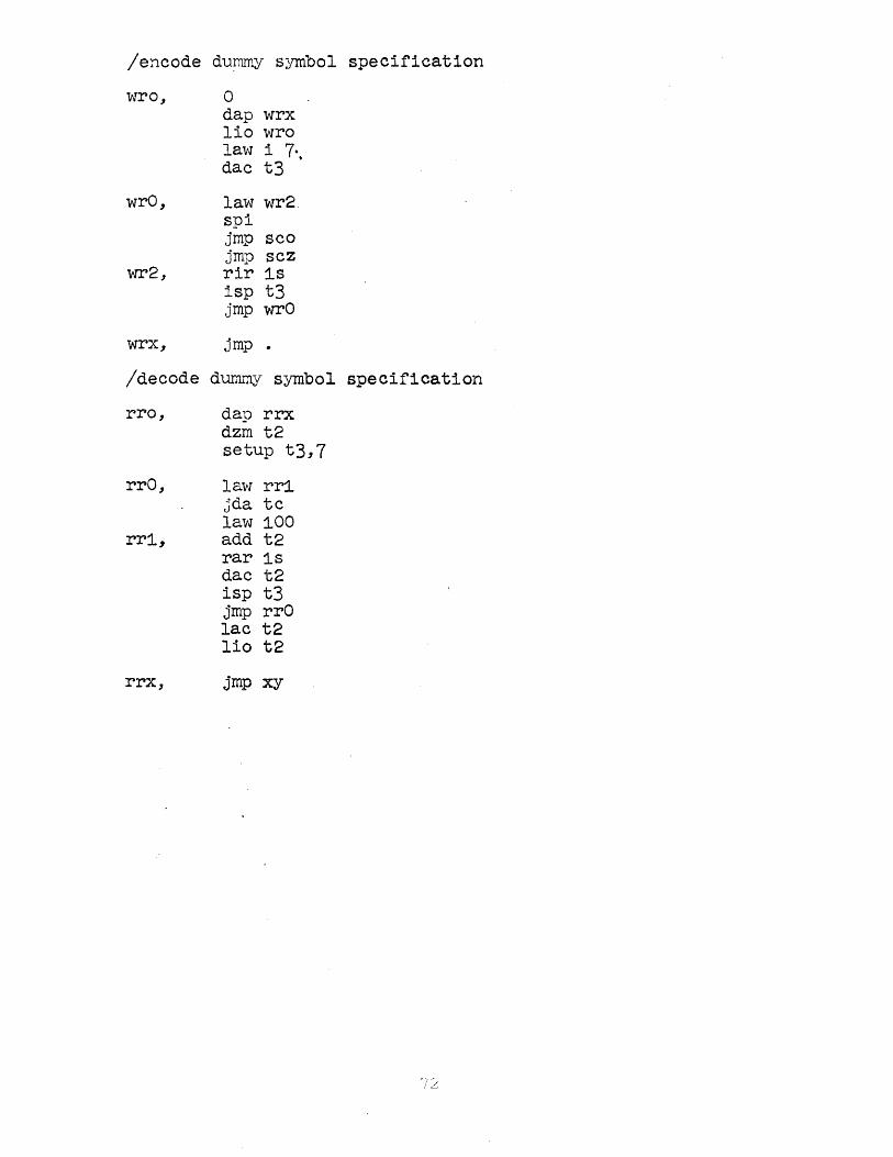
/encode du!MlY symbol specification
wro, 0 dap wrx lio wro lavl i 7 .. dac t3
wrO, law wr2. spi jrnp sco jrnp scz
wr2, rir 1s isp t3 jrnp wrO
wrx, jrnp . /decode dumrny symbol specification
rro, dap rrx dzrn t2 setup t3,7
rrO, law rri jda tc law 100
rrl, add t2 rar ls dac t2 isp t3 jrnp rrO lac t2 lio t2
rrx, jmp xy
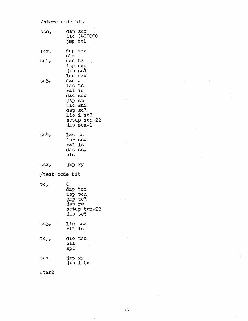
/store code bit
sea, dap scx lac (400060 jmp sc1
scz, dap scx cIa
se1, dac tc isp sen jmp se4 lac sew
se3, dac . lac te ral 1s dae scw jsp sm lac mai dap sc3 lio i se3 setup sen,22 jmp sex-1
5c4, lac tc ior sew ral 1s dac sew ela
sex, jmp xy I. • /t;es"C code bit
te, 0 dap tex isp ten jmp te3 jsp rw setup ten,22 jmp te5
te3, 1io tee ri1 1s
te5, dio tee c1a spi
tcx, jmp xy jmp i te
start

Nacro FlO-DEC part 3
/set to pick up constant
Ip,
Ipl,
Ip2,
Ip3,
Ip4,
ttt, tct, tqt, tbt,
jsp evl law 1 jda pi . sad (dio cv4+ncl jsp tmc 1io prs dio xy 1io wrd dio xy 110 sgn dio xy lio def dio xy sas (dio cv4+1 jmp rsw move tt,ttt move ct,tct move qt,tqt move bt,tbt init tt,rp dap rt dap ct init qt,ilf dap bt jmp rsw
o o o o

/save constant and reduce level
rt,
rp,
rp5, .
rp3,
rp8,
jmp xy
jsp evl lac mif· spq jmp rp8 jsp co.·
xct i Ip3 add i Ip2 dac wrd law 1 dac def law i 1 jda pi sas (dio cv4 jmp rp3 move ttt,tt move tct,ct move tqt,qt move tbt,bt init rt,ilf stf 5
jsp rss lac t sad (55
. jmp r sas (77 jmp r2 jmp tt
jsp mc jsp dd jda wro
lac (-200000 xct i Ip3 sub (-200000 add wro jda pr cIa jmp rp5
pi, 0 dap pix lac pi add Ip1 dap Ip1 add (cv2-cv1 dap Ip2 add (cv3-cv2 dap Ip3 add (cv4-cv3 dap Ip4
pix, jmp x.y
/syl
fright paren
7S

/constant table search
co,
jmp co4+1
co2, c03,
c04,
c06,
coS, cox,
dap cox ~idx nca lac psst spq jmp coB lac def spq jsp usc lac con dap co3
lac wrd sad xy jmp co6 index c03, nco, co2 add one dac nco add (lac-sad+1 dac hih sad low jsp sce 110 wrd dio 1 c03
lac c03 sub con add i cn6 and (7777 dac num jmp xy
Icar table (first)
76

/pseudo-instruction constants
cns, lac mii spq
cn6,
cn3,
cn4,
cn8,
cn7, cn5,
cn1,
jsp il~ lac lac' dac xy leor table (first) dac tlo lac nca. add aml laml is "alarm location" dac aml lac pss spq jmp cn5 init bs,cn4 lac con dap cn3 jmp cn8 lac xy /const. list dac wrd jmp tb4
idx cn3 add (sad-lac sas nco jmp cn3 lac lac dac cr2 Isto cor table (second) lac tlo add nca dac wrd init bs,cn1 jmp ba1
init bs,rnw move con,nco ' dzm nca idx cn6 index cn7,(dac cr2+nen,rnw
tme, error aIm, alh, flex tmc
77
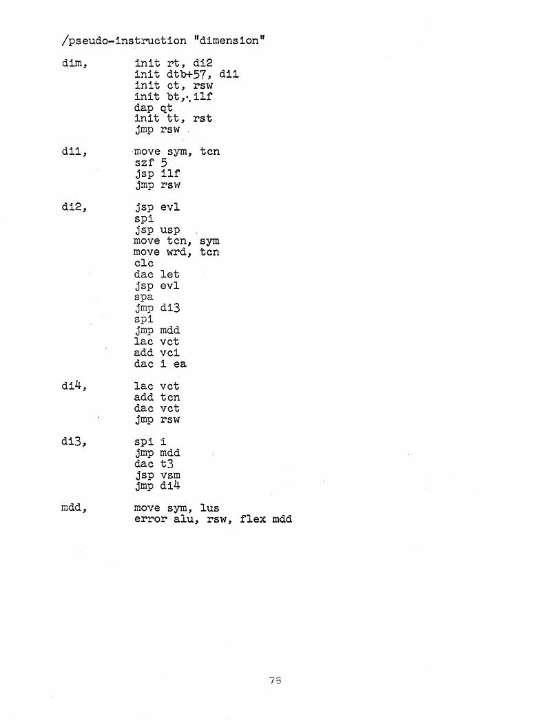
/pseudo-instruetion "dimension lf
dim, init rt, di2 init dtb+57, d11 init et, rsw init bt,·, 11£ dap qt init tt, rst jmp rsw .
dil, ,move sym, ten szf 5 jsp il£ jmp rsw
di2, jsp evl spi jsp usp move ten, sym move wrd, ten ele dae let jsp evl spa jmp di3 spi jmp mdd lae vet add vel dae i ea
di4, lac vet add ten dac vet jmp rsw
di3, spi i jmp mdd dac t3 jsp vsm jmp di4
mdd, move sym, Ius error alu, rsw, flex mdd
73

/pseudo-instruetion variables
var, lac mii spa jrnp ilf lac loe spa jmp ilf lio vai spi jmp tmv load vai, -0 1io pss spi jrnp vaa sas vel jmp vld
vae, lac ve2 dac wrd jmp b5
vaa, dac vel add vet dae ve2 lac aml add vet dae amI jmp vac
79
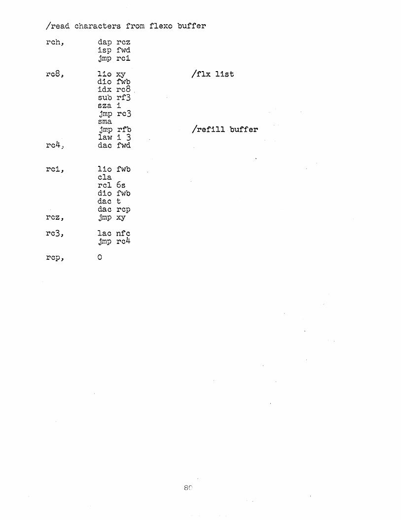
/read characters from. flexo buffer
reh, dap rez isp r\1d jmp rei
re8 p lio xy /flx list dio fwb idx re8 sub rf3 sza i jmp re3 sma jmp rfb /refill buffer law i 3
re4) dac fwd
rei, 110 fwb cIa reI 6s dio fwb dae t dac rep
rez, jmp xy
re3, lac nrc jmp re4
rep, 0

/refill flexo buffer
rfb, init rcB~flx dap rf3
rfS, rf1, rf2,
add
rfa,
rf3,
rf4,
(1000
law rf4+1
dap rf4' setup nfc,3 rpa dio t rir 7s spi jrnp rf2 sense 6 jmp rfa lac t sza 1 .jmp rf2
dap .+2 law 5252 rar spa jmp 11p
cla lio t rcr 6s lio xy reI 6s dio i rf3 rcr 6s sad (130000 jmp rf6 sad (770000 jrnp xy count nfc,rf2 index rf3,(lio law rf6 jmp rfS
rf6, rcl 6s isp nfc ril 6s isp nfc ril 6s dio i rf3 law i 2 sub nfc dac nfc idx rf3 jrnp reB
ilp, law 7143 jda tys law 4777 jda tys 1nit sov, rf2 110 t hlt+clc-opr jmp rfa
17th code=delete
Icheck parity
/flx list
/stop code
Icar ret /.+1 or rf6
flx+nfw-24,rf1
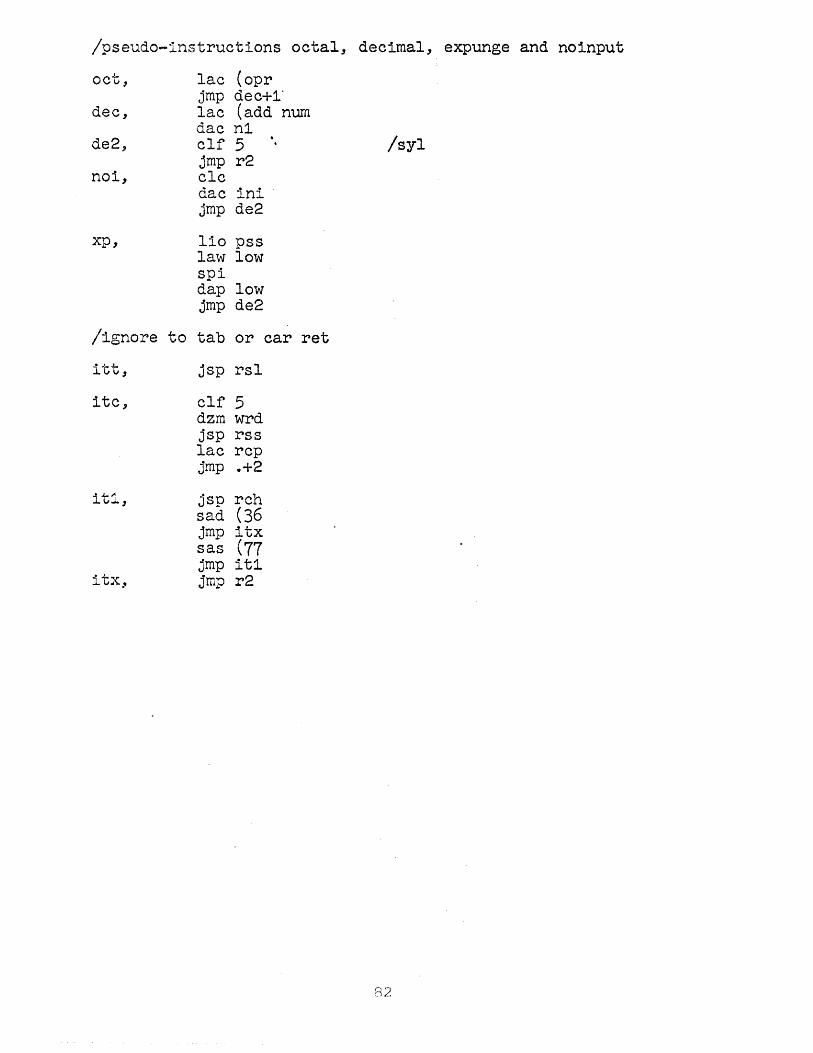
/pseudo-instructions octal, decimal, expunge and nOinput
oct"
dec,
de2,
nOi,
xp,
lae (opr jmp dec+l' lac (add num dac nl elf 5 jmp r2 clc dac ini . jmp de2
lio pss law low spi dap low jmp de2
/ignore to tab or car ret
itt, jsp rsl
itc, elf 5 dzm wrd jsp rss lae rep jmp .+2
itl,
itx,
jsp rch sad (36 jmp itx sas (77 jmp itl jmp r2
/syl
82

/feed subroutine
fee, 0 dap fex eli ppa isp fee jrnp .-2
fex, jrnp •
/puneh routine
pnb, 0 lio pnb dap pnx lac loc ppb ril 6s ppb ril 6s ppb
pnx, jmp •
/oet7znt subroutine
opt,
op1,
o dap opx lio (100000 lac opt elf 1 -rer 9s rer 6s sza jrnp op2 law 20
op3, swap szf 1 tyo sad (10000 stf 1 ell sas (100000 jrnp op1 -
opx, jrnp x.y
op2, stf 1 jrnp op3
83
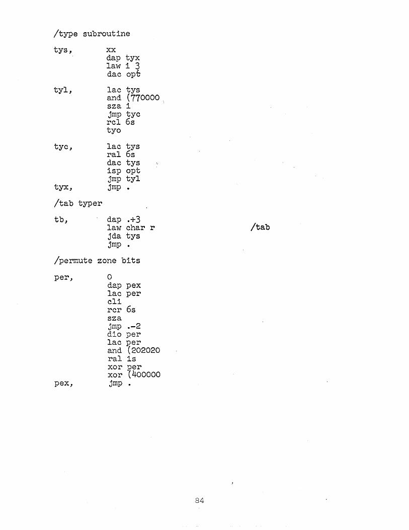
/type subroutine
tys, xx dap tyx law i 3 dac opt
tyl, lac tys and (770000, sza 1 jmp tyc reI 6s tyo
tyc, lac tys ral 6s dac tys isp opt jmp tyl
tyx, jmp •
/tab typer
tb, dap .+3 law char r /tab jda tys jmp •
/permute zone bits
per, 0 dap pex lac per eli rcr 6s sza jmp .-2 dio per lac per and (202020 ral 1s xor per xor {400oo0
pex, jmp •
84

/error print routines.
ust, error alu:, tb3, flex usw
usb, error alu,b5,flex usl
usq, error alu,rst,flex usp
uss, error alu,s2,flex uss
usm, jda alu flex usm
usc, jda alu flex usc
usr, error alu,rst,flex 'lisr
usp, jda alu flex usa
usd, jda alu flex usd
uds, dio lus error alu,evx,flex uds
il, error alm,r,flex ich
ilf, error alm,itt,flex 1lf
ipi, error alrn,itc,flex 1p1
mdt, move sym,lus error alu,rnw,flex mdt
mdm, error alm,dmi,flex mdm
ipa, error alm,itt,flex 1pa
lds, dzm sym jda aIm flex 1ds
lIs, error alm,alh,flex 11s
see, error alm,alh,flex see
tmp, error alm,alh,flex tmp
vld, error alm,rnw,flex vld
tmv, error alm,rnw,flex tmv
85

/error print routine
alu, 0 move alu,alm jmp alb
aIm, 0 dzm Ius
alb, dap .+3 lac aIm dap sov lac xy jda tys jsp tb lac loc
spa jmp a11 jda opt jmp a12
a11, lac (flex ind jda tys
a12, jsp tb lac asi
. spa jrnp a16 lac asm jda per jda tys lac amI sza i jmp a16 110 amI lac (flex + spi
law char r-jda tys lac amI spa cma jda opt
a,t:: "","v, lac api
sza" i jmp a19
86

a17, jsp tb lac api jda tys lac syn jda' tys lac Ius sza 1 jmp a18
als, jsp tb lac Ius jda per jda tys
a18, la.w 77 le.r. jda tys lat rar 1s 1io (-0 sma
alh, clc+hlt-opr dio pch jmp SOY
a19, lac Ius sza i jmp ala jsp tb jmp als
87

/title punch table
ftp, 0 0 /spaee 004277 400000 /1 625151 514600 /2 224145. 453200 ~~ 141211 · 771000 274545 453100 ~g 364545 453000 010171 050300 ~~ 324545 453200 065151 513600 19 0 0 0 0 0 0 0 0 0 0 0 0 364141 413600 Izero 000047 000000 Is 2245 5 .453000 0101r7 010100 It 3740 0 403700 /u 073060 300700 ~~ 376014 603700 412214 224100 Ix 010274 020100 ~~ 615141 454300 0 0 141414 141400 1= 0 0 0 0 0 0 0 0 0 0 204040 403700 ~~ 771014 224100 774040 404000 /1 770214 027700 1m 770214 207700 In 364141 413600 /0 771111 110600
~ 364151 215600 771111 314600 0 0 0 0 101010 101000 ~) 000041 221400 101074 101000 + 001422 410000 I( 0 0 761111 117600 /a 774545 453200 /b 364141 412200 /e 774141 413600 /d 774545 414100 Ie 770505 OiOl00 I,.
II 364151 513000 ~~ 771010 107700 004177 410000 /i 010300 010300 /elose quotes 000060 600000 I. 030200 030200 /open quotes

/Indicators and-variable st.orage'
vai, 0 vc1, 0 vc2, 0 vet, 0 ovb, 0 pss, 0 npa, 0 pch, 0 inp, 0 tit, 0 psa, 0 psb, 0 ini, 0 hih, 0 nfc, 0 Ius, 0 fwd, 0 fwb, 0 wrd, 0 num, 0 sym, 0 def, 0 ehe, 0 let, 0 api, 0 asi, 0 asm, 0 amI, 0 nsm, 0 asa, 0 amn, 0 con, 0 nco, 0 nea, 0 tIo, 0 mii, 0 mdi, 0 syn, 0 tea, 0 scn, 0 sew,. 0 ten, 0 tcc, 0 dsk, sad x:y dsI, 0
+- 0 v, t2, 0
!variables pseudo-instruction indicator !beginning of variables lend of variables /variables counter
.. /overbar indicator, 1= on, O~' off /-0 = pass 1, +1 =-pass 2 1-0 = begin pass, +1= continue pass /-0 = do not punch, +1 = punh if pass 2 1-0 = suppress input routine, +1 = punch input routine 1-0 = suppress title, +1 = punch title lend of psuedo-instruction list) at beginning lend of macro-instruction list ) of pass 1 faux. input routine indicator lupper limit of macro instruction and constant .list Itest word for end of flexo word list Ilast undefined symbol /flexo word from input tape /flexo word from list . Ipartial sum of. syllables of word (number = value of syllable. /symbol = flexo word for symbol. 1-0 = indefinite word, +1 = definite /character count of characters in syllable -/0 = no letters in syllable, -0 = at least one letter Ilast psuedo-instruction for error stop !relative location-+O = yes, -1 = no /alarm symbol for relative location . /location relative to above symbol (asm) I(for establishing above symbolic relative I(location from location . !(assignment /current address in constant list Inumber of distinct constant values /number of constant syllables /temporary for current location Imacro instruction mode indicator Idefine indicator /second three characs of M-I name /temporary subroutine exit address
I for code. '. I! temporaries
I word I subroutines . !durnmy symbol count /temporary for durn sym count
t1, t3,
o· o
89
/temporary /registers

constants
/pseudo instruction list and macro names and definitions
psi/
npi,
dSs/ dsm/ cvi!
1 ow/
law npi-3
lac npi.:.i
text .repeat. text .charac. text .fIe xo. text .tex t. text .sta rt. text .termin. text .define. text .consta. text .oct ale text .decima. -text .noinpu. text .expung. text .variab. text .dimens.
1 110000 pdl
lac low
start ps5
rpt ch fx txt sta ter dfn ens oct dec noi xp var dim
90

SYMBOL PACKAGE - macro fio-dec
/MACRO P SYMBO PL~CH.10-27-61
flx/
1sb, clf 5 senses 1001 jmp 7751
law i 20 jda. fee
1s, listen swap senses 1001 jrnp 7751 sad (77 jrnp ls3 sas (36 jmp ptl-5
1s2, listen swap
1s3, senses 1001 jrnp 7751 lio !jmp sps sad char rm 1io jmp mps sad char rs stf 5 dio sps-l lio ls3+2 dio .-2 sas (77 jmp 1s2 law i 40 jda fee lac end-l jda pnb la~'l i 40 jda fee xx
sps, lac low dap bpp law low+l jda ,end szf 5 jrnp pse law i 40
. jda fee
mps, law psi dap bpp add (2 ,jda end init bpp,npi lac mai add (law-lac+l sad .-4

jmp pse dap end jsp pst
pse, law i 3.0 jda fee' lac (jmp ps5 jda pnb law i 240 jda fee jmp 7751
end, 0 pst, dap pSX
clf 4 bpp, law xy psr, dac org
dap sor and ~-77 add 100 dac loc law pbf dap .+2
psu, lac. 1 sor dac • 1dx .-1 dap ts idx sor sad end jmp .+4 sad loc jmp psc jmp psu dac loc stf 4
pcb, jmp 4sc szf
pSX, jmp xy lac loc jmp psr
psc, senses 1001 jmp 7751 jmp pun+6
sor, xy
constants
bnp/ jmp pcb+l ptl/ jmp pt1+4 pt6-1/ jmp Is
start lsb
92
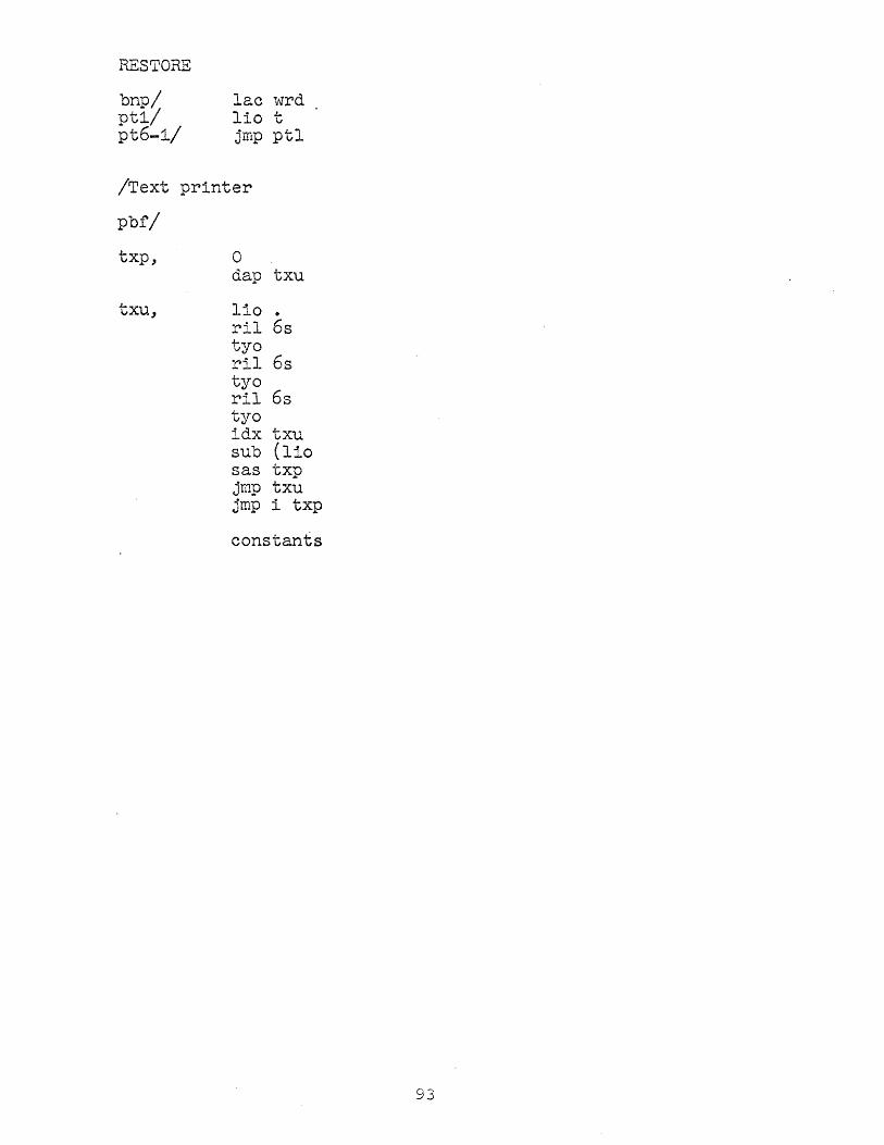
RESTORE
bnp/ lac wrd pt1/ lio t pt6-1/ jmp ptl
/Text printer
pbf/
txp, 0 dap txu
txu, lio . ril 6s tyo ril 6s tyo ri1 6s tyo idx txu sub (liO sas txp jmp txu jmp i txp
constants
93

/init .. sym. val
1st, flex 1s 1 flex 28 3 flex 3s 7 flex lJ.s 17 flex :3s 37 flex 6s 77 flex 7s 177 flex 8s 377 flex 9s 777
char Ii 10000
flex and 020000 flex ior 040000 flex xor 060000 flex xct 100000 flex jfd 120000 flex cal 160000 flex jda 170000 flex lac 200000 flex lio 220000 flex dac 240000 flex dap 260000 flex dip 300000 flex dio 320000 flex dzm 340000 flex add 400000 flex sub 420000 flex idx 440000 flex isp 460000 flex sad 500000 flex sas 520000 flex mus 540000 flex dis 560000 flex jmp 600000 flex jsp 620000
flex skp 640000 flex szf 640000 flex szs 640000
flex sza 640100 flex spa 640200 flex sma 640400 flex szo 641000 flex spi 642000
94

flex ral 661000 flex ril 662000 flex reI 663000 flex sal . 665000 flex sil 666000 flex scI 667000 flex rar' 671000 flex rir 672000 flex rcr 673000 flex sar 675000 flex sir 676000 flex scr 677000
flex law 700000 flex iot 720000 flex tyi 720004 flex rrb 720030 flex cks 720033 flex Ism 720054 flex esm 720055
flex cdf 720074 flex cfd 720074
flex rpa 730001 flex rpb 730002 flex tyo 730003 flex ppa 730005 flex ppb 730006 flex dpy 730007
flex elf 760000 flex nop 760000 flex apr 760000
flex stf 760010 flex cIa 760200
flex hIt 760400 flex xx 760400
flex cma 761000 flex cle 761200 flex lat 762200 flex eli 764000
iyi, -0 -0
95
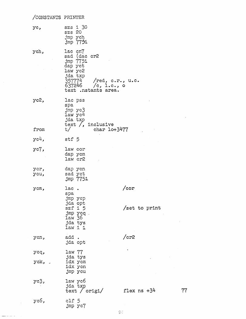
ICONSTANTS PRINTER
yc,
ych,
szs i 30 szs 20 jmp ych jmp 77~
lac cn7 sad (dac cr2 jmp 7751 dap yct law yc2 jda txp 357774 Ired, c.r., u.c. 637246 Ic, l.c., 0 text .nstants area.
yc2,
from
lac pss spa jmp yc3 law ye4 jda tX
7D
text , tl
yc4, stf 5
yc7, law cor dap ycm law cr2
yer, dap ycn yeu, sad yet
jmp 7751
ycm,
yen,
yeq,
yek, _
yc3,
lac • spa jmp jda szf jmp
·law jda la"'vV'
ycp opt i 5 yeq 36 tys ..!l ., ...L. ~
add . jda opt
law 77 jda tys idx ycm idx yen jmp ycu
inclusive char 10+3477
Icor
Iset to print
/cr2
la,,,, yc6 jda txp text I origil flex ns +34
yc6, elf 5 jmp yc7
77

yet, add •
yep, law yeo jda txp' 357145 Ired, -1, n flex def char 1'~+3477
yeo, jmp yck
constants
start yc
97

ALPHA SYMBOL PRINTER
ye/ yes, szs i 20 ..
jmp syx law yel jda txp .. 3577 text /Defined Symbols ALPHA/ 3477 .
yel, lac low sad .-1 jmp syx dap ye8 lio (77 iot 4003
yey, law ist dap yea
yea, lac • list jda per
ye8, sad • / symbol jmp yeb idx yea idx yea sas (lac iy1 jmp yea elf 5
yez, iot i
ye1,
szs i 20 jmp syx lae i ye8 jda per jda tys jsp tb idx ye8 lae i ye8 jdaopt szf i 5 jmp yc1 jsp tb lac i yea jda opt lio (77 iot 4003 jmp yev
Isymbol
/value
/set if print
98

ycb,
ycc, ycv,
syx,
text
syy,
idx ycS idx yea lac i yeS sad i yca jmp ycc. stf 5 law i 1 add yeS dac ycS· jmp ycz
idxycS sas (sad low jrnp ycy iot i
szs i 30 . 77, '=)1 Jmp .., law syy jda txp 357777
/Defined Symbols NUMERIC/ 3477 jmp 7751
constants
start ycs
/value

NUMERIC SYMBOL PRINT
yc/ , sy, szs 30 i
jmp 7751 dzm t ,
init SYa"ist init sy ,ist+1 lio (77 tyo-4000
sya, lac t dac tl clc dac .I-
l"
lac low dap syb idx syb
syb, lac xy /value lio i syb xor t1 spa jmp sq5 sza i jmp syc xor tl sub tl
sql, spa jmp syi
sq2, lac t xor i syb spa jll~P sq3 lac i syb sub t
sq4, spa dio t
syi, idx syb idx syb sas (lac low+l jmp syb lac t1 cma sza jmp sya iot ~ jmp 7751
sq5, lac t1 jrnp sql
,,100

sq3, lac t jmp sq4
syc, law i 1 add syb. dap syz'
Sy~, sy , lac xy list value
xor i syb spa jmp sy5 sza i jmp syf lac i syb sub i sy4
syl, spa jmp syp
syd, idx sy4 dap sy3 idx sy4 jmp syg
sy5, lac i sy4 jrnp syl
syp, iot i szs i 30 jmp 7751
Ima1 symbol syz, lac xy jda per jda tys jsp tb lac i syb jda opt lio (77 tyo-4000 jrnp syi
syf, sy3, lac xy 11st table
jda per sas i syz jmp syp idx sy4 dap sy3 idx sy4 jmp syi
constants
start sy
101

/restore macro
dsm/ rm, szs 40 i jmp 7751
load mai,lac npi-1 load PSi, law npi-3 load low,lac low init rm2,ist-2
rm4, idx rm2 idx rm2 add (1 dap rm3
rm2, lac xy sad iyi jmp 7751 jda per dac sym
rm3, lac xy dac t3 jsp vsm jmp rm4
constants
start rm
102

/final uwhere to go routine"
dsm/ 110000 szs 40 jmp ps5 lac pss sma+szf"6-skp jmp. s6 sma jmp s4 szf 6 jmp 1st jmp s5
dss/ 1 eVil pdl
start dsm+1
/permuted char lr

104

APPENDIX 2
MACRO INSTRUCTION EXAMPLE
105

106

Appendix·2; r"Iacro Instruction-·ExampTe-----··
The sample program on the next page is analyzed in
detail to illustrate most of the features of the macro . -.
processor. We illust~ate first how a programmer might analyze
the macros. Each successive level of macro expansion is
indented one column from its predecessor.
On the next page is listed an English transliteration
of the macro structure from r~cRols point of view. Internal
dummy symbol numbers correspond to the letters used as shown
by the chart below. The most important changes to the dss table
are shown also, but the reader should remember that any dummy
symbol parameter assignment will in general alter the dss
table. Note particularl~T how the extra argument of second
is lost.
Finally there is an octal and binary dump of the mai
table for these macros. The octal numbers are in the left hand
coluwn, and on the right appear the binary forms of the same
numbers divided off according to their significance. Numbers
in parentheses are value words associated with the zero-nonzero
indicator bits immediately preceding them. Periods represent
word boundarys, and semicolons represent statement boundarys.
Each statement corresponds precisely with one entry in the mai
table as listed on the preceding page. The pseudo-instruction
data is shown also.
Table of Dummy S;ymbols
1 R 2 fI, r.
3 B 4 c 5 D 6 E 7 F
10 G 11 H 12 J 13 K' 14 L

Sample programa June, 1962, RAS.
define
define
define
a,
b, c, d,
const
start a
first A, B, C law A add B dac C term
. .
second X, Y 2=105 -dac 2 X=X+(Y first 1, (X, X+X lac 2 Z=X add Z term
third J, K second 100, J+(K+200, K term
first a, b, c second 1, 2 third 10000, (40000 dac d hIt o o o
108

Expansion of S8..L"Tlple Program
Source tape Intermediate results vJord Location
a, first 4 25, 26 ., law 4 4 . . add 25 5 .. dac 26 6
second 1, 2 z=105 dac z dac 105 7 X=1+(2) x=1+30 x=31 first 1, (31), 62 first 1, 31, 62
law 1 10 add 31 11 dac 62 12
lac z lac 105 13 z=x z=31 add z add 31 14
third 10000, (40000) third 10000, 32
second 100, 10000+(32+200), 32 second 100, 10000+33, 32 second 100, 10033, 32
z=105 dac z dac 105 15 x=100+(10033) x=100+34 x=134 first 1, (134) , 270 first 1, 35, 270
law 1 16 add 35 17 dac 270 20
lac z lac 105 21 z=x z=134 add z add 134 22
dac d dac 27 23 hIt hIt 24
b, 0 0 25 c, 0 0 26 d, 0 0 27
const 2 30 31 31 40000 32 232 33 10033·' 34 134 35
- " ..... ' _."
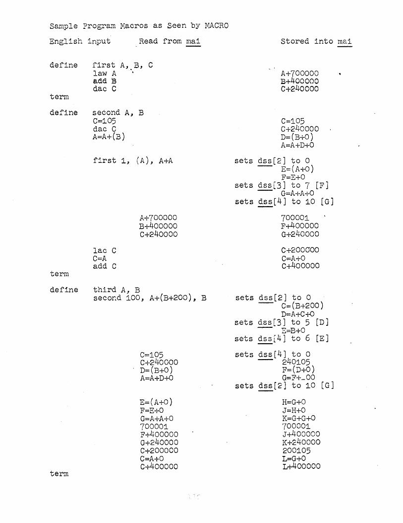
Sample Program Macros as Seen by ~ACRO
English
define
term
define
term
define
term
input
first A, law A add B dac C
second A, C=105 dac C A=A+(B)
first 1,
lac C C=A add C
Read from mai
B, C
B
(A), A+A
A+700000 B+400000 c+240000
third A, B second 100, A+(B+200), B
C=105 c+240000 D=(B+O) A=A+D+O
E=(A+O) F=E+O G=A+A+O 700001 F+400000 G+240000 C+200000 C=A+O c+4ooooo
stored into mai
A+700000 B+4ooooo C+240000
C=105 C+24oooo D=(B+O) A=A+D+O
sets dss[2] to 0 - E=(A+O)
F=E+O sets dss[3] to 7 [F]
- G=A+A+O sets ~[4] to 10 [G]
700001 F+400000 G+2400oo
C+200aoo C=A+O c+400000
sets dss[2] to 0 - C=(B+200)
D=A+C+O sets dss[3] to 5 [D)
- E=B+O sets dss[4] to 6 [E)
sets dss[4J to 0 - 240105
F=(D+O) G=F+_OO
sets dss[2]to 10 [G)
H=G+O J=H+O K=G+G+O 700001 J+400000 K+240ooo 200105 L=G+O L+400000

Octal and Binary Dlli~P of mai Table
667151 002223 705026 420314 700000 060417 400000 240000 400000
226563 . 464564 705031 721041
105 031414 240000 242102 243450 210303 043070 704204 207004
'316060 700001 400000 214163 240000 200000 041622 102076 400000
FIRST fir st
[pointer] 10 0010000 0 1(700000), 10 01100.00
o 1(400000)J 10 0001000 0 1(240000), 111.1/
SECOND sec ond [pointer] 1110 1(105) 0001000, 10 0001.000
o 1(240000), 10 0110000 110 0.(0)
01010003 10 0010000 10. 0101000 1110 O(O} 101000.0, 10 0010000 110 O{O) 0011.000g 10 0011000 1110 0(0) 0.111000; 10 0010000 10 0.010000 1110 0(0) 0000100.j o 1(700001), 10 0111000 0 1(400000), 10 000.0100
o 1(240000), 10 0001000 G 1(200000),
1.0 0010000 1110 0(0) 10010.00; 10 0001000 0 1(400000), 1111/

237071 005164 705042 460642
200 104102 161211 416060 624307 240105 047072
100 044046 111111 605101 101161 506121 700001 400000 464260 240000 200105 234062 061740 400000
THIRD thi rd
[pointer] 10 0110000 110 1(200) 00010.003
10 00100bO 10 00010.00 1110 0(0) 0101000y 10 01.10000 1110 0(0) 0011000; o. 1(240105)3 10 0101000 110 0(0) 0111.000;
10 0111000 1110 1(100) 0.000100;
10 0000100 110. 0(0) 0100100, 10 0100100 1.110 0 (0) 00.10100, 10 00001.00 10 0000100 1110 0(0) 01.10100, o 1(700001)~ 10 0010100 0 1.(400000),
10 0110100 0 1. .. ( 240000), 0 1 (200105) ~
10 000.0100 1110 0(0) 0001100j 10. 0001100 0 1(400000), 1111/
_.'_.~ .. 2

extended pdp-1 ops and macros, jan 1962
lap=cla 100 ioh=iot 1 clo=6S1600 spq=6S0500 szm=640500
define
. .
sensewitch A repeat 3, A-A+A szs A term
define initialize A, B law B dapA term
define index A, idx A
B, ,C
sas B jmp C term
define listen cla+c11+clf 1-opr-opr szf 1 1 jmp .-1 tyi term
define swap rel 98 rcl 98 term
define load A, B lio (B dio A term
define setup A, B law i B dacA term
define count A, B isp A jmp B term
113

define
define
start
. move A, B' 110 A dl0 B term
clear A, B lnlt .+2, A dzm index .-1, (dzm B+1, .-1 ;erm
114

F36 P 500-7/62