2 1 structural behavior of an air-inflated fabric arch frame
TRANSCRIPT

PROOF
ONLY
1
2 Structural Behavior of an Air-Inflated Fabric Arch Frame1
3 Xiao Guo1; Qingsong Li2; Daxu Zhang3; and Jinghai Gong4
4 Abstract: This paper2 presents experimental and numerical studies on the structural behavior of an air-inflated frame consisting of arches and5 coupling beams. In the experimental study, a full-scale specimen, which was 25.0 m long, 20.0 m wide, and 10.5 m tall, was tested under6 vertical and horizontal loading. The structural behavior of the inflated arch frame is evaluated by analyzing the load-displacement response7 and failure mode. Two vertical loading cases, in which vertical loads were respectively applied to the middle arch and to all the arches, are8 considered. A comparison of their load-displacement curves is made to evaluate the spatial action of the structure under vertical loading. For9 the horizontal loading, concentrated forces at one end of the structure can be fairly uniformly transferred to the entire structure by the coupling
10 beams. However, the arch frame exhibited slightly different lateral stiffness in the two horizontal loading cases, in which the coupling11 beams were in tension and in compression, respectively. A finite element model has been developed to predict the stresses, deformation,12 and wrinkling modes of the arch frame. The fidelity of the model is verified by comparing the prediction with the experimental data. The air-13 inflated arch frame demonstrated excellent structural integrity, and the coupling beams played an essential role in creating the spatial action.14 DOI: 10.1061/(ASCE)ST.1943-541X.0001374. © 2015 American Society of Civil Engineers.
15 Author keywords: Membrane; Inflatable structure; Experiment; Finite element; Mechanical behavior; Metal and composite structures.
16 Introduction
17 Inflatable3 structures are known as tensegrity structures, in which18 the skin is the tension member and the air is the compression19 member (Voisembert et al. 2011). Due to their advantages of light20 weight, quick deployment, and low storage volume, inflatable21 structures have been widely used in many engineering applications,22 e.g., buildings, balloons, boats, airships, and space antennas. For23 inflatable building structures, the Fuji Group Pavilion for Expo’7024 (Kawaguchi and Engineers 2011) was the largest inflated tube25 structure in the world. Since then, inflatable fabric structures have26 received great attentions as a form of modern building structures.27 A great effort has been made to investigate the behavior of28 inflatable members and structures for more than half a century.29 Early research on these structures was carried out mainly for aero-30 space applications. The pioneering work of Leonard et al. (1960)31 employed the linear plate theory to study the deflections of inflated32 wings in inflatable reentry vehicles. The inflatable tube is one of the33 simplest elements in inflatable structures technology (Nguyen et al.34 2013). Stein and Hedgepeth (1961) performed an early analysis35 to investigate the effects of average displacements of the wrinkled36 material on the behavior of inflatable beams. Based on the
37assumption of a circular and planner cross section during loading,38Comer and Levy (1963) evaluated the deflections of an inflated39cantilever beam and stresses for loads between incipient buckling40and final collapse. Fichter (1966) developed a linearized theory41with the assumption of zero twist to predict deformation of a42pin-end inflated beam under compressive axial force and transverse43load. Main et al. (1994, 1995) developed an Euler-Bernoulli beam44model and an improved bending model to predict load-deflection45behavior of inflatable fabric beams. The latter approach considered46the biaxial stress state in the beam fabric and was verified by the47experimental data of cantilever beams.48The studies on inflatable structures for ground applications be-49gan in the 1970s. As part of a systems analysis of military needs for50shelters, Steeves (1975, 1978) developed a linear beam theory and a51nonlinear finite element method to predict mechanical behavior52of pressure stabilized beams under static load. Lukasiewicz and53Balas (1990b, a) proposed two models to analyze the behavior54of a pneumatic hinge in a cylindrical free-standing inflatable55membrane, and consequently were able to predict the collapse56modes and loading capacity of the structure. Molloy et al. (1999)57employed the finite element method and shell theory to evaluate the58deflections, stability, and vibrations of a pair of pressurized arches59leaning against each other and attached at the point of contact near60their crowns. Plaut et al. (2000) developed an analytical method,61which used the linear thin-shell theory of Sanders (1959) and con-62sidered the effect of initial membrane stresses, to determine the de-63flections of an inflatable arch under snow and wind loading.64Luchsinger and Galliot (2013) employed experimental, numerical,65and analytical approaches to study the load-bearing behavior of66symmetric spindle-shaped Tensairity girders with 5-m span and67thin chords.68Researchers at the University of Nantes have performed exten-69sive studies on evaluating the behavior of inflatable membrane70tubes. Wielgosz and Thomas (2002) developed a Timoshenko’s71beam–based theory to predict deflections of inflatable fabric panels72at high pressure. Later on the theory was extended by Thomas and73Wielgosz (2004) to analyze inflated tubes. By solving a cubic equa-74tion, Thomas and Le van (2013) proposed an exact solution for75inflated orthotropic membrane tubes, with the orthotropic axes
1Ph.D. Candidate, School of Naval Architecture, Ocean and CivilEngineering, Shanghai Jiao Tong Univ., Shanghai 200240, China. E-mail:[email protected]
2Ph.D. Candidate, School of Naval Architecture, Ocean and CivilEngineering, Shanghai Jiao Tong Univ., Shanghai 200240, China. E-mail:[email protected]
3Associate Professor, School of Naval Architecture, Ocean and CivilEngineering, Shanghai Jiao Tong Univ., Shanghai 200240, China (corre-sponding author). E-mail: [email protected]
4Professor, School of Naval Architecture, Ocean and Civil Engineering,Shanghai Jiao Tong Univ., Shanghai 200240, China. E-mail: [email protected]
Note. This manuscript was submitted on January 14, 2015; approved onJune 10, 2015No Epub Date. Discussion period open until 0, 0; separatediscussions must be submitted for individual papers. This paper is part ofthe Journal of Structural Engineering, © ASCE, ISSN 0733-9445/(0)/$25.00.
© ASCE 1 J. Struct. Eng.
PROOF
ONLY
76 parallel to the circumference and the axis of the tube. In the same77 year, Nguyen et al. (2013) presented an analytical solution for the78 inflation of an orthotropic membrane tube whose warp or weft di-79 rections are arbitrarily orientated. Bouzidi et al. (2013) investigated80 the quasistatic deployment of membrane tubes numerically and ex-81 perimentally. A minimization problem was formulated to consider82 the self-contact of membranes and a descent algorithm was em-83 ployed to tackle the issue of numerical singularity.84 Davids and coauthors focused on characterizing the behavior of85 inflatable fabric arches used in tent structures. Davids et al. (2007)86 developed a Timoshenko beam element, which incorporates pres-87 sure effects, wrinkling, and geometric nonlinearities, to predict the88 behavior of pressurized tubes made from woven fabric. Davids and89 Zhang (2008) then extended the element formulation to an incre-90 mental form, and compared the theory with load-deflection experi-91 ments of woven fabric tubes. Davids (2009) used the theory to92 evaluate the in-plane load deflection and buckling of pressurized93 fabric arches, and test data of a 9.5-m-span semicircular arch under94 a central concentrated load were presented. Malm et al. (2009) re-95 ported experimental torsion testing and bend test results of woven96 fabric beams, and a three-dimensional membrane finite element97 model was validated by the experimental results. More recently,98 bending and torsion tests were performed by Brayley et al. (2012)99 to quantify the load-displacement response of inflated braided fab-
100 ric arches and beams with bonded external reinforcing straps.101 A number of prior studies have explored the dynamic character-102 istics of inflatable members. Wei et al. (2008) and Wang et al.103 (2014) carried out experimental studies to investigate the dynamic104 deployment behavior of folded inflated membrane tubes, and per-105 formed numerical simulations to evaluate the effects of wrinkles on106 the vibration of an inflated arch, respectively. Apedo et al. (2009,107 2010) proposed a theoretical approach and a nonlinear finite108 element method, which took into account geometric nonlinearities109 and the inflation pressure follower force effect, to analyze the110 bending behavior of inflatable beams made from orthotropic fabric.111 Rodriguez et al. (2011) employed an explicit scheme to predict the112 final shape of inflatable fabric structures by extending the dynamic113 relaxation method with kinetic damping. It demonstrated that the114 method converges very rapidly despite the complex behavior.115 Furuya and Yokoyama (2013) used a linear membrane theory116 and a nonlinear finite element model to study the bending behavior,117 wrinkle, and collapse mode of bellows-type inflatable tubes. He118 et al. (2013) carried out both theoretical and experimental stud-119 ies to investigate the load-defection behavior, vibrational modes,120 and frequency of an inflatable cantilever beam, made of an121 airship envelope4 fabric, Uretek3216L5 , and ETFE (ethylene-122 tetrafluoroethylene).123 It can be noted that the majority of the available literature ex-124 amines the behavior of individual inflatable fabric members,125 e.g., tubes or arches. However, the performance of inflatable fabric126 structures has been scarcely investigated. Barbero et al. (2013) car-127 ried out an experimental study to evaluate the performance of full-128 scale inflatable plug structures for flood protection of tunnels.129 While the response of individual members provides fundamental130 information for design, the overall behavior of an inflatable struc-131 ture is even more critical. To this end, the present paper addresses132 the structural behavior of a three-dimensional inflated fabric frame,133 in which the spatial action and the structural integrity under vertical134 and horizontal loadings are evaluated. In comparison with the struc-135 ture of the Fuji Group Pavilion, in which arches are immediately136 next to the adjacent ones, arch frames use many fewer arches. They137 are lightweight and can be fully deployed in a short time. These138 features make them favorable candidates for movable structures.139 In addition, previous research mainly employed analytical methods
140and therefore test data are still scarce. This paper presents a full-141scale experimental test study and a numerical analysis to investigate142the structural behavior of an inflated arch frame. In the beginning,143the paper describes the full-scale experimental program, observa-144tions, and test results. Then the formulation of a finite element145model considering the membrane ground contact and membrane146wrinkling is introduced. The finite element results are verified147by comparing the predicted wrinkling mode and load-displacement148curves with those observed and measured in the experiment, re-149spectively. Finally, a discussion section is present to evaluate the150integrity and the spatial action of the arch frame.
151Experimental Program
152Test Specimen
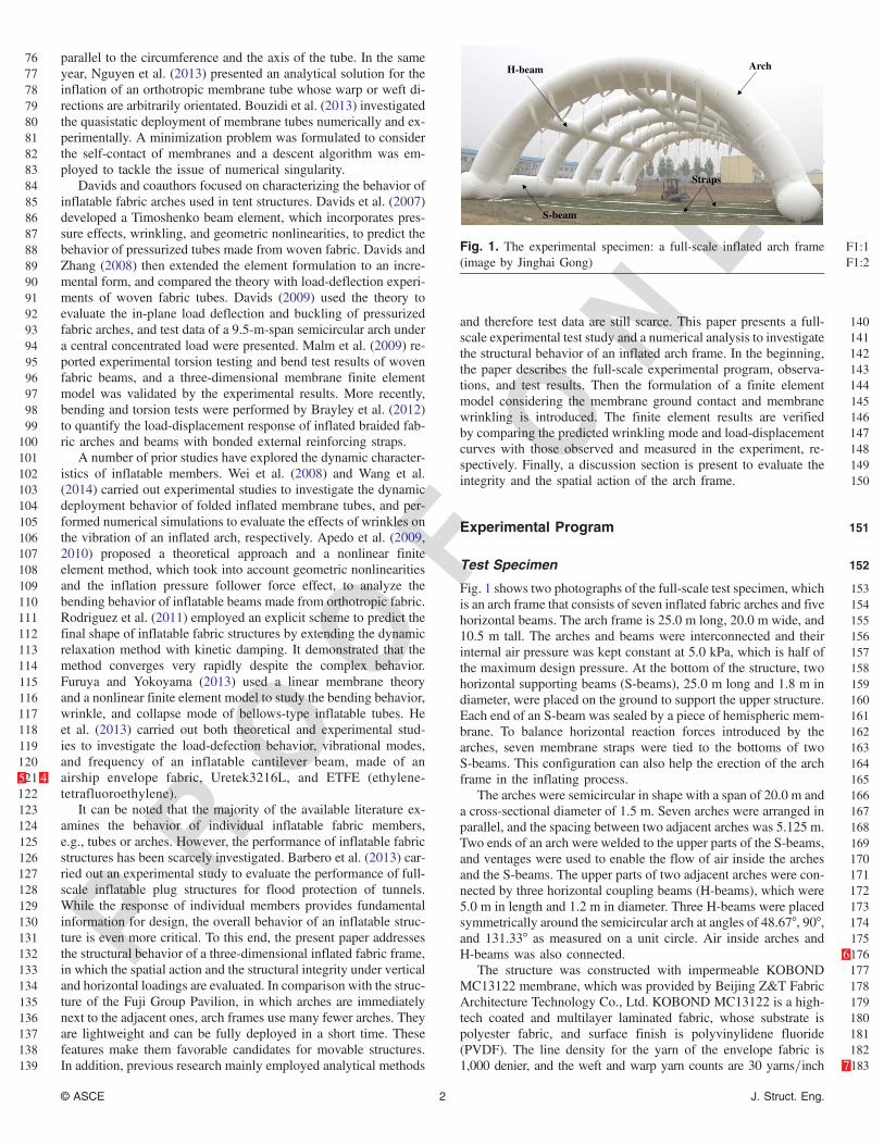
153Fig. 1 shows two photographs of the full-scale test specimen, which154is an arch frame that consists of seven inflated fabric arches and five155horizontal beams. The arch frame is 25.0 m long, 20.0 m wide, and15610.5 m tall. The arches and beams were interconnected and their157internal air pressure was kept constant at 5.0 kPa, which is half of158the maximum design pressure. At the bottom of the structure, two159horizontal supporting beams (S-beams), 25.0 m long and 1.8 m in160diameter, were placed on the ground to support the upper structure.161Each end of an S-beam was sealed by a piece of hemispheric mem-162brane. To balance horizontal reaction forces introduced by the163arches, seven membrane straps were tied to the bottoms of two164S-beams. This configuration can also help the erection of the arch165frame in the inflating process.166The arches were semicircular in shape with a span of 20.0 m and167a cross-sectional diameter of 1.5 m. Seven arches were arranged in168parallel, and the spacing between two adjacent arches was 5.125 m.169Two ends of an arch were welded to the upper parts of the S-beams,170and ventages were used to enable the flow of air inside the arches171and the S-beams. The upper parts of two adjacent arches were con-172nected by three horizontal coupling beams (H-beams), which were1735.0 m in length and 1.2 m in diameter. Three H-beams were placed174symmetrically around the semicircular arch at angles of 48.67°, 90°,175and 131.33° as measured on a unit circle. Air inside arches and176H-beams was also connected. 6177The structure was constructed with impermeable KOBOND178MC13122 membrane, which was provided by Beijing Z&T Fabric179Architecture Technology Co., Ltd. KOBOND MC13122 is a high-180tech coated and multilayer laminated fabric, whose substrate is181polyester fabric, and surface finish is polyvinylidene fluoride182(PVDF). The line density for the yarn of the envelope fabric is1831,000 denier, and the weft and warp yarn counts are 30 yarns=inch 7
Arch H-beam
S-beam
Straps
F1:1Fig. 1. The experimental specimen: a full-scale inflated arch frameF1:2(image by Jinghai Gong)
© ASCE 2 J. Struct. Eng.

PROOF
ONLY
184 and 30 yarns=inch, respectively. This fabric shows 1, 100 g=m2
185 areal density. A monouniaxial tensile test following the MASJ186 (1995) standard was carried out to measure the material properties187 of the KOBOND MC13122 membrane. The maximum tensile188 strengths for the warp and weft directions are 71.10 and 65.39 kN=m,189 respectively. Fig. 2 shows the stress-strain curves for both190 directions.
191 Test Setup
192 Fig. 3 shows photographs of the inflation sequence of the arch193 frame. Some large equipment was used in the test and a significant194 amount of work was involved in setting up the test. Inflation pres-195 sure was generated and controlled by a set of equipment, including196 the high-flow fan units and the frequency control system both pow-197 ered by diesel-engine generator units. A forklift was used to erect198 the arch frame by lifting the semi-inflated arch. Membrane straps,
199ropes, sandbags, hooks, and trestles were used to apply vertical and200horizontal loads. Loading trestles were mainly used to fix pulleys201for changing the loading direction from vertical to horizontal.
202Measurements
203A total station was used to measure the displacements of the ob-204servation points close to the midspans of the inflated arches. As205shown in Fig. 4, these points are on one side of each arch and206are marked as black dots. It also can be seen that arches are denoted207by Arch-A to Arch-E in accordance with the distance to the total208station. Since the distance between Arch-E and the station was out209of the measurement range, no data were collected for this arch. To210ensure that the experimental results were measured at a steady state,211the deformation data were read and recorded in 3 to 5 minutes after212the loads were applied. In order to eliminate the effects of residual213deformation caused by previous loading cases, the initial positions214of the arches were measured at the beginning of each loading case.
215Loading
216Snow weight and wind pressure are two major building loads for an217inflatable structure. In the current study, vertical and horizontal218forces were applied to the structure to simulate the effects of snow219and wind loads. Specifically, two vertical and two horizontal load-220ing cases were carried out to evaluate the structural performance of221the inflated arch frame.222Fig. 5 illustrates a dimensioned drawing of the experimental223setup, in which three point loading is applied on one of the frame224arches. Four membrane straps are bound to the arch to transfer the225vertical forces at three locations: one is at the midspan and the other226two are higher than the H-beams. A 300-mm pull strap is connected227to S-beams to balance the horizontal reaction of the arch.228One vertical loading case is called the middle-arch case, in229which only Arch-C was loaded by three sets of suspended sand-230bags. The objective of this loading case is twofold: (1) to evaluate231the spatial action of the arch frame and its effects on the behavior232of a local arch, and (2) to investigate the load transfer capacity
F2:1 Fig. 2. Uniaxial tensile load-displacement curves of the KOBONDF2:2 MC13122 membrane
(a) (b)
(c) (d)
F3:1 Fig. 3. The inflation sequence of the full-scale inflatable arch frame (images by Jinghai Gong)
© ASCE 3 J. Struct. Eng.

PROOF
ONLY
233of H-beams subject to lateral deformation. The loading history of234this test is listed in Table 1.235The other vertical loading case is called the all-arch case, where236all inflated arches were loaded by three point vertical forces. It237should be noted that the loads applied to the double arches238(Arch-A and Arch-E), were twice the forces applied to the single239arches (Arch-B, Arch-C, and Arch-D). This allows us to obtain a240uniform deflection of the whole structure. In addition, the incre-241ment of loading levels is larger than that of the middle-arch loading242case. This is because the test was carried out on a very windy day243and the inflation stage took much longer than planned. To complete244the test before sunset, the number of loading levels was then reduced245to three. Table 1 summarizes the loading history of this loading case.
F4:1 Fig. 4. A schematic drawing of the experimental measurement setup (image by Jinghai Gong)
F5:1 Fig. 5. A dimensioned drawing of the experimental setup to apply three point loading on a single arch
Table 1. Loading History of the Four Loading Cases
T1:1 Cases
Loading levels (kN=point)
T1:2 1 2 3 4 5 6 7
T1:3 Middle-arch (Arch-C)vertical loading case, FV1
0.3 0.6 0.9 1.2 1.5 1.8 2.1
T1:4 All-arch vertical loadingcase, FV2
a0.45 0.75 0.9 — — — —
T1:5 Two longitudinal horizontalloading cases, FH
0.9 1.8 2.7 3.6 — — —
aThe loads applied to Arch-A and Arch-E were twice the value listedhere.
© ASCE 4 J. Struct. Eng.
PROOF
ONLY
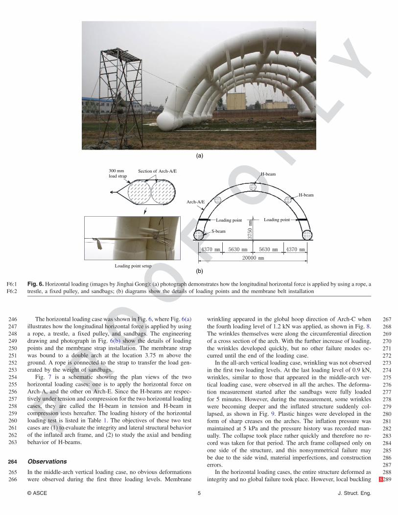
246 The horizontal loading case was shown in Fig. 6, where Fig. 6(a)247 illustrates how the longitudinal horizontal force is applied by using248 a rope, a trestle, a fixed pulley, and sandbags. The engineering249 drawing and photograph in Fig. 6(b) show the details of loading250 points and the membrane strap installation. The membrane strap251 was bound to a double arch at the location 3.75 m above the252 ground. A rope is connected to the strap to transfer the load gen-253 erated by the weight of sandbags.254 Fig. 7 is a schematic showing the plan views of the two255 horizontal loading cases: one is to apply the horizontal force on256 Arch-A, and the other on Arch-E. Since the H-beams are respec-257 tively under tension and compression for the two horizontal loading258 cases, they are called the H-beam in tension and H-beam in259 compression tests hereafter. The loading history of the horizontal260 loading test is listed in Table 1. The objectives of these two test261 cases are (1) to evaluate the integrity and lateral structural behavior262 of the inflated arch frame, and (2) to study the axial and bending263 behavior of H-beams.
264 Observations
265 In the middle-arch vertical loading case, no obvious deformations266 were observed during the first three loading levels. Membrane
267wrinkling appeared in the global hoop direction of Arch-C when268the fourth loading level of 1.2 kN was applied, as shown in Fig. 8.269The wrinkles themselves were along the circumferential direction270of a cross section of the arch. With the further increase of loading,271the wrinkles developed quickly, but no other failure modes oc-272curred until the end of the loading case.273In the all-arch vertical loading case, wrinkling was not observed274in the first two loading levels. At the last loading level of 0.9 kN,275wrinkles, similar to those that appeared in the middle-arch ver-276tical loading case, were observed in all the arches. The deforma-277tion measurement started after the sandbags were fully loaded278for 5 minutes. However, during the measurement, some wrinkles279were becoming deeper and the inflated structure suddenly col-280lapsed, as shown in Fig. 9. Plastic hinges were developed in the281form of sharp creases on the arches. The inflation pressure was282maintained at 5 kPa and the pressure history was recorded man-283ually. The collapse took place rather quickly and therefore no re-284cord was taken for that period. The arch frame collapsed only on285one side of the structure, and this nonsymmetrical failure may286be due to the side wind, material imperfections, and construction287errors.288In the horizontal loading cases, the entire structure deformed as289integrity 8and no global failure took place. However, local buckling
(a)
Section of Arch-A/E300 mmload strap
Loading point setup
Loading point
Arch-A/E
S-beam
H-beam
H-beam
Loading point
(b)
F6:1 Fig. 6. Horizontal loading (images by Jinghai Gong): (a) photograph demonstrates how the longitudinal horizontal force is applied by using a rope, aF6:2 trestle, a fixed pulley, and sandbags; (b) diagrams show the details of loading points and the membrane belt installation
© ASCE 5 J. Struct. Eng.

PROOF
ONLY
290 was found at the loading points on arches due to the stress concen-291 tration. In the H-beam in compression case, the ends of the S-beams292 close to Arch-E tilted away from the ground when the load was up293 to 0.8 kN.
294 Experimental Results
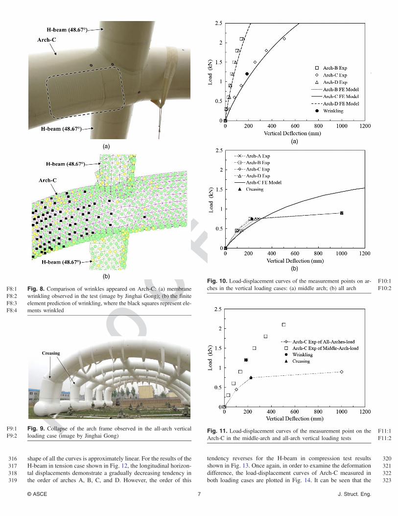
295 Fig. 10 plots the load-deflection curves of the two vertical loading296 cases. For the middle-arch loading case [Fig. 10(a)], it can be seen297 that the overall load-deflection curves display moderate nonlinear298 character. The deflection of Arch-C is much greater than those of299 Arch-B and Arch-D. As expected, the deformations of Arch-B and300 Arch-D are nearly identical due to the symmetry. As aforemen-301 tioned, membrane wrinkling, denoted by the black dot, took place
302on Arch-C at the load of 1.2 kN. For the all-arch loading test results303[Fig. 10(b)], all the load-deflection curves are very similar and304their nonlinearity is very severe. The slopes of the Arch-C curve305for the three loading levels are 4.37 kN=mm, 2.42 kN=mm, and3060.19 kN=mm, respectively. As shown by the black triangle, mem-307brane creases occurred at the third loading level, and thereafter the308deflections increased dramatically. In order to identify the deforma-309tion difference of the two vertical cases, the load-deflection curves310of Arch-C in both cases are shown in Fig. 11. It can be seen that the311maximum load of the middle-arch test is more than twice that of the312all-arch case, and the initial stiffness of curve for the middle-arch313case is approximately twice as high as that for the all-arch case.314The load-horizontal displacement curves of the two horizontal315loading cases are plotted in Figs. 12 and 13, respectively. The overall
F7:1 Fig. 7. Plan views of the horizontal loading (images by Jinghai Gong): (a) H-beam in tension, where the longitudinal horizontal force is applied onF7:2 Arch-A; (b) H-beam in compression, where the longitudinal horizontal force is applied on Arch-E
© ASCE 6 J. Struct. Eng.
PROOF
ONLY
316 shape of all the curves is approximately linear. For the results of the317 H-beam in tension case shown in Fig. 12, the longitudinal horizon-318 tal displacements demonstrate a gradually decreasing tendency in319 the order of arches A, B, C, and D. However, the order of this
320tendency reverses for the H-beam in compression test results321shown in Fig. 13. Once again, in order to examine the deformation322difference, the load-displacement curves of Arch-C measured in323both loading cases are plotted in Fig. 14. It can be seen that the
F8:1 Fig. 8. Comparison of wrinkles appeared on Arch-C: (a) membraneF8:2 wrinkling observed in the test (image by Jinghai Gong); (b) the finiteF8:3 element prediction of wrinkling, where the black squares represent ele-F8:4 ments wrinkled
Creasing
F9:1 Fig. 9. Collapse of the arch frame observed in the all-arch verticalF9:2 loading case (image by Jinghai Gong)
F10:1Fig. 10. Load-displacement curves of the measurement points on ar-F10:2ches in the vertical loading cases: (a) middle arch; (b) all arch
F11:1Fig. 11. Load-displacement curves of the measurement point on theF11:2Arch-C in the middle-arch and all-arch vertical loading tests
© ASCE 7 J. Struct. Eng.

PROOF
ONLY
324 longitudinal horizontal displacement of the H-beam in compression325 is slightly greater than that of the H-beam in tension, and the per-326 centages of increase per load level are 33.3, 14.3, 21.1, and 18.2%.
327 Finite Element Model
328 The structural behavior of the inflated arch frame under the afore-329 mentioned four loading conditions was studied by employing a330 nonlinear three-dimensional membrane finite element model. An331 analysis and design software for membrane and cable structures,332 SMCAD (2012) was used to perform the simulation. SMCAD333 was first developed by the second author in 2003 and it is special-334 ized for analyzing flexible structures consisting of membranes and335 cables. SMCAD can consider the geometrical nonlinearity and ten-336 sion-only membrane elements. Finite strain theory in continuum337 mechanics was used to describe the undeformed and deformed con-338 figurations, and the Lagrangian-Green strain was adopted to char-339 acterize large membrane deformation. The geometrically nonlinear
340analysis was carried out by use of an incremental formulation of341equilibrium equations. The modified Newton-Raphson method342(Bathe and Cimento 1980) was used to solve the incremental equi-343librium equations. It requires fewer stiffness reformations than full344Newton iteration, and the stiffness matrix is only updated when an345accepted criterion is not satisfied. The general-purpose three-node346constant strain membrane element was used to mesh the entire347model. A wrinkling criterion (Seokwoo and Seyoung 1997) was348introduced to define the stiffness matrix of the membrane element,349and more details will be described later.
350Geometry and Mesh
351The geometry and the mesh of the finite element model for the in-352flated arch frame was created in SMCAD. The adjacent members,353e.g., arches to H-beams, arches to S-beams, and straps to S-beams,354are connected by common nodes, and therefore their displacement355compatibility of intersecting edges is maintained. Arch-A and356Arch-E are double arches and they are also connected by common357nodes at the contact edges. Local coordinates of the three-node el-358ements may not match the fabrics’ orientations. To ensure that the359fabric’s 9local warp and weft directions are correctly defined in the360constitutive equation, a coordinate transformation matrix has been361used to consider the mismatch angle for each element. A mesh re-362finement study by Christopher et al. (2009) demonstrated that a363global element size of 20 mm was fairly accurate to model the364four-point bending of an air-inflated membrane tube. Considering365the large scale of the current model, the global mesh employed366element sizes in a range from 20 to 30 mm, and the total number367of elements is 60,734.
368Material Properties
369The monouniaxial tensile experimental results show that the370KOBOND MC13122 membrane demonstrates nonlinear ortho-371tropic properties (Fig. 2). In the current experiment study, the in-372flation pressure was maintained at 5 kPa, and the membrane373stresses were less than 10 kN=m. It can be seen from Fig. 2 that374stress-strain curves are approximately linear below this stress level.375Hence, the membrane is assumed to be elastic orthotropic in the376current analysis. The secant moduli of 625 and 100 kN=m at the
F12:1 Fig. 12. Load-displacement curves of the measurement points on ar-F12:2 ches in the horizontal loading case of the H-beam in tension: a com-F12:3 parison of the experimental data and the finite element results
F13:1 Fig. 13. Load-displacement curves of the measurement points on ar-F13:2 ches in the horizontal loading case of the H-beam in compression: aF13:3 comparison of the experimental data and the finite element results
F14:1Fig. 14. Load-displacement curves of the measurement point on Arch-F14:2C in the horizontal loading cases: a comparison of the results for the H-F14:3beam in tension and H-beam in compression cases
© ASCE 8 J. Struct. Eng.

PROOF
ONLY
377 tensile stress of 10 kN=m were assigned to elastic properties in the378 warp and weft directions, respectively.379 Membrane wrinkling is a common instability phenomenon of380 membrane structures under compression or shear loads. The prin-381 cipal stress wrinkling criterion (Seokwoo and Seyoung 1997) is382 adopted in the current finite element analysis. Depending on the383 loading conditions, a membrane element has one of the following384 three stress states:385 1. Taut state: minor principal stress σ2 > 0. No wrinkling occurs386 and the element stresses are computed normally;387 2. Slack state: major principal stress σ1 ≤ 0. The membrane388 element has no stress and the element stiffnesses are set to very389 small values; and390 3. Wrinkled state: Principal stresses σ1 > 0 and σ2 ≤ 0. The ele-391 ment is under uniaxial tension and the membrane stresses are392 updated as follows. Take the directions of principal stresses as393 the wrinkling coordinate system (r-s) and the constitutive394 equation becomes
8<:
σ̂rr
σ̂ss
σ̂rs
9=; ¼
24a 0 0
0 αa 0
0 0 αa
358<:
ε̂rrε̂ssε̂rs
9=;þ
8<:
0σ̂rr0σ̂ss0σ̂rs
9=; ð1Þ
where σ̂rr, σ̂ss, and σ̂rs = current membrane stresses; ε̂rr, ε̂ss,395 and ε̂rs = current membrane strains; 0σ̂rr, 0σ̂ss, and 0σ̂rs = in-396 itial membrane stresses; α is a very small positive coefficient397 to maintain numerical stability; and
a ¼ 1
C22C33 − C23C32
½C11ðC22C33 − C23C32Þ
þC12ðC23C31 − C21C33Þ þ C13ðC32C21 − C31C22Þ� ð2Þwhere Cij (for i, j ¼ 1, 2, and 3)10 are elements of the stiffness
398 matrix in the local coordinate system.
399 Boundary Conditions and Loads
400 As shown in Fig. 15, the contact interaction between the401 S-beam and the ground are modeled. When the S-beam is under402 vertical compression, no penetration into the ground is allowed403 and the lower circular part of the S-beam cross section flattens404 [Fig. 15(a)]. When the S-beam is under lifting, the contact pair be-405 tween the S-beam end and the ground separates and the S-beam406 end tilts up [Fig. 15(b)]. In order to avoid any rigid motion, the407 displacements of nodes touching the ground are constrained in408 the z-directions. However, this constraint is deactivated to allow409 the separation when its nodal reaction force in the z-direction be-410 comes positive. To model the frictional behavior of the contact be-411 tween S-beams and the ground, spring elements with the axial412 stiffness of 1.0 kN=m are assigned to the x- and y-directions of413 the contact nodes. The spring stiffness is approximately evaluated414 by the ratio of the maximum horizontal load to the average sliding415 distance of S-beams. The inflation load is modeled by applying416 uniformly distributed pressure on membrane elements. The infla-417 tion load is treated as pressure follower forces, which change418 their directions each time the normal to the surface changes in419 the current configuration, and are updated at the beginning of each420 load increment.
421 Predictions
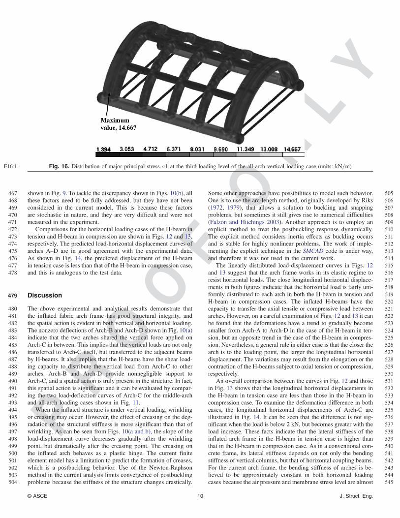
422 Fig. 16 shows the distribution of major principal stress of the whole423 structure at the last loading level of the all-arch loading case. It can424 be seen that the majority of the membrane stresses11 are below425 10 kN=m, apart from a small local region where Arch-E meets
426S-beams. The deformed and undeformed shapes of the arch427frame model under four loading cases are presented in Fig. 17.428The prediction of the middle-arch vertical loading case is shown429in Fig. 17(a), and the vertical deflection of the middle arch is much430greater than that of the adjacent arches. The deformation of the two431double arches at the far ends can hardly be seen. Fig. 17(b) plots the432results of the all-arch vertical loading case, and the deflections of433all the arches are almost the same. The shapes of the H-beam in434tension horizontal loading case are shown in Fig. 17(c). All the435arches tilt to the right side slightly, and the double arch on the right436has the largest longitudinal horizontal displacement. Fig. 17(d)437demonstrates the deformation of the H-beam in compression case.438This time the double arch on the left has the largest displacement439and the left end of the S-beam is tilted up. In both horizontal load-440ing conditions, local buckling, marked by dotted circles, appeared441at the loading points. All the deformed shapes depicted in Fig. 17442are consistent with the experimental observations.443Fig. 10 shows comparisons of the predicted load-deflection444curves and experimental data for the two vertical loading cases.445It can be seen from Fig. 10(a) that in general the prediction has446a good correlation with the test data for the middle-arch case. As447shown in Fig. 8, the current model is also capable of predicting the448wrinkling location observed in the test. For the all-arch test case449shown in Fig. 10(b), the finite element results agree well with450the test data before the point of creasing, but thereafter underpredict451the deflection. This is because the current model is not capable452of capturing the creasing mode and therefore fails to predict the453effect of the creases on the deflections. Both wrinkles and creases454are mechanical instabilities of membranes under compression.455Membrane wrinkles usually have a relatively uniform wavy shape456and are evenly distributed in a certain area. In the current analysis,457the wrinkling of fabrics is modeled in a smeared fashion and there-458fore only their locations, but no three-dimensional wrinkles, were459shown in Fig. 8(b). Membrane creases are local sharp folds, which460can be initiated from wrinkling. Creasing is a postbuckling phe-461nomena and a converged solution is difficult to achieve by using462the current Newton-Raphson method. To the authors’ best knowl-463edge, the modeling of membrane creasing in a large-scale structure464remains as a challenge problem for numerical analysis. Factors in-465cluding side wind, material imperfections, and construction errors466may have influences on the initiation and development of creasing
F15:1Fig. 15. Schematic of the contact interaction between the S-beam andF15:2the ground: (a) contact between the S-beam cross section and theF15:3ground; (b) separation between the end of the S-beam and the ground
© ASCE 9 J. Struct. Eng.
PROOF
ONLY
467 shown in Fig. 9. To tackle the discrepancy shown in Figs. 10(b), all468 these factors need to be fully addressed, but they have not been469 considered in the current model. This is because these factors470 are stochastic in nature, and they are very difficult and were not471 measured in the experiment.472 Comparisons for the horizontal loading cases of the H-beam in473 tension and H-beam in compression are shown in Figs. 12 and 13,474 respectively. The predicted load-horizontal displacement curves of475 arches A–D are in good agreement with the experimental data.476 As shown in Fig. 14, the predicted displacement of the H-beam477 in tension case is less than that of the H-beam in compression case,478 and this is analogous to the test data.
479 Discussion
480 The above experimental and analytical results demonstrate that481 the inflated fabric arch frame has good structural integrity, and482 the spatial action is evident in both vertical and horizontal loading.483 The nonzero deflections of Arch-B and Arch-D shown in Fig. 10(a)484 indicate that the two arches shared the vertical force applied on485 Arch-C in between. This implies that the vertical loads are not only486 transferred to Arch-C itself, but transferred to the adjacent beams487 by H-beams. It also implies that the H-beams have the shear load-488 ing capacity to distribute the vertical load from Arch-C to other489 arches. Arch-B and Arch-D provide nonnegligible support to490 Arch-C, and a spatial action is truly present in the structure. In fact,491 this spatial action is significant and it can be evaluated by compar-492 ing the two load-deflection curves of Arch-C for the middle-arch493 and all-arch loading cases shown in Fig. 11.494 When the inflated structure is under vertical loading, wrinkling495 or creasing may occur. However, the effect of creasing on the deg-496 radation of the structural stiffness is more significant than that of497 wrinkling. As can be seen from Figs. 10(a and b), the slope of the498 load-displacement curve decreases gradually after the wrinkling499 point, but dramatically after the creasing point. The creasing on500 the inflated arch behaves as a plastic hinge. The current finite501 element model has a limitation to predict the formation of creases,502 which is a postbuckling behavior. Use of the Newton-Raphson503 method in the current analysis limits convergence of postbuckling504 problems because the stiffness of the structure changes drastically.
505Some other approaches have possibilities to model such behavior.506One is to use the arc-length method, originally developed by Riks507(1972, 1979), that allows a solution to buckling and snapping508problems, but sometimes it still gives rise to numerical difficulties509(Falzon and Hitchings 2003). Another approach is to employ an510explicit method to treat the postbuckling response dynamically.511The explicit method considers inertia effects as buckling occurs512and is stable for highly nonlinear problems. The work of imple-513menting the explicit technique in the SMCAD code is under way,514and therefore it was not used in the current work.515The linearly distributed load-displacement curves in Figs. 12516and 13 suggest that the arch frame works in its elastic regime to517resist horizontal loads. The close longitudinal horizontal displace-518ments in both figures indicate that the horizontal load is fairly uni-519formly distributed to each arch in both the H-beam in tension and520H-beam in compression cases. The inflated H-beams have the521capacity to transfer the axial tensile or compressive load between522arches. However, on a careful examination of Figs. 12 and 13 it can523be found that the deformations have a trend to gradually become524smaller from Arch-A to Arch-D in the case of the H-beam in ten-525sion, but an opposite trend in the case of the H-beam in compres-526sion. Nevertheless, a general rule in either case is that the closer the527arch is to the loading point, the larger the longitudinal horizontal528displacement. The variations may result from the elongation or the529contraction of the H-beams subject to axial tension or compression,530respectively.531An overall comparison between the curves in Fig. 12 and those532in Fig. 13 shows that the longitudinal horizontal displacements in533the H-beam in tension case are less than those in the H-beam in534compression case. To examine the deformation difference in both535cases, the longitudinal horizontal displacements of Arch-C are536illustrated in Fig. 14. It can be seen that the difference is not sig-537nificant when the load is below 2 kN, but becomes greater with the538load increase. These facts indicate that the lateral stiffness of the539inflated arch frame in the H-beam in tension case is higher than540that in the H-beam in compression case. As in a conventional con-541crete frame, its lateral stiffness depends on not only the bending542stiffness of vertical columns, but that of horizontal coupling beams.543For the current arch frame, the bending stiffness of arches is be-544lieved to be approximately constant in both horizontal loading545cases because the air pressure and membrane stress level are almost
F16:1 Fig. 16. Distribution of major principal stress σ1 at the third loading level of the all-arch vertical loading case (units: kN=m)
© ASCE 10 J. Struct. Eng.

PROOF
ONLY
546 consistent. However the bending stiffness of H-beams may vary547 because the tensile membrane stresses in the H-beam in tension548 case are higher than those in the H-beam in compression case.549 Usually, the stiffness of membrane structures is sensitive to the550 stress level, and normally a higher stress level increases their stiff-551 ness. This can explain the slightly higher bending stiffness of552 H-beams in the H-beam in tension case because their membrane553 stress level is higher in the two horizontal loading cases.
554The above discussion shows that the contribution of the555H-beams to the integrity and the spatial action of the arch frame556is essential. The H-beams connected the separated arches together557and the formed arch frame has a totally different structural behavior558than an isolated arch. The vertical load on a single arch can be dis-559tributed to other arches, and therefore its vertical loading capacity is560enhanced. The horizontal load can also be transferred to the entire561structure. The lateral stiffness of the structure is not a sum of the
F17:1 Fig. 17. Deformed and undeformed shapes of the finite element models: (a) middle-arch vertical loading; (b) all-arch vertical loading; (c) H-beam inF17:2 tension longitudinal horizontal loading; (d) H-beam in compression longitudinal horizontal loading
© ASCE 11 J. Struct. Eng.
PROOF
ONLY
562 lateral stiffness of arches, and the effects of the horizontal coupling563 beams need to be considered.
564 Conclusions
565 This paper investigates the structural behavior of a three-566 dimensional air-inflated fabric arch frame by using physical testing567 and finite element methods. Two vertical and two horizontal load-568 ing cases were used to discover the spatial action and integrity of569 the structure. The following conclusions can be drawn:570 1. The middle-arch vertical loading results showed that the loads571 were distributed in the in-plane and out-of-plane directions of572 an arch and the H-beams had the capacity to transfer shear573 loads;574 2. A comparison of the middle-arch and the all-arch loading re-575 sults demonstrated that a strong spatial action was present in576 the structure and it helped to reduce the arch deflection in the577 middle-arch case;578 3. The two horizontal loading cases indicated that the arch frame579 can resist horizontal loads as integrity, but its lateral stiffness in580 the H-beam in tension case was higher than that in the H-beam581 in compression case. H-beams had the capacity to transfer ax-582 ial tension and compression, and bending. H-beams coupled583 the separate arches together and they were critical members for584 the inflated arch frame to establish the structural integrity;585 4. The effect of wrinkling on the structural stiffness was minimal,586 but the presence of creasing can result in catastrophic failure of587 the structure; and588 5. In general, the finite element results have good correlation589 with the experimental data. The current model can predict590 membrane wrinkling, but not local creasing. This is a signifi-591 cant limitation of the model. Use of the arch-length algorithm592 or the explicit technique provides an opportunity to solve the593 problem. Further work needs to be performed to improve this594 limit of the current model.
595 Acknowledgments
596 The authors gratefully acknowledge financial support from597 National Natural Science Foundation of China (NSFC) under Grant598 No. 51178263. Beijing Z&T Fabric Architecture Technology Co.,599 Ltd is acknowledged for providing the membrane materials and600 assisting with the experiments.
601 References
602 Apedo, K. L., Ronel, S., Jacquelin, E., Bennani, A., and Massenzio, M.603 (2010). “Nonlinear finite element analysis of inflatable beams604 made from orthotropic woven fabric.” Int. J. Solids Struct., 47(16),605 2017–2033.606 Apedo, K. L., Ronel, S., Jacquelin, E., Massenzio, M., and Bennani, A.607 (2009). “Theoretical analysis of inflatable beams made from orthotropic608 fabric.” Thin-Walled Struct., 47(12), 1507–1522.12609 Barbero, E. J., Sosa, E. M., and Thompson, G. J. (2013). “Testing of full-610 scale confined inflatable for the protection of tunnels.” 6th Int. Conf. on611 Textile Composites and Inflatable Structures, Structural Membrane612 2013, Munich, Germany.13613 Bathe, K. J., and Cimento, A. P. (1980). “Some practical procedures for the614 solution of nonlinear finite element methods.” Comput. Methods Appl.615 Mech. Eng., 22(1), 59–85.616 Bouzidi, R., Buytet, S., and Le van, A. (2013). “A numerical and exper-617 imental study of the quasi-static deployment of membrane tubes.” Int. J.618 Solids Struct., 50(5), 651–661.
619Brayley, K. E., Davids, W. G., and Clapp, J. D. (2012). “Bending response620of externally reinforced, inflated, braided fabric arches and beams.”621Constr. Build Mater., 30, 50–58. 14622Christopher, G. M., Davids, W. G., Peterson, M. L., and Turner, A. W.623(2009). “Experimental characterization and finite element analysis of624inflated fabric beams.” Constr. Build Mater., 23(5), 2027–2034.625Comer, R. L., and Levy, S. (1963). “Deflections of an inflated circular-626cylindrical cantilever beam.” AIAA J., 1(7), 1652–1655.627Davids, W. G. (2009). “In-plane load-deflection behavior and buckling of628pressurized fabric arches.” J. Struct. Eng., 10.1061/(ASCE)0733-9445629(2007)133:7(990), 990–998.630Davids, W. G., and Zhang, H. (2008). “Beam finite element for nonlinear631analysis of pressurized fabric beam-columns.” Eng. Struct., 30(7),6321969–1980.633Davids, W. G., Zhang, H., and Turner, A. W. (2007). “Beam finite-element634analysis of pressurized fabric tubes.” J. Struct. Eng., 10.1061/(ASCE)635ST.1943-541X.0000068, 1320–1329. 15 16636Falzon, G. G., and Hitchings, D. (2003). “Capturing mode-switching in637postbuckling composite panels using a modified explicit procedure.”638Compos. Struct., 60(4), 447–453.639Fichter, W. B. (1966). “A theory for inflated thin-wall cylindrical beams.”640NASA Tech. Note D-3466, Langley Research Center, Langley Field,641VA.642Furuya, H., and Yokoyama, J. (2013). “Bending properties of bellows-type643inflatable tube elements.” 54th AIAA/ASME/ASCE/AHS/ASC Struc-644tures, Structural Dynamics, and Materials Conf., AIAA, Boston.645He, Y. L., Chen, Y. F., and Chen, W. J. (2013). “Theory and experiment646research on the static capability and dynamic property of inflatable647beams.” 6th Int. Conf. on Textile Composites and Inflatable Structures,648Structural Membrane 2013, Munich, Germany. 17649Kawaguchi and Engineers. (2011). “Expo’70 Fuji group pavilion (1970).”650⟨http://www.kawa-struc.com/projects/projects_0302_e.htm⟩ (Mar. 2,6512015).652Leonard, R. W., Brooks, G. W., and McComb, H. G. (1960). “Structural653considerations of inflatable reentry vehicles.” NASA Tech. Note D-457,654Langley Research Center, Langley Field, VA.655Luchsinger, R. H., and Galliot, C. (2013). “Structural behavior of symmet-656ric spindle-shaped Tensairity girders.” J. Struct. Eng., 10.1061/(ASCE)657ST.1943-541X.0000619, 169–179.658Lukasiewicz, S., and Balas, L. (1990a). “Collapse loads of a cylindrical659or toroidal free-standing inflatable membrane.” Mech. Struct. Mach.,66018(4), 499–513.661Lukasiewicz, S., and Balas, L. (1990b). “Collapse mode of an inflatable662free-standing membrane.” Mech. Struct. Mach., 18(4), 483–497.663Main, J. A., Peterson, S., and Strauss, A. M. (1994). “Load-deflection664behavior of space-based inflatable fabric beams.” J. Aerosp. Eng.,66510.1061/(ASCE)0893-1321(1994)7:2(225), 225–238.666Main, J. A., Peterson, S., and Strauss, A. M. (1995). “Beam-type bending667of space-based inflated membrane structures.” J. Aerosp. Eng., 10.1061/668(ASCE)0893-1321(1995)8:2(120), 120–125.669Malm, C. G., Davids, W. G., Peterson, M. L., and Turner, A. W. (2009). “670Experimental characterization and finite element analysis of inflated671fabric beams.” Constr. Build. Mater., 23(5), 2027–2034. 18672Molloy, S. J., Plaut, R. H., and Kim, J.-Y. (1999). “Behavior of pair673of leaning arch-shells under snow and wind loads.” J. Eng. Mech.,67410.1061/(ASCE)0733-9399(1999)125:6(663), 663–667.675MSAJ (Membrane Structures Association of Japan). (1995). “Testing676method for elastic constants of membrane materials.” MSAJ/M-02-6771995, Japan.678Nguyen, Q. T., Thomas, J. C., and Le van, A. (2013). “An analytical679solution for an inflated orthotropic membrane tube with an arbitrarily680oriented orthotropy basis.” Eng. Struct., 56, 1080–1091. 19 20681Plaut, R. H., Goh, J. K. S., Kigudde, M., and Hammerand, D. C. (2000).682“Shell analysis of an inflatable arch subjected to snow and wind load-683ing.” Int. J. Solids Struct., 37(31), 4275–4288.684Riks, E. (1972). “The application of Newton’s method to the problem of685elastic stability.” J. Appl. Mech., 39(4), 1060–1065.686Riks, E. (1979). “An incremental approach to the solution of snapping and687buckling problems.” Int. J. Solids Struct., 15(7), 529–551.
© ASCE 12 J. Struct. Eng.

PROOF
ONLY
688 Rodriguez, J., Rio, G., Cadou, J. M., and Troufflard, J. (2011). “Numerical689 study of dynamic relaxation with kinetic damping applied to inflatable690 fabric structures with extensions for 3D solid element and non-linear691 behavior.” Thin-Walled Struct., 49(11), 1468–1474.21692 Sanders, J. L. (1959). “An improved first-approximation theory for thin693 shells.” Technical Rep. TR-R24, NASA, Washington, DC.694 Seokwoo, K., and Seyoung, I. (1997). “Finite element analysis of wrinkling695 membranes.” J. Appl. Mech., 64(2), 263–269.696 SMCAD. (2012). “SMCAD user’s manual, version 4.0.” Shanghai Jiao697 Tong Univ., Shanghai, China.698 Steeves, E. C. (1975). “A linear analysis of the deformation of pressure699 stabilized beams.” AD/A-006 493, Army Natick Laboratories, Natick,700 MA.701 Steeves, E. C. (1978). “Pressure stabilized beam finite element.” TR-79/702 002, Aero-Mechanical Engineering Laboratory, Natick, MA.703 Stein, M., and Hedgepeth, J. M. (1961). “Analysis of partly wrinkled mem-704 branes.” NASA Tech. Note D-813, Langley Research Center, Langley705 Field, VA.
706Thomas, J.-C., and Le van, A. (2013). “An exact solution for inflated707orthotropic membrane tubes.” Thin-Walled Struct., 67, 116–120. 22708Thomas, J.-C., and Wielgosz, C. (2004). “Deflections of highly inflated709fabric tubes.” Thin-Walled Struct., 42(7), 1049–1066.710Voisembert, S., Riwan, A., Mechbal, N., and Barraco, A. (2011). “A711novel inflatable robot with constant and continuous volume.”712Proc., ASME 2011 Int. Design Engineering Technical Conf. and713Computers and Information in Engineering Conf., Washington,714DC. 23715Wang, C. G., Xie, J., and Tan, H. F. (2014). “Vibration simulations of a716wrinkled membrane-inflated arch.” J. Aerosp. Eng., 10.1061/(ASCE)717AS.1943-5525.0000260, 414–422.718Wei, J. Z., Tan, H. F., Du, X. W., and He, X. D. (2008). “Experimental study719of inflatable deployment process of folded membrane tubes.” Int. Conf.720on Experimental Mechanics. 24721Wielgosz, C., and Thomas, J.-C. (2002). “Deflections of inflatable722fabric panels at high pressure.” Thin-Walled Struct., 40(6),723523–536.
© ASCE 13 J. Struct. Eng.

PROOF
ONLY
Queries1. NEW! ASCE Open Access: Authors may choose to publish their papers through ASCE Open Access, making the paper freely
available to all readers via the ASCE Library website. ASCE Open Access papers will be published under the Creative Commons-Attribution Only (CC-BY) License. The fee for this service is $1750, and must be paid prior to publication. If you indicate Yes,you will receive a follow-up message with payment instructions. If you indicate No, your paper will be published in the typicalsubscribed-access section of the Journal.
2. Please provide the ASCE Membership Grades for the authors who are members.
3. Please check the hierarchy of section heading levels.
4. Please confirm that “envelop” (verb form) should be “envelope” (noun form). (Introduction)
5. Please provide the manufacturer and manufacturer location in parentheses for any specialized product, device, or equipmentmentioned in the paper (e.g., Uretek3216L).
6. In “Air inside arches and H-beams were also connected,” either the verb needs to match singular “air” (“was”) or “air” needs tobecome a modifier to a plural noun (e.g. “Air pockets were : : : ” (Test Specimen section)
7. The journal prefers SI units to customary. Please convert all values (such as yarns/inch) throughout the paper to SI. You may keepthe customary measurements in parentheses following the SI units.
8. Please check “the entire structure deformed as integrity : : : ” Is this correct? Do you mean “with integrity”? (Observations section)
9. Please confirm fabrics’ (plural) and fabric’s (singular) in these two sentences. (Geometry section)
10. Please set “for” and “and” roman in this expression. (below Eq. 2)
11. In “majority of the membrane stresses,” the emphasis of the phrase is on stresses so “are” is required. (Predictions section)
12. Issue number ’12’ has been inserted in this reference. Please check and confirm the edit made here.
13. Please provide the publisher or sponsor name and location (not the conference location) for Ref. Barbero et al. (2013).
14. Please provide the issue number for Ref. Brayley et al. (2012).
15. A check of online databases year found in this reference. Please Add year ’2009’.
16. The Volume tag and Issue tag were deleted. Because of ASCE doi occured
17. Please provide the publisher or sponsor name and location (not the conference location) for Ref. He et al. (2013).
18. Issue number ’5’ has been inserted in this reference. Please check and confirm the edit made here.
19. “Le van” should either be closed up or “Van” should be set with an initial cap in Nguyen 2013 and Thomas 2013.
20. Please provide the issue number for Ref. Nguyen et al. (2013).
21. Issue number ’11’ has been inserted in this reference. Please check and confirm the edit made here.
22. Please provide the issue number for Ref. Thomas and Le van (2013).
23. Please provide the publisher or sponsor name and location (not the conference location) for Ref. Voisembert et al. (2011).
24. Please provide the publisher or sponsor name and location (not the conference location) for Ref. Wei et al. (2008).
© ASCE 14 J. Struct. Eng.