2-80 · loads are simulated by acoustic pressure fields or multipoint shaker load. in ......
TRANSCRIPT

\
PRINCIPLES AND PRACTICES FOR SIMULATION O F
STRUCTURAL DYNAMICS OF SPACE VEHICL&X!
By George W. Brooks
NASA Langley Research Center Langley S ta t ion , Hampton, V a .
-
VPI Conference on t h e Role of Simulation and Space Technology
.
GPO PRICE $
CSFTI PRICE(S) $
Hard copy (HC) 2 - 8 0 Microfiche (MF)
ff 653 July 65
Blacksburg, Virginia August 17-21, 1964
https://ntrs.nasa.gov/search.jsp?R=19650022554 2018-07-27T10:05:04+00:00Z

PRINCIPLES AND PRACTICES FOR SIMULATION OF
STRUCTURAL DYNAMICS OF SPACE VEHICLES
By George W . Brooks* NASA Langley Research Center
ABSTRACT i 53-14-5-
The paper d iscusses the philosophy and p r inc ip l e s f o r t h e se lec t ion and design of dynamic models f o r ana lys i s of s t r u c t u r a l dynamics of space vehic les . Subjects t r e a t e d include s imi l i tude , model scal ing, app l i ca t ions of modeling t o launch veh ic l e s and spacecraf t , and considerations r e l a t i v e t o damping and model support systems. An appendix i s included which summarizes t h e var ious dimension- l e s s r a t i o s used i n aerospace f l i g h t .
d INTRODUCTION
From p r a c t i c a l considerat ions we begin with t h e s i t u a t i o n t h a t w e have a s t r u c t u r e which i s designed t o place some useful payload i n t o space. Typical examples include both c lus t e red and nonclustered configurat ions with e i t h e r l i qu id - o r so l id-propel lan t systems. s t r u c t u r e i s subjected t o an environment o r combination of environments which induces ex te rna l and/or i n t e r n a l responses of t h e s t r u c t u r e . loads c r e a t e ex te rna l motions of these s t ruc tu res and induce i n t e r n a l s t r e s s e s i n t h e s t r u c t u r a l elements. A s engineers we have both a profess iona l i n t e r e s t and r e spons ib i l i t y , pecu l i a r t o our own f i e l d of endeavor, t o m a x i m i z e the e f f i c i ency and r e l i a b i l i t y of t he s t ruc tu res which we employ. p r i n c i p a l i n t e r e s t a t t h i s conference and the content of t h i s paper a r e p r inc i - p a l l y devoted t o space vehicle systems, t h e reader w i l l recognize t h a t t h e gen- e r a l philosophy and much of t h e bas i c content a r e genera l ly appl icable t o s t ruc - t u r e s assoc ia ted with o the r engineering d i sc ip l ines .
During t h e performance of t h i s t a sk , t he
For example, wind
Although our
I n order t o design e f f i c i e n t space vehicle s t r u c t u r e s we must have adequate means f o r p red ic t ing t h e c h a r a c t e r i s t i c s of t h e s t ruc tu re , t h e environment and loads t o which it i s subjected, and i t s response. I f t h e s t r u c t u r e s were simple and +.he envirmrner;t a d loads vel1 &Tined i n a s p a t i a l and temporal sense, ade- quate so lu t ions could be obtained by straightforward a n a l y t i c a l procedures. Unfortunately it i s usua l ly d i f f i c u l t and of ten impossible e i t h e r t o def ine t h e s t r u c t u r e o r t h e forc ing funct ion with necessary f i n e s s e t o assure high confi- dence i n ca lcu la ted response, and hence it becomes necessary t o r e l y on experi- mental programs t o generate t h e information desired f o r so lu t ion of immediate problems and t o guide t h e formulation of ana ly t i ca l procedures f o r fu tu re analy- ses of similar systems. research programs i s t o cont inua l ly advance the s t a t e of t h e ar t , w e cannot a n t i c i p a t e a s i t u a t i o n where t h e s t r u c t u r a l systems and environments of i n t e r e s t
Furthermore, s ince the p r inc ipa l ob jec t ive of our
* Head, Vibrat ion and Dynamics Branch, Dynamic Loads Division. %.
L- 4277
* ' 6
a r e s u f f i c i e n t l y wel l defined t h a t i n t e r e s t i n g problems cbn be adequately f o & i u l a t ed and solved s o l e l y on t h e b a s i s of t h e o r e t i c a l ana lys i s . our i n t e r e s t i n and r e l i ance on properly planned experimental programs as an adjunct t o t h e o r e t i c a l developments i s more l i k e l y t o wax than wane i n the fore- seeable fu tu re .
L Consequently,
A s out l ined i n f i g u r e 1, experimental programs may be conceived which employ the following: (b) modified f u l l - s c a l e s t r u c t u r e and a similar environment; o r (c) r e p l i c a o r dynamically similar model s t r u c t u r e s and simulated environments. t h e s t r u c t u r a l dynamics of space vehic les , t he aforementioned approaches may be b r i e f l y characterized by the following considerat ions.
(a) f u l l - s c a l e s t r u c t u r e s and t h e a c t u a l environment;
Rela t ive t o
The experimental study of exact f u l l - s c a l e s t r u c t u r e s and t h e i r r eac t ion t o t h e exact environment e s s e n t i a l l y means t h a t we employ whatever t h e o r e t i c a l and experimental knowledge and experience we have t o design and b u i l d what w e t h ink we want, f l y severa l vehic les , and see what happens. I f the veh ic l e s per- form as desired, we consider ourselves for tuna te and a r e i n business . I f t h e performance i s d e f i c i e n t during t h e f l i g h t of e a r l y vehic les , l a t e r veh ic l e s a r e modified t o cor rec t t hese de f i c i enc ie s and the program i s continued t o comple- t i o n . For smaller, comparatively simple, inexpensive space vehic le systems, and f o r those which a r e not man ra ted , experience t e l l s u s t h a t t h i s i s a good approach. Thor-Delta i s a good example.
Ground v ib ra t ion tes ts of f u l l - s c a l e launch veh ic l e s or f l ight tes ts of
I n t h e f irst case t h e s p a t i a l and temporal d i s t r i b u t i o n s of v ib ra to ry launch vehicles with b o i l e r p l a t e payloads a r e representa t ive of t h e second ca te - gory. loads a r e simulated by acous t ic pressure f i e lds o r mult ipoint shaker load. I n t h e second case, i n t e r n a l coupling of s t r u c t u r a l elements and t h e coupling of t h e s t ruc tu re with the environment are somewhat compromised; however, t h e r e s u l t s of f l i g h t programs f o r Mercury, Gemini, and Apollo subs t an t i a t e t h e i r value. pos tu l a t e t h a t such programs a r e both complex and expensive.
The sheer s i z e and complexity of t h e systems and hardware involved
The study of r e p l i c a o r dynamically similar model s t r u c t u r e s and t h e i r response t o simulated environments i s t h e subjec t of primary concern i n t h i s paper. t h e same type of construct ion, and e s s e n t i a l l y bu i ld a miniature of t he f l i g h t a r t i c l e . I f w e have a good understanding of t h e s t r u c t u r e and are pr imar i ly in t e re s t ed i n bas i c phenomena and t h e magnitudes of events such as n a t u r a l f r e - quencies and nodal loca t ions , it i s usua l ly poss ib l e t o economize on manufac- t u r i n g and t e s t procedures and c o s t s by use of a model which i s dynamically s imi l a r . t r y f o r many years and w i l l be discussed t o some ex ten t i n t h e present paper.
By a r e p l i c a model, w e e s s e n t i a l l y mean t h a t we keep t h e same mate r i a l s ,
Such techniques have been successfu l ly employed i n t h e a i r c r a f t indus-
The f a c t t h a t dynamic models have been used w i t h exce l len t r e s u l t s i n t h e study of s t r u c t u r a l dynamic problems i n a i r c r a f t may, i n i t s e l f , be s u f f i c i e n t j u s t i f i c a t i o n f o r t h e i r use i n space veh ic l e s s ince t h e bas i c problems and s t r u c t u r a l c h a r a c t e r i s t i c s a r e s u b s t a n t i a l l y similar. However t h e tremendous s i ze , complexity, and cost of space veh ic l e systems i n d i c a t e t h a t cons t ruc t ion , t e s t i n g , and modification of f u l l - s c a l e hardware pose problems of a higher
2
- k ' $
\ 6
order of magnitude and f u r t h e r emphasize the need f o r e f f e c t i v e dynamic model .programs e i t h e r as a so le o r companion source of experimental data.
SIMILARITY AND WDEL SCALING
Fundamentals of S imi l a r i t y
I n genera l terminology, a model s t ruc ture i s similar t o a f u l l - s c a l e s t ruc- t u r e i n a t l e a s t some respec t . The ex ten t of t h i s s i m i l a r i t y may vary widely. It depends on the nature of t h e problem under study, t h e types of s t r u c t u r e involved, and t o a l a rge ex ten t , on t h e f e a s i b i l i t y of c lose simulation of t h e f u l l - s c a l e s t r u c t u r e and t h e environment which induces some type of i n t e r n a l o r e x t e r n a l response of t h e s t r u c t u r e .
Granting t h a t dynamic models are of some value i n t h e study of t h e s t ruc- t u r a l dynamics of space vehic les , t h e bas i c question then a r i s e s : How do w e design and construct t h e model and i t s environment t o simulate t h e f u l l - s c a l e response of i n t e r e s t and obta in t h e needed response data?
Many t echn ica l r epor t s and textbooks have been wr i t t en with t h e i n t e n t of answering t h i s quest ion, and although the scope of t h i s paper does not permit a d e t a i l e d d iscuss ion of t h e answer, an attempt w i l l be made t o ou t l ine t h e bas i c p r inc ip l e s .
To begin, we recognize t h a t t h e response of any phys ica l system i s governed by a set of equat ions, u sua l ly d i f f e r e n t i a l , which a r e based on p r inc ip l e s of conservation of one o r more q u a n t i t i e s . Conservation of mass, conservation of energy, and conservation of momentum a re typ ica l examples. Newton's second l a w , s t a t e d i n t h e manner of d'Alembert, t h a t F - ma = 0 i s a very simple but ty-pi- c a l example. Be rnou l l i ' s equation f o r t h e pressure along a streamline i n an incompressible flow i s another example. I n some cases, where the system of s t r u c t u r e and environment and t h e i r mutual i n t e rac t ions a r e w e l l known, t h e equat ions which govern t h e response can be derived, and ce r t a in c l a s ses of these may be solved. If t h e governing equations can be derived and solved, t he physi- c a l system i s converted t o a mathematical analog and t h e need f o r a dynamic model o r physical analog diminishes o r disappears. Thus we a r e pr imar i ly i n t e r - e s t ed i n systems f o r which we cannot wr i t e the governing equations, cannot solve them, o r cannot i n t e r p r e t t h e a n a l y t i c a l solut ions adequately i n terms of ~hysi- c a i responses which descr ibe the behavior of the system.
Even i f t h e governing equations cannot be wr i t t en conceptually, they s t i l l e x i s t and we know from t h e p r inc ip l e of dimensional homogeneity t h a t t h e dimen- s ions of every term of any given governing equation must necessar i ly be t h e same. For example, every term of a fo rce equation i s a fo rce and every term of a moment equat ion i s a moment, e t c .
Since t h e dimension of each term of a governing equation i s i d e n t i c a l , t he r a t i o of any two terms i s dimensionless. Thus, conceptually, a l l governing equat ions f o r any physical system may be made dimensionless, and every term then becomes a dimensionless r a t i o . The solut ions of t h e governing equations a r e

* r ' *
4
then independent of the dimensions of t he system. Complete s i m i l a r i t y i s t h h f achieved i f a l l s ign i f i can t dimensionless r a t i o s ( a complete s e t ) are included and corresponding dimensionless r a t i o s pe r t inen t t o the problem have t h e same value f o r both t h e model and f u l l - s c a l e systems where t h e system includes both t h e s t ruc tu re and the environment.
..
The next t a s k f o r achieving s i m i l a r i t y i s t h e determination of t h e dimen- s ion le s s r a t i o s which are pe r t inen t t o t h e problem a t hand. During t h e decades which have followed s ince Professor Osborne Reynolds c r i t i c a l ana lys i s of t h e importance of simulating s ign i f i can t dimensionless r a t i o s i n experimental research, many such r a t i o s ( f requent ly re fer red t o as parameters o r numbers) have been derived which p e r t a i n t o one o r more regimes of aerospace f l i g h t . The more important of t hese have been assembled by Norman Land of t he Langley Research Center and a re compiled i n t h e appendix f o r reference. ways of obtaining these r a t i o s are out l ined i n f igu re 2 and b r i e f l y described as follows:
Four poss ib le
(1) Select t h e parameters which a r e s i g n i f i c a n t on t h e b a s i s of p a s t exper- ience. For example, pas t experience ind ica t e s t h a t t h e fo rces and moments on a r i g i d wing a t subsonic speeds a re dependent on t h e Reynolds number and i f model and f u l l - s c a l e tes ts a r e run a t t h e same Reynolds number, f u l l - s c a l e fo rces and moments may be determined from model t e s t r e s u l t s .
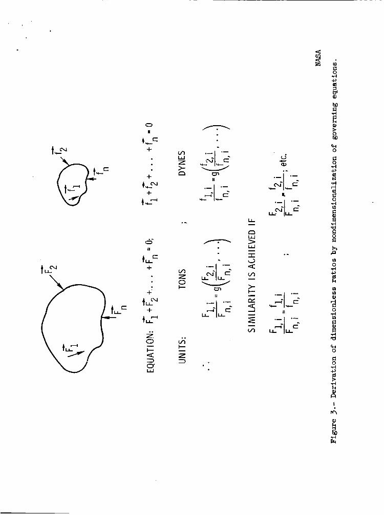
( 2 ) Write t h e governing equations of motion and nondimensionalize them. A s i l l u s t r a t e d i n f i g u r e 3, t h e dimensionless parameters a r e r ead i ly obtained i f t h e governing equations can be wr i t ten , but f o r most of t h e problems of real i n t e r e s t , t h i s may not be poss ib le .
( 3 ) Form r a t i o s of dimensionally similar q u a n t i t i e s which govern t h e system response. Reynolds number i s obtained and defined, f o r example, as t h e r a t i o of t h e f l u i d i n e r t i a fo rces t o the f l u i d viscous forces .
(4) Derive t h e dimenionless parameters by app l i ca t ion of t h e p r inc ip l e s of dimensional ana lys i s . Since t h e techniques involved here a r e widely known and published, fu r the r discussion of dimensional ana lys i s i s not bel ieved t o be necessary.
The reader w i l l recognize from t h e foregoing d iscuss ion t h a t t h e successfu l appl ica t ion of dynamic model techniques t o t h e study of any c l a s s of problems requi res a s u b s t a n t i a l knowledge of t he s t r u c t u r e , t h e environment, and a f a i r assessment of what t h e response w i l l be . We must know w h a t va r i ab le s , fo rces , moments, e t c . , a r e important, and w e must have some recogni t ion of why and how a given var iable inf luences the response. If i n s i g n i f i c a n t va r i ab le s a r e i n t r o - duced, they complicate the problem, and i f important v a r i a b l e s a r e omitted, t h e r e s u l t s may be completely erroneous and use l e s s . Consequently, dynamic model design and t e s t i n g a re perhaps as much an a r t as a science and t h e sca l ing of dynamic models usua l ly involves se l ec t ion of t h e important dimensionless r a t i o s by appl icat ion of severa l o r a l l of t h e four aforementioned techniques, as w i l l be borne out by spec i f i c examples given i n subsequent sec t ions of t h e paper.
The dimensionless r a t i o s o r dimensionless products of i n t e r e s t a r e inde- pendent of each other i n t he sense t h a t no one of t h e r a t i o s i s a product of
4

powers of t h e o thers . ‘ t h e condition t h a t each r a t i o contain a t l e a s t one var iab le which i s contained
i n no other r a t i o . The set of a l l poss ib le independent dimensionless r a t i o s which can occur f o r a given problem i s then complete. A s an example, f i gu re 4 shows t h e complete s e t of independent dimensionless r a t i o s f o r t h e force on a body i n a f l u i d under t h e assumption t h a t the force i s dependent on t h e l eng th of t h e body, g rav i ty , and t h e ve loc i ty , densi ty , v i scos i ty , speed of sound, and surface tens ion of t h e f l u i d .
A s u f f i c i e n t condition t h a t each r a t i o be independent i s
M
L
F ina l ly t h e question a r i s e s as t o t h e number of dimensionless r a t i o s which occur i n the study of a given problem. To answer t h i s quest ion, we must f i rs t def ine t h e nature of t h e physical quan t i t i e s which w e use f o r our standard of measurement and thus designate as fundamental, i . e . , w i l l w e use mass, length, and time o r force, length, and time. Mass, length, and time a re dimensionally independent i n t h e sense t h a t t h e i r magnitude can be determined by only one spec i f i c type of measurement. On t h e other hand, force i s not dimensionally independent because it can be determi:ed by measuring mass, length, and t ime, o r mass and acce lera t ion . If t h e fundamental physical q u a n t i t i e s a r e dimensionally independent and r i n number, and i f the problem involves a t o t a l of n physi- c a l q u a n t i t i e s , then, as shown i n reference 1, t h e number of independent dimen- s ion le s s r a t i o s w i l l be n - r. I n any event t h e number of independent dimen- s ion le s s r a t i o s i n t h e complete set w i l l be equal t o t h e number of va r i ab le s minus t h e rank of t h e i r dimensional matrix.
1 0 0 1 0 0
1 1 1 -3 1 1
-2 -1 0 0 -1 -2
L e t us consider two examples involving t h e fo rces on a body i n an inv i sc id , compressible flow where, i n t h e f i r s t case, the fundamental q u a n t i t i e s are dimensionally independent and, i n the second case, they a r e dimensionally dependent.
Case I
N
F v 2 P C
Since t h e r e are 6 va r i ab le s involved and t h e rank of t h e matrix i s 3 , there w i l l be th ree dimensionless products i n the complete s e t . These w i l l be t h e Force coe f f i c i en t , Mach number, and Froude number.
5

Case I1
Y
I
. . I
F" v 2 P C
F 1 0 0 1 0 0
L 0 1 1 -4 1 1
T 0 -1 0 2 -1 -2
Though the matrix i s d i f f e r e n t , t h e rank i s s t i l l 3 and t h e comments per- t a i n i n g t o case I a r e pe r t inen t .
Types of S imi l a r i t y +
With respect t o s t r u c t u r a l dynamics of space vehic les , t he types of s i m i - l a r i t y of primary i n t e r e s t a r e geometric s i m i l a r i t y , kinematic s i m i l a r i t y , and dynamic s imi l a r i t y . The d e f i n i t i o n of each of these types of s i m i l a r i t y i s given i n f igure 5 and t h e r e l a t ionsh ips which e x i s t between the independent quan t i t i e s ( length, mass, and time) a re given i n f igu re 6 where the subscr ip ts f and m a r e used t o denote corresponding f u l l - s c a l e and model q u a n t i t i e s , respec t ive ly .
I n addi t ion t o geometric, kinematic, and dynamic s i m i l a r i t y , i n some ins tances t h e r e i s a need f o r thermal s i m i l a r i t y . thermal e f f e c t s may be t r e a t e d as a separate problem, and i s not of prime impor- tance t o the discussion on s t r u c t u r a l dynamics presented herein. of thermal s i m i l a r i t y i s discussed i n some d e t a i l i n references 2, 3 , and 4.
However, the in t roduct ion of
The subject
DERIVATION OF SCALE FACTORS FOR STRUCTURAL
DYNAMICS MODELS
Launch-Vehi c l e St ruc ture s
I n the sca l ing of launch-vehicle s t r u c t u r e s f o r l a t e r a l o r l ong i tud ina l s t r u c t u r a l dynamics, only dynamic s i m i l a r i t y i s of p r i n c i p a l concern. s i m i l a r i t y i s automatical ly assured i f dynamic s i m i l a r i t y i s achieved. Since t h e t e s t s of such models do no t , i n general , involve aerodynamic flows, geo- met r ic s imi l a r i t y e n t e r s only i n a gross sense.
Kinematic
La te ra l dynamics.- The l a t e r a l dynamics of a l iqu id-propel lan t launch vehic le involve the long i tud ina l d i s t r i b u t i o n s of four p r i n c i p a l types of forces ; namely:
6

b
S t r u c t u r a l s t i f f n e s s
S t r u c t u r a l i n e r t i a
F lu id s t i f f n e s s
iiia
F lu id i n e r t i a
- a2u at*
m -
where
E1 flexural r i g i d i t y of s t ruc tu re
U s t r u c t u r a l bending displacements, o r l a t e r a l f l u i d displacements
m mass pe r u n i t l ength of vehicle ( includes s t r u c t u r a l mass plus pro- p e l l a n t mass which moves with the s t ruc tu re )
- m mass of propel lan t per u n i t length of vehic le which moves as a separate
degree of freedom and p a r t i c i p a t e s i n f u e l sloshing
a absolute acce le ra t ion of vehicle ( includes acce lera t ion of g rav i ty p lus acce le ra t ion of vehic le r e l a t i v e t o a f ixed coordinate system)
If t h e d i s t r i b u t e d values of t h e r a t i o s of these fo rces a re t h e same on t h e model and full-scale vehic les , dynamic and kinematic s i m i l a r i t y a r e assured.
If t h e f l u i d s t i f f n e s s forces a r e neglected, and 2 i s a c h a r a c t e r i s t i c length, t h e f l u i d mass may be considered as add i t ive t o t h e s t r u c t u r a l masses, and
f L t2 - m
o r
7
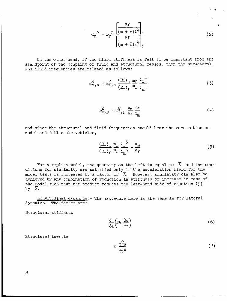
On the o t h e r hand, i f t h e f l u i d s t i f f n e s s i s f e l t t o be important from t h e standpoint of t he coupling of f l u i d and s t r u c t u r a l masses, then t h e s t r u c t u r a l and f l u i d frequencies a r e r e l a t ed as follows:
and s ince the s t r u c t u r a l and f l u i d frequencies should bear t h e same r a t i o s on model and f u l l - s c a l e vehic les ,
For a r e p l i c a model, t he quan t i ty on t h e l e f t i s equal t o x and t h e con- d i t i o n s for s i m i l a r i t y a r e s a t i s f i e d only if t h e acce le ra t ion f i e l d f o r t h e model t e s t s i s increased by a f a c t o r of 5;. However, s i m i l a r i t y can a l s o be achieved by any combination of reduct ion i n s t i f f n e s s o r increase i n mass of the model such t h a t t h e product reduces the . l e f t -hand s ide of equation (3) by x.
Longitudinal dynamics.- The procedure here i s t h e same as f o r l a t e r a l dynamics. The fo rces a re :
S t ruc t u r a1 s t i f f ne s s
L(m aZ 5) S t r u c t u r a l i n e r t i a
a2w a t2
m -
8

Fiuid s t i f f n e s s * i i a
F lu id i n e r t i a
- a2w a t 2
m - ( 9 )
where
EA extensional r i g i d i t y of s t ruc tu re
W s t r u c t u r a l extensional displacements, o r longi tudina l f l u i d displacements
Again i f t h e d i s t r i b u t e d values of the r a t i o s of these forces a r e the same f o r t h e model and f u l l - s c a l e s t ruc tu res , the condi t ions f o r dynamic s i m i l a r i t y a r e s a t i s f i e d . The sca l e f a c t o r s which evolve a r e t h e same as those f o r l a t e r a l dynamics.
Tank pressures . - I n t h e case of l iquid-propel lant launch vehic les , a con- d i t i o n f o r s i m i l a r i t y i s that t h e stresses induced by i n t e r n a l u l l age pressures bear t h e same r a t i o t o t h e dynamic s t r e s s e s f o r t he model and prototype. It can be r e a d i l y shown t h a t t h i s condition i s s a t i s f i e d i f t h e model and f u l l - s ca l e u l l age pressures a r e equal e i t h e r f o r a r e p l i c a model o r f o r a model designed t o maintain f u l l - s c a l e r a t i o s of s t r u c t u r a l frequencies t o f l u i d frequencies .
Spacecraft S t ruc tures
I n t h e design of o r b i t i n g spacecraf t s t ruc tu res , it i s only necessary t o maintain t h e f u l l - s c a l e d i s t r i b u t i o n s of mass and s t i f f n e s s throughout. This condi t ion assures proper simulation of mode shapes and t h e model t o f u l l - s c a l e frequency r a t i o i s r e a d i l y ca lcu la ted from simple beam, p l a t e , o r mass-spring considerat ions.
However, if t h e spacecraf t i s t o land, i t s toppl ing s t a b i l i t y during landing i s dependent on t h e g rav i t a t iona l f i e l d .
i nva r i an t o r t h a t
The condition f o r simulation +L.-* *--*-:-A- AI^-& +I^- --+:A r.P +L- : m n r + ; o f n r e a c tc t h e g;p-~.rit;r f n r ~ p ~ UILLLI r ~ y u s i ~ u b u a b buc i a u s v UL UUL L L L L L V A U A V I ~ G Y
where g i s t h e acce lera t ion due t o gravi ty .
I f the model i s a r e p l i c a model, (%2/wf2) = h2 and s ince
s imulat ion of t h e dynamics during landing requi res t h a t
'-1
= A. Thus, t o ( z m / z f ) = 7 -
9

v
I
model a l u n a r landing spacecraf t f o r t e s t s on ea r th ,
s ca l e i s l a rge r , t h e model must be d i s t o r t e d o r t h e g r a v i t a t i o n a l f i e l d has t o be reduced by t e s t i n g i n a s imulator .
(g , /g f ) = x = 6. If t h e ' 4
APPLICA'I'IONS OF DYNAMIC MODELS
General Remarks
For p r a c t i c a l reasons, dynamic model s tud ie s of space vehic les seldom involve a complete simulation of t h e composite environment-structure system. Ins tead , such s tud ie s a r e usua l ly problem or ien ted i n t h a t one or more dynamic models i s designed t o study a s p e c i f i c o r l imi ted group of r e l a t ed problems. The l o g i c of t h i s approach has severa l j u s t i f i c a t i o n s among which a r e those d l s - cussed i n t h e following sec t ions .
I Mul t ip l i c i ty of Environmental Conditions
From a dynamics viewpoint, t h e environment of space vehic les may be defined as the composite of conditions which induce, o r l i m i t dynamic motions of t he s t ruc tu re . Those conditions which induce motions, commonly re fer red t o as t h e sources of exc i t a t ion , a r e of fundamental importance and w i l l be discussed f irst .
I
Figure 7 l i s t s t h e primary sources of exc i t a t ion of space vehic le s t ruc- t u r e s . Even a percursory glance a t t h e f igu re w i l l i nd ica t e t o t h e reader the d i f f i c u l t y of a r e a l i s t i c simulation of these sources of exc i t a t ion on any given dynamic model i n a r e a l i s t i c t e s t setup. Y e t , each of t he inputs has posed severe problems f o r one or more vehic les , and most veh ic l e s a r e encumbered by t h e majori ty of t h e inputs . A s ind ica ted by t h e f i g u r e , induced responses of t h e s t ruc tu re become of concern during t h e manufacturing and shipping s tage , p e r s i s t through ign i t ion , l i f t - o f f , f l ight, s tage separa t ion , and i n t h e case of t h e Apollo vehicle , pose a s i g n i f i c a n t problem during landing.
During f l i g h t through t h e atmosphere, t h e sources of e x c i t a t i o n a r e highly t r a n s i e n t due t o t h e s t r u c t u r e of t h e atmospheric wind p r o f i l e s , t h e d i s s i p a t i o n of launch-vehicle f u e l , t he changes i n c h a r a c t e r i s t i c flows about t h e vehic le from subsonic t o t ransonic t o supersonic, and t h e changes i n v b i c l e s t r u c t u r e due t o separation of spent s tages . A s a consequence of t hese 6 ighly t r a n s i e n t and var iab le conditions, t h e s p a t i a l and temporal d i s t r i b u t i o n s of the sources of exc i ta t ion a re only approximately known and hence any one of t h e environ- mental e f f e c t s can only be approximately simulated. f a c t t h a t , during the f l i g h t phase, near ly a l l of t h e inpu t s a r e superimposed, leading t o a condition commonly r e fe r r ed t o as "combined environments."
O f s ign i f icance a l s o i s t h e
The pr inc ipa l phenomenon of importance r e l a t i v e t o t h e l imi t ing of dynamic motions i s damping, and from a s t r u c t u r a l dynamics viewpoint, t he p r i n c i p a l con- cern r e l a t i v e t o environmental e f f e c t s i s t h a t t h e thermal and vacuum environ-
I ments of space, ac t ing sepa ra t e ly o r c o l l e c t i v e l y , may tend t o reduce t h e damping
I 10
I
~ ‘ 9 ,
o’f composite s t ruc tu res t o t h e very low l eve l s associated with t h e h y s t e r e t i c
pe r t inen t t o t h i s problem a r e presented i n a separate sec t ion on damping. \ d i s s ipa t ion of energy i n t h e s t r u c t u r a l mater ia ls themselves. Some comments
Various Types of Dynamic Models
I n view of t h e d i f f i c u l t y of subjecting a s ingle dynamic model t o t h e space vehicle environment and in t e rp re t ing the f u l l - s c a l e response by sca l ing up t h e dynamic model r e s u l t s , t h e general approach a t present i s t o use a com- b ina t ion of models t o generate s t r u c t u r a l , aerodynamic, and propel lan t inputs which a r e in t eg ra t ed i n t o a n a l y t i c a l programs f o r pred ic t ion of o v e r a l l vehic le responses. The types of models used t o accomplish these object ions, and t h e nature of t he data obtained a r e given i n f igu re 8. f o r a e r o e l a s t i c and landing dynamics s tudies t h e model r e s u l t s may be scaled t o d i r e c t l y ind ica t e f u l l - s c a l e vehic le responses. I n addi t ion , spec ia l purpose models f o r studying var ious phenomena and problem areas a r e widely used as i n t h e case of a i r c r a f t . Models t o study control-surface loads, p rope l lan t b a f f l e dampers, and t h e response of panels t o acoust ic pressures are t y p i c a l of t hese .
I n some ins tances , such as
To da te , t h e appl ica t ion of models t o the study of space vehicle dynamics has been pr imar i ly focused on the launch-vehicle c h a r a c t e r i s t i c s with t h e space- c r a f t represented as a concentrated mass, o r appropriate aerodynamic shape. Figure 9 shows some such models u t i l i z e d i n var ious s tud ie s , cur ren t o r i n t h e pas t , by t h e Langley Research Center. i s t i c s , research objec t ives , and tes t r e s u l t s are presented i n comparison papers a t t h i s symposium by Reed and Runyan. A s shown by t h e f igu re , t h e models repre- sent both monocoque and c l u s t e r launch-vehicle configurat ions, and a r e used t o study problems involving s t r u c t u r a l dynamics, ground winds, and buf fe t ing .
De ta i l s of t h e model design character-
Typical Examples of t h e U s e of S t ruc tu ra l Dynamics Models
Launch veh ic l e s - Ti tan 111.- Typical samples of t h e data obtained from t e s t s of s t r u c t u r a l dynamics models of launch vehic les are shown i n figures 10 and 11. These data were derived from ea r ly t es t s of a 1/5-scale model of T i t an 111, t h e veh ic l e shown i n f i g u r e 12 .
Figure 10 shows t h e acce lera t ion of a simulated 45,000-pound payload i n t h e y a w d i r e c t i o n ( t h e longi tudina l plane containing t h e so l id s ) f o r a simulated f l ight condi t ion wherein one-half of t h e mass of t he strapped-on s o l i d s i s spent . Resonance condi t ions, exemplified by peak response l eve l s , are shown and t h e first t h r e e n a t u r a l modes a r e iden t i f i ed . Although t h e exact s t r u c t u r a l deformations involved have not ye t been c l ea r ly i d e n t i f i e d , t h e figure a l s o shows t h e ex is tence of s t rong resonances a t higher f requencies .
An i n t e r e s t i n g observation from f igure 10 i s t h e f a c t that t h e response l e v e l s a t resonance increase with frequency which ind ica t e s that, s ince t h e magnitudes of t h e force inpu t s a r e held e s s e n t i a l l y constant , t h e damping of t h e s t ruc tu re - fue l system decreases w i t h frequency. This t r end i s subs tan t ia ted by t h e logar i thmic decay data presented i n f i g u r e 11 which show that t h e damping
11

w * '
as high as f o r t h e f i r s t n a t u r a l second n a t u r a l mode. #
of t h e t h i r d n a t u r a l mode i s only 60 percent mode and about 80 percent as high as f o r t h e
I The data presented i n f i g u r e s 10 and 11
I the d a t a being generated on t h i s model. The represent only a small sample of Langley Research Center i s working
i n cooperation with t h e Ai.r Force and Martin-Deriver (who designed, b u i l t , and i s j o i n t l y t e s t i n g t h e model) t o measure t h e s t r u c t u r a l dynamics c h a r a c t e r i s t i c s f o r t h e f u l l range of payloads, i npu t s , and propel lant loadings. The t e s t pro- gram involves t h e use of mul t ip l e shakers and includes a n a l y s i s of both t h e core and core-plus-solids configurat ions. It i s hoped t h a t t he model t e s t r e s u l t s w i l l provide t h e necessary checks and modifications t o t h e theory so t h a t t h e f u l l - s c a l e responses can be analyzed with confidence without t h e need f o r exten- sive dynamic t e s t i n g of the f u l l - s c a l e hardware.
Orbiting spacecraf t - Nimbus.- A s previously mentioned, t h e use of dynamic models t o study t h e experimental a spec t s of t h e s t r u c t u r a l dynamics of space veh ic l e s has been focused on launch veh ic l e s . The reason f o r t h i s i s t h a t t h e g r e a t majority of spacecraf t i n t h e pas t have been small enough t o permit a f u l l - s c a l e dynamic mockup t o be r e a d i l y constructed and t e s t e d , o r they have been s u f f i c i e n t l y compact that t h e s t r u c t u r e could be adequately r e s t r a ined from highly undesirable dynamic responses. Ranger and Ti ros , r e spec t ive ly , are good examples .
As spacecraft become l a r g e r , more f l e x i b l e , and more expensive, an increased need f o r dynamic model tes ts w i l l no doubt arise. A s an example the Nimbus spacecraft , a f u t u r e po la r o r b i t i n g weather s a t e l l i t e shown i n figure 13, exhibi ted complex high-amplitude dynamic responses during e a r l y q u a l i f i c a t i o n tes t s wherein t h e s o l a r panels were folded t o simulate t h e launch configurat ion. A review of t h e e a r l y tes t resul ts suggested t h e need f o r a simple, inexpensi.ve, dynamic model program t o e s t a b l i s h :
(1) The c h a r a c t e r i s t i c motions of the veh ic l e as a funct ion of frequency including n a t u r a l frequencies, mode shapes, and forced response;
(2) The r e l a t i v e merits of hard vs . s o f t mounting systems f o r a t t ach ing t h e spacecraf t t o t h e launch veh ic l e ; and
( 3 ) The e f f ec t iveness of l o c a l i z e d and d i s t r i b u t e d damping on t h e f re- quency response.
Sketches of t h e model and two samples of t h e t e s t results, s e l ec t ed from reference 5 , are shown i n f i g u r e s 1 4 and 15. The s c a l e chosen was 1/2, and as shown i n f igu re 14, t h e model afforded a reasonable simulation of t h e dynamics of t h e fu l l - s ca l e s t r u c t u r e over the lower frequency range as des i r ed . The model w a s constructed of standard tubing and p l a t e s with mixed welded and r ive t ed construction. I n l i e u of honeycomb sandwich s o l a r panels , t h e model panels were constructed by laminating two t h i n sheets of aluminum t o a sheet of balsa. Two sets of panels were constructed. I n one set t h e bonding agent used t o laminate t h e panels w a s an epoxy r e s i n ( a ha rd - se t t i ng glue) and i n t h e o t h e r
t h e use of t h e damping adhesive e f f e c t i v e l y reduced t h e ampl i f i ca t ion f a c t o r I I
set t h e bonding agent was a v i s c o e l a s t i c damping adhesive. Figure 15 shows that
12

( t h e r a t i o of output t o input acce lera t ions) by near ly a n order of magnitude .. over the frequency range of primary i n t e r e s t . Other tests a l s o demonstrated t h e e f fec t iveness of i s o l a t i o n techniques, and a l l t e s t r e s u l t s were of sub- s t a n t i a l a i d i n t he d e f i n i t i o n of t he contr ibut ions of t h e var ious componentc of t h e s t ruc tu re t o the o v e r a l l vehicle motions.
Landing spacecraf t - Apollo LEM.- A subs t an t i a l research e f f o r t i s cur- r e n t l y d i r ec t ed t o the ana lys i s of t h e landing dynamics of space vehic les designed t o land on e x t r a t e r r e s t i a l surfaces such as t h e moon. This research includes both t h e o r e t i c a l and experimental s tud ies , and i s or iented t o e s t a b l i s h both t h e t i pove r s t a b i l i t y during t h e landing process and t h e loads and mGtions generated i n the landing gear during the impact process.
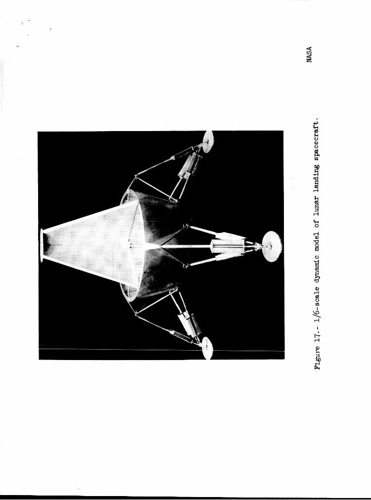
Among t h e more important va r i ab le s f o r such problems i s t he g r a v i t a t i c n a l constant . A s shown i n a previous sec t ion of t h e paper, f r e e - f a l l drop t e s t s of a vehicle on t h e e a r t h ' s surface w i l l not simulate landing of the same vehicle on t h e moon even though the ve loc i ty conditions and the surface mater ia l s a t t h e point of touchdown a r e t h e same. The necessary experimental t e s t resu l tas can be obtained by t e s t i n g f u l l - s c a l e s t ruc tu res o r l a rge dynamic models i n some type of lunar g r a v i t a t i o n a l s imulators , o r by t e s t i n g 1/6-scale dynamic models.
Gravi ta t iona l s imulators may be of several types such as the incl ined plane, a counter fo rce system which supports 5/6 of t h e weight of t he vehic le , o r a simulator which permits impacts f o r t h e ve loc i ty and surface conditions desired onto a surface which i s acce lera t ing downward r e l a t i v e t o t h e ea r th . A simu- l a t o r of t h e l a t t e r type i s discussed i n reference 6 and shown Lr! f igu re 16 . For simulation of f u l l - s c a l e lunar landing vehic les , t h e impact surface would acce le ra t e downward r e l a t i v e t o e a r t h a t 5/6g and t h e r a t i o of t he counter mass % t o t h e simulator mass Ml would be such t h a t Ml z 1lM2.
An example of a 1/6-scale dynamic model f o r simulating lunar landing dynam- i c s i s shown i n f i g u r e 17. The bas i c s t ruc ture of t h e model i s designed t o r e a d i l y permit v a r i a t i o n s i n spacecraf t mass and moments of i n e r t i a by appro- p r i a t e d i s t r i b u t i o n of added masses t o t h e bas i c s t r u c t u r e . Landing-gear con- f i g u r a t i o n s can a l s o be var ied i n number and s t r u c t u r a l d e t a i l s . The configu- r a t i o n shown has four t r i pod gears with each member of t h e t r i pod having honeycomb shock absorbers t o permit d i ss ipa t ion of t h e impact energy with mini- mum rebound. Other gear configurat ions a r e a l s o under study. I n addi t ion t o generat ing b a s i c information on landing dynamics of lunar spacecraf t , t h e model p ~ r a ~ ~ i e i x r s tire se iec ted so as t o inciude values pel-Li[ied, tu the A p l l ~ TLE14 veh ic l e .
DAMPING
General Remarks
The damping of launch-vehicle and spacecraf t s t ruc tu res i s among t h e more c r i t i c a l f a c t o r s i n t h e cont ro l of t h e i r response t o t h e many types of inputs .

Since the peak amplitudes of forced responses a re e s s e n t i a l l y inverse ly pro- p o r t i o n a l t o damping, and s ince t h e rate of exponential decay of f r e e o s c i l l a - - t i o n s i s d i r e c t l y proport ional t o damping, it i s necessary t o know the i.nherent damping o f t h e s t ruc tu re i n a l l cases t o p red ic t i t s response. A s a general r u l e , t h e higher t h e inherent damping t h e b e t t e r , and a g rea t dea l of e f f o r t has been expended i n recent years on t h e development of v i s c o e l a s t i c f i l m s , t apes , sandwiches, e t c . , t o achieve higher damping.
Fromthe viewpoint of simulation, damping i s among the more d i f f i c u l t quan- t i t i e s t o scale . Several types of damping a r e of concern including aerodynamic damping and s t r u c t u r a l damping. t a i n t o dynamic modeling i s presented i n t h e following paragraphs.
Some discussion of each of these a s they per-
Aerodynamic Damping
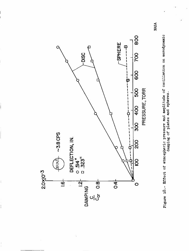
Since t h e primary v ib ra t ions of launch vehic les and spacecraf t occur during flight, t h e dens i ty of t h e a i r which surrounds t h e s t r u c t u r a l components of t h e vehicles during conditions of peak response i s usua l ly lower than ambient condi t ions a t t h e e a r t h ' s surface. Yet f o r convenience, it i s highly des i r ab le t o be ab le t o conduct tests of s t r u c t u r a l dynamic models under atmospheric con- d i t i o n s . damping of t h e v ib ra t ions of space vehic les and t h e i r components a r i s e s . addi t ion t o t h e dens i ty e f f e c t , t h e quest ion of s i ze o r a rea of t h e components a l so e x i s t s . I n an e f f o r t t o determine t h e e f f e c t s of these and o ther va r i ab le s on t h e damping of s t ruc tu res f o r space vehic le appl ica t ions , a study of t h e damping of t y p i c a l components w a s r ecen t ly conducted a t t h e Langley Research Center. The study consis ted of measuring t h e damping of var ious s i z e s of c i r - cu l a r and rectangular panels, spheres, and cy l inders a t a i r pressures ranging from atmospheric down t o 4 x 10⁻² t o r r . The t e s t components were mounted on t h e ends of cant i lever beams of d i f f e r e n t f requencies and the damping w a s de t e r - mined by measuring t h e logari thmic decay of t h e free v ib ra t ions of t he beam- component systems. t h e r a t i o of t h e damping t o t h e c r i t i c a l damping i s p lo t t ed as a funct ion of t h e pressure of t he surrounding a i r medium f o r a panel and sphere f o r two ampli- tudes of o s c i l l a t i o n . For t h e case shown, t h e c ross -sec t iona l area was 30 square inches and t h e frequency of o s c i l l a t i o n was 3.8 cycles per second. The r e s u l t s show t h a t t h e aerodynamic cont r ibu t ion t o t h e damping of t h e panel, obtained by subt rac t ing out t h e damping a t 4 x 10⁻² t o r r , i s propor t iona l t o t h e amplitude of o s c i l l a t i o n and t h e dens i ty of t h e t e s t medium. show t h a t t he damping of t h e sphere i s e s s e n t i a l l y propor t iona l t o dens i ty , bu t independent of amplitude. a c t e r i s t i c va r i a t ions as f o r spheres. I n summary t h e r e s u l t s of t h e s t u d i e s t o da t e show that t h e damping f o r panels v a r i e s as follows:
Thus t h e question of t h e e f f e c t of a i r dens i ty on t h e aerodynamic I n
Typical samples of t h e r e s u l t s are shown i n f igu re 18 where
The r e s u l t s a l s o
Other tes ts involving cy l inders showed t h e same char-
6 = 22 pxA4I3 m
14
h ’
where 4
6 damping coe f f i c i en t , 2rtc/ccr
P dens i ty of t h e t e s t medium, s lugs / f t3
X amplitude of o s c i l l a t i o n , f t
A area of t h e panel, f t 2
m e f f e c t i v e mass of the panel-beam system, s lugs
Thus it appears that the increase i n damping due t o t e s t i n g panel-type s t r u c t u r e s i n atmosphere as opposed t o t h e low-pressure space environment i s d i r e c t l y propor t iona l t o t h e pressure r a t i o s and can be r ead i ly accounted f o r . The same i s t r u e f o r spheres and cy l inders . On t h e o ther hand, t h e r e s u l t s show that t h e damping r a t i o f o r a model of a panel s t r u c t u r e t e s t e d i n atmos- phere i s s u b s t a n t i a l l y less because o f t h e smaller area than it would be f o r a f u l l - s c a l e s t r u c t u r e t e s t e d under similar conditions. The damping f a c t o r f o r spheres and cylinders, however, a r e independent of s i z e and t h e sca l ing problem i s r a t h e r s t ra ightforward. The essence of t hese remarks a l s o po in t s up t h e f a c t t h a t t h e low-amplification f a c t o r s measured f o r tests of spacecraf t having l a r g e s o l a r panel a r r ays may be due t o high aerodynamic damping - a condition t h a t w i l l not e x i s t during f l i g h t i n low-density regimes.
S t r u c t u r a l Damping
I n addi t ion t o t h e aerodynamic damping which may d i s s i p a t e t h e motion of a s t ruc tu re , a l l s t r u c t u r e s possess an i n t e r n a l d i s s ipa t ion mechanism usua l ly r e fe r r ed t o as s t r u c t u r a l damping. For purposes of t h i s paper, s t r u c t u r a l damping i s def ined as t h e composite of those e f f e c t s which involve h y s t e r e t i c d i s s i p a t i o n wi th in t h e c r y s t a l s of the s t r u c t u r a l materials and t h e damping assoc ia ted with t h e deformation of t h e s t ruc tu re a t i t s j o i n t s .
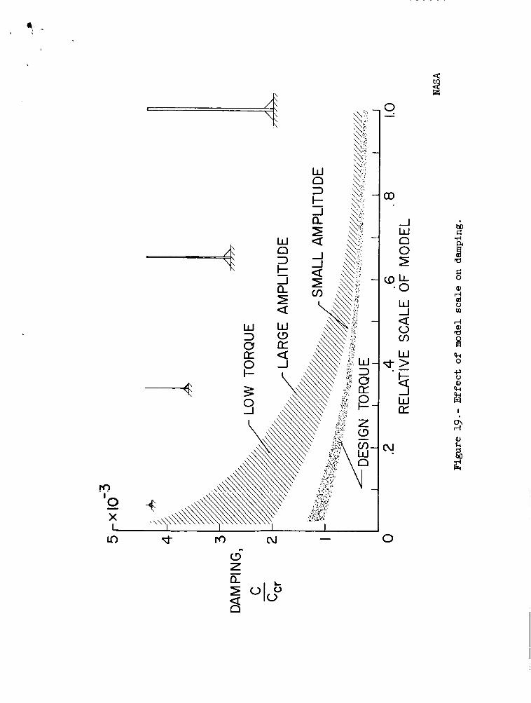
It has long been expected t h a t t h e damping of small composite s t ruc tu res r ep resen ta t ive of aerospace usage would have higher s t r u c t u r a l damping than l a r g e r s t r u c t u r e s constructed of t he same mater ia ls by t h e same techniques. I n o the r words, i s the s t r u c t u r a l damping coef f ic ien t of a r ep l i ca dynamic model i nhe ren t ly higher than t h a t f o r t h e fu l l - s ca l e s t ruc tu re? I n an attempt t o answer t h i s quest ion, the Langley Research Center constructed four aluminum beams w i t h c a n t i l e v e r supports and t e s t e d them. c ros s sec t ion wi th a width-to-thickness r a t i o of 6 t o 1, and a length-to-width r a t i o of 10. The l a r g e s t beam was 5 f e e t long. The cant i lever support f o r
The beams had a rectangular

each beam consisted of two machined angle blocks designed so t h a t t h e s t r e s s e s i n t h e support were cons is ten t with t h e s t r e s s e s i n the beam. The r e l a t i v e sca l e of the models and the r e s u l t s of t h e damping t e s t s a r e shown i n f igu re 19. The beams were mounted t o a massive s t e e l and concrete backstop and every pre- caut ion was taken t o assure t h a t t h e mounting and t e s t condi t ions were cons i s t en t .
~
During t h e t e s t s , t h e clamping pressure of t he beam supports w a s cont ro l led by varying t h e torque appl ied t o t h e b o l t s and f o r a comparative t e s t condition, t h e clamping pressure f o r a l l beams was t h e same. The damping was measured f o r both a low torque condition ( r ep resen ta t ive of a semitight f i t ) and a design torque condition. For each torque condition, t h e damping w a s a l s o measured f o r a range of amplitudes.
The r e s u l t s of t h e t e s t s show that t h e damping coe f f i c i en t decreases as t h e clamping pressure, j o i n t t igh tness , o r torque i s increased, and increases as t h e amplitude of t h e v ib ra t ion i s increased. But perhaps of g rea t e r importance from t h e standpoint of dynamic modeling of s t r u c t u r e s i s t h e f a c t that the s t r u c t u r a l damping increased by a f a c t o r of 2 as t h e sca le was reduced by a f a c t o r of about 18 for design torque condi t ions and by a f a c t o r of 4 f o r low torque con- d i t i o n s . Yet every attempt w a s made t o assure t h a t each beam w a s a r e p l i c a model of the o ther t h ree . On t h e b a s i s of t hese r e s u l t s , it would appear highly l i k e l y tha t t h e s t r u c t u r a l damping of a r e a l i s t , i c a l l y s ized dynamic model of a launch vehicle might d i f f e r s u b s t a n t i a l l y from t h a t of the f u l l - s c a l e s t r u c t u r e . Furthermore, the r e s u l t s a l s o emphasize the importance of maintaining close con- t r o l over j o i n t t i gh tness and i n t e g r i t y during model construct ion.
Another f a c t o r of concern r e l a t i v e t o the s t r u c t u r a l damping of spacecraf t i s t h e probabi l i ty t h a t long exposure t o space vacuum condi t ions may outgas t h e adsorbed gases from the mating surfaces a t s t r u c t u r a l j o i n t s and permit them t o vacuum weld. I n t h i s event t h e s t r u c t u r a l damping of t h e assembled s t ruc tu re would approach t h e inherent damping of t h e ma te r i a l s - a reduction of one o r more orders of magnitude. A conservative approach i n t h i s case would be t o use welded j o i n t s i n t h e construct ion of dynamic models t o assure t h a t t h e amplif i - ca t ion f a c t o r s f o r t h e f i l l - s c a l e s t r u c t u r e do not exceed those of t h e model i n s o f a r a s s t r u c t u r a l damping i s concerned.
MODEL SUPPORT SYSTEMS
Launch Vehicles
I n e s sen t i a l ly a l l cases of i n t e r e s t , t h e boundary condi t ions f o r launch veh ic l e s are e s s e n t i a l l y f r ee - f r ee , and an equivalent support system must be used during dynamic model tests t o assure that t h e n a t u r a l f requencies , mode shapes, s t r u c t u r a l damping, and dynamic response of t he model represent those which occur on t h e f u l l - s c a l e vehic le under f l i g h t condi t ions. c r i t e r i a i s one of frequency separat ion. If t h e frequency of t h e support system can be made s u f f i c i e n t l y low compared t o t h e n a t u r a l frequency of t h e lowest frequency na tu ra l mode of i n t e r e s t , say by a f a c t o r of 3 octaves, t h e e f f e c t of
The fundamental
16

.& .
t h e support system on the s t r u c t u r a l c h a r a c t e r i s t i c s of t h e model can usua l ly be neglected.
If t h e s t ruc tu re of t h e vehicle i s such that it may be handled as a u n i t and can be or ien ted hor izonta l ly , t he b e t t e r approach i s usua l ly t o support it as shown i n f igu re 20. I n t h i s type of support system, t h e e f f e c t of t h e sup- po r t i s secondary, and i f , i n the exc i t a t ion of t h e na tu ra l modes of the s t ruc - t u r e , t h e supports are located a t t he nodal po in t s , t h e i r e f f e c t on t h e s t ruc- t u r e i s neg l ig ib l e . It i s usua l ly des i rab le t o mount t h e e x c i t e r near an anti-node t o m a x i m i z e t h e response of t h e s t ruc tu re i n the mode of i n t e r e s t . However, i f t h e response of t h e vehicle ind ica tes coupling of o ther modes, such coupling can be minimized by mounting t h e e x c i t e r a t a node poin t of t he mode producing t h e undesired coupling e f f e c t .
I n general , t h e support cables should be made of e l a s t i c shock cord bu t t h e r e s u l t s of many t e s t s of small sol id-propel lant rocket vehic les at t h e Langley Research Center i nd ica t e t h a t s t e e l cables can be used successfu l ly i f properly adjusted. I n most cases, a two-point support i s adequate f o r such vehic les , t h e loca t ion of these supports being adjusted t o coincide with nodal po in t s of t h e mode being exci ted.
I n some cases, p a r t i c u l a r l y those involving vehic les containing l i q u i d pro- p e l l a n t s and t h i n pressurized she l l s , it i s necessary t o o r i en t t h e vehic le ver- t i c a l l y t o properly simulate t h e e f f e c t s of t h e e a r t h ' s g r a v i t a t i o n a l f i e l d on t h e dynamics of t he vehicle-propel lant system. Robert W. Herr of t h e Langley Research Center has s tudied t h i s problem, reference 7, and has developed two unique and very e f f e c t i v e support systems which are shown i n f i g u r e 21. Both of these systems c lose ly dupl ica te the f ree- f ree boundary condi t ions f o r such vehic les .
The first of these v e r t i c a l support systems i s r e fe r r ed t o as a high-bay harness. The w e i g h t of t he vehic le i s car r ied by t w o support cables which a r e a t tached t o t h e bottom of t h e vehic le and t o t h e overhead support s t ruc tu re . S t a b i l i t y i s achieved by two hor izonta l r e s t r a in ing cables t i e d between t h e support cab les and t h e periphery of t h e vehicle a t some poin t , e .g . , above the veh ic l e ' s cen ter of grav i ty . T h i s support system has e s s e n t i a l l y two degrees of freedom i n t h e plane normal t o t h e cables - t r a n s l a t i o n as a pendulum and p i tch ing . I n terms of t h e dimensions shown on t h e f igu re , t he s t i f f n e s s , and thus t h e frequency, of t h e p i tch ing mode can be cont ro l led by separat ion of t h e p o i n t s where t h e support cables f a s t e n t o the r i g i d support s t ruc tu re . The vehic le w i i i s tand e r e c t i f
a > f ($ - E ) -b b
and t h e frequency of t h e p i tch ing mode w i l l approach zero as

This support system was used successful ly on the 1/5-scale SAl-Block I, and t h e l / b - s c a l e SATURN V dynamic models s tudied a t t h e Langley Research Center. A
I n some instances involving t h e tests of very l a rge dynamic models o r f u l l - s ca l e launch-vehicle s t ruc tu res , it may be d i f f i c u l t t o provide an overhead r i g i d support s t ruc tu re as necessary f o r t h e high-bay harness. I n such cases , t h e low-bay harness, though s l i g h t l y more complicated i s preferab le and i s being used f o r the s t r u c t u r a l dynamics s tud ie s of t h e f u l l - s c a l e Thor-Agena launch vehic le t o be conducted a t Langley i n t h e near f u t u r e . As was t h e case f o r t h e high-bay harness, t he weight of t h e vehic le i s car r ied by two support cables . However, i n t h i s case t h e support cables may be much shor t e r than t h e length of t h e vehicle . The vehicle i s held e r e c t by cont ro l l ing t h e tens ions i n t h e r e s t r a in ing cables by means of turnbuckles, and the condition f o r neu t r a l sta- b i l i t y , and hence, zero frequency i n p i t c h , i s
r
- Although it i s s t i l l necessary t o have some support s t ruc tu re near t he top of t h e vehicle , t h i s s t ruc tu re can be r e l a t i v e l y l i g h t s ince it need support only a small f r ac t ion of the weight of the vehic le .
I Spacecraf t
Since t h e majori ty of spacecraf t are small r e l a t i v e t o t h e s i z e of launch vehic les , t he support of spacecraf t models f o r dynamic s tud ie s can be accom- p l i shed with comparative ease. Since spacecraf t a r e usua l ly mounted t o t h e launch vehicles i n semirigid fashion, t he i n - f l i g h t support system i s c lose ly representa t ive of f ixed-free boundary condi t ions. i s t o r i g i d l y f a s t en the spacecraf t t o t h e e x c i t e r f o r tests along t h e longi- t u d i n a l o r f l i g h t axis, and t o a t t a c h t h e spacecraf t t o a s l i ppe ry t a b l e f o r exc i t a t ion of l a t e r a l modes and frequencies . It i s important t o recognize, how- ever , t h a t t h e impedance of t h e support system, whether it be t h e e x c i t e r o r s l i ppe ry t ab le , w i l l d i f f e r from t h a t of t h e launch vehic le , and proper consid- e r a t i o n of t h i s f a c t should be exercised during i n t e r p r e t a t i o n of t he response da t a obtained during v ibra t ion t e s t s of spacecraf t o r spacecraf t models.
Hence the general procedure
CONCLUDING REMARKS
During recent years , dynamic models have been used t o good advantage f o r so lu t ion of some of the problems r e l a t e d t o s t r u c t u r a l dynamics of space vehi- c l e s . Because of t h e s i ze , complexity, and cos t of t h e s t r u c t u r e s and t h e var- i a b l e environments which c o n s t i t u t e t h e s t r u c t u r a l loads , it appears t h a t cur- r e n t t rends which involve t h e construct ion and t e s t i n g of spec ia l ized models f o r ana lys i s of s t r u c t u r a l c h a r a c t e r i s t i c s , and responses t o ground winds, wind shear, buffet ing, and f u e l s loshing loads w i l l continue i n t h e foreseeable

fu tu re . Much add i t iona l work i s necessary t o understand t h e e f f e c t s of t h e ‘a highly t r a n s i e n t na ture of s t r u c t u r a l p roper t ies and loading condi t ions, and t o
e s t a b l i s h appropr ia te modeling techniques fo r t h e i r simulation and ana lys i s . P a r t i c u l a r a t t e n t i o n i s needed i n t h e a reas of simulation of t h e coupling of propel lan t systems with t h e s t ruc tu re t o avo id i n s t a b i l i t i e s such as t h e POGO o s c i l l a t i o n s .
A s pointed out i n t h e paper, c a r e f u l a t t en t ion must be given t o proper simulation of bo th aerodynamic and s t r u c t u r a l damping i n model design and t e s t i n g .
Proper support of launch-vehicle models t o simulate f r e e - f l i g h t condi t ions during tes ts i s important, and methods are presented i n t h e paper which have proven t o be adequate and simple.
I n seve ra l a r e a s of concern such a s f u e l s loshing and lunar landing, grav- i t y i s an important va r i ab le . simulate g rav i ty e f f e c t s a r e discussed.
Some of t h e techniques which may be employed t o
APPENDIX
DIMENSIONLESS RATIOS
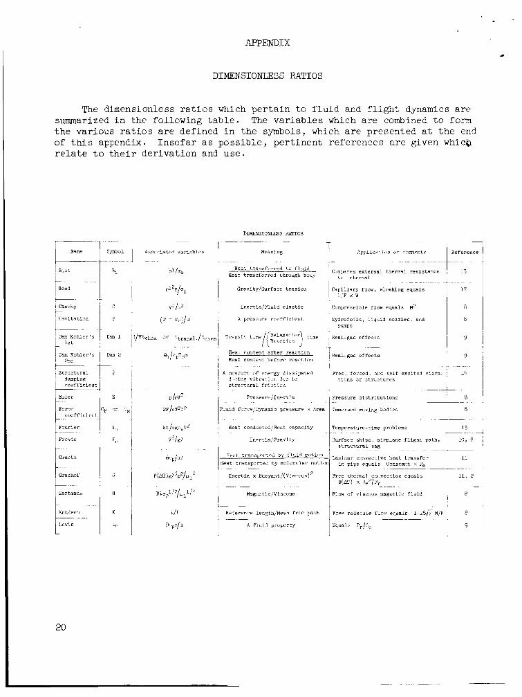
The dimensionless r a t i o s which p e r t a i n t o f l u i d and f l i g h t dynamics are summarized i n t h e following t a b l e . The va r i ab le s which are combined t o form t h e various r a t i o s a r e defined i n t h e symbols, which a r e presented a t t h e end of t h i s appendix. In so fa r as possible , pe r t inen t references are given whicb r e l a t e t o t h e i r der ivat ion and use.
Namp
Biot
Bond
Cauchy
c n v i t n t i o n ~
___ -~ Cam Kohler's
1st ___ ~
Dam K o h l e r ' s 2md
s t r u c t u r a l dampinR c o e f f i c i e n t
Euler
Forcc c o e f f i c i e n t
F o u r i e r
f i a u d e
Grae tz
~~
Grsshof
Symbol
mcp/k2
DIMENSIO!iLESS RATIOS ~~ ~~
Meaning
Heat t r a n s f e r r e d t o f l u i d Heat t r a n s f e r r e d through body
G r a v i t y f s u r f a c c t e n s i o n
I n e r t i a f F l u i d e l a s t i c
A pressure c o e f f i c i e n t
T r a n s i t t m e / ~ ~ ~ ~ ~ ~ ~ ~ time
Heat conten t a f t e r r e a c t i o n Heat conten t b e f o r e r e a c t i o n
A measure of energy d i s s i p a t e d
~ ~~
di i r ine v i b r s t i a n due t c s t r u c t u r a l f r i c t i o n
P r e s s u r e J I n e r t i a ~~~-
l u i d force/Dynsrmc p r e s s u r e x Area
Heat ConductedJHPnt capac i ty
I n e r t i a / G r a v i t y
Heat t r a n s p o r t e d by f l u i d m o t i O r l
[ ea t t r a n s p o r t e d b y molecular moti i ~~
I n e r t i a x Buoyant/(Viscous)'l
~~
Magnetic/Viscous
___ ~~
Reference 1engthfMean f r e e p a t h
A f l u i d p r o p e r t y __
Applicalloil o r commentb Reference
Campareb e x t e r n a l thermal r e s i s t a n c e t o i n t e r n a l
C a p i l l a r y flow, sloshing equals 1 , F x W
Campr?sclble flow equals M2
Hydrofo i l s , l i q u i d n o z z l e s , and pumps
Real-gas e f f e c t s
Real-gas e f f e c t s
Free , f o r c e d , nnd s e l f - e x c i t e d v i b r t i o n 6 of s t m c t h r e s
Pre 6 sure d i s t r i b u t i o n s
Immersed moving bodies
Temperature-time problems
Surface ships, a i r p l a n e f l i g h t p a t h
- structural sag
l aminar convec t ive h e a t t r a n s f e r in p i p e equals Constant x Pe
O(N) X lb ' /Fr
~~~~
Free thermal convec t ion e q u a l s
Flow of v i scous magnetic f l u i d
Fret- molecule f l o w equals 1.286 M
Equal:, Pr/S,
9
10, 8
11
11, 2
8
8
9
20

L
5
~ - ~ _ _ Sag due t o weight
DIMENSIONLESS W I O S - Concluded
4
symbol 1 Associated v a r i a b l e s Meaning Reference Applicat ion o r comments
~
Compressible flows
i___-
Magnetic
I n e r t i a p l u i d e l a s t i c
I F l o w speed/Alfven wave speed
Motion induced f ie ld/Applied f i e l d
_ _ _ _ ~ _ _ _ ~ ~ . -
Heat t r a n s f e r r e d t o f lu id Nu
Heat t r anspor t ed by f l u i d flow Heat t r anspor t ed by molecular motion
Magnetic compress ib i l i t y i 8 1
Flu id f i e l d i n t e r a c t i o n
~~ - .~~
Convective hea t t r a n s f e r 11, 2
Compressible flow equa l s R x Pr 11 I
L a t e r a l con t r ac t ion L l j (EzI=1) - i L ang i tud ina l extension - ~ - ~ - - - _ _ _ _ _ - __-
A f l u i d p rope r ty I _ ~ _ _ _ ~ - - -
Pr 1 Cpltk
&-- Measure of t o r s i o n a l s t i f f n e s s r equ i r ed
for n e u t r a l f l u t t e r s t a b i l i t y
E l a s t i c i t y 1 15 j Poisson
1 P r a n d t l Equals 213 monatomic, 3 / h diatomic,
?. -1.0 polyatomic 1 3
Regier 1 F l u t t e r index f o r subsonic speeds 1 18, 19 1 Reynolds i Skin f r i c t i o n , boundary l a y e r s ,
Equals 0.7 t o 0.74 r e a l gases i 10 , +- ~ ~ _ _ _ _ _ _ ~ - ~~~~
I 13 Mass t r a n s f e r i n gases 1
I d e a l i s e n t r o p i c gas flow e--r~ - ~~ ~
1.67 nonatomic, 1 .4 diatomic
I A f l u i d p rope r ty
ScNu/Pr Mass t r a n s f e r by d i f fus ion , 1 Sherwood
1 Spec i f i c - hea t r a t i o
A gas p rope r ty i Heat t r a n s f e r r e d t o f l u i d
Heat t r anspor t ed by f lu id flow ~ 1 I Conductive heat t r a n s f e r
~ bvrJeJ speed/Transl. speed F l u t t e r , wind-induced o s c i l l a t i o n
Dynamics of p l a s t i c s and " th i ck" ~~~ ~-
l i q u i d s 1
. L- -1- ~- shear/Viscous shear 7 E l a s t i c
I
Weber L-- w 1 pv21/q 1 I n e r t i a / S u r f a c e tension Ripple su r face waves, c a p i l l a r y f low ~ ~ - _ _
Spher i ca l wave i n s t a n t energy added a t cen te r
Growth parameter Nuclear
N 1 o,p21/pv2 i Magnetic/Dynamic pressures Magnetic f l u i d flow
F l u t t e r , a i r p l a n e s t a b i l i t y I ass r a t i o
' S t r u c t u r a l s t i f fnes s /Aero . f o r c e
L
21

SYMBOLS FOR DIMENSI0NL;ESS RATIOS
Symbol and d e f i n i t i o n '
. . . . . . . . . . . . . . a sonic speed
B magnetic induction f i e l d
b semi c hord . . . . . . . . . . . . . . . . . . . . . . .
spec i f i c heat a t constant pressure . . . P C
cv spec i f i c heat a t constant volume . . . . D coe f f i c i en t of s e l f - d i f f u s i v i t y . . . . E~ energy . . . . . . . . . . . . . . . . . E2 modulus of e l a s t i c i t y i n tens ion . . . . F force . . . . . . . . . . . . . . . . . G1 modulus of e l a s t i c i t y i n to r s ion . . . . 63 g rav i t a t iona l acce lera t ion . . . . . . . h heat transfer/area/time/temperature . . k thermal conduct ivi ty . . . . . . . . . . 2 reference length . . . . . . . . . . . . L length of mean f r e e path, - 16 pi . .
5
m un i t of mass . . . . . . . . . . . . . . m mass flow rate . . . . . . . . . . . . . ml mas6 flow r a t e . . . . . . . . . . . . . P l o c a l s t a t i c pressure . . . . . . . . . pc c r i t i c a l o r vapor pressure . . . . . . . Q un i t of e l e c t r i c charge o r flu . . . . Q1 heat added a t constant pressure . . . .
2 , m, t , (T, Q ) dimension
2 / t
m / Q t
22/t%
22/t
m12/t'
m / z t '
m2 /t'
m / 2 t*
2 / t 2
2
22/t2T
m/t3T
m 2 / t 3 "
2
2
m
m / t
m / t
m/2t2
m/2t2
Q
m 2 2 / t 2
22
f t / s e c
I f t
Btu / lb -OR
Btu/lb -OR
f t - l b
l b / in . 2
~
lb
lb / i n .
f t / s e c 2
Btu/f t2 / sec /%
Btu /hr - f t -OR
f t
f t
lb - sec2/f t
s lugs /se c
lb - sec / f t
l b / f t 2
l b / f t 2
coulombs
Btu

SYMBOLS FOR DIMENSIONLESS RATIOS - Concluded
Symbol and d e f i n i t i o n
~~
q dynamic pressure . . . . . . . . . . . . R universa l gas constant . . . . . . . . . r r a d i u s . . . . . . . . . . . . . . . . . T temperature . . . . . . . . . . . . . . t t i m e . . . . . . . . . . . . . . . . . . V speed . . . . . . . . . . . . . . . . .
Va Alfven wave speed, f$ . . . . . . . .
p coe f f i c i en t of thermal expansion . . . . p1 coe f f i c i en t of v i scos i ty , abs . . . . . p2 magnetic permeabi l i ty . . . . . . . . . p mass dens i ty . . . . . . . . . . . . . .
al c o e f f i c i e n t of surface tension . . . . . a2 e l e c t r i c a l conduct ivi ty . . . . . . . . a3 s t r u c t u r a l dens i ty . . . . . . . . . . . w frequency . . . . . . . . . . . . . . .
I ma t o r s i o n a l frequency . . . . . . . . . .
(;; :’ t 9 dimension
Frequently used
dimension
l b / f t 2
f t
OR
sec
f t /sec
f t /sec
i n . / i n . -OR
l b - se c /f t2
lb- sec2/ f t
dyne s /cm
ft3/ohm
lb - se c2 /f t
rad/sec
rs.’ IC,, I --- I

F@FERENCES d
1. Langharr, Henry L.: Dimensional Analysis and Theory of Models. John Wiley &. Sons, I n c . , 1951, Chapter 3 .
2. Katzoff, S . : Simili tude i n Thermal Models of Spacecraft . NASA TN D-1631, 1.963 *
3 . O'Sullivan, William J., Jr. : Theory of A i rc ra f t S t r u c t u r a l Models Subject t o Aerodynamic Heating and External Loads. NACA TN 4115, 1957.
4. Molyneux, W . G . : Scale Models f o r Thermo-Aeroelastic Research. C.P. 579, B r i t i s h A . R . C . , 1962.
5. Carden, Huey D . , and Herr, Robert W . : Vibration Studies on a Simplified 1/2-Scale Model of t he Nimbus Spacecraft . Shock, Vibration, and Associated Environments. Washington, D . C . , Decem-
Thi r ty- th i rd Symposium on
ber 3-5, 1953.
6. Brooks, George W . : Techniques f o r Simulation and Analysis of Shock and Vibration Environments of Space F l igh t Systems. ASME Shock and Vibration Colloquium, New York. Nov. 27, 1962, ed i t ed by W i l l J . Worley.
7. Herr, Robert W . , and Carden, Huey D . : Support Systems and Exci ta t ion Tech- niques f o r Dynamic Models of Space Vehicle S t ruc tures . Symposium on Aeroelastic and Dynamic Modeling Technology, AIA RTD-TDR-63-4197, Pa r t 1. Dayton, Ohio, September 23-25, 1963, pp. 249-277.
8. S t r ee t e r , Victor L. : Handbook of F lu id Dynamics. McGraw-Hill Book Co., Inc . , New York, F i r s t ed. , 1961.
9. von Karman, Theodore: Fundamental Equations i n Aerothermochemistry. From Selected Combustion Problems, 11. Butterworth's S c i e n t i f i c Publ ica t ions , London, 19%.
10. Neihouse, Anshal I . , and Pepoon, Ph i l ip : Dynamic Simili tude Between a Model and a Full-Scale Body f o r Model Inves t iga t ion a t a Full-Scale Mach Number. NACA TN 2062, l9w.
11. Ipsen, D. C . : Units, Dimensions, and Dimensionless Numbers. McGraw-Hill Book Co., I n c . , New York, 1960, Chapter 12.
12. Alfrey, Turner, Jr.: Mechanical Behavior of High Polymers. In t e r sc i ence Publishers, I n c . , New York, 1948.
13. Kreith, Frank: P r inc ip l e s of Heat Transfer. I n t . Textbook Co. (Scranton, Pa . ) , c . 1 9 9 .
14. Bisplinghoff, R . L . , Ashley, H. , and Halfman, R . L . : Ae roe la s t i c i ty . Addison-Wesley Publishing Co., Inc . , Cambridge, Mass., 1955, p . $1.
24
15. Timoshenko, S. , and Goodier, J. N . : Theory of E l a s t i c i t y . McGraw-Hill Book Co., Inc . , New York, Second Ed., 1951, p. 9.
16. Harris, Cyr i l M. : Handbook of Noise Control. McGraw-Hill Book Co., I n c . , 1957, Chapter 33, p . 18.
17. Eide, Donald G . : Preliminary Analysis of Variation of P i t c h Motion of a Vehicle i n a Space Environment Due t o Fuel Sloshing i n a Rectangular Tank. NASA TN D-2336, 1964.
18. Frueh, Frank J.: A F l u t t e r Design Parameter t o Supplement t h e Regier Number. AIM Jour . , vo l . 2, no. 7, Ju ly 1964.
19. Harris, G . , and Head, A. L. , Jr.: F l u t t e r C r i t e r i a f o r Preliminary Design. Engineering Report 2-?3450/3R467. Ling-Temco Vought , Inc . , Dallas 22, Texas, September 1963. (CONFIDF,N"IAL)
Chance Vought Corp., A Division of
25

c
- n W
4 2 - v,
x 0 e a. 0, a
d
2 I- o a
a
-
x x x x x
X
X
I- I c3 d LL
W 2 2
I
rn a, 3 d $
VI 0 m 4
k rl (d
3 d cd -lJ c a, E
0 + rn

z 0
li
z 0
* * E- 5 5 na z 3 o w z w
e n a a.
d
m 0 d c, (d k rn m a,
d m c Q, a d a c, c Q) d d +J k El
k 0 % m Q) s
I
(u
,
+
0 a
LS +
+
..
+hCv + t--
0- II
tLLs +
+' tLL"
tLLd
+
l- a
m w z > n
.. .,I .-
II
.-I *- --I s- L L L L
.. v, I-
z 3
-
.-I a-
a
k 0
ii
d i-l (d c 0
x P
k 0 c n d -P
d k F 8

p-r 0
> I f
u, m >- A
z
-
a a a A z 0 m z -
2 - n E 0 ai LL
cv > Q
>
. cv
4 cc
ai
W p1
c al
0 d p-r 0 aJ

01 0 W a
I v, 0
a --1
z 0 I-
a -
d k
W 01 -4 a
d ca 01 0 e 0
d
3 D W
a k 0 0
c3 W rn W 01-
0 c3 W 01 e v, s W
01 a W 01
v, I I- c3
a m 3 0
z v, - I-
2 E 3 0 0 0
v, W d c3 z a
W c3 z a I 0
C 0 .A c3 z + d C c3
7
7 0 e v, W 01 e 0 0
- a
c3 z z 0 d k
& I
In
- a z 0 e v, W ni w 0 0
- I-
VI 0
- e
01 0 a 0
.. 0
01 - I--
.. 0 I- - s G w 7 -
.. 0
ni 0
01 a. s 0 W
a 7 > -
c3 x. 0 0
b 0

m-
E-
E m
EE
x 4J
E m I I
II +si- & k 0 m
K 4J
m 3 0 u
II U t:
IX m
II
k 0 k m
3 m c 0 rl 4J (d rl
E
ac E 0 > II
E LL lLN LL A- ILLd
II
E
.. 0 - E a z >- n
II
a?- E 1 2
.. W 4J c
Q) k
3 H
v ) r g e- c
.. 0 I- - a s
Q .. - 0 I -
er .. W Q
W I-
s I
w 7 0 4 s
W er 0

c3 7 - rn
2 v, W 111 3 1/) v, W nf CL 7 0 I-
cd
CL w v,
- a a
e a, - I v, n a 7
v, 7 0 - z of W a W 0 0
W I-
I- v,
a
a
$ n a W I- v, i c3 I -
t- v, 3 nf I I- W 7 c3 7
- W
v, v, I- 3 e 7 -
x bd 0 0 I v,
0 $ W
v, L z 0
v, w 0 111 0 L
0 z
in
a
3 0 0
v, n
(H 0 0
7 61 W
v, bd 0 0 I v, 7
- I- a e 7
0 rn a
9 1 I3 n.
al
5 0 m
7 0
v, n &
m v, Y
~ - I-
nf a a e W v)
W 7 4
> nf a n 3 0 m
-7 G
- I- - a
0 - > 7
= n a
n 7 n
a 7 v, 7 0 - z v,
7 c3
c3 7 W I- 2
.J
CY W > 2 w 7 a E
I
< aJ
LL -I 0 W
7 t- I c3 --I LL W
- w 7 t-
f c3
Clf L
c3 7 0
0 L
c3 7
2 0
0 0 CY
3 0 c
- n 7
x c3 W
~ e 0 nf Q S

v, c v, c v,
t a f 2 m
m a al
W a
al rl 0
d v, W >
c3 z v, z 0 - W o z
4
v, o I- v, cr W I- o
- -
a
- I-
> a - n
3 al 0
P v, w v, v, w cr
3 v,
v, W o z
n W z
I- z E 2
a 0 z w ct W n
c3 z v, Y z s m
0
v, W cr a
v, a of 3
n o - v,
W a I v, a
v, w a 4 v,
a I s a s n
a z v) w = cr
a I o
- cc > a
c3 z LL
c3 z J a c3 z n w o cr 9
cr W c
m e oi 3 c
v, W .-I
QI a 0 a
W a 2
W n
2 a E a n
3 s LL
v, W er a
o cr 0
i- 3 LL
a z u
i R a t v, 0
v, o % 0 m
m
h L 0
-L o I
cd 0

-2
rl e, a 0 EI ra 0
i! R a
4 9 m

m m m v) 0 0 0 u
m 0
9 4J a
nn zz Ll
v, -r W n
8 h
I- z W
Y a 0 m a d
I 4 0 V k
W - 0 c z 0 - ..
w c> I w >
- I- 3 0 0
I- - CL 3 m
rn t-l
w
Y a 0 m A A 3 LL


n z 0
0
d
5
I (u rl

k
I

3 c
El
0

0 Y
2
P
0
m
0 %

b
!3 a ‘dr E (D
D D I -
0
D m 1s -- Z* d X
--I v)
\s
m n
r m 2 (D P a m
k 0
R a
:? li I
b I
= I 3 ' I I
I I I I I I I I
I I I
2
0 0 00
0 0 k
8
8 E
(D
0 0 I- W"
* o 8:
W K
8 "
8
m
c\I
0 Q
0
d 0
o.( 0
I
\
I /$ \: \
w 3 I-
n
+
d- 0
bo c rl
a R c 0 al rl
rn
rl al a 0 El k 0
al q-l zi I
U

w J 0 I w >
-
a 0 0 J
u"
4
4 k 0 Q4
. f i
k 8 I
Ei

v, v) W z oi
4 2 3
>
3
v, v,
rn a, rl 0
k e
0 PI !3 rn
NASA-Langley, 1964