2-axis laser beam deflection...
TRANSCRIPT

2-Axis Laser Beam Deflection Units SUPERSCAN II-10 SUPERSCAN II-15 SUPERSCAN II-HS-15 SUPERSCAN II-15 ENHANCED SUPERSCAN II-HS-15 ENHANCED SUPERSCAN II-20 SUPERSCAN II-HS-20 SUPERSCAN II-30 SUPERSCAN II-HS-30

This manual has been compiled by RAYLASE for its customers and employees. RAYLASE reserves the right to change the product described in this manual and the infor-mation contained therein without prior notice. The software included in the product and this manual itself are protected by copyright. All rights are reserved. Duplication of this manual in whole or in part, particularly by photocopy-ing, scanning or imaging, and reproduction by any means are forbidden without the prior, writ-ten consent of RAYLASE.

Contents
MN051_v1.0.5 2-Axis Laser Beam Deflection Units 3
CONTENTS
1 BASIC SAFETY INSTRUCTIONS .................................................................................. 4 1.1 Laser safety ..................................................................................................................... 4 1.2 Laser shutter.................................................................................................................... 4 1.3 Signs ................................................................................................................................ 4 1.4 Classification of laser devices ......................................................................................... 5 1.5 Laser area ....................................................................................................................... 6
2 BASIC INFORMATION ................................................................................................... 7 2.1 Introduction ...................................................................................................................... 7 2.2 Package contents ............................................................................................................ 7 2.3 Module overview ............................................................................................................. 8 2.4 Warranty .......................................................................................................................... 9 2.5 Manufacturer ................................................................................................................... 9 2.6 Customer support ............................................................................................................ 9 2.7 Status LEDs................................................................................................................... 10
3 TECHNICAL DATA ....................................................................................................... 11 3.1 Conformity with directives ............................................................................................. 11 3.2 Rating plate code .......................................................................................................... 11 3.2.1 SUPERSCAN II ............................................................................................................. 11
4 FUNCTIONAL DESCRIPTION ..................................................................................... 12 4.1 Laser beam deflection unit ............................................................................................ 12 4.2 F-Theta lens .................................................................................................................. 13 4.3 Analog interface ............................................................................................................ 14 4.4 Digital interface .............................................................................................................. 15 4.5 Power supply ................................................................................................................. 16
5 INSTALLATION ............................................................................................................ 17
6 CLEANING .................................................................................................................... 18 6.1 Cleaning the housing ..................................................................................................... 18 6.2 Cleaning the optical system .......................................................................................... 18 6.2.1 Instructions for cleaning lenses and glass guards ........................................................ 19 6.2.2 Instructions for cleaning mirrors .................................................................................... 19 6.2.3 Special instructions for zinc selenide optical elements ................................................. 19
7 MAINTENANCE ............................................................................................................ 21
8 TROUBLESHOOTING .................................................................................................. 22
9 APPENDIX .................................................................................................................... 25

Chapter 1 Basic safety instructions
4 RAYLASE 2-Axis Laser Beam Deflection Units MN051_v1.0.5
1 BASIC SAFETY INSTRUCTIONS
1.1 Laser safety The user is responsible for safe operation and for safeguarding the surrounding area against hazards that can be caused by laser radiation. OEM customers must ensure compliance with all local and national regulations.
1.2 Laser shutter The deflection unit is designed to deflect an input laser beam and output it again. The deflection unit cannot block or weaken the laser beam. To prevent unwanted emission of the laser beam, above a particular danger class the laser device must be fitted with a shutter ( page 5, Classification of laser devices). The laser device must be of sufficient quality that the laser beam can only be emitted at the beam output on the deflection unit.
1.3 Signs The following signs must be attached to the deflection unit. These signs may not be removed. Signs that have become illegible must be replaced.
Rating plate The rating plate and the identification code printed on it allow the type of the deflection unit to be determined ( page 11, Rating plate code). The serial number and the item number are also used to identify the deflection unit.
The CE symbol confirms the deflection unit's compliance with European directives. It indicates that the deflection unit is ap-proved for free trade within the EU.
The seal label warns against unauthorized opening of the de-flection unit. If the seal is broken, all warranty claims against RAYLASE are void.
At the point where laser radiation is emitted, a laser warning sign must be attached. It provides information about the type of radiation, specific hazards and the degree of protection. The laser warning sign is attached by the OEM customer in accord-ance with the laser device's classification ( page 5, Classifi-cation of laser devices).

Basic safety instructions Chapter 1
MN051_v1.0.5 2-Axis Laser Beam Deflection Units 5
1.4 Classification of laser devices The deflection unit can be fitted on various laser devices. Every laser device is assigned to a particular danger class , which must be specified at the point where laser radiation is emitted, e.g. using a warning sign. The following classifications are defined in DIN EN 60825-1:
Class Description
1 The accessible laser radiation is not dangerous under reasonable foreseeable conditions.
1M The accessible laser radiation is in the wavelength range of 302.5 to 4,000 nm. The accessi-ble laser radiation is not dangerous to the eyes, as long as the cross-section is not reduced by optical instruments (magnifying glasses, lenses, telescopes).
2 The accessible laser radiation is in the visible spectrum (400 to 700 nm). Short-term expo-sure (up to 0.25s) is not dangers to the eyes. Additional radiation components outside the wavelength range from 400-700 nm meet the requirements for class 1.
2M The accessible laser radiation is in the visible spectrum from 400 to 700 nm. Short-term ex-posure (up to 0.25s) is not dangerous to the eyes, as long as the cross-section is not reduced by optical instruments (magnifying glasses, lenses, telescopes). Additional radiation compo-nents outside the wavelength range from 400-700 nm meet the requirements for class 1M.
3R The accessible laser radiation is in a wavelength range of 302.5 to 10,600 nm and is danger-ous to the eyes. The power or energy is a maximum of five times the limit for permissible class 2 radiation in the wavelength range from 400 to 700 nm.
3B The accessible laser radiation is dangerous to the eyes and frequently to the skin.
4 The accessible laser radiation is extremely dangerous to the eyes and dangerous to the skin. Even diffuse scattered radiation can be dangerous. The laser radiation can cause fires or a risk of explosion.
Note: Bear in mind that the deflection unit changes the position at which the beam is emitted and the new beam output must be marked with a warning sign showing the appropriate classi-fication. Note: The deflection unit can change the classification of the laser device, particularly if it is fitted with a focusing lens. The laser device may require additional protective equipment as a result.

Chapter 1 Basic safety instructions
6 RAYLASE 2-Axis Laser Beam Deflection Units MN051_v1.0.5
1.5 Laser area For the purposes of accident prevention, the laser area is defined as the area in which the maximum permitted radiation value can be exceeded. This is generally applicable for class 3B, 3R and 4 lasers. For class 1 to 2M laser devices, a laser area can be produced by focus-ing the laser beam. A sufficient beam intensity produces a laser area that covers the entire radiation angle of the deflection unit and includes the reflection from all objects that can be exposed to the radiation as a result. Note that even apparently diffuse surfaces can reflect laser radiation and a laser beam that has been reflected several times can still be dangerous. The laser area must be indicated by corresponding warning signs or lamps and protected by appropriate shading and interlock switches. No flammable or explosive objects or liquids should be located in the laser area. This operating manual interprets a selection of accident prevention regulations from the point of view of using laser deflection units in industrial plants. However, the applicable local and national standards, rules and regulations are binding.
laser
shutter
RAYLASEdeflection unitcover
reflected laser beam
deflected laser beam
working surface
Laser area

Basic information Chapter 2
MN051_v1.0.5 2-Axis Laser Beam Deflection Units 7
2 BASIC INFORMATION
2.1 Introduction Chapters 1 to 8 of this operating manual describe the general handling of deflection units from the following series: SUPERSCAN II and SUPERSCAN II-HS. Appendix A lists the different features. For details of the type you are using, refer to the rating plate. This operating manual contains important information on qualified and safe handling of the deflection unit. You should therefore familiarize yourself with the content of this manual before using the deflection unit for the first time. In case of any queries, please contact RAYLASE. The operating manual must be accessible to anyone who will be involved in developing, in-stalling or using a laser device featuring the RAYLASE deflection unit. If the deflection unit is sold on, this operating manual or an authorized copy must be passed on with it.
2.2 Package contents Standard: Deflection unit
Optional:
F-Theta lens, glass guard Control card Connecting cable between control card and deflection unit Software package
Chapter 2 Basic information
8 RAYLASE 2-Axis Laser Beam Deflection Units MN051_v1.0.5
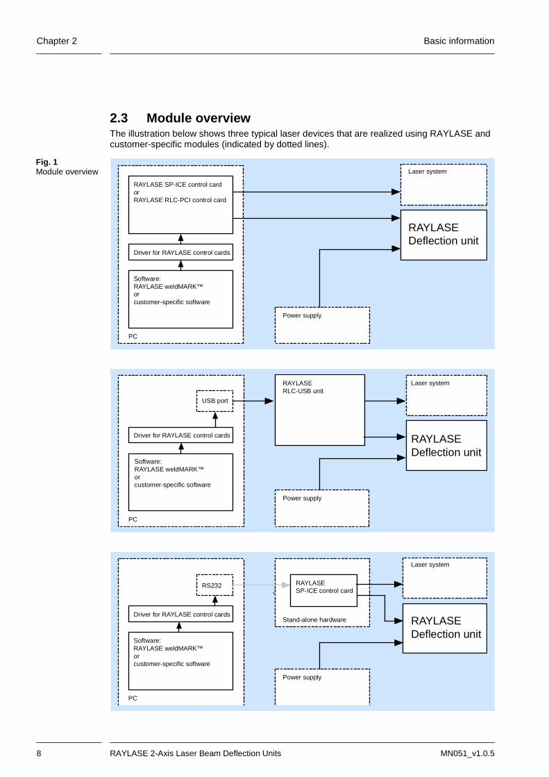
2.3 Module overview The illustration below shows three typical laser devices that are realized using RAYLASE and customer-specific modules (indicated by dotted lines).
RAYLASE SP-ICE control cardorRAYLASE RLC-PCI control card
PC
Driver for RAYLASE control cards
Software:RAYLASE weldMARK™orcustomer-specific software
Power supply
RAYLASEDeflection unit
Laser system
RAYLASERLC-USB unit
PC
USB port
Driver for RAYLASE control cards
Software:RAYLASE weldMARK™orcustomer-specific software
Power supply
RAYLASEDeflection unit
Laser system
RS232
Driver for RAYLASE control cards
Software:RAYLASE weldMARK™orcustomer-specific software
PC
RAYLASESP-ICE control card
Power supply
Stand-alone hardware RAYLASEDeflection unit
Laser system
Fig. 1 Module overview

Basic information Chapter 2
MN051_v1.0.5 2-Axis Laser Beam Deflection Units 9
2.4 Warranty The rights of the customer in respect of any defects in quality or deficiencies in title are gov-erned by the general conditions of business of RAYLASE AG. These conditions are available for review on our website. Before returning the product, please request an authorization number from RAYLASE. Pack the product in the original packaging or in packaging that provides equivalent protection for shipping. RAYLASE shall not be obliged to repair defects under the following circumstances: If persons not authorized by RAYLASE have attempted to repair the product. If persons not authorized by RAYLASE have modified the product. If the product has been used improperly. If the product has been connected to incompatible devices. If the product has been damaged because of inadmissible high laser power or focusing the
laser on optical areas. If the product has been damaged because of unqualified cleaning of the optical areas. If the warranty period is expired. Note: No implicit guarantee or warranty of suitability for specific purposes has been made. RAYLASE is not responsible for damages arising from use of the product. Individual assem-blies or other assemblies manufactured by RAYLASE may be subject to separate warranty conditions. Refer to the corresponding manuals for further information.
2.5 Manufacturer RAYLASE AG Argelsrieder Feld 2+4 82234 Wessling Germany Tel.: +49 (0) 81 53 - 88 98 - 0 Fax: +49 (0) 81 53 - 88 98 - 10 http://www.raylase.de E-mail: [email protected]
2.6 Customer support The RAYLASE support services are available for your problems either in respect to the deflec-tion unit or this manual. Before calling for support, please make sure you refer to any appropriate sections in the manuals on the supplied CD that may answer your questions. If you need further assistance call RAYLASE customer service department, Monday through Friday between 8 A.M. and 5 P.M. (Middle European Time). The customer service personnel will be able to give you direct assistance and answers to your questions. Germany (Wessling) +49 (0) 81 53 - 88 98 – 0 E-Mail: [email protected] ... ask for the customer service department

Chapter 2 Basic information
10 RAYLASE 2-Axis Laser Beam Deflection Units MN051_v1.0.5
2.7 Status LEDs The status LEDs allow you to check important functions and statuses on the deflection unit. They are located on the front or on the top of the deflection unit (depends on type).
LED arrangement Name Color Meaning
D1 Red CLK fault
Data transmission faulty. Cable defective. D2 Red Parity fault X
D3 Red Parity fault Y
D4 Green Temp. status X Temperature status available if LEDs are lit. D5 Green Temp. status Y
D6 Orange New data X Transfer new data if status LEDs are lit. D7 Orange New data Y
D8 Red Fault X Galvanometer scanner or driver electronics defective. Power supply defective if sta-tus LEDs are flickering. D9 Red Fault Y
D10 Green +VCC Power supplies available if LEDs are lit. D11 Green -VCC

Technical data Chapter 3
MN051_v1.0.5 2-Axis Laser Beam Deflection Units 11
3 TECHNICAL DATA This section outlines the common features of all deflection units. For type-specific features, refer to the data sheets in the Appendix. The individual data is assigned by the rating plate on the deflection unit and by the identification code ( below, Rating plate code).
3.1 Conformity with directives The deflection unit conforms to the requirements of the following directives:
EU Directive 2004/108/EG or German law on electromagnetic compatibility (EMVG) EU Directive 2002/95/EC or German law on electrical equipment (ElektroG) Directive 2006/42/EC on machinery For details of conformity with other directives, contact RAYLASE.
3.2 Rating plate code The type designation on the rating plate allows you to assign the deflection unit to the appro-priate data sheet in the Appendix. The data sheet contains the specific data for the unit.
3.2.1 SUPERSCAN II The following key is used on the label of SUPERSCAN II series. Type designation SS-II SUPERSCAN II SS-II-LD SUPERSCAN II Low Drift SS-II-AC SUPERSCAN II Auto Calibration SS-II-HS SUPERSCAN II High Speed SS-II-HS-LD SUPERSCAN II High Speed, Low Drift SS-II-HS-AC SUPERSCAN II High Speed, Auto Calibration SS-IIE-LD SUPERSCAN II Enhanced Low Drift SS-IIE-HS SUPERSCAN II Enhanced High Speed SS-IIE-HS-LD SUPERSCAN II Enhanced High Speed, Low Drift │ │ Apertur [mm] │ │ │ │ Coating code Wavelength [nm] ............. Laser │ │ AL 180-700 ...................... UV laser │ │ TY 355 .......................... Nd: YAG tripled │ │ AG 400-1064 ..................... various │ │ AR 488-514 ...................... Argon ions │ │ DY 532 .......................... Nd: YAG doubled │ │ DY+Y 532 & 1064 ................... various │ │ 780-980nm 780-980 ...................... LEDs │ │ Y+(850-870) 850-870 & 1064 ............... Nd:YAG │ │ 915+975nm 915 & 975 .................... LEDs │ │ 975 975 .......................... LEDs │ │ Y 1064 ......................... Nd:YAG │ │ AU 10600 ........................ CO2 │ │ C 10600 ........................ CO2 │ │ │ │ │ │ Tuning/Version │ │ │ LN Low noise Tuning │ │ │ W Short acceleration time tuning │ │ │ Vx Version │ │ │ │ │ │ │ │ Interface type │ │ │ │ Dig1 Digital interface with 25-pin D-SUB connector │ │ │ │ Dig2 Digital interface with 9-pin and 25-pin D-SUB connector │ │ │ │ An2 Analog interface │ │ │ │ │ │ │ │ │ │ Additional or customer code └─ └─ └─ └─ └─ └ XX-XX[XX]XX XX/X
Note: In addition to the coatings listed above, all mirrors have a deflection coating for a wave-length of 633nm.

Chapter 4 Functional description
12 RAYLASE 2-Axis Laser Beam Deflection Units MN051_v1.0.5
Fig. 2 Functional principle
4 FUNCTIONAL DESCRIPTION
4.1 Laser beam deflection unit The deflection unit can be used to deflect a laser beam in X and Y directions. This produces an area within which a laser can be directed at any position. This area is known as the "mark-ing field" and is shown in Fig. 2. Deflection is performed by two mirrors, each of which is moved by a galvanometer scanner. The deflection unit has a beam input, into which the laser beam is fed, and a beam output, through which the laser beam is emitted from the unit after deflection. Only suitable lasers can be fed into the beam input. Refer to the corresponding data sheet in the Appendix for details. Depending on the version, the beam output is either open or fitted with an F-Theta lens or glass guard ( page 13, F-Theta lens).
1 Digital interface of deflection unit 2 Power supply of subsystem 3 Beam input 4 Beam output 5 Operating field 6 Status LEDs 7 Galvanometer scanners with
mirrors
Only for deflection units with water cooling 8 Input coolant 9 Output coolant

Functional description Chapter 4
MN051_v1.0.5 2-Axis Laser Beam Deflection Units 13
Only for deflection units fitted with an F-Theta lens
4.2 F-Theta lens The F-Theta lens is specially designed for use with 2-axis deflection units. It focuses the laser beam at optimum quality on any position in the marking field. At the same time, it provides partial optical compensation for the barrel-shaped distortion that is unavoidable when using a two-axis deflection unit. The remaining distortion (see below) must be compensated by the deflection unit drive.
Distortion caused by two-mirror deflection.
Distortion caused by F-Theta lens.
Distortion caused by two-mirror deflection. and F-Theta lens.
1 Lens element inc. lens 2 Glass guard
3 Clamp ring 4 Protective cap
Assembly instructions o Before installation, check the protection window for dirt, scratches or cracks.
- If the protection window is dirty, it must be cleaned ( page 19, Instructions for cleaning lenses and glass guards).
- If the protection window is scratched or cracked, it must be replaced. o Brush the outer thread of the protective glass with a small amount of special grease for
photo-mechanical components. Normal fats are not suitable because they release gases and thus the optical system can be destroyed.
o Screw the protection window and mount into the beam output on the deflection unit until it is positioned securely.
Fig. 3 Field distortion with and without F-Theta lens
Fig. 4 Example: F-Theta lens for Nd:YAG
Chapter 4 Functional description
14 RAYLASE 2-Axis Laser Beam Deflection Units MN051_v1.0.5
For deflection units with analog interface only
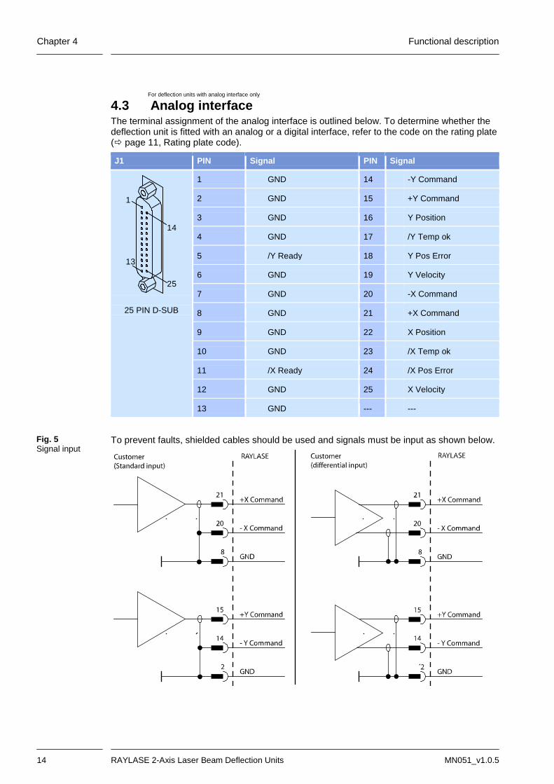
4.3 Analog interface The terminal assignment of the analog interface is outlined below. To determine whether the deflection unit is fitted with an analog or a digital interface, refer to the code on the rating plate ( page 11, Rating plate code).
J1 PIN Signal PIN Signal
1
13
25
14
25 PIN D-SUB
1 GND 14 -Y Command
2 GND 15 +Y Command
3 GND 16 Y Position
4 GND 17 /Y Temp ok
5 /Y Ready 18 Y Pos Error
6 GND 19 Y Velocity
7 GND 20 -X Command
8 GND 21 +X Command
9 GND 22 X Position
10 GND 23 /X Temp ok
11 /X Ready 24 /X Pos Error
12 GND 25 X Velocity
13 GND --- ---
To prevent faults, shielded cables should be used and signals must be input as shown below.
Fig. 5 Signal input

Functional description Chapter 4
MN051_v1.0.5 2-Axis Laser Beam Deflection Units 15
For deflection units with digital interface only
4.4 Digital interface The deflection unit is connected to a RAYLASE control card using the 25-pin D-SUB connect-or. All signals are compatible with RAYLASE's extended function XY2-100 standard. If the deflection unit is also fitted with a 9-pin D-SUB connector, the power supply to the de-flection unit comes from this additional connector. Deflection units that are not fitted with a 9-pin D-SUB connector are powered by the digital interface. Refer to the following connection table:
J1 PIN Signal PIN Signal
1
13
25
14
25 PIN D-SUB
1 I -SENDCLOCK 14 I +SENDCLOCK
2 I -SYNC 15 I +SYNC
3 I -X CHANNEL 16 I +X CHANNEL
4 I -Y CHANNEL 17 I +Y CHANNEL
5 I -Z CHANNEL 18 I +Z CHANNEL
6 O -HEAD-STATUS 19 O +HEAD-STATUS
7 I -P-DAC CHANNEL 20 I +P-DAC CHANNEL
8 nc 21 nc
9 Nc1 +VSS1 22 nc1 +VSS1
10 nc1 +VSS1 23 GND
11 GND 24 GND
12 nc1 -VSS1 25 nc1 -VSS1
13 nc1 -VSS1 --- ---
I= Diff. Input, nc = Not connected (not used) O = Diff. Output 1) If there is no separate 9-pin D-SUB power input, the power supply is provided by the digital interface. The power supply must be provided by the OEM customer.
Specifications
Diff. Input-, Diff. Input+ - Diff. Output-, Diff. Output+
Input voltage max. ±24.0V Output low max. 0.6V max. 40mA
Input threshold 200mV Output high min. 2V @ 50Ω max. 40mA
Hysteresis typ. 45mV ESD protection ±10kV
Input impedance 120Ω
ESD protection ±15kV
Power supply Designation Voltage Current Residual rip-
ple Noise
-VSS -15V to -18V 2.5A ≤100mV ≤0.5% DC at 30MHz
+VSS +15V to +18V 2.5A

Chapter 4 Functional description
16 RAYLASE 2-Axis Laser Beam Deflection Units MN051_v1.0.5
For deflection units with 9-pin D-SUB connector only
4.5 Power supply The 9-pin D-SUB connector provides the deflection unit with power. The power supply must be provided by the OEM customer. Refer to the following connection and parameter table:
J1 PIN Des-igna-tion
Voltage Current Residual rip-ple
Noise
6
1
5
9
9 PIN D-SUB
1, 2, 6 -VSS -15V to -18V min. 2.5A ≤100mV ≤0.5% DC at 30MHz
4, 5, 9 +VSS +15V to +18V min. 2.5A
3, 7, 8 GND

Installation Chapter 5
MN051_v1.0.5 2-Axis Laser Beam Deflection Units 17
5 INSTALLATION
Warning: The laser beam can cause severe injury to the eyes and the skin. Note that
even apparently matt objects can reflect the wavelength of laser beams. All personnel in the room must wear appropriate laser protection goggles and, if necessary, protective clothing.
Never look directly at the laser beam, even when wearing protective gog-gles.
The deflection unit may require the laser device to be assigned to a different danger class ( page 5, Classification of laser devices).
The laser must be switched off during installation. We recommend that the laser area is completely protected by an appropri-
ate working chamber. If this is not possible, appropriate protective measures for the laser class must be implemented.
The mirrors in the deflection unit must move freely after installation of the deflection unit. No components of the laser device may protrude into the de-flection unit.
The laser device must be of sufficient quality that the laser beam can only be emitted at the beam output on the deflection unit.
The "Laser radiation" national accident prevention regulations must be ob-served.
Connecting cables may not be subjected to mechanical strain. The deflection unit must be protected against moisture, dust and corrosive
vapors. The optical components may only be touched when wearing suitable cotton
gloves. The deflection unit must be protected against static discharge and strong
electromagnetic fields. The power density of the input laser radiation may not exceed the maximum
permissible power density of the optical components of the deflection unit. The beam path and the function of the deflection unit must be tested after
installation. We recommend performing all tests with a danger class 1 or 2 laser to min-imize the risk of injury. If this is not possible, the laser used must be set to the lowest possible power. This setting must be secured against accidental adjustment.
Procedure o Carefully remove the protective cover over the beam input with a small screwdriver. o To install the deflection unit, insert locating pins into the corresponding holes and attach
the deflection unit to the prepared installation surface using screws. Note: The deflection unit may only be installed using the pins and screws specified by RAYLASE. Follow the installation drawing supplied.
o For details of how to connect the deflection unit to a RAYLASE control card, refer to the corresponding manual.

Chapter 6 Cleaning
18 RAYLASE 2-Axis Laser Beam Deflection Units MN051_v1.0.5
6 CLEANING
6.1 Cleaning the housing
Warning: The laser beam can cause severe injury to the eyes and the skin. Before clean-ing, make sure that the laser device is switched off and secured against acci-dentally being switched on.
The deflection unit housing is dust proof. It can be cleaned with a duster. If it is very dirty, the duster can be moistened with a light and non-aggressive cleaning solution (e.g. soap solu-tion).
6.2 Cleaning the optical system
Warning: The laser beam can cause severe injury to the eyes and the skin. Before clean-ing, make sure that the laser device is switched off and secured against acci-dentally being switched on.
Dirty optical surfaces result in increased absorption of the laser radiation. This can cause the dirt to heat up sufficiently for it to burn into the optical surfaces and permanently damage them. The following circumstances can cause increased accumulation of dirt: The ambient atmosphere is contaminated with dirt, grease or other particles. Vapors and particles are produced while working. Talking, coughing or sneezing close to optical surfaces. In general, all contamination of the optical system should be avoided wherever possible. However, as contamination cannot be completely avoided, the optical system must be cleaned at appropriate intervals. Regular checking and cleaning of the optical surfaces can prevent permanent damage. Note: RAYLASE accepts no liability for damaged optical components! Note: Damage caused during the laser process, e.g. when processing metals, is irreversible and cannot be resolved by cleaning.
Cleaning Chapter 6
MN051_v1.0.5 2-Axis Laser Beam Deflection Units 19
For deflection units with lens and glass guard only
6.2.1 Instructions for cleaning lenses and glass guards
Warning: The laser beam can cause severe injury to the eyes and the skin. Before clean-ing, make sure that the laser device is switched off and secured against acci-dentally being switched on.
Fingerprints contain aggressive substances that can damage the optical surfaces. Optical surfaces should therefore only be touched when wearing suitable gloves or with a lens clean-ing cloth. o Only touch the optical elements when wearing suitable cotton gloves and only touch the
edges. o Blow loose particles from the surface with clean and oil-free compressed air. Note that the
compressed air in workshops can contain oil particles and is therefore unsuitable for clean-ing the optical system.
o Moisten a suitable lens cleaning cloth with ethanol suitable for cleaning optical compo-nents.
o Place one end of the moistened cloth on the optical system and slowly move it over the optical components. Do not exert any pressure and do not rub the optical components.
o Remove any remaining ethanol residue with a dry optical cloth. o Repeat the procedure until the surface is completely clean. Use a new cleaning cloth for
each repetition. 6.2.2 Instructions for cleaning mirrors
Warning: The laser beam can cause severe injury to the eyes and the skin. Before clean-ing, make sure that the laser device is switched off and secured against acci-dentally being switched on.
The mirror surfaces are extremely sensitive and may only be cleaned by experienced person-nel. We strongly recommend sending the deflection unit in to RAYLASE for the mirrors to be cleaned, as opening of the deflection unit by unauthorized personnel voids the warranty. However, if you do want to clean the mirrors yourself, follow the same procedure as for clean-ing the lens but with even more care ( above, Instructions for cleaning lenses and glass guards). 6.2.3 Special instructions for zinc selenide optical elements Zinc selenide (ZnSe) is an inorganic orange material that can be used in different forms as an optical component (e.g. lenses, beam splitters, mirrors) in CO2 laser systems. Properties of zinc selenide Melting point 1,520°C Density 5.27g/cm³ at 25°C Solubility Sensitive to water To improve the optical properties of the material, zinc selenide is often given an anti-reflex coating that can contain thorium fluoride. Thorium is a α emitter and is slightly radioactive. Thorium is potentially hazardous to health if it is inhaled or swallowed. As the coating contain-

Chapter 6 Cleaning
20 RAYLASE 2-Axis Laser Beam Deflection Units MN051_v1.0.5
ing thorium is enclosed between non-radioactive layers, there is no risk to the user under normal circumstances.
Damage to zinc selenide optical elements Under normal circumstances, no special precautions are necessary when handling or storing zinc selenide. In case of damage to a zinc selenide optical element or its anti-reflex coating, follow the in-structions below.
Damage to anti-reflex coating Possible causes:
- Coating coming into contact with water, acids or alkalis - Mechanical damage due to improper cleaning or handling
Action: - Pack the optical elements in an airtight sealed plastic container. - Return the container to your supplier. The supplier is responsible for professional
disposal of the material. Damage to optical element Possible causes:
- Contact with water, acid or alkali - Mechanical damage due to improper cleaning or handling
Action: - Avoid inhaling dust! - Carefully collect up fragments and pack them in an airtight sealed plastic container. - Return the container to your supplier. The supplier is responsible for professional
disposal of the material. Damage to optical element due to laser radiation Cause:
- Damage to optical element due to laser radiation (laser radiation is no longer completely transmitted but is absorbed into the element due to damage to the anti-reflex coating or contamination of the optical element)
Action: - Switch off the laser device immediately! - Leave the room for at least 30 minutes! - Wear gloves and a mouth protector while performing the subsequent steps! - Carefully collect up all fragments and pack them in an airtight sealed plastic container. - Clean all contaminated components and surfaces with a damp cloth and pack the
cleaning cloths in a sealed plastic container. - Return the containers to your supplier. The supplier is responsible for professional
disposal of the material. Warning: Because of the risks outlined, zinc selenide optical elements must be cleaned with special care and is performed entirely at your own risk!

Maintenance Chapter 7
MN051_v1.0.5 2-Axis Laser Beam Deflection Units 21
7 MAINTENANCE Repairs may only carried out by RAYLASE or RAYLASE Certified Service Centres as special know-how and comprehensive testing methods are required. Certified Service Centres: Russia Laser Technology Centre Politechnicheskaya 29 195251 St.Petersburg, Russia Phone: +7 (812) 552 72 61 Fax: +7 (812) 535 46 98 E-mail: [email protected] Web: www.ltc.ru Turkey ISSE ULUSLARARASI TICARET ve DANISMANLIK LTD. STI. Ikitelli O.S.B. Sefaköy San. Sit. 4. Blok No: 1 Kücukcekmece Istanbul, Turkey Phone: +90 212 671 15 64 Fax: +90 212 671 21 64 E-mail: [email protected] Web: www.lasersos.com.tr China RAYLASE Laser Technology (Shenzhen) Co., Ltd 5th Floor, No.6 Qiancheng Road Henggang 228 Industrial Park Longgang District, Shenzhen 518115 Guangdong China Phone: +86-(0)755-8222 8324 Fax: +86-(0)755-8222 8193 E-mail: [email protected] Web: www.raylase.cn Brazil ReB Laser Comercial Serviços Ltda. Rua Eula Herper Bowden, 82 09629-100 - Rudge Ramos São Bernardo do Campo - SP Phone: +55(11) 4368-7976 - +55(11) 4368-5053 Fax: +55(11) 4365-4572 E-mail: [email protected] Web: www.reblaser.com.br

Chapter 8 Troubleshooting
22 RAYLASE 2-Axis Laser Beam Deflection Units MN051_v1.0.5
8 TROUBLESHOOTING
Warning: The laser beam can cause severe injury to the eyes and the skin.
Never look directly or indirectly into the laser beam during troubleshooting. Do not disable any safety precautions to protect against laser radiation. Wear protective clothing and/or goggles appropriate for the relevant laser
class. In case of malfunctions, check whether the symptom and a possible remedy are included in the following checklist.
Problem Possible cause and remedy
Poor marking quality
Defective power supply
Incorrect marking parameters
Marking quality has deteriorated
Lens dirty page 19, Instructions for cleaning lenses and glass guards
Mirror dirty page 19, Instructions for cleaning mirrors
Laser power decreasing
The RAYLASE weldMARK™ software can compensate for a loss of laser power. Menu: System > Global adjustments
Marking parameters changed
Divergence optics changed
Laser spot changed
Dirty lens page 19, Instructions for cleaning lenses and glass guards Dirty or dam-aged mirrors
page 19, Instructions for cleaning mirrors Send deflection unit in for repair
Laser system adjusted
No laser beam, although pro-cess started from PC.
Beam path blocked.
Remove protective cover from beam input and/or output
Laser drive fault
Fault in laser system
The deflection unit only de-flects the laser beam in one direction or not at all.
Data cable de-fective
page 10, Status LEDs
X and Y axis reversed
Incorrect cabling
If the fault cannot be resolved, contact RAYLASE Customer Service for further assistance.

Index
MN051_v1.0.5 2-Axis Laser Beam Deflection Units 23
INDEX
A Analog interface .............................................14
C CE symbol ....................................................... 4 Cleaning .........................................................18 Conformity with directives ..............................11 Customer Service............................................ 9 Customer Support ........................................... 9
D Digital interface ..............................................15
F Functional description ....................................12
I Installation ......................................................17
L Laser beam deflection unit .............................12 Laser safety .................................................... 4
M Maintenance ..................................................21 Manufacturer ................................................... 9
P Package contents ............................................ 7 Power supply ................................................. 16
R Rating plate ..................................................... 4
S Safety instructions ........................................... 4 Seal label ........................................................ 4 Shutter............................................................. 4 Signs ............................................................... 4 Status LEDs .................................................. 10
T Technical data ............................................... 11 Troubleshooting ............................................ 22
W Warranty .......................................................... 9
X XY2-100 Standard ......................................... 16 XY2-100-Standard ........................................ 15

Data Sheet 2-Axis Subsystems for Laser Beam Deflection
03/2013
SUPERSCAN II General Specifications
Power Supply
Voltage ±15 to ±18 V Typical Deflection (optical) ±0.393 rad
Resolution 12 µrad Current 3 A, RMS, max. 10 A Repeatability RMS 2 µrad
Ripple Noise
Max. 200 mVpp, @ 20 MHz bandwidth
Max. Gaindrift1) 50 ppm/K
Max. Offsetdrift1) 30 µrad/K Ambient Temperature +15 to +35 °C Long-term Drift over 8 hours1), 2) SS-II < 300 µrad Storage Temperature -10 to +60 °C Long-term Drift over 24 hours1), 2) SS-II-LD < 200 µrad Humidity ≤ 80 % non-condensing Auto-calibration option:
Interface Signals Digital XY2-100 Protocol Position Accuracy 3) < 50 µrad/K 1) Drift per axis, 2) after warming-up, variations of ambient temperature < 1K, variations of cooling water 1K < 3) depending on the intervalbetween auto-calibration cycles
Aperture Dependent Specifications – Mechanical Data
SS-II-10 SS-II-12 SS-II-15 SS-II-20 SS-II-30 Input Aperture [mm] 10.0 12.0 15.0 20.0 30.0 Beam Displacement [mm] 12.4 14.0 18.3 26.0 35.7 Weight, without objective [kg] approx. 3.1 approx. 3.7 approx. 3.7 approx. 3.9 approx 5.9 Dimension (mm) (L x W x H) 165 x 120 x 115 170 x 125 x 126 170 x 125 x 126 168.5 x 130 x 121 200 x 159 x 150
Aperture Dependent Specifications – Dynamic Data
Input Aperture 10 mm 15 mm Options Standard Low Drift Auto-calibration Standard Low Drift Auto-calibration Acceleration Time [ms] ≤ 0,19 ≤ 0,19 ≤ 0,22 ≤ 0,32 ≤ 0,32 ≤ 0,36 Writing Speed [cps] 1), 2) > 800 > 800 > 700 >500 >500 > 435 Positioning Speed [m/s] 1) > 10 > 10 > 8,8 > 7 > 7 > 6 Input Aperture 20 mm 30 mm Options Standard Low Drift Auto-calibration Standard Low Drift Auto-calibration Acceleration Time [ms] ≤ 0,60 ≤ 0,60 ≤ 0,69 ≤ 0,75 ≤ 0,75 ≤ 0,80 Writing Speed [cps] 1), 2) > 350 > 350 > 300 Positioning Speed [m/s ]1) > 6 > 6 > 5.2 > 5 > 5 > 4 1) With F-Theta Lens f=163 / field size 120 mm x 120 mm, 2) Single-stroke font with 1 mm height.
Mirrors & Objectives
Scan mirrors and objectives with optimized mounts are available for all typical laser types, wavelengths, power densities, focal lengths and working fields. Customer specific configurations are also possible. Please contact the RAYLASE support team for specific information and possible combinations on +49-8153-8898-0 or email [email protected]
Water Tempering Specifications
Specifications Flow rate Pressure loss Water1) Clean tap water with additives 2 l / min 0,3 bar Temperature 22-28°C 4 l / min 0,4 bar Pressure 2-3 bar 6 l / min 0,7 bar
(1) Caution: When using cooling water including deionized water, suitable additives must be
used to prevent the growth of algae and protect the aluminium parts against corrosion.
Additive recommendations: Standard industrial applications e.g. CCL105 (NALCO)
Food & beverage, packaging applications: e.g. polypropylene glycol (Dow Chemical)
Please consult your additive supplier for dosage information
Data Sheet 2-Axis Subsystems for Laser Beam Deflection
03/2013
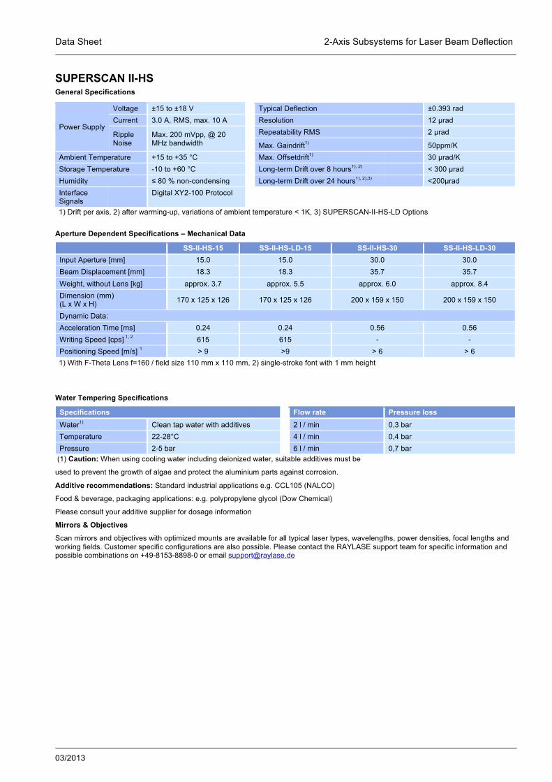
SUPERSCAN II-HS General Specifications
Power Supply
Voltage ±15 to ±18 V Typical Deflection ±0.393 rad Current 3.0 A, RMS, max. 10 A Resolution 12 µrad
Ripple Noise
Max. 200 mVpp, @ 20 MHz bandwidth
Repeatability RMS 2 µrad
Max. Gaindrift1) 50ppm/K Ambient Temperature +15 to +35 °C Max. Offsetdrift1) 30 µrad/K Storage Temperature -10 to +60 °C Long-term Drift over 8 hours1), 2) < 300 µrad Humidity ≤ 80 % non-condensing Long-term Drift over 24 hours1), 2),3) <200µrad Interface Signals
Digital XY2-100 Protocol
1) Drift per axis, 2) after warming-up, variations of ambient temperature < 1K, 3) SUPERSCAN-II-HS-LD Options
Aperture Dependent Specifications – Mechanical Data
SS-II-HS-15 SS-II-HS-LD-15 SS-II-HS-30 SS-II-HS-LD-30 Input Aperture [mm] 15.0 15.0 30.0 30.0 Beam Displacement [mm] 18.3 18.3 35.7 35.7 Weight, without Lens [kg] approx. 3.7 approx. 5.5 approx. 6.0 approx. 8.4 Dimension (mm) (L x W x H) 170 x 125 x 126 170 x 125 x 126 200 x 159 x 150 200 x 159 x 150
Dynamic Data: Acceleration Time [ms] 0.24 0.24 0.56 0.56 Writing Speed [cps] 1, 2 615 615 - - Positioning Speed [m/s] 1 > 9 >9 > 6 > 6 1) With F-Theta Lens f=160 / field size 110 mm x 110 mm, 2) single-stroke font with 1 mm height
Water Tempering Specifications
Specifications Flow rate Pressure loss Water1) Clean tap water with additives 2 l / min 0,3 bar Temperature 22-28°C 4 l / min 0,4 bar Pressure 2-5 bar 6 l / min 0,7 bar
(1) Caution: When using cooling water including deionized water, suitable additives must be
used to prevent the growth of algae and protect the aluminium parts against corrosion.
Additive recommendations: Standard industrial applications e.g. CCL105 (NALCO)
Food & beverage, packaging applications: e.g. polypropylene glycol (Dow Chemical)
Please consult your additive supplier for dosage information
Mirrors & Objectives
Scan mirrors and objectives with optimized mounts are available for all typical laser types, wavelengths, power densities, focal lengths and working fields. Customer specific configurations are also possible. Please contact the RAYLASE support team for specific information and possible combinations on +49-8153-8898-0 or email [email protected]
Data Sheet 2-Axis Subsystems for Laser Beam Deflection
03/2013
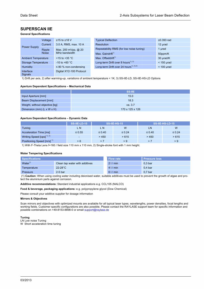
SUPERSCAN IIE General Specifications
Power Supply
Voltage ±15 to ±18 V Typical Deflection ±0.393 rad Current 3.0 A, RMS, max. 10 A Resolution 12 µrad
Ripple Noise
Max. 200 mVpp, @ 20 MHz bandwidth
Repeatability RMS (for low noise tuning) 1 µrad
Max. Gaindrift1) 50ppm/K Ambient Temperature +15 to +35 °C Max. Offsetdrift1) 30 µrad/K Storage Temperature -10 to +60 °C Long-term Drift over 8 hours1), 2) < 150 µrad Humidity ≤ 80 % non-condensing Long-term Drift over 24 hours1), 2),3) < 100 µrad Interface Signals
Digital XY2-100 Protocol
1) Drift per axis, 2) after warming-up, variations of ambient temperature < 1K, 3) SS-IIE-LD, SS-IIE-HS-LD Options
Aperture Dependent Specifications – Mechanical Data
SS-IIE Input Aperture [mm] 15.0 Beam Displacement [mm] 18.3 Weight, without objective [kg] ca. 3.7 Dimension (mm) (L x W x H) 170 x 125 x 126
Aperture Dependent Specifications – Dynamic Data
SS-IIE-LD-15 SS-IIE-HS-15 SS-IIE-HS-LD-15 Tuning L N L N W LN W Acceleration Time [ms] ≤ 0.55 ≤ 0.40 ≤ 0.24 ≤ 0.40 ≤ 0.24 Writing Speed [cps] 1), 2) - > 450 > 615 > 450 > 615 Positioning Speed [m/s] 1) > 6 > 7 > 9 > 7 > 9 1) With F-Theta Lens f=160 / field size 110 mm x 110 mm, 2) Single-stroke font with 1 mm height.
Water Tempering Specifications
Specifications Flow rate Pressure loss Water1) Clean tap water with additives 2 l / min 0,3 bar Temperature 22-28°C 4 l / min 0,4 bar Pressure 2-5 bar 6 l / min 0,7 bar
(1) Caution: When using cooling water including deionised water, suitable additives must be used to prevent the growth of algae and pro-tect the aluminium parts against corrosion.
Additive recommendations: Standard industrial applications e.g. CCL105 (NALCO)
Food & beverage, packaging applications: e.g. polypropylene glycol (Dow Chemical)
Please consult your additive supplier for dosage information
Mirrors & Objectives
Scan mirrors and objectives with optimized mounts are available for all typical laser types, wavelengths, power densities, focal lengths and working fields. Customer specific configurations are also possible. Please contact the RAYLASE support team for specific information and possible combinations on +49-8153-8898-0 or email [email protected]
Tuning LN Low noise Tuning W Short acceleration time tuning