2 cse et ppt
TRANSCRIPT
UNIT-IIIDC MACHINES

• MACHINE:• DC MACHINE:• DC MOTOR:• DC GENERATOR:
Faradays laws of electromagnetic induction
• Faradays 1 st law:
When ever conductor cuts magnetic flux an EMF is induced in that condutor.
• Faradays 2 nd law:
The magnitude of induced emf is equal to the rate of change of flux linkages.
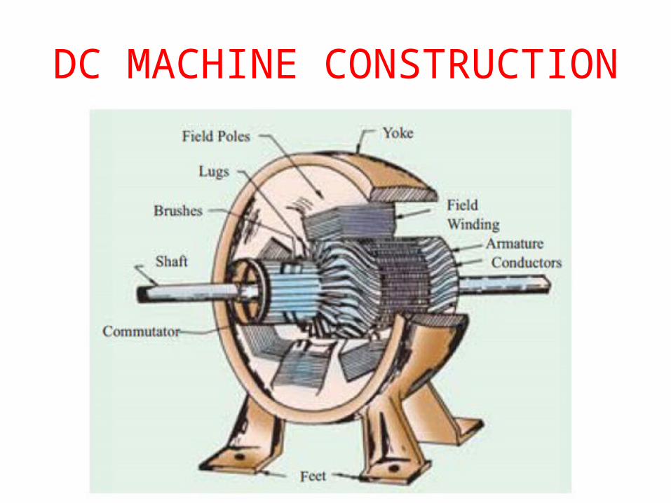
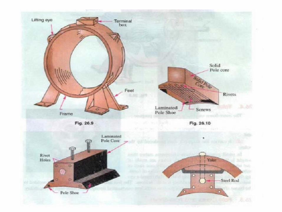
DC MACHINE CONSTRUCTION
IMPORTANT PARTS IN DC MACHINE
• A DC generator has the following parts1) Yoke2) Pole 3) field winding4) Armature core5) Brushes 6) Bearings
7)Commutator
8)Shaft
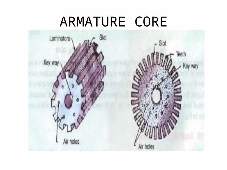
ARMATURE CORE
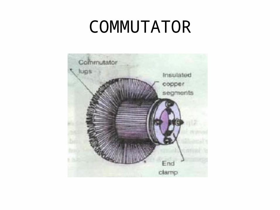
COMMUTATOR
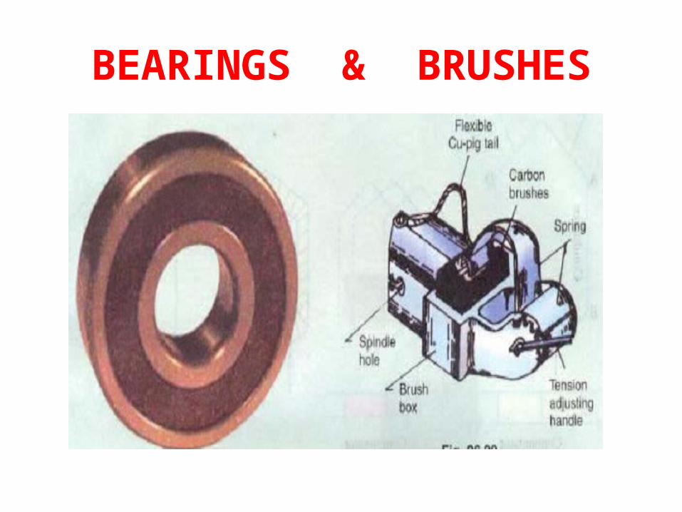
BEARINGS & BRUSHES

Methods of Excitation
• Separately excitation• Self excitation
The process of generating a magnetic field by means of an electric current is called excitation.
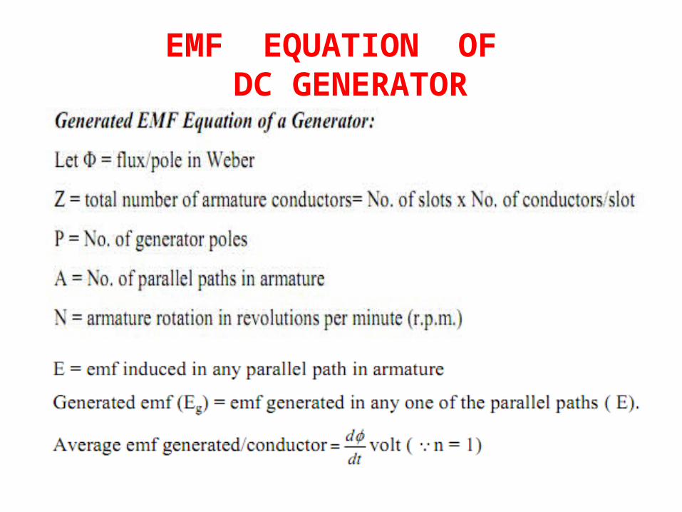
EMF EQUATION OF DC GENERATOR

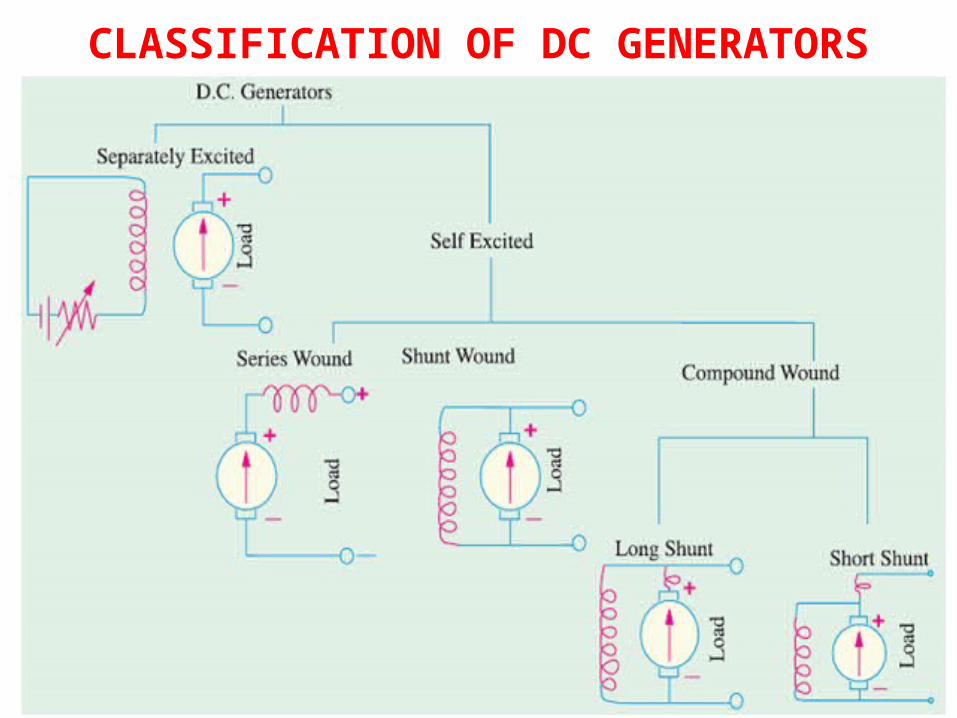
CLASSIFICATION OF DC GENERATORS
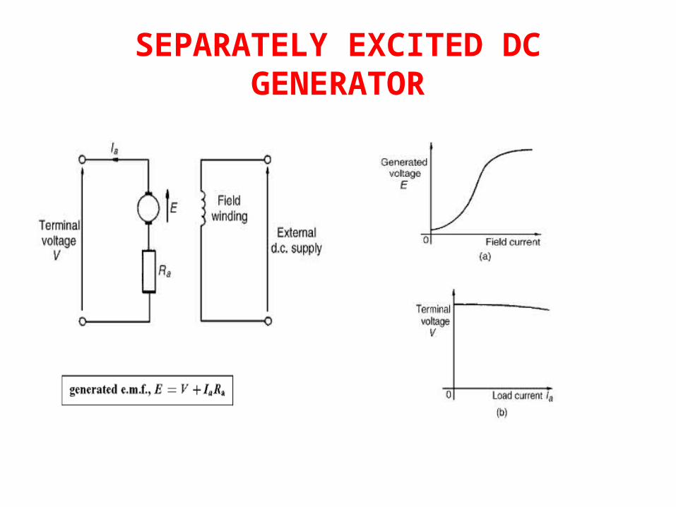
SEPARATELY EXCITED DC GENERATOR
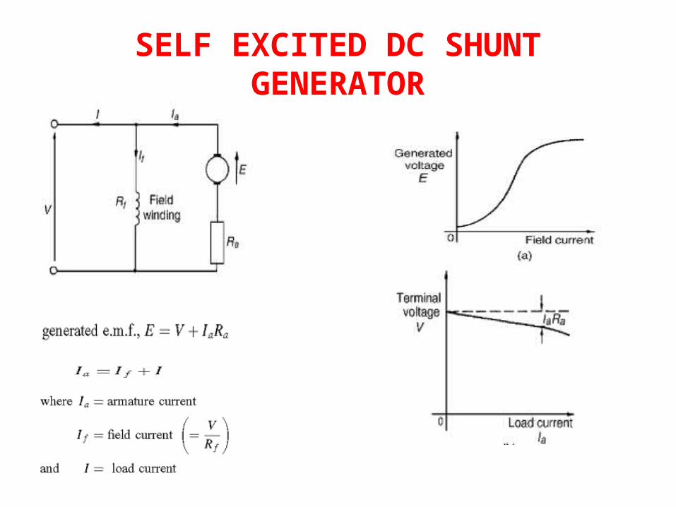
SELF EXCITED DC SHUNT GENERATOR
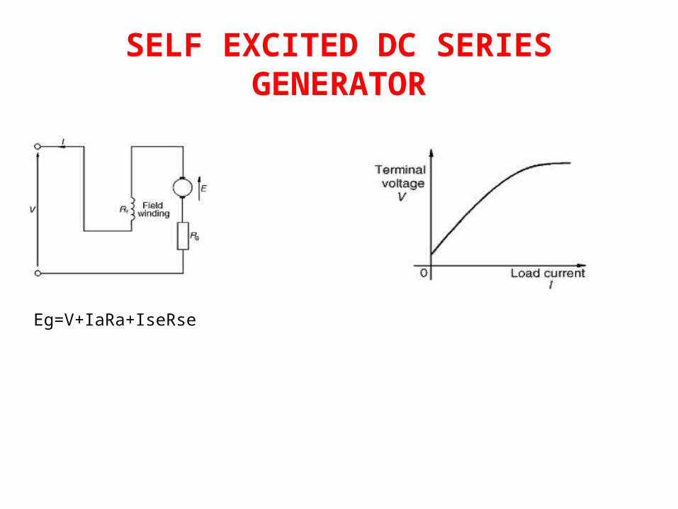
SELF EXCITED DC SERIES GENERATOR
Eg=V+IaRa+IseRse
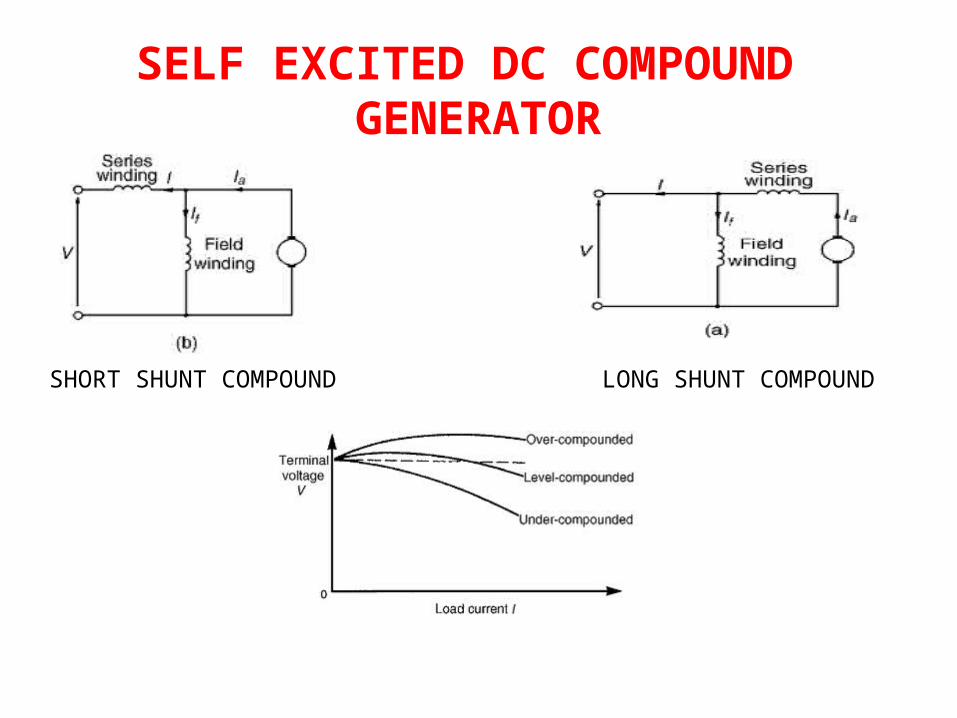
SELF EXCITED DC COMPOUND GENERATOR
SHORT SHUNT COMPOUND LONG SHUNT COMPOUND
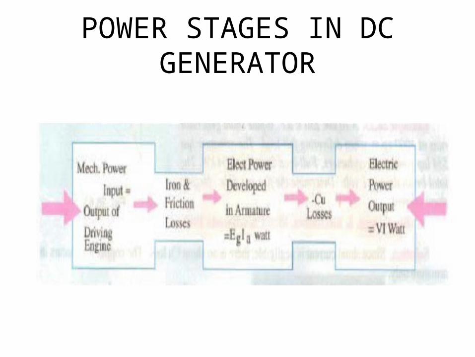
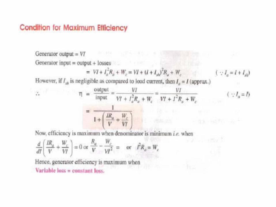
POWER STAGES IN DC GENERATOR
DC MOTORS
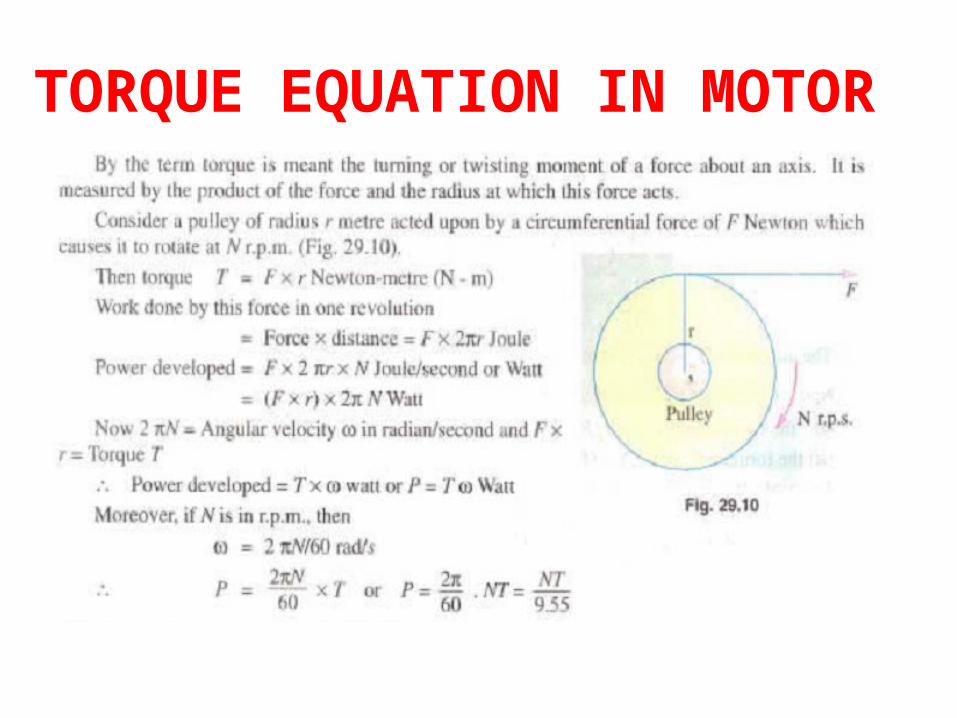
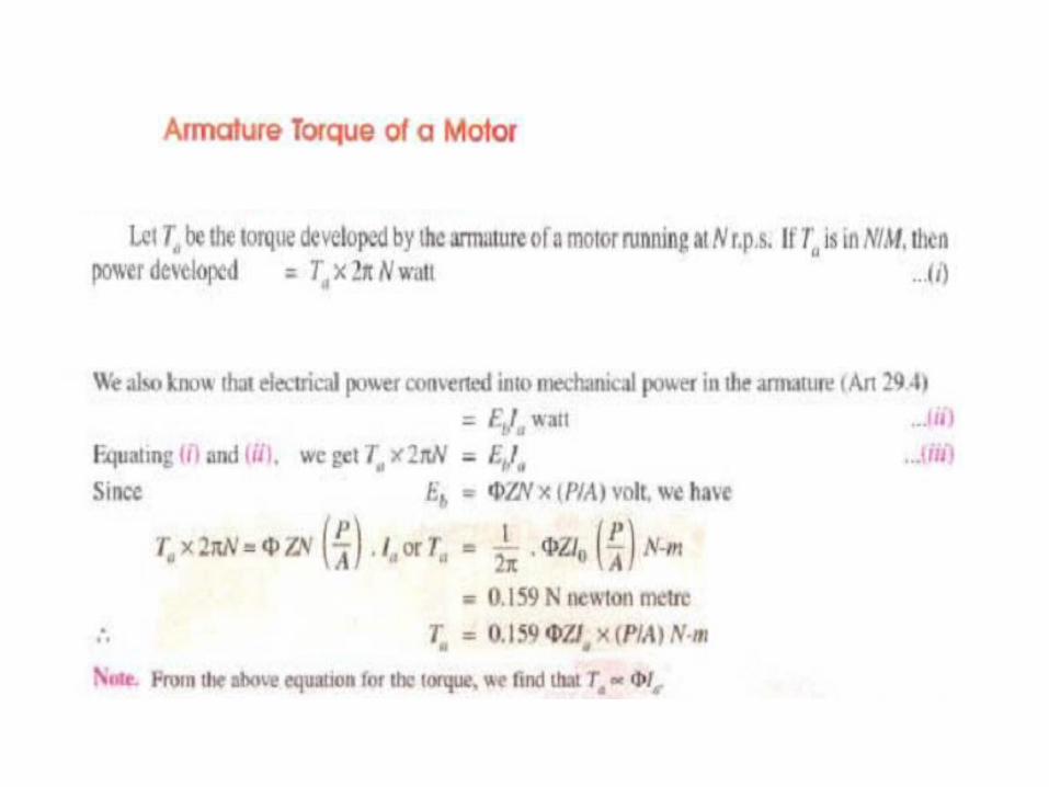
TORQUE EQUATION IN MOTOR

SPEED CONTROL OF DC SHUNT MOTOR
1.Flux control method
2.Armature resistance control method
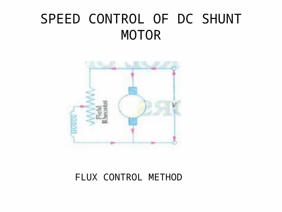
SPEED CONTROL OF DC SHUNT MOTOR
FLUX CONTROL METHOD
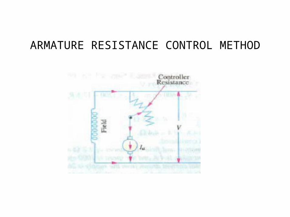
ARMATURE RESISTANCE CONTROL METHOD
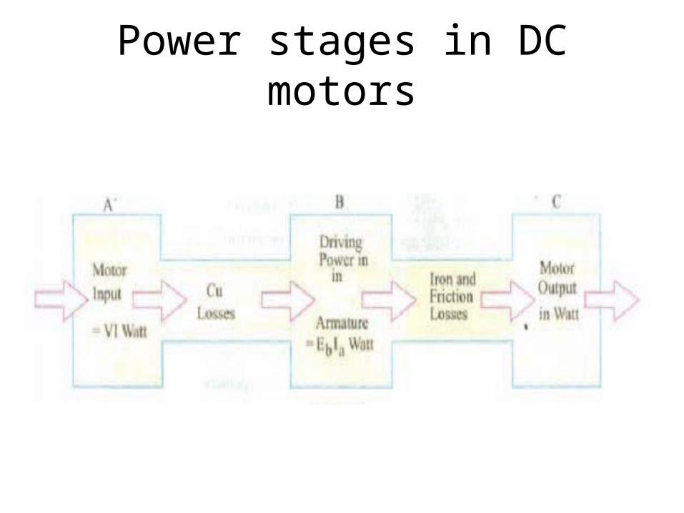
Power stages in DC motors
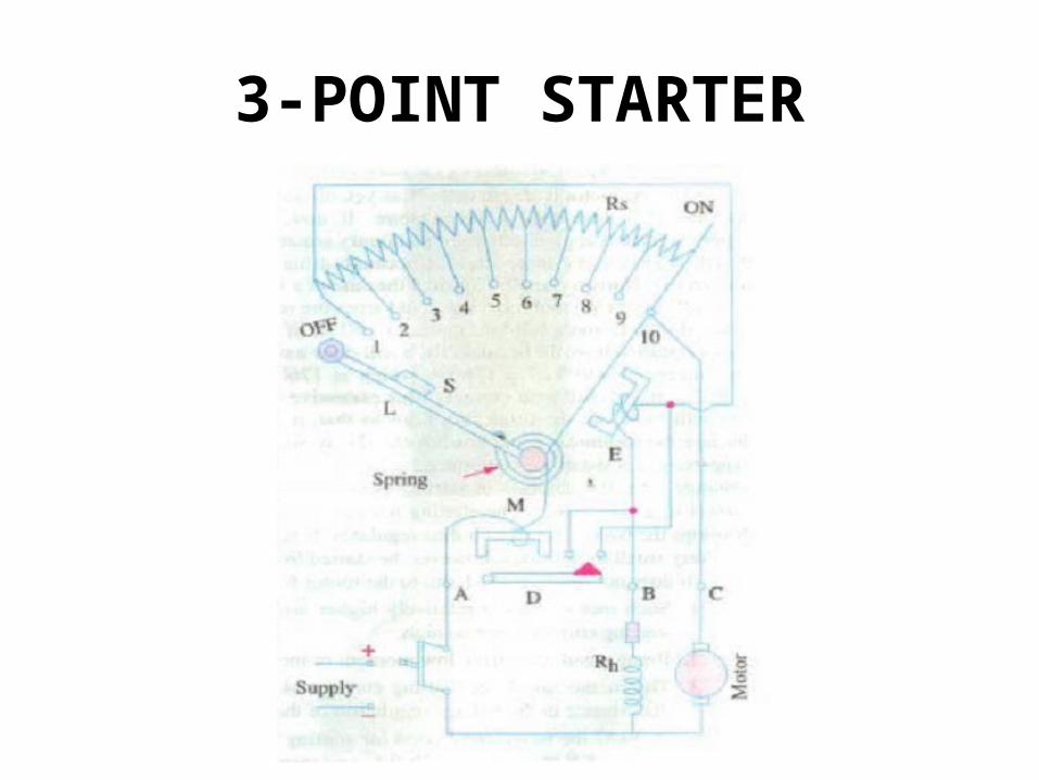
3-POINT STARTER

TRANSFORMERS

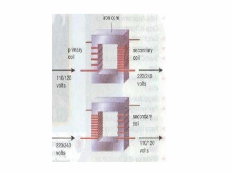
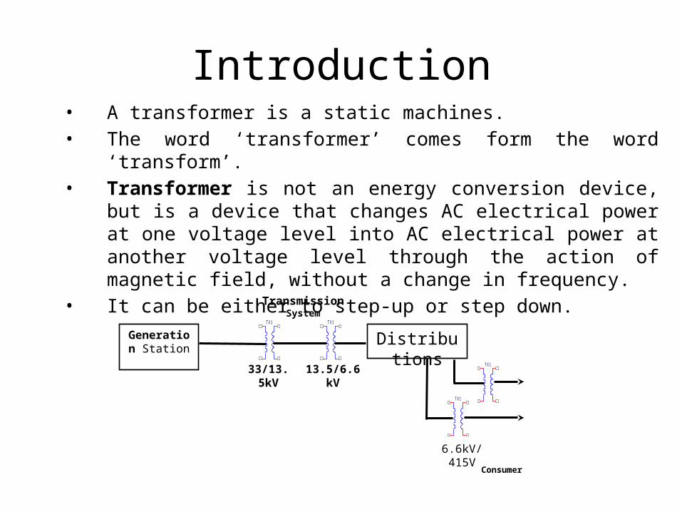
Introduction• A transformer is a static machines.• The word ‘transformer’ comes form the word ‘transform’.• Transformer is not an energy conversion device, but is a device that
changes AC electrical power at one voltage level into AC electrical power at another voltage level through the action of magnetic field, without a change in frequency.
• It can be either to step-up or step down.
Generation Station
TX1 TX1
Distributions TX1
TX1
Transmission System
33/13.5kV
13.5/6.6kV
6.6kV/415V
Consumer
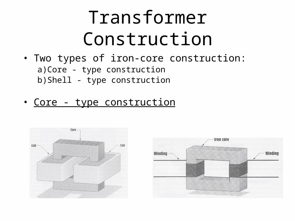
Transformer Construction• Two types of iron-core construction:
a) Core - type constructionb) Shell - type construction
• Core - type construction
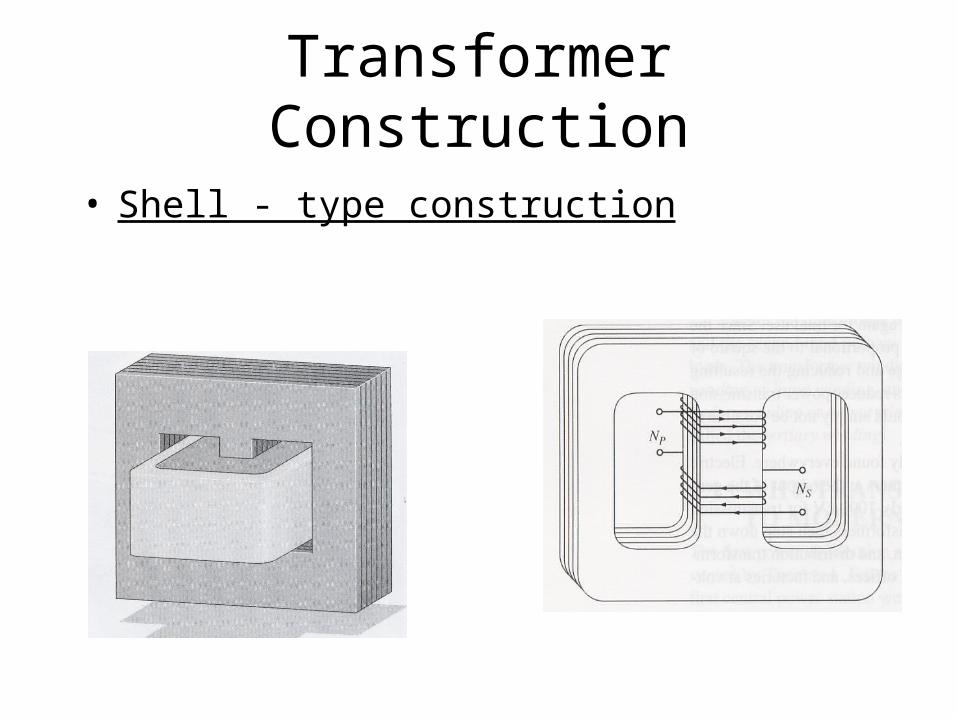
Transformer Construction
• Shell - type construction
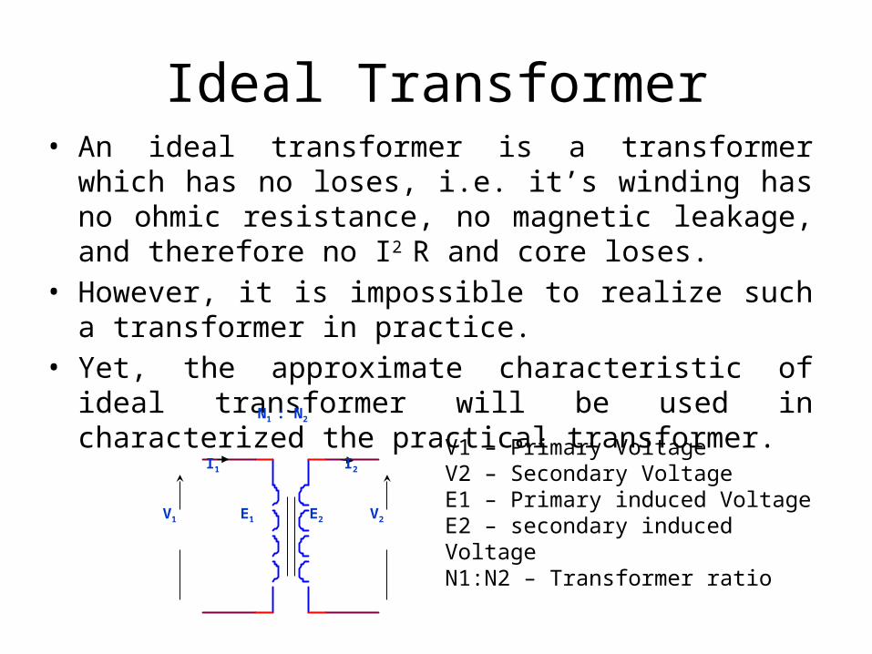
Ideal Transformer• An ideal transformer is a transformer which has no loses, i.e.
it’s winding has no ohmic resistance, no magnetic leakage, and therefore no I2 R and core loses.
• However, it is impossible to realize such a transformer in practice.
• Yet, the approximate characteristic of ideal transformer will be used in characterized the practical transformer.
V1 V2
N1 : N2
E1 E2
I1 I2
V1 – Primary VoltageV2 – Secondary VoltageE1 – Primary induced VoltageE2 – secondary induced VoltageN1:N2 – Transformer ratio
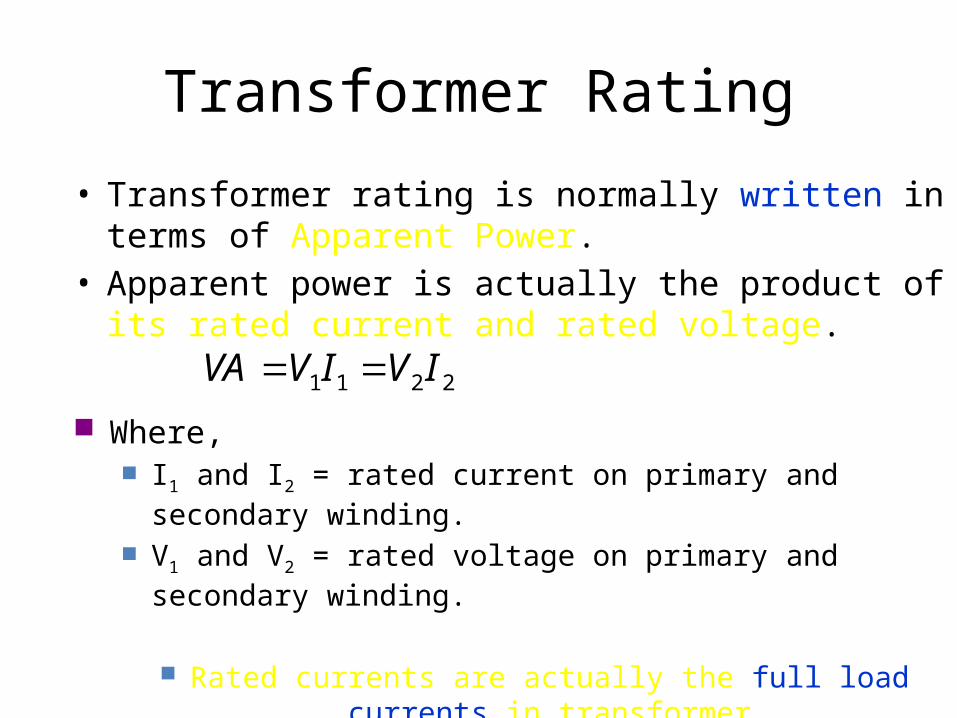
Transformer Rating
• Transformer rating is normally written in terms of Apparent Power.
• Apparent power is actually the product of its rated current and rated voltage.
2211 IVIVVA Where,
I1 and I2 = rated current on primary and secondary winding. V1 and V2 = rated voltage on primary and secondary winding.
Rated currents are actually the full load currents in transformer
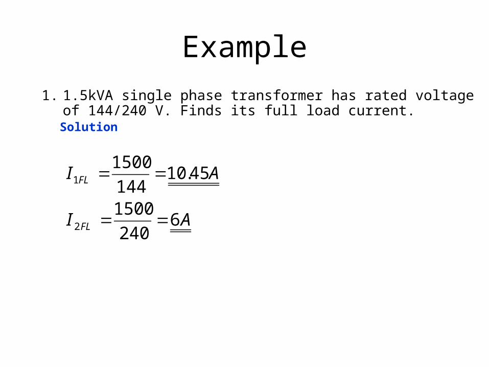
Example
1. 1.5kVA single phase transformer has rated voltage of 144/240 V. Finds its full load current.
Solution
AI
AI
FL
FL
6240
1500
45.10144
1500
2
1

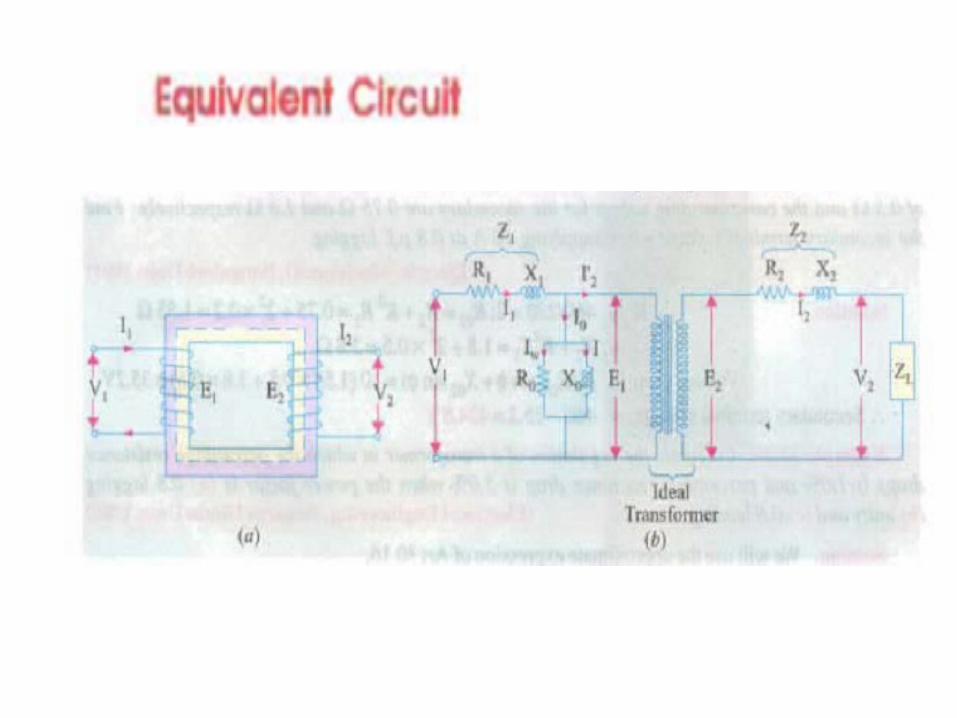
Practical Transformer (Equivalent Circuit)
V1 = primary supply voltage
V2 = 2nd terminal (load) voltage
E1 = primary winding voltage
E2 = 2nd winding voltage
I1 = primary supply current
I2 = 2nd winding current
I1’ = primary winding current
Io = no load current
V1
I1 R1X1
RC
Ic
Xm
Im
Io
E1 E2
V2
I1’
N1: N2R2
X2
Load
I2
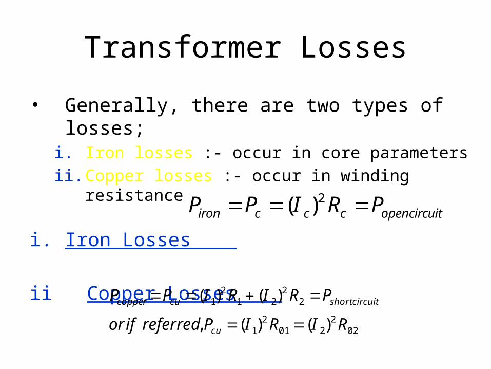
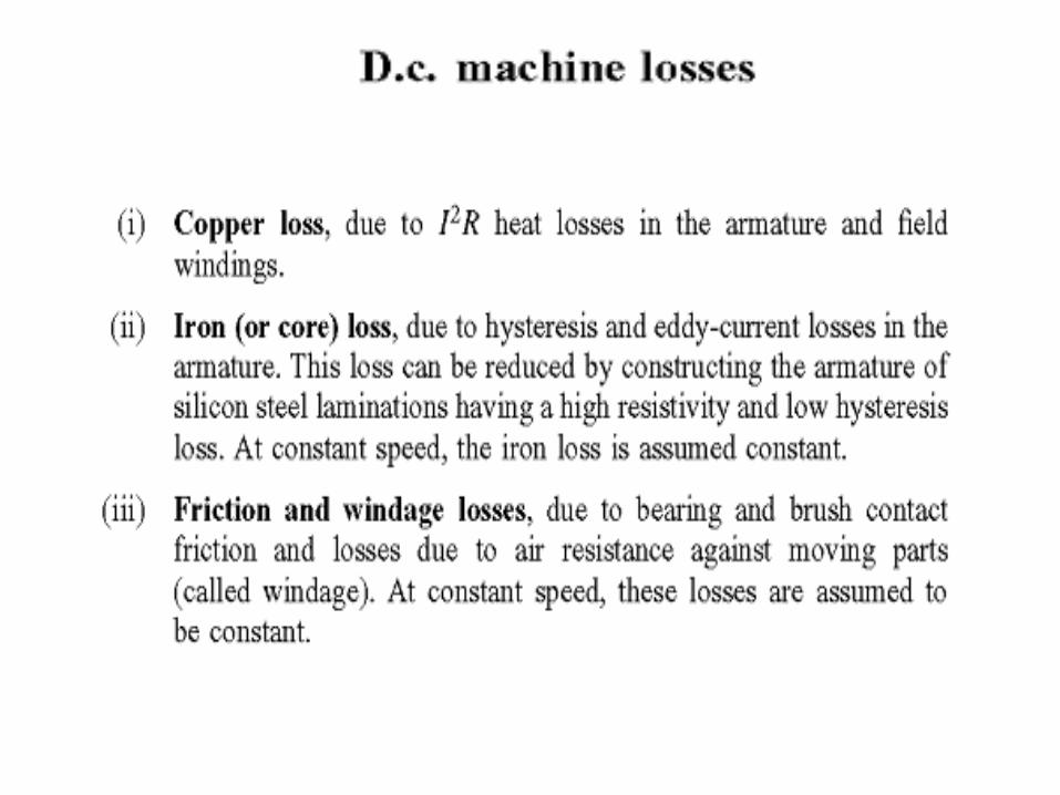
Transformer Losses
• Generally, there are two types of losses;i. Iron losses :- occur in core parametersii. Copper losses :- occur in winding resistance
i. Iron Losses
ii Copper Losses
circuitopenccciron PRIPP 2)(
022
2012
1
22
212
1
)()(,
)()(
RIRIPreferredifor
PRIRIPP
cu
circuitshortcucopper
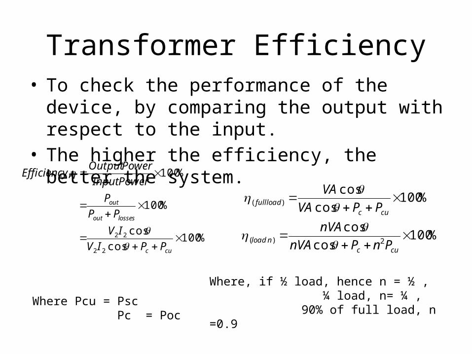
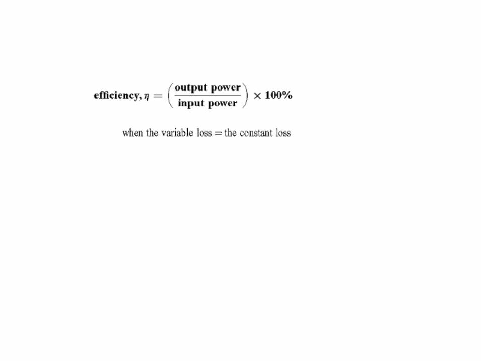
Transformer Efficiency• To check the performance of the device, by
comparing the output with respect to the input.• The higher the efficiency, the better the system.
%100cos
cos
%100
%100,
22
22
cuc
lossesout
out
PPIV
IV
PP
P
PowerInput
PowerOutputEfficiency
%100cos
cos
%100cos
cos
2)(
)(
cucnload
cucloadfull
PnPnVA
nVA
PPVA
VA
Where, if ½ load, hence n = ½ , ¼ load, n= ¼ , 90% of full load, n =0.9
Where Pcu = Psc Pc = Poc

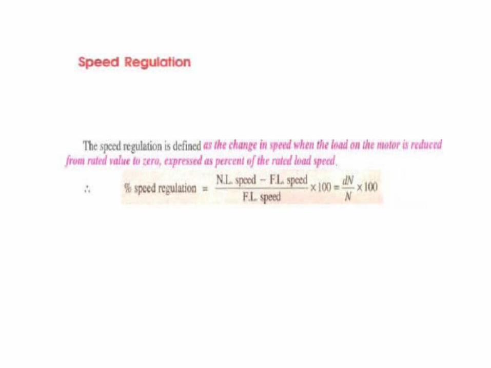
Voltage Regulation
• The purpose of voltage regulation is basically to determine the percentage of voltage drop between no load and full load.
• Voltage Regulation can be determine based on 3 methods:
a) Basic Defination b) Short – circuit Test c) Equivalent Circuit
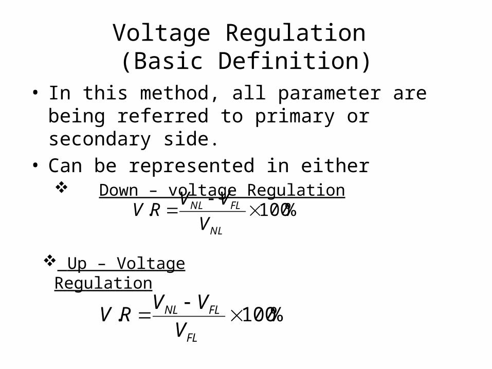
Voltage Regulation (Basic Definition)
• In this method, all parameter are being referred to primary or secondary side.
• Can be represented in either Down – voltage Regulation
%100.
NL
FLNL
V
VVRV
Up – Voltage Regulation
%100.
FL
FLNL
V
VVRV


KI
I
N
N
E
E
2
1
1
2
1
2

LOSSES IN TRANSFORMERS
• Copper Loss in Transformer• Copper loss is I2R loss, in primary side it is
I12R1 and in secondary side it is I22R2 loss,
where I1 & I2 are primary & secondary current of transformer and R1 & R2 are resistances of primary & secondary winding. As the both primary & secondary currents depend upon load of transformer, copper loss in transformer vary with load.

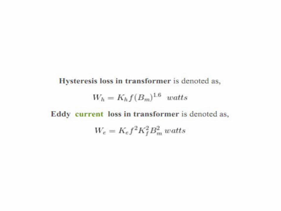
• Core Losses in Transformer• Hysteresis loss and eddy current loss, both
depend upon magnetic properties of the materials used to construct the core of transformer and its design. So these losses in transformer are fixed and do not depend upon the load current. So core losses in transformer which is alternatively known as iron loss in transformer can be considered as constant for all range of load.

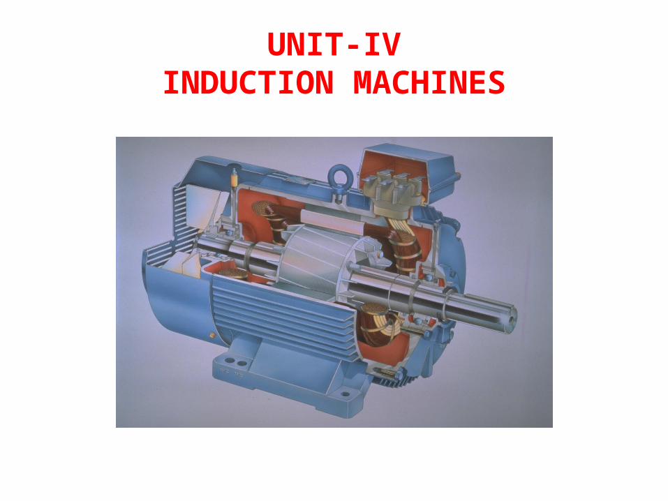
UNIT-IVINDUCTION MACHINES
Introduction
• Three-phase induction motors are the most common and frequently encountered machines in industry– simple design, rugged, low-price, easy maintenance– wide range of power ratings: fractional horsepower to 10
MW – run essentially as constant speed from no-load to full load– Its speed depends on the frequency of the power source• not easy to have variable speed control • requires a variable-frequency power-electronic drive
for optimal speed control
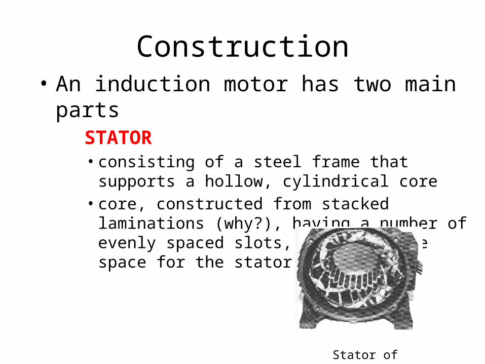
Construction• An induction motor has two main parts
STATOR • consisting of a steel frame that supports a hollow,
cylindrical core• core, constructed from stacked laminations (why?),
having a number of evenly spaced slots, providing the space for the stator winding
Stator of IM

Construction ROTOR
• composed of punched laminations, stacked to create a series of rotor slots, providing space for the rotor winding
• one of two types of rotor windings • conventional 3-phase windings made of insulated wire (wound-rotor) »
similar to the winding on the stator• aluminum bus bars shorted together at the ends by two aluminum rings,
forming a squirrel-cage shaped circuit (squirrel-cage)
• Two basic design types depending on the rotor design– SQUIRREL-CAGE: conducting bars laid into slots and shorted at both
ends by shorting rings.– WOUND-ROTOR: complete set of three-phase windings exactly as the
stator. Usually Y-connected, the ends of the three rotor wires are connected to 3 slip rings on the rotor shaft. In this way, the rotor circuit is accessible.
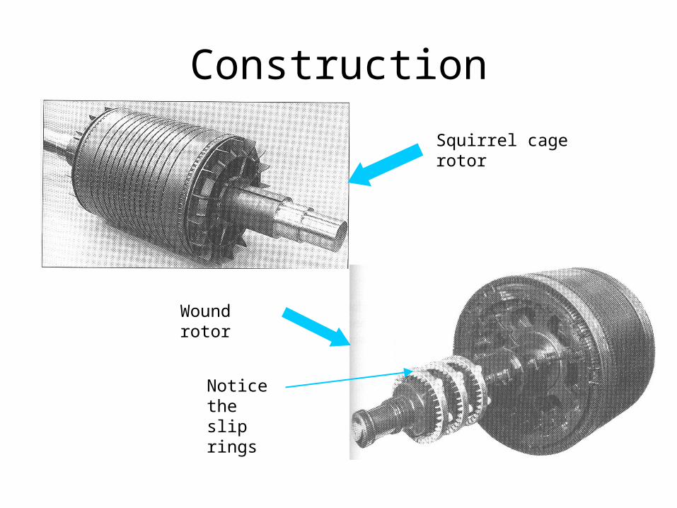
Construction
Squirrel cage rotor
Wound rotor
Notice the slip rings
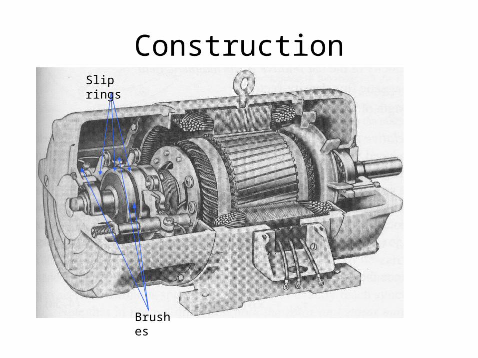
Construction
Brushes
Slip rings

IMPORTANT PARTS IN I.M
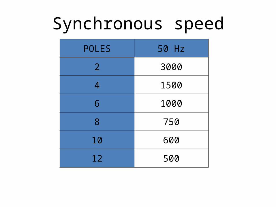
Synchronous speedPOLES 50 Hz
2 3000
4 1500
6 1000
8 750
10 600
12 500
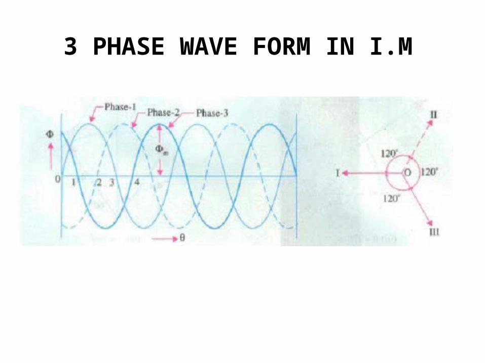
3 PHASE WAVE FORM IN I.M
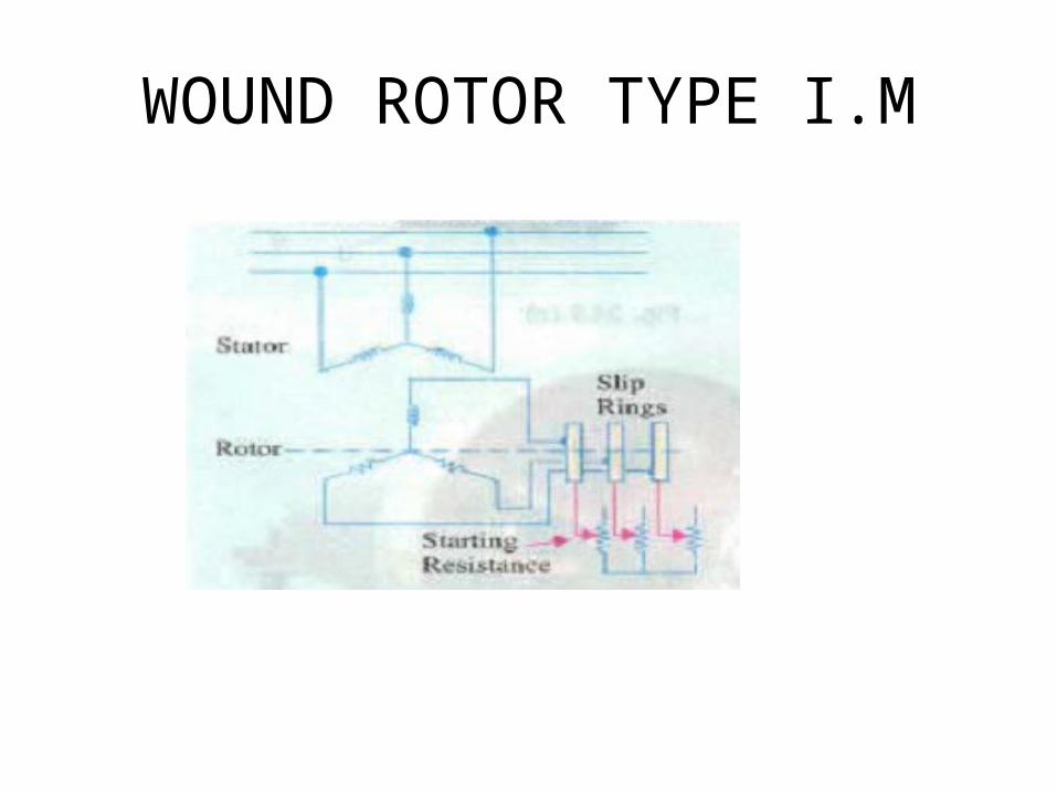
WOUND ROTOR TYPE I.M
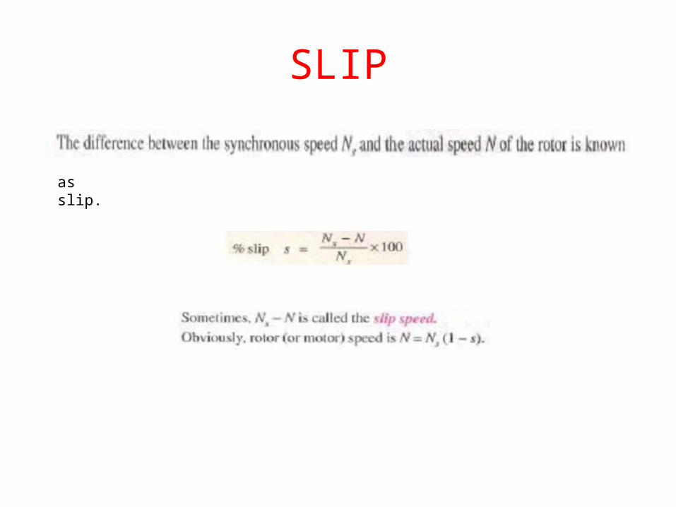
SLIP
as slip.
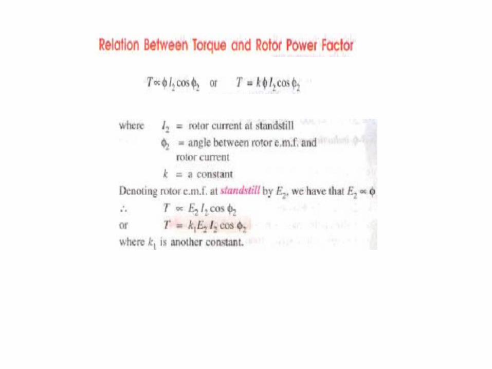

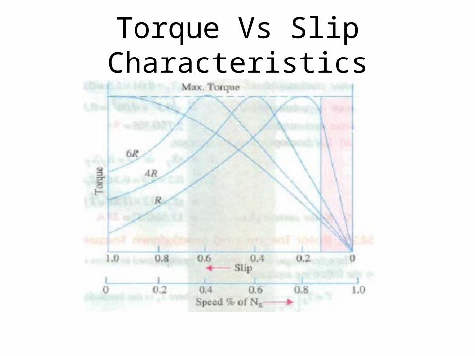
Torque Vs Slip Characteristics


Comparison between Single Phase and Three Phase Induction Motors
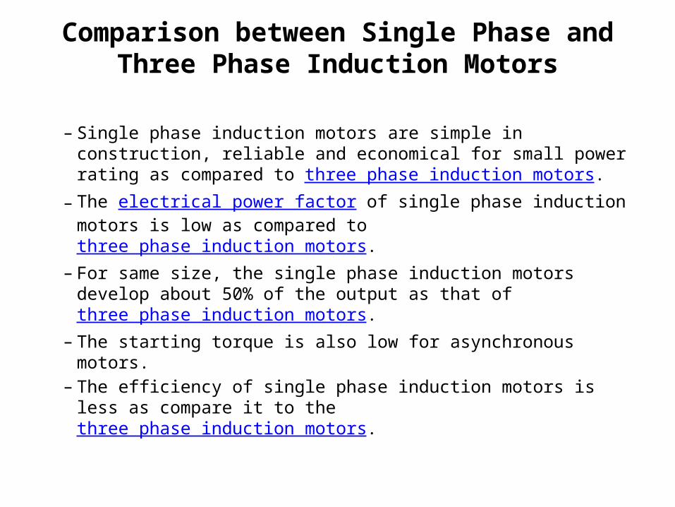
– Single phase induction motors are simple in construction, reliable and economical for small power rating as compared to three phase induction motors.
– The electrical power factor of single phase induction motors is low as compared to three phase induction motors.
– For same size, the single phase induction motors develop about 50% of the output as that of three phase induction motors.
– The starting torque is also low for asynchronous motors.– The efficiency of single phase induction motors is less as
compare it to the three phase induction motors.
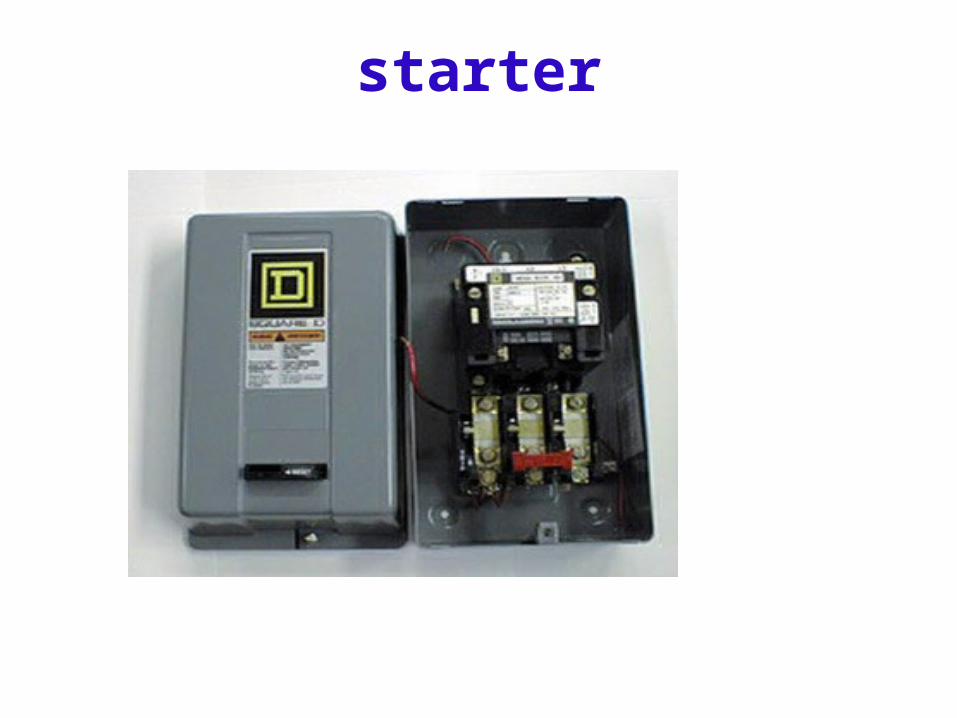
starter
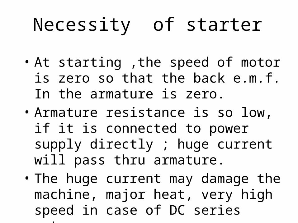
Necessity of starter
• At starting ,the speed of motor is zero so that the back e.m.f. In the armature is zero.
• Armature resistance is so low, if it is connected to power supply directly ; huge current will pass thru armature.
• The huge current may damage the machine, major heat, very high speed in case of DC series motor.
• Ia = V/Ra
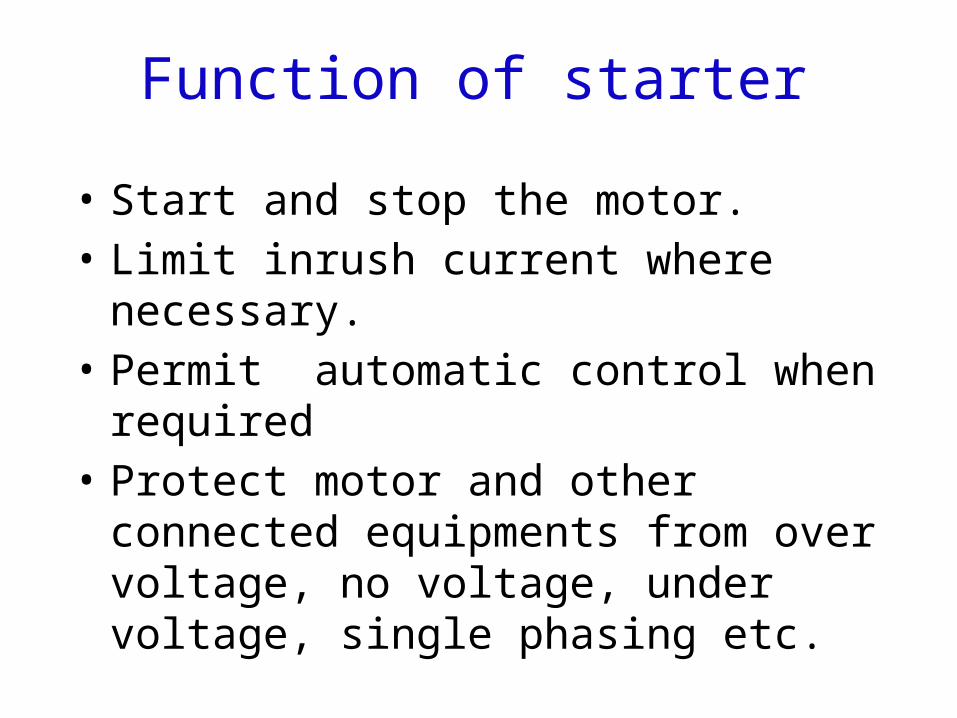
Function of starter
• Start and stop the motor. • Limit inrush current where necessary.• Permit automatic control when required• Protect motor and other connected
equipments from over voltage, no voltage, under voltage, single phasing etc.
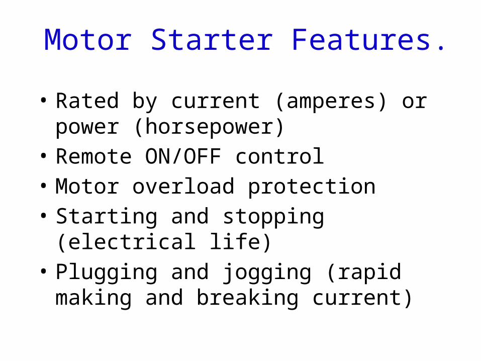
Motor Starter Features.
• Rated by current (amperes) or power (horsepower)
• Remote ON/OFF control • Motor overload protection • Starting and stopping (electrical life) • Plugging and jogging (rapid making and
breaking current)

Type of starter
for DC Motor• Two point starter for DC series motor• Three point starter for shunt motor • Four point starter for compound motor
For AC Motor • DOL Starter • Star-Delta• Auto-transformer• Variable Frequency drive
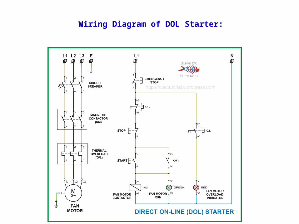
Wiring Diagram of DOL Starter:
Motor Starting Characteristics on DOL Starter:
• Available starting current: 100%.• Peak starting current: 6 to 8 Full Load
Current.• Peak starting torque: 100%
Advantages of DOL Starter:
• Most Economical and Cheapest Starter• Simple to establish, operate and maintain• Simple Control Circuitry• Easy to understand and trouble shoot.‐• It provides 100% torque at the time of starting.• Only one set of cable is required from starter to
motor.• Motor is connected in delta at motor terminals.
Disadvantages of DOL Starter:
• It does not reduce the starting current of the motor.• High Starting Current: Very High Starting Current
(Typically 6 to 8 times the FLC of the motor).• Mechanically Harsh: Thermal Stress on the motor,
thereby reducing its life.• Voltage Dip: There is a big voltage dip in the
electrical installation• High starting Torque: Unnecessary high starting
torque, even when not required by the load.
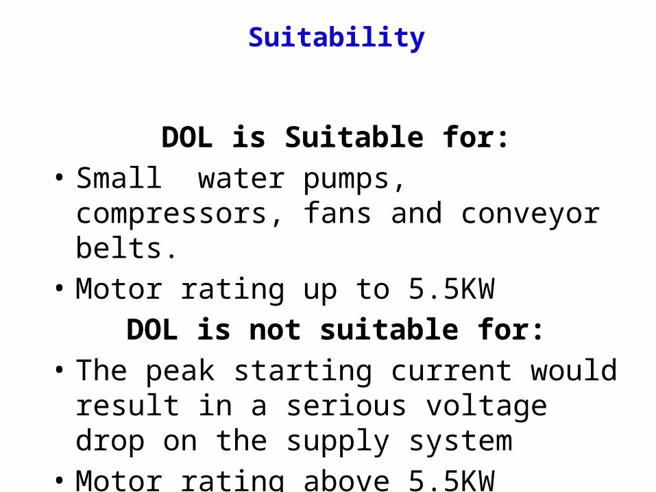
Suitability
DOL is Suitable for:• Small water pumps, compressors, fans and
conveyor belts.• Motor rating up to 5.5KW
DOL is not suitable for:• The peak starting current would result in a
serious voltage drop on the supply system• Motor rating above 5.5KW

Star delta starter
• Most induction motors are started directly on line, but when very large motors are started that way, they cause a disturbance of voltage on the supply lines due to large starting current surges.
• To limit the starting current surge, large induction motors are started at reduced voltage and then have full supply voltage reconnected when they run up to near rotated speed.

STAR -DELTA STARTER
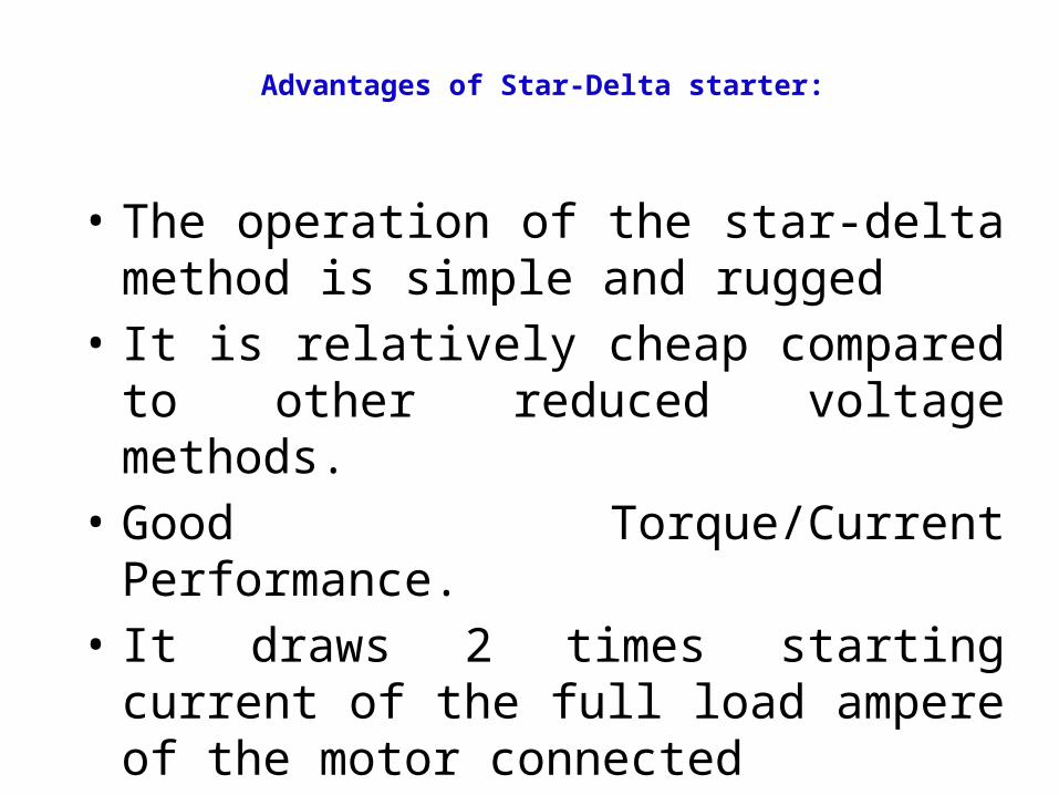
Advantages of Star-Delta starter:
• The operation of the star-delta method is simple and rugged
• It is relatively cheap compared to other reduced voltage methods.
• Good Torque/Current Performance.• It draws 2 times starting current of the full
load ampere of the motor connected
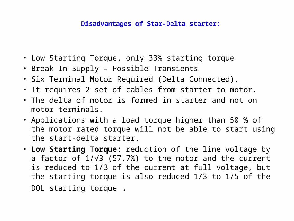
Disadvantages of Star-Delta starter:
• Low Starting Torque, only 33% starting torque • Break In Supply – Possible Transients• Six Terminal Motor Required (Delta Connected).• It requires 2 set of cables from starter to motor.• The delta of motor is formed in starter and not on motor
terminals.• Applications with a load torque higher than 50 % of the motor
rated torque will not be able to start using the start-delta starter.• Low Starting Torque: reduction of the line voltage by a factor of
1/√3 (57.7%) to the motor and the current is reduced to 1/3 of the current at full voltage, but the starting torque is also reduced 1/3
to 1/5 of the DOL starting torque .
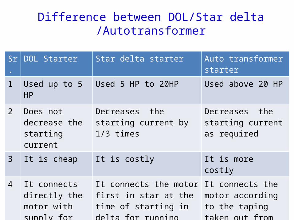
Difference between DOL/Star delta /Autotransformer
Sr. DOL Starter Star delta starter Auto transformer starter
1 Used up to 5 HP Used 5 HP to 20HP Used above 20 HP
2 Does not decrease the starting current
Decreases the starting current by 1/3 times
Decreases the starting current as required
3 It is cheap It is costly It is more costly
4 It connects directly the motor with supply for starting as well as for running
It connects the motor first in star at the time of starting in delta for running
It connects the motor according to the taping taken out from the auto transformer
Synchronous Motor - Construction
• Synchronous motor and induction motor are the most widely used types of AC motor. Construction of a synchronous motor is similar to an alternator (AC generator). A same synchronous machine can be used as a synchronous motor or as an alternator. Synchronous motors are available in a wide range, generally rated between 150kW to 15MW with speeds ranging from 150 to 1800 rpm.
Synchronous Motor - Construction
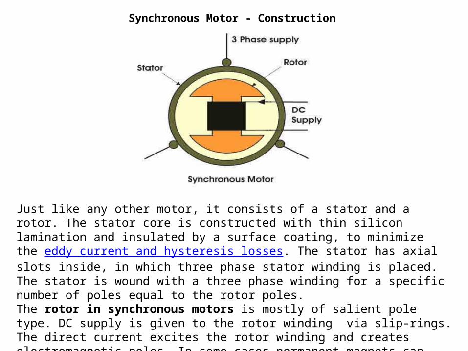
Just like any other motor, it consists of a stator and a rotor. The stator core is constructed with thin silicon lamination and insulated by a surface coating, to minimize the eddy current and hysteresis losses. The stator has axial slots inside, in which three phase stator winding is placed. The stator is wound with a three phase winding for a specific number of poles equal to the rotor poles. The rotor in synchronous motors is mostly of salient pole type. DC supply is given to the rotor winding via slip-rings. The direct current excites the rotor winding and creates electromagnetic poles. In some cases permanent magnets can also be used.

Working Of Synchronous Motor
• The stator is wound for the similar number of poles as that of rotor, and fed with three phase AC supply. The 3 phase AC supply produces rotating magnetic field in stator. The rotor winding is fed with DC supply which magnetizes the rotor. Consider a two pole synchronous machine as shown in figure above

Construction• Rotor: There are two types of rotor used in an AC generator /
alternator:(i) Salient and (ii) Cylindrical type
• Salient pole type: Salient pole type rotor is used in low and medium speed alternators. Construction of AC generator of salient pole type rotor is shown in the figure above. This type of rotor consists of large number of projected poles (called salient poles), bolted on a magnetic wheel. These poles are also laminated to minimize the eddy current losses. Alternators featuring this type of rotor are large in diameters and short in axial length.
• Cylindrical type: Cylindrical type rotors are used in high speed alternators, especially in turbo alternators. This type of rotor consists of a smooth and solid steel cylinder havingg slots along its outer periphery. Field windings are placed in these slots.
Principle of Operation Synchronous Motor
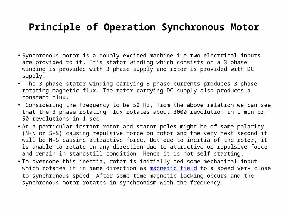
• Synchronous motor is a doubly excited machine i.e two electrical inputs are provided to it. It’s stator winding which consists of a 3 phase winding is provided with 3 phase supply and rotor is provided with DC supply.
• The 3 phase stator winding carrying 3 phase currents produces 3 phase rotating magnetic flux. The rotor carrying DC supply also produces a constant flux.
• Considering the frequency to be 50 Hz, from the above relation we can see that the 3 phase rotating flux rotates about 3000 revolution in 1 min or 50 revolutions in 1 sec.
• At a particular instant rotor and stator poles might be of same polarity (N-N or S-S) causing repulsive force on rotor and the very next second it will be N-S causing attractive force. But due to inertia of the rotor, it is unable to rotate in any direction due to attractive or repulsive force and remain in standstill condition. Hence it is not self starting.
• To overcome this inertia, rotor is initially fed some mechanical input which rotates it in same direction as magnetic field to a speed very close to synchronous speed. After some time magnetic locking occurs and the synchronous motor rotates in synchronism with the frequency.

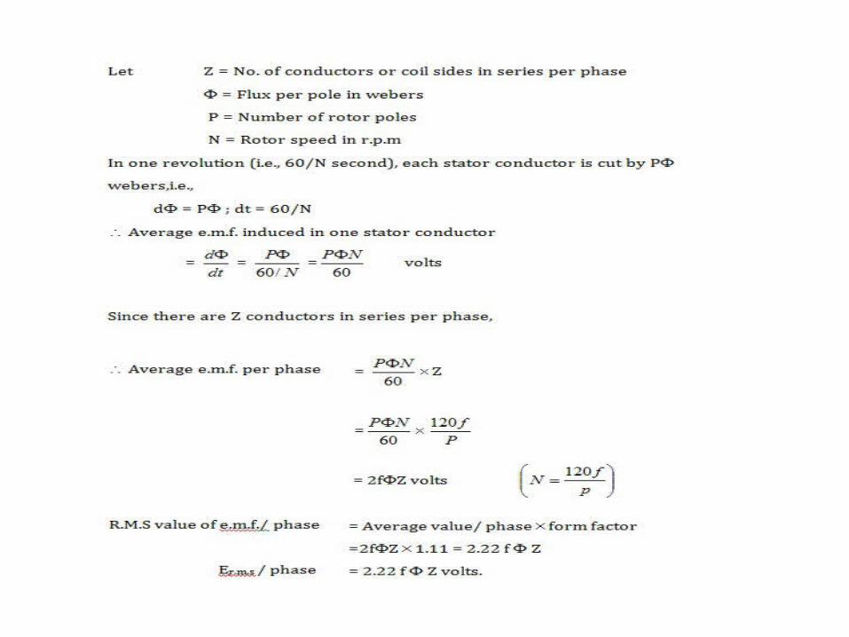
EMF EQUATION OF SYNCHRONOUS MOTOR
Main Features of Synchronous Motors
• Synchronous motors are inherently not self starting. They require some external means to bring their speed close to synchronous speed to before they are synchronized.
The speed of operation of is in synchronism with the supply frequency and hence for constant supply frequency they behave as constant speed motor irrespective of load condition
This motor has the unique characteristics of operating under any electrical power factor. This makes it being used in electrical power factor improvement.
Application of Synchronous Motor
• Synchronous motor having no load connected to its shaft is used for power factor improvement. Owing to its characteristics to behave at any electrical power factor, it is used in power system in situations where static capacitors are expensive.
• Synchronous motor finds application where operating speed is less (around 500 rpm) and high power is required. For power requirement from 35 kW to 2500 KW, the size, weight and cost of the corresponding three phase induction motor is very high. Hence these motors are preferably used. Ex- Reciprocating pump, compressor, rolling mills etc.