2. facilities planning and programming - the california state
TRANSCRIPT
California State University
TIP Standards Effective May 2007 F ACIL IT IES PL ANNING AND PROGR AMMING Page 2-1
2. Facilities Planning and Programming
This section defines both general and specific standards to be employed in planning the types of technology and information systems-related infrastructure services that are required for CSU facilities construction projects (either new or remodel/ retrofit).
2.1 General Goals and Objectives
2.1.1 Introduction Section 2. of these Standards is primarily intended to provide guidance for architects and facility planners in achieving compliance with CSU requirements in technology infrastructure development. The focus of the material presented is on space planning, general architectural and other design criteria, and the identification of individual components required in a telecommunications distribution system serving a university campus environment. Section 2. also includes a list of the commonly used industry standards and related reference materials that constitute supporting resources for this Standards document.
222
- Focus – Architects
Space & Facility Planners
- Outputs – Program Plan
Space Concepts Room Adjacencies
California State University
TIP Standards Effective May 2007 F ACIL IT IES PL ANNING AND PROGR AMMING Page 2-2
Section 2. should always be used by the design team in conjunction with Section 3., Infrastructure & Pathway Designs, to assure a comprehensive investigation of both space and pathway issues and specific electrical, mechanical, and construction requirements. Section 3. contains detailed information on the major infrastructure components, to provide sub-consultants and other design team members greater direction in the preparation of actual working design documents. Team Formation and Role Determination The ultimate success of a project planning and/or design team is likely to be determined in large part by the quality and extent of the disciplines represented, and by the team’s ability to share information. As it is formed, the need is obvious to assure that it incorporates sufficient overall expertise to address the scope of work in a comprehensive manner, and the requirement for fully delineating its management structure and functional relationships is usually well understood. Basic responsibilities must be defined early in the process, such as those for schedule management and issue resolution—along with the procedures for addressing them. Code compliance requirements and controlling references (such as the Campus Master Plan, TIPS, local best practices and procedures, etc.) must be reviewed and placed in perspective. Other information sources must also be established: for example, who will provide information on projected power and HVAC loads to guide the efforts of engineering personnel assigned to the project? Many such matters should be covered in the RFP or other formal selection process leading to the team’s formation, but good project management dictates that all be addressed at an early date. As the planning and design activities then progress, the flow of information must continue throughout in a timely and accurate manner according to established procedures.
2.1.2 Design Concepts A major goal for telecommunications infrastructure design within the CSU is to plan today’s facilities to meet tomorrow’s requirements without the need for costly renovations. Almost every campus within the CSU has gone through one or more major retrofits of its existing buildings to provide updated telecommunications and network services. These updates usually include new media (cable or wireless transmission systems), pathways and spaces,
California State University
TIP Standards Effective May 2007 F ACIL IT IES PL ANNING AND PROGR AMMING Page 2-3
and terminal resources (network electronics). One of the most costly parts of that process is the renovation of pathways and spaces within and between buildings that is often required before any new media can be installed.
Frequently, the principal reason for the high costs of renovations is that the designs for the original structures supported specific systems and applications, and were not a response to an overall media or cabling plan. Under such circumstances, rooms, connection points, and pathways to user locations were probably designed to meet very specific needs, with little allowance for future growth or technologic change. In the contemporary telecommunications world, growth and change are constant occurrences, and provision for them must be an integral part of any facility design concept.
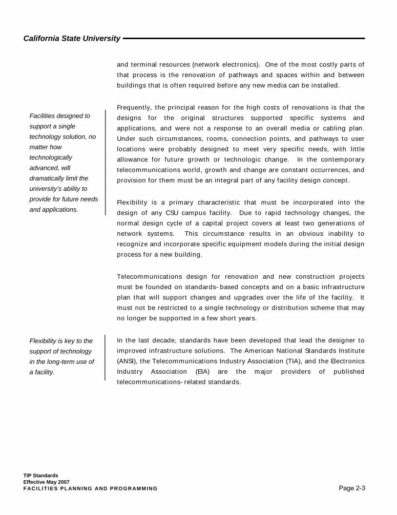
Flexibility is a primary characteristic that must be incorporated into the design of any CSU campus facility. Due to rapid technology changes, the normal design cycle of a capital project covers at least two generations of network systems. This circumstance results in an obvious inability to recognize and incorporate specific equipment models during the initial design process for a new building.
Telecommunications design for renovation and new construction projects must be founded on standards-based concepts and on a basic infrastructure plan that will support changes and upgrades over the life of the facility. It must not be restricted to a single technology or distribution scheme that may no longer be supported in a few short years.
In the last decade, standards have been developed that lead the designer to improved infrastructure solutions. The American National Standards Institute (ANSI), the Telecommunications Industry Association (TIA), and the Electronics Industry Association (EIA) are the major providers of published telecommunications-related standards.
Facilities designed to support a single technology solution, no matter how technologically advanced, will dramatically limit the university’s ability to provide for future needs and applications.
Flexibility is key to the support of technology in the long-term use of a facility.

California State University
TIP Standards Effective May 2007 F ACIL IT IES PL ANNING AND PROGR AMMING Page 2-4
2.2 Reference Standards
In addition to recognized state and local building codes, a variety of reference materials is available to assist architects and facility designers with telecommunications infrastructure planning and design. Where pertinent, it is expected that such sources will be given cognizance and employed in connection with CSU infrastructure improvements to supplement the standards presented in this document. Some of the primary sources are:
1. TIA/EIA – 569-A (and associated addenda) Commercial Building
Standard for Telecommunications Pathways and Spaces. This standard provides specifications for the design and construction of the intra-building pathways and spaces required to support telecommunications equipment and media.
2. TIA/EIA – 568-B (and associated addenda) Commercial Building
Telecommunications Cabling Standard. This standard provides specifications for inter- and intra-building cabling media and related installation and support hardware. It replaced TIA/EIA-568-A in 2001 and eliminated Category 4 and 5 copper cabling systems. Category 3 and Category 5e systems are fully recognized, and most recently, Category 6 is approved as the media of choice. The standard is divided into three parts:
a. General Requirements
b. Balanced Twisted Pair Cable Component Systems
c. Optical Fiber Cable Component Systems
3. TIA/EIA – 606A Administration Standard for the Telecommunications
Infrastructure of Commercial Buildings. This standard identifies record-keeping requirements and information needed to effectively administer building telecommunications systems.
4. J-STD- 607-A Commercial Building Grounding and Bonding
Requirements. This document identifies the need for, and composition of, a dedicated electrical grounding system for telecommunications.
California State University
TIP Standards Effective May 2007 F ACIL IT IES PL ANNING AND PROGR AMMING Page 2-5
5. TIA/EIA – 758 Customer-Owned Outside Plant Telecommunications
Cabling Standard, plus Addendum No. 1. This standard provides specifications for the minimum requirements for interbuilding telecommunications facilities, including cabling, pathways, and spaces.
6. A variety of other TIA/EIA standards relating to the details of design, installation, testing, and documentation of telecommunications infrastructure are available, and some are defined in Sections 3 and 4 of this document.
7. Rural Utility Services (RUS) formally Rural Electrification Association (REA), bulletins (1700 series) define standards and methods for the construction of outside pathways and the installation of interbuilding media.
a. Telecommunications Engineering & Construction Manual (TE&CM) including all updates.
b. Bulletins 175xxF-xxx Related to underground plant (cable and pathways) design, specifications, and construction.1
8. Building Industry Consulting Services International (BICSI)
Telecommunications Distribution Methods Manual. The manual describes intrabuilding infrastructure design guidelines and methods accepted by the telecommunications industry.
9. BICSI – Customer-Owned Outside Plant Design Manual. This manual describes interbuilding infrastructure design guidelines and methods accepted by the telecommunications industry.
10. BICSI - Wireless Design Reference Manual, 2nd Edition. This revised manual incorporates current information required for planning, designing and implementing a wide array of wireless design projects.
BICSI, one of the leading telecommunications industry associations, provides training, testing, and certification in the design and installation of telecommunications distribution systems. A BICSI Registered Communications Distribution Designer (RCDD) is often employed by the architect or design engineer to assist with the initial program and space
1 This series of RUS Bulletins replaces all former Rural Electrification Association (REA) materials such as PE-89 and PE-39.

California State University
TIP Standards Effective May 2007 F ACIL IT IES PL ANNING AND PROGR AMMING Page 2-6
planning and to prepare the detailed telecommunications infrastructure design.
The Construction Specifications Institute (CSI) completed work in 2004 on major revisions to the organization of its widely-recognized MasterFormat construction specification system. Previously, the MasterFormat system was organized into 16 divisions in a structure that provided little opportunity for emphasis on telecommunications or information systems requirements. This was only one of several perceived needs motivating the revision, others including: provision of improved capability to recognize new materials and processes; inclusion of types of construction not previously incorporated; facilitation of increased database use; resolution of project life-cycle issues; and provision of flexibility for future change. As a result, the Masterformat system was expanded from 16 to 50 divisions, including numbers reserved for future expansion. It is believed that this comprehensive revision has addressed most of the concerns previously expressed by telecommunications designers.

California State University
TIP Standards Effective May 2007 F ACIL IT IES PL ANNING AND PROGR AMMING Page 2-7
2.3 Telecommunications Design Elements
2.3.1 Element Definition The major elements of a telecommunications distribution design are spaces and pathways. Each of these elements consists of multiple components.
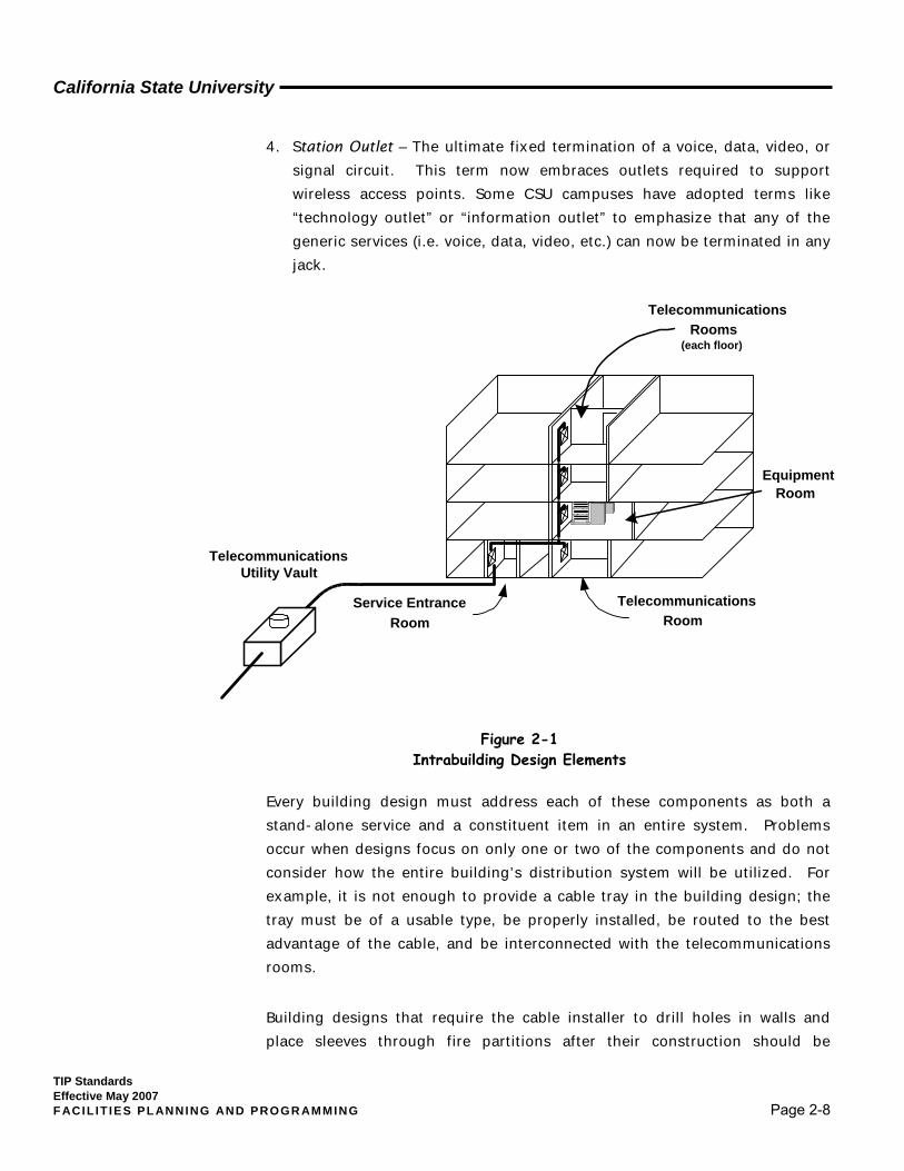
Spaces include the building service entrances, equipment rooms, and telecommunications rooms, as defined below:
1. Building Service Entrance – An independent room in which campus voice, data, and video distribution pathways and media systems enter the building.
2. Equipment Room – The primary space allocated solely to housing (and supporting) telecommunications systems that will service the building, such as a voice switching node, backbone network equipment, and/or video transmission equipment.
3. Telecommunications Room – The space or spaces on each floor of a building that are utilized to interconnect the building backbone (riser) system to station (horizontal) locations on a given floor and also provide the secondary space for housing local electronic equipment.
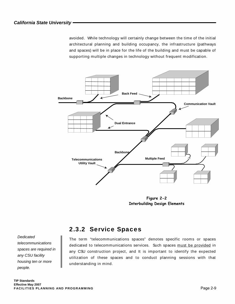
Pathways include the interbuilding (between buildings) distribution system, building backbone (riser) system, horizontal pathways, and station outlets, as follows:
1. Interbuilding Distribution System – The conduit, tunnel system, overhead, or buried media support structures for wire (and to a lesser extent, wireless) between buildings on the campus.
2. Building Backbone (Riser) – The vertical (and on occasion, horizontal) pathways that connect all telecommunications rooms and spaces throughout an individual building.
3. Horizontal Pathways – The conduit, cable tray, or other cable support system from the telecommunications room to the station (user) locations on a given floor.
The CSU has adopted the ANSI/TIA/EIA and BICSI terms for telecommunications infrastructure.
California State University
TIP Standards Effective May 2007 F ACIL IT IES PL ANNING AND PROGR AMMING Page 2-8
4. Station Outlet – The ultimate fixed termination of a voice, data, video, or signal circuit. This term now embraces outlets required to support wireless access points. Some CSU campuses have adopted terms like “technology outlet” or “information outlet” to emphasize that any of the generic services (i.e. voice, data, video, etc.) can now be terminated in any jack.
Every building design must address each of these components as both a stand-alone service and a constituent item in an entire system. Problems occur when designs focus on only one or two of the components and do not consider how the entire building’s distribution system will be utilized. For example, it is not enough to provide a cable tray in the building design; the tray must be of a usable type, be properly installed, be routed to the best advantage of the cable, and be interconnected with the telecommunications rooms.
Building designs that require the cable installer to drill holes in walls and place sleeves through fire partitions after their construction should be
Service EntranceRoom
EquipmentRoom
TelecommunicationsRooms
(each floor)
TelecommunicationsRoom
TelecommunicationsUtility Vault
Figure 2-1 Intrabuilding Design Elements
California State University
TIP Standards Effective May 2007 F ACIL IT IES PL ANNING AND PROGR AMMING Page 2-9
avoided. While technology will certainly change between the time of the initial architectural planning and building occupancy, the infrastructure (pathways and spaces) will be in place for the life of the building and must be capable of supporting multiple changes in technology without frequent modification.
2.3.2 Service Spaces The term “telecommunications spaces” denotes specific rooms or spaces dedicated to telecommunications services. Such spaces must be provided in any CSU construction project, and It is important to identify the expected utilization of these spaces and to conduct planning sessions with that understanding in mind.
Dedicated telecommunications spaces are required in any CSU facility housing ten or more people.
Dual Entrance
Back Feed
Multiple Feed
Backbone
Backbone
TelecommunicationsUtility Vault
Communication Vault
Figure 2-2 Interbuilding Design Elements
California State University
TIP Standards Effective May 2007 F ACIL IT IES PL ANNING AND PROGR AMMING Page 2-10
There are three main categories of spaces, as previously defined: service entrances, equipment rooms, and telecommunications rooms. Each of the three has a distinct function, but all are very inter-dependent. In very rare cases, a single space may fulfill the function of all three spaces for a small building. However, it must be emphasized that the size and environmental support requirements are additive. If the size of a particular building calls for an equipment room of 150 square feet and that room is expected to serve as a service entrance room, the floor area must then be increased to 200 square feet to allow for the additional equipment and maintenance space.
The Criticality Concept in Service Space Planning
In working with private industry on a recent project attempting to rationalize and categorize the diverse parameters involved in telecommunications service space planning, CSU personnel were introduced to the concept of criticality, which is an attempt to take into consideration the relative “importance” of the activities supported by a particular space. Power consumption, device dimensions, voltages required, and other basic characteristics of the space’s physical contents are generally not difficult to assess, and determining the requirements needed to respond to those characteristics is comparatively straightforward. Support for criticality, on the other hand, involves value judgments about needs for power and cooling redundancy, reserve cooling capacity, monitoring strategies, robustness of physical security, and fire protection. For this reason, criticality can be a useful way to categorize standard room “types.” The subjective decisions regarding criticality support can then be made in a general context, and standardized in a table of recommendations by space type. An example of this approach is offered later in this TIPS section, as applied to telecommunications room (TR) planning.
2.3.2.1 Service Entrance Room
The service entrance is a room in which outside cable is terminated and interconnected with the backbone cable used throughout the building. It provides facilities and supporting hardware for large splice containers, cable termination mountings, and possibly copper cable electrical protectors. If this is a stand-alone space, it should not house any network or telecommunications equipment. Typically, a service entrance should be located on a lower level and within 50 feet of an outside wall, allowing direct access by the interbuilding (entrance) conduit. It should be situated to
All telecommunication
spaces will have specific
requirements for the
following:
• Floor & wall space
• Heating & air handling
• Electrical and grounding
• Access (media & personnel)
• Floor loading
• Room location
California State University
TIP Standards Effective May 2007 F ACIL IT IES PL ANNING AND PROGR AMMING Page 2-11
provide a direct pathway to the equipment room or backbone (riser) distribution spaces.
If used only as a service entrance room in the strict sense, such a space requires no special air handling provisions unless unusual environmental conditions exist. Service entries normally should not be located in or directly adjacent to the building’s electrical service entrance, transformer room, or mechanical room, although such limitations should be evaluated by the designer to assure their actual applicability. If exceptions seem necessary, a mitigating technology (e.g., UPS or other electrical noise filtering) may be employed.
The minimum floor space requirement for a stand-alone service entrance room is five (5) feet by seven (7) feet in buildings under 10,000 gross square feet. See Section 3. of these Standards for additional detailed information on that subject.
2.3.2.2 Equipment Room
The equipment room (ER) is the central space used to house telecommunications network equipment intended to service users throughout the building. In the CSU, this type of equipment commonly includes a PBX or other digital switching nodes; local area network routers, switches, and hubs; video distribution equipment; and cable inter- and cross-connect hardware. Past documents sometimes referred to this space as a “Building Distribution Frame” or BDF; however, the most recent concept encompasses additional functions and the installation of more types of equipment than that previously installed in these spaces.
In some situations, voice-switching nodes in one building will serve users in other nearby facilities, generally over copper cable. In these cases, the equipment room must support the termination of additional copper cables that are extended between buildings.
The equipment room will house sensitive electronic components that will often be connected to a backup power source and will generate heat 24 hours a day, 365 days a year. It is important this space be designed with necessary environmental controls and backup systems to maintain the conditions

California State University
TIP Standards Effective May 2007 F ACIL IT IES PL ANNING AND PROGR AMMING Page 2-12
necessary for support of critical telecommunications systems under emergency conditions.
The air handling system for equipment rooms must be designed to provide positive airflow and cooling even during times when the main building systems are shut down. This requires separate stand-alone cooling systems or separate temperature control zones. If the equipment room is to be used as a campus communications hub and the equipment is served by an auxiliary power supply, the air handling system for this space should also be connected to the building’s backup power generation system if one exists.
The equipment room must be located near the service entrance room and must have adequate access from outside the building to allow for the installation of large equipment cabinets (36” wide by 96” tall). However, every effort must be exerted to avoid locations in basements or at other low levels where there exists any possibility of flooding. The minimum size of this room is ten (10) feet by fifteen (15) feet. However, campus-specific requirements may easily increase its size.
Minimum CSU design requirements for an equipment room are as follows:
1. To further limit the possibility of flooding, water or drainage pipes must not be placed directly over or near the equipment room. Cooling unit chilled water supply and return lines must be deployed so as to avoid danger to the room contents. The surrounding floor area should be configured to drain accidental leaks before the equipment room becomes involved, or a floor drain should be installed in the room if the danger of water entrance cannot be overcome in any other way.
2. Fire suppression methods and requirements are subject to California State Fire Marshal (CFM or SFM) review and approval. However, contingent upon such approval, the CSU’s strong preference is that a dry (pre-action or gas) fire suppression system be provided in equipment rooms. Activation of the suppression system should be linked to the equipment’s serving electrical panel to disconnect power in the event of activation.
3. The room must be open from floor to true ceiling. No false ceiling should be installed.
California State University
TIP Standards Effective May 2007 F ACIL IT IES PL ANNING AND PROGR AMMING Page 2-13
4. A floor loading of 100 lbs. per square foot (distributed loading) must be the minimum structural design standard for this space.
5. The equipment room must be located away from potential sources of electrical interference, such as electrical power supply transformers, motors, generators, or elevator equipment. One reasonable rule-of-thumb would be a ten-foot separation between building electrical rooms and ERs.
6. In the event power generation equipment is not provided and battery backup is to be installed to meet emergency needs, all pertinent code requirements must be met. Only sealed batteries are to be used in the backup installation if it is located in the equipment room. Local codes must be referenced for specific location requirements, floor-loading limitations, splash wall and drain curb details, venting requirements, and other safety concerns.
7. The size of the equipment room is critical to the long-term support of technology within the facility. It must be adequately sized to support both existing and potential future services and applications. The specific sizing criteria are as follows:
a. If no specific requirements are known, the minimum equipment room size is 150 square feet.
b. For buildings over 20,000 square feet, the minimum equipment room space is .75 square foot for every 100 assignable square feet.
c. Design situations that will increase the required size of the equipment room include the following:
The building under design will act as a serving point for other campus buildings.
The density of workstations within the building will exceed an average of one per every 100 assignable square feet.
The equipment room will also serve as an entrance room. It will be necessary to house computing equipment (as opposed
to network-only equipment) within the space.
d. A laboratory or computer/technology building facility without a specific design requirement must meet the following equipment room space minimums:
An example of equipment room sizing for a 42,000 sq. ft. building not considered high density –
42,000 gross sq. ft. ÷ 100 = 420 ∗ .75 = 315
The minimum equipment room size for this building is 315 sq. ft.
California State University
TIP Standards Effective May 2007 F ACIL IT IES PL ANNING AND PROGR AMMING Page 2-14
2.3.2.3 Telecommunications Room
A telecommunications room (TR) is the space that supports the cable and equipment necessary for transmission between the building’s backbone system and user (station) locations. This space was identified in the past as a “telephone closet,” a term that is very misleading but still used within the construction industry. The TIP Guidelines, the predecessor document to these Standards, referred to this space as an Intermediate Distribution Frame (IDF), another term that no longer defines the activities this space must support. In keeping with changes within the industry, the CSU has adopted the more descriptive term, “telecommunications room.”
This space is used to terminate the media from station outlets and backbone (riser) systems and to house and support local area network equipment, cable cross-connects, video distribution equipment, wireless resources, and system monitoring components
It is important to give the design and location of these spaces high priority within a building plan. At a minimum, these spaces must meet the following design constraints:
1. In a multi-story building, telecommunications rooms must be stacked and should be centrally located, minimizing the distance from the room to all user locations.
3 Figure 2-3 taken from ANSI/TIA/EIA 569-A 4Figure 2-4 taken from ANSI/TIA/EIA 569-A
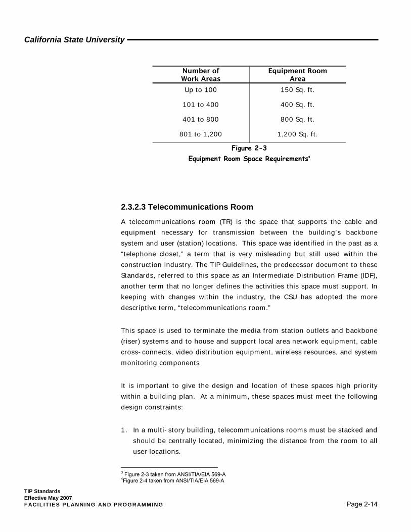
Number of Work Areas
Equipment Room Area
Up to 100
101 to 400
401 to 800
801 to 1,200
150 Sq. ft.
400 Sq. ft.
800 Sq. ft.
1,200 Sq. ft.
Figure 2-3 Equipment Room Space Requirements3
California State University
TIP Standards Effective May 2007 F ACIL IT IES PL ANNING AND PROGR AMMING Page 2-15
2. While telecommunications rooms must be located near the center of the building, they must also be no farther than 290 feet (cable pathway distance) from the most distant user outlet. The average distance should be 150 feet or less.
3. These spaces must be dedicated to the telecommunications function and must not be shared with electrical, janitorial, fire alarms, security systems, or storage functions.
4. The room must be designed and situated to eliminate overhead obstructions (including false ceilings) and minimize any potential damage from items such as water or drain pipes, electrical interference, dust or other airborne contaminants, and physical hazards.
5. The environment of these rooms must be equal to or better than a normal office (positive air flow/cooling, office-level lighting, sealed or tiled floor – no carpet). These rooms are intended to house terminal resources (network electronics) and must be equipped with adequate electrical service and cooling equipment to assure that equipment’s safety, dependability and functionality. Depending upon the room’s level of criticality in the campus network, the requirement may be 24-hour-a-day, seven-days-a-week support.
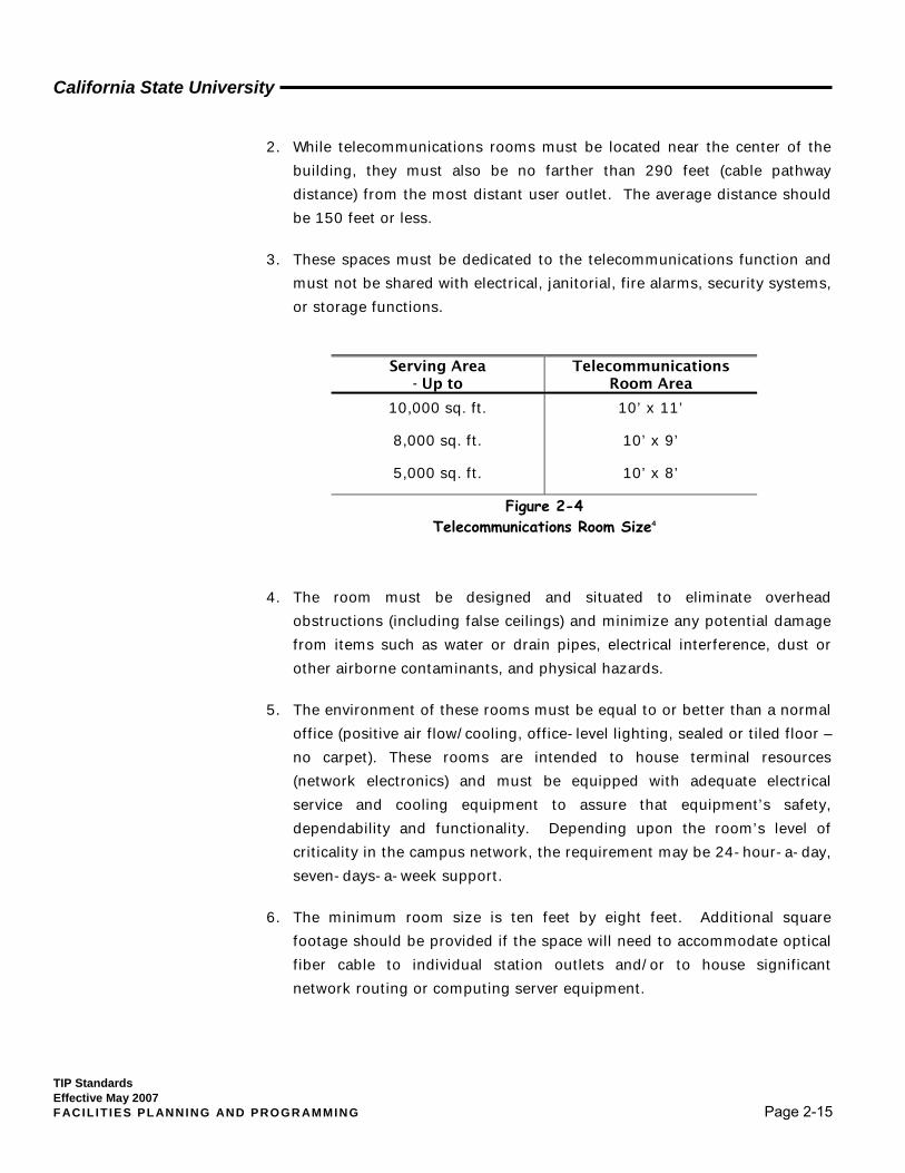
6. The minimum room size is ten feet by eight feet. Additional square footage should be provided if the space will need to accommodate optical fiber cable to individual station outlets and/or to house significant network routing or computing server equipment.
Serving Area - Up to
Telecommunications Room Area
10,000 sq. ft.
8,000 sq. ft.
5,000 sq. ft.
10’ x 11’
10’ x 9’
10’ x 8’
Figure 2-4 Telecommunications Room Size4

California State University
TIP Standards Effective May 2007 F ACIL IT IES PL ANNING AND PROGR AMMING Page 2-16
An Example of Criticality Assessment Applied to TR Planning
It was mentioned earlier in this TIPS section that the criticality concept might be useful in telecommunications space planning, and that is particularly true with regard to telecommunications rooms. Because of the University’s large size and scope, planning and design personnel across the CSU typically must cope with an extremely wide range of physical and environmental considerations in programming TRs, from the very simple to the extraordinarily complex. Under such circumstances, it can be expedient to seek commonalities rather than differences—and relative space criticality can provide a basic structure for such processes.
Figure 2-5 provides an example of what is essentially a three-level (or three-tier) categorization system based on criticality assessment, ranging from TR 1(low criticality) to TR 3 (high); the factors considered in establishing a space rating are indicated in the table. The table itself is adapted from a white paper jointly drafted in 2006 by a working group from NTA (the NTA Infrastructure Physical Plant Working Group, IPPWG) and technical staff from American Power Conversion Corporation (APCC)1. In fact, the genesis of that joint effort was the paucity of useful information on current telecommunications room planning and design requirements. Inasmuch as the CSU has approximately 2,500 TRs in place system-wide (2006), the subject is of considerable technologic and economic interest to University managers.
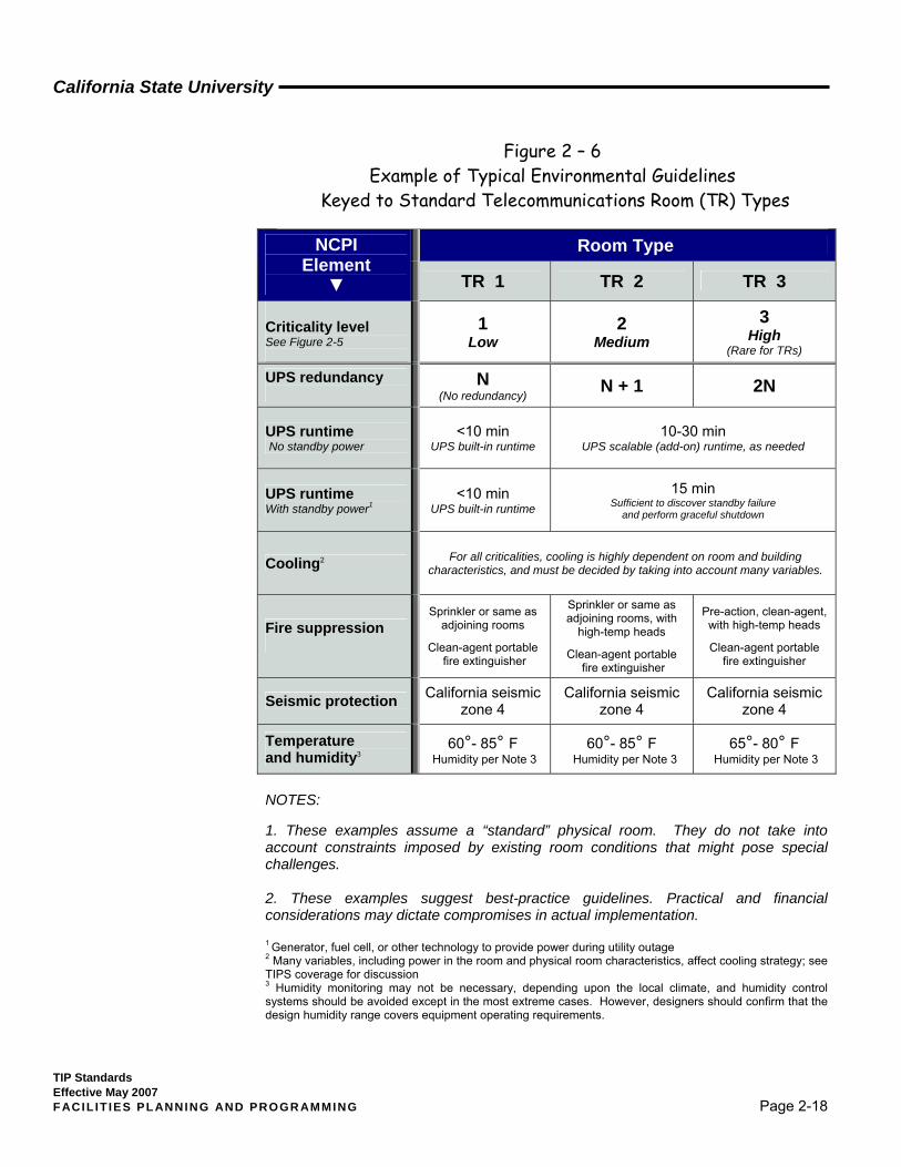
With Figure 2-5 established as a structure for defining pertinent relationships, it becomes possible to create a fabric of physical and environmental planning parameters associated with each of the three primary levels (TR 1 through TR 3). Examples are summarized in Figure 2-6. The types of information contained therein have been the subject of much discussion between and among the participants contributing to the white paper, which itself now represents the consensus of that body; the substance of that effort has been adopted by the CSU as one productive approach to telecommunications planning. The original white paper is not an accepted CSU standard at this
time. It may be viewed at http://nta.calstate.edu/Archives.shtml .
1 “Network and Technology Alliance Recommendations for Telecommunications Room Guidelines,” NTA-IPPWG & American Power Conversion, 2006

California State University
TIP Standards Effective May 2007 F ACIL IT IES PL ANNING AND PROGR AMMING Page 2-17
Criticality level Equipment Supported Importance Typical TR features
Criticality
0
Wiring connections.
Disruption of hours or even days can be tolerated. Loss of operation causes minor inconvenience.
Open racks or wall-mount for cable connection boxes. Little or no power; Little or no heating, ventilation or air conditioning. Little or no security.
Criticality
1
Small electronic devices supporting activities or processes that are not critical.
Disruption of minutes or hours can be tolerated. Loss of availability is roughly equivalent to loss of local productivity. Minor consequences for business operations.
Open racks or wall-mounting for electronic devices. Low power requirement. Extremes of temperature, humidity, dirt, or power disturbances could damage equipment. Short-duration power back-up. Light security.
Criticality
2
Small to mid-size electronics supporting important business processes and communications
Loss of availability could widely affect productivity, depending upon timing. Downtime can be tolerated if given warning and time to respond. Full recovery following momentary, unplanned downtime might take significant time and/or require human intervention. Maintenance downtime can be regularly scheduled or planned with short notice.
Open or enclosed racks for electronic devices. Power disturbances or extremes of temperature, humidity, or dirt could damage equipment. Several minutes of power back-up available. Environmental management & remote annunciation present. Limited access.
Criticality
3
“High-end” electronics supporting critical business processes and communications. VoIP applications that need to be available in emergencies.Criticality 3 actually rare for a TR; described environment would be more typical of ERs, MDFs and data centers.
Loss of availability could have serious life safety and/or business continuity implications, including damage to reputation with students, parents, and the general public. Full recovery following momentary unplanned downtime could take hours or days. Maintenance downtime or low-risk windows can be scheduled, but well in advance.
Enclosed racks for electronic devices. Extremes of temperature, humidity, dirt, or power disturbances could damage equipment. Several minutes to hours of power back-up available. Environmental management, remote annunciation and/or control present. Controlled access.
Criticality levels based on Syska Hennessy Group, Syska Criticality Level Definitions, 2005, with permission.
Figure 2 – 5 An Example of Possible Criticality Levels for Telecommunications Rooms (TRs)
California State University
TIP Standards Effective May 2007 F ACIL IT IES PL ANNING AND PROGR AMMING Page 2-18
NOTES: 1. These examples assume a “standard” physical room. They do not take into account constraints imposed by existing room conditions that might pose special challenges. 2. These examples suggest best-practice guidelines. Practical and financial considerations may dictate compromises in actual implementation. 1 Generator, fuel cell, or other technology to provide power during utility outage 2 Many variables, including power in the room and physical room characteristics, affect cooling strategy; see TIPS coverage for discussion
3 Humidity monitoring may not be necessary, depending upon the local climate, and humidity control systems should be avoided except in the most extreme cases. However, designers should confirm that the design humidity range covers equipment operating requirements.
Room Type NCPI Element
▼ TR 1 TR 2 TR 3 Criticality level See Figure 2-5
1 Low
2 Medium
3 High
(Rare for TRs)
UPS redundancy
N (No redundancy) N + 1 2N
UPS runtime No standby power
<10 min UPS built-in runtime
10-30 min UPS scalable (add-on) runtime, as needed
UPS runtime With standby power1
<10 min UPS built-in runtime
15 min Sufficient to discover standby failure
and perform graceful shutdown
Cooling2 For all criticalities, cooling is highly dependent on room and building characteristics, and must be decided by taking into account many variables.
Fire suppression
Sprinkler or same as adjoining rooms
Clean-agent portable
fire extinguisher
Sprinkler or same as adjoining rooms, with
high-temp heads
Clean-agent portable fire extinguisher
Pre-action, clean-agent, with high-temp heads
Clean-agent portable
fire extinguisher
Seismic protection California seismic zone 4
California seismic zone 4
California seismic zone 4
Temperature and humidity3
60°- 85° F Humidity per Note 3
60°- 85° F Humidity per Note 3
65°- 80° F Humidity per Note 3
Figure 2 – 6 Example of Typical Environmental Guidelines
Keyed to Standard Telecommunications Room (TR) Types
California State University
TIP Standards Effective May 2007 F ACIL IT IES PL ANNING AND PROGR AMMING Page 2-19
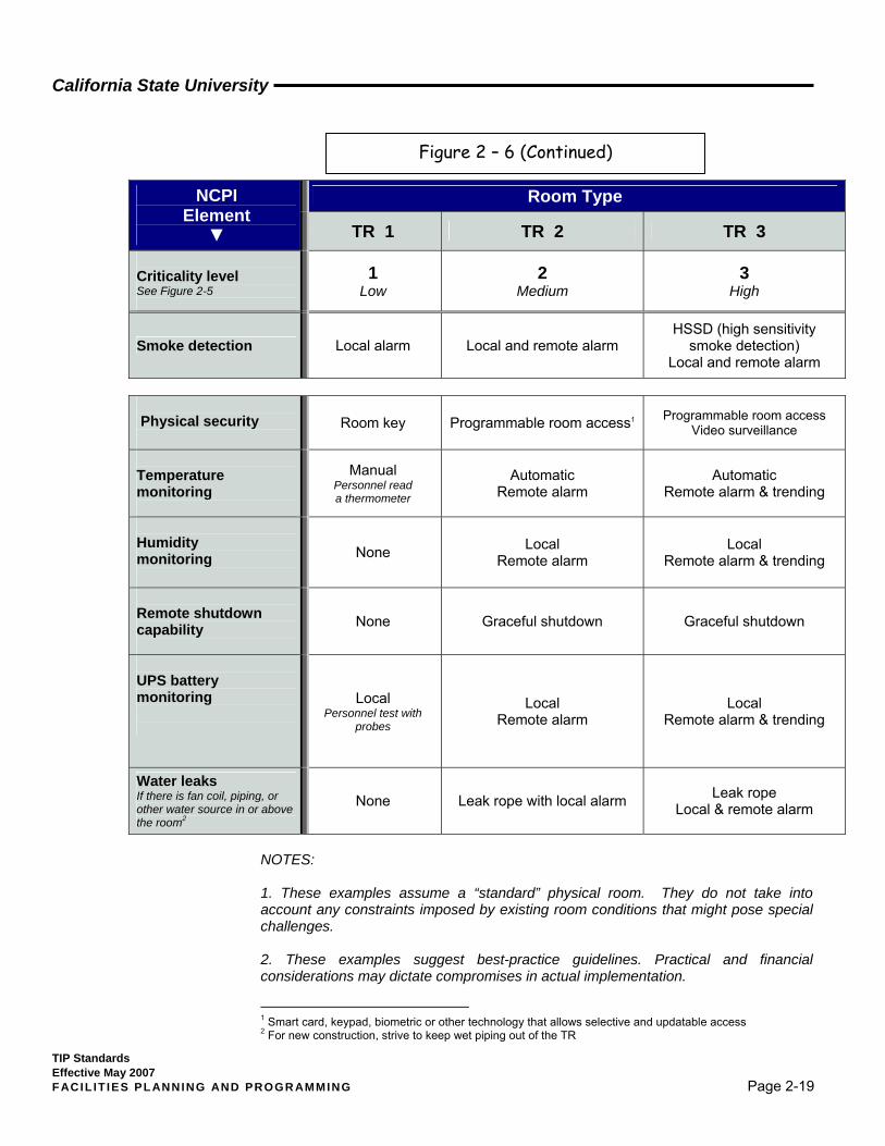
Room Type NCPI Element
▼ TR 1 TR 2 TR 3 Criticality level See Figure 2-5
1 Low
2 Medium
3 High
Smoke detection Local alarm Local and remote alarm HSSD (high sensitivity
smoke detection) Local and remote alarm
Physical security
Room key Programmable room access1 Programmable room access Video surveillance
Temperature monitoring
Manual Personnel read a thermometer
Automatic Remote alarm
Automatic Remote alarm & trending
Humidity monitoring
None Local Remote alarm
Local Remote alarm & trending
Remote shutdown capability
None Graceful shutdown Graceful shutdown
UPS battery monitoring
Local Personnel test with
probes Local
Remote alarm Local
Remote alarm & trending
Water leaks If there is fan coil, piping, or other water source in or above the room2
None Leak rope with local alarm Leak rope Local & remote alarm
NOTES: 1. These examples assume a “standard” physical room. They do not take into account any constraints imposed by existing room conditions that might pose special challenges. 2. These examples suggest best-practice guidelines. Practical and financial considerations may dictate compromises in actual implementation.
1 Smart card, keypad, biometric or other technology that allows selective and updatable access 2 For new construction, strive to keep wet piping out of the TR
Figure 2 – 6 (Continued)
California State University
TIP Standards Effective May 2007 F ACIL IT IES PL ANNING AND PROGR AMMING Page 2-20
As emphasized in TIPS Section 1, nothing presented in Figures 2-5 and 2-6, or in the parent white paper itself, is intended to relieve campus planners and design consultants of their responsibility for exerting sound judgment on behalf of their local campus. The indicated approach is presented herein merely to suggest a possibly effective planning technique for addressing the CSU’s quality standards for technology infrastructure in a uniform manner. This particular example applies only to TRs, and not to ERs and other spaces.
California State University
TIP Standards Effective May 2007 F ACIL IT IES PL ANNING AND PROGR AMMING Page 2-21
2.3.3 Telecommunications Pathways The term “pathways” refers to the facilities and supporting structures used to transport telecommunications media (twisted copper cable, optical fiber, and coaxial cable) from one location to another. Most often, a telecommunications pathway consists of more than one physical structure, and it is important that the designer think in terms of the overall intent of these pathways rather than the individual components.
Pathways include interbuilding (outdoor) backbone pathways and intrabuilding (indoor) backbone and horizontal pathways. The following subsections outline the general design concepts for each type. For more in-depth information, refer to the appropriate subsection of Section 3. of this document.
2.3.3.1 Interbuilding Distribution System
The interbuilding distribution system is composed of the conduit, utility vault, and/or tunnel systems that support the telecommunications media between buildings on campus. The design focus for the planner/designer of a new or remodeled CSU structure must include not only such matters as the distance from the new facility to the closest telecommunications utility vault, but also the condition of the overall distribution and feeder system back to the point of origin.
Although most design projects for new CSU campus buildings incorporate interconnection of telecommunications links from outside the building, the scope of the project rarely includes required renovation or expansion work on major interbuilding pathways impacted by the new facility. In some cases, a separate construction project may be required to provide adequate pathways up to the point at which the building project is to be interconnected.
In the case of remodeling projects, it is vital to prepare a telecommunications transfer or cutover plan prior to the start of construction. Older buildings seldom have sufficient pathways to meet expanded needs. In addition, if the building is to remain occupied during construction, it may be necessary to install new telecommunications services prior to removal of the old. In those cases, additional pathways often are critical in meeting the on-going needs of
The designer must look back to the distribution system’s point of origin and determine the requirements of both the new construction and other planned projects (see university's Campus Master Plan).
California State University
TIP Standards Effective May 2007 F ACIL IT IES PL ANNING AND PROGR AMMING Page 2-22
the university faculty, staff, and students for service during an active cutover (conversion).
In general, the following points should be observed when developing plans for communication feeder facilities:
1. Anywhere from four (4) to twelve (12) four-inch (minimum diameter), conduits are required to feed typical university buildings, depending upon their size and functionality. (See Section 3. for details.)
2. The entrance conduits must be designed to allow the placement of various types of cables, including large copper, optical fiber, and coaxial cables.
3. Telecommunications utility vaults (manholes) must be situated to allow the conduit to enter the building with no more than two ninety-degree bends.
4. The entrance conduits should enter the service entrance space either directly from outside, perpendicular to the outer wall at a level above eight feet, or through the floor, parallel with the outer wall (keeping the conduit bend radius greater than forty-eight [48] inches).
2.3.3.2 Intrabuilding Backbone
The term “backbone pathway” replaces the terms “riser” and “tie” conduit to reflect the need for both horizontal and vertical pathways in a building distribution system. In general, the building backbone is the path used for placement of telecommunications media between the service entrance room, the equipment room, and individual telecommunications rooms. These pathways must typically support copper, optical fiber, and coaxial cables connecting equipment and cross-connection hardware serving end-users located on each floor of the building.
1. All backbone conduits and sleeves must be four (4) inches in diameter.
2. Pathways must be designed with no more than two (2) ninety (90) degree bends, with a maximum distance between pull boxes of 100 feet.
3. The minimum number of vertical backbone (riser) conduits is three (3). In addition, pathways for both telecommunications and power must be extended to the roofs of all buildings having the structural capability to support the installation and servicing of exterior equipment (e;g., wireless
The design team must develop a specific series of interconnected pathways throughout the building. The pathways must be designed to support both an initial installation of media and upgrades throughout the life of the facility.
California State University
TIP Standards Effective May 2007 F ACIL IT IES PL ANNING AND PROGR AMMING Page 2-23
devices, television antennas, etc.). Section 3. of this document provides specific sizing requirements.
4. A plenum-rated pathway is required between all telecommunications spaces within a building. Many of the large (shielded) copper cables used to distribute telecommunications within a building are not available with plenum-rated sheaths. This means an open cable tray cannot be used as the only horizontal backbone pathway, as most ceiling spaces are considered a plenum under the current California Electric Code (CEC).
5. All station conduits, except as otherwise specified, must be at least 1” diameter.
2.3.3.3 Horizontal Pathways
The horizontal pathways between telecommunications rooms and station outlet locations receive the heaviest usage and are the source of the most complaints of any component of a telecommunications distribution system. Such pathways can be addressed in a number of alternative ways, but inadequate solutions are frequently adopted in efforts to meet budget restrictions. When working in this realm, the designer should identify specific methods for placing and supporting the initial cable, while at the same time providing the flexibility required to meet future changes in technology.
Almost no facility design concept exists that will permit the use of a single telecommunications distribution method throughout an entire structure. Structure-based systems, such as cell floors, raised floors, and trench and duct systems, all have limitations as well as advantages. Alternative systems, such as cable trays, zone or direct-run conduits, and floor monuments, must be analyzed for specific space requirements; it cannot simply be assumed that space will be available somewhere within the building structure to support adequate pathway installation.
The telecommunications designer must coordinate with all members of the design team to define specific pathway configurations that are founded on an understanding of the long-term use of the facility and which afford the flexibility for system modification over time. Section 3. of this document provides greater detail on the major alternatives for pathways.
Refer to Section 3., Infrastructure and Pathway Design, for detailed design elements.

California State University
TIP Standards Effective May 2007 F ACIL IT IES PL ANNING AND PROGR AMMING Page 2-24
Unfortunately, there is no one correct approach to meeting the design requirements of horizontal pathway systems. There are some definite wrong answers, however, and the best approach is a review of the distribution needs coupled with a careful inspection of any limitations.
Important design considerations include:
1. The preferred horizontal distribution method for new buildings and in most renovation projects is a cable tray used in conjunction with plenum cable in the false ceiling.
2. Every telecommunications room must provide a minimum of twice the amount of horizontal pathway access as is required to support the initial installation.
3. Any outlet separated from the main horizontal support system (such as a cable tray) by a fire or smoke partition must have a rated pathway, such as a sleeve that can be fire-stopped after cable is installed or an enclosed conduit or raceway directly from the outlet to the tray side of the partition.
4. Every room must be provided a specific pathway from the false ceiling area (used to access user jack locations) to the main horizontal distribution pathway (such as the cable tray).
2.3.3.4 Station Outlet
In current practice, a station outlet will often be configured to serve a variety of telecommunications needs. An outlet, which only a few years ago merely provided access to a voice connection, today typically supports connections to fax, multi-media data, and video devices of various types by the time the building construction is complete. If all outlet locations are standardized, the university may gain flexibility through being able to determine the actual configuration in terms of the type of cable and terminations placed in the outlet.
An important point to remember about station outlets is the need to design their locations for projected future needs, not just current applications. Outlets that are not initially activated can be capped for later use. By paying attention to potential locations for telecommunications devices and the routes by which they are served, the designer can save significant time and costs in

California State University
TIP Standards Effective May 2007 F ACIL IT IES PL ANNING AND PROGR AMMING Page 2-25
responding to the changing requirements of the university community. This is particularly true of outlets intended to support emerging technologies, such as equipment required for wireless access implementation; in such instances, the design professional has a duty to remain conversant with industry directions and to understand and address related campus goals. At this point in time, some outlets may even house live electronic circuitry; one example is a unit that includes both typical network connections and also an actual wireless access point.
2.3.3.5 Wireless Support Provisions
In recent years CSU campuses have experienced growing pressure to provide wireless network access for their academic communities, and they are responding to such pressures at a rapidly accelerating pace. Those responses have heretofore been initiated, funded and managed at the local level, but planning for the ITRP 2 program quickly resulted in recognition of the fact that demands for wireless access had reached a level of system-wide concern. In consequence, campus provisioning for ITRP 2 will incorporate consideration of wireless equipment as part of the overall refresh solution. This development has generated a clear need to reflect any associated new physical plant requirements in these TIP Standards. This is not always a simple matter, since currently available wireless technology is not yet entirely standardized, and the marketplace still includes some proprietary solutions. However, unless the CSU specifies otherwise in some particular instance, design consultants are expected to comply with 802.11a-f standards
As part of ITRP 2 implementation, the CSU has instituted a competitive selection process (“bake-off”) to choose the wireless vendor solution to be deployed system-wide. Information regarding the outcomes of that process, including the specific equipment chosen and its necessary design parameters, can be obtained by campus personnel by contacting the TIS section of the Chancellor’s Office. Designers assigned to the development of wireless systems at CSU campuses should consult their campus contacts for specific guidance as to the University’s requirements.
Obviously, the unusual feature of wireless systems is the very fact that no media exists, in the physical sense of wire or cable, to connect the end-user to a wired electronic network. Instead, the connection is made through radio frequency signal transmission, thus introducing a new realm of technology
California State University
TIP Standards Effective May 2007 F ACIL IT IES PL ANNING AND PROGR AMMING Page 2-26
into the campus telecommunications design, implementation and management paradigm. It is also true that wireless system designers have typically evolved from an unusual variety of backgrounds: possibly they may have originated as network engineers, physical plant specialists (e.g., RCDDs), or radio engineers—but they have subsequently acquired whatever additional skills and training were necessary to meet the requirements of the wireless world. Because CSU campus personnel are still adapting to that same new hybrid world, this section of TIPS will explore the nature of the technology involved in somewhat more depth than is true of other sections of this document.
Historical and Technical Perspective
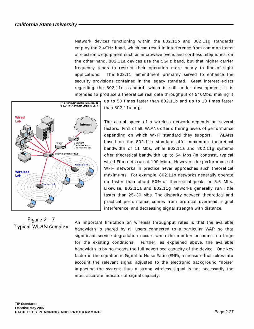
Wireless Ethernet is the principal standard for wireless networking within a home or office; it is the wireless counterpart to regular, wired Ethernet, and is also known as a “WLAN,” a "Wi-Fi" or an "802.11" network. A WLAN (Wireless Local Area Network) is fundamentally a radio frequency (RF) system that transmits data over the air, typically in the 2.4GHz or 5GHz bands. It generally does not require line of sight between sender and receiver. Wireless base stations (wireless access points, frequently called APs or WAPs) are attached to a wired Ethernet network and transmit over an area of several hundred square feet through walls and other non-metallic barriers. Roaming users can be handed off from one access point to another in a fashion similar to a cellular phone system.
While it is certainly well beyond the scope of this TIPS document to provide a detailed description of WLAN technology, one or two historical and developmental notes may be helpful. The “802.11” connotation simply refers to a family of IEEE standards for wireless LANs that were designed to extend 802.3 (wired Ethernet) into the wireless domain. The 802.11 standard is more widely known as "Wi-Fi" because the Wi-Fi Alliance, an organization independent of IEEE, provides certification for products that conform to 802.11. The first 802.11 specifications were introduced in 1997 and included two spread-spectrum methods for transmission in the 2.4GHz band. At the present time, the 802.11 family includes six over-the-air modulation techniques all using essentially the same protocol: the original legacy 802.11 standard and its a, b, g, i and n amendments.
California State University
TIP Standards Effective May 2007 F ACIL IT IES PL ANNING AND PROGR AMMING Page 2-27
Network devices functioning within the 802.11b and 802.11g standards employ the 2.4GHz band, which can result in interference from common items of electronic equipment such as microwave ovens and cordless telephones; on the other hand, 802.11a devices use the 5GHz band, but that higher carrier frequency tends to restrict their operation more nearly to line-of-sight applications. The 802.11i amendment primarily served to enhance the security provisions contained in the legacy standard. Great interest exists regarding the 802.11n standard, which is still under development; it is intended to produce a theoretical real data throughput of 540Mbs, making it
up to 50 times faster than 802.11b and up to 10 times faster than 802.11a or g.
The actual speed of a wireless network depends on several factors. First of all, WLANs offer differing levels of performance depending on which Wi-Fi standard they support. WLANs based on the 802.11b standard offer maximum theoretical bandwidth of 11 Mbs, while 802.11a and 802.11g systems offer theoretical bandwidth up to 54 Mbs (In contrast, typical wired Ethernets run at 100 Mbs). However, the performance of Wi-Fi networks in practice never approaches such theoretical maximums. For example, 802.11b networks generally operate no faster than about 50% of theoretical peak, or 5.5 Mbs. Likewise, 802.11a and 802.11g networks generally run little faster than 25-30 Mbs. The disparity between theoretical and practical performance comes from protocol overhead, signal interference, and decreasing signal strength with distance.
An important limitation on wireless throughput rates is that the available bandwidth is shared by all users connected to a particular WAP, so that significant service degradation occurs when the number becomes too large for the existing conditions. Further, as explained above, the available bandwidth is by no means the full advertised capacity of the device. One key factor in the equation is Signal to Noise Ratio (SNR), a measure that takes into account the relevant signal adjusted to the electronic background “noise” impacting the system; thus a strong wireless signal is not necessarily the most accurate indicator of signal capacity.
Figure 2 - 7 Typical WLAN Complex
California State University
TIP Standards Effective May 2007 F ACIL IT IES PL ANNING AND PROGR AMMING Page 2-28
Interior Wireless Physical Planning Considerations In the early days of wireless deployment at CSU campuses (only a few short years ago), an access point installation was typically a single device located to serve a particular space to the extent that its signal strength and throughput capacity would cover the desired area. This sort of implementation became known as a wireless “hotspot.” More recently, however, the demands for ever greater coverage and capacity have resulted in the development of strategies for using multiple WAP units distributed in patterns providing coverage with deliberate partial signal overlap. Such groupings are typically designed to yield some redundancy in case of single unit failure and to meet estimated coverage and capacity requirements as seamlessly as possible within the limitations of the RF equipment being deployed. Recent equipment announcements from some vendors suggest a migration toward so-called “lightweight” (less intelligent, also referred to as “thin” or even “ultra-thin”) access point devices connected to wired Ethernet through multi-point controllers capable of monitoring and managing the array of WAP units attached to them. One argument for this approach is based on the improved security implications: if an AP is stolen there are no network configurations or business secrets to be had.
Security issues for WLAN installations extend well beyond physical theft, as they are subject to electronic intrusion from a variety of sources, including:
1. Rogue AP—An unsanctioned AP connected to a network and opening it to
security risk; such devices are often attached by well-intentioned
employees ignorant of possible electronic outcomes.
2. Ad-hoc Network—A peer-to-peer wireless network that transmit from
computer to computer without the use of a central base station (access
point);
3. “Honeypot” AP—An AP set up by an intruder within the range of a WLAN,
leading unsuspecting clients to associate with it and open access to the
WLAN.
4. Wireless Bridge—A device operating with a directed signal and capable of
connecting into unprotected enterprise WLANs.
California State University
TIP Standards Effective May 2007 F ACIL IT IES PL ANNING AND PROGR AMMING Page 2-29
One primary approach to addressing such security issues is to include air monitoring capability in the WLAN design. Air Monitors (AMs) may be dedicated devices or their functionality may be incorporated as part of AP units. They act to scan the entire RF spectrum in their range of coverage, and incorporate electronic tools such as remote packet capture (“sniffing”) and statistics monitoring to detect security breaches. The same tools provide them with other valuable capabilities including remote WLAN device management. Dedicated AMs obviously may provide better WLAN control than access points configured to perform both AP and AM functions, as the “time slicing” techniques employed to achieve the latter may somewhat reduce throughput and provide slightly less comprehensive monitoring.
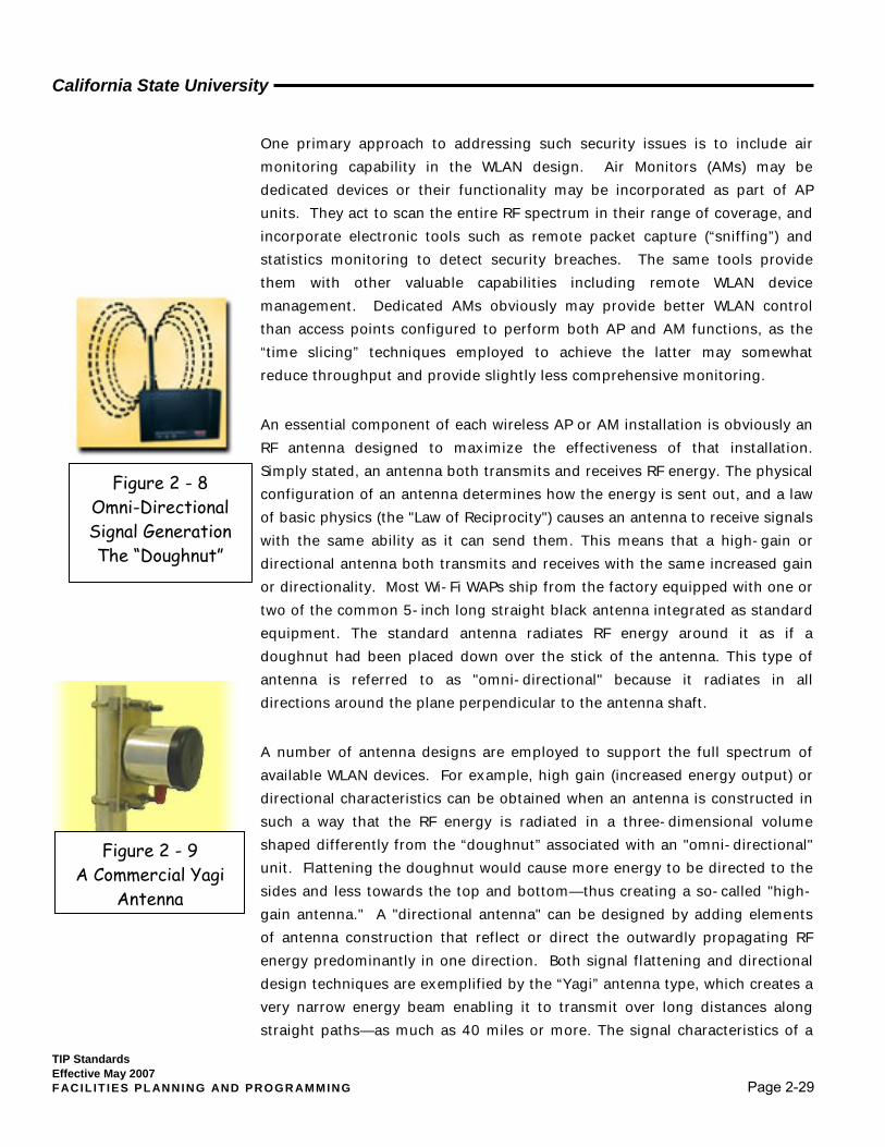
An essential component of each wireless AP or AM installation is obviously an RF antenna designed to maximize the effectiveness of that installation. Simply stated, an antenna both transmits and receives RF energy. The physical configuration of an antenna determines how the energy is sent out, and a law of basic physics (the "Law of Reciprocity") causes an antenna to receive signals with the same ability as it can send them. This means that a high-gain or directional antenna both transmits and receives with the same increased gain or directionality. Most Wi-Fi WAPs ship from the factory equipped with one or two of the common 5-inch long straight black antenna integrated as standard equipment. The standard antenna radiates RF energy around it as if a doughnut had been placed down over the stick of the antenna. This type of antenna is referred to as "omni-directional" because it radiates in all directions around the plane perpendicular to the antenna shaft.
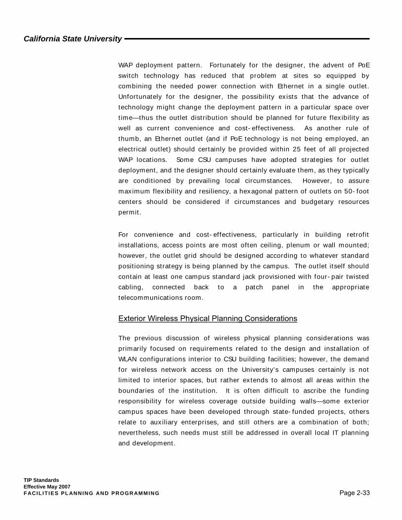
A number of antenna designs are employed to support the full spectrum of available WLAN devices. For example, high gain (increased energy output) or directional characteristics can be obtained when an antenna is constructed in such a way that the RF energy is radiated in a three-dimensional volume shaped differently from the “doughnut” associated with an "omni-directional" unit. Flattening the doughnut would cause more energy to be directed to the sides and less towards the top and bottom—thus creating a so-called "high-gain antenna." A "directional antenna" can be designed by adding elements of antenna construction that reflect or direct the outwardly propagating RF energy predominantly in one direction. Both signal flattening and directional design techniques are exemplified by the “Yagi” antenna type, which creates a very narrow energy beam enabling it to transmit over long distances along straight paths—as much as 40 miles or more. The signal characteristics of a
Figure 2 - 8 Omni-Directional Signal Generation The “Doughnut”
Figure 2 - 9 A Commercial Yagi
Antenna

California State University
TIP Standards Effective May 2007 F ACIL IT IES PL ANNING AND PROGR AMMING Page 2-30
particular antenna are frequently depicted in a special graph called an Antenna Pattern Polar Coordinate Graph or, simply, an Antenna Pattern Graph. Antenna technology is certainly complex, and a detailed exposition of the subject need not be incorporated in this TIPS document.
In addition to APs and AMs and their related antennas, other devices
commonly associated with Wi-Fi systems include:
1. Wireless adapter—allows various devices to connect to a wireless network,
using interconnects such as PCI, USB and PCMCIA;
2. Wireless router—combines a WAP, ethernet switch and internal router
firmware application that provides IP Routing, NAT and DNS forwarding
through an integrated WAN interface, thus yielding functionality for wired
and wireless Ethernet LAN devices to connect to (typically) a single WAN
unit such as a cable or a DSL modem;
3. Wireless Ethernet bridge—connects a wired network to a wireless network
at less than the data-link layer, so that two bridges might be useful to
connect two wired networks over a wireless link;
4. Range extender (wireless repeater)—can be strategically located to
elongate a signal area or to reach around RF signal barriers, but increased
latency results from each hop, while the signal chain is only as good as its
weakest link; and
5. Antenna connectors—come in a variety of formats --
6. The majority of commercial devices (routers, APs, bridges, repeaters, PCI
adapters, etc.) employ either RP-SMA or RP-TNC antenna connectors,
7. Most PCMCIA and USB devices only have internal antennas etched on their
circuit boards (although some feature supplementary external MMCX, MC-
Card or even RP-SMA connectors),
8. Most Mini PCI wireless cards utilize Hirose U.FL connectors (but nearly all
connectors listed above can be found in one or more of the available
appliances), and
9. Most high-gain antennas employ the Type N connector common in other
radio communications applications.
Figure 2 - 10 Typical Antenna Pattern
Graph Omni-Directional
Antenna

California State University
TIP Standards Effective May 2007 F ACIL IT IES PL ANNING AND PROGR AMMING Page 2-31
It is important to emphasize that access point location is not as yet an exact science. Since they are often in a dynamically changing environment, a multitude of variables affect coverage patterns: the building structure and materials, space configurations, background noise in the RF spectrum being employed, and the electronic characteristics and performance of the selected AP equipment, to name just a few. A number of software tools are marketed purporting to automate the location process—and most equipment vendors offer their in-house versions of such tools as a design resource. Required input to such software typically includes .jpeg or CAD drawings of detailed building geometry, the building materials to be encountered, expected user characteristics, parameters describing technical expectations for the equipment being deployed, and other information defining and detailing the projected installation.
Many experienced WLAN designers are hesitant to rely entirely upon automated tools, commonly regarding them as a useful vehicle for creating an initial layout, to be supplemented and improved by a field site survey involving both visual and electronic assessment. While it is not feasible to discuss in this TIPS document the details of a comprehensive site survey, extensive coverage of that subject may be found in available reference materials (e.g., BICSI—Wireless Design Reference Manual, 2nd Edition). In brief, the typical site survey report may incorporate the following elements:
1. An executive summary of the survey and its results
2. A detailed Statement of Work
3. The results of an RF spectrum scan of the 2.4/5.8 frequency bands
4. The results of a rogue AP detection process
5. A cable plant diagram
6. Recommendations on access point placement, including at least the
following supplemental information --
7. Power settings for radio output.
8. Antenna selection
9. Antenna orientation
10. Channel planning diagram.
11. A Bill of Materials (BOM) for the recommended installation

California State University
TIP Standards Effective May 2007 F ACIL IT IES PL ANNING AND PROGR AMMING Page 2-32
12. A coverage map or blueprint for each facilities area surveyed, including
SNR/Noise/Signal Strength indications
13. Photos of individual AP placements and their related telecommunications
room (TR/IDF)
14. A logical network diagram The CSU normally expects that WLAN design consultants will provide for an
appropriate site survey in preparing construction/installation documents for a
campus facility incorporating wireless capability. However, that responsibility
will vary depending upon the nature of the project:
1. Retrofit—The site survey should be performed as a component of the
original design.
2. New Construction—The construction/installation plans and specifications
should provide for verification and possible adjustment of the deployment
initially designed and specified, at such a time as the facility is nearing
completion but WLAN outlet provisioning may still be modified without
excessive cost.
Although currently available FCC-compliant WAP units may individually radiate as far as 400 feet outdoors and 150 feet indoors, most vendors seem to indicate that the optimum effective interior coverage radius in terms of data throughput is perhaps on the order of 50 to 75 feet—but that effective radius is heavily impacted by the environmental variables already mentioned. Considering the need for overlap, some WLAN designers begin a manual analysis by using a rough rule-of-thumb that AP spacing will average 100 feet, often according to a hexagonal pattern accommodating to the radial nature of the signal technology. The pattern is then adjusted to fit the realities of the facility’s physical configuration and projected client load, with that adjustment heavily influenced by the results of a site survey. Automated procedures are founded on much the same principles.
Whether dealing with one WAP or many, the problem for the telecommunications physical plant designer seeking to assure adequate support for an interior WLAN installation is to locate wired Ethernet and electrical power outlets in some convenient configuration responding to the
California State University
TIP Standards Effective May 2007 F ACIL IT IES PL ANNING AND PROGR AMMING Page 2-33
WAP deployment pattern. Fortunately for the designer, the advent of PoE switch technology has reduced that problem at sites so equipped by combining the needed power connection with Ethernet in a single outlet. Unfortunately for the designer, the possibility exists that the advance of technology might change the deployment pattern in a particular space over time—thus the outlet distribution should be planned for future flexibility as well as current convenience and cost-effectiveness. As another rule of thumb, an Ethernet outlet (and if PoE technology is not being employed, an electrical outlet) should certainly be provided within 25 feet of all projected WAP locations. Some CSU campuses have adopted strategies for outlet deployment, and the designer should certainly evaluate them, as they typically are conditioned by prevailing local circumstances. However, to assure maximum flexibility and resiliency, a hexagonal pattern of outlets on 50-foot centers should be considered if circumstances and budgetary resources permit.
For convenience and cost-effectiveness, particularly in building retrofit installations, access points are most often ceiling, plenum or wall mounted; however, the outlet grid should be designed according to whatever standard positioning strategy is being planned by the campus. The outlet itself should contain at least one campus standard jack provisioned with four-pair twisted cabling, connected back to a patch panel in the appropriate telecommunications room.
Exterior Wireless Physical Planning Considerations The previous discussion of wireless physical planning considerations was primarily focused on requirements related to the design and installation of WLAN configurations interior to CSU building facilities; however, the demand for wireless network access on the University’s campuses certainly is not limited to interior spaces, but rather extends to almost all areas within the boundaries of the institution. It is often difficult to ascribe the funding responsibility for wireless coverage outside building walls—some exterior campus spaces have been developed through state-funded projects, others relate to auxiliary enterprises, and still others are a combination of both; nevertheless, such needs must still be addressed in overall local IT planning and development.
California State University
TIP Standards Effective May 2007 F ACIL IT IES PL ANNING AND PROGR AMMING Page 2-34
Many of the considerations previously discussed in connection with interior WLAN access—such as available transmission standards and protocols, the factors impacting on equipment spacing and configuration, and the need for site surveys as part of the design process—are equally pertinent to exterior installations. At the same time, the very fact that they are outside raises some new design considerations and modifies others. Among those considerations are:
1. Equipment housing and protection—when equipment must be deployed away from buildings in large exterior open areas, some form of housing must be provided to assure its physical and electronic security and to protect it from weather damage. In regions where harsh weather extremes are prevalent, below-ground vault mounting may be required, raising additional concerns about antenna functionality. Numerous manufacturers offer lines of enclosures designed for such use, both metallic and non-metallic.
2. Utility services—Wireless equipment installed away from immediate building support obviously raises issues relating to provision of Ethernet and electrical power connectivity. This is particularly true when the distances involved exceed normal distribution standards. Under such circumstances, a remote exterior TR may need to be established to support the wireless configuration. Range extending equipment and AP power boosting techniques may be employed to develop an exterior wireless design, but utilities connectivity always remains a concern.
3. Design parameters—The coverage potential of an AP device in an exterior space, particularly an open space of large size, tends to be greater than in a building interior: obviously the impact of the building structure and various other environmental physical factors will tend to be less, line-of-sight issues are generally easier to assess, and the density of end-user devices will probably be smaller. Range extension and power boosting tools are likely to be more useful under such conditions. On the other hand, major building structures tend to be total impediments to signal transmission and may also offer signal interference from internal wireless systems. As with internal wireless design, a site survey is essential in evaluating the issues associated with a proposed project. An example of a special problem unique to exterior AP coverage is the effect of plant

California State University
TIP Standards Effective May 2007 F ACIL IT IES PL ANNING AND PROGR AMMING Page 2-35
foliage: surveys of the same site are likely to yield different answers in winter as contrasted with summer!
A relatively new exterior wireless tool emerging in the marketplace is what is called “Long-Range Wi-Fi.” Several companies now offer systems with specialized antenna systems which greatly increase traditional Wi-Fi range. The current world record was set in 2005, with a test broadcast of 137.2 miles between two mountaintops in Idaho. Interesting from the CSU perspective is the fact that several universities around the world have used such equipment to connect their main campuses to subsidiary remote sites. However, Long-Range Wi-Fi technology is not yet developed to a point where this TIPs document should attempt to present it as a standard. Even so, CSU campuses may find specialized applications of that technology very useful—for example, it might be employed to provide temporary LAN connectivity to a new building while the facility awaited an extension of the campus telecommunications outside plant.
An older and more recognized version of long-range wireless technology is referred to generically as “point-to-point telecommunications,” a broad term embracing wireless data transmission for Internet or VoIP applications via radio frequencies in the multi-gigahertz range—laser light may also be used as the medium. This definition would seemingly subsume Long-Range Wi-Fi. In all instances, the transmission is line-of-sight and tightly beamed from transmitter to receiver; it is typically bi-directional. Such systems are, of course, subject to applicable FCC regulations. Several CSU campuses have utilized various point-to-point applications in recent years to address specific connectivity problems. However, such applications are subject to individual design according to prevailing conditions; attempting to standardize them is well beyond the scope of this document.
Figure 2 - 11 NEMA-Rated Exterior
Wireless Enclosure

California State University
TIP Standards Effective May 2007 F ACIL IT IES PL ANNING AND PROGR AMMING Page 2-36
2.3.4 Summary of Physical Requirements
Figure 2-12 summarizes some of the key information reviewed in Section 2.3.
Room Type
Space
Requirement Service
Entrance
Telecom Network Hub or Center
Equipment
Technology/Computer Laboratory
Roof/ Antenna
Site Equipment None Active
devices
Active
devices,
monitoring,
mgm’t. &
control
equipment
Active
devices
and/or PBX
Active devices,
workstations
and printers;
possibly servers
Active
devices
Floor Space Shared Dedicated Dedicated Dedicated Shared Shared
Wall Space Shared Dedicated Dedicated Dedicated Dedicated Dedicated
Room Access Shared Dedicated Dedicated Dedicated Multi-use Shared
Separate Ground
TMGB* TGB TGB TGB TGB TGB
Electrical Service
2- 20 amp
circuits
Separate
100/150
amp, 208V
panel;
possible
new
transformer
Separate
250 amp,
208V panel;
possible
new
transformer
Separate 250
amp, 208V
panel;
possible new
transformer
1-20 amp
dedicated
circuit per every
4 workstations,
every 2
printers, and
each rack of
equipment;
probable bldg.
Power retrofit
Separate
250 amp,
208V panel
Mechanical System(s)
Complex Planning/Design Issue: Refer to Section 3, Paragraph 3.2.1.3
Fig. 2 - 12 Telecommunications Space Physical Requirements
*Telecommunications Master Grounding Bar
California State University
TIP Standards Effective May 2007 F ACIL IT IES PL ANNING AND PROGR AMMING Page 2-37
2.4 Campus Facilities Support Requirements
In addition to telecommunications space and pathway issues, a variety of university environment-specific issues must be factored into the design of a new facility. Significant changes taking place in how education is being delivered are very frequently reflected by fundamental changes in information system-related infrastructure requirements. New educational facilities simply cannot be designed using formulas and criteria developed two decades in the past.
This subsection provides an overview of the minimum telecommunications infrastructure requirements in specific areas of new construction and remodel projects. They are intended by the CSU to be used during program planning if more specific local requirements are not identified. 2.4.1 Offices Office spaces range from the standard one-person space to multi-room office suites, and all need to be suitably equipped to afford access to various campus telecommunications resources. All offices must be designed with multiple voice, data, and video outlets situated to allow changes in furniture layouts. Other specific design considerations include:
1. All offices must be equipped with a minimum of two communication outlets, preferably on opposite walls and near electrical outlets.
2. Larger offices and open suite areas should have multiple communication outlets (minimum of one per 75 square feet) but no fewer than one at every-other electrical outlet.
3. Use of modular furniture in offices requires significant coordination to define the methods to be used to connect the furniture systems to the distribution system. Each cubical must be designed with sufficient pathways to meet the needs of a single-person office. Each pathway linking the furniture to the distribution system must be sized to support two outlets (each with a minimum of three cables) in each cubicle seating area.
California State University
TIP Standards Effective May 2007 F ACIL IT IES PL ANNING AND PROGR AMMING Page 2-38
2.4.2 Conference Rooms Conference rooms smaller than 12' by 12' should be equipped in a similar fashion to a standard office with a voice/data outlet on each wall and, at a minimum, two video outlets on opposite walls. Larger conference rooms should be equipped as follows:
1. Rooms longer than twelve (12) feet should be equipped with one or more floor outlet boxes that provide power and two signal pathways. (One signal pathway is for connection to the building network, and the other is for room control equipment.)
2. Separate lighting controls should be provided upon entry to the room and at the front of the room (presentation area) to provide presenter and task lighting and a switch-activated power outlet. Signal and power needs and distribution methods must be coordinated with the selected furniture layout.
3. The walls, doors, and windows should contain additional soundproofing material to reduce outside noise and prevent sound generated in the room from penetrating or traveling to another space.
Each major building should be equipped with a conference room configured
for utilization as a teleconferencing or video-conferencing room. This will
require additional acoustic material on the floor, ceiling, walls, and windows;
storage space for equipment; enhanced power, lighting, and HVAC controls;
blackout shades; and appropriate furniture.
2.4.3 Instructional Areas
2.4.3.1 General Requirements
This Standards document is not intended to be a classroom design guide, nor does it purport to limit the application of technology within the educational setting. The material presented is a set of general standards and guidelines and is meant to be a starting point for the design professional in the definition of technology requirements.
California State University
TIP Standards Effective May 2007 F ACIL IT IES PL ANNING AND PROGR AMMING Page 2-39
Trends within education are being impacted not only by technology but also by a different perspective on how people learn and share knowledge. Many faculty are moving away from the traditional lecture mode of instruction. There is a trend to more interaction between faculty and students, between students, and with technology.
New approaches in teaching and learning will impact the size, shape, and use of classroom space across the university. The challenge to the building designer is to meet current requirements and budgets while still providing flexibility for change. The challenge for the designer of technology systems is in determining specific requirements and defining sufficient flexibility to meet emerging instructional trends.
Several issues related to the increased use and reliance upon technology in the instructional setting must be addressed in the planning process.
1. Additional space is required to support even a limited number of workstations and/or multimedia display equipment. This equipment may also require secure storage facilities or simply additional floor space.
2. Additional telecommunications outlets of varying types must be installed in every classroom facility.
3. Additional electrical service must be provided to meet the loads presented by instructor and student equipment.
4. Air handling systems must be modified to address the increased cooling load and to reduce the level of sound associated with air movement.
5. Lighting and lighting controls must be modified to meet the needs of display systems, task lighting, and group work efforts.
6. Each classroom must have the basic infrastructure to support instructor-controlled display and computing equipment, even if the systems will not initially be installed.
7. Acoustical treatment of walls, ceiling, and floors is required to improve the student’s ability to make use of display systems and allow for the origination of communications from any classroom.

California State University
TIP Standards Effective May 2007 F ACIL IT IES PL ANNING AND PROGR AMMING Page 2-40
8. Assisted listening devices (where they are required) must be interconnected with all display systems and must be configured to allow for interconnection to changing technology.
9. Any built-in seating must be designed to provide pathways for both power and telecommunications to every seat, even if those services will not be initially installed.
10. Instructor positions must have multiple pathways to link to lighting controls, multimedia control equipment, power, and network access. The layout of these pathways must be flexible enough to support changes in room configuration and technology.
11. A central control panel location must be provided in each classroom linking the instructor’s position(s) with expected display and computing systems. This can be a control room, wall panel, ceiling-mounted box, or freestanding equipment cabinet.
12. Classrooms must be designed to support both the instructor and the student in their efforts to use technology and to learn. Some general guidelines for classroom design related to display systems or imaging systems are as follows:
a. The size of the display screen(s) must allow students at all locations within the room to obtain an unobstructed view. Without other specific requirements, the viewing distance should be between two and eight times the height of the image. For example; if the room is configured so the most distant seating row is 24 feet from the display screen or monitor, the image should be three feet in height (24’ ÷ 8 = 3’). In addition, if the image is three feet in height the minimum distance to the closest viewing row would be six feet (3’ × 2 = 6’).
b. The location of seating in front of the screen should enable the student to remain at a workstation and still view the display. This means the end seats of the front rows should be at an angle of 35 degrees or less in relation to the centerline of the room and screen.
c. It may be necessary to install additional viewing screens or monitors to augment the central screen if viewing distance or angles cannot be met.
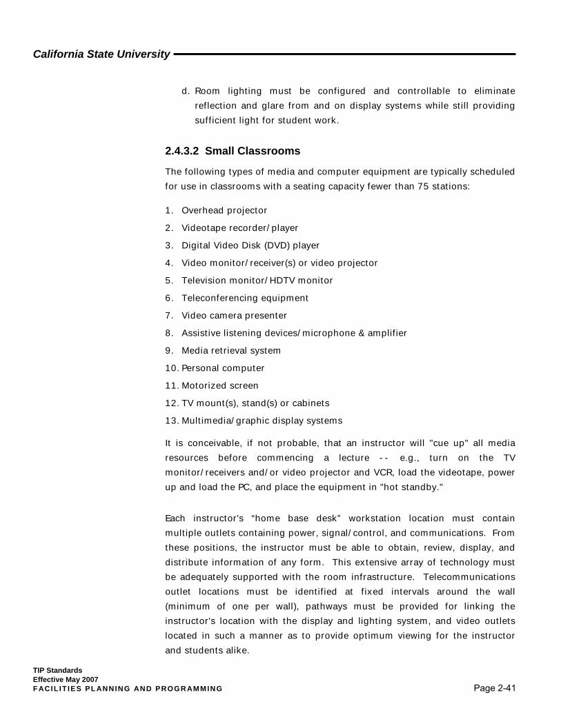
California State University
TIP Standards Effective May 2007 F ACIL IT IES PL ANNING AND PROGR AMMING Page 2-41
d. Room lighting must be configured and controllable to eliminate reflection and glare from and on display systems while still providing sufficient light for student work.
2.4.3.2 Small Classrooms
The following types of media and computer equipment are typically scheduled for use in classrooms with a seating capacity fewer than 75 stations:
1. Overhead projector
2. Videotape recorder/player
3. Digital Video Disk (DVD) player
4. Video monitor/receiver(s) or video projector
5. Television monitor/HDTV monitor
6. Teleconferencing equipment
7. Video camera presenter
8. Assistive listening devices/microphone & amplifier
9. Media retrieval system
10. Personal computer
11. Motorized screen
12. TV mount(s), stand(s) or cabinets
13. Multimedia/graphic display systems
It is conceivable, if not probable, that an instructor will "cue up" all media resources before commencing a lecture -- e.g., turn on the TV monitor/receivers and/or video projector and VCR, load the videotape, power up and load the PC, and place the equipment in "hot standby."
Each instructor's “home base desk” workstation location must contain multiple outlets containing power, signal/control, and communications. From these positions, the instructor must be able to obtain, review, display, and distribute information of any form. This extensive array of technology must be adequately supported with the room infrastructure. Telecommunications outlet locations must be identified at fixed intervals around the wall (minimum of one per wall), pathways must be provided for linking the instructor's location with the display and lighting system, and video outlets located in such a manner as to provide optimum viewing for the instructor and students alike.
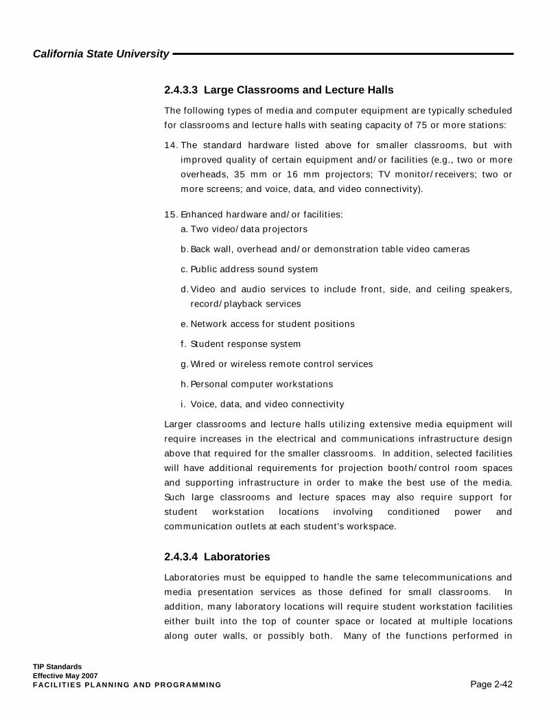
California State University
TIP Standards Effective May 2007 F ACIL IT IES PL ANNING AND PROGR AMMING Page 2-42
2.4.3.3 Large Classrooms and Lecture Halls
The following types of media and computer equipment are typically scheduled for classrooms and lecture halls with seating capacity of 75 or more stations:
14. The standard hardware listed above for smaller classrooms, but with improved quality of certain equipment and/or facilities (e.g., two or more overheads, 35 mm or 16 mm projectors; TV monitor/receivers; two or more screens; and voice, data, and video connectivity).
15. Enhanced hardware and/or facilities: a. Two video/data projectors
b. Back wall, overhead and/or demonstration table video cameras
c. Public address sound system
d. Video and audio services to include front, side, and ceiling speakers, record/playback services
e. Network access for student positions
f. Student response system
g. Wired or wireless remote control services
h. Personal computer workstations
i. Voice, data, and video connectivity
Larger classrooms and lecture halls utilizing extensive media equipment will require increases in the electrical and communications infrastructure design above that required for the smaller classrooms. In addition, selected facilities will have additional requirements for projection booth/control room spaces and supporting infrastructure in order to make the best use of the media. Such large classrooms and lecture spaces may also require support for student workstation locations involving conditioned power and communication outlets at each student's workspace.
2.4.3.4 Laboratories
Laboratories must be equipped to handle the same telecommunications and media presentation services as those defined for small classrooms. In addition, many laboratory locations will require student workstation facilities either built into the top of counter space or located at multiple locations along outer walls, or possibly both. Many of the functions performed in
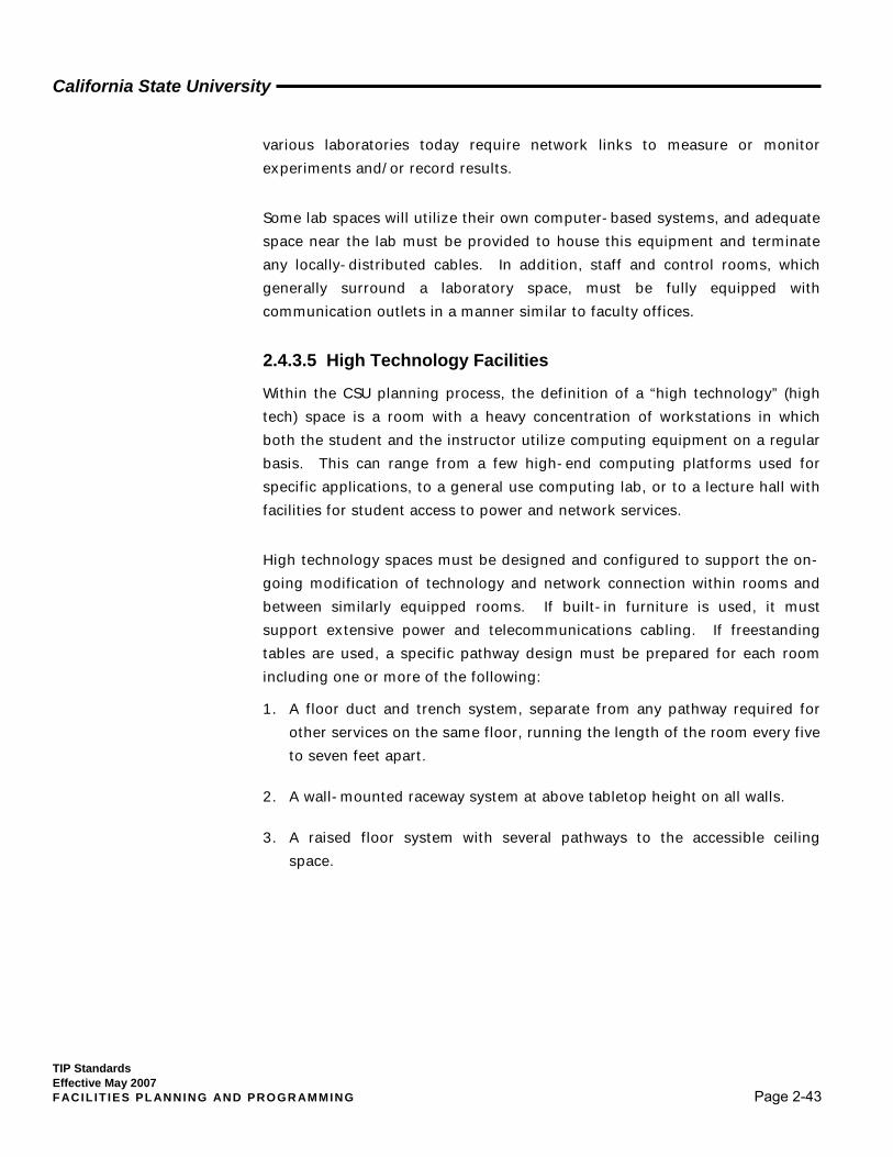
California State University
TIP Standards Effective May 2007 F ACIL IT IES PL ANNING AND PROGR AMMING Page 2-43
various laboratories today require network links to measure or monitor experiments and/or record results.
Some lab spaces will utilize their own computer-based systems, and adequate space near the lab must be provided to house this equipment and terminate any locally-distributed cables. In addition, staff and control rooms, which generally surround a laboratory space, must be fully equipped with communication outlets in a manner similar to faculty offices.
2.4.3.5 High Technology Facilities
Within the CSU planning process, the definition of a “high technology” (high tech) space is a room with a heavy concentration of workstations in which both the student and the instructor utilize computing equipment on a regular basis. This can range from a few high-end computing platforms used for specific applications, to a general use computing lab, or to a lecture hall with facilities for student access to power and network services.
High technology spaces must be designed and configured to support the on-going modification of technology and network connection within rooms and between similarly equipped rooms. If built-in furniture is used, it must support extensive power and telecommunications cabling. If freestanding tables are used, a specific pathway design must be prepared for each room including one or more of the following:
1. A floor duct and trench system, separate from any pathway required for other services on the same floor, running the length of the room every five to seven feet apart.
2. A wall-mounted raceway system at above tabletop height on all walls.
3. A raised floor system with several pathways to the accessible ceiling space.
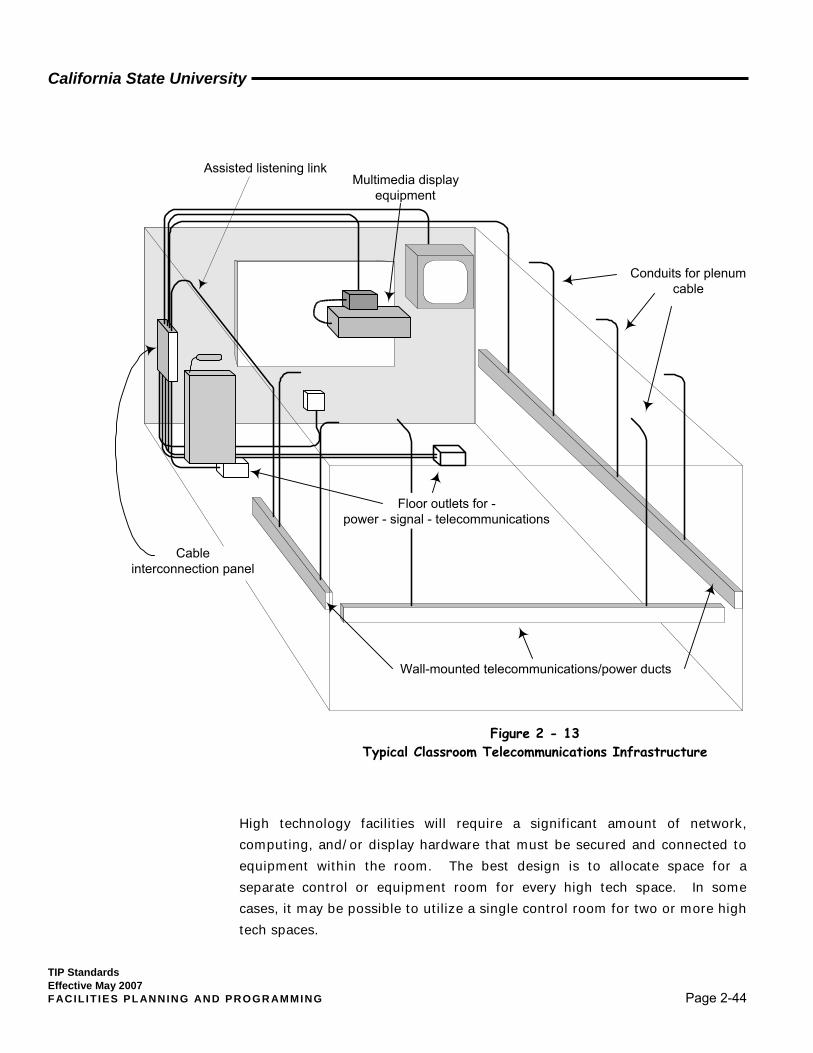
California State University
TIP Standards Effective May 2007 F ACIL IT IES PL ANNING AND PROGR AMMING Page 2-44
High technology facilities will require a significant amount of network, computing, and/or display hardware that must be secured and connected to equipment within the room. The best design is to allocate space for a separate control or equipment room for every high tech space. In some cases, it may be possible to utilize a single control room for two or more high tech spaces.
Conduits for plenumcable
Multimedia displayequipment
Cableinterconnection panel
Wall-mounted telecommunications/power ducts
Assisted listening link
Floor outlets for -power - signal - telecommunications
Note: Power conduits not shownFigure 2 - 13 Typical Classroom Telecommunications Infrastructure
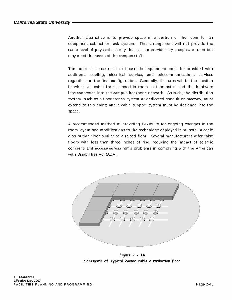
California State University
TIP Standards Effective May 2007 F ACIL IT IES PL ANNING AND PROGR AMMING Page 2-45
Another alternative is to provide space in a portion of the room for an equipment cabinet or rack system. This arrangement will not provide the same level of physical security that can be provided by a separate room but may meet the needs of the campus staff.
The room or space used to house the equipment must be provided with additional cooling, electrical service, and telecommunications services regardless of the final configuration. Generally, this area will be the location in which all cable from a specific room is terminated and the hardware interconnected into the campus backbone network. As such, the distribution system, such as a floor trench system or dedicated conduit or raceway, must extend to this point; and a cable support system must be designed into the space.
A recommended method of providing flexibility for ongoing changes in the room layout and modifications to the technology deployed is to install a cable distribution floor similar to a raised floor. Several manufacturers offer false floors with less than three inches of rise, reducing the impact of seismic concerns and access/egress ramp problems in complying with the American with Disabilities Act (ADA).
Figure 2 - 14 Schematic of Typical Raised cable distribution floor
California State University
TIP Standards Effective May 2007 F ACIL IT IES PL ANNING AND PROGR AMMING Page 2-46
These floors are generally not suited for use in a computer room environment due the limited capacity for below grade cable and/or cooling pathways. Fortunately, high tech rooms usually need only a few inches of clearance, and if the system is well planned, it can support changes over many years.
2.4.4 Libraries Library facilities are frequently the central hub for electronic information on a campus. In addition to the main automated systems designed specifically for libraries, such as reference and information retrieval systems, libraries are often the focal point for instructional media (video) and a variety of instructional and academic computing systems.
Libraries must be designed both to support specific systems and to provide various methodologies allowing access to information. This includes the use of "public" computing and information retrieval equipment with access to a wide range of services. These public access points will require a significant increase in the number of user-accessible communication services (both wired and wireless) throughout the facility. Group study and meeting rooms must be designed to provide access facilities for voice, data, and video services from a variety of sources.
2.4.5 Residence Halls Planning for residence hall communication services must be undertaken with the realization that expectations now go well beyond a telephone in each room (in fact, the proliferation of cell phone technology has recently raised some doubt about the need for the latter). Additional space must be provided in each building to terminate cable and house communications components, and each room (and students within that room) must have voice, data, and video system access.
Careful consideration should be given to designing the residence hall infrastructure to allow for the on-going installation of new services and additional outlets. One of the features important to students considering campus housing is now the availability of high speed data network access from each study area, as well as connectivity to on- and/or off-campus video entertainment networks. These types of services will require multiple outlets per housing unit based upon the number of students and/or potential work
California State University
TIP Standards Effective May 2007 F ACIL IT IES PL ANNING AND PROGR AMMING Page 2-47
areas, rather than "common" outlets shared by all users in a given room. In short, every residence hall student should have his/her own voice, data, and video station outlet.
2.4.6 Public Space The term “public space” refers to various areas within a campus environment where faculty, staff, and students may wait for services, stop to gather, or even pause to be alone. This includes such spaces as those outside financial aid and registration offices, walkway or open entry areas, common meeting areas, or group study areas. In keeping with the concept of improved access to information throughout the educational experience, public spaces need to be equipped with the necessary infrastructure to provide community announcement information, such as display monitors and interactive information kiosks, and with public or semi-private network access points for high speed data communication.
2.5 Summary of Design Considerations and Requirements There is no such thing as a "perfect" telecommunications distribution design. Building planners, however, can provide a robust and flexible design, with minimized cost impacts, by keeping three things in mind:
1. Telecommunications pathways and spaces are to be designed for the life of the building, not for a specific system or technology.
2. Retrofitting a newly constructed building to provide service is expensive and time consuming. A few additional feet of conduit initially designed into a new building will involve minimal cost. During or after construction, that same conduit could cost several times as much.
3. The telecommunications infrastructure should accommodate and reflect the university’s probable need to install a significant number of new (and as yet undefined) services subsequent to construction of the building. Changes in technology do not stop when the construction of the building is complete, and the design must take that into consideration.

California State University
TIP Standards Effective May 2007 F ACIL IT IES PL ANNING AND PROGR AMMING Page 2-48
Facilities must be designed to support standards-based infrastructure solutions providing long-term flexibility. Designs in support of a specific technology must be avoided.
TIA/EIA standards must be used to define the minimum size criteria for telecommunications spaces. Campus-specific requirements will often increase the size above those minimums.
Telecommunications rooms and equipment rooms must be dedicated to the support of telecommunications systems only.
Any telecommunications space housing or expected to house electronic equipment must be designed with 24 hour a day/365 days a year environmental services configured for the specific campus conditions.
Each project must have a specific telecommunications pathway plan prepared from the point of network origination on campus into and throughout the facility.
All instructional areas must be designed to support the distribution of technology for faculty, staff, and students and the use of multi-media systems.
High technology spaces should be designed with flexible access flooring and/or telecommunications pathways built in to student furniture.
The identification and design of the telecommunications infrastructure must follow the Planet Infrastructure Resource Management (IRM) documentation.
KEY POINTS For Architects and Facility Planners