2 generation of bio-engineered biliary tissue
TRANSCRIPT

1
Isolation and propagation of primary human cholangiocyte organoids for the 1
generation of bio-engineered biliary tissue 2
Olivia C Tysoe1,2*, Alexander W Justin3*, Teresa Brevini1,4*, Si Emma Chen1, Krishnaa T. 3
Mahbubani2, Anna Frank5, 6, 7, Espen Melum5,8,9, Hajer Zedira1, Kourosh Saeb-Parsy2†, Athina 4
Markaki3†, Ludovic Vallier1,2,† and Fotios Sampaziotis1,2,10,11†. 5
1Wellcome Trust-Medical Research Council Stem Cell Institute, Cambridge Stem Cell Institute, Anne 6
McLaren Laboratory, Department of Surgery, University of Cambridge, Cambridge, UK 7
2Department of Surgery, University of Cambridge and NIHR Cambridge Biomedical Research Centre, 8
Cambridge, UK 9
3Department of Engineering, University of Cambridge, Trumpington Street, Cambridge, UK. 10
4Department of Medical Biotechnology and Traslational Medicine (BIOMETRA), Università degli Studi 11
di Milano, Milan, Italy 12
5Norwegian PSC Research Center, Department of Transplantation Medicine, Division of Surgery, 13
Inflammatory Diseases and Transplantation, Oslo University Hospital, Rikshospitalet, Oslo, Norway. 14
6Research Institute of Internal Medicine, Division of Surgery, Inflammatory Diseases and 15
Transplantation, Oslo University Hospital, Rikshospitalet, Oslo, Norway, 16
7Department of Medicine III, University Hospital Aachen, Aachen, Germany, 17
8Section for Gastroenterology, Department of Transplantation Medicine, Division of Surgery, 18
Inflammatory Diseases and Transplantation, Oslo University Hospital Rikshospitalet, Oslo, Norway, 19
9Institute of Clinical Medicine, Faculty of Medicine, University of Oslo, Oslo, Norway 20
10Department of Hepatology, Cambridge University Hospitals NHS Foundation Trust, Cambridge, UK 21
11Department of Medicine, University of Cambridge, Cambridge, UK 22
Authorship note: * Olivia Tysoe, Alexander Justin and Teresa Brevini contributed equally to this 23
manuscript. † Fotios Sampaziotis, Ludovic Vallier, Athina Markaki and Kourosh Saeb-Parsy share 24
senior authorship for this manuscript. 25
Correspondence: Fotios Sampaziotis, Laboratory for Regenerative Medicine, West Forvie Building, 26
Robinson Way, University of Cambridge. Cambridge CB2 0SZ, United Kingdom. Telephone: 27
44.1223.747489; Fax: 44.1223.763.350; E-mail: [email protected] 28

2
Ludovic Vallier, Laboratory for Regenerative Medicine, West Forvie Building, Robinson Way, 1
University of Cambridge. Cambridge CB2 0SZ, United Kingdom. Telephone: 44.1223.747489; Fax: 2
44.1223.763.350; E-mail: [email protected] 3
4
Abstract 5
Biliary disorders are the leading indication for pediatric liver transplantation due to the lack of alternative 6
treatments for repairing or replacing damaged bile ducts. To address this challenge, we developed a 7
protocol for generating bioengineered biliary tissue suitable for biliary reconstruction. Our platform 8
allows the derivation of cholangiocyte-organoids (COs) expressing key biliary markers and function 9
from primary extra- or intrahepatic duct cholangiocytes, within 2 weeks of isolation. COs are 10
subsequently seeded on Poly-Glycolic Acid scaffolds or densified collagen constructs for 4 weeks to 11
generate bioengineered tissue retaining biliary characteristics. Therefore, expertise in organoid culture 12
and tissue-engineering are desirable for optimal results. Importantly, COs correspond to mature 13
functional cholangiocytes, differentiating our method from alternative organoid systems propagating 14
adult stem cells. Consequently, COs provide a unique platform for studies in biliary physiology and 15
pathophysiology; while the resulting bioengineered tissue has broad applications for regenerative 16
medicine and cholangiopathies. 17
18
Keywords: Cholangiocytes, organoids, cholangiopathies, biliary atresia, scaffolds, tissue engineering, 19
bioengineering 20
21
22
23
24
25
26

3
INTRODUCTION 1
Cholangiopathies comprise a diverse group of disorders characterized by damage to the biliary tree 2
and loss of bile ducts resulting in cholestasis, hepatic injury and ultimately liver failure1,2. However, 3
treatment options are limited to liver transplantation. Indeed, biliary disease remains the leading 4
indication for this intervention in children, with more than 70% of paediatric liver grafts being used to 5
treat biliary atresia3. The generation of healthy biliary tissue suitable for replacing or reconstructing 6
damaged bile ducts could address the clinical need for alternative therapeutic approaches and reduce 7
pressure on the transplant waiting list. However, progress in this area has been hampered by 8
challenges in long-term culture and large-scale expansion of primary cholangiocytes. Here, we describe 9
a protocol for the fabrication of functional bioengineered biliary tissue, using biocompatible and 10
biodegradable scaffolds and a novel method for the isolation and propagation of primary cholangiocytes 11
in organoid format. 12
13
Development of the protocol 14
To generate bioengineered biliary tissue suitable for surgical manipulation and biliary reconstruction, 15
we decided to combine primary biliary epithelium with appropriate matrices. 16
Development of the protocol for cholangiocyte organoid culture 17
First, we developed a culture protocol for the propagation and large-scale expansion of primary adult, 18
functional cholangiocytes4. Because biliary reconstruction is predominantly performed on the common 19
bile duct (CBD), we initially focused on the isolation of CBD cholangiocytes using excised bile ducts 20
from deceased organ donors. To achieve expansion of the isolated cholangiocytes, the cells were 21
embedded in Matrigel and treated with a combination of EGF, R-Spondin-1 and DKK-1. We have 22
previously demonstrated that the combination of EGF and 3D culture can promote limited growth of 23
partially mature, foetal CLC organoids derived from iPS5,6, while primary adult stem cell organoids have 24
been isolated from murine biliary tissue7. To support the long-term expansion of adult cholangiocytes 25
we used R-spondin-1, a WNT agonist reported to stimulate organoid derivation from multiple adult 26
epithelia 8-13. However, R-spondin promotes the propagation of adult stem cells rather than mature 27
epithelial populations by enhancing canonical Wnt signalling 14. To avoid the amplification of adult stem 28

4
cells, we introduced DKK-115, a canonical WNT/β-catenin pathway antagonist 16,17. When used in 1
combination with R-spondin, DKK-1 inhibits canonical and enhances non-canonical WNT signalling 2
though the planar cell polarity (PCP) pathway 4, which has been reported to play a role in cholangiocyte 3
maturation 18,19. The combination of EGF, R-Spondin-1 and DKK-1 allowed for long-term, large-scale 4
expansion of functional, genetically stable, primary adult cholangiocyte organoids (COs). 5
Our system was developed and optimized for the culture of CBD cholangiocyte organoids, isolated from 6
fresh excised bile ducts. However, this isolation method depends on a major complex operation, thereby 7
posing significant limitations related with access to biliary tissue. To overcome this issue, we 8
subsequently validated the capacity of our culture system for the derivation of cholangiocyte organoids 9
from multiple sources such as excised gallbladders, endoscopic retrograde cholangiopancreatography 10
(ERCP) brushings and liver biopsy samples. Using this platform cholangiocyte organoids can be 11
isolated and expanded using samples from any area of the biliary tree acquired by any of these isolation 12
methods. 13
Choice of scaffolds 14
Our next goal was to identify appropriate scaffolds that could be combined with the cells to generate 15
tissue-like constructs. Important considerations for the choice of scaffolds were their potential to support 16
growth of the cells, their capacity to be integrated to the host tissue following transplantation with 17
minimal inflammatory response and the use of biodegradable materials allowing for tissue remodelling 18
which is crucial for neo-vascularization. Furthermore, to support future clinical translation, the materials 19
used should be compatible with human transplantation. 20
Importantly, both synthetic and biological polymer scaffolds with these specifications are available. 21
Since there are advantages and disadvantages associated with each approach, we decided to explore 22
both. Synthetic polymer scaffolds are widely used as they can be easily processed using a wide range 23
of techniques and adapted for multiple tissue engineering applications 20. They have tuneable and 24
reproducible physicochemical properties, mechanical strength, and degradation rates, making them 25
highly customisable as a scaffold material 20,21. Biological polymer scaffolds are more challenging to 26
tailor to a particular application owing to purity issues, immunogenicity, and scaffold homogeneity and 27
reproducibility 22. However biological polymer scaffolds have superior bioactive properties (e.g. cell 28
attachment, migration, cell scaffold remodelling) and thus better cell and tissue interactions 22,23. 29

5
Generation of bioengineered tissue using synthetic scaffolds 1
First, we focused on synthetic scaffolds commercially available ‘off the shelf’, to optimize cell seeding, 2
attachment and culture of the resulting tissue. We decided to use a Poly-Glycolic Acid (PGA) matrix 3
due to its biodegradability, flexibility and lack of inflammatory response in vivo24. Additionally, synthetic 4
PGA scaffolds can be easily processed into tailored architectures 22,23. For these reasons, PGA is one 5
of the most commonly used synthetic polymers in tissue engineering21 and has been approved by the 6
FDA for use in human studies25. 7
We subsequently identified the optimal method for seeding COs on the scaffolds. Our results 8
demonstrated the use of cell clumps concentrated in small volumes to be the optimal seeding method. 9
Indeed, the dissociation of organoids into single cells requires aggressive enzymatic digestion. This 10
approach reduces cell viability and attachment due to the cleavage of multiple cell-to-matrix adhesion 11
molecules26. Furthermore, small volumes of cell suspension are absorbed by the scaffold, maximizing 12
cell to scaffold contact. This technique resulted in the generation of confluent PGA-scaffolds seeded 13
with COs, which were used to successfully repair biliary tree wall defects in immunocompromised mice, 14
following transplantation. 15
Generation of bioengineered tissue using biological scaffolds 16
We subsequently used the same seeding methodology to populate biological scaffolds. Here we chose 17
densified collagen hydrogel due to its biocompatibility, low immunogenicity, ability to favour cell 18
attachment and growth, biodegradability, and ability to be naturally remodelled by cells 27. Importantly, 19
unlike standard collagen gel, densified collagen demonstrates superior mechanical properties for 20
surgical applications27,28. Densification expels the majority of the water content of the collagen gel, vastly 21
reducing its volume, resulting in a polymer scaffold of higher concentration and fibrillar alignment 28. 22
Through the use of appropriate moulds, the densification process can be customized to generate 23
constructs of more complex geometries, which can be successfully seeded with COs. 24
Generation of bioengineered mouse bile ducts 25
One of the most relevant clinical applications of bioengineered biliary tissue is the generation of tubular 26
constructs suitable for biliary reconstruction. However, bile duct transplantation can be associated with 27
significant inflammatory response, epithelial damage and formation of anastomotic strictures in humans 28
6
29,30. Consequently, in vivo validation of the function, biocompatibility and patency of bioengineered 1
ducts following reconstruction is required. To achieve this goal, we decided to generate bioengineered 2
constructs populated with human COs, transplant them in immunocompromised mice and characterise 3
them. 4
A key challenge was the fabrication of tubular structures with dimensions comparable to the mouse 5
CBD (250 µm inner diameter and 30 µm wall thickness). Indeed, commercially-available fibrous PGA 6
scaffolds31 were incompatible with these requirements due to a minimum thickness (300 µm) 7
significantly larger than the required wall thickness. Appropriate thickness pre-densified collagen gel 8
sheets could be fashioned into a tube using sutures; however, interruption of the collagen fibrils along 9
the seam led to partial collapse of the lumen under the weight of the wall. To overcome these 10
challenges, a method was developed in which collagen was cast around a central rod and densified 11
afterwards, to yield a seamless tube with a thin and robust wall. Furthermore, a conical funnel mould 12
was used which allowed a proportionately large volume of collagen to densify into a short length of tube 13
and enabled efficient water removal via multiple routes (through on-axis absorption and radial 14
evaporation). These techniques yielded bioengineered tubes with a patent lumen and dimensions 15
similar to the mouse CBD. 16
We subsequently used the approach we developed for seeding COs on flat collagen scaffolds to seed 17
the luminar surface of the construct with cells and generate mouse-sized bioengineered bile ducts 18
populated with human cells. Importantly, the potential of these constructs for biliary reconstruction in 19
vivo was illustrated through their successful transplantation in immunocompromised mice4. 20
21
Applications and target audience 22
The propagation of cholangiocyte organoids and generation of bioengineered biliary tissue is likely to 23
be of interest to a broad scientific audience including clinician scientists focusing on translation of new 24
therapies to clinic, bioengineers working on whole organ reconstruction, groups focusing on biliary 25
physiology and disease and the pharmaceutical industry. Currently the only therapeutic option for biliary 26
disorders is liver transplantation. The generation of bioengineered biliary tissue could provide one of 27
the first alternative treatments and pioneer the use of regenerative medicine for cholangiopathies 32,33. 28

7
Furthermore, a limitation of complex liver co-culture systems is the lack of a biliary system. The capacity 1
of cholangiocyte organoids to grow in a variety of matrices and scaffolds makes them an ideal addition 2
for complex tissue engineering applications that focus on recapitulating the microanatomy of the liver 3
and the development of artificial whole-organ systems. 4
Cholangiocytes constitute a rare liver cell type and access to primary tissue has limited large scale 5
analyses in the past. Cholangiocyte organoids resemble primary biliary epithelium very closely in terms 6
of transcriptional profile and function 4. Consequently, extrahepatic COs (ECOs) and intrahepatic (ICOs) 7
could serve as a surrogate for primary cholangiocytes from any region of the biliary tree, enabling in 8
depth, large scale studies of biliary physiology and pathophysiology. Similarly, COs recapitulate the 9
effects of compounds such as verapamil or somatostatin, rendering them suitable for drug screening 10
applications. 11
12
Comparison to other methods 13
A unique feature of our culture system is that it enables the long-term culture of mature cholangiocytes 14
through the inhibition of canonical WNT signalling by DKK-1, maintaining adult characteristics and 15
functionality with no need for additional differentiation. Therefore, our system is distinct to alternative 16
primary organoid platforms based on canonical WNT signalling which propagate adult stem cells 8,11,13,34 17
rather than bona-fide biliary epithelium. Consequently, COs may be better suited for studies on biliary 18
physiology and disease requiring high fidelity cholangiocytes, while adult stem cells are optimal for 19
studies on liver repair and regeneration. 20
While methods for short-term culture of murine35 and human primary cholangiocytes have been 21
reported 36,37, these systems are technically challenging, only allow for limited expansion restricting 22
large scale analyses and the function of the resulting cells has not been extensively characterized. COs 23
combine high proliferative capacity, increased functionality and the potential for large scale expansion, 24
which is crucial for regenerative medicine or for high-throughput applications. 25
Importantly, cholangiocytes can be derived from induced pluripotent stem cells 5,6,38,39. However, these 26
cells correspond to fetal intrahepatic cholangiocytes, whereas our method can generate both 27
intrahepatic and extrahepatic adult cholangiocytes. Additionally, COs can be rapidly isolated and 28

8
expanded, unlike iPSC systems which require a lengthy differentiation process and cannot be further 1
propagated once terminally differentiated. Consequently, stem cell derived cholangiocytes are optimal 2
for studies on intrahepatic bile duct development and its disorders, while COs are better suited for 3
studies of adult intra- and extra-hepatic cholangiocyte physiology or regenerative medicine applications 4
requiring large numbers of highly functional cells in little time. 5
Our system provides multiple advantages for tissue engineering and regenerative medicine. The 6
generation of bioengineered tissue is versatile, allowing the use of synthetic (PGA) or biological 7
scaffolds (collagen). Furthermore, it is compatible with GMP-compliant materials, such as collagen 8
which has an excellent in vivo profile and is used extensively in clinical applications 24. The method by 9
which the densified collagen tubes are formed allows their generation at customisable length-scales 10
compatible with small animal studies. Further, the densification process does not impart significant 11
stress upon the cells, which can be mixed in the gel if required. The resulting constructs can be 12
maintained more than 2 months in culture enabling the generation of large batches of bioengineered 13
tissue with prolonged ‘shelf-life’. Importantly, our bioengineered biliary tissue provides the first proof-of-14
principle for organ reconstruction using primary epithelial organoids, where the resulting bioengineered 15
construct was used to fully replace the native organ 4. 16
17
Limitations 18
A limitation of our system is that COs, as adult primary cholangiocytes, are not suitable for studying 19
biliary development, an application for which stem cell derived systems are more appropriate. 20
Additionally, as COs represent a pure epithelial population, this system does not currently allow for the 21
study of epithelial and mesenchymal interactions, although the potential exists within our system to 22
generate bioengineered tissue with additional cell types. A further, technical, limitation is that COs 23
currently rely on the use of Matrigel, a non-GMP-compliant extracellular matrix. However, multiple 24
chemically defined hydrogel matrices, which could replace Matrigel, are currently in development 40. 25
For research groups without access to a hospital with hepatobiliary services access to primary tissue 26
may present a challenge, as primary samples need to be processed promptly following isolation. We 27
note that samples can be obtained in any hospital that offers a cholecystectomy, ERCP or liver biopsy 28

9
service and organoid derivation is still feasible after small delays associated with tissue transfer over 1
short distances. Nevertheless, to compensate for transport associated delays when multiple samples 2
from distal centres are processed, a team of trained technicians working in parallel may be required. 3
Finally, although mouse-sized (submillimetre) constructs serve as proof-of-principle for the generation 4
of bioengineered ducts populated with human cells, their mechanical properties do not translate to those 5
of the human bile duct (7mm diameter, 1mm wall thickness). Therefore, optimisation of our technique 6
for the generation of human sized constructs with appropriate physical attributes will be required prior 7
to clinical translation. 8
9
Experimental design 10
Our method describes a system for isolating primary extrahepatic and intrahepatic cholangiocytes from 11
primary tissue, culturing these primary cholangiocytes in a 3D organoid system and generating 12
bioengineered biliary tissue using artificial scaffolds (Figure 1). In this section we describe infrastructure 13
and experimental setup considerations that need to be taken into account prior utilising this protocol. 14
Isolation of cholangiocytes from primary tissue 15
Our protocol requires the isolation of cholangiocytes from primary human tissue, either from living 16
patients or deceased organ donors. As such, appropriate ethical approval from the relevant regulatory 17
bodies is required, while informed consent is essential prior to acquiring any human tissue samples. 18
Obtaining fresh human tissue samples will require access to a hospital with one of the following 19
services: hepatology, advanced endoscopy, hepatobiliary surgery, transplant organ procurement or 20
liver transplantation. Importantly, donor tissue viability decreases proportionally to ex-vivo storage and 21
bile exposure. Therefore, tissue must be flushed from bile and stored immediately in cold preservation 22
solution (such as University of Wisconsin (UW) solution) or supplemented William’s E+ media) at 4 °C 23
until it can be processed 41. 24
When multiple tissue samples are obtained simultaneously (such as from a deceased organ donor), 25
the tissue should be processed in order of sensitivity to cold storage (supplemental figure 1). Liver 26
biopsies require immediate processing, while extrahepatic tissue can be stored at 4 °C for several 27

10
hours, provided it is appropriately flushed of bile. Furthermore, all tissue handling should be performed 1
under aseptic conditions to avoid contamination. Consequently, good communication with the clinicians 2
obtaining the sample is crucial. Long-distance transport of samples is likely to impact the viability of 3
explanted tissue, so samples must ideally be processed in a facility close to the site of collection. Tissue 4
must be processed in a category 2 tissue culture hood under aseptic conditions and sterile surgical 5
equipment must be used. 6
CO lines can be generated using multiple approaches, depending on the source of available tissue and 7
the method of sample collection (Fig. 1). Surgically excised tissue samples such as gallbladders and 8
bile ducts can be used for the generation of COs following isolation of the luminal layer of cholangiocytes 9
through mechanical scraping (Fig. 2a-e). Endoscopic Retrograde Cholangiopancreatography (ERCP) 10
brushings provide an alternative source of tissue for patients having endoscopy (Fig. 3a-d). Isolation of 11
COs from liver biopsy tissue can be performed by dividing a liver biopsy core into small pieces 12
(approximately 1 mm3) and plating them directly in CO organoid culture conditions (Fig. 4a-e). 13
Alternatively, CO lines can be derived from a population of EpCAM+ sorted single cells (Supplementary 14
Fig. 2a-c). Tissue can be enzymatically digested to a single-cell suspension and then EpCAM+ sorted 15
through either FACS or MACS. 16
Provided the tissue has been appropriately and promptly processed, the methods described should 17
produce CO lines with almost 100% efficiency, apart from EpCAM+ sorting, which yields viable lines 18
with an efficacy of 66% (supplementary table 1) due to the impact of single cell dissociation on cell 19
viability. Flushing the tissue of bile is crucial to achieving these results. Indeed, derivation efficiency is 20
reduced from 95% to to 40% if flushing is not performed (supplementary table 1). The optimal technique 21
for CO line derivation should be decided based on sample availability and access to tissue. 22
Establishment and maintenance of cholangiocyte organoids 23
Once plated, primary cholangiocytes should form organoids in 3-10 days. Clump size and seeding 24
density can affect the speed and efficiency of derivation. Single cells tend to require longer culture and 25
yield lower numbers of organoids for the same number of starting cells. Large clumps of >50-100 cells 26
and high seeding density may result in cell attachment and limit organoid growth. 27

11
CO lines should be passaged approximately every five days (Fig. 5a-b), although the cells should be 1
monitored daily for reaching confluency (Fig. 5b, Supplementary Fig. 3). Delays in passaging confluent 2
wells can result in organoid collapse and affect the long-term health of the organoid line (Supplementary 3
Fig. 4b). The same considerations as for organoid derivation apply with regards to clump size and 4
seeding density during passaging (Supplementary Fig. 4b). Importantly, our protocol relies on Matrigel 5
as an extracellular matrix which has a profound impact on the quality of the resulting organoid lines. 6
Therefore, Matrigel must be batch tested before use. It is also important to ensure that all reagents and 7
media used in the maintenance of CO lines are not used for longer than three months as this can impact 8
on organoid quality. 9
Organoids can be analysed through a variety of methods such as qPCR, immunofluorescence and flow 10
cytometry, as we have previously described 5,6. COs should show robust expression of key biliary 11
markers such as cytokeratin 19, cytokeratin 7, Sox9 and gamma-glutamyl transferase (GGT), as well 12
as key cholangiocyte functions such as alkaline phosphatase (ALP) and GGT activity (Fig. 6a-e), which 13
can be used to assess the quality of CO derivation and culture. 14
Scaffold preparation 15
Bioengineered tissue can be generated using both synthetic (PGA) and biological (densified collagen 16
gel) polymeric scaffolds, each of which may be suited to different applications. PGA scaffolds can be 17
commercially sourced, are cheap, and require minimal processing to yield positive results. The 18
mechanical properties of the scaffold (e.g. Young’s modulus, strength) are tuneable and can be 19
customized by adjusting density and pore size. Furthermore PGA constructs can be easily fabricated 20
into custom architectures 22,23. 21
Collagen constitutes a physiological component of the extracellular matrix 42 with high bioactivity 43 22
which can interact with cells and present multiple cues that enhance attachment, survival, proliferation 23
and tissue remodelling 42,44. Furthermore, unlike PGA, cells may be mixed directly into the collagen gel 24
precursor solution prior to gelation and densification, generating a uniform network of cells throughout 25
the scaffold, which is useful for applications such as complex co-culture systems. However, it is more 26
expensive than synthetic alternatives and scaffolds with adequate mechanical strength for surgical 27
manipulation 45,46 are not commercially available and need to be custom made. Indeed, densified 28
collagen sheets need to be fabricated from collagen gels through water absorption (figure 7a-b); while 29

12
densified collagen tubes, need to be formed through moulding of collagen gel around a cylindrical 1
template and water removal by evaporation from the gel surface (figure 8a-d). Consequently, densified 2
collagen scaffolds are more physiological but require a higher level of expertise and pose a greater 3
number of potential pitfalls, while PGA scaffolds may be appropriate for settings where the expertise 4
and equipment for the generation of custom-made scaffolds are not available. 5
Scaffold seeding 6
PGA and densified collagen scaffolds (both flat and tubular) can be seeded with COs to generate 7
bioengineered biliary tissue within 2-4 weeks. The cells are seeded as clumps in small volumes to 8
maximize contact with the scaffold and incubated for 1 hour to allow attachment prior to the addition of 9
media. For tubular scaffolds cannulation with a small gauge (< 30G) needle is necessary for seeding. 10
This procedure is technically challenging and may require the assistance of a surgeon to avoid 11
damaging the scaffold. 12
The efficiency and quality of cell attachment following seeding (Fig. 9d-e and 10c-d) depends on clump 13
size, cell number, seeding cell suspension volume and drying time for the scaffold. Single cells and low 14
cell numbers are associated with reduced seeding efficiency, while large clumps may attach only 15
partially. Importantly, parts of a clump which have not attached may remodel to form organoid-like 16
structures connected to the scaffold or overlap with neighbouring clumps which have attached 17
generating a pseudostratified epithelium. Consequently, the use of 30-50 cell clumps is crucial to 18
achieve optimal seeding results. 19
Low cell suspension volumes result in poor scaffold coverage and therefore suboptimal seeding, while 20
cell viability may be reduced due to media evaporation during the incubation period. High volumes may 21
lead to overflow and ‘spillage’ of the cell suspension from the scaffold to the plate resulting in a reduced 22
cell-to-surface ratio and poor seeding efficiency. Consequently, the seeding volume must be optimized 23
based on the scaffold surface as described in the procedure section. This is particularly important when 24
seeding on the luminal surface of a tubular scaffold, where the cell suspension must be optimised for 25
minimal volume and maximal density, to be contained within the tube lumen. 26

13
Reduced incubation time does not allow an adequate period for the cells to attach. Consequently, the 1
addition of media at the end of the incubation phase results in washing the poorly attached cells off the 2
scaffold. Prolonged incubation can result in scaffold drying and reduced cell viability. 3
Importantly, the scaffold is rarely confluent following seeding. Indeed, in most cases only a proportion 4
of the scaffold is covered with cells. However, these expand to generate a confluent layer within weeks. 5
The time to confluency can be reduced by seeding higher number of cells or performing repeated 6
rounds of seeding. Importantly, if an additional round of seeding is performed the scaffold should not 7
be allowed to dry before the new cells are added to preserve the viability of the cells already attached. 8
Bioengineered biliary tissue can be analysed through immunofluorescence or functional assays as 9
previously described 4 and should show robust expression of key biliary markers such as cytokeratin 10
19 and cytokeratin 7 (Fig. 11a, 11c and 11e) as well as key cholangiocyte functions such as GGT 11
activity (Fig. 11b, 11d and 11f). Once confluent, the scaffolds can be transplanted in vivo or maintained 12
in culture for several months. 13
Scaffold specific considerations 14
Pore size is an important consideration for PGA scaffolds. The scaffold pore size will determine the 15
optimal cell clump size for seeding- scaffold with large pores would, in principle, allow deeper cell 16
penetration, provided there is good interconnectivity between pores. However, constructs with larger 17
pores are weaker, and seeding with large clumps is required to ensure the cells do not ‘fall through’ the 18
spaces between fibres. Furthermore, preparation of the scaffolds for seeding includes treatment with 19
ethanol and high concentration NaOH. It is crucial that at the point of seeding the scaffold is completely 20
free of ethanol or NaOH remnants which could result in cell death and poor attachment. 21
For collagen scaffolds, the quality of collagen plays a key role for the attachment and growth of cells. 22
As collagen solutions are not 100% pure, testing of each new collagen batch for cell attachment, 23
proliferation, expression of biliary markers and function is recommended. 24
For the generation of tubular densified collagen scaffolds, assistance of an experienced engineer and 25
access to engineering facilities, including a 3D printer, is essential. Furthermore, transplantation of 26
bioengineered ducts into small animal models requires significant skill due to construct size and the 27
procedure must be performed by an experienced surgeon. 28

14
Appropriate Controls 1
Freshly isolated primary biliary tissue should be used as a positive control for the expression of biliary 2
markers. For histology or immunofluorescence (IF) analyses, whole tissue can be frozen in OCT or 3
fixed in 10% formalin and embedded in paraffin for sectioning. Cells can be isolated as described in 4
step 2, sections A and D and dissociated to a single cell suspension for flow cytometry or resuspended 5
in RNA lysis buffer for RNA extraction and quantitative PCR (QPCR), as described in steps 41, section 6
C. Alternatively, RNA can be extracted from snap frozen tissue. While primary tissue represents the 7
ideal control for CO function and marker expression, it is also possible to compare COs established 8
cholangiocyte cell lines could be used as alternatives if access to primary tissue is not possible. 9
Starting population considerations 10
We have demonstrated that our protocol for cholangiocyte organoid derivation is reproducible with >70 11
CO lines (Supplementary Table 1). Additionally, CO lines can be generated from very low numbers 12
(<20,000) of viable primary cells (Supplementary Fig. 5). CO lines can be maintained in culture for >20 13
passages or 6 months. COs represent primary cells rather than immortalized cell lines, therefore it is 14
possible that a reduction in the growth potential of function of the line is observed after this time. The 15
‘incubator life’ of each line varies and therefore the expansion potential, expression of biliary markers 16
and function should be regularly tested after passage 20 to periodically validate the quality of the line. 17
For the generation of bioengineered tissue, some variability in cell attachment and expansion potential 18
following seeding and after transplantation is expected. Therefore, minor optimization may be required 19
for certain CO lines as described in the following sections. 20
21
MATERIALS 22
REAGENTS 23
• Human bile duct, gall bladder and liver tissue samples or cholangiocytes from ERCP brushings. 24
CAUTION: All human tissue samples must be collected with the appropriate ethical approval in place 25
and with full informed consent. Donors should be tested to exclude HIV, hepatitis B and hepatitis C. 26

15
• William’s E basal medium, no phenol red (Invitrogen; cat. no. A12176-01) 1
• Nicotinamide (Sigma Life science, cat. no. N0636-100G) 2
• Sodium Bicarbonate (Sigma Life Science, cat. no. S6014-500G) 3
• Sodium Pyruvate (Invitrogen, cat. no. 11360-070) 4
• D- Glucose (Gibco, cat. no. 15023-021) 5
• HEPES (Sigma, H0887-20ml) 6
• ITS+ universal cell culture premix (20ml) (SLS, cat. no. 354352) 7
• Dexamethasone (R&D Systems, cat. no. 1126/100) 8
• L- Glutamine (Life Technologies, cat. no. 25030) 9
• Penicillin-streptomycin (Life Technologies, cat. no. 15140122) 10
• L-phospho-ascorbic acid (Sigma Life Sciences, cat. no. 49752-10G) 11
• Matrigel (BD Biosciences, cat. no. 356237) 12
• Cell recovery solution (SLS, cat. no. 354253) 13
• Cell Banker 2 (Amsbio, cat. no. 11891) 14
• Recombinant Human Epidermal Growth Factor (EGF) (R&D Systems, cat. no. 236-EG) 15
• Recombinant Human DKK-1 protein (R&D Systems, cat. no. 5439-DK-01M/CF) 16
• Recombinant Human Rspondin-1 (R&D Systems, 4645-RS) 17
• Recombinant Human HGF (Peprotech, cat. no. 100-39) 18
• Recombinant Human Forskolin (FSK) (Sigma Aldrich, cat. no. F6886-10MG) 19
• Y27632 (Stratech Scientific, cat. no. S1049-SEL) 20
• Liberase™ DL Research Grade (Sigma Aldrich, cat. no. 5466202001) 21
• Deoxyribonuclease I from bovine pancreas (Sigma Aldrich, cat. no. D5025-150KU) 22
• UW cold storage solution (Belzer; cat. no. BTLBUW-1000) 23
• Dulbecco's PBS (DPBS; Life Technologies, cat. no. 14190) 24
• Red Blood Cell Lysis Solution (10×) (MACS Miltenyi Biotech, cat. no. 130-094-183) 25
• Bovine Serum Albumin (Sigma Life Sciences, cat. no. A3059) 26
• PolyGlycolic Acid BIOFELT scaffold (1 mm thickness, 50 mg/cm3 PGA density) (Biomedical 27
structures LLC, custom order- enquire with the manufacturer) 28
• CD326 (EpCAM) MicroBeads, human (MACS Miltenyi Biotech, cat. no. 130-061-101) 29

16
• FcR Blocking Reagent (MACS Miltenyi Biotech, cat. no. 130-059-90) 1
• MACS BSA Stock Solution (MACS Miltenyi Biotech, cat. no. 130-091-376) 2
• AutoMACS™ Rinsing Solution (MACS Miltenyi Biotech, cat. no. 130-091-222) 3
• AutoMACS® running buffer (MACS Miltenyi Biotech, cat. no. 130-091-221) 4
• AutoMACS® pro washing solution (MACS Miltenyi Biotech, cat. no. 130-092-987) 5
• Collagen I, High concentration rat tail collagen solution, 100 mg (Scientific Laboratory Supplies, 6
354249) 7
• 10x M199 (Sigma, cat. no. M0650) 8
• 1M Sodium Hydroxide (Sigma, cat. no. 2770) 9
CAUTION: Sodium hydroxide can cause inflammation, irritation or corrosion upon contact with 10
skin, eyes or when ingested or inhaled. It should be handled while wearing appropriate safety 11
equipment 12
• DI water 13
• Water for embryo transfer (Sigma, cat. no. W1503) 14
• Trigene (Distel concentrate; Starlab, cat. no. TM309) 15
• Absolute ethanol (Fisher Scientific, cat. no. 10041814) 16
• Trypan Blue solution (Thermo Fisher Scientific, cat. no. 15250061) 17
CAUTION: Trypan Blue is a potential carcinogen and can potentially cause damage to fertility 18
• Donkey serum (AbD Serotec, cat. no. c06sb) 19
• Triton-X100 solution (Sigma, cat. no. X100-500ML) 20
• Paraformaldehyde 16% (wt/vol) (PFA; Alfa Aesar, cat. no. 30525-89-4) 21
CAUTION: Paraformaldehyde contains formaldehyde, which is carcinogenic. 22
Paraformaldehyde can cause tissue damage if inhaled, ingested or exposed to skin and should 23
be handled using appropriate safety measures 24
• Cytokeratin 7 antibody (Abcam, cat. no. ab68459; Table 1) 25
• Cytokeratin 19 antibody (Abcam, cat. no. ab7754; Table 1) 26
• Goat anti-human Sox9 (R&D Systems, cat. no. AF3075; Table 1) 27
• Rabbit anti-human albumin (Abcam, cat. no. ab137885; Table 1) 28
• Mouse anti-human GGT-1 (Abcam, cat. no. ab55138; Table 1) 29
• Donkey anti-mouse Alexa Fluor 488 (Life Technologies, cat. no. A2102; Table 1) 30

17
• Donkey anti-rabbit Alexa Fluor 568 (Life Technologies, cat. no. A10042; Table 1) 1
• Donkey anti-goat Alexa Fluor 488 (Life Technologies, cat. no. A21447; Table 1) 2
EQUIPMENT 3
• Plate heater (TAP Biosystem, cat. no. 016-0R10) 4
• Inverted microscope (Olympus, cat. no. CKX41) 5
• 100-mm TC-Treated Culture Dish (Corning, cat. no. 430167) 6
• Costar 24-Well Clear TC-Treated Multiple-Well Plates (Corning, cat. no. 3526) 7
• Surgical Scalpel Blade No.22 (sterile) (Swann Morton Ltd, cat. no. 0508) 8
• Dumont #5 - Fine Forceps (F.S.T., cat. no. 11254-20) 9
• 15 ml and 50 ml Centrifuge tubes (Corning, cat. nos. 430791 and 430291) 10
• 500-ml Vacuum Filter/Storage Bottle System, 0.22-μm pore (Corning, cat. no. 431097) 11
• CO2 incubator (Sanyo, cat. no. MCO-18AC) 12
• Centrifuge (Eppendorf, cat. no. 5804) 13
• Orbital shaking incubator (New Brunswick Scientific, cat. no. M1299-0082) 14
• Disposable serological pipettes (5, 10 and 25 ml) (Corning, cat. nos. 4487, 4488 and 4489) 15
• Graduated filter tips (1000, 200, 20 and 10 μl) (Starlab, cat. nos. S1122-1830, S1120-8810, 16
S1120-1810, S1120-3810) 17
• Cryotube vials (2 ml) (Thermo Scientific, cat. no. 368632) 18
• AutoMACS® Pro Separator (MACS Miltenyi Biotech, cat. no. 130-092-545) 19
• 40 μm cell strainers (Corning, cat. no. 352340) 20
• Countess™ II Automated Cell Counter (Thermo Fischer Scientific, cat. no. AMQAX1000) 21
• CountessTM cell counting chamber slides (Thermo Fischer Scientific, cat. no. C10283) 22
• Insulin syringes, 1 ml (VWR International, cat. no. 613-4892) 23
• Syringes, 20 ml (Fisher Scientific, cat. no. 15829152) 24
• Needles, 18G, 23G (Camlab, cat. no. 305180, 300700) 25
• Stainless steel fine tweezers (Onecall, cat. no. 1779183) 26
• Dissecting scissors, straight (Fisher Scientific, cat. no. 15207266) 27
• Precision wipes, Kimtech (Fisher Scientific, cat. no. 12660543) 28
• Self-seal sterilisation pouches (Fisher Scientific, cat. no. 15428782) 29

18
• 0.2 µm syringe filters (Fisher Scientific, cat. no. 10268401) 1
• 6 well plates (Fisher Scientific, cat. no. 10396482) 2
• Autoclave tape (Greiner Bio-One, cat. no. TAP02) 3
• Micro-spatula, 21 mm length (VWR International, cat. no. 231-0446) 4
• Specimen tubes, flat bottom, 10 mm (Samco, cat. no. G05017) 5
• Nylon membrane, 10 μm pore size, hydrophilic (Millipore, cat. no. NY1002500 ) 6
• 25 μl Model 1702 Hamilton syringe (Hamilton, cat. no. 80265) 7
• 34 gauge small hub removable needle (Hamilton, cat. no. 207434) 8
Critical: While the exact make and model of syringe and removable needle can vary according to 9
the researcher’s preference, it is essential that small volume syringes and removable needles with 10
no dead space are used for seeding the tubular scaffolds (step 40, section B), due to the very small 11
(25 μl) volumes needed for seeding. 12
13
REAGENT SET UP 14
• Human biliary and liver tissue Primary tissue can be obtained from surgically excised 15
gallbladder or bile duct tissue, ERCP brushings or liver biopsies. Once collected, tissue should 16
be stored immediately at 4°C in Williams E+ media with 50 ng/ml of EGF and 10 μM of Y27632 17
or in University of Wisconsin (UW) cold storage solution. 18
CAUTION: Leaving primary tissue longer than 8 hours before processing will negatively affect the 19
viability of the isolated cells 20
• Nicotinamide 0.4 M stock solution Dissolve 24.4 g of nicotinamide powder in 500 ml of 21
embryo transfer water. 22
CRITICAL: Sterilize nicotinamide stock solution using a vacuum filter/storage bottle system. 23
Mix it well before filtration. Store the solution at 4 °C for up to 3 months. 24
25
• Sodium bicarbonate 1 M stock solution preparation Dissolve 42 g of sodium bicarbonate 26
powder in 500 ml of embryo transfer water. 27

19
CRITICAL: Sterilize sodium bicarbonate stock solution using a vacuum filter/storage bottle 1
system. Mix it well before filtration. Store the solution at 4 °C for up to 3 months. 2
3
• Ascorbic acid trisodium salt 100 mM stock solution preparation Dissolve 16.1 g of ascorbic 4
acid trisodium salt powder in 500 ml of embryo transfer water. 5
CRITICAL: Sterilize ascorbic acid trisodium salt stock solution using a vacuum filter/storage 6
bottle system. Mix the solution well before filtration. Store it at 4 °C for up to 3 months. Protect 7
it from light. 8
9
• D-Glucose 1 M stock solution preparation Dissolve 90.1 g of D-glucose powder in 500 ml of 10
embryo transfer water. Warm the mixture to 50 °C to facilitate dissolution. 11
CRITICAL: Sterilize D-glucose stock solution using a vacuum filter/storage bottle system. Mix 12
the solution well before filtration. Store it at 4 °C for up to 3 months. 13
14
• Dexamethasone 10 mM stock solution Dissolve 100 mg of dexamethasone in 25.4797 ml of 15
DMSO. Prepare 50- to 100-μl aliquots. Store them at −80 °C for up to 12 months. 16
17
• Supplemented William's E medium (Willliam’s E+) Combine 443 ml of William's E medium 18
with 12.5 ml of nicotinamide stock solution, 8.5 ml of sodium bicarbonate stock solution, 1 ml 19
of ascorbic acid trisodium salt stock solution, 7 ml of glucose stock solution, 3.15 ml of sodium 20
pyruvate, 10 ml of HEPES solution, 5 ml of ITS+ premix, 5 μl of dexamethasone (R&D 21
Systems), 5.3 ml of glutamine and 5 ml of pen/strep. 22
CRITICAL: Sterilize William’s E+ medium using a vacuum filter/storage bottle system. Mix the 23
medium well before filtration. Store it at 4 °C for up to 1 month. Warm it to 37 °C before use. 24
25
• Sodium bicarbonate 7.5 % (wt/vol) stock solution Dissolve 3.75 g of sodium bicarbonate 26
powder in 46.25 ml of deionised water. 27
CRITICAL: Sterilize sodium bicarbonate stock solution using a 50 ml syringe and 0.2 μm 28
syringe filter. Mix it well before filtration. Store the solution at 4 °C for up to 3 months. 29
30

20
• 70% (wt/vol) ethanol. Combine 700 ml of absolute ethanol and 300 ml deionised water. 1
2
• Matrigel preparation. 10 ml Matrigel vials should be thawed slowly in a refrigerator placed at 3
4 °C overnight. Thawed Matrigel should be mixed well and then divided into 1 ml aliquots. 4
Aliquotting of Matrigel should always be performed in a tissue culture hood to avoid bacterial 5
contamination. Matrigel should be kept constantly on ice to avoid solidification. All equipment 6
coming into contact with Matrigel should be precooled to 4 °C. This includes pipette tips and 7
media for diluting Matrigel. Tubes for aliquotting should be kept on ice. Store Matrigel aliquots 8
at −20 °C or −80 °C for up to 3 months. 9
CRITICAL: Each aliquot should undergo a maximum of two freeze–thaw cycles. This can be 10
achieved by adjusting aliquot volumes accordingly. 11
12
• Preparation of a 3X supplemented William’s E+ solution. William’s E+ media is 13
supplemented with 1.5 μg/ml RSPO, 300 ng/ml DKK, 150 ng/ml EGF and 3 μM Y27632 (3X 14
the typical concentration of all Supplementary cytokines). 15
16
COs are cultured in 3D conditions, suspended in 50 μl droplets composed of a 66.7% (vol/vol) 17
Matrigel and 33.3% (vol/vol) 3X supplemented William’s E+ solution, which form a dome after 18
plating (Fig. 4b, Image 6A(i)). Prior to plating, a master mix is prepared with a volume 19
corresponding to the number of droplets that will be plated as described in steps 3-10. 20
Importantly, for generating this master mix COs or primary cholangiocytes are first resuspended 21
in the 3X supplemented William’s E+ solution (step 3) and Matrigel is subsequently added (step 22
5). To calculate the volume of supplemented William’s E+ needed for resuspension of the CO 23
pellet, the following formula can be used: 24
25
Volume of supplemented William’s E+ media= [(number of CO wells) x 50 μl]/3 26
27
CRITICAL: As the volume of media needed to resuspend the CO pellet will typically be very 28
small, it is advisable to instead prepare a larger volume of 3X concentrated William’s E+ 29
solution. This can then be diluted to 1X and added to the wells after plating as their plating 30

21
medium. This volume corresponds to 1/3 the total number of wells to be plated (e.g. if plating 1
12 wells, prepare 4 ml of 3X William’s E+ solution) assuming 1ml of media / well is used. A 2
small aliquot of the resulting 3X solution can then be used to resuspend the pellet and the 3
remaining solution can be diluted to 1X with William’s E+ devoid of additional cytokines and 4
used as plating medium. 5
E.g. If plating 12 wells, resuspend the pellet in 200 μl of 3X supplemented William’s E+ 6
solution, taken from the initial 4 ml of 3X supplemented William’s E+ solution. After CO 7
plating (steps 3-10), add 8 ml of non-supplemented William’s E+ media to the 4 ml of 8
supplemented William’s E+ solution to make a 1X supplemented William’s E+ solution 9
10
Preparation of a 66.7% Matrigel (vol/vol) solution To obtain the volume of Matrigel 11
needed when plating, multiply the volume of 3X supplemented William’s E+ solution by 12
two. E.g. if plating 12 wells, 200 μl of supplemented William’s E+ solution should be added 13
to the pellet followed by 400 μl of Matrigel. 14
CRITICAL: The 3X supplemented William’s E+ solution should be precooled to 4 °C 15
16
CRITICAL: Both Matrigel and the 3X supplemented William’s E+ solution should be kept on 17
ice for the duration of the procedure to avoid Matrigel solidification 18
19
• Liberase preparation Reconstitute the lyophilised liberase enzyme with 10 ml of sterile 20
injection-quality water, as per the manufacturer’s instructions, to obtain a stock solution. 21
CRITICAL: Aliquot the reconstituted liberase stock solution into 1 ml aliquots to avoid repeated 22
freeze-thaw cycles and store at -15 to -25 °C. Reconstitution and aliquotting should take place 23
in a tissue culture hood to avoid contamination. 24
25
• DNase I preparation Reconstitute the lyophilised DNase I to a 4 mg/ml stock solution using 26
sterile PBS. 27
CRITICAL: Aliquot the reconstituted DNase I stock solution into 100 μl aliquots to avoid 28
repeated freeze-thaw cycles and store at -80 °C. Reconstitution and aliquotting should take 29
place in a tissue culture hood to avoid contamination. 30

22
1
• PBS 1% BSA (wt/vol) preparation Weigh out 5 g of BSA powder and dissolve in 500 ml of 2
PBS to obtain a 1% solution. 3
CRITICAL: Sterilize PBS 1% BSA solution using a vacuum filter/storage bottle system. Mix the 4
solution well before filtration. Aliquot in 50 ml centrifuge tubes and store at -20 °C to avoid 5
contamination. 6
7
• MACS buffer preparation Prepare a 1 in 20 dilution of MACS BSA stock solution in 8
AutoMACS™ Rinsing Solution 9
CRITICAL: MACS buffer should be freshly prepared at point of use and should be kept at 4 °C. 10
Buffer preparation should take place in a tissue culture hood to avoid contamination 11
12
• Preparation of a 0.1% Triton X-100 solution Add 50 μl of Triton X-100 to 50 ml of PBS in a 13
50 ml centrifuge tube. Gently shake the tube by inversion until the Triton X-100 is fully dissolved 14
15
EQUIPMENT SET UP 16
Plate heater setup 17
• Clean the plate heater with trigene and 70% (vol/vol) ethanol and place it in a tissue culture 18
hood. Set the temperature to 37 °C and place a 24-well plate on the heating surface. 19
CRITICAL: Allow a minimum of 30 min for the plate to warm up, before plating Matrigel with cells. If you 20
are using multiple plates, these can be prewarmed in an incubator for a minimum of 30 min, with each 21
plate placed on the plate heater immediately before plating. 22
AUTOMACS pro separator set up 23
• Run column exchange before use. Check that the columns are secured and there are no leaks 24
anywhere in the system. Check that there is sufficient running buffer, washing solution and 70% 25
(vol/vol) ethanol and that the waste bottle is not too full. Run an additional “Qrinse” before 26
starting cell sorting. This can be done while the cells are incubating with the MACS beads to 27
23
save time. To shut down the machine after EpCAM+ sorting, select the “sleep” programme. 1
Turn off the machine once the “sleep” programme has finished 2
Fabrication and assembly of densification chamber for densified collagen tubes. 3
Critical step: The densification chamber, used to form the densified collagen tubes, requires 4
fabrication and assembly ahead of the collagen gel preparation. This involves 3D printing the base and 5
funnel pieces, mounting a rigid metal wire in the base, and fixing paper towels between the base and 6
funnel. This procedure requires access to basic engineering facilities. 7
I. Design chamber geometry in computer-aided design (CAD) package (e.g. Autodesk 8
Inventor). See Supplementary Software 1 and 2 for reference. 9
II. Export as .stl file and prepare file for 3D printing using 3D printer software (e.g. Doraware). 10
III. 3D print chamber model using poly-lactic acid (PLA) filament and assemble components 11
shown in Fig. 8a, Image 1. 12
IV. Mount straight rigid wire in hole of base piece of chamber by supergluing it into place (Fig. 8a, 13
Image 2). 14
Critical step: Let superglue cure before continuing (1 hour). 15
V. Fold 2 sheets of absorbent precision wipe paper towels four times and using scissors, cut to 16
size of base plate. Autoclave these paper towels in an autoclave pouch. 17
Critical step: Let towels fully dry before continuing. 18
VI. Sterilize base plate and funnel piece by immersion in 70% (vol/vol) ethanol. 19
VII. Place 3D printed components under a sterile biological cabinet until dry. 20
VIII. Autoclave 4x M4 screws and nuts. 21
IX. Using a sterile 23G needle, punch a hole through the centre of the sheets and feed the 22
mounted metallic wire through the needle (Fig. 8a, Image 3). 23
X. Pull out 23G needle and push down paper towels. 24
XI. Feed metallic wire through funnel piece (Fig. 8a, Image 4) and fix funnel piece to base piece 25
using 4x M4 screws and nuts (Fig. 8a, Image 5). 26
XII. Tighten using screwdriver. Chamber is now ready for densification process. 27

24
Critical Step: Screws must be tight in order to prevent leaking of water to the towels prior to a collagen 1
gel forming. 2
Critical Step: The top of the metallic wire must not extrude above the top of the funnel. This is a 3
necessary condition for successful collagen densification for tube formation. 4
5
PROCEDURE 6
Derivation of cholangiocyte organoids from primary human tissue 7
1. Primary tissue can be obtained from surgically excised gallbladder or bile duct tissue, ERCP 8
brushings or liver biopsies (Fig. 1b). Once collected, tissue should be stored immediately as 9
described in “reagent setup”. 10
Pause point: Tissue can be kept in media/cold storage solution for up to 8 hours although for optimal 11
viability, tissue should be processed as soon as possible after collection. Guidance on the maximum 12
length of storage before processing for each tissue type is shown in Supplementary Fig. 1. 13
CAUTION: Dissection of tissue should take place in a category 2 cell culture hood under aseptic 14
conditions 15
2. For derivation of COs from excised bile ducts or gall bladders, see section A. For derivation of 16
COs from ERCP brushings, see section B. For derivation of COs from liver tissue, see section 17
C and for derivation of COs from an EpCAM+ sorted single cell suspension, see section D. 18
Step 2, Section A: Derivation of extrahepatic cholangiocyte organoids from deceased organ 19
donors 20
Timing: 1-2 hours (including plating) 21
Critical step: All equipment used should be sterile and all work must be done under aseptic conditions 22
in a category 2 tissue culture hood. 23
I. Transfer the tissue from the storage container onto an empty 10 cm plate. 24

25
II. Using a scalpel and forceps, make a longitudinal incision along the length of the excised bile 1
duct or from the fundus to the neck of the excised gallbladder. (Fig. 2b, Images 1A(ii) and 2B(ii)) 2
to expose the lumen. 3
This step should result in a flat sheet of biliary tissue with the biliary epithelium on the luminal 4
surface, usually pigmented yellow by bile and an ‘exterior’ surface corresponding to the outer 5
wall of the bile duct or gallbladder. 6
CAUTION: Ensure the luminal surface is facing upwards to avoid loss of cholangiocytes 7
8
III. Wash the tissue by transferring in a 50 ml centrifuge tubes containing PBS to remove excess 9
bile (Fig. 2b and c, Image 2). Repeat twice using a fresh tube each time [Troubleshooting] 10
Critical step: PBS washes must be performed cautiously to prevent detachment of the biliary 11
epithelial layer. This is particularly important if the bile duct or gallbladder tissue has been kept on 12
ice for <2-4 hours after surgical excision 13
IV. Transfer the tissue to an empty plate 14
V. Add Williams’ E+ media to the plate until the tissue is fully submerged in media. It is not 15
necessary to supplement the media with additional cytokines. 16
CAUTION: The tissue must be submerged in media quickly to prevent it from drying 17
VI. Gently scrape the luminal surface of the tissue with a scalpel to release the cholangiocytes into 18
the media (Fig. 2b and c, Image 3) 19
Critical step: Examine the cell suspension under the microscope after scraping the tissue and before 20
collecting the cells into a centrifuge tube to ensure the mechanical dissociation has been successful. 21
The epithelial cells should be released from the tissue as small clumps and should display columnar 22
morphology (Fig. 2b and c, Image 9). 23
VII. Collect the media and cells into a 50 ml centrifuge tube using a 10 ml pipette 24
VIII. Wash the tissue again by adding approximately 10 ml of fresh media directly on the luminal 25
surface of the tissue in the plate with a 10 ml pipette 26
IX. Repeat the process of scraping and washing until the entire epithelial layer is collected. By the 27
end of this stage, the luminal side of the biliary tissue will appear smooth, losing the 28

26
characteristic velvet-like appearance of the biliary epithelium (Fig. 2b and c, Images 1A(iii) and 1
1B(iii)). 2
Critical step: Scrape cautiously to avoid releasing fibrous tissue and debris into the cell suspension 3
[Troubleshooting] 4
X. Centrifuge the cells at 444 g for 4 minutes at room temperature (23 °C) 5
XI. Aspirate the supernatant 6
XII. Resuspend the pellet in 10 ml of WE+ media (regardless of pellet size) to wash the cells. 7
If there is bile or debris remaining in the suspension, repeat this wash step. 8
Critical step: Remove large pieces of debris and fibrous tissue using a p1000 pipette as these may 9
not be easily removed by washing [Troubleshooting] 10
XIII. Centrifuge the cells at 444 g for 4 minutes at room temperature 11
XIV. Optional step: Red cell lysis to avoid erythrocyte contamination 12
XV. Optional step: Resuspend in 10 ml of ice cold red cell lysis buffer 13
XVI. Optional step: Incubate the cell suspension on ice for up to ten minutes. 14
XVII. Optional step: Wash twice in William’s E+ media as described in steps XI – XII before continuing 15
with step XXI 16
XVIII. Aspirate the supernatant 17
XIX. Wash the pellet in William’s E media. 18
XX. Plate the cells as described in steps 5-14 [Troubleshooting] 19
Critical step: typical morphology for COs plated from GB or BD tissue after one week and >20 weeks 20
after plating is displayed in Fig. 2d Image 1 and 2d Image 2 respectively. COs should begin to form 21
approximately 3 days after plating and debris should disappear from the CO culture after the first two 22
passages 23
24
Step 2, Section B: Derivation of extrahepatic cholangiocyte organoids through Endoscopic 25
retrograde cholangiopancreatography (ERCP) brushings 26
Timing: 30 minutes 27

27
I. Prepare a 50 ml centrifuge tube of William’s E+ media with 50 ng/ml of EGF and 10 μM of 1
Y27632. Provide this tube to the clinicians before the start of the ERCP procedure 2
II. Following brushing, wash the ERCP brush in the tube of media to dislodge the collected cells 3
(Fig. 3a, panel 2) 4
III. Transport the centrifuge tube at 4 °C to a category 2 tissue culture hood under aseptic 5
conditions 6
IV. Centrifuge the 50 ml tube at 444 g for 4 minutes at room temperature 7
V. Plate the resulting pellet of cells as described in the “plating of cholangiocyte organoids” section 8
below (steps 3-10) [Troubleshooting] 9
Critical step: typical morphology of COs derived from ERCP brushings immediately after plating, 24 10
hours after plating and one week after plating are displayed in Fig. 3b Image 5, 3c Image 1 and 3c 11
Image 2 respectively. Organoids should begin to form within 24 hours of plating and debris should 12
disappear from the organoid culture after the first two passages. 13
14
Step 2, Section C: Derivation of intrahepatic cholangiocyte organoids from liver tissue 15
Timings: 30-40 minutes (including plating) 16
I. Place a liver biopsy core into a well of a 6 well tissue culture plate. Alternatively, place a small 17
piece of liver tissue (approximately 1 cm3) on a sterile 10 cm tissue culture dish and cut into 18
small pieces (approximately 3-4 mm3) before transferring into a well of a 6 well plate for further 19
dissection 20
II. Using a scalpel, carefully dissect the tissue into as small pieces as possible, approximately <1 21
mm3 (Fig. 4b and c, Image 1) [Troubleshooting] 22
Critical step: Care should be taken to ensure the tissue is cut as small as possible so it can fit into a 23
p1000 pipette tip (Fig. 4b and c, Image 2). Tissue dissection should be done as quickly as possible to 24
prevent the tissue from drying out. 25
III. Add 1 ml of William’s E+ media with 50 ng/ml EGF, 10 μM (1 μl/ml) Y27632 to the dissected 26
liver tissue 27

28
IV. Transfer the dissected tissue and media into a 15 ml centrifuge tube using a p1000 pipette (Fig. 1
4b and c, Image 3) and centrifuge at 300 g for 2 minutes at room temperature (Fig. 4b and c, 2
Image 4) 3
V. Carefully aspirate the supernatant 4
VI. Wash the pellet in Williams E+ media 5
VII. Centrifuge at 300 g for 2 minutes at room temperature 6
VIII. Plate the dissected tissue pieces following the instructions in the “plating of cholangiocyte 7
organoids” section below (steps 3-10) (Fig. 4b and c, Image 6(i)) [Troubleshooting] 8
Critical step: Typical morphology for COs plated from diced liver tissue < one week after plating and 9
>20 weeks after plating is displayed in Fig. 4d Image 1 and 4d Image 2 respectively. 10
11
Step 2, Section D: Derivation of intrahepatic cholangiocyte organoids through EpCAM+ MACS 12
sorting 13
Timing: 2-3 hours 14
Critical step: the liberase and DNase I solutions should be pre-warmed to 37 °C before starting the 15
isolation process 16
I. Place a liver biopsy core into a well of a 6 well tissue culture plate. Alternatively, place a small 17
piece of liver tissue (approximately 1 cm3) on a sterile 10 cm tissue culture dish and cut into 18
small pieces (approximately 3-4 mm3) before transferring into a well of a 6 well plate for further 19
dissection 20
II. Using a sterile scalpel, dissect the tissue into very small pieces < 1 mm3 (Fig. 4b and c, Image 21
2) 22
III. Add 1.5 ml of pre-warmed liberase digestion solution (0.5 U) with 4 mg/ml of DNase I 23
(Supplementary Fig. 2b, Image 3) 24
Critical step: DNase I must be added during the dissociation to prevent the cells from forming clumps. 25
IV. Place the plate on a heated orbital shaker at 170 rpm and 37 °C for 30 minutes. Ensure the 26
plate is secured to the orbital shaker. 27

29
V. Every ten minutes, remove the tube from the rocker and gently pipette up and down with a 1
p1000 pipette. 2
Critical step: Examine the cells under the microscope at these ten minute intervals to check the progress 3
of the dissociation. The dissociation will be finished once all the tissue has been dissociated to a single-4
cell suspension, with only the collagen scaffold of the tissue remaining (Supplementary Fig. 2b, Image 5
4). [Troubleshooting] 6
VI. After 30 minutes, stop the reaction by adding an equivalent volume of cold PBS 1% BSA 7
(wt/vol). 8
VII. Filter through a 40 μm filter into a 15 ml centrifuge tube [Troubleshooting] 9
Critical step: filter gently and do not force any material through the filter as this will reduce viability and 10
result in fibrous material in the final cell suspension 11
VIII. Centrifuge at 444 g for 4 minutes at room temperature 12
IX. Aspirate the supernatant using a p1000 pipette 13
X. Resuspend the pellet in 10 ml of red cell lysis buffer with 4 mg/ml of DNase I and 10 μM of 14
Y27632 15
Critical step: Aspiration of the supernatant should not be done using a vacuum pump aspirator from this 16
stage onwards as this presents a risk of losing the pellet 17
XI. Incubate the cells on ice in red cell lysis buffer for up to ten minutes. 18
XII. Add an equivalent volume of PBS 1% BSA (wt/vol) to the red cell lysis buffer and centrifuge at 19
444g for 4 minutes at room temperature 20
XIII. Aspirate the supernatant using a p1000 pipette and resuspend in 1 ml of cold PBS 1% BSA 21
(wt/vol) with 4 mg/ml of DNase I and 10 μM of Y27632. 22
XIV. Repeat this wash step one more time to ensure the complete removal of the red cell lysis buffer, 23
and resuspend the pellet once more in in 1ml of cold PBS 1% BSA (wt/vol) with 4 mg/ml of 24
DNase I and 10 μM of Y27632 25
XV. Take a 10 μl aliquot of the cell suspension and mix with an equivalent volume of Trypan Blue. 26
Count the cells using a haemocytometer or an automated cell counter. [Troubleshooting] 27
XVI. Centrifuge the pellet at 444 g for 4 minutes at room temperature. 28

30
XVII. Resuspend the pellet in the appropriate volume of MACS buffer, FcR blocking reagent and 1
CD326 (EpCAM) MicroBeads according to the manufacturer’s instructions 2
Critical step: Use the cell count obtained in step XV to determine the appropriate volume of each 3
reagent to add for the number of cells according to the manufacturer’s instructions (300 μl MACS 4
buffer, 100 μl FcR blocking reagent and 100 μl CD326 (EpCAM) MicroBeads for every 5 x 10⁷ total 5
cells) 6
XVIII. Incubate the cells for 30 minutes at 4 °C 7
XIX. While the cells are incubating, prepare the AutoMACS® Pro Separator for cell sorting. See 8
“AUTOMACS® pro separator set up” in “Equipment Setup” for instructions. 9
XX. Wash the cells with 5 ml of PBS 1% BSA (wt/vol) 10
XXI. Centrifuge at 300 g for 10 minutes at room temperature 11
XXII. Aspirate the supernatant and resuspend in 5 ml of PBS 1% BSA (wt/vol) with 4 mg/ml of DNase 12
I and 10 μM of Y27632 13
XXIII. Filter the sample through a 40 μm filter immediately before sorting (Supplementary Fig. 2b, 14
Image 6) 15
XXIV. Run the sample through the AutoMACS® Pro Separator on a “POSSELD” programme. This 16
will select for the EpCAM+ fraction. Collect the EpCAM+ fraction in a 15 ml centrifuge tube. 17
[Troubleshooting] 18
Critical step: Ensure this takes place under aseptic conditions- the AutoMACS® Pro Separator should 19
be in a tissue culture hood and all buffers and running solutions should be kept sterile. 20
Critical step: The MACS centrifuge tube rack should be pre-cooled in the fridge for at least an hour 21
before use 22
XXV. Top up the 15 ml centrifuge tube with PBS 1% BSA (wt/vol) 23
XXVI. Centrifuge at 444 g for 4 minutes at room temperature 24
XXVII. Plate the cell suspension following the instructions in the “plating of cholangiocyte organoids” 25
section (steps 3-10) below. [Troubleshooting] 26
XXVIII. Critical step: Typical morphology for COs plated from EpCAM+ sorted liver tissue < one week 27
after plating is displayed in (Supplementary Fig. 2c). Organoids will grow from single cells over 28

31
the course of 5-15 days after plating. After the first passage, EpCAM+ sorted organoids will 1
display typical CO morphology, as demonstrated in Supplementary Fig. 4a, Image 5). 2
3
Plating of primary cholangiocytes in organoid format 4
Timing: 10-40 minutes 5
Critical step: Pre-heat an adequate number of 24-well tissue culture plates at 37 °C for at least one hour 6
prior to use (pre-heating overnight is preferable) 7
Critical step: Thaw Matrigel on ice for two hours to overnight prior to starting the isolation procedure. 8
Matrigel will solidify at room temperature and so should always be kept on ice when in use. It is important 9
to work quickly to prevent the Matrigel solidifying during the plating procedure. 10
Critical step: COs should be plated in 3D Matrigel domes composed of a 2:1 ratio (33.3% to 66.7% 11
vol/vol solution) of Matrigel and William’s E+ media. The CO pellet must first be resuspended in a 3X 12
supplemented William’s E+ solution before the separate addition of Matrigel. See “preparation of a 3X 13
supplemented William’s E+ solution” in Reagent Setup for instructions on how to calculate the volumes 14
of 3X William’s E+ and Matrigel required to prepare this solution. 15
3. Resuspend the CO pellet in a volume of the 3X supplemented William’s E+ solution appropriate 16
for the number of wells being plated. E.g. if plating 9 wells, resuspend in 150 μl of WE+ media 17
with 1.5 µg/ml R-spondin, 150 ng/ml EGF, 30 μM (3 μl/ml) Y27632 and 300 ng/ml DKK-1. 18
Critical step: Y27632 should always be freshly added at this stage and kept in the culture media for 48 19
hours to ensure maximal survival of the cholangiocyte cells 20
4. Mix the Matrigel stock thoroughly with a p1000 pipette. 21
Critical step: Matrigel should be kept on ice throughout the entire procedure and must be mixed with 22
care to avoid bubbles 23
5. Add Matrigel to the cell suspension in a 2:1 ratio (66.7% vol/vol) and mix well. See “preparation 24
of a 66.7% Matrigel (vol/vol) solution” for instructions on how to calculate the amount of Matrigel 25
required. 26

32
6. Plate the organoids in 50 µl Matrigel/media domes using a p1000 pipette, each in a well of a 1
24 well plate. To plate the dome, hold the tip of the p1000 pipette very close to the surface of 2
the well, in the centre, and slowly start pipetting. Move the pipette upwards as the droplet forms. 3
[Troubleshooting] 4
Critical step: Do not go down to the second stop of the pipette as this will form bubbles in the Matrigel 5
dome. 6
Critical step: Mix thoroughly before plating each dome 7
7. Allow the Matrigel to solidify for 1-2 minutes in the plate heater. Gently tilt the plate to test that 8
the Matrigel has solidified. 9
8. Invert the plate and keep in the 37 °C incubator for 30 minutes. This step should be omitted 10
when plating dissected liver tissue (Section C) or EpCAM+ sorted single cells (Section D) 11
[Troubleshooting] 12
Critical step: Without the plate inversion step, cell clumps are likely to migrate to the bottom of the well 13
and attach to the plate. If this happens, the cells will not be able to form organoids. 14
9. Make up the 3X William’s E+ media solution to a final concentration of 500 ng/ml Rspondin, 50 15
ng/ml EGF, 10 μM (1 μl/ml) Y27632 and 100 ng/ml DKK-1 (+/- 50 ng/ml HGF) by following the 16
formula below 17
Final volume of media = initial volume of media prepared in step 5 + [initial volume of media prepared in step 5 x 2] 18
E.g. If 1 ml of media was initially prepared with 1.5 μg/ml Rspondin, 150 ng/ml EGF, 30 μM (3 μl/ml) 19
Y27632 and 300 ng/ml DKK-1 (+/- 50 ng/ml HGF and 6 μM FSK), add a further 2 ml of William’s 20
E+ media without cytokines, for a total of 3 ml of media with 500 ng/ml Rspondin, 50 ng/ml EGF, 21
10 μM (1 μl/ml) Y27632 and 100 ng/ml DKK-1 (+/- 50 ng/ml HGF and 2 μM FSK) 22
10. Add 1 ml of this supplemented media per organoid well using a 5 ml or 10 ml pipette. 23
Critical step: Add the media slowly to the side of each well to avoid disrupting the Matrigel domes 24
Critical step: When plating from primary cells, organoids from the common bile duct and gallbladder 25
should begin to form within two days of plating and should be ready for the first passage within 5-7 26
days of initial plating (Fig. 2d, Image 2 and Fig. 3c, Image 2). Organoids from liver biopsies or excised 27

33
liver tissue should take about 5-10 days to develop (Fig. 4d, Image 2) and should be passaged when 1
the plate is approaching 80% confluency [Troubleshooting]. 2
Critical step: CO lines should always express the biliary markers CK19, CK7, Sox9 and GGT (Fig. 6a 3
and 6b) and display ALP and GGT activity (Fig. 6c and 6d, respectively). Established CO lines should 4
comprise a <99% pure population of CK19+/CK7+ cells (Fig. 6e). After approximately passage 2, CO 5
lines derived from different tissues of origin or through different derivation methods will appear 6
morphologically identical (Supplementary Fig. 4a). 7
8
Cell culture: Changing media for CO lines for maintenance 9
Timing 20 minutes 10
Critical step: Once primary cholangiocytes have been isolated and plated as described above, culture 11
conditions for all CO lines are the same and the following procedural steps for CO maintenance (steps 12
15-30) apply equally to all CO lines, regardless of tissue of origin or derivation method. Equally, the 13
characterisation data shown in Fig. 6 is representative of CO lines derived from all tissue types or 14
derivation methods 15
11. Media should be changed approximately every 48 hours. 16
12. Prepare 1ml of William’s E+ media per well supplemented with 500 ng/ml Rspondin, 50 ng/ml 17
EGF and 100 ng/ml DKK-1 to each well of a 24 well plate. Additionally, 50 ng/ml of HGF and 18
2 μM of FSK can be added optionally for slow growing lines requiring > 5-7 days between 19
passages. [Troubleshooting] 20
13. Carefully aspirate the old media from the well 21
Critical step: tilt the plate when aspirating and aspirate from the edge of the well to avoid disrupting the 22
Matrigel dome 23
14. Add the new media to all the wells using a 5 ml or 10 ml pipette. 24
Critical step: When adding media, tilt the plate and hold the pipette against the side of the well to avoid 25
disrupting the Matrigel dome. Add the media slowly. 26
27

34
Passaging of CO lines for maintenance 1
Timing: 90 minutes 2
15. CO lines should be passaged approximately once every five days. However, the optimal time 3
for passaging should be decided based on the confluency of the organoids, therefore the cells 4
should be examined daily. (Fig. 5b, Image 1) 5
Critical step: Allowing the wells to become too confluent may lead to collapse of organoids and 6
subsequent cell death (Supplementary Fig. 4b, Image 2) 7
16. Remove the media and add 500 μl of cell recovery solution to each well. The pipette should be 8
aimed at the centre of the Matrigel dome and the cell recovery solution should be ejected 9
forcefully to disrupt the surface of the dome. 10
17. Mechanically dissociate the remaining Matrigel dome by scraping with a p1000 pipette (Fig. 5a, 11
step 1) 12
Critical step: Ensure that the whole surface of the well has been scraped to remove as many cells 13
as possible 14
18. Transfer the cells from each well to a 15 ml centrifuge tube 15
19. Wash each well with 500 μl of cell recovery solution 16
Optional step: The same 500 μl can be carried across to each of the wells at this step to 17
minimize the volume of cell recovery solution required for the washes 18
20. Incubate the cells on ice at 4 °C for 30 minutes to fully dissolve the Matrigel 19
21. Centrifuge at 444 g for 4 minutes at room temperature [Troubleshooting] 20
22. Aspirate the supernatant 21
23. Optional: If appropriate, use this wash step to split the cell pellet in multiple fractions. 22
Critical step: We recommend the splitting the pellet appropriately to allow the generation of a 23
single plate of organoids from a single pellet fraction. This is important to avoid prolonged use 24
of the Matrigel master mix in following steps. This can lead to Matrigel solidification and 25
gravitation of larger cell clumps to the bottom of the mix, compromising uniform distribution of 26
cells and seeding density. 27

35
24. Resuspend in WE+ media mixing well using the following formula to calculate the minimum 1
volume of media required: 2
Volume of media to add (ml) = number of pellets to be made after splitting 3
Example: For a 1:4 split, resuspend in 4 ml of media 4
25. Aliquot the cell suspension into multiple 15 ml centrifuge tubes adding 1ml per tube (e.g. for a 5
1:4 split, share the 4 ml volume equally between four 15 ml centrifuge tubes) 6
Critical step: CO pellets can typically be split between 1:4-1:6, depending on the number of wells in 7
the initial plate and their confluency (Fig. 5a). For reference, Fig. 5b, Image 4 depicts a 8
representative pellet for plating 9 CO wells (approximately 4.0 x 10⁵ cells), obtained after a 1:4 split 9
26. Centrifuge at 444 g for 4 minutes at room temperature 10
27. Optional: CO pellets can be cryopreserved at this point if necessary by resuspending in 1 ml of 11
CellBanker2, transferring to a 2 ml cryovial and freezing immediately at -80 °C. 12
Critical step: For long-term cryopreservation, COs should be stored in a liquid nitrogen cryobank. 13
Cryopreserved COs can be stored short-term at -80 °C but long-term storage at this temperature 14
will affect the viability and overall health of the line 15
28. Resuspend the pellet in a volume of 3X supplemented Williams E+ medium (supplemented 16
with 1.5 μg/ml Rspondin, 150 ng/ml EGF, 30 μM (3 μl/ml) Y27632 and 300 ng/ml DKK-1) as 17
described in Step 5. See the “preparation of a 3X supplemented William’s E+ solution” in 18
Reagent Setup for instructions on how to prepare this solution and how to determine the 19
appropriate volume to add. 20
Critical step: The number of plated wells of COs depends on the size of the resulting cell pellet. E.g. 21
a pellet of approximately 4.0 x 10⁵ cells should be plated in 9 wells (Fig. 5b, Image 4). 22
29. Mechanically dissociate the pellet to break up the organoids, using a p200 pipette. This should 23
typically be done around 30-50 times although the exact number will vary according to the 24
starting size of the organoids. [Troubleshooting] 25
Critical step: Organoids must be dissociated into small clumps of approximately 10-20 cells to allow 26
cysts to reform after splitting (Fig. 5b, Image 5). Mechanical dissociation should be done slowly to avoid 27
damaging the cells 28

36
Critical step: Organoid breaking must be carried out with a p200 pipette, even if the volume of 3X 1
William’s E+ media required exceeds 200 μl. In that case, add the initial 200 μl and break the organoids 2
as described in step 29 before adding the remaining volume of media. 3
30. Plate the organoids onto a pre-heated 24 well tissue culture plate as described in steps 3-10 4
[Troubleshooting] 5
Critical step: Organoids should reform from small clumps into organoids 24-48 hours hours after plating 6
(Fig. 5b, Image 7(ii), enlarged Image in Supplementary Fig. 2, Image 2). Organoids should proliferate 7
rapidly and should reach approximately 80% confluence 5 days after plating. 8
9
Generation of densified collagen scaffolds 10
Densified collagen scaffolds can be prepared to yield a sheet or tubular form. The sheet form produces 11
a structure which has well a defined thickness and density, and yields highly reproducible scaffolds 12
owing to the controlled nature of the process, while the collagen tube method is more technically 13
challenging. 14
Preparation of 5 mg/ml Collagen Gel 15
Timing: 10 minutes 16
Critical step: A collagen gel is produced by first mixing a collagen gel precursor solution. This 17
neutralizes the pH of the stock collagen solution, and raises the ionic content, which induces 18
the collagen fibrils to form a gel. Here we produce two collagen sheets by preparing 2.5 ml of 19
collagen precursor solution, which is prepared to a final collagen concentration of 5 mg/ml. 1 ml 20
of this volume is sufficient to produce a collagen scaffolds of a reproducible thickness 21
(approximately 750 μm), using the recommended specimen tubes. The quantities in brackets 22
represent the volumes required for a final volume of 2.5 ml; enough for two collagen sheets. 23
24
Critical step: All equipment and reagents need to be sterilized before use and the following steps need 25
to take place in a tissue culture hood under aseptic conditions. 26
27

37
31. Transfer 10x M199 at 10 %(vol/vol) final volume to a sterile 50 ml tube (0.25 ml). 1
32. Calculate the volume of stock collagen solution required to yield a final collagen concentration 2
of 5 mg/ml (1.25 ml). This is calculated by: 3
Volume stock collagen [ml] = 5 [𝑚𝑚𝑚𝑚 𝑚𝑚𝑚𝑚⁄ ]stock collagen concentration [𝑚𝑚𝑚𝑚 𝑚𝑚𝑚𝑚⁄ ]
× precursor solution final volume [ml] 4
33. Add sterile 1 M NaOH solution to the precursor solution at 2.5 % (vol/vol) the volume of stock 5
collagen solution to be added (31 μl). 6
34. Add sterile 7.5 % (wt/vol) sodium bicarbonate solution to the precursor solution at 3 %(vol/vol) 7
the final volume (75 μl). 8
Critical step: This volume makes up a constituent volume of the collagen gel precursor solution and so 9
must be accurate or the concentration of collagen after gelation will vary. 10
35. Using a 1 ml syringe, transfer stock collagen solution, at pre-calculated volume, to precursor 11
solution (1.25 ml). [Troubleshooting] 12
Critical step: Stock collagen solution will be viscous due to high concentration; use a syringe rather than 13
a pipette to transfer the collagen accurately. 14
36. Shake the collagen precursor solution vigorously until of a uniform colour. [Troubleshooting] 15
37. Calculate the remaining volume of cell medium to be added to the precursor solution to reach 16
the required final volume (0.894 ml) and transfer to Falcon tube. 17
38. Centrifuge collagen precursor solution at 200 g for 1 min at 4 ºC in order to remove air bubbles 18
and return the liquid to the bottom of Falcon tube. 19
20
39. Generation of densified collagen scaffolds 21
Critical step: Collagen scaffolds can be generated either as flat sheets or as tubes (Fig. 1c). For 22
fabrication of flat collagen sheets, see Step 39, Section A. For Fabrication of collagen tubes, see Step 23
39, section B 24
Step 39, Section A: Fabrication of Densified Collagen Sheets 25
Timing: 1 hour 30 minutes- 2 hours 26

38
Critical step: Larger-sized densified collagen sheets are possible with larger (flat-bottomed) containers 1
(e.g. a 24 well plate). In order to produce collagen sheets of the same thickness, the collagen precursor 2
solution should be poured into the container such that the height of the solution is 25 mm. 3
I. Using a 1 ml syringe and 18G needle, transfer the 5 mg/ml collagen precursor solution to a 4
specimen tube until the height of the solution is 25 mm (Fig. 7b, Image 1). Repeat as 5
necessary. 6
Critical step: Avoid inserting air bubbles into the mixture. Add collagen solution slowly. 7
II. Gel the collagen solution by placing the specimen tube in a 37 °C incubator for 30 min. 8
[Troubleshooting] 9
Critical step: To maintain sterility transfer the specimen tube within an upside down 15 ml falcon 10
tube 11
III. Tightly roll three sheets of absorbent paper towels into a cylinder, roughly 5 mm in diameter 12
and secure with autoclave tape. 13
IV. Using scissors, cut the paper cylinder to 25 mm in length. Flatten end by pushing cylinder 14
against a sterile surface (i.e. a 10cm plate). Autoclave both paper cylinder and nylon 15
membrane. 16
Critical step: The paper cylinder must have a flat edge in order to suitably contact and thus dry the 17
collagen gel evenly. 18
V. Using scissors, cut a piece of nylon membrane into a round piece of a slightly lower diameter 19
than the specimen tube. 20
VI. Return the specimen tube to the tissue culture hood. Carefully place the nylon membrane on 21
top of the gel and then place the paper towel wadding into the specimen tube, on top of the 22
membrane (Fig. 7b, Image 2(i)). 23
VII. Apply very light finger pressure on the top of the wadding so as to make good contact with the 24
gel and then leave to densify for approximately 1 hour (Fig. 7b, Images 1-3(i)). 25
[Troubleshooting] 26
VIII. Monitor the densification process every 5-10 minutes to ensure the wadding is in contact with 27
the gel and occasionally apply light pressure to keep the wadding in place. [Troubleshooting] 28
Critical step: Applying too much pressure will rip the top surface of the gel. 29

39
IX. The densification is terminated when the paper towel has almost reached the bottom of the 1
specimen tube and water cannot be removed any further (Fig. 7b, Image 3(ii)). Once this has 2
occurred, remove the paper wadding; the collagen gel and nylon membrane should be adhered 3
to the wadding. [Troubleshooting] 4
X. Using tweezers, carefully grip the edge of the collagen sheet and peel it away from the paper 5
wadding. 6
XI. The nylon membrane is likely to remain attached to the collagen sheet. By gripping the nylon 7
sheet with tweezers, this can also be peeled away from the collagen sheet (Fig. 7b, Image 4) 8
[Troubleshooting] 9
Critical step: Avoid ripping the collagen sheet by gently peeling it away from the nylon membrane. 10
XII. Transfer 4 ml of William’s E+ media or PBS to a 6 well plate, and then transfer the densified 11
collagen sheet to the 6 well plate (Fig. 7b, Image 5). For larger collagen sheet preparations, 12
transfer to an appropriately-sized container. 13
XIII. For storage, place the plate containing the densified collagen sheet at 4 °C. Warm to 37 °C 14
prior to cell seeding, by placing it in the incubator. 15
XIV. Cells can be seeded onto the surface of the collagen sheet at this point and cultured for several 16
months. 17
18
Step 39, Section B: Fabrication of Densified Collagen Tubes 19
Timings: 5 – 25 hours 20
I. Using a 1 mL pipette, transfer the precursor solution to the densification chamber until the 21
chamber is full (approximately 1.5 mL) (Fig. 8c, Image 1). 22
Critical step: Avoid inserting air bubbles into the mixture. Add collagen solution slowly. 23
II. Gel the collagen solution by placing the densification chamber in a 37 °C incubator for 30-24
60 minutes. [Troubleshooting] 25
III. In order to form a collagen tube, it is necessary to dislodge the collagen gel from the top of 26
the funnel to encourage the gel surface to drop. Thus, using a sterile pair of tweezers under 27

40
a sterile hood, gently peel the collagen gel away from the walls of the chamber (Fig. 8c, 1
Image 2). 2
IV. Loosen the screws attaching the base to the funnel. 3
V. Return the densification chamber to the incubator. Monitor the chamber regularly for 30 min 4
until the level of the collagen gel drops to the top of the metallic wire (Fig. 8c, Image 3). 5
Critical step: The top end of the metallic wire, embedded in the collagen, will prevent the gel surface 6
dropping further. Water will continue to be removed through evaporation around the sides of the 7
funnel to yield a tubular structure. [Troubleshooting] 8
Critical step: There should be a visible gap between the collagen gel and the edges of the funnel. 9
VI. Monitor the densification chamber in the incubator for a further 4-24 hours to allow for 10
evaporation of the water phase of the gel (Fig. 8b, panel 4). 11
Critical step: It is important to monitor the collagen gel and prevent the tube from over-drying, based 12
on the humidity conditions of the incubator. 13
VII. Continue the process until the vast majority of water has evaporated. The collagen scaffold 14
should consist of a dense and thin cylindrical component around the wire core, with a larger 15
region near the top of the funnel. (Fig. 8c, Image 4). [Troubleshooting] 16
VIII. Transfer 4 mL of William’s E+ media to a 6 well plate. 17
Taking a sterile pair of tweezers, grip the top of the collagen tube and slowly pull it upwards 18
over the end of the metallic wire (Fig. 8c, Image 5). [Troubleshooting] 19
Critical step: Be careful not to damage the collagen tube with the tweezers or the end of the metallic 20
wire. 21
IX. Place collagen tube in 6 well plate for storage. The pink colouration will disappear from the 22
collagen tube over several hours (Fig. 8d, Images 1 and 2). 23
X. Prior to surgical implantation, it is necessary to trim away the excess collagen sheet and cut 24
a suitable length of tube for the experiment. Place the tube under a dissecting microscope 25
and, using a surgical scalpel, cleanly trim any excess collagen (Fig. 8d, Image 3). 26

41
XI. Determine a suitable length of collagen tube along the scaffold. Pick a region which is 1
cylindrical in nature (likely the middle section). Using a surgical scalpel, cleanly cut across 2
the tube to yield the required length for the particular application. (Fig. 8d, Image 4). 3
Critical step: Trimming the tube is a particularly difficult step, likely requiring the assistance of an 4
experienced surgeon. Be extremely careful not to cut into the lumen of the tube. Doing so will result in 5
leakages when the tube is perfused. 6
XII. Observe patent lumen under phase contrast using inverted microscope (Fig. 8d, Image 5) 7
XIII. Transfer the densified collagen tube to the 6 well plate. 8
XIV. Store the collagen tube in William’s E+ medium in the incubator until ready. The surface of 9
the tubes can be further seeded with cells at this point. 10
11
40. Seeding COs onto scaffolds 12
Critical step: The use of an optimal CO line is essential for scaffold seeding. Suboptimal lines will 13
result in reduced cell attachment, proliferation and long-term viability. All CO lines should express the 14
biliary markers CK19, CK7, Sox9 and GGT (Fig. 6a and 6b) and display ALP and GGT activity (Fig. 15
6c and 6d). Healthy CO lines should require passaging every five days (Fig. 5b, Image 1). CO lines 16
that fail to meet these criteria should not be considered for scaffold seeding. See Troubleshooting for 17
steps 10, 12, 29 and 30 for guidance on how to improve the quality of a suboptimal CO line. 18
Critical step: For seeding COs onto densified collagen sheets, see Step 40, Section A. For seeding COs 19
onto densified collagen tubes, see Step 40, Section B. For seeding COs onto PGA scaffolds, see Step 20
40, Section C (Fig. 1d). 21
Step 40, Section A: Seeding on densified collagen sheets 22
Timing: 2 hours 30 minutes - 4 hours 23
Critical step: Collagen scaffolds must be of an optimal quality to be used for seeding. Batch test the 24
stock collagen solution used for collagen densification for cell attachment and proliferation and ensure 25
that the densification process has completed fully (see Troubleshooting for Step 39, Section A) and the 26
scaffold has not dried out during storage to ensure the quality of the collagen scaffolds 27

42
Critical step: For long term storage, the collagen scaffolds are maintained in PBS to prevent them from 1
drying out. 2
I. Remove the PBS and place the collagen scaffold in a 24 well tissue culture plate, then place it 3
in the incubator for 30 minutes to 1 hour, or until the PBS is evaporated and residues on the 4
surface are no longer visible. 5
Critical step: The excess presence of liquid on the scaffold’s surface may prevent cell attachment 6
Critical step: Allowing the scaffold to dry for a prolonged period following evaporation of the PBS may 7
affect the collagen fibre micro-architecture. 8
II. Remove the organoids from the Matrigel domes using cell recovery solution and incubate on 9
ice for 30 minutes as described in steps 16-26. An optimal seeding density of 1.5x10⁶ cells/cm2 10
has been observed to give confluent scaffolds over a short period of time; the number of wells 11
required for a certain surface area can be calculated with the given formula: 12
III. 13
𝑛𝑛𝑛𝑛. 𝑛𝑛𝑜𝑜 𝑐𝑐𝑐𝑐𝑐𝑐𝑐𝑐𝑐𝑐 = 𝑐𝑐𝑐𝑐𝑠𝑠𝑜𝑜𝑜𝑜𝑛𝑛𝑐𝑐𝑠𝑠 𝑐𝑐𝑠𝑠𝑠𝑠𝑜𝑜𝑠𝑠𝑐𝑐𝑐𝑐 (𝑐𝑐𝑐𝑐2) × 1.5 × 106𝑐𝑐𝑐𝑐𝑐𝑐𝑐𝑐𝑐𝑐/𝑐𝑐𝑐𝑐2 14
IV. Aspirate the supernatant and resuspend the pellet in an adequate volume of William’s E+ media 15
supplemented with 500 ng/ml Rspondin, 50 ng/ml EGF, 100 ng/ml DKK-1 and 10 μM Y27632. 16
Critical step: For the seeding solution a cell density of 5 x 10⁴ cells/μl is recommended. E.g. a pellet of 17
1x10⁶ cells, equivalent to approximately 10 confluent wells, is resuspended in a volume of 20 µL. 18
Once seeded on a scaffold surface of 0.65 cm2 this should allow to reach a confluent layer of cells in 19
approximately 2 weeks’ time, with slight variations depending on the organoid line. 20
V. Gently pipette up and down with a p20 pipette 30-40 times to mechanically dissociate the 21
organoids in small clumps (approximately 10-20 cells per clump) and obtain a homogeneous 22
solution. [Troubleshooting] 23
VI. Seed the cells by directly pipetting this solution onto the scaffold’s surface with a p10 pipette 24
(Fig. 9b, Image 3(i) and 3(ii)) [Troubleshooting] 25
Critical step: In order to achieve a homogeneous attachment, seeding multiple aliquot of 5 µl in different 26
positions all over the scaffold surface is recommended. 27

43
VII. After seeding on collagen scaffolds, keep the plate in a 37 °C incubator for 1-2 hours to allow 1
the cells to attach to the scaffold 2
Critical step: monitor the scaffolds every 30 minutes to avoid drying the cells out [Troubleshooting] 3
VIII. Prepare 2 ml of William’s E+ media supplemented with 500 ng/ml Rspondin, 50 ng/ml EGF, 4
100 ng/ml DKK-1 and 10 μM Y27632 for each scaffold 5
IX. To add the media, tilt the plate and slowly add from the bottom of the well (Fig. 9b, Image 5) 6
[Troubleshooting] 7
Critical step: Media must be added as slowly as possible, using a P1000 pipette. Care must be taken 8
to avoid disrupting the scaffold when adding media 9
X. The seeded scaffold should be kept in culture for 4 days before the first media change, in order 10
to maximize cell attachment. After this period, 500 µl of William’s E+ media supplemented with 11
500 ng/ml Rspondin, 50 ng/ml EGF and 100 ng/ml DKK-1 are changed every other day. 12
[Troubleshooting] 13
Critical step: When changing the media, all previous media must first be aspirated. Care must be 14
taken to avoid disrupting the scaffold during media aspiration 15
Critical step: COs will start growing and expanding on the scaffold after a first lag phase (lasting 16
approximately 4-5 days after seeding), then confluency should be reached in approximately 2 17
weeks, according to the age of the cell line. 18
Step 40, Section B: Seeding onto the lumen of densified collagen tubes 19
Timings: 2 hours 30 minutes- 3 hours 30 minutes 20
21
I. Working under aseptic conditions, transfer the densified collagen tube onto a dry 10 cm plate 22
II. leave to dry under a tissue culture hood for approximately half an hour, or until almost all the 23
residual PBS has evaporated 24
III. Passage the organoids as described in steps 16-26. 25
Critical step: Preparation of the CO cell suspension (steps III-IV) can be done during the waiting step 26
described in step II 27

44
IV. Resuspend the cells in 25 μl of William’s E+ media with 50 ng/ml EGF and 10 μM Y27632 1
V. Using a p20 pipette, carefully break the COs into small clumps (10 – 20 cells) 2
[Troubleshooting] 3
Critical step: failure to break the COs into small enough clumps (Supplementary Fig. 2, Image 2) will 4
result in the cells failing to form a confluent monolayer on the luminal surface of the tube 5
VI. Using a 34 G Hamilton removable needle and a pair of fine forceps, cannulate the tube with 6
the 34 G needle. For best results, this should be done under a dissecting microscope (Fig. 7
10b, Image 2) 8
Critical step: Cannulation of the tube should ideally be performed by an experienced surgeon. 9
Improper attempts at cannulation can result in disruption of the construct wall beyond repair. 10
VII. Using a p200 pipette, transfer the cell suspension into a 25 μl or 50 μl Hamilton syringe 11
Critical step: it is highly advisable to use Hamilton syringes, as recommended in the equipment list, or 12
some other model of small volume syringes with removable needles and no dead space. This is due 13
to the very low volume of cell suspension required for seeding, which is smaller than the dead space 14
in standard needles 15
VIII. Slowly depress the plunger on the syringe to deposit the cell suspension in the lumen of the 16
tube while simultaneously removing the needle from the tube in order to distribute the cells 17
evenly along the tube lumen (Fig. 10b, Image 3) [Troubleshooting] 18
IX. Incubate the freshly seeded tube in a covered 10 cm plate at 37 °C without media for up to an 19
hour to allow cell attachment [Troubleshooting] 20
X. Transfer the tube to a 6 well plate 21
XI. Prepare 2 ml of William’s E+ media supplemented with 500 ng/ml Rspondin, 50 ng/ml EGF, 22
100 ng/ml DKK-1 and 10 μM Y27632 23
XII. Using a P1000 pipette, tilt the plate and add the media slowly to the side of the well, until the 24
tube is covered [Troubleshooting] 25
Critical step: Media must be added as slowly and carefully as possible, to avoid disruption of the 26
newly attached cells. Care must be taken to avoid touching the tube with the pipette 27

45
XIII. The seeded tube should be kept in culture for 4 days before the first media change, in order 1
to maximize cells attachment. After this period, 2 ml of William’s E+ media supplemented with 2
500 ng/ml Rspondin, 50 ng/ml EGF and 100 ng/ml DKK-1 are changed every 4 days in order 3
to reduce the disruption caused by media change. [Troubleshooting] 4
Critical step: When changing the media, all previous media must first be aspirated. Care must be 5
taken to avoid disrupting the tube during media aspiration. 6
Critical step: The construct is kept in culture and a confluent layer of cells should be reached in 7
approximately 4 weeks’ time, depending on the age of the cell line (Fig. 10c and 10d). 8
9
Step 40, Section C: Seeding on PGA scaffolds 10
Timings: 3 hours 30 minutes - 4 hours 11
I. PGA scaffolds are available commercially (see Materials list) and can be stored until needed. 12
II. Place the PGA scaffold, with a thickness of 1 mm and density of 50 mg/cm3, in 1 M NaOH for 13
10-30 seconds 14
III. Sterilize the scaffold by immersion in 70% ethanol for 30 minutes. 15
IV. Air-dry the PGA scaffold in a 6 well tissue culture plate under a sterile tissue culture hood for a 16
further 30 minutes (Fig. 9c, Image 1). 17
Critical step: Ensure that all traces of NaOH and ethanol are gone from the scaffold before 18
beginning seeding. Improper drying can lead to cell death and failure to attach to the scaffold 19
V. Remove the COs from organoid culture and prepare a suspension of small clumps as 20
described in step 40, Section A II-V [Troubleshooting] 21
Critical step: Given the pores size of the electrospun PGA it is important that the CO clumps are 22
no smaller than 40-60 cells per clump, as small cell clumps will fall through the pores of the 23
scaffold and not be retained. 24
VI. Gently pipette up and down with a p20 pipette 10-20 times in order to have a homogeneous 25
cells suspension of with CO clumps of approximately 40-60 cells per clump. 26

46
VII. Seed the cells onto the PGA scaffold as described in step 40, section A VI-X (Fig. 9c, Images 1
3(i) and 3(ii)). [Troubleshooting] 2
3
41. Characterisation of cholangiocyte organoids 4
41. For analysis of COs through immunofluorescence, see Step 41, Section A. For analysis through 5
flow cytometry, see Step 41 Section B. For RNA extraction from COs for qPCR, see Step 41, 6
Section C. 7
Step 41, Section A: Immunofluorescence 8
I. Day 1: Aspirate William’s E+ culture medium 9
II. Add 1 ml of 4 % PFA (vol/vol) per well 10
Critical step: PFA should be added gently to the side of the well to not disrupt the Matrigel dome 11
III. Incubate at 4 °C for 20 minutes to fix the cells [Troubleshooting] 12
IV. Aspirate the PFA 13
Critical step: PFA should be aspirated with a p1000 pipette to avoid disruption to the Matrigel 14
dome 15
V. Wash twice in PBS. Each wash should take 10 minutes 16
Pause Point: The CO plate can be sealed and kept at 4 °C for up to four weeks 17
VI. Prepare a solution of 10% (vol/vol) donkey serum and 0.1% (vol/vol) TritonX-100 in PBS. 18
[Troubleshooting] 19
VII. Add 1 ml of this solution to each organoid well and incubate at room temperature for one 20
hour to block and permeabilise the COs [Troubleshooting] 21
VIII. Dilute the primary antibodies in a solution of 1% (vol/vol) donkey serum and 0.1% (vol/vol) 22
TritonX-100 in PBS. 23
IX. Add 500 μl of primary antibody solution per CO well 24
X. Stain the COs overnight at 4 °C 25
XI. Day 2: wash the COs three times with 1% (vol/vol) donkey serum and 0.1% (vol/vol) TritonX-26
100 in PBS. Each wash should take 45 minutes 27
47
XII. Dilute the secondary antibodies in a solution of 1% (vol/vol) donkey serum and 0.1% (vol/vol) 1
TritonX-100 in PBS. 2
XIII. Add 500 μl of secondary antibody solution per CO well 3
XIV. Stain the COs overnight at 4 °C [Troubleshooting] 4
XV. Critical step: CO plates should be wrapped in foil to prevent exposure of the secondary 5
antibody to light 6
XVI. Day 3: aspirate the secondary antibody solution 7
XVII. Prepare a solution of Hoechst 33258 1:10,000 (vol/vol) in PBS 8
XVIII. Incubate the COs in this Hoecscht 33258 solution for 10 minutes at room temperature 9
[Troubleshooting] 10
XIX. Aspirate the Hoecscht 33258 solution 11
XX. Wash the COs three times with PBS. Each wash should take 45 minutes 12
XXI. Add a final 1 ml of PBS per CO well and Image the COs immediately or store the plate at 4 °C 13
until ready for analysis 14
XXII. Image using a confocal microscope. All IF images (Figs. 6a and Fig. 11a, 11c and 11e) were 15
acquired using a Zeiss LSM 700 confocal microscope. Imagej 1.51h software (Wayne 16
Rasband, NIHR, USA, http://Imagej.nih.gov/ij) was used for Image processing such as 17
merging of different channels. 18
19
Step 41, Section B: Flow Cytometry 20
Timings: 3-5 hours 21
Preparation of a single-cell suspension 22
I. Passage organoids as described in steps 16-24 23
II. Resuspend the pellet in 1 ml of William’s E+ media and centrifuge at 444g for 4 minutes 24
III. Prepare a solution of Accutase (pre-warmed to 37 °C) with 4 mg/ml of DNase I and 10 μM 25
Y27632 26
Critical step: Omission of DNase I and Y27632 can lead to cell clumping and greatly reduce viability 27
IV. Aspirate the supernatant and resuspend the pellet in 1 ml of Accutase solution 28

48
V. Incubate the cells at 37 °C for up to five minutes to produce a single-cell suspension 1
[Troubleshooting] 2
Critical step: Examine the cells under a microscope halfway through to check the progress of the 3
dissociation 4
VI. Add 1 ml of William’s E+ media or PBS 1% BSA (wt/vol) with 4 mg/ml of DNase I and 10 μM 5
Y27632 to the cell suspension 6
VII. Centrifuge the cells at 444 g for 4 minutes at room temperature 7
VIII. Resuspend the pellet in 1 ml of William’s E+ media or PBS 1% BSA (wt/vol) with 4 mg/ml of 8
DNase I and 10 μM Y27632 9
IX. Filter through a 40 μm filter [Troubleshooting] 10
Critical step: If performing flow cytometry on a live cell population, skip steps X-XV and go directly to 11
steps XVI-XXIX (staining of a single cell suspension for flow cytometry) 12
X. Centrifuge the cells at 444 g for 4 minutes at room temperature 13
XI. Resuspend the pellet in 1 ml of 4% PFA (vol/vol) 14
XII. Incubate the cells at 4 °C for 15 minutes to fix the cells 15
XIII. Add 1 ml of PBS 1% BSA (wt/vol) 16
XIV. Centrifuge the cells at 444 g for 4 minutes at room temperature 17
XV. Resuspend the pellet in 1 ml of PBS 1% BSA (wt/vol) 18
Critical step: Cells should be handled very carefully after fixation to avoid damage. Pellets should be 19
resuspended by flicking the centrifuge tube (as opposed to pipetting) and all pipetting should be done 20
slowly 21
Staining a single cell suspension for flow cytometry 22
XVI. If staining for cell-surface markers only, prepare a 1 in 20 dilution of FcR block in PBS 1% BSA 23
(wt/vol) 24
XVII. If staining for intracellular markers, prepare a 1 in 20 dilution of FcR block in PBS 1% BSA 25
(wt/vol) with 0.1% Triton X (vol/vol) 26
XVIII. Centrifuge the cells at 444 g for 4 minutes at room temperature and resuspend the pellet in 200 27
μl ml of diluted FcR block 28

49
XIX. Incubate at room temperature for 30 minutes 1
Critical step: An aliquot of the cell suspension (at least 1 x 10⁵ cells) should be used as an unstained 2
control. If using separate primary and secondary antibodies, a further aliquot must be used for a 3
secondary-only control. Both aliquots should be kept at 4 °C until required 4
XX. Prepare a master mix of all antibodies (if using conjugated antibodies) or all primary antibodies 5
(if using separate primary and secondary antibodies) in PBS 1% BSA (wt/vol) 6
XXI. Centrifuge the cells at 444 g for 4 minutes at room temperature 7
XXII. Resuspend the pellet in 200 μl of master mix solution 8
XXIII. If using conjugated antibodies, incubate at 4 °C for half an hour. If using primary antibodies, 9
incubate at room temperature for an hour 10
XXIV. If using conjugated antibodies, wash the cells three times in PBS 1% BSA (wt/vol) and filter 11
through a 40 μm filter before analysing the sample on the flow cytometer 12
XXV. If using unconjugated antibodies, wash the cells three times in PBS 1% BSA (wt/vol). Each 13
wash should take 5 minutes 14
XXVI. Prepare a solution of all secondary antibodies in PBS 1% BSA (wt/vol) 15
XXVII. Resuspend the cells in 200 μl of secondary antibody solution and incubate at room temperature 16
for one hour. 17
Critical step: The secondary-only control should also be stained at this point 18
Critical step: The cells should be kept in the dark to prevent exposure of the secondary antibody to 19
light 20
XXVIII. Wash the cells three times in PBS 1% BSA (wt/vol). Each wash should take 5 minutes 21
XXIX. Resuspend the cells in 200 μl of PBS 1% BSA (wt/vol) and filter through a 40 μm filter before 22
analysing the sample on the flow cytometer. All flow cytometric analyses were performed on a 23
FACS Cyan flow cytometer and analysed using FlowJo version 10.4.2. 24
25
Step 41, Section C: RNA extraction 26
Timings: 2 hours 27

50
I. If isolating RNA from an established CO line, first remove COs from organoid culture as 1
described in steps 16-25. If isolating RNA from a suspension of primary cells, go straight to 2
step II 3
II. Centrifuge the cells at 444 g for 4 minutes 4
III. Aspirate the supernatant and resuspend the pellet in 350 μl of RNA lysis buffer. 5
Critical step: Ensure the lysed cell suspension is fully homogenised 6
IV. Transfer the lysed cell suspension into a pre-labelled 1.5 ml Eppendorf tube and store the tube 7
immediately at -80 °C [Troubleshooting] 8
Critical step: Delay in transferring the lysed sample to -80 °C storage can result in degradation of RNA 9
quality 10
Pause Point: Samples in RNA lysis buffer can be stored at -80 °C for > 1 year until needed 11
V. Thaw samples on ice 12
VI. Use the Sigma Aldrich “GenElute™ Mammalian Total RNA Miniprep Kit” to extract RNA from 13
the samples according to the manufacturer’s instructions 14
15
Timings 16
These timings are estimated based on the approximate time required for a researcher with experience 17
in this protocol to complete each of the steps. When attempting this protocol for the first time, 18
researchers may find that aspects of the procedure take longer to complete. 19
Step 1, tissue collection: 1-8 hours 20
Step 2 section A, derivation of extrahepatic cholangiocyte organoids from deceased organ 21
donors: 1-2 hours (Washing, dissecting and scraping the tissue (steps I-VIII): 20-30 minutes; wash 22
steps and optional red blood cell lysis (steps IX-XII): 20-40 minutes; organoid plating (steps XIII-XX): 23
40 minutes) 24
Step 2 section B, derivation of extrahepatic cholangiocyte organoids through Endoscopic 25
retrograde cholangiopancreatography (ERCP) brushings: 30 minutes 26
51
Step 2 section C, derivation of intrahepatic cholangiocyte organoids from liver tissue: 30-40 1
minutes (Tissue dissection (steps I-II): 10-20 minutes; washing and plating preparation (steps III-VI): 2
10-15 minutes; plating (steps VII-VIII): 10 minutes) 3
Step 2 section D, derivation of intrahepatic cholangiocyte organoids through EpCAM+ MACS 4
sorting: 2-3 hours (Preparing the tissue for digestion (steps I-III): 10 minutes; digestion and filtering 5
(steps IV-VII): approximately 1 hour; red cell lysis, washing and cell counting (steps VIII-XVI): 20-30 6
minutes; MACS sorting and plating (steps XVII-XXVII): approximately 1 hour) 7
Steps 3-10, plating of primary cholangiocytes in organoid format: 10-40 minutes 8
Steps 11-14, changing media for CO lines for maintenance: 20 minutes 9
Steps 15-30, passaging of CO lines for maintenance: 90 minutes (Removing organoids from 10
Matrigel (steps 15-21): 40 minutes; washing and splitting the pellet (steps 22-26): 10 minutes; plating 11
the cells (steps 28-30): 45 minutes) 12
Steps 31-38, preparation of 5 mg/ml collagen gel: 20 minutes 13
Section 39A: Fabrication of Densified Collagen Sheets: 1 hour 30 minutes-2 hours (Preparation 14
of the densification chamber (steps I-VI): approximately 45 minutes; collagen densification (steps VII-15
IX): 1 hour; removal and storage of the densified collagen scaffold (steps X-XIV): approximately 10 16
minutes) 17
Section 39B: Fabrication of Densified Collagen Tubes: 5-27 hours (Loading chamber with 18
collagen and gelation (steps I-II): 40 minutes-1 hour; collagen densification (steps III-VII): 4-24 hours; 19
removal and storage of the densified collagen tube (steps VIII-XIV): approximately 30 minutes) 20
Section 40A: Seeding on flat densified collagen scaffolds: 2 hours 30 minutes-4 hours (drying of 21
the collagen scaffold (step I): 30 minutes-1 hour; preparation of the COs for seeding (steps II-V): 45 22
minutes; scaffold seeding (step V): 15 minutes; waiting step before media addition (step VII): 1-2 hours; 23
media addition (steps VII-IX): 5 minutes) 24
Section 40B: Seeding on densified collagen tubes: 2 hours 30 minutes-3 hours 30 minutes 25
(drying of collagen tube (steps I-II): 30 minutes-1 hour; preparation of the COs for seeding (steps III-26

52
V): 45 minutes; tube cannulation and cell seeding (steps VI- VII): 30 minutes; cell attachment (Step 1
IX): 30 minutes- 1 hour; Addition of media (steps IX- XII): 15 minutes 2
Section 40 C: Seeding on PGA scaffolds: 3 hours 30 minutes - 4 hours (Preparation of the PGA 3
scaffold (steps I-III): Approximately 1 hour; preparation of CO suspension (steps IV-V): 40 minutes; 4
seeding of the PGA scaffold (step VI): 15 minutes; waiting step before media addition (step VI): 1-2 5
hours; media addition (step VI): 5-10 minutes) 6
Section 41 A: Immunofluorescence: 3 days (Organoid fixation (steps I-V): 40 minutes; blocking and 7
primary antibody addition (steps VI-IX): approximately 90 minutes; primary antibody staining (step X): 8
overnight; washing and secondary antibody addition (steps XI-XIII): approximately 2 hours and 30 9
minutes; secondary antibody staining (steps XIV-XV): overnight; washing and nuclear staining (steps 10
XVI-XXI): approximately 2 hours and 40 minutes) 11
Section 41 B: Flow cytometry: 3 hours – 5 hours (Preparation of a single-cell suspension (steps I-12
X): 60 minutes; fixation (steps XI-XV): 30 minutes; blocking (steps XVI-XIX): 45 minutes; staining with 13
conjugated antibodies (steps XX- XXIV): 45 minutes; staining with separate primary and secondary 14
antibodies (steps XXV- XXIX): 2 hours 30 minutes) 15
Section 41 C: RNA extraction: 2 hours (cell lifting (steps I-II): 40 minutes; RNA lysis (steps III-IV): 16
10 minutes; RNA extraction (steps V-VI): 1 hour) 17
18
TROUBLESHOOTING 19
20
Step Problem Explanation Solution
Step 2,
Section A III
Very few or no
cells are collected
after mechanical
dissociation
Cell detachment during
PBS washes
1. Reduce the number of washes
2. If the tissue has been in cold
storage solution for longer than 2-4
hours, consider omitting the wash

53
step. Aspirate any excess bile with a
p1000 pipette instead
3. Centrifuge the PBS to collect the
cells detached during the washes
Step 2,
Section A
IX, XII
Pellet contains too
much debris
Forceful scraping of the
tissue can mechanically
dissociate part of the
fibrous tissue as well as
biliary epithelia
1. Scrape the tissue very gently and
avoid scraping the same area of
tissue more than twice
2. Where possible, remove large
debris with a p1000 pipette before
centrifugation
Step 2,
Section A X
Cells do not form a
pellet in step X
after mechanical
dissociation
1. Inadequate wash
2. Remnants of bile and/or
debris in the cell
suspension
1. Increase the number of PBS
washes prior to mechanical
dissociation
2. Ensure that the tissue is
adequately washed before starting
mechanical dissociation
2. Remove large pieces of debris
using a p1000 pipette before
transferring the cells to a 50 ml
centrifuge tube
Step 2,
Section A X
Cells are lost
during the wash
steps
Washing was done in PBS
or media with inadequate
protein content
Use only complete Williams E+
media during the wash steps or PBS
supplemented with 1%BSA (wt/vol)
Step 2,
Section A
XVIII
Organoids do not
form following
plating
Poor cell viability due to:
1. Dissect the tissue as quickly as
possible and submerge in media as
soon as dissection is complete

54
Step 2,
Section B V
1. Tissue drying during
the dissection steps
2. Stress of mechanical
dissociation
3. Prolonged cold storage
4. Lack of necessary
cytokines in the media
5. Poor quality of tissue
culture media and
reagents (Matrigel or
cytokines)
2. Avoid vigorous scraping of the
tissue resulting in cell death
2. Avoid vigorous washes and
pipetting resulting in increased cell
stress and/or death
3. Process the tissue as soon as
possible after surgical excision
4. Ensure that the media contains
150 ng/ml of EGF and 10 μM Y27632
at every stage
5. Batch test Matrigel and media
components
Always store Matrigel and cytokines
at -80 °C
Avoid repeat freeze-thaw cycles of
cytokines and do not use Matrigel
that has undergone more than two
freeze-thaw cycles
Step 2,
Section C
VIII
Organoids do not
form once the
tissue is plated
Poor cell viability due to:
1. Tissue drying during
the dissection steps
1. Complete the dissection step as
quickly as possible

55
Step 2,
Section D
XXVII
2. Stress of mechanical
dissociation
3. Prolonged cold storage
4. Lack of necessary
cytokines in the media
5. Poor quality of tissue
culture media and
reagents (Matrigel or
cytokines)
2. Ensure the dissected liver pieces
are as small as possible so they can
fit into the tip of a p1000 pipette
without difficulty
3. Process the tissue as soon as
possible after surgical excision
4. Ensure that the media contains
150 ng/ml of EGF and 10 μM Y27632
at every stage
5. Batch test Matrigel and media
components
Step 2,
Section D V
Poor viability of
cells before
EpCAM+ sorting
1. Prolonged enzymatic
dissociation
2. Vigorous pipetting to
dissociate cell clumps
resulting in cell death
3. Prolonged cold storage
1. Examine the cells every ten
minutes during the dissociation.
Ensure the dissociation is stopped as
soon as a single cell suspension is
obtained and the majority of liver
cells have been released from the
extracellular matrix (Supplementary
Fig. 2b, Image 4)
2. Dissociate cell clumps gently.
Prolong enzymatic digestion if
vigorous pipetting is required

56
3. Process the tissue as soon as
possible after surgical excision
Step 2,
Section D
V, VII
Cells clumping
during or after
dissociation to a
single cell
suspension
DNA fragments in the
suspension originating
from non-viable cells
cause cholangiocytes to
clump
1. Monitor the cells closely during
dissociation. If cells show signs of
clumping, increase the concentration
of DNase I by 30%
2. Following filtering the cells should
be resuspended in PBS containing
1% BSA (wt/vol) supplemented with
4 mg/ml of DNase I and 10 μM
Y27632
Step 2,
Section D
XV
Significant loss of
cells after single
cell dissociation
Cell adhesion to the
surfaces of the centrifuge
tube during centrifugation
or MACS sorting
1. Resuspend cells in sterile PBS
1% BSA (wt/vol) with 4 mg/ml of
DNase I and 10 μM Y27632
2. Prime centrifuge tubes with PBS
1% BSA (wt/vol) before use
Step 2,
Section D
XXIV
Blockages during
the MACS sorting
Cell clumps remain in the
cell suspension
Filter the sample immediately before
running on the MACS cell sorter
6 Matrigel does not
form a dome but
attaches to the
side of the well
during plating
Remnants of solidified
Matrigel blocking the
pipette tip and preventing
uniform dispensation of
the gel
Change pipette tip
8
30
Cells attach to the
bottom of the plate
1. Delay in inverting the
plate after plating of the
cells
1. Ensure the plates are adequately
pre-warmed

57
2. Delay in Matrigel
solidification due to low
plate starting temperature
allowing cell clumps to
gravitate to the bottom of
the plate
2. Ensure plating occurs on a plate
heater to allow the Matrigel to solidify
quickly as possible
3. Keep the plates inverted for 30
minutes in a 37 °C incubator
10
11
Cells form small
spheres lacking a
lumen after plating
Overly dense initial
plating, preventing
organoid expansion
1. Passage the cells earlier than 5
days and plate at a reduced density
2. Add 2 μM FSK to the media
21 Matrigel remnants
are present in the
pellet following the
incubation with
cell recovery
solution
Incubation time was too
short
Ensure the cells have been
incubated for the full 30 minutes in
cell recovery solution and that the
volume of ice is adequate to keep the
cells at 4 °C
10
11
29
Cells demonstrate
signs of stress
such as thickening
of organoid walls,
organoid collapse,
and reduced
organoid
proliferation.
Cell death is
observed for
several days after
passaging/consist
1. Events during
passaging could be
causing stress to the cells:
a. Dissociating the
organoids too vigorously
during step 29
b. Prolonged duration of
passaging, stressing the
cells by delaying return to
optimal culture conditions
2. Suboptimal batch of
Matrigel
1a. Avoid vigorous dissociation of
during passaging
1b. Minimize delays during
passaging
2. Batch-test new lots of Matrigel
3. Store all stock solutions at 4 °C
and do not use stock solutions made
more than 3 months previously
Where applicable, do not use stock
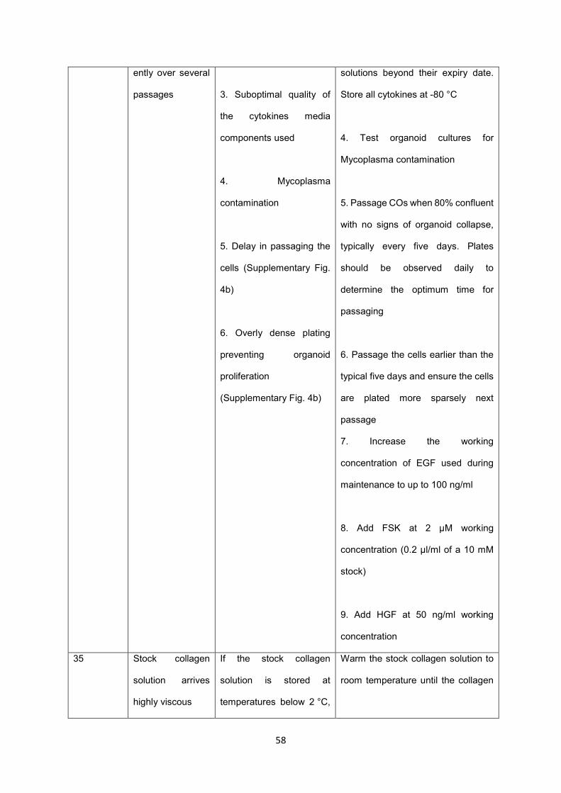
58
ently over several
passages
3. Suboptimal quality of
the cytokines media
components used
4. Mycoplasma
contamination
5. Delay in passaging the
cells (Supplementary Fig.
4b)
6. Overly dense plating
preventing organoid
proliferation
(Supplementary Fig. 4b)
solutions beyond their expiry date.
Store all cytokines at -80 °C
4. Test organoid cultures for
Mycoplasma contamination
5. Passage COs when 80% confluent
with no signs of organoid collapse,
typically every five days. Plates
should be observed daily to
determine the optimum time for
passaging
6. Passage the cells earlier than the
typical five days and ensure the cells
are plated more sparsely next
passage
7. Increase the working
concentration of EGF used during
maintenance to up to 100 ng/ml
8. Add FSK at 2 μM working
concentration (0.2 μl/ml of a 10 mM
stock)
9. Add HGF at 50 ng/ml working
concentration
35 Stock collagen
solution arrives
highly viscous
If the stock collagen
solution is stored at
temperatures below 2 °C,
Warm the stock collagen solution to
room temperature until the collagen

59
it can appear to have
gelled
solution is liquid. Once liquid, store at
4 °C
36
Step 39,
Section A II
Collagen
precursor solution
solidifies in the
mixing tube.
1. Solution mixing occurs
too slowly
2. The room temperature
is too high.
1. Before starting cool down all the
reagents to 4 °C
2. Mix the solution in an ice bath
Step 39,
Section A
VII, VIII
Collagen gel
densification
stops prematurely
1. The absorbent paper
wadding has poor contact
with the collagen gel and
so cannot remove water
effectively
2. As the paper wadding
absorbs water, it expands
and gets wedged in
specimen tube, preventing
further densification
1. Remove the paper wadding from
the specimen tube and flatten the
end in contact with the collagen gel
Once sufficiently flat, return to
densification chamber
2. Gently remove the paper wadding
from the specimen tube and replace
with a fresh roll, with a slightly
reduced diameter
Step 39,
Section A
IX
Following
densification
steps and removal
of paper wadding,
specimen tube is
empty
Collagen solution has
been prematurely
absorbed into the paper
wadding before gelation
1. Repeat process and extend time
for collagen gelation from 30 min to 1
h
2. Test gelation by carefully pressing
the metal spatula against the top
surface. Only add paper wadding
once sure that collagen has gelled
Step 39,
Section A
XI
Collagen sheet
not attached to
paper wadding on
its final removal
After the removal of the
wadding, the collagen
sheet remains at the
The scaffold can be removed
carefully using a pair of tweezers or
by flushing some PBS into the
specimen tube

60
bottom of the specimen
tube
Step 39,
Section A
XI
Once removed
from the
densification
chamber the lower
part of the scaffold
retains a gel-like
structure
Densification has been
stopped prematurely,
causing the lower part of
the collagen sheet to
retain a higher water
content
Return the scaffold to the
densification chamber and continue
the densification process with fresh
paper wadding
Step 39,
Section B
II
Prior to collagen
gelation, the level
of the collagen
solution has
dropped.
The collagen precursor
solution is leaking out of
the bottom of the funnel of
the densification chamber.
1. Keeping the chamber upright,
carefully tighten the screws such that
the base is firmly attached the funnel.
2. Transfer an extra volume of
collagen precursor solution until
funnel is once again full.
Step 39,
Section B
II
The level of the
collagen gel has
dropped below the
top of the metallic
wire.
The volume of collagen
above the wire was unable
to stop the collagen gel
from dropping below the
wire.
1. Using scissors, remove a couple of
millimetres of length from the top of
the metallic wire.
2. Repeat collagen gelling process.
Step 39,
Section B V
The level of the
collagen gel has
not dropped to the
top of the metallic
wire.
The paper towels at the
base are not in sufficient
contact with the gel and so
water is not being drawn
out.
Repeat the process. When loosening
the screws, do not displace the base
away from the funnel, thereby
keeping the paper towels in contact
with the bottom of the collagen gel.
Step 39,
Section B
V, VII, VIII
Collagen gel has
not densified after
24 hours.
There has been
insufficient evaporation of
water from the collagen
gel to form a tube.
1. Using sterile tweezers, repeat the
process of peeling the collagen gel
from the chamber walls. One should
observe a 1-2 mm spacing between

61
the collagen gel and funnel walls.
Continue densifying until tube forms.
2. The humidity of the incubator may
be high and so an insufficient volume
of water has evaporated from the
collagen gel. Continue Step VII,
monitoring the evaporative process,
until a collagen tube forms.
Step 40,
Section A V
Step 40,
Section C
VI
Immediately after
seeding, the cell
suspension
overspills from the
scaffold
1. The seeding volume is
too big
2. The seeding has
occurred too close to the
edge
1. Immediately retrieve the spilled
solution and seed it again onto the
scaffold
2. Reduce the total volume of cell
suspension used during seeding
Step 40,
Section A
IV, V, IX
Step 40,
Section B
V, VIII, IX
Step 40,
Section C
V, VI
Low cell
attachment
immediately after
seeding
1. Reduced incubation
time preventing cell
attachment
2. Cell detachment during
media change
3. Low cell number.
Optimal cell number and
attachment potential may
vary between lines
4. Prolonged incubation
leading to cell death and
drying
1. After seeding, increase the
duration of the incubation step a
further 30 minutes
2. Add media very carefully. Tilt the
plate and hold the pipette against the
side of the well to avoid disrupting the
Matrigel dome. Add the media slowly
using a p1000 pipette
3. Optimise the seeding density for
each CO line
4. Monitor the scaffolds closely after
seeding and before addition of

62
5. Small clump size
leading to loss of cells
through the pores of the
PGA scaffold
6. Single cells or very
small clumps floating in
the seeding solution and
preventing attachment
7. Remnants of EtOH or
NaOH in PGA scaffolds
leading to cell death in
PGA scaffolds
8. Excessive breaking of
the CO clumps reducing
cell viability
media. Check the scaffolds every 30
minutes to ensure the seeding
solution has not evaporated
5. Optimise the clump size when
seeding PGA scaffolds
6. Pipette more slowly and fewer
times when breaking the COs into
small clumps
7. Increase the drying time to ensure
all traces of NaOH and EtOH are
gone (PGA scaffolds only)
8. Use a P200 pipette instead of a
p20 to break the CO clumps
Pipette more slowly when breaking
the CO clumps
Step 40,
Section B V
CO clumps form
organoid-like 3D
structures rather
than a monolayer
CO clumps were not
dissociated to a sufficiently
small size
Break clumps further, using a p10
pipette if necessary
Step 40,
section B
VIII
Cell suspension
overflows from the
construct lumen
during seeding
Rapid addition of the cell
suspension with
inadequate needle
withdrawal
Dispense cells slowly,
simultaneously withdrawing the
needle from the tube lumen
Step 40,
Section A X
Low cell density
on the scaffold
The cells may have been
seeded too sparsely
1. Increase the cell density

63
Step 40,
Section B
XIII
Step 40,
Section C
VI
2. Allow a longer time for the cells to
reach confluency
Step 40,
Section A X
Step 40,
Section B
XII
Step 40,
Section C
VII
Poor cell survival
and/or expansion
on the scaffold
1. Cells are washed away
during media change
2. Y27632 not added to
the media
3. Suboptimal CO line
2. Suboptimal collagen
batch for collagen
scaffolds
5. Suboptimal quality of
cytokines, media
components or collagen
stock
6. Remnants of EtOH or
NaOH in PGA scaffolds
leading to cell death in
PGA scaffolds
1. Increase the media to 1 ml and
change it very carefully every 4 days
2. Ensure fresh Y27632 is added to
the media when seeding
3. All CO lines should express the
biliary markers CK19, CK7, Sox9 and
GGT (Fig. 6a and b) and display ALP
and GGT activity (Fig. 6c and 6d).
Healthy CO lines should be
proliferating at a rate requiring
passaging every five days (Fig. 5b,
Image 1). Do not attempt scaffold
seeding with a CO line that does not
meet these criteria. See the
Troubleshooting for steps 10, 12 and
29 for recommendations on how to
improve the quality of a suboptimal
CO line

64
7. Prolonged incubation
leading to cell death and
drying
4. Batch-test all new lots of collagen
solution. (collagen scaffolds only)
5. Store all stock solutions at 4 °C
and do not use stock solutions made
more than 3 months previously.
Where applicable, do not use stock
solutions beyond their expiry date.
Store all cytokines at -80 °C
6. Increase the drying time (70) to
ensure all traces of NaOH and EtOH
are gone (PGA scaffolds only)
7. Monitor the scaffolds closely after
seeding and before addition of
media- check the scaffolds every 30
minutes to ensure they have not
dried out
Step 41,
Section A
III
Staining appears
weak or non-
specific
1. The 4% (vol/vol) PFA
may have degraded
2. Samples may have
been fixed for too long
1. Store 4% (vol/vol) PFA at 4 °C and
do not use for longer than one month
2. Reduce fixation time. Do not
attempt to fix too many samples at
one time, to avoid accidental over-
fixation
Step 41,
Section A
VI
Nuclear and
intracellular
staining is poor
The cells are not properly
permeabilised, preventing
adequate penetration of
the antibody
Increase the concentration of Triton
X-100, e.g 0.3% (vol/vol) Triton X-
100 or 0.5% (vol/vol) Triton X-100

65
Step 41,
Section A
VII, XIV
High levels of non-
specific and
background
staining
1. Blocking time may have
been too short
2. Secondary antibody
incubation may have been
too long
1. Increase blocking time e.g. to one
hour
2. Incubate secondary antibodies for
1 hour at room temperature instead
of overnight at 4 °C
Step 41,
Section A
XVII
DAPI staining is
unclear
Incubation with DAPI may
not have been long
enough
Increase incubation with DAPI to 20
or 30 minutes
Step 41,
Section B V
COs do not
dissociate into a
single-cell
suspension
1. Cell clumping and/or
poor viability
2. CO clumps are not
breaking up into single
cells during the 5 minute
incubation period
1. Increase the concentration of
DNase I in the accutase solution
Ensure that all pipetting is done as
slowly and carefully as possible
2. Ensure the Accutase solution is
pre-warmed
Prolong incubation for longer (e.g. 7-
10 minutes)
Step 41,
Section B
IX
Single cell
suspension forms
clumps
Concentration of DNase I
is too low
Increase the concentration of DNase
I, e.g. to 6 mg/ml
1
ANTICIPATED RESULTS 2
We describe a protocol for the isolation of primary biliary epithelial cells from a variety of clinical 3
samples, their propagation as cholangiocyte organoids and the generation of bioengineered biliary 4
tissue by seeding these organoids on PGA or densified collagen scaffolds. Our cholangiocyte isolation 5
methods (ERCP, mechanical scraping, EPCAM sorting) result in a >95% pure (CK7+/CK19+) 6
population of isolated cholangiocytes (Fig. 2e, 3d and 4e, respectively). Furthermore, 95% of plated 7
samples derived from excised bile ducts (when appropriately flushed of bile after excision) and 100% 8
of samples derived from gallbladders, liver biopsies and ERCP brushings yield robust CO lines within 9
66
5 days of initial plating (Supplementary Table 1). CO lines can be derived from EpCAM+ sorted liver 1
samples with an approximate efficiency of 66% (Supplementary Table 1). While it is important to derive 2
lines from fresh, highly viable primary tissue to ensure the most reliable results, robust, highly-3
proliferative CO lines can also be derived from poor-quality samples with low cell numbers 4
(supplemental Fig. 5). CO lines can subsequently be passaged approximately every 5 days and can 5
typically be split in a 1:4-1:6 ratio for further expansion, analysis or cryopreservation. 6
The resulting organoids consist of a near homogenous (>99%) population of cholangiocytes (Fig. 6e). 7
They express biliary markers such as CK19, CK7, Sox9 and GGT (Fig. 6a) at levels comparable to 8
primary tissue (Fig. 6b) in the absence of hepatic markers such as albumin (Fig. 6a). Furthermore, CO 9
lines exhibit key cholangiocyte functions, such as alkaline phosphatase (ALP) and gamma-glutamyl 10
transferase (GGT) activity (Fig. 6c and 6d). COs also display functional secretory capacity, as measured 11
by the luminal secretion of rhodamine 123 (Sampaziotis et al; Nat. Med. (2017)- Fig. 2a-c) and bile acid 12
transport, as measured by export of the fluorescently-labelled bile acid CLF (Sampaziotis et al; Nat. 13
Med. (2017)- Fig. 2d-f). Additionally, COs respond appropriately to hormonal signals such as secretin 14
and somatostatin ((Sampaziotis et al; Nat. Med. (2017)- Fig. 2i and 2j). For further validation, COs can 15
be transplanted under the kidney capsule of immunocompromised mice where they form tubular 16
structures retaining expression of biliary markers, such as CK7 and CK19 and are capable of surviving 17
long-term 4 (Sampaziotis et al; Nat. Med. (2017) - Supplementary Fig. 7). 18
COs can be seeded onto both densified collagen and PGA scaffolds to form bioengineered biliary 19
tissue. Additionally, COs can be seeded onto the lumen of tubular densified collagen scaffolds (Fig. 20
11e). The efficiency of cell attachment following seeding is variable between CO lines. However, 21
following attachment the cells demonstrate a unique potential to expand and fully populate the scaffold. 22
Therefore, the generation of confluent constructs is always possible by varying the time the scaffolds 23
are maintained in culture. The resulting tissue expresses key cholangiocyte markers such as CK19 and 24
CK7 (Fig. 11a, 11c and 11e) and exhibits biliary function such as GGT activity (Fig. 11b, 11d and 11f). 25
These constructs can be used to successfully reconstruct or repair the biliary tree of 26
immunocompromised mice4 (Sampaziotis et al; Nat. Med. (2017) - Fig. 4 and 6) while retaining the 27
expression of biliary markers and function following transplantation (Sampaziotis et al; Nat. Med. (2017) 28
- Fig. 4 and 6). 29

67
1
Data Availability 2
The authors declare that the main data supporting this study are available within the article. Extra data 3
are available from the corresponding authors upon request. 4
5
Acknowledgements 6
The authors would like to acknowledge the Cambridge Biorepository for Translational Medicine for the 7
provision of human tissue used in the study and to thank K. Mahbubani, N. Georgakopoulos and B. 8
Bareham for their role in collecting and distributing this tissue. The authors would additionally like to 9
thank William G. Bernard and Laure Gambardella for their help and advice with regards to the fixation 10
and staining of tubular bioengineered biliary constructs. 11
OCT was supported by an MRC-Sackler Doctoral Training Partnership. FS has been supported by an 12
Addenbrooke's Charitable Trust Grant, the Academy of Medical Sciences Clinical Lecturer Starter Grant 13
and an NIHR Clinical Lectureship. AWJ and AEM acknowledge support from EPSRC (EP/R511675/1 14
& EP/N509620/1) and the Isaac Newton Trust. The LV lab is funded by the ERC Proof of Concept grant 15
Relieve-Chol, by the ERC advanced grant New-Chol and the core support grant from the Wellcome 16
Trust and Medical Research Council to the Wellcome–Medical Research Council Cambridge Stem Cell 17
Institute. AWJ, FS, LV, AEM and KSP gratefully acknowledge support from the Rosetrees Trust 18
(REAG/240 & NMZG/233). AKF and EM were supported by funds from the Norwegian PSC research 19
center 20
21
Author contributions 22
OCT: manuscript writing and editing, coordination of study, execution of experiments and data 23
acquisition, validation of the CO culture protocol, design and production of figure, final approval of the 24
manuscript. AWJ: manuscript writing and editing, design and concept of the collagen densification 25
protocol, development and validation of the collagen densification protocol, final approval of the 26
manuscript. TB: manuscript writing and editing, collection of data, validation of the CO culture, collagen 27

68
densification and scaffold seeding protocols. SEC: production of schematics for figures 1, 2, 3, 4, 6 and 1
7 and validation of the collagen densification protocol. KTAM: execution of experiments and data 2
acquisition. AF: development and validation of the CO and ERCP brushing collection protocols. EM: 3
critical revision of the manuscript, validation of the CO protocols. HZ: validation of CO culture and data 4
acquisition. KSP: design and concept of the study, development of the protocol, critical revision and 5
final approval of the manuscript. AEM: design and concept of the collagen densification protocol, 6
critical revision and final approval of the manuscript. LV: design and concept of the study, critical 7
revision and final approval of the manuscript. FS: design and concept of the study, development and 8
validation of the protocol, manuscript writing and editing, critical revision and final approval of the 9
manuscript. OCT, AWJ and TB contributed equally to this work. 10
11
List of Supplementary Information 12
Supplementary Fig. 1: Flowchart showing recommended order of primary tissue processing for 13
CO line derivation 14
Supplementary figure 2: Derivation of intrahepatic organoids through EpCAM+ sorting 15
(a) Schematic representation of the optional EpCAM+ sorting step (procedure steps D III-DXXVI) for 16
the derivation of intrahepatic COs. (b) Representative brightfield images of key EpCAM+ sorting steps. 17
Numbers correspond to schematic stages in (a). 3: Liver tissue before enzymatic dissociation. 4: Liver 18
tissue after enzymatic dissociation demonstrating release of cells in the medium and remnants of the 19
extracellular matrix. 6: Single-cell suspension after filtration and before EpCAM+ sorting. Scale bars, 20
100 μm. (c) Representative brightfield image of an organoid derived from a single EpCAM+ cell, 48 21
hours after plating. Scale bar, 50 µm. 22
Supplementary Figure 3: Enlarged images of COs before and after organoid breaking (from Figure 5) 23
Enlarged images of COs before and after organoid breaking (from Figure 5). Enlarged brightfield images 24
of figures 5b, image 1 and 5b, image 5. Scale bars, 100 μm. 25
Supplementary figure 4: Representative images of cholangiocyte organoids 26
Additional characterisation and troubleshooting of CO lines 27

69
(a) Representative brightfield images of healthy CO lines derived from all tissue types: 1: bile duct (BD), 1
gallbladder (GB), Endoscopic Retrograde Cholangio-Pancreatography (ERCP), liver biopsy (biopsy) 2
and EpCAM+ sorted cells (EpCAM). Scale bars- 200 μm. (b) Representative brightfield images of CO 3
lines showing typical CO culture issues contrasted with optimal CO lines. Scale bars, 200 μm 4
Supplementary figure 5: Derivation of a CO line from low cell numbers 5
(a) Representative brightfield images of a CBD CO line derived from ~3.0 x 10³ viable cells/well (total: 6
~2.0 x 10⁴ viable cells). D0- D12: days after plating. P1: passage 1. (b) Graph illustrating cell number 7
over time for the CBD line derived in (a) demonstrating appropriate expansion. 8
Supplementary Figure 6: Gating strategy for flow cytometric analyses 9
Representative flow cytometry plots showing gating strategy for all flow cytometric analyses. (a) 10
Exclusion of debris. (b) Exclusion of doublets. (c) Secondary-only control to exclude negative 11
population. (d) Representative C19+/CK7+ population. A minimum of 2 × 10⁴ gated events were used 12
for analysis. 13
Supplementary Table 1: List of all CO lines derived since September 2016 14
Table showing key details of all CO lines derived since September 2016: anonymised donor ID number; 15
tissue type (bile duct (BD), gallbladder (GB) or intrahepatic ducts (IHD)); age; sex; donor type (if 16
applicable) (donation after brain death (DBD) or donation after cardiac death (DCD); blood group; and 17
the success of the line derivation 18
Supplementary Table 2: List of antibodies used for flow cytometry and immunofluorescence 19
Supplementary Software 1: CAD file for the base of the 3D-printed densification chamber used 20
in Step 39, Section B 21
Supplementary Software 2: CAD file for the funnel of the 3D-printed densification chamber used 22
in Step 39, Section B 23
24
REFERENCES 25
1 Park, S. M. The Crucial Role of Cholangiocytes in Cholangiopathies. Gut and Liver 6, 295-304, 26 doi:10.5009/gnl.2012.6.3.295 (2012). 27

70
2 Lazaridis, K. N. & LaRusso, N. F. The Cholangiopathies. Mayo Clinic proceedings 90, 791-800, 1 doi:10.1016/j.mayocp.2015.03.017 (2015). 2
3 Murray, K. F. & Carithers, R. L. AASLD practice guidelines: Evaluation of the patient for liver 3 transplantation. Hepatology 41, 1407-1432, doi:10.1002/hep.20704 (2005). 4
4 Sampaziotis, F. et al. Reconstruction of the mouse extrahepatic biliary tree using primary 5 human extrahepatic cholangiocyte organoids. Nature Medicine 23, 954, 6 doi:10.1038/nm.4360 7
https://www.nature.com/articles/nm.4360#supplementary-information (2017). 8 5 Sampaziotis, F. et al. Cholangiocytes derived from human induced pluripotent stem cells for 9
disease modeling and drug validation. Nature Biotechnology 33, 845, doi:10.1038/nbt.3275 10
https://www.nature.com/articles/nbt.3275#supplementary-information (2015). 11 6 Sampaziotis, F. et al. Directed differentiation of human induced pluripotent stem cells into 12
functional cholangiocyte-like cells. Nature Protocols 12, 814, doi:10.1038/nprot.2017.011 13
https://www.nature.com/articles/nprot.2017.011#supplementary-information (2017). 14 7 Lugli, N. et al. R-spondin 1 and noggin facilitate expansion of resident stem cells from non-15
damaged gallbladders. EMBO reports 17, 769-779, doi:10.15252/embr.201642169 (2016). 16 8 Sato, T. et al. Long-term Expansion of Epithelial Organoids From Human Colon, Adenoma, 17
Adenocarcinoma, and Barrett's Epithelium. Gastroenterology 141, 1762-1772, 18 doi:https://doi.org/10.1053/j.gastro.2011.07.050 (2011). 19
9 Huch, M. et al. In vitro expansion of single Lgr5+ liver stem cells induced by Wnt-driven 20 regeneration. Nature 494, 247, doi:10.1038/nature11826 21
https://www.nature.com/articles/nature11826#supplementary-information (2013). 22 10 Kessler, M. et al. The Notch and Wnt pathways regulate stemness and differentiation in 23
human fallopian tube organoids. Nature Communications 6, 8989, doi:10.1038/ncomms9989 24
https://www.nature.com/articles/ncomms9989#supplementary-information (2015). 25 11 Huch, M. et al. Long-Term Culture of Genome-Stable Bipotent Stem Cells from Adult Human 26
Liver. Cell 160, 299-312, doi:10.1016/j.cell.2014.11.050 (2015). 27 12 Karthaus, Wouter R. et al. Identification of Multipotent Luminal Progenitor Cells in Human 28
Prostate Organoid Cultures. Cell 159, 163-175, 29 doi:https://doi.org/10.1016/j.cell.2014.08.017 (2014). 30
13 Barker, N. et al. Lgr5+ve Stem Cells Drive Self-Renewal in the Stomach and Build Long-Lived 31 Gastric Units In Vitro. Cell Stem Cell 6, 25-36, 32 doi:https://doi.org/10.1016/j.stem.2009.11.013 (2010). 33
14 Koo, B.-K. & Clevers, H. Stem Cells Marked by the R-Spondin Receptor LGR5. 34 Gastroenterology 147, 289-302, doi:https://doi.org/10.1053/j.gastro.2014.05.007 (2014). 35
15 Glinka, A. et al. Dickkopf-1 is a member of a new family of secreted proteins and functions in 36 head induction. Nature 391, 357, doi:10.1038/34848 (1998). 37
16 Fedi, P. et al. Isolation and Biochemical Characterization of the Human Dkk-1 Homologue, a 38 Novel Inhibitor of Mammalian Wnt Signaling. Journal of Biological Chemistry 274, 19465-39 19472, doi:10.1074/jbc.274.27.19465 (1999). 40
17 Bafico, A., Liu, G., Yaniv, A., Gazit, A. & Aaronson, S. A. Novel mechanism of Wnt signalling 41 inhibition mediated by Dickkopf-1 interaction with LRP6/Arrow. Nature Cell Biology 3, 683, 42 doi:10.1038/35083081 (2001). 43
18 Cui, S., Capecci, L. M. & Matthews, R. P. Disruption of planar cell polarity activity leads to 44 developmental biliary defects. Developmental Biology 351, 229-241, 45 doi:https://doi.org/10.1016/j.ydbio.2010.12.041 (2011). 46

71
19 Strazzabosco, M. & Fabris, L. Development of the bile ducts: Essentials for the clinical 1 hepatologist. Journal of Hepatology 56, 1159-1170, 2 doi:https://doi.org/10.1016/j.jhep.2011.09.022 (2012). 3
20 Place, E. S., George, J. H., Williams, C. K. & Stevens, M. M. Synthetic polymer scaffolds for 4 tissue engineering. Chemical Society Reviews 38, 1139-1151, doi:10.1039/B811392K (2009). 5
21 Polymeric Scaffolds in Tissue Engineering Application: A Review. International Journal of 6 Polymer Science 2011, doi:10.1155/2011/290602 (2011). 7
22 O'Brien, F. J. Biomaterials & scaffolds for tissue engineering. Materials Today 14, 88-95, 8 doi:https://doi.org/10.1016/S1369-7021(11)70058-X (2011). 9
23 Lutolf, M. P. & Hubbell, J. A. Synthetic biomaterials as instructive extracellular 10 microenvironments for morphogenesis in tissue engineering. Nature Biotechnology 23, 47, 11 doi:10.1038/nbt1055 (2005). 12
24 Cheung, H.-Y., Lau, K.-T., Lu, T.-P. & Hui, D. A critical review on polymer-based bio-13 engineered materials for scaffold development. Composites Part B: Engineering 38, 291-300, 14 doi:https://doi.org/10.1016/j.compositesb.2006.06.014 (2007). 15
25 Kehoe, S., Zhang, X. F. & Boyd, D. FDA approved guidance conduits and wraps for peripheral 16 nerve injury: A review of materials and efficacy. Injury 43, 553-572, 17 doi:https://doi.org/10.1016/j.injury.2010.12.030 (2012). 18
26 Frisch, S. & Francis, H. Disruption of epithelial cell-matrix interactions induces apoptosis. The 19 Journal of Cell Biology 124, 619-626, doi:10.1083/jcb.124.4.619 (1994). 20
27 Zeugolis, D. I., Paul, R. G. & Attenburrow, G. Engineering extruded collagen fibers for 21 biomedical applications. Journal of Applied Polymer Science 108, 2886-2894, 22 doi:doi:10.1002/app.27208 (2008). 23
28 Abou Neel, E. A., Cheema, U., Knowles, J. C., Brown, R. A. & Nazhat, S. N. Use of multiple 24 unconfined compression for control of collagen gel scaffold density and mechanical 25 properties. Soft Matter 2, 986-992, doi:10.1039/B609784G (2006). 26
29 Landi, F. et al. Endoscopic treatment of anastomotic biliary stricture after adult deceased 27 donor liver transplantation with multiple plastic stents versus self-expandable metal stents: 28 a systematic review and meta-analysis. Transplant International 31, 131-151, 29 doi:doi:10.1111/tri.13089 (2018). 30
30 Seehofer, D., Eurich, D., Veltzke-Schlieker, W. & Neuhaus, P. Biliary Complications After Liver 31 Transplantation: Old Problems and New Challenges. American Journal of Transplantation 13, 32 253-265, doi:doi:10.1111/ajt.12034 (2013). 33
31 Cellon. Revolutions in Cell & Tissue Culture. BioFELT scaffold, <http://www.cellon.lu/biofelt-34 scaffold.html > (2019). 35
32 Zhang, L. & Hui, L. Bile ducts regenerated. Nature 547, 171, doi:10.1038/547171a (2017). 36 33 Thomas, H. Bioengineering the common bile duct. Nature Reviews Gastroenterology &Amp; 37
Hepatology 14, 504, doi:10.1038/nrgastro.2017.99 (2017). 38 34 Huch, M. et al. Unlimited <em>in vitro</em> expansion of adult bi-potent pancreas 39
progenitors through the Lgr5/R-spondin axis. The EMBO Journal 32, 2708-2721, 40 doi:10.1038/emboj.2013.204 (2013). 41
35 Cho, W. K., Mennone, A. & Boyer, J. L. Isolation of functional polarized bile duct units from 42 mouse liver. American Journal of Physiology-Gastrointestinal and Liver Physiology 280, G241-43 G246, doi:10.1152/ajpgi.2001.280.2.G241 (2001). 44
36 Demetris, A. J. et al. Isolation and primary cultures of human intrahepatic bile ductular 45 epithelium. In Vitro Cellular & Developmental Biology 24, 464-470, doi:10.1007/BF02628499 46 (1988). 47
37 H., A. M. K. et al. Morphogenesis of primary human biliary epithelial cells: Induction in high-48 density culture or by coculture with autologous human hepatocytes. Hepatology 33, 519-49 529, doi:doi:10.1053/jhep.2001.22703 (2001). 50

72
38 Ogawa, M. et al. Directed differentiation of cholangiocytes from human pluripotent stem 1 cells. Nature Biotechnology 33, 853, doi:10.1038/nbt.3294 2
https://www.nature.com/articles/nbt.3294#supplementary-information (2015). 3 39 De Assuncao, T. M. et al. Development and Characterization of Human Induced Pluripotent 4
Stem Cell-Derived Cholangiocytes. Laboratory investigation; a journal of technical methods 5 and pathology 95, 684-696, doi:10.1038/labinvest.2015.51 (2015). 6
40 Gjorevski, N. et al. Designer matrices for intestinal stem cell and organoid culture. Nature 7 539, 560, doi:10.1038/nature20168 (2016). 8
41 Petrowsky, H. & Clavien, P.-A. in Transplantation of the Liver (Third Edition) (eds Ronald W. 9 Busuttil & Göran B. G. Klintmalm) 582-599 (W.B. Saunders, 2015). 10
42 Badylak, S. F. The extracellular matrix as a scaffold for tissue reconstruction. Seminars in Cell 11 & Developmental Biology 13, 377-383, doi:https://doi.org/10.1016/S1084952102000940 12 (2002). 13
43 Dong, C. & Lv, Y. Application of Collagen Scaffold in Tissue Engineering: Recent Advances and 14 New Perspectives. Polymers 8, 42 (2016). 15
44 Glowacki, J. & Mizuno, S. Collagen scaffolds for tissue engineering. Biopolymers 89, 338-344, 16 doi:doi:10.1002/bip.20871 (2008). 17
45 Drury, J. & J Mooney, D. Hydrogels for Tissue Engineering: Scaffold Design Variables and 18 Applications. Vol. 24 (2003). 19
46 Brown, R. A., Wiseman, M., Chuo, C.-B., Cheema, U. & Nazhat, S. N. Ultrarapid Engineering of 20 Biomimetic Materials and Tissues: Fabrication of Nano- and Microstructures by Plastic 21 Compression. Advanced Functional Materials 15, 1762-1770, 22 doi:doi:10.1002/adfm.200500042 (2005). 23
24
Figure. Legends 25
Figure 1: Flowchart of key steps for the generation of bioengineered biliary tissue 26
(a) Overview flowchart showing the 3 major protocol steps: cell isolation, scaffold preparation and 27
generation of bioengineered biliary tissue. (b) Flowchart summarising the process of cell isolation 28
from different biliary tissue samples with reference to the relevant protocol sections. (c) Flowchart 29
illustrating the different types of biological or synthetic scaffolds used, with reference to the relevant 30
protocol sections. (d) Flowchart summarising the seeding of acellular scaffolds with cholangiocyte 31
organoid (CO) cells, with reference to the relevant protocol sections. 32
33
Figure 2: Derivation of extrahepatic cholangiocyte organoids from extrahepatic biliary tissue 34
(a) Schematic representation of key stages of the derivation of extrahepatic cholangiocyte organoids 35
(ECO) from primary bile duct (BD) and gallbladder (GB) tissue (Procedure step 2, section A). (b, c) 36
Representative images of key stages of the derivation of cholangiocytes from (b) primary BD and GB 37

73
(c) tissue. Numbers in (b) and (c) correspond to the schematic stages illustrated in (a): 1A(i), 1B(i): 1
Resected biliary tissue prior to dissection. 1A(ii), 1B(ii): Tissue dissection. 1A(iii),1B(iii): Exposed 2
luminal surface following dissection. 2: PBS wash. 3: Mechanical dissociation of the biliary epithelium. 3
4: Primary cholangiocytes in suspension following dissociation. Scale bars: (b) Images 1(i) – 3, 1 cm. 4
(c) Images 1(i) – 3:, 2 cm. (b) Image 4, (c) Image 4: 100 μm. (d) Representative brightfield images 5
demonstrating key time points of ECO derivation. Scale bars, 200 μm. 1: Primary cholangiocytes 24 6
hours after plating demonstrating the formation of early organoid structures. 2: ECOs following long 7
term culture (passage 20). (e) Flow cytometry analysis of the primary cell suspension, demonstrating 8
>90% cholangiocyte isolation efficiency (Steps 2 A I-A VIII; gating strategy demonstrated in 9
supplementary figure 6). 10
11
Figure 3: Derivation of extrahepatic cholangiocyte organoids through ERCP brushings 12
(a) Schematic representation of ECO derivation from ERCP brushings (procedure step 2, section B). 13
(b) Representative images of key stages of the derivation procedure. Numbers correspond to 14
schematic stages in (a). 1: ERCP brush. 2: Media wash to dislodge the collected cholangiocytes from 15
the brush. 3: Representative cell pellet after isolation. 4: Brightfield image of ERCP isolated 16
cholangiocytes following plating.1-3: Scale bars, 1 cm. Scale bar, 200 μm. (c) Brightfield images 17
demonstrating representative time points in the derivation of organoids from cholangiocytes obtained 18
through ERCP brushings. 1: Primary cholangiocytes 24 hours after plating demonstrating the 19
formation of early organoid structures. 2: Cholangiocyte organoids one week after plating. Scale bars, 20
200 μm. (d) Flow cytometry analysis of the cell suspension obtained with through ERCP, 21
demonstrating >90% cholangiocyte isolation efficiency (Steps 2 B I- BV; gating strategy demonstrated 22
in supplementary figure 6). 23
24
Figure 4: Derivation of intrahepatic organoids 25
(a) Schematic representation of intrahepatic cholangiocyte organoid (ICOs) derivation (procedure step 26
C). (b and c) Representative images of key stages of ICO derivation for (b) liver biopsies and (c) 27
surgically resected liver tissue. Numbers correspond to schematic stages in (a). 1: Dissection of liver 28
tissue. 2: Collection of dissected tissue. 3-4: Dissected tissue before (3) and after (4) centrifugation. 29

74
6(i): Representative image of liver tissue after embedding in Matrigel, prior to media addition. 1-6(i): 1
Scale bars, 1 cm. 6(ii): Representative brightfield images of liver tissue after plating. Scale bar, 200 2
μm. (d) Representative brightfield images demonstrating key time points of ICO derivation 1: ICO 3
culture 5 days after plating demonstrating the emergence of an organoid from a segment of liver 4
tissue. 2: Established ICO line (passage 20). Scale bars: 200 μm. (e) Flow cytometry analysis of ICO 5
cells, demonstrating >95% cholangiocyte isolation efficiency (gating strategy in supplementary figure 6
6). 7
8
Figure 5: Passaging of cholangiocyte organoids 9
(a) Schematic representation of the CO passaging procedure (procedure steps 15-30). (b) 10
Representative images of key steps of the CO passaging procedure. Numbers correspond to 11
schematic stages in (a). 1: Confluent COs prior to passaging. 4: Representative organoid pellet 12
yielding 9 organoid wells following plating (approximately 4.0 x 10⁵ cells). 5: Suspension of COs after 13
manual dissociation demonstrating representative clump size for passaging (approximately 30-100 14
cells per clump) (procedure step 28). 7(i): COs immediately after plating (procedure steps 9-13) 15
demonstrating that the majority of cells remain in small clumps and have not yet formed organoids at 16
this stage. 7(ii) COs 24 hours after passaging, demonstrating that the majority of CO clumps have 17
remodelled into organoids at this point. 1, 5, 7(i) and 7(ii): Scale bars, 100 μm. 4: Scale bar, 5 mm. 18
19
Figure 6: Characterisation of cholangiocyte organoids 20
(a) Immunofluorescence images demonstrating expression of key biliary markers in cholangiocyte 21
organoids. Scale bar, 50 μm. (See table 1 for a detailed list of antibodies and concentrations used). 22
(b) qRT–PCR confirming the expression of key biliary markers in ECOs compared to freshly isolated 23
primary cholangiocytes (PC); n = 4 biological replicates. Centre line, median; box, interquartile range 24
(IQR); whiskers, range (minimum to maximum). Values relative to the housekeeping gene HMBS 25
(HydroxyMethylBilane Synthase). # P > 0.05 (two-tailed Student’s t-test). (c) Cholangiocyte 26
organoids demonstrate ALP activity. Scale bars, 100 μm. (d) GGT activity of cholangiocyte organoids 27
measured in absorbance units (a.u.); n = 3; MEFs: mouse embryonic feeders, used as a negative 28
75
control. Error bars, s.d.; individual data points are demonstrated; ****P < 0.0001, two-tailed Student's 1
t-test. GGT activity were assessed using a commercially available (MaxDiscovery gamma-Glutamyl 2
Transferase (GGT) Enzymatic Assay) according to the manufacturer's instructions. (e) Flow 3
cytometric analyses performed on COs after long term culture (20 passages) demonstrating >99% 4
CK7+/CK19+ expression (gating strategy demonstrated in supplementary figure 6). 5
6
Figure 7: Generation of densified collagen sheets 7
8
(a) Schematic representation of the procedure for generating densified collagen sheets (procedure 9
step 39, Section A). (b) Representative images of key stages of the collagen densification process. 10
Numbers correspond to schematic stages in (a). 1: Specimen tube containing 5% collagen gel before 11
densification (25 mm height). 2-3(i): Representative gel height following water absorption for 0 (2(i)), 12
30 (2(ii)) and 60 (3(i)) minutes. 3(ii): Specimen tube containing fully densified collagen scaffold 13
(indicated by the black arrow). 4: Removal of nylon mesh. 5: Representative image of the resulting 14
densified collagen sheet. 1-4: Scale bars, 1 cm. 5: Scale bars, 5 mm. 15
16
Figure 8: Generation of densified collagen tubes 17
(a) Representative images of densification chamber assembly (Equipment Setup). 1: Densification 18
chamber components: (i) Funnel, (ii) Base, (iii) wire, (iv) 25 G needle, (v) paper towels, (vi) M4 screws 19
and (vii) nuts. 2: Mounting of the rigid metal wire in the chamber base. 3: Addition of paper towels. 4: 20
Addition of funnel. 5. Chamber assembly. Scale bars: 20 mm. (b) Schematic representation of 21
collagen tube densification (step 39B I-IX). (c) Representative images of tube densification. Numbers 22
correspond to schematic stages in (b). 1: Addition of collagen precursor solution. 2. Peeling of 23
collagen from funnel walls. 3: Gel optimally positioned for evaporation. 4: Completion of densification. 24
5. Removal of densified tube from wire. Scale bars, 15 mm. (d) Tube trimming following densification 25
(step 39B, X-XV). 1: Collagen tubes immediately post-densification. 2. Washed tube. 3, 4: Tube 26
trimming. 5. Trimmed tube with patent lumen (white dashed lines). Scale bars: (1)-(3), 2 cm; (4), 2mm; 27
(5) 1 mm. 28
29

76
Figure 9: Seeding of flat densified collagen or PGA scaffolds 1
(a) Schematic representation of the procedure for seeding densified collagen sheets and polyglycolic 2
acid (PGA) scaffolds (procedure step 40, sections A and C, respectively). (b and c) Representative 3
images of key stages of the seeding procedure for (b) densified collagen and (c) flat PGA scaffolds. 4
Numbers correspond to schematic stages in (a). 1: Dried scaffold before seeding. 3(i): Addition of cell 5
suspension on the scaffold at the start of seeding process. William’s E+ media with phenol red used 6
for illustrative purposes. The use of phenol red in the media is optional. 3(ii): Scaffold after completion 7
of seeding and prior to incubation. 5: Seeded scaffold following media addition. Scale bars, 1 cm. (d) 8
Representative fluorescent image of a flat densified collagen scaffold confluently seeded with RFP+ 9
COs. Scale bar, 100 µm (e) Representative fluorescent image of a PGA scaffold confluently seeded 10
with GFP+ COs. Scale bar, 50 µm. 11
12
Figure 10: Seeding of densified collagen tubular scaffolds 13
(a) Schematic representation of densified collagen tube seeding (procedure step 40B). (b) 14
Representative images of the seeding process. Image numbers refer to the corresponding stages 15
illustrated in the schematic in (a). 2: Cannulation of tube lumen with 34 G needle. 3: Seeding of tube 16
lumen with COs. Note the change in the tube colour as the lumen fills with Phenol Red containing 17
media. Scale bars: (2), 1 mm; (3), 5 mm. (c) Representative brightfield image of a CO-seeded 18
densified collagen tube. Scale bar, 200 µm. (d) Representative fluorescent image of a densified 19
collagen tube seeded with RFP+ COs. Scale bar, 200 µm. 20
21
Figure 11: Characterisation of bioengineered biliary tissue 22
(a) Immunofluorescence images demonstrating expression of key biliary markers in CO-seeded PGA 23
scaffolds. Scale bar, 100 μm. (b) CO-seeded PGA scaffolds demonstrate GGT activity. A.U: 24
absorbance units; n = 3; mouse embryonic feeders (MEFs) used as a negative control. Error bars, 25
s.d.; individual data points are demonstrated; ****P < 0.0001, two-tailed Student's t-test. (c) 26
Immunofluorescence images showing expression of key biliary markers in CO-seeded densified 27
collagen sheets. Scale bar, 100 μm. (d) CO-seeded collagen scaffolds demonstrate GGT activity. 28

77
A.U.: absorbance units; n = 3; mouse embryonic feeders (MEFs) used as a negative control. Error 1
bars, s.d.; individual data points are demonstrated; **P= 0.0055, two-tailed Student's t-test. (e) 2
Immunofluorescence images showing expression of key biliary markers in CO-seeded densified 3
collagen tubes. Scale bar, 100 μm. (d) CO-seeded collagen tubes demonstrate GGT activity. A.U.: 4
absorbance units; n = 3; mouse embryonic feeders (MEFs) used as a negative control. Error bars, 5
s.d.; individual data points are demonstrated; ****P= 0.0001, two-tailed Student's t-test. GGT activity 6
was assessed using a commercially available kit (MaxDiscovery gamma-Glutamyl Transferase (GGT) 7
Enzymatic Assay Kit) according to the manufacturer's instructions. 8