2 horizontal housing /hh - sew eurodrive · 12 catalog – x series for horizontal applications 2...
TRANSCRIPT

10 Catalog – X series for horizontal applications
2 Horizontal housing /HHProduct description
2 Product description This catalog describes gear units for horizontal applications (mounting position M1). Forinformation and dimension sheets for vertical gear units (mounting position M5) and up-right gear units with input and output shaft arranged on top of one another (mountingposition M4), refer to the vertical and upright gear units catalog edition 04/2014.
SEW distinguishes between two housing designs which can be used for horizontal gearunits:
2.1 Horizontal housing /HHThe horizontal housing is designed for mounting position M1. This housing design isnon-reversible. For more information, see chapter "Reversible gear units" (page 31).
The following figure shows an example of a single-piece housing for gear unit sizes 100to 210:
The following figure shows an example of a two-piece housing for gear unit sizes 220 to320:
9007208285647499
9453596299

Catalog – X series for horizontal applications 11
2Universal housing /HUProduct description
2.2 Universal housing /HUThe universal housings can be installed in any mounting positions (M1 to M6). The hous-ings can be reversible if required. For more information, see chapter "Reversible gearunits" (page 31).
The following figure shows an example of a single-piece housing for gear unit sizes 100to 210:
The following figure shows an example of a two-piece housing for gear unit sizes 220 to320:
9007207839154827
9007207839156491

12 Catalog – X series for horizontal applications
2 Gear unit typesProduct description
2.3 Gear unit typesSEW-EURODRIVE distinguishes between the following 2 gear unit types:
• X.F..
• Helical gear unit with parallel shafts
• 23 gear unit sizes from 100 to 320
• Number of stages 2, 3 and 4
• Mounting position: Horizontal
• Input and output shafts designs (page 20)
• Gear ratio 6.3 to 475 (page 16)
• Torque classes from 6.8 to 475 kNm (page 16)
• X.K..
• Bevel-helical gear units with right-angle shaft arrangement
• 23 gear unit sizes from 100 to 320
• Number of stages 2, 3 and 4
• Mounting position: Horizontal
• Input and output shafts designs (page 20)
• Gear ratio 6.3 to 475 (page 16)
• Torque classes from 6.8 to 475 kNm (page 16)
8584289931
8584291595

Catalog – X series for horizontal applications 13
2Combination overview of housing designs with option only in mounting posi-Product description
2.4 Combination overview of housing designs with option only in mounting posi-tion M1
Single-piece and two-piece gear unit housings for horizontal applications (HH) as wellas universal housings (HU) offer a wide range of possible variants. The following tableshows which options can be combined with horizontal housings (HH) and which can becombined with universal housings (HU). The universal housing can be combined with alloptions listed in the table.
Base frame (5.6)Backstop (5.7)Torque-limited backstop Water cooling cover (4.7.2)Water cooling cartridge (4.7.3)Mounting flange (5.2)Flange coupling (5.3) Fan (4.7)Fan Advanced (4.7)Through-going input shaft Through-going output shaftMotor adapter (5.4)Swing base (5.6)Shaft end pump (4.6.1)Torque arm (5.1)Oil-air cooler (4.7.6)Oil-water cooler (4.7.4) Oil-air cooler (4.7.7) Oil-water cooler (4.7.5) Motor pump (4.6.2)Oil dipstick (4.5)Oil drain valve (4.5)Oil heater (4.8) Oil level glass (4.5)V-belt drives (5.5)Temperature sensor (6.2)Temperature switch (6.3)Temperature switch (6.4)Diagnostic unit (6.5)
2F 2KX100-X210 X220-X250
HU
Options (Chapt.)Abbreviation X260-X320Gear unit sizes
-
HUHUHU HU
HH
HUHU
HU
HU
HU
HU
HUHUHUHU
HUHU
HU
HUHUHUHU
HUHUHUHU
HUHU
HUHUHUHUHUHUHUHUHUHU
HUHU
HU
-
HU
HUHU
HU
HU
HU
HU
HUHU HUHUHUHU
HUHU
-
HUHU
HU
HU
HUHUHU
HU HU
HUHUHUHU
HUHUHUHU
HUHUHUHU
HUHU
HUHUHUHUHUHUHUHUHUHU HUHU
HUHU
3FHH
-HH
HHHUHU
HH
HHHUHUHU
HUHU
HUHUHUHUHUHUHUHUHUHU
HUHU
3K 4F 4K 2F 2F2K 3F 3K 4F 4K 3F 3K 4F 4K
HUHHHH
HHHHHHHH
HH
HHHUHH
HH HH HH HH HH HH
-- - - - - - - - - -
- -- - - - -HH HH
HH HH HH HH HH
HH HH HH HH
HHHUHU HUHU
HH
HUHUHUHU
HUHU HUHU
HUHU HUHUHUHU HUHUHUHU HUHUHUHU HUHUHUHU
HUHU
HU HU HU HU HUHUHHHHHH HHHHHH
HHHH
HHHH
HUHU
HUHU
HHHH
HHHH
HHHH
HHHH
HH
HHHH
HH
HHHH
HHHH
HHHH
HHHH
HHHH
HHHH
HHHH
HH
HHHUHH
HUHUHUHU
HUHU
HU HUHU
HH HH HH HHHH HH HH HH
HUHU
HH HHHUHU
- - - - - - HH- - - -
HU HUHHHH HH HH HHHU HU HU HU
HUHH
HHHH
HHHH
HH HHHU
HU
HU
HU
HUHUHU
HU
HUHUHUHU
HUHU
HUHU HUHU
HUHU
HUHUHUHUHUHUHUHU
HUHUHUHU
HUHU
HHHUHU
HH
HHHHHHHH
HHHHHHHH
HUHU
HUHUHU HUHU HUHU
HHHUHU
HU HH
HUHUHUHU
HHHHHHHH
HUHUHUHU
HUHU
HUHUHUHUHUHUHUHUHUHU
HUHU
HH
HHHHHHHH
HUHU
HH
HH
HHHHHH
HH
HHHHHHHH
HUHU
HH
HH
HHHHHH
HHHHHHHH
HUHU
HHHH HHHH HH HH
HUHU HUHU HUHU HUHU HUHU HUHU
HHHH HHHH HH HHHH HHHH HH HHHH HHHH HH HHHH HHHH HH HHHH HHHH HH HH
HHHHHHHH
HHHHHHHH
HUHU
HH
HH
HHHHHHHH
HH
HHHHHHHH
HUHU
HH
HH
HHHHHH
HH
HHHHHHHH
HUHU
HH
HH
HHHHHH
HHHHHHHH
HUHU
HHHHHH HH HH
HHHHHH HH HHHHHH HH HHHHHH HH HHHHHH HH HHHHHH
HH
HHHHHHHH
HUHU
HH
HH
HHHHHH
HH
HHHHHHHHHH HH HH
HHHHHHHH
HHHHHHHH
HUHU
- -- ---
-
/BF/BS/BSL/CCV/CCT/F/FC/FAN/FAN-ADV/HSST/LSST/MA/SB/SEP/T/OAC/OWC/OAP/OWP/ONP/OD/ODV/OH/OLG/VBD/PT100/NTB/TSK/DUO10A
- - - - - -
Options are available in all gear unit sizes
Options are not available in all gear unit sizes
HH / Horizontal housing
HU / Universal housing
INFORMATIONReversible gear units are based exclusively on the universal housing design (HU). Thehorizontal housing (HH) is not reversible. For more information, see chapter "Revers-ible gear units" (page 31).

14 Catalog – X series for horizontal applications
2 Design featuresProduct description
2.5 Design featuresThe X series provides the following design features:
• Independent industrial gear unit platform
• Helical and bevel-helical gear units
• Single-piece and split gear unit housing
• Distinctive modular technology
• Customer-specific adaptations
• Large number of variants due to predefined accessory equipment and options
2.6 Overview of advantagesThe X series was completely newly designed. Advantages are:
• Extremely robust gear unit housing
• Reduced costs and weight due to high power density and finely stepped gear unitsizes
• Effective cooling systems
• Efficient project planning tools including 2D and 3D dimension drawing generators
• Short delivery times for standard designs
• Worldwide service
2.7 Application areasThe X series can be used in the following application areas:
• In conveyor systems as used in the building material, extractive, chemical, food andfeed industries
• In the timber and paper industry
• In the environmental industry
• In agitators and mixers
• As traction and hoist drives for assembly halls, handling and container cranes
• For shredders and crushers
• Bucket conveyors in bulk handling applications

Catalog – X series for horizontal applications 15
2Mounting positionProduct description
2.8 Mounting position2.8.1 Definition
The mounting position defines the spatial orientation of the gear unit housing and is des-ignated M1...M6. The table below shows the mounting positions.
The mounting surface is defined as the surface where the gear unit is attached.
The following figure shows the X.F.. gear unit in mounting position M1 and on the mount-ing surface F1.
Mounting position(shown in gray in the illustration) Alternative mounting position
Horizontal gear unit M1 M31)
1) only possible with universal housings / HU. Observe the notes in the "Reversible gear units" section
Vertical gear units2)
2) Information can be found in the vertical and upright gear units catalog edition 04/2014
M5 M6
Upright gear unit2) M4 M2
INFORMATION• The mounting position and/or mounting surface must not differ from the order.• A deviation of ±1° is permitted.• The gray shaded gear unit shows the pre-defined standard design.
8991268107
M1
M6 M2
M3
M4
F1
M5

16 Catalog – X series for horizontal applications
2 Torques and input speedsProduct description
2.9 Torques and input speedsThe nominal power and torque values mentioned in the catalog depend on the inputspeed and are valid for a service factor of FS = 1.0 and constant, unidirectional load.Only 70% of these values apply in the case of changing load directions.
The overview shows nominal torques for input speeds of 1000 rpm to 1800 rpm. Thenominal torque classes also apply to drive speeds 3% less than the synchronous speed.For speeds >1800 rpm, contact SEW-EURODRIVE.
The following table provides an overview of the technical data.
Housingdesign
Gearunit size
Nominal torqueclasses [kNm]
Nominal gear ratio rangesX.F.. X.K..
100 6.8 7.1 – 100 7.1 – 80110 8.5 8 – 112 8 – 90120 12.8 6.3 – 355130 16 8 – 450140 22 6.3 – 355150 27.5 8 – 450160 36 6.3 – 355170 45 8 – 450180 58 6.3 – 355190 65 7.1 – 400200 79 6.3 – 355210 90 7.1 – 400220 112 6.3 – 355230 131 7.1 – 400240 156 6.3 – 355250 175 7.1 – 400260 205 6.3 – 355 12.5 – 355270 240 7.1 – 400 14 – 400280 270 8 – 450 16 – 450290 308 6.3 – 355 12.5 – 355300 350 7.1 – 400 14 – 400310 425 6.3 – 355 12.5 – 355320 475 7.1 – 400 14 – 400
sing
le-p
iece
hou
sing
two-
piec
e ho
usin
g

Catalog – X series for horizontal applications 17
2Type designationsProduct description
2.10 Type designations2.10.1 Gear unit
The type designation of gear units is set up as follows:
X 3 K S 260 /HH /BGear unit mounting:/B = Foot mounting/T = Torque arm/F = Flange
Housing designs HH = Horizontal housingHU = Universal housing
Gear unit sizes:100 – 320
Application:= General designB = Bucket elevator drive
Type of output shaft:S = Solid shaft with keyR = Smooth solid shaftL = Splined solid shaftA = Hollow shaft with keywayH = hollow shaft with shrink diskV = Splined hollow shaft
Gear unit types:F = Helical gear unitK = Bevel-helical gear unitT = Bevel-helical gear unit
Number of gear unit stages:2 = 2 stages3 = 3 stages4 = 4 stages
Industrial gear unit series
18 Catalog – X series for horizontal applications
2 Type designationsProduct description
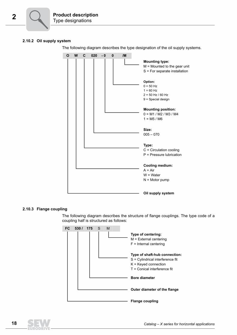
2.10.2 Oil supply system
The following diagram describes the type designation of the oil supply systems.
2.10.3 Flange couplingThe following diagram describes the structure of flange couplings. The type code of acoupling half is structured as follows:
O W C 020 - 0 0 /MMounting type:M = Mounted to the gear unitS = For separate installation
Option:0 = 50 Hz1 = 60 Hz2 = 50 Hz / 60 Hz9 = Special design
Mounting position:0 = M1 / M2 / M3 / M41 = M5 / M6
Size:005 – 070
Type:C = Circulation coolingP = Pressure lubrication
Cooling medium:A = AirW = WaterN = Motor pump
Oil supply system
FC 530 / 175 S M
Type of centering:M = External centeringF = Internal centering
Type of shaft-hub connection:S = Cylindrical interference fitK = Keyed connectionT = Conical interference fit
Bore diameter
Outer diameter of the flange
Flange coupling

Catalog – X series for horizontal applications 19
2NameplateProduct description
2.11 Nameplate2.11.1 Gear unit
The following figure shows an example nameplate for helical gear units.
9021319307
Type Type designation
No. 1 Serial number
PK1 [kW] Operating power on the input shaft (HSS)
MK2 [Nm] Gear unit output torque
n1 [rpm] Input speed (HSS)
n2 [rpm] Output speed (LSS)
min. Operating point at minimum speed
norm. Normal operating point
max. Operating point at maximum speed
i Exact gear unit ratio
FS Service factor
PM1 [kW] Nominal motor power
IM Mounting position and mounting surface
Mass [kg] Weight of the gear unit
Qty of greasing points Number of greasing points
Fans Number of installed fans
Oil grade and viscosity class / oil quantity
Year Year of manufacture
IM Mounting position and mounting surface
Made in Germany
M1-M4/9°
. . .
..
Ta

20 Catalog – X series for horizontal applications
2 Input and output shaftProduct description
2.12 Input and output shaftThere are 2 types of shafts:
• High-speed shaft (HSS), usually an input shaft
• Low-speed shaft (LSS), usually an output shaft
2.12.1 Input shaftThe input shaft is provided with a closed keyway according to DIN 6885/T1 and a centerbore (according to DIN 332). The matching key according to DIN 6885/T1 - form A isincluded in the scope of delivery.
2.12.2 Output shaft as a solid shaft with key /..SThe output shaft is provided with a closed keyway according to DIN 6885/T1 and a cen-ter bore (according to DIN 332). The scope of delivery includes a key according to DIN6885/T1 - form B. The shaft has an insertion area with a reduced diameter to simplifythe mounting of output elements, such as a coupling hub.
X.F.. X.K..
LSS
HSS
LSSHSS
8593123467X

Catalog – X series for horizontal applications 21
2Input and output shaftProduct description
2.12.3 Smooth output shaft /..RThe gear units are available with a smooth output shaft to be able to install non-positiveoutput elements, such as flange couplings with a cylindrical interference fit. The face ofthe shaft has a center bore according to DIN 332. The insertion area with reduced diam-eter facilitates the mounting of output elements.
2.12.4 Output shaft as a splined solid shaft /..LThe output shaft is a splined shaft according to DIN 5480. There is a centering in frontof and behind the splined shaft to improve the guide of the output element. Two threadsare available on the front end of the shaft for the mounting of an end plate.
8593135243
8593137931

22 Catalog – X series for horizontal applications
2 Input and output shaftProduct description
2.12.5 Output shaft as a hollow shaft with keyway /..A
The hollow shaft is equipped with a keyway according to DIN 6885/T1.
Included in the scope of delivery: Endplate with screws [1] or 2 retaining rings, and pro-tection cover [2].
The protection cover is dust-proof. The standard sealing system is therefore normallyused on the side of the protection cover.
2.12.6 Output shaft as a hollow shaft with shrink disk /..HThe shrink disk is positioned on the opposite side of the machine shaft.
Included in the scope of delivery: End plate with retaining screws [1], or 2 retaining rings,shrink disk [2], protection cover [3].
The protection cover is dust-proof. The standard sealing system is therefore normallyused on the side of the protection cover.
[1]
[2]
INFORMATIONFor detailed information on the geometry of the machine shaft, refer to (page 289).
In case of a through-going machine shaft, the gear unit is delivered without endplateand protection cover. In this case, both gear unit sides are equipped with the samesealing system.
[1]
[2]
[3]
INFORMATIONFor detailed information on the geometry of the machine shaft, refer to (page 290).
In case of a through-going machine shaft, the gear unit is delivered without endplateand protection cover. In this case, both gear unit sides are equipped with the samesealing system.

Catalog – X series for horizontal applications 23
2Input and output shaftProduct description
2.12.7 Output shaft as a splined hollow shaft /..VThe output shaft is a splined shaft according to DIN 5480.
Included in the scope of delivery:
End plate with screws [1], or 2 retaining rings and protection cover [2].
2.12.8 Gear unit mounting with hollow shaft gear unitsDue to the rigid connection between the machine shaft and hollow shaft of the gear unit,constraining forces can occur on the output shaft bearing.
This is why you have to observe the following points when mounting hollow shaft gearunits:
• The gear unit is usually foot or flange-mounted and used as bearing point when themachine shaft has no individual bearing or merely provides one bearing point. Youhave to provide for an accurate coaxial alignment with the bearing point.
• If the machine shaft has at least two bearing points, the gear unit should be con-nected only to the machine shaft and supported with a torque arm. In order to preventexcess stress on the bearing, gear units with foot or flange mounting are to beavoided.
8593160843[1]
[2]
INFORMATIONFor detailed information on the geometry of the machine shaft, refer to (page 293).
In case of a through-going machine shaft, the gear unit is delivered without endplateand protection cover. In this case, both gear unit sides are equipped with the samesealing system.
The protection cover is dust-proof, see previous page.
INFORMATIONNon-observance may result in damages to the output shaft bearing and increased fret-ting corrosion in the connection between the machine and the hollow shaft of the gearunit.

24 Catalog – X series for horizontal applications
2 Shaft positionsProduct description
2.13 Shaft positionsThe shaft positions and corresponding directions of rotation shown in the following fig-ures apply to solid shafts (LSS) with solid and hollow shaft. The shaft positions in gearunits with backstop and shaft end pump may be limited.
2.13.1 X.F..The following shaft positions are possible for gear unit type X.F..:
2.13.2 X.K..The following shaft positions are possible for gear unit type X.K..:
Shaft position X.FS.. Shaft position X.FH.. / X.FA..
85934499958593451659
4
2
3
1
4
1
2
3
Shaft position X.KS.. Shaft position X.KH.. / X.KA..
8593454347 8593456011
40
3
4
0
3

Catalog – X series for horizontal applications 25
2Direction of rotation dependenciesProduct description
2.14 Direction of rotation dependencies
The following tables show the direction of rotation dependencies between input and out-put shafts. The gear units as well as the position of the backstop are schematicallyshown as the solid shaft version.
2.14.1 X.F..
INFORMATIONThe gear unit can be operated in both directions of rotation. An exception are gearunits with backstop.
= Position of the backstop
= Alternative backstop position (depending on size and gear ratio)
* = Consult SEW-EURODRIVE when using a backstop
1) Note the restrictions regarding external forces on the LSS
134 243 213 * 124 * 1234 *
3 4 3 3
Shaftposition 14 23 13 24
End gearposition
End gearposition 3 4 3 4
X2F...
X3F...
X4F...
Shaftposition
X2F...
X3F...
X4F...
4
1) 1)
1) 1) 1)

26 Catalog – X series for horizontal applications
2 Direction of rotation dependenciesProduct description
2.14.2 X.K... Standard
Direction of rota-tion reversal
03 04 034End gear pos. 4 3 3
X2K...
X3K...
X4K...
Shaft position 1)0431)
4
= Position of the backstop
= Alternative backstop position (depending on size and gear ratio)* = Consult SEW-EURODRIVE when using a backstop
1) Note the restrictions regarding external forces on the LSS
03 04End gear position 3 4
X2K...
X3K...
X4K...
1) 1)Shaft position

Catalog – X series for horizontal applications 27
2Coating and surface protection systemsProduct description
2.15 Coating and surface protection systemsGear units are available with surface protection OS1, OS2, and OS3.
The following table provides an overview of coating and surface protection systems.
SEW version OS1Low environmental impact
OS2Medium environmental impact
OS3High environmental impact
Used as surface protec-tion with typical ambi-ent conditions Corrosion categories DIN EN ISO 12944-2 Suited for environments prone to
condensation and atmospheres with low humidity or contamina-tion, such as outdoor applications under roof or with protection, unheated buildings where con-densation can build up.According to corrosivity category: C2 (low)
Suited for environments with high humidity or moderate atmo-spheric contamination, such as applications outdoors subject to direct weathering.According to corrosivity category: C3 (moderate)
Suited for environments with high humidity and occasionally severe atmospheric and chemical con-tamination. Occasionally acidic or caustic wet cleaning. Also for applications in coastal areas with moderate salt load.According to corrosivity category: C4 (high)
Sample applications • Systems in saw mills• Agitators and mixers
• Applications in gravel plants• Cable cars
• Port cranes• Sewage treatment plants• Mining applications
Condensation testISO 6270 120 h 120 h 240 h
Salt spray test ISO 7253 – 240 h 480 h
Top coat color1) RAL 7031 RAL 7031 RAL 7031
Color according to RAL yes yes yes
Uncoated parts shaft end/flanges Coat with hand perspiration and water repellent rust preventive for exterior corrosion protection
1) Standard color
INFORMATION• Sheet metal parts (such as protection covers) are painted in RAL 1003 as standard.• Higher quality surface protection systems are available on request.
28 Catalog – X series for horizontal applications
2 Storage and transport conditionsProduct description
2.16 Storage and transport conditionsThe gear units can be provided with the following protection and packaging types de-pending on the storage and transport conditions.
2.16.1 Internal conservationStandard corro-sion protection
After the test run, the test oil fill is drained out of the gear unit. The remaining oil film pro-tects the gear unit against corrosion for a limited period of time.
Long-term corro-sion protection
After the test run, the test oil fill is drained out of the gear unit and the interior space isfilled with a vapor phase inhibitor. The breather filter is replaced by a screw plug and en-closed with the gear unit.
2.16.2 Exterior corrosion protectionThe following measures are taken for exterior corrosion protection:
• Anti-corrosion agent is applied to bare, non-painted functional surfaces of shafts,flanges, mounting and foot surfaces of the housing. Remove it only using an appro-priate solvent which is not harmful to the oil seal.
• Small spare parts and loose pieces, such as bolts, nuts, etc., are packed in corrosionprotection plastic bags (VCI corrosion protection bags).
• Threaded holes and blind holes are covered by plastic plugs.
2.16.3 Packagingstandard packaging
The gear unit is delivered on a pallet, securely attached and without cover.
Use: Transportation by land
Long-term packaging
The gear unit is delivered in a wooden box that is also appropriate for sea transport.
Use: Sea transport and/or for long-term storage
INFORMATION• If the gear unit is stored longer than 6 months, regularly check the protective coat-
ing of unpainted areas as well as the paint coating. Areas in which the protectivecoating and/or painting has been damaged may have to be repainted.

Catalog – X series for horizontal applications 29
2Ambient ConditionsProduct description
2.16.4 Storage conditions
2.17 Ambient ConditionsThe gear units are suited for operation at ambient temperatures from -40 °C to +40 °C,however, the standard design might have to be modified depending on the ambient tem-perature.
When operated in areas with low ambient temperatures, high levels of humidity, aggres-sive or explosive atmospheres, please consult SEW-EURODRIVE.
Sealing, lubrication, ventilation, surface protection and other properties of the gear unitcan then be adjusted to the specific ambient conditions.
2.18 Gearing and shaftsThe gearing with edge corrections is made of high-quality, tempered and ground casehardening steels. The output shafts are made of tough quenched and tempered steel.
INFORMATION• During storage up to startup, the gear unit must be stored in a shock-free manner
to prevent damage to the rolling bearing races!• The output shaft must be rotated at least one full rotation every 6 months so that
the position of the rolling elements in the bearings of the input and output shaftschanges.
• The gear units are delivered without oil; different protection systems are requireddepending on the storage period and storage conditions as shown in the table be-low.
Corrosion protection + packaging Storage location Storage duration
Standard corrosion protection+
standard packaging
Under roof and enclosed at constant temperature and atmo-spheric humidity (5 °C < ϑ < 60 °C, < 50 % relative humidity).
No sudden temperature fluctuations. Controlled ventilation with filter (free from dust and dirt). No aggressive vapors, no shocks.
Max. 6 months with intact sur-face protection.
Long-term corrosion protection+
standard packaging
Under roof and enclosed at constant temperature and atmo-spheric humidity (5 °C < ϑ < 60 °C, < 50 % relative humidity).
No sudden temperature fluctuations. Controlled ventilation with filter (free from dust and dirt). No aggressive vapors, no shocks.
Max. 3 years with regular inspection and checking for
intactness.
Long-term corrosion protection+
Long-term packagingWith roof, protected against rain and shocks.
Max. 3 years with regular inspection and checking for
intactness.
INFORMATIONIf stored in tropical zones, provide for sufficient protection against insect damage. Con-tact SEW-EURODRIVE for differing requirements.

30 Catalog – X series for horizontal applications
2 Thermal ratingProduct description
2.19 Thermal ratingThe thermal rating needs to be checked for every gear unit. The relevant values arelisted in the selection tables on (page 129).
2.20 Shaft bearingsSelf-aligning, cylindrical and tapered roller bearings from well-known manufacturers areused.
2.21 Very low output speedsThe gear units described in this catalog cover a nominal gear ratio range of up to 400:1.With a 4-pole motor connected to the gear unit, minimum output speeds of about 4 rpmcan be reached.
Lower output speeds can be achieved by a combination with frequency inverter, multi-polar motors or with an SEW-EURODRIVE primary gear unit or gearmotor type R…,F…, K… or S…. Contact SEW-EURODRIVE in this case.
2.22 Noise levelNormally, the sound-power levels of the gear unit, according to ISO 8579-1, are belowthe 50% line given in the standard.

Catalog – X series for horizontal applications 31
2Reversible gear unitsProduct description
2.23 Reversible gear units
The universal housings are symmetrical to the central axis and each mounting surfaceis designed so that "overhead mounting" is possible for mounting positions M1/M3. Ifyou want this to be the case, contact SEW-EURODRIVE for adjusting the gear unit, op-tions and accessories accordingly.
INFORMATIONReversible gear units are only available with universal housing / HU.
8584295179
180°
M1
M3
32 Catalog – X series for horizontal applications
2 Mounting position sheetsProduct description
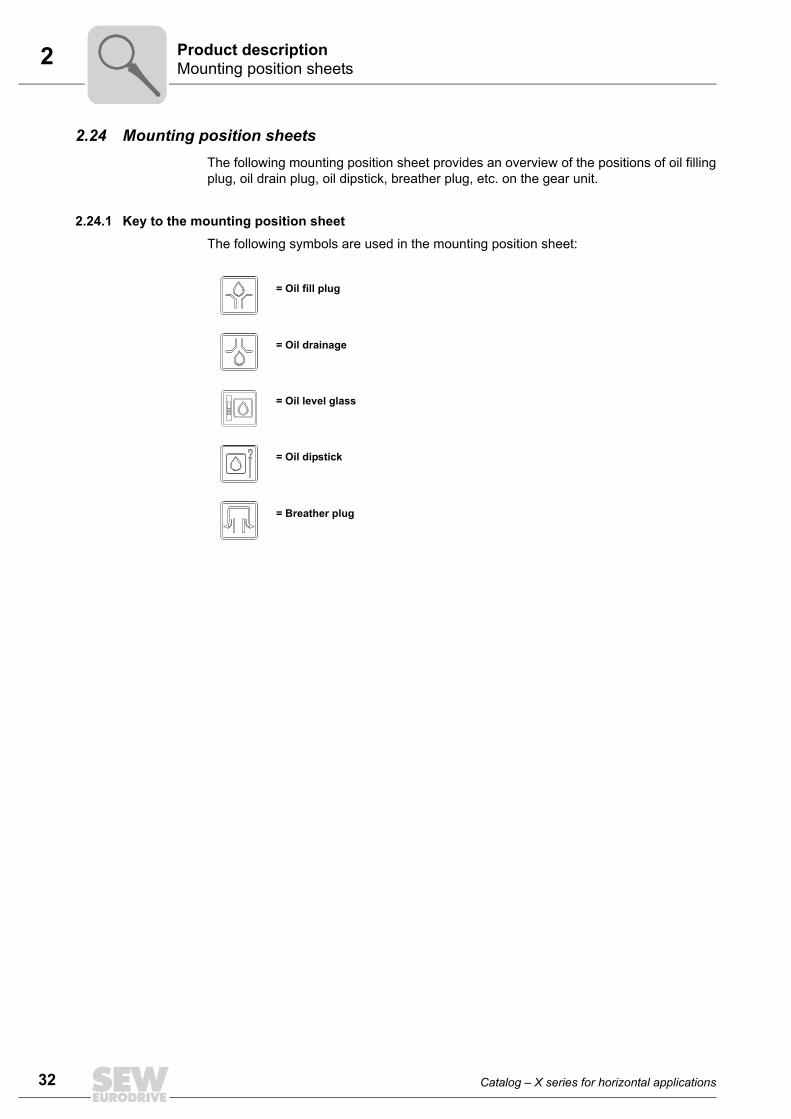
2.24 Mounting position sheetsThe following mounting position sheet provides an overview of the positions of oil fillingplug, oil drain plug, oil dipstick, breather plug, etc. on the gear unit.
2.24.1 Key to the mounting position sheetThe following symbols are used in the mounting position sheet:
= Oil fill plug
= Oil drainage
= Oil level glass
= Oil dipstick
= Breather plug
Catalog – X series for horizontal applications 33
2Mounting position sheetsProduct description
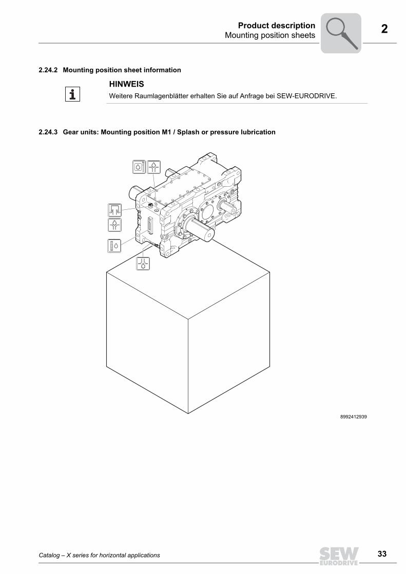
2.24.2 Mounting position sheet information
2.24.3 Gear units: Mounting position M1 / Splash or pressure lubrication
HINWEISWeitere Raumlagenblätter erhalten Sie auf Anfrage bei SEW-EURODRIVE.
8992412939

34 Catalog – X series for horizontal applications
2 Fixed and variable pivoted mounting positionsProduct description
2.25 Fixed and variable pivoted mounting positionsMounting positions deviating from the standard are distinguished as fixed or variablepivoted mounting position.
INFORMATION• Fixed and variable pivoted mounting positions are only possible after consultation
with SEW-EURODRIVE. Observe the order documents, such as the dimensionsheet.
• Fixed and variable pivoted mounting positions might involve restrictions concerningaccessories and technical data. Also, delivery times might be longer. ConsultSEW-EURODRIVE.
8021651467
M1
M6
M2
M5
M4
+
++
+
0°

Catalog – X series for horizontal applications 35
2Fixed and variable pivoted mounting positionsProduct description
2.25.1 Fixed pivoted mounting position Definition: Gear units with fixed pivoted mounting position have a fixed mounting position that dif-
fers from the standard.
This means the gear unit does not change its mounting position during operation.
Example: The type designation is set up as follows:
This results in the following fixed pivoted mounting position:
The oil level is checked in the selected fixed pivoted mounting position.
The fixed pivoted mounting position is shown on the nameplate as follows:
M1 = Initial mounting positionM4 = Pivoting direction9° = Fixed pivoting angle
Pivoted from mounting position M1 to M4 by 9°.
M1-M4/9°
8021656843
+9°
+9°M1-M4/9°
M1
M4
M2
+
M10°
0°
68021658507
Made in Germany M1-M4/9°/F1

36 Catalog – X series for horizontal applications
2 Fixed and variable pivoted mounting positionsProduct description
2.25.2 Variable pivoted mounting position Definition: Gear units with variable mounting position can change the mounting position variably
during operation within the specified max./min. range.
Example: The gear unit is operated in variable pivoted mounting position M1 to M6 = 9° and M1 toM5 = 12°.
Step 1: The largest pivoting angle determines the positive pivoting direction (12° > 9°). In thisexample, this is 12° towards M5.
12° → pivoted from M1 to M5 by +12°
9° → pivoted from M1 to M5 by -9°
8021660171
M1
M6
M5
-9° +12°
0°
0°
M1
M6
M5
-
+
M1-M5/12° M1 +12°
M1-M5/–9° –9°
0°
Catalog – X series for horizontal applications 37
2Fixed and variable pivoted mounting positionsProduct description
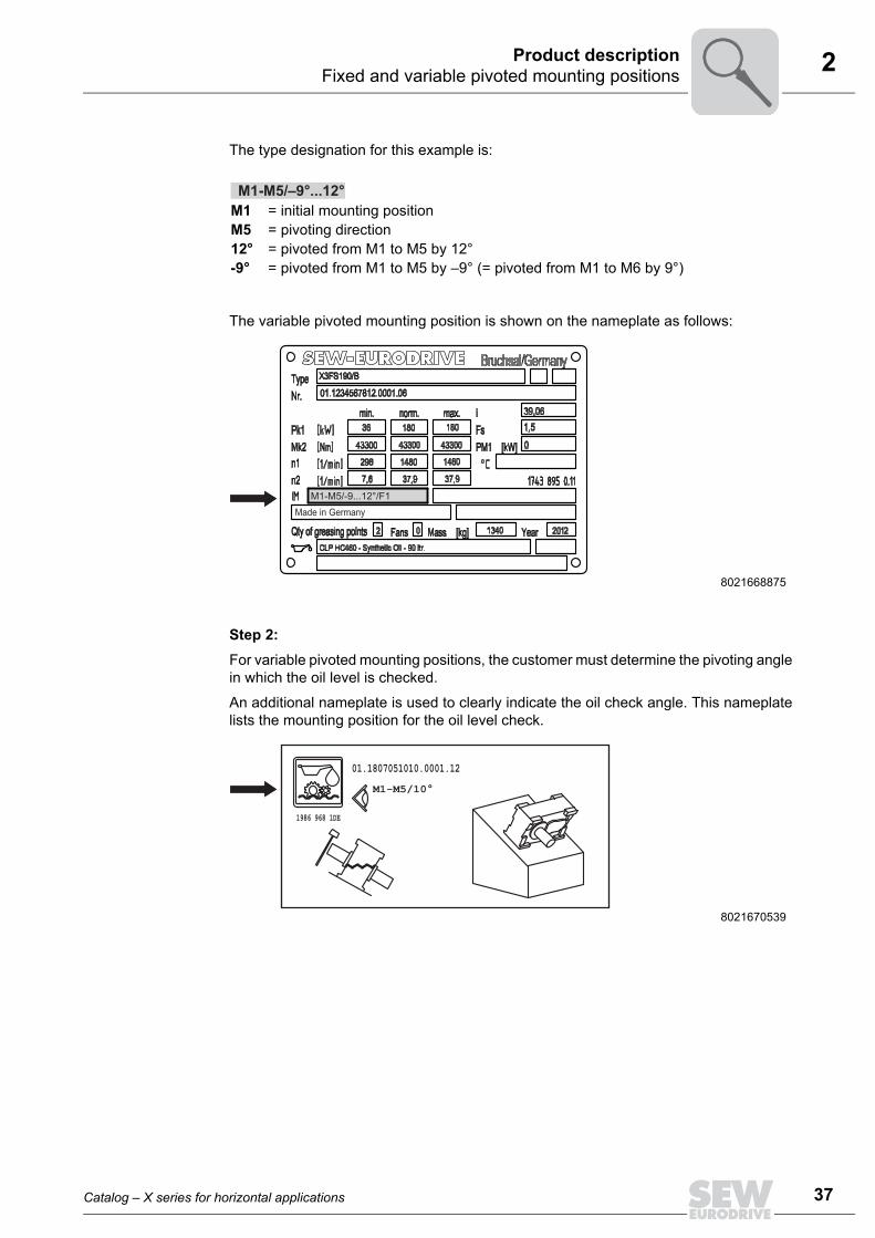
The type designation for this example is:
The variable pivoted mounting position is shown on the nameplate as follows:
Step 2:For variable pivoted mounting positions, the customer must determine the pivoting anglein which the oil level is checked.
An additional nameplate is used to clearly indicate the oil check angle. This nameplatelists the mounting position for the oil level check.
M1 = initial mounting positionM5 = pivoting direction12° = pivoted from M1 to M5 by 12° -9° = pivoted from M1 to M5 by –9° (= pivoted from M1 to M6 by 9°)
8021668875
8021670539
M1-M5/–9°...12°
Made in Germany M1-M5/-9...12°/F1
01.1807051010.0001.12M1-M5/10°
1986 968 1DE

38 Catalog – X series for horizontal applications
2 Fixed and variable pivoted mounting positionsProduct description
2.25.3 Combination of variable and fixed pivoted mounting positions
Fixed and variable pivoted mounting positions can be combined.
Example: The following example describes a combination of fixed and variable pivoted mountingpositions according to chapters 3.5.1 and 3.5.2.
The type designation is set up as follows:
The variable and fixed pivoted mounting position is shown on the nameplate as follows:
When combining fixed and variable pivoted mounting position, the customer must deter-mine the variable pivoting angle in which the oil level is checked. The fixed angle for theoil level check is already defined.
The gear unit has an additional nameplate to ensure correct oil level checks. This name-plate lists the mounting position for the oil level check.
M1 = initial mounting positionM4 = pivoting direction9° = Fixed pivoting angle
M1 = initial mounting positionM5 = pivoting direction12° = 12° from M1 to M5 –9° = –9° from M1 to M5 (= 9° from M1 to M6)
8021676939
M1-M4/9° (fixed pivoted mounting position)
M1-M5/–9°...12° (variable pivoted mounting position)
Made in Germany
M1-M4/9° M1-M5/-9...12°/F1

Catalog – X series for horizontal applications 39
2Fixed and variable pivoted mounting positionsProduct description
In this example, the operator checks the oil level at M1-M4/9° M1-M5/10°.
8021678603
01.1807051011.0001.12
1986 968 1DE
M1-M4/9°M1-M5/10°