2 hydrocarbons from non-conventional and alternative fossil resources · resources, the...
TRANSCRIPT

2
HYDROCARBONS FROM NON-CONVENTIONAL
AND ALTERNATIVE FOSSIL RESOURCES


2.1.1 Non-conventional fossil fuels
There are perhaps 1.8�1012 m3 (�12�1012 bbl) ofliquid petroleum (oil, heavy oil, bitumen and extraheavy oil) trapped in sedimentary rocks in severalthousand basins around the world. Of this amount,�0.5�1012 m3 is conventional oil (m�50 cP, Table 1)and �1.3�1012 m3 is viscous oil (m�50 cP). Apartfrom coal and natural gas, there is also a similaramount of kerogen, a solid organic matter trappedin shales. As conventional oil continues to bedepleted, the focus of fossil fuel development is
shifting slowly, but inexorably, to more viscousresources, the non-conventional resources thatcannot be exploited economically without specialtechniques (mining, sand production) or viscosityreduction (steam, solvents, combustion). Thischapter deals with existing, emerging and futuretechnologies for the extraction of viscous non-conventional oil.
Non-conventional oil productionand consumption trends
The earliest systematic use of oil in the formof natural tars predates written history. Indians
21VOLUME III / NEW DEVELOPMENTS: ENERGY, TRANSPORT, SUSTAINABILITY
2.1
Oil from non-conventionalsources
Table 1. Definition of conventional and non-conventional oil terms
Term Definition Physical properties
Conventional oil Oil that is mobile in situ and can be produced economically using conventionalmethods
m�50 cPLow S content
Heavy oil Oil that is only slightly mobile in situ, usually requiring technologies that improvemobility
50�m�10,000 cPS content �1%
Bitumen Oil that is immobile in situ, requiring large viscosity reductions or miningmethods
10,000�m�107 cPS content �1%
Extra heavy oil Oil that has an exceptionally high specificgravity (�1) but that has some mobility in thereservoir because of a natural high temperature
1,000�m�100,000 cPS content �1%
Oil sands Arenaceous strata saturated with extra heavyoil or bitumen, more viscous than heavy oil
k�0.5 D
Upgrading The process of turning viscous oils intorefinery feedstocks through coking andhydrogenation
C-rejection and H-addition areused

used tar from oil sand outcrops in Alberta to sealtheir canoes, and a number of civilizations usedoil and tar from natural seeps for variouspurposes. These viscous materials had lost theirlow-viscosity components because ofevaporation and oxidation.
Much later – first in China, then in Canada,the United States, Azerbaijan, followed by othercountries – wells were dug or sunk mechanicallyto find low viscosity oils that could flow underthe natural reservoir pressures. Withsophisticated drilling methods, deeper reservoirswere accessed, and methods such as gas andwater injection were developed to sustain naturalpressures and displace low viscosity oils toproduction wellbores. However, these methodsproved futile for the vast deposits of viscous oiland bitumen discovered during conventional oilexploration; therefore, large-scale exploitation ofthese viscous resources did not begin until late inthe Twentieth century because growingconventional oil discoveries and production metmost of the demands of an increasinglydeveloped and technologically sophisticatedworld.
Since 1980, viscous oil has slowly become amore important part of the world’s oil supply.Starting from a proportion in the order of a fewpercent, largely from California, Venezuela andCanada, viscous oil grew to comprise 10-12% ofworld production by the beginning of theTwenty-first century. This proportion willcontinue to grow because of improvedtechnology in production and upgrading, andbecause of economic factors associated withdemand and a declining rate of replacement ofconventional oil reserves.
Currently (2006), the United States consumes25% of world oil production, about 21 Mbbl/dfrom a total of 84 Mbbl/d. China consumes about6.5 Mbbl/d, followed by Japan, Germany, thenother countries. Most growth is in developingcountries (China, India, Brazil), assuringdemand rise of 1.5-2%/yr for the near future.About 12% of the oil supply (�9 Mbbl/d) isnon-conventional oil, and much of it needssignificant upgrading to make suitable feedstockfor conventional refining. Canada produces �1.6 Mbbl/d of viscous oil, 60% of its oilproduction of 2.6 Mbbl/d; Venezuela about 1 Mbbl/d, 40% of its total production; and theUnited States and Indonesia each produce about0.5 Mbbl/d. Other countries with importantviscous oil production include Russia,Kazakhstan, Oman and China.
Though technological innovations will increasethe recoverable fraction of existing conventionaloil, it must be realistically viewed as a fixedconsumable resource that is inexorably beingdepleted. Barring unforeseen technical oreconomic paradigm shifts, the easiest and richestores are always exploited first, followed by ores oflesser concentration; so it is with oil, and viscousoil development proceeds only as fast as theworld’s inability to sustain cheaper conventionaloil production. Viscous oil development is notcheap; however, viscous oil is plentiful and will bethe major source of liquid fuel in the second halfof the Twenty-first century.
Technological innovation in fossil fuelextraction
The last twenty years has seen the emergenceof new viscous oil production technologies thathave already profoundly changed the view ofworld oil supply. Old technologies are beingmodified or recreated. For example, CyclicSteam Stimulation is being modified through theuse of horizontal wells and large pad steaming.Gravity drainage and sand production are nearly100 years old as production concepts, but onlyrecently have emerged in new clothing and withnew accessories to take their place on the menuof options that now exists for viscous oilproduction. The only safe assumption about thefuture is that innovation will continue and otherproduction technologies will be developed, evenfor those resources that currently seemimprobable fuel sources, such as deep-sea gashydrates, oil shales, even biofuels.
Table 2 is a list of new viscous oil productiontechnologies that are commercial, emerging, orunder study, but have already been field tested.Combinations of these methods are alreadytaking place, as well as careful planning in theirsequencing so that more oil can be squeezedfrom a reservoir.
Low recovery factors (RF) for viscous oil arebeing replaced by RF expectations that wereinconceivable twenty years ago, �20% forCHOPS in lower viscosity oils, 70% for SAGDin a good reservoir zone. However, thesetechnologies come at some cost: extra energy,high capital costs, sand disposal requirements,and a need to carefully address carbonemissions.
New and future fossil sources for oilLeaving aside coal liquefaction,
Gas To Liquids (GTL) conversion and biomass
22 ENCYCLOPAEDIA OF HYDROCARBONS
HYDROCARBONS FROM NON-CONVENTIONAL AND ALTERNATIVE FOSSIL RESOURCES
sources, there remain three realistic sources ofnon-conventional oil: heavy oil, oil sands, andoil shales. Rigid definitions for these areimpossible; there is natural overlap amongcategories. In this Chapter, viscous oil is usedgenerically to describe all liquid petroleumwith an in situ viscosity greater than 50 cP;usually, these oils are heavier than 25 °APIgravity. Viscous oils may be found as deep as3,500 m (e.g. Tuha Field in China), butbecause of catagenesis and thermal effects onviscosity, the largest accumulations areshallow (�1,000 m), and significant viscousoil (�100 cP) deposits appear to be rare below3,000 m.
Heavy oil The term heavy oil is generally taken to mean
oil that has a low mobility in its natural condition,but will slowly flow toward wellbores, though atuneconomic or modest rates without some form ofstimulation. In terms of viscosity, a reasonableupper limit is 10,000 cP, as economically flowingwells above this limit, even with sandco-production or horizontal drain technology, aregenerally not possible.
The great majority of heavy oil (�90%) isfound in shallow high-porosity sandstones(porosity f�25%); significant carbonatedeposits are far less common, of lower porosity(f�15%) and generally thinner. Sulphur and
23VOLUME III / NEW DEVELOPMENTS: ENERGY, TRANSPORT, SUSTAINABILITY
OIL FROM NON-CONVENTIONAL SOURCES
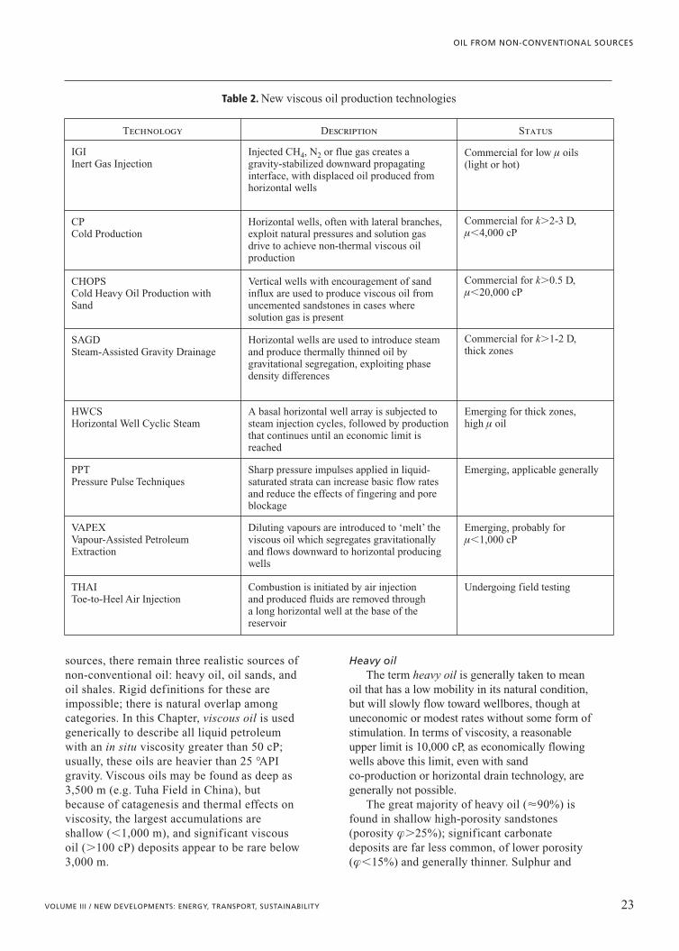
Table 2. New viscous oil production technologies
Technology Description Status
IGI Inert Gas Injection
Injected CH4, N2 or flue gas creates agravity-stabilized downward propagatinginterface, with displaced oil produced fromhorizontal wells
Commercial for low m oils(light or hot)
CPCold Production
Horizontal wells, often with lateral branches,exploit natural pressures and solution gasdrive to achieve non-thermal viscous oilproduction
Commercial for k�2-3 D,m�4,000 cP
CHOPSCold Heavy Oil Production withSand
Vertical wells with encouragement of sandinflux are used to produce viscous oil fromuncemented sandstones in cases wheresolution gas is present
Commercial for k�0.5 D,m�20,000 cP
SAGDSteam-Assisted Gravity Drainage
Horizontal wells are used to introduce steamand produce thermally thinned oil bygravitational segregation, exploiting phasedensity differences
Commercial for k�1-2 D,thick zones
HWCSHorizontal Well Cyclic Steam
A basal horizontal well array is subjected tosteam injection cycles, followed by productionthat continues until an economic limit isreached
Emerging for thick zones,high m oil
PPTPressure Pulse Techniques
Sharp pressure impulses applied in liquid-saturated strata can increase basic flow ratesand reduce the effects of fingering and poreblockage
Emerging, applicable generally
VAPEX Vapour-Assisted PetroleumExtraction
Diluting vapours are introduced to ‘melt’ theviscous oil which segregates gravitationallyand flows downward to horizontal producingwells
Emerging, probably form�1,000 cP
THAIToe-to-Heel Air Injection
Combustion is initiated by air injection and produced fluids are removed through a long horizontal well at the base of thereservoir
Undergoing field testing

nitrogen contents are high, and the oils containtraces of the heavy metals nickel and vanadium.
Among the large deposits of heavy oil in theworld, the most noteworthy is the Faja del Orinocoregion in Venezuela with a viscosity of 500-8,000 cP,in 30% porosity sands from 400 to 900 mdeep. Because of their high density (�10°API)and sulphur content (�2%), these deposits havebeen referred to as extra heavy oil. In Kazakhstan,Canada and Russia, large heavy oil deposits canalso be found, and some heavy oil accumulationscan be found in virtually every petroliferoussedimentary basin in the world.
Oil sandsThe term oil sands is widely used in a
generic sense to describe any high-porosityuncemented sandstone that contains oil, but inAlberta and elsewhere, it is used to describeimmobile viscous oil in sand deposits. Thegreatest accumulation of oil sands is in Canadawhere vast deposits, often with net oilaccumulations exceeding 60 m thick, occur in30% porosity sands at relatively shallow depths(0-600 m). These have been called bituminoussands, tar sands and oil sands, and containhigh-sulphur oil with viscosities ranging up to2�106 cP. There are smaller deposits of oil sandsin China, Russia, India, Indonesia, Ecuador andelsewhere.
Most basins in the world have some amountof highly viscous oil found at shallow depths,having migrated from the deeper oil-formingwindow (3,500-4,500 m). The viscous oil ismature conventional oil that underwentbiodegradation, diffusive loss of lighthydrocarbon fractions, and the addition ofsulphur and oxygen. Sulphur content can be ashigh as 4-5% in the most viscous oils and,usually, there are significant concentrations ofnickel and vanadium that tend to poison catalystsin the upgrading process.
Oil shalesOil is generated in shales from animal matter
as burial depth and temperature increase(catagenesis). The oil flows out of the shale byinduced fracture flow, and accumulates inlimestone and sandstone reservoirs. However, inmost sedimentary basins, there are shales thatcontain kerogen, which is immature carbon-richand semisolid organic matter left after anaerobicCH4 generation. Kerogenous shales are foundeverywhere in the world, but only those depositsthat contain over 8% by weight of kerogen are
considered to be potential future resources.There are two difficulties with kerogenousshales: first, the kerogen itself is not a true liquidand cannot flow even under high gradients;second, the kerogen is found in fine-grainedargillaceous strata of low intrinsic permeability.
The early years: 1950-2000Large-scale attempts to produce viscous
petroleum date from the middle of the Twentiethcentury, though small-scale non-thermalproduction has taken place for far longer. Earlyattempts using steam proved successful, andmany countries have active thermal projects; theUSA, Canada, Indonesia, Romania, Russia,China, Kazakhstan and other countries currentlyproduce, perhaps, 4-5�106 bbl/d through varioussteam technologies. In situ combustion was triedas early as 1953, but combustion has yet to seegeneral commercialization for heavy oils. In theperiod 1973-90, many methods, including waterflooding, solvent injection, polymerdisplacement, micellar methods and variousother techniques using high Dp (high-pressuregradient) displacement were tried, with minimalcommercial success because of flowinstabilities. Beginning in the 1980s, newconcepts evolved: major developments includedthe rediscovery that sand co-productionenhances solution gas drive in viscous oils(Kobbe, 1917); the advent of easy horizontaldrilling, and a more profound understanding ofgravity drainage physics.
Non-thermal production using conventionalwells, sand co-production (�0,7 Mbbl/d inCanada), and horizontal well methods (�0,7 Mbbl/d in Venezuela alone) currentlyaccounts for �4 Mbbl/d of heavy oil production.The latter methods are growing in worldwideapplication, but perhaps the most significantdevelopment to date is thermal productionthrough steam-assisted gravity drainage(SAGD), which is responsible for an increase inCanadian URR (Ultimate Recoverable Reserves)by 175 Gbbl in 2003. These three developments,combined with surface mining in Canada,will underpin heavy oil production increases inthe coming decades, although emergingtechnologies and other new concepts willcontinue to affect the view of what constitutes arecoverable resource.
IOR (Innovative Oil Recovery) methods forconventional oil are not described here, and oldconcepts for viscous oils (classical in situcombustion, steam flooding, other pre-1990
24 ENCYCLOPAEDIA OF HYDROCARBONS
HYDROCARBONS FROM NON-CONVENTIONAL AND ALTERNATIVE FOSSIL RESOURCES

methods) will not be discussed. Neither will thischapter deal in highly speculative technologiesfor viscous oil recovery (e.g. biological methods,electrical heating) that currently seemirretrievably doomed by the laws of physics orthe constraints of economics.
Briefly, important related issues such asupgrading, transportation, and environmentalissues will be explored, though not dealt with indepth, and only in the context ofnon-conventional fossil oil.
A number of generalizations are made in thediscussions to follow. It is believed that these areusually correct, but exceptions can always befound.
2.1.2 Pressure-driven viscousoil technologies
Natural or induced high-pressure gradients areused to drive fluids through porous media toproduction points. Induced high-pressuregradients are sustained by injection of fluids(water, steam, gas, solvents, polymers), but inviscous oil, this rapidly leads to advectiveinstabilities such as viscous fingering, water orgas coning, channelling and fracturing (Fig. 1).Two other forms of instability take place inporous media: gravitational instabilities arisingbecause of the density segregation of immisciblephases, and capillary blockage because ofinterfacial tension between oil, water andgaseous phases. Much of the IOR technologydeveloped since 1960 is directed towardsovercoming or mitigating these effects and, morerecently, exploiting them.
Cold heavy oil production with sand – CHOPSCHOPS is now widely used in thousands of
wells in Canada for primary production fromunconsolidated sandstones containing viscousoil. Approximately 25% (�692,000 bbl/d) ofCanadian production in 2004 was from CHOPSapplied to reservoirs from 11 to 18 °API(m�500-15,000 cP). Combined with otherCHOPS projects that are beginning around theworld, about 1.1-1.3% of the world’s oilproduction is through CHOPS approaches. Thisproportion will continue to rise for theforeseeable future.
CHOPS mechanismsInstead of blocking sand ingress by screens
or gravel packs, sand flow into the wellbore isencouraged by aggressive perforation andswabbing strategies, and is sustained duringproduction by high drawdown. Years of evidence,including field implementation of every possiblesand exclusion approach conceivable, haveconclusively demonstrated that sand exclusionleads to uneconomic production rates.Productivity increases over conventional(sand-free) primary production by factors of �5to 20 are regularly achieved (e.g. 100 bbl/drather than 5 to 20 bbl/d). A good CHOPS wellcan produce as much as 40-150 bbl/d for manyyears, and as much as 200-600 bbl/d during thefirst few years, depending on viscosity. As muchas 12-25% of OOIP (Original Oil in Place) canbe recovered, rather than the 2-8% typical ofprimary production without sand. Interestingly,because massive sand production creates a largedisturbed zone of greater porosity andpermeability, the reservoir may be improved for
25VOLUME III / NEW DEVELOPMENTS: ENERGY, TRANSPORT, SUSTAINABILITY
OIL FROM NON-CONVENTIONAL SOURCES
viscous fingering
channelling
low k
high k
low k
low k
high k
low m
low m
low m
high m
high muniform k
breakthrough
gas, H2O coning
fracturing
fracture rise
water
gas
oil
Fig. 1. Advectiveinstabilities in viscous oil (Dp, k, m dominated).

later implementation of thermal processes (CSS,SAGD).
CHOPS increases well productivity for fivereasons: • If sand can move, the basic mobility of the
flowing fluid phase is enhanced.• As more sand is produced, a growing zone of
enhanced permeability is generated, similarto a large-radius well that gives betterproduction.
• Gas exsolution in viscous oil does notgenerate a continuous phase; rather, non-coalescing bubbles flow with the fluid (andsand), expanding down-gradient, generatingan internal gas drive that is referred to asfoamy flow.
• Continuous sand production means thatasphaltene precipitation or fines plugging ofthe near-wellbore environment cannot occurto impair productivity.
• As sand is removed, the overburden weightacts to shear and destabilize sand, helping todrive sand and oil laterally toward thewellbore.
Well and field behaviour in CHOPSTypically, a CHOPS well initially produces a
high sand cut, perhaps more than 20% by liquidvolume; however, this decays to 0.1-6% aftersome weeks or months (lower viscosity oilsgenerate lower sand rates). Some of the bestCHOPS wells in Canada, producing from 10-12 mthick 30% porosity reservoirs with 1,500 cP oil,have reached cumulative oil production�100,000 m3 over a 8-12 yr life. The total sandproduction for such a well may be 2,000-4,000 m3,
although lower viscosity cases will generate lesscumulative sand. Water production typicallyincreases with time, and operators will continueproducing a CHOPS well until the oil rates dropbelow 1-2 m3/d, or until water influx becomesunmanageable, given the amount of oilproduced.
Vertical or inclined wells (40° maximum) areinstalled for CHOPS, large-diameter perforationsare used for well completion, and the wells areusually operated with rotary progressive cavitypumps, rather than reciprocating pumps, toproduce a slurry of sand, oil, water and gas. Oldfields that have progressively been converted tohigher-capacity progressive cavity pumps showsubstantial production boosts in wells that usedreciprocating pumps. Continued improvementsin progressing cavity pumps are increasing pumplife and reliability, and other pumpingtechnologies capable of lifting large sandvolumes are now emerging. New liftingtechnologies capable of handling 20-40% sandindefinitely now exist, and may extend theviscosity range over which CHOPS is used.
Fig. 2 shows a cumulative production historyfor a 430 m deep well in a �7 m thick reservoirin Canada, where the viscosity was about 10,000cP. For this field, CHOPS was the only possiblechoice of production technology: no otherproduction method was economical, and ahorizontal well trial proved an abysmal failure.Note how the sand tracks the oil production. Thiswas an excellent economic success for viscousoil.
Fig. 3 shows a cumulative production historyfor the Luseland Field, Saskatchewan (Canada).
26 ENCYCLOPAEDIA OF HYDROCARBONS
HYDROCARBONS FROM NON-CONVENTIONAL AND ALTERNATIVE FOSSIL RESOURCES
cum
ulat
ive
oil,
wat
er p
rodu
ctio
n (m
3 )
cum
ulat
ive
sand
pro
duct
ion
(m3 )
336 m3
35,292 m3
25,360 m3
40,000
35,000
30,000
0
5,000
10,000
15,000
20,000
25,000
400
350
300
0
50
100
150
200
250
year1993 1994 1995 1996 1997 1998 1999 2000 2001 2002 2003
oilwatersand
m�10,000 cPz�430 m��30-31%
Fig. 2. Productionhistory for a singleCHOPS well.
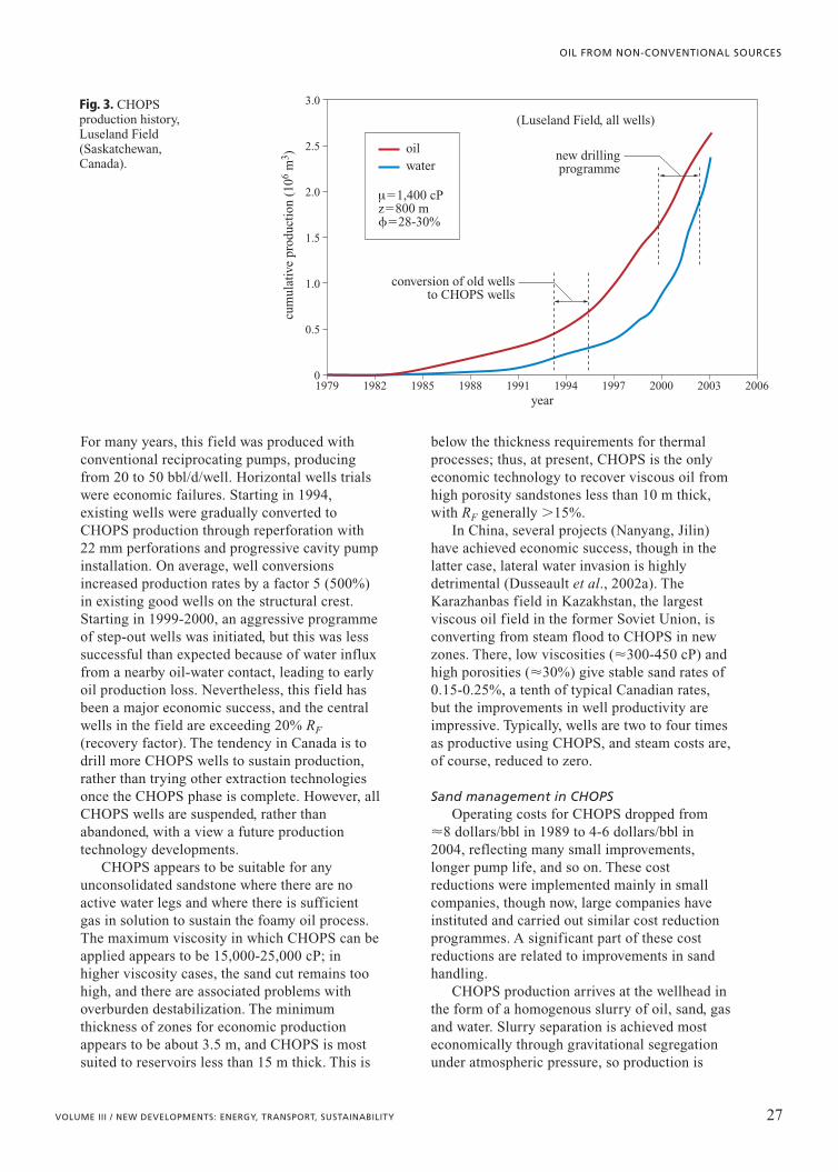
For many years, this field was produced withconventional reciprocating pumps, producingfrom 20 to 50 bbl/d/well. Horizontal wells trialswere economic failures. Starting in 1994,existing wells were gradually converted toCHOPS production through reperforation with22 mm perforations and progressive cavity pumpinstallation. On average, well conversionsincreased production rates by a factor 5 (500%)in existing good wells on the structural crest.Starting in 1999-2000, an aggressive programmeof step-out wells was initiated, but this was lesssuccessful than expected because of water influxfrom a nearby oil-water contact, leading to earlyoil production loss. Nevertheless, this field hasbeen a major economic success, and the centralwells in the field are exceeding 20% RF
(recovery factor). The tendency in Canada is todrill more CHOPS wells to sustain production,rather than trying other extraction technologiesonce the CHOPS phase is complete. However, allCHOPS wells are suspended, rather thanabandoned, with a view a future productiontechnology developments.
CHOPS appears to be suitable for anyunconsolidated sandstone where there are noactive water legs and where there is sufficientgas in solution to sustain the foamy oil process.The maximum viscosity in which CHOPS can beapplied appears to be 15,000-25,000 cP; inhigher viscosity cases, the sand cut remains toohigh, and there are associated problems withoverburden destabilization. The minimumthickness of zones for economic productionappears to be about 3.5 m, and CHOPS is mostsuited to reservoirs less than 15 m thick. This is
below the thickness requirements for thermalprocesses; thus, at present, CHOPS is the onlyeconomic technology to recover viscous oil fromhigh porosity sandstones less than 10 m thick,with RF generally �15%.
In China, several projects (Nanyang, Jilin)have achieved economic success, though in thelatter case, lateral water invasion is highlydetrimental (Dusseault et al., 2002a). TheKarazhanbas field in Kazakhstan, the largestviscous oil field in the former Soviet Union, isconverting from steam flood to CHOPS in newzones. There, low viscosities (�300-450 cP) andhigh porosities (�30%) give stable sand rates of0.15-0.25%, a tenth of typical Canadian rates,but the improvements in well productivity areimpressive. Typically, wells are two to four timesas productive using CHOPS, and steam costs are,of course, reduced to zero.
Sand management in CHOPSOperating costs for CHOPS dropped from
�8 dollars/bbl in 1989 to 4-6 dollars/bbl in2004, reflecting many small improvements,longer pump life, and so on. These costreductions were implemented mainly in smallcompanies, though now, large companies haveinstituted and carried out similar cost reductionprogrammes. A significant part of these costreductions are related to improvements in sandhandling.
CHOPS production arrives at the wellhead inthe form of a homogenous slurry of oil, sand, gasand water. Slurry separation is achieved mosteconomically through gravitational segregationunder atmospheric pressure, so production is
27VOLUME III / NEW DEVELOPMENTS: ENERGY, TRANSPORT, SUSTAINABILITY
OIL FROM NON-CONVENTIONAL SOURCES
cum
ulat
ive
prod
ucti
on (
106
m3 )
3.0
0
0.5
1.0
1.5
2.0
2.5
year
(Luseland Field, all wells)
new drillingprogramme
conversion of old wellsto CHOPS wells
m�1,400 cPz�800 m��28-30%
1979 1982 1985 1988 1991 1994 1997 2000 2003 2006
oilwater
Fig. 3. CHOPSproduction history,Luseland Field(Saskatchewan,Canada).
directly into large, on-lease tanks of 100-200 m3
capacity. Some companies add an emulsion-breaking chemical to the slurry, which ispartially effective in reducing the amount ofemulsion. Some companies use auger units thatheat the slurry and shear it slowly as it enters thetank, after it has been treated with demulsifier.Apparently, this accelerates and improvessegregation in the tank, and further reduces theamount of emulsion.
Lease tanks are insulated and heated to�80-90°C with the annulus gas produced fromCHOPS wells, so that the viscosity of the oil isreduced to less than 30-50 cP. The sand (densityr�2.65 g/cm3) drops to the tank bottom, gas(CH4) evolves and is collected from the top, andthe oil (r�0.95 g/cm3) floats on top of theproduced water (r�1.03 g/cm3). Much of the oilis stripped off the sand as it sinks to the bottombecause the sand is water-wet. Also, stableemulsion, a mixture of asphaltene-rich oil, claysand water, segregates from the water and oilphases and either sinks to the tank bottom(if r�1.03 g/cm3) or forms a layer between theoil and water (if r�1.03 g/cm3).
The lease tanks are managed by periodicalwithdrawals of oil, water and sand. Oil is truckedin 30 m3 loads to local cleaning plants, water isfiltered and injected at depth, and sand is sent tostockpiles or directly to disposal (see Section2.1.9). Emulsions present a particular problem asthey are extremely stable and cannot beeconomically treated; current practice is mainlyto dispose of them.
Sand extraction from the lease tanks is doneby slurrification in the tank and vacuum truckextraction, or by auger withdrawal in a moist butsolid mass. Overall, the entire process of sandmanagement accounts for about 25% ofoperating costs.
Pressure pulsing for flow rate enhancement
Theory of pressure pulsingPPT involves applying sharp displacement
impulses to liquid at the bottom of an excitationor injection well. A sharp pulse rapidly forcesliquid (20-100 litres) through the perforations,creating a displacement wave, called a porositydilation wave or a soliton, which propagatesthrough the reservoir. Effects on flow andproduction response on adjacent heavy wells inCHOPS applications are positive, increasing oilflow rates and reducing blockage problems(Dusseault et al., 2002b). The porosity dilation
wave can be generated in any liquid-dominatedporous system of high permeability (�0.1 D),but free gas dampens it rapidly, so that PPT isineffective in low-k reservoirs and cases of highgas saturation (Sg�0.10). Flow enhancementgenerated by earthquakes, even distant ones, haslong been known (Beresenev and Johnson,1994). For example, in California, earthquakestemporarily increase outflow from smallwatersheds (Manga et al., 2003); a flow rateincrease is followed by slow decay to theprevious baseline flow rate over a period ofseveral weeks.
It appears that success is imminent in thistechnology development, and this section will tryto explain the physics of the process and how itcould be exploited to enhance viscous (andconventional) oil recovery.
The displacement wave generated by a sharpliquid displacement impulse is analogous to atsunami in the ocean (a soliton). In water,acoustic strain waves (P-wave) travel at �1.5 km/s,but the tsunami is a displacement wave thattravels at �0.2 km/s. The porosity dilation waveis a displacement wave, not a strain wave, and ina porous medium, it travels at a velocity of0.02-0.2 km/s, depending on phasecompressibilities, viscosities and saturation.Skeleton compressibility depends on theconfining stress, therefore the velocity of theporosity dilation wave is also dependent on thestress state (depth).
To fully describe wave propagation in aporous medium, it is necessary to write dynamicequations coupling the mechanical response(compressibilities, porosity, saturations) of thephases with liquid diffusion behaviour (Biotwave mechanics plus Darcy diffusion mechanics;Spanos, 2001). First-order time differentials(d-/dt) describing diffusionally controlled flow arecombined with second-order time differentials(d2-/dt2) that describe wave effects. Laboratoryand preliminary field results show that excitationshould mainly contain frequencies of about0.1-0.3 Hz in typical petroleum systems, andhigher amplitude excitation is, of course, better.
Fig. 4 shows a simple physical justificationfor a theory coupling diffusion and dynamiceffects. For slow excitation frequencies,diffusion fully dominates, resulting in bulk flowand pressure migration, and for high frequencies,the Biot approach is valid. By virtue of physicalarguments, there must be three orders ofmagnitude of excitation frequencies betweenthese ranges where coupling is essential to
28 ENCYCLOPAEDIA OF HYDROCARBONS
HYDROCARBONS FROM NON-CONVENTIONAL AND ALTERNATIVE FOSSIL RESOURCES

describe the process. It is in this range that theporosity dilation wave effects take place.
At the pore scale, a porosity dilation wavepassing through a porous medium will causesmall amounts of liquid to accelerate into andout of pores, leading to sharp microscaleaccelerations. These help overcome capillarybarriers, destroy pore blockages fromasphaltenes and minerals, and increase the flowrate of liquids in a pressure gradient field.
How to implement pressure pulsingTo create high amplitude porosity dilation
waves, a sharp pulse must be generated by asudden solid or liquid impulse. Trying toaccelerate the entire well liquid column in abouthalf a second would burst the well, thus adownhole positive displacement pump is used to
suddenly accelerate and expel about 20-40 l ofliquid through the perforations. One way toaccomplish this is to link the piston to thesurface through the tubing string and suddenlyforce the tubing string downward with ahydraulic ram (Fig. 5). The double-actinghydraulic actuator at the surface then lifts thetubing for the next downstroke. Typically, acontinuously operating PPT system will perform20 strokes per minute, with a 2 m downstroketaking �0.6 s and the recharge stroke taking �2 s.
A PPT operation can consist of excitationonly, with backflow through the perforations torecharge the pump with liquid; it can operate asa liquid pump, with 100% of the recharge liquidcoming from the surface through the casing orthe tubing; or it can operate in any ratio of the
29VOLUME III / NEW DEVELOPMENTS: ENERGY, TRANSPORT, SUSTAINABILITY
OIL FROM NON-CONVENTIONAL SOURCES
exci
tati
on f
requ
ency
(H
z)
104
103
102
101
100
10�5
10�4
10�3
10�2
10�1
acceptable formulation
and�p
�t
�p
�t
�2p
�t2
�2p
�t2
terms
diffusion equation(Darcy theory)
wave equation, basedon Biot-Gassmann work
*the specific rangeof strong coupling depends
on phase viscositiesand compressibilities
Darcy flow
seismic frequencies
regime of strong coupling*
Fig. 4. A rationale for couplingdiffusion anddynamic processes.
tubing movedfrom surface
instrumentation
moving piston
fixed piston
cased well
downholesystem
surfacesystem
cable
hydraulicactuator
tool mast,2.3 m stroke
Fig. 5. Downholeand surfaceconfiguration of a pulsing system.

two. Thus, one may trickle in a treatmentchemical, and the sharp flow in and out of theperforations guarantees excellent mixing withthe reservoir fluids.
PPT applicationsPPT was field tested in heavy oil (Spanos et
al., 2003), and beneficial results on productionin surrounding wells in a highly depleted fieldwere observed where PPT was used. Theexcitation in a central well did not have an effectimmediately because of the high viscosity, butafter some time, sand influx increased and oilproduction decline was almost arrested.
PPT is in its infancy, but properly applied, itshould increase flow rates and help recover someof the residual oil that is usually left behind inconventional processes. It is not widely known atthe time of writing, but holds promise as a cheapmethod of improving recovery in a number oftechnologies, even gravity drainage, where itshould help increase liquid flux along theliquid-saturated boundaries of steam and vapourchambers. Although it cannot eliminateinstabilities, it will help reduce the advective andcapillary instabilities that plague all displacementprocesses based on pressure gradients.
New directions in high-pressure steamtechnologies
If viscous oil cannot be economicallyrecovered by cold flow or mining, the viscositymust be reduced: the three possible methods areheating, dilution, or reduction of the molecularweight. Of these, heating through steamtechnologies has been, by far, the mostsuccessful approach.
High-pressure steam injection takes placeunder fracturing conditions, so thin shale bedsare not a severe restriction on fluid flow,although the thermal penalty associated withheating the shale is substantial. Because of heatlosses and energy costs (steam is usuallygenerated from CH4 combustion), steaminjection processes are limited to reservoirs�10-12 m thick. Heat management is vital, andnew heat sources such as nuclear and clean coaltechnologies with power co-generation will beused in the future. Although the Steam-Oil Ratio(SOR) is commonly used as a measure of theefficacy of a process, it is far better to assess theoverall thermal efficiency, adding the costs of allthe energy sources used on a project siteexpressed in equivalent barrels of oil, divided bythe production.
A severe limitation to all high-pressure steamprocesses is that they are unsuitable forreservoirs that have active water zones or gascaps. For example, CSS uses phases of lowpressure during production; if active water ispresent, it enters to quench the steam,immobilize the oil, and short-circuit the process.During high-pressure injection, if a free gas capor water zone is present, steam losses will makethe process uneconomic. Later, we will see thatgravity-dominated processes can usually avoidthis limitation, providing that other conditionsare favourable. Nevertheless, new approaches tosteam injection are being developed to increaseRF and thermal efficiency for reservoirs whereSAGD methods may not give economicproduction rates because of shale barriers or lowvertical permeability.
Megarow cyclic steam stimulationConventional CSS uses individual vertical
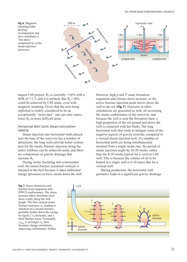
wells; typically, RF of 15-30% is achieved. Inmegarow CSS, steam injection and fluidproduction are conducted along long rows ofwells (Fig. 6), and this gives some benefits,increasing steam contact area with the reservoirand increasing RF. Typically, injection will lastfor �10 weeks; the process is then reversed, withproducing rows becoming injection rows andvice-versa.
Three important production mechanisms takeplace in CSS. First, Dp-driven flow of the hotfluids, aided by steam flashing and expansion asthe pressure is dropped, drives fluids toproduction wells. Second, during high-pressureinjection, substantial shear dilation takes place,and as matrix stresses increase during thepressure drawdown phase, formationre-compaction occurs to help displace fluids tothe production wells. Third, in megarowstimulation, there is a steam-drive effect thathelps displace oil from the injection to theproduction rows because of the large pressuredifferences that are sustained for many weeksbefore being reversed.
Even in good reservoirs (thick, high k, low m),CSS yields only moderate RF because much ofthe low-lying oil between vertical wells cannoteasily be contacted with heat (steam override),and because the fracturing necessary for steaminjection during early cycles leads to non-uniformheat distribution, more override, and some lossof heat from the pattern, perhaps even throughthe overburden. For example, in ImperialOil Cold Lake (Alberta, Canada), the world’s
30 ENCYCLOPAEDIA OF HYDROCARBONS
HYDROCARBONS FROM NON-CONVENTIONAL AND ALTERNATIVE FOSSIL RESOURCES
largest CSS project, RF is currently �26% with aSOR of �2.5, and it is unlikely that RF�30%could be achieved by CSS alone, even withmegarow steaming. Given that the area beingexploited is widely considered to be anexceptionally ‘sweet spot’, one can only expectlower RF in more difficult areas.
Horizontal Well Cyclic Steam stimulation(HWCS)
Steam injection into horizontal wells placednear the base of the reservoir has a number ofattractions: the long wells provide better contactarea for the steam, fracture injection along theentire wellbore can be achieved easily, and thereare components of gravity drainage thatincrease RF.
During steam fracturing into a horizontalwell, the initial fracture (assumed vertical) isinitiated at the heel because it takes additionalenergy (pressure) to force steam down the well.
However, high p and T cause formationexpansion and closure stress increase, so theactive fracture injection point moves down thewell to the toe (Fig. 7). Fractures in otherorientations are generated as well, all increasingthe steam conformance to the reservoir, andbecause the well is near the formation base, ahigh proportion of the oil around and above thewell is contacted with hot fluids. The longhorizontal well also tends to mitigate some of thenegative aspects of gravity override, compared toa vertical steam injection well. If a number ofhorizontal wells are being simultaneouslysteamed from a single steam line, the period ofsteam injection might be 16-20 weeks, ratherthan the 8-10 weeks typical for a vertical CSSwell. This is because the volume of oil to beheated in a single well is 6-10 times that for avertical well.
During production, the horizontal wellgeometry leads to a significant gravity drainage
31VOLUME III / NEW DEVELOPMENTS: ENERGY, TRANSPORT, SUSTAINABILITY
OIL FROM NON-CONVENTIONAL SOURCES
200 m sectional view
heave
�Dz
�DV
�Dz�Dz
�DV�DV
compactioncompaction
production row
production row
injection row
Fig. 6. Megarowsteaming helpsdeveloprecompaction andalso contributes a‘line drive’component to cyclicsteam injectionprocesses.
32
1
activefracture
initialstresses
�DT
��s3 �s3
s3
sv
Fig. 7. Stress alterations andfracture locus migration aidsHWCS conformance. The stressincrease effect distributes heatmore evenly along the welllength. The first vertical steamfracture increases s3, leading toinitiation of a second fracture,probably further down the casing.In region 2 s3 increases, and athird fracture starts. Eventually,shmin is no longer s3; thenfractures change orientation,improving conformance further.
effect in addition to recompaction and Dp-drive.Gaseous phases (solution gases and steam) moveupward while hot oil and condensed water movedownward, overcoming some of the naturaltendencies for coning under the effect of highpressure gradients. As pressure is dropped duringproduction, steam flashing helps fill the voidagegenerated by drainage, improving gravitysegregation. Simultaneous inert gas injection,high in the heated zone during production, couldbe used as a means of increasing gravitationaldisplacement effects.
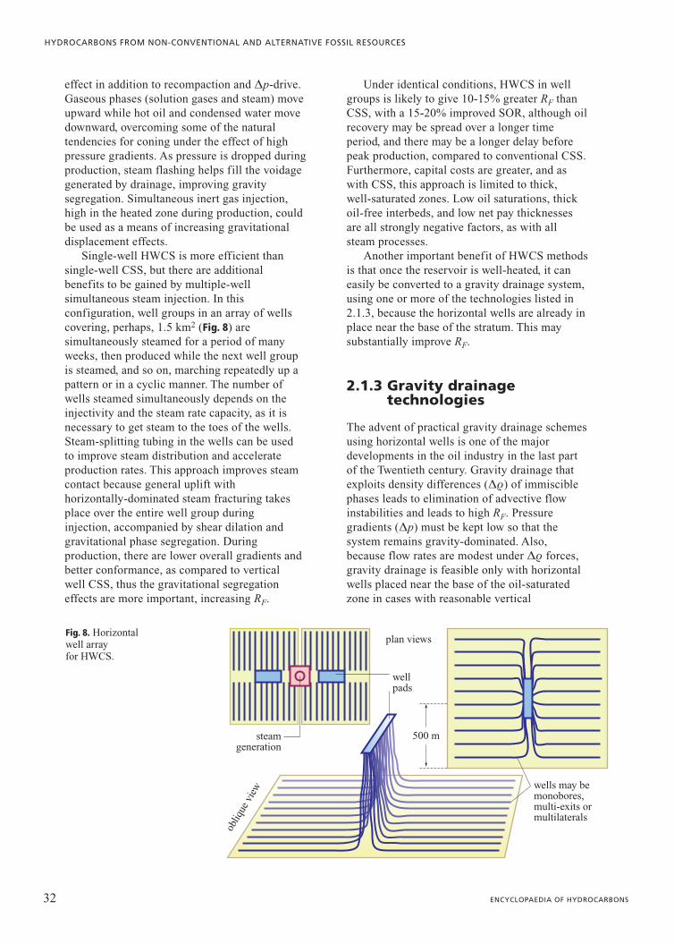
Single-well HWCS is more efficient thansingle-well CSS, but there are additionalbenefits to be gained by multiple-wellsimultaneous steam injection. In thisconfiguration, well groups in an array of wellscovering, perhaps, 1.5 km2 (Fig. 8) aresimultaneously steamed for a period of manyweeks, then produced while the next well groupis steamed, and so on, marching repeatedly up apattern or in a cyclic manner. The number ofwells steamed simultaneously depends on theinjectivity and the steam rate capacity, as it isnecessary to get steam to the toes of the wells.Steam-splitting tubing in the wells can be usedto improve steam distribution and accelerateproduction rates. This approach improves steamcontact because general uplift withhorizontally-dominated steam fracturing takesplace over the entire well group duringinjection, accompanied by shear dilation andgravitational phase segregation. Duringproduction, there are lower overall gradients andbetter conformance, as compared to verticalwell CSS, thus the gravitational segregationeffects are more important, increasing RF.
Under identical conditions, HWCS in wellgroups is likely to give 10-15% greater RF thanCSS, with a 15-20% improved SOR, although oilrecovery may be spread over a longer timeperiod, and there may be a longer delay beforepeak production, compared to conventional CSS.Furthermore, capital costs are greater, and aswith CSS, this approach is limited to thick,well-saturated zones. Low oil saturations, thickoil-free interbeds, and low net pay thicknessesare all strongly negative factors, as with allsteam processes.
Another important benefit of HWCS methodsis that once the reservoir is well-heated, it caneasily be converted to a gravity drainage system,using one or more of the technologies listed in2.1.3, because the horizontal wells are already inplace near the base of the stratum. This maysubstantially improve RF.
2.1.3 Gravity drainagetechnologies
The advent of practical gravity drainage schemesusing horizontal wells is one of the majordevelopments in the oil industry in the last partof the Twentieth century. Gravity drainage thatexploits density differences (Dr) of immisciblephases leads to elimination of advective flowinstabilities and leads to high RF. Pressuregradients (Dp) must be kept low so that thesystem remains gravity-dominated. Also,because flow rates are modest under Dr forces,gravity drainage is feasible only with horizontalwells placed near the base of the oil-saturatedzone in cases with reasonable vertical
32 ENCYCLOPAEDIA OF HYDROCARBONS
HYDROCARBONS FROM NON-CONVENTIONAL AND ALTERNATIVE FOSSIL RESOURCES
500 m
plan views
well pads
wells may bemonobores,multi-exits ormultilaterals
steamgeneration
obliq
ue v
iew
Fig. 8. Horizontalwell array for HWCS.
permeability (intrinsic or induced). Of course,any oil below the production well will remaininaccessible to gravity drainage methods, whichis why wells are invariably placed as low aspossible in the zone.
In gravity-dominated processes, immisciblephase density differences (Dr) and voidagebalance (DVin�DVout) lead to verticalgravitational segregation: dense liquids drop,light liquids and gaseous phases rise; this is thewell-known override instability, now deliberatelyexploited as a production method. Wells can beoperated at any pressure, so gravity drainagemethods can be used where there is activebottom water or flank water; the production wellbackpressure is kept the same (10-20 kPa) asthe water zone pressure so that water influxcannot take place. Because Dp�0 in gravitydrainage, viscous fingering, coning andchannelling cannot occur. Eliminating theseadvective instabilities is a great advantage and,in their absence, gravity forces tend to stabilizefronts and increase RF, albeit at slow flow rates.
Inert Gas Injection (IGI)IGI alone is not suitable for viscous oil, but it
is useful to enhance RF in conventional oils andit has potential applications after thermalprocesses. Furthermore, the physical process ofgravitational segregation is particularly clear inthe case of IGI (Chatzis et al., 1988).
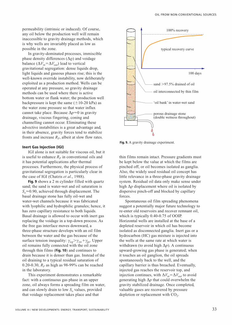
Fig. 9 shows a 2 m cylinder filled with quartzsand; the sand is water-wet and oil saturation isSo�0.90, achieved through displacement. Thebasal drainage stone has fully oil-wet andwater-wet channels because it was fabricatedwith lyophilic and hydrophilic granules; hence, ithas zero capillary resistance to both liquids.Basal drainage is allowed to occur with inert gasreplacing the voidage in a top-down process. Asthe free gas interface moves downward, athree-phase structure develops with an oil filmbetween the water and the gas because of thesurface tension inequality: gwg�gow�ggo. Upperoil remains fully connected with the oil zonethrough thin films (Fig. 10) and continues todrain because it is denser than gas. Instead of theoil draining to a typical residual saturation of0.20-0.30, RF as high as 98-99% can be reachedin the laboratory.
This experiment demonstrates a remarkablefact: with a continuous gas phase in an upperzone, oil always forms a spreading film on water,and can slowly drain to low So values, providedthat voidage replacement takes place and that
thin films remain intact. Pressure gradients mustbe kept below the value at which the films arepinched off, or oil becomes isolated as ganglia.Also, the widely used residual oil concept haslittle relevance in a three-phase gravity drainagesystem. Residual oil data only make sense underhigh Dp displacement where oil is isolated bydispersive pinch-off and blocked by capillaryforces.
Spontaneous oil film spreading phenomenasuggest a potentially major future technology tore-enter old reservoirs and recover remnant oil,which is typically 0.40-0.75 of OOIP.Horizontal wells are installed at the base of adepleted reservoir in which oil has becomeisolated as disconnected ganglia. Inert gas or ahydrocarbon (HC) gas mixture is injected intothe wells at the same rate at which water iswithdrawn (to avoid high Dp). A continuousupward-growing gas phase is generated; whenit touches an oil ganglion, the oil spreadsspontaneously back to the well, and thecapillary barrier is thus breached. Eventually,injected gas reaches the reservoir top, andinjection continues, with DVin�DVout to avoidgenerating high Dp that could overwhelm thegravity stabilized drainage. Once completed,valuable gases are recovered by pressuredepletion or replacement with CO2.
33VOLUME III / NEW DEVELOPMENTS: ENERGY, TRANSPORT, SUSTAINABILITY
OIL FROM NON-CONVENTIONAL SOURCES
sand �97.5% drained of oil
oil interconnected by thin film
‘oil bank’ in water-wet sand
porous drainage stone(double wetness throughout)
100% recovery
typical recovery curve
100 days
Fig. 9. A gravity drainage experiment.

In IGI applied to a virgin reservoir with goodkv (vertical permeability) but an active waterzone, CH4 or N2 is injected high in the reservoirto displace oil toward horizontal wells at the baseof the structure (CO2 could be used, but it is nota gas at p�7.4 MPa, T�31.1°C). In thehorizontal well, the pressure is maintained equalto the pressure in the water zone to eliminate
advective instabilities (Fig. 11), and gas isinjected at the same reservoir volume rate atwhich liquids are withdrawn so that coning doesnot take place. If there is a good bottom waterdrive, it is possible to have a downward movinggas interface and an upward moving waterinterface, both gravitationally stabilized.Because of the smaller Dr between oil andwater, interface velocities cannot be the same; insuch a case, production wells are placed closer tothe water contact to balance the production.
An ideal IGI reservoir would be one with amodest dip so that the surface area of the gas-oilinterface is as large as possible, yet with a goodgravity drainage effect (Ren et al., 2005). Thesubtle interplay of reservoir structure and gravitysegregation processes in three-phase systems isstill poorly appreciated, and there are manyapplications for IGI that will be perceived as theawareness of its efficacy increases in theindustry.
Vapour-Assisted Petroleum Extraction (VAPEX)To achieve economical flow rates, one may
reduce viscosity by dilution with solvents andcondensing HC gases. Combined with gravitydrainage using long horizontal wells, this isknown as VAPEX (Butler and Mokrys, 1991).Many options exist, but VAPEX was originallyconceived for a well pair (Fig. 12), with thegaseous mixture injected into the upper well anddiluted oil produced from the basal well. In thechamber, HC vapours and condensed liquidsdiffuse into the oil along an interface, meltingthe oil which flows downwards, exposing a newsurface for dilution. At the scale of 1-100 mm,the front is highly fingered because of imbibitionand dilution effects, so the surface area for
34 ENCYCLOPAEDIA OF HYDROCARBONS
HYDROCARBONS FROM NON-CONVENTIONAL AND ALTERNATIVE FOSSIL RESOURCES
mainly gas
water,one-phase
zone
oil bank,two-phase zone
three-phase zonehorizontalwells
inert gas injection, usually N2 or CH4
keep Dp to a minimum everywhere in the system
Fig. 11. Inert gas injection, a gravity drainage processfor less viscous oils. Gas injection andproduction rates ingravity-dominatedprocesses are controlled toavoid gas (or water) coning.V-balance is necessary:DVin�DVout. Horizontalwells must be parallel tostructure, close to the oilwater contact, if necessary.
gas
oil
sand
sand
water
gas
dm
Dp
Fig. 10. Fluids microstructure; dm�diameter.

diffusion is large, and this helps accelerate themass transport rate of the diluent phase into theviscous oil. The process tends to self-stabilizewithout large-scale fingering, giving greatstability and macroscopic planarity to themelting front. The absence of high Dp meansthat costly diluents are recovered and recycledwith high efficiency, overcoming poor solventrecovery problems that plague high Dp solventdrive processes. Also, diluent left after extractioncan be recovered through IGI or pressureblowdown.
To achieve condensation of light HCs at themelting front, one may heat the vapours beforeinjection by 20-40°C above reservoirtemperatures; this also allows greater choice inthe composition of the VAPEX gases used.Thermal energy requirements are a smallfraction of those typical of steam processesbecause of the small DT involved, the low heatcapacity of the solvents, and the low heat ofcondensation. The small amount of heat is also aviscosity reduction aid.
As with IGI, VAPEX can operate at anypressure because it is a gravity drive system. Ifthere is active water, careful pressure control canbe used to minimize influx or losses.
Compared to SAGD, a thermal process,VAPEX has both advantages and disadvantages.Solvent dilution means that in cases of highviscosity oil (�100,000 cP), a great amount ofdiluent must be entrained in the oil (20-30% byvolume); this suggests that VAPEX may be mosteffective in the 50-5,000 cP range where only
5-15% dilution is needed. Another concern inhigh viscosity oil is that HC liquids causeasphaltene precipitation, which may blockporosity, reducing flow rates. Though this hasbeen touted as a means of in situ upgrading, thenegative effects of asphaltene precipitation andpore blockage are substantial. Perhaps PPT couldbe used to keep pore throats open in such cases.
Because there are no thermal shear anddilation effects in cold VAPEX, even thin shalesbeds represent serious flow barriers. Toovercome this, propped fractures can beemplaced to create vertical flow paths, but thisonly partly resolves the problem, as the effectiveflow angle in such cases can be so flat thatrecovery rates become too slow.
However, VAPEX requires little heat, so thesevere heat cost penalty (�60-70% ofOPerational EXpenditure – OPEX – in SAGD andcyclic steam processes) is absent. However, otherwell configurations become feasible (e.g. Fig. 13),and a much longer exploitation time, perhapsseveral decades, could be tolerated in return forthe high RF values expected (70-85%). By contrast, in SAGD, exploitation must be asfast as possible because of heat losses, and wellspacing has to be modest; this limitation is farless severe for cold VAPEX.
VAPEX does not suffer the materialsmanagement penalties associated with steaminjection. There is no need for water, thus nocosts for purification, pumping and recycling –all major issues in SAGD. OPEX in VAPEXconfigurations should be �40% of SAGD OPEX
35VOLUME III / NEW DEVELOPMENTS: ENERGY, TRANSPORT, SUSTAINABILITY
OIL FROM NON-CONVENTIONAL SOURCES
overburden
countercurrentflow
lateral chamberextension
cham
ber grow
th
chamber growth
q
shale underburden
free gases
diluted oil
liquidlevel
condensation,diffusion, meltingof the viscous oil
in active water, pwater�ppin production well will prevent advective flow
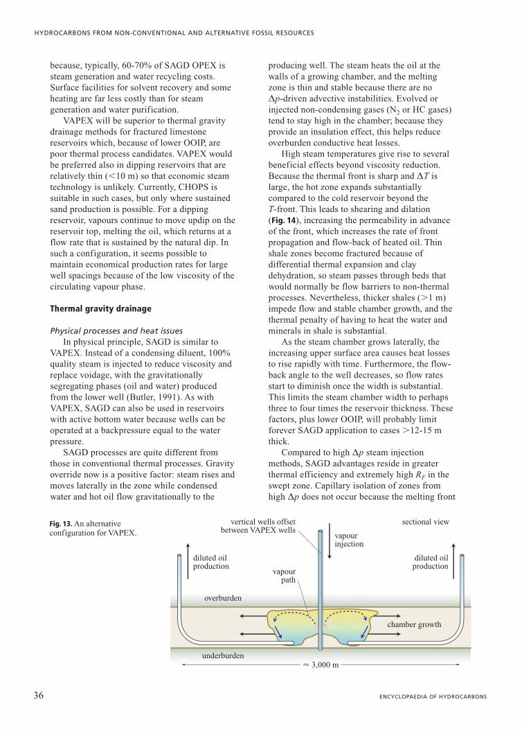
Fig. 12. The growingchamber in a VAPEX (or SAGD) process.
because, typically, 60-70% of SAGD OPEX issteam generation and water recycling costs.Surface facilities for solvent recovery and someheating are far less costly than for steamgeneration and water purification.
VAPEX will be superior to thermal gravitydrainage methods for fractured limestonereservoirs which, because of lower OOIP, arepoor thermal process candidates. VAPEX wouldbe preferred also in dipping reservoirs that arerelatively thin (�10 m) so that economic steamtechnology is unlikely. Currently, CHOPS issuitable in such cases, but only where sustainedsand production is possible. For a dippingreservoir, vapours continue to move updip on thereservoir top, melting the oil, which returns at aflow rate that is sustained by the natural dip. Insuch a configuration, it seems possible tomaintain economical production rates for largewell spacings because of the low viscosity of thecirculating vapour phase.
Thermal gravity drainage
Physical processes and heat issuesIn physical principle, SAGD is similar to
VAPEX. Instead of a condensing diluent, 100%quality steam is injected to reduce viscosity andreplace voidage, with the gravitationallysegregating phases (oil and water) producedfrom the lower well (Butler, 1991). As withVAPEX, SAGD can also be used in reservoirswith active bottom water because wells can beoperated at a backpressure equal to the waterpressure.
SAGD processes are quite different fromthose in conventional thermal processes. Gravityoverride now is a positive factor: steam rises andmoves laterally in the zone while condensedwater and hot oil flow gravitationally to the
producing well. The steam heats the oil at thewalls of a growing chamber, and the meltingzone is thin and stable because there are noDp-driven advective instabilities. Evolved orinjected non-condensing gases (N2 or HC gases)tend to stay high in the chamber; because theyprovide an insulation effect, this helps reduceoverburden conductive heat losses.
High steam temperatures give rise to severalbeneficial effects beyond viscosity reduction.Because the thermal front is sharp and DT islarge, the hot zone expands substantiallycompared to the cold reservoir beyond theT-front. This leads to shearing and dilation(Fig. 14), increasing the permeability in advanceof the front, which increases the rate of frontpropagation and flow-back of heated oil. Thinshale zones become fractured because ofdifferential thermal expansion and claydehydration, so steam passes through beds thatwould normally be flow barriers to non-thermalprocesses. Nevertheless, thicker shales (�1 m)impede flow and stable chamber growth, and thethermal penalty of having to heat the water andminerals in shale is substantial.
As the steam chamber grows laterally, theincreasing upper surface area causes heat lossesto rise rapidly with time. Furthermore, the flow-back angle to the well decreases, so flow ratesstart to diminish once the width is substantial.This limits the steam chamber width to perhapsthree to four times the reservoir thickness. Thesefactors, plus lower OOIP, will probably limitforever SAGD application to cases �12-15 mthick.
Compared to high Dp steam injectionmethods, SAGD advantages reside in greaterthermal efficiency and extremely high RF in theswept zone. Capillary isolation of zones fromhigh Dp does not occur because the melting front
36 ENCYCLOPAEDIA OF HYDROCARBONS
HYDROCARBONS FROM NON-CONVENTIONAL AND ALTERNATIVE FOSSIL RESOURCES
sectional view
underburden
overburden
chamber growth
� 3,000 m
diluted oilproduction
vapourinjection
diluted oilproduction
vapourpath
vertical wells offsetbetween VAPEX wells
Fig. 13. An alternativeconfiguration for VAPEX.

remains thin and relatively planar. If the processadvances more rapidly in a more permeablezone, there are counteracting thermodynamicand shearing effects that tend to equalize theprogression, keeping the front from developinglarge amplitude instabilities (as in viscousfingering or channelling). In the laboratory,�95% recovery from 2-D models is easilyachieved. In the field, depending on factors suchas the number and location of clay seams, therecovery rate versus the heat loss rate, themagnitude of thermal dilation, and so on, it isreasonable to expect RF�65-80% in suitablereservoirs.
Higher thermal efficiency arises because of thesharpness of the thermal front that progressesthrough the reservoir and the reduced heat lossesin the vertical direction, compared to high-pressuresteam injection processes. When SAGD is close totermination (5-8 yr), steam injection can bereplaced by inert gas injection to displace the hotliquids and vapours to the production well, wherethey can be produced and the heat scavenged.SAGD should be about 40% more thermallyefficient than an equivalent CSS operation. Forexample, in Cold Lake, SOR values of 2.5 arebeing achieved, but it is likely that SAGD couldachieve a far better RF with SOR values �1.5-1.6.However, high CAPEX (CAPital EXpenditures)for double horizontal wells makes up for part ofthe enhanced efficiency.
Implementation of SAGDTo date, SAGD has been economically
proven in Canada in good permeability zones
(k�1 D, h�20 m thickness) in oils of viscosityas high as 1-2�106 cP at depths of 150 to 650 m.RF values over a typical 5-8 yr life span shouldapproach 80% in the best cases with excellentvertical permeability, but values of 65-70% areperhaps more reasonable as an overall average.Note that even in conventional oil sandstonereservoirs using high Dp methods, RF of 60% isexceptional because of oil bypassing, capillaryblockage, and the high residual oil contentassociated with Dp-driven processes.
Although a double well strategy is theconfiguration that is currently used, in principle,it is possible to achieve stable SAGD with asingle well where steam injection takes placealong the length of the well, with the steamsegregating and rising out of the well to bereplaced by the liquids. Other configurations canbe used, providing that Dp is kept low so that theprocess is dominated by Dr effects. At present,the double well concept is deemed mostappropriate for new, thick viscous oil zonesbecause it keeps the flow path short, reducingheat losses, and because full communicationalong the length of the well can be establishedquickly. However, as SAGD is applied to otherreservoirs that have already had a productionphase using a different technology, or toreservoirs where communication has alreadybeen established, different well combinations canbe used. For example, horizontally alternatinginjection and production wells or verticalinjection well rows with offset horizontalproducing wells may prove more efficient inspecial cases (such as SAGD following HWCS).
37VOLUME III / NEW DEVELOPMENTS: ENERGY, TRANSPORT, SUSTAINABILITY
OIL FROM NON-CONVENTIONAL SOURCES
‘insulated’ region
interface shear slip
stress-strainbehaviour
weakeningbehaviour major
dilatancyregions
thermalshearing
colddilation
strong dilatancy
�DV
�DV
stre
ss (s
a)
ea
ea
dilatancy
Fig. 14. Thermal and non-thermal dilatancyincrease k and ruptureshales.

SAGD well pairs are usually placed about 4m apart and operated so that DT between the twowells is �30°C. This appears to be optimum forCanadian conditions, but must be determined forindividual cases. Well lengths of �800 m seemto be the best because pressure drops along verylong horizontal wells lead either to excessivelyslow development of drainage at the toe, or topressure gradients in the reservoir thatdestabilize the gravitational drainage throughconing and viscous fingering.
In a reservoir with active water, theproducing well backpressure must remain closeto the water pressure, but if there is no activewater, it is possible to operate SAGD at lowerpressures. This may have some advantages forlower viscosity oils, but for high viscosity oil,lower temperature inhibits formation sheardilation, and the viscosity reduction related toDT may be insufficient for good flow rates. Inthese cases, low temperature SAGD is notadvantageous (Collins, 2004).
Hybrid gravity drainage methodsGravity drainage is generally slow,
constrained by high viscosities, low Dp and theintrinsic rock permeability. Hybrid methods mayovercome some of these constraints.
VAPEX and SAGD or IGI and SAGDSAGD is already being combined with
VAPEX concepts in field production. HC gasesare injected along with steam to gain benefits ofdilution, as well as to provide voidagereplacement and to help keep the verticalconductive heat losses at reduced levels throughthe effect of insulation provided by gases at thetop of the zone (Gupta et al., 2002). Thetendency of the inert gases to remain high in thestructure and of the steam to condense give anIGI component to the flow system, allowing oilto continue to drain until the oil zone is fullydepleted. This should give reduced heatrequirements and more rapid recovery, and mayeven improve RF marginally because the processcan be optimized and costs less than a simpleSAGD approach.
Once it becomes commonplace to usetechnologies in hybrid modes, oil companies willbegin exploring different combinations of gasesand steam. Perhaps it will prove most cost-effective to operate wells in one mode first, suchas SAGD for several years so that the shalezones are breached, then gradually shift toVAPEX which has far lower operating costs, but
is also slower. For the lower viscosity range (lessthan 1,000 cP), one can easily envisage a cyclicprocess of steam and gas injection under gravityconditions, followed by IGI, in a cyclic process,in an effort to reduce heat losses and operatingcosts.
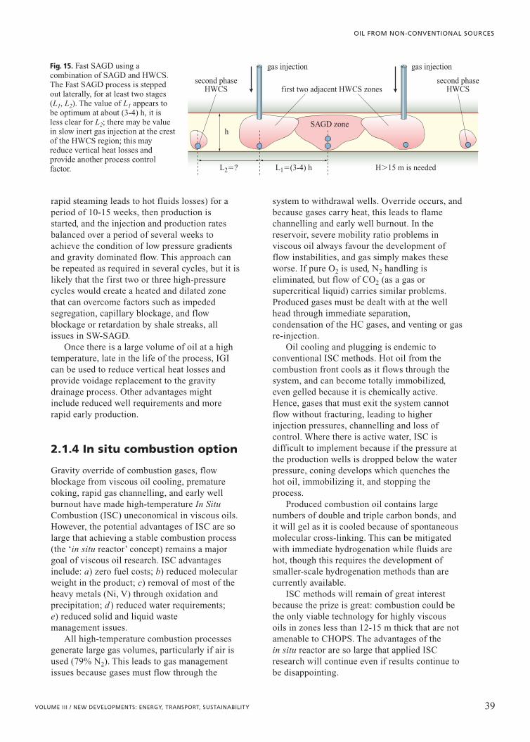
Fast SAGDThe Fast-SAGD concept (Gong et al.,
2002) proposes a central SAGD pair alongwith offset HWCS wells that are subjected tolong cycles of steam injection (many monthsto over a year for a single cycle), thenconverted to gravity drainage once there isgood communication between adjacent wells(Fig. 15). The HWCS process tends to breakthrough thin shale barriers easily, and the heatmay even tend to stay lower in the reservoir forlonger as fractures become dominated byhorizontal components because of inducedstress changes. The well drilling requirementsare lower than in SAGD, as the lateral spacingis envisaged to be similar, because the offsetwells are single, rather than double wells. Onemay assume that some component of VAPEXor IGI could be used to further ameliorateproduction rates and reduce heat requirements,perhaps by as much as 20-25% overconventional SAGD. It is likely that RF will notbe quite as high as in SAGD, although thisdepends on well spacing.
There are many combinations andpermutations possible in gravity dominatedprocesses, particularly if they are combinedepisodically or in sequence with pressuredriven processes. Fast SAGD and othermethods will be studied carefully inmathematical simulators, laboratoryconfigurations, and field implementation tofind methods of operation that help reduceheat losses, shorten exploitation time, increaseflow rates, and increase RF. Variousconfigurations of vertical and horizontal wellscan be used in different sequences, and it isunlikely that the current double-well conceptwith its high well installation costs will be theonly configuration used in the future.
SW-SAGD and HWCSTo achieve a large heated zone quickly,
horizontal wells can be operated in a cyclicpattern combining SW (Single-Well)-SAGD andcyclic steam injection (Elliott and Kovscek,1999). A single 800 m long well is firstsubjected to moderate rate steam injection (too
38 ENCYCLOPAEDIA OF HYDROCARBONS
HYDROCARBONS FROM NON-CONVENTIONAL AND ALTERNATIVE FOSSIL RESOURCES
rapid steaming leads to hot fluids losses) for aperiod of 10-15 weeks, then production isstarted, and the injection and production ratesbalanced over a period of several weeks toachieve the condition of low pressure gradientsand gravity dominated flow. This approach canbe repeated as required in several cycles, but it islikely that the first two or three high-pressurecycles would create a heated and dilated zonethat can overcome factors such as impededsegregation, capillary blockage, and flowblockage or retardation by shale streaks, allissues in SW-SAGD.
Once there is a large volume of oil at a hightemperature, late in the life of the process, IGIcan be used to reduce vertical heat losses andprovide voidage replacement to the gravitydrainage process. Other advantages mightinclude reduced well requirements and morerapid early production.
2.1.4 In situ combustion option
Gravity override of combustion gases, flowblockage from viscous oil cooling, prematurecoking, rapid gas channelling, and early wellburnout have made high-temperature In SituCombustion (ISC) uneconomical in viscous oils.However, the potential advantages of ISC are solarge that achieving a stable combustion process(the ‘in situ reactor’ concept) remains a majorgoal of viscous oil research. ISC advantagesinclude: a) zero fuel costs; b) reduced molecularweight in the product; c) removal of most of theheavy metals (Ni, V) through oxidation andprecipitation; d ) reduced water requirements; e) reduced solid and liquid waste management issues.
All high-temperature combustion processesgenerate large gas volumes, particularly if air isused (79% N2). This leads to gas managementissues because gases must flow through the
system to withdrawal wells. Override occurs, andbecause gases carry heat, this leads to flamechannelling and early well burnout. In thereservoir, severe mobility ratio problems inviscous oil always favour the development offlow instabilities, and gas simply makes theseworse. If pure O2 is used, N2 handling iseliminated, but flow of CO2 (as a gas orsupercritical liquid) carries similar problems.Produced gases must be dealt with at the wellhead through immediate separation,condensation of the HC gases, and venting or gasre-injection.
Oil cooling and plugging is endemic toconventional ISC methods. Hot oil from thecombustion front cools as it flows through thesystem, and can become totally immobilized,even gelled because it is chemically active.Hence, gases that must exit the system cannotflow without fracturing, leading to higherinjection pressures, channelling and loss ofcontrol. Where there is active water, ISC isdifficult to implement because if the pressure atthe production wells is dropped below the waterpressure, coning develops which quenches thehot oil, immobilizing it, and stopping theprocess.
Produced combustion oil contains largenumbers of double and triple carbon bonds, andit will gel as it is cooled because of spontaneousmolecular cross-linking. This can be mitigatedwith immediate hydrogenation while fluids arehot, though this requires the development ofsmaller-scale hydrogenation methods than arecurrently available.
ISC methods will remain of great interestbecause the prize is great: combustion could bethe only viable technology for highly viscousoils in zones less than 12-15 m thick that are notamenable to CHOPS. The advantages of thein situ reactor are so large that applied ISCresearch will continue even if results continue tobe disappointing.
39VOLUME III / NEW DEVELOPMENTS: ENERGY, TRANSPORT, SUSTAINABILITY
OIL FROM NON-CONVENTIONAL SOURCES
gas injection gas injection
SAGD zone
second phaseHWCS
second phaseHWCS
h
first two adjacent HWCS zones
L2�? H�15 m is neededL1�(3-4) h
Fig. 15. Fast SAGD using acombination of SAGD and HWCS.The Fast SAGD process is steppedout laterally, for at least two stages(L1, L2). The value of L1 appears tobe optimum at about (3-4) h, it isless clear for L2; there may be valuein slow inert gas injection at the crest of the HWCS region; this mayreduce vertical heat losses andprovide another process controlfactor.
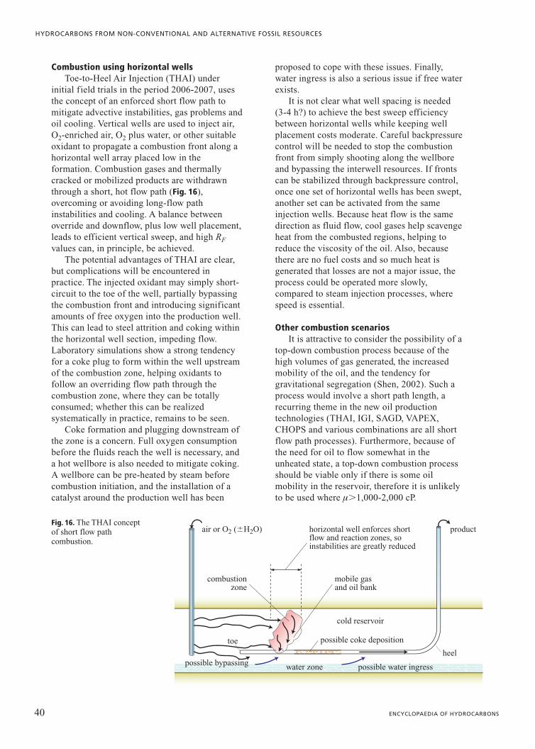
Combustion using horizontal wellsToe-to-Heel Air Injection (THAI) under
initial field trials in the period 2006-2007, usesthe concept of an enforced short flow path tomitigate advective instabilities, gas problems andoil cooling. Vertical wells are used to inject air,O2-enriched air, O2 plus water, or other suitableoxidant to propagate a combustion front along ahorizontal well array placed low in theformation. Combustion gases and thermallycracked or mobilized products are withdrawnthrough a short, hot flow path (Fig. 16),overcoming or avoiding long-flow pathinstabilities and cooling. A balance betweenoverride and downflow, plus low well placement,leads to efficient vertical sweep, and high RF
values can, in principle, be achieved. The potential advantages of THAI are clear,
but complications will be encountered inpractice. The injected oxidant may simply short-circuit to the toe of the well, partially bypassingthe combustion front and introducing significantamounts of free oxygen into the production well.This can lead to steel attrition and coking withinthe horizontal well section, impeding flow.Laboratory simulations show a strong tendencyfor a coke plug to form within the well upstreamof the combustion zone, helping oxidants tofollow an overriding flow path through thecombustion zone, where they can be totallyconsumed; whether this can be realizedsystematically in practice, remains to be seen.
Coke formation and plugging downstream ofthe zone is a concern. Full oxygen consumptionbefore the fluids reach the well is necessary, anda hot wellbore is also needed to mitigate coking.A wellbore can be pre-heated by steam beforecombustion initiation, and the installation of acatalyst around the production well has been
proposed to cope with these issues. Finally,water ingress is also a serious issue if free waterexists.
It is not clear what well spacing is needed (3-4 h?) to achieve the best sweep efficiencybetween horizontal wells while keeping wellplacement costs moderate. Careful backpressurecontrol will be needed to stop the combustionfront from simply shooting along the wellboreand bypassing the interwell resources. If frontscan be stabilized through backpressure control,once one set of horizontal wells has been swept,another set can be activated from the sameinjection wells. Because heat flow is the samedirection as fluid flow, cool gases help scavengeheat from the combusted regions, helping toreduce the viscosity of the oil. Also, becausethere are no fuel costs and so much heat isgenerated that losses are not a major issue, theprocess could be operated more slowly,compared to steam injection processes, wherespeed is essential.
Other combustion scenariosIt is attractive to consider the possibility of a
top-down combustion process because of thehigh volumes of gas generated, the increasedmobility of the oil, and the tendency forgravitational segregation (Shen, 2002). Such aprocess would involve a short path length, arecurring theme in the new oil productiontechnologies (THAI, IGI, SAGD, VAPEX,CHOPS and various combinations are all shortflow path processes). Furthermore, because ofthe need for oil to flow somewhat in theunheated state, a top-down combustion processshould be viable only if there is some oilmobility in the reservoir, therefore it is unlikelyto be used where m�1,000-2,000 cP.
40 ENCYCLOPAEDIA OF HYDROCARBONS
HYDROCARBONS FROM NON-CONVENTIONAL AND ALTERNATIVE FOSSIL RESOURCES
horizontal well enforces shortflow and reaction zones, soinstabilities are greatly reduced
air or O2 (H2O) product
heel
possible coke deposition
mobile gasand oil bank
combustionzone
water zone possible water ingresspossible bypassing
cold reservoir
toe
Fig. 16. The THAI conceptof short flow pathcombustion.

Consider a geometry as shown in Fig. 17; tostart with, basal wells are subjected tosingle-well HWCS until the steam chamber is ingood contact with the overburden and a heatedvertical flow path exists. It is at this stage thatpermanent heat losses through the overburdenbegin to be significant. Pure oxygen is theninjected slowly into the upper wells, generatingcombustion in the top of the zone. If combustiongases that stay near the top of the zone can bewithdrawn without having to flow down to thelower wells and impair flow behaviour (reducedpermeability to liquids, thermal channelling), thegravitationally segregated hot liquid can beproduced more efficiently. One way to achievethis is to inject oxygen into the upper well untilenough combustion has occurred, and then backproduce the combustion gases from the upperwell while producing hot oil from the lower well.Cyclic operation seems the best approach here.
Alternatively, it may be feasible to injectoxygen into the lower well while withdrawingthe combustion gases from the upper well.Combustion takes place, but the oil cannot flowupwards, and a hot low viscosity oil bankdevelops gravitationally around the lower well,episodically produced once the volumes are largeenough.
Even though the concepts involved in usinghorizontal wells for achieving short path,controlled combustion are new and untried inpractice, these ideas will soon be tested inpractice – most likely as technologiesimplemented after SAGD, CSS or other thermalmethods – as a final sweep of the reservoir toextract another modest increment of oil withoutthe need for large additional investment.
In an inclined reservoir (Fig. 18), it may bepossible to take advantage of formation dip tohelp mitigate problems such as gravity override
and gas channelling. Because of the naturaltendency for gas to stay high in the formationand hot liquids to drop, it may be feasible towithdraw combustion gases as they segregateand accumulate high in the formation, while theliquids continue to flow down-dip because of ahigher density. Horizontal wells along the strikedirection will, in general, be the most effectivemeans of carrying out combustion in such cases.
2.1.5 Technology mixing and sequencing
Mixing involves using different or combinedtechnologies within the same reservoir, or evenwithin the same well. Sequencing refers to theuse of different technologies one after the otherin a reservoir to increase RF by taking advantageof favourable changes in properties. Given thelarge number of technologies that are nowavailable, there are many possibilities, and only afew are detailed here; these have not been triedin practice yet, but the concepts appear sound(Dusseault, 2006), and implementation appearsstraightforward.
Mixing and sequencing of technologies toincrease RF and reduce overall costs should beconsidered at the beginning of a project, ratherthan after several years of production, as theimpact of reducing short-term costs (3-12 monthperiod) on overall long-term costs can be severe.For example, a technology sequencing strategymight require thermal vertical wells at a laterstage (e.g. after 5-6 years), but it is tempting todrill the first-generation wells as cheaply aspossible to avoid the early extra costs of thermalwells. Redevelopment now is far more costly if amajor drilling programme into a depleted or hotreservoir is needed. If the cost of the latter is
41VOLUME III / NEW DEVELOPMENTS: ENERGY, TRANSPORT, SUSTAINABILITY
OIL FROM NON-CONVENTIONAL SOURCES
phase 1: HWCS zonalheating and oil production
phase 2: possible cyclic combustion withgas off-take high in the stratum
hot zone
airinjection
slow steaminjection?
gas or steaminjection?
gas withdrawal orO2 injection
Fig. 17. A possibleapproach to HWCSfollowed by cycliccombustion.

substantial, and only a part of the resource isleft, a new cost-benefit analysis may show thatthe second investment is not warranted. If thethermal well investment had been done at thebeginning, the overall project would haverecovered far more oil and given financialreturns for a longer period, albeit not at theshort-term rate that the cheap initialdevelopment scheme achieved.
Combining production technologies
CHOPS and horizontal drains CHOPS generates massive reservoir changes
because of dilation and sand removal (up to1,500-2,500 m3 of sand in exceptional cases).The disturbed zone has a higher f, k may bedoubled, and relative permeability to water andto gas krw, krg (to steam or hot water) may beincreased by over a factor of 10. Also, the lateralstress has dropped to �30-40% of the verticalstress, and the rock compressibility is increasedby a factor of 10 to 100.
In steam processes, the faster that hot fluidscontact the cold zone and the more uniform theheating, the more economical extractionbecomes. Steam should spread rapidly throughthe region of CHOPS disturbance, therefore itseems attractive to combine SAGD (or HWCS)with CHOPS. Such a process would likely belimited to zones �12-15 m thick, but perhaps itcould be effective in higher oil viscosities thanconventional CHOPS. Fig. 19 shows a possiblecombined configuration.
Single horizontal wells are installed withvertical CHOPS wells which are producedimmediately and sustained for several years.Then, horizontal well steam injection is started
at relatively slow rates (30-40 t/d), perhaps withseveral HWCS production/injection cycles, untilcommunication with the disturbed zone isevident. The horizontal well is placed on SAGDproduction and steam injected into recompletedCHOPS wells. The system is operated at gravitydrainage conditions (low Dp), and RF values ashigh as conventional SAGD can be expected, butat a faster rate because of the disturbed zone.When production rates drop to low values,CHOPS wells are converted to IGI wells toscavenge heat, HC vapours and some additionaloil.
Among the advantages of such a system arefewer horizontal wells, likely with wider spacing,compared to SAGD alone.
CHOPS means good early production fromcheap vertical wells, and because of higher k,steam chamber development will be more rapidand oil produced in a shorter time frame.However, this scheme can likely be used only inreservoirs without active bottom water and withoil viscosities less than 50,000 cP.
VAPEX along with CHOPS may also be ofinterest, particularly since the CHOPS processbreaks through shale barriers and thus improvesvertical permeability. In the zones of high k andf generated by the CHOPS process, the vapourswould spread much more easily. In a VAPEX-CHOPS hybrid approach, there may beadvantages in continuing to operate the CHOPSwells long after vapour breakthrough tomaximize the extent of the disturbed zone beforeconverting them to vapour injection.
PPT and other technologiesPPT will be effective when gas saturation is
low, as the excitation waves are rapidly
42 ENCYCLOPAEDIA OF HYDROCARBONS
HYDROCARBONS FROM NON-CONVENTIONAL AND ALTERNATIVE FOSSIL RESOURCES
horizontal wells parallel to structure
combustion gasesflow to wells
water - one phase
injection rates are controlled toreduce excessive gas coning
air injection
oil bank, beingdisplaced byhot gases
combustion region,partly gravitationallystabilized
gas
Fig. 18. Possibleconfiguration forgravitationally stabilizedcombustion. Productionwell back-pressure iskept at the samepressure as in the activebottom water zone toeliminate water coningand production.
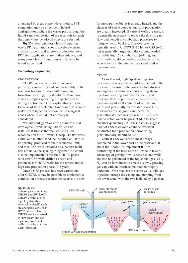
attenuated by a gas phase. Nevertheless, PPTstimulation may be effective in hybridconfigurations where the waves pass through theliquid-saturated portion of the reservoir to reachthe zone where beneficial effects are desired.
Fig. 20 shows one possible configurationwhere PPT excitation should accelerate steamchamber growth and improve production rates.PPT field applications are in their infancy, andmany possible configurations will have to betested in the field.
Technology sequencing
CHOPS-CSS-ISCCHOPS generates zones of enhanced
porosity, permeability and compressibility in thereservoir because of sand withdrawal andformation shearing; this should result in moreefficient (rapid) spreading of injected steamduring a subsequent CSS exploitation episode.Because of the accelerated time frame, this couldmake steam injection economical in marginalzones where it would not normally beconsidered.
Various configurations are possible: initialdevelopment wells using CHOPS can beinstalled at first as thermal wells to allowrecompletion to CSS wells. Cheap CHOPS wellscould, on the other hand, be installed on 10 to 20ha spacing, produced to their economic limit,and then CSS wells installed on a pattern infillbasis to halve the spacing. Megarow CSS couldalso be implemented after the CHOPS phase,with new CSS wells drilled as rows andproduced as CHOPS wells for the typical initialhigh-rate production phase (2-3 years).
Once a CSS process has been carried outafter CHOPS, it may be possible to implement acombustion process because the reservoir is now
far more permeable; it is already heated, and thechances of stable combustion front propagationare greatly increased. If vertical wells are used, itis generally necessary to reduce the downstreamflow path length in combustion processes tomitigate the oil banking. The well spacingtypically used in CHOPS (8-16 ha) or CSS (6-10ha) is generally larger than the spacing neededfor stable high Dp combustion (4-8 ha), andinfill wells would be needed, preferably drilledas new wells in the interwell area and used asinjection sites.
CSS-IGIAs well as oil, high Dp steam injection
processes leave a great deal of heat behind in thereservoir. Because of the low effective stressesand high temperature gradients during steaminjection, shearing and dilation occur, andreservoir flow properties are enhanced. Thus,there are significant volumes of oil that arewarm and potentially recoverable. Good CSSreservoirs are also good candidates forgravitational processes because CSS requiresthat no active water be present (due to steamchamber quenching). All these factors suggestthat hot CSS reservoirs could be excellentcandidates for a production period usinggravitationally-stabilized IGI.
Vertical CSS wells are almost alwayscompleted in the lower part of the reservoir, atabout the ? point. To implement IGI, re-perforating at the base of the oil zone to take fulladvantage of gravity flow is possible, and wellsare also re-perforated at the top so that gas (CH4,N2) can be introduced to create a slowly growinggas cap with an interface maintained roughlyhorizontal. One may use the same wells, with gasinjection through the casing and pumping fromthe lower zone, with the two isolated by a packer.
43VOLUME III / NEW DEVELOPMENTS: ENERGY, TRANSPORT, SUSTAINABILITY
OIL FROM NON-CONVENTIONAL SOURCES
4 times vertical exaggeration SW-SAGD wells
CHOPS wells
yieldedzone
sand, oil, water,gas production
steam or gasmixtures
sealedperforations
Fig. 19. Hybridtechnologies: combiningCHOPS and SW-SAGD.CHOPS creates a largehigh k, f disturbedzone, while SAGD wellsare operated slowly or inHWCS mode (phase 1);CHOPS wells convertedto slow steam and gasinjection, horizontalwells to gravity drainagewells (phase 2).

HWCS-IGI-ISCHorizontal well cyclic steaming will only
recover about 35-40% of OOIP and, in a mannersimilar to CSS-IGI, the process can be convertedto inert gas injection once cyclic productionbecomes uneconomical. At this stage, most ofthe reservoir is hot, but flow of the low viscosityoil to production wells is impeded because ofcapillary blockage, low local gradients, and soon. Inert gas is injected high in the reservoir toprovide voidage replacement and constantpressure, and oil is withdrawn from the basalhorizontal wells at the same volumetric rate asgas injection to avoid build-up of destabilizingpressure gradients. Because there is no free gasnear the production wells due to gravitationalsegregation of phases, the permeability to oilremains at reasonable values, and the free waterin the reservoir is also withdrawn along with theoil.
The inert gas injection allows the hot oil todrain with a minimum of cooling because thespecific heat of gas is low and, because oncegas forms a continuous zone at the top of thereservoir, it is also an insulator, slowingvertical conductive heat losses from the pad.Depending on permeability, it may benecessary to use vertical gas injection wells atspacings of 250-350 m to achieve a relativelyflat gas blanket.
In this case, it is not advisable to inject inertgas into the horizontal wells because thisintroduces free gas saturation around the wells,reducing the oil flow rate under Dp. However,one may inject hot HC gases that condense in thereservoir and dilute the oil, fill the voidage, andlead to a modified VAPEX process. If thisconcept is used, the process continues until oilrates slow down, then the valuable solvents canbe displaced by injection of light inert gas highin the zone.
Finally, once any valuable vapours have beenrecovered, air injection takes place, using theouter rows of vertical wells so that ascombustion develops, a front can be displacedalong the horizontal wells toward the heels.Because the wellbores are hot and the wholereservoir is heated, combustion should be quiteeffective. A possible well layout for thesesequenced technologies is sketched in Fig. 21.
2.1.6 Reservoir screeningcriteria
Tentative criteria are given in Table 3, butoverlap among suitable technologies exists inmany cases. For example, cold production usinghorizontal wells may be suitable for lowerviscosity oil in high permeability reservoirs(m�5,000 cP, k�2 D). However, if the reservoiris thick, CSS, SAGD, or VAPEX may also besuitable, and the latter two may give far greaterRF, though at higher OPEX. Because sometechnologies are very young or even largelyunproven, the criteria suggested here will changewith experience. The price of oil also will affectmatters; at �15 dollars/bbl, no steam injectionprocess will be viable for highly viscous oil. At75 dollars/bbl, even 10 m thick reservoirs mightbe economical if other properties are favourable.
Geological factors are vital; in many cases, atechnology will be more effective in a dippingreservoir because of the increased vertical extentprovided by the dip. For VAPEX, a limit of 10 mand a lateral spacing of 60 m is suggested for flat-lying strata, but with 8° dip, 4-6 m thickness isfeasible, and well spacing might increase to 100 m.
Some clear principles are evolving forviscous oil development, and these should beemphasized in light of the different technologiesdiscussed here:
44 ENCYCLOPAEDIA OF HYDROCARBONS
HYDROCARBONS FROM NON-CONVENTIONAL AND ALTERNATIVE FOSSIL RESOURCES
PPT wells
SAGD wells
excitation waves movethrough theliquid-saturated zoneSAGD chambers
3 times verticalexaggeration
(4-5) h
h
Fig. 20. Pressurepulse excitation in a gravity drainageenvironment.
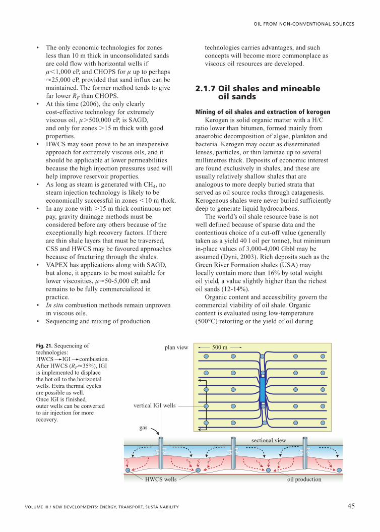
• The only economic technologies for zonesless than 10 m thick in unconsolidated sandsare cold flow with horizontal wells ifm�1,000 cP, and CHOPS for m up to perhaps�25,000 cP, provided that sand influx can bemaintained. The former method tends to givefar lower RF than CHOPS.
• At this time (2006), the only clearlycost-effective technology for extremelyviscous oil, m�500,000 cP, is SAGD,and only for zones �15 m thick with goodproperties.
• HWCS may soon prove to be an inexpensiveapproach for extremely viscous oils, and itshould be applicable at lower permeabilitiesbecause the high injection pressures used willhelp improve reservoir properties.
• As long as steam is generated with CH4, nosteam injection technology is likely to beeconomically successful in zones �10 m thick.
• In any zone with �15 m thick continuous netpay, gravity drainage methods must beconsidered before any others because of theexceptionally high recovery factors. If thereare thin shale layers that must be traversed,CSS and HWCS may be favoured approachesbecause of fracturing through the shales.
• VAPEX has applications along with SAGD,but alone, it appears to be most suitable forlower viscosities, m�50-5,000 cP, andremains to be fully commercialized inpractice.
• In situ combustion methods remain unprovenin viscous oils.
• Sequencing and mixing of production
technologies carries advantages, and suchconcepts will become more commonplace asviscous oil resources are developed.
2.1.7 Oil shales and mineableoil sands
Mining of oil shales and extraction of kerogenKerogen is solid organic matter with a H/C
ratio lower than bitumen, formed mainly fromanaerobic decomposition of algae, plankton andbacteria. Kerogen may occur as disseminatedlenses, particles, or thin laminae up to severalmillimetres thick. Deposits of economic interestare found exclusively in shales, and these areusually relatively shallow shales that areanalogous to more deeply buried strata thatserved as oil source rocks through catagenesis.Kerogenous shales were never buried sufficientlydeep to generate liquid hydrocarbons.
The world’s oil shale resource base is notwell defined because of sparse data and thecontentious choice of a cut-off value (generallytaken as a yield 40 l oil per tonne), but minimumin-place values of 3,000-4,000 Gbbl may beassumed (Dyni, 2003). Rich deposits such as theGreen River Formation shales (USA) maylocally contain more than 16% by total weightoil yield, a value slightly higher than the richestoil sands (12-14%).
Organic content and accessibility govern thecommercial viability of oil shale. Organiccontent is evaluated using low-temperature(500°C) retorting or the yield of oil during
45VOLUME III / NEW DEVELOPMENTS: ENERGY, TRANSPORT, SUSTAINABILITY
OIL FROM NON-CONVENTIONAL SOURCES
oil production
vertical IGI wells
HWCS wells
sectional view
500 mplan view
gas
Fig. 21. Sequencing oftechnologies:HWCS��IGI��combustion.After HWCS (RF�35%), IGIis implemented to displacethe hot oil to the horizontalwells. Extra thermal cyclesare possible as well. Once IGI is finished, outer wells can be convertedto air injection for morerecovery.

46 ENCYCLOPAEDIA OF HYDROCARBONS
HYDROCARBONS FROM NON-CONVENTIONAL AND ALTERNATIVE FOSSIL RESOURCES
Technology Critical criteria Well criteria
IGIInert Gas Injection
As a first IOR method, m�50 cP, kv�0.25 D, if active water,pwell�poriginal.After a steam process, similar criteria will apply to the hotreservoir. Any depth is feasible
Horizontal, as long asfeasible (no maximum Lconsidered)
CPCold Production (nosand)
For 50-500 cP, kv and kh�0.5 D, h�6-7 m.For 500-5,000 cP, kv and kh�2-3 D. Good virgin pressures and solution gas needed, �10,000 cP is theupper limit, even with good k. No active water or large gas cap,any depth
L must be large, somulti-laterals must beconsidered in marginalcases
CHOPSCold Heavy OilProduction with Sand
Up to �25,000 cP, k�0.5 D (less if m below 300 cP), h as low as3 m to 20 m max, good solution gas needed, no active bottomwater or significant gas cap. Sand must be totallyunconsolidated, maximum depth 1,200-1,500 m, minimum200 m
Vertical or deviated (up to50°) dip wells, largeperforations
CSS - megarowCyclic SteamStimulation
m up to 250,000 cP, �20 m thick if m�50,000 cP but as thin as10 m for m�500 cP. 800-1,000 m maximum depth, no gas cap oractive bottom water, shale beds traversed by fracturing, so low kv(e.g. 0.1 D) is fine as long as kh�0.5 D and vertical flowchannels are sustained. Solution gas is largely irrelevant to thistechnology
Vertical wells, rows spaced(6-8) h apart, wells spaced(3-5) h along row
HWCSHorizontal Well CyclicSteam
Similar conditions to CSS, no active bottom water or flank water,no closely overlying thief zones that could take steam. Probably250 m is the minimum depth for both HWCS and CSS toguarantee no steam breakthrough to surface
1,000 m long wells seemappropriate, perhaps up to1,200 m
SAGDSteam-AssistedGravity Drainage,horizontal wells
Any m if high enough T can be reached to reduce flowing m to �10 cP. �15 m thick net pay, if some 0.5 - 1 m shale beds, net pay must be higher. kv�0.5 D, kh�1-2 D,maximum depth perhaps 1,000-1,200 m. In higher m cases,�500,000 cP, thickness of 20 m may be the minimum. Can be used in cases of active water, thick gas caps are moreproblematic
800 m long horizontalwells, longer if m�1,000 cP,spaced laterally at �4h,except if strata dip
PPTPressure PulseTechniques
Effective in various technologies where the system is liquid saturated (0 or very low Sg). PPT is used with other production methods as a production or floodingenhancement, therefore the criteria for those methods apply. Any depth, and PPT is also applicable toconventional oil
Excitation or injection wellis vertical, limited (4-5 m)perforation interval
VAPEXVapour-AssistedPetroleum Extraction
Good intrinsic kv (�0.5 D) is needed with no flow barriers.Probably limited to reservoirs �6-8 m thick with m�1,000 cP,kh�1 D. Any depth to 3,500 m, can be used in the presence ofactive bottom water. Highly viscous oils may be used incombination with SAGD as a means of reducing the minimumthickness for economic SAGD
Horizontal producers up to1,500 m long, verticalinjectors depending onapproach
THAIToe-to-Heel AirInjection
Not yet proven, but probably any viscosity is suitable because of the combustion process. Thickness �4-5 m, probably unsuitable if there is free gas or active bottom water,k�0.5 D
Vertical toe injector wells,horizontal producers
Table 3. Screening criteria for non-conventional oil production methods*
* Assumptions: m�50 cP in virgin conditions, reservoirs have good oil saturation, high porosities (25% or larger) and sufficient lateralcontinuity. All gravity methods will probably be more effective in dipping cases
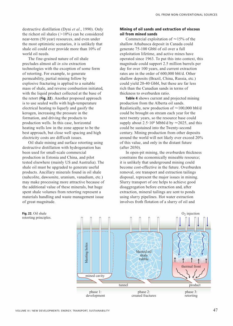
destructive distillation (Dyni et al., 1990). Onlythe richest oil shales (�10%) can be considerednear-term (50 year) resources, and even underthe most optimistic scenarios, it is unlikely thatshale oil could ever provide more than 10% ofworld oil needs.
The fine-grained nature of oil shaleprecludes almost all in situ extractiontechnologies with the exception of some formof retorting. For example, to generatepermeability, partial mining follow byexplosive fracturing is applied to a suitablemass of shale, and reverse combustion initiated,with the liquid product collected at the base ofthe retort (Fig. 22). Another proposed approachis to use sealed wells with high-temperatureelectrical heating to liquefy and gasify thekerogen, increasing the pressure in theformation, and driving the products toproduction wells. In this case, horizontalheating wells low in the zone appear to be thebest approach, but close well spacing and highelectricity costs are difficult issues.
Oil shale mining and surface retorting usingdestructive distillation with hydrogenation hasbeen used for small-scale commercialproduction in Estonia and China, and pilottested elsewhere (mainly US and Australia). Theshale oil must be upgraded to generate usefulproducts. Ancillary minerals found in oil shale(nahcolite, dawsonite, uranium, vanadium, etc.)may make processing more attractive because ofthe additional value of these minerals, but hugespent shale volumes from retorting represent amaterials handling and waste management issueof great magnitude.
Mining of oil sands and extraction of viscousoil from mined sands
Commercial exploitation of �15% of theshallow Athabasca deposit in Canada couldgenerate 75-100 Gbbl of oil over a fullexploitation lifetime, and active mines haveoperated since 1963. To put this into context, thismagnitude could support 2.5 million barrels perday for over 100 years, and current extractionrates are in the order of 600,000 bbl/d. Othershallow deposits (Brazil, China, Russia, etc.)could yield 20-40 Gbbl, but these are far lessrich than the Canadian sands in terms ofthickness to overburden ratio.
Table 4 shows current and projected miningproduction from the Alberta oil sands.Realistically, new production of �100,000 bbl/dcould be brought on stream each year for thenext twenty years, so the resource base couldsupply about 2.5�106 Mbbl/d by �2025, and thiscould be sustained into the Twenty-secondcentury. Mining production from other depositsaround the world will not likely ever exceed 20%of this value, and only in the distant future(after 2050).
In open-pit mining, the overburden thicknessconstrains the economically mineable resource;it is unlikely that underground mining couldbecome cost-effective in the future. Overburdenremoval, ore transport and extraction tailingsdisposal, represent the major issues in mining.Slurry transport of ore helps to achieve gooddisaggregation before extraction and, afterextraction, mineral tailings are sent to pondsusing slurry pipelines. Hot water extractioninvolves froth flotation of a slurry of oil and
47VOLUME III / NEW DEVELOPMENTS: ENERGY, TRANSPORT, SUSTAINABILITY
OIL FROM NON-CONVENTIONAL SOURCES
phase 1:development
mined cavity
phase 2:created fractures
blasted oilshalerubble
phase 3:retorting
thermal front
product
blas
ting
hol
es
tunnel
O2 injectionFig. 22. Oil shaleretorting principles.

water to which heat and NaOH have been addedto maximize oil release. With current technologyachieving about 92% oil extraction, each cubicmetre of ore requires removing 0.2-0.6 tonnes ofoverburden, and yields about 200 litres ofbitumen, 1.1 m3 of sand tailings and perhaps 0.3 m3 of liquid tailings comprising oil, clay andwater. Froth is treated to remove minerals andwater before upgrading and, interestingly, theprocess concentrates rutile grains, a potentiallyvast source of titanium.
Anhydrous extraction, which could reducethe tailings pond environmental issues, involvessolvents, oleophilic screens and other concepts.These have been studied since the 1970s, buthave yet to achieve full-scale application.
2.1.8 Upgrading and transportation
The need for special upgrading approaches anddifferent transportation strategies for non-conventional oils will gradually alter thesesectors of the oil industry in decades to come. Afactor affecting all decisions related to non-conventional oil is the feedstock value; viscous,high sulphur oil carries a substantial penalty thathas averaged 10 dollars/bbl over the years inwestern Canada, and has been as high as 20 dollars/bbl when conventional oil prices wereat their highest. This differential price reflects alimited upgrading capacity rather than theadditional costs associated with upgrading, asevidenced by fully integrated mining andupgrading operations that have achieved totaloperating costs in the order of 13-15 dollars/bbl.
Probably, true upgrading costs are in the order of50% of these operating costs, �6-7 dollars/bbl.
Upgrading High asphaltene and resin percentages in
viscous oil mean complex aromatic moleculeswith many carbon rings (low H/C ratio) which,when broken, generate free carbon, double andtriple C bonds, or open bonds that must besatisfied with hydrogen (Fig. 23). Viscous oilsalso have high heavy metals content (vanadiumand nickel), which means that process catalystsare rapidly poisoned.
A small quantity of viscous oil can be addedto conventional refining streams; this increasesresidual tar production, which is used forasphaltic products. Direct generation of a lowviscosity synthetic crude oil, called upgrading,involves carbon rejection (coking), hydrogenaddition (hydrogenation) and sulphur removal tocreate a product suitable for conventional oilrefineries. There are many process variants toachieve these goals, depending on whethercoking or hydrogenation is favoured, whatpressures are used, when it happens in theprocess, and so on.
No dramatic breakthroughs appear to beimminent for upgrading, though small advanceswill continue to be made in hydrogenation andcoking processes (better yields, less catalystconsumption, etc.). However, a large increase inupgrading efficiency can be achieved in the areaof heat preservation. The hot coupling concept,wherein cooling of streams is avoided by shortflow distances and direct treatment of hotstreams, should allow overall cost efficiencies of20% over current upgraders, although it leads to
48 ENCYCLOPAEDIA OF HYDROCARBONS
HYDROCARBONS FROM NON-CONVENTIONAL AND ALTERNATIVE FOSSIL RESOURCES
Table 4. Current and projected Alberta mining projects
Project 2003 production (bbl/d) <2012 projection(bbl/d)
Syncrude 255,496 �500,000
Suncor 273,563 �550,000*
AOSP - Athabasca Oil Sands Project 51,230 �525,000
Northern Lights 0 �100,000
Kearl Lake 0 �100,000
Horizon 0 �232,000
Total 580,289 �2,007,000
* Including some proportion of oil from SAGD, perhaps 20-25%
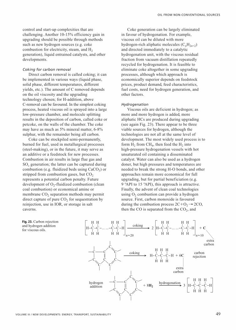
control and start-up complexities that arechallenging. Another 10-15% efficiency gain inupgrading should be possible through methodssuch as new hydrogen sources (e.g. cokecombustion for electricity, steam, and H2
generation), liquid entrained catalysts, and otherdevelopments.
Coking for carbon removalDirect carbon removal is called coking; it can
be implemented in various ways (liquid phase,solid phase, different temperatures, differentyields, etc.). The amount of C removed dependson the oil viscosity and the upgradingtechnology chosen; for H-addition, aboveC-removal can be favoured. In the simplest cokingprocess, heated viscous oil is sprayed into a largelow-pressure chamber, and molecule splittingresults in the deposition of carbon, called coke orpetcoke, on the walls of the chamber. The cokemay have as much as 5% mineral matter, 6-8%sulphur, with the remainder being all carbon.
Coke can be stockpiled semi-permanently,burned for fuel, used in metallurgical processes(steel-making), or in the future, it may serve asan additive or a feedstock for new processes.Combustion in air results in large flue gas andSOx generation; the latter can be captured duringcombustion (e.g. fluidized beds using CaCO3) orstripped from combustion gases, but CO2
represents a potential carbon penalty. Futuredevelopment of O2-fluidized combustion (cleancoal combustion) or economical amine ormembrane CO2 separation methods may permitdirect capture of pure CO2 for sequestration byreinjection, use in IOR, or storage in saltcaverns.
Coke generation can be largely eliminatedin favour of hydrogenation. For example,viscous oil can be diluted with morehydrogen-rich aliphatic molecules (CnH2n+2)and directed immediately to a catalytichydrogenation unit, with the viscous residualfraction from vacuum distillation repeatedlyrecycled for hydrogenation. It is feasible toeliminate coke altogether in some upgradingprocesses, although which approach iseconomically superior depends on feedstockprices, product demand, feed characteristics,fuel costs, need for hydrogen generation, andother factors.
HydrogenationViscous oils are deficient in hydrogen; as
more and more hydrogen is added, morealiphatic HCs are produced during upgrading(see again Fig. 23). There appear to be threeviable sources for hydrogen, although thetechnologies are not all at the same level ofdevelopment. The most widely used process is toform H2 from CH4, then feed the H2 intohigh-pressure hydrogenation vessels with hotunsaturated oil containing a disseminatedcatalyst. Water can also be used as a hydrogendoner, but high pressures and temperatures areneeded to break the strong H-O bonds, and otherapproaches remain more economical for fullupgrading, but for partial beneficiation (e.g. 9 °API to 15 °API), this approach is attractive.Finally, the advent of clean coal technologiesusing O2 combustion can provide a hydrogensource. First, carbon monoxide is favouredduring the combustion process 2C�O2�� 2CO,then the CO is separated from the CO2, and
49VOLUME III / NEW DEVELOPMENTS: ENERGY, TRANSPORT, SUSTAINABILITY
OIL FROM NON-CONVENTIONAL SOURCES
C
C
C
C C
C
C
C
CC
C
C
C C
C
C
C
CC
... ...H C
H H
H H
CH C
H H
H H
CH C
H H
H
C H
H
H
C H
H
H
H
C HC 2
3
� C
� 6C
� 8H2
H H
H H n�20
C ... ...H C
H H
H H
C HC
H H
H H n�10
coking
coking
hydrogenation
extracarbon
extracarbon
carbonrejection
hydrogenaddition
Fig. 23. Carbon rejectionand hydrogen additionfor viscous oils.

reacted at high pressure and temperature to yieldhydrogen: CO�H2O�� CO2�H2.
In hydrogenation processes, continuousrecycling loops are incorporated into the upgradingscheme so that the viscous residual HCs arereturned to the hydrogenation facility. It is possibleto avoid coking altogether by this recyclingprocess, but coking is considered generally to bean aid to upgrading because it also reduces S andheavy metals content in the oil.
Sulphur removal Sulphur content of viscous oils is extremely
high, from perhaps 0.1-0.2% for the lowerviscosities to as high as 4% for the most viscousmaterials, although in the case of oil shales, it isfar lower. The increasing insistence for lowsulphur products means that high-pressurehydrogenation must be used during upgrading, aprocess which turns S into a gaseous substance(H2S) that can be easily separated and turnedinto elemental sulphur, a relatively inertsubstance that is easy to store or transport.
Viscous oil transportationIt is generally not optimal to perform all
upgrading and refining into products at theviscous oil extraction site. Refinery capacityaround the world is geared to provide localproducts, and capital costs for these facilitieshave already been made. Hence, viscous oilneeds to be transported by pipeline.
The initial approach in viscous oildevelopment was local upgrading to a productgravity of about 30 °API, a synthetic crude thatcould easily be pipelined great distances, althoughthis product tends to have a narrow range ofmolecular weights. To pipeline viscous crude,three options are available. First, dilution with 5-20% low molecular weight HCs can be used.Second, synthetic crude can be blended with rawbitumen to generate a pipeline feed for shipping.Third, an emulsion with fresh water can begenerated. The former two methods are in wideuse, the latter is used only in a limited manner.Diluent shortages in the future will see more andmore blending with synthetic oil for pipelining, aswell as construction of diluent return pipelines sothat it can be re-used repeatedly.
2.1.9 Environmental impact
Non-conventional oil development meansparticular attention to environmental issues
because viscous oil and oil shale exploitationgenerate large waste volumes that must bedisposed of economically and in anenvironmentally safe manner. One may expectthat large-scale increases in viscous oil miningand upgrading will be strongly opposed by manyon environmental grounds, therefore particularcare and the development of low-impact wastehandling must be emphasized. Carbon dioxideemissions are also a long-term environmentalissue in the petroleum industry, but this area iscomplex and dynamic, and will not be addressed here.
Surface mining solid wastesMaterials handling and reclamation are
perhaps the most important issues for anysurface mining process. For example, surfaceretorted oil shales generate �1.2-1.4 m3 ofuncompacted solid waste for each m3 processed.Waste must be returned to the open pit orotherwise placed so that re-establishment of floraand fauna can occur. In extractive processes, allsolid materials must be handled twice; evenoverburden materials have to be stripped, andthen replaced onto the spent shale. Additionalhandling is to be avoided.
Huge solid waste volumes are also generatedin oil sand mining. Volumes are immense: foreach m3 of 30% porosity oil sands processed byhot water extraction, 0.2-0.5 m3 of overburdenmust be removed and 1.1 m3 of 40% porositywaste sand is generated, along with largevolumes of fine-grained oily sludge. These solidwastes must be permanently disposed of with aminimum of rehandling, and rehabilitated to areasonable landscape quality.
Liquid wastes and sludgesShale oil retorting is an anhydrous process;
only small amounts of waste water are generated.However, in oil sands extraction, approximately1.2-1.4 m3 of slurry are generated for each m3 ofore processed; this slurry contains oil and clayminerals, as well as other fine-grained minerals,and consolidation of oil-rich clay sludge is anextremely lengthy process. Improvements inprocessing such as partial flocculation andtertiary extraction, and reduction of tailingsstream water requirements by thickening, reduceproduced sludge volumes, but sludge pondsremain an issue of concern. Freeze-thawprocesses and other means of accelerating sludgeconsolidation are being developed to reducevolumes and allow more rapid land reclamation,
50 ENCYCLOPAEDIA OF HYDROCARBONS
HYDROCARBONS FROM NON-CONVENTIONAL AND ALTERNATIVE FOSSIL RESOURCES

reducing long-term environmental impact andland use degradation.
The search for a practical anhydrousextraction method for oil sands continues; such amethod would eliminate the need for tailingsponds and long residence times before ponds canbe closed. However, generating entirely solidwastes would also increase transport costs,compared with the slurry pipelines that are nowused, though this is less of a penalty with highoil prices.
Sulphur and coke: wastes turned into possibleresources
Is coke a resource or a waste? Currently, cokeis stockpiled, burned as a local energy source, orused in extractive metallurgy. With emergingclean coal technologies, even high sulphur andsolids content coke could be used as a fuel forgenerating power, heat, and hydrogen in anintegrated system. Elements of coke combustioncould include O2 as an oxidant, pressurizedfluidized bed combustion, heat exchangers,steam generation for viscous oil, and fullemissions capture for SOx and particulates; eventhe �98-99% pure CO2 emitted could besequestered or used for miscible CO2 enhancedrecovery processes. As carbon emission taxes areinternationally adopted, with matching taxcredits, coke has value as a carbon credit source,and permanent coke storage may beeconomically more interesting than combustionin some cases.
Is sulphur a resource or a waste? More andmore H2S-rich natural gas is being produced, andviscous oil exploitation implies increasingquantities of S production. A world glut of Scurrently exists, and this glut will persist for allof this century. Thus, in viscous oil upgradingprojects, considering S as a material to bestockpiled indefinitely is necessary, or it must beshipped, probably at a loss. In surface mining,the solution is obvious: storage in the mined-outpit in a local area that can be accessed in thedistant future. For in situ viscous oil extractionprojects, S must be stored on the surface or inlandfills, or injected under fracturing conditionsin a slurry form so that a solid sulphur deposit isgenerated at depth, to be recovered decadeshence by hot water injection.
If fluidized beds with CaCO3 are used toburn S-rich coke fuels, huge volumes ofdesulphurization sludges, essentially gypsum-type molecules (CaSO4), will be generated.Because the gypsum contains heavy metals, ash,
and other by-products, it has no industrial use,and will have to be either stored permanently atthe surface or otherwise disposed in pits or deepunderground.
Options for waste management Treatment of gaseous emissions to reduce
noxious gases (SOx, NOx, particulates) is now soefficient that non-conventional oil extraction andupgrading methods should not significantlyimpact atmospheric quality. This is merely anissue of regulatory policy and strongenforcement.
National regulations permitting, largevolumes of waste water that cannot be cleanedeconomically can be injected deep intosedimentary strata with negligible environmentalrisk. Liquids with oily scum and colloidallysuspended solids or oil are usually clarifiedbefore injection, though this costly step is notnecessary if injection under fracturing conditionsis permitted. In steam projects, water recycling iswidely practised, but water must be treated toremove calcium and other polyvalent cationsbefore steam is generated. Lime sludgesgenerated by water treatment represent solidwastes that must be disposed of, and the clearsupernatent liquid can be injected.
Solid waste disposal options depend onwhether it is dry or in the form of tailings, andwhether it is a hazardous or a non-hazardousmaterial. Small amounts of hazardous andnon-hazardous solid waste can be treated anddisposed by means such as chemical leaching,thermophilic decomposition, centrifuging, oilseparation, and landfill placement. In Canadianregulations, class I landfills are extremelycarefully lined and capped, and are used forhazardous materials only if detailed studies aredone and a limited permit issued; class IIlandfills have compacted clay liners and are usedfor non-hazardous wastes such as oily sand anddrill cuttings; class III landfills are unlined andused for non-oily wastes that cannot generatenoxious leachates.
Non-hazardous slurries can be sent toseparators (small volumes), to tailings ponds forgravitational separation (huge volumes), orinjected directly at depth under hydraulicfracturing conditions (intermediate volumes).Non-hazardous solid wastes can be disposed ofin class II landfills, by deep slurry injection, orthrough salt cavern placement (Fig. 24). Attemptsto thermally treat or clean or recover oil fromlarge-volume oilfield waste streams is invariably
51VOLUME III / NEW DEVELOPMENTS: ENERGY, TRANSPORT, SUSTAINABILITY
OIL FROM NON-CONVENTIONAL SOURCES

more costly than disposal because cleaningusually creates several additional streams, suchas dirty water, poor oil and clean sand, whichstill must be disposed of.
For example, large volumes of oily sand areproduced during CHOPS; in Canada, about 1 m3
per 50 m3 oil, giving about 0.5�106 m3 total sandin 2004 alone. Produced sand was once disposedby land or road spreading, but this is no longerenvironmentally acceptable. Warm waterwashing has been tried, but three companies havegone bankrupt trying to do this profitably.Biotreatment and thermal decomposition appearto be prohibitively costly and technologicallyrisky.
Some of the sand, along with emulsions,slops and other wastes, is now disposed in localsalt caverns where solids settle to the base,displacing brine. Because of its high density (1.2 g/cm3), and because it destroys natural ionicsurfactants, brine helps separate much of the oilfrom the wastes, although this recovered oil is ofvery poor quality.
Produced sand can be slurried with wastewater, some emulsion and slops (all costly todispose of conventionally), and injected underfracture pressure into appropriate porous andpermeable formations. A large slurry injectiondisposal site in Duri, Indonesia, at anon-conventional oil production project, hasaveraged over 500,000 m3/yr of slurryplacement over four years using two injectionwells. Costs for slurry injection are lower thanfor salt cavern creation and placement, and theenvironmental liability is essentially zero oncethe wastes are injected into an appropriatezone, often a depleted reservoir.
Oily sand can be placed in landfills if it isstackable (no free liquids) with chloride contentsless than 3,000 mg/l. In general, this means thatwaste sand must be stockpiled on the surface for
a year or two to drain before trucking todisposal. This method is slightly cheaper thanthe others, but there remains a sustainedenvironmental liability because of near-surfaceplacement of the solids.
These methods, used for appropriate wastesteams, along with good monitoring andenforcement policies, can virtually eliminateenvironmental problems.
2.1.10 Predictions
The changing fossil fuel mixNew energy sources gradually become
available, and the mix of fossil fuels has changedaccordingly. Coal was the first widely exploitedfossil fuel; it displaced wood, peat and charcoal.Conventional oil has displaced coal for transport,and conventional natural gas is displacing oil andcoal for heating and cooking, and is alsoaffecting power generation. Oil was widely usedfor power generation and space heating, but isnow used almost exclusively (�90%) for twopurposes: transportation fuel andpetrochemicals.
It appears that conventional oil productionwill peak in the period 2005-2010 (Deffeyes,2001), and continued demand growth can thenonly be met by new sources, by changing theenergy mix, and by changing consumptionpatterns. Viscous oil production will continue toincrease, both in absolute terms and as aproportion of the total oil produced, for at leastthe next fifty years, barring unpredictable events,even if the total world oil production stays below100 Mbbl/d (it was �84 Mbbl/d in 2005).Natural gas will be used for transportation moreand more, but we can expect that worldwidenatural gas production will peak near 2020-2025(Laherrère, 2004).
52 ENCYCLOPAEDIA OF HYDROCARBONS
HYDROCARBONS FROM NON-CONVENTIONAL AND ALTERNATIVE FOSSIL RESOURCES
tailingsponds old or
new mineslandfills,quarries
ocean dumping
not to scale
salt caverns
deep solidsslurry
injection
deep liquiddisposal
Fig. 24. Permanentdisposal methods forliquid and solid wastes.

Thus, the energy mix (coal, gas, oil, nuclear,solar, hydro, wind, tides, geothermal, etc.) andthe nature of energy use (transportation, heating,manufacturing, etc.) will shift slowly in responseto costs, demand and technological feasibility.Even ten years ago, viscous oils were consideredto be irrelevant in terms of long-range oilproduction, but this is no longer the case:non-conventional oil will become an increasinglyimportant part of the energy mix over the nexttwo generations.
Continued innovation and costsIt is safe to predict that continued technical
progress will occur in societies that develop anduse scientific knowledge. In the past 250 years,this has meant that all commodities, withoutexception, have become cheaper as a proportionof income (Simon, 1996). Though many haverepeatedly claimed that this trend will sooncease, history seems clear on this issue. Fossiloil will eventually be replaced by othertransportation fuels; this is inevitable, much ascopper is being replaced with silica fibre, steelby plastics, and so on. Yet, economies have notsuffered as these shifts and replacements havetaken place.
The new production technologies developedin 1985-2005 mean that more of the fossil oilresource base will become accessible atreasonable cost. Innovation will continue, andenvironmental costs of fossil fuel extraction anduse will be mitigated by greater efficiencies andnew methods of waste disposal.
However, barring major technologicalbreakthroughs, future energy costs are likely tobe a higher proportion of personal expendituresthan in the last half of the Twentieth centurybecause of the high cost of renewable energy,depletion of fossil fuel resources, and CO2
emission penalties. Will there ever be agenuinely major and prolonged energy crisis, assuggested by Deffeyes (2001), Campbell (1999),and others? The large potential reserves in placesuggest that sustained high prices will generatemore recoverable oil, and that there may be asmuch as 2�1012 bbl of viscous oil andconventional IOR oil technically accessible andwithin realistic economic reach. As innovationcontinues, this oil will be gradually added to theworld total recoverable reserves. The first majorevent in this regard was the addition of 174�109
barrels of Canadian viscous oil to worldrecoverable reserves in 2002, based solely on thesuccess of SAGD in Canada. Applying the same
standard to the Faja del Orinoco reservoirs inVenezuela would immediately add another(225-250) �109 bbl. This process can be expectedto continue for many decades.
Nevertheless, non-conventional oil is notcheap oil, so higher prices are likely to besustained; this will place downward pressure onconsumption and generate many new methods ofconserving fossil fuels. The decline of oil is,therefore, extremely unlikely to generate acatastrophic economic plummet; rather, a slowcontrolled descent in fossil oil production rateswill take place, mitigated by new sources ofenergy, better environmental husbandry, greaterefficiency, and a sustained high standard ofliving for a slowly declining world population.
Some predictionsContinued high prices for oil will have a
number of effects, and the following predictionsseem safe to make at the present time (neglectingpossible effects of CO2 emissions penalties):• The high price for oil will have the effect of
increasing the economically recoverableresource base.
• Non-conventional oil production technologieswill become widely utilized if a stable highprice for oil is sustained, leading to adramatically increased volume ofeconomically recoverable reserves.
• The economically recoverable reserves fromCanada and Venezuela will gradually rise tovalues in the order of 0.8⋅1012 bbl of oil froma resource base that is currently estimated tobe about 2.8�1012 bbl.
• Viscous oil resources in other countries willprovide 0.5-0.8�1012 bbl recoverableresources from a similar sized, though lowerquality, resource base.
• Technology spin-off from viscous oilextraction will permit economical re-entryinto depleted conventional oil reservoirs; thiswill likely provide an additional 0.5-0.8�1012
bbl of oil that is not yet considered in currentresource-base analysis.
• By 2050, viscous oil production will exceedconventional oil production, and Canada andVenezuela will be among the top three oilproducing countries.
• Clean coal combustion technologies ornuclear power as alternative methods togenerate steam should provide substantiallybetter economics, but implementing theseapproaches in non-conventional oil areasseems to be some time away.
53VOLUME III / NEW DEVELOPMENTS: ENERGY, TRANSPORT, SUSTAINABILITY
OIL FROM NON-CONVENTIONAL SOURCES
HYDROCARBONS FROM NON-CONVENTIONAL AND ALTERNATIVE FOSSIL RESOURCES
ENCYCLOPAEDIA OF HYDROCARBONS54
• High diluent value and shortages of CH4 willimpact large-scale viscous oil exploitation,and these factors should favour more cokingand local synthetic crude oil generation forshipping. These issues will also sustainresearch efforts to seek other options andreplacement.
• Clean coal technologies promise to fit verywell with viscous oil exploitation because ofheat and electricity co-generation, andbecause of hydrogen production and potentialeasy CO2 capture.
• Oil means transportation; sustained highprices mean more efficient transportationmethods will evolve including hybridvehicles, electric city cars, more rapid transitsystems for urban regions, a revitalization ofrail transport, and so on. Fossil fuels will playan important role in transportation for thenext 100 years, and perhaps for longer.
• Nuclear energy will experience renewedgrowth because of its promise to providepower without CO2 emissions. Better designand solutions for waste management willhelp overcome most of the concerns with thistype of energy.
• 100 to 125 years from now, fossil oil andnatural gas will not be the dominant playersin the field of energy, and oil companies willhave morphed into providers of other energystreams.
• Transportable synthetic liquid and gaseousfuels, whether from biotechnology or othersources, will gradually displace fossilresource sourced fuels. The rate at which thiswill occur cannot be predicted in detail. Non-conventional oil will be sourced mainly
from the large deposits of Venezuela, Canada,Russia, Kazakhstan, Mexico, and a few othercountries, simply because these countries possessthe majority of the high-quality viscous oilresource base. Hydrogen for upgrading willbecome a constraint in some areas within the nextthirty years. Eventually, although probably notbefore the midpoint of this century, oil extractedfrom shale will become a significant source(Johnson et al., 2004), though it will never comeclose to viscous oil as a fossil fuel source.
References
Beresenev I.A., Johnson P.A. (1994) Elastic-wavestimulation of oil production: a review of methods andresults, «Geophysics», 59, 1000-1017.
Butler R.M. (1991) Thermal recovery of oil and bitumen,Englewood Cliffs (NJ), Prentice Hall.
Butler R.M., Mokrys I.J. (1991) A new process (VAPEX)for recovering heavy oils using hot water and hydrocarbonvapour, «Journal of Canadian Petroleum Technology»,30, 97-105.
Campbell C.J. (1999) The coming oil crisis, Brentwood(UK), MultiScience & Petroconsultants S.A.
Chatzis I. et al. (1988) On the investigation of gravity-assisted inert gas injection using micromodels, long BereaSandstone core, and computer assisted tomography, in:Proceedings of the Society of Petroleum Engineers annualtechnical conference and exhibition, Houston (TX), 2-5October, SPE 18284.
Collins P.M. (2004) The false lucre of low-pressure SAGD,in: Proceedings of the Canadian international petroleumconference, Calgary (Alberta), 8-10 June, Paper 2004-031.
Deffeyes K. (2001) Hubbert’s peak. The impending worldoil shortage, Princeton (NJ), Princeton University Press.
Dusseault M.B. et al. (2002a) CHOPS in Jilin Province,China, in: Proceedings of the Society of PetroleumEngineers international thermal operations and heavyoil symposium and international horizontal welltechnology conference, Calgary (Canada), 4-7 November,SPE 79032.
Dusseault M.B. et al. (2002b) Field applications of pressurepulsing in porous media, in: Proceedings of the 2nd Biotconference on poromechanics, Grenoble (France), 26-28August, 639-645.
Dusseault M.B. (2006) Sequencing technologies to maximizerecovery, in: Proceedings of the Canadian internationalpetroleum conference, Calgary (Canada), 13-15 June,Paper 2006-135.
Dyni J.R. (2003) Geology and resources of some world oilshale deposits, «Oil Shale», 20, 193-252.
Dyni J.R. et al. (1990) Comparison of hydroretorting, Fischerassay, and Rock-Eval analyses of some world oil shales,in: Proceedings of 1989 Eastern oil shale symposium,Lexington (KY), 15-17 November, 270-286.
Elliott K.T., Kovscek A.R. (1999) Simulation of early-time response of single-well steam assisted gravitydrainage (SW-SAGD), in: Proceedings of the Society ofPetroleum Engineers Western regional meeting, Anchorage(AK), 26-27 May, SPE 54618.
Gong J. et al. (2002) Fast SAGD and geomechanicalmechanisms, in: Proceedings of the Canadian internationalpetroleum conference, Calgary (Canada), 11-13 June, Paper2002-163.
Gupta S. et al. (2002) Field implementation of solvent aidedprocesses, in: Proceedings of the Canadian internationalpetroleum conference, Calgary (Canada), 11-13 June,Paper 2002-299.
Johnson H.R. et al. (2004) Strategic significance of America’soil shale resource; 2v.; Volume I: Assessment of strategicissues; Volume II: Oil shale resources, technology andeconomics, US DOE Office of naval petroleum and oilshales reserves.
Kobbe W. (1917), «Transactions of the American Instituteof Mining Engineers», 56, 814.
Laherrère J. (2004) Future of natural gas supply, in:Proceedings of the 3rd International workshop on oil &gas depletion, Berlin, 25-26 May.

OIL FROM NON-CONVENTIONAL SOURCES
VOLUME III / NEW DEVELOPMENTS: ENERGY, TRANSPORT, SUSTAINABILITY 55
Manga M. et al. (2003) Response of streamflow to multipleearthquakes, «Geophysical Research Letters», 30, 1214-1217.
Ren W. et al. (2005) A study of the gravity assisted tertiarygas injection processes, «Journal of Canadian PetroleumTechnology», 44, 26-32.
Shen C. (2002) Limitations and potentials for in situ combustionprocesses for heavy oil reservoirs, in: Proceedings of theCanadian international petroleum conference, Calgary(Canada), 11-13 June, Paper 2002-217.
Simon J.L. (1996) The ultimate resource II, Princeton-Chichester,Princeton University Press.
Spanos T.J.T. (2001) The thermophysics of porous media,Boca Raton (FL), Chapman&Hall-CRC Press.
Spanos T.J.T. et al. (2003) Pressure pulsing at the reservoirscale. A new IOR approach, «Journal of Canadian PetroleumTechnology», 42, 16-28.
Maurice B. Dusseault
Department of Earth SciencesUniversity of Waterloo
Waterloo, Ontario, Canada
