2. packaging trends and thermal management - cupathways.cu.edu.eg/ec/text-pdf/part a-2.pdfpackaging...
TRANSCRIPT

Course Part A: Introduction to Electronics Cooling
17MPE 635: Electronics Cooling
2. Packaging Trends and Thermal Management 2.1 Introduction Packaging is one of the important stages in the electronic devices manufacturing. Proper packaging of electronic component increase reliability and lifetime but unfortunately increases its cost. Due to the nature of the design and development in the electronics industry, while the function of a computer is undeniably, the electronic failures in the field today are most often mechanical. 2.1.1 Electronic packaging and interconnection technology Electronic packaging is the realization of the physical, electronic system, starting with block-circuit diagram. This involves choice of technology for implementation, choice of materials, detailed design in chosen technology, analysis of electrical and thermal properties, and reliability. This definition is one among many, and may shift as the field is further developed. Due to the multi-disciplinary of the electronic packaging and interconnection technology, a combination of the following disciplines should be studied: • Electronics • Materials properties and materials compatibility • Mechanics • Chemistry • Metallurgy • Production technology • Heat transfer • Reliability, etc • Product development should involve experts from the various fields, and the interdependence of the fields may be the most important to make a good product. 2.1.2 Types of Electronics and Demands Satellite Electronics Production volume: one unit, 20 years life required, no repair, very low weight, and very high development cost acceptable. Life Saving Medical Electronics Similar reliability/power demand may be in harsh environment (body fluids), medium production volume. Telephone Main Switchboard 10 year life, benign environment, very high complexity, low and high production volume, and high price pressure.

Course Part A: Introduction to Electronics Cooling
18MPE 635: Electronics Cooling
Military Electronics Very high reliability demands, in very rough environments. High development cost (and production cost) acceptable. Computers High performance and reliability required. Very short product life, high production volume for some, and small volume for some products. Consumer Products (watches, calculators...) Extreme price pressure, very short product life, low weight and power, very big market, and no repair. 2.1.3 Automotive Electronics Electronic content in cars and trucks has significantly increased in the last 30 years. Much of the functional content of these vehicles is now generated or controlled by electronic systems. This trend will continue in the future, as more mechanical functions are converted to electronic and electrical functions. A list of many current automotive electronic functions can be found in Table 2.1.
Table 2.1 Current Automotive Electronic Functions Where Are We Today?
� Collision Warning Systems � Adaptive Cruise Control � Night Vision � LED Displays � Incandescent Lamp Lighting � UV Front Lighting � Motor Controls � Low Tire Pressure Warning � Reconfigurable Displays � Electric Vehicle Propulsion Systems � Cockpit Modules � Automatic Wiper Control � Automatic Head/Tail Lamp Controls
� Electronic Spark Control � Body Control Computer � Speakers and Enclosures � High Fidelity Music Systems � Compact Disc Players � AM Radios � Anti-Lock Brakes � Traction Controls � Engine Control Modules � Suspension Controllers � FM Radios � Power Modules � Remote Keyless Entry � Cellular Telephone � Emergency Call Service � Satellite Radio � Automatic/Remote Mirror Control � Remote Start � CB Radio
� Voltage Regulators � Anti-Theft Systems � Electromechanical Instrument Clusters � Heating/Ventilation/Air Conditioning Controls � Electronic Instrument Clusters � Driver Information Center � Head-Up Displays � Steering Wheel Controls � Air meter Electronics � Air Bag Electronics � Pressure Sensors � Ignition Electronics � Four Wheel Steering Systems � Vehicle Stability Control Systems � Power Train and Transmission Control Modules
Some recently introduced vehicles – hybrid cars – use internal combustion engines in conjunction with electric drive motors. Electric vehicles use electric motors alone without internal combustion engines. It is anticipated that fuel cell based electric vehicles will go into

Course Part A: Introduction to Electronics Cooling
19MPE 635: Electronics Cooling
production some time late in this decade. These vehicles will use high power motor controls and drive electronics that will likely dissipate kilowatts of thermal energy. Cost, Size, and Reliability The requirements of low cost and small size is a given for nearly all commercial electronics applications. This is also true for automotive electronic systems and, as is the case with many consumer electronic products, price is a major driver of the hardware design. One example can be seen in the history of typical engine control modules (ECMs) shown in Figure 2.1. Over time, the size and cost of the typical ECM has decreased while the required functionality and operating temperatures have significantly increased.
Figure 2.1 History of typical engine control modules (ECMs)
Although both consumer and automotive electronic hardware trends push suppliers toward smaller size and lower cost, there are significantly higher requirements for operating life, reliability and operating environment in automotive applications. Automotive safety issues as well as customer expectations require flawless function under all weather and operating conditions for 10 years or more. Hence, the challenge for automotive electronic hardware designs and the resident cooling technology is not only achieving small size and low cost, but also high reliability in high ambient temperatures. 2.2 Packaging Levels There are six generally recognized levels of electronic packaging. Figure 2.2 shows the packaging hierarchy described. The six levels are: Level 0: Bare semiconductor (unpackaged). Level 1: Packaged semiconductor or packaged electronic functional device. The electronic device can be active, passive, or other (e.g., electromechanical).

Course Part A: Introduction to Electronics Cooling
20MPE 635: Electronics Cooling
Level 2: Printed wiring assembly (PWA). This level involves joining the packaged electronic devices to a suitable substrate material. The substrate is most often an organic material such as FR-4 epoxy-fiberglass board, or ceramic such as alumina. Level 2 is sometimes referred to as the circuit card assembly (CCA) or, more simply, the card assembly. Level 3: Electronic subassembly. This level refers to several printed wiring assemblies (PWAs), normally two, bonded to a suitable backing functioning both as a mechanical support frame and a thermal heat sink. Sometimes this backing, or support frame, is called a sub-chassis. Level 4: Electronic assembly. This level consists of a number of electronic subassemblies mounted in a suitable frame. An electronic assembly, then, is a mechanically and thermally complete system of electronic subassemblies. Level 5: System. This refers to the completed product.
Figure 2.2 Packaging levels The trend in electronic packaging is to simplify and/or reduce the number of packaging levels. For example, the chip-on-board technology (COB), where a bare integrated circuit die (sometimes also called a chip) is placed directed on a printed wiring board and bonded to the board, eliminating the first level of packaging by going directly from the zeroth level to the second level. COB technology is a particular example of direct chip attache (DCA). The packaging hierarchy given above is not universal. For computer packaging, for example, Level 3 entails a number of PWAs plugged into a backplane board and supported in a suitable chassis.

Course Part A: Introduction to Electronics Cooling
21MPE 635: Electronics Cooling
2.3 Package Function Definition Physical implementation of the electronic design, as shown in Figure 2.3, proper package design should provide: • Signal distribution • Power delivery • Thermal management • Gentle environment • Minimum signal delay • Minimum cost In the present course we will focus only on providing good thermal management and gentle environment through the scope of heat transfer design. The thermal management strategy plays a pivotal role in: • Establishing physical configuration • Determining environmental/dissipation envelope • Life - cycle cost • System reliability Consequently, thermal analysis techniques are of critical importance.
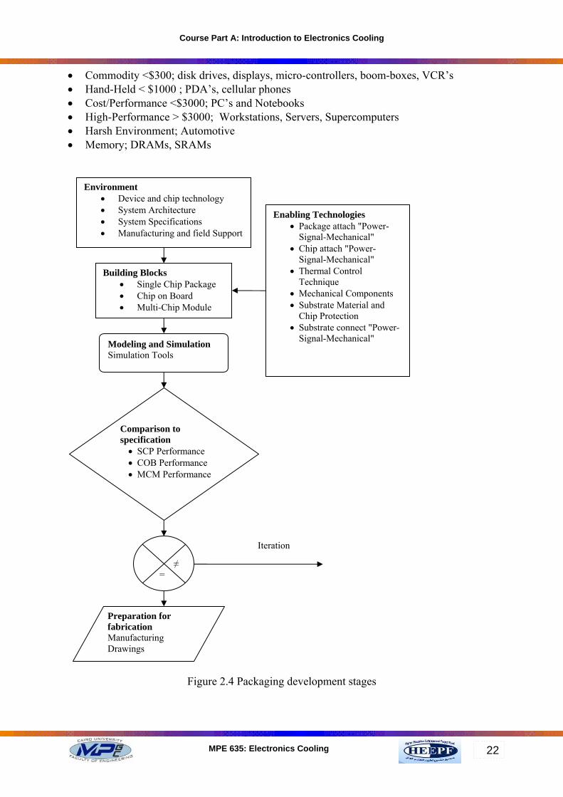
Figure 2.3 Package function 2.4 Stages in the Development of a Packaging Technology The development of electronic packaging goes through various stages, which are: • Environment • Building blocks • Enabling technology • Modeling and simulation • Comparison to specifications • Preparation for manufacturing The inter-relation-ship of these stages is shown in Figure 2.4. 2.5 Product Categories Packaging parameters and requirements are different from one category to the other. The following product categories are illustrative examples to show the different product categories with the suggested price for each:
Course Part A: Introduction to Electronics Cooling
22MPE 635: Electronics Cooling
• Commodity <$300; disk drives, displays, micro-controllers, boom-boxes, VCR’s • Hand-Held < $1000 ; PDA’s, cellular phones • Cost/Performance <$3000; PC’s and Notebooks • High-Performance > $3000; Workstations, Servers, Supercomputers • Harsh Environment; Automotive • Memory; DRAMs, SRAMs
Figure 2.4 Packaging development stages
Environment • Device and chip technology • System Architecture • System Specifications • Manufacturing and field Support
Building Blocks • Single Chip Package • Chip on Board • Multi-Chip Module
Modeling and Simulation Simulation Tools
Comparison to specification • SCP Performance • COB Performance • MCM Performance
≠ =
Preparation for fabrication Manufacturing Drawings
Iteration
Enabling Technologies • Package attach "Power-
Signal-Mechanical" • Chip attach "Power-
Signal-Mechanical" • Thermal Control
Technique • Mechanical Components • Substrate Material and
Chip Protection • Substrate connect "Power-
Signal-Mechanical"

Course Part A: Introduction to Electronics Cooling
23MPE 635: Electronics Cooling
2.5.1 Packaging Parameters As seen above the electronic products may vary in category from commodity to high performance products. As such the packaging parameters should vary. This variation is driven by the application and cost of the electronic products. Table 2.2 below shows common packaging parameters.
Table 2.2 Packaging Parameter, 1999 Commodity Hand-Held Cost-Perf High-Perf Automot Memory
Power Dissipation(W) n/a 1.4 48 88 14 0.8Chip size (mm2) 53 53 340 340 53 400On-Chip Frequency (MHz) 300 300 526 958 150 100Transistors or Bits 6M/cm2 1GJunction Temperature (C) 125 115 100 100 175 100Ambient Temperature (C) 55 55 45 45 165 45Pin Count 40-236 117-400 300-976 1991 40-236 30-82Chip Heat Flux (W/cm2) n/a 2.6 14.1 25.9 26.4 0.2Chip/Ambient Specific Resist (K/(W/cm2))
n/a 23.1 3.9 2.1 0.38 275
2.6 Thermal Packaging Strategies In order to reach the optimum package design for each product category, it is required to consider the market needs during the development of the end product. As a rule of thumb, the following packaging strategies may apply. Commodity & Memory: Natural Convection Hand-Held: Natural Convection + Spreaders

Course Part A: Introduction to Electronics Cooling
24MPE 635: Electronics Cooling
High-Performance: Forced-Air Heat Sinks; Water-Cooled Cold Plates; Refrigeration; Immersion
Cost/Performance: PC - Forced-Air Heat Sinks, Fan-Sinks Notebooks - Heat Pipe Spreaders, Fans, Heat Sinks
Peltier Cooling Concept Cray-2 Supercomputer
Harsh Environment:
Forced Air Heat Sink
(3DfxCOOL BigMoFoHO-REX heat sink w/12V, 40cfm fan)
2.7 Examples of Thermal Requirements for Various Product Categories 2.7.1 Cost/Performance 2004 Microprocessor Thermal Requirements • Power Dissipation – 200 W • Temperatures: Junction = 95 oC; Ambient = 45 oC • Chip Size – 15 mm x 15 mm x 0.3 mm • Thermal “Space Claim” - 100 x 100 x 50 mm • Thermal “Mass Claim” – 250 gm • Flow Parameters: Pressure Drop = 40 Pa (0.15”H2O), 40 cfm 2.7.2 Cost/Performance 2004 RF Chip Thermal Requirements • Power Dissipation – 100 W • Temperatures: Junction = 150 oC; Ambient = 45 oC • Chip Size - 3mm x 1mm x 0.3mm • Wireless Module = 10 Chips, 1 kW • Thermal “Space Claim” - 150 x 150 x 150mm • Thermal Resistances: Spreading (Chip Level) = 0.6 K/W

Course Part A: Introduction to Electronics Cooling
25MPE 635: Electronics Cooling
Internal Convective (Chip Level) = 0.2 K/W External Convective (Module Level) = 0.25 K/W 2.8 Thermal Packaging, Future Forecasting 2.8.1 Future Thermal Packaging Needs As the technology develops, the electronic products increase its needs. Reaching the nano-technology for the ICs' manufacturing enlarge the thermal management demand and requires higher volumetric heat densities as more electronic components are packed in a smaller volume. Other future needs may result fro the market competition and the search for the least expensive product. Also the environmental pollution laid severe constraints on the manufacturing process. • Higher power dissipation • Higher volumetric heat density • Market-driven thermal solutions • Air as the ultimate heat sink • Environmentally-friendly design 2.8.2 Future Thermal Packaging Solutions • Thermo-fluid modeling tools • Integrated packaging CAD • Compact heat exchanger technology • Design for manufacturability/sustainability • “Commodity” refrigeration technology • Thermal packaging options and trends 2.9 Aims of Thermal Control 2.9.1 Prevent Catastrophic Failure • Electronic function • Structural integrity 2.9.2 Provide Acceptable Microclimate • Device reliability • Packaging reliability • Prevent fatigue, plastic deformation and creep 2.9.3 System Optimization • Fail safe or graceful degradation • Multilevel design • Reduction of “cost of ownership”

Course Part A: Introduction to Electronics Cooling
26MPE 635: Electronics Cooling
2.10 Direct Air-Cooling Applications 2.10.1 Turbulator for Boundary Layer Control
2.10.2 Air cooling of chip carriers
2.11 Heat Sink Assisted Air-Cooling Applications 2.11.1 Single Chip Package with Heat Sink 42 x 37x 20 mm high chip module
Thermal Resistance Schematic
Chip on isothermal PCB

Course Part A: Introduction to Electronics Cooling
27MPE 635: Electronics Cooling
Structure of single chip package: 1. Conductive plate 2. Low temperature solder 3. Chip 4. Flip chip bonding 5. Fin 6. Thermal conductive material 7. Cap 8. Package substrate 2.11.2 PGA Package with Attached Heat Sink
Schematic of a cavity down, 149 pin PGA package with attached heat sink to house a 12 W chip in an air cooled application, 40 x 40 x 20 mm high. Example: UNISYS A-16 MCM Chips: ECL, 10,000 Gate ASIC + 8 SRAMS Size: 46 x 46 x 15 mm high Power: 14 W ASIC + 14 W in all SRAMS Cooling: Impinging or Streaming Air , Convoluted Fins (CCI) WKja /5.1=θ For module

Course Part A: Introduction to Electronics Cooling
28MPE 635: Electronics Cooling
2.11.3 SIC RAM Module
Hitachi
2.11.4 Air-Cooled Module
(IBM 4381) (IBM 4331) cross-sectional view

Course Part A: Introduction to Electronics Cooling
29MPE 635: Electronics Cooling
2.11.5 Thermal Conduction Module (TCM)
(IBM 9370 Model 90)
Example: SIEMENS H-90 MCM Chips: 166,000 GATE LSI, 12 mm Size: 115 x 115 x 52 mm Power: 280 W Cooling: Water/Dry Interface Ultrasound Inspection for Particles
WKja /11.0=θ For module
2.12 Indirect water-cooling Applications 2.12.1 Water-Cooled Cold Plate
(Siemens H-90)

Course Part A: Introduction to Electronics Cooling
30MPE 635: Electronics Cooling
2.12.2 Liquid-Cooled Module
(NEC SX-3)
Example: NEC SX-3 MCP Chips: 100 FTCs, 20,000 GATE LCLM, 18.5mm Size: 300 x 300 x 60 mm Power: 4000 W Cooling: Water, Internal Jet Impingement Dry Interface WKja /0075.0=θ For module
2.13 Passive Immersion Module Smooth or Finned Module Walls

Course Part A: Introduction to Electronics Cooling
31MPE 635: Electronics Cooling
2.14 Phase Change Cooling Applications Passive Immersion Module
Evaporation Scheme
XHA-6 Semiconductor Cooler Small

Course Part A: Introduction to Electronics Cooling
32MPE 635: Electronics Cooling
Light weight Low cost Low thermal resistance Forced convection
HS-7 Heat Sink Low cost Natural or forced convection Low thermal resistance
Heat Pipe to Keyboard Thermal Design Can handle 6.5 Watts CPU power Keyboard temperature control Cost of thermal solution
(Intel)
Heat Dissipation of Tape Carrier Package (TCP)

Course Part A: Introduction to Electronics Cooling
33MPE 635: Electronics Cooling
(Intel)
Concepts for High Flux Thermal Packaging
2.15 Future Thermal Packaging Needs The future works should include many topics to enhancement the cooling as: • Compact heat sinks - High performance fans • Low resistance heat spreading • Heat pipes - High conductivity materials • Low interfacial resistance

Course Part A: Introduction to Electronics Cooling
34MPE 635: Electronics Cooling
• Adhesives - Mechanical – Fluid Typical Compact Pin-Fin Heat Sinks
Advanced Immersion Cooling
2.16 Refrigerated Packaging • CMOS chip/CPU performance • Cost of refrigeration system • Life cycle cost • Volume, mass • Power consumption • Reliability of refrigeration/packaging • Refrigeration hardware • Condensation on PCBs + refrigerant lines • Vibration

Course Part A: Introduction to Electronics Cooling
35MPE 635: Electronics Cooling
2.17 Practical Applications IBM S/390 G4 Server, Refrigeration Cooled MCM
Kryotech Vapor Phase Refrigeration, Cool-Athalon 800MHz