2, part 2 · method -re-interpretation of radiographic film to n-rt-1(r4) of dpm n80e3. criteria...
TRANSCRIPT

0
Preparer Date
Welding Project Da Engineer
_T
BLEIT Pr
f-6 6 11190326 861110 PDR ADOCK 05000438
. PDR
dject Engi
0
BELLEFONTE NUCLEAR PLANT
WELDING PROJECT REINSPECTION PLAN
REVISION 0
/,

WELDING PROJECT
PHASE 2, PART 2
BELLEFONTE REINSPECTION OF SELECTED WELDS
REINSPECTION PLAN
OBJECTIVE
The objective of the program described in this reinspection plan is to
provide additional data addressing the adequacy of the Bellefonte weld
program and to provide indicators regarding the suitability of welding in
relation to continued construction and licensing the BLN units and to
address nonspecific employee concerns related to welding.
BACKGROUND
Employee concerns from Watts Bar have possible generic implications to the
Bellefonte plant. Some of these concerns relate to: quality of weld
filler materials, control of weld filler materials, welder qualifications,
inadequate training of welders, inspector qualifications, falsification of
records, weld adequacy, and record keeping. A reinspection of hardware to
design requirements and comparison to the records package cuts across these
and other issues to address the concerns and the welding program adequacy.
Nonspecific employee concerns are best addressed by reestablishing
confidence in the original programs. Inadequacies in the welding program.
in the areas of these concerns would be reflected in the hardware qualit
1 DE05;

and the relevant records. While the concerns have generic implications,
this reinspection will address them by focusing on safety-related portions
of the plant. This conservative approach biases the reinspection toward
items which have safety related and/or safety affecting functions. Due to
an employee concern about the quality of TVA butt welds in duct work made
from spiral welded pipe at Watts Bar Nuclear Plant and its subsequent
investigation, TVA will reexamine a portion of a like system at BLN to
verify that field welded joints meet the design requirements.
Due to normal construction sequence at a job site, the selection of
different systems at various elevations and various units of the plant will
cut across different timeframes of plant construction. The reinspection
effort will include some modifications performed by Nuclear Operations if
safety related work has been performed.
SCOPE
The reinspection of the safety-related features described in the groups
below addresses the concerns described above for various installation
crafts and various timeframes.
1. Selected process and instrumentation piping and attachment welds in
ASME Class 1, 2, and 3 and ANSI B31.1 safety related systems at various
units and elevations in the Reactor, Auxiliary, Control, and Diesel
Generator Buildings and in the ERCW pumping station. The sample will
include carbon and stainless steel piping components.
2 DE05;096176.0

2. Welds of supports for piping and instrumentation lines (related to
above piping components).
3. Welds of cable tray supports, conduit supports, and electrical
components and mountings.
4. Structurally significant welds on miscellaneous structural steel in the
Reactor, Control, Auxiliary and Diesel Generator Buildings, and in the
ERCW pumping station.
5. HVAC support welds in the Reactor,.Control, Auxiliary, and Diesel
Generator Buildings and in the ERCW pumping station.
6. Spiral weld pipe used as ductwork in the Reactor
Building.
7. Reactor building containment liner welds made to the requirements of
specification N4C-871.
Welds to be reinspected will be as designated by the Welding Project from
the categories and locations as listed in items 1 thru 7 above. Additional
welds in other plant features may also be selected for reinspection at the
option of the Welding Project. Weld selection will utilize BLN's
computerized weld and component accountability program to the maximum
extent practical to provide random selection of reinspection items.
The scope of this reinspection.is limited to visual, surface (magnetic
3 DEO5;096176.01 3~
r "4
particle or liquid penetrant)methods , and review of radiographic film. It
is not the intent of this work plan to require reinspection by any method
not explicitly required by applicable codes, specifications, and drawings.
It is not the intent of this work plan to re-perform any volumetric
examintation. When welds which received radiography at installation are
selected for reinspection, a review of radiographic film for conformance to
applicable criteria will constitute the reinspection. Approximately 400
piping welds, 20 spiral weld duct welds, 170 structural items, and 50 one
foot sections of containment liner welds will be reinspected in the above
groups. The items to be reinspected will be selected to provide a
representative look at each of the above classes and to cover work that has
been performed during construction. Welds which are inaccessible due to
removal of supports or equipment for inspection access will be excluded.
For all pipe welds, all containment welds, and for those structural and
support welds requiring MT or PT examination, any existing coatings will be
removed from all welds or portions of weld to be reinspected.
For all other welds, visual re-examination may be performed without removal
of coatings. For these welds the attributes of interest are presence,
size, length and location. Existing coatings will not effect this
reinspection. Coating thickness as measured by a dry film thickness
indicator will be reported for information.
For all welds, the generic type, carbon steel as opposed to stainless steel
will be checked by magnetic means.
CRITERIA
All inspections will be conducted in accordance with established inspection
procedures and this work plan. In case of conflicts, this work plan shall 4 DE05;096176.01
govern. For purposes of this reinspection, the examination methods and
acceptance criteria shall be as follows:
A. ASME Section III, Class 1 Welds
1. All complete penetration circumferential butt welds and welds
attaching branch connections larger than 4" nominal pipe size
method - re-interpretation of radiographic film to N-RT-1(R4) of
DPM N80E3.
criteria - welds meeting the acceptance criteria of N-RT-1(R4) as
amended by Attachment 3 are acceptable. The reporting
form shall be the standard form for RT interpretation
used at BLN.
2. All welds in or to Class 1 Systems (including those in A.1 above)
method - perform PT or MT and visual examination using the methods
as required by N-PT-1(R6) or N-MT-1(R5) and N-VT-3 (R5) of
DPM N80E3 respectively. The method used (PT or MT) should
be that used originally.
criteria - welds meeting the acceptance criteria of N-MT-1(R5) or N
PT-1(R6), as applicable and N-VT-3 (R5) as modified by
Attachment 1 are acceptable. The reporting form for PT
or MT examination shall be the standard form for the
5 DE05;096176.01

particular method at BLN. The reporting form for visual
examination shall be as shown in attachment 1.
B. ASME Section III, Class 2 Welds
1. All complete penetration circumferential butt welds and welds
attaching branch connection larger than 4" nominal pipe size.
method - re-interpretation of radiographic film to N-RT-1(R4) of
DPM N80E3 and visual examination to the requirements of N
VT-3(R5) of DPM N80E3.
criteria - welds meeting the acceptance criteria of N-RT-1(R4) as
amended by Attachment 3 and N-VT-3(R5) as modified by
Attachment 1 are acceptable. The reporting form for RT
interpretation shall be the standard form used at BLN.
The reporting form for visual examination shall be as
shown in Attachment 1.
2. All other welds in or to Class 2 systems
method - PT or MT and visual examination as detailed in A.2 above.
criteria - As stated in A.2 above.
C. ASME Section III Class 3 Welds
1. Circumferential butt welds in pipe greater than 4" nominal pipe 6 DEO5;096176 01

size and welds attaching branch connections greater than 4" nominal
pipe size.
method - PT or MT and visual examination as detailed in A.2 above.
criteria - As stated in A.2 above.
2. All welds in or to Class 3 systems (including those in C.1 above)
method - Perform visual examination to the requirements of N-VT
3(R5) of DPM N80E3.
criteria - Welds which meet the criteria of N-VT-3(R5) as modified
by Attachment 1 are acceptable. The reporting form
shall be as shown in Attachment 1.
D. ANSI B31.1 Welds
1. All welds
method - visual examination as detailed in C.2 above.
criteria - as stated in C.2 above.
E. Containment Liner Welds
t
1. Welds which received spot radiography during construction per
7 DE05;096176.l 0
*~4~4~431
0 0 Construction Specification N4C-871.
method - re-interpretation of radiographic film as detailed in A.1
above.
criteria - as stated in A.1 above. Appendix H of Attachment 3 was
used for the evaluation of root conditions in these
welds.
2. All welds (including those in E.1 above).
method - MT and visual examination as detailed in A.2 above.
criteria - As stated in A.2 above.
F. Structural and support welds (ASME Section III, NF)
1. All welds
method - visual examination as detailed in C.2 above.
criteria - as stated in C.2 above, except that the reporting form
of Attachment 2 shall be used.
2. Welds which required PT, NT, or RT during construction. (Refer to
applicable drawings and construction records.)
8 nFln c -096 0 6.o 7

method - perform PT, MT or re-interpretation of radiographic film
as applicable and as detailed in A.1 and B.2 above. PT
examination of NF class I and 2 welds shall include at
least 1/2 inch of base material on either side of the
weld.
criteria - as stated in A.1 or B.2 above (as applicable). Porosity
in radiographs shall not be cause for rejection of the
weld.
G. Structural and Support Welds (other than ASME III, NF)
I. All welds
Method - Structural steel and support welds which were designed
based upon the AISC specification will be reinspected
visually to drawing requirements in accordance with N-VT
6(RO) of DPM N80E3.
Criteria - Welds meeting the criteria of N-VT-6(RO) and attachment
2 are acceptable. The reporting form is included in
attachment 2.
2. Welds requiring MT or PT examination per applicable drawings
Method - MT or PT (as applicable) using the methods of N-MT-1(R5)
or N-PT-1(R6)
9 DE05;096176.01 . . . . . . . . . .. . . . . . . . . . . . . . . 4.. 4J
, 3. ~-
Criteria - Welds meeting the MT acceptance criteria of Attachment 4
are acceptable. Welds meeting the PT acceptance
criteria of Attachment 5 are acceptable.
H. Spiral Duct Butt Welds
Method - Perform visual examination
Criteria - The acceptance criteria for spiral duct butt welds will be
the presence of weld.
I. All Welds
The generic filler metal type for all welds will be checked by the use
of magnets. The acceptability will be based upon the weld metal being,
of the correct type; carbon steel (magnetic), stainless steel (not
magnetic or slightly magnetic) as appropriate for the materials being
joined. The confirmation of generic filler material type does not
require a special procedure, as it is an accept/reject test. The
results of filler metal type shall be recorded on the respective visual
examination records.
Any base material defects found during this reinspection shall be
reported via the site QA program requirements but shall not be cause
for rejection of the weld to the requirements of this reinspection
program.
10 DE05;096176.01
- ~ ~ .3
*~~ J4
V~

REINSPECTION PERSONNEL
For inspection of structural and support welds other than ASME NF,
inspection personnel shall be qualified AWS-Certified Welding Inspectors
(CWIs). The CWIs will be from TVA's Procurement Quality Assurance Branch
(Vendor Surveillance). For piping and ASME NF support welds, inspection
personnel shall be qualified in accordance with SNT-TC-lA or equivalent
(certification program for visual patterned after the format for NDE
established in SNT-TC-1A) Level II or III.
SPECIAL DATA
For structural and support welds, in addition to accepting or rejecting a
weld, the inspector will note their own opinion of the workmanship of the
weld: better than average, average, or below average. This judgemental
evaluation may be made independent of the presence or absence of rejectable
attributes used for formal acceptance or rejection of the weld.
QUALITY ASSURANCE
Overview of this reinspection effort will be provided by a person or
persons independent of TVA who have current certification as AWS Certified
Welding Inspectors (CWIs) for structural steel, non-ASME NF supports, and
duct and SNT-TC-lA Level III for piping and ASME NF support welds. The
independent inspector(s) will provide a written report to the Welding
11 DE05;096176.01

Project Engineer summarizing the overview activity and their concurrence or
reason for disagreement with the results.
RECORDS
For each weld there will be a record of acceptability as to presence, size,
length, location of defects, and the generic type of filler metal. Weld
discrepancies shall additionally be reported on a Weld Discrepancy Report
(attachment 6).
PLANT SAFETY & SECURITY
Plant safety and security procedures shall apply.
DISPOSITION OF DISCREPANT CONDITION
Discrepancies will be documented on attached forms in accordance with TVA
quality assurance program and dispositioned by the design organization
using engineering justification to use as-is or to provide corrective
action. Determination of generic importance of discrepancies to the
welding program will be performed by the Welding Project. All defects
which require design disposition will be reported along with the ultimate
disposition. The NRC will be notified immediately if significant
discrepancies are identified during the reinspection. Root causes will be
investigated. All this will be included in the Phase 2 Final Report.
12 DE5;09617 6 .01

INSPECTION REPORT
The results of this reinspection will be forwarded to TVA Management and
will subsequently be included in the overall report on the Welding Project
activities on BLN to be submitted to the NRC.
13 DEO5;096176.01

* 0 ATTACHMENT 1
'Exceptions to N-VT-3(R5) for reinspection of piping and ASME NF support welds are tabulated below:
Paragraph From N-VT-3 Exception To Be Taken
5.0 Examination prior to welding does not apply.
6.2.1.1 ;Overlap - Overlap for which the fusion zone can be seen is acceptable. If surface examination is performed and is acceptable, the overlap is acceptable.
Porosity - Visually detected porosity is acceptable if surface examination (MT/PT) is performed and the surface examination is acceptable. If surface examination is not . performed, porosity and slag inclusions may be evaluated to the RT porosity chart in Attachment 1 to this reinspection plan.
Arc Strikes - Arc strikes are acceptable on ASTM A105, A106, A234 carbon steel materials and on type 304 and 316 stainless steel if no cracking is apparent and they do not reduce the base material thickness. Report the depth of material reduction, to the nearest 1/32 inch, for any arc strike 1/32 of an inch deep or more.
DE05;096176.04

S
Attachment 1 Page 2 of 3
Paragraph From N-VT-3
6.2.3
6.2.7.2
Exception To Be Taken
Weld Spatter - Weld spatter is acceptable. It has no metallurgical significance and is not related to weld quality.
The maximum offset does not apply.
Figure 5 (c) applies to all socket weld joints, including slip-on flanges for ANSI B31.1 welds.
Documentation of examinations shall be on the form attached.
The magnetic check is to be performed by touching a small permanent magnet to the weld deposit and noting whether the weld deposit is strongly magnetic, weakly magnetic, or non-magnetic.
Base material defects, judged not to be the result of welding, shall be reported and handled separetely via site QA requirements.
DE05;096176.04

0
NONDESTttCTIVE XMINA1ON PROCEDURE YA - W=y 0t Kta oU
Cts VELD
Attachment
rage 3 Or 3
I 1 I
cu-Vt va Me o a r mocusa -VT- ML.... "e ML
F. 0A1Q# 00/5?Cat
UD
MD OE t3_ _ ___ __ _ _
cmourwna ucur ___
F-lift Wak r~e
KIID tMTM I 0i4UGTI a Elt-gaMM 0 lot-Ug(TC a O-oT
SOY dMETIC a 5750Y 1WEN a STioy WaTC a STIORHY WMEllC a _EELY AGNETE a WEEEY TCWlE 0 VERLY WGETnC a 1ELY IMETIC a
B uT STAHSS a SM a STAlS a AUMS a CAMDI a CCMED 0 CNI a
BLcrr/GRVIO aw4T-/GPV. E Bur/cDAw O s '-/GKv O WELD TYPE SOckEr O2 sO QK ET O SCKET C soc.ar O
FILLET 0 FILLET tfl FIU-eT 0 FILLEr "]
PIPE rO PIE C] PIPT TO PIPE PtE TO PIPE C PE pIpE, PIPE TO FTQ. PIPE TO FTC,.Q PIPE To FTC.. PIPS r-TG C
cornfov.IELT PIPE TO VLV. C3 PIPE To VILV 0 PIfE TO PIPE 2 Pier Fe PLVL( 1 FrG. TO F ,. [] Fr6. To FrQ = FTG.ro FTC% C FTG TO FTG F TG. To v L-v. 0 r To VL. [ FrG. To VLV C FTG TO V LV[
ExMasa SY-
* - ~. 4
4 ~ ~ 4
* ~. - 44-444~4~ 44.4.*444 - - -~A' -4
I

0 0Page 1 of 2
ATTACHMENT 2
Exceptions to N-VT-6(RO) and N-VT-3(R5) for reinspection of structural welds are tabulated below:
Inspect and accept/reject for all attributes on the documentation form included in this attachment. Your judgement will be based only on your ability to see the attribute through paint on those welds from which paint is not required to be removed by this reinspection plan.
The inspector should attempt to manually remove or have removed surface slag prior to rejecting a weld for slag.
The magnetic check is to be performed by touching a small permanent magnet to the weld deposit and noting whether it is strongly magnetic, weakly magnetic, or non-magnetic.
The judgemental evaluation will consider the overall workmanship of the weld: above average, average or below average.
DEO5;096176.05.

NONDESTRUCTAV INAT10N PROCEDURE TyA - DMSION OF NUCLR POWER
?q- 2- - aRoseni
ATTMEDUi B
MEME CFYVSUAL WE1D DENATION ve 0- 1
PROCDUR N0. N-VT- WR/ HQ _
F. KCWry: MN/sM DUsW
CR I TERIA WELD NO. WELD NO. WELD NO. WELD NO.
ACC.FRE3.NA ACC.REJ.NA ACC. REJ.NNA ACC.REJ.NA WELD CRAC.S
FILLET WELD SIZE
INCOMPLETE FUSION
WELD OVERLAP
UNDERFILLED CRATERS
WELD PROFILES
UNDERCUT
SURFACE POROSITY
WELD LENGTH
WELD LOCAiTION
ARC STRIKES
SURFACE SLAG
WELD SF'ATTER
WELDME A L NONE F"- NONE ONONE O= NONE (mANcEXTIC. 2 STRONG = STRONG M STRONG = STRONG
ATTRACTIok) O WEA. r WEAK AWEAK O WEAK
BASE METAL l STAINLESS E STAINLESS [~STAINLESS OSTAINLESS CARBON MCARBON C)CARBON OCARBON
SURFACE O YES 0 YES O YES OYES
PAINTED O NO fjNO ONO DNO
PAIMT TAIcKMESS
TMSTFuMEt'r USED
TUDGEMEN3TAL > AVG. O > AVG O- >AVG > AvG EVALuATION 0 AVG. 0 AVG C] AVG O AVG
__<AVG C < AVG IC<AVG ED1FP/G
EXAMINED BY: LEVEL DATE

0ATTACHMENT 3
TABLE 2 PENETRAMETER SELECTION tABLE
Applicable Section of ASME Code
Single Wall Exposure
Double Wall Exposure
ASME III RBNC ,ND VIII Divisions 1 and 2
ASME III NE
ANSI 331.1 ASME I, III NF
TVA N4C-871 ASME III CC
V Article 2
ASME III, Appendix X
V Article 3
V1 Article 3, Appendix H of this specification
1Penetrameters used for accordance with Figure
radiography of liner plates A2.
may be in
jjA
-S r9a:*t~. <LA.>:
0Page 1 of 15
Class Code
1 ,2,3,.CS
MC
Liner
Table 4
Table 5
Table 3
Table 3
Table 6
Table 5
Table 3
NA

ATTACHMENT 3 Page 2 of 15
TABLE 3
THICK ESS, ?ENETRAMETER CESIGNATIONS, AND ESSENTIAL HOLES
FOR SINGLE-WALL RADIOGRAPHIC rECHNIQUE
Applicable to ANSI 831.1*, ASME I*, III (N ), III (Division 2),
and TVA N4C-871 (ASME 1II, CC)*, **
Single-Wall Material Thickness
R-ange (Iches)
Up to 1/4 inclusive Over 1/4 through 3/8
Over 3/8 through 1/2
Over 1/2 through 5/8
Over 5/8 through 3/4
Over 3/4 through 7/8
Over 7/8 through 1
Over I through 1-1/4
Over 1-1/4 through 1-1/2
Over 1-1/2 through 2
Over 2 through 2-1/2
Over 2-1/2 through 3
Over 3 through 4 Over 4 through 6
Over 6 through 8
Over 8 through 10 Over 10 through 12
Over 12 through 16
Over 16 through 20
*Penetrameters shall
wall radiography.
**Penetrameters used*
Figure A2.
. Penetrameter
Source Side Ess, nTal Essential
Desig ole De sig Hole
10 12 15 15 17 20 20 25 30 35 40
45 50 60 80
100 120 160 200
4T 4T 14T 4T 4T 4T 4T 4T 2T 2T 2T 2T 2T 2T 2T 2T 2T 2T 2T
10 12 12 15 17 17 20 25 30 35 40 45 50 60 80
100 120 160
4T 4T 4T 4T 4T 4T 4T 2T 2T 2T 2T 2T 2T 2T 2T 2T 2T 2T
be as specified in this table for either single or double
for radiography of liner plates may be in accordance with
0

Attachment 3 Page 3 of 15
TABLE 4
THICKNESS, PENETRAMETER DESIGNATIONS, AND ESSENTIAL HOLES
FOR SINGLE-WALL RADIOGRAPHIC- TECHNIQUE*
Applicable to ASME III (NB, NC, nD) As-mE VIII
Single-Wall Material Thickness
ane(Inches)
Up to 1/4 inclusive Over 1/4 through 3/8 Over 3/8 through 1/2 Over 1/2 through 5/8 Over 5/8 through 3/4 Cvi 3/4 through 7/ S Over 7/8 through 1 Over 1 through 1-1/4 Over 1-1/4 through 1-1/2 Over 1-1/2 through 2
Over 2 through 2-1/2 Over 2-1/2 through 3 Over 3 through 4 Over 4 through 6 Over 6 through 8 Over 8 through 10 Over 10 through 12 Over 12 through 16 Over 16 through 20
Penetr aeter Source Side Film ide
EssentlaT EssentiT
Des Hole Desig Hole
5 4T 5 4T
7 4T 7 4T
10 4T 10 4T
12 4T 12 4T
15 4T 12. 4T
17 4T 417
20 2T 15 2T
25 2T 2T
30 2T 20 2T
35 2T 25 27
40 2T 30 2T
45 2T 35 2T
50 2T 40 2T
60 2T 45 2T 80 2T s0 2T
100 2T 60 2T
120 ZT 80 2T
160 2T 100 2T 200 2T 120 2T
*For double wall exposure, single or double wall viewing,
penetrameter and essential hole selection.
use
0
for
Table b A
~ .. ~.A
A
~ *-W~

0Page 4 of 15
Weld Thickness1 Range, Inches
TABLE 5 STANDARDP7 LNEY.TER S IZES
FOR ASME SECTION III, NE CLASS MC Thickness of Thickness of Penetrameter - Desicnation Fenetrameter
on Source Side, - on on Film Side Inch Penetrameter Inch
Designatior on
Penetrameter
Up to 1/4 inclusive Over 1/4 thru 3/8 Over 3/8 thru 1/2 Over 1/2 thru 5/8 Over 5/3 thru 3/4 Over 3/4 thru 7/8 Over 7/3 thru I Over 1 thru 1-1/4 Over 1-1/4 thru 1-1/2 Over 1-1/2 thru 2 Over 2 thru 2-1/2 Over 2-1/2 thru 3 Over 3 thru 4 Over 4 thru 6 Over 6 thru 8 Over 8 thru 10 Over -10 thru 12 Over 12 thru 16 Over 16 thru 20
0.005 0.0075 0.010 0.0125 0.015 0.0175 0.020 0.025 0.030 0.035 0.040 0.045 0.050 0.060 0.080 0.100 0.120 0.160 0.200
5 7
10 12 15 17 20 25 30 35 40 45 50 60 80
100 120 160 200
0.005 0.0075 0.010 0.010 0.012 0.015 0.017 0.020 0.025 0.030 0.030 0.035 0.040 0.050 0.060 0.080 0.100 0.120 0.150
5 7
10 10 12 15 17 20 25 30 30 35 40
60 80
100 120 160
11ncluding any weld i-inforcement or backing strip thickness, if inot 7-erroved. In the case of double wall tube radiography, the thickness of the weld next to the film.
2The images of the identifying the 2T hole are all essential except that for penetrameters and the hole need not appear.
numbers of the penetrareter outline and of indexes of image quality on the radiograph, 5, 7, and 10, the slit shall appear clearly
7~
Z'
ATTACHMENT 3
0ATTACHMENT 3
0Page 5 of 15
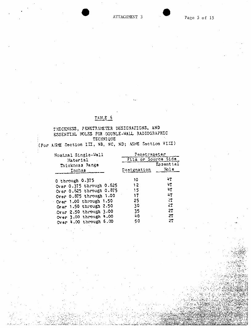
TA3LE 6
THIC"NESS, ?EETMETER DESIGNAIONS, AND ESENTIAL HOLES FOR DOUBLE-WALL RADIOGRAPHIC
TECKR{IQUE (For ASME Section 1II, NB, NC, ND; XSME Zsction ViI)
-IomiLnal Single-aall Material
Thickness Rnge Inches
0 through 0.375 Over 0.315 through
over 0.625 through Over 0.875 throuph Over 1.00 through Over 1.50 through cver 2.50 through Over 3.00 through Over 4.00 through
0.625 0.875 1.00
1.50 2.50 3.00 4.00 6.00
P netrameter Film or Source Side
Fasential esiat ion Hole
10 4T 12 4T 15 4T 17 4T 25 _2 30 n 35 ZT 40 - 2 50 2T

xIIACHEIvNT .3 Page 6 of 15
APPENDIX A
PENETAMETER REQUIREMENTS
1. Penetrameters shall be procured to Purchase Specification PF-1058
which meets the requirements of ASME SE-142, which is identical to
ASTM E 142, 1977. In addition penetrameters 5 through 10 may be
procured to the requirements of ASME, Section III, Appendix X.
2. Penetrameters shall be fabrIcated of radiographically similar
material to the weld material or weld metal to be examined.
Radiographically similar material is a material or alloy having
the same radiation absorption as that being examined.
3. Penetrameters shall be fabricated in accordance with Figure Al
and/or A2 as applicable.
4. Penetrameters shall be identified by permanently attached lead
numbers at least 3/32-inch wide. The cumbers shall indicate the
penetrameter thickness in accordance with Table Al in thousandths
of an inch.
5. Penetrameters which otherwise conform to the requirements of this
specification nethod, but do not have the proper identification,
may be used provided the lead numbers indicating penetrameter
thickness are placed adjacent to the penetrameter.
TABLE Al
PENETRAMETER DESIGNATION AND ESSENTIAL ROLES
Penetrameter Penetrameter 1 T Hole 2 T 1'o1e 4 T Hole
Desionation Thickness Diameter iameter 0iareter
5 0.005 0.010 0.020 0.040
7 0.007 0.010 0.020 0.040
10 0.010 0.010 0.020 0.040
12 0.012 0.012 0.025 0.050
15 0.015 0.015 0.030 0.060
17 0.017 0.017 0.035 0.070
20 0.020 0.020 0.040 0.080
25 0.025 0.025 0.050 0.100
30 0.030 0.030 0.060 0.120
35 0.035 0.035 0.070 0.140
40 0.040 0.040 0.080 0.160
45 0.045 0.045 0.090 0.180
50 0.050 0.050 0.100 0.200
60 0.060 0.060 0.120 0.240
80 0.080 0.080 0.160 0.320 100 0.100 0.100 0.200 0.400
120 0.120 0.120 0.240 0.480
160 0.160 0.160 0.320 '0.640
200 0.200 0.200 0.400 ut00

ATTACHMENT 3 0 Page 7 of 15
APPENDIX A (Continued)
Ploce Identificotio Numbers Here
Minimum Penetrometer ThicknessO0.005 Minimum Diometer for IT Hole-.0.0 10" Minimum Diometer for 2T Hole 0.020" Minimum Diometer for 4T Hole-0.040"
Holes sholl be True and Normal to the Surface of the Penetrometer Do Not Chamfer
Design for penetrameter thickness from 0.005 in. and including 0.050 in.
Place Identification Numbers Here
4Tdiom
Design for penet-ramescr thickness from 0.060 in. to 0.160 in. incl. Made in 0.010-in. increments.
S2T4T
1.33T I
t TfDesign for penetrameter thickness of 0.180 in. and over. Tolerance Made in 0.020-in. increments. NOT I -Tolerances on penetrameter thickness and hole diameter shall be i 10 % or one half of the thickness increment between penctrarneter sizes. whichever is smaller.
FIGURE Al. PENETRAMETER DESIGN
,~. .~ .<
.~......~
. . ,*~ ~.,-,.-r.,2 ' .zsaiW ~ ~

ATTACHMENT 3
APPENDIX A (Continued)
/ II
-
DESIGN FOR PENETRAMETERS +/
5 THRU 10
± o.or/
ALTERNATE SLIT LOCATIONS
NOTE: ALL OTHER PENETRAMETER DIMENSIONS SHALL BE IN ACCOR
FIGURE A2. PENETRAMETER DESIGN - LINER P
DANCE WITH APPENDIX A
ILATES
Cd ~
I
Page 8 of 15

ATTACHMENT 3 is Page 9 of 15
APPENDIX E
BELLEFONTE NUCLEAR PLANT DENSITY REQUIREK-ENTS
Applicable Codes
ASME III NB, NC, ND VIII DIVISIONS
2.AND 2
Linear plate (TVA N4C-871) ASME I, III NF,
III Division 2 ANSI 831.1
RT Performed
Per
Section V Article 2
Section V Article 3
Minimum Density
for Single Film Viewing
2.0
1.3
Minimum Density
for Composite Viewing
2.6*
1.8
Ma x imum Density
for Single or Double
Film Viewing
3.8
3.8
Appendix X 1.3 1.8 No maximum
*Each radioagraph of a composite set shall have a minimum density of 1.3.
A ~. ,r~.
,~' .p~
'4"~"
AbA .4' .,,,.-.b,~ it
* -e.' .,Zb ~ '.4
NE

Page 10 of 15
APPENDIX H
ACCEPTANCE CRITERIA FOR ROOT CONDITIONS IN 3ACKING RING WELDS
1.0 Scope
1.1 This appendix will not be used unless invoked by OE. The criteria
specified in this appendix shall be used when interpreting radiographs of
backing ring welds when such radiographs show indications that can be
attributed to a condition along the root of the weld. This criteria shall
apply only to such root conditions and indications accepted must be clearly
identifiable to this area.
2.0 The film interpreter shall record which figure most closely represents the
weld root condition shown on the radiograph. The completed joint is then
ajudged acceptable or unacceptable according to the acceptance criteria of
this procedure.
3.0 The following figures show shim geometry and diagrams of root conditions
most commonly found in backing ring welds.
3.1 Figure 1 gives the size and location of the grooves in the shim.
This appendix provides the limits for undercuts or depressions
allowed in a weld. The interpreter must evaluate the depth of a
depressed area by visually comparing the density of the image of
the grooves with the.density of the depressed weld area.
3.1.1 The penatrameter should be positioned as shown in the diagram to avoid
distortion of required sensitivity. If an ungrooved shim is
inadvertently used and the weld does not contain any questionable root
conditions, use of the ungrooved shim shall not be cause for rejection of
the radiographs.
.2Approx.Holes shall not 0.020Approalign with slot
0.010"
0.015" 0.020"
0.025"
0.030" 0.035"
Standard Penetrameter
ATTACHMENT 3

ATTACHMENT 3 S Page 11 of 15
APPENDIX H (Continued)
ACCEPTABLE WELD JOINT
3.2 Weld Root
The weld joint illustrated in Figure 2 meets the requirements of this procedure. The weld metal is fused to the backing ring and fills the root gap without any harmful depressions, grooves, etc.
3.2.1 Description of Radiograph
Because the root face is free of deprssions, grooves, etc., just two
different photographic densities are apparent; the lighter density of the
weld deposit contrasts with the darker base metal. The line of
demarcation between the two areas is usually distinctive, but normally not straight.
RDOT EDGE FUSION CONDITION
CHANGE IN DENSITY OF IMAGE OCCURS HERE AS A RESULT
OF ROOT EDGE FUSION
FIGURE 2 - ACCEPTABLE WELD JOINT
0

A 3Page 12 of 15
APPENDIX H (Continued)
CONDITIONALLY ACCEPTABLE WELD JOINT
3.3 Weld Root
The weld joint illustrated in Figure 3 could meet the requirements of this
procedure, even though some cavity is evident in the weld deposit or the
base metal at the root. As long as these cavities do not present any sharp
edges, do not exceed 1/32-inch, and do not encroach on the minimum wall
thickness, they may be accepted. Cavities (or depressions) in both the
weld deposit and base metal may coexist.
3.3.1 Description of Radiograph
Cavities (or depressions) appear in radiographs as areas of greater
density (darker) because the part is thinner at these locations, i.e.
there is less material for the radiation to penetrate. The change in
density from one area to another is gradual. The radiographic density of
this area should not exceed the density of the image of the applicable
groove in the shim. The density of the image of the shim groove should
be compared to the portion of the groove not covered by the penetrameter.
TYPICAL ROOT UNDERCUT
FIGURE 3 - CONDITIONALLY ACCEPTABLE WELD JOINT
ATTACHMENT 3

Page 13 of 15
APPENDIX H (Continued)
UNACCEPTABLE WELD JOINT
3.4.1 Weld Root
The weld joint illustrated in Figure 4 does not meet the requirements of this procedure. The cavities (or depressions) at the edge of the weld root in either the weld deposit or base metal are sharper but not necessarily deeper than those in Figure 3; they may or may not exceed 1/32-inch and/or encroach on the minimum wall thickness. In this case, the primary criterion is the sharpness.of the edges of the weld root rather than depth of the cavities.
NOTE: The cavity (or depression) at the right edge of the weld root (Figure 4) often occurs in tack welding. The cavity at the left shows part of the root face still unmelted.
3.4.2 -Description of Radiograph
Cavities (or depressions) -ire depicted as darker areas (more dense). The transition in density from the defect to the adjoining area appears sharp and usually narrow. The length of the defect is usually short and generally occurs intermittently along the weld.
FIGURE 4 - UNACCEPTABLE WELD
ATTACHMENT 3
JOINT

A Page 14 of 15
APPENDIX H (Continued)
4.0 Workmanship samples( WS) may be used as an aid in evaluation of Figure 3
conditions in radiographs. If there is any doubt if a WS is needed, one
should be used.
4.1 A WS consists of a joint of the same design and same nominal thickness and
material as the production weld and may be a welder or procedure
qualification test assembly. Radiograph the area of a weld to be used for
a WS and prove it acceptable by visual or macro examination.
4.2 The radiograph of a WS used to evaluate a condition. in a production weld
must be made using the same radiographic technique as is used to make the
production radiograph.
4.2.1 The parameters of the radiographic technique which should have the same
nominal values for both the WS and the production radiograph are: type
source, source intensity, source-to-film distance, film, intensifying screen type and thickness, whether source-side or film-side penetrameter
used, whether single- or double-vall exposure, and whether for single- or
double-wall viewing.
4.2.2 The film density of the WS radiograph must be acceptable and within -10%
to +30% of the density of the questionable area of the production weld
radiograph so that an accurate comparison may be made.
4.3 Method of Manufacture of a WS
4.3.1 Select an area of a test assembly containing a Figure 3 indication.
4.3.2 Identify for radiography the area selected using a unique WS number.
4.3.3 Radiograph this area using the same technique and parameters as will be
used in production.
'T W
ATTACHMENT 3

. . ATTACHMENT 3 age 15 of 15
APPENDIX H (Continued)
4.3.4 Make a section through the questionable area, polish and etch for macro
examination.
4.3.5 If the macro section is proven to be acceptable, the radiograph and macro
should be saved for a workmanship sample.
4.4 Workmanship samples, radiographs, and macros must be numbered and retained
for future use.
4.4.1 Each time the WS is used for evaluating. a questionable condition, record
the WS number used for evaluation.
9
A
- . . - It.

Page 1 of 2
ATTACHMENT 4
MT Acceptance Criteria for Structural Welds (AISC/AWS)
Tne following may be used as
the acceptance criteria tor welds fabricated to the requirements of Section
8, Design of New Buildings, of the Structural Welding Code:
8.1 The following disccntinuities are unacceptable:
8.1.1 Cracks
8.1.2 Individual discontinuities having a greatest dimension of 3/32-inch
(2.4 mm) or greater, if
8.1.2.1 The greatest dimension of a discontinuity is larger than 2/3 of
the effective throat, 2/3 the weld size, or 3/4-inch (19.0 mm).
8.1.2.2 The discontinuity is closer than three times its greatest
dimension to the end of a groove weld subject to primary tensile
stresses.
8.1.2.3 A group of such discontinuities is in line such that:
(a) The sum of the greatest dimensions of all such
discontinuities is larger than the effective throat or weld
size in any length of six times the effective throat or weld
size. When the length of the weld being examined is less
than six times the effective throat or weld size, Lhe
permissible sum of the greatest dimensions shall be
proportionally less than the effective throat or weld size.
(b) The space between two such discontinuities which are adjacent
is less than three times the greatest dimension of the larger
of the discontinuities in the pair being considered.
8.1.3 Any indication 3/32-inch or greater, closer than three times its
greatest dimension from the end of a weld.
8.1.4 Independent of the requirements of sections 8.1.2 and 8.1.3, discontinuities having a greatest dimension of less than 3/32-inch,
if the sum of their greatest. dimensions exceeds 3/8-inch in any
linear inch of weld.
sheet 2 provides examples of the above acceptance criteria. provides~~~ exapl crtra
.' . 1

ATTACHMENT 4
w = 1"1"
K~ 1/32'1
1@1/32" A B C
1/16"HH-
1/4" 1" 3/8"1-1/4"
C is not counted in accumulation for 1 inch (See 5.2.4). A, B, and C are not considered aligned because A, being less than 3/32", is
not evaluated as an aligned indication. C is more than 3 times its. greatest dimension from the end of the weld and
is acceptable.
3/8" 1,, 1/8" 3/8"
D, E, and F are aligned indicatio acceptable.
D and E are rejectable because th each other. Removal of either
and indication accumulation (IA) i
ey are closer than 3 times the size of D to 0, E, or F would make this weld acceptable.
Page 2 of 2
I
1/4"1
W ATTACHMENT 5 W Page 1 of 1
PT Acceptance Criteria for Structural Welds (AISC/AUS)
1. A weld shall be acceptable by liquid penetrant examination if
it shows that:
2. The weld has no cracks.
3. Thorough fusion exists between weld metal and base metal.
4. The sum of diameters of piping porosity does not exceed 3/8
inch in any linear inch of weld nor does it exceed 3/4-inch in
any 12-inch length of weld..
* .. *~i.7-~~ .~ ~ .-. ~.. A ~
.............................. ft*~
.7 ~ .....................................
I

ATTACHMENT ,
WELD DISCREPANCY REPORT
DNG/SKETCH 30. WED ]0.
I. Description of Discrepancy (Attach Sketch/Photograph).
Reported by
II. Disposition
Inspector
D 0E Representative
III. Corrective Action Taken
Date
Date
I3LM PersonnelDate
j:j