2. simulation modelling of sensor less speed control of bldc motor using artificial neural network
TRANSCRIPT
7/21/2019 2. Simulation Modelling of Sensor Less Speed Control of BLDC Motor Using Artificial Neural Network
http://slidepdf.com/reader/full/2-simulation-modelling-of-sensor-less-speed-control-of-bldc-motor-using-artificial 1/9
Dr.T.Govindaraj and S. Vishnu 7
International Journal of Emerging Trends in Electrical and Electronics (IJETEE – ISSN: 2320-9569) Vol. 10, Issue. 2, Mar-2014.
Simulation Modelling of Sensor less Speed
Control of BLDC Motor Using
Artificial Neural Network
Dr.T.Govindaraj and S.Vishnu
Abstract: This project presents an intelligent speed controller
for BLDC motor, based on a single artificial neuron. Artificial
neural network-based motor controllers require no offline
training, which is both time consuming and requires extensive
knowledge of motor behavior for the specific drive system. In
addition, drive behavior is measured with the help of Back
Emf sensing. This method of Back Emf sensing is used for
providing the controlled gate pulse to the MOSFET switches.
In existing method used Hall Sensor. The proposed drive
system overcomes the limitations of Hall Sensors using backEmf control and using ANN control algorithm, is robust under
varying operating parameters, and is easily adaptable to
various drive systems. Drive efficiency is verified in simulation
as well as experimentally.
Keywords: Artificial neural network (ANN), Brushless DC
motor (BLDC), back Emf control.
I INTRODUCTION
The Brushless DC motor (BLDC) is a synchronous
electric motor which is power driven by direct-current
electricity (DC) and which has an electronically controlled
commutation system, instead of a mechanical commutation
system based on brushes. In such motors, current andtorque, voltage and rpm are linearly related [1]. In BLDC
motor, there are two sub-types used which are the Stepper
Motor type that may have more poles on the stator and the
Reluctance Motor. In a conventional (brushed) DC motor,
the brushes make mechanical contact with a set of electrical
contacts on the rotor or also called the commutator, forming
an electrical circuit between the DC electrical source and
the armature coil-windings.
As the armature rotates on axis, the stationary brushes
come into contact with different sections of the rotating
commutator. The commutator and brush system form a set
of electrical switches, each firing in sequence, such thatelectrical-power always flows through the armature coil
closest to the permanent magnet that is used as a stationary
stator [2]. In a BLDC motor, the electromagnets do not
move; but, the permanent magnets rotate and the armature
remains static. This gets around the problem of how to
transfer current to a moving armature. The method which is
the brush-system/commutator assembly is replaced by an
electronic controller is used.
Dr.T.Govindaraj is working as Prof and Head- Department of EEE and
S.Vishnu is a Research Scholar-M.E Power Electronics and Drives, both are
from Muthayammal Engineering College,Rasipuram, Tamil Nadu, India,Emails: [email protected] , [email protected]
The controller performs the same power distribution
found in a brushed DC motor, but using a solid-state circuit
rather than a commutator/brush system. In this motor, the
mechanical "rotating switch" or commutator/brush gear
assembly is replaced by an external electronic switch
synchronized to the rotor's position. Brushless motors are
typically 85-90% efficient, whereas DC motors with brush
gear are typically 75-80% efficient. BLDC motors also have
several advantages over brushed DC motors, includinghigher efficiency and reliability, reduced noise, longer
lifetime caused by no brush erosion in it; elimination of
ionizing sparks from the commutator, and overall reduction
of electromagnetic interference (EMI)[1-2]. With no
windings on the rotor, they are not subjected to centrifugal
forces, and because the electromagnets are located around
the perimeter, the electromagnets can be cooled by
conduction to the motor casing, requiring no airflow inside
the motor for cooling.
This means that the motor's internals can be entirely
enclosed and protected from dirt or other foreign matter.
The maximum power that can be applied to a BLDC motor
is exceptionally high, limited almost exclusively by heat,
which can damage the magnets. BLDC motors are
considered to be more efficient than brushed DC motors.
This means that for the same input power, a BLDC motor
will convert more electrical power into mechanical power
than a brushed motor, mostly due to the absence of friction
of brushes. The enhanced efficiency is greatest in the no-
load and low-load region of the motor’s performance curve
[3]. Under high mechanical loads, BLDC motors and high
quality brushed motors are comparable in efficiency.
Brushless DC motors are commonly used where precise
speed control is necessary, as in computer disk drives or invideo cassette recorders, the spindles within CD, and etc.
Brushless dc (BLDC) motors have been desired for
small horsepower control motors due to their high
efficiency, silent operation, compact form, reliability, and
low maintenance. However, the control complexity for
variable speed control and the high cost of the electric drive
hold back the widespread use of brushless dc motor. Over
the last decade, continuing technology development in
power semiconductors, microprocessors/logic ICs,
adjustable speed drivers (ASDs) control schemes and
permanent-magnet brushless electric motor production have
combined to enable reliable, cost-effective solution for a broad range of adjustable speed applications.
7/21/2019 2. Simulation Modelling of Sensor Less Speed Control of BLDC Motor Using Artificial Neural Network
http://slidepdf.com/reader/full/2-simulation-modelling-of-sensor-less-speed-control-of-bldc-motor-using-artificial 2/9
Dr.T.Govindaraj and S. Vishnu 8
International Journal of Emerging Trends in Electrical and Electronics (IJETEE – ISSN: 2320-9569) Vol. 10, Issue. 2, Mar-2014.
Brushless DC motor has a rotor with permanent
magnets and a stator with windings [5]. It is essentially a
DC motor turned inside out. The brushes and commutator
have been eliminated and the windings are connected to the
control electronics. The control electronics replace the
function of the commutator and energize the proper
winding. The motor has less inertia, therefore easier to start
and stop. BLDC motors are potentially cleaner, faster, moreefficient, less noisy and more reliable[1]-[20]. The
Brushless DC motor is driven by rectangular or trapezoidal
voltage strokes coupled with the given rotor position. The
voltage strokes must be properly aligned between the
phases, so that the angle between the stator flux and the
rotor flux is kept close to 90 to get the maximum developed
torque. BLDC motors often incorporate either internal or
external position sensors to sense the actual rotor position
or its position can also be detected without sensors[21]-[36].
II CONTROL ALGORITHM
Conventionally, proportional–integral (PI)[6] and
proportional–integral–derivative (PID) speed controllers
have been utilized to meet these control challenges
controller has an advantages that it is very simple,
inexpensive, have applications in most systems, faster
response.
But the disadvantages are the set point offset, delay if gain
is lower. So this P Controller needs the gain adjustment.
Then the PI controller is preferred [9]. And it has an
advantages that there is no offset, have applications in
many processes. The disadvantage of this controller are
more costly, little complex, slow response, oscillations and
overshootIn PID controller it has no offset, faster, no or very less
oscillations, and it has low overshoot. It has disadvantages
that it was costly and it is used for limited applications, it is
more difficult to configure and tune the functions. FLC
(fuzzy logic controllers) -based systems typically require
extensive initial tuning and may impose significant
computational burden. So, here I go with Artificial Neural
Network and sensor less speed control of BLDC motor
.
II (A) ARTIFICIAL NEURAL NETWORKS (ANN)This project presents an ANN-based controller for the
BLDC motor drive which requires minimal offline training
yet precisely and accurately follows command speed with
insensitivity to load and parameter variations. The system is
simplified to a single artificial neuron (SAN) to minimize
complexity and computational burden requirements. By
using sensor less speed measuring system we can find out
the Speed error and conditionally used at each iteration to
adaptively modify the SAN parameters to produce the
precise command torque to minimize speed error. BLDC is
widely used because of its high mechanical power density,
simplicity and cost effectiveness. A mathematical model of
the drive system is developed to analyse the performance of
the proposed drive.
ANNs are mathematical systems consisting of many
weighted interconnected operation elements (neurons). A
processing element is an equation, which is often termed a
transfer function. This processing element receives signals
from other neurons; combines and converts them; and produces a numerical result. In general, processing
elements roughly correspond to real neurons, they are
interconnected via a network and this structure constitutes
neural networks.
1
N
i i
i
x AW
1
Equation 1 shows Single Artificial Neuron. The
structure of ANNs contains three main elements neurons,
the connection providing input and output route, and
connection weights indicating the strength of these
connections. Typically, the architecture (structure) of an
ANN is formed and weight values required to optimize the
accuracy of the outputs are determined using one of several
mathematical algorithms. The ANNs unravel a relationship
between the input variables and estimated variables by
determining the weights using previous examples. In other
words, ANNs are "trained". Once these relationships are
determined (in other words, once the network is trained), an
ANN can be operated with new data and estimations can be
produced.
The performance of a network is measured by theaimed signal and error criterion. The error margin is
obtained by the comparison of the output of the network and
the aimed output. A back-propagation algorithm is used to
adjust the weights in such a way to reduce the error margin.
The network is trained by repeating this processing many
times. The aim of training is to reach an optimum solution
based on performance measurements. ANNs have an
extensive range of applications in real life problems. They
are currently used successfully in many industries.
7/21/2019 2. Simulation Modelling of Sensor Less Speed Control of BLDC Motor Using Artificial Neural Network
http://slidepdf.com/reader/full/2-simulation-modelling-of-sensor-less-speed-control-of-bldc-motor-using-artificial 3/9
Dr.T.Govindaraj and S. Vishnu 9
International Journal of Emerging Trends in Electrical and Electronics (IJETEE – ISSN: 2320-9569) Vol. 10, Issue. 2, Mar-2014.
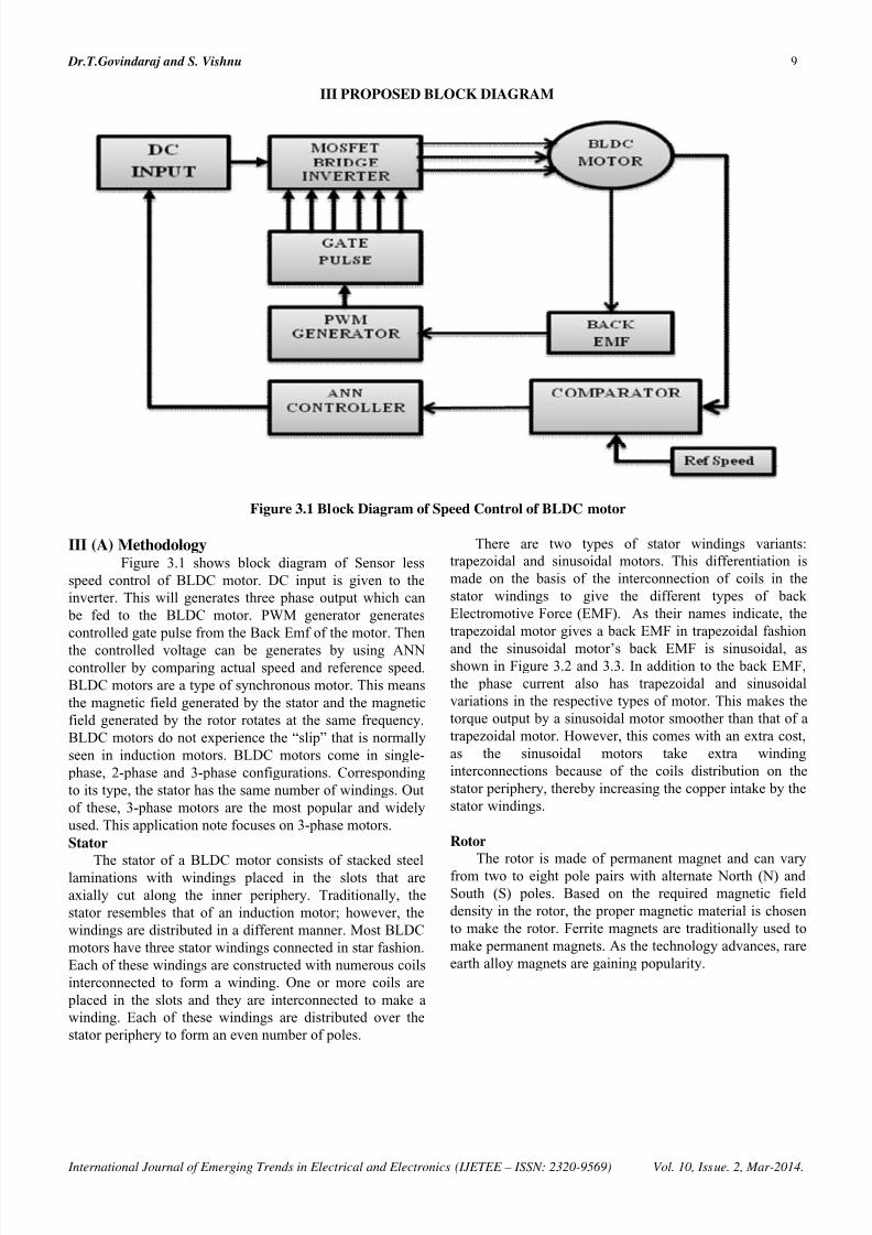
III PROPOSED BLOCK DIAGRAM
Figure 3.1 Block Diagram of Speed Control of BLDC motor
III (A) MethodologyFigure 3.1 shows block diagram of Sensor less
speed control of BLDC motor. DC input is given to the
inverter. This will generates three phase output which can
be fed to the BLDC motor. PWM generator generates
controlled gate pulse from the Back Emf of the motor. Then
the controlled voltage can be generates by using ANNcontroller by comparing actual speed and reference speed.
BLDC motors are a type of synchronous motor. This means
the magnetic field generated by the stator and the magnetic
field generated by the rotor rotates at the same frequency.
BLDC motors do not experience the “slip” that is normally
seen in induction motors. BLDC motors come in single-
phase, 2-phase and 3-phase configurations. Corresponding
to its type, the stator has the same number of windings. Out
of these, 3-phase motors are the most popular and widely
used. This application note focuses on 3-phase motors.
Stator
The stator of a BLDC motor consists of stacked steellaminations with windings placed in the slots that are
axially cut along the inner periphery. Traditionally, the
stator resembles that of an induction motor; however, the
windings are distributed in a different manner. Most BLDC
motors have three stator windings connected in star fashion.
Each of these windings are constructed with numerous coils
interconnected to form a winding. One or more coils are
placed in the slots and they are interconnected to make a
winding. Each of these windings are distributed over the
stator periphery to form an even number of poles.
There are two types of stator windings variants:
trapezoidal and sinusoidal motors. This differentiation is
made on the basis of the interconnection of coils in the
stator windings to give the different types of back
Electromotive Force (EMF). As their names indicate, the
trapezoidal motor gives a back EMF in trapezoidal fashion
and the sinusoidal motor’s back EMF is sinusoidal, asshown in Figure 3.2 and 3.3. In addition to the back EMF,
the phase current also has trapezoidal and sinusoidal
variations in the respective types of motor. This makes the
torque output by a sinusoidal motor smoother than that of a
trapezoidal motor. However, this comes with an extra cost,
as the sinusoidal motors take extra winding
interconnections because of the coils distribution on the
stator periphery, thereby increasing the copper intake by the
stator windings.
Rotor
The rotor is made of permanent magnet and can varyfrom two to eight pole pairs with alternate North (N) and
South (S) poles. Based on the required magnetic field
density in the rotor, the proper magnetic material is chosen
to make the rotor. Ferrite magnets are traditionally used to
make permanent magnets. As the technology advances, rare
earth alloy magnets are gaining popularity.
7/21/2019 2. Simulation Modelling of Sensor Less Speed Control of BLDC Motor Using Artificial Neural Network
http://slidepdf.com/reader/full/2-simulation-modelling-of-sensor-less-speed-control-of-bldc-motor-using-artificial 4/9
Dr.T.Govindaraj and S. Vishnu 10
International Journal of Emerging Trends in Electrical and Electronics (IJETEE – ISSN: 2320-9569) Vol. 10, Issue. 2, Mar-2014.
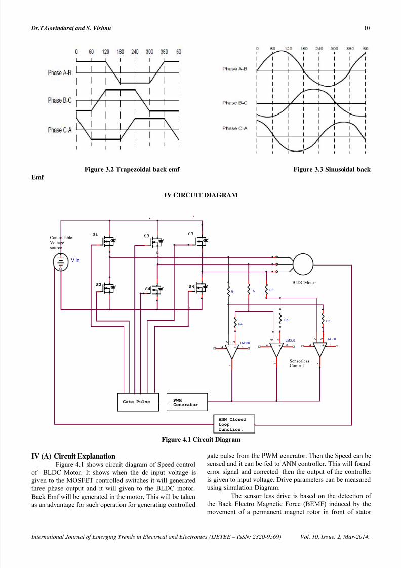
Figure 3.2 Trapezoidal back emf Figure 3.3 Sinusoidal back
Emf
IV CIRCUIT DIAGRAM
+-
LM358 5 6
7
84
R4
R6
S1Controllable
Voltagesource
S3
+-
LM358 3 2
1
84
S2S4
ANN Closed
Loop
function.
R5
PWM Generator
+-LM358
3 2
1
84
Gate Pulse
S3
R3
S4
V in
BLDC Moto r
R2
SensorlessControl
R1
Figure 4.1 Circuit Diagram
IV (A) Circuit ExplanationFigure 4.1 shows circuit diagram of Speed control
of BLDC Motor. It shows when the dc input voltage is
given to the MOSFET controlled switches it will generated
three phase output and it will given to the BLDC motor.
Back Emf will be generated in the motor. This will be takenas an advantage for such operation for generating controlled
gate pulse from the PWM generator. Then the Speed can be
sensed and it can be fed to ANN controller. This will found
error signal and corrected then the output of the controller
is given to input voltage. Drive parameters can be measured
using simulation Diagram.
The sensor less drive is based on the detection ofthe Back Electro Magnetic Force (BEMF) induced by the
movement of a permanent magnet rotor in front of stator
7/21/2019 2. Simulation Modelling of Sensor Less Speed Control of BLDC Motor Using Artificial Neural Network
http://slidepdf.com/reader/full/2-simulation-modelling-of-sensor-less-speed-control-of-bldc-motor-using-artificial 5/9
Dr.T.Govindaraj and S. Vishnu 11
International Journal of Emerging Trends in Electrical and Electronics (IJETEE – ISSN: 2320-9569) Vol. 10, Issue. 2, Mar-2014.
winding. This method also requires the use of a trapezoidal
signal in order to have a zero crossing of the BEMF. For a
given fixed motor design (number of stator winding turns,
mechanical rotor characteristics and rotor magnet
characteristics) the BEMF Amplitude is proportional to the
rotor speed. The sensor less method uses the zero crossing
of
BEMF to synchronize phase commutations. To detectBEMF the specific 120° six-step drive is used. "120° six-
step drive" forces zero current twice in each phase during a
six step period. This allows BEMF zero crossing to be
detected and read.
Back Emf, NlrB 2
Where, N = number of windings per phase
l = length of the rotor
r = internal radius of the rotor
B = rotor magnetic field
ω = angular velocity
Because the controller must direct the rotor
rotation, the controller requires some means of determining
the rotor's orientation/position (relative to the stator coils.)
Some designs use Hall Effect sensors or a rotary encoder to
directly measure the rotor's position. Others measure the
back EMF in the undriven coils to infer the rotor position,
eliminating the need for separate Hall Effect sensors, and
therefore are often called sensor less controllers. Controllersthat sense rotor position based on back-EMF have extra
challenges in initiating motion because no back-EMF is
produced when the rotor is stationary. This is usually
accomplished by beginning rotation from an arbitrary
phase, and then skipping to the correct phase if it is found
to be wrong. This can cause the motor to run briefly
backwards, adding even more complexity to the startup
sequence. Other sensors less controllers are capable of
measuring winding saturation caused by the position of the
magnets to infer the rotor position.
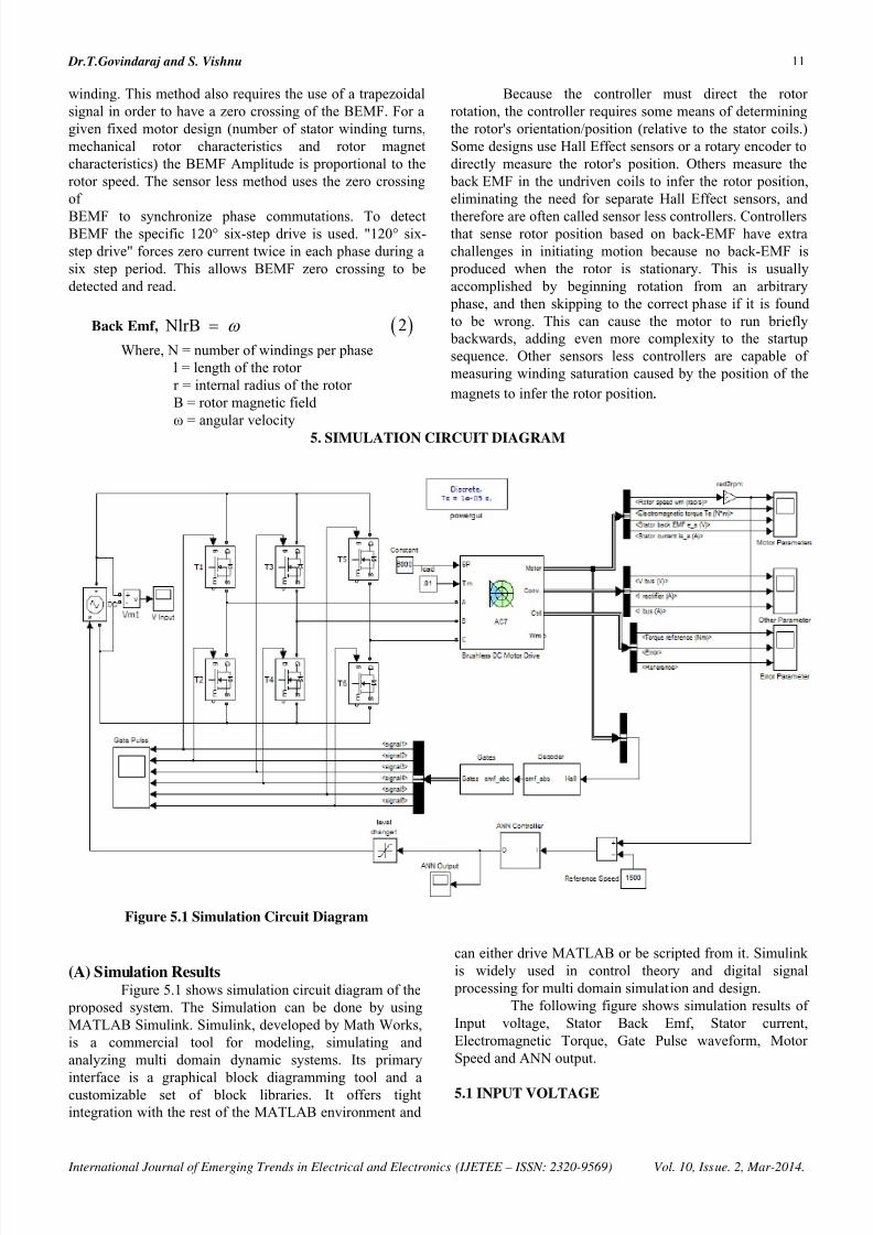
5. SIMULATION CIRCUIT DIAGRAM
Figure 5.1 Simulation Circuit Diagram
(A) Simulation ResultsFigure 5.1 shows simulation circuit diagram of the
proposed system. The Simulation can be done by using
MATLAB Simulink. Simulink, developed by Math Works,
is a commercial tool for modeling, simulating and
analyzing multi domain dynamic systems. Its primary
interface is a graphical block diagramming tool and acustomizable set of block libraries. It offers tight
integration with the rest of the MATLAB environment and
can either drive MATLAB or be scripted from it. Simulink
is widely used in control theory and digital signal
processing for multi domain simulation and design.
The following figure shows simulation results of
Input voltage, Stator Back Emf, Stator current,
Electromagnetic Torque, Gate Pulse waveform, Motor
Speed and ANN output.
5.1 INPUT VOLTAGE

7/21/2019 2. Simulation Modelling of Sensor Less Speed Control of BLDC Motor Using Artificial Neural Network
http://slidepdf.com/reader/full/2-simulation-modelling-of-sensor-less-speed-control-of-bldc-motor-using-artificial 6/9
Dr.T.Govindaraj and S. Vishnu 12
International Journal of Emerging Trends in Electrical and Electronics (IJETEE – ISSN: 2320-9569) Vol. 10, Issue. 2, Mar-2014.
Figure 5.2 shows input voltage corresponds to the output
speed. Error can be corrected.
Figure 5.2 Input voltage
5.2 ELECTROMAGNETIC TORQUE
Figure 5.3 shows Electromagnetic Torque.
F
igure 5.3 Electromagnetic Torque
5.3 STATOR BACK EMF
Figure 5.4 shows Stator Back Emf
Figure 5.4 Stator Back Emf
5.4 STATOR CURRENT
Figure 5.5 shows Electromagnetic Torque.
Figure 5.5 Stator Current
5.5 ANN OUTPUT
Fig 5.6 Shows ANN Output
Figure 5.6 ANN Output
5.6GATE PULSE WAVEFORM
Fig 5.7 Shows Gate Pulse Waveform

7/21/2019 2. Simulation Modelling of Sensor Less Speed Control of BLDC Motor Using Artificial Neural Network
http://slidepdf.com/reader/full/2-simulation-modelling-of-sensor-less-speed-control-of-bldc-motor-using-artificial 7/9
Dr.T.Govindaraj and S. Vishnu 13
International Journal of Emerging Trends in Electrical and Electronics (IJETEE – ISSN: 2320-9569) Vol. 10, Issue. 2, Mar-2014.
Figure 5.7 Gate Pulse Waveform
5.7 MOTOR SPEED
Fig 5.8 shows Motor Speed
Figure 5.8 Motor Speed
6. ConclusionIn view of the pulsation of three-phase BLDC
motor with non-ideal back EMF, a new current control
method is proposed. The PWM_ON_PWM pattern is used
to eliminate the diode freewheeling of inactive phase.
When the motor works at low speed, the torque ripple isrestrained by speeding up the turn- ON phase current
through increasing the duty cycle of PWM. When the
motor works at high speed, overlapping commutation
scheme is used. The commutation times are given by the
current controller in low and high speeds. Aiming at the
non-ideal back EMF, the duty cycle is calculated in the
current controller by measuring the angular position,
speed, and the offline measured back EMF. Here I used
Artificial Neural Network technique of SAN controller. By
using this, the motor rpm is fed to the ANN and theregulated input voltage is generated automatically
according to the output.
7. References[1] Casey B. Butt and M. Azizur Rahman, “Untrained Artificial
Neuron-Based Speed Control of Interior Permanent-Magnet
Motor Drives Over Extended Operating Speed Range,”
IEEE Trans. Ind. Appl., vol. 49, no. 3, may/june 2013
[2] Dr.T.Govindaraj, and V.Purushothaman, “Simulation
Modeling of Inverter Controlled BLDC Drive Using Four
Switch,” International Journal of Advanced and
Innovative Research .ISSN: 2278-7844, Dec- 2012, pp
554-559.[3] Dr.T.Govindaraj, and S.Deepika, “Hybrid input Boost
converter Fed BLDC Drive,” International Journal Of
Advanced and Innovative Research. ISSN: 2278-7844, Dec-
2012 , pp 444-451.
[4] Jiancheng Fang, Haitao Li, and Bangcheng Han “Torque
Ripple Reduction in BLDC Torque Motor With Non-ideal
Back EMF,” IEEE Trans. Power Elec., Vol. 27, No. 11,
November 2012.
[5] C. B. Butt, M. A. Hoque, and M. A. Rahman, “Simplified
fuzzy logic based MTPA speed control of IPMSM drive,”
IEEE Trans. Ind. Appl., vol. 40, no. 6, pp. 1529–1535,
Nov./Dec. 2004.
[6] Y. Yi, D. M. Vilathgamuwa, and M. A. Rahman,
“Implementation of an Artificial-Neural-Network-based
real-time adaptive controller for an interior permanent-
magnet motor drive,” IEEE Trans. Ind. Appl., vol. 39,no. 1,
pp. 96–104, Jan./Feb. 2003.
[7] M. A. Rahman, M. A. Hoque, C. B. Butt, M. N. Uddin, and
M. A. Abido,“Testing of genetic algorithm based PI
controller for IPMSM drive,” in Proc. IEEE Int. Conf. Ind.
Technol., Bangkok, Thailand, Dec. 2002,pp. 119–124.
[8] M. A. Hoque, B. Casey, and M. A. Rahman, “A novel
approach forMTPAspeed control of IPMSM drive,” in Proc.
2nd IEEE Int. Conf. Elect.Comput. Eng., Dhaka,
Bangladesh, Dec. 26/27, 2002, pp. 336–339.
[9] M. N. Uddin, M. A. Abido, and M. A. Rahman,
“Laboratory implementation of an artificial neural networkfor online tuning of a genetic algorithm based PI controller
for IPMSM drive,” in Proc. Int. Conf. Modelling, Simul.
Elect. Mach., Converters Syst., Montreal, QC, Canada,
Aug. 2002.
[10] S. Y. Yi and M. J. Chung, “Robustness of fuzzy logic
control for an uncertain dynamic system,” IEEE Trans.
Fuzzy Syst., vol. 6, no. 2, pp. 216–225,May 1998.
[11] B. K. Bose, “A high performance inverter-fed drive system
of an interior permanent magnet synchronous machine,”
IEEE Trans. Ind. Appl.,vol. 24, no. 6, pp. 987–997,
Nov./Dec. 1988.
[12] M. A. Rahman and P. Zhou, “Field circuit analysis of
brushless permanent magnet synchronous motors,” IEEE
Trans. Ind. Electron., vol. 43, no. 2, pp. 256–267, Apr.1996.
7/21/2019 2. Simulation Modelling of Sensor Less Speed Control of BLDC Motor Using Artificial Neural Network
http://slidepdf.com/reader/full/2-simulation-modelling-of-sensor-less-speed-control-of-bldc-motor-using-artificial 8/9
Dr.T.Govindaraj and S. Vishnu 14
International Journal of Emerging Trends in Electrical and Electronics (IJETEE – ISSN: 2320-9569) Vol. 10, Issue. 2, Mar-2014.
[13] M. A. Rahman and M. A. Hoque, “On-line self-tuning ANN
based speed control of a PMDC motor,” IEEE/ASME
Trans. Mechatronics, vol. 2, no. 3, pp. 169–178, Sep. 1997.
[14] M. R. Emami, I. B. Turksen, and A. A. Goldenburg,
“Development of a systematic methodology of fuzzy logic
modeling,” IEEE Trans. Fuzzy Syst., vol. 6, no. 3, pp. 346–
361, Aug. 1998.
[15] K. Erenay, I. Ciprut, L. Tezduyar, and Y. Istefanopulos,
“Application of fuzzy algorithms to the speed control ofwashing machines with brushless dc motors,” in Proc. Int.
Conf. Elect. Mach., Istanbul, Turkey, 1998, pp. 1231–1236.
[16] C. Namudri and P. C. Sen, “A servo-control system using a
self controlled synchronous motor (SCSM) with sliding
mode controller,” IEEE Trans. Ind. Appl., vol. 23, no. 2,
pp. 283–295, Mar. 1987.
[17] A. Consoli and Antonio, “A DSP based sliding mode field
oriented control of an interior permanent magnet
synchronous motor drive,” in Proc. IPEC Conf. Rec.,
Tokyo, Japan, 1990, pp. 263–303.
[18] M. A. El-Sarkawi, A. A. El-Samahy, and M. L. El-Syed,
“High performance drive of dc brushless motors using
neural network,” IEEE Trans. Energy Convers., vol. 9, no.2, pp. 317–322, Jun. 1994.
[19] M. A. Rahman and M. A. Hoque, “On-line adaptive
artificial neural network based vector control of permanent
magnet synchronous motors,” IEEE Trans. Energy
Convers., vol. 13, no. 4, pp. 311–318, Dec. 1998.
[20] S. Morimoto, Y. Takeda, and T. Hirasa, “Current phase
control methods for permanent magnet synchronous
motors,” IEEE Trans. Power Electron., vol. 5, no. 2, pp.
133–139, Apr. 1990.
[21] Govindaraj Thangavel ,”Low Frequency Axial Flux Linear
Oscillating Motor Suitable for Short Strokes” International
Journal ISRN Electronics ,2013
[22] T.Govindaraj, Debashis Chatterjee, and Ashoke K.
Ganguli,”Development, Finite Element Analysis andElectronic Controlled Axial Flux Permanent Magnet Linear
direct Oscillating Motor drive suitable for short strokes”,
Proc. International Conference on Control, Automation,
Communication and Energy Conservation, INCACEC-
2009, Kongu Engineering College, India Jun. 4–6, 2009,
pp.479– 483.
[23] Govindaraj T, Debashis Chatterjee, and Ashoke K.
Ganguli, “Development, Analysis and Control of an Axial
Flux Permanent Magnet Linear Oscillating Motor suitable
for Short Strokes”, Proc. 2009 IEEE International
Symposium on Industrial Electronics, IEEE ISIE 2009,
Seoul Olympic Parktel, Seoul, Korea, July 5-8 2009.
[24] Govindaraj T, Debashis Chatterjee, and Ashoke K.
Ganguli,”Development, Control and Testing of a New Axial
Flux Permanent Magnet Linear Oscillating Motor using FE
Magnetic Field Analysis Simulation Models”, Proc. 2009
International Conference on Mechanical and Electronics
Engineering, ICMEE 2009, International Association of
Computer Science and Information Technology, IACSIT ,
Chennai, India, July 24-26, 2009
[25] Govindaraj T, Debashis Chatterjee, and Ashoke K.
Ganguli,”FE Magnetic Field Analysis Simulation Models
based Design, Development, Control and Testing of An
Axial Flux Permanent Magnet Linear Oscillating
Motor”,Proc.The International Conference on Electrical
and Electronics Engineering, ICEEE2009, International
Association of Engineers, World Congress on Engineering2009, London, United Kingdom.1-3, Jul 2009
[26] T.Govindaraj, Rasila R,”Development of Fuzzy Logic
Controller for DC – DC Buck Converters”, Int J. Engg
Techsci Vol 2(2), 192-198, 2010
[27] T.Govindaraj, Debashis Chatterjee, and Ashoke K.
Ganguli, “A Permanent Magnet Linear Oscillating Motor
for Short Strokes,” Proc. International Conference on
Electrical Energy Systems & Power Electronics in
Emerging Economies ,ICEESPEEE- 2009, SRM University,
India, April 16-18, 2009, pp. 351- 355
[28] Govindaraj Thangavel,” Design, Development, Analysis
and Control of an Axial Flux Permanent Magnet Linear
Oscillating Motor suitable for short strokes using Finite
Element Method,” International Journal of Electronic
Engineering Research Volume 2 Number 3 pp. 419–428,
2010
[29] Dr.T.Govindaraj, and M. Gunasegaran,“ PV Micro inverter
System based Electric Drive , ” International Journal Of
Advanced and Innovative Research.ISSN: 2278-7844, Dec-
2012 , pp 458-467.
[30] Govindaraj Thangavel, Debashis Chatterjee, and Ashoke K.
Ganguli,” Modelling and Simulation of Microcontroller
based Permanent Magnet Linear OscillatingMotor,” International Journal of Modelling and Simulation
of Systems, Vol.1, Iss.2, pp. 112-117 , 2010
[31] Govindaraj Thangavel, Debashis Chatterjee, and Ashoke K.
Ganguli,”Design, Development and Control of an Axial
Flux Permanent Magnet Linear Oscillating Motor using FE
Magnetic Analysis Simulation Models,” Int. Journal of
Electrical and Electronics Engineering, Oradea, Romania,
October 2010
[32] Govindaraj Thangavel, Debashis Chatterjee, and Ashoke
K. Ganguli,”FEA based Axial Flux permanent Magnet
Linear Oscillating Motor ,” international journal the
annals of "dunarea de jos" university of galati f ascicle
iii, electrotechnics, electronics, automatic control,
informatics , July 2010[33] Govindaraj Thangavel, Debashis Chatterjee, and Ashoke K.
Ganguli,”FEA Simulation Models based Development and
Control of An Axial Flux PMLOM,” International Journal
of Modelling and Simulation of Systems, Vol.1, Iss.1,
pp.74-80, 2010
[34] Govindaraj Thangavel, Debashis Chatterjee, and Ashoke K.
Ganguli,” Design, Development and Finite Element
Magnetic Analysis of an Axial Flux PMLOM,”
International Journal of Engineering and Technology,
Vol.2 (2), 169-175 , 2010
[35] Govindaraj Thangavel, Ashoke K. Ganguli and Debashis
Chatterjee,”Dynamic modeling of direct drive axial flux
PMLOM using FEM analysis” International journal of
Elixir Electrical Engineering Vol.45 pp 8018- 8022, April
2012
[36] G. Thangavel and A. K. Ganguli,”Dynamic Modeling of
Directive Drive Axial Flux PM Linear Oscillatory
Machine Prototype Using FE Magnetic Analysis”, Iranian
Journal of Electrical and Computer Engineering, Vol.
10, No. 2, Summer-Fall 2011
7/21/2019 2. Simulation Modelling of Sensor Less Speed Control of BLDC Motor Using Artificial Neural Network
http://slidepdf.com/reader/full/2-simulation-modelling-of-sensor-less-speed-control-of-bldc-motor-using-artificial 9/9
Dr.T.Govindaraj and S. Vishnu 15
International Journal of Emerging Trends in Electrical and Electronics (IJETEE – ISSN: 2320-9569) Vol. 10, Issue. 2, Mar-2014.
Dr.Govindaraj Thangavel born in Tiruppur , Indiain 1964. He received the B.E. degree fromCoimbatore Institute of Technology, M.E. degreefrom PSG College of Technology and Ph.D. fromJadavpur University, Kolkatta,India in 1987, 1993and 2010 respectively. His Biography is included inWho's Who in Science and Engineering 2011-2012(11th Edition). Scientific Award of Excellence 2011from American Biographical Institute (ABI).Outstandin Scientist of the 21st century by
International Biographical centre of Cambridge, England 2011.Since July2009 he has been Professor and Head of the Department of Electrical andElectronics Engineering, Muthayammal Engineering College affiliated toAnna University, Chennai, India. His Current research interests includesPermanent magnet machines, Axial flux Linear oscillating Motor, AdvancedEmbedded power electronics controllers,finite element analysis of specialelectrical machines,Power system Engineering and Intelligent controllers.Heis a Fellow of Institution of Engineers India(FIE) and Chartered Engineer(India).Senior Member of International Association of Computer Science andInformation. Technology (IACSIT). Member of International Association ofEngineers(IAENG), Life Member of Indian Society for TechnicalEducation(MISTE). Ph.D. Recognized Research Supervisor for AnnaUniversity and Satyabama University Chennai. Editorial Board Member for
journals like International Journal of Computer and Electrical
Engineering,International Journal of Engineering andTechnology,International Journal of Engineering and Advanced Technology(IJEAT).International Journal Peer Reviewer for Taylor &FrancisInternational Journal “Electrical Power Components & System”UnitedKingdom,Journal of Electrical and Electronics Engineering Research,Journalof Engineering and Technology Research (JETR ),International Journal of thePhysical Sciences,Association for the Advancement of Modelling andSimulation Techniques in Enterprises,International Journal of Engineering &Computer Science (IJECS),Scientific Research and Essays,Journal ofEngineering and Computer Innovation,E3 Journal of Energy Oil and GasResearch,World Academy of Science, Engineering and Technology,Journal
of Electrical and Control Engineering( JECE),Applied Computational
Electromagnetics Society etc.. He has published 167 research papers inInternational/National Conferences and Journals. Organized 40 National /International Conferences/Seminars/Workshops. Received Best paper awardfor ICEESPEEE 09 conference paper. Coordinator for AICTE SponsoredSDP on special Drives,2011.Coordinator for AICTE Sponsored National
Seminar on Computational Intelligence Techniques in Green Energy,2011.Chief Coordinator and Investigator for AICTE sponsored MODROBS -Modernization of Electrical Machines Laboratory. Coordinator for AICTESponsored International Seminar on “Power Quality Issues in RenewableEnergy Sources and Hybrid Generating System”, July 2013
S. Vishnu pursuing his Master of Engineering in
Power Electronics and Drives in Muthayammal
Engineering College, Rasipuram. And he received his
Bachelor of Engineering in Electrical and Electronics
at Tagore Institute of Engineering and Technology,
Deviyakurichi. His areas of interests are Power
Electronics and Drives, Electrical Drives and Control
and Electrical Machines.