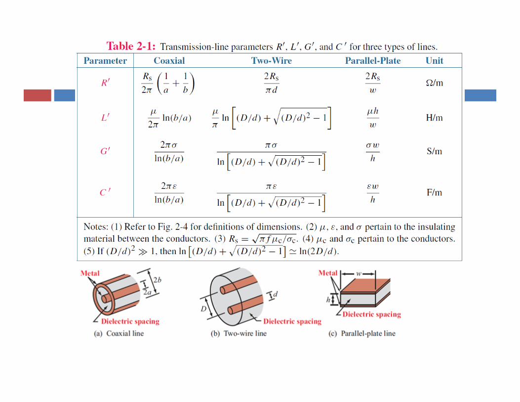
2. transmission lines - sonoma state university · pdf file2. transmission lines ....
TRANSCRIPT
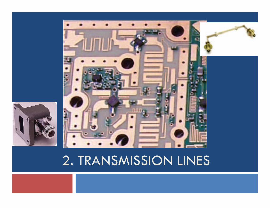
2. TRANSMISSION LINES
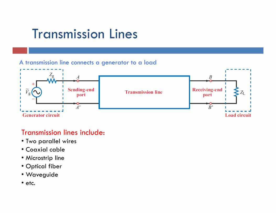
Transmission Lines
A transmission line connects a generator to a load
Transmission lines include: • Two parallel wires • Coaxial cable • Microstrip line • Optical fiber • Waveguide • etc.
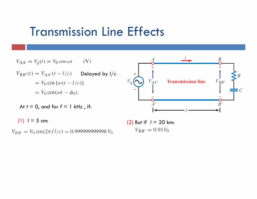
Transmission Line Effects
Delayed by l/c
At t = 0, and for f = 1 kHz , if: (1) l = 5 cm: (2) But if l = 20 km:
Dispersion and Attenuation
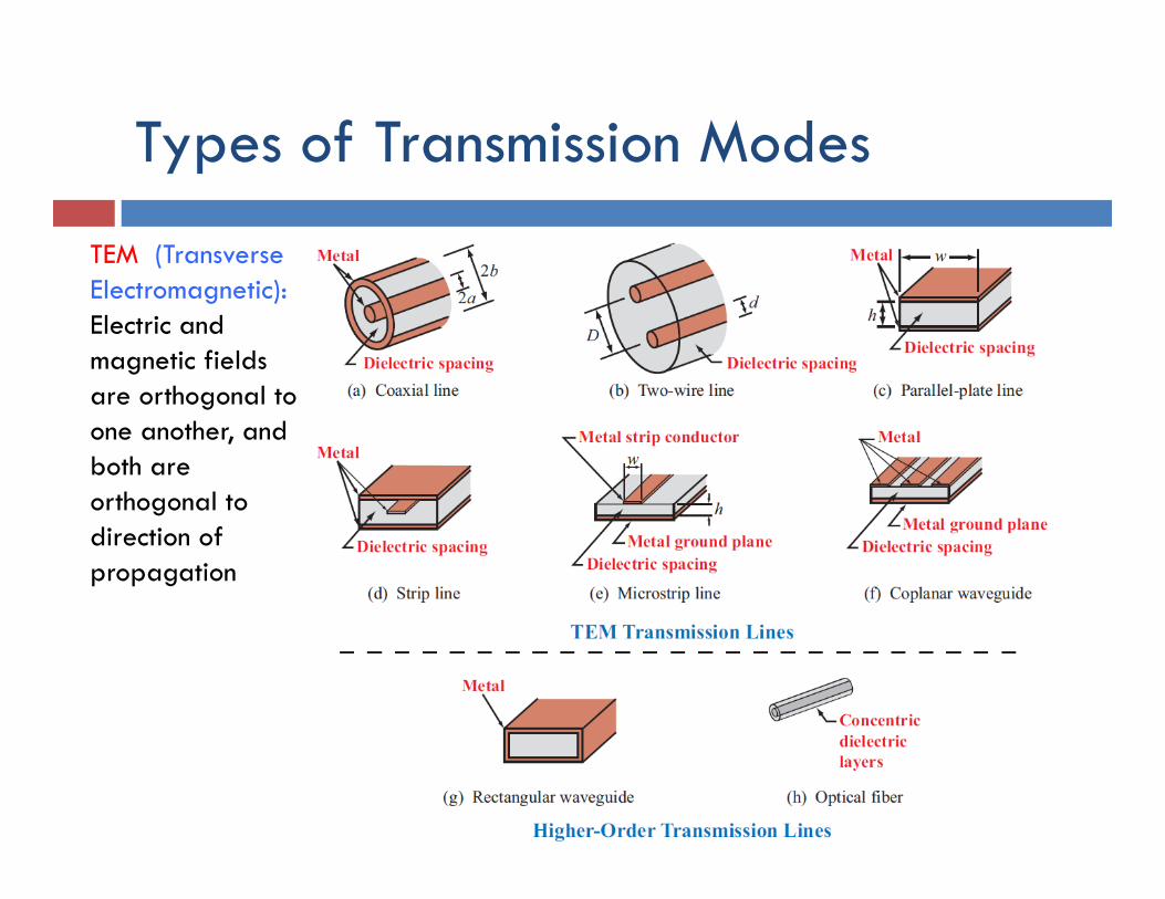
Types of Transmission Modes
TEM (Transverse Electromagnetic): Electric and magnetic fields are orthogonal to one another, and both are orthogonal to direction of propagation
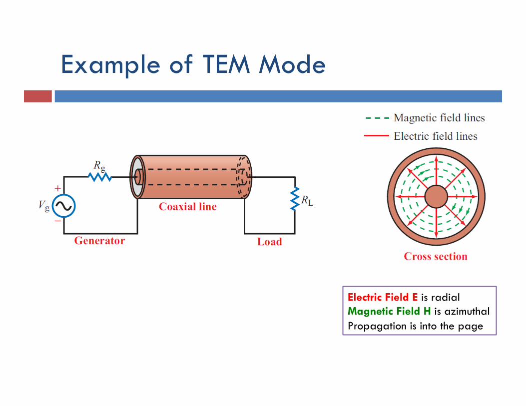
Example of TEM Mode
Electric Field E is radial Magnetic Field H is azimuthal Propagation is into the page
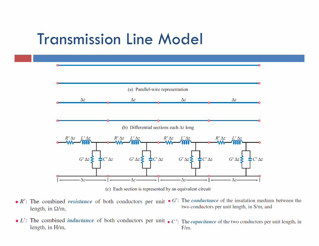
Transmission Line Model
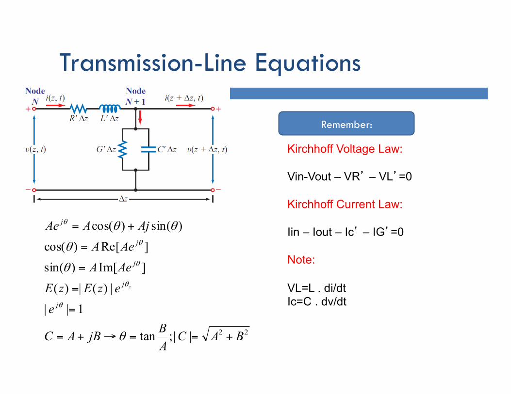
Transmission-Line Equations
Kirchhoff Voltage Law: Vin-Vout – VR’ – VL’=0 Kirchhoff Current Law: Iin – Iout – Ic’ – IG’=0 Note: VL=L . di/dt Ic=C . dv/dt
Remember:
22||;tan
1|||)(|)(
]Im[)sin(]Re[)cos(
)sin()cos(
BACABjBAC
eezEzEAeAAeAAjAAe
j
j
j
j
j
z
+==→+=
=
=
=
=
+=
θ
θ
θ
θθ
θ
θ
θ
θ
θ
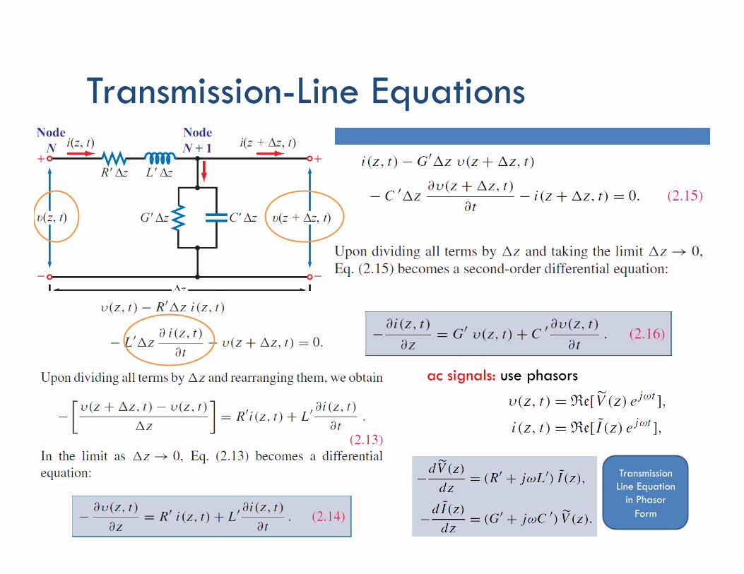
Transmission-Line Equations
ac signals: use phasors
Transmission Line Equation
in Phasor Form
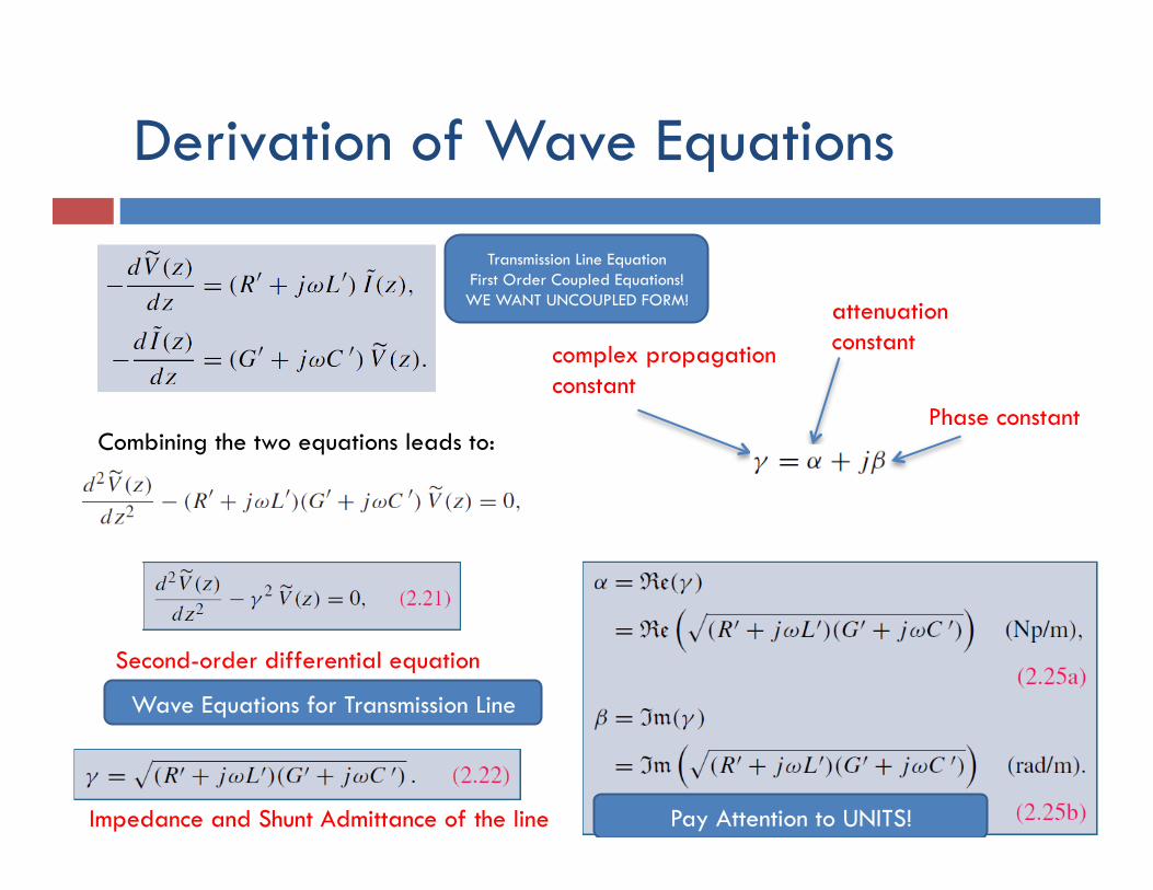
Derivation of Wave Equations
Combining the two equations leads to:
Second-order differential equation
complex propagation constant
attenuation constant
Phase constant
Transmission Line Equation First Order Coupled Equations! WE WANT UNCOUPLED FORM!
Pay Attention to UNITS!
Wave Equations for Transmission Line
Impedance and Shunt Admittance of the line
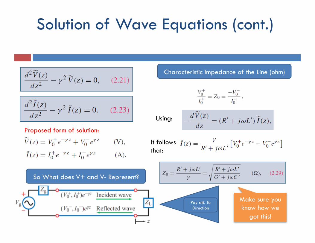
Solution of Wave Equations (cont.)
Proposed form of solution:
Using:
It follows that:
Characteristic Impedance of the Line (ohm)
So What does V+ and V- Represent?
Pay att. To Direction
Make sure you know how we
got this!
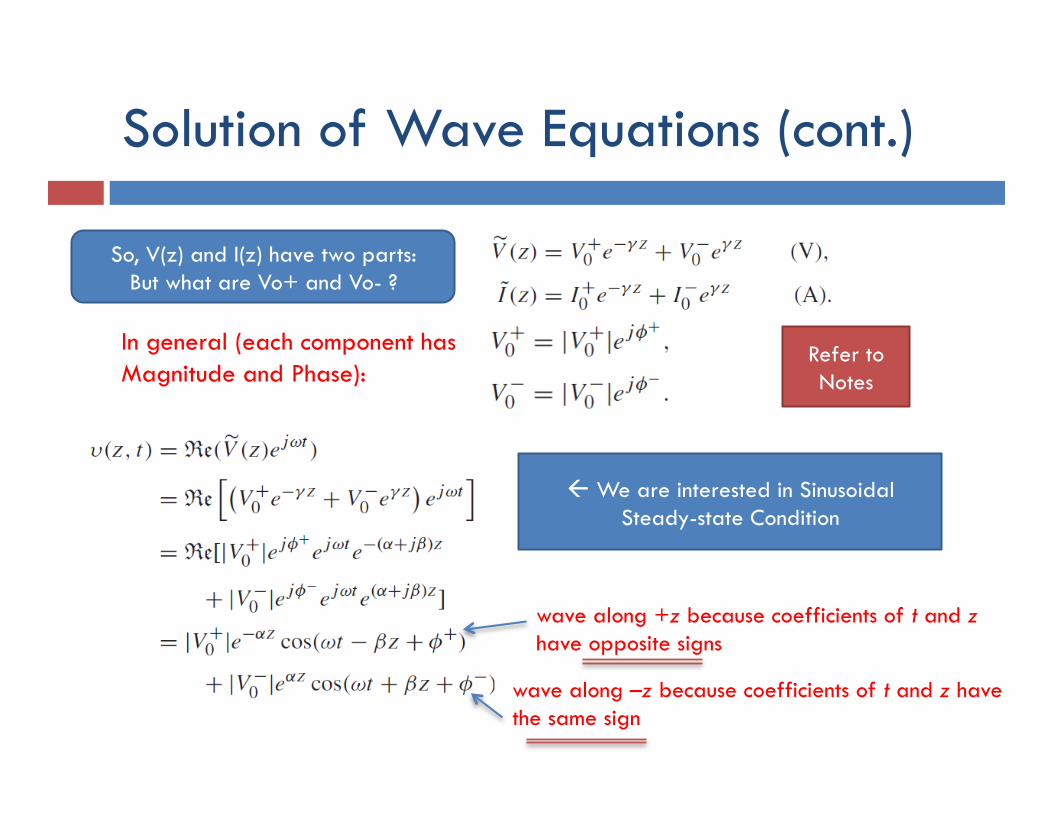
Solution of Wave Equations (cont.)
In general (each component has Magnitude and Phase):
wave along +z because coefficients of t and z have opposite signs
wave along –z because coefficients of t and z have the same sign
So, V(z) and I(z) have two parts: But what are Vo+ and Vo- ?
ß We are interested in Sinusoidal Steady-state Condition
Refer to Notes
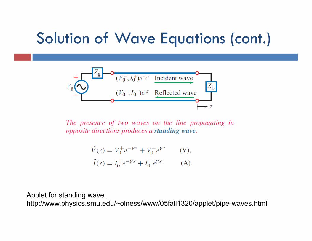
Solution of Wave Equations (cont.)
Applet for standing wave: http://www.physics.smu.edu/~olness/www/05fall1320/applet/pipe-waves.html
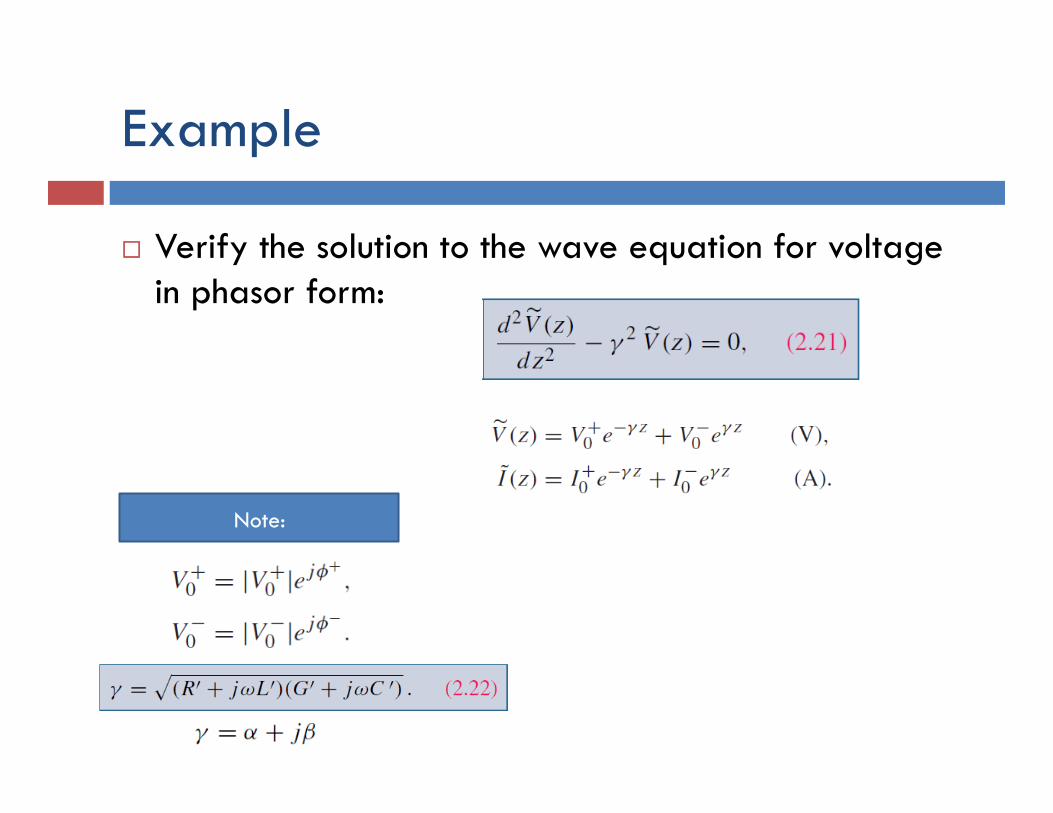
Example
¨ Verify the solution to the wave equation for voltage in phasor form:
Note:
Assume the following waves:
Assume having perfect dielectric insolator and the wire have
perfect conductivity with no loss
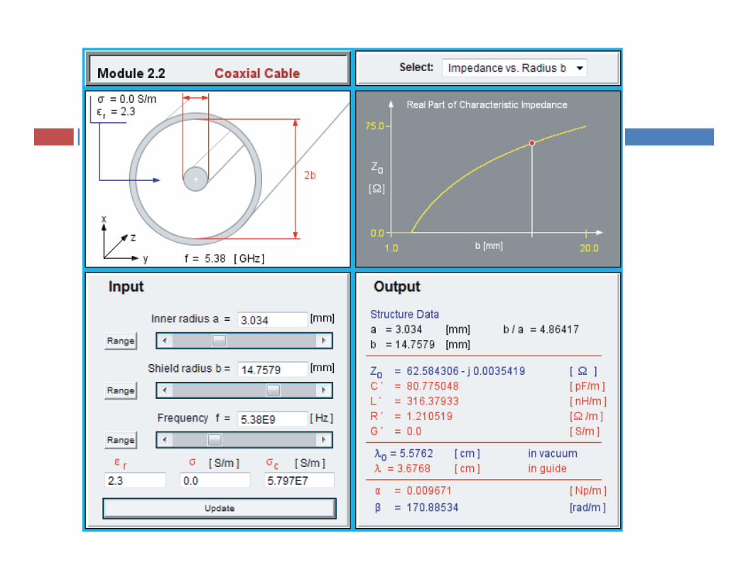
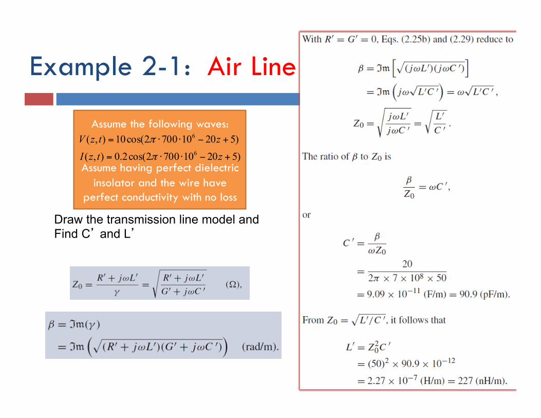
Example 2-1: Air Line
Draw the transmission line model and Find C’ and L’
)520107002cos(2.0),()520107002cos(10),(
6
6
+−⋅⋅=
+−⋅⋅=
ztzIztzV
π
π
Section 2
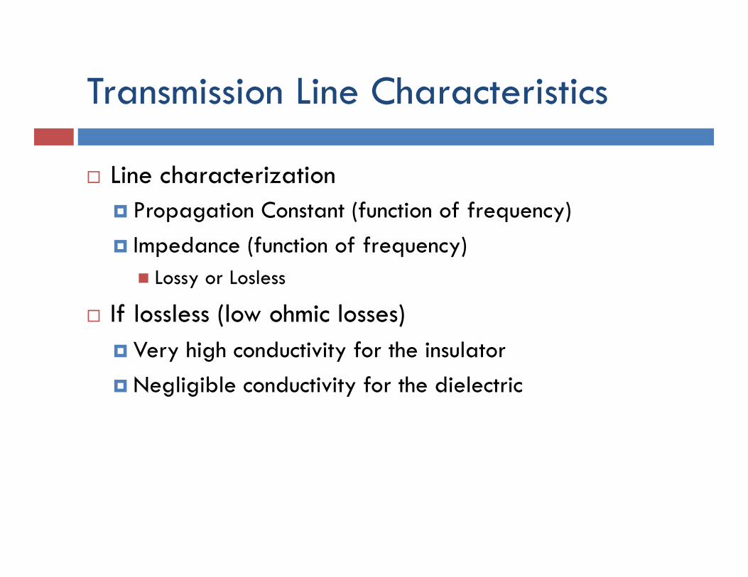
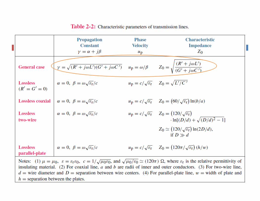
Transmission Line Characteristics
¨ Line characterization ¤ Propagation Constant (function of frequency) ¤ Impedance (function of frequency)
n Lossy or Losless
¨ If lossless (low ohmic losses) ¤ Very high conductivity for the insulator ¤ Negligible conductivity for the dielectric
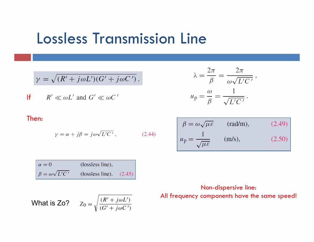
Lossless Transmission Line
If
Then:
Non-dispersive line: All frequency components have the same speed!
What is Zo?
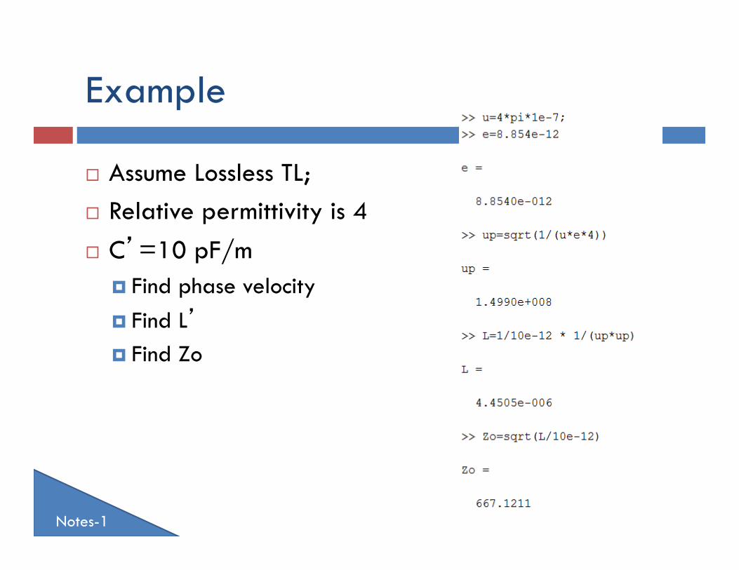
Example
¨ Assume Lossless TL; ¨ Relative permittivity is 4 ¨ C’=10 pF/m
¤ Find phase velocity ¤ Find L’ ¤ Find Zo
Notes-1
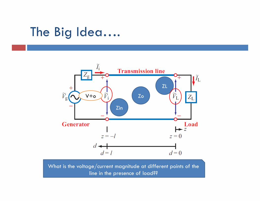
The Big Idea….
Zin
ZL
Zo V+o
What is the voltage/current magnitude at different points of the line in the presence of load??
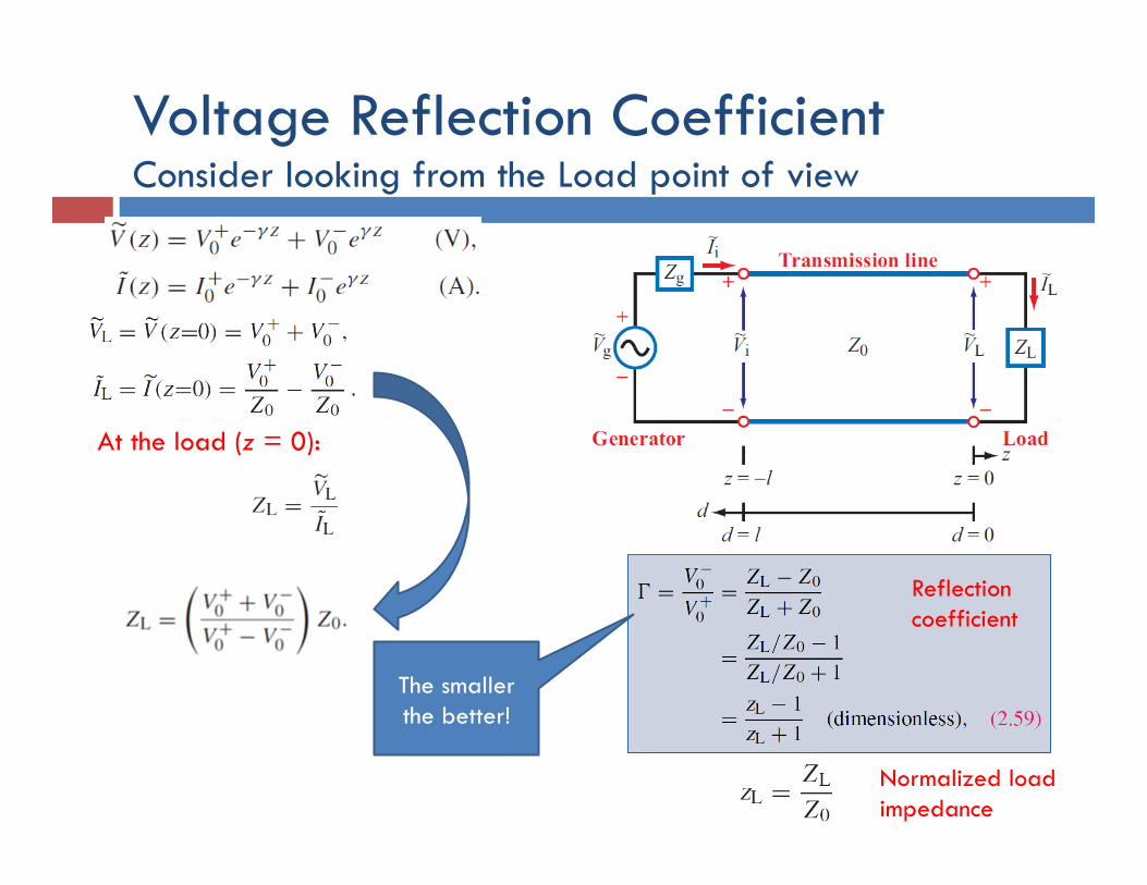
Voltage Reflection Coefficient Consider looking from the Load point of view
At the load (z = 0):
Reflection coefficient
Normalized load impedance
The smaller the better!
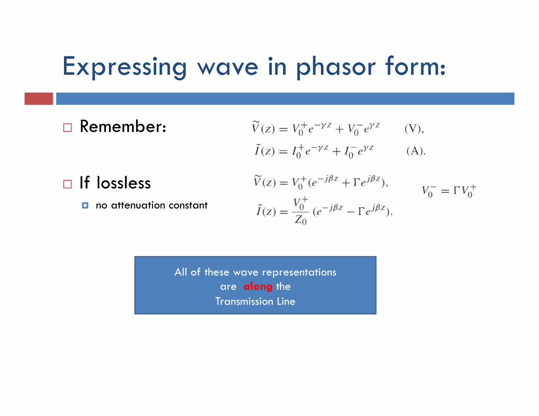
Expressing wave in phasor form:
¨ Remember: ¨ If lossless
¤ no attenuation constant
All of these wave representations are along the
Transmission Line
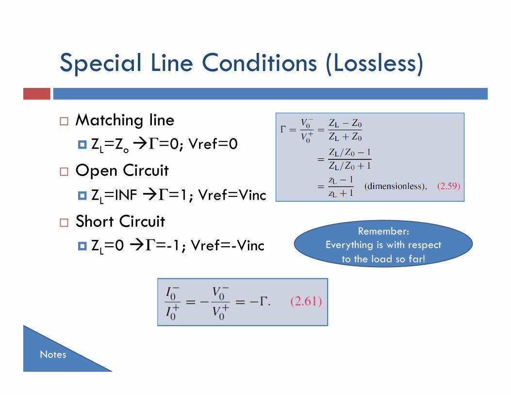
Special Line Conditions (Lossless)
¨ Matching line ¤ ZL=Zo àΓ=0; Vref=0
¨ Open Circuit ¤ ZL=INF àΓ=1; Vref=Vinc
¨ Short Circuit ¤ ZL=0 àΓ=-1; Vref=-Vinc
Notes
Remember: Everything is with respect
to the load so far!
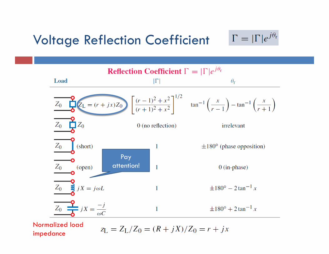
Voltage Reflection Coefficient
Normalized load impedance
Pay attention!
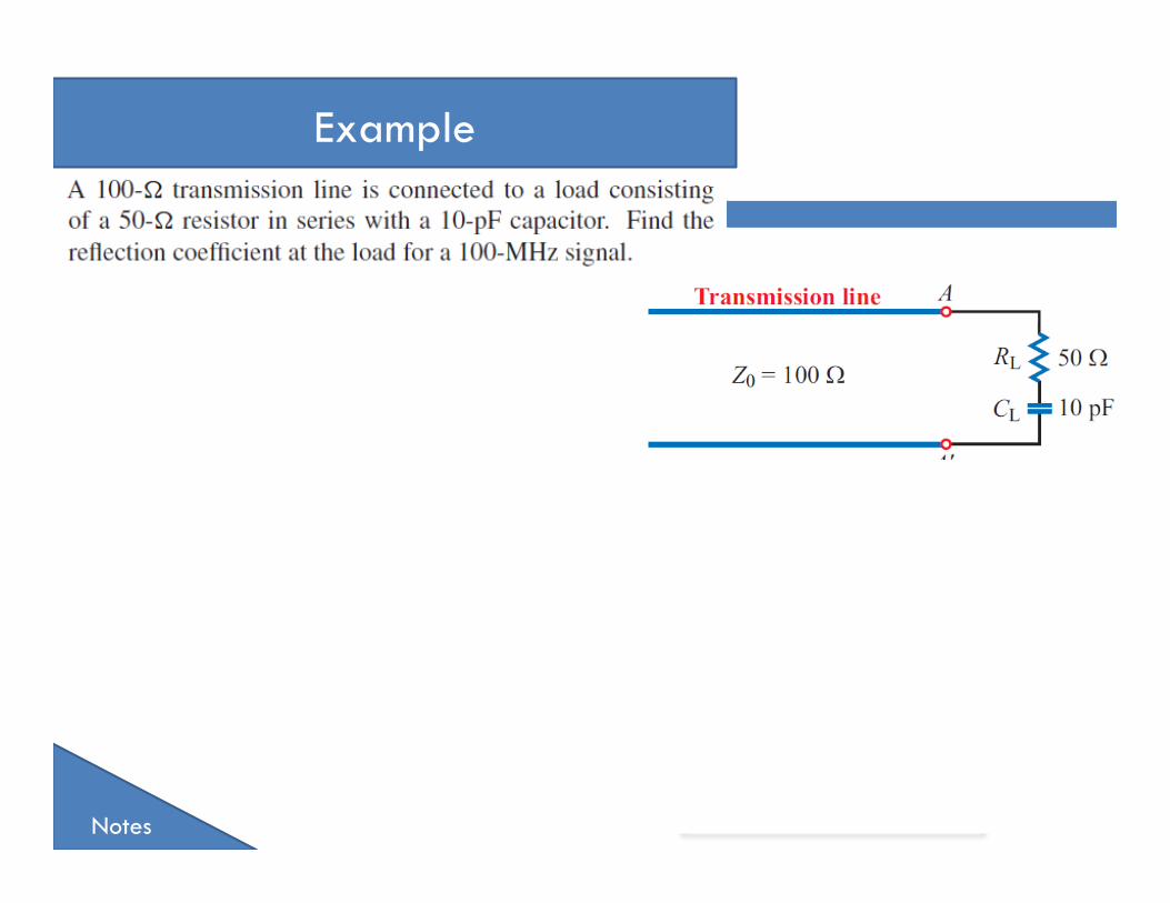
Example
Example
Example
Notes
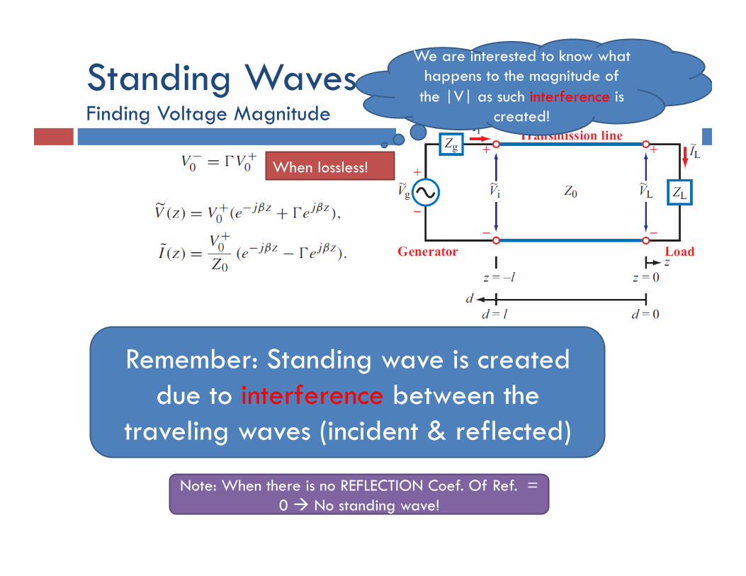
Standing Waves Finding Voltage Magnitude
Note: When there is no REFLECTION Coef. Of Ref. = 0 à No standing wave!
Remember: Standing wave is created due to interference between the
traveling waves (incident & reflected)
When lossless!
We are interested to know what happens to the magnitude of
the |V| as such interference is created!
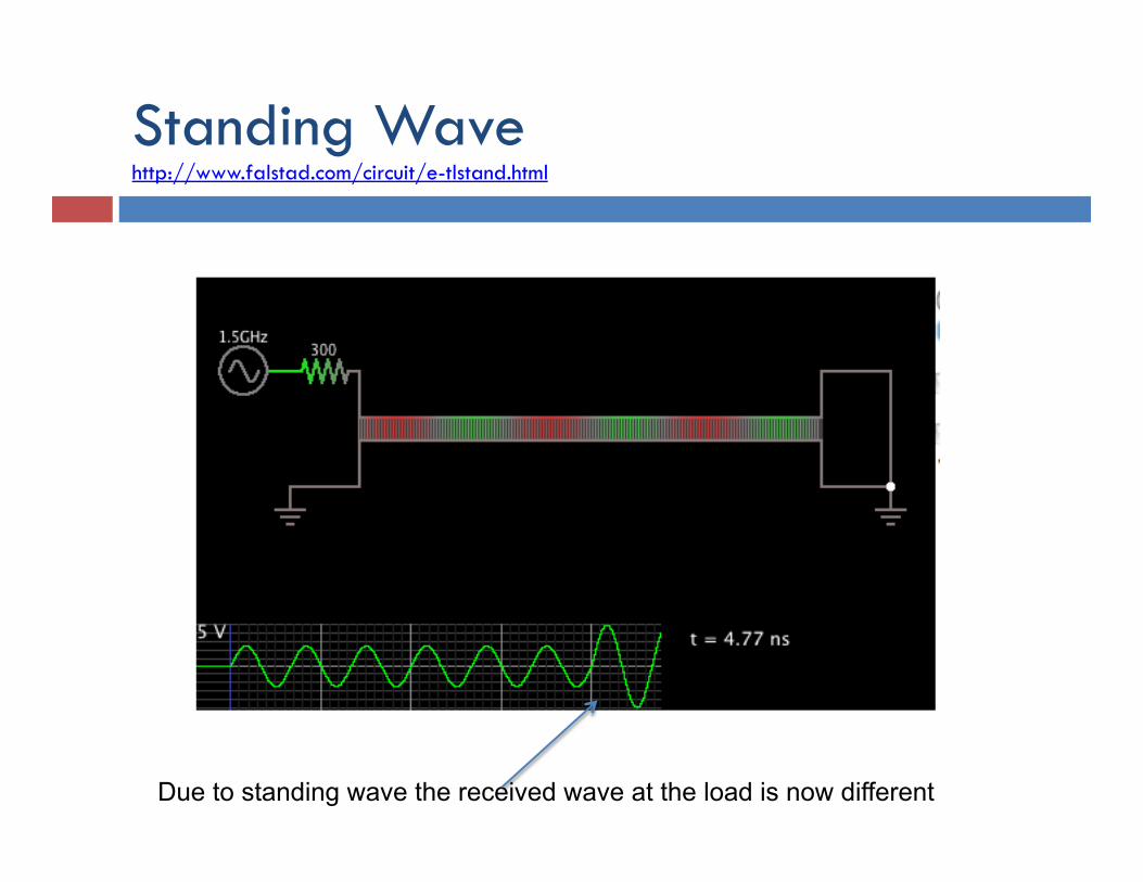
Standing Wave http://www.falstad.com/circuit/e-tlstand.html
Due to standing wave the received wave at the load is now different
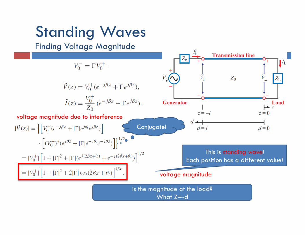
Standing Waves Finding Voltage Magnitude
voltage magnitude
Conjugate!
is the magnitude at the load? What Z=-d
This is standing wave! Each position has a different value!
voltage magnitude due to interference
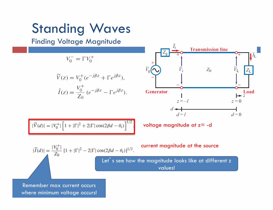
Standing Waves Finding Voltage Magnitude
voltage magnitude at z= -d
current magnitude at the source
Let’s see how the magnitude looks like at different z values!
Remember max current occurs where minimum voltage occurs!
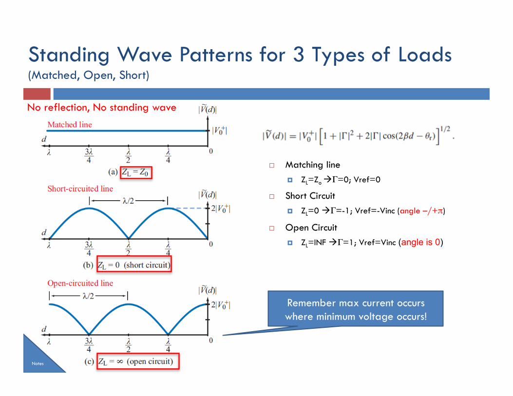
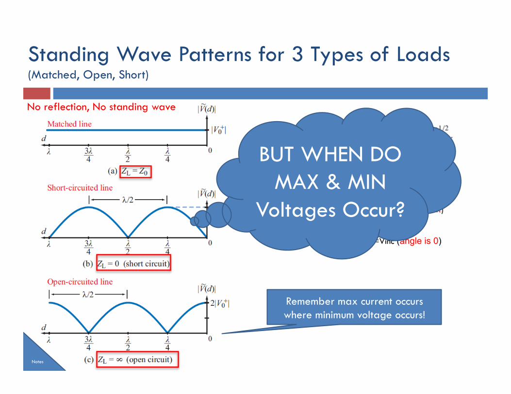
Standing Wave Patterns for 3 Types of Loads (Matched, Open, Short)
¨ Matching line ¤ ZL=Zo àΓ=0; Vref=0
¨ Short Circuit ¤ ZL=0 àΓ=-1; Vref=-Vinc (angle –/+π)
¨ Open Circuit ¤ ZL=INF àΓ=1; Vref=Vinc (angle is 0)
Remember max current occurs where minimum voltage occurs!
Notes
No reflection, No standing wave
BUT WHEN DO MAX & MIN
Voltages Occur?
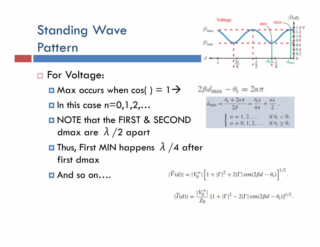
Standing Wave Pattern
¨ For Voltage: ¤ Max occurs when cos( ) = 1à ¤ In this case n=0,1,2,… ¤ NOTE that the FIRST & SECOND
dmax are λ/2 apart ¤ Thus, First MIN happens λ/4 after
first dmax ¤ And so on….
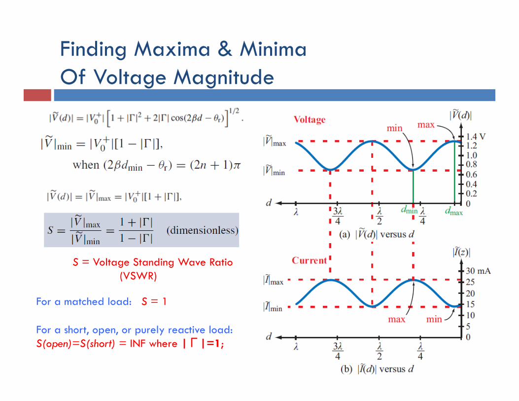
Finding Maxima & Minima Of Voltage Magnitude
S = Voltage Standing Wave Ratio (VSWR)
For a matched load: S = 1 For a short, open, or purely reactive load: S(open)=S(short) = INF where |Γ|=1;
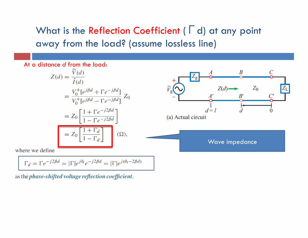
What is the Reflection Coefficient (Γd) at any point away from the load? (assume lossless line)
At a distance d from the load:
Wave impedance
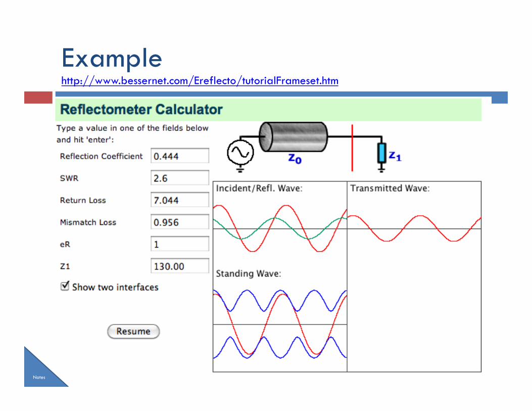
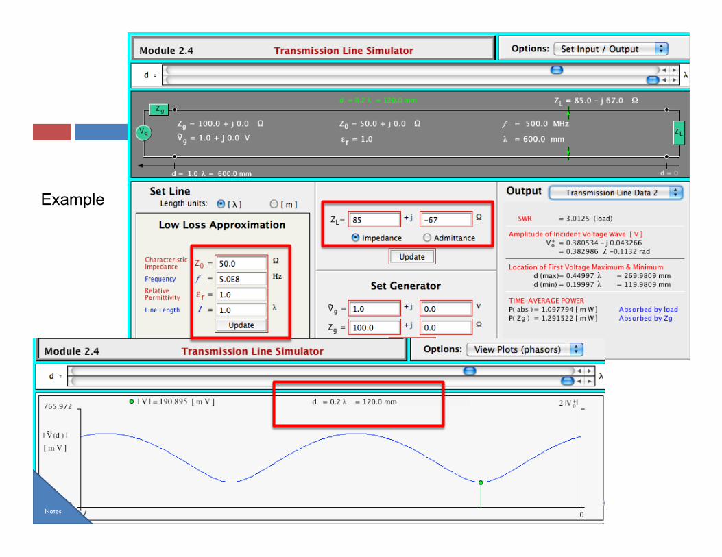
Example http://www.bessernet.com/Ereflecto/tutorialFrameset.htm
Notes
Example
Notes
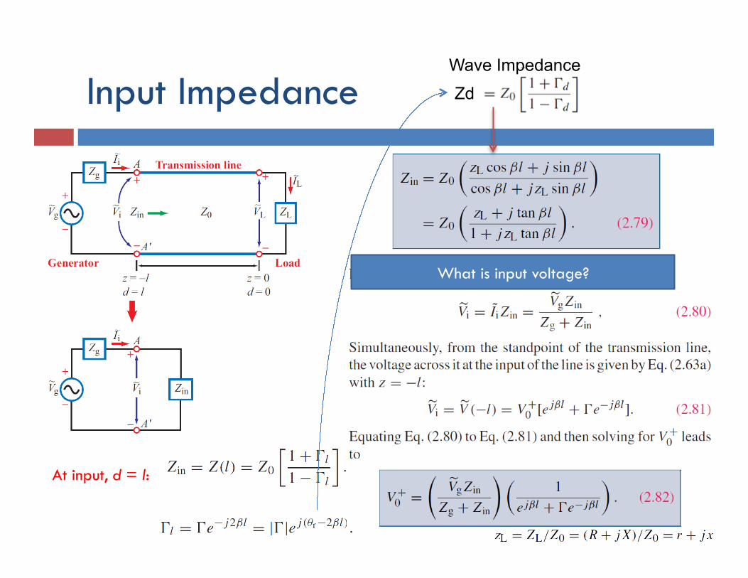
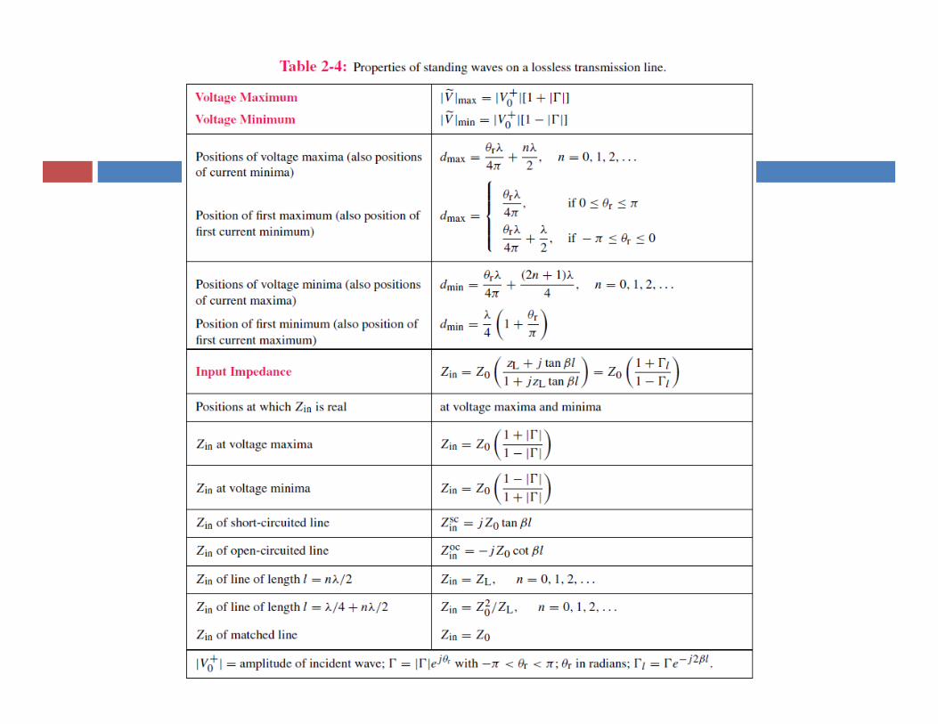
Input Impedance
At input, d = l:
Zd
Wave Impedance
What is input voltage?
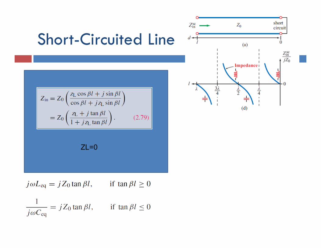
Short-Circuited Line
For the short-circuited line:
At its input, the line appears like an inductor or a capacitor depending on the sign of
ZL=0

Input Impedance Special Cases - Lossless
What is Zin when matched?
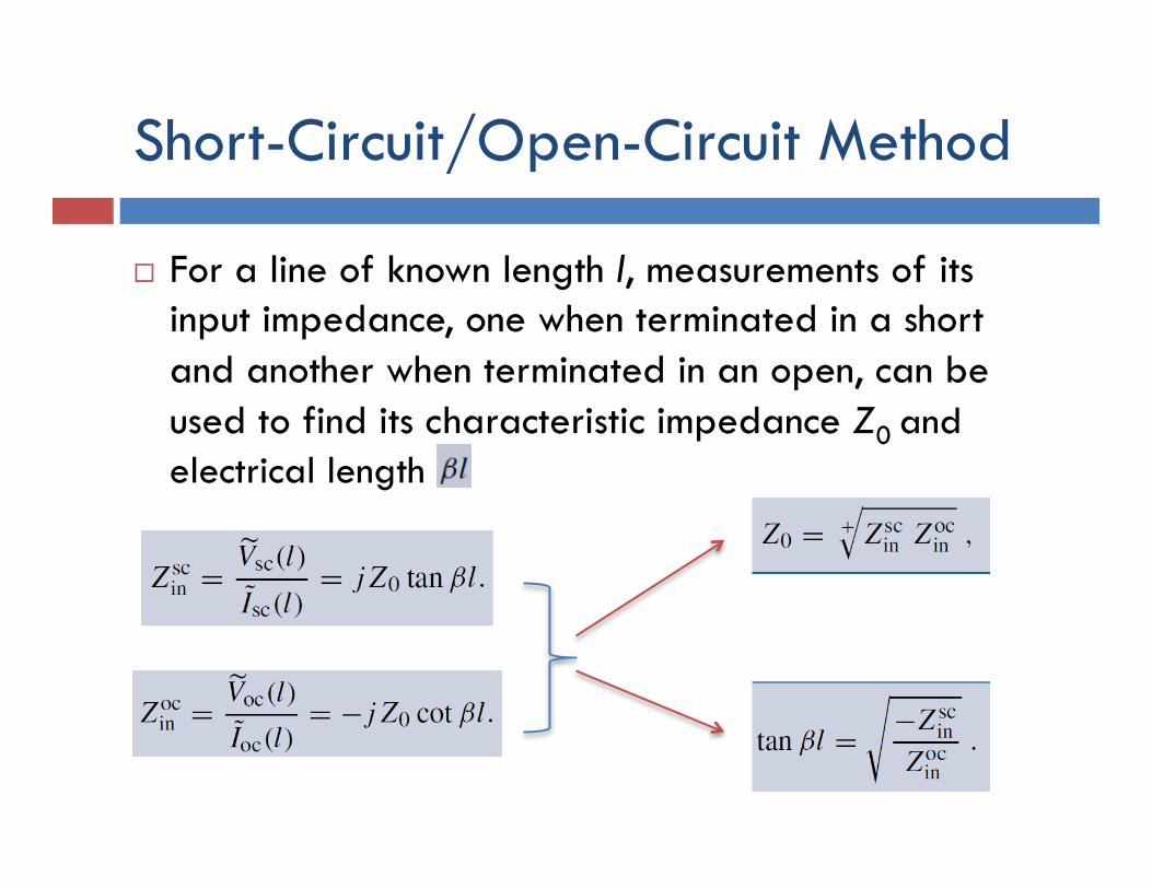
Short-Circuit/Open-Circuit Method
¨ For a line of known length l, measurements of its input impedance, one when terminated in a short and another when terminated in an open, can be used to find its characteristic impedance Z0 and
electrical length

Example
¨ Check your notes!
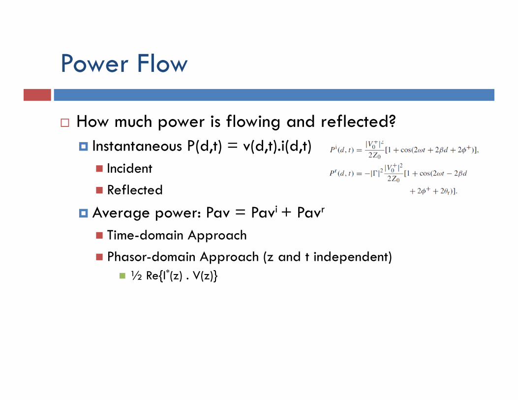
Power Flow
¨ How much power is flowing and reflected? ¤ Instantaneous P(d,t) = v(d,t).i(d,t)
n Incident n Reflected
¤ Average power: Pav = Pavi + Pavr
n Time-domain Approach n Phasor-domain Approach (z and t independent)
n ½ Re{I*(z) . V(z)}
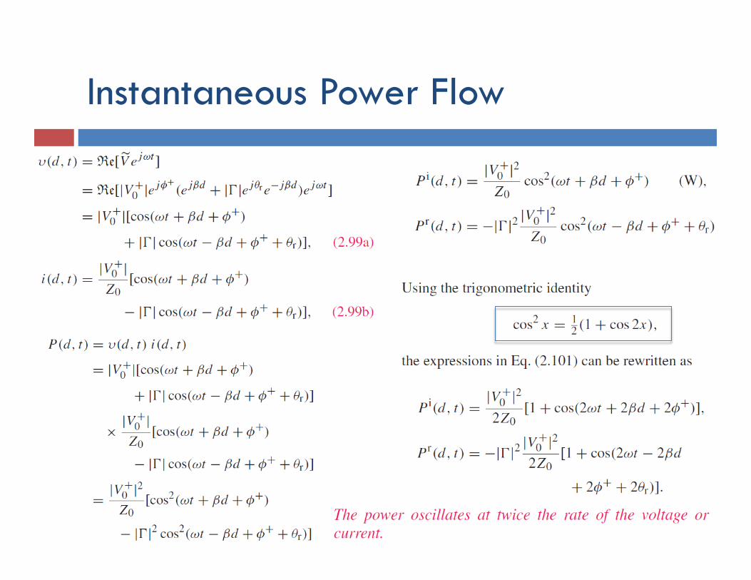
Instantaneous Power Flow
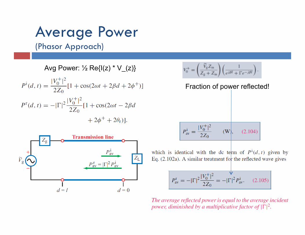
Average Power (Phasor Approach)
Fraction of power reflected!
Avg Power: ½ Re{I(z) * V_(z)}
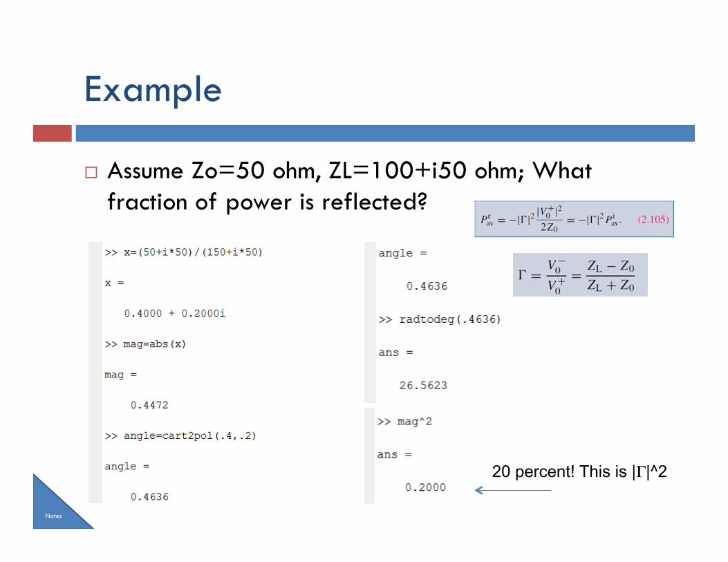
Example
¨ Assume Zo=50 ohm, ZL=100+i50 ohm; What fraction of power is reflected?
20 percent! This is |Γ|^2
Notes
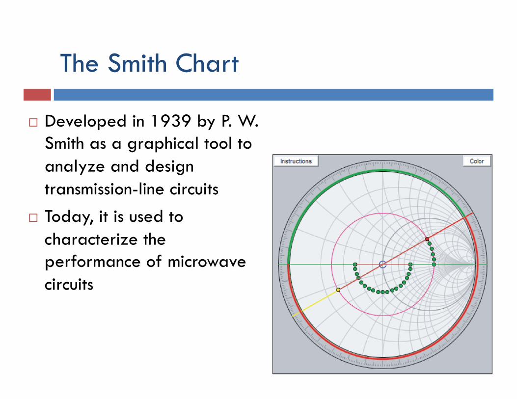
The Smith Chart
¨ Developed in 1939 by P. W. Smith as a graphical tool to analyze and design transmission-line circuits
¨ Today, it is used to characterize the performance of microwave circuits
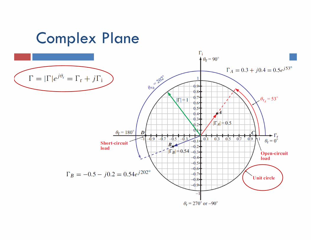
Complex Plane
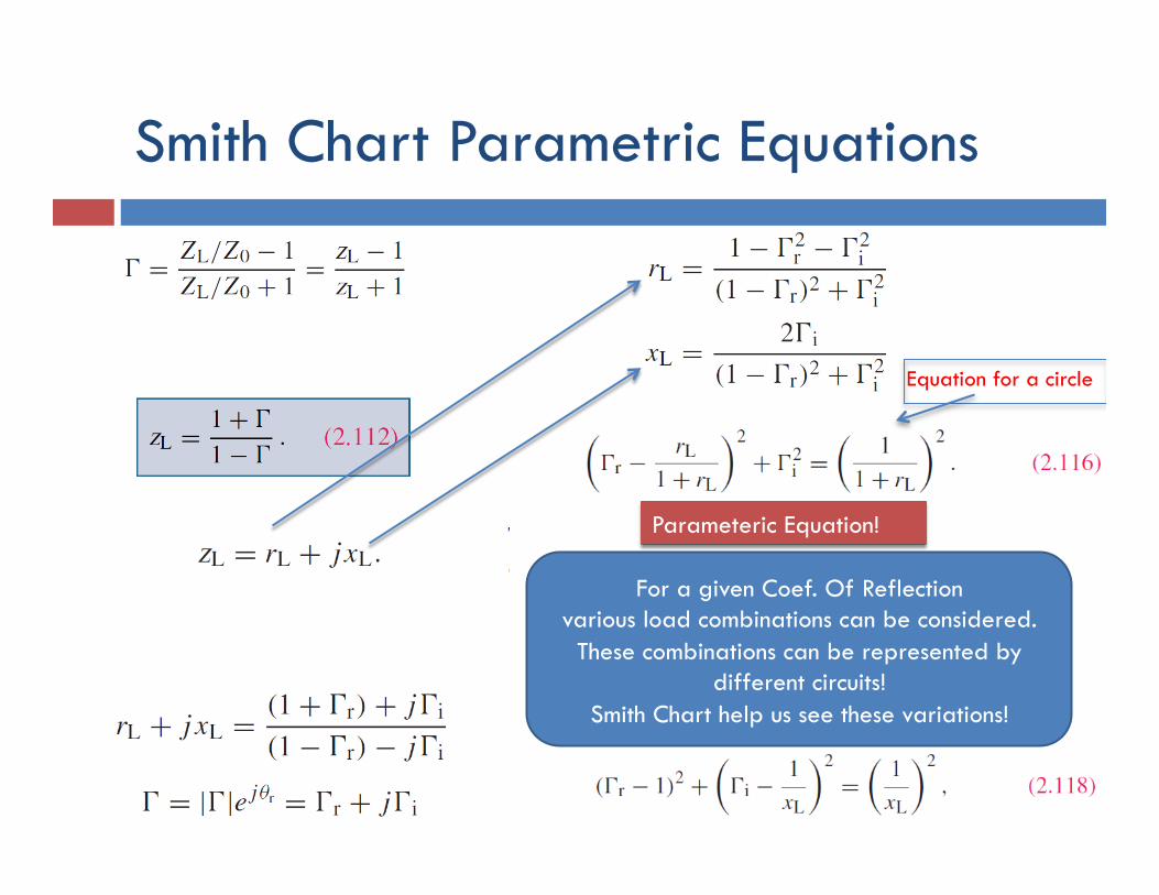
Smith Chart Parametric Equations
Equation for a circle
For a given Coef. Of Reflection various load combinations can be considered.
These combinations can be represented by different circuits!
Smith Chart help us see these variations!
Parameteric Equation!
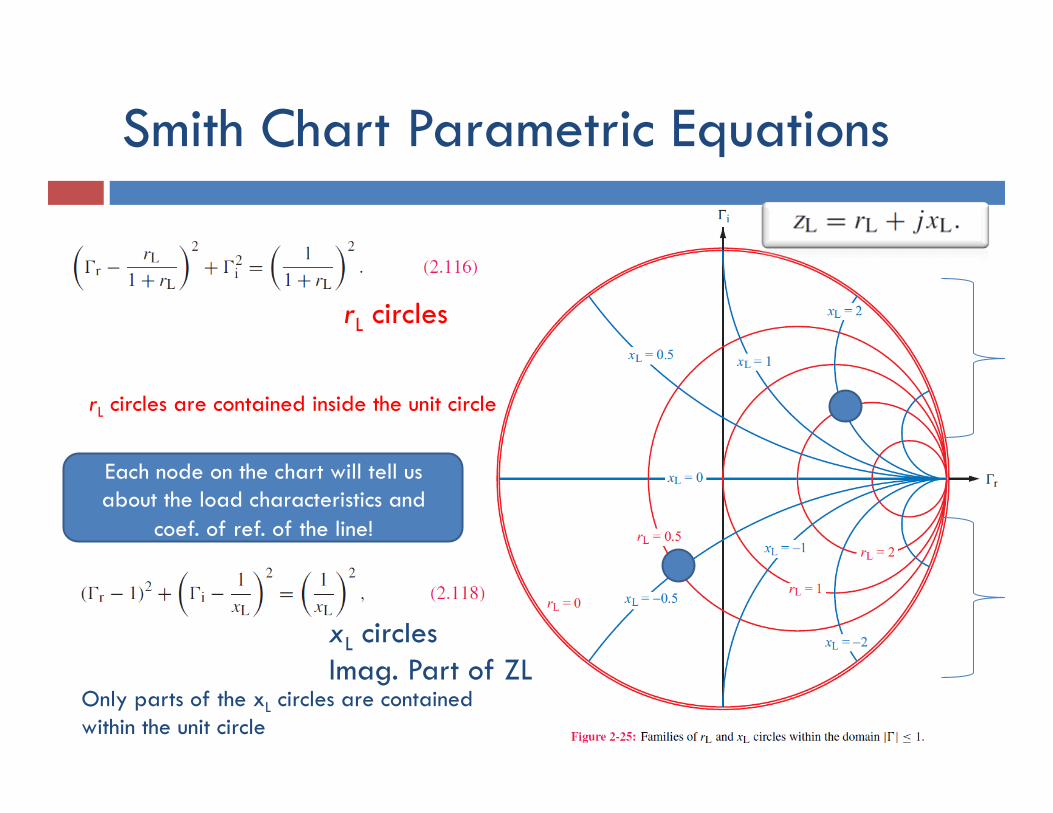
Smith Chart Parametric Equations
rL circles
xL circles Imag. Part of ZL
rL circles are contained inside the unit circle
Only parts of the xL circles are contained within the unit circle
Each node on the chart will tell us about the load characteristics and
coef. of ref. of the line!
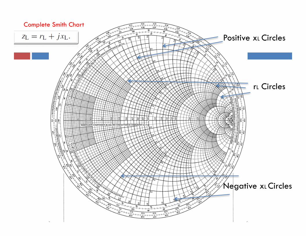
Complete Smith Chart
rL Circles
Positive xL Circles
Negative xL Circles
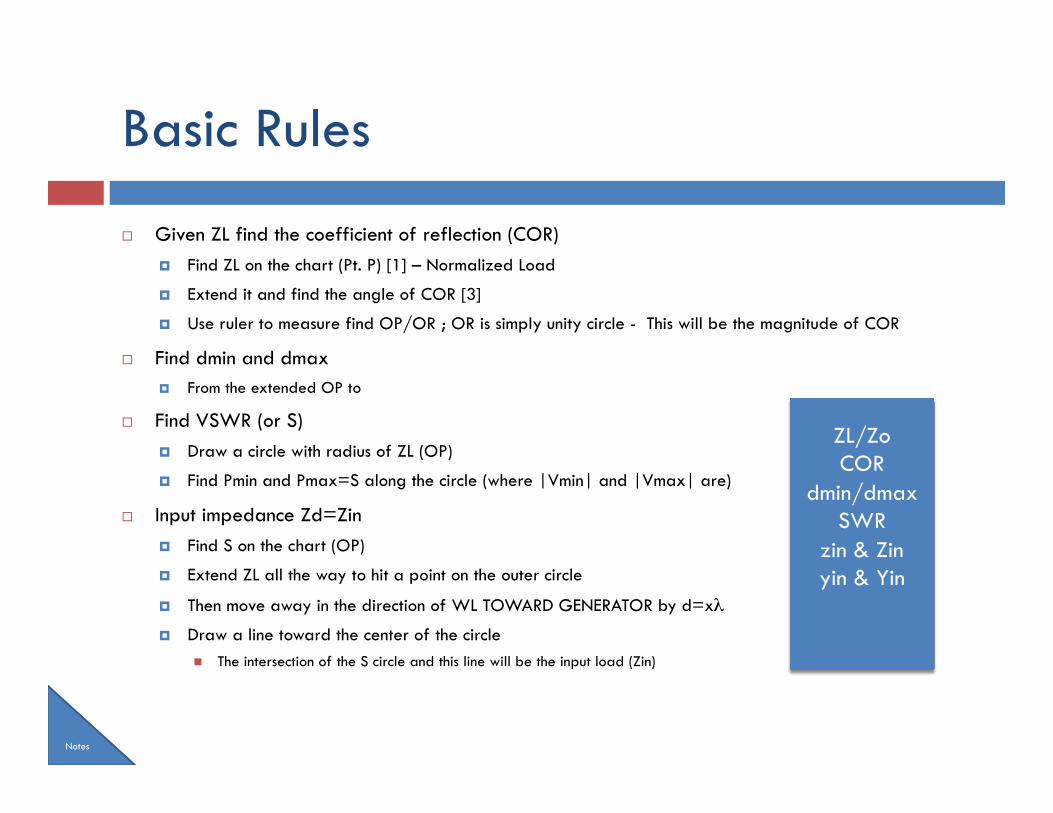
Basic Rules
¨ Given ZL find the coefficient of reflection (COR) ¤ Find ZL on the chart (Pt. P) [1] – Normalized Load
¤ Extend it and find the angle of COR [3]
¤ Use ruler to measure find OP/OR ; OR is simply unity circle - This will be the magnitude of COR
¨ Find dmin and dmax ¤ From the extended OP to
¨ Find VSWR (or S) ¤ Draw a circle with radius of ZL (OP)
¤ Find Pmin and Pmax=S along the circle (where |Vmin| and |Vmax| are)
¨ Input impedance Zd=Zin ¤ Find S on the chart (OP)
¤ Extend ZL all the way to hit a point on the outer circle
¤ Then move away in the direction of WL TOWARD GENERATOR by d=xλ
¤ Draw a line toward the center of the circle n The intersection of the S circle and this line will be the input load (Zin)
Notes
ZL/Zo COR
dmin/dmax SWR
zin & Zin yin & Yin
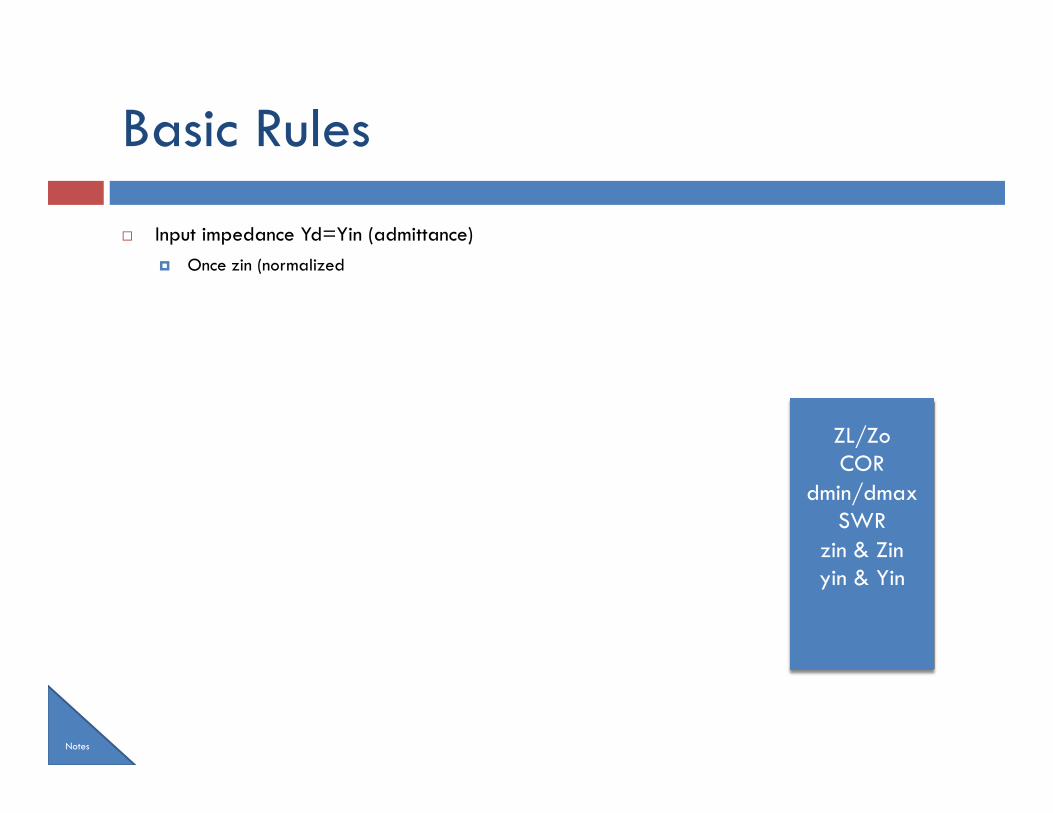
Basic Rules
¨ Input impedance Yd=Yin (admittance) ¤ Once zin (normalized
Notes
ZL/Zo COR
dmin/dmax SWR
zin & Zin yin & Yin
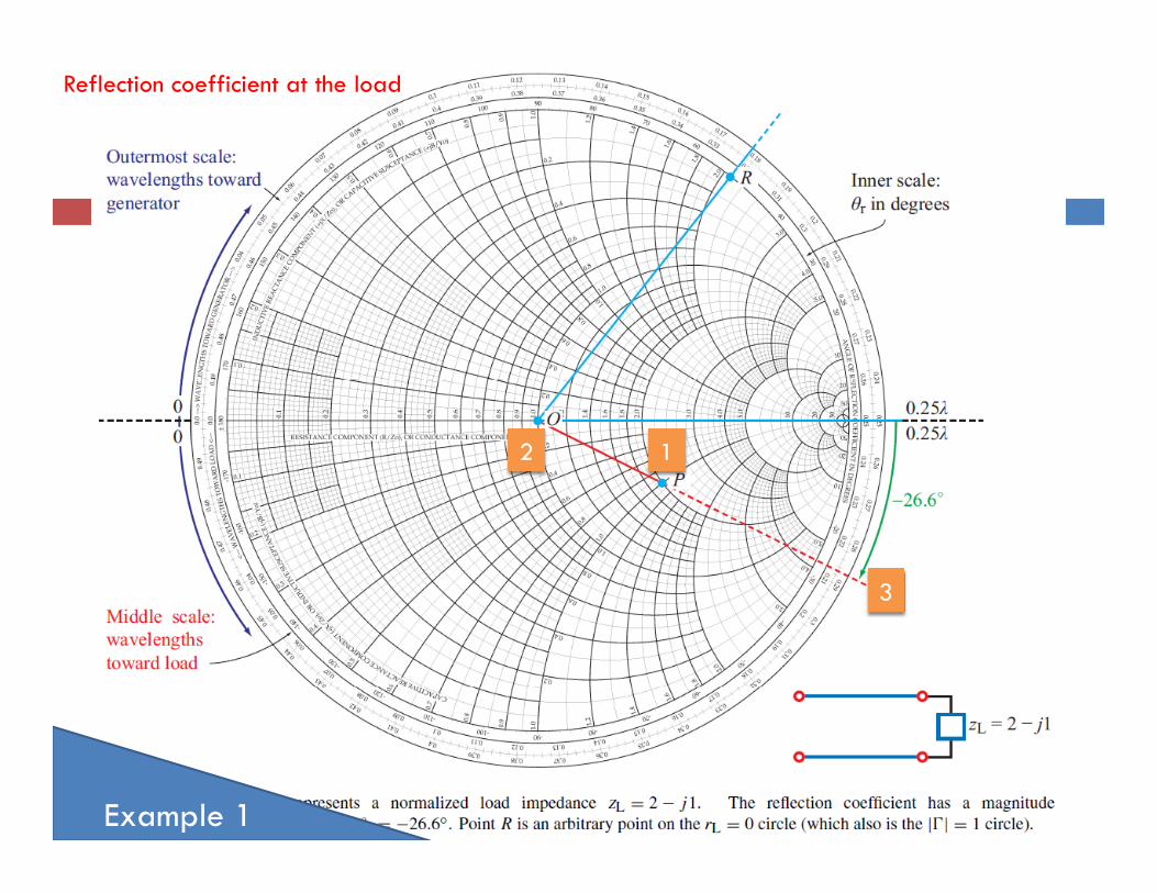
Reflection coefficient at the load
Example 1
1 2
3
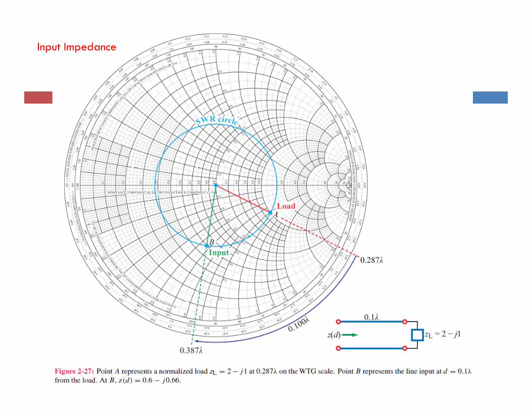
Input Impedance
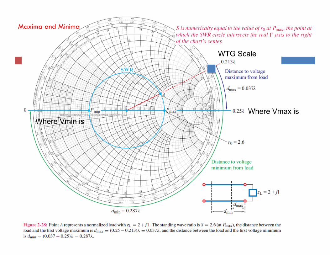
Maxima and Minima
Where Vmax is Where Vmin is
WTG Scale
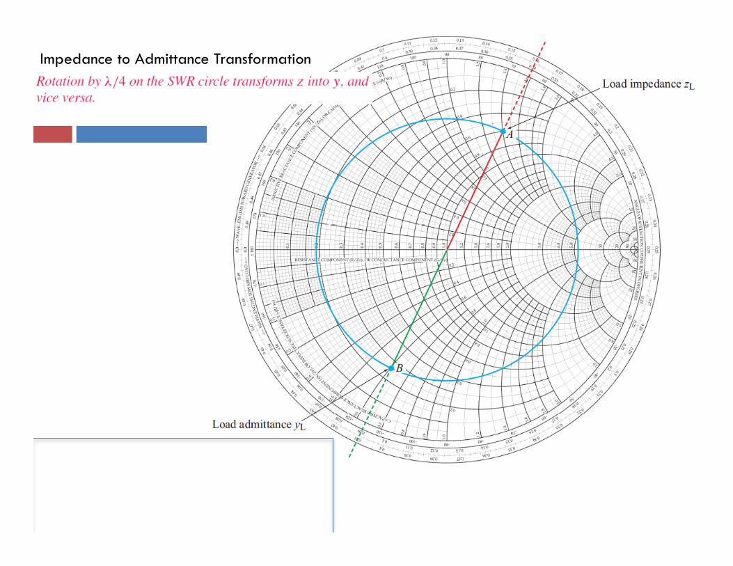
Impedance to Admittance Transformation
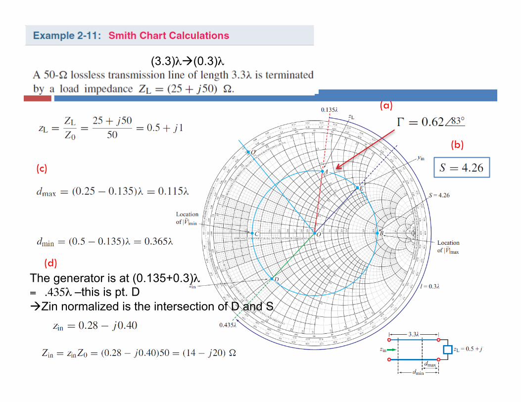
(c)
(d)
(a)
(b)
The generator is at (0.135+0.3)λ = .435λ –this is pt. D àZin normalized is the intersection of D and S
(3.3)λà(0.3)λ
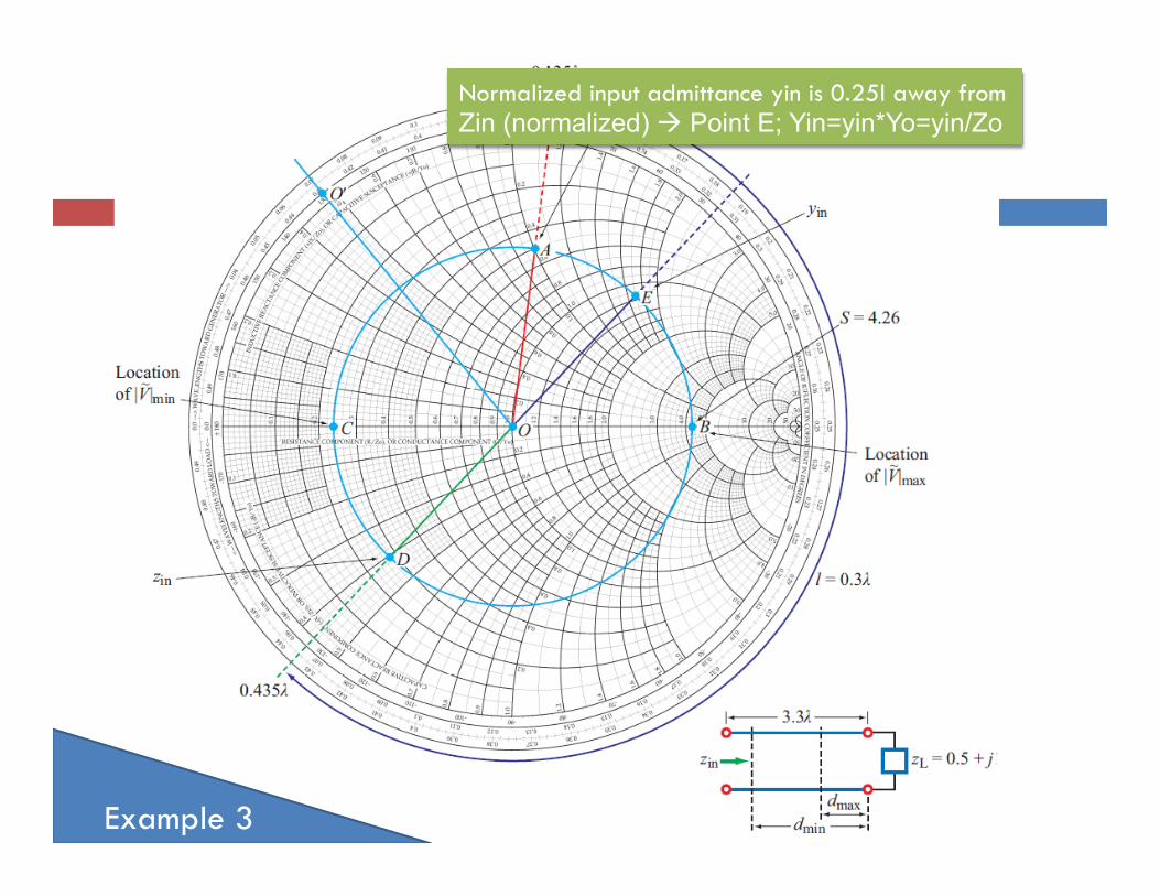
Example 3
Normalized input admittance yin is 0.25l away from Zin (normalized) à Point E; Yin=yin*Yo=yin/Zo
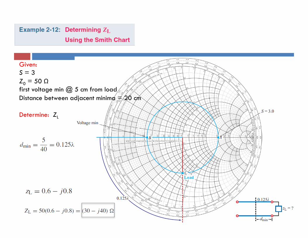
Given: S = 3 Z0 = 50 Ω first voltage min @ 5 cm from load Distance between adjacent minima = 20 cm Determine: ZL
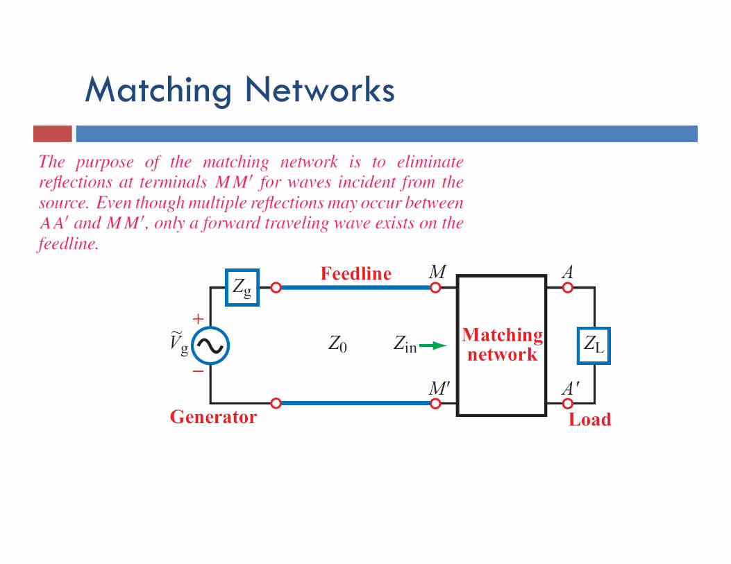
Matching Networks
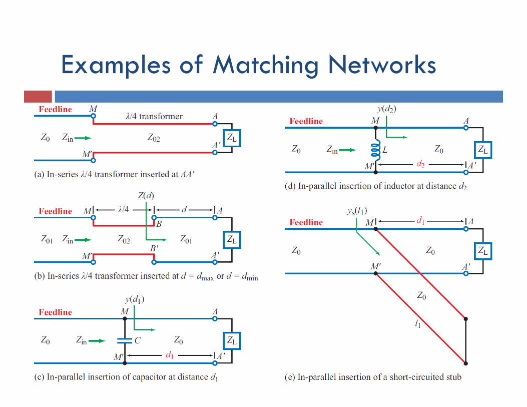
Examples of Matching Networks
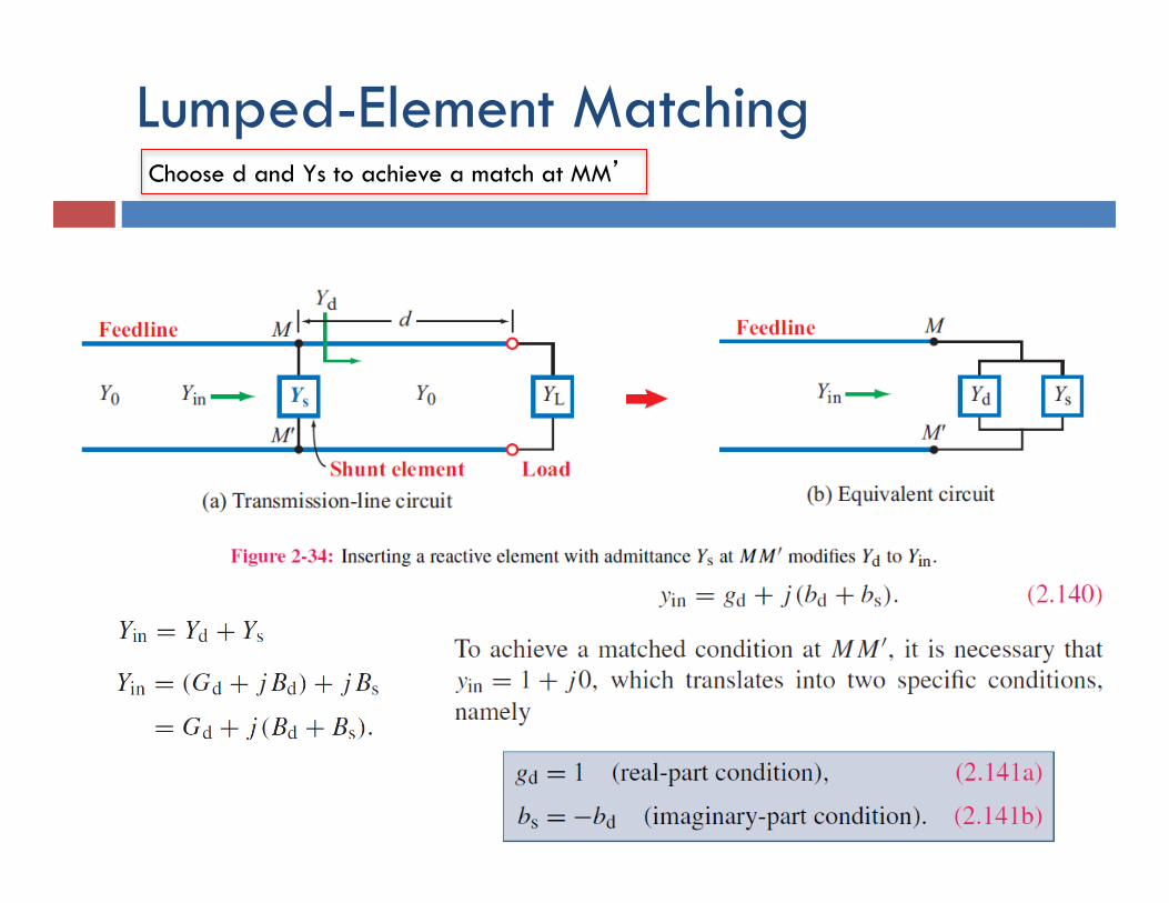
Lumped-Element Matching Choose d and Ys to achieve a match at MM’
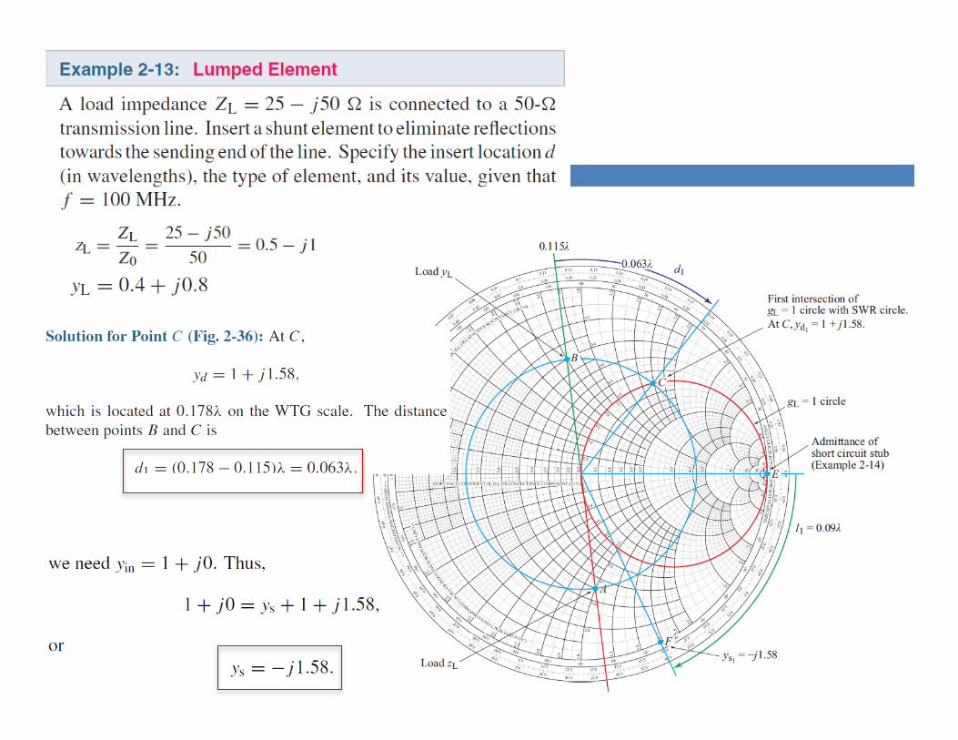
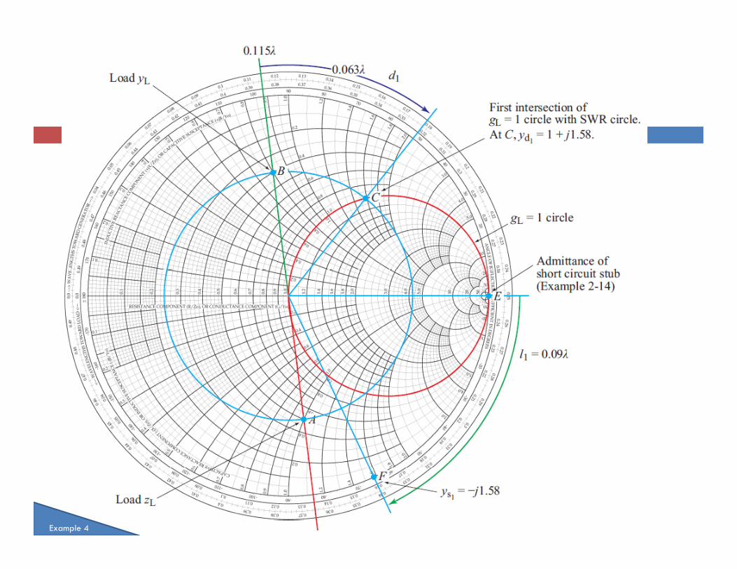
Example 4
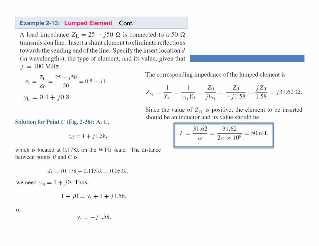
Cont.
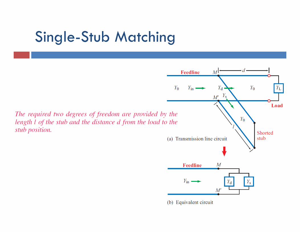
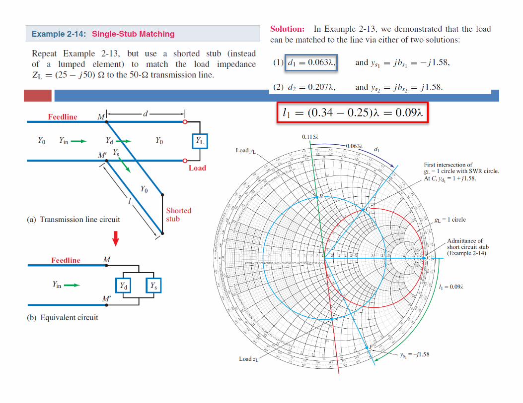
Single-Stub Matching
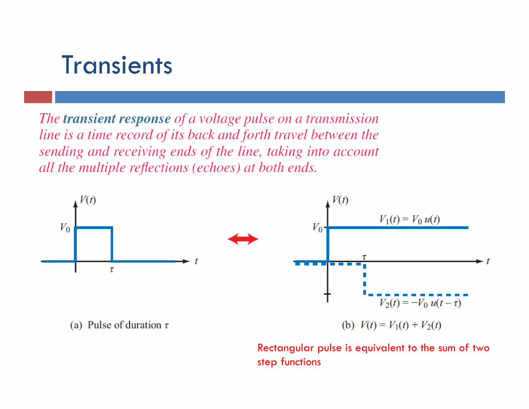
Transients
Rectangular pulse is equivalent to the sum of two step functions
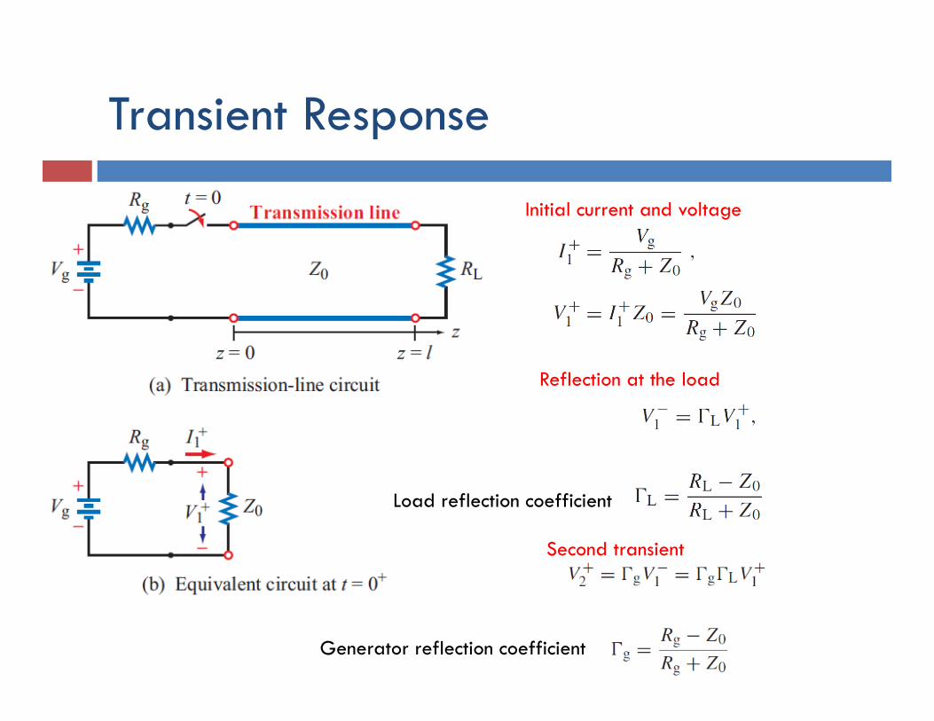
Transient Response
Initial current and voltage
Reflection at the load
Second transient
Load reflection coefficient
Generator reflection coefficient
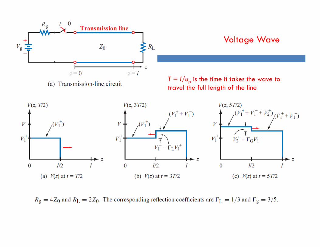
T = l/up is the time it takes the wave to travel the full length of the line
Voltage Wave
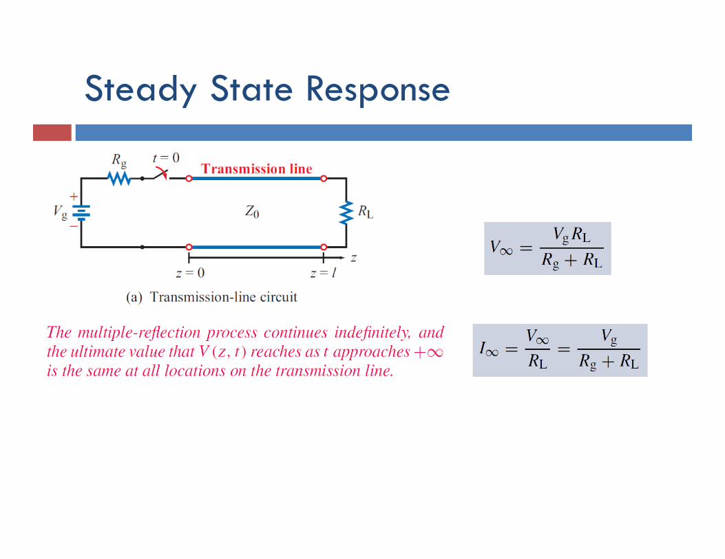
Steady State Response
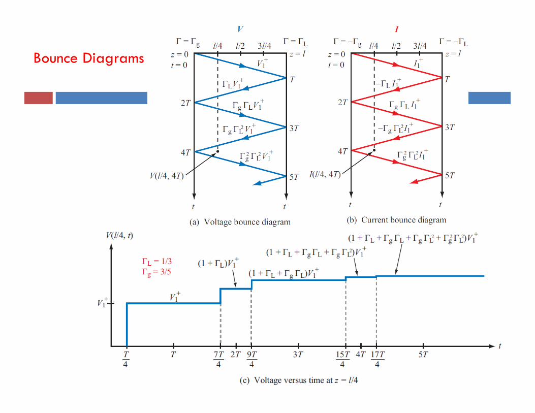
Bounce Diagrams