2-wire programmable transmitter tt518
TRANSCRIPT

2-WIRE PROGRAMMABLE TRANSMITTER TT518

1 Minco Products, Inc. •Tel: 763.571.3121 • www.minco.com • 2612426 (B)
2-WIRE PROGRAMMABLE TRANSMITTER TT518
CONTENTS Application ......................................................................................................... 2
Technical Characteristics ..................................................................................... 2
Mounting / Installation ....................................................................................... 2
Applications ........................................................................................................ 3
TT518 Order Options ........................................................................................... 4
Electrical specifications ....................................................................................... 4
Connections ........................................................................................................ 7
Programming ...................................................................................................... 8
Mechanical specifications ................................................................................... 9
Mounting of sensor wires ................................................................................... 9
Appendix .......................................................................................................... 10
ATEX Installation Drawing .......................................................................... 10
IECEx Installation Drawing ......................................................................... 12
FM Installation Drawing ............................................................................ 14
CSA Installation Drawing ............................................................................ 16
InNMETRO Instruções de Segurança ........................................................... 17

2 Minco Products, Inc. •Tel: 763.571.3121 • www.minco.com • 2612426 (B)
2-WIRE PROGRAMMABLE TRANSMITTER TT518
• RTD or Ohm input
• High measurement accuracy
• 3-wire connection
• Programmable sensor error outputs
• For DIN form B sensor head mounting
Application
• Linearized temperature measurement with Pt100…Pt1000 and other sensor types.
• Conversion of linear resistance variation to a standard 4-20mA current signal, for
instance from valves or Ohmic level sensors.
Technical characteristics
• Within a few seconds the user can program the TT518 to measure temperatures within
all ranges defined by the norms.
• The RTD and resistance inputs have cable compensation for 3-wire connection.
Mounting / Installation
• For DIN form B sensor head mounting. In non-hazardous areas the TT518 can be
mounted on a DIN rail with the AC807 Minco DIN rail adapter.


4 Minco Products, Inc. •Tel: 763.571.3121 • www.minco.com • 2612426 (B)
TT518 Order Options:
Electrical specifications Specifications Range: -40°C to +85°C Common specifications: Supply voltage, DC ………………………………………………. 8…30 VDC Internal consumption ………………………………………….. 25 mW…0.7 W Voltage drop ………………………………………………………… 8 VDC Warm-up time ……………………………………………………… 5 min. Communications interface …………………………………… Loop Link (with Minco AC205817) Signal /noise ratio ………………………………………………… Min. 60 dB Response time (programmable) ………………………….. 0.33…60 s Signal dynamics, input …………………………………………. 19 bit Signal dynamics, output ………………………………………. 16 bit Calibration temperature ………………………………………. 20…28°C

5 Minco Products, Inc. •Tel: 763.571.3121 • www.minco.com • 2612426 (B)
Accuracy: Calibration Type Accuracy
Nominal
Pt(.00385) and Ni RTD
Greater of: ±0.54°F/±0.3°C or ±0.1% of Span
Non-Pt(.00385) ±0.9°F/±0.5°C
Matched All See ordering options
EMC immunity influence ……………………………………………… <±0.5% of span Effect of supply voltage variation ………………………………… ≤ 0.005% of span/VDC Vibration ……………………………………………………………………… IEC 60068-2-6:2007 Test FC 2…25 Hz .…………………………………………………………. ±1.6 mm
25…100 Hz ………………………………………………………. ±4 g Max. wire size ………………………………………………………………. 1x1.5 mm2 stranded wire Humidity ………………………………………………………………………. < 95% RH (non-cond.) Dimensions ………………………………………………………………….. Ø 44 x 20.2 mm Protection degree (enclosure / terminal) …………………….. IP68 / IP00 Weight …………………………………………………………………………. 50 g
Electrical specification, input: RTD and linear resistance input:
RTD type Min. value Max. value Min. span Standard
Pt100 -200°C +850°C 25°C IEC 60751
Ni100 -60°C +250°C 25°C DIN 43760
Lin. R 0 Ω 10000 Ω 30°C ----
Max. offset ………………………………………………………….. 50% of selec. max. value Cable resistance per wire (max.) …………………………. 10 Ω Sensor current …………………………………………………….. > 0.2 mA, <0.4 mA Effect of sensor cable resistance (3-wire) ……………………………………………………………….. < 0.002Ω/Ω Sensor error detection ………………………………………… Yes
Output: Current output: Signal range ………………………………………………………. 4…20 mA Min. signal range ………………………………………………. 16mA Updating time …………………………………………………… 135 ms Load resistance …………………………………………………. ≤ (Vsupply- 8)/0.023 [Ω] Load stability …………………………………………………….. < ±0.01% of span/100 Ω Sensor error detection: Programmable ………………………………………………….. 3.5…23 mA Namur NE43 Upscale ………………………………………… 23 mA Namur NE43 Downscale…………………………………….. 3.5 mA Of span = Of the presently selected range
6 Minco Products, Inc. •Tel: 763.571.3121 • www.minco.com • 2612426 (B)
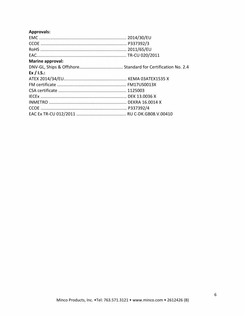
Approvals: EMC ........................................................................ 2014/30/EU CCOE ....................................................................... P337392/3 RoHS ....................................................................... 2011/65/EU EAC.......................................................................... TR-CU 020/2011 Marine approval: DNV-GL, Ships & Offshore.................................... Standard for Certification No. 2.4 Ex / I.S.: ATEX 2014/34/EU.................................................... KEMA 03ATEX1535 X FM certificate ......................................................... FM17US0013X CSA certificate ........................................................ 1125003 IECEx ....................................................................... DEK 13.0036 X INMETRO ................................................................ DEKRA 16.0014 X CCOE ....................................................................... P337392/4 EAC Ex TR-CU 012/2011 ......................................... RU C-DK.GB08.V.00410


8 Minco Products, Inc. •Tel: 763.571.3121 • www.minco.com • 2612426 (B)
PROGRAMMING • Loop Link is a communications interface that is needed for programming the TT508,
TT509, TT510, TT511, TT518, TT519, TT520 & TT521.
• Use Minco AC205817.
• For programming please refer to the drawing below.
• Loop link is not approved for communication with modules installed in hazardous (Ex) areas.


10 Minco Products, Inc. •Tel: 763.571.3121 • www.minco.com • 2612426 (B)
APPENDIX
ATEX Installation drawing For safe installation of the TT518 the following must be observed. The module shall only be installed by qualified personnel who are familiar with the national and international laws, directives and standards that apply to this area. Year of manufacture can be taken from the first two digits in the serial number.
ATEX Certificate KEMA 03ATEX 1535 X
Marking II 1 G EX ia IIC T4..T6 Ga II 1 D Ex ia IIIC Da II 1 M Ex ia I Ma
Standards EN 60079-0 : 2012, EN 60079-11 : 2012, EN 60079-26 : 2007, EN 60079-15: 2010

11 Minco Products, Inc. •Tel: 763.571.3121 • www.minco.com • 2612426 (B)
Installation notes:
In a potentially explosive gas atmosphere, the transmitter shall be mounted in an enclosure in order to provide a degree of protection of at least IP20 according to EN60529. If the transmitter is installed in an explosive atmosphere requiring the use of equipment of category 1 G, 1 M or 2 M, and if the enclosure is made of aluminum, if must be installed such, that ignition sources due to impact and friction sparks are excluded. If the enclosure is made of non-metallic materials, electrostatic charging shall be avoided. For installation in a potentially explosive dust atmosphere, the following instructions apply: The transmitter shall be mounted in a metal enclosure form B that is providing a degree of protection of at least IP6X according to EN60529, that is suitable for the application and correctly installed. Cable entries and blanking elements shall be used that are suitable for the application and correctly installed. For an ambient temperature ≥ 60ºC, heat resistant cables shall be used with a rating of at least 20 K above the ambient temperature. The surface temperature of the enclosure is equal to the ambient temperature plus 20 K, for a dust layer with a thickness up to 5 mm.

12 Minco Products, Inc. •Tel: 763.571.3121 • www.minco.com • 2612426 (B)
IECEx Installation Drawing
For safe installation of TT518 the following must be observed. The module shall only be installed by qualified personnel who are familiar with the national and international laws, directives and standards that apply to this area. Year of manufacture can be taken from the first two digits in the serial number.
Certificate IECEx DEK 13.0036X Marking Ex ia IIC T4…T6 Ga Ex ia IIIC Da Ex ia I Ma Standards IEC 60079-0 : 2011, IEC 60079-11 : 2011, IEC 60079-26:2006

13 Minco Products, Inc. •Tel: 763.571.3121 • www.minco.com • 2612426 (B)
Installation notes:
In a potentially explosive gas atmosphere, the transmitter shall be mounted in a metal form B
enclosure in order to provide a degree of protection of at least IP20 according to IEC60529. If
however the environment requires a higher degree of protection, this shall be taken into
account.
If the transmitter is installed in an explosive atmosphere requiring the use of equipment
protection level Ga, Ma and Mb, and if the enclosure is made of aluminum, it must be installed
such, that ignition sources due to impact and friction sparks are excluded.
For installation in a potentially explosive dust atmosphere, the following instructions apply:
For explosive dust atmospheres, the surface temperature of the outer enclosure is 20 K above
the ambient temperature.
The transmitter shall be mounted in a metal enclosure form B according to DIN43729 that is
providing a degree of protection of at least IP6X according to IEC60529, that is suitable for the
application and correctly installed.
Cable entries and blanking elements shall be used that are suitable for the application and
correctly installed.
For an ambient temperature ≥ 60ºC, heat resistant cables shall be used with a rating of at least
20 K above the ambient temperature.

14 Minco Products, Inc. •Tel: 763.571.3121 • www.minco.com • 2612426 (B)
FM Installation Drawing 5300Q502 Rev AH

15 Minco Products, Inc. •Tel: 763.571.3121 • www.minco.com • 2612426 (B)
The entity concept The Transmitter must be installed according to National Electrical Code (ANSI-NFPA 70) and shall be installed with the enclosure, mounting, and spacing segregation requirement of the ultimate application. Equipment that is FM-approved for intrinsic safety may be connected to barriers based on the ENTITY CONCEPT. This concept permits interconnection of approved transmitters, meters and other devices in combinations which have not been specifically examined by FM, provided that the agency's criteria are met. The combination is then intrinsically safe, if the entity concept is acceptable to the authority having jurisdiction over the installation. The entity concept criteria are as follows: The intrinsically safe devices, other than barriers, must not be a source of power. The maximum voltage Ui(VMAX) and current Ii(IMAX), and maximum power Pi(Pmax), which the device can receive and remain intrinsically safe, must be equal to or greater than the voltage (Uo or VOC or Vt) and current (Io or ISC or It) and the power Po which can be delivered by the barrier. The sum of the maximum unprotected capacitance (Ci) for each intrinsically device and the interconnecting wiring must be less than the capacitance (Ca) which can be safely connected to the barrier. The sum of the maximum unprotected inductance (Li) for each intrinsically device and the interconnecting wiring must be less than the inductance (La) which can be safely connected to the barrier. The entity parameters Uo,VOC or Vt and Io,ISC or It, and Ca and La for barriers are provided by the barrier manufacturer.
NI Field Circuit Parameters

16 Minco Products, Inc. •Tel: 763.571.3121 • www.minco.com • 2612426 (B)
CSA Installation Drawing 533XQC03
CLASS 2258 04 - PROCESS CONTROL EQUIPMENT - Intrinsically Safe Entity - For Hazardous Locations Class I, Division 1, Groups A, B, C and D Ex ia IIC, Ga CLASS 2258 84 - PROCESS CONTROL EQUIPMENT - Intrinsically Safe Entity - For Hazardous Locations - Certified to US Standards Class I, Division 1, Groups A, B, C and D Class I, Zone 0, AEx ia IIC, Ga
Warning: Substitution of components may impair intrinsic safety. The transmitters must be installed in a suitable enclosure to meet installation codes stipulated in the Canadian Electrical Code (CEC) or for US the National Electrical Code (NEC).

17 Minco Products, Inc. •Tel: 763.571.3121 • www.minco.com • 2612426 (B)
Desenho de Instalação InNMETRO
Para instalação segura do TT518 o seguinte deve ser observado. O modo deve apenas ser
instalado por pessoas qualificadas que são familiarizadas com as leis nacionais e internacionais,
diretrizes e padrões que se aplicam a esta área.
Ano de fabricação pode ser pego dos dois primeiros dígitos do número de série.
Certificado DEKRA 16.0014 X
Indicaçã Ex ia IIC T6…T4 Ga
Ex ia IIIC Da
Padrões ABNT NBR IEC 60079-0 : 2013, ABNT NBR IEC 60079-11 : 2013,

18 Minco Products, Inc. •Tel: 763.571.3121 • www.minco.com • 2612426 (B)
Notas para instalação
Em uma atmosfera de gás potencialmente explosiva, o transmissor deve ser montado em um
enclousure a fim de garantir um grau de proteção de no mínimo IP20 de acordo com EN60529.
Se contudo o ambiente requer um nível de proteção maior, isso deve ser levado em conta
Se o transmissor é instalado em uma atmosfera explosiva exigindo o uso de equipamento de
categoria Ga e se o enclosure é feito de alumínio, ele deve ser instalado de modo que, mesmo
em caso de avaria rara, fontes de ignição devido a impacto e fricção, faíscas são eliminadas; se o
enclosure é feito de materiais não metálicos, cargas eletroestáticas devem ser evitadas.
Para instalação em atmosfera de poeira potencialmente explosiva, as instruções a seguir:
O transmissor deve ser montado em enclosure de metal forma B de acordo com DIN43729 que
está fornecendo um grau de proteção de pelo menos IP6X de acordo com EN60529. Isso é
adequado para aplicação e corretamente instalado.
As entradas dos cabos e os elementos de obturação que podem ser utilizados são adequados
para a aplicação e corretamente instalados.
Para temperatura ambiente >= 60ºC, fios de resistência ao calor devem ser usados com uma
faixa de pelo menos 20K acima da temperatura ambiente.
A temperatura da superfície do enclosure é igual à temperatura ambiente mais de 20 K, por uma
camada de pó, com uma espessura até 5 mm.