20 liter (5 gallon) pail size 76 mm (3 in.) dual post
TRANSCRIPT

Instructions – Parts List
20 LITER (5 GALLON) PAIL SIZE76 MM (3 IN.) DUAL POST, HEATED
Therm-O-Flow� 5 & Mini-5�Air-Powered Ram Heated Pail Unloaders
310528K
Model 918343Therm-O-Flow 5
Model 918337Mini-5
Important Safety InstructionsRead all warnings and instructions in this manual.Save these instructions.
See page 2 for List of Models and page 3 forTable of Contents.
EN

2 310528
List of ModelsThe supply units listed below all include silicone wipers.
Part Number Motor/Pump Ratio Max. Fluid WorkingPressure
Voltage Page
918334* President™ 15:1 126 bar (1800 psi) 480 VAC 42
918337PolyurethaneReactive (PUR)
President 15:1 126 bar (1800 psi) 480 VAC 42
918340 (Swirl)* President 15:1 126 bar (1800 psi) 480 VAC 42
918522 President 15:1 126 bar (1800 psi) 480VAC 42
918532 President 15:1 126 bar (1800 psi) 240VAC 42
C58630 President 15:1 126 bar (1800 psi) 480VAC 42
C58805 President 15:1 126 bar (1800 psi) 240VAC 42
918343 Senator®/Check-Mate® 800 19:1 131 bar (1900 psi) 480 VAC 46
918352 (PUR)* Senator/Check-Mate 800 19:1 131 bar (1900 psi) 480 VAC 46
918344* Bulldog®/Check-Mate 800 31:1 214 bar (3100 psi) 480 VAC 48
918437 Bulldog/Check-Mate 800 31:1 214 bar (3100 psi) 240 VAC 48
918593 Bulldog/Check-Mate 800 31:1 214 bar (3100 psi) 480VAC 48
C59398* King 65:1 403 bar (5850 psi) 480 VAC 50
* These models are no longer available.

310528 3
Table of ContentsList of Models 2. . . . . . . . . . . . . . . . . . . . . . . . . . . . . . . . Symbols 5. . . . . . . . . . . . . . . . . . . . . . . . . . . . . . . . . . . . . . Warnings 5. . . . . . . . . . . . . . . . . . . . . . . . . . . . . . . . . . . . . Unpacking and Repacking 8. . . . . . . . . . . . . . . . . . . . .
Unpacking the Product 8. . . . . . . . . . . . . . . . . . . . . . Repair and Repacking the Product 8. . . . . . . . . . . .
Typical Installation 9. . . . . . . . . . . . . . . . . . . . . . . . . . . . Selecting a Location for the Ram 10. . . . . . . . . . . . . System Accessories and Modules 10. . . . . . . . . . . .
Installation 13. . . . . . . . . . . . . . . . . . . . . . . . . . . . . . . . . . Locating the Ram 13. . . . . . . . . . . . . . . . . . . . . . . . . . Electrically Connect Hose to the ElectricalControl Panel 13. . . . . . . . . . . . . . . . . . . . . . . . . . . . . Ground The System 14. . . . . . . . . . . . . . . . . . . . . . . . Connecting the Electrical Control Panel to a Power Source 15. . . . . . . . . . . . . . . . . . . . . . . . . Check the Resistance Between the Supply Unit and the True Earth Ground 15. . . . . . . Checking Resistance 16. . . . . . . . . . . . . . . . . . . . . . . Overview of the TemperatureController Settings 18. . . . . . . . . . . . . . . . . . . . . . . . . Graco Factory P, I, and D Settings 18. . . . . . . . . . . Flushing the System 19. . . . . . . . . . . . . . . . . . . . . . . Initial Material Loading 20. . . . . . . . . . . . . . . . . . . . . .
Operation 21. . . . . . . . . . . . . . . . . . . . . . . . . . . . . . . . . . . . Pressure Relief Procedure 21. . . . . . . . . . . . . . . . . . Raising and Lowering the Ram 21. . . . . . . . . . . . . . Daily Start-up Procedure 22. . . . . . . . . . . . . . . . . . . . Changing Empty Pails 23. . . . . . . . . . . . . . . . . . . . . . Shutdown 24. . . . . . . . . . . . . . . . . . . . . . . . . . . . . . . . . Emergency Stop 24. . . . . . . . . . . . . . . . . . . . . . . . . . . Reading the Electrical Control Panel Indicators 25Resetting the Ground Fault Interrupt 26. . . . . . . . . . Flushing Safety 27. . . . . . . . . . . . . . . . . . . . . . . . . . . .
Ram Troubleshooting 28. . . . . . . . . . . . . . . . . . . . . . . . Heated Pump Troubleshooting 29. . . . . . . . . . . . . . . . Air Motor Troubleshooting 30. . . . . . . . . . . . . . . . . . . . Electrical Control Panel Troubleshooting 30. . . . . .
Service 31. . . . . . . . . . . . . . . . . . . . . . . . . . . . . . . . . . . . . . Servicing the Ram 31. . . . . . . . . . . . . . . . . . . . . . . . . Removing a Material Pail from the Supply Unit 31. Servicing the Follower 32. . . . . . . . . . . . . . . . . . . . . . Servicing the Pump/Motor Assembly for the Check-Mate 800 34. . . . . . . . . . . . . . . . . . . . . Servicing the Pump/Motor Assembly for the Therm-O-Flow Mini-5 Supply Unit 39. . . . . . Inspection Frequency 40. . . . . . . . . . . . . . . . . . . . . . Removing/Replacing the CB100 Controller 40. . . .
Parts 42. . . . . . . . . . . . . . . . . . . . . . . . . . . . . . . . . . . . . . . . Model 918334, 76 mm (3 in.) Ram,Therm-O-Flow 15:1 President, w/siliconefollower wipers, 480 VAC 42. . . . . . . . . . . . . . . . . . . Model 918337, 76 mm (3 in.) Ram,PUR Therm-O-Flow 15:1 President, w/siliconefollower wipers, 480 VAC 42. . . . . . . . . . . . . . . . . . . Model 918340, 76 mm (3 in.) Ram,PUR Therm-O-Flow 15:1 President, Swirl Valve,w/silicone follower wipers, 480 VAC 42. . . . . . . . . . Model 918522, 76 mm (3 in.) Ram,Therm-O-Flow 15:1 President,w/silicone follower wipers, 480 VAC 42. . . . . . . . . . Model 918532, 76 mm (3 in.) Ram,Therm-O-Flow 15:1 President,w/silicone follower wipers, 240 VAC 42. . . . . . . . . . Model 918343, 76 mm (3 in.) Ram, 19:1 Senator,Therm-O-Flow Heated Check-Mate 800,w/silicone follower wipers, 480 VAC 46. . . . . . . . . . Model 918352, 76 mm (3 in.) Ram, 19:1 Senator,PUR Therm-O-Flow Heated Check-Mate 800,w/silicone follower wipers, 480 VAC 46. . . . . . . . . . Model 918344, 76 mm (3 in.) Ram, 31:1 Bulldog,Therm-O-Flow PUR Heated Check-Mate 800,w/silicone follower wipers, 480 VAC 48. . . . . . . . . . Model 918437, 76 mm (3 in.) Ram, 31:1 Bulldog,Therm-O-Flow PUR Heated Check-Mate 800,w/silicone follower wipers, 240 VAC 48. . . . . . . . . . Model 918593, 76 mm (3 in.) Ram, 31:1 Bulldog,Therm-O-Flow PUR Heated Check-Mate 800,w/finned platen, 480 VAC 48. . . . . . . . . . . . . . . . . . . Model C59398, 76 mm (3 in.) Ram, 65:1 King,Therm-O-Flow PUR Heated Check-Mate 800,w/silicone follower wipers, 240 VAC 50. . . . . . . . . .

4 310528
Table of Contents (Continued)
Model 617318, Vent Hood Kitfor use with PUR units 56. . . . . . . . . . . . . . . . . . . . . . Model 617334, Proximity Switch Kit (PumpActivity) for use with Therm-O-Flow 5 units 57. . . Model 918433, Proximity Switch Kit (Pump Activity) for use with President Pumps 58. . Model 617325, Heated Follower Plate Kitfor use with President pump assemblies 59. . . . . . Model 617335, Heated Follower Plate Kitfor use with Heated Check-Mate 800pump modules 60. . . . . . . . . . . . . . . . . . . . . . . . . . . . Model 918499, Heated Follower Plate Kit withfinned bottom for use with President pumpassemblies 61. . . . . . . . . . . . . . . . . . . . . . . . . . . . . . . . Model 617300 (standard), 480 VAC3-zone electrical control panel (interior) 62. . . . . . . Model 617330 (standard), 480 VAC3-zone electrical control panel (interior) 63. . . . . . . Model 617300 (standard) and 617330 (swirl),480 VAC 3-zone and 617484 240 VAC3-zone electrical control panel (exterior) 64. . . . . . . Model 617349 (480 VAC) and 617485 (240 VAC)4-zone electrical control panel (exterior) 65. . . . . . . Model 617349 (480 VAC) and 617485 (240 VAC)4-zone electrical control panel (interior) 66. . . . . . .
Schematics 67. . . . . . . . . . . . . . . . . . . . . . . . . . . . . . . . . . Electrical Control Panel and Wiring 67. . . . . . . . . . . Model C03510, Pump Air Motor Mounting Kit 52. . Model 918416, 4-Regulator Ram AirControl Module 55. . . . . . . . . . . . . . . . . . . . . . . . . . . .
Accessories 75. . . . . . . . . . . . . . . . . . . . . . . . . . . . . . . . . Dimensions 77. . . . . . . . . . . . . . . . . . . . . . . . . . . . . . . . . .
3-Zone Electrical Control Panel Mounting and Clearance Dimensions 77. . . . . . . . . . . . . . . . . . . . . . 4-Zone Electrical Control Panel Mounting and Clearance Dimensions 78. . . . . . . . . . . . . . . . . . Ram Mounting and Clearance Dimensions for Therm-O-Flow 5 79. . . . . . . . . . . . . . . . . . . . . . . . Ram Mounting and Clearance Dimensions w/15:1 President Air Motor 80. . . . . . . . . . . . . . . . . .
Technical Data 83. . . . . . . . . . . . . . . . . . . . . . . . . . . . . . . Related Publications 84. . . . . . . . . . . . . . . . . . . . . . . . . Appendix 85. . . . . . . . . . . . . . . . . . . . . . . . . . . . . . . . . . . .
Setting List 85. . . . . . . . . . . . . . . . . . . . . . . . . . . . . . . . Graco Standard Warranty 88. . . . . . . . . . . . . . . . . . . . . Graco Information 88. . . . . . . . . . . . . . . . . . . . . . . . . . . .

310528 5
SymbolsWarning Symbol
WARNINGThis symbol alerts you to the possibility of seriousinjury or death if you do not follow the correspondinginstructions.
Caution Symbol
CAUTIONThis symbol alerts you to the possibility of damage toor destruction of equipment if you do not follow thecorresponding instructions.
WARNING
INSTRUCTIONS
EQUIPMENT MISUSE HAZARD
Equipment misuse can cause the equipment to rupture, malfunction, or start unexpectedly andresult in serious injury.
� This equipment is for professional use only.
� Read all instruction manuals, warnings, tags, and labels before operating the equipment.
� Use the equipment only for its intended purpose. If you are uncertain about usage, call yourGraco distributor.
� Do not alter or modify this equipment. Use only genuine Graco parts and accessories.
� Check the equipment daily. Repair or replace worn or damaged parts immediately.
� Do not exceed 100 psi (6.9 bar) maximum inbound air pressure to the ram.
� Never exceed the recommended working pressure or the maximum air inlet pressure stated onyour pump or in the Technical Data on page 83.
� Be sure that all spray/dispensing equipment and accessories are rated to withstand the maxi-mum working pressure of the pump. Do not exceed the maximum working pressure of anycomponent or accessory used in the system.
� Route the hoses away from the traffic areas, sharp edges, moving parts, and hot surfaces. Donot expose non–heated hoses to temperatures above 82° C (180° F) or below -40° C (-40° F).
� Do not use the hoses to pull the equipment.
� Use fluids and solvents that are chemically compatible with the equipment wetted parts. See theTechnical Data sections of all the equipment manuals. Always read the material manufactur-er’s literature before using fluid or solvent in this pump.
� Always wear protective eyewear, gloves, clothing, and respirator as recommended by the fluidand solvent manufacturers.
� Wear hearing protection when operating this equipment.
� Comply with all applicable local, state and national fire, electrical and other safety regulations.

6 310528
WARNINGHOT SURFACE AND FLUID HAZARD
Heated fluid can cause severe burns and can cause equipment surfaces to become very hot.
� Wear protective gloves and clothing when operating this equipment in a heated system.
� Do not touch the metal heat sink when the surface is hot.
� Allow the equipment to cool thoroughly before servicing.
Some heated systems are designed to dispense PUR heated materials. PUR systems are suppliedwith ventilation hoods, and require proper ventilation and specially designed system components.
SKIN INJECTION HAZARD
Fluid from the dispense gun, hose leaks, or ruptured components can inject fluid into your bodyand cause extremely serious injury, including the need for amputation. Splashing fluid in the eyesor on the skin can also cause serious injury.
� Fluid injected into the skin might look like just a cut, but it is a serious injury. Get immediatesurgical treatment.
� Do not point the gun/valve at anyone or at any part of the body.
� Do not put your hand or fingers over the spray tip/nozzle.
� Do not stop or deflect fluid leaks with your hand, body, glove, or rag.
� If spraying, always have the trigger guard on the gun when dispensing.
� If the unit is equipped with a gun diffuser, check the gun diffuser operation weekly. Refer to thegun manualgun manual.
� Be sure the gun/valve trigger safety operates before dispensing.
� Lock the gun/valve trigger safety when you stop dispensing.
� Follow the Pressure Relief Procedure on page 21 if the nozzle clogs, and before cleaning,checking or servicing the equipment.
� Tighten all fluid connections before operating the equipment.
� Check the hoses, tubes, and couplings daily. Replace worn, damaged, or loose parts immedi-ately. Do not repair high pressure couplings; you must replace the entire hose.

310528 7
WARNINGFIRE, EXPLOSION AND ELECTRIC SHOCK HAZARD
Improper grounding, poor air ventilation, open flames, or sparks can cause a hazardous conditionand result in fire, explosion, or electrostatic shock and other serious injury.
� Ground the equipment, the object being dispensed, and all other electrically conductive objectsin the dispense area. Proper grounding dissipates static electricity generated in the equipment.See Ground the System on page 14.
� Do not use this equipment with flammable liquids.
� Keep the dispense area free of debris, including solvent, rags, and gasoline.
� If there is any static sparking while using the equipment, stop dispensing immediately. Identi-fy and correct the problem.
� Make sure all electrical work is performed by a qualified electrician only.
� Make sure all electrical equipment is installed and operated in compliance with applicablecodes.
� Make sure power is disconnected when servicing and repairing equipment.
� Have any checks, installation, or service to electrical equipment performed by a qualified electri-cian only.
MOVING PARTS HAZARD
Moving parts, such as the ram follower plate/pump inlet can pinch fingers.
� Do not operate the equipment with the guard removed.
� Keep clear of all moving parts when starting or operating the equipment.
� Keep hands and fingers away from the priming piston during operation and whenever the pumpis charged with air.
� Keep clear of the follower plate, pump fluid inlet, and lip of the fluid container when raising orlowering the ram.
� Before checking or servicing the ram or pump, follow the Pressure Relief Procedure onpage 21.
TOXIC FLUID HAZARD
Hazardous fluid or toxic fumes can cause serious injury or death if splashed in the eyes or on theskin, inhaled, or swallowed.
� Know the specific hazards of the fluid you are using.
� Store hazardous fluid in an approved container. Dispose of hazardous fluid according to alllocal, state and national guidelines.
� Always wear protective eyewear, gloves, clothing and respirator as recommended by the fluidand solvent manufacturer.
� Avoid exposure to heated material fumes.
� Provide adequate ventilation.

8 310528
Unpacking and RepackingUnpacking the ProductYour Therm-O-Flow® 5 or Mini-5™ was carefullypackaged for shipment by Graco. When the packagearrives, perform the following procedure to unpack theunits:
1. Inspect the shipping box carefully for shippingdamage. Contact the carrier promptly if damage isdiscovered.
2. Unseal the box and inspect the contents carefully.There should not be any loose or damaged partsin the box.
3. Compare the packing slip against all items in-cluded in the box. Any shortages or other inspec-tion problems should be reported immediately.
4. Store the box and packing materials in a safeplace for future use. Graco recommends that allpacking materials be saved in case the unit needsto be shipped again.
Repair and Repacking the Product
When the Therm-O-Flow® 5 or Mini-5™ requiresservice, it is the purchaser’s responsibility to have theunit repaired. As an option, the purchaser can have theunit repaired by an authorized Graco distributor.
On-site Service
Therm-O-Flow® 5 and Mini-5™ components are cus-tomarily serviced by the purchaser or an authorizedGraco technician. When service is required, follow theService procedures in this manual.

310528 9
Typical InstallationA Air Line FilterB Lock-out Master Air Valve (bleed-type)
(required)C Pump Bleed-Type Master Air Valve (required)D Pump Air RegulatorE Main Air Line SupplyF Electrical Control PanelG Follower Blow-off ValveH Pump Air Supply HoseI Air Line LubricatorJ Heated Hose
K Hose HangerL Follower Blow-off Valve RegulatorM Follower Plate Bleed StickP Depressurization Valve1 Pump Assembly2 Ram Module 3 Ram Hand Valve4 Applicator Gun or Valve5 Heated Follower Plate Assembly6 Wiper
AI D
B
G
6
C
H
F
J
K
4
1
3
E
5
2
L
M
8247A
Fig. 1P

10 310528
Typical InstallationThe typical installation discussed below is only a guidefor selecting and installing system components andaccessories. Contact your Graco representative orGraco Technical Assistance for help in designing asystem to suit your particular needs.
This air-powered ram extruder forces high viscosityfluids into the intake valve of the fluid pump. Wiperrings and other accessory equipment for use with thisram are listed in the Accessories section on page 75.
Selecting a Location for the Ram
Refer to the Ram Mounting and Clearance Dimensionsdrawings on page 79 for ram mounting and clearancedimensions.
When selecting a location for the ram, keep the follow-ing in mind:
1. There should be sufficient space for installing andusing the equipment.
� Make sure there is sufficient overhead clear-ance for the pump and ram when the ram is inthe fully raised position.
� If you are installing a vent hood, make surethere is sufficient horizontal clearance for it.
� Make sure the air regulators for the pump andram are fully accessible.
� Make sure there is easy and safe access to anappropriate electrical power source. TheNational Electrical Code requires 3 feet ofopen space in front of the electrical panel.
2. If you are installing a vent hood, make sure theram is installed or located near a connection to thefactory ventilation system.
Refer to the Ram Mounting and Clearance Dimen-sions drawings on page 79 for ram mounting andclearance dimensions.
3. You need to decide whether you will be bolting theram to the floor, or bolting it to a mobile platform.
4. If you bolt the ram to the floor, make sure:
� you will be able to level the base of the ramusing metal shims
� you have anchors long enough to prevent theunit from tipping. Refer to the DimensionalDrawings on page 77 for more information.
5. If you bolt the ram to a mobile platform, makesure:
� you locate the platform on a surface where itwon’t roll around.
� the ram and platform are stable in all operatingpositions, so the ram won’t tip over.
System Accessories and Modules
Before you install the system you should be familiarwith the parts discussed below. For more information,refer to Fig. 1, A Typical Installation, on page 9.
Air and Fluid Hoses
When installing a system, make sure:
� all air and fluid hoses are properly sized for yoursystem.
� to use only electrically conductive air and fluidhoses.

310528 11
Typical InstallationAir Line Modules
WARNINGPRESSURIZED FLUID HAZARD ANDMOVING PARTS HAZARDThe bleed-type master air valve (C) isrequired in your system to relieve airtrapped between this valve and thepump after the pump air regulator isclosed. Trapped air can cause the pumpto cycle unexpectedly, which could result
in serious bodily injury, including splashing in theeyes or on the skin and injury from moving parts.
4-Regulator Air Control Module (918416) (Fig. 1 onpage 9)
See the Typical Installation drawing (Fig. 1). Thefollowing components are included with the module:
� Bleed-type Lock-out Master Air Valve (B) is used toshut off and lock out the air supply from the entiresupply unit.
� Bleed-type Master Air Valve (C) is required in yoursystem to relieve air trapped between it and the airmotor when the valve is closed (see the Pressur-ized Fluid Hazard And Moving Parts HazardWARNING above). This bleed valve should beeasily accessible and located downstream from theair regulator. It can be used for a safety lockout.
� Pump Air Regulator (D) controls pump speed andoutlet pressure by adjusting the air pressure to thepump. It is located on the air control panel up-stream from the bleed-type master air valve.
� Ram Air Regulator controls the air pressure to theram. There are separate air regulators to controlthe ram pressure in the up and down directions.
� Pump Air Supply Hose (H) connects the ram airregulator to the air manifold.
� Follower Blow-off Valve Regulator (L)(N) controlsthe air pressure to the follower blow-off valve.
� PHYLA (filter, regulator, lubricator) (A), (D), and (I)conditions the air to the ram and the pump. Thepump air regulator is located in this assembly. Theram air is taken from this assembly; an air line tubeconnects the PHYLA and the ram air control mod-ule.
� Auto Depressurization Valve (P) exhausts air fromthe system at shut off. The built in timer delays startup to allow material to heat thoroughly.
2-Regulator Air Control Modules (not shown)
The following components are included with the mod-ule:
� Pump Bleed-type Master Air Valve (C) is required inyour system to relieve air trapped between it andthe air motor when the valve is closed (see theWARNING above). Be sure the bleed valve iseasily accessible from the pump, and is locateddownstream from the air regulator.
� Pump Air Regulator (D) controls pump speed andoutlet pressure by adjusting the air pressure to thepump. Locate the regulator close to the pump, butupstream from the bleed-type master air valve.
� Ram Air Regulator (not shown) controls the airpressure to the ram.
� Ram Air Supply Hose (H) connects the ram airregulator to the air manifold.
� Air Manifold (F) divides the main air supply intoseparate lines for the pump and ram.
Air Line Accessories
If you have a 2-Regulator Air Control Module, installthe following accessories, using adapters as neces-sary:
� Pump runaway valve senses when the pump isrunning too fast and automatically shuts off the airto the motor. A pump that runs too fast can beseriously damaged.
� Air line lubricator provides automatic air motorlubrication (standard on the 4-Regulator Air ControlModule).
� Air line filter removes harmful dirt and moisturefrom the compressed air supply (standard on the4-Regulator Air Control Module).
� Accessory bleed-type air valve isolates the air lineaccessories for servicing. Locate upstream from allother air line accessories. This isolates the acces-sories for servicing.
Vent Hood Kit (617318 on page 56)
The vent hood assembly is designed to efficiently drawfumes to the factory exhaust system during drumpailchange-out. This assembly requires connection to afactory ventilation system that draws a minimum airflow of 8.4 m3/min (300 scfm). This kit is required forPolyurethane Reactive (PUR) applications.

12 310528
Notes

310528 13
InstallationThe installation procedure includes:
� locating and installing the ram
� electrically connecting hoses to the electrical con-trol panel
� grounding the system
� connecting the electrical control panel to a powersource
� checking resistance
� setting controls on the electrical control panel
� starting up the system
� initially loading material
Locating the Ram
To locate the ram, follow one of the procedures below.Refer to the Ram Mounting and Clearance Dimensionsdrawings on page 79 for ram mounting and clearancedimensions.
Bolting the Ram to the Floor
To install the ram in a permanent location:
1. Select a convenient location for the equipment.Check that there is sufficient overhead clearancefor the pump and ram when the ram is in the fullyraised position. Make sure the air regulators for thepump and ram are fully accessible.
2. Level the base of the ram, using metal shims.
3. Using the holes in the base as a guide, drill holesfor 1/2 in. (13 mm) anchors.
4. Bolt the ram to the floor anchors, which must belong enough to prevent the unit from tipping. Referto the Dimensional Drawings starting on page 77.
Securing the Ram to a Mobile Platform
When performing the following procedure, use theMobile Platform Kit (918414) to secure the ram to amobile platform.
To install the ram on a mobile platform:
1. Brace the platform so it remains stationary whileyou attach the ram to the platform.
2. Place the ram on the platform and line up theholes in its base with the holes in the platform.
3. Secure the ram to the platform with the providednuts and bolts.
Electrically Connect Hoses to theElectrical Control Panel
Assemble the hose and gun components as needed.For information on connecting the hose and gun com-ponents, follow the gun’s instructions.
Electrically connect the hoses to the electrical controlpanel. The connector is are located on the back of theelectrical control panel.
Connect the plug from hose 1 to the Hose 1/Gun 1receptacle. Refer to page 64 for connecting the hoseto a 3-zone panel, or to page 65 for connecting thehose to a 4-zone panel.

14 310528
InstallationGrounding the System
WARNINGFIRE, EXPLOSION, AND ELECTRICSHOCK HAZARDTo reduce the risk of fire, explosion, orelectric shock:
� The power source conduit is not anadequate ground for the system. Theunit must be bonded to either thebuilding ground or a true earthground.
� A qualified electrician must completeall grounding and wiring connectionsand check the resistance asinstructed on page 15.
� Refer to your local code for the requirements fora “true earth ground” in your area.
� Also read and follow the warnings on page 7.
To reduce the risk of static sparking, ground the objectbeing dispensed upon and all other spraying/dispens-ing equipment used or located in the spraying/dispens-ing area. Check your local electrical code for detailedgrounding instructions for your area and type of equip-ment.
Ground the supply unit as instructed here and in theindividual component manuals.
Air and Fluid Hoses
Use electrically conductive hoses only.
Dispensing/Spray Gun
Follow the dispensing/spray gun grounding instruc-tions.
Fluid Supply Container
Ground the container according to your local code.
Object to which Material is Applied
Ground the object according to your local code.
Material Pails
Ground the material pails according to your local code.Use only metal pails, which are conductive, placed ona grounded surface. Do not place the pail on a noncon-ductive surface, such as paper or cardboard, whichinterrupts the grounding continuity.
Maintain Grounding Continuity When Purging OrRelieving Pressure
Follow the instructions in your separate gun manual forsafely grounding your gun while purging.

310528 15
InstallationConnecting the Electrical Control Panel toa Power Source
The Electrical Control Panel (Fig. 2) comes alreadyattached and wired to the ram, however before thesupply unit becomes functional, you must connect theelectrical control panel to a power source.
Fig. 2
Have a trained electrician connect the electrical controlpanel to a grounded electrical source that has therequired service ratings:
ControlPanelModel:
Zones: VAC: Hz: Phase:Full
LoadAmps
617300(Standard)
3 480 60 1 7.3
617330(Swirl)
617349 4 480 60 3 9.8
For information about specific terminal locations andconnections, see Schematics on page 67 for wiringdiagram information.
To connect the control panel to the electrical source:
1. Create an opening in the control panel’s housingfor the conduit that will enclose the wire from thefacility’s power source.
2. Thread the wire from the power source into thecontrol panel housing, and then connect the powersource wires to the appropriate terminals on theDISCONNECT switch.
Checking Resistance Between the SupplyUnit and the True Earth Ground
WARNINGFIRE, EXPLOSION, AND ELECTRICSHOCK HAZARDTo reduce the risk of fire, explosion, orelectric shock the resistance betweenthe supply unit components and trueearth ground must be less than 0.25ohms.
Have a qualified electrician check the resistancebetween each supply unit component and the trueearth ground. The resistance must be less than0.25 ohms. If the resistance is greater than 0.25 ohms,a different ground site may be required. Do not operatethe system until the problem is corrected.

16 310528
InstallationChecking Resistance
WARNINGELECTRIC SHOCK HAZARDDo not open the electrical control panel,unless you are a trained professional.
Before opening the control panel, make sure thatall power has been removed from the control panel.
Sensor Resistance Checks
WARNINGELECTROCUTION HAZARD
To reduce risk of injury or damage toequipment, conduct these electricalchecks with the main disconnect OFF.
The supply unit includes either three or four heat sen-sors and controllers for each heated zone. To checksensor resistance:
1. Make sure the power is off and that the disconnectswitch is in the OFF position.
2. Make electrical resistance checks for the compo-nents. Refer to Schematics on page 67 for wiringdiagram information.
3. Replace any parts whose resistance readings donot comply with the ranges listed in the chartbelow.
NOTE: Check resistance at ambient room tempera-ture (63�–77� F).
3-Zone RTD Sensors
Zone Component Terminals Value Range
1 Follower 1311 &1321
107–109 ohms
2 DispenseHose
1531 &1541
97.4–102.8 ohms
3 DispenseGun
1601 &1611
97.4–102.8 ohms
4-Zone RTD Sensors
Zone Component Terminals Value Range
1 Follower 1311 &1321
107–109 ohms
2 DispenseHose
1531 &1541
97.4–102.8 ohms
3 DispenseGun
1601 &1611
97.4–102.8 ohms
4 Pump 1381 &1391
97.4–102.8 ohms

310528 17
InstallationHeater Resistance Checks
WARNINGELECTROCUTION HAZARD
To reduce risk of injury or damage toequipment, conduct these electricalchecks with the main disconnect OFF.
To check heater resistance:
1. Make sure the power is off and that the disconnectswitch is in the OFF position.
2. Make electrical resistance checks for the compo-nents. Refer to Schematics on page 67 for wiringdiagram information.
3. Replace any parts whose resistance readings donot comply with the ranges listed in the chartbelow.
NOTE: Check resistance at ambient room tempera-ture (63�–77� F).
Heaters for 3-Zone Control Panels
Zone Component TerminalsValueRange
1 Follower 2L1 & 2L2 98–127h2L2 & 2L1 ohms
2 Dispense Hose 1532 &1551
SeeTechnicalDatasuppliedw/Hose
3 Dispense Gun 1602 &1621
SeeTechnicalDatasuppliedw/Gun
Heaters for 4-Zone Control Panels
Zone Component TerminalsValueRange
1 Follower 3L1 & 3L3 98–127h3L2 & 3L3 ohms
2 Dispense Gun 1532 &1551
SeeTechnicalDatasuppliedw/Gun
3 Dispense Hose 1602 &1621
SeeTechnicalDatasuppliedw/Hose
4 Pump 5L1 & 5L2 187.2 ohms� 24 ohms

18 310528
InstallationOverview of the Temperature Controller Settings
The basic program settings for each temperaturecontroller satisfy most application needs. These set-tings are preset at the factory, but can be changed.The input type, temperature scale, and over tempera-ture alarm point are the critical controller settings thatyou must check before doing an auto-tune or usingany controller in normal operation. See form# 309100for operation of the temperature controls.
Graco Factory P, I, and d Settings
Table 1 lists the P, I, and d settings for standard controlpanels. These settings are preset at the factory. Seeform# 309100 for accessing these values and use thetable for reference information only.
Table 1. Graco Factory P, I, and d Settings
Category P I d Unit Voltage
Follower 2 326 49 480
Hose .8 63 9 ALL
Pump 4.2 1081 162 480
Gun 2.1 126 19 ALL
These P, I, and d values are usually generated byrunning an autotune process for each heat zone. Thecontrollers will automatically find the proper P (propor-tional), I (integral), and d (derivative) values during thisautotune process. These are values that allow the heatzones to reach their maximum temperature as fast aspossible without significantly exceeding desired tem-perature.

310528 19
InstallationFlushing the System
Flushing the system before its initial use can preventmaterial contamination, which may cause the materialto fail or perform poorly.
CAUTIONFlush the system before performing the initialmaterial loading procedure. The system was facto-ry-tested using a light soluble oil, a soybean oil, orsome other oil as tagged. Flush the system to avoidcontaminating the material that has been designatedfor initial material loading.
To flush the system, perform the following procedure:
1. Select the material for the initial material load.
2. Verify whether the factory-test oil and the initialmaterial load are compatible:
a. If the two substances are compatible, omit theremaining steps in this procedure and performthe Initial Material Loading procedure onpage 20.
b. If the two substances are incompatible, per-form the remaining steps in this procedure toflush the system.
WARNINGUse fluids and solvents that are chemically compat-ible with the equipment wetted parts. See theTechnical Data sections of all the equipmentmanuals. Always read the material manufacturer’sliterature before using fluid or solvent in this pumpand always provide adequate ventilation.
3. Select a drum containing solvent that can dissolve,clean, and eliminate the factory-test oil from thesystem. If necessary, check with Graco or the ma-terial supplier for a recommended solvent.
4. Before flushing, be sure the entire system andflushing drums are properly grounded. Refer toGround The System, on page 14.
5. Perform steps 1 through 7 of the Initial MaterialLoading procedure on page 20 to load the drumcontaining the solvent.
6. Flush the solvent through the system for approxi-mately 1 to 2 minutes.
7. Remove the drum containing the solvent.
8. Perform the Initial Material Loading procedureon page 20.
Starting Up the System
WARNINGPRESSURIZED EQUIPMENT HAZARDTo reduce risk of injury or equipmentdamage:
� Make sure all material hose connec-tions are secure.
� Make sure system is ready to pres-surize before pressurizing system.
CAUTIONTo help avoid damage to equipment, be sure to openthe dispense valve during system heatup to alleviatepressure which might occur in the system due to ma-terial expansion.
1. Check all material hoses and fittings to insuretightness and to prevent any material leakage.
2. Check all system air and electrical lines. Makesure that all routing of air and electrical lines willnot interfere with any moving components withinthe fixture.
3. Raise the arm, using the following procedure:
a. Close all air regulators.
b. Move the ram hand valve lever to the UP posi-tion.
c. Slowly open the air regulators until the ramstarts to move up.
d. When the follower plate is above the height ofthe material drum to be used, move the ramhand valve lever to OFF.
4. Turn the electrical disconnect ON.
5. On the electrical control panel, turn the CONTROLON switch to ON.
6. Check the temperature controller set points andchange them if necessary. See Changing the SetPoint in form# 309100.
7. Wait until all system zones are heated to the pre-set temperatures. Go to the next section, InitialMaterial Loading.

20 310528
InstallationInitial Material Loading
WARNINGThe material and equipment will behot! To reduce risk of injury, wear eyeprotection, gloves and protective clothingwhen installing, operating, or servicing this dispensing system.
PRESSURIZED FLUID HAZARDTo reduce the risk of serious bodily inju-ry, such as fluid injection or splashingfluid in the eyes or on the skin, ALWAYS
wear eye protection and protective clothing wheninstalling, operating, or servicing this dispensingsystem.
WARNING
WARNINGMOVING PARTS HAZARDMoving equipment parts can cause per-sonal injury, including severing of handsor fingers. Make sure all personnel areclear of moving parts before operatingthe equipment.
WARNINGTo reduce risk of injury or damage toequipment, be sure to tighten the bleedstick after bleeding the air. Otherwise hotmaterial will leak out of the opening.
CAUTIONThe use of a non-compatible lubricant can causematerial contamination or inadequate performance.Use only a lubricant compatible with the material tobe pumped. Check with the material supplier for arecommended lubricant.
CAUTIONTo help avoid damage to equipment, do not use adrumpail of material that has been dented or other-wise damaged; damage to the follower wipers mayresult.
1. Make sure the follower plate is high enough to puta drumpail of material under it.
2. Open a drumpail of the proper material and locateit under the elevated follower plate.
NOTE: Whenever drumpail changes are required, re-move the cover from the drumpail of new ma-terial by holding it level and lifting it straight up.Tipping the cover may allow accumulated dirtto spill into the drumpail, which may result indamage to the equipment.
3. Lubricate the follower wipers with a lubricant com-patible with the material to be pumped. Check withyour material supplier for compatibility.
4. Before lowering the pump into the drumpail, makesure that nothing is between the follower plate andthe drumpail, or between the ram tie bar and thetop of the ram posts.
5. Lower the pump into the drumpail of material.
a. To lower the pump and follower into the drum-pail, move the ram hand valve lever to theDOWN position and slowly adjust the air regu-lator.
b. As the follower enters the drumpail, loosen thebleed stick. Removing the bleed stick allowstrapped air between the follower plate and thetop of the material to escape.
c. When air stops exhausting from the bleed stickport, replace and tighten the bleed stick.
6. Place a material waste container under the dis-pense gun.
7. Slowly adjust the pump air regulator. This will startthe pump and fill the material passage.
8. Dispense material from the dispense gun until air-free material is dispensed. Allow the system toheat for approximately 30 minutes.

310528 21
OperationPressure Relief Procedure
MOVING PARTS HAZARDFollow the Pressure Relief Procedurebelow before checking or repairing theram or any other part of the system and
when shutting down the system. Keep hands andfingers away from the follower plate, fluid pumpinlet, and lip of the fluid container when raising orlowering the ram to reduce the risk of pinching oramputating hands or fingers.
During operation, also keep hands and fingersaway from limit switches to reduce the risk ofpinching or amputating hands or fingers.
WARNING
WARNINGThe material and equipment will behot! To reduce risk of injury, wear eyeprotection, gloves and protective clothingwhen installing, operating, or servicingthis dispensing system.
WARNINGHIGH PRESSURES CAN CAUSE SE-RIOUS PERSONAL INJURY. Be sureto OPEN THE DISPENSE VALVEDURING SYSTEM HEATUP to allevi-
ate pressure which might occur in the system dueto material expansion.
WARNINGSKIN INJECTION HAZARDThe system pressure must be manuallyrelieved to prevent the system fromstarting or spraying accidentally. Fluid
under high pressure can be injected through theskin and cause serious injury. To reduce the risk ofan injury from injection, splashing fluid, movingparts, follow the Pressure Relief Procedurewhenever you:
� are instructed to relieve the pressure
� stop spraying/dispensing
� check or service any of the system equipment
� install or clean the spray tip/nozzle
This procedure describes how to relieve pressure forthe supply unit. Use this procedure whenever you shutoff the dispenser/sprayer and before checking oradjusting any part of the system, to reduce the risk ofserious injury.
1. Lock the gun/valve trigger safety.
2. Shut off the main air supply to the pump.
3. Close all air bleed valves.
4. Unlock the gun/valve trigger safety.
5. Hold a metal part of the gun/valve firmly to the sideof a grounded metal drumpail, and trigger thegun/valve to relieve pressure.
6. Lock the gun/valve trigger safety.
7. Have a container ready to catch the drainage, thenopen the drain valve or pump bleed valve.
8. Leave the drain valve open until you are ready tospray/dispense again.
If you suspect that the spray tip/nozzle or hose iscompletely clogged, or that pressure has not been fullyrelieved after following the steps above, very slowlyloosen the nozzle retaining nut or hose end coupling torelieve pressure gradually, then loosen completely.Now clear the tip/nozzle or hose.
9. If you want to relieve pressure in the ram, see theRam Pressure Relief Procedure on page 31.
Raising and Lowering the Ram
The ram hand valve on the ram air control has 3positions [Fig. 3 (4-regulator version shown)]:
� Ram UP raises the ram
� Ram DOWN lowers the ram
� Ram OFF puts the ram in “neutral.” Moving thehand valve to OFF does not change the position ofthe ram, but it stops the air pressure from attempt-ing to move the ram either up or down.
Fig. 3
Ram OFF (neutral)
Ram UP
Ram DOWN7979A

22 310528
OperationDaily Start-up Procedure
PRESSURIZED FLUID HAZARDTo reduce the risk of serious bodily inju-ry, such as fluid injection or splashingfluid in the eyes or on the skin, ALWAYS
wear eye protection and protective clothing wheninstalling, operating, or servicing this dispensingsystem.
WARNING
There are 2 ways to start up the system. You caneither:
� manually start the system each day� use the optional 7-day timer to heat up the system
unattended
If you manually start up the system, be sure to allow atleast 30 minutes for the material to fully heat up beforethe system is ready for use.
If you use the optional 7-day timer to heat up thesystem, you must:
� create a schedule and program it into the 7-daytimer (see the documentation that came with theelectrical control panel). Be sure to allow at least 30minutes for the material to heat up before thesupply unit is ready for use.
� perform specific procedures each night to make thesystem ready for automatic operation.
Starting the System Manually
To start the system manually:
1. Verify that the main disconnect is ON.
2. Turn the CONTROL ON switch to ON.
3. Open the dispense valve over a waste container toallow the material to expand. This will preventdamage to the equipment.
4. After each of the dispense zones is heated to op-erating temperature, wait an additional 30 minutesto allow the material to heat fully.
5. Make sure that all material valves are open.
6. Turn the pump air supply ON and set the regulatorfor normal operation.
7. Dispense some material into a waste container.
8. Verify the flow rate is correct; adjust if required.
With the material heated, and the flow rate correctedas necessary, the system is ready for operation.
WARNINGDo not over pressurize the system, as this couldresult in serious injury or damage to the equipment.
NOTE: It is normal for the pump to stop moving if thedispense gun or other fluid valve is closed.
Using the 7-Day Timer
The optional 7-Day Timer allows you to automaticallyheat the system without having to manually turn on theheat.
Before you can use this feature, you must program the7-day timer, located on the electrical control panel. Formore information about programming the timer, seethe documentation that came with the electronic con-trol panel.
Each Night:
Follow this procedure each time you use the 7-daytimer:
1. Turn the CONTROL ON (61) switch to AUTO.
2. Turn the HEAT switch (62) on the electrical controlpanel to ON.
WARNINGTo reduce the risk of serious injury whenever youare instructed to relieve pressure, always follow thePressure Relief Procedure (page 21).
3. Relieve the supply unit pressure.
4. Leave the dispense valve open and over an emptywaste container, to relieve pressure that couldbuild up while the system is heating.
5. Make sure that all material valves are open.
6. Make sure the pump air supply has been turnedOFF.
The system is ready for start-up with the 7-day timer.
310528 23
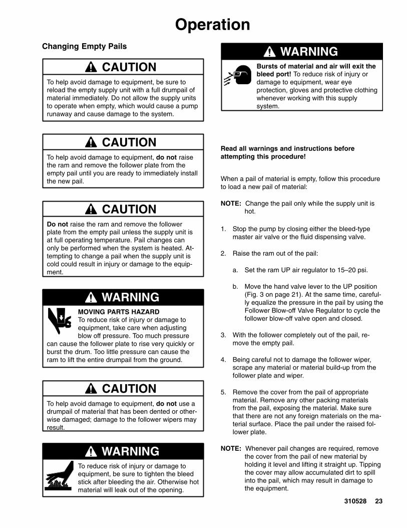
OperationChanging Empty Pails
CAUTIONTo help avoid damage to equipment, be sure toreload the empty supply unit with a full drumpail ofmaterial immediately. Do not allow the supply unitsto operate when empty, which would cause a pumprunaway and cause damage to the system.
CAUTIONTo help avoid damage to equipment, do not raisethe ram and remove the follower plate from theempty pail until you are ready to immediately installthe new pail.
CAUTIONDo not raise the ram and remove the followerplate from the empty pail unless the supply unit isat full operating temperature. Pail changes canonly be performed when the system is heated. At-tempting to change a pail when the supply unit iscold could result in injury or damage to the equip-ment.
WARNINGMOVING PARTS HAZARDTo reduce risk of injury or damage toequipment, take care when adjustingblow off pressure. Too much pressure
can cause the follower plate to rise very quickly orburst the drum. Too little pressure can cause theram to lift the entire drumpail from the ground.
CAUTIONTo help avoid damage to equipment, do not use adrumpail of material that has been dented or other-wise damaged; damage to the follower wipers mayresult.
WARNINGTo reduce risk of injury or damage toequipment, be sure to tighten the bleedstick after bleeding the air. Otherwise hotmaterial will leak out of the opening.
Bursts of material and air will exit thebleed port! To reduce risk of injury ordamage to equipment, wear eyeprotection, gloves and protective clothingwhenever working with this supplysystem.
WARNING
Read all warnings and instructions beforeattempting this procedure!
When a pail of material is empty, follow this procedureto load a new pail of material:
NOTE: Change the pail only while the supply unit ishot.
1. Stop the pump by closing either the bleed-typemaster air valve or the fluid dispensing valve.
2. Raise the ram out of the pail:
a. Set the ram UP air regulator to 15–20 psi.
b. Move the hand valve lever to the UP position(Fig. 3 on page 21). At the same time, careful-ly equalize the pressure in the pail by using theFollower Blow-off Valve Regulator to cycle thefollower blow-off valve open and closed.
3. With the follower completely out of the pail, re-move the empty pail.
4. Being careful not to damage the follower wiper,scrape any material or material build-up from thefollower plate and wiper.
5. Remove the cover from the pail of appropriatematerial. Remove any other packing materialsfrom the pail, exposing the material. Make surethat there are not any foreign materials on the ma-terial surface. Place the pail under the raised fol-lower plate.
NOTE: Whenever pail changes are required, removethe cover from the pail of new material byholding it level and lifting it straight up. Tippingthe cover may allow accumulated dirt to spillinto the pail, which may result in damage tothe equipment.

24 310528
OperationChanging Empty Pails (continued)
6. Lower the follower into the drumpail:
a. Move the ram hand valve lever to the DOWNposition.
b. Check the pail position as the follower lowers.If necessary, stop lowering the follower beforecontacting the pail, and adjust the pail positionto align the pail with the follower plate.
c. Continue lowering the follower. As the followerenters the pail, loosen the air bleed stick.Loosening the bleed stick allows trapped airbetween the follower plate and the top of thematerial to escape.
d. When air stops exhausting from the bleed stickport, replace and tighten the bleed stick.
7. Adjust the ram air pressure for normal operation.
8. Bleed, from the pump, the air that was introducedduring the pail change:
a. Place a waste container under the pump bleedport.
b. Open the bleed port and turn on pump airpressure.
c. Allow material to flow from the bleed port untilit is air-free.
d. Shut off air to the pump and close the bleedport.
e. Turn air on to the pump and set the pump airregulator for normal operation.
9. Resume normal operation.
Shutdown
1. Turn the CONTROL ON switch to OFF.
2. Turn OFF the main electrical disconnect.
3. Move the ram hand valve lever (Fig. 3 on page 21)to the OFF position. Shut off the air supply to theram and pump.
WARNINGTo reduce the risk of serious injury whenever youare instructed to relieve pressure, always follow thePressure Relief Procedure (page 21).
4. Relieve the pressure.
Emergency Stop
1. On the electrical control panel:
a. Turn OFF the main electrical disconnect.
b. Turn the CONTROL ON switch to OFF.
2. Stop the pump by closing the Bleed-type MasterAir Valve closest to the motor’s air inlet, (C) in Fig.1, on page 9.
3. Stop the ram from moving by:
a. Closing the ram air lock-out valve.
b. Moving the ram hand valve lever (Fig. 3 onpage 21) to the OFF position.

310528 25
OperationReading the Electrical Control Panel Indicators
Use the table and Fig. 4 below to read the indicators on the electrical control panel. For information on setting thetemperature controllers, see Setting Temperature Controllers in Form# 309100.
Light# Indicator: IndicatorLight is:
Meaning:
61 Power On/G d C t d
ON Power is on and ground is connected.Ground Connected OFF Power is off and/or ground is disconnected.
DIMLY LIT There may be a problem with the system power connections.Have connections checked by a qualified electrician beforeattempting to start the system.
62 Control On ON The CONTROL ON switch (65) is set to either the ON orAUTO position and power is being supplied to the electricalcontrol panel components.
OFF The CONTROL ON switch (65) is set to the OFF position.
63 High TemperatureAlarm
ON The temperature of any of the heated components is out ofrange, and the power to all heated components is inter-rupted.
OFF None of the heated components have temperatures that areout of range.
64 Auto Heat Off ON The Inactivity Timer has turned off the heat for the supplyunit, due to inactivity. See Resetting the Supply Unit Afterthe Inactivity Timer (Worklife Timer) Has Been Triggered,on page 26, for instructions on restarting the supply unit.
OFF The supply unit is functioning normally.
Fig. 4
61 6263 64
6566

26 310528
OperationTemperature Out of Range
Should any of the temperatures go out of the presetrange for any of the zones, power to the heatedcomponents is interrupted, and the HIGHTEMPERATURE ALARM light goes ON. The alarmautomatically goes OFF and the system resets whenthe temperature is back in range.
Resetting the Supply Unit After the Inactivity Timer(Worklife Timer) Has Been Triggered
Your system may have an inactivity timer. If the pumphas not moved for a set amount of time, the inactivitytimer:
� turns off power to the heaters� lights the AUTO HEAT OFF light
For information about setting the time period on theinactivity timer, see the documentation that cameinside the control panel.
To re-heat the supply unit:
Fig. 566
1. Turn the HEAT switch (66) to the OFF position,then turn it to the ON position.
2. Wait until all components in the supply unit havereturned to operating temperature.
3. Resume operation.
Resetting the Ground Fault Interrupt
This control panel is equipped with a ground faultinterrupt (GFI) circuit breaker (Fig. 6). If the disconnectswitch is ON, but all lights on the electrical controlpanel are off, have a qualified electrician check theground fault interrupt.
WARNINGELECTROCUTION HAZARD
To reduce risk of injury or damage toequipment, perform this procedure withthe main disconnect OFF.
To reset the ground fault interrupt, have a qualifiedelectrician:
1. Turn OFF the electrical disconnect on the electricalcontrol panel.
2. Open the electrical control box and locate theGround Fault Interrupt switch (71). The GFI shouldbe in a “neutral” position, between the ON andOFF positions.
3. Move the GFI switch to the OFF position, thenmove it to the ON position.
4. Close the door and turn ON the disconnect switch.
For more information about the GFI switch, see thedocumentation that came with the electrical controlpanel.
Fig. 6
71

310528 27
OperationFlushing Safety
WARNINGUse fluids and solvents that are chemically compat-ible with the equipment wetted parts. See theTechnical Data sections of all the equipmentmanuals. Always read the material manufacturer’sliterature before using fluid or solvent in this pump.
1. Before flushing, be sure the entire system andflushing pails are properly grounded. Refer toGround The System, on page 14.
WARNINGTo reduce the risk of serious injury whenever youare instructed to relieve pressure, always follow thePressure Relief Procedure (page 21).
2. Relieve the pressure.
PRESSURIZED FLUID HAZARD Always use the lowest possible fluidpressure, and maintain firm metal-to-metal contact between the gun/valve
and the pail during flushing to reduce the risk offluid injection injury, static sparking and splashing.
WARNING
3. Remove the spray tip/nozzle from the spray gun/dispensing valve.

28 310528
Ram TroubleshootingProblem Cause(s) Solution(s)
Ram won’t raise or lower Closed main air valve or clogged air line Open air valve, clear air line
Not enough air pressure Increase ram pressure
Worn or damaged piston Replace piston. See procedure inForm #310523.
Hand valve closed or clogged Open, clear hand valve or exhaust
Ram raises or lowers too fast Ram air pressure too high Decrease ram air pressure
Air leaks around cylinder rod Worn rod seal Replace o-rings in guide sleeve.See procedure in Form #310523.
Fluid squeezes past follower platei
Ram air pressure too high Decrease ram air pressurewipers Worn or damaged wipers Replace wipers. See procedure on
page 32.
Pump won’t prime properly, ori
Closed main air valve or clogged air line Open air valve, clear air linepumps air Not enough pump air pressure Increase pump pressure
Worn or damaged piston Replace piston. See procedure inForm #310523.
Hand valve closed or clogged Open, clear hand valve or exhaust
Hand valve dirty, worn or damaged Clean, service hand valve
Bent drum has stopped follower Replace drum
Air pressure won’t hold drumd h l t
Closed main air valve or clogged air line Open air valve, clear air linedown or push plate up Not enough ram air pressure Increase ram air pressure
Valve passage clogged Clean valve passage
Worn piston seal Replace seal

310528 29
Heated Pump TroubleshootingFor additional information about the pump, see the pump’s documentation.
Problem Cause(s) Solution(s)
Rapid down stroke or up stroke(pump cavitation)
Material not heated to properpumping temperature.
Check and adjust temperature set point.
Air is trapped in pump. Bleed air from the pump using this pro-cedure:
1. Place a waste container under thepump bleed port.
2. Turn on air to the pump
3. Allow material to flow from the bleedport until it is air-free.
4. Shut off air to the pump and closethe bleed port.
5. Turn air on to the pump and set thepump air regulator for normal opera-tion.
Downstroke: Lower check in pumpis worn.
Upstroke: Upper check in pump isworn.
Rebuild and replace pump, as neces-sary.
Material leaks around pump outlet Outlet fitting is loose. Tighten outlet fitting.
Material leaks around bleed port Bleed port fitting is loose. Tighten bleed port fitting.
Pump won’t move up or down Problem with air motor. See Air Motor Troubleshooting chart onpage 30.
Foreign object lodged in pump. Remove object and rebuild pumpassembly.
WARNINGTo reduce the risk of serious injurywhenever you are instructed to relievepressure, always follow the PressureRelief Procedure (page 21).
Before attempting to dislodge a foreignobject:
1. Relieve system pressure.
2. Remove the pump from the airmotor.
Wet-cup leaks Worn throat seal For Therm-O-Flow Mini-5:
1. Tighten wet-cup and/or throat sealpackings.
2. Replace wet-cup and/or throat sealpackings if tightening does not stopleaking.
For Therm-O-Flow 5, replace wet-cupand throat seal packings.

30 310528
Air Motor TroubleshootingFor additional information about the air motor, see the air motor’s documentation.
Problem Cause(s) Solution(s)
Air motor will not shift directions,stalled in DOWN position
Main air valve is dirty or damaged Clean/rebuild main air valve.
Air motor will not shift directions,stalled in UP position
Air motor stalled halfway betweenthe top and bottom
Air continually exhausting aroundair motor shaft.
Air motor shaft seal is damaged Replace air motor shaft seal.
Air continually exhausting aroundthe air valve/slide valve
Air valve/slide valve gasket is damaged Replace the valve gasket.
Air continually exhausting frommuffler while the motor is idle
Internal seal damage Rebuild air motor.
Oil leaking from exhaust port Too much lubricant mixed in with the airsupply
Reduce lubricant supply.
Frost build-up on muffler Air motor operating at high pressure, orhigh cycle rate
Reduce pressure, cycle rate, orduty cycle of the air motor.
Electrical Control Panel TroubleshootingProblem Cause(s) Solution(s)
Disconnect is ON, but no indica-tor lights are lit
The ground fault interrupt has beenactivated
See procedure on page 26.g
One or more fuses has (have) beenblown
Replace the blown fuse(s)
High Temperature Alarm lights The temperature of a heated compo-nent has gone out of range.
Supply unit automatically turns offpower to supply unit components.Unit turns power back on whenoverheated components reach ap-propriate temperatures.
Heat is turned off after inactivitytimer has been triggered.
Pump has not moved within the pro-grammed time period
See procedure on page 26.

310528 31
ServiceServicing the Ram
To relieve ram air pressure, follow the procedurebelow. For more more information about servicing theram, see Form# 310525, 76 mm (3 in.) Global RamModule.
Ram Pressure Relief Procedure
WARNINGTo reduce the risk of serious injury whenever youservice the ram, always follow the procedurebelow.
To relieve air pressure in the ram:
1. Relieve the supply unit pressure.
WARNINGTo reduce the risk of serious injury whenever youare instructed to relieve pressure, always follow thePressure Relief Procedure (page 21).
2. Using the ram hand valve lever on the pump aircontrol (Fig. 3 on page 21), move the ram to theDOWN position.
3. To stop the ram from moving (Fig. 7):
a. Close the master air lock-out valve (B).
b. Move the hand valve (3) to the OFF position.This valve shuts off the air supply to the ram.
Fig. 7 7980A
B
3
4. Exhaust air from both sides of the ram:
a. Move the ram hand valve lever to the DOWNposition until all air is exhausted from one sideof the ram.
b. Move the ram hand valve lever to the UPposition until all air is exhausted from the otherside of the ram.
Removing a Material Pail from the SupplyUnit
WARNINGThe material and equipment will behot! To reduce risk of injury, wear eyeprotection, gloves and protective clothingwhen installing, operating, or servicingthis dispensing system.
Before you perform the procedures in this section,remove the material pail from the supply unit. Onlyremove the pail from the supply unit while the supplyunit is hot. Observe the cautions and warnings, thenfollow steps1 through 4 of the procedure for ChangingEmpty Pails on page 23.

32 310528
ServiceServicing the Follower
This section describes service procedures for thefollower:
� servicing wipers� replacing heat sensors
For information about replacing wires connecting thefollower to the pump, see Form# 310530 or contactyour Graco technical service representative.
Servicing Wipers
WARNINGThe material and equipment will behot! To reduce risk of injury, wear eyeprotection, gloves and protective clothingwhen installing, operating, or servicingthis dispensing system.
To replace a worn or damaged wiper (W):
Fig. 8
W
2. Raise the follower plate up out of the drumpail byobserving the cautions and warnings, then follow-ing steps 1 through 4 of the procedure for Chang-ing Empty Pails on page 23.
3. Separate the wiper butt joint and bend back thestrapping that covers the clamp. Loosen the clampby unscrewing the worm gear, then remove thewiper.
4. Thread the strapping through the new wiper.
5. Insert the end of the strap through the clamp andtighten.
6. Use a rubber mallet to pound the wiper all the wayaround the follower plate until the wiper’s ends arebutted tightly together.
7. Apply a lubricant to the wipers. The lubricantshould be compatible with the material to bepumped. (Check with the material supplier for acompatible lubricant.)

310528 33
ServiceReplacing Heat Sensors
For more information about the follower plate, refer to pages 59 and 60. To replace a sensor:
WARNINGThe material and equipment will behot! To reduce risk of injury, wear eyeprotection, gloves and protective clothingwhen installing, operating, or servicingthis dispensing system.
1. If the material drumpail has already been removedfrom the supply unit, go to step 2. If you need toremove the material drumpail, perform steps 1through 4 of the procedure in Changing EmptyPails on page 23.
2. Make sure the ram hand valve is in the OFF posi-tion.
WARNINGELECTROCUTION HAZARD
To reduce risk of injury or damage toequipment, make sure the main discon-nect is OFF before continuing with thisprocedure.
3. Turn the system CONTROL ON switch to OFF.
4. Turn OFF the main electrical disconnect.
5. Loosen the conduit locknut (120).
6. Remove the sensor (90) from the follower plate.
7. Loosen the cord grip (100), located under the junc-tion box.
8. Remove the junction box’s cover.
9. Disconnect the 2 sensor wires from the junctionbox. See Fig. 9.
Fig. 9
10. Connect the 2 wires from the new sensor to theterminals in the junction box.
11. Replace the junction box cover.
12. Coat the sensor with non-silicone heat-sinkcompound.
13. Slide the cord grip o-ring back into the cord gripand then tighten the cord grip underneath thejunction box.
14. Slide the new sensor into the sensor opening inthe follower plate.
15. Tighten the conduit locknut (120).

34 310528
ServiceServicing the Pump/Motor Assembly forthe Check-Mate 800
For specific information about servicing theCheck-Mate 800 pump, see either Form# 308570 or310530. The sections below describe how to:
� remove/re-install the pump from the ram� separate the pump from the air motor� re-attach the air motor to the pump� remove the follower from the pump
Removing/Re-installing the Check-Mate 800 Pumpfrom the Ram
To remove the pump assembly from the ram, followthis procedure:
1. If the material drumpail has already been removedfrom the supply unit, go to step 2. If you need toremove the material drumpail, perform the proce-dure in Changing Empty Pails on page 23.
2. Make sure the ram hand valve is in the OFFposition.
WARNINGTo reduce the risk of serious injury whenever youare instructed to relieve pressure, always follow thePressure Relief Procedure (page 21).
3. Relieve the supply unit pressure.
WARNINGTo reduce the risk of serious injury whenever youare instructed to relieve ram pressure, alwaysfollow the Ram Pressure Relief Procedure(page 31).
4. Relieve the ram air pressure.
5. Turn off the electrical power to the supply unit. Fol-low all applicable safety procedures and lockoutrules.
6. Turn OFF the main electrical disconnect.
WARNINGELECTROCUTION HAZARD
To reduce risk of injury or damage toequipment, make sure the main discon-nect is OFF before continuing with thisprocedure.
7. Bleed off pressure in the system and excessmaterial by opening the dispense gun and catchingthe material in a waste container.
8. Turn the system CONTROL ON switch to OFF.
9. Disconnect all material hoses.
10. RTV sealant on the pump shroud may make itdifficult to remove individual shroud pieces. Usinga knife or a razor, scrape the sealant off of theseams of the shrouds.
11. Disconnect the junction box from the pump by:
a. Removing the cover of the junction box.
b. Disconnecting the heater wires and sensorwires that come from the pump.
c. Removing the wires from the junction box.
d. Disconnecting the pump’s back shroud andmoving it backwards out of the way.
12. Remove the follower from the pump, using theprocedure described in the Removing the Fol-lower from the Check-Mate 800 Pump sectionon page 35.
13. Separate the pump from the air motor, using theprocedure described in the Separating theCheck-Mate 800 Pump from the Air Motorsection on page 35.
14. Remove the pump and service it as needed. SeeForm# 308570 and 310530 for more informationabout the pump.
15. Reverse this procedure to reinstall the pump. Besure to re-apply RTV sealant to the seams of theshrouds before replacing them on the pump.

310528 35
ServiceSeparating the Check-Mate 800 Pump from the AirMotor
See page 52 for more information. To separate thepump from the air motor:
1. Perform steps 1–11 of the Removing/Reinstal-ling the Pump Assembly procedure, on page 34.
2. Remove the remaining sheet-metal shrouds fromthe pump.
3. Remove the coupling nut (40), which attaches thepump to the air motor. Be careful not to lose thecollar couplings(30).
4. Remove the nuts from the stand-off rods (20). Youcan now separate the pump from the air motor.
5. To access the bare pump, remove the pump’s:
� insulation� 2 heater bands� sensor block
Re-attaching the Air Motor to the Check-Mate 800Pump
Reverse the above procedure to re-attach the pump tothe air motor.
Be sure that:
� when you reinsert the collar couplings (30) into thecoupling nut the large flanges point upwards
� you re-apply RTV sealant to the pump shroudsbefore re-assembling them
For more information, see Form# 310530, or call yourGraco technical support representative.
Removing the Follower from the Check-Mate 800Pump
See page 60 for more information about the follower.To remove the follower from the pump assembly:
1. Remove the pump assembly by following steps1–12 of the Removing the Pump Assemblyprocedure.
2. Remove the sensor wires from the follower plate.
3. Disconnect the follower-plate wires from the junc-tion box (Fig. 10, 11 or 12).
4. Loosen the coupling nuts from the follower con-duits and from the sensor conduit.
5. Remove the air line from the blow-off valve.
6. Remove the 6 screws (170) and washers (160)from the follower adapter.
7. Slide off the follower.

36 310528
Service
240 Volt Ram Plate Assembly Wiring (3 Zone Control)
480 Volt Ram Plate Assembly Wiring (3 Zone Control)
JUNCTION BOXFOLLOWER HEATERS
FHA1
FHB2
FHB1
FHA2
GROUNDGROUND FROM FOLLOWER PLATE
2L1
2L2
To 3
-Zon
e C
ontr
ol B
ox
JUNCTION BOXFOLLOWER HEATERS
FHA1
FHB2
FHB1
FHA2
GROUNDGROUND FROM FOLLOWER PLATE
2L1
2L2
To 3
-Zon
e C
ontr
ol B
ox
Fig. 10

310528 37
Service
Fig. 11
240 Volt Ram Plate Assembly Wiring (4 Zone Control)
To Control Box
ABCDEF

38 310528
Service
Fig. 12
480/575 Volt Ram Plate Assembly Wiring (4 Zone Control)
To Control Box
FHA1
5L2
3L1
PHB2
3L2 FHB1
5L1
FHB2
PHB1
FHA2
PHT1
PHT2

310528 39
ServiceServicing the Pump/Motor Assembly forthe Therm-O-Flow Mini-5 Supply Unit
The sections below describe how to:
� remove the pump lower assembly from the airmotor
� re-attach the pump lower assembly to the air motor� remove the follower from the pump lower assembly
Removing the Pump Lower Assembly from the AirMotor
For more information about the pump lower assembly,refer to document number 307431.
To remove the pump lower assembly from the ram,follow this procedure:
1. If the material drumpail has already been removedfrom the supply unit, go to step 2. If you need toremove the material drum, perform the procedurein Changing Empty Pails on page 23.
2. Make sure the ram hand valve is in the OFFposition.
WARNINGTo reduce the risk of serious injury whenever youare instructed to relieve pressure, always follow thePressure Relief Procedure (page 21).
3. Relieve the supply unit pressure.
WARNINGTo reduce the risk of serious injury whenever youare instructed to relieve ram pressure, alwaysfollow the Ram Pressure Relief Procedure(page 31).
4. Relieve the ram air pressure.
5. Turn off the electrical power to the supply unit. Fol-low all applicable safety procedures and lockoutrules.
6. Turn the system CONTROL ON switch to OFF.
7. Turn OFF the main electrical disconnect.
WARNINGELECTROCUTION HAZARD
To reduce risk of injury or damage toequipment, make sure the main discon-nect is OFF before continuing with thisprocedure.
8. Bleed off pressure in the system and excessmaterial by opening the dispense gun and catchingthe material in a waste container.
9. Disconnect all material hoses.
10. Remove the connecting rod nut (100) from theconnecting rod.
11. Remove the 3 nuts (170) and 3 washers (160)from the stand-off rods (70).
12. Remove the pump and service it as needed.
Re-attaching the Pump Lower Assembly to theAir Motor
Reverse the above procedure to re-attach the pump tothe air motor. Make sure you torque the connecting rodnut to 40.67–54.23 N.m (30–40 ft-lb).
Removing the Follower from the Pump LowerAssembly
See page 59 for more information. To remove thefollower from the pump assembly:
1. Remove the pump by following steps 1–9 of theRemoving the Pump Lower Assembly from theAir Motor procedure, above.
2. Remove the sensor from the follower plate.
3. Loosen the coupling nuts from the follower conduit.
4. Remove the air line from the blow-off valve.
5. Remove the screws (180) and washers (170) fromthe follower adapter.
6. Slide off the follower.

40 310528
ServiceInspection FrequencyRamPeriodically (once a month), inspect the ram guidesleeves, rods and cylinders for wear or damage,replace all worn parts. See the Service section ofForm# 310523, 310525, 310533 for instructions onreplacing worn parts.
PumpSee the pump’s instructions for its inspection frequen-cy.
Ground Fault InterruptPeriodically (once a month) test the ground faultinterrupt switch by pushing the TEST button. See theliterature that came with the electrical control panel formore information.
Removing/Replacing the CB100 Controller
See Form# 309100 for instructions on removing and/orreplacing the temperature controllers on the system.

310528 41
Notes
42 310528
Parts
Notes
Models 918337 and 918340 only
Model 918340 only
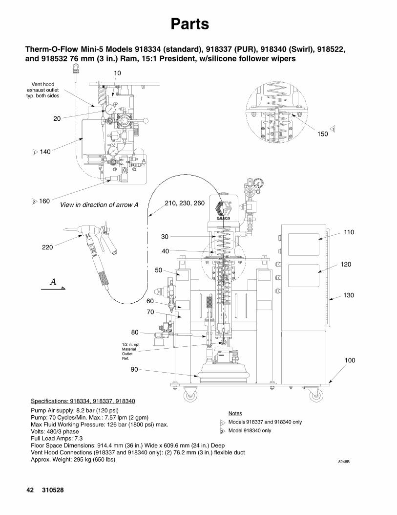
Therm-O-Flow Mini-5 Models 918334 (standard), 918337 (PUR), 918340 (Swirl), 918522,and 918532 76 mm (3 in.) Ram, 15:1 President, w/silicone follower wipers
1
2
Specifications: 918334, 918337, 918340
Pump Air supply: 8.2 bar (120 psi)Pump: 70 Cycles/Min. Max.: 7.57 lpm (2 gpm)Max Fluid Working Pressure: 126 bar (1800 psi) max.Volts: 480/3 phaseFull Load Amps: 7.3Floor Space Dimensions: 914.4 mm (36 in.) Wide x 609.6 mm (24 in.) DeepVent Hood Connections (918337 and 918340 only): (2) 76.2 mm (3 in.) flexible ductApprox. Weight: 295 kg (650 lbs)
150
110
120
130
100
30
40
50
60
70
80
90
1/2 in. nptMaterialOutletRef.
�
Vent hoodexhaust outlettyp. both sides
10
20
140
160
1
View in direction of arrow A
1
2
8248B
220
210, 230, 260

310528 43
PartsModel 918334, 76 mm (3 in.) Ram, Therm-O-Flow 15:1 President, w/silicone followerwipers, 480 VAC
RefNo.
PartNo.
Description Qty.
10 617321 Assembly, junction box 120 918505 Control, air 130 C31197 Kit, hose support 140 C31202 Pump, President assembly 15:1* 150 C14043 Label, pinch point 460 C14005 Label, warning hot surface 470 918405 Ram, 76 mm (3 in.) 1
RefNo.
PartNo.
Description Qty.
80 C31203 Kit, blow-off/bleed 190 617325 Follower, TFE coated, heated 20 li-
ter (5 gal.)1
100 918414 Base, portable ram 20 liter (5 gal.) 1110 C14004 Label, caution 1120 C14003 Label, warning 1130 617300 Control, 480 VAC, electrical 3-zone 1160 918506 Kit, air motor depressurization 1
Model 918337, 76 mm (3 in.) Ram, PUR Therm-O-Flow, 15:1 President, w/silicone follower wipers, 480 VAC
RefNo.
PartNo.
Description Qty.
10 617321 Assembly, junction box 120 918505 Control, air 130 C31197 Kit, hose support 140 C31202 Pump, President assembly 15:1* 150 C14043 Label, pinch point 460 C14005 Label, warning hot surface 470 918405 Ram, 76 mm (3 in.) 180 C31203 Kit, blow-off/bleed 1
RefNo.
PartNo.
Description Qty.
90 617325 Follower, TFE coated, heated 20 li-ter (5 gal.)
1
100 918414 Base, portable ram 20 liter (5 gal.) 1110 C14004 Label, caution 1120 C14003 Label, warning 1130 617300 Control, 480 VAC, electrical 3-zone 1140 617318 Hood, 20 liter, (5 gal.) vent 1150 918433 Kit, prox. switch pump inactivity 1160 918506 Kit, air motor depressurization 1
Model 918340, 76 mm (3 in.) Ram, PUR Therm-O-Flow, 15:1 President, Swirl Valve,w/silicone follower wipers 480 VAC
RefNo.
PartNo.
Description Qty.
10 617321 Assembly, junction box 120 918505 Control, air 130 C31197 Kit, hose support 140 C31202 Pump, President assembly 15:1* 150 C14043 Label, pinch point 460 C14005 Label, warning hot surface 470 918405 Ram, 76 mm (3 in.) 180 C31203 Kit, blow-off/bleed 1
RefNo.
PartNo.
Description Qty.
90 617325 Follower, TFE coated, heated 20 li-ter (5 gal.)
1
100 918414 Base, portable ram 20 liter (5 gal.) 1110 C14004 Label, caution 1120 C14003 Label, warning 1130 617330 Control, 480 VAC, electrical 3-zone 1140 617318 Hood, 20 liter, (5 gal.) vent 1150 918433 Kit, prox. switch pump inactivity 1160 918506 Kit, air motor depressurization 1170 617328 Kit, swirl valve 1

44 310528
Parts
Models 918522 and C58630 76 mm (3 in.) Ram, Therm-O-Flow, 15:1 President, w/silicone follower wipers 480 VAC
RefNo.
PartNo.
Description Qty.
10 617321 Assembly, junction box 120 918505 Control, air 130 C31197 Kit, hose support 140 C31202 Pump, President assembly 15:1* 150 C14043 Label, pinch point 460 C14005 Label, warning hot surface 470 918405 Ram, 76 mm (3 in.) 180 C31203 Kit, blow-off/bleed 190 918499 Inductor, heated, PTFE 20 liter
(5 gal.)1
100 918414 Base, portable ram 20 liter (5 gal.) 1130 617330 Control, 480 VAC, electrical 3-zone 1160 918506 Kit, air motor depressurization 1
RefNo.
PartNo.
Description Qty.
210 C34093 Hose, heated; 10’; 7/8–14 JIC(Model C58630 only)
1
220 C34005 Gun, hot melt (Model C58630 only)
1
230 C20679 Fitting, elbow; 1/2 npt (Model C58630 only)
1
240 C33049 Tape, adhesive; fiberglass (Model C58630 only)
4.2’
250 C34137 Insulator; fiberglass (Model C58630 only)
8.3’
260 110332 Adapter; 1/2 npt (m x f) (Model C58630 only)
1
Models 918532 and C5880576 mm (3 in.) Ram, Therm-O-Flow, 15:1 President, w/silicone follower wipers 240 VAC
RefNo.
PartNo.
Description Qty.
10 617321 Assembly, junction box 120 918505 Control, air 130 C31197 Kit, hose support 140 C31202 Pump, President assembly 15:1* 150 C14043 Label, pinch point 460 C14005 Label, warning hot surface 470 918405 Ram, 76 mm (3 in.) 180 C31203 Kit, blow-off/bleed 190 918499 Inductor, heated, PTFE 20 liter
(5 gal.)1
100 918414 Base, portable ram 20 liter (5 gal.) 1130 617484 Control, 240 VAC, electrical 3-zone 1
RefNo.
PartNo.
Description Qty.
160 918506 Kit, air motor depressurization 1210 C34093 Hose, heated; 10’; 7/8–14 JIC
(Model C58805 only)1
220 C34005 Gun, hot melt (Model C58805 only)
1
230 C20679 Fitting, elbow; 1/2 npt (Model C58805 only)
1
240 C33049 Tape, adhesive; fiberglass (Model C58805 only)
4.2’
250 C34137 Insulator; fiberglass (Model C58805 only)
8.3’
* Refer to instruction manual 307431 to obtain C31202 pump assembly parts information on the 918417 fluid pump.

310528 45
Notes

46 310528
Parts
Therm-O-Flow 5 Models 918343, 918352 (PUR)76 mm (3 in.) Ram, 19:1 Senator, Heated Check-Mate 800,w/silicone follower wipers
Notes
Model 918352 only1
Specifications 918343, 918352
Pump Air supply: 6.9 bar (100 psi)Pump: 60 Cycles/Min. Max., 2.24 m3/min (80 scfm)Max Fluid Working Pressure: 131 bar (1900 psi) max.Volts: 480/3 phaseFull Load Amps: 9.8Floor Space Dimensions: 914.4 mm (36 in.) Wide x 609.6 mm (24 in.) DeepVent Hood Connections (918352 only): (2) 76.2 mm (3 in.) flexible ductApprox. Weight: 318 kg (700 lbs)
Vent hoodexhaust outlettyp. both sides
ref.
1 in. nptMaterialOutlet Ref.
10
20
30405060
70
80
90
100 110
120
130
140
150
160
1200
170
180
210 1
190
8249A

310528 47
PartsModel 918343, 76 mm (3 in.) Ram, 19:1 Senator, Therm-O-Flow Heated Check-Mate 800,w/silicone follower wipers 480 VAC
RefNo.
PartNo.
Description Qty.
10 217540 Motor, Senator air 5-1/2 in. 120 C31197 Kit, hose support 130 100003 Screw, hex; 3/8-16 UNC x 1.5 in. 440 C19200 Washer, flat 3/8 in. 450 C19213 Washer, lock 3/8 in. 460 C19185 Nut, hex 3/8-16 470 918405 Ram, 76 mm (3 in.) global 180 C03510 Kit, pump/air motor mounting 190 918416 Control, air 1100 517453 Sealer, RTV A/R110 C03509 Pump, HCM-800, assembly
480/575 VAC1
RefNo.
PartNo.
Description Qty.
120 617347 Kit, follower blow-off/bleed 1130 617335 Follower, heated, tfe coated, 20 liter
(5 gal.)1
140 617349 Control, 480 VAC electrical 4-zone 1150 C14004 Label, caution 1160 C14003 Label, warning 1170 C14043 Label, pinchpoint 4180 C14005 Label, warning hot surface 4190 918414 Base, portable ram 20 liter (5 gal.) 1
Model 918352, 76 mm (3 in.) Ram, 19:1 Senator, PUR Therm-O-FlowHeated Check-Mate 800, w/silicone follower wipers 480 VAC
RefNo.
PartNo.
Description Qty.
10 217540 Motor, Senator air 5.5 in. 120 C31197 Kit, hose support 130 100003 Screw, hex; 3/8-16 UNC x 1.5 in. 440 C19200 Washer, flat 3/8 in. 450 C19213 Washer, lock 3/8 in. 460 C19185 Nut, hex 3/8-16 470 918405 Ram, 76 mm (3 in.) global 180 C03510 Kit, pump/air motor mounting 190 918416 Control, air 1100 517453 Sealer, RTV A/R110 C03509 Pump, HCM-800, assembly
480/575 VAC1
RefNo.
PartNo.
Description Qty.
120 617347 Kit, follower blow-off/bleed 1130 617335 Follower, heated, tfe coated, 20 liter
(5 gal.)1
140 617349 Control, 480 VAC electrical 4-zone 1150 C14004 Label, caution 1160 C14003 Label, warning 1170 C14043 Label, pinchpoint 4180 C14005 Label, warning hot surface 4190 918414 Base, portable ram 20 liter (5 gal.) 1200 617334 Kit, prox. switch pump activity 1210 617318 Hood, vent assembly 20 liter (5 gal.) 1

48 310528
PartsTherm-O-Flow 5 Models 918344, 918437 and 91859376 mm (3 in.) Ram, 31:1 Bulldog, Heated Check-Mate 800,w/silicone follower wipers
Specifications 918344
Pump Air supply: 6.9 bar (100 psi)Pump: 60 Cycles/Min. Max., 2.8 m3/min (100 scfm)Max Fluid Working Pressure: 214 bar (3100 psi) max.Volts: 480/3 phaseFull Load Amps: 9.8Floor Space Dimensions: 914.4 mm (36 in.) Wide x 609.6 mm (24 in.) DeepApprox. Weight: 318 kg (700 lbs)
8250A
10
20
30405060
70
80
90
100 110
120
130
140
150
160
170
180
190
1 in. nptMaterialOutlet Ref.

310528 49
PartsModel 918344, 76 mm (3 in.) Ram, 31:1 Bulldog, Therm-O-Flow PUR HeatedCheck-Mate 800, w/silicone follower wipers 480 VAC
RefNo.
PartNo.
Description Qty.
10 208356 Motor, Bulldog air 7 in. 120 C31197 Kit, hose support 130 100003 Screw, hex; 3/8-16 UNC x 1.5 in. 440 C19200 Washer, flat 3/8 in. 450 C19213 Washer, lock 3/8 in. 460 C19185 Nut, hex 3/8-16 470 918405 Ram, 76 mm (3 in.) global 180 C03510 Kit, pump/air motor mounting 190 918416 Control, air 1100 517453 Sealer, RTV A/R
RefNo.
PartNo.
Description Qty.
110 C03512 Pump, HCM-800, assembly240 VAC
1
120 617347 Kit, follower blow-off/bleed 1130 617335 Follower, heated, tfe coated, 20 liter
(5 gal.)1
140 617485 Control, 240 VAC electrical 4-zone 1150 C14004 Label, caution 1160 C14003 Label, warning 1170 C14043 Label, pinchpoint 4180 C14005 Label, warning hot surface 4190 918414 Base, portable ram 20 liter (5 gal.) 1
Model 918437, 76 mm (3 in.) Ram, 31:1 Bulldog, Therm-O-Flow PUR HeatedCheck-Mate 800, 240 VAC
RefNo.
PartNo.
Description Qty.
10 208356 Motor, Bulldog air 7 in. 120 C31197 Kit, hose support 130 100003 Screw, hex; 3/8-16 UNC x 1.5 in. 440 C19200 Washer, flat 3/8 in. 450 C19213 Washer, lock 3/8 in. 460 C19185 Nut, hex 3/8-16 470 918405 Ram, 76 mm (3 in.) global 180 C03510 Kit, pump/air motor mounting 190 918416 Control, air 1
RefNo.
PartNo.
Description Qty.
110 C03512 Pump, HCM-800, assembly240 VAC, 5 gal
1
120 617347 Kit, follower blow-off/bleed 1130 617335 Follower, heated, tfe coated, 20 liter
(5 gal.)1
140 617485 Control, 240 VAC electrical 4-zone 1170 C14043 Label, pinchpoint 4180 C14005 Label, warning hot surface 4190 918414 Base, portable ram 20 liter (5 gal.) 1
Model 918593, 76 mm (3 in.) Ram, 31:1 Bulldog, Therm-O-Flow PUR HeatedCheck-Mate 800, w/Finned Platen 480 VAC
RefNo.
PartNo.
Description Qty.
10 241201 Motor, Bulldog 120 C31197 Kit, hose support 130 100003 Screw, hex; 3/8-16 UNC x 1.5 in. 440 C19200 Washer, flat 3/8 in. 450 C19213 Washer, lock 3/8 in. 460 C19185 Nut, hex 3/8-16 470 918405 Ram, 76 mm (3 in.) global 180 C03510 Kit, pump/air motor mounting 190 918416 Control, air 1
RefNo.
PartNo.
Description Qty.
110 C03509 Pump, HCM-800, 480 VAC (5 gal.) 1120 617347 Kit, follower blow-off/bleed 1140 617349 Control, 480 VAC electrical 4-zone 1170 C14043 Label, pinchpoint 4180 C14005 Label, warning hot surface 4190 918414 Base, portable ram 20 liter (5 gal.) 1

50 310528
PartsTherm-O-Flow 5 Model C5939876 mm (3 in.) Ram, 65:1 King, Heated Check-Mate 800,w/silicone follower wipers
Specifications 918344
Pump Air supply: 4.2 bar (60 psi)Pump: 50 Cycles/Min. Max., 4.4 m3/min (150 scfm)Max Fluid Working Pressure: 214 bar (3100 psi) max.Volts: 480/3 phaseFull Load Amps: 9.8Floor Space Dimensions: 914.4 mm (36 in.) Wide x 609.6 mm (24 in.) DeepApprox. Weight: 318 kg (700 lbs)
8250A
10
20
30405060
70
90
120
130
140
170
180
190
1 in. nptMaterialOutlet Ref.

310528 51
PartsModel C59398, 76 mm (3 in.) Ram, 65:1 King, Therm-O-Flow PUR Heated Check-Mate 800,w/silicone follower wipers 480 VAC
RefNo.
PartNo.
Description Qty.
10 241200 Motor, King 8cm SST 120 C31197 Kit, hose support 130 100003 Screw, hex; 3/8-16 UNC x 1.5 in. 440 C19200 Washer, flat 3/8 in. 450 C19213 Washer, lock 3/8 in. 460 C19185 Nut, hex 3/8-16 470 918405 Ram, 76 mm (3 in.) global 190 918416 Control, air 1
RefNo.
PartNo.
Description Qty.
120 617347 Kit, follower blow-off/bleed 1130 617335 Follower, heated, tfe coated, 20 liter
(5 gal.)1
140 617349 Control, 480 VAC electrical 4-zone 1170 C14043 Label, pinchpoint 4180 C14005 Label, warning hot surface 4190 918414 Base, portable ram 20 liter (5 gal.) 1

52 310528
PartsModel C03510, Pump Air Motor Mounting Kit
#C03509HCM 800- 200 liter(55 gal.)ref
10
20
30
40
1
2
#207647 King™ Air Motor ref.
Notes
Torque to 81–89 N.m (60–66 ft-lb)
Torque to 196–210 N.m (145–155 ft-lb)
1
2
7990A
RefNo.
PartNo.
Description Qty.
10 106166 Nut, hex M16 x 2 320 190000 Rod, stand-off 3
RefNo.
PartNo.
Description Qty.
30 184129 Collar, coupling 240 186925 Nut, coupling 1

310528 53
Notes

54 310528
Parts
7980A
Model 918416, 4-Regulator Ram Air Control Module
350400
410
420
310320
330340
220
240
370
360
180, 80, 380
450
27029028018080170
270300100260
250
240
460

310528 55
PartsModel 918416, 4-Regulator Ram Air Control Module
7991A
10
6080 170
100390
90
110
20 30 5040 120
260
260 140 150 440
190 80
70160
130
60 80 190100390
8060
5040
5040
504080
80 200
190 8010
80
80 17060
ALTERNATE SCHEMATIC
RefNo.
PartNo.
Description Qty.
10 C06021 Valve, lockout 1/2 npt 120 C11033 Filter, air 130 C11034 Lubricator 140 C11029 Regulator, air 150 C36260 Gauge, pressure 160 psi 160 C19391 Elbow, connector 1/4P x 1/4T 470 C06299 Muffler 10-32 unf 180 C12509 Tubing, nylon black ∅ 1/4 126”90 C06093 Valve, check 1/4 npt 1100 C36183 Muffler, 1/4 npt 2110 C06015 Valve, hand 1120 C19024 Union, 90° 1/2 npt 1130 C12021 Hose, air 1/2 60”140 C06297 Valve, ball lockable 1/2 npt 1150 157191 Nipple red, hex 3/4 x1/2 1160 C20365 Tee, run-male 1/4P x 1/4T 1170 C20350 Elbow, connector female 1/4P x 1/4T 3180 597151 Elbow, connector 1/8P x 1/4T 4190 C19382 Elbow, connector 3/8P x 1/4T 4200 517413 Valve, toggle 1210 C20372 Insert 1/2 npt 2220 C11055 Kit. FRL mounting 1230 C14043 Label, pinch point 1240 C11057 Regulator, air 2250 C07585 Gauge, air pressure 160 psi 2
RefNo.
PartNo.
Description Qty.
260 C19019 Union, swivel 1/2 npt 2270 C11037 Insert, pipe port 1/2 npt 2280 C11039 Connector, air interface 1290 C11040 Insert, ported 1/4 npt 1300 C20485 Nipple, hex 1/2 npt 1310 C19204 Washer, lock #10 4320 100179 Nut, hex #10-24 4330 C19981 Screw. soc. hd. cap #10-24 x 0.62 4340 C19197 Washer, flat #10 4350 C19209 Washer, lock 1/4 4360 C06090 Gauge, air pressure 60 psi 1370 C06116 Regulator, air 50 psi 1380 C20349 Elbow, connector female 1/8P x 1/4T 1390 C19445 Elbow, street 1/4 npt 1400 C19815 Screw, soc. hd. cap 1/4-20 x 2 4410 C51978 Spacer 4420 C32436 Plate, mounting 1430 C20382 Ferrule 2440 C20362 Fitting, tube tee 1/8P x 1/4T 1450 C14042 Label, panel 1460 918506 Kit, auto depressurization 1470 617714 Trim, black vinyl edge 51”480 617718 Plug, .25 OD tube 1490 617717 Fitting, nipple .25 OD 1500 C20341 Fitting, union, female 1/4Px1/4T 1

56 310528
PartsModel 617318, Vent Hood Kit for use with PUR units
76 mm (3 in.) outlettyp. Both sides
10 20
3040
RefNo.
PartNo.
Description Qty.
10 C56022 Hood, vent 20 liter (5 gal.) 120 C14038 Label 1
RefNo.
PartNo.
Description Qty.
30 C19802 Screw, shc 1/4-20 x 3/4 in. 240 C19198 Washer, flat 1/4 in. 2

310528 57
PartsModel 617334, Proximity Switch Kit (Pump Activity)for use with Therm-O-Flow 5 units
To pumpjunction box ref
1020
40 50
70
6030
8090
100
110
120
4 mm (.157 in.)max. set-updimension
RefNo.
PartNo.
Description Qty.
10 617337 Collar, clamp 220 C19209 Washer, lock 1/4 in. 230 C19800 Screw, shc 1/4-20 x 1/2 in. 240 617338 Bracket, prox switch mounting 150 517455 Switch, proximity 18 mm 160 C56572 Cable, prox 2 meters lg. 170 C20575 Fitting, cord grip 1/2 in. npt 1
RefNo.
PartNo.
Description Qty.
80 C20874 Seal, conduit 1/2 in. 190 C20715 Nut, conduit lock 1/2 in. npt 1100 C20865 Bushing, conduit 1/2 in. npt 1110 617339 Housing, coupling nut 1120 C19363 Screw, cup point set 1/4-20 x 1/2 in. 1130 C78342 Timer (not shown) 1140 C78552 Socket, 8-receptacle (not shown) 1

58 310528
PartsModel 918433, Proximity Switch Kit (Pump Activity)for use with President Pumps
C31202 ref.
617415 Connectingrod ref (part of
C31202)
5.79 mm (2.28 in.)set-up dimension
6.1 mm (2.4 in.)air motor full
down stroke ref
4 mm (.157 in.)max. set-updimension
Tomain
controls ref
10
20
3040
50
6070
80
90
100
6.35 mm (.25 in.)
RefNo.
PartNo.
Description Qty.
10 C50174 Cable assembly 1.83 m (6’) 120 517469 Switch, proximity 130 C19209 Washer, lock 1/4 in. 440 C20452 Bolt, U 1/4-20 250 C20571 Fitting, cord grip 1/2 in. npt 160 C20874 Seal, conduit 1/2 in. 1
RefNo.
PartNo.
Description Qty.
70 C20715 Nut, conduit lock 1/2 in. npt 180 C20865 Bushing, conduit 1/2 in. npt 190 617417 Bracket, prox switch mounting 1100 517470 Collar, clamp 1110 C78342 Timer (not shown) 1120 C78552 Socket, 8-receptacle (not shown) 1

310528 59
PartsModel 617325, Heated Follower Plate Kit with smooth bottomfor use with President pump assemblies
10
20
30
40
50
80 70 60
100 90
110
120
130
140 150160
70 80
210
200
170180
Apply sealeritem 240
Apply sealeritem 240
190
230
RefNo.
PartNo.
Description Qty.
10 617396 Adapter, pump/follower 120 C31092 Tube, blow-off/bleed 130 C31093 Nut 140 617324 Cover, follower 150* C20240 Seal, o-ring 160 C31088 Element, heater 170 C32386 Wire, hi-temp 10 awg 4572 mm 180”80 C32256 Ring, terminal 10 awg x 1/4 in. 590 C31052 Seal, follower 1100 C31154 Clamp, worm-gear 2110 C31153 Ring, seal tfe coated 1120* C31062 Gasket 1130 C31152 Inductor plate tfe coated 1140 C19743 Screw, flat head 1/4-20 x 5/8 in. 6150 C19800 Screw, shc 1/4-20 x 1/2 in. 1160 C19209 Washer, lock 1/4 in. 1170 C19213 Washer, lock 3/8 in. 3
RefNo.
PartNo.
Description Qty.
180 C19837 Screw, shc 3/8-16 x 1 in. 3190 C19815 Screw, shc 1/4-20 x 2 in. 3200 C19986 Screw, shc #10-24 x 1-3/4 in. 1210 C19812 Screw, shc 1/4-20 x 1-1/2 in. 4220 517428 Sensor, RTD (not shown) 1230* C38225 Seal, o-ring 1240 C31056 Sealer RTV (not shown)250 C07664 Compound, heat sink (not shown)260 C20571 Grip, 1/2 in. npt 90° cord
(not shown)1
270 C20874 Seal, 1/2 in. conduit (not shown) 1280 C20715 Nut, 1/2 in. npt conduit lock
(not shown)1
290 150707 Plate, designation (not shown) 1300 100508 Screw, drive (not shown) 2
* Included in Follower Repair Kit 918443

60 310528
PartsModel 617335, Heated Follower Plate Kit with smooth bottomfor use with Heated Check-Mate 800 pump modules
10 190
20
30
40
50
80 70 60
100 90
110
120
130
140150160
70 80
210
200
170160
310280300290
Apply sealeritem 240
Apply sealeritem 240
RefNo.
PartNo.
Description Qty.
10 C32339 Adapter, pump/follower 120 C31092 Tube, blow-off/bleed 130 C31093 Nut 140 617324 Cover, follower 150* C20240 Seal, o-ring 160 C31088 Element, heater 170 C32386 Wire, hi-temp 10 awg 4572 mm 180”80 C32256 Ring, terminal 10 awg x 1/4 in. 590 C31052 Seal, follower 1100 C31154 Clamp, worm-gear 2110 C31153 Ring, seal tfe coated 1120* C31062 Gasket 1130 C31152 Inductor plate tfe coated 1140 C19743 Screw, flat head 1/4-20 x 5/8 in. 6150 C19800 Screw, shc 1/4-20 x 1/2 in. 1160 C19209 Washer, lock 1/4 in. 7170 C19096 Screw, hex head 1/4-20 x 1-1/2 in. 6
RefNo.
PartNo.
Description Qty.
180 100508 Screw, drive (not shown) 2190 C19818 Screw, shc 1/4-20 x 2-1/2 in. 3200 C19986 Screw, shc #10-24 x 1-3/4 in. 1210 C19812 Screw, shc 1/4-20 x 1-1/2 in. 4220 517428 Sensor, RTD (not shown) 1230 C31056 Sealer RTV (not shown)240 C07664 Compound, heat sink (not shown)250 C20571 Grip, 1/2 in. npt 90° cord
(not shown)1
260 C20874 Seal, 1/2 in. conduit (not shown) 1270 C20715 Nut, 1/2 in. npt conduit lock
(not shown)1
280 C20726 Fitting, 90° conduit 3/4 in. npt 1290 C20727 Fitting, conduit 3/4 in. npt 2300 C38202 Conduit, flexible steel 3/4 in.
(610mm)24”
310 C20875 Seal, conduit 3/4 in. 1330 150707 Plate, designation (not shown) 1
* Included in Follower Repair Kit C31087

310528 61
PartsModel 918499, Heated Follower Plate Kit with finned bottomfor use with President pump assemblies
10
20
30
40
50
60, 70, 80
100 90
110
70, 80
210
200
120130
Apply sealeritem 240
Apply sealeritem 240
230
9527A
150 160
RefNo.
PartNo.
Description Qty.
10 617396 Adapter, pump/follower 120 617539 Tube, blow-off/bleed 130 C31093 Nut 140 617324 Cover, follower 150* C20240 Seal, o-ring 160 C31088 Element, heater 170 C32386 Wire, hi-temp 10 awg 4572 mm 180”80 C32256 Ring, terminal 10 awg x 1/4 in. 590 C31052 Seal, follower 1100 C31154 Clamp, worm-gear 2110 617540 Plate, finned follower PTFE coated 1120 C19213 Washer, lock 3/8 in. 3130 C19837 Screw, shc 3/8-16 x 1 in. 3140* C38225 Seal, o-ring 6
RefNo.
PartNo.
Description Qty.
150 C19815 Screw, shc 1/4-20 x 2 in. 3160 C19986 Screw, shc #10-24 x 1-3/4 in. 1170 517428 Sensor, RTD (not shown) 1180 C19812 Screw, shc 1/4-20 x 1-1/2 in. 4190 C31056 Sealer RTV (not shown)200 C07664 Compound, heat sink (not shown)210 C20571 Grip, 1/2 in. npt 90° cord
(not shown)1
220 C20874 Seal, 1/2 in. conduit (not shown) 1230 C20715 Nut, 1/2 in. npt conduit lock
(not shown)1
240 150707 Plate, designation (not shown) 1250 100508 Screw, drive #4 x 3/16 in.
(not shown)2
* Included in Follower Repair Kit 918502

62 310528
Parts
Model 617300 (Standard), 480 VAC3-zone Electrical Control Panel (interior)
TERMINALS
120 V FusesFU109FU175FU177
FU179TOTAL(4) Type CE6
480 V Terminals
2L12L2GND(1) SPARE Total (4) TYPE CD2
120V Terminals
108110821082108211011141114211811311131213211331153115321541155116011602161116211641166116621711175217721792GNDGND(5) SparesTOTAL (34) Type CA1
Spare Parts Part NumberTemperature Controller 195764Solid State Relay (for SSRs 153 & 160) C78082Timer, 7-day C78167Timer, Inactivity C78342
For information about other parts, contact your Gracotechnical support representative.
Reservedfor Optional7-day Timer
10
20
30InactivityTimer
Optional
Ground FaultInterrupt
GNDBUS

310528 63
Parts
Model 617330 (Swirl), 480 VAC3-zone Electrical Control Panel (interior)
Spare Parts Part NumberTemperature Controller 195764Solid State Relay (for SSRs 153 & 160) C78082Timer, 7-day C78167Timer, Inactivity C78342
For information about other parts, contact your Gracotechnical support representative.
Reservedfor Optional7-day Timer
10
20
30InactivityTimer
Optional
Ground FaultInterrupt
GNDBUS
TERMINALS
120 V FusesFU109FU175FU177FU179FU181TOTAL(5) Type CE6
480 V Terminals
2L12L2GND(1) SPARE Total (4) TYPE CD2
120V Terminals
108110821082108211011141114211811311131213211331153115321541155116011602161116211641166116621691175217721812GNDGND(3) SparesTOTAL (32) Type CA1

64 310528
PartsModels 617300 (standard) and 617330 (Swirl), 480 VAC 3-zone and617484 240 VAC 3-zone Electrical Control Panel (exterior)
Swirl Valve(Model 617330 only)

310528 65
Parts
Models 617349 (480 VAC) and 617485 (240 VAC)4-zone Electrical Control Panel (exterior)

66 310528
Parts
Models 617349 (480 VAC) and 617485 (240 VAC)4-zone Electrical Control Panel (interior)
10 Fuses
FU109FU175FU177FU179(4) Total Type CE6
20 Terminals
3L13L25L15L2GND(5) Total Type CD2
30 Terminals1081108210821082110111411142118113111312132113311381138213911401153115321541155116011602161116211641166116621711175217721972GNDGND(3) Spares(36) Total Type CA1
Spare Parts Part NumberTemperature Controller 195764Solid State Relay (for SSRs 153 & 160) C78082Timer, 7-day C78167Timer, Inactivity C78342
For information about other parts, contact your Gracotechnical support representative.
Reservedfor Optional7-day Timer
10
20
30 InactivityTimer
Optional
Ground FaultInterrupt
GNDBUS
DH1

310528 67
SchematicsElectrical Control Panel and Wiring Partsand Description
617300 Page 1
9604A

68 310528
Schematics
617300 Page 2
9605A

310528 69
Schematics
617485_1
9606A

70 310528
Schematics
617485_2

310528 71
Schematics
617484 Page1
9608A

72 310528
Schematics
617484 Page2
9609A

310528 73
Schematics
617349 Page1
9689A

74 310528
Schematics
617349 Page 2
9690A

310528 75
AccessoriesUse Only Genuine Graco Parts and Accessories
Description Part No.
HEATED 5-GALLON FOLLOWER PLATE ASSEMBLYUsed for 240, 480, 575 VAC.305 mm (12 in.) O.D. Silicone Wiper hose
15:1 President finned bottom 918499
CM800 Heated Module smooth bottom15:1 President smooth bottom
617335617325
WIPER REPAIR KIT
FOLLOWER REPAIR KIT
for Therm-O-Flow Mini-5 supply unitsand Therm-O-Flow 5 units
C31065
AIR CONTROL MODULES FOR RAM AND AIR CONTROL2 Regulator module contains controls for ram and motor4 Regulator module contains controls for ram up, ram down, blow-off and motor8.8 bar (125 psig) MAXIMUM WORKING PRESSURE for Ram
2-Regulator air control module for 15:1 President air motor4-Regulator air control module for Bulldog and Senator air motors
918505918416
LOW LEVEL PAIL KITLights a red beacon signal when the pail is empty
918430
CASTER BASEPLATEUsed for heated applications.
918414
HOSE SUPPORT KITSupports hose to ram to prevent hose kinks. Used only in 20 l (5 gal.) applications.
C31197
AUTOMATIC CROSSOVER KITSwitches ram operation to alternate ram, automatically
918393
PUMP AIR MOTOR MOUNTING KITUsed in heated applications to connect the heated CM800 pump to King, Bulldog, andSenator air motors.
C03510
VENT HOOD KIT (5 Gallon)Used for venting toxic fumes. Required for Polyurethane Reactive (PUR) supply units.
617318
PUMP INACTIVITY KITUsed to shut down the heaters if there is no pump activity. Contains proximity switch,electronic timer, and the hardware necessary to install it in the supply unit.
617334
PUMP REBUILD KITSee Form# 308570 for CheckMate 800See Form# 307431 for Mini-5 Pump
HEATER/SENSOR REPAIR KITContains heaters, sensors and wires for replacing heaters and sensors
C32202
7-DAY TIMER KITContains electronic timer and the hardware necessary to install the timer in the electricalcontrol panel
C78167

76 310528
Notes

310528 77
Dimensions
3-Zone Electrical Control Panel Mounting and Clearance Dimensions
254 mm(10 in.)
914 mm(36 in.)
533 mm(21 in.) 9691A

78 310528
Dimensions
4-Zone Electrical Control Panel Mounting and Clearance Dimensions
254 mm(10 in.)
1067 mm(42 in.)
533 mm(21 in.)

310528 79
Dimensions
1470 mm(57.9 in.)
1842 mm(72.5 in.)
610 mm(24.0 in.)
559 mm(22.0 in.)
406 mm(16.0 in.)
457 mm(18.0 in.)
(4 X)Φ13.46 mm (0.53 in.)
Ram Mounting and Clearance Dimensions for Therm-O-Flow 5

80 310528
Dimensions
1203 mm(47.4 in.)
1666 mm(65.6 in.)
610 mm(24.0 in.)
559 mm(22.0 in.)
406 mm(16.0 in.)
457 mm(18.0 in.)
(4 X)Φ13.46 mm (0.53 in.)
Ram Mounting and Clearance Dimensions w/15:1 President Air Motor

310528 81
Dimensions
Electrical Control Panel Mounting and Clearance Dimensions
254 mm(10 in.)
1189 mm(46.8 in.)
945 mm(37.25 in.)
493 mm(19.4 in.)
646 mm(25.4 in.)

82 310528
Dimensions
Ram Mounting and Clearance Dimensions
1732 mm(68.2 in.)
2748 mm.(108.2 in.)
1168 mm.(46.0 in.)
1067 mm.(42.0 in.)
635 mm(25 .0 in.)
533 mm(21.0 in.)
736 mm(29.0 in.)
937 mm(36.9 in.)

310528 83
Technical Data
Maximum ram inlet air pressure 8.8 bar (125 psi)
Maximum pump inlet air pressureSenator, Bulldog pumpsPresident pumpsKing pumps
7 bar (100 psi)8.2 bar (120 psi)6.3 bar (90 psi)
Maximum fluid working pressure (pump only) 403 bar (5850 psi)
Maximum fluid working pressure (pump)Senator pumps (19:1)Bulldog pumps (31:1)President (15:1) pumps
131 bar (1900 psi)214 bar (3100 psi)126 bar (1800 psi)
Weight (ram assembly) approx. 68 kg (150 lbs)
Weight (typical pump + ram assembly)Senator, Bulldog pumpsPresident pumps
approx. 318 kg (700 lbs)approx. 295 kg (650 lbs)
Wetted parts (ram) Carbon steel, aluminum, nitrile, nylon, nickel plating
Wetted parts (pump) See Form# 308570 for Therm-O-Flow 5 unitsCall Technical Service for Therm-O-Flow Mini-5 units
Floor space dimensions (w/vent hood) 914 mm wide x 610 mm deep (36 in. x 24 in.)
Overall height (lowered)Senator, Bulldog pumpsPresident pumps
1.47 m (57.9 in.)1.2 m (47.4 in.)
Overall height (extended)Senator, Bulldog pumpsPresident pumps
1.84 m (72.5 in.)1.66 m (65.6 in.)
Pump main air inlet 1/24 in. npt (f)
Fluid outletPresident (15:1) pumpsSenator, Bulldog pumps
1/2 in. npt (f)1 in. npt (f)
Sound Data See individual component manuals for their respectivesound pressure levels.

84 310528
Related PublicationsForm Name Form#
President Air Motor 306982
Bulldog Air Motor, 31:1 307049
Senator Air Motor, 19:1 and Quiet Senator Air Motor, 19:1 307592
King Air Motor, 65:1 306968
20 Liter (5 Gallon) 76 mm (3 in.) Air-Powered Ram Module 310525
165 mm (6.5 in.) Global Ram Module 310523
Check-Mate 800 Displacement Pump 308570
Heated Check-Mate 800 Pump Modules 310530
Mini-5 Hot Melt 15:1 Ratio President Pump 307431
Hydraulic Power Supply 307550
Check-Mate, King, Mini-5, and President are trademarks of Graco, Inc.Bulldog, Senator, and Therm-O-Flow are registered trademarks of Graco, Inc.

310528 85
AppendixNew Style Temperature Controller SettingsList

86 310528
AppendixOlder Style (E5KC) Temperature ControllerSettings ListLevel 0, Function Mode Parameter Names
Set point
Run/Stop
Level 1, Function Mode Parameter Names
Auto-tuning Execute/Cancel
Alarm value 1
Alarm value 2
Proportional band
Integral time
Derivative time
Control period (heat)
Level 2, Function Mode Parameter Names
SP ramp time unit
SP ramp set value
MV at stop
MV at PV error
MV upper limit
MV lower limit
MV change rate limit
Input digital filter
Alarm 1 hysteresis
Alarm 2 hysteresis
Input shift upper limit
Input shift lower limit
Setup, Function Mode Parameter Names
Input type
�C/�F selection
Parameter initialize
Control output 1 assignment
Control output 2 assignment
Auxiliary control 1 assignment
Alarm 1 type
Alarm 1 open in alarm
Alarm 2 type
Alarm 2 open in alarm
Direct/Reverse operation
Expansion, Function Mode Parameter Names
Set point upper limit
Set point lower limit
PID/ON/OFF
ST
alpha range: 0.01 to 1.00
AT calculated gain
Standby sequence reset setting method
Automatic return of display mode
AT hysteresis

310528 87
Notes

88 310528
Graco Standard Warranty Graco warrants all equipment manufactured by Graco and bearing its name to be free from defects in material and workmanship on thedate of sale to the original purchaser for use. With the exception of any special, extended, or limited warranty published by Graco,Graco will, for a period of twelve months from the date of sale, repair or replace any part of the equipment determined by Graco to bedefective. This warranty applies only when the equipment is installed, operated and maintained in accordance with Graco’s writtenrecommendations.
This warranty does not cover, and Graco shall not be liable for general wear and tear, or any malfunction, damage or wear caused byfaulty installation, misapplication, abrasion, corrosion, inadequate or improper maintenance, negligence, accident, tampering, or sub-stitution of non–Graco component parts. Nor shall Graco be liable for malfunction, damage or wear caused by the incompatibility ofGraco equipment with structures, accessories, equipment or materials not supplied by Graco, or the improper design, manufacture,installation, operation or maintenance of structures, accessories, equipment or materials not supplied by Graco.
This warranty is conditioned upon the prepaid return of the equipment claimed to be defective to an authorized Graco distributor forverification of the claimed defect. If the claimed defect is verified, Graco will repair or replace free of charge any defective parts. Theequipment will be returned to the original purchaser transportation prepaid. If inspection of the equipment does not disclose any defectin material or workmanship, repairs will be made at a reasonable charge, which charges may include the costs of parts, labor, andtransportation.
THIS WARRANTY IS EXCLUSIVE, AND IS IN LIEU OF ANY OTHER WARRANTIES, EXPRESS OR IMPLIED, INCLUDING BUTNOT LIMITED TO WARRANTY OF MERCHANTABILITY OR WARRANTY OF FITNESS FOR A PARTICULAR PURPOSE.
Graco’s sole obligation and buyer’s sole remedy for any breach of warranty shall be as set forth above. The buyer agrees that no otherremedy (including, but not limited to, incidental or consequential damages for lost profits, lost sales, injury to person or property, or anyother incidental or consequential loss) shall be available. Any action for breach of warranty must be brought within two (2) years of thedate of sale.
Graco makes no warranty, and disclaims all implied warranties of merchantability and fitness for a particular purpose in connectionwith accessories, equipment, materials or components sold but not manufactured by Graco. These items sold, but not manufacturedby Graco (such as electric motors, switches, hose, etc.), are subject to the warranty, if any, of their manufacturer. Graco will providepurchaser with reasonable assistance in making any claim for breach of these warranties.
In no event will Graco be liable for indirect, incidental, special or consequential damages resulting from Graco supplying equipmenthereunder, or the furnishing, performance, or use of any products or other goods sold hereto, whether due to a breach of contract,breach of warranty, the negligence of Graco, or otherwise.
FOR GRACO CANADA CUSTOMERSThe parties acknowledge that they have required that the present document, as well as all documents, notices and legal proceedingsentered into, given or instituted pursuant hereto or relating directly or indirectly hereto, be drawn up in English. Les parties reconnais-sent avoir convenu que la rédaction du présente document sera en Anglais, ainsi que tous documents, avis et procédures judiciairesexécutés, donnés ou intentés à la suite de ou en rapport, directement ou indirectement, avec les procedures concernées.
Graco InformationFor the latest information about Graco products, visit www.graco.com.
TO PLACE AN ORDER, contact your Graco distributor or call to identify the nearest distributor.Phone: 612–623–6921 or Toll Free: 1–800–328–0211 Fax: 612–378–3505
All written and visual data contained in this document reflects the latest product information available at the time of publication.Graco reserves the right to make changes at any time without notice.
For patent information, see www.graco.com/patents.
Original instructions. This manual contains English. MM 310528
Graco Headquarters: MinneapolisInternational Offices: Belgium, China, Japan, Korea
GRACO INC. AND SUBSIDIARIES � P.O. BOX 1441 � MINNEAPOLIS MN 55440–1441 � USACopyright 1999, Graco Inc. All Graco manufacturing locations are registered to ISO 9001.
www.graco.comRevised June 2013