2.0. requirements capture and analysis with uml
DESCRIPTION
2.0. Requirements Capture and Analysis with UML. The Unified Modeling Language 2.0 (www.uml.org) Class/Object diagrams (static) Sequence diagrams (dynamic) Statecharts (dynamic) OCL (static) Standard developed by OMG adopting earlier ideas (Booch, Rumbaugh, Jacobson). - PowerPoint PPT PresentationTRANSCRIPT
2.0. Requirements Capture and Analysis with UML
The Unified Modeling Language 2.0 (www.uml.org)• Class/Object diagrams (static)• Sequence diagrams (dynamic)• Statecharts (dynamic)• OCL (static)Standard developed by OMG adopting earlierideas (Booch, Rumbaugh, Jacobson)
1
2.1. Requirements Models
Models express requirements, architecture & detailed design. (Video Game examples)
Use Case Model: In this situation do the following …
e.g. how to engage a foreign character
2
Object / Class Model: with objects of these classes …
Object provides a set of services, e.g. engagement class.
State Model: by reacting to these events …state/event reactione.g. if foreign character shoots while we are
friendly … run away
3
2.2. O-O Analysis & Design
The basic OOA&D approach (iterative)
1. State the main use cases2. Convert the use cases to sequence
diagrams3. Select the resulting domain classes4. If not finished goto 1.
4
2.3. UML Use Case DiagramsUML gives us a graphical language toorganize all our use case scenarios into one overview:
Use Case DiagramsThese display organisation of:• actors• use cases• associations, • dependencies
5
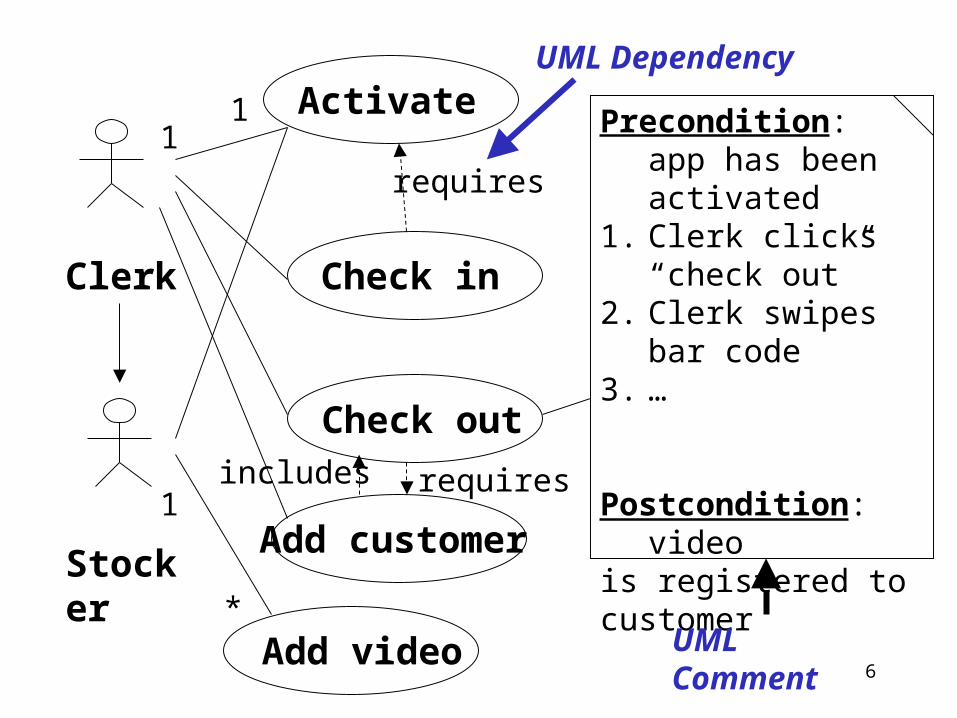
Activate
Check in
Check out
Add video
Clerk
Stocker
Precondition: app has been activated
1. Clerk clicks “check out”
2. Clerk swipes bar code
3. …
Postcondition: video is registered to customer
UML Comment
requires
Add customer
requiresincludes
UML Dependency
11
1
*
6
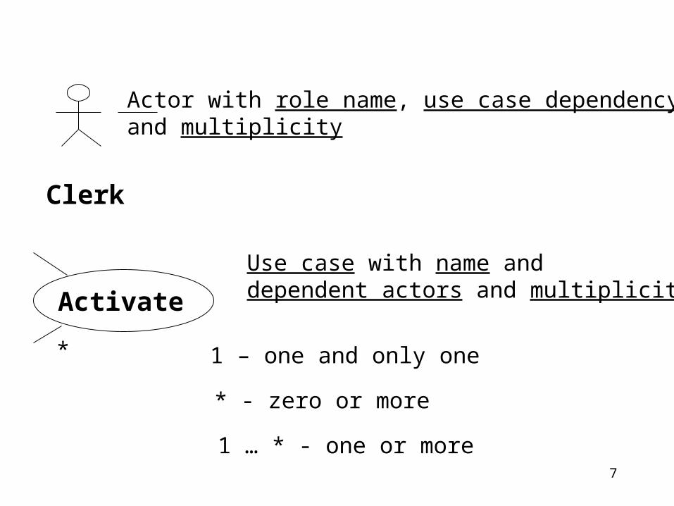
Clerk
1 – one and only one
Actor with role name, use case dependencyand multiplicity
Activate
Use case with name and dependent actors and multiplicities
*
* - zero or more
1 … * - one or more7
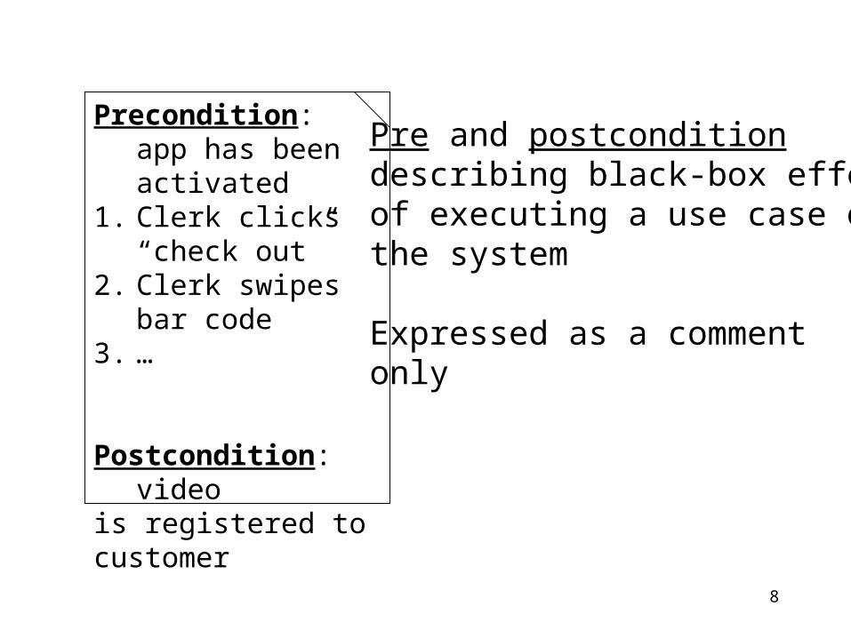
Precondition: app has been activated
1. Clerk clicks “check out”
2. Clerk swipes bar code
3. …
Postcondition: video is registered to customer
Pre and postconditiondescribing black-box effect of executing a use case onthe system
Expressed as a comment only
8
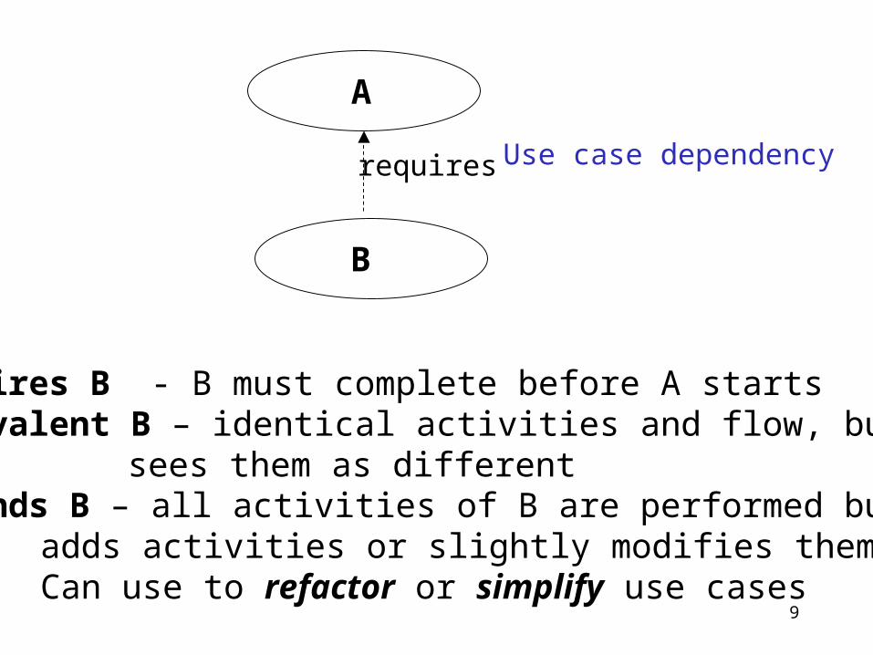
requires
A
B
Use case dependency
A requires B - B must complete before A startsA equivalent B – identical activities and flow, but user
sees them as differentA extends B – all activities of B are performed but A
adds activities or slightly modifies them. Can use to refactor or simplify use cases
9
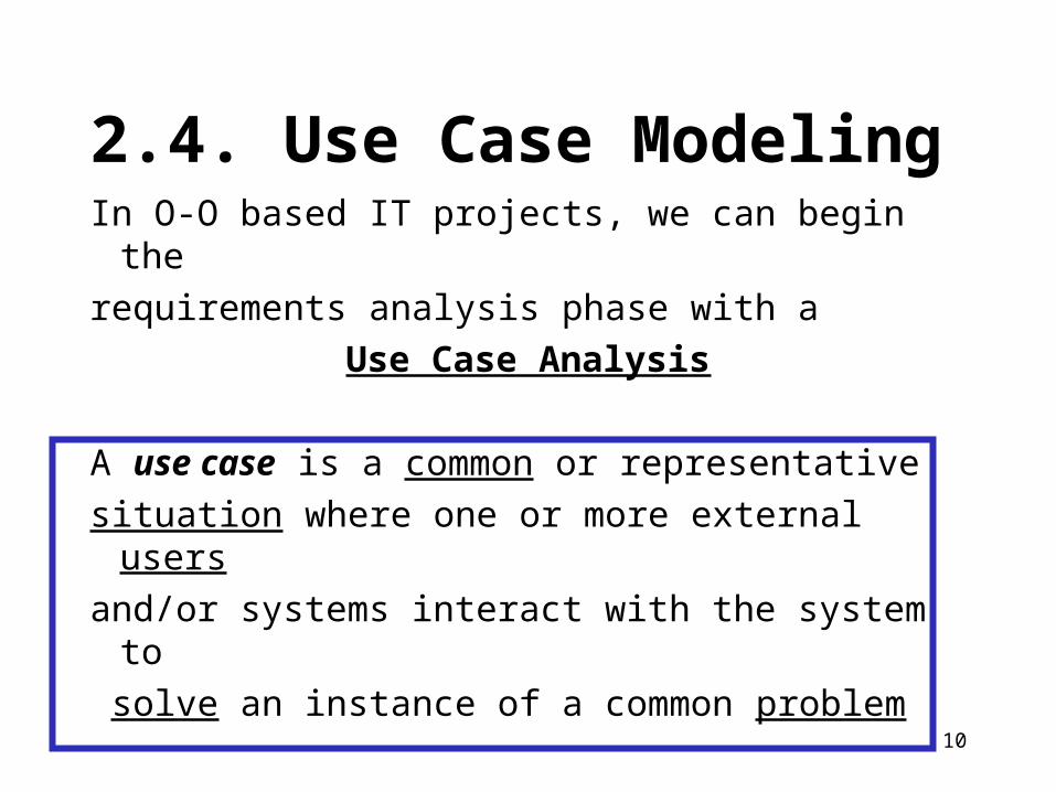
2.4. Use Case ModelingIn O-O based IT projects, we can begin therequirements analysis phase with a
Use Case Analysis
A use case is a common or representative situation where one or more external usersand/or systems interact with the system to solve an instance of a common problem
10
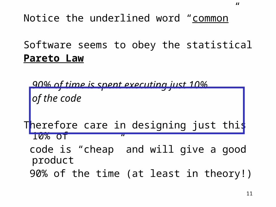
Notice the underlined word “common”
Software seems to obey the statistical Pareto Law
90% of time is spent executing just 10% of the code
Therefore care in designing just this 10% of code is “cheap” and will give a good product 90% of the time (at least in theory!)
11
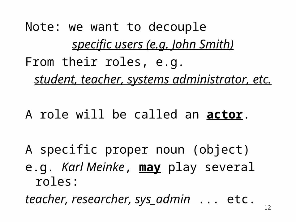
Note: we want to decouple specific users (e.g. John Smith)
From their roles, e.g.student, teacher, systems administrator, etc.
A role will be called an actor.
A specific proper noun (object) e.g. Karl Meinke, may play several roles: teacher, researcher, sys_admin ... etc.
12
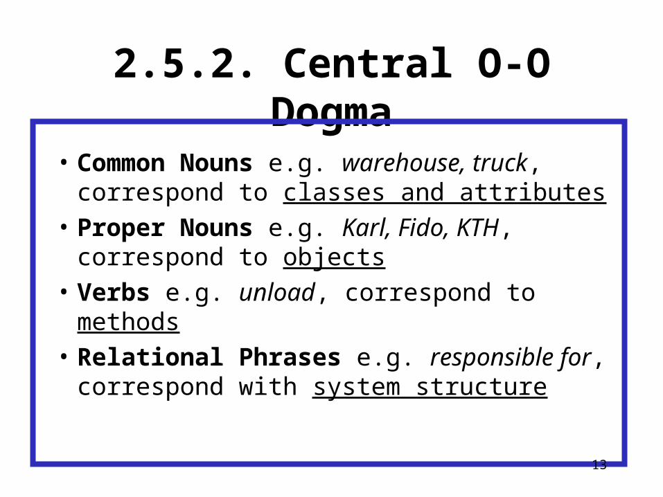
2.5.2. Central O-O Dogma
• Common Nouns e.g. warehouse, truck, correspond to classes and attributes
• Proper Nouns e.g. Karl, Fido, KTH, correspond to objects
• Verbs e.g. unload, correspond to methods• Relational Phrases e.g. responsible for,
correspond with system structure
13
Not every noun will be an actor …
… but every actor will be a noun, so:
Actors Nouns
14
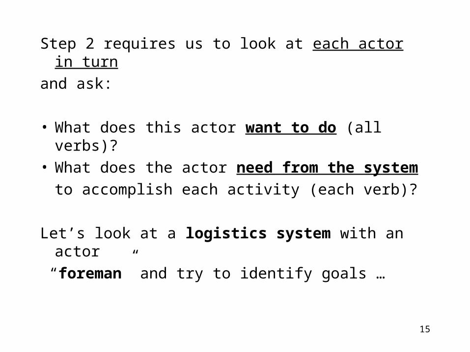
Step 2 requires us to look at each actor in turnand ask:
• What does this actor want to do (all verbs)?• What does the actor need from the system
to accomplish each activity (each verb)?
Let’s look at a logistics system with an actor “foreman” and try to identify goals …
15
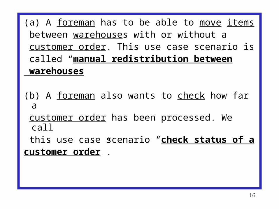
(a) A foreman has to be able to move items between warehouses with or without a customer order. This use case scenario is called “manual redistribution between warehouses”
(b) A foreman also wants to check how far a customer order has been processed. We call this use case scenario “check status of acustomer order”.
16

Let’s try to informally define the 1st use case scenario: “manual redistribution betweenwarehouses”.
This could be broken down into 4 steps
(1) Initialisation: when a foreman gives arequest to do a redistribution.
17

(2) Planning: when the system plans how toco-ordinate the various transports, and issues transport requests
(3) Loading: when a truck fetches the itemsfrom a source warehouse.
(4) Unloading: when a truck delivers itemsto a destination warehouse.
18
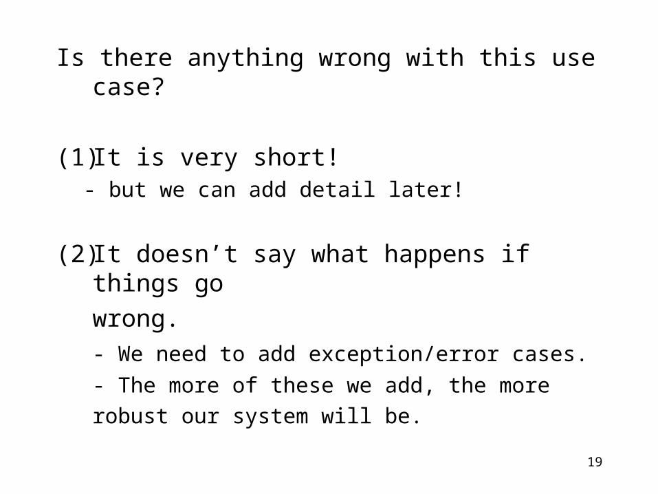
Is there anything wrong with this use case?
(1) It is very short!- but we can add detail later!
(2) It doesn’t say what happens if things gowrong.- We need to add exception/error cases.- The more of these we add, the morerobust our system will be.
19

2.6. UML Sequence Diagrams
A use case scenario describes asequence of interactions
or messages
between a collection of actors and the system
in order to carry out some task20
Often we would like to formally modela use case scenario, to study:
• timing aspects (relative or absolute)• communication patterns• system states• exception behavior• alternative paths or behaviors
21
2.6.1. Basic Concepts
A basic sequence diagram depicts a set of objects orprocesses each of which has its own timeline.
Conventionally, objects go across the diagramhorizontally, while time goes down the diagramvertically. Down the timelines, betweenobjects, we show messages.
22

C : Computer P : Print_server D : Device
>lprfile
print(file, device)print(file,size)
donedone
>done(time)
Here’s a sequence diagram with the basic elements:
object/processtimeline message
time
SD Print
23
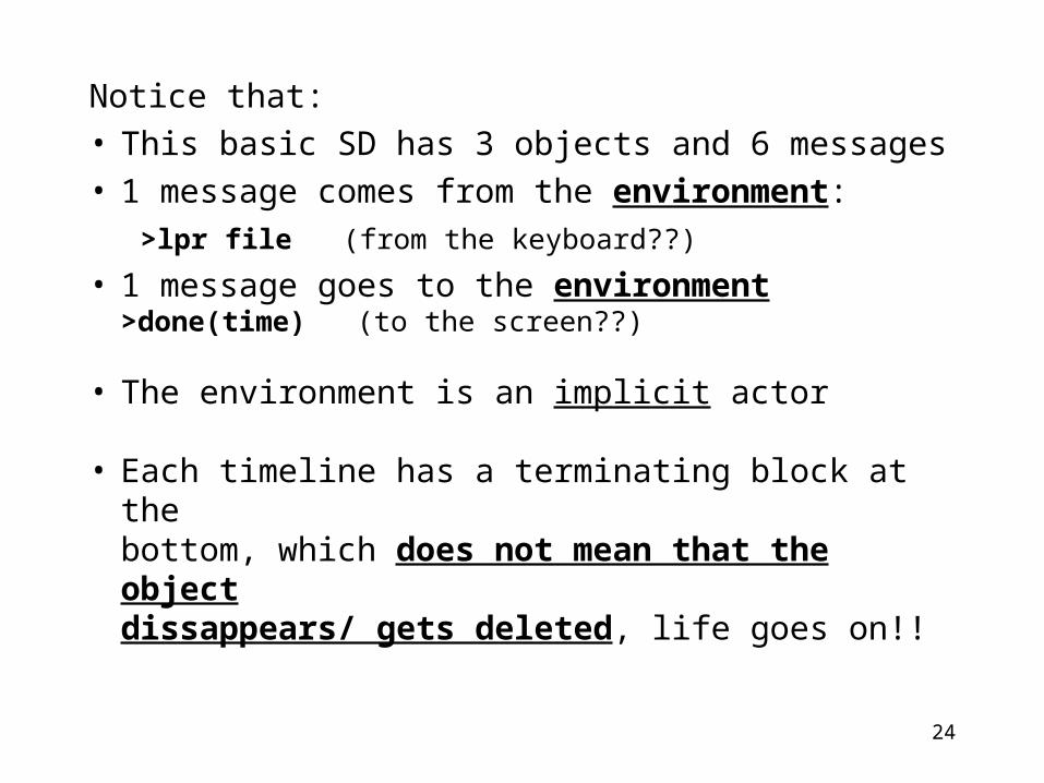
Notice that:• This basic SD has 3 objects and 6 messages• 1 message comes from the environment:
>lpr file (from the keyboard??)• 1 message goes to the environment
>done(time) (to the screen??)
• The environment is an implicit actor
• Each timeline has a terminating block at thebottom, which does not mean that the objectdissappears/ gets deleted, life goes on!!
24
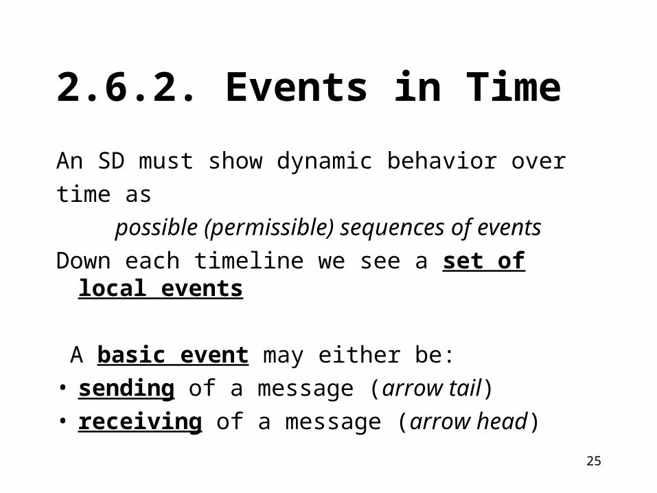
2.6.2. Events in Time
An SD must show dynamic behavior overtime as
possible (permissible) sequences of eventsDown each timeline we see a set of local events
A basic event may either be:• sending of a message (arrow tail)• receiving of a message (arrow head)
25
26
Partial Ordering Rules
Local Rules allow us to infer the global partial ordering of events
Rule 1. For every message m: send(m) occurs before receive(m)
Rule 2. Events are constrained globally by their local order of occurrence down each timeline
27
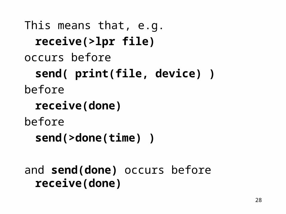
This means that, e.g. receive(>lpr file)
occurs before send( print(file, device) )
before receive(done)
before send(>done(time) )
and send(done) occurs before receive(done)
28
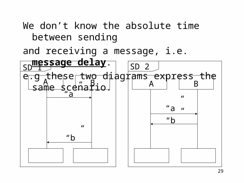
We don’t know the absolute time between sendingand receiving a message, i.e. message delay.e.g these two diagrams express the same scenario.
BA A B“a”
“b”
“a”“b”
SD 1 SD 2
29