20 through 60 tons intellipak air-cooled chillers · 20 through 60 tons intellipak® air-cooled...
TRANSCRIPT
1
® CG-DS-1July 1997
Air-CooledLiquidChillers10 and 15 TonsAir-Cooled Chillers
20 Through 60 TonsIntelliPak® Air-Cooled Chillers
CG
-DS
-1
Second Reprint — March 1999

2
Features andBenefits
©American Standard Inc. 1999
10-60 Tons
•Product ReliabilityDesign and manufacturing excellencehas made Trane the leader in the air-cooled chiller marketplace. For over 40years, Trane has been using the bestengineering available in development,manufacturing, and marketing toproduce a quality product. This traditionof using excellence to meet marketdemands is best illustrated by the Trane10 through 60-ton air-cooled chillers.
Quality Assurance ProgramAt Trane, a long quality tradition hasbeen transformed into daily qualitypractice. Special training in how tomeet customer requirements isprovided for all employees. Our qualitypolicy is literally cast in bronze on eachbuilding. Advanced technology inmeasuring and testing equipment helpsverify that specifications are met. Acomprehensive solution system assuresthat corrective action is quickly appliedto any problem. Overview monitoringby skilled Trane professionals extendsfrom product conception to unitperformance in the field. All of ourefforts uphold our tradition and enableour customers to share in the pride ofquality by Trane.
•InstallationSmall size, complete factory wiring,easy lifting provisions, factory installedoptions and start-up control provide fast,easy installation. A complete factory runtest is performed on each unit,eliminating potential start-up problems.
•Integrated Comfort ™ SystemsAll Trane chillers are ICS compatible. Asimple twisted wire pair is all it takes tohook an air-cooled chiller into aTRACER® system. An ICS systemprovides the most advanceddiagnostics, monitoring, and control thatthe industry can offer. Trane is the onlycompany that can supply the entirepackage. ICS provides comfort withone word — Trane.
•Packed Stock IncreasesProject Flexibility
®
Trane 10 through 60-ton air-cooledchillers are available through the mostflexible packed stock program in theindustry. Trane® chillers are availableto meet the most demanding jobschedules.
Trane knows you want your units on thejobsite, on time, when you need them.As a result, Trane has improved itsstock availability. Trane keeps amultitude of unit sizes and voltages inpacked stock. Many of these includeoptional features such as isolators, lowambient head pressure controls andrefrigerant gauge piping. You no longerhave to settle for a scaled-down, basicunit to meet your job schedule. In manycases, units can be shipped directly tothe jobsite from packed stock!
In short, Trane packed stock providesmore choices for unit selection andtherefore, more control over schedulingthan ever before. It is just one moreway that Trane helps to meet thedemands of the market.

3
Features and Benefits 2
Model Number Description 8
General Data 9
Application Considerations 10
Selection Procedure 15
Performance Adjustment Factors 16
Performance Data 20
Electrical Data 26
Controls 28
Dimensional Data 35
Weights 43
Mechanical Specifications 44
Contents
10, 15 Tons
20-60 Tons
The standard ARI rating condition fullload and IPLV are ARI certified. Allother ratings, including the following,are outside the scope of thecertification program and areexcluded:• Glycol
• 50 Hz
• Unit Size CGA 120

4
Features andBenefits
10, 15 Tons
In addition to the many standardfeatures of the 10 and 15-ton air cooledCold Generator® chiller, there areseveral added benefits which makeselection, installation, and serviceeasier.
FlexibilityFootprintCentral to the design of any project isthe operating envelope of the air-cooledpackaged chiller. With this in mind,Trane builds the chillers to make themost efficient use of the availableinstallation space. The Trane CGAmodel chillers are extremely compact.They have the lightest weight, thesmallest footprint, and the lowestsilhouette of any chiller in the industry.
Weight ReductionThe weight of the 10 and 15-ton unitshas been reduced up to 27 percent incomparison to previous models. Lessweight results in less stress on buildingsupports and greater handling ease.
InstallationInstallation time and effort are reducedwhen dealing with a significantly smallerand lighter unit. In addition, havingelectrical and water connections on thesame side of the unit and a single-pointmain power connection serves to makeinstallation easier. The unit arrives atthe jobsite fully assembled, tested,charged and ready to provide chilledwater.
ServiceabilityThe control panel and unit panels arecompletely removable for serviceaccessibility and convenience.
ICS InterfaceCommunication with Trane Tracer® orTracker® is possible through the ICSInterface on the 10 and 15 ton ColdGenerator chiller.
Optional Features• Hot Gas Bypass — Allows unit
operation below the minimum step ofunloading.
• Low Ambient Head PressureControl — Modulates the rpm of thefan motor in response to outdoorambient temperature and unit headpressure. Provides unit coolingoperation down to outdoortemperatures of 0°F.
• Coil Guard — Metal grille with PVCcoating to protect the condenser coil.
• Isolation — Neoprene in shear orspring flex isolators.
• Power Supply Monitor — Providesprotection against phase loss, phasereversal, phase imbalance, incorrectphase sequence and low line voltage.
• Elapsed Time Meter/Number StartsCounter — Records number ofcompressor starts and operatinghours.
• Flow Switch — Required as a safetyinterlock to prevent operation of unitwithout evaporator flow (availableoption for field installation only).
• Integrated Comfort™ Systems (ICS)Interface — Provides the ability tocommunicate with Trane Tracer® orTracker® building managementsystems via a Thermostat ControlModule — (TCM).
• Gauges — Monitor suction anddischarge pressures.

5
Features andBenefits
20-60 Tons
Other Standard Features• Trane 3-D® Scroll compressors• Advanced motor protection• 300 psi waterside evaporator• Evaporator insulation (¾-inch
Armaflex II or equivalent)• Evaporator heat tape (thermostat
controlled)• Condenser coil guards• Operation down to 30°F without
additional wind baffles or headpressure control
• Loss of flow protection• UL and CSA approval available• Packed stock availability• Control Power Transformer• Low ambient lockout• Plain English (Spanish/French)
Human Interface display• Smart Lead/Lag operation• Integrated chilled solution pump
control• Selectable process or comfort control
algorithm• External auto/stop• Electronic low ambient damper
control integrated into UCM
Following our IntelliPak® Rooftop’slead, Trane’s 20-60 ton chillers aremoving into the 21st century. Thetime-tested and proven controltechnology that makes our IntelliPakrooftop superior has been applied tothe IntelliPak® Air Cooled chiller. Thisis a truly advanced chiller.
Standard Features
• Microprocessor ControlThe IntelliPak chiller’s Unit ControlModule (UCM) is an innovative,modular microprocessor controldesign. It coordinates the actions ofthe chiller in an efficient manner andprovides stand-alone operation of theunit. A Human Interface (HI) Panel isa standard component of theIntelliPak Chiller. Access to all unitcontrols is via the Human InterfacePanel.
• Factory Run TestingIn addition to outstanding efficientperformance, IntelliPak Chillers haveestablished a reputation for reliableoperation. Aside from the individualcomponent tests, all Trane 20 through60-ton chillers are factory run testedwith water running through theevaporator to confirm properoperation. Control operation andcurrent draw are both monitored toassure safe, reliable operation.
Optional Features• Controls for ice making operation
Miscellaneous Options
• Trane Communications InterfaceModule (TCI)
• Unit Mounted Disconnect• Isolators• Superheat/Sub-Cooling Module• Hot Gas Bypass• Generic B A S Modules with 0-10 v.
analog input/output, 0-5 v analoginput/binary output
• Remote Human Interface Panel(RHI)
• Remote Setpoint Potentiometer• Zone Sensor (Chilled Solution
Reset)• Flow Switch• Copper Fin Condenser Coils• Electronic Low Ambient Damper(s)• Inter-Processor Communication
Bridge (IPCB)• Ice building control• Other Options
In addition to all of these options,Trane can offer in-house design formany applications, including specialcoil coating.

6
Features andBenefits
20-60 Tons
Enhanced Controls
IntelliPak ® Chiller Unit ControlModule (UCM)
Microprocessor Control
The brain of the 20 through 60 ton air-cooled chiller is its Unit Control Module(UCM). The UCM is an innovative,modular microprocessor control design,which coordinates the actions of thechiller in an efficient manner, providingstand-alone operation of the unit.
Access to the unit controls is via aHuman Interface (HI) Panel, a standardcomponent of the IntelliPak chiller. Thispanel provides a high degree of control.Superior monitoring capability andunmatched diagnostic information isprovided through a 2 line 40 characterper line, English language display.There are no diagnostic “codes”requiring a translation key forinterpretation. All system statusinformation and control adjustments canbe made from the onboard HumanInterface Panel.
The Integrated Comfort™ System — The Industry’s Most Advanced Comfort Systemmonitoring and diagnostics can helpbuilding owners to market their buildingsmore effectively. You are in a position toshow owners you understand theirneeds and that you are ready to handlea comfort problem before tenants evenknow they’ve got one.
An ICS system is the most advancedcomfort system in the industry. By usingICS, you will be seen as a leader in yourmarketplace. Because Trane has moreexperience with ICS than all otherequipment manufacturers combined,you can feel secure knowing you aredealing with a company that has aproven track record in buildingmanagement. Trane is the onlycompany that can supply the entirepackage. ICS provides comfort with oneword — Trane.
The UCM allows your 20 through 60-tonIntelliPak® chiller to be part of thefactory installed Integrated ComfortSystem (ICS). ICS joins the TraneTracer® building management systemsand Trane HVAC equipment by a singletwisted wire pair. This allowsbidirectional communication betweenthe Tracer system and the unit mountedcontrols. Connected to the chiller’sUCM, this simple pair allows you tocontrol, monitor, and diagnose yourbuilding’s comfort system. The UCM islinked to the Tracer system and theyelectronically “talk” to one another.Since ICS is factory-packaged, there isno need to install separate sensors tomonitor your chiller’s operation. All ofthe control points are on the controllerand ready to go when the unit ships.Simply hook-up the Tracer system tothe IntelliPak® chiller with the twistedwire pair. This feature means lowerinstalled cost, less chance for jobsiteerrors, less design time on the front endof your project, and fewer callbacks.
ICS gives you the most powerfulmonitoring and diagnostic systemavailable. Monitoring up to 30 individualpoints, the ICS can detect and correctproblems before a comfort level changeis even noticed. In addition, advanced
Tracer control points forIntelliPak ® Chillers
• Chilled solution setpoint• Default chilled solution setpoint• Ice Setpoint• Default Ice Setpoint• Chiller enable point• Failure mode• Ice making enable point• KW limit enable point• Demand limiting cooling stages• Default number of compressors• Design delta temperature• Control response setpoint• Reset Option
Remote Human Interface (RHI) — The optional Remote Human Interface (RHI)performs the same functions as the Human Interface, with the exception of theservice mode. The RHI can be used with up to 4 air-cooled chillers from a singlepanel.

7
Features andBenefits
20-60 Tons
• Trane 3-D® Scroll CompressorSimple Design with 70% Fewer PartsFewer parts than an equal capacityreciprocating compressor meanssignificant reliability and efficiencybenefits. The single orbiting scrolleliminates the need for pistons,connecting rods, wrist pins and valves.Fewer parts lead to increased reliability.Fewer moving parts, less rotating massand less internal friction means greaterefficiency than reciprocatingcompressors.
The Trane 3-D Scroll provides importantreliability and efficiency benefits. The 3-DScroll allows the orbiting scrolls to touchin all three dimensions, forming acompletely enclosed compressionchamber which leads to increasedefficiency. In addition, the orbiting scrollsonly touch with enough force to create aseal; there is no wear between the scrollplates. The fixed and orbiting scrolls aremade of high strength cast iron whichresults in less thermal distortion, lessleakage, and higher efficiencies. Themost outstanding feature of the 3-DScroll compressor is that slugging willnot cause failure. In a reciprocatingcompressor, however, the liquid or dirtcan cause serious damage.
Low Torque VariationThe 3-D Scroll compressor has a verysmooth compression cycle; torquevariations are only 30 percent of thatproduced by a reciprocatingcompressor. This means that the scrollcompressor imposes very little stress onthe motor resulting in greater reliability.Low torque variation reduces noise andvibration.
Suction Gas Cooled MotorCompressor motor efficiency andreliability is further optimized with thelatest scroll design. Cool suction gaskeeps the motor cooler for longer lifeand better efficiency.
Proven Design Through Testing andResearchWith over twenty years of developmentand testing, Trane 3-D Scrollcompressors have undergone morethan 400,000 hours of laboratory testingand field operation. This work combinedwith over 25 patents makes Trane theworldwide leader in air conditioningscroll compressor technology.
One of two matched scroll plates —the distinguishing feature of the scrollcompressor.
Chart illustrates low torque variation of3-D Scroll compressor vsreciprocating compressor.

8
ModelNumberDescription
CGA 120 B 3 00 B A 123 456 7 8 9,10 11 12
DIGIT 10 — Leaving Solution Setpoint0 = Standard Expansion Valve
40-60°F Leaving Water (CGA100 & CGA120 models) 20-60°F Leaving Solution
(CGA150 & CGA180 Models)V = Nonstandard Expansion Valve
20-39°F Leaving Solution (CGA100 & CGA120 models)
DIGIT 11 — Minor Design ChangeA = First, B = Second, etc.
DIGIT 12 —Service Digit
DIGIT 1,2,3 — Unit TypeCGA = Air-Cooled Cold Generator®
DIGITS 4,5,6 — Nominal Capacity(MBh)100 = 8 Tons (50 Hz Model only)120 = 10 Tons (60 Hz Model only)150 = 12.5 Tons (50 Hz Model Only)180 = 15 Tons (60 Hz Model Only)
DIGIT 7 — Major Design Change(Number of Refrigerant Circuits/Number ofCompressors)B = 2 Refrigerant Circuits/2 Compressors
DIGIT 8 — Voltage1 = 208-230/60/1
(Available — CGA120 Only)3 = 208-230/60/34 = 460/60/3W = 575/60/3D = 380-415/50/3
DIGIT 9 — Factory Installed Options0 = No OptionsH = Hot Gas BypassC = Black Epoxy Coil Standard DeviationK = Hot Gas Bypass & Black Epoxy CoilS = Special
10, 15 Tons
DIGIT 13 — MiscellaneousA = Trane Communication Interface (TCI)
ModuleB = No Unit Heat Tape (50 Hz Only)C = Compressor Current Sensing (CSM)D = Unit Mounted Disconnect Switch
NonfusedE = Unit Isolators NeopreneF = Unit Isolators SpringG = Superheat/Sub-CoolingH = Hot Gas BypassJ = Generic B A S Module
(0-5 v Input, Binary Output)M = Remote Human InterfaceN = Generic B A S Module
(0-10 v Analog)P = Remote Setpoint Potentiometer
20-60 Tons
DIGIT 1,2 — Unit ModelCG = IntelliPak® Air-Cooled Chiller
DIGIT 3 — Unit TypeA = Air-Cooled Condensing
DIGIT 4 — Development SequenceF = Sixth
DIGIT 5,6,7 — Nominal CapacityC20 = 20 TonsC25 = 25 TonsC30 = 30 TonsC40 = 40 TonsC50 = 50 TonsC60 = 60 Tons
DIGIT 8 — Voltage & Start CharacteristicsE = 200/60/3 XLF = 230/60/3 XL4 = 460/60/3 XL5 = 575/60/3 XL9 = 380/50/3 XLD = 415/50/3 XLS = Special
DIGIT 9 — Factory InputA = Standard
DIGIT 10 — Design SequenceA = FirstB = SecondEtc...
CG A F C40 4 A A A 1 A 12 3 4 567 8 9 10 11 12 13
DIGIT 11 — Leaving Solution SetpointA = 40-50 Deg. F w/o Ice MachineB = 30-39 Deg. F w/o Ice MachineD = 51-65 Deg. F w/o Ice MachineE = 20-29 Deg. F w/o Ice Machine1 = 40-50 Deg. F with Ice Machine2 = 30-39 Deg. F with Ice Machine3 = 51-65 Deg. F with Ice Machine4 = 20-29 Deg. F with Ice MachineS = Special
DIGIT 12 — Agency Approval1 = UL/CSA0 = None
Q = Zone Sensor — Chilled SolutionReset
T = Flow SwitchV = Copper Fin Condenser CoilsW = Electronic Low Ambient Damper(s)Y = Inter-Processor Communication
Bridge (IPCB)9 = Packed Stock Unit
The following items can be ordered forseparate shipment —Unit Isolators — Neoprene*Unit Isolators — Spring*Flow SwitchElectronic Low Ambient Damper(s)Trane Communication Interface Module(TCI)Generic B A S Module (GBAS)(0-5 volt Analog Input/Binary Output)Generic B A S Module (GBAS)(0-10 volt Analog Input/Output)Remote Human InterfaceRemote Setpoint PotentiometerZone Sensor (Chilled Solution Reset)Inter-Processor Communication Bridge(IPCB)*Unit size must be specified whenordering this item.
®

9
GeneralData
Table 9-1 — General Data — 10-60 Ton Units10 Ton 15 Ton 20 Ton 25 Ton 30 Ton 40 Ton 50 Ton 60 Ton
Model Number CGA120 CGA180 CGAF-C20 CGAF-C25 CGAF-C30 CGAF-C40 CGAF-C50 CGAF-C60
Compressor Data Model Climatuff® Trane H Scroll Scroll Scroll Scroll Scroll Scroll Quantity 2 2 2 1/1 2 4 2/2 4 Nominal Tons per Compressor 5 7.5 10 10/15 15 10 10/15 15
Evaporator Nominal Size (Tons) 10 15 20 25 30 40 50 60 Water Storage Capacity (Gallons)² 1.4 1.5 11.7 10.7 16.3 13.8 21.0 37.8 Min. Flow Rate (GPM) 12.0 18.0 24 30 36 48 60 72 Max. Flow Rate (GPM) 36.0 54.0 72 90 108 144 180 216
Max EWT At Start-Up — Deg F³ 100 100 108 108 108 108 108 108
Condenser Nominal Size (Tons) 10 15 20 25 30 40 50 60 Number of Coils 1 2 1 2 2 2 2 2 Coil Size (ea., Inches)4 28 x 108 28 x 83 61 x 71 45 x 71/35 x 71 56 x 70 56 x 70 57 x 96 57 x 96Number of Rows 2 2 3 3 3 3 3 4
Subcooler Size (ea., Inches) 4 x 10⁸ 4 x 83 10 x 71 14 x 71 9 x 70 9 x 70 9 x 96 9 x 96
Condenser Fans Quantity 1 2 2 3 4 4 6 6Diameter (Inches) 28 26 26 26 26 26 26 26CFM (Total) 8,120 11,600 15,000 21,650 29,200 29,200 42,300 40,700
Nominal RPM 1100 1100 1140 1140 1140 1140 1140 1140Tip Speed (Ft/Min) 8060 7490 7750 7750 7750 7750 7750 7750
Motor HP (ea.) 1 1/2 1.0 1.0 1.0 1.0 1.0 1.0 Drive Type Direct Direct Direct Direct Direct Direct Direct Direct
Minimum Outdoor Air Temperature PermissibleFor Mechanical Cooling¹ Standard Ambient Control Unit (°F) 50 45 30 30 30 30 30 30Standard Ambient w/Hot Gas Bypass 60 60 40 40 40 40 40 40(°F)
Low Ambient Option (°F) 0 0 0 0 0 0 0 0 Low Ambient Control w/Hot Gas Bypass 15 15 10 10 10 10 10 10
(°F)
General Unit Unload Steps 100-50 100-50 100-50 100-60-40 100-50 100-75-50-25 100-80-60-30 100-75-50-25 No. of Independent Refrig. Circuits 2 2 1 1 1 2 2 2Refrigerant Charge (lbs. R22/Circuit) 9.5 12.4 40.5 54.0 72.0 38.0 47.0 67.0
Oil Charge (Pints/Circuit) 4.2 7.5 8.0 8.0/14.0 14.0 8.0 8.0/14.0 14.0*Unloading steps depend upon which compressor is lead compressor.Notes:(1) Minimum start-up ambient based on unit at minimum step of unloading and a 5 mph wind across the condenser.(2) Includes piping internal to chiller.(3) At 95°F ambient.(4) Does not include subcooling portion of coil.
®

10
ApplicationConsiderations
Certain application constraints shouldbe considered when sizing, selectingand installing TraneTM air-cooled chillers.Unit and system reliability is oftendependent upon proper and completecompliance with these considerations.Where the application varies from theguidelines presented, it should bereviewed with your local Trane salesengineer.
Note: The terms water and solution areused interchangeably in the followingparagraphs.
UNIT SIZINGUnit capacities are listed in the“Performance Data” section.Intentionally oversizing a unit toassure adequate capacity is notrecommended. Erratic systemoperation and excessive compressorcycling are often a direct result of anoversized chiller. In addition, anoversized unit is usually moreexpensive to purchase, install, andoperate. If oversizing is desired,consider using two units.
UNIT PLACEMENT
1Setting The UnitA base or foundation is not required ifthe selected unit location is level andstrong enough to support the unit’soperating weight (see “Weights”section of this catalog).
For a detailed discussion of base andfoundation construction, refer to theTrane Reciprocating RefrigerationManual. Manuals are availablethrough the local Trane office.
2Isolation and Sound EmissionThe most effective form of isolation isto locate the unit away from anysound sensitive area. Structurallytransmitted sound can be reduced byusing spring isolators. Spring isolatorsare generally effective in reducingvibratory noise generated bycompressors, and therefore, are
and must be avoided: warm airrecirculation and coil starvation.Warm air recirculation occurs whendischarge air from the condenser fansis recycled back to the condenser coilinlet. Coil starvation occurs when freeairflow to the condenser is restricted.
Condenser coils and fan dischargemust be kept free of snow or otherobstructions to permit adequateairflow for satisfactory unit operation.
Debris, trash, supplies, etc., shouldnot be allowed to accumulate in thevicinity of the air-cooled chiller. Supplyair movement may draw debris intothe condenser coil, blocking spacesbetween coil fins and causing coilstarvation.
Both warm air recirculation and coilstarvation cause reductions in unitefficiency and capacity because of thehigher head pressures associatedwith them. In addition, in more severecases, nuisance unit shutdowns willresult from excessive head pressures.Estimates of the degree of efficiencyand capacity reduction in suchsituations can be determined. Consultyour local Trane sales engineer.
Cross winds, those perpendicular tothe condenser, tend to aid efficientoperation in warmer ambientconditions, however, they tend to bedetrimental to operation in lowerambients or when hot gas bypass isused due to the accompanying loss ofadequate head pressure. As a result,it is advisable to protect air-cooledchillers from continuous direct windsexceeding 10 miles per hour in lowambient conditions.
Low Ambient Operation — 20-60Ton models — Human InterfaceRecommendations
When the temperature outside is sub-zero, who wants to be out theremonitoring or troubleshootingdiagnostics? Because we understanda service technician’s reluctance to dothis, we recommend using a RemoteHuman Interface (RHI) panel. Theservice technician can troubleshootand diagnose in the comfort of amechanical room.
recommended for sound sensitiveinstallations. An acoustical engineershould always be consulted on criticalapplications.For maximum isolation effect, waterlines and electrical conduit shouldalso be isolated. Wall sleeves andrubber isolated piping hangers can beused to reduce the sound transmittedthrough water piping. To reduce thesound transmitted through electricalconduit, use flexible electrical conduit.
State and local codes on soundemissions should always beconsidered. Since the environment inwhich a sound source is locatedaffects sound pressure, unitplacement must be carefullyevaluated. Sound pressure and soundpower levels for chillers are availableon request.
3ServicingAdequate clearance for evaporatorand compressor servicing should beprovided. Recommended minimumspace envelopes for servicing arelocated in the dimensional datasection and can serve as a guidelinefor providing adequate clearance. Theminimum space envelopes also allowfor control panel door swing androuting maintenance requirements.Local code requirements may takeprecedence.
4Unit LocationaGeneralUnobstructed flow of condenser air isessential to maintain chiller capacityand operating efficiency. Whendetermining unit placement, carefulconsideration must be given to assurea sufficient flow of air across thecondenser heat transfer surface. Twodetrimental conditions are possible
®

11
ApplicationConsiderations
cProvide Lateral ClearanceThe condenser coil inlet must not beobstructed. A unit installed closer thanthe minimum recommended distance toa wall or other vertical riser mayexperience a combination of coilstarvation and warm air recirculation,resulting in unit capacity and efficiencyreductions and possible excessive headpressures.
The recommended lateral clearancesare depicted in the dimensional datasection. These are estimates andshould be reviewed with the local Tranesales engineer at the jobsite.
bProvide Vertical ClearanceVertical condenser air discharge mustbe unobstructed. While it is difficult topredict the degree of warm airrecirculation, a unit installed as shownbelow would have its capacity andefficiency significantly reduced —possibly to the degree of nuisancehigh head pressure tripouts.Performance data is based on free airdischarge.
dProvide Sufficient Unit-to-UnitClearanceUnits should be separated from eachother by sufficient distance to preventwarm air recirculation or coil starvation.Doubling the recommended single unitair-cooled chiller clearances willgenerally prove to be adequate.eWalled Enclosure InstallationsWhen the unit is placed in anenclosure or small depression, the topof the fans should be no lower thanthe top of the enclosure ordepression. If they are, considerationshould be given to ducting the top ofthe unit. Ducting individual fans,however, is not recommended. Suchapplications should always bereviewed with the local Trane salesengineer.
WATER TREATMENTDirt, scale, products of corrosion, andother foreign material in the water willadversely affect heat transfer betweenthe water and system components.Foreign matter in the chilled watersystem can also increase pressuredrop and, consequently, reducewaterflow. Proper water treatmentmust be determined locally anddepends on the type of system andlocal water characteristics.
Do not use salt or brackish water inTrane chillers. Use of either will leadto a shortened life. The TraneCompany encourages theemployment of a reputable watertreatment specialist, familiar with localwater conditions, to assist in theestablishment of a proper watertreatment program.
The capacities given in the“Performance Data” section of thiscatalog are based on water with afouling factor of 0.0001 (per ARI550/590-98). For capacities at otherfouling factors, see “PerformanceAdjustment Factors” section of thiscatalog.
EFFECT OF ALTITUDE ONCAPACITYChiller capacities given in the“Performance Data” section are basedupon application at sea level. Atelevations substantially above sealevel, the decreased air density willdecrease condenser capacity and,therefore, unit capacity and efficiency.The adjustment factors in the“Performance Adjustment Factors”section of this catalog can be applieddirectly to the performance data todetermine the unit’s adjustedperformance.
AMBIENT LIMITATIONSTrane chillers are designed for year-round applications in ambients from0°F to 115°F. For operation below 0°For above 115°F, contact the localTrane sales office. If hot gas bypass isused, operating ambients varydepending upon unit size (see the“General Data” section of thiscatalog).1Low Ambient OperationStart-up and operation of Trane™chillers at lower ambient temperaturesrequire that sufficient head pressurebe maintained for proper expansionvalve operation.
VOLTAGENominal voltage is the nameplaterating voltage. The actual range of linevoltages at which the equipment cansatisfactorily operate are given below.
Voltage Rated UtilizationVoltage Range
200 180-220208-230 187-253
230 208-254380 342-418400 360-440415 374-456460 414-508575 520-635

12
migration to the evaporator during“off” periods.
4Hot Gas BypassHot gas bypass provides more stableleaving solution temperature control atlight load conditions. The compressorruns continuously for a user-definedrun time. Minimum starting andoperating ambients with hot gasbypass are shown in the “GeneralData” section of this catalog. The hotgas bypass reduces the unit headpressure, thereby increasing theminimum operating ambient.
5Loss of Flow ProtectionLoss of flow may result in evaporatorfreeze up. Full chilled solution flowmust be maintained through theevaporator while compressors areoperating.
A flow switch used as a safety interlockis always recommended for CGA units.
The CGAF air-cooled chiller has asystem which senses a loss of flowcondition and shuts the unit down. TheCGAF’s microcomputer is automaticallyreset for the unit to resume operation. Aset of contacts is available for externallystarting and stopping the pump
WATERFLOW LIMITSThe minimum water flow rates are givenin the “General Data” section of thiscatalog. Evaporator flow rates below thetabulated values will result in laminarflow causing scaling, stratification,freeze-up problems, and poortemperature control.
The maximum evaporator water flowrate is given in the “General Data”section. Flow rates exceeding thoselisted will result in excessive tubeerosion and very high pressure dropacross the evaporator.
Trane recommends that constant waterflow be maintained at all times throughthe evaporator. Because thetemperature controller strictly sensestemperature, variable flow through theevaporator may result in loss of controland localized freezing or nuisance lowtemperature cutouts. Consult your localTrane sales engineer if your applicationrequires varying flows.
TEMPERATURE LIMITS1Leaving Solution Temperature rangeThe minimum leaving solutiontemperature setpoint is dependent onthe number of capacity stages and thetemperature difference across theevaporator. Water supply temperaturesetpoints less than these values resultin suction temperatures at or below thefreezing point of cold water.
A glycol solution is required foroperation below the recommendedminimum setpoints. Refer to the“Performance Adjustment Factors”section of this catalog to determine theminimum leaving chilled solutionsetpoint and adequate ethylene glycolconcentration for safe operation.
The maximum catalog leaving solutiontemperature from the evaporator is 65°Ffor outdoor ambients up to 115°F. Highleaving water temperatures exceedingthis may result in excessive suctiontemperatures and, therefore,inadequate motor cooling. Forapplications requiring high leaving watertemperatures, contact your local Tranesales office for suggested alternatives.
The maximum water temperature thatcan be circulated through anevaporator, when the unit is notoperating, is 108°F (100°F for CGA 8,10, 12½ and 15 ton chillers). Theevaporator becomes thermal stresslimited at these temperatures.
ApplicationConsiderations
Minimum operating ambienttemperatures for standard unitselections and units with hot gasbypass are shown in the “GeneralData” section of this catalog.
Minimum ambient temperatures arebased on still conditions (winds notexceeding five mph). Greater windvelocities will result in a drop in headpressure, therefore increasing theminimum starting and operatingambient temperatures.
Optional low ambient units use aelectronic low ambient damper control(20-60 tons) or a variable speed fanmotor (10-15 tons) arrangement tocontrol condenser capacity bymodulating condenser fans in responseto refrigerant pressure.2High Ambient OperationMaximum cataloged ambienttemperature operation of a standardTrane™ chiller is 115°F. Operation atdesign ambients above 115°F canresult in excessive head pressures.For operation above 115°F, contactyour local Trane sales office.
CONTROLS1Temperature ControllerIn order to provide stable systemoperation and to prevent excessivecompressor cycling, the temperaturecontrol sensor in all 20-60 ton chillersis located in the supply (outlet)solution. The temperature sensor in all10 and 15 ton chillers is located in thereturn (inlet) solution. This sensorcannot be relocated. Doing so wouldresult in improper unit operation.2Anti-recycle Timer/Fixed-Off TimerAll IntelliPak air-cooled chillers comestandard with Anti-recycle/Fixed OffTimers. This function prevents rapidcycling of the compressors due to lowload conditions or short water loops.3PumpdownCGAF air-cooled chillers willpumpdown, if function is enabled,when a refrigerant circuit is turned off.All of the refrigerant is pumped intothe condenser. A solenoid valveprovides a positive shutoff betweenthe condenser and the evaporator,allowing little or no refrigerant

13
ApplicationConsiderations
2 Supply Water Temperature DropThe performance data for Trane™chillers is based on a chilled watertemperature drop of 10°F. Temperaturedrops outside this range will result inunit performance that differs from thatcataloged. For performance dataoutside the 10°F range see the“Performance Adjustment Factors”section in this catalog. Chilled watertemperature drops from 6 to 18°F (8 to12°F in CGA units) may be used as longas minimum and maximum watertemperature and minimum andmaximum flow rates are not violated.
Temperature drops outside 6 to 18°F (8to 12°F in CGA units) are beyond theoptimum range for control and mayadversely affect the controller’scapability to maintain an acceptablesupply water temperature range.
Further, temperature drops of less than6°F may result in inadequate refrigerantsuperheat. Sufficient superheat isalways a primary concern in any directexpansion refrigeration system and isespecially important in a package chillerwhere the evaporator is closely coupledto the compressor. When temperaturedrops are less than 6°F, an evaporatorrunaround loop may be required.
TYPICAL WATER PIPINGAll building water piping must be flushedprior to making final connections to thechiller. To reduce heat loss and preventcondensation, insulation should beapplied. Expansion tanks are alsousually required so that chilled watervolume changes can beaccommodated. A typical pipingarrangement is shown on the followingpage.
SHORT WATER LOOPSThe proper location of the temperaturecontrol sensor is in the supply (outlet)water for 20-60 ton chillers and in thereturn (inlet) water for 8, 10, 12½ and 15ton chillers. This location allows thebuilding to act as a buffer and assures aslowly changing return watertemperature. If there is not a sufficientvolume of water in the system to providean adequate buffer, temperature controlcan be lost, resulting in erratic systemoperation and excessive compressorcycling. A short water loop (less than oneminute in duration) will lead to erraticsystem operation.
To prevent the effect of a short waterloop, the following items should be givencareful consideration:1Add a storage tank or larger header pipeto increase the volume of water in thesystem and, therefore, reduce the rate ofchange of the return water temperature.2Use three-way modulating valves in lieuof two-position valves with crossoverpipes at the airside evaporators. Thethree-way valves will reduce the rate ofchange in the return water temperature.3Hot gas bypass to prevent compressorcycling at rapidly changing supply watertemperatures at low load conditions.
MULTIPLE UNIT OPERATIONWhenever two or more units are usedon one chilled water loop, Tranerecommends that their operation becontrolled from a single control device,such as a Trane Tracer® system. The“Stand-alone” alternative is the DDCChiller Sequencer.1Series OperationSome systems require large chilledwater temperature drops (16 to 24°F).For those installations, two units withtheir evaporators in series are usuallyrequired. Control of the units should befrom a common temperature sensor toprevent the separate unit controls fromfighting one another and continuallyhunting. It is possible to control watertemperature from the two individual unitcontrols, but a common temperaturecontroller provides a positive method forpreventing control overlap, more closelymatching system load and simplifyingcompressor lead-lag capability.
2Parallel OperationSome systems require more capacity orstandby capability than a singlemachine can provide. For thoseinstallations, two units with theirevaporators in a parallel configurationare typical. The only effective way ofcontrolling two units in parallel is with asingle temperature controller. Forfurther information, please contactTrane Applications.

14
ApplicationConsiderations
Figure 14-1 — Recommended Piping ComponentsFor Typical Evaporator Installation
Air Vents(Located At High Points
In Piping System)
Valved
Pressure
Gauge
Union
Union
VibrationEliminator
VibrationEliminator
WaterStrainer
Gate Valve(see note)
Gate Valve(see note)
BalancingValve
Flow Switch
Drain
Note: Be certain to provide shutoff (gate)valves in the evaporator inlet and outlet pipingto facilitate water temperature sensor removal.
Note:Provide shutoff valves in the evaporatorinlet and outlet to facilitate watertemperature sensor removal.
High pressures resulting from rising watertemperatures (due to ambient conditions)may cause internal damage to theevaporator.
Shutoff valves should not be closed withcold water in the chiller.
20-60 Ton
10, 15 Ton

15
SelectionProcedure
The chiller capacity tables presented inthe “Performance Data” section coverthe most frequently encountered leavingwater temperatures. The tables reflect a10°F temperature drop through theevaporator. For temperature drops otherthan 10°F, fouling factors other than0.0001 (per ARI Standard 550/590-98)and for units operating at altitudes thatare significantly greater than sea level,refer to the “Performance AdjustmentFactors” section and apply theappropriate adjustment factors. Forchilled brine selections, refer to the“Performance Adjustment Factors”section for ethylene glycol adjustmentfactors.
To select a Trane air-cooled chiller, thefollowing information is required:1Design system load (in tons ofrefrigeration).2Design leaving chilled watertemperature.3Design chilled water temperature drop.4Design ambient temperature.5Evaporator fouling factor.
Evaporator chilled water flow rate canbe determined by using the followingformula:
Tons x 24GPM = Temperature Drop (Degrees F)
NOTE: Flow rate must fall within thelimits specified in the “General Data”section of this catalog.
SELECTION EXAMPLE
Given:Required System Load = 53 tonsLeaving Chilled Water Temperature(LCWT) = 45°FChilled Water Temperature Drop = 10°FDesign Ambient Temperature = 95°FEvaporator Fouling Factor = 0.0001
T
∇
®
MINIMUM LEAVING CHILLED WATERTEMPERATURE SETPOINTSThe minimum leaving chilled watertemperature setpoint for water is listed inthe following table:
Table 15-1 — Minimum Leaving ChilledWater TemperatureSetpoints for Water 1
Evaporator Minimum Leaving Chilled WaterTemperature Temperature Setpoint (°F)Difference CGAF- CGAF-
(Degrees F) C20,C25,C30 C40,C50,C60
6 40 398 41 3910 42 4012 43 4014 44 4116 45 4118 46 42
1These are for units without HGBP, for units withHGBP, add 2°F to each minimum temperature in thetable.
For those applications requiring lowersetpoints, a glycol solution must beused. The minimum leaving chilledwater setpoint for a glycol solution canbe calculated using the followingequation:
LCWS (Minimum) = GFT + 5 + T (Evap)
# of stages of capacity.
LCWS = Leaving Chilled WaterSetpoint (F)
GFT = Glycol FreezingTemperature (F)
T = Delta T (the differencebetween the temperatureof the water entering andleaving theevaporator)
Solution freezing point temperaturescan be found in Tables 16-1 thorough16-2 and the number of stages ofcapacity can be found in the generaldata section. For selectionassistance, refer to the CGA ChillerSelection program.
1To calculate the required chilled waterflowrate we use the formula:
GPM = Tons x 24
From the 60 ton unit table in the“Performance Data” section of thiscatalog, a CGAF-C60 at the givenconditions will produce 57.3 tons with asystem power input of 70.2 kw and a unitEER of 9.8
GPM = 56.8 Tons x 24 = 137.510°F
2To determine the evaporator waterpressure drop we use the flow rate (gpm)and the evaporator water pressure dropcurves found in the “PerformanceAdjustment Factors” section of thiscatalog. Entering the curve at 137.5 gpm,the pressure drop for a nominal 60 tonevaporator is 16.5 feet.
3 For selection of chilled brine units orapplications where the altitude issignificantly greater than sea level or thetemperature drop is different than 10°F,the performance adjustment factorsshould be applied at this point.
For example:
Corrected Capacity = Capacity(unadjusted) x Appropriate AdjustmentFactor
Corrected Flow Rate = Flow Rate(unadjusted) x Appropriate AdjustmentFactor
Corrected KW Input = KW Input(unadjusted) x Appropriate AdjustmentFactor4Verify that the selection is within designguidelines. The final unit selection is:
• Quantity (1) CGAF-C60• Cooling Capacity = 57.3 Tons• Entering/Leaving Chilled Water
Temperatures = 55/45°F• Chilled Waterflow Rate (GPM) = 137.5• Evaporator Water Pressure Drop = 16.5 ft.• System Power Input = 70.2 KW• Unit EER = 9.8
∇
∇

16
GLYCOL AND PERFORMANCE ADJUSTMENT FACTORS
PerformanceAdjustmentFactors
Notes:1. Use this table with the capacity table to correct performance for ethylene glycol concentrations other than those listed.2. Flow rate (GPM) correction factor required to maintain a 10°F delta T.3. Shaded area may result in freezing.
®
Percent of Ethylene Glycol By WeightLeaving 0% 10% 20% 30% 40% 50%Solution Freezing Point = 32°F Freezing Point = 25°F Freezing Point = 16°F Freezing Point = 4°F Freezing Point = -11°F Freezing Point = -32°FTemp. CAP GPM KW CAP GPM KW CAP GPM KW CAP GPM KW CAP GPM KW CAP GPM KW
20°F 1.06 0.97 1.04 1.01 0.97 1.01 1.01 0.98 1.01 1.00 1.00 1.00 0.99 1.05 1.00 0.98 1.10 0.9930°F 1.04 0.98 1.02 1.01 0.99 1.00 1.00 1.00 1.00 0.99 1.02 0.99 0.98 1.07 0.99 0.97 1.12 0.9835°F 1.03 0.98 1.01 1.00 0.99 1.00 1.00 1.01 0.99 0.99 1.03 0.99 0.98 1.07 0.98 0.97 1.12 0.9840°F 1.00 1.00 1.00 0.98 1.00 0.99 0.98 1.03 0.98 0.97 1.06 0.98 0.96 1.11 0.98 0.95 1.15 0.9745°F 1.00 1.00 1.00 0.99 1.01 0.99 0.98 1.03 0.99 0.98 1.07 0.98 0.97 1.11 0.98 0.96 1.16 0.9750°F 1.00 1.00 1.00 0.99 1.01 0.99 0.99 1.04 0.99 0.98 1.07 0.98 0.97 1.11 0.98 0.96 1.16 0.9760°F 1.00 1.00 1.00 1.00 1.02 1.00 0.99 1.04 1.00 0.98 1.07 0.99 0.98 1.11 0.99 0.97 1.16 0.98
Percent of Ethylene Glycol By WeightLeaving 0% 10% 20% 30% 40% 50%Solution Freezing Point = 32°F Freezing Point = 24°F Freezing Point = 15°F Freezing Point = 5°F Freezing Point = -12°F Freezing Point = -33°FTemp. CAP GPM KW CAP GPM KW CAP GPM KW CAP GPM KW CAP GPM KW CAP GPM KW
20°F — — — — — — — — — .998 1.008 1.000 .985 1.050 .997 .971 1.098 .99525°F — — — — — — — — — .993 1.022 .999 .981 1.064 .996 .968 1.111 .99430°F — — — — — — .999 1.003 1.000 .989 1.037 .998 .977 1.078 .995 .964 1.125 .99335°F — — — — — — .995 1.016 .999 .985 1.049 1.009 .973 1.090 .994 .962 1.137 .99240°F 1.000 1.000 1.000 .956 .974 .984 .949 1.000 .984 .943 1.034 .984 .937 1.077 .984 .930 1.124 .97945°F 1.000 1.000 1.000 .965 .981 .990 .959 1.005 .990 .953 1.039 .985 .947 1.080 .985 .936 1.129 .97950°F 1.000 1.000 1.000 .962 .982 .990 .957 1.007 .990 .951 1.038 .990 .946 1.079 .990 .935 1.124 .985
Table 16-1 — Glycol Adjustment Factor for CGA — 10 and 15 Ton Units Only 1 2 3
Table 16-2 — Glycol Adjustment Factor for CGAF — 20 - 60 Ton Units Only 1

17
PerformanceAdjustmentFactors (Cont.)
GLYCOL AND PERFORMANCE ADJUSTMENT FACTORS
Chilled AltitudeFouling Water Sea Level 2,000 Feet 4,000 Feet 6,000 FeetFactor ∆ T CAP GPM KW CAP GPM KW CAP GPM KW CAP GPM KW
6 1.00 1.66 1.00 0.98 1.63 1.01 0.95 1.59 1.02 0.93 1.54 1.058 1.00 1.25 1.00 0.98 1.22 1.01 0.96 1.19 1.02 0.93 1.16 1.05
0.00025 10 1.00 1.00 1.00 0.98 0.98 1.01 0.95 0.95 1.02 0.92 0.92 1.0412 1.00 0.83 1.00 0.98 0.81 1.01 0.95 0.79 1.02 0.92 0.77 1.0414 0.99 0.71 1.00 0.97 0.59 1.01 0.95 0.68 1.02 0.92 0.66 1.04
6 0.96 1.60 0.98 0.94 1.57 0.99 0.92 1.53 1.00 0.90 1.49 1.018 0.96 1.20 0.98 0.94 1.18 0.99 0.92 1.15 1.00 0.90 1.12 1.01
0.001 10 0.96 0.96 0.98 0.94 0.94 0.99 0.92 0.92 1.00 0.89 0.89 1.0112 0.96 0.80 0.98 0.94 0.79 0.99 0.92 0.77 1.00 0.89 0.74 1.0114 0.96 0.68 0.98 0.94 0.67 0.99 0.92 0.65 1.00 0.89 0.66 1.01
8 0.93 1.15 0.95 0.91 1.13 0.96 0.88 1.10 0.98 0.86 1.07 0.990.002 10 0.90 0.90 0.94 0.89 0.88 0.95 0.87 0.87 0.96 0.85 0.84 0.98
12 0.90 0.75 0.94 0.88 0.73 0.95 0.86 0.72 0.95 0.84 0.70 0.9814 0.90 0.64 0.94 0.87 0.63 0.95 0.86 0.82 0.95 0.84 0.60 0.98
*Standard chilled water ∆ is 8-12 for CGA120-180. Standard chilled water ∆ is 6-16 for CGAF 20-60.
Chilled AltitudeFouling Water Sea Level 2,000 Feet 4,000 Feet 6,000 FeetFactor ∆ T CAP GPM KW CAP GPM KW CAP GPM KW CAP GPM KW
6 0.987 1.650 0.993 0.967 1.640 1.003 0.952 1.620 1.019 0.932 1.570 1.0298 0.993 1.250 0.997 0.973 1.240 1.007 0.956 1.220 1.025 0.935 1.190 1.035
0.00025 10 1.000 1.000 1.000 0.980 0.990 1.010 0.960 0.970 1.030 0.940 0.940 1.04012 1.007 0.820 1.003 0.987 0.810 1.013 0.966 0.800 1.035 0.945 0.780 1.04514 1.013 0.710 1.007 0.993 0.700 1.017 0.972 0.680 1.038 0.952 0.660 1.04816 1.020 0.640 1.010 1.000 0.630 1.020 0.980 0.620 1.040 0.960 0.600 1.050
6 0.957 1.615 0.979 0.953 1.600 0.989 0.931 1.570 0.990 0.914 1.540 1.0028 0.964 1.215 0.982 0.959 1.210 0.992 0.937 1.180 0.994 0.920 1.170 1.006
0.001 10 0.970 0.965 0.985 0.964 0.960 0.995 0.943 0.940 0.998 0.926 0.920 1.00912 0.976 0.785 0.989 0.966 0.790 0.998 0.945 0.770 1.007 0.926 0.760 1.01814 0.982 0.675 0.993 0.968 0.670 1.001 0.947 0.650 1.016 0.927 0.640 1.02716 0.989 0.620 0.996 0.970 0.600 1.004 0.949 0.590 1.025 0.927 0.580 1.036
6 0.916 1.565 0.951 0.913 1.550 0.969 0.896 1.490 0.975 0.871 1.450 0.9848 0.923 1.245 0.958 0.919 1.170 0.972 0.898 1.110 0.979 0.874 1.080 0.987
0.002 10 0.930 0.925 0.965 0.925 0.920 0.975 0.900 0.890 0.982 0.877 0.880 0.98912 0.934 0.810 0.969 0.927 0.750 0.978 0.908 0.730 0.986 0.885 0.720 0.99314 0.938 0.695 0.973 0.929 0.640 0.981 0.916 0.620 0.989 0.894 0.610 0.99716 0.948 0.580 0.976 0.931 0.580 0.983 0.924 0.580 0.993 0.902 0.570 1.001
Table 17-1 — Performance Adjustment Factors (20-60 Ton Units Only)
Table 17-2 — Performance Adjustment Factors (10 & 15 Ton Units Only)

18
PerformanceAdjustmentFactors
Chart 18-1 — Evaporator Water Pressure Drop 10 and 15 Ton Air-Cooled Chillers
WATER FLOW RATE (GPM)
WATER FLOW RATE (GPM)
Table 18-2 — Evaporator Water Pressure Drop 20-60 Ton Air-Cooled Chillers
(FE
ET
OF
WAT
ER
)P
RE
SS
UR
E D
RO
P(F
EE
T O
F W
ATE
R)
PR
ES
SU
RE
DR
OP
WATER FLOW RATE (GPM)
WATER FLOW RATE (GPM)

19
PerformanceAdjustmentFactorsGLYCOL AND PERFORMANCE ADJUSTMENT FACTORS
Chart 19-2 — Pressure Drop Adjustment Factors — Glycol Percentage
Chart 19-1 — Pressure Drop Adjustment Factors — Glycol Temperature

20
10-25 TonFull Load
PerformanceData — 60 HZ
Entering Condenser Air Temperature (Degree F)75.0 85.0 95.0 105.0 115.0
LWT Percent Capacity System Capacity System Capacity System Capacity System Capacity System(Deg F) Glycol (Tons) KW EER (Tons) KW EER (Tons) KW EER (Tons) KW EER (Tons) KW EER
20 28 6.0 8.1 8.8 5.6 8.6 7.8 5.2 8.9 7.0 4.8 9.1 6.3 N/A N/A N/A25 24 6.7 8.6 9.4 6.3 9.0 8.4 5.9 9.4 7.5 5.4 9.8 6.7 5.0 10.1 5.930 19 7.5 9.0 10.0 7.0 9.4 9.0 6.6 9.8 8.0 6.1 10.3 7.1 5.6 10.7 6.335 14 8.3 9.3 10.7 7.8 9.9 9.5 7.3 10.3 8.5 6.8 10.7 7.6 6.3 11.2 6.740 0 9.2 9.6 11.6 8.7 10.2 10.2 8.2 10.8 9.1 7.6 11.3 8.1 7.0 11.8 7.142 0 9.5 9.7 11.8 9.0 10.3 10.5 8.5 10.9 9.3 7.9 11.5 8.2 7.3 12.0 7.244 0 9.8 9.8 12.0 9.3 10.5 10.7 8.8 11.1 9.5 8.1 11.7 8.4 7.5 12.3 7.445 0 10.0 9.9 12.2 9.5 10.5 10.8 8.9 11.2 9.5 8.3 11.8 8.4 7.7 12.4 7.446 0 10.2 9.9 12.3 9.6 10.6 10.9 9.0 11.3 9.6 8.4 11.9 8.5 7.8 12.5 7.548 0 10.5 10.0 12.5 9.9 10.8 11.1 9.3 11.4 9.8 8.7 12.1 8.6 8.0 12.7 7.650 0 10.8 10.1 12.8 10.2 10.9 11.3 9.6 11.6 10.0 9.0 12.3 8.8 8.3 12.9 7.755 0 11.6 10.4 13.3 11.0 11.2 11.8 10.4 12.0 10.4 9.7 12.8 9.1 9.0 13.5 8.060 0 12.4 10.7 13.9 11.8 11.6 12.2 11.1 12.4 10.7 10.4 13.3 9.4 9.7 14.1 8.2
Table 20-1 — 10 Ton — CGA 120
Table 20-2 — 15 Ton — CGA 180
Table 20-3 — 20 Ton — CGAF-C20Entering Condenser Air Temperature (Degree F)
75.0 85.0 95.0 105.0 115.0 LWT Percent Capacity System Capacity System Capacity System Capacity System Capacity System(Deg F) Glycol (Tons) KW EER (Tons) KW EER (Tons) KW EER (Tons) KW EER (Tons) KW EER
20 28 11.5 15.8 8.8 10.9 17.4 7.6 10.3 19.2 6.4 9.6 21.4 5.4 8.8 23.9 4.425 24 13.0 16.2 9.7 12.4 17.8 8.3 11.6 19.7 7.1 10.9 21.9 6.0 10.1 24.4 4.930 19 14.6 16.6 10.6 13.9 18.3 9.1 13.1 20.2 7.8 12.2 22.4 6.5 11.4 24.9 5.535 14 16.2 17.0 11.4 15.4 18.7 9.9 14.6 20.7 8.4 13.7 23.0 7.1 12.7 25.5 6.040 0 18.0 17.5 12.4 17.2 19.3 10.7 16.2 21.3 9.2 15.3 23.6 7.8 14.2 26.1 6.542 0 18.7 17.7 12.7 17.8 19.5 11.0 16.9 21.5 9.4 15.9 23.8 8.0 14.8 26.4 6.744 0 19.4 17.9 13.0 18.5 19.6 11.3 17.5 21.7 9.7 16.4 24.0 8.2 15.4 26.6 6.945 0 19.7 18.0 13.2 18.8 19.7 11.4 17.8 21.8 9.8 16.7 24.1 8.3 15.6 26.7 7.046 0 20.1 18.1 13.3 19.1 19.8 11.6 18.1 21.9 9.9 17.0 24.2 8.4 15.9 26.8 7.148 0 20.8 18.2 13.7 19.8 20.1 11.8 18.7 22.1 10.2 17.6 24.5 8.7 16.5 27.1 7.350 0 21.5 18.4 14.0 20.5 20.3 12.1 19.4 22.3 10.4 18.3 24.7 8.9 17.1 27.3 7.555 0 23.3 18.9 14.8 22.2 20.8 12.8 21.1 22.9 11.0 19.8 25.3 9.4 18.6 27.9 8.060 0 25.2 19.5 15.5 24.0 21.4 13.5 22.8 23.5 11.6 21.5 25.9 9.9 20.1 28.6 8.4
Table 20-4 — 25 Ton — CGAF-C25Entering Condenser Air Temperature (Degree F)
75.0 85.0 95.0 105.0 115.0LWT Percent Capacity System Capacity System Capacity System Capacity System Capacity System
(Deg F) Glycol (Tons) KW EER (Tons) KW EER (Tons) KW EER (Tons) KW EER (Tons) KW EER20 28 15.4 21.4 8.6 14.5 23.3 7.5 13.6 25.6 6.4 12.7 28.2 5.4 11.8 31.1 4.525 24 17.3 21.9 9.5 16.4 23.9 8.2 15.4 26.2 7.1 14.4 28.8 6.0 13.4 31.8 5.130 19 19.4 22.4 10.4 18.4 24.4 9.0 17.4 26.8 7.8 16.3 29.5 6.6 15.2 32.6 5.635 14 21.6 22.9 11.3 20.5 25.1 9.8 19.4 27.5 8.5 18.2 30.2 7.2 17.0 33.3 6.140 0 23.9 23.5 12.2 22.8 25.7 10.6 21.6 28.2 9.2 20.3 31.0 7.9 19.0 34.1 6.742 0 24.8 23.8 12.5 23.6 25.9 10.9 22.4 28.4 9.4 21.1 31.3 8.1 19.8 34.4 6.944 0 25.7 24.0 12.9 24.5 26.2 11.2 23.2 28.7 9.7 21.9 31.5 8.3 20.5 34.7 7.145 0 26.2 24.1 13.0 24.9 26.3 11.4 23.6 28.8 9.8 22.3 31.7 8.4 20.9 34.9 7.246 0 26.7 24.2 13.2 25.4 26.4 11.5 24.1 29.0 10.0 22.7 31.8 8.6 21.3 35.0 7.348 0 27.6 24.5 13.5 26.3 26.7 11.8 24.9 29.2 10.2 23.5 32.1 8.8 22.1 35.3 7.550 0 28.6 24.7 13.9 27.2 27.0 12.1 25.8 29.5 10.5 24.4 32.4 9.0 22.9 35.6 7.755 0 31.0 25.3 14.7 29.6 27.6 12.8 28.1 30.2 11.1 26.5 33.2 9.6 24.9 36.4 8.260 0 33.6 26.0 15.5 32.0 28.3 13.6 30.4 31.0 11.8 28.7 34.0 10.2 27.0 37.3 8.7
Entering Condenser Air Temperature (Degree F)75.0 85.0 95.0 105.0 115.0
LWT Percent Capacity System Capacity System Capacity System Capacity System Capacity System(Deg F) Glycol (Tons) KW EER (Tons) KW EER (Tons) KW EER (Tons) KW EER (Tons) KW EER
20 28 9.3 12.6 8.8 8.5 12.9 7.9 7.7 13.1 7.1 7.0 13.2 6.3 N/A N/A N/A25 24 10.5 13.4 9.4 9.7 13.8 8.4 8.8 14.1 7.5 8.0 14.3 6.7 7.1 14.4 6.030 19 11.8 14.2 10.0 10.9 14.7 8.9 10.0 15.1 7.9 9.1 15.5 7.1 8.2 15.6 6.335 14 13.1 15.0 10.5 12.2 15.6 9.4 11.2 16.1 8.3 10.3 16.6 7.4 9.3 16.9 6.640 0 14.8 15.8 11.2 13.7 16.6 10.0 12.7 17.2 8.8 11.7 17.8 7.9 10.6 18.2 7.042 0 15.3 16.1 11.4 14.3 16.9 10.1 13.2 17.6 9.0 12.1 18.2 8.0 11.0 18.7 7.144 0 15.8 16.4 11.6 14.8 17.2 10.3 13.7 18.0 9.1 12.6 18.6 8.1 11.5 19.1 7.245 0 16.1 16.5 11.7 15.0 17.4 10.4 13.9 18.2 9.2 12.8 18.8 8.2 11.7 19.4 7.346 0 16.4 16.7 11.8 15.3 17.6 10.4 14.2 18.3 9.3 13.1 19.0 8.2 11.9 19.6 7.348 0 16.9 17.0 12.0 15.8 17.9 10.6 14.7 18.7 9.4 13.5 19.4 8.4 12.4 20.1 7.450 0 17.5 17.3 12.1 16.3 18.2 10.7 15.2 19.1 9.5 14.0 19.9 8.5 12.8 20.3 7.555 0 18.8 18.0 12.6 17.7 19.0 11.1 16.5 20.0 9.9 15.2 20.9 8.8 14.0 21.6 7.860 0 20.3 18.7 13.0 19.0 19.9 11.5 17.8 21.0 10.2 16.5 21.9 9.0 15.2 22.8 8.0
Notes:1. Based on the ethylene glycol concentration shown, a 10° delta T, a fouling factor of 0.0001 and sea level pressure.2. Performance must be corrected for glycol concentrations other than those showing, delta T other than 10°, fouling factor and altitude.3. Ethylene glycol is to be added and appropriate performance corrections are to be made for all leaving solution temperatures less than 40°F.
®
Notes:1. Data based on 0.0001 fouling factor at sea level. 5. Ratings based on evaporator drop of 10°F2. Interpolation between points is permissible. 6. Ratings based on ARI Standard 550/590-98.3. Extrapolation beyond points is not permissible. 7. Minimum recommended ethylene glycol percentage used for leaving4. EER - Energy Efficiency Ratio (Btu/watt-hour). Power inputs include compressors, water temperatures below 40°F.
condenser fans and control power
21
PerformanceData — 60 HZ
30-60 TonFull Load
Entering Condenser Air Temperature (Degree F)75.0 85.0 95.0 105.0 115.0
LWT Percent Capacity System Capacity System Capacity System Capacity System Capacity System(Deg F) Glycol (Tons) KW EER (Tons) KW EER (Tons) KW EER (Tons) KW EER (Tons) KW EER
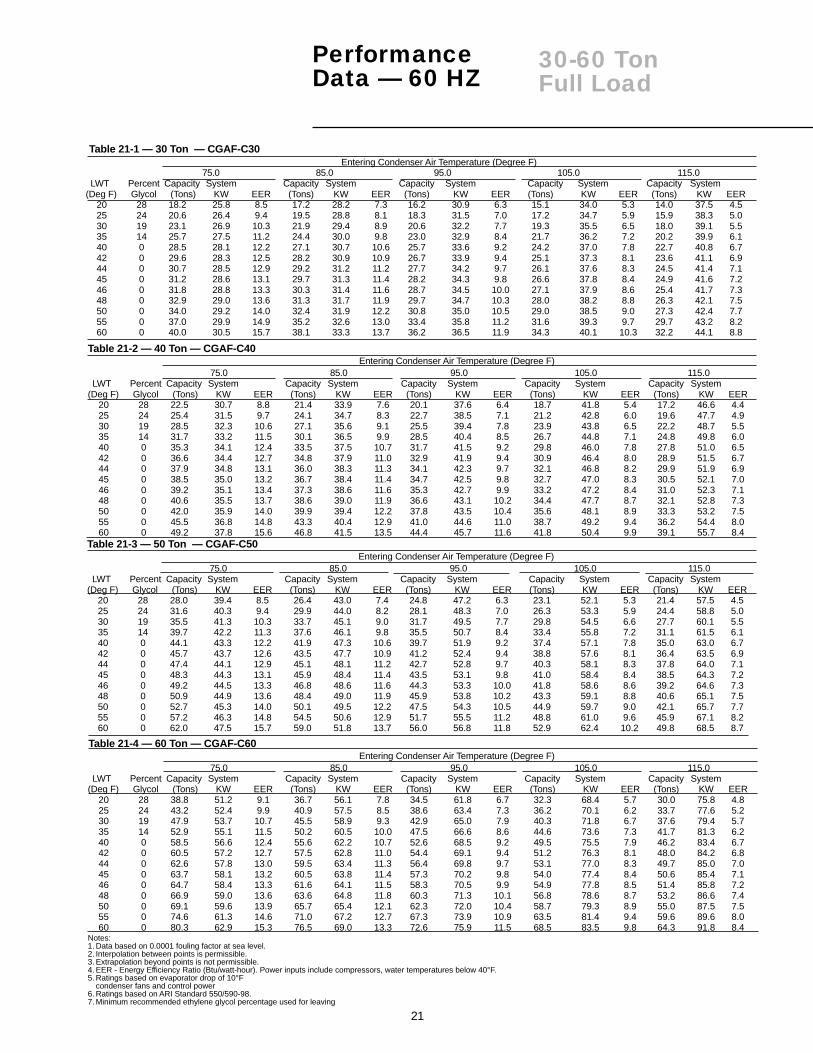
20 28 18.2 25.8 8.5 17.2 28.2 7.3 16.2 30.9 6.3 15.1 34.0 5.3 14.0 37.5 4.525 24 20.6 26.4 9.4 19.5 28.8 8.1 18.3 31.5 7.0 17.2 34.7 5.9 15.9 38.3 5.030 19 23.1 26.9 10.3 21.9 29.4 8.9 20.6 32.2 7.7 19.3 35.5 6.5 18.0 39.1 5.535 14 25.7 27.5 11.2 24.4 30.0 9.8 23.0 32.9 8.4 21.7 36.2 7.2 20.2 39.9 6.140 0 28.5 28.1 12.2 27.1 30.7 10.6 25.7 33.6 9.2 24.2 37.0 7.8 22.7 40.8 6.742 0 29.6 28.3 12.5 28.2 30.9 10.9 26.7 33.9 9.4 25.1 37.3 8.1 23.6 41.1 6.944 0 30.7 28.5 12.9 29.2 31.2 11.2 27.7 34.2 9.7 26.1 37.6 8.3 24.5 41.4 7.145 0 31.2 28.6 13.1 29.7 31.3 11.4 28.2 34.3 9.8 26.6 37.8 8.4 24.9 41.6 7.246 0 31.8 28.8 13.3 30.3 31.4 11.6 28.7 34.5 10.0 27.1 37.9 8.6 25.4 41.7 7.348 0 32.9 29.0 13.6 31.3 31.7 11.9 29.7 34.7 10.3 28.0 38.2 8.8 26.3 42.1 7.550 0 34.0 29.2 14.0 32.4 31.9 12.2 30.8 35.0 10.5 29.0 38.5 9.0 27.3 42.4 7.755 0 37.0 29.9 14.9 35.2 32.6 13.0 33.4 35.8 11.2 31.6 39.3 9.7 29.7 43.2 8.260 0 40.0 30.5 15.7 38.1 33.3 13.7 36.2 36.5 11.9 34.3 40.1 10.3 32.2 44.1 8.8
Table 21-1 — 30 Ton — CGAF-C30
Table 21-2 — 40 Ton — CGAF-C40Entering Condenser Air Temperature (Degree F)
75.0 85.0 95.0 105.0 115.0LWT Percent Capacity System Capacity System Capacity System Capacity System Capacity System
(Deg F) Glycol (Tons) KW EER (Tons) KW EER (Tons) KW EER (Tons) KW EER (Tons) KW EER20 28 22.5 30.7 8.8 21.4 33.9 7.6 20.1 37.6 6.4 18.7 41.8 5.4 17.2 46.6 4.425 24 25.4 31.5 9.7 24.1 34.7 8.3 22.7 38.5 7.1 21.2 42.8 6.0 19.6 47.7 4.930 19 28.5 32.3 10.6 27.1 35.6 9.1 25.5 39.4 7.8 23.9 43.8 6.5 22.2 48.7 5.535 14 31.7 33.2 11.5 30.1 36.5 9.9 28.5 40.4 8.5 26.7 44.8 7.1 24.8 49.8 6.040 0 35.3 34.1 12.4 33.5 37.5 10.7 31.7 41.5 9.2 29.8 46.0 7.8 27.8 51.0 6.542 0 36.6 34.4 12.7 34.8 37.9 11.0 32.9 41.9 9.4 30.9 46.4 8.0 28.9 51.5 6.744 0 37.9 34.8 13.1 36.0 38.3 11.3 34.1 42.3 9.7 32.1 46.8 8.2 29.9 51.9 6.945 0 38.5 35.0 13.2 36.7 38.4 11.4 34.7 42.5 9.8 32.7 47.0 8.3 30.5 52.1 7.046 0 39.2 35.1 13.4 37.3 38.6 11.6 35.3 42.7 9.9 33.2 47.2 8.4 31.0 52.3 7.148 0 40.6 35.5 13.7 38.6 39.0 11.9 36.6 43.1 10.2 34.4 47.7 8.7 32.1 52.8 7.350 0 42.0 35.9 14.0 39.9 39.4 12.2 37.8 43.5 10.4 35.6 48.1 8.9 33.3 53.2 7.555 0 45.5 36.8 14.8 43.3 40.4 12.9 41.0 44.6 11.0 38.7 49.2 9.4 36.2 54.4 8.060 0 49.2 37.8 15.6 46.8 41.5 13.5 44.4 45.7 11.6 41.8 50.4 9.9 39.1 55.7 8.4
Entering Condenser Air Temperature (Degree F)75.0 85.0 95.0 105.0 115.0
LWT Percent Capacity System Capacity System Capacity System Capacity System Capacity System(Deg F) Glycol (Tons) KW EER (Tons) KW EER (Tons) KW EER (Tons) KW EER (Tons) KW EER
20 28 38.8 51.2 9.1 36.7 56.1 7.8 34.5 61.8 6.7 32.3 68.4 5.7 30.0 75.8 4.825 24 43.2 52.4 9.9 40.9 57.5 8.5 38.6 63.4 7.3 36.2 70.1 6.2 33.7 77.6 5.230 19 47.9 53.7 10.7 45.5 58.9 9.3 42.9 65.0 7.9 40.3 71.8 6.7 37.6 79.4 5.735 14 52.9 55.1 11.5 50.2 60.5 10.0 47.5 66.6 8.6 44.6 73.6 7.3 41.7 81.3 6.240 0 58.5 56.6 12.4 55.6 62.2 10.7 52.6 68.5 9.2 49.5 75.5 7.9 46.2 83.4 6.742 0 60.5 57.2 12.7 57.5 62.8 11.0 54.4 69.1 9.4 51.2 76.3 8.1 48.0 84.2 6.844 0 62.6 57.8 13.0 59.5 63.4 11.3 56.4 69.8 9.7 53.1 77.0 8.3 49.7 85.0 7.045 0 63.7 58.1 13.2 60.5 63.8 11.4 57.3 70.2 9.8 54.0 77.4 8.4 50.6 85.4 7.146 0 64.7 58.4 13.3 61.6 64.1 11.5 58.3 70.5 9.9 54.9 77.8 8.5 51.4 85.8 7.248 0 66.9 59.0 13.6 63.6 64.8 11.8 60.3 71.3 10.1 56.8 78.6 8.7 53.2 86.6 7.450 0 69.1 59.6 13.9 65.7 65.4 12.1 62.3 72.0 10.4 58.7 79.3 8.9 55.0 87.5 7.555 0 74.6 61.3 14.6 71.0 67.2 12.7 67.3 73.9 10.9 63.5 81.4 9.4 59.6 89.6 8.060 0 80.3 62.9 15.3 76.5 69.0 13.3 72.6 75.9 11.5 68.5 83.5 9.8 64.3 91.8 8.4
Entering Condenser Air Temperature (Degree F)75.0 85.0 95.0 105.0 115.0
LWT Percent Capacity System Capacity System Capacity System Capacity System Capacity System(Deg F) Glycol (Tons) KW EER (Tons) KW EER (Tons) KW EER (Tons) KW EER (Tons) KW EER
20 28 28.0 39.4 8.5 26.4 43.0 7.4 24.8 47.2 6.3 23.1 52.1 5.3 21.4 57.5 4.525 24 31.6 40.3 9.4 29.9 44.0 8.2 28.1 48.3 7.0 26.3 53.3 5.9 24.4 58.8 5.030 19 35.5 41.3 10.3 33.7 45.1 9.0 31.7 49.5 7.7 29.8 54.5 6.6 27.7 60.1 5.535 14 39.7 42.2 11.3 37.6 46.1 9.8 35.5 50.7 8.4 33.4 55.8 7.2 31.1 61.5 6.140 0 44.1 43.3 12.2 41.9 47.3 10.6 39.7 51.9 9.2 37.4 57.1 7.8 35.0 63.0 6.742 0 45.7 43.7 12.6 43.5 47.7 10.9 41.2 52.4 9.4 38.8 57.6 8.1 36.4 63.5 6.944 0 47.4 44.1 12.9 45.1 48.1 11.2 42.7 52.8 9.7 40.3 58.1 8.3 37.8 64.0 7.145 0 48.3 44.3 13.1 45.9 48.4 11.4 43.5 53.1 9.8 41.0 58.4 8.4 38.5 64.3 7.246 0 49.2 44.5 13.3 46.8 48.6 11.6 44.3 53.3 10.0 41.8 58.6 8.6 39.2 64.6 7.348 0 50.9 44.9 13.6 48.4 49.0 11.9 45.9 53.8 10.2 43.3 59.1 8.8 40.6 65.1 7.550 0 52.7 45.3 14.0 50.1 49.5 12.2 47.5 54.3 10.5 44.9 59.7 9.0 42.1 65.7 7.755 0 57.2 46.3 14.8 54.5 50.6 12.9 51.7 55.5 11.2 48.8 61.0 9.6 45.9 67.1 8.260 0 62.0 47.5 15.7 59.0 51.8 13.7 56.0 56.8 11.8 52.9 62.4 10.2 49.8 68.5 8.7
Table 21-4 — 60 Ton — CGAF-C60
Table 21-3 — 50 Ton — CGAF-C50
Notes:1. Data based on 0.0001 fouling factor at sea level.2. Interpolation between points is permissible.3. Extrapolation beyond points is not permissible.4. EER - Energy Efficiency Ratio (Btu/watt-hour). Power inputs include compressors, water temperatures below 40°F.5. Ratings based on evaporator drop of 10°F
condenser fans and control power6. Ratings based on ARI Standard 550/590-98.7. Minimum recommended ethylene glycol percentage used for leaving

22
20-60 TonFull Load
PerformanceData — 50 HZ
Entering Condenser Air Temperature (Degree F)85.0 95.0 105.0 115.0 120.0
LWT Percent Capacity System Capacity System Capacity System Capacity System Capacity System(Deg F) Glycol (Tons) KW EER (Tons) KW EER (Tons) KW EER (Tons) KW EER (Tons) KW EER
40 0 14.4 15.2 11.4 13.7 17.0 9.7 12.8 19.0 8.1 12.0 21.3 6.7 11.5 22.5 6.142 0 15.0 15.3 11.7 14.2 17.1 9.9 13.3 19.2 8.4 12.4 21.5 7.0 12.0 22.7 6.344 0 15.6 15.5 12.1 14.7 17.3 10.2 13.8 19.3 8.6 12.9 21.6 7.2 12.4 22.9 6.545 0 15.8 15.5 12.2 15.0 17.3 10.4 14.1 19.4 8.7 13.2 21.7 7.3 12.7 23.0 6.646 0 16.1 15.6 12.4 15.3 17.4 10.5 14.4 19.5 8.8 13.4 21.8 7.4 12.9 23.1 6.748 0 16.7 15.7 12.7 15.8 17.6 10.8 14.9 19.7 9.1 13.9 22.0 7.6 13.4 23.3 6.950 0 17.3 15.9 13.1 16.4 17.7 11.1 15.4 19.8 9.3 14.4 22.2 7.8 13.9 23.4 7.1
Table 22-1 — 20 Ton — CGAF-C20
Table 22-2 — 25 Ton — CGAF-C25Entering Condenser Air Temperature (Degree F)
85.0 95.0 105.0 115.0 120.0LWT Percent Capacity System Capacity System Capacity System Capacity System Capacity System
(Deg F) Glycol (Tons) KW EER (Tons) KW EER (Tons) KW EER (Tons) KW EER (Tons) KW EER40 0 19.3 20.1 11.5 18.2 22.2 9.9 17.1 24.6 8.4 16.0 27.4 7.0 15.4 28.8 6.442 0 20.0 20.2 11.8 18.9 22.4 10.1 17.8 24.8 8.6 16.6 27.6 7.2 16.0 29.1 6.644 0 20.7 20.4 12.2 19.7 22.6 10.4 18.5 25.1 8.9 17.3 27.8 7.5 16.6 29.3 6.845 0 21.1 20.5 12.4 20.0 22.7 10.6 18.8 25.2 9.0 17.9 28.0 7.7 17.3 29.5 7.046 0 21.5 20.6 12.5 20.4 22.8 10.7 19.2 25.3 9.1 18.6 28.3 7.9 17.9 29.8 7.248 0 22.3 20.8 12.9 21.1 23.0 11.0 19.9 25.5 9.4 19.3 28.5 8.1 18.6 30.0 7.450 0 23.0 21.0 13.2 21.9 23.2 11.3 20.6 25.7 9.6 17.6 27.9 7.6 17.0 29.4 6.9
Entering Condenser Air Temperature (Degree F)85.0 95.0 105.0 115.0 120.0
LWT Percent Capacity System Capacity System Capacity System Capacity System Capacity System(Deg F) Glycol (Tons) KW EER (Tons) KW EER (Tons) KW EER (Tons) KW EER (Tons) KW EER
40 0 22.9 23.9 11.5 21.7 26.4 9.9 20.5 29.4 8.4 19.1 32.6 7.0 18.4 34.4 6.442 0 23.8 24.1 11.9 22.6 26.6 10.2 21.3 29.6 8.6 19.9 32.9 7.2 19.1 34.6 6.644 0 24.7 24.2 12.2 23.4 26.8 10.5 22.1 29.8 8.9 20.6 33.1 7.5 19.9 34.9 6.845 0 25.1 24.3 12.4 23.8 26.9 10.6 22.5 29.9 9.0 21.0 33.2 7.6 20.3 35.0 6.946 0 25.6 24.4 12.6 24.3 27.0 10.8 22.9 30.0 9.2 21.4 33.3 7.7 20.6 35.1 7.148 0 26.5 24.6 12.9 25.2 27.2 11.1 23.7 30.2 9.4 22.2 33.6 7.9 21.4 35.4 7.350 0 27.4 24.8 13.3 26.1 27.5 11.4 24.6 30.5 9.7 23.0 33.8 8.2 22.2 35.6 7.5
Table 22-3 — 30 Ton — CGAF-C30
Entering Condenser Air Temperature (Degree F)85.0 95.0 105.0 115.0 120.0
LWT Percent Capacity System Capacity System Capacity System Capacity System Capacity System(Deg F) Glycol (Tons) KW EER (Tons) KW EER (Tons) KW EER (Tons) KW EER (Tons) KW EER
40 0 28.3 29.6 11.5 26.8 33.1 9.7 25.1 37.1 8.1 23.4 41.6 6.7 22.5 44.1 6.142 0 29.4 29.9 11.8 27.8 33.4 10.0 26.1 37.4 8.4 24.3 42.0 7.0 23.4 44.4 6.344 0 30.5 30.2 12.1 28.8 33.7 10.3 27.1 37.7 8.6 25.3 42.3 7.2 24.3 44.8 6.545 0 31.0 30.3 12.3 29.4 33.8 10.4 27.6 37.9 8.7 25.7 42.5 7.3 24.8 44.9 6.646 0 31.6 30.4 12.5 29.9 34.0 10.6 28.1 38.0 8.9 26.2 42.6 7.4 25.2 45.1 6.748 0 32.7 30.7 12.8 31.0 34.3 10.8 29.1 38.4 9.1 27.2 43.0 7.6 26.2 45.4 6.950 0 33.8 31.0 13.1 32.0 34.6 11.1 30.2 38.7 9.4 28.2 43.3 7.8 27.1 45.8 7.1
Table 22-4 — 40 Ton — CGAF-C40
Entering Condenser Air Temperature (Degree F)85.0 95.0 105.0 115.0 120.0
LWT Percent Capacity System Capacity System Capacity System Capacity System Capacity System(Deg F) Glycol (Tons) KW EER (Tons) KW EER (Tons) KW EER (Tons) KW EER (Tons) KW EER
40 0 35.5 36.9 11.5 33.6 40.9 9.9 31.6 45.4 8.4 29.4 50.5 7.0 28.3 53.2 6.442 0 36.8 37.2 11.9 34.9 41.2 10.2 32.8 45.8 8.6 30.6 50.8 7.2 29.5 53.6 6.644 0 38.2 37.5 12.2 36.2 41.5 10.5 34.1 46.1 8.9 31.8 51.2 7.5 30.6 54.0 6.845 0 38.9 37.7 12.4 36.9 41.7 10.6 34.7 46.3 9.0 32.4 51.4 7.6 31.2 54.2 6.946 0 39.6 37.8 12.6 37.6 41.9 10.8 35.4 46.5 9.1 33.0 51.6 7.7 31.8 54.4 7.048 0 41.0 38.2 12.9 38.9 42.2 11.1 36.7 46.9 9.4 34.3 52.0 7.9 33.0 54.8 7.250 0 42.5 38.5 13.2 40.3 42.6 11.4 38.0 47.3 9.6 35.5 52.4 8.1 34.2 55.2 7.4
Table 22-5 — 50 Ton — CGAF-C50
Entering Condenser Air Temperature (Degree F)85.0 95.0 105.0 115.0 120.0
LWT Percent Capacity System Capacity System Capacity System Capacity System Capacity System(Deg F) Glycol (Tons) KW EER (Tons) KW EER (Tons) KW EER (Tons) KW EER (Tons) KW EER
40 0 47.2 49.0 11.6 44.7 54.5 9.8 41.9 60.6 8.3 39.0 67.5 6.9 37.5 71.2 6.342 0 48.9 49.5 11.9 46.3 55.0 10.1 43.4 61.2 8.5 40.4 68.1 7.1 38.9 71.8 6.544 0 50.6 50.0 12.2 47.9 55.5 10.4 45.0 61.7 8.7 41.9 68.7 7.3 40.3 72.4 6.745 0 51.5 50.2 12.3 48.7 55.8 10.5 45.8 62.0 8.9 42.7 69.0 7.4 41.0 72.7 6.846 0 52.4 50.5 12.5 49.6 56.1 10.6 46.6 62.3 9.0 43.4 69.3 7.5 41.8 73.0 6.948 0 54.1 51.0 12.7 51.3 56.6 10.9 48.2 62.9 9.2 44.9 69.9 7.7 43.2 73.7 7.050 0 55.9 51.5 13.0 53.0 57.2 11.1 49.8 63.5 9.4 46.5 70.6 7.9 44.7 74.3 7.2
Table 22-6 — 60 Ton — CGAF-C60
Notes:1. Data based on 0.0001 fouling factor at sea level. 5. Ratings based on evaporator drop of 10°F.2. Interpolation between points is permissible. 6. Ratings based on ARI Standard 550/590-983. Extrapolation beyond points is not permissible. 7. Minimum recommended ethylene glycol percentage used for leaving4. EER - Energy Efficiency Ratio (Btu/watt-hour). Power inputs include compressors, water temperatures below 40°.
condenser fans and control power. 8. Data obtained assuming 400 Volt Supply.

23
PerformanceData - 60 HZ
Table 23-1 — Part Load Data, ARI Points (10-60 Tons)
Entering Condenser Air Temperature (Degrees F)Model 95 86 84.2 83.6 77 76.4 74 72.2
Tons Number 100% Load 85% Load 82% Load 81% Load 70% Load 69% Load 65% Load 62% LoadEER 9.4 — — — — — 13.9 —
10 CGA 120 Capacity (Tons) 8.7 — — — — — 5.7 — KW Input 11.1 — — — — — 4.9 —
EER 9.1 — — — — 12.2 — —15 CGA 180 Capacity (Tons) 13.6 — — — — 9.3 — —
KW Input 17.9 — — — — 9.2 — —EER 9.7 — — — — — — —
20 CGAF-C20 Capacity (Tons) 17.5 — — — — — — —KW Input 21.7 — — — — — — —
EER 9.7 — — — — 13.4 — —25 CGAF-C25 Capacity (Tons) 23.2 — — — — 16.1 — —
KW Input 28.7 — — — — 14.5 — —EER 9.7 — — — — — — —
30 CGAF-C30 Capacity (Tons) 27.7 — — — — — — —KW Input 34.2 — — — — — — —
EER 9.7 — — 11.8 — — — —40 CGAF-C40 Capacity (Tons) 34.1 — — 27.8 — — — —
KW Input 42.3 — — 28.3 — — — —EER 9.7 11.3 — — 13.3 — — —
50 CGAF-C50 Capacity (Tons) 42.7 36.5 — — 29.8 — — —KW Input 52.8 38.9 — — 26.9 — — —
EER 9.7 — 11.9 — — — — 15.260 CGAF-C60 Capacity (Tons) 56.4 — 46.3 — — — — 35
KW Input 69.8 — 46.6 — — — — 27.6
Table 23-1 — Part Load Data, ARI Points (10-60 Tons) Continued
Entering Condenser Air Temperature (Degrees F)Model 71.6 71.0 64.4 57.2 55
Tons Number 61% Load 60% Load 49% Load 37% Load 32% LoadEER — — — — —
10 CGA 120 Capacity (Tons) — — — — — KW Input — — — — —
EER — — — — —15 CGA 180 Capacity (Tons) — — — — —
KW Input — — — — —EER — 14.6 — — —
20 CGAF-C20 Capacity (Tons) — 10.4 — — —KW Input — 8.6 — — —
EER — — 14.4 — —25 CGAF-C25 Capacity (Tons) — — 11.3 — —
KW Input — — 9.4 — —EER — 13.7 — — —
30 CGAF-C30 Capacity (Tons) — 16.6 — — —KW Input — 14,5 — — —
EER 14.8 — — — 17.140 CGAF-C40 Capacity (Tons) 20.7 — — — 10.8
KW Input 16.8 — — — 7.6EER — — — 16.9 —
50 CGAF-C50 Capacity (Tons) — — — 15.7 —KW Input — — — 11.2 —
EER — — — — 18.360 CGAF-C60 Capacity (Tons) — — — — 18.2
KW Input — — — — 11.9
Tons Model Number IPLV10 CGA 120 14.315 CGA 180 13.820 CGAF-C20 14.225 CGAF-C25 13.630 CGAF-C30 13.540 CGAF-C40 14.550 CGAF-C50 14.260 CGAF-C60 15.0
Table 23-2 — Integrated Part Load Values
Notes:1. Integrated Part Load Values are EERs in
(Btu/watt-hour).
10-60 TonsPart Load
Notes:1. Data is rated in accordance with ARI Standard 550/590-98
- 44 Degrees leaving chilled water temperature - Constant Evaporator waterflow as determined at full load operation, 95 F ambient, and 10F evaporator temperature drop. - Entering ambient temperature based on 55F for loads below 33% - Entering ambient temperature based on 0.60(%load)+35 for loads above 33% - EER- Energy Efficiency Ratio ( Btu/Watt-hour). Power inputs include compressor, condenser fans and control power.

24
PerformanceData - 50 HZ
20-30 TonsPart Load
Table 24-1 — 20 Ton — CGAF-C20
Percent Entering Condenser Air Temperature (Degrees F)Load 75 85 95 105 115 120
EER 14.1 12.1 10.2 8.6 7.2 6.5100 Capacity 16.3 15.6 14.7 13.8 12.9 12.4
System KW 13.9 15.5 17.3 19.3 21.6 22.9EER 15.2 13.2 11.4 9.7 8.2 7.5
50 Capacity 8.5 8.1 7.7 7.3 6.8 6.6System KW 6.7 7.4 8.1 9.0 10.0 10.6
Table 24-3 — 30 Ton — CGAF-C30
Percent Entering Condenser Air Temperature (Degrees F)
Load 75 85 95 105 115 120
EER 14.1 12.2 10.5 8.9 7.5 6.8100 Capacity 25.9 24.7 23.4 22.1 20.6 19.9
System KW 22.0 24.2 26.8 29.8 33.1 34.9EER 13.4 11.8 10.3 8.8 7.5 6.9
50 Capacity 13.4 12.8 12.2 11.5 10.8 10.4System KW 12.0 13.0 14.3 15.7 17.3 18.2
Table 24-2 — 25 Ton — CGAF-C25
Percent Entering Condenser Air Temperature (Degrees F)Load 75 85 95 105 115 120
EER 14.1 12.2 10.4 8.9 7.5 6.8100 Capacity 21.7 20.7 19.7 18.5 17.3 16.6
System KW 18.5 20.4 22.6 25.1 27.8 29.3EER 15.4 13.5 11.7 10.0 8.4 7.7
60 Capacity 13.5 12.9 12.2 11.6 10.8 10.4System KW 10.5 11.5 12.6 13.9 15.4 16.2
EER 14.4 12.6 11.0 9.4 8.0 7.340 Capacity 8.9 8.5 8.1 7.6 7.1 6.9
System KW 7.4 8.1 8.8 9.7 10.8 11.3
Notes:1. Data based on 0.0001 fouling factor at sea level.2. Interpolation between points is permissible.3. Extrapolation beyond points is not permissible.4. EER - Energy Efficiency Ratio (Btu/watt-hour). Power inputs include compressors,
condenser fans and control power5. Ratings based on evaporator drop of 10°F6. Ratings based on ARI Standard 550/590-98.7. Data obtained assuming 400 Volt supply.

25
Table 25-1 — 40 Ton — CGAF-C40
Percent Entering Condenser Air Temperature (Degrees F)
Load 75 85 95 105 115 120
PerformanceData - 50 HZ
40-60 TonsPart Load
Table 25-3 — 60 Ton — CGAF-C60
Percent Entering Condenser Air Temperature (Degrees F)
Load 75 85 95 105 115 120EER 14.1 12.2 10.4 8.7 7.3 6.7
100 Capacity 53.2 50.6 47.9 45.0 41.9 40.3System KW 45.1 50.0 55.5 61.7 68.7 72.4
EER 14.7 12.7 10.9 9.2 7.8 7.175 Capacity 40.8 38.9 36.9 34.7 32.3 31.1
System KW 33.2 36.7 40.6 45.1 50.0 52.7EER 16.0 14.0 12.1 10.3 8.8 8.0
50 Capacity 28.6 27.4 26.0 24.6 23.1 22.2System KW 21.4 23.4 25.8 28.5 31.6 33.2
EER 15.4 13.3 11.4 9.6 8.1 7.425 Capacity 13.9 13.2 12.6 11.8 11.0 10.6
System KW 10.8 12.0 13.3 14.7 16.4 17.3
Table 25-2 — 50 Ton — CGAF-C50
Percent Entering Condenser Air Temperature (Degrees F)
Load 75 85 95 105 115 120
EER 14.0 12.2 10.5 8.9 7.5 6.8100 Capacity 39.7 38.2 36.2 34.1 31.8 30.6
System KW 34.0 37.5 41.5 46.1 51.2 54.0EER 14.4 12.5 10.8 9.1 7.7 7.0
80 Capacity 32.5 31.0 29.4 27.7 25.8 24.9System KW 27.0 29.7 32.8 36.3 40.3 42.4
EER 14.9 13.1 11.3 9.7 8.2 7.560 Capacity 25.0 23.9 22.7 21.4 20.0 19.3
System KW 20.1 21.9 24.1 26.6 29.4 30.9EER 14.2 12.2 10.5 8.9 7.4 6.8
30 Capacity 12.0 11.4 10.8 10.2 9.5 9.1System KW 10.1 11.2 12.4 13.8 15.3 16.1
Notes:1. Data based on 0.0001 fouling factor at sea level.2. Interpolation between points is permissible.3. Extrapolation beyond points is not permissible.4. EER - Energy Efficiency Ratio (Btu/watt-hour). Power inputs include compressors,
condenser fans and control power5. Ratings based on evaporator drop of 10°F6. Ratings based on ARI Standard 550/590-98.7. Data obtained assuming 400 Volt supply.
EER 14.2 12.1 10.3 8.6 7.2 6.5100 Capacity 32.0 30.5 28.8 27.1 25.3 24.3
System KW 27.1 30.2 33.7 37.7 42.3 44.8EER 14.6 12.5 10.7 9.0 7.5 6.8
75 Capacity 24.4 23.2 22.0 20.7 19.3 18.6System KW 20.1 22.2 24.7 27.6 30.9 32.7
EER 15.3 13.3 11.5 9.8 8.2 7.550 Capacity 16.9 16.1 15.3 14.4 13.5 13.0
System KW 13.2 14.5 16.0 17.8 19.8 20.9EER 14.1 12.3 10.5 8.9 7.5 6.9
25 Capacity 8.2 7.9 7.5 7.1 6.6 6.4System KW 7.0 7.7 8.5 9.5 10.6 11.2

26
ElectricalData - 60 HZ
10-60 Tons
Table 26-1 — Electrical DataUnit Wiring Motor Data
Model Nameplate Voltage Max Fuse Rec. Dual Compressor (Ea) Fans (Ea)Tons Number Voltage Range MCA Size Element Qty. RLA LRA Qty KW FLA
CGA120B1 208-230/60/1 187-254 71.0 90 2 28.9 150 1 .95 6.0CGA120B3 208-230/60/3 187-254 48.3 60 2 18.8 118 1 .95 6.0
10 CGA120B4 460/60/3 414-506 25.2 35 2 10.0 71 1 .95 2.7CGA120BW 575/60/3 518-632 17.3 20 2 6.8 43 1 .95 2.0
CGA180B3 208-230/60/3 187-254 72.6 90 2 29.5 179 2 1.03 3.115 CGA180B4 460/60/3 414-506 33.6 40 2 13.5 90 2 1.03 1.6
CGA180BW 575/60/3 518-632 26.7 35 2 10.8 72 2 1.03 1.2200/60/3 180-220 98 125 110 2 39.4 269 2 0.9 4.1230/60/3 208-254 98 125 110 2 39.4 251 2 0.9 4.120 CGAF-C20460/60/3 416-508 44 60 50 2 17.2 117 2 0.9 1.8575/60/3 520-635 33 45 40 2 13.2 94 2 0.9 1.4
200/60/3 180-220 124 175 150 2 39.3,56.9 269,409 3 0.9 4.1230/60/3 208-254 124 175 150 2 39.3,56.9 251,376 3 0.9 4.125 CGAF-C25460/60/3 416-508 56 80 70 2 17.1,25.4 117,178 3 0.9 1.8575/60/3 520-635 44 60 50 2 13.8,20.2 94,143 3 0.9 1.4200/60/3 180-220 146 200 175 2 56.9 409 4 0.9 4.1230/60/3 208-254 146 200 175 2 56.9 376 4 0.9 4.130 CGAF-C30460/60/3 416-508 65 80 80 2 25.1 178 4 0.9 1.8575/60/3 520-635 51 70 60 2 19.9 143 4 0.9 1.4
200/60/3 180-220 187 225 200 4 39.4 269 4 0.9 4.1230/60/3 208-254 186 225 200 4 39.4 251 4 0.9 4.140 CGAF-C40460/60/3 416-508 82 90 90 4 17.2 117 4 0.9 1.8575/60/3 520-635 62 70 70 4 13.2 94 4 0.9 1.4200/60/3 180-220 224 250 250 4 35.5,55.5 269,409 6 0.9 4.1230/60/3 208-254 223 250 250 4 35.5,55.5 251,376 6 0.9 4.150 CGAF-C50460/60/3 416-508 98 110 110 4 15.5,24.2 117,178 6 0.9 1.8575/60/3 520-635 77 90 90 4 12.4,19.4 94,143 6 0.9 1.4
200/60/3 180-220 270 300 300 4 56.9 409 6 0.9 4.1230/60/3 208-254 269 300 300 4 56.9 376 6 0.9 4.160 CGAF-C60460/60/3 416-508 120 125 125 4 25.4 178 6 0.9 1.8575/60/3 520-635 95 110 100 4 20.2 143 6 0.9 1.4
Notes:1. MCA: Minimum Circuit Ampacity is 125% of the largest compressor RLA plus 100% of the other compressor(s) RLA plus the sum of the condenser fan FLA plus any other load rated at 1
AMP or more2. Maximum Fuse Size: 225% of the largest compressor RLA plus 100% of the other compressor(s) RLA plus the sum of the condenser fan FLA plus any other load rated at 1 AMP or more3. Recommended Dual Element Fuse Size: 150% of the largest compressor RLA plus 100% of the other compressor(s) RLA plus the sum of the condenser fan FLA plus any other loadrated
at 1 AMP or more.4. RLA: Rated in accordance with UL standard 1995.5. Local codes may take precedence.6. All units are across the line starting. Compressors will never start simultaneously.7. One 115/60/1, 15 AMP jobsite provided power connection is required to operate the evaporator heat tape.
Load DefinitionsLOAD1 = Current of the largest motor — compressor or fan motorLOAD2 = Sum of the currents of all remaining motorsLOAD3 = Current of electric heatersLOAD4 = Any other load rated at 1 amp or more
MCA = (1.25 x LOAD1) + LOAD2 +LOAD4
MOP = (2.25 x LOAD1) + LOAD2 +LOAD4
Select a fuse rating equal to the MOPvalue. If the MOP value does not equala standard fuse size as listed in NEC240-6, select the next lower standardfuse rating.
NOTE: If selected MOP is less thanthe MCA, then reselect the loweststandard maximum fuse size whichis equal to or larger than the MCA,provided the reselected fuse sizedoes not exceed 800 amps.
RDE =(1.5 x LOAD1) + LOAD2 +LOAD4
Select a fuse rating equal to the RDEvalue. If the RDE value does notequal a standard fuse size as listed inNEC 240-6, select the next higherstandard fuse rating.
NOTE: If the selected RDE isgreater than the selected MOPvalue, then reselect the RDE valueto equal the MOP value.
DSS =1.5 x (LOAD1 + LOAD2 +LOAD3 + LOAD4)
Select a disconnect switch size equalto or larger than the DSS valuecalculated.
®

27
10-60 TonsElectricalData - 50 HZ
Table 27-1 — Electrical DataUnit Wiring Motor Data
Model Nameplate Voltage Max Fuse Rec. Dual Compressor (Ea) Fans (Ea)Tons Number Voltage Range MCA Size Element Qty. RLA LRA Qty KW FLA
10 CGA100BD 380-415/50/3 342-456 25.2 35 — 2 10.0 71 1 0.57 2.7
15 CGA150BD 380-415/50/3 342-456 33.6 45 — 2 13.5 90 2 0.33 1.6
20 CGAF-C20 380/50/3 342-418 44 60 50 2 17.2 110 2 0.75 1.7415/50/3 373-456 44 60 50 2 17.2 110 2 0.75 1.7
25 CGAF-C25 38050/3 342-418 55 80 70 2 17.3/25.2 110/174 3 0.75 1.7415/50/3 373-456 55 80 70 2 17.3/25.2 110/174 3 0.75 1.7
30 CGAF-C30 380/50/3 342-418 65 80 80 2 25.2 174 4 0.75 1.7415/50/3 373-456 65 80 80 2 25.2 174 4 0.75 1.7
40 CGAF-C40 380/50/3 342-418 81 90 90 4 17.2 110 4 0.75 1.7415/50/3 373-456 81 90 90 4 17.2 110 4 0.75 1.7
50 CGAF-C50 380/50/3 342-418 97 110 110 4 15.5/24.2 110/174 6 0.75 1.7415/50/3 373-456 97 110 110 4 15.5/24.2 110/174 6 0.75 1.7
60 CGAF-C60 380/50/3 342-418 119 125 125 4 25.2 174 6 0.75 1.7415/50/3 373-456 119 125 125 4 25.2 174 6 0.75 1.7
Notes:1. MCA: Minimum Circuit Ampacity is 125% of the largest compressor RLA plus 100% of the other compressor(s) RLA plus the sum of the condenser fan FLA plus any other load rated at 1
AMP or more.2. Maximum Fuse Size: 225% of the largest compressor RLA plus 100% of the other compressor(s) RLA plus the sum of the condenser fan FLA plus any other load rated at 1AMP or more.3. Recommended Dual Element Fuse Size: 150% of the largest compressor RLA plus 100% of the other compressor(s) RLA plus the sum of the condenser fan FLA plus any other loadrated
at 1 AMP or more.4. RLA: Rated in accordance with UL standard 1995.5. Local codes may take precedence.6. Control kw includes operational controls only. Does not include evaporator heat tape.7. All units are across the line starting. Compressors will never start simultaneously.8. One 240/50/1, 5 AMP jobsite provided power connection is required to operate the evaporator heat tape.
28
Controls10,15 Tons
Interface withOther ControlSystems
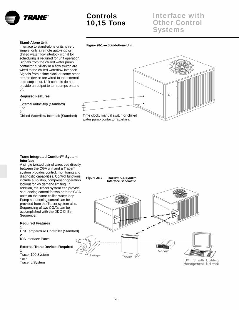
Stand-Alone UnitInterface to stand-alone units is verysimple; only a remote auto-stop orchilled water flow interlock signal forscheduling is required for unit operation.Signals from the chilled water pumpcontactor auxiliary or a flow switch arewired to the chilled waterflow interlock.Signals from a time clock or some otherremote device are wired to the externalauto-stop input. Unit controls do notprovide an output to turn pumps on andoff.
Required Features1External Auto/Stop (Standard)- or -2Chilled Waterflow Interlock (Standard)
Trane Integrated Comfort™ SystemInterfaceA single twisted pair of wires tied directlybetween the CGA unit and a Tracer®
system provides control, monitoring anddiagnostic capabilities. Control functionsinclude auto/stop, compressor operationlockout for kw demand limiting. Inaddition, the Tracer system can providesequencing control for two or three CGAunits on the same chilled water loop.Pump sequencing control can beprovided from the Tracer system also.Sequencing of two CGA’s can beaccomplished with the DDC ChillerSequencer.
Required Features1Unit Temperature Controller (Standard)2ICS Interface Panel
External Trane Devices Required1Tracer 100 System- or -Tracer L System
®
Figure 28-1 — Stand-Alone Unit
Figure 28-2 — Tracer® ICS SystemInterface Schematic
Time clock, manual switch or chilledwater pump contactor auxiliary.

29
Controls 10, 15 Tons
ELECTRICAL CONTROL SYSTEMThe controls used on CGA 10 and 15-ton units are classified either as“safety” controls or “operational”controls. Brief descriptions of thespecific safety and operating controlsused in the CGA control scheme areprovided in the following paragraphs.
Refer to the following controldescriptions for control settings.
UNIT SAFETY CONTROLS
Low Pressure Cutout (LPC01,LPC02) Mounted below the unitcontrol box are two low pressurecutouts that open and stopcompressor operation if the operatingpressure drops below 38.5 + 1 psig.The cutout automatically resets whenthe pressure reaches 44.5 + 2 psig.The LPCO is a SPDT device. If itopens at low ambient start-up, it willenergize ODF relay, stopping theoutdoor fan(s) while the compressorremains energized through the LAST(Low Ambient Start Timer).
High Pressure Cutout (HPC01,HPC02) —These units have highpressure cutouts that open and stopcompressor operation if the dischargepressure reaches 400 + 10 psig. Thecutout automatically resets whenpressure drops to 250 + 15 psig.
Reset Relays (RRS, RR2) — If theunit is shut down by the low pressurecutout (or high pressure cutout), thereset relay locks out the compressorcontactor (CCS, CC2). This preventsthe system from recycling until thecondition that caused the low (or high)pressure cutout to trip is determinedand corrected.
CAUTION: To prevent unit damage,do not reset the control circuit untilthe cause of the safety lockout isidentified and corrected.
To reset RR1 and RR2, open andreclose the unit disconnect switch.
Low Temperature Cutout (LTC) —The LTC is designed to disable theunit if the leaving water temperaturefalls too low. The LTC’s remotesensing bulb is mounted at the outletend of the evaporator, where itmonitors leaving water temperature.
During normal unit operation, if thelow temperature cutout (LTC) sensesa temperature falling to 36°F + 3.0°F,the LTC will open to interruptcompressor operation. (Manual resetis required.)
Motor Overloads —These units haveinternal compressor and condenserfan motor overloads. These overloadsprotect the motors from overcurrentand overheating conditions andautomatically reset as soon as theycool sufficiently.
UNIT OPERATIONAL CONTROLS
Water Temperature Thermostat(WTT) — System operation for 10 and15-ton CGA units is governed by atwo-stage water temperaturethermostat (WTT). The remotesensing bulb of this device is factory-installed in a bulb well located on theevaporator water inlet; here, itmonitors the temperature of the waterreturning to the evaporator.
Low Ambient Start Timer (LAST) —When one of the two timersenergizes, the low pressure control isbypassed for four minutes, this allowstime for suction pressure to buildsufficiently for the low pressure cutoutcontacts to close.
Hot Gas Bypass Timer, Solenoid(HGBT, HGBS) —The hot gas bypassoption is factory-installed only, and isused in a chilled water system to keepthe first stage compressor on-lineduring short no-load or light-loadconditions. When Water TemperatureThermostat (WTT) first stage opens,24-volt power is supplied to theCompressor Contactor (CC1) throughHot Gas Bypass Timer (HGBT) pinsone and four. Power is also appliedfrom WTT-B to HGBT coil (fixed 30-minute time delay pick-up) and to theHot Gas Bypass Solenoid (HGBS)through HGBT pins eight and five. Iffirst stage cooling remains satisfied for30 minutes, HGBT will energize andshut down the compressor. If there isa call for cooling during HGBP mode,the unit will return to cooling mode.
The adjustable hot gas bypass valveis factory set at 70 psig.
Note: Hot gas bypass is availableonly on the lead compressor circuit.
Anti-Short Cycle Timers (ASCT1,ASCT2) — An anti-short cycle timer isprovided in each compressor controlcircuit to protect the compressors fromstarting too frequently. This can occuras a result of just over 0%, or just over50% of the unit capacity, or because ofsudden power outages of shortduration. Whenever the contacts of thewater temperature thermostat (WTT)open — or when there is a momentarypower outage — the anti-short cycletimer will lock out compressoroperation for three minutes.
Delay Between Compressors (DBC)—The delay between compressorsprevents both compressors fromstarting at the same time by delayingcompressor number two for 30seconds.
Definition of AcronymsASCT — Anti-Short Cycle TimerCC — Compressor ContactorCWFIR — Chilled Water Flow
Interlock RelayCWPS — Chilled Water Pump
StarterDBC — Time Delay Between
CompressorsHGBT — Hot Gas Bypass TimerHPCO — High Pressure CutoutLAST — Low Ambient Start
TimerLPCO — Low Pressure CutoutLTC — Low Temperature
CutoutODF — Outdoor FanRR — Reset RelaySPDT — Single Pole, Double
ThrowWTT — Water Temperature
Thermostat
30
Controls 10, 15 Tons
LOW AMBIENT OPERATION
Field Installed Head Pressure ControlAccessoryStandard units will operate in outdoorambient temperatures down to thevalues shown in the “General Data”section of this catalog. This accessorywill enable units to operate down tomuch lower temperature extremes (see“General Data” section of this catalog).
Head pressure control for CGA units isregulated by means of a field-installedhead pressure accessory which variescondenser fan speed in relation todischarge pressure.
When discharge pressure is 270 psig orhigher, the condenser fan runs at fullspeed. At pressures between 270 psigand 180 psig, the fan speed is adjusted(increased or decreased) in directrelation to the pressure, with minimumfan speed (10 percent of rated motorrpm) occurring when the pressurereaches 180 psig. At pressures below180 psig, the fan will not run. Whendischarge pressure rises to 180 psig,the fan will start and run at the reducedspeed. Fan speed will continue toincrease, as the pressure increases,until full speed is reached at 270 psig.
SEQUENCE OF UNIT OPERATIONRefer to the unit wiring schematicpasted to the inside of the control panelcover when reviewing the controlsequence described below.
Refer to the legend on the previouspage for an explanation of theacronyms used in this sequence.
10-Ton OperationWith fused disconnect switch closed,power is supplied to the crankcaseheaters and the 24-volt control circuit.
Starting the chilled water pump closesthe CWPS auxiliary contacts andcompletes the flow switch.
When the water temperature risesabove the WTT’s setpoint, its first stageswitch closes, allowing power to passthrough CWPS auxiliary contacts, theflow switch, the LTC, the ASCT1, theRR1 contacts, the LPC01, and theHPC01 to energize the CC1 coil. Thisstarts compressor number one and theoutdoor fan.
If compressor number one can’t satisfythe cooling demand, WTT’s 2nd stageswitch closes, allowing power to passthrough the CC1 auxiliary contacts, theDBC, the ASCT2, the RR2 contacts, theLPC02, and the HPC02 to energize theCC2 coil which starts compressornumber two.
15-Ton OperationWith fused disconnect switch closed,power is supplied to the crankcaseheaters, and the 24-volt control circuit.
Starting the chilled water pump closesthe CWPS auxiliary contacts andcompletes the flow switch, allowingpower to pass through the LTC toenergize the CWFIR.
When the water temperature risesabove the WTT’s setpoint, its first stageswitch closes, allowing power to passthrough the CWFIR contacts, theASCT1, the RR1 contacts, the LPC01,and the HPC01 to energize the CC1coil. This starts compressor number oneand outdoor fan number one.
If compressor number one can’t satisfythe cooling demand, WTT’s secondstage switch closes, allowing power topass through the CWFIR contacts, theDBC, the ASCT2, the RR2 contacts, theLPC02, and the HPC02 to energize theCC2 coil. This starts compressornumber two and outdoor fan numbertwo.
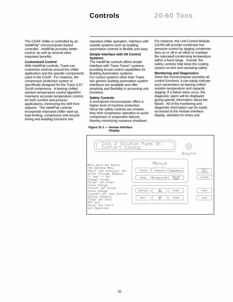
31
Controls 20-60 Tons
standard chiller operation. Interface withoutside systems such as buildingautomation controls is flexible and easy.
Simple Interface with All ControlSystemsThe IntelliPak controls afford simpleinterface with Trane Tracer® systems,providing broad control capabilities forBuilding Automation systems.For control systems other than Trane,two generic building automation systeminterfaces are available and offersimplicity and flexibility in accessing unitfunctions.
Safety ControlsA centralized microcomputer offers ahigher level of machine protection.Since the safety controls are smarter,they limit compressor operation to avoidcompressor or evaporator failures,thereby minimizing nuisance shutdown.
The CGAF chiller is controlled by anIntelliPak® microcomputer-basedcontroller. IntelliPak provides bettercontrol, as well as several otherimportant benefits.
Customized ControlWith IntelliPak controls, Trane cancustomize controls around the chillerapplication and the specific componentsused in the CGAF. For instance, thecompressor protection system isspecifically designed for the Trane 3-D®
Scroll compressor. A leaving chilledsolution temperature control algorithmmaintains accurate temperature control,for both comfort and processapplications, minimizing the drift fromsetpoint. The IntelliPak controlsincorporate improved chiller start-up,load limiting, compressor anti-recycletiming and lead/lag functions into
For instance, the Unit Control Module(UCM) will provide condenser lowpressure control by staging condenserfans on or off in an effort to maintainthe saturated condensing temperaturewithin a fixed range. Overall, thesafety controls help keep the coolingsystem on-line and operating safely.
Monitoring and DiagnosticsSince the microcomputer provides allcontrol functions, it can easily indicatesuch parameters as leaving chilledsolution temperature and capacitystaging. If a failure does occur, thediagnostic alarm will be displayedgiving specific information about thefailure. All of the monitoring anddiagnostic information can be easilyaccessed at the Human Interfacedisplay, standard on every unit.
Figure 31-1 — Human InterfaceDisplay

32
Controls 20-60 TonsInterface
example, if a field supplied TraneCommunication Interface (TCI)module was added to the unit in thefield, the unit configuration would needto be edited to reflect that feature.
• SERVICE — used to selectivelycontrol outputs (for compressors,fans, etc.) when servicing ortroubleshooting the unit. This menu isaccessible only at the unit-mountedHuman Interface Panel.STOP, AUTO — when the chiller is inthe stop mode, pressing the AUTOKEY will cause the UCM to go intoeither the Auto/Local or Auto/ICSmode, depending on the setpointsource setting.
Chiller Capacity Control — The UnitControl Module (UCM) will controlleaving solution temperature to a useradjustable setpoint. The UCMmonitors the leaving solutiontemperature sensor and determineshow far away this temperature is fromthe leaving solution setpoint and howlong it has been there. The rate atwhich capacity stages are added orsubtracted is determined by a controlintegrator algorithm. This algorithmcalculates a control integrator valuebased upon the inputs from thecontrol response setpoint, thedifference between the leavingsolution setpoint and the leavingsolution temperature, the number ofcapacity steps, and the design deltatemperature. This function can beuser defined for comfort or processcontrol applications. The followingsetpoints are integrated into thecapacity control algorithm:
Leaving Solution Setpoint (LSS) —The LSS is adjustable from the factoryas standard within a range from 40-50°F. Three other possible rangescan be selected and ordered from thefactory, 20-29, 30-39°, and 51-65°F.When these options are selected, theunit hardware changes to allow theunit to operate under safe conditions.
Standard Control FeaturesHuman Interface (HI) PanelThe Human Interface (HI) Panelprovides a 2 line X 40 character clearEnglish language liquid crystal displayand a 16 button keypad formonitoring, setting, editing andcontrolling. The Human InterfacePanel is mounted in the unit’s maincontrol panel and is accessiblethrough a hatch built into the unit’scontrol panel door.The optional remote-mounted versionof the Human Interface panel has allthe functions of the unit-mounted HI,with the exception of the ServiceMode. To use a Remote HumanInterface (RHI), the unit must beequipped with an optionalInterProcessor CommunicationsBridge (IPCB). The RHI can belocated up to 5,000 feet from the unit.A single RHI can be used to monitorand control up to 4 chillers, eachcontaining an IPCB.
The Main Menu of the HumanInterface panel:
• STATUS — used to monitor alltemperatures, pressures, setpoints,input and output status. The CUSTOMKEY will have four reports that can beuser defined. The report screensconsist of the data available in themain status menu.
• SETPOINTS — used to edit all factorypreset default setpoints and assignsetpoint sources.
• DIAGNOSTICS — used to reviewactive and historical lists of diagnosticconditions. A total of 41 differentdiagnostics can be read at the HumanInterface Panel. The last 20diagnostics can be held in an activehistory buffer log at the HumanInterface Panel.
• SETUP — Control parameters, sensorselections, setpoint source selections,output definitions, and numerousother points can be edited from thismenu. All points have factory presetvalues so unnecessary editing is keptto a minimum.
• CONFIGURATION — Preset withthe proper configuration for the unitas it ships from the factory, thisinformation would be edited only ifcertain features were physicallyadded or deleted from the unit. For

33
Controls 20-60 TonsInterface
Design Delta Temperature setpoint—- the design delta T drop within theevaporator is adjustable from 4-20 °Fin one degree increments. In addition,the control response setpoint canaffect the speed of the UCM’sresponse to changing coolingrequirements. This value can be setthrough the HI to allow flexibility inmaintaining precise control conditions.
Chiller Freeze Protection — Themicroprocessor will prevent theevaporator fluid from freezing byreducing chiller capacity, ultimatelyshutting down all compressors andsending a manually resettablediagnostic. The inputs for freezeprotection are the low leaving solutiontemperature cutout and the leavingsolution temperature.
Evaporator Solution Flow Interlock— The IntelliPak controls offer both aninternal loss of flow protection, as wellas an external evaporator flow switchinterlock. Internally, the controlalgorithm will sense and compare theentering solution temperature and theleaving solution temperature to detectloss of flow during or after start-up.This input to the UCM shall havepriority over all other commands andwill stop the chiller and a manuallyresettable diagnostic will result.Additionally, an external field installedflow switch can be wired into the unitterminal strip; this feature can beenabled or disabled. When an opencondition is detected for 6 seconds orlonger, the chiller will shut down andsend a manually resettable diagnosticalarm.
Head Pressure Control —Condenser head pressure control isprovided in the UCM by stagingcondenser fans on or off to maintainthe saturated condensingtemperature. This function will allowcooling operation down to 30°F asstandard. Minimum on and off timingis built into the algorithm to preventrapid cycling.
Pump down — This feature can beenabled or disabled through theHuman Interface. When it is enabled,pump down will be initiated prior toshutting down the last capacity stageon each circuit by de-energizing aliquid line solenoid valve. Pump downis terminated by the opening of thelow pressure switch, or 30 seconds
after the cycle is initiated. On unitsequipped with hot gas bypass, pumpdown will be initiated upon terminationof the hot gas bypass cycle.
Chiller Solution Pump Control —The UCM has two operating modesfor the chiller solution pump control,Auto and On. The UCM additionallyhas a relay output that will energize/de-energize the chiller’s solutionpump control circuit. The relay isdeenergized, stopping the pump,when emergency stop is activated.The solution pump relay is energizedto run the pump in the followingmodes: freeze protection, normalcooling control, low ambient freezeprotection, ice building and loopstabilization, and service mode.Modes that will request the pump tostop are ice building complete, icebuilding delay, unit stop and externalauto/stop.
Low Ambient Start Control — Twofunctions are integrated into thecontrol to allow operation in extremeconditions and still protect the overallsystem. Low ambient start control willallow compressor operation below65°F. In order to avoid nuisancetripping, the low pressure control willbe bypassed for a period of time. Ifthe low pressure control is still open atthe end of the period, the compressoris shut down and the solenoid valve isopened. The loss of refrigerant flowprotection is active in this sequence toadditionally protect the chiller.
Hot Start Control — A high ambientstart sequence will permit only onecompressor to operate when theleaving solution temperature is in theuser adjustable range of 60-80°F.When the leaving solutiontemperature falls below this high limit,the second compressor will be active.
Low Ambient Compressor Lockout— This function will lock out thecompressor if the outdoor airtemperature is below the low ambientcompressor lock out temperaturesetpoint. This setpoint is adjustable atthe Human Interface Panel (HI)between 0-60°F. Compressors will belocked out when outdoor airtemperatures fall below that selectedtemperature and will be allowed tostart again when the temperaturerises 5° F above the setpoint.
Compressor Lead/Lag —Compressor lead/lag is a user-selectable feature through the HumanInterface Panel available on all units.When enabled, the algorithm in theUCM will start compressors basedupon the least number of starts and/orrun time. This feature is not availablewith the hot gas bypass option.
Emergency Stop Input — A binaryinput is provided on the Unit ControlModule (UCM) for installation of fieldprovided switch or contacts forimmediate shutdown of all unitfunctions.
External Auto/Stop — A set ofcontacts or switches can be fieldinstalled that will start and stop thechiller.
Demand Limit — The UCM willaccept an input from a field installeddevice which will prevent one or morecompressors from operating. Theuser can select the number ofcompressors to be turned off.Leaving Solution Reset — Thisflexible option allows active leavingsolution reset based on customerselectable inputs from the zone,entering solution temperature oroutside air temperature. When theapplication is sensitive to one of theseparameters, subcooling of criticalzones is prevented.
Optional Control Features
Current Monitoring — This optionwill measure and average the ampdraw of 2 phases of each compressor.
Superheat/Subcooling Option —This option will include the necessarytemperature and pressure sensors tomeasure and calculate the chiller’ssuperheat and subcooling numbersfor each circuit. These temperaturesand pressures, along with calculatedvalues of superheat/subcool, will bedisplayed in the status menu of theHuman Interface. No externalrefrigerant gauges need to beinstalled on the chiller for the systemoperator to check out theseconditions.
34
Controls 20-60 TonsInterface
Hot Gas Bypass (HGBP) — TheHGBP control allows unit operationbelow the minimum step of unloading.Hot gas bypass is initiated when thelast capacity step is running and thecapacity control algorithm generates asubtract command. HGBP remainsenergized until the load increases, thechiller freeze protection function isactivated, a user defined run time hasexpired, the low pressure control isopen, or the unit goes into ice buildingmode.
Alarm and Max Capacity Relay —These features are user selectableand are mutually exclusive of eachother. If the alarm relay output isselected, it will provide a way totrigger a field supplied alarmwhenever the UCM detects a faultrequiring manual reset. The customercan assign which fault modes willtrigger the alarm relay. The alarm willdeenergize when the manual reset iscleared. When Max Capacity Outputis selected, it will trigger a fieldinstalled device indicating the unit hasreached its maximum cooling stage;this gives the customer the ability toturn on auxiliary systems to managecomfort.
Ice Building Control — A contactclosure on the UCM allows either afield installed device or an ICS systemto initiate the unit to operate in the icebuilding mode. In this mode normalchiller temperature control isbypassed and the unit runs fullyloaded until ice building is complete.There are two optional ice buildingmodes that can be selected throughthe HI. Ice building is terminatedwhen the customer provide contactsare opened, Ice Building Stop isinitiated from the Tracer, or theentering solution temperature reachesor drops below the ice buildingterminate setpoint.
External Leaving Solution Setpoint— Remote setpoint potentiometer canbe ordered to allow adjustment of theleaving solution setpoint remotely.
Generic Building AutomationSystem Module (GBAS) — TwoGeneric Building Automation SystemModules (GBAS) are available as anoption to provide broad controlcapabilities for building automationsystems, other than the Trane’sTracer® system.
The 0-5 vdc input GBAS Modulecontains 4 analog inputs, one binaryinput for demand limit, and 5 binaryoutputs.
• The 4 Analog inputs can accept a 0-5 vdc or a three wire potentiometersignal and be assigned to:1. Leaving Solution Setpoint2. Ice Build Terminate Setpoint3. Hot Start Load Limit Setpoint4. Maximum Capacity Level
Setpoint• The 5 Binary Outputs can be
assigned:1. Active Unit Diagnostics2. Compressor running status3. Maximum Capacity (all
compressors running)4,5. Open - Diagnostics can be
grouped or individually assignedby the user and may be placed
in these outputs.
The 0-10 vdc input GBAS modulecontains 4 analog inputs, one binaryinput for demand limit, four analogoutputs and one binary output.
• The 4 analog inputs can accept a 0-10 vdc signal and be assigned to:1. Leaving Solution Setpoint2. Ice Build Terminate Setpoint3. Hot Start Load Limit Setpoint4. Maximum Capacity Level Setpoint
• The 4 analog outputs can beassigned to:1. Leaving Solution Temperature2. Entering Solution Temperature3. Saturated Condenser Temp.
Ckt 1, 24. Evaporator Temp. Ckt 1, 25. Liquid Line Pressure Ckt1, 26. Suction Pressure Ckt 1, 27. Actual Capacity Level8. Outdoor Air Temperature
• One Binary output can be assignedto:1. Active Unit Diagnostics2. Compressors Running Status3. Max Capacity
• Option 1 - One time Ice buildingmode allows the unit to run fullyloaded until the entering solutiontemperature falls to the active icebuilding terminate setpoint (IBTS)When the entering solutiontemperature reaches the terminatesetpoint, the unit will go throughpumpdown if enabled and remain inIce Complete standby mode until theice build mode is terminated.
• Option 2 - Continuous ice buildmode allows the unit to run fullyloaded until the entering solutiontemperature falls to the active icebuilding terminate setpoint (IBTS).When the entering solutiontemperature reaches the terminatesetpoint, the unit will go throughpumpdown if enabled, and remain inIce build delay. The unit will remain inice build stand-by until the ice buildtimer expires. The unit will then startthe pump and wait for the loopstabilization timer to expire. The unitwill run fully loaded until the enteringsolution temperature falls below theice build termination setpoint. Theunit will continue cycling through theseice building states until the Ice buildmode is terminated or changed tooption 1.

35
10 TonDimensionalData
Figure 35-1 — CGA-120B Unit Dimensions
®
Notes:1. Minimum clearance around the perimeter of the unit is 3 feet. Minimum clearance between adjacent units
is 6 feet.2. When installing water pipes, be certain to route them away from the compressor access panels to allow
for compressor servicing or replacement.

36
DimensionalData
15 Ton
Figure 36-1 — CGA-180B Unit Dimensions
Notes:1. Minimum clearance around the perimeter of the unit is 3 feet.Minimum clearance between adjacent units is 6 feet.2. When installing water pipes, be certain to route them away from thecompressor access panels to allow for compressor servicing orreplacement.

37
DimensionalData
20 Ton
Figure 37-1 — CGAF-C20 Unit Dimensions

38
DimensionalData
25 Ton
Figure 38-1 — CGAF-C25 Unit Dimensions

39
30 TonDimensionalData
Figure 39-1 — CGAF-C30 Unit Dimensions
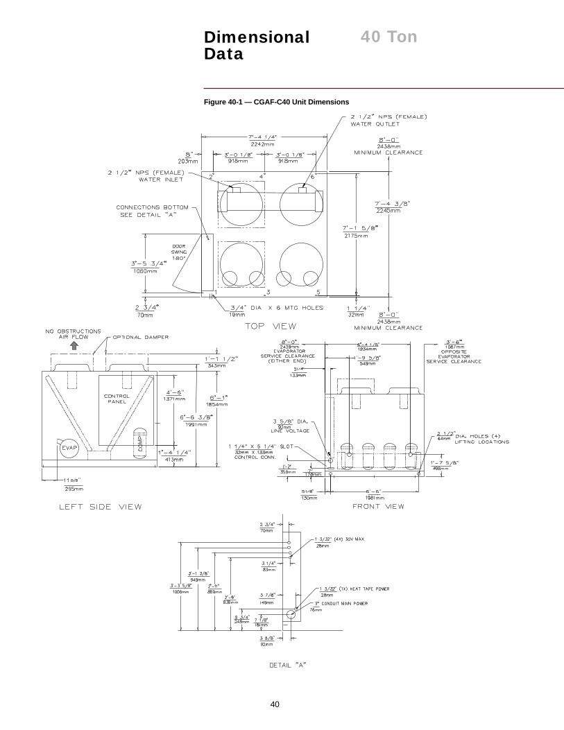
40
40 TonDimensionalData
Figure 40-1 — CGAF-C40 Unit Dimensions

41
50 TonDimensionalData
Figure 41-1 — CGAF-C50 Unit Dimensions

42
DimensionalData
60 Ton
Figure 42-1 — CGAF-C60 Unit Dimensions

43
Weights 10-60 Tons
Table 43-1 — Approximate Corner Weights (lbs) 10-Ton UnitIsolator Loading
Tons Model Number 1 2 3 4 Operating Wt. Shipping Wt.10 CGA 120B 187 180 116 112 595 642
Table 43-2 — Approximate Corner Weights (lbs) 15-Ton UnitIsolator Loading
Tons Model Number 1 2 3 4 Operating Wt. Shipping Wt.15 CGA 180B 222 223 205 204 854 937
Table 43-3 — CGAF Unit Weights (lbs)Model Condenser Isolator Loadings Location (lbs) Operating Shipping
Tons Number Fin Type 1 2 3 4 5 6 Weight (lbs) Weight (lbs)
Aluminum 654 586 449 402 — — 2091 1994Copper 710 630 513 455 — — 2308 2211
Aluminum 684 656 478 459 — — 2277 2187Copper 752 719 558 534 — — 2563 2474
Aluminum 884 641 641 465 399 289 3319 3223Copper 958 680 723 513 488 346 3708 3614
Aluminum 573 674 544 640 516 606 3553 3438Copper 625 725 609 706 592 687 3944 3828
Aluminum 712 838 642 756 572 673 4193 4072Copper 793 916 733 847 672 777 4738 4618
Aluminum 875 1135 805 1044 734 952 5545 5289Copper 1013 1269 958 1200 903 1131 6474 6218
Notes:1. Operating weights include refrigerant and water, but do not include weight of accessories.2. Shipping weights include refrigerant and crating.3. Refer to dimensional data for location of isolator loading points.
®
30 CGAFC30
40 CGAFC40
50 CGAFC50
60 CGAFC60
25 CGAFC25
20 CGAFC20
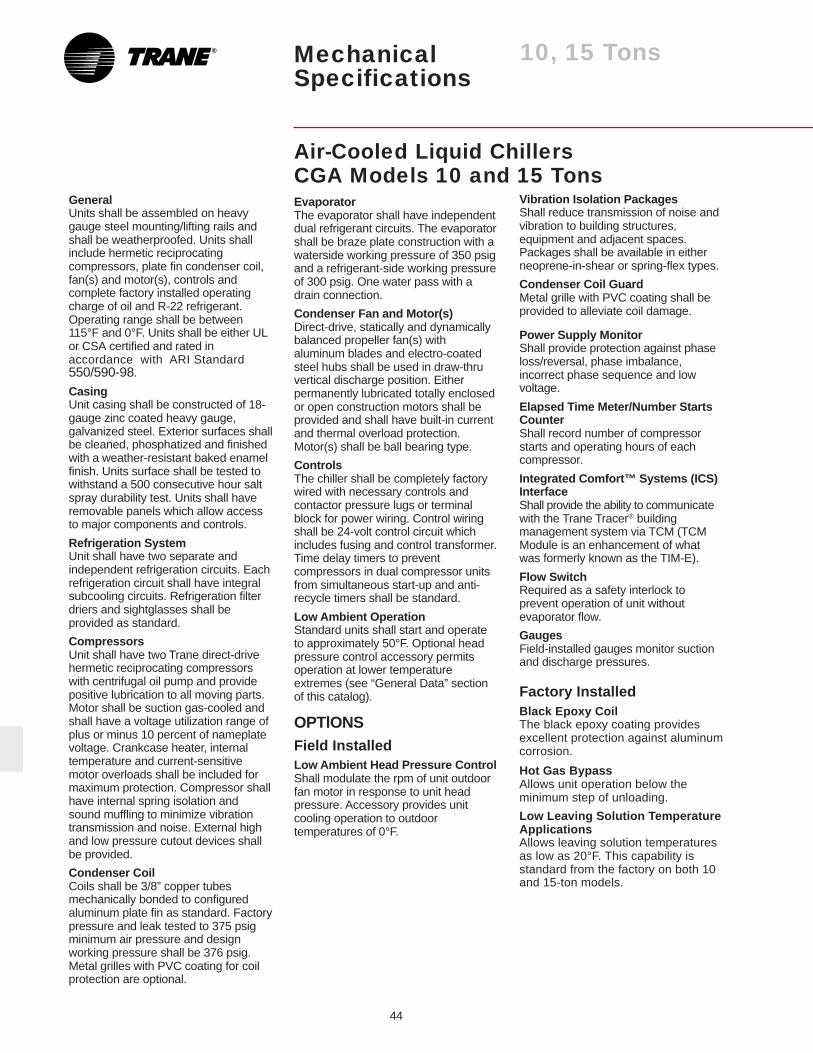
44
MechanicalSpecifications
10, 15 Tons
Air-Cooled Liquid ChillersCGA Models 10 and 15 Tons
®
GeneralUnits shall be assembled on heavygauge steel mounting/lifting rails andshall be weatherproofed. Units shallinclude hermetic reciprocatingcompressors, plate fin condenser coil,fan(s) and motor(s), controls andcomplete factory installed operatingcharge of oil and R-22 refrigerant.Operating range shall be between115°F and 0°F. Units shall be either ULor CSA certified and rated inaccordance with ARI Standard550/590-98.
CasingUnit casing shall be constructed of 18-gauge zinc coated heavy gauge,galvanized steel. Exterior surfaces shallbe cleaned, phosphatized and finishedwith a weather-resistant baked enamelfinish. Units surface shall be tested towithstand a 500 consecutive hour saltspray durability test. Units shall haveremovable panels which allow accessto major components and controls.
Refrigeration SystemUnit shall have two separate andindependent refrigeration circuits. Eachrefrigeration circuit shall have integralsubcooling circuits. Refrigeration filterdriers and sightglasses shall beprovided as standard.
CompressorsUnit shall have two Trane direct-drivehermetic reciprocating compressorswith centrifugal oil pump and providepositive lubrication to all moving parts.Motor shall be suction gas-cooled andshall have a voltage utilization range ofplus or minus 10 percent of nameplatevoltage. Crankcase heater, internaltemperature and current-sensitivemotor overloads shall be included formaximum protection. Compressor shallhave internal spring isolation andsound muffling to minimize vibrationtransmission and noise. External highand low pressure cutout devices shallbe provided.
Condenser CoilCoils shall be 3/8” copper tubesmechanically bonded to configuredaluminum plate fin as standard. Factorypressure and leak tested to 375 psigminimum air pressure and designworking pressure shall be 376 psig.Metal grilles with PVC coating for coilprotection are optional.
Vibration Isolation PackagesShall reduce transmission of noise andvibration to building structures,equipment and adjacent spaces.Packages shall be available in eitherneoprene-in-shear or spring-flex types.
Condenser Coil GuardMetal grille with PVC coating shall beprovided to alleviate coil damage.
Power Supply MonitorShall provide protection against phaseloss/reversal, phase imbalance,incorrect phase sequence and lowvoltage.
Elapsed Time Meter/Number StartsCounterShall record number of compressorstarts and operating hours of eachcompressor.
Integrated Comfort™ Systems (ICS)InterfaceShall provide the ability to communicatewith the Trane Tracer® buildingmanagement system via TCM (TCMModule is an enhancement of whatwas formerly known as the TIM-E).
Flow SwitchRequired as a safety interlock toprevent operation of unit withoutevaporator flow.
GaugesField-installed gauges monitor suctionand discharge pressures.
Factory InstalledBlack Epoxy CoilThe black epoxy coating providesexcellent protection against aluminumcorrosion.
Hot Gas BypassAllows unit operation below theminimum step of unloading.
Low Leaving Solution TemperatureApplicationsAllows leaving solution temperaturesas low as 20°F. This capability isstandard from the factory on both 10and 15-ton models.
EvaporatorThe evaporator shall have independentdual refrigerant circuits. The evaporatorshall be braze plate construction with awaterside working pressure of 350 psigand a refrigerant-side working pressureof 300 psig. One water pass with adrain connection.
Condenser Fan and Motor(s)Direct-drive, statically and dynamicallybalanced propeller fan(s) withaluminum blades and electro-coatedsteel hubs shall be used in draw-thruvertical discharge position. Eitherpermanently lubricated totally enclosedor open construction motors shall beprovided and shall have built-in currentand thermal overload protection.Motor(s) shall be ball bearing type.
ControlsThe chiller shall be completely factorywired with necessary controls andcontactor pressure lugs or terminalblock for power wiring. Control wiringshall be 24-volt control circuit whichincludes fusing and control transformer.Time delay timers to preventcompressors in dual compressor unitsfrom simultaneous start-up and anti-recycle timers shall be standard.
Low Ambient OperationStandard units shall start and operateto approximately 50°F. Optional headpressure control accessory permitsoperation at lower temperatureextremes (see “General Data” sectionof this catalog).
OPTlONSField InstalledLow Ambient Head Pressure ControlShall modulate the rpm of unit outdoorfan motor in response to unit headpressure. Accessory provides unitcooling operation to outdoortemperatures of 0°F.
45
20-60 TonsMechanicalSpecifications
Air-Cooled Liquid ChillersCGAF Models 20-60 Tons
GENERALAll chillers are factory run-tested toconfirm proper operation. Units arechecked on a computer-based teststand at typical ambient and waterconditions and control operation ismonitored. Units ship with a fulloperating charge of refrigerant and oil.
Units are constructed of 14-gaugewelded galvanized steel frame with 14and 16-gauge galvanized steel panelsand access doors. Unit surface isphosphatized and finished with an air-dry paint. This air-dry paint finishexceeds 672 consecutive hour saltspray resistance in accordance withASTM B117.
EvaporatorTube-in-shell design with seamlessinternally finned copper tubes, roller-expanded into tube sheets. Chiller isdesigned, tested and stamped inaccordance with ASME code forrefrigerant side working pressure of225 psig. The chiller is designed towithstand a waterside working pressureof 300 psig. It has one water pass witha series of internal baffles. Each shellincludes a drain and a vent connection,fittings for temperature control sensorsand 3/4-inch insulation (K = 0.26). Heattape, which is thermostat controlled,protects the evaporator to an ambientof -20°F.
CondenserAir-cooled condenser coils haveconfigurated aluminum finsmechanically bonded to seamlesscopper tubing and integral subcoolingcircuits. Condensers are factory leak-tested with air underwater at 425 psigair pressure.
Direct-drive vertical dischargecondenser fans are statically anddynamically balanced. Three-phasecondenser fan motors with permanentlylubricated ball bearings and three-phase thermal overload protection.Optional low ambient units start andoperate to 0°F with electronic damperassemblies for head pressure control.
Unit ControlsCompressor contactors and unitcontrols are in a weathertight enclosurewith knockouts for jobsite installedwiring. The unit controller shall besuitable to control leaving chilledsolution temperature for comfort orprocess applications, automaticcompressor sequencing, condenser fansequencing, load limiting and anti-recycle functions. Failure protectionsinclude loss of chilled solution flow,chiller freeze protection, chilled solutionflow interlock, head pressure control,pump down control, low ambient start,hot start control, and low ambientlockout. Leaving and entering solutiontemperature sensor is factory installed.Controls include auto/stop switch, aleaving water temperature setpointadjustment, a Delta T adjustmentviewable through the unit HumanInterface digital display.
Decorative grilles provide protectionfrom exterior damage to coil surfaceand other interior unit components.Grilles are factory mounted, louvered,galvanized steel mesh panels finishedwith an air-dry paint. Grilles will coverall open ends of units.
CompressorsTrane 3-D® Scroll compressors havesimple mechanical design with onlythree major moving parts. Scroll typecompression provides inherently lowvibration. The 3-D Scroll provides acompletely enclosed compressionchamber which leads to increasedefficiency. Exhaustive testing on the3-D Scroll, including start up with theshell full of liquid, has proven thatslugging does not fail involutes.Direct-drive, 3600 rpm, suction gas-cooled hermetic motor. Trane 3-DScroll compressor includescentrifugal oil pump, oil levelsightglass and oil charging valve.Each compressor shall have crankcaseheaters installed, properly sized tominimize the amount of liquidrefrigerant present in the oil sumpduring off cycles.
Refrigerant Circuits and CapacityModulationTwenty through 30-ton sizes have asingle refrigerant circuit. Forty through60-ton sizes have dual refrigerantcircuits. Each refrigerant circuit has twoTrane 3-D Scroll compressors, piped inparallel, with a passive oil managementsystem. Passive oil managementsystem maintains proper oil levelswithin compressors and has no movingparts. Each refrigerant circuit includesan expansion valve, a filter drier, and aliquid line sightglass with moistureindicator. Capacity modulation isachieved by turning compressors onand off. Twenty through 30-ton sizeshave two capacity stages. Forty, 50and 60-ton sizes have four capacitystages. The standard leaving chilledwater temperature range is 40°F to50°F. Options are available for leavingchilled solution temperature rangesfrom 20° to 29°F, 30° to 39°F, and 51°to 65°F.

46
20-60 TonsMechanicalSpecifications
and interconnecting wiring are in properoperating condition.
The modules (boards) shall beprotected to prevent RFI and voltagetransients from affecting the board’scircuits. All field wiring shall beterminated at separate, clearly markedterminal strip. Direct field wiring to theI/O boards is not acceptable.
The microprocessor’s memory shall benon-volatile EEPROM type requiring nobattery or capacitive backup, whilemaintaining all data.2Zone sensor will be available for zonetemperature reset.3The Human Interface Panel’s keypaddisplay character format shall be 40characters x 2 lines. The character fontshall be 5 x 7 dot matrix plus cursor.The display shall be Supertwist LiquidCrystal Display (LCD) with bluecharacters on a gray/green backgroundwhich provides high visibility and easeof interface. The display format shall bein clear English. Two or three digitcoded displays are not acceptable.4The keypad shall be equipped with16 individual touch-sensitive membranekey switches. The switches shall bedivided into four separate sections andbe password protected from changeby unauthorized personnel. The sixmain menus shall be STATUS,SETPOINTS, DIAGNOSTICS,SETUP, CONFIGURATION andSERVICE MODE.
Unit ControllerDDC microprocessor controls shall beprovided to control all unit functions.The control system shall be suitable tocontrol comfort and processapplications. The controls shall befactory-installed and mounted in themain control panel. All factory-installedcontrols shall be fully commissioned(run tested) at the factory. The unit shallhave a Human Interface Panel with a 16key keypad, a 2 line X 40 characterclear English display as standard toprovide the operator with full adjustmentand display of control data functions.The unit controls shall be used as astand-alone controller, or as part of abuilding management system involvingmultiple units.1The unit shall be equipped with acomplete microprocessor controlsystem. This system shall consist oftemperature and pressure (thermistorand transducer) sensors, printed circuitboards (modules), and a unit mountedHuman Interface Panel. Modules(boards) shall be individuallyreplaceable for ease of service. Allmicroprocessors, boards and sensorsshall be factory mounted, wired andtested.
The microprocessor boards shall bestand-alone DDC controls notdependent on communications with anon-site PC or a Building ManagementNetwork. The microprocessors shall beequipped with on-board diagnostics,indicating that all hardware, software
Standard power connections includemain three-phase power and a single115-volt, 24-volt single-phaseconnection that handles unit controls.
Unit accepts any of these jobsitesupplied contact closures for:
External Auto/Stop — A contact closurethat will start and stop the unitoperation.
External Chilled Solution Interlock —A chilled solution pump interlock incombination with a flow switch is notrequired for unit protection since the unitcontroller senses loss of flow. Ifadditional flow protection is required, orif the pump contactor is used toschedule the unit, this input may beused.
Kw Demand Limit — Unit will only beallowed to operate on user selectedquantity of compressors in order tomaintain the building demand limit.
Ice BuildingTwo ice building modes are optionaland can be ordered on the unit. Thetwo modes are one time ice build modeand continuous ice build mode.

47
MechanicalSpecifications
20-60 Tons
Generic Building Automation System(GBAS)Two modules are available to integratebuilding automation systems other thanTrane. The modules are designed foreither 0-5 vdc or 0-10 vdc signals.
Remote Human Interface (RHI) PanelThe Remote Human Interface Panelcan perform all the same functions asunit mounted Human Interface Panel,with the exception of the Service Mode.
The field installed RHI can monitor andcontrol up to 4 chillers. The RHI issuitable for mounting inside a building,up to 5,000 feet from the unit. The RHIis wired to the IPCB mounted in eachchiller with a wire pair communicationwiring and 24V control wiring.
Remote Setpoint PotentiometerField installed option that allows remoteadjustment of the leaving solutionsetpoint.
Zone Sensor (Chilled Solution Reset)Field installed zone sensor that allowsthe leaving chilled solution temperatureto be reset by the zone temperature.
Flow SwitchThis field installed option indicates lossof evaporator flow — available for fieldinstallation.
Copper Fin Condenser CoilsCopper fins mechanically bonded toseamless copper tubes are available foruse in corrosive atmospheres
Electronic Low Ambient Damper(s)Allows the unit to operate down to 0°Foutdoor ambient conditions.
Inter-Processor CommunicationBridge (IPCB)This module provides an amplified andfiltered version of the IPC link forconnection to a Remote HumanInterface (RHI) Panel. Each chiller thatis tied into a RHI must have a IPCBinstalled.
Other OptionsIn addition to all of these options, Tranecan offer in-house design for many ap-plications, including special coil coating.
Miscellaneous Options
Trane Communications InterfaceModule (TCI)Provides capability to communicate witha Trane ICS® system.
Compressor Current Sensing (CSM)This option measures and averagesamp draw on each compressor.
Unit Mounted DisconnectNon-fused, factory installed, and locatedinside the main control box, thisdisconnect switch features an externalhandle that allows the operator todisconnect unit power without having toopen the control box door.
IsolatorsSpring or neoprene-in-shear isolatorsavailable for jobsite installation.
Superheat/Sub-CoolingIn place of externally mountedrefrigerant gauges, a module can beordered that will calculate and displayon the Human Interface (HI) eachcircuit’s superheat and subcoolingtemperatures.
Hot Gas BypassAlthough unnecessary on scroll chillersfor comfort applications (due to scrollcycling capabilities), hot gas bypass isstill available for applications requiringclose temperature control at low loadconditions.

Library Product Literature
Product Section Refrigeration
Product Air-Cooled Liquid Chiller
Model 000
Literature Type Data Sales Catalog
Sequence 1
Date July 1997
File No. PL-RF-CG-000-DS-1-0797
Supersedes CG-DS-1 7/96Ordering No. CG-DS-1
The Trane Company2701 Wilma Rudolph BoulevardClarksville, TN 37040
www.trane.com
An American-Standard Company
Since The Trane Company has a policy of continuousproduct improvement, it reserves the right to changedesign and specification without notice.