-2000tm immer cabinet with d controls · tell a dimmer module whether it is to be a dimmer or a...
TRANSCRIPT
User Guide
a-2000TM DIMMER CABINET WITH DIGITAL CONTROLS
12 & 24 CIRCUIT VERSIONSSoftware revision 2.40 and above
COMMUNICATION PORTS
FULL BRIGHT
AUXILIARY
LUMANET
PHASE LOSS
DMX
FAN
R
BRIGHT
SELECT
CANCEL
FULL
SAVE
CLEAR
INDUSTRIAL CONTROL EQUIPMENT
TUALATIN, OR
32300AR
MADE IN U.S.A.
a-2000R
TM
LISTED
88H9 C R
20
20
20
MODULE
MODULE
9
8
20
20
20
20
20
20
20
20
20
20
20
MODULE
MODULE
BYPASSNORMAL
7
6
MODULE
MODULE
MODULE
BYPASSNORMAL
5
4
3
20
20
20
20
20
20
20
B
MODULE
MODULE
BYPASSNORMAL
C
PHASE
2
1
CONTROL
PHASE
A
PHASE
10MODULE
11
12
MODULE
MODULE
NORMAL BYPASS
20
20
20
20
20
20

Notes:

a-2000 User Guide
Overview . . . . . . . . . . . . . . . . . . . . . . . . . . . . . . . . . . . . . . . . . . . . . . . 5Inspection ..........................................................................................................5Updates .............................................................................................................5Description .........................................................................................................5Control Overview ...............................................................................................6Mounting - Surface or Flush Mounted? .............................................................6Stacked Mounting ..............................................................................................6Cooling Fans .....................................................................................................6Feed and Load Wiring .......................................................................................7Control Input Wiring ...........................................................................................7Fluorescent Wiring .............................................................................................7Turn On .............................................................................................................7Bypass Switch - Non Universal 120V Units Only ..............................................7Bypass Shunts - Non Universal 277V Units Only ..............................................7Bypass Switch-Universal Units Only .................................................................8Modules .............................................................................................................8Checklist ............................................................................................................8
Warnings . . . . . . . . . . . . . . . . . . . . . . . . . . . . . . . . . . . . . . . . . . . . . . . 9Installation . . . . . . . . . . . . . . . . . . . . . . . . . . . . . . . . . . . . . . . . . . . . . 10
Installation Checklist - Non Universal 120V Units .............................................10Installation Checklist - Non Universal 277V and Universal Units ......................10Step 1: Mounting ...............................................................................................11
Step 1A -Surface Mount ...............................................................................11Flush Mount .......................................................................................................12
Step 1B - Flush Mount Frames ....................................................................12Main Feed and Load Wiring . . . . . . . . . . . . . . . . . . . . . . . . . . . . . . . 14
Step 2: Power Wiring - Feed\Line Wiring ..........................................................14Step 3: Load Circuit Wiring - 120 Volt Units ......................................................18Step 4 - Relay Cabinet (OPTIONAL) .................................................................21
Low Voltage Control Wiring . . . . . . . . . . . . . . . . . . . . . . . . . . . . . . . 23Step 5: Control Input Wiring ..............................................................................23Luma-Net® III ....................................................................................................24
Power Considerations for Control Systems .................................................24Power Requirements & Maximum Run Length ............................................24Power Wire - Run Length .............................................................................26Terminating the wiring ..................................................................................26Wiring the Phoenix Connector .....................................................................29Special Feature for Low Voltage Power Terminations .................................30Testing the Wiring ........................................................................................31DMX-512 ......................................................................................................32DMX Wire Recommendation: .......................................................................32Analog Input, 0-10 VDC (Optional) ..............................................................33
Photocell Input ...................................................................................................33Multiple Signal Types ...................................................................................35External Full On/Emergency (Full Bright) .....................................................36
a-2000 Page 1 Dimmer Cabinets with Digital ControlsRevision G November 2006

Step 6: Fluorescent Dimming and Control Output Wiring ..................................38Types of Dimming Ballasts ...........................................................................38
Other Ballast Types ...........................................................................................39Dimmer Module Installation . . . . . . . . . . . . . . . . . . . . . . . . . . . . . . . 40
Step 7: Dimmer Module Installation and/or Replacement .................................40Blanking Plates ............................................................................................40Removal or Installation of Dimmer Module: .................................................41To remove a dimmer module: ......................................................................41To install a dimmer module into one of the positions ...................................41
Step 8: Bypass Mode ........................................................................................43Set 120 V Non Universal Dimmers to Bypass Mode: ...................................43277V Non Universal Bypass ........................................................................44Universal Bypass .........................................................................................44
Step 9: Double Check the Wiring ......................................................................45Step 10: Turn On The Power .............................................................................45Step 11: Clear Faults that have Caused any Breakers to Trip ..........................45Step 12: 120 V Systems - Set Bypass Switches to Normal ...............................45
Digital Control Panel . . . . . . . . . . . . . . . . . . . . . . . . . . . . . . . . . . . . . 46Readouts and Indicators ....................................................................................46
LCD Display .................................................................................................46Programming/Function Buttons ....................................................................46LED Indicators ..............................................................................................46Navigation Buttons .......................................................................................47
Step 13: Configuration and Programming . . . . . . . . . . . . . . . . . . . . 48LCD Display Menu Structures ...........................................................................48
Basic Concepts ............................................................................................53Step 13A: Display at Startup .............................................................................54
Potential Error Screens in the Main Menu: ..................................................54To Auto Assign Module Types: ....................................................................54
Step 13B: Verifying Phase Voltages ..................................................................54Step 13C: Assigning Module Types ..................................................................54
Assign the Module/Load Type ......................................................................57 ...........................................................................................................................58Step 13D: Modify the Dimmer Type Features: ..................................................58Step 13E: Verifying Module Programming in a Dimmer Cabinet .......................60Step 13F: Assigning Luma-Net and/or DMX512 Channels ...............................61
Assigning Numbers Automatically ................................................................61Assigning Individual Control Channels .........................................................61Verifying Assignment of Mark VII Analog Output Signal ..............................62
Step 13G: Daylight Harvesting/Photocells .........................................................62Background-Daylighting: ..............................................................................62Background-Photocells: ...............................................................................63
Configuring your a-2000 cabinet to use a photocell: .........................................63For example, to use this feature given the following installation: .................65To Enable the dimmer for photocell control .................................................65
Page 2

a-2000 User Guide
Step: 13H: Modifying Factory Defaults ..............................................................65Luma-Net Restore: .......................................................................................66Line Regulation: ...........................................................................................66
Parts Replacement ............................................................................................67Specifications ....................................................................................................68
Appendix A . . . . . . . . . . . . . . . . . . . . . . . . . . . . . . . . . . . . . . . . . . . . . 69Control Inputs ....................................................................................................69
Luma-Net® III ...............................................................................................69DMX512 .......................................................................................................69Analog ..........................................................................................................69Multiple Signal Types ...................................................................................69
Types of Dimmer Modules .................................................................................70Dual Dimmer Module 000-A20DD-012(120V), -A27 (120/277V) .................70Constant Module 000-A20DC-012 (120V), -A27 (120/277V) .......................70High Rise Time Module 000-A20HD-012 .....................................................70Dual Universal Module 000-A20UN-012(120V), -027 (120/277V) ...............71
Fluorescent Dimming Ballast Types ..................................................................710-10 VDC Controlled Ballasts ......................................................................71Two-Wire Fluorescent Ballasts (Additional Control Wiring is not required) ..72Other Ballasts - Three-Wire- (Refer to the load wiring schematic.) ..............72
Warranty Information . . . . . . . . . . . . . . . . . . . . . . . . . . . . . . . . . . . . . 74Limited Warranty ...............................................................................................74Power Considerations for Control Systems .......................................................77
Terminology .................................................................................................77Power Requirements & Maximum Run Length ............................................77Power Wire - Run Length .............................................................................82
a-2000 Page 3 Dimmer Cabinets with Digital ControlsRevision G November 2006

Page 4
a-2000 User Guide
Overview
InspectionCarefully unpack the dimmer system, and inspect to make sure there has been no hidden shipping damage. Report all damage to the freight carrier who delivered the system. Claims for damages are filed with the freight carrier as all freight is shipped FOB Tualatin, Oregon. The a-2000 can be serviced in the field with replacement factory components in case of damaged parts.
UpdatesFor updates to this manual, latest bulletins, announcements, and other helpful documentation, please reference the support and product sections of Leviton’s webbiest which can be found at http://lms.leviton.com.
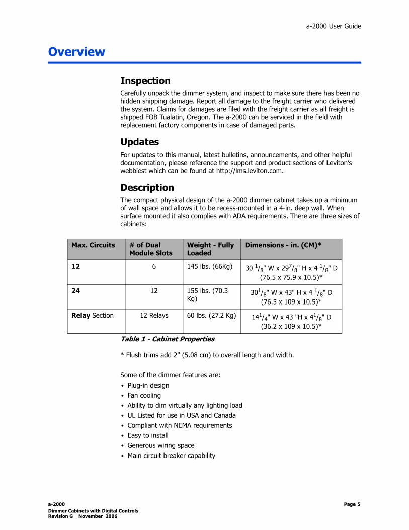
DescriptionThe compact physical design of the a-2000 dimmer cabinet takes up a minimum of wall space and allows it to be recess-mounted in a 4-in. deep wall. When surface mounted it also complies with ADA requirements. There are three sizes of cabinets:
Table 1 - Cabinet Properties
* Flush trims add 2" (5.08 cm) to overall length and width.
Some of the dimmer features are:• Plug-in design• Fan cooling• Ability to dim virtually any lighting load• UL Listed for use in USA and Canada• Compliant with NEMA requirements• Easy to install• Generous wiring space• Main circuit breaker capability
Max. Circuits # of Dual Module Slots
Weight - Fully Loaded
Dimensions - in. (CM)*
12 6 145 lbs. (66Kg) 30 1/8" W x 297/8" H x 4 1/8" D(76.5 x 75.9 x 10.5)*
24 12 155 lbs. (70.3 Kg)
301/8" W x 43" H x 4 1/8" D(76.5 x 109 x 10.5)*
Relay Section 12 Relays 60 lbs. (27.2 Kg) 141/4" W x 43 "H x 41/8" D
(36.2 x 109 x 10.5)*
a-2000 Page 5 Dimmer Cabinets with Digital ControlsRevision G November 2006

The control portion of the dimmer cabinet employs all digital circuitry for accuracy and for minimum wiring requirements between the dimmer cabinet and its control systems. Surface-mount and flush-mount units both include necessary mounting hardware.
Control OverviewThe Leviton a-2000D Dimmer Cabinet uses an intelligent central control card (Digital Main Control Module), enabling the dimmers in this system to dim and control virtually any incandescent or fluorescent lighting load. The software can tell a dimmer module whether it is to be a dimmer or a non-dim, tell it what type of fluorescent dimmer ballast it will operate, and set up the required parameters to properly drive virtually any type of fluorescent dimmer ballast. You can use three different types of control input signals, Luma-Net III, DMX512 and 0-10VDC (with optional Analog Card) to control the dimmers. The LCD display provides an easy user interface.
Mounting - Surface or Flush Mounted?The 12 and 24 circuit dimming cabinets comes standard for surface mounting. In order to flush mount the unit, you must use the appropriate flush mount hardware kit. Consult the factory for the appropriate kit.
Table 2 - Flush Trim Kits
Stacked MountingThe following cabinets can be joined together vertically and wired with a single feed:• 12+24 - Factory only.• 24+24 - Field or factory. Field kit part number A2K24-Kit This can be accomplished in the factory or the field using a UL listed bussing kit.
Cooling FansBoth surface and flush-mounted units contain fans for cooling. They are relatively quiet, but this unit should not be mounted where minor fan noise is objectionable. The fans are rated at 41 dBa each. The fan(s) are normally off when the system is off, and comes on when any dimmer comes on.
Cooling Fan dust covers should be removed and cleaned with compressed air or non abrasive cleaning agent every 6 months for optimum fan operation.
Cabinet Size/Type Flush Trim Kit Part Number
12 A2K12-T10
24 A2000-T10
12+24 A2K12-T30
24+24 A2000-T20
Page 6

a-2000 User Guide
Feed and Load WiringThe entire right side of the dimmer cabinet is reserved for power wiring. The cabinet includes:• Knockouts for feeding in and out through the top, bottom, or right side of the
cabinet.• Main lugs for phases A, B, and C (or A and B in the case of a single-phase
cabinet)• A load terminal block. • A multi-terminal neutral block.• A single ground terminalAn optional multiple-terminal ground bus is available, part number OPT-A2GND-KIT. Unless limited by an optional main breaker, the main lugs are sized for every dimmer to be loaded to maximum capacity. You may elect to size the feed to the actual connected load on the cabinet.
Control Input WiringThe upper left portion of the dimmer cabinet is reserved for control wiring.
Fluorescent Wiring There are several types of fluorescent dimming ballasts. Check carefully for the type of ballasts you are installing on this system.
Incorrect wiring of these ballasts to dimmers can damage the ballasts.
Turn OnPrior to turn on, verify the following is installed correctly:• Main feed wiring• Load wiring• Control wiring• Configuration of each module with the type of load connected and any ballast
control wiring
Bypass Switch - Non Universal 120V Units OnlyThe Bypass switch has two modes: Normal and Bypass. When the switches are set to Bypass, all the dimmer electronics are removed from the circuit and line is connected directly to load. Leviton normally ships the cabinet with all these switches in the Bypass position and all circuit breakers in the Off position.
Bypass Shunts - Non Universal 277V Units OnlyOn 277V units, the bypass is accomplished via an optional constant module.
a-2000 Page 7 Dimmer Cabinets with Digital ControlsRevision G November 2006

Bypass Switch-Universal Units OnlyThe bypass switch has two modes: Normal and Bypass. When the switch is set to Bypass (red LED illuminated) the SCR’s and relays are forced to turn on independent of the control module.
ModulesThe dimmer modules simply slide and plug in. No tools are required, except for a shipping screw when dimmers are pre-installed at the factory.
To avoid misapplication of product, 277V cabinets are mechanically keyed to reject 120V modules and the previous style of 277V dimmer modules without integral breakers.
Checklist Unpack the system Report any damages to the freight carrier Attach the flush or surface mounting hardware Attach the cabinet to the wall Terminate the main feed wiring Terminate the load wiring Terminate control wiring Verify the dimmer ballasts are correctly wired Verify the main feed wiring Verify the load wiring Verify the remote control wiring Verify the configuration of each module
Page 8

a-2000 User Guide
Warnings
1 To be installed and/or used in accordance with appropriate electrical codes and regulations.
2 To be installed by a qualified Electrician.3 DO NOT CONNECT line voltage wires to low voltage terminals.4 When a magnetic low voltage circuit is operated at a dim level, with all
lamps inoperative, excess current may flow through the transformer. To avoid possible transformer failure, due to over current, use a transformer that incorporates thermal protection or a fuse in the primary winding.
5 For best lamp life, lamp manufacturers recommend their fluorescent lamps should be operated at full brightness for a minimum or 100 hours before dimming is permitted. For best results, lamp brands and types should not be intermixed on a circuit
5a) Hook up flourescent control wiring, if required6 When using with fluorescent ballasts, both lighting fixture and ballast
must be grounded.7 Use this dimmer cabinet only with 90o C copper wire at 75o ampacity.8 Do not mix load types on a single zone (i.e. 120 V tungsten and magnetic
low voltage).9 Disconnect power when servicing the dimmer, fixture or when changing
lamps.10 Indoor use only.11 TO AVOID FIRE, SHOCK OR DEATH: TURN OFF POWER AT MAIN
CIRCUIT BREAKER OR FUSE AND TEST THAT THE POWER IS OFF BEFORE WIRING, OPENING THE PANEL, OR REPLACING A DIMMER MODULE!
a-2000 Page 9 Dimmer Cabinets with Digital ControlsRevision G November 2006
Installation
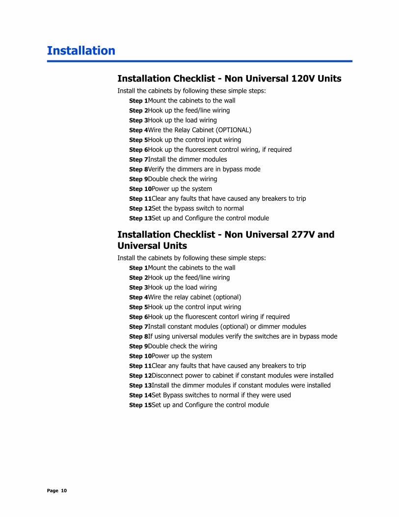
Installation Checklist - Non Universal 120V UnitsInstall the cabinets by following these simple steps:
Step 1Mount the cabinets to the wallStep 2Hook up the feed/line wiringStep 3Hook up the load wiringStep 4Wire the Relay Cabinet (OPTIONAL)Step 5Hook up the control input wiringStep 6Hook up the fluorescent control wiring, if requiredStep 7Install the dimmer modulesStep 8Verify the dimmers are in bypass mode Step 9Double check the wiringStep 10Power up the systemStep 11Clear any faults that have caused any breakers to tripStep 12Set the bypass switch to normalStep 13Set up and Configure the control module
Installation Checklist - Non Universal 277V and Universal UnitsInstall the cabinets by following these simple steps:
Step 1Mount the cabinets to the wallStep 2Hook up the feed/line wiringStep 3Hook up the load wiringStep 4Wire the relay cabinet (optional)Step 5Hook up the control input wiringStep 6Hook up the fluorescent contorl wiring if requiredStep 7Install constant modules (optional) or dimmer modulesStep 8If using universal modules verify the switches are in bypass modeStep 9Double check the wiringStep 10Power up the systemStep 11Clear any faults that have caused any breakers to tripStep 12Disconnect power to cabinet if constant modules were installedStep 13Install the dimmer modules if constant modules were installedStep 14Set Bypass switches to normal if they were usedStep 15Set up and Configure the control module
Page 10
a-2000 User Guide
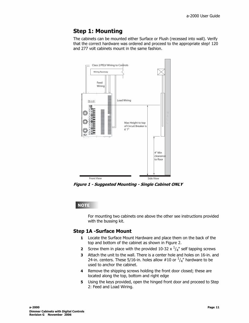
Step 1: MountingThe cabinets can be mounted either Surface or Flush (recessed into wall). Verify that the correct hardware was ordered and proceed to the appropriate step! 120 and 277 volt cabinets mount in the same fashion.
Figure 1 - Suggested Mounting - Single Cabinet ONLY
For mounting two cabinets one above the other see instructions provided with the bussing kit.
Step 1A -Surface Mount1 Locate the Surface Mount Hardware and place them on the back of the
top and bottom of the cabinet as shown in Figure 2.2 Screw them in place with the provided 10-32 x 1/4" self tapping screws3 Attach the unit to the wall. There is a center hole and holes on 16-in. and
24-in. centers. These 5/16-in. holes allow #10 or 1/4" hardware to be used to anchor the cabinet.
4 Remove the shipping screws holding the front door closed; these are located along the top, bottom and right edge
5 Using the keys provided, open the hinged front door and proceed to Step 2: Feed and Load Wiring.
Wiring Raceway
Class 2/PELV Wiring to Controls
FeedWiring
Load Wiring
WALL
Front View
4" Min clearance to floor
Max Height to top of Circuit Breaker is6' 7"
Side View
a-2000 Page 11 Dimmer Cabinets with Digital ControlsRevision G November 2006

Figure 2 - Surface Mount Hardware
Leviton recommends that cabinet mounting hardware reaches through the drywall and attaches to the wall studs. However, properly sized struts and suitable hardware can also be used. They must distribute the load to the anchors without exceeding the recommended anchor limit. Using drywall screws directly through drywall without a stud is not recommended.
Flush Mount
Step 1B - Flush Mount Frames
All Cabinets are designed to accept a Flush Mount kit (See Table 2) which is designed like a picture frame. To install, simply remove door, screw the four pieces to the front frame of the cabinet using the provided hardware and replace the door.
Install Steps - All Cabinets1 Remove the screws holding the front door closed; these are located along
the top, bottom and right edges.2 Locate the Flush Mount Hardware and place on the side of the cabinet as
shown in Figure 3.3 Screw them in place with the provided 10-32 x 1/4" self tapping screws.
The bottom left edge is not accessible for attaching a fourth mount. 4 Attach the unit to the wall using #10 or larger screws or 16-penny or
larger nails, through the 1/4" diameter holes in the mounting bracket and on the top, right, and bottom sides of the cabinet.
Attach mounting brackets tothe back of the cabinetas shown, using the 10-32 x 1/4" self-tappingscrews provided
Top
Page 12

a-2000 User Guide
5 Once the cabinet is mounted, proceed to Step 2: Feed and Load Wiring.
Figure 3 - Flush Mounting Hardware
Top
a-2000 Page 13 Dimmer Cabinets with Digital ControlsRevision G November 2006

Main Feed and Load Wiring
Step 2: Power Wiring - Feed\Line WiringThe entire right side of the dimmer cabinet is reserved for power wiring. Refer to Figure 4 and the cabinet labels for all appropriate wiring notes. The cabinet includes:• Knockouts for feeding in and out through the top, bottom, or right side of the
cabinet.• Main lugs for phases A, B, and C (or A and B in the case of a single-phase
cabinet (feed terminates to optional main breaker if provided).• A load terminal block to land all the dimmer output load wiring. • A multi-terminal neutral block.• A single ground terminal.Consult the factory if a multiple terminal ground bus is needed for your particular installation.
Unless limited by an optional main breaker, the main lugs are sized for every dimmer to be loaded to maximum capacity, however you may elect to size the feed to the actual connected load on the cabinet.
Page 14

a-2000 User Guide
Figure 4 - Typical Low Voltage and High Voltage Wire Connections
OptionalMainBreaker
High VoltageConnections
Low Voltage Wiring Area
a-2000 Page 15 Dimmer Cabinets with Digital ControlsRevision G November 2006
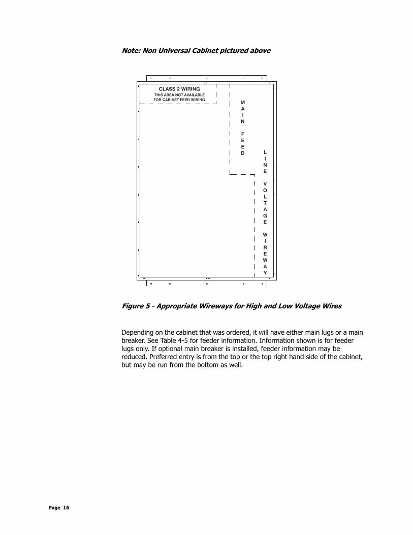
Note: Non Universal Cabinet pictured above
Figure 5 - Appropriate Wireways for High and Low Voltage Wires
Depending on the cabinet that was ordered, it will have either main lugs or a main breaker. See Table 4-5 for feeder information. Information shown is for feeder lugs only. If optional main breaker is installed, feeder information may be reduced. Preferred entry is from the top or the top right hand side of the cabinet, but may be run from the bottom as well.
Y
A
W
E
R
I
W
L
I
N
E
V
O
L
T
A
G
E
CLASS 2 WIRINGTHIS AREA NOT AVAILABLE
FOR CABINET FEED WIRING
D
E
E
F
N
I
A
M
Page 16

a-2000 User Guide
Table 4 - Max Feeder and Wire Size, Cabinets with Main Breakers
Table 5 - Max Feeder and Wire Size, Cabinets with Main Lugs
Cabinets with Main Breakers (factory installed)
Main Breaker Size (A) Cabinet Sizes Wire Size
30, 50, 60 12, 24 #14-#2 AWG
40 24 #14-#2 AWG
70, 80, 100 12, 24 #12-2/0 AWG
90 24 #12-2/0 AWG
110, 125 24 #4-250kcmil
125 (1 phase only) 12 #4-250kcmil
150 24, 36 #4-250kcmil
175, 200 24, 36 #4-250kcmil
225 36 #4-250kcmil
Main Breaker not available 48 N/A
Cabinets with Main Lugs
Cabinet Size Phase Max Feed Size Wire Size
12 1 125A #14-#2 AWG
3 80A #14-#2 AWG
24 1 250A #6-250kcmil
3 250A #6-250kcmil
36 1 250A #4 - 250kcmil
3 175A #4 - 250kcmil
48 1 500A (2) #6-250kcmil
3 350A (2) #6-250kcmil
a-2000 Page 17 Dimmer Cabinets with Digital ControlsRevision G November 2006
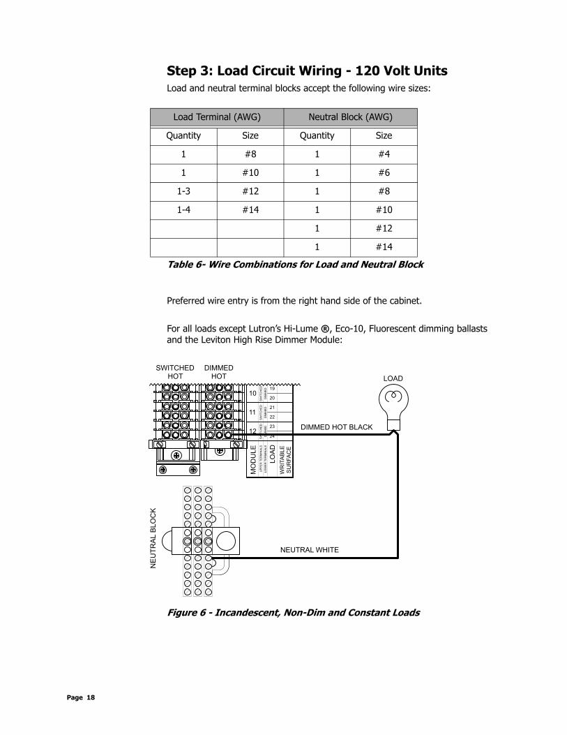
Step 3: Load Circuit Wiring - 120 Volt UnitsLoad and neutral terminal blocks accept the following wire sizes:
Table 6- Wire Combinations for Load and Neutral Block
Preferred wire entry is from the right hand side of the cabinet.
For all loads except Lutron’s Hi-Lume ®, Eco-10, Fluorescent dimming ballasts and the Leviton High Rise Dimmer Module:
Figure 6 - Incandescent, Non-Dim and Constant Loads
Load Terminal (AWG) Neutral Block (AWG)
Quantity Size Quantity Size
1 #8 1 #4
1 #10 1 #6
1-3 #12 1 #8
1-4 #14 1 #10
1 #12
1 #14
Black
White
SU
RFA
CE
MO
DU
LE
LO
AD
12
11
10
22
24
23
20
21
19
SW
ITC
HE
D
DIM
ME
D
SW
ITC
HE
D
DIM
ME
D
SW
ITC
HE
D
DIM
ME
D
UP
PE
R T
ER
MIN
ALS
LO
WE
R T
ER
MIN
ALS
WR
ITA
BLE
LOAD
NEUTRAL WHITE
DIMMED HOT BLACK
DIMMED
HOTHOT
SWITCHED
NE
UT
RA
L B
LO
CK
Page 18

a-2000 User Guide
Figure 7 - Load Terminal Wiring for Leviton High Rise Time Dimmer
Figure 8 - Load Terminal Wiring for Advance Mark XTM or Lutron Tu-WireTM
1
6
5
4
3
2
7
1
3
2
Mo
du
le
Ch
ann
elN
eutr
alB
lock
Load
Neutral
Dimmed Hot/Live
NOT USED!
Black - Dimmed Hot
White - Neutral
Advance Mark X and/orLutron Tu Wire
Lamp*
Blue
Red
*Wiring Diagram of Fluorescent Lamp for Illustrative PurposesOnly! Consult Individual BallastWiring Diagram
SU
RF
AC
E
MO
DU
LE
LO
AD
12
11
10
22
24
23
20
21
19
SW
ITC
HE
D
DIM
ME
D
SW
ITC
HE
D
DIM
ME
D
SW
ITC
HE
D
DIM
ME
D
UP
PE
R T
ER
MIN
AL
S
LO
WE
R T
ER
MIN
AL
S
WR
ITA
BL
E
NEUTRAL WHITE
DIMMED HOT BLACK
DIMMED
HOTHOT
SWITCHED
NE
UT
RA
L B
LO
CK
LAMP
BALLAST
a-2000 Page 19 Dimmer Cabinets with Digital ControlsRevision G November 2006

Figure 9 - Load Terminal Wiring for 0-10 VDC Control Dimming Ballasts
Figure 10 - Load Terminal Wiring for Lutron Hi-Lume or Eco 10
Lamp*
White - Neutral
Black - Switched Hot
GreyViolet
Red
Blue
*Wiring Diagram of Fluorescent Lamp for Illustrative PurposesOnly! Consult Individual BallastWiring Diagram
SU
RF
AC
E
MO
DU
LE
LO
AD
12
11
10
22
24
23
20
21
19
SW
ITC
HE
D
DIM
ME
D
SW
ITC
HE
D
DIM
ME
D
SW
ITC
HE
D
DIM
ME
D
UP
PE
R T
ER
MIN
AL
S
LO
WE
R T
ER
MIN
AL
S
WR
ITA
BL
E
NEUTRAL WHITE
HOT BLACK
DIMMED
HOTHOT
SWITCHED
NE
UT
RA
L B
LO
CK
LAMP
BALLASTGRAY
VIOLET
0-10 VDC
White - Neutral
Orange - Dimmed Hot
Black - Switched Hot
Lamp*
DHSH
Red
Blue
*Wiring Diagram of Fluorescent Lamp for Illustrative PurposesOnly! Consult Individual BallastWiring Diagram
SU
RF
AC
E
MO
DU
LE
LO
AD
12
11
10
22
24
23
20
21
19
SW
ITC
HE
D
DIM
ME
D
SW
ITC
HE
D
DIM
ME
D
SW
ITC
HE
D
DIM
ME
D
UP
PE
R T
ER
MIN
AL
S
LO
WE
R T
ER
MIN
AL
S
WR
ITA
BL
E
NEUTRAL WHITE
HOT BLACK
DIMMED
HOTHOT
SWITCHED
NE
UT
RA
L B
LO
CK
LAMP
LUTRON
BALLAST
ORANGE
DIMMED HOT
Page 20

a-2000 User Guide
Step 4 - Relay Cabinet (OPTIONAL)The optional relay cabinet is primarily intended for 277 Volt fluorescent dimming ballast with a 0-10 VDC control signal. However the cabinet can accommodate 120V and 347V applications and may be used for any non dim load. They come completely pre-wired and attached to the main a-2000 cabinet. The relay cabinet can be configured with branch circuit breakers as shown in Figure 12. The relay cabinet must be ordered attached to a either a 12 or 24 channel cabinet only at the factory.
Figure 11 - Relay Cabinets Attached to a 24 Circuit a-2000 Cabinet (on left) and a 12 Circuit cabinet (on the right)
Branch Breakers in the Relay Cabinet - See Figure 12:To wire the relay cabinet, follow these simple steps:
1 Remove or open the door.2 Run and land the power/feed wires to the relay Cabinet Feed Terminals3 Run and land the load wires to the Load side of the relay terminal block4 Run and land the neutral wires to the Neutral Terminal Block5 Run and land the ground wire to the Ground Lug
No Branch Breakers in the Relay Cabinet -See Figure 13:To wire the relay cabinet, follow these simple steps:
1 Remove or open the door.2 From the external branch circuit breaker, run and land the power wires to
the Line side of the relay terminal block3 Run and land the load wires to the Load side of the relay terminal block4 Run and land the neutral wires to the individual Neutral Terminals5 Run and land the ground wire to the Ground Lug
a-2000 Page 21 Dimmer Cabinets with Digital ControlsRevision G November 2006

Figure 12 - Detail of Relay Cabinet (Optional Breakers shown - other similar)
UPPERTB2TB1
LOW
ER
REVISION-PCA-32143-
MADE IN THE U.S.A.ALL RIGHTS RESERVED WORLDWIDEC 2002 LEVITON MFG. CO. INC.
C6
C5
+12DC 2
SENSE 2
C4
C3
+12DC 1
SENSE 1
C2
C1
AC2AC2
AC2
AC1AC1
AC1
COM
COM
SENSE 3
+12VDC
U1
J5J4
J3
R4D3
J1
U3
R3
JP2JP1
C5
JP3JP6
JP4
C3
J2
J8
+12VDC
+12DC 3
R1
R2
J7
D7D8
D9D10
J6
JP5
R5
D4
D6
U6U5
C7C8
R6
D1
+DC-DC
AC1AC2
D2
C2
C4C6
C1D5
U2U4
OFF
ON
WIRE RANGE#6 AWG TO #22 AWG
TORQUE18-22 IN-LBS
6- LOAD
6- LINE
5- LOAD
5- LINE
4- LOAD
4- LINE
3- LOAD
3- LINE
2- LOAD
2- LINE
1- LOAD
1- LINE
LOAD TERMINALS
CA B
15A, 347VAC, Ballast20A, 277VAC, Ballast20A, 120VAC, TungstenContact Rating (Max.):
OFFON
15A, 347VAC, Ballast20A, 277VAC, Ballast20A, 120VAC, TungstenContact Rating (Max.):
OFFON
Use Copper Wire OnlyWire Range 2/0 to #14
Main Lugs OnlyRated ____ Amps
________ VAC, ___Ph, ___Wire, w/Gnd, 60Hz
CABINET FEED
Wire Size1202/0 to #6
#10-#14#8
PrimaryTorque - In-lbs
4035
Use Copper Wire Only
ATQR1/2 FUSECLASS CC
TIME DELAYReplace with
WIRE RANGE #6 AWG TO #22 AWGTORQUE 18-22 IN-LBS
FUSE TERMINAL
Use Copper Wire Only
Torque 120 in-lbs2/0 - #14 AWG
GROUND LUG
SOCKET
353535404545#4
#6#8
#10#12#14
#4 - #14Tap
BLOCKNEUTRAL
MAIN250 MCM - #6
SOCKETSIZE
3/8 375
In-lbsTORQUE
OFF
ON
OFF
ON
OFF
ON
OFF
ON
OFF
ON
OFF
ON
OFF
ON
C 2002 LEVITON MFG. CO. INC.ALL RIGHTS RESERVED WORLDWIDE
MADE IN THE U.S.A.
LOW
ERTB1
UPPERTB2
SENSE 3
+12DC 2
+12DC 3
C5
C6
D4
+12VDC
U6
D10
R5
U5
COM
J12
C8
J13
JP6
J6J7
PCA-32143-REVISION-
AC1
J5
AC2AC2
SENSE 2
C2
SENSE 1
+12DC 1
C3
C4
C1
R6D3
R4D2
AC2AC1
-DC+DC
J8
AC1
J3
AC1 J4
AC2
D1
R2
R3
D9D8
U4
D7D6
U3U2
C7C6
C5C4
R1
D5C1
U1
C3
C2
COM
J1
JP2JP5
JP4JP3
+12VDC
J2
JP1
5- LOAD
6- LINE
6- LOAD
4- LINE
4- LOAD
5- LINE
2- LINE
2- LOAD
3- LINE
3- LOAD
LOAD TERMINALS
1- LINE
1- LOAD
18-22 IN-LBSTORQUE
#6 AWG TO #22 AWGWIRE RANGE
FLUSH MOUNT VERSION AVAILABLE
SURFACE MOUNT HARDWARE SHOWN
1" CONDUIT
ENTRY
3 PLACES
30 1/8"
LINE/LOAD TERMINALS
CABINET FEED
6 PLACES
LOAD ENTRY
1" CONDUIT
NEUTRAL
ENTRY
2" CONDUIT
GROUND LUG
2" CONDUIT
43"
WIRING ENTRY
INTER-CABINET
TERMINALS - ONLY IN CABINETS
WITH BREAKERS
45 1/2"
ENTRY
3 PLACES
1" CONDUIT
PROTECTION
LOAD
BREAKERS
ELECTRONICS
2" DIAMETER
INTER-CABINET
WIRING ENTRY
WIRING ENTRY
INTER-CABINET
1-1/8" DIAMETER
SUPPLY
POWER
CONTROL
(OPTIONAL)
D13D14
D15D16
20A, 277VAC, Ballast20A, 120VAC, TungstenContact Rating (Max.):
OFFON
J13
JP6JP5
5- LOAD
6- LINE
6- LOAD
4- LOAD
5- LINE
18-22 IN-LBSTORQUE
#6 AWG TO #22 AWGWIRE RANGE
Page 22

a-2000 User Guide
Low Voltage Control Wiring
Step 5: Control Input WiringOnce the power wiring has been completed, control wiring can be addressed. The upper left side of the dimmer cabinet is reserved for control wiring. Refer to Figure 4 and 28 for the location of the control module and the low voltage wire way. Terminate all control wiring directly to the terminal blocks on the printed circuit card found in the upper left location. Use a small 1/8-in. flat screwdriver on these terminals.Wire Range:•24-12 AWG, Stranded, Torque to 9 in-lbs.•16-8 AWG, Stranded, Torque to 18-20 in-lbs. for 24 Channel power supply terminals
The digital control panel can accept the following control signals:• Luma-Net® III• DMX512• Analog 0-10VDC Inputs - Available as an Option
See the Appendix for a full description of the various control inputs
Figure 13 - Digital Control Module
Control Wiring Terminal Blocks
0-10 VDC Ballast Outputs
Optional! AnalogConnectors
a-2000 Page 23 Dimmer Cabinets with Digital ControlsRevision G November 2006

Luma-Net® III
Power Considerations for Control SystemsThe control system should be carefully planned out to take into consideration these important issues:• Power Supply for Control Stations• Wire Size for Power Runs
On most systems, our applications engineering department has already managed these calculations for you so this information should be irrelevant. However, if this is not the case, like an ASAP (Quick Ship) program, when adding on to a system or planning for a remodel, you will want to take this information into consideration.
Power Requirements & Maximum Run LengthEach device on a Luma-Net network has a different load (draw) and each source of power can support a different total load (supply.) To determine the total capacity of your network, first determine the maximum supply current of your power source, convert that to Unit Loads, then determine the total load it can handle by summing the load of each device.
One Unit Load = 25mA
Figure 14 - Load Rating Verification Formula
The a-2000 cabinets are designed to be able to power either D4200 or D8000 stations from the internal power supply. See Table 7 for the available power from each cabinet.
Table 7 - Power Supply Maximum Unit Loads
Supply Maximum # of Unit Loads
a-2000D, 12 Circuit,Standard Power Supply
40
a-2000D, 24 CircuitStandard Power Supply
24
NPC – XP 49
NPC – DHV 0 (no Luma-Net)
NPC – DLR 49
Control Station A Unit Load
XQuantity of Station A's attached
+Same formulafor any other attached control Station
Control Station B Unit Load
XQuantity of Station B's attached
<+ Power Supply's Available Unit Load
Page 24

a-2000 User Guide
Table 8- Control Station Loads
Example:
Suppose we had a network with the following equipment:• D4200 LCD Stations• D4200 Entry Stations• Remote IR Station• Powered from an a-2000 24 Cabinet with a Standard Power Supply
Use these quantities along with the Load Rating verification formula (Figure 15) to do the math and verify that the combined unit input load does not exceed the maximum input Unit Load Available.
Station Type Unit Load (per station)
Station Type Unit Load (per station)
D4200 LCD 2 D8000 Entry (Button) 1
D4200 Entry (Button)
1 D8000 Slider 1
D4200 Room Combine Station
1 D8000 Key switch 1
D4200 Remote I/R 1 D8000 Port (LumaEdit, A/V, etc.)
1
Luma-Net Hub 3 D8000 Combine/Closure (Advanced)
10
D8000 LCD 2
Quantity Unit Loads
D4200 LCD Stations
4 x 2 = 8
+
D4200 Entry Stations
6 x 1 = 6
+
Remote IR Station
1 x 1 = 1
Total 15
a-2000 Page 25 Dimmer Cabinets with Digital ControlsRevision G November 2006

15 is less than the 40 available so all the components CAN BE wired on a single run from the a-2000 24 Channel cabinet without an additional external power supply.
Power Wire - Run LengthThe maximum total run length of each segment is a function of the total number of unit loads. A run becomes to long when the voltage drop, due to wire size and run length, increase to a point where the station does not have sufficient voltage to operate. The maximum run length, in feet, based on the total number of unit loads is shown below:
Table 9 - Wire Size vs. Length of Runs - Power Wiring
Terminating the wiringControl Stations can be located up to 2,000 ft. from the dimming cabinet.
The 2,000 ft. limitation is a RS485 digital communications specification. The power supply pair must be sized correctly for the control stations that are connected to them.
Luma-Net is wired Daisy Chained, station to station. For applications where runs become too long a Luma-Net Hub can be used. See Figure 15 for the correct ways to wire this system.
14 AWG (Feet) 12 AWG (Feet) 10 AWG Feet)
10 Unit Loads 1905 3000 4800
20 Unit Loads 950 1500 2400
30 Unit Loads 630 1000 1600
40 Unit Loads 475 750 1200
50 Unit Loads 380 600 960
60 Unit Loads 315 500 800
70 Unit Loads 270 425 685
80 Unit Loads 235 375 600
90 Unit Loads 210 330 530
100 Unit Loads 190 300 480
110 Unit Loads 170 270 435
120 Unit Loads 155 250 400
Page 26

a-2000 User Guide
The cable should not pass near any source of electrical noise such as fluorescent circuits or motor wiring. Avoid close proximity to any AC wiring. All control/power wiring must be in conduit.
Figure 15 - The Right and Wrong Way to Run Luma-Net
• See Table 10 for recommended Wire Types• Use RS485 compatible cable for the communications. It is recommended that a cable with 2
Twisted Pair, 24 AWG, stranded conductors be used. The spare pair is for future uses. • Capacitance of wire shall be 12pF/ft. or less• Nominal Impedance of wire shall be between 100-120 ohms• A second pair (#14 AWG stranded or larger) is required for the power.• Drain/Shields to be tied together, insulated and grounded (on one point only)!• We strongly recommend the use of either Belden 9829 or Belden 9729 for the Luma-
Net wire runs.
The most effective way to insulate the drain/shield wire is to use a piece of heat shrink tubing!
D4200 CONTROL STATION
PRESET SELECT STATION
C
12
18
1516
17
1314
6
910
11
78
34
5
12
AB
DMX CANCEL
LUMANET CLEAR
PHASE LOSS
AUXILIARY
FULL BRIGHT
COMMUNICATION PORTS
FAN
SAVE
FULL
SELECT
BRIGHT
a-2000D a-2000D
PRESET SELECT STATION
17
16
18
10
11
1413
15
12
5
87
9
6
B
2
43
C
1
A
D4200 CONTROL STATION
LUMANET
DMX
CLEAR
CANCEL
FAN
COMMUNICATION PORTS
FULL BRIGHT
AUXILIARY
PHASE LOSS
BRIGHT
SELECT
FULL
SAVE
LUMA-NET III HUB
Note: a-2000D Cabinet can be in the middle of a daisy chain
a-2000D
PRESET SELECT STATION
17
16
18
10
11
1413
15
12
5
87
9
6
B
2
43
C
1
A
D4200 CONTROL STATION
LUMANET
DMX
CLEAR
CANCEL
FAN
COMMUNICATION PORTS
FULL BRIGHT
AUXILIARY
PHASE LOSS
BRIGHT
SELECT
FULL
SAVE
a-2000 Page 27 Dimmer Cabinets with Digital ControlsRevision G November 2006

.
Table 10- Luma-Net Recommended Wire
Table 11 - Color Coding for Belden Wire
Figure 16 - Belden Wire Callouts
Manufacturer Catalog Number # of Pairs
Belden 9729, 9829 2
Belden 9841 1
Belden 88102 2 (Plenum Rated)
Alpha 6222C 1
Alpha 6412 1
Wire/Color No. Pair Pin/Terminal Pin/FunctionBelden 9729RedBlack
1 12
REM+REM-
RedWhite
2 N/C - Not Con-nectedN/C - Not Con-nected
N/C - Not Con-nectedN/C - Not Con-nected
Drains/Shields N/C - Not Con-nected
See figure 17
Belden 9829Blue with white stripeWhite with blue stripe
1 12
REM+REM-
Orange with white stripeWhite with orange stripe
2 N/C - Not Con-nectedN/C - Not Con-nected
N/C - Not Con-nectedN/C - Not Con-nected
Drain/Shield N/C - Not Con-nected
See figure 17
Drain/Shield
Drain/Shield
Belden 9729
Drain/Shield
BraidFoil Foil
Belden 9829
BlackRedBlackWhite
Blue w/ White StripeWhite w/ Blue StripeOrange w/ White StripeWhite w/ Orange Stripe
Page 28

a-2000 User Guide
If a remote DC power supply is used and you have multiple Luma-Net runs, all DC common wires must be joined at the power supply.
Wiring the Phoenix ConnectorStep 1: Connect leads per wiring diagram as illustrated in Figure 18.Step 2: Twist strands of each lead tightly (making sure that there are no
stray strands) and push firmly into appropriate plug connector location.
Step 3: Tighten the screws on the plug connector—making sure that no bare conductor is showing.
Step 4: Tie the Drain/Shield wires together and insulate using a small piece of heat shrink tubing.
Step 5: Install termination jumpers as required. Termination jumpers are required at the two ends of the Luma-Net run.
Figure 17 - Luma-Net Wiring Connections
REM
+
REM
-
CO
M
TERM
N/C
+V
1 2 3 4 5 6
Upto
1#1
2AW
G
2#14AWG min.
2#14AWG min.
Upto
1#1
2AW
G
Drain/Shield - Insulated and tied together(Ground at one point only-probably an end)
Red (+V )
Black (Common)
5 6
1 2 3 4
Phoenix Connector
a-2000 Page 29 Dimmer Cabinets with Digital ControlsRevision G November 2006
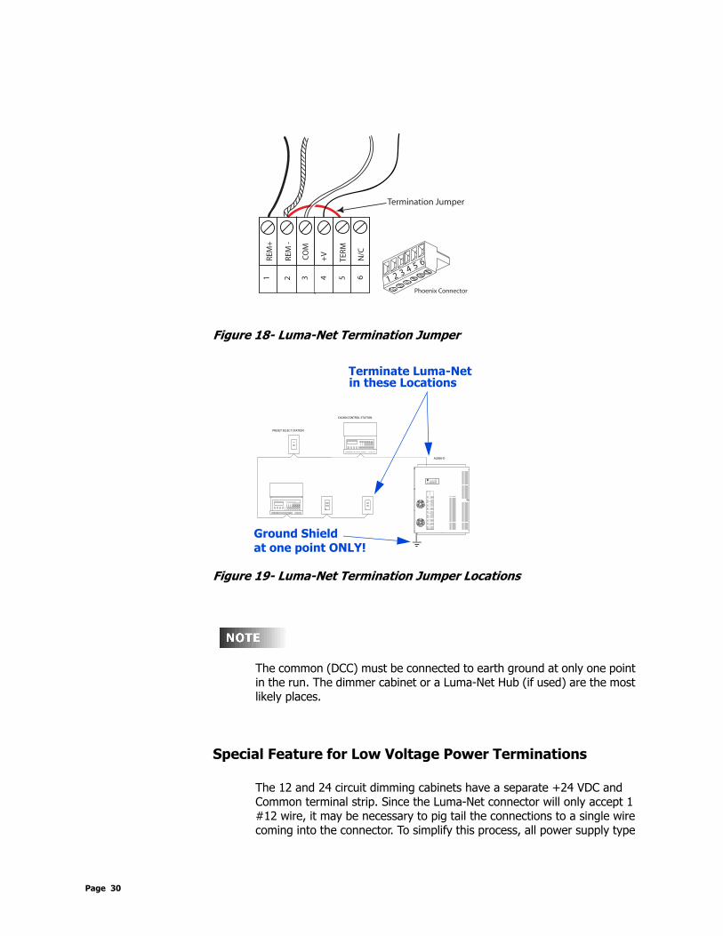
Figure 18- Luma-Net Termination Jumper
Figure 19- Luma-Net Termination Jumper Locations
The common (DCC) must be connected to earth ground at only one point in the run. The dimmer cabinet or a Luma-Net Hub (if used) are the most likely places.
Special Feature for Low Voltage Power Terminations
The 12 and 24 circuit dimming cabinets have a separate +24 VDC and Common terminal strip. Since the Luma-Net connector will only accept 1 #12 wire, it may be necessary to pig tail the connections to a single wire coming into the connector. To simplify this process, all power supply type
REM
+
REM
-
CO
M
TERM
N/C
+V
1 2 3 4 5 6
Termination Jumper
5 6
1 2 3 4
Phoenix Connector
D4200 CONTROL STATION
PRESET SELECT STATION
C
12
18
1516
17
1314
6
910
11
78
34
5
12
AB
DMX CANCEL
LUMANET CLEAR
PHASE LOSS
AUXILIARY
FULL BRIGHT
COMMUNICATION PORTS
FAN
SAVE
FULL
SELECT
BRIGHT
A2000-D
Terminate Luma-Netin these Locations
Ground Shieldat one point ONLY!
Page 30

a-2000 User Guide
wiring for control stations should go to these terminals in the these cabinets. These terminals are fed directly by the power supply and accommodate larger wires and multiple wires per terminal section solving power distribution problems for remote power controls.
Figure 20 - Control Station Power Wiring - Preferred Wiring Method
Testing the WiringTo assure problem-free startup, it is important to check the system wiring for proper connections, shorts and opens.
The following procedure is recommended:Step 1: Test the following wire pairs for shorts at each station location, using
an ohmmeter or other continuity tester. 1-2 Open2-3 Open3-4 Open
Step 2: Repair any short circuits before continuing.
+24 VDC
COMMON
a-2000 Page 31 Dimmer Cabinets with Digital ControlsRevision G November 2006
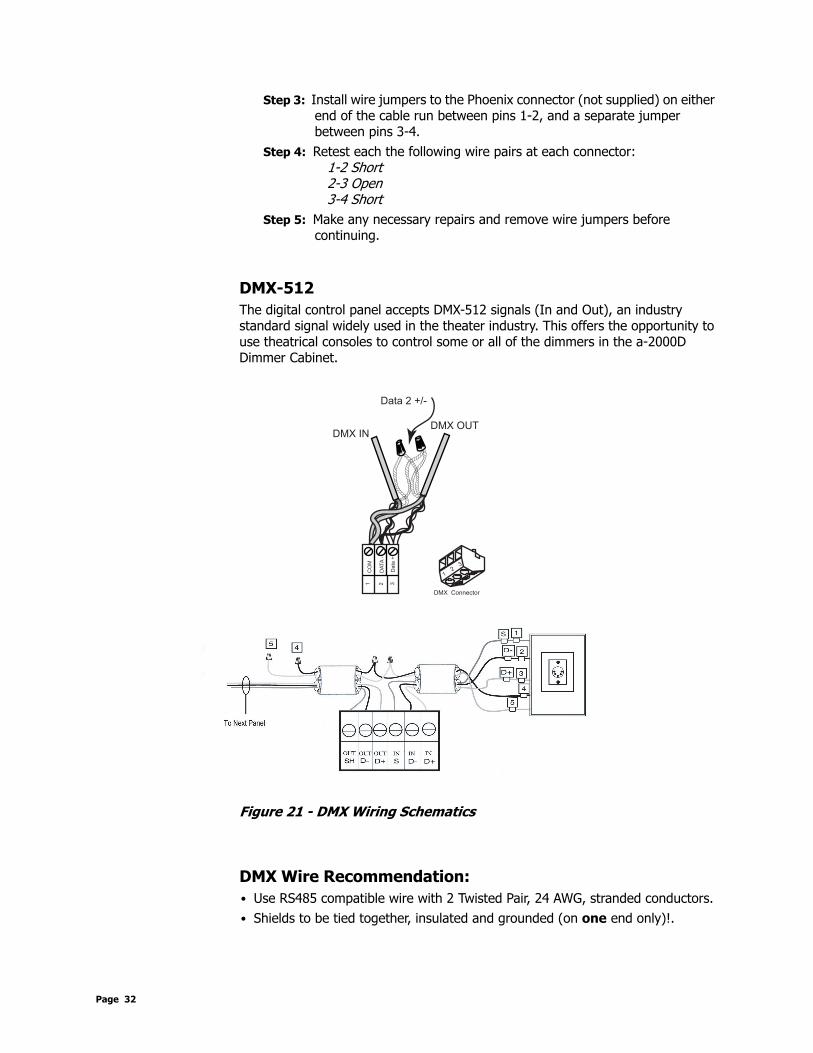
Step 3: Install wire jumpers to the Phoenix connector (not supplied) on either end of the cable run between pins 1-2, and a separate jumper between pins 3-4.
Step 4: Retest each the following wire pairs at each connector: 1-2 Short2-3 Open3-4 Short
Step 5: Make any necessary repairs and remove wire jumpers before continuing.
DMX-512The digital control panel accepts DMX-512 signals (In and Out), an industry standard signal widely used in the theater industry. This offers the opportunity to use theatrical consoles to control some or all of the dimmers in the a-2000D Dimmer Cabinet.
Figure 21 - DMX Wiring Schematics
DMX Wire Recommendation:• Use RS485 compatible wire with 2 Twisted Pair, 24 AWG, stranded conductors.• Shields to be tied together, insulated and grounded (on one end only)!.
CO
M
DA
TA
-
Da
ta +
1 2 3
DMX Connector
DMX INDMX OUT
12
3
Data 2 +/-
Page 32

a-2000 User Guide
Table 12 - DMX512 Recommended Wire
Analog Input, 0-10 VDC (Optional)A third type of control input signal, 0-10 Volt DC, can be used if equipped with the optional Analog DC Control Card. This signal varies between 0-+10 VDC and can be used to control the dimmer outputs or for photo cell/daylight harvesting application.
This section relates only to use of the analog input for direct 0-+10V control. For Protocol/Daylight harvesting applications see page 71.
Table 13 - Analog Control Input Signal
Varying this signal from 0 VDC to +10 VDC varies the AC output voltage from zero to virtually full line voltage.
Analog connections can be hooked up in two ways:1 Analog devices powered by external source2 Analog devices powered by a-2000 cabinets
If +12 VDC is supplied from the analog card to power analog controls, the common MUST BE connected to the TB9 terminal on the main control module board - See Figures 22.
Photocell InputSee page 71 for details on photocell operation. This section relates to the connection of the photocell device to the a-2000 dimmer cabinet.
Manufacturer Catalog Number # of Pairs
Belden 9729, 9829 2
Belden 88102 2 (Plenum Rated)
Control Input Output to Dimmers
0 VDC Lights off
+10 VDC Lights at full
a-2000 Page 33 Dimmer Cabinets with Digital ControlsRevision G November 2006

In order to use photocells in daylight harvesting applications, the analog input card must be installed.
To connect the photocell to the a-2000, perform the following steps (reference figures 24-25):
1 Connect the +0-10VDC output from the photocell to one of the a-2000 analog input terminals, labeled "Input 1, Input 2,... etc.
2 Connect the photocell common to the a-2000 input card3 If the a-2000 +12VDC supply is powering the photocell, connect the
photocell +V and common supply leads to the +12V and common terminals of the a-2000 analog input card.
The photocell manufacturer’s instructions must be followed explicitly to ensure accurate results. Some photocells require a +24VDC supply. In this case the photocell must be supplied from the +24 VDC remote control panel power terminal.
When the above connections have been made correctly, and the programming complete per page 71, the photocell will inversely control the output of the dimmer level to reach the desired target level.
Figure 22 - Wiring Diagrams for One Photocell
Input 2
Common
+12 vdc
Input 1
Analog Card
CommonControl Module
0-10 VDC
Input 3
Using a-2000 power 1 photo cell
V
VV To -10VDC
Vcommon
V V+12VDC
Page 34

a-2000 User Guide
Figure 23 - Multiple Photocells with External Power Supply
Multiple Signal TypesUnder certain circumstances the digital control panel can receive two or more types of input signals. The output for each dimmer is determined as follows:
1 DMX and Analog- by the highest input signal it is receiving from the different sources.
2 DMX/Analog and Luma-Net - by the last action input signal it receives from different sources. e.g. If DMX signal is on and a Luma-Net signal appears, control is faded from the DMX level to the Luma-Net level. If DMX level is then changed, control will fade back to and track the DMX level.
Figure 24: Control Signal Precedence and Merging
Input 2
Common
+12 vdc
Input 1
Analog Card
Input 3
C
V
V
V
V V
V
V
Power Supply
V
Incoming power
+V
To 10VDC
Photocells
To -10VDC
DMX Analog
HTP Merge
LTP LumaNet
Emergency/Full Bright
(see page 35)
To Dimmer Module
a-2000 Page 35 Dimmer Cabinets with Digital ControlsRevision G November 2006

External Full On/Emergency (Full Bright)The a-2000 cabinet has an external trigger which can be used to force selected dimmers to full bright.
The external full bright input is enabled with a contact closure between terminals on TB7.
The software feature is called External Full Bright, however the label of TB7 is called "Emergency" (formerly "All On").
• If the closure is open, the system operates normally. • If the closure is closed, the system overrides all channels, that have been
programmed to respond to External Full Bright, to 100% and overrides the remainder of the channels to 0%.
• When the closure is re-opened, the channels return to their previous levels
Factory default programming has all channels to respond to an external full bright command
One application of this feature is shown in Figure 23. If any one of the phases is low in the "Normal" cabinet, the phase dropout relay relaxes, closing the "All On" contact closure. For Example: If circuits 1, 2 and 3 are on at 50% (and are programmed to respond to the external full bright command), they will go to 100%. If channels 4, 5 and 6 are at 50% (and not programmed to respond to external full bright), they will go to 0% to unload the emergency generator.
Page 36

a-2000 User Guide
Figure 25 - External Full On Wiring Diagram
a2000-D PROCESSOR PHASE PHASE DROPOUTDROPOUT
ALL ON
AUX SERIALAUX SERIALLUMANETLUMANET DMX-512DMX-512 CANCAN
D+
D+
33
CO
MC
OM
REM
-R
EM-
REM
+R
EM+
TB1
TB1
2211
TER
MTE
RM
N/C
N/C
TB2
TB2
5544 66
+V
+V
2211 33 5544
D+
D+
SLD
SLD
D-
D-
D-
D-
SLD
SLD
ININ OUTOUT
J11
J11
CA
NL
CA
NL
23
2T
23
2T
CO
MC
OM
23
2R
23
2R
48
5-
48
5-
48
5+
48
5+
CA
NH
CA
NH
44TB3
TB3
66 11 22 33SL
DSL
D
TB6
TB6
55 66 11 22
RS485RS485 RS232RS232
INP
UT
+5
VD
C
TB7
33 21
SLD
SLD
J10
J10
J6J6 J3J3
RLY NO1RLY NO1
RLY NC1RLY NC1RYL COM1RYL COM1
-CO
M-C
OM
DIMMING BALLAST OUTPUTSDIMMING BALLAST OUTPUTSO
UT
5O
UT
5
OU
T 6
OU
T 6
-CO
M-C
OM
-CO
M-C
OM
-CO
M-C
OM
OU
T 8
OU
T 8
-CO
M-C
OM
OU
T 7
OU
T 7
OU
T 2
OU
T 2
OU
T 3
OU
T 3
OU
T 4
OU
T 4
OU
T 1
OU
T 1TB
8TB
8
GRAYGRAY VIOLETVIOLET
14141616 1515 991313 1212 10101111 88 77 4466 55
-CO
M-C
OM
-CO
M-C
OM
-CO
M-C
OM
GRAYGRAY
2233 11TB9TB9
NEUNEU
GNDGND+V+V
ØØBBØØCC
ØØAA
CANCANDMX-512DMX-512LUMANETLUMANET AUX SERIALAUX SERIAL ALL ON
PHASE DROPOUT
a2000-D PROCESSOR
TER
MTE
RM
REM
+R
EM+
REM
-R
EM-
CO
MC
OM
TB1
TB1
3311 22 44 55
+V
+V
RYL COM1RLY NC1
RLY NO1
RS485RS485
N/C
N/C
D+
D+
TB2
TB2
66 3311 22
D-
D-
SLD
SLD
TB3
TB3
44 55 1166
D+
D+
SLD
SLD
D-
D-
SLD
SLD
ININ OUTOUT
CA
NH
CA
NH
48
5+
48
5+
48
5-
48
5-
23
2R
23
2R
CO
MC
OM
23
2T
23
2T
CA
NL
CA
NL
443322 6655 TB7
TB6
TB6
2211 33
SLD
SLD
RS232RS232
+5
VD
C
INP
UT
1 2
J11
J11
J10
J10
J6J6 J3J3
DIMMING BALLAST OUTPUTSDIMMING BALLAST OUTPUTS
TB8
TB8
-CO
M-C
OM
OU
T 8
OU
T 8
-CO
M-C
OM
-CO
M-C
OM
-CO
M-C
OM
GRAYGRAY
141415151616 12121313
-CO
M-C
OM
-CO
M-C
OM
-CO
M-C
OM
OU
T 1
OU
T 1
OU
T 4
OU
T 4
OU
T 3
OU
T 3
OU
T 2
OU
T 2
OU
T 7
OU
T 7
OU
T 6
OU
T 6
OU
T 5
OU
T 5
-CO
M-C
OM
GRAYGRAYVIOLETVIOLET
991111 1010 7788 445566 33 22 11TB9TB9
NEUNEU
GNDGND+V+V
ØØBBØØCC
ØØAA
NORMAL/EMERGENCY POWER FEED
NORMAL POWER FEED
(THIS IS NOT AN A/V INTERFACE, IT IS USED FOR CONTROL MODULE
HOW THE "FULL ON" FEATURE WORKS IN a2000 CABINET APPLICATIONS:
RUN TWO (2) WIRES BETWEEN CABINET CONTROL MODULES (BY E.C.).WHEN THE "NORMAL" CABINET LOSES POWER, PHASE DROPOUT RELAY CLOSESCOMPLETING THE "FULL ON" CIRCUIT IN THE "NORMAL/EMERGENCY" CABINET.
Control Module of Unit A
Control Module of Unit B
a-2000 Page 37 Dimmer Cabinets with Digital ControlsRevision G November 2006

Step 6: Fluorescent Dimming and Control Output WiringMany installations incorporate fluorescent dimming ballasts into some or all of the fluorescent fixtures. Refer to the Appendix section for general information about dimming ballasts, their use and their control methods.
For best lamp life, lamp manufacturers recommend their fluorescent lamps should be operated at full brightness for a minimum or 100 hours before dimming is permitted. For best results, lamp brands and types should not be intermixed on a circuit.
Types of Dimming Ballasts• 0-10 volt DC control• Two Wire Ballasts• Three Wire ballasts0-10 volt DC control:These ballasts require that the low voltage wires (typically Violet and Grey) are landed on the Dimming Ballast Output terminals located on the Control Modules main circuit board.
The control output channels are auto assigned. The control wire for the first M7 dimmer will be the first control terminal, and the second M7 dimmer will be the second terminal, even though there are other dimmers of different types in between.
Figure 26 - 0-10 VDC Ballast Control Wiring
BallastL a m p
S w i t c h e d H o t -
N e u t r a l -
0 - 1 0 V D CC o n t r o lT o
D i m m e rC a b i n e t
T o N e x tB a l l a s t
G r a y
V i o l e t
B l a c k
W h i t e
M o u n t t oG r o u n d e d
F i x t u r e
}
0-10 Volt DC Wire S c h e m a t i c
Note: drawing shows one lamp, but can beappl ied to 2,3, and 4 lamp bal last versions.
Page 38

a-2000 User Guide
The maximum number of 0-10 VDC dimming ballasts that can be controlled on any one circuit is 100. (THIS IS A NEW FEATUE)
Double check the wiring to the dimmer output terminals that feed the dimmer ballasts before turning on any power; these ballasts can be adversely affected if the line voltage control wire and the switched line connections are reversed. Make sure the dimmer ballasts are correctly wired prior to turn on.
Other Ballast TypesFor other ballast wiring options, see the following page on Dimmer Module Wiring.
a-2000 Page 39 Dimmer Cabinets with Digital ControlsRevision G November 2006

Dimmer Module Installation
Step 7: Dimmer Module Installation and/or Replacement
Blanking PlatesIn some instances the dimmer modules are shipped separately from the cabinet. When this occurs, the blanking plates (two per module slot) must be removed prior to installing the dimmer modules. These plates are installed to maintain proper airflow. See Figure 27 for the locations of the blanking plates.
Figure 27 - Blanking Plate Locations
Fan Door
Blanking Plate
Dimmer Module
Blanking Plate(s)
Page 40

a-2000 User Guide
Removal or Installation of Dimmer Module:When the cabinets are shipped with the modules pre-installed, they are held in place by a single sheet metal screw (#10-32). This screw is located on the left side of the dimmer and securely holds each module to the cabinet for transportation from the factory. The dimmer modules simply plug in. No tools are required (except for shipping screw when dimmer modules are pre-installed at factory) and there is no risk of crossed wires when hooking up a new module.
If project drawings have been supplied by the factory and if the dimmers are shipped separately, make sure that any special dimmers are inserted into the proper module position within the dimmer cabinet. These positions are marked in the cabinet and shown on the installation diagrams provided with the system and should also have a label inside the cabinet instructing where these modules should be placed.
To remove a dimmer module:1 Remove the shipping screw located on the left side of the module (if
installed).2 Slide the module to the left to clear the power and control plugs until it
bumps the stop.3 Lift it straight out of the cabinet.
To install a dimmer module into one of the positions 1 Remove the appropriate blanking plate(s) from the cabinet. There are
two plates per module location. One is located on the fan door. The second is screwed down to the back pan. Start from the top and work your way down (see Figure 27)
2 Place the heat sink notches over the two tabs while aligning the dimmer module against the dimmer stop. Place the dimmer against the cabinet pan. If the dimmer is not against the dimmer stop, the two notches will not catch the two tabs on the pan.
a-2000 Page 41 Dimmer Cabinets with Digital ControlsRevision G November 2006
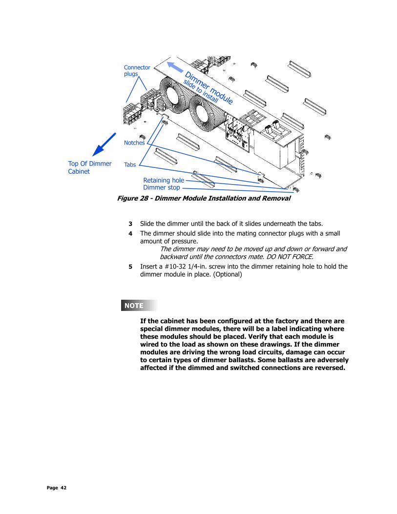
Figure 28 - Dimmer Module Installation and Removal
3 Slide the dimmer until the back of it slides underneath the tabs.4 The dimmer should slide into the mating connector plugs with a small
amount of pressure. The dimmer may need to be moved up and down or forward and backward until the connectors mate. DO NOT FORCE.
5 Insert a #10-32 1/4-in. screw into the dimmer retaining hole to hold the dimmer module in place. (Optional)
If the cabinet has been configured at the factory and there are special dimmer modules, there will be a label indicating where these modules should be placed. Verify that each module is wired to the load as shown on these drawings. If the dimmer modules are driving the wrong load circuits, damage can occur to certain types of dimmer ballasts. Some ballasts are adversely affected if the dimmed and switched connections are reversed.
Tabs
Retaining hole
Notches
Dimmer module
Connectorplugs
Dimmer stop
slide to install
Top Of DimmerCabinet
Page 42

a-2000 User Guide
Step 8: Bypass Mode
Set 120 V Non Universal Dimmers to Bypass Mode:Each 120 V dual dimmer is equipped with two 20-amp circuit breakers; one for each circuit to be fed from that dimmer module. It is also equipped with two dimmer bypass switches, adjacent to the breakers, see Figure 29.
Figure 29 - Bypass Switch - 120V Modules
The Bypass switch has two modes: • Normal and • Bypass. When the switch is set to Bypass, all the dimmer electronics are removed from the dimming circuit and the line is connected directly to load. Leviton normally ships the dimmer cabinet with all these switches in Bypass mode.
1 After checking that all circuits come on and contain no short circuits,2 Turn these switches to the Normal position. Once these switches are
turned to Normal, the dimmers and non-dims all operate in their programmed condition.
If a dimmer fails to come on, the bypass switch associated with that dimmer channel can be used to achieve full bright light output until repairs can be made to the appropriate system components.
0-10 VDC controlled ballasts require an additional step to ensure that the lights come to full brightness when the switch is in the Bypass position. The purple control wire from the control terminals must be removed and capped to allow the ballast to “float high.” Once this control wire is removed and capped, the bypass switch can be used to force the lights to the full bright condition.
Bypass Switches
Circuit Breakers
Top Of DimmerCabinet
a-2000 Page 43 Dimmer Cabinets with Digital ControlsRevision G November 2006
You can use the FULL BRIGHT button on the control panel in addition to the bypass switches to set the lights to full brightness.
Be sure to turn Full Bright switch off when you turn off the bypass switches and go to normal operation. This switch overrides all controls and forces all lights to full brightness.
277V Non Universal BypassThe 277V dimmer modules have no bypass switch. To achieve similar functionary for testing or electronics bypass, a constant module can be inserted in place of the dimmer module.
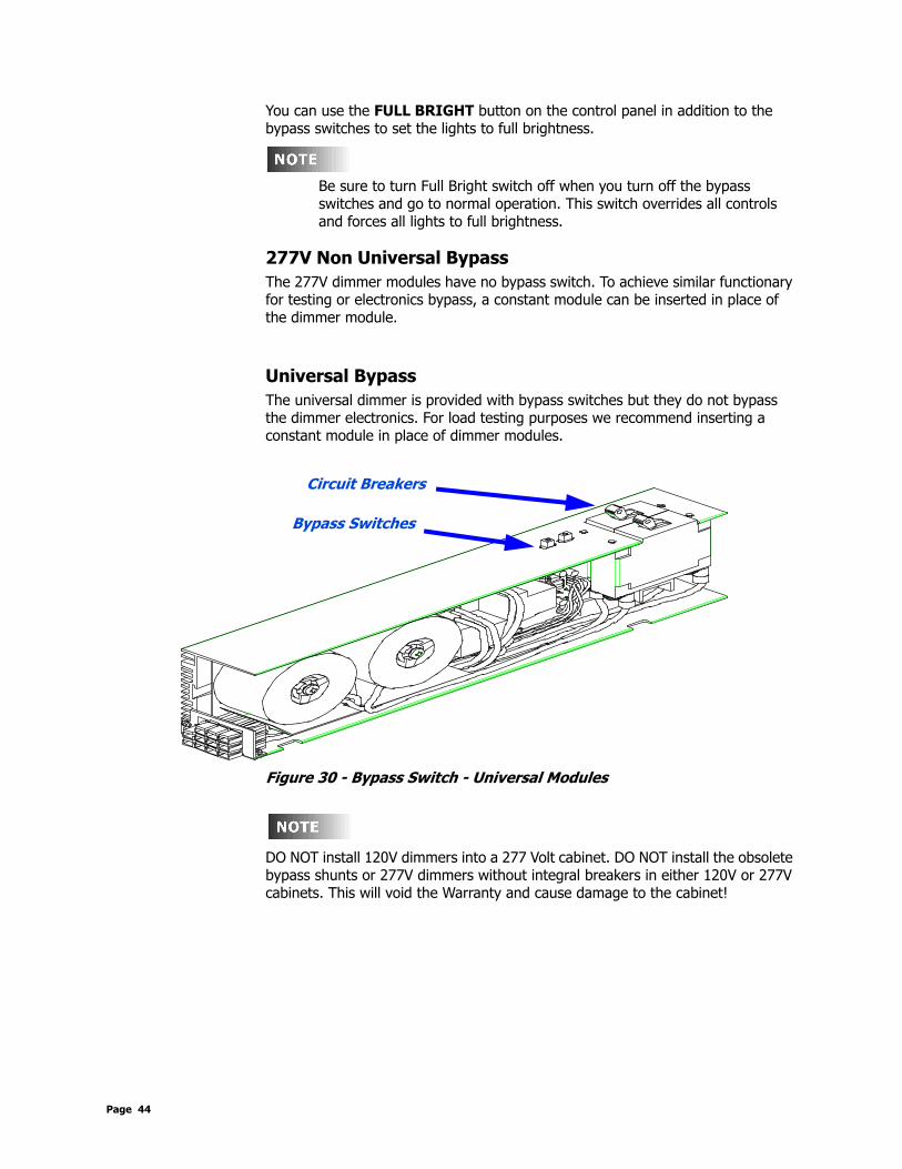
Universal BypassThe universal dimmer is provided with bypass switches but they do not bypass the dimmer electronics. For load testing purposes we recommend inserting a constant module in place of dimmer modules.
Figure 30 - Bypass Switch - Universal Modules
DO NOT install 120V dimmers into a 277 Volt cabinet. DO NOT install the obsolete bypass shunts or 277V dimmers without integral breakers in either 120V or 277V cabinets. This will void the Warranty and cause damage to the cabinet!
Bypass Switches
Circuit Breakers
Page 44
a-2000 User Guide
Step 9: Double Check the WiringPrior to turn on, verify that the following has been done correctly:• Main feed wiring• Load wiring• Remote control wiring• Correct wiring to any fluorescent dimmer ballasts• Dimmers are set in the Bypass ModeWith all power and control wiring in place, and all dimmer modules or constant modules installed, breakers off and bypass on, the system is ready for turn-on.
Step 10: Turn On The Power
Step 11: Clear Faults that have Caused any Breakers to Trip
Step 12: 120 V Systems - Set Bypass Switches to NormalNote: If your system uses constant modules for testing in lieu of bypass switches, replace the constant modules with the appropriate dimmer module.
a-2000 Page 45 Dimmer Cabinets with Digital ControlsRevision G November 2006

Digital Control Panel
Readouts and Indicators
LCD DisplayThe LCD display helps you determine that the system is operating properly: it helps locate certain types of malfunctions or errors in connections to the system, and enables certain setup instructions to be programmed, such as combining more than one dimmer to a single channel of control. When the system is operating normally the top line of the LCD display shows the name of the system and the version of software running in the microprocessor (a2000 Ver 2.40 (or above)). The second line flashes continuously and displays STATUS=OK 3PHASE or STATUS=OK 1PHASE.
Programming/Function ButtonsThe three programming buttons are located to the right of the LCD display:• FULL BRIGHT. Turns all lights assigned to react to the Full Bright button.
Pushing it twice turns off this function and returns the lights to their previous state.
• SELECT/SAVE. Causes a new readout on the LCD display. It shows the actual input voltage on each of the incoming three phases. It reads out directly in volts as well as showing the frequency as 60 Hz or 50 Hz.
• CANCEL/CLEAR. Returns the LCD display to the normal readout.
Many parameters can be modified using the LCD screen and a password (setup code), however these modifications should be made by a qualified factory technician. Some of these options are covered in Step 13: Configuration and Programming.
LED IndicatorsThe digital control panel has several LED indicators:• PHASE LOSS. Lights if one or more of the three phases feeding the dimmer
cabinet are lost or are low. On a single-phase system it indicates the loss of one or more of the two legs.
PHASE LOSS
AUX
FULL BRIGHTFAN
DMXLUMANET
FULLBRIGHT
SELECTSAVE
CANCELCLEAR
LCD displayProgramming buttons
LED indicators
Navigation buttons
Page 46

a-2000 User Guide
• FULL BRIGHT. Indicates that someone has selected full bright using the manual switch on the front panel or any external full bright switch, and no outside signals will override and allow dimming to occur.
• FAN. Shows that power is being fed to the fan(s). • AUX, DMX, LUMANET. Shows digital signals being received. A blinking
indicator light indicates that a digital signal is actively being received through the channel with the blinking LED. If more than one is lighted, more than one digital signal is being received.
Navigation ButtonsThe lower four buttons, used for navigation of menu items, are LEFT , UP , DOWN , and RIGHT .
a-2000 Page 47 Dimmer Cabinets with Digital ControlsRevision G November 2006

Step 13: Configuration and Programming
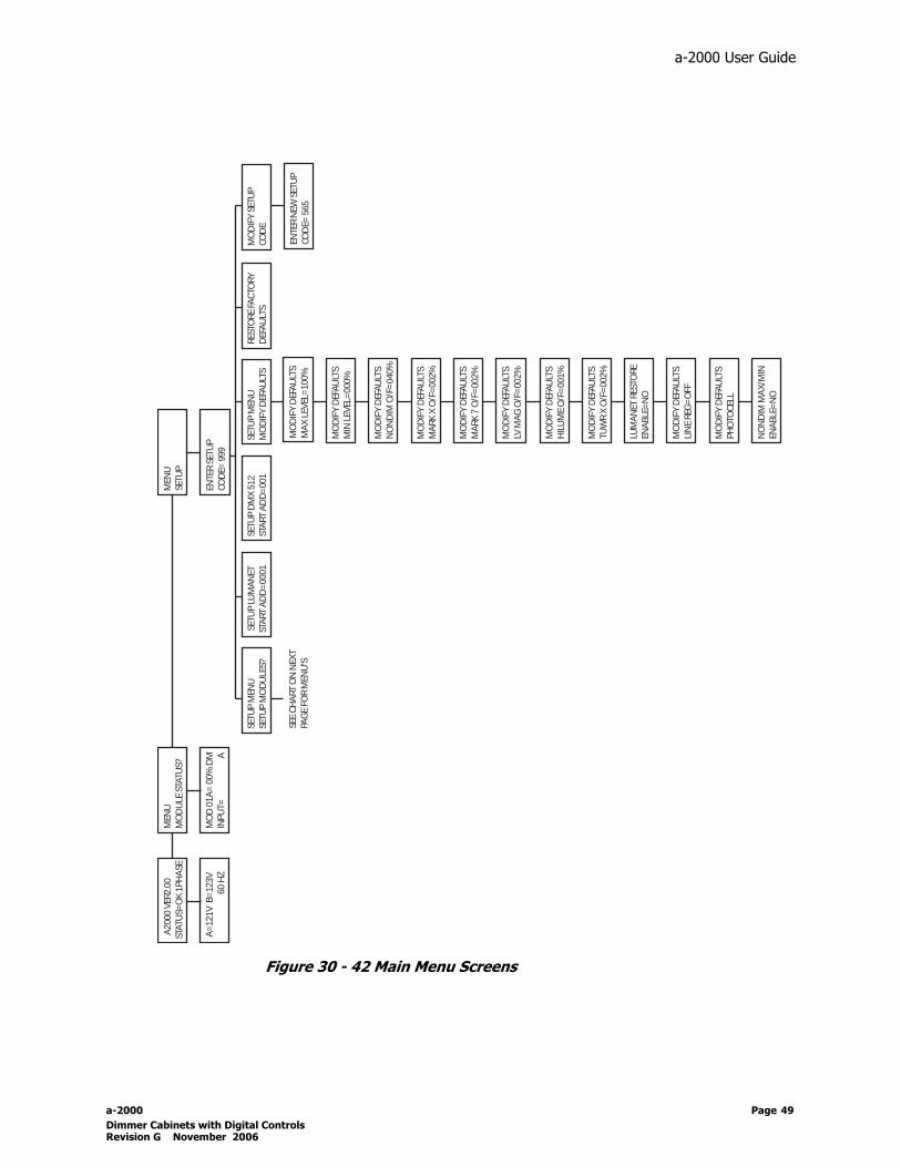
LCD Display Menu StructuresSee Figure 40-44 for the Flow Chart of LCD Display Menu’s.The next few pages will give you a pictorial overview for reference of menu structures used for programming your a-2000 cabinet. Following the menu structures is a text based description of the setup, configuration and programming procedure.
Page 48
a-2000 User Guide
Figure 30 - 42 Main Menu Screens
A20
00 V
ER2.
00ST
ATU
S=O
K 1P
HA
SE
A=
121V
B=
123V
60
HZ
MEN
USE
TUP
ENTE
R SE
TUP
COD
E= 9
99
SETU
P M
ENU
SETU
P M
OD
ULE
S?
MEN
UM
OD
ULE
STA
TUS?
SET
UP
LUM
AN
ET
STA
RT A
DD
=00
01
MO
D 0
1A=
00%
DM
INPU
T=
A
MO
DIF
Y SE
TUP
COD
ESE
TUP
MEN
UM
OD
IFY
DEF
AU
LTS
SETU
P D
MX
512
STA
RT A
DD
=00
1RE
STO
RE F
AC
TORY
DEF
AU
LTS
MO
DIF
Y D
EFA
ULT
SM
IN L
EVEL
=00
0%
MO
DIF
Y D
EFA
ULT
SM
AX
LEV
EL=
100%
MO
DIF
Y D
EFA
ULT
SN
ON
DIM
O/F
=04
0%
MO
DIF
Y D
EFA
ULT
SM
ARK
X O
/F=
002%
MO
DIF
Y D
EFA
ULT
SM
ARK
7 O
/F=
002%
MO
DIF
Y D
EFA
ULT
SLV
MA
G O
/F=
002%
MO
DIF
Y D
EFA
ULT
SH
ILU
ME
O/F
=00
1%
MO
DIF
Y D
EFA
ULT
STU
WR
X O
/F=
002%
LUM
AN
ET R
ESTO
REEN
ABL
E=N
O
MO
DIF
Y D
EFA
ULT
SLI
NE
REG
=O
FF
MO
DIF
Y D
EFA
ULT
SPH
OTO
CEL
L
NO
ND
IM M
AX
/MIN
ENA
BLE=
NO
ENTE
R N
EW S
ETU
PCO
DE=
565
SEE
CH
ART
ON
NEX
TPA
GE
FOR
MEN
U'S
a-2000 Page 49 Dimmer Cabinets with Digital ControlsRevision G November 2006

Figure 31 - Module Set Up Screens
Page 50

a-2000 User Guide
Figure 32 - Module Set Up Screen Shots and Sub-Menu Options
LCD Menus for Dimmer Setup
LCD Menus for Non Dim Setup
SETUP MOD 01A DMPH ANAww xx y zz
SETUP MOD 01A DMPH ANAww xx y zz
a-2000 Page 51 Dimmer Cabinets with Digital ControlsRevision G November 2006

Figure 33- Module Set Up Screen Shots and Sub-Menu Options
Page 52
a-2000 User Guide
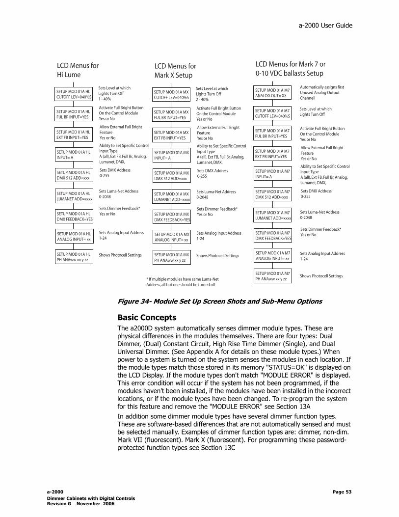
Figure 34- Module Set Up Screen Shots and Sub-Menu Options
Basic ConceptsThe a2000D system automatically senses dimmer module types. These are physical differences in the modules themselves. There are four types: Dual Dimmer, (Dual) Constant Circuit, High Rise Time Dimmer (Single), and Dual Universal Dimmer. (See Appendix A for details on these module types.) When power to a system is turned on the system senses the modules in each location. If the module types match those stored in its memory "STATUS=OK" is displayed on the LCD Display. If the module types don't match "MODULE ERROR" is displayed. This error condition will occur if the system has not been programmed, if the modules haven't been installed, if the modules have been installed in the incorrect locations, or if the module types have been changed. To re-program the system for this feature and remove the "MODULE ERROR" see Section 13AIn addition some dimmer module types have several dimmer function types. These are software-based differences that are not automatically sensed and must be selected manually. Examples of dimmer function types are: dimmer, non-dim. Mark VII (fluorescent). Mark X (fluorescent). For programming these password-protected function types see Section 13C
a-2000 Page 53 Dimmer Cabinets with Digital ControlsRevision G November 2006

Step 13A: Display at StartupThe main menu should appear like the menu below. It indicates the version of
software and if the voltage is single or three phase power.
If "Fault Condition" appears in lieu of "Status=OK", call Leviton’s Technical Service Department at 1-800-959-6004.
Potential Error Screens in the Main Menu:Module Error
If the system does not find the modules that were previously assigned, it will flash "Module Error". To clear this message you must:
1 enter the set-up mode (or install the pre-assigned dimmers). 2 When you enter the set-up mode "Auto Assigning Module Types" will
appear. 3 Follow the procedure below
To Auto Assign Module Types:1 When auto assign module type appears, push SELCT/SAVE to auto
assign the current module. 2 Once assigned press CANCEL/CLEAR to move on to the next module.3 If the "auto assign module" appears again, repeat steps 1 and 2 for all
subsequent modules.
Step 13B: Verifying Phase VoltagesTo check the phase voltages:
1 From the main menu Press the Select/Save button.
Step 13C: Assigning Module TypesThe control module and dimmer modules have auto sensing technology. Regardless of where you insert a dimmer module the unit will set itself to the
a2000 Ver 2.00STATUS=OK 1PHASE
a2000 Ver 2.00MODULE ERROR
A=123V B=121V 60 HZ
Page 54

a-2000 User Guide
appropriate dimmer module type (see Appendix). In addition, some dimmer types must be set up for specific dimmer types (functions) manually.
Table 15 - Available Dimmer Modules
Since the Dual Dimmer , Universal Dimmer, and High Rise Time Modules can be used for load types other than an incandescent dimmer, you must assign the particular module the functionality you wish it to use.
Below are the different type of dimmer functions: • DM. A basic dimmer meant to drive incandescent lamps, quartz halogen lamps,
stepdown transformers for low voltage incandescent lamps, and neon or cold cathode low power factor type transformers.
Module Catalog Number Description Automatically assigns Dimmer Type-function to:
120 Volt Modules
000-A15DC-012 15 amp dual constant module N.A.
000-A15DD-012 15 amp dual dimmer module Dual-Dimmer (DM)
000-A15HD-012 15 amp high rise time (700 micro second) single channel module
Single-Dimmer (DM)
000-A20DC-012 20 amp dual constant module N.A.
000-A20DD-012 20 amp dual dimmer module Dual-Dimmer (DM)
000-A20HD-012 20 amp high rise time (700 micro second) single channel module
Single-Dimmer (DM)
000-A20UN-012 20 amp universal dual dimmer module
Univers-Dimmer (DM)
120/277 Volt Modules
000-A20DD-A27 120/277 Volt dual dimmer module
Dual-Dimmer (DM)
000-A20UN-027 120/277 universal dual dimmer module
Univers-Dimmer (DM)
000-A20DC-A27 20A dual 120/277V constant module
N.A.
a-2000 Page 55 Dimmer Cabinets with Digital ControlsRevision G November 2006

If a “High Rise Time” dimmer” is used for an incandescent circuit, it occupies one whole module space. The software sees it is as a single dimmer, and does not assign or try to use the B position of that module.
• M7. The module is set up to drive a dimming ballast requiring that the 120 V power to the ballast be turned on and off, and the control for the ballast is a signal voltage varying from 0 VDC to +10 VDC. The control output channels are auto assigned. The control wire for the first M7 dimmer will be the first control terminal, and the second M7 dimmer will be the second terminal, even though there are other dimmers of different types in between. There is a maximum number of 8 of these control output channels.
Inserting a new M7 dimmer at a later time may require renumbering dimmers, or the control wires will fall out of order.
• TU. The output is set up to drive the Lutron TuWire™ dimming ballast. It wires the same as the Advance Mark X ballast, but requires a different low light limit setting which is automatically provided whenever the TU setting is chosen.
• MX. The dimmer is set up to drive an Advance Mark X dimmer ballast, and the software automatically provides the proper low light limit as required for that ballast type. The ballast requires only two power wires for control; a dimmed line and a neutral.
• ND. The module is set up for On/Off operation only. As the input signal approaches 40% the module switches full On. When the input falls below about 38% it switches Off. The slight difference in level is called hysteresis and is used to prevent "chattering" at the switching point.
• LV. A normal dimmer but with a low-end cutoff. This can be useful for certain load types such as driving a stepdown transformer for low voltage lights where a complete turnoff is needed at some low light level.
• HL. This module is set up to drive the Lutron HiLume™ and EcoDim™ dimmer ballasts. Each of the two channels include two sub-channels; dimming and switching. When the control channel is off both sub-channels are off. When the channel is on to 1% the switching channel turns on and the dimming channel goes to its minimum level.
•
By pressing the UP button, from the main menu, you can step through each of the modules to determine how they are programmed, if they are receiving an input, and the source of that input. If a dimmer is being driven from two inputs (for example Luma-Net and DMX512), whichever input is higher has control, and that control type appears.
Page 56

a-2000 User Guide
Assign the Module/Load TypeAssigning the module type involves the use of a password (setup code) to prevent unauthorized changes of vital data within the digital module. The factory default password is 000.
If the Setup Code is lost or forgotten you will have to contact the factory to regain access to your system setup menus. If your system normally resides in a locked electrical room it may be best to keep the default Setup Code.
To access the module you want to change:
1 Press the UP button until Menu Setup appears on the LCD display.2 Press the Select/Save button.
Enter Setup Code 000 appears on the LCD display.3 Press the UP or DOWN buttons to change the 000 to the actual
password (setup code).Note: If it has not been changed use 000.
4 Press the Select/Save button.The LCD display shows SETUP MENU SETUP MODULES?.
5 Press the Select/Save button to access the first module.The setup module display for module 01A appears flashing; the number is the module number, the letter (A or B) is the channel within the module.
6 Press the Select/Save button to access that channel of the module,or press the UP button to move to another channel of another module.
Once you have reached the module you wish to change:1 Press the Select/Save button.
The number stops flashing, and the module type starts flashing.2 With the type flashing, press the DOWN button until the LCD display
shows Function = Dimmer.3 Press the Select/Save button.
Dimmer flashes.4 Press the UP or DOWN buttons to scan through the functions.5 Press the Select/Save button to select the desired function.
The flashing moves from Function to several choices of dimmer types.
6 Press the UP or DOWN buttons to select a dimmer type7 Press the Select/Save button.8 Press the UP button to move on to another channel,
or press the Cancel/Clear button three times slowly to return to the to- level menu.
9 Continue to change the rest of the modules to the desired dimmer type.
SETUP MOD 01A DMTYPE DUAL
a-2000 Page 57 Dimmer Cabinets with Digital ControlsRevision G November 2006

Step 13D: Modify the Dimmer Type Features:Once you have assigned the module type, you can alter the default settings for each dimmer type.
Features applicable to all dimmer types:• Full Bright Input: Toggles On/Off override to Full Bright from the front
control panel• External Full Bright: Toggles On/Off override to Full Bright from an external
contact.• Input: Determines the control input source. Choices are:
•Scan All (A)•EXT Full Bright•Full Bright•Analog •Luma-Net•DMX512
• DMX 512 Address: Sets the DMX address for that particular circuit (1-512)• Luma-Net Address: Sets the Luma-Net address for that particular circuit (1-
2048)• Dimmer Feedback: Toggles the Dimmer Feedback for Luma-Net on or off.
If multiple dimmer circuits have the same Luma-Net address, all but one should have its Dimmer Feedback turned off.
• Max Level: Sets the max level a dimmer will reach (%). An "S" next to this number indicates that it is using the default setting.
• Min Level: Sets the min. level a dimmer will reach (%). An "S" next to this number indicates that it is using the default setting.
• Analog Input: Sets the Analog input number if applicable.
• Ph (Photocell): See step 13G•
Features Specific to dimmer types:Dimmer:• Curve: Sets the dimmer curve. Choices are:
•Square Law•Linear Volts•Linear Lights
Page 58

a-2000 User Guide
Non Dim:• Cutoff Level: Sets the level (%) at which the dimmer will switch off. Default is
40%.
Mark X (10):• Cutoff Level: Sets the level (%) at which the dimmer will turn off. Default is
2%
Mark VII (7):• Analog Output: System automatically assigns the first available analog
output. This is not user adjustable. • Cutoff level: Sets the level (%) at which the dimmer will turn off. default is
2%.
Low Voltage Magnetic:• Cutoff Level: Sets the level (%) at which the dimmer will turn off. Default is
2%
Lutron Tu-Wire:• Cutoff Level: Sets the level (%) at which the dimmer will turn off. Default is
2%Hi Lume:• Cutoff Level: Sets the level (%) at which the dimmer will turn off. Default is
1%
Example: To change the max level for a dimmed circuit:
1 Press the UP button until Menu Setup appears on the LCD display.2 Press the Select/Save button.
Enter Setup Code 999 appears on the LCD display.3 Press the UP or DOWN buttons to change the 999 to the actual
password (setup code).Note: If it has not been changed use 000.
4 Press the Select/Save button.The LCD display shows SETUP MENU SETUP MODULES?.
5 Press the Select/Save button to access the first module.The setup module display for module 01A appears flashing; the number is the module number, the letter (A or B) is the circuit within the module.
6 Press the Select/Save button to access that circuit of the module,or press the UP button to move to another circuit of another module.
Once you have reached the module you wish to change:1 Press the Select/Save button.
The number stops flashing, and the module type starts flashing.
SETUP MOD 01A DMTYPE DUAL
a-2000 Page 59 Dimmer Cabinets with Digital ControlsRevision G November 2006

2 With the type flashing, press the DOWN button until the LCD display shows Function = Dimmer.
3 Press the Select/Save button.Dimmer flashes.
4 Press the UP or DOWN buttons until the LCD display shows MAX LEVEL= 100%.
5 Press the Select/Save button to select the desired function.6 Press the UP or DOWN buttons to select the desired maximum
level.7 Press the Select/Save button.8 Press the RIGHT or LEFT button to move on to another circuit
or press the Cancel/Clear button several times slowly to return to the main menu.
Step 13E: Verifying Module Programming in a Dimmer CabinetTo determine how the modules are programmed in the dimmer cabinet, check the module programming:
1 Make sure the powered on and in operating normally.2 Press the UP button.
The LCD display shows MENU SETUP, with MENU flashing.3 Press the UP button again.
The LCD display shows MENU MODULE STATUS.4 Press the SELECT button.
The LCD display shows how the first circuit of the first dual dimmer is programmed.
Module programming information is displayed in a two-line format, as in the following example:
The above example indicates Module 01A, which is normally a dual dimmer, and the A circuit of that dimmer is set to 50% of full brightness. DM indicates that it is set up as a standard dimmer.
MOD 01A = 50% DMINPUT=LUMANET S
Module numberPortion of dimmer set to this percent brightness
Percent of full brightness (FL for 100%)Dimmer type
Whether dimmer can accept more than oneinput type (blank if only assigned to one input type)
Type of signal driving this half of module(could be LUMANET or DMX512 or ANALOG in this case)
Page 60

a-2000 User Guide
Step 13F: Assigning Luma-Net and/or DMX512 ChannelsThe a-2000D can assign dimming channels to various Luma-Net and/or DMX512 control channels within the software; no wiring changes are necessary.
Assigning Numbers AutomaticallyFor a simple configuration, the first control channel number is defined as a system-wide address (the factory default is 0001), and the system automatically assigns the control channel numbers in numerical order to the dimming zones (dimmers) within the dimmer cabinet. If a second dimmer cabinet is connected, its system-wide address can be set (to 0025, for example), and the dimmer circuits are assigned beginning with that number. To change the system-wide addresses:
1 Press the UP button until the LCD display shows Menu Setup.2 Press the Select/Save button.
The LCD display shows Enter Setup Code = 999.3 Press the UP and DOWN buttons to change the 999 to the
actual setup code.The unit is now unlocked so changes can be made.
4 Press the Select/Save button.The LCD display shows Setup Menu Setup Modules?.
5 Press the DOWN button once to set up the Luma-Net start address,
or press the DOWN button twice to set up the DMX 512 start address.
6 Press the Select/Save button.The flashing moves from the description to the number.
7 Press the UP and DOWN buttons to change the flashing number to the desired new address.
8 Press the Select/Save button to store the new address.The flashing returns to the description.
9 Press the Cancel/Clear button twice.Returns to the top level menu.
Assigning Individual Control ChannelsYou might need to assign control channels in a sequence other than the automatic assignment described above. This can happen when single rather than dual dimmers are installed, and you do not want to lose the continuity of the numbering system due to the loss of the second module circuit. After completing most of the assignments using the system-wide method described above, the individual dimming channels can be further modified.
SETUP LUMANETSTART ADD = 0001
SETUP DMX 512START ADD = 001
a-2000 Page 61 Dimmer Cabinets with Digital ControlsRevision G November 2006

To select a dimming circuit to modify:
1 Press the UP button until the LCD display shows Menu Setup.2 Press the Select/Save button.
The LCD display shows Enter Setup Code = 999.3 Press the UP and DOWN buttons to change the 999 to the
actual setup code.4 Press the Select/Save button.
The LCD display shows Setup Menu Setup Modules?.5 Press the Select/Save button.
The LCD display shows Setup Mod 01A.6 Press the UP and DOWN buttons to change the dimming circuit
to be modified (01A, 01B, 02A, etc.).7 Press the Select/Save button to select the dimming circuit.
The flashing moves from the upper number to the lower description.
To modify the channel:
1 Press the UP button twice to display the Luma-Net address,
or press the UP button three times to display the DMX 512 address.
2 Press the Select/Save button.The flashing in the lower part of the display moves from the description to the number.
3 Press the UP and DOWN buttons to change the flashing number to the desired new address.
4 Press the Select/Save button to store the new address.The flashing returns to the description.
5 Push the Cancel/Clear button five times to return to the top level menu.
Verifying Assignment of Mark VII Analog Output Signal1 Enter Set-up2 Enter Set-up Modules3 Select Modules and Circuits4 Page once to Analog Out = X
Where X (1 - 8) is the analog out (auto) assigned. It can now be changed if desired.
Step 13G: Daylight Harvesting/Photocells
Background-Daylighting:In a daylight harvesting application, the goal is to maintain a consistent lighting level within the space, regardless of the source of light which could be either
LUMANET ADD=0001
DMX 512 ADD=001
Page 62
a-2000 User Guide
daylight or dimmable artificial light. If this lighting level can be maintained completely with daylight, no artificial light is necessary. However, if the lighting is not sufficient to meet the desired level, it can be boosted by the artificial light connected to the a-2000 dimming cabinet to whatever level is necessary to reach the desired lighting level. That is the theory behind daylight harvesting. The desired lighting level is called the "target."
Background-Photocells:Photocells are devices which sense the incident light levels, and output a voltage proportional to the dynamic range which the photocell has been pre-configured to support. For example, Leviton's ODC0P-00W calibrated photocell senses 0-70fc. When the photocell receives 0fc of incident light, the output voltage will be 0V. Likewise, when the photocell receives 70fc of incident light, the output voltage will be +10Vdc. When received by the a-2000, this is converted to a scale of 0-255.
Configuring your a-2000 cabinet to use a photocell:1 Connect the photocell(s) to one of the a-2000 analog inputs on the
optional analog input card.2 Configure the system defaults for photocell operations:
a. From the Setup Menu, select modify defaults, and set the following settings:
RESPONSE determines how quickly the dimmers fade from point A to point B in order to achieve the desired threshold. Valid values are 1-7, 1=fast response, 7=slow response. A fast response is about 3.33% change per second and a slow response it about 0.83% change per second.
DEAD BAND determines the deviation from the target which must occur before the dimmer level will be adjusted to again match the target. For example, if the dead band is 5, the target is 128, and the current lighting level is 130, the dimmer level will not lower to meet the target. If however the current lighting level exceeds target+dead band, or 133, the dimmer levels will lower until either their value is 0, or the current lighting level is 128.
If your lights are oscillating between levels and do not seem to settle upon one current level, try increasing the dead band and/or slowing down the response.
3 Assign dimmer modules to the photocell and set the settings for that module:
a. From the dimmer modules setup menu, page until the PH ANA setting is reached. From this point, your LCD screen should read similar to the following:
a-2000 Page 63 Dimmer Cabinets with Digital ControlsRevision G November 2006

Figure 35- Setting up Dimmer Module 01A
Module type - is set elsewhere in the module setup screens and the information is provided here for reference only.
ANA01 - is used to set which analog input the photocell is connected to which this dimmer is listening to. Depending on your application, many dimmers may be reacting to the same photocell.
48 - the Target Level represents the level which you want the photocell to achieve indicating that the lighting level is at it's desired setting. This level is represented in hexadecimal format, valid values in the range of 00 to FF. 00 is equivalent to 0 in decimal notation and FF is equivalent to 255 in decimal notation.
D - indicates disabled. The valid settings are E for Enabled or D for Disabled. When enabled, it indicates that the dimmer is "enabled" in photocell mode and that it will reach to the analog input in attempt to reach the target.
When a dimmer is "Enabled", any control change required of the dimmer and requested by any source other than the photocell will automatically disable the photocell function.
If analog input channel = photomatic channel, then analog input is ignored.
00 - shows the current level being reported by the analog input.
SETUP MOD 01A DMPH ANA01 48 D 00
Setting up dimmer module 01A
Module type "dimmer"
Indicates "photocell" setup mode
Current level of analog input 01 (report in hex, 00-FF=0-255)
"D" = Disabled, "E"= EnabledTarget Level (reported in hex, 00-FF=0-255)
Analog input with photocell controlling this dimmer
Page 64

a-2000 User Guide
‘ All of these settings can be set through the a-2000 menu structure as shown. However, in some installations which also have connected either Dimension 4200 or Dimension 8000 control stations, other methods can be used to set these settings.
Threshold can be "captured" from the current live setting by issuing a fade time of 253, Photocell Rec if using D4200 or D8000, on the Luma-Net channels patched to the dimmers assigned to the analog input.
For example, to use this feature given the following installation:
Photocell connected to Analog input 1Analog Input 1 assigned to dimmers 7, 8, 9, & 10Luma-Net channels 7, 8, 9 & 10 assigned to dimmers 7, 8, 9 & 10
1 Program a button/preset on either a D4200 or D8000 station with channels 7, 8, 9, & 10 at any levels with a fade time of 253s, Photocell Rec if using D4200 or D8000.
2 Create the desired lighting level in the space 3 Execute the button/reset
The current level reported by the photocell will now be stored as the target in dimmers 7,8,9 & 10.
Enabling dimmers to be controlled by their assigned photocell can also be triggered from a button/preset on a D4200 or D8000 control device.
To Enable the dimmer for photocell control1 Program a button/preset on either the D4200 or D8000 station with the
Luma-Net channel patched to the dimmer which you want to enable and a fade time of 254, Photocell On if using D4200 or D8000.
2 Execute the button/preset.
The assigned dimmer will now be enabled for photocell control.
Step: 13H: Modifying Factory DefaultsThe majority are self explanatory, however a few deserve a little explanation.
a-2000 Page 65 Dimmer Cabinets with Digital ControlsRevision G November 2006

Luma-Net Restore:If this feature is turned "ON", the control module will take snapshots of the Luma-Net values periodically and in the event of a power failure, will restore the lighting to the levels they were at prior to the power failure. When the feature is turned "OFF", the control system will be responsible for restoring the lighting levels or the levels will go to zero.
Line Regulation:Regulation is designed to maintain basic long term levels and will not correct for momentary instantaneous changes in excess of 10% of Line Voltage. When turned "ON", the dimmer cabinet will maintain consistent lighting levels as the incoming voltage varies. When turned "OFF" the cabinet will not compensate for the varying voltage levels.
Speed of response controlled by a DIP switch. Contact factory for more information.
Page 66

a-2000 User Guide
Parts Replacement
Figure 37 - 12 Circuit Cabinet
a-2000 Page 67 Dimmer Cabinets with Digital ControlsRevision G November 2006

D
Dh
W
C
M
A
M
I1
I1
I2
N
P1
P2
O
C
C
S
T
F
D
B
O
U
D
Specifications
immer cabinet capacity 12 circuits, 15 or 20-amp each 24 circuits, 15 or 20-amp each
imensions with surface-mount ardware
30.125" wide x 29.88" high x 4.125" deep
30.125" wide x 43" high x 4.125" deep
eight, fully loaded 125lb. 155 lb.
onduit entry See Figure 4 See Figure 4
aximum fan noise rating 41 dBA each 41 dBA each
mbient operating temperature 32° F to 104° F 32° F to 104° F
aximum operating humidity 90% non-condensing 90% non-condensing
nput Feeder Configurations20V 3φ Cabinets
120/208V 3φ, 80A Max 4 wire+Ground, 60Hz
120/208V 3φ, 175A Max4 wire+Ground, 60Hz
nput Feeder Configurations20V 1φ Cabinets
120/240V 1φ, 125A Max3 wire+Ground, 60Hz
120/240V 1φ, 250A Max 3 wire+Ground, 60Hz
nput Feeder Configurations77V 3φ Cabinets
277/480V 3φ, 80A Max4 wire + Ground, 60Hz
277/480V 3φ, 175A Max4 wire + Ground, 60Hz
ominal 240 V circuits Not available
hase to neutral operating voltage20V Cabinets
110 to 130 V +/- 10%
hase to neutral operating voltage, 77V Cabinets
277V +/- 10%
perating frequency 47 - 63 Hz
abinet type NEMA type 1 for indoor use only; available for surface or flush mounting
ontrol inputs Luma-Net, DMX-512, 0 to +10 VDC (Optional Analog card)
quare law curve control Yes
op, bottom, right side feed Yes
ully plug-in dimmer modules Yes
immers available for Incandescent, LV stepdown transformers, neon, cold cathode, high-rise time, fluorescent dimmer ballasts, 0-10 VDC controlled ballasts, Mark X,
Hi-Lume, quartz, and constant circuits. Electronic Low Voltage is supported with factory qualification of transformer.
ypass switch for every dimmer 120V Dimmers YesUniversal Dimmers: Yes
277V Dimmers optional, requires 277V constant module
perating efficiency Minimum 97%
L and cUL Listed Yes
efault SETUP Code (Password) 000
Page 68

a-2000 User Guide
Appendix A
Control Inputs
Luma-Net® IIIThe most common input is Luma-Net III, a Leviton protocol, that sends serial digital data over a twisted pair of communication (data) wires. With this system, controls can be located up to 2000 ft. from the dimming cabinet. The two data wires terminate on REM+ and REM- of the Luma-Net Terminal Block. Any shield if present is not connected.Along with this pair of communications (data) wires are a second pair of wires for providing current limited 24 VDC power to operate displays and electronics in the remote control stations. These wires terminate on COM and +V. The communications signals require very little power, and number 24 AWG wire is adequate for the twisted pair. Belden number 9729 or equivalent is recommended. However the 24 VDC power wires handle more current and should be a #14 AWG minimum wire to insure that only a very small amount of voltage drop takes place over long distances. If a remote DC power supply is used, all DC common wires must be joined.Where more than one remote control panel or dimmer cabinet using Luma-Net III communications is used in a system, the data wires and the DC power wires are run together from the dimmer cabinet to the nearest control station, then on to the next station, and the next, and so on. At the last control station or dimmer cabinet on both ends of the run, a small jumper wire must be run from the terminal labeled “Rem-” to the terminal marked “Term” on that last station. This jumper wire properly terminates the digital communications lines at the end of the line. Shield to ground at one point only.
DMX512The digital control panel accepts DMX-512 signals, an industry standard signal widely used in the theater industry. This offers the opportunity to use theatrical consoles to control some or all of the dimmers in the a-2000D Dimmer Cabinet.
AnalogThe digital control panel accepts a third type of control signal often used with analog control systems, if equipped with the optional analog control card. This signal varies between 0 VDC and +10 VDC to control the dimmer outputs. An input of 0 V results in no output power from the dimmer; an input of +10 VDC gives full voltage output from the dimmer. Varying this signal from 0 VDC to +10 VDC varies the AC output voltage from zero to virtually full line voltage. If this system uses analog inputs, an optional analog control card will have been added during fabrication.
Multiple Signal TypesUnder certain circumstances the digital control panel can receive two or more types of input signals. See page 34.
a-2000 Page 69 Dimmer Cabinets with Digital ControlsRevision G November 2006
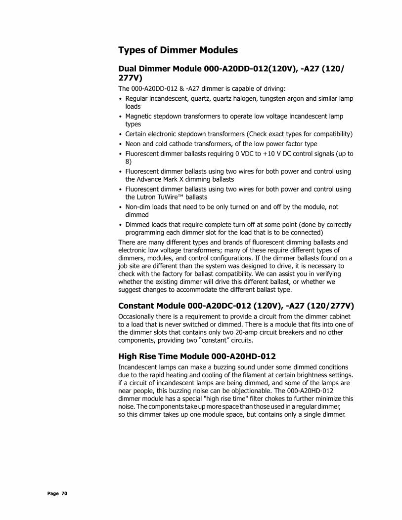
Types of Dimmer Modules
Dual Dimmer Module 000-A20DD-012(120V), -A27 (120/277V)The 000-A20DD-012 & -A27 dimmer is capable of driving:• Regular incandescent, quartz, quartz halogen, tungsten argon and similar lamp
loads• Magnetic stepdown transformers to operate low voltage incandescent lamp
types• Certain electronic stepdown transformers (Check exact types for compatibility)• Neon and cold cathode transformers, of the low power factor type• Fluorescent dimmer ballasts requiring 0 VDC to +10 V DC control signals (up to
8)• Fluorescent dimmer ballasts using two wires for both power and control using
the Advance Mark X dimming ballasts• Fluorescent dimmer ballasts using two wires for both power and control using
the Lutron TuWire™ ballasts• Non-dim loads that need to be only turned on and off by the module, not
dimmed• Dimmed loads that require complete turn off at some point (done by correctly
programming each dimmer slot for the load that is to be connected)There are many different types and brands of fluorescent dimming ballasts and electronic low voltage transformers; many of these require different types of dimmers, modules, and control configurations. If the dimmer ballasts found on a job site are different than the system was designed to drive, it is necessary to check with the factory for ballast compatibility. We can assist you in verifying whether the existing dimmer will drive this different ballast, or whether we suggest changes to accommodate the different ballast type.
Constant Module 000-A20DC-012 (120V), -A27 (120/277V)Occasionally there is a requirement to provide a circuit from the dimmer cabinet to a load that is never switched or dimmed. There is a module that fits into one of the dimmer slots that contains only two 20-amp circuit breakers and no other components, providing two “constant” circuits.
High Rise Time Module 000-A20HD-012Incandescent lamps can make a buzzing sound under some dimmed conditions due to the rapid heating and cooling of the filament at certain brightness settings. if a circuit of incandescent lamps are being dimmed, and some of the lamps are near people, this buzzing noise can be objectionable. The 000-A20HD-012 dimmer module has a special "high rise time" filter chokes to further minimize this noise. The components take up more space than those used in a regular dimmer, so this dimmer takes up one module space, but contains only a single dimmer.
Page 70

a-2000 User Guide
Dual Universal Module 000-A20UN-012(120V), -027 (120/277V)The 000-A20UN-012 & -027 dimmer is capable of driving on its dimming channels (lower load terminals):• Regular incandescent, quartz, quartz halogen, tungsten argon and similar lamp
loads• Magnetic stepdown transformers to operate low voltage incandescent lamp
types• Certain electronic stepdown transformers (Check exact types for compatibility)• Neon and cold cathode transformers, of the low power factor type• Fluorescent dimmer ballasts requiring 0 VDC to +10 V DC control signals (up to
8)• Fluorescent dimmer ballasts using two wires for both power and control using
the Advance Mark X dimming ballasts• Fluorescent dimmer ballasts using two wires for both power and control using
the Lutron TuWire™ ballasts• Non-dim loads that need to be only turned on and off by the module, not
dimmed• Dimmed loads that require complete turn off at some point (done by correctly
programming each dimmer slot for the load that is to be connected)There are many different types and brands of fluorescent dimming ballasts and electronic low voltage transformers; many of these require different types of dimmers, modules, and control configurations. If the dimmer ballasts found on a job site are different than the system was designed to drive, it is necessary to check with the factory for ballast compatibility. We can assist you in verifying whether the existing dimmer will drive this different ballast, or whether we suggest changes to accommodate the different ballast type.
The Lutron company makes a series of dimmer ballasts called HiLume™ and Eco-10™ that control differently than other dimmer ballasts on the market. The 000-A20HL-027 dimmer module can drive these ballasts. It has two output terminals. One provides the 120V (-027, 277V)line voltage and is switched On or Off. The other output terminal provides a symmetrical phase-controlled dimmer output with a low end limit as required to drive these ballasts to different light outputs. The dimmed circuit is connected to the lower load terminal. The switched circuit is connected to associated upper load terminal. The upper terminals are for ballast loads only.
Fluorescent Dimming Ballast Types
0-10 VDC Controlled BallastsThis method of ballast control is used by Sylvania, MagneTek, Advance (for the Mark VII ballasts) and others. It requires that the line voltage feed to the ballasts be switched On for operation, and Off to achieve zero light level, because these ballasts do not dim all the way to blackout.
One half of a dual dimmer module is used as an On/Off switch as described above, and feeds the line voltage to the dimmer ballast. A row of screw compression terminals located along the top of the PC board provides the 0 VDC
a-2000 Page 71 Dimmer Cabinets with Digital ControlsRevision G November 2006

to +10 VDC control voltage drain for the ballast. There are sufficient terminals for the purple (+V) control wire for up to eight circuits using these ballasts. Therefore the maximum number of circuits with this type ballasts that can be fed from one a-2000D dimmer cabinet is eight. The system automatically assigns outputs in order of these dimmer types. Refer to the Configuring and Programming Section to determine that assignment. There is also a group of terminals for the (common) gray ballast control wires.
Since these are dual dimmers, one half of the dimmer provides the On/Off line voltage to the ballast, and for that same position the 0 VDC to +10 VDC signal is available to tell the ballast what brightness is required.
Two-Wire Fluorescent Ballasts (Additional Control Wiring is not required)
A second method of control, used by the Advance Mark X TM fluorescent dimmer ballast and certain Lutron dimmer ballasts called TU Wire™, uses the power feed wires to the dimmer for both power and control. Only half of a dual dimmer is required to drive the ballast since it serves to dim both the ballast and as an On/Off switch to turn the lights fully off when necessary. In this configuration, the dimmer output that controls the light intensity is not allowed to go below some value of true RMS voltage in order to allow the ballast to generate the correct amount of filament voltage for the fluorescent lamps. By selecting the correct ballast type in setup, the digital circuitry of the a-2000D control board automatically sets the correct minimum voltage for the ballast type selected.
Other Ballasts - Three-Wire- (Refer to the load wiring schematic.)
A third method of control used by Lutron Hi Lume™ or Eco 10™ ballasts and older core and coil type magnetic dimming ballasts uses Universal Dimmer Module (000-A20UN-012, -027). There are three power wires to the ballast, which differs from other dimming ballasts on the market. The first power wire supplies line voltage whose output is varied by the dimmer & is connected to the lower dimmer load terminal. The second power wire supplies line voltage that must be switched on and off is connected to the corresponding upper switching load terminal. The third power wire is the neutral return. This dimmer module uses only one input breaker to feed the dimming load & the switching load.
A minimum light level must be set for the Lutron ballasts, depending on the particular ballast being used. Operating the ballasts below that minimum level can result in damage to the ballast and lamps.
Page 72

a-2000 User Guide
Figure 38 - Factory Set Dip Switches
The above figure shows the dip switches on the Control Module. These are factory set and should not be altered unless instructed to do so by an authorized Leviton Factory Person.
Note: Your actual cabinet may varyfrom the illustration shown.
a-2000 Page 73 Dimmer Cabinets with Digital ControlsRevision G November 2006

Warranty Information
Limited Warranty
LEVITON LIGHTING CONTROL DIVISION of Leviton Manufacturing Co Inc. warrants its Lighting Control Systems products to be free of material and workmanship defects for a period of two years after system acceptance or 26 months after shipment, whichever comes first. The Z-MAX Relay cards are covered for a period of Ten (10) years. Lighting fixtures manufactured by Leviton are covered for a period of one year.
This Warranty is limited to repair or replacement of defective equipment returned Freight Pre-Paid to Leviton Lighting Control Division at 20497 SW Teton Ave., Tualatin, Oregon 97062, USA. User shall call 1-800-959-6004 and request a return authorization number to mark on the outside of the returning carton, to assure that the returned material will be properly received at Leviton.
All equipment shipped back to Leviton must be carefully and properly packed to avoid shipping damage. Replacements or repaired equipment will be returned to sender freight prepaid, F.O.B. factory. Leviton is not responsible for removing or replacing equipment on the job site, and will not honor charges for such work. Leviton will not be responsible for any loss of use time or subsequent damages should any of the equipment fail during the warranty period, but agrees only to repair or replace defective equipment returned to its plant in Tualatin, Oregon.
This Warranty is void on any product that has been improperly installed, overloaded, short circuited, abused, or altered in any manner. Neither the seller nor Leviton shall be liable for any injury, loss or damage, direct or consequential arising out of the use of or inability to use the equipment. This Warranty does not cover lamps, ballasts, and other equipment which is supplied or warranted directly to the user by their manufacturer. Leviton makes no warranty as to the Fitness for Purpose or other implied Warranties.
Page 74

a-2000 User Guide
This Page Left Intentionally Blank
a-2000 Page 75 Dimmer Cabinets with Digital ControlsRevision G November 2006

Page 76

a-2000 User Guide
Power Considerations for Control SystemsThe control system should be carefully planned to take these important issues into consideration:• Power Supply for connected devices• Wire Size for Power Runs
On systems where full factory drawings have been provided, our Applications Engineering department has already managed these calculations for you so you need only follow the instructions on the system drawings. However, on any installation where factory drawings were not provided, the information contained within this guide must be followed to ensure that all of your devices operate properly and without failures or complete in-operability.
This chapter contains information which applies to many Leviton products and is not necessarily limited to the product which is primarily included in this manual. There may be information in this chapter which is not relevant to your particular installation. If you have questions about ANY information contained herein, please immediately contact our Technical Services Department prior to proceeding with installation.
TerminologyPlease review these definitions which are used throughout this chapter:• Power Supply or Supply - references a device which supplies power to other
devices• Power Control Device (PCD) - refers to a device which controls power.
Examples of Devices in the Leviton product line which control power are dimming racks, relay panels, A-2000, i-series e, Z-MAX, etc. Generally PCD’s also supply a certain amount of power to connected low voltage control devices
• Control Devices or Low Voltage Control Devices or Device - these terms all refer to control devices which connect to a Power Control Device (PCD). These devices could be simple low voltage switches, Occupancy Sensors, or D8000 control stations
• Luma-Net - is one of our network lighting control protocols. Luma-Net is an RS-485- based control protocol used by D8000 & D4200 control devices. Many of our PCD (Power Control Device) products have a direct data connection for a Luma-Net device. All Luma-Net Control Devices require power in one form or another. This power generally accompanies the data wires
• Unit Load - (1) Unit load is defined as 25mA, or 0.025A. It is an arbitrary definition by Leviton and was created to simplify power calculations
Power Requirements & Maximum Run LengthEach Control Device used in your system has a different load (draw) and each PCD can support a different total load (supply.) The steps for determining the total load of your network and verifying that the supply is sufficient are simple--or at least logical:
a-2000 Page 77 Dimmer Cabinets with Digital ControlsRevision G November 2006

Step 3: Determine the maximum available current of your supply, be it a PCD or other Power Supply. Convert this to the maximum number of Unit Loads if necessary.
Step 4: Sum the required load of each Control Device, expressed in unit loadsStep 5: Verify that the Sum from Step 2 <= the maximum available power from your
supply in Step 1. • If this verification fails, the Sum of required loads is > than the available
supply, either use an external power supply or reduce the number of control devices. Or, contact our Technical Services department for help.
One Unit Load = 25mA =.025A
Load Rating Verification Formula
Power Control Devices - Available Supply CurrentThe Z-MAX cabinets are designed to be able to power external control loads from the internal power supply. See the table below for the available power from each cabinet.
Power Supply Maximum Unit Loads
Power Control Device (PCD)
Maximum # of UnitLoads
Supply(VDC)
Power Control Device (PCD)
Maximum # of Unit Loads
Supply (VDC)
a-2000D, 12 Circuit,Standard Power Supply
40 24VDC Z-MAX 8 Cabinet 20 24 VDC
a-2000D, 24 CircuitStandard Power Supply
46 12VDC Z-MAX 48 Cabinet(Master or Slave)
20 24 VDC
a-2000D, 12 Circuit,Large Power Supply
120 12VDC Z-MAX Switch Input Board (accessory to Z-MAX 24 & 48 size Cabinets)
20 24 VDC
a-2000D, 24 CircuitLarge Power Supply
114 12VDC RRP - Z-MAX Remote Relay Panel
6 24 VDC
NPC – XP 49 12-24 VDC
i Series e (all Racks)
NPC – DHV N/A N/A
NPC – DLR 49 12-24 VDC
Control Station A Unit Load
XQuantity of Station A's attached
+Same formulafor any other attached control Station
Control Station B Unit Load
XQuantity of Station B's attached
<+ Power Supply's Available Unit Load
Page 78

a-2000 User Guide
The sum of all devices connected to all power output terminals can not exceed the Maximum number of Unit Loads available in the PCD or supply.
a-2000 Page 79 Dimmer Cabinets with Digital ControlsRevision G November 2006

Page 80

a-2000 User Guide
Control Devices Unit Load
@12VDC
Unit Load
@24VDC
Station Type Unit Load @
12VDC
Unit Load @ 24VDC
D4200 LCD 5 2 Z-MAX Digital Switch, 1 Button
N/A 0.6
D4200 Entry (Button),
2 1 Z-MAX Digital Switch, 2 Buttons
N/A 0.8
D4200 Room Combine Station
3 1 Z-AX Digital Switch, 3 Buttons
N/A 1.0
D4200 Remote I/R 2 1 Z-MAX Digital Sw., 4 Buttons
N/A 1.1
Luma-Net Hub 6 3 Z-MAX Digital Switch, 5 Button
N/A 1.3
D8000 LCD 3 2 Z-MAX Digital Switch, 6 Button
N/A 1.0
D8000 Entry (Button)
2 1 Z-MAX Digital Switch, 8 Button
N/A 1.1
D8000 Slider 2 1 Z-MAX Digital Sw., 10 Button
N/A 1.3
D8000 Key switch 1 1 1 Button Low Voltage Switch
N/A 0.6
D8000 I.O Port 2 1 2 Button Low Voltage Switch
N/A 0.9
D8000 Combine/Closure (Advanced)
11 10 3 Button Low Voltage Switch
N/A 1.2
Infrared Only Occ Sensor
N/A 1.2 4 Button Low Voltage Switch
N/A 1.5
Ultrasonic Only Occ. Sensor
N/A 1.2 5 Button Low Voltage Switch
N/A 1.8
Multi-tech Occ Sensor
N/A 1.2 6 Button Low Voltage Switch
N/A 2.1
Ultrasonic 2-Way Occ. Sensor
N/A 1.4 8 Button Low Voltage Switch
N/A 2.7
Multi-tech 2-Way Occ, Sensor
N/A 1.4 10 Button Low Voltage Switch
N/A 3.3
Photocell, odc0p-00w
Photocell, pcatr-000
Photocell, pcind-000
-
a-2000 Page 81 Dimmer Cabinets with Digital ControlsRevision G November 2006

Control Device Loads
Power Wire - Run LengthThe maximum total run length of each segment is a function of the total number of unit loads. A run becomes too long when the voltage drop, due to wire size and run length, increases to a point where the station does not have sufficient voltage to operate. The maximum run length, in feet, based on the total number of unit loads is shown below:
(2) Tables are provided, (1) @ 12VDC and (1) at 24VDC. Make sure that you use the correct table!
Wire Size vs. Length of Runs - Power Wiring @24 VDC
Photocell, pcout-000
-
Photocell, pcsky-000
-
Control Devices Unit Load
@12VDC
Unit Load
@24VDC
Station Type Unit Load @
12VDC
Unit Load @ 24VDC
Voltage Drop Table
(Ams) (Unit Loads 12V 24V 12V 24V 12V 24V 12V 24V 12V 24V0.25 10 756 3,528 1,200 5,600 1,904 8,885 3,000 14,000 4,800 22,4000.50 20 378 1,764 600 2,800 952 4,443 1,500 7,000 2,400 11,2000.75 30 252 1,176 400 1,867 635 2,962 1,000 4,667 1,600 7,4671.00 40 189 882 300 1,400 476 2,221 750 3,500 1,200 5,6001.25 50 151 706 240 1,120 381 1,777 600 2,800 960 4,4801.50 60 126 588 200 933 317 1,481 500 2,333 800 3,7331.75 70 108 504 171 800 272 1,269 429 2,000 686 3,2002.00 80 150 700 238 1,111 375 1,750 600 2,8002.25 90 133 622 212 987 333 1,556 533 2,4892.50 100 120 560 190 889 300 1,400 480 2,2402.75 110 109 509 173 808 273 1,273 436 2,0363.00 120 100 467 159 740 250 1,167 400 1,8673.25 130 146 683 231 1,077 369 1,7233.50 140 136 635 214 1,000 343 1,6003.75 150 127 592 200 933 320 1,4934.00 160 119 555 188 875 300 1,4004.25 170 112 523 176 824 282 1,3184.50 180 106 494 167 778 267 1,2444.75 190 100 468 158 737 253 1,1795.00 200 150 700 240 1,120
10AWGCurrent 18AWG 16AWG 14AWG 12AWG
Page 82

Leviton Lighting Management Systems Division Headquarters20497 SW Teton Avenue, Tualatin, OR 97062Customer Service Telephone: 1-800-736-6682 • FAX: 1-503-404-5600Tech Line: 1-800-959-6004
Leviton Manufacturing Co., Inc.59-25 Little Neck Parkway, Little Neck, NY 11362-2591Telephone: 1-800-323-8920 • FAX: 1-800-832-9538
Visit Leviton’s Web site at http://www.leviton.com© 2002-2006 Leviton Manufacturing Co., Inc. All Rights ReservedSpecifications and Pricing Subject to Change at any time
LIT-32400-00