2001 dodge ram 3500 pickup -...
TRANSCRIPT
2001 Dodge RAM 3500 PICKUPSubmodel: | Engine Type: L6 | Liters: 5.9
Fuel Delivery: FI | Fuel: DIESEL
Subarticles
MANUAL- NV3500 - DISASSEMBLY
MANUAL- NV3500 - DISASSEMBLY
MANUAL - NV3500 - ASSEMBLY
DISASSEMBLY
FRONT HOUSING
Shift transmission into Neutral.1.
If lubricant was not drained out of transmission during removal, remove drain plug and drain lubricant.2.
Inspect drain plug magnet for debris.3.
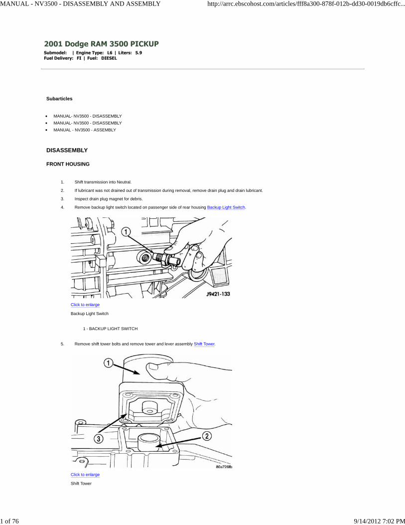
Remove backup light switch located on passenger side of rear housing Backup Light Switch.
Click to enlarge
Backup Light Switch
1 - BACKUP LIGHT SWITCH
4.
Remove shift tower bolts and remove tower and lever assembly Shift Tower.
Click to enlarge
Shift Tower
5.
MANUAL - NV3500 - DISASSEMBLY AND ASSEMBLY http://arrc.ebscohost.com/articles/fff8a300-878f-012b-dd30-0019db6cffc...
1 of 76 9/14/2012 7:02 PM
1 - SHIFT TOWER AND LEVER ASSEMBLY
2 - SHIFT SOCKET
3 - SEAL
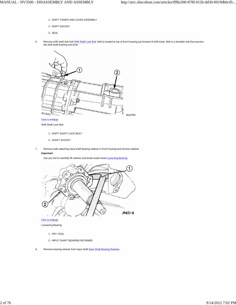
Remove shift shaft lock bolt Shift Shaft Lock Bolt. Bolt is located at top of front housing just forward of shift tower. Bolt is a shoulder bolt that securesthe shift shaft bushing and lever.
Click to enlarge
Shift Shaft Lock Bolt
1 - SHIFT SHAFT LOCK BOLT
2 - SHAFT SOCKET
6.
Remove bolts attaching input shaft bearing retainer to front housing and remove retainer.
Important:
Use pry tool to carefully lift retainer and break sealer bead Loosening Bearing.
Click to enlarge
Loosening Bearing
1 - PRY TOOL
2 - INPUT SHAFT BEARING RETAINER
7.
Remove bearing retainer from input shaft Input Shaft Bearing Retainer.8.
MANUAL - NV3500 - DISASSEMBLY AND ASSEMBLY http://arrc.ebscohost.com/articles/fff8a300-878f-012b-dd30-0019db6cffc...
2 of 76 9/14/2012 7:02 PM

Click to enlarge
Input Shaft Bearing Retainer
1 - SHAFT BEARING
2 - BEARING RETAINER
3 - INPUT SHAFT
Remove snap ring that secures input shaft in front bearing Input Shaft.
Click to enlarge
Input Shaft
1 - INPUT SHAFT SNAP RING
2 - OIL FEED
9.
Remove shift shaft detent plug with Remover 8117A. Attach fingers of the remover to the detent plug and push the cup down till it contacts the trans.Then tighten the nut till it pulls the plug from the case.
10.
Remove shift shaft detent plunger and spring with a pencil magnet.11.
Remove bolts that attach front housing to rear housing Housing And Bearing Retainer Bolt. Three bolts at extreme rear of housing are actually for theoutput shaft bearing retainer. It is not necessary to remove all three bolts at this time. Leave at least one bolt in place until geartrain is ready to beremoved from case.
12.
MANUAL - NV3500 - DISASSEMBLY AND ASSEMBLY http://arrc.ebscohost.com/articles/fff8a300-878f-012b-dd30-0019db6cffc...
3 of 76 9/14/2012 7:02 PM

Click to enlarge
Housing And Bearing Retainer Bolt
1 - RETAINER BOLTS
2 - HOUSING BOLTS
3 - RETAINER BOLT
4 - HOUSING BOLT LOCATIONS
Separate front housing from rear housing Front Housing. Use plastic hammer to tap front housing off alignment dowels.
Click to enlarge
Front Housing
1 - FRONT HOUSING
2 - REAR HOUSING
3 - DOWELS (2)
13.
MANUAL - NV3500 - DISASSEMBLY AND ASSEMBLY http://arrc.ebscohost.com/articles/fff8a300-878f-012b-dd30-0019db6cffc...
4 of 76 9/14/2012 7:02 PM

4 - PLASTIC MALLET
Remove and inspect input shaft bearing. Inspect countershaft front bearing race Input Shaft Bearing and Countershaft Front Bearing Race.
Click to enlarge
Input Shaft Bearing and Countershaft Front Bearing Race
1 - INPUT SHAFT BEARING
2 - FRONT HOUSING
3 - COUNTERSHAFT FRONT BEARING
14.
Note position of input shaft, shift shaft and forks, and geartrain components in housing Geartrain And Shift Components.
Click to enlarge
Geartrain And Shift Components
1 - SHIFT SHAFT
2 - BUSHING
3 - REAR HOUSING
4 - REVERSE IDLER AND SUPPORT
5 - OUTPUT SHAFT AND GEARS
6 - COUNTERSHAFT
15.
MANUAL - NV3500 - DISASSEMBLY AND ASSEMBLY http://arrc.ebscohost.com/articles/fff8a300-878f-012b-dd30-0019db6cffc...
5 of 76 9/14/2012 7:02 PM

7 - 1-2 FORK
8 - INPUT SHAFT
9 - 3-4 FORK
SHIFT/FORK SHAFTS AND REVERSE IDLER SEGMENT
Unseat shift socket roll pin with Remover 6858. Position remover on shift shaft and center tool over the roll pin. Verify tool legs are firmly seated onthe shift socket Shift Socket.
Click to enlarge
Shift Socket
1 - REMOVER 6858
2 - SHIFT SOCKET
1.
Tilt socket toward the side of the case to avoid trapping the pin between the gear teeth.2.
Tighten remover to press the roll pin downward and out of the shift socket Shift Socket.
Click to enlarge
Shift Socket
1 - REMOVER 6858
2 - SHIFT SOCKET
3.
Important:
Roll pin does not have to be completely removed, the pin must only be clear of the shift shaft. Be careful not to push the pin into the geartrain.
Drive out shift bushing and lever roll pint with a hammer and punch Shift Shaft Lever And Bushing Roll Pin.1.
MANUAL - NV3500 - DISASSEMBLY AND ASSEMBLY http://arrc.ebscohost.com/articles/fff8a300-878f-012b-dd30-0019db6cffc...
6 of 76 9/14/2012 7:02 PM

Click to enlarge
Shift Shaft Lever And Bushing Roll Pin
1 - PIN PUNCH
2 - BUSHING AND LEVER
3 - SHIFT SHAFT
Important:
Use proper size punch to avoid bending the shift shaft.
Pull shift shaft straight out of rear housing, shift socket, fifth-reverse fork and 1-2 fork Shift Shaft.
Click to enlarge
Shift Shaft
1 - SHIFT SHAFT
2 - 3-4 FORK
3 - SHAFT DETENT NOTCHES
1.
Remove shift socket from rear housing Shift Socket And Roll.2.
MANUAL - NV3500 - DISASSEMBLY AND ASSEMBLY http://arrc.ebscohost.com/articles/fff8a300-878f-012b-dd30-0019db6cffc...
7 of 76 9/14/2012 7:02 PM

Click to enlarge
Shift Socket And Roll
1 - SHAFT BORE
2 - ROLL PIN
3 - SHIFT SOCKET
Remove lever and bushing Shift Shaft Lever And Bushing.
Click to enlarge
Shift Shaft Lever And Bushing
1 - SHAFT LEVER AND BUSHING
2 - 3-4 FORK
3.
Remove 3-4 fork. Rotate 3-4 fork around synchro sleeve until fork clears shift arms on 1-2 and fifth-reverse forks. Then remove 3-4 fork 3-4 ShiftFork.
Click to enlarge
3-4 Shift Fork
4.
MANUAL - NV3500 - DISASSEMBLY AND ASSEMBLY http://arrc.ebscohost.com/articles/fff8a300-878f-012b-dd30-0019db6cffc...
8 of 76 9/14/2012 7:02 PM

1 - 3-4 FORK
2 - 1-2 AND 5TH-REVERSE FORK ARMS
3 - 3-4 SYNCHRO SLEEVE
MANUAL - NV3500 - DISASSEMBLY AND ASSEMBLY http://arrc.ebscohost.com/articles/fff8a300-878f-012b-dd30-0019db6cffc...
9 of 76 9/14/2012 7:02 PM
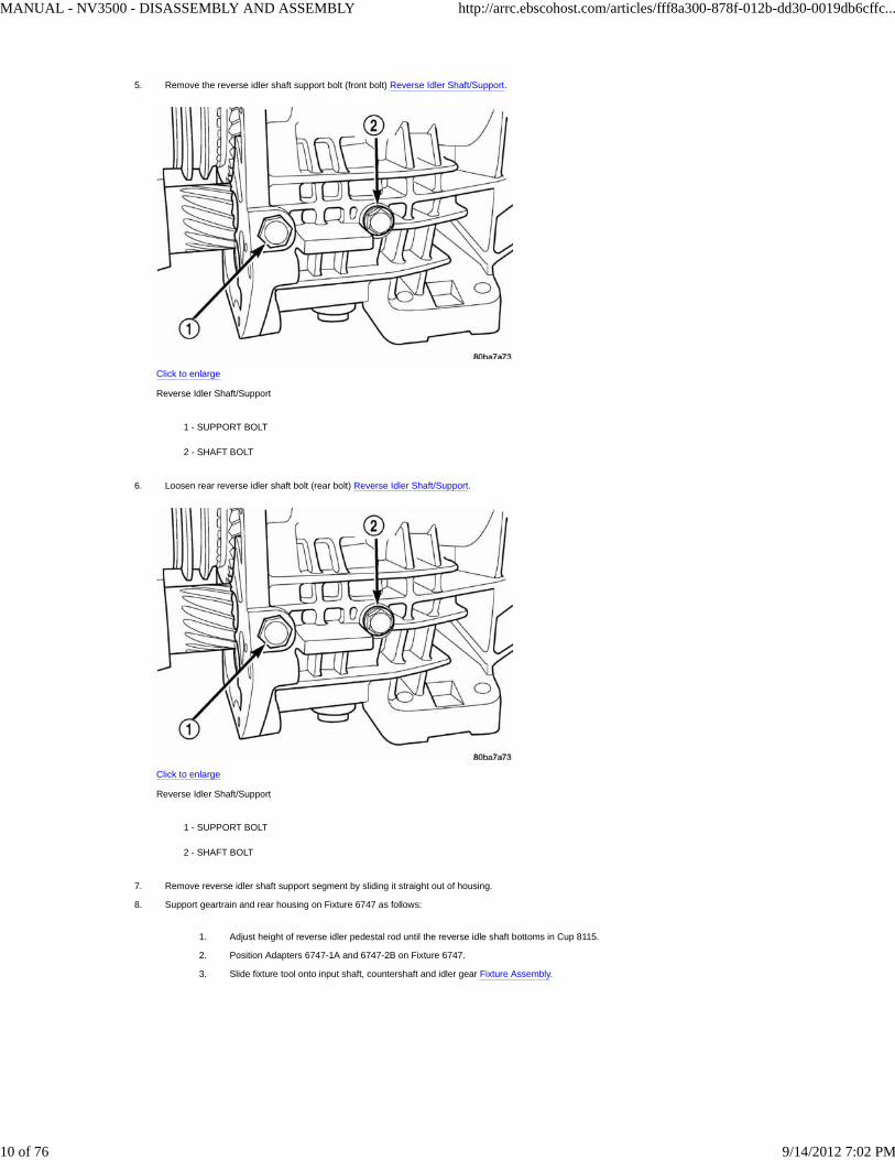
Remove the reverse idler shaft support bolt (front bolt) Reverse Idler Shaft/Support.
Click to enlarge
Reverse Idler Shaft/Support
1 - SUPPORT BOLT
2 - SHAFT BOLT
5.
Loosen rear reverse idler shaft bolt (rear bolt) Reverse Idler Shaft/Support.
Click to enlarge
Reverse Idler Shaft/Support
1 - SUPPORT BOLT
2 - SHAFT BOLT
6.
Remove reverse idler shaft support segment by sliding it straight out of housing.7.
Support geartrain and rear housing on Fixture 6747 as follows:
Adjust height of reverse idler pedestal rod until the reverse idle shaft bottoms in Cup 8115.1.
Position Adapters 6747-1A and 6747-2B on Fixture 6747.2.
Slide fixture tool onto input shaft, countershaft and idler gear Fixture Assembly.3.
8.
MANUAL - NV3500 - DISASSEMBLY AND ASSEMBLY http://arrc.ebscohost.com/articles/fff8a300-878f-012b-dd30-0019db6cffc...
10 of 76 9/14/2012 7:02 PM

Click to enlarge
Fixture Assembly
1 - FIXTURE 6747
2 - ADAPTER 6747-1A
3 - CUP 8115
4 - REVERSE IDLER PEDESTAL
5 - ADAPTER 6747-2B
Stand geartrain and rear housing upright on fixture Geartrain And Housing Mounted On Fixture. Have helper hold fixture tool inplace while housing and geartrain is being rotated into upright position.
Click to enlarge
Geartrain And Housing Mounted On Fixture
1 - INPUT SHAFT
2 - COUNTERSHAFT
4.
MANUAL - NV3500 - DISASSEMBLY AND ASSEMBLY http://arrc.ebscohost.com/articles/fff8a300-878f-012b-dd30-0019db6cffc...
11 of 76 9/14/2012 7:02 PM

3 - FIXTURE 6747
Remove rear bolt holding reverse idler shaft in housing.9.
REAR HOUSING - 2WD
On 2-wheel drive transmission, remove three bolts that attach output shaft bearing retainer to rear case Output Shaft. Bolts are rear of shift toweropening.
Click to enlarge
Output Shaft
1 - OUTPUT SHAFT BEARING RETAINER BOLTS (THIRD BOLT IS AT OPPOSITE SIDE OF CASE)
1.
Unseat output shaft bearing from bearing bore in rear housing. With a plastic/rawhide hammer tap rear housing upward and off output shaft bearingSeperate Rear Housing From Output Shaft Bearing - 2WD.
2.
MANUAL - NV3500 - DISASSEMBLY AND ASSEMBLY http://arrc.ebscohost.com/articles/fff8a300-878f-012b-dd30-0019db6cffc...
12 of 76 9/14/2012 7:02 PM

Click to enlarge
Seperate Rear Housing From Output Shaft Bearing - 2WD
1 - REAR HOUSING
2 - PLASTIC OR RAWHIDE MALLET
3 - FIXTURE 6747
Lift rear housing up and off geartrain Rear Housing - 2WD.3.
MANUAL - NV3500 - DISASSEMBLY AND ASSEMBLY http://arrc.ebscohost.com/articles/fff8a300-878f-012b-dd30-0019db6cffc...
13 of 76 9/14/2012 7:02 PM

Click to enlarge
Rear Housing - 2WD
1 - REAR HOUSING
2 - SHIFT FORKS AND GEARTRAIN
Remove countershaft rear bearing from countershaft Countershaft Rear Bearing.
Click to enlarge
Countershaft Rear Bearing
1 - COUNTERSHAFT REAR BEARING
2 - OUTPUT SHAFT
3 - COUNTER SHAFT
4.
Examine condition of bearing bore and idler shaft notch in rear housing . Replace housing if any of these components are damaged.5.
REAR ADAPTER HOUSING - 4WD
MANUAL - NV3500 - DISASSEMBLY AND ASSEMBLY http://arrc.ebscohost.com/articles/fff8a300-878f-012b-dd30-0019db6cffc...
14 of 76 9/14/2012 7:02 PM

Locate dimples in face of rear seal Dimples In Seal Face - 4WD. With a slide hammer mounted screw remove seal by inserting screw into seal atdimple locations Rear Seal - 4WD.
Click to enlarge
Dimples In Seal Face - 4WD
1 - LOCATION OF DIMPLES
2 - SEAL FACE
Click to enlarge
Rear Seal - 4WD
1 - SLIDE HAMMER
2 - REMOVER TOOL
3 - REAR SEAL
1.
Remove rear bearing snap ring from output shaft with snap ring pliers Rear Bearing Snap Ring - 4WD.2.
MANUAL - NV3500 - DISASSEMBLY AND ASSEMBLY http://arrc.ebscohost.com/articles/fff8a300-878f-012b-dd30-0019db6cffc...
15 of 76 9/14/2012 7:02 PM
Click to enlarge
Rear Bearing Snap Ring - 4WD
1 - HEAVY DUTY SNAP RING PLIERS
2 - REAR BEARING SNAP RING
3 - OUTPUT SHAFT
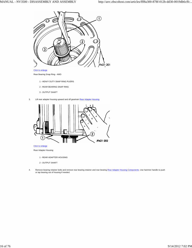
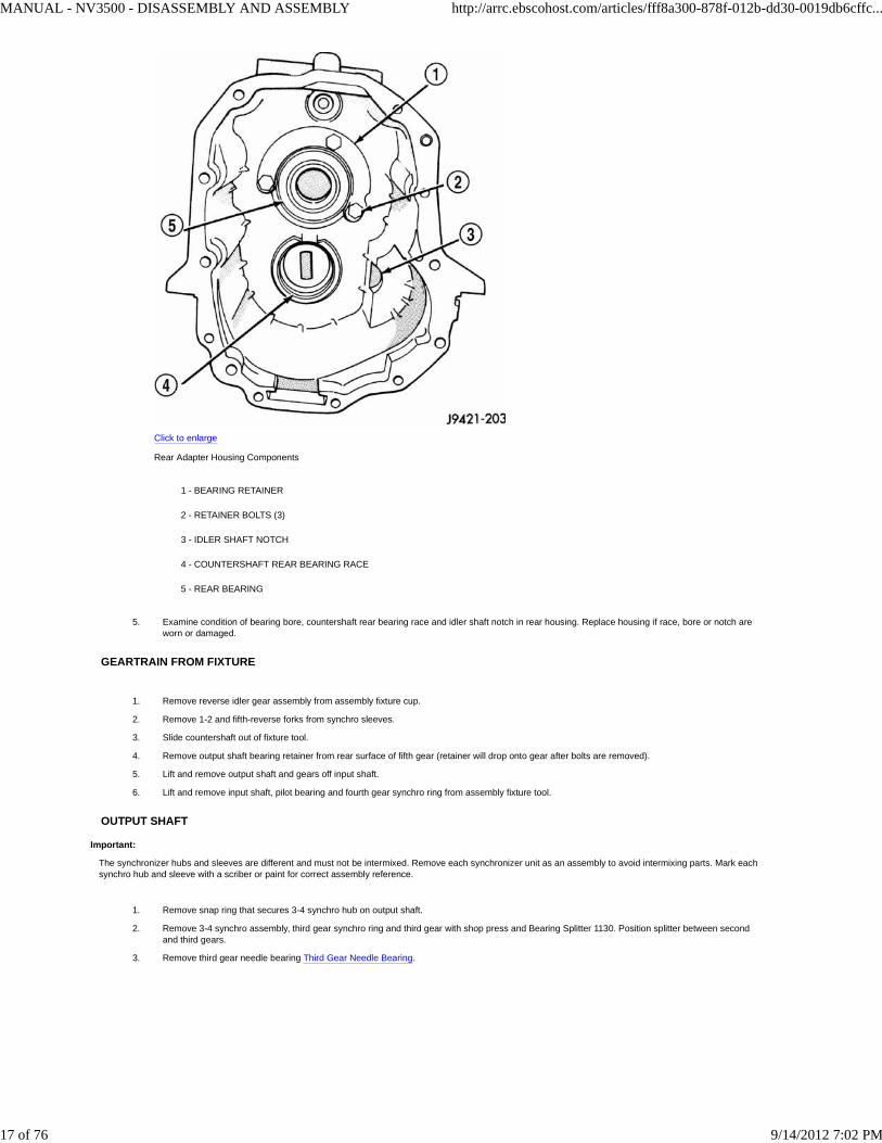
Lift rear adapter housing upward and off geartrain Rear Adapter Housing.
Click to enlarge
Rear Adapter Housing
1 - REAR ADAPTER HOUSING
2 - OUTPUT SHAFT
3.
Remove bearing retainer bolts and remove rear bearing retainer and rear bearing Rear Adapter Housing Components. Use hammer handle to pushor tap bearing out of housing if needed.
4.
MANUAL - NV3500 - DISASSEMBLY AND ASSEMBLY http://arrc.ebscohost.com/articles/fff8a300-878f-012b-dd30-0019db6cffc...
16 of 76 9/14/2012 7:02 PM
Click to enlarge
Rear Adapter Housing Components
1 - BEARING RETAINER
2 - RETAINER BOLTS (3)
3 - IDLER SHAFT NOTCH
4 - COUNTERSHAFT REAR BEARING RACE
5 - REAR BEARING
Examine condition of bearing bore, countershaft rear bearing race and idler shaft notch in rear housing. Replace housing if race, bore or notch areworn or damaged.
5.
GEARTRAIN FROM FIXTURE
Remove reverse idler gear assembly from assembly fixture cup.1.
Remove 1-2 and fifth-reverse forks from synchro sleeves.2.
Slide countershaft out of fixture tool.3.
Remove output shaft bearing retainer from rear surface of fifth gear (retainer will drop onto gear after bolts are removed).4.
Lift and remove output shaft and gears off input shaft.5.
Lift and remove input shaft, pilot bearing and fourth gear synchro ring from assembly fixture tool.6.
OUTPUT SHAFT
Important:
The synchronizer hubs and sleeves are different and must not be intermixed. Remove each synchronizer unit as an assembly to avoid intermixing parts. Mark eachsynchro hub and sleeve with a scriber or paint for correct assembly reference.
Remove snap ring that secures 3-4 synchro hub on output shaft.1.
Remove 3-4 synchro assembly, third gear synchro ring and third gear with shop press and Bearing Splitter 1130. Position splitter between secondand third gears.
2.
Remove third gear needle bearing Third Gear Needle Bearing.3.
MANUAL - NV3500 - DISASSEMBLY AND ASSEMBLY http://arrc.ebscohost.com/articles/fff8a300-878f-012b-dd30-0019db6cffc...
17 of 76 9/14/2012 7:02 PM

Click to enlarge
Third Gear Needle Bearing
1 - THIRD GEAR NEEDLE BEARING
Remove retaining ring that secures two-piece thrust washer on shaft with a small pry tool Thrust Washer.
Click to enlarge
Thrust Washer
1 - PRY TOOL
2 - THRUST WASHER RETAINING RING
4.
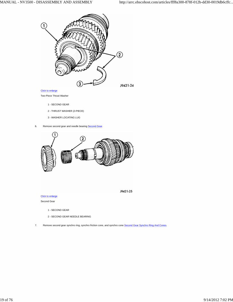
Remove two-piece thrust washer Two-Piece Thrust Washer. Note position of washer locating lugs in shaft notches for installation reference.5.
MANUAL - NV3500 - DISASSEMBLY AND ASSEMBLY http://arrc.ebscohost.com/articles/fff8a300-878f-012b-dd30-0019db6cffc...
18 of 76 9/14/2012 7:02 PM
Click to enlarge
Two-Piece Thrust Washer
1 - SECOND GEAR
2 - THRUST WASHER (2-PIECE)
3 - WASHER LOCATING LUG
Remove second gear and needle bearing Second Gear.
Click to enlarge
Second Gear
1 - SECOND GEAR
2 - SECOND GEAR NEEDLE BEARING
6.
Remove second gear synchro ring, synchro friction cone, and synchro cone Second Gear Synchro Ring And Cones.7.
MANUAL - NV3500 - DISASSEMBLY AND ASSEMBLY http://arrc.ebscohost.com/articles/fff8a300-878f-012b-dd30-0019db6cffc...
19 of 76 9/14/2012 7:02 PM

Click to enlarge
Second Gear Synchro Ring And Cones
1 - 1-2 SYNCHRO HUB AND SLEEVE
2 - INTERM RING
3 - SYNCHRO FRICTION CONE
4 - SYNCHRO CONE
5 - SYNCHRO RING
Remove interm ring.8.
Remove 1-2 synchro hub snap ring.9.
Remove 1-2 synchro hub and sleeve and first gear from output shaft with shop press and Bearing Splitter 1130 Hub Sleeve And 1-2 Synchro.Position splitter between first and reverse gears.
Click to enlarge
Hub Sleeve And 1-2 Synchro
1 - 1-2 SYNCHRO HUB AND SLEEVE
2 - SPLITTER 1130
10.
Remove first gear needle bearing First Gear Needle Bearing.11.
MANUAL - NV3500 - DISASSEMBLY AND ASSEMBLY http://arrc.ebscohost.com/articles/fff8a300-878f-012b-dd30-0019db6cffc...
20 of 76 9/14/2012 7:02 PM

Click to enlarge
First Gear Needle Bearing
1 - FIRST GEAR NEEDLE BEARING
Remove output shaft bearing snap ring Output Shaft Bearing Snap Ring.
Click to enlarge
Output Shaft Bearing Snap Ring
1 - OUTPUT SHAFT BEARING
2 - BEARING SNAP RING
3 - SNAP RING PLIERS
12.
On 2-wheel drive models, remove output shaft bearing.13.
Remove fifth gear Fifth Gear.
Click to enlarge
Fifth Gear
14.
MANUAL - NV3500 - DISASSEMBLY AND ASSEMBLY http://arrc.ebscohost.com/articles/fff8a300-878f-012b-dd30-0019db6cffc...
21 of 76 9/14/2012 7:02 PM

1 - FIFTH GEAR AND SYNCHRO RING
MANUAL - NV3500 - DISASSEMBLY AND ASSEMBLY http://arrc.ebscohost.com/articles/fff8a300-878f-012b-dd30-0019db6cffc...
22 of 76 9/14/2012 7:02 PM

Remove fifth gear needle bearing, spreading bearing apart just enough to clear shoulder on output shaft Fifth Gear Needle.
Click to enlarge
Fifth Gear Needle
1 - FIFTH GEAR NEEDLE BEARING
15.
Remove fifth-reverse synchro hub snap ring Fifth-Reverse.
Click to enlarge
Fifth-Reverse
1 - FIFTH-REVERSE SYNCHRO HUB AND SLEEVE
2 - SYNCHRO HUB SNAP RING
3 - SNAP RING PLIERS
16.
Remove fifth-reverse synchro hub and sleeve with shop press Fifth-Reverse Synchro.17.
MANUAL - NV3500 - DISASSEMBLY AND ASSEMBLY http://arrc.ebscohost.com/articles/fff8a300-878f-012b-dd30-0019db6cffc...
23 of 76 9/14/2012 7:02 PM

Click to enlarge
Fifth-Reverse Synchro
1 - PRESS
2 - FIFTH-REVERSE SYNCHRO HUB AND SLEEVE
3 - REVERSE GEAR
4 - OUTPUT SHAFT
Remove reverse gear and needle bearing Reverse Gear And Needle Bearing.
Click to enlarge
Reverse Gear And Needle Bearing
1 - REVERSE GEAR AND NEEDLE BEARING
18.
REVERSE IDLER
Remove idler gear snap rings Reverse Idler Components.1.
MANUAL - NV3500 - DISASSEMBLY AND ASSEMBLY http://arrc.ebscohost.com/articles/fff8a300-878f-012b-dd30-0019db6cffc...
24 of 76 9/14/2012 7:02 PM

Click to enlarge
Reverse Idler Components
1 - SNAP RING
2 - FLAT WASHER
3 - WAVE WASHER
4 - THRUST WASHER
5 - REVERSE IDLER GEAR
6 - IDLER GEAR BEARING
7 - IDLER SHAFT
8 - THRUST WASHER
9 - SNAP RING
10 - THRUST WASHER LOCKBALLS
Remove thrust washer, wave washer, thrust plate and idler gear from shaft.2.
Remove idler gear needle bearing from shaft.3.
ASSEMBLY
Gaskets are not used in this transmission. Sealers are used at all case joints. Recommended sealers are Mopar Gasket Maker for all case joints and Mopar siliconesealer, or equivalent, for the input shaft bearing retainer. Apply these products as indicated in the assembly procedures.
Important:
The transmission shift components must be in Neutral position during assembly. This prevents damaging to the synchro and shift components when the housings areinstalled.
The 3-4, 1-2 and fifth-reverse synchro hub snap rings can be fitted selectively. New snap rings are available in 0.05 mm (0.0019 in.) thickness increments. Use thickestsnap ring that will fit in each snap ring groove.
SYNCHRONIZER
To assemble each synchro install the springs, struts and detent balls one at a time as follows:
Slide sleeve part way onto the hub. Leave enough room to install the spring in the hub and the strut in the hub groove.1.
Install first spring in the hub, then install a strut over the spring. Verify spring is seated in the spring bore in the strut.2.
Slide sleeve onto the hub just far enough to hold the first strut and spring in place.3.
Place detent ball in the top of the strut, then carefully work the sleeve over the ball to hold it in place. A small flat blade screwdriver can be used topress the ball into place while moving the sleeve over it.
4.
Repeat procedure for the remaining springs, struts and balls. Tape or a rubber band can be used to temporarily secure each strut and ball as they areinstalled.
5.
Verify the synchro three springs, struts and detent balls are all in place Synchronizer Components.6.
MANUAL - NV3500 - DISASSEMBLY AND ASSEMBLY http://arrc.ebscohost.com/articles/fff8a300-878f-012b-dd30-0019db6cffc...
25 of 76 9/14/2012 7:02 PM

Click to enlarge
Synchronizer Components
1 - SLEEVE
2 - HUB SHOULDER
3 - SPRING (3)
4 - STRUT (3)
5 - DETENT BALL (3)
6 - HUB
OUTPUT SHAFT
Important:
Lubricate shaft, gears and bearings with recommended lubricant during assembly. Petroleum jelly can be used to hold parts in place. Immerse each synchro ring inlubricant before installation.
Lubricate and install reverse gear needle bearing on shaft Reverse Gear Bearing. Slide bearing up against shoulder on output shaft.
Click to enlarge
Reverse Gear Bearing
1 - REVERSE GEAR BEARING
2 - SHOULDER
1.
Install reverse gear over needle bearing Reverse Gear.2.
MANUAL - NV3500 - DISASSEMBLY AND ASSEMBLY http://arrc.ebscohost.com/articles/fff8a300-878f-012b-dd30-0019db6cffc...
26 of 76 9/14/2012 7:02 PM

Click to enlarge
Reverse Gear
1 - REVERSE GEAR
Install brass synchro ring on reverse gear Reverse Gear Synchro.
Click to enlarge
Reverse Gear Synchro
1 - REVERSE GEAR
2 - SYNCHRO RING
3.
Assemble fifth-reverse synchro hub, sleeve, struts, springs and detent balls, if not previously done.4.
Caution:
One side of the hub has shoulders around the hub bore, this side of the hub faces the front of the shaft. One side of the sleeve is tapered the tapered side faces the frontof the shaft.
Start fifth-reverse synchro assembly on output shaft splines by hand. Then seat synchro onto shaft with shop press and Remover 6310-1 Fifth-Reverse Synchro Assembly.
1.
MANUAL - NV3500 - DISASSEMBLY AND ASSEMBLY http://arrc.ebscohost.com/articles/fff8a300-878f-012b-dd30-0019db6cffc...
27 of 76 9/14/2012 7:02 PM

Click to enlarge
Fifth-Reverse Synchro Assembly
1 - SPACER
2 - PRESS RAM
3 - REVERSE GEAR
4 - FIFTH-REVERSE SYNCHRO ASSEMBLY
5 - REMOVER 6310-1
6 - PRESS BLOCKS
7 - OUTPUT SHAFT
Install the thickest newfifth-reverse hub snap ring Fifth-Reverse Synchro Hub Snap Ringthat will fit in shaft groove. Verify snap ring is seated in thegroove.
Click to enlarge
Fifth-Reverse Synchro Hub Snap Ring
1 - FIFTH-REVERSE SYNCHRO ASSEMBLY
2 - SNAP RING
3 - PRESS BED
2.
MANUAL - NV3500 - DISASSEMBLY AND ASSEMBLY http://arrc.ebscohost.com/articles/fff8a300-878f-012b-dd30-0019db6cffc...
28 of 76 9/14/2012 7:02 PM
4 - PRESS BLOCKS
Important:
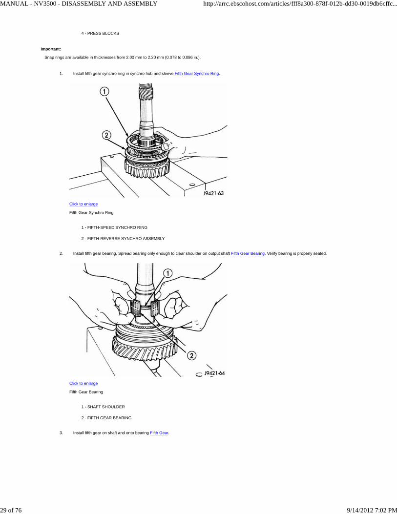
Snap rings are available in thicknesses from 2.00 mm to 2.20 mm (0.078 to 0.086 in.).
Install fifth gear synchro ring in synchro hub and sleeve Fifth Gear Synchro Ring.
Click to enlarge
Fifth Gear Synchro Ring
1 - FIFTH-SPEED SYNCHRO RING
2 - FIFTH-REVERSE SYNCHRO ASSEMBLY
1.
Install fifth gear bearing. Spread bearing only enough to clear shoulder on output shaft Fifth Gear Bearing. Verify bearing is properly seated.
Click to enlarge
Fifth Gear Bearing
1 - SHAFT SHOULDER
2 - FIFTH GEAR BEARING
2.
Install fifth gear on shaft and onto bearing Fifth Gear.3.
MANUAL - NV3500 - DISASSEMBLY AND ASSEMBLY http://arrc.ebscohost.com/articles/fff8a300-878f-012b-dd30-0019db6cffc...
29 of 76 9/14/2012 7:02 PM
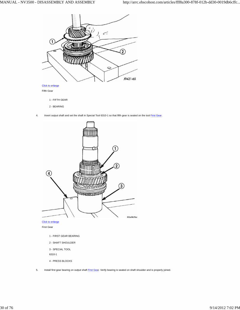
Click to enlarge
Fifth Gear
1 - FIFTH GEAR
2 - BEARING
Invert output shaft and set the shaft in Special Tool 6310-1 so that fifth gear is seated on the tool First Gear.
Click to enlarge
First Gear
1 - FIRST GEAR BEARING
2 - SHAFT SHOULDER
3 - SPECIAL TOOL
6310-1
4 - PRESS BLOCKS
4.
Install first gear bearing on output shaft First Gear. Verify bearing is seated on shaft shoulder and is properly joined.5.
MANUAL - NV3500 - DISASSEMBLY AND ASSEMBLY http://arrc.ebscohost.com/articles/fff8a300-878f-012b-dd30-0019db6cffc...
30 of 76 9/14/2012 7:02 PM

Click to enlarge
First Gear
1 - FIRST GEAR BEARING
2 - SHAFT SHOULDER
3 - SPECIAL TOOL
6310-1
4 - PRESS BLOCKS
Install first gear on shaft and over bearing First Gear. Verify bearing synchro cone is facing up as shown.
Click to enlarge
First Gear
1 - FIRST GEAR
2 - SPECIAL TOOL
6310-1
3 - BEARING
6.
Install first gear synchro ring First Gear Synchro Ring.7.
MANUAL - NV3500 - DISASSEMBLY AND ASSEMBLY http://arrc.ebscohost.com/articles/fff8a300-878f-012b-dd30-0019db6cffc...
31 of 76 9/14/2012 7:02 PM

Click to enlarge
First Gear Synchro Ring
1 - FIRST GEAR SYNCHRO RING
2 - SPECIAL TOOL
6310-1
3 - FIRST GEAR
Assemble 1-2 synchro hub sleeve, springs, struts and detent balls.8.
Caution:
One side of the synchro sleeve is marked First Gear Side. This side of the sleeve must face first gear after installation.
Start 1-2 synchro assembly on shaft by hand Starting 1-2 Synchro. Verify synchro sleeve is properly positioned.
Click to enlarge
Starting 1-2 Synchro
1 - 1-2 SYNCHRO ASSEMBLY
2 - SPECIAL TOOL
6310-1
3 - FIRST GEAR SIDE
1.
Press 1-2 synchro onto output shaft using suitable size pipe and shop press Press 1-2 Synchro On Output Shaft.2.
MANUAL - NV3500 - DISASSEMBLY AND ASSEMBLY http://arrc.ebscohost.com/articles/fff8a300-878f-012b-dd30-0019db6cffc...
32 of 76 9/14/2012 7:02 PM

Click to enlarge
Press 1-2 Synchro On Output Shaft
1 - PIPE TOOL
2 - SYNCHRO RING
3 - SPECIAL TOOL
6310-1
4 - 1-2 SYNCHRO ASSEMBLY
5 - PRESS RAM
Caution:
Carefully align the synchro ring and sleeve as hub the is being pressed onto the shaft. The synchro ring can be cracked if it becomes misaligned.
Install interm ring.1.
Install thickest new1-2 synchro hub snap ring 1-2 Synchro Hub Snap Ringthat will fit in shaft groove. Verify snap ring is seated in shaft groove.
Click to enlarge
1-2 Synchro Hub Snap Ring
2.
MANUAL - NV3500 - DISASSEMBLY AND ASSEMBLY http://arrc.ebscohost.com/articles/fff8a300-878f-012b-dd30-0019db6cffc...
33 of 76 9/14/2012 7:02 PM

1 - 1-2 SYNCHRO
2 - SPECIAL TOOL
6310-1
3 - SYNCHRO SNAP RING
MANUAL - NV3500 - DISASSEMBLY AND ASSEMBLY http://arrc.ebscohost.com/articles/fff8a300-878f-012b-dd30-0019db6cffc...
34 of 76 9/14/2012 7:02 PM

Important:
Snap rings are available in thicknesses from 1.80 mm to 2.00 mm (0.070 to 0.078 in.).
Install second gear synchro ring in 1-2 synchro hub and sleeve Second Gear Synchro Ring. Verify synchro ring is seated in sleeve.
Click to enlarge
Second Gear Synchro Ring
1 - SECOND GEAR SYNCHRO RING
2 - 1-2 SYNCHRO
3 - SPECIAL TOOL
6310-1
1.
Install synchro friction cone and synchro cone in synchro ring.2.
Install second gear needle bearing on shaft Second Gear Bearing.
Click to enlarge
Second Gear Bearing
1 - SECOND GEAR BEARING
2 - SPECIAL TOOL
6310-1
3.
MANUAL - NV3500 - DISASSEMBLY AND ASSEMBLY http://arrc.ebscohost.com/articles/fff8a300-878f-012b-dd30-0019db6cffc...
35 of 76 9/14/2012 7:02 PM
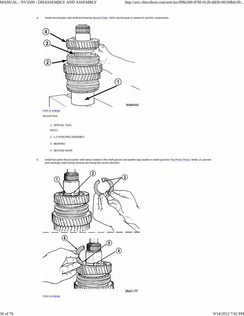
Install second gear onto shaft and bearing Second Gear. Verify second gear is seated on synchro components.
Click to enlarge
Second Gear
1 - SPECIAL TOOL
6310-1
2 - 1-2 SYNCHRO ASSEMBLY
3 - BEARING
4 - SECOND GEAR
4.
Install two-piece thrust washer with halves seated in the shaft groove and washer lugs seated in shaft lug bores Two-Piece Thrust. Verify i.d. groovesand markings noted during removal are facing the correct direction.
Click to enlarge
5.
MANUAL - NV3500 - DISASSEMBLY AND ASSEMBLY http://arrc.ebscohost.com/articles/fff8a300-878f-012b-dd30-0019db6cffc...
36 of 76 9/14/2012 7:02 PM

Two-Piece Thrust
1 - WASHER GROOVE IN SHAFT
2 - LUG BORE
3 - THRUST WASHER LUGS
4 - LUG BORE
5 - LUG
6 - WASHER HALF
Start retaining ring around two-piece thrust washer Retaining Ring. Verify locating dimple is between thrust washer halves.
Click to enlarge
Retaining Ring
1 - THRUST WASHER RETAINING RING
2 - THRUST WASHER HALVES
3 - SECOND GEAR
4 - LOCATING DIMPLE
6.
Seat thrust washer retaining ring with plastic mallet Thrust Retainer.
Click to enlarge
Thrust Retainer
7.
MANUAL - NV3500 - DISASSEMBLY AND ASSEMBLY http://arrc.ebscohost.com/articles/fff8a300-878f-012b-dd30-0019db6cffc...
37 of 76 9/14/2012 7:02 PM

1 - PLASTIC MALLET
2 - THRUST WASHER RETAINING RING
MANUAL - NV3500 - DISASSEMBLY AND ASSEMBLY http://arrc.ebscohost.com/articles/fff8a300-878f-012b-dd30-0019db6cffc...
38 of 76 9/14/2012 7:02 PM

Install third gear needle bearing on shaft Third Gear Bearing.
Click to enlarge
Third Gear Bearing
1 - THIRD GEAR BEARING
8.
Install third gear on shaft and bearing Third Gear.
Click to enlarge
Third Gear
1 - THIRD GEAR
2 - BEARING
9.
Install third speed synchro ring on third gear Third Gear Synchro Ring.10.
MANUAL - NV3500 - DISASSEMBLY AND ASSEMBLY http://arrc.ebscohost.com/articles/fff8a300-878f-012b-dd30-0019db6cffc...
39 of 76 9/14/2012 7:02 PM

Click to enlarge
Third Gear Synchro Ring
1 - THIRD SPEED SYNCHRO RING
2 - THIRD GEAR
Assemble 3-4 synchro hub, sleeve, springs, struts and detent balls.11.
Caution:
The 3-4 synchro hub and sleeve can be installed backwards if care is not exercised. One side of the sleeve has grooves in it, this side of sleeve faces the front of theshaft.
Start 3-4 synchro hub on output shaft splines by hand 3-4 Synchro Hub On Output Shaft.
Click to enlarge
3-4 Synchro Hub On Output Shaft
1 - GROOVED SIDE OF SLEEVE
2 - 3-4 SYNCHRO ASSEMBLY
1.
Press 3-4 synchro assembly onto output shaft with shop press and suitable size pipe Press 3-4 Synchro On Output Shaft. Verify tool presses on hubas close to output shaft as possible but does not contact the shaft splines.
2.
MANUAL - NV3500 - DISASSEMBLY AND ASSEMBLY http://arrc.ebscohost.com/articles/fff8a300-878f-012b-dd30-0019db6cffc...
40 of 76 9/14/2012 7:02 PM

Click to enlarge
Press 3-4 Synchro On Output Shaft
1 - PRESS RAM
2 - PIPE TOOL
3 - 3-4 SYNCHRO
4 - THIRD SPEED SYNCHRO RING
Install thickest new3-4 synchro hub snap ring 3-4 Synchro Hub Snap Ringthat will fit in shaft groove. Verify snap ring is seated in groove.
Click to enlarge
3-4 Synchro Hub Snap Ring
1 - 3-4 SYNCHRO HUB SNAP RING
2 - HEAVY DUTY SNAP RING PLIERS
3.
Important:
Snap rings are available in thicknesses from 2.00 - 2.30 mm (0.078 - 0.090 in.).
Install output shaft bearing.1.
Install output shaft bearing snap ring with heavy duty snap ring pliers Output Shaft Bearing Snap. Verify snap ring is seated in shaft groove.2.
MANUAL - NV3500 - DISASSEMBLY AND ASSEMBLY http://arrc.ebscohost.com/articles/fff8a300-878f-012b-dd30-0019db6cffc...
41 of 76 9/14/2012 7:02 PM

Click to enlarge
Output Shaft Bearing Snap
1 - BEARING SNAP RING
2 - HEAVY DUTY SNAP RING PLIERS
Important:
Spread snap ring only enough to install it.
Verify position of synchro sleeves before proceeding Synchro Sleeve Locations. Grooved side of 3-4 sleeve must be facing forward. First gear side of1-2 sleeve must be facing first gear. Tapered side of fifth-reverse sleeve must be facing forward.
Click to enlarge
Synchro Sleeve Locations
1 - DOUBLE GROOVE FORWARD
2 - GROOVE FORWARD
3 - FIRST GEAR SIDE MARKING TOWARD FIRST GEAR
4 - TAPER FORWARD
5 - GROOVE FORWARD
6 - 5TH-REV SYNCHRO SLEEVE
7 - 1-2 SYNCHRO SLEEVE
8 - 3-4 SYNCHRO SLEEVE
1.
REVERSE IDLER ASSEMBLY
Lubricate idler components with gear lube.1.
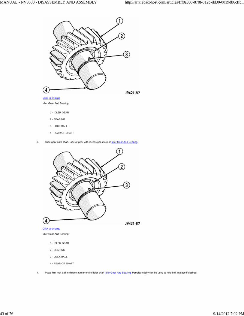
Slide idler gear bearing on shaft Idler Gear And Bearing. Bearing fits either way on shaft.2.
MANUAL - NV3500 - DISASSEMBLY AND ASSEMBLY http://arrc.ebscohost.com/articles/fff8a300-878f-012b-dd30-0019db6cffc...
42 of 76 9/14/2012 7:02 PM
Click to enlarge
Idler Gear And Bearing
1 - IDLER GEAR
2 - BEARING
3 - LOCK BALL
4 - REAR OF SHAFT
Slide gear onto shaft. Side of gear with recess goes to rear Idler Gear And Bearing.
Click to enlarge
Idler Gear And Bearing
1 - IDLER GEAR
2 - BEARING
3 - LOCK BALL
4 - REAR OF SHAFT
3.
Place first lock ball in dimple at rear end of idler shaft Idler Gear And Bearing. Petroleum jelly can be used to hold ball in place if desired.4.
MANUAL - NV3500 - DISASSEMBLY AND ASSEMBLY http://arrc.ebscohost.com/articles/fff8a300-878f-012b-dd30-0019db6cffc...
43 of 76 9/14/2012 7:02 PM

Click to enlarge
Idler Gear And Bearing
1 - IDLER GEAR
2 - BEARING
3 - LOCK BALL
4 - REAR OF SHAFT
Slide thrust rear thrust washer onto shaft and over lock ball Idler Gear Rear Thrust Washer.
Click to enlarge
Idler Gear Rear Thrust Washer
1 - LOCK BALL
2 - SNAP RING GROOVE
3 - THRUST WASHER
5.
Install snap ring in groove at rear of shaft Idler Gear Rear Thrust Washer.6.
MANUAL - NV3500 - DISASSEMBLY AND ASSEMBLY http://arrc.ebscohost.com/articles/fff8a300-878f-012b-dd30-0019db6cffc...
44 of 76 9/14/2012 7:02 PM

Click to enlarge
Idler Gear Rear Thrust Washer
1 - LOCK BALL
2 - SNAP RING GROOVE
3 - THRUST WASHER
Install lock ball in dimple at front of shaft. Hold ball in place with petroleum jelly if desired.7.
Install front thrust washer on shaft and slide washer up against gear and over lock ball Idler Gear And Shaft Assembly.
Click to enlarge
Idler Gear And Shaft Assembly
1 - REAR OF SHAFT
2 - GEAR
3 - THRUST WASHER AND BALL
4 - WAVE WASHER
5 - FLAT WASHER
6 - FRONT OF SHAFT
8.
MANUAL - NV3500 - DISASSEMBLY AND ASSEMBLY http://arrc.ebscohost.com/articles/fff8a300-878f-012b-dd30-0019db6cffc...
45 of 76 9/14/2012 7:02 PM

7 - SNAP RING
8 - SNAP RING
Install wave washer, flat washer and remaining snap ring on idler shaft Idler Gear And Shaft Assembly. Verify snap ring is seated.
Click to enlarge
Idler Gear And Shaft Assembly
1 - REAR OF SHAFT
2 - GEAR
3 - THRUST WASHER AND BALL
4 - WAVE WASHER
5 - FLAT WASHER
6 - FRONT OF SHAFT
7 - SNAP RING
8 - SNAP RING
9.
SHIFT SHAFT AND DETENT PLUNGER BUSHINGS/BEARINGS
Inspect shift shaft bushing and bearing for damage.1.
If necessary, the shift shaft bushing can be replaced as follows:
Locate a bolt that will thread into the bushing without great effort.1.
Thread the bolt into the bushing, allowing the bolt to make its own threads in the bushing.2.
Attach a slide hammer or suitable puller to the bolt and remove bushing.3.
Use the short end of Installer 8119 to install the new bushing.4.
Bushing is correctly installed if flush with the transmission case.5.
2.
If necessary, the shift shaft bearing can be replaced as follows:
Locate a bolt that will thread into the bearing without great effort.1.
Thread the bolt into the bearing as much as possible.2.
Attach a slide hammer or suitable puller to the bolt and remove the bearing.3.
3.
MANUAL - NV3500 - DISASSEMBLY AND ASSEMBLY http://arrc.ebscohost.com/articles/fff8a300-878f-012b-dd30-0019db6cffc...
46 of 76 9/14/2012 7:02 PM

Use the short end of Installer 8119 to install the new bearing.4.
Bearing is correctly installed if flush with the transmission case.5.
Inspect detent plunger bushings for damage.4.
Important:
The detent plunger bushings are installed to a specific depth. The space between the two bushings when correctly installed contain an oil feed hole. Do not attempt toinstall the bushings with anything other than the specified tool or this oil hole may become restricted.
If necessary, the detent plunger bushings can be replaced as follows:
Using the long end of Installer 8119, drive the detent bushings through the outer case and into the shift shaft bore.1.
Remove the bushings from the shift shaft bore.2.
Install a new detent plunger bushing on the long end of Installer 8118.3.
Start bushing in the detent plunger bore in the case.4.
Drive bushing into the bore until the tool contacts the transmission case.5.
Install a new detent plunger bushing on the short end of Installer 8118.6.
Start the bushing in the detent plunger bore in the case.7.
Drive bushing into the bore until the tool contacts the transmission case.8.
1.
GEARTRAIN ASSEMBLY
Install Adapter 6747-1A on input shaft hub of Fixture 6747 Fixture For Geartrain Build-up. Then install Adapter 6747-2B on front bearing hub ofcountershaft. Be sure the shoulder is seated against the countershaft.
Click to enlarge
Fixture For Geartrain Build-up
1 - ADAPTER 6747-2B
2 - CUP 8115
3 - ADAPTER 6747-1A
4 - FIXTURE 6747
1.
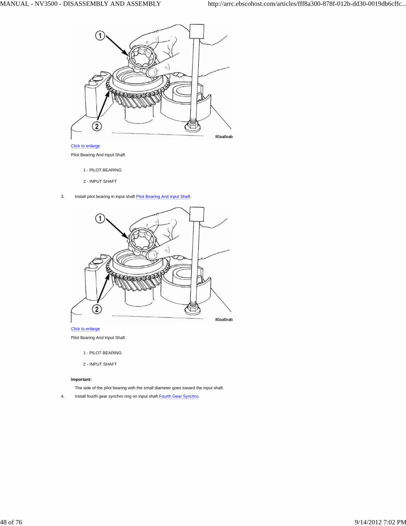
Install input shaft in fixture tool. Make sure Adapter Tool 6747-1A is positioned under shaft as shown Pilot Bearing And Input Shaft.2.
MANUAL - NV3500 - DISASSEMBLY AND ASSEMBLY http://arrc.ebscohost.com/articles/fff8a300-878f-012b-dd30-0019db6cffc...
47 of 76 9/14/2012 7:02 PM
Click to enlarge
Pilot Bearing And Input Shaft
1 - PILOT BEARING
2 - INPUT SHAFT
Install pilot bearing in input shaft Pilot Bearing And Input Shaft.
Click to enlarge
Pilot Bearing And Input Shaft
1 - PILOT BEARING
2 - INPUT SHAFT
Important:
The side of the pilot bearing with the small diameter goes toward the input shaft.
3.
Install fourth gear synchro ring on input shaft Fourth Gear Synchro.4.
MANUAL - NV3500 - DISASSEMBLY AND ASSEMBLY http://arrc.ebscohost.com/articles/fff8a300-878f-012b-dd30-0019db6cffc...
48 of 76 9/14/2012 7:02 PM

Click to enlarge
Fourth Gear Synchro
1 - FOURTH GEAR SYNCHRO RING
2 - INPUT SHAFT
Adjust height of idler gear pedestal on assembly fixture Idler Pedestal Base Height. Start with a basic height of 18.4 cm (7-1/4 in.). Final adjustmentcan be made after gear is positioned on pedestal.
Click to enlarge
Idler Pedestal Base Height
1 - REVERSE IDLER PEDESTAL
5.
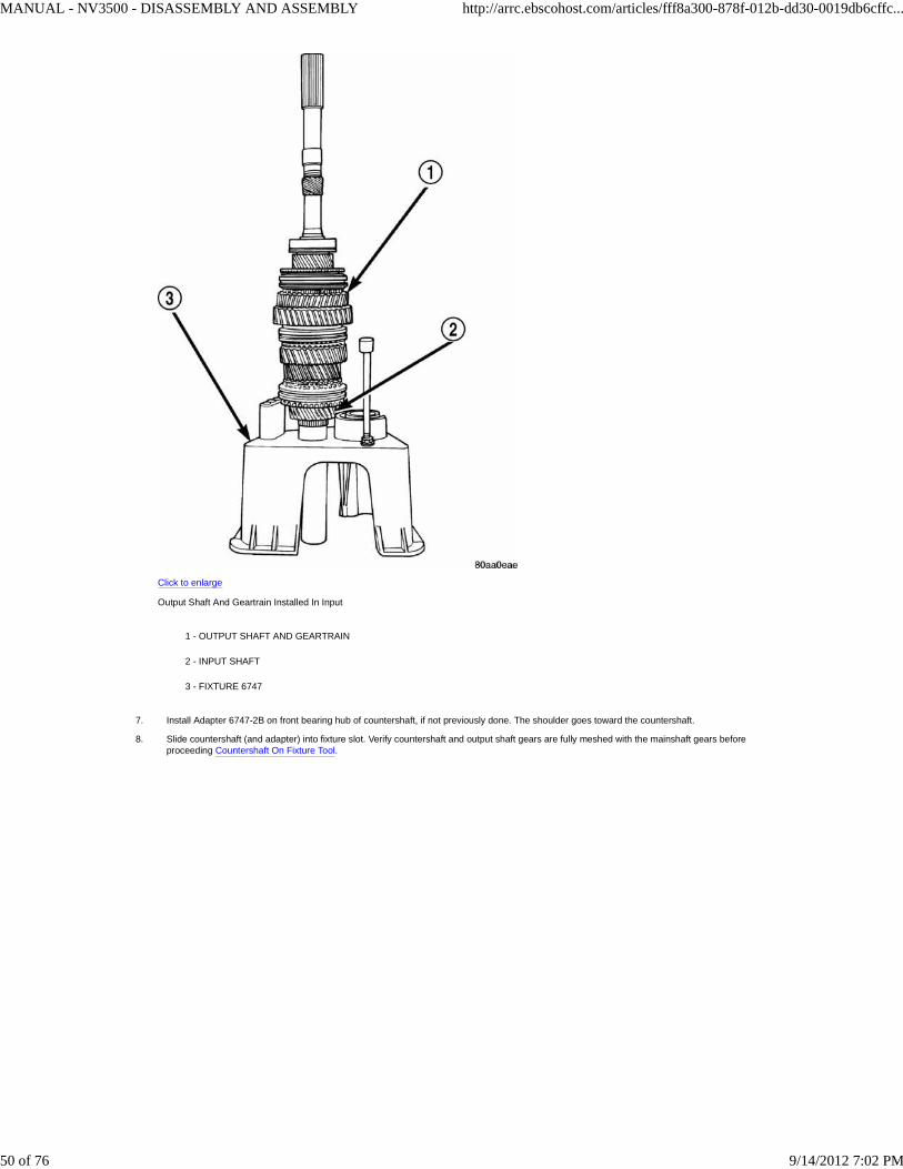
Install assembled output shaft and geartrain in input shaft Output Shaft And Geartrain Installed In Input. Carefully rotate output shaft until the 3-4synchro ring seats in synchro hub and sleeve.
6.
MANUAL - NV3500 - DISASSEMBLY AND ASSEMBLY http://arrc.ebscohost.com/articles/fff8a300-878f-012b-dd30-0019db6cffc...
49 of 76 9/14/2012 7:02 PM
Click to enlarge
Output Shaft And Geartrain Installed In Input
1 - OUTPUT SHAFT AND GEARTRAIN
2 - INPUT SHAFT
3 - FIXTURE 6747
Install Adapter 6747-2B on front bearing hub of countershaft, if not previously done. The shoulder goes toward the countershaft.7.
Slide countershaft (and adapter) into fixture slot. Verify countershaft and output shaft gears are fully meshed with the mainshaft gears beforeproceeding Countershaft On Fixture Tool.
8.
MANUAL - NV3500 - DISASSEMBLY AND ASSEMBLY http://arrc.ebscohost.com/articles/fff8a300-878f-012b-dd30-0019db6cffc...
50 of 76 9/14/2012 7:02 PM

Click to enlarge
Countershaft On Fixture Tool
1 - OUTPUT SHAFT AND GEARTRAIN
2 - COUNTERSHAFT (SLIDE INTO PLACE ON FIXTURE TOOL)
Check alignment of countershaft and output shaft gear teeth. Gears may not align perfectly a difference in height of 1.57 to 3.18 mm (1/16 to 1/8 in.)will probably exist. This difference will not interfere with assembly. If difference is greater than this, the countershaft adapter tool is probably upsidedown. Remove countershaft, reverse adapter tool, reinstall countershaft and check alignment again.
9.
Position reverse idler in support cup of assembly fixture Reverse Idler Assembly On Assembly Fixture Tool. Verify idler gear is properly meshed andaligned with shaft gear teeth and that bolt holes are facing out from the geartrain. Adjust pedestal up or down if necessary and verify short end of idlershaft is facing up as shown.
10.
MANUAL - NV3500 - DISASSEMBLY AND ASSEMBLY http://arrc.ebscohost.com/articles/fff8a300-878f-012b-dd30-0019db6cffc...
51 of 76 9/14/2012 7:02 PM
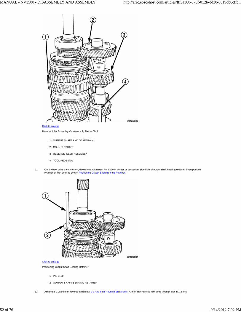
Click to enlarge
Reverse Idler Assembly On Assembly Fixture Tool
1 - OUTPUT SHAFT AND GEARTRAIN
2 - COUNTERSHAFT
3 - REVERSE IDLER ASSEMBLY
4 - TOOL PEDESTAL
On 2-wheel drive transmission, thread one Alignment Pin 8120 in center or passenger side hole of output shaft bearing retainer. Then positionretainer on fifth gear as shown Positioning Output Shaft Bearing Retainer.
Click to enlarge
Positioning Output Shaft Bearing Retainer
1 - PIN 8120
2 - OUTPUT SHAFT BEARING RETAINER
11.
Assemble 1-2 and fifth reverse-shift forks 1-2 And Fifth-Reverse Shift Forks. Arm of fifth-reverse fork goes through slot in 1-2 fork.12.
MANUAL - NV3500 - DISASSEMBLY AND ASSEMBLY http://arrc.ebscohost.com/articles/fff8a300-878f-012b-dd30-0019db6cffc...
52 of 76 9/14/2012 7:02 PM
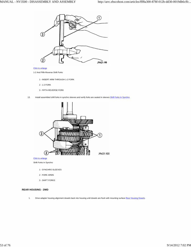
Click to enlarge
1-2 And Fifth-Reverse Shift Forks
1 - INSERT ARM THROUGH 1-2 FORK
2 - 1-2 FORK
3 - FIFTH-REVERSE FORK
Install assembled shift forks in synchro sleeves and verify forks are seated in sleeves Shift Forks In Synchro.
Click to enlarge
Shift Forks In Synchro
1 - SYNCHRO SLEEVES
2 - FORK ARMS
3 - SHIFT FORKS
13.
REAR HOUSING - 2WD
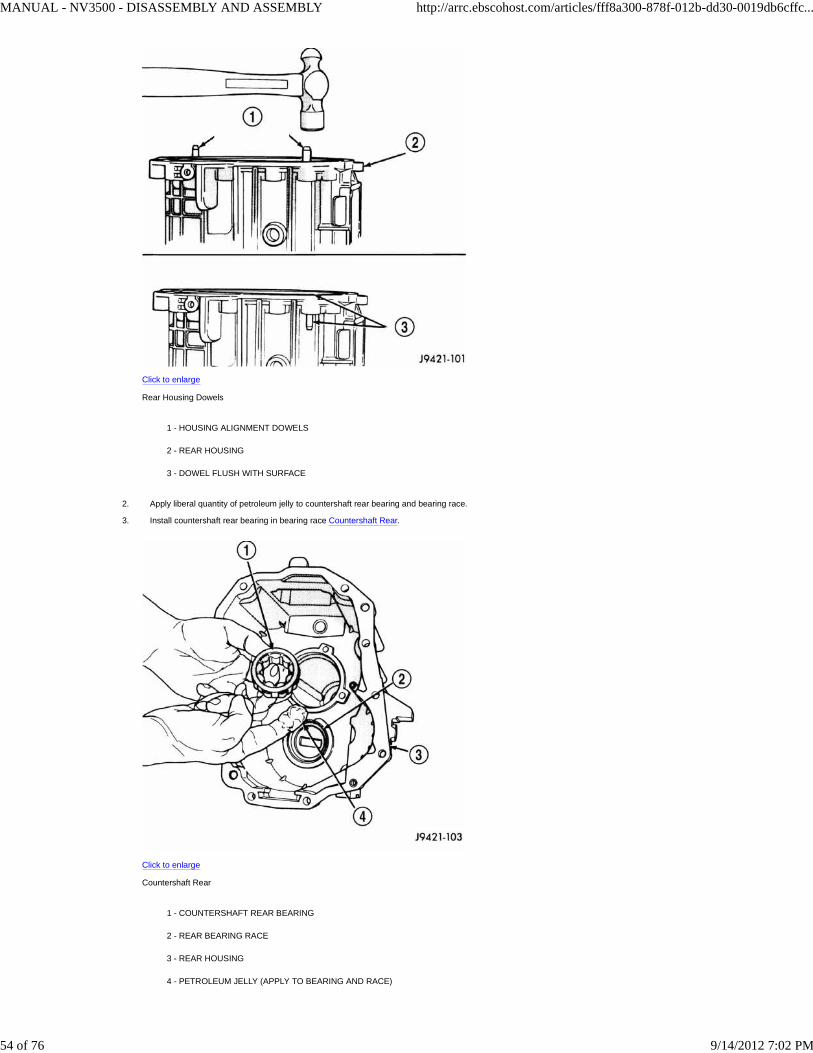
Drive adapter housing alignment dowels back into housing until dowels are flush with mounting surface Rear Housing Dowels.1.
MANUAL - NV3500 - DISASSEMBLY AND ASSEMBLY http://arrc.ebscohost.com/articles/fff8a300-878f-012b-dd30-0019db6cffc...
53 of 76 9/14/2012 7:02 PM
Click to enlarge
Rear Housing Dowels
1 - HOUSING ALIGNMENT DOWELS
2 - REAR HOUSING
3 - DOWEL FLUSH WITH SURFACE
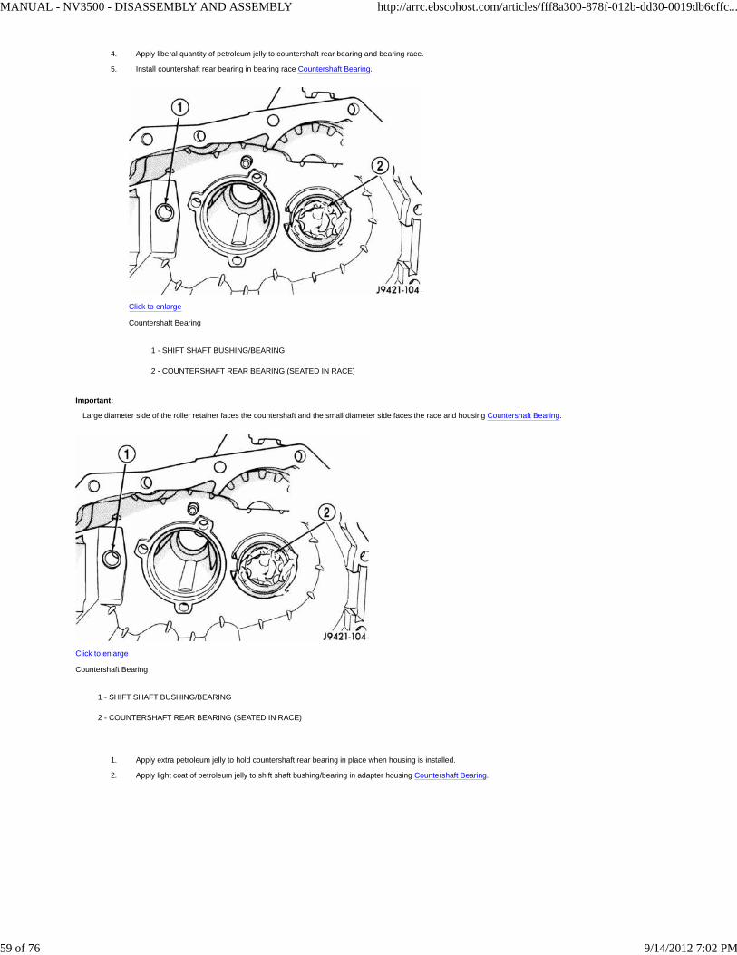
Apply liberal quantity of petroleum jelly to countershaft rear bearing and bearing race.2.
Install countershaft rear bearing in bearing race Countershaft Rear.
Click to enlarge
Countershaft Rear
1 - COUNTERSHAFT REAR BEARING
2 - REAR BEARING RACE
3 - REAR HOUSING
4 - PETROLEUM JELLY (APPLY TO BEARING AND RACE)
3.
MANUAL - NV3500 - DISASSEMBLY AND ASSEMBLY http://arrc.ebscohost.com/articles/fff8a300-878f-012b-dd30-0019db6cffc...
54 of 76 9/14/2012 7:02 PM

Important:
Large diameter side of the roller retainer faces the countershaft and the small diameter side faces the race and housing Countershaft Bearing.
Click to enlarge
Countershaft Bearing
1 - SHIFT SHAFT BUSHING/BEARING
2 - COUNTERSHAFT REAR BEARING (SEATED IN RACE)
Apply extra petroleum jelly to hold countershaft rear bearing in place when housing is installed.1.
Apply light coat of petroleum jelly to shift shaft bushing/bearing in rear housing Countershaft Bearing.
Click to enlarge
Countershaft Bearing
1 - SHIFT SHAFT BUSHING/BEARING
2 - COUNTERSHAFT REAR BEARING (SEATED IN RACE)
2.
Reach into countershaft rear bearing with finger and push each bearing roller outward against the race. Then apply extra petroleum jelly to holdrollers in place during housing installation.
3.
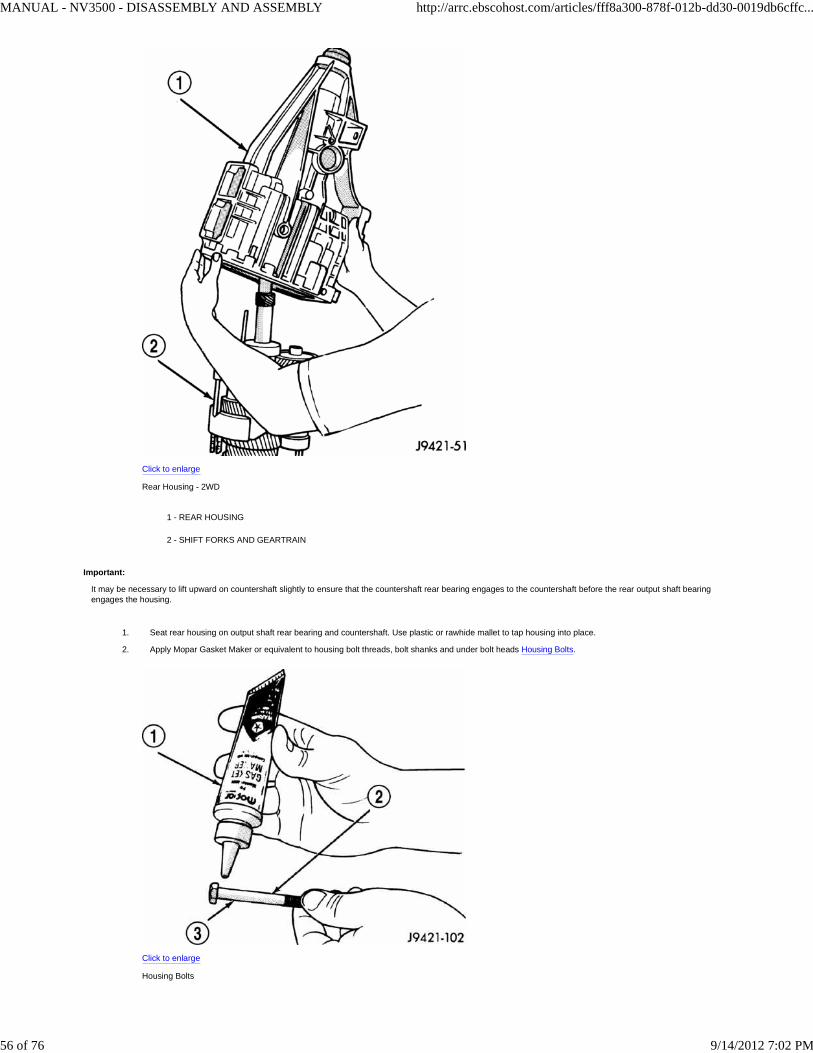
Install rear housing onto geartrain Rear Housing - 2WDand verify bearing retainer pilot stud is in correct bolt hole in housing. Be sure countershaftand output shaft bearings are aligned in housing and on countershaft.
4.
MANUAL - NV3500 - DISASSEMBLY AND ASSEMBLY http://arrc.ebscohost.com/articles/fff8a300-878f-012b-dd30-0019db6cffc...
55 of 76 9/14/2012 7:02 PM
Click to enlarge
Rear Housing - 2WD
1 - REAR HOUSING
2 - SHIFT FORKS AND GEARTRAIN
Important:
It may be necessary to lift upward on countershaft slightly to ensure that the countershaft rear bearing engages to the countershaft before the rear output shaft bearingengages the housing.
Seat rear housing on output shaft rear bearing and countershaft. Use plastic or rawhide mallet to tap housing into place.1.
Apply Mopar Gasket Maker or equivalent to housing bolt threads, bolt shanks and under bolt heads Housing Bolts.
Click to enlarge
Housing Bolts
2.
MANUAL - NV3500 - DISASSEMBLY AND ASSEMBLY http://arrc.ebscohost.com/articles/fff8a300-878f-012b-dd30-0019db6cffc...
56 of 76 9/14/2012 7:02 PM

1 - MOPAR GASKET MAKER (OR LOCTITE 518)
2 - RETAINER AND HOUSING BOLTS
3 - APPLY SEALER TO UNDERSIDE OF BOLT HEAD, SHANK AND THREADS
Start first two bolts in retainer Pilot Stud Tool And Retainer Bolts - 2WD. It may be necessary to move retainer rearward (with pilot stud) in order tostart bolts in retainer.
Click to enlarge
Pilot Stud Tool And Retainer Bolts - 2WD
1 - BEARING RETAINER BOLT
2 - PIN 8120
3.
Remove Alignment Pin 8120 and install last retainer bolt Pilot Stud Tool And Retainer Bolts - 2WD.
Click to enlarge
Pilot Stud Tool And Retainer Bolts - 2WD
1 - BEARING RETAINER BOLT
2 - PIN 8120
4.
Tighten all three retainer bolts to 30-35 N·m (22-26 ft. lbs.).5.
ADAPTER HOUSING - 4WD
Install rear bearing in adapter housing. Use wood hammer handle or wood dowel to tap bearing into place.1.
Position rear bearing retainer in adapter housing Adapter Housing - 4WD.2.
MANUAL - NV3500 - DISASSEMBLY AND ASSEMBLY http://arrc.ebscohost.com/articles/fff8a300-878f-012b-dd30-0019db6cffc...
57 of 76 9/14/2012 7:02 PM

Click to enlarge
Adapter Housing - 4WD
1 - BEARING RETAINER
2 - RETAINER BOLT
3 - IDLER SHAFT NOTCH
4 - COUNTERSHAFT BEARING RACE
5 - REAR BEARING
Apply Mopar Gasket Maker or equivalent to threads, bolt shanks and under hex heads of bearing retainer bolts Housing Bolts.
Click to enlarge
Housing Bolts
1 - MOPAR GASKET MAKER (OR LOCTITE 518)
2 - RETAINER AND HOUSING BOLTS
3 - APPLY SEALER TO UNDERSIDE OF BOLT HEAD, SHANK AND THREADS
3.
MANUAL - NV3500 - DISASSEMBLY AND ASSEMBLY http://arrc.ebscohost.com/articles/fff8a300-878f-012b-dd30-0019db6cffc...
58 of 76 9/14/2012 7:02 PM
Apply liberal quantity of petroleum jelly to countershaft rear bearing and bearing race.4.
Install countershaft rear bearing in bearing race Countershaft Bearing.
Click to enlarge
Countershaft Bearing
1 - SHIFT SHAFT BUSHING/BEARING
2 - COUNTERSHAFT REAR BEARING (SEATED IN RACE)
5.
Important:
Large diameter side of the roller retainer faces the countershaft and the small diameter side faces the race and housing Countershaft Bearing.
Click to enlarge
Countershaft Bearing
1 - SHIFT SHAFT BUSHING/BEARING
2 - COUNTERSHAFT REAR BEARING (SEATED IN RACE)
Apply extra petroleum jelly to hold countershaft rear bearing in place when housing is installed.1.
Apply light coat of petroleum jelly to shift shaft bushing/bearing in adapter housing Countershaft Bearing.2.
MANUAL - NV3500 - DISASSEMBLY AND ASSEMBLY http://arrc.ebscohost.com/articles/fff8a300-878f-012b-dd30-0019db6cffc...
59 of 76 9/14/2012 7:02 PM

Click to enlarge
Countershaft Bearing
1 - SHIFT SHAFT BUSHING/BEARING
2 - COUNTERSHAFT REAR BEARING (SEATED IN RACE)
Install adapter housing on geartrain.3.
Install rear bearing snap ring on output shaft Rear Bearing Snap Ring - 4WD.
Click to enlarge
Rear Bearing Snap Ring - 4WD
1 - SNAP RING PLIERS
2 - SNAP RING
3 - OUTPUT SHAFT
4.
Lubricate lip of new rear seal Rear Sealwith Mopar® Door Ease, or transmission fluid.5.
MANUAL - NV3500 - DISASSEMBLY AND ASSEMBLY http://arrc.ebscohost.com/articles/fff8a300-878f-012b-dd30-0019db6cffc...
60 of 76 9/14/2012 7:02 PM

Click to enlarge
Rear Seal
1 - REAR SEAL
2 - SEAL LIP
3 - OUTPUT SHAFT
Install newrear seal in adapter housing bore with Installer C-3860-A. Verify seal is seated in housing bore Rear Seal.
Click to enlarge
Rear Seal
1 - REAR SEAL
2 - SEAL LIP
3 - OUTPUT SHAFT
6.
SHIFT SHAFT, SHAFT LEVER AND BUSHING AND SHIFT SOCKET
Verify that all synchro sleeves are in Neutral position (centered on hub).1.
Caution:
Transmission synchros must all be in Neutral position for reassembly. Otherwise the housings, shift forks and gears can be damaged during installation of the twohousings.
Install 3-4 shift fork in synchro sleeve 3-4 Shift Fork. Verify groove in fork arm is aligned with grooves in 1-2 and fifth-reverse fork arms as shown.1.
MANUAL - NV3500 - DISASSEMBLY AND ASSEMBLY http://arrc.ebscohost.com/articles/fff8a300-878f-012b-dd30-0019db6cffc...
61 of 76 9/14/2012 7:02 PM

Click to enlarge
3-4 Shift Fork
1 - 3-4 FORK
2 - ALIGN GROOVES IN FORK ARMS
Slide shift shaft through 3-4 shift fork Shift Shaftwith shaft detent notches to the rear.
Click to enlarge
Shift Shaft
1 - SHIFT SHAFT
2 - 3-4 FORK
3 - SHAFT DETENT NOTCHES
2.
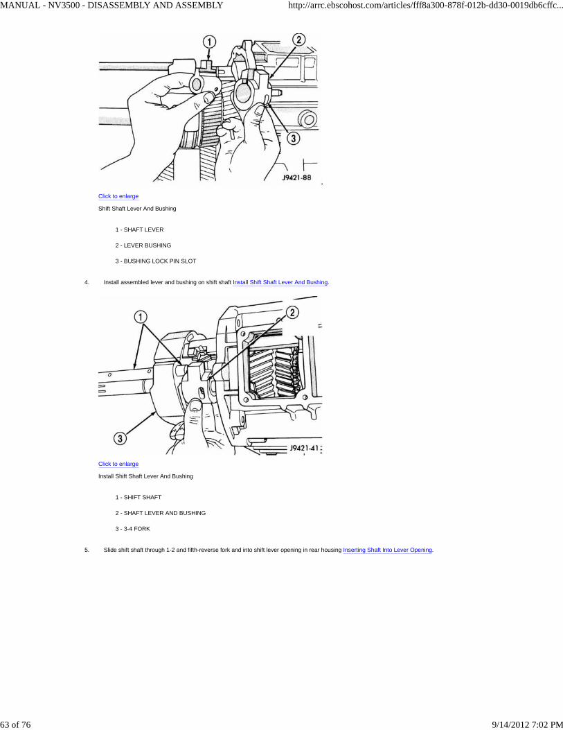
Assemble shift shaft shift lever and bushing Shift Shaft Lever And Bushing. Verify slot in bushing is facing up and roll pin hole for lever is aligned withhole in shaft.
3.
MANUAL - NV3500 - DISASSEMBLY AND ASSEMBLY http://arrc.ebscohost.com/articles/fff8a300-878f-012b-dd30-0019db6cffc...
62 of 76 9/14/2012 7:02 PM
Click to enlarge
Shift Shaft Lever And Bushing
1 - SHAFT LEVER
2 - LEVER BUSHING
3 - BUSHING LOCK PIN SLOT
Install assembled lever and bushing on shift shaft Install Shift Shaft Lever And Bushing.
Click to enlarge
Install Shift Shaft Lever And Bushing
1 - SHIFT SHAFT
2 - SHAFT LEVER AND BUSHING
3 - 3-4 FORK
4.
Slide shift shaft through 1-2 and fifth-reverse fork and into shift lever opening in rear housing Inserting Shaft Into Lever Opening.5.
MANUAL - NV3500 - DISASSEMBLY AND ASSEMBLY http://arrc.ebscohost.com/articles/fff8a300-878f-012b-dd30-0019db6cffc...
63 of 76 9/14/2012 7:02 PM

Click to enlarge
Inserting Shaft Into Lever Opening
1 - SHIFT SHAFT
Align shift socket with shaft and slide shaft through socket and into shift shaft bearing in rear housing Shift Socket.
Click to enlarge
Shift Socket
1 - SHIFT SOCKET
2 - SHIFT SHAFT
6.
Rotate shift shaft so detent notches in shaft are facing the TOP of the transmission housing.7.
Caution:
Both shaft roll pins can be installed when the shaft is 180° off. If this occurs, the transmission wil l have to be disassembled again to correct shaft alignment.
Select correct newroll pin for shift shaft lever Roll Pin Identification. Shaft lever roll pin is approximately 22 mm (7/8 in.) long. Shift socket roll pin isapproximately 33 mm (1-1/4 in.) long.
1.
MANUAL - NV3500 - DISASSEMBLY AND ASSEMBLY http://arrc.ebscohost.com/articles/fff8a300-878f-012b-dd30-0019db6cffc...
64 of 76 9/14/2012 7:02 PM

Click to enlarge
Roll Pin Identification
1 - SHAFT LEVER ROLL PIN
2 - SHIFT SOCKET ROLL PIN
Align roll pin holes in shift shaft, lever and bushing. Then start roll pin into shaft lever by hand Roll Pin In Shift Socket.
Click to enlarge
Roll Pin In Shift Socket
1 - SHAFT LEVER ROLL PIN
2 - LEVER AND BUSHING
2.
Seat shaft lever roll pin with pin punch Shift Shaft Lever Roll.
Click to enlarge
Shift Shaft Lever Roll
1 - BUSHING LOCK PIN SLOT
2 - SEAT ROLL PIN FLUSH WITH LEVER
3.
Caution:
Shaft lever roll pin must be flush with the surface of the lever. The lever bushing will bind on the roll pin if the pin is not seated flush.
Verify that lock pin slot in lever bushing is positioned as shown Shift Shaft Lever Roll.1.
MANUAL - NV3500 - DISASSEMBLY AND ASSEMBLY http://arrc.ebscohost.com/articles/fff8a300-878f-012b-dd30-0019db6cffc...
65 of 76 9/14/2012 7:02 PM

Click to enlarge
Shift Shaft Lever Roll
1 - BUSHING LOCK PIN SLOT
2 - SEAT ROLL PIN FLUSH WITH LEVER
Align roll pin holes in shift socket and shift shaft. Then start roll pin into shift shaft by hand Roll Pin In Shift Socket.
Click to enlarge
Roll Pin In Shift Socket
1 - ROLL PIN
2 - SHIFT SOCKET
3 - SHIFT SHAFT
2.
Seat roll pin in shift socket with pin punch. Roll pin must be flush with socket after installation Seat Shift Socket.3.
MANUAL - NV3500 - DISASSEMBLY AND ASSEMBLY http://arrc.ebscohost.com/articles/fff8a300-878f-012b-dd30-0019db6cffc...
66 of 76 9/14/2012 7:02 PM

Click to enlarge
Seat Shift Socket
1 - PIN PUNCH
2 - SHIFT SOCKET
3 - SEAT ROLL PIN FLUSH
4 - SHIFT SOCKET
Verify that notches in shift fork arms are aligned. Realign arms if necessary.4.
FRONT HOUSING AND INPUT SHAFT BEARING RETAINER
If previously removed, install input shaft bearing in front housing bore Input Shaft Bearing And Countershaft Front Bearing. Install snap ring and useplastic mallet to seat bearing. Bearing goes in from front side of housing only.
Click to enlarge
Input Shaft Bearing And Countershaft Front Bearing
1 - INPUT SHAFT BEARING
2 - COUNTERSHAFT FRONT BEARING
3 - SHIFT SHAFT BUSHING
1.
MANUAL - NV3500 - DISASSEMBLY AND ASSEMBLY http://arrc.ebscohost.com/articles/fff8a300-878f-012b-dd30-0019db6cffc...
67 of 76 9/14/2012 7:02 PM
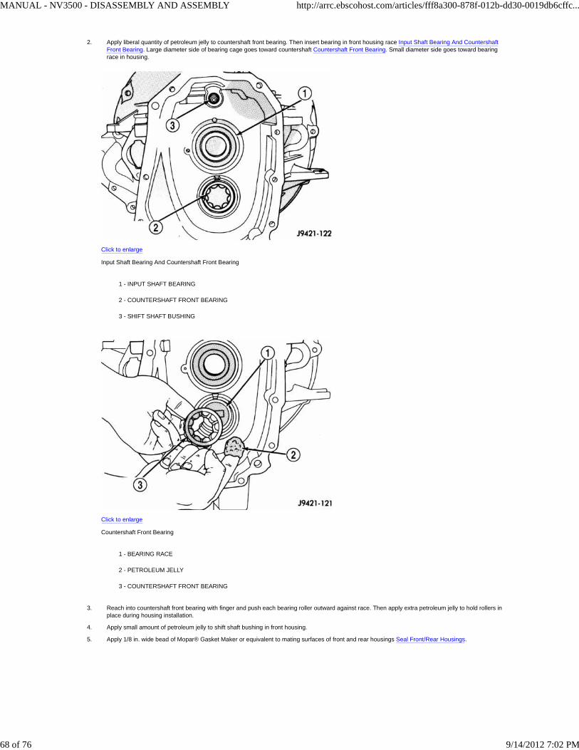
Apply liberal quantity of petroleum jelly to countershaft front bearing. Then insert bearing in front housing race Input Shaft Bearing And CountershaftFront Bearing. Large diameter side of bearing cage goes toward countershaft Countershaft Front Bearing. Small diameter side goes toward bearingrace in housing.
Click to enlarge
Input Shaft Bearing And Countershaft Front Bearing
1 - INPUT SHAFT BEARING
2 - COUNTERSHAFT FRONT BEARING
3 - SHIFT SHAFT BUSHING
Click to enlarge
Countershaft Front Bearing
1 - BEARING RACE
2 - PETROLEUM JELLY
3 - COUNTERSHAFT FRONT BEARING
2.
Reach into countershaft front bearing with finger and push each bearing roller outward against race. Then apply extra petroleum jelly to hold rollers inplace during housing installation.
3.
Apply small amount of petroleum jelly to shift shaft bushing in front housing.4.
Apply 1/8 in. wide bead of Mopar® Gasket Maker or equivalent to mating surfaces of front and rear housings Seal Front/Rear Housings.5.
MANUAL - NV3500 - DISASSEMBLY AND ASSEMBLY http://arrc.ebscohost.com/articles/fff8a300-878f-012b-dd30-0019db6cffc...
68 of 76 9/14/2012 7:02 PM

Click to enlarge
Seal Front/Rear Housings
1 - HOUSING FLANGE SURFACE
2 - MOPAR GASKET MAKER (OR LOCTITE 518)
Have helper hold rear housing and geartrain in upright position. Then install front housing on rear housing and geartrain.6.
Work front housing downward onto geartrain until seated on rear housing.7.
Caution:
Front housings will not seat if shift components are not in Neutral or one or more components are misaligned. Do not force the front housing into place.
Tap rear housing alignment dowels back into place with hammer and pin punch. Both dowels should be flush fit in each housing. Have helper holdtransmission upright while dowels are tapped back into place.
1.
Place transmission in horizontal position.2.
Apply Mopar® Gasket Maker or equivalent, to housing attaching bolts. Apply sealer material sealer to underside of bolt heads and to bolt shanks andthreads Housing Bolts.
Click to enlarge
Housing Bolts
1 - HOUSING ATTACHING BOLTS (APPLY SEALER BEFOREHAND)
3.
Install and start housing attaching bolts by hand Housing Bolts. Then tighten bolts to 34 N·m (25 ft. lbs.).4.
MANUAL - NV3500 - DISASSEMBLY AND ASSEMBLY http://arrc.ebscohost.com/articles/fff8a300-878f-012b-dd30-0019db6cffc...
69 of 76 9/14/2012 7:02 PM
Click to enlarge
Housing Bolts
1 - HOUSING ATTACHING BOLTS (APPLY SEALER BEFOREHAND)
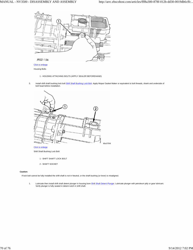
Install shift shaft bushing lock bolt Shift Shaft Bushing Lock Bolt. Apply Mopar Gasket Maker or equivalent to bolt threads, shank and underside ofbolt head before installation.
Click to enlarge
Shift Shaft Bushing Lock Bolt
1 - SHIFT SHAFT LOCK BOLT
2 - SHAFT SOCKET
5.
Caution:
If lock bolt cannot be fully installed the shift shaft is not in Neutral, or the shaft bushing (or lever) is misaligned.
Lubricate then install shift shaft detent plunger in housing bore Shift Shaft Detent Plunger. Lubricate plunger with petroleum jelly or gear lubricant.Verify plunger is fully seated in detent notch in shift shaft.
1.
MANUAL - NV3500 - DISASSEMBLY AND ASSEMBLY http://arrc.ebscohost.com/articles/fff8a300-878f-012b-dd30-0019db6cffc...
70 of 76 9/14/2012 7:02 PM

Click to enlarge
Shift Shaft Detent Plunger
1 - FRONT HOUSING
2 - PLUG
3 - SPRING
4 - PLUNGER
Install detent spring inside plunger Shift Shaft Detent Plunger.
Click to enlarge
Shift Shaft Detent Plunger
1 - FRONT HOUSING
2 - PLUG
3 - SPRING
4 - PLUNGER
2.
Install detent plug in end of Installer 8123. Position plug on detent spring and compress spring until detent plug pilots in detent plunger bore. Drivedetent plug into transmission case until plug seats.
3.
Install backup light switch Backup Light Switch.4.
MANUAL - NV3500 - DISASSEMBLY AND ASSEMBLY http://arrc.ebscohost.com/articles/fff8a300-878f-012b-dd30-0019db6cffc...
71 of 76 9/14/2012 7:02 PM
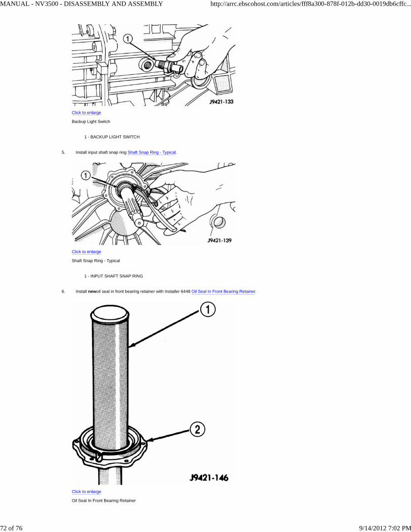
Click to enlarge
Backup Light Switch
1 - BACKUP LIGHT SWITCH
Install input shaft snap ring Shaft Snap Ring - Typical.
Click to enlarge
Shaft Snap Ring - Typical
1 - INPUT SHAFT SNAP RING
5.
Install newoil seal in front bearing retainer with Installer 6448 Oil Seal In Front Bearing Retainer.
Click to enlarge
Oil Seal In Front Bearing Retainer
6.
MANUAL - NV3500 - DISASSEMBLY AND ASSEMBLY http://arrc.ebscohost.com/articles/fff8a300-878f-012b-dd30-0019db6cffc...
72 of 76 9/14/2012 7:02 PM

1 - INSTALLER 6448
2 - FRONT BEARING RETAINER
MANUAL - NV3500 - DISASSEMBLY AND ASSEMBLY http://arrc.ebscohost.com/articles/fff8a300-878f-012b-dd30-0019db6cffc...
73 of 76 9/14/2012 7:02 PM
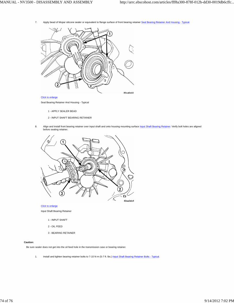
Apply bead of Mopar silicone sealer or equivalent to flange surface of front bearing retainer Seal Bearing Retainer And Housing - Typical.
Click to enlarge
Seal Bearing Retainer And Housing - Typical
1 - APPLY SEALER BEAD
2 - INPUT SHAFT BEARING RETAINER
7.
Align and install front bearing retainer over input shaft and onto housing mounting surface Input Shaft Bearing Retainer. Verify bolt holes are alignedbefore seating retainer.
Click to enlarge
Input Shaft Bearing Retainer
1 - INPUT SHAFT
2 - OIL FEED
3 - BEARING RETAINER
8.
Caution:
Be sure sealer does not get into the oil feed hole in the transmission case or bearing retainer.
Install and tighten bearing retainer bolts to 7-10 N·m (5-7 ft. lbs.) Input Shaft Bearing Retainer Bolts - Typical.1.
MANUAL - NV3500 - DISASSEMBLY AND ASSEMBLY http://arrc.ebscohost.com/articles/fff8a300-878f-012b-dd30-0019db6cffc...
74 of 76 9/14/2012 7:02 PM

Click to enlarge
Input Shaft Bearing Retainer Bolts - Typical
1 - RETAINER BOLTS
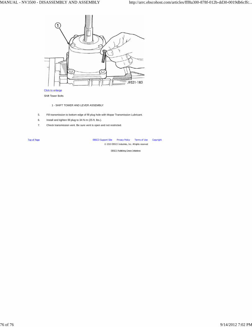
SHIFT TOWER AND LEVER
Apply petroleum jelly to ball end of shift lever and interior of shift socket.1.
Shift the transmission into third gear.2.
Align and install shift tower and lever assembly Shift Tower. Be sure shift ball is seated in socket and the offset in the tower is toward the passengerside of the vehicle before installing tower bolts.
Click to enlarge
Shift Tower
1 - SHIFT TOWER
3.
Install shift tower bolts Shift Tower Boltsand tighten bolts to 8.5 N·m (75.2 in. lbs.).4.
MANUAL - NV3500 - DISASSEMBLY AND ASSEMBLY http://arrc.ebscohost.com/articles/fff8a300-878f-012b-dd30-0019db6cffc...
75 of 76 9/14/2012 7:02 PM
Top of Page EBSCO Support Site Privacy Policy Terms of Use Copyright
© 2010 EBSCO Industries, Inc. All rights reserved
EBSCO Publishing Green Initiatives
Click to enlarge
Shift Tower Bolts
1 - SHIFT TOWER AND LEVER ASSEMBLY
Fill transmission to bottom edge of fill plug hole with Mopar Transmission Lubricant.5.
Install and tighten fill plug to 34 N·m (25 ft. lbs.).6.
Check transmission vent. Be sure vent is open and not restricted.7.
MANUAL - NV3500 - DISASSEMBLY AND ASSEMBLY http://arrc.ebscohost.com/articles/fff8a300-878f-012b-dd30-0019db6cffc...
76 of 76 9/14/2012 7:02 PM