2002 owner's manual
TRANSCRIPT

Owner’s ManualOwner’s Manual

Owner’s ManualThis Owner’s Manual will acquaint you with the operation and general maintenance of your new spa. We suggest that
you take some time to carefully review all seven sections. Please keep this manual available for reference.If you have any questions about any aspect of your spa’s set-up, operation or maintenance, contact your authorizedHot Spring dealership. They are trained professionals who are familiar with the product as well as new spa ownershipconcerns. Their expertise will facilitate the enjoyment of your new Hot Spring spa.The serial number label is located within the equipment compartment of your Hot Spring spa.IMPORTANT: Watkins Manufacturing Corporation reserves the right to change specifications, or design, withoutnotification and without incurring any obligation.
DATE PURCHASED: __________________________________________________________________________________________________________
DATE INSTALLED: ____________________________________________________________________________________________________________
DEALER: ____________________________________________________________________________________________________________________
ADDRESS: __________________________________________________________________________________________________________________
TELEPHONE: ________________________________________________________________________________________________________________
SPA MODEL/SERIAL NUMBER: ________________________________________________________________________________________________
COVER SERIAL NUMBER: ____________________________________________________________________________________________________
ACCESSORY SERIAL NUMBERS: ______________________________________________________________________________________________
Important!Important!
Watkins® Manufacturing Corporation congratulates you on your decision to enjoy the finestspa available... Welcome to the growing family of Hot Spring® spa owners.
In most cities and counties, permits will be required for the installation of electrical circuits or the construction of exteriorsurfaces (decks and gazebos). In addition, some communities have adopted residential barrier codes which mayrequire fencing and/or self-closing gates on the property to prevent unsupervised access to a pool (or spa) by children
under 5 years of age. Your Hot Spring spa is equipped with a locking cover that meets the ASTM F1346-91 Standard forSafety Covers and as a result, is usually exempt from most barrier requirements. As a general practice, your local BuildingDepartment will inform you of any applicable barrier requirements at the time a permit is obtained for the installation of anelectrical circuit. Your Hot Spring dealer can provide information on which permits may be required.

Table of ContentsTable of Contents
SAFETY INFORMATION ............................................1Important Spa Instructions............................................................3
SPA SPECIFICATIONS ................................................4
CONTROLS AND EQUIPMENT ........................5LANDMARK® (Model S) ................................................................5GRANDEE® (Model G) ..................................................................6VANGUARD™ (Model V) ................................................................7SOVEREIGN® Limited Edition (Model ILE) ..................................8SOVEREIGN® (Model I) ................................................................9PRODIGY® (Model H)..................................................................10JETSETTER® (Model J) ..............................................................11
INSTALLATION INSTRUCTIONSSite Preparation ..................................................................12Outdoor and Patio Installation ........................................12Deck Installation ..............................................................12Indoor/Basement Installation ..........................................12Spa Leveling Instructions ................................................13
ELECTRICAL REQUIREMENTS ANDPRECAUTIONS
230 Volt Permanently Connected Models..................................18115 / 230 Volt Convertible Models ............................................20115 Volt Operation ......................................................................22
OPERATING INSTRUCTIONSGeneral Information ....................................................................23230 Volt Permanently Connected Models..................................23115 / 230 Volt Convertible Models ............................................23Start-Up and Refill Procedures ..................................................24SmartJet® System ......................................................................25Comfort Control® System ..........................................................25
JETSMoto-Massage® Jet ....................................................................25Hydromassage Jets ....................................................................25Soothing Seven® Jet ..................................................................25Precision® Jets ............................................................................26JetStream® Jet............................................................................26DreamJet® Massage Pillow ........................................................26
JET SYSTEM MENUSLANDMARK® (Model S) ..............................................................27GRANDEE® (Model G) ................................................................28VANGUARD™ (Model V) ..............................................................29SOVEREIGN® Limited Edition (Model ILE) ................................30SOVEREIGN® (Model I) ..............................................................31PRODIGY® (Model H)..................................................................32JETSETTER® (Model J) ..............................................................33
CONTROL PANEL VIEWSMain Control Panels....................................................................34Control Panels ............................................................................34Indicator Lights............................................................................34Locking Features ........................................................................34Main Control Panel Buttons and Display ..................................35Water Care ..................................................................................36Auxiliary Control Panel ................................................................36115 Volt GFCI ..............................................................................37Light ............................................................................................37Summer Mode ............................................................................37
SPA CARE AND MAINTENANCEGeneral Information ....................................................................38Draining the Water ......................................................................38Filter System................................................................................38Filter Cartridges Removal and Cleaning ....................................39Care of the Spa Pillows ..............................................................39Care of the Exterior ....................................................................39Care of the Spa Cover ................................................................40Retractable Cover Systems ........................................................40Vacation Care Instructions..........................................................41Prevention of Freezing ................................................................42
WATER QUALITY AND MAINTENANCEGeneral Information ....................................................................43Methods for Testing the Spa Water............................................43Hot Spring® Spa Water Maintenance Program..........................44EverFresh® Water Care System..................................................46Hot Spring Water Treatment Guide............................................47Freshwater Ag+® Silver Ion Purifier Replacement ......................48Chlorine (Sodium Dichlor) ..........................................................49Ozone ..........................................................................................50Common Water Chemistry Questions........................................51Water Terminology ......................................................................52
SERVICE INFORMATIONGeneral Information ....................................................................53GFCI and High Limit Thermostat................................................53No-Fault® 6000 Heater and Heater Thermal Cut-off..................53Silent Flo® 5000 Circulation Pump and Circulation Pump Thermal Cut-off..............................................53Freshwater® III High Output Ozone System ..............................53Miscellaneous Service Information ............................................54Acts Invalidating Warranty ..........................................................54Disclaimers ..................................................................................54Watkins Customer Service..........................................................54Troubleshooting Guides..............................................................55Spa Care and Maintenance Record ..........................................56

Page 1Safety Information
SAFETY INFORMATIONIMPORTANT SAFETY INSTRUCTIONSREAD AND FOLLOW ALL INSTRUCTIONSAVOIDING THE RISK TO CHILDRENDANGER:
• RISK OF CHILD DROWNING. Extreme caution must be exercised to prevent unauthorized access by children. To avoid accidents,ensure that children cannot use a spa unless they are supervised at all times.
WARNING:• To reduce the risk of injury, do not permit children to use this spa unless they are closely supervised at all times.• To reduce the risk of injury, lower water temperatures are recommended for young children. Children are especially sensitive to hot water.
DO:• Make sure you always lock the child resistant locks after using the spa for your children’s safety. Every Hot Spring® spa is equipped with a
locking cover that meets the ASTM F1346-91 Standard for Safety Covers.• Test the water temperature with your hand before allowing children to enter the spa to be sure that it’s comfortable. Children are
especially sensitive to hot water.• Remind children that wet surfaces can be very slippery. Make sure that children are careful when entering, or exiting the spa.
DON’T:• Allow children to climb onto the spa cover.• Allow children to have unsupervised access to the spa.
AVOIDING THE RISK OF ELECTROCUTIONRisk of electrocution
• Connect only to a grounded source.• Do not bury the power cord. A buried power cord may result in death, or serious personal injury due to electrocution if direct burial-type
cable is not used, or if improper digging occurs.• A ground terminal (pressure wire connector) is provided on the control box inside the unit to permit connection of a minimum No. 10 AWG
(6 mm2) solid copper bonding conductor between this point and any metal equipment, metal water pipe, metal enclosures of electricalequipment, or conduit within five feet (1.5 m) of the unit as needed to comply with local requirements.
WARNING:• To reduce the risk of electrical shock, replace a damaged cord immediately. Failure to do so may result in death or serious personal injury
due to electrocution.• Your spa is provided with a Ground Fault Circuit Interrupter for user and equipment protection. To ensure proper operation of this
important safety device, test according to the following instructions per electrical configuration.Cord-Connected 115 volt, 20 amp models: The GFCI is located at the end of the power cord. Before each use, with the unit operating,push the TEST button. The unit should stop operating and the GFCI power indicator will go out. Wait 30 seconds and then reset the GFCIby pushing the RESET button. The GFCI power indicator will turn on, restoring power to the spa. If the interrupter does not perform in thismanner, there may be an electrical malfunction and with it, the possibility of an electric shock. Disconnect the power until the problem hasbeen corrected.230 volt, permanently installed or converted models:
• A ground terminal is provided on the terminal block (TB-1, system ground terminal) located inside the control box. To reduce the risk ofelectric shock, connect this terminal to the grounding terminal of your electrical service or supply panel with a continuous green, insulatedcopper wire. The wire must be equivalent in size to the circuit conductors supplying the equipment. In addition, a bonding terminal(pressure wire connector) is provided on the outside of the control box for bonding to local ground points. To reduce the risk of electricshock, this connector should be bonded with a No. 10 AWG (6 mm2) solid copper wire to any metal ladders, water pipes, or other metalwithin 5 feet (1.5 m) of the spa to comply with local requirements. The means of disconnection must be readily accessible, but must beinstalled at least 5 feet (1.5 m) from the spa.
• Your spa is provided with a suitably rated circuit breaker to open all ungrounded supply conductors.

Page 2
• Your spa uses ground fault circuit interrupters in the electrical subpanel. Before each use of the spa and with the unit operating, push theTEST button on each breaker. The switch should click over to the “Trip” position. Wait 30 seconds and reset each GFCI breaker byswitching it completely off and then completely on. The switch should then stay on. If either of the interrupters does not perform in thismanner, it is an indication of an electrical malfunction and the possibility of an electric shock. Disconnect the power until the fault hasbeen identified and corrected.NOTE: Failure to wait 30 seconds before resetting the GFCI may cause the spa’s Power Indicator (on the control panel) to blink. If thisoccurs, repeat the GFCI test procedure.
DANGER: RISK OF ELECTRICAL SHOCK• Install at least 5 feet (1.5 m) from all metal surfaces. A spa may be installed within 5 feet of a metal surface if each metal surface is
permanently connected by a minimum No. 10 AWG (6 mm2) solid copper conductor attached to the wire ground connector on theterminal box that is provided for this purpose if in accordance with National Electrical Code ANSI/NMFPA70-1993.
• Do not permit any electrical appliances, such as a light, telephone, radio, or television within 5 feet (1.5 m) of a spa. Failure to maintain asafe distance may result in death, or serious personal injury due to electrocution, if the appliance should fall into the spa.
• Install your spa is such a way that drainage is away from the electrical compartment and from all electrical components.
DO:• Be sure your spa is connected to the power supply correctly - use a licensed electrical contractor.• Disconnect the spa from the power supply before draining the spa or servicing the electrical components.• Test the Ground Fault Circuit Interrupter(s) before each use.
DON’T:• Use the spa with the equipment compartment door removed.• Place electrical appliances within 5 feet (1.5m) of the spa.• Use an extension cord to connect the spa to its power source. The cord may not be properly grounded and the connection is a shock
hazard. An extension cord may cause a voltage drop, which will cause overheating of the jet pump motor and motor damage.• Attempt to open the electrical control box. There are no user serviceable parts inside.
RISKS TO AVOIDDANGER: RISK OF INJURY
• To reduce the risk of injury to persons, DO NOT remove suction fittings (filter standpipes) located in the filter compartment. • The suction fittings in the spa are sized to match the specific water flow created by the pump. Never replace a suction fitting with one
rated less than the flow rate marked on the original suction fitting.• There is a danger of slipping and falling. Remember that wet surfaces can be very slippery. Take care when entering or exiting the spa.• Never operate spa if the suction fittings are broken or missing.
Increased side effects of medication• The use of drugs, alcohol, or medication before or during spa use may lead to unconsciousness with the possibility of drowning.• Persons using medications should consult a physician before using a spa; some medication may cause a user to become drowsy, while
other medication may affect heart rate, blood pressure, and circulation.• Persons taking medications which induce drowsiness, such as tranquilizers, antihistamines or anticoagulants should not use the spa.
Health problems affected by spa use• Pregnant women should consult a physician before using spa.• Persons suffering from obesity, or with a medical history of heart disease, low or high blood pressure, circulatory system problems, or
diabetes should consult a physician before using spa.
Unclean water• Keep the water clean and sanitized with correct chemical care. The recommended levels for your Hot Spring® spa are:
Free Available Chlorine (FAC): 3.0-5.0 ppmWater pH: 7.4-7.6Total Alkalinity: 125-150 ppmCalcium Hardness: 150-200 ppm
(Refer to Water Quality and Maintenance section for complete instructions.)IMPORTANT: Turn on the jet pump for a least ten minutes after adding ANY spa water chemicals into the filter compartment.
• Clean the filter cartridges monthly to remove debris and mineral buildup which may affect the performance of the hydromassage jets, limitthe flow, or trip the high limit thermostat, which will turn off the entire spa.
Safety Information

Page 3Safety Information
AVOIDING THE RISK OF HYPERTHERMIAProlonged immersion in hot water can result in HYPERTHERMIA, a dangerous condition which occurs when the internal temperature of the bodyreaches a level above normal (98.6°F). The symptoms of hyperthermia include unawareness of impending hazard, failure to perceive heat, failureto recognize the need to exit the spa, physical inability to exit the spa, fetal damage in pregnant women, and unconsciousness resulting in adanger of drowning.
WARNING:The use of alcohol, drugs, or medication can greatly increase the risk of fatal hyperthermia in hot tubs and spas.
TO REDUCE THE RISK OF INJURY:• The water in the spa should never exceed 104°F. Water temperatures between 100°F and 104°F are considered safe for a healthy adult.
Lower water temperatures are recommended for extended use (exceeding ten minutes) and for young children. Extended use can causehyperthermia.
• Pregnant or possibly pregnant women should limit spa water temperatures to 100°F. Failure to do so may result in permanent injury toyour baby.
AVOIDING THE RISK OF SKIN BURNS:• To reduce the risk of injury, before entering a spa the user should measure the water temperature with an accurate thermometer, since the
tolerance of temperature-regulating devices may vary by as much as ±5°F.• Test the water with your hand before entering the spa to be sure it’s comfortable.
SAFETY SIGNEach Hot Spring® spa is shipped with a SAFETY SIGN in the owner’s package. The sign, which is required as a condition of Product Listing,should be permanently installed where it is visible to the users of the spa. To obtain additional SAFETY SIGNS, contact your Hot Spring dealer andrequest Part #70798.
IMPORTANT SPA INSTRUCTIONSThe following contains important spa information, and we strongly encourage you to read and apply them.
DO:• Use and lock the vinyl cover when the spa is not in use, whether it is empty or full.• Follow the Spa Care and Maintenance recommendations stated in this manual.• Use only approved accessories and recommended spa chemicals and cleaners.
DON’T:• Leave the Hot Spring spa exposed to the sun without water or the cover in place. Exposure to direct sunlight can cause solar distress of
the shell material.• Roll or slide the spa on its side. This will damage the siding.• Lift or drag the vinyl cover by using the cover lock straps; always lift or carry the cover by using the handles.• Attempt to open the electrical control box. There are no user serviceable parts inside. Opening of the control box by the spa owner will
void the warranty. If you have an operational problem, carefully go through the steps outlined in the Troubleshooting section. If you are notable to resolve the problem, contact your authorized Hot Spring dealer. Many problems can easily be diagnosed over the telephone by anAuthorized Service Technician.
SAVE THESE INSTRUCTIONS

Page 4
7'3"x
7'3"
2.20mx
2.20m
6'8"x
7'9"
2.03mx
2.36m
6'2"x
7'3"
1.88mx
2.21m
5'2"x
6'10"
1.57mx
2.08m
Grandee®
(Model G)
7'7"x
8'4"
2.31mx
2.54m
38"
.96 m
150square
feet
6,000 500 gallons
1,893 litres
877lbs.
398 kg.
6,167lbs.
2,797kg.
115lbs. per square
foot
230 volt, 50 amp Single phase GFCI protected circuit
7'7"x
8'4"
2.31mx
2.54m
Landmark®
(Model S)38"
.96 m
150square
feet
6,000 525gallons
1,987 litres
877lbs.
398kg.
6,195lbs.
2,810kg.
115lbs. per square
foot
230 volt, 50 amp Single phase GFCI protected circuit
VanguardTM
(Model V)36"
.91 m
120square
feet
6,000 400gallons
1,514litres
686lbs.
311kg.
4,988lbs.
2,263kg.
110lbs. per square
foot
230 volt, 50 amp Single phase GFCI protected circuit
Sovereign®
Limited Edition
(Model ILE)
36"
.91 m
120 square
feet
6,000 365gallons
1,382 litres
705lbs.
320kg.
4,675lbs.
2,121kg.
105lbs. per square
foot
230 volt, 50 amp Single phase GFCI protected circuit
6'8"x
7'9"
2.03mx
2.36m
Sovereign®
(Model I )33"
.84 m
90 square
feet
1,500or
6,000
355gallons
1,344 litres
620lbs.
281kg.
4,556lbs.
2,067kg.
105lbs. per square
foot
115 volt, 20 amp Dedicated GFCIprotected circuit or230 volt, 50 amp Single phase GFCIprotected circuit
Prodigy®
(Model H)33"
.84 m
90square
feet
1,500or
6,000
325gallons
1,230 litres
533lbs.
242kg.
4,051lbs.
1,838 kg.
105lbs. per square
foot
115 volt, 20 amp Dedicated GFCIprotected circuit or230 volt, 50 amp Single phase GFCIprotected circuit
Jetsetter®
(Model J)29"
.74 m
90square
feet
1,500or
6,000
215gallons
814 litres
365Lbs.
166kg.
2,638lbs.
1,197kg.
90lbs. per square
foot
115 volt, 20 amp Dedicated GFCIprotected circuit or230 volt, 50 amp Single phase GFCIprotected circuit
Foot
prin
tdi
men
sion
sH
eigh
tEf
fect
ive
filter
are
aH
eate
r(W
atts
)W
ater
ca
paci
ty
Dry
wei
ght
Fille
d w
eigh
t*D
ead
wei
ght*
Elec
trica
lR
equi
rem
ents
SPA SPECIFICATIONS
CAUTION: Watkins Manufacturing Corporation suggests a structural engineer or contractor be consulted before the spa is placedon an elevated deck.* NOTE: The “Filled weight” and “Dead weight” of the spa includes the weight of the occupants (assuming an average occupant
weight of 175 lbs).
Spa Specifications

Page 5Controls and Equipment
Landmark®
Model S
1. Wavemaster® jet pump2. No-Fault® 6000 heater3. Silent Flo 5000® circulation pump4. IQ 2020™ control box5. Ozone injector (optional accessory)
6. Main drain valve7. Secondary drain8. Heater thermal cut-off9. Bonding terminal
EQUIPMENT COMPARTMENT
D
C
R
K
K
K
K
L
N
P
H
H
I
I
6 7
81
1
9
4
2
5
3
I
J
A
O
A
B E
D
M
F
F
F
G
G
OVERHEAD VIEWA. SmartJet® system leverB. Moto-Massage® jet Comfort
Control® system leverC. JetStream® jet Comfort
Control system leverD. Precision® jets Comfort
Control system leverE. DreamJet® Comfort Control
system leverF. Hydromassage jet with
directional nozzleG. Hydromassage jet with
rotary nozzleH. Soothing Seven® jetsI. JetStream jetJ. Moto-Massage jetK. Precision jetsL. Heater return and spa drainM. Light lensN. Filter compartmentO. Main control panelP. Auxiliary control panelQ. PillowR. DreamJet massage pillow

Page 6
OVERHEAD VIEWA. SmartJet® system leverB. Moto-Massage® jet Comfort
Control® system leverC. Precision® jets Comfort
Control system leverD. JetStream® jet Comfort
Control system leverE. PillowF. Hydromassage jet with
directional nozzleG. Hydromassage jet with rotary
nozzleH. Moto-Massage jetI. Precision jetsJ. Soothing Seven® jetsK. JetStream jetL. Heater return and spa drainM. Light lensN. Filter compartmentO. Main control panelP. Auxiliary control panel
Grandee®
Model G
1. Wavemaster® jet pump2. No-Fault® 6000 heater3. Silent Flo 5000® circulation pump4. IQ 2020™ control box5. Ozone injector (optional accessory)
6. Main drain valve7. Secondary drain8. Heater thermal cut-off9. Bonding terminal
EQUIPMENT COMPARTMENT
C
C
G
F
F
P
G
C
C
D
B
B
E E
E
H H
I
I I
I
I
I
6 7
81
1
94
2
5
3
A
KK
N
K
J
J
M
A
O
L
Controls and Equipment

Page 7
Vanguard™
Model V
1. Wavemaster® jet pump2. No-Fault® 6000 heater3. Silent Flo 5000® circulation pump4. IQ 2020™ control box5. Ozone injector (optional accessory)
6. Main drain valve7. Secondary drain8. Heater thermal cut-off9. Bonding terminal
EQUIPMENT COMPARTMENT
OVERHEAD VIEWA. SmartJet® system leverB. Moto-Massage® jet Comfort
Control® system leverC. Precision® jets Comfort
Control system leverD. PillowE. Hydromassage jet with
directional nozzleF. Hydromassage jet with rotary
nozzleG. Moto-Massage jetH. Precision jetsI. Soothing Seven® jetsJ. JetStream® jetK. Heater return and spa drainL. Light lensM. Filter compartmentN. Main control panelO. Auxiliary control panel
A
N
1
3
4
2
5
6 7
8
9
L
J J
KI
I
O
D D
G G
HH
H H
H
F
F
M
E
C
CC
BB
Controls and Equipment

Page 8
Sovereign®
LimitedEditionModel ILE
1. Wavemaster® jet pump2. No-Fault® 6000 heater3. Silent Flo 5000® circulation pump4. IQ 2020™ control box5. Ozone injector (optional accessory)
6. Main drain valve7. Secondary drain8. Heater thermal cut-off9. Bonding terminal
EQUIPMENT COMPARTMENT
OVERHEAD VIEWA. SmartJet® system leverB. Moto-Massage® jet Comfort
Control® system leverC. Precision® jets Comfort
Control system leverD. PillowE. Hydromassage jet with
directional nozzleF. Hydromassage jet with
rotary nozzleG. Moto-Massage jetH. Precision jetsI. Soothing Seven® jetsJ. JetStream® jetK. Heater return and spa drainL. Light lensM. Filter compartmentN. Main control panelO. Auxiliary control panel
C
D
H
H
E
J
J
C
G
F
F
E
E
K
B
A
M
L
I I
O
N
1
2
3
4
5
6 7
8
9
Controls and Equipment

Page 9Controls and Equipment
Sovereign®
Model I
1. Wavemaster® jet pump2. No-Fault® 6000 heater3. Silent Flo 5000® circulation pump4. IQ 2020™ control box5. Ozone injector (optional accessory)
6. Main drain valve7. Secondary drain8. Heater thermal cut-off9. Bonding terminal
EQUIPMENT COMPARTMENT
OVERHEAD VIEWA. SmartJet® system leverB. Moto-Massage® jet Comfort
Control® system leverC. Precision® jets Comfort
Control® system leverD. PillowE. Hydromassage jet with
directional nozzleF. Hydromassage jet with
rotary nozzleG. Moto-Massage jetH. Precision jetsI. Soothing Seven® jetsJ. JetStream® jetK. Heater return and spa drainL. Light lensM. Filter compartmentN. Main control panelO. Auxiliary control panelP. Cup holder
C
D
D
H H
J
J
C
G
F
F
E
E
K
B
A
M
L
I
I
O
N
P
P
1
2
3
4
5
6 7
8
9

Page 10
Prodigy®
Model H
1. Wavemaster® jet pump2. No-Fault® 6000 heater3. Silent Flo 5000® circulation pump4. IQ 2020™ control box5. Ozone injector (optional accessory)
6. Main drain valve7. Secondary drain8. Heater thermal cut-off9. Bonding terminal
EQUIPMENT COMPARTMENT
OVERHEAD VIEWA. SmartJet® system leverB. JetStream® jet Comfort
Control® system leverC. Precision® jets Comfort
Control® system leverD. Hydromassage jet with
directional nozzleE. Hydromassage jet with rotary
nozzleF. Precision jetsG. Soothing Seven® jetsH. JetStream jetI. Heater return and spa drainJ. Light lensK. Filter compartmentL. Main control panelM. Auxiliary control panel
B
E
ED
D
D
J
K
A
G
L
I
F
H
M
C
Controls and Equipment

Page 11
Jetsetter®
Model J
1. Wavemaster® jet pump2. No-Fault® 6000 heater3. Silent Flo 5000® circulation pump4. IQ 2020™ control box5. Ozone injector (optional accessory)
6. Main drain valve7. Secondary drain8. Heater thermal cut-off9. Bonding terminal
EQUIPMENT COMPARTMENT
OVERHEAD VIEWA. SmartJet® system leverB. JetStream® jet Comfort
Control® system leverC. Moto-Massage® jet Comfort
Control system leverD. Precision® jets Comfort
Control system leverE. PillowF. Hydromassage jet with
directional nozzleG. Hydromassage jet with
rotary nozzleH. Moto-Massage jetI. Precision jetsJ. Soothing Seven® jetsK. JetStream jetL. Heater return and spa drainM. Light lensN. Filter compartmentO. Main control panel
D
E
G
F
F J
J
A
K
M
L
N
H
I
B
C O
Controls and Equipment

Page 12
INSTALLATION INSTRUCTIONSSITE PREPARATIONYou probably have a spot picked out for your new spa, whether it’s indoors or outdoors, on a patio or on a
deck. Just make sure you check the following:• Always put your spa on a structurally sound, level surface. A filled spa can weigh a great deal. Make certain
that the location you choose can support the weight of your filled spa.• Don’t forget to level your spa before filling it. (See Spa Leveling Instructions) • Locate your equipment compartment, which houses all of the electrical components, in a place where water
drainage will be away from it. Do not allow water into the equipment compartment. Water can cause damageto the electronics, or may trip the circuit breaker on your house’s electrical panel.
• Leave yourself easy access to the circuit breakers in the subpanel (230 volt models), or to the interrupterswitch on the end of the power cord (115 volt models).
• Never let water get into the subpanel (230 volt models), into the interrupter switch (115 volt models), or intothe electrical outlet that your spa is plugged into. Your 115 volt Hot Spring® spa comes with a protectivebox designed to keep out rain and water from sprinkler systems. Your 230 volt spa’s subpanel is rain-tightwhen installed correctly with the door closed. Periodically check these conditions and correct any flaws ifdetected.
• Leave access to the equipment compartment for periodic spa care and maintenance.• If your spa is going to be installed in a location known to be frequented by mice, rats or other nocturnal creatures, Watkins Manufacturing
Corpoation recommends covering the access opening to the spa’s equipment compartment with a heavy gauge screen material availableat your local hardware store.
WARNING: Damage to the spa’s equipment compartment components or internal plumbing as a result of rodent infestation is NOTcovered under your warranty!
OUTDOOR AND PATIO INSTALLATIONNo matter where you install your new spa, it’s important that you have a solid foundation to support it. Structural damage to the spa, resulting
from incorrect installation, or placement on an inadequate foundation, is not covered under the spa’s limited warranty.
If you install the spa outdoors, we recommend a reinforced concrete pad at least four inches thick. The reinforcing rod or mesh in the pad shouldbe attached to a #10 AWG bonding wire per national electrical codes (contact your local electrical code compliance inspector for moreinformation; inspection for proper grounding may be required before pouring concrete to form the slab).
If you place the spa on the ground, even temporarily, place stepping stones under the leveling areas (see Spa Leveling Instructions). The stonesshould be at least two inches thick and twelve inches square. Even with stones in place, the spa will inevitably settle and become unlevel. Plus, aspa surrounded by dirt or grass will soon be filled with dirt or grass from users’ feet; therefore, it is important to get it onto a solid foundation assoon as possible.
DECK INSTALLATIONTo be certain your deck can support your spa, you must know the deck’s maximum load capacity. Consult a qualified building contractor or
structural engineer. To find the weight of your spa, its contents and occupants, refer to the Spa Specification chart. This weight per square footmust not exceed the structure’s rated capacity, or serious structural damage could result.
INDOOR/BASEMENT INSTALLATIONBe aware of some special requirements if you place your spa indoors. Water will accumulate around the spa, so flooring materials must provide
a good grip when wet. Proper drainage is essential to prevent a build-up of water around the spa. When building a new room for the spa it isrecommended that a floor drain be installed. The humidity will naturally increase with the spa installed. Water may get into woodwork and producedry rot, mildew, or other problems. Check for airborne moisture’s effects on exposed wood, paper, etc. in the room. To minimize these effects, it isbest to provide plenty of ventilation to the spa area. An architect can help to determine if more ventilation must be installed.
IMPORTANT: Your Hot Spring spa is equipped with a vent to remove excessive heat from the equipment compartment. Find this vent (it’s underthe bottom right corner) and be sure the vent is not blocked by anything, including carpeting.
Your Hot Spring dealership can help you with local information such as zoning regulations and building codes. They can also give you a copy ofour planning guide – just ask for a Hot Spring spa Pre-Delivery Instruction.
Warning!Warning!
Watkins ManufacturingCorporation recommendsthat the Hot Spring® spa beinstalled above ground.Lowering the top of the spato ground level, oremploying decking whichraises standing level towardthe top of the spasubstantially increases thehazard of accidental entry.Consult a licensed buildingcontractor to design orevaluate your customdecking requirements.
Installation Instructions
Page 13Spa Leveling Instructions
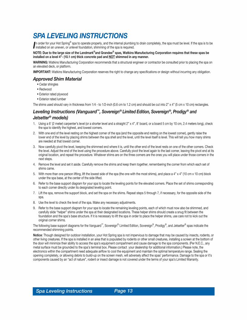
SPA LEVELING INSTRUCTIONSIn order for your Hot Spring® spa to operate properly, and the internal plumbing to drain completely, the spa must be level. If the spa is to be
installed on an uneven, or unlevel foundation, shimming of the spa is required.
NOTE: Due to the large size of the Landmark®and Grandee® spas, Watkins Manufacturing Corporation requires that these spas beinstalled on a level 4”- (10.1 cm) thick concrete pad and NOT shimmed in any manner.
WARNING: Watkins Manufacturing Corporation recommends that a structural engineer or contractor be consulted prior to placing the spa onan elevated deck, or platform.
IMPORTANT: Watkins Manufacturing Corporation reserves the right to change any specifications or design without incurring any obligation.
Approved Shim Material• Cedar shingles• Redwood• Exterior rated plywood• Exterior rated lumber
The shims used should vary in thickness from 1/4 - to 1/2-inch (0.6 cm to 1.2 cm) and should be cut into 2” x 4” (5 cm x 10 cm) rectangles.
Leveling Instructions (Vanguard™, Sovereign® Limited Edition, Sovereign®, Prodigy® andJetsetter® models)1. Using a 6’ (2 meter) carpenter’s level (or a shorter level and a straight 2” x 4”, 8’ board, or a board 5 cm by 10 cm, 2.4 meters long), check
the spa to identify the highest, and lowest corners.
2. With one end of the level resting on the highest corner of the spa (and the opposite end resting on the lowest corner), gently raise thelower end of the level by placing shims between the spa shell and the level, until the level itself is level. This will tell you how many shimsare needed at that lowest corner.
3. Now carefully pivot the level, keeping the shimmed end where it is, until the other end of the level rests on one of the other corners. Checkthe level. Adjust the end of the level using the procedure above. Carefully pivot the level again to the last corner, leaving the pivot end at itsoriginal location, and repeat the procedure. Whatever shims are on the three corners are the ones you will place under those corners in thenext steps.
4. Remove the level and set it aside. Carefully remove the shims and keep them together, remembering the corner from which each set ofshims came.
5. With more than one person lifting, lift the lowest side of the spa (the one with the most shims), and place a 4” x 4” (10 cm x 10 cm) blockunder the spa base, at the center of the side lifted.
6. Refer to the base support diagram for your spa to locate the leveling points for the elevated corners. Place the set of shims correspondingto each corner directly under its designated leveling point.
7. Lift the spa, remove the support block, and set the spa on the shims. Repeat steps 5 through 7, if necessary, for the opposite side of thespa.
8. Use the level to check the level of the spa. Make any necessary adjustments.
9. Refer to the base support diagram for your spa to locate the remaining leveling points, each of which must now also be shimmed, andcarefully slide “helper” shims under the spa at their designated locations. These helper shims should create a snug fit between thefoundation and the spa’s base structure. If it is necessary to lift the spa in order to place the helper shims, use care not to kick out theoriginal corner shims.
The following base support diagrams for the Vanguard™, Sovereign® Limited Edition, Sovereign®, Prodigy®, and Jetsetter® spas indicate therecommended shimming points.
Notice: Though designed for outdoor installation, your Hot Spring spa is not impervious to damage that may be caused by insects, rodents, orother living creatures. If the spa is installed in an area that is populated by rodents or other small creatures, installing a screen at the bottom ofthe door will minimize their ability to access the spa’s equipment compartment and cause damage to the spa components. (Per N.E.C., anymetal surface must be grounded to the spa’s terminal box. Please contact your dealership for additional information.) Please note, theelectronics within the compartment need adequate airflow to cool the equipment and maintain the optimal temperature range. Sealing theopening completely, or allowing debris to build-up on the screen mesh, will adversely affect the spas’ performance. Damage to the spa or it’scomponents caused by an “act of nature”, rodent or insect damage is not covered under the terms of your spa’s Limited Warranty.
Page 14
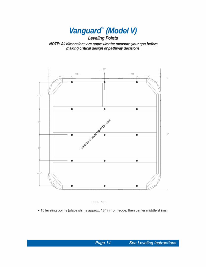
Vanguard™ (Model V)Leveling Points
NOTE: All dimensions are approximate; measure your spa beforemaking critical design or pathway decisions.
• 15 leveling points (place shims approx. 18” in from edge, then center middle shims).
UPSIDE D
OWN V
IEW
OF S
PA
Spa Leveling Instructions

Page 15Spa Leveling Instructions
Sovereign® (Model I & ILE)Leveling Points
NOTE: All dimensions are approximate; measure your spa beforemaking critical design or pathway decisions.
• 15 leveling points (place shims approx. 18” in from edge, then center middle shims).

Page 16
Prodigy® (Model H)Leveling Points
NOTE: All dimensions are approximate; measure your spa beforemaking critical design or pathway decisions.
Spa Leveling Instructions
• 10 leveling points (place shims approx. 15” in from edge, then center middle shims).

Page 17
Jetsetter® (Model J)Leveling Points
NOTE: All dimensions are approximate; measure your spa beforemaking critical design or pathway decisions.
Spa Leveling Instructions
• 10 leveling points (place shims approx. 15” in from edge, then center middle shims).

Page 18
ELECTRICAL REQUIREMENTS ANDPRECAUTIONSYour Hot Spring® spa has been carefully designed to give you maximum safety against electrical shock. Connecting the spa to an improperly
wired circuit will negate many of the spa’s safety features. Improper wiring may also cause electrocution, risk of fire, and other risks of injuries.Please read and follow the electrical installation requirements and instructions for your specific spa model completely!
SERVICE NOTE: All Hot Spring spa models are equipped with a power indicator which, in addition to showing the spa has power to it, has adiagnostic function as well. It will begin blinking if the heater high-limit thermostat has tripped. If the power indicator light is blinking, follow theinstructions in the Troubleshooting section to identify and correct the cause. The power indicator will stop blinking once the problem has beencorrected.
230 VOLT PERMANENTLY CONNECTED MODELS• Landmark® (Model S) • Vanguard™ (Model V)• Grandee® (Model G) • Sovereign® Limited Edition (Model ILE)HOT SPRING SPAS MUST BE WIRED IN ACCORDANCE WITH ALL APPLICABLE LOCAL ELECTRICAL CODES. ALL ELECTRICAL WORKSHOULD BE DONE BY AN EXPERIENCED, LICENSED ELECTRICIAN. WE RECOMMEND THE USE OF APPROPRIATE ELECTRICAL CONDUIT,FITTINGS, AND WIRE FOR ALL CIRCUITS.
An electrical subpanel containing two GFCI breakers is included with each 230 volt spa. We recommend that this subpanel be used to supplypower and protect the spa.
This subpanel requires a 50 amp, single phase, 230 volt, four wire service (two line, one neutral, one ground). The grounding conductor must be atleast the same gauge as the line conductors, but not less than #10 AWG. A minimum #10 AWG solid copper bond wire is also required.
Mount the subpanel in the vicinity of the spa, but not closer than five feet away, in accordance with all local codes. (N.E.C. 680-38 to 41-A-3)
INSTALLATION INSTRUCTIONS1. To connect the electrical service, first remove the screws from the equipment compartment door. Carefully pull the door panel away and
down in order to remove it completely from the spa.
2. Locate the IQ 2020™ spa control box. Loosen the screws on the front of the control box. Remove the screws and the control box cover.
3. Route the electrical service from the subpanel into the spa equipment compartment. Position the conduit in the recess provided between theframe and door. Install the supply conduit so as not to block the drain valve.
NOTE: The subpanel must be placed in sight of the spa, at a minimum distance of five feet away.
4. Connect the supply conduit to the bottom of the IQ 2020™ spa control box, using a minimum of 3/4” liquid-tight, flex conduit fittings.
WIRING CONNECTIONS1. Identify the TB-1 terminal block, located inside the IQ 2020™ control box at the lower left-hand corner.
2. Connect the #12 AWG, BLUE wire, from the subpanel 20 amp breaker, terminal L1 to TB-1, terminal 2.
3. Connect the #12 AWG, RED wire, from the subpanel 20 amp breaker, terminal L2 to TB-1, terminal 4.
4. Connect the #12 AWG, WHITE wire, from the subpanel 20 amp breaker, terminal N (load neutral) to TB-1, terminal 5.
NOTE: The WHITE neutral wire must be attached to the LOAD neutral on the 230 volt, 20 amp breaker (not to the neutral bus bar in the subpanel).The WHITE neutral wire coming from the breaker itself is already connected to the neutral bus bar.
5. Connect the #10 AWG, BLUE wire, from the subpanel 30 amp breaker, terminal L1 to TB-1, terminal 1.
6. Connect the #10 AWG, RED wire, from the subpanel 30 amp breaker, terminal L2 to TB-1, terminal 3.
7. Connect the #10 AWG, GREEN wire, from the subpanel GROUND bar to TB-1, system ground terminal.
8. Using the pressure wire connector provided on the outside of the control box, bond the spa to all exposed metal equipment or fixtures,handrails, and the concrete pad (if applicable) per N.E.C. Article 680 and local codes.
9. Replace the control box cover and securely tighten the fastening screws. Close and secure the equipment compartment door.
WARNING: FILL THE SPA WITH WATER BEFORE TURNING ON THE POWER.
Once your spa has been filled with water, turn it on and test all of the circuit breakers.
NOTE: If both breakers immediately trip, verify that the #12 AWG WHITE neutral wire is connected from TB-1 terminal 5 to the L1 (load neutral)terminal of the 20 amp subpanel breaker. Each breaker should be tested prior to each use. Here’s how:
Electrical Requirements

Page 19Electrical Requirements
1. Push the “TEST” button on each GFCI breaker, and observe it click OFF.
2. Wait 30 seconds, then push the breaker switch to the OFF (down) position (to ensure that it has completely disengaged), then push thebreaker switch to the ON (up) position. If you don’t wait 30 seconds, the spa’s power indicator may continue to blink – try again.
If any of the GFCI breakers fails to operate in this manner, your spa may have an electrical malfunction, and you may be at risk of electrical shock.Turn off all circuits and do not use the spa until the problem has been corrected by an authorized service agent.
WARNING: Removing, or bypassing any GFCI breaker will result in an unsafe spa and will void the spa’s warranty.
IMPORTANT: Should you ever find the need to move or relocate your Hot Spring® spa, it is essential that you understand and apply theseinstallation requirements. Your Hot Spring spa has been carefully engineered to provide maximum safety against electric shock. Remember,connecting the spa to an improperly wired circuit will negate many of its safety features.
NOTE: Long wiring runs may require larger-gauge wire than stated. We recommend using a maximum 3% voltage drop when calculating wiregauge requirements.
12
34
5
GRD
Landmark® (Model S), Grandee® (Model G), Vanguard™ (Model V), and Sovereign® LimitedEdition (Model ILE) 230 volt permanently connected models
WARNING! The exact physical location of the terminals on the GFCIbreaker will vary between manufacturers. Connecting the hot wire to the
neutral terminal will cause irreversible damage to the control box.
*PROVIDED WITH SPA. NOTE: ALL WIRING SHOULD BE COPPER.NOTE: The wire connections to GFCI breakers are for reference only. Always ensure the white neutral wire is connected to the load neutral of the 20 amp breaker.** Refer to NEC 250-122 (table)
**

Electrical Requirements
115-230 VOLT CONVERTIBLE MODELS• Sovereign® (Model I)• Prodigy® (Model H)• Jetsetter® (Model J)230 VOLT CONVERSION INSTRUCTIONSRefer to the following instructions to convert a 115 volt spa to a 230 volt spa.
NOTE: Converting the spa to 230 volt operation should only be done by anauthorized service agent or a qualified electrician.
Required Parts: (3) P.N. 36021 program jumpers (staged on JP jumpers in IQ 2020™
control box) and (1) P.N. 20679 or 37087 subpanel (230 volt)
1. Disconnect the power cord from the house receptacle.
2. Remove the screws and open the equipment compartment door.
3. Remove the screws on the front of the IQ 2020™ spa control box.
4. Open the control box cover.
5. Identify TB-1, located in the lower left-hand corner inside the control box.
6. Refer to Figure 1, item A. Remove both the 3 pin jumper attached to terminals 3,4, and 5, and the 2 pin jumper attached to terminals 1 and 2.
7. Refer to Figure 1, item B. Remove the power cord wires from terminals 2, 4 andthe system ground terminal.
8. Refer to Figure 1, item C. Attach the 2 pin jumper to terminals 4 and 5.
9. Unscrew the power cord strain relief and remove the power cord from theaccess hole in the control box.
10. On the large circuit board, locate the program jumpers, JP-1 through JP-10 (positioned near the center of the circuitboard, with JP-1 being the top jumper).
WARNING: Do not allow pliers to contact any electronic components inside the control box.
11. Use a pair of needlenose pliers to place the program jumpers as shown in Figure 2 (use Watkins P.N. 36021).
NOTE: The program jumpers JP-1, JP-2, JP-3 and JP-4 must be set correctly for the spa to operate. Disregard jumpers 5through 10, they have been factory set.
Converting from 115 volts to 230 volts changes the voltage supplied to the heater from 115 volts to 230 volts. The jetpump will continue to operate at 115 volts.
INSTALLATION INSTRUCTIONS1. To connect the electrical service, first remove the screws from the equipment compartment door. Carefully pull the
door panel away and remove it from the spa.
2. Locate the IQ 2020™ spa control box. Loosen the screws on the front of the control box. Remove the screws and thecontrol box cover.
3. Route the electrical service from the subpanel into the spa equipment compartment. Position the conduit in the recess provided between theframe and the door.
NOTE: The subpanel must be placed in sight of the spa, at a minimum distance of 5 feet away.
4. Connect the supply conduit to the bottom of the IQ 2020™ spa control box, using a minimum of 3/4” liquid-tight, flex conduit fittings.
WIRING CONNECTIONS1. Identify the TB-1 terminal block, located at the lower left-hand corner of the control box.
2. Connect the #12 AWG, BLUE wire from the subpanel 20 amp breaker, terminal L1 to TB-1 terminal 2.
3. Connect the #12 AWG, WHITE wire from the subpanel 20 amp breaker, terminal N (load neutral) to TB-1, terminal 5.
NOTE: The WHITE neutral wire must be attached to the load neutral on the 115 volt, 20 amp breaker (not the neutral bus bar in the subpanel). TheWHITE pigtail (neutral) wire from the 20 amp breaker is already connected to the neutral bus bar.
Page 20 Electrical Requirements

Page 21
4. Connect the #10 AWG, BLUE wire from the subpanel 30 amp breaker, terminal L1 to TB-1, terminal 1.
5. Connect the #10 AWG, RED wire from the subpanel 30 amp breaker, terminal L2 to TB-1, terminal 3.
6. Connect the #10 AWG, GREEN wire from the subpanel ground bar to TB-1 system ground terminal.
7. Bond the spa to all exposed metal equipment or fixtures, handrails, and concrete pad per N.E.C. Article 680 and all local codes.
8. Replace the control box cover and securely tighten the fastening screws. Close and secure the equipment compartment door.
WARNING: FILL THE SPA WITH WATER BEFORE TURNING ON THE POWER.
Once your spa has been filled with water, turn it on and test all the circuit breakers.
NOTE: If both breakers immediately trip, verify that the #12 AWG WHITE neutral wire is connected from TB-1 terminal 5 to the L1 (load neutral)terminal of the 20 amp subpanel breaker. Each breaker should be tested prior to each use. Here’s how:
1. Push the “TEST” button on each GFCI breaker, and observe it click off.
2. Wait 30 seconds, then push the breaker switch to the OFF (down) position (to ensure that it has completely disengaged), then push thebreaker switch to the ON (up) position. If you don’t wait 30 seconds, the spa’s power indicator may continue to blink – try again.
If any of the GFCI breakers fails to operate in this manner, your spa may have an electrical malfunction, and you may be risking electrical shock.Turn off all circuits and do not use the spa until the problem has been corrected by an authorized service agent.
12
34
5Sovereign® (Model I), Prodigy® (Model H) and Jetsetter® (Model J)
230 volt converted models
WARNING! The exact physical location of the terminals on the GFCIbreaker will vary between manufacturers. Connecting the hot wire to the
neutral terminal will cause irreversible damage to the control box.
*AVAILABLE FROM DEALER. NOTE: ALL WIRING SHOULD BE COPPER.NOTE: The wire connections to GFCI breakers are for reference only. Always ensure the white neutral wire is connected to the load neutral of the 20 amp breaker.
** Refer to NEC 250-122 (table)
Electrical Requirements
Page 22
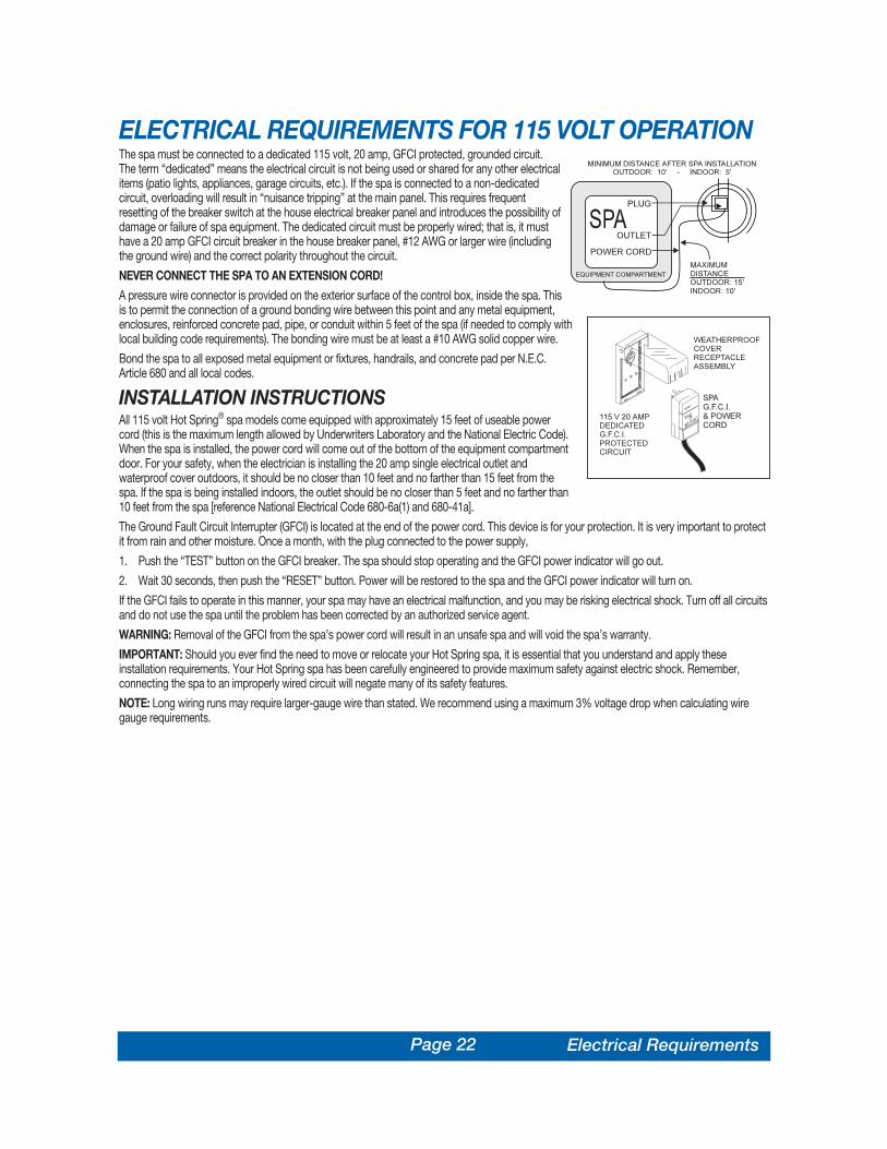
ELECTRICAL REQUIREMENTS FOR 115 VOLT OPERATIONThe spa must be connected to a dedicated 115 volt, 20 amp, GFCI protected, grounded circuit.The term “dedicated” means the electrical circuit is not being used or shared for any other electricalitems (patio lights, appliances, garage circuits, etc.). If the spa is connected to a non-dedicatedcircuit, overloading will result in “nuisance tripping” at the main panel. This requires frequentresetting of the breaker switch at the house electrical breaker panel and introduces the possibility ofdamage or failure of spa equipment. The dedicated circuit must be properly wired; that is, it musthave a 20 amp GFCI circuit breaker in the house breaker panel, #12 AWG or larger wire (includingthe ground wire) and the correct polarity throughout the circuit.
NEVER CONNECT THE SPA TO AN EXTENSION CORD!
A pressure wire connector is provided on the exterior surface of the control box, inside the spa. Thisis to permit the connection of a ground bonding wire between this point and any metal equipment,enclosures, reinforced concrete pad, pipe, or conduit within 5 feet of the spa (if needed to comply withlocal building code requirements). The bonding wire must be at least a #10 AWG solid copper wire.
Bond the spa to all exposed metal equipment or fixtures, handrails, and concrete pad per N.E.C.Article 680 and all local codes.
INSTALLATION INSTRUCTIONSAll 115 volt Hot Spring® spa models come equipped with approximately 15 feet of useable powercord (this is the maximum length allowed by Underwriters Laboratory and the National Electric Code).When the spa is installed, the power cord will come out of the bottom of the equipment compartmentdoor. For your safety, when the electrician is installing the 20 amp single electrical outlet andwaterproof cover outdoors, it should be no closer than 10 feet and no farther than 15 feet from thespa. If the spa is being installed indoors, the outlet should be no closer than 5 feet and no farther than10 feet from the spa [reference National Electrical Code 680-6a(1) and 680-41a].
The Ground Fault Circuit Interrupter (GFCI) is located at the end of the power cord. This device is for your protection. It is very important to protectit from rain and other moisture. Once a month, with the plug connected to the power supply,
1. Push the “TEST” button on the GFCI breaker. The spa should stop operating and the GFCI power indicator will go out.
2. Wait 30 seconds, then push the “RESET” button. Power will be restored to the spa and the GFCI power indicator will turn on.
If the GFCI fails to operate in this manner, your spa may have an electrical malfunction, and you may be risking electrical shock. Turn off all circuitsand do not use the spa until the problem has been corrected by an authorized service agent.
WARNING: Removal of the GFCI from the spa’s power cord will result in an unsafe spa and will void the spa’s warranty.
IMPORTANT: Should you ever find the need to move or relocate your Hot Spring spa, it is essential that you understand and apply theseinstallation requirements. Your Hot Spring spa has been carefully engineered to provide maximum safety against electric shock. Remember,connecting the spa to an improperly wired circuit will negate many of its safety features.
NOTE: Long wiring runs may require larger-gauge wire than stated. We recommend using a maximum 3% voltage drop when calculating wiregauge requirements.
Electrical Requirements

Page 23Operating Instructions
OPERATING INSTRUCTIONSHot Spring® spas are manufactured in two different electrical versions, 230 volt permanently connected, and 115 / 230 volt convertible models.
The largest spa models, the Landmark®, Grandee®, Vanguard™, and Sovereign® Limited Edition are available only as 230 volt permanentlyconnected models (these spas can not be converted to 115 volt systems), and utilize a continuous heating system. This means that the heatermay turn on while the jet pump is operating, unlike 115 volt models where the heater will automatically be turned off when the the jet pump isturned on.
The remaining spa models, the Sovereign®, Prodigy®, and Jetsetter®, are available as 115v / 230v convertible systems, meaning that a 115 voltmodel can be converted to a 230 volt model. The benefit of operating in 230 volt mode is an increase in the wattage (heater capacity) of theheater, allowing the heater to run when the jet pump is operating, which keeps your water hotter longer when the jets are in use. Contact yourauthorized Hot Spring dealer for the requirements to convert between electrical systems at your home.
IMPORTANT: Improper conversion from one system to another may damage the spa’s electrical components. Always consult your authorizedHot Spring dealer prior to converting from one electrical system to another.
230 VOLT PERMANENTLY CONNECTED MODELS• Landmark® (Model S) • Vanguard™ (Model V)• Grandee® (Model G) • Sovereign® Limited Edition (Model ILE)The 230 volt permanently connected models come with a subpanel which contains two GFCI circuit breakers - a 20 amp / 230 volt GFCI circuitbreaker for the jet pump and control circuit, and a 30 amp / 230 volt GFCI circuit breaker for the heating system. The subpanel and spa must be“hardwired” by a licensed electrician using appropriate wire, conduit, and fittings.
The Landmark®’s and Grandee®’s dual 1.65 HP Wavemaster® 7000 jet pumps allow you to operate each half of the jet system separately, or bothhalves simultaneously. Each half of the jet system has two different jet menus which are selected with the individual SmartJet® levers. This featureallows you to select any one of four menus or a combination of menus when using the spa. The Vanguard™ and Sovereign® Limited Edition use asingle 2.5 HP Wavemaster® 9000 jet pump and offer two jet menus.
The Landmark®, Grandee®, Vanguard™, and Sovereign® Limited Edition are equipped with a No-Fault® 6000 stainless steel, high watt densityheater. The heating system consists of a 6,000 watt (6 kW) heater, an energy efficient low-flow circulation pump, and a high-limit thermostat andheater thermal cut-off for protection of user and equipment.
In each of these spas, the heater will turn on while the jet pump is operating (after a 1-1/2 degree temperature drop) to help maintain the watertemperature during spa use. Factors such as the number of people using the spa, the air temperature, and the length of time the pump is operatedwill affect the heating system’s ability to maintain the water temperature.
115/230 VOLT CONVERTIBLE MODELS• Sovereign® (Model I)• Prodigy® (Model H)• Jetsetter® (Model J)The 115 / 230 volt convertible Hot Spring spa models come configured with a familiar 115 volt electrical system, with a GFCI plug at the end of acord. The GFCI plug contains a GFCI breaker for user and equipment protection. The 115 volt configuration requires a dedicated outlet to supplypower to the spa.
These models can be converted to 230 volt operation with the addition of a subpanel and a control box wiring change. Consult your dealer beforeattempting to convert from 115 volt operation to 230 volt operation. Any damage to the spa from improper conversion is not covered under thewarranty.
In the 115 volt configuration, either the heater, or the jet pump can operate, but they can’t work at the same time. In a 115 volt system, as long asthe jet pump is activated, the heater will not turn on. On the other hand, when the spa is converted to operate in the 230 volt configuration, theheater and jet pump can operate simultaneously.
Each convertible spa model is equipped with a No-Fault® 6000 stainless steel, high watt density heater. The heater will operate at 1500 wattswhen the spa is configured as a 115 volt cord-and-plug connected model, and at 6000 watts when the spa is configured as a 230 volt convertedmodel. The heating system consists of the No-Fault® 6000 heater, an energy efficient low-flow circulation pump, and a high-limit thermostat andheater thermal cut-off for user and equipment protection.
All three of these models feature a Wavemaster® jet pump to operate their jet systems. The Sovereign®, Prodigy®, and Jetsetter® models use the1.65 HP Wavemaster® 7000. The SmartJet® lever is used to operate the jet menus available in these models.

Page 24
START-UP AND REFILL PROCEDURESYour Hot Spring® spa has been thoroughly tested during the manufacturing process to ensure reliability and long-term customer satisfaction. Asmall amount of water may have remained in the plumbing after testing and, as a result, may have spotted the spa shell or the spa siding prior todelivery. Before filling the spa, wipe the spa shell clean with a soft rag.
The following instructions must be read and followed exactly to ensure a successful start-up or refill.
CAUTIONS• Do not fill the spa with hot water, as tripping of the high-limit thermostat may result.• DO NOT CONNECT POWER TO AN EMPTY SPA. Power to the spa automatically activates critical components within the spa,
such as controls, heater, circulation pump, and other systems. If power is supplied to these components prior to the spa beingfilled, the components will be damaged, and this may result in a non-warranty component failure.
• Do not use your spa after filling until all of the steps listed below are completed.• Do not add chlorine if treating your spa with polyhexamethylene biguanide (Biguanide, PHMB, eg. BaquaSpa™) sanitizer.
1. Close all drains and fill the spa with water through the filter compartment. The water level of your Hot Spring spa should be maintained at alevel equal to the middle of the tile. The water level for the Sovereign® Limited Edition is 4 1/2” below the bar top, or just below the pillow.
RECOMMENDED: Use the FreshStart®10,000 pre-filter to remove unwanted contaminants from the tap water.
IMPORTANT: Watkins Manufacturing Corporation does not recommend that the spa be filled with “softened” water, as this may damage thespa’s equipment.
2. AFTER the spa has been filled with water and the equipment compartment door is secured, power must be applied to the spa. • 115 volt models: Connect the GFCI to the waterproof receptacle and push the RESET button on the GFCI.• 230 volt models: Open the door of the electrical subpanel and reset the 20 amp GFCI breaker, verify that the system is primed (see step 3),
then reset the 30 amp breaker. Close and secure the subpanel door.
3. The jet pump, heating system, and all internal plumbing will achieve a partial prime as the spa is filled. To check the operation of the jetsystem and to purge any remaining air from the heating system, push the JETS button (for the Landmark® and Grandee®, push both JETS 1and JETS 2 buttons) to make the jet pump run on high speed for one minute. Once the jet system is fully operational (as indicated by strong,non-surging jets), priming of the spa is complete. Weak or surging jets are an indication of a low water level condition or clogged filtercartridges.
IMPORTANT: Be sure the air control valves (see illustration in Comfort Control® system section) are open by turning each one clockwise andchecking to see that the SmartJet® lever is pointing to the 3 o’clock position (see illustration in SmartJet® system section).
4. Adjust Total Alkalinity (TA) to 125 ppm, Calcium Hardness (CH) to 150 ppm, then spa water pH to between 7.4 and 7.6. These procedures arelisted in the “Water Quality and Maintenance” section.
IMPORTANT: Add spa water chemicals directly into the filter compartment with the jet pump on high speed for at least ten minutes.
OPERATION NOTE: Adjusting the Total Alkalinity as the first step is important, as out-of-balance TA will affect your ability to adjust the pHcorrectly and will prevent the sanitizer from operating effectively.
5. Superchlorinate the spa water by adding 1-1/2 teaspoons of chlorine (sodium dichlor) per 250 gallons of spa water. Use the jet button marked“CLEAN” to circulate the spa water for a ten-minute period.
6. During the super-chlorination period, rotate the SmartJet® lever(s) through each of their operating positions, letting the spa water circulate(with jets on) for equal periods of time. For example, if your spa has four operating positions, leave the SmartJet® lever in each position forapproximately two to three minutes.
OPERATION NOTE: The Landmark®, Grandee®, Vanguard™, Sovereign® Limited Edition , and Jetsetter® SmartJet® levers are designed tooperate in the 3 o’clock and 9 o’clock positions. The Sovereign® and Prodigy® SmartJet® levers are designed to operate in the 3 o’clock, 6o’clock, 9 o’clock, and 12 o’clock positions.
7. Set the temperature control to the desired temperature (between 100°F and 104°F), then place the vinyl cover on the spa and allow the watertemperature to stabilize (approximately 24 hours). Make sure you secure the cover in place using the cover locks. Periodically check the spawater temperature. When the water temperature climbs above 90°F, proceed to the next step.
8. Rotate the SmartJet® lever(s) to the primary position (3 o’clock) and turn on the CLEAN cyle for ten minutes to circulate the spa water. After theclean cycle is complete, test the spa water for Free Available Chlorine (FAC) residual. If the residual is between 3 and 5 ppm on the test strips(found in the test kit) go on to the next step. If the residual is less than 3 ppm, superchlorinate the spa water by adding 1-1/2 teaspoons ofchlorine (sodium dichlor) per 250 gallons of spa water. Use the jet button marked “CLEAN” to circulate the spa water for a ten-minute period.
9. Rotate the SmartJet® lever(s) to next position and let the spa water circulate (using the jet) for ten minutes. Test the spa water for FreeAvailable Chlorine (FAC) residual. If the residual is between 3 and 5 ppm on the test strips (found in the test kit) go on to the next step. If theresidual is less than 3 ppm, superchlorinate the spa water by adding 1-1/2 teaspoons of chlorine (sodium dichlor) per 250 gallons of spawater. Then use the jet button marked “CLEAN” to circulate the spa water for a ten-minute period. Repeat this procedure until all SmartJet®
lever operating positions have been tested.
Operating Instructions

Page 25
10. Recheck the Total Alkalinity (TA) at 125 ppm, Calcium Hardness (CH) at 150 ppm, then spa water pH at between 7.4 and 7.6.
Operational Note: Make sure you adjust your Total Alkalinity first, as an out-of-balance condition will affect your ability to adjust the pHcorrectly, and will prevent the sanitizer from operating effectively. The spa is ready for use when the spa water has circulated througheach SmartJet® lever operating position and the chlorine level remains between 3 ppm and 5 ppm.
11. The spa temperature is pre-programmed to reach 102°F, and will normally do so within 18 to 24 hours. You may raise the water temperatureby pressing the TEMP (+) button on the control panel, or lower it by pressing TEMP (-) button. After a few hours, the water temperature willremain within 1-1/2 degrees of your selected temperature. To prevent tampering, you can lock your desired temperature setting. Refer to theControl Panel section for details.
NOTE: Allowing the jet pump to operate for long uninterrupted periods of time with the cover in place will cause a rise in the spa watertemperature. All spas are equipped with a safety device to reduce the risk of component damage or personal injury, should the jet pump beleft running continuously for a long period of time. After two hours of continuous operation, the jet pump controller will automatically turn offthe jet pump.
SMARTJET ® SYSTEMWith your Hot Spring® spa’s exclusive SmartJet® system, you can control the massaging action ofyour spa. Using the SmartJet® lever, the jets are activated in sets, known as jet systems.
On the Vanguard™, Grandee®, Landmark®, Sovereign® Limited Edition, and Jetsetter®, eachSmartJet® lever controls two jet systems. To access a jet system, simply turn the SmartJet®
lever to the 3 o’clock or 9 o’clock position. On the Sovereign® and Prodigy®, the singleSmartJet® lever has four positions to access the four jet systems. The jet systems are selected byturning the SmartJet® lever to the 3, 6, 9 or 12 o’clock position (facing the spa). Please consult the jetsystem menus on the following pages to determine which jets are activated with each SmartJet® leverposition. Or just jump in and play – turn the lever(s) and see what happens.
COMFORT CONTROL® SYSTEMThe Comfort Control® system allows you to control the intensity of the massage at each jet byadjusting the mixture of air and water. Jets with an adjustable faceplate are controlled byturning the faceplate clockwise for a stronger flow, counterclockwise for a softer flow. Jetswithout an adjustable faceplate are controlled by a Comfort Control® lever. The Precision®
jets are controlled by dark teal, forest green or blue Comfort Control® levers. The Moto-Massage® jet is controlled by seafoam green or light grey Comfort Control® levers. TheJetStream® jet is controlled by a steel blue or dark grey lever. The DreamJet® ComfortControl® lever is controlled by a dark teal, forest green or blue Comfort Control® lever.
NOTE: The intensity of the JetStream® jets in the footwell can not be altered.
Turn the Comfort Control® lever clockwise to increase the intensity of the jet and counterclockwise to decrease the intensity.
JETSMOTO-MASSAGE® JET (Not available on Prodigy®)The Moto-Massage® jet automatically travels up and down in a sweeping motion, simulating the natural stroking effects of a manual massage. Theintensity and speed of the Moto-Massage® jet may be adjusted by turning the Comfort Control® lever with the seafoam green or light grey dot.
The Moto-Massage® jet has been factory adjusted to provide maximum hydromassage, and to achieve full vertical travel with its Comfort Control®
lever in the full air volume position. Should the Moto-Massage® jet not achieve full vertical travel and the problem is not a closed air control valveor clogged filter cartridge, then your Hot Spring Service Center should be contacted.
SERVICE NOTE: A slow or non-moving Moto-Massage® jet may indicate that the filter cartridge pores are obstructed with dirt, body oils, orcalcification. Follow the filter cartridge cleaning procedures in the Spa Care and Maintenance section of this manual.
ACCESSORY NOTE: For a different-feeling massage, ask your dealer about the HydroPulse® option; an alternative faceplate for your Moto-Massage® jet.
HYDROMASSAGE JETSThe Hydromassage jets have two different nozzle options: directional and dual port rotary. The directional nozzle allows you to aim the water in thedirection that feels best. The dual port rotary nozzle divides the water flow into two streams, and then spins.
ACCESSORY NOTE: Your Hot Spring dealer stocks hydromassage jet kits which can easily be installed in your spa to modify your jets fromdirectional to dual port rotary.
12 o’clock
3 o’clock9 o’clock
6 o’clock
Dot color indicates which jets are controlled
Increase AirVolume
Decrease AirVolume
Operating Instructions

Page 26
SOOTHING SEVEN® JETThe Soothing Seven® jet is another unique feature of Hot Spring spas. Its seven outlets are designed to massage the muscles in the upper backand shoulders, gently and thoroughly. Turn the faceplate clockwise to increase the jet pressure and counterclockwise to decrease the jet pressure.
PRECISION® JETSPrecision® jets are located above Moto-Massage® jets and in groups of various sizes in the Landmark®, Grandee®, Vanguard™, Sovereign® LimitedEdition, Sovereign® , and Prodigy® models. They are designed to perform a soft, soothing massage on your back and shoulders. Adjust the pressureof the Precision® jets using the Comfort Control® lever with the dark teal, forest green, or blue dot (located closest to the Precision® jets).
Refer to the drawings on the following pages to familiarize yourself with the SmartJet® system menus for your spa. Please note that the SmartJet®
lever side of the spa is always considered the front when referring to the locations of the different types of jets and jet systems. The clockpositions are correct when facing the spa, standing at the SmartJet® lever.
JETSTREAM® JETThe JetStream® jet is a large orifice hydromassage jet designed to put maximum massaging action on a specific area of the body. It is located in thelower part of the spa to afford optimal access for the massaging of feet, legs, hips, and lower back. The intensity of the JetStream® jets can bealtered (except the ones found in the FootWell® system) using only the Comfort Control® lever with the steel blue or dark grey lever. JetStream®
jets located in the FootWell are not adjustable.
DREAMJET® MASSAGE PILLOWUnique to the Landmark Spa, the DreamJet® massage pillow provides an adjustable dry neck massage. The strength of the massage is adjustedby turning the left Comfort Control® lever (located closest to the DreamJet® massage pillow). Increasing the air volume will increase the intensity ofthe massage, while decreasing the air volume will lessen the intensity, providing soothing relaxation.
OPERATIONAL NOTE: The height of the DreamJet® massage pillow is adjustable, this provides the same comfort for different users. To adjustthe height of the pillow, simply push in on the button directly below the pillow to raise or lower the entire assembly (see illustration below).
DOS AND DON’TS• DO change the height of the DreamJet® massage pillow only when the jets are off.• DO push the faceplate in for height adjustment, don’t pull up or push down on the button.• DON’T push or pull on the black membrane to raise or lower the DreamJet® massage pillow.• DON’T run the spa if the black membrane is damaged or removed.• DON’T sit on the DreamJet® massage pillow.
To adjust height, push in and hold the button
While button is depressed, raise orlower entire assembly at the
locations shown
DO NOT adjust the assembly bygrabbing the black membrane
Operating Instructions

Page 27Jet Menus
Landmark® (Model S) Jet System MenuLandmark® (Model S) Jet System Menu
Left Jet Pump–Jet System 1Left SmartJet® lever in the 3 o’clock position
• 1 directional hydromassage jet on left wall• 2 Soothing Seven® jets on left wall• 1 Moto-Massage® jet on right front• 4 Precision® jets on right wall• 1 DreamJet® massage pillow on right front
Left Jet Pump–Jet System 2Left SmartJet® lever in the 9 o’clock position
• 3 Jet-Cluster™ system on left front (2 Soothing Seven®
jets, 1 directional hydromassage)• 1 JetStream® jet on right wall• 1 DreamJet® massage pillow on right front
Right Jet Pump–Jet System 1Right SmartJet® lever in the 3 o’clock position
• 3 Jet-Cluster™ system on left rear (2 dual port rotary,1 directional hydromassage)
• 1 JetStream® jet in FootWell® system• 10 Precision® jets on right rear wall• 2 Precision® jets in left rear seat
Right Jet Pump–Jet System 2Right SmartJet® lever in the 9 o’clock position
• 2 dual port rotary jets on left rear wall• 10 Precision® jets on right rear wall• 1 directional hydromassage jet on left wall• 2 Precision® jets in FootWell® system• 1 JetStream® jet in left front wall

Page 28
Left Jet Pump–Jet System 1Left SmartJet® lever in the 3 o’clock position
• 1 Moto-Massage® jet on left rear• 4 Precision® jets above left Moto-Massage® jet • 3 Jet-Cluster™ system on left wall (1 directional
hydromassage, 2 Soothing Seven®)• 2 dual port rotary jets on back wall
Left Jet Pump–Jet System 2Left SmartJet® lever in the 9 o’clock position
• 1 Moto-Massage® jet on left rear• 4 Precision® jets above left Moto-Massage® jet • 1 directional hydromassage on left wall• 2 dual port rotary jets on back wall• 1 JetStream® jet in FootWell® System• 2 Precision® jets on left seat (calf area)
Right Jet Pump–Jet System 2Right SmartJet® lever in the 9 o’clock position
• 1 Moto-Massage® jet on right rear• 4 Precision® jets above right Moto-Massage® jet• 4 Precision® jets on right wall• 10 Precision® jets on right front• 1 JetStream® jet in FootWell® System• 2 Precision® jets on right seat (calf area)
Right Jet Pump–Jet System 1Right SmartJet® lever in the 3 o’clock position
• 1 Moto-Massage® jet on right rear• 4 Precision® jets above right Moto-Massage® jet• 10 Precision® jets on right front• 1 directional hydromassage jet on back wall • 2 Precision® jets on right rear seat (calf area)• 1 JetStream® jet on right wall
Grandee® (Model G) Jet System MenuGrandee® (Model G) Jet System Menu
Jet Menus

Page 29
Vanguard™ (Model V) Jet System MenuVanguard™ (Model V) Jet System Menu
Jet System 1SmartJet® lever in the 3 o’clock position
• 1 Moto-Massage® jet on left rear• 4 Precision® jets above left Moto-Massage® jet• 1 Moto-Massage® jet on right rear• 4 Precision® jets above right Moto-Massage® jet• 3 Jet-Cluster™ system on right wall (2 dual port rotary,
1 directional hydromassage)• 2 Soothing Seven® jets on left wall• 2 Precision® jets on left rear seat (calf area)• 2 Precision® jets on right rear seat (calf area)
Jet System 2SmartJet® lever in the 9 o’clock position
• 1 Moto-Massage® jet on left rear• 4 Precision® jets above left Moto-Massage® jet• 1 Moto-Massage® jet on right rear• 4 Precision® jets above right Moto-Massage® jet• 10 Precision® jets on back wall• 2 JetStream Jets® in FootWell® System
Jet Menus

Page 30
Sovereign® Limited Edition (Model ILE) Jet System MenuSovereign® Limited Edition (Model ILE) Jet System Menu
Jet System 2SmartJet® lever in the 9 o’clock position
• 1 Moto-Massage® jet on right rear• 4 Precision® jets above Moto-Massage® jet• 2 JetStream® jets in FootWell® System• 1 directional hydromassage jets on left wall • 3 Jet-Cluster™ system on left wall (2 dual port rotary,
1 directional hydromassage)
Jet System 1SmartJet® lever in the 3 o’clock position
• 1 Moto-Massage® jet on right rear• 4 Precision® jets above Moto-Massage® jet• 10 Precision® jets on front right• 3 directional hydromassage jets on left wall• 2 Soothing Seven® jets on back wall
Jet Menus
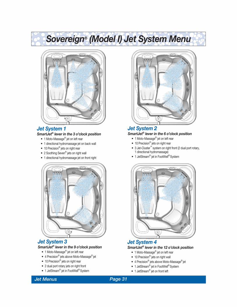
Page 31
Sovereign® (Model I) Jet System MenuSovereign® (Model I) Jet System Menu
Jet System 1SmartJet® lever in the 3 o’clock position
• 1 Moto-Massage® jet on left rear• 1 directional hydromassage jet on back wall• 10 Precision® jets on right rear• 2 Soothing Seven® jets on right wall• 1 directional hydromassage jet on front right
Jet System 3SmartJet® lever in the 9 o’clock position
• 1 Moto-Massage® jet on left rear• 4 Precision® jets above Moto-Massage® jet• 10 Precision® jets on right rear• 2 dual port rotary jets on right front• 1 JetStream® jet in FootWell® System
Jet System 2SmartJet® lever in the 6 o’clock position
• 1 Moto-Massage® jet on left rear• 10 Precision® jets on right rear• 3 Jet-Cluster™ system on right front (2 dual port rotary,
1 directional hydromassage)• 1 JetStream® jet in FootWell® System
Jet System 4SmartJet® lever in the 12 o’clock position
• 1 Moto-Massage® jet on left rear• 10 Precision® jets on right wall• 4 Precision® jets above Moto-Massage® jet• 1 JetStream® jet in FootWell® System• 1 JetStream® jet on front left
Jet Menus

Page 32
Jet System 3SmartJet® lever in the 9 o’clock position
• 1 JetStream® jet on rear wall• 3 Jet-Cluster™ system on left rear (2 dual port rotary,
1 directional hydromassage)• 2 Soothing Seven® jets on front left
Jet System 4SmartJet® lever in the 12 o’clock position
• 2 stacked directional hydromassage jets on right wall• 10 Precision® jets on right rear• 3 Jet-Cluster™ system on left rear (2 dual port rotary,
1 directional hydromassage)
Jet System 1SmartJet® lever in the 3 o’clock position
• 10 Precision® jets on right rear• 2 dual port rotary jets on left rear • 1 directional hydromassage jet on left wall• 2 Soothing Seven® jets on front left
Jet System 2SmartJet® lever in the 6 o’clock position
• 2 dual port rotary jets on left rear• 2 stacked directional hydromassage jets on right wall• 2 Soothing Seven® jets on front left
Prodigy® (Model H) Jet System MenuProdigy® (Model H) Jet System Menu
Jet Menus

Page 33
Jet System 1SmartJet® lever in the 3 o’clock position
• 1 Moto-Massage® jet on left rear• 3 Jet-Cluster™ system on front right (2 Soothing Seven®
jets, 1 directional hydromassage jet)• 1 directional hydromassage jet on back wall
Jet System 2SmartJet® lever in the 9 o’clock position
• 1 Moto-Massage® jet on left rear• 4 Precision® jets above Moto-Massage® jet • 2 Stacked hydromassage jets on back wall (1 directional
hydromassage, 1 dual port rotary)• 1 JetStream® jet on front left
Jetsetter® (Model J) Jet System MenuJetsetter® (Model J) Jet System Menu
Control PanelsVanguard™
Sovereign® Limited EditionSovereign®
Prodigy®
Jetsetter®
Landmark®
Grandee®
Control Panels

Page 34
CONTROL PANELSHot Spring® spa models are equipped with a main control panel, located on the side of the spa, and an auxiliary control panel (except Jetsetter®)located within the seating area of the spa.
The main control panel controls all of the spa functions, and uses indicator lights and an integrated LCD display to aid in determining the status ofthe spa. At night, the main control panel and display are illuminated by a soft light from the top of the panel.
The auxiliary control panel (Landmark®, Grandee®, Vanguard™, Sovereign® Limited Edition, Sovereign®, Prodigy®) is conveniently located so that auser inside the spa can operate the light or the jets.
NOTE: If the SPA LOCK function has been initiated at the main control panel, the auxiliary control panel will not operate.
MAIN CONTROL PANELThe main control panel provides a quick visual check of the spa’s status, and allows the user to set the temperature, activate the jets and light,and lock the temperature and/or spa functions.
INDICATOR LIGHTSAt a glance, the indicator lights are readily visible on the main control panel. The three indicator lights (POWER, READY and CLEAN) workindependently from the rest of the control panel display. That way, even if the control panel is off, you can simply glance at the “READY” indicatorlight to determine whether or not your spa is within the range of your set temperature.
Power Indicator: The POWER indicator is ‘on’ when the spa is properly supplied with power. It also provides a diagnostic function–a blinkingpower indicator indicates that the heater high limit has tripped, meaning that either the spa water is above its acceptable temperature range, or amalfunction has occurred within the spa (such as low circulation due to clogged filters). An ‘off’ power indicator means that there is a problem withthe spa control box or the power supplied to the spa.
Ready Indicator: The READY indicator will light when the spa water temperature is within 2-1/2°F of the set temperature, and will turn off whenthe temperature is outside of that range. If you increase or decrease the temperature setting of the spa, the ready indicator will turn off until the spatemperature reaches the acceptable range for the new set temperature. Additionally, a blinking READY indicator indicates that a problem existswith the temperature sensor.
Clean Indicator: The CLEAN indicator lights up when the CLEAN button is pressed. It remains on during the ten-minute clean cycle (used forwater maintenance), then automatically shuts off at the end of the cycle. The JET symbol will also illuminate on the display to indicate that the jetpump is on.
NOTE: When the SPA LOCK feature is activated, the CLEAN button is disabled. If the CLEAN button will not turn on the jet pump, refer to thefollowing section and verify that the SPA LOCK is off.
LOCKING FEATURESThe two locking features, TEMPERATURE LOCK and SPA LOCK, are enabled from the main control panel by pressing a specific combination ofbuttons. Once enabled, a lock will remain active until the specific button combination is applied to disable the lock. Even if power is disconnectedfrom the spa and soon thereafter reapplied (such as in a power outage) the lock will remain in place.
SPA LOCK The SPA LOCK feature deactivates all of the functions of the main and auxiliary control panels. It isgenerally used to prevent unwanted use of the spa.
To activate the SPA LOCK, press the LIGHT minus (-) and TEMP minus (-) buttons at thesame time and hold them down until the word SPA and the lock symbol are illuminatedon the display (approximately two seconds).
When the SPA LOCK is activated, if a button is pressed, the control panel willdisplay the lock symbol and the word SPA for 30 seconds, then turn off.
To deactivate the SPA LOCK, press the LIGHT minus (-) and TEMP minus (-) buttons at the same time and hold them down until the word SPAand the lock symbol are no longer illuminated on the display (approximately two seconds).
TEMPERATURE LOCKThe TEMPERATURE LOCK feature deactivates the temperature control function of the main control panel. All other functions on the main andauxiliary control panels will operate normally. TEMPERATURE LOCK is most often used by people who do not want others to tamper with orchange the set temperature of the spa water.
Operating Instructions

Page 35Operating Instructions
To activate the TEMPERATURE LOCK, press the LIGHT plus (+)and TEMP plus (+) buttons at the same time and hold them down until
the words SET TEMP, the numerical set temperature value and the lock symbol areilluminated on the display (approximately two seconds).
When the TEMPERATURE LOCK is activated, the JETS, LIGHT, and CLEANbuttons will operate normally, and the temperature setting can be viewed butcan NOT be changed. If a temperature button is pressed, the control panel willdisplay the lock symbol and the set temperature for 30 seconds, then turnoff.
To deactivate the TEMPERATURE LOCK, press the LIGHT plus (+) and TEMP plus (+)buttons at the same time and hold them down until the lock symbol is no longer illuminated on the
display (approximately two seconds).
LOCK OVERRIDEThe Lock Override feature is for spa users who normally keep the set temperature locked. Should the user wish to lock all spa controlstemporarily, the spa lock can be applied over an already-applied temperature lock. Then, when the spa lock is removed, the temperature lock willremain on, to prevent unwanted tampering with the set temperature.
MAIN CONTROL PANEL BUTTONS AND DISPLAYThe main control panel has buttons which the spa user presses to set the temperature, initiate the clean cycle, vary the intensity of the light, andactivate or deactivate the jet pump. With the exception of the CLEAN button, the control panel display responds to let you know you’ve pressed abutton, and that the selected function has been performed. After a period of non-use, pressing any button will wake up a sleeping display, as wellas performing its function.
TEMPERATURE CONTROL The set temperature range is from 80°F to 104°F. The set temperature of the spa water will automatically be 102°F the first time that power isapplied. This is the setting programmed at the factory. After the spa has been set up and used, the last temperature value set by the user will be
stored in memory. If power is disconnected from the spa, it will automatically revert to thelast set temperature when power is reapplied.
To display the set temperature of the spa, press the TEMP plus (+) button. The settemperature will be displayed, unless the spa is locked (in which case the word SPA is
displayed with the lock symbol). The set temperature display will automatically shutoff after 30 seconds.
To increase the set temperature of the spa water, press the TEMP plus(+) button. Each time the button is pressed, the set temperature
display will increment by one degree. If the button is held down, the set temperature display will increase by one degree every half-second.
To decrease the set temperature of the spa water, press the TEMP minus (-) button. Each time the button is pressed, the set temperature displaywill decrement by one degree. If the button is held down, the set temperature display will decrease by one degree every half-second.
If the set temperature value will not change, check the TEMP LOCK and SPA LOCK features. When either of these features is applied, thetemperature control is disabled.
JETS CONTROLThere are two buttons (three buttons on Landmark® and Grandee® models) which affect the jet pump(s):
The JETS button (all models) / JETS 1 (Landmark® and Grandee® models only) activates the jet pump. When the JETS or JETS 1 button ispressed, the jets symbol will illuminate on the control panel display. The symbol will
remain lit until the button is pressed to turn off the jet pump, or after two hours ofcontinuous operation when the pump is automatically shut off by the control system.
The JETS 2 button (Landmark® and Grandee® only) activates the second jet pump. Whenthe JETS 2 button is pressed, the jets symbol will illuminate on the control panel display. Thesymbol will remain lit until the button is pressed to turn off the jet pump, or after two hours ofcontinuous operation when the pump is automatically shut off by the control system.
The CLEAN button, provided as a convenient timer for water maintenance, activates the jetpump for a ten minute period. The CLEAN indicator will turn on and the JET symbol on the
display will illuminate to indicate the jet pump is engaged. Next you may add properly measured spa water chemicals into the filter compartment.The jet pump and clean indicator will automatically shut off after ten minutes.
If the jet pump will not engage, make sure SPA LOCK is deactivated. SPA LOCK disables the controls on both the main and auxiliary controlpanels.
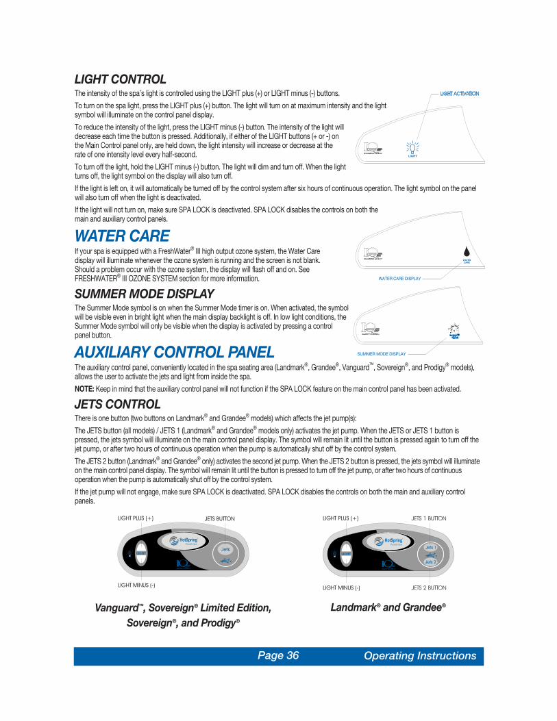
Page 36
LIGHT CONTROLThe intensity of the spa’s light is controlled using the LIGHT plus (+) or LIGHT minus (-) buttons.
To turn on the spa light, press the LIGHT plus (+) button. The light will turn on at maximum intensity and the lightsymbol will illuminate on the control panel display.
To reduce the intensity of the light, press the LIGHT minus (-) button. The intensity of the light willdecrease each time the button is pressed. Additionally, if either of the LIGHT buttons (+ or -) onthe Main Control panel only, are held down, the light intensity will increase or decrease at therate of one intensity level every half-second.
To turn off the light, hold the LIGHT minus (-) button. The light will dim and turn off. When the lightturns off, the light symbol on the display will also turn off.
If the light is left on, it will automatically be turned off by the control system after six hours of continuous operation. The light symbol on the panelwill also turn off when the light is deactivated.
If the light will not turn on, make sure SPA LOCK is deactivated. SPA LOCK disables the controls on both themain and auxiliary control panels.
WATER CAREIf your spa is equipped with a FreshWater® III high output ozone system, the Water Caredisplay will illuminate whenever the ozone system is running and the screen is not blank.Should a problem occur with the ozone system, the display will flash off and on. SeeFRESHWATER® III OZONE SYSTEM section for more information.
SUMMER MODE DISPLAYThe Summer Mode symbol is on when the Summer Mode timer is on. When activated, the symbolwill be visible even in bright light when the main display backlight is off. In low light conditions, theSummer Mode symbol will only be visible when the display is activated by pressing a controlpanel button.
AUXILIARY CONTROL PANELThe auxiliary control panel, conveniently located in the spa seating area (Landmark®, Grandee®, Vanguard™, Sovereign®, and Prodigy® models),allows the user to activate the jets and light from inside the spa.
NOTE: Keep in mind that the auxiliary control panel will not function if the SPA LOCK feature on the main control panel has been activated.
JETS CONTROLThere is one button (two buttons on Landmark® and Grandee® models) which affects the jet pump(s):
The JETS button (all models) / JETS 1 (Landmark® and Grandee® models only) activates the jet pump. When the JETS or JETS 1 button ispressed, the jets symbol will illuminate on the main control panel display. The symbol will remain lit until the button is pressed again to turn off thejet pump, or after two hours of continuous operation when the pump is automatically shut off by the control system.
The JETS 2 button (Landmark® and Grandee® only) activates the second jet pump. When the JETS 2 button is pressed, the jets symbol will illuminateon the main control panel display. The symbol will remain lit until the button is pressed to turn off the jet pump, or after two hours of continuousoperation when the pump is automatically shut off by the control system.
If the jet pump will not engage, make sure SPA LOCK is deactivated. SPA LOCK disables the controls on both the main and auxiliary controlpanels.
Vanguard™, Sovereign® Limited Edition,Sovereign®, and Prodigy®
Landmark® and Grandee®
Operating Instructions

Page 37
LIGHT CONTROLSee Main Control Panel’s Light Control section.
115 VOLT GFCIThe Ground Fault Circuit Interrupter is a safety device that is designed to detect as little as 5 milliamps (±1mA) of electricalcurrent leakage to ground. Watkins Manufacturing Corporation recommends that the GFCI be tested prior to each use toensure it is functioning correctly. With the spa connected to the power supply, push the TEST button. The spa should stopoperating and the GFCI power indicator will go out. Wait 30 seconds and then reset the GFCI by pushing the RESET button.The GFCI power indicator will turn on, restoring power to the spa. If the interrupter does not perform in this manner, it is an indication of anelectrical malfunction and the possibility of an electric shock. Disconnect the plug from the receptacle until the fault has been identified andcorrected.
NOTE: Failure to wait 30 seconds before resetting the GFCI may cause the spa’s POWER indicator (on the control panel) to blink. If this occurs,repeat the GFCI test procedure.
CAUTION: Never use the GFCI as a means to disconnect power to the spa (always unplug it). If the GFCI is tripped while the spa is plugged in,and a power outage occurs, when power returns the GFCI will automatically reset and power will flow to the spa.
LIGHTAll Hot Spring® spas come equipped with a specially designed low voltage dimmable LED light to enhance nighttime use. The light source shouldnever need replacing in normal use.
SUMMER MODEYour Hot Spring spa is equipped with a Summer Mode timer. The Summer Mode timer can be activated during extremely hot summer months if itbecomes difficult to maintain water temperatures low enough for comfort. Upon switching to the ON mode, the circulation pump (which can addheat to the water through normal operation), heater, and ozone (if installed) will immediately shut down for the next eight hours. Additionally, thesummer mode display on the main control panel will activate and remain active for as long as the summer mode is on. Following this eight-hourperiod, the circulation pump, heater, and ozone will automatically restart and will operate normally for the next sixteen hours. The circulationpump, heater, and ozone will continue to turn off for an eight-hour period every day that the switch remains in the ON position. In this way, theamount of heat transferred to the spa water will be minimized. When the outside temperatures begin to cool, the Summer Mode timer should beturned to the OFF position (the summer mode display on the main control panel will go out). This is the efficient 24 hour circulation mode thatkeeps the heater operation and operating costs to a minimum during colder/heavier usage months.
NOTE: Whenever power is disconnected and then reconnected to the spa, the Summer Mode timer will reset starting with the eight-hourshutdown mode. If a different eight-hour shut down time is desired, deactivate the Summer Mode, then reactivate at the beginning of the desiredeight-hour shut down time.
IMPORTANT: The Summer Mode will not lower the spa’s water temperature below the ambient air temperature.
To activate the Summer Mode, simply follow these steps:
1. Set the temperature control to 80°F (26°C).
2. On the control panel, simultaneously press and hold for three seconds Temp Plus and Temp Minus buttons to activate the Summer Timer.
The Summer Mode must be deactivated when cooler temperatures return. To do this, simply repeat step 2.
WARNING: Failure to deactivate the Summer Mode when the temperature drops below 32°F will result in freezing of the spa. Damage resultingfrom this situation is not covered under the terms of the warranty.
Operating Instructions

Page 38
SPA CARE AND MAINTENANCEGENERAL INFORMATIONYour Hot Spring® spa is manufactured from the highest quality, most durable materials available. Even so, the spa care and maintenance
program you develop will ultimately determine how long your spa, and its individual components, will last. Regular maintenance and followingthe advice in this section will help you to protect your investment.
DRAINING THE WATERDetergent residues from bathing suits and soap film from your body may gradually accumulate in your spa’s water. Normally, in about four monthsthe water will become sudsy and should be replaced. Showering without using soap prior to entering the spa, or using only the rinse cycle whenlaundering your bathing suit, will help to reduce detergent residue in the spa water.
IMPORTANT: Remember to change your water every three to four months.
TO DRAIN YOUR SPA:1. Disconnect the spa from the power supply by the appropriate method:
115 volt models: Disconnect the power cord from the house receptacle. Set the power cord in an elevated position so as not to allow waterto enter the GFCI plug housing during draining of the spa.
230 volt models: Trip both of the GFCI breakers located in the subpanel.
2. Locate the main drain valve for the spa and remove the drain cap. Attach the inlet of a garden hose to the drain valve (to avoid flooding of thefoundation surrounding the spa) and route the outlet of the hose to an appropriate draining area.
NOTE: Spa water with a high sanitizer level may harm plants and grass.
3. Open the valve by turning the knob. The spa will drain by gravitational flow.
IMPORTANT: All Hot Spring spa models will drain almost completely through the main drain valve and the secondary drain. Equipment suchas the jet pump and heating system will drain. Any water remaining within the plumbing or equipment after draining will only need to beremoved if the spa is being winterized.
4. Allow most of the water to drain through the main drain.
5. Remove threaded cap from secondary drain. This will drain the remaining water (about one gallon) from the bleedline system.
6. When empty, inspect the spa shell and clean as required. (Follow the Care of the Exterior Finish instructions.)
7. Close the drain valve and reinstall the drain cap.
8. Reinstall threaded cap onto secondary drain.
9. Replace or close the equipment access door and replace the screws.
10. Refill the spa through the filter compartment BEFORE restoring power.
IMPORTANT: Always clean and rotate the filter cartridges each time the spa is drained for cleaning.
FILTER SYSTEMHot Spring spas are equipped with balanced filtration, meaning that the filter cartridges are sized to meet the needs of the jet pump system.Additionally, a separate filter is dedicated to serving the 24-hour circulation system.
As with any water filtering system, the filter cartridges may become clogged, resulting in reduced water flow. It is important to maintain a clean,unobstructed filtering system. This not only provides the maximum performance from the jets, but allows the 24 hour filtration system to functioneffectively. Watkins Manufacturing Corporation recommends the filter cartridges be cleaned (by soaking to dissolve minerals) at least once everymonth.
SERVICE NOTE: Rotating the placement of the filter cartridges within the filter compartment after each cleaning will help to extend their servicelife.
WARNING: The frequency and duration of use, and the number of occupants, all contribute to determining the appropriate time between filtercleanings. More use means that more frequent filter cleanings are required. Failure to maintain the cartridges in a clean, unobstructed manner willresult in reduced water flow through the heater assembly that may cause the High-Limit Thermostat, Heater Thermal Cut-off or Circulation PumpThermal Cut-off to trip. If this high-limit or thermal cut-off trip occurs during sub-freezing temperatures and goes unnoticed, the spa water mayfreeze. Any damage to the spa (due to freezing) caused as a result of poor maintenance (stated under misuse or abuse in the Hot Spring spaLimited Warranty), will not be covered by your spa warranty.
DANGER: To reduce the risk of injury to persons using the spa, DO NOT remove the suction fittings (filter standpipes) located in the filtercompartment.
Spa Care and Maintenance
Page 39Spa Care and Maintenance
FILTER CARTRIDGES REMOVAL & CLEANING1. Disconnect the spa from the power supply by the appropriate method:
115 volt models: Disconnect the power cord from the house receptacle. Set the power cord in an elevated position so as not to allow waterto enter the GFCI plug housing during draining of the spa.
230 volt models: Trip both of the GFCI breakers located in the subpanel.
2. Remove and carefully set aside the filter compartment cover.
3. Remove any floating items from within the filter compartment.
4. Turn the filter retainer handle (located on the top of the filter cartridge) counterclockwise until the retainer can be removed from the filterstandpipe.
5. Remove the filter retainer and cartridge.
SERVICE NOTE: Never remove the filter standpipes when debris is present in the filter compartment. Debris may find its way into the internalplumbing which may result in blockage. NEVER REMOVE SUCTION FITTINGS.
6. Always clean the filter using a filter degreaser, such as Hot Spring FreshWaterTM Filter Cleaner, to remove mineral and oil buildup. Simply soakthe filter in the degreaser according to the package directions, then place the filter on a clean surface and spray until clean using a gardenhose. It may be necessary to rotate the filter while spraying to remove any debris lodged between the filter pleats.
7. To reinstall the filter cartridge, reverse the order of steps in which it was removed. Do not overtighten!
WARNING: Do not use the spa with the filter cartridges, or filter standpipe(s) removed!
CARE OF THE SPA PILLOWSThe spa pillows used on the Grandee®, Landmark®, Vanguard™, Sovereign® Limited Edition, Sovereign®, and Jetsetter® models will provide yearsof comfort if treated with care. They have been positioned above the water level to minimize the bleaching effects of chlorinated water, and otherspa water chemicals. To extend their life, whenever the spa shell is being cleaned, the spa pillows should be removed and cleaned. Body oils canbe removed with a mild soap and water solution. ALWAYS rinse off the spa pillows thoroughly to remove any soap residue. The pillows can beconditioned with Hot Spring® Cover Shield™ after cleaning. If the spa is not going to be used for a long period of time (that is during a vacation, orif the spa is winterized), or when the spa water is being super-chlorinated, the spa pillows should be removed until the next spa use.
To remove and replace the spa pillows:1. Carefully lift one end of the pillow away from the spa shell.
2. Continue lifting one end until all pillow retainers are released from the pillow.
IMPORTANT: Just pulling the pillow straight up, and out of the shell recess, will eventually damage the pillow. This abuse is not coveredunder warranty.
3. To reinstall the spa pillow, carefully bend the pillow slightly to allow one of the pillow retainers to slip into the recess in the back of the pillow.
4. Keeping the pillow slightly bent, slide the other pillow retainer into the recess in the back of the pillow.
5. After all the pillow retainers are in place, press the pillow down into the recess in the spa shell.
6. Place the two tabs of the DreamJet® massage pillow (Landmark Spa only) into the holes provided.
CARE OF THE EXTERIORSPA SHELLYour Hot Spring spa has an Endurol® thermoplastic shell, a Quarite Plus® shell, or an acrylic pearlescent, or metalescent shell (Sovereign® LimitedEdition only). Stains and dirt generally will not adhere to your spa’s surface. A soft rag or a nylon scrubber should easily remove most dirt. Mosthousehold chemicals are harmful to your spa’s shell. Watkins Manufacturing Corp. recommends HotSpring® FreshWater™ Spa Shine; the onlyother products which have passed the manufacturer’s tests are Soft Scrub® and Windex®. Sodium bicarbonate (baking soda) can also be used forminor surface cleaning. Always thoroughly rinse off any spa shell cleaning agent with fresh water.
SERVICE NOTES:
1. Iron and copper in the water can stain the spa shell if allowed to go unchecked. Ask your Hot Spring dealer about a Stain and Scale Inhibitorto use if your spa water has a high concentration of dissolved minerals. (Watkins recommends FreshWater™ Stain & Scale Defense.)
2. The use of alcohol or any household cleaners other than those listed to clean the spa shell surface is NOT recommended. DO NOT use anycleaning products containing abrasives or solvents since they may damage the shell surface. NEVER USE HARSH CHEMICALS! Damage tothe shell by the use of harsh chemicals is not covered under the warranty.
IMPORTANT: Some surface cleaners contain eye and skin irritants. Keep all cleaners out of the reach of children and use care whenapplying.

Page 40
EVERWOOD® SPA CABINETHot Spring® spas include an Everwood spa cabinet. Everwood consists of a rigid polymer that combines the durability of plastic with the beauty ofredwood. Everwood won’t crack, peel, blister or delaminate even after prolonged exposure to the elements.
Cleaning of Everwood® consists of simply spraying the cabinet with a mild soap and water solution to remove any stains and residue.
Do not rub the Everwood with an abrasive material or use abrasive cleaners as this may damage its texture.
Watkins Manufacturing Corp. recommends touch-up or restaining of the Everwood every three to four years (this will vary according to theenvironment). Contact your local dealer for restaining procedures and recommended stains.
CARE OF THE SPA COVERWARNING: The cover is a manual safety cover that meets or exceeds all prevailing requirements of ASTM Standards for spa safety covers wheninstalled and used correctly as of the date of manufacture. Non-secured, or improperly secured covers are a hazard. Open the cover to its fullyopen position before use.
VINYL COVERThe vinyl spa cover is an attractive, durable foam insulation product. Monthly cleaning and conditioning are recommended to maintain its beauty.
To clean and condition the vinyl cover:1. Remove the cover from the spa and gently lean it against a wall or fence.
2. With a garden hose, spray the cover to loosen and rinse away dirt or debris.
3. Using a large sponge and/or a soft bristle brush, and using a very mild soap solution (one teaspoon dishwashing liquid with two gallons of water), orbaking soda (sodium bicarbonate), scrub the vinyl top in a circular motion. Do not let the vinyl dry with a soap film on it before it can be rinsed clean.
4. Scrub the cover’s perimeter and side flaps. Rinse clean with water.
5. Rinse off the underside of the cover with water only (use no soap), and wipe it clean with a dry rag.
6. To condition the cover after cleaning, apply a thin film of Hot Spring Cover Shield® to the vinyl surface and buff to a high luster.
SERVICE NOTE: To remove tree sap, use cigarette lighter fluid (not charcoal lighter fluid). Use sparingly, and rinse with a saddle soap solutionimmediately afterwards, then wipe dry.
Important reminders:• DO remove snow buildup to avoid breakage of the foam core from the additional weight of the snow.• DO lock cover lock straps to secure the cover when the spa is not in use.• DO NOT drag or lift the spa cover using either the flaps, or the cover lock straps.• DO NOT walk, stand, or sit on the cover.• DO NOT place any metal or heat transferring object on the cover or place any type of plastic tarp or drop cloth over the cover as this may
result in a melted foam core, which would not be covered under the warranty.• DO NOT use any lifting mechanisms, chemicals, or cleaners except those recommended by Watkins Manufacturing Corporation, or its
Authorized Sales and Service Dealer.
RETRACTABLE COVER SYSTEMHOW TO OPEN THE VINYL COVER NOTE: Never attempt to open or remove the vinyl cover by grasping or pulling on the skirting or cover lock straps. The skirting will tear, and tornskirting is not covered under the terms of the warranty.
Check for ice build-up around the gas springs and pivot points of the retractable cover system. Ice buildup may damage system components.
WARNING: The vinyl cover and retractable cover system are not recommended for use in wind conditions reaching above 25 mph (40 kmh).
NOTE: If your spa is located in an area susceptible to high winds, additional coverlock straps may be installed to minimize wind damage to the cover.
How to Open the Cover1. With the cover lock straps unfastened, place one hand under the cover skirting, between the spa and cover, to break the cover’s vacuum
seal. Then, fold the front half of the cover over onto the back half.
2. The easiest and best way to operate the mechanism is to stand directly behind the spa, locate the handle placed at the rear center of thecover and simply pull the handle. This allows the cover to come to a gentle stop.
3. If no rear access is available, stand to the side of the spa directly adjacent to the hinge area of the folded cover.
A. For the CoverCradle® retractable cover system: Using both hands, cup one hand under the lower half of the cover (just above the
Spa Care and Maintenance

Page 41Spa Care and Maintenance
water) and place the other along the side of the cover, just above the skirt. Gently push (do not lift) with both hands towards the oppositerear corner of the cover (diagonally). As the cover opens, the gas springs will allow the cover to come to a gentle stop.
B. For the UpRite® or GlideRite® retractable cover system: Simply lift the cover at its center hinge, allowing it to move to the back of thespa and to rest gently there.
NOTE: When opening a cover with a retractable cover system, only use one of these two specific methods. Do not attempt to open the coverin any other way. Damage caused by improper opening or closing of the cover is not covered under the terms of the limited warranty.
How to Close the Cover1. Standing along side the cover, place one hand on the upper corner of the cover and gently push forward in the direction of the spa. The cover
will rotate forward to cover half of the spa.
NOTE: For the UpRite® or GlideRite® retractable cover systems, disengage the locking mechanism(s) before pushing the cover forward.
2. Unfold the cover by lifting the handle located on the top (front) half of the cover. Allow the unfolded half to fall down onto the spa. The airpressure created by the cover falling will keep the vinyl skirting from being trapped between the cover and the spa shell.
3. Secure the cover lock straps to the spa and lock them.
Important reminders:• DO always practice safety around your spa.• DO unlock and release all cover locks before attempting to open cover.• DO lock the cover when the spa is not in use.• DO cover the spa with the vinyl cover when the spa is not in use, whether it is empty or full.• DO remove snow build-up to prevent cover damage.• DO keep the cover open during super-chlorination or shock treatment of the spa water.• DO NOT walk, stand, climb, or sit on the vinyl cover or retractable cover system.• DO NOT lift the cover or operate the retractable cover system by using the cover locks. They are not designed to be used as handles.• DO NOT use any chemicals or cleaners except those recommended by Watkins Manufacturing Corporation, or its Authorized Sales and
Service Dealer.• DO NOT use hard, sharp, or metal objects, such as a car windshield scraper, to remove ice. Such objects can cut, mar, or puncture the
vinyl surfaces.
WARNING: Keep unsupervised children away from the cover. Always lock the cover in place after use! Keep hands away from the hinging points.Do not allow anyone to climb, sit, or stand on the cover when in the open position. Injury may occur, as well as damage to the cover andmechanism.
VACATION CARE INSTRUCTIONSIf you plan to be away from home, follow these instructions to ensure that the water quality of your spa is maintained:
SHORT TIME PERIODS (3-5 DAYS):1. Adjust the pH by following the instructions outlined in the Water Quality and Maintenance section.
2. Sanitize the water by following the shock procedures also listed in the Water Quality section.
3. Lock your cover in place using the coverlocks.
4. Upon your return, sanitize the water by following the shock procedures, and balance the pH.
LONG TIME PERIODS (5-14 DAYS):Prior to leaving:1. At least one day before you leave, set the temperature to its lowest level. This setting should represent an approximate water temperature of 80°F.
IMPORTANT NOTE: Spa water oxidizers such as sodium dichlor (chlorine) maintain their level of effectiveness substantially longer in warmwater (80°F) than in hot water (101°F to 104°F).
2. Adjust the pH as required. Sanitize the water by following the shock procedures.
Upon your return: 3. Sanitize the water by following the shock procedures. Return the set temperature to its original setting. The spa water will be safe for you to
use once the Free Available Chlorine residual level has dropped below 5.0 ppm.
NOTE: If you will not be using your spa for an extended period of time (in excess of 14 days) and an outside maintenance service (or neighbor)is not available to assist with the water maintenance, draining or winterizing of the spa is recommended. Spas equipped with our FreshWater®
III ozone system can extend this to 4 weeks. The FreshWater® III ozone system does not guard against possible freezing damage, however.

Page 42
PREVENTION OF FREEZINGYour Hot Spring® spa has been designed and engineered for year-round use in any climate. In some areas, extremely cold temperatures (below10°F) combined with strong wind, may cause partial freezing of the jet pump, even though the water inside the spa remains at the selectedtemperature. The energy efficiency of the spa may also decrease during these cold periods, as the heater will cycle more frequently. To avoidmost problems associated with component freezing, the 24-hour continuous filtration system has been designed with bleed lines connecting thejet pump(s) with the heating system. Since the heating system’s circulation pump runs continuously, cooler water in the heating and filteringsystems is continually being replaced by warm water from the spa. As an additional precaution against partial freezing of some of thecomponents, the equipment compartment can be insulated with an insulating kit (available from your Hot Spring dealer). This insulating kit will alsohelp to maximize the spa’s energy efficiency.
NOTE: When warmer weather returns (approx. 60°-70°F), the insulating kit must be removed to prevent overheating of the jet pump.
Please contact your Hot Spring dealer for additional information, or to order the insulating kit.
WINTERIZINGIn very cold weather you may not want to venture outside to use your spa. In this case, you may move it to a heated area, or leave it as is until theweather warms. If you do leave the spa unused for a long period of time in severely cold weather, you should drain the spa to avoid accidentalfreezing due to a power or equipment failure.
Your local authorized dealer can perform the following winterizing steps if you do not wish to attempt them yourself:
1. Disconnect the spa from the power supply by the appropriate method:
115 volt models: Disconnect the power cord from the house receptacle, coil it and place it in the equipment compartment.
230 volt models: Trip both of the GFCI breakers located in the subpanel.
2. Remove the screws from the equipment access door; remove the door completely (for 115 volt models only).
3. Locate the main drain valve and remove the drain cap. Attach a garden hose to the drain valve and route the outlet of the hose to anappropriate draining area.
4. Open the valve and the spa will drain by gravitational flow.
5. Remove the threaded cap from the secondary drain. The remaining water (about 1 gallon) will drain from the bleedline system.
6. Remove the filter cartridges, then clean and store the cartridges in a dry place.
IMPORTANT: The following additional instructions must be followed when draining and winterizing your spa in climates where thetemperature falls below 32°F (0°C). A five gallon combination wet/dry shop vac (capable of blowing air as well as vacuuming) must be used toeffectively remove water that is trapped inside the plumbing lines.
7. Attach the vacuum’s hose to the output (blower) side of the shop vac.a) Remove the filter standpipes by turning them counterclockwise.b) Place the end of the vacuum hose into one of the filter openings and cover the closest filter opening with a clean rag.c) Turn on the blower and allow it to blow out any water remaining in the plumbing lines (should take approximately 3 to 5 minutes).d) Turn the SmartJet® lever to the second position and allow that system to purge.e) If your spa is equipped with more than two jet systems, each jet system must be purged.f) Allow the blower to run for 3 to 5 minutes for each jet system in order to be sure the plumbing has been completely purged of any
remaining water.g) Once no more water is being blown out of the jets, the blower can be turned off and the filter standpipes reinstalled.
NOTES:• The standpipes may have a silicone sealant temporarily holding them in place and it may take firm pressure to get them to initially
break free.• On spas equipped with two jet pumps, each jet pump system and SmartJet® system must be purged.
8. Attach the vacuum hose to the vacuum side of the shop vac.
NOTE: When removing the water from jet openings, you may notice suction coming from another jet. With the help of a second person, blockoff any suction from the other jet using a large rag. This will help pull out the water that is trapped deeper inside the main line.a) Use the shop vac to pull any remaining water out of the filter compartment and Moto-Massage niche, if applicable (removal of the
faceplate may be necessary).
NOTE: It will be necessary to cover the drain grate tightly with a rag when vacuuming the main drain and secondary freeze drain outlets to besure that all water has been drawn from the internal plumbing system.b) Place the shop vac hose over the main drain outlet and allow it to draw any remaining water from the spa’s internal plumbing
(approximately 3 to 5 minutes).
Spa Care and Maintenance

Page 43Water Quality and Maintenance
c) Place the shop vac hose over the secondary “freeze” drain outlet and allow it to draw any remaining water from the spa’s bleedlines(approximately 3 to 5 minutes).
9. Thoroughly dry the spa shell with a clean towel.
10. Leave the main drain valve open approximately 1/2 turn and leave the caps off of both outlets during the winter months.
11. Close the spa cover and fasten the cover tie downs. Cover the spa cover with a large piece of plywood to more evenly distribute the weight ofsnow and ice.
WARNING: IF THESE INSTRUCTIONS ARE NOT FOLLOWED, DAMAGE DUE TO FREEZING WATER IN THE PLUMBING LINES MAYOCCUR!
To Reactivate:Reinstall the filter cartridges, close the main drain, and reinstall the drain caps. Follow the Start-Up and Refill Procedures to make your Hot Spring®
spa operational.
IMPORTANT: Always keep spa covered when not in use, whether it is empty or full.
WATER QUALITY AND MAINTENANCEIt’s important to have clean water. Water maintenance is one of the least understood, yet most important, areas of spa ownership. Your dealer
can guide you through the process of achieving and maintaining perfect water in your spa, given your local conditions. Your program willdepend on your water’s mineral content, how often you use your spa, and how many people use it. Here is our suggested step-by-step program:
Watkins Manufacturing Corporation has developed the EverFresh® water care system for its spas, which is an alternative to using an entirelychlorine-based system. This system uses silver ions, ozone, and an oxidizer (monopersulfate, or MPS) and dichlor to sanitize the spa. It includesthe FreshStart®10,000 pre-filter, the FreshWater® III high output ozone system, and the FreshWaterAg+® silver ion purifier.
GENERAL INFORMATIONTHE THREE FUNDAMENTAL AREAS OF WATER MAINTENANCE:
• Water Filtration• Chemical Balance/pH Control• Water Sanitation
Water sanitation is the responsibility of the spa owner, achieved through the regular and periodic (daily, if necessary) addition of an approvedsanitizer. The sanitizer will chemically control the bacteria and viruses present in the fill water or introduced during use of the spa. Bacteria andviruses can grow quickly in undersanitized spa water.
The water’s chemical balance and pH control are also the responsibility of the spa owner. You will have to add chemicals to maintain proper levelsof Total Alkalinity (TA), Calcium Hardness (CH) and pH. Proper water balance and pH control will minimize scale buildup and corrosion of metals,extend the life of the spa, and allow the sanitizer to work at maximum efficiency.
METHODS FOR TESTING THE SPA WATER Accurate water testing and analysis are an important part of effectively maintaining your spa water. You must have the ability to test for:
• Total Alkalinity (TA)• Calcium Hardness (CH)• pH• Sanitizer
Two types of testing methods are recognized and recommended by Watkins Manufacturing Corporation:
The Reagent Test Kit is a method which provides a high level of accuracy. The reagents come in either liquid or tablet form.
Test Strips are a convenient testing method used by many spa owners. Keep in mind that test strips are susceptible to heat and moisturecontamination, which will result in inaccurate readings.
IMPORTANT: Always read and carefully follow the directions included with the Test Kit or Test Strips to ensure the accuracy of the test results.
BASIC CHEMICAL SAFETY When using chemicals, read the labels carefully and follow directions precisely. Though chemicals protect you and your spa when used correctly,they can be hazardous in concentrated form. Always observe the following guidelines:
• Allow only a responsible person to handle spa chemicals. KEEP THEM OUT OF THE REACH OF CHILDREN.

Page 44
• Accurately measure the exact quantities specified, never more. Do not overdose your spa.• Handle all containers with care. Store in a cool, dry, well ventilated place.• Always keep chemical containers closed when not in use. Replace caps on their proper containers.• Don’t inhale fumes, or allow chemicals to come in contact with your eyes, nose, or mouth. Wash your hands immediately after use.• Follow the emergency advice on the product label in case of accidental contact, or if the chemical is swallowed. Call a doctor or the local
Poison Control Center. If a doctor is needed, take the product container along with you so that the substance can be identified.• Don’t let chemicals get on surrounding surfaces or landscaping. Don’t use a vacuum cleaner to clean up chemical spills.• Never smoke around chemicals. Some fumes can be highly flammable.• Don’t store any chemicals in the spa equipment compartment.
HOW TO ADD CHEMICALS TO THE WATERIMPORTANT: All spa water chemicals, including granulated dichlor, MPS, granulated pH increaser or decreaser, granulated total alkalinityincreaser, liquid stain and scale inhibitor, and liquid defoamer must always be added directly into the filter compartment while the jet pump isrunning in its high speed mode, and it must run for a minimum of ten minutes.
To Administer Spa Water Chemicals:1. Fold back the cover. Carefully remove and set aside the filter compartment cover.
2. Push the CLEAN button to turn on the jet pump.
3. Carefully measure the recommended amount of chemical and slowly pour it into the filter compartment. Use care not to splash chemicals onyour hands, in your eyes, on the spa shell surface, or on the spa cabinet.
4. Replace the filter compartment cover. After ten minutes, the jet pump will automatically shut off to complete the procedure. Close and securethe cover. Risk of Drowning: Never leave an open spa unattended!
IMPORTANT “SUPER CHLORINATION/NON-CHLORINE SHOCK TREATMENT” NOTE: After administering a super chlorination treatment ornon-chlorine shock to your spa, leave the cover open for a minimum of 20 minutes to allow the oxidizer gas to vent. A high concentration oftrapped oxidizer gas which may exist as a result of the shock treatment (not daily sanitation) may eventually cause discoloration or vinyldegradation to the bottom of the cover. This type of damage is considered chemical abuse and is not covered under the terms of the limitedwarranty.
THE HOT SPRING® SPA WATER MAINTENANCE PROGRAMEach step in your water maintenance program is dependent on the completion of the previous steps. Omitting a step, or failing to reach therecommended range may cause an imbalance in your water chemistry. Unbalanced water chemistry can damage the spa, and its components, aswell as cause discomfort for the user.
FILLING THE SPA WITH WATERA. To prevent contaminants from entering the spa, Watkins recommends using the FreshStart®10,000 pre-filter when filling the spa with water.
Always fill the spa through the filter compartment.
B. The FreshStart10,000 pre-filter is designed to remove unwanted contaminants such as rust, dirt, detergents, and algae from the fill water.Dissolved minerals and metals such as lead, calcium, copper, and iron are not removed.
C. Instructions are included with the FreshStart®10,000 pre-filter. When the spa is filled, proceed to the Start-Up and Refill Procedures section.
BALANCING THE TOTAL ALKALINITY (TA)A. The recommended Total Alkalinity (TA) for your spa water is 125-150 ppm.
B. Total Alkalinity is a measure of the total levels of carbonates, bicarbonates, hydroxides, and other alkaline substances in the water. TA isreferred to as the water’s “pH buffer”. In other words, it’s a measure of the ability of the water to resist changes in pH level.
C. If the TA is too low, the pH level will fluctuate widely from high to low. Fluctuations in pH can cause corrosion or scaling of the spacomponents. Low TA can be corrected by adding Hot Spring FreshWater® pH/Alkalinity Up, or sodium hydrogen carbonate.
D. If the Total Alkalinity is too high, the pH level will tend to be high and may be difficult to bring down. It can be lowered by adding Hot SpringFreshWater pH/Alkalinity Down, or sodium bisulfate.
E. Once the TA is balanced, it normally remains stable, although the addition of more water with a high or low alkalinity will raise or lower the TAreading of the water.
F. When the Total Alkalinity is within the recommended range, proceed to the next step.
Water Quality and Maintenance

Page 45
BALANCING THE CALCIUM HARDNESS (CH)A. The recommended Calcium Hardness (CH) level for your spa is 150-200 ppm.
B. Calcium Hardness is a measure of the total amount of dissolved calcium in the water. Calcium helps control the corrosive nature of the spa’swater. That’s why calcium-low water (commonly known as “soft” water) is not recommended. It is very corrosive to the equipment, and cancause staining of the spa shell.
C. If the CH is too high (commonly known as “hard” water), formation of scale on the spa’s shell surface and equipment can result. CH can bedecreased by dilution – a mixture of 75% hard and 25% soft water will be a good starting point. If soft water is not available, or practicalfor you, a stain and scale control such as Hot Spring FreshWater Stain and Scale Defense should be added to the spa water, according toinstructions on its label.
D. Once the CH is balanced, it normally remains stable, although the addition of more water with a high or low calcium content will raise or lowerthe CH reading of the water.
E. When the Calcium Hardness is within the recommended range, proceed to the next step.
BALANCING THE pHA. The recommended pH level for your spa water is 7.4-7.6.
B. The pH level is the measure of acidity and alkalinity. Values above 7 are alkaline; those below7 are acidic. Maintaining the proper pH level is extremely important for:
• Optimizing the effectiveness of the sanitizer.• Maintaining water that is comfortable for the user.• Preventing equipment deterioration.
C. If the spa water’s pH level is too low, the following may result:• The sanitizer will dissipate rapidly.• The water may become irritating to spa users.• The spa’s equipment may corrode.
If the pH is too low, it can be increased by adding Hot Spring FreshWater pH/Alkalinity Up, or sodium hydrogen carbonate to the spawater.
D. If the pH level is too high, the following may result:• The sanitizer is less effective.• Scale will form on the spa shell surface and the equipment.• The water may become cloudy.• The filter cartridge pores may become obstructed.
If the pH is too high, it can be decreased by adding Hot Spring FreshWater pH/Alkalinity Down, or sodium bisulfate to the spa water.
NOTE: After adding sodium hydrogen carbonate or sodium bisulfate, wait two hours before testing the water for pH. Measurements taken toosoon may not be accurate.
E. It is important to check the pH on a regular basis. The pH will be affected by the bather load, the addition of new water, the addition of variouschemicals, and the type of sanitizer used.
F. When the pH is within the recommended range, proceed to the final step.
ALKALINESPA
WATER
(SCALINGZONE)
ADD pHDECREASERTO LOWER
pH
ACIDICSPA
WATER
(CORROSIVEZONE)
ADD pHINCREASER
TO RAISEpH
COMFORTZONE
IDEAL
Water Quality and Maintenance

Page 46
MAINTAINING THE SANITIZER LEVELA. Sanitizer is extremely important for killing algae, bacteria and viruses, and preventing unwanted organisms from growing in the spa. At the
same time, you don’t want too high a sanitizer level, or it can irritate your skin, lungs, and eyes.
B. Always maintain the sanitizer level in your spa at the recommended level for each type of sanitizer.
C. Watkins recommends only the following sanitizers:• Sodium Dichloro-s-Triazinetrione (sodium dichlor or chlorine)• Brominating Concentrate™ (one step granular bromine)• Baqua Spa™ (please consult your Baqua Spa™ manual for instructions on the use of this product).
WARNING: DO NOT use tri-chlor chlorine, bromo-chloro-dimethyl-hydantoin (BCDMH), or any type of compressed bromine or chlorine, acid orany type of sanitizer which is not recommended by Watkins Manufacturing Corporation.
EVERFRESH® WATER CARE SYSTEMThe EverFresh® water care system is comprised of the following products:
• FreshStart®10,000 Pre-filter• Sodium Dichlor• Monopersulfate (MPS)• FreshWater® III high output ozone system• FreshWaterAg+® silver ion purifier
FreshStart10,000 Pre-filter is used when filling a spa for the first time or at refill. It attaches to a garden hose and filters out rust, dirt, detergents, algaeand chemicals.
Sodium Dichlor (chlorine) is the only recommended sanitizer that will work in conjunction with all of the other products in this system.
FreshWater III high output ozone system uses Corona Discharge technology to produce a high concentration of ozone which is injected into thespa water.
Monopersulfate (MPS) is an oxidizing chemical used to prevent the buildup of contaminants, maximize sanitizer efficiency, minimize combinedchlorine, and improve water clarity.
FreshWaterAg+ silver ion purifier introduces silver ions into the spa water, inhibiting bacteria growth. When combined with MPS, or chlorine,oxidizes particulates in the spa water.
It is important to follow the recommended application and maintenance programs outlined for each product’s use.
If the spa is being used over an extended period of time, such as a whole afternoon or evening, additional sanitizer will be needed.
THE WATKINS WATER MAINTENANCE QUICK REFERENCE GUIDEIdeal Range (ppm) What Chemicals to Use
Steps Minimum Maximum To Raise To Lower
1 Total Alkalinity 125 150 Sodium Hydrogen Sodium BisulfateCarbonate, orSodium Bicarbonate
2 Calcium Hardness 150 200 Calcium Hardness Use a mixture of Increaser 75% hard water
and 25% soft water or use a Stain and Scale Inhibitor
3 pH 7.4 7.6 Sodium Hydrogen Sodium BisulfateCarbonate
4 Sanitizer See section on Maintaining the Sanitizer Level
Water Quality and Maintenance

Page 47
A weekly “shock treatment” is required.The shock treatment quickly destroys any remaining contaminants while revitalizing the silver ion cartridge, allowing the silver ions to continue tobe released into the water. Without this weekly shock treatment, the silver ion cartridge may stop releasing silver ions into the water.
To weekly “shock treat” your spa you may use either MPS or sodium dichlor. It will require much less sodium dichlor to administer the shocktreatment than MPS (one teaspoon of sodium dichlor has oxidizing capabilities comparable to two tablespoons of MPS). Sodium dichlor may be amore appropriate weekly shock for those users that experience heavy bather load conditions.
IMPORTANT NOTE: MPS is an oxidizer, not a sanitizer.
HOT SPRING® WATER TREATMENT GUIDEAt spastartup or refill
Follow Start-Up and Refill Procedures section
NOTE: Use the FreshStart®10,000 pre-filter when filling thespa to remove unwanted contaminants.
Prior toeach use(Test before addingany chemicals; do notadd any chemicals ifproper or higher levelsare found.)
Add one (1) tablespoon of monopersulfate (MPS)* per 250 gallons
Landmark (Model S) 2 tablespoonsGrandee (Model G) 2 tablespoonsVanguard (Model V) 1-1/2 tablespoonsSovereign (Model ILE) 1-1/2 tablespoonsSovereign (Model I) 1-1/2 tablespoonsProdigy® (Model H) 1-1/4 tablespoonsJetsetter (Model J) 1 tablespoon
Add one-half (1/2) teaspoon of chlorine per250 gallons
Landmark® (Model S) 1 teaspoonGrandee® (Model G) 1 teaspoonVanguard™ (Model V) 3/4 teaspoonSovereign® (Model ILE) 3/4 teaspoonSovereign® (Model I) 3/4 teaspoonProdigy® (Model H) 2/3 teaspoonJetsetter® (Model J) 1/2 teaspoon
Once aweek
Add three (3) tablespoons of monopersulfate (MPS)* per 250 gallons
Landmark (Model S) 6 tablespoonsGrandee (Model G) 6 tablespoonsVanguard (Model V) 4-1/2 tablespoonsSovereign (Model ILE) 4-1/2 tablespoonsSovereign (Model I) 4-1/2 tablespoonsProdigy (Model H) 4 tablespoonsJetsetter (Model J) 2-1/2 tablespoons
Add one and one half (1-1/2) teaspoons ofchlorine per 250 gallons
Landmark (Model S) 3 teaspoonsGrandee (Model G) 3 teaspoonsVanguard (Model V) 2-1/4 teaspoonsSovereign (Model ILE) 2-1/4 teaspoonsSovereign (Model I) 2-1/4 teaspoonsProdigy (Model H) 2 teaspoonsJetsetter (Model J) 1-1/2 teaspoons
Every four months
Drain and refill your spa.
Replace the FreshWaterAg+® silver ion purifier
NOTE: Use the FreshStart®10,000 pre-filter when fillingthe spa to remove unwanted contaminants.
As needed,if water ishazy,cloudy orhas an odor
Add one and one half (1-1/2) teaspoons of chlorineper 250 gallons
Landmark (Model S) 3 teaspoonsGrandee (Model G) 3 teaspoonsVanguard (Model V) 2-1/4 teaspoonsSovereign (Model ILE) 2-1/4 teaspoonsSovereign (Model I) 2-1/4 teaspoonsProdigy (Model H) 2 teaspoonsJetsetter (Model J) 1-1/2 teaspoons
*MPS is an oxidizer, not a sanitizer.
OR
OR
Water Quality and Maintenance

Page 48
FRESHWATERAg+® SILVER ION PURIFIER REPLACEMENTINSTRUCTIONSWhen replacing the FreshWaterAg+ silver ion purifier (every four months), it is highly recommended that the spa be drained and refilled at the sametime. After refilling the spa with water, balance the Total Alkalinity (TA), Calcium Hardness (CH) and pH to the recommended levels. Shock the spaby adding sanitizer, either MPS or sodium dichlor.
1. Fold back the vinyl cover.
2. Carefully remove and set aside the filter compartment cover.
3. Remove any floating items within the filter compartment.
4. Locate the grey filter cap. Turn the filter cap counterclockwise until the cap can be removed from the filter standpipe.
5. Remove and clean filter cartridges.
NOTE: When replacing the FreshWaterAg+ silver ion purifier, it is an excellent time to clean and rotate the filters to extend their lives. To rotatethe filters, simply move the filters from one standpipe to another. Typically, the filter on the circulation system (with grey filter cap, standpipeand wallfitting) is subject to the greatest load. By rotating the filters, the load placed on the individual filter by the circulation system is greatlyreduced. This extends the life of the filters.
6. Remove the existing FreshWaterAg+ silver ion purifier.
7. Install the new FreshWaterAg+ silver ion purifier into the filter standpipe. Do not force the FreshWaterAg+ silver ion purifier down into the filterstandpipe.
8. Reinstall the cleaned filter cartridges.
9. Replace and secure the grey filter cap.
10. Replace the filter compartment cover.
11. Fold the cover back into place.
WARNING: Never use the spa with the filter cartridges or filter standpipes removed!
SILVER IONS QUESTIONS AND ANSWERSQuestion: How are the silver ions actually added to the water?
Answer: The silver ion cartridge contains ceramic beads that are infused with silver. By placing the cartridge in the circulation pump filterstandpipe, it is subjected to the continuous flow of water created by the pump’s 24 hour circulation. The flowing water, through a chemicalerosion process, carries with it the silver ions necessary to add a sanitizing residual to the spa water.
Question: What happens if I do not add the weekly shock treatment?
Answer: The contaminants in the water may coat the silver ion cartridge’s ceramic beads, blocking the silver ions’ release into the water. Whenthis occurs, there will be no residual of silver ions present in the water, eliminating them from the sanitizing process.
Question: How often should the FreshWaterAg+ silver ion purifier cartridge be replaced?
Answer: The cartridge must be replaced every four months. Please refer to the instructions provided with each FreshWaterAg+ silver ion purifiercartridge.
Question: Can I use the FreshWater® III ozone system in addition to the silver ion system?
Answer: Yes. In fact, it is preferred! The use of the FreshWater III ozone system will enhance the performance of the silver ions and maysubstantially reduce the need for supplemental chemical treatments when the spa is not in use.
Question: Why can’t I use bromine or biguanides instead of MPS or chlorine?
Answer: Bromine and biguanides will chemically react with the sanitizing action of the silver ions. This will eliminate their beneficial sanitizing effect.
DOS AND DON’TS• DO check your MPS or dichlor chemical level prior to each use.• DO shock the spa weekly (use either MPS or sodium dichlor).• DO change the FreshWaterAg+ silver ion purifier every four months.• DO test Total Alkalinity and pH weekly.• DO use MPS for spas only, such as Hot Spring® MPS chlorine-free oxidizer.• DO store all chemicals in a tightly sealed container in a cool, dry place.• DO shock the spa with chlorine at spa startup or refill.• DON’T use bromine, sodium bromide or biguanides. These are an active sanitizer and will combine with the silver ions to inactivate them.• DON’T use a water clarifier. Clarifiers will cause the spa water to become cloudy.
Water Quality and Maintenance

Page 49
CHLORINE (SODIUM DICHLOR)A. Sanitizing chemicals, such as chlorine, are oxidants that kill bacteria and viruses in the water. The
Free Available Chlorine (FAC) is a measure of the amount of unused chlorine available to sanitize thespa. The recommended FAC for your spa water is 3.0-5.0 ppm.
B. Watkins Manufacturing Corporation recommends the use of sodium dichlor type granulatedchlorine for sanitizing the water. Sodium dichlor is preferred because it is totally soluble, dissolvesquickly and is nearly pH neutral.
C. Maintaining the proper level of chlorine during use is extremely important.
D. If the FAC is too low, bacteria and viruses can grow rapidly in the warm water. Increase the FACby adding granulated sodium dichlor.
E. If the FAC is too high, the water can cause discomfort to the user’s eyes, lungs and skin. Simplyallow some time to pass. The FAC level will naturally drop over time.
F. When the Free Available Chlorine is within the recommended range, the spa is ready to be enjoyed.
WARNING: There are several forms of stabilized chlorine available for use in spas and swimmingpools and each form has specific chemical characteristics. It is extremely important that the oneyou choose is specifically designed for use in spas. Use of an incorrect product such as tri-chlor, which has a very low pH (2.6), dissolves tooquickly in hot water resulting in extremely high levels of chlorine, and is designed for concrete or plaster swimming pools, WILL causedamage to your spa. Use of a liquid or any type of compressed bromine or chlorine, acid or any type of sanitizer which is not recommendedby Watkins Manufacturing Corporation WILL damage your spa and is specifically not covered under the terms of the limited warranty.
IMPORTANT: Granulated chlorine (sodium dichlor) will degrade if stored improperly. We recommend purchasing chlorine in one , two, or fivepound containers and storing it in a cool, dry place to maintain its potency.
SUPER CHLORINATIONSuper Chlorination is designed to “burn-off” the build-up of chloramines (used chlorine), to eliminate the chlorine smell and to allow the properlevel of free chlorine to be maintained.
When giving your water a super chlorination treatment, open the cover at least half way to allow the chlorine gas to vent off. The highconcentration of chlorine gas which may exist as a result of super chlorination (not daily sanitation) may eventually cause discoloration ordegradation to the bottom of the cover or the tile grouting, which would not be covered under the terms of your warranty.
IMPORTANT: Always allow the Free Available Chlorine to fall below 5 ppm before using your spa.
WARNING: Never leave an open spa unattended, especially if there are children present!
BUILDING A SANITIZER ROUTINEDuring the first month of ownership, measure the sanitizer residual daily in order to establish standards for User Load and Usage Time versusSanitizer Needed.
• The User Load of the spa is the number of times anyone enters the spa. • The Usage Time is simply the amount of time a user spends in the spa. • Sanitizer Needed is the amount of Free Available Chlorine needed to accommodate the number of users and their combined usage time.
For example, two spa users who regularly use the spa once an evening for twenty minutes create a specific and somewhat consistent demand onthe sanitizer. During the first month of ownership, these two users can determine exactly how much sanitizer to use in order to maintain the properresidual. If, at any time, the user load and/or usage pattern changes dramatically (invited guests), the amount and frequency of sanitizer requiredincreases dramatically.
The greater the usage time, or the bather load, the faster the residual value is diminished.
SUPPLEMENTAL WATER MAINTENANCEProper water sanitation and mineral balance (pH control) are absolutely essential for a complete spa water maintenance program. Here are threeother popular water additives that are optional:
Mineral Deposit InhibitorsAs water evaporates from your spa and new water is added, the amount of dissolved minerals will increase. (Minimize evaporation by keeping thecover on the spa whenever possible.) The spa water may eventually become “hard” (Calcium Hardness too high) enough to damage the heater bycalcifying its surface. Proper pH control can minimize this.
Normal soap build-up will require water replacement regularly enough that mineral deposits normally are not a problem.
Occasionally, high iron or copper content in the water may produce green or brown stains on the spa. A stain and scale inhibitor may help toreduce these metals.
Water Quality and Maintenance
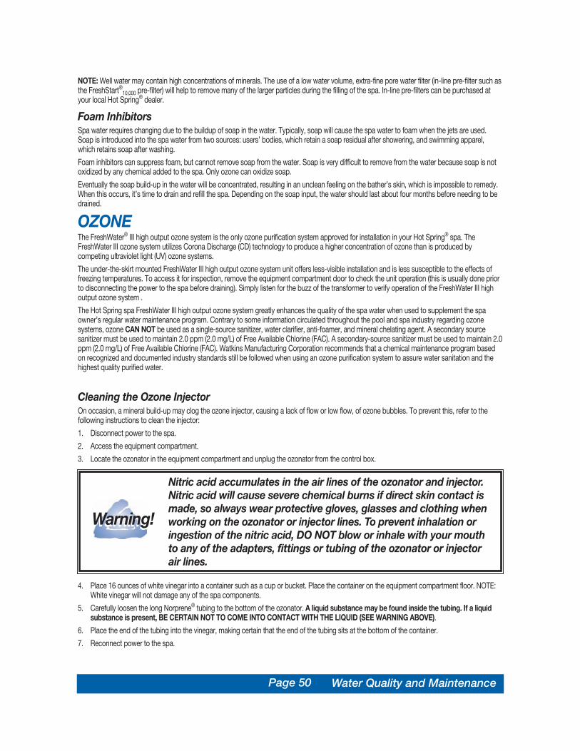
Page 50
NOTE: Well water may contain high concentrations of minerals. The use of a low water volume, extra-fine pore water filter (in-line pre-filter such asthe FreshStart®10,000 pre-filter) will help to remove many of the larger particles during the filling of the spa. In-line pre-filters can be purchased atyour local Hot Spring® dealer.
Foam InhibitorsSpa water requires changing due to the buildup of soap in the water. Typically, soap will cause the spa water to foam when the jets are used.Soap is introduced into the spa water from two sources: users’ bodies, which retain a soap residual after showering, and swimming apparel,which retains soap after washing.
Foam inhibitors can suppress foam, but cannot remove soap from the water. Soap is very difficult to remove from the water because soap is notoxidized by any chemical added to the spa. Only ozone can oxidize soap.
Eventually the soap build-up in the water will be concentrated, resulting in an unclean feeling on the bather’s skin, which is impossible to remedy.When this occurs, it’s time to drain and refill the spa. Depending on the soap input, the water should last about four months before needing to bedrained.
OZONE The FreshWater® III high output ozone system is the only ozone purification system approved for installation in your Hot Spring® spa. TheFreshWater III ozone system utilizes Corona Discharge (CD) technology to produce a higher concentration of ozone than is produced bycompeting ultraviolet light (UV) ozone systems.
The under-the-skirt mounted FreshWater III high output ozone system unit offers less-visible installation and is less susceptible to the effects offreezing temperatures. To access it for inspection, remove the equipment compartment door to check the unit operation (this is usually done priorto disconnecting the power to the spa before draining). Simply listen for the buzz of the transformer to verify operation of the FreshWater III highoutput ozone system .
The Hot Spring spa FreshWater III high output ozone system greatly enhances the quality of the spa water when used to supplement the spaowner’s regular water maintenance program. Contrary to some information circulated throughout the pool and spa industry regarding ozonesystems, ozone CAN NOT be used as a single-source sanitizer, water clarifier, anti-foamer, and mineral chelating agent. A secondary sourcesanitizer must be used to maintain 2.0 ppm (2.0 mg/L) of Free Available Chlorine (FAC). A secondary-source sanitizer must be used to maintain 2.0ppm (2.0 mg/L) of Free Available Chlorine (FAC). Watkins Manufacturing Corporation recommends that a chemical maintenance program basedon recognized and documented industry standards still be followed when using an ozone purification system to assure water sanitation and thehighest quality purified water.
Cleaning the Ozone InjectorOn occasion, a mineral build-up may clog the ozone injector, causing a lack of flow or low flow, of ozone bubbles. To prevent this, refer to thefollowing instructions to clean the injector:
1. Disconnect power to the spa.
2. Access the equipment compartment.
3. Locate the ozonator in the equipment compartment and unplug the ozonator from the control box.
4. Place 16 ounces of white vinegar into a container such as a cup or bucket. Place the container on the equipment compartment floor. NOTE:White vinegar will not damage any of the spa components.
5. Carefully loosen the long Norprene® tubing to the bottom of the ozonator. A liquid substance may be found inside the tubing. If a liquidsubstance is present, BE CERTAIN NOT TO COME INTO CONTACT WITH THE LIQUID (SEE WARNING ABOVE).
6. Place the end of the tubing into the vinegar, making certain that the end of the tubing sits at the bottom of the container.
7. Reconnect power to the spa.
Nitric acid accumulates in the air lines of the ozonator and injector.Nitric acid will cause severe chemical burns if direct skin contact ismade, so always wear protective gloves, glasses and clothing whenworking on the ozonator or injector lines. To prevent inhalation oringestion of the nitric acid, DO NOT blow or inhale with your mouthto any of the adapters, fittings or tubing of the ozonator or injectorair lines.
Warning!Warning!
Water Quality and Maintenance

Page 51
8. Run the spa until all 16 ounces of the vinegar are gone. This should allow an ample flow of vinegar to be run through the injector and clear theblockage.
9. Disconnect power to the spa.
10. Remove the empty cup or bucket.
11. Reinstall the tubing to the bottom of the ozonator.
12. Plug the ozonator into the control box.
13. Close the equipment compartment door.
14. Reconnect power to the spa.
DOS AND DON’TS• DO add all chemicals slowly into the filter compartment with the jet pump operating for ten minutes.• DO use special care if using baking soda to clean either the interior or exterior plastic surfaces.• DON’T use swimming pool (muriatic) acid to lower pH.• DON’T use compressed sanitizers.
The use of bromine sticks or tablets in floaters, which may become entrapped in a lounge or cooling seat (or sink to the spa floor), have beenshown to cause discoloration of or surface distress to a spa’s shell.
• DON’T use a floater type sanitization system as a low or no maintenance solution to your spa maintenance program.
The spa shell easily can withstand the effects of a properly administered sanitizer. Floating dispensers can become trapped in one area and causean over-sanitization (or chemical burn) of that particular area.
If the dispenser setting is too high, the high concentration can discolor the spa shell and damage the underside of the cover.
Automatic floating dispensers have a tendency to either over-brominate or under-brominate as the rate of erosion varies greatly. Damage to thespa and cover can occur very quickly.
WARNING: Watkins Manufacturing Corporation DOES NOT recommend the use of any floating chemical dispenser. Damage to the spa shell orcomponents caused by a floating chemical dispenser is specifically not covered under the terms of the limited warranty.
• DON’T use a sanitizer which is not designed for spas.• DON’T use household bleach (liquid sodium hypochlorite).• DON’T broadcast or sprinkle the chemicals onto the water surface. This method may cause chemically-induced spa surface blistering
(chemical abuse).
COMMON WATER CHEMISTRY QUESTIONSQuestion: Why can’t I use a floater to sanitize my spa water?
Answer: Watkins Manufacturing Corporation does not recommend the use of a floater for three reasons:
1. The floater is unable to control the rate at which the sanitizer is dissolved into the water. When a floater is first placed in a spa, the sanitizerlevel can be extremely high. High sanitizer levels can chemically burn or discolor the spa’s shell or the underside of the cover. Then, after aperiod of time, the sanitizer level dispensed by the floater will fall to near zero. A low sanitizer level will allow viruses, bacteria or algae to grow.
2. Floaters tend to stay in one area of the spa most of the time (usually over the cool down seat), causing this area to be exposed to extremesanitizer levels.
3. The floater may allow pieces of the highly concentrated sanitizer to fall out and settle on the floor or seat of the spa shell. These pieces ofsanitizer will chemically burn (blister) the spa shell. Although your spa shell is specifically designed to resist the effects of spa chemicals, nospa surface can withstand this type of highly concentrated chemical. Remember, chemical abuse is specifically not covered under the termsof the warranty.
Question: When I open my spa, I smell chlorine. How do I get rid of this smell?
Answer: There are two types of chlorine in your spa. The first is the Free Available Chlorine (FAC), which is the chlorine available to sanitize yourspa. This type of chorine does not have an odor. The second is Chloramine, which is residue from chlorine already expended. Chloramines have astrong chlorine odor. The smell from Chloramines can be eliminated by “shocking” the water. If you smell chlorine in the water, your spa isreminding you to add a shock treatment.
Question: Why can’t I fill my spa with soft water?
Answer: Soft water is essentially the same as regular water except that most or all of the calcium has been replaced by sodium. Soft water maybe corrosive to the heater and other components. Replacement of spa components damaged by soft water is extremely expensive.
Question: I am trying to reduce the number of chemicals to which my family is exposed. Do I really need to use so many chemicals and in suchlarge amounts?
Water Quality and Maintenance

Page 52
Answer: While over-exposure to any chemical can be unhealthful, many low levels of chemicals are effective and beneficial. In the case of spawater, the chemicals recommended in the Hot Spring® water maintenance program are needed to protect the user from water-borne pathogens(disease-causing microbes) and to prevent corrosion of spa components. The EverFresh® water care system minimizes the use of chemicals withharsh side effects, such as halogen sanitizers.
Question: Why isn’t water chemistry damage covered by the warranty?
Answer: The chemical levels and water quality of the water in the spa are under your direct control. With proper basic care, the spa will providemany years of hot water relaxation. If you are unsure about any chemical or its usage in the spa, contact your Authorized Dealer, or WatkinsManufacturing Corporation.
WATER TERMINOLOGYThe following chemical terms are used in this Water Quality and Maintenance section. Understanding their meaning will help you to betterunderstand the water maintenance process.
Bromamines: Compounds formed when bromine combines with nitrogen from body oils, urine, perspiration, etc. Unlike chloramines,bromamines have no pungent odor, and are effective sanitizers.
Bromine: A halogen sanitizer (in the same chemical family as chlorine). Bromine is commonly used in stick, tablet, or granular form. See the DO’sand DON’Ts of Spa Water Maintenance for additional information.
Calcium Hardness: The amount of dissolved calcium in the spa water. This should be approximately 150-200 ppm. High levels of calcium cancause cloudy water and scaling. Low levels can cause harm to the spa equipment.
Chloramines: Compounds formed when chlorine combines with nitrogen from body oils, urine, perspiration, etc. Chloramines can cause eyeirritation as well as having a strong odor. Unlike bromamines, chloramines are weaker, slower sanitizers.
Chlorine: An efficient sanitizing chemical for spas. Watkins Manufacturing Corporation recommends the use of sodium dichlor-type granulatedchlorine. This type is preferred because it is totally soluble and nearly pH neutral.
Chlorine (or Bromine) Residual: The amount of chlorine or bromine remaining after chlorine or bromine demand has been satisfied. The residualis, therefore, the amount of sanitizer which is chemically available to kill bacteria, viruses and algae.
Corrosion: The gradual wearing away of metal spa parts, usually caused by chemical action. Generally, corrosion is caused by low pH or by waterwith levels of TA, CH, pH or sanitizer which are outside the recommended ranges.
DPD: The preferred reagent used in test kits to measure the Free Available Chlorine.
Halogen: Any one of these five elements: fluorine, chlorine, bromine, iodine, and astatine.
MPS: Monopersulfate is the non-chlorine oxidizer used with the FreshWaterAg+® silver ion purification system.
Nitric Acid: The formulation of nitric acid, a highly corrosive chemical, is a byproduct of the ozone generating process. Nitric acid is produced invery small quantities and is readily dissolved in the water stream with ozone.
Oxidizer: The use of an oxidizing chemical is to prevent the buildup of contaminants, maximize sanitizer efficiency, minimize combined chlorineand improve water clarity.
Ozone: Ozone is a powerful oxidizing agent which is produced in nature and artificially by man. Ozone forms no byproducts of chloramines (ozoneactually oxidizes chloramines) and will not alter the water’s pH.
Pathogen: A microorganism such as bacterium that cause disease.
pH: The measure of the spa water’s acidity and alkalinity. The recommended pH for the spa water is 7.4 to 7.6. Below 7.0 (considered neutral), thespa water is too acidic and can damage the heating system. Above 7.8, the water is too alkaline and can result in cloudy water, and scaleformation on the shell and heater.
ppm: The abbreviation of “parts per million”, the standard measurement of chemical concentration in water. Identical to mg/l (milligrams per liter).
Reagent: A chemical material in liquid, powder, or tablet form for use in chemical testing.
Sanitizer: Sanitizers are added and maintained at recommended residuals to protect bathers against pathogenic organisms which can causedisease and infection in spa water.
Scale: Rough calcium-bearing deposits that can coat spa surfaces, heaters, plumbing lines, and clog filters. Generally, scaling is caused bymineral content combined with high pH. Additionally, scale forms more readily at higher water temperatures.
Super-Chlorination: Also known as “shock treatment.” Super-Chlorination is a process of adding significant doses of a quick dissolving sanitizer(“dichlor” is recommended) to oxidize non-filterable organic waste and to remove chloramines and bromamines.
Total Alkalinity: The amount of bicarbonates, carbonates, and hydroxides present in spa water. Proper total alkalinity is important for pH control.If the TA is too high, the pH is difficult to adjust. If the TA is too low, the pH will be difficult to hold at the proper level. The desired range of TA inspa water is 125 to 150 ppm.
Water Quality and Maintenance

Page 53Service Information
SERVICE INFORMATIONGENERAL INFORMATIONYour Hot Spring® spa has been designed to provide years of trouble-free use. As with any appliance, problems may occasionally occur that
require the expertise of a qualified service person. Though such simple repairs as resetting a GFCI switch or breaker, resetting a high limitthermostat or replacing a light bulb may not require a service call, they may indicate that a more serious condition exists. These conditions mayrequire an experienced service person. Before calling for service, please refer to the Troubleshooting Guide.
NOTE: Always retain your original sales receipt for future reference.
GFCI AND HIGH LIMIT THERMOSTATIf your spa fails to operate at any time, first check the power supply to the spa.
In 115 volt models, check the GFCI at the end of the power cord. In 230 volt models, check each of the GFCI breakers in the subpanel. If a GFCIhas tripped, reset it. If it will not reset, this may be an indication of a ground fault (short circuit) within the electrical components. Contact anAuthorized Service Technician for a complete diagnosis.
If upon checking the GFCI’s you find that they have not tripped, check the house breaker panel and ensure the main breaker for the electricalcircuit supplying the spa has not tripped. If it has, this is an indication that the circuit was either overloaded or a ground fault exists between thebreaker panel and the spa receptacle or subpanel. Contact a qualified electrician.
If upon checking the main house breaker and spa GFCI’s you find no failures, check the high limit thermostat. To check it, simply turn off power tothe spa for 30 seconds. This will automatically reset the high limit thermostat if it has tripped. If the spa energizes once you turn the power backon, this indicates reduced water flow through the heating system. Tripping of the high limit thermostat is normally a result of one or a combinationof these problems. 1) clogged filter cartridge(s), 2) blockage within the system plumbing, 3) a non-functioning heater circulation pump, 4) powerwas not disconnected from the spa before it was drained, 5) an air lock in the plumbing lines. (The Power Indicator on the front of the spa’s controlpanel will also be blinking if the high limit thermostat circuit has tripped.)
If the spa does not function after tripping and resetting the GFCI’s or resetting the high limit thermostat, then the problem should be referred to anAuthorized Service Technician. Refer to the Heater section if the spa operates but does not heat, or refer to the Troubleshooting Guide foradditional service information.
NO-FAULT® 6000 HEATER AND HEATER THERMAL CUT-OFFThe Hot Spring spa No-Fault 6000 heater is called the No-Fault heater because it comes with an unconditional warranty. This means that anyfailure during the stated warranty period that requires the replacement of the heater will be warranted unconditionally.
It is important to note that the No-Fault® heater is protected by both the heater high limit thermostat circuit and the heater thermal cut-off. Thecauses of heater high limit tripping are discussed in the previous section.
If the spa is not heating, but the pump and light are operating, then the heater thermal cut-off may have tripped. To reset it, simply locate the redbutton on the top of the heater and push firmly on the button, if it has tripped you will feel a slight click. The thermal cut-off cannot be reset untilthe heater has cooled, so do not attempt to force the button if it trips again soon after resetting. Do not remove the protective tape over the resetbutton. If the heater energizes once you push the heater thermal cut-off button, this indicates reduced water flow through the heating system.Tripping of the heater thermal cut-off is normally a result of one or a combination of these problems: 1) a clogged filter cartridge, 2) blockage withinthe system plumbing, 3) power was not disconnected to the spa before it was drained, or 4) an air lock in the plumbing lines. Once the problemhas been identified and corrected the heater thermal cut-off will be able to be reset which will energize the heater.
SILENT FLO® 5000 CIRCULATION PUMP AND CIRCULATIONPUMP THERMAL CUT-OFFThe Hot Spring Silent Flo 5000 circulation pump is a dedicated, water cooled, energy efficient, quiet pump that provides continuous filtration forthe spa. Since the Silent Flo 5000 pump is water cooled, it is equipped with a thermal cut-off to prevent the pump from being damaged by runninghot when water is not present.
Reset the circulation pump’s thermal cut-off by disconnecting power to the spa and allowing the pump to cool.
Tripping of the thermal cut-off is normally the result of one or a combination of these problems: 1) clogged filter cartridge(s), 2) blockage within thesystem plumbing, 3) power was not disconnected to the spa before it was drained, or 4) an air lock in the plumbing lines. Once the problem hasbeen identified and corrected the pump thermal cut-off will be able to be reset which will allow it to operate normally.
FRESHWATER® III HIGH OUTPUT OZONE SYSTEMThe FreshWater III ozone system is practically maintenance-free because it is located within the spa’s equipment compartment. If bubbles areappearing at the spa’s heater return but the smell of ozone is not noticeable (the water may also appear not as clear as usual) then the operation ofthe ozone generator should be checked. Carefully open the equipment compartment door (remember to use care, as power is still connected to

Page 54
the spa) and verify that the CD tube and its transformer are energized (a slight buzz will be emitted from the ozone generator housing). If a slightbuzz or hum is not audible, verify that the generator is completely plugged into the spa’s control box.
If the unit is plugged in and power is connected to the spa, then the fuse (for the ozone generator) should be checked.
WARNING: Contact your Hot Spring® dealer if your spa requires troubleshooting beyond the scope of this manual. Freshwater® III ozone systemsshould only be serviced by a qualified technician.
WARRANTY NOTE: Cleaning of the ozone injector is not covered under the warranty. Refer to the Ozone section of this manual for ozone injectorcleaning instructions.
MISCELLANEOUS SERVICE INFORMATIONThe control and high-limit thermostats are equipped with electronic sensors that are connected to the spa’s plumbing. Never cut or kink the wiresthat connect the sensors to the thermostats within the control box.
The jet pump is equipped with a thermal overload cutoff switch that is designed to protect the pump from overheating. If the pump shuts itself offin an older spa, it could indicate failure of the pump motor bearings. If the pump shuts itself off in a new spa, it is usually the result of one or acombination of the following factors:
• Thermal overload: Although mass-produced, not all thermal overload cutoffs are exactly the same. Some are more sensitive than othersand will shut the pump off at lower temperatures.
• High temperature: All Hot Spring spa models are equipped with a jet pump shroud that vents the heat generated by the pump motor tothe outside of the equipment compartment, and back into the spa water. If the vent is blocked by masonry, grass or debris, overheating ofthe jet pump may occur. Once the pump motor has cooled sufficiently and any blockage has been removed from the vent opening, the jetpump can be restarted.
• Friction: Sometimes the moving parts of a new pump are tight enough to cause heat build-up due to friction. After a normal break-inperiod, the pump will run cooler.
• Improper wiring: If the spa is connected with an extension cord, and/or the house wiring is undersized, the pump may starve for voltageand therefore may draw more amperage and generate excessive heat.
• If the pump is shutting down due to excessive heat, make sure the equipment compartment has adequate ventilation. The air gap at thebottom must not be blocked. Should your jet pump continue to shut off after short periods of use, contact a qualified service technician.
ACTS INVALIDATING WARRANTYThe limited warranty is void if the Hot Spring spa has been improperly installed, subjected to alteration, misuse, or abuse, or if any repairs on thespa are attempted by anyone other than an authorized representative of Watkins Manufacturing Corporation. Alteration shall include anycomponent or plumbing change, electrical conversion, or the addition of any non-approved sanitation or water purification device, or heatingsystem which contributes to component or unit failure or unsafe operating system. Misuse and abuse shall include any operation of the spa otherthan in accordance with Watkins Manufacturing Corporation printed instructions, or use of the spa in an application for which it is not designed;specifically: use of the spa in a non-residential application; damage caused by operation* of the spa at water temperatures outside the range of35°F and 120 °F; damage caused by a dirty, clogged or calcified filter cartridge; damage to the spa surface caused by the use of tri-chlorochlorine, BCDMH, chemical tablets in a floater, acid, or any other spa chemicals or spa surface cleaners which are not recommended by WatkinsManufacturing Corporation; damage caused by allowing undissolved spa sanitizing chemicals to lie on the spa surface (no spa surface materialcan withstand this kind of abuse); damage to components or spa surface caused by improper water chemistry maintenance; and damage to thespa surface caused by leaving the spa uncovered while empty of water and in direct exposure to sunlight (this may cause solar heating distress inwarm weather regions). These are considered abuses and may invalidate this warranty.
Acts of nature, and damage caused by animals, rodents, and insects are considered abuses and are not covered under this warranty.
*Operation of the spa does not mean “use” of the spa! Watkins Manufacturing Corporation does not recommend using the spa if the watertemperature is above or below the spa’s control panel temperature range.
DISCLAIMERSWatkins Manufacturing Corporation shall not be liable for loss of use of the Hot Spring spa or other incidental, consequential, special, indirect, orpunitive costs, expenses or damages, which may include but are not limited to the removal of a permanent deck or other custom fixture or thenecessity for crane removal. Any implied warranty shall have a duration equal to the duration of the applicable limited warranty stated above.Some states do not allow limitations on how long an implied warranty lasts. Under no circumstances shall Watkins Manufacturing Corporation orany of its representatives be held liable for injury to any person or damage to any property, however arising.
Some states do not allow the exclusion or limitation of incidental or consequential damages, so the above limitations may not apply to you.
WATKINS CUSTOMER SERVICEIf you have any questions about any aspect of your Hot Spring spa set-up, operation or maintenance that have not been answered by this manual,consult your Hot Spring dealer.
Watkins Manufacturing Corporation can be reached at: 800-999-4688 (Extension 432), Monday through Friday, 8 am to 5 pm Pacific StandardTime (PST), or e-mail [email protected].
Service Information

SPA WATER MAINTENANCE TROUBLESHOOTING GUIDE
Cloudy Water
Water Odor
Chlorine Odor
Musty Odor
• Dirty filters• Excessive oils / organic matter• Improper sanitization• Suspended particles / organic matter• Overused or old water
• Excessive organics in water• Improper sanitization• Low pH
• Chloramine level too high• Low pH
• Bacteria or algae growth
• Build-up of oils and dirt
• High pH• Low sanitizer level
• Low pH• Low sanitizer level
• Unsanitary water• Free chlorine level above 5 ppm
• Total alkalinity and/or pH too low• High iron or copper in source water
• High calcium content in water – totalalkalinity and pH too high
Organic buildup /scum ring around spaAlgae Growth
Eye Irritation
Skin Irritation / Rash
Stains
Scale
• Clean filters• Shock spa with sanitizer• Add sanitizer• Adjust pH and/or alkalinity to recommended range• Run jet pump(s) and clean filters• Drain and refill the spa
• Shock spa with sanitizer• Add sanitizer• Adjust pH to recommended range
• Shock spa with sanitizer• Adjust pH to recommended range
• Shock spa with sanitizer–if problem is visible or persistent, drain, clean andrefill the spa
• Wipe off scum with clean rag – if severe, drain the spa, use a spa surfaceand tile cleaner to remove the scum, and refill the spa
• Shock spa with sanitizer and adjust pH• Shock spa with sanitizer and maintain sanitizer level
• Adjust pH• Shock spa with sanitizer and maintain sanitizer level
• Shock spa with sanitizer and maintain sanitizer level• Allow free chlorine level to drop below 5 ppm before spa use
• Adjust total alkalinity and/or pH• Use a metal deposit inhibitor
• Adjust total alkalinity and pH – if scale requires removal, drain the spa,scrub off the scale, refill the spa and balance the water
Problem Probable causes Solutions
Page 55
GENERAL OPERATION TROUBLESHOOTING GUIDE
Entire spa is inoperative
Spa does not heat; jetsand light operate (Readyindicator is dark)
Jets weak or surging
Light inoperative
• Power failure• GFCI tripped• Heater high-limit thermostat tripped
• Spa lock activated
• Heater thermal cut-off tripped
• Circulation pump thermal cut-off tripped
• Spa water level too low• Filters clogged • Comfort Control® lever closed
• Spa lock activated• Light wiring or assembly is faulty
• Comfort Control® valves closed• Filters clogged
• Heater high-limit thermostat tripped
• Temperature sensor problem
Moto-Massage® jetinoperative or erratic
Power indicator blinking(Entire spa inoperative)
Ready indicator blinking
• Check power source• Reset GFCI; call for service if it will not reset• Disconnect power for at least thirty seconds to reset heater high limit. If it
will not reset, check for clogged filters. If tripping continues, call for service.• Deactivate spa lock
• Reset heater thermal cut-off and check for clogged filters. Heater thermalcut-off will reset when the flow of water through the heater has beenrestored. Call for service if it heater thermal cut-off trips frequently.
• Check for clogged filters or air locks in plumbing. Disconnect power to thespa, allow circulation pump to cool. Circulation pump thermal cut-off willreset when pump has cooled and power is reapplied. Call for service ifcirculation pump thermal cut-off trips frequently.
• Add water• Clean filters• Open Comfort Control lever
• Deactivate spa lock• Replace light assembly
• Open Comfort Control levers• Clean filters
• Disconnect power for at least thirty seconds to reset heater high limit. If itwill not reset, check for clogged filters. If tripping continues, call for service.
• Disconnect power for at least thirty seconds. If blinking continues, call forservice.
Problem Probable causes Solutions
TROUBLESHOOTINGShould you experience any problem whatsoever, do not hesitate to contact your authorized Hot Spring® dealer. Here are some tips to help you todiagnose and rectify some more common sources of trouble yourself, if you choose to do so.
Troubleshooting

Page 56 Care and Maintenance Record
SPA CARE AND MAINTENANCE RECORD
Dra
in a
nd C
lean
Spa
She
ll
Dra
in a
nd C
lean
Spa
She
ll
Spr
ay C
lean
Filt
er C
artri
dge
Spr
ay C
lean
Filt
er C
artri
dge
Soa
k Fi
lter C
artri
dge
Soa
k Fi
lter C
artri
dge
Res
tain
Eve
rwoo
d
Res
tain
Eve
rwoo
d® S
pa C
abin
et
Spa
Cab
inet
Cle
an a
nd C
ondi
tion
Vin
yl S
pa C
over
Cle
an a
nd C
ondi
tion
Vin
yl S
pa C
over
Win
teriz
e S
pa
Win
teriz
e S
pa
Mis
cella
neou
s S
ervi
ce
Mis
cella
neou
s S
ervi
ce
DateDate

Watkins Manufacturing CorporationVista, California
USA
This manual contains installation, operating, maintenance and service information for thefollowing Hot Spring® spa models:
USA MODELS EFFECTIVE DATE CANADIAN MODELS EFFECTIVE DATE
LANDMARK® (MODEL S) 12/01 LANDMARK (MODEL SC) 12/01GRANDEE® (MODEL G) 12/01 GRANDEE (MODEL GC) 12/01VANGUARD™ (MODEL V) 12/01 VANGUARD (MODEL VC) 12/01SOVEREIGN® (MODEL I) 12/01 SOVEREIGN (MODEL IC) 12/01SOVEREIGN® LIMITED EDITION (MODEL ILE) 12/01 SOVEREIGN LIMITED EDITION (MODEL ILE) 12/01PRODIGY® (MODEL H) 12/01 PRODIGY (MODEL HC) 12/01JETSETTER® (MODEL J) 12/01 JETSETTER (MODEL JC) 12/01
©2001 Watkins Manufacturing Corporation. Hot Spring, Built for a lifetime of relaxation, Endurol, Moto-Massage, Landmark, Grandee, Vanguard,Sovereign, Prodigy, Jetsetter, Jet-Cluster, SmartJet, Comfort Control, No-Fault, IQ 2020, Wavemaster, Silent Flo 5000, DreamJet, SoothingSeven, JetStream, Precision, Everwood, CoverCradle, UpRite, GlideRite, EverFresh, FreshStart, FreshWater, FreshWaterAg+, HydroPulse andThe Home Relaxation Specialists are trademarks of Watkins Manufacturing Corporation. Quarite Plus is a trademark of Aristech Acrylics LLC.Baqua Spa is a trademark of AVECIA, Inc. Windex® is a trademark of S.C. Johnson & Son, Inc. Soft Scrub® is a trademark of The CloroxCompany. Norprene® is a trademark of Norton. Brominating Concentrate™ is a trademark of Bio-Lab Inc.
PART #39619, REV. A (12/01)