2003 a reverse engineering based approach for product form design
DESCRIPTION
hiTRANSCRIPT
1 Kruth, J P and Kerstens, A‘Reverse engineering modelingof free-form surfaces from pointclouds subject to boundary con-ditions’ Journal of Materials Pro-cessing Technology Vol 76(1998) 120–1272 Lee, K H and Woo, H ‘Directintegration of reverse engineer-ing and rapid prototyping’ Com-puters & Industrial EngineeringVol 38 (2000) 21–38
www.elsevier.com/locate/destud0142-694X/03 $ - see front matter Design Studies 24 (2003) 155–171doi:10.1016/S0142-694X(02)00030-3 155 2003 Elsevier Science Ltd All rights reserved Printed in Great Britain
A reverse engineering based approachfor product form design
Shih-Wen Hsiao and Jiun-Chau Chuang, Department of IndustrialDesign, National Cheng Kung University, Tainan, Taiwan 70101, R.O.C.
A reverse engineering based approach for product form design isaddressed in this article. In this method, the designer makes 3D productmodels based on his/her ideas with polyurethane or polystyrene foamfirst. The data points on the surface of the product are then measuredusing a non-contact 3D scan device, and the point clouds for 30 cross-sections of these products are obtained based on the measuredinformation. New shapes are further generated with two differentproduct models using four shape blending/morphing techniques. In thismanner, the designer can generate creative product that fits user’sdemand in a shorter time.�c 2003 Elsevier Science Ltd. All rights reserved.
Keywords: industrial design, computer aided design, design method,product design, reverse engineering
Idea development and mock-up making are key works for a designerto present his/her ideas during the process of product development.Traditionally, the designers usually used Polyurethane (PU) foam or
Extruded Polystyrene (EK) foam, clay, gypsum, lumber, wax and so forthto make a mock-up after the ideas were developed. Lately, designers gradu-ally make product-models with computer and related equipment automati-cally instead of manually, due to the rapid progress in computer hardwareas well as software. After the CAD/CAM system was ushered into theproduct development process, the time schedule for product developmentand manufacture was reduced a lot. In today’s highly competitive market-place along with technology improvement, a good product should not onlysatisfy consumers’ physical requirements, but should also satisfy theirpsychological needs. If the PU or EK foam, clay or other models can bescanned with a contact or non-contact scanner to obtain their geometricinformation, a real 3D product model can be created. Thus, reverse engin-eering1,2 is a good method for new product-form development.
We know that the acquisition of geometric information of the product is
3 Ishida, J ‘The general B-spline interpolation method andits application to the modificationof curves and surfaces’ Com-puter-Aided Design Vol 29 No 11(1997) 779–7904 Lai, J Y, Ueng, W D and Yao,C Y ‘Registration and data merg-ing for multiple sets of scan data’Advanced Manufacturing Tech-nology Vol 15 (1999) 54–635 Ueng, W D, Lai, J Y andDoong, J L ‘Sweep-surfacereconstruction from three-dimen-sional measured data’ Com-puter-Aided Design Vol 30 No 10(1998) 791–8056 Kim, H K and Lee, S C ‘Amethod for approximate NURBScurve compatibility based onmultiple curve refitting’ Com-puter-Aided Design Vol 32(2000) 237–2527 Ma, W and He, P ‘B-splinesurface local updating with unor-ganized points’ Computer-AidedDesign Vol 30 No 11 (1998)853–8628 Lin, A C, Lin, S Y and Fang,T H ‘Automated sequencearrangement of 3D point data forsurface fitting in reverse engin-eering’ Computers in IndustryVol 35 (1998) 149–1739 Yang, M and Lee, E ‘Seg-mentation of measured pointdata using a parametric quadricsurface approximation’ Com-puter-Aided Design Vol 31(1999) 449–45710 Huang, M C and Tai, C C‘The pre-processing of datapoints for curve fitting in reverseengineering’ The InternationalJournal of Advanced Manufac-turing Technology Vol 16 (2000)635–64211 Chen, S C and Parent, R E‘Shape averaging and its appli-cations to industrial design’ IEEEComputer Graphics and Appli-cations Vol 9 No 1 (1989) 47–5412 Jones, J C Design Method,Second edition Van NostrandReinhold, New York, USA (1992)13 Roozenburg, N F M andEekels, J Product Design: Fun-damentals and Methods JohnWiley & Sons, Chichester, UK(1995)14 Hui, K C and Li, Y ‘A fea-ture-based shape blending tech-nique for industrial design’ Com-puter-Aided Design Vol 30 No 10(1998) 823–834
156 Design Studies Vol 24 No. 2 March 2003
the first step and the most important work for reverse engineering. Theaccuracy of the acquired configuration data affects the surface quality ofthe product model directly. Therefore, how to measure and, further to takeproper regulation to obtain good data points, is a very important problemto be solved3–9.
In the application of industrial design, the material used usually affects theaccuracy of the constructed model. Thus, it is very important to cut offthe improper measured data and reduce the number of data points beforea 3D product model is constructed, if the point clouds are obtained withlaser scanner10. Parametric model and shape averaging are two techniquesusually used in constructing 3D configuration with computer graphics11. If2D configurations are considered as the cross sections of an object, thena 3D product model could be constructed with them. On the other hand,if the shapes of these 2D cross sections are changed, a new 3D productmodel can be created.
Evoking design ideas is a very important task for a designer in the designprocess. Several methods usually used for this purpose such as the brain-storming, function analysis, morphological chart, synectics, and analysisof interconnected decision area (AIDA) etc. have been proposed12,13. Inthe mean time, a few researchers proposed theories for automatic generat-ing product forms11,14,15. However, they were all focused on describing thesurface blending method, and seldom considered a connection with reverseengineering. A parametric shape blending method11 was usually used forautomatic product configuration generation. Hui and Li14 proposed a 2Dcurve blending method, which could be used to synthesize 3D configur-ation by combining outlines of 2D curves. This method is started by takingthe features of curves that could be used for blending surfaces and thenestablishing the corresponding relationships among the features. It wasapplied to cases for shape design. Wang16 proposed another method forshape generation. In the related research, the configuration of a productwas usually blended with a set of discrete points. Thus, the correspondingrelationships between the points on different sections should be knownbefore a product configuration is generated. In establishing the correspond-ing relationships between points, Chen and Parent11 proposed a methodwith the shortest distance between two points, while Sederberg and Green-wood15 proposed another physically based approach, to avoid the con-structed curves crisscrossing each other during the shape blending pro-cedure.
As for the processing of the data information, a lot of researchers havepaid much attention to the studies of how to deal with the data information

15 Sederberg, T W andGreenwood, E ‘A physicallybased approach to 2-D shapeblending’ ACM Computer Graph-ics Vol 26 No 2 (1992) 25–3416 Wang, H S ‘An approach tocomputer-aided styling’ DesignStudies Vol 16 No 1 (1995) 50–6117 Yau, H T ‘Reverse engineer-ing of engine intake ports by digi-tization and surface approxi-mation International’ Journal ofMachine Tools and ManufactureVol 37 No 6 (1997) 855–87118 Lai, J Y and Ueng, W D‘Reconstruction of surfaces ofrevolution from measured points’Computers in Industry Vol 41 No2 (2000) 147–161
157A reverse engineering based approach for product form design
such that the product configuration can be created in the shortest time. Forexample, Ma and He7 applied unorganized points to update a B-splinesurface. Kruth and Kerstens1 proposed a method for constructing a free-form surface with point clouds subject to boundary conditions.
In surface blending method, Yau17 proposed an approach for constructingthe engine intake ports by using surface lofting algorithm. In this method,the measured cross-section data were first blended to form rational B-splines, which were then used to blend the required surface. Ueng et al.5
constructed sweep-surface with the measured three-dimensional data. Laiand Ueng18 proposed a revolution surface constructing method, which canbe used to construct a revolution surface with the measured points. ThoughLee and Woo2 integrated reverse engineering and a rapid prototyping tech-nique to create a product model, no attention has been paid to how to blendnew shapes with the original shapes.
In this study, we would like to integrate the reverse engineering and shapeblending techniques to construct a shape-generating model. With the aidof this system, a designer can generate new creative 3D product modelsby using two handmade original models. It will be more convenient forproduct design if this shape design model is integrated with the existingcommercial CAD systems. In this manner, designers can generate manydifferent product forms from two original PU forms or clay models.
1 Outline of the design modelThe design model used in this study includes the following steps:
(1) Select two objective product samples.(2) Acquire the geometric information of the given products with a non-
contact scanner.(3) Pre-processing for setting the point clouds.(4) Take cutting planes for the point clouds.(5) Establish sequential order of the cross sections on an object.(6) Establish the corresponding relationship between cross sections on two
different objects.(7) Generate new morphed point cloud.(8) Construct product surface with the new morphed point cloud.(9) Certify surface accuracy.(10)Construct 3D model.(11)Generate 3D solid model with rapid prototyping machine.
158 Design Studies Vol 24 No. 2 March 2003
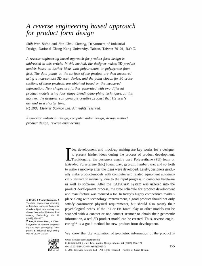
Figure 1 Acquisition of the
data with a no contact scan-
ner.
2 Implementation procedures
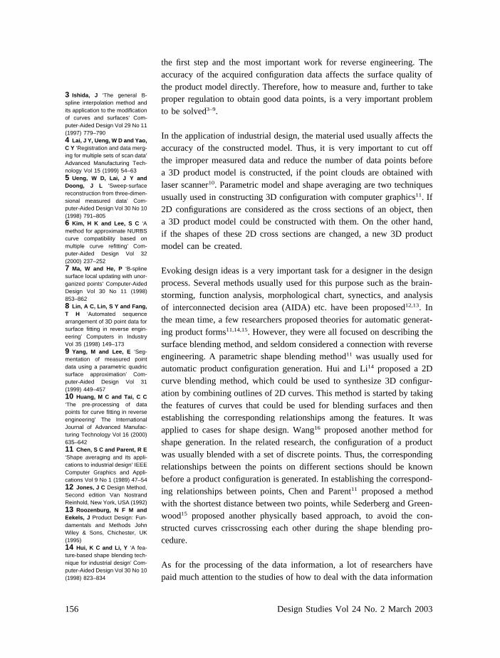
2.1 Acquisition of data pointsThe first step is to make a 3D product model and scan it with a non-contactlaser scanner (Shape Grabber Co.) shown in Fig. 1 to get the measureddata of a complete model (Fig. 2).
Figure 2 The measured
data of a complete model.

159A reverse engineering based approach for product form design
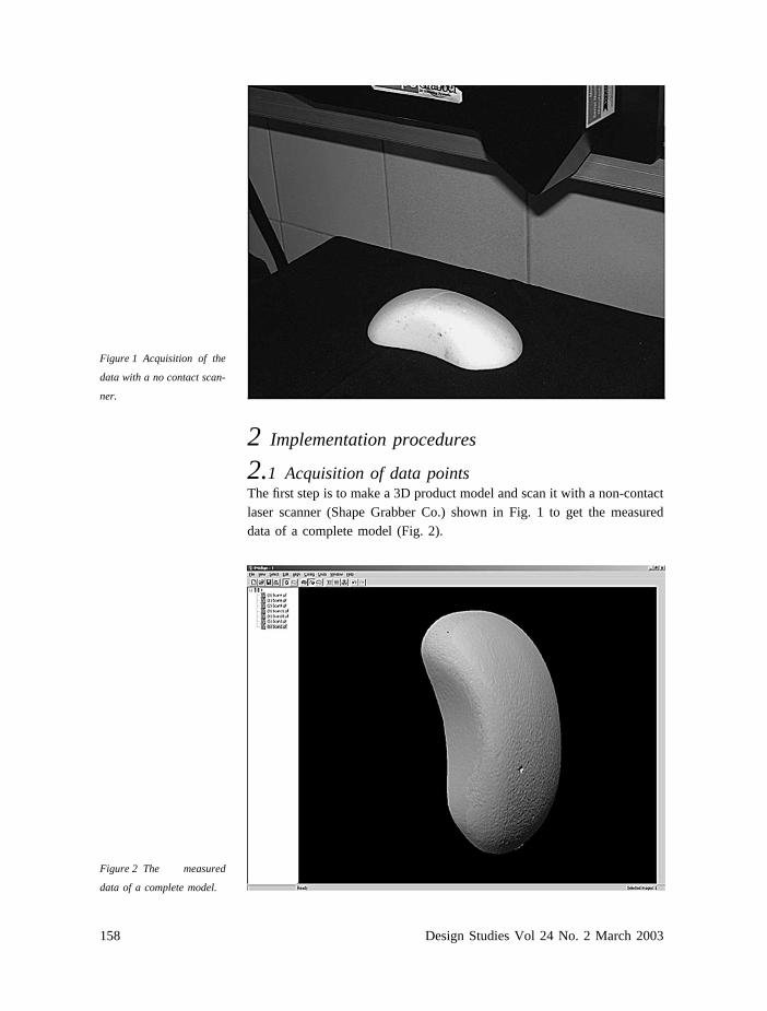
2.2 Preparation of point cloudsThe orientation of the scanned data might not coincide with the coordinatesystem. For the sake of convenience to construct the product model, theorientation of the scanned point clouds should be regulated to coincide withthe coordinate system. The regulating procedure is specified as follows.
(1) Construct three fundamental planes at origin.(2) Select a flat part of the point cloud as a reference plane.(3) Stick the point cloud on one of the fundamental planes constructed in
step 1 with the reference plane selected in step 2.(4) Take proper translations and/or rotations with the operation interface
in Fig. 3 to orient the point clouds to a right direction (Fig. 4).
2.3 Take proper cross sections for the modelTo simplify and unify the set of variables, all the product models are setto cut along Z-axis to take the cross sections. In this paper, each modelwas cut by 30 sections with equal space. Fig. 5 shows an example ofcutting a model to take the cross sections. How to cut the model can be setby the operating interface shown in Fig. 5 (a) that is designed in this study.
2.4 Retrieve data pointsSometimes the scanned data will miss for several reasons, such as havinga concavity or a partition line on the model. In this case, the data shouldbe retrieved. In this study, the interpolation method was used for dataretrieving. Fig. 6 shows the difference between the retrieved and notretrieved models.
2.5 Reduce the data pointsWhen the density of scanned data is too high, the number of data pointscan be reduced. In this study, the point cloud reduction method proposedby Lee and Woo2 was used to reduce the redundant points. Fig. 7 showsthe errors of the constructed curves in terms of the data reduction ratios.The designer can take a proper reduction ratio based on the assigned error.The data distribution after retrieving is shown in Fig. 8.
Figure 3 Operation inter-
face for translations and
rotations.
160 Design Studies Vol 24 No. 2 March 2003
Fig
ure
4T
here
gula
ted
poin
tcl
oud
atri
ght
orie
ntat
ion
(a)
top
view
(b)
fron
tvi
ew(c
)si
devi
ew.

161A reverse engineering based approach for product form design
Figure 5 Cutting planes for
the model of the cross sec-
tions (a) side view (b)
another view.
Figure 6 The difference
between the retrieved and no
retrieved models.
Figure 7 The relationship
between the data reduction
ratios and the errors of con-
structed curves.
2.6 Establish the corresponding relationship betweenthe points on two different sectionsThe number of points may be different on two different sections. However,not only the number of points on each section should be the same, but thepoints should also be corresponded one to one on two different sections ifa new shape is to be created by using shape-blending method. To establish

162 Design Studies Vol 24 No. 2 March 2003
Figure 8 Data distribution
after data reduction.
the corresponding relationship between points on different sections, a rayfiring method is introduced as follows.
The ray firing procedure can be performed with the following steps:
(1) Set all the sections parallel to XY plane with their bottom on XZ plane.(2) Take the origin (0,0) z-axis as the central axis.(3) Calculate the angle θ’s between horizontal line and the radial lines
connecting the center point and the points on the curves.(4) Take the curve with fewer points as the datum curve for comparison.
Here we take an example to specify the ray-firing method. Assuming thatthere are nine and seven points on two section curves a and b shown inFig. 9, respectively. Now the corresponding relationships between thepoints a1~a9 and b1~b7 are required. The procedure is specified step bystep as follows:
(1) Put two curves on the horizontal plane, say XZ plane, with their centerscoincide with the origin (0,0) (see Fig. 10 (a)).
(2) Calculate the angles θbi and θaj formed with the horizontal line andthe radial lines connecting the origin (0,0) and points b1~b7 and pointsa1~a9, respectively.
(3) Decide the corresponding relationship between point bi and point aj
Figure 9 Two sections on
two different models to be
blended.

163A reverse engineering based approach for product form design
Figure 10 Establish the cor-
responding relationship
between two curves with the
ray-firing method.
by comparing the magnitude of θbi and θaj. Point bi and point aj aretaken as a pair if the difference between the angles θbi and θaj is theminimum in comparison with the differences betweenθbi and all otherangles except θaj.
(4) The corresponding relationships among the points on different sectionswill be obtained after the process has completed. The result is shownin Fig. 10 (b).
2.7 Generate new point cloudsA new product shape can be obtained by blending with two differentshapes. In this study, four blending methods are adopted. The formulae ofthese methods are listed as follows:
(1) Weighted arithmetic mean method:
C = w1×g1 + w2×g2 (1)(2) Weighted geometric mean method:
C = �g1w1×g2
w2 (2)
(3) Weighted harmonic mean method:
C =1
w1
g1+
w2
g2
(3)
(4) Generalized weighted mean method:
C = [(w1×g1)α + (w2×g2)α]1/α (4)
Where g1 and g2 are the geometric data and w1 and w2 are the weightingsof shape 1 and shape 2, respectively, C is the geometric data of the newshape, and α is a blending parameter which is decided by the designer forany real number in the range
���� (5)
19 Hsiao, S W ‘Computeraided shape design of an under-water hull’ Naval Engineers Jour-nal Vol 108 No 1 (1996) 37–4720 Hsiao, S W and Chen, C H‘A semantic and shape grammarbased approach for productdesign’ Design Studies Vol 18(1997) 275–29621 Hsiao, S W and Wang, H P‘Applying the semantic trans-formation method to productform design’ Design Studies Vol19 (1998) 309–330
164 Design Studies Vol 24 No. 2 March 2003
Figure 11 The constructed
section curves.
Figure 12 The constructed
surface.
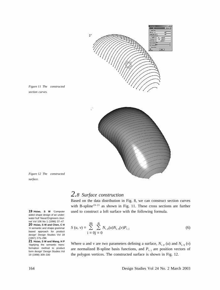
2.8 Surface constructionBased on the data distribution in Fig. 8, we can construct section curveswith B-spline19–21 as shown in Fig. 11. These cross sections are furtherused to construct a loft surface with the following formula.
S (u, v) = �mi = 0
�nj = 0
Ni, p(u)Nj, q(v)Pi, j (6)
Where u and v are two parameters defining a surface, Ni, p (u) and Nj, q (v)are normalized B-spline basis functions, and Pi, j are position vectors ofthe polygon vertices. The constructed surface is shown in Fig. 12.
165A reverse engineering based approach for product form design
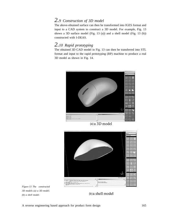
2.9 Construction of 3D modelThe above-obtained surface can then be transformed into IGES format andinput to a CAD system to construct a 3D model. For example, Fig. 13shows a 3D surface model (Fig. 13 (a)) and a shell model (Fig. 13 (b))constructed with I-DEAS.
2.10 Rapid prototypingThe obtained 3D CAD model in Fig. 13 can then be transferred into STLformat and input to the rapid prototyping (RP) machine to produce a real3D model as shown in Fig. 14.
Figure 13 The constructed
3D models (a) a 3D model;
(b) a shell model.

166 Design Studies Vol 24 No. 2 March 2003
Figure 14 A 3D real model
made by RP.
3 Results and discussion
3.1 Application for product designAfter the 3D models are constructed, they can be used to generate newshapes to help the designer to develop design ideas. Here we take anexample to specify how to apply it to product design.
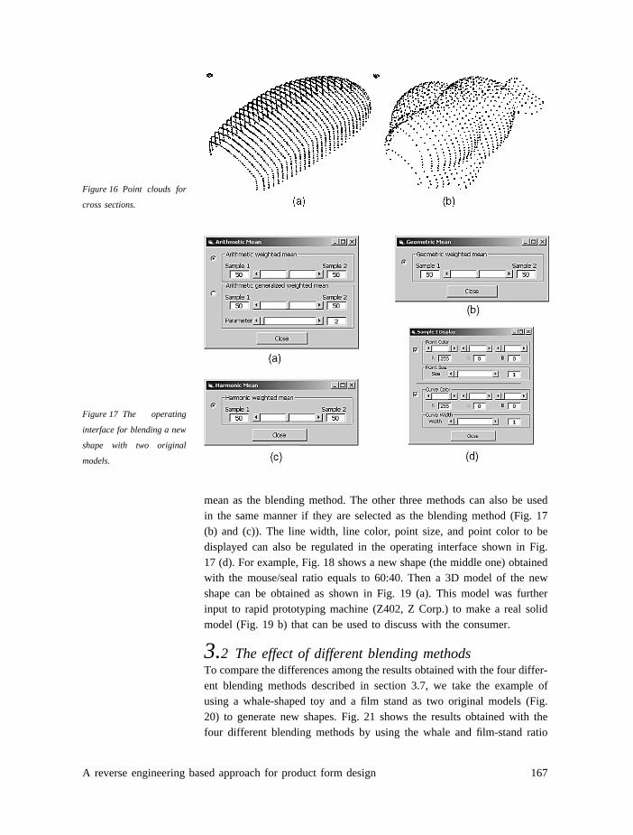
Fig. 15 shows two models of a mouse and a small seal. Taking their pointclouds for cross sections with a laser scanner, based on the previouslyspecified techniques, we have the point clouds of both samples as shownin Fig. 16. Take these samples to blend out a new shape. For ease of useby the user, a friendly operating interface was designed by the authors asshown in Fig. 17. Fig. 17 (a) is used to regulate the required blending ratioof the two samples. This figure shows the example of using the arithmatic
Figure 15 A mouse and a seal-shaped model.
167A reverse engineering based approach for product form design
Figure 16 Point clouds for
cross sections.
Figure 17 The operating
interface for blending a new
shape with two original
models.
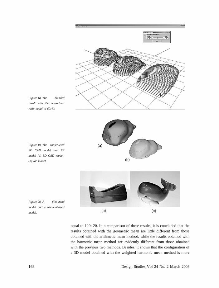
mean as the blending method. The other three methods can also be usedin the same manner if they are selected as the blending method (Fig. 17(b) and (c)). The line width, line color, point size, and point color to bedisplayed can also be regulated in the operating interface shown in Fig.17 (d). For example, Fig. 18 shows a new shape (the middle one) obtainedwith the mouse/seal ratio equals to 60:40. Then a 3D model of the newshape can be obtained as shown in Fig. 19 (a). This model was furtherinput to rapid prototyping machine (Z402, Z Corp.) to make a real solidmodel (Fig. 19 b) that can be used to discuss with the consumer.
3.2 The effect of different blending methodsTo compare the differences among the results obtained with the four differ-ent blending methods described in section 3.7, we take the example ofusing a whale-shaped toy and a film stand as two original models (Fig.20) to generate new shapes. Fig. 21 shows the results obtained with thefour different blending methods by using the whale and film-stand ratio
168 Design Studies Vol 24 No. 2 March 2003
Figure 18 The blended
result with the mouse/seal
ratio equal to 60:40.
Figure 19 The constructed
3D CAD model and RP
model (a) 3D CAD model;
(b) RP model.
Figure 20 A film-stand
model and a whale-shaped
model.
equal to 120:-20. In a comparison of these results, it is concluded that theresults obtained with the geometric mean are little different from thoseobtained with the arithmetic mean method, while the results obtained withthe harmonic mean method are evidently different from those obtainedwith the previous two methods. Besides, it shows that the configuration ofa 3D model obtained with the weighted harmonic mean method is more

169A reverse engineering based approach for product form design
Figure 21 The new shapes
obtained with four different
blending methods.
unexpected than those obtained with the arithmetic mean and geometricmean methods. Thus, creative design ideas without exception will beobtained if the harmonic method is used. However, the discrepancy of themodel constructed with this method is larger than those obtained with theprevious two methods. On the other hand, the results obtained with thegeneralized weighted mean method have the effect of local scaling, socreative design ideas can also be obtained by using this method.
3.3 The effect of different blending ratioTo show the effect of adopting different blending ratios, we also use thewhale and film-stand shown in Fig. 20 as the two original models to gener-ate new shapes with different blending ratios. Fig. 22 shows the resultsobtained with weighted arithmetic mean method (Eq. (1)) by using theratios of the whale to the film-stand equal to �40:140; 30:70; 50:50; 70:30;and 140:-40. In these ratios, the weights of whale are increased monot-
Figure 22 The shapes
obtained with different
whale to film-stand ratios
(a) �40:140; (b) 30:70; (c)
50:50; (d) 70: 30; (e)
140:�40.
170 Design Studies Vol 24 No. 2 March 2003
onously, while those of film-stand are decreased monotonously. The resultsshow that the new shapes are evidently different and strongly affected bythe blending ratio. It is seen that the model with the larger weighting domi-nates the generated new shape.
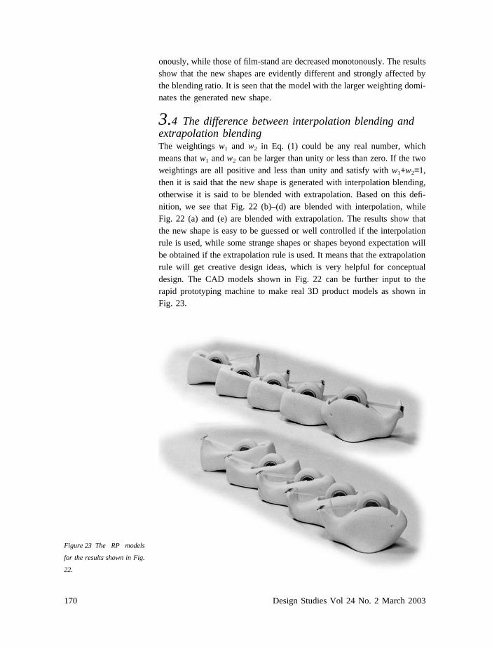
3.4 The difference between interpolation blending andextrapolation blendingThe weightings w1 and w2 in Eq. (1) could be any real number, whichmeans that w1 and w2 can be larger than unity or less than zero. If the twoweightings are all positive and less than unity and satisfy with w1+w2=1,then it is said that the new shape is generated with interpolation blending,otherwise it is said to be blended with extrapolation. Based on this defi-nition, we see that Fig. 22 (b)–(d) are blended with interpolation, whileFig. 22 (a) and (e) are blended with extrapolation. The results show thatthe new shape is easy to be guessed or well controlled if the interpolationrule is used, while some strange shapes or shapes beyond expectation willbe obtained if the extrapolation rule is used. It means that the extrapolationrule will get creative design ideas, which is very helpful for conceptualdesign. The CAD models shown in Fig. 22 can be further input to therapid prototyping machine to make real 3D product models as shown inFig. 23.
Figure 23 The RP models
for the results shown in Fig.
22.
171A reverse engineering based approach for product form design
4 ConclusionsA reverse engineering based approach for product design is proposed inthis article. In this method, a designer can make 3D product models withPU or EK foam artificially. Then a non-contact laser scanner is used tomeasure and record the geometric data of the configurations. The measureddata are then smoothed with skills to get smooth models. A ray firingmethod was used to generate the corresponding relationships between twopoints on two different sections. Two different models are further used togenerate new shapes with four different shape-blending methods. In thismanner, designers can develop their ideas in a shorter time. Though anexample is used to specify the implementation procedures, this method canalso be used to do form design for all other products.
AcknowledgementsThe authors are grateful to the National Science Council of the Republicof China for supporting this research under grant NSC90-2218-E-006-023.