2004 356 motor yacht owner’s guide - microsoft · 2004 356 motor yacht owner’s guide hin - cdr...
TRANSCRIPT

2004
356 Motor Yacht
Owner’s Guide
HIN - CDR
2004 Version 1

Congratulations and Welcome Aboard!
This Owner’s Guide was designed to acquaint you with the safe, proper operation andmaintenance of your new boat and its systems. Your first duty as Captain of your newCarver should be to read your Owner’s Guide and all manufacturer-supplied operating andmaintenance instructions found within your Owner’s Information kit.
Be sure to mail in all manufacturer registrations and warranty cards to validate yourCarver and OEM warranties. These warranty cards have been assembled and are containedin the OEM information packets within your Owner’s Information kit.
If you’re new to boating, learn the proper rules of seamanship to ensure the safety of yourpassengers. Refer to Chapman’s Piloting, Seamanship and Small Boat Handling and attenda safe boating class offered by the U.S. Coast Guard Auxiliary, United States Power Squad-ron, or any enterprise experienced in conducting safe boating courses.
Thank you for choosing Carver. We’re confident your new boat will provide you and yourfamily with years of enjoyable cruising.
Carver Boat Corporation790 Markham DriveP.O. Box 1010Pulaski, WI 54162-1010USAPhone (920) 822-3214Fax (920) 822-3213www.carveryachts.com
Robert VanGrunsvenPresident

DECLARATION OFCONFORMITY
Model Designation
356 Motor Yacht
Carver Boat Corporation declares that the 356 Motor Yacht complies with EC directive 94/25/EC, and in accordance with the following harmonized standards and the recreationalcraft sectoral guidelines in effect at the time of construction.
ISO Reference (Directive) Requirement (RSG) Reference
8666 12216 8469 Annex I 3.212217 8849 8099 Annex V-VIII, XII 3.38665 11812 10088 Article 8 2.114945 12216 12217 2.2 2.315083 10087 9094 3.6 2.415084 14945 15085 2.5 3.18885 11592 11591 3.4 3.510240 11192 7840 3.7 3.88846 10133 11105 3.9 412215 9093 13592 5.1.1 5.1.39097 13297 15584 5.2.1 5.2.28847 8848 9775 5.3 5.4.110592 13929 15852 5.5 COLREGS10239 4505
Type Examination Certification Number
EC Module B+C CAR004
Notified Body
IMCI (#0609) Robin J. ClonkeyRond-Point Manager Manufacturing MethodsSchuman 6 Box 6 Carver Boat CorporationB-1040 Brussels 790 Markham DriveBelgium Pulaski, WI 54162
USA

Your Owner’s Information kit contains this Owner’sGuide and a set of manuals referred to as "OEMinformation." Please read the Owner’s Guide andOEM information carefully and familiarize yourselfwith your boat before operating the boat or any of itscomponents or systems.
IMPORTANT: The Owner’s Information kit must beonboard whenever your boat is operated. If you sellyour boat, make sure the new owner receives the entirekit.
This guide explains how to safely operate and maintainyour boat and its various systems. The guide also con-tains safety precautions and operational tips, as de-scribed below.
Describes a hazard that can cause death or severeinjury if the instructions are ignored.
Describes a hazard that can cause serious injury and/or property damage if the instructions are ignored.
Describes a hazard that can cause damage to yourboat or its components if the instructions are ignored.
NOTE: Provides important information that can helpyou avoid problems.
If this is your first boat, or if you are changing to a typeof boat you are not familiar with, for your own comfortand safety, please obtain handling and operation experi-ence before operating the boat. Your dealer or nationalsailing federation or yacht club can advise you of localsea schools or competent instructors.
NOTE: Drawings and illustrations contained within thisguide are included as graphic aids to assist in thegeneral operation and maintenance of your boat. Thesedrawings and graphics do not include all details of
Using Your Owner’sInformation Kit
Owner’s Guide
A TIP FROM CARVER!
There are many people within theCarver organization who are avidboaters. Some of the experiencegained during our years ofboating are presented in thisOwner's Guide. This informationis presented in the left marginand is entitled "A TIP FROMCARVER".
PREFACE
5/01

each system and are not drawn to scale. Do not refer-ence these drawings to order parts or to service yourboat. Contact your authorized Carver Dealer for anyparts or service required for your boat.
The information contained in this Owner’s Guide wascomplete and accurate at the time the guide was printed.Carver reserves the right to change materials, partnumbers, specifications, or system designs at any timewithout notice.
The OEM (Original Equipment Manufacturer) informa-tion is supplied by companies from whom Carver haspurchased components to install in your boat. Thesecomponents include, but are not limited to, standarditems like the engines, sanitation system, various pumps,and 12-volt batteries, as well as optional items like theair conditioning system and navigation systems. TheOEM information explains how to operate and maintainthe components.
If you install an aftermarket accessory on your boat, addthe OEM information that accompanies the accessory tothe Owner's Information kit.
NOTE: If the OEM information conflicts with thisOwner’s Guide, follow the instructions in the OEMinformation.
OEM Information
PREFACE
5/01

The Pre-Delivery Service Record that follows thispage must be completed and signed by your CarverDealer before you take delivery of your new Carveryacht. Your Carver Dealer will prepare your boat fordelivery in accordance with the procedures detailedwithin this document.
Be certain that the boat’s Pre-Delivery Service Recordand all OEM warranty cards have been completed andmailed to their respective companies. Be sure youretain a copy of the Pre-Delivery Service Record foryour own reference.
Carver warrants every boat we manufacture as ex-plained in the Carver Limited Warranty. Your copy ofthe warranty is located in Section 9. Please reviewthe warranty carefully.
The Warranty Registration that follows this page isthe first step in activating your Carver limited war-ranty. This document must be completed and signedby you and your Carver Dealer before you take deliv-ery of your new Carver yacht. Failure to complete andregister this Warranty Registration could void yourCarver limited warranty.
Your Carver Dealer will review the terms of theCarver warranty and make certain the warranty isregistered with Carver.
To ensure that the warranty remains in effect duringits lifetime, Carver Boat Corporation, your CarverDealer, and you must each uphold specific responsi-bilities. These responsibilities are described in Sec-tion 9.
At time of delivery, make a complete inspection of theboat and its systems. Document any work that needsto be completed by the Dealer in order to meet theterms of your agreement.
There are two cards located at the end of this Preface.These are Second and Third Owner RegistrationCards. We strongly recommend that the purchaser ofa previously-owned Carver register ownership withCarver.
Pre-Delivery ServiceRecord
PREFACE
5/01
WarrantyRegistration

PREFACE
5/01

SECOND OWNER REGISTRATION
Owner's Name:
Street Address:
City: State: Zip Code:
Telephone: ( ) Date of Purchase:
Purchased From:
Boat Hull Identification Number: CDR
Second Owner Registration does not extend, alter, or transfer the Carver Limited War-ranty. Refer to the Carver Limited Warranty for details.
THIRD OWNER REGISTRATION
Owner's Name:
Street Address:
City: State: Zip Code:
Telephone: ( ) Date of Purchase:
Purchased From:
Boat Hull Identification Number: CDR
Third Owner Registration does not extend, alter, or transfer the Carver Limited Warranty.Refer to the Carver Limited Warranty for details.

CARVER BOAT CORPORATIONP O BOX 1010PULASKI WI 54162-1010
CARVER BOAT CORPORATIONP O BOX 1010PULASKI WI 54162-1010

13307 6/02
SECTION 1 BOATING SAFETY
Boating Safety
Safe Operation ............................................................................ 2Safety Recommendations ................................................. 2Adverse Conditions ........................................................... 3Emergency Procedures ..................................................... 6Safety Equipment ............................................................ 11
Owner’s Responsibilities .......................................................... 14Safe Boating Courses ...................................................... 14Rules of the Road ............................................................ 15Documentation ................................................................ 15Drugs and Alcohol ........................................................... 16Distress Calls................................................................... 16Voluntary Inspections ..................................................... 16Boating Accidents ........................................................... 16Boating Regulations ........................................................ 17Pre-Departure Actions..................................................... 18
Carbon Monoxide (CO) Warnings ............................................. 19Preventing CO Exposure ................................................. 19Identifying CO Exposure ................................................. 21Treating CO Exposure ..................................................... 21
Warning Labels ......................................................................... 21
2
BOATING SAFETY
3307 6/02
SECTION 1
Boating safety is your responsibility. You must fullyunderstand the operating procedures and safety precau-tions in the Owner’s Information kit and this owner’sguide before you operate your new boat. Safe boating isno accident.
Safe operation includes, but is not limited to, the follow-ing.
• Keep your boat and equipment in safe operatingcondition. Inspect the hull, engines, safety equip-ment, and all boating gear regularly.
NOTE: Federal law requires you to provide andmaintain safety equipment on your boat. ConsultU.S. Coast Guard, state, and local regulations toensure your boat has all required safety equipmentonboard. Additional equipment may be recom-mended for your safety and that of your passengers.Make yourself aware of its availability and use.
• Be very careful when fueling your boat. Be sure youknow the capacity of your boat’s fuel tank and theamount of fuel used when operating at frequentlyused engine speeds (RPMs). Refer to the “Specifi-cations” portion of Section 9 for the fuel tankcapacity. Refer to the “Fueling” portion of Section5 for information on fueling your boat.
• Make sure you have enough fuel onboard for antici-pated cruising requirements. In general, use 1/3 ofyour supply to reach your destination and use 1/3 toreturn. Keep 1/3 in reserve for changes in yourplans due to weather or other circumstances.
• Be sure fire extinguishing and lifesaving equipmentis onboard. This equipment must meet regulatorystandards, and it should be noticeable, accessibleand in proper operating condition. Your passengersshould know where this equipment is and how touse it.
• Keep an eye on the weather. Be aware of possiblechanging conditions by checking local weatherreports before your departure. Monitor strongwinds and electrical storms.
Safe Operation
SafetyRecommendations
33307 6/02
SECTION 1 BOATING SAFETY
• Always keep accurate, updated charts of the areayou are cruising. Back up charts if you use a chartplotter.
• Before you leave the port or harbor, file a Float Planwith a family member, relative, friend, or otherresponsible person ashore.
• Always operate your boat with care, courtesy andcommon sense.
• Instruct at least one passenger onboard in the basicoperation of your boat. This person can take over ifyou unexpectedly become unable to do so.
• Do not allow passengers to ride on parts of yourboat other than designated seating areas.
• Ask all passengers to remain seated while the boatis in motion.
• Do not use the boarding platform or boarding ladderwhile either or both of the engines are running.
• Understand and obey the “Rules of the Road.”Always maintain complete control of your boat.
• Do not overload or improperly load your boat.
• Do not travel faster than conditions warrant orbeyond your abilities.
• Do not operate your boat in weather or sea condi-tions beyond your skill and experience.
• Do not operate your boat while under the influenceof drugs and/or alcohol.
• Do not operate your boat if your visibility is im-paired.
Weather
Storms rarely appear without advance notice. Check theweather forecast before you begin a day of boating. Beaware, however, that weather conditions can changerapidly. If you have a marine radio, listen to theweather reports issued by the U.S. Coast Guard and
AdverseConditions

4
BOATING SAFETY
3307 6/02
SECTION 1
others. If you have a portable radio, keep it tuned to astation broadcasting frequent weather reports. Manyboating clubs fly weather signals. Learn to recognizethese signals, and listen to your local forecasts beforeleaving port.
WEATHER SIGNALS
Your surroundings can also be a good indicator of chang-ing weather conditions. Watch for changes in winddirection or cloud formations. There is no substitute fora good understanding of weather conditions and what todo when the weather takes a turn for the worse.
RED
WHITE
RED
WHITE123456712345671234567123456712345671234567
RED
Small Craft AdvWinds to 38 mph
RED
Gale WarningWinds to 54 mph
Day
Fla
gsN
ight
Lig
hts
123456123456123456123456123456123456123456
RED
RED
WHITE123456712345671234567123456712345671234567
BLACK onRED
Storm WarningWinds to 72 mph
HurricaneWinds to 54 mph
Day
Fla
gsN
ight
Lig
hts
123456123456123456123456123456123456123456
1234567890123412345678901234123456789012341234567890123412345678901234123456789012341234567890123412345678901234
12345678901231234567890123123456789012312345678901231234567890123123456789012312345678901231234567890123
123456789012312345678901231234567890123123456789012312345678901231234567890123123456789012312345678901231234567890123
BLACK onRED
RED123456123456123456123456123456123456
123456712345671234567123456712345671234567
RED

53307 6/02
SECTION 1 BOATING SAFETY
Fog
Fog is a result of either warm-surface or cold-surfaceconditions. You can judge the likelihood of fog formationby periodically measuring the air temperature and dewpoint temperature. If the difference between these twotemperatures is small, fog is likely to develop.
Remember the following guidelines:
• Unless your boat is well equipped with charts andnavigational equipment, head for shore at the firstsign of fog and wait until conditions improve. If youhave charts on board, take bearings as fog sets in,mark your position, and continue to log your courseand speed.
• Make sure all persons onboard put on their per-sonal flotation devices.
• If your boat has sounding equipment, take sound-ings regularly and match them with depths shownon your charts.
• Station a person forward in the boat as a lookout.
• Reduce your speed. From time to time, stop enginesand listen for other fog signals.
• Sound the horn or fog bell intermittently to warnothers.
• If there is any doubt in continuing your excursion,anchor. Listen for other fog signals while continu-ing to sound your fog horn or bell.
Storms
At all times, the boat operator should be aware ofpresent weather conditions and the weather forecast. Ifstorms are a possibility, keep a watch on the horizon,especially to the West for approaching storms. Monitorthe weather forecast on a marine channel or localweather station. It would be best to return to a safe portif time allows.
Other steps to follow to weather the storm include:

6
BOATING SAFETY
3307 6/02
SECTION 1
• Close portlights, exterior doors and hatches andsecure them. Stow all loose gear below deck and tiedown any gear on deck.
• Reduce speed as the seas build. Make sure allpersons onboard have put on their personal flota-tion devices.
• Drop a sea anchor to maintain the bow into theseas. If you do not have a sea anchor onboard, use acanvas bucket, tackle box, or other object that willwork like an anchor.
Radar reflectors (if installed on your boat) should be 18inches, measured diagonally. They should be placed 12feet above the waterline, otherwise, a boat with radarmay have trouble “seeing” your boat.
The following is not an exhaustive list of situationswhich may be encountered while boating. You shouldobtain training to handle any emergencies which mayarise.
Fire
Any fire onboard your boat is serious. Explosion ispossible. Develop a fire response plan. Respondimmediately.
To help prevent a fire onboard your boat, keep yourbilges clean and check for fuel and gas vapors at regularintervals. Also, DO NOT fit free-hanging curtains orother fabrics in the vicinity of or above the stove top orother open flame devices. Do not store any materials orequipment of any kind in the engine room.
Every boater should develop a fire response plan todetermine what kind of fire (fuel, electrical, etc.) mightbreak out, where it might break out, and the best wayto react. Have a plan and, if possible, assign responsi-bilities to others to allow quicker decisions and reac-tions.
EmergencyProcedures

73307 6/02
SECTION 1 BOATING SAFETY
Never:• Obstruct passage ways to exits and hatches.• Obstruct safety controls, such as fuel valves, gas
valves and electrical system switches.• Obstruct portable fire extinguishers in lockers.• Leave the boat unattended when cooking or heat-
ing appliances are in use.• Use gas lights in the boat.• Modify any of the boat's systems (especially
electrical, fuel or gas).• Fill any fuel tank or replace gas bottles when
machinery is running or when cooking or heatingappliances are in use.
• Smoke while handling fuel or gas.
NOTE: Everyone onboard should know where fireextinguishers are and how to operate them.
In case of fire:
• Stop the engines immediately.
• If the fire is in the engine room, shut off the bilgeblowers immediately. Do not open the hatch tothe engine room. The fire will flare up if the freshair supply increases suddenly.
• Keep the fire downwind if possible. If the fire is aft,head into the wind.
• Have all persons onboard put on their personalflotation devices.
• If you can get at the fire, aim the fire extinguisherat the base of the flames and use a sweeping motionto put out the fire.
• If the fire gets out of control, make a distress signaland call for help on the radio.
Deciding whether to stay with the boat or abandon shipwill be difficult. If the decision is to abandon ship, allpersons onboard should jump overboard and swim asafe distance away from the burning boat.

8
BOATING SAFETY
3307 6/02
SECTION 1
Smoking, poor maintenance or carelessness whenrefueling can cause hazardous conditions. Alwaysfollow proper refueling procedures for your boat.
Flooding
If your boat is taking on water from a leak in the hull,turn on your bilge pumps. Assign someone to bail outthe bilge and investigate the cause of the flooding. Whenthe source of the leak is found, attempt to repair it.
Almost anything can be stuffed into a hole to stop theleaking temporarily. Material used to stop a leak willwork better if it is applied from the outside where waterpressure can help hold it in. If necessary, station a crewmember to hold the plug in place if the plug is appliedfrom the inside. In all cases, station a crew member orpassenger to watch the plugged area and alert others ifit fails.
Swamped or Capsized Boat
If your boat becomes swamped or capsizes, put on apersonal flotation device immediately and set off adistress signal. Chances are good a capsized boat willstay afloat. For this reason, stay with the boat. Do notleave the boat or try to swim to shore except underextreme conditions. A capsized boat is easier to see thana swimmer, and the shore may be further away than itappears.
If water is coming over the bow, reduce headway andturn the boat slightly so that the bow is slightly off frommeeting the waves head on. Drop a sea anchor andadjust the length of the line to hold the bow at the mostfavorable angle.
Collision
If a serious collision occurs, check everyone onboard forinjuries, then inspect the boat to determine the extentof the damage.
• Prepare to help the other craft unless your boat orits passengers are in danger.

93307 6/02
SECTION 1 BOATING SAFETY
• If the bow of the other craft penetrated your boat’shull, prepare to plug the fracture once the boats areseparated.
• Shore up the hole inside your boat with a spare lifejacket or bunk cushion.
• While plugging the hole, trim weight to get the holeabove the water level during repairs, if possible.
• If your boat is in danger of sinking, have everyoneonboard put on their personal flotation devices.
• If your boat has a radio, contact the U.S. CoastGuard or other rescue authorities immediately onVHF channel 16 or CB radio channel 22. (You mayalso be able to use VHF channels 9 or 13 or yourcellular phone in some states).
Running Aground
Excessive weight in the fore or aft sections of the boatwill cause a trim change and may yield greater draftthan expected. Equip your boat with a good qualitydepth-measuring instrument and allow ample waterbelow the hull while operating.
If your boat runs aground, check everyone onboard forinjuries, then inspect the boat for damage. If lightlygrounded, shift the weight of the passengers or gear toheel the boat while reversing engines. If towing becomesnecessary, use a commercial towing service.
Never attach a tow line to a deck cleat or anchor wind-lass. The cleats and windlass are not designed to takethe full load of the boat and may pull free from thedeck, causing serious injury or property damage.
Man Overboard
You should know what to do in case someone fallsoverboard. Emergency procedures are published inChapman’s and instruction is offered by the U.S. CoastGuard.

10
BOATING SAFETY
3307 6/02
SECTION 1
If a person falls overboard, hypothermia may be animmediate concern. Hypothermia occurs when aperson’s body loses heat faster than the body can replaceit. If not rescued, the person will become exhausted orlikely drown. In general, the colder the water, the fasterbody heat is lost. Personal flotation devices increasesurvival time because they provide insulation.
WATER SURVIVAL CHART
WaterTemp. (°F)
32.532.5-4040-5050-6060-7070-80Over 80
ExhaustionUnconsciousness
Under 15 min.15-30 min.30-60 min.1-2 hr.2-7 hr.3-12 hr.Indefinite
Expected Timeof Survival
Under 45 min.30-90 min.1-3 hr.1-6 hr.2-40 hr.3 hr.- IndefiniteIndefinite
Medical Emergency
No one should act as a doctor if they are not prop-erly trained and educated. Someone onboard yourboat should know first aid. First aid training is availablethrough your local Red Cross. Keep a fully stocked firstaid kit onboard your boat at all times.
Equipment Failure
Steering, propulsion or control failure can be preventedby having your boat maintained correctly and checkedperiodically. If systems onboard your boat do fail, radiofor help or signal with flags and wait until help arrives.
Radio Communication
You are responsible for obtaining a radio operator’spermit and knowing and following proper rules andprocedures. Private boats are not required to have theirradio on at all times; however, if your radio is on, itshould be tuned to channel 16 unless it is being activelyused. Channel 16 is the frequency for emergency calls orinitial calls between boats. After establishing contact onchannel 16, change your frequency to channel 22.
113307 6/02
SECTION 1 BOATING SAFETY
More information on radio communications can be foundin Chapman’s Piloting.
Distress Signals
The operator is required to lend assistance to a craft indistress as long as your life or boat is not put in harm’sway in the process. Good Samaritan laws protect youfrom any liability incurred while giving aid.
NOTE: Federal law requires you to provide and main-tain safety equipment onboard your boat. Consult U.S.Coast Guard, state and local regulations to ensure yourboat has all required safety equipment onboard. Youmust learn about any additional recommended equip-ment before operating the boat.
Personal Flotation Devices (PFDs)
There must be one U.S. Coast Guard-approved wearablepersonal flotation device of Type I, II, or III for eachperson onboard your boat. The PFDs must be readilyaccessible and in serviceable condition. They must alsobe of a suitable size for each person onboard. ThreePFDs (two wearable and one throwable) are requiredregardless of the number of persons onboard.
PFD Type I, Wearable: This offshore life jacket ismost effective for all waters when rescue may be de-layed. In the water, its design turns most unconsciouspeople from a facedown position to a vertical or face-upposition.
PFD Type II, Wearable: This near-shore buoyant vestis intended for calm inland waters where there is achance of quick rescue. It turns its wearer to a face-upposition, but the turning action is not as pronounced asthe Type I, and it will not turn as many people underthe same conditions as a Type I.
PFD Type III, Wearable: Classified as a flotation aid,this PFD will not turn a victim to a face-up position.This type of PFD is frequently used in water sports.
PFD Type IV, Throwable: You must also have on-board at least one throwable PFD Type IV device. Thedesign of the Type IV device does not allow it to be worn.It must be thrown to a person in the water and held by
Safety Equipment

12
BOATING SAFETY
3307 6/02
SECTION 1
the user until rescued. The most common Type IV PFDsare buoyant cushions or ring buoys. This PFD must bein serviceable condition and immediately available foruse.
Visual Distress Signals
The U.S. Coast Guard requires that all boats operatingon U.S. coastal waters have visual distress signalequipment. Boats owned in the United States andoperating on the high seas must also carry this equip-ment.
Visual distress equipment must be readily accessibleand in serviceable condition. Both pyrotechnic and non-pyrotechnic equipment must be U.S. Coast Guardapproved. This equipment can become ineffective withage. If your equipment’s usage date has expired, replacethe equipment before taking your boat out.
Approved pyrotechnic equipment includes:
• Hand held or aerial red flares• Hand held or floating orange smoke• Launchers for aerial red meteors or parachute
flares.
Approved non-pyrotechnic equipment includes:
• Orange distress flag• Dye markers• Electric distress light.
No one signaling device is ideal under all conditions.Consider carrying various types of equipment. Carefulselection and proper stowage of visual distress equip-ment are very important. Select devices with packagingthat children, but not adults, will find difficult to open,especially if young children are onboard.
Sound Signaling Device
Your boat must have an operable device that can pro-duce a sound signal if conditions require. A horn isstandard equipment on all Carver models.
For boats over 26 feet and under 39 feet, 4 inches, thedevice can be hand or power operated and must be ableto produce a four-second blast which can be heard one-

133307 6/02
SECTION 1 BOATING SAFETY
half mile away. Refer to the U.S. Coast Guard’s publica-tion “Navigational Rules, International-Inland” fordetails on the appropriate signals.
Boats longer than 39 feet, 4 inches, must have a belland a whistle. These devices must meet the require-ments of the Inland Navigational Rules Act of 1980.
Running and Navigation Lights
Your boat must have running and navigation lights forsafe operation after dark. Observe all navigation rulesfor meeting and passing. Do not run at high speedsduring night operation. Always use common sense andgood judgment when operating your boat at night.
Fire Extinguishers
Fire extinguishers must be approved by the U.S. CoastGuard. The U.S. Coast Guard classifies fire extinguish-ers by the type of fire they can extinguish. These classi-fications include foam, carbon dioxide, chemical, andHalon-type fire extinguishers. Below are the require-ments for fire extinguishers at the time this guide wasprepared.
Boats longer than 26' and shorter than 40': TwoType B-I or at least one Type B-II portable hand extin-guisher. If your boat has a fixed fire extinguishingsystem approved by the U.S. Coast Guard, one Type B-1extinguisher is required.
Boats longer than 40' and shorter than 65': ThreeType B-I or one Type B-I and one Type B-II portablehand extinguishers. If your boat has a fixed fire extin-guishing system approved by the U.S. Coast Guard,Two Type B-I or one Type B-II extinguisher is required.
All fire extinguishers should be mounted in a readilyaccessible location away from the engine room. Every-one onboard should know where the fire extinguishersare and how to operate them.
If your fire extinguisher has a charge indicator gauge,cold or hot weather may affect the gauge reading.Consult the instruction manual supplied with the fireextinguisher to determine the accuracy of the gauge.

14
BOATING SAFETY
3307 6/02
SECTION 1
Check and maintain fire extinguishing equipment inaccordance with its manufacturer’s recommendations.Be sure to replace fire fighting equipment, if expired ordischarged, by devices of identical or greater fire fight-ing capacity.
Recommended Equipment
In addition to required equipment, you may want tocarry the following:
• Spare anchor• Heaving line• Fenders• Flashlight• Mirror• Suntan lotion• Spare propeller(s)• Tool kit• Ring buoy• Navigational charts• Mooring lines• Binoculars• Spare parts• Spare pump.
There are several areas you must have knowledge of tooperate your boat in a safe, responsible manner.
Your local U.S. Coast Guard Auxiliary and the U.S.Power Squadrons offer comprehensive safe boatingclasses several times a year. You may contact the Boat/U.S. Foundation at 1-800-336-BOAT (2628) or, in Vir-ginia, at 1-800-245-BOAT (2628). For a course schedulein your area you may also contact your local U.S. CoastGuard Auxiliary or Power Squadron Flotilla for the timeand place of their next scheduled class.
Carver also recommends that you read Chapman’sPiloting, Seamanship and Small Boat Handling forfurther information on how to handle your boat invarious situations.
Owner’sResponsibilities
Safe BoatingCourses

153307 6/02
SECTION 1 BOATING SAFETY
Rules of the Road Navigating a boat responsibly requires you to complywith a set of rules intended to prevent accidents. Just asyou assume other car drivers know what they are doing,other boaters assume you know what you are doing.
As a responsible boater, you must comply with themarine traffic rules enforced by the U.S. Coast Guard.There are two sets of rules: the United States InlandNavigational Rules and the International Rules. TheUnited States Inland Rules apply to all vessels insidethe demarcation lines separating inland and interna-tional waters. The U.S. Coast Guard lists the trafficregulations in its publication “Navigational Rules,International-Inland.” You can get a copy from yourlocal U.S. Coast Guard Unit or the United States CoastGuard Headquarters, 1300 E Street NW, Washington,D.C. 20226.
Other helpful publications available from the U.S. CoastGuard include “Aids to Navigation” (U.S. CoastGuard pamphlet #123), which explains the significanceof various lights and buoys; the “Boating SafetyTraining Manual” and “Federal Requirements ForRecreational Boats.” Check with your local U.S. CoastGuard station, your Carver Dealer, or a local marinaabout navigational aids unique to your area.
The owner of a boat registered with the U.S. CoastGuard is issued a Certificate of Number. This certificatemust be onboard whenever the boat is in use. Stateregistration is also required. If your boat has a VHFradio onboard, an FCC license must also be displayed.Check with the U.S. Coast Guard or your state regula-tory agency to determine what other records are re-quired on your boat.
In addition to required documents, it is strongly recom-mended that you maintain the following logs. Log booksare available from maritime supply stores.
• A navigation log containing engine speeds, compasscourses and time records, which are essential forboth cruising and maintenance purposes.
• A radio log, which is mandatory on vessels requiredto have a radio. A radio log can be useful to recordunusual events, especially for future litigation.
Documentation

16
BOATING SAFETY
3307 6/02
SECTION 1
• A maintenance log to track the type and frequencyof maintenance procedures performed on your boatand its systems. Refer to Section 7 for more infor-mation on maintaining your boat.
• An engine/fuel log, which is essential for calculatingrange and fuel requirements.
• A GPS/Loran log if your boat contains this equip-ment.
Drugs and alcohol adversely affect a person’s ability tomake sound judgments, react quickly and, in general,safely operate a boat. As a responsible boater, you mustrefrain from using drugs or alcohol while operating yourboat. Operating a motorized boat while under the influ-ence of drugs or alcohol carries a significant penalty.
If you have a ship-to-shore radio telephone, heed stormwarnings and answer any distress calls from otherboats. The word “MAYDAY” spoken three times is theinternational signal of distress. Monitor marine radiochannel 16 which is reserved for emergency and safetymessages. You can also use this channel to contact theU.S. Coast Guard or other boaters if you have trouble.Never send a “MAYDAY” message unless there is aserious emergency and you are in need of immedi-ate assistance.
The U.S. Coast Guard Auxiliaries or state boatingofficials in many states offer courtesy inspections tocheck your boat for compliance with safety standardsand required safety equipment. You may voluntarilyconsent to one of these inspections, after which you areallowed time to make corrections without prosecution.Check with the appropriate state agency or the U.S.Coast Guard Auxiliary for details.
The operator of a vessel used for recreational purposesis required to file a report whenever an accident resultsin loss of life or disappearance from a vessel, an injuryrequiring medical treatment beyond first aid, propertydamage in excess of $200 or complete loss of the vessel.
VoluntaryInspections
Boating Accidents
Distress Calls
Drugs and Alcohol

173307 6/02
SECTION 1 BOATING SAFETY
BoatingRegulations
In cases of death and injury, reports must be submittedwithin 48 hours. In other cases, reports must be submit-ted within 10 days. Reports must be submitted in thestate where the accident occurred.
It is your responsibility to make sure that your boat isin compliance with all federal, state and local regula-tions. Check with your local U.S. Coast Guard office forrelevant federal regulations. Your state’s Department ofNatural Resources may have some publications avail-able which deal with relevant state laws.
Garbage
Dumping garbage into the sea is a worldwide problem.U.S. Coast Guard regulations prohibit dumping plasticrefuse and garbage mixed with plastic into any waters,and restrict the dumping of other forms of garbage. It isessential that all boaters help to clean our waterwaysby properly disposing of all garbage.
Within three miles of the shore of U.S. lakes, rivers andbays it is illegal to dump plastic, dunnage, lining andpacking materials that float, and any garbage exceptdishwater/greywater or fresh fish parts. From three totwelve miles from shore it is illegal to dump plastic,dunnage, lining and packing materials that float, andany garbage not ground to less than one square inch.From 12 to 25 miles from shore it is illegal to dumpplastic, dunnage, lining and packing materials thatfloat. Beyond 25 miles from shore it is illegal to dumpplastics.
Oil
The Federal Water Pollution Control Act prohibits thedischarge of oil or oily waste into or upon the navigablewaters and contiguous zone of the United States if suchdischarge causes a film or sheen upon, or discolorationof, the surface of the water, or causes a sludge or emul-sion beneath the surface of the water. Violators aresubject to a significant fine.
Septic Waste
On U.S. inland and coastal waters, it is illegal to dis-charge septic waste directly overboard. If your boat isequipped with an overboard discharge option, check

18
BOATING SAFETY
3307 6/02
SECTION 1
with your local U.S. Coast Guard office to be sure thatyou are in compliance with federal regulations.
State and Local Ordinances
Your state or locality may have laws limiting speed,noise, or your boat’s wake. Check with your harbormaster to find out whether your boat’s operation isrestricted in any way by local ordinances or state laws.Check with state and local authorities to make surethat you are in compliance with local regulations re-garding marine sanitation, noise, speed and wake.
• Check the weather. Make sure conditions and seaswill not be hazardous during your voyage.
• Make sure all safety equipment is onboard, acces-sible and in good working condition.
• Check the bilge for fuel vapor or water. Ventilate orpump out the bilge as necessary.
• Be sure the horn, navigation equipment and lightsare working properly.
• Instruct guests and crew in safety and operationalmatters.
• Check engine and transmission oil and coolantlevels. After starting the engines, check the over-board flow of cooling water, engine temperaturesand oil pressures.
• Fill fuel tanks as full as you need. Know your tankcapacity and fuel consumption at various RPMsand the cruising radius this gives you. When esti-mating your range, it is best to count on using 1/3of your fuel to reach your destination and 1/3 ofyour fuel to return, with the remaining 1/3 of yourfuel in reserve for emergencies.
• Have a second person onboard capable of takingover the boat’s operation in case you are disabled.
• Before departing, inform a friend or relative whereyou intend to cruise and when you will return sothey can tell the U.S. Coast Guard where to look
Pre-DepartureActions

193307 6/02
SECTION 1 BOATING SAFETY
and the type of boat in case you are delayed. Re-member to tell them of your safe return to preventfalse alarms. Do not file a float plan with the U.S.Coast Guard. They do not have the manpower tomonitor all boats.
• Stow all loose gear securely. Fenders and docklinesshould be stowed immediately after getting under-way.
Carbon monoxide (CO) is a colorless, odorless andtasteless gas which is emitted in all engine and gen-erator exhaust. Prolonged exposure to CO can result inunconsciousness, brain damage and death.
Carver has installed CO detectors on your boat. Havethese detectors professionally calibrated at regularintervals.
To help prevent the accumulation of CO in your boat’scabin and in enclosed exterior areas:
• Pay attention to prevailing conditions and provideventilation to induce fresh air and minimize ex-haust re-entry. Position the boat to maximize thedissipation of CO. Be aware that CO can enter theboat through cockpit and deck drains, especiallywhen the cockpit and deck are enclosed.
• Do not operate the engines or generator for morethan a very short period of time while the boat isstationary, especially if the boat is rafted or mooredin a confined area.
• Be aware that mooring and anchoring in an areawhere other boats’ engines or generators are run-ning may put your boat in an atmosphere contain-ing CO, even if your boat’s engines and generatorare not running.
• Keep the engine room hatch(es) closed when operat-ing the engines and generator.
Carbon Monoxide(CO) Warnings
Preventing COExposure

20
BOATING SAFETY
3307 6/02
SECTION 1
• Be aware that exterior enclosures can create airflows that draw in and trap CO in the enclosedareas. Provide adequate ventilation to these areas.
• Do not occupy aft lounging areas, including theboarding platform, or swim near the engine exhaustoutlets while the engines or generator are running.
• Because CO production is greater when the enginesare cold, minimize the time spent getting underway.
• Avoid backdrafting. Backdrafting occurs when airmoving past the boat creates a low pressure orsuction area near the stern. This low pressure areacan draw CO into the boat’s cabin and enclosedexterior areas.
Under certain speed and operating conditions, thelow pressure area may form in other areas of theboat and permit CO to enter through openings thatare not near the stern.
To avoid backdrafting:
- Maintain the proper trim angle; avoid a high bowangle.
- Distribute the boat’s load evenly.
- Do not operate the boat at slow speeds, especiallywith a following wind.
- Provide adequate ventilation; make sure the airflow is moving from forward to aft inside thecabin and enclosed exterior areas.
• Have a trained marine technician inspect the boat’sexhaust systems whenever the boat is in for serviceor if you notice a change in the sound of an engineor the generator.
• Maintain the propulsion and generator engines tooptimize their efficiency; this in turn reduces COemissions.
For additional information on carbon monoxide as itrelates to boating, please contact marine organizationsthat produce safety publications.

213307 6/02
SECTION 1 BOATING SAFETY
Treating COExposure
Identifying COExposure
In high concentrations, CO can be fatal within minutes;however, the effects of lower concentrations can also belethal. Symptoms of exposure to CO are:
• Watering and itchy eyes• Flushed appearance• Throbbing temples• Inattentiveness• Inability to think coherently• Loss of physical coordination• Ringing in the ears• Tightness across the chest• Headache• Drowsiness• Incoherence / slurred speech• Nausea• Dizziness• Fatigue• Vomiting• Collapse• Convulsions.
If you suspect that someone is suffering from exposureto CO, take the following actions immediately:
• Thoroughly ventilate the area if possible• Evacuate the area and move the affected person(s)
to a fresh air environment• Administer oxygen, if available• Get medical assistance• Determine the probable source of the CO and cor-
rect the condition.
Warning labels are posted throughout your boat toprotect you, your passengers, your boat and its equip-ment, and any personal property on the boat. It isimportant to read, understand and obey all warninglabels. Failure to obey a warning label may result inserious injury or damage to the boat, its equipment, orany personal property on the boat.
Warning Labels

22
BOATING SAFETY
3307 6/02
SECTION 1
NOTES

233307 6/02
SECTION 1 BOATING SAFETY
NOTES

24
BOATING SAFETY
3307 6/02
SECTION 1
NOTES

SECTION 2 DC ELECTRICAL SYSTEM
253937 2/99
DC Electrical System
Introduction ............................................................... 26
Battery Power ............................................................ 26Battery Selector Switch .................................................. 26Battery Master Disconnect Switches(Diesel Engines Only) ...................................................... 28Voltmeters ....................................................................... 2912 Volt Equipment ........................................................... 29Battery Charger ............................................................... 29
DC Circuit Breaker Panels ......................................... 3012 Volt DC Power Main Breaker Panel ............................ 30Bridge Breaker Panel ...................................................... 37Safety Breaker Panel ....................................................... 42
Battery Maintenance ................................................. 46
Troubleshooting the DC Electrical System ............... 48
12 Volt Wiring Schematic .......................................... 50

DC ELECTRICAL SYSTEM SECTION 2
26 3937 2/99
Your Carver yacht is equipped with a 12 volt DC (DirectCurrent) electrical system. This is a comprehensivesystem that is designed to meet your present and future12 volt electrical needs. Wire-runs and connections areplaced and positioned to prevent abrasion and exposureto moisture, as well as to remain accessible for inspec-tion, repairs and adding additional electrical compo-nents.
Electrical wire used throughout your boat is plasticcoated, color-coded wire. Connections are made usingcrimped connector points. Your boat's electrical systemis virtually maintenance free, with only the batteriesrequiring periodic inspection and maintenance.
Gasoline Engines
If your boat is equipped with gasoline engines, power tothe propulsion engines and the "house" 12 volt equip-ment is powered by two 12 volt batteries mounted in theengine room between the two center stringers. Eachbattery is dedicated to start either the port or starboardengine.
Diesel Engines
If your boat is equipped with diesel propulsion, eachdiesel engine requires a dedicated double battery bankto start the engine. In this case, each engine will requirea master disconnect switch ON/OFF switch located inthe engine compartment. These master disconnectswitches must be in the ON position for the engines tostart.
NOTE: With diesel engines, the battery selector switchlocated beneath the salon stairs should only be used toselect which battery bank (#1 or #2) that your “house” 12volt equipment will draw power from. Or, you can usethe “BOTH” position to parallel the power from bothbattery banks should one or the other become unable tostart an engine.
The power from these batteries to the "house" equip-ment is controlled by the battery selector switch. Thisswitch is located below the lowest step leading from thesalon to the aft deck, on the Safety Breaker Panel. Thebattery selector switch acts as a master disconnect for
Introduction
Battery Power
Battery SelectorSwitch

SECTION 2 DC ELECTRICAL SYSTEM
273937 2/99
BATTERY SELECTOR SWITCH
the "house" 12 volt systems. The selector switch lets 12volt equipment draw power from either battery bank #1,battery bank #2, or both battery banks together.
If your boat is equipped with gasoline engines, theselector switch also lets your start your boat's enginesby combining the power within both batteries shouldthe charge in an engine's dedicated battery bank be-come unable to start the boat's engine. This is accom-plished by positioning the battery selector switch to the"BOTH" position.
Battery Selector Switch Positions
The following information refers only to boats equippedwith gasoline engines. If your boat is equipped withdiesel engines, the engines are wired directly to batteryON/OFF switches mounted in the engine room. Withdiesel propulsion, the battery selector switch should be

DC ELECTRICAL SYSTEM SECTION 2
28 3937 2/99
used only to parallel both batteries together if thecharge in either battery is too low to start your engines.
With the battery selector switch in the “OFF” position,all 12 volt DC power to the boat is shut off except for thebilge pumps, voltmeters, battery charger leads, and theCO detectors.
The boat’s bilge pumps and CO detectors are “hard-wired” to the selector switch so they operate automati-cally even when the boat is unattended and the selectorswitch is in the “OFF” position.
Never turn the battery selector switch or the dieselmaster disconnect switch to the "OFF" position whilethe engine or generator is running. Doing so maycause damage to your engine's electrical system.
1: Position “1” uses battery bank #1 to power bothengines and all other 12 volt equipment. Battery bank#2 is then isolated and remains in reserve.
2: Position “2” uses battery bank #2 to power bothengines and all other 12 volt equipment. Battery bank#1 is then isolated and remains in reserve.
BOTH: With the selector switch in the “BOTH” posi-tion, battery bank #1 and battery bank #2 are connectedin parallel. Both battery banks are then used by theengines and all other 12 volt equipment.
Power from the boat's batteries to diesel engines areregulated by master disconnect ON/OFF switches. Eachengine and the optional generator have a dedicatedmaster disconnect switch. For the propulsion engines,these master disconnect switches are mounted in theengine compartment.
For the generator, this master disconnect switch islocated near the generator. These master disconnectswitches must be turned to the "ON" position beforestarting your engines or the generator.
Battery MasterDisconnectSwitches (DieselEngines Only)
A TIP FROM CARVER!
Carver recommends using ONEBATTERY AT A TIME. The onlytime you should use the “BOTH”position is when a single batteryis not capable of starting yourengines.
After starting the engines in the“BOTH” position, switch theselector to either the “1” or “2”position. Running the boat in the“BOTH” position combines theoutput of both batteries and doesnot permit the engine alternator’svoltage regulator to sense thecharge level of an individualbattery.
This could lead to inadequatecharging if one battery has beendrained more than the other.Alternating between position “1”and position “2” increases the lifeof your batteries.

SECTION 2 DC ELECTRICAL SYSTEM
293937 2/99
Two active voltmeter gauges are installed at the helmconsole. These gauges become active whenever theignition has been activated.
A voltmeter gauge reads static voltage when the enginesare off. When the engines are running, each battery willindicate a higher reading than when the engine is off.This is because the voltmeter reads alternator chargingrate when the engines are running. Each engine'salternator automatically charges the dedicated batterywhenever it is running.
While the engines are running, 12 volt equipment canbe used with little concern for excess battery discharge.The power generated by the engine alternators is usu-ally more than adequate to replace any power consumedby 12 volt equipment.
However, without an engine running, a battery willdischarge as it powers 12 volt equipment. Operating 12volt equipment without the engines running or thebattery charger functioning will eventually completelydischarge the battery. This is why we recommend usingeither battery bank #1 OR battery bank #2 . The condi-tion of your batteries can be monitored by referencingthe voltmeters.
Fully charged batteries that have not been charged ordischarged for at least 2 hours should indicate between12.3 and 12.6 volts. A reading below this level indicatesa partly discharged battery.
Your boat is equipped with a 35 amp battery charger.The battery charger uses AC power to recharge the 12volt batteries. You can find this battery chargermounted in near the center of the engine room’s aftbulkhead. With the boat connected to a dockside powersource, you can provide AC power to the battery chargerby turning the AC breaker labeled BATTERYCHARGER to the "ON" position. This breaker is locatedin the salon's AC power panel mounted behind thesliding panel outboard the dinette.
When activated, the battery charger automaticallymonitors the charge of the propulsion and “house”batteries, regardless of the position of the batteryselector switch. When the voltage in a battery drops
Voltmeters
12 Volt Equipment
Battery Charger
A TIP FROM CARVER!
If your boat is equipped with agenerator and a battery be-comes completely discharged sothat you are unable to start anengine, start the onboard gen-erator. Next, switch the BatteryCharger circuit breaker on theAC Power Panel "ON". In a shorttime your battery will be chargedenough to start the engine.
DC ELECTRICAL SYSTEM SECTION 2
30 3937 2/99
below a predetermined level the charger automaticallyrecharges the low battery.
With your boat connected to AC power (either throughthe shore power cord or by operating the onboard gen-erator) and your battery charger operating, you can use12 volt equipment (such as cabin lights) with littleconcern for discharging the boat's batteries.
NOTE: The battery charger charges the batteries evenwhen the battery selector switch is in the "OFF" position.More information on using the battery charger can befound in the "Shore 1" portion of Section 3.
Twelve volt (direct current) power is managed through-out your boat using three 12 volt circuit breaker panels.
• 12 Volt DC Power Main Breaker Panel• Bridge Breaker Panel• Safety Breaker Panel.
The circuit breakers on these panels enable you tocontrol the electricity to the boat’s various 12 voltsystems by switching the breakers ON or OFF. Theyalso protect the electrical system by automaticallydisconnecting the circuit from the power source in theevent of a short or overload.
Never reset a breaker that has been automaticallytripped without first correcting the problem. Failure tofollow this procedure may create a dangerous situa-tion.
NOTE: Sometimes a circuit breaker location is labeledbut no circuit breaker is present. In this case, the compo-nent named on the label is an option that is not installedon your boat.
The 12 Volt DC Power Main Breaker Panel is mountedbehind a sliding panel located on the starboard walloutboard the dinette. To provide power to this panel,position the battery selector switch to draw from eitherbattery #1 or battery #2. The main breaker panel is
DC Circuit BreakerPanels
12 Volt DC PowerMain BreakerPanel

SECTION 2 DC ELECTRICAL SYSTEM
313937 2/99
12 VOLT DC POWER MAIN BREAKER PANEL

DC ELECTRICAL SYSTEM SECTION 2
32 3937 2/99
divided into three rows of circuit breakers which controlpower to the systems described below.
DC Main
The DC Main breaker controls the flow of electricity toall of the other circuit breakers on this panel. To supplypower to the other circuit breakers, switch the DC Mainbreaker "ON". To cut the power supply to the otherbreakers, switch this breaker "OFF".
Pressure Water Pump
This breaker controls the flow of electricity to the watersystem's pressure water pump. After your water tank isfilled, switch this breaker "ON" to activate the pressurewater pump. Refer to the "Priming the Water Sys-tem" portion of Section 4 for information on filling andpriming your water system using this pressure pump.
Washdown Pump (Raw Water)
This breaker controls the flow of electricity to the boat'soptional transom washdown pump. To activate thewashdown pump, switch this breaker "ON". When youare finished, turn the washdown pump off by switchingthis breaker "OFF". Refer to the "Raw WaterWashdown" portion of Section 4 for information onoperating the washdown.
Waste Pump
On boats equipped with overboard discharge, thisbreaker controls the flow of electricity to the overboarddischarge waste pump ON/OFF switch. This wastepump is used to empty your waste holding tank directlyoverboard.
You can find this waste pump and its ON/OFF switchbelow the hatch beneath the dinette’s aft seat. Switchthis breaker "ON" to supply power to the overboarddischarge waste pump controls. Refer to the "DirectOverboard Discharge" portion of Section 4 for theproper use of this pump.
Intercom
This breaker controls the flow of electricity to the boat’soptional intercom system. Switch this breaker "ON" to
SECTION 2 DC ELECTRICAL SYSTEM
333937 2/99
supply power to the intercom system. Refer to the OEMinformation for details on operating the intercom.
Fwd Cabin Lights
This breaker controls the flow of electricity to the lightcontrols in the forward stateroom. To supply power tothe lights’ ON/OFF switches, switch this breaker "ON."
Wiper Port
This breaker controls the flow of electricity to the helm'sport windshield wiper controls. Use this wiper to clearwater from your boat's port windshield. Switch thisbreaker "ON" to enable the port windshield wiper.
Stereo
This breaker controls the flow of electricity to yourboat's stereo. To supply power to the stereo, switch thisbreaker "ON". Refer to the OEM information for detailson operating the stereo.
Vent Fan
This breaker controls the flow of electricity to the ventfan controls in the salon. The vent fan draws outside airinto the salon. To supply power to the fan's ON/OFFswitch, switch this breaker "ON."
Electric Head Fwd
On boats equipped with the electric head, switching thisbreaker "ON" supplies electricity to the forward headtoilet pump. Pressing the button labeled "FLUSH" thenflushes the toilet. Refer to the OEM information fordetails on operating the electric head.
NOTE: If your boat is equipped with a Vacu-Flushhead, switch this breaker "ON" to activate the vacuumpump. Pressing the foot lever at the base of the toilet thenflushes the toilet.
Head Fan Fwd
This breaker controls the flow of electricity to the ex-haust fan controls in the forward head. To supply powerto the fan's ON/OFF switch, switch this breaker "ON."
DC ELECTRICAL SYSTEM SECTION 2
34 3937 2/99
Refrigerator
This breaker controls the flow of electricity to the dualvoltage refrigerator located in the galley. To operate therefrigerator using your boat's 12 volt power, switch thisbreaker "ON."
Your refrigerator will also operate on AC power whenyour boat is connected to dockside power or when anonboard generator is running. This breaker does notneed to be "ON" when the refrigerator is using ACpower. However, when this breaker is "ON", the boat'scircuitry automatically switches to DC power when ACpower is not available.
NOTE: Be careful when operating your dual voltagerefrigerator using 12 volt power without the enginesrunning. A refrigerator left operating on 12 volt powerwill eventually discharge the boat's batteries.
Waste Tank Monitor Forward
This breaker controls the flow of electricity to the boat'sforward waste tank monitor, which is located in theforward head. Use this monitor to determine the level ofwaste in the forward waste tank. To activate this moni-tor, switch this breaker "ON". Refer to the OEM infor-mation for details on operating the forward waste tankmonitor.
LP Gas
This breaker controls the flow of electricity to the boat'soptional propane stove. Before switching this breaker"ON", read both the propane stove OEM informationand the "Propane Stove" portion of Section 4.
Salon Lights
This breaker controls the flow of electricity to the lightsin the salon. To supply power to the lights’ ON/OFFswitches, switch this breaker "ON."
Wiper Center
This breaker controls the flow of electricity to the helm'scenter windshield wiper controls. Use this wiper to clearwater from your boat's center windshield. Switch thisbreaker "ON" to enable the center windshield wiper.

SECTION 2 DC ELECTRICAL SYSTEM
353937 2/99
Spare
This breaker is reserved for aftermarket accessories youwould like to install on your boat.
Oil Change
This breaker controls the flow of electricity to the boat’soptional oil change pump. The pump is located in theengine room and is designed to assist you in changingthe propulsion and generator engine oil. Switch thisbreaker "ON" to enable the pump. Refer to the OEMinformation for details on operating the oil changepump.
Electric Head Aft
On boats equipped with the electric head, switching thisbreaker "ON" supplies electricity to the aft head toiletpump. Pressing the button labeled "FLUSH" thenflushes the toilet. Refer to the OEM information fordetails on operating the electric head.
NOTE: If your boat is equipped with a Vacu-Flushhead, switch this breaker "ON" to activate the vacuumpump. Pressing the foot lever at the base of the toilet thenflushes the toilet.
Spare
This breaker is reserved for aftermarket accessories youwould like to install on your boat.
Aft Deck Refrigerator
This breaker controls the flow of electricity to the dualvoltage refrigerator located on the aft deck. To operatethe refrigerator using your boat's 12 volt power, switchthis breaker "ON."
Your refrigerator will also operate on AC power whenyour boat is connected to dockside power or when anonboard generator is running. This breaker does notneed to be "ON" when the refrigerator is using ACpower. However, when this breaker is "ON", the boat'scircuitry automatically switches to DC power when ACpower is not available.
NOTE: Be careful when operating your dual voltagerefrigerator using 12 volt power without the engines

DC ELECTRICAL SYSTEM SECTION 2
36 3937 2/99
running. A refrigerator left operating on 12 volt powerwill eventually discharge the boat's batteries.
Waste Tank Monitor Aft
This breaker controls the flow of electricity to the boat'saft waste tank monitor, which is located in the aft head.Use this monitor to determine the level of waste in theaft waste tank. To activate this monitor, switch thisbreaker "ON". Refer to the OEM information for detailson operating the aft waste tank monitor.
Water Tank Monitor Aft
This breaker controls the flow of electricity to the boat'swater tank monitor. Use this monitor to determine thelevel of water in the water tank. To activate this moni-tor, switch this breaker "ON". Refer to the OEM infor-mation for details on operating the water tank monitor.
Aft Cabin Lights
This breaker controls the flow of electricity to the lightcontrols in the aft stateroom. To supply power to thelights’ ON/OFF switches, switch this breaker "ON."
Wiper Stbd
This breaker controls the flow of electricity to the helm'sstarboard windshield wiper controls. Use this wiper toclear water from your boat's starboard windshield.Switch this breaker "ON" to enable the starboard wind-shield wiper.
Spare
This breaker is reserved for aftermarket accessories youwould like to install on your boat.
Spare
This breaker is reserved for aftermarket accessories youwould like to install on your boat.
Blower On/Off Switch
This switch turns on and off the two bilge blowers. Toenable this switch, the bilge blower breakers on theBridge Breaker Panel must be "ON". An additionalblower on/off switch is located at each helm station.
SECTION 2 DC ELECTRICAL SYSTEM
373937 2/99
Generator Start/Stop Switch
This switch turns on and off the optional generator. Referto the "Using the Generator" portion of Section 3 forinformation on operating the generator.
The Bridge Breaker Panel manages power to the bilgepumps, navigation equipment and electronics, and otherequipment commonly used while cruising. This breakerpanel is located conveniently on the command bridgebelow the forward bench seat.
Main
The Main breaker controls the flow of electricity to all ofthe other circuit breakers on this panel. To supplypower to the other circuit breakers, switch the Mainbreaker "ON". To cut the power supply to the otherbreakers, switch the Main breaker "OFF".
Spotlight
This breaker controls the flow of electricity to the con-trols for the boat’s optional spotlight. Switch thisbreaker "ON" to activate the spotlight controls. Thecontrols are located at the boat's helm station. Refer tothe OEM information for details on operating the spot-light.
Exterior Lights
This breaker controls the flow of electricity to the boat’sexterior light controls. To supply power to the lights’ON/OFF switch, switch this breaker "ON."
Panel Lights
This breaker controls the flow of electricity to the helminstrument panel. To supply power to the panel, switchthis breaker "ON."
Navigation/Anchor Lights
This breaker controls the flow of electricity to the navi-gation/anchor light controls at the helm station. Tosupply power to the lights’ ON/OFF switches, switchthis breaker "ON." Then turn the navigation/anchorlight switch to the desired position.
Bridge BreakerPanel

DC ELECTRICAL SYSTEM SECTION 2
38 3937 2/99
BRIDGE BREAKER PANEL
Synchronizer
This breaker controls the flow of electricity to the con-trols for the boat’s optional synchronizer. The synchro-nizer assists in equalizing the RPMs for both engines.Switch this breaker "ON" to activate the synchronizercontrols. The controls are located at the boat's helmstation. Refer to the OEM information for details onoperating the synchronizer.
Fuel Transfer Pump
This breaker controls the flow of electricity to the boat'soptional fuel transfer pump control. The pump and itscontrols are located in the aft, port corner of the engineroom.
SECTION 2 DC ELECTRICAL SYSTEM
393937 2/99
Since the generator draws fuel from only one tank, thefuel levels in the tanks may become unequal. If thisoccurs, use the fuel transfer pump to pump fuel fromone tank to the other until the fuel levels are equal.
Switch this breaker "ON" to activate the pump controls.The fuel transfer switch, on the helm instrument panel,toggles between the port and starboard fuel tanks.Placing the switch in the "PORT" position transfers fuelfrom the starboard tank into the port tank. Placing theswitch in the "STBD" position transfers fuel from theport tank into the starboard tank.
Fwd, Mid and Aft Bilge Pump
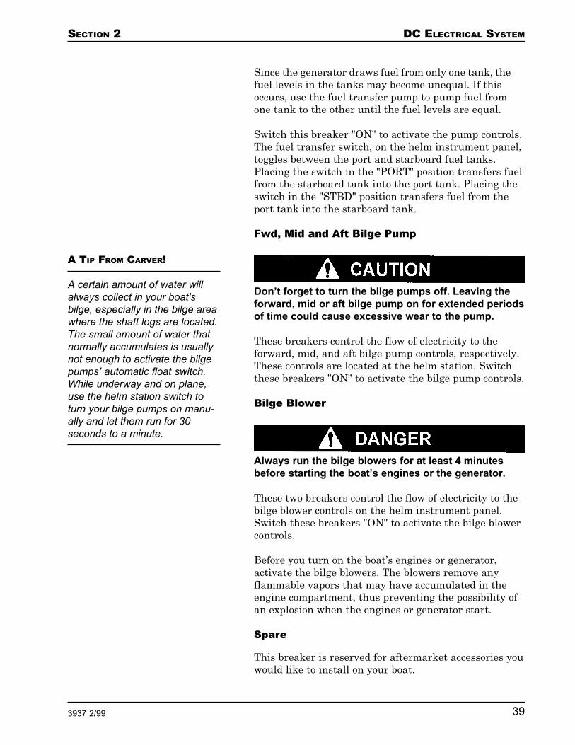
Don’t forget to turn the bilge pumps off. Leaving theforward, mid or aft bilge pump on for extended periodsof time could cause excessive wear to the pump.
These breakers control the flow of electricity to theforward, mid, and aft bilge pump controls, respectively.These controls are located at the helm station. Switchthese breakers "ON" to activate the bilge pump controls.
Bilge Blower
Always run the bilge blowers for at least 4 minutesbefore starting the boat’s engines or the generator.
These two breakers control the flow of electricity to thebilge blower controls on the helm instrument panel.Switch these breakers "ON" to activate the bilge blowercontrols.
Before you turn on the boat’s engines or generator,activate the bilge blowers. The blowers remove anyflammable vapors that may have accumulated in theengine compartment, thus preventing the possibility ofan explosion when the engines or generator start.
Spare
This breaker is reserved for aftermarket accessories youwould like to install on your boat.
A TIP FROM CARVER!
A certain amount of water willalways collect in your boat'sbilge, especially in the bilge areawhere the shaft logs are located.The small amount of water thatnormally accumulates is usuallynot enough to activate the bilgepumps’ automatic float switch.While underway and on plane,use the helm station switch toturn your bilge pumps on manu-ally and let them run for 30seconds to a minute.

DC ELECTRICAL SYSTEM SECTION 2
40 3937 2/99
Halon
This breaker controls the flow of electricity to the halonfire suppression system in the engine room. Switch thisbreaker "ON" to activate the halon system. Refer to theOEM information for details on operating this equip-ment.
Spare
This breaker is reserved for aftermarket accessories youwould like to install on your boat.
Spare
This breaker is reserved for aftermarket accessories youwould like to install on your boat.
Spare
This breaker is reserved for aftermarket accessories youwould like to install on your boat.
Trim Tabs
This breaker controls the flow of electricity to the trimtab controls at the helm station. Trim tabs are used toimprove the running angle of your boat while underway.Switch this breaker "ON" to activate the trim tab con-trols. Refer to the "Trim Tabs" portion of Section 6 formore information on using the trim tabs.
Spare/Lower Helm Accessories
This breaker controls the flow of electricity to the cigarlighter and remote stereo controls at the lower helmstation. Switch this breaker "ON" to activate the lighterand stereo controls.
NOTE: If your boat is not equipped with this option, thisbreaker is labeled SPARE and reserved for aftermarketaccessories you would like to install on your boat.
Helm Accessories
This breaker controls the flow of electricity to the cigarlighter and remote stereo controls at the upper helmstation. Switch this breaker "ON" to activate the lighterand stereo controls.

SECTION 2 DC ELECTRICAL SYSTEM
413937 2/99
Horn
This breaker controls the flow of electricity to the boat’shorn controls at the helm station. To supply power tothe horn’s ON/OFF switch, switch this breaker "ON." Tooperate the horn, rotate the horn switch to the "ON"position.
Radar
This breaker controls the flow of electricity to the op-tional radar system. Switch this breaker "ON" to acti-vate the radar system. Refer to the OEM informationfor details on operating the radar.
VHF Radio
This breaker controls the flow of electricity to the op-tional VHF radio. Switch this breaker "ON" to activatethe VHF radio. Refer to the OEM information for detailson operating the radio.
Loran/GPS
This breaker controls the flow of electricity to the op-tional Loran and Global Positioning System. Switch thisbreaker "ON" to activate the Loran and GPS. Refer tothe OEM information for details on operating the Loranand GPS.
Chart Plotter
This breaker controls the flow of electricity to the op-tional plotter. Switch this breaker "ON" to activate theplotter. Refer to the OEM information for details onoperating the plotter.
Depth Sounder
This breaker controls the flow of electricity to the op-tional depth sounder. Switch this breaker "ON" toactivate the depth sounder. Refer to the OEM informa-tion for details on operating the depth sounder.
Auto Pilot
This breaker controls the flow of electricity to the op-tional auto pilot. Switch this breaker "ON" to activatethe auto pilot. Refer to the OEM information for detailson operating the auto pilot.

DC ELECTRICAL SYSTEM SECTION 2
42 3937 2/99
Spare
This breaker is reserved for aftermarket accessories youwould like to install on your boat.
The Safety Breaker Panel is mounted beneath thelowest step in the stairway leading from the salon to theaft deck. This panel is reserved for safety equipmentsuch as automatic bilge pumps. Some safety equipmentlisted on the Safety Breaker Panel is directly wired tothe batteries and should remain in the "ON" position atall times. This allows various pumps and other safetyequipment to remain active regardless of the position ofthe battery selector switch.
While the safety equipment wired though this SafetyBreaker Panel does operate at all times even when thebattery selector switch is in the "OFF" position, it willnot run if a breaker trips. Therefore, it is important tofrequently check that these breakers are "ON" andworking properly.
Voltmeter - Battery One
This breaker protects the circuitry between the helm'svoltmeter and battery #1. When this breaker is "ON",the voltmeter operates whenever the engine ignition isengaged. The voltmeter indicates the charge level inbattery #1.
Voltmeter - Battery Two
This breaker protects the circuitry between the helm'svoltmeter and battery #2. When this breaker is "ON",the voltmeter operates whenever the engine ignition isengaged. The voltmeter indicates the charge level inbattery #2.
Stereo Memory
This breaker controls the flow of electricity to the boat’sstereo system. This breaker should always be "ON" tomaintain the information programmed into the stereo’smemory. If this breaker is ever switched "OFF", you willhave to reprogram the stereo. Refer to the OEM infor-mation for details on programming the stereo.
Safety BreakerPanel

SECTION 2 DC ELECTRICAL SYSTEM
433937 2/99
Shower Sump - Fwd and Aft
These breakers control the flow of electricity to theforward and aft shower sump pumps. Since each showersump is located below the boat's water line, a sumppump is needed to pump shower water overboard or intothe optional grey water holding tank. The showersumps are activated automatically by a float switchwhenever water within the sump rises above a predeter-mined level. Switch the appropriate breaker "ON"before using the forward or aft shower or sink.
SAFETY BREAKER PANEL

DC ELECTRICAL SYSTEM SECTION 2
44 3937 2/99
NOTE: Since condensation from the air conditionerdrains into the shower sump, the shower sump breakersmust remain "ON" whenever the air conditioner isoperating.
Battery Charger - One
This breaker protects the circuitry between the boat's35 amp battery charger and battery #1. When thisbreaker is "ON" and the battery charger is operating,the battery charger automatically charges battery #1whenever the battery’s voltage decreases below a prede-termined level.
Battery Charger - Gen
This breaker protects the circuitry between the boat's35 amp battery charger and the generator battery.When this breaker is "ON" and the battery charger isoperating, the battery charger automatically chargesthe generator battery whenever the battery’s voltagedecreases below a predetermined level.
Battery Charger - Two
This breaker protects the circuitry between the boat's35 amp battery charger and battery #2. When thisbreaker is "ON" and the battery charger is operating,the battery charger automatically charges battery #2whenever the battery’s voltage decreases below a prede-termined level.
Main - Bridge
This breaker protects the circuitry between the BridgeBreaker Panel and the batteries. This breaker must be"ON" for electricity to reach the Bridge Breaker Panel.
Main - Salon
This breaker protects the circuitry between the 12 VoltDC Power Main Breaker Panel and the batteries. Thisbreaker must be "ON" for electricity to reach the 12 VoltDC Power Main Breaker Panel.
Auto Bilge Pump - Fwd, Mid and Aft
These breakers control the flow of electricity to the bilgepumps. Each pump is activated automatically by a floatswitch whenever water within the bilge rises to a prede-

SECTION 2 DC ELECTRICAL SYSTEM
453937 2/99
termined level. These breakers must be "ON" wheneverthe boat is in the water.
NOTE: Because the bilge pumps are “hard-wired” to theSafety Breaker Panel, they operate automatically regard-less of the position of the battery selector switch or thebilge pump breakers on the Bridge Breaker Panel. Peri-odically test each float switch by lifting the float. Thepump should turn on when the float is lifted.
CO Detector
Always activate the CO detectors when the boat'sengines or generator are running. Carbon monoxide isdangerous. Refer to Section 1 of this Owner's Guidefor information on minimizing, detecting and control-ling carbon monoxide accumulation.
Carver has installed several carbon monoxide (CO)detectors on your boat for your safety. This breakermust be "ON" for the CO detectors to operate.
The CO detectors monitor the air throughout the boat’scabin for the presence of carbon monoxide. Carbonmonoxide is a colorless and odorless gas that is presentin engine and generator exhaust fumes. Carbon monox-ide is a very dangerous gas that is potentially lethalwhen inhaled.
When your CO detectors are activated, they will alertyou to the presence of carbon monoxide in the cabin byemitting a loud, high pitched sound. When you hear thisalarm, determine the cause and correct it immediately.
There is a test button on each CO detector. Test eachunit on a weekly basis. If you suspect that a CO detectoris faulty, have your dealer repair or replace it immedi-ately. More information concerning carbon monoxide isincluded in Section 1 of this Owner's Guide.
Windlass
This breaker protects the circuitry between the boat'swindlass and the batteries. This breaker must be "ON"to operate the windlass controls at the helm and at thebow of the boat. Refer to the OEM information fordetails on operating the windlass.
DC ELECTRICAL SYSTEM SECTION 2
46 3937 2/99
Your boat's 12 volt DC electrical system is powered by 12volt batteries. These batteries are anchored in the engineroom between the propulsion engines. If your boat isequipped with an optional generator, an additionalbattery supplies power to the generator starter. Thisgenerator battery is located near the generator.
While your boat's batteries are relatively maintenance-free, there are a few things you can do to increase theireffectiveness and life.
Your boat's batteries contain electrolyte which is anacid. Wear gloves and protective eye glasses whenworking on and around the batteries.
When servicing your boat's batteries avoid spillingelectrolyte into the engine compartment or bilge. Also,avoid getting any salt water in or on the battery. Eitherof these conditions could create a poisonous gas that isharmful if inhaled.
If you do spill electrolyte, ventilate the area. Neutralizethe acid in the electrolyte by pouring baking soda on thespill. Remove the neutralized electrolyte using a dispos-able rag or paper towel.
Maintaining Your Batteries
1. Keep your batteries fully charged. Batteries thatare kept fully or near fully charged last longer thanbatteries stored with a partial charge. The chargelevel of the batteries can be monitored using thevoltmeters on the helm instrument panel.
2. Inspect your boat's batteries at least once every 30days.
Disconnect the batteries before cleaning them.
3. Periodically clean the battery terminals and cableconnections.
Battery Maintenance

SECTION 2 DC ELECTRICAL SYSTEM
473937 2/99
Remove any accumulation of dirt on the top of thebattery case. Use a wire brush to clean the termi-nals. Coating the terminals with a terminal protect-ing product will help reduce corrosion that can formin these areas.
4. Check that the battery cables are securely attachedto the terminal posts. Tighten the terminal wingnuts 1/4 turn beyond finger tight using a pliers.
5. Check the level of electrolyte in each cell of eachbattery. The correct level is just above the plates. Ifthe fluid level is low, top off the cell with DIS-TILLED water only. DO NOT OVERFILL.
Remove the batteries from the boat during periods ofextended storage. Store your batteries in a cool (abovefreezing temperature), dry area. All batteries lose somecharge during storage, but the lower the temperaturethe less loss of charge. Avoid storing the batteries in ahumid place. Humidity causes the terminals to corrode.
Check the battery charge level every 3 months using ahydrometer or voltmeter. If the specific gravity of thebattery is less than 1.225 or the voltage is less than 12.4volts, charge the battery. Avoid overcharging.

DC ELECTRICAL SYSTEM SECTION 2
48 3937 2/99
Problem Possible Cause Possible Solution
12 volt equipmentdoes not function.
Individual 12 voltcomponent does notfunction.
Cabin lights do notcome on or are dim.
Battery selector switch is inthe "OFF" position.
Main - Bridge or Main - Saloncircuit breaker on the SafetyBreaker Panel is "OFF".
DC Main circuit breaker onthe 12 Volt DC Power MainBreaker Panel is "OFF".
Main circuit breaker on theBridge Breaker Panel is"OFF".
Battery is weak or dead.
Circuit breaker for that com-ponent is "OFF".
Battery is weak or dead.
A wire within the 12 voltsystem is loose or discon-nected.
Fwd Cabin Lights, SalonLights or Aft Cabin Lightscircuit breaker on the 12 VoltDC Power Main BreakerPanel is "OFF".
Battery is weak or dead.
One or more light bulbs areburned out.
Turn the battery selector switchto position #1 or position #2.
Turn both circuit breakers "ON".
Turn the circuit breaker "ON".
Turn the circuit breaker "ON".
Reposition the battery selectorswitch and charge the battery.
Switch the circuit breaker forthat component "ON".
Reposition the battery selectorswitch and charge the battery.
Locate and repair the wire.
Switch appropriate circuitbreaker "ON".
Reposition the battery selectorswitch and charge the battery.
Replace light bulb(s).
Troubleshooting the DC Electrical System

SECTION 2 DC ELECTRICAL SYSTEM
493937 2/99
Battery does nothold a charge.
Engine is runningand voltmeter doesnot indicate ad-equate voltage.
Battery failed.
Engine alternator belt isloose.
Replace with new battery.
Refer to engine manual totighten belt.
Problem Possible Cause Possible Solution
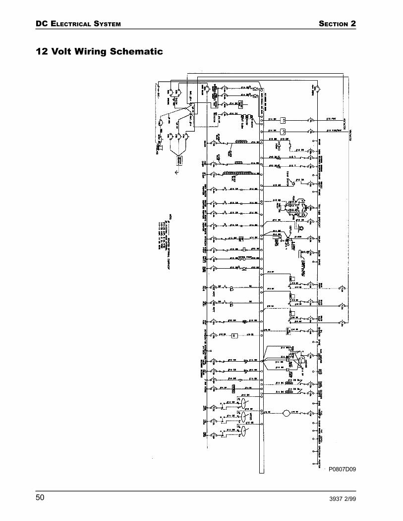
DC ELECTRICAL SYSTEM SECTION 2
50 3937 2/99
12 Volt Wiring Schematic
P0807D09

SECTION 2 DC ELECTRICAL SYSTEM
513937 2/99
NOTES

DC ELECTRICAL SYSTEM SECTION 2
52 3937 2/99
NOTES

SECTION 3 AC ELECTRICAL SYSTEM
533937 2/99
AC Electrical System
AC Electrical System ................................................. 54Shore Power..................................................................... 55Generator Power.............................................................. 57
AC Circuit Breaker Panels ......................................... 60European AC Electrical System Circuit Breaker ............ 60AC Power Panel ............................................................... 61
Ground Fault Circuit Interrupters ............................. 66
Electrical Loads ......................................................... 68
Bonding System ......................................................... 69
Troubleshooting the AC Electrical System ............... 71
AC Wiring Schematic ................................................. 73

AC ELECTRICAL SYSTEM SECTION 3
54 3937 2/99
Your boat is equipped with a 30 amp AC (alternatingcurrent) electrical system. The power for this system issupplied by either a shore power source or the optionalonboard generator. All AC power is routed through theAC Power Panel, which is mounted behind a slidingmirror on the salon’s starboard bulkhead outboard thedinette. The lights above the main breakers on your ACPower Panel indicate which source your AC electricalsystem is receiving power from. The procedures forconnecting to shore power and generator power areexplained later in this section.
If your boat does not have the optional air conditioningsystem, all AC power is routed through a single dock-side MAIN breaker service called Line 1. If your boat isequipped with air conditioning, the air conditioningsystem is powered through an additional 30 ampbreaker service called Line 2.
Wiring System
The AC electrical system on your boat uses three color-coded wires.
The black wire carries the current from the powersource to the equipment or receptacle. Each black wireis connected to and protected by a circuit breaker that isinstalled in the AC Power Panel.
The white wire carries the current from the equipmentor receptacle back to the power source.
Ground wires are either green or bare copper. Duringnormal operation, current does not flow through theground wires.
Buss bars are used within the AC electrical system tohelp route and organize the wires. The system's whiteor neutral wires are connected together at buss bars.The ground wires are also connected together at aseparate buss bar.
Do not touch the black or white wires while the ACelectrical system is connected to a power source.These wires carry enough current to kill or causeserious injury.
AC Electrical System

SECTION 3 AC ELECTRICAL SYSTEM
553937 2/99
Reverse Polarity
Reverse polarity can occur only with 110 volt electricalsystems. If your boat is equipped with a 220 volt sys-tem, disregard this section.
The MAIN circuit within your boat's electrical system isdesigned to sense the voltage difference between theneutral and ground terminal blocks. If the docksideelectrical power source is incorrectly wired and thepolarity is reversed, the red reverse polarity light in thedockside electrical box illuminates. If reverse polarityoccurs while your boat is connected to shore power, thereverse polarity light on your boat's AC Power Panelilluminates.
If reverse polarity occurs, turn off the 30 amp mainbreaker(s) on your AC Power Panel and disconnectyour power cord(s) from the shore power supply.Notify marina management of the problem. Use adifferent dockside electrical box.
NOTE: Remove all perishables from your refrigerator ifyou leave your boat for more than forty-eight hours. Thepower supply to your refrigerator may be interruptedand your food may spoil.
To connect to shore power:
Do not supply power to the water heater when it isempty. Doing so may damage the unit’s heatingelement and cause a fire.
1. Switch "OFF" the Water Heater circuit breaker onthe AC Power Panel. Do not switch the breaker onagain until your boat's fresh water system andwater heater have been filled, pressurized andprimed.
2. Make sure the AC Main Line 1 and AC Main Line 2(if present) circuit breakers on the AC Power Panelare switched "OFF."
Shore Power

AC ELECTRICAL SYSTEM SECTION 3
56 3937 2/99
Make sure the shore power cord you use is in excel-lent condition with no cuts, nicks or abrasions in theexterior plastic cover. Also make sure that the cordis specifically designed to connect your boat to ashore power source. Using a damaged cord or a cordthat is not designed for this purpose can causeelectrical shock resulting in death or serious injury.
3. Locate your 50' shore power cord(s).
4. Connect the female end of the cord to your boat'sshore power receptacle located on the transom.
5. Secure the nonmetallic threaded locking ring thatlocks the cord to the boat’s shore power receptacle.This prevents accidental disconnection or arcingdue to a gap between the cord plug and the recep-tacle.
Do not allow the end of the shore power cord tohang in the water. This can cause an electrical fieldto form which can kill or seriously injure nearbyswimmers or passengers.
6. Choose a neat and safe way to route the shorepower cord(s) to the shore power source.
7. Switch "OFF" the circuit breaker that is installed inthe shore power source box.
8. Plug the male end of the shore power cord into theshore power source box.
9. Secure the nonmetallic threaded locking ring thatlocks the cord to the shore power source outlet. Thisprevents accidental disconnection or arcing due to agap between the cord plug and the outlet.
10. Switch "ON" the circuit breaker that is installed inthe shore power source box.
11. Switch "ON" the AC Main circuit breaker next toyour boat's shore power receptacle.
SECTION 3 AC ELECTRICAL SYSTEM
573937 2/99
12. If the red Polarity Reversed light(s) on the ACPower Panel illuminates, disconnect the shorepower cord immediately. Notify marina manage-ment of the reverse polarity problem and use adifferent shore power source box.
If the green Polarity Reversed light(s) illuminates,switch "ON" the AC Main Line 1 and AC Main Line2 (if present) breakers on the AC Power Panel.
13. Monitor the voltmeter(s) and ammeter(s) whileyour boat is connected to the shore power source.The operation of the voltmeters and ammeters isdescribed later in this section.
Only people who are trained and experienced in work-ing with electricity should service your boat's highvoltage AC electrical system. Inexperienced or un-trained people may be killed or seriously injured byincorrectly servicing the AC electrical system.
Always disconnect the boat from the shore powersource before attempting to service the AC electricalsystem.
You can use the optional onboard generator to powerthe boat’s AC electrical systems when a shore powersource is not available. The generator is installed in theengine compartment between the two main stringers.Fuel for the generator is drawn from the port fuel tank.
To start the generator:
1. Read, understand and follow the OEM informationthat describes the generator.
2. The generator starter is powered by its own 12 voltdeep cycle battery. This battery is installed aft andbelow the generator. Power to the generator fromthis battery is controlled by an ON/OFF switchmounted on the aft portion of the generator. Turnthis switch to the "ON" position.
Generator Power

AC ELECTRICAL SYSTEM SECTION 3
58 3937 2/99
NOTE: The boat’s battery charger automaticallymonitors the voltage level in the generator batteryand recharges the battery when necessary as long asthe Battery Charger - Gen circuit breaker on theSafety Breaker Panel is "ON".
Never turn the generator battery ON/OFF switch tothe “OFF” position while the generator is running.Doing this can damage the generator or alternatorwiring.
3. The generator engine uses seawater as a coolant.Open the seawater seacock before you start thegenerator. This seacock is located beneath thehatch under the dinette’s aft cushion.
4. Switch "ON" the two Bilge Blower circuit breakerson the Bridge Breaker Panel.
5. Turn "ON" the bilge blowers using the blowerswitch on the 12 Volt DC Power Main BreakerPanel or at the helm station(s).
GENERATOR LAYOUTA TIP FROM CARVER!
Dedicating a 12 volt battery tothe generator provides an impor-tant safety feature. A dedicatedbattery enables you to start thegenerator regardless of thecondition of the two 12 volt ship’sbatteries. If the batteries becomedischarged to the point wherethey are not able to start anengine, start the generator andturn on the battery charger. Thisrecharges the boat’s batteriesand enables you to start thepropulsion engines when thebatteries have been recharged toan adequate level.

SECTION 3 AC ELECTRICAL SYSTEM
593937 2/99
Before starting the generator, operate the bilgeblowers for at least 4 minutes, then inspect the bilgefor fuel vapor. If fuel vapor is present in the bilge, donot start the generator. Identify and correct thesource of the vapor, then operate the bilge blowersfor at least 4 more minutes before starting the gen-erator. Continue to operate the bilge blowers whilethe generator is running.
The generator STOP/START switch is spring acti-vated. Release the switch from its "START" positionas soon as the generator starts. If you continue tohold the switch in its "START" position after thegenerator starts, you may damage the starter.
While you are attempting to start the generator,never hold the STOP/START switch in the "START"position for more than 10 seconds.
6. A spring-loaded generator STOP/START switch islocated at the bottom of the 12 Volt DC Power MainBreaker Panel. Push the switch to the "START"position and hold it there until the generator starts.Release the switch when the generator starts.
If the generator does not start within 10 seconds,release the STOP/START switch, wait 1 minute,then try to start the generator again.
7. When the generator is running smoothly, switch"ON" the AC Main Line 1 and AC Main Line 2 (ifpresent) breakers on the AC Power Panel. Thisconnects the generator to the boat’s AC electricalsystem. AC receptacles and accessories can now beused in the same manner as when the boat isconnected to shore power.
8. To turn the generator "OFF", push the STOP/START switch to the "STOP" position. If you do notintend to use the generator again for at least a fewdays, turn the generator battery ON/OFF switch tothe "OFF" position.
AC ELECTRICAL SYSTEM SECTION 3
60 3937 2/99
9. To change from generator to shore power, switch"OFF" the AC Main Line 1 and AC Main Line 2 (ifpresent) breakers on the AC Power Panel. Thenconnect to shore power as described earlier in thissection.
Do not inhale generator exhaust. Generator exhaustcontains carbon monoxide, a poisonous gas. Referto the "Carbon Monoxide Warnings for GasolineEngines" portion of Section 1 for more informationon engine exhaust and carbon monoxide.
AC power is managed throughout your boat using one ortwo circuit breaker panels.
• AC Electrical System Circuit Breaker• AC Power Panel
The circuit breakers on these panels enable you tocontrol the electricity to the boat’s various AC electricalsystems by switching the breakers ON or OFF. Theyalso protect the AC electrical system by automaticallydisconnecting the circuit from the power source in theevent of a short or overload.
Never reset a breaker that has been automaticallytripped without first correcting the problem. Failure tofollow this procedure may create a dangerous situa-tion.
NOTE: Sometimes a circuit breaker location is labeledbut no circuit breaker is present. In this case, the compo-nent named on the label is an option that is not installedon your boat.
If your boat was built for use in Europe, it has an ACElectrical System circuit breaker located inside thestorage area next to the berth’s headboard in the aftstateroom. This breaker controls AC power to all of theAC systems in the boat. Switch this breaker "ON" toprovide power to the AC Power Panel.
European ACElectrical SystemCircuit Breaker
AC Circuit BreakerPanels

SECTION 3 AC ELECTRICAL SYSTEM
613937 2/99
The AC Power Panel has a 30 amp MAIN breaker whichprotects the entire AC electrical system. A second MAINbreaker protects the circuits used by the optional airconditioning system.
Line 1
The Line 1 30 amp circuit is standard on your boat. Thiscircuit is powered by either a single 30 amp shore powercord or the boat's onboard generator.
The Line 1 circuit is configured as either 110 volts ACor 220 volts AC. 110 volt systems are used throughoutNorth American and Pacific Rim countries. 220 voltsystems are primarily used in European countrieswhose standard electrical system is based on 220 voltpower.
AC Power Panel
SALON AC MAIN DISTRIBUTION PANEL

AC ELECTRICAL SYSTEM SECTION 3
62 3937 2/99
Line 2
If your boat is equipped with air conditioning, a second30 amp circuit called Line 2 is installed to handle theextra current flow. The Line 2 circuit is composed of two30 amp circuits, each powered by its own 30 amp shorepower cord or by the boat's onboard generator. The Line2 circuit is configured as either 110 volt or 220 volt.
Voltmeter
The voltmeter indicates the amount of electrical voltagethat is entering your boat's AC system. There is avoltmeter each for Line 1 and Line 2.
When your is boat connected to a dockside power source,the voltmeter should read between 110 and 120 volts ina 110 volt system and between 210 and 240 volts in a220 volt system. If the voltage indicates a reading of 105volts (205 volts in a 220 volt system) or less, DO NOTUSE THE SYSTEM. If you experience a low voltagereading as described, contact the marina's managementto locate the source of the problem.
If the voltmeter is reading zero voltage, it means thatno current is getting to the AC Power Panel. Check yourshore power cord to make sure it is properly attached toboth the boat and the dockside electrical box. Also,make sure you have turned on the dockside electricalbreaker.
If, after checking these items, the voltmeter is stillreading zero voltage, contact marina management toensure that the dockside power is operable. If indica-tions are that the problem is with the boat's electricalsystem, have the system inspected by a qualified electri-cian.
Ammeter
The ammeter indicates the load (amount of current)that is being put on the boat's 30 amp electrical system.There is an ammeter each for Line 1 and Line 2.
When the MAIN breaker is "ON", all other breakers onthe AC Power Panel are "OFF", and the voltmeter isreading between 110 and 120 volts (210 and 240 voltsfor a 220 volt system), the ammeter should read 0 amps.
SECTION 3 AC ELECTRICAL SYSTEM
633937 2/99
As you switch the AC Power Panel breakers "ON" andturn on their associated equipment or turn on equip-ment plugged into the AC receptacles, the ammeterreadings increase above 0 amps. Refer to "ElectricalLoads" later in this section for information on the ACelectrical system load limits.
AC Main Line 1
The AC Main Line 1 breaker controls the flow of elec-tricity to all of the other circuit breakers on AC Line 1.To supply power to the other circuit breakers, switchthe AC Main Line 1 breaker "ON". To cut the powersupply to the other breakers, switch this breaker "OFF".
Receptacles
This breaker controls the flow of electricity to the recep-tacles along the port salon, galley and forward cabin.Switch this breaker "ON" to supply power to thesereceptacles. Use the receptacles as you would the out-lets in your home.
NOTE: The Ground Fault Circuit Interrupter (GFCI)receptacle for this group of receptacles is located in theforward, port corner of the salon. If the appropriatecircuit breakers are "ON" but power is still not availableat any of the receptacles in this group, the GFCI breakermay have tripped. Refer to "Ground Fault CircuitInterrupters" later in this section for more information.
Receptacles
This breaker controls the flow of electricity to the recep-tacles in the forward head, dinette area, starboardsalon, aft stateroom, aft head compartment and theexterior icemaker. Switch this breaker "ON" to supplypower to these receptacles. Use the receptacles as youwould the outlets in your home.
NOTE: There are two GFCI receptacles for this group ofreceptacles. One is located in the forward head; the otheris located in a locker below the aft stateroom TV. If theappropriate circuit breakers are "ON" but power is stillnot available at any of the receptacles in this group, oneor both of the GFCI breakers may have tripped. Refer to"Ground Fault Circuit Interrupters" later in thissection for more information.
AC ELECTRICAL SYSTEM SECTION 3
64 3937 2/99
Range
This breaker controls the flow of electricity to thegalley’s stove. Switch this breaker "ON" to supply powerto the stove. Refer to the OEM information for detailson operating the stove.
NOTE: If your boat contains the optional propane stove,an additional circuit breaker labeled LP Gas on the 12Volt DC Power Main Breaker Panel must be switched"ON" to operate the stove. Refer to the OEM informationfor details on operating the propane stove.
Water Heater
Do not supply power to the water heater when it isempty. Doing so may damage the unit’s heating ele-ment and cause a fire. Refer to the "Fresh WaterSystem" portion of Section 4 to fill, pressurize andprime the fresh water system before turning on thewater heater.
This breaker controls the flow of electricity to the waterheater. The water heater supplies hot water to yourfresh water system. Switch this breaker "ON" to supplypower to the water heater. The water heater is locatedunder a hatch beneath the dinette. Refer to the OEMinformation for details on operating the water heater.
Spare
This breaker is reserved for aftermarket accessories youwould like to install on your boat.
Microwave
This breaker controls the flow of electricity to thegalley’s microwave. Switch this breaker "ON" to supplypower to the microwave. Refer to the OEM informationfor details on operating the microwave.
Battery Charger
This breaker controls the flow of electricity to the boat's35 amp battery charger. When AC power is supplied toyour boat, the battery charger automatically monitorsand charges the boat's 12 volt batteries regardless of the
A TIP FROM CARVER!
Whenever your water heater hasbeen winterized for storage, oryour water tanks are empty,Carver recommends taping theWater Heater breaker in the"OFF" position. This helpsprevent the breaker from acci-dentally being switched "ON"when no water is in the watersystem.

SECTION 3 AC ELECTRICAL SYSTEM
653937 2/99
position of the battery selector switch on the SafetyBreaker Panel. The battery charger is mounted betweenthe propulsion engines in the aft, center portion of theengine room. Refer to the OEM information for detailson operating the battery charger.
Spare
This breaker is reserved for aftermarket accessories youwould like to install on your boat.
AC Main Line 2
The AC Main Line 2 breaker controls the flow of elec-tricity to all of the air conditioning circuit breakers onAC Line 2. To supply power to the air conditioningcircuit breakers, switch the AC Main Line 2 breaker"ON". To cut the power supply to the air conditioningbreakers, switch this breaker "OFF".
NOTE: The air conditioning system uses water to oper-ate. Before switching "ON" the A/C Water Pump breakeror either of the A/C Unit breakers, you must supply theair conditioning system with sea water. Refer to the "AirConditioning System" portion of Section 4 to preparethe air conditioning system for operation. Refer to theOEM information for details on operating the air condi-tioning units.
A/C Water Pump
This breaker controls the flow of electricity to the waterpump that supplies the air conditioning system with seawater. Switch this breaker "ON" to supply power to thewater pump.
A/C Unit
This breaker controls the flow of electricity to the for-ward air conditioning unit beneath the dinette’s for-ward-most seat. Before switching this breaker "ON" tosupply power to the unit, switch the A/C Water Pumpbreaker "ON".
A/C Unit
This breaker controls the flow of electricity to the aft airconditioning unit beneath the aft cabin berth. Beforeswitching this breaker "ON" to supply power to the unit,switch the A/C Water Pump breaker "ON".

AC ELECTRICAL SYSTEM SECTION 3
66 3937 2/99
Spare
This breaker is reserved for expanding the air condi-tioning system.
Certain receptacles on your boat contain Ground FaultCircuit Interrupters (GFCI). The GFCI measures boththe amount of current flowing to the receptacle and theamount of current returning from the receptacle, thencompares the two values. If the values are not the same,the GFCI instantly trips, shutting off power to thereceptacle.
When someone receives an electrical shock through aGFCI receptacle, the current flowing to the receptaclecontinues flowing through the person’s body and intoany grounded object the person is touching or standingon. Thus, the current does not return from the recep-tacle through the appropriate wire. The GFCI “sees”this difference in current and shuts off power to thereceptacle. This limits the amount of time the person isbeing shocked to a brief moment, which can reduce theamount of injury to the person.
Any electrical shock from the AC electrical system,even through a GFCI receptacle, can cause death orserious injury. Always seek immediate medical atten-tion after receiving such a shock.
GFCI Receptacle Locations
Three GFCI receptacles are installed on your boat. Oneis located in the galley above the range and protects thereceptacles in the port side salon and forward state-room. Another GFCI receptacle is located in the forwardhead and protects the receptacles there, in the star-board salon and dinette, and in the aft head and state-room. The third GFCI receptacle is located in a lockerbelow the TV in the aft stateroom and protects the TVand aft deck icemaker.
Testing GFCI Receptacles
The GFCI receptacles are identified by Test and Resetbuttons located between the receptacles’ two outlets.
Ground Fault CircuitInterrupters
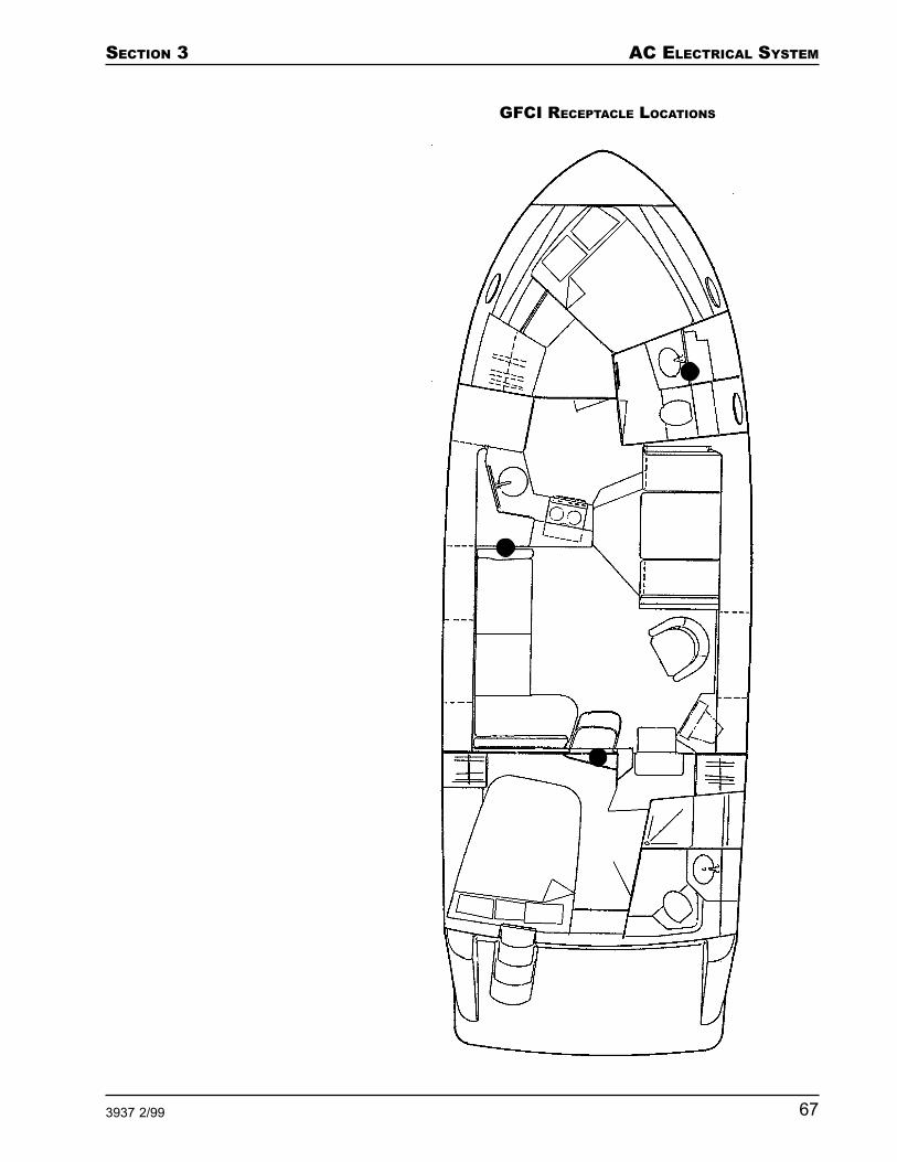
SECTION 3 AC ELECTRICAL SYSTEM
673937 2/99
GFCI RECEPTACLE LOCATIONS
AC ELECTRICAL SYSTEM SECTION 3
68 3937 2/99
Test each GFCI receptacle once every week:
1. Press the Test button. If the GFCI is operatingnormally, this cuts the power supply to the GFCIreceptacle and to all other receptacles on thatcircuit.
If the GFCI receptacle or any other receptacle on thatcircuit still has power after the Test button ispressed, do not use any of the receptacles on thatcircuit. Contact a qualified electrician to make theappropriate repairs.
2. Plug a lamp or other AC powered device into theGFCI receptacle and turn on the device. The deviceshould not operate.
3. Repeat Step 2 for each receptacle on the samecircuit as the GFCI receptacle.
4. Press the Reset button to restore power to the GFCIreceptacle and to all other receptacles on thatcircuit.
When operating AC powered devices through yourboat’s AC electrical system, be aware that each deviceexerts a “load” on the system. This load is equal to theamount of current (amps) that the device draws fromthe AC electrical system. The AC electrical system, likeyour house’s electrical system, has a maximum totalload that it can handle. The Line 1 and Line 2 (if in-stalled) circuits each have an electrical load capacity of30 amps.
If the total load on the circuit exceeds the circuit’scapacity, the breaker for that circuit trips. This meansthat the devices operating from the circuit are drawingtoo much current.
Do not overload the electrical circuits. If an excessiveload trips a circuit breaker, turn off all devices con-nected to the circuit, then switch the breaker back"ON".
Electrical Loads

SECTION 3 AC ELECTRICAL SYSTEM
693937 2/99
A list of common AC powered devices and the approxi-mate maximum current that they draw when operatingis shown below. If you use an AC powered device thathas an electric motor, such as a vacuum cleaner orelectric drill, the device should have a “motor load plate”mounted on it. This plate lists the current that thedevice draws while operating.
As the chart indicates, appliances that use a motor or aheating element draw relatively large amounts ofcurrent. Therefore, be especially careful when usingcurling irons, toasters, coffee makers, hair dryers, foodmixers or similar types of AC powered devices. Do notuse too many of these types of devices at the same time.
Your boat is equipped with a comprehensive metallicbonding system that interconnects all underwaterequipment and thru-hull fittings. The bonding systemensures that the “cases” of all metallic equipmentonboard your boat, including the fittings, are at thesame electrical potential. This minimizes corrosion ofthe underwater fittings caused by stray electrical cur-rents.
Included within this bonding system are sacrificial zincanodes that have been installed on each of the boat'spropeller shafts and onto the underwater portion of theboat's transom. These anodes corrode and deterioratebefore the boat's underwater fittings and provide avisual reference to the level of stray current to whichyour boat is being exposed.
ELECTRICAL LOADS
AC Device
FanElectric blanketTelevisionCoffee makerBattery chargerToasterFry panSpace heaterRefrigerator
Approximate Maximum Cur-rent Used (Amps)
0.7 2.0 2.7 6.3 7.310.512.313.7 1.5
Bonding System

AC ELECTRICAL SYSTEM SECTION 3
70 3937 2/99
Your boat's 12 volt DC electrical system, AC electricalsystem, and the batteries’ negative leads are all con-nected to the bonding system through buss bars. Thebuss bars are located in the engine and aft bilge com-partments and are connected to the transom-mountedzinc plate.
Do not tamper with or modify the boat's bondingsystem. Doing so could threaten the integrity of thesystem.
Monitor the condition of your boat's zinc anodes.Replace the zinc anodes when they have deterioratedto 50% of their original size. Do not allow the zincanodes to completely deteriorate. Refer to the "Gen-eral Maintenance Schedule" portion of Section 7 forrecommended inspection intervals.
NOTE: Damage resulting from stray current or galvaniccorrosion is NOT covered under the Carver limitedwarranty.

SECTION 3 AC ELECTRICAL SYSTEM
713937 2/99
Problem Possible Cause Possible Solution
No AC power asindicated byvoltmeter(s).
Cabin receptacleshave no power.
Shore power cord is notconnected.
There is no power at theshore power source box.
The circuit breaker installed inthe shore power source box is"OFF".
The AC Main circuit breakernext to your boat’s shorepower receptacle is "OFF".
If your boat was built for usein Europe, the AC ElectricalSystem circuit breaker is"OFF".
The AC Main Line 1 and ACMain Line 2 breakers on theAC Power Panel are "OFF".
A wire within the AC electricalsystem is loose or discon-nected.
The AC Main Line 1 and ACMain Line 2 breakers on theAC Power Panel are "OFF".
The Receptacles breakers onthe AC Power Panel are"OFF".
A GFCI tripped.
The shore power cord be-came disconnected.
Connect the shore power cord.
Contact marina management.
Switch the breaker "ON".
Switch the breaker "ON".
Switch the breaker "ON".
Switch the breakers "ON".
Contact a qualified electrician tomake the appropriate repairs.
Switch the breakers "ON".
Switch the breakers "ON".
Locate the tripped GFCI andpress the Reset button.
Reconnect the shore powercord.
Troubleshooting the AC Electrical System

AC ELECTRICAL SYSTEM SECTION 3
72 3937 2/99
Problem Possible Cause Possible Solution
The AC Main Line 1or AC Main Line 2breaker trips imme-diately after beingreset.
The breaker failed. Contact your Carver Dealer tohave the breaker replaced.

SECTION 3 AC ELECTRICAL SYSTEM
733937 2/99
AC Wiring Schematic
P0714C-7

AC ELECTRICAL SYSTEM SECTION 3
74 3937 2/99
NOTES

SECTION 3 AC ELECTRICAL SYSTEM
753937 2/99
NOTES

AC ELECTRICAL SYSTEM SECTION 3
76 3937 2/99
NOTES

SECTION 4 INTERNAL SYSTEMS
773937 2/99
Internal Systems
Air Conditioning System ............................................ 78Producing Heat ................................................................ 79Powering The Air Conditioning ....................................... 79
Fresh Water System ................................................... 80Filling The Water Tank .................................................... 80Pressurizing and Priming the Water System .................. 81Using the Water System .................................................. 82
Raw Water Washdown ............................................... 84
Shore Water Hookup .................................................. 85
Bilge System .............................................................. 86Bilge Pump Operation...................................................... 88Garboard Drain ................................................................ 89
Sanitation System...................................................... 89Heads ............................................................................... 90Emptying the Waste Tanks.............................................. 92
Grey Water System .................................................... 99
Propane Stove .......................................................... 100Checking the System For Leaks ................................... 101

INTERNAL SYSTEMS SECTION 4
78 3937 2/99
This section applies only to the optional air conditioningsystem installed at the Carver factory. An air condition-ing system installed as an aftermarket accessory maynot necessarily operate as described in this section.
For the air conditioning system to operate it needs asource of AC power (supplied by either a shore powersource or the optional onboard generator) and a supplyof seawater (either salt or fresh).
The factory-installed air conditioning option consists oftwo air conditioning units. The first, a 16,000 BTU unit,is installed beneath the forward seat in the dinette.
AIR CONDITIONING SYSTEM LAYOUT
Air ConditioningSystem
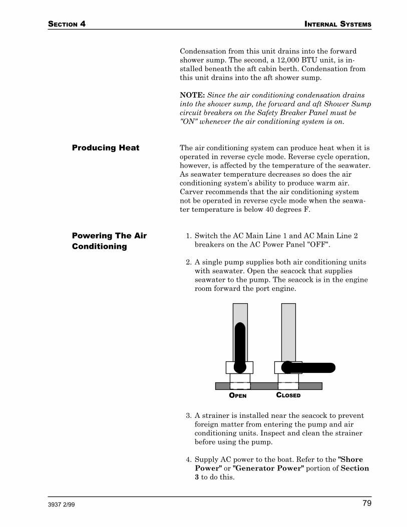
SECTION 4 INTERNAL SYSTEMS
793937 2/99
Condensation from this unit drains into the forwardshower sump. The second, a 12,000 BTU unit, is in-stalled beneath the aft cabin berth. Condensation fromthis unit drains into the aft shower sump.
NOTE: Since the air conditioning condensation drainsinto the shower sump, the forward and aft Shower Sumpcircuit breakers on the Safety Breaker Panel must be"ON" whenever the air conditioning system is on.
The air conditioning system can produce heat when it isoperated in reverse cycle mode. Reverse cycle operation,however, is affected by the temperature of the seawater.As seawater temperature decreases so does the airconditioning system’s ability to produce warm air.Carver recommends that the air conditioning systemnot be operated in reverse cycle mode when the seawa-ter temperature is below 40 degrees F.
1. Switch the AC Main Line 1 and AC Main Line 2breakers on the AC Power Panel "OFF".
2. A single pump supplies both air conditioning unitswith seawater. Open the seacock that suppliesseawater to the pump. The seacock is in the engineroom forward the port engine.
Producing Heat
Powering The AirConditioning
OPEN CLOSED
3. A strainer is installed near the seacock to preventforeign matter from entering the pump and airconditioning units. Inspect and clean the strainerbefore using the pump.
4. Supply AC power to the boat. Refer to the "ShorePower" or "Generator Power" portion of Section3 to do this.

INTERNAL SYSTEMS SECTION 4
80 3937 2/99
5. Switch the AC Main Line 2 breaker on the ACPower Panel "ON".
6. Switch the A/C Water Pump breaker on the ACPower Panel "ON".
7. Switch both A/C Unit breakers on the AC PowerPanel "ON". These breakers supply power to thecontrols for each air conditioning unit.
8. Verify that seawater is being pumped through theair conditioning units. As the seawater exits theunits, it flows out of the discharge outlets in theboat’s hull.
9. Use the controls for each air conditioning unit to setthe desired temperature. Refer to the OEM infor-mation for details on operating the air conditioningcontrols.
The capacity of your boat’s fresh water system is ap-proximately 81 gallons. The water is divided between afresh water tank and an 11 gallon water heater. Thewater tank is located beneath the aft stateroom berth.The water heater is located beneath a hatch below theboat’s dinette.
The fresh water tank is filled through a single deckfitting with a plate labeled "WATER". The plate is onthe port sidedeck near amidships. Refer to the "FillPlate/Pumpout Locations" portion of Section 9 forthe exact location of the "WATER" plate.
NOTE: Thoroughly flush and sanitize the water systembefore initial use and at least once each season.
Put only clean, fresh water into your water tank. Yourtank is full when water is discharged from the watertank vent fitting installed through your boat's hull. DONOT overfill your water tank OR leave a fill hose unat-tended while the tanks are being filled.
Fresh Water System
Filling The WaterTank

SECTION 4 INTERNAL SYSTEMS
813937 2/99
Perform the following ONLY after the fresh water tankis full.
1. Verify that the forward and aft Shower Sumpcircuit breakers on the Safety Breaker Panel are"ON".
2. Partially open all cold water faucets, including thefaucets for the optional transom shower and freshwater washdown.
3. Turn the battery selector switch on the SafetyBreaker Panel to either the #1 or #2 position.
FRESH WATER SYSTEM
Pressurizing andPriming the WaterSystem

INTERNAL SYSTEMS SECTION 4
82 3937 2/99
4. On the 12 Volt DC Power Main Breaker Panel,switch the DC Main circuit breaker "ON", thenswitch the Pressure Water Pump circuit breaker"ON". This activates the boat’s pressure waterpump, which pressurizes the water system. Thepump is located in the aft, center portion of theengine room between the propulsion engines.
5. The system is primed when all air is purged fromthe system's pipes. Monitor each faucet and showerhead. When a steady steam of water flows from theCOLD side of a faucet or shower head, turn thevalve for that faucet or shower head to the HOTside. When a steady stream of water flows from theHOT side of a faucet or shower head, turn thatfaucet or shower head off. When you have done thisfor each faucet and shower head, the water systemis primed.
When water pressure within the system increases to apredetermined point, the pressure water pump auto-matically shuts off. Priming the system also fills andmaintains the water level within the water heater.
The fresh water system is designed to operate in thesame manner as the water system in your home. Afterfilling, pressurizing and priming the fresh water sys-tem, simply turn on a faucet to receive fresh water. Asyou draw water from the system, the pressure in thesystem decreases. When the pressure decreases to apredetermined point, the pressure water pump auto-matically turns on and increases the pressure. Thisensures a steady flow of water any time you turn on afaucet.
Sometimes a recently filled system or one that has notbeen used for some time may need re-priming. This isnormal and is caused by an accumulation of air bubblesat the pressure water pump. To re-prime the freshwater system, repeat steps 2 and 5 in "Pressurizingand Priming the Water System".
Using the WaterSystem
A TIP FROM CARVER!
If your boat will be left unat-tended for at least a few days,switch "OFF" the Pressure WaterPump circuit breaker on the 12Volt DC Power Main BreakerPanel. If this breaker is left on,pressure within the fresh watersystem may fall and cause thewater pressure pump to engage.If this happens frequently, itcould discharge your batteries.

SECTION 4 INTERNAL SYSTEMS
833937 2/99
Water Heating System
Do not supply power to the water heater when it isempty. Doing so may damage the unit’s heating ele-ment and cause a fire. Fill, pressurize and prime thefresh water system as described in "Filling the WaterTank" and "Pressurizing and Priming the Water Sys-tem" before turning on the water heater.
When you pressurize the fresh water tank, the pressurewater pump automatically fills the water heater. Tooperate the water heater, verify that the AC Main Line1 circuit breaker on the AC Power Panel is "ON", thenswitch the Water Heater circuit breaker on the samepanel "ON". Refer to the OEM information for details onoperating the water heater.
Showers
Your boat has a shower in each head. The showersrequire minimal preparation before use and cleanupafter use.
Each shower’s drain basin is positioned lower than theboat's water line. Because of this, a sump pump isneeded for each shower to drain the basin and dischargethe drain water overboard or into an optional greywater holding tank. When the forward and aft ShowerSump circuit breakers on the Safety Breaker Panel are"ON", each shower sump pump operates automaticallywhen water in the shower’s drain basin rises above apredetermined level.
NOTE: The shower sump pumps can not operate if theforward and aft Shower Sump circuit breakers are"OFF". Make sure both circuit breakers are "ON" beforeusing the showers.
Transom Hand Shower
The optional transom or cockpit hand shower is a conve-nient device that enables you and your guests to rinseoff with warm, fresh water after swimming withouthaving to enter the cabin. The hand shower is especiallyuseful if you operate your boat in salt water.
A TIP FROM CARVER!
To obtain the most consistentshower temperature, turn on thecold water valve fully, then slowlyturn on the hot water valve untilthe water flowing from theshower head is at the desiredtemperature. This method keepsthe pressure water pump run-ning, eliminating widely fluctuat-ing water temperatures.

INTERNAL SYSTEMS SECTION 4
84 3937 2/99
The hand shower is an integral part of your boat's freshwater system. Simply turn on the faucets and adjustthem for the desired water temperature. The handshower and mixing valves are located in the starboardcorner of the transom or cockpit.
Fresh Water Washdown
The optional fresh water washdown enables you to usewater from the fresh water tank to washdown and cleanyour boat. Fresh water washdown is especially useful ifyou operate your boat in salt water.
To use the fresh water washdown:
1. Locate the transom-mounted hose fitting and valve.
2. Attach one end of a nylon water hose to the hosefitting.
3. Attach a nozzle to the other end of the hose. Thebest type of nozzle to use is the “pistol grip” typethat can be opened and closed by squeezing yourhand.
4. Open the valve at the base of the hose fitting tosupply water to the hose. Use the washdown as youwould a garden hose at your home.
The optional raw water washdown enables you to useseawater to washdown and clean your boat.
To use the raw water washdown:
1. Locate the transom-mounted hose fitting in thetransom's lower starboard corner.
2. Attach one end of a 3/4" nylon water hose to thehose fitting.
3. Attach a nozzle to the other end of the hose. Thebest type of nozzle to use is the “pistol grip” typethat can be opened and closed by squeezing yourhand.
4. Open the seacock that supplies seawater to the rawwater washdown pump.
Raw WaterWashdown
A TIP FROM CARVER!
Remember that the fresh waterwashdown system draws itswater from the boat's fresh watertank. Prolonged use of thewashdown system quicklyreduces the amount of freshwater in the water tank.

SECTION 4 INTERNAL SYSTEMS
853937 2/99
5. Turn the battery selector switch on the SafetyBreaker Panel to either the #1 or #2 position.
6. On the 12 Volt DC Power Main Breaker Panel,switch the DC Main circuit breaker "ON", thenswitch the Washdown Pump circuit breaker "ON".
7. Turn the washdown's ON/OFF switch, located nearthe washdown hose fitting, to the "ON" position.
8. The raw water washdown system uses a pressurewater pump to create pressure in the system. Whenthe hand nozzle is closed, water pressure within thesystem increases to a predetermined point at whichthe pump automatically shuts off. When the handnozzle is open, releasing water from the system, thepressure in the system decreases. When the pres-sure decreases to a predetermined point, the pumpautomatically turns on and increases the pressure.This ensures a steady flow of water any time youuse the raw water washdown.
Do not run the pressure water pump when the sea-cock that supplies seawater to the washdown sys-tem is closed. Also, frequently clean the raw waterfilter. Operating the pump with no or a restrictedsupply of seawater can damage it.
Your boat has a shore water hookup. This enables yourfresh water system to draw water from a land watersource while your boat is docked. When you use shorewater you are not drawing water from your onboard
OPEN CLOSED
Shore Water Hookup

INTERNAL SYSTEMS SECTION 4
86 3937 2/99
water tank. The shore water hose fitting is located inthe starboard corner of the transom.
NOTE: Connecting your boat to shore water bypassesthe boat's water tank and pressure water pump, there-fore the water tank does not get filled. The only way tofill the fresh water tank is through the deck plate labeledWATER.
To connect to shore water:
1. Locate the shore water hookup fitting, labeledSHORE WATER, in the transom’s lower starboardcorner.
2. Attach one end of a water hose to the hose fitting.
3. Attach the other end of the hose to the docksidewater tap.
4. Close all sink and shower faucets.
5. Switch the forward and aft Shower Sump circuitbreakers on the Safety Breaker Panel are "ON".
6. Turn ON the dockside water tap.
Do not leave your boat unattended when it is con-nected to shore water. Should one of the water linesin your boat develop a leak, an unlimited amount ofwater could enter your boat. Disconnect the shorewater hose whenever you leave your boat unat-tended.
Your boat is equipped with three automatic bilge pumpslocated beneath the cabin floor. The bilge is the lowestpoint in the interior of the boat's hull where any liquidthat finds its way into the hull will accumulate. Eachpump can pump up to 1500 gallons of water per hour.These pumps have been strategically installed to re-move water that accumulates in three bilges:
1. The forward bilge starts below the galley and runsto the bow. Access the forward bilge pump by liftingthe hatch beneath the center of the galley floor.
Bilge System

SECTION 4 INTERNAL SYSTEMS
873937 2/99
2. The amidships bilge starts at the base of the engineroom's forward bulkhead and runs as far as the aftstateroom. The amidships bilge pump is located inthe engine room forward the propulsion enginesnear the centerline. If your boat was built for use inEurope, there is also a hand bilge pump in theamidships bilge.
BILGE SYSTEM
INTERNAL SYSTEMS SECTION 4
88 3937 2/99
3. The aft bilge starts beneath the aft stateroom floorand runs to the stern. Access the aft bilge pump bylifting the aft-most hatch in the aft stateroom floor.Refer to the "Interior Hatch Locations" portion ofSection 9 for more information on bilge pumpaccess.
Never store anything in the bilges. Storing loose itemsin the bilges could damage pumps, pipes or othercomponents that are essential for the proper operationof your boat.
If you keep your boat in a climate where temperaturescan drop below freezing, make sure that all waterwithin the bilges is drained before you store the boatfor the winter. Water that freezes in the bilge couldcause severe damage to your boat and its compo-nents. Refer to the "Bilges" portion of Section 8 formore information on winterizing the bilges.
For safety and convenience, each bilge pump can beoperated either automatically or manually.
The bilge pumps remove almost, but not quite, all of thewater that collects within the bilges. If you want yourbilges to be completely dry, use a sponge and bucket toremove the small amount of water that remains.
NOTE: Before operating your boat's bilge pumps, wipeup any oil that may have accumulated in the bilge area.Pumping oil overboard contributes to water pollutionand is in violation of the Federal Water Pollution Con-trol Act. Violators are subject to a substantial penalty.
Automatic Operation
Each bilge pump is wired to its own circuit breaker onthe Bridge Breaker Panel and then routed to the batter-ies. Incorporated into each bilge pump is a float switch.If the pump is not already operating, the float switchautomatically turns on the appropriate bilge pumpwhen bilge water rises to a predetermined level. Thepumps operate in automatic mode regardless of the
Bilge PumpOperation

SECTION 4 INTERNAL SYSTEMS
893937 2/99
position of the battery selector switch. Periodically testeach switch by lifting the float, which should turn thebilge pump on.
NOTE: The circuit breakers for the bilge pumps shouldbe "ON" at all times so that the pumps can operate inautomatic mode when necessary.
Manual Operation
The bilge pumps can also be operated manually. A set ofbilge pump control switches have been installed at thebridge helm station to manually control the pumps. Formanual operation, first make sure the Forward, Mid,and Aft Bilge Pump circuit breakers on the BridgeBreaker Panel are "ON". Then, at the helm station, turnthe switches marked FWD, MID and AFT BILGEPUMP "ON".
When operating a bilge pump in manual mode, youmust turn the pump "OFF" when the bilge water levelis so low that the pump can no longer drain it. Allow-ing the pump to operate when it is not pumping watercould seriously damage the pump.
Your boat is equipped with one garboard drain. Thedrain allows water to drain from the bilges while theboat is in dry storage. The boat and cradle should bepositioned to allow water to flow toward the garboarddrain. The drain is located in the transom in the deep-est portion of the hull's “V."
Make sure the garboard drain plug is securely screwedinto the garboard drain before launching the boat.
Your boat’s sanitation system includes the forward andaft heads, waste tanks, an optional overboard wastedischarge system and an optional grey water system.When properly used, this system conforms to all UnitedStates antipollution laws.
Garboard Drain
A TIP FROM CARVER!
Coat the threads of the garboarddrain plug with waterproofgrease before you install the pluginto the garboard drain fitting.This makes it easier to removethe plug at a later date.
A TIP FROM CARVER!
A certain amount of water al-ways collects in your boat'sbilge, especially in the bilge areawhere the shaft log is located.The small amount of water thatnormally accumulates is usuallynot enough to activate an auto-matic float switch.
While underway and on plane,use the helm station switches toturn your bilge pumps on manu-ally and let them run for 30seconds to a minute.
When your boat is on plane,water in the forward and aftbilges flows to the aft of thesebilge areas, where the bilgepumps are located. The midbilge pump is near the lowestpoint in the hull at rest.
Sanitation System

INTERNAL SYSTEMS SECTION 4
90 3937 2/99
The three types of heads available for your boat aredescribed below. The manual head is standard. Themanual and electric heads use either the boat’s freshwater or seawater to flush. If you have guests who areunfamiliar with marine sanitation systems, instructthem on how to properly use the head.
Fresh water heads: To flush a head that uses freshwater, there must be water in the fresh water tank orthe boat must be connected to shore water.
Seawater heads: To flush a head that uses seawater,you must first open the seacocks for both heads. Theforward head’s seacock is located beneath a hatch in thegalley floor. The aft head’s seacock is located beneaththe aft-most hatch in the aft stateroom floor.
A TIP FROM CARVER!
If your boat will be left unat-tended for at least 48 hours,pump the foot lever in each headseveral times. For electric heads,flush for at least 10 seconds.This ensures that waste hascleared the sanitation transferhose and has entered the wastetank. Waste left in the transferhose tends to dry and harden.This could become an obstruc-tion which prevents the sanita-tion system from operatingproperly.
Make sure that there is always asmall amount of water left in thebowl of the head. This acts as atrap and reduces odors.
If seawater is used to flush thehead, material suspended in thewater (seaweed, aquatic organ-isms, etc.) can become trappedwithin the passages of thesystem and lead to bowl stainingand odors. Contact your marinesupply dealer to obtain an in-linedeodorant dispenser that canminimize these problems.
OPEN CLOSED
Refer to the OEM information for details on operatingthe head.
Manual Head
The manual head is flushed by manually operating afoot pump.
Electric Head
The optional electric head is flushed with the aid of anelectric motor. To operate the motor, first switch theElectric Head Forward and Electric Head Aft circuitbreakers on the 12 Volt DC Power Main Breaker Panel"ON". Then, press and hold, for several seconds, the"FLUSH" button mounted near the toilet. The toiletcontinues to flush for as long as the button is pressed.
Heads

SECTION 4 INTERNAL SYSTEMS
913937 2/99
Vacuum Head
The optional vacuum head uses fresh water and vacuumpressure to remove waste from the head. To operate theVacu-Flush system, first switch the Electric HeadForward and Electric Head Aft circuit breakers on the12 Volt DC Power Main Breaker Panel "ON". Flush thehead by pressing the foot pedal at the base of the toilet.
It is common for vacuum systems to gradually losevacuum pressure. When pressure in the system dropsbelow a predetermined level, the vacuum pump engagesautomatically to bring vacuum pressure back to theoptimum level.
STANDARD SANITATION SYSTEM

INTERNAL SYSTEMS SECTION 4
92 3937 2/99
NOTE: Whenever you don’t want to hear the vacuumpump operating, such as at night, you can temporarilyshut it off using a "Sleep" switch installed in the head.
The sanitation system contains two polyethylene wastetanks. The forward tank is located below the galleyfloor. The aft tank is located below the aft stateroomfloor. The three systems that empty the waste tanks aredescribed below. The dockside discharge system isstandard.
Dockside Discharge
With the dockside discharge methods, waste is flushedfrom the heads to the waste tanks where it is storeduntil it can be transferred to a dockside pumpout sta-tion. To empty the tanks:
1. Locate a dockside pumpout station.
2. Remove the forward waste tank deck plate labeled"WASTE" using the cap removal tool supplied withyour boat. This plate is located on the starboardsidedeck near amidships. Refer to the "Fill Plate/Pumpout Locations" portion of Section 9 for theexact location of this "WASTE" plate.
3. Attach the pumpout vacuum hose to the "WASTE"deck fitting. Because the transfer process uses avacuum action, it is essential that there is a secureconnection between the transfer hose and the deckfitting.
4. Activate the pumpout vacuum. The pumpoutvacuum transfers onboard waste to the docksideholding station.
5. After all waste is removed, flush the waste tank bypouring a few gallons of fresh water through the"WASTE" deck fitting. Reattach the vacuum hose tothe deck fitting and activate the pumpout vacuumagain to remove the fresh water and any remainingwaste.
6. Replace the "WASTE" deck plate.
7. Remove the aft waste tank deck plate labeled"WASTE" using the cap removal tool supplied with
Emptying theWaste Tanks
A TIP FROM CARVER!
The cap for the WASTE deckplate is not connected to theplate and does not float. Becareful that you don’t drop thecap in the water when youremove it.
If you do lose the cap, you canorder a replacement from yourCarver Dealer. WASTE deckplate caps are dropped over-board frequently enough that wesuggest you carry an extra inyour onboard spare parts kit.

SECTION 4 INTERNAL SYSTEMS
933937 2/99
your boat. This plate is located on the starboardsidedeck near amidships. Refer to the "Fill Plate/Pumpout Locations" portion of Section 9 for theexact location of this "WASTE" plate.
8. Repeat steps 3, 4, 5 and 6 for the aft waste tank.
As the waste tanks are filled, air is displaced frominside the tanks and vented through a screen to outsidethe boat’s hull. Clean the screen once a month.
Overboard Discharge
NOTE: It is against the law to discharge waste over-board in many areas of the United States. It is yourresponsibility to make sure that you are in compliancewith all applicable Federal, state and local laws whenusing your boat's overboard discharge system. Peoplewho discharge waste overboard in restricted areas aresubject to significant penalties.
In certain coastal areas of the world it is legal to dis-charge waste into the sea. To accommodate this proce-dure Carver offers an optional overboard dischargesystem for your boat. This system is available only onboats that are exported or used in the coastal areas ofthe United States.
With the overboard discharge system, waste is flushedfrom the heads to the waste tanks where it is stored.Where it is legal, you can then transfer the waste di-rectly overboard. If overboard discharge is not legalwhere you are, you can either wait until you reach anarea where it is legal or use a dockside pumpout stationto empty the waste tanks.
To empty the tanks:
1. Open the overboard discharge seacock locatedbeneath a hatch below the dinette’s aft cushion.
2. Locate the waste tank selector valve located be-neath a hatch below the dinette’s aft cushion. Thisvalve allows you to select the forward or aft wastetank to pump overboard. Position the valve to selectthe forward waste tank.
A TIP FROM CARVER!
The overboard discharge systemcontains a significant length ofsanitation hose and a number ofsystem components. Whenusing this system in either directoverboard or overboard transfermode, allow the head to flush orthe transfer pump to run for atleast 10 seconds. This ensuresthat waste has cleared thesanitation transfer hose. Wasteleft in the transfer hose tends todry and harden. This couldbecome an obstruction whichprevents the sanitation systemfrom operating properly.
INTERNAL SYSTEMS SECTION 4
94 3937 2/99
OPEN CLOSED
VACUUM HEAD SYSTEM(OVERBOARD DISCHARGE)

SECTION 4 INTERNAL SYSTEMS
953937 2/99
3. On the 12 Volt DC Power Main Breaker Panel,switch the DC Main circuit breaker "ON", thenswitch the Waste Pump circuit breaker "ON".
4. Turn "ON" the waste pump ON/OFF switch locatedbeneath a hatch below the dinette’s aft cushion.This activates the waste pump, which pumps thewaste overboard.
ELECTRIC HEAD SYSTEM(OVERBOARD DISCHARGE)

INTERNAL SYSTEMS SECTION 4
96 3937 2/99
Do not run the waste pump for an extended periodafter the waste tank is empty. Doing so damages thepump.
5. After all waste is pumped overboard, turn "OFF"the waste pump.
6. Remove the forward waste tank deck plate labeled"WASTE" using the cap removal tool supplied withyour boat. This plate is located on the starboardsidedeck near amidships. Refer to the "Fill Plate/Pumpout Locations" portion of Section 9 for theexact location of this "WASTE" plate.
7. Flush the waste tank by pouring a few gallons offresh water through the "WASTE" deck fitting.Reactivate the waste pump and remove the freshwater and any remaining waste, then turn "OFF"the waste pump.
8. Replace the "WASTE" deck plate.
9. Position the waste tank selector valve to select theaft waste tank.
10. Turn "ON" the waste pump ON/OFF switch.
Do not run the waste pump for an extended periodafter the waste tank is empty. Doing so damages thepump.
11. After all waste is pumped overboard, turn "OFF"the waste pump.
12. Remove the aft waste tank deck plate labeled"WASTE" using the cap removal tool supplied withyour boat. This plate is located on the starboardsidedeck near amidships. Refer to the "Fill Plate/Pumpout Locations" portion of Section 9 for theexact location of this "WASTE" plate.
13. Flush the waste tank by pouring a few gallons offresh water through the "WASTE" deck fitting.Reactivate the waste pump and remove the fresh

SECTION 4 INTERNAL SYSTEMS
973937 2/99
water and any remaining waste, then turn "OFF"the waste pump.
14. Replace the "WASTE" deck plate.
15. Switch the Waste Pump circuit breaker "OFF".
16. Close the overboard discharge seacock.
Direct Overboard Discharge
NOTE: It is against the law to discharge waste over-board in many areas of the United States. It is yourresponsibility to make sure that you are in compliancewith all applicable Federal, state and local laws whenusing your boat's direct overboard discharge system.People who discharge waste overboard in restrictedareas are subject to significant penalties.
In certain coastal areas of the world it is legal to dis-charge waste into the sea. To accommodate this proce-dure Carver offers an optional direct overboard dis-charge system for your boat. This system is availableonly on boats that are exported or used in the coastalareas of the United States.
With the direct overboard discharge system, waste isflushed from the heads directly overboard. If overboarddischarge is not legal where you are, you can flush thewaste to waste tanks where it is stored. You can theneither wait until you reach an area where overboarddischarge is legal or use a dockside pumpout station toempty the waste tanks.
To flush waste directly overboard:
1. Open the direct overboard discharge seacock for theforward head. This seacock is located below thehatch in the galley floor.
2. Locate the valve that lets you bypass the forwardwaste tank and flush waste directly overboard. Thisvalve is located below the hatch in the galley floor.Position the valve to "OVERBOARD".
3. Open the direct overboard discharge seacock for theaft head. This seacock is located below the aft hatchin the aft stateroom floor.

INTERNAL SYSTEMS SECTION 4
98 3937 2/99
4. Locate the valve that lets you bypass the aft wastetank and flush waste directly overboard. This valveis also located below the aft hatch in the aft state-room floor. Position the valve to “OVERBOARD”.
5. Flushing the head now transfers waste directlyoverboard.
To flush waste to the waste tanks:
1. Close the direct overboard discharge seacock for theforward head.
2. Locate the valve that lets you direct waste to theforward waste tank rather than flushing the wastedirectly overboard. Position the valve to “HOLD-ING TANK”.
3. Close the direct overboard discharge seacock for theaft head.
4. Locate the valve that lets you direct waste to the aftwaste tank rather than flushing the waste directlyoverboard. Position the valve to “HOLDINGTANK”.
5. Flushing the head now transfers waste to the wastetanks.
6. To empty the waste tanks, follow the steps in the"Overboard Discharge" portion of this section.
OPEN CLOSED

SECTION 4 INTERNAL SYSTEMS
993937 2/99
Certain areas of the United States and Europe haveinitiated antipollution regulations that require theinstallation of a grey water system on boats.
With the optional grey water system, all sink andshower drain water, as well as condensation from theoptional air conditioning system, drain into grey waterwaste tanks rather than flow directly overboard. Thegrey water initially drains into one of two sumps, wherea sump pump transfers the water to the waste tank.
Use waste tank deodorizer inside the grey water wastetanks between pumpouts. The grey water waste tanks
Grey Water System
GREY WATER SYSTEM

INTERNAL SYSTEMS SECTION 4
100 3937 2/99
are emptied when you empty the toilet waste tanks.Refer to the "Emptying the Waste Tanks" portion ofthis section for more information.
The optional propane stove system includes the stoveand a liquid propane gas (LPG) storage tank. Refer tothe OEM information for details on operating the pro-pane stove. The propane tank is installed in a fiberglassbox on the boat's boarding platform.
Once the propane stove system is properly set-up,switch the LP Gas circuit breaker on the 12 Volt DCPower Main Breaker Panel "ON". The stove is nowready to operate.
The stove system is designed to use only LPG. Do notuse any other fuel.
The propane tank must be firmly secured to the boatwith the tank in a horizontal position. The AmericanBoat and Yacht Council (ABYC) has developed specificstandards on how propane tanks must be installed.Carver has installed this tank according to the ABYCstandards. Do not relocate or reposition the tank.
NOTE: The propane tank valve outlet fitting and theregulator system nut, by law, have left-hand threads.The nut is so marked with a slot.
Always close the propane supply line valves and cylin-der valve when the stove is not in use. Close valvesimmediately in an emergency. The appliance valvesmust be closed before opening the cylinder valve.
When the propane stove is lit, it burns propane. Theburning process uses cabin oxygen and releasescombustion by-products. You must ventilate the cabinwhen using the stove. Failure to do so could result in alack of oxygen and/or a build-up of combustion by-products, which can cause death or serious injury. Donot operate the stove for space heating. Never ob-struct the ventilation openings.
Propane Stove

SECTION 4 INTERNAL SYSTEMS
1013937 2/99
Never obstruct quick access to the propane stove systemcomponents and shut-off valves. Keep valves on emptypropane tanks closed and disconnected.
Keep protective covers, caps or plugs in place. Storereserve or empty tanks on open decks or in gas-tightlockers that vent overboard and are intended for storingpropane tanks. Do not use the propane tank box forstoring any other equipment.
Never leave your boat unattended when the propanestove is in use. Do not smoke or use an open flame whilereplacing propane tanks. Hoses in the propane stovesystem must be inspected regularly, at least annually,and replaced if any deterioration is found. Inspect theflue pipes, at least annually, and replace them if anydeterioration, cracks or openings are found.
Never use flame to check your propane stove systemfor leaks.
The propane stove system is inspected and pressurechecked as part of Carver’s quality assurance process.We do, however, suggest that you test the system forleaks regularly. Use the following system inspectionprocess every time you remove and reinstall the pro-pane tank. The following information has been takenfrom the Seaward Products Owner’s Manual For Gas-Operated Stoves.
1. After the propane tank has been installed, theregulator system connected, the hose run andconnected to both the stove and regulator, slowlyopen the propane tank valve until the propane isflowing. The pressure gauge on the regulationsystem should read approximately 110 psi at 70degrees F. (the pressure is higher if the air aroundyou is warmer; lower if the air is cooler).
2. Close the propane tank valve and observe thepressure gauge. It should hold a constant readingover a 15-minute period. If the gauge readingdecreases over that time, there is a leak in thesystem.
Checking theSystem For Leaks

INTERNAL SYSTEMS SECTION 4
102 3937 2/99
If a leak is present:
1. Make sure the propane tank valve is closed.
Do not use soap that contains ammonia.
2. Use a soap and water solution to check all propanefittings. The solution forms bubbles where propaneis leaking from the system.
If you cannot find the leak, contact SeaWard Prod-ucts or your Carver Dealer.
3. Have a qualified person repair the propane system.
Propane is heavier than air and if allowed to leak,could settle and accumulate. This accumulationcould then ignite and explode.

SECTION 4 INTERNAL SYSTEMS
1033937 2/99
NOTES

INTERNAL SYSTEMS SECTION 4
104 3937 2/99
NOTES

SECTION 5 PROPULSION
1053937 3/99
Propulsion
Introduction ............................................................. 106
Fuel Systems............................................................ 106Fuel Tanks ..................................................................... 106Gasoline Fuel Systems ..................................................106Diesel Fuel Systems ...................................................... 107Fuel Tank Vents ............................................................. 109
Engine Room Ventilation ......................................... 109
Cooling System ........................................................ 110
Exhaust System ....................................................... 111
Fire Suppression System ......................................... 111
Engine Gauges ......................................................... 112Gauge Maintenance ...................................................... 115
Helm Controls .......................................................... 116Shift and Throttle .......................................................... 116Steering ......................................................................... 117
Preparing for Cruising.............................................. 118Fueling ........................................................................... 118Operating the Engines ................................................... 120
PROPULSION SECTION 5
106 3937 3/99
Your boat can be equipped with several types of inboardengine packages. The engines may be gas or diesel, fuelinjected or carbureted. This section gives a generaloverview of your propulsion system and how it works.For a detailed explanation of the engines installed inyour boat, including how to operate and maintain them,refer to the OEM information.
Your boat’s propulsion engines use either a gasoline ordiesel fuel system. The major components used by eachsystem are explained below.
Your boat holds a maximum 316 gallons of fuel in threetanks. The two forward fuel tanks are positioned out-board each engine. The third, auxiliary fuel tank isinstalled below the cockpit floor and can be accessed byremoving the engine room’s aft bulkhead. The fuelsystem meets or exceeds the standards set by the U.S.Coast Guard, the Boating Industry Association and theAmerican Boat and Yacht Council that were in effectwhen your boat was constructed. Each fuel tank haspassed a rigorous test conducted by the tank manufac-turer. Additionally, the entire fuel system passedCarver’s own pressure testing and inspection.
Before your boat is delivered, your Carver Dealer alsomakes a full inspection of the fuel system. An entry onthe Carver Pre-Delivery Service Record verifies thedealer's completion of this inspection.
Each gasoline propulsion engine in your boat isplumbed to the fuel tank located on the same side of theboat as the engine. Each engine can also draw fuel fromthe 120 gallon auxiliary fuel tank.
You can choose the fuel tank you wish each engine todraw fuel from using the fuel selector valves mountedforward the port engine. If your boat is equipped withthe optional generator, the generator draws fuel onlyfrom the port fuel tank.
Anti-siphon check valves are installed in gasoline fuelsystems between the fuel hose and the fuel tank with-drawal tube. Anti-siphon check valves are spring-loadedand automatically stop the flow of fuel in the case of aruptured or disconnected fuel hose.
Introduction
Fuel Systems
Fuel Tanks
Gasoline FuelSystems

SECTION 5 PROPULSION
1073937 3/99
Never remove an anti-siphon check valve from the fuelsystem. The valves are important safety components.Clean or replace obstructed or sticking valves.
On electronically fuel-injected systems, fuel return lineshave been installed. With electronic fuel-injected en-gines, the fuel selector valves select both the fuel feedand fuel return lines simultaneously. The fuel returnlines return the fuel to the tank the fuel was drawnfrom, preventing the other tanks from overflowing.
NOTE: Fuel return lines are not used with carburetedengines.
Each diesel propulsion engine in your boat is plumbedto the fuel tank located on the same side of the boat asthe engine. The diesel propulsion system uses fuelsupply and return lines. The supply lines feed fuel tothe engine. The return lines transfer fuel not burned by
STARBOARD FUEL SELECTOR VALVE
PORT FUEL SELECTOR VALVE
STARBOARD ENGINE
STBDTANK
AUXTANK
OFF
PORT ENGINE
PORTTANK
AUXTANK
OFF
Diesel FuelSystems

PROPULSION SECTION 5
108 3937 3/99
the engine back to the fuel tank. If your boat isequipped with the optional generator, the generatordraws fuel from the port fuel tank.
Fuel Transfer Pump
A fuel transfer pump is included with the diesel fuelsystem. Because the optional generator draws fuel onlyfrom the port fuel tank, the fuel levels in the tanks maybecome unequal. If this occurs, use the fuel transferpump to pump fuel from one tank to the other until thefuel levels are equal.
NOTE: You cannot transfer fuel from the auxiliary tankto the forward tanks, only between the port and star-board tanks.
To transfer fuel between fuel tanks:
1. On the Bridge Breaker Panel, switch the Maincircuit breaker "ON", then switch the Fuel TransferPump circuit breaker "ON".
2. Check the fuel gauges at the helm station. Identifythe fuel tank that has the highest fuel level.
3. Turn the fuel transfer switch, located on the helminstrument panel, to the fuel tank to which youwant the fuel to flow.
4. Monitor the fuel gauges as the fuel transfers. Whenthe fuel levels in the tanks are equal, stop transfer-ring fuel.
Fuel Shut-Off Valves
Fuel shut-off valves are included with the diesel fuelsystem. The valves are installed between the fuel lines,both supply and return, and the fuel tank that they areconnected to. The valves are located on top of the fueltanks and must be open when operating the engines.
Do not operate the diesel engine with the return line’sfuel shut-off valve closed. Doing so creates excessivepressure within the fuel system that could lead to fuelsystem failure.

SECTION 5 PROPULSION
1093937 3/99
Each fuel tank, for both gasoline and diesel fuel sys-tems, is vented overboard. As the fuel tank is filled, airis displaced from inside the tank and escapes throughthe vent.
Your boat’s engine room is equipped with a ventilationsystem consisting of intake ducts, exhaust ducts andbilge blowers. This system is designed to remove anyfuel vapors from the engine room before you start theengines or generator.
Always run the bilge blowers for at least 4 minutesbefore starting the boat’s engines or the generator.
After fueling and before starting the engines or genera-tor:
1. On the Bridge Breaker Panel, switch the Maincircuit breaker "ON", then switch the two BilgeBlower circuit breakers "ON".
2. Turn "ON" the bilge blowers using the controls onthe helm instrument panel. Allow the blowers torun for at least four minutes. Do not turn "OFF"the blowers yet.
3. Inspect the engine room. If you smell any fuelvapor, wait another four minutes so that the bilgeblowers can remove the vapor. Repeat this step asmany times as is necessary until the engine room isfree of fuel vapor. Do not operate any onboardequipment until you are sure that the boat is free offuel vapor.
4. Leave the blowers "ON" while operating the boatbelow cruise speed. The blowers help disperseexcess heat in the engine room and also prevent theaccumulation of CO which may occur under someoperating conditions.
Never obstruct or modify the engine room ventilationsystem in any way.
Fuel Tank Vents
Engine RoomVentilation
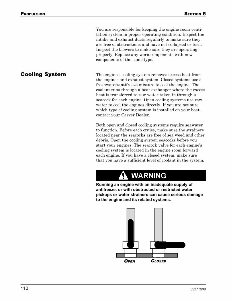
PROPULSION SECTION 5
110 3937 3/99
You are responsible for keeping the engine room venti-lation system in proper operating condition. Inspect theintake and exhaust ducts regularly to make sure theyare free of obstructions and have not collapsed or torn.Inspect the blowers to make sure they are operatingproperly. Replace any worn components with newcomponents of the same type.
The engine’s cooling system removes excess heat fromthe engines and exhaust system. Closed systems use afreshwater/antifreeze mixture to cool the engine. Thecoolant runs through a heat exchanger where the excessheat is transferred to raw water taken in through aseacock for each engine. Open cooling systems use rawwater to cool the engines directly. If you are not surewhich type of cooling system is installed on your boat,contact your Carver Dealer.
Both open and closed cooling systems require seawaterto function. Before each cruise, make sure the strainerslocated near the seacocks are free of sea weed and otherdebris. Open the cooling system seacocks before youstart your engines. The seacock valve for each engine'scooling system is located in the engine room forwardeach engine. If you have a closed system, make surethat you have a sufficient level of coolant in the system.
Running an engine with an inadequate supply ofantifreeze, or with obstructed or restricted waterpickups or water strainers can cause serious damageto the engine and its related systems.
Cooling System
OPEN CLOSED

SECTION 5 PROPULSION
1113937 3/99
After starting your engines, check the engine exhaustoutlet. If water is not being ejected from the outlet,immediately shut down the engines. Determine whyseawater is not being pumped through the system. Havethe problem corrected before restarting the engines.
If the engine temperature gauges register a higher thannormal temperature reading, the cooling system mayneed to be repaired. If the needles move quickly towarda high temperature reading, immediately shut down theengines and have the cooling system inspected andrepaired.
The exhaust system consists of an exhaust manifold, amuffler, and the exhaust pipes used to remove exhaustfrom the engine to the atmosphere. Each engine has itsown exhaust system. If the exhaust system containsleaks or obstructions, or has any other problem thatprevents it from venting exhaust properly, carbonmonoxide may escape and endanger you and yourpassengers. Check the exhaust system regularly forproper operation. Any change in engine noise couldindicate an exhaust system problem and should beimmediately investigated.
An automatic, Halon fire suppression system is in-stalled in your boat’s engine room. This system providesan added measure of safety in the event of an engineroom fire. Refer to the OEM information for details onoperating the Halon fire suppression system. If yourboat was built for use in Europe, the Halon system canalso be activated manually using a release controllocated on the helm.
If the Halon fire suppression system is activated,anyone in the engine room must immediately evacuatethe room. Halon can cause asphyxiation. Once the fireis extinguished and the Halon system is deactivated,ventilate the engine room with fresh air before reenter-ing it.
The Halon tank is installed on the engine room’scenterline. A Halon system monitor, installed near thehelm station, is wired to an ignition switch. The
Exhaust System
Fire SuppressionSystem

PROPULSION SECTION 5
112 3937 3/99
monitor’s light should be "ON" when the ignition switchis turned "ON."
The Halon system contains an engine shut-off circuit.When the system is activated, the engines automati-cally shut down. An override switch, located on themonitor, resets the engine shut-off circuit after theHalon system has been activated, allowing you to re-start the engines.
When replacing components while servicing the Halonsystem, you must use new components that have thesame designation or that are equivalent in their techni-cal and fire-resistance capabilities.
Each helm station is equipped with a complete set ofgauges on the instrument panel. The gauges allow youto monitor the operation and condition of your boat'spropulsion systems. The side of the instrument panelthat the gauges are on (port or starboard) determineswhich engine (port or starboard) that the gauges are for.Familiarize yourself with the gauges before starting theengines for the first time.
Do not start the engines until you have read andunderstood the engine OEM information.
Tachometer
The tachometer displays the speed of the engine inrevolutions per minute (RPMs). This is not the boat'sspeed over the water or the speed of propeller rotation.The tachometer may not register zero RPM when itsengine’s ignition key is turned off; this is normal.
The engine manufacturer has established a maximumRPM rating for your engines, as listed in the engineOEM information. Do not exceed the maximum RPM.Doing so could damage the engines.
Engine Gauges

SECTION 5 PROPULSION
1133937 3/99
HELM GAUGES

PROPULSION SECTION 5
114 3937 3/99
Temperature Gauge
The temperature gauge displays the temperature of thecoolant in the engine’s cooling system. Every engine isdesigned to operate within a specific temperature range.A sudden increase in the temperature gauge readingcould indicate that the cooling water intake system hasbecome blocked; a water intake hose has failed; or thecoolant system's water pump has malfunctioned.
Each engine is equipped with a temperature alarm. Thealarm sounds when the temperature of the engine’scoolant increases to a predetermined point. If the alarmsounds, immediately shut down the affected engine.
Even with high temperature alarms installed, it isimportant that you visually monitor both temperaturegauges while running the engines. If a temperaturegauge indicates excessive engine temperature, immedi-ately shut down the affected engine.
The engine manufacturer has established a maximumcoolant temperature rating for your engines, as listedin the engine OEM information. Do not exceed themaximum coolant temperature. Doing so could dam-age the engines.
Oil Pressure Gauge
The oil pressure gauge displays the pressure within theengine's lubrication system. The oil pressure readingchanges as engine speed changes. However, a noticeabledecrease (either sudden or gradual) in an engine's oilpressure while the boat is maintaining a constant speedmay indicate an oil pump failure, a leak in the lubrica-tion system or excessive engine wear.
Each engine is equipped with a pressure alarm. Thealarm sounds when the pressure in the lubricationsystem decreases to a predetermined point. The alarmalso sounds when the engine is started or when theignition switch is "ON" and the engine is not running.In these situations, the engine does not yet have ad-equate oil pressure; the alarm is silenced as soon as theoil pressure increases to within the normal operating
A TIP FROM CARVER!
A cold engine has a tendency tostall when first put into gear. Letyour engines warm up a fewminutes before departing yourdock or anchorage.

SECTION 5 PROPULSION
1153937 3/99
range. Refer to the engine OEM information for thenormal operating range.
If the alarm sounds after the engine has been runningfor a while, or if the alarm is not silenced within 15seconds after starting the engine, check the oil pressuregauges. If either gauge indicates abnormally low oilpressure, immediately shut down the affected engine.
Even with the low oil pressure alarms installed, it isimportant that you visually monitor both oil pressuregauges while running the engines. If a pressure gaugeindicates low oil pressure, immediately shut down theaffected engine.
The engine manufacturer has established a minimumoil pressure rating for your engines, as listed in theengine OEM information. To avoid damaging theengines, shut them down if the oil pressure is belowthe minimum rating.
Voltmeter
The voltmeter displays the amount of charge in theboat's batteries. When the battery is fully charged, thevoltmeter indicates 12.5 volts. As a battery is used, itsindicated voltage decreases. Each engine battery has itsown voltmeter. The voltmeters are protected by circuitbreakers located on the Safety Breaker Panel. Refer tothe "Voltmeters", "Voltmeter - Battery One" and"Voltmeter - Battery Two" portions of Section 2 foradditional information on the voltmeters.
Fuel Gauges
The fuel gauges display the approximate amount of fuelin the fuel tanks. These gauges are not calibrated andshould not be regarded as an accurate method of mea-suring the amount of fuel in the tanks. Both fuel gaugesare "OFF" until the ignition switch for the port engine isturned "ON".
The gauges on the helm instrument panel should beprotected from the sun and weather when not in use.The gauges are not waterproof. Protecting them fromthe elements prolongs their life.
GaugeMaintenance

PROPULSION SECTION 5
116 3937 3/99
NOTE: Small beads of moisture (condensation) canform behind the glass bezel on some gauges. This doesnot mean the gauge is defective. The Carver LimitedWarranty does not cover the replacement of gauges thatare cosmetically affected by condensation.
The gauges can be affected by static electricity that maybuild up on their glass bezels. To help reduce the staticelectricity and thus improve the gauges’ accuracy,periodically wash the bezels with warm water and amild liquid detergent.
The helm controls allow you to engage the boat’s en-gines, control the boat’s speed and engine RPMs, andcontrol the direction in which the boat is traveling.
Shift Levers
Two shift levers allow you to shift the engines fromneutral to forward or reverse. The shift levers arelocated on the port side of the steering wheel. Theoutboard lever controls the port engine and the inboardlever controls the starboard engine. The engines can beshifted independently to improve maneuverability intight quarters.
Do not shift into or out of gear while the engine speed(as indicated by the tachometers) is above IDLE. Doingso could result in serious damage to the engine's drivetrain.
A neutral safety switch is incorporated into the linkageof each shift lever. When properly adjusted, the safetyswitch does not permit you to start an engine while it isin gear.
Throttle Levers
Two throttles allow you to increase or decrease thespeed of the engines. The throttles are located on thestarboard side of the steering wheel. The inboard levercontrols the port engine and the outboard lever controlsthe starboard engine. The levers are designed to allowindependent control of each engine’s speed.
Helm ControlsShift and Throttle
A TIP FROM CARVER!
If you turn the ignition switch keyand the engine starter fails toengage, it may be because theneutral safety switch for thatengine is slightly out of adjust-ment. If this happens, wiggle theshift lever for that engine forwardand aft until the starter engages.

SECTION 5 PROPULSION
1173937 3/99
Before shifting an engine into or out of gear, alwaysreturn its throttle to the extreme low speed position.Failure to follow this procedure could result in seriousdamage to the engine’s drive train.
Because your boat has dual engines, it is recommendedthat you operate the engines at the same speed whilecruising. This reduces engine noise and vibration, andimproves engine efficiency.
Use the optional engine synchronizer gauge to monitorthe speed of each engine. Adjust the throttles so thatthe synchronizer gauge needle is centered.
NOTE: Aligning the throttles with each other does notnecessarily mean the engines are synchronized. Toaccurately synchronize the engines, rely on the tachom-eters or the engine synchronizer gauge.
Throttle Synchronizer
The optional throttle synchronizer allows you to elec-tronically and mechanically interconnect both enginethrottles. This allows you to increase and decreaseengine speed using one throttle lever. This also keepsthe engines precisely synchronized. Refer to the OEMinformation for details on operating the throttle syn-chronizer.
Control Cables
Push-pull cables are used to connect the shift andthrottle levers to the engines. Refer to the OEM infor-mation for details on adjusting and maintaining theshift and throttle control systems.
Your boat uses a hydraulic steering system. This systemis preferable over a mechanical steering system becauseit provides better response for large boats.
The boat's helm is connected to the rudders through ahydraulic pump, a network of hydraulic lines, an oilreservoir, a hydraulic cylinder, and a tiller tie rod.When the helm is turned, oil pumps through the hy-draulic line, which activates the hydraulic cylinder. The
Steering
PROPULSION SECTION 5
118 3937 3/99
cylinder is connected to the tiller tie rod. Extending andretracting the cylinder moves the rudders, enabling youto steer the boat. With hydraulic steering, the effortneeded to turn the helm remains the same regardless ofthe boat’s speed.
For the hydraulic steering system to operate properly, itmust have an adequate source of hydraulic fluid andsufficient pressure within the hydraulic pump and lines.Refer to the OEM information for details on operatingand maintaining the steering system.
Follow the steps provided below to help ensure thatyour boat is prepared for a safe cruise.
Your boat’s fuel tanks are designed to take on fuel at amaximum rate of 9 gallons per minute (GPM) when thetank is between 25% and 75% full. During this time thepressure inside the tank must not exceed 4 psi.
When fueling tanks that are either completely empty ornearly full, decrease the fueling rate. This helps preventthe tanks from fuel surge and rupture when they areempty, and from backing up and spilling fuel when theyare full. Be aware that many marine fuel pumps candeliver fuel at rates up to 35 GPM. This high fuelingrate should never be used with your boat; it coulddamage your fuel system.
Before Fueling
NOTE: Refer to the engine OEM information for the typeof fuel and octane rating recommended for your boat'sengines.
1. Make sure that the boat is securely moored.
2. Close all ports, windows, hatches and doors.
3. Turn "OFF" all fans, motors and any other devicesthat could create a spark, including the stove, oven,and generator.
4. Extinguish all open flames and smoking material,such as cigarettes, on the boat and in the areaaround the fuel dock.
Preparing forCruising
Fueling
SECTION 5 PROPULSION
1193937 3/99
5. Turn the battery selector switch on the SafetyBreaker Panel to the "OFF" position.
6. Have all guests and passengers leave the boat.Only the fuel handlers should be in the area.
Fueling
1. Remove the starboard and port fuel fill deck platesusing the cap removal tool supplied with your boat.Refer to the "Fill Plate/Pumpout Locations"portion of Section 9 for the exact locations of theseplates.
2. Make sure that the fuel you are about to pump intoyour fuel tanks is the type recommended by theboat’s engine manufacturer.
3. Estimate the approximate amount of fuel you wishto take on.
4. Begin pumping fuel into the fuel tanks a rate of nomore that 9 GPM. When the tank is close to full,slow the fuel flow rate to less than 9 GPM. Whilefueling, keep the fuel hose nozzle in constant con-tact with the metal fuel fill deck plate. This is asafeguard against static sparks.
Avoid spilling fuel on the gelcoat surface of yourboat. Fuel can stain the gelcoat and damage the hullaccent stripes.
5. Monitor the fuel tank air vents. When the fuel tankis almost full, air whistles through the vent.
After Fueling
1. Replace the starboard and port fuel fill deck plates.
2. Wash down or wipe up all spilled fuel.
3. Ventilate the cabin by opening ports, windows,doors and hatches.
4. Turn the battery selector switch on the SafetyBreaker Panel to either the "1" or "2" position.

PROPULSION SECTION 5
120 3937 3/99
5. On the Bridge Breaker Panel, switch the Maincircuit breaker "ON", then switch the Bilge Blowercircuit breakers "ON".
Always run the bilge blowers for at least 4 minutesbefore starting the boat’s engines or the generator.
6. Turn "ON" the bilge blowers using the controls onthe helm instrument panel. Allow the blowers torun for at least four minutes. Do not turn "OFF"the blowers yet.
7. Inspect the engine room. If you smell any fuelvapor, wait another four minutes so that the bilgeblowers can remove the vapor. Repeat this step asmany times as is necessary until the engine room isfree of fuel vapor. Do not operate any onboardequipment until you are sure that the boat is free offuel vapor.
Pre-Start Checklist
1. Read and understand this Owner's Guide and allOEM information.
2. Check both fuel gauges to verify that you havesufficient fuel for your trip.
3. Inspect the engine room:
a. Sniff for fuel vapor.b. Check the bilge water level.c. Check for oil in the bilge.d. Check the crank case oil level in each engine.e. Make an overall inspection of the engine room to
look for signs of potential problems.f. Follow all maintenance instructions as detailed
in Section 7.
4. Turn the battery selector switch on the SafetyBreaker Panel to either the "1" or "2" position.
5. On the Safety Breaker Panel, switch the MainBridge and Salon circuit breakers "ON".
Operating theEngines

SECTION 5 PROPULSION
1213937 3/99
Switch "ON" any other circuit breakers for equip-ment you may need.
6. On the Bridge Breaker Panel, switch the Maincircuit breaker "ON", then switch the Bilge Blowercircuit breakers "ON".
Switch "ON" any other circuit breakers for equip-ment you may need (horn, trim tabs, Halon, etc.).
7. Turn "ON" the bilge blowers using the controls onthe helm instrument panel.
8. Check the output level of the bilge ventilator. Youcan feel air being blown from the output bilge ventif the bilge blower is operating properly.
9. Verify that all safety gear is onboard and in properoperating condition. Check items such as the navi-gation lights, VHF radio, depth sounder, etc. Makesure your boat carries all safety equipment re-quired by Federal, State and local regulations.
10. Verify that you have an adequate supply of freshwater.
11. Check the level of waste in the waste tanks. Emptythem if necessary. Refer to the "Emptying theWaste Tanks" portion of Section 4.
12. Disconnect and store the shore power cord andshore water hose.
Starting the Engines
Always run the bilge blowers for at least 4 minutesbefore starting the boat’s engines or the generator.
1. Open the cooling system seacocks for both engines.
2. Move both shift levers to neutral.
3. Select the engine you wish to start first. NEVERstart both engines at the same time.
PROPULSION SECTION 5
122 3937 3/99
The ignition switch is spring activated. Release thekey as soon as the engine starts. Failure to do somay damage the starter.
If the engine does not start within 10 seconds, re-lease the key, then try starting the engine again. Donot hold the ignition key in the START position formore than 10 seconds.
4. Place one hand on the throttle of the engine you arestarting. With the other hand, turn the ignitionkey.
The oil pressure alarm sounds for the first fewseconds after the engine has started. This is nor-mal. The alarm is silenced as soon as the oil pres-sure increases to within the normal operatingrange.
If the engine is cold when it starts, it may runrough. Advance its throttle lever slightly to keep itrunning.
5. Start the other engine in the same manner as thefirst engine.
After the Engines Have Started
Always run the bilge blowers while the boat’s en-gines are at idle speed.
1. Check the engine gauges. Make sure the oil pres-sure is within the normal operating range. Thevoltmeters should read approximately 12.5 to 13.4volts.
2. Verify that water is being pumped through eachengine's exhaust port, located near the transom. Ifyou do not see water being pumped out, turn theaffected engine off. Identify and correct the cause ofthe problem before restarting the engine.

SECTION 5 PROPULSION
1233937 3/99
The engine room contains moving, hot machinery.Keep your hands, feet and body out of the engineroom while one or both engines are operating.
3. Look into the engine room and visually inspect thefuel system hoses and exhaust hoses. If you see aleak or suspect that anything is out of order, shutdown the engines and investigate. Identify andcorrect the cause of any problem before restartingthe engines.
4. Let the engines warm up until the needles on thetemperature gauges begin moving up.
5. Make sure all navigation systems are operatingproperly.

PROPULSION SECTION 5
124 3937 3/99
NOTES

SECTION 5 PROPULSION
1253937 3/99
NOTES

PROPULSION SECTION 5
126 3937 3/99
NOTES

SECTION 6 OPERATING AND MANEUVERING
1273937 3/99
Operating and Maneuvering
Launching the Boat .................................................. 128
Navigation ................................................................ 128
Controlling the Boat................................................. 129Loading ..........................................................................129Casting Off and Docking ...............................................129Maneuvering .................................................................. 133
Anchoring ................................................................. 134Stern Anchors ................................................................ 135Mooring Lines ................................................................ 135
Getting Underway .................................................... 137Shakedown Cruise ......................................................... 137
Operating at Planing Speed ..................................... 138Trim Tabs ....................................................................... 138
OPERATING AND MANEUVERING SECTION 6
128 3937 3/99
Have a professional launch your boat. Your dealer caneither provide experienced people to do this or recom-mend someone.
Understanding navigation is very important whenoperating your boat on the open seas. Instructions onhow to navigate your boat are beyond the scope of thisguide. Carver encourages you to read Chapman's Pilot-ing and Seamanship and obtain instruction regardinghow to navigate your boat.
Charts
You can obtain charts of the waters in which you intendto navigate from the National Ocean Survey, a branchof the National Oceanic and Atmospheric Administra-tion in Washington D.C. The NOS offers a publicationlisting the charts you will need for your area; however,this listing may not include inland rivers. Charts ofinland rivers are also available from the appropriatedistrict office of the U.S. Army Corps of Engineers. Yourdealer may also have charts of the waters in which youintend to cruise.
Keeping your charts up-to-date is a very important partof navigation. The Weekly Notice to Mariners availablefrom the Defense Mapping agency or the U.S. CoastGuard is an excellent resource for updating charts.
Compass
The compass is the most important piece of navigationequipment onboard your boat. To operate properly, thecompass must be free from interference by local mag-netic influences and electrical components. Refer to theOEM information for details on using and maintainingthe compass. When it is time to compensate your com-pass, Carver recommends having it done professionally.
Horn
If you are navigating in fog or at night, use your boat’shorn to alert other boaters of your presence. The hornmeets U.S. Coast Guard standards.
Navigation
Launching the Boat

SECTION 6 OPERATING AND MANEUVERING
1293937 3/99
Depth Sounder
The optional depth sounder can help you avoid enteringwaters that are too shallow for your boat and can aid innavigation.
Speed Log
Keeping a speed log is essential when trying to deter-mine your position over time. Use the informationrecorded on the log to plot your approximate positionfrom a known position.
Shallow Water Operation
Always pay attention to the depth of the waters inwhich you are cruising. Do not venture into waterswhich are too shallow for your boat's draft. Shallowwater navigation can be very hazardous. If you do findyourself in shallow waters, reduce speed immediately.Consult nautical charts to determine your position. Tryto plot a course out of the shallows through waters deepenough for your boat's draft. If your boat runs aground,radio for help and wait until it arrives. Do not attemptto relaunch your boat. You may do serious damage toyour hull or underwater gear.
Every boat owner should know how to perform thefollowing procedures competently. Do not attempt anyof these procedures without first receiving appropriatetraining.
When you load items onto the boat, have someone onthe pier hand them to you after you have boarded theboat. Stow all items securely to prevent them fromshifting when the boat is in motion. If your boat isloaded near capacity or if seas get rough, distribute theweight evenly and keep the load low. Don't make anyabrupt changes in its distribution. Shift the load ormove about only after stopping or slowing the boat.
Docking and casting off can be hampered by wind andcurrent. It is important to use the current by approach-ing or leaving with the current instead of fightingagainst it. Also, the operator should adequately fenderhis boat against collisions with docks or other boats.
Controlling the Boat
Loading
Casting Off andDocking

OPERATING AND MANEUVERING SECTION 6
130 3937 3/99
Leaving a Pier or Mooring
Getting underway from a pier is normally accomplishedby taking in all lines except the bow spring. With aneutral rudder, power the boat forward using only theengine farthest from the pier. The boat will pivotaround the bow spring line, moving the stern out andaway from the pier. A fender should be placed betweenthe bow and the pier to prevent scraping as the boatpivots about the bow spring. Once the stern is clear ofboats and other obstructions, take the bow spring in andback the boat away.
At marina anchorages, boats are often secured to amooring buoy. Fouling your propeller with a mooringline is the principal hazard when leaving a mooring. Ifyou use a dinghy to reach your boat, make sure thedinghy line does not foul the propeller.
After getting onboard, start the engines and send some-one forward to slacken the line. Release the line. In ariver with current, the boat will gain headway with thecurrent. After you are clear of the buoy, power the boatforward. In a calm bay, if there is neither wind norcurrent, back the boat away a few boat lengths. As youpower forward, keep the buoy in sight and give it ampleroom until you are clear. Run slowly until you clear theanchorage to avoid creating a nuisance with your wake.

SECTION 6 OPERATING AND MANEUVERING
1313937 3/99
Landing at a Pier
To land at a pier, approach the pier at a right angle. Ifyou desire a starboard side landing, place the rudders toport and reverse the port engine to check headway.Leave the starboard engine in forward gear to swing theboat parallel to the pier. For landings on the port side,turn the rudders to starboard and put the starboardengine into reverse as the boat comes in. You may haveto shift into and out of gear to control the boat’s speed.
Picking Up a Mooring
As you return to the anchorage, approach your mooringat slow speed. Take note of how other boats are lying attheir buoys. They are heading into the wind or currentand your approach course should be roughly parallel totheir heading. Stay clear of other moorings to avoidfouling them. If you tow your dinghy, station a crewmember at the helm to keep the dinghy line from foul-ing the propeller.
Shift the engines into neutral when you estimate thatthe boat's forward momentum will carry you to thebuoy. Station someone at the bow with a boat hook topick up the pennant float. If you are about to overshootyour mark, check headway as the bow comes up to thebuoy. If you fall short, a few turns of the propellershould get you to the buoy. Keep the engine runninguntil the pennant eye has been secured on the bitt orbow cleat.
If your crewman can not reach the pennant or if youovershoot, get clear and calmly try again.

OPERATING AND MANEUVERING SECTION 6
132 3937 3/99
TRACKING FORWARD (PROPS ONLY)
TRACKING ASTERN (PROPS ONLY)

SECTION 6 OPERATING AND MANEUVERING
1333937 3/99
The propellers on your boat rotate in opposite direc-tions. With only the port propeller rotating, your boattracks forward and to starboard in forward gear andbackward and to port in reverse gear. With only thestarboard propeller rotating, your boat tracks forwardand to port in forward gear and backward and to star-board in reverse gear.
With both propellers rotating at the same speed, therudders amidships and the engines in forward gear,your boat tracks straight forward.
When the boat is moving backward, its rudders are notas effective and the side force from the propellers isused to steer the boat.
Maneuvering Astern
Backing a boat may be necessary in a crowded marina.Your boat’s twin engines allow the boat to track straightastern or to either side. When backing, be sure to keepyour trim tabs up. To make a turn to port, shift the portengine to neutral. A starboard turn astern is made byshifting the starboard engine to neutral.
Check sternway (stop reverse motion) by shifting yourengines to forward gear and throttling forward.
Full stern turns can be executed, but watch the bow.The bow cuts a much wider arc than the stern andcollisions could occur in crowded areas.
Checking Headway
Stopping the boat’s forward motion is referred to as“checking headway”. You should learn how to confi-dently stop your boat within any required distance. Youcan check headway by shifting engines to neutral andcoming to a complete stop over a long distance, or byreversing engines and stopping within a shorter dis-tance.
Close Quarters Turns
To execute a close quarters turn, check your headway,then shift one engine into reverse while shifting theother into forward gear. As you advance the throttles,the opposing forces cause the boat to pivot about a pointcentered between the propellers. You can assist the rate
Maneuvering

OPERATING AND MANEUVERING SECTION 6
134 3937 3/99
of turn by turning the rudders in the direction of theturn.
Towing
Always offer assistance to a vessel in distress. However,towing a capsized boat or a boat with a damaged hull isnot recommended. In these situations, lend aid to theoccupants and call the proper authorities. Remember,you are obligated to lend aid to any person in distress,but not to the vessel. If you believe your vessel can nottow the vehicle in distress, do not attempt it. Onedisabled boat is better than two.
An anchor's holding power depends on its weight andthe length of the anchor line. The most effective lengthis six to seven times the depth of the water you intendto anchor in. For example, if the water is 10 feet deep,you should have 60-70 feet of anchor line.
Approach your selected anchor site from downwind.Come to a dead stop over the spot where you want todrop anchor. Have a crew member lower the anchor.When the anchor hits bottom, reverse engines andslowly move the boat backwards to pay out more anchorline as the crew member keeps a slight tension on theline. When the proper length is out, the crew membercan snub the line by winding it around the bow cleat.This should cause the anchor flukes to dig in and holdeffectively.
Anchoring

SECTION 6 OPERATING AND MANEUVERING
1353937 3/99
Check for anchor drag. Immediately after anchoring,observe shoreline landmarks. After thirty minutes,observe the landmarks again. If the points of referencehave changed, reset your anchor.
When weighing (pulling in) your anchor, pull the line inuntil it is vertical. When the line is taut, a hard tug willpull the anchor's shank up. If the anchor is stuck, wrapsome of the line around a bow cleat and keep tension onthe line. The boat's momentum may free the anchor. Ifthere is a swell, wind the line around a bow cleat whenthe bow drops into a wave trough. As the bow lifts, itmay free the anchor. If neither of these methods works,pay out a few feet of line, secure it around the bow cleat,and maneuver around the anchor. Keep the line tightuntil you find the angle that pulls the anchor loose.
An electric windlass simplifies the above procedures.Follow the above procedures and use the windlasscontrol at the helm to drop anchor. To relieve strain onthe windlass, hooks called devil's claws engage thechain when the anchor is down.
If you intend to stay at anchor overnight or if you an-chor your boat close to another structure, considerdropping another anchor from the stern. This preventsyour boat from swinging around if the wind or currentshifts.
You may also need to anchors in a strong wind. If youdrop your spare anchor, make sure the two anchors arelaid out at an angle. If both anchors are set in-line andone of them drags, it may cut a trough for the otheranchor to follow.
In some anchorages, boats lie to anchors bow and stern.To get these anchors down, drop the bow anchor first,then pay out extra anchor line (15-18 times the depth).Drop the stern anchor and adjust the length of linepayed out on both anchors as necessary.
It’s a good idea to familiarize yourself with mooring lineterminology and using mooring lines. If necessary,obtain training on mooring your boat. Learn how andwhen to tie the various knots used in seamanship.Boats which are not moored correctly can suffer and
Stern Anchors
Mooring Lines

OPERATING AND MANEUVERING SECTION 6
136 3937 3/99
cause serious damage. The following information servesonly as a guide to mooring your boat.
The mooring illustration above demonstrates possiblemooring lines for a small vessel. These lines include the(1) bow line, (2) after bow spring, (3) after quarterspring, (4) stern lines and (5) forward quarter spring. Ofthe two dockings shown, the left one shows how to tieup when docking your boat in an alongside berth. Thedocking shown on the right is used when tying up atfour corners of the boat.
The two spring lines are crossed and running to sepa-rate deck cleats. If possible, the stern line should be runto the offshore quarter cleat. Spring lines are useful inpreventing undesired movement ahead or astern in aberth; they also keep a moored vessel in position whenthere is a significant rise or fall in tide.
1
2
3
5

SECTION 6 OPERATING AND MANEUVERING
1373937 3/99
It takes training and experience to become an "expertyachtsman." Reading and understanding this Owner'sGuide gives you only part of the knowledge you’ll needto operate a boat safely and skillfully.
Carver Owners have a wide range of abilities, fromseasoned yachtsmen with years of experience to abso-lute beginners with a new-found love for the water. Behonest with yourself in appraising your level of skill.
Before taking your boat on its first outing, be sure thatthe following tasks have been completed.
1. Your Carver Dealer has completed Pre-Deliverycommissioning. This inspection is documented onthe Pre-Delivery Service Document and is signed bythe dealer and the owner.
2. All warranty registration cards have been com-pleted and mailed.
3. You have read and understand this Owner's Guideand all OEM information.
4. The safety equipment onboard your boat is incompliance with Federal, State and local regula-tions.
5. Your boat has been documented or registered anddisplays the appropriate identification on the hull.
7. A representative of your Carver Dealer has re-viewed the operation of the boat and its systemswith you and answered all of your questions to yoursatisfaction.
If possible, pick a calm day for your first outing. Theshakedown cruise with a new boat is not the best timeto bring friends or guests along. Entertaining guests candistract you from the real purpose of the cruise, whichis to familiarize yourself with your new boat. Bring onlythose people (spouse and children) who will make upyour regular crew. Invite the sales person who sold youthe boat or a member of your Carver Dealer's servicestaff along for the ride.
Getting Underway
Shakedown Cruise
OPERATING AND MANEUVERING SECTION 6
138 3937 3/99
Carry a pad and pencil with you during this first outing.Write down any questions that come to mind during thecruise so you can discuss them with your dealer.
Follow the procedures outlined at the beginning of thissection for fueling and starting the boat's engines.
This may be the first time you have been in total com-mand of your new boat. Proceed slowly. Have fun butremember that the objective of the cruise is to learnmore about how your boat operates and handles. Oper-ate at different RPM settings. Try different trim angles.Monitor the gauges. Practice backing down and turningslow speed tight corners that simulate docking maneu-vers.
Your boat has a “planing” hull. A planing hull skims“over” the water rather than “through” it. To do this,however, your boat first has to reach a certain speed,called "planing speed."
When you first accelerate from a dead stop, the trimangle of the boat increases, causing the bow to rise andthe stern to drop. If you continue to accelerate, the boateventually achieves plane, which means the bow slowlydrops to a more level attitude.
It is important to get on plane as soon as possible andavoid speeds that cause the boat to plow through thewater with the boat in a bow-high attitude. A bow-highattitude obstructs your vision and limits the boat’shandling and performance capabilities.
Once the boat is on plane, you can back the throttles offto a point where the hull is still planing but the enginesare operating at a fuel efficient speed.
Your boat is equipped with a set of electric / hydraulictrim tabs. Trim tabs help the boat get on plane byallowing you to adjust the attitude of the boat for vari-ables such as load, passengers, seas or wind. Undernormal conditions your boat does not need adjustmentsto the trim tabs to achieve plane. Use the tabs at plan-
Operating at PlaningSpeed
Trim Tabs

SECTION 6 OPERATING AND MANEUVERING
1393937 3/99
ing speeds to make minor adjustments in the fore andaft and beam-to-beam angle of the boat.
To use the trim tabs:
1. Switch the Trim Tabs circuit breaker on the BridgeBreaker Panel "ON".
2. The trim tabs controls are located at the helmstation. The controls consist of two switches. Theport switch controls the port tab; the starboardswitch controls the starboard tab. Each switch islabeled "BOW UP" and "BOW DOWN." Beforeadvancing the throttles, press both switches on the"BOW UP" side for 5 seconds. This lifts the trimtabs to the full "up" position.
3. Advance the throttles to bring the boat on plane.Adjust the engine RPMs for cruising speed.
Do not overtrim your boat. When adjusting the trimtabs, press their control switches for only one-halfsecond at a time, then allow the boat to respond.Continue to adjust the trim tabs in this manner untilthe boat is at the desired trim angle. Over-trimmingcan cause the bow to veer and may lead to loss ofcontrol. Always reset the trim tabs to the BOW UPposition before advancing throttles to achieve plane.Accelerating the boat to planing speed while the trimtabs are lowered can cause a loss of control.
4. Use the trim tabs individually to make beam-to-beam adjustments. If the majority of your passen-gers are sitting on the port side, you may find thatthe starboard side of your boat is riding higher thanthe port side. Use the "BOW DOWN" side of thestarboard trim tab switch to adjust the trim.
If your passengers decide to shift to the other sideof the boat, level the boat by pressing the "BOWUP" side of the starboard trim tab switch for a fewseconds. This undoes your previous adjustment.Then, use the "BOW DOWN" side of the port trimtab switch to adjust the trim.

OPERATING AND MANEUVERING SECTION 6
140 3937 3/99
5. The trim tab switches can be used together to bringthe bow of the boat to a lower attitude. This adjust-ment is often used when running into choppy seas.Bringing the bow down uses the sharper part of theboats "V" hull to break through waves. Use the"BOW DOWN" side of both trim tab switchessimultaneously to adjust the trim. Be careful whenmaking bow down adjustments. Excessive bowdown trim can cause considerable bow spray whichhampers visibility and reduces control of your boat.

SECTION 6 OPERATING AND MANEUVERING
1413937 3/99
NOTES

OPERATING AND MANEUVERING SECTION 6
142 3937 3/99
NOTES

SECTION 7 MAINTENANCE
1433937 3/99
Maintenance
Maintenance Schedule ............................................ 144
Exterior Maintenance .............................................. 148Fiberglass Surfaces....................................................... 148Anti-Fouling Bottom Paint ............................................. 149Caulking and Sealants................................................... 150Stainless Steel Rails and Hardware ............................. 150Decorative Striping Tape............................................... 151Windows......................................................................... 151Exterior Vinyl Upholstery .............................................. 152Exterior Carpet ..............................................................152Canvas ........................................................................... 152
Interior Maintenance ............................................... 155Woodwork ...................................................................... 155High Pressure Laminate ................................................ 155Woven Fabrics................................................................ 155Carpet ............................................................................ 157Interior Fiberglass ......................................................... 157Plexiglass ...................................................................... 157
Mechanical Systems ................................................ 158Engines / Generator ....................................................... 158Thru-Hull Valves ............................................................ 158Propeller Shaft Seals ..................................................... 158Props .............................................................................. 159Struts ............................................................................. 159DC Electrical System..................................................... 159Fresh Water System ...................................................... 161Bilge System .................................................................. 162Sanitation System ......................................................... 162

MAINTENANCE SECTION 7
144 3937 3/99
The maintenance activities and their intervals listed onthe following pages are provided as guidelines only. Theideal maintenance activities and maintenance scheduledepend on the components installed in your boat andthe manner and environment in which you use yourboat. The more frequently you use your boat, the moreoften maintenance needs to be performed. If you useyour boat in salt water, it requires more maintenance,especially on its exterior.
For instructions on when and how to maintain many ofyour boat’s components, refer to the OEM information.
Maintenance activities are divided into four types:
Type A Maintenance
Perform Type A maintenance 48 hours after the firstlaunching of your boat, and 48 hours after launchingyour boat following a period of onshore storage.
Type B Maintenance
Perform Type B maintenance after the engines haveoperated for 25 hours following launching, whether yourboat is new or coming out of onshore storage.
Type C Maintenance
Perform Type C maintenance semiannually or after theengines have operated for 100 hours, whichever comesfirst.
Type D Maintenance
Perform Type D maintenance annually or after theengines have operated for 200 hours, whichever comesfirst.
A maintenance log is included at the end of this owner'sguide. The log lists the maintenance activities shown onthe following pages. Make several copies of the log. Usethe log to keep a record of the maintenance activitiesyou perform.
A blank log sheet is also included so that you can de-velop a maintenance list for OEM components. Make acopy of this log sheet and write in the suggested itemsfrom the OEM information.
MaintenanceSchedule

SECTION 7 MAINTENANCE
1453937 3/99
Type A48 hours after
launching
Type B25 engine
hours afterlaunching
Type C6 months or100 engine
hours
Type D12 months or200 engine
hours
ENGINES AND DRIVE SYSTEM
Maintenance as outlined in theengine manual.
As recommendedby manufacturer.
As recommendedby manufacturer.
As recommendedby manufacturer.
As recommendedby manufacturer.
Inspect water intake hoses &connections.
X X X
Inspect exhaust system hoses &connections.
X X X X
Inspect exhaust guard cover. X
Check prop for balance & nicks X
Check strut bearings X
Check rudder alignment X
Check all thru-hull fittings X
Inspect shaft log packing nut X X X X
Check engine and shaftalignment
X X X X
Spray ignition switch with contactcleaner
X
Tighten engine mounts X X
Weigh halon bottle X X
CONTROL SYSTEM
Throttle and shift adjustments X X
Test neutral safety switch X
Lubricate cables and controls X
STEERING SYSTEM
Inspect linkage and connections X X
Inspect hydraulic fluid level X X X X
Inspect rudder packing nut X X X X
Inspect tiller tie bar linkage X X X
Inspect trim tab reservoir X X X

MAINTENANCE SECTION 7
146 3937 3/99
Type A48 hours after
launching
Type B25 engine
hours afterlaunching
Type C6 months or100 engine
hours
Type D12 months or200 engine
hours
ELECTRICAL SYSTEM
Inspect and clean batteries X X
Check battery fluid levels X X X
Check operation of all 12 voltequipment
X X X X
Check operation of all ACequipment
X X X
Inspect shore power cord X X
Inspect generator water intakeand discharge
X X X
Inspect zincs X X
Generator maintenance As recommendedby manufacturer.
As recommendedby manufacturer.
As recommendedby manufacturer.
As recommendedby manufacturer.
FUEL SYSTEM
Clean engine fuel filters X X X
Inspect for fuel leaks X X X X
Inspect fuel lines for signs ofchafe
X X X
Check propane system for leaks X X X
Inspect propane storage system X X
FRESH WATER SYSTEM
Flush water tank and system X X
Clean in-line water filter X X
FIBERGLASS / WOODWORK
Clean fiberglass X
Wax hull & all non-tread areas X
Repair chipped fiberglass X X
Clean interior woodwork X

SECTION 7 MAINTENANCE
1473937 3/99
Type A48 hours after
launching
Type B25 engine
hours afterlaunching
Type C6 months or100 engine
hours
Type D12 months or200 engine
hours
INTERIOR
Head maintenance As recommendedby manufacturer.
As recommendedby manufacturer.
As recommendedby manufacturer.
As recommendedby manufacturer.
Inspect thru-hull fittings X X X X
Clean refrigerator X X
Clean stove X X
Lubricate door hinges andlocks
X X
Clean vinyl fabrics & wallcoverings
X
Spot clean woven fabrics X
Spot clean carpet X
EXTERIOR
Check compass for magneticdiviation
X
Check trim tab system forleaks
X X
Check deck hardwaretightness & caulking
X
Clean vinyl upholstery X X
Clean plexiglass surfaces X
Lubricate hinges, latches &locks
X X
Wash weather covers X
BILGE SYSTEM
Check garboard drain plug X X X
Check and test bilge pumps X X X X
Inspect shower sump pump X X
Check & test bilge blower Each time beforestarting engine
Each time beforestarting engine
Each time beforestarting engine
Each time beforestarting engine

MAINTENANCE SECTION 7
148 3937 3/99
The following paragraphs explain how to maintain thevarious materials present outside your boat’s cabin tohelp keep the boat looking new.
The exterior fiberglass surfaces of your boat are coatedwith a protective layer of gelcoat. Gelcoat forms a hard,smooth and durable surface. It does, however, containvery small pores that, over time, collect dirt and discolorif the gelcoat is not kept clean.
Do not use abrasive cleaners when washing your boat.Abrasive cleaners scratch and dull the gelcoat.
Wash the boat with fresh water after each outing tohelp keep the gelcoat clean. If you operate your boat insalt water, wash it at least once every week, even if ithasn’t been used since the last washing. Periodicallywash the boat with a solution of fresh water and mildsoap. Use a sponge to wash smooth surfaces and a stiffnylon or natural bristle brush to wash nonskid surfaces.
Do not wax the nonskid surfaces. Waxing them makesthem slippery and dangerous to walk on.
Wax all non-tread areas at least once a season. Use ahigh quality, non-yellowing, marine wax. Waxing yourboat provides a shiny surface and seals the pores in thegelcoat, making it easier to keep clean.
The continued and overly frequent use of abrasivepolishing compounds eventually erodes the gelcoat.
Gelcoat eventually dulls with age, much like the painton your car. When it does this, you can restore thegelcoat’s luster using an electric buffer and a very finegrade polishing compound. Ask your Carver Dealerwhat brand and grade of polish to use.
Stress cracks are common on all fiberglass boats. In themajority of instances these cracks are cosmetic and
ExteriorMaintenance
FiberglassSurfaces

SECTION 7 MAINTENANCE
1493937 3/99
limited to the gelcoat surface only. Gelcoat stress cracksare rarely an indication of structural problems. If youdiscover stress cracks in your boat contact your CarverDealer.
NOTE: The repair of cosmetic (non-structural) gelcoatstress cracks is not included under the terms of theCarver Limited Warranty.
Gelcoat Repair
Cosmetic repair of minor gelcoat nicks and scratches isnot difficult nor does it require the use of special orunique tools. Any boat owner with a little practice canmake visually satisfying repairs. Repairs to fiberglasslaminates or structural fiberglass components are bestleft to the experienced technicians at your CarverDealer.
A gelcoat repair kit is available from your CarverDealer (Carver part number 82036-03). This kit in-cludes color matched gel, gel hardener and detailedinstructions on making gelcoat repairs.
Gelcoat Blisters
While fiberglass is a durable and economical material, itis not indestructible as is often assumed by many boat-ers. The most commonly known problem associated withfiberglass is blistering. These blisters generally form inthe gelcoat or in the outer most layer of laminate. Theycan range in size from microscopic to two inches orlarger in diameter.
The appearance of fiberglass blisters does not indicatestructural problems or faulty hull lamination. Gelcoatblisters form through a natural process and are quitecommon. If you discover blisters on the underwaterportion of your boat's hull, contact your Carver Dealer.
The underwater surfaces of your boat are coated with ahigh-quality, factory-applied coat of antifouling bottompaint, applied after the hull has been carefully preparedand primed.
The paint has a high copper content and antifoulingelements that retard the growth of marine life on thebottom of your boat's hull. The antifouling elements in
Anti-FoulingBottom Paint

MAINTENANCE SECTION 7
150 3937 3/99
this paint have a limited life span, usually about 12months. Because of this, Carver suggests you repaintthe hull with a fresh coat of bottom paint on an annualbasis. Be sure to use a paint that is compatible with thefactory-applied paint. Failure to do so can void yourbottom paint warranty. Also make sure the paint is bestfor the type of water you operate the boat in. See yourCarver Dealer for assistance in selecting an appropriatebottom paint.
To prepare the hull bottom for painting, lightly sand theexisting paint with 80 grit or 100 grit sandpaper. Re-move all dirt and sanding residue from the hull. Applythe new paint using a brush, roller or sprayer. If youwish to apply a second coat, allow the first coat to drybefore proceeding.
Deck fittings, rail bases, window frames and all under-water fittings have been sealed with the finest qualitysealants. These sealants, however, do not last indefi-nitely. The working action of the boat and the expansionand contraction caused by variations in outside tem-perature eventually break down the sealant.
Fittings that have begun to leak must be resealed.Remove the fitting and clean the old sealant from bothmating surfaces. Reseal the fitting using the sealantrecommended by your Carver Dealer.
Stainless steel is not rust-resistant nor is it stain-resistant. When left in contact with the marine environ-ment it does rust and corrode. Proper care helps keepthe stainless fittings on your boat looking bright andshiny.
Clean the stainless steel rails and fittings after eachouting with either soap and water or glass cleaner. Ifyou operate your boat in salt water, clean the rails andfittings at least once every week, even if the boat hasn’tbeen used since the last cleaning.
If you discover any rust, remove it immediately. Failureto do so leads to irreversible pitting. Use brass, silver orchrome polish to remove rust on stainless steel. Wax thestainless fittings and rails to help protect them from theelements and keep them looking their best. Use thesame wax you use on the fiberglass surfaces of the boat.
Stainless SteelRails andHardware
Caulking andSealants

SECTION 7 MAINTENANCE
1513937 3/99
Never use abrasives like sandpaper or steel wool toclean stainless steel fittings or rails. Never use mineralacids or bleach to clean stainless steel. Never letstainless steel come into prolonged contact with iron,steel or other metals which cause contaminationleading to rust or corrosion.
A variety of decorative stripes are used on the exteriorof your boat. Striping tapes are custom-made toCarver’s color and size specifications. Replacementstriping tape is only available through Carver Dealers.To remove a damaged section of tape, heat the areawith a hair dryer. This softens the adhesive and makesthe tape easier to remove. To remove any adhesiveresidue, use acetone.
When fueling your boat, avoid spilling fuel on any ofthe decorative striping tape. Fuel damages the stripingtape.
The window and hatch frames on your boat are fabri-cated from aluminum. Some of these frames are paintedwith enamel. To clean both the painted and unpaintedframes, use a sponge dipped in a solution of fresh waterand mild soap. Do not use a brush or abrasive cleaneras these can scratch the painted frame surfaces, damag-ing their appearance.
The cabin windows are made from tempered glass.Clean the windows using a soft rag and glass cleaner.The bridge wind screen is made from formed plexiglass.Do not use glass cleaner to clean plexiglass; instead, usea solution of fresh water and mild soap.
DecorativeStriping Tape
Windows
MAINTENANCE SECTION 7
152 3937 3/99
If you have used Dr. Vinyl to repair damaged uphol-stery, do not use the following cleaners on the re-paired area as they will damage it.
• Denatured alcohol• 3M Citrus Cleaner• Ammonia and hydrogen peroxide
To care for the exterior vinyl on your boat, refer to thecleaning recommendations in the following "VinylCleaning and Care" insert. The insert also containsspecific information on removing certain types of stains.The treatment for additional types of stains is describedbelow.
Grease and Pencil Marks: Use a medium-soft brushto apply either a solution of fresh water and Ivory Soapor Fantastik Spray Cleaner.
Tough Stains, Adhesive, Teak Oil and Rust: Use3M Citrus Cleaner; rinse with soap and water.
Avoid saturating the exterior cushions with water. Toenhance the appearance of the exterior cushions andupholstery, occasionally treat them with an approvedvinyl protectant.
Rinse the bridge and deck carpet with fresh water whencleaning the other portions of the boat's exterior. Whenthe exterior carpet becomes soiled, remove the carpetfrom the boat and wash it with hot water and any brandof carpet detergent suitable for hot water extraction. Toremove stains from the carpet, refer to the carpet OEMinformation.
White Vinyl
White exterior enclosures are made from vinyl coatedmaterials. Clean the enclosures using a sponge dippedin a solution of fresh water and mild soap. To removeheavy dirt, use a vinyl cleaner. Treat the vinyl with avinyl protectant twice each season.
Exterior VinylUpholstery
Exterior Carpet
Canvas

SECTION 7 MAINTENANCE
1533937 3/99
MAINTENANCE SECTION 7
154 3937 3/99
Sunbrella
Colored canvas enclosures are made from Sunbrellafabric. This fabric should be cleaned regularly beforedirt accumulates and becomes embedded in it. Thefabric can be cleaned without removing it from thestainless steel bow supports. Brush all loose dirt off theSunbrella, then hose down the fabric with a solution ofnatural soap and lukewarm fresh water (no more than100 degrees F.). Rinse with fresh water until the soap isremoved. Do not use detergents.
Do not soak the Sunbrella in Clorox for an excessiveamount of time as this can damage the stitching.Cleaning the Sunbrella using bleach may reduce thefabric’s water repellency. To restore its water repel-lency, apply an air-curing fluorocarbon water repellenttreatment.
For stubborn stains: Remove the fabric from the bowsupports. Soak the fabric for 20 minutes in a solution ofno more than 1/2 cup (4 oz.) Clorox and 1/4 cup (2 oz.)natural soap per gallon of lukewarm fresh water (nomore than 100 degrees F.). Rinse with fresh water untilthe soap is removed, then allow the fabric to air dry.
Do not subject canvas fabric to excessive heat. Beforestoring the fabric, thoroughly air dry it. Store it in adry, ventilated area.
Enclosure Curtains
The enclosure curtain's clear vinyl windows are easilyscratched if cleaned incorrectly. Because of this, useonly nonabrasive cleaners and a soft cloth to clean thevinyl windows. To remove water spots, use glass cleanerand a clean, soft cloth. To remove dirt and dust, use aclean, soft cloth dipped in a solution of fresh water andvery mild soap. Do not use paper towel to clean theclear vinyl windows as it will scratch them.
There are several cleaners made specifically for vinylwindows. If you decide to use one of these cleaners, firsttry the product on a small, inconspicuous area to makesure that it does not damage or scratch the vinyl sur-face.

SECTION 7 MAINTENANCE
1553937 3/99
One of the best things you can do to maintain the inte-rior of your boat is to ventilate the cabin as often aspossible. Do not allow moisture to accumulate in theboat's interior. Moisture leads to a damp, musty envi-ronment, which encourages the growth of mildew.
Solid hardwood and hardwood veneer are used through-out the interior of your boat. Treat this woodwork likeyou treat your finest furniture. Dust it on a regularbasis using lemon oil and a soft rag. Avoid using wax-based furniture polish.
Do not lay wet or damp towels or clothing on or againstthe finished hardwood surfaces.
The interior woodwork was finished at the factory withMOHAWK POUR-N-WIPE FINISH #603-3017. This isan industrial/commercial grade finish that is not com-monly found at local paint and hardware stores. Youcan order MOHAWK POUR-N-WIPE (Carver partnumber 81069-00) through your Carver Dealer. Followthe manufacturer’s instructions on the product packagewhen applying this product to your wood surfaces.
High Pressure Laminate (HPL) is used on many of thecabinet faces and counter tops inside your boat. HPL isextremely durable and easy to clean. Clean the lami-nated surfaces with a cleaner made for use on house-hold counter tops. Avoid using the counter tops ascutting surfaces. Cutting or slicing on the HPL surfacescan permanently scratch them.
The woven fabrics used in your boat’s interior includedrapes, pillow shams, bed spreads, woven (fuzzy) head-liners and sofa and barrel chair coverings. These fabricshave been treated with a popular stain retardant prod-uct. Even so, the fabrics still need periodic cleaning. Tocare for the fabrics, refer to the cleaning recommenda-tions in the following "Fabric Cleaning and Care"insert. The insert also contains specific information onremoving certain types of stains. The treatment foradditional types of stains is described below.
Pencil Marks: Use a clean, white cloth and Westley’sClear Magic.
Interior Maintenance
Woodwork
High PressureLaminate
Woven Fabrics

MAINTENANCE SECTION 7
156 3937 3/99

SECTION 7 MAINTENANCE
1573937 3/99
Tough Stains and Set Water Stains: Always try thetechnique outlined in the insert first. If that doesn’tremove the stain, spray Westley’s Clear Magic on thearea, going two inches around the stain or, if possible,bring the wetness to a break point, such as a bulkhead.Spray water on the area as directed on the productbottle. Let set about 5 minutes. Rub the area with aclean towel, rotating the towel as the stain is removed.As you rub, go a little beyond the wetness with thetowel, flaring the edges.
Allow the area to dry or blow the entire cleaned areawith compressed air. Repeat if necessary or use Lendowglass cleaner. After the stain is removed, use the clothesshaver to remove “fuzzies”.
The carpet used on the interior of the boat has beentreated with a popular stain retardant product. Even so,the carpet still needs periodic cleaning. Care for thecarpet as you would care for the carpet in your home.Vacuum it often and shampoo it as needed.
When your boat is new, the carpet sheds and needs tobe vacuumed frequently. This is normal. The sheddingstops after a few weeks.
Some of your boat’s interior components, such as theshower stalls, lower helm module and master stateroombed platform, are made of gelcoated fiberglass. Interiorfiberglass can be cleaned with any household cleanerthat has been made for cleaning fiberglass. Many ofthese types of cleaners are marketed as “tub and tile”cleaners. Do not use abrasive cleaners on the interiorfiberglass surfaces. Abrasive cleaners scratch and dullthe shiny gelcoat surface.
Do not use glass cleaner, abrasive cleaners or aro-matic solvents on plexiglass. Doing so etches theplexiglass.
The shower door, mirrored face of the head medicinecabinets, and other areas of your boat are made ofplexiglass. Clean plexiglass with a solution of fresh
Carpet
Interior Fiberglass
Plexiglass
MAINTENANCE SECTION 7
158 3937 3/99
water and mild liquid detergent. Remove any finescratches with a fine automotive acrylic rubbing andpolishing compound.
The following paragraphs explain how to maintain yourboat’s propulsion, electrical, fresh water, bilge andsanitation systems.
Refer to the engine and generator OEM information forinstructions on maintaining your boat’s engines andoptional generator. There is an in-line seawater strainerinstalled in the water intake lines for each engine andthe generator. Open and clean the strainers at leastonce every 30 days. If you are operating the boat indirty waters or areas with a high degree of aquaticvegetation, inspect the strainers more frequently. Aclogged strainer restricts the intake of seawater whichcan cause the affected engine or the generator to over-heat.
Inspect the thru-hull valves on a monthly basis. Makesure the connections between the hose and the valve aretight. Look for water leaks around the area where thevalve and hull meet. Every 30 days open and close eachvalve two or three times. This guards against the valveseizing in the open or closed position. While doing thismake sure the valve handle is securely fastened.Tighten any loose handles.
Make sure the engines are OFF before inspecting thepropeller shaft seals. The engine room contains mov-ing, hot machinery. Keep your hands, feet and bodyout of the engine room while one or both engines areoperating.
The propeller shaft extends through a watertight fittingcalled a shaft seal. Check the shaft seal every month; ifyou notice the seal is leaking, contact your CarverDealer.
Mechanical Systems
Engines /Generator
Thru-Hull Valves
Propeller ShaftSeals

SECTION 7 MAINTENANCE
1593937 3/99
Wear gloves when handling a propeller. Its blades aresharp.
Inspect your props often. Carry a swim mask in yourboat so you can inspect the props while swimming.Props that are out-of-balance or damaged can diminishthe boat’s performance by reducing the boat’s speed,causing steering problems, and creating vibrations.Vibrations can lead to drive train damage.
Have the propellers balanced by an established propel-ler repair shop at least once a year. Repair or replacedamaged props.
Propeller shaft struts require very little maintenance.Within each strut is a strut or cutlass bearing thatprovides a smooth surface for the shaft to rotate. Thesebearings occasionally need to be replaced. They needreplacement more often if you use your boat in waterthat has a lot of sand or abrasive material suspended init. Have your marine technician inspect the strut bear-ings whenever the boat is pulled. Replace the bearingswhen the technician recommends it.
The majority of difficulties that occur with the 12 voltDC electrical system are caused by poor battery mainte-nance. The factory-installed batteries on your boatshould function normally for several years if properlymaintained. These heavy-duty batteries can be dis-charged and recharged repeatedly without damagingthem; however, completely discharging and overcharg-ing a battery can shorten its life span.
To maximize the useful life of the batteries:
1. Do not store batteries that are only partiallycharged. Recharge the batteries to a voltage read-ing between 12.3 and 12.6 volts before storing.Monitor the voltage reading every 30 days whilethe batteries are in storage and recharge them ifthe voltage drops below 12.3 volts.
2. Do not overcharge the batteries. Stop charging thebatteries when the voltage is between 12.3 and 12.6
Props
A TIP FROM CARVER!
Consider purchasing and carry-ing a spare set of props onboardyour boat. Many marine dealersdo not carry a full inventory ofreplacement propellers. A spareset allows your vacation or cruiseto continue in the event that yourboat's primary set of props isdamaged.
Struts
DC ElectricalSystem

MAINTENANCE SECTION 7
160 3937 3/99
volts. Do not continuously (trickle) charge thebatteries. Trickle charging a fully charged batteryreduces its useful life.
While using the boat, use the voltmeters to frequentlymonitor the charge level of each battery bank. Monitorthe charge level with the engines turned off (staticcondition). Use the onboard battery charger (the con-trols are on the Safety Breaker Panel) or the enginealternators (which work automatically while the en-gines are running) to recharge the batteries when theyare not fully charged. When the battery bank is fullycharged the voltmeter reads between 12.3 and 12.6volts.
Do not charge the batteries if they are already fullycharged. The engine alternators can not overcharge thebatteries. The onboard battery charger can overchargethe batteries because, when it determines the batteriesare fully charged, it does not shut off but switches totrickle charge mode.
Disconnect the batteries when performing mainte-nance tasks on the DC electrical system. Failure to doso can lead to electrical shock.
Inspect the batteries once every month. Clean anycorrosion that has developed on the battery terminals.Spray a terminal protector on the terminals and batterycable eye connectors. Make sure the battery cables aresecurely fastened to the terminals. Tighten the wingnuts only slightly beyond finger tight with a pliers.
Check the level of fluid in each battery cell. Fill any lowcells with distilled water only. The fill level is markedon the side of the battery case.
Spray the connections for the bridge instruments andswitches with an electrical connection protector everysix months.

SECTION 7 MAINTENANCE
1613937 3/99
Flush and sanitize the fresh water system at least onceevery season. Flushing involves draining all water fromthe system. Sanitizing involves using a commercially-made fresh water tank sanitizing liquid that is avail-able at many marine supply stores.
NOTE: The fresh water system, including the waterheater, must be drained as part of the winterizationprocess. Failure to winterize the water system could leadto damaged pipes, valves, faucets, tanks, or a rupturedwater heater. Refer to the "Fresh Water System" por-tion of Section 8.
Shower
If the water flow from the shower becomes restricted, itmay be due to the accumulation of sediment in theshower head. If this happens, remove the head andrinse it with clean water. If necessary, clean the dis-charge holes with a narrow wire.
Shower Sump
Clean the shower sump frequently. Hair, dirt and soapscum collect in the sump and, if not removed, eventuallyclog the sump pump system.
Faucet Discharge Spouts
Periodically remove and clean the filter screens fromthe faucet discharge spouts. Rinse the screens withclean water. If necessary, clean the screens with anarrow wire. A buildup of debris in the filter screenscan block the water flow enough to cause the pressurewater pump to repeatedly cycle on and off.
Pressure Water Pump
There is an in-line filter installed near the pressurewater pump. Clean the filter once a month.
Water Tank Vent Screen
A vent for each fresh water tank is installed throughthe boat’s hull. Each vent has a screen over its openingto prevent dirt and insects from entering the freshwater tank. Clean the vent screens once every sixmonths or twice a season. Refer to the "Fill Plate/Pumpout Locations" portion of Section 9 for theexact location of the vents.
Fresh WaterSystem
MAINTENANCE SECTION 7
162 3937 3/99
Keeping the bilges clean is important. A dirty bilgeleads to clogged bilge pumps and unpleasant odors inthe cabin. Keeping the bilges dry helps reduce moisturein the cabin.
1. Periodically inspect and clean each bilge pump’sstrainer. The strainers prevent dirt and debris fromclogging the bilge pump intakes.
2. Frequently check the operation of each bilge pumpfloat switch to ensure that it is operating properly.Clean the float switch so that it can move freely.
3. Clean the bilge pumps twice a season by wiping anydirt or oil from their exterior surfaces.
4. Remove any oil, dirt or debris from the bilges. Treatthe bilges with a commercial bilge cleaner twice aseason. Bilge cleaners are available from yourCarver Dealer.
Unlike the other systems in your boat, the sanitationsystem requires ongoing maintenance to avoid prob-lems.
Always use sanitation system deodorizer. Use the brandrecommended by your Carver Dealer. Your boat's headand sanitation system is not like the toilet and sewer ina home. Do not flush any items down the head that thehead was not designed to accommodate. Refer to theOEM information for details on maintaining the heads.
Empty the waste tanks often and when you know theboat will not be used for an extended period. Each timeyou empty the waste tanks, flush them with freshwater. This helps remove any remaining waste from thetanks.
Sanitation System
Bilge System

SECTION 7 MAINTENANCE
1633937 3/99
NOTES

MAINTENANCE SECTION 7
164 3937 3/99
NOTES

SECTION 8 WINTERIZATION AND STORAGE
1653937 3/99
Winterization and Storage
Introduction ............................................................. 166
Lifting ....................................................................... 166
Blocking ................................................................... 166
Winterization ............................................................ 168Engines ..........................................................................168Air Conditioning System ................................................ 168Fresh Water System ...................................................... 168Raw Water Washdown ................................................... 171Bilge ............................................................................... 172Sanitation System ......................................................... 173Exterior .......................................................................... 181Interior ........................................................................... 182
Storage ..................................................................... 182Dry Storage.................................................................... 182Wet Storage ................................................................... 182
Spring Recommissioning Checklist......................... 185
WINTERIZATION AND STORAGE SECTION 8
166 3937 3/99
Before you store your boat for an extended period oftime during which temperatures could fall below freez-ing (such as during winter), you must properly winter-ize it. Winterizing your boat removes all water from itsvarious systems. If this water froze, it could causeextensive damage to the boat and its systems.
Carver recommends that you hire a professional towinterize your boat and its systems. Carver also recom-mends that you place your boat in dry, as opposed towet, storage. Some of the winterizing procedures canonly be completed when the boat is out of the water. Drystorage also gives you the opportunity to thoroughlyinspect your boat’s hull and underwater components forany maintenance needs.
To lift your boat from the water, hire a professionalexperienced and trained in lifting yachts. The boat’shull must be properly supported during the liftingoperation to avoid serious and permanent hull deforma-tion.
Do not place a lifting strap around the boat’s shaft orany other underwater component.
Use approved lifting straps. “SLING” tags are locatedon the sidedeck of the boat. These are the only placeswhere lifting straps should be positioned for lifting.
Never go under the boat when it is suspended in a lift.
When your boat is placed in dry storage its hull must beproperly blocked to avoid damaging it. You can eitheruse a cradle designed specifically by Carver to supportyour model of boat or build your own blocking supports.
If using the Carver-designed cradle, the forward end ofthe cradle should be slightly elevated to position theboat in a bow-high attitude. This allows any water inthe bilges to flow to the back of the aft bilge compart-ment and drain through the garboard drain.
Lifting
Introduction
Blocking

SECTION 8 WINTERIZATION AND STORAGE
1673937 3/99
If you wish to build your own blocking supports, youneed the following items to make each support.
• Four 4”x4”s, each three feet long• One 2"x8", two feet long• The appropriate fasteners (nails, bolts or screws)• The appropriate tools.
4x4's4x4's
2x8
Side ViewAft View
4x4's
2x8
4x4's
4x4's4x4's
2x8
Position one blocking support under the boat's keelbeneath a transverse stringer in each of three locations:forward, amidships and aft. Position additional sidesupports on each side of the boat adjacent to the keelblocking.
All of these supports should be setup to prevent the boatfrom shifting while it is in storage.
WINTERIZATION AND STORAGE SECTION 8
168 3937 3/99
Your boat must be properly winterized before storage.Failure to winterize the boat could result in damagedpipes, valves, faucets, tanks, hot water heater andother components.
The following paragraphs explain how to winterize thesystems that require it.
Refer to the OEM information for details on winterizingthe engines.
Refer to the OEM information for details on winterizingthe air conditioning system. Carver recommends thatyou have a qualified marina winterize your air condi-tioning system for you.
When winterizing your boat’s fresh water system,drain the entire system including the water heater andoptional engine heat exchanger.
Draining the System
1. Switch the Water Heater circuit breaker on the ACPower Panel "OFF". Carver recommends taping thebreaker in the "OFF" position until the watersystem is filled and primed after spring recommis-sioning.
Do not supply power to the water heater when it isempty. Doing so may damage the unit’s heatingelement and cause a fire.
2. Switch the Pressure Water Pump circuit breaker onthe 12 Volt DC Power Main Breaker Panel "ON".
3. Open all faucets and shower valves on the boat,including the faucets for the optional transomshower and fresh water washdown.
Winterization
Engines
Air ConditioningSystem
Fresh WaterSystem
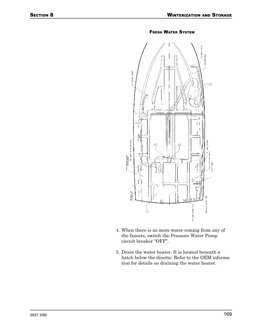
SECTION 8 WINTERIZATION AND STORAGE
1693937 3/99
FRESH WATER SYSTEM
4. When there is no more water coming from any ofthe faucets, switch the Pressure Water Pumpcircuit breaker "OFF".
5. Drain the water heater. It is located beneath ahatch below the dinette. Refer to the OEM informa-tion for details on draining the water heater.

WINTERIZATION AND STORAGE SECTION 8
170 3937 3/99
Winterizing the System
You must use an approved, nontoxic antifreeze inyour boat’s fresh water system. Refer to the SeaLandTechnical Bulletin at the end of this section forinformation on the proper type of antifreeze to use.Using the wrong type of antifreeze can damage thefresh water system. The repair of such damage is notincluded under the terms of either the Carver LimitedWarranty or the fresh water system OEM’s warranty.
1. Purchase 15 gallons of nontoxic recreational vehicleantifreeze.
2. Pour the nontoxic antifreeze into your boat's freshwater tank. The fresh water tank is filled through asingle deck fitting with a plate labeled "WATER".The plate is on the port sidedeck near amidships.Refer to the "Fill Plate/Pumpout Locations"portion of Section 9 for the exact location of the"WATER" plate.
3. Close all faucets.
4. Switch the Pressure Water Pump circuit breaker onthe 12 Volt DC Power Main Breaker Panel "ON".
5. Switch the Forward and Aft Shower Sump circuitbreakers on the Safety Breaker Panel "ON".
6. Open the galley sink cold water faucet. When asteady stream of antifreeze flows from it, close thefaucet. Repeat this step for the galley hot waterfaucet, then for each cold and hot water faucet onthe boat, except for the optional transom showerand fresh water washdown faucets.
For the transom shower, place the shower head in abucket before turning on the shower faucet. Thiscatches the antifreeze, which can be reused. Pro-ceed as described earlier in this step.
For the fresh water washdown:
a. Remove the hose and nozzle from the fresh waterwashdown fitting.
SECTION 8 WINTERIZATION AND STORAGE
1713937 3/99
b. Place a bucket under the washdown fitting tocatch the antifreeze, which can be reused.
c. Open the washdown faucet. When a steadystream of antifreeze flows from it, close thefaucet.
7. Pour one or two quarts of nontoxic antifreeze intoeach shower drain until the shower sump pumpsturn ON.
8. Pour a quart of nontoxic antifreeze into each sinkdrain.
9. Winterize the engine heat exchanger system. Whenthe boat’s engines are running, this system, ratherthan the electric water heater, heats fresh water toprovide hot water.
a. Locate the 5/8" heater hose that runs from theport engine to the water heater and back to theengine.
b. Disconnect the heater hose in both places whereit connects to the engine.
c. Drain all water from the hose.
d. Pour antifreeze into the hose.
Preparing the System for Use Again
When you remove your boat from storage and prepare touse it again, flush the entire fresh water system withfresh water. Nontoxic antifreeze is colored, so the watersystem is adequately flushed when uncolored waterflows from all of the faucets and shower heads.
Before performing this procedure on the optional rawwater washdown, your boat should be pulled from thewater.
1. Locate and close the thru-hull valve that suppliesthe raw water washdown pump with seawater.
2. Disconnect the end of the hose that is attached tothe thru-hull valve.
Raw WaterWashdown

WINTERIZATION AND STORAGE SECTION 8
172 3937 3/99
You must use an approved antifreeze in your boat’sraw water washdown system. Refer to the SeaLandTechnical Bulletin at the end of this section forinformation on the proper type of antifreeze to use.Using the wrong type of antifreeze can damage theraw water washdown system. The repair of suchdamage is not included under the terms of either theCarver Limited Warranty or the raw water washdownsystem OEM’s warranty.
3. Place the disconnected hose end into a bucket thatcontains about a gallon of antifreeze.
4. Remove the raw water washdown hose from thetransom-mounted washdown fitting.
5. Place a bucket under the washdown fitting.
6. Switch the Washdown Pump circuit breaker on the12 Volt DC Power Main Breaker Panel "ON".
7. When a steady stream of antifreeze flows from thewashdown fitting, switch the Washdown Pumpcircuit breaker "OFF".
8. Reconnect the hose to the washdown fitting.
9. Reconnect the hose that was disconnected in Step 2.
1. Open the garboard drain. Leave the drain openwhile your boat is in storage.
2. Remove all water from the bilge.
OPEN CLOSED
Bilge

SECTION 8 WINTERIZATION AND STORAGE
1733937 3/99
3. Clean the bilge as described in the "Bilge" portionof Section 7.
Before performing this procedure on the sanitationsystem, your boat should be pulled from the water.Refer to the OEM information for more information onwinterizing the sanitation system.
There are three types of sanitation systems: the stan-dard system, the overboard discharge system and thedirect overboard discharge system.
Standard Sanitation System
1. Empty the waste tanks as described in the "Emp-tying the Waste Tanks" portion of Section 4.Remove as much of the fresh water used in flushingthe tanks as possible.
2. If your boat has the optional seawater head system:
a. Close the seacock for each head.
Sanitation System
OPEN CLOSED
b. Disconnect the seawater pickup hoses from theseacocks.
c. Flush the heads until all water is drained fromthe seawater pickup hoses.
d. Reconnect the seawater pickup hoses to theseacocks. Leave the seacocks closed.

WINTERIZATION AND STORAGE SECTION 8
174 3937 3/99
You must use an approved antifreeze in your boat’ssanitation system. Refer to the SeaLand TechnicalBulletin at the end of this section for information onthe proper type of antifreeze to use. Using the wrongtype of antifreeze can damage the sanitation system.The repair of such damage is not included under theterms of either the Carver Limited Warranty or thesanitation system OEM’s warranty.
3. Purchase at least 8 gallons of nontoxic recreationalvehicle antifreeze.
STANDARD SANITATION SYSTEM

SECTION 8 WINTERIZATION AND STORAGE
1753937 3/99
4. Flush 4 gallons of antifreeze through each head andallow it to remain in the waste tanks while the boatis in storage.
5. When you remove your boat from storage andprepare to use it again:
a. Pour 5 gallons of fresh water through each head.
b. Empty the waste tanks as described in the"Emptying the Waste Tanks" portion of Sec-tion 4.
c. Open the seawater pickup seacocks. Flush thehead a few times to prime the sanitation system.
d. Charge the waste tanks by adding deodorizer.Use the brand of deodorizer recommended byyour Carver Dealer.
Overboard Discharge System
1. Empty the waste tanks as described in the "Emp-tying the Waste Tanks" portion of Section 4.Remove as much of the fresh water used in flushingthe tanks as possible.
2. If your boat has the optional seawater heads:
a. Close the seawater seacocks.
OPEN CLOSED
b. Disconnect the seawater pickup hoses from theseacocks.
c. Flush the heads until all water is drained fromthe seawater pickup hoses.

WINTERIZATION AND STORAGE SECTION 8
176 3937 3/99
d. Reconnect the seawater pickup hoses to theseacocks. Leave the seacocks closed.
3. Below the boat, place a large bucket beneath theoverboard discharge fitting to collect antifreezepumped out later in this procedure. This fitting islocated beneath a hatch below the dinette’s aftcushion.
You must use an approved antifreeze in your boat’ssanitation system. Refer to the SeaLand Technical
VACUUM HEAD SYSTEM(OVERBOARD DISCHARGE)

SECTION 8 WINTERIZATION AND STORAGE
1773937 3/99
Bulletin at the end of this section for information onthe proper type of antifreeze to use. Using the wrongtype of antifreeze can damage the sanitation system.The repair of such damage is not included under theterms of either the Carver Limited Warranty or thesanitation system OEM’s warranty.
4. Purchase 20 gallons of nontoxic recreational vehicleantifreeze.
ELECTRIC HEAD SYSTEM(OVERBOARD DISCHARGE)

WINTERIZATION AND STORAGE SECTION 8
178 3937 3/99
5. Locate the waste tank selector valve located be-neath a hatch below the dinette’s aft cushion. Thisvalve allows you to select the forward or aft wastetank to pump overboard. Position the valve to selectthe forward waste tank.
6. Flush 10 gallons of antifreeze through the forwardhead.
7. Open the overboard discharge seacock locatedbeneath a hatch below the dinette’s aft cushion.
8. On the 12 Volt DC Power Main Breaker Panel,switch the DC Main circuit breaker "ON", thenswitch the Waste Pump circuit breaker "ON".
9. Turn "ON" the waste pump ON/OFF switch locatedbeneath a hatch below the dinette’s aft cushion.This activates the waste pump.
10. When a steady stream of antifreeze flows from theoverboard discharge fitting, turn "OFF" the wastepump.
11. Position the waste tank selector valve to select theaft waste tank.
12. Flush 10 gallons of antifreeze through the aft head.
13. Turn "ON" the waste pump ON/OFF switch.
14. When a steady stream of antifreeze flows from theoverboard discharge fitting, turn "OFF" the wastepump.
15. Switch the Waste Pump circuit breaker "OFF".
16. Close the overboard discharge seacock.
17. When you remove your boat from storage andprepare to use it again, flush and pump the wastetanks to remove the antifreeze.
Direct Overboard Discharge System
1. Empty the waste tanks as described in the "Emp-tying the Waste Tanks" portion of Section 4.Remove as much of the fresh water used in flushingthe tanks as possible.

SECTION 8 WINTERIZATION AND STORAGE
1793937 3/99
2. If your boat has the optional seawater head system:
a. Close the seacock for each head.
OPEN CLOSED
b. Disconnect the seawater pickup hoses from theseacocks.
c. Flush the heads until all water is drained fromthe seawater pickup hoses.
d. Reconnect the seawater pickup hoses to theseacocks. Leave the seacocks closed.
3. Below the boat, place a large bucket beneath theoverboard discharge fitting to collect antifreezepumped out later in this procedure. This fitting islocated beneath a hatch below the dinette’s aftcushion.
You must use an approved antifreeze in your boat’ssanitation system. Refer to the SeaLand TechnicalBulletin at the end of this section for information onthe proper type of antifreeze to use. Using the wrongtype of antifreeze can damage the sanitation system.The repair of such damage is not included under theterms of either the Carver Limited Warranty or thesanitation system OEM’s warranty.
4. Purchase 30 gallons of nontoxic recreational vehicleantifreeze.
5. Locate the waste tank selector valve located be-neath a hatch below the dinette’s aft cushion. Thisvalve allows you to select the forward or aft waste

WINTERIZATION AND STORAGE SECTION 8
180 3937 3/99
tank to pump overboard. Position the valve to selectthe forward waste tank.
6. Locate the forward head overboard dischargeselector valve located below the hatch in the galleyfloor. This valve allows you to bypass the forwardwaste tank and flush waste directly overboard.Position the valve to "HOLDING TANK".
7. Flush 10 gallons of antifreeze through the forwardhead.
8. Open the overboard discharge seacock locatedbeneath a hatch below the dinette’s aft cushion.
9. On the 12 Volt DC Power Main Breaker Panel,switch the DC Main circuit breaker "ON", thenswitch the Waste Pump circuit breaker "ON".
10. Turn "ON" the waste pump ON/OFF switch locatedbeneath a hatch below the dinette’s aft cushion.This activates the waste pump.
11. When a steady stream of antifreeze flows from theoverboard discharge fitting, turn "OFF" the wastepump.
12. Position the waste tank selector valve to select theaft waste tank.
13. Locate the aft head overboard discharge selectorvalve located below the aft hatch in the aft state-room floor. This valve allows you to bypass the aftwaste tank and flush waste directly overboard.Position the valve to "HOLDING TANK".
14. Flush 10 gallons of antifreeze through the aft head.
15. Turn "ON" the waste pump ON/OFF switch.
16. When a steady stream of antifreeze flows from theoverboard discharge fitting, turn "OFF" the wastepump.
17. Switch the Waste Pump circuit breaker "OFF".
18. Close the overboard discharge seacock.

SECTION 8 WINTERIZATION AND STORAGE
1813937 3/99
19. Position the aft head overboard discharge selectorvalve to "OVERBOARD".
20. Below the boat, place a large bucket beneath the aftoverboard discharge fitting to collect antifreezepumped out later in this procedure. This fitting islocated beneath the aft hatch in the aft stateroomfloor.
21. Flush 5 gallons of antifreeze through the aft head.Continue flushing the head until a steady stream ofantifreeze flows from the overboard dischargefitting.
22. Close the aft overboard discharge fitting.
23. Position the forward head overboard dischargeselector valve to "OVERBOARD".
24. Below the boat, place a large bucket beneath theforward overboard discharge fitting to collect anti-freeze pumped out later in this procedure. Thisfitting is located below the galley floor hatch.
25. Flush 5 gallons of antifreeze through the forwardhead. Continue flushing the head until a steadystream of antifreeze flows from the overboarddischarge fitting.
26. Close the forward overboard discharge valve.
27. When you remove your boat from storage andprepare to use it again, flush and pump the wastetanks to remove the antifreeze.
Wash the exterior of the boat, particularly the underwa-ter portions. Remove as much aquatic growth as pos-sible while it is still wet. Once the growth has dried it ismore difficult to remove.
Check the zinc sacrificial anodes for deterioration. If thezincs shows signs of deterioration have them replacedbefore spring launch. Check stainless steel rails andfittings for signs of rust. Remove rust prior to winterlay-up. Inspect the underwater portions of the hull.Review anything that looks out of the ordinary withyour Carver Dealer.
Exterior

WINTERIZATION AND STORAGE SECTION 8
182 3937 3/99
Air out the cushions and make sure they are dry. Stor-ing damp cushions leads to mildew. Position the cush-ions so air can circulate around them. Purchase andposition moisture accumulators throughout the boat.These help reduce the amount of moisture that accumu-lates during storage. Remove everything from the boatthat could spoil or freeze while the boat is stored. Alsoremove all dried food. Food attracts mice and insects.
To give your boat the maximum protection while it is instorage, Carver recommends that you place your boat indry, as opposed to wet, storage.
Protecting the boat from the elements during winterstorage is advised. Have your marina shrink wrap theboat or have a winter storage cover made. Occasionallycheck on the boat while it is in storage to make surethat it is in good condition.
If your boat will be in outside storage, properly supporta storage cover and secure it over the boat. Do notsecure the cover to the boat too tightly. Allow adequateventilation to protect against dry rot. Do not store theboat in a damp storage enclosure. Purchase and positionmoisture accumulator packets between the shrink-wrapand your boat's enclosures to help prevent moisturefrom accumulating. Excessive dampness can lead tomildew, electrical problems, corrosion and dry rot.
NOTE: Do not use the bridge enclosure, aft deck enclo-sure, bimini top or convertible top canvas in place of awinter storage cover. These are not designed for long-term storage purposes. The life of these enclosures maybe significantly shortened if they are exposed to harshweather elements for prolonged periods.
Wet storage procedures vary from region to region.Consult your dealer before preparing to leave your boatin the water over the winter.
Interior
Storage
Dry Storage
Wet Storage
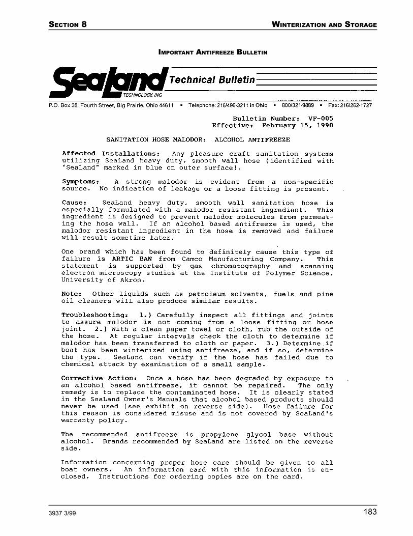
SECTION 8 WINTERIZATION AND STORAGE
1833937 3/99
IMPORTANT ANTIFREEZE BULLETIN

WINTERIZATION AND STORAGE SECTION 8
184 3937 3/99

SECTION 8 WINTERIZATION AND STORAGE
1853937 3/99
SpringRecommissioningChecklist
Before launching your boat, complete thefollowing.
Hull
Remove old antifouling bottom paint
Fill nicks and gouges
Inspect props, struts, rudders
Inspect through hull fittings
Apply new antifouling bottom paint
Buff out minor hull scratches
Remove dirt, stains
Apply wax
Deck and Cabin
Inspect hatches and windows for leaks
Wax non-walking surfaces
Engines
Follow manufacturer's recommissioningguidelines
Check crankcase, transmission oil levels
Inspect belts, hoses
Tune-up engine
Replace fuel filters
Electrical System
Check battery water level
Charge batteries
Inspect connections for corrosion

WINTERIZATION AND STORAGE SECTION 8
186 3937 3/99
Plumbing
Purge antifreeze
Replace taste/odor filters
Inspect, lubricate sea valves
Inspect, repair heads
Chemically charge waste and grey water tanks
Fill fresh water tanks
Safety Equipment
Inspect PFDs
Replace old distress signals
Inspect fire extinguishers
Inspect, test bilge pumps
Inspect mooring lines, fenders
After launching your boat, complete the following.
Check for engine cooling water flow
Check propshaft alignment
Check propeller shaft seals
Have compass professionally readjusted

SECTION 8 WINTERIZATION AND STORAGE
1873937 3/99
NOTES

WINTERIZATION AND STORAGE SECTION 8
188 3937 3/99
NOTES
SECTION 9 WARRANTY AND PARTS
1893937 4/99
Warranty and Parts
Warranty Information............................................... 190Carver Dealer’s Responsibilities ...................................190Owner's Responsibilities ...............................................190
Obtaining Warranty Service .................................... 191
Second Owner Registration..................................... 192
Hull Identification Number ...................................... 192
OEMs ........................................................................ 193Serial Number Record Sheet .........................................200
Specifications .......................................................... 202
Component Locations .............................................. 202Interior/Cabin Layout .....................................................203Interior Hatch Locations ............................................... 204Fill Plate/Pumpout Locations ........................................ 205Bridge Canvas Layout ................................................... 206Aft Deck Canvas Layout ................................................ 207
Bill of Material.......................................................... 208
Carver Limited Warranty ......................................... 211

WARRANTY AND PARTS SECTION 9
190 3937 4/99
Carver warrants every boat we manufacture as ex-plained in the Carver Limited Warranty. Your copy ofthe warranty is located at the end of this section. Pleasereview the warranty carefully.
To ensure that the warranty remains in effect during itslifetime, Carver Boat Corporation, your Carver Dealer,and you must each uphold specific responsibilities.Carver’s responsibilities are described in the CarverLimited Warranty.
Warranty Information
Your Carver Dealer will review the terms of the war-ranty and make certain the warranty is registered withCarver. Your Dealer will also instruct you on how toobtain warranty service.
Pre-Delivery Service Procedure
Your Carver Dealer will prepare your boat for deliveryin accordance with the procedures detailed on the Pre-Delivery Service Record. Your dealer will sign the Pre-Delivery Service Record and provide you with a copy.
Registration of your boat and its engines is required bythe Federal Safe Boating Act of 1971. Your CarverDealer will complete and mail your engine warrantycards as part of the Pre-Delivery Service procedure.
Boat and Systems Review
A representative from your Carver Dealership willreview the operation of your boat and its systems withyou.
Pre-Delivery Service Record
Verify that the boat's pre-delivery service record hasbeen completed and mailed to Carver. The pre-deliveryservice record is located in the Preface of this guide.Review the Pre-Delivery Service procedure with yourdealer. Read the Pre-Delivery Service Record. Be cer-tain you sign a copy of the Pre-Delivery Service Recordand retain a copy for your records.
WarrantyInformation
Carver Dealer’sResponsibilities
Owner'sResponsibilities

SECTION 9 WARRANTY AND PARTS
1913937 4/99
OEM Components
Many of the OEM components installed in your boat arewarranted by their respective manufacturers. To acti-vate these warranties, complete and mail all OEMwarranty cards. The warranty card for each componentthat is warranted is located with its respective OEMinformation. Many of these OEMs also have programsdesigned to resolve any problems you may experiencewith their products. Your Carver Dealer can assist youwhen necessary in gaining access to these programs.
NOTE: All warranty cards must be completed andforwarded to the appropriate company within 5 days oftaking delivery of your boat.
Delivery
At the time of delivery, make a complete inspection ofthe boat and its systems. Document any work thatneeds to be completed by the dealer in order to meet theterms of your agreement.
Owner’s Information Kit
Read, understand, and follow the instructions in thisOwner’s Guide and all OEM information.
Contact your Carver Dealer if you have any questionsregarding warranty responsibilities.
The following requirements must be met before war-ranty work can be performed on your boat.
1. Your boat must be registered with the Carver BoatCorporation. Registration is accomplished by com-pleting, then submitting the Pre-Delivery ServiceRecord to the Carver Boat Corporation, P.O. Box1010, Pulaski, WI 54162-1010.
2. Pre-Delivery Service must be completed by yourCarver Dealer. Information concerning Pre-Deliv-ery Service can be found in the preface of thismanual. The Pre-Delivery Service Record must besigned by both the dealer and the owner.
NOTE: Your Carver Dealer is the ONLY personauthorized to approve warranty work. If warranty
Obtaining WarrantyService


WARRANTY AND PARTS SECTION 9
194 3937 4/99
Cummins Engine Company875 Lawrence DriveDePere, WI 54115(414) 337-1991
Caterpillar Tractor CompanyAttn: Marine Customer ServiceEngine DivisionP.O. Box 610Mossville, IL 61552-06101-800-447-4986
Fuel Filters
Racor Industries, Inc.P.O. Box 3208Modesto, CA 95353(209) 521-7860
Drive Systems
Walters Machine Company84-98 Cambridge AvenueJersey City, NJ 07307(201) 656-5654
Velvet Drive Transmissions200 Theadore Rice Blvd.New Bedford, MA 02745(508) 979-4800
ZF IndustriesAttn: Marine Dept.777 Hickory Hills DriveVernon Hills, IL 60061(847) 634-3500
Generators
Kohler Generators / Kohler Company444 Highland DriveKohler, WI 53044(414) 565-3381
Onan Corporation1350 73rd Avenue N.E.Minneapolis, MN 55432(612) 574-5000

SECTION 9 WARRANTY AND PARTS
1953937 4/99
Westerbeke Corporation41 LedinAvon, MA 02322(508) 588- 7700
Steering Systems
Hynautic Marine Systems1579 Barber Rd.Sarasota, FL 34240(941) 379-0500
Teleflex Steering Systems640 N. Lewis RoadLimerick, PA 19468(610) 948-5100
Heads
SeaLand Technology, Inc.P.O. Box 384th StreetBig Prairie, OH 44611(216) 496-3211
Raritan Engineering CorporationP.O. Box 1157530 Orange StreetMillville, NJ 08332(609) 825-4900
Water Heaters
SeaWard Products3721 Capitol DriveWhittier, CA 90601(310) 699-7997
Air Conditioners
Marine Air Systems2000 N. Andrews Avenue ExtensionPompano Beach, FL 33069(954) 973-2477

WARRANTY AND PARTS SECTION 9
196 3937 4/99
Trim Tabs
Bennett Marine Inc.550 N.W. 12th AvenueDeerfield Beach, FL 33442(305) 427-1350
Boat Leveler Company7305 Natural BridgeSt. Louis, MO 63121(314) 385-7470
Entertainment Equipment
JVC Service & Engineering Company ofAmerica - Div. of JCV Corporation107 Little Falls Rd.Fairfield, NJ 070041-800-537-5722(110 volt stereo system)
Capitol Sales Co.3110 Neil Armstrong Blvd.Eagan, MN 551211-800-545-2672(Quasar TV)
Marine Audio Sales16137 Westwoods Business ParkEllisville, MO 63021(314) 394-2631(12 volt Clarion AM/FM/CD stereo system)
Battery Chargers
Professional Mariner2970 Seaborg Ave.Ventura, CA 93003(805) 644-1886
Guest Corporation95 Research ParkwayMeridin, CT 06450(203) 235-4421
Charles Marine Products5600 Apollo DriveRolling Meadows, IL 60008(708) 806-6300

SECTION 9 WARRANTY AND PARTS
1973937 4/99
Refrigerators and Ice Makers
Norcold Inc. (Division of Stolle Co.)P.O. Box 42482655 Cambell Rd.Sidney, OH 453651-800-543-1219
Nova Kool Mfg., Inc.1457 Barrow St.North Vancouver, B.C.Canada V7JIB6(604) 984-7794
Raritan Engineering CorporationP.O. Box 1157530 Orange StreetMillville, NJ 08332(609) 825-4900
General Electric CompanyConsumer Affairs Dept.Appliance ParkLouisville, KY 402251-800-626-2000
Ranges and Microwaves
SeaWard Products3721 Capitol DriveWhittier, CA 90601(310) 699-7997
Kenyon Marine351 New Whitfield St.Guilford, CT 06437(203) 453-4374
Origo USA, Inc.1121 Lewis AvenueSarasota, FL 34237(941) 365-3660
Miscellaneous Accessories
Teleflex Marine, Inc.1816 57th StreetSarasota, FL 34243(941) 355-7721(Instruments)

WARRANTY AND PARTS SECTION 9
198 3937 4/99
Teleflex MarineMechanical Products640 North Lewis Rd.Limerick, PA 19468(610) 948-5100(Controls)
Teleflex of Canada LTD3831 No. 6 RoadRichmond, British ColumbiaCanada V6V 1P6(604) 270-6899(Steering)
VDO Yazaki Corporation188 Brooke RoadWinchester, VA 22603(540) 665-0100(Gauges)
Guest Company, Inc.95 Research ParkwayMeriden, CT 06450(203) 235-4421(Spot Lights)
Morse Controls - IMO21 Clinton StreetHudson, OH 44236(216) 653-7701(Controls, Throttle & Shift Cables)
ITT Jabsco152 South West 8th St.Miami, FL 33130(7" and 8" Spotlights)
E.S. Ritchie & Sons Inc.P.O. Box 548243 Oak StreetPembroke, MA 02359(617) 826-5131(Compass)
Alson Corporation42 Union StreetHillsdale, MI 49242(517) 439-1411(Shower Controls)

SECTION 9 WARRANTY AND PARTS
1993937 4/99
Maxwell Winches, Inc.1610 Babcock St.Costa Mesa, CA 92627(714) 631-2634(winches)
Sea-FireDivision of Metalcraft, Inc.9331-A Philadelphia RoadBaltimore, MD 21237(410) 687-5500(Halon System)
MTI IndustriesDivision of Marine Technologies, Inc.1000 Brown StreetSuite 107Wauconda, IL 600841-800-383-0269(CO Detector)
Bomar, Inc.South West StreetP.O. Box WCharlestown, NH 03603(603) 826-5791(Hatches)
Aluminum 2000, Inc.595 East Oregon RoadLititz, PA 17543(717) 569-2300(Doors)

WARRANTY AND PARTS SECTION 9
200 3937 4/99
Serial NumberRecord Sheet

SECTION 9 WARRANTY AND PARTS
2013937 4/99

WARRANTY AND PARTS SECTION 9
202 3937 4/99
The specifications listed here are based on a standardmodel with no options installed. Certain options maychange some of these specifications.
Length Overall (LOA)with boarding platform ............................... 43’5" / 13,23 m
Beam ......................................................... 13’3" / 4,04 m
Bridge Clearance(waterline to arch) ..................................... 17’6" / 5,33 m
Draft .......................................................... 39" / 0,99 m
Weight (estimated,with fuel and water): .................................. 21,000 lbs /
9525,60 kg
Water......................................................... 81 U.S. gal /306,61 l
Hot Water .................................................. 11 gal. /41,64 liters
Waste ........................................................ 36 U.S. gal /136,27 l
Fuel ........................................................... 318 gal. /1203,76 liters
The illustrations on the following pages show the loca-tions of various components, deck plates, and thru-hullfittings discussed throughout this guide.
Specifications
ComponentLocations

SECTION 9 WARRANTY AND PARTS
2033937 4/99
Interior/CabinLayout
ForwardStateroomBerth
ForwardHead
Dinette
AC PowerPanel and12 Volt DCPower mainBreakerPanel
Salon
Safety BreakerPanel andBattery Selec-tor Switch
HangingCloset
Galley
Salon Sofa
Aft Berth
Aft Head

WARRANTY AND PARTS SECTION 9
204 3937 4/99
Interior HatchLocations
Direct Overboard Discharge ValveShower Sump PumpForward Bilge PumpForward Head Water PickupY-Valve (overboard or holding tank)Vacuum Tank (vacuum heads only)
Air Conditioning Water PumpAmidships Bilge Pump
Engine Room
Air Conditioning UnitWater Tank
Air Conditioning Unit
Water HeaterForward Waste Tank
123456123456123456123456123456123456123456123456123456123456123456123456123456 123456
123456123456123456
123456781234567812345678123456781234567812345678
123456123456123456123456
Generator PickupEngine PickupDirect Overboard Discharge ValveOverboard Discharge Y-Valve (forward or aft tank)Overboard Discharge “ON/OFF” SwitchOverboard Discharge Seacock
123451234512345123451234512345
12345671234567123456712345671234567
123456123456123456123456123456123456123456123456123456123456123456123456123456123456
1234561234561234561234561234561234561234561234561234561234561234561234561234567
12345671234567
1234567123456712345671234567123456712345671234567
12345671234567123456712345671234567123456712345671234567123456712345671234567
123456123456123456
Battery Selector Switch
Aft Waste TankOverboard Discharge Y-Valve (overboard or waste tank)Shower Sump Pump
12345123451234512345
123451234512345123451234512345
1234567123456712345671234567123456712345671234567
Seawater Head PickupTrim Tab PumpDirect Overboard Discharge ValveVacuum Tank (vacuum heads only) Aft Bilge Pump
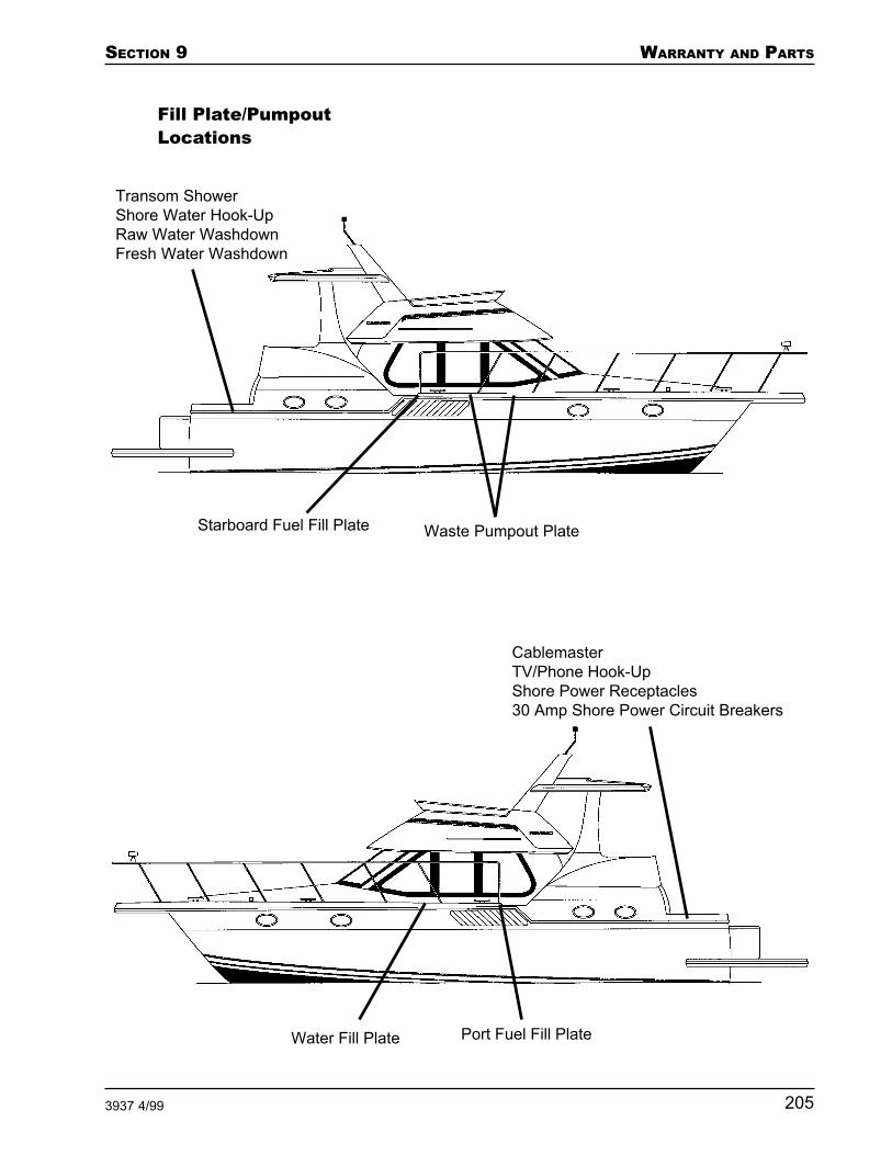
SECTION 9 WARRANTY AND PARTS
2053937 4/99
Fill Plate/PumpoutLocations
Water Fill Plate Port Fuel Fill Plate
CablemasterTV/Phone Hook-UpShore Power Receptacles30 Amp Shore Power Circuit Breakers
Waste Pumpout Plate
Transom ShowerShore Water Hook-UpRaw Water WashdownFresh Water Washdown
Starboard Fuel Fill Plate

WARRANTY AND PARTS SECTION 9
206 3937 4/99
Bridge CanvasLayout

SECTION 9 WARRANTY AND PARTS
2073937 4/99
Aft Deck CanvasLayout
AFT
DE
CK C
AN
VA
S L
AY
OU
T (
WIT
H H
AR
D W
ING
DO
OR
S)
AFT
DE
CK C
AN
VA
S L
AYO
UT (
WIT
H C
AN
VA
S W
ING
DO
OR
S)

WARRANTY AND PARTS SECTION 9
208 3937 4/99
Bill of Material Any component that begin with a letter or have a cat-egory number lower than 50 is a manufactured compo-nent and therefore may not have all of its subcompo-nents listed.
CategoryNumber Part Description
50 Engines and V-Drives51 Inboard Engine Equipment52 Propellers53 Steering Cables54 Steering Helms and Kits55 Control Cables56 Controls and Kits57 Instruments and Instrument Accessories58 Fresh Water Cooling59 Engine Equipment; Batteries60 Fuel System and Tanks61, 62 Galley, Head and Shower Equipment, and
Tanks63 Pressure Water System64 Navigation and Interior Lighting65 Bilge Pumps, Blowers, and Ventilators66 Deck Hardware; Arch67 Rails, Taffrail Kits, and Ladders68 Wire Harnesses, Dockside Kits, and
Panels69 Electrical Equipment, Generator,
Windlass70 Windows, Doors, Windshield Sets,
Hatches, and Screens71 Hardware, Logo72 Pilot Seat Hardware, Table Legs and
Footrests73 Accessories; Hatch, Horn, Screens, Stereo,
TV, Vacuum74 Fittings, Pipe and Tube75 Clamps, Hoses, and Tubing77 Wood Screws and Sheet Metal Screws78 Lag and Machine Screws, Bolts, Nuts,
and Washers79 Nails, Staples, and Rivets80 Blinds, Canvas, Carpet, Curtains, and
Upholstery Material81 Finishing Material and Adhesives; Logos,
Paint, Plaques, Stripe82 Fiberglass Materials, Gel and Putty83 Extrusions

SECTION 9 WARRANTY AND PARTS
2093937 4/99
CategoryNumber Part Description
84 Lumber, Plywood, Hardboard, and Balsa85 Plastics, Plastic Laminates, Doors, Lids,
and Covers89 Electrical90 Air Conditioning and Accessories91 Foam94 Woodset

WARRANTY AND PARTS SECTION 9
210 3937 4/99

SECTION 9 WARRANTY AND PARTS
2113937 4/99
Carver LimitedWarranty

WARRANTY AND PARTS SECTION 9
212 3937 4/99

INDEX
3937 4/99
A
A/C reverse cycle mode 79A/C unit condensation 79A/C units 65A/C water pump 65Abandon ship 7AC main line 1 63AC main line 2 65AC reverse polarity 55AC schematic - 110V 53, 73, 74AC voltmeter 62AC wiring 54Aft cabin lights 36Aft electric head 35Aft waste tank monitor 36Aft water tank monitor 36Air Conditioning 168Air conditioning seawater pickup
filter 79Air conditioning seawater pickup
seacock 79Air conditioning system layout 78Air conditioning water pump 79Ammeter 62Anchor lights 37Anti-siphon check valves 106Antifreeze bulletin 183Auto pilot 41
B
Back drafting 21Battery cables 47Battery charger 44, 64Battery electrolyte 46Battery inspection 46Battery management 46Battery selector switch positions 27Beam 202Bilge 172Bilge blower 39Bilge blowers 36, 59Bilge pumps 28, 39, 86, 162Bilge pumps - automatic 44Bilge pumps - automatic operation
88Bilge pumps - manual operation 89Boarding ladder use 3Boarding platform use 3Boat and systems review 190Boat cradle 166Bridge main circuit breaker 44Buss bars 54, 70
C
Cabin layout 203Calling for help 9Capsized boat 8Carver Limited Warranty 211Certificate of number 17Chart plotter 41Charts 3, 128Checking headway 133Cigar lighter 40Close quarters turns 133CO detector 28, 45Collision 8Compass 128
D
DC main 32DC voltmeters 115DC wiring schematic 50Dealer responsibilities 190Delivery 191Depth sounder 41, 129Desired airflow through boat 20Diesel engines 26Direct overboard discharge 181Direct overboard waste discharge 97Direct overboard waste discharge
system 178Distress signals 10Dockside waste discharge 92Draft 202
E
Electrical wire 26Enclosure curtains 154Engine batteries 26Engine cooling system seacock valve
110Engine ignition switch 122Engine oil change 35Engine oil pump 114Engine pre-start checklist 120Engine shut-off circuit 112Engine synchronizer gauge 117Engine temperature alarm 114Engine temperature gauges 114Engine/fuel log 18Engines 168Engines - after starting 122Engines - starting 121Equipment failure 10Exhaust systems 20
Exterior lights 37
F
Faucet discharge spouts 161FCC radio license 17Fire 6Fire extinguishers 13Float plan 3Flooding 8Fog 4Forward cabin lights 33Forward electric head 33Forward head fan 33Forward waste tank monitor 34Fresh water system 169Fresh water tank vent screen 161Fresh water washdown 84Fuel 202Fuel gauges 115Fuel requirements 2Fuel selector valves 106Fuel shut-off valves 108Fuel transfer pump 108Fuel transfer switch 39Fueling 2, 119Fueling - after 119Fueling - before 118Fueling flow rate 118
G
Garbage 16Garboard drain 166, 172Gasoline engines 26Gelcoat 148Gelcoat blisters 149Gelcoat repair 149Gelcoat stress cracks 148Generator 37Generator battery 58Generator layout 58GFCI receptacle locations 67GFCI receptacles - testing 66GPS / Loran log 18
H
Halon 40, 111Halon system monitor 111Hand bilge pump 87hand bilge pump 87Hardwood 155Hardwood veneer 155Head - electric 90Head - manual 90

INDEX
3937 4/99
Head - vacuum 91Heads - fresh water 90Heads - seawater 90Helm accessories 40Helm instrument panel lights 37High engine temperature reading
111Horn 12, 41, 128Hypothermia 9
I
Inspections 16Intercom 32
L
Landing at a pier 131Layout 203Leaving a mooring 130Leaving a pier 130Lifting 166Line 1 61Line 2 62Local ordinances 17Loran/GPS 41Lower helm accessories 40
M
Maintenance log 15, 144Maintenance types 144Man overboard 9Maneuvering astern 133Marine traffic rules 14Master disconnect switch 26, 28Medical emergency 10Microwave 64Mooring lines - after bow spring
136Mooring lines - after quarter spring
136Mooring lines - bow line 136Mooring lines - forward quarter
spring 136Mooring lines - stern lines 136
N
Navigation lights 13, 37Navigation log 15Neutral safety switch 116Nontoxic antifreeze 170
O
OEM components 191OEM warranty cards 191Oil 17Oil pressure alarm 114Oil pressure gauges 114Overboard waste discharge 93Overboard waste discharge seacock
178Overboard waste discharge system
175Overboard waste discharge system -
electric head 177Overboard waste discharge system -
vacuum head 176Owner's information kit 191
P
Personal flotation devices 5, 11Picking up a mooring 131Planing hull 138Pre-delivery service procedure 190Pre-delivery service record 190Pressure water pump 32, 82, 161Propane gas 34Propane stove 64
R
Radar 41Radar reflectors 6Radio communication 10Radio log 15Range 64Raw water washdown pump 32Receptacles 63Recommended antifreeze products
185Refrigerator 34Refrigerator - aft deck 35Registration 15Registration - boat and engines 190Remote stereo controls 40Running aground 9Running lights 13
S
Safety equipment 2, 42Salon lights 34Salon main circuit breaker 44Sanitation system - standard 91Sea anchor 6Service 191
Shallow water operation 129Shift control cables 117Shift levers 116Shore power 30Shore power receptacle 56Shower 161Shower sump 161Shower sump pumps 43, 79Showers 83“SLING” tags 166Sound signaling device 12Spare set of props 159Speed log 129Spotlight 37Standard sanitation system 174State ordinances 17Station wagon effect 21Stereo 33Stereo memory 42Storage 182Storms 5Sunbrella 154Swamped boat 8Synchronizer 38
T
Tachometer 112Tail wind 21Throttle control cables 117Throttle levers 116Throttle synchronizer 117Towing 134Tracking astern 132Tracking forward 132Transom hand shower 83Trim Tabs 40
V
Vent fan 33VHF radio 41Visual distress signals 12Voltmeter - battery one 42Voltmeter - battery two 42
W
Warranty information 190Warranty registration 190Waste 17, 202Waste pump 32Waste tank bypass valve 97Waste tank selector valve 93Water heater 64, 168Water heating system 83

INDEX
3937 4/99
Water survival chart 10Weather 2, 3Weather signals 4Weight 202White vinyl 152Windlass 45, 135Windshield wipers 33, 34, 36
Z
Zinc anodes 69, 181

INDEX
3937 4/99