2006 hybrid owner manual m - general motors canada€¦ · ... 5-20 tires ... 2006 hybrid owner...
TRANSCRIPT

Seats and Restraint System ............................. 1-1Airbag System ........................................... 1-2Restraint System Check .............................. 1-2
Features and Controls ..................................... 2-1Features and Controls ................................ 2-2Starting and Operating Your Vehicle ............. 2-8
Instrument Panel ............................................. 3-1Climate Controls ........................................ 3-2Driver Information Center (DIC) .................... 3-2
Driving Your Vehicle ....................................... 4-1Your Driving, the Road, and Your Vehicle ..... 4-2Towing ..................................................... 4-2
Service and Appearance Care .......................... 5-1Service ..................................................... 5-3Checking Things Under the Hood ................. 5-4Electrical System ...................................... 5-20Tires ...................................................... 5-24Capacities and Specifications ..................... 5-28
Maintenance Schedule ..................................... 6-1Maintenance Schedule ................................ 6-2
Index ................................................................ 1
2006 Hybrid Owner Manual M

GENERAL MOTORS, GM and the GM Emblem,CHEVROLET, the CHEVROLET Emblem, GMC, theGMC Emblem, and the names SILVERADO and SIERRAare registered trademarks of General Motors Corporation.
The information in this manual supplements the ownermanual. This manual includes the latest informationavailable at the time it was printed. We reserve the rightto make changes in the product after that time withoutnotice.
Please keep this manual with the owner manual in yourvehicle, so it will be there if you ever need it while you areon the road. If you sell your vehicle, leave this manualand the owner manual with the vehicle.
IntroductionYour hybrid pickup truck is designed to be more fuelefficient than the standard pickup truck, which results inreduced carbon dioxide emissions. Your new vehicle alsofeatures a 120-volt (2,400 watt) auxiliary power outletsystem, enabling you to power most electrical/electronicdevices.
Litho in U.S.A.Part No. 15105919 A First Printing ©2005 General Motors Corporation. All Rights Reserved.
ii
Warranty InformationFor vehicles sold in the United States, in addition to theBumper-to-Bumper Coverage described in the WarrantyBooklet, General Motors will warrant certain Hybridcomponents for each 2006 Chevrolet Silverado Hybridand GMC Sierra Hybrid (hereafter referred to as Hybrid)for 8 years or 100,000 miles (160 000 kilometres),whichever comes first, from the original in-service dateof the vehicle, against warrantable repairs to the specificHybrid components of the vehicle. For vehicles sold inCanada, in addition to the Complete Vehicle Coveragedescribed in the GM TOTAL Warranty, Maintenance andOwner Assistance Booklet, General Motors of CanadaLimited will warrant certain Hybrid components for each2006 Chevrolet Silverado Hybrid and GMC Sierra Hybrid(hereafter referred to as Hybrid) for 8 years, or160,000 kilometres, whichever comes first, from theoriginal in-service date of the vehicle, against warrantablerepairs to the specific Hybrid components of the vehicle.
In addition to the initial owner of the vehicle, the coveragedescribed in this Hybrid warranty is transferable atno cost to any subsequent person(s) who assumesownership of the vehicle within the above described8 year or 100,000-mile (160 000 kilometres) term. Nodeductibles are associated with this Hybrid warranty.
This Hybrid warranty is in addition to the expressconditions and warranties described in the WarrantyBooklet. The coverage and benefits described inthe Warranty Booklet under “New Vehicle LimitedWarranty” are not extended or altered because ofthis special Hybrid Component Warranty.
For 2006 Hybrid owners requiring more comprehensivecoverage than that provided under this Hybrid warranty, aGM Protection Plan may be available. See your Chevroletor GMC Dealer for more details.
iii
What is CoveredThis hybrid warranty covers repairs to correct anyvehicle defect related to materials or workmanshipoccurring during the 8 year or 100,000 mile(160 000 kilometres) term for the following:
TransmissionAll automatic transmission components including theauxiliary transmission fluid pump assembly, flexplateassembly, electric machine rotor and stator.
SteeringElectrohydraulic power steering pump and reservoir.
BrakesBrake apply system sensor on the brake pedalassembly.
Other Hybrid ComponentsStarter generator control module, SGCM radiator,SGCM coolant pump and bottle; Energy storage boxand components including batteries and control module;hood switch, electric power outlets, 3 phase cableassembly, hybrid control module.
TowingDuring the 8-year or 100,000 mile (160 000 kilometres)Hybrid warranty period, towing is covered to the nearestChevrolet or GMC Hybrid servicing dealer if your vehiclecannot be driven because of a warranted defect. Contactthe Chevrolet or GMC Roadside Assistance Center fortowing. Refer to the Warranty Booklet for details.
Courtesy TransportationDuring the 8-year or 100,000 mile (160 000 kilometres)Hybrid warranty period, interim transportation maybe available under the Chevrolet or GMC CourtesyTransportation Program. Please consult your dealerfor details.
iv
What is Not CoveredIn addition to the “What is Not Covered” section of theWarranty Booklet, this Hybrid warranty does not coverthe following items:
Wear ItemsWear items, such as brake linings, are not covered inthis Hybrid warranty.
MaintenanceAs the vehicle owner, you are responsible for theperformance of the scheduled maintenance listed inyour owner’s manual. Maintenance intervals, checks,inspections, and recommended fluids and lubricants asprescribed in the owner’s manual are necessary to keepyour vehicle in good working condition. Any damagecaused by owner/lessee failure to follow scheduledmaintenance may not be covered by warranty.Scheduled maintenance includes such items as:
• Filters
• Coolants and Fluids
• Brake Pads / Linings
How to Use This SupplementThis supplement contains information specific to therestraint system, auxiliary power outlet system, hybridcooling system, and fuel system on your vehicle. It doesnot explain everything you need to know about yourvehicle. You must use this supplement along with yourGM owner manual. Only then will you be able to properlyoperate and maintain your vehicle. Many people readtheir owner’s manual supplement from beginning to endwhen they first receive their new vehicle. If you do this,it will help you learn about the features and controls foryour vehicle. In this supplement, you will find that picturesand words work together to explain things quickly.
IndexA good place to look for what you need is the Index inback of this supplement. It is an alphabetical list of whatis in the supplement, and the page number where youwill find it.
v

✍ NOTES
vi
Airbag System .................................................1-2What Will You See After an Airbag Inflates? ......1-2
Restraint System Check ...................................1-2Replacing Restraint System Parts
After a Crash .............................................1-2
Section 1 Seats and Restraint System
1-1

Airbag System
What Will You See After an AirbagInflates?After an airbag inflates or if there is a right side impact,the automatic battery disconnect will open and the 42-voltbattery will be disconnected. The 42-volt electrical powerto the vehicle will be off and the vehicle will not start. Tooperate the vehicle, the automatic battery disconnectmust be reconnected by a qualified service technician atyour dealership. Have your vehicle serviced right away.
Restraint System Check
Replacing Restraint System PartsAfter a CrashIf you have been in a collision in which the right side ofyour vehicle has been hit, your vehicle’s sensing systemmay alert the automatic battery disconnect to open. Thebattery will disconnect. The 42-volt electrical power to thevehicle will be off and the vehicle will not start. The airbagreadiness light will come on. See “Airbag ReadinessLight” in the Index of your owner manual. To operateyour vehicle, the automatic battery disconnect mustbe reconnected by a qualified service technician andsensing system parts will need to be replaced. Haveyour vehicle serviced right away.
1-2

Features and Controls ......................................2-2Auxiliary Power Outlet (APO) System ................2-2
Starting and Operating Your Vehicle .................2-8Starting Your Vehicle ......................................2-8
Section 2 Features and Controls
2-1
Features and Controls
Auxiliary Power Outlet (APO)SystemThe Auxiliary Power Outlet (APO) system provides upto 2,400 watts of 120-volt AC power. With these poweroutlets, you can plug in most auxiliary electricalequipment and devices with a maximum limit of2,400 watts. If you try to use equipment that requiresmore than the limit, a 20-amp protection circuit will cutthe power supply and a light in the APO switch will flashalong with a Driver Information Center (DIC) messagethat will flash 120V OVERLOAD. Once this occurs, thesystem must be reset. See “Resetting the Short Circuit,Overload or Ground Fault Detection (GFD) Circuit” laterin this section and DIC Warnings and Messages onpage 3-2 for more information.
When running APO, do not have the front of the vehicleobstructed. Leave at least five feet (1.5 m) of spacebetween the front of the vehicle and any other object.This will allow airflow through the radiator and helpto keep the SGCM cooler.
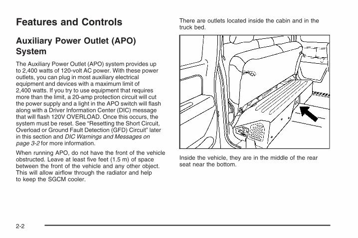
There are outlets located inside the cabin and in thetruck bed.
Inside the vehicle, they are in the middle of the rearseat near the bottom.
2-2
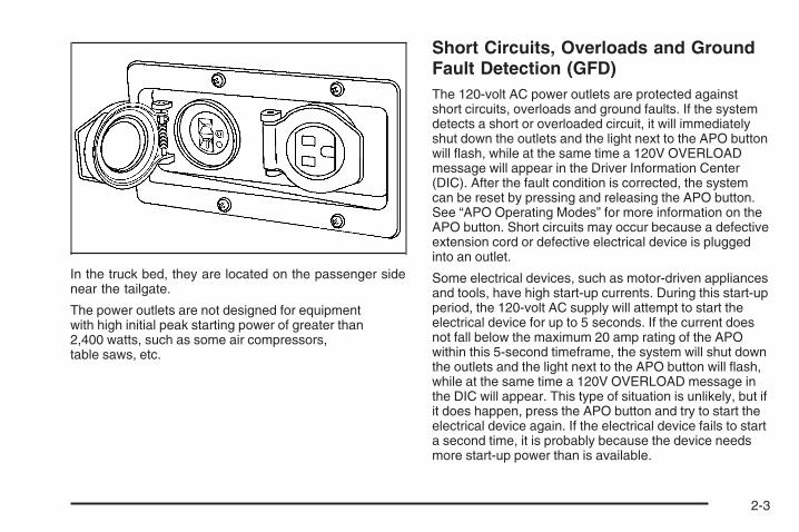
In the truck bed, they are located on the passenger sidenear the tailgate.
The power outlets are not designed for equipmentwith high initial peak starting power of greater than2,400 watts, such as some air compressors,table saws, etc.
Short Circuits, Overloads and GroundFault Detection (GFD)The 120-volt AC power outlets are protected againstshort circuits, overloads and ground faults. If the systemdetects a short or overloaded circuit, it will immediatelyshut down the outlets and the light next to the APO buttonwill flash, while at the same time a 120V OVERLOADmessage will appear in the Driver Information Center(DIC). After the fault condition is corrected, the systemcan be reset by pressing and releasing the APO button.See “APO Operating Modes” for more information on theAPO button. Short circuits may occur because a defectiveextension cord or defective electrical device is pluggedinto an outlet.
Some electrical devices, such as motor-driven appliancesand tools, have high start-up currents. During this start-upperiod, the 120-volt AC supply will attempt to start theelectrical device for up to 5 seconds. If the current doesnot fall below the maximum 20 amp rating of the APOwithin this 5-second timeframe, the system will shut downthe outlets and the light next to the APO button will flash,while at the same time a 120V OVERLOAD message inthe DIC will appear. This type of situation is unlikely, but ifit does happen, press the APO button and try to start theelectrical device again. If the electrical device fails to starta second time, it is probably because the device needsmore start-up power than is available.
2-3
The Ground Fault Detection (GFD) system checks forleakage current to ground, or the truck frame, that couldpotentially be a shock hazard, in much the same way asthe Ground Fault Circuit Interrupt (GFCI) outlets protectyou in your home. The GFD self-test is automaticallyperformed during the activation of the APO system.Thereafter, if the GFD system detects a significantleakage current, it will immediately shut down the outletsand the light next to the APO button will flash, while atthe same time a 120V GROUND FAULT message willappear in the DIC. If this happens, unplug all electricaldevices and reset the system by pressing the APObutton. Then plug in each electrical device individuallyuntil the malfunctioning extension cord or electricaldevice is identified.
If, after unplugging all electrical devices and cords andresetting the system, either the 120V OVERLOADmessage or the 120V GROUND FAULT messagecontinues to be displayed, have the vehicle serviced.
APO Operating ModesThe APO system is capable of being operated intwo different modes:
• Normal mode: This is used while the vehicleis running and in PARK (P), the vehicle is inAuto-Stop mode, or the vehicle is moving.
• Continuous mode: This is used while the vehicleis parked.
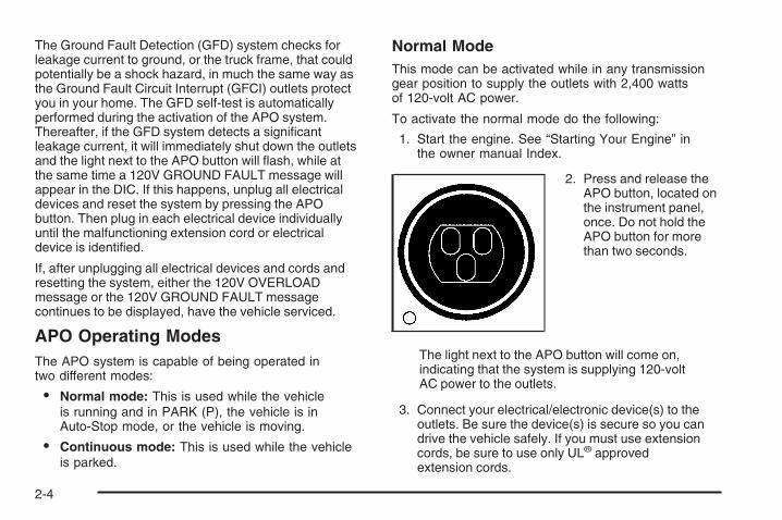
Normal ModeThis mode can be activated while in any transmissiongear position to supply the outlets with 2,400 wattsof 120-volt AC power.
To activate the normal mode do the following:
1. Start the engine. See “Starting Your Engine” inthe owner manual Index.
2. Press and release theAPO button, located onthe instrument panel,once. Do not hold theAPO button for morethan two seconds.
The light next to the APO button will come on,indicating that the system is supplying 120-voltAC power to the outlets.
3. Connect your electrical/electronic device(s) to theoutlets. Be sure the device(s) is secure so you candrive the vehicle safely. If you must use extensioncords, be sure to use only UL® approvedextension cords.
2-4

If the system stops supplying 120-volt AC powerunexpectedly and the APO button starts flashing, thesystem has detected an overload or ground faultcondition. To reset the system see “Resetting the ShortCircuit, Overload or Ground Fault Detection (GFD)Circuit” later in this section.
The APO system will operate in the normal mode untilyou turn it off by doing one of the following:
• Pressing the APO button. The light in the APObutton will turn off.
• Turning the ignition switch to ACCESSORY orLOCK. See “Ignition Positions” in your ownermanual Index.
Continuous ModeThis mode can be operated only when the vehicle is notmoving and the transmission is in PARK (P) and willprovide up to 2,400 watts of 120-volt AC power tothe outlets.
Continuous mode can be operated with the key removedfrom the ignition. The engine will run continuously in thismode to supply electrical power to the APO system.
You can use the vehicle as a generator in this modewhen no electrical power outlets are available or duringinstances such as power outages.
Use this mode to power critical appliances rather than anentire circuit in a home/building. Never connect the APOsystem outlets directly to a building’s circuitry or anotherpower supply.
For more information on running your vehicle while it isparked, see “Parking Over Things that Burn,” “EngineExhaust,” and “Running Your Engine While You AreParked” in your owner manual Index.
To activate the continuous mode, do the following:
1. Place the transmission in PARK (P) with the ignitionin RUN and the engine running. See “IgnitionPositions” in your owner manual Index.
2. Press and hold theAPO button, locatedon the instrumentpanel, for longer thantwo seconds. The lightnext to the APO buttonshould begin to flashand the DIC message,120V READY willappear.
2-5
3. Turn the ignition key to LOCK while the light isflashing. The light will flash for up to 30 seconds.When the ignition key has been turned to LOCK, thelight next to the APO switch will stop flashing andremain on. The engine will continue to run.
4. Connect your 120-volt AC electrical/electronicdevice(s) to the outlets. If you must use extensioncords, be sure to use only UL® approvedextension cords.
You can remove the key from the ignition at this point.
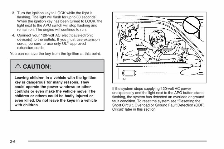
{CAUTION:
Leaving children in a vehicle with the ignitionkey is dangerous for many reasons. Theycould operate the power windows or othercontrols or even make the vehicle move. Thechildren or others could be badly injured oreven killed. Do not leave the keys in a vehiclewith children.
If the system stops supplying 120-volt AC powerunexpectedly and the light next to the APO button startsflashing, the system has detected an overload or groundfault condition. To reset the system see “Resetting theShort Circuit, Overload or Ground Fault Detection (GDF)Circuit” later in this section.
2-6

The APO system will operate in the continuous modewith the engine running until one of the following occurs:
• You press the APO button. The light in the APObutton will turn off and the engine will turn off.
• If the fuel level gets low.
A FUEL LEVEL LOW message will appear in the DICand the horn will sound intermittently for five secondsevery minute for five minutes.If the vehicle is left unattended for the fullfive minute warning, the engine and APO system willshut down, unless the APO button is pressed duringthe five minute warning period. See DIC Warningsand Messages on page 3-2 for more information onthe FUEL LEVEL LOW message.
• An overload or ground fault condition is detected andnot reset in five minutes.
• Vehicle security is violated.
• Engine oil pressure becomes too low.
• Engine coolant temperature becomes too hot.
• The ignition key is moved out of LOCK.
This may display an OIL PRESSURE LOW DICwarning message and chimes which is a normalcondition when the APO button was not used toshut off the continuous mode.
• The hybrid power system becomes too hot.
Resetting the Short Circuit, Overloador Ground Fault Detection (GFD) CircuitTo reset the Short Circuit, Overload or Ground FaultDetection (GFD) Circuit while operating in both thenormal and continuous modes, ensure any observed faultis removed, and press the APO button. The light next tothe button will illuminate indicating that the system issupplying 120-volt AC power to the outlets. In the caseof an engine shutdown due to a ground fault while in thecontinuous mode, restart the engine by turning the keyfrom LOCK to START, then follow the instructions forentering APO Continuous Mode earlier in this section.
2-7

Starting and Operating YourVehicle
Starting Your Vehicle
{CAUTION:
There is something about your vehicle that canmake it move suddenly, and you or others canbe seriously injured. This can happen if thevehicle is in the Auto Stop mode, and the shiftlever is in DRIVE (D). Because your vehicle hasthe Automatic Engine Start/Stop feature, yourvehicle’s engine might seem to be shut offwhen you come to a complete stop. However,if you then start to exit the vehicle, as soon asyou take your foot off the brake pedal, theengine will start again and the vehicle canmove forward. If you are going to exit yourvehicle, first shift to PARK (P) and turn theignition to LOCK. Then exit.
Your vehicle has an automatic engine start/stop feature.This feature can cause the engine to turn off when youare applying the brake and going less than 13 mph(21 km/h), or when you come to a complete stop. Whenyou take your foot off the brake pedal, the engine will startagain and you will continue forward. However, if you areon an incline, your vehicle may roll backwards a shortdistance until the engine performs the auto start. To besure your vehicle will not move or roll, always keep yourfoot firmly on the brake pedal until you are ready for thevehicle to move.
Start the engine just as you would any normal engine.Also see “Starting Your Engine” in the Index of the ownermanual for more information on starting. After the engineis started and has reached operating temperature, itwill shut off automatically when bringing the vehicle to astop — usually the engine will shut off before a completestop if you are braking at speeds below about 13 mph(21 km/h). If you are pulling a trailer and your trailer isequipped with trailer brakes, see Towing a Trailer onpage 4-2 for more information.
To restart the engine during the auto stop, release thebrake pedal and the engine will start immediately.The vehicle will operate as a normal vehicle, untilthe next stop.
2-8

Automatic Engine Start/Stop OverrideThe automatic engine start/stop override feature maycause the engine to remain running at a complete stopor may start the engine at a complete stop. The followingare reasons why either of these conditions may beencountered.
The engine will stay running at a complete stop or willautomatically start from a complete stop if:
• The outside temperatures are high — usually above95°F (35°C). The climate control system is workingto cool the cabin in AUTO mode. See ClimateControls on page 3-2.
• You release the brake pedal in DRIVE (D) orTHIRD (3) — even slightly.
• The shift lever is in NEUTRAL, REVERSE (R),SECOND (2) or FIRST (1).
• The battery pack charge is low.
• The tow/haul mode is active.
• The transfer case is in 4LO.
• The brake pedal has been released for more thanthree seconds while the vehicle is in PARK (P).
• It is necessary to maintain 120-volt APO operationfor loads greater than 1kw.
• The hood is not fully closed.
2-9
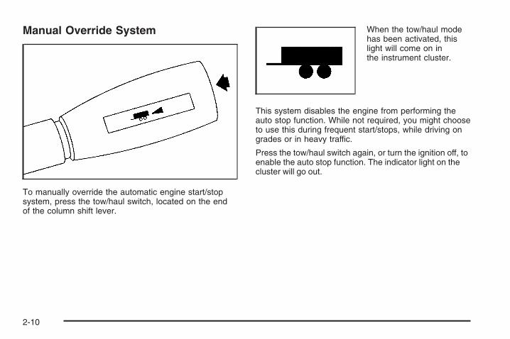
Manual Override System
To manually override the automatic engine start/stopsystem, press the tow/haul switch, located on the endof the column shift lever.
When the tow/haul modehas been activated, thislight will come on inthe instrument cluster.
This system disables the engine from performing theauto stop function. While not required, you might chooseto use this during frequent start/stops, while driving ongrades or in heavy traffic.
Press the tow/haul switch again, or turn the ignition off, toenable the auto stop function. The indicator light on thecluster will go out.
2-10

Climate Controls ..............................................3-2 Driver Information Center (DIC) .........................3-2DIC Warnings and Messages ...........................3-2
Section 3 Instrument Panel
3-1
Climate ControlsFor more information on your vehicle’s climate controlsystem, see “Climate Control System” in the ownermanual Index.
Air Conditioning Engine Start/StopOverrideWith the system in AUTO mode in warm or hot weather,the engine may continue to run at a complete stop, orit may re-start during a complete stop if the systemdetermines that it is necessary to run the air conditioningcompressor to cool the cabin and/or dehumidify the air.
The system may allow the engine to shut off if the cabintemperature selected is met, but engine off time willusually be short.
If you would like to get maximum engine off time in hotweather, select manual operation for vent or bi-levelmode; this will prevent the system from keeping theengine running at complete stops; however, this doesnot provide maximum air conditioning performance.
Selecting a higher air conditioning temperature in hotweather will maximize engine off time.
Driver Information Center (DIC)
DIC Warnings and MessagesWarning messages are displayed on the DIC to notify thedriver that the status of the vehicle has changed and thatsome action may be needed by the driver to correct thecondition. If there is more than one message that needsto be displayed they will appear one after another. Somemessages may not require immediate action but youshould press the select button or the trip odometer resetstem on the instrument panel cluster to acknowledge thatyou received the message and clear it from the display.Some messages cannot be cleared from the displaybecause they are more urgent; these messages requireaction before they can be removed from the DIC display.The following are the possible messages that canbe displayed and some information about them.For information on other DIC messages, see “DICWarnings and Messages” in the owner manual Index.
3-2
42V SWITCH OFFWhen a fuse in the 42-volt battery system is blown,the battery cut off (BCO) switch is open or the batterydisconnect switch is open, this message will appear. Itwill clear when the problem is fixed, when the batterydisconnect switch is closed or by pressing the DIC selectbutton or the trip reset stem on the instrument panelcluster. The fuse on the 42-volt battery pack can onlybe replaced and the automatic battery disconnect canonly be closed by a qualified service technician. SeeFuses and Circuit Breakers on page 5-22 and BatteryDisconnect Switch on page 5-20 and “Instrument PanelCluster” in the owner manual Index for more information.
120V DISABLEDThis message will display when the hybrid’s powersystem is too hot to function in the APO normal mode.This message will display for 10 seconds or until thesystem cools down. This message will also display for10 seconds each time the APO is activated while thesystem is too hot to function. See “Normal Mode” underAuxiliary Power Outlet (APO) System on page 2-2.
120V GROUND FAULTThis message will display when the APO normalor continuous mode turns off due to an electricalground fault.
When in the normal mode, the message will display for10 seconds.
When in the continuous mode, the engine will continueto run for five minutes after a ground fault condition isidentified and the APO is not reset. The message willbe displayed the entire time the engine is running. See“Resetting the Short Circuit, Overload or Ground FaultDetection (GFD) Circuit” under Auxiliary Power Outlet(APO) System on page 2-2.
120V OVERLOADThis message will display when the APO normalor continuous mode turns off due to an electricaloverload fault.
When in the normal mode, the message will display for10 seconds.
When in the continuous mode, the engine will continueto run for five minutes after an overload condition isidentified and the APO is not reset. The message willbe displayed the entire time the engine is running. See“Resetting the Short Circuit, Overload or Ground FaultDetection (GFD) Circuit” under Auxiliary Power Outlet(APO) System on page 2-2.
3-3

120V READYThis message will display and the light in the APO buttonwill flash when the system is ready/waiting to enter thecontinuous mode for 30 seconds or until the ignition isturned to LOCK. See “Continuous Mode” under AuxiliaryPower Outlet (APO) System on page 2-2.
120V SYSTEM FAULTThis message will display when the APO normal orcontinuous mode turns off due to a system fault.
When in the normal mode, the message will display for10 seconds.
When in the continuous mode, the message will displayfor 60 seconds and the engine will turn off. It will alsodisplay for 10 seconds the next time the engine is starteduntil the problem is fixed. See Auxiliary Power Outlet(APO) System on page 2-2.
BATTERY NOT CHARGINGIf the hybrid battery system faults or fails (42-volt or12-volt system), this message will appear on the DIC.The engine auto start/stop feature will be disabledand the battery/charging system light will appear in theinstrument panel cluster. See “Battery Warning Light”in the owner manual Index.
Driving with this light on could drain your batteries.Have the electrical system checked as soon as possible.Pressing the select button or the trip odometer resetstem on the instrument panel cluster will acknowledgethis message and clear it from the DIC display.
ENGINE AUTO START MODEWhen the vehicle is in PARK (P) and the auto stopfunction is active, this message will display to let youknow that the engine may start automatically at any giventime. This message will clear when the vehicle is takenout of PARK (P), if the key is turned to LOCK, or whenthe engine auto starts.
Pressing the DIC select button or the trip odometerreset stem on the instrument panel cluster will alsoclear the message.
3-4

ENGINE COOLANT HOTIf the engine cooling system temperature gets hot, thismessage will appear on the DIC. Stop the vehicle andlet the engine idle in PARK (P) to allow the coolant toreach a safe temperature. This message will clearwhen the coolant temperature drops to a safe operatingtemperature. See “Cooling System” in the owner manualIndex for more information.
The APO continuous mode will also stop operatingwhen this message comes on. See “Continuous Mode”under Auxiliary Power Outlet (APO) System onpage 2-2.
FUEL LEVEL LOWIf the fuel level is low while the APO system is incontinuous mode, this message will appear on the DICand the horn will sound for five seconds every minute forfive minutes. Refuel as soon as possible. If the vehicle isleft unattended for the full five minute warning, the engineand APO system will shut down, unless the APO buttonis pressed during the five minute warning period. See“Continuous Mode” under Auxiliary Power Outlet (APO)System on page 2-2.
Pressing the select button or the trip odometer resetstem on the instrument panel cluster will acknowledgethis message immediately and clear it from the DICdisplay. It will also clear itself after five minutes. Thelow fuel light near the fuel gage will still remain onin either case. See “Fuel Gage” and “Instrument PanelCluster” in the owner manual Index.
HOOD AJARIf the hood is not fully closed, this message will appearon the display. Close the hood to clear the message.Pressing the select button or the trip stem on theinstrument panel cluster will acknowledge thismessage and clear it from the DIC display also.
When this message is displayed, the auto start/stopfunction will not operate with the hood open. If thevehicle is in auto stop mode when this messageappears, you will have to restart the engine with theignition key. See Starting Your Vehicle on page 2-8.
3-5

OIL PRESSURE LOWIf engine oil pressure is low, this message will bedisplayed on the DIC. Stop the vehicle as soon as safelypossible and do not operate it until the cause of the low oilpressure has been corrected. Check your oil as soon aspossible and have your vehicle serviced. See “Engine Oil”in the owner manual Index.
The APO continuous mode will stop operating when thismessage comes on. The message will reappear for60 seconds when the vehicle is shut off and 10 secondswhen restarted to let you know why the APO continuousmode was canceled. See “Continuous Mode” underAuxiliary Power Outlet (APO) System on page 2-2.
SECURITYThis message, along with the security light on theinstrument panel cluster, will appear on the DIC for60 seconds when a security violation has occurred.The APO continuous mode will cancel at this time. See“Theft-Deterrent Systems” in the owner manual Index.
SERVICE 42V BATTERIESThis message will display when the 42-volt batteriesneed service or replacement due to age or if a failurecondition is present. This message will be displayed for10 seconds and then will display again each time theignition key is turned from LOCK to RUN. See Batteryon page 5-13 for more information.
SERVICE BRAKE SYSTEMIf you hear four short chimes along with the brake systemwarning light and this message alternating with theSERVICE STEER SYSTEM message, the power assistsystem is not working. You will still be able to steer andbrake, but it will be much more difficult. Pull off the roadto a safe location and have your vehicle towed to thenearest dealer for service. See “Brakes,” “Brake SystemWarning Light,” and “ABS Brake System Warning Light”in the owner manual Index.
SERVICE STEER SYSTEMIf the SERVICE STEER SYSTEM message is displayedwithout any chimes, the power assist system will continueto function, but it may be more difficult to steer. Have thesteering system serviced as soon as possible. Also, see“SERVICE BRAKE SYSTEM” listed previously.
3-6
Your Driving, the Road, and Your Vehicle ..........4-2Regenerative Braking ......................................4-2
Towing ............................................................4-2Towing a Trailer .............................................4-2
Section 4 Driving Your Vehicle
4-1
Your Driving, the Road, andYour Vehicle
Regenerative BrakingYour vehicle has a regenerative braking system.This system works whenever you take your foot offthe accelerator pedal while your vehicle is moving inDRIVE (D). This causes your vehicle to slow downslightly faster. It may feel like the brake pedal is beingpressed, even when it is not.
Regenerative braking takes some of the energy fromthe moving vehicle and turns it back into electricalenergy. This energy is then stored back into thevehicle’s 42-volt battery system, contributing toincreased fuel efficiency.
Towing
Towing a TrailerFor more information, see “Towing a Trailer” in yourowner manual Index.
Weight of the TrailerHow heavy can a trailer safely be?
It depends on how you plan to use your rig. For example,speed, altitude, road grades, outside temperature andhow much your vehicle is used to pull a trailer are allimportant. And, it can also depend on any specialequipment that you have on your vehicle.
Use the charts following to determine how much yourvehicle can weigh, based upon your vehicle model andoptions.
Maximum trailer weight is calculated assuming thedriver and one passenger are in the tow vehicle and ithas all the required trailering equipment. The weightof additional optional equipment, passengers and cargoin the tow vehicle must be subtracted from themaximum trailer weight.
Above the 5,000 lbs (2 268 kg) trailer rating, the handling/trailering suspension is required on C-1500 models andthe handling/trailering or off-road suspension is requiredon K-1500 models.
4-2

C-1500 Extended Cab Short Box (2WD)
Vehicle Axle Ratio Maximum Trailer Weight GCWR
5300 V8 3.233.73
6,700 lbs (3 039 kg)7,700 lbs (3 493 kg)
12,000 lbs (5 443 kg)13,000 lbs (5 897 kg)
Hybrid vehicles are neither designed nor intended to tow fifth-wheel or gooseneck trailers.
K-1500 Extended Cab Short Box (4WD)
Vehicle Axle Ratio Maximum Trailer Weight GCWR
5300 V8 3.423.73
7,400 lbs (3 357 kg)7,400 lbs (3 356 kg)
13,000 lbs (5 897 kg)13,000 lbs (5 897 kg)
Hybrid vehicles are neither designed nor intended to tow fifth-wheel or gooseneck trailers.
The Gross Combination Weight Rating (GCWR) is thetotal allowable weight of the completely loaded vehicleand trailer including any passengers, cargo, equipmentand conversions. The GCWR for your vehicle should notbe exceeded.
Trailer BrakesIf you are towing a trailer that is equipped with trailerbrakes and you manually apply the trailer brakes whiledriving slower than 13 mph (21 km/h), your vehicle maygo into auto stop mode even if you are not pressing onthe vehicle’s brakes.
Using the trailer brake system manually can make yourhybrid vehicle perform as if you are using the brake pedalin the vehicle. The trailer brake operation check will stillwork. If you manually apply the trailer brakes for anextended period of time, the SERVICE BRAKE SYSTEMDIC message will come on. The message will go off afterthe trailer brakes have been released. No other action isnecessary. For more information, see “Trailer Brakes” inthe owner manual Index.
4-3

✍ NOTES
4-4

Service ............................................................5-3Doing Your Own Service Work .........................5-3
Checking Things Under the Hood .....................5-4Engine Compartment Overview .........................5-4Automatic Transmission Fluid ...........................5-6SGCM Coolant Surge Tank Pressure Cap .........5-6Cooling System ..............................................5-7Power Steering Fluid .....................................5-12Battery ........................................................5-13Jump Starting ...............................................5-14
Electrical System ............................................5-20Battery Disconnect Switch ..............................5-20Fuses and Circuit Breakers ............................5-22
Tires ..............................................................5-24Changing a Flat Tire .....................................5-24
Capacities and Specifications ..........................5-28
Section 5 Service and Appearance Care
5-1

✍ NOTES
5-2

Service
Doing Your Own Service Work
{CAUTION:
Never try to do your own service on hybridcomponents. You can be injured and yourvehicle can be damaged if you try to do yourown service work. Service and repair of thesehybrid components should only be performedby a GM-trained service technician with theproper knowledge and tools.
5-3

Checking Things Under the Hood
Engine Compartment OverviewWhen you open the hood on your vehicle, you will see the following:
5-4

A. Starter Generator Control Module (SGCM) CoolantSurge Tank. See Cooling System on page 5-7.
B. Starter Generator Control Module (SGCM). SeeCooling System on page 5-7.
C. Engine Oil Dipstick. See “Engine Oil” in the ownermanual Index.
D. Automatic Transmission Dipstick. See AutomaticTransmission Fluid on page 5-6.
E. Brake Fluid Reservoir. See “Brakes” in the ownermanual Index.
F. Hybrid Underhood Fuse Block. See Fuses andCircuit Breakers on page 5-22.
G. Underhood Fuse Block. See “Underhood FuseBlock” in the owner manual Index.
H. Engine Air Cleaner/Filter. See “Engine AirCleaner/Filter” in the owner manual Index.
I. Air Filter Restriction Indicator (If Equipped). See“Engine Air Cleaner/Filter” in the owner manualIndex.
J. Engine Coolant Surge Tank. See “Cooling System”in the owner manual Index.
K. Engine Oil Fill. See “Engine Oil” in the ownermanual Index.
L. Remote Negative (−) Terminal (GND). See JumpStarting on page 5-14.
M. Electrohydraulic Power Steering Fluid Reservoir.See Power Steering Fluid on page 5-12.
N. Remote Positive (+) Terminal. See Jump Starting onpage 5-14.
O. 12-Volt Battery. See Battery on page 5-13.P. Windshield Washer Fluid Reservoir. See “Windshield
Washer Fluid” in the owner manual Index.
5-5
Automatic Transmission FluidFor more information, see “Automatic TransmissionFluid” in the owner manual Index.
Checking the Fluid Level
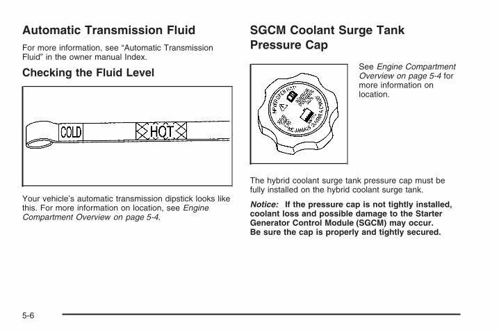
Your vehicle’s automatic transmission dipstick looks likethis. For more information on location, see EngineCompartment Overview on page 5-4.
SGCM Coolant Surge TankPressure Cap
See Engine CompartmentOverview on page 5-4 formore information onlocation.
The hybrid coolant surge tank pressure cap must befully installed on the hybrid coolant surge tank.
Notice: If the pressure cap is not tightly installed,coolant loss and possible damage to the StarterGenerator Control Module (SGCM) may occur.Be sure the cap is properly and tightly secured.
5-6

Cooling System
Starter Generator Control Module(SGCM) Cooling SystemIn addition to your vehicle’s regular cooling system, yourvehicle is also equipped with a cooling system for theSGCM system. This system is serviced differently thanthe vehicle’s main cooling system. The SGCM coolingsystem includes the SGCM coolant surge tank, SGCMsurge tank pressure cap, SGCM cooling pump and theStarter Generator Control Module (SGCM). The SGCMcooling system uses the same type of coolant as thevehicle’s regular cooling system, but the two systemsoperate separately and independently. See “EngineCoolant” and “Cooling System” in the Index of theowner’s manual for more information.
When you decide it is safe to lift the hood, here is whatyou will see:
A. SGCM Coolant Pressure Tank Cap.B. Starter Generator Control Module (SGCM).C. SGCM Cooling Hoses.D. SGCM Coolant Surge Tank.E. Engine Coolant Surge Tank and Pressure Cap.F. SGCM Cooling Pump (Out of View).
5-7
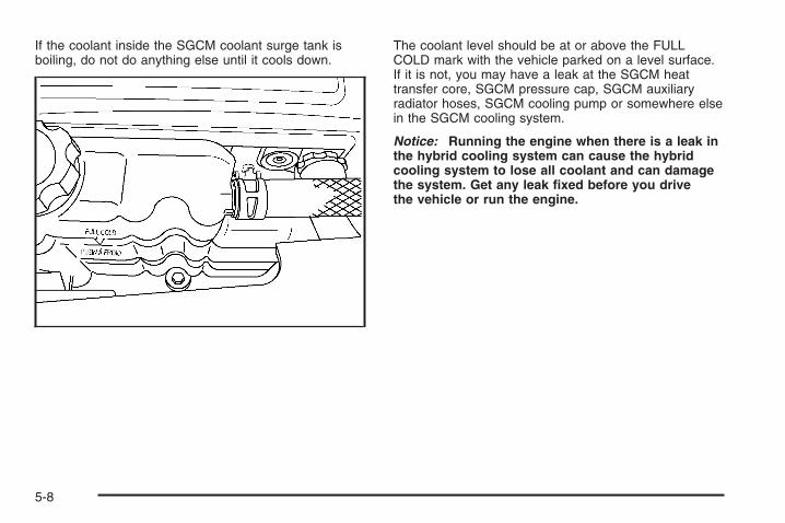
If the coolant inside the SGCM coolant surge tank isboiling, do not do anything else until it cools down.
The coolant level should be at or above the FULLCOLD mark with the vehicle parked on a level surface.If it is not, you may have a leak at the SGCM heattransfer core, SGCM pressure cap, SGCM auxiliaryradiator hoses, SGCM cooling pump or somewhere elsein the SGCM cooling system.
Notice: Running the engine when there is a leak inthe hybrid cooling system can cause the hybridcooling system to lose all coolant and can damagethe system. Get any leak fixed before you drivethe vehicle or run the engine.
5-8

How to Add Coolant to the SGCMCoolant Surge Tank
If you have not found a problem yet, check to see ifcoolant is visible in the SGCM coolant surge tank.
If coolant is visible and within one inch (2.54 cm) ofthe FULL COLD mark, add a 50/50 mixture of clean,drinkable water and DEX-COOL® coolant at the SGCMcoolant surge tank, but be sure the SGCM coolingsystem, including the SGCM coolant surge tank pressurecap, is cool before you do it. Use the procedure following.
{CAUTION:
Steam and scalding liquids from a hot coolingsystem can blow out and burn you badly. Theyare under pressure, and if you turn the coolantsurge tank pressure cap — even a little — theycan come out at high speed. Never turn thecap when the cooling system, including thecoolant surge tank pressure cap, is hot. Waitfor the cooling system and coolant surge tankpressure cap to cool if you ever have to turnthe pressure cap.
Notice: Using coolant other than DEX-COOL® maydamage your vehicle. Any repairs would not becovered by your warranty. Always use DEX-COOL®
(silicate-free) coolant in your vehicle.
5-9
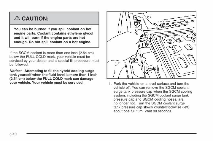
{CAUTION:
You can be burned if you spill coolant on hotengine parts. Coolant contains ethylene glycoland it will burn if the engine parts are hotenough. Do not spill coolant on a hot engine.
If the SGCM coolant is more than one inch (2.54 cm)below the FULL COLD mark, your vehicle must beserviced by your dealer and a special fill procedure mustbe followed.
Notice: Attempting to fill the hybrid cooling surgetank yourself when the fluid level is more than 1 inch(2.54 cm) below the FULL COLD mark can damageyour vehicle. Your vehicle must be serviced. 1. Park the vehicle on a level surface and turn the
vehicle off. You can remove the SGCM coolantsurge tank pressure cap when the SGCM coolingsystem, including the SGCM coolant surge tankpressure cap and SGCM cooling hoses, areno longer hot. Turn the SGCM coolant surgetank pressure cap slowly counterclockwise (left)about one full turn. Wait 30 seconds.
5-10

2. Then keep turning the SGCM coolant surge tankpressure cap slowly, and remove it.
3. Add the proper coolant mixture to the SGCMcoolant surge tank until the level reaches theFULL COLD mark.
4. Then replace theSGCM coolant surgetank pressure cap.Be sure the pressurecap is hand-tightand fully seated.
Notice: Using cooling system sealers orconditioners in an attempt to stop coolant leakscan damage the SGCM and engine cooling systems.Never use cooling system sealers or conditionersin your cooling system.
5-11

Power Steering Fluid
When to Check Power Steering FluidIt is not necessary to regularly check power steering fluidunless you suspect there is a leak in the system oryou hear an unusual noise. A fluid loss in this systemcould indicate a problem. Have the system inspectedand repaired. See Engine Compartment Overviewon page 5-4 for reservoir location.
How to Check Power Steering FluidTurn the key off, let the engine compartment cool down.
Locate the power steering reservoir and cap. Wipe thecap and the top of the reservoir clean, then unscrewthe cap and wipe the dipstick with a clean rag. Replacethe cap and completely tighten it. Then remove thecap again and look at the fluid level on the dipstick.
The level should be at the FULL COLD mark. Ifnecessary, add only enough fluid to bring the levelup to the mark.
5-12

What to UseTo determine what kind of fluid to use, seeRecommended Fluids and Lubricants on page 6-2 formore information. Your hybrid vehicle requires a specialpower steering fluid. Always use the proper fluid.Failure to use the proper fluid can cause leaks anddamage hoses, seals and other steering system partsand repairs may not be covered by your vehicle’swarranty.
BatteryYour vehicle has a standard 12-volt battery and a42-volt hybrid battery system.
When it is time for a new standard 12-volt battery, getone that has the replacement number shown onthe original battery’s label. We recommend an ACDelco®
replacement battery.
When it is time for a new 42-volt hybrid battery system,see your dealer.Warning: Battery posts, terminals, and relatedaccessories contain lead and lead compounds,chemicals known to the State of California to causecancer and reproductive harm. Wash hands afterhandling.
Vehicle StorageIf you are not going to drive your vehicle for 30 days ormore you should disconnect your standard 12-voltbattery. Remember to reconnect your battery whenyou are ready to drive your vehicle. You should alsodisconnect the 42-volt hybrid battery system. SeeBattery Disconnect Switch on page 5-20.
{CAUTION:
Batteries have acid that can burn you and gasthat can explode. You can be badly hurt if youare not careful. See Jump Starting onpage 5-14 for tips on working around a batterywithout getting hurt.
5-13

Jump StartingIf your 42-volt battery has run down, you may want touse another vehicle’s 12-volt battery and jumper cablesto start your vehicle. Jump starting your hybrid vehiclemay take considerably longer than a regular vehicle.You may have to wait 10 to 20 minutes total foryour vehicle to charge from the other vehicle’s good12-volt battery in order to start your vehicle. Usethe following steps to do it safely:
{CAUTION:
Batteries can hurt you. They can be dangerousbecause:
• They contain acid that can burn you.• They contain gas that can explode or
ignite.• They contain enough electricity to
burn you.
If you do not follow these steps exactly, someor all of these things can hurt you.
Notice: Ignoring these steps could result in costlydamage to your vehicle that would not be coveredby your warranty.
Trying to start your vehicle by pushing or pulling itwill not work, and it could damage your vehicle.
1. Check to see that the battery disconnect switch onyour hybrid vehicle is in the power position. If it isnot, turn it clockwise until it stops and then tryto start your vehicle. See Battery Disconnect Switchon page 5-20 for more information. If your vehiclestill won’t start, continue to Step 2.
2. Check the other vehicle. It must have a 12-voltbattery with a negative ground system.
Notice: If the other vehicle’s system is not a 12-voltsystem with a negative ground, both vehicles canbe damaged. Only use vehicles with 12-volt systemswith negative grounds to jump start your vehicle.
5-14

3. Get the vehicles close enough so the jumper cablescan reach, but be sure the vehicles are not touchingeach other. If they are, it could cause a groundconnection you do not want. You would not be ableto start your vehicle, and the bad groundingcould damage the electrical systems.To avoid the possibility of the vehicles rolling, set theparking brake firmly on both vehicles involved in thejump start procedure. Put an automatic transmissionin PARK (P) or a manual transmission in NEUTRALbefore setting the parking brake.
Notice: If you leave your radio or other accessorieson during the jump starting procedure, they couldbe damaged. The repairs would not be coveredby your warranty. Always turn off your radio andother accessories when jump starting your vehicle.
4. Turn off the ignition on both vehicles. Unplugunnecessary accessories plugged into the cigarettelighter and accessory power outlets. Turn off theradio and all lamps that are not needed. This willavoid sparks and help save both batteries. And itcould save your radio!
5. Open the hoods and locate the positive (+) andnegative (−) terminal locations of the other vehicle.Your vehicle has a remote positive (+) 12-voltjump starting terminal and a remote negative (−)jump starting terminal. You should always use theseremote terminals instead of the terminals on thebattery.
The remote positive (+) terminal is located undera red plastic cover near the center of the enginecompartment. See Engine Compartment Overviewon page 5-4. To access the remote positive (+)terminal, open the red plastic cover.
5-15

The remote negative (−) terminal is located on theengine accessory drive bracket behind the powersteering pump and is marked GND. Do not connectthe jumper cables to any part of the power steeringpump or hoses.See Engine Compartment Overview on page 5-4 formore information on location of the positive (+)and negative (−) terminals.
{CAUTION:
Using a match near a battery can cause batterygas to explode. People have been hurt doingthis, and some have been blinded. Use aflashlight if you need more light.Be sure the battery has enough water. You donot need to add water to the battery installedin your new vehicle. But if a battery has fillercaps, be sure the right amount of fluid is there.If it is low, add water to take care of that first.If you do not, explosive gas could be present.Battery fluid contains acid that can burn you.Do not get it on you. If you accidentally get itin your eyes or on your skin, flush the placewith water and get medical help immediately.
{CAUTION:
An electric fan can start up even when theengine is not running and can injure you. Keephands, clothing and tools away from anyunderhood electric fan.
5-16

{CAUTION:
Fans or other moving engine parts can injureyou badly. Keep your hands away from movingparts once the engine is running.
6. Check that the jumper cables do not have loose ormissing insulation. If they do, you could get ashock. The vehicles could be damaged too.Before you connect the cables to the other vehicle,here are some basic things you should know.Positive (+) will go to positive (+) or to a remotepositive terminal (+) if the vehicle has one.Negative (−) will go to a heavy, unpainted metalengine part or to a remote negative (−) terminal,if the vehicle has one.Do not connect positive (+) to negative (−) or youwill get a short that would damage the batteryand maybe other parts too.
7. Connect the red positive (+) cable to the remotepositive (+) terminal of your hybrid vehicle.
8. Do not let the other end touch metal. Connect it tothe positive (+) terminal of the good battery. Use aremote positive (+) terminal if the other vehiclehas one.
5-17
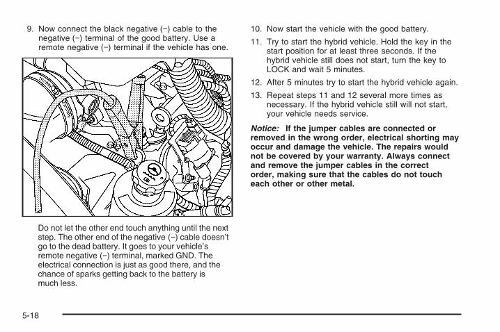
9. Now connect the black negative (−) cable to thenegative (−) terminal of the good battery. Use aremote negative (−) terminal if the vehicle has one.
Do not let the other end touch anything until the nextstep. The other end of the negative (−) cable doesn’tgo to the dead battery. It goes to your vehicle’sremote negative (−) terminal, marked GND. Theelectrical connection is just as good there, and thechance of sparks getting back to the battery ismuch less.
10. Now start the vehicle with the good battery.
11. Try to start the hybrid vehicle. Hold the key in thestart position for at least three seconds. If thehybrid vehicle still does not start, turn the key toLOCK and wait 5 minutes.
12. After 5 minutes try to start the hybrid vehicle again.
13. Repeat steps 11 and 12 several more times asnecessary. If the hybrid vehicle still will not start,your vehicle needs service.
Notice: If the jumper cables are connected orremoved in the wrong order, electrical shorting mayoccur and damage the vehicle. The repairs wouldnot be covered by your warranty. Always connectand remove the jumper cables in the correctorder, making sure that the cables do not toucheach other or other metal.
5-18
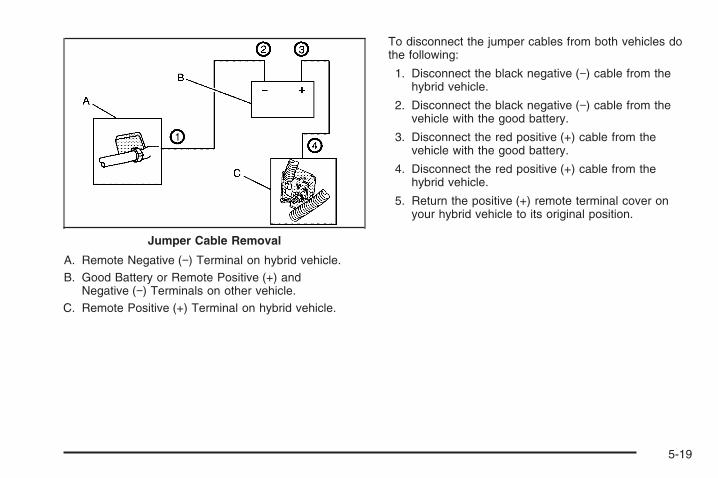
A. Remote Negative (−) Terminal on hybrid vehicle.B. Good Battery or Remote Positive (+) and
Negative (−) Terminals on other vehicle.C. Remote Positive (+) Terminal on hybrid vehicle.
To disconnect the jumper cables from both vehicles dothe following:
1. Disconnect the black negative (−) cable from thehybrid vehicle.
2. Disconnect the black negative (−) cable from thevehicle with the good battery.
3. Disconnect the red positive (+) cable from thevehicle with the good battery.
4. Disconnect the red positive (+) cable from thehybrid vehicle.
5. Return the positive (+) remote terminal cover onyour hybrid vehicle to its original position.
Jumper Cable Removal
5-19

Electrical System
Battery Disconnect SwitchNotice: Placing items that weigh more than 200 lbs(90 kg) on the battery box may cause damage tothe battery box and electrical system. Never placeitems weighing more than 200 lbs (90 kg) on thebattery box.
If you will not be using your vehicle for a period of 30 daysor more, you will need to disconnect 42-volt battery powerfrom the vehicle to prevent the batteries from discharging.
Open the passenger side rear door to access thebattery box. The battery disconnect switch is located onthe passenger side of the battery box.
5-20

To access the battery disconnect switch and disconnectbattery power, do the following:
1. Turn the ignition key to LOCK.
2. Grab the tab at the top of the access door and pullthe top of the door out.
3. Pull the access cover up and out from the accessopening.
4. Locate the battery disconnect switch.
5. Turn the switch counterclockwise until it stops.The 42-volt battery power is now disconnectedfrom the vehicle.This switch can be removed when it is in the off(no power) position.When you are ready to reconnect battery power tothe vehicle, turn the switch clockwise until it stops.
5-21

6. Reinstall the access door by first placing the tab onthe access door into the slot on the lower edge ofthe battery box access opening.
7. Push the corners of the access door in until theysnap into place.
If your 42-volt battery system is disconnected due to anairbag inflation or right-side impact, you must take yourvehicle to a qualified service technician to have the42-volt battery system reconnected. See What Will YouSee After an Airbag Inflates? on page 1-2 for moreinformation.
Fuses and Circuit BreakersThe wiring circuits in your vehicle are protected fromshort circuits by a combination of fuses, circuit breakersand fusible thermal links. This greatly reduces thechance of fires caused by electrical problems.
Be sure you replace a bad fuse with a new one of theidentical size and rating.
If you ever have a problem on the road and do not havea spare fuse, you can borrow one that has the sameamperage. Just pick some feature of your vehiclethat you can get along without — like the radio orcigarette lighter — and use its fuse, if it is the correctamperage. Replace it as soon as you can.
Your vehicle also has a special fuse in the battery boxfor the 42-volt batteries. If this fuse has failed andneeds to be replaced, the vehicle will be disabled andyou will need to have your vehicle repaired by yourdealer. Do not attempt to self-service this fuse.
5-22

Hybrid Underhood Fuse Block
The hybrid underhood fuse block is located in the enginecompartment on the driver’s side of the vehicle near themain underhood fuse block. Lift the cover for access tothe fuse/relay block. See Engine Compartment Overviewon page 5-4 for more information on its location. For moreinformation on the main underhood fuse block see“Underhood Fuse Block” in the Index of your ownermanual.
To remove fuses, hold the end of the fuse between yourthumb and index finger and pull straight out.
Relays UsageSGCM COOLANTPUMP RELAY
SGCM Coolant Fan PumpRelay
AUX HTR PUMPRELAY Auxiliary Heater Pump
TRANS PUMP RELAY Transmission PumpPWR MAINT RELAY Power Maintain
5-23
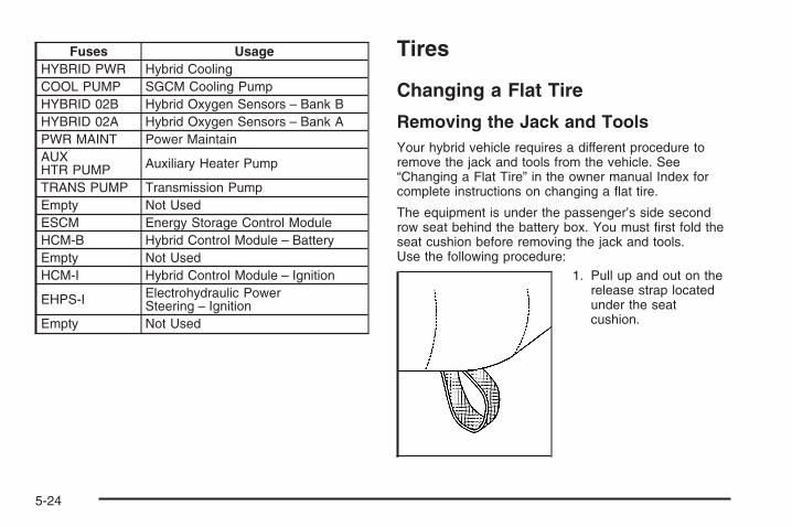
Fuses UsageHYBRID PWR Hybrid CoolingCOOL PUMP SGCM Cooling PumpHYBRID 02B Hybrid Oxygen Sensors – Bank BHYBRID 02A Hybrid Oxygen Sensors – Bank APWR MAINT Power MaintainAUXHTR PUMP Auxiliary Heater Pump
TRANS PUMP Transmission PumpEmpty Not UsedESCM Energy Storage Control ModuleHCM-B Hybrid Control Module – BatteryEmpty Not UsedHCM-I Hybrid Control Module – Ignition
EHPS-I Electrohydraulic PowerSteering – Ignition
Empty Not Used
Tires
Changing a Flat Tire
Removing the Jack and ToolsYour hybrid vehicle requires a different procedure toremove the jack and tools from the vehicle. See“Changing a Flat Tire” in the owner manual Index forcomplete instructions on changing a flat tire.
The equipment is under the passenger’s side secondrow seat behind the battery box. You must first fold theseat cushion before removing the jack and tools.Use the following procedure:
1. Pull up and out on therelease strap locatedunder the seatcushion.
5-24

2. Fold the seat cushion upward until it latches withthe seatback.
3. Push and pull on the seat cushion to make sure theseat is secure.
4. Turn the wing nut (B) counterclockwise untilloosened and flip the black retaining clip backto remove the storage bag and tools (C) from thevehicle.
A. Jack and Wheel BlocksB. Wing NutC. Tool Kit
5-25

5. Release the jack and wheel blocks (A) from theholder as an assembly by turning the yellow knobon the jack counterclockwise to lower the jack head.
6. Pull the jack back toward the seat bracket.
5-26

7. Turn the jack upside down so the small wing nutholding the wheel blocks is facing the battery box.
8. Push the seat cushionback while pulling thejack out.
Pulling the jack out this way will reduce thepotential of scratching the battery cover.
9. Loosen the wing nut on top of the wheel blocks byturning it counterclockwise to separate the wheelblocks from the jack.
When you are finished, place the tools in the storagebag and reinstall the tools in the vehicle by reversing theremoval procedure. Reinstall the wheel blocks to thejack and reinstall the jack back into the vehicle byreversing the removal procedure.
5-27

Capacities and SpecificationsAuxiliary Power Outlet (APO) Specifications
Maximum Output Power 2.4 kw
Output Voltage 120 VAC +5% −8% measured at the outlets
Current Output (Maximum Continuous) 20 Amps
Output Frequency 60 Hz ± 0.25 Hz
Total Harmonic Distortion (THD) ≤10%
Overload Protection Level 21 A(rms) current limit for 5 seconds
Ground Fault Detection Level ≥6ma
Capacities
Application
Capacities
English Metric
Hybrid Cooling System 2.1 quarts 2.0 L
After refill, the level must be rechecked.
5-28

Maintenance Schedule ......................................6-2Recommended Fluids and Lubricants ................6-2Engine Drive Belt Routing ................................6-2
Section 6 Maintenance Schedule
6-1

Maintenance Schedule
Recommended Fluids andLubricantsFluids and lubricants identified below by name, partnumber, or specification may be obtained fromyour dealer.
Usage Fluid/Lubricant
Power SteeringSystem
Electrohydraulic Power SteeringFluid (GM Part No. U.S. 88901975,in Canada 88901976).
StarterGenerator
Control Module(SGCM) Engine
Coolant
50/50 mixture of clean, drinkablewater and use only DEX-COOL®
Coolant. See “Engine Coolant” inthe owner manual.
For all other recommended fluids and lubricants, see“Recommended Fluids and Lubricants” in the Indexof your owner manual.
Engine Drive Belt Routing
6-2

AAirbag System
What Will You See After an Airbag Inflates? ...... 1-2Automatic Transmission, Fluid ............................ 5-6Auxiliary Power Outlet (APO) System .................. 2-2
BBattery Disconnect Switch ................................ 5-20Braking
Regenerative ................................................ 4-2
CCapacities and Specifications ............................ 5-28Changing a Flat Tire ....................................... 5-24Climate Controls ............................................... 3-2Cooling System ................................................ 5-7
DDriver Information Center (DIC)
Warnings and Messages ................................ 3-2
1

EEngine
Compartment Overview .................................. 5-4
FFuses and Circuit Breakers .............................. 5-22
JJump Starting ................................................. 5-14
RRegenerative Braking ........................................ 4-2Restraint System Check
Replacing Restraint System Parts After aCrash ....................................................... 1-2
SService, Doing Your Own Work .......................... 5-3Specifications, Capacities ................................. 5-28Starting Your Vehicle ......................................... 2-8
TTires
Changing a Flat .......................................... 5-24Towing
Trailer .......................................................... 4-2Transmission, Automatic Fluid ............................. 5-6
2