2007 gmc yukon, yukon xl owner manual m
TRANSCRIPT

Seats and Restraint Systems ....................... 7Front Seats .............................................. 9Rear Seats ............................................. 19Safety Belts ............................................ 38Child Restraints ...................................... 62Airbag System ........................................ 93Restraint System Check ....................... 112
Features and Controls .............................. 115Keys ..................................................... 117Doors and Locks .................................. 126Windows ............................................... 136Theft-Deterrent Systems ....................... 138Starting and Operating Your Vehicle ....... 143Mirrors .................................................. 166OnStar® System ................................... 175Universal Home Remote System .......... 179Storage Areas ...................................... 190Sunroof ................................................ 197
Instrument Panel ....................................... 199Instrument Panel Overview ................... 202Climate Controls ................................... 227Warning Lights, Gages, and
Indicators .......................................... 242Driver Information Center (DIC) ............ 262Audio System(s) ................................... 292
Driving Your Vehicle ................................. 359Your Driving, the Road, and
Your Vehicle ..................................... 360Towing ................................................. 422
Service and Appearance Care .................. 447Service ................................................. 450Fuel ...................................................... 452Checking Things Under the Hood ......... 460Rear Axle ............................................. 500Four-Wheel Drive .................................. 501Front Axle ............................................ 502
2007 GMC Yukon, Yukon XL Owner Manual M
1
Headlamp Aiming ................................. 503Bulb Replacement ................................ 506Windshield Wiper Blade Replacement .... 509Tires ..................................................... 510Appearance Care .................................. 555Vehicle Identification ............................. 565Electrical System .................................. 565Capacities and Specifications ................ 573
Maintenance Schedule .............................. 575Maintenance Schedule .......................... 576
Customer Assistance Information ............. 595Customer Assistance and Information ..... 596Reporting Safety Defects ...................... 612
Index .......................................................... 615
2

GENERAL MOTORS, GM, the GM Emblem,GMC, the GMC Truck Emblem, and the nameYUKON are registered trademarks of GeneralMotors Corporation.
This manual includes the latest information at thetime it was printed. We reserve the right tomake changes after that time without furthernotice. For vehicles first sold in Canada, substitutethe name “General Motors of Canada Limited”for GMC whenever it appears in this manual.
This manual describes features that may beavailable in this model, but your vehicle may nothave all of them. For example, more than oneentertainment system may be offered or yourvehicle may have been ordered without a frontpassenger or rear seats.
Keep this manual in the vehicle, so it will be thereif it is needed while you are on the road. If thevehicle is sold, leave this manual in the vehicle.
Canadian OwnersA French language copy of this manual can beobtained from your dealer/retailer or from:
Helm, IncorporatedP.O. Box 07130Detroit, MI 48207
Litho in U.S.A.Part No. 15854793 C Third Printing ©2006 General Motors Corporation. All Rights Reserved.
3

How to Use This ManualMany people read the owner manual frombeginning to end when they first receive their newvehicle. If this is done, it can help you learnabout the features and controls for the vehicle.Pictures and words work together in theowner manual to explain things.
IndexA good place to quickly locate information aboutthe vehicle is the Index in the back of the manual.It is an alphabetical list of what is in the manualand the page number where it can be found.
Safety Warnings and SymbolsThere are a number of safety cautions in thisbook. We use a box and the word CAUTION totell about things that could hurt you if you were toignore the warning.
{CAUTION:
These mean there is something that couldhurt you or other people.
In the caution area, we tell you what the hazard is.Then we tell you what to do to help avoid orreduce the hazard. Please read these cautions.If you do not, you or others could be hurt.
You will also find acircle with a slashthrough it in this book.This safety symbolmeans “Do Not,” “DoNot do this” or “Do Notlet this happen.”
4

Vehicle Damage WarningsAlso, in this manual you will find these notices:
Notice: These mean there is somethingthat could damage your vehicle.
A notice tells about something that can damagethe vehicle. Many times, this damage would not becovered by your vehicle’s warranty, and it couldbe costly. But the notice will tell what to do to helpavoid the damage.
When you read other manuals, you might seeCAUTION and NOTICE warnings in different colorsor in different words.
There are also warning labels on the vehicle.They use the same words, CAUTION or NOTICE.
Vehicle SymbolsThe vehicle has components and labels that usesymbols instead of text. Symbols are shownalong with the text describing the operation orinformation relating to a specific component,control, message, gage, or indicator.
If you need help figuring out a specific name of acomponent, gage, or indicator, reference thefollowing topics:
• Seats and Restraint Systems in Section 1
• Features and Controls in Section 2
• Instrument Panel Overview in Section 3
• Climate Controls in Section 3
• Warning Lights, Gages, and Indicators inSection 3
• Audio System(s) in Section 3
• Engine Compartment Overview in Section 5
5

These are some examples of symbols that may be found on the vehicle:
6

Front Seats ..................................................... 9Manual Seats ................................................ 9Power Seats ............................................... 10Power Lumbar ............................................. 11Heated Seats .............................................. 12Memory Seat, Mirrors, and Pedals .............. 13Reclining Seatbacks .................................... 15Head Restraints .......................................... 18Center Seat ................................................ 19
Rear Seats .................................................... 19Heated Seats .............................................. 1960/40 Split Bench Seat
(Second Row) .......................................... 20Bucket Seats (Second Row) ........................ 26Third Row Seat ........................................... 33
Safety Belts .................................................. 38Safety Belts: They Are for Everyone ........... 38Questions and Answers About
Safety Belts ............................................. 42How to Wear Safety Belts Properly ............. 43Driver Position ............................................. 44
Shoulder Belt Height Adjustment ................. 51Safety Belt Use During Pregnancy .............. 52Right Front Passenger Position ................... 52Center Front Passenger Position ................. 53Rear Seat Passengers ................................ 54Rear Safety Belt Comfort Guides ................ 57Safety Belt Pretensioners ............................ 61Safety Belt Extender ................................... 61
Child Restraints ............................................ 62Older Children ............................................. 62Infants and Young Children ......................... 65Child Restraint Systems .............................. 69Where to Put the Restraint .......................... 74Lower Anchors and Tethers for Children
(LATCH) .................................................. 76Securing a Child Restraint in a
Rear Seat Position ................................... 85Securing a Child Restraint in the Center
Front Seat Position .................................. 88Securing a Child Restraint in the Right
Front Seat Position .................................. 88
Section 1 Seats and Restraint Systems
7
Airbag System .............................................. 93Where Are the Airbags? .............................. 97When Should an Airbag Inflate? ................ 100What Makes an Airbag Inflate? ................. 102How Does an Airbag Restrain? ................. 102What Will You See After an Airbag
Inflates? ................................................. 103Passenger Sensing System ....................... 104
Servicing Your Airbag-Equipped Vehicle .... 110Adding Equipment to Your
Airbag-Equipped Vehicle ........................ 111Restraint System Check ............................. 112
Checking the Restraint Systems ................ 112Replacing Restraint System Parts After
a Crash ................................................. 113
Section 1 Seats and Restraint Systems
8

Front Seats
Manual Seats
{CAUTION:
You can lose control of the vehicle if youtry to adjust a manual driver’s seat whilethe vehicle is moving. The suddenmovement could startle and confuse you,or make you push a pedal when you donot want to. Adjust the driver’s seat onlywhen the vehicle is not moving.
To move a manual seat forward or rearward:
1. Lift the bar to unlockthe seat.
2. Slide the seat towhere you want itand release the bar.
Try to move the seat with your body to be surethe seat is locked in place.
9

Power Seats
On a vehicle with power seats, the controls used tooperate them are located on the outboard side ofthe seats.
To adjust the seat, do any of the following:
• Move the seat forward or rearward by slidingthe control forward or rearward.
• Raise or lower the front part of the seat cushionby moving the front of the control up or down.
• Raise or lower the rear part of the seat cushionby moving the rear of the control up or down.
• Raise or lower the entire seat by moving theentire control up or down.
On seats with power reclining seatbacks, thecontrol is located behind the power seat control onthe outboard side of the seats. See “PowerReclining Seatbacks” under Reclining Seatbackson page 15.
A vehicle with a memory function allows seatsettings to be saved and recalled. See MemorySeat, Mirrors, and Pedals on page 13 for moreinformation.
Driver’s Seat with Power Seat Control, PowerRecline, and Power Lumbar shown
10

Power Lumbar
If the seats have power lumbar, the controls used tooperate this feature are located on the outboardside of the seats.
• To increase lumbar support, press and hold thefront of the control.
• To decrease lumbar support, press and holdthe rear of the control.
• To raise the height of the lumbar support, pressand hold the top of the control.
• To lower the height of the lumbar support,press and hold the bottom of the control.
Release the control when the lower seatbackreaches the desired level of lumbar support.
Your vehicle may have a memory function whichallows seat settings to be saved and recalled.See Memory Seat, Mirrors, and Pedals on page 13for more information.
Keep in mind that as your seating positionchanges, as it may during long trips, so should theposition of your lumbar support. Adjust the seatas needed.
11

Heated SeatsOn vehicles with heatedfront seats, the controlsare located on thedriver’s and passenger’sdoors, near the doorhandle.
I (Heated Seatback): Press this button to turnon the heated seatback.
The light on the button will come on to indicatethat the feature is working. Press the buttonto cycle through the temperature settings of high,medium, and low and to turn the heat to theseatback off. Indicator lights below the button showthe level of heat selected: three for high, two formedium, and one for low.
J (Heated Seat and Seatback): Press thisbutton to turn on the heated seat and seatback.
The light on the button will come on to indicate thatthe feature is working. Press the button to cyclethrough the temperature settings of high, medium,and low and to turn the heat to the seat off.Indicator lights above the button will show the levelof heat selected: three for high, two for medium,and one for low.
The heated seats will be canceled ten secondsafter the ignition is turned off. If you want touse the heated seat feature after you restart yourvehicle, you will need to press the appropriateheated seat or seatback button again.
12

Memory Seat, Mirrors, and PedalsYour vehicle may have the memory package.
The controls for thisfeature are located onthe driver’s doorpanel, and are used toprogram and recallmemory settings for thedriver’s seat, outsidemirrors, and theadjustable throttle andbrake pedal.
To save your positions in memory, do the following:
1. Adjust the driver’s seat, including theseatback recliner and lumbar, both outsidemirrors, and the throttle and brake pedals to acomfortable position.See Outside Power Mirrors on page 172and Adjustable Throttle and Brake Pedal onpage 147 for more information.
Not all mirrors will have the ability to save andrecall their positions.Not all adjustable throttles and brake pedalswill have the ability to save and recall theirpositions.
2. Press and hold button 1 until two beeps areheard indicating that the position has beenstored.
A second seating, mirror, and throttle and brakepedal position can be programmed by repeatingthe above steps and pressing button 2.
To recall the memory positions, the vehicle mustbe in PARK (P). Press and release either button 1or button 2 corresponding to the desired drivingposition. The seat, outside mirrors, and adjustablethrottle and brake pedals will move to the positionpreviously stored. You will hear a single beep.
If you use the remote keyless entry transmitter toenter your vehicle and the remote recall memoryfeature is on, automatic seat, adjustable mirror,and adjustable pedal movements will occur.See “MEMORY SEAT RECALL” under DIC VehicleCustomization (With DIC Buttons) on page 282for more information.
13

To stop recall movement of the memory functionat any time, press one of the power seat controls,memory buttons, power mirror buttons, oradjustable pedal switch.
If something has blocked the driver’s seat and/orthe adjustable pedals while recalling a memoryposition, the driver’s seat and/or the adjustablepedals recall may stop working. If this happens,remove the obstruction and press the appropriatecontrol for the area that is not responding fortwo seconds. Try recalling the memory positionagain by pressing the appropriate memory button.If the memory position is still not recalling, seeyour dealer for service.
Easy Exit SeatThe control for this feature is located on thedriver’s door panel between buttons 1 and 2.
With the vehicle in PARK (P), the driver’s seat exitposition can be recalled by pressing the exitbutton. You will hear a single beep, and thedriver’s seat will move back.
If the easy exit seat feature is programmed in theDriver Information Center (DIC), automaticseat movement will occur when the key is removedfrom the ignition. See “EASY EXIT SEAT” underDIC Vehicle Customization (With DIC Buttons)on page 282 for more information.
The memory seat and easy exit features can alsobe programmed using the DIC.
For programming information, see DIC VehicleCustomization (With DIC Buttons) on page 282.
14

Reclining SeatbacksManual Reclining Seatbacks
{CAUTION:
You can lose control of the vehicle if youtry to adjust a manual driver’s seat whilethe vehicle is moving. The suddenmovement could startle and confuse you,or make you push a pedal when you donot want to. Adjust the driver’s seat onlywhen the vehicle is not moving.
{CAUTION:
If the seatback is not locked, it couldmove forward in a sudden stop or crash.That could cause injury to the personsitting there. Always push and pull on theseatback to be sure it is locked.
If the seats have manual reclining seatbacks, thelever used to operate them is located on theoutboard side of the seat(s).
To recline the seatback, do the following:
1. Lift the recline lever.
2. Move the seatback to the desired position,then release the lever to lock the seatbackin place.
3. Push and pull on the seatback to make sure itis locked.
15

To return the seatback to an upright position,do the following:
1. Lift the lever fully without applying pressure tothe seatback and the seatback will return tothe upright position.
2. Push and pull on the seatback to make sure itis locked.
Power Reclining Seatbacks
If the seats have power reclining seatbacks,the control used to recline them is located onthe outboard side of the seat behind the powerseat control.
• To recline the seatback, tilt the top of thecontrol rearward.
• To bring the seatback forward, tilt the top ofthe control forward.
16

{CAUTION:
Sitting in a reclined position when yourvehicle is in motion can be dangerous.Even if you buckle up, your safety beltscannot do their job when you are reclinedlike this.
The shoulder belt cannot do its job. In acrash, you could go into it, receiving neckor other injuries.
The lap belt cannot do its job either. In acrash the belt could go up over yourabdomen. The belt forces would be there,not at your pelvic bones. This could causeserious internal injuries.
For proper protection when the vehicle isin motion, have the seatback upright.Then sit well back in the seat and wearyour safety belt properly.
Do not have a seatback reclined if your vehicle ismoving.
17

Head Restraints
Adjust the head restraint so that the top of therestraint is at the same height as the top ofthe occupant’s head. This position reduces thechance of a neck injury in a crash.
Pull the head restraintup to raise it. To lowerthe head restraint,press the releasebutton (A), located onthe top of the seatback,while you push thehead restraint down.
The front seats may have head restraints that alsotilt forward and rearward.
To tilt the head restraint, grasp the top of therestraint while pressing the button (B), located onthe inboard side of the head restraint, andmove it forward or rearward until the desiredlocking position is reached. Try to move the headrestraint after the button is released to makesure that it is locked in place.
The second row seats may have head rests thatcan be adjusted up and down, but they do not tilt.
18
Center SeatYour vehicle may have a front center seat.The seatback doubles as an armrest andcupholder/storage area for the driver andpassenger when the center seat is not used.Do not use it as a seating position whenthe seatback is folded down.
For information on safety belts for this position,see Center Front Passenger Position on page 53.
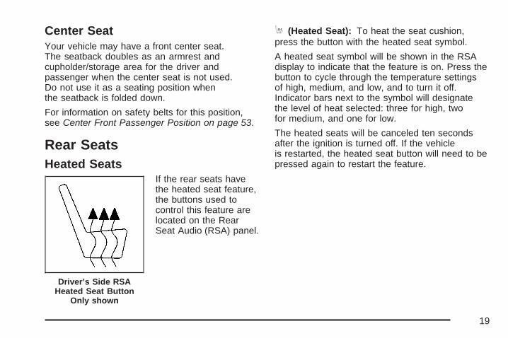
Rear SeatsHeated Seats
If the rear seats havethe heated seat feature,the buttons used tocontrol this feature arelocated on the RearSeat Audio (RSA) panel.
M (Heated Seat): To heat the seat cushion,press the button with the heated seat symbol.
A heated seat symbol will be shown in the RSAdisplay to indicate that the feature is on. Press thebutton to cycle through the temperature settingsof high, medium, and low, and to turn it off.Indicator bars next to the symbol will designatethe level of heat selected: three for high, twofor medium, and one for low.
The heated seats will be canceled ten secondsafter the ignition is turned off. If the vehicleis restarted, the heated seat button will need to bepressed again to restart the feature.
Driver’s Side RSAHeated Seat Button
Only shown
19

60/40 Split Bench Seat(Second Row)If your vehicle has a 60/40 split bench, the seat(s)can be folded for additional cargo space orfolded and tumbled for easy entry and exit tothe third row seats, if your vehicle has them.These seats will have either the manual fold andtumble feature or the automatic seat releasefold and tumble feature.
Manual Fold and Tumble FeatureFolding and Tumbling the Seat(s)To fold and tumble the seat, do the following:
1. Make sure that there is nothing under, in frontof, or on the seat.
Notice: Folding a rear seat with the safetybelts still fastened may cause damage to theseat or the safety belts. Always unbucklethe safety belts and return them to their normalstowed position before folding a rear seat.
2. Lift the lever, located on the outboard side ofthe seat, to release the seatback.
20

The seatback will fold forward automatically.Leaving the seatback in this position createsa flat load floor.
If the seatback cannot fold flat, try movingthe front seat forward and/or put the frontseatback in the upright position.
3. Lift the same leveragain to releasethe rear of the seatfrom the floor.The seat will tumbleforward.
21

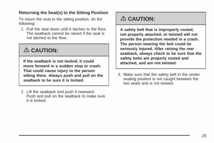
Returning the Seat(s) to the Sitting PositionTo return the seat to the sitting position, do thefollowing:1. Pull the seat down until it latches to the floor.
The seatback cannot be raised if the seat isnot latched to the floor.
{CAUTION:
If the seatback is not locked, it couldmove forward in a sudden stop or crash.That could cause injury to the personsitting there. Always push and pull on theseatback to be sure it is locked.
2. Lift the seatback and push it rearward.Push and pull on the seatback to make sureit is locked.
{CAUTION:
A safety belt that is improperly routed, notproperly attached, or twisted will notprovide the protection needed in a crash.The person wearing the belt could beseriously injured. After raising the rearseatback, always check to be sure thatthe safety belts are properly routed andattached, and are not twisted.
3. Make sure the safety belt in the centerseating position is not caught between thetwo seats and is not twisted.
22

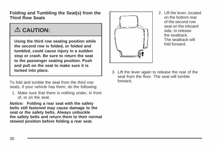
Folding and Tumbling the Seat(s) from theThird Row Seats
{CAUTION:
Using the third row seating position whilethe second row is folded, or folded andtumbled, could cause injury in a suddenstop or crash. Be sure to return the seatto the passenger seating position. Pushand pull on the seat to make sure it islocked into place.
To fold and tumble the seat from the third rows,if your vehicle has them, do the following:1. Make sure that there is nothing under,
in front of, or on the seat.
Notice: Folding a rear seat with the safetybelts still fastened may cause damage to theseat or the safety belts. Always unbucklethe safety belts and return them to their normalstowed position before folding a rear seat.
2. Lift the lever(s), located on the bottom rear ofthe second row seat(s) on the inboard side,to release the seatback. The seatback will foldforward.
3. Lift the same lever again to release the rearof the seat from the floor. The seat willtumble forward automatically.
23

Automatic Release Fold and TumbleFeatureThe transmission must be in PARK (P) for thisfeature to work.
Folding and Tumbling the Seat(s)
{CAUTION:
Automatically folding and tumbling theseat when someone is sitting in the seat,could cause injury to the person sittingthere. Always make sure there is no onesitting in the seat before pressing theautomatic seat release button.
To fold and tumble the seat, do the following:1. Make sure that there is nothing under,
in front of, or on the seat.
Notice: Folding a rear seat with the safetybelts still fastened may cause damage to theseat or the safety belts. Always unbucklethe safety belts and return them to their normalstowed position before folding a rear seat.
2. From the frontseats, press one ofthe automaticseat release buttonslocated on theoverhead console.
When accessing the third row seats, if yourvehicle has them, from the outside of thevehicle, press the button on the panel behindeither rear door.One press of the button automatically folds theseatback flat and tumbles the seat forward.There will be a slight delay between the foldingof the seatback and the tumbling of the seat.
Overhead ConsoleButtons shown, Panel
Button similar
24
Returning the Seat(s) to the Sitting PositionTo return the seat to the sitting position, do thefollowing:1. Pull the seat down until it latches to the floor.
The seatback cannot be raised if the seat isnot latched to the floor.
{CAUTION:
If the seatback is not locked, it couldmove forward in a sudden stop or crash.That could cause injury to the personsitting there. Always push and pull on theseatback to be sure it is locked.
2. Lift the seatback and push it rearward.Push and pull on the seatback to make sureit is locked.
{CAUTION:
A safety belt that is improperly routed,not properly attached, or twisted will notprovide the protection needed in a crash.The person wearing the belt could beseriously injured. After raising the rearseatback, always check to be sure that thesafety belts are properly routed andattached, and are not twisted.
3. Make sure that the safety belt in the centerseating position is not caught between thetwo seats and is not twisted.
25

Folding and Tumbling the Second RowSeat(s) from the Third Row Seats orOutside
{CAUTION:
Using the third row seating position whilethe second row is folded, or folded andtumbled, could cause injury in a suddenstop or crash. Be sure to return the seatto the passenger seating position. Pushand pull on the seat to make sure it islocked into place.
To fold and tumble the seat from the third rowseats, if your vehicle has them, do the following:1. Make sure that there is nothing under,
in front of, or on the seat.
Notice: Folding a rear seat with the safetybelts still fastened may cause damage to theseat or the safety belts. Always unbucklethe safety belts and return them to their normalstowed position before folding a rear seat.
2. Press the automaticseat release buttonlocated on thepanel behind therear doors.
One press of the button automatically folds theseatback flat and tumbles the seat forward.There will be a slight delay between the foldingof the seatback and the tumbling of the seat.
Bucket Seats (Second Row)If your vehicle has bucket seats, the seatbackscan be reclined, the seats can be folded foradditional cargo space, or folded and tumbled foreasy entry and exit to the third row seats,if your vehicle has them. These seats will haveeither the manual fold and tumble feature orthe automatic seat release fold and tumble feature.
Driver’s Side Rear PanelButton shown
26

Reclining SeatbacksTo recline the seatback, do the following:
1. Lift the lever located on the outboard side ofthe seat.
2. Move the seatback to the desired position,then release the lever to lock the seatbackin place.
3. Push and pull on the seatback to make sure itis locked.
To return the seatback to an upright position, dothe following:
1. Lift the lever fully without applying pressure tothe seatback and the seatback will return tothe upright position.
{CAUTION:
If the seatback is not locked, it couldmove forward in a sudden stop or crash.That could cause injury to the personsitting there. Always push and pull on theseatback to be sure it is locked.
2. Push and pull on the seatback to make sure itis locked.
27

Manual Fold and Tumble FeatureFolding and Tumbling the Seat(s)To fold and tumble the seat, do the following:1. Make sure that there is nothing under, in front
of, or on the seat.
Notice: Folding a rear seat with the safetybelts still fastened may cause damage to theseat or the safety belts. Always unbucklethe safety belts and return them to their normalstowed position before folding a rear seat.
2. Lift the lever, located on the outboard side ofthe seat, to release the seatback.
The seatback will fold forward. Leaving theseatback in this position creates a flatload floor.
If the seatback cannot fold flat, try moving thefront seat forward and/or put the front seatbackin the upright position.
28

3. Lift the lever againto release the rearof the seat fromthe floor. The seatwill tumble forward.
Returning the Seat(s) to the Sitting PositionTo return the seat to the sitting position, do thefollowing:1. Pull the seat down until it latches to the floor.
The seatback cannot be raised if the seat isnot latched to the floor.
{CAUTION:
If the seatback is not locked, it couldmove forward in a sudden stop or crash.That could cause injury to the personsitting there. Always push and pull on theseatback to be sure it is locked.
2. Lift the seatback and push it rearward.Push and pull on the seatback to make sureit is locked.
29
Folding and Tumbling the Seat(s) from theThird Row Seats
{CAUTION:
Using the third row seating position whilethe second row is folded, or folded andtumbled, could cause injury in a suddenstop or crash. Be sure to return the seatto the passenger seating position. Pushand pull on the seat to make sure it islocked into place.
To fold and tumble the seat from the third rowseats, if your vehicle has them, do the following:
1. Make sure that there is nothing under, in frontof, or on the seat.
Notice: Folding a rear seat with the safetybelts still fastened may cause damage to theseat or the safety belts. Always unbucklethe safety belts and return them to their normalstowed position before folding a rear seat.
2. Lift the lever, locatedon the bottom rearof the second rowseat on the inboardside, to releasethe seatback.The seatback willfold forward.
3. Lift the lever again to release the rear of theseat from the floor. The seat will tumbleforward.
30

Automatic Release Fold and TumbleFeatureThe transmission must be in PARK (P) for thisfeature to work.
Folding and Tumbling the Seat(s)
{CAUTION:
Automatically folding and tumbling theseat when someone is sitting in the seat,could cause injury to the person sittingthere. Always make sure there is no onesitting in the seat before pressing theautomatic seat release button.
To fold and tumble the seat, do the following:1. Make sure that there is nothing under, in front
of, or on the seat.
Notice: Folding a rear seat with the safetybelts still fastened may cause damage to theseat or the safety belts. Always unbucklethe safety belts and return them to their normalstowed position before folding a rear seat.
2. From the frontseats, press one ofthe automaticseat release buttonslocated on theoverhead console.
When accessing the third row seats, if yourvehicle has them, from the outside of thevehicle, press the button on the panel behindeither rear door.One press of the button automatically foldsthe seatback flat and tumbles the seat forward.There will be a slight delay between thefolding of the seatback and the tumbling ofthe seat.
Overhead ConsoleButtons shown
31

Returning the Seat(s) to the Sitting PositionTo return the seat to the sitting position, do thefollowing:
1. Pull the seat down until it latches to the floor.The seatback cannot be raised if the seat isnot latched to the floor.
{CAUTION:
If the seatback is not locked, it couldmove forward in a sudden stop or crash.That could cause injury to the personsitting there. Always push and pull on theseatback to be sure it is locked.
2. Lift the seatback and push it rearward.Push and pull on the seatback to make sureit is locked.
Folding and Tumbling the Second RowSeat(s) from the Third Row Seats orOutside
{CAUTION:
Using the third row seating position whilethe second row is folded, or folded andtumbled, could cause injury in a suddenstop or crash. Be sure to return the seatto the passenger seating position. Pushand pull on the seat to make sure it islocked into place.
To fold and tumble the seat from the third rowseats, if your vehicle has them, do the following:
1. Make sure that there is nothing under,in front of, or on the seat.
Notice: Folding a rear seat with the safetybelts still fastened may cause damage to theseat or the safety belts. Always unbucklethe safety belts and return them to their normalstowed position before folding a rear seat.
32

2. Press the automaticseat release buttonlocated on thepanel behind therear doors.
One press of the button automatically folds theseatback flat and tumbles the seat forward.There will be a slight delay between the foldingof the seatback and the tumbling of the seat.
Third Row SeatIf the vehicle has a third row seat, the seatback(s)can be folded and the entire seat can betumbled, or removed from the vehicle.
Folding the Seatback(s)To fold the seatback, do the following:
1. Open the liftgate to access the controls forthe seat.
2. Remove all items on the seat cushion.
Notice: Folding a rear seat with the safetybelts still fastened may cause damage to theseat or the safety belts. Always unbucklethe safety belts and return them to their normalstowed position before folding a rear seat.
3. Lift the releaselever, located onthe bottom rear ofthe seatback onthe outboard sideof the seat, and theseatback will foldforward.
Driver’s Side Rear PanelButton shown
33

Unfolding the Seatback(s)To return the seatback to the upright position,do the following:1. Open the liftgate to access the controls for
the seat.2. Pull up on the seatback until it locks into the
upright position.
{CAUTION:
If the seatback is not locked, it couldmove forward in a sudden stop or crash.That could cause injury to the personsitting there. Always push and pull on theseatback to be sure it is locked.
3. Push and pull on the seatback to make sure itis locked.
Tumbling the Third Row SeatThe seat can be tumbled forward for additionalcargo space.To tumble the seat, do the following:1. Open the liftgate to access the controls for
the seat.2. Make sure the head rests are completely
lowered, there is nothing under, in front of,or on the seat, and all items are removed fromthe cupholder and storage bin, if the seat isa two-passenger seat.
3. Fold the seatbacks forward using theinstructions previously listed under “Foldingthe Seatbacks”. You will not be able to unlatchthe seat from the floor unless the seatbackis folded down.
4. Unlatch the seatfrom the floor bylifting the leverlocated next to thecarrying handleon the rear of theseat near thebottom.
34

5. Lift the rear of the seat up from the floor.
6. Tilt the seat fully forward to lock it into place.
7. Push and pull on the seat to make sure itis locked.
Put the seat in this position only when necessaryfor additional cargo space.
Returning the Third Row Seat from aTumbled PositionTo return the seat to the normal seating position,do the following:1. Open the liftgate to access the controls for
the seat.
2. Make sure there is nothing that could becometrapped under the seat.
3. Release the seat from the tumbled position bylifting the lever located next to the carryinghandle at the bottom rear of the seat.
4. Pull the seat down until it latches to the floor.The seatback cannot be raised if the seat isnot latched to the floor.
5. Pull up on the seatback until it locks into theupright position.
{CAUTION:
If the seatback is not locked, it couldmove forward in a sudden stop or crash.That could cause injury to the personsitting there. Always push and pull on theseatback to be sure it is locked.
6. Push and pull on the seatback to make sure itis locked.
35
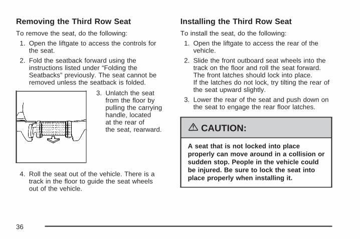
Removing the Third Row SeatTo remove the seat, do the following:
1. Open the liftgate to access the controls forthe seat.
2. Fold the seatback forward using theinstructions listed under “Folding theSeatbacks” previously. The seat cannot beremoved unless the seatback is folded.
3. Unlatch the seatfrom the floor bypulling the carryinghandle, locatedat the rear ofthe seat, rearward.
4. Roll the seat out of the vehicle. There is atrack in the floor to guide the seat wheelsout of the vehicle.
Installing the Third Row SeatTo install the seat, do the following:
1. Open the liftgate to access the rear of thevehicle.
2. Slide the front outboard seat wheels into thetrack on the floor and roll the seat forward.The front latches should lock into place.If the latches do not lock, try tilting the rear ofthe seat upward slightly.
3. Lower the rear of the seat and push down onthe seat to engage the rear floor latches.
{CAUTION:
A seat that is not locked into placeproperly can move around in a collision orsudden stop. People in the vehicle couldbe injured. Be sure to lock the seat intoplace properly when installing it.
36

4. Push and pull on the seat to make sure it islocked into place. The seatback cannot beraised to the upright position unless the seat issecured to the floor.
5. Pull up on the seatback until it locks into theupright position.
{CAUTION:
If the seatback is not locked, it couldmove forward in a sudden stop or crash.That could cause injury to the personsitting there. Always push and pull on theseatback to be sure it is locked.
6. Push and pull on the seatback to make sure itis locked.
{CAUTION:
A safety belt that is improperly routed,not properly attached, or twisted will notprovide the protection needed in a crash.The person wearing the belt could beseriously injured. After raising the rearseatback, always check to be sure that thesafety belts are properly routed andattached, and are not twisted.
7. Make sure the safety belts are returned to theoriginal position over the seatbacks.
37

Safety Belts
Safety Belts: They Are for EveryoneThis part of the manual tells you how to usesafety belts properly. It also tells you some thingsyou should not do with safety belts.
{CAUTION:
Do not let anyone ride where he or shecannot wear a safety belt properly. If youare in a crash and you are not wearing asafety belt, your injuries can be muchworse. You can hit things inside thevehicle or be ejected from it. You can beseriously injured or killed. In the samecrash, you might not be, if you arebuckled up. Always fasten your safetybelt, and check that your passengers’belts are fastened properly too.
{CAUTION:
It is extremely dangerous to ride in acargo area, inside or outside of a vehicle.In a collision, people riding in these areasare more likely to be seriously injured orkilled. Do not allow people to ride in anyarea of your vehicle that is not equippedwith seats and safety belts. Be sureeveryone in your vehicle is in a seat andusing a safety belt properly.
Your vehicle has indicators to remind you andyour passengers to buckle your safety belts.See Safety Belt Reminder Light on page 244and Passenger Safety Belt Reminder Lighton page 245.
38

In most states and in all Canadian provinces,the law says to wear safety belts. Here iswhy: They work.
You never know if you will be in a crash. If youdo have a crash, you do not know if it will be abad one.
A few crashes are mild, and some crashes can beso serious that even buckled up, a personwould not survive. But most crashes are inbetween. In many of them, people who buckle upcan survive and sometimes walk away. Withoutbelts they could have been badly hurt or killed.
After more than 40 years of safety belts invehicles, the facts are clear. In most crashesbuckling up does matter... a lot!
Why Safety Belts WorkWhen you ride in or on anything, you go as fastas it goes.
Take the simplest vehicle. Suppose it is just aseat on wheels.
39

Put someone on it. Get it up to speed. Then stop the vehicle.The rider does not stop.
40

The person keeps going until stopped bysomething. In a real vehicle, it could be thewindshield...
or the instrument panel...
41
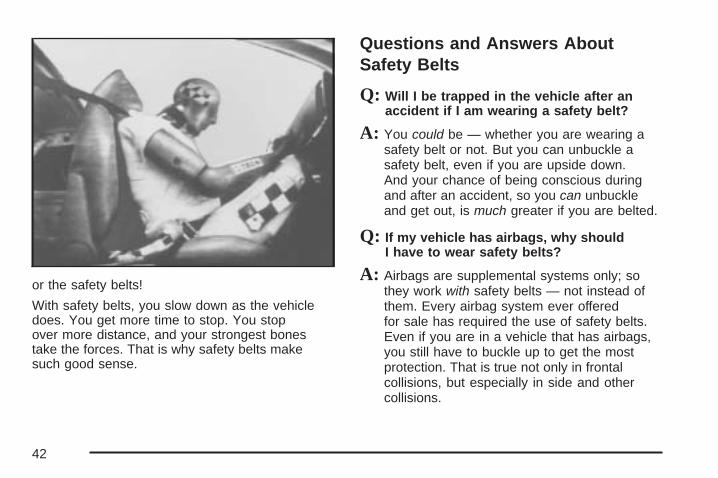
or the safety belts!
With safety belts, you slow down as the vehicledoes. You get more time to stop. You stopover more distance, and your strongest bonestake the forces. That is why safety belts makesuch good sense.
Questions and Answers AboutSafety Belts
Q: Will I be trapped in the vehicle after anaccident if I am wearing a safety belt?
A: You could be — whether you are wearing asafety belt or not. But you can unbuckle asafety belt, even if you are upside down.And your chance of being conscious duringand after an accident, so you can unbuckleand get out, is much greater if you are belted.
Q: If my vehicle has airbags, why shouldI have to wear safety belts?
A: Airbags are supplemental systems only; sothey work with safety belts — not instead ofthem. Every airbag system ever offeredfor sale has required the use of safety belts.Even if you are in a vehicle that has airbags,you still have to buckle up to get the mostprotection. That is true not only in frontalcollisions, but especially in side and othercollisions.
42
Q: If I am a good driver, and I never drive farfrom home, why should I wear safety belts?
A: You may be an excellent driver, but if you arein an accident — even one that is not yourfault — you and your passengers can be hurt.Being a good driver does not protect youfrom things beyond your control, such asbad drivers.
Most accidents occur within 25 miles (40 km)of home. And the greatest number ofserious injuries and deaths occur at speedsof less than 40 mph (65 km/h).
Safety belts are for everyone.
How to Wear Safety Belts ProperlyThis part is only for people of adult size.
Be aware that there are special things to knowabout safety belts and children. And there aredifferent rules for smaller children and babies.If a child will be riding in your vehicle, see OlderChildren on page 62 or Infants and Young Childrenon page 65. Follow those rules for everyone’sprotection.
First, you will want to know which restraintsystems your vehicle has.
We will start with the driver position.
43

Driver Position
Lap-Shoulder BeltThe driver has a lap-shoulder belt. Here is how towear it properly.1. Close and lock the door.2. Adjust the seat so you can sit up straight.
To see how, see “Seats” in the Index.
3. Pick up the latch plate and pull the belt acrossyou. Do not let it get twisted.
The lap-shoulder belt may lock if you pull thebelt across you very quickly. If this happens,let the belt go back slightly to unlock it.Then pull the belt across you more slowly.
4. Push the latch plate into the buckle untilit clicks.Pull up on the latch plate to make sure it issecure. If the belt is not long enough,see Safety Belt Extender on page 61.Make sure the release button on the buckle ispositioned so you would be able to unbucklethe safety belt quickly if you ever had to.
5. Move the shoulder belt height adjuster to theheight that is right for you. Improper shoulderbelt height adjustment could reduce theeffectiveness of the safety belt in a crash.See Shoulder Belt Height Adjustmenton page 51.
44

6. To make the lap part tight, pull up on theshoulder belt.It may be necessary to pull stitching on thesafety belt through the latch plate to fullytighten the lap belt on smaller occupants.
The lap part of the belt should be worn low andsnug on the hips, just touching the thighs. In acrash, this applies force to the strong pelvic bones.And you would be less likely to slide under the lapbelt. If you slid under it, the belt would apply force atyour abdomen. This could cause serious or evenfatal injuries. The shoulder belt should go over theshoulder and across the chest. These parts of thebody are best able to take belt restraining forces.The safety belt locks if there is a sudden stopor crash.
45

Q: What is wrong with this?
A: The shoulder belt is too loose. It will not givenearly as much protection this way.
{CAUTION:
You can be seriously hurt if your shoulderbelt is too loose. In a crash, you wouldmove forward too much, which couldincrease injury. The shoulder belt shouldfit against your body.
46

Q: What is wrong with this?
A: The lap belt is too loose. It will not give nearlyas much protection this way.
{CAUTION:
You can be seriously hurt if your lap beltis too loose. In a crash, you could slideunder the lap belt and apply force at yourabdomen. This could cause serious oreven fatal injuries. The lap belt should beworn low and snug on the hips, justtouching the thighs.
47
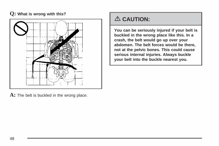
Q: What is wrong with this?
A: The belt is buckled in the wrong place.
{CAUTION:
You can be seriously injured if your belt isbuckled in the wrong place like this. In acrash, the belt would go up over yourabdomen. The belt forces would be there,not at the pelvic bones. This could causeserious internal injuries. Always buckleyour belt into the buckle nearest you.
48

Q: What is wrong with this?
A: The shoulder belt is worn under the arm.It should be worn over the shoulder atall times.
{CAUTION:
You can be seriously injured if you wearthe shoulder belt under your arm. In acrash, your body would move too farforward, which would increase the chanceof head and neck injury. Also, the beltwould apply too much force to the ribs,which are not as strong as shoulderbones. You could also severely injureinternal organs like your liver or spleen.
49

Q: What is wrong with this?
A: The belt is twisted across the body.
{CAUTION:
You can be seriously injured by a twistedbelt. In a crash, you would not have thefull width of the belt to spread impactforces. If a belt is twisted, make it straightso it can work properly, or ask yourdealer/retailer to fix it.
50

To unlatch the belt, push the button on the buckle.The belt should go back out of the way.
Before you close the door, be sure the belt is outof the way. If you slam the door on it, you candamage both the belt and your vehicle.
Shoulder Belt Height AdjustmentBefore you begin to drive, move the shoulder beltadjuster to the height that is right for you.
Adjust the height so that the shoulder portion ofthe belt is centered on your shoulder. The beltshould be away from your face and neck, but notfalling off your shoulder. Improper shoulderbelt height adjustment could reduce theeffectiveness of the safety belt in a crash.
To move it down,squeeze the buttons (A)on the sides of theheight adjusterand move the heightadjuster to the desiredposition.
You can move the adjuster up just by pushing upon the shoulder belt guide.
After you move the adjuster to where you want it,try to move it down without squeezing thebuttons to make sure it has locked into position.
51

Safety Belt Use During PregnancySafety belts work for everyone, including pregnantwomen. Like all occupants, they are more likelyto be seriously injured if they do not wearsafety belts.
A pregnant woman should wear a lap-shoulderbelt, and the lap portion should be worn as low aspossible, below the rounding, throughout thepregnancy.
The best way to protect the fetus is to protect themother. When a safety belt is worn properly,it is more likely that the fetus will not be hurt in acrash. For pregnant women, as for anyone,the key to making safety belts effective is wearingthem properly.
Right Front Passenger PositionTo learn how to wear the right front passenger’ssafety belt properly, see Driver Position onpage 44.
The right front passenger’s safety belt works thesame way as the driver’s safety belt — exceptfor one thing. If you ever pull the shoulder portionof the belt out all the way, you will engage thechild restraint locking feature which may turn offthe passenger’s frontal airbag. If this happens, justlet the belt go back all the way and start again.
52

Center Front Passenger Position
Lap BeltYour vehicle may have a center front seatingposition.
When you sit in the center front seating position,you have a lap safety belt, which has no retractor.To make the belt longer, tilt the latch plate andpull it along the belt.
To make the belt shorter, pull its free end asshown until the belt is snug.
Buckle, position and release it the same way asthe lap part of a lap-shoulder belt. If the belt is notlong enough, see Safety Belt Extender onpage 61.
Make sure the release button on the buckle ispositioned so you would be able to unbuckle thesafety belt quickly if you ever had to.
53

Rear Seat PassengersIt is very important for rear seat passengers tobuckle up! Accident statistics show that unbeltedpeople in the rear seat are hurt more often incrashes than those who are wearing safety belts.
Rear passengers who are not safety beltedcan be thrown out of the vehicle in a crash.And they can strike others in the vehicle who arewearing safety belts.
Lap-Shoulder BeltAll rear seat positions have lap-shoulder belts.Here is how to wear one properly.
1. Pick up the latch plate and pull the belt acrossyou. Do not let it get twisted.The shoulder belt may lock if you pull the beltacross you very quickly. If this happens,let the belt go back slightly to unlock it.Then pull the belt across you more slowly.
54

2. Push the latch plate into the buckle untilit clicks.Pull up on the latch plate to make sure it issecure.When the shoulder belt is pulled out all theway, it will lock. If it does, let it go back all theway and start again.If the belt is not long enough, see Safety BeltExtender on page 61.Make sure the release button on the buckle ispositioned so you would be able to unbucklethe safety belt quickly if you ever had to.
3. To make the lap part tight, pull up on theshoulder part.
55

The lap part of the belt should be worn low andsnug on the hips, just touching the thighs. In acrash, this applies force to the strong pelvic bones.
And you would be less likely to slide under the lapbelt. If you slid under it, the belt would apply force atyour abdomen. This could cause serious or evenfatal injuries. The shoulder belt should go over theshoulder and across the chest. These parts of thebody are best able to take belt restraining forces.
The safety belt locks if there is a sudden stop ora crash.
{CAUTION:
You can be seriously hurt if your shoulderbelt is too loose. In a crash, you wouldmove forward too much, which couldincrease injury. The shoulder belt shouldfit against your body.
56

To unlatch the belt, push the button on the buckle.
Rear Safety Belt Comfort GuidesRear shoulder belt comfort guides may provideadded safety belt comfort for older childrenwho have outgrown booster seats and for someadults. When installed on a shoulder belt, thecomfort guide positions the belt away fromthe neck and head.
There is one guide for each outside passengerposition in the second row seat and the third row,if your vehicle has one.
57

Here is how to install a comfort guide to thesafety belt:
1. For the second row, remove the guide from itsstorage clip on the interior body.
If your vehicle has a third row, remove theguide from its storage pocket on the sideof the seat.
Second Row
Third Row
58

2. Slide the guide under and past the belt.The elastic cord must be under the belt.Then, place the guide over the belt, and insertthe two edges of the belt into the slots ofthe guide.
3. Be sure that the belt is not twisted and it liesflat. The elastic cord must be under the beltand the guide on top.
59

{CAUTION:
A safety belt that is not properly wornmay not provide the protection needed ina crash. The person wearing the beltcould be seriously injured. The shoulderbelt should go over the shoulder andacross the chest. These parts of the bodyare best able to take belt restrainingforces.
4. Buckle, position, and release the safety beltas described in Rear Seat Passengers onpage 54. Make sure that the shoulderbelt crosses the shoulder.
To remove and store the comfort guide, squeezethe belt edges together so that you can takethem out of the guide. Slide the guide intoits storage clip on the interior body or storagepocket on the side of the seat.
60

Safety Belt PretensionersYour vehicle has safety belt pretensioners for thedriver and right front passenger. Although youcannot see them, they are part of the safety beltassembly. They help tighten the safety belts duringthe early stages of a moderate to severe frontalor near frontal crash if the threshold conditions forpretensioner activation are met. And, if yourvehicle has roof-mounted rollover airbags, safetybelt pretensioners can help tighten the safetybelts in a side crash or a rollover event.
Pretensioners work only once. If they activate in acrash, you will need to get new ones, andprobably other new parts for your safety beltsystem. See Replacing Restraint System PartsAfter a Crash on page 113.
Safety Belt ExtenderIf the vehicle’s safety belt will fasten around you,you should use it.
But if a safety belt is not long enough, yourdealer/retailer will order you an extender. Whenyou go in to order it, take the heaviest coat you willwear, so the extender will be long enough foryou. To help avoid personal injury, do notlet someone else use it, and use it only for theseat it is made to fit. The extender has beendesigned for adults. Never use it for securing childseats. To wear it, attach it to the regular safetybelt. For more information, see the instructionsheet that comes with the extender.
61

Child Restraints
Older Children
Older children who have outgrown booster seatsshould wear the vehicle’s safety belts.
If you have the choice, a child should sit in a seatthat has a lap-shoulder belt and get the additionalrestraint a shoulder belt can provide.
Q: What is the proper way to wear safety belts?
A: If possible, an older child should wear alap-shoulder belt and get the additionalrestraint a shoulder belt can provide.The shoulder belt should not cross the faceor neck. The lap belt should fit snuglybelow the hips, just touching the top of thethighs. It should never be worn over theabdomen, which could cause severe or evenfatal internal injuries in a crash.
According to accident statistics, children are saferwhen properly restrained in the rear seatingpositions than in the front seating positions.
In a crash, children who are not buckled up canstrike other people who are buckled up, or can bethrown out of the vehicle. Older children needto use safety belts properly.
62

{CAUTION:
Never do this.
Here two children are wearing the samebelt. The belt cannot properly spread theimpact forces. In a crash, the two childrencan be crushed together and seriouslyinjured. A belt must be used by only oneperson at a time.
Q: What if a child is wearing a lap-shoulderbelt, but the child is so small that theshoulder belt is very close to the child’sface or neck?
A: If the child is sitting in a rear seat outsideposition, move the child toward the centerof the vehicle. If the child is sitting in thesecond row center position, move the childtoward the safety belt buckle. In eithercase, be sure that the shoulder belt still is onthe child’s shoulder, so that in a crash thechild’s upper body would have the restraintthat belts provide. See Rear Safety BeltComfort Guides on page 57. If the child is sosmall that the shoulder belt is still veryclose to the child’s face or neck, you mightwant to place the child in a rear seat that hasa lap belt, if your vehicle has one.
63

{CAUTION:
Never do this.
Here a child is sitting in a seat that has alap-shoulder belt, but the shoulder part isbehind the child. If the child wears thebelt in this way, in a crash the child mightslide under the belt. The belt’s forcewould then be applied right on the child’sabdomen. That could cause serious orfatal injuries.
Wherever the child sits, the lap portion of the beltshould be worn low and snug on the hips, justtouching the child’s thighs. This applies belt forceto the child’s pelvic bones in a crash.
64

Infants and Young ChildrenEveryone in a vehicle needs protection! Thisincludes infants and all other children. Neither thedistance traveled nor the age and size of thetraveler changes the need, for everyone, to usesafety restraints. In fact, the law in every statein the United States and in every Canadianprovince says children up to some age must berestrained while in a vehicle.
{CAUTION:
Children can be seriously injured orstrangled if a shoulder belt is wrappedaround their neck and the safety beltcontinues to tighten. Never leave childrenunattended in a vehicle and never allowchildren to play with the safety belts.
Every time infants and young children ride invehicles, they should have the protection providedby appropriate restraints. Young children shouldnot use the vehicle’s adult safety belts alone,unless there is no other choice. Instead, they needto use a child restraint.
65
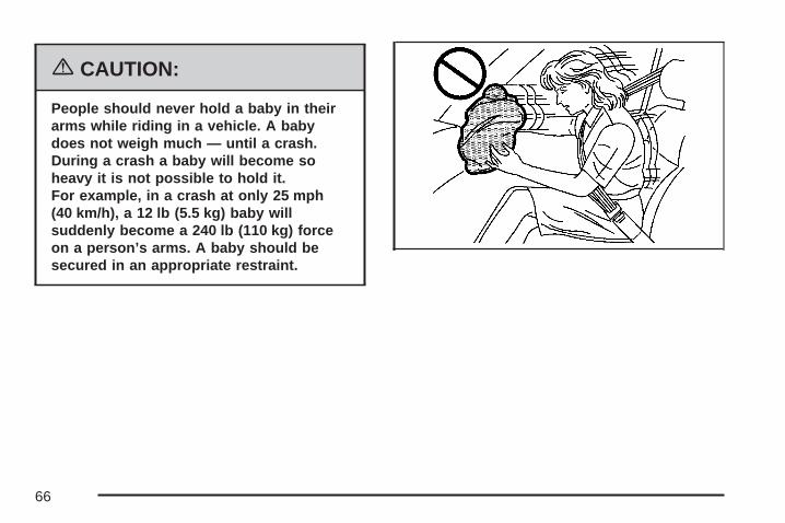
{CAUTION:
People should never hold a baby in theirarms while riding in a vehicle. A babydoes not weigh much — until a crash.During a crash a baby will become soheavy it is not possible to hold it.For example, in a crash at only 25 mph(40 km/h), a 12 lb (5.5 kg) baby willsuddenly become a 240 lb (110 kg) forceon a person’s arms. A baby should besecured in an appropriate restraint.
66

{CAUTION:
Children who are up against, or very closeto, any airbag when it inflates can beseriously injured or killed. Airbags pluslap-shoulder belts offer protection foradults and older children, but not foryoung children and infants. Neither thevehicle’s safety belt system nor its airbagsystem is designed for them. Youngchildren and infants need the protectionthat a child restraint system can provide.
67
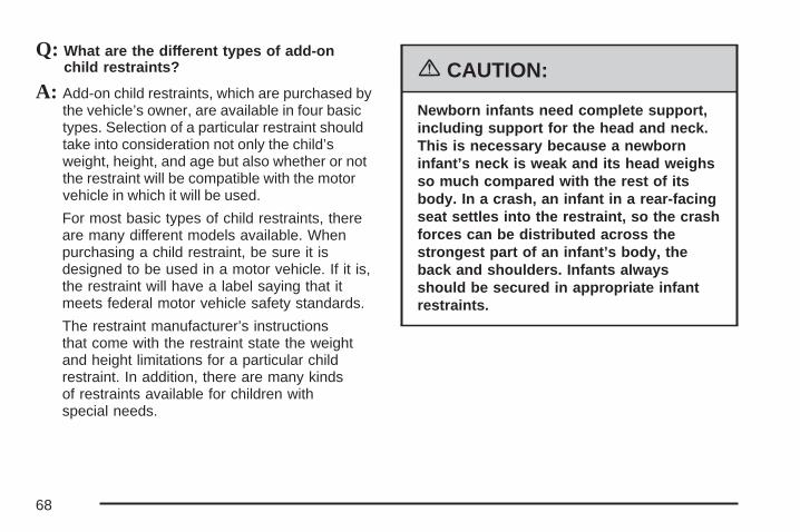
Q: What are the different types of add-onchild restraints?
A: Add-on child restraints, which are purchased bythe vehicle’s owner, are available in four basictypes. Selection of a particular restraint shouldtake into consideration not only the child’sweight, height, and age but also whether or notthe restraint will be compatible with the motorvehicle in which it will be used.
For most basic types of child restraints, thereare many different models available. Whenpurchasing a child restraint, be sure it isdesigned to be used in a motor vehicle. If it is,the restraint will have a label saying that itmeets federal motor vehicle safety standards.
The restraint manufacturer’s instructionsthat come with the restraint state the weightand height limitations for a particular childrestraint. In addition, there are many kindsof restraints available for children withspecial needs.
{CAUTION:
Newborn infants need complete support,including support for the head and neck.This is necessary because a newborninfant’s neck is weak and its head weighsso much compared with the rest of itsbody. In a crash, an infant in a rear-facingseat settles into the restraint, so the crashforces can be distributed across thestrongest part of an infant’s body, theback and shoulders. Infants alwaysshould be secured in appropriate infantrestraints.
68

{CAUTION:
The body structure of a young child isquite unlike that of an adult or older child,for whom the safety belts are designed.A young child’s hip bones are still sosmall that the vehicle’s regular safety beltmay not remain low on the hip bones, asit should. Instead, it may settle up aroundthe child’s abdomen. In a crash, the beltwould apply force on a body area that isunprotected by any bony structure. Thisalone could cause serious or fatal injuries.Young children always should be securedin appropriate child restraints.
Child Restraint Systems
An infant car bed (A), a special bed made for usein a motor vehicle, is an infant restraint systemdesigned to restrain or position a child on acontinuous flat surface. Make sure that the infant’shead rests toward the center of the vehicle.
69
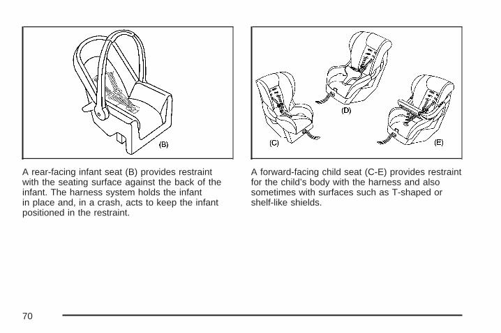
A rear-facing infant seat (B) provides restraintwith the seating surface against the back of theinfant. The harness system holds the infantin place and, in a crash, acts to keep the infantpositioned in the restraint.
A forward-facing child seat (C-E) provides restraintfor the child’s body with the harness and alsosometimes with surfaces such as T-shaped orshelf-like shields.
70

A booster seat (F-G) is a child restraint designedto improve the fit of the vehicle’s safety beltsystem. Some booster seats have a shoulder beltpositioner, and some high-back booster seatshave a five-point harness. A booster seat can alsohelp a child to see out the window.
Q: How Should I Use a Child Restraint?
A: A child restraint system is any device designedfor use in a motor vehicle to restrain, seat, orposition children. A built-in child restraintsystem is a permanent part of the motorvehicle. An add-on child restraint system is aportable one, which is purchased by thevehicle’s owner. To help reduce injuries, anadd-on child restraint must be secured inthe vehicle. With built-in or add-on childrestraints, the child has to be secured withinthe child restraint.
When choosing an add-on child restraint, besure the child restraint is designed to beused in a vehicle. If it is, it will have a labelsaying that it meets federal motor vehiclesafety standards. Then follow the instructionsfor the restraint. You may find theseinstructions on the restraint itself or in abooklet, or both.
71

Securing an Add-on Child Restraint inthe Vehicle
{CAUTION:
A child can be seriously injured or killedin a crash if the child restraint is notproperly secured in the vehicle. Make surethe child restraint is properly installed inthe vehicle using the vehicle’s safety beltor LATCH system, following theinstructions that came with that restraint,and also the instructions in this manual.
To help reduce the chance of injury, the childrestraint must be secured in the vehicle.Child restraint systems must be secured in vehicleseats by lap belts or the lap belt portion of alap-shoulder belt, or by the LATCH system.
See Lower Anchors and Tethers for Children(LATCH) on page 76 for more information.A child can be endangered in a crash if the childrestraint is not properly secured in the vehicle.
When securing an add-on child restraint, refer tothe instructions that come with the restraintwhich may be on the restraint itself or in a booklet,or both, and to this manual. The child restraintinstructions are important, so if they are notavailable, obtain a replacement copy from themanufacturer.
Keep in mind that an unsecured child restraintcan move around in a collision or suddenstop and injure people in the vehicle. Be sureto properly secure any child restraint in yourvehicle — even when no child is in it.
72

Securing the Child Within theChild RestraintThere are several systems for securing the childwithin the child restraint. One system, thethree-point harness, has straps that come downover each of the infant’s shoulders and buckletogether at the crotch. The five-point harnesssystem has two shoulder straps, two hip straps,and a crotch strap. A shield may take the place ofhip straps. A T-shaped shield has shoulderstraps that are attached to a flat pad which restslow against the child’s body. A shelf- orarmrest-type shield has straps that are attachedto a wide, shelf-like shield that swings up orto the side.
{CAUTION:
A child can be seriously injured or killedin a crash if the child is not properlysecured in the child restraint. Make surethe child is properly secured, followingthe instructions that came with thatrestraint.
Because there are different systems, it is importantto refer to the instructions that come with therestraint. A child can be endangered in a crashif the child is not properly secured in thechild restraint.
73

Where to Put the RestraintAccident statistics show that children are safer ifthey are restrained in the rear rather than the frontseat. We recommend that child restraints besecured in a rear seat, including an infant ridingin a rear-facing infant seat, a child riding in aforward-facing child seat and an older child ridingin a booster seat.
Your vehicle has a rear seat that will accommodatea rear-facing child restraint. A label on your sunvisor says, “Never put a rear-facing child seatin the front.” This is because the risk to therear-facing child is so great, if the airbag deploys.
{CAUTION:
A child in a rear-facing child restraint canbe seriously injured or killed if the rightfront passenger’s airbag inflates.This is because the back of therear-facing child restraint would be veryclose to the inflating airbag.
Even though the passenger sensingsystem is designed to turn off thepassenger’s frontal airbag if the systemdetects a rear-facing child restraint,no system is fail-safe, and no one can
CAUTION: (Continued)
74

CAUTION: (Continued)
guarantee that an airbag will not deployunder some unusual circumstance, eventhough it is turned off. We recommendthat rear-facing child restraints be securedin the rear seat, even if the airbag is off.
If you need to secure a forward-facingchild restraint in the right front seat,always move the front passenger seat asfar back as it will go. It is better to securethe child restraint in a rear seat.
{CAUTION:
A child in a child restraint in the centerfront seat can be badly injured or killed bythe right front passenger’s airbag if itinflates. Never secure a child restraint inthe center front seat. It is always better tosecure a child restraint in the rear seat.
Wherever you install a child restraint, be sure tosecure the child restraint properly.
Keep in mind that an unsecured child restraintcan move around in a collision or sudden stopand injure people in the vehicle. Be sure toproperly secure any child restraint in yourvehicle — even when no child is in it.
75

Lower Anchors and Tethers forChildren (LATCH)The LATCH system holds a child restraint duringdriving or in a crash. This system is designedto make installation of a child restraint easier.The LATCH system uses anchors in the vehicleand attachments on the child restraint thatare made for use with the LATCH system.
Make sure that a LATCH-compatible child restraintis properly installed using the anchors, or usethe vehicle’s safety belts to secure the restraint,following the instructions that came with thatrestraint, and also the instructions in this manual.
When installing a child restraint with a top tether,you must also use either the lower anchors orthe safety belts to properly secure the childrestraint. A child restraint must never be attachedusing only the top tether and anchor.
In order to use the LATCH system in your vehicle,you need a child restraint that has LATCHattachments. The child restraint manufacturer willprovide you with instructions on how to usethe child restraint and its attachments. Thefollowing explains how to attach a child restraintwith these attachments in your vehicle.
Not all vehicle seating positions or child restraintshave lower anchors and attachments or toptether anchors and attachments.
76

Lower Anchors
Lower anchors (A) are metal bars built into thevehicle. There are two lower anchors for eachLATCH seating position that will accommodate achild restraint with lower attachments (B).
Top Tether Anchor
A top tether (A, C) anchors the top of the childrestraint to the vehicle. A top tether anchor is builtinto the vehicle. The top tether attachment (B)on the child restraint connects to the top tetheranchor in the vehicle in order to reduce the forwardmovement and rotation of the child restraintduring driving or in a crash.
Your child restraint may have a single tether (A)or a dual tether (C). Either will have a singleattachment (B) to secure the top tether to theanchor.
77

Some child restraints with top tethers are designedfor use with or without the top tether beingattached. Others require the top tether always tobe attached. In Canada, the law requires thatforward-facing child restraints have a top tether,and that the tether be attached. In the UnitedStates, some child restraints also have atop tether. Be sure to read and follow theinstructions for your child restraint.
If the child restraint does not have a top tether,one can be obtained, in kit form, for manychild restraints. Ask the child restraintmanufacturer whether or not a kit is available.
Lower Anchor and Top Tether AnchorLocations
j (Lower Anchor):Seating positions withtwo lower anchors.
i (Top Tether Anchor):Seating positions withtop tether anchors.
j (Lower Anchor):Seating positions withtwo lower anchors.
i (Top Tether Anchor):Seating positions withtop tether anchors.
Second Row — 60/40
Second Row — Bucket
78

i (Top Tether Anchor):Seating positions withtop tether anchors.
i (Top Tether Anchor):Seating positions withtop tether anchors.
For models with a three passenger third row seat,see the information following for installing achild restraint with a top tether in the third row,if your vehicle has one. Never install two toptethers using the same top tether anchor.
For models with 60/40 second row seating, therear right side passenger and center seatingpositions have exposed metal anchors located inthe crease between the seatback and the seatcushion.
For models with second row bucket seats, bothrear seating positions have exposed metal anchorslocated in the crease between the seatback andthe seat cushion.
Third Row — TwoPassenger
Third Row — ThreePassenger
79

For models with bucket second row seating, thetop tether anchors are located at the bottom rear ofthe seat cushion for each seating position in thesecond row. Be sure to use an anchor locatedon the same side of the vehicle as the seatingposition where the child restraint will be placed.
For models with 60/40 second row seating, the toptether anchors are located at the bottom rear ofthe seat cushion for each seating position inthe second row. Be sure to use an anchor locatedon the same side of the vehicle as the seatingposition where the child restraint will be placed.
Second Row Seat — Bucket Second Row Seat — 60/40
80

For vehicles with a two passenger third row seat,there is one top tether anchor located at thebottom rear of the seat cushion that can be usedfor the rear driver side seating position in thethird row. Never install two top tethers using thesame top tether anchor.
For vehicles with a three passenger third row seat,there is one top tether anchor located at thebottom rear of the seat cushion that can be usedfor either the third row center or driver sideseating position. Never install two top tethers usingthe same top tether anchor.
Do not secure a child restraint in the right frontpassenger position or the third row passenger sideseating position if your vehicle has a third rowseat, if a national or local law requires that the toptether be attached, or if the instructions thatcome with the child restraint say that the top tethermust be attached. There is no place to attachthe top tether in these positions.
Accident statistics show that children are safer ifthey are restrained in the rear rather than the frontseat. See Where to Put the Restraint on page 74for additional information.
Third Row Seat — Two or Three Passenger
81

Securing a Child Restraint Designed forthe LATCH System
{CAUTION:
If a LATCH-type child restraint is notattached to anchors, the restraint will notbe able to protect the child correctly. In acrash, the child could be seriously injuredor killed. Make sure that a LATCH-typechild restraint is properly installed usingthe anchors, or use the vehicle’s safetybelts to secure the restraint, following theinstructions that came with that restraint,and also the instructions in this manual.
{CAUTION:
Each top tether anchor and lower anchorin the vehicle is designed to hold only onechild restraint. Attaching more than onechild restraint to a single anchor couldcause the anchor or attachment to comeloose or even break during a crash.A child or others could be injured if thishappens. To help prevent injury to peopleand damage to your vehicle, attach onlyone child restraint per anchor.
82

{CAUTION:
Children can be seriously injured orstrangled if a shoulder belt is wrappedaround their neck and the safety beltcontinues to tighten. Secure any unusedsafety belts behind the child restraint sochildren cannot reach them. Pull theshoulder belt all the way out of theretractor to set the lock, if your vehiclehas one, after the child restraint hasbeen installed. Be sure to follow theinstructions of the child restraintmanufacturer.
Notice: Contact between the child restraint orthe LATCH attachment parts and the vehicle’ssafety belt assembly may cause damage tothese parts. Make sure when securing unusedsafety belts behind the child restraint thatthere is no contact between the child restraintor the LATCH attachment parts and thevehicle’s safety belt assembly.
Folding an empty rear seat with the safetybelts secured may cause damage to the safetybelt or the seat. When removing the childrestraint, always remember to return the safetybelts to their normal, stowed position beforefolding the rear seat.
1. Attach and tighten the lower attachments tothe lower anchors. If the child restraint doesnot have lower attachments or the desiredseating position does not have lower anchors,secure the child restraint with the top tetherand the safety belts. Refer to your childrestraint manufacturer instructions and theinstructions in this manual.
1.1. Find the lower anchors for the desiredseating position.
1.2. Put the child restraint on the seat.1.3. Attach and tighten the lower
attachments on the child restraint to thelower anchors.
83

2. If the child restraint manufacturer recommendsthat the top tether be attached, attach andtighten the top tether to the top tether anchor,if the vehicle has one. Refer to the childrestraint instructions and the following steps:
2.1. Find the top tether anchor.2.2. Route, attach and tighten the top tether
according to your child restraintinstructions and the followinginstructions:
If the position you areusing does not have ahead rest/restraintand you are usinga single tether,route the tether overthe seatback.
If the position you areusing does not have ahead rest/restraintand you are using adual tether, routethe tether over theseatback.
If the position you areusing has an adjustablehead rest/restraintand you are using adual tether, routethe tether around thehead rest/restraint.
84

If the position you areusing has an adjustablehead rest/restraintand you are using asingle tether, raise thehead rest/restraintand route the tetherunder the headrest/restraint and inbetween the headrest/restraint posts.
3. Push and pull the child restraint in differentdirections to be sure it is secure.
Securing a Child Restraint in aRear Seat PositionIf your child restraint has the LATCH system,see Lower Anchors and Tethers for Children(LATCH) on page 76.
If your vehicle has a third row, there is no toptether anchor in the passenger-side seatingposition. Do not secure a child restraint in thisposition if a national or local law requires that thetop tether be anchored or if the instructionsthat come with the child restraint say that the toptether must be anchored.
If your child restraint does not have the LATCHsystem, you will be using the lap-shoulder beltto secure the child restraint in this position.
85

Be sure to follow the instructions that came withthe child restraint. Secure the child in the childrestraint when and as the instructions say.
1. Put the child restraint on the seat.2. Pick up the latch plate, and run the lap and
shoulder portions of the vehicle’s safety beltthrough or around the restraint. The childrestraint instructions will show you how.
3. Buckle the belt. Make sure the release buttonis positioned so you would be able to unbucklethe safety belt quickly if you ever had to.
4. Pull the rest of the shoulder belt all the wayout of the retractor to set the lock.
86

5. To tighten the belt, push down on the childrestraint, pull the shoulder portion of the beltto tighten the lap portion of the belt andfeed the shoulder belt back into the retractor.If you are using a forward-facing childrestraint, you may find it helpful to use yourknee to push down on the child restraintas you tighten the belt.
6. If your child restraint manufacturerrecommends using a top tether, and theposition that you are using has a top tetheranchor, attach and tighten the top tether to thetop tether anchor. Refer to the instructionsthat came with the child restraint and to LowerAnchors and Tethers for Children (LATCH)on page 76.
7. Push and pull the child restraint in differentdirections to be sure it is secure.
To remove the child restraint, if the top tether isattached to the top tether anchor, disconnectit. Unbuckle the vehicle’s safety belt and let it goback all the way. The safety belt will movefreely again and be ready to work for an adult orlarger child passenger.
87

Securing a Child Restraint in theCenter Front Seat Position
{CAUTION:
A child in a child restraint in the centerfront seat can be badly injured or killed bythe right front passenger’s airbag if itinflates. Never secure a child restraint inthe center front seat. It is always better tosecure a child restraint in the rear seat.
Do not use child restraints in this position.The restraints will not work properly.
Securing a Child Restraint in theRight Front Seat PositionYour vehicle has a right front passenger airbag.A rear seat is a safer place to secure aforward-facing child restraint. See Where toPut the Restraint on page 74.
In addition, your vehicle has a passenger sensingsystem. The passenger sensing system isdesigned to turn off the right front passenger’sfrontal airbag when an infant in a rear-facinginfant seat or a small child in a forward-facingchild restraint or booster seat is detected.See Passenger Sensing System on page 104 andPassenger Airbag Status Indicator on page 246for more information on this including importantsafety information.
88

A label on your sun visor says, “Never put arear-facing child seat in the front.” This is becausethe risk to the rear-facing child is so great, if theairbag deploys.
{CAUTION:
A child in a rear-facing child restraintcan be seriously injured or killed if the rightfront passenger’s airbag inflates. This isbecause the back of the rear-facing childrestraint would be very close to theinflating airbag.
Even though the passenger sensingsystem is designed to turn off the rightfront passenger’s frontal airbag if thesystem detects a rear-facing child restraint,no system is fail-safe, and no one can
CAUTION: (Continued)
CAUTION: (Continued)
guarantee that an airbag will not deployunder some unusual circumstance, eventhough it is turned off. We recommend thatrear-facing child restraints be secured inthe rear seat, even if the airbag is off.
If you need to secure a forward-facing childrestraint in the right front seat, alwaysmove the front passenger seat as far backas it will go. It is better to secure the childrestraint in a rear seat.
If you need to secure a forward-facing childrestraint in the right front seat position, move theseat as far back as it will go before securingthe forward-facing child restraint. See ManualSeats on page 9 or Power Seats on page 10.
89

If your child restraint has the LATCH system,see Lower Anchors and Tethers for Children(LATCH) on page 76.
There is no top tether anchor at the right frontseating position. Do not secure a child seat in thisposition if a national or local law requires thatthe top tether be anchored or if the instructionsthat come with the child restraint say that the toptether must be anchored. See Lower Anchorsand Tethers for Children (LATCH) on page 76if the child restraint has a top tether.
You will be using the lap-shoulder belt to securethe child restraint in this position. Be sure to followthe instructions that came with the child restraint.
Secure the child in the child restraint when and asthe instructions say.
1. Your vehicle has a right front passenger’sfrontal airbag. See Passenger SensingSystem on page 104. We recommend thatrear-facing child restraints be secured in a rearseat, even if the airbag is off. If your childrestraint is forward-facing, move the seat asfar back as it will go before securing thechild restraint in this seat. See Manual Seatson page 9 or Power Seats on page 10.When the passenger sensing system hasturned off the right front passenger’s frontalairbag, the off indicator in the passengerairbag status indicator should light and stay litwhen you turn the ignition to RUN orSTART. See Passenger Airbag StatusIndicator on page 246.
2. Put the child restraint on the seat.
90

3. Pick up the latch plate, and run the lap andshoulder portions of the vehicle’s safety beltthrough or around the restraint. The childrestraint instructions will show you how.
4. Buckle the belt. Make sure the release buttonis positioned so you would be able to unbucklethe safety belt quickly if you ever had to.
5. Pull the rest of the shoulder belt all the wayout of the retractor to set the lock.
91

6. To tighten the belt, push down on the childrestraint, pull the shoulder portion of the beltto tighten the lap portion of the belt andfeed the shoulder belt back into the retractor.If you are using a forward-facing childrestraint, you may find it helpful to use yourknee to push down on the child restraintas you tighten the belt. You should not be ableto pull more of the belt from the retractoronce the lock has been set.
7. Push and pull the child restraint in differentdirections to be sure it is secure.
8. If the airbag is off, the off indicator will be litand stay lit when the key is turned to RUNor START.
If a child restraint has been installed and the onindicator is lit, turn the vehicle off. Removethe child restraint from the vehicle and reinstall thechild restraint.
If, after reinstalling the child restraint and restartingthe vehicle, the on indicator is still lit, check tomake sure that the vehicle’s seatback is notpressing the child restraint into the seat cushion.If this happens, slightly recline the vehicle’sseatback and adjust the seat cushion if possible.
92

Also make sure the child restraint is not trappedunder the vehicle head restraint. If this happens,adjust the head restraint.
If the on indicator is still lit, secure the child in thechild restraint in a rear seat position in the vehicleand check with your dealer.
To remove the child restraint, just unbuckle thevehicle’s safety belt and let it go back all the way.The safety belt will move freely again and be readyto work for an adult or larger child passenger.
Airbag SystemYour vehicle has a frontal airbag for the driver anda frontal airbag for the right front passenger.Your vehicle may also have roof-mounted rolloverairbags designed for either side impact orrollover deployment. Roof-mounted rolloverairbags are available for the driver and thepassenger seated directly behind the driver andfor the right front passenger and the passengerseated directly behind that passenger.
If your vehicle has roof-mounted rollover airbags,the word AIRBAG will appear on the airbagcovering on the ceiling above the sidewall trimnear the driver’s and right front passenger’swindow and the second row outside seatingpositions.
Also, if your vehicle has a third row passengerseat, you may have third row roof-mountedrollover airbags.
93
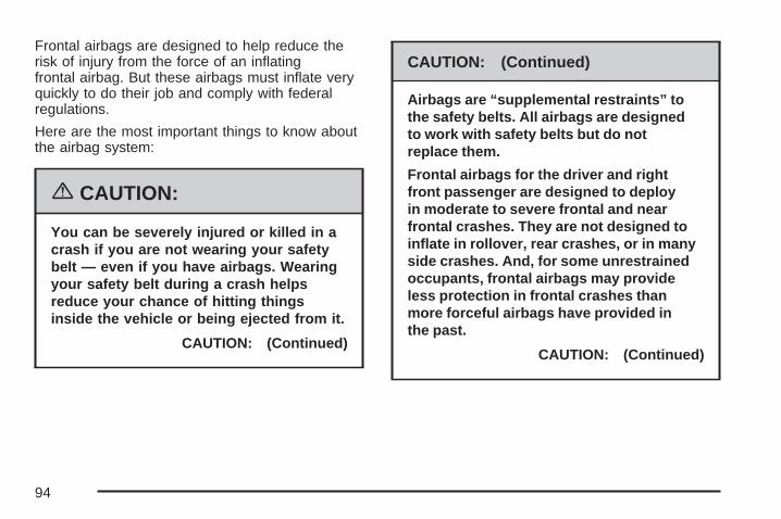
Frontal airbags are designed to help reduce therisk of injury from the force of an inflatingfrontal airbag. But these airbags must inflate veryquickly to do their job and comply with federalregulations.
Here are the most important things to know aboutthe airbag system:
{CAUTION:
You can be severely injured or killed in acrash if you are not wearing your safetybelt — even if you have airbags. Wearingyour safety belt during a crash helpsreduce your chance of hitting thingsinside the vehicle or being ejected from it.
CAUTION: (Continued)
CAUTION: (Continued)
Airbags are “supplemental restraints” tothe safety belts. All airbags are designedto work with safety belts but do notreplace them.
Frontal airbags for the driver and rightfront passenger are designed to deployin moderate to severe frontal and nearfrontal crashes. They are not designed toinflate in rollover, rear crashes, or in manyside crashes. And, for some unrestrainedoccupants, frontal airbags may provideless protection in frontal crashes thanmore forceful airbags have provided inthe past.
CAUTION: (Continued)
94

CAUTION: (Continued)
Roof-mounted rollover airbags aredesigned to inflate in moderate to severecrashes where something hits the side ofyour vehicle, during a vehicle rollover,or in a severe frontal impact. They are notdesigned to inflate in rear crashes. If yourvehicle has roof-mounted airbags, they aredesigned to provide both side impactprotection and rollover protection.Everyone in your vehicle should wear asafety belt properly — whether or not thereis an airbag for that person.
{CAUTION:
Both frontal and roof-mounted rolloverairbags inflate with great force, faster thanthe blink of an eye. If you are too close toan inflating airbag, as you would be if youwere leaning forward, it could seriouslyinjure you. Safety belts help keep you inposition for airbag inflation before andduring a crash. Always wear your safetybelt even with frontal airbags. The drivershould sit as far back as possible whilestill maintaining control of the vehicle.Occupants should not lean on or sleepagainst the door in the first or second rowseats, or the rear windows in the third rowseat, if your vehicle has roof-mountedrollover airbags.
95

{CAUTION:
Anyone who is up against, or very close to,any airbag when it inflates can be seriouslyinjured or killed. Airbags plus lap-shoulderbelts offer the best protection for adults,but not for young children and infants.Neither the vehicle’s safety belt system norits airbag system is designed for them.Young children and infants need theprotection that a child restraint system canprovide. Always secure children properlyin your vehicle. To read how, see OlderChildren on page 62 or Infants and YoungChildren on page 65.
Occupants should not lean on or sleepagainst the door in the first or second rowseats, or the rear windows in the third rowseat, if your vehicle has roof-mountedrollover airbags.
There is an airbagreadiness light on theinstrument panel cluster,which shows theairbag symbol.
The system checks the airbag electrical system formalfunctions. The light tells you if there is anelectrical problem. See Airbag Readiness Light onpage 245 for more information.
96

Where Are the Airbags?
The driver’s airbag is in the middle of the steeringwheel.
The right front passenger’s airbag is in theinstrument panel on the passenger’s side.
97
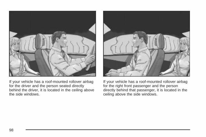
If your vehicle has a roof-mounted rollover airbagfor the driver and the person seated directlybehind the driver, it is located in the ceiling abovethe side windows.
If your vehicle has a roof-mounted rollover airbagfor the right front passenger and the persondirectly behind that passenger, it is located in theceiling above the side windows.
98
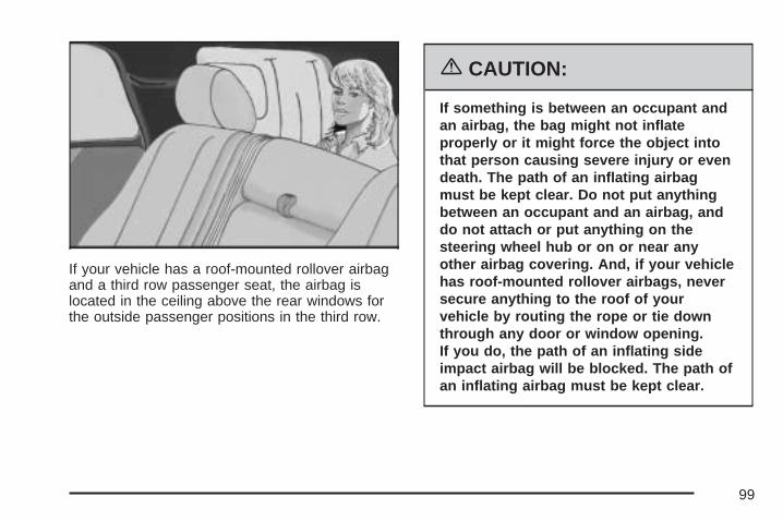
If your vehicle has a roof-mounted rollover airbagand a third row passenger seat, the airbag islocated in the ceiling above the rear windows forthe outside passenger positions in the third row.
{CAUTION:
If something is between an occupant andan airbag, the bag might not inflateproperly or it might force the object intothat person causing severe injury or evendeath. The path of an inflating airbagmust be kept clear. Do not put anythingbetween an occupant and an airbag, anddo not attach or put anything on thesteering wheel hub or on or near anyother airbag covering. And, if your vehiclehas roof-mounted rollover airbags, neversecure anything to the roof of yourvehicle by routing the rope or tie downthrough any door or window opening.If you do, the path of an inflating sideimpact airbag will be blocked. The path ofan inflating airbag must be kept clear.
99

When Should an Airbag Inflate?The driver’s and right front passenger’s frontalairbags are designed to inflate in moderateto severe frontal or near-frontal crashes.But they are designed to inflate only if the impactexceeds a predetermined deployment threshold.Deployment thresholds take into account a varietyof desired deployment and non-deploymentevents and are used to predict how severe acrash is likely to be in time for the airbags to inflateand help restrain the occupants. Whether yourfrontal airbags will or should deploy is not basedon how fast your vehicle is traveling. It dependslargely on what you hit, the direction of the impact,and how quickly your vehicle slows down.
In addition, your vehicle has “dual stage” frontalairbags, which adjust the restraint accordingto crash severity. Your vehicle has electronicfrontal sensors, which help the sensing systemdistinguish between a moderate frontalimpact and a more severe frontal impact.For moderate frontal impacts, these airbags inflateat a level less than full deployment. For moresevere frontal impacts, full deployment occurs.
If the front of your vehicle goes straight into a wallthat does not move or deform, the thresholdlevel for the reduced deployment is about9 to 16 mph (14 to 26 km/h), and the thresholdlevel for a full deployment is about 18 to 25 mph(29 to 40 km/h). The threshold level can vary,however, with specific vehicle design, so that it canbe somewhat above or below this range.
Frontal airbags may inflate at different crashspeeds. For example:
• If the vehicle hits a stationary object, theairbags could inflate at a different crash speedthan if the vehicle hits a moving object.
• If the vehicle hits an object that deforms,the airbags could inflate at a different crashspeed than if the vehicle hits an objectthat does not deform.
• If the vehicle hits a narrow object (like a pole),the airbags could inflate at a different crashspeed than if the vehicle hits a wide object(like a wall).
• If the vehicle goes into an object at an angle,the airbags could inflate at a different crashspeed than if the vehicle goes straight intothe object.
100

Frontal airbags (driver and right front passenger)are not intended to inflate during vehiclerollovers, rear impacts, or in many side impacts.
Your vehicle has a seat position sensor whichenables the sensing system to monitor thefore and aft position of the driver’s seat.Seat position sensors provide information that isused to determine if the airbags should deploy at areduced level or at full deployment.
Your vehicle may or may not have roof-mountedrollover airbags and a rollover sensor. SeeAirbag System on page 93. These “rollovercapable” airbags are intended to inflate inmoderate to severe side crashes, during a rollover,or in a severe frontal impact. A roof-mountedrollover airbag will inflate if the crash severity isabove the system’s designed “threshold level.”The threshold level can vary with specific vehicledesign. Roof-mounted airbags are not intendedto inflate in rear impacts. Both roof-mountedrollover airbags will deploy when either side of thevehicle is struck, during a rollover, or in asevere frontal impact.
In any particular crash, no one can say whetheran airbag should have inflated simply becauseof the damage to a vehicle or because of what therepair costs were. For frontal airbags, inflation isdetermined by what the vehicle hits, the angleof the impact, and how quickly the vehicle slowsdown. For roof-mounted rollover airbags,inflation is determined by the location and severityof the impact or a rollover event.
The airbag system is designed to work properlyunder a wide range of conditions, including off-roadusage. Observe safe driving speeds, especiallyon rough terrain. As always, wear your safety belt.See Off-Road Driving on page 377 for tips onoff-road driving.
101

What Makes an Airbag Inflate?In an impact of sufficient severity, the airbagsensing system detects that the vehicle isin a crash. In the case of a roof-mounted rolloverairbag, the sensing system detects that thevehicle is about to roll over or has been in a severefrontal or side impact. The sensing systemtriggers a release of gas from the inflator, whichinflates the airbag. The inflator, airbag, and relatedhardware are all part of the airbag modulesinside the steering wheel and in the instrumentpanel in front of the right front passenger.For vehicles with roof-mounted rollover airbags,the airbag modules are located in the ceiling of thevehicle, near the side windows.
If your vehicle has a third row seat withroof-mounted rollover airbags, the airbag modulesare located inside the rear-most pillar trim andabove in the ceiling above the fixed rear glass.
How Does an Airbag Restrain?In moderate to severe frontal or near frontalcollisions, even belted occupants can contact thesteering wheel or the instrument panel. Inmoderate to severe side collisions, even beltedoccupants can contact the inside of the vehicle.Airbags supplement the protection providedby safety belts. Airbags distribute the force of theimpact more evenly over the occupant’s upperbody, stopping the occupant more gradually. Butthe frontal airbags would not help you in manytypes of collisions, including rollovers, rearimpacts, and many side impacts, primarily becausean occupant’s motion is not toward the airbag.Roof-mounted rollover airbags would not help youin many types of collisions, including manyfrontal or near frontal collisions, and rear impacts.
Airbags should never be regarded as anythingmore than a supplement to safety belts, and thenonly in moderate to severe frontal or near-frontalcollisions for the driver’s and right frontpassenger’s frontal airbags, and only in moderateto severe side collisions or rollovers for vehicleswith roof-mounted rollover airbags.
102

What Will You See After anAirbag Inflates?After a frontal airbag inflates, it quickly deflates, soquickly that some people may not even realizean airbag inflated. Roof-mounted rollover airbagsmay still be at least partially inflated minutesafter the vehicle comes to rest. Some componentsof the airbag module — the steering wheel hubfor the driver’s airbag, the instrument panel for theright front passenger’s airbag, and the areaalong the ceiling of the vehicle near the sidewindows for vehicles with roof–mounted sideimpact airbags — may be hot for a short time.The parts of the airbag that come into contact withyou may be warm, but not too hot to touch.There may be some smoke and dust coming fromthe vents in the deflated airbags. Airbag inflationdoes not prevent the driver from seeing out of thewindshield or being able to steer the vehicle,nor does it prevent people from leaving the vehicle.
{CAUTION:
When an airbag inflates, there may bedust in the air. This dust could causebreathing problems for people with ahistory of asthma or other breathingtrouble. To avoid this, everyone in thevehicle should get out as soon as it issafe to do so. If you have breathingproblems but cannot get out of the vehicleafter an airbag inflates, then get fresh airby opening a window or a door. If youexperience breathing problems followingan airbag deployment, you should seekmedical attention.
Your vehicle has a feature that may automaticallyunlock the doors, turn the interior lamps on, andflash the hazard warning flashers when the airbagsinflate. You can lock the doors again, turn theinterior lamps off, and turn off the hazard warningflashers by using the controls for those features.
103

In many crashes severe enough to inflate theairbag, windshields are broken by vehicledeformation. Additional windshield breakage mayalso occur from the right front passenger airbag.
• Airbags are designed to inflate only once.After an airbag inflates, you will need somenew parts for your airbag system. If you do notget them, the airbag system will not be thereto help protect you in another crash. A newsystem will include airbag modules andpossibly other parts. The service manual foryour vehicle covers the need to replaceother parts.
• Your vehicle has a crash sensing anddiagnostic module which records informationafter a crash. See Vehicle Data Collection andEvent Data Recorders on page 607.
• Let only qualified technicians work on theairbag system. Improper service can meanthat an airbag system will not work properly.See your dealer for service.
Passenger Sensing SystemYour vehicle has a passenger sensing system.The passenger airbag status indicator on theoverhead console will be visible when you turnyour ignition key to RUN or START.
The words ON and OFF or the symbol for on andoff, will be visible during the system check.When the system check is complete, either theword ON or the word OFF, or the symbol for on orthe symbol for off will be visible. See PassengerAirbag Status Indicator on page 246.
The passenger sensing system will turn off theright front passenger’s frontal airbag under certainconditions. The driver’s airbags are not part ofthe passenger sensing system.
United States Canada
104

The passenger sensing system works withsensors that are part of the right front passenger’sseat and safety belt. The sensors are designedto detect the presence of a properly-seatedoccupant and determine if the passenger’s airbagshould be enabled (may inflate) or not.
Accident statistics show that children are safer ifthey are restrained in the rear rather than the frontseat. We recommend that child restraints besecured in a rear seat, including an infant ridingin a rear-facing infant seat, a child riding in aforward-facing child seat, and an older child ridingin a booster seat.
Your vehicle has a rear seat that will accommodatea rear-facing child restraint. A label on your sunvisor says, “Never put a rear-facing child seatin the front.” This is because the risk to therear-facing child is so great, if the airbag deploys.
{CAUTION:
A child in a rear-facing child restraint canbe seriously injured or killed if the rightfront passenger’s airbag inflates. This isbecause the back of the rear-facingchild restraint would be very close to theinflating airbag.Even though the passenger sensing systemis designed to turn off the passenger’sfrontal airbag if the system detects arear-facing child restraint, no system isfail-safe, and no one can guarantee that anairbag will not deploy under some unusualcircumstance, even though it is turned off.We recommend that rear-facing childrestraints be secured in the rear seat, evenif the airbag is off.If you need to secure a forward-facingchild restraint in the right front seat,always move the front passenger seat asfar back as it will go. It is better to securethe child restraint in a rear seat.
105

The passenger sensing system is designed to turnoff the right front passenger’s airbag if:
• The right front passenger seat is unoccupied
• The system determines that an infant ispresent in a rear-facing infant seat
• The system determines that a small child ispresent in a forward-facing child restraint
• The system determines that a small child ispresent in a booster seat
• A right front passenger takes his/her weight offof the seat for a period of time
• The right front passenger seat is occupied bya smaller person, such as a child who hasoutgrown child restraints
• Or, if there is a critical problem with the airbagsystem or the passenger sensing system.
When the passenger sensing system has turnedoff the passenger’s airbag, the off indicator will lightand stay lit to remind you that the airbag is off.
If a child restraint has been installed and theon indicator is lit, turn the vehicle off. Remove thechild restraint from the vehicle and reinstall thechild restraint following the child restraintmanufacturer’s directions and refer to Securing aChild Restraint in the Right Front Seat Positionon page 88.
If, after reinstalling the child restraint and restartingthe vehicle, the on indicator is still lit, check tomake sure that the vehicle’s seatback is notpressing the child restraint into the seat cushion.If this happens, slightly recline the vehicle’sseatback and adjust the seat cushion if possible.
106

Also make sure the child restraint is not trappedunder the vehicle head restraint. If this happens,adjust the head restraint.
If the on indicator is still lit, secure the child in thechild restraint in a rear seat position in thevehicle and check with your dealer.
The passenger sensing system is designed toenable (may inflate) the right front passenger’sairbag anytime the system senses that a person ofadult size is sitting properly in the right frontpassenger’s seat. When the passenger sensingsystem has allowed the airbag to be enabled, theon indicator will light and stay lit to remind youthat the airbag is active.
For some children who have outgrown childrestraints and for very small adults, the passengersensing system may or may not turn off theright front passenger’s airbag, depending uponthe person’s seating posture and body build.Everyone in your vehicle who has outgrownchild restraints should wear a safety beltproperly — whether or not there is an airbagfor that person.
107

If a person of adult-size is sitting in the right frontpassenger’s seat, but the off indicator is lit,it could be because that person is not sittingproperly in the seat. If this happens, turn thevehicle off and ask the person to place theseatback in the fully upright position, then situpright in the seat, centered on the seat cushion,with the person’s legs comfortably extended.Restart the vehicle and have the person remainin this position for about two minutes. This willallow the system to detect that person and thenenable the passenger’s airbag.
108

{CAUTION:
If the airbag readiness light in theinstrument panel cluster ever comes onand stays on, it means that somethingmay be wrong with the airbag system.If this ever happens, have the vehicleserviced promptly, because an adult-sizeperson sitting in the right front passenger’sseat may not have the protection of theairbag(s). See Airbag Readiness Light onpage 245 for more on this, includingimportant safety information.
Aftermarket equipment, such as seat covers, canaffect how well the passenger sensing systemoperates. You may want to consider not usingseat covers or other aftermarket equipment.See Adding Equipment to Your Airbag-EquippedVehicle on page 111 for more informationabout modifications that can affect how thesystem operates.
{CAUTION:
Stowing of articles under the passenger’sseat or between the passenger’s seatcushion and seatback may interfere withthe proper operation of the passengersensing system.
109
Servicing Your Airbag-EquippedVehicleAirbags affect how your vehicle should beserviced. There are parts of the airbag system inseveral places around your vehicle. You donot want the system to inflate while someone isworking on your vehicle. Your dealer and theservice manual have information about servicingyour vehicle and the airbag system. To purchasea service manual, see Service PublicationsOrdering Information on page 613.
{CAUTION:
For up to 10 seconds, after the ignition isturned off and the battery is disconnected,an airbag can still inflate during improperservice. You can be injured if you areclose to an airbag when it inflates. Avoidyellow connectors. They are probably partof the airbag system. Be sure to followproper service procedures, and make surethe person performing work for you isqualified to do so.
The airbag system does not need regularmaintenance.
110

Adding Equipment to YourAirbag-Equipped Vehicle
Q: Is there anything I might add to the frontor sides of the vehicle that could keep theairbags from working properly?
A: Yes. If you add things that change yourvehicle’s frame, bumper system, height,front end or side sheet metal, they may keepthe airbag system from working properly.Also, the airbag system may not work properlyif you relocate any of the airbag sensors.If you have any questions about this,you should contact Customer Assistancebefore you modify your vehicle. The phonenumbers and addresses for CustomerAssistance are in Step Two of the CustomerSatisfaction Procedure in this manual.See Customer Satisfaction Procedure onpage 596.
Q: Because I have a disability, I have to getmy vehicle modified. How can I find outwhether this will affect my airbag system?
A: Changing or moving any parts of thefront seats, safety belts, the airbag sensingand diagnostic module, rollover sensormodule, steering wheel, instrument panel,overhead console, ceiling headliner, ceilingand pillar garnish trim, roof-mounted rolloverairbag modules, or airbag wiring can affectthe operation of the airbag system. If youhave questions, call Customer Assistance.The phone numbers and addresses forCustomer Assistance are in Step Two of theCustomer Satisfaction Procedure in thismanual. See Customer Satisfaction Procedureon page 596.
111

Restraint System Check
Checking the Restraint SystemsNow and then, make sure the safety belt reminderlight and all your belts, buckles, latch plates,retractors and anchorages are working properly.Look for any other loose or damaged safetybelt system parts. If you see anything that mightkeep a safety belt system from doing its job, haveit repaired. Keep safety belts clean and dry.See Care of Safety Belts on page 558 for moreinformation.
Torn or frayed safety belts may not protect you ina crash. They can rip apart under impact forces.If a belt is torn or frayed, get a new one right away.
Also look for any opened or broken airbag covers,and have them repaired or replaced. The airbagsystem does not need regular maintenance.
Notice: If you damage the covering for thedriver’s or the right front passenger’s airbag,or the side impact airbag covering on theceiling near the side windows, the airbag maynot work properly. You may have to replacethe airbag module in the steering wheel, boththe airbag module and the instrument panelfor the right front passenger’s airbag, orside impact airbag module and ceiling coveringfor roof-mounted rollover airbags (if equipped).Do not open or break the airbag coverings.
112
Replacing Restraint System PartsAfter a Crash
{CAUTION:
A crash can damage the restraint systemsin your vehicle. A damaged restraintsystem may not properly protect theperson using it, resulting in serious injuryor even death in a crash. To help make sureyour restraint systems are workingproperly after a crash, have them inspectedand any necessary replacements made assoon as possible.
If you have had a crash, do you need new belts orLATCH system parts?
After a very minor collision, nothing may benecessary. But if the belts were stretched, as theywould be if worn during a more severe crash,then you need new parts.If the LATCH system was being used during amore severe crash, you may need new LATCHsystem parts.
If belts are cut or damaged, replace them.Collision damage also may mean you will need tohave LATCH system, safety belt or seat partsrepaired or replaced. New parts and repairs maybe necessary even if the belt or LATCH systemwas not being used at the time of the collision.
If an airbag inflates, you will need to replace airbagsystem parts. See the part on the airbag systemearlier in this section.
If the frontal airbags inflate you will also need toreplace the driver and front passenger’s safety beltretractor assembly. Be sure to do so. Then thenew retractor assembly will be there to help protectyou in a collision.
After a crash you may need to replace the driverand front passenger’s safety belt retractorassemblies, even if the frontal airbags have notdeployed. The driver and front passenger’s safetybelt retractor assemblies contain the safety beltpretensioners. Have your safety belt pretensionerschecked if your vehicle has been in a collision,or if your airbag readiness light stays on afteryou start your vehicle or while you are driving.See Airbag Readiness Light on page 245.
113

✍ NOTES
114
Keys ............................................................ 117Remote Keyless Entry (RKE) System ........ 118Remote Keyless Entry (RKE) System
Operation ............................................... 119Doors and Locks ........................................ 126
Door Locks ................................................ 126Power Door Locks ..................................... 127Delayed Locking ........................................ 127Programmable Automatic Door Locks ........ 128Rear Door Security Locks ......................... 128Lockout Protection ..................................... 129Liftgate/Liftglass ......................................... 130Power Liftgate ........................................... 132Power Running Boards .............................. 135
Windows ...................................................... 136Power Windows ........................................ 137Sun Visors ................................................ 138
Theft-Deterrent Systems ............................. 138Content Theft-Deterrent ............................. 139PASS-Key® III+ ......................................... 141PASS-Key® III+ Operation ......................... 141
Starting and Operating Your Vehicle ......... 143New Vehicle Break-In ................................ 143Ignition Positions ....................................... 144Retained Accessory Power (RAP) ............. 145Starting the Engine .................................... 145Adjustable Throttle and Brake Pedal .......... 147Engine Coolant Heater .............................. 147Active Fuel Management™ ........................ 149Automatic Transmission Operation ............. 149Tow/Haul Mode ......................................... 153Four-Wheel Drive ...................................... 154Parking Brake ........................................... 160Shifting Into Park (P) ................................. 161Shifting Out of Park (P) ............................. 163Parking Over Things That Burn ................. 163Engine Exhaust ......................................... 164Running the Engine While Parked ............. 164
Section 2 Features and Controls
115

Mirrors ......................................................... 166Automatic Dimming Rearview Mirror
with OnStar®, Compass andTemperature Display .............................. 166
Automatic Dimming Rearview Mirrorwith Compass and TemperatureDisplay ................................................... 168
Outside Manual Mirrors ............................. 171Outside Trailer-Tow Mirrors ....................... 171Outside Power Mirrors ............................... 172Outside Power Foldaway Mirrors ............... 173Outside Automatic Dimming Mirror ............. 174Outside Curb View Assist Mirrors .............. 174Outside Convex Mirror ............................... 175Outside Heated Mirrors ............................. 175
OnStar® System .......................................... 175
Universal Home Remote System ................ 179System Identification .................................. 179Universal Home Remote System ............... 180Universal Home Remote System
Operation (With One Triangular LED) ....... 180Universal Home Remote System
Operation (With Three Round LED) ....... 184Storage Areas ............................................. 190
Glove Box ................................................. 190Cupholder(s) .............................................. 190Center Console Storage Area .................... 191Luggage Carrier ........................................ 191Rear Storage Area .................................... 192Rear Seat Armrest .................................... 192Cargo Cover ............................................. 193Cargo Management System ...................... 194
Sunroof ....................................................... 197
Section 2 Features and Controls
116
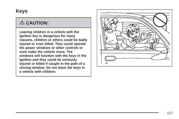
Keys
{CAUTION:
Leaving children in a vehicle with theignition key is dangerous for manyreasons, children or others could be badlyinjured or even killed. They could operatethe power windows or other controls oreven make the vehicle move. Thewindows will function with the keys in theignition and they could be seriouslyinjured or killed if caught in the path of aclosing window. Do not leave the keys ina vehicle with children.
117

Your vehicle hasone double-sided keyfor the ignition andall door locks.
If you ever lose your keys, your dealer/retailer willbe able to assist you with obtaining replacements.
Notice: If you ever lock your keys in yourvehicle, you may have to damage the vehicleto get in. Be sure you have spare keys.
If you ever do get locked out of your vehicle, callthe GM Roadside Assistance Center. SeeRoadside Assistance Program on page 601.
Remote Keyless Entry (RKE)SystemYour Remote Keyless Entry (RKE) systemoperates on a radio frequency subject to FederalCommunications Commission (FCC) Rulesand with Industry Canada.
This device complies with Part 15 of the FCCRules. Operation is subject to the followingtwo conditions:
1. This device may not cause interference.
2. This device must accept any interferencereceived, including interference that maycause undesired operation of the device.
This device complies with RSS-210 of IndustryCanada. Operation is subject to the followingtwo conditions:
1. This device may not cause interference.
2. This device must accept any interferencereceived, including interference that maycause undesired operation of the device.
Changes or modifications to this system by otherthan an authorized service facility could voidauthorization to use this equipment.
118

At times you may notice a decrease in operatingrange. This is normal for any RKE system. Ifthe transmitter does not work or if you have tostand closer to your vehicle for the transmitter towork, try this:
• Check the distance. You may be too far fromyour vehicle. You may need to stand closerduring rainy or snowy weather.
• Check the location. Other vehicles or objectsmay be blocking the signal. Take a few stepsto the left or right, hold the transmitterhigher, and try again.
• Check to determine if battery replacement isnecessary. See “Battery Replacement”under Remote Keyless Entry (RKE) SystemOperation on page 119.
• If you are still having trouble, see yourdealer/retailer or a qualified technicianfor service.
Remote Keyless Entry (RKE)System OperationThe vehicle’s doors can be locked and unlockedfrom about 3 feet (1 m) up to 65 feet (20 m)away with the Remote Keyless Entry (RKE)transmitter.
If your vehicle has the remote start feature youcan also start your vehicle with the RKEtransmitter. The RKE transmitter, with the remotestart button, provides an increased operatingrange of 195 feet (60 m) away. However,the operating range may be less while the vehicleis running. As a result, you may need to becloser to your vehicle to turn it off than you wereto start it.
There are other conditions which can affect theperformance of the transmitter. See RemoteKeyless Entry (RKE) System on page 118.
119

The following functions may be available if yourvehicle has the RKE system:
/ (Remote Vehicle Start): If your vehicle hasthis feature, it may be started from outsidethe vehicle using the RKE transmitter. See“Remote Vehicle Start” following for more detailedinformation.
Q (Lock): Press the lock button to lock all thedoors. If enabled through the Driver InformationCenter (DIC), the parking lamps will flash once toindicate locking has occurred. If enabled throughthe DIC, the horn will chirp when the lock button ispressed again within five seconds of the previouspress of the lock button. See DIC VehicleCustomization (With DIC Buttons) on page 282 foradditional information. Pressing the lock buttonmay arm the content theft-deterrent system.See Content Theft-Deterrent on page 139.
" (Unlock): Press the unlock button to unlock thedriver’s door. If the button is pressed againwithin five seconds, all remaining doors will unlock.The interior lamps will come on and stay on for20 seconds or until the ignition is turned on.If enabled through the DIC, the parking lamps willflash once to indicate unlocking has occurred.See DIC Vehicle Customization (With DIC Buttons)on page 282. Pressing the unlock button on theRKE transmitter will disarm the contenttheft-deterrent system. See ContentTheft-Deterrent on page 139.
With Remote Start andLiftglass (Without
Remote Start Similar)
With Remote Start andPower Liftgate andLiftglass (Without
Remote Start Similar)
120

m (Liftglass): Press and hold this button onthe RKE transmitter to open the liftglass.
& (Power Liftgate): Press and hold this buttonon the RKE transmitter to open and close theliftgate. The taillamps will flash and a chime willsound to indicate when the liftgate is opening andclosing.
L (Vehicle Locator/Panic Alarm): Press andrelease this button to locate your vehicle. The turnsignal lamps will flash and the horn will soundthree times. Press and hold this button for morethan two seconds to activate the panic alarm. Theturn signal lamps will flash and the horn willsound repeatedly for 30 seconds. The alarm willturn off when the ignition is moved to RUN orthe alarm button is pressed again. The ignitionmust be in OFF for the panic alarm to work.
Matching Transmitter(s) to YourVehicleEach RKE transmitter is coded to prevent anothertransmitter from unlocking your vehicle. If atransmitter is lost or stolen, a replacement can bepurchased through your GM dealer. Remember tobring any additional transmitters so they can alsobe re-coded to match the new transmitter. Onceyour dealer has coded the new transmitter, the losttransmitter will not unlock your vehicle. The vehiclecan have a maximum of eight transmitters matchedto it. See “Relearn Remote Key” under DICOperation and Displays (With DIC Buttons) onpage 262 or DIC Operation and Displays (WithoutDIC Buttons) on page 269 for instructions on how tomatch RKE transmitters to your vehicle.
121

Battery ReplacementUnder normal use, the battery in the RKEtransmitter should last about four years.
The battery is weak if the transmitter will not workat the normal range in any location. If you haveto get close to your vehicle before the transmitterworks, it is probably time to change the battery.
The REPLACE BATTERY IN REMOTE KEYmessage in the vehicle’s DIC will display if theRKE transmitter battery is low. See “REPLACEBATTERY IN REMOTE KEY” under DIC Warningsand Messages on page 272 for additionalinformation.
Notice: When replacing the battery, use carenot to touch any of the circuitry. Staticfrom your body transferred to these surfacesmay damage the transmitter.
To replace the battery in the RKE transmitter dothe following:
1. Insert a flat object with a thin edge into thenotch on the side of the transmitter andseparate the bottom half from the top half.
2. Remove the old battery, but do not use ametal object to do this.
3. Slide the new battery into the transmitter withthe positive side of the battery facing down.Use a type CR2032 battery, or equivalenttype. Make sure the cover is on tightly,so water will not get in.
122

4. Snap the front and the back of the transmittertogether.
5. Test the operation of the transmitter with thevehicle.
Remote Vehicle StartYour vehicle may have a remote starting feature.This feature allows you to start the enginefrom outside of the vehicle. It may also start upthe vehicle’s heating or air conditioning systemsand rear window defogger. Normal operation of thesystem will return after the key is turned to theRUN position.
During a remote start, if your vehicle has anautomatic climate control system, the climatecontrol system will default to a heating modeduring colder outside temperatures and a coolingmode during warmer outside temperatures. Ifyour vehicle does not have an automatic climatecontrol system, during remote start, the climatecontrol system will turn on at the setting the vehiclewas set to when the vehicle was last turned off.
During a remote start, if your vehicle has anautomatic climate control system and heatedseats, the heated seats will turn on during colderoutside temperatures and will shut off when
the key is turned to RUN. If your vehicle does nothave an automatic climate control system,during remote start, you will need to manually turnthe heated seats on and off. See Heated Seatson page 12 for additional information.
Laws in some communities may restrict the useof remote starters. For example, some lawsmay require a person using the remote start tohave the vehicle in view when doing so. Checklocal regulations for any requirements on remotestarting of vehicles.
Do not use the remote start feature if your vehicleis low on fuel. Your vehicle may run out of fuel.
The RKE transmitter with the remote start button,provides an increased range of operation.However, the range may be less while the vehicleis running. As a result, you may need to becloser to your vehicle to turn it off, than you wereto turn it on.
There are other conditions which can affect theperformance of the transmitter, see RemoteKeyless Entry (RKE) System on page 118 foradditional information.
123
/ (Remote Start): Press and release the lockbutton and then press and hold the remotestart button to start the vehicle.
To start the vehicle using the remote start feature,do the following:
1. Aim the transmitter at the vehicle.
2. Press and release the transmitter’s lockbutton, then immediately press and holdthe transmitter’s remote start button until theturn signal lights flash. If you cannot seethe vehicle’s lights, press and hold the remotestart button for at least four seconds. Thevehicle’s doors will lock. Pressing the remotestart button again after the vehicle hasstarted will turn off the ignition.When the vehicle starts, the parking lampswill turn on and remain on while the vehicleis running.
3. If it is the first remote start since the vehiclehas been driven, repeat these steps, whilethe engine is still running, to extend the enginerunning time by 10 minutes. Remote startcan be extended one time.
After entering the vehicle during a remote start,insert and turn the key to RUN to drive the vehicle.
If the vehicle is left running it will automaticallyshut off after 10 minutes unless a time extensionhas been done.
To manually shut off a remote start, do any of thefollowing:
• Aim the RKE transmitter at the vehicle andpress the remote start button until theparking lamps turn off.
• Turn on the hazard warning flashers.
• Turn the ignition switch on and then off.
The vehicle can be remote started two separatetimes between driving sequences. The engine willrun for 10 minutes after each remote start.
Or, you can extend the engine run time by another10 minutes within the first 10 minute remotestart time frame, and before the engine stops.
For example, if the lock button and then theremote start buttons are pressed again afterthe vehicle has been running for five minutes,10 minutes are added, allowing the engine torun for 15 minutes.
124

The additional ten minutes are considered asecond remote vehicle start.
Once two remote starts, or a single remote startwith one time extension has been done, thevehicle must be started with the key.
After the key is removed from the ignition, thevehicle can be remote started again.
The vehicle cannot be remote started if the key isin the ignition, the hood is not closed, or ifthere is an emission control system malfunction.
Also, the engine will turn off during a remotevehicle start if the coolant temperature gets toohigh or if the oil pressure gets low.
Vehicles that have the remote vehicle start featureare shipped from the factory with the remotevehicle start system enabled. The system may beenabled or disabled through the DIC. See“REMOTE START” under DIC VehicleCustomization (With DIC Buttons) on page 282 foradditional information. If your vehicle does nothave DIC buttons, see your dealer to enableor disable the remote vehicle start system.″
Remote Start ReadyIf your vehicle does not have the remote vehiclestart feature, it may have the remote start readyfeature. This feature allows your dealer to add themanufacturer’s remote vehicle start feature.
If your vehicle has the remote start ready feature,the RKE transmitter will have an extendedrange that allows locking or unlocking of thevehicle from approximately 197 feet (60 m) away.
See your dealer if you would like to add themanufacturer’s remote vehicle start feature toyour vehicle.
125

Doors and Locks
Door Locks
{CAUTION:
Unlocked doors can be dangerous.• Passengers, especially children, can
easily open the doors and fall out of amoving vehicle. When a door islocked, the handle will not open it.You increase the chance of beingthrown out of the vehicle in a crash ifthe doors are not locked. So, wearsafety belts properly and lock thedoors whenever you drive.
• Young children who get into unlockedvehicles may be unable to get out. Achild can be overcome by extremeheat and can suffer permanent injuriesor even death from heat stroke.
CAUTION: (Continued)
CAUTION: (Continued)
Always lock your vehicle wheneveryou leave it.
• Outsiders can easily enter through anunlocked door when you slow downor stop your vehicle. Locking yourdoors can help prevent this fromhappening.
There are several ways to lock and unlock yourvehicle.
From the outside, use the Remote KeylessEntry (RKE) transmitter or the key in thedriver’s door.
From the inside, use the power door locks ormanual door locks. To lock or unlock the doorwith the manual locks, push down or pull up onthe manual lock knob.
126

Power Door LocksThe power door lock switches are located on thearmrest on the front doors.
K (Unlock): Press the side of the switch with theunlock symbol to unlock the doors.
Q (Lock): Press the side of the switch with thelock symbol to lock the doors.
Delayed LockingWhen locking the doors with the power lock switchor the remote keyless entry (RKE) transmitterand a door or the liftgate is open, the doors willlock five seconds after the last door is closed. Youwill hear three chimes to signal that the delayedlocking feature is in use.
Pressing the power lock switch or the lock buttonon the RKE transmitter twice will override thedelayed locking feature and immediately lock allthe doors.
This feature will not operate if the key is in theignition.
You can program this feature using the DriverInformation Center (DIC). See DELAY DOORLOCK under DIC Vehicle Customization (With DICButtons) on page 282.
127
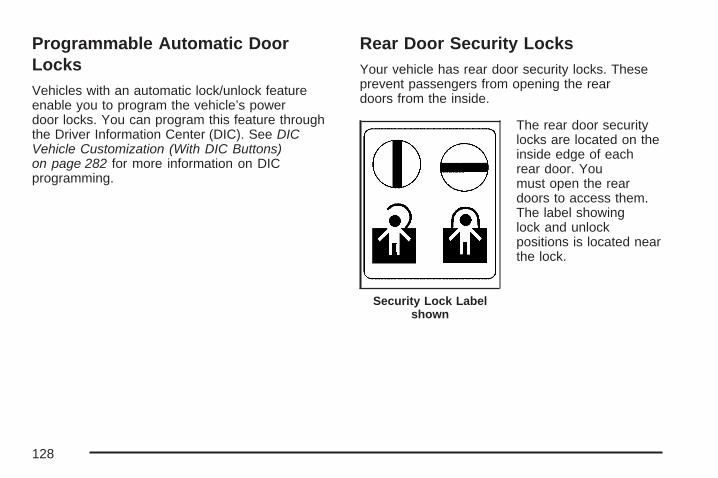
Programmable Automatic DoorLocksVehicles with an automatic lock/unlock featureenable you to program the vehicle’s powerdoor locks. You can program this feature throughthe Driver Information Center (DIC). See DICVehicle Customization (With DIC Buttons)on page 282 for more information on DICprogramming.
Rear Door Security LocksYour vehicle has rear door security locks. Theseprevent passengers from opening the reardoors from the inside.
The rear door securitylocks are located on theinside edge of eachrear door. Youmust open the reardoors to access them.The label showinglock and unlockpositions is located nearthe lock.
Security Lock Labelshown
128

To set the locks, do the following:
1. Insert the key into the security lock slot andturn it so the slot is in the horizontal position.
2. Close the door.
When you want to open a rear door when thesecurity lock is on, do the following:
1. Unlock the door using the remote keylessentry transmitter, if the vehicle has one, thepower door lock switch, or by lifting therear door manual lock.
2. Open the door from the outside.
To cancel the rear door security lock, do thefollowing:
1. Unlock the door and open it from the outside.
2. Insert the key into the security lock slotand turn it so the slot is in the vertical position.
Lockout ProtectionThis feature protects you from locking the key inthe vehicle when the key is in the ignition anda front door is open.
If the driver’s side power door lock switch ispressed when the driver’s door is open and thekey is in the ignition, all of the doors will lock andthen the driver’s door will unlock.
If the passenger’s side power door lock switch ispressed when the front passenger’s door isopen and the key is in the ignition, all of the doorswill lock and then the front passenger’s doorwill unlock.
129

Liftgate/Liftglass
{CAUTION:
It can be dangerous to drive with theliftglass or liftgate open because carbonmonoxide (CO) gas can come into yourvehicle. You cannot see or smell CO. It cancause unconsciousness and even death.
If you must drive with the liftglass orliftgate open, or if electrical wiring or othercable connections must pass through theseal between the body and the liftglass orliftgate:
• Make sure all other windows are shut.• Turn the fan on your heating or cooling
system to its highest speed with therecirculation mode off. That will forceoutside air into your vehicle. SeeClimate Control System on page 227 orDual Automatic Climate ControlSystem on page 231.
CAUTION: (Continued)
CAUTION: (Continued)
• If you have air outlets on or under theinstrument panel, open them allthe way.
• If your vehicle has a power liftgate,disable the power liftgate function.
See Engine Exhaust on page 164.
If your vehicle has a power liftgate, see PowerLiftgate on page 132.
To unlock the liftgate, use the power door lockswitch or press the door unlock button onthe Remote Keyless Entry (RKE) transmitter twice.See Remote Keyless Entry (RKE) SystemOperation on page 119.
130

To open the liftglass, press the button on theunderside of the license pocket applique (A). Theliftglass can also be opened by pressing theliftglass release button on the RKE.
To open the entire liftgate, press the touchpad onthe underside of the liftgate handle (B). Thevehicle must be in PARK (P) to open the liftgate.To close the liftgate, use the pull cup or pullstrap as an aid.
The liftgate or liftglass cannot be opened if therear wipers are in motion. Attempting to open theliftgate or liftglass while the rear wipers are inmotion will cause the release of the liftglassor liftgate to delay until the wipers are moved offthe liftglass.
Both the liftglass and liftgate have an electriclatch. If the battery is disconnected or haslow voltage, the liftglass and liftgate will not open.The liftglass and liftgate will resume operationwhen the battery is reconnected and charged.
If the battery is properly connected and hasadequate voltage, and the liftgate or liftglass stillwill not function, your vehicle should be taken to adealership for service.
131

Power LiftgateYour vehicle may have a power liftgate. Thevehicle must be in PARK (P) to power open orclose the liftgate.
The liftgate must be completely closed to poweropen or completely open to power close.
The taillamps will flash and a chime will sound atthe beginning of each power operation cycle.
{CAUTION:
You or others could be injured if caught inthe path of the power liftgate. Make surethere is no one in the way of the liftgateas it is opening and closing.
Notice: If you open the liftgate withoutchecking for overhead obstructions such as agarage door, you could break the liftgate orthe liftgate glass. Always check to make surethe area above the liftgate is clear beforeopening it.
To open and close the liftgate, press and hold thepower liftgate button on the Remote KeylessEntry (RKE) transmitter until the liftgate startsmoving. Press the RKE button a second timeduring liftgate operation to reverse that operation.See Remote Keyless Entry (RKE) SystemOperation on page 119 for more information.
The liftgate can also beopened and closed bypressing the powerliftgate button onthe overhead console.Press the button asecond time duringliftgate operationto reverse thatoperation.
The liftgate can be power opened by pressing thetouchpad switch on the liftgate handle. Pressthe button a second time during liftgate operationto reverse that operation.
Power Liftgate Buttonon Overhead Console
132

The liftgate can be power closed by pressing thepower liftgate button next to the liftgate latch.Press the button a second time during liftgateoperation to reverse that operation.
The power liftgate my be temporarily disabledunder extreme high or low temperatures. Ifthis occurs, the liftgate can still be operatedmanually. The power liftgate may not operateunder low battery conditions.
If you shift the transmission out of PARK (P) whilethe power function is in progress, the liftgatepower function will continue to completion. If youshift the transmission out of PARK (P) andaccelerate before the power liftgate latches closed,
the liftgate may reverse to the open position.Cargo could fall out of the vehicle. Always makesure the power liftgate is closed and latched beforeyou drive away.
If you power open the liftgate and the liftgatesupport struts have lost pressure, the lights willflash and a chime will sound. The liftgate will holdopen temporarily, then slowly close. See yourdealer for service before using the liftgate.
Obstacle Detection FeaturesIf the liftgate encounters an obstacle during apower open or close cycle, a warning chime willsound and the liftgate will automatically reversedirection to the full closed or open position.After removing the obstruction, the liftgate may bepower opened or closed normally. If the liftgateencounters multiple obstacles on the same powercycle, the power function will deactivate, andthe liftgate will switch to manual operation. TheREAR ACCESS OPEN warning message inthe Driver Information Center (DIC) will indicatethat the liftgate is open. After removing theobstructions, manually open the liftgate to the fullopen position or close the liftgate to the fullyclosed and latched position. The liftgate will nowresume normal power operation.
Power Liftgate Button Near Liftgate Latch
133

Your vehicle has pinch sensors located on theside edges of the liftgate. If an object is caughtbetween the liftgate and the body and pressesagainst this sensor, the liftgate will reversedirection and open fully. The liftgate will remainopen until it is activated again or closed manually.
Manual Operation of Power Liftgate
To change the liftgate tomanual operation,toggle the switch on theoverhead console tothe “Disable” positionindicated by a circle.
With the power liftgate disabled and the doorunlocked, the power liftgate can be manuallyopened and closed.
To open the liftgate, press the touchpad on thehandle on the outside of the liftgate, and liftthe gate open. To close the liftgate, use the pullcup or pull strap to lower the liftgate and close.The liftgate latch will power cinch to closedposition. Always close the liftgate before driving.
If the RKE button or the power close button on theliftgate is pressed while power operation isdisabled, the lights will flash three times, but theliftgate will not move.
It is not recommended that you drive with theliftgate open, however, if you must drive with theliftgate open, the power liftgate should be switchedto manual liftgate operation — the overheadconsole switch set to the “Disable” position.
Both the liftglass and liftgate have an electric latch.If the battery is disconnected or has low voltage,the liftglass and liftgate will not open. Theliftglass and liftgate will resume operation whenthe battery is reconnected and charged.
If the battery is properly connected and hasadequate voltage, and the liftgate or liftglass stillwill not function, your vehicle should be taken to adealership for service.
134

{CAUTION:
It can be dangerous to drive with theliftglass or liftgate open because carbonmonoxide (CO) gas can come into yourvehicle. You cannot see or smell CO. Itcan cause unconsciousness and evendeath.
If you must drive with the liftglass orliftgate open, or if electrical wiring orother cable connections must passthrough the seal between the body andthe liftglass or liftgate:
• Make sure all other windows are shut.• Turn the fan on your heating or
cooling system to its highest speedwith the recirculation mode off. Thatwill force outside air into your vehicle.See Climate Control System onpage 227 or Dual Automatic ClimateControl System on page 231.
CAUTION: (Continued)
CAUTION: (Continued)
• If you have air outlets on or underthe instrument panel, open themall the way.
• If your vehicle has a power liftgate,disable the power liftgate function.
See Engine Exhaust on page 164.
Power Running BoardsYour vehicle may have power running boards.
The power running boards automatically extendfrom beneath the vehicle on the side in which thedoor has been opened. Once the door is closed,the running boards will automatically moveback under the vehicle. The vehicle must not bemoving for the running boards to extend or retract.
135

The switch used todisable the powerrunning boards islocated on the centerconsole below theclimate control system.
The running boards cannot be disabled in theextended position.
Windows
{CAUTION:
Leaving children, helpless adults, or petsin a vehicle with the windows closed isdangerous. They can be overcome by theextreme heat and suffer permanent
CAUTION: (Continued)
CAUTION: (Continued)
injuries or even death from heat stroke.Never leave a child, a helpless adult, or apet alone in a vehicle, especially with thewindows closed in warm or hot weather.
136

Power Windows
{CAUTION:
Leaving children, helpless adults, or petsin a vehicle with the windows closed isdangerous. They can be overcome fromextreme heat in warm or hot weather andsuffer permanent injuries or even deathfrom heat stroke.Leaving children in a vehicle with theignition key is dangerous for manyreasons, children or others could be badlyinjured or even killed. They could operatethe power windows or other controls oreven make the vehicle move. Thewindows will function with the keys in theignition and they could be seriouslyinjured or killed if caught in the path of aclosing window. Do not leave keys in avehicle with children.When there are children in the rear seatuse the window lockout button to preventunintentional operation of the windows.
The power windowcontrols are located oneach of the side doors.
The driver’s door also has switches that controlthe passenger and rear windows. The powerwindows work when the ignition has been turnedto ACCESSORY or RUN or when RetainedAccessory Power (RAP) is active. See RetainedAccessory Power (RAP) on page 145.
Press the switch to lower the window.
Pull up on the front edge of the switch to raisethe window.
Driver’s Side shown
137

Express-Down WindowsThe driver and front passenger windows have anexpress-down feature that allows the windowsto be lowered without holding the switch. Pressdown fully on the window switch, then release,to activate the express-down mode. Theexpress-down mode can be canceled at any timeby pulling up on the front edge of the switch.
Window Lockout
o (Window Lockout): The window lockoutswitch is located with the power window switcheson the driver’s door armrest. This feature preventsthe rear passenger windows from operating, exceptfrom the driver’s position. Press the switch to turnthe lockout feature on or off. An indicator light willcome on to show the lockout feature is on.
Sun VisorsPull the sun visor down to block glare. Detach thesun visor from the center mount and slide it alongthe rod from side-to-side to cover the driver orpassenger side of the front window. Swing the sunvisor to the side to cover the side window. It can bemoved along the rod from side-to-side in thisposition also.
Lighted Visor Vanity MirrorYour vehicle may have lighted visor vanity mirrorson both the driver’s and passenger’s sun visors.Pull the sun visor down and lift the mirror cover toturn the lamps on.
Theft-Deterrent SystemsVehicle theft is big business, especially in somecities. Although your vehicle has a number oftheft-deterrent features, we know that nothing weput on it can make it impossible to steal.
138

Content Theft-DeterrentYour vehicle may have a content theft-deterrentalarm system.
To activate the theft-deterrent system, do thefollowing:
1. Open the door.
2. Lock the door with the Remote Keyless Entry(RKE) transmitter. The security light shouldcome on and flash. The door does not need tobe open.If the delayed locking feature is active, thealarm will not be activated until all doors areclosed and the security light goes off.
3. Close all doors. The security light will stopflashing and go off after approximately30 seconds. The content theft deterrent alarmis not armed until the security light goes off.
If a door is opened without using the RKEtransmitter, a ten second pre-alarm will occur. Thehorn will chirp and the lights will flash. If the keyis not placed in the ignition and turned toSTART or the door is not unlocked by pressingthe unlock button on the RKE transmitterduring the ten second pre-alarm, the alarm will gooff. Your vehicle’s headlamps will flash and thehorn will sound for about two minutes, thenwill turn off to save the battery power.
The theft-deterrent system will not activate if youlock the doors with a key, the manual door lock, orthe power door lock switch. It activates only if youuse the RKE transmitter. You should alsoremember that you can start your vehicle with thecorrect ignition key if the alarm has been set off.
139

Here is how to avoid setting off the alarm byaccident:
• If you do not want to activate thetheft-deterrent system, the vehicle should belocked with the door key after the doorsare closed.
• Always unlock a door with the RKE transmitter.Unlocking a door any other way will set off thealarm if the system has been armed.
If you set off the alarm by accident, turn off thealarm by pressing unlock on the RKE transmitter orby placing the key in the ignition and turning itto START.
Testing the AlarmThe alarm can be tested by following these steps:
1. From inside the vehicle, lower the driver’swindow and open the driver’s door.
2. Activate the system by locking the doors withthe RKE transmitter.
3. Get out of the vehicle, close the door and waitfor the security light to go out.
4. Then reach in through the window, unlock thedoor with the manual door lock and open thedoor. This should set off the alarm.
If the alarm does not sound when it should, butthe vehicle’s headlamps flash, check to see if thehorn works. The horn fuse may be blown. Toreplace the fuse, see Fuses and Circuit Breakerson page 566.
If the alarm does not sound or the vehicle’sheadlamps do not flash, see your dealer forservice.
140

PASS-Key® III+The PASS-Key® III+ system operates on a radiofrequency subject to Federal CommunicationsCommission (FCC) Rules and with IndustryCanada.
This device complies with Part 15 of the FCCRules. Operation is subject to the followingtwo conditions:
1. This device may not cause harmfulinterference.
2. This device must accept any interferencereceived, including interference that maycause undesired operation.
This device complies with RSS-210 of IndustryCanada. Operation is subject to the followingtwo conditions:
1. This device may not cause interference.
2. This device must accept any interferencereceived, including interference that maycause undesired operation of the device.
Changes or modifications to this system by otherthan an authorized service facility could voidauthorization to use this equipment.
PASS-Key® III+ uses a radio frequencytransponder in the key that matches a decoder inyour vehicle.
PASS-Key® III+ OperationYour vehicle has PASS-Key® III+ (PersonalizedAutomotive Security System) theft-deterrentsystem. PASS-Key® III+ is a passive theft-deterrentsystem. This means you do not have to do anythingspecial to arm or disarm the system. It works whenyou transition the key to RUN, ACCESSORY orSTART from the OFF position.
When the PASS-Key® III+ system senses thatsomeone is using the wrong key, it preventsthe vehicle from starting. Anyone using atrial-and-error method to start the vehicle willbe discouraged because of the high number ofelectrical key codes.
If the engine does not start and the security light onthe instrument panel cluster comes on when tryingto start the vehicle, the key may have a damagedtransponder. Turn the ignition off and try again.
141

If the engine still does not start, and the keyappears to be undamaged, try another ignitionkey. At this time, you may also want to check thefuse, see Fuses and Circuit Breakers onpage 566. If the engine still does not start with theother key, your vehicle needs service. If yourvehicle does start, the first key may be faulty. Seeyour dealer who can service the PASS-Key® III+to have a new key made. In an emergency,contact Roadside Assistance.
It is possible for the PASS-Key® III+ decoder tolearn the transponder value of a new orreplacement key. Up to nine additional keys maybe programmed for the vehicle. The followingprocedure is for programming additional keys only.If all the currently programmed keys are lost ordo not operate, you must see your dealer ora locksmith who can service PASS-Key® III+ tohave keys made and programmed to the system.
See your dealer or a locksmith who can servicePASS-Key® III+ to get a new key blank that is cutexactly as the ignition key that operates thesystem.
To program the new additional key do thefollowing:
1. Verify that the new key has a 1 stamped on it.
2. Insert the original, already programmed, keyin the ignition and start the engine. If theengine will not start, see your dealerfor service.
3. After the engine has started, turn the key toOFF, and remove the key.
4. Insert the new key to be programmed andturn it to the RUN position within five secondsof removing the original key.
5. The security light will turn off once the keyhas been programmed.
6. Repeat Steps 1 through 5 if additional keysare to be programmed.
If you are driving and the security light comes onand stays on, you may be able to restart yourengine. Your PASS-Key® III+ system, however,may not be working properly and must be servicedby your dealer.
If you lose or damage your PASS-Key® III+ key,see your dealer or a locksmith who can servicePASS-Key® III+ to have a new key made.
142

Starting and Operating YourVehicle
New Vehicle Break-In
Notice: Your vehicle does not need anelaborate break-in. But it will perform better inthe long run if you follow these guidelines:• Keep your speed at 55 mph (88 km/h)
or less for the first 500 miles (805 km).• Do not drive at any one constant speed,
fast or slow, for the first 500 miles(805 km). Do not make full-throttle starts.Avoid downshifting to brake, or slow,the vehicle.
• Avoid making hard stops for the first200 miles (322 km) or so. During this timeyour new brake linings are not yetbroken in. Hard stops with new linings canmean premature wear and earlierreplacement. Follow this breaking-inguideline every time you get new brakelinings.
• Do not tow a trailer during break-in. SeeTowing a Trailer on page 428 for thetrailer towing capabilities of your vehicleand more information.
Following break-in, engine speed and load canbe gradually increased.
143

Ignition Positions
Use the key to turn the ignition switch to fourdifferent positions.
A (LOCK): This position locks the ignition andtransmission. It is a theft-deterrent feature. You willonly be able to remove the key when the ignitionis turned to LOCK.
Notice: Using a tool to force the key from theignition switch could cause damage or breakthe key. Use the correct key and turn the key
only with your hand. Make sure the key is all theway in. If it is, turn the steering wheel left andright while you turn the key hard. If none of thisworks, then your vehicle needs service.
B (ACCESSORY): This position lets you usethings like the radio and the windshield wiperswhen the engine is off.
Lengthy operation of features such as the radio inthe ACCESSORY ignition position and theRUN position may drain the battery and preventyour vehicle from starting. Do not operateyour vehicle in the ACCESSORY ignition positionfor a long period of time.
C (RUN): This is the position for driving. It is theposition the switch returns to after the enginestarts, and you release the key.
The battery could be drained if you leave the keyin the ACCESSORY or RUN position with theengine off. You may not be able to start yourvehicle if the battery is allowed to drain foran extended period of time.
D (START): This position starts the engine.
144
Key In the IgnitionNever leave your vehicle with the keys inside, as itis an easy target for joy riders or thieves. If youleave the key in the ignition and park your vehicle,a chime will sound, when you open the driver’sdoor. Always remember to remove your key fromthe ignition and take it with you. This will lockyour ignition and transmission. Also, alwaysremember to lock the doors.
The battery could be drained if you leave the key inthe ignition while your vehicle is parked. You maynot be able to start your vehicle after it has beenparked for an extended period of time.
Retained Accessory Power (RAP)Your vehicle has a Retained Accessory Power(RAP) feature which will allow certain features onyour vehicle to continue to work up to 10 minutesafter the ignition key is turned to LOCK.
The radio, power windows, and if the vehicle hasa sunroof and the OnStar® System, will workwhen the ignition key is in RUN or ACCESSORY.
Once the key is turned from RUN to LOCK, thewindows and sunroof will continue to workuntil a door is opened. The radio will continue towork for up to 10 minutes or until the driver’s dooris opened.
Starting the EngineTo place the transmission in the proper gear:
Move your shift lever to PARK (P) orNEUTRAL (N). Your engine will not start inany other position — this is a safety feature.To restart when you are already moving,use NEUTRAL (N) only.
Starting Procedure1. With your foot off the accelerator pedal, turn
the ignition key to START. When the enginestarts, let go of the key. The idle speed will godown as your engine gets warm. Do notrace the engine immediately after starting it.Operate the engine and transmission gently toallow the oil to warm up and lubricate allmoving parts.
145

Your vehicle has a Computer-ControlledCranking System. This feature assists instarting the engine and protects components. Ifthe ignition key is turned to the START position,and then released when the engine beginscranking, the engine will continue cranking for afew seconds or until the vehicle starts. If theengine does not start and the key is held inSTART for many seconds, cranking will bestopped after 15 seconds to prevent crankingmotor damage. To prevent gear damage, thissystem also prevents cranking if the engine isalready running. Engine cranking can bestopped by turning the ignition switch to theACCESSORY or LOCK position.
Notice: Cranking the engine for long periodsof time, by returning the key to the STARTposition immediately after cranking has ended,can overheat and damage the crankingmotor, and drain the battery. Wait at least15 seconds between each try, to allowthe cranking motor to cool down.
2. If the engine does not start after 5-10 seconds,especially in very cold weather (below 0°F or−18°C), it could be flooded with too muchgasoline. Try pushing the accelerator pedal allthe way to the floor and holding it there asyou hold the key in START for up to amaximum of 15 seconds. Wait at least15 seconds between each try, to allow thecranking motor to cool down. When the enginestarts, let go of the key and accelerator. Ifthe vehicle starts briefly but then stops again,do the same thing. This clears the extragasoline from the engine. Do not race theengine immediately after starting it. Operatethe engine and transmission gently until the oilwarms up and lubricates all moving parts.
Notice: Your engine is designed to work withthe electronics in your vehicle. If you addelectrical parts or accessories, you couldchange the way the engine operates. Beforeadding electrical equipment, check with yourdealer. If you do not, your engine might notperform properly. Any resulting damage wouldnot be covered by your vehicle’s warranty.
146

Adjustable Throttle and Brake PedalIf your vehicle has this feature, you can changethe position of the throttle and brake pedals.
This feature is designed for shorter drivers, sincethe pedals cannot move farther away from thestandard position, but can move toward the driverfor better pedal reach.
The switch used toadjust the pedals islocated on theinstrument panelbelow the climatecontrol system.
Press the arrow at the bottom of the switch tomove the pedals closer to your body. Pressthe arrow at the top of the switch to move thepedals away from your body.
No adjustment to the pedals can be made whenthe vehicle is in REVERSE (R) or while usingthe cruise control.
Your vehicle may have a memory function whichallows pedal settings to be saved and recalled.See Memory Seat, Mirrors, and Pedals on page 13for more information.
Engine Coolant HeaterYour vehicle may have an engine coolant heater.
In very cold weather, 0°F (−18°C) or colder,the engine coolant heater can help. You will geteasier starting and better fuel economy duringengine warm-up.
Usually, the coolant heater should be plugged in aminimum of four hours prior to starting yourvehicle. At temperatures above 32°F (0°C), use ofthe coolant heater is not required. Your vehiclemay also have an internal thermostat in theplug end of the cord. This will prevent operation ofthe engine coolant heater when the temperatureis at or above 0°F (−18°C) as noted on the cord.
147

To Use the Engine Coolant Heater1. Turn off the engine.
2. Open the hood and unwrap the electricalcord. The cord is located on the driver’sside of the engine compartment, nearthe power steering fluid reservoir.
3. Plug the cord into a normal, grounded110-volt AC outlet.
{CAUTION:
Plugging the cord into an ungroundedoutlet could cause an electrical shock.Also, the wrong kind of extension cordcould overheat and cause a fire. Youcould be seriously injured. Plug the cordinto a properly grounded three-prong110-volt AC outlet. If the cord will notreach, use a heavy-duty three-prongextension cord rated for at least 15 amps.
4. Before starting the engine, be sure to unplugand store the cord as it was before to keep itaway from moving engine parts. If you donot, it could be damaged.
How long should you keep the coolant heaterplugged in? The answer depends on the outsidetemperature, the kind of oil you have, andsome other things. Instead of trying to listeverything here, we ask that you contact yourdealer in the area where you will be parking yourvehicle. The dealer can give you the bestadvice for that particular area.
148

Active Fuel Management™Your vehicle’s V8 engine may have Active FuelManagement™. This system allows the engine tooperate on either all or half of its cylinders,depending on the driving conditions.
When less power is required, such as cruising at aconstant vehicle speed, the system will operatein the half cylinder mode, allowing your vehicle toachieve better fuel economy. When greaterpower demands are required, such as acceleratingfrom a stop, passing, or merging onto a freeway,the system will maintain full-cylinder operation.
Your vehicle has an Active Fuel Management™indicator. For more information on using thisdisplay see DIC Operation and Displays (With DICButtons) on page 262 or DIC Operation andDisplays (Without DIC Buttons) on page 269.
Automatic Transmission OperationThere are several different positions for theshift lever.
Your vehicle has an automatic transmission withan electronic shift position indicator within theinstrument panel cluster. This display will show theposition anytime the shift lever is moved out ofPARK (P).
149

PARK (P): This position locks your rear wheels. Itis the best position to use when you start yourengine because your vehicle cannot move easily.
{CAUTION:
It is dangerous to get out of your vehicleif the shift lever is not fully in PARK (P)with the parking brake firmly set. Yourvehicle can roll.
Do not leave your vehicle when the engineis running unless you have to. If you haveleft the engine running, the vehicle canmove suddenly. You or others could beinjured. To be sure your vehicle will notmove, even when you are on fairly levelground, always set your parking brakeand move the shift lever to PARK (P). SeeShifting Into Park (P) on page 161. If youare pulling a trailer, see Towing a Traileron page 428.
{CAUTION:
If you have four-wheel drive, your vehiclewill be free to roll — even if your shiftlever is in PARK (P) — if your transfercase is in NEUTRAL. So, be sure thetransfer case is in a drive gear, two-wheelhigh, four-wheel high or four-wheellow — not in NEUTRAL. See Shifting IntoPark (P) on page 161.
REVERSE (R): Use this gear to back up.
Notice: Shifting to REVERSE (R) while yourvehicle is moving forward could damagethe transmission. The repairs would not becovered by your warranty. Shift toREVERSE (R) only after your vehicle isstopped.
To rock your vehicle back and forth to get out ofsnow, ice, or sand without damaging yourtransmission, see If Your Vehicle is Stuck in Sand,Mud, Ice, or Snow on page 409.
150

NEUTRAL (N): In this position, your engine doesnot connect with the wheels. To restart whenyou are already moving, use NEUTRAL (N) only.Also, use NEUTRAL (N) when your two-wheeldrive vehicle is being towed.
{CAUTION:
Shifting into a drive gear while yourengine is running at high speed isdangerous. Unless your foot is firmly onthe brake pedal, your vehicle could movevery rapidly. You could lose control andhit people or objects. Do not shift into adrive gear while your engine is running athigh speed.
Notice: Shifting out of PARK (P) orNEUTRAL (N) with the engine running at highspeed may damage the transmission. Therepairs would not be covered by your warranty.Be sure the engine is not running at highspeed when shifting your vehicle.
DRIVE (D): This position is for normal driving. Itprovides the best fuel economy for your vehicle. Ifyou need more power for passing, and you are:
• Going less than about 35 mph (56 km/h), pushyour accelerator pedal about halfway down.
• Going about 35 mph (56 km/h) or more, pushthe accelerator all the way down.
DRIVE (D) can be used when towing a trailer,carrying a heavy load, driving on steep hillsor for off-road driving. You may want to shift thetransmission to THIRD (3) or, if necessary, alower gear selection if the transmission shiftstoo often.
Downshifting the transmission in slippery roadconditions could result in skidding, see “Skidding”under Loss of Control on page 375
THIRD (3): This position is also used for normaldriving. However, it reduces vehicle speedmore than DRIVE (D) without using your brakes.You can use THIRD (3) on hills. It can help controlyour speed as you go down steep mountainroads, but then you would also want to use yourbrakes off and on.
151

SECOND (2): This position reduces vehicle speedeven more than THIRD (3) without using yourbrakes. You can use SECOND (2) on hills. It canhelp control your speed as you go down steepmountain roads, but then you would also want touse your brakes off and on.
If you select SECOND (2) and the Tow/Haul hasnot been selected, the transmission will drivein SECOND (2) gear. You may use this feature forreducing the speed of the rear wheels whenyou are trying to start your vehicle from a stop onslippery road surfaces.
If you select SECOND (2) and the Tow/Haul hasalso been selected, the transmission operation willbe limited to FIRST (1) and SECOND (2) gears.You may use this feature for reducing the speed ofthe rear wheels when you are trying to startyour vehicle from a stop on slippery road surfaces.
FIRST (1): This position reduces vehicle speedeven more than SECOND (2) without usingyour brakes. You can use it on very steep hills, orin deep snow or mud. If the shift lever is put inFIRST (1) while the vehicle is moving forward, thetransmission will not shift into first gear until thevehicle is going slowly enough.
Notice: Spinning the tires or holding thevehicle in one place on a hill using only theaccelerator pedal may damage thetransmission. The repair will not be covered byyour warranty. If you are stuck, do not spinthe tires. When stopping on a hill, use thebrakes to hold the vehicle in place.
When temperatures are very cold, theHydra-Matic® Automatic Transmission’s gearshifting may be delayed providing more stableshifts until the engine warms up. Shifts maybe more noticeable with a cold transmission. Thisdifference in shifting is normal.
The transmission torque converter clutch operationis restricted during cold operation. When thestartup transmission temperature is approximately64°F (18°C) your torque converter clutch willtemporarily not operate. Once the transmissiontemperature rises above 68°F (20°C), normaloperation will resume.
152

Tow/Haul Mode
Your vehicle has a Tow/Haul mode. The selectorbutton is located on the end of the columnshift lever. You can use this feature to assist whentowing or hauling a heavy load or if there is aneed to charge a battery installed in a trailer. SeeTowing a Trailer on page 428 for moreinformation.
When Tow/Haul modeis selected the Tow/Haulindicator light willcome on.
The Tow/Haul mode works with the Autoride®
feature, if the vehicle has this, to enhance the ridewhen trailering or with a loaded vehicle. SeeAutoride® on page 427.
153

Four-Wheel DriveIf your vehicle has four-wheel drive, you can sendyour engine’s driving power to all four wheelsfor extra traction. Read the part that follows beforeusing four-wheel drive.
Notice: Driving on clean, dry pavement inFour-Wheel-Drive High or Four-Wheel-DriveLow for an extended period of time may causepremature wear on your vehicle’s powertrain.Do not drive on clean, dry pavement inFour-Wheel-Drive High or Four-Wheel-DriveLow for extended periods of time.
While driving on clean dry pavement and duringtight turns, you may experience a vibration inthe steering system.
Front Axle Locking FeatureThe front axle locks and unlocks automaticallywhen you shift the transfer case. Some delay forthe axle to lock or unlock is normal.
Automatic Transfer Case
The transfer case knobis located to the left ofthe instrument panelcluster.
Your vehicle has Four Wheel Drive withStabiliTrak®. For information on StabiliTrak®,see StabiliTrak® System on page 367.
Use this dial to shift into and out of four-wheeldrive.
154

You can choose among five driving settings:
Indicator lights in the switches show you whichsetting you are in. The indicator lights will come onbriefly when you turn on the ignition and the lastchosen setting will stay on. If the lights do notcome on, you should take your vehicle in forservice. An indicator light will flash while shifting.Fast flashing means the conditions were notmet to make the desired shift, typically the vehiclewas going too fast, the automatic transmissionwas not in neutral or the clutch pedal was not fullypressed. Slow flashing means the shift is inprogress. It will stay on when the shift iscompleted. If for some reason the transfer casecannot make a requested shift, it will return to thelast chosen setting.
2 m (Two-Wheel Drive High): This setting isused for driving in most street and highwaysituations. Your front axle is not engaged intwo-wheel drive. This setting also provides thebest fuel economy.
AUTO (Automatic Four-Wheel Drive): Thissetting is ideal for use when road surface tractionconditions are variable. When driving yourvehicle in AUTO, the front axle is engaged, butthe vehicle’s power is primarily sent to therear wheels. When the vehicle’s softwaredetermines a need for more traction, the systemwill transfer more power to the front wheels.Driving in this mode results in slightly lower fueleconomy than Two-Wheel Drive High.
4 m (Four-Wheel Drive High): Use thefour-wheel high position when you need extratraction, such as on snowy or icy roads or in mostoff-road situations. This setting also engagesyour front axle to help drive your vehicle. This isthe best setting to use when plowing snow.
4 n (Four-Wheel Drive Low): This setting alsoengages your front axle and delivers extra torque.You may never need this setting. It sends maximumpower to all four wheels. You might chooseFour-Wheel Drive Low if you are driving off-road indeep sand, deep mud, deep snow, and whileclimbing or descending steep hills. StabiliTrak® willnot engage in this mode. See StabiliTrak® Systemon page 367 for more information.
155

{CAUTION:
Shifting the transfer case to NEUTRALcan cause your vehicle to roll even if thetransmission is in PARK (P). You orsomeone else could be seriously injured.Be sure to set the parking brake beforeplacing the transfer case in NEUTRAL.See Parking Brake on page 160.
NEUTRAL (N): Shift the vehicle’s transfer caseto NEUTRAL only when towing your vehicle.See Recreational Vehicle Towing on page 423 orTowing Your Vehicle on page 422 for moreinformation.
If the SERVICE 4 WHEEL DRIVE message stayson, you should take your vehicle to your dealerfor service. See “SERVICE 4 WHEEL DRIVEmessage” under DIC Warnings and Messageson page 272.
Shifting Into Four-Wheel Drive High orAUTO (Automatic Four-Wheel Drive)Turn the knob to the Four-Wheel High or AUTOposition. This can be done at any speed,except when shifting from Four-Wheel Drive Low.The indicator light will flash while shifting. It willremain on when the shift is completed.
Shifting Into Two-Wheel Drive HighTurn the knob to the Two-Wheel High position.This can be done at any speed, except whenshifting from Four-Wheel Drive Low.
See shifting out of Four-Wheel Drive Low later inthis section for more information.
Shifting Into Four-Wheel Drive LowWhen Four-Wheel Low is engaged, vehicle speedshould be kept below 45 mph. Extendedhigh-speed operation in 4L may damage orshorten the life of the drivetrain.
To shift to the Four-Wheel Drive Low position, theignition must be in RUN and the vehicle mustbe stopped or moving less than 3 mph (5 km/h)with the transmission in NEUTRAL (N).
156

The preferred method for shifting into Four-WheelDrive Low is to have your vehicle moving1 to 2 mph (1.6 to 3.2 km/h). Turn the knob to theFour-Wheel Drive Low position. You must waitfor the Four-Wheel Drive Low indicator light to stopflashing and remain on before shifting yourtransmission in gear.
Notice: Shifting the transmission into gearbefore the Four-Wheel Drive Low indicator lighthas stopped flashing could damage thetransfer case. To help avoid damaging yourvehicle, always wait for the Four-WheelDrive Low indicator light to stop flashingbefore shifting the transmission into gear.
The vehicle may have significant engagementnoise and bump when shifting between Four-WheelDrive Low and Four-Wheel Drive High ranges orfrom NEUTRAL while the engine is running.
If the knob is turned to the Four-Wheel Drive Lowposition when your vehicle is in gear and/ormoving, the Four-Wheel Drive Low indicator lightwill flash for 30 seconds and not complete theshift unless your vehicle is moving less than 3 mph(5 km/h) and the transmission is in NEUTRAL (N).After 30 seconds the transfer case will shift toFour-Wheel Drive High mode.
Shifting Out of Four-Wheel Drive LowTo shift from Four-Wheel Drive Low to Four-WheelDrive High, AUTO, or Two-Wheel Drive High,your vehicle must be stopped or moving less than3 mph (5 km/h) with the transmission inNEUTRAL (N) and the ignition in RUN. Thepreferred method for shifting out of Four-WheelDrive Low is to have your vehicle moving1 to 2 mph (1.6 to 3.2 km/h). Turn the knob tothe Four-Wheel Drive High, AUTO, or Two-WheelDrive High position. You must wait for theFour-Wheel Drive High, AUTO, or Two-WheelDrive High indicator light to stop flashing andremain on before shifting your transmissioninto gear.
Notice: Shifting the transmission into gearbefore the Four-Wheel Drive Low indicator lighthas stopped flashing could damage thetransfer case. To help avoid damaging yourvehicle, always wait for the Four-WheelDrive Low indicator light to stop flashingbefore shifting the transmission into gear.
157

The vehicle may have significant engagementnoise and bump when shifting betweenFour-Wheel Drive Low and Four-Wheel DriveHigh ranges or from NEUTRAL while the engineis running.
If the knob is turned to the Four-Wheel Drive High,AUTO, or Two-Wheel Drive High switch positionwhen your vehicle is in gear and/or moving,the Four-Wheel Drive High, AUTO or Two-WheelDrive High indicator light will flash for 30 secondsbut will not complete the shift unless yourvehicle is moving less than 3 mph (5 km/h) andthe transmission is in NEUTRAL (N).
Shifting into NEUTRALTo shift the transfer case to NEUTRAL do thefollowing:
1. Make sure the vehicle is parked so that it willnot roll.
2. Set the parking brake and apply the regularbrake pedal. See Parking Brake on page 160for more information.
3. Start the vehicle or turn the ignition to RUN.
4. Put the transmission in NEUTRAL (N).
5. Shift the transfer case to Two-WheelDrive High.
6. Turn the transfer case dial clockwise toNEUTRAL till it stops and hold it for10 seconds. Then slowly release the dial tothe four low position. The NEUTRAL light willcome on when the transfer case shift toNEUTRAL is complete.
7. If the engine is running, verify that thetransmission is in NEUTRAL (N) by shifting thetransmission to REVERSE (R) for one second,then shift the transmission to DRIVE (D) forone second.
8. Turn the ignition to ACCESSORY, which willturn the engine off.
9. Place the transmission shift lever in PARK (P).
10. Release the parking brake prior to movingthe vehicle.
11. Turn the ignition to LOCK.
158

Shifting Out of NEUTRALTo shift out of NEUTRAL do the following:
1. Set the parking brake and apply the regularbrake pedal.
2. Shift the transmission to NEUTRAL (N) andturn the ignition to RUN with the engine off.
3. Turn the transfer case dial to the desiredtransfer case shift position (Two-WheelDrive High, Four-Wheel Drive High, AUTO).After the transfer case has shifted out ofNEUTRAL the NEUTRAL light will go out.
4. Release the parking brake prior to moving thevehicle.
Notice: Shifting the transmission into gearbefore the Four-Wheel Drive Low indicator lighthas stopped flashing could damage thetransfer case. To help avoid damaging yourvehicle, always wait for the Four-WheelDrive Low indicator light to stop flashingbefore shifting the transmission into gear.
5. Start the engine and shift the transmission tothe desired position.
Excessively shifting the transfer case into or out ofthe different modes may cause the transfercase to enter the shift protection mode. This willprotect the transfer case from possible damageand will only allow the transfer case to respond toone shift per 10 seconds. The transfer casemay stay in this mode for up to three minutes.
159

Parking BrakeTo set the parking brake, hold the regular brakepedal down with your right foot. Push downthe parking brake pedal with your left foot.
A chime will activate and the warning light willflash when the parking brake is applied andthe vehicle is moving at least 5 mph (8 km/h).
To release the parking brake, hold the regularbrake pedal down. Pull the bottom edge ofthe lever, located above the parking brake pedal,with the parking brake symbol, to release theparking brake.
If the ignition is on when the parking brake isreleased, the brake system warning light willgo off.
Notice: Driving with the parking brake on canoverheat the brake system and causepremature wear or damage to brake systemparts. Verify that the parking brake is fullyreleased and the brake warning light isoff before driving.
If you are towing a trailer and are parking on anyhill, see Towing a Trailer on page 428.
160

Shifting Into Park (P)
{CAUTION:
It can be dangerous to get out of yourvehicle if the shift lever is not fully inPARK (P) with the parking brake firmly set.Your vehicle can roll. If you have left theengine running, the vehicle can movesuddenly. You or others could be injured.To be sure your vehicle will not move, evenwhen you are on fairly level ground, usethe steps that follow. With four-wheel drive,if your transfer case is in NEUTRAL, yourvehicle will be free to roll, even if your shiftlever is in PARK (P). So, be sure thetransfer case is in a drive gear — not inNEUTRAL. If you are pulling a trailer, seeTowing a Trailer on page 428.
1. Hold the brake pedal down with your right footand set the parking brake.
2. Move the shift lever into the PARK (P)position by pulling the shift lever towardyou and moving it up as far as it will go.
3. Be sure the transfer case is in a drivegear — not in NEUTRAL (N).
4. Turn the ignition key to LOCK.
5. Remove the key and take it with you. If youcan leave your vehicle with the ignition key inyour hand, your vehicle is in PARK (P).
161

Leaving Your Vehicle With the EngineRunning
{CAUTION:
It can be dangerous to leave your vehiclewith the engine running. Your vehiclecould move suddenly if the shift lever isnot fully in PARK (P) with the parkingbrake firmly set.
If you have four-wheel drive and yourtransfer case is in NEUTRAL, your vehiclewill be free to roll, even if your shift leveris in PARK (P). So be sure the transfercase is in a drive gear — not in NEUTRAL.
And, if you leave the vehicle with theengine running, it could overheat andeven catch fire. You or others could beinjured. Do not leave your vehicle with theengine running unless you have to.
If you have to leave your vehicle with the enginerunning, be sure your vehicle is in PARK (P)and the parking brake is firmly set beforeyou leave it. After you move the shift lever intoPARK (P), hold the regular brake pedal down.Then, see if you can move the shift lever awayfrom PARK (P) without first pulling it toward you. Ifyou can, it means that the shift lever was notfully locked into PARK (P).
Torque LockIf you are parking on a hill and you do not shiftyour transmission into PARK (P) properly,the weight of the vehicle may put too much forceon the parking pawl in the transmission. Youmay find it difficult to pull the shift lever outof PARK (P). This is called torque lock. To preventtorque lock, set the parking brake and then shiftinto PARK (P) properly before you leave thedriver’s seat. To find out how, see Shifting IntoPark (P) on page 161.
162
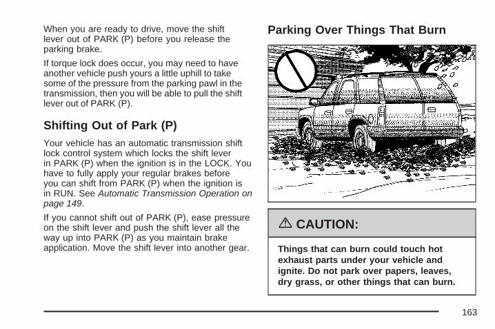
When you are ready to drive, move the shiftlever out of PARK (P) before you release theparking brake.
If torque lock does occur, you may need to haveanother vehicle push yours a little uphill to takesome of the pressure from the parking pawl in thetransmission, then you will be able to pull the shiftlever out of PARK (P).
Shifting Out of Park (P)Your vehicle has an automatic transmission shiftlock control system which locks the shift leverin PARK (P) when the ignition is in the LOCK. Youhave to fully apply your regular brakes beforeyou can shift from PARK (P) when the ignition isin RUN. See Automatic Transmission Operation onpage 149.
If you cannot shift out of PARK (P), ease pressureon the shift lever and push the shift lever all theway up into PARK (P) as you maintain brakeapplication. Move the shift lever into another gear.
Parking Over Things That Burn
{CAUTION:
Things that can burn could touch hotexhaust parts under your vehicle andignite. Do not park over papers, leaves,dry grass, or other things that can burn.
163

Engine Exhaust
{CAUTION:
Engine exhaust can kill. It contains thegas carbon monoxide (CO), which youcannot see or smell. It can causeunconsciousness and death.
You might have exhaust coming in if:• The exhaust system sounds strange
or different.• Your vehicle gets rusty underneath.• Your vehicle was damaged in a
collision.• Your vehicle was damaged when
driving over high points on the roador over road debris.
• Repairs were not done correctly.• Your vehicle or the exhaust system
has been modified improperly.
CAUTION: (Continued)
CAUTION: (Continued)
If you ever suspect exhaust is coming intoyour vehicle:
• Drive it only with all the windowsdown to blow out any CO; and
• Have your vehicle fixed immediately.
Running the Engine While ParkedIt is better not to park with the engine running. But ifyou ever have to, here are some things to know.
{CAUTION:
Idling the engine with the climate controlsystem off could allow dangerous exhaustinto your vehicle. See the earlier cautionunder Engine Exhaust on page 164.Also, idling in a closed-in place can let
CAUTION: (Continued)
164

CAUTION: (Continued)
deadly carbon monoxide (CO) into yourvehicle even if the climate control fan is atthe highest setting. One place this canhappen is a garage. Exhaust — withCO — can come in easily. NEVER park ina garage with the engine running.
Another closed-in place can be a blizzard.See Winter Driving on page 405.
{CAUTION:
It can be dangerous to get out of yourvehicle if the shift lever is not fully inPARK (P) with the parking brake firmlyset. Your vehicle can roll. Do not leaveyour vehicle when the engine is runningunless you have to. If you have left the
CAUTION: (Continued)
CAUTION: (Continued)
engine running, the vehicle can movesuddenly. You or others could be injured.To be sure your vehicle will not move,even when you are on fairly level ground,always set the parking brake and movethe shift lever to PARK (P).
{CAUTION:
Four-wheel drive vehicles with the transfercase in NEUTRAL will allow the vehicle toroll, even if the shift lever is in PARK (P).So, be sure the transfer case is in a drivegear — not in NEUTRAL. Always set theparking brake.
Follow the proper steps to be sure your vehicle willnot move. See Shifting Into Park (P) on page 161.
If you are pulling a trailer, see Towing a Trailer onpage 428.
165

Mirrors
Automatic Dimming Rearview Mirrorwith OnStar®, Compass andTemperature DisplayYour vehicle may have this feature. When on, theautomatic dimming mirror dims to the proper levelto minimize glare from lights behind you after dark.
The mirror has a dual display in the upper rightcorner of the mirror face that shows the compassreading and the outside temperature.
Control buttons for the OnStar® system are at thebottom of the mirror. See OnStar® System onpage 175 for more information about the servicesOnStar® provides.
P (On/Off): This is the on/off button.
Temperature and Compass DisplayPress the on/off button, located to the farleft, briefly to turn the compass/temperaturedisplay on or off.
If the display reads CAL, the compass needs tobe calibrated. For more information, see “CompassCalibration” following.
To adjust between Fahrenheit and Celsius, do thefollowing:
1. Press and hold the on/off button forapproximately four seconds until either aflashing F or C appears.
2. Press the button again to change the displayto the desired unit of measurement. Afterapproximately four seconds of inactivity, thenew unit will be locked in and thecompass/temperature display will return.
If an abnormal temperature reading is displayedfor an extended period of time, see yourdealer. Under certain circumstances, a delay inupdating the temperature is normal.
166

Automatic Dimming Mirror OperationThe automatic dimming mirror function is turned onautomatically each time the ignition is started.To operate the automatic dimming mirror, do thefollowing:
1. Make sure the green indicator light, locatedto the left of the on/off button, is lit. If it isnot, press and hold the on/off button forapproximately six seconds until the greenlight comes on, indicating that the mirror isin automatic dimming mode.
2. Turn off the automatic dimming mirror functionby pressing and holding the on/off button forapproximately six seconds, until the greenindicator light turns off.
Compass CalibrationThe compass may need calibration if one of thefollowing occurs:
• After approximately five seconds, the displaydoes not show a compass heading, N forNorth, for example, there may be a strongmagnetic field interfering with the compass.
Such interference may be caused by amagnetic antenna mount, magnetic note padholder, or a similar magnetic item.
• The compass does not display the correctheading and the compass zone varianceis set correctly.
In order to calibrate, CAL must be displayed in themirror compass windows. If CAL is not displayed,push the on/off button for approximately12 seconds or until CAL is displayed.
The compass can be calibrated by driving thevehicle in circles at 5 mph (8 km/h) or less untilthe display reads a direction.
Compass VarianceThe mirror is set in zone eight upon leaving thefactory. It will be necessary to adjust the compassto compensate for compass variance if thevehicle is outside of zone eight. Under certaincircumstances, as during a long distancecross-country trip, it will be necessary to adjust forcompass variance. Compass variance is thedifference between earth’s magnetic north and truegeographic north. If not adjusted to account forcompass variance, the compass could givefalse readings.
167

To adjust for compass variance, do the following:
1. Find your current location and variancezone number on the following zone map.
2. Press and hold the on/off button until a Z anda zone number appears in the display. Thecompass is now in zone mode.
3. Keep pressing the on/off button until thedesired zone number appears in thedisplay. Release the button. After
approximately four seconds of inactivity, thenew zone number will be locked in andthe compass/temperature display will return.
Cleaning the MirrorWhen cleaning the mirror, use a paper towel orsimilar material dampened with glass cleaner.Do not spray glass cleaner directly on the mirroras that may cause the liquid cleaner to enterthe mirror housing.
Automatic Dimming Rearview Mirrorwith Compass and TemperatureDisplayYour vehicle may have this mirror. When on, anautomatic dimming mirror will dim to the properlevel to minimize glare from lights behind youafter dark.
The mirror also includes a dual display in theupper right corner of the mirror with the compassreading and the outside temperature.
Yb: Briefly press this button to turn the displayon or off.
168

Temperature DisplayThe temperature can be displayed by pressing thecompass/temperature button. Pressing thecompass/temperature button once briefly, willtoggle the display reading on and off. To alternatethe temperature reading between Fahrenheit andCelsius, press and hold the compass/ temperaturebutton for approximately three seconds until thedisplay blinks F and C. After approximatelyfive seconds of inactivity, the display will stopblinking and display the last selection made.
If an abnormal reading is displayed, see yourdealer.
Automatic Dimming Mirror Operation
O: Press this button to turn the automaticdimming feature on or off. The indicator light tothe left of the button will turn on to indicate whenthe feature is on. Once the mirror is turned off,it will remain off until it is turned back on, or untilthe vehicle is restarted.
Compass OperationPress the compass/temperature button oncebriefly to turn the display on or off.
Compass CalibrationThe compass may need calibration if one of thefollowing occurs:
• If CAL is displayed while driving in the vehicle.
• After approximately five seconds, the displaydoes not show a compass heading, N forNorth, for example, there may be a strongmagnetic field interfering with the compass.Such interference may be caused by amagnetic antenna mount, magnetic note padholder, or a similar magnetic item.
• The compass does not display the correctheading and the compass zone varianceis set correctly.
In order to calibrate, CAL must be displayed in themirror compass windows. If CAL is not displayed,push in the compass/temperature button forapproximately nine seconds or until CAL isdisplayed.
The compass can be calibrated by driving thevehicle in circles at 5 mph (8 km/h) or less until thedisplay reads a direction.
169

Compass VarianceThe mirror is set in zone eight upon leaving thefactory. It will be necessary to adjust the compassto compensate for compass variance if thevehicle is outside zone eight. Under certaincircumstances, as during a long distancecross-country trip, it will be necessary to adjust forcompass variance. Compass variance is thedifference between earth’s magnetic north and truegeographic north. If not adjusted to account forcompass variance, your compass could give falsereadings.
To adjust for compass variance:
1. Find your current location and variance zonenumber on the following zone map.
2. Press and hold the compass/temperaturebutton for six seconds until a zone numberappears in the display.
3. Press the compass/temperature button on thebottom of the mirror until the new zonenumber appears in the display. After you stoppressing the button, the display will show acompass direction within a few seconds.
170

Cleaning the MirrorUse a paper towel or similar material dampenedwith glass cleaner. Do not spray glass cleanerdirectly on the mirror as that may cause the liquidcleaner to enter the mirror housing.
Outside Manual MirrorsAdjust your outside mirrors so you can just seethe side of your vehicle and have a clear view ofobjects behind you. The mirrors can be foldedin to enter narrow areas.
The use of hood-mounted air deflectors andadd-on convex mirror attachments may adverselyaffect mirror performance.
Outside Trailer-Tow Mirrors
If your vehicle has trailer towing type mirrors, theycan be adjusted so you can have a clear viewof the objects behind you. Manually pull outthe mirror head to extend it for better visibilitywhen towing a trailer.
These mirrors can be manually folded forward orrearward. The lower portion of the mirror isconvex. A convex mirror’s surface is curved soyou can see more from the driver’s seat. Theconvex mirror can be adjusted manually to thedriver’s preferred position for better vision.
171
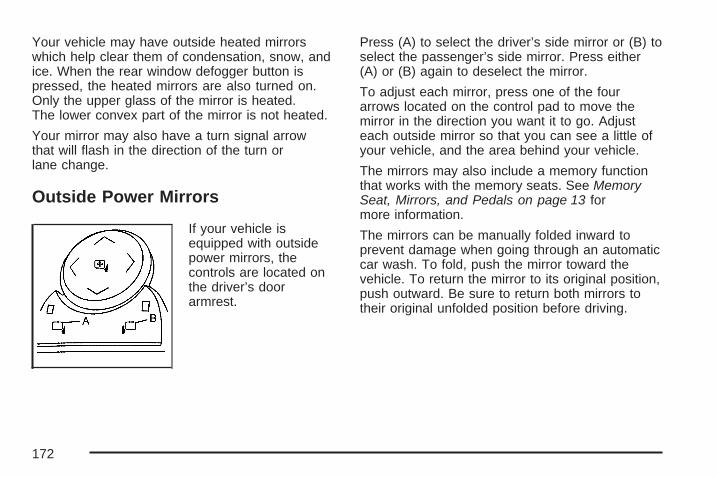
Your vehicle may have outside heated mirrorswhich help clear them of condensation, snow, andice. When the rear window defogger button ispressed, the heated mirrors are also turned on.Only the upper glass of the mirror is heated.The lower convex part of the mirror is not heated.
Your mirror may also have a turn signal arrowthat will flash in the direction of the turn orlane change.
Outside Power Mirrors
If your vehicle isequipped with outsidepower mirrors, thecontrols are located onthe driver’s doorarmrest.
Press (A) to select the driver’s side mirror or (B) toselect the passenger’s side mirror. Press either(A) or (B) again to deselect the mirror.
To adjust each mirror, press one of the fourarrows located on the control pad to move themirror in the direction you want it to go. Adjusteach outside mirror so that you can see a little ofyour vehicle, and the area behind your vehicle.
The mirrors may also include a memory functionthat works with the memory seats. See MemorySeat, Mirrors, and Pedals on page 13 formore information.
The mirrors can be manually folded inward toprevent damage when going through an automaticcar wash. To fold, push the mirror toward thevehicle. To return the mirror to its original position,push outward. Be sure to return both mirrors totheir original unfolded position before driving.
172
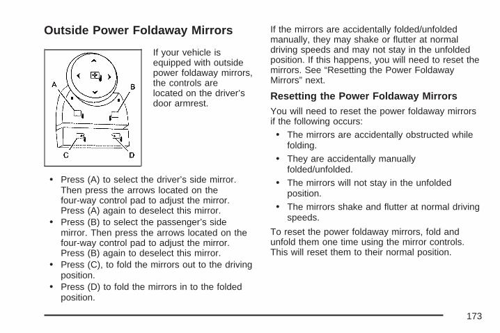
Outside Power Foldaway Mirrors
If your vehicle isequipped with outsidepower foldaway mirrors,the controls arelocated on the driver’sdoor armrest.
• Press (A) to select the driver’s side mirror.Then press the arrows located on thefour-way control pad to adjust the mirror.Press (A) again to deselect this mirror.
• Press (B) to select the passenger’s sidemirror. Then press the arrows located on thefour-way control pad to adjust the mirror.Press (B) again to deselect this mirror.
• Press (C), to fold the mirrors out to the drivingposition.
• Press (D) to fold the mirrors in to the foldedposition.
If the mirrors are accidentally folded/unfoldedmanually, they may shake or flutter at normaldriving speeds and may not stay in the unfoldedposition. If this happens, you will need to reset themirrors. See “Resetting the Power FoldawayMirrors” next.
Resetting the Power Foldaway MirrorsYou will need to reset the power foldaway mirrorsif the following occurs:
• The mirrors are accidentally obstructed whilefolding.
• They are accidentally manuallyfolded/unfolded.
• The mirrors will not stay in the unfoldedposition.
• The mirrors shake and flutter at normal drivingspeeds.
To reset the power foldaway mirrors, fold andunfold them one time using the mirror controls.This will reset them to their normal position.
173

Turn Signal IndicatorYour vehicle may have a turn signal indicator onthe mirror. An arrow on the mirror will flash inthe direction of the turn or lane change.
Ground Illumination LampsThe mirrors may also include ground illuminationlamps in the base of the mirror. These lampshelp you see the area near the base of the frontdoors when it is dark out.
Outside Automatic Dimming MirrorIf your vehicle is equipped with this feature,the driver’s outside mirror will adjust for the glareof headlamps behind you. This feature iscontrolled by the on and off settings found on theelectrochromic inside mirror. See AutomaticDimming Rearview Mirror with OnStar®, Compassand Temperature Display on page 166 orAutomatic Dimming Rearview Mirror with Compassand Temperature Display on page 168 for moreinformation.
Outside Curb View Assist MirrorsIf your vehicle has the memory package, theoutside mirrors are able to perform the curb viewassist mirror function. This feature may be useful inallowing the driver to view the curb when parallelparking. This feature will cause the passenger’sand/or driver’s mirror to tilt to a preselected positionwhen the vehicle is in REVERSE (R).
The passenger’s and/or driver’s mirror will returnto its original position when the vehicle isshifted out of REVERSE (R) and either a thirtysecond delay has occurred, the vehicle speed isgreater than 8 mph (12 km/h), or the ignitionis turned to off.
This feature can be turned on or off through theDriver Information Center (DIC). See DriverInformation Center (DIC) on page 262 for moreinformation.
174

Outside Convex MirrorYour passenger’s side mirror may have convexglass. A convex mirror’s surface is curved so youcan see more from the driver’s seat.
{CAUTION:
A convex mirror can make things (likeother vehicles) look farther away thanthey really are. If you cut too sharply intothe right lane, you could hit a vehicle onyour right. Check your inside mirror orglance over your shoulder beforechanging lanes.
Outside Heated MirrorsThe vehicle may have outside heated mirrorswhich help clear them of condensation, snow,and ice.
When the rear window defogger button is pressed,the heated mirrors are also turned on. See
“Rear Window Defogger” under Dual AutomaticClimate Control System on page 231 or ClimateControl System on page 227 for more information.
OnStar® System
OnStar® uses several innovative technologies andlive advisors to provide you with a wide rangeof safety, security, information, and convenienceservices. If your airbags deploy, the system isdesigned to make an automatic call to OnStar®
Emergency advisors who can request emergencyservices be sent to your location. If you lockyour keys in the vehicle, call OnStar® at1-888-4-ONSTAR and they can send a signal tounlock your doors. If you need roadsideassistance, press the OnStar® button and theycan contact Roadside Service for you.
175

OnStar® service is provided to you subject to theOnStar® Terms and Conditions. You maycancel your OnStar® service at any time bycontacting OnStar® as provided below. A completeOnStar® Owners Guide and the OnStar® Termsand Conditions are included in the vehicle’sOnStar® Subscriber glove box literature. For moreinformation, visit onstar.com or onstar.ca,contact OnStar® at 1-888-4-ONSTAR(1-888-466-7827) or TTY 1-877-248-2080, orpress the OnStar® button to speak with anOnStar® advisor 24 hours a day, 7 days a week.
Not all OnStar® features are available on allvehicles. To check if your vehicle is equipped toprovide the services described below, or for afull description of OnStar® services and systemlimitations, see the OnStar® Owner’s Guide in yourglove box or visit onstar.com.
OnStar® ServicesFor new vehicles with OnStar®, the Safe & SoundPlan, or the Directions & Connections® Plan isincluded for one year from the date of purchase.You can extend this plan beyond the first year,or upgrade to the Directions & Connections® Plan.
For more information, press the OnStar® button tospeak with an advisor. Some OnStar® services(such as Remote Door Unlock or Stolen VehicleLocation Assistance) may not be availableuntil you register with OnStar®.
Available Services with Safe &Sound® Plan• Automatic Notification of Airbag Deployment
• Advanced Automatic Crash Notification(AACN) (If equipped)
• Link to Emergency Services
• Roadside Assistance
• Stolen Vehicle Location Assistance
• AccidentAssist
• Remote Door Unlock/Vehicle Alert
• OnStar® Vehicle Diagnostics
• GM Goodwrench® On Demand Diagnostics
• OnStar® Hands-Free Calling with30 complimentary minutes
• OnStar® Virtual Advisor (U.S. Only)
176

Available Services included with Directions& Connections® Plan• All Safe and Sound Plan Services
• Driving Directions - Advisor delivered orOnStar® Turn-by-Turn Navigation (If equipped)
• RideAssist
• Information and Convenience Services
OnStar® Hands-Free CallingOnStar® Hands-Free Calling allows eligibleOnStar® subscribers to make and receive callsusing voice commands. Hands-Free Calling is fullyintegrated into the vehicle, and can be used withOnStar® Pre-Paid Minute Packages. Hands-FreeCalling may also be linked to a Verizon Wirelessservice plan in the U.S. or a Bell Mobility serviceplan in Canada, depending on eligibility. To find outmore, refer to the OnStar® Owners Guide in thevehicle’s glove box, visit www.onstar.com orwww.onstar.ca, or speak with an OnStar® advisorby pressing the OnStar® button or calling1-888-4-ONSTAR (1-888-466-7827).
OnStar® Virtual AdvisorOnStar® Virtual Advisor is a feature of OnStar®
Hands-Free Calling that uses your minutes toaccess location-based weather, local traffic reports,and stock quotes. By pressing the phone buttonand giving a few simple voice commands, you canbrowse through the various topics. See the OnStar®
Owners Guide for more information (Only availablein the continental U.S.).
OnStar® Steering Wheel ControlsYour vehicle may have a Talk/Mute button thatcan be used to interact with OnStar® Hands-FreeCalling. See Audio Steering Wheel Controls onpage 354 for more information.
On some vehicles, you may have to hold thebutton for a few seconds and give the command“ONSTAR” in order to activate the OnStar®
Hands-Free Calling feature.
On some vehicles, the mute button can be used todial numbers into voicemail systems, or to dialphone extensions. See the OnStar® Owner’sGuide for more information.
177

How OnStar® Service WorksIn order to provide you with OnStar® services,your vehicle’s OnStar® system has the capabilityof recording and transmitting vehicle information.This information is automatically sent to anOnStar® Call Center at the time of an OnStar®
button press, Emergency button press or ifyour airbags or AACN system deploys. The vehicleinformation usually includes your GPS locationand, in the event of a crash, additional informationregarding the accident that your vehicle hasbeen involved in (e.g. the direction from whichyour vehicle was hit). When you use the VirtualAdvisor feature of OnStar® Hands-Free Calling,your vehicle also sends OnStar® your GPSlocation so that we can provide you withlocation-based services.OnStar® service cannot work unless your vehicleis in a place where OnStar® has an agreementwith a wireless service provider for service in thatarea. OnStar® service also cannot work unlessyou are in a place where the wireless serviceprovider OnStar® has hired for that areahas coverage, network capacity and receptionwhen the service is needed, and technology that
is compatible with the OnStar® service. Not allservices are available everywhere, particularly inremote or enclosed areas, or at all times.OnStar® service that involves location informationabout your vehicle cannot work unless GPSsatellite signals are unobstructed and available inthat place as well.
Your vehicle must have a working electricalsystem (including adequate battery power) for theOnStar® equipment to operate. There are otherproblems OnStar® cannot control that may preventOnStar® from providing OnStar® service to youat any particular time or place. Some examples aredamage to important parts of your vehicle in anaccident, hills, tall buildings, tunnels, weatheror wireless phone network congestion.
Your ResponsibilityYou may need to increase the volume of yourradio to hear the OnStar® advisor. If the light nextto the OnStar® buttons is red, this means thatyour system is not functioning properly and shouldbe checked by your dealer/retailer. If the lightappears clear (no light is appearing), your OnStar®
subscription has expired. You can always pressthe OnStar® button to confirm that your OnStar®
equipment is active.
178

Universal Home RemoteSystem
System IdentificationYour vehicle may have a Universal Home RemoteSystem.
Determine which Universal Home Remote yourvehicle has and then read the pages following forinstructions on programming your specificsystem.
If there is one triangular Light Emitting Diode(LED) indicator light above the Universal HomeRemote buttons, follow the instructions underUniversal Home Remote System Operation (WithOne Triangular LED).
If there are three round LED indicator lights abovethe Universal Home Remote buttons, follow theinstructions under Universal Home Remote SystemOperation (With Three Round LED).
For help or information on the Universal HomeRemote System, call the customer assistancephone number under Customer Assistance Officeson page 600.
179

Universal Home Remote SystemThe Universal Home Remote System providesa way to replace up to three hand-heldRadio-Frequency (RF) transmitters used toactivate devices such as garage door openers,security systems, and home lighting.
This device complies with Part 15 of the FCCRules. Operation is subject to the followingtwo conditions:
1. This device may not cause harmfulinterference.
2. This device must accept any interferencereceived, including interference that maycause undesired operation.
This device complies with RSS-210 of IndustryCanada. Operation is subject to the followingtwo conditions:
1. This device may not cause interference.
2. This device must accept any interferencereceived, including interference that maycause undesired operation of the device.
Changes or modifications to this system by otherthan an authorized service facility could voidauthorization to use this equipment.
Universal Home Remote SystemOperation (With One Triangular LED)
If there is one triangular Light Emitting Diode(LED) indicator light above the Universal HomeRemote buttons, follow the instructions below.
Do not use the Universal Home Remote with anygarage door opener that does not have the stopand reverse feature. This includes any garage dooropener model manufactured before April 1, 1982. Ifyou have a newer garage door opener with rollingcodes, please be sure to follow Steps 6 through 8 tocomplete the programming of your Universal HomeRemote Transmitter.
180
Read the instructions completely before attemptingto program the Universal Home Remote. Becauseof the steps involved, it may be helpful to haveanother person available to assist you in theprogramming steps.
Keep the original hand-held transmitter for use inother vehicles as well as for future Universal HomeRemote programming. It is also recommended thatupon the sale of the vehicle, the programmedUniversal Home Remote buttons should be erasedfor security purposes. See “Erasing UniversalHome Remote Buttons” later in section.
When programming a garage door, it is advised topark outside of the garage. Be sure that peopleand objects are clear of the garage door orgate operator you are programming.
It is recommended that a new battery be installedin your hand-held transmitter for quicker andmore accurate transmission of the radio-frequencysignal.
Programming the Universal HomeRemote SystemFollow these steps to program up to three devices:
1. Press and hold down the two outsideUniversal Home Remote buttons, releasingonly when the Universal Home Remoteindicator light begins to flash, after20 seconds. Do not hold down the buttons forlonger than 30 seconds and do not repeatthis step to program a second and/orthird hand-held transmitter to the remainingtwo Universal Home Remote buttons.
2. Hold the end of your hand-held transmitterabout 1 to 3 inches (3 to 8 cm) away fromthe Universal Home Remote buttonswhile keeping the indicator light in view.
3. At the same time, press and hold both thedesired Universal Home Remote button andthe hand-held transmitter button. Do notrelease the buttons until Step 4 has beencompleted.Some entry gates and garage door openersmay require you to substitute Step 3 withthe procedure noted in “Gate Operator andCanadian Programming” later in this section.
181

4. The indicator light will flash slowly at first andthen rapidly after Universal Home Remotesuccessfully receives the frequency signalfrom the hand-held transmitter. Release bothbuttons.
5. Press and hold the newly-trained UniversalHome Remote button and observe theindicator light.If the indicator light stays on continuously,programming is complete and your deviceshould activate when the Universal HomeRemote button is pressed and released.To program the remaining two Universal HomeRemote buttons, begin with Step 2 under“Programming Universal Home Remote.”Do not repeat Step 1 as this will erase allof the programmed channels.If the indicator light blinks rapidly fortwo seconds and then turns to a constantlight, continue with Steps 6 through 8 followingto complete the programming of a rolling-codedevice, most commonly, a garage dooropener.
6. Locate in the garage, the garage door openerreceiver (motor-head unit). Locate the “Learn”or “Smart” button. This can usually befound where the hanging antenna wire isattached to the motor-head unit.
7. Firmly press and release the “Learn” or“Smart” button. The name and color ofthe button may vary by manufacturer.You will have 30 seconds to start Step 8.
8. Return to the vehicle. Firmly press and holdthe programmed Universal Home Remotebutton for two seconds, then release it.Immediately press and hold the same buttona second time for two seconds, thenrelease it. Immediately, press and hold thesame button a third time for two seconds, thenrelease.The Universal Home Remote should nowactivate the rolling-code device.
To program the remaining two Universal HomeRemote buttons, begin with Step 2 of“Programming Universal Home Remote.” You donot want to repeat Step 1, as this will eraseall previous programming from the Universal HomeRemote buttons.
182
Gate Operator and CanadianProgrammingCanadian radio-frequency laws require transmittersignals to time out or quit after several secondsof transmission. This may not be long enoughfor Universal Home Remote to pick up the signalduring programming. Similarly, some U.S. gateoperators are manufactured to time out inthe same manner.
If you live in Canada, or you are having difficultyprogramming a gate operator or garage dooropener by using the “Programming UniversalHome Remote” procedures, regardless of whereyou live, replace Step 3 under “ProgrammingUniversal Home Remote” with the following:
Continue to press and hold the Universal HomeRemote button while you press and release everytwo seconds (cycle) the hand-held transmitterbutton until the frequency signal has beensuccessfully accepted by the Universal HomeRemote. The Universal Home Remote indicatorlight will flash slowly at first and then rapidly.Proceed with Step 4 under “ProgrammingUniversal Home Remote” to complete.
Using Universal Home RemotePress and hold the appropriate Universal HomeRemote button for at least half of a second.The indicator light will come on while the signalis being transmitted.
Erasing Universal Home RemoteButtonsTo erase programming from the three UniversalHome Remote buttons do the following:
1. Press and hold down the two outside buttonsuntil the indicator light begins to flash, after20 seconds. Do not hold the two outsidebuttons for longer than 30 seconds.
2. Release both buttons.
The Universal Home Remote is now in the training(learning) mode and can be programmed at anytime beginning with Step 2 under “ProgrammingUniversal Home Remote” shown earlier inthis section.
Individual buttons cannot be erased, but they canbe reprogrammed. See “Reprogramming aSingle Universal Home Remote Button” followingthis section.
183

Reprogramming a Single UniversalHome Remote ButtonTo program a device to Universal Home Remoteusing a Universal Home Remote buttonpreviously trained, follow these steps:
1. Press and hold the desired Universal HomeRemote button. Do not release the button.
2. The indicator light will begin to flash after20 seconds. While still holding the UniversalHome Remote button, proceed with Step 2under “Programming Universal Home Remote”shown earlier in this section.
For help or information on the Universal HomeRemote System, call the customer assistancephone number under Customer Assistance Officeson page 600.
Universal Home Remote SystemOperation (With Three Round LED)
Your vehicle may have the Universal HomeRemote System. If there are three round LightEmitting Diode (LED) indicator lights abovethe Universal Home Remote buttons, follow theinstructions below.
This system provides a way to replace up tothree remote control transmitters used to activatedevices such as garage door openers, securitysystems, and home automation devices.
Do not use this system with any garage dooropener that does not have the stop and reversefeature. This includes any garage door openermodel manufactured before April 1, 1982.
184
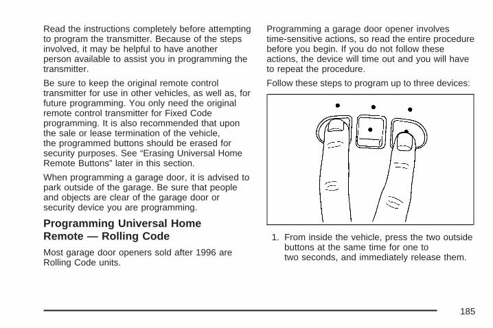
Read the instructions completely before attemptingto program the transmitter. Because of the stepsinvolved, it may be helpful to have anotherperson available to assist you in programming thetransmitter.
Be sure to keep the original remote controltransmitter for use in other vehicles, as well as, forfuture programming. You only need the originalremote control transmitter for Fixed Codeprogramming. It is also recommended that uponthe sale or lease termination of the vehicle,the programmed buttons should be erased forsecurity purposes. See “Erasing Universal HomeRemote Buttons” later in this section.
When programming a garage door, it is advised topark outside of the garage. Be sure that peopleand objects are clear of the garage door orsecurity device you are programming.
Programming Universal HomeRemote — Rolling CodeMost garage door openers sold after 1996 areRolling Code units.
Programming a garage door opener involvestime-sensitive actions, so read the entire procedurebefore you begin. If you do not follow theseactions, the device will time out and you will haveto repeat the procedure.
Follow these steps to program up to three devices:
1. From inside the vehicle, press the two outsidebuttons at the same time for one totwo seconds, and immediately release them.
185

2. Locate in the garage, the garage door openerreceiver (motor-head unit). Locate the “Learn”or “Smart” button. It can usually be foundwhere the hanging antenna wire is attachedto the motor-head unit and may be acolored button. Press this button. After youpress this button, you will have 30 seconds tocomplete the following steps.
3. Immediately return to your vehicle. Press andhold the universal home remote button thatyou would like to use to control the garagedoor until the garage door moves. Theindicator light, above the selected button,should slowly blink. You may need to hold thebutton from five to 20 seconds.
4. Immediately, within one second, release thebutton when the garage door moves. Theindicator light will blink rapidly untilprogramming is complete.
5. Press and release the same button again.The garage door should move, confirmingthat programming is successful and complete.
To program another Rolling Code device suchas an additional garage door opener, a securitydevice, or home automation device, repeatSteps 1-5, choosing a different function button inStep 3 than what you used for the garage dooropener.
If these instructions do not work, you probablyhave a Fixed Code garage door opener. Follow theProgramming instructions below for a FixedCode garage door opener.
186
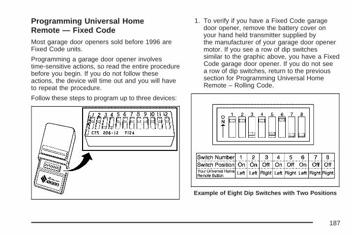
Programming Universal HomeRemote — Fixed CodeMost garage door openers sold before 1996 areFixed Code units.
Programming a garage door opener involvestime-sensitive actions, so read the entire procedurebefore you begin. If you do not follow theseactions, the device will time out and you will haveto repeat the procedure.
Follow these steps to program up to three devices:
1. To verify if you have a Fixed Code garagedoor opener, remove the battery cover onyour hand held transmitter supplied bythe manufacturer of your garage door openermotor. If you see a row of dip switchessimilar to the graphic above, you have a FixedCode garage door opener. If you do not seea row of dip switches, return to the previoussection for Programming Universal HomeRemote – Rolling Code.
Example of Eight Dip Switches with Two Positions
187

Your panel of switches may not appearexactly as they do in the examples above, butthey should be similar.The switch positions on your hand-heldtransmitter may be labeled, as follows:
• A switch in the up position may be labeledas “Up,” “+,” or “On.”
• A switch in the down position may belabeled as “Down,” “−,” or “Off.”
• A switch in the middle position may belabeled as “Middle,” “0,” or “Neutral.”
2. Write down the eight to 12 switch settingsfrom left to right as follows:
• When a switch is in the up position,write “Left.”
• When a switch is in the down position,write “Right.”
• If a switch is set between the up and downposition, write “Middle.”The switch settings that you wrote down inStep 2 will now become the button strokesyou enter into the Universal Home Remote inStep 4. Be sure to enter the switch settingsthat you wrote down in Step 2, in order fromleft to right, into the Universal Home Remote,when completing Step 4.
3. From inside your vehicle, first firmly pressall three buttons at the same time for aboutthree seconds. Release the buttons to putthe Universal Home Remote intoprogramming mode.
Example of Eight Dip Switches with Three Positions
188

4. The indicator lights will blink slowly. Enter eachswitch setting from Step 2 into your vehicle’sUniversal Home Remote. You will have twoand one-half minutes to complete Step 4. Nowpress one button on the Universal HomeRemote for each switch setting as follows:
• If you wrote “Left,” press the left button in thevehicle.
• If you wrote “Right,” press the right button inthe vehicle.
• If you wrote “Middle,” press the middlebutton in the vehicle.
5. After entering all of the switch positions,again, firmly press and release allthree buttons at the same time. Theindicator lights will turn on.
6. Press and hold the button you would like touse to control the garage door until thegarage door moves. The indicator light abovethe selected button should slowly blink.You may need to hold the button from five to55 seconds.
7. Immediately release the button when thegarage door moves. The indicator light willblink rapidly until programming is complete.
8. Press and release the same button again.The garage door should move, confirmingthat programming is successful and complete.
To program another Fixed Code device such as anadditional garage door opener, a security device,or home automation device, repeat Steps 1-8,choosing a different button in Step 6 than what youused for the garage door opener.
189

Using Universal Home RemotePress and hold the appropriate button for atleast half of a second. The indicator light willcome on while the signal is being transmitted.
Reprogramming Universal HomeRemote ButtonsYou can reprogram any of the three buttons byrepeating the instructions.
Erasing Universal Home RemoteButtonsYou should erase the programmed buttons whenyou sell or terminate your lease.
To erase either Rolling Code or Fixed Code onthe Universal Home Remote device, do thefollowing:
1. Press and hold the two outside buttons at thesame time for approximately 20 seconds, untilthe indicator lights, located directly abovethe buttons, begin to blink rapidly.
2. Once the indicator lights begin to blink,release both buttons. The codes from allbuttons will be erased.
For help or information on the Universal HomeRemote System, call the customer assistancephone number under Customer Assistance Officeson page 600.
Storage Areas
Glove BoxOpen the glove box by pulling up on the bottom ofthe handle.
Cupholder(s)Your vehicle may have cupholders located in thefront and rear of the floor console or in thefold down armrest. The front cupholders can beadjusted by moving the insert forward or rearward.You may also have cupholders in the secondand third row seat armrest areas.
190

To access the cupholders in the rear floor console,pull downward on the lid.
Center Console Storage AreaYour vehicle may have a console compartmentwith cupholders between the bucket seats.
To open it, press the button and lift the consolelid open.
The rear of the console has a cupholder thatswings down for the rear seat passenger to use.
Luggage CarrierThe vehicle may have a luggage carrier that canbe used to load things on top of the vehicle.
The luggage carrier has siderails attached to theroof. It may also have crossrails which can bemoved back and forth to help secure cargo. Tie theload to the siderails or siderail supports.
Notice: Loading cargo on the luggage carrierthat weighs more than 200 lbs (91 kg) orhangs over the rear or sides of the vehiclemay damage your vehicle. Load cargo so thatit rests on the slats as far forward aspossible and against the side rails, makingsure to fasten it securely.
Do not exceed the maximum vehicle capacitywhen loading your vehicle. For more informationon vehicle capacity and loading, see Loading YourVehicle on page 411.
191

To prevent damage or loss of cargo while you aredriving, check to make sure the luggage andcargo are still securely fastened.
Be sure the cargo is properly loaded.
• If small heavy objects are placed on the roof,cut a piece of 3/8 inch plywood to fit insidethe crossrails and siderails to spread the load.Tie the plywood to the siderail supports.
• Tie the load to the crossrails or the siderailsupports. Use the crossrails only to keep theload from sliding. To move a crossrail, lift therelease lever, on both sides of the rail, up toloosen it. Slide the crossrail to the desiredposition balancing the force side to side. Pressthe release lever on both sides of the rail, downto tighten it. Try to slide the crossrail back andforth slightly to be sure it is tight.
• If you need to carry long items, move thecrossrails as far apart as they will go. Tie theload to the crossrails and the siderails orsiderail supports. Also tie the load to thebumpers. Do not tie the load so tightly that thecrossrails or siderails are damaged.
• After moving a crossrail, be sure it is securelylocked into the siderail.
Your vehicle has a Center High-Mounted Stoplamp(CHMSL) located above the rear glass.
If items are loaded on the roof of the vehicle, careshould be taken not to block or damage theCHMSL unit.
Rear Storage AreaYour vehicle may have a storage compartmentlocated in the rear cargo area of the vehicle in thedriver’s side trim panel.
To open the utility compartment, turn the knobsand swing the compartment door open. Thecompartment door can be removed.
Rear Seat ArmrestYour vehicle may be equipped with a rear seatarmrest. Pull the loop at the top of the armrestdown to access the cupholders.
192

Cargo Cover
{CAUTION:
An improperly stored cargo cover could bethrown about the vehicle during a collisionor sudden maneuver. You or others couldbe injured. If you remove the cover, alwaysstore it in the proper storage location.When you put it back, always be sure that itis securely reattached.
If your vehicle has a cargo cover, you can use itto cover items in the cargo area of your vehicle.
To use the cover, do the following:
1. Pull the cover handle toward the rear of thevehicle.
2. Latch the cover posts into the retainingsockets on the cargo area trim panels.
To return the cover to the retracted position, dothe following:
1. Pull up on the cover handle to release thecover posts from the retaining sockets.
2. Let the cover move forward to the full retractedposition.
To remove the cover, from a regular wheelbasemodel, do the following:
1. Let the cover go all the way into the holder.
2. Then, grasping the driver’s side coverend cap, push the cover end cap toward thepassenger’s side of the vehicle.
3. Swing the cover rearward and take it out ofthe vehicle.
To put the cover in the vehicle, do the following:
1. Make sure the cover slot in the holder facesrearward with the round surface facing down.
2. Then, hold the cover at an angle and placethe cover end cap into the slot in thepassenger’s side trim panel.
3. Move the other end of the cover forward andhold it next to the driver’s side trim panel slot.
193

4. Press the end caps in, this will allow the coverto fit into the trim slot.
5. Lightly pull on the cover holder to make sureit is secure.On the extended wheelbase models there aretwo cover positions. The slots furthestforward allow the cover to be used if the thirdseat is removed or folded down. The covercan be installed and removed from either side.
Cargo Tie DownsYour vehicle may have cargo tie downs in the rearcargo area that allow you to strap cargo in andkeep it from moving inside the vehicle.
Cargo Management SystemYour vehicle may be equipped with a cargomanagement system. It can be used for storingand separating cargo and as a table. Themaximum load is 200 lbs. (91 kg) distributed. It islocated in the rear of the vehicle on upper orlower horizontal guides. There are two verticalcurved guides that connect the upper andlower horizontal guides together. The system hasthree rollers on each side. The system has a
release lever located in the center of the grabhandle. This will engage and disengage a locatorpin. This is used in adjusting and positioningthe system.
The cargo management system can be positionedon the upper or lower horizontal guides.
To adjust the system from the upper position tothe lower position, do the following:
1. Squeeze and hold the release lever to retractthe locator pin.
2. Pull the system back until the front rollersreach the vertical curved guides.
194

3. Lower the front rollers to the lower guides andpull the system back until the middle set ofrollers clear the upper guides.
4. Lower the system until the middle rollers arelined up with lower guides. While holding inthe release lever, push the system forwarduntil all three sets of rollers are on the guides.
5. Release the lever and push the system untilthe locator pin reaches the locator hole.
To adjust the system from the lower position tothe upper position, do the following:
1. Squeeze and hold the release lever to retractthe locator pin.
2. Pull the system back and lift until the middlerollers can be placed into the upper guides.
3. Push the system forward until the front rollersare lined up with the vertical curved guides.
4. Push down on the rear of the system andraise the front rollers up the vertical curvedguides.
5. Push the system forward until all three sets ofrollers are resting on the guides and releasethe lever to engage the locating pin intothe hole.
To utilize the cargo management system as atable feature, squeeze the release lever and pullthe system towards you until the locator pinreaches the next hole. The system will extend outof the vehicle. The liftgate cannot be closed inthis position. Do not operate the vehicle withliftgate open.
The cargo management system can be removedfrom the vehicle. This procedure should becompleted by two people. While squeezing therelease lever, pull the system back until the rollersclear the guides. To reinstall the system, alignthe rollers to the guides, squeeze the release leverand push into position.
On one side of the system is a retractablestorage area.
195

To access, pull the handle in the center of thesystem up.
Slide the hinge covers to the center of each side.This will keep the sides of the storage systemstationary and allow it to stay upright. Inside thesystem are two removable dividers. To remove,unhook the loops at the ends of each divider.When not in use, slide the hinge covers back andthe storage system will fold back down. Pressdown on the storage cover to lock it into place.
To utilize the cupholders, follow the procedure forremoving the system from the vehicle.
196

SunroofYour vehicle may be equipped with a power slidingsunroof. To open or close the sunroof, the ignitionneeds to be turned to ON, or Retained AccessoryPower (RAP) must be active. When RAP is active,the sunroof will work for 10 minutes after theignition is turned off, or until a front door is opened.See Retained Accessory Power (RAP) on page 145for more information.
There are two switchesin the overhead consolethat operate thesunroof.
Manual-Open/Manual-Close: To open thesunroof press and hold the rear of the driver’s sideswitch until the sunroof reaches the desiredposition. To close the sunroof, press and hold thefront of the driver’s side switch until the sunroofreaches the desired position. The sunshadewill open automatically with the sunroof, but canalso be opened manually.
The sunroof has a comfort stop feature whichstops the sunroof from opening to the full-openposition. From the comfort stop position, press therear of the driver’s side switch a second time toopen the sunroof to the full-open position.
When the sunroof is opened, an air deflector willautomatically raise. The air deflector will retractwhen the sunroof is closed.
197

Express-Open/Express-Close: To express-openthe sunroof, fully press and release the rear ofthe driver’s side switch. The sunroof will openautomatically. To stop the sunroof partway, pressthe switch a second time. To express-closethe sunroof, fully press and release the front ofthe driver’s side switch. The sunroof will closeautomatically. To stop the sunroof partway, pressthe switch a second time. The sunshade willopen automatically with the sunroof, but can alsobe opened manually.
The sunroof has a comfort stop feature whichstops the sunroof from opening to the full-openposition. From the comfort stop position, press therear of the driver’s side switch a second time toopen the sunroof to the full-open position.
When the sunroof is opened, an air deflector willautomatically raise. The air deflector will retractwhen the sunroof is closed.
Vent: The sunroof has an express-vent openfeature. From the closed position, press the rearof the passenger’s side switch to vent the sunroof.To stop the sunroof partway, press the switch asecond time. To close the sunroof, press and holdthe front of the passenger’s side switch. Tostop the sunroof partway, release the switch.
Anti-Pinch Feature: If an object is in the pathof the sunroof while it is closing, the anti-pinchfeature will detect the object and stop the sunrooffrom closing at the point of the obstruction.The sunroof will then open halfway, and the airdeflector will raise. To close the sunroof onceit has re-opened, refer to the “Express-Close” or“Manual-Close” functions described previously.If the sunroof is in the vent position, and there isan object in the path of the sunroof when itclosing, the anti-pinch feature will detect the objectand stop the sunroof. To close the sunroof onceit has re-opened, refer to the “Manual-Close”or “Express-Close” functions described previously.
198

Instrument Panel Overview ........................ 202Hazard Warning Flashers .......................... 204Other Warning Devices ............................. 204Horn .......................................................... 205Tilt Wheel .................................................. 205Turn Signal/Multifunction Lever .................. 206Turn and Lane-Change Signals ................. 207Headlamp High/Low-Beam Changer .......... 208Flash-to-Pass ............................................ 208Windshield Wipers ..................................... 208Rainsense™ II Wipers ............................... 209Windshield Washer .................................... 210Rear Window Wiper/Washer ...................... 211Cruise Control ........................................... 212Exterior Lamps .......................................... 215Headlamps on Reminder ........................... 216Daytime Running Lamps (DRL) ................. 216Automatic Headlamp System ..................... 217Fog Lamps ................................................ 218Auxiliary Roof Mounted Lamp .................... 219
Instrument Panel Brightness ...................... 219Dome Lamps ............................................. 220Dome Lamp Override ................................ 220Entry Lighting ............................................ 220Exit Lighting .............................................. 220Reading Lamps ......................................... 220Electric Power Management ...................... 221Battery Run-Down Protection ..................... 221Ultrasonic Rear Parking Assist (URPA) ...... 222Accessory Power Outlet(s) ........................ 225Ashtray(s) and Cigarette Lighter ................ 227
Climate Controls ......................................... 227Climate Control System ............................. 227Dual Automatic Climate Control System .... 231Outlet Adjustment ...................................... 238Rear Air Conditioning and Heating
System .................................................. 239Rear Air Conditioning and Heating
System and Electronic Climate Controls ... 240
Section 3 Instrument Panel
199

Warning Lights, Gages, and Indicators ..... 242Instrument Panel Cluster ........................... 243Speedometer and Odometer ...................... 244Trip Odometer ........................................... 244Tachometer ............................................... 244Safety Belt Reminder Light ........................ 244Passenger Safety Belt Reminder Light ....... 245Airbag Readiness Light ............................. 245Passenger Airbag Status Indicator ............. 246Charging System Light .............................. 248Voltmeter Gage ......................................... 249Brake System Warning Light ..................... 250Anti-Lock Brake System Warning Light ...... 251StabiliTrak® Indicator Light ......................... 252Engine Coolant Temperature Gage ............ 252Tire Pressure Light .................................... 253Malfunction Indicator Lamp ........................ 254
Oil Pressure Gage ..................................... 257Oil Pressure Light ..................................... 258Security Light ............................................ 259Fog Lamp Light ......................................... 259Cruise Control Light .................................. 259Highbeam On Light ................................... 260Tow/Haul Mode Light ................................ 260Fuel Gage ................................................. 260Low Fuel Warning Light ............................ 261
Driver Information Center (DIC) .................. 262DIC Operation and Displays
(With DIC Buttons) ................................. 262DIC Operation and Displays
(Without DIC Buttons) ............................ 269DIC Warnings and Messages .................... 272DIC Vehicle Customization
(With DIC Buttons) ................................. 282
Section 3 Instrument Panel
200

Audio System(s) ......................................... 292Setting the Time (MP3 Radio
with a Single CD Player) ........................ 294Setting the Time (MP3 Radio
with a CD and DVD Player) ................... 295Setting the Time (MP3 Radio
with a Six-Disc CD Player) ..................... 296Radio with CD (MP3) ................................ 297Radio with CD and DVD (MP3) ................. 307Using an MP3 (Radio with CD or
Six-Disc CD Player) ............................... 324Using an MP3 (Radio with CD and DVD
Player) ................................................... 330
XM Radio Messages ................................. 338Navigation/Radio System ........................... 340Rear Seat Entertainment System ............... 340Rear Seat Audio (RSA) ............................. 352Theft-Deterrent Feature ............................. 354Audio Steering Wheel Controls .................. 354Radio Reception ........................................ 355Care of Your CDs and DVDs .................... 356Care of the CD and DVD Player ............... 356Rear Side Window Antenna ....................... 356XM™ Satellite Radio Antenna System ....... 357
Section 3 Instrument Panel
201

Instrument Panel Overview
United States version shown; Canada similar
202

A. Air Outlets. See Outlet Adjustment onpage 238.
B. Turn Signal/Multifunction Lever. See TurnSignal/Multifunction Lever on page 206.
C. Instrument Panel Cluster. See Instrument PanelCluster on page 243.
D. Hazard Warning Flasher Button. See HazardWarning Flashers on page 204.
E. Shift Lever. See Automatic TransmissionOperation on page 149.
F. Tow/Haul Selector Button (If Equipped). SeeTow/Haul Mode on page 153.
G. Driver Information Center Controls. See DriverInformation Center (DIC) on page 262.
H. Audio System. See Audio System(s) onpage 292.
I. Exterior Lamps Control. See Exterior Lamps onpage 215.
J. Dome Lamp Override Button. See Dome LampOverride on page 220.
K. Automatic Transfer Case Control. (If Equipped).See Four-Wheel Drive on page 154.
L. Cruise Control Buttons. See Cruise Control onpage 212.
M. Tilt Wheel Lever. See Tilt Wheel on page 205.N. Horn. See Horn on page 205.O. Audio Steering Wheel Controls. See Audio
Steering Wheel Controls on page 354.P. Climate Controls. See Climate Control System
on page 227 or Dual Automatic ClimateControls (If Equipped). See Dual AutomaticClimate Control System on page 231.
Q. Accessory Power Outlets. See AccessoryPower Outlet(s) on page 225. Cigarette Lighter(If Equipped). See Ashtray(s) and CigaretteLighter on page 227.
R. StabiliTrak® Button (If Equipped). SeeStabiliTrak® System on page 367. Pedal AdjustButton (If Equipped). See Adjustable Throttleand Brake Pedal on page 147. Rear Park AssistDisable Button (If Equipped). See UltrasonicRear Parking Assist (URPA) on page 222.Heated Windshield Washer Fluid Button(If Equipped). See Windshield Washer onpage 210. Power Running Boards DisableButton (If Equipped). See Power RunningBoards on page 135.
S. Glove Box. See Glove Box on page 190.
203

Hazard Warning FlashersThe hazard warning flashers warn others. Theyalso let police know you have a problem.Your front and rear turn signal lamps will flash onand off.
The hazard warningflasher button is locatedon top of the steeringcolumn.
The hazard warning flashers work no matter whatignition position the key is in, and even if thekey is not in the ignition.
Press the button to make the front and rear turnsignal lamps flash on and off. Press the buttonagain to turn the flashers off.
When the hazard warning flashers are on, yourturn signals will not work.
Other Warning DevicesIf you carry reflective triangles, you can set themup at the side of the road about 300 feet(100 m) behind your vehicle.
204

HornTo sound the horn, press the center pad on thesteering wheel.
Tilt WheelYour vehicle has a tilt wheel, that lets you adjustthe steering wheel before driving. Raising it tothe highest level gives more room to exit and enteryour vehicle.
The tilt steering wheel lever is located on thelower left side of the column.
To tilt the wheel, hold the steering wheel and pullthe lever. Then move the steering wheel to acomfortable position and release the lever to lockthe wheel in place.
205

Turn Signal/Multifunction Lever
The lever on the left side of the steering columnincludes the following:
G (Turn and Lane Change Signals): SeeTurn and Lane-Change Signals on page 207.
53 (Headlamp High/Low-Beam Changer):See Headlamp High/Low-Beam Changer onpage 208.
Flash-to-Pass. See Flash-to-Pass on page 208.
N (Windshield Wipers): See WindshieldWipers on page 208.
L ( Windshield Washer): See WindshieldWasher on page 210.
5 (Rear Wiper Delay): See Rear WindowWiper/Washer on page 211.
Z (Rear Wiper): See Rear WindowWiper/Washer on page 211.
= (Rear Wiper Wash): See Rear WindowWiper/Washer on page 211.
206

Turn and Lane-Change SignalsThe turn signal has two upward (for right) andtwo downward (for left) positions. These positionsallow you to signal a turn or a lane change.
To signal a turn, move the lever all the way up ordown. When the turn is finished, the lever willreturn automatically.
To signal a lane change, raise or lower the lever forless than one second until the arrow starts to flash.This will cause the turn signals to automaticallyflash three times. It will flash six times if tow-haulmode is active. Holding the turn signal lever formore than one second will cause the turn signals toflash until you release the lever. The lever willreturn by itself when it is released.
An arrow on theinstrument panelcluster will flash inthe direction of theturn or lane change.
As you signal a turn or a lane change, if thearrows flash more quickly than normal, a signalbulb may be burned out and other drivers will notsee your turn signal.
If a bulb is burned out, replace it to help avoid anaccident. If the arrows do not go on at all whenyou signal a turn, check for burned-out bulbs and ablown fuse. See Fuses and Circuit Breakers onpage 566.
Turn Signal On ChimeIf your turn signal is left on for more than 3/4 of amile (1.2 km), a chime will sound at each flashof the turn signal and the message TURN SIGNALON will also appear in the Driver InformationControl (DIC). To turn the chime and message off,move the turn signal lever to the off position.
207

Headlamp High/Low-Beam Changer
53 (Headlamp High/Low Beam Changer): Tochange the headlamps from low to high beam, pushthe lever toward the instrument panel. To return tolow-beam headlamps, pull the multifunction levertoward you. Then release it.
When the high beamsare on, this indicator lighton the instrument panelcluster will also be on.
Flash-to-PassThis feature lets you use your high-beamheadlamps to signal a driver in front of you thatyou want to pass. It works even if your headlampsare in the automatic position.To use it, pull the turn signal lever toward you,then release it.
If your headlamps are in the automatic position oron low beam, your high-beam headlamps willturn on. They will stay on as long as you hold the
lever toward you. The high-beam indicator on theinstrument panel cluster will come on. Releasethe lever to return to normal operation.
Windshield WipersBe sure to clear ice and snow from the wiperblades before using them. If they are frozen to thewindshield, gently loosen or thaw them. Damagedwiper blades may not clear the windshield well,making it harder to see and drive safely. Ifthe blades do become damaged, install newblades or blade inserts. For more information, seeWindshield Wiper Blade Replacement onpage 509.
Heavy snow or ice can overload the wiper motor.A circuit breaker will stop the motor until itcools down. Clear away snow or ice to prevent anoverload.
The windshield wipers are controlled by turningthe band with the wiper symbol.
8 (Mist): Turn the band to mist for a singlewiping cycle. Hold it there until the wipers start.Then let go. The wipers will stop after one wipe.Hold the band on mist longer, for more wipe cycles.
208

9 (Off): To stop the wipers, move the bandto off.
6 (Delay): The wiper speed can be set for a longor short delay between wiping cycles. This canbe very useful in light rain or snow. Turn the bandto choose the delay time. The closer to the topof the lever, the shorter the delay.
6 (Low Speed): Turn the band away fromyou to the first solid band past the delay settings,for steady wiping at low speed.
1 (High Speed): Turn the band further, to thesecond solid band past the delay settings, forhigh-speed wiping.
Rainsense™ II WipersIf your vehicle has Rainsense™ II windshieldwipers, the moisture sensor is located next to theinside rearview mirror and is mounted on thewindshield. When active, these sensors are ableto detect moisture on the windshield andautomatically turn on the wipers.
To turn on the Rainsense™ feature, the wipersmust be set to one of the five delay settings on themultifunction lever. Each of the five settingsadjusts the sensitivity of the rainsensor.
Since different drivers have different settingpreferences, it is recommended that the mid-rangesetting (position 3) be used initially. For morewipes, select the higher settings; for fewer wipes,select the lower settings located closer to theoff position on the multifunction lever.
The rainsensor will automatically control thefrequency of the wipes from the off setting to thehigh speed setting according to the weatherconditions. The wipers can be left in a rainsensemode even when it is not raining.
When Rainsense™ is active, the headlamps willturn on automatically if the exterior lamp control isin the AUTO position.
Notice: Going through an automatic car washwith the wipers on can damage them. Turnthe wipers off when going through anautomatic car wash.
209

Windshield Washer
{CAUTION:
In freezing weather, do not use yourwasher until the windshield is warmed.Otherwise the washer fluid can form iceon the windshield, blocking your vision.
L (Washer Fluid): There is a paddle markedwith the windshield washer symbol at the top of themultifunction lever. To spray washer fluid on thewindshield, push the paddle. The wipers willclear the window and then either stop or return toyour preset speed.
Heated Windshield WasherIf your vehicle has the heated windshield washerfluid system it may be used to help clear ice,snow, tree sap, or bugs from your windshield.
The button is located inthe switchbank underthe climate controls.
Push the heated washer fluid button to activatethe heated windshield washer fluid system.The indicator light will flash. This activation willinitiate four heated wash/wipe cycles. Thefirst heated wash/wipe cycle may take up to40 seconds to occur, depending on outsidetemperature. After the first wash/wipe cycle, it maytake up to 20 seconds for each of the remainingcycles to begin. Press the button again to turnoff the heated windshield washer fluid system or itwill automatically turn off after four wipe cycleshave been completed.
When the heated windshield washer fluid systemis activated under certain outside temperatureconditions, steam may flow out of the washernozzles for a short period of time before washerfluid is sprayed. This is a normal condition.
210

Rear Window Wiper/Washer
{CAUTION:
In freezing weather, do not use yourwasher until the windshield is warmed.Otherwise the washer fluid can form iceon the windshield, blocking your vision.
The rear wiper control is located on the turnsignal/multifunction lever.
To turn the rear wiper on, slide the lever to awiper position.
9 (Off): To turn the wiper off, slide the lever tothis setting.
5 (Rear Wiper Delay): To turn on the rear wiperdelay, slide the lever to this setting.
Z (Rear Wiper): To turn on the rear wiper, slidethe lever to this setting.
= (Rear Wiper Wash): To turn on the rearwiper wash, push the button on the end of the turnsignal/multifunction lever to spray washer fluidon the rear window. The wipers will clear the rearwindow and either stop or return to your presetspeed. For more washer cycles, press andhold the button.
The rear window wiper/washer will not operate ifthe liftgate or liftglass is open or ajar. If the liftgateor liftglass is opened while the rear wiper is on,the wiper will return to the parked positionand stop.
211

Cruise Control
{CAUTION:
Cruise control can be dangerous whereyou cannot drive safely at a steady speed.So, do not use your cruise control onwinding roads or in heavy traffic.
Cruise control can be dangerous onslippery roads. On such roads, fastchanges in tire traction can causeexcessive wheel slip, and you could losecontrol. Do not use cruise control onslippery roads.
With cruise control, you can maintain a speed ofabout 25 mph (40 km/h) or more withoutkeeping your foot on the accelerator. This canreally help on long trips. Cruise control does notwork at speeds below about 25 mph (40 km/h).
When you apply your brakes, cruise controlis turned off.
If your vehicle has the StabiliTrak® system andbegins to limit wheel spin while you are usingcruise control, the cruise control will automaticallydisengage. See StabiliTrak® System onpage 367. When road conditions allow you tosafely use it again, you may turn the cruise controlback on.
The cruise controlbuttons are located onleft side of thesteering wheel.
T (On/Off): This button can both activate andturn off the system. The indicator light on thebutton turns on when cruise control is on and turnsoff when cruise control is off.
212

+ RES (Resume/Accelerate): Press this buttonto make the vehicle accelerate or resume toa previously set speed.
SET − (Set/Coast): Press this button to set thespeed or make the vehicle decelerate.
[ (Cancel): Press this button to cancel cruisecontrol without erasing the set speed from memory.
Setting Cruise ControlCruise control will not work if your parking brakeis set, or if the master cylinder brake fluid levelis low.
The cruise control light on the instrument panelcluster will come on after the cruise controlhas been set to the desired speed.
{CAUTION:
If you leave your cruise control on whenyou are not using cruise, you might hit abutton and go into cruise when you do notwant to. You could be startled and evenlose control. Keep the cruise control switchoff until you want to use cruise control.
1. Press the cruise control On/Off button.
2. Get up to the desired speed.
3. Press the SET− button located on the steeringwheel and release it.
4. Take your foot off the accelerator.
213

Resuming a Set SpeedSuppose you set your cruise control at a desiredspeed and then you apply the brake. Thisshuts off the cruise control. But you do not needto reset it.
Once you are driving about 25 mph (40 km/h) ormore, press the +RES button on your steeringwheel. The vehicle will go back to the previous setspeed and stay there.
Increasing Speed While Using CruiseControlTo increase the cruise speed while using cruisecontrol:
• Press and hold the +RES button on thesteering wheel until you reach your newdesired speed, then release it.
• To increase vehicle speed in small increments,press the +RES button. Each time you do this,you will go about 1 mph (1.6 km/h) faster.
Reducing Speed While Using CruiseControlTo reduce your speed while using cruise control:
• Press and hold the SET– button on thesteering wheel until the desired lower speed isreached, then release it.
• To slow down in very small amounts, pressthe SET– button on the steering wheelbriefly. Each time you do this, the vehicle willgo about 1 mph (1.6 km/h) slower.
Passing Another Vehicle While UsingCruise ControlUse the accelerator pedal to increase your speed.When you take your foot off the pedal, your vehiclewill slow down to the previous set cruise speed.
214

Using Cruise Control on HillsHow well your cruise control will work on hillsdepends upon your speed, load, and thesteepness of the hills. When going up steep hills,you may have to step on the accelerator pedalto maintain the vehicle’s speed. When goingdownhill, you may have to brake or shift to a lowergear to keep the vehicle’s speed down. Ofcourse, applying the brake takes you out of cruisecontrol. Many drivers find this to be too muchtrouble and do not use cruise control on steep hills.
Ending Cruise ControlThere are three ways to end cruise control:
• Step lightly on the brake pedal.
• Press the cancel button on the steering wheel.
• Press the On/Off button on the steering wheel.
Erasing Speed MemoryWhen you turn off the cruise control or the ignition,the cruise control set speed memory is erased.
Exterior Lamps
The exterior lampscontrol is located on theinstrument panel to theleft of the steering wheel.
It controls the following systems:• Headlamps• Taillamps• Parking Lamps• License Plate Lamps• Instrument Panel Lights
The exterior lamps control has four positions:
9 (Off): Turn the control to this position to turnoff the automatic headlamps and daytimerunning lamps (DRL). Turning the headlampcontrol to the off position again will turn theautomatic headlamps or DRL back on.
For vehicles first sold in Canada, the off positionwill only work for vehicles that are shifted intothe PARK (P) position.
215

AUTO (Automatic): Turn the control to thisposition to automatically turn on the headlamps atnormal brightness, together with the following:• Parking Lamps• Instrument Panel Lights• Taillamps• License Plate Lamps
; (Parking Lamps): Turn the control to thisposition to turn on the parking lamps together withthe following:• Instrument Panel Lights• Taillamps• License Plate Lamps
2 (Headlamps): Turn the control to this positionto turn on the headlamps together with thefollowing lamps listed below.
When the headlamps are turned on while thevehicle is on, the headlamps will turn offautomatically 10 minutes after the ignition is turnedoff. When the headlamps are turned on while thevehicle is off, the headlamps will continue to stayon. Turn the control to the off position to turn theheadlamps off or the battery will be drained.
A warning chime will sound if you open the driver’sdoor when the ignition switch is off and theheadlamps are on.
• Parking Lamps
• Instrument Panel Lights
• Taillamps
• License Plate Lamps
Headlamps on ReminderA reminder chime will sound when the headlampsor parking lamps are manually turned on andyour ignition is off and a door is open. To disablethe chime, turn the light off.
Daytime Running Lamps (DRL)Daytime Running Lamps (DRL) can make it easierfor others to see the front of your vehicle duringthe day. DRL can be helpful in many differentdriving conditions, but they can be especiallyhelpful in the short periods after dawn and beforesunset. Fully functional daytime running lampsare required on all vehicles first sold in Canada.
216

The DRL system will come on when the followingconditions are met:
• The ignition is on.
• The exterior lamps control is in AUTO.
• The transmission is not in PARK (P).
• The light sensor determines it is daytime.
When the DRL are on, only your DRL lamps willbe on. The taillamps, sidemarker, and other lampswill not be on. The instrument panel will not belit up either.
When it begins to get dark, the automaticheadlamp system will switch from DRL to theheadlamps.
To turn off the DRL lamps, turn the exterior lampscontrol to the OFF position and then release.For vehicles first sold in Canada, the transaxlemust be in the PARK (P) position, before the DRLlamps can be turned off.
As with any vehicle, you should turn on theregular headlamp system when you need it.
Automatic Headlamp SystemWhen it is dark enough outside, the automaticheadlamp system will turn on the headlamps at thenormal brightness, along with the taillamps,sidemarker, parking lamps, and the instrumentpanel lights. The radio lights will also be dim.
To turn off the automatic headlamp system, turnthe exterior lamps switch to the off positionand then release. For vehicles first sold in Canada,the transaxle must be in the PARK (P) position,before the automatic headlamp system canbe turned off.
The vehicle has a light sensor located on the topof the instrument panel in the defroster grillethat regulates when the automatic headlamps turnon. Be sure it is not covered, or the headlampswill come on whenever the ignition is on.
The system may also turn on the headlamps whendriving through a parking garage, heavy overcastweather, or a tunnel. This is normal.
217

There is a delay in the transition between thedaytime and nighttime operation of the DaytimeRunning Lamps (DRL) and the automatic headlampsystems so that driving under bridges or brightoverhead street lights does not affect the system.The DRL and automatic headlamp system will onlybe affected when the light sensor detects a changein lighting lasting longer than the delay.
If you start your vehicle in a dark garage, theautomatic headlamp system will come onimmediately. Once you leave the garage, it willtake approximately one minute for the automaticheadlamp system to change to DRL if it isbright enough outside. During that delay, yourinstrument panel cluster may not be as bright asusual. Make sure your instrument panel brightnesscontrol is in the full bright position. See InstrumentPanel Brightness on page 219.
Your headlamps will also stay on after you exit thevehicle. You can program this feature using theDriver Information Center (DIC). See DIC VehicleCustomization (With DIC Buttons) on page 282.
As with any vehicle, you should turn on the regularheadlamp system when needed.
Fog Lamps
- (Fog Lamps): If your vehicle has fog lamps,the button is located on the instrument panelto the left of the steering column and below thedome lamp override button.
The ignition must be in RUN and the parkinglamps must be on for the fog lamps to work.
To turn the fog lamps on, press the fog lampsbutton. A light comes on in the instrumentpanel cluster to let you know that the fog lampsare on. Press the button again to turn the foglamps off.
When the fog lamps are turned on, the low-beamheadlamps automatically turn on.
The fog lamps turn off while you change tohigh-beam headlamps. When the high-beamheadlamps go off, the fog lamps will comeon again.
Fog lamps should only be used in foggy conditionssince they could be distracting to oncomingdrivers in clear weather conditions.
Some localities have laws that require theheadlamps to be on along with the fog lamps.
218

Auxiliary Roof Mounted LampIf your vehicle has this feature, this button includeswiring provisions for a dealer or a qualifiedservice center to install an auxiliary roof lamp.
This button is locatedon the overheadconsole.
When the wiring is connected to an auxiliary roofmounted lamp, pressing the bottom of thebutton will activate the lamp and illuminate anindicator light at the bottom of this button. Pressingthe top of the button will turn off the roof mountedlamp and indicator.
The emergency roof lamp circuit is fused at30 amps, so the total current draw of the attachedlamps should be less than this value. Theattachment points for the roof lamp circuits aretwo blunt cut wires located above the overheadconsole, a dark green switched power wire and ablack ground wire.
For further information on roof mount emergencylamp installation, please visit the GM Upfitterwebsite at www.gmupfitters.com or contactyour dealer.
If your vehicle has this button, your vehicle mayhave the snow plow prep package. For furtherinformation see Adding a Snow Plow or SimilarEquipment on page 418.
Instrument Panel Brightness
D (Instrument Panel Brightness): Thisfeature controls the brightness of the instrumentpanel lights.
The knob for this feature is located next to theheadlamp control.
Turn the knob clockwise or counterclockwise toadjust the brightness of the instrument panel lights.Turn the knob clockwise to return the instrumentpanel cluster or radio display to full brightnesswhen the headlamps or parking lamps are on. Toturn on the dome lamps, turn the knob to thefarthest clockwise position.
219

Dome LampsThe dome lamps come on when a door is opened.The dome lamps can also be turned on byturning the knob, located next to the exterior lampscontrol, clockwise to the farthest position. In thisposition, the dome lamps will remain on whether adoor is opened or closed.
Dome Lamp Override
E (Dome Lamp Override): Press the domeoverride button, located next to the exterior lampscontrol, to keep the dome lamps off when a door isopen. To set the lamps to the automatic operation,press the button again so that it is extended. Withthe button in this position, the dome lamps willcome on when a door is opened.
Entry LightingYour vehicle has an illuminated entry feature.
When the doors are opened, the dome lamps willcome on if the dome override button is in theextended position. If the dome override button ispressed in, the lamps will not come on.
Exit LightingWith exit lighting, the interior lamps will come onwhen the key is removed from the ignition.They will turn off automatically in 20 seconds. Thelights will not come on if the dome overridebutton is pressed in.
Reading LampsIf your vehicle has reading lamps they are locatedon the overhead console.
To turn on the reading lamps, press the buttonlocated next to each lamp. To turn them off, pressthe button again.
Your vehicle may also have reading lamps inother locations. To turn the lamps on or off, pressthe button located next to the lamp.
The lamps are fixed and cannot be adjusted.
220
Electric Power ManagementThe vehicle has Electric Power Management (EPM)that estimates the battery’s temperature and stateof charge. It then adjusts the voltage for bestperformance and extended life of the battery.When the battery’s state of charge is low, thevoltage is raised slightly to quickly put the chargeback in. When the state of charge is high, thevoltage is lowered slightly to prevent overcharging.If the vehicle has a voltmeter gage or voltagedisplay on the Driver Information Center (DIC), youmay see the voltage move up or down. This isnormal. If there is a problem, an alert will bedisplayed.The battery can be discharged at idle if theelectrical loads are very high. This is true for allvehicles. This is because the generator (alternator)may not be spinning fast enough at idle toproduce all the power that is needed for very highelectrical loads.A high electrical load occurs when several of thefollowing loads are on: headlamps, high beams,fog lamps, rear window defogger, climatecontrol fan at high speed, heated seats, enginecooling fans, trailer loads, and loads plugged intoaccessory power outlets.
EPM works to prevent excessive discharge of thebattery. It does this by balancing the generator’soutput and the vehicle’s electrical needs. Itcan increase engine idle speed to generate morepower, whenever needed. It can temporarilyreduce the power demands of some accessories.
Normally, these actions occur in steps or levels,without being noticeable. In rare cases at thehighest levels of corrective action, this action maybe noticeable to the driver. If so, a DriverInformation Center (DIC) message might bedisplayed, such as Battery Saver Active or ServiceBattery Charging System. If this message isdisplayed, it is recommended that the driverreduce the electrical loads as much as possible.See DIC Warnings and Messages on page 272.
Battery Run-Down ProtectionThis feature shuts off the dome, and readinglamps if they are left on for more than 10 minuteswhen the ignition is off. This will keep thebattery from running down.
221
Ultrasonic Rear ParkingAssist (URPA)If your vehicle has the Ultrasonic Rear ParkingAssist (URPA) system it is designed to helpyou park while in Reverse (R). It operates only atspeeds less than 5 mph (8 km/h). URPA helpsmake parking easier and helps you avoid collidingwith objects such as parked vehicles. TheURPA system detects objects that are close to therear of the vehicle which are at least 10 inches(25.4 cm) off the ground and below hood or trunklevel. The system detects objects up to 8 feet(2.5 m) behind your vehicle. The URPA sensorsdetermine how close these objects are fromyour bumper within this area.
{CAUTION:
The Ultrasonic Rear Park Assist (URPA)system does not replace driver vision.URPA does not:
• Operate above speeds of 5 mph(8 km/h).
• Detect objects more than 8 feet(2.5 meters) behind the vehicle. Thisdistance may be less during warmeror humid weather.
• Detect objects that are below thebumper, underneath the vehicle, orthat are very close to the vehicle.
• Detect children, pedestrians,bicyclists, or pets.
So if you do not use proper care beforebacking up, you could hit a vehicle, child,pedestrian, bicyclist, or pet, resulting invehicle damage, injury, or death. Eventhough the vehicle has the URPA system,always check carefully before backing upby checking behind your vehicle.
222

The URPA display islocated near thepassenger side rearwindow and canbe seen by looking overyour right shoulder.
The URPA display has three color-coded lights.The lights are used to provide distance and systeminformation, along with beeps that will be heardthrough the speakers.
URPA can be turned offby pressing the rear parkaid disable buttonlocated next to the radio.The indicator light willcome on to indicate thatURPA is off.
The red light in the URPA display will also be lit ifthe vehicle is in REVERSE (R). If the vehiclehas a Driver Information Center (DIC), PARKINGASSIST OFF will display on the screen. URPAautomatically turns back on each time the vehicleis started.
How the System WorksWhen the shift lever is moved into REVERSE (R),the rear display will briefly come on to let youknow the display is operating correctly. URPAcomes on automatically when the shift leveris moved into REVERSE (R).
The system does not work at a reverse speedgreater than 5 mph (8 km/h). To remind you of this,the red light on the rear display will flash.
223

How the System Works when BackingIf the shift lever is in REVERSE (R), URPAdetects objects close to the rear bumper. The firsttime an object is detected a single beep willsound. If an object is detected at a REVERSE (R)speed between 0 mph (0 km/h) and 5 mph(8 km/h), the following describes what will occurbased on your distance to a detected objectlocated behind the vehicle:
• At distances between 40 inches (1 m)and 8 ft (2.5 m), a single amber light willcome on.
• At distances between 23 inches (0.6 m) and40 inches (1 m), both amber lights will be on.
• At distances between 12 inches (0.3 m) and23 inches (0.6 m), all three lights (amber/amber/red) will be on.
• At distances less than 12 inches (0.3 m), abeeping sound will repeat for a short time andall three lights (amber/amber/red) will flash.
When the System Does Not Seem toWork ProperlyIf the URPA system will not activate due to atemporary condition, the message PARKINGASSIST OFF will be displayed on the DIC screenand a red light will come on the URPA displaywhen the shift lever is moved into REVERSE (R).This occurs under the following conditions:
• The driver disables the system.
• The parking brake pedal is depressed.
• A trailer was attached to your vehicle, or abicycle or an object was hanging out of yourtrunk during your last drive when you turned offthe vehicle. If the attached objects are removedfrom your vehicle before the start of your nextdrive, the system will return to normal operationunless an object is detected when the vehicle isshifted into REVERSE (R). If this occurs, URPAassumes the object is still attached, so you willhave to wait until the vehicle is driven forwardabove 15 mph (25 km/h) before URPA willreturn to normal operation.
224

• The ultrasonic sensors are not kept clean. So,be sure to keep your vehicle’s rear bumper freeof mud, dirt, snow, ice, and slush. For cleaninginstructions, see Washing Your Vehicle onpage 559. If the DIC still displays the PARKINGASSIST OFF message after cleaning thebumper and driving forward at a speed of atleast 15 mph (25 km/h), see your dealer.
• Other conditions that may affect systemperformance include vibrations from ajackhammer or the compression of air brakeson a very large truck or other mechanicaldevices that interfere with URPA performance.
• When URPA is disabled without driver actionand the driver attempts to turn URPA back onby pressing the rear park aid button, theindicator light will flash for 3 seconds and thenstay lit to indicate that URPA is off.
As always, drivers should use care when backingup a vehicle. Always look behind you, beingsure to check for other vehicles, obstructions andblind spots.
For Driver Information Center messages related toURPA, see DIC Warnings and Messages onpage 272.
If the vehicle bumper is damaged, the URPAsystem may not work properly. Take the vehicle toyour dealer to repair the system.
Accessory Power Outlet(s)Accessory power outlets can be used toconnect auxiliary electrical equipment, such as acellular telephone or CB radio. The outlet canaccept electrical equipment up to a maximum of20 amperes.
There are four accessory power outlets. There aretwo under the climate controls, one on the backof the floor console and a additional accessorypower outlet in the rear cargo area on thepassenger side.
To use the power outlet, lift the spring cap andinsert electrical 12V device plug. To closethe power outlet, remove 12V electrical deviceplug and the spring cap will close.
225

The accessory power outlets are powered, evenwith the ignition off. Continuing to use poweroutlets while the ignition is off may causethe vehicle’s battery to run down.
Notice: If electrical devices are left pluggedinto a power outlet, the battery may draincausing your vehicle not to start or damage tothe battery. This would not be covered bythe warranty. Always unplug all electricaldevices when turning off your vehicle.
Certain power accessory plugs may not becompatible to the accessory power outlet and couldresult in blown adapter or vehicle fuses. If youexperience a problem, see your dealer foradditional information on the accessorypower plugs.
Notice: Adding any electrical equipment toyour vehicle may damage it or keep othercomponents from working as they should. Therepairs would not be covered by yourwarranty. Do not use equipment exceedingmaximum amperage rating of 20 amperes.Check with your dealer/retailer before addingelectrical equipment.
When adding electrical equipment, be sure tofollow the proper installation instructions includedwith the equipment. Do not use equipmentexceeding the maximum amperage rating of20 amperes.
Notice: Improper use of the power outlet cancause damage not covered by your warranty.Do not hang any type of accessory oraccessory bracket from the plug because thepower outlets are designed for accessorypower plugs only.
226

Ashtray(s) and Cigarette LighterThe front ashtray is located near the center of theinstrument panel or on the front console, ifequipped. Pull on the ashtray door to open it.
Notice: If you put papers, pins, or otherflammable items in the ashtray, hot cigarettesor other smoking materials could ignitethem and possibly damage your vehicle. Neverput flammable items in the ashtray.
To remove the front ashtray pull the ashtray up.
To use the cigarette lighter, push it in all the way,and let go. When it’s ready, it will pop back outby itself.
Notice: Holding a cigarette lighter in while itis heating does not let the lighter backaway from the heating element when it is hot.Damage from overheating can occur to thelighter or heating element, or a fuse could beblown. Do not hold a cigarette lighter in while itis heating.
Climate Controls
Climate Control SystemWith this system you can control the heating,cooling, defrost, defog and ventilation ofyour vehicle.
Manual OperationTurn the right knob clockwise or counterclockwiseto direct the airflow inside of your vehicle.
227

To change the current mode, select one of thefollowing:
H (Vent): This mode directs air to the instrumentpanel outlets.
) (Bi-Level): This mode directs half of the air tothe instrument panel outlets and to the flooroutlets. The flow can be divided between vent andfloor outlets depending upon where the knob isplaced between the settings. A little air is directedtowards the windshield and side window outlets.Cooler air is directed to the upper outlets andwarmer air to the floor outlets.
6 (Floor): This mode directs most of the air tothe floor outlets, with some of the air directedto the windshield, side window outlets, and secondrow floor outlets. In this mode, the system willautomatically select outside air. Recirculationcannot be selected when in Floor Mode.
The right knob can also be used to select defog ordefrost mode. For more information, see“Defogging and Defrosting” later in this section.
By positioning the right knob between two modes,a combination of those two modes is selected.
The air conditioning compressor will be on unlessthe outside temperature is close to freezing.
9 (Fan): Turn the left knob clockwise orcounterclockwise to increase or decrease the fanspeed. Turn the knob all the way counterclockwiseto turn the front system off.
? (Recirculation): Press this button to turnthe recirculation mode on. When the buttonis pressed, an indicator light will come on.
This mode keeps outside air from entering thevehicle. It can be used to reduce outside air andprevent odors from entering your vehicle.Recirculation may also help cool the air insideyour vehicle more quickly once the temperatureinside the vehicle is less than the outsidetemperature.
228

The recirculation mode cannot be used with floor,defrost, or defogging modes. If you try to selectrecirculation in one of those modes, the indicatorwill flash three times and turn off. The airconditioning compressor will also come on whenthis mode is activated. While in recirculation modethe windows may fog when the weather is coldand damp. To clear the fog, select either the defogor defrost mode and increase the fan speed.Recirculation mode can be turned off by pressingthe button again, or turning off the engine.
AUX (Auxiliary): Pressing this button will turn therear heating and air conditioning on. See RearAir Conditioning and Heating System on page 239or Rear Air Conditioning and Heating Systemand Electronic Climate Controls on page 240 formore information.
Temperature Control: Rotate the thumbwheelsup or down to increase or decrease thetemperature on the driver’s side or the passengerside of the vehicle for the dual zone system.
# (Air Conditioning): Press this button on theleft knob to turn the air conditioning system onor off. When A/C is pressed, an indicator light willcome on to let you know that the air conditioninghas been activated.
On hot days, open the windows to let hot insideair escape; then close them. This helps to reducethe time it takes for your vehicle to cool down.It also helps the system to operate more efficiently.
The air conditioning system removes moisturefrom the air, so you may sometimes notice a smallamount of water dripping underneath yourvehicle while idling or after turning off the engine.This is normal.
Defogging and DefrostingFog on the inside of the windows is a result ofhigh humidity (moisture) condensing on thecool window glass. This can be minimized if theclimate control system is used properly. There aretwo modes to clear fog or frost from yourwindshield. Turn the right knob clockwise to selectthe defog or defrost mode.
229

- (Defog): The defog mode is used to clear thewindows of fog or moisture and warm thepassengers. This mode directs air to thewindshield, floor outlets, and side window vents.When you select this mode, the system turnsoff recirculation and runs the air conditioningcompressor unless the outside temperature isclose to freezing. The recirculation mode cannotbe selected while in the defog mode. Do not drivethe vehicle until all the windows are clear.
0 (Defrost): The defrost mode is used toremove fog or frost from the windshield morequickly. This mode directs a portion of the air tothe windshield and side window vents and some tothe floor vents. In this mode, the system willautomatically force outside air into your vehicle.The recirculation mode cannot be selected while inthe defrost mode. The air conditioning compressorwill run automatically in this setting, unless theoutside temperature is close to freezing. Donot drive the vehicle until all the windows are clear.
Rear Window DefoggerThe rear window defogger uses a warming grid toremove fog from the rear window.
< (Rear Window Defogger): Press this buttonon the right knob to turn on the rear windowdefogger. The system will automatically turn offseveral minutes after it has been activated. Thedefogger can also be turned off by pressing thebutton again or by turning off the engine. Do notdrive the vehicle until all the windows are clear.
If your vehicle has heated outside rearview mirrors,the mirrors will heat to help clear fog or frostfrom the surface of the mirror when the rearwindow defog button is pressed.
Notice: Do not use anything sharp on theinside of the rear window. If you do, you couldcut or damage the warming grid, and therepairs would not be covered by your warranty.Do not attach a temporary vehicle license,tape, a decal or anything similar to thedefogger grid.
230

Dual Automatic ClimateControl SystemWith this system, you can control the heating,cooling, and ventilation in your vehicle. Yourvehicle also has a flow-through ventilation systemdescribed later in this section.
You can select different climate control settings forthe driver and passengers.
Driver’s Side Temperature ControlThe driver’s side temperature buttons are used toadjust the temperature of the air coming throughthe system on the driver’s side. The temperaturecan be adjusted even if the system is turnedoff. This is possible since outside air will alwaysflow through the system as the vehicle is movingforward unless it is set to recirculation mode.See “Recirculation” later in this section.
Press the + or − buttons to increase or decreasethe cabin temperature. The driver sidetemperature display will show the temperaturesetting decreasing or increasing.
231

Passenger’s Side Temperature ControlThe passenger’s temperature buttons can be usedto change the temperature of the air comingthrough the system on the passenger’s side of thevehicle. The temperature can be adjusted evenif the system is turned off. This is possiblesince outside air will always flow through thesystem as the vehicle is moving forward unless itis set to recirculation mode. See “Recirculation”later in this section.
Press the + or − buttons to increase or decreasethe cabin temperature. The passenger sidedisplay will show the temperature settingdecreasing or increasing.
The passenger’s temperature setting can be set tomatch the driver’s temperature setting by pressingthe PASS button and turning off the PASS indicator.When the passenger’s temperature setting is setdifferent than the driver’s setting, the indicator onthe PASS button will illuminate and both the driver’sside and passenger’s side temperature displays willbe shown.
Automatic Operation
AUTO (Automatic): When automatic operation isactive the system will control the insidetemperature, the air delivery, and the fan speed.
Use the steps below to place the entire system inautomatic mode:
1. Press the AUTO button.When AUTO is selected, the display willchange to show the current temperature(s)and AUTO will be lit on the display. Thecurrent delivery mode and fan speed will alsobe displayed for approximately 5 seconds.When AUTO is selected, the air conditioningoperation and air inlet will be automaticallycontrolled. The air conditioning compressor willrun when the outside temperature is overabout 40°F (4°C). The air inlet will normally beset to outside air. If it is hot outside, the airinlet may automatically switch to recirculateinside air to help quickly cool down yourvehicle. The light on the button will illuminatein recirculation.
232

2. Set the driver’s and passenger’s temperature.To find your comfort setting, start with a 74°F(23°C) temperature setting and allow about20 minutes for the system to regulate. Use thedriver’s or passenger’s temperature buttons toadjust the temperature setting as necessary. Ifyou choose the temperature setting of 60°F(15°C), the system will remain at the maximumcooling setting. If you choose the temperaturesetting of 90°F (32°C), the system will remainat the maximum heat setting. Choosing eithermaximum setting will not cause the vehicle toheat or cool any faster.
Be careful not to cover the solar sensor located onthe top of the instrument panel near thewindshield. This sensor regulates air temperaturebased on sun load and also turns on yourheadlamps. For more information on the solarsensor, see “Sensors” later in this section.
To avoid blowing cold air in cold weather, thesystem will delay turning on the fan until warm airis available. The length of delay depends onthe engine coolant temperature. Pressing the fanswitch will override this delay and change thefan to a selected speed.
O (On/Off): Press this button to turn off theclimate control system. Outside air will still enter thevehicle, and will be directed to the floor. Thisdirection can be changed by pressing the modebutton. Recirculation can be selected once youhave selected vent or bi-level mode. Thetemperature can also be adjusted using eithertemperature button. If you adjust the air deliverymode or temperature settings with the system off,the display will illuminate briefly to show you thesettings and then return off. Press the on/off buttonor the up down arrows on the fan switch, the defrostbutton, AUTO button, or the air conditioning buttonto turn the system on when it is off.
233

Manual OperationYou may manually adjust the air delivery mode orfan speed.
y9 z (Fan): The buttons with the fan symbolsallow you to manually adjust the fan speed.Press the up arrow to increase fan speed and thedown arrow to decrease fan speed.
Pressing one of these buttons when the system isoff will turn the system on. Pressing one ofthese buttons when in automatic control will placethe fan under manual control. The fan settingwill remain displayed and the AUTO light will turnoff. The air delivery mode will remain underautomatic control.
yN z (Mode): Press the mode up and downbuttons to manually change the direction ofthe airflow in your vehicle. Repeatedly press thebutton until the desired mode appears on thedisplay. Pressing one of these buttons when thesystem is off will change air delivery mode withoutturning the system on. Pressing one of thesebuttons when in automatic control will place themode under manual control.
The air delivery mode setting will be displayed andthe AUTO light will turn off. The fan will remainunder automatic control.
H (Vent): This setting will deliver air to theinstrument panel outlets.
) (Bi-Level): This mode directs half of the air tothe instrument panel outlets and half to the flooroutlets. The flow can be divided between vent andfloor outlets depending upon where the knob isplaced between the settings. A little air is directedtowards the windshield and side window outlets.Cooler air is directed to the upper outlets andwarmer air to the floor outlets.
6 (Floor): This mode directs most of the air tothe floor outlets, with some of the air directedto the windshield, side window outlets, and secondrow floor outlets. In this mode, the system willautomatically select outside air.
- (Defog): See “Defogging and Defrosting” laterin this section.
234

@ (Recirculation): Press this button to turn therecirculation mode on. When the button ispressed, an indicator light will come on.
This mode keeps outside air from entering thevehicle. It can be used to reduce outside air andprevent odors from entering your vehicle.Recirculation may also help cool the air insideyour vehicle more quickly once the temperatureinside the vehicle is less than the outsidetemperature.
The recirculation mode cannot be used with floor,defrost, or defogging modes. If you try to selectrecirculation in one of those modes, the indicatorwill flash three times and turn off. The airconditioning compressor will also come on whenthis mode is activated. While in recirculation modethe windows may fog when the weather is coldand damp. To clear the fog, select either the defogor defrost mode and increase the fan speed.Recirculation mode can be turned off by pressingthe button again, or turning off the engine.
Air Conditioning
# (Air Conditioning): Press this button to turnthe air conditioning (A/C) compressor on andoff. When air conditioning is selected, an indicatorlight will come on to let you know that the airconditioning has been activated.
Pressing this button when the outside temperatureis too cool for air conditioning will make the airconditioning indicator flash three times and thenturn off to let you know the air conditioning mode isnot available. If the air conditioning is on and theoutside temperature drops below a temperaturewhich is too cool for air conditioning to be effective,the air conditioning light will turn off to show that theair conditioning mode has been canceled.
On hot days, open the windows long enough to lethot inside air escape. This helps to reduce thetime it takes for your vehicle to cool down. It alsohelps the system to operate more efficiently.
The air conditioning system removes moisture fromthe air, so you may sometimes notice a smallamount of water dripping underneath your vehiclewhile idling or after turning off the engine. Thisis normal.
235

Sensors
The solar sensor, located in the defrost grille inthe middle of the instrument panel, monitorsthe solar radiation. Do not cover the solar sensoror the system will not work properly.
The interior temperature sensors located in theheadliner above the driver side seat and in theheadliner above the second row seats measure thetemperature of the air inside your vehicle.
There is also an exterior temperature sensorlocated behind the front grille. This sensor readsthe outside air temperature and helps maintain thetemperature inside the vehicle. Any cover onthe front of the vehicle could cause a false readingin the displayed temperature.
236

The climate control system uses the informationfrom these sensors to maintain your comfortsetting by adjusting the outlet temperature, fanspeed, and the air delivery mode. The system mayalso supply cooler air to the side of the vehiclefacing the sun. The recirculation mode will also beused as needed to maintain cool outlettemperatures.
Defogging and DefrostingFog on the inside of the windows is a result ofhigh humidity (moisture) condensing on thecool window glass. This can be minimized if theclimate control system is used properly. There aretwo modes to clear fog or frost from yourwindshield.
Use the mode up and down arrows to select thedefog or defrost modes.
- (Defog): The defog mode is used to clear thewindows of fog or moisture and warm thepassengers. This mode directs air to thewindshield, floor outlets, and side window vents.
When you select this mode, the system turns offrecirculation and runs the air conditioningcompressor unless the outside temperature isclose to freezing. The recirculation mode cannotbe selected while in the defog mode. Do not drivethe vehicle until all the windows are clear.
0 (Defrost): Press this button to remove fog orfrost from the windshield more quickly. Thismode directs a portion of the air to the windshieldand side window vents and some to the floorvents. In this mode, the system will automaticallyforce outside air into your vehicle. Therecirculation mode cannot be selected while in thedefrost mode. The air conditioning compressorwill run automatically in this setting, unlessthe outside temperature is close to freezing. Donot drive the vehicle until all the windows are clear.
237

Rear Window DefoggerThe rear window defogger uses a warming grid toremove fog from the rear window.
< (Rear Window Defogger): Press this buttonto turn on the rear window defogger. It willautomatically turn off several minutes after it hasbeen activated. The defogger can also beturned off by pressing the button again or byturning off the engine. Do not drive the vehicle untilall the windows are clear.
If your vehicle has heated outside rearviewmirrors, the mirrors will heat to help clear fog orfrost from the surface of the mirror when therear window defog button is pressed.
Notice: Do not use a razor blade or sharpobject to clear the inside rear window. Do notadhere anything to the defogger grid linesin the rear glass. These actions may damagethe rear defogger. Repairs would not becovered by your warranty.
Outlet AdjustmentUse the air outlets located in the center and on theside of your instrument panel to direct the airflow.
Operation Tips• Keep the hood and front air inlets free of ice,
snow, or any other obstruction (such asleaves). The heater and defroster will work farbetter, reducing the chance of fogging theinside of your windows.
• When you enter a vehicle in cold weather,press the fan up button to the maximumfan level before driving. This helps clear theintake ducts of snow and moisture, andreduces the chance of fogging the inside ofyour window.
• Keep the air path under the front seats clearof objects. This helps air to circulatethroughout your vehicle.
• Adding outside equipment to the front of yourvehicle, such as hood-air deflectors, mayaffect the performance of the heating and airconditioning system. Check with yourdealer before adding equipment to the outsideof your vehicle.
238

Rear Air Conditioning andHeating SystemIf your vehicle has this system, the rear controlsare three knobs located in the headliner. Thesystem can be controlled from the front controlsas well as the rear controls.
To turn the system on, press the AUX button onthe front climate control system, an indicator will belit. Pressing the AUX button the first time willturn the rear system on in a mimic mode. In thismode, the airflow in the rear will be approximatelythe same direction, temperature, and fan speedas the front. Pressing the AUX button againwill turn the rear system and the indicator off.
If the rear controls are adjusted, the system willenter a rear independent mode. Airflow in the rearwill then be directed according to the settings ofrear controls. The rear system can be turned off bypressing the AUX button on the front climatecontrol system and the indicator will turn off.
Fan KnobTurn the left knob clockwise or counterclockwiseto increase or decrease the fan speed. Turnthe knob all the way counterclockwise to turn therear system off.
Temperature KnobThe middle knob on the control panel lets youselect the temperature of the air flowing into thepassenger area. Turn the knob clockwisetoward the red area for warmer air. Turn the knobcounterclockwise toward the blue area forcooler air.
239

Mode KnobThe right knob on the control panel allows you tochoose the direction of air delivery.
H (Vent): This setting directs the air through theheadliner outlets.
) (Bi-Level): Air is delivered through the flooroutlets as well as the headliner outlets. The rearsystem floor outlets are located directly behind thesecond row seats. The flow can be divided betweenvent and floor outlets depending upon where theknob is placed between the settings.
6 (Floor): This setting directs most of the airthrough the floor outlets. The rear systemfloor outlets are located directly behind the secondrow seats.
Rear Air Conditioning and HeatingSystem and Electronic ClimateControlsIf your vehicle has this system, the rear heat andair conditioning controls are integrated with therear seat audio controls located in the centerconsole. The system can be controlled from thefront controls as well as the rear controls.
To turn the system on, press the AUX button onthe front climate control system, an indicator will belit. Pressing the AUX button the first time willturn the rear system on in a mimic mode. In thismode, the airflow in the rear will be approximatelythe same direction, temperature, and fan speedas the front. Pressing the AUX button againwill turn the rear system and the indicator off.
If the rear controls are adjusted, the system willenter a rear independent mode. Airflow in the rearwill then be directed according to the settings ofrear controls. The rear system can be turned off bypressing the AUX button on the front climatecontrol system and the indicator will turn off.
If the indicator in the front AUX button is off, therear system is off.
240
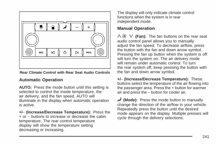
Automatic Operation
AUTO: Press the mode button until this setting isselected to control the inside temperature, theair delivery, and the fan speed. AUTO willilluminate in the display when automatic operationis active.
+/− (Increase/Decrease Temperature): Press the+ or − buttons to increase or decrease the cabintemperature. The rear control temperaturedisplay will show the temperature settingdecreasing or increasing.
The display will only indicate climate controlfunctions when the system is in rearindependent mode.
Manual Operation
y9 z (Fan): The fan buttons on the rear seataudio control panel allows you to manuallyadjust the fan speed. To decrease airflow, pressthe button with the fan and down arrow symbol.Pressing the fan up button when the system is offwill turn the system on. The air delivery modewill remain under automatic control. To turnthe rear system off, keep pressing the button withthe fan and down arrow symbol.
+/− (Increase/Decrease Temperature): Thesebuttons select the temperature of the air flowing intothe passenger area. Press the + button for warmerair and press the − button for cooler air.
N (Mode): Press the mode button to manuallychange the direction of the airflow in your vehicle.Repeatedly press the button until the desiredmode appears on the display. Multiple presses willcycle through the delivery selections.
Rear Climate Control with Rear Seat Audio Controls
241

Warning Lights, Gages, andIndicatorsThis part describes the warning lights and gages onyour vehicle. The pictures help to locate them.
Warning lights and gages can signal that somethingis wrong before it becomes serious enough tocause an expensive repair or replacement. Payingattention to the warning lights and gages could alsosave you or others from injury.
Warning lights come on when there may be or is aproblem with one of your vehicle’s functions. Asthe details show on the next few pages, somewarning lights come on briefly when you start theengine just to let you know they are working. Ifyou are familiar with this section, you shouldnot be alarmed when this happens.
Gages can indicate when there may be or is aproblem with one of your vehicle’s functions. Oftengages and warning lights work together to letyou know when there is a problem with yourvehicle.
When one of the warning lights comes on andstays on as you are driving, or when one ofthe gages shows there may be a problem, checkthe section that tells you what to do about it.Please follow this manual’s advice. Waiting to dorepairs can be costly and even dangerous. Soplease get to know your vehicle’s warninglights and gages. They can be a big help.
Your vehicle also has a Driver InformationCenter (DIC) that works along with warning lightsand gages. See DIC Warnings and Messageson page 272 for more information.
242

Instrument Panel Cluster
Your instrument cluster is designed to let you know at a glance how your vehicle is running. You willknow how fast you are going, about how much fuel you have and many other things you will need toknow to drive safely and economically.
United States version shown. Canada similar.
243

Speedometer and OdometerYour speedometer lets you see your speed inboth miles per hour (mph) and kilometers perhour (km/h).
Your odometer shows how far your vehicle hasbeen driven, in either miles (used in the UnitedStates) or kilometers (used in Canada).
Trip OdometerThe trip odometer can tell you how far yourvehicle has been driven since you last set the tripodometer to zero.
Press the reset button, located on the instrumentpanel cluster next to the trip odometer display,to toggle between the trip odometer and theregular odometer. Holding the reset button forapproximately one second while the trip odometeris displayed will reset it.
To display the odometer reading with the ignitionoff, press the reset button.
TachometerYour tachometer displays the engine speed inrevolutions per minute (rpm).
Safety Belt Reminder LightWhen the key is turned to RUN or START, achime will sound for several seconds to remindpeople to buckle their safety belts. The driversafety belt light will also come on and stay on forseveral seconds. Then it will flash for severalmore. You should buckle your seat belt.
This chime and light willbe repeated if the driverremains unbuckledand the vehicleis in motion.
If the driver’s belt is buckled, neither the chime northe light will come on.
See Passenger Sensing System on page 104 formore information.
244

Passenger Safety BeltReminder LightSeveral seconds after the key is turned to RUN orSTART, a chime will sound for several secondsto remind the front passenger to buckle their safetybelt. The passenger safety belt light will alsocome on and stay on for several seconds, then itwill flash for several more.
This chime and light willbe repeated if thepassenger remainsunbuckled andthe vehicle is in motion.
If the passenger’s safety belt is buckled, neitherthe chime nor the light will come on.
Airbag Readiness LightThere is an airbag readiness light on theinstrument panel, which shows the airbag symbol.The system checks the airbag’s electricalsystem for malfunctions. The light tells you if thereis an electrical problem. The system checkincludes the airbag sensors, the airbag modules,the wiring and the crash sensing and diagnosticmodule. For more information on the airbagsystem, see Airbag System on page 93.
This light will come onwhen you start yourvehicle, and it will flashfor a few seconds.
245

Then the light should go out. This means thesystem is ready.
{CAUTION:
If the airbag readiness light stays on afteryou start your vehicle, it means the airbagsystem may not be working properly. Theairbags in your vehicle may not inflate ina crash, or they could even inflate withouta crash. To help avoid injury to yourselfor others, have your vehicle serviced rightaway if the airbag readiness light stays onafter you start your vehicle.
If the airbag readiness light stays on after youstart the vehicle or comes on when you are driving,your airbag system may not work properly.Have your vehicle serviced right away.
The airbag readiness light should flash for a fewseconds when you turn the ignition key to RUN. Ifthe light does not come on then, have it fixedso it will be ready to warn you if there is a problem.
Passenger Airbag Status IndicatorYour vehicle has the passenger sensing system.Your overhead console has a passenger airbagstatus indicator.
When the ignition key is turned to RUN or START,the passenger airbag status indicator will lightON and OFF, or the symbol for on and off,for several seconds as a system check. Then,after several more seconds, the status indicatorwill light either ON or OFF, or either the onor off symbol, to let you know the status of theright front passenger’s frontal airbag.
United States Canada
246

If the word ON or the on symbol is lit on thepassenger airbag status indicator, it means thatthe right front passenger’s frontal airbag is enabled(may inflate).
{CAUTION:
If the on indicator comes on when you havea rear-facing child restraint installed in theright front passenger’s seat, it means thatthe passenger sensing system has notturned off the passenger’s frontal airbag. Achild in a rear-facing child restraint can beseriously injured or killed if the right frontpassenger’s airbag inflates. This isbecause the back of the rear-facing childrestraint would be very close to theinflating airbag. Do not use a rear-facingchild restraint in the right front passenger’sseat if the airbag is turned on.
Your vehicle has a rear seat that will accommodatea rear-facing child restraint. A label on your sunvisor says, “Never put a rear-facing child seatin the front.” This is because the risk to therear-facing child is so great, if the airbag deploys.
{CAUTION:
Even though the passenger sensingsystem is designed to turn off the rightfront passenger’s frontal airbag if thesystem detects a rear-facing child restraint,no system is fail-safe, and no one canguarantee that an airbag will not deployunder some unusual circumstance, eventhough it is turned off. We recommend thatrear-facing child restraints be secured inthe rear seat, even if the airbag is off.
If the word OFF or the off symbol is lit on theairbag status indicator, it means that thepassenger sensing system has turned off the rightfront passenger’s frontal airbag. See PassengerSensing System on page 104 for more onthis, including important safety information.
247

If, after several seconds, all status indicator lightsremain on, or if there are no lights at all, theremay be a problem with the lights or the passengersensing system. See your dealer for service.
{CAUTION:
If the off indicator and the airbagreadiness light ever come on together, itmeans that something may be wrong withthe airbag system. If this ever happens,have the vehicle serviced promptly,because an adult-size person sitting in theright front passenger seat may not havethe protection of the frontal airbag. SeeAirbag Readiness Light on page 245.
Charging System Light
The charging systemlight will come on brieflywhen you turn on theignition, but theengine is not running,as a check to show youit is working.
It should go out once the engine is running. If itstays on, or comes on while you are driving, youmay have a problem with the charging system. Itcould indicate that you have problems with thegenerator, the generator drive belt, or anotherelectrical problem. Have it checked right away.Driving while this light is on could drain your battery.
When this light comes on, the Driver InformationCenter (DIC) will also display the SERVICEBATTERY NOT CHARGING SYSTEM message.See DIC Warnings and Messages on page 272for more information.
If you must drive a short distance with the light on,be certain to turn off all your accessories, suchas the radio and air conditioner, to reducethe drain on your battery.
248

Voltmeter Gage
When your engine is notrunning, but the ignitionis in RUN, this gageshows your battery’sstate of charge inDC volts.
When the engine is running, the gage shows thecondition of the charging system. The chargingsystem regulates voltage based on the state of thebattery for improved fuel economy and batterylife. The gage may transition from a higher to loweror a lower to higher reading, this is normal.Readings between the low and high warning zonesindicate the normal operating range.
Readings in the low warning zone may occurwhen a large number of electrical accessories areoperating in the vehicle and the engine is left atan idle for an extended period. This conditionis normal since the charging system is not able toprovide full power at engine idle. As enginespeeds are increased, this condition should correctitself as higher engine speeds allow the chargingsystem to create full power. If there is a problemwith the battery charging system, this lightwill come on or the SERVICE BATTERYCHARGING SYSTEM DIC message will display.See DIC Warnings and Messages on page 272and Charging System Light on page 248 for moreinformation.
249

Brake System Warning LightWith the ignition on, the brake system warninglight will come on when you set the parking brake.If you try to drive with the parking brake engaged,a chime will sound when the vehicle speed isgreater than 5 mph (8 km/h).
Your vehicle’s hydraulic brake system is dividedinto two parts. If one part is not working, the otherpart can still work and stop you. For goodbraking, though, you need both parts working well.
If the warning light comes on and a chimesounds there could be a brake problem. Haveyour brake system inspected right away.
This light may also come on due to low brakefluid. See Brakes on page 489 for moreinformation.
This light should come on briefly when you turnthe ignition key to RUN. If it does not comeon then, have it fixed so it will be ready to warnyou if there is a problem.
{CAUTION:
Your brake system may not be workingproperly if the brake system warning lightis on. Driving with the brake systemwarning light on can lead to an accident.If the light is still on after you have pulledoff the road and stopped carefully, havethe vehicle towed for service.
If the light comes on while you are driving, pull offthe road and stop carefully. You may noticethat the pedal is harder to push or may go closerto the floor. It may take longer to stop. If thelight is still on, have the vehicle towed for service.See Towing Your Vehicle on page 422.
United States Canada
250

Anti-Lock Brake SystemWarning Light
With the Anti-Lock BrakeSystem (ABS), this lightwill come on when youstart your engine andmay stay on forseveral seconds.
That is normal. If the light does not come on then,have it fixed so it will be ready to warn you ifthere is a problem.
If the light stays on, or comes on when you aredriving, your vehicle needs service. A chimewill sound when the light stays on. If the regularbrake system warning light is not on, you still havebrakes, but you do not have ABS. If the regularbrake system warning light is also on you donot have ABS and there is a problem with yourregular brakes. In addition to both lights, youwill also hear a chime sound on the firstoccurrence of a problem and each time thevehicle is shut off and then restarted. See BrakeSystem Warning Light on page 250.
The ABS warning light should come on brieflywhen you turn the ignition key to RUN. If the lightdoes not come on then, have it fixed so it willbe ready to warn you if there is a problem.
251

StabiliTrak® Indicator Light
If equipped, this warninglight should come onbriefly when the engineis started.
If the warning light does not come on then, have itfixed so it will be ready to warn you if there is aproblem. If it stays on, or comes on when you aredriving, there may be a problem with yourStabiliTrak® system and your vehicle may needservice. When this warning light is on, the systemis off and will not limit wheel spin. Adjust yourdriving accordingly.
This light will also flash when the StabiliTrak®
system is active.
If the StabiliTrak® system warning light comes onand stays on for an extended period of timewhen the system is turned on, your vehicle needsservice. See StabiliTrak® System on page 367for more information.
Engine Coolant Temperature Gage
This gage shows the engine coolant temperature.
It also provides an indicator of how hard yourvehicle is working. During a majority of theoperation, the gage will read 210°F (100°C) or less.If you are pulling a load or going up hills, it is normalfor the temperature to fluctuate and approach the250°F (122°C) mark. If the gage reaches the 260°F(125°C) mark, it indicates that the cooling system isworking beyond its capacity.
See Engine Overheating on page 478.
United States Canada
252
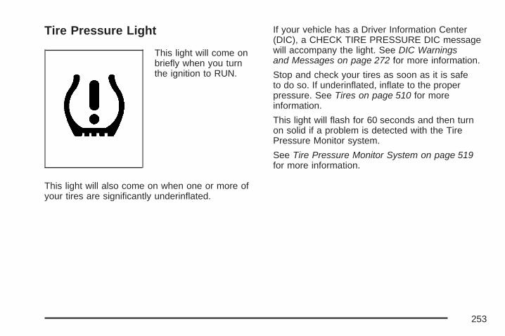
Tire Pressure Light
This light will come onbriefly when you turnthe ignition to RUN.
This light will also come on when one or more ofyour tires are significantly underinflated.
If your vehicle has a Driver Information Center(DIC), a CHECK TIRE PRESSURE DIC messagewill accompany the light. See DIC Warningsand Messages on page 272 for more information.
Stop and check your tires as soon as it is safeto do so. If underinflated, inflate to the properpressure. See Tires on page 510 for moreinformation.
This light will flash for 60 seconds and then turnon solid if a problem is detected with the TirePressure Monitor system.
See Tire Pressure Monitor System on page 519for more information.
253
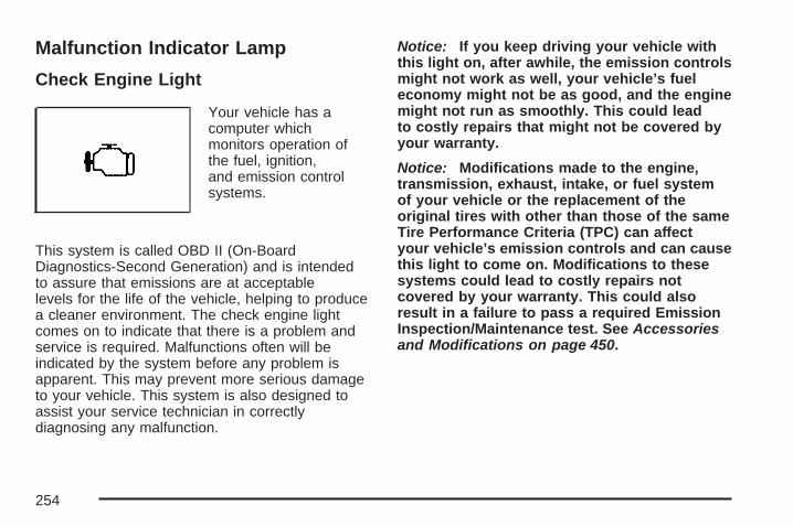
Malfunction Indicator Lamp
Check Engine Light
Your vehicle has acomputer whichmonitors operation ofthe fuel, ignition,and emission controlsystems.
This system is called OBD II (On-BoardDiagnostics-Second Generation) and is intendedto assure that emissions are at acceptablelevels for the life of the vehicle, helping to producea cleaner environment. The check engine lightcomes on to indicate that there is a problem andservice is required. Malfunctions often will beindicated by the system before any problem isapparent. This may prevent more serious damageto your vehicle. This system is also designed toassist your service technician in correctlydiagnosing any malfunction.
Notice: If you keep driving your vehicle withthis light on, after awhile, the emission controlsmight not work as well, your vehicle’s fueleconomy might not be as good, and the enginemight not run as smoothly. This could leadto costly repairs that might not be covered byyour warranty.
Notice: Modifications made to the engine,transmission, exhaust, intake, or fuel systemof your vehicle or the replacement of theoriginal tires with other than those of the sameTire Performance Criteria (TPC) can affectyour vehicle’s emission controls and can causethis light to come on. Modifications to thesesystems could lead to costly repairs notcovered by your warranty. This could alsoresult in a failure to pass a required EmissionInspection/Maintenance test. See Accessoriesand Modifications on page 450.
254

This light should come on, as a check to showyou it is working, when the ignition is on and theengine is not running. If the light does notcome on, have it repaired. This light will alsocome on during a malfunction in one of two ways:
• Light Flashing — A misfire condition hasbeen detected. A misfire increases vehicleemissions and may damage the emissioncontrol system on your vehicle. Diagnosis andservice may be required.
• Light On Steady — An emission controlsystem malfunction has been detected on yourvehicle. Diagnosis and service may berequired.
If the Light is FlashingThe following may prevent more serious damageto your vehicle:
• Reducing vehicle speed
• Avoiding hard accelerations
• Avoiding steep uphill grades
• If you are towing a trailer, reduce the amountof cargo being hauled as soon as it ispossible
If the light stops flashing and remains on steady,see “If the Light Is On Steady” following.
If the light continues to flash, when it is safe to doso, stop the vehicle. Find a safe place to parkyour vehicle. Turn the key off, wait at least10 seconds and restart the engine. If the lightremains on steady, see “If the Light Is On Steady”following. If the light is still flashing, follow theprevious steps, and see your dealer for service assoon as possible.
255

If the Light Is On SteadyYou may be able to correct the emission systemmalfunction by considering the following:
Did you recently put fuel into your vehicle?
If so, reinstall the fuel cap, making sure to fullyinstall the cap. See Filling the Tank on page 457.The diagnostic system can determine if thefuel cap has been left off or improperly installed. Aloose or missing fuel cap will allow fuel toevaporate into the atmosphere. A few driving tripswith the cap properly installed should turn thelight off.
Did you just drive through a deep puddleof water?
If so, your electrical system may be wet. Thecondition will usually be corrected when theelectrical system dries out. A few driving tripsshould turn the light off.
Have you recently changed brands of fuel?
If so, be sure to fuel your vehicle with quality fuel.See Gasoline Octane on page 453. Poor fuelquality will cause your engine not to run asefficiently as designed. You may notice this asstalling after start-up, stalling when you putthe vehicle into gear, misfiring, hesitation onacceleration, or stumbling on acceleration. (Theseconditions may go away once the engine iswarmed up.) This will be detected by the systemand cause the light to turn on.
If you experience one or more of these conditions,change the fuel brand you use. It will require atleast one full tank of the proper fuel to turn thelight off.
If none of the above steps have made the lightturn off, your dealer can check the vehicle.Your dealer has the proper test equipment anddiagnostic tools to fix any mechanical or electricalproblems that may have developed.
256

Emissions Inspection and MaintenanceProgramsSome state/provincial and local governments haveor may begin programs to inspect the emissioncontrol equipment on your vehicle. Failure to passthis inspection could prevent you from getting avehicle registration.
Here are some things you need to know to helpyour vehicle pass an inspection:
Your vehicle will not pass this inspection if thecheck engine light is on or not working properly.
Your vehicle will not pass this inspection ifthe OBD (on-board diagnostic) system determinesthat critical emission control systems have notbeen completely diagnosed by the system.The vehicle would be considered not ready forinspection. This can happen if you have recentlyreplaced your battery or if your battery hasrun down. The diagnostic system is designed toevaluate critical emission control systemsduring normal driving. This may take several daysof routine driving. If you have done this andyour vehicle still does not pass the inspection forlack of OBD system readiness, your dealercan prepare the vehicle for inspection.
Oil Pressure Gage
The oil pressure gage shows the engine oilpressure in psi (pounds per square inch) when theengine is running. Canadian vehicles indicatepressure in kPa (kilopascals).
Oil pressure may vary with engine speed, outsidetemperature and oil viscosity, but readingsabove the low pressure zone indicate the normaloperating range. When the oil pressure reachesthe low pressure zone, the OIL PRESSURE LOWSTOP ENGINE message will appear in theDriver Information Center (DIC). See DICWarnings and Messages on page 272 and EngineOil on page 463 for more information.
United States Canada
257

A reading in the low pressure zone may becaused by a dangerously low oil level or someother problem causing low oil pressure. Checkyour oil as soon as possible.
{CAUTION:
Do not keep driving if the oil pressure islow. If you do, your engine can become sohot that it catches fire. You or others couldbe burned. Check your oil as soon aspossible and have your vehicle serviced.
Notice: Lack of proper engine oil maintenancemay damage the engine. The repairs wouldnot be covered by your warranty. Always followthe maintenance schedule in this manual forchanging engine oil.
Oil Pressure Light
This light will come onbriefly when you startyour engine.
{CAUTION:
Do not keep driving if the oil pressure islow. If you do, your engine can become sohot that it catches fire. You or others couldbe burned. Check your oil as soon aspossible and have your vehicle serviced.
258

Notice: Lack of proper engine oil maintenancemay damage the engine. The repairs wouldnot be covered by your warranty. Always followthe maintenance schedule in this manual forchanging engine oil.
That is a check to be sure the light works. If itdoes not come on, be sure to have it fixed so it willbe there to warn you if something goes wrong.
When the light comes on and stays on, it meansthat oil is not flowing through your engineproperly. You could be low on oil and you mighthave some other system problem.
Security Light
This light flashes whenthe vehicle securitysystem is activated.
Fog Lamp Light
The fog lamp light willcome on when the foglamps are in use.
The light will go out when the fog lamps areturned off. See Fog Lamps on page 218 for moreinformation.
Cruise Control Light
This light comes onwhenever you set thecruise control.
The light goes out when the cruise control isturned off. See Cruise Control on page 212 formore information.
259

Highbeam On Light
This light comes onwhen the high-beamheadlamps are in use.
See Headlamp High/Low-Beam Changer onpage 208 for more information.
Tow/Haul Mode Light
This light is displayedwhen the Tow/Haulmode has beenactivated.
For more information, see Towing a Trailer onpage 428 and Tow/Haul Mode on page 153.
Fuel Gage
The fuel gage, when the ignition is on, tells youabout how much fuel you have left in your tank.
The gage will first indicate empty before youare out of fuel, and you should get more fuel assoon as possible.
United States Canada
260
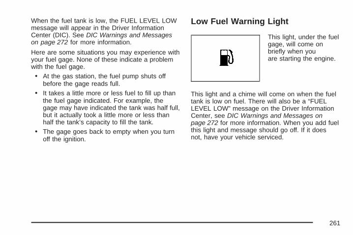
When the fuel tank is low, the FUEL LEVEL LOWmessage will appear in the Driver InformationCenter (DIC). See DIC Warnings and Messageson page 272 for more information.
Here are some situations you may experience withyour fuel gage. None of these indicate a problemwith the fuel gage.
• At the gas station, the fuel pump shuts offbefore the gage reads full.
• It takes a little more or less fuel to fill up thanthe fuel gage indicated. For example, thegage may have indicated the tank was half full,but it actually took a little more or less thanhalf the tank’s capacity to fill the tank.
• The gage goes back to empty when you turnoff the ignition.
Low Fuel Warning Light
This light, under the fuelgage, will come onbriefly when youare starting the engine.
This light and a chime will come on when the fueltank is low on fuel. There will also be a “FUELLEVEL LOW” message on the Driver InformationCenter, see DIC Warnings and Messages onpage 272 for more information. When you add fuelthis light and message should go off. If it doesnot, have your vehicle serviced.
261

Driver Information Center (DIC)Your vehicle has a Driver InformationCenter (DIC).
The DIC displays information about your vehicle. Italso displays warning messages if a systemproblem is detected.
All messages will appear in the DIC displaylocated below the tachometer in the instrumentpanel cluster.
The DIC comes on when the ignition is on. After ashort delay, the DIC will display the informationthat was last displayed before the engine wasturned off.
If your vehicle has DIC buttons, see “DICOperation and Displays (With DIC Buttons)” laterin this section and DIC Vehicle Customization(With DIC Buttons) on page 282 for the displaysavailable.
If your vehicle does not have DIC buttons, see“DIC Operation and Displays (Without DICButtons)” later in this section for the displaysavailable.
DIC Operation and Displays(With DIC Buttons)If your vehicle has DIC buttons, the informationbelow explains the operation of this system.
The DIC has different displays which can beaccessed by pressing the DIC buttons located onthe instrument panel, next to the steeringwheel.
The DIC displays trip, fuel, and vehicle systeminformation, and warning messages if a systemproblem is detected.
The DIC also allows some features to becustomized. See DIC Vehicle Customization (WithDIC Buttons) on page 282 for more information.
If your vehicle has DIC buttons, you can also usethe trip odometer reset stem to view some ofthe DIC displays. See “DIC Operation and Displays(Without DIC Buttons)” later in this section.
262

DIC Buttons
The buttons are thetrip/fuel, vehicleinformation,customization, andset/reset buttons. Thebutton functionsare detailed in thefollowing pages.
3 (Trip/Fuel): Press this button to display theodometer, trip odometer, fuel range, averageeconomy, fuel used, timer, and transmissiontemperature. Some vehicles also displayinstantaneous economy and an Active FuelManagement™ indicator.
T (Vehicle Information): Press this button todisplay the oil life, units, tire pressure readingsfor vehicles with a Tire Pressure Monitor (TPM)system, engine hours, Tire Pressure Monitor(TPM) system programming for vehicles with aTPM system, and Remote Keyless Entry(RKE) transmitter programming.
U (Customization): Press this button tocustomize the feature settings on your vehicle.See DIC Vehicle Customization (With DIC Buttons)on page 282 for more information.
V (Set/Reset): Press this button to set or resetcertain functions and to turn off or acknowledgemessages on the DIC.
263
Trip/Fuel Menu Items
3 (Trip/Fuel): Press this button to scrollthrough the following menu items:
OdometerPress the trip/fuel button until ODOMETERdisplays. This display shows the distance thevehicle has been driven in either miles (mi)or kilometers (km). Pressing the trip odometerreset stem will also display the odometer.
To switch between English and metricmeasurements, see “Units” later in this section.
Trip OdometerPress the trip/fuel button until TRIP displays. Thisdisplay shows the current distance traveled ineither miles (mi) or kilometers (km) since the lastreset for the trip odometer. Pressing the tripodometer reset stem will also display the tripodometer.
The trip odometer can be reset to zero by pressingthe set/reset button while the trip odometer isdisplayed. You can also reset the trip odometerwhile it is displayed by pressing and holdingthe trip odometer reset stem.
The trip odometer has a feature called theretro-active reset. This can be used to set the tripodometer to the number of miles (kilometers)driven since the ignition was last turned on. Thiscan be used if the trip odometer is not reset at thebeginning of the trip.
To use the retro-active reset feature, press andhold the set/reset button for at least four seconds.The trip odometer will display the number ofmiles (mi) or kilometers (km) driven since theignition was last turned on and the vehiclewas moving. Once the vehicle begins moving, thetrip odometer will accumulate mileage. Forexample, if the vehicle was driven 5 miles (8 km)before it is started again, and then the retro-activereset feature is activated, the display will show5 miles (8 km). As the vehicle begins moving, thedisplay will then increase to 5.1 miles (8.2 km),5.2 miles (8.4 km), etc.
If the retro-active reset feature is activated afterthe vehicle is started, but before it begins moving,the display will show the number of miles (mi)or kilometers (km) that were driven during the lastignition cycle.
264

Fuel RangePress the trip/fuel button until FUEL RANGEdisplays. This display shows the approximatenumber of remaining miles (mi) or kilometers (km)the vehicle can be driven without refueling. Thedisplay will show LOW if the fuel level is low.
The fuel range estimate is based on an average ofthe vehicle’s fuel economy over recent drivinghistory and the amount of fuel remaining in the fueltank. This estimate will change if drivingconditions change. For example, if driving in trafficand making frequent stops, this display mayread one number, but if the vehicle is driven on afreeway, the number may change even thoughthe same amount of fuel is in the fuel tank. This isbecause different driving conditions producedifferent fuel economies. Generally, freewaydriving produces better fuel economy than citydriving. Fuel range cannot be reset.
Average EconomyPress the trip/fuel button until AVG ECONOMYdisplays. This display shows the approximateaverage miles per gallon (mpg) or liters per100 kilometers (L/100 km). This number iscalculated based on the number of mpg (L/100 km)recorded since the last time this menu item wasreset. To reset AVG ECONOMY, press andhold the set/reset button.
Fuel UsedPress the trip/fuel button until FUEL USEDdisplays. This display shows the number ofgallons (gal) or liters (L) of fuel used since the lastreset of this menu item. To reset the fuel usedinformation, press and hold the set/reset buttonwhile FUEL USED is displayed.
265

TimerPress the trip/fuel button until TIMER displays.This display can be used as a timer.
To start the timer, press the set/reset button whileTIMER is displayed. The display will show theamount of time that has passed since the timerwas last reset, not including time the ignition is off.Time will continue to be counted as long as theignition is on, even if another display is being shownon the DIC. The timer will record up to 99 hours,59 minutes and 59 seconds (99:59:59) after whichthe display will return to zero.
To stop the timer, press the set/reset button brieflywhile TIMER is displayed.
To reset the timer to zero, press and hold theset/reset button while TIMER is displayed.
Transmission TemperaturePress the trip/fuel button until TRANS TEMPdisplays. This display shows the temperature ofthe automatic transmission fluid in either degreesFahrenheit (°F) or degrees Celsius (°C).
Instantaneous Economy and Active FuelManagement™ IndicatorIf your vehicle has this display, press the trip/fuelbutton until INST ECONOMY V8 MODE displays.This display shows the current fuel economy at aparticular moment and will change frequently asdriving conditions change. This display shows theinstantaneous fuel economy in miles per gallon(mpg) or liters per 100 kilometers (L/100 km).Unlike average economy, this screen cannotbe reset.
An Active Fuel Management™ indicator willdisplay on the right side of the DIC, whileINST ECONOMY displays on the left side. ActiveFuel Management™ allows the engine tooperate on either four or eight cylinders, dependingon your driving demands. When Active FuelManagement™ is active, V4 MODE will display onthe DIC. When Active Fuel Management™ isinactive, V8 MODE will display. See Active FuelManagement™ on page 149 for more information.
Blank DisplayThis display shows no information.
266

Vehicle Information Menu Items
T (Vehicle Information): Press this button toscroll through the following menu items:
Oil LifePress the vehicle information button until OIL LIFEREMAINING displays. This display shows anestimate of the oil’s remaining useful life. If yousee 99% OIL LIFE REMAINING on the display,that means 99% of the current oil life remains.The engine oil life system will alert you to changeyour oil on a schedule consistent with yourdriving conditions.
When the remaining oil life is low, the CHANGEENGINE OIL SOON message will appear onthe display. See “CHANGE ENGINE OIL SOON”under DIC Warnings and Messages onpage 272. You should change your oil as soon asyou can. See Engine Oil on page 463. Inaddition to the engine oil life system monitoringthe oil life, additional maintenance isrecommended in the Maintenance Schedule in thismanual. See Scheduled Maintenance onpage 578 for more information.
Remember, you must reset the OIL LIFE displayyourself after each oil change. It will not resetitself. Also, be careful not to reset the OIL LIFEdisplay accidentally at any time other thanwhen the oil has just been changed. It cannot bereset accurately until the next oil change. Toreset the engine oil life system, see Engine OilLife System on page 466.
UnitsPress the vehicle information button until UNITSdisplays. This display allows you to select betweenEnglish or Metric units of measurement. Once inthis display, press the set/reset button to selectbetween ENGLISH or METRIC units. All ofthe vehicle information will then be displayed inthe unit of measurement selected.
Tire PressureIf your vehicle has a Tire Pressure Monitor (TPM)system, the pressure for each tire can beviewed in the DIC. The tire pressure will be shownin either pounds per square inch (psi) orkilopascals (kPa). Press the vehicle informationbutton until the DIC displays FRONT TIRESPSI (kPa) LEFT ## RIGHT ##. Press the vehicleinformation button again until the DIC displaysREAR TIRES PSI (kPa) LEFT ## RIGHT ##.
267

If a low or high tire pressure condition is detectedby the system while driving, a message advisingyou to check the pressure in a specific tirewill appear in the display. See Inflation - TirePressure on page 518 and DIC Warningsand Messages on page 272 for more information.
If the tire pressure display shows dashesinstead of a value, there may be a problem withyour vehicle. If this consistently occurs, seeyour dealer for service.
Engine HoursPress the vehicle information button until ENGINEHOURS displays. This display shows the totalnumber of hours the engine has run.
Relearn Tire PositionsIf your vehicle has a Tire Pressure Monitor (TPM)system, after rotating the tires or after replacinga tire or sensor, the system must re-learn the tirepositions. To re-learn the tire positions, seeTire Pressure Monitor System on page 519. SeeTire Inspection and Rotation on page 524 and DICWarnings and Messages on page 272 for moreinformation.
Relearn Remote KeyThis display allows you to match Remote KeylessEntry (RKE) transmitters to your vehicle. To matchan RKE transmitter to your vehicle, do the following:1. Press the vehicle information button until
PRESS V TO RELEARN REMOTE KEYdisplays.
2. Press the set/reset button until REMOTE KEYLEARNING ACTIVE is displayed.
3. Press and hold the lock and unlock buttonson the first transmitter at the same time forabout 15 seconds.On vehicles with memory recall seats, the firsttransmitter learned will match driver 1 andthe second will match driver 2.A chime will sound indicating that thetransmitter is matched.
4. To match additional transmitters at this time,repeat Step 3.Each vehicle can have a maximum ofeight transmitters matched to it.
5. To exit the programming mode, you mustcycle the key to LOCK.
Blank DisplayThis display shows no information.
268

DIC Operation and Displays(Without DIC Buttons)If your vehicle does not have DIC buttons, theinformation below explains the operation ofthis system.
The DIC has different displays which can beaccessed by pressing the trip odometer reset stemlocated on the instrument panel cluster. Pressingthe trip odometer reset stem will also turn off,or acknowledge, DIC messages.
The DIC displays trip and vehicle systeminformation, and warning messages if a systemproblem is detected.
If your vehicle does not have DIC buttons, youcan use the trip odometer reset stem to view thefollowing displays: odometer, engine hours,trip odometer, oil life, Tire Pressure Monitor (TPM)system programming for vehicles with a TPMsystem, Remote Keyless Entry (RKE) transmitterprogramming, and display language.
If your vehicle has DIC buttons, you can use thetrip odometer reset stem to view the followingdisplays: odometer, engine hours, trip odometer,and display language.
Trip Odometer Reset Stem Menu ItemsOdometerPress the trip odometer reset stem untilODOMETER displays. This display shows thedistance the vehicle has been driven in eithermiles (mi) or kilometers (km).
Engine HoursTo display the ENGINE HOURS, place the ignitionin LOCK or ACCESSORY, then press and holdthe trip odometer reset stem for four seconds whileviewing the ODOMETER. This display showsthe total number of hours the engine has run.
Trip OdometerPress the trip odometer reset stem until TRIPdisplays. This display shows the current distancetraveled in either miles (mi) or kilometers (km)since the last reset for the trip odometer.
The trip odometer can be reset to zero by pressingand holding the trip odometer reset stem whilethe trip odometer is displayed.
269

The trip odometer has a feature called theretro-active reset. This can be used to set the tripodometer to the number of miles (kilometers)driven since the ignition was last turned on. Thiscan be used if the trip odometer is not reset at thebeginning of the trip.
To use the retro-active reset feature, press andhold the trip odometer reset stem for at leastfour seconds. The trip odometer will display thenumber of miles (mi) or kilometers (km) drivensince the ignition was last turned on and thevehicle was moving. Once the vehicle beginsmoving, the trip odometer will accumulate mileage.For example, if the vehicle was driven 5 miles(8 km) before it is started again, and thenthe retro-active reset feature is activated, thedisplay will show 5 miles (8 km). As the vehiclebegins moving, the display will then increaseto 5.1 miles (8.2 km), 5.2 miles (8.4 km), etc.
If the retro-active reset feature is activated afterthe vehicle is started, but before it begins moving,the display will show the number of miles (mi)or kilometers (km) that were driven during the lastignition cycle.
Oil LifeTo access this display, the vehicle must be inPARK (P). Press the trip odometer reset stem untilOIL LIFE REMAINING displays. This displayshows an estimate of the oil’s remaining usefullife. If you see 99% OIL LIFE REMAINING on thedisplay, that means 99% of the current oil liferemains. The engine oil life system will alert you tochange your oil on a schedule consistent withyour driving conditions.
When the remaining oil life is low, the CHANGEENGINE OIL SOON message will appear onthe display. See “CHANGE ENGINE OIL SOON”under DIC Warnings and Messages onpage 272. You should change your oil as soon asyou can. See Engine Oil on page 463. Inaddition to the engine oil life system monitoringthe oil life, additional maintenance isrecommended in the Maintenance Schedule in thismanual. See Scheduled Maintenance onpage 578 for more information.
270

Remember, you must reset the OIL LIFE displayyourself after each oil change. It will not resetitself. Also, be careful not to reset the OIL LIFEdisplay accidentally at any time other thanwhen the oil has just been changed. It cannot bereset accurately until the next oil change. Toreset the engine oil life system, see Engine OilLife System on page 466.
Relearn Tire PositionsTo access this display, the vehicle must be inPARK (P). If your vehicle has a Tire PressureMonitor (TPM) system, after rotating the tires orafter replacing a tire or sensor, the systemmust re-learn the tire positions. To re-learn the tirepositions, see Tire Pressure Monitor System onpage 519. See Tire Inspection and Rotationon page 524 and DIC Warnings and Messages onpage 272 for more information.
Relearn Remote KeyTo access this display, the vehicle must be inPARK (P). This display allows you to matchRemote Keyless Entry (RKE) transmitters to yourvehicle. To match an RKE transmitter to yourvehicle, do the following:1. Press the trip odometer reset stem until
RELEARN REMOTE KEY displays.2. Press and hold the trip odometer reset stem
for three seconds.The message REMOTE KEY LEARNINGACTIVE will display.
3. Press and hold the lock and unlock buttonson the first transmitter at the same time forabout 15 seconds.On vehicles with memory recall seats, the firsttransmitter learned will match driver 1 andthe second will match driver 2.A chime will sound indicating that thetransmitter is matched.
4. To match additional transmitters at this time,repeat Step 3.Each vehicle can have a maximum ofeight transmitters matched to it.
5. To exit the programming mode, you mustcycle the key to LOCK.
271

LanguageThis display allows you to select the language inwhich the DIC messages will appear. To selecta language, do the following:
1. Press the trip odometer reset stem untilODOMETER displays.
2. While in the ODOMETER display, pressand hold the trip odometer reset stem forthree seconds until the currently set languagedisplays.
3. Continue to press and hold the trip odometerreset stem to scroll through all of the availablelanguages.The available languages are ENGLISH(default), FRANCAIS (French), ESPANOL(Spanish), and NO CHANGE.
4. Once the desired language is displayed,release the trip odometer reset stem toset your choice.
DIC Warnings and MessagesMessages are displayed on the DIC to notify thedriver that the status of the vehicle has changedand that some action may be needed by the driverto correct the condition. Multiple messages mayappear one after another.
Some messages may not require immediateaction, but you can press any of the DIC buttonson the instrument panel or the trip odometerreset stem on the instrument panel clusterto acknowledge that you received the messagesand to clear them from the display.
Some messages cannot be cleared from the DICdisplay because they are more urgent. Thesemessages require action before they can becleared. You should take any messages thatappear on the display seriously and remember thatclearing the messages will only make themessages disappear, not correct the problem.
The following are the possible messages that canbe displayed and some information about them.
272

CHANGE ENGINE OIL SOONThis message displays when the engine oil needsto be changed. When you change the engineoil, be sure to reset the CHANGE ENGINE OILSOON message. See Engine Oil Life Systemon page 466 for information on how to reset themessage. This message clears itself after10 seconds until the next ignition cycle or until themessage is reset. See Engine Oil on page 463and Scheduled Maintenance on page 578 formore information.
CHECK TIRE PRESSUREIf your vehicle has a Tire Pressure Monitor (TPM)system, this message displays when thepressure in one or more of the vehicle’s tires needto be checked. This message also displaysLEFT FRONT, RIGHT FRONT, LEFT REAR, orRIGHT REAR to indicate which tire needs tobe checked. You can receive more than one tirepressure message at a time. To read the othermessages that may have been sent at the sametime, press the set/reset button or the tripodometer reset stem. If a tire pressure messageappears on the DIC, stop as soon as you can.
Have the tire pressures checked and set to thoseshown on the Tire Loading Information label.See Tires on page 510, Loading Your Vehicle onpage 411, and Inflation - Tire Pressure onpage 518. The DIC display also shows the tirepressure values for the front and rear tiresby pressing the vehicle information button. See“DIC Operation and Displays (With DIC Buttons)”earlier in this section. If the tire pressure islow, the low tire pressure warning light comes on.See Tire Pressure Light on page 253.
DRIVER DOOR OPENThis message displays and a chime sounds if thedriver’s door is not fully closed and the vehicleis in a drive gear. Stop and turn off the vehicle,check the door for obstructions, and close the dooragain. Check to see if the message still appearson the DIC.
273

ENGINE HOT A/C (Air Conditioning)TURNED OFFThis message displays when the engine coolantbecomes hotter than the normal operatingtemperature. See Engine Coolant TemperatureGage on page 252. To avoid added strain on a hotengine, the air conditioning compressorautomatically turns off. When the coolanttemperature returns to normal, the air conditioningcompressor turns back on. You can continue todrive your vehicle.
If this message continues to appear, have thesystem repaired by your dealer as soon aspossible to avoid damage to the engine.
ENGINE OIL LOW ADD OILIf your vehicle has an oil level sensor, thismessage displays if the oil level in the vehicle islow. Check the oil level and correct it asnecessary. You may need to let the vehicle coolor warm up and cycle the ignition to be surethis message clears.
This message clears itself after 10 seconds, untilthe next ignition cycle. See Engine Oil onpage 463 for additional information.
ENGINE OVERHEATED IDLE ENGINE
Notice: If you drive your vehicle while theengine is overheating, severe engine damagemay occur. If an overheat warning appearson the instrument panel cluster and/orDIC, stop the vehicle as soon as possible. SeeEngine Overheating on page 478 for moreinformation.
This message displays when the engine coolanttemperature is too hot. Stop and allow the vehicleto idle until it cools down. See Engine CoolantTemperature Gage on page 252.
See Overheated Engine Protection OperatingMode on page 480 for information on driving to asafe place in an emergency.
274
ENGINE OVERHEATED STOP ENGINE
Notice: If you drive your vehicle while theengine is overheating, severe engine damagemay occur. If an overheat warning appearson the instrument panel cluster and/orDIC, stop the vehicle as soon as possible. SeeEngine Overheating on page 478 for moreinformation.
This message displays and a chime sounds if theengine cooling system reaches unsafetemperatures for operation. Stop and turn off thevehicle as soon as it is safe to do so to avoidsevere damage. This message clears when theengine has cooled to a safe operating temperature.
ENGINE POWER IS REDUCEDThis message displays and a chime sounds whenthe cooling system temperature gets too hotand the engine further enters the engine coolantprotection mode. See Engine Overheating onpage 478 for further information.
This message also displays when the vehicle’sengine power is reduced. Reduced engine powercan affect the vehicle’s ability to accelerate. If thismessage is on, but there is no reduction inperformance, proceed to your destination. Theperformance may be reduced the next time thevehicle is driven. The vehicle may be driven at areduced speed while this message is on, butacceleration and speed may be reduced. Anytimethis message stays on, the vehicle should be takento your dealer for service as soon as possible.
FUEL LEVEL LOWThis message displays and a chime sounds if thefuel level is low. Refuel as soon as possible.See Fuel Gage on page 260 and Fuel on page 452for more information.
HOOD OPENThis message displays and a chime sounds if thehood is not fully closed. Stop and turn off thevehicle, check the hood for obstructions, and closethe hood again. Check to see if the messagestill appears on the DIC.
275

LEFT REAR DOOR OPENThis message displays and a chime sounds if thedriver’s side rear door is not fully closed andthe vehicle is in a drive gear. Stop and turn off thevehicle, check the door for obstructions, andclose the door again. Check to see if the messagestill appears on the DIC.
OIL PRESSURE LOW STOP ENGINE
Notice: If you drive your vehicle whilethe engine oil pressure is low, severe enginedamage may occur. If a low oil pressurewarning appears on the Driver InformationCenter (DIC), stop the vehicle as soon aspossible. Do not drive the vehicle until thecause of the low oil pressure is corrected. SeeEngine Oil on page 463 for more information.
This message displays if low oil pressurelevels occur. Stop the vehicle as soon as safelypossible and do not operate it until the causeof the low oil pressure has been corrected. Checkthe oil as soon as possible and have yourvehicle serviced by your dealer. See Engine Oil onpage 463.
PARK ASSIST OFFIf your vehicle has the Ultrasonic Rear ParkingAssist (URPA) system, after the vehicle has beenstarted, this message displays to remind thedriver that the URPA system has been turned off.Press the set/reset button or the trip odometerreset stem to acknowledge this message and clearit from the DIC display. To turn the URPAsystem back on, see Ultrasonic Rear ParkingAssist (URPA) on page 222.
PASSENGER DOOR OPENThis message displays and a chime sounds if thepassenger’s door is not fully closed and thevehicle is in a drive gear. Stop and turn off thevehicle, check the door for obstructions, and closethe door again. Check to see if the messagestill appears on the DIC.
REAR ACCESS OPENThis message displays and a chime sounds if theliftgate or liftglass is open while the ignition isin RUN. Turn off the vehicle and check the liftgateand liftglass. Restart the vehicle and check forthe message on the DIC display.
276

REMOTE KEY LEARNING ACTIVEThis message displays while you are matching aRemote Keyless Entry (RKE) transmitter toyour vehicle. See “Matching Transmitter(s) to YourVehicle” under Remote Keyless Entry (RKE)System Operation on page 119 and DIC Operationand Displays (With DIC Buttons) on page 262 orDIC Operation and Displays (Without DIC Buttons)on page 269 for more information.
REPLACE BATTERY IN REMOTE KEYThis message displays if a Remote KeylessEntry (RKE) transmitter battery is low. The batteryneeds to be replaced in the transmitter. See“Battery Replacement” under Remote KeylessEntry (RKE) System Operation on page 119.
RIGHT REAR DOOR OPENThis message displays and a chime sounds if thepassenger’s side rear door is not fully closedand the vehicle is in a drive gear. Stop and turnoff the vehicle, check the door for obstructions, andclose the door again. Check to see if themessage still appears on the DIC.
SERVICE 4 WHEEL DRIVEThis message displays if a problem occurs withthe four-wheel-drive system. If this messageappears, stop as soon as possible and turn off thevehicle. Restart the vehicle and check for themessage on the DIC display. If the message is stilldisplayed or appears again when you begindriving, the four-wheel-drive system needs service.See your dealer.
SERVICE AIR BAGThis message displays if there is a problem withthe airbag system. Have your dealer inspectthe system for problems. See Airbag ReadinessLight on page 245 and Airbag System on page 93for more information.
277
SERVICE BATTERY CHARGINGSYSTEMOn some vehicles, this message displays if thereis a problem with the battery charging system.Under certain conditions, the charging system lightmay also turn on in the instrument panel cluster.See Charging System Light on page 248.Driving with this problem could drain the battery.Turn off all unnecessary accessories. Havethe electrical system checked as soon as possible.See your dealer.
SERVICE BRAKE SYSTEMThis message displays along with the brakesystem warning light if there is a problem with thebrake system. See Brake System WarningLight on page 250. If this message appears, stopas soon as possible and turn off the vehicle.Restart the vehicle and check for the message onthe DIC display. If the message is still displayedor appears again when you begin driving, thebrake system needs service as soon as possible.See your dealer.
SERVICE BRAKES SOONThis message displays if there is a problem withthe brake system. If this message appears, stop assoon as possible and turn off the vehicle. Restartthe vehicle and check for the message on theDIC display. If the message is still displayedor appears again when you begin driving, thebrake system needs service. See your dealer.
SERVICE PARK ASSISTIf your vehicle has the Ultrasonic Rear ParkingAssist (URPA) system, this message displaysif there is a problem with the URPA system. Donot use this system to help you park. SeeUltrasonic Rear Parking Assist (URPA) onpage 222 for more information. See your dealerfor service.
278

SERVICE STABILITRAKIf your vehicle has StabiliTrak® and this messagedisplays, it means there may be a problemwith the StabiliTrak® system. If you see thismessage, try to reset the system. Stop; turn offthe engine for at least 15 seconds; then startthe engine again. If this message still comes on, itmeans there is a problem. You should see yourdealer for service. The vehicle is safe to drive,however, you do not have the benefit ofStabiliTrak®, so reduce your speed and driveaccordingly.
SERVICE SUSPENSION SYSTEMIf your vehicle has the Autoride® suspensionsystem, this message displays when the Autoride®
suspension system is not operating properly.Have your vehicle serviced by your dealer.
SERVICE THEFT DETERRENT SYSTEMThis message displays when there is a problemwith the theft-deterrent system. The vehicle may ormay not restart so you may want to take thevehicle to your dealer before turning off the engine.See PASS-Key® III+ Operation on page 141 formore information.
SERVICE TIRE MONITOR SYSTEMIf your vehicle has the Tire Pressure Monitor(TPM) system, this message displays if a part onthe system is not working properly. If you driveyour vehicle while any of the four sensorsare missing or inoperable, the warning comes onin about 20 minutes. A sensor would be missing,for example, if you put different wheels onyour vehicle without transferring the sensors. If thewarning comes on and stays on, there may bea problem with the TPM. See your dealer.
279

SERVICE TRACTION CONTROLIf your vehicle has StabiliTrak®, this messagedisplays when there is a problem with the TractionControl System (TCS). When this messagedisplays, the system will not limit wheel spin.Adjust your driving accordingly. See your dealerfor service. See StabiliTrak® System on page 367for more information.
STABILITRAK OFFIf your vehicle has StabiliTrak®, this messagedisplays when you turn off StabiliTrak®, or whenthe stability control has been automaticallydisabled. To limit wheel spin and realize the fullbenefits of the stability enhancement system, youshould normally leave StabiliTrak® on. However,you should turn StabiliTrak® off if your vehicle getsstuck in sand, mud, ice, or snow and you wantto rock your vehicle to attempt to free it, or if youare driving in extreme off-road conditions andrequire more wheel spin. See If Your Vehicle isStuck in Sand, Mud, Ice, or Snow on page 409. Toturn the StabiliTrak® system on or off, seeStabiliTrak® System on page 367.
There are several conditions that can cause thismessage to appear.
• One condition is overheating, which couldoccur if StabiliTrak® activates continuouslyfor an extended period of time.
• The message also displays if the brakesystem warning light is on. See Brake SystemWarning Light on page 250.
• The message could display if the stabilitysystem takes longer than usual to complete itsdiagnostic checks due to driving conditions.
• The message displays if an engine or vehiclerelated problem has been detected and thevehicle needs service. See your dealer.
• The message also displays if the vehicle isshifted into 4LO.
The message turns off as soon as the conditionsthat caused the message to be displayed areno longer present.
280

TIGHTEN GAS CAPThis message may display along with the checkengine light on the instrument panel cluster ifthe vehicle’s fuel cap is not tightened properly. SeeMalfunction Indicator Lamp on page 254.Reinstall the fuel cap fully. See Filling the Tank onpage 457. The diagnostic system can determineif the fuel cap has been left off or improperlyinstalled. A loose or missing fuel cap allows fuel toevaporate into the atmosphere. A few drivingtrips with the cap properly installed should turn thislight and message off.
TIRE LEARNING ACTIVEIf your vehicle has a Tire Pressure Monitor (TPM)system, this message displays when the systemis re-learning the tire positions on your vehicle.See DIC Operation and Displays (With DICButtons) on page 262 or DIC Operation andDisplays (Without DIC Buttons) on page 269 formore information. The tire positions must bere-learned after rotating the tires or after replacinga tire or sensor. See Tire Inspection andRotation on page 524, Tire Pressure MonitorSystem on page 519, and Inflation - Tire Pressureon page 518 for more information.
TRACTION CONTROL OFFIf your vehicle has StabiliTrak®, this messagedisplays when the Traction Control System (TCS)is turned off. Adjust your driving accordingly.See StabiliTrak® System on page 367 for moreinformation.
TRANSMISSION HOT IDLE ENGINE
Notice: If you drive your vehicle while thetransmission fluid is overheating and thetransmission temperature warning is displayedon the instrument panel cluster and/or DIC, youcan damage the transmission. This could leadto costly repairs that would not be covered byyour warranty. Do not drive your vehicle withoverheated transmission fluid or while thetransmission temperature warning is displayed.
This message displays along with a continuouschime if the transmission fluid in the vehiclegets hot. Driving with the transmission fluidtemperature high can cause damage to thevehicle. Stop the vehicle and let it idle to allow thetransmission to cool. This message clears andthe chime stops when the fluid temperaturereaches a safe level.
281

TURN SIGNAL ONThis message displays and a chime sounds if aturn signal is left on for 3/4 of a mile (1.2 km).Move the turn signal/multifunction lever to theoff position.
WASHER FLUID LOW ADD FLUIDThis message displays when the windshieldwasher fluid is low. Fill the windshield washer fluidreservoir as soon as possible. See EngineCompartment Overview on page 462 for thelocation of the windshield washer fluid reservoir.Also, see Windshield Washer Fluid on page 488for more information.
DIC Vehicle Customization(With DIC Buttons)Your vehicle may have customization capabilitiesthat allow you to program certain features toone preferred setting. Customization features canonly be programmed to one setting on thevehicle and cannot be programmed to a preferredsetting for two different drivers.
All of the customization options may not beavailable on your vehicle. Only the optionsavailable will be displayed on your DIC.
The default settings for the customization featureswere set when your vehicle left the factory, butmay have been changed from their defaultstate since then.
The customization preferences areautomatically recalled.
To change customization preferences, use thefollowing procedure.
282

Entering the Feature Settings Menu1. Turn the ignition on and place the vehicle in
PARK (P).To avoid excessive drain on the battery, it isrecommended that the headlamps areturned off.
2. Press the customization button to scrollthrough the available customizable options.
Feature Settings Menu ItemsThe following are customization features that allowyou to program settings to the vehicle:
DISPLAY IN ENGLISHThis feature will only display if a language otherthan English has been set. This feature allows youto change the language in which the DICmessages appear to English.
Press the customization button until the PRESS V
TO DISPLAY IN ENGLISH screen appears onthe DIC display. Press the set/reset button once todisplay all DIC messages in English.
DISPLAY LANGUAGEThis feature allows you to select the language inwhich the DIC messages will appear.
Press the customization button until the DISPLAYLANGUAGE screen appears on the DIC display.Press the set/reset button once to access thesettings for this feature. Then press thecustomization button to scroll through thefollowing settings:
ENGLISH (default): All messages will appear inEnglish.
FRANCAIS: All messages will appear in French.
ESPANOL: All messages will appear inSpanish.
NO CHANGE: No change will be made to thisfeature. The current setting will remain.
Choose one of the available settings and pressthe set/reset button while it is displayed on the DICto select it.
You can also change the language by pressingthe trip odometer reset stem. See “Language”under DIC Operation and Displays (Without DICButtons) earlier in this section for more information.
283

AUTO DOOR LOCKThis feature allows you to select when thevehicle’s doors will automatically lock. SeeProgrammable Automatic Door Locks on page 128for more information.
Press the customization button until AUTO DOORLOCK appears on the DIC display. Press theset/reset button once to access the settings for thisfeature. Then press the customization button toscroll through the following settings:
SHIFT OUT OF PARK (default): The doors willautomatically lock when the vehicle is shifted outof PARK (P).
AT VEHICLE SPEED: The doors willautomatically lock when the vehicle speed isabove 8 mph (13 km/h) for three seconds.
NO CHANGE: No change will be made to thisfeature. The current setting will remain.
Choose one of the available settings and pressthe set/reset button while it is displayed on the DICto select it.
AUTO DOOR UNLOCKThis feature allows you to select whether or not toturn off the automatic door unlocking feature. Italso allows you to select which doors andwhen the doors will automatically unlock. SeeProgrammable Automatic Door Locks on page 128for more information.
Press the customization button until AUTO DOORUNLOCK appears on the DIC display. Pressthe set/reset button once to access the settings forthis feature. Then press the customizationbutton to scroll through the following settings:
OFF: None of the doors will automatically unlock.
DRIVER AT KEY OUT: Only the driver’s door willunlock when the key is taken out of the ignition.
DRIVER IN PARK: Only the driver’s door willunlock when the vehicle is shifted into PARK (P).
ALL AT KEY OUT: All of the doors will unlockwhen the key is taken out of the ignition.
ALL IN PARK (default): All of the doors willunlock when the vehicle is shifted into PARK (P).
284

NO CHANGE: No change will be made to thisfeature. The current setting will remain.
Choose one of the available settings and pressthe set/reset button while it is displayed on the DICto select it.
REMOTE DOOR LOCKThis feature allows you to select the type offeedback you will receive when locking the vehiclewith the Remote Keyless Entry (RKE) transmitter.You will not receive feedback when lockingthe vehicle with the RKE transmitter if the doorsare open. See Remote Keyless Entry (RKE)System Operation on page 119 for moreinformation.
Press the customization button until REMOTEDOOR LOCK appears on the DIC display. Pressthe set/reset button once to access the settingsfor this feature. Then press the customizationbutton to scroll through the following settings:
OFF: There will be no feedback when you pressthe lock button on the RKE transmitter.
LIGHTS ONLY: The exterior lamps will flashwhen you press the lock button on the RKEtransmitter.
HORN ONLY: The horn will sound on the secondpress of the lock button on the RKE transmitter.
HORN & LIGHTS (default): The exteriorlamps will flash when you press the lock button onthe RKE transmitter, and the horn will soundwhen the lock button is pressed again withinfive seconds of the previous command.
NO CHANGE: No change will be made to thisfeature. The current setting will remain.
Choose one of the available settings and pressthe set/reset button while it is displayed on the DICto select it.
285
REMOTE DOOR UNLOCKThis feature allows you to select the type offeedback you will receive when unlocking thevehicle with the Remote Keyless Entry (RKE)transmitter. You will not receive feedback whenunlocking the vehicle with the RKE transmitterif the doors are open. See Remote Keyless Entry(RKE) System Operation on page 119 for moreinformation.
Press the customization button until REMOTEDOOR UNLOCK appears on the DIC display.Press the set/reset button once to accessthe settings for this feature. Then press thecustomization button to scroll through the followingsettings:
LIGHTS OFF: The exterior lamps will not flashwhen you press the unlock button on theRKE transmitter.
LIGHTS ON (default): The exterior lamps willflash when you press the unlock button onthe RKE transmitter.
NO CHANGE: No change will be made to thisfeature. The current setting will remain.
Choose one of the available settings and pressthe set/reset button while it is displayed on the DICto select it.
DELAY DOOR LOCKThis feature allows you to select whether or notthe locking of the vehicle’s doors and liftgatewill be delayed. When locking the doors andliftgate with the power door lock switch or theRemote Keyless Entry (RKE) transmitter anda door or the liftgate is open, this feature will delaylocking the doors and liftgate until five secondsafter the last door is closed. You will hearthree chimes to signal that the delayed lockingfeature is in use. The key must be out of theignition for this feature to work. You cantemporarily override delayed locking by pressingthe power door lock switch or the RKE transmittera second time. See Delayed Locking onpage 127 for more information.
286

Press the customization button until DELAYDOOR LOCK appears on the DIC display. Pressthe set/reset button once to access the settingsfor this feature. Then press the customizationbutton to scroll through the following settings:
OFF: There will be no delayed locking ofthe vehicle’s doors.
ON (default): The doors will not lock untilfive seconds after the last door or the liftgateis closed.
NO CHANGE: No change will be made to thisfeature. The current setting will remain.
Choose one of the available settings and pressthe set/reset button while it is displayed on the DICto select it.
EXIT LIGHTINGThis feature allows you to select the amount oftime you want the exterior lamps to remainon when it is dark enough outside. This happensafter the key is turned from RUN to LOCK.
Press the customization button until EXITLIGHTING appears on the DIC display. Press theset/reset button once to access the settings forthis feature. Then press the customization buttonto scroll through the following settings:
OFF: The exterior lamps will not turn on.
30 SECONDS (default): The exterior lamps willstay on for 30 seconds.
1 MINUTE: The exterior lamps will stay on forone minute.
2 MINUTES: The exterior lamps will stay on fortwo minutes.
NO CHANGE: No change will be made to thisfeature. The current setting will remain.
Choose one of the available settings and pressthe set/reset button while it is displayed on the DICto select it.
287
APPROACH LIGHTINGThis feature allows you to select whether or not tohave the exterior lights turn on briefly duringlow light periods after unlocking the vehicle usingthe Remote Keyless Entry (RKE) transmitter.
Press the customization button until APPROACHLIGHTING appears on the DIC display. Pressthe set/reset button once to access the settings forthis feature. Then press the customizationbutton to scroll through the following settings:
OFF: The exterior lights will not turn on when youunlock the vehicle with the RKE transmitter.
ON (default): If it is dark enough outside, theexterior lights will turn on briefly when you unlockthe vehicle with the RKE transmitter.
The lights will remain on for 20 seconds or untilthe lock button on the RKE transmitter is pressed,or the vehicle is no longer off. See RemoteKeyless Entry (RKE) System Operation onpage 119 for more information.
NO CHANGE: No change will be made to thisfeature. The current setting will remain.
Choose one of the available settings and pressthe set/reset button while it is displayed on the DICto select it.
CHIME VOLUMEThis feature allows you to select the volume levelof the chime.
Press the customization button until CHIMEVOLUME appears on the DIC display. Press theset/reset button once to access the settings for thisfeature. Then press the customization button toscroll through the following settings:
NORMAL (default): The chime volume will be setto a normal level.
LOUD: The chime volume will be set to aloud level.
NO CHANGE: No change will be made to thisfeature. The current setting will remain.
Choose one of the available settings and pressthe set/reset button while it is displayed on the DICto select it.
288

PARK TILT MIRRORSIf your vehicle has this feature, it allows you toselect whether or not the outside mirror(s)will automatically tilt down when the vehicle isshifted into REVERSE (R). See Outside Curb ViewAssist Mirrors on page 174 for more information.
Press the customization button until PARKTILT MIRRORS appears on the DIC display. Pressthe set/reset button once to access the settingsfor this feature. Then press the customizationbutton to scroll through the following settings:
OFF (default): Neither outside mirror will betilted down when the vehicle is shifted intoREVERSE (R).
DRIVER MIRROR: The driver’s outside mirror willbe tilted down when the vehicle is shifted intoREVERSE (R).
PASSENGER MIRROR: The passenger’s outsidemirror will be tilted down when the vehicle isshifted into REVERSE (R).
BOTH MIRRORS: The driver’s and passenger’soutside mirrors will be tilted down when the vehicleis shifted into REVERSE (R).
NO CHANGE: No change will be made to thisfeature. The current setting will remain.
Choose one of the available settings and pressthe set/reset button while it is displayed on the DICto select it.
EASY EXIT SEATIf your vehicle has this feature, it allows you toselect your preference for the automatic easy exitseat feature. See Memory Seat, Mirrors, andPedals on page 13 for more information.
Press the customization button until EASY EXITSEAT appears on the DIC display. Press theset/reset button once to access the settings for thisfeature. Then press the customization button toscroll through the following settings:
OFF (default): No automatic seat exit recallwill occur.
ON: The driver’s seat will move back when thekey is removed from the ignition.
289

The automatic easy exit seat movement will onlyoccur one time after the key is removed fromthe ignition. If the automatic movement has alreadyoccurred, and you put the key back in theignition and remove it again, the seat will stay inthe original exit position, unless a memoryrecall took place prior to removing the key again.
NO CHANGE: No change will be made tothis feature. The current setting will remain.
Choose one of the available settings and pressthe set/reset button while it is displayed on the DICto select it.
MEMORY SEAT RECALLIf your vehicle has this feature, it allows you toselect your preference for the remote memory seatrecall feature. See Memory Seat, Mirrors, andPedals on page 13 for more information.
Press the customization button until MEMORYSEAT RECALL appears on the DIC display. Pressthe set/reset button once to access the settingsfor this feature. Then press the customizationbutton to scroll through the following settings:
OFF (default): No remote memory seat recallwill occur.
ON: The driver’s seat and, on some vehicles, theoutside mirrors will automatically move to the storeddriving position when the unlock button on theRemote Keyless Entry (RKE) transmitter ispressed. On some vehicles with the adjustablethrottle and brake pedal feature, the pedals will alsoautomatically move. See “Relearn Remote Key”under DIC Operation and Displays (With DICButtons) on page 262 or DIC Operation andDisplays (Without DIC Buttons) on page 269 formore information on matching transmitters to driverID numbers.
NO CHANGE: No change will be made to thisfeature. The current setting will remain.
Choose one of the available settings and pressthe set/reset button while it is displayed on the DICto select it.
290
REMOTE STARTIf your vehicle has this feature, it allows you toturn the remote start off or on. The remotestart feature allows you to start the engine fromoutside of the vehicle using your Remote KeylessEntry (RKE) transmitter. See ″Remote VehicleStart″ under Remote Keyless Entry (RKE) SystemOperation on page 119 for more information.Press the customization button until REMOTESTART appears on the DIC display. Pressthe set/reset button once to access the settings forthis feature. Then press the customizationbutton to scroll through the following settings:
OFF: The remote start feature will be disabled.
ON (default): The remote start feature willbe enabled.
NO CHANGE: No change will be made to thisfeature. The current setting will remain.Choose one of the available settings and pressthe set/reset button while it is displayed on the DICto select it.
FACTORY SETTINGSThis feature allows you to set all of thecustomization features back to their factory defaultsettings.
Press the customization button until FACTORYSETTINGS appears on the DIC display. Press theset/reset button once to access the settings forthis feature. Then press the customization buttonto scroll through the following settings:
RESTORE ALL (default): The customizationfeatures will be set to their factory default settings.
DO NOT RESTORE: The customization featureswill not be set to their factory default settings.
Choose one of the available settings and press theset/reset button while it is displayed on the DICto select it.
291

EXIT FEATURE SETTINGSThis feature allows you to exit the featuresettings menu.
Press the customization button until PRESS V TOEXIT FEATURE SETTINGS appears in the DICdisplay. Press the set/reset button once to exitthe menu.
If you do not exit, pressing the customizationbutton again will return you to the beginning of thefeature settings menu.
Exiting the Feature Settings MenuThe feature settings menu will be exited when anyof the following occurs:
• The vehicle is no longer in RUN.
• The trip/fuel or vehicle information DIC buttonsare pressed.
• The end of the feature settings menu isreached and exited.
• A 40 second time period has elapsed with noselection made.
Audio System(s)Determine which radio your vehicle has and thenread the pages following to familiarize yourselfwith its features.
Driving without distraction is a necessity for asafer driving experience. See Defensive Driving onpage 360. By taking a few moments to read thismanual and get familiar with your vehicle’saudio system, you can use it with less effort, aswell as take advantage of its features. While yourvehicle is parked, set up your audio system bypresetting your favorite radio stations, setting thetone and adjusting the speakers. Then, whendriving conditions permit, you can tune toyour favorite stations using the presets andsteering wheel controls if the vehicle has them.
292

{CAUTION:
This system provides you with a far greateraccess to audio stations and song listings.Giving extended attention to entertainmenttasks while driving can cause a crash andyou or others can be injured or killed.Always keep your eyes on the road andyour mind on the drive — avoid engagingin extended searching while driving.
Keeping your mind on the drive is important forsafe driving. Here are some ways in which you canhelp avoid distraction while driving.While your vehicle is parked:• Familiarize yourself with all of its controls.• Familiarize yourself with its operation.• Set up your audio system by presetting your
favorite radio stations, setting the tone, andadjusting the speakers. Then, when drivingconditions permit, you can tune to your favoriteradio stations using the presets and steeringwheel controls if the vehicle has them.
Notice: Before adding any sound equipment toyour vehicle, such as an audio system, CDplayer, CB radio, mobile telephone, or two-wayradio, make sure that it can be added bychecking with your dealer/retailer. Also, checkfederal rules covering mobile radio andtelephone units. If sound equipment can beadded, it is very important to do it properly.Added sound equipment can interfere with theoperation of your vehicle’s engine, radio, orother systems, and even damage them. Yourvehicle’s systems can interfere with theoperation of sound equipment that hasbeen added.
Your vehicle has a feature called RetainedAccessory Power (RAP). With RAP, the audiosystem can be played even after the ignitionis turned off. See Retained Accessory Power(RAP) on page 145 for more information.
293

Setting the Time (MP3 Radio with aSingle CD Player)If your vehicle has a radio with a single CD, theradio has a clock button for setting the timeand date.
To set the time and date, follow the instructions:
1. Press the clock button and the HR, MIN, MM,DD, YYYY (hour, minute, month, day, andyear) displays.
2. Press the pushbutton located under anyone of the labels that you want to change.Every time the pushbutton is pressed again,the time or the date if selected, increasesby one.
• Another way to increase the time or date, isto press the right SEEK arrow or the FWD(forward) button.
3. To decrease the time or date, press the leftSEEK arrow or the REV (reverse) button.You can also turn the tune knob, located onthe upper right side of the radio, to adjustthe selected setting.
Changing the Time and Date DefaultSettingsYou can change the time default setting from12 hours to 24 hours or change the date defaultsetting from month/day/year to day/month/year.
To change the time or date default settings, followthese instructions:
1. Press the clock button and then thepushbutton located under the forward arrowthat is currently displayed on the radio screenuntil the time 12H (hour) and 24H (hour),and the date MM/DD (month and day)and DD/MM (day and month) displays.
2. Press the pushbutton located under thedesired option.
3. Press the clock button again to apply theselected default, or let the screen time out.
294

Setting the Time (MP3 Radio with aCD and DVD Player)If your vehicle has a radio with a single CD andDVD player, the radio has a clock button for settingthe time and date.
To set the time and date, follow these instructions:
1. Press the clock button and the HR, MIN,MM, DD, YYYY (hour, minute, month, day,and year) displays.
2. Press the pushbutton located under anyone of the labels that you want to change.Every time the pushbutton is pressed again,the time or the date if selected, increasesby one.
• Another way to increase the time or date, isto press the right SEEK arrow or the FWD(forward) button.
3. To decrease the time or date, press the leftSEEK arrow or the REV (reverse) button, orturn the tune knob, located on the upperright side of the radio, to adjust the selectedsetting.
Changing the Time and Date DefaultSettingsYou can change the time default setting from12 hours to 24 hours or change the date defaultsetting from month/day/year to day/month/year.
To change the time or date default settings, followthese instructions:
1. Press the clock button and then thepushbutton located under the forward arrowthat is currently displayed on the radio screenuntil the time 12H (hour) and 24H (hour),and the date MM/DD (month and day)and DD/MM (day and month) displays.
2. Press the pushbutton located under thedesired option.
3. Press the clock button again to apply theselected default, or let the screen time out.
295

Setting the Time (MP3 Radio with aSix-Disc CD Player)If your vehicle has a radio with a six-disc CDplayer, the radio has a MENU button instead ofthe clock button to set the time and date.
To set the time and date, follow these instructions:
1. Press the MENU button. Once the clockoption displays, press the pushbuttonlocated under that label. The HR, MIN, MM,DD, YYYY (hour, minute, month, day,and year) displays.
2. Press the pushbutton located under anyone of the time or date setting labels thatyou want to change. Every time thepushbutton is pressed again, the time or thedate if selected, increases by one.
• Another way to increase the time or date, isto press the right SEEK arrow or the FWD(forward) button.
3. To decrease the time or date, press the leftSEEK arrow or the REV (reverse) button.You can also turn the tune knob, located onthe upper right side of the radio, to adjustthe selected setting.
Changing the Time and Date DefaultSettingsYou can change the time default setting from12 hours to 24 hours or change the date defaultsetting from month/day/year to day/month/year.
To change the time or date default settings, followthese instructions:
1. Press the MENU button. Once the clockoption displays, press the pushbuttonlocated under the forward arrow that iscurrently displayed on the radio screen untilthe 12H (hour) and 24H (hour), and thedate MM/DD (month and day) and DD/MM(day and month) displays.
2. Press the pushbutton located under thedesired option.
3. Press the MENU button again to apply theselected default, or let the screen time out.
296

Radio with CD (MP3)
Radio Data System (RDS)The audio system has a Radio Data System(RDS). The RDS feature is available for use onlyon FM stations that broadcast RDS information.This system relies upon receiving specificinformation from these stations and only workswhen the information is available. While the radiois tuned to an FM-RDS station, the station
name or call letters display. In rare cases, a radiostation could broadcast incorrect informationthat causes the radio features to work improperly.If this happens, contact the radio station.
XM™ Satellite Radio ServiceXM™ is a satellite radio service that is based inthe 48 contiguous United States and Canada.XM™ offers a large variety of coast-to-coastchannels including music, news, sports, talk,traffic/weather (U.S. subscribers), and children’sprogramming. XM™ provides digital qualityaudio and text information that includes song titleand artist name. A service fee is required inorder to receive the XM™ service. For moreinformation, contact XM™; In the U.S. atwww.xmradio.com or call 1-800-852-XMXM (9696)or in Canada at www.xmradio.ca or call1-877-GET-XMSR (438-9677).
Playing the Radio
O (Power/Volume): Press this knob to turn thesystem on and off.
Turn this knob clockwise or counterclockwise toincrease or decrease the volume.
Radio with CD shown, Radio with Six-Disc CDsimilar
297

Speed Compensated Volume (SCV): The radiohas Speed Compensated Volume (SCV). WhileSCV is on, the radio volume automatically adjuststo compensate for road and wind noise asdriving speed changes. That way, the volume levelshould sound about the same as you drive.To activate SCV:1. Set the radio volume to the desired level.2. Press the MENU button to display the radio
setup menu.3. Press the pushbutton under the AUTO
VOLUM (volume) label on the radio display.4. Press the pushbutton under the desired Speed
Compensated Volume setting (OFF, Low, Med(medium), or High) to select the level of radiovolume compensation. The display times outafter approximately 10 seconds. Each highersetting allows for more radio volumecompensation at faster vehicle speeds.
Finding a Station
BAND: Press this button to switch between AM,FM, or XM™ (if equipped). The selection displays.
f (Tune): Turn this knob to select radiostations.
© SEEK ¨: Press the right or left SEEK arrowto go to the next or to the previous station andstay there.
To scan stations, press and hold either SEEKarrow for a few seconds until a beep sounds. Theradio goes to a station, plays for a few seconds,then goes to the next station. Press eitherSEEK arrow again to stop scanning.
The radio seeks and scans stations only with astrong signal that are in the selected band.
4 (Information) (XM™ Satellite Radio Service,MP3, and RDS Features): Press the informationbutton to display additional text informationrelated to the current FM-RDS or XM™ station, orMP3 song. A choice of additional informationsuch as: Channel, Song, Artist, and CAT(category) might appear. Continue pressing theinformation button to highlight the desired label,or press the pushbutton positioned under anyone of the labels and the information about thatlabel displays.
When information is not available, No Infodisplays.
298
Storing a Radio Station as a FavoriteDrivers are encouraged to set up their radio stationfavorites while the vehicle is parked. Tune toyour favorite stations using the presets, favoritesbutton, and steering wheel controls, if thevehicle has this feature. See Defensive Driving onpage 360.
FAV (Favorites): A maximum of 36 stations canbe programmed as favorites using thesix pushbuttons positioned below the radio stationfrequency labels and by using the radio favoritespage button (FAV button). Press the FAV button togo through up to six pages of favorites, eachhaving six favorite stations available per page.Each page of favorites can contain anycombination of AM, FM, or XM™ (if equipped)stations. To store a station as a favorite, performthe following steps:
1. Tune to the desired radio station.
2. Press the FAV button to display the pagewhere you want the station stored.
3. Press and hold one of the six pushbuttonsuntil a beep sounds. Whenever thatpushbutton is pressed and released, thestation that was set, returns.
4. Repeat the steps for each pushbutton radiostation you want stored as a favorite.
The number of favorites pages can be setup usingthe MENU button. To setup the number offavorites pages, perform the following steps:
1. Press the MENU button to display the radiosetup menu.
2. Press the pushbutton located below theFAV 1-6 label.
3. Select the desired number of favorites pagesby pressing the pushbutton located below thedisplayed page numbers.
4. Press the FAV button, or let the menu timeout, to return to the original main radioscreen showing the radio station frequencylabels and to begin the process ofprogramming your favorites for the chosenamount of numbered pages.
299

Setting the Tone(Bass/Midrange/Treble)
BASS/MID/TREB (Bass, Midrange, orTreble): To adjust bass, midrange, or treble,press the tune knob until the tone control labelsdisplay. Continue pressing to highlight the desiredlabel, or press the pushbutton positioned underthe desired label. Turn the tune knob clockwise orcounterclockwise to adjust the highlightedsetting. The highlighted setting can also beadjusted by pressing either the SEEK, FWD(forward), or REV (reverse) button until the desiredlevels are obtained. If a station’s frequency isweak or if there is static, decrease the treble.
To quickly adjust bass, midrange, or treble to themiddle position, press the pushbutton positionedunder the BASS, MID, or TREB label for more thantwo seconds. A beep sounds and the leveladjusts to the middle position.
To quickly adjust all tone and speaker controls tothe middle position, press the tune knob formore than two seconds until a beep sounds.
EQ (Equalization): Press this button to choosebass and treble equalization settings designed fordifferent types of music. The choices are pop,rock, country, talk, jazz, and classical. SelectingMANUAL or changing bass or treble, returnsthe EQ to the manual bass and treble settings.
Unique EQ settings can be saved for each source.
If the radio has a Bose® audio system, the EQsettings are either MANUAL or TALK.
Adjusting the Speakers (Balance/Fade)
BAL/FADE (Balance/Fade): To adjust balanceor fade, press the tune knob until the speakercontrol labels display. Continue pressing tohighlight the desired label, or press the pushbuttonpositioned under the desired label. Turn thetune knob clockwise or counterclockwise to adjustthe highlighted setting. The highlighted settingcan also be adjusted by pressing either the SEEK,FWD (forward), or REV (reverse) button untilthe desired levels are obtained.
300

To quickly adjust balance or fade to the middleposition, press the pushbutton positioned under theBAL or FADE label for more than two seconds. Abeep sounds and the level adjusts to the middleposition.
To quickly adjust all speaker and tone controls tothe middle position, press the tune knob for morethan two seconds until a beep sounds.
Finding a Category (CAT) Station
CAT (Category): The CAT button is used to findXM™ stations when the radio is in the XM™mode. To find XM™ channels within a desiredcategory, perform the following:
1. Press the BAND button until the XM™frequency is displayed. Press the CAT buttonto display the category labels on the radiodisplay. Continue pressing the CAT buttonuntil the desired category name displays.
2. Press either of the two buttons below thedesired category label to immediately tuneto the first XM™ station associated with thatcategory.
3. Turn the tune knob, press the buttons belowthe right or left arrows displayed, or press theright or left SEEK buttons to go to the nextor previous XM™ station within the selectedcategory.
4. To exit the category search mode, press theFAV button or BAND button to display yourfavorites again.
Undesired XM™ categories can be removedthrough the setup menu. To remove an undesiredcategory, perform the following:
1. Press the MENU button to display the radiosetup menu.
2. Press the pushbutton located below the XMCAT label.
3. Turn the tune knob to display the categoryyou want removed.
4. Press the pushbutton located under theRemove label until the category namealong with the word Removed displays.
5. Repeat the steps to remove more categories.
301

Removed categories can be restored by pressingthe pushbutton under the Add label when aremoved category displays or by pressing thepushbutton under the Restore All label.
Categories cannot be removed or added while thevehicle is moving faster than 5 mph (8 km/h).
Radio Messages
Calibration Error: The audio system has beencalibrated for your vehicle from the factory. IfCalibration Error displays, it means that the radiohas not been configured properly and yourvehicle must be returned to your dealer for service.
Locked: This message displays when theTHEFTLOCK® system has locked up the radio.Take the vehicle to your dealer for service.
If any error occurs repeatedly or if an error cannotbe corrected, contact your dealer.
Radio Messages for XM™ OnlySee XM Radio Messages on page 338 later in thissection for further detail.
Playing a CD (Single CD Player)Insert a CD partway into the slot, label side up. Theplayer pulls it in and the CD should begin playing.
Playing a CD(s) (Six-Disc CD Player)
LOAD ^: Press this button to load CDs into theCD player. This CD player holds up to six CDs.
To insert one CD, do the following:
1. Press and release the load button.
2. Wait for the message to insert the disc.
3. Load a CD. Insert the CD partway into the slot,label side up. The player pulls the CD in.
To insert multiple CDs, do the following:
1. Press and hold the load button fortwo seconds. A beep sounds and Load AllDiscs displays.
2. Follow the displayed instruction on when toinsert the discs. The CD player takes up tosix CDs.
3. Press the Load button again to cancel loadingmore CDs.
302

If the ignition or radio is turned off, with a CD in theplayer, it stays in the player. While the ignition orradio is turned on, the CD starts playing where itstopped, if it was the last selected audio source.
When a CD is inserted, the CD symbol appears onthe CD. As each new track starts to play, thetrack number displays. When more than one CD isin the radio, the desired CD to be played can bechanged by pressing the pushbuttons locatedunder the displayed Disc label.
The CD player can play the smaller 3 inch (8 cm)single CDs with an adapter ring. Full-size CDsand the smaller CDs are loaded in the samemanner.
If playing a CD-R, the sound quality can bereduced due to CD-R quality, the method ofrecording, the quality of the music that has beenrecorded, and the way the CD-R has beenhandled. There can be an increase in skipping,difficulty in finding tracks, and/or difficulty in loadingand ejecting. If these problems occur, check the
bottom surface of the CD. If the surface of the CDis damaged, such as cracked, broken, orscratched, the CD will not play properly. If thesurface of the CD is soiled, see Care of Your CDsand DVDs on page 356 for more information.
If there is no apparent damage, try a knowngood CD.
Notice: If a label is added to a CD, or morethan one CD is inserted into the slot at a time,or an attempt is made to play scratched ordamaged CDs, the CD player could bedamaged. While using the CD player, use onlyCDs in good condition without any label,load one CD at a time, and keep the CD playerand the loading slot free of foreign materials,liquids, and debris.
Do not add any label to a CD, it could get caughtin the CD player. If a CD is recorded on apersonal computer and a description label isneeded, try labeling the top of the recorded CDwith a marking pen.
303

If an error displays, see “CD Messages” later inthis section.
Z EJECT: Press the CD eject button to ejectCD(s). To eject the CD that is currently playing,press and release this button. A beep sounds andEjecting Disc displays. Once the disc is ejected,Remove Disc displays. The CD can be removed. Ifthe CD is not removed, after several seconds, theCD automatically pulls back into the player andbegins playing.
For the Six-Disc CD player, press and hold the ejectbutton for two seconds to eject all discs.
f (Tune): Turn this knob to select tracks on theCD that is currently playing.
© SEEK ¨: Press the left SEEK arrow togo to the start of the current track, if more thanten seconds on the CD have played. Pressthe right SEEK arrow to go to the next track. Ifeither SEEK arrow is held, or pressed multipletimes, the player continues moving backward orforward through the tracks on the CD.
s REV (Reverse): Press and hold this buttonto reverse playback quickly within a track. Sound isheard at a reduced volume. Release thispushbutton to resume playing the track. Theelapsed time of the track displays.
\ FWD (Fast Forward): Press and hold thisbutton to advance playback quickly within a track.Sound is heard at a reduced volume. Releasethis button to resume playing the track. Theelapsed time of the track displays.
304

RDM (Random): With the random setting, thetracks can be listened to in random, ratherthan sequential order, on one CD or all CDs in asix-disc CD player. To use random, do one ofthe following:
• Press the CD/AUX button, or for a single CDplayer, insert a disc partway into the slot ofthe CD player. A RDM label displays.To play the tracks from the single CD inrandom order, press the pushbutton positionedunder the RDM label until Random CurrentDisc displays. Press the pushbutton again toturn off random play.
• Press the CD/AUX button, or for a six-disc CDplayer, press and hold the LOAD button. Abeep sounds and Load All Discs displays.Insert one or more discs partway into the slotof the CD player.To play tracks from all CDs loaded in asix-disc CD player in random order, press thepushbutton positioned under the RDMlabel until Randomize All Discs displays. Pressthe same pushbutton again to turn offrandom play.
BAND: Press this button to listen to the radiowhen a CD is playing. The CD remains inside theradio for future listening.
CD/AUX (CD/Auxiliary): Press this button to playa CD when listening to the radio. The CD iconand a message showing the disc and/or tracknumber displays when a CD is in the player. Pressthis button again and the system automaticallysearches for an auxiliary input device, such as aportable audio player. If a portable audio playeris not connected, No Input Device Found displays.
Playing an MP3 CD-R or CD-RW DiscIf you have a radio with a single CD (MP3)or a six-disc CD (MP3) player, it is capable ofplaying an MP3 CD-R or CD-RW disc. For moreinformation on how to play an MP3 CD-R orCD-RW disc, see “Using an MP3” in the index.
305

CD Messages
CHECK DISC: If this message displays and/orthe CD comes out, it could be for one of thefollowing reasons:
• It is very hot. When the temperature returns tonormal, the CD should play.
• You are driving on a very rough road.When the road becomes smoother, the CDshould play.
• The CD is dirty, scratched, wet, orupside down.
• The air is very humid. If so, wait about anhour and try again.
• There could have been a problem whileburning the CD.
• The label could be caught in the CD player.
If the CD is not playing correctly, for anyother reason, try a known good CD.
If any error occurs repeatedly or if an error cannotbe corrected, contact your dealer. If the radiodisplays an error message, write it down andprovide it to your dealer when reporting theproblem.
Using the Auxiliary Input JackThe radio system has an auxiliary input jacklocated on the lower right side of the faceplate.This is not an audio output; do not plug theheadphone set into the front auxiliary input jack.However, an external audio device such asan iPod, laptop computer, MP3 player, CD player,or cassette tape player, etc. can be connectedto the auxiliary input jack for use as another sourcefor audio listening.
Drivers are encouraged to set up any auxiliarydevice while the vehicle is in PARK (P). SeeDefensive Driving on page 360 for moreinformation on driver distraction.
To use a portable audio player, connect a 3.5 mm(1/8 inch) cable to the radio’s front auxiliaryinput jack. When a device is connected, press theradio CD/AUX button to begin playing audiofrom the device over the vehicle speakers.
306

O (Power/Volume): Turn this knob clockwise orcounterclockwise to increase or decrease thevolume of the portable player. Additional volumeadjustments might be needed from the portabledevice if the volume does not go loud or softenough.
BAND: Press this button to listen to the radiowhen a portable audio device is playing. Theportable audio device continues playing, so youmight want to stop it or turn it off.
CD/AUX (CD/Auxiliary): Press this button to playa CD when a portable audio device is playing.Press this button again and the system beginsplaying audio from the connected portable audioplayer. If a portable audio player is notconnected, No Input Device Found displays.
Radio with CD and DVD (MP3)
If your vehicle has a Rear Seat Entertainment(RSE) system, it has a CD/DVD radio. See RearSeat Entertainment System on page 340 formore information on the vehicle’s RSE system.
307

The DVD player is the top slot on the radiofaceplate. The player is capable of reading theDTS programmed DVD Audio or DVD Videomedia, (DTS and DTS Digital Surround aretrademarks of Digital Theater Systems, Inc.).
Dolby® is manufactured under license fromDolby® Laboratories. Dolby® and the double-Dsymbol are trademarks of Dolby® Laboratories.
Radio Data System (RDS)The audio system has a Radio Data System(RDS). The RDS feature is available for use onlyon FM stations that broadcast RDS information.This system relies upon receiving specificinformation from these stations and only workswhen the information is available. While the radiois tuned to an FM-RDS station, the stationname or call letters display. In rare cases, a radiostation could broadcast incorrect informationthat causes the radio features to work improperly.If this happens, contact the radio station.
XM™ Satellite Radio ServiceXM™ is a satellite radio service that is based inthe 48 contiguous United States and Canada.XM™ offers a large variety of coast-to-coastchannels including music, news, sports, talk,traffic/weather (U.S. subscribers), and children’sprogramming. XM™ provides digital qualityaudio and text information that includes song titleand artist name. A service fee is required inorder to receive the XM™ service. For moreinformation, contact XM™; In the U.S. atwww.xmradio.com or call 1-800-852-XMXM (9696)or in Canada at www.xmradio.ca or call1-877-GET-XMSR (438-9677).
Playing the Radio
O (Power/Volume): Press this knob to turn thesystem on and off.
Turn this knob clockwise or counterclockwise toincrease or decrease the volume.
308

Speed Compensated Volume (SCV): The radiohas Speed Compensated Volume (SCV). WhileSCV is on, the radio volume automatically adjuststo compensate for road and wind noise asdriving speed changes. That way, the volume levelshould sound about the same as you drive. Toactivate SCV:
1. Set the radio volume to the desired level.
2. Press the MENU button to display the radiosetup menu.
3. Press the pushbutton under the AUTOVOLUM (volume) label on the radio display.
4. Press the pushbutton under the desired SCVsetting (OFF, Low, Med (medium), or High) toselect the level of radio volume compensation.The display times out after approximately10 seconds. Each higher setting allowsfor more radio volume compensation at fastervehicle speeds.
Finding a Station
BAND: Press this button to switch between AM,FM, or XM™ (if equipped). The display showsthe selection.
f (Tune): Turn this knob to select radio stations.
© SEEK ¨: Press the left or right SEEK arrowto go to the next or to the previous station andstay there.
To scan stations, press and hold either SEEKarrow for a few seconds until a beep sounds. Theradio goes to a station, plays for a few seconds,then goes to the next station. Press eitherSEEK arrow again to stop scanning.
The radio seeks and scans stations only with astrong signal that are in the selected band.
4 (Information) (XM™ Satellite Radio Service,MP3, and RDS Features): Press the informationbutton to display additional text information relatedto the current FM-RDS or XM™ station, or MP3song. A choice of additional information such as:Channel, Song, Artist, and CAT (category) couldappear. Continue pressing the information button tohighlight the desired label, or press the pushbuttonpositioned under any one of the labels and theinformation about that label is displayed.
When information is not available, No Info displays.
309

Storing a Radio Station as a FavoriteDrivers are encouraged to set up their radio stationfavorites while the vehicle is parked. Tune toyour favorite stations using the presets, favoritesbutton, and steering wheel controls, if thevehicle has them. See Defensive Driving onpage 360.
FAV (Favorites): A maximum of 36 stations canbe programmed as favorites using thesix pushbuttons positioned below the radio stationfrequency labels and by using the radio favoritespage button (FAV button). Press the FAV button togo through up to six pages of favorites, eachhaving six favorite stations available per page.Each page of favorites can contain anycombination of AM, FM, or XM™ (if equipped)stations. To store a station as a favorite, performthe following steps:
1. Tune to the desired radio station.
2. Press the FAV button to display the pagewhere you want the station stored.
3. Press and hold one of the six pushbuttonsuntil a beep sounds. Whenever thatpushbutton is pressed and released, thestation that was set, returns.
4. Repeat the steps for each pushbutton radiostation you want stored as a favorite.
The number of favorites pages can be setup usingthe MENU button. To setup the number offavorites pages, perform the following steps:
1. Press the MENU button to display the radiosetup menu.
2. Press the pushbutton located below theFAV 1-6 label.
3. Select the desired number of favorites pagesby pressing the pushbutton located below thedisplayed page numbers.
4. Press the FAV button, or let the menu timeout, to return to the original main radioscreen showing the radio station frequencylabels and to begin the process ofprogramming your favorites for the chosenamount of numbered pages.
310
Setting the Tone(Bass/Midrange/Treble)BASS/MID/TREB (Bass, Midrange, or Treble): Toadjust bass, midrange, or treble, press the tuneknob until the tone control labels display. Continuepressing to highlight the desired label, or press thepushbutton positioned under the desired label. Turnthe tune knob clockwise or counterclockwise toadjust the highlighted setting. If a station’sfrequency is weak or if there is static, decreasethe treble.
To quickly adjust bass, midrange, or treble to themiddle position, press the pushbutton positionedunder the BASS, MID, or TREB label for more thantwo seconds. A beep sounds and the level adjuststo the middle position.
To quickly adjust all tone and speaker controls tothe middle position, press the tune knob for morethan two seconds until a beep sounds.
EQ (Equalization): Press this button to choosebass and treble equalization settings designed fordifferent types of music. The choices are pop,rock, country, talk, jazz, and classical. SelectingMANUAL or changing bass or treble, returnsthe EQ to the manual bass and treble settings.
Unique EQ settings can be saved for each source.
If the radio has a Bose® audio system, the EQsettings are either MANUAL or TALK.
Adjusting the Speakers (Balance/Fade)
BAL/FADE (Balance/Fade): To adjust balanceor fade, press the tune knob until the speakercontrol labels display. Press the pushbuttonpositioned under the desired label. Turn the tuneknob clockwise or counterclockwise to adjustthe highlighted setting. The highlighted setting canalso be adjusted by pressing either the SEEK,FWD (forward), or REV (reverse) button until thedesired levels are obtained.
To quickly adjust balance or fade to the middleposition, press the pushbutton positioned under theBAL or FADE label for more than two seconds.A beep sounds and the level adjusts to the middleposition.
To quickly adjust both the balance and fade to themiddle position at one time, press the tune knob formore than two seconds until a beep sounds.
If the Rear Seat Audio (RSA) is turned on, the radiodisables FADE and mutes the rear speakers.
311

Finding a Category (CAT) Station
CAT (Category): The CAT button is used to findXM™ stations when the radio is in the XM™mode. To find XM™ channels within a desiredcategory, perform the following:
1. Press the BAND button until the XM™frequency displays. Press the CAT button todisplay the category labels on the radiodisplay. Continue pressing the CAT buttonuntil the desired category name is displayed.Another way to navigate the category listis to press the REV button or the FWD button.
2. Press either of the two buttons belowthe desired category label to immediately tuneto the first XM™ station associated withthat category.
3. Turn the tune knob, press the buttons belowthe right or left arrows displayed, or press theright or left SEEK buttons to go to the nextor previous XM™ station within the selectedcategory.
4. To exit the category search mode, press theFAV button or BAND button to display yourfavorites again.
Undesired XM™ categories can be removedthrough the setup menu. To remove an undesiredcategory, perform the following:
1. Press the MENU button to display the radiosetup menu.
2. Press the pushbutton located below the XMCAT label.
3. Turn the tune knob to display the categoryyou want removed.
4. Press the pushbutton located under theRemove label until the category namealong with the word Removed displays.
5. Repeat the steps to remove more categories.
Removed categories can be restored by pressingthe pushbutton under the Add label when aremoved category displays or by pressing thepushbutton under the Restore All label.
Categories cannot be removed or added while thevehicle is moving faster than 5 mph (8 km/h).
312
Radio Messages
Calibration Error: The audio system has beencalibrated for your vehicle from the factory. IfCalibration Error displays, it means that the radiohas not been configured properly for your vehicleand it must be returned to your dealer for service.
Locked: This message displays when theTHEFTLOCK® system has locked up the radio.Take the vehicle to your dealer for service.
If any error occurs repeatedly or if an error cannotbe corrected, contact your dealer.
Radio Messages for XM™ OnlySee XM Radio Messages on page 338 later in thissection for further detail.
Playing a CD (In Either the DVD orCD Slot)Insert a CD partway into the slot, label side up.The player pulls it in and the CD should beginplaying (loading a disc into the system, dependingon media type and format ranges from5 to 20 seconds for a CD, and up to 30 secondsfor a DVD to begin playing).
If the ignition or radio is turned off, with a CD inthe player, it stays in the player. When the ignitionor radio is turned on, the CD starts playingwhere it stopped, if it was the last selected audiosource. The CD is controlled by the buttonson the radio faceplate. The DVD/CD decks, (upperslot is the DVD deck and the lower slot is theCD deck) of the radio are compatible with mostaudio CDs, CD-R, CD-RW, and MP3s.
When a CD is inserted, the text label DVD or CDsymbol appears on the left side of the radiodisplay. As each new track starts to play, the tracknumber appears on the display.
The CD player can play the smaller 3 inch (8 cm)single CDs with an adapter ring. Full-size CDs andthe smaller CDs are loaded in the same manner.
313
If playing a CD-R, the sound quality can bereduced due to CD-R quality, the method ofrecording, the quality of the music that has beenrecorded, and the way the CD-R has beenhandled. There can be an increase in skipping,difficulty in finding tracks, and/or difficulty in loadingand ejecting. If these problems occur, check thebottom surface of the CD. If the surface of the CDis damaged, such as cracked, broken, orscratched, the CD will not play properly. If thesurface of the CD is soiled, see Care of Your CDsand DVDs on page 356 for more information.
If there is no apparent damage, try a knowngood CD.
Notice: If a label is added to a CD, or morethan one CD is inserted into the slot at a time,or an attempt is made to play scratched ordamaged CDs, the CD player could bedamaged. While using the CD player, use onlyCDs in good condition without any label,load one CD at a time, and keep the CD playerand the loading slot free of foreign materials,liquids, and debris.
Do not add any label to a CD. It could get caughtin the CD player. If a CD is recorded on apersonal computer and a description label isneeded, try labeling the top of the recorded CDwith a marking pen.
If an error displays, see “CD Messages” later inthis section.
Z CD (Eject): Press and release the CD ejectbutton to eject the CD that is currently playingin the bottom slot. A beep sounds and EjectingDisc displays. Once the disc is ejected, RemoveDisc displays. The CD can be removed. If theCD is not removed, after several seconds, the CDautomatically pulls back into the player.
If loading and reading of a CD cannot becompleted, such as unknown format, etc., and thedisc fails to eject, press and hold the DVD ejectbutton for more than five seconds to force the discto eject.
314

Z DVD (Eject): Press and release the DVDeject button to eject the CD that is currently playingin the top slot. A beep sounds and Ejecting Discdisplays. Once the disc is ejected, RemoveDisc displays. The CD can be removed. If the CDis not removed, after several seconds, the CDautomatically pulls back into the player.
If loading and reading of a CD cannot becompleted, such as unknown format, etc., and thedisc fails to eject, press and hold the DVD ejectbutton for more than five seconds to force the discto eject.
f (Tune): Turn this knob to select tracks on theCD that is currently playing.
© SEEK ¨: Press the left SEEK arrow to go tothe start of the current track, if more thanfive seconds on the CD have played. If less thanfive seconds on the CD have played, theprevious track plays. Press the right SEEK arrowto go to the next track. If either SEEK arrow isheld, or pressed multiple times, the playercontinues moving backward or forward through thetracks on the CD.
s REV (Reverse): Press and hold this buttonto reverse playback quickly within a track. Sound isheard at a reduced volume. Release thispushbutton to resume playing the track. Theelapsed time of the track displays.
\ FWD (Fast Forward): Press and hold thisbutton to advance playback quickly within a track.Sound is heard at a reduced volume. Releasethis button to resume playing the track. Theelapsed time of the track displays.
RDM (Random): With random, tracks can belistened to in random, rather than sequential order.To play the tracks from the CD, press theDVD/CD AUX button when not sourced to the CD,or insert a disc partway into the slot. A RDMlabel displays. Press the pushbutton positionedunder the RDM label until Random CurrentDisc displays. Press the pushbutton again to turnoff random play.
BAND: Press this button to listen to the radiowhen a CD or DVD is playing. The CD orDVD remains inside the radio for future listeningor for viewing entertainment.
315

DVD/CD AUX (Auxiliary): Press this button tocycle through DVD, CD, or Auxiliary when listeningto the radio. The DVD/CD text label and amessage showing the track or chapter numberdisplays when a disc is in either slot. Pressthis button again and the system automaticallysearches for an auxiliary input device, such as aportable audio player. If a portable audio playeris not connected, “No Aux Input Device” displays.If a disc is in both the DVD slot and the CDslot the DVD/CD AUX button cycles between thetwo sources and not indicate “No Aux InputDevice”. If a front auxiliary device is connected,the DVD/CD AUX button cycles through allavailable options, such as: DVD slot, CD slot,Front Auxiliary, and Rear Auxiliary (if available).See “Using the Auxiliary Input Jack(s)” later in thissection, or “Audio/Video (A/V) Jacks” under,Rear Seat Entertainment System on page 340 formore information.
If a disc is inserted into top DVD slot, the rearseat operator can turn on the video screenand use the remote control to navigate the CD(tracks only) through the remote control.
Audio OutputOnly one audio source can be heard through thespeakers at one time. An audio source isdefined as DVD slot, CD slot, XM™, FM/AM,Front Auxiliary Jack, or Rear Auxiliary Jack.
Press the power button to turn the radio on. Theradio can be heard through all of the vehiclespeakers.
Front seat passengers can listen to the radio (AM,FM, or XM) by pressing the BAND button or theDVD/CD AUX button to select CD slot, DVDslot, front or rear auxiliary input (if available).
If a playback device is plugged into the radio’sfront auxiliary input jack or the rear auxiliary jack,the front seat passengers are able to listen toplayback from this source through the vehiclespeakers. See “Using the Auxiliary Input Jack(s)”later in this section, or “Audio/Video (A/V)Jacks” under, Rear Seat Entertainment System onpage 340 for more information.
316

Playing an MP3/WMA CD-R orCD-RW DiscA radio with CD and DVD has the capability ofplaying an MP3/WMA CD-R or CD-RW disc. Formore information on how to play an MP3/WMACD-R or CD-RW disc, see “Using an MP3” inthe index.
CD MessagesIf these messages displays and/or the CD comesout, it could be for one of the following reasons:
Optical Error: The disc was inserted upside down.
Disk Read Error: A disc was inserted with aninvalid or unknown format.
Player Error: There are disc LOAD or discEJECT problems.
• It is very hot. When the temperature returns tonormal, the CD should play.
• You are driving on a very rough road.When the road becomes smoother, theCD should play.
• The CD is dirty, scratched, wet, orupside down.
• The air is very humid. If so, wait about anhour and try again.
• There could have been a problem whileburning the CD.
• The label could be caught in the CD player.
If the CD is not playing correctly, for anyother reason, try a known good CD.
If any error occurs repeatedly or if an error cannotbe corrected, contact your dealer. If the radiodisplays an error message, write it down andprovide it to your dealer when reporting theproblem.
Using the DVD PlayerThe DVD player is controlled by the buttons onthe remote control or by the buttons on the radiofaceplate. See “Remote Control”, under RearSeat Entertainment System on page 340 for moreinformation.
The DVD player is only compatible with DVDs ofthe appropriate region code that is printed onthe jacket of most DVDs.
317

The DVD slot of the radio is compatible with mostaudio CDs, CD-R, CD-RW, DVD-Video,DVD-Audio, DVD-R/RW, DVD+R/RW media alongwith MP3 and WMA formats.
If an error message appears on the video screenor the radio, see “DVD Display Error Messages”under, Rear Seat Entertainment System onpage 340 and “DVD Radio Error Messages” in thissection for more information.
Playing a DVD
DVD/CD AUX (Auxiliary): Press this button tocycle through DVD, CD, or Auxiliary when listeningto the radio. The DVD/CD text label and amessage showing track or chapter numberdisplays when a disc is in either slot. Press thisbutton again and the system automaticallysearches for an auxiliary input device, such as aportable audio player. If a portable audio player isnot connected, “No Aux Input Device” displays.If a disc is in both the DVD slot and the CD slot theDVD/CD AUX button cycles between thetwo sources and not indicate “No Aux InputDevice”.
If a front auxiliary device is connected, theDVD/CD AUX button cycles through all availableoptions, such as: DVD slot, CD slot, FrontAuxiliary, and Rear Auxiliary (if available). See“Using the Auxiliary Input Jack(s)” later inthis section, or “Audio/Video (A/V) Jacks” under,Rear Seat Entertainment System on page 340for more information.
O (Power): Press this knob to turn the radio on oroff. Turn this knob clockwise or counterclockwise toincrease or decrease the volume. Press and holdthe knob for more than two seconds to turn off theentire radio and Rear Seat Entertainment (RSE)system and to start the parental control feature.Parental control prevents the rear seat occupantfrom operating the Rear Seat Audio (RSA) systemor remote control.
A lock symbol appears next to the clock display.The parental control feature remains on until thisbutton is pressed and held for more thantwo seconds again, or until the driver turns theignition off and exits the vehicle.
318
f (Tune): Turn this knob to change tracks on aCD or DVD, to manually tune a radio station, or tochange clock or date settings, while in the clockor date setting mode. See the informationgiven earlier in this section specific to the radio,CD, and the DVD. Also, see “Setting the Time” inthe index, for setting the clock and date.
© SEEK (Previous Track/Chapter): Press thisbutton to return to the start of the current trackor chapter. Press this button again to go tothe previous track or chapter. This button mightnot work when the DVD is playing the copyrightinformation or the previews.
SEEK ¨ (Next Track/Chapter): Press thisbutton to go to the next track or chapter. Thisbutton might not work when the DVD is playing thecopyright information or the previews.
s REV (Reverse): Press this button to quicklyreverse the CD or DVD at five times the normalspeed. The radio displays the elapsed time while infast reverse. To stop fast reversing, press thisbutton again. This button might not work when theDVD is playing the copyright information or thepreviews.
\ FWD (Fast Forward): Press this button tofast forward the CD or DVD. The radio displays theelapsed time and fast forwards five times thenormal speed. To stop fast forwarding, press thisbutton again. This button might not work whenthe DVD is playing the copyright information or thepreviews.
Z (Eject): Press this button to eject a CD orDVD. If a CD or DVD is ejected, but not removed,the player automatically pulls it back in after15 seconds.
If loading and reading of a CD cannot becompleted, because of an unknown format, etc.,and the disc fails to eject, press and hold theCD eject button for more than five seconds to forcethe disc to eject.
319

DVD-V (Video) Display ButtonsOnce a DVD-V is inserted, the radio display menushows several tag options for DVD playing.Press the pushbuttons located under any desiredtag option during DVD playback. See the tagoptions listed below for more information.
The rear seat passenger can navigate the DVD-Vmenus and controls through the remote control.See “Remote Control”, under Rear SeatEntertainment System on page 340 for moreinformation. The Video Screen automatically turnson when the DVD-V is inserted into the DVD slot.
r /j (Play/Pause): Press either the play orpause icon displays on the radio system, to togglebetween pausing or restarting playback of aDVD. If the forward arrow is showing on display,the system is in pause mode. If the pauseicon is showing on display, the system is inplayback mode. If the DVD screen is off, press theplay button to turn the screen on.
Some DVDs begin playing after the previews havefinished, although there might be a delay of upto 30 seconds. If the DVD does not begin playing
the movie automatically, press the pushbuttonlocated under the play/pause symbol tag displayedon the radio. If the DVD still does not play, referto the on-screen instructions, if available.
c (Stop): Press this button to stop playing,rewinding, or fast forwarding a DVD.
r (Enter): Press this button to select thechoices that are highlighted in any menu.
y (Menu): Press this button to access the DVDmenu. The DVD menu is different on everyDVD. Use the pushbuttons located under thenavigation arrows to navigate the cursor throughthe DVD menu. After making a selection press theenter button. This button only operates whenusing a DVD.
Nav (Navigate): Press this button to displaydirectional arrows for navigating through themenus.
q (Return): Press this button to exit the currentactive menu and return to the previous menu.This button operates only when a DVD is playingand a menu is active.
320

DVD-A (Audio) Display ButtonsOnce a DVD-A is inserted, radio display menushows several tag options for DVD playing. Pressthe pushbuttons located under any desired tagoption during DVD playback. See the tag optionslisted below for more information.
The rear seat operator can navigate the DVD-Amenus and controls through the remote control.See “Remote Control”, under Rear SeatEntertainment System on page 340 for moreinformation. The Video Screen does notautomatically power on when the DVD-A isinserted into the DVD slot. It must be manuallyturned on by the rear seat occupant throughthe remote control power button.
r /j (Play/Pause): Press either the play orpause icon displays on the radio system, to togglebetween pausing or restarting playback of aDVD. If the forward arrow is showing on display,the system is in pause mode. If the pauseicon is showing on display, the system is inplayback mode.
q Group r: Press this button to cycle throughmusical groupings on the DVD-A disc.
Nav (Navigate): Press this button to displaydirectional arrows for navigating throughthe menus.
e (Audio Stream): Press this button to cyclethrough audio stream formats located on theDVD-A disc. There is not any type of notificationfor the customer to see through the radiodisplay, but VSM has a text field that shows audiostream changing.
Inserting a DiscTo play a disc, gently insert the disc, with the labelside up, into the loading slot. The DVD playermight not accept some paper labeled media. Theplayer starts loading the disc into the systemand show “Loading Disc” on the radio display. Atthe same time, the radio displays a softkeymenu of option(s). Some discs automatically playthe movie while others default to the softkeymenu display, which requires the Play, Enter, orNavigation softkeys to be pressed; either bysoftkey or by the rear seat passenger using theremote control.Loading a disc into the system, dependingon media type and format, ranges from5 to 20 seconds for a CD, and up to30 seconds for a DVD.
321

Stopping and Resuming PlaybackTo stop playing a DVD without turning off thesystem, press the stop button on the remotecontrol, or press the pushbutton located under thestop or the play/pause symbol tags displayedon the radio. If the radio head is sourced tosomething other than DVD-V, press the DVD/CDAUX button to make DVD-V the active source.
To resume DVD playback, press the play/pausebutton on the remote control, or press thepushbutton located under the play/pause symboltag displayed on the radio. The DVD should resumeplay from where it last stopped if the disc has notbeen ejected and the stop button has not beenpressed twice on the remote control. If the disc hasbeen ejected or the stop button has been pressedtwice on the remote control, the disc resumesplaying at the beginning of the disc.
Ejecting a DiscPress the eject button on the radio to eject thedisc. If a disc is ejected from the radio, butnot removed, the radio reloads the disc after ashort period of time. The disc is stored in the radio.
The radio does not resume play of the discautomatically. If the RSA system is sourced to theDVD, the movie when reloaded into the DVDplayer begins to play again. In case loading andreading of a DVD or CD cannot be completed(unknown format, etc.), and the disc fails to eject,press and hold the DVD Eject button morethan five seconds to force the disc to eject.
DVD Radio Error Messages
Player Error: This message displays when thereare disc load or eject problems.
Disc Format Error: This message displays, if thedisc is inserted with the disc label wrong sideup, or if the disc is damaged.
Disc Region Error: This message displays, if thedisc is not from a correct region.
No Disc Inserted: This message displays, if nodisc is present when the EJECT or DVD/CD AUXbutton is pressed on the radio.
322
Using the Auxiliary Input Jack(s)The radio system has an auxiliary input jacklocated on the lower right side of the faceplate.This is not an audio output; do not plug theheadphone set into the front auxiliary input jack.However, an external audio device such asan iPod, laptop computer, MP3 player, CD player,or cassette tape player, etc. can be connectedto the auxiliary input jack for use as another sourcefor audio listening.
Drivers are encouraged to set up any auxiliarydevice while the vehicle is in PARK (P). SeeDefensive Driving on page 360 for moreinformation on driver distraction.
To use a portable audio player, connect a 1/8 inch(3.5 mm) cable to the radio’s front auxiliaryinput jack. While a device is connected, the radioautomatically begins playing audio from thedevice over the vehicle speakers.
To listen to a device through the rear auxiliary inputover the speakers, cycle the DVD/CD Aux buttonon the radio faceplate until “Rear Aux Input”displays on the radio. The RSA or DVD Screenmust be on in order for the radio to source to rearauxiliary.
O (Power/Volume): Turn this knob clockwise orcounterclockwise to increase or decrease thevolume of the portable player. Additional volumeadjustments might be needed from the portabledevice if the volume is not loud or soft enough.
BAND: Press this button to listen to the radiowhen a portable audio device is playing. Theportable audio device continues playing, so youmight want to stop it or power it off.
323

DVD/CD AUX (CD/Auxiliary): Press this button tocycle through DVD, CD, or Auxiliary when listeningto the radio. The DVD/CD text label and a messageshowing track or chapter number displays when adisc is in either slot. Press this button again and thesystem automatically searches for an auxiliary inputdevice, such as a portable audio player. If aportable audio player is not connected, “No AuxInput Device” displays. If a disc is in both the DVDslot and the CD slot the DVD/CD AUX button cyclesbetween the two sources and not indicate “No AuxInput Device”. If a front auxiliary device isconnected, the DVD/CD AUX button cycles throughall available options, such as: DVD slot, CD slot,Front Auxiliary, and Rear Auxiliary (if available).See “Using the Auxiliary Input Jack(s)” later in thissection, or “Audio/Video (A/V) Jacks” under, RearSeat Entertainment System on page 340 for moreinformation.
Using an MP3 (Radio with CD orSix-Disc CD Player)
MP3/WMA CD-R or CD-RW DiscThe radio plays MP3/WMA files that were recordedon a CD-R or CD-RW disc. The files can berecorded with the following fixed bit rates: 32 kbps,40 kbps, 56 kbps, 64 kbps, 80 kbps, 96 kbps,112 kbps, 128 kbps, 160 kbps, 192 kbps,224 kbps, 256 kbps, and 320 kbps or a variablebit rate. Song title, artist name, and albumare available for display by the radio whenrecorded using ID3 tags version 1 and 2.
Compressed AudioThe radio also plays discs that contain bothuncompressed CD audio (.CDA files) andMP3/WMA files. By default the radio shows theMP3/WMA label on the left side of the screen butplays both file formats in the order in whichthey were recorded to the disc.
324

MP3/WMA FormatIf you burn your own MP3/WMA disc on apersonal computer:
• Make sure the MP3/WMA files are recordedon a CD-R or CD-RW disc.
• Do not mix standard audio and MP3/WMAfiles on one disc.
• The CD player is able to read and play amaximum of 50 folders, 15 playlists, anda combined total of 512 folders and files.
• Create a folder structure that makes it easy tofind songs while driving. Organize songs byalbums using one folder for each album.Each folder or album should contain 18 songsor less.
• Avoid subfolders. The system can support up toeight subfolders deep, however, keep the totalnumber of folders to a minimum in order toreduce the complexity and confusion in trying tolocate a particular folder during playback.
• Make sure playlists have a .mp3 or .wplextension (other file extensions mightnot work).
• Minimize the length of the file, folder, or playlistnames. Long file, folder, or playlist names, or acombination of a large number of files andfolders, or playlists can cause the player to beunable to play up to the maximum number offiles, folders, playlists, or sessions. If you wishto play a large number of files, folders, playlistsor sessions, minimize the length of the file,folder, or playlist name. Long names also takeup more space on the display, potentiallygetting cut off.
• Finalize the audio disc before you burn it.Trying to add music to an existing disc mightcause the disc not to function in the player.
Playlists can be changed by using the previousand next folder buttons, the tuner knob, orthe seek buttons. An MP3/WMA CD-R or CD-RWthat was recorded can also be played using nofile folders. If a CD-R or CD-RW containsmore than the maximum of 50 folders, 15 playlists,and a combined total of 512 folders and files,the player lets you access and navigate up to themaximum, but all items over the maximum arenot accessible.
325

Root DirectoryThe root directory of the CD-R or CD-RW istreated as a folder. If the root directory hascompressed audio files, the directory is displayedas the CD label. All files contained directlyunder the root directory are accessed prior to anyroot directory folders. However, playlists (Px)are always accessed before root folders or files.If a disc contains both uncompressed CDaudio (.CDA) and MP3/WMA files, a folder underthe root directory called CD accesses all ofthe CD audio tracks on the disc.
Empty Directory or FolderIf a root directory or a folder exists somewhere inthe file structure that contains onlyfolders/subfolders and no compressed files directlybeneath them, the player advances to the nextfolder in the file structure that contains compressedaudio files. The empty folder does not display.
No FolderWhen the CD-R or CD-RW contains onlycompressed files, the files are located under theroot folder. The next and previous folder functiondoes not display on a CD-R or CD-RW thatwas recorded without folders or playlists.
When the CD-R or CD-RW contains only playlistsand compressed audio files, but no folders, allfiles are located under the root folder. The folderdown and the folder up buttons search playlists(Px) first and then goes to the root folder.
Order of PlayTracks recorded to the CD-R or CD-RW areplayed in the following order:
• Play begins from the first track in the firstplaylist and continues sequentially throughall tracks in each playlist. When the last trackof the last playlist has played, play continuesfrom the first track of the first playlist.
• Play begins from the first track in the firstfolder and continues sequentially throughall tracks in each folder. When the last track ofthe last folder has played, play continuesfrom the first track of the first folder.
When play enters a new folder, the display doesnot automatically show the new folder name unlessyou have chosen the folder mode as the defaultdisplay. The new track name displays.
326

File System and NamingThe song name that displays is the song namethat is contained in the ID3 tag. If the song name isnot present in the ID3 tag, then the radio displaysthe file name without the extension (suchas .mp3) as the track name.
Track names longer than 32 characters orfour pages are shortened. Parts of words on thelast page of text and the extension of the filenamedoes not display.
Preprogrammed PlaylistsPreprogrammed playlists that were created usingWinAmp™, MusicMatch™, or Real Jukebox™software can be accessed, however, they cannotbe edited using the radio. These playlists aretreated as special folders containing compressedaudio song files.
Playing an MP3/WMAInsert a CD-R or CD-RW partway into the slot(Single CD Player), or press the load button andwait for the message to insert disc (Six-DiscCD Player), label side up. The player pulls it in,and the CD-R or CD-RW should begin playing.
If the ignition or radio is turned off with a CD-R orCD-RW in the player, it stays in the player.When the ignition or radio is turned on, the CD-Ror CD-RW starts to play where it stopped, if itwas the last selected audio source.
As each new track starts to play, the track numberand song title displays.
If playing a CD-R or CD-RW, the sound qualitycan be reduced due to CD-R or CD-RW quality,the method of recording, the quality of themusic that has been recorded, and the way theCD-R or CD-RW has been handled. There can bean increase in skipping, difficulty in findingtracks, and/or difficulty in loading and ejecting. Ifthese problems occur, check the bottom surface ofthe CD. If the surface of the CD is damaged,such as cracked, broken, or scratched, the CDdoes not play properly. If the surface of the CD issoiled, see Care of Your CDs and DVDs onpage 356 for more information.
327

If there is no apparent damage, try a knowngood CD.
Notice: If a label is added to a CD, or morethan one CD is inserted into the slot at a time,or an attempt is made to play scratched ordamaged CDs, the CD player could bedamaged. While using the CD player, use onlyCDs in good condition without any label,load one CD at a time, and keep the CD playerand the loading slot free of foreign materials,liquids, and debris.
Do not add any label to a CD, it could get caughtin the CD player. If a CD is recorded on apersonal computer and a description label isneeded, try labeling the top of the recorded CDwith a marking pen.
If an error displays, see “CD Messages” later inthis section.
Z EJECT: Press the CD eject button to ejectCD-R(s) or CD-RW(s). To eject the CD-R orCD-RW that is currently playing, press and releasethis button. A beep sounds and Ejecting Discdisplays. Once the disc is ejected, Remove Discdisplays. The CD-R or CD-RW can be removed.If the CD-R or CD-RW is not removed, after
several seconds, the CD-R or CD-RW automaticallypulls back into the player and begins playing. Forthe Six-Disc CD player, press and hold the ejectbutton for two seconds to eject all discs.
f (Tune): Turn this knob to select MP3/WMAfiles on the CD-R or CD-RW currently playing.
© SEEK ¨: Press the left SEEK arrow to go tothe start of the current MP3/WMA file, if morethan ten seconds have played. Press theright SEEK arrow to go to the next MP3/WMA file.If either SEEK arrow is held or pressed multipletimes, the player continues moving backwardor forward through MP3/WMA files on the CD.
S c (Previous Folder): Press the pushbuttonpositioned under the Folder label to go to thefirst track in the previous folder.
c T (Next Folder): Press the pushbuttonpositioned under the Folder label to go to the firsttrack in the next folder.
s REV (Reverse): Press and hold this buttonto reverse playback quickly within an MP3/WMAfile. Sound is heard at a reduced volume. Releasethis button to resume playing the file. Theelapsed time of the file displays.
328

\ FWD (Fast Forward): Press and hold thisbutton to advance playback quickly within anMP3/WMA file. Sound is heard at a reducedvolume. Release this button to resume playing thefile. The elapsed time of the file displays.
RDM (Random): With the random setting,MP3/WMA files on the CD-R or CD-RW can belistened to in random, rather than sequential order,on one CD-R or CD-RW, or all discs in a six-discCD player. To use random, do one of the following:
1. To play MP3/WMA files from the CD-R orCD-RW in random order, press the pushbuttonpositioned under the RDM label until RandomCurrent Disc displays. Press the samepushbutton again to turn off random play.
2. To play songs from all CDs loaded in a six-discCD player in random order, press thepushbutton positioned under the RDM labeluntil Randomize All Discs displays. Press thesame pushbutton again to turn off random play.
h (Music Navigator): Use the music navigatorfeature to play MP3/WMA files on the CD-R orCD-RW in order by artist or album. Pressthe pushbutton located below the music navigatorlabel. The player scans the disc to sort the filesby artist and album ID3 tag information. Itmight take several minutes to scan the discdepending on the number of MP3/WMA filesrecorded to the CD-R or CD-RW. The radio canbegin playing while it is scanning the disc inthe background. When the scan is finished, theCD-R or CD-RW begins playing again.
Once the disc has scanned, the player defaults toplaying MP3/WMA files in order by artist. Thecurrent artist playing is shown on the second lineof the display between the arrows. Once allsongs by that artist are played, the player movesto the next artist in alphabetical order on theCD-R or CD-RW and begins playing MP3/WMAfiles by that artist. To listen to MP3/WMA filesby another artist, press the pushbutton locatedbelow either arrow button. The CD goes tothe next or previous artist in alphabetical order.Continue pressing either button until the desiredartist is displayed.
329

To change from playback by artist to playback byalbum, press the pushbutton located below theSort By label. From the sort screen, push one ofthe buttons below the album button. Press thepushbutton below the back label to return to themain music navigator screen. Now the albumname displays on the second line betweenthe arrows and songs from the current albumbegins to play. Once all songs from that album areplayed, the player moves to the next album inalphabetical order on the CD-R or CD-RWand begins playing MP3/WMA files from thatalbum.
To exit music navigator mode, press thepushbutton below the Back label to return tonormal MP3/WMA playback.
BAND: Press this button to listen to the radiowhen a CD is playing. The CD remains inside theradio for future listening.
CD/AUX (CD/Auxiliary): Press this button to playa CD when listening to the radio. The CD icon and amessage showing disc and/or track numberdisplays when a CD is in the player. Press thisbutton again and the system automaticallysearches for an auxiliary input device such as aportable audio player. If a portable audio player isnot connected, “No Input Device Found” displays.
Using an MP3 (Radio with CD andDVD Player)
MP3/WMA CD-R or CD-RW DiscCompressed Audio or Mixed Mode DiscsThe radio also plays discs that contain bothuncompressed CD audio (.CDA files) andMP3/WMA files depending on which slot the discis loaded into. By default the radio reads onlythe uncompressed audio (.CDA) and ignores theMP3/WMA files on the DVD deck. On the CDdeck, pressing the CAT button toggles betweencompressed and uncompressed audio format, thedefault being the uncompressed format (.CDA).
330

MP3/WMA FormatIf you burn your own MP3/WMA disc on apersonal computer:
• Make sure the MP3/WMA files are recordedon a CD-R or CD-RW disc.
• Do not mix standard audio and MP3/WMAfiles on one disc.
• The CD player (lower slot) is able to read andplay a maximum combination of 512 files andfolders. The DVD player (upper slot) isable to read 255 folders, 15 playlists and 40sessions.
• Create a folder structure that makes it easy tofind songs while driving. Organize songs byalbums using one folder for each album.Each folder or album should contain 18 songsor less.
• Avoid subfolders. The system can support up toeight subfolders deep, however, keep the totalnumber of folders to a minimum in order toreduce the complexity and confusion in trying tolocate a particular folder during playback.
• Make sure playlists have a .m3u, .wpl or .plsextension as other file extensions maynot work.
• Minimize the length of the file, folder or playlistnames. Long file, folder, or playlist names, or acombination of a large number of files andfolders, or playlists can cause the player to beunable to play up to the maximum number offiles, folders, playlists, or sessions. If you wishto play a large number of files, folders, playlists,or sessions, minimize the length of the file,folder, or playlist name. Long names also takeup more space on the display, potentiallygetting cut off.
• Finalize the audio disc before you burn it.Trying to add music to an existing disc cancause the disc not to function in the player.
Root DirectoryThe root directory of the CD-R or CD-RW istreated as a folder. If the root directory hascompressed audio files, the directory is displayedas F1 ROOT. All files contained directly underthe root directory are accessed prior to any rootdirectory folders. However, playlists (Px) arealways accessed before root folders or files.
331

Empty Directory or FolderIf a root directory or a folder exists somewhere inthe file structure that contains onlyfolders/subfolders and no compressed files directlybeneath them, the player advances to the nextfolder in the file structure that contains compressedaudio files. The empty folder does not display.
No FolderWhen the CD-R or CD-RW contains onlycompressed files, the files are located under theroot folder. The next and previous folder functiondoes not function on a CD-R or CD-RW thatwas recorded without folders or playlists. Whendisplaying the name of the folder the radiodisplays ROOT.
When the CD-R or CD-RW contains only playlistsand compressed audio files, but no folders, allfiles are located under the root folder. The folderdown and the folder up buttons search playlists(Px) first and then goes to the root folder.When the radio displays the name of the folderthe radio displays ROOT.
Order of PlayTracks recorded to the CD-R or CD-RW areplayed in the following order:
• Play begins from the first track in the firstplaylist and continues sequentially throughall tracks in each playlist. When the last trackof the last playlist has played, play continuesfrom the first track of the first playlist.
• Play begins from the first track in the firstfolder and continues sequentially throughall tracks in each folder. When the last track ofthe last folder has played, play continuesfrom the first track of the first folder.
When play enters a new folder, the display doesnot automatically show the new folder name unlessthe folder mode was chosen as the defaultdisplay. The new track name displays.
332

File System and NamingThe song name that is displayed is the song namethat is contained in the ID3 tag. If the songname is not present in the ID3 tag, then the radiodisplays the file name without the extension(such as .mp3) as the track name.
Track names longer than 32 characters orfour pages are shortened. Parts of words on thelast page of text and the extension of the filenamedisplays.
Preprogrammed PlaylistsPreprogrammed playlists that were created usingWinAmp™, MusicMatch™, or Real Jukebox™software can be accessed, however, they cannotbe edited using the radio. These playlists aretreated as special folders containing compressedaudio song files.
Playing an MP3/WMA (In Either the DVD orCD Slot)Insert a CD-R or CD-RW partway into either thetop or bottom slot, label side up. The player pulls itin, and the CD-R or CD-RW should beginplaying.
Depending on the format of the disc, a softkeymenu appears and allows navigation of the disc.The menu reads left to right as RDM (Randomizesong play order), a Folder icon with left andright arrows (to move up or down through availablefolders), a PL tag if the disc has a Playlistavailable, and a Music Navigator tag. If a Playlisttag is shown, toggling this key brings up aFolder softkey only or the menu as previouslydescribed.
If the ignition or radio is turned off with a CD-R orCD-RW in the player, it stays in the player.When the ignition or radio is turned on, the CD-Ror CD-RW starts to play where it stopped, if itwas the last selected audio source.
As each new track starts to play, the track numberand song title displays.
333

If playing a CD-R or CD-RW, the sound qualitycan be reduced due to CD-R or CD-RW quality,the method of recording, the quality of themusic that has been recorded, and the way theCD-R or CD-RW has been handled. There can bean increase in skipping, difficulty in findingtracks, and/or difficulty in loading and ejecting. Ifthese problems occur, check the bottom surface ofthe CD. If the surface of the CD is damaged,such as cracked, broken, or scratched, the CDdoes not play properly. If the surface of the CD issoiled, see Care of Your CDs and DVDs onpage 356 for more information.
If there is no apparent damage, try a knowngood CD.
Notice: If a label is added to a CD, or morethan one CD is inserted into the slot at a time,or an attempt is made to play scratched ordamaged CDs, the CD player could bedamaged. While using the CD player, use onlyCDs in good condition without any label,load one CD at a time, and keep the CD playerand the loading slot free of foreign materials,liquids, and debris.
Do not add any label to a CD. It could get caughtin the CD player. If a CD is recorded on apersonal computer and a description label isneeded, try labeling the top of the recorded CDwith a marking pen.
If an error displays, see “CD Messages” later inthis section.
Z CD (Eject): Press and release theZ CDbutton to eject the CD-R or CD-RW that iscurrently playing in the bottom slot. A beep soundsand Ejecting Disc displays. Once the disc isejected, Remove Disc displays. The CD-R can beremoved. If the CD-R or CD-RW is not removed,after several seconds, the CD-R or CD-RWautomatically pulls back into the player.
If loading and reading of a CD cannot becompleted, such as unknown format, etc., and thedisc fails to eject, press and hold theZ CDbutton for more than five seconds to force the discto eject.
334

Z DVD (Eject): Press and release theZ DVDbutton to eject the CD-R or CD-RW that is currentlyplaying in the top slot. A beep sounds and EjectingDisc displays. Once the disc is ejected, RemoveDisc displays. The CD-R or CD-RW can beremoved. If the CD-R or CD-RW is not removed,after several seconds, the CD-R or CD-RWautomatically pulls back into the player. If loadingand reading of a CD cannot be completed, such asunknown format, etc., and the disc fails to eject,press and hold theZ DVD button for more thanfive seconds to force the disc to eject.
f (Tune): Turn the f knob to select MP3/WMAfiles on the CD-R or CD-RW that is currentlyplaying.
© SEEK ¨: Press the left © SEEK arrow to goto the start of the current MP3/WMA file, if morethan five seconds have played. If less thanfive seconds have played, the previous MP3/WMAfile plays. Press the right ¨ SEEK arrow to go tothe next MP3/WMA file. If either the left © orright ¨ SEEK arrow is held, or pressed multipletimes, the player continues moving backward orforward through the MP3/WMA files on the CD.
Sc (Previous Folder): Press the pushbuttonpositioned under the Folder label to go to thefirst track in the previous folder.
cT (Next Folder): Press the pushbuttonpositioned under the Folder label to go to the firsttrack in the next folder.
s REV (Reverse): Press and hold thes REV button to reverse playback quickly withinan MP3/WMA file. Sound is heard at a reducedvolume. Release thes REV button to resumeplaying the file. The elapsed time of the filedisplays.
\ FWD (Fast Forward): Press and hold the\ FWD button to advance playback quicklywithin an MP3/WMA file. Sound is heard ata reduced volume. Release the\ FWD buttonto resume playing the file. The elapsed time of thefile displays.
335

RDM (Random): With the random setting,MP3/WMA files on the CD-R or CD-RW can belistened to in random, rather than sequential order.To play MP3/WMA files from the CD-R orCD-RW you are listening to in random order,press the pushbutton positioned under the RDMlabel until Random Current Disc displays.Press the same pushbutton again to turn offrandom play.
h (Music Navigator): Use the music navigatorfeature to play MP3/WMA files on the CD-R orCD-RW in order by artist or album. Pressthe pushbutton located below the music navigatorlabel. The player scans the disc to sort the filesby artist and album ID3 tag information. Itmight take several minutes to scan the discdepending on the number of MP3/WMA filesrecorded to the CD-R or CD-RW.
To cancel music navigator while the player isscanning, press the pushbutton located below themusic navigator label or eject the disc.
The radio can begin playing while it is scanning thedisc in the background. When the scan is finished,the CD-R or CD-RW begins playing again.
Once the disc has been scanned, the playerdefaults to playing MP3/WMA files in order by artist.The current artist playing is shown on the secondline of the display between the arrows. If you wantto listen to MP3/WMA files by another artist, pressthe pushbutton located below either arrow button.The disc goes to the next or previous artist inalphabetical order. Continue pressing either buttonuntil the desired artist is displayed.
To change from playback by artist to playback byalbum, press the pushbutton located below the SortBy label. From the sort screen, push one of thebuttons below the album button. Press thepushbutton below the back label to return to themain music navigator screen. Now the album nameis displayed on the second line between the arrowsand songs from the current album begin to play.Once all songs from that album are played, theplayer moves to the next album in alphabeticalorder on the CD-R or CD-RW and begins playingMP3/WMA files from that album.
To exit music navigator mode, press the pushbuttonbelow the Back label to return to normal MP3/WMAplayback.
336

BAND: Press this button to listen to the radiowhen a CD or a DVD is playing. The CD or DVDremains inside the radio for future listening orviewing entertainment.
DVD/CD AUX (Auxiliary): Press this button tocycle through DVD, CD, or Auxiliary when listeningto the radio. The DVD/CD text label and amessage showing track or chapter numberdisplays when a disc is in either slot. Press thisbutton again and the system automaticallysearches for an auxiliary input device, such as aportable audio player. If a portable audio player isnot connected, “No Aux Input Device” displays.If a disc is in both the DVD slot and the CD slot theDVD/CD AUX button cycles between the
two sources and not indicate “No Aux InputDevice”. If a front auxiliary device is connected,the DVD/CD AUX button cycles through allavailable options, such as: DVD slot, CD slot,Front Auxiliary, and Rear Auxiliary (if available).See “Using the Auxiliary Input Jack(s)” later in thissection, or “Audio/Video (A/V) Jacks” under,Rear Seat Entertainment System on page 340 formore information.
If a MP3/WMA is inserted into top DVD slot, therear seat operator can turn on the video screenand use the remote control to navigate theCD (tracks only) through the remote control.
337

XM Radio Messages
Radio Display Message Condition Action Required
XL (Explicit LanguageChannels)
XL on the radio display,after the channel name,indicates content withexplicit language.
These channels, or any others, can be blocked at acustomer’s request, by calling 1-800-852-XMXM (9696).
XM Updating Updating encryption code The encryption code in the receiver is being updated, andno action is required. This process should take no longerthan 30 seconds.
No XM Signal Loss of signal The system is functioning correctly, but the vehicle is in alocation that is blocking the XM™ signal. When you moveinto an open area, the signal should return.
Loading XM Acquiring channel audio(after four second delay)
The audio system is acquiring and processing audio andtext data. No action is needed. This message shoulddisappear shortly.
Channel Off Air Channel not in service This channel is not currently in service. Tune to anotherchannel.
Channel Unavail Channel nolonger available
This previously assigned channel is no longer assigned.Tune to another station. If this station was one of thepresets, choose another station for that preset button.
No Artist Info Artist Name/Featurenot available
No artist information is available at this time on this channel.The system is working properly.
No Title Info Song/Program Titlenot available
No song title information is available at this time on thischannel. The system is working properly.
338

Radio Display Message Condition Action Required
No CAT Info Category Namenot available
No category information is available at this time on thischannel. The system is working properly.
No Information No Text/Informationalmessage available
No text or informational messages are available at this timeon this channel. The system is working properly.
CAT Not Found No channel available forthe chosen category
There are no channels available for the selected category.The system is working properly.
XM TheftLocked Theft lock active The XM™ receiver in the vehicle could have previouslybeen in another vehicle. For security purposes, XM™receivers cannot be swapped between vehicles. If thismessage appears after having your vehicle serviced, checkwith your dealer.
XM Radio ID Radio ID label (channel 0) If tuned to channel 0, this message alternates with theXM™ Radio eight digit radio ID label. This label is neededto activate the service.
Unknown Radio ID not known(should only be ifhardware failure)
If this message is received when tuned to channel 0, therecould be a receiver fault. Consult with your dealer/retailer.
Check XM Receivr Hardware failure If this message does not clear within a short period of time,the receiver could have a fault. Consult with yourdealer/retailer.
XM Not Available XM™ Not Available If this message does not clear within a short period of time,the receiver could have a fault. Consult with yourdealer/retailer.
339

Navigation/Radio SystemYour vehicle may have a navigation radio system.
The navigation system has built-in featuresintended to minimize driver distraction. Technologyalone, no matter how advanced, can neverreplace your own judgment. See the NavigationSystem manual for some tips to help youreduce distractions while driving.
Rear Seat Entertainment SystemYour vehicle may have a DVD Rear SeatEntertainment (RSE) system. The RSE systemworks with the vehicle’s audio system. TheDVD player is part of the front radio. The RSEsystem includes a radio with a DVD player, a videodisplay screen, audio/video jacks, two wirelessheadphones, and a remote control. See Radio withCD and DVD (MP3) on page 307 for moreinformation on the vehicle’s audio/DVD system.
Before You DriveThe RSE is designed for rear seat passengersonly. The driver cannot safely view the videoscreen while driving and should not try to do so.
In severe or extreme weather conditions theRSE system may or may not work until thetemperature is within the operating range. Theoperating range for the RSE system is above−4°F (−20°C) or below 140°F (60°C). If thetemperature of your vehicle is outside of thisrange, heat or cool the vehicle until thetemperature is within the operating range of theRSE system.
Parental ControlThe RSE system may have a Parental Controlfeature, depending on which radio you have. TheParental Control feature turns off the videoscreen and Rear Seat Audio (RSA). This featurealso disables all button operations from the remotecontrol and all audio button operations from theRSA. This feature can be used to gain theattention of the rear passengers that are usingheadphones.
340

To enable Parental Control, press and hold theradio power button for more than two seconds. Ifon, the radio, video screen, and RSA turnsoff. If a DVD and/or CD is playing, it stops. WhileParental Control is on, either a padlock icon ora text message comes on, depending on the radio.When the radio is turned back on, the RSEsystem remains in Parental Control.
To turn off Parental Control, press and hold theradio power button for more than two seconds. Thevideo screen and RSA returns to the state theywere in before Parental Control was turned on andif the padlock icon is on the display, it disappears.
Parental Control is also turned off by insertingor ejecting a disc, by pressing the play icon on theradio DVD display menu, or when the ignition isturned off.
Headphones
The RSE includes two 2-channel wirelessheadphones that are dedicated to this system.These headphones are used to listen to mediasuch as CDs, DVDs, MP3s, DVDAs, radio,any auxiliary source connected to A/V jacks, orthe auxiliary input jack, if your vehicle hasthis feature. The wireless headphones have anOn/Off button, channel 1/2 switch, and a volumecontrol.
If your vehicle has a third row video screendisplay, it has two additional headphones.
341

Push the power button to turn on the headphones.An indicator light located on the headphonescomes on. If the light does not come on,the batteries may need to be replaced. See“Battery Replacement” later in this section for moreinformation. Switch the headphones to Off whennot in use. Channel 1 is dedicated to the videoscreen, while Channel 2 is dedicated to RSAselections.
Infrared transmitters are located at the rear of theRSE overhead console. The headphones shutoff automatically to save the battery power if theRSE system and RSA are shut off or if theheadphones are out of range of the transmittersfor more than three minutes. If you move toofar forward or step out of the vehicle, theheadphones lose the audio signal.
The headphones automatically turns off afterfour hours of continuous use.
To adjust the volume on the headphones, use thevolume control located on the right side.
For optimal audio performance, the headphonesmust be worn correctly. The symbol L (Left)appears on the upper left side, above the ear padand should be positioned on the left ear. Thesymbol R (Right) appears on the upper right side,above the ear pad and should be positioned onthe right ear.
If the remote control becomes lost or damaged, anew universal remote control can be purchased.If this happens, make sure the universalremote control uses a code set of Toshiba®.
Notice: Do not store the headphones in heator direct sunlight. This could damage theheadphones and repairs will not be covered byyour warranty. Keep the headphones storedin a cool, dry place.
If the foam ear pads attached to the headphonesbecome worn or damaged, the pads can bereplaced separately from the headphone setthrough your dealer for more information.
342

Battery ReplacementTo change the batteries on the headphones, dothe following:
1. Turn the screw with a coin or screw driver toloosen the battery door located on the leftside of the headphones. Slide the batterydoor open.
2. Replace the two batteries in the compartment.Make sure that they are installed correctly,using the diagram on the inside of the batterycompartment.
3. Replace the battery door and tighten thedoor screw.
If the headphones are to be stored for a longperiod of time, remove the batteries and keep themin a cool, dry place.
Audio/Video (A/V) Jacks
The A/V jacks, located on the rear of the floorconsole, allow audio or video signals to beconnected from an auxiliary device such as acamcorder or a video game unit to the RSEsystem. Adapter connectors or cables may berequired to connect the auxiliary device to the A/Vjacks. Refer to the manufacturer’s instructionsfor proper usage.
The A/V jacks are color coded to match typicalhome entertainment system equipment. The yellowjack (A) is for the video input. The white jack (B)is for the left audio input. The red jack (C) is for theright audio input.
343

Power for auxiliary devices is not supplied by theradio system.
To use the auxiliary inputs of the RSE system,connect an external auxiliary device to thecolor-coded A/V jacks and turn both the auxiliarydevice and the video screen power on. If thevideo screen is in the DVD player mode, pressingthe AUX (auxiliary) button on the remote controlswitches the video screen from the DVDplayer mode to the auxiliary device. The radio canlisten to the audio of the connected auxiliarydevice by sourcing to auxiliary. See Radio with CDand DVD (MP3) on page 307 for more information.
How to Change the RSE Video ScreenSettingsThe screen display mode (normal, full, and zoom),screen brightness, and setup menu languagecan be changed from the on screen setup menu.To change any feature, do the following:
1. Press the display menu button on the remotecontrol.
2. Use the remote control menu navigationarrows and the enter button to use thesetup menu.
3. Press the display menu button again toremove the setup menu from the screen.
344

Audio OutputAudio from the DVD player or auxiliary inputs maybe heard through the following possible sources:• Wireless Headphones• Vehicle Speakers• Vehicle wired headphone jacks on the rear
seat audio system, if your vehicle has thisfeature.
The RSE system always transmits the audiosignal to the wireless headphones, if there is audioavailable. See “Headphones” earlier in thissection for more information.The DVD player is capable of outputting audio tothe wired headphone jacks on the RSA system,if your vehicle has this feature. The DVDplayer may be selected as an audio source on theRSA system. See Rear Seat Audio (RSA) onpage 352 for more information.When a device is connected to the A/V jacks, orthe radio’s auxiliary input jack, if your vehiclehas this feature, the rear seat passengers are ableto hear audio from the auxiliary device throughthe wireless or wired headphones. The front seatpassengers are able to listen to playback fromthis device through the vehicle speakers byselecting AUX as the source on the radio.
Video ScreenThe video screen is located in the RSE overheadconsole.
To use the video screen, do the following:
1. Push the release button located on the RSEoverhead console.
2. Turn the screen to the desired position.
When the video screen is not in use, push it upinto its locked position.
If a DVD is playing and the screen is raised to itslocked position, the screen remains on, this isnormal, and the DVD continues to play through theprevious audio source. Use the remote controlpower button or eject the disc to turn off the screen.
The RSE overhead console contains the infraredreceivers for the wireless headphones andthe infrared receivers for the remote control. Theyare located at the rear of the console.
Notice: Avoid directly touching the videoscreen, as damage may occur. See “Cleaningthe Video Screen” later in this section formore information.
345

Remote ControlTo use the remote control, aim it at the transmitterwindow at the rear of the RSE overhead consoleand press the desired button. Direct sunlightor very bright light could affect the ability of theRSE transmitter to receive signals from the remotecontrol. If the remote control does not seem tobe working, the batteries might need to bereplaced. See “Battery Replacement” later in thissection. Objects blocking the line of sight couldalso affect the function of the remote control.
If a CD or DVD is in the Radio DVD slot,the remote control power button can be used toturn on the video screen display and start the disc.The radio can also turn on the video screendisplay. See Radio with CD and DVD (MP3) onpage 307 for more information.
Notice: Storing the remote control in a hotarea or in direct sunlight can damage it,and the repairs will not be covered by yourwarranty. Keep the remote control stored in acool, dry place.
Remote Control Buttons
O (Power): Press this button to turn the videoscreen on and off.
P (Illumination): Press this button to turn theremote control backlight on. The backlightautomatically times out after seven to ten seconds ifno other button is pressed while the backlight is on.
v (Title): Press this button to return the DVD tothe main menu of the DVD. This function couldvary for each disc.
346

y (Main Menu): Press this button to access theDVD menu. The DVD menu is different onevery DVD. Use the up, down, left, and right arrowbuttons to move the cursor around the DVDmenu. After making a selection press the enterbutton. This button only operates when usinga DVD.
n, q, p, o (Menu Navigation Arrows): Usethe arrow buttons to navigate through a menu.
r (Enter): Press this button to select the choicethat is highlighted in any menu.
z (Display Menu): Press this button to adjustthe brightness, screen display mode (normal,full, or zoom), and display the language menu.
q (Return): Press this button to exit the currentactive menu and return to the previous menu.This button operates only when the display menuor a DVD menu is active.
c (Stop): Press this button to stop playing,rewinding, or fast forwarding a DVD. Press thisbutton twice to return to the beginning of the DVD.
s (Play/Pause): Press this button to startplaying a DVD. Press this button while a DVD isplaying to pause it. Press it again to continueplaying the DVD.
When the DVD is playing, depending on the radio,you may be able to do slow play by pressingthe pause button then pressing the fast forwardbutton. The DVD continues playing in a slow playmode. You may also, depending on the radio,perform reverse slow play by pressing the pausebutton and then pressing the fast reversebutton. To cancel slow play mode, press theplay/pause button.
347

t (Previous Track/Chapter): Press this buttonto return to the start of the current track orchapter. Press this button again to go to theprevious track or chapter. This button might notwork when the DVD is playing the copyrightinformation or the previews.
u (Next Track/Chapter): Press this button to goto the beginning of the next chapter or track. Thisbutton might not work when the DVD is playing thecopyright information or the previews.
r (Fast Reverse): Press this button to quicklyreverse the DVD or CD. To stop fast reversinga DVD video, press the play button. To stop fastreversing a DVD audio or CD, release the fastreverse button. This button might not work whenthe DVD is playing the copyright information or thepreviews.
[ (Fast Forward): Press this button to fastforward the DVD or CD. To stop fast forwarding aDVD video, press the play button. To stop fastforwarding a DVD audio or CD, release thefast forward button. This button may not workwhen the DVD is playing the copyright informationor the previews.
e (Audio): Press this button to change audiotracks on DVDs that have this feature whenthe DVD is playing. The format and content of thisfunction varies for each disc.
{ (Subtitles): Press this button to turn ON/OFFsubtitles and to move through subtitle optionswhen a DVD is playing. The format and content ofthis function varies for each disc.
348

AUX (Auxiliary): Press this button to switch thesystem between the DVD player and an auxiliarysource.
d (Camera): Press this button to change cameraangles on DVDs that have this feature when aDVD is playing. The format and content ofthis function varies for each disc.
1 through 0 (Numeric Keypad): The numerickeypad provides the capability of direct chapter ortrack number selection.
\ (Clear): Press this button within three secondsafter entering a numeric selection, to clear allnumerical inputs.
} 10 (Double Digit Entries): Press this button toselect chapter or track numbers greater thannine. Press this button before entering the number.
Battery ReplacementTo change the remote control batteries, do thefollowing:
1. Remove the battery compartment doorlocated on the bottom of the remote control.
2. Replace the two batteries in the compartment.Make sure that they are installed correctly,using the diagram on the inside of the batterycompartment.
3. Close the battery door securely.
If the remote control is to be stored for a longperiod of time, remove the batteries and keep themin a cool, dry place.
349
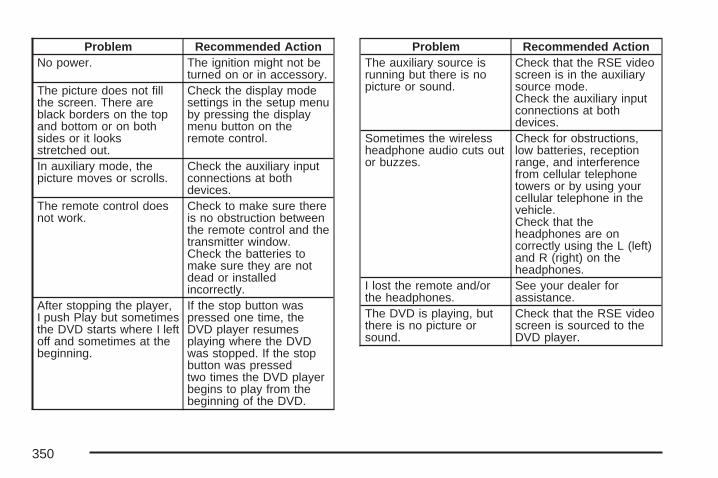
Problem Recommended ActionNo power. The ignition might not be
turned on or in accessory.The picture does not fillthe screen. There areblack borders on the topand bottom or on bothsides or it looksstretched out.
Check the display modesettings in the setup menuby pressing the displaymenu button on theremote control.
In auxiliary mode, thepicture moves or scrolls.
Check the auxiliary inputconnections at bothdevices.
The remote control doesnot work.
Check to make sure thereis no obstruction betweenthe remote control and thetransmitter window.Check the batteries tomake sure they are notdead or installedincorrectly.
After stopping the player,I push Play but sometimesthe DVD starts where I leftoff and sometimes at thebeginning.
If the stop button waspressed one time, theDVD player resumesplaying where the DVDwas stopped. If the stopbutton was pressedtwo times the DVD playerbegins to play from thebeginning of the DVD.
Problem Recommended ActionThe auxiliary source isrunning but there is nopicture or sound.
Check that the RSE videoscreen is in the auxiliarysource mode.Check the auxiliary inputconnections at bothdevices.
Sometimes the wirelessheadphone audio cuts outor buzzes.
Check for obstructions,low batteries, receptionrange, and interferencefrom cellular telephonetowers or by using yourcellular telephone in thevehicle.Check that theheadphones are oncorrectly using the L (left)and R (right) on theheadphones.
I lost the remote and/orthe headphones.
See your dealer forassistance.
The DVD is playing, butthere is no picture orsound.
Check that the RSE videoscreen is sourced to theDVD player.
350

DVD Display Error MessagesThe DVD display error message depends onwhich radio you have. The video screen maydisplay one of the following:
Disc Load/Eject Error: This message isdisplayed when there are disc load or ejectproblems.
Disc Format Error: This message is displayed, ifthe disc is inserted with the disc label wrongside up, or if the disc is damaged.
Disc Region Error: This message is displayed, ifthe disc is not from a correct region.
No Disc Inserted: This message is displayed, ifno disc is present when the EJECT button ispressed on the radio.
DVD DistortionVideo distortion may occur when operating cellularphones, scanners, CB radios, Global PositionSystems (GPS)*, two-way radios, mobile fax, orwalkie talkies.
It might be necessary to turn off the DVD playerwhen operating one of these devices in or near thevehicle.
*Excludes the OnStar® System.
Cleaning the RSE Overhead ConsoleWhen cleaning the RSE overhead console surface,use only a clean cloth dampened with cleanwater.
Cleaning the Video ScreenWhen cleaning the video screen, use only a cleancloth dampened with clean water. Use carewhen directly touching or cleaning the screen, asdamage may result.
351

Rear Seat Audio (RSA)This feature allows rear seat passengers to listento and control any of the music sources: radio,CDs, DVDs, or other auxiliary sources. However,the rear seat passengers can only control themusic sources the front seat passengers are notlistening to (except on some radios wheredual control is allowed). For example, rear seatpassengers can listen to and control a CD throughthe headphones, while the driver listens to theradio through the front speakers. The rearseat passengers have control of the volume foreach set of headphones.
You can operate the RSA functions even whenthe main radio is off.
Audio can be heard through wired headphones(not included) plugged into the jacks on the RSA.If your vehicle has this feature, audio can alsobe heard on Channel 2 of the wirelessheadphones.
The audio system mutes the rear speakers whenthe RSA audio is active through the headphones.
P (Power): Press this button to turn the RSA onor off.
Volume: Turn this knob to increase or todecrease the volume of the wired headphones.The left knob controls the left headphones and theright knob controls the right headphones.
SRCE (Source): Press this button to switchbetween the radio (AM/FM), XM (if equipped), CD,and if your vehicle has these features, DVD,front auxiliary, and rear auxiliary.
352

©¨ (Seek): When listening to FM, AM, or XM(if equipped), press the seek up or the seekdown arrow to go to the next or the previousstation or channels and stay there. This function isinactive, with some radios, if the front seatpassengers are listening to the radio.
Press and hold the seek up or seek down arrowuntil the display flashes, to tune to an individualstation. The display will stop flashing afterthe buttons have not been pushed for more thantwo seconds. This function is inactive, withsome radios, if the front seat passengers arelistening to the radio.
While listening to a disc, press the seek up arrowto go to the next track or chapter on the disc.Press the seek down arrow to go back to the startof the current track or chapter (if more thanten seconds have played). This function is inactive,with some radios, if the front seat passengersare listening to the disc.
When a DVD video menu is being displayed,press the seek up arrow or seek down arrow toperform a cursor up or down on the menu.Hold the seek up arrow or seek down arrow toperform a cursor right or left on the menu.
PROG (Program): Press this button to go to thenext preset radio station or channel set on themain radio. This function is inactive, withsome radios, if the front seat passengers arelistening to the radio.
When a CD or DVD audio is playing, press thisbutton to go to the beginning of the CD orDVD audio. This function is inactive, with someradios, if the front seat passengers are listening tothe disc.
When a disc audio is playing in the CD or DVDchanger, press this button to select the next disc, ifmultiple discs are loaded. This function isinactive, with some radios, if the front seatpassengers are listening to the disc.
When a DVD video menu is being displayed,press the PROG button to perform the menufunction, enter.
353

Theft-Deterrent FeatureTHEFTLOCK® is designed to discourage theft ofyour vehicle’s radio. The feature worksautomatically by learning a portion of the VehicleIdentification Number (VIN). If the radio ismoved to a different vehicle, it does not operateand LOCKED displays.
Audio Steering Wheel Controls
If your vehicle has audiosteering wheel controls,they could differdepending on yourvehicle’s options. Someaudio controls canbe adjusted atthe steering wheel.They include thefollowing:
xw (Next/Previous): Press the up or the downarrow to go to the next or to the previous radiostation stored as a favorite.
When a CD/DVD is playing, press the up or thedown arrow to go to the next or previous track orchapter.
g (Mute/Voice Recognition): Press and releasethis button to silence the vehicle speakers only.The audio of the wireless and wired headphones, ifyour vehicle has these features, does not mute.Press and release this button again, to turnthe sound on.
If your vehicle has the navigation system, pressand hold this button for longer than one second toinitiate voice recognition. See “Voice Recognition”in the Navigation System manual for moreinformation.
If your vehicle has OnStar®, press and hold thisbutton for longer than one second to interactwith the OnStar® system. If your vehicle also hasthe navigation system, press and hold thisbutton for longer than one second to initiate voicerecognition and say “OnStar” to enter OnStar®
mode. See the OnStar® System on page 175 inthis manual for more information.
354

SRCE (Source): Press this button to switchbetween the radio (AM, FM), XM™ (if equipped),CD, and if your vehicle has these features,DVD, front auxiliary, and rear auxiliary.
+ e − e (Volume): Press the plus or minusbutton to increase or to decrease the radio volume.
¨ (Seek): Press the seek arrow to go to thenext radio station while in AM, FM, or XM™(if equipped). Press this button to go to the nexttrack or chapter while sourced to the CD orDVD slot.
Radio ReceptionFrequency interference and static during normalradio reception can occur if items such ascellphone chargers, vehicle convenienceaccessories, and external electronic devices areplugged into the accessory power outlet. If there isinterference or static, unplug the item from theaccessory power outlet.
AMThe range for most AM stations is greater than forFM, especially at night. The longer range can causestation frequencies to interfere with each other. Forbetter radio reception, most AM radio stations boostthe power levels during the day, and then reducethese levels during the night. Static can also occurwhen things like storms and power lines interferewith radio reception. When this happens, tryreducing the treble on your radio.
FM StereoFM stereo gives the best sound, but FM signalsreach about 10 to 40 miles (16 to 65 km). Tallbuildings or hills can interfere with FM signals,causing the sound to fade in and out.
355

XM™ Satellite Radio ServiceXM™ Satellite Radio Service gives digital radioreception from coast-to-coast in the 48 contiguousUnited States, and in Canada. Just as with FM,tall buildings or hills can interfere with satelliteradio signals, causing the sound to fade in and out.In addition, traveling or standing under heavyfoliage, bridges, garages, or tunnels can causeloss of the XM™ signal for a period of time.The radio could display NO XM SIGNAL to indicateinterference.
Care of Your CDs and DVDsHandle CDs carefully. Store them in their originalcases or other protective cases and away fromdirect sunlight and dust. The CD player scans thebottom surface of the disc. If the surface of aCD is damaged, such as cracked, broken,or scratched, the CD does not play properly or notat all. If the surface of a CD is soiled, take asoft, lint free cloth or dampen a clean, soft cloth ina mild, neutral detergent solution mixed withwater, and clean it. Make sure the wiping processstarts from the center to the edge.
Do not touch the bottom side of a CD whilehandling it; this could damage the surface. Pick upCDs by grasping the outer edges or the edge ofthe hole and the outer edge.
Care of the CD and DVD PlayerThe use of CD lens cleaners for CDs is notadvised, due to the risk of contaminating the lensof the CD optics with lubricants internal to theCD mechanism.
Rear Side Window AntennaYour AM-FM antenna is located in the passengerrear side windows. Be sure that the insidesurfaces of the rear side windows are notscratched and that the lines on the glass are notdamaged. If the inside surfaces are damaged, theycould interfere with radio reception.
Notice: Using a razor blade or sharp object toclear the inside of the rear side windows mayaffect radio reception or damage the rearwindow defogger. Repairs would not becovered by your warranty. Do not clear theinside of the rear side windows with sharpobjects.
356

Notice: Do not apply aftermarket glass tintingwith metallic film. The metallic film in sometinting materials will interfere with or distort theincoming radio reception. Any damage causedto your antenna due to metallic tinting materialswill not be covered by your warranty.
Because this antenna is built into your rear sidewindow, there is a reduced risk of damage causedby car washes and vandals.
If you choose to add an aftermarket cellulartelephone to your vehicle, and the antenna needsto be attached to the glass, be sure that youdo not damage the grid lines for the AM-FMantennas or place the cellular telephone antennaover the grid lines.
XM™ Satellite Radio AntennaSystemThe XM™ Satellite Radio antenna is located onthe roof of your vehicle. Keep this antenna clear ofsnow and ice build up for clear radio reception.
The performance of the XM™ system maybe affected if the sunroof is open.
Loading items onto the roof of your vehicle caninterfere with the performance of the XM™ system.Make sure the XM™ Satellite Radio antenna isnot obstructed.
357

✍ NOTES
358

Your Driving, the Road, and Your Vehicle .... 360Defensive Driving ...................................... 360Drunken Driving ........................................ 361Control of a Vehicle .................................. 364Braking ...................................................... 364Anti-Lock Brake System (ABS) .................. 365Braking in Emergencies ............................. 367Locking Rear Axle ..................................... 367StabiliTrak® System ................................... 367Steering .................................................... 371Off-Road Recovery .................................... 373Passing ..................................................... 373Loss of Control .......................................... 375Off-Road Driving ........................................ 377Driving at Night ......................................... 394Driving in Rain and on Wet Roads ............ 396City Driving ............................................... 399Freeway Driving ........................................ 400
Before Leaving on a Long Trip .................. 401Highway Hypnosis ..................................... 402Hill and Mountain Roads ........................... 403Winter Driving ........................................... 405If Your Vehicle is Stuck in Sand, Mud,
Ice, or Snow .......................................... 409Rocking Your Vehicle to Get It Out ........... 410Recovery Hooks ........................................ 410Loading Your Vehicle ................................ 411Adding a Snow Plow or Similar
Equipment .............................................. 418Towing ........................................................ 422
Towing Your Vehicle ................................. 422Recreational Vehicle Towing ...................... 423Level Control ............................................. 427Autoride® ................................................... 427Towing a Trailer ........................................ 428Trailer Recommendations .......................... 446
Section 4 Driving Your Vehicle
359

Your Driving, the Road, andYour Vehicle
Defensive DrivingThe best advice anyone can give about driving is:Drive defensively.
Please start with a very important safety devicein your vehicle: Buckle up. See Safety Belts:They Are for Everyone on page 38.
{CAUTION:
Defensive driving really means “Be readyfor anything.” On city streets, rural roads,or expressways, it means “Always expectthe unexpected.” Assume that pedestriansor other drivers are going to be carelessand make mistakes. Anticipate what theymight do and be ready. Rear-end collisionsare about the most preventable ofaccidents. Yet they are common. Allowenough following distance. Defensivedriving requires that a driver concentrateon the driving task. Anything that distractsfrom the driving task makes properdefensive driving more difficult and caneven cause a collision, with resultinginjury. Ask a passenger to help do thesethings, or pull off the road in a safe place todo them. These simple defensive drivingtechniques could save your life.
360

Drunken DrivingDeath and injury associated with drinking anddriving is a national tragedy. It is the number onecontributor to the highway death toll, claimingthousands of victims every year.
Alcohol affects four things that anyone needs todrive a vehicle:
• Judgment
• Muscular Coordination
• Vision
• Attentiveness
Police records show that almost half of all motorvehicle-related deaths involve alcohol. In mostcases, these deaths are the result of someone whowas drinking and driving. In recent years, morethan 16,000 annual motor vehicle-related deathshave been associated with the use of alcohol,with more than 300,000 people injured.
Many adults — by some estimates, nearly halfthe adult population — choose never to drinkalcohol, so they never drive after drinking.For persons under 21, it is against the law inevery U.S. state to drink alcohol. There are goodmedical, psychological, and developmentalreasons for these laws.
The obvious way to eliminate the leading highwaysafety problem is for people never to drinkalcohol and then drive. But what if people do?How much is “too much” if someone plansto drive? It is a lot less than many might think.Although it depends on each person and situation,here is some general information on the problem.
The Blood Alcohol Concentration (BAC) ofsomeone who is drinking depends upon four things:
• The amount of alcohol consumed
• The drinker’s body weight
• The amount of food that is consumed beforeand during drinking
• The length of time it has taken the drinker toconsume the alcohol
361

According to the American Medical Association, a180 lb (82 kg) person who drinks three 12 ounce(355 ml) bottles of beer in an hour will end up witha BAC of about 0.06 percent. The person wouldreach the same BAC by drinking three 4 ounce(120 ml) glasses of wine or three mixed drinks ifeach had 1-1/2 ounces (45 ml) of liquors likewhiskey, gin, or vodka.
It is the amount of alcohol that counts. For example,if the same person drank three double martinis(3 ounces or 90 ml of liquor each) within an hour,the person’s BAC would be close to 0.12 percent.A person who consumes food just before or duringdrinking will have a somewhat lower BAC level.
There is a gender difference, too. Womengenerally have a lower relative percentage of bodywater than men. Since alcohol is carried in bodywater, this means that a woman generally willreach a higher BAC level than a man of her samebody weight will when each has the samenumber of drinks.
The law in most U.S. states, and throughoutCanada, sets the legal limit at 0.08 percent.In some other countries, the limit is even lower.For example, it is 0.05 percent in both Franceand Germany. The BAC limit for all commercialdrivers in the United States is 0.04 percent.
The BAC will be over 0.10 percent after three tosix drinks (in one hour). Of course, as we haveseen, it depends on how much alcohol is in thedrinks, and how quickly the person drinks them.
362
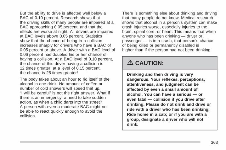
But the ability to drive is affected well below aBAC of 0.10 percent. Research shows thatthe driving skills of many people are impaired at aBAC approaching 0.05 percent, and that theeffects are worse at night. All drivers are impairedat BAC levels above 0.05 percent. Statisticsshow that the chance of being in a collisionincreases sharply for drivers who have a BAC of0.05 percent or above. A driver with a BAC level of0.06 percent has doubled his or her chance ofhaving a collision. At a BAC level of 0.10 percent,the chance of this driver having a collision is12 times greater; at a level of 0.15 percent,the chance is 25 times greater!
The body takes about an hour to rid itself of thealcohol in one drink. No amount of coffee ornumber of cold showers will speed that up.“I will be careful” is not the right answer. What ifthere is an emergency, a need to take suddenaction, as when a child darts into the street?A person with even a moderate BAC might notbe able to react quickly enough to avoid thecollision.
There is something else about drinking and drivingthat many people do not know. Medical researchshows that alcohol in a person’s system can makecrash injuries worse, especially injuries to thebrain, spinal cord, or heart. This means that whenanyone who has been drinking — driver orpassenger — is in a crash, that person’s chanceof being killed or permanently disabled ishigher than if the person had not been drinking.
{CAUTION:
Drinking and then driving is verydangerous. Your reflexes, perceptions,attentiveness, and judgment can beaffected by even a small amount ofalcohol. You can have a serious — oreven fatal — collision if you drive afterdrinking. Please do not drink and drive orride with a driver who has been drinking.Ride home in a cab; or if you are with agroup, designate a driver who will notdrink.
363

Control of a VehicleYou have three systems that make your vehiclego where you want it to go. They are the brakes,the steering, and the accelerator. All threesystems have to do their work at the places wherethe tires meet the road.
Sometimes, as when you are driving on snowor ice, it is easy to ask more of those controlsystems than the tires and road can provide.That means you can lose control of your vehicle.See StabiliTrak® System on page 367.
Adding non-GM accessories can affect yourvehicle’s performance. See Accessories andModifications on page 450.
BrakingSee Brake System Warning Light on page 250.
Braking action involves perception time andreaction time.
First, you have to decide to push on the brakepedal. That is perception time. Then you have tobring up your foot and do it. That is reaction time.
Average reaction time is about three-fourths of asecond. But that is only an average. It mightbe less with one driver and as long as two orthree seconds or more with another. Age, physicalcondition, alertness, coordination, and eyesightall play a part. So do alcohol, drugs, andfrustration. But even in three-fourths of a second,a vehicle moving at 60 mph (100 km/h) travels66 feet (20 m). That could be a lot of distance in anemergency, so keeping enough space betweenyour vehicle and others is important.
And, of course, actual stopping distances varygreatly with the surface of the road, whether it ispavement or gravel; the condition of the road,whether it is wet, dry, or icy; tire tread; thecondition of the brakes; the weight of the vehicle;and the amount of brake force applied.
364
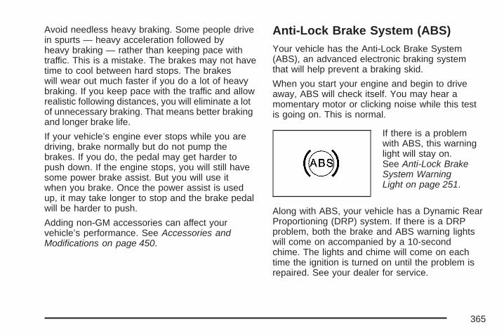
Avoid needless heavy braking. Some people drivein spurts — heavy acceleration followed byheavy braking — rather than keeping pace withtraffic. This is a mistake. The brakes may not havetime to cool between hard stops. The brakeswill wear out much faster if you do a lot of heavybraking. If you keep pace with the traffic and allowrealistic following distances, you will eliminate a lotof unnecessary braking. That means better brakingand longer brake life.
If your vehicle’s engine ever stops while you aredriving, brake normally but do not pump thebrakes. If you do, the pedal may get harder topush down. If the engine stops, you will still havesome power brake assist. But you will use itwhen you brake. Once the power assist is usedup, it may take longer to stop and the brake pedalwill be harder to push.
Adding non-GM accessories can affect yourvehicle’s performance. See Accessories andModifications on page 450.
Anti-Lock Brake System (ABS)Your vehicle has the Anti-Lock Brake System(ABS), an advanced electronic braking systemthat will help prevent a braking skid.
When you start your engine and begin to driveaway, ABS will check itself. You may hear amomentary motor or clicking noise while this testis going on. This is normal.
If there is a problemwith ABS, this warninglight will stay on.See Anti-Lock BrakeSystem WarningLight on page 251.
Along with ABS, your vehicle has a Dynamic RearProportioning (DRP) system. If there is a DRPproblem, both the brake and ABS warning lightswill come on accompanied by a 10-secondchime. The lights and chime will come on eachtime the ignition is turned on until the problem isrepaired. See your dealer for service.
365

Let us say the road is wet and you are drivingsafely. Suddenly, an animal jumps out in front ofyou. You slam on the brakes and continue braking.Here is what happens with ABS:
A computer senses that wheels are slowing down.If one of the wheels is about to stop rolling, thecomputer will separately work the brakes at eachfront wheel and at both rear wheels.
ABS can change the brake pressure faster than anydriver could. The computer is programmed to makethe most of available tire and road conditions.This can help you steer around the obstacle whilebraking hard.
As you brake, your computer keeps receivingupdates on wheel speed and controls brakingpressure accordingly.
366

Remember: ABS does not change the time youneed to get your foot up to the brake pedalor always decrease stopping distance. If you gettoo close to the vehicle in front of you, you will nothave time to apply your brakes if that vehiclesuddenly slows or stops. Always leave enoughroom up ahead to stop, even though youhave ABS.
Using ABSDo not pump the brakes. Just hold the brakepedal down firmly and let anti-lock work for you.You may feel the brakes vibrate, or you may noticesome noise, but this is normal.
Braking in EmergenciesWith ABS, you can steer and brake at the sametime. In many emergencies, steering can help youmore than even the very best braking.
Locking Rear AxleIf your vehicle has this feature, your locking rearaxle can give you additional traction on snow, mud,ice, sand or gravel. It works like a standard axlemost of the time, but when one of the rear wheelshas no traction and the other does, this feature willallow the wheel with traction to move the vehicle.
StabiliTrak® SystemYour vehicle may be equipped with theStabiliTrak® system which combines antilockbrake, traction and stability control systems andhelps the driver maintain directional control of thevehicle in most driving conditions.
When you first start your vehicle and begin todrive away, the system performs severaldiagnostic checks to ensure there are noproblems. You may hear or feel the systemworking. This is normal and does not mean thereis a problem with your vehicle. The system shouldinitialize before the vehicle reaches 20 mph(32 km/h). In some cases, it may takeapproximately two miles of driving before thesystem initializes.
367

If the system fails to turn on or activate, theStabiliTrak® light along with one of the followingmessages will be displayed on the DriverInformation Center (DIC): TRACTION CONTROLOFF, SERVICE TRACTION CONTROL,STABILITRAK OFF, SERVICE STABILITRAK.If these DIC messages appear, make surethe StabiliTrak® system has not been turned offusing the StabiliTrak® on/off button. Then turn thesteering wheel clockwise from the nine o’clockposition to the three o’clock position. If this clearsthe message(s), your vehicle does not needservicing. If this does not clear the message(s),then turn the vehicle off, wait 15 seconds, and thenturn it back on again to reset the system. If anyof these messages still appear on the DriverInformation Center (DIC), your vehicle should betaken in for service. For more information onthe DIC messages, see Driver InformationCenter (DIC) on page 262.
The StabiliTrak® lightwill flash on theinstrument panel clusterwhen the system isboth on and activated.
You may also feel or hear the system working;this is normal.
The traction controldisable button is locatedon the instrumentpanel below theclimate controls.
368

The traction control part of StabiliTrak® canbe turned off by pressing and releasing theStabiliTrak® button if both systems (traction controland StabiliTrak®) were previously on. To disableboth traction control and StabiliTrak®, press andhold the button for five seconds.
Traction control and StabiliTrak® can be turned onby pressing and releasing the StabiliTrak® button ifnot automatically shut off for any other reason.
When the TCS or StabiliTrak® system is turned off,the StabiliTrak® light and the appropriate TCSoff or StabiliTrak® off message will be displayed onthe DIC to warn the driver. Your vehicle will stillhave brake-traction control when traction control isoff, but will not be able to use the engine speedmanagement system. See “Traction ControlOperation” next for more information.
When the traction control system has been turnedoff, you may still hear system noises as a resultof the brake-traction control coming on.
It is recommended to leave the system on fornormal driving conditions, but it may be necessaryto turn the system off if your vehicle is stuck insand, mud, ice or snow, and you want to “rock”your vehicle to attempt to free it. It may alsobe necessary to turn off the system when drivingin extreme off-road conditions where highwheel spin is required. See If Your Vehicle isStuck in Sand, Mud, Ice, or Snow on page 409.
When the transfer case is in 4LO, the stabilitysystem is automatically disabled, the StabiliTrak®
light will come on and the STABILITRAK OFFmessage will appear on the DIC. Both tractioncontrol and StabiliTrak® are automatically disabledin this condition.
369

Traction Control OperationThe traction control system is part of theStabiliTrak® system. Traction control limits wheelspin by reducing engine power to the wheels(engine speed management) and by applyingbrakes to each individual wheel (brake-tractioncontrol) as necessary.
The traction control system is enabled automaticallywhen you start your vehicle. It will activate and theStabiliTrak® light will flash if it senses that any of thewheels are spinning or beginning to lose tractionwhile driving. If you turn off traction control, only thebrake-traction control portion of traction control willwork. The engine speed management will bedisabled. In this mode, engine power is not reducedautomatically and the driven wheels can spin morefreely. This can cause the brake-traction control toactivate constantly.
Notice: If you allow the wheel(s) of one axleto spin excessively while the StabiliTrak®, ABSand brake warning lights and the SERVICESTABILITRAK message are displayed,you could damage the transfer case.
The repairs would not be covered by yourwarranty. Reduce engine power and do not spinthe wheel(s) excessively while these lights andthis message are displayed.
The traction control system may activate on dry orrough roads or under conditions such as heavyacceleration while turning or abrupt upshifts/downshifts of the transmission. When this happens,you may notice a reduction in acceleration, or mayhear a noise or vibration. This is normal.
If your vehicle is in cruise control when the systemactivates, the StabiliTrak® light will flash and thecruise control will automatically disengage.When road conditions allow you to use cruiseagain, you may re-engage the cruise control.See Cruise Control on page 212.
StabiliTrak® may also turn off automatically if itdetermines that a problem exists with the system.If the problem does not clear itself after restartingthe vehicle, you should see your dealer for service.
370

Steering
Power SteeringIf you lose power steering assist because theengine stops or the system is not functioning,you can steer but it will take much more effort.
Steering TipsIt is important to take curves at a reasonablespeed.
A lot of the “driver lost control” accidentsmentioned on the news happen on curves.Here is why:
Experienced driver or beginner, each of us issubject to the same laws of physics when drivingon curves. The traction of the tires against theroad surface makes it possible for the vehicle tochange its path when you turn the front wheels.If there is no traction, inertia will keep thevehicle going in the same direction. If you haveever tried to steer a vehicle on wet ice, youwill understand this.
The traction you can get in a curve depends onthe condition of the tires and the road surface, theangle at which the curve is banked, and yourspeed. While you are in a curve, speed is the onefactor you can control.
Suppose you are steering through a sharp curve.Then you suddenly accelerate. Both controlsystems — steering and acceleration — have todo their work where the tires meet the road.Adding the sudden acceleration can demand toomuch of those places. You can lose control.See StabiliTrak® System on page 367.
What should you do if this ever happens? Ease upon the accelerator pedal, steer the vehicle theway you want it to go, and slow down.
Speed limit signs near curves warn that youshould adjust your speed. Of course, the postedspeeds are based on good weather and roadconditions. Under less favorable conditions you willwant to go slower.
If you need to reduce your speed as you approacha curve, do it before you enter the curve, whilethe front wheels are straight ahead.
371

Try to adjust your speed so you can “drive”through the curve. Maintain a reasonable, steadyspeed. Wait to accelerate until you are out ofthe curve, and then accelerate gently intothe straightaway.
Adding non-GM accessories can affect yourvehicle’s performance. See Accessories andModifications on page 450.
Steering in EmergenciesThere are times when steering can be moreeffective than braking. For example, you comeover a hill and find a truck stopped in your lane, ora car suddenly pulls out from nowhere, or achild darts out from between parked cars andstops right in front of you. You can avoid theseproblems by braking — if you can stop in time.But sometimes you cannot; there is not room.That is the time for evasive action — steeringaround the problem.
Your vehicle can perform very well in emergencieslike these. First, apply the brakes. See Brakingon page 364. It is better to remove as much speedas you can from a possible collision. Then steeraround the problem, to the left or right dependingon the space available.
An emergency like this requires close attentionand a quick decision. If you are holding thesteering wheel at the recommended 9 and3 o’clock positions, you can turn it a full180 degrees very quickly without removing eitherhand. But you have to act fast, steer quickly,and just as quickly straighten the wheel once youhave avoided the object.
The fact that such emergency situations arealways possible is a good reason to practicedefensive driving at all times and wear safety beltsproperly.
372

Off-Road RecoveryYou may find that your right wheels have droppedoff the edge of a road onto the shoulder while youare driving.
If the level of the shoulder is only slightly belowthe pavement, recovery should be fairly easy.Ease off the accelerator and then, if thereis nothing in the way, steer so that yourvehicle straddles the edge of the pavement.
You can turn the steering wheel up to one-quarterturn until the right front tire contacts the pavementedge. Then turn the steering wheel to go straightdown the roadway.
PassingThe driver of a vehicle about to pass another on atwo-lane highway waits for just the right moment,accelerates, moves around the vehicle ahead,then goes back into the right lane again. A simplemaneuver?
Not necessarily! Passing another vehicle on atwo-lane highway is a potentially dangerous move,since the passing vehicle occupies the samelane as oncoming traffic for several seconds.A miscalculation, an error in judgment, or a briefsurrender to frustration or anger can suddenlyput the passing driver face to face with the worstof all traffic accidents — the head-on collision.
373

So here are some tips for passing:
• Drive ahead. Look down the road, to thesides, and to crossroads for situationsthat might affect your passing patterns. If youhave any doubt whatsoever about makinga successful pass, wait for a better time.
• Watch for traffic signs, pavement markings,and lines. If you can see a sign up aheadthat might indicate a turn or an intersection,delay your pass. A broken center lineusually indicates it is all right to pass, providingthe road ahead is clear. Never cross a solidline on your side of the lane or a doublesolid line, even if the road seems empty ofapproaching traffic.
• Do not get too close to the vehicle you wantto pass while you are awaiting an opportunity.For one thing, following too closely reducesyour area of vision, especially if you arefollowing a larger vehicle. Also, you will nothave adequate space if the vehicle aheadsuddenly slows or stops. Keep back areasonable distance.
• When it looks like a chance to pass is comingup, start to accelerate but stay in the rightlane and do not get too close. Time your moveso you will be increasing speed as the timecomes to move into the other lane. If the wayis clear to pass, you will have a runningstart that more than makes up for the distanceyou would lose by dropping back. And ifsomething happens to cause you to cancelyour pass, you need only slow down and dropback again and wait for another opportunity.
• If other vehicles are lined up to pass a slowvehicle, wait your turn. But take care thatsomeone is not trying to pass you as you pullout to pass the slow vehicle. Remember toglance over your shoulder and check theblind spot.
374
• Check your vehicle’s mirrors, glance over yourshoulder, and start your left lane changesignal before moving out of the right lane topass. When you are far enough ahead ofthe passed vehicle to see its front in yourvehicle’s inside mirror, activate the right lanechange signal and move back into theright lane. Remember that, if your vehicle’spassenger side outside mirror is convex,the vehicle you just passed may seem to befarther away from you than it really is.
• Try not to pass more than one vehicle at atime on two-lane roads. Reconsider beforepassing the next vehicle.
• Do not overtake a slowly moving vehicletoo rapidly. Even though the brake lampsare not flashing, it may be slowing down orstarting to turn.
• If you are being passed, make it easy forthe following driver to get ahead of you.Perhaps you can ease a little to the right.
Loss of ControlLet us review what driving experts say about whathappens when the three control systems — brakes,steering, and acceleration — do not have enoughfriction where the tires meet the road to do what thedriver has asked.
In any emergency, do not give up. Keep trying tosteer and constantly seek an escape route orarea of less danger.
SkiddingIn a skid, a driver can lose control of the vehicle.Defensive drivers avoid most skids by takingreasonable care suited to existing conditions,and by not overdriving those conditions.But skids are always possible.
375

The three types of skids correspond to yourvehicle’s three control systems. In the braking skid,your wheels are not rolling. In the steering orcornering skid, too much speed or steering in acurve causes tires to slip and lose cornering force.And in the acceleration skid, too much throttlecauses the driving wheels to spin.
A cornering skid is best handled by easing yourfoot off the accelerator pedal.
Remember: StabiliTrak® helps avoid only theacceleration skid. See StabiliTrak® Systemon page 367. If the StabiliTrak® System is off,then an acceleration skid is also best handled byeasing your foot off the accelerator pedal.
If your vehicle starts to slide, ease your foot offthe accelerator pedal and quickly steer theway you want the vehicle to go. If you startsteering quickly enough, your vehicle maystraighten out. Always be ready for a second skidif it occurs.
Of course, traction is reduced when water, snow,ice, gravel, or other material is on the road.For safety, you will want to slow down and adjustyour driving to these conditions. It is importantto slow down on slippery surfaces becausestopping distance will be longer and vehicle controlmore limited.
While driving on a surface with reduced traction, tryyour best to avoid sudden steering, acceleration, orbraking, including reducing vehicle speed byshifting to a lower gear. Any sudden changes couldcause the tires to slide. You may not realize thesurface is slippery until your vehicle is skidding.Learn to recognize warning clues — such asenough water, ice, or packed snow on the road tomake a mirrored surface — and slow down whenyou have any doubt.
Remember: Any Anti-Lock Brake System (ABS)helps avoid only the braking skid.
376

Off-Road DrivingThis off-road guide is for vehicles that havefour-wheel drive. Also, see Braking on page 364.If your vehicle does not have four-wheel drive,you should not drive off-road unless you are on alevel, solid surface.
The airbag system is designed to work properlyunder a wide range of conditions, including off-roadusage. Observe safe driving speeds, especiallyon rough terrain. As always, wear your safety belt.
Off-road driving can be great fun. But it doeshave some definite hazards. The greatest of theseis the terrain itself.
“Off-roading” means you have left the greatNorth American road system behind. Traffic lanesare not marked. Curves are not banked. Thereare no road signs. Surfaces can be slippery, rough,uphill or downhill. In short, you have gone rightback to nature.
Off-road driving involves some new skills. And thatis why it is very important that you read this guide.You will find many driving tips and suggestions.These will help make your off-road driving safer andmore enjoyable.
If you think you will need some more groundclearance at the front of your vehicle, youcan remove the front fascia lower air dam.
The front fascia lower air dam is held in place bytwo bolts and 10 snap features. The bolts andsnap features are accessible from underneath thefront fascia.
The following steps must be performed on thebolts and snap features to remove the air dam:1. Remove the two outboard air dam bolts.2. With a flat-blade screwdriver, push down on
the snap features and disengage the snaps.3. After the bolts are removed and the snaps are
disengaged, push forward on the air dam untilit is free.
377

When you are back on roads, though, be sure toreplace the air dam.
Notice: Operating your vehicle for extendedperiods without the front fascia lower air daminstalled can cause improper air flow to theengine. Always be sure to replace the frontfascia air dam when you are finished off-roaddriving.
To reinstall the lower air dam do the following:1. Line up the snap features and push the
air dam rearward to engage the snaps.2. Install the two outboard bolts.
Before You Go Off-RoadingThere are some things to do before you go out.For example, be sure to have all necessarymaintenance and service work done. Check tomake sure all underbody shields, if the vehicle hasthem, are properly attached. Be sure you readall the information about your four-wheel-drive orall-wheel-drive vehicle in this manual. Is thereenough fuel? Is the spare tire fully inflated? Are thefluid levels up where they should be? What arethe local laws that apply to off-roading where youwill be driving? If you do not know, you shouldcheck with law enforcement people in thearea. Will you be on someone’s private land?If so, be sure to get the necessary permission.
378

Loading Your Vehicle for Off-RoadDriving
{CAUTION:
• Cargo on the load floor piled higherthan the seatbacks can be thrownforward during a sudden stop. You oryour passengers could be injured.Keep cargo below the top of theseatbacks.
• Unsecured cargo on the load floor canbe tossed about when driving overrough terrain. You or your passengerscan be struck by flying objects.Secure the cargo properly.
• Heavy loads on the roof raise thevehicle’s center of gravity, making itmore likely to roll over. You can beseriously or fatally injured if thevehicle rolls over. Put heavy loadsinside the cargo area, not on the roof.Keep cargo in the cargo area as farforward and low as possible.
There are some important things to rememberabout how to load your vehicle.
• The heaviest things should be on the loadfloor and forward of your rear axle. Putheavier items as far forward as you can.
• Be sure the load is secured properly, sodriving on the off-road terrain does nottoss things around.
You will find other important information in thismanual. See Loading Your Vehicle on page 411and Tires on page 510.
379

Environmental ConcernsOff-road driving can provide wholesome andsatisfying recreation. However, it also raisesenvironmental concerns. We recognize theseconcerns and urge every off-roader to follow thesebasic rules for protecting the environment:
• Always use established trails, roads, and areasthat have been specially set aside for publicoff-road recreational driving; obey all postedregulations.
• Avoid any driving practice that could damagethe environment — shrubs, flowers, trees,grasses — or disturb wildlife. This includeswheel-spinning, breaking down trees, orunnecessary driving through streams or oversoft ground.
• Always carry a litter bag — make sure all refuseis removed from any campsite before leaving.
• Take extreme care with open fires (wherepermitted), camp stoves and lanterns.
• Never park your vehicle over dry grass or othercombustible materials that could catch fire fromthe heat of the vehicle’s exhaust system.
Traveling to Remote AreasIt makes sense to plan your trip, especially whengoing to a remote area. Know the terrain andplan your route. You are much less likely to getbad surprises. Get accurate maps of trailsand terrain. Try to learn of any blocked or closedroads.
It is also a good idea to travel with at least oneother vehicle. If something happens to oneof them, the other can help quickly.
Does your vehicle have a winch? If so, be sure toread the winch instructions. In a remote area, awinch can be handy if you get stuck. But you willwant to know how to use it properly.
380

Getting Familiar with Off-Road DrivingIt is a good idea to practice in an area that issafe and close to home before you go intothe wilderness. Off-road driving does require somenew and different skills. Here is what we mean.
Tune your senses to different kinds of signals.Your eyes, for example, need to constantly sweepthe terrain for unexpected obstacles. Your earsneed to listen for unusual tire or engine sounds.With your arms, hands, feet, and body, youwill need to respond to vibrations and vehiclebounce.
Controlling your vehicle is the key to successfuloff-road driving. One of the best ways tocontrol your vehicle is to control your speed.
Here are some things to keep in mind.At higher speeds:
• You approach things faster and you haveless time to scan the terrain for obstacles.
• You have less time to react.
• You have more vehicle bounce when youdrive over obstacles.
• You will need more distance for braking,especially since you are on an unpavedsurface.
{CAUTION:
When you are driving off-road, bouncingand quick changes in direction can easilythrow you out of position. This couldcause you to lose control and crash.So, whether you are driving on or off theroad, you and your passengers shouldwear safety belts.
381

Scanning the TerrainOff-road driving can take you over many differentkinds of terrain. You need to be familiar withthe terrain and its many different features.Here are some things to consider.
Surface Conditions: Off-roading can take youover hard-packed dirt, gravel, rocks, grass, sand,mud, snow, or ice. Each of these surfacesaffects the steering, acceleration, and braking ofyour vehicle in different ways. Depending upon thekind of surface you are on, you may experienceslipping, sliding, wheel spinning, delayedacceleration, poor traction, and longer brakingdistances.
Surface Obstacles: Unseen or hidden obstaclescan be hazardous. A rock, log, hole, rut, orbump can startle you if you are not prepared forthem. Often these obstacles are hidden bygrass, bushes, snow, or even the rise and fall ofthe terrain itself. Here are some things to consider:
• Is the path ahead clear?
• Will the surface texture change abruptly upahead?
• Does the travel take you uphill or downhill?There is more discussion of these subjectslater.
• Will you have to stop suddenly or changedirection quickly?
When you drive over obstacles or rough terrain,keep a firm grip on the steering wheel. Ruts,troughs, or other surface features can jerk thewheel out of your hands if you are not prepared.
When you drive over bumps, rocks, or otherobstacles, the wheels can leave the ground. If thishappens, even with one or two wheels, youcannot control the vehicle as well or at all.
382

Because you will be on an unpaved surface, it isespecially important to avoid sudden acceleration,sudden turns, or sudden braking.
In a way, off-road driving requires a different kindof alertness from driving on paved roads andhighways. There are no road signs, posted speedlimits, or signal lights. You have to use yourown good judgment about what is safe andwhat is not.
Drinking and driving can be very dangerous onany road. And this is certainly true for off-roaddriving. At the very time you need special alertnessand driving skills, your reflexes, perceptions,and judgment can be affected by even a smallamount of alcohol. You could have a serious — oreven fatal — accident if you drink and drive orride with a driver who has been drinking.See Drunken Driving on page 361.
Driving on Off-Road HillsOff-road driving often takes you up, down, oracross a hill. Driving safely on hills requires goodjudgment and an understanding of what yourvehicle can and cannot do. There are some hillsthat simply cannot be driven, no matter howwell built the vehicle.
{CAUTION:
Many hills are simply too steep for anyvehicle. If you drive up them, you willstall. If you drive down them, you cannotcontrol your speed. If you drive acrossthem, you will roll over. You could beseriously injured or killed. If you have anydoubt about the steepness, do not drivethe hill.
383

Approaching a HillWhen you approach a hill, you need to decideif it is one of those hills that is just too steepto climb, descend, or cross. Steepness can behard to judge. On a very small hill, for example,there may be a smooth, constant incline withonly a small change in elevation where youcan easily see all the way to the top. On alarge hill, the incline may get steeper as younear the top, but you may not see this becausethe crest of the hill is hidden by bushes, grassor shrubs.
Here are some other things to consider as youapproach a hill.
• Is there a constant incline, or does the hill getsharply steeper in places?
• Is there good traction on the hillside, or willthe surface cause tire slipping?
• Is there a straight path up or down the hill soyou will not have to make turning maneuvers?
• Are there obstructions on the hill that can blockyour path, such as boulders, trees, logs, or ruts?
• What is beyond the hill? Is there a cliff, anembankment, a drop-off, a fence? Get out andwalk the hill if you do not know. It is the smartway to find out.
• Is the hill simply too rough? Steep hills oftenhave ruts, gullies, troughs, and exposed rocksbecause they are more susceptible to theeffects of erosion.
384

Driving UphillOnce you decide you can safely drive up the hill,you need to take some special steps.
• Use a low gear and get a firm grip on thesteering wheel.
• Get a smooth start up the hill and try tomaintain your speed. Do not use more powerthan you need, because you do not wantthe wheels to start spinning or sliding.
{CAUTION:
Turning or driving across steep hills canbe dangerous. You could lose traction,slide sideways, and possibly roll over.You could be seriously injured or killed.When driving up hills, always try to gostraight up.
• Try to drive straight up the hill if at all possible.If the path twists and turns, you might want tofind another route.
• Ease up on your speed as you approach thetop of the hill.
• Attach a flag to the vehicle to make you morevisible to approaching traffic on trails or hills.
• Sound the horn as you approach the top of thehill to let opposing traffic know you are there.
• Use your headlamps even during theday. They make your vehicle more visible tooncoming traffic.
{CAUTION:
Driving to the top (crest) of a hill at fullspeed can cause an accident. There couldbe a drop-off, embankment, cliff, or evenanother vehicle. You could be seriouslyinjured or killed. As you near the top of ahill, slow down and stay alert.
385

Q: What should I do if my vehicle stalls,or is about to stall, and I cannot make itup the hill?
A: If this happens, there are some things youshould do, and there are some things youmust not do. First, here is what you should do:
• Push the brake pedal to stop the vehicleand keep it from rolling backwards. Also,apply the parking brake.
• If your engine is still running, shift thetransmission to REVERSE (R), release theparking brake, and slowly back down the hill inREVERSE (R).
• If your engine has stopped running, you willneed to restart it. With the brake pedalpressed and the parking brake still applied,shift the transmission to PARK (P) and restartthe engine. Then, shift to REVERSE (R),release the parking brake, and slowly backdown the hill as straight as possible inREVERSE (R).
• As you are backing down the hill, put your lefthand on the steering wheel at the 12 o’clockposition. This way, you will be able to tellif your wheels are straight and maneuver asyou back down. It is best that you backdown the hill with your wheels straight ratherthan in the left or right direction. Turningthe wheel too far to the left or right willincrease the possibility of a rollover.
Here are some things you must not do if you stall,or are about to stall, when going up a hill.
• Never attempt to prevent a stall by shiftinginto NEUTRAL (N) to rev-up the engineand regain forward momentum. This will notwork. Your vehicle will roll backwardsvery quickly and you could go out of control.Instead, apply the regular brake to stopthe vehicle. Then apply the parking brake.Shift to REVERSE (R), release the parkingbrake, and slowly back straight down.
386

{CAUTION:
Shifting the transfer case to NEUTRALcan cause your vehicle to roll even if thetransmission is in PARK (P). This isbecause the NEUTRAL position on thetransfer case overrides the transmission.You or someone else could be injured.If you are going to leave your vehicle,set the parking brake and shift thetransmission to PARK (P). But do not shiftthe transfer case to NEUTRAL.
• Never attempt to turn around if you are aboutto stall when going up a hill. If the hill is steepenough to stall your vehicle, it is steepenough to cause you to roll over if you turnaround. If you cannot make it up the hill,you must back straight down the hill.
Q: Suppose, after stalling, I try to back downthe hill and decide I just cannot do it. Whatshould I do?
A: Set the parking brake, put your transmissionin PARK (P) and turn off the engine. Leavethe vehicle and go get some help. Exit on theuphill side and stay clear of the path thevehicle would take if it rolled downhill. Do notshift the transfer case to NEUTRAL whenyou leave the vehicle. Leave it in some gear.
387

Driving DownhillWhen off-roading takes you downhill, you will wantto consider a number of things:
• How steep is the downhill? Will I be able tomaintain vehicle control?
• What is the surface like? Smooth? Rough?Slippery? Hard-packed dirt? Gravel?
• Are there hidden surface obstacles? Ruts?Logs? Boulders?
• What is at the bottom of the hill? Is there ahidden creek bank or even a river bottomwith large rocks?
If you decide you can go down a hill safely, thentry to keep your vehicle headed straight down, anduse a low gear. This way, engine drag can helpyour brakes and they will not have to do allthe work. Descend slowly, keeping your vehicleunder control at all times.
{CAUTION:
Heavy braking when going down a hill cancause your brakes to overheat and fade.This could cause loss of control and aserious accident. Apply the brakes lightlywhen descending a hill and use a lowgear to keep vehicle speed under control.
388

Q: Are there some things I should not dowhen driving down a hill?
A: Yes! These are important because if youignore them you could lose control andhave a serious accident.
• When driving downhill, avoid turns that takeyou across the incline of the hill. A hill thatis not too steep to drive down may betoo steep to drive across. You could roll overif you do not drive straight down.
• Never go downhill with the transmission inNEUTRAL (N). This is called “free-wheeling.”Your brakes will have to do all the workand could overheat and fade.
Q: Am I likely to stall when going downhill?
A: It is much more likely to happen goinguphill. But if it happens going downhill,here is what to do.
1. Stop your vehicle by applying the regularbrakes. Apply the parking brake.
2. Shift to PARK (P) and, while still braking,restart the engine.
3. Shift back to a low gear, release the parkingbrake, and drive straight down.
4. If the engine will not start, get out andget help.
389

Driving Across an InclineSooner or later, an off-road trail will probably goacross the incline of a hill. If this happens,you have to decide whether to try to drive acrossthe incline. Here are some things to consider:
{CAUTION:
Driving across an incline that is too steepwill make your vehicle roll over. You couldbe seriously injured or killed. If you haveany doubt about the steepness of theincline, do not drive across it. Find anotherroute instead.
• A hill that can be driven straight up or downmay be too steep to drive across. When you gostraight up or down a hill, the length of thewheel base — the distance from the frontwheels to the rear wheels — reduces thelikelihood the vehicle will tumble end over end.
But when you drive across an incline, the muchmore narrow track width — the distancebetween the left and right wheels — may notprevent the vehicle from tilting and rolling over.Also, driving across an incline puts more weighton the downhill wheels. This could cause adownhill slide or a rollover.
• Surface conditions can be a problem whenyou drive across a hill. Loose gravel, muddyspots, or even wet grass can cause your tiresto slip sideways, downhill. If the vehicle slipssideways, it can hit something that willtrip it — a rock, a rut, etc. — and roll over.
• Hidden obstacles can make the steepness ofthe incline even worse. If you drive across arock with the uphill wheels, or if the downhillwheels drop into a rut or depression, yourvehicle can tilt even more.
For reasons like these, you need to decidecarefully whether to try to drive across an incline.Just because the trail goes across the inclinedoes not mean you have to drive it. The lastvehicle to try it might have rolled over.
390

Q: What if I am driving across an incline thatis not too steep, but I hit some loosegravel and start to slide downhill.What should I do?
A: If you feel your vehicle starting to slide sideways,turn downhill. This should help straighten out thevehicle and prevent the side slipping. However,a much better way to prevent this is to get outand “walk the course” so you know what thesurface is like before you drive it.
Stalling on an Incline
{CAUTION:
Getting out on the downhill (low) side of avehicle stopped across an incline isdangerous. If the vehicle rolls over, youcould be crushed or killed. Always get outon the uphill (high) side of the vehicle andstay well clear of the rollover path.
If your vehicle stalls when you are crossing anincline, be sure you, and any passengers, get outon the uphill side, even if the door there isharder to open. If you get out on the downhill sideand the vehicle starts to roll over, you will beright in its path.
If you have to walk down the slope, stay out of thepath the vehicle will take if it does roll over.
391

Driving in Mud, Sand, Snow, or IceWhen you drive in mud, snow, or sand, yourwheels will not get good traction. You cannotaccelerate as quickly, turning is more difficult, andyou will need longer braking distances.
It is best to use a low gear when you are inmud —the deeper the mud, the lower the gear.In really deep mud, the idea is to keep your vehiclemoving so you do not get stuck.
When you drive on sand, you will sense a changein wheel traction. But it will depend upon howloosely packed the sand is. On loosely packedsand, such as on beaches or sand dunes,your tires will tend to sink into the sand. This hasan effect on steering, accelerating, and braking.Drive at a reduced speed and avoid sharp turns orabrupt maneuvers.
Hard packed snow and ice offer the worst tiretraction. On these surfaces, it is very easy to losecontrol. On wet ice, for example, the traction isso poor that you will have difficulty accelerating.And if you do get moving, poor steering anddifficult braking can cause you to slide out ofcontrol.
{CAUTION:
Driving on frozen lakes, ponds, or riverscan be dangerous. Underwater springs,currents under the ice, or sudden thawscan weaken the ice. Your vehicle couldfall through the ice and you and yourpassengers could drown. Drive yourvehicle on safe surfaces only.
392

Driving in Water
{CAUTION:
Driving through rushing water can bedangerous. Deep water can sweep yourvehicle downstream and you and yourpassengers could drown. If it is onlyshallow water, it can still wash away theground from under your tires, and youcould lose traction and roll the vehicleover. Do not drive through rushing water.
Heavy rain can mean flash flooding, and floodwaters demand extreme caution.
Find out how deep the water is before you drivethrough it. If it is deep enough to cover your wheelhubs, axles, or exhaust pipe, do not try it — youprobably will not get through. Also, water that deepcan damage your axle and other vehicle parts.
If the water is not too deep, drive slowly through it.At faster speeds, water splashes on your ignitionsystem and your vehicle can stall. Stalling can alsooccur if you get your tailpipe under water. And,as long as your tailpipe is under water, youwill never be able to start your engine. When yougo through water, remember that when yourbrakes get wet, it may take you longer to stop.
See Driving in Rain and on Wet Roads onpage 396 for more information on driving throughwater.
393

After Off-Road DrivingRemove any brush or debris that has collected onthe underbody, chassis, or under the hood.These accumulations can be a fire hazard.
After operation in mud or sand, have the brakelinings cleaned and checked. These substancescan cause glazing and uneven braking. Check thebody structure, steering, suspension, wheels,tires, and exhaust system for damage. Also, checkthe fuel lines and cooling system for any leakage.
Your vehicle will require more frequent servicedue to off-road use. Refer to the MaintenanceSchedule for additional information.
Driving at NightNight driving is more dangerous than day driving.One reason is that some drivers are likely tobe impaired — by alcohol or drugs, with nightvision problems, or by fatigue.
Here are some tips on night driving.
• Drive defensively.
• Do not drink and drive.
• Adjust the inside rearview mirror to reduce theglare from headlamps behind you.
• Since you cannot see as well, you may needto slow down and keep more space betweenyou and other vehicles.
• Slow down, especially on higher speed roads.Your vehicle’s headlamps can light up only somuch road ahead.
• In remote areas, watch for animals.
• If you are tired, pull off the road in a safeplace and rest.
394

No one can see as well at night as in the daytime.But as we get older these differences increase.A 50-year-old driver may require at least twice asmuch light to see the same thing at night as a20-year-old.
What you do in the daytime can also affect yournight vision. For example, if you spend theday in bright sunshine you are wise to wearsunglasses. Your eyes will have less troubleadjusting to night. But if you are driving, do notwear sunglasses at night. They may cut down onglare from headlamps, but they also make alot of things invisible.
You can be temporarily blinded by approachingheadlamps. It can take a second or two, oreven several seconds, for your eyes to re-adjustto the dark. When you are faced with severe glare,as from a driver who does not lower the highbeams, or a vehicle with misaimed headlamps,slow down a little. Avoid staring directly intothe approaching headlamps.
Keep the windshield and all the glass on yourvehicle clean — inside and out. Glare at nightis made much worse by dirt on the glass.Even the inside of the glass can build up a filmcaused by dust. Dirty glass makes lightsdazzle and flash more than clean glass would,making the pupils of your eyes contract repeatedly.
Remember that the headlamps light up far lessof a roadway when you are in a turn or curve.Keep your eyes moving; that way, it is easier topick out dimly lighted objects. Just as theheadlamps should be checked regularly for properaim, so should your eyes be examined regularly.Some drivers suffer from night blindness — theinability to see in dim light — and are not evenaware of it.
395

Driving in Rain and on Wet Roads
Rain and wet roads can mean driving trouble.On a wet road, you cannot stop, accelerate, or turnas well because your tire-to-road traction is not asgood as on dry roads. And, if your tires do not havemuch tread left, you will get even less traction.
It is always wise to go slower and be cautious if rainstarts to fall while you are driving. The surface mayget wet suddenly when your reflexes are tuned fordriving on dry pavement.The heavier the rain, the harder it is to see.Even if your windshield wiper blades are in goodshape, a heavy rain can make it harder to seeroad signs and traffic signals, pavement markings,the edge of the road, and even people walking.
It is wise to keep your wiping equipment ingood shape and keep your windshield washer fluidreservoir filled with washer fluid. Replace yourwindshield wiper inserts when they show signs ofstreaking or missing areas on the windshield,or when strips of rubber start to separate fromthe inserts.
{CAUTION:
Wet brakes can cause accidents. Theymay not work as well in a quick stop andmay cause pulling to one side. You couldlose control of the vehicle.
CAUTION: (Continued)
396

CAUTION: (Continued)
After driving through a large puddle ofwater or a car wash, apply the brake pedallightly until the brakes work normally.
Driving too fast through large water puddles oreven going through some car washes can causeproblems, too. The water may affect yourbrakes. Try to avoid puddles. But if you cannot,try to slow down before you hit them.
HydroplaningHydroplaning is dangerous. So much water canbuild up under your tires that they can actually rideon the water. This can happen if the road is wetenough and you are going fast enough. When yourvehicle is hydroplaning, it has little or no contactwith the road.
Hydroplaning does not happen often. But it can ifyour tires do not have much tread or if thepressure in one or more is low. It can happen if alot of water is standing on the road. If you cansee reflections from trees, telephone poles,or other vehicles, and raindrops dimple the water’ssurface, there could be hydroplaning.
Hydroplaning usually happens at higher speeds.There just is not a hard and fast rule abouthydroplaning. The best advice is to slow downwhen it is raining.
Driving Through Deep Standing WaterNotice: If you drive too quickly throughdeep puddles or standing water, water cancome in through the engine’s air intakeand badly damage the engine. Never drivethrough water that is slightly lower than theunderbody of your vehicle. If you cannot avoiddeep puddles or standing water, drivethrough them very slowly.
397

Driving Through Flowing Water
{CAUTION:
Flowing or rushing water creates strongforces. If you try to drive through flowingwater, as you might at a low watercrossing, your vehicle can be carriedaway. As little as six inches of flowingwater can carry away a smaller vehicle.If this happens, you and other vehicleoccupants could drown. Do not ignorepolice warning signs, and otherwise bevery cautious about trying to drivethrough flowing water.
Some Other Rainy Weather Tips• Turn on your low-beam headlamps — not just
your parking lamps — to help make you morevisible to others.
• Besides slowing down, allow some extrafollowing distance. And be especiallycareful when you pass another vehicle.Allow yourself more clear room ahead, andbe prepared to have your view restricted byroad spray.
• Have good tires with proper tread depth.See Tires on page 510.
398

City Driving
One of the biggest problems with city streets isthe amount of traffic on them. You will wantto watch out for what the other drivers are doingand pay attention to traffic signals.
Here are ways to increase your safety in citydriving:
• Know the best way to get to where you aregoing. Get a city map and plan your tripinto an unknown part of the city just as youwould for a cross-country trip.
• Try to use the freeways that rim and crisscrossmost large cities. You will save time andenergy. See Freeway Driving on page 400.
• Treat a green light as a warning signal.A traffic light is there because the corner isbusy enough to need it. When a lightturns green, and just before you start to move,check both ways for vehicles that have notcleared the intersection or may be running thered light.
399

Freeway Driving
Mile for mile, freeways — also called thruways,parkways, expressways, turnpikes, orsuperhighways — are the safest of all roads.But they have their own special rules.
The most important advice on freeway driving is:Keep up with traffic and keep to the right.Drive at the same speed most of the other driversare driving. Too-fast or too-slow driving breaksa smooth traffic flow. Treat the left lane ona freeway as a passing lane.
At the entrance, there is usually a ramp that leadsto the freeway. If you have a clear view of thefreeway as you drive along the entrance ramp, youshould begin to check traffic. Try to determinewhere you expect to blend with the flow. Try tomerge into the gap at close to the prevailingspeed. Switch on your turn signal, check yourmirrors, and glance over your shoulder as oftenas necessary. Try to blend smoothly with thetraffic flow.
Once you are on the freeway, adjust your speedto the posted limit or to the prevailing rate if itis slower. Stay in the right lane unless you wantto pass.
400

Before changing lanes, check your mirrors.Then use your turn signal.
Just before you leave the lane, glance quicklyover your shoulder to make sure there is notanother vehicle in your blind spot.
Once you are moving on the freeway, makecertain you allow a reasonable following distance.Expect to move slightly slower at night.
When you want to leave the freeway, move to theproper lane well in advance. If you miss yourexit, do not, under any circumstances, stop andback up. Drive on to the next exit.
The exit ramp can be curved, sometimes quitesharply. The exit speed is usually posted.
Reduce your speed according to yourspeedometer, not to your sense of motion. Afterdriving for any distance at higher speeds, you maytend to think you are going slower than youactually are.
Before Leaving on a Long TripMake sure you are ready. Try to be well rested.If you must start when you are not fresh — such asafter a day’s work — do not plan to make toomany miles that first part of the journey. Wearcomfortable clothing and shoes you can easilydrive in.
Is your vehicle ready for a long trip? If you keep itserviced and maintained, it is ready to go. If itneeds service, have it done before starting out.Of course, you will find experienced and ableservice experts in GM dealerships all acrossNorth America. They will be ready and willing tohelp if you need it.
401

Here are some things you can check before a trip:
• Windshield Washer Fluid: Is the reservoirfull? Are all windows clean inside and outside?
• Wiper Blades: Are they in good shape?
• Fuel, Engine Oil, Other Fluids: Have youchecked all levels?
• Lamps: Are they all working? Are the lensesclean?
• Tires: They are vitally important to a safe,trouble-free trip. Is the tread good enoughfor long-distance driving? Are the tiresall inflated to the recommended pressure?
• Weather Forecasts: What is the weatheroutlook along your route? Should youdelay your trip a short time to avoid a majorstorm system?
• Maps: Do you have up-to-date maps?
Highway HypnosisIs there actually such a condition as highwayhypnosis? Or is it just plain falling asleep at thewheel? Call it highway hypnosis, lack ofawareness, or whatever.
There is something about an easy stretch of roadwith the same scenery, along with the hum of thetires on the road, the drone of the engine, and therush of the wind against the vehicle that can makeyou sleepy. Do not let it happen to you! If it does,your vehicle can leave the road in less than asecond, and you could crash and be injured.
What can you do about highway hypnosis?First, be aware that it can happen.
Then here are some tips:
• Make sure your vehicle is well ventilated, witha comfortably cool interior.
• Keep your eyes moving. Scan the road aheadand to the sides. Check your vehicle’s mirrorsand instruments frequently.
• If you get sleepy, pull off the road into a rest,service, or parking area and take a nap, getsome exercise, or both. For safety, treatdrowsiness on the highway as an emergency.
402

Hill and Mountain Roads
Driving on steep hills or mountains is differentfrom driving in flat or rolling terrain.
If you drive regularly in steep country, or if you areplanning to visit there, here are some tips thatcan make your trips safer and more enjoyable.See Off-Road Driving on page 377 for informationabout driving off-road.
• Keep your vehicle in good shape. Check allfluid levels and also the brakes, tires,cooling system, and transmission. These partscan work hard on mountain roads.
{CAUTION:
If you do not shift down, the brakes couldget so hot that they would not work well.You would then have poor braking oreven none going down a hill. You couldcrash. Shift down to let the engine assistthe brakes on a steep downhill slope.
403

{CAUTION:
Coasting downhill in NEUTRAL (N) or withthe ignition off is dangerous. The brakeswill have to do all the work of slowingdown. They could get so hot that theywould not work well. You would then havepoor braking or even none going down ahill. You could crash. Always have theengine running and your vehicle in gearwhen you go downhill.
• Know how to go down hills. The most importantthing to know is this: let your engine do some ofthe slowing down. Shift to a lower gear whenyou go down a steep or long hill.
• Know how to go uphill. You may want to shiftdown to a lower gear. The lower gears helpcool your engine and transmission, and you canclimb the hill better.
• Stay in your own lane when driving on two-laneroads in hills or mountains. Do not swing wideor cut across the center of the road. Drive atspeeds that let you stay in your own lane.
• As you go over the top of a hill, be alert. Therecould be something in your lane, like a stalledcar or an accident.
• You may see highway signs on mountains thatwarn of special problems. Examples are longgrades, passing or no-passing zones, a fallingrocks area, or winding roads. Be alert to theseand take appropriate action.
404

Winter Driving
Here are some tips for winter driving:
• Have your vehicle in good shape for winter.
• You may want to put winter emergencysupplies in your vehicle.
Also see Tires on page 510.
Include an ice scraper, a small brush or broom, asupply of windshield washer fluid, a rag, somewinter outer clothing, a small shovel, a flashlight,a red cloth, and a couple of reflective warningtriangles. And, if you will be driving under severeconditions, include a small bag of sand, a pieceof old carpet, or a couple of burlap bags tohelp provide traction. Be sure you properly securethese items in your vehicle.
405
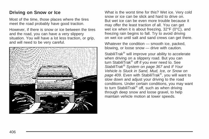
Driving on Snow or IceMost of the time, those places where the tiresmeet the road probably have good traction.
However, if there is snow or ice between the tiresand the road, you can have a very slipperysituation. You will have a lot less traction, or grip,and will need to be very careful.
What is the worst time for this? Wet ice. Very coldsnow or ice can be slick and hard to drive on.But wet ice can be even more trouble because itmay offer the least traction of all. You can getwet ice when it is about freezing, 32°F (0°C), andfreezing rain begins to fall. Try to avoid drivingon wet ice until salt and sand crews can get there.
Whatever the condition — smooth ice, packed,blowing, or loose snow — drive with caution.
StabiliTrak® will improve your ability to acceleratewhen driving on a slippery road. But you canturn StabiliTrak® off if you ever need to. SeeStabiliTrak® System on page 367 and If YourVehicle is Stuck in Sand, Mud, Ice, or Snow onpage 409. Even with StabiliTrak®, you will want toslow down and adjust your driving to the roadconditions. Under certain conditions, you may wantto turn StabiliTrak® off, such as when drivingthrough deep snow and loose gravel, to helpmaintain vehicle motion at lower speeds.
406

The Anti-Lock Brake System (ABS) improves yourvehicle’s stability when you make a hard stopon a slippery road. Even though you have ABS,you will want to begin stopping sooner thanyou would on dry pavement. See Anti-Lock BrakeSystem (ABS) on page 365.
• Allow greater following distance on anyslippery road.
• Watch for slippery spots. The road might befine until you hit a spot that is covered withice. On an otherwise clear road, ice patchesmay appear in shaded areas where thesun cannot reach, such as around clumps oftrees, behind buildings, or under bridges.Sometimes the surface of a curve or anoverpass may remain icy when thesurrounding roads are clear. If you see apatch of ice ahead of you, brake before youare on it. Try not to brake while you areactually on the ice, and avoid sudden steeringmaneuvers.
If You Are Caught in a BlizzardIf you are stopped by heavy snow, you could be ina serious situation. You should probably staywith your vehicle unless you know for sure that youare near help and you can hike through thesnow. Here are some things to do to summonhelp and keep yourself and your passengers safe:
• Turn on your hazard flashers.
• Tie a red cloth to your vehicle to alert policethat you have been stopped by the snow.
• Put on extra clothing or wrap a blanketaround you. If you do not have blanketsor extra clothing, make body insulatorsfrom newspapers, burlap bags, rags,floor mats — anything you can wraparound yourself or tuck under your clothingto keep warm.
407

You can run the engine to keep warm, but becareful.
{CAUTION:
Snow can trap exhaust gases under yourvehicle. This can cause deadly CO(carbon monoxide) gas to get inside.CO could overcome you and kill you.You cannot see it or smell it, so you mightnot know it is in your vehicle. Clear awaysnow from around the base of yourvehicle, especially any that is blocking theexhaust pipe. And check around againfrom time to time to be sure snow doesnot collect there.
Open a window just a little on the side ofthe vehicle that is away from the wind.This will help keep CO out.
Run your engine only as long as you must.This saves fuel. When you run the engine, make itgo a little faster than just idle. That is, push theaccelerator slightly. This uses less fuel for the heatthat you get and it keeps the battery charged.
408

You will need a well-charged battery to restart thevehicle, and possibly for signaling later on withyour headlamps. Let the heater run for a while.
Then, shut the engine off and close the windowalmost all the way to preserve the heat. Startthe engine again and repeat this only when youfeel really uncomfortable from the cold. But do it aslittle as possible. Preserve the fuel as long asyou can. To help keep warm, you can get out ofthe vehicle and do some fairly vigorous exercisesevery half hour or so until help comes.
If Your Vehicle is Stuck in Sand,Mud, Ice, or SnowIn order to free your vehicle when it is stuck, youneed to spin the wheels, but you do not wantto spin the wheels too fast. The method known asrocking can help you get out when you arestuck, but you must use caution.
{CAUTION:
If you let your vehicle’s tires spin at highspeed, they can explode, and you or otherscould be injured. And, the transmission orother parts of the vehicle can overheat.That could cause an engine compartmentfire or other damage. When you are stuck,spin the wheels as little as possible. Do notspin the wheels above 35 mph (55 km/h) asshown on the speedometer.
Notice: Spinning the wheels can destroy partsof your vehicle as well as the tires. If youspin the wheels too fast while shiftingthe transmission back and forth, you candestroy the transmission.
For information about using tire chains on yourvehicle, see Tire Chains on page 532.
409

Rocking Your Vehicle to Get It OutFirst, turn the steering wheel left and right.That will clear the area around the front wheels.If you have a four-wheel-drive vehicle, shiftinto Four-Wheel High or Four-Wheel Low. Turnthe StabiliTrak® System off. See StabiliTrak®
System on page 367. Then shift back and forthbetween REVERSE (R) and a forward gear,spinning the wheels as little as possible. Releasethe accelerator pedal while you shift, and presslightly on the accelerator pedal when thetransmission is in gear. By slowly spinning thewheels in the forward and reverse directions, youwill cause a rocking motion that may free yourvehicle. If that does not get your vehicle out aftera few tries, it may need to be towed out. Or,you can use the recovery hooks if your vehiclehas them. If your vehicle does need to be towedout, see Towing Your Vehicle on page 422.
Recovery Hooks
{CAUTION:
These hooks, when used, are under a lotof force. Always pull the vehicle straightout. Never pull on the hooks at asideways angle. The hooks could breakoff and you or others could be injuredfrom the chain or cable snapping back.
410

Notice: Never use recovery hooks to tow thevehicle. Your vehicle could be damagedand it would not be covered by warranty.
Your vehicle may have recovery hooks at the frontof the vehicle. You may need to use them if youare stuck off-road and need to be pulled tosome place where you can continue driving.
Loading Your VehicleIt is very important to know how much weight yourvehicle can carry. This weight is called thevehicle capacity weight and includes the weight ofall occupants, cargo, and all nonfactory-installedoptions. Two labels on your vehicle show howmuch weight it was designed to carry, the Tire andLoading Information label and the Certification/Tirelabel.
{CAUTION:
Do not load your vehicle any heavier thanthe Gross Vehicle Weight Rating (GVWR),or either the maximum front or rear GrossAxle Weight Rating (GAWR). If you do,parts on your vehicle can break, and itcan change the way your vehicle handles.These could cause you to lose controland crash. Also, overloading can shortenthe life of your vehicle.
411

Tire and Loading Information Label
A vehicle specific Tire and Loading Informationlabel is attached to the center pillar (B-pillar).With the driver’s door open, you will find thelabel attached below the door lock post (striker).
The tire and loading information label showsthe number of occupant seating positions (A),and the maximum vehicle capacity weight (B) inkilograms and pounds.
The Tire and Loading Information label also showsthe size of the original equipment tires (C) andthe recommended cold tire inflation pressures (D).For more information on tires and inflation seeTires on page 510 and Inflation - Tire Pressure onpage 518.
There is also important loading information on thevehicle Certification/Tire label. It tells you theGross Vehicle Weight Rating (GVWR) andthe Gross Axle Weight Rating (GAWR) for thefront and rear axles. See “Certification/Tire Label”later in this section.
Label Example
412

Steps for Determining Correct Load Limit1. Locate the statement “The combined weight of
occupants and cargo should never exceedXXX kg or XXX lbs” on your vehicle’s placard.
2. Determine the combined weight of the driverand passengers that will be riding in yourvehicle.
3. Subtract the combined weight of the driverand passengers from XXX kg or XXX lbs.
4. The resulting figure equals the availableamount of cargo and luggage load capacity.For example, if the “XXX” amount equals 1400lbs and there will be five 150 lb passengersin your vehicle, the amount of available cargoand luggage load capacity is 650 lbs(1400 − 750 (5 x 150) = 650 lbs).
5. Determine the combined weight of luggageand cargo being loaded on the vehicle. Thatweight may not safely exceed the availablecargo and luggage load capacity calculatedin Step 4.
6. If your vehicle will be towing a trailer, the loadfrom your trailer will be transferred to yourvehicle. Consult this manual to determine howthis reduces the available cargo and luggageload capacity of your vehicle. See Towinga Trailer on page 428 for important informationon towing a trailer, towing safety rules andtrailering tips.
413

Item Description Total
A Vehicle Capacity Weightfor Example 1 = 1,000 lbs (453 kg)
BSubtract OccupantWeight 150 lbs(68 kg) × 2 =
300 lbs (136 kg)
C Available Occupant andCargo Weight = 700 lbs (317 kg)
Item Description Total
A Vehicle Capacity Weightfor Example 2 = 1,000 lbs (453 kg)
BSubtract OccupantWeight 150 lbs(68 kg) × 5 =
750 lbs (136 kg)
C Available CargoWeight = 250 lbs (113 kg)
Example 1 Example 2
414

Item Description Total
A Vehicle Capacity Weightfor Example 3 = 1,000 lbs (453 kg)
BSubtract OccupantWeight 200 lbs(91 kg) × 5 =
1,000 lbs (453 kg)
C Available CargoWeight = 0 lbs (0 kg)
Refer to your vehicle’s tire and loading informationlabel for specific information about your vehicle’scapacity weight and seating positions.The combined weight of the driver, passengers,and cargo should never exceed your vehicle’scapacity weight.
Certification/Tire Label
A vehicle specific Certification/Tire label is foundon the rear edge of the driver’s door. The labelshows the size of your vehicle’s original tires andthe inflation pressures needed to obtain thegross weight capacity of your vehicle. This iscalled Gross Vehicle Weight Rating (GVWR).The GVWR includes the weight of the vehicle,all occupants, fuel, and cargo.
Example 3
415

The Certification/Tire label also tells you themaximum weights for the front and rear axles,called Gross Axle Weight Rating (GAWR). To findout the actual loads on your front and rearaxles, you need to go to a weigh station andweigh your vehicle. Your dealer can help you withthis. Be sure to spread out your load equally onboth sides of the centerline.
Never exceed the GVWR for your vehicle,or the GAWR for either the front or rear axle.
The Certification/Tire label also containsinformation about your Front Axle ReserveCapacity.
And, if you do have a heavy load, you shouldspread it out.
{CAUTION:
Do not load your vehicle any heavier thanthe Gross Vehicle Weight Rating (GVWR),or either the maximum front or rear GrossAxle Weight Rating (GAWR). If you do,parts on your vehicle can break, and itcan change the way your vehicle handles.These could cause you to lose controland crash. Also, overloading can shortenthe life of your vehicle.
416

Notice: Overloading your vehicle may causedamage. Repairs would not be covered by yourwarranty. Do not overload your vehicle.
The label will help you decide how much cargoand installed equipment your truck can carry.
Using heavier suspension components toget added durability might not change your weightratings. Ask your dealer to help you load yourvehicle the right way.
If you put things inside your vehicle — likesuitcases, tools, packages, or anythingelse — they go as fast as the vehicle goes.If you have to stop or turn quickly, or if there isa crash, they will keep going.
{CAUTION:
Things you put inside your vehicle canstrike and injure people in a sudden stopor turn, or in a crash.
• Put things in the cargo area of yourvehicle. Try to spread the weightevenly.
• Never stack heavier things, likesuitcases, inside the vehicle so thatsome of them are above the tops ofthe seats.
• Do not leave an unsecured childrestraint in your vehicle.
• When you carry something inside thevehicle, secure it whenever you can.
• Do not leave a seat folded downunless you need to.
There is also important loading information foroff-road driving in this manual. See “Loading YourVehicle for Off-Road Driving” under Off-RoadDriving on page 377.
417

Adding a Snow Plow or SimilarEquipmentBefore installing a snow plow on your vehicle,here are some things you will need to know:
Notice: If your vehicle does not have the snowplow prep package, adding a plow candamage your vehicle, and the repairs wouldnot be covered by warranty. Unless yourvehicle was built to carry a snow plow, do notadd one to your vehicle. If your vehicle hasthe snow plow prep package, called RPO VYU,then the payload your vehicle can carry willbe reduced when a snow plow is installed.Your vehicle can be damaged if either thefront or rear axle ratings or the Gross VehicleWeight (GVW) are exceeded.
Q: How do I know if my vehicle can handle asnow plow?
A: Some vehicles are built with a special snowplow prep package, called RPO VYU. If yourvehicle has this option, you can add aplow to it, provided certain weights, such asthe weights on the vehicle’s axles andthe Gross Vehicle Weight (GVW), are notexceeded.
Q: How heavy can a snow plow safely be?
A: The plow your vehicle can carry depends onmany things, such as:
• The options your vehicle came with, and theweight of those options.
• The weight and number of passengers youintend to carry.
• The weight of items you have added to yourvehicle.
• The total weight of any additional cargo youintend to carry.
418

Say, for example, you have a 700 lb (318 kg)snow plow. The total weight of all occupants andcargo inside the cab should not exceed 300 lb(135 kg). This means that you may only be able tocarry one passenger. But, even this may betoo much if you have got other equipment alreadyadding to the weight of your vehicle.
Here are some guidelines for safely carrying asnow plow on your vehicle:
• Make sure the weight on the front andrear axles does not exceed the axle ratingfor each.
• For the front axle, if more cargo or passengersmust be carried, appropriate counter ballastmust be installed rear of the rear axle.Counter ballast must be properly secured so itwill not move during driving.
• Follow the snow plow manufacturer’srecommendations regarding rear ballast.Rear ballast may be required to ensurea proper front and rear weight distributionratio, even though the actual weight atthe front axle may be less than the frontaxle rating.
• The snow plow manufacturer or installer canassist you in determining the amount of rearballast required, to help make sure yoursnowplow/vehicle combination does notexceed the GVW rating, the front and rearaxle ratings, and the front and rear weightdistribution ratio.
• The total vehicle must not exceed theGVW rating.
419

Q: What is front axle reserve capacity, andhow do I calculate it?
A: Front axle reserve capacity is the differencebetween your front Gross Axle Weight Rating(GAWR) and the front axle weight of yourvehicle with full fuel and passengers. Basically,it is the amount of weight you can add to yourfront axle before reaching your front GAWR.
The front axle reserve capacity for your vehiclecan be found in the lower right corner of theCertification/Tire label, as shown.
In order to calculate the amount of weight anyfront accessory, such as a snow plow, is adding tothe front axle, use the following formula:
(W x (A + W.B.)) /W.B.= Weight the accessory isadding to the front axle.
Where:W = Weight of added accessoryA = Distance that the accessory is in front ofthe front axleW.B. = Vehicle Wheelbase
United States Canada
420

For example, adding a 700 lb (318 kg) snow plowactually adds more than 700 lbs (318 kg) to thefront axle. Using the formula, if the snow plowis 4 ft (122 cm) in front of the front axle and thewheel base is 10 ft (305 cm), then:W = 700 lb (318 kg)A = 4 ft (122 cm)W.B. = 10 ft (305 cm)
(W x (A + W.B.))/W.B. = (700 x (4 + 10))/10 = 980 lbs (445 kg)
So, if your vehicle’s front axle reserve capacity ismore than 980 lbs (445 kg), you could add thesnow plow without exceeding the front GAWR.
Q: What if I want to add heavier equipmentto my vehicle?
A: You can add heavier equipment on the frontof the vehicle if you compensate for it bycarrying fewer passengers, less cargo, or bypositioning cargo towards the rear. This hasthe effect of reducing the load on thefront. However, the front GAWR, rear GAWR,and the Gross Vehicle Weight Rating(GVWR) must never be exceeded.
{CAUTION:
On some vehicles that have certain frontmounted equipment, such as a snowplow, it may be possible to load the frontaxle to the front gross axle weight rating(GAWR) but not have enough weight onthe rear axle to have proper brakingperformance. If your brakes can not workproperly, you could have a crash. To helpyour brakes work properly when a snowplow is installed, always follow the snowplow manufacturer or installer’srecommendation for rear ballast to ensurea proper front and rear weight distributionratio, even though the actual front weightmay be less than the front GAWR, and thetotal vehicle weight is less than the grossvehicle weight rating (GVWR). Maintaininga proper front and rear weight distributionratio is necessary to provide properbraking performance.
421

Q: What is total vehicle reserve capacity?
A: This is the difference between your GVWR andthe weight of your vehicle with full fuel andpassengers. It is the amount of weight you canadd to your vehicle before reaching yourGVWR. Keep in mind that reserve capacitynumbers are intended as a guide whenselecting the amount of equipment or cargoyour vehicle can carry. If you are unsureof your vehicle’s front, rear, or total weight, goto a weigh station and weigh your vehicle.Your dealer can also help you with this.
The total vehicle reserve capacity for yourvehicle can be found in the lower right cornerof the Certification/Tire label as shownpreviously.
See your dealer for additional advice andinformation about using a snow plow on yourvehicle. Also, see Loading Your Vehicle onpage 411.
Emergency Roof Lamp ProvisionsVehicles with the RPO VYU snow plow preppackage also have an emergency roof lampprovision package, RPO TRW. Wiring for theemergency roof lamp is provided above theoverhead console. See Auxiliary Roof MountedLamp on page 219 for switch location.
TowingTowing Your VehicleConsult your dealer or a professional towingservice if you need to have your disabled vehicletowed. See Roadside Assistance Program onpage 601.
If you want to tow your vehicle behind anothervehicle for recreational purposes (such as behinda motorhome), see “Recreational VehicleTowing” following.
422

Recreational Vehicle TowingRecreational vehicle towing means towing yourvehicle behind another vehicle – such as behind amotorhome. The two most common types ofrecreational vehicle towing are known as dinghytowing, towing your vehicle with all four wheelson the ground, and dolly towing, towing yourvehicle with two wheels on the ground andtwo wheels up on a device known as a “dolly”.
With the proper preparation and equipment, manyvehicles can be towed in these ways. See “DinghyTowing” and “Dolly Towing”, following.
Here are some important things to consider beforeyou do recreational vehicle towing:
• What’s the towing capacity of the towingvehicle? Be sure you read the tow vehiclemanufacturer’s recommendations.
• How far will you tow? Some vehicles haverestrictions on how far and how long theycan tow.
• Do you have the proper towing equipment?See your dealer or trailering professionalfor additional advice and equipmentrecommendations.
• Is your vehicle ready to be towed? Just asyou would prepare your vehicle for a longtrip, you’ll want to make sure your vehicle isprepared to be towed. See Before Leaving ona Long Trip on page 401.
423

Dinghy TowingTwo-Wheel-Drive VehiclesNotice: If you tow a two-wheel-drivevehicle with all four wheels on the ground, thetransmission could be damaged. The repairswould not be covered by your warranty.Do not tow a two-wheel-drive vehicle with allfour wheels on the ground.
Two-wheel-drive vehicles should not betowed with all four wheels on the ground.Two-wheel-drive transmissions have no provisionsfor internal lubrication while being towed.
Four-Wheel-Drive Vehicles
Use the following procedure to tow your vehicle:
1. Shift the transmission to PARK (P).
2. Turn the engine off, but leave the ignition on.
3. Firmly set the parking brake.
4. Securely attach the vehicle being towed to thetow vehicle.
424

{CAUTION:
Shifting a four-wheel-drive vehicle’stransfer case into NEUTRAL can causeyour vehicle to roll even if thetransmission is in PARK (P). You orothers could be injured. Make sure theparking brake is firmly set before you shiftthe transfer case to NEUTRAL.
5. Shift the transfer case to NEUTRAL (N).See Four-Wheel Drive on page 154 forthe proper procedure to select theNEUTRAL (N) position for your vehicle.
6. Release the parking brake only after thevehicle being towed is firmly attached tothe towing vehicle.
7. Turn the ignition off.
Dolly TowingTwo-Wheel-Drive Vehicles
Notice: If you tow a two-wheel-drivevehicle with the rear wheels on the ground,the transmission could be damaged.The repairs would not be covered by yourwarranty. Never tow your vehicle with therear wheels on the ground.
Two-wheel-drive vehicles should not be towedwith the rear wheels on the ground.Two-wheel-drive transmissions have no provisionsfor internal lubrication while being towed.
Two-wheel-drive vehicles can be towed on a dollywith the front wheels on the ground providedthat the wheels are straight.
425

Four-Wheel-Drive VehiclesIf your vehicle is equipped with StabiliTrak®, it isnot designed to be dolly towed. If you need to towyour vehicle, see “Dinghy Towing” earlier in thissection.
If your vehicle is not equipped with StabiliTrak®,use the following procedure to tow your vehicle:
1. Drive the vehicle up onto the tow dolly.2. Shift the transmission to PARK (P).
3. Turn the engine off, but leave the ignition on.
4. Firmly set the parking brake.
5. Securely attach the vehicle being towed to thetow dolly.
{CAUTION:
Shifting a four-wheel-drive vehicle’stransfer case into NEUTRAL cancause your vehicle to roll even if thetransmission is in PARK (P). You orothers could be injured. Make sure theparking brake is firmly set before you shiftthe transfer case to NEUTRAL.
6. Shift the transfer case to NEUTRAL.See Four-Wheel Drive on page 154 for theproper procedure to select the NEUTRALposition for your vehicle.
7. Release the parking brake only after thevehicle being towed is firmly attached tothe towing vehicle.
426

Level Control
Automatic Level ControlThe automatic level control rear suspension isavailable on two-wheel drive and four-wheel drivelight-duty vehicles and comes as a part of theAutoride® suspension, if equipped.
This type of level control is fully automatic and willprovide a better leveled riding position as well asbetter handling under a variety of passenger andloading conditions. An air compressor connected tothe rear shocks will raise or lower the rear of thevehicle to maintain proper vehicle height. Thesystem is activated when the ignition key is turnedto RUN and will automatically adjust vehicle heightthereafter. The system may exhaust (lower vehicleheight) for up to ten minutes after the ignition keyhas been turned off. You may hear the aircompressor operating when the height is beingadjusted.
If a weight-distributing hitch is being used, it isrecommended to allow the shocks to inflate,thereby leveling the vehicle prior to adjustingthe hitch.
Autoride®
If equipped, the Autoride® feature will provide asuperior vehicle ride and handling under a varietyof passenger and loading conditions.
The system is fully automatic and uses a computercontroller to continuously monitor vehicle speed,wheel to body position, lift/dive and steeringposition of the vehicle. The controller then sendssignals to each shock absorber to independentlyadjust the damping level to provide the optimumvehicle ride.
Autoride® also interacts with the tow/haul switchthat, when engaged, will provide additional controlof the shock absorbers. This additional controlresults in better ride and handling characteristicswhen the vehicle is loaded or towing a trailer.See Tow/Haul Mode Light on page 260 for moreinformation.
427

Towing a TrailerDo not tow a trailer during break-in. See NewVehicle Break-In on page 143 for more information.
{CAUTION:
If you do not use the correct equipmentand drive properly, you can lose controlwhen you pull a trailer. For example, if thetrailer is too heavy, the brakes may notwork well — or even at all. You and yourpassengers could be seriously injured.Pull a trailer only if you have followed allthe steps in this section. Ask your dealerfor advice and information about towing atrailer with your vehicle.
Notice: Pulling a trailer improperly candamage your vehicle and result in costlyrepairs not covered by your warranty. To pull atrailer correctly, follow the advice in thispart, and see your dealer for importantinformation about towing a trailer with yourvehicle.
To identify the trailering capacity of your vehicle,you should read the information in “Weight ofthe Trailer” that appears later in this section.
Trailering is different than just driving your vehicleby itself. Trailering means changes in acceleration,braking, handling, durability and fuel economy.Successful, safe trailering takes correct equipment,and it has to be used properly.
That’s the reason for this part. In it are manytime-tested, important trailering tips and safetyrules. Many of these are important for your safetyand that of your passengers. So please readthis section carefully before you pull a trailer.
428

If You Do Decide To Pull A TrailerIf you do, here are some important points:
• There are many different laws, including speedlimit restrictions, having to do with trailering.Make sure your rig will be legal, not only whereyou live but also where you’ll be driving. Agood source for this information can be stateor provincial police.
• Consider using a sway control. See “Hitches”later in this section.
• Don’t tow a trailer at all during the first500 miles (800 km) your new vehicle is driven.Your engine, axle or other parts could bedamaged.
• Then, during the first 500 miles (800 km) thatyou tow a trailer, don’t drive over 50 mph(80 km/h) and don’t make starts at full throttle.This helps your engine and other parts ofyour vehicle wear in at the heavier loads.
• You can tow in DRIVE (D). You may want toshift the transmission to THIRD (3) or, ifnecessary, a lower gear selection if thetransmission shifts too often (e.g., under heavyloads and/or hilly conditions). See “Tow/HaulMode” later in this section.
Three important considerations have to do withweight:
• The weight of the trailer
• The weight of the trailer tongue
• The weight on your vehicle’s tires
429

Tow/Haul ModeTow/Haul is a feature that assists when pullinga heavy trailer or a large or heavy load.The purpose of the Tow/Haul mode is to:
• Reduce the frequency and improve thepredictability of transmission shifts whenpulling a heavy trailer or a large or heavy load.
• Provide the same solid shift feel when pulling aheavy trailer or a large or heavy load as whenthe vehicle is unloaded.
• Improve control of vehicle speed whilerequiring less throttle pedal activity whenpulling a heavy trailer or a large or heavy load.
• Increase the charging system voltage to assistin recharging a battery installed in a trailer.
Press this button at the end of the shift lever toenable/disable the tow/haul mode.
A light on the instrumentpanel will illuminate toindicate that tow/haulmode has beenselected.
430

Your vehicle is equipped with a button at the endof the shift lever which, when pressed, enablestow/haul. Your vehicle may be equipped withAutoride® which further improves your vehicle’sride while towing. See Autoride® on page 427for more information. When the button is pressed,a light on the instrument panel will illuminate toindicate that Tow/Haul has been selected.Tow/Haul may be turned off by pressing the buttonagain, at which time the indicator light on theinstrument panel will turn off. The vehicle willautomatically turn off Tow/Haul every timeit is started.
Tow/Haul is designed to be most effectivewhen the vehicle and trailer combined weightis at least 75 percent of the vehicle’s GrossCombined Weight Rating (GCWR).See Weight of the Trailer later in this section.
Tow/Haul is most useful under the followingdriving conditions:
• When pulling a heavy trailer or a large orheavy load through rolling terrain.
• When pulling a heavy trailer or a large orheavy load in stop and go traffic.
• When pulling a heavy trailer or a large orheavy load in busy parking lots whereimproved low speed control of the vehicleis desired.
Operating the vehicle in tow/haul when lightlyloaded or with no trailer at all will not causedamage. However, there is no benefit to theselection of Tow/Haul when the vehicle isunloaded. Such a selection when unloaded mayresult in unpleasant engine and transmissiondriving characteristics and reduced fuel economy.Tow/Haul is recommended only when pulling aheavy trailer or a large or heavy load.
431
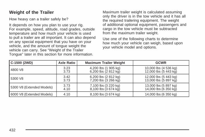
Weight of the TrailerHow heavy can a trailer safely be?
It depends on how you plan to use your rig.For example, speed, altitude, road grades, outsidetemperature and how much your vehicle is usedto pull a trailer are all important. It can also dependon any special equipment that you have on yourvehicle, and the amount of tongue weight thevehicle can carry. See “Weight of the TrailerTongue” later in this section for more information.
Maximum trailer weight is calculated assumingonly the driver is in the tow vehicle and it has allthe required trailering equipment. The weightof additional optional equipment, passengers andcargo in the tow vehicle must be subtractedfrom the maximum trailer weight.
Use one of the following charts to determinehow much your vehicle can weigh, based uponyour vehicle model and options.
C-1500 (2WD) Axle Ratio Maximum Trailer Weight GCWR
4800 V8 3.233.73
4,200 lbs (1 905 kg)6,200 lbs (2 812 kg)
10,000 lbs (4 536 kg)12,000 lbs (5 443 kg)
5300 V8 3.423.73
6,200 lbs (2 812 kg)7,200 lbs (3 266 kg)
12,000 lbs (5 443 kg)13,000 lbs (5 897 kg)
5300 V8 (Extended Models) 3.734.10
7,100 lbs (3 220 kg)8,100 lbs (3 674 kg)
13,000 lbs (5 897 kg)14,000 lbs (6 350 kg)
6000 V8 (Extended Models) 4.10 8,100 lbs (3 674 kg) 14,000 lbs (6 350 kg)
432

K-1500 (4WD) Axle Ratio Maximum Trailer Weight GCWR
5300 V8 3.734.10
6,700 lbs (3 039 kg)7,700 lbs (3 493 kg)
13,000 lbs (5 897 kg)14,000 lbs (6 350 kg)
5300 V8 (Extended Models) 3.734.10
7,000 lbs (3 175 kg)8,000 lbs (3 629 kg)
13,000 lbs (5 897 kg)14,000 lbs (6 350 kg)
6000 V8 (Extended Models) 4.10 7,900 lbs (3 583 kg) 14,000 lbs (6 350 kg)
C-2500 (2WD) Axle Ratio Maximum Trailer Weight GCWR
6000 V8 (Extended Models) 3.734.10
7,700 lbs (3 493 kg)9,700 lbs (4 400 kg)
14,000 lbs (6 350 kg)16,000 lbs (7 257 kg)
K-2500 (4WD) Axle Ratio Maximum Trailer Weight GCWR
6000 V8 (Extended Models) 3.734.10
7,500 lbs (3 402 kg)9,500 lbs (4 309 kg)
14,000 lbs (6 350 kg)16,000 lbs (7 257 kg)
The Gross Combination Weight Rating (GCWR)is the total allowable weight of the completelyloaded vehicle and trailer including anypassengers, cargo, equipment and conversions.The GCWR for your vehicle should not beexceeded.
You can ask your dealer for our traileringinformation or advice, or you can write us at theaddress listed in your Warranty and OwnerAssistance Information Booklet.
In Canada, write to:
General Motors of Canada LimitedCustomer Communication Centre, 163-0051908 Colonel Sam DriveOshawa, Ontario L1H 8P7
433

Weight of the Trailer TongueThe tongue load (A) of any trailer is an importantweight to measure because it affects the totalor gross weight of your vehicle. The Gross VehicleWeight (GVW) includes the curb weight of thevehicle, any cargo you may carry in it, andthe people who will be riding in the vehicle. If youhave a lot of options, equipment, passengersor cargo in your vehicle, it will reduce the tongueweight your vehicle can carry, which will alsoreduce the trailer weight your vehicle can tow. Andif you will tow a trailer, you must add the tongueload to the GVW because your vehicle will becarrying that weight, too. See Loading YourVehicle for more information about your vehicle’smaximum load capacity.
The trailer tongue weight (A) should be 10 percentto 15 percent of the total loaded trailer weight, up toa maximum of 600 lbs (272 kg) with a weightcarrying hitch. The trailer tongue weight (A) shouldbe 10 percent to 15 percent of the total loadedtrailer weight, up to a maximum of 1,000 lbs(453 kg) for the 1500 series and up to a maximumof 1,500 lbs (680 kg) for the 2500 series with aweight distributing hitch.
Do not exceed the maximum allowable tongueweight for your vehicle. Choose the shortest hitchextension that will position the hitch ball closestto the vehicle. This will help reduce the effectof trailer tongue weight on the rear axle.
434

After you have loaded the trailer, weigh the trailerand then the tongue separately, to see if theweights are proper. If they are not, you may beable to get them right by moving some itemsaround in the trailer.
Trailering may be limited by the vehicle’s ability tocarry tongue weight. Tongue weight cannotcause the vehicle to exceed the GVWR (GrossVehicle Weight Rating) or the RGAWR (RearGross Axle Weight Rating). The effect of additionalweight may reduce your trailering capacity morethan the total of the additional weight.
Consider the following example:
A vehicle model base weight is 5,500 lbs(2 495 kg); 2,800 lbs (1 270 kg) at the front axleand 2,700 lbs (1 225 kg) at the rear axle. Ithas a GVWR of 7,200 lbs (3 266 kg), a RGAWRof 4,000 lbs (1 814 kg) and a GCWR (GrossCombination Weight Rating) of 14,000 lbs(6 350 kg). The trailer rating should be:
You can expect tongue weight to be at least10 percent of trailer weight (850 lbs (386 kg)) andbecause the weight is applied well behind the rearaxle, the effect on the rear axle will be greater thanjust the weight itself, as much as 1.5 times as much.The weight at the rear axle could be 850 lbs(386 kg) X 1.5 = 1,275 lbs (578 kg). Since the rearaxle already weighs 2,700 lbs (1 225 kg), adding1,275 lbs (578 kg) brings the total to 3,975 lbs(1 803 kg). This is very close to, but within the limitfor RGAWR as well. The vehicle is set to trailer upto 8,500 lbs (3 856 kg).
But let’s say your specific vehicle is equipped withsome of the latest options and you have a frontseat passenger and two rear seat passengers withsome luggage and gear in the vehicle as well.
435
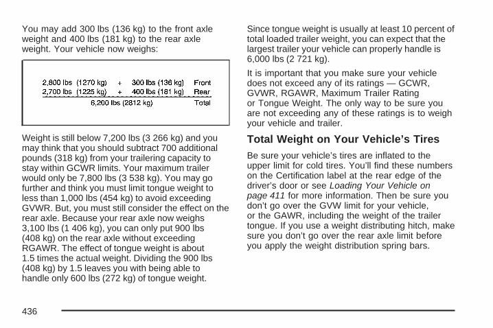
You may add 300 lbs (136 kg) to the front axleweight and 400 lbs (181 kg) to the rear axleweight. Your vehicle now weighs:
Weight is still below 7,200 lbs (3 266 kg) and youmay think that you should subtract 700 additionalpounds (318 kg) from your trailering capacity tostay within GCWR limits. Your maximum trailerwould only be 7,800 lbs (3 538 kg). You may gofurther and think you must limit tongue weight toless than 1,000 lbs (454 kg) to avoid exceedingGVWR. But, you must still consider the effect on therear axle. Because your rear axle now weighs3,100 lbs (1 406 kg), you can only put 900 lbs(408 kg) on the rear axle without exceedingRGAWR. The effect of tongue weight is about1.5 times the actual weight. Dividing the 900 lbs(408 kg) by 1.5 leaves you with being able tohandle only 600 lbs (272 kg) of tongue weight.
Since tongue weight is usually at least 10 percent oftotal loaded trailer weight, you can expect that thelargest trailer your vehicle can properly handle is6,000 lbs (2 721 kg).
It is important that you make sure your vehicledoes not exceed any of its ratings — GCWR,GVWR, RGAWR, Maximum Trailer Ratingor Tongue Weight. The only way to be sure youare not exceeding any of these ratings is to weighyour vehicle and trailer.
Total Weight on Your Vehicle’s TiresBe sure your vehicle’s tires are inflated to theupper limit for cold tires. You’ll find these numberson the Certification label at the rear edge of thedriver’s door or see Loading Your Vehicle onpage 411 for more information. Then be sure youdon’t go over the GVW limit for your vehicle,or the GAWR, including the weight of the trailertongue. If you use a weight distributing hitch, makesure you don’t go over the rear axle limit beforeyou apply the weight distribution spring bars.
436

HitchesIt’s important to have the correct hitch equipment.Crosswinds, large trucks going by and roughroads are a few reasons why you will need theright hitch.
Weight-Distributing Hitches and WeightCarrying Hitches
When using a weight-distributing hitch, the hitchmust be adjusted so the distance (A) remainsthe same both before and after coupling the trailerto the tow vehicle.
If you use a step-bumper hitch, the bumper couldbe damaged in sharp turns. Make sure there isample room when turning to avoid contact betweenthe trailer and the bumper.
If you will be pulling a trailer that, when loaded,will weigh more than 5,000 lbs (2 270 kg) be sureto use a properly mounted weight-distributinghitch and sway control of the proper size.This equipment is very important for proper vehicleloading and good handling when driving. Alwaysuse a sway control if the trailer will weighmore than these limits. You can ask a hitch dealerabout sway controls.
(A) Body to Ground Distance (B) Front of Vehicle
437

Safety ChainsYou should always attach safety chains betweenyour vehicle and your trailer. Cross the safetychains under the tongue of the trailer to helpprevent the tongue from contacting the road if itbecomes separated from the hitch.
Attach the safety chains to the attaching point onthe hitch platform. If you are towing with anaftermarket hitch, following the trailer or hitchmanufacturer’s recommendation for attachingsafety chains. Always leave just enough slack soyou can turn with your rig. Never allow safetychains to drag on the ground.
Trailer BrakesIf your trailer weighs more than 2,000 lbs (900 kg)loaded, then it needs its own brakes – and theymust be adequate. Be sure to read and follow theinstructions for the trailer brakes so you’ll beable to install, adjust and maintain them properly.
If your vehicle is equipped with StabiliTrak®, yourtrailer cannot tap into the vehicle’s hydraulicbrake system.
Your trailer brake system can tap into the vehicle’shydraulic brake system only if:
• The trailer parts can withstand 3,000 psi(20 650 kPa) of pressure.
• The trailer’s brake system will use less than0.02 cubic inches (0.3 cc) of fluid from yourvehicle’s master cylinder. Otherwise, bothbraking systems won’t work well. You couldeven lose your brakes.
If everything checks out this far, make the braketap at the port on the master cylinder thatsends the fluid to the rear brakes. But don’t usecopper tubing for this. If you do, it will bendand finally break off. Use steel brake tubing.
438

Driving with a Trailer
{CAUTION:
If you have a rear-most window open andyou pull a trailer with your vehicle, carbonmonoxide (CO) could come into yourvehicle. You cannot see or smell CO. Itcan cause unconsciousness or death. SeeEngine Exhaust on page 164. To maximizeyour safety when towing a trailer:
• Have your exhaust system inspectedfor leaks, and make necessary repairsbefore starting on your trip.
CAUTION: (Continued)
CAUTION: (Continued)
• Keep the rear-most windows closed.• If exhaust does come into your vehicle
through a window in the rear oranother opening, drive with your front,main heating or cooling system onand with the fan on any speed. Thiswill bring fresh, outside air into yourvehicle. Do not use the climate controlsetting for maximum air because itonly recirculates the air inside yourvehicle. See Climate Control Systemon page 227.
Towing a trailer requires a certain amount ofexperience. Before setting out for the open road,you’ll want to get to know your rig. Acquaintyourself with the feel of handling and braking withthe added weight of the trailer. And alwayskeep in mind that the vehicle you are driving isnow a good deal longer and not nearly asresponsive as your vehicle is by itself.
439

Before you start, check all trailer hitch parts andattachments, safety chains, electrical connector,lamps, tires and mirror adjustment. If the trailer haselectric brakes, start your vehicle and trailermoving and then apply the trailer brake controllerby hand to be sure the brakes are working.This lets you check your electrical connection atthe same time.
During your trip, check occasionally to be surethat the load is secure, and that the lamps and anytrailer brakes are still working.
Following DistanceStay at least twice as far behind the vehicle aheadas you would when driving your vehicle withouta trailer. This can help you avoid situationsthat require heavy braking and sudden turns.
PassingYou’ll need more passing distance up ahead whenyou’re towing a trailer. And, because you’re agood deal longer, you’ll need to go much fartherbeyond the passed vehicle before you canreturn to your lane.
Backing UpHold the bottom of the steering wheel with onehand. Then, to move the trailer to the left,just move that hand to the left. To move the trailerto the right, move your hand to the right. Alwaysback up slowly and, if possible, have someoneguide you.
Making Turns
Notice: Making very sharp turns whiletrailering could cause the trailer to come incontact with the vehicle. Your vehicle could bedamaged. Avoid making very sharp turnswhile trailering.
When you’re turning with a trailer, make widerturns than normal. Do this so your trailerwon’t strike soft shoulders, curbs, road signs,trees or other objects. Avoid jerky or suddenmaneuvers. Signal well in advance.
440

Turn Signals When Towing a TrailerThe arrows on your instrument panel willflash whenever you signal a turn or lane change.Properly hooked up, the trailer lamps will alsoflash, telling other drivers you’re about toturn, change lanes or stop.
When towing a trailer, the arrows on yourinstrument panel will flash for turns even if thebulbs on the trailer are burned out. Thus, you maythink drivers behind you are seeing your signalwhen they are not. It’s important to checkoccasionally to be sure the trailer bulbs are stillworking.
Driving On GradesReduce speed and shift to a lower gear beforeyou start down a long or steep downgrade. If youdon’t shift down, you might have to use yourbrakes so much that they would get hot and nolonger work well.
You can tow in DRIVE (D). You may want to shiftthe transmission to THIRD (3) or, if necessary,a lower gear selection if the transmission shifts toooften (e.g., under heavy loads and/or hillyconditions).
You may also want to activate the tow/haul modeif the transmission shifts too often. See “Tow/HaulMode” earlier in this section for more information.
When towing at high altitude on steep uphillgrades, consider the following: Engine coolant athigher altitudes will boil at a lower temperaturethan at or near sea level. If you turn your engineoff immediately after towing at high altitude onsteep uphill grades, your vehicle may show signssimilar to engine overheating. To avoid this, letthe engine run while parked (preferably onlevel ground) with the automatic transmission inPARK (P) for a few minutes before turningthe engine off. If you do get the overheat warning,see Engine Overheating on page 478.
441

Parking on Hills
{CAUTION:
You really should not park your vehicle,with a trailer attached, on a hill. Ifsomething goes wrong, your rig couldstart to move. People can be injured, andboth your vehicle and the trailer can bedamaged.
But if you ever have to park your rig on a hill,here’s how to do it:
1. Apply your regular brake, but don’t shift intoPARK (P) yet.
2. Have someone place chocks under the trailerwheels.
3. When the wheel chocks are in place, releasethe regular brakes until the chocks absorb theload.
4. Reapply the regular brakes. Then apply yourparking brake and shift into PARK (P).
5. If you have a four-wheel-drive vehicle, be surethe transfer case is in a drive gear and not inNEUTRAL.
6. Release the regular brakes.
{CAUTION:
It can be dangerous to get out of yourvehicle if the shift lever is not fully inPARK (P) with the parking brake firmlyset. Your vehicle can roll.
If you have left the engine running, thevehicle can move suddenly. You or otherscould be injured. To be sure your vehiclewill not move, even when you are on fairlylevel ground, use the steps that follow.
CAUTION: (Continued)
442

CAUTION: (Continued)
Always put the shift lever fully in PARK (P)with the parking brake firmly set.
If the transfer case on four-wheel-drivevehicles is in NEUTRAL, your vehicle willbe free to roll, even if your shift lever is inPARK (P). So, be sure the transfer case isin a drive gear — not in NEUTRAL.
When You Are Ready to Leave AfterParking on a Hill1. Apply your regular brakes and hold the pedal
down while you:• start your engine,• shift into a gear, and• release the parking brake.
2. Let up on the brake pedal.3. Drive slowly until the trailer is clear of the
chocks.4. Stop and have someone pick up and store the
chocks.
Maintenance When Trailer TowingYour vehicle will need service more often whenyou’re pulling a trailer. See the MaintenanceSchedule for more on this. Things that areespecially important in trailer operation areautomatic transmission fluid (don’t overfill), engineoil, axle lubricant, belts, cooling system andbrake system. Each of these is covered in thismanual, and the Index will help you find themquickly. If you’re trailering, it’s a good ideato review these sections before you start your trip.
Check periodically to see that all hitch nuts andbolts are tight.
443

Trailer Wiring HarnessYour vehicle is equipped with the following wiringharnesses for towing a trailer.
Basic Trailer WiringThe trailer wiring harness, with a seven-pinconnector, is located at the rear of the vehicle andis tied to the vehicle’s frame. The harnessconnector can be plugged into a seven-pinuniversal heavy-duty trailer connector availablethrough your dealer.
The seven-wire harness contains the followingtrailer circuits:
• Yellow: Left Stop/Turn Signal
• Dark Green: Right Stop/Turn Signal
• Brown: Taillamps
• White: Ground
• Light Green: Back-up Lamps
• Red: Battery Feed*
• Dark Blue: Trailer Brake*
*The fuses for these two circuits are installed inthe underhood electrical center, but the wiresare not connected. They should be connected byyour dealer or a qualified service center.
444

Heavy-Duty Trailer Wiring HarnessPackage
Your vehicle is equipped with the seven-wiretrailer towing harness. This harness with aseven-pin universal trailer connector is attached toa bracket on the hitch platform.
The seven-wire harness contains the followingtrailer circuits:
• Yellow: Left Stop/Turn Signal
• Dark Green: Right Stop/Turn Signal
• Brown: Taillamps
• White: Ground
• Light Green: Back-up Lamps
• Red: Battery Feed*
• Dark Blue: Trailer Brake*
*The fuses for these two circuits are installed inthe underhood electrical center, but the wiresare not connected. They should be connected byyour dealer or a qualified service center.
If you are charging a remote (non-vehicle) battery,press the tow/haul mode button located at theend of the shift lever. This will boost the vehiclesystem voltage and properly charge the battery. Ifthe trailer is too light for tow/haul mode, youcan turn on the headlamps as a second way toboost the vehicle system and charge the battery.
445

Electric Brake Control WiringProvisionsThese wiring provisions are included with yourvehicle as part of the trailer wiring package. Theseprovisions are for an electric brake controller. Theinstrument panel contains blunt cut wires near thedata link connector for the trailer brake controller.The harness contains the following wires:
• Dark Blue: Brake Signal to Trailer Connector
• Red/Black: Battery
• Light Blue/White: Brake Switch
• White: Ground
It should be installed by your dealer or a qualifiedservice center.
Power WinchesIf you wish to use a power winch on your vehicle,only use it when your vehicle is stationary oranchored.
Trailer RecommendationsYou must subtract your hitch loads from the CargoWeight Rating (CWR) for your vehicle. CWR isthe maximum weight of the load your vehicle cancarry. It doesn’t include the weight of the peopleinside. But you can figure about 150 lbs. (68 kg) foreach seat. The total cargo load must not bemore than your vehicle’s CWR.
Weigh your vehicle with the trailer attached, sothat you won’t go over the GVWR or GAWR. If youare using a weight-distributing hitch, weigh thevehicle without the spring bars in place.
You’ll get the best performance if you spread outthe weight of your load the right way, and ifyou choose the correct hitch and trailer brakes.
For more information, see Towing a Traileron page 428.
446
Service ........................................................ 450Accessories and Modifications ................... 450California Proposition 65 Warning .............. 451Doing Your Own Service Work .................. 451Adding Equipment to the Outside of
Your Vehicle .......................................... 452Fuel ............................................................. 452
Gasoline Octane ........................................ 453Gasoline Specifications .............................. 453California Fuel ........................................... 453Additives ................................................... 454Fuel E85 (85% Ethanol) ............................ 455Fuels in Foreign Countries ........................ 456Filling the Tank ......................................... 457Filling a Portable Fuel Container ............... 459
Checking Things Under the Hood .............. 460Hood Release ........................................... 460Engine Compartment Overview .................. 462Engine Oil ................................................. 463Engine Oil Life System .............................. 466
Engine Air Cleaner/Filter ............................ 468Automatic Transmission Fluid .................... 471Engine Coolant .......................................... 475Coolant Surge Tank Pressure Cap ............ 478Engine Overheating ................................... 478Overheated Engine Protection
Operating Mode ..................................... 480Cooling System ......................................... 481Engine Fan Noise ..................................... 486Power Steering Fluid ................................. 487Windshield Washer Fluid ........................... 488Brakes ...................................................... 489Battery ...................................................... 493Jump Starting ............................................ 494
Rear Axle .................................................... 500Four-Wheel Drive ........................................ 501Front Axle ................................................... 502Headlamp Aiming ........................................ 503
Section 5 Service and Appearance Care
447

Bulb Replacement ....................................... 506Halogen Bulbs ........................................... 506Taillamps, Turn Signal, Stoplamps
and Back-up Lamps ............................... 506License Plate Lamp ................................... 508Replacement Bulbs ................................... 508
Windshield Wiper Blade Replacement ....... 509Tires ............................................................ 510
Tire Sidewall Labeling ............................... 512Tire Terminology and Definitions ............... 515Inflation - Tire Pressure ............................. 518Tire Pressure Monitor System ................... 519Tire Inspection and Rotation ...................... 524When It Is Time for New Tires .................. 526Buying New Tires ...................................... 526Different Size Tires and Wheels ................ 528Uniform Tire Quality Grading ..................... 529Wheel Alignment and Tire Balance ............ 530Wheel Replacement .................................. 530Tire Chains ............................................... 532If a Tire Goes Flat .................................... 533
Changing a Flat Tire ................................. 534Removing the Spare Tire and Tools .......... 535Removing the Flat Tire and Installing
the Spare Tire ....................................... 539Secondary Latch System ........................... 545Storing a Flat or Spare Tire and Tools ...... 549Spare Tire ................................................. 554
Appearance Care ........................................ 555Cleaning the Inside of Your Vehicle .......... 555Fabric/Carpet ............................................. 556Leather ...................................................... 557Instrument Panel, Vinyl, and Other
Plastic Surfaces ..................................... 558Care of Safety Belts .................................. 558Weatherstrips ............................................ 558Washing Your Vehicle ............................... 559Cleaning Exterior Lamps/Lenses ................ 559Finish Care ............................................... 559Windshield, Backglass, and Wiper
Blades ................................................... 560
Section 5 Service and Appearance Care
448
Aluminum or Chrome-Plated Wheelsand Trim ................................................ 561
Tires ......................................................... 562Sheet Metal Damage ................................. 562Finish Damage .......................................... 562Underbody Maintenance ............................ 563Chemical Paint Spotting ............................ 563Vehicle Care/Appearance Materials ............ 564
Vehicle Identification .................................. 565Vehicle Identification Number (VIN) ........... 565Service Parts Identification Label ............... 565
Electrical System ........................................ 565Add-On Electrical Equipment ..................... 565Windshield Wiper Fuses ............................ 566Power Windows and Other Power
Options .................................................. 566Fuses and Circuit Breakers ....................... 566Instrument Panel Fuse Block ..................... 567Center Instrument Panel Fuse Block ......... 568Underhood Fuse Block .............................. 569
Capacities and Specifications .................... 573
Section 5 Service and Appearance Care
449

ServiceYour dealer knows your vehicle best and wantsyou to be happy with it. We hope you will goto your dealer for all your service needs. You willget genuine GM parts and GM-trained andsupported service people.
We hope you will want to keep your GM vehicle allGM. Genuine GM parts have one of these marks:
Accessories and ModificationsWhen you add non-GM accessories to your vehiclethey can affect your vehicle’s performance andsafety, including such things as, airbags, braking,stability, ride and handling, emissions systems,aerodynamics, durability, and electronic systemslike anti-lock brakes, traction control and stabilitycontrol. Some of these accessories may evencause malfunction or damage not coveredby warranty.
GM Accessories are designed to complement andfunction with other systems on your vehicle.Your GM dealer/retailer can accessorize yourvehicle using genuine GM Accessories. When yougo to your GM dealer/retailer and ask for GMAccessories, you will know that GM-trained andsupported service technicians will perform the workusing genuine GM Accessories.
450

California Proposition 65 WarningMost motor vehicles, including this one, containand/or emit chemicals known to the State ofCalifornia to cause cancer and birth defects orother reproductive harm. Engine exhaust,many parts and systems (including some insidethe vehicle), many fluids, and some componentwear by-products contain and/or emit thesechemicals.
Doing Your Own Service Work
{CAUTION:
You can be injured and your vehicle couldbe damaged if you try to do service workon a vehicle without knowing enoughabout it.
• Be sure you have sufficient knowledge,experience, the proper replacementparts, and tools before you attempt anyvehicle maintenance task.
• Be sure to use the proper nuts, bolts,and other fasteners. English and metricfasteners can be easily confused. If youuse the wrong fasteners, parts can laterbreak or fall off. You could be hurt.
If you want to do some of your own service work,you should use the proper service manual. Ittells you much more about how to service yourvehicle than this manual can. To order the properservice manual, see Service PublicationsOrdering Information on page 613.
451

Your vehicle has an airbag system. Beforeattempting to do your own service work, seeServicing Your Airbag-Equipped Vehicle onpage 110.
You should keep a record with all parts receiptsand list the mileage and the date of any servicework you perform. See Maintenance Recordon page 592.
Adding Equipment to the Outside ofYour VehicleThings you might add to the outside of yourvehicle can affect the airflow around it. This maycause wind noise and affect windshield washerperformance. Check with your dealer beforeadding equipment to the outside of your vehicle.
FuelUse of the recommended fuel is an important partof the proper maintenance of your vehicle. Tohelp keep the engine clean and maintain optimumvehicle performance, GM recommends the useof gasoline advertised as TOP TIER DetergentGasoline.
The 8th digit of the Vehicle Identification Number(VIN) shows the code letter or number thatidentifies your vehicle’s engine. The VIN is at thetop left of the instrument panel. See VehicleIdentification Number (VIN) on page 565.
If your vehicle has the 5.3L V8 engine (VIN Code 0)or the 5.3L V8 engine (VIN Code 3), you can useeither regular unleaded gasoline or ethanol fuelcontaining up to 85% ethanol (E85); also see FuelE85 (85% Ethanol) on page 455. In all otherengines, use only regular unleaded gasoline.
452

Gasoline OctaneUse regular unleaded gasoline with a postedoctane rating of 87 or higher. If the octane ratingis less than 87, you might notice an audibleknocking noise when you drive, commonly referredto as spark knock. If this occurs, use a gasolinerated at 87 octane or higher as soon as possible. Ifyou are using gasoline rated at 87 octane orhigher and you hear heavy knocking, the engineneeds service.
Gasoline SpecificationsAt a minimum, gasoline should meet ASTMspecification D 4814 in the United States orCAN/CGSB-3.5 in Canada. Some gasolines maycontain an octane-enhancing additive calledmethylcyclopentadienyl manganese tricarbonyl(MMT). General Motors recommends against theuse of gasolines containing MMT. See Additiveson page 454 for additional information.
California FuelIf your vehicle is certified to meet CaliforniaEmissions Standards, it is designed to operate onfuels that meet California specifications. Seethe underhood emission control label. If this fuel isnot available in states adopting Californiaemissions standards, your vehicle will operatesatisfactorily on fuels meeting federalspecifications, but emission control systemperformance may be affected. The malfunctionindicator lamp may turn on and your vehicle mayfail a smog-check test. See Malfunction IndicatorLamp on page 254. If this occurs, return toyour authorized GM dealer for diagnosis. If it isdetermined that the condition is caused by the typeof fuel used, repairs may not be covered byyour warranty.
453

AdditivesTo provide cleaner air, all gasolines in the UnitedStates are now required to contain additivesthat will help prevent engine and fuel systemdeposits from forming, allowing your emissioncontrol system to work properly. In most cases,you should not have to add anything to your fuel.However, some gasolines contain only theminimum amount of additive required to meet U.S.Environmental Protection Agency regulations.To help keep fuel injectors and intake valves clean,or if your vehicle experiences problems due todirty injectors or valves, look for gasoline that isadvertised as TOP TIER Detergent Gasoline. Also,your dealer has additives that will help correctand prevent most deposit-related problems.
Gasolines containing oxygenates, such as ethersand ethanol, and reformulated gasolines maybe available in your area. General Motorsrecommends that you use these gasolines if theycomply with the specifications described earlier.
However, E85 (85% ethanol) and other fuelscontaining more than 10% ethanol must not beused in vehicles that were not designed forthose fuels.
Notice: Your vehicle was not designed forfuel that contains methanol. Do not usefuel containing methanol. It can corrode metalparts in the fuel system and also damageplastic and rubber parts. That damage wouldnot be covered under your warranty.
Some gasolines that are not reformulated for lowemissions may contain an octane-enhancingadditive called methylcyclopentadienyl manganesetricarbonyl (MMT); ask the attendant where youbuy gasoline whether the fuel contains MMT.General Motors recommends against the use ofsuch gasolines. Fuels containing MMT can reducethe life of spark plugs and the performance ofthe emission control system may be affected. Themalfunction indicator lamp may turn on. If thisoccurs, return to your dealer for service.
454

Fuel E85 (85% Ethanol)The 8th digit of the Vehicle Identification Number(VIN) shows the code letter or number thatidentifies your vehicle’s engine. The VIN is at thetop left of the instrument panel. See VehicleIdentification Number (VIN) on page 565.
If your vehicle has the 5.3L V8 engine (Code 0)or the 5.3L V8 engine (Code 3), you can useeither regular unleaded gasoline or ethanol fuelcontaining up to 85% ethanol (E85); also seeFuel on page 452. In all other engines, use onlythe unleaded gasoline described under GasolineOctane on page 453.
Only vehicles that have the 5.3L V8 engine(Code 0) or the 5.3L V8 engine (Code 3) can use85% ethanol fuel (E85). We encourage the useof E85 in vehicles that are designed to use it.The ethanol in E85 is a “renewable” fuel, meaningit is made from renewable sources such ascorn and other crops.
Many service stations will not have an 85%ethanol fuel (E85) pump available. The U. S.Department of Energy has an alternative fuelswebsite (www.eere.energy.gov/afdc/infrastructure/
locator.html) that can help you find E85 fuel.Those stations that do have E85 should havea label indicating ethanol content. Do not use thefuel if the ethanol content is greater than 85%.
At a minimum, E85 should meet ASTMSpecification D 5798. By definition, this meansthat fuel labeled E85 will have an ethanol contentbetween 70% and 85%. Filling the fuel tankwith fuel mixtures that do not meet ASTMspecifications can affect driveability and couldcause the malfunction indicator lamp to come on.
To ensure quick starts in the wintertime, the E85fuel must be formulated properly for your climateaccording to ASTM specification D 5798. If youhave trouble starting on E85, it could be becausethe E85 fuel is not properly formulated for yourclimate. If this happens, switching to gasoline oradding gasoline to the fuel tank can improvestarting. For good starting and heater efficiencybelow 32°F (0°C), the fuel mix in the fuel tankshould contain no more than 70% ethanol. It is bestnot to alternate repeatedly between gasoline andE85. If you do switch fuels, it is recommended thatyou add as much fuel as possible — do not addless than three gallons (11 L) when refueling.
455

You should drive the vehicle immediately afterrefueling for at least seven miles (11 km) to allowthe vehicle to adapt to the change in ethanolconcentration.
E85 has less energy per gallon than gasoline, soyou will need to refill the fuel tank more oftenwhen using E85 than when you are using gasoline.See Filling the Tank on page 457.
Notice: Some additives are not compatiblewith E85 fuel and can harm your vehicle’s fuelsystem. Damage caused by additives wouldnot be covered by your new vehicle warranty.
Notice: Your vehicle was not designed forfuel that contains methanol. Do not usefuel containing methanol. It can corrode metalparts in the fuel system and also damageplastic and rubber parts. That damage wouldnot be covered under your warranty.
Fuels in Foreign CountriesIf you plan on driving in another country outsidethe United States or Canada, the proper fuel mightbe hard to find. Never use leaded gasoline orany other fuel not recommended in the previoustext on fuel. Costly repairs caused by use ofimproper fuel would not be covered by yourwarranty.
To check the fuel availability, ask an auto club, orcontact a major oil company that does businessin the country where you will be driving.
456

Filling the Tank
{CAUTION:
Fuel vapor burns violently and a fuel firecan cause bad injuries. To help avoidinjuries to you and others, read and followall the instructions on the pump island.Turn off your engine when you arerefueling. Do not smoke if you are nearfuel or refueling your vehicle. Do not usecellular phones. Keep sparks, flames, andsmoking materials away from fuel. Do notleave the fuel pump unattended whenrefueling your vehicle. This is against thelaw in some places. Do not re-entervehicle while pumping fuel. Keep childrenaway from the fuel pump; never letchildren pump fuel.
The tethered fuel cap is located behind a hingedfuel door on the driver’s side of the vehicle.For vehicles with E85 fuel capability, a yellow capwith the words “E85 or gasoline” will appear.
457

To open the fuel door, push the rearward centeredge inboard and release. The door will pop open.
To remove the fuel cap, turn it slowlycounterclockwise. The fuel cap has a spring in it;if the cap is released too soon, it will springback to the right.
While refueling, hang the tethered fuel cap fromthe hook on the fuel door.
{CAUTION:
If you spill fuel and then somethingignites it, you could be badly burned. Fuelcan spray out on you if you open the fuelcap too quickly. This spray can happen ifyour tank is nearly full, and is more likelyin hot weather. Open the fuel cap slowlyand wait for any hiss noise to stop. Thenunscrew the cap all the way.
Be careful not to spill fuel. Do not top off or overfillthe tank and wait a few seconds after you havefinished pumping before removing the nozzle.Clean fuel from painted surfaces as soon aspossible. See Washing Your Vehicle on page 559.
When replacing the fuel cap, turn it clockwise until itclicks. Make sure the cap is fully installed. Thediagnostic system can determine if the fuel cap hasbeen left off or improperly installed. This wouldallow fuel to evaporate into the atmosphere. SeeMalfunction Indicator Lamp on page 254.
458

If your vehicle has a Driver Information Center(DIC), the TIGHTEN GAS CAP message will bedisplayed if the fuel cap is not properly installed.
{CAUTION:
If a fire starts while you are refueling, donot remove the nozzle. Shut off the flow offuel by shutting off the pump or bynotifying the station attendant. Leave thearea immediately.
Notice: If you need a new fuel cap, be sure toget the right type. Your dealer can get onefor you. If you get the wrong type, it may notfit properly. This may cause your malfunctionindicator lamp to light and may damageyour fuel tank and emissions system. SeeMalfunction Indicator Lamp on page 254.
Filling a Portable Fuel Container
{CAUTION:
Never fill a portable fuel container while it isin your vehicle. Static electricity dischargefrom the container can ignite the gasolinevapor. You can be badly burned and yourvehicle damaged if this occurs. To helpavoid injury to you and others:
• Dispense gasoline only into approvedcontainers.
• Do not fill a container while it is inside avehicle, in a vehicle’s trunk, pickup bed,or on any surface other than theground.
• Bring the fill nozzle in contact with theinside of the fill opening beforeoperating the nozzle. Contact should bemaintained until the filling is complete.
• Do not smoke while pumping gasoline.• Do not use a cellular phone while
pumping gasoline.
459

Checking Things Underthe Hood
{CAUTION:
An electric fan under the hood can start upand injure you even when the engine is notrunning. Keep hands, clothing, and toolsaway from any underhood electric fan.
{CAUTION:
Things that burn can get on hot engineparts and start a fire. These includeliquids like fuel, oil, coolant, brake fluid,windshield washer and other fluids, andplastic or rubber. You or others could beburned. Be careful not to drop or spillthings that will burn onto a hot engine.
Hood ReleaseTo open the hood do the following:
1. Pull the handle withthis symbol on it. It islocated inside thevehicle to the lowerleft of the steeringwheel.
460

2. Then go to the front of the vehicle and locatethe secondary hood release, near the centerof the grille.
3. Push the secondary hood release to the right.
4. Lift the hood.Before closing the hood, be sure all the fillercaps are on properly. Then bring the hoodfrom full open to within 6 inches (152 mm)from the closed position, pause, then push thefront center of the hood with a swift, firmmotion to fully close the hood.
461

Engine Compartment OverviewWhen you open the hood on the 5.3L engine (4.8L and 6.0L similar), here is what you will see:
462

A. Engine Air Cleaner/Filter. See Engine AirCleaner/Filter on page 468.
B. Air Filter Restriction Indicator (If Equipped).See Engine Air Cleaner/Filter on page 468.
C. Coolant Surge Tank and Pressure Cap.See Cooling System on page 481 and CoolantSurge Tank Pressure Cap on page 478.
D. Remote Positive (+) Terminal. See JumpStarting on page 494.
E. Battery. See Battery on page 493.F. Engine Oil Fill Cap. See “When to Add Engine
Oil” under Engine Oil on page 463.G. Automatic Transmission Dipstick. See
“Checking the Fluid Level” under AutomaticTransmission Fluid on page 471.
H. Remote Negative (−) Terminal (Out of View).See Jump Starting on page 494.
I. Engine Oil Dipstick (Out of View). See“Checking Engine Oil” under Engine Oil onpage 463.
J. Engine Cooling Fan. See Cooling System onpage 481.
K. Power Steering Fluid Reservoir. See PowerSteering Fluid on page 487.
L. Brake Master Cylinder Reservoir. See “BrakeFluid” under Brakes on page 489.
M. Underhood Fuse Block. See Underhood FuseBlock on page 569.
N. Windshield Washer Fluid Reservoir. See“Adding Washer Fluid” under WindshieldWasher Fluid on page 488.
Engine OilIf the CHECK OIL LEVEL message in the DriverInformation Center (DIC) comes on, check theengine oil level right away. For more information,see CHECK OIL LEVEL under DIC Warningsand Messages on page 272. You should check theengine oil level regularly; this is an addedreminder.
Checking Engine OilIt is a good idea to check the engine oil every timeyou get fuel. In order to get an accurate reading,the oil must be warm and the vehicle must beon level ground.
463

The engine oil dipstick handle is a yellow loop.See Engine Compartment Overview on page 462for the location of the engine oil dipstick.
1. Turn off the engine and give the oilseveral minutes to drain back into the oil pan.If you do not do this, the oil dipstick mightnot show the actual level.
2. Pull out the dipstick and clean it with a papertowel or cloth, then push it back in all theway. Remove it again, keeping the tip down,and check the level.
When to Add Engine Oil
If the oil is below the cross-hatched area at thetip of the dipstick, you need to add at leastone quart/liter of oil. But you must use the rightkind. This section explains what kind of oil to use.For engine oil crankcase capacity, see Capacitiesand Specifications on page 573.
Notice: Do not add too much oil. If the enginehas so much oil that the oil level gets abovethe cross-hatched area that shows theproper operating range, the engine couldbe damaged.
See EngineCompartmentOverview on page 462for the location of theengine oil fill cap.
Be sure to add enough oil to put the levelsomewhere in the proper operating range.Push the dipstick all the way back in whenyou are through.
464

What Kind of Engine Oil to Use
Look for three things:
• GM6094M
Your vehicle’s engine requires oil meeting GMStandard GM6094M. Look for and use onlyan oil that meets GM Standard GM6094M.
• SAE 5W-30
As shown in the viscosity chart, SAE 5W-30 isbest for your vehicle.
These numbers on an oil container show itsviscosity, or thickness. Do not use otherviscosity oils such as SAE 20W-50.
• Oils meeting theserequirements shouldhave the starburstsymbol on thecontainer. Thissymbol indicatesthat the oil has beencertified by theAmerican PetroleumInstitute (API).
Look for this information on the oil container, anduse only those oils that are identified as meetingGM Standard GM6094M and have the starburstsymbol on the front of the oil container.Notice: Use only engine oil identified asmeeting GM Standard GM6094M and showingthe American Petroleum Institute CertifiedFor Gasoline Engines starburst symbol. Failureto use the recommended oil can result inengine damage not covered by your warranty.
GM Goodwrench® oil meets all the requirementsfor your vehicle.
465

If you are in an area of extreme cold, where thetemperature falls below −20°F (−29°C), it isrecommended that you use either an SAE 5W-30synthetic oil or an SAE 0W-30 oil. Both provideeasier cold starting and better protection forthe engine at extremely low temperatures.
Engine Oil AdditivesDo not add anything to the oil. The recommendedoils with the starburst symbol that meet GMStandard GM6094M are all you need for goodperformance and engine protection.
Engine Oil Life System
When to Change Engine OilYour vehicle has a computer system that lets youknow when to change the engine oil and filter.This is based on engine revolutions and enginetemperature, and not on mileage. Based on drivingconditions, the mileage at which an oil changewill be indicated can vary considerably. For the oillife system to work properly, you must reset thesystem every time the oil is changed.
When the system has calculated that oil life hasbeen diminished, it will indicate that an oil changeis necessary. A CHANGE ENGINE OIL SOONmessage will come on. See DIC Warningsand Messages on page 272. Change your oil assoon as possible within the next 600 miles(1 000 km). It is possible that, if you are drivingunder the best conditions, the oil life system maynot indicate that an oil change is necessary forover a year. However, your engine oil andfilter must be changed at least once a year and atthis time the system must be reset. Your dealerhas GM-trained service people who will performthis work using genuine GM parts and resetthe system. It is also important to check your oilregularly and keep it at the proper level.
If the system is ever reset accidentally, you mustchange your oil at 3,000 miles (5 000 km)since your last oil change. Remember to reset theoil life system whenever the oil is changed.
466

How to Reset the Engine Oil LifeSystemThe Engine Oil Life System calculates when tochange your engine oil and filter based on vehicleuse. Anytime your oil is changed, reset thesystem so it can calculate when the next oilchange is required. If a situation occurs where youchange your oil prior to a CHANGE ENGINEOIL SOON message coming on, reset the system.
Always reset the engine oil life to 100% afterevery oil change. It will not reset itself. To resetthe Engine Oil Life System, do the following:
1. Display the OIL LIFE REMAINING on the DIC.If your vehicle does not have DIC buttons, thevehicle must be in PARK (P) to access thisdisplay. See DIC Operation and Displays (WithDIC Buttons) on page 262 or DIC Operationand Displays (Without DIC Buttons) onpage 269.
2. Press and hold the SET/RESET button onthe DIC, or the trip odometer reset stem ifyour vehicle does not have DIC buttons,for more than five seconds. The oil life willchange to 100%.
If the CHANGE ENGINE OIL SOON messagecomes back on when you start your vehicle, theEngine Oil Life System has not reset. Repeatthe procedure.
What to Do with Used OilUsed engine oil contains certain elements that maybe unhealthy for your skin and could even causecancer. Do not let used oil stay on your skin for verylong. Clean your skin and nails with soap andwater, or a good hand cleaner. Wash or properlydispose of clothing or rags containing used engineoil. See the manufacturer’s warnings about the useand disposal of oil products.
Used oil can be a threat to the environment. If youchange your own oil, be sure to drain all the oil fromthe filter before disposal. Never dispose of oil byputting it in the trash, pouring it on the ground, intosewers, or into streams or bodies of water. Instead,recycle it by taking it to a place that collects usedoil. If you have a problem properly disposing ofused oil, ask your dealer, a service station, or alocal recycling center for help.
467

Engine Air Cleaner/Filter
See EngineCompartment Overviewon page 462 for thelocation of the engine aircleaner/filter and theair filter restrictionindicator, if the vehiclehas one.
When to Inspect the Engine AirCleaner/FilterIf your vehicle has an air filter restriction indicator,it lets you know when the engine air cleaner/filterneeds to be replaced. On vehicles with a restrictionindicator, you should inspect the air filterrestriction indicator at every oil change andreplace the engine air cleaner/filter when theindicator tells you to.
On vehicles without an air filter restriction indicator,inspect the air cleaner/filter at the Maintenance IIintervals and replace it at the first oil change aftereach 50,000 mile (83 000 km) interval. SeeScheduled Maintenance on page 578 for moreinformation. If you are driving in dusty/dirtyconditions, inspect the filter at each engineoil change.
468

How to Inspect the Engine AirCleaner/FilterVehicles With an Air Filter RestrictionIndicatorLocate the air filter restriction indicator on theengine air cleaner/filter cover. When the indicatorturns black or is in the red/orange “change” zone,replace the filter and reset the indicator. See thesteps following to replace the engine air cleaner/filter and to reset the air filter restriction indicator.
Vehicles Without an Air Filter RestrictionIndicatorTo inspect the air cleaner/filter, remove the engineair cleaner/filter from the vehicle by followingSteps 1 through 6. When you have the engine aircleaner/filter removed, lightly shake it to releaseloose dust and dirt. If the engine air cleaner/filterremains caked with dirt, a new filter is required.
Replacing the Engine Air Cleaner/Filterand Resetting the Air Filter RestrictionIndicator
1. Locate the air cleaner/filter assembly. SeeEngine Compartment Overview on page 462.
2. Loosen the four screws on the cover of thehousing and lift up the cover.
469

3. Remove the engine air cleaner/filter from thehousing. Care should be taken to dislodge aslittle dirt as possible.
4. Clean the engine air cleaner/filter sealingsurfaces and the housing.
5. Inspect or replace the engine air cleaner/filter.
6. Reinstall the cover and tighten the screws.
7. Reset the air filter restriction indicator, ifthe vehicle has one, by pressing the top buttonon the indicator.
{CAUTION:
Operating the engine with the aircleaner/filter off can cause you or othersto be burned. The air cleaner not onlycleans the air; it helps to stop flames ifthe engine backfires. If it is not there andthe engine backfires, you could beburned. Do not drive with it off, and becareful working on the engine with the aircleaner/filter off.
470

Automatic Transmission Fluid
When to Check and Change AutomaticTransmission FluidA good time to check your automatic transmissionfluid level is when the engine oil is changed.
Change the fluid and filter at the intervals listed inAdditional Required Services on page 581, andbe sure to use the transmission fluid listed inRecommended Fluids and Lubricants on page 588.
How to Check Automatic TransmissionFluidBecause this operation can be a little difficult, youmay choose to have this done at the dealershipservice department.
If you do it yourself, be sure to follow all theinstructions here, or you could get a false readingon the dipstick.
Notice: Too much or too little fluid candamage your transmission. Too much canmean that some of the fluid could come outand fall on hot engine parts or exhaust systemparts, starting a fire. Too little fluid couldcause the transmission to overheat. Be sure toget an accurate reading if you check yourtransmission fluid.
Wait at least 30 minutes before checking thetransmission fluid level if you have been driving:
• When outside temperatures are above90°F (32°C).
• At high speed for quite a while.
• In heavy traffic — especially in hot weather.
• While pulling a trailer.
To get the right reading, the fluid should be atnormal operating temperature, which is 180°F to200°F (82°C to 93°C).
471

Get the vehicle warmed up by driving about15 miles (24 km) when outside temperatures areabove 50°F (10°C). If it is colder than 50°F (10°C),drive the vehicle in THIRD (3) until the enginetemperature gage moves and then remains steadyfor 10 minutes.
A cold fluid check can be made after the vehiclehas been sitting for eight hours or more withthe engine off, but this is used only as a reference.Let the engine run at idle for five minutes ifoutside temperatures are 50°F (10°C) or more. If itis colder than 50°F (10°C), you may have to idlethe engine longer. Should the fluid level below during this cold check, you must check thefluid hot before adding fluid. Checking the fluid hotwill give you a more accurate reading of thefluid level.
Checking the Fluid LevelPrepare your vehicle as follows:
1. Park your vehicle on a level place. Keep theengine running.
2. With the parking brake applied, place the shiftlever in PARK (P).
3. With your foot on the brake pedal, move theshift lever through each gear range, pausingfor about three seconds in each range.Then, position the shift lever in PARK (P).
4. Let the engine run at idle for three minutesor more.
472

Then, without shutting off the engine, followthese steps:
The transmissiondipstick handle with thisgraphic is located atthe rear of the enginecompartment, onthe passenger’s side ofthe vehicle.
See Engine Compartment Overview on page 462for more information on location.
1. Flip the handle up and then pull out thedipstick and wipe it with a clean rag orpaper towel.
2. Push it back in all the way, wait three secondsand then pull it back out again.
3. Check both sides of the dipstick, and read thelower level. The fluid level must be in theCOLD area, below the cross-hatched area, fora cold check or in the HOT or cross-hatchedarea for a hot check. Be sure to keep thedipstick pointed down to get an accuratereading.
4. If the fluid level is in the acceptable range,push the dipstick back in all the way; thenflip the handle down to lock the dipstickin place.
473

Consistency of ReadingsAlways check the fluid level at least twice usingthe procedure described previously. Consistency(repeatable readings) is important to maintainingproper fluid level. If readings are still inconsistent,contact your dealer.
How to Add Automatic TransmissionFluidRefer to the Maintenance Schedule to determinewhat kind of transmission fluid to use. SeeRecommended Fluids and Lubricants on page 588.
Using a funnel, add fluid down the transmissiondipstick tube only after checking the transmissionfluid while it is hot. A cold check is used onlyas a reference. If the fluid level is low, add onlyenough of the proper fluid to bring the level up tothe HOT area for a hot check. It does not takemuch fluid, generally less than one pint (0.5 L).Do not overfill.
Notice: Use of the incorrect automatictransmission fluid may damage your vehicle,and the damages may not be covered byyour warranty. Always use the automatictransmission fluid listed in RecommendedFluids and Lubricants on page 588.• After adding fluid, recheck the fluid level as
described under “How to Check AutomaticTransmission Fluid,” earlier in this section.
• When the correct fluid level is obtained, pushthe dipstick back in all the way; then flip thehandle down to lock the dipstick in place.
474

Engine CoolantThe cooling system in your vehicle is filled withDEX-COOL® engine coolant. This coolant isdesigned to remain in your vehicle for five years or150,000 miles (240 000 km), whichever occursfirst, if you add only DEX-COOL® extendedlife coolant.
The following explains your cooling system andhow to add coolant when it is low. If you havea problem with engine overheating, see EngineOverheating on page 478.
A 50/50 mixture of clean, drinkable water andDEX-COOL® coolant will:
• Give freezing protection down to−34°F (−37°C).
• Give boiling protection up to 265°F (129°C).
• Protect against rust and corrosion.
• Help keep the proper engine temperature.
• Let the warning lights and gages work asthey should.
Notice: Using coolant other than DEX-COOL®
may cause premature engine, heater core,or radiator corrosion. In addition, the enginecoolant may require changing sooner, atthe first maintenance service after each30,000 miles (50 000 km) or 24 months,whichever occurs first. Any repairs would notbe covered by your warranty. Always useDEX-COOL® (silicate-free) coolant in yourvehicle.
475

What to UseUse a mixture of one-half clean, drinkable waterand one-half DEX-COOL® coolant which willnot damage aluminum parts. If you use this coolantmixture, you do not need to add anything else.
{CAUTION:
Adding only plain water to your coolingsystem can be dangerous. Plain water, orsome other liquid such as alcohol, canboil before the proper coolant mixture will.Your vehicle’s coolant warning system isset for the proper coolant mixture. Withplain water or the wrong mixture, yourengine could get too hot but you wouldnot get the overheat warning. Your enginecould catch fire and you or others couldbe burned. Use a 50/50 mixture of clean,drinkable water and DEX-COOL® coolant.
Notice: If you use an improper coolantmixture, your engine could overheat and bebadly damaged. The repair cost would not becovered by your warranty. Too much waterin the mixture can freeze and crack the engine,radiator, heater core, and other parts.
If you have to add coolant more than four times ayear, have your dealer check your cooling system.
Notice: If you use extra inhibitors and/oradditives in your vehicle’s cooling system, youcould damage your vehicle. Use only the propermixture of the engine coolant listed in thismanual for the cooling system. SeeRecommended Fluids and Lubricants onpage 588 for more information.
476

Checking CoolantThe coolant surge tank is located in the enginecompartment on the passenger’s side of thevehicle. See Engine Compartment Overview onpage 462 for more information on location.
{CAUTION:
Turning the surge tank pressure cap whenthe engine and radiator are hot can allowsteam and scalding liquids to blow outand burn you badly. Never turn the surgetank pressure cap — even a little — whenthe engine and radiator are hot.
The vehicle must be on a level surface. When yourengine is cold, the coolant level should be at theFULL COLD mark.
Adding CoolantIf you need more coolant, add the properDEX-COOL® coolant mixture at the surge tank,but only when the engine is cool.
{CAUTION:
You can be burned if you spill coolant onhot engine parts. Coolant containsethylene glycol, and it will burn if theengine parts are hot enough. Do not spillcoolant on a hot engine.
When replacing the pressure cap, make sure it ishand-tight and fully seated.
477

Coolant Surge Tank Pressure Cap
Notice: If the pressure cap is not tightlyinstalled, coolant loss and possible enginedamage may occur. Be sure the cap is properlyand tightly secured.
The coolant surge tank pressure cap must be fullyinstalled on the coolant surge tank. See EngineCompartment Overview on page 462 for moreinformation on location.
Engine OverheatingYou will find a coolant temperature gage on yourvehicle’s instrument panel. See Engine CoolantTemperature Gage on page 252.
In addition, you will find an ENGINEOVERHEATED STOP ENGINE, ENGINEOVERHEATED IDLE ENGINE, and an ENGINEPOWER IS REDUCED message in the DriverInformation Center (DIC) on the instrument panel.See DIC Warnings and Messages on page 272.
If Steam Is Coming From Your Engine
{CAUTION:
Steam from an overheated engine canburn you badly, even if you just open thehood. Stay away from the engine if yousee or hear steam coming from it. Turn itoff and get everyone away from thevehicle until it cools down. Wait until thereis no sign of steam or coolant before youopen the hood.
If you keep driving when the vehiclesengine is overheated, the liquids in it cancatch fire. You or others could be badlyburned. Stop your engine if it overheats,and get out of the vehicle until the engineis cool.
See Overheated Engine ProtectionOperating Mode on page 480 forinformation on driving to a safe place in anemergency.
478
Notice: If your engine catches fire becauseyou keep driving with no coolant, your vehiclecan be badly damaged. The costly repairswould not be covered by your warranty. SeeOverheated Engine Protection Operating Modeon page 480 for information on driving to asafe place in an emergency.
If No Steam Is Coming From YourEngineThe ENGINE OVERHEATED STOP ENGINE orthe ENGINE OVERHEATED IDLE ENGINEmessage, along with a low coolant condition, canindicate a serious problem.
If you get an engine overheat warning, but see orhear no steam, the problem may not be tooserious. Sometimes the engine can get a little toohot when you:
• Climb a long hill on a hot day.
• Stop after high-speed driving.
• Idle for long periods in traffic.
• Tow a trailer. See Towing a Trailer onpage 428.
If you get the ENGINE OVERHEATED STOPENGINE or the ENGINE OVERHEATED IDLEENGINE message with no sign of steam, try thisfor a minute or so:
1. If you have an air conditioner and it is on, turnit off.
2. Turn on your heater to full hot at the highestfan speed and open the windows asnecessary.
3. In heavy traffic, let the engine idle inNEUTRAL (N) while stopped. If it is safe to doso, pull off the road, shift to PARK (P) orNEUTRAL (N) and let the engine idle.
If you no longer have the overheat warning, youcan drive. Just to be safe, drive slower forabout 10 minutes. If the warning does not comeback on, you can drive normally.
If the warning continues, pull over, stop, and parkyour vehicle immediately.
479
If there is still no sign of steam and your vehicle isequipped with an engine-driven cooling fan,push down the accelerator until the engine speedis about twice as fast as normal idle speed forat least five minutes while you are parked.
If there is still no sign of steam and your vehicle isequipped with an electric cooling fan, idle theengine for five minutes while you are parked.
If you still have the warning, turn off the engineand get everyone out of the vehicle until itcools down. Also, see “Overheated EngineProtection Operating Mode” later in this section.
You may decide not to lift the hood but to getservice help right away.
Overheated Engine ProtectionOperating ModeIf an overheated engine condition exists and theREDUCED ENGINE POWER message isdisplayed, an overheat protection mode whichalternates firing groups of cylinders helps preventengine damage. In this mode, you will notice aloss in power and engine performance. Thisoperating mode allows your vehicle to be driven toa safe place in an emergency. Driving extendedmiles (km) and/or towing a trailer in the overheatprotection mode should be avoided.
Notice: After driving in the overheated engineprotection operating mode, to avoid enginedamage, allow the engine to cool beforeattempting any repair. The engine oil will beseverely degraded. Repair the cause of coolantloss, change the oil and reset the oil lifesystem. See Engine Oil on page 463.
480

Cooling SystemWhen you decide it is safe to lift the hood, here iswhat you will see:
A. Coolant Surge TankB. Coolant Surge Tank Pressure CapC. Engine Cooling Fan(s)
{CAUTION:
An electric fan under the hood can start upand injure you even when the engine is notrunning. Keep hands, clothing, and toolsaway from any underhood electric fan.
If the coolant inside the coolant surge tank isboiling, do not do anything else until it cools down.If possible, the vehicle should be parked on alevel surface. Check the coolant level afterthe system cools down. Some amount of coolantmay be lost due to overheating.
5.3L Engine (4.8L and 6.0L Similar)
481

The coolant level should be at or above the FULLCOLD mark. If it is not, you may have a leak atthe pressure cap or in the radiator hoses,heater hoses, radiator, water pump or somewhereelse in the cooling system.
{CAUTION:
Heater and radiator hoses, and otherengine parts, can be very hot. Do nottouch them. If you do, you can be burned.
Do not run the engine if there is a leak.If you run the engine, it could lose allcoolant. That could cause an engine fire,and you could be burned. Get any leakfixed before you drive the vehicle.
Notice: Engine damage from running yourengine without coolant is not covered by yourwarranty. See Overheated Engine ProtectionOperating Mode on page 480 for information ondriving to a safe place in an emergency.
482

Notice: Using coolant other than DEX-COOL®
may cause premature engine, heater core,or radiator corrosion. In addition, the enginecoolant could require changing sooner, at30,000 miles (50 000 km) or 24 months,whichever occurs first. Any repairs would notbe covered by your warranty. Always useDEX-COOL® (silicate-free) coolant in yourvehicle.
How to Add Coolant to the CoolantSurge TankIf you have not found a problem yet, check to seeif coolant is visible in the surge tank. If coolantis visible but the coolant level is not at or above theFULL COLD mark, add a 50/50 mixture ofclean, drinkable water and DEX-COOL® coolant atthe coolant surge tank, but be sure the coolingsystem, including the coolant surge tank pressurecap, is cool before you do it. See EngineCoolant on page 475 for more information.
If no coolant is visible in the surge tank, addcoolant as follows:
{CAUTION:
Steam and scalding liquids from a hotcooling system can blow out and burnyou badly. They are under pressure, and ifyou turn the coolant surge tank pressurecap — even a little — they can come out athigh speed. Never turn the cap when thecooling system, including the coolantsurge tank pressure cap, is hot. Wait forthe cooling system and coolant surgetank pressure cap to cool if you ever haveto turn the pressure cap.
483

{CAUTION:
Adding only plain water to your coolingsystem can be dangerous. Plain water, orsome other liquid such as alcohol, canboil before the proper coolant mixture will.Your vehicle’s coolant warning system isset for the proper coolant mixture. Withplain water or the wrong mixture, yourengine could get too hot but you wouldnot get the overheat warning. Your enginecould catch fire and you or others couldbe burned. Use a 50/50 mixture of clean,drinkable water and DEX-COOL® coolant.
Notice: In cold weather, water can freeze andcrack the engine, radiator, heater core andother parts. Use the recommended coolant andthe proper coolant mixture.
{CAUTION:
You can be burned if you spill coolant onhot engine parts. Coolant containsethylene glycol and it will burn if theengine parts are hot enough. Do not spillcoolant on a hot engine.
484

1. You can remove thecoolant surge tankpressure capwhen the coolingsystem, includingthe coolantsurge tank pressurecap and upperradiator hose, is nolonger hot.
Turn the pressure cap slowly counterclockwiseabout one full turn. If you hear a hiss, waitfor that to stop. A hiss means there isstill some pressure left.
2. Then keep turning the pressure cap slowly,and remove it.
3. Fill the coolant surge tank with the propermixture, to the FULL COLD mark.
485

4. With the coolant surge tank pressure cap off,start the engine and let it run until you canfeel the upper radiator hose getting hot. Watchout for the engine cooling fan.By this time, the coolant level inside thecoolant surge tank may be lower. If the levelis lower, add more of the proper mixtureto the coolant surge tank until the levelreaches the FULL COLD mark.
5. Then replace the pressure cap. Be sure thepressure cap is hand-tight and fully seated.
6. Verify coolant level after engine is shut offand the coolant is cold. If necessary, repeatcoolant fill procedure steps 1 through 6.
Engine Fan NoiseIf your vehicle has a clutched engine cooling fan,when the clutch is engaged, the fan spinsfaster to provide more air to cool the engine. Inmost everyday driving conditions, the fan isspinning slower and the clutch is not fully engaged.This improves fuel economy and reduces fannoise. Under heavy vehicle loading, trailer towing,and/or high outside temperatures, the fan speedincreases as the clutch more fully engages, so youmay hear an increase in fan noise. This isnormal and should not be mistaken as thetransmission slipping or making extra shifts. It ismerely the cooling system functioning properly.The fan will slow down when additional cooling isnot required and the clutch disengages.
486

You may also hear this fan noise when you startthe engine. It will go away as the fan clutchpartially disengages.
If your vehicle has electric cooling fans, you mayhear the fans spinning at low speed duringmost everyday driving. The fans may turn off if nocooling is required. Under heavy vehicle loading,trailer towing, and/or high outside temperatures, orif you are operating your air conditioning system,the fans may change to high speed and youmay hear an increase in fan noise. This is normaland indicates that the cooling system isfunctioning properly. The fans will change to lowspeed when additional cooling is no longerrequired.
Power Steering Fluid
See EngineCompartment Overviewon page 462 forreservoir location.
When to Check Power Steering FluidIt is not necessary to regularly check powersteering fluid unless you suspect there is a leak inthe system or you hear an unusual noise. Afluid loss in this system could indicate a problem.Have the system inspected and repaired.
487

How to Check Power Steering FluidTo check the power steering fluid, do the following:
1. Turn the key off and let the enginecompartment cool down.
2. Wipe the cap and the top of the reservoirclean.
3. Unscrew the cap and wipe the dipstick with aclean rag.
4. Replace the cap and completely tighten it.
5. Remove the cap again and look at thefluid level on the dipstick.
The level should be at the FULL COLD mark. Ifnecessary, add only enough fluid to bring the levelup to the mark.
What to UseTo determine what kind of fluid to use, seeRecommended Fluids and Lubricants on page 588.Always use the proper fluid. Failure to use theproper fluid can cause leaks and damage hosesand seals.
Windshield Washer Fluid
What to UseWhen you need windshield washer fluid, be sureto read the manufacturer’s instructions beforeuse. If you will be operating your vehicle in an areawhere the temperature may fall below freezing,use a fluid that has sufficient protection againstfreezing.
Adding Washer FluidYour vehicle has a low washer fluid message inthe DIC that comes on when the washer fluidis low. The message is displayed for 15 secondsat the start of each ignition cycle. When theWASHER FLUID LOW ADD FLUID message isdisplayed, you will need to add washer fluid to thewindshield washer fluid reservoir.
488

Open the cap with thewasher symbol on it.Add washer fluiduntil the tank is full. SeeEngine CompartmentOverview on page 462for reservoir location.
Notice:• When using concentrated washer fluid,
follow the manufacturer’s instructionsfor adding water.
• Do not mix water with ready-to-use washerfluid. Water can cause the solution tofreeze and damage your washer fluid tankand other parts of the washer system.Also, water does not clean as wellas washer fluid.
• Fill your washer fluid tank onlythree-quarters full when it is very cold.This allows for expansion if freezingoccurs, which could damage the tank if itis completely full.
• Do not use engine coolant (antifreeze) inyour windshield washer. It can damageyour washer system and paint.
Brakes
Brake Fluid
Your brake mastercylinder reservoir isfilled with DOT-3 brakefluid. See EngineCompartment Overviewon page 462 for thelocation of the reservoir.
There are only two reasons why the brake fluidlevel in the reservoir might go down. The firstis that the brake fluid goes down to an acceptablelevel during normal brake lining wear. Whennew linings are put in, the fluid level goes backup. The other reason is that fluid is leaking out ofthe brake system. If it is, you should have yourbrake system fixed, since a leak means thatsooner or later your brakes will not work well, orwill not work at all.
489

So, it is not a good idea to top off your brake fluid.Adding brake fluid will not correct a leak. If youadd fluid when your linings are worn, then you willhave too much fluid when you get new brakelinings. You should add or remove brake fluid, asnecessary, only when work is done on thebrake hydraulic system.
{CAUTION:
If you have too much brake fluid, it canspill on the engine. The fluid will burn ifthe engine is hot enough. You or otherscould be burned, and your vehicle couldbe damaged. Add brake fluid only whenwork is done on the brake hydraulicsystem. See “Checking Brake Fluid” inthis section.
When the brake fluid falls to a low level, the brakewarning light will come on. See Brake SystemWarning Light on page 250.
Refer to the Maintenance Schedule to determinewhen to check your brake fluid. See ScheduledMaintenance on page 578.
Checking Brake FluidYou can check the brake fluid without taking offthe cap.
Look at the brake fluidreservoir. The fluid levelshould be aboveMIN. If it is not, haveyour brake systemchecked to see if thereis a leak.
After work is done on the brake hydraulic system,make sure the level is above the MIN but notover the MAX mark.
490

What to AddWhen you do need brake fluid, use only DOT-3brake fluid. Use new brake fluid from a sealedcontainer only. See Recommended Fluidsand Lubricants on page 588.
Always clean the brake fluid reservoir cap and thearea around the cap before removing it. Thiswill help keep dirt from entering the reservoir.
{CAUTION:
With the wrong kind of fluid in the brakesystem, the brakes may not work well.This could cause a crash. Always use theproper brake fluid.
Notice:• Using the wrong fluid can badly damage
brake system parts. For example, just afew drops of mineral-based oil, suchas engine oil, in the brake system candamage brake system parts so badly thatthey will have to be replaced. Do notlet someone put in the wrong kind of fluid.
• If you spill brake fluid on your vehicle’spainted surfaces, the paint finish canbe damaged. Be careful not to spill brakefluid on your vehicle. If you do, wash itoff immediately. See Washing Your Vehicleon page 559.
491

Brake WearYour vehicle has four-wheel disc brakes.
Disc brake pads have built-in wear indicators thatmake a high-pitched warning sound when thebrake pads are worn and new pads are needed.The sound may come and go or be heard allthe time your vehicle is moving, except when youare pushing on the brake pedal firmly.
{CAUTION:
The brake wear warning sound means thatsoon the brakes will not work well. Thatcould lead to an accident. When you hearthe brake wear warning sound, have yourvehicle serviced.
Notice: Continuing to drive with worn-outbrake pads could result in costly brake repair.
Some driving conditions or climates may causea brake squeal when the brakes are first applied orlightly applied. This does not mean something iswrong with your brakes.
Properly torqued wheel nuts are necessary to helpprevent brake pulsation. When tires are rotated,inspect brake pads for wear and evenly tightenwheel nuts in the proper sequence to GM torquespecifications.
Brake linings should always be replaced ascomplete axle sets.
Brake Pedal TravelSee your dealer if the brake pedal does not returnto normal height, or if there is a rapid increasein pedal travel. This could be a sign of braketrouble.
Brake AdjustmentEvery time you make a brake stop, your discbrakes adjust for wear.
492
Replacing Brake System PartsThe braking system on a vehicle is complex. Itsmany parts have to be of top quality and work welltogether if the vehicle is to have really goodbraking. Your vehicle was designed and tested withtop-quality GM brake parts. When you replace partsof your braking system — for example, when yourbrake linings wear down and you need new onesput in — be sure you get new approved GMreplacement parts. If you do not, your brakes mayno longer work properly. For example, if someoneputs in brake linings that are wrong for your vehicle,the balance between your front and rear brakes canchange — for the worse. The braking performanceyou have come to expect can change in many otherways if someone puts in the wrong replacementbrake parts.
BatteryYour vehicle has a maintenance free battery.When it is time for a new battery, get one that hasthe replacement number shown on the originalbattery’s label. We recommend an ACDelco®
replacement battery. See Engine CompartmentOverview on page 462 for battery location.Warning: Battery posts, terminals, and relatedaccessories contain lead and lead compounds,chemicals known to the State of Californiato cause cancer and reproductive harm. Washhands after handling.
493

Vehicle StorageIf you are not going to drive your vehicle for25 days or more, remove the black, negative (−)cable from the battery. This will help keep thebattery from running down.
{CAUTION:
Batteries have acid that can burn you andgas that can explode. You can be badlyhurt if you are not careful. See JumpStarting on page 494 for tips on workingaround a battery without getting hurt.
Jump StartingIf your vehicle’s battery (or batteries) has rundown, you may want to use another vehicle andsome jumper cables to start your vehicle. Be sureto use the following steps to do it safely.
{CAUTION:
Batteries can hurt you. They can bedangerous because:
• They contain acid that can burn you.• They contain gas that can explode or
ignite.• They contain enough electricity to
burn you.
If you do not follow these steps exactly,some or all of these things can hurt you.
Notice: Ignoring these steps could result incostly damage to your vehicle that wouldnot be covered by your warranty.
Trying to start your vehicle by pushing orpulling it will not work, and it could damageyour vehicle.
1. Check the other vehicle. It must have a12-volt battery with a negative ground system.
494
Notice: If the other vehicle’s system is not a12-volt system with a negative ground,both vehicles can be damaged. Only usevehicles with 12-volt systems with negativegrounds to jump start your vehicle.
2. Get the vehicles close enough so the jumpercables can reach, but be sure the vehicles arenot touching each other. If they are, it couldcause a ground connection you do notwant. You would not be able to start yourvehicle, and the bad grounding could damagethe electrical systems.To avoid the possibility of the vehicles rolling,set the parking brake firmly on both vehiclesinvolved in the jump start procedure. Putthe automatic transmission in PARK (P) or amanual transmission in NEUTRAL beforesetting the parking brake. If you have afour-wheel-drive vehicle, be sure the transfercase is in a drive gear, not in NEUTRAL.
Notice: If you leave your radio or otheraccessories on during the jump startingprocedure, they could be damaged. The repairswould not be covered by your warranty.Always turn off your radio and otheraccessories when jump starting your vehicle.
3. Turn off the ignition on both vehicles.Unplug unnecessary accessories plugged intothe cigarette lighter or the accessory poweroutlets. Turn off the radio and all thelamps that are not needed. This will avoidsparks and help save both batteries. And itcould save the radio!
4. Open the hood on the other vehicle andlocate the positive (+) and negative (−)terminal locations on that vehicle.Your vehicle has a remote positive (+) jumpstarting terminal and a remote negative (−)jump starting terminal. You should always usethese remote terminals instead of theterminals on the battery.The remote positive (+) terminal, if equipped, islocated under a red plastic cover at the positivebattery post. To uncover the remote positive (+)terminal, open the red plastic cover.
495

The remote negative (-) terminal is a stud locatedon the right front of the engine, where thenegative battery cable attaches.
See Engine Compartment Overview on page 462for more information on the location of theremote positive (+) and remote negative (-)terminals.
{CAUTION:
An electric fan can start up even when theengine is not running and can injure you.Keep hands, clothing and tools away fromany underhood electric fan.
496

{CAUTION:
Using a match near a battery can causebattery gas to explode. People have beenhurt doing this, and some have beenblinded. Use a flashlight if you needmore light.
Be sure the battery has enough water.You do not need to add water to thebattery installed in your new vehicle. Butif a battery has filler caps, be sure theright amount of fluid is there. If it is low,add water to take care of that first. If youdo not, explosive gas could be present.
Battery fluid contains acid that can burnyou. Do not get it on you. If youaccidentally get it in your eyes or on yourskin, flush the place with water and getmedical help immediately.
{CAUTION:
Fans or other moving engine parts caninjure you badly. Keep your hands awayfrom moving parts once the engine isrunning.
5. Check that the jumper cables do not haveloose or missing insulation. If they do, youcould get a shock. The vehicles couldbe damaged too.Before you connect the cables, here are somebasic things you should know. Positive (+)will go to positive (+) or to a remotepositive (+) terminal if the vehicle has one.Negative (−) will go to a heavy, unpaintedmetal engine part or to a remote negative (−)terminal if the vehicle has one.Do not connect positive (+) to negative (−) oryou will get a short that would damagethe battery and maybe other parts too. And donot connect the negative (−) cable to thenegative (−) terminal on the dead batterybecause this can cause sparks.
497

6. Connect the redpositive (+) cable tothe positive (+)terminal of thevehicle with the deadbattery. Use aremote positive (+)terminal if the vehiclehas one.
7. Do not let the other end touch metal. Connectit to the positive (+) terminal of the goodbattery. Use a remote positive (+) terminal ifthe vehicle has one.
8. Now connect the black negative (−) cable tothe negative (−) terminal of the good battery.Use a remote negative (−) terminal if thevehicle has one.Do not let the other end touch anything untilthe next step. The other end of thenegative (−) cable does not go to the deadbattery. It goes to a heavy, unpaintedmetal engine part or to the remote negative (−)terminal on the vehicle with the dead battery.
9. Connect the other end of the negative (−)cable to the remote negative (−) terminal,on the vehicle with the dead battery.
10. Now start the vehicle with the good batteryand run the engine for a while.
11. Try to start the vehicle that had the deadbattery. If it will not start after a few tries, itprobably needs service.
Notice: If the jumper cables are connected orremoved in the wrong order, electricalshorting may occur and damage the vehicle.The repairs would not be covered by yourwarranty. Always connect and removethe jumper cables in the correct order, makingsure that the cables do not touch each otheror other metal.
498

A. Heavy, Unpainted Metal Engine Part orRemote Negative (−) Terminal
B. Good Battery or Remote Positive (+) andRemote Negative (−) Terminals
C. Dead Battery or Remote Positive (+) Terminal
To disconnect the jumper cables from bothvehicles do the following:
1. Disconnect the black negative (−) cable fromthe vehicle that had the bad battery.
2. Disconnect the black negative (−) cable fromthe vehicle with the good battery.
3. Disconnect the red positive (+) cable from thevehicle with the good battery.
4. Disconnect the red positive (+) cable from theother vehicle.
5. Return the remote positive (+) terminal cover,if equipped, to its original position.
Jumper Cable Removal
499

Rear AxleWhen to Check LubricantIt is not necessary to regularly check rear axlefluid unless you suspect there is a leak or you hearan unusual noise. A fluid loss could indicate aproblem. Have it inspected and repaired.
All axle assemblies are filled by volume of fluidduring production. They are not filled to reacha certain level. When checking the fluid level onany axle, variations in the readings can be causedby factory fill differences between the minimumand the maximum fluid volume. Also, if a vehiclehas just been driven before checking the fluidlevel, it may appear lower than normal becausefluid has traveled out along the axle tubes and hasnot drained back to the sump area. Therefore, areading taken five minutes after the vehiclehas been driven will appear to have a lower fluidlevel than a vehicle that has been stationaryfor an hour or two. Remember that the rear axleassembly must be supported to get a true reading.
How to Check Lubricant
To get an accurate reading, the vehicle should beon a level surface.
• For 4.8L and 5.3L engines, the proper level isfrom 0.04 inch to 0.75 inch (1.0 mm to19.0 mm) below the bottom of the filler plughole, located on the rear axle. Add onlyenough fluid to reach the proper level.
500

• For 6.0L engines, the proper level is from0.6 inch to 1.6 inches (15 mm to 40 mm) belowthe bottom of the filler plug hole, located onthe rear axle. Add only enough fluid toreach the proper level.
• The proper fill level for the 2500 Series is from0 to 1/2 inch (0 to 13 mm) below the bottom ofthe filler plug hole, located at the front of theaxle. Add only enough fluid to reach the properlevel.
Four-Wheel DriveLubricant checks in this section also apply tothese vehicles. There are two additional systemsthat need lubrication.
Transfer CaseWhen to Check LubricantIt is not necessary to regularly check transfer casefluid unless you suspect there is a leak, or youhear an unusual noise. A fluid loss could indicatea problem. Have it inspected and repaired.
How to Check Lubricant
To get an accurate reading, the vehicle should beon a level surface.
If the level is below the bottom of the filler plughole, you will need to add some lubricant.Add enough lubricant to raise the level to thebottom of the filler plug hole. Use care notto overtighten the plug.
Automatic Transfer Case
501

When to Change LubricantRefer to the Maintenance Schedule to determinehow often to change the lubricant. SeeScheduled Maintenance on page 578.
What to UseRefer to the Maintenance Schedule to determinewhat kind of lubricant to use. See RecommendedFluids and Lubricants on page 588.
Front AxleWhen to Check and Change LubricantIt is not necessary to regularly check front axlefluid unless you suspect there is a leak or you hearan unusual noise. A fluid loss could indicate aproblem. Have it inspected and repaired.
How to Check LubricantTo get an accurate reading, the vehicle should beon a level surface.
A: Fill PlugB: Drain Plug
If the level is below the bottom of the filler plughole, located on the front axle, you may needto add some lubricant:
• When the differential is cold, add enoughlubricant to raise the level from 0 (0 mm)to 1/8 inch (3.2 mm) below the filler plug hole.
• When the differential is at operatingtemperature (warm), add enough lubricantto raise the level to the bottom of the fillerplug hole.
502

What to UseRefer to the Maintenance Schedule to determinewhat kind of lubricant to use. See RecommendedFluids and Lubricants on page 588.
Headlamp AimingThe vehicle has a visual optical headlamp aimingsystem. The aim of the headlamps have beenpreset at the factory and should need no furtheradjustment.
However, if the vehicle is damaged in an accident,the aim of the headlamps may be affected andadjustment may be necessary.
If oncoming vehicles flash their high beams atyou, this may mean the vertical aim of yourheadlamps needs to be adjusted.
It is recommended that the vehicle is taken to yourdealer/retailer for service if the headlamps needto be adjusted. It is possible however, to re-aim theheadlamps as described in the followingprocedure.
The vehicle should be properly prepared asfollows:
• The vehicle should be placed so theheadlamps are 25 ft. (7.6 m) from a lightcolored wall.
• The vehicle must have all four tires on a levelsurface which is level all the way to the wall.
• The vehicle should be placed so it isperpendicular to the wall.
• The vehicle should not have any snow, ice, ormud on it.
• The vehicle should be fully assembled and allother work stopped while headlamp aiming isbeing performed.
• The vehicle should be normally loaded with afull tank of fuel and one person or 160 lbs(75 kg) sitting on the driver’s seat.
• Tires should be properly inflated.
• The spare tire is in its proper location in thevehicle.
Headlamp aiming is done with the vehicle’slow-beam headlamps. The high-beam headlampswill be correctly aimed if the low-beam headlampsare aimed properly.
503

To adjust the vertical aim, do the following:
1. Open the hood. See Hood Release onpage 460 for more information.
2. Locate the aim dot on the lens of thelow-beam headlamp.
3. Measure the distance from the ground to theaim dot on the low-beam headlamp. Recordthe distance.
4. At the wall measure from the groundupward (A) to the recorded distancefrom Step 3 and mark it.
5. Draw or tape a horizontal line (B) on the wallthe width of the vehicle at the height of themark in Step 4.
Notice: Do not cover a headlamp to improvebeam cut-off when aiming. Covering aheadlamp may cause excessive heat build-upwhich may cause damage to the headlamp.
6. Turn on the low-beam headlamps and place apiece of cardboard or equivalent in front of theheadlamp not being adjusted. This allowsonly the beam of light from the headlampbeing adjusted to be seen on the flat surface.
504

7. Locate the vertical headlamp aiming screws,which are under the hood near each headlampassembly.The adjustment screw can be turned with aE8 Torx® socket.
8. Turn the vertical aiming screw until theheadlamp beam is aimed to the horizontaltape line. Turn it clockwise orcounterclockwise to raise or lower the angleof the beam.
9. Make sure that the light from the headlamp ispositioned at the bottom edge of the horizontaltape line. The lamp on the left (A) showsthe correct headlamp aim. The lamp on theright (B) shows the incorrect headlamp aim.
10. Repeat Steps 7 through 9 for the oppositeheadlamp.
505

Bulb ReplacementFor the proper type of replacement bulbs, seeReplacement Bulbs on page 508.
For any bulb changing procedure not listed in thissection, contact your dealer.
Halogen Bulbs
{CAUTION:
Halogen bulbs have pressurized gasinside and can burst if you drop orscratch the bulb. You or others could beinjured. Be sure to read and follow theinstructions on the bulb package.
Taillamps, Turn Signal, Stoplampsand Back-up Lamps
A. Taillamp/TurnSignal Lamp
B. Back-up LampC. Stoplamp/Taillamp
506

To replace one of these bulbs, do the following:
1. Open the liftgate. See Power Liftgate onpage 132 for more information.
2. Remove the twoscrews from thetaillamp assembly.
3. Pull the taillamp assembly rearward until youdisengage the inner pins on the taillampassembly from the vehicle.
4. Press the release tab, if bulb socket has one,and turn the bulb socket counterclockwise toremove it from the taillamp assembly.
5. Pull the old bulb straight out from the bulbsocket.
6. Press a new bulb into the bulb socket andinsert it into the taillamp assembly. Turn thebulb socket clockwise into the taillampassembly until it clicks.
7. Reinstall the taillamp assembly. Whenreinstalling, make sure to line up the pins onthe taillamp assembly with the vehicle. Ifyou do not do this, you will not be ablecorrectly install the taillamp assembly.
507

License Plate Lamp
1. Remove the two screws holding each of thelicense plate lamps to the molding that is partof the liftgate.
2. Twist and pull the license plate lamp forwardthrough the molding opening.
3. Turn the bulb socket counterclockwise andpull the bulb straight out of the socket.
4. Install the new bulb.
5. Reverse Steps 1 through 3 to reinstall thelicense plate lamp.
Replacement Bulbs
Exterior Lamp Bulb NumberBack-up Lamp 7441License Plate Lamp 168Rear Turn Signal Lamp, Taillamp,and Stoplamp 3057KX
For replacement bulbs not listed here, contactyour dealer/retailer.
508

Windshield Wiper BladeReplacementWindshield wiper blades should be inspected forwear or cracking. See Scheduled Maintenanceon page 578.
Replacement blades come in different types andare removed in different ways. To replace thewiper blade assembly, do the following:
1. Pull the windshield wiper arm connector awayfrom the windshield.
2. Squeeze the grooved areas on each side ofthe blade, and rotate the blade assemblyaway from the arm connector.
3. Install the new blade onto the arm connectorand make sure the grooved areas are fully setin the locked position.
For the proper type and size, see NormalMaintenance Replacement Parts on page 590.
509

Backglass Wiper Blade Replacement1. Lift the wiper blade assembly up and out
of the park rest position.
2. Pull the wiper blade assembly away from thebackglass. The backglass wiper blade will notlock in a vertical position, so care shouldbe used when pulling it away from the vehicle.
3. Rotate the wiper blade assembly, and pull itoff of the wiper arm. Hold the wiper arm inposition and push the blade away fromthe wiper arm.
4. Replace the wiper blade.
5. Return the wiper blade assembly to the parkrest position.
TiresYour new vehicle comes with high-quality tiresmade by a leading tire manufacturer. If you everhave questions about your tire warranty and whereto obtain service, see your GM Warranty booklet fordetails. For additional information refer to the tiremanufacturer’s booklet included with your vehicle.
510

{CAUTION:
Poorly maintained and improperly usedtires are dangerous.
• Overloading your vehicle’s tires cancause overheating as a result of toomuch friction. You could have anair-out and a serious accident. SeeLoading Your Vehicle on page 411.
• Underinflated tires pose the samedanger as overloaded tires. Theresulting accident could cause seriousinjury. Check all tires frequently tomaintain the recommended pressure.Tire pressure should be checked whenyour vehicle’s tires are cold. SeeInflation - Tire Pressure on page 518.
• Overinflated tires are more likely to becut, punctured, or broken by a suddenimpact — such as when you hit apothole. Keep tires at therecommended pressure.
CAUTION: (Continued)
CAUTION: (Continued)
• Worn, old tires can cause accidents. Ifthe tire’s tread is badly worn, or ifyour vehicle’s tires have beendamaged, replace them.
20-Inch TiresIf your vehicle has the optional 20-inchP275/55R20 size tires, they are classified astouring tires and are designed for on road use.The low-profile, wide tread design is notrecommended for off-road driving. See Off-RoadDriving on page 377, for additional information.
511

Tire Sidewall LabelingUseful information about a tire is molded into thesidewall. The following illustrations are examplesof a typical P-Metric and a LT-Metric tire sidewall.
(A) Tire Size: The tire size code is a combinationof letters and numbers used to define a particulartire’s width, height, aspect ratio, constructiontype, and service description. See the “Tire Size”illustration later in this section for more detail.
(B) TPC Spec (Tire Performance CriteriaSpecification): Original equipment tires designedto GM’s specific tire performance criteria havea TPC specification code molded onto the sidewall.GM’s TPC specifications meet or exceed allfederal safety guidelines.
(C) DOT (Department of Transportation): TheDepartment of Transportation (DOT) code indicatesthat the tire is in compliance with the U.S.Department of Transportation Motor Vehicle SafetyStandards.(D) Tire Identification Number (TIN): The lettersand numbers following DOT code are the TireIdentification Number (TIN). The TIN showsthe manufacturer and plant code, tire size, anddate the tire was manufactured. The TIN is moldedonto both sides of the tire, although only oneside may have the date of manufacture.
(E) Tire Ply Material: The type of cord andnumber of plies in the sidewall and under the tread.
(F) Uniform Tire Quality Grading (UTQG): Tiremanufacturers are required to grade tires based onthree performance factors: treadwear, traction, andtemperature resistance. For more information, seeUniform Tire Quality Grading on page 529.
Passenger (P-Metric) Tire
512

(G) Maximum Cold Inflation Load Limit:Maximum load that can be carried and themaximum pressure needed to support that load.For information on recommended tire pressure seeInflation - Tire Pressure on page 518 and LoadingYour Vehicle on page 411.
(A) Tire Size: The tire size code is a combinationof letters and numbers used to define a particulartire’s width, height, aspect ratio, construction type,
and service description. See the “Tire Size”illustration later in this section for more detail.
(B) TPC Spec (Tire Performance CriteriaSpecification): Original equipment tires designedto GM’s specific tire performance criteria have aTPC specification code molded onto the sidewall.GM’s TPC specifications meet or exceed all federalsafety guidelines.
(C) Dual Tire Maximum Load: Maximum loadthat can be carried and the maximum pressureneeded to support that load when used in a dualconfiguration. For information on recommendedtire pressure see Inflation - Tire Pressure onpage 518 and Loading Your Vehicle on page 411.
(D) DOT (Department of Transportation): TheDepartment of Transportation (DOT) code indicatesthat the tire is in compliance with the U.S.Department of Transportation Motor Vehicle SafetyStandards.
(E) Tire Identification Number (TIN): The lettersand numbers following DOT code are the TireIdentification Number (TIN). The TIN showsthe manufacturer and plant code, tire size, anddate the tire was manufactured. The TIN is moldedonto both sides of the tire, although only oneside may have the date of manufacture.
Light Truck (LT-Metric) Tire
513
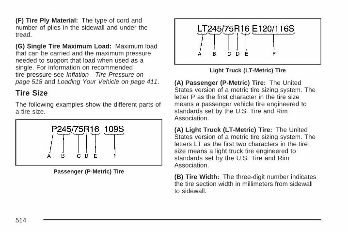
(F) Tire Ply Material: The type of cord andnumber of plies in the sidewall and under thetread.
(G) Single Tire Maximum Load: Maximum loadthat can be carried and the maximum pressureneeded to support that load when used as asingle. For information on recommendedtire pressure see Inflation - Tire Pressure onpage 518 and Loading Your Vehicle on page 411.
Tire SizeThe following examples show the different parts ofa tire size.
(A) Passenger (P-Metric) Tire: The UnitedStates version of a metric tire sizing system. Theletter P as the first character in the tire sizemeans a passenger vehicle tire engineered tostandards set by the U.S. Tire and RimAssociation.
(A) Light Truck (LT-Metric) Tire: The UnitedStates version of a metric tire sizing system. Theletters LT as the first two characters in the tiresize means a light truck tire engineered tostandards set by the U.S. Tire and RimAssociation.
(B) Tire Width: The three-digit number indicatesthe tire section width in millimeters from sidewallto sidewall.
Passenger (P-Metric) Tire
Light Truck (LT-Metric) Tire
514

(C) Aspect Ratio: A two-digit number thatindicates the tire height-to-width measurements.For example, if the tire size aspect ratio is 75, asshown in item C of the light truck (LT-Metric) tireillustration, it would mean that the tire’s sidewall is75 percent as high as it is wide.
(D) Construction Code: A letter code is used toindicate the type of ply construction in the tire. Theletter R means radial ply construction; the letter Dmeans diagonal or bias ply construction; and theletter B means belted-bias ply construction.
(E) Rim Diameter: Diameter of the wheel ininches.
(F) Service Description: The service descriptionindicates the load range and speed rating of atire. The load index can range from 1 to 279.Speed ratings range from A to Z.
Tire Terminology and Definitions
Air Pressure: The amount of air inside the tirepressing outward on each square inch of thetire. Air pressure is expressed in poundsper square inch (psi) or kilopascal (kPa).
Accessory Weight: This means the combinedweight of optional accessories. Some examples ofoptional accessories are, automatic transmission,power steering, power brakes, power windows,power seats, and air conditioning.
Aspect Ratio: The relationship of a tire’s heightto its width.
Belt: A rubber coated layer of cords that islocated between the plies and the tread. Cordsmay be made from steel or other reinforcingmaterials.
Bead: The tire bead contains steel wires wrappedby steel cords that hold the tire onto the rim.
Bias Ply Tire: A pneumatic tire in which the pliesare laid at alternate angles less than 90 degreesto the centerline of the tread.
515

Cold Tire Pressure: The amount of air pressurein a tire, measured in pounds per square inch(psi) or kilopascals (kPa) before a tire has built upheat from driving. See Inflation - Tire Pressureon page 518.
Curb Weight: This means the weight of a motorvehicle with standard and optional equipmentincluding the maximum capacity of fuel, oil, andcoolant, but without passengers and cargo.
DOT Markings: A code molded into the sidewallof a tire signifying that the tire is in compliancewith the U.S. Department of Transportation (DOT)motor vehicle safety standards. The DOT codeincludes the Tire Identification Number (TIN),an alphanumeric designator which can also identifythe tire manufacturer, production plant, brand,and date of production.
GVWR: Gross Vehicle Weight Rating. SeeLoading Your Vehicle on page 411.
GAWR FRT: Gross Axle Weight Rating for thefront axle. See Loading Your Vehicle on page 411.
GAWR RR: Gross Axle Weight Rating for therear axle. See Loading Your Vehicle on page 411.
Intended Outboard Sidewall: The side of anasymmetrical tire, that must always face outwardwhen mounted on a vehicle.
Kilopascal (kPa): The metric unit for air pressure.
Light Truck (LT-Metric) Tire: A tire used onlight duty trucks and some multipurpose passengervehicles.
Load Index: An assigned number ranging from1 to 279 that corresponds to the load carryingcapacity of a tire.
Maximum Inflation Pressure: The maximum airpressure to which a cold tire may be inflated.The maximum air pressure is molded ontothe sidewall.
Maximum Load Rating: The load rating for a tireat the maximum permissible inflation pressurefor that tire.
Maximum Loaded Vehicle Weight: The sum ofcurb weight, accessory weight, vehicle capacityweight, and production options weight.
Normal Occupant Weight: The number ofoccupants a vehicle is designed to seat multipliedby 150 lbs (68 kg). See Loading Your Vehicleon page 411.
516

Occupant Distribution: Designated seatingpositions.
Outward Facing Sidewall: The side of anasymmetrical tire that has a particular side thatfaces outward when mounted on a vehicle.The side of the tire that contains a whitewall, bearswhite lettering, or bears manufacturer, brand,and/or model name molding that is higheror deeper than the same moldings on the othersidewall of the tire.
Passenger (P-Metric) Tire: A tire used onpassenger cars and some light duty trucks andmultipurpose vehicles.
Recommended Inflation Pressure: Vehiclemanufacturer’s recommended tire inflationpressure as shown on the tire placard. SeeInflation - Tire Pressure on page 518 and LoadingYour Vehicle on page 411.
Radial Ply Tire: A pneumatic tire in which the plycords that extend to the beads are laid at 90degrees to the centerline of the tread.
Rim: A metal support for a tire and upon whichthe tire beads are seated.
Sidewall: The portion of a tire between the treadand the bead.
Speed Rating: An alphanumeric code assignedto a tire indicating the maximum speed atwhich a tire can operate.
Traction: The friction between the tire and theroad surface. The amount of grip provided.
Tread: The portion of a tire that comes intocontact with the road.
Treadwear Indicators: Narrow bands, sometimescalled wear bars, that show across the tread ofa tire when only 1/16 inch (1.6 mm) of treadremains. See When It Is Time for New Tires onpage 526.
UTQGS (Uniform Tire Quality GradingStandards): A tire information system thatprovides consumers with ratings for a tire’straction, temperature, and treadwear. Ratings aredetermined by tire manufacturers usinggovernment testing procedures. The ratings aremolded into the sidewall of the tire. See UniformTire Quality Grading on page 529.
517

Vehicle Capacity Weight: The number ofdesignated seating positions multiplied by 150 lbs(68 kg) plus the rated cargo load. See LoadingYour Vehicle on page 411.
Vehicle Maximum Load on the Tire: Load on anindividual tire due to curb weight, accessoryweight, occupant weight, and cargo weight.
Vehicle Placard: A label permanently attached toa vehicle showing the vehicle’s capacity weightand the original equipment tire size andrecommended inflation pressure. See “Tire andLoading Information Label” under LoadingYour Vehicle on page 411.
Inflation - Tire PressureTires need the correct amount of air pressure tooperate effectively.
Notice: Do not let anyone tell you thatunder-inflation or over-inflation is all right. It isnot. If your tires do not have enough air(under-inflation), you can get the following:• Too much flexing
• Too much heat
• Tire overloading
• Premature or irregular wear
• Poor handling
• Reduced fuel economy
If your tires have too much air (over-inflation),you can get the following:• Unusual wear
• Poor handling
• Rough ride
• Needless damage from road hazards
A Tire and Loading Information label is attached tothe vehicle’s center pillar (B-pillar), below thedriver’s door lock post (striker). This label lists yourvehicle’s original equipment tires and theirrecommended cold tire inflation pressures. Therecommended cold tire inflation pressure,shown on the label, is the minimum amount of airpressure needed to support your vehicle’smaximum load carrying capacity.
For additional information regarding how muchweight your vehicle can carry, and an example ofthe tire and loading information label, seeLoading Your Vehicle on page 411.
518

When to CheckCheck your tires once a month or more. Do notforget to check the spare tire. For additionalinformation regarding the spare tire, see SpareTire on page 554.
How to CheckUse a good quality pocket-type gage to check tirepressure. You cannot tell if your tires areproperly inflated simply by looking at them. Radialtires may look properly inflated even whenthey’re underinflated. Check the tire’s inflationpressure when the tires are cold. Cold means yourvehicle has been sitting for at least three hoursor driven no more than 1 mile (1.6 km).
Remove the valve cap from the tire valve stem.Press the tire gage firmly onto the valve toget a pressure measurement. If the cold tireinflation pressure matches the recommendedpressure on the Tire and Loading Informationlabel, no further adjustment is necessary. If theinflation pressure is low, add air until you reach therecommended amount.
If you overfill the tire, release air by pushing onthe metal stem in the center of the tire valve.Recheck the tire pressure with the tire gage.
Be sure to put the valve caps back on the valvestems. They help prevent leaks by keeping out dirtand moisture.
Tire Pressure Monitor SystemThe Tire Pressure Monitor System (TPMS) usesradio and sensor technology to check tire pressurelevels. If your vehicle has this feature, sensors aremounted on each tire and wheel assembly, exceptthe spare tire. The TPMS sensors monitor the airpressure in your vehicle’s tires and transmit tirepressure readings to a receiver located in thevehicle.The TPMS is designed to alert the driver, if a lowtire pressure condition exists. If your vehicle has theDriver Information Center (DIC), the driver may alsocheck tire pressure levels using the DIC.When a low tire pressure condition is detected, theTPMS will illuminate the low tire pressure warningsymbol located on the instrument panel cluster. Ifyour vehicle has the DIC feature, a message tocheck the pressure in a specific tire will also appearon the DIC display.
519

The low tire pressure warning symbol on theinstrument panel cluster and the CHECK TIREPRESSURE warning message on the DIC displaywill appear at each ignition cycle until the tires areinflated to the correct inflation pressure. Foradditional information and details about the DICoperation and displays see DIC Operation andDisplays (With DIC Buttons) on page 262 or DICOperation and Displays (Without DIC Buttons) onpage 269 and DIC Warnings and Messages onpage 272.
You may notice, during cooler weather conditions,that the tire pressure monitor light, located onthe instrument panel cluster, and the CHECK TIREPRESSURE message will appear when thevehicle is first started and then turn off as youstart to drive the vehicle. This could be an earlyindicator that the tire pressures are getting low andneed to be inflated to the proper pressure.
Each tire, including the spare (if provided), shouldbe checked monthly when cold and inflated tothe inflation pressure recommended by the vehiclemanufacturer on the vehicle placard or tireinflation pressure label. (If your vehicle has tires ofa different size than the size indicated on the
vehicle placard or tire inflation pressure label, youshould determine the proper tire inflationpressure for those tires.)
As an added safetyfeature, your vehiclehas been equipped witha tire pressuremonitoring system(TPMS) that illuminatesa low tire pressuretelltale when oneor more of your tires issignificantlyunder-inflated.
Accordingly, when the low tire pressure telltaleilluminates, you should stop and check your tiresas soon as possible, and inflate them to theproper pressure. Driving on a significantlyunder-inflated tire causes the tire to overheat andcan lead to tire failure. Under-inflation alsoreduces fuel efficiency and tire tread life, and mayaffect the vehicle’s handling and stopping ability.
520

Please note that the TPMS is not a substitute forproper tire maintenance, and it is the driver’sresponsibility to maintain correct tire pressure,even if under-inflation has not reached the level totrigger illumination of the TPMS low tire pressuretelltale.
Your vehicle has also been equipped with a TPMSmalfunction indicator to indicate when thesystem is not operating properly. The TPMSmalfunction indicator is combined with the low tirepressure telltale. When the system detects amalfunction, the telltale will flash for approximatelyone minute and then remain continuouslyilluminated. This sequence will continue uponsubsequent vehicle start-ups as long as themalfunction exists.
When the malfunction indicator is illuminated, thesystem may not be able to detect or signal lowtire pressure as intended. TPMS malfunctions mayoccur for a variety of reasons, including theinstallation of replacement or alternate tires orwheels on the vehicle that prevent the TPMS fromfunctioning properly. Always check the TPMSmalfunction telltale after replacing one or more
tires or wheels on your vehicle to ensure that thereplacement or alternate tires and wheels allowthe TPMS to continue to function properly.
The CHECK TIRE PRESSURE warning messageand low tire pressure light (telltale) will comeon each time the vehicle is started until the tiresare inflated to the correct inflation pressure.
The Tire and Loading Information label (tireinformation placard) shows the size of yourvehicle’s original tires and the correct inflationpressure for your vehicle’s tires when theyare cold. See Inflation - Tire Pressure onpage 518. For the location of the tire and loadinginformation label, see Loading Your Vehicleon page 411.
Your vehicle’s TPMS can alert you about a lowtire pressure condition but it does not replacenormal tire maintenance. See Tire Inspection andRotation on page 524 and Tires on page 510.
Notice: Do not use a tire sealant if yourvehicle has Tire Pressure Monitors. The liquidsealant can damage the tire pressure monitorsensors.
521

Resetting the TPMS Identification CodesEach TPMS sensor has a unique identificationcode. Any time you rotate your vehicle’s tires orreplace one or more of the TPMS sensors,the identification codes will need to be matched tothe new tire/wheel position. The sensors arematched to the tire/wheel positions in the followingorder: driver’s side front tire, passengers sidefront tire, passengers side rear tire, and driver’sside rear tire using a TPMS diagnostic tool.See your GM dealer for service.
The TPMS sensors may also be matched to eachtire/wheel position by increasing or decreasingthe tire’s air pressure. If increasing the tire’sair pressure, do not exceed the maximum inflationpressure indicated on the tire’s sidewall.
You will have two minutes to match the firsttire/wheel position, and five minutes overall tomatch all four tire/wheel positions. If it takes longerthan two minutes, to match the first tire andwheel, or more than five minutes to match all fourtire and wheel positions the matching processstops and you will need to start over.
The TPMS sensor matching process is outlinedbelow:
1. Set the parking brake.
2. Turn the ignition switch to RUN with theengine off.
3. Using the DIC, press the vehicle informationbutton until the RELEARN TIRE POSITIONSmessage displays. If your vehicle does nothave the DIC buttons, press the trip odometerreset stem located on the instrument panelcluster until the RELEARN TIRE POSITIONSmessage displays.
4. If your vehicle has the DIC buttons, press theset/reset button. The horn will sound twice toindicate the TPMS receiver is ready, andthe TIRE LEARNING ACTIVE message willdisplay. If your vehicle does not have the DICbuttons, press and hold the trip odometerreset stem until the horn chirps twice and theTIRE LEARNING ACTIVE message isdisplayed.
5. Start with the driver’s side front tire.
522

6. Remove the valve cap from the valve cap stem.Activate the TPMS sensor by increasing ordecreasing the tire’s air pressure for fiveseconds, or until a horn chirp sounds. The hornchirp, which make take up to 30 seconds tosound, confirms that the sensor identificationcode has been matched to this tire and wheelposition. To decrease air-pressure out of a tireyou can use the pointed end of the valve cap, apencil-style air pressure gage, or a key.
7. Proceed to the passenger’s side front tire, andrepeat the procedure in Step 6.
8. Proceed to the passenger’s side rear tire, andrepeat the procedure in Step 6.
9. Proceed to the driver’s side rear tire, andrepeat the procedure in Step 6.
10. After hearing the confirming horn chirp for thedriver’s side rear tire, the horn chirp will soundtwo more times to signal the tire learningmode is no longer active. Turn the ignitionswitch to LOCK.
11. Set all four tires to the recommended airpressure level as indicated on the Tireand Loading Information label.
12. Put the valve caps back on the valve stems
The spare tire does not have a TPMS sensor. If youreplace one of the road tires with the spare, theSERVICE TIRE MONITOR message will bedisplayed on the DIC screen. This message shouldgo off once you re-install the road tire containing theTPMS sensor.
Federal Communications Commission(FCC) and Industry and Science CanadaThe Tire Pressure Monitor System (TPMS)operates on a radio frequency and complies withPart 15 of the FCC Rules. Operation is subjectto the following two conditions:
1. This device may not cause harmfulinterference.
2. This device must accept any interferencereceived, including interference that maycause undesired operation.
523

The Tire Pressure Monitor System (TPMS)operates on a radio frequency and complies withRSS-210 of Industry and Science Canada.Operation is subject to the following twoconditions:
1. This device may not cause interference.
2. This device must accept any interferencereceived, including interference that maycause undesired operation of the device.
Changes or modifications to this system by otherthan an authorized service facility could voidauthorization to use this equipment.
Tire Inspection and RotationTires should be rotated every 5,000 to 8,000 miles(8 000 to 13 000 km).
Any time you notice unusual wear, rotate yourtires as soon as possible and check wheelalignment. Also check for damaged tires or wheels.See When It Is Time for New Tires on page 526and Wheel Replacement on page 530 formore information.
Make sure the spare tire is stored securely. Push,pull, and then try to rotate or turn the tire. If itmoves, use the ratchet/wheel wrench to tighten thecable. See Changing a Flat Tire on page 534.
The purpose of regular rotation is to achieve moreuniform wear for all tires on the vehicle. Thefirst rotation is the most important. See ScheduledMaintenance on page 578.
When rotating your vehicle’s tires, always use thecorrect rotation pattern shown here.
Do not include the spare tire in the tire rotation.
524

After the tires have been rotated, adjust the frontand rear inflation pressures as shown on thetire and loading information label. See LoadingYour Vehicle on page 411 and Inflation - TirePressure on page 518, for more information.
Vehicles that have the Tire Pressure MonitorSystem (TPMS) will need to have the TPMSsensors reset after a tire rotation. See “TPMSSensor Identification Codes” under Tire PressureMonitor System on page 519.
Make certain that all wheel nuts are properlytightened. See “Wheel Nut Torque” underCapacities and Specifications on page 573.
{CAUTION:
Rust or dirt on a wheel, or on the parts towhich it is fastened, can make wheel nutsbecome loose after time. The wheel couldcome off and cause an accident. Whenyou change a wheel, remove any rust ordirt from places where the wheel attachesto the vehicle. In an emergency, you canuse a cloth or a paper towel to do this;but be sure to use a scraper or wire brushlater, if needed, to get all the rust or dirtoff. See Changing a Flat Tire on page 534.
525

When It Is Time for New TiresOne way to tell when it istime for new tires is tocheck the treadwearindicators, which willappear when your tireshave only 1/16 inch(1.6 mm) or less of treadremaining. Somecommercial truck tiresmay not have treadwearindicators.
You need a new tire if any of the followingstatements are true:• You can see the indicators at three or more
places around the tire.• You can see cord or fabric showing through
the tire’s rubber.• The tread or sidewall is cracked, cut or
snagged deep enough to show cord or fabric.• The tire has a bump, bulge, or split.• The tire has a puncture, cut, or other damage
that cannot be repaired well because of thesize or location of the damage.
Buying New TiresGM has developed and matched specific tires foryour vehicle. The original equipment tiresinstalled on your vehicle, when it was new, weredesigned to meet General Motors TirePerformance Criteria Specification (TPC spec)system rating. If you need replacement tires, GMstrongly recommends that you get tires withthe same TPC Spec rating. This way, your vehiclewill continue to have tires that are designed togive the same performance and vehicle safety,during normal use, as the original tires.
GM’s exclusive TPC Spec system considers overa dozen critical specifications that impact theoverall performance of your vehicle, includingbrake system performance, ride and handling,traction control, and tire pressure monitoringperformance. GM’s TPC Spec number is moldedonto the tire’s sidewall by the tire manufacturer.If the tires have an all-season tread design,the TPC spec number will be followed by an MSfor mud and snow. See Tire Sidewall Labelingon page 512 for additional information.
526

{CAUTION:
Mixing tires could cause you to losecontrol while driving. If you mix tires ofdifferent sizes, brands, or types (radialand bias-belted tires), the vehicle may nothandle properly, and you could have acrash. Using tires of different sizes,brands or types may also cause damageto your vehicle. Be sure to use the samesize, brand, and type tires on all wheels.
Your vehicle may have a different sizespare than the road tires (those originallyinstalled on your vehicle). When new, yourvehicle included a spare tire and wheelassembly with a similar overall diameteras your vehicle’s road tires and wheels,so it is all right to drive on it. Becausethis spare was developed for use on yourvehicle, it will not affect vehicle handling.
{CAUTION:
If you use bias-ply tires on your vehicle,the wheel rim flanges could developcracks after many miles of driving. A tireand/or wheel could fail suddenly, causinga crash. Use only radial-ply tires with thewheels on your vehicle.
If you must replace your vehicle’s tires with thosethat do not have a TPC Spec number, makesure they are the same size, load range, speedrating, and construction type (radial andbias-belted tires) as your vehicle’s original tires.
Vehicles that have a tire pressure monitoringsystem may give an inaccurate low-pressurewarning if non-TPC spec rated tires are installedon your vehicle. Non-TPC Spec rated tiresmay give a low-pressure warning that is higher orlower than the proper warning level you wouldget with TPC Spec rated tires. See Tire PressureMonitor System on page 519.
527
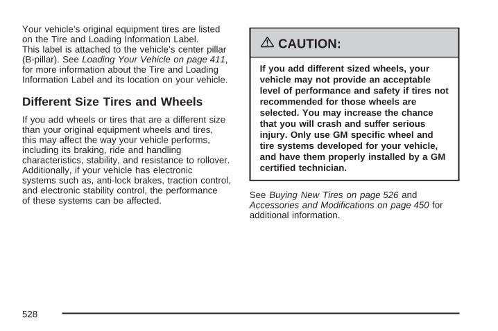
Your vehicle’s original equipment tires are listedon the Tire and Loading Information Label.This label is attached to the vehicle’s center pillar(B-pillar). See Loading Your Vehicle on page 411,for more information about the Tire and LoadingInformation Label and its location on your vehicle.
Different Size Tires and WheelsIf you add wheels or tires that are a different sizethan your original equipment wheels and tires,this may affect the way your vehicle performs,including its braking, ride and handlingcharacteristics, stability, and resistance to rollover.Additionally, if your vehicle has electronicsystems such as, anti-lock brakes, traction control,and electronic stability control, the performanceof these systems can be affected.
{CAUTION:
If you add different sized wheels, yourvehicle may not provide an acceptablelevel of performance and safety if tires notrecommended for those wheels areselected. You may increase the chancethat you will crash and suffer seriousinjury. Only use GM specific wheel andtire systems developed for your vehicle,and have them properly installed by a GMcertified technician.
See Buying New Tires on page 526 andAccessories and Modifications on page 450 foradditional information.
528

Uniform Tire Quality GradingQuality grades can be found where applicable onthe tire sidewall between tread shoulder andmaximum section width. For example:
Treadwear 200 Traction AA Temperature AThe following information relates to the systemdeveloped by the United States National HighwayTraffic Safety Administration (NHTSA), whichgrades tires by treadwear, traction, andtemperature performance. This applies only tovehicles sold in the United States. The grades aremolded on the sidewalls of most passenger cartires. The Uniform Tire Quality Grading (UTQG)system does not apply to deep tread, winter-typesnow tires, space-saver, or temporary usespare tires, tires with nominal rim diameters of10 to 12 inches (25 to 30 cm), or to somelimited-production tires.
While the tires available on General Motorspassenger cars and light trucks may vary withrespect to these grades, they must also conformto federal safety requirements and additionalGeneral Motors Tire Performance Criteria (TPC)standards.
TreadwearThe treadwear grade is a comparative ratingbased on the wear rate of the tire when testedunder controlled conditions on a specifiedgovernment test course. For example, a tiregraded 150 would wear one and a half (1.5) timesas well on the government course as a tiregraded 100. The relative performance of tiresdepends upon the actual conditions of their use,however, and may depart significantly fromthe norm due to variations in driving habits, servicepractices, and differences in road characteristicsand climate.
Traction – AA, A, B, CThe traction grades, from highest to lowest, areAA, A, B, and C. Those grades represent the tire’sability to stop on wet pavement as measuredunder controlled conditions on specifiedgovernment test surfaces of asphalt and concrete.A tire marked C may have poor tractionperformance.
Warning: The traction grade assigned to this tireis based on straight-ahead braking tractiontests, and does not include acceleration, cornering,hydroplaning, or peak traction characteristics.
529

Temperature – A, B, CThe temperature grades are A (the highest), B,and C, representing the tire’s resistance tothe generation of heat and its ability to dissipateheat when tested under controlled conditions on aspecified indoor laboratory test wheel. Sustainedhigh temperature can cause the material of the tireto degenerate and reduce tire life, and excessivetemperature can lead to sudden tire failure.The grade C corresponds to a level of performancewhich all passenger car tires must meet underthe Federal Motor Vehicle Safety StandardNo. 109. Grades B and A represent higher levelsof performance on the laboratory test wheelthan the minimum required by law.
Warning: The temperature grade for this tire isestablished for a tire that is properly inflatedand not overloaded. Excessive speed,underinflation, or excessive loading, eitherseparately or in combination, can cause heatbuildup and possible tire failure.
Wheel Alignment and Tire BalanceThe tires and wheels on your vehicle were alignedand balanced carefully at the factory to give youthe longest tire life and best overall performance.Adjustments to wheel alignment and tirebalancing will not be necessary on a regular basis.However, if you notice unusual tire wear or yourvehicle pulling to one side or the other, thealignment may need to be checked. If you noticeyour vehicle vibrating when driving on a smoothroad, your tires and wheels may need to berebalanced. See your dealer/retailer for properdiagnosis.
Wheel ReplacementReplace any wheel that is bent, cracked, or badlyrusted or corroded. If wheel nuts keep comingloose, the wheel, wheel bolts, and wheelnuts should be replaced. If the wheel leaks air,replace it (except some aluminum wheels,which can sometimes be repaired). See yourdealer/retailer if any of these conditions exist.
Your dealer/retailer will know the kind of wheelyou need.
530

Each new wheel should have the sameload-carrying capacity, diameter, width, offset andbe mounted the same way as the one itreplaces.
If you need to replace any of your wheels, wheelbolts, or wheel nuts, replace them only withnew GM original equipment parts. This way, youwill be sure to have the right wheel, wheelbolts, and wheel nuts for your vehicle.
{CAUTION:
Using the wrong replacement wheels,wheel bolts, or wheel nuts on your vehiclecan be dangerous. It could affect thebraking and handling of your vehicle,make your tires lose air and make youlose control. You could have a collision inwhich you or others could be injured.Always use the correct wheel, wheel bolts,and wheel nuts for replacement.
Notice: The wrong wheel can also causeproblems with bearing life, brake cooling,speedometer or odometer calibration,headlamp aim, bumper height, vehicle groundclearance, and tire or tire chain clearanceto the body and chassis.
See Changing a Flat Tire on page 534 for moreinformation.
Used Replacement Wheels
{CAUTION:
Putting a used wheel on your vehicle isdangerous. You cannot know how it hasbeen used or how far it has been driven. Itcould fail suddenly and cause a crash. Ifyou have to replace a wheel, use a newGM original equipment wheel.
531

Tire Chains
{CAUTION:
If your vehicle has P265/65R18 or P275/55R20 size tires, do not use tire chains.They can damage your vehicle becausethere is not enough clearance. Tire chainsused on a vehicle without the properamount of clearance can cause damage tothe brakes, suspension, or other vehicleparts. The area damaged by the tire chainscould cause you to lose control of yourvehicle and you or others may be injured ina crash.
Use another type of traction device onlyif its manufacturer recommends it for useon your vehicle and tire size combinationand road conditions. Follow thatmanufacturer’s instructions. To help avoiddamage to your vehicle, drive slowly,
CAUTION: (Continued)
CAUTION: (Continued)
readjust or remove the device if it iscontacting your vehicle, and do not spinyour vehicle’s wheels.
If you do find traction devices that will fit,install them on the rear tires.
Notice: If your vehicle has P265/70R17 sizetires, use tire chains only where legal and onlywhen you must. Use chains that are theproper size for your vehicle’s tires. Install themon the rear tires only.
Do not use chains on the front tires.
Tighten them as tightly as possible with theends securely fastened. Drive slowly and followthe chain manufacturer’s instructions. If youcan hear the chains contacting your vehicle,stop and retighten them. If the contactcontinues, slow down until it stops. Drivingtoo fast or spinning the wheels with chains onwill damage your vehicle.
532

If a Tire Goes FlatIt is unusual for a tire to blowout while you aredriving, especially if you maintain your vehicle’stires properly. If air goes out of a tire, it ismuch more likely to leak out slowly. But if youshould ever have a blowout, here are a few tipsabout what to expect and what to do:
If a front tire fails, the flat tire will create a dragthat pulls the vehicle toward that side. Take yourfoot off the accelerator pedal and grip thesteering wheel firmly. Steer to maintain laneposition, and then gently brake to a stop well outof the traffic lane.
A rear blowout, particularly on a curve, acts muchlike a skid and may require the same correctionyou would use in a skid. In any rear blowoutremove your foot from the accelerator pedal. Getthe vehicle under control by steering the wayyou want the vehicle to go. It may be very bumpyand noisy, but you can still steer. Gently braketo a stop, well off the road if possible.
{CAUTION:
Lifting a vehicle and getting under it to domaintenance or repairs is dangerouswithout the appropriate safety equipmentand training. The jack provided with yourvehicle is designed only for changing aflat tire. If it is used for anything else, youor others could be badly injured or killedif the vehicle slips off the jack. Use thejack provided with your vehicle only forchanging a flat tire.
If a tire goes flat, the next part shows how to use thejacking equipment to change a flat tire safely.
533

Changing a Flat TireIf a tire goes flat, avoid further tire and wheeldamage by driving slowly to a level place. Turn onyour hazard warning flashers. See Hazard WarningFlashers on page 204 for more information.
{CAUTION:
Changing a tire can be dangerous. Thevehicle can slip off the jack and roll overor fall on you or other people. You andthey could be badly injured or even killed.Find a level place to change your tire. Tohelp prevent the vehicle from moving:
1. Set the parking brake firmly.2. Put the shift lever in PARK (P).
CAUTION: (Continued)
CAUTION: (Continued)
3. If you have a four-wheel-drive vehicle,be sure the transfer case is in a drivegear— not in NEUTRAL.
4. Turn off the engine and do not restartwhile the vehicle is raised.
5. Do not allow passengers to remain inthe vehicle.
6. Put the wheel blocks at the front andrear of the tire farthest away from theone being changed. That would bethe tire on the other side, at theopposite end of the vehicle.
534

When your vehicle has a flat tire, use the followingexample as a guide to assist you in the placementof wheel blocks.
The following information will tell you how to usethe jack and change a tire.
Removing the Spare Tire and ToolsThe equipment you will need to change a flat tire isstored under the storage tray, which is located onthe driver’s side trim panel (over the rearwheelhouse).
1. Remove the tray to access the tools by pullingup on the finger depression under the jacksymbol.
Regular Wheelbase shown, ExtendedWheelbase similar.
535

2. Remove the wing nut (B) used to retain thetool bag by turning it counterclockwise.
3. Turn the knob (A) on the jackcounterclockwise to release the jack andwheel blocks from the bracket.
4. Remove the wheel blocks and the wheelblock retainer by turning the wing nut (C)counterclockwise.
The tools you will be using include the following:A. JackB. Wheel BlocksC. Jack Handle
D. Jack HandleExtensions
E. Wheel Wrench
536

To access the spare tire, refer to the followinggraphics and instructions:
A. Hoist AssemblyB. Hoist ShaftC. Hoist Shaft
AccessCover/Hole
D. Jack HandleExtensions
E. Wheel WrenchF. Hoist Cable
G. Tire RetainerH. Spare Tire
(Valve StemPointed Down)
I. Hoist ShaftAccess Hole
J. Hoist End ofExtension Tool
K. Spare Tire Lock
1. Open the hoist shaft access door (C) on thebumper to access the spare tire lock (K).
2. Insert the ignition key, turn it clockwise andthen pull it to remove the spare tire lock.
3. Assemble the two jack handle extensions (D)and wheel wrench (E) as shown.
537

4. Insert the open endof the extension (J)through the holein the rearbumper (I) (hoistshaft access hole).
Be sure the hoist end (J) of the extension (D)connects to the hoist shaft (B). The ribbedsquare end of the extension is used to lowerthe spare tire.
5. Turn the wheel wrench (E) counterclockwiseto lower the spare tire (H) to the ground.Continue to turn the wheel wrench until thespare tire can be pulled out from underthe vehicle.If the spare tire does not lower to the ground,the secondary latch is engaged causingthe tire not to lower. See Secondary LatchSystem on page 545 for more information.
6. Use the wheelwrench hook thatallows you topull the hoist cabletowards you, toassist in reachingthe spare tire.
7. Tilt the tireretainer (G) at theend of the cablewhen the tirehas been lowered,so it can bepulled up throughthe wheel opening.
8. Put the spare tire near the flat tire.
538
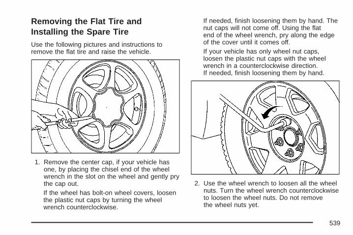
Removing the Flat Tire andInstalling the Spare TireUse the following pictures and instructions toremove the flat tire and raise the vehicle.
1. Remove the center cap, if your vehicle hasone, by placing the chisel end of the wheelwrench in the slot on the wheel and gently prythe cap out.If the wheel has bolt-on wheel covers, loosenthe plastic nut caps by turning the wheelwrench counterclockwise.
If needed, finish loosening them by hand. Thenut caps will not come off. Using the flatend of the wheel wrench, pry along the edgeof the cover until it comes off.If your vehicle has only wheel nut caps,loosen the plastic nut caps with the wheelwrench in a counterclockwise direction.If needed, finish loosening them by hand.
2. Use the wheel wrench to loosen all the wheelnuts. Turn the wheel wrench counterclockwiseto loosen the wheel nuts. Do not removethe wheel nuts yet.
539

A. Front PositionB. Rear Position
{CAUTION:
Getting under a vehicle when it is jackedup is dangerous. If the vehicle slips offthe jack you could be badly injured orkilled. Never get under a vehicle when it issupported only by a jack.
{CAUTION:
Raising your vehicle with the jackimproperly positioned can damage thevehicle and even make the vehicle fall. Tohelp avoid personal injury and vehicledamage, be sure to fit the jack lift headinto the proper location before raising thevehicle.
3. Position the jack under the vehicle as shown.
Jacking Locations (Overall View)
540

Front Tire Flat: If the flat tire is on a front tireof the vehicle, you will need to use the jackhandle (B) and only one jack handleextension (C). Attach the wheel wrench (D) tothe jack handle extension (C). Attach thejack handle (B) to the jack (A). Position thejack on the frame behind the flat tire where theframe sections overlap (E). Turn the wheelwrench (D) clockwise to raise the vehicle.
Raise the vehicle far enough off the ground sothere is enough room for the spare tire toclear the ground.
Front Position
Rear Position – 1500 Models
541

Rear Tire Flat: If the flat tire is on a rear tireof the vehicle, you will need to use thejack handle (B) and both jack handleextensions (C). Attach the wheel wrench (D)to the jack handle extensions (C). Attachthe jack handle (B) to the jack (A). Use thejacking pad provided on the rear axle. Turn thewheel wrench (D) clockwise to raise thevehicle.
Raise the vehicle far enough off the ground sothere is enough room for the spare tire toclear the ground.
4. Remove all of thewheel nuts.
5. Take off the flat tire.
542

{CAUTION:
Rust or dirt on the wheel, or on the partsto which it is fastened, can make thewheel nuts become loose after time. Thewheel could come off and cause anaccident. When you change a wheel,remove any rust or dirt from the placeswhere the wheel attaches to the vehicle. Inan emergency, you can use a cloth or apaper towel to do this; but be sure to usea scraper or wire brush later, if needed, toget all the rust or dirt off.
6. Remove any rust ordirt from the wheelbolts, mountingsurfaces and sparewheel.
{CAUTION:
Never use oil or grease on studs or nuts.If you do, the nuts might come loose.Your wheel could fall off, causing aserious accident.
7. Put the wheel nuts back on with the roundedend of the nuts toward the wheel aftermounting the spare tire.
543

8. Tighten each wheel nut by hand. Then usethe wheel wrench to tighten the nuts until thewheel is held against the hub.
9. Turn the wheel wrench counterclockwise tolower the vehicle. Lower the jack completely.
{CAUTION:
Incorrect wheel nuts or improperlytightened wheel nuts can cause the wheelto come loose and even come off. Thiscould lead to an accident. Be sure to usethe correct wheel nuts. If you have toreplace them, be sure to get new GMoriginal equipment wheel nuts. Stopsomewhere as soon as you can and havethe nuts tightened with a torque wrench tothe proper torque specification. SeeCapacities and Specifications on page 573for wheel nut torque specification.
Notice: Improperly tightened wheel nuts canlead to brake pulsation and rotor damage.To avoid expensive brake repairs, evenlytighten the wheel nuts in the proper sequenceand to the proper torque specification. SeeCapacities and Specifications on page 573 forthe wheel nut torque specification.
10. Tighten the nuts firmly in a crisscrosssequence as shown by turning the wheelwrench clockwise.
544

When you reinstall the regular wheel and tire, youmust also reinstall the either the center cap, orbolt-on hub cap, depending on what your vehiclehas. For center caps, place the cap on thewheel and tap it into place until it seats flush withthe wheel. The cap only goes on one way. Besure to line up the tab on the center cap with theindentation on the wheel. For bolt-on hub caps,align the plastic nut caps with the wheel nuts andthen tighten by hand. Then use the wheelwrench to tighten.
Secondary Latch SystemYour vehicle has an underbody-mounted tire hoistassembly which has a secondary latch system.It is designed to stop the spare tire from suddenlyfalling off your vehicle. For the secondary latchto work, the spare tire must be installed withthe valve stem pointing down. See Storing a Flator Spare Tire and Tools on page 549.
{CAUTION:
Before beginning this procedure read allthe instructions. Failure to read and followthe instructions could damage the hoistassembly and you and others could gethurt. Read and follow the instructionslisted next.
To release the spare tire from the secondary latch,do the following:
1. Check under thevehicle to see if thecable end isvisible. If the cableis not visible,proceed to Step 6.
545

2. If it is visible, first try to tighten the cable byturning the wheel wrench clockwise until youhear two clicks or feel it skip twice. Youcannot overtighten the cable.
3. Loosen the cable by turning the wheel wrenchcounterclockwise three or four turns.
4. Repeat this procedure at least two times. Ifthe spare tire lowers to the ground, continuewith Step 5 of Removing the Spare Tireand Tools on page 535.
5. If the spare tire does not lower, turn the wheelwrench counterclockwise until approximately6 inches (15 cm) of cable is exposed.
6. Stand the wheel blocks on their shortest ends,with the backs facing each other.
7. Place the bottomedge of the jack (A)on the wheelblocks (B),separating them sothat the jack isbalanced securely.
546

8. Attach the jack handle, extension, and wheelwrench to the jack and place it (with thewheel blocks) under the vehicle toward thefront of the rear bumper.
9. Position the center lift point of the jack underthe center of the spare tire.
10. Turn the wheel wrench clockwise to raise thejack until it lifts the end fitting.
547

11. Continue raising the jack until the spare tirestops moving upward and is held firmly inplace so that the secondary latch has releasedand the spare tire is balancing on the jack.
12. Lower the jack by turning the wheel wrenchcounterclockwise. Keep lowering the jackuntil the spare tire slides off the jack oris hanging by the cable.
{CAUTION:
Someone standing too close during theprocedure could be injured by the jack. Ifthe spare tire does not slide off the jackcompletely, make sure no one is behindyou or on either side of you as you pullthe jack out from under the spare.
13. Disconnect the jack handle from the jack andcarefully remove the jack with the other hand.
14. Use one hand to push against the spare whilefirmly pulling the jack out from under thespare tire with the other hand. If the spare tireis hanging from the cable, insert the hoistend of the extension, and wheel wrench intothe hoist shaft hole in the bumper andturn the wheel wrench counterclockwise tolower the spare tire the rest of the way.
548

15. Tilt the tire retainerat the end of thecable and pullit through the wheelopening. Pull thetire out fromunder the vehicle.
16. Turn the wheel wrench in the hoist shaft holein the bumper clockwise to raise the cableback up if the cable is hanging underthe vehicle.
Have the hoist assembly inspected as soon asyou can. You will not be able to store a spare orflat tire using the hoist assembly until it hasbeen replaced.
To continue changing the flat tire, see Removingthe Flat Tire and Installing the Spare Tire onpage 539.
Storing a Flat or Spare Tire andTools
{CAUTION:
Storing a jack, a tire, or other equipmentin the passenger compartment of thevehicle could cause injury. In a suddenstop or collision, loose equipment couldstrike someone. Store all these in theproper place.
Notice: Storing an aluminum wheel with a flattire under your vehicle for an extendedperiod of time or with the valve stem pointingup may damage the wheel. Always stowthe wheel with the valve stem pointing downand have the wheel/tire repaired as soonas possible.
549
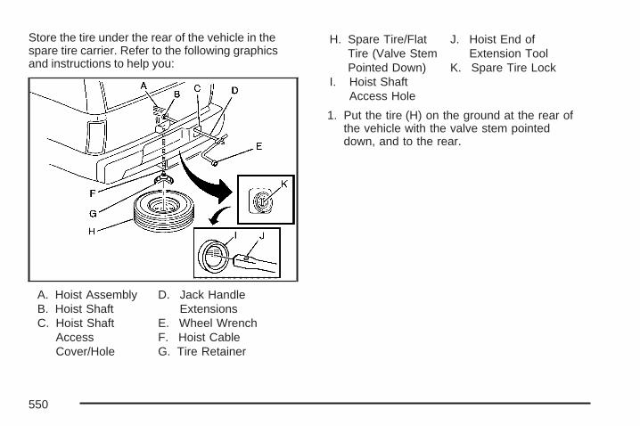
Store the tire under the rear of the vehicle in thespare tire carrier. Refer to the following graphicsand instructions to help you:
A. Hoist AssemblyB. Hoist ShaftC. Hoist Shaft
AccessCover/Hole
D. Jack HandleExtensions
E. Wheel WrenchF. Hoist CableG. Tire Retainer
H. Spare Tire/FlatTire (Valve StemPointed Down)
I. Hoist ShaftAccess Hole
J. Hoist End ofExtension Tool
K. Spare Tire Lock
1. Put the tire (H) on the ground at the rear ofthe vehicle with the valve stem pointeddown, and to the rear.
550

2. Tilt the retainerdownward andthrough the wheelopening. Makesure the retainer isfully seatedacross the undersideof the wheel.
3. Assemble the two jack handle extensions (D)and wheel wrench (E) as shown.
4. Insert the open endof the extension (J)through the holein the rearbumper (I) (hoistshaft access hole).
5. Raise the tire part way upward. Make sure theretainer is seated in the wheel opening.
6. Raise the tire fully against the underside ofthe vehicle by turning the wheel wrenchclockwise until you hear two clicks or feel itskip twice. You cannot overtighten the cable.
551

7. Make sure the tire is stored securely. Push,pull (A), and then try to turn (B) the tire. If thetire moves, use the wheel wrench to tightenthe cable.
8. Reinstall the spare tire lock.
9. Reinstall the hoist shaft access cover.
To store the tools, do the following.
A. Wheel BlocksB. Tool Bag with
Jack ToolsC. Retaining
BracketD. Wing Nut
RetainingTool Bag
E. JackF. Wing Nut
Retaining WheelBlocks
G. Wing Nuton Jack
1. Return the tools (wheel wrench, jack handle,and jack handle extensions) to the tool bag (B).
552

2. Assemble wheel blocks (A) and jack (E)together with the wing nut (F).
3. Position the jack (E) and wheel blocks (A) inthe driver’s side trim panel over thewheelhouse.
4. Turn the wing nut (G) clockwise until the jackis secured tight in the mounting bracket. Besure to position the holes in the base ofthe jack onto the pin in the mounting bracket.
5. Use the retaining bracket (C) to fasten the toolbag (B) on the stud and turn the wing nut (D)clockwise to secure.
6. Return the storage tray to its original storedposition.
553

Spare TireYour vehicle, when new, had a fully-inflated sparetire. A spare tire may lose air over time, so check itsinflation pressure regularly. See Inflation - TirePressure on page 518 and Loading Your Vehicle onpage 411 for information regarding proper tireinflation and loading your vehicle. For instruction onhow to remove, install or store a spare tire, seeRemoving the Flat Tire and Installing the Spare Tireon page 539 and Storing a Flat or Spare Tire andTools on page 549.
Notice: If your vehicle has four-wheel driveand the different size spare tire is installed onyour vehicle, do not drive in four-wheeldrive until you can have your flat tire repairedand/or replaced. You could damage yourvehicle, and the repair costs would not becovered by your warranty. Never usefour-wheel drive when the different size sparetire is installed on your vehicle.
Your vehicle may have a different size spare tirethan the road tires originally installed on yourvehicle. This spare tire was developed for use onyour vehicle, so it is all right to drive on it. Ifyour vehicle has four-wheel drive and the differentsize spare tire is installed, keep the vehicle intwo-wheel drive.
After installing the spare tire on your vehicle, youshould stop as soon as possible and makesure the spare tire is correctly inflated. Have thedamaged or flat road tire repaired or replacedas soon as you can and installed back onto yourvehicle. This way, the spare tire will be availablein case you need it again.
Do not mix tires and wheels of different sizes,because they will not fit. Keep your spare tire andits wheel together. If your vehicle has a sparetire that does not match your vehicle’s original roadtires and wheels in size and type, do not includethe spare in the tire rotation.
554

Appearance Care
Cleaning the Inside of Your VehicleYour vehicle’s interior will continue to look itsbest if it is cleaned often. Although not alwaysvisible, dust and dirt can accumulate on yourupholstery. Dirt can damage carpet, fabric, leather,and plastic surfaces. Regular vacuuming isrecommended to remove particles from yourupholstery. It is important to keep your upholsteryfrom becoming and remaining heavily soiled.Soils should be removed as quickly as possible.Your vehicle’s interior may experience extremes ofheat that could cause stains to set rapidly.
Lighter colored interiors may require more frequentcleaning. Use care because newspapers andgarments that transfer color to your homefurnishings may also transfer color to yourvehicle’s interior.
When cleaning your vehicle’s interior, only usecleaners specifically designed for the surfacesbeing cleaned. Permanent damage may resultfrom using cleaners on surfaces for whichthey were not intended.
Use glass cleaner only on glass. Remove anyaccidental over-spray from other surfacesimmediately. To prevent over-spray, apply cleanerdirectly to the cleaning cloth.
Notice: If you use abrasive cleaners whencleaning glass surfaces on your vehicle, youcould scratch the glass and/or cause damageto the rear window defogger. When cleaningthe glass on your vehicle, use only a soft clothand glass cleaner.
Many cleaners contain solvents that may becomeconcentrated in your vehicle’s breathing space.Before using cleaners, read and adhere toall safety instructions on the label. While cleaningyour vehicle’s interior, maintain adequateventilation by opening your vehicle’s doors andwindows.
Dust may be removed from small buttons andknobs using a small brush with soft bristles.
Your dealer has a product for cleaning yourvehicle’s glass. Should it become necessary, youcan also obtain a product from your dealer toremove odors from your vehicle’s upholstery.
555
Do not clean your vehicle using the followingcleaners or techniques:
• Never use a knife or any other sharp object toremove a soil from any interior surface.
• Never use a stiff brush. It can cause damageto your vehicle’s interior surfaces.
• Never apply heavy pressure or rubaggressively with a cleaning cloth. Use ofheavy pressure can damage your interior anddoes not improve the effectiveness of soilremoval.
• Use only mild, neutral-pH soaps. Avoidlaundry detergents or dishwashing soaps withdegreasers. Using too much soap will leavea residue that leaves streaks and attracts dirt.For liquid cleaners, about 20 drops pergallon (3.78 L) of water is a good guide.
• Do not heavily saturate your upholstery whilecleaning.
• Damage to your vehicle’s interior may resultfrom the use of many organic solvents suchas naptha, alcohol, etc.
Fabric/CarpetUse a vacuum cleaner with a soft brushattachment frequently to remove dust and loosedirt. A canister vacuum with a beater bar inthe nozzle may only be used on floor carpet andcarpeted floor mats. For soils, always try to removethem first with plain water or club soda. Beforecleaning, gently remove as much of the soilas possible using one of the following techniques:
• For liquids: gently blot the remaining soilwith a paper towel. Allow the soil to absorb intothe paper towel until no more can beremoved.
• For solid dry soils: remove as much aspossible and then vacuum.
556

To clean, use the following instructions:
1. Saturate a lint-free, clean white cloth withwater or club soda.
2. Wring the cloth to remove excess moisture.
3. Start on the outside edge of the soil and gentlyrub toward the center. Continue cleaning,using a clean area of the cloth each time itbecomes soiled.
4. Continue to gently rub the soiled area until thecleaning cloth remains clean.
5. If the soil is not completely removed, use amild soap solution and repeat the cleaningprocess that was used with plain water.
If any of the soil remains, a commercial fabriccleaner or spot lifter may be necessary. When acommercial upholstery cleaner or spot lifter is to beused, test a small hidden area for colorfastnessfirst. If the locally cleaned area gives anyimpression that a ring formation may result, cleanthe entire surface.
After the cleaning process has been completed, apaper towel can be used to blot excess moisturefrom the fabric or carpet.
LeatherA soft cloth dampened with water may be used toremove dust. If a more thorough cleaning isnecessary, a soft cloth dampened with a mild soapsolution can be used. Allow the leather to drynaturally. Do not use heat to dry. Never use steamto clean leather. Never use spot lifters or spotremovers on leather. Many commercial leathercleaners and coatings that are sold to preserveand protect leather may permanently changethe appearance and feel of your leather and arenot recommended. Do not use silicone orwax-based products, or those containing organicsolvents to clean your vehicle’s interior becausethey can alter the appearance by increasingthe gloss in a non-uniform manner. Never useshoe polish on your leather.
557

Instrument Panel, Vinyl, and OtherPlastic SurfacesA soft cloth dampened with water may be used toremove dust. If a more thorough cleaning isnecessary, a clean soft cloth dampened with amild soap solution can be used to gently removedust and dirt. Never use spot lifters or removerson plastic surfaces. Many commercial cleaners andcoatings that are sold to preserve and protectsoft plastic surfaces may permanently change theappearance and feel of your interior and arenot recommended. Do not use silicone orwax-based products, or those containing organicsolvents to clean your vehicle’s interior becausethey can alter the appearance by increasingthe gloss in a non-uniform manner.
Some commercial products may increase gloss onyour instrument panel. The increase in glossmay cause annoying reflections in the windshieldand even make it difficult to see through thewindshield under certain conditions.
Care of Safety BeltsKeep belts clean and dry.
{CAUTION:
Do not bleach or dye safety belts. If youdo, it may severely weaken them. In acrash, they might not be able to provideadequate protection. Clean safety beltsonly with mild soap and lukewarm water.
WeatherstripsSilicone grease on weatherstrips will make themlast longer, seal better, and not stick or squeak.Apply silicone grease with a clean cloth. Duringvery cold, damp weather frequent application maybe required. See Recommended Fluids andLubricants on page 588.
558

Washing Your VehicleThe paint finish on the vehicle provides beauty,depth of color, gloss retention, and durability.
The best way to preserve the vehicle’s finish is tokeep it clean by washing it often with lukewarmor cold water.
Do not wash the vehicle in the direct rays of thesun. Use a car washing soap. Do not usestrong soaps or chemical detergents. Be sure torinse the vehicle well, removing all soapresidue completely. Approved cleaning productscan be obtained from your dealer. See VehicleCare/Appearance Materials on page 564. Do notuse cleaning agents that are petroleum based,or that contain acid or abrasives. All cleaningagents should be flushed promptly and not allowedto dry on the surface, or they could stain. Drythe finish with a soft, clean chamois or anall-cotton towel to avoid surface scratches andwater spotting.
High pressure car washes may cause water toenter the vehicle.
Cleaning Exterior Lamps/LensesUse only lukewarm or cold water, a soft cloth anda car washing soap to clean exterior lampsand lenses. Follow instructions under WashingYour Vehicle on page 559.
Finish CareOccasional waxing or mild polishing of yourvehicle by hand may be necessary to removeresidue from the paint finish. You can get approvedcleaning products from your dealer. See VehicleCare/Appearance Materials on page 564.
If your vehicle has a basecoat/clearcoat paintfinish, the clearcoat gives more depth and gloss tothe colored basecoat. Always use waxes andpolishes that are non-abrasive and made for abasecoat/clearcoat paint finish.
Notice: Machine compounding or aggressivepolishing on a basecoat/clearcoat paintfinish may damage it. Use only non-abrasivewaxes and polishes that are made for abasecoat/clearcoat paint finish on your vehicle.
559

Foreign materials such as calcium chloride andother salts, ice melting agents, road oil and tar, treesap, bird droppings, chemicals from industrialchimneys, etc., can damage your vehicle’s finish ifthey remain on painted surfaces. Wash the vehicleas soon as possible. If necessary, use non-abrasivecleaners that are marked safe for painted surfacesto remove foreign matter.
Exterior painted surfaces are subject to aging,weather and chemical fallout that can take their tollover a period of years. You can help to keepthe paint finish looking new by keeping yourvehicle garaged or covered whenever possible.
Protecting Exterior Bright Metal PartsBright metal parts should be cleaned regularly tokeep their luster. Washing with water is allthat is usually needed. However, you may usechrome polish on chrome or stainless steel trim, ifnecessary.
Use special care with aluminum trim. To avoiddamaging protective trim, never use auto orchrome polish, steam or caustic soap to cleanaluminum. A coating of wax, rubbed to high polish,is recommended for all bright metal parts.
Windshield, Backglass, and WiperBladesIf the windshield is not clear after using thewindshield washer, or if the wiper blade chatterswhen running, wax, sap or other material maybe on the blade or windshield.
Clean the outside of the windshield with afull-strength glass cleaning liquid. The windshieldis clean if beads do not form when you rinse itwith water.
Grime from the windshield will stick to the wiperblades and affect their performance. Cleanthe blade by wiping vigorously with a cloth soakedin full-strength windshield washer solvent. Thenrinse the blade with water.
Check the wiper blades and clean them asnecessary; replace blades that look worn.
560

Aluminum or Chrome-Plated Wheelsand TrimYour vehicle may have either aluminum orchrome-plated wheels.
Keep the wheels clean using a soft clean clothwith mild soap and water. Rinse with clean water.After rinsing thoroughly, dry with a soft cleantowel. A wax may then be applied.
Notice: Chrome wheels and other chrome trimmay be damaged if you do not wash yourvehicle after driving on roads that have beensprayed with magnesium, calcium or sodiumchloride. These chlorides are used on roads forconditions such as ice and dust. This damagewould not be covered by your vehicle’swarranty. Always wash your vehicle’s chromewith soap and water after exposure.
Notice: If you use strong soaps, chemicals,abrasive polishes, cleaners, brushes, orcleaners that contain acid on aluminum orchrome-plated wheels, you could damage thesurface of the wheel(s). The repairs would notbe covered by your warranty. Use onlyGM-approved cleaners on aluminum orchrome-plated wheels.
The surface of these wheels is similar to thepainted surface of your vehicle. Do not use strongsoaps, chemicals, abrasive polishes, abrasivecleaners, cleaners with acid, or abrasive cleaningbrushes on them because you could damagethe surface. Do not use chrome polish onaluminum wheels.
Notice: Using chrome polish on aluminumwheels could damage the wheels. The repairswould not be covered by your warranty.Use chrome polish on chrome wheels only.
Use chrome polish only on chrome-plated wheels,but avoid any painted surface of the wheel, andbuff off immediately after application.
Notice: If you drive your vehicle through anautomatic car wash that has silicone carbidetire cleaning brushes, you could damagethe aluminum or chrome-plated wheels. Therepairs would not be covered by your warranty.Never drive a vehicle equipped with aluminumor chrome-plated wheels through anautomatic car wash that uses silicone carbidetire cleaning brushes.
561

TiresTo clean the tires, use a stiff brush with tirecleaner.
Notice: Using petroleum-based tire dressingproducts on your vehicle may damage thepaint finish and/or tires. When applying a tiredressing, always wipe off any oversprayfrom all painted surfaces on your vehicle.
Sheet Metal DamageIf the vehicle is damaged and requires sheet metalrepair or replacement, make sure the bodyrepair shop applies anti-corrosion material to partsrepaired or replaced to restore corrosionprotection.
Original manufacturer replacement parts willprovide the corrosion protection while maintainingthe warranty.
Finish DamageAny stone chips, fractures or deep scratches inthe finish should be repaired right away. Baremetal will corrode quickly and may develop intomajor repair expense.
Minor chips and scratches can be repaired withtouch-up materials available from your dealer.Larger areas of finish damage can be corrected inyour dealer’s body and paint shop.
562

Underbody MaintenanceChemicals used for ice and snow removal anddust control can collect on the underbody. If theseare not removed, corrosion and rust can developon the underbody parts such as fuel lines,frame, floor pan, and exhaust system even thoughthey have corrosion protection.
At least every spring, flush these materials from theunderbody with plain water. Clean any areas wheremud and debris can collect. Dirt packed in closeareas of the frame should be loosened before beingflushed. Your dealer or an underbody car washingsystem can do this for you.
Chemical Paint SpottingSome weather and atmospheric conditions cancreate a chemical fallout. Airborne pollutants canfall upon and attack painted surfaces on thevehicle. This damage can take two forms: blotchy,ring-shaped discolorations, and small, irregulardark spots etched into the paint surface.
Although no defect in the paint job causes this, GMwill repair, at no charge to the owner, the surfacesof new vehicles damaged by this fallout conditionwithin 12 months or 12,000 miles (20 000 km) ofpurchase, whichever occurs first.
563

Vehicle Care/Appearance Materials
Description UsagePolishing ClothWax-Treated
Interior and exteriorpolishing cloth.
Tar and Road OilRemover
Removes tar, road oil,and asphalt.
Chrome Cleaner andPolish
Use on chrome orstainless steel.
White Sidewall TireCleaner
Removes soil and blackmarks from whitewalls.
Vinyl Cleaner Cleans vinyl.
Glass Cleaner Removes dirt, grime,smoke and fingerprints.
Chrome and Wire WheelCleaner
Removes dirt and grimefrom chrome wheels andwire wheel covers.
Finish Enhancer
Removes dust,fingerprints, and surfacecontaminants. Spray onand wipe off.
Description Usage
Swirl Remover PolishRemoves swirl marks, finescratches, and other lightsurface contamination.
Cleaner Wax Removes light scratchesand protects finish.
Foaming Tire Shine LowGloss
Cleans, shines, andprotects in one step. Nowiping necessary.
Wash Wax Concentrate
Medium foamingshampoo. Cleans andlightly waxes.Biodegradable andphosphate free.
Spot Lifter
Quickly removes spotsand stains from carpets,vinyl, and clothupholstery.
Odor EliminatorOdorless spray odoreliminator used on fabrics,vinyl, leather and carpet.
564

Vehicle Identification
Vehicle Identification Number (VIN)
This is the legal identifier for your vehicle. Itappears on a plate in the front corner of theinstrument panel, on the driver side. You can seeit if you look through the windshield from outsideyour vehicle. The VIN also appears on theCertification/Tire and Service Parts labels and thecertificates of title and registration.
Engine IdentificationThe eighth character in the VIN is the enginecode. This code helps you identify your vehicle’sengine, specifications, and replacement parts.
Service Parts Identification LabelThis label is on the inside of the glove box.It is very helpful if you ever need to order parts.The label has the following information:
• Vehicle Identification Number (VIN)
• Model designation
• Paint information
• Production options and special equipment
Do not remove this label from the vehicle.
Electrical System
Add-On Electrical Equipment
Notice: Do not add anything electrical to yourvehicle unless you check with your dealerfirst. Some electrical equipment can damageyour vehicle and the damage would notbe covered by your warranty. Some add-onelectrical equipment can keep othercomponents from working as they should.
Add-on equipment can drain your vehicle’s battery,even if your vehicle is not operating.
565

Your vehicle has an airbag system. Beforeattempting to add anything electrical to yourvehicle, see Servicing Your Airbag-EquippedVehicle on page 110.
Windshield Wiper FusesThe windshield wiper motor is protected by aninternal circuit breaker and a fuse. If the motoroverheats due to heavy snow, etc., the wiper willstop until the motor cools. If the overload iscaused by some electrical problem and not snow,etc., be sure to get it fixed.
Power Windows and Other PowerOptionsCircuit breakers protect the power windows andother power accessories. If the current load is tooheavy, the circuit breaker opens and thencloses after a cool down period, protecting thecircuit until the problem is fixed or goes away.
Fuses and Circuit BreakersThe wiring circuits in your vehicle are protectedfrom short circuits by a combination of fuses,circuit breakers and fusible thermal links.This greatly reduces the chance of fires caused byelectrical problems.
Look at the silver-colored band inside the fuse. Ifthe band is broken or melted, replace the fuse.Be sure you replace a bad fuse with a new one ofthe identical size and rating.
If you ever have a problem on the road and do nothave a spare fuse, you can borrow one that hasthe same amperage. Just pick some featureof your vehicle that you can get along without, likethe radio or cigarette lighter, and use its fuse ifit is the correct amperage. Replace it as soon asyou can.
566

Instrument Panel Fuse BlockThe instrument panel fuse block access door islocated on the driver’s side edge of the instrumentpanel.
Fuses Usage
LT DR Driver’s Side Power Window CircuitBreaker
REAR SEAT Rear Seats
Fuses UsageAUX PWR2 Rear Cargo Area Power OutletsSWC BKLT Steering Wheel Controls BacklightDDM Driver Door Module
CTSY Dome Lamps, Driver’s Side TurnSignal
LT STOP TRN Driver’s Side Turn Signal, StoplampDIM Instrument Panel Back Lighting
RT STOP TRN Passenger’s Side Turn Signal,Stoplamp
BCM Body Control ModuleUNLCK2 Power Door Lock 2 (Unlock Feature)LCK2 Power Door Lock 2 (Lock Feature)
STOP LAMPS Stoplamps, Center-High MountedStoplamp
REAR HVAC Rear Climate Controls
PDM Passenger Door Module, UniversalHome Remote System
567

Fuses UsageAUX PWR Accessory Power OutletsIS LPS Interior LampsUNLCK1 Power Door Lock 1 (Unlock Feature)
OBS DET Ultrasonic Rear Parking Assist,Power Liftgate
LCK1 Power Door Lock 1 (Lock Feature)REAR WPR Rear WiperCOOLEDSEATS Not Used
DSM Driver Seat Module, RemoteKeyless Entry System
HarnessConnector Usage
LT DR Driver’s Door Harness ConnectionBODY Harness ConnectorBODY Harness Connector
Center Instrument Panel Fuse BlockThe center instrument panel fuse block islocated underneath the instrument panel, to theleft of the steering column.
Top View
HarnessConnector Usage
BODY 2 Body Harness Connector 2BODY 1 Body Harness Connector 1BODY 3 Body Harness Connector 3
568

HarnessConnector Usage
HEADLINER 3 Headliner Harness Connector 3HEADLINER 2 Headliner Harness Connector 2HEADLINER 1 Headliner Harness Connector 1
BRAKECLUTCH Brake Clutch Harness Connector
SEO/UPFITTER Special Equipment Option UpfitterHarness Connector
Circuit Breaker Usage
CB1 Passenger’s Side Power WindowCircuit Breaker
CB2 Passenger’s Seat Circuit BreakerCB3 Driver’s Seat Circuit BreakerCB4 Not Used
Underhood Fuse Block
The underhood fuse block is located in the enginecompartment, on the driver’s side of the vehicle.Lift the cover for access to the fuse/relay block.
To remove fuses, hold the end of the fuse betweenyour thumb and index finger and pull straight out.
569

Fuses Usage1 Not Used
2Electronic Stability SuspensionControl, Automatic Level ControlExhaust
3 Left Trailer Stop/Turn Lamp
Fuses Usage4 Engine Controls
5 Engine Control Module, ThrottleControl
6 Right Trailer Stop/Turn Lamp7 Front Washer
570

Fuses Usage8 Oxygen Sensors9 Anti-lock Brakes System 2
10 Trailer Back-up Lamps11 Driver’s Side Low-Beam Headlamp12 Engine Control Module (Battery)
13 Fuel Injectors, Ignition Coils (RightSide)
14 Transmission Control Module(Battery)
15 Vehicle Back-up Lamps
16 Passenger’s Side Low-BeamHeadlamp
17 Air Conditioning Compressor18 Oxygen Sensors19 Transmission Controls (Ignition)20 Fuel Pump21 Not Used22 Rear Washer
23 Fuel Injectors, Ignition Coils (LeftSide)
24 Trailer Park Lamps25 Driver’s Side Park Lamps26 Passenger’s Side Park Lamps27 Fog Lamps
Fuses Usage28 Horn
29 Passenger’s Side High-BeamHeadlamp
30 Daytime Running Lamps31 Driver’s Side High-Beam Headlamp32 Daylight Running Lamps 233 Sunroof, Emergency Roof Lamp
34 Key Ignition System, Theft DeterrentSystem
35 Windshield Wiper36 SEO B2 Upfitter Usage (Battery)37 Electric Adjustable Pedals38 Climate Controls (Battery)39 Airbag System (Ignition)40 Amplifier41 Audio System42 Four-Wheel Drive
43 Miscellaneous (Ignition), Rear VisionCamera, Cruise Control
44 Liftgate Release
45 OnStar®, Rear Seat EntertainmentDisplay
46 Instrument Panel Cluster47 Not Used
571

Fuses Usage48 Not Used
49 Auxiliary Climate Control (Ignition),Compass-Temperature Mirror
50 Rear Defogger51 Airbag System (Battery)52 SEO B1 Upfitter Usage (Battery)
53 Cigarette Lighter, Auxiliary PowerOutlet
54 Automatic Level Control CompressorRelay, SEO Upfitter Usage
55 Climate Controls (Ignition)
56 Engine Control Module, SecondaryFuel Pump (Ignition)
J-Case Fuses Usage60 Cooling Fan 161 Automatic Level Control Compressor62 Heavy Duty Anti-lock Brake System63 Cooling Fan 264 Anti-lock Brake System 165 Starter66 Stud 2 (Trailer Brakes)67 Left Bussed Electrical Center 168 Electric Running Boards
J-Case Fuses Usage69 Heated Windshield Washer System70 Four-Wheel Drive System
71 Stud 1 (Trailer Connector BatteryPower)
72 Mid-Bussed Electrical Center 173 Climate Control Blower74 Power Liftgate Module75 Left Bussed Electrical Center 2
Relays UsageFAN HI Cooling Fan High SpeedFAN LO Cooling Fan Low SpeedENG EXH VLV Not UsedFAN CNTRL Cooling Fan ControlHDLP LO/HID Low-Beam HeadlampFOG LAMP Front Fog LampsA/C CMPRSR Air Conditioning CompressorSTRTR StarterPWR/TRN PowertrainFUEL PMP Fuel PumpPRK LAMP Parking LampsREAR DEFOG Rear DefoggerRUN/CRANK Switched Power
572

Capacities and SpecificationsThe following approximate capacities are given in English and metric conversions. See RecommendedFluids and Lubricants on page 588 for more information.
ApplicationCapacities
English Metric
Air Conditioning Refrigerant R134aFor the air conditioning system refrigerant chargeamount, see the refrigerant caution label located
under the hood. See your dealer for moreinformation.
Cooling System4.8L V8 17.8 qt 16.9 L5.3L V8 18.3 qt 17.3 L6.0L V8 1500 Series 17.9 qt 16.9 L6.0L V8 2500 Series 17.4 qt 16.5 L
Engine Oil with Filter 6.0 qt† 5.7 L†Fuel Tank
Regular 26.0 gal 98.4 LExtended 1500 Series 31.5 gal 119.2 LExtended 2500 Series 39.0 gal 147.6 L
Transmission Fluid4L70-E Super Duty Transmission and 4L60-E ElectronicTransmission 5.0 qt 4.7 L
4L80-E Transmission 7.7 qt 7.3 L
573
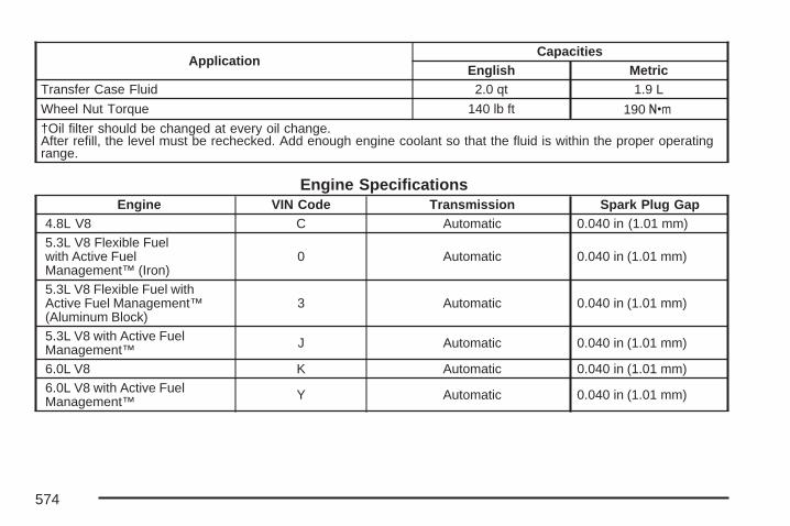
ApplicationCapacities
English MetricTransfer Case Fluid 2.0 qt 1.9 L
Wheel Nut Torque 140 lb ft 190 Y†Oil filter should be changed at every oil change.After refill, the level must be rechecked. Add enough engine coolant so that the fluid is within the proper operatingrange.
Engine SpecificationsEngine VIN Code Transmission Spark Plug Gap
4.8L V8 C Automatic 0.040 in (1.01 mm)5.3L V8 Flexible Fuelwith Active FuelManagement™ (Iron)
0 Automatic 0.040 in (1.01 mm)
5.3L V8 Flexible Fuel withActive Fuel Management™(Aluminum Block)
3 Automatic 0.040 in (1.01 mm)
5.3L V8 with Active FuelManagement™ J Automatic 0.040 in (1.01 mm)
6.0L V8 K Automatic 0.040 in (1.01 mm)6.0L V8 with Active FuelManagement™ Y Automatic 0.040 in (1.01 mm)
574

Maintenance Schedule ................................ 576Introduction ............................................... 576Maintenance Requirements ........................ 576Your Vehicle and the Environment ............ 576Using the Maintenance Schedule ............... 577Scheduled Maintenance ............................. 578Additional Required Services ..................... 581Maintenance Footnotes .............................. 582
Owner Checks and Services ..................... 584At Each Fuel Fill ....................................... 585At Least Once a Month ............................. 585At Least Once a Year ............................... 586Recommended Fluids and Lubricants ........ 588Normal Maintenance Replacement Parts ... 590Engine Drive Belt Routing ......................... 591Maintenance Record .................................. 592
Section 6 Maintenance Schedule
575
Maintenance Schedule
IntroductionImportant: Keep engine oil at the proper leveland change as recommended.
Have you purchased the GM Protection Plan? ThePlan supplements your new vehicle warranties.See your Warranty and Owner Assistance bookletor your dealer for details.
Maintenance Requirements
Notice: Maintenance intervals, checks,inspections, replacement parts, andrecommended fluids and lubricants asprescribed in this manual are necessary tokeep your vehicle in good working condition.Any damage caused by failure to followscheduled maintenance might not be coveredby warranty.
Your Vehicle and the EnvironmentProper vehicle maintenance not only helps to keepyour vehicle in good working condition, but alsohelps the environment. All recommendedmaintenance is important. Improper vehiclemaintenance can even affect the quality of the airwe breathe. Improper fluid levels or the wrongtire inflation can increase the level of emissionsfrom your vehicle. To help protect our environment,and to keep your vehicle in good condition, besure to maintain your vehicle properly.
576

Using the Maintenance ScheduleWe at General Motors want to help you keep yourvehicle in good working condition. But we donot know exactly how you will drive it. You maydrive very short distances only a few times a week.Or you may drive long distances all the time invery hot, dusty weather. You may use your vehiclein making deliveries. Or you may drive it towork, to do errands, or in many other ways.
Because of all the different ways people use theirvehicles, maintenance needs vary. You mayneed more frequent checks and replacements. Soplease read the following and note how youdrive. If you have any questions on how to keepyour vehicle in good condition, see your GMGoodwrench® dealer.
This schedule is for vehicles that:
• carry passengers and cargo withinrecommended limits. You will find these limitson the Tire and Loading Information label.See Loading Your Vehicle on page 411.
• are driven on reasonable road surfaces withinlegal driving limits.
• are driven off-road in the recommendedmanner. See Off-Road Driving on page 377.
• use the recommended fuel. See GasolineOctane on page 453.
The services in Scheduled Maintenance onpage 578 should be performed when indicated.See Additional Required Services on page 581 andMaintenance Footnotes on page 582 for furtherinformation.
{CAUTION:
Performing maintenance work on avehicle can be dangerous. In trying to dosome jobs, you can be seriously injured.Do your own maintenance work only ifyou have the required know-how and theproper tools and equipment for the job. Ifyou have any doubt, see your GMGoodwrench® dealer to have a qualifiedtechnician do the work. See Doing YourOwn Service Work on page 451.
577

Some maintenance services can be complex. So,unless you are technically qualified and havethe necessary equipment, you should have yourGM Goodwrench® dealer do these jobs.
When you go to your GM Goodwrench® dealer foryour service needs, you will know that GM-trainedand supported service technicians will performthe work using genuine GM parts.
If you want to purchase service information, seeService Publications Ordering Information onpage 613.
Owner Checks and Services on page 584 tells youwhat should be checked, when to check it, andwhat you can easily do to help keep your vehicle ingood condition.
The proper replacement parts, fluids, andlubricants to use are listed in RecommendedFluids and Lubricants on page 588 and NormalMaintenance Replacement Parts on page 590.When your vehicle is serviced, make sure theseare used. All parts should be replaced and allnecessary repairs done before you or anyone elsedrives the vehicle. We recommend the use ofgenuine GM parts.
Scheduled MaintenanceWhen the CHANGE ENGINE OIL SOON messagecomes on, it means that service is required foryour vehicle. Have your vehicle serviced as soonas possible within the next 600 miles (1 000 km).It is possible that, if you are driving under the bestconditions, the engine oil life system may notindicate that vehicle service is necessary for overa year. However, your engine oil and filtermust be changed at least once a year and at thistime the system must be reset. Your GMGoodwrench® dealer has GM-trained servicetechnicians who will perform this work usinggenuine GM parts and reset the system.
If the engine oil life system is ever resetaccidentally, you must service your vehicle within3,000 miles (5 000 km) since your last service.Remember to reset the oil life system wheneverthe oil is changed. See Engine Oil Life System onpage 466 for information on the Engine Oil LifeSystem and resetting the system.
578

When the CHANGE ENGINE OIL SOON messageappears, certain services, checks, and inspectionsare required. Required services are describedin the following for “Maintenance I” and“Maintenance II.” Generally, it is recommendedthat your first service be Maintenance I, yoursecond service be Maintenance II, and that youalternate Maintenance I and Maintenance IIthereafter. However, in some cases,Maintenance II may be required more often.
Maintenance I — Use Maintenance I if theCHANGE ENGINE OIL SOON message comes onwithin 10 months since the vehicle was purchasedor Maintenance II was performed.
Maintenance II — Use Maintenance II if theprevious service performed was Maintenance I.Always use Maintenance II whenever the messagecomes on 10 months or more since the lastservice or if the message has not come on at allfor one year.
Scheduled MaintenanceService Maintenance I Maintenance II
Change engine oil and filter. See Engine Oil on page 463. Reset oil life system.See Engine Oil Life System on page 466. An Emission Control Service. • •
Lubricate chassis components. See footnote #. • •
Visually check for any leaks or damage. See footnote (j). • •
Inspect engine air cleaner filter or change indicator (if equipped). If necessary,replace filter. See Engine Air Cleaner/Filter on page 468. See footnote (l). •
Rotate tires and check inflation pressures and wear. See Tire Inspection andRotation on page 524 and “Tire Wear Inspection” in At Least Once a Month onpage 585.
• •
Inspect brake system. See footnote (a). • •
579

Scheduled Maintenance (cont’d)Service Maintenance I Maintenance II
Check engine coolant and windshield washer fluid levels and add fluid asneeded. • •
Perform any needed additional services. See “Additional Required Services” inthis section. • •
Inspect suspension and steering components. See footnote (b). •
Inspect engine cooling system. See footnote (c). •
Inspect wiper blades. See footnote (d). •
Inspect restraint system components. See footnote (e). •
Lubricate body components. See footnote (f). •
Check transmission fluid level and add fluid as needed. •
580

Additional Required ServicesThe following services should be performed at the first maintenance service (I or II) after the indicatedmiles (kilometers) shown for each item.
Additional Required Services
Service and Miles (Kilometers) 25,000(40 000)
50,000(80 000)
75,000(120 000)
100,000(160 000)
125,000(200 000)
150,000(240 000)
Inspect fuel system for damageor leaks. • • • • • •
Inspect exhaust system for loose ordamaged components. • • • • • •
Vehicles without a filter restrictionindicator: Replace engine air cleanerfilter. See Engine Air Cleaner/Filter onpage 468.
• • •
Change automatic transmissionfluid and filter (severe service).See footnote (h).
• • •
Change automatic transmission fluidand filter (normal service). •
Four-wheel drive: Change transfer casefluid. See footnote (g). • • •
Inspect evaporative control system.An Emission Control Service.See footnotes † and (k).
• • •
581

Additional Required Services (cont’d)
Service and Miles (Kilometers) 25,000(40 000)
50,000(80 000)
75,000(120 000)
100,000(160 000)
125,000(200 000)
150,000(240 000)
Replace spark plugs and inspect sparkplug wires. An Emission ControlService.
•
Engine cooling system service (or everyfive years, whichever occurs first).An Emission Control Service.See footnote (i).
•
Inspect engine accessory drive belt.An Emission Control Service.See footnote (m).
•
Maintenance Footnotes† The U.S. Environmental Protection Agency orthe California Air Resources Board has determinedthat the failure to perform this maintenance itemwill not nullify the emission warranty or limitrecall liability prior to the completion of thevehicle’s useful life. We, however, urge that allrecommended maintenance services be performedat the indicated intervals and the maintenancebe recorded.
# Lubricate the front suspension, steering linkage,transmission shift linkage, and parking brake cableguides. Control arm ball joints on 2500 seriesvehicles require lubrication but should not belubricated unless their temperature is 10°F (−12°C)or higher, or they could be damaged. Control armball joints on 1500 series vehicles aremaintenance-free.
582

(a) Visually inspect brake lines and hoses forproper hook-up, binding, leaks, cracks, chafing,etc. Inspect disc brake pads for wear and rotors forsurface condition. Inspect other brake parts,including calipers, parking brake, etc.
(b) Visually inspect front and rear suspension andsteering system for damaged, loose, or missingparts, signs of wear, or lack of lubrication. Inspectpower steering lines and hoses for properhook-up, binding, leaks, cracks, chafing, etc.Visually check constant velocity joints, rubberboots, and axle seals for leaks.
(c) Visually inspect hoses and have them replacedif they are cracked, swollen, or deteriorated.Inspect all pipes, fittings, and clamps; replace withgenuine GM parts as needed. To help ensureproper operation, a pressure test of the coolingsystem and pressure cap and cleaning the outsideof the radiator and air conditioning condenser isrecommended at least once a year.
(d) Visually inspect wiper blades for wear orcracking. Replace wiper blades that appear wornor damaged or that streak or miss areas ofthe windshield.
(e) Make sure the safety belt reminder light and allyour belts, buckles, latch plates, retractors, andanchorages are working properly. Look forany other loose or damaged safety belt systemparts. If you see anything that might keep a safetybelt system from doing its job, have it repaired.Have any torn or frayed safety belts replaced. Alsolook for any opened or broken airbag coverings,and have them repaired or replaced. Theairbag system does not need regular maintenance.
(f) Lubricate all key lock cylinders, hood latchassembly, secondary latch, pivots, spring anchor,release pawl, rear compartment hinges, outerliftgate handle pivot points, rear door detent link,roller mechanism, liftgate handle pivot points, latchbolt, fuel door hinge, cargo door hinge, locks,and folding seat hardware. More frequentlubrication may be required when exposed to acorrosive environment. Applying silicone grease onweatherstrips with a clean cloth will make themlast longer, seal better, and not stick or squeak.
(g) Check vent hose at transfer case for kinks andproper installation.
583

(h) Change automatic transmission fluid and filterif the vehicle is mainly driven under one ormore of these conditions:
− In heavy city traffic where the outsidetemperature regularly reaches 90°F (32°C) orhigher.
− In hilly or mountainous terrain.− When doing frequent trailer towing.− Uses such as found in taxi, police, or delivery
service.
(i) Drain, flush, and refill cooling system. Thisservice can be complex; you should haveyour dealer perform this service. See EngineCoolant on page 475 for what to use. Inspecthoses. Clean radiator, condenser, pressure cap,and filler neck. Pressure test the coolingsystem and pressure cap.
(j) A fluid loss in any vehicle system could indicatea problem. Have the system inspected andrepaired and the fluid level checked. Add fluid ifneeded.
(k) Inspect system. Check all fuel and vapor linesand hoses for proper hook-up, routing, andcondition. Check that the purge valve worksproperly, if equipped. Replace as needed.
(l) If you drive regularly under dusty conditions,inspect the filter at each engine oil change.
(m) Visually inspect belt for fraying, excessivecracks, or obvious damage. Replace belt ifnecessary.
Owner Checks and ServicesThese owner checks and services should beperformed at the intervals specified to help ensurethe safety, dependability, and emission controlperformance of your vehicle. Your GMGoodwrench® dealer can assist you with thesechecks and services.
Be sure any necessary repairs are completed atonce. Whenever any fluids or lubricants are addedto your vehicle, make sure they are the properones, as shown in Recommended Fluids andLubricants on page 588.
584

At Each Fuel FillIt is important to perform these underhood checksat each fuel fill.
Engine Oil Level CheckCheck the engine oil level and add the proper oil ifnecessary. See Engine Oil on page 463 forfurther details.
Notice: It is important to check the engine oilregularly and keep it at the proper level.Failure to keep the engine oil at the properlevel can cause damage to the engine notcovered by your warranty.
Engine Coolant Level CheckCheck the engine coolant level and addDEX-COO® coolant mixture if necessary. SeeEngine Coolant on page 475 for further details.
Windshield Washer Fluid Level CheckCheck the windshield washer fluid level inthe windshield washer fluid reservoir and add theproper fluid if necessary.
At Least Once a Month
Tire Inflation CheckVisually inspect your vehicle’s tires and makesure they are inflated to the correct pressures.Do not forget to check the spare tire. SeeInflation - Tire Pressure on page 518. Check tomake sure the spare tire is stored securely.See Changing a Flat Tire on page 534.
Tire Wear InspectionTire rotation may be required for high mileagehighway drivers prior to the Engine Oil Life Systemservice notification. Check the tires for wearand, if necessary, rotate the tires. See TireInspection and Rotation on page 524.
585

At Least Once a Year
Starter Switch Check
{CAUTION:
When you are doing this inspection, thevehicle could move suddenly. If the vehiclemoves, you or others could be injured.
1. Before you start, be sure you have enoughroom around the vehicle.
2. Firmly apply both the parking brake and theregular brake. See Parking Brake onpage 160.Do not use the accelerator pedal, and beready to turn off the engine immediately ifit starts.
3. Try to start the engine in each gear. Thevehicle should start only in PARK (P) orNEUTRAL (N). If the vehicle starts in anyother position, contact your GM Goodwrench®
dealer for service.
Automatic Transmission Shift LockControl System Check
{CAUTION:
When you are doing this inspection, thevehicle could move suddenly. If the vehiclemoves, you or others could be injured.
1. Before you start, be sure you have enoughroom around the vehicle. It should be parkedon a level surface.
2. Firmly apply the parking brake. See ParkingBrake on page 160.Be ready to apply the regular brakeimmediately if the vehicle begins to move.
3. With the engine off, turn the ignition to RUN,but do not start the engine. Without applyingthe regular brake, try to move the shiftlever out of PARK (P) with normal effort. If theshift lever moves out of PARK (P), contactyour GM Goodwrench® dealer for service.
586

Ignition Transmission Lock CheckWhile parked, and with the parking brake set, tryto turn the ignition to LOCK in each shift leverposition.
• The ignition should turn to LOCK only whenthe shift lever is in PARK (P).
• The ignition key should come out only in LOCK.
Contact your GM Goodwrench® dealer if service isrequired.
Parking Brake and AutomaticTransmission Park (P) Mechanism Check
{CAUTION:
When you are doing this check, yourvehicle could begin to move. You orothers could be injured and propertycould be damaged. Make sure there isroom in front of your vehicle in case itbegins to roll. Be ready to apply theregular brake at once should the vehiclebegin to move.
Park on a fairly steep hill, with the vehicle facingdownhill. Keeping your foot on the regularbrake, set the parking brake.
• To check the parking brake’s holdingability: With the engine running andtransmission in NEUTRAL (N), slowly removefoot pressure from the regular brake pedal.Do this until the vehicle is held by the parkingbrake only.
• To check the PARK (P) mechanism’s holdingability: With the engine running, shift toPARK (P). Then release the parking brakefollowed by the regular brake.
Contact your GM Goodwrench® dealer if serviceis required.
587

Hood and Liftgate Support Gas StrutServiceVisually inspect gas strut for signs of wear,corrosion, cracks, loss of lubricant, or otherdamage. Check the hold open ability of gas strut.If necessary, replace with genuine GM parts.
Underbody Flushing ServiceAt least every spring, use plain water to flush anycorrosive materials from the underbody. Takecare to clean thoroughly any areas where mud andother debris can collect.
Recommended Fluids andLubricantsFluids and lubricants identified below by name,part number, or specification can be obtained fromyour dealer.
Usage Fluid/Lubricant
Engine Oil
Engine oil which meets GMStandard GM6094M and displaysthe American Petroleum InstituteCertified for Gasoline Enginesstarburst symbol. GM Goodwrench®
oil meets all the requirements foryour vehicle. To determine theproper viscosity for your vehicle’sengine, see Engine Oil on page 463.
Engine Coolant
50/50 mixture of clean, drinkablewater and use only DEX-COOL®
Coolant. See Engine Coolant onpage 475.
Hydraulic BrakeSystem
Delco® Supreme 11 Brake Fluid orequivalent DOT-3 brake fluid.
WindshieldWasher GM Optikleen® Washer Solvent.
Power SteeringSystem
GM Power Steering Fluid(GM Part No. U.S. 89021184,in Canada 89021186).
588
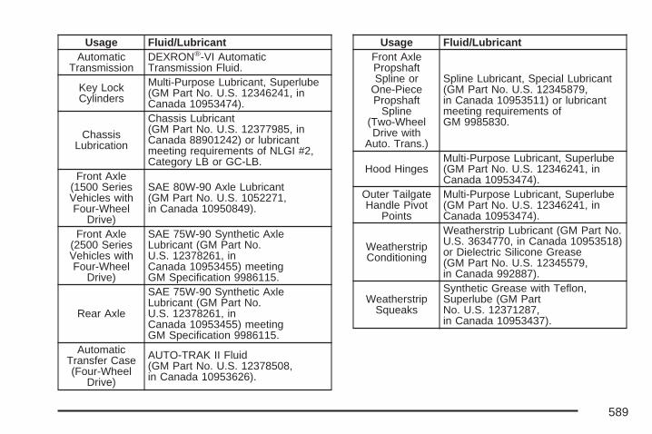
Usage Fluid/LubricantAutomatic
TransmissionDEXRON®-VI AutomaticTransmission Fluid.
Key LockCylinders
Multi-Purpose Lubricant, Superlube(GM Part No. U.S. 12346241, inCanada 10953474).
ChassisLubrication
Chassis Lubricant(GM Part No. U.S. 12377985, inCanada 88901242) or lubricantmeeting requirements of NLGI #2,Category LB or GC-LB.
Front Axle(1500 SeriesVehicles withFour-Wheel
Drive)
SAE 80W-90 Axle Lubricant(GM Part No. U.S. 1052271,in Canada 10950849).
Front Axle(2500 SeriesVehicles withFour-Wheel
Drive)
SAE 75W-90 Synthetic AxleLubricant (GM Part No.U.S. 12378261, inCanada 10953455) meetingGM Specification 9986115.
Rear Axle
SAE 75W-90 Synthetic AxleLubricant (GM Part No.U.S. 12378261, inCanada 10953455) meetingGM Specification 9986115.
AutomaticTransfer Case(Four-Wheel
Drive)
AUTO-TRAK II Fluid(GM Part No. U.S. 12378508,in Canada 10953626).
Usage Fluid/LubricantFront AxlePropshaftSpline or
One-PiecePropshaft
Spline(Two-WheelDrive with
Auto. Trans.)
Spline Lubricant, Special Lubricant(GM Part No. U.S. 12345879,in Canada 10953511) or lubricantmeeting requirements ofGM 9985830.
Hood HingesMulti-Purpose Lubricant, Superlube(GM Part No. U.S. 12346241, inCanada 10953474).
Outer TailgateHandle Pivot
Points
Multi-Purpose Lubricant, Superlube(GM Part No. U.S. 12346241, inCanada 10953474).
WeatherstripConditioning
Weatherstrip Lubricant (GM Part No.U.S. 3634770, in Canada 10953518)or Dielectric Silicone Grease(GM Part No. U.S. 12345579,in Canada 992887).
WeatherstripSqueaks
Synthetic Grease with Teflon,Superlube (GM PartNo. U.S. 12371287,in Canada 10953437).
589
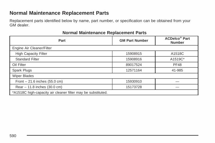
Normal Maintenance Replacement PartsReplacement parts identified below by name, part number, or specification can be obtained from yourGM dealer.
Normal Maintenance Replacement Parts
Part GM Part Number ACDelco® PartNumber
Engine Air Cleaner/Filter
High Capacity Filter 15908915 A1518C
Standard Filter 15908916 A1519C*
Oil Filter 89017524 PF48
Spark Plugs 12571164 41-985
Wiper Blades
Front – 21.6 inches (55.0 cm) 15930910 —
Rear – 11.8 inches (30.0 cm) 15173728 —
*A1518C high-capacity air cleaner filter may be substituted.
590

Engine Drive Belt Routing
591

Maintenance RecordAfter the scheduled services are performed, record the date, odometer reading, who performed theservice, and the type of services performed in the boxes provided. See Maintenance Requirements onpage 576. Any additional information from Owner Checks and Services on page 584 can be added on thefollowing record pages. You should retain all maintenance receipts.
Maintenance Record
Date OdometerReading Serviced By Maintenance I or
Maintenance II Services Performed
592

Maintenance Record (cont’d)
Date OdometerReading Serviced By Maintenance I or
Maintenance II Services Performed
593

Maintenance Record (cont’d)
Date OdometerReading Serviced By Maintenance I or
Maintenance II Services Performed
594

Customer Assistance and Information ....... 596Customer Satisfaction Procedure ............... 596Online Owner Center ................................. 598Customer Assistance for Text
Telephone (TTY) Users .......................... 599Customer Assistance Offices ..................... 600GM Mobility Reimbursement Program ........ 601Roadside Assistance Program ................... 601Courtesy Transportation ............................. 604Vehicle Data Collection and Event
Data Recorders ...................................... 607Collision Damage Repair ........................... 608
Reporting Safety Defects ............................ 612Reporting Safety Defects to the
United States Government ..................... 612Reporting Safety Defects to the
Canadian Government ............................ 612Reporting Safety Defects to General
Motors ................................................... 612Service Publications Ordering Information .... 613
Section 7 Customer Assistance Information
595
Customer Assistance andInformation
Customer Satisfaction ProcedureYour satisfaction and goodwill are importantto your dealer/retailer and to GMC. Normally, anyconcerns with the sales transaction or theoperation of the vehicle will be resolved by yourdealer’s/retailer’s sales or service departments.Sometimes, however, despite the best intentions ofall concerned, misunderstandings can occur. Ifyour concern has not been resolved to yoursatisfaction, the following steps should be taken:
STEP ONE: Discuss your concern with a memberof dealership/retailer management. Normally,concerns can be quickly resolved at that level. If thematter has already been reviewed with the sales,service or parts manager, contact the owner of thedealership/retailer or the general manager.
STEP TWO: If after contacting a member ofdealership/retailer management, it appears yourconcern cannot be resolved by the dealership/retailer without further help, in the U.S., contact theGMC Consumer Relations Manager by calling1-800-GMC-8782 (1-800-462-8782, CustomerAssistance prompt). In Canada, contact GeneralMotors of Canada Customer Communicationby calling 1-800-263-3777 (English) or1-800-263-7854 (French).
We encourage you to call the toll-free number inorder to give your inquiry prompt attention. Pleasehave the following information available to givethe Customer Assistance Representative:
• Vehicle Identification Number (VIN). This isavailable from the vehicle registration or title, orthe plate at the top left of the instrument paneland visible through the windshield.
• Dealership/retailer name and location.
• Vehicle delivery date and present mileage.
When contacting GMC, please remember that yourconcern will likely be resolved at a dealer’s/retailer’s facility. That is why we suggest you followStep One first if you have a concern.
596

STEP THREE — U.S. Owners: Both GeneralMotors and your dealer/retailer are committed tomaking sure you are completely satisfied with yournew vehicle. However, if you continue to remainunsatisfied after following the procedure outlined inSteps One and Two, you should file with theBetter Business Bureau (BBB) Auto Line Programto enforce your rights.
The BBB Auto Line Program is an out of courtprogram administered by the Council of BetterBusiness Bureaus to settle automotive disputesregarding vehicle repairs or the interpretationof the New Vehicle Limited Warranty. Although youmay be required to resort to this informal disputeresolution program prior to filling out a courtaction, use of the program is free of charge andyour case will generally be heard within 40 days. Ifyou do not agree with the decision given in yourcase, you may reject it and proceed with any othervenue for relief available to you.
You may contact the BBB Auto Line Programusing the toll-free telephone number or write themat the following address:
BBB Auto Line ProgramCouncil of Better Business Bureaus, Inc.4200 Wilson BoulevardSuite 800Arlington, VA 22203-1838
Telephone: 1-800-955-5100
This program is available in all 50 states and theDistrict of Columbia. Eligibility is limited byvehicle age, mileage, and other factors. GeneralMotors reserves the right to change eligibilitylimitations and/or discontinue its participation inthis program.
STEP THREE — Canadian Owners: In the eventthat you do not feel your concerns have beenaddressed after following the procedure outlined inSteps 1 and 2, General Motors of CanadaLimited wants you to be aware of its participationin a no-charge Mediation/Arbitration Program.General Motors of Canada Limited has committedto binding arbitration of owner disputes involvingfactory-related vehicle service claims.
597
The program provides for the review of the factsinvolved by an impartial third party arbiter,and may include an informal hearing before thearbiter. The program is designed so that the entiredispute settlement process, from the time youfile your complaint to the final decision, should becompleted in approximately 70 days. We believeour impartial program offers advantages overcourts in most jurisdictions because it is informal,quick, and free of charge.
For further information concerning eligibility in theCanadian Motor Vehicle Arbitration Plan(CAMVAP), call toll-free 1-800-207-0685.Alternatively, you can call the General MotorsCustomer Communication Centre, 1-800-263-3777(English), 1-800-263-7854 (French), or write to:
Mediation/Arbitration Programc/o Customer Communication CentreGeneral Motors of Canada LimitedMail Code: CA1-163-0051908 Colonel Sam DriveOshawa, Ontario L1H 8P7
Telephone: 1-800-955-5100
Your inquiry should be accompanied by yourVehicle Identification Number (VIN).
Online Owner Center
Online Owner Center (UnitedStates only)The Owner Center is a resource for your GMownership needs. Specific vehicle informationcan be found in one place.
The Online Owner Center allows you to:• Get e-mail service reminders.
• Access information about your specificvehicle, including tips and videos andan electronic version of this owner manual.
• Keep track of your vehicle’s service historyand maintenance schedule.
• Find GM dealers/retailers for servicenationwide.
• Receive special promotions and privilegesonly available to members.
Refer to www.MyGMLink.com on the web forupdated information and to register your vehicle.
598

My GM Canada (Canada only)My GM Canada is a password-protected sectionof gmcanada.com where you can save informationon GM vehicles, get personalized offers, anduse handy tools and forms with greater ease.
Here are a few of the valuable tools and servicesyou will have access to:
− My Showroom: Find and save information onvehicles and current offers in your area.
− My Dealers/Retailers: Save details such asaddress and phone number for each ofyour preferred GM Dealers or Retailers.
− My Driveway: Receive service reminders andhelpful advice on owning and maintainingyour vehicle.
− My Preferences: Manage your profile,subscribe to E-News and use tools and formswith greater ease.
To sign up to My GM Canada, visit the My GMCanada section within www.gmcanada.com.
Customer Assistance for TextTelephone (TTY) UsersTo assist customers who are deaf, hard ofhearing, or speech-impaired and who use the TextTelephones (TTYs), GMC has TTY equipmentavailable at its Customer Assistance Center. AnyTTY user can communicate with GMC bydialing: 1-800-GMC-8583 (462-8583). (TTY usersin Canada can dial 1-800-263-3830.)
599

Customer Assistance OfficesGMC encourages customers to call the toll-freenumber for assistance. However, if a customerwishes to write or e-mail GMC, the letter should beaddressed to:
United StatesGMC Customer Assistance CenterP.O. Box 33172Detroit, MI 48232-5172
www.GMC.com1-800-GMC-8782 (462-8782)1-800-GMC-8583 (462-8583)(For Text Telephone devices (TTYs))Roadside Assistance: 1-800-GMC-8782(1-800-462-8782)Fax Number: 313-381-0022
From Puerto Rico1-800-496-9992 (English)1-800-496-9993 (Spanish)Fax Number: 313-381-0022
U.S. Virgin Islands:1-800-496-9994Fax Number: 313-381-0022
CanadaGeneral Motors of Canada LimitedCustomer Communication Centre, CA1-163-0051908 Colonel Sam DriveOshawa, Ontario L1H 8P7
www.gmcanada.com1-800-263-3777 (English)1-800-263-7854 (French)1-800-263-3830 (For Text Telephonedevices (TTYs))Roadside Assistance: 1-800-268-6800
All Overseas LocationsPlease contact the local General MotorsBusiness Unit.
Mexico, Central America and CaribbeanIslands/Countries (Except PuertoRico and U.S. Virgin Islands)
General Motors de Mexico, S. de R.L. de C.V.Customer Assistance CenterPaseo de la Reforma # 2740Col. Lomas de BezaresC.P. 11910, Mexico, D.F.01-800-508-0000Long Distance: 011-52-53 29 0 800
600

GM Mobility ReimbursementProgram
This program, available to qualified applicants, canreimburse you up to $1,000 of the cost of eligibleaftermarket adaptive equipment required foryour vehicle, such as hand controls or awheelchair/scooter lift.
The offer is available for a very limited period oftime from the date of vehicle purchase/lease.For more details, or to determine your vehicle’seligibility, visit gmmobility.com or call the GMMobility Assistance Center at 1-800-323-9935.Text telephone (TTY) users, call 1-800-833-9935.
General Motors of Canada also has a MobilityProgram. Call 1-800-GM-DRIVE (463-7483)for details. TTY users call 1-800-263-3830.
Roadside Assistance ProgramIn the U.S. call, 1-800-GMC-8782(1-800-462-8782).
In Canada, call 1-800-268-6800.
Service is available 24 hours a day, 365 daysa year.
As the owner of a new GMC vehicle, you areautomatically enrolled in the GMC RoadsideAssistance program. This value-added service isintended to provide you with peace of mind as youdrive in the city or travel the open road.
601
Who is Covered?Roadside Assistance coverage is for the vehicleoperator, regardless of ownership. A person drivingthis vehicle without the consent of the owner isnot eligible for coverage.
The following services are provided in the U.S.during the Bumper-to-Bumper warranty period and,in Canada, during the Base Warranty coverageperiod of the New Vehicle Limited Warranty, up toa maximum coverage of $100.
• Fuel Delivery: Delivery of enough fuel for thecustomer to get to the nearest service station(approximately $5 in the U.S. and 10 litresin Canada). Service to provide diesel may berestricted. For safety reasons, propaneand other alternative fuels will not be providedthrough this service.
• Lock-out Service: To ensure security, thedriver must present the vehicle registrationand personal ID before lock-out serviceis provided. Lock-out service will be coveredat no charge if you are unable to gainentry into your vehicle.
• Emergency Tow From a Public Roadway orHighway: Tow to the nearest dealership/retailer for warranty service or in the event ofa vehicle-disabling accident. Winch-outassistance when the vehicle is mired in sand,mud, or snow.
• Flat Tire Change: Installation of a spare tirein good condition, when equipped andproperly inflated, will be covered at no charge.The customer is responsible for the repairor replacement of the tire if not covered by awarrantable failure.
• Jump Start: No-start occurrences whichrequire a battery jump start will be covered atno charge.
• Trip Routing: Your Roadside AssistanceRepresentative can provide you withspecific information regarding this feature.
• Trip Interruption Expense Benefits: YourRoadside Assistance Representative canprovide you with specific information regardingthis feature.
602

Additional Services for CanadianCustomers• Trip Routing Service: Upon request,
Roadside Assistance will send you detailed,computer- personalized maps, highlightingyour choice of either the most direct route orthe most scenic route to your destination,anywhere in North America, along withany helpful travel information we may havepertaining to your trip. To request this service,please call us toll-free at 1-800-268-6800.We will make every attempt to send yourpersonalized trip routing as quickly aspossible, but it is best to allow three weeksbefore your planned departure date. Triprouting requests will be limited to six percalendar year.
• Trip Interruption Benefits and Assistance:In the event of a warranty related vehicledisablement, while en route and over250 kilometres from original point of departure,you may qualify for trip interruption expenseassistance. This assistance covers reasonablereimbursement of up to a maximum of $500for (A) meals (maximum of $50/day),(B) lodging (maximum of $100/night) and
(C) alternate ground transportation (maximumof $40/day). This benefit is to assist youwith some of the unplanned expense you mayincur while waiting for your vehicle to berepaired.Pre-authorization, original detailed receipts,and a copy of the repair order are required.Once authorization has been given, youradvisor will help you make any necessaryarrangements and explain how to claim for tripinterruption expense assistance.
• Alternative Service: There may be times,when Roadside Assistance cannot providetimely assistance, your advisor may authorizeyou to secure local emergency road service,and you will be reimbursed up to $100upon submission of the original receipt toRoadside Assistance.
In many instances, mechanical failures are coveredunder GMC’s Bumper-to-Bumper warranty.However, when other services are utilized, ourRoadside Assistance Representatives will explainany payment obligations you might incur.
603

For prompt and efficient assistance when calling,please provide the following to the RoadsideAssistance Representative:
• Your name, home address, and hometelephone number.
• Telephone number of your location.
• Location of the vehicle.
• Model, year, color, and license plate numberof the vehicle.
• Odometer reading, Vehicle IdentificationNumber (VIN) and delivery date of the vehicle.
• Description of the problem.
While we hope you never have the occasion touse our service, it is added security while travelingfor you and your family. Remember, we areonly a phone call away. U.S. customers call GMCRoadside Assistance: 1-800-462-8782, texttelephone (TTY) users, call 1-888-889-2438.Canadian customers call 1-800-268-6800.
GMC and General Motors of Canada Limitedreserve the right to limit services or reimbursementto an owner or driver when, in their solediscretion, the claims become excessive infrequency or type of occurrence.
Roadside Assistance is not part of or included inthe coverage provided by the New Vehicle LimitedWarranty. GMC and General Motors of Canadareserve the right to make any changes ordiscontinue the Roadside Assistance program atany time without notification.
Towing and Road Service ExclusionsSpecifically excluded from Roadside Assistancecoverage are towing or services for vehiclesoperated on a non-public roadway or highway,fines, impound towing caused by a violationof local, Municipal, State, Provincial, or Federallaw, and mounting, dismounting or changingof snow tires, chains, or other traction devices.
Courtesy TransportationTo enhance your ownership experience, we andour participating dealers/retailers are proud to offerCourtesy Transportation, a customer supportprogram for new vehicles.
For warranty repairs during the Bumper-to-Bumper(U.S.) or Base Warranty Coverage period(Canada), provided by the New Vehicle LimitedWarranty, interim transportation may be availableunder the Courtesy Transportation program.
604

Several courtesy transportation options areavailable to assist in reducing your inconveniencewhen warranty repairs are required.
Courtesy Transportation is not a part of the NewVehicle Limited Warranty and is available onlyat participating dealers/retailers. A separatebooklet entitled “Warranty and Owner AssistanceInformation” furnished with each new vehicleprovides detailed warranty coverage information.
Scheduling Service AppointmentsWhen your vehicle requires warranty service,contact your dealer/retailer and request anappointment. By scheduling a service appointmentand advising your service consultant of yourtransportation needs, your dealer/retailer can helpminimize your inconvenience.
If your vehicle cannot be scheduled into theservice department immediately, keep driving ituntil it can be scheduled for service, unless,of course, the problem is safety-related. If it is,please call your dealership/retailer, let them knowthis, and ask for instructions.
If the dealer/retailer requests that you simply dropthe vehicle off for service, you are urged to doso as early in the work day as possible to allow forthe same day repair.
Transportation OptionsWarranty service can generally be completedwhile you wait. However, if you are unable to wait,GM helps to minimize your inconvenience byproviding several transportation options.Depending on the circumstances, yourdealer/retailer can offer you one of the following:
Shuttle ServiceShuttle service is the preferred means of offeringCourtesy Transportation and participatingdealers/retailers can provide you with shuttleservice to get you to your destination with minimalinterruption of your daily schedule. This includesone-way or round trip shuttle service withinreasonable time and distance parameters for thedealer’s/retailer’s area.
605

Public Transportation or FuelReimbursementIf your vehicle requires overnight warranty repairs,and public transportation is used as ‘shuttleservice,’ the reimbursement is limited to theassociated shuttle allowance and must besupported by original receipts. In addition, for U.S.customers, should you arrange transportationthrough a friend or relative, limited reimbursementfor reasonable fuel expenses may be available.Claim amounts should reflect actual costs and besupported by original receipts.
Courtesy Rental VehicleYour dealer/retailer may arrange to provide youwith a courtesy rental vehicle or reimburse you for arental vehicle that you obtain if your vehicle is keptfor an overnight warranty repair. Rentalreimbursement will be limited and must besupported by original receipts. This requires thatyou sign and complete a rental agreement andmeet state/provincial, local, and rental vehicleprovider requirements. Requirements vary and may
include minimum age requirements, insurancecoverage, credit card, etc. You are responsible forfuel usage charges and may also be responsible fortaxes, levies, usage fees, excessive mileage, orrental usage beyond the completion of the repair.
Generally it is not possible to provide a like-vehicleas a courtesy rental.
Additional Program InformationAll program options, such as shuttle service, maynot be available at every dealer/retailer. Pleasecontact your dealer/retailer for specific informationabout availability. All Courtesy Transportationarrangements will be administered by appropriatedealer/retailer personnel.
General Motors reserves the right to unilaterallymodify, change or discontinue CourtesyTransportation at any time and to resolve allquestions of claim eligibility pursuant to the termsand conditions described herein at its solediscretion.
606
Vehicle Data Collection and EventData RecordersYour vehicle, like other modern motor vehicles,has a number of sophisticated computersystems that monitor and control severalaspects of the vehicle’s performance. Yourvehicle uses on-board vehicle computersto monitor emission control components tooptimize fuel economy, to monitor conditionsfor airbag deployment and, if so equipped,to provide anti-lock braking and to helpthe driver control the vehicle in difficult drivingsituations. Some information may be storedduring regular operations to facilitate repair ofdetected malfunctions; other information isstored only in a crash event by computersystems, such as those commonly called EventData Recorders (EDR).
In a crash event, computer systems, such asthe airbag Sensing and Diagnostic Module(SDM) in your vehicle may record informationabout the condition of the vehicle and howit was operated, such as data related to enginespeed, brake application, throttle position,vehicle speed, safety belt usage, airbag
readiness, airbag performance, and theseverity of a collision. If your vehicle isequipped with StabiliTrak®, steeringperformance, including yaw rate, steeringwheel angle, and lateral acceleration, is alsorecorded. This information has been usedto improve vehicle crash performance and maybe used to improve crash performance offuture vehicles and driving safety. Unlike thedata recorders on many airplanes, theseon-board systems do not record sounds, suchas conversation of vehicle occupants.
To read this information, special equipment isneeded and access to the vehicle or thedevice that stores the data is required. GM willnot access information about a crash eventor share it with others other than:• with the consent of the vehicle owner or, if
the vehicle is leased, with the consent ofthe lessee,
• in response to an official request of policeor similar government office,
• as part of GM’s defense of litigationthrough the discovery process, or
• as required by law.
607
In addition, once GM collects or receives data,GM may:• use the data for GM research needs,
• make it available for research whereappropriate confidentiality is to bemaintained and need is shown, or
• share summary data which is not tied to aspecific vehicle with non-GM organizationsfor research purposes.
Others, such as law enforcement, may haveaccess to the special equipment that can readthe information if they have access to thevehicle or the device that stores the data.
If your vehicle has OnStar®, please check theOnStar® subscription service agreement ormanual for information on its operations anddata collection.
Collision Damage RepairIf your vehicle is involved in a collision and it isdamaged, have the damage repaired by a qualifiedtechnician using the proper equipment andquality replacement parts. Poorly performed
collision repairs will diminish your vehicle’s resalevalue, and safety performance can becompromised in subsequent collisions.
Collision PartsGenuine GM Collision parts are new parts madewith the same materials and construction methodsas the parts with which your vehicle wasoriginally built. Genuine GM Collision parts areyour best choice to assure that your vehicle’sdesigned appearance, durability, and safety arepreserved. The use of Genuine GM parts can helpmaintain your GM New Vehicle Warranty.
Recycled original equipment parts may also beused for repair. These parts are typically removedfrom vehicles that were total losses in prioraccidents. In most cases, the parts being recycledare from undamaged sections of the vehicle. Arecycled original equipment GM part, maybe an acceptable choice to maintain your vehicle’soriginally designed appearance and safetyperformance, however, the history of these partsis not known. Such parts are not covered byyour GM New Vehicle Limited Warranty, and anyrelated failures are not covered by that warranty.
608

Aftermarket collision parts are also available.These are made by companies other than GM andmay not have been tested for your vehicle. As aresult, these parts may fit poorly, exhibit prematuredurability/corrosion problems, and may not performproperly in subsequent collisions. Aftermarket partsare not covered by your GM New Vehicle LimitedWarranty, and any vehicle failure related to suchparts are not covered by that warranty.
Repair FacilityGM also recommends that you choose a collisionrepair facility that meets your needs before youever need collision repairs. Your GM dealer/retailermay have a collision repair center with GM-trainedtechnicians and state of the art equipment, orbe able to recommend a collision repair center thathas GM-trained technicians and comparableequipment.
Insuring Your VehicleProtect your investment in your GM vehicle withcomprehensive and collision insurance coverage.There are significant differences in the qualityof coverage afforded by various insurance policyterms. Many insurance policies provide reducedprotection to your GM vehicle by limitingcompensation for damage repairs by usingaftermarket collision parts. Some insurancecompanies will not specify aftermarket collisionparts. When purchasing insurance, we recommendthat you assure your vehicle will be repairedwith GM original equipment collision parts. If suchinsurance coverage is not available from yourcurrent insurance carrier, consider switchingto another insurance carrier.
If your vehicle is leased, the leasing company mayrequire you to have insurance that assuresrepairs with Genuine GM Original EquipmentManufacturer (OEM) parts or GenuineManufacturer replacement parts. Read your leasecarefully, as you may be charged at the end ofyour lease for poor quality repairs.
609

If an Accident OccursHere is what to do if you are involved in anaccident.
• Try to relax and then check to make sure youare all right. If you are uninjured, make surethat no one else in your vehicle, or theother vehicle, is injured.
• If there has been an injury, call 911 for help.Do not leave the scene of an accident until allmatters have been taken care of. Move yourvehicle only if its position puts you in danger oryou are instructed to move it by a police officer.
• Give only the necessary and requestedinformation to police and other parties involvedin the accident. Do not discuss your personalcondition, mental frame of mind, or anythingunrelated to the accident. This will help guardagainst post-accident legal action.
• If you need roadside assistance, call GMRoadside Assistance. See RoadsideAssistance Program on page 601 for moreinformation.
• If your vehicle cannot be driven, know wherethe towing service will be taking it. Get a cardfrom the tow truck operator or write down thedriver’s name, the service’s name, and thephone number.
• Remove any valuables from your vehicle beforeit is towed away. Make sure this includes yourinsurance information and registration if youkeep these items in your vehicle.
• Gather the important information you will needfrom the other driver. Things like name,address, phone number, driver’s licensenumber, vehicle license plate, vehicle make,model and model year, Vehicle IdentificationNumber (VIN), insurance company and policynumber, and a general description of thedamage to the other vehicle.
• If possible, call your insurance company fromthe scene of the accident. They will walk youthrough the information they will need. If theyask for a police report, phone or go to the policedepartment headquarters the next day and youcan get a copy of the report for a nominal fee. Insome states/provinces with “no fault” insurancelaws, a report may not be necessary. This isespecially true if there are no injuries and bothvehicles are driveable.
610
• Choose a reputable collision repair facility foryour vehicle. Whether you select a GM dealer/retailer or a private collision repair facility to fixthe damage, make sure you are comfortablewith them. Remember, you will have to feelcomfortable with their work for a long time.
• Once you have an estimate, read it carefullyand make sure you understand what work willbe performed on your vehicle. If you have aquestion, ask for an explanation. Reputableshops welcome this opportunity.
Managing the Vehicle Damage RepairProcessIn the event that your vehicle requires damagerepairs, GM recommends that you take an activerole in its repair. If you have a pre-determinedrepair facility of choice, take your vehicle there, orhave it towed there. Specify to the facility thatany required replacement collision parts be originalequipment parts, either new Genuine GM partsor recycled original GM parts. Remember, recycledparts will not be covered by your GM vehiclewarranty.
Insurance pays the bill for the repair, but you mustlive with the repair. Depending on your policylimits, your insurance company may initially valuethe repair using aftermarket parts. Discuss thiswith your repair professional, and insist onGenuine GM parts. Remember if your vehicle isleased you may be obligated to have thevehicle repaired with Genuine GM parts, even ifyour insurance coverage does not pay the full cost.
If another party’s insurance company is payingfor the repairs, you are not obligated to accept arepair valuation based on that insurancecompany’s collision policy repair limits, as youhave no contractual limits with that company. Insuch cases, you can have control of the repair andparts choices as long as cost stays withinreasonable limits.
611

Reporting Safety Defects
Reporting Safety Defects to theUnited States GovernmentIf you believe that your vehicle has a defect whichcould cause a crash or could cause injury ordeath, you should immediately inform the NationalHighway Traffic Safety Administration (NHTSA),in addition to notifying General Motors.
If NHTSA receives similar complaints, it may openan investigation, and if it finds that a safety defectexists in a group of vehicles, it may order a recalland remedy campaign. However, NHTSA cannotbecome involved in individual problems betweenyou, your dealer/retailer, or General Motors.
To contact NHTSA, you may call the VehicleSafety Hotline toll-free at 1-888-327-4236(TTY: 1-800-424-9153); go tohttp://www.safercar.gov; or write to:
Administrator, NHTSA400 Seventh Street, SW.Washington, D.C. 20590
You can also obtain other information about motorvehicle safety from http://www.safercar.gov.
Reporting Safety Defects to theCanadian GovernmentIf you live in Canada, and you believe that yourvehicle has a safety defect, you shouldimmediately notify Transport Canada, in additionto notifying General Motors of Canada Limited.You may call them at 1-800-333-0510 or write to:
Transport CanadaRoad Safety Branch2780 Sheffield RoadOttawa, Ontario K1B 3V9
Reporting Safety Defects to GeneralMotorsIn addition to notifying NHTSA (or TransportCanada) in a situation like this, we certainly hopeyou will notify us. Please call us at1-800-GMC-8782 (1-800-462-8782), or write:
GMC Customer Assistance CenterP.O. Box 33172Detroit, MI 48232-5172
612

In Canada, please call us at 1-800-263-3777(English) or 1-800-263-7854 (French). Or, write:
General Motors of Canada LimitedCustomer Communication Centre, CA1-163-0051908 Colonel Sam DriveOshawa, Ontario L1H 8P7
Service Publications OrderingInformation
Service ManualsService Manuals have the diagnosis and repairinformation on engines, transmission, axlesuspension, brakes, electrical, steering, body, etc.
Transmission, Transaxle, TransferCase Unit Repair ManualThis manual provides information on unit repairservice procedures, adjustments, andspecifications for GM transmissions, transaxles,and transfer cases.
Service BulletinsService Bulletins give technical service informationneeded to knowledgeably service GeneralMotors cars and trucks. Each bulletin containsinstructions to assist in the diagnosis and serviceof your vehicle.
In Canada, the service bulletin reference numbercan be obtained by contacting your GeneralMotors dealer/retailer or by calling1-800-GM-DRIVE (1-800-463-7483). Thisreference number is needed to order the servicebulletin from Helm, Inc.
RETAIL SELL PRICE: $6.00 US + Processing Fee
613

Owner InformationOwner publications are written specifically forowners and intended to provide basic operationalinformation about the vehicle. The ownermanual will include the Maintenance Schedule forall models.
In-Portfolio: Includes a Portfolio, Owner Manual,and Warranty Booklet.
RETAIL SELL PRICE: $35.00 US +Processing Fee
Without Portfolio: Owner’s Manual only.
RETAIL SELL PRICE: $25.00 US +Processing Fee
Current and Past Model Order FormsTechnical Service Bulletins and Manuals areavailable for current and past model GM vehicles.To request an order form, please specify yearand model name of the vehicle.
ORDER TOLL FREE: 1-800-551-4123Monday-Friday 8:00 AM - 6:00 PMEastern TimeFor Credit Card Orders Only(VISA-MasterCard-Discover), visit Helm, Inc. onthe World Wide Web at: www.helminc.com
Or you can write to:
Helm, IncorporatedP.O. Box 07130Detroit, MI 48207
Prices are subject to change without notice andwithout incurring obligation. Allow ample timefor delivery.
Note to Canadian Customers: All listed prices arequoted in U.S. funds. Canadian residents areto make checks payable in U.S. funds.
614

AAccessories and Modifications ..................... 450Adding a Snow Plow or Similar
Equipment ................................................ 418Adding Equipment to Your
Airbag-Equipped Vehicle ........................... 111Additives, Fuel ............................................ 454Add-On Electrical Equipment ....................... 565Adjustable Throttle and Brake Pedal ............ 147Air Cleaner/Filter, Engine ............................. 468Air Conditioning .................................. 227, 231Airbag
Passenger Status Indicator ....................... 246Readiness Light ....................................... 245
Airbag Sensing and DiagnosticModule (SDM) .......................................... 607
Airbag System ............................................... 93What Will You See After an
Airbag Inflates? ..................................... 103When Should an Airbag Inflate? ............... 100Where Are the Airbags? ............................. 97
Airbag SystemsAdding Equipment to Your
Airbag-Equipped Vehicle ....................... 111How Does an Airbag Restrain? ................ 102
Airbag Systems (cont.)Passenger Sensing System ...................... 104Servicing Your Airbag-Equipped Vehicle ..... 110What Makes an Airbag Inflate? ................ 102
Antenna, Rear Side Window ........................ 356Antenna, XM™ Satellite Radio Antenna
System .................................................... 357Anti-Lock Brake System .............................. 365Anti-Lock Brake, System Warning Light ....... 251Appearance Care
Aluminum or Chrome-Plated Wheels ........ 561Care of Safety Belts ................................ 558Chemical Paint Spotting ........................... 563Cleaning Exterior Lamps/Lenses .............. 559Cleaning the Inside of Your Vehicle .......... 555Fabric/Carpet ........................................... 556Finish Care .............................................. 559Finish Damage ......................................... 562Instrument Panel, Vinyl, and Other
Plastic Surfaces .................................... 558Leather .................................................... 557Sheet Metal Damage ............................... 562Tires ........................................................ 562Underbody Maintenance ........................... 563Vehicle Care/Appearance Materials .......... 564Washing Your Vehicle .............................. 559
615

Appearance Care (cont.)Weatherstrips ........................................... 558Windshield, Backglass, and
Wiper Blades ........................................ 560Ashtray ....................................................... 227Audio System .............................................. 292
Audio Steering Wheel Controls ................. 354Care of Your CD and DVD Player ............ 356Care of Your CDs and DVDs ................... 356Navigation/Radio System,
see Navigation Manual ......................... 340Radio with CD ......................................... 297Rear Seat Audio (RSA) ............................ 352Setting the Time ..................... 294, 295, 296Theft-Deterrent Feature ............................ 354Understanding Radio Reception ............... 355XM™ Satellite Radio Antenna System ...... 357
Audio System(s)Radio with CD and DVD .......................... 307Rear Side Window Antenna ..................... 356
Automatic Headlamp System ....................... 217Automatic Transmission
Fluid ........................................................ 471Operation ................................................. 149
Autoride® ..................................................... 427Auxiliary Roof Mounted Lamp Switch .......... 219
BBattery ........................................................ 493
Electric Power Management ..................... 221Run-Down Protection ............................... 221
Before Leaving on a Long Trip .................... 401Bench Seat, Split (60/40) .............................. 20Brake
Emergencies ............................................ 367Parking .................................................... 160
Brakes ........................................................ 489System Warning Light .............................. 250
Braking ....................................................... 364Braking in Emergencies ............................... 367Break-In, New Vehicle ................................. 143Bucket Seats, Rear ....................................... 26Bulb Replacement ....................................... 506
Halogen Bulbs ......................................... 506Headlamp Aiming ..................................... 503License Plate Lamps ................................ 508Replacement Bulbs .................................. 508Taillamps, Turn Signal, Stoplamps and
Back-up Lamps ..................................... 506Buying New Tires ........................................ 526
616
CCalibration .......................................... 166, 168California Fuel ............................................. 453California Proposition 65 Warning ................ 451Canadian Owners ........................................... 3Capacities and Specifications ...................... 573Carbon Monoxide ..... 130, 132, 164, 405, 428Care of
Safety Belts ............................................. 558Your CD and DVD Player ........................ 356Your CDs and DVDs ................................ 356
Cargo Cover ............................................... 193Cargo Management System ........................ 194CD, MP3 ............................................ 324, 330Center Console Storage Area ...................... 191Center Front Passenger Position,
Safety Belts ............................................... 53Center Seat .................................................. 19Chains, Tire ................................................. 532Charging System Light ................................ 248Check
Engine Light ............................................ 254Checking Things Under the Hood ................ 460Chemical Paint Spotting .............................. 563
Child RestraintsChild Restraint Systems ............................. 69Infants and Young Children ........................ 65Lower Anchors and Tethers for
Children .................................................. 76Older Children ........................................... 62Securing a Child Restraint in a
Rear Seat Position ................................. 85Securing a Child Restraint in the
Center Front Seat Position ..................... 88Securing a Child Restraint in the
Right Front Seat Position ........................ 88Where to Put the Restraint ........................ 74
Cigarette Lighter .......................................... 227Cleaning
Aluminum or Chrome-Plated Wheels ........ 561Exterior Lamps/Lenses ............................. 559Fabric/Carpet ........................................... 556Finish Care .............................................. 559Inside of Your Vehicle .............................. 555Instrument Panel, Vinyl, and Other
Plastic Surfaces .................................... 558Leather .................................................... 557Tires ........................................................ 562Underbody Maintenance ........................... 563
617

Cleaning (cont.)Washing Your Vehicle .............................. 559Weatherstrips ........................................... 558Windshield, Backglass, and
Wiper Blades ........................................ 560Climate Control System ............................... 227
Dual Automatic ......................................... 231Outlet Adjustment ..................................... 238Rear Air Conditioning and Heating
System ................................................. 239Rear Air Conditioning and Heating
System, Electronic ................................ 240Clock ......................................... 294, 295, 296Collision Damage Repair ............................. 608Comfort Guides, Rear Safety Belt ................. 57Compass ............................................ 166, 168Content Theft-Deterrent ............................... 139Control of a Vehicle ..................................... 364Coolant
Engine Temperature Gage ........................ 252Heater, Engine ......................................... 147Surge Tank Pressure Cap ........................ 478
Cooling System ........................................... 481Cruise Control ............................................. 212Cruise Control Light .................................... 259
Cupholder(s) ................................................ 190Customer Assistance Information
Courtesy Transportation ........................... 604Customer Assistance for Text
Telephone (TTY) Users ......................... 599Customer Assistance Offices .................... 600Customer Satisfaction Procedure .............. 596GM Mobility Reimbursement Program ...... 601Reporting Safety Defects to
General Motors ..................................... 612Reporting Safety Defects to the
Canadian Government .......................... 612Reporting Safety Defects to the
United States Government .................... 612Roadside Assistance Program .................. 601Service Publications Ordering
Information ........................................... 613
DDaytime Running Lamps ............................. 216Defensive Driving ........................................ 360Delayed Locking .......................................... 127Disc, MP3 .......................................... 324, 330Doing Your Own Service Work .................... 451
618
Dome Lamp Override .................................. 220Dome Lamps ............................................... 220Door
Delayed Locking ...................................... 127Locks ....................................................... 126Power Door Locks ................................... 127Programmable Automatic Door Locks ....... 128Rear Door Security Locks ........................ 128
DriverPosition, Safety Belt ................................... 44
Driver Information Center (DIC) ................... 262DIC Operation and Displays ............ 262, 269DIC Vehicle Customization ....................... 282DIC Warnings and Messages ................... 272
DrivingAt Night ................................................... 394City .......................................................... 399Defensive ................................................. 360Drunken ................................................... 361Freeway ................................................... 400Hill and Mountain Roads .......................... 403In Rain and on Wet Roads ...................... 396Off-Road .................................................. 377Recovery Hooks ....................................... 410Rocking Your Vehicle to Get it Out .......... 410Winter ...................................................... 405
Dual Automatic Climate Control System ....... 231DVD
Rear Seat Entertainment System ............. 340
EElectrical System
Add-On Equipment ................................... 565Center Instrument Panel Fuse Block ........ 568Fuses and Circuit Breakers ...................... 566Instrument Panel Fuse Block ................... 567Power Windows and Other Power
Options ................................................. 566Underhood Fuse Block ............................. 569Windshield Wiper Fuses ........................... 566
EngineAir Cleaner/Filter ...................................... 468Check and Service Engine Soon Light ........ 254Coolant .................................................... 475Coolant Heater ......................................... 147Coolant Temperature Gage ...................... 252Drive Belt Routing .................................... 591Engine Compartment Overview ................ 462Exhaust ................................................... 164Fan Noise ................................................ 486Oil ........................................................... 463
619

Engine (cont.)Oil Life System ........................................ 466Overheated Protection Operating Mode ...... 480Overheating ............................................. 478Starting .................................................... 145
Entry Lighting .............................................. 220Event Data Recorders (EDR) ...................... 607Exit Lighting ................................................ 220Extender, Safety Belt ..................................... 61Exterior Lamps ............................................ 215
FFilter
Engine Air Cleaner ................................... 468Finish Damage ............................................ 562Flashers, Hazard Warning ........................... 204Flash-to-Pass .............................................. 208Flat Tire ...................................................... 533Flat Tire, Changing ...................................... 534Flat Tire, Storing ......................................... 549Fluid
Automatic Transmission ............................ 471Power Steering ........................................ 487Windshield Washer .................................. 488
Fog LampFog .......................................................... 218
Fog Lamp Light ........................................... 259Four-Wheel Drive ............................... 154, 501Front Axle ................................................... 502Fuel ............................................................ 452
Additives .................................................. 454California Fuel .......................................... 453E85 (85% Ethanol) ................................... 455Filling a Portable Fuel Container .............. 459Filling Your Tank ...................................... 457Fuels in Foreign Countries ....................... 456Gage ....................................................... 260Gasoline Octane ...................................... 453Gasoline Specifications ............................ 453Low Warning Light ................................... 261
FusesCenter Instrument Panel Fuse Block ........ 568Fuses and Circuit Breakers ...................... 566Instrument Panel Fuse Block ................... 567Underhood Fuse Block ............................. 569Windshield Wiper ..................................... 566
620

GGage
Engine Coolant Temperature .................... 252Fuel ......................................................... 260Oil Pressure ............................................. 257Speedometer ........................................... 244Tachometer .............................................. 244Voltmeter Gage ........................................ 249
Garage Door Opener ................................... 180Gasoline
Octane ..................................................... 453Specifications ........................................... 453
Glove Box ................................................... 190GM Mobility Reimbursement Program .......... 601
HHazard Warning Flashers ............................ 204Head Restraints ............................................ 18Headlamp
Aiming ..................................................... 503Headlamps
Bulb Replacement .................................... 506Daytime Running Lamps .......................... 216Flash-to-Pass ........................................... 208
Headlamps (cont.)Halogen Bulbs ......................................... 506High/Low Beam Changer ......................... 208On Reminder ........................................... 216
Heated Seats ................................................ 12Heater ......................................................... 227Heater ......................................................... 231Highbeam On Light ..................................... 260Highway Hypnosis ....................................... 402Hill and Mountain Roads ............................. 403Hood
Checking Things Under ............................ 460Release ................................................... 460
Horn ............................................................ 205How to Use This Manual ................................ 4How to Wear Safety Belts Properly ............... 43
IIgnition Positions ......................................... 144Infants and Young Children, Restraints .......... 65Inflation - Tire Pressure ............................... 518Instrument Panel
Overview .................................................. 202Instrument Panel (I/P)
Brightness ................................................ 219Cluster ..................................................... 243
621

JJump Starting .............................................. 494
KKeyless Entry System ................................. 118Keys ........................................................... 117
LLabeling, Tire Sidewall ................................. 512Lamps
Auxiliary Roof Mounted Lamp .................. 219Dome ....................................................... 220Dome Lamp Override ............................... 220Exterior .................................................... 215Reading ................................................... 220
LATCH SystemChild Restraints ......................................... 76
Level Control ............................................... 427License Plate Lamps ................................... 508Liftgate, Power ............................................ 132Liftgate/Liftglass ........................................... 130Liftglass/Liftgate ........................................... 130
LightAirbag Readiness ..................................... 245Anti-Lock Brake System Warning ............. 251Brake System Warning ............................. 250Charging System ..................................... 248Cruise Control .......................................... 259Fog Lamp ................................................ 259Highbeam On .......................................... 260Low Fuel Warning .................................... 261Malfunction Indicator ................................ 254Oil Pressure ............................................. 258Passenger Airbag Status Indicator ............ 246Passenger Safety Belt Reminder .............. 245Safety Belt Reminder ............................... 244Security ................................................... 259StabiliTrak® Indicator ................................ 252Tire Pressure ........................................... 253Tow/Haul Mode ........................................ 260
LightingEntry ........................................................ 220Exit .......................................................... 220
Loading Your Vehicle ................................... 411Locking Rear Axle ....................................... 367Lockout Protection ....................................... 129
622

LocksDelayed Locking ...................................... 127Door ........................................................ 126Lockout Protection ................................... 129Power Door ............................................. 127Programmable Automatic Door Locks ....... 128Rear Door Security Locks ........................ 128
Loss of Control ........................................... 375Low Fuel Warning Light ............................... 261Luggage Carrier .......................................... 191Lumbar
Power Controls .......................................... 11
MMaintenance Schedule
Additional Required Services .................... 581At Each Fuel Fill ...................................... 585At Least Once a Month ............................ 585At Least Once a Year .............................. 586Introduction .............................................. 576Maintenance Footnotes ............................ 582Maintenance Record ................................ 592Maintenance Requirements ...................... 576Normal Maintenance
Replacement Parts ............................... 590
Maintenance Schedule (cont.)Owner Checks and Services .................... 584Recommended Fluids and Lubricants ....... 588Scheduled Maintenance ........................... 578Using ....................................................... 577Your Vehicle and the Environment ............ 576
Malfunction Indicator Light ........................... 254Manual Seats .................................................. 9Memory Seat, Mirrors, and Pedals ................ 13Message
DIC Warnings and Messages ................... 272Mirrors
Automatic Dimming Rearview withCompass and Temperature Display ........ 168
Automatic Dimming Rearview with OnStar®,Compass and Temperature Display ........ 166
Outside Automatic Dimming Mirror ........... 174Outside Convex Mirror ............................. 175Outside Curb View Assist Mirrors ............. 174Outside Heated Mirrors ............................ 175Outside Manual Mirrors ............................ 171Outside Power Foldaway Mirrors .............. 173Outside Power Mirrors ............................. 172Outside Trailer-Tow Mirrors ....................... 171
MP3 ................................................... 324, 330MyGMLink.com ............................................ 598
623

NNavigation/Radio System, see Navigation
Manual ..................................................... 340New Vehicle Break-In .................................. 143Normal Maintenance Replacement Parts ....... 590
OOdometer .................................................... 244Odometer, Trip ............................................ 244Off-Road Driving .......................................... 377Off-Road Recovery ...................................... 373Oil
Engine ..................................................... 463Pressure Gage ......................................... 257Pressure Light .......................................... 258
Oil, Engine Oil Life System ......................... 466Older Children, Restraints ............................. 62Online Owner Center ................................... 598OnStar® System, see OnStar® Manual ........ 175Operation, Universal Home
Remote System .............................. 180, 184Other Warning Devices ................................ 204Outlet Adjustment ........................................ 238
OutletsAccessory Power ..................................... 225
OutsideAutomatic Dimming Mirror ........................ 174Convex Mirror .......................................... 175Curb View Assist Mirrors .......................... 174Heated Mirrors ......................................... 175Manual Mirrors ......................................... 171Power Foldaway Mirrors ........................... 173Power Mirrors .......................................... 172Trailer-Tow Mirrors ................................... 171
Overheated Engine Protection OperatingMode ....................................................... 480
Owner Checks and Services ....................... 584Owners, Canadian .......................................... 3
PPaint, Damage ............................................ 562Park Aid ...................................................... 222Park (P)
Shifting Into ............................................. 161Shifting Out of ......................................... 163
624

ParkingAssist ....................................................... 222Brake ....................................................... 160Over Things That Burn ............................ 163
Passenger Airbag Status Indicator ............... 246Passenger Sensing System ......................... 104Passing ....................................................... 373PASS-Key® III+ ........................................... 141PASS-Key® III+ Operation ........................... 141Power
Door Locks .............................................. 127Electrical System ..................................... 566Liftgate ..................................................... 132Lumbar Controls ........................................ 11Retained Accessory (RAP) ....................... 145Running Boards ....................................... 135Seat .......................................................... 10Steering Fluid .......................................... 487Windows .................................................. 137
Pretensioners, Safety Belt ............................. 61Programmable Automatic Door Locks .......... 128
QQuestions and Answers About Safety Belts ...... 42
RRadios ........................................................ 292
Care of Your CD and DVD Player ............ 356Care of Your CDs and DVDs ................... 356Navigation/Radio System,
see Navigation Manual ......................... 340Radio with CD ......................................... 297Radio with CD and DVD .......................... 307Rear Seat Audio ...................................... 352Setting the Time ..................... 294, 295, 296Theft-Deterrent ......................................... 354Understanding Reception ......................... 355
Rainsense™ II Wipers ................................. 209Reading Lamps ........................................... 220Rear Air Conditioning and Heating
System .................................................... 239Rear Air Conditioning and Heating
System and Electronic Climate Controls ..... 240Rear Axle .................................................... 500
Locking .................................................... 367Rear Door Security Locks ........................... 128Rear Heated Seats ....................................... 19Rear Safety Belt Comfort Guides .................. 57Rear Seat Armrest ...................................... 192
625

Rear Seat Audio (RSA) ............................... 352Rear Seat Entertainment System ................. 340Rear Seat Passengers, Safety Belts .............. 54Rear Side Window Antenna ......................... 356Rear Storage Area ...................................... 192Rear Windshield Washer/Wiper .................... 211Rearview Mirror, Automatic Dimming with
Compass and Temperature Display .......... 168Rearview Mirror, Automatic Dimming with
OnStar®, Compass and TemperatureDisplay ..................................................... 166
Reclining Seatbacks ...................................... 15Recommended Fluids and Lubricants .......... 588Recovery Hooks .......................................... 410Recreational Vehicle Towing ........................ 423Remote Keyless Entry (RKE) System .......... 118Remote Keyless Entry (RKE) System,
Operation ................................................. 119Removing the Flat Tire and Installing the
Spare Tire ................................................ 539Removing the Spare Tire and Tools ............ 535Replacement Bulbs ..................................... 508Reporting Safety Defects
Canadian Government ............................. 612General Motors ........................................ 612United States Government ....................... 612
Restraint System CheckChecking the Restraint Systems ............... 112Replacing Restraint System Parts
After a Crash ........................................ 113Retained Accessory Power (RAP) ................ 145Right Front Passenger Position,
Safety Belts ............................................... 52Roadside
Assistance Program ................................. 601Rocking Your Vehicle to Get it Out .............. 410Routing, Engine Drive Belt .......................... 591Running Boards, Power ............................... 135Running the Engine While Parked ............... 164
SSafety Belt
Passenger Reminder Light ....................... 245Pretensioners ............................................. 61Reminder Light ........................................ 244
Safety BeltsCare of .................................................... 558Center Front Passenger Position ................ 53Driver Position ........................................... 44How to Wear Safety Belts Properly ............ 43
626

Safety Belts (cont.)Questions and Answers About
Safety Belts ............................................ 42Rear Safety Belt Comfort Guides ............... 57Rear Seat Passengers ............................... 54Right Front Passenger Position .................. 52Safety Belt Extender .................................. 61Safety Belt Use During Pregnancy ............. 52Safety Belts Are for Everyone .................... 38Shoulder Belt Height Adjuster .................... 51
Safety Warnings and Symbols ......................... 4Scheduled Maintenance ............................... 578Seats
60/40 Split Bench Seat .............................. 20Bucket Seats, Rear .................................... 26Center Seat ............................................... 19Head Restraints ......................................... 18Heated Seats ............................................. 12Heated Seats - Rear .................................. 19Manual ........................................................ 9Memory, Mirrors and Pedals ...................... 13Power Lumbar ........................................... 11Power Seats .............................................. 10Reclining Seatbacks ................................... 15Third Row Seat ......................................... 33
Secondary Latch System ............................. 545Securing a Child Restraint
Center Front Seat Position ......................... 88Rear Seat Position ..................................... 85Right Front Seat Position ........................... 88
Security Light .............................................. 259Service ........................................................ 450
Accessories and Modifications .................. 450Adding Equipment to the Outside of
Your Vehicle ......................................... 452California Proposition 65 Warning ............. 451Doing Your Own Work ............................. 451Engine Soon Light ................................... 254Publications Ordering Information ............. 613
Servicing Your Airbag-Equipped Vehicle ....... 110Sheet Metal Damage ................................... 562Shifting Into Park (P) ................................... 161Shifting Out of Park (P) ............................... 163Shoulder Belt Height Adjuster ........................ 51Signals, Turn and Lane-Change .................. 207Snow Plow .................................................. 418Spare Tire ................................................... 554
Installing .................................................. 539Removing ................................................ 535Storing ..................................................... 549
627

Specifications, Capacities ............................ 573Speedometer ............................................... 244Split Bench Seat (60/40) ............................... 20StabiliTrak® System ..................................... 367StabiliTrak® Indicator Light ........................... 252Starting Your Engine ................................... 145Steering ...................................................... 371Steering Wheel Controls, Audio ................... 354Steering Wheel, Tilt Wheel .......................... 205Storage Areas
Cargo Management System ..................... 194Center Console Storage Area ................... 191Cupholder(s) ............................................ 190Glove Box ................................................ 190Luggage Carrier ....................................... 191Rear Seat Armrest ................................... 192Rear Storage Area ................................... 192
Stuck in Sand, Mud, Ice, or Snow ............... 409Sun Visors .................................................. 138Sunroof ....................................................... 197System Identification, Universal Home
Remote System ....................................... 179
TTachometer ................................................. 244Taillamps
Turn Signal, Stoplamps andBack-up Lamps ..................................... 506
Theft-Deterrent, Radio ................................. 354Theft-Deterrent Systems .............................. 138
Content Theft-Deterrent ............................ 139PASS-Key® III+ ........................................ 141PASS-Key® III+ Operation ........................ 141
Third Row Seat ............................................. 33Tilt Wheel .................................................... 205Time, Setting ............................. 294, 295, 296Tire
Pressure Light .......................................... 253Tires ........................................................... 510
Aluminum or Chrome-Plated Wheels,Cleaning ............................................... 561
Buying New Tires ..................................... 526Chains ..................................................... 532Changing a Flat Tire ................................ 534Cleaning .................................................. 562Different Size ........................................... 528
628

Tires (cont.)If a Tire Goes Flat ................................... 533Inflation - Tire Pressure ............................ 518Inspection and Rotation ............................ 524Installing the Spare Tire ........................... 539Pressure Monitor System ......................... 519Removing the Flat Tire ............................. 539Removing the Spare Tire and Tools ......... 535Secondary Latch System ......................... 545Spare Tire ................................................ 554Storing a Flat or Spare Tire and Tools ..... 549Tire Sidewall Labeling .............................. 512Tire Terminology and Definitions ............... 515Uniform Tire Quality Grading .................... 529Wheel Alignment and Tire Balance ........... 530Wheel Replacement ................................. 530When It Is Time for New Tires ................. 526
Tow/Haul Mode ........................................... 153Tow/Haul Mode Light ................................... 260Towing
Recreational Vehicle ................................. 423Towing a Trailer ....................................... 428Your Vehicle ............................................. 422
TractionStabiliTrak® System ................................. 367
TrailerRecommendations .................................... 446
TransmissionFluid, Automatic ....................................... 471
Transmission Operation, Automatic .............. 149Trip Odometer ............................................. 244Turn and Lane-Change Signals ................... 207Turn Signal/Multifunction Lever .................... 206
UUltrasonic Rear Parking Assist (URPA) ........ 222Understanding Radio Reception ................... 355Uniform Tire Quality Grading ....................... 529Universal Home Remote System ................. 180
Operation ........................................ 180, 184System Identification ................................ 179
VVehicle
Control ..................................................... 364Damage Warnings ....................................... 5Loading .................................................... 411Symbols ...................................................... 5
629

Vehicle Customization, DIC ......................... 282Vehicle Data Collection and Event Data
Recorders ................................................ 607Vehicle Identification
Number (VIN) .......................................... 565Service Parts Identification Label .............. 565
Ventilation Adjustment .................................. 238Visors .......................................................... 138Voltmeter Gage ........................................... 249
WWarning Lights, Gages and Indicators ......... 242Warnings
DIC Warnings and Messages ................... 272Hazard Warning Flashers ......................... 204Other Warning Devices ............................ 204Safety and Symbols ..................................... 4Vehicle Damage .......................................... 5
WheelsAlignment and Tire Balance ..................... 530Different Size ........................................... 528Replacement ............................................ 530
Where to Put the Restraint ............................ 74Windows ..................................................... 136
Power ...................................................... 137Windshield
Backglass, and Wiper Blades,Cleaning ............................................... 560
Rainsense™ II Wipers ............................. 209Washer .................................................... 210Washer Fluid ........................................... 488Wiper Blade Replacement ........................ 509Wiper Fuses ............................................ 566Wipers ..................................................... 208
Windshield, Rear Washer/Wiper ................... 211Winter Driving ............................................. 405
XXM Radio Messages ................................... 338XM™ Satellite Radio Antenna System ......... 357
YYour Vehicle and the Environment ............... 576
630