2007 suzuki bandit 1250 - power commander · 334-411 2007 suzuki bandit 1250 - pciii usb - 1...
TRANSCRIPT

2007 Suzuki Bandit 1250 - PCIII USB - 1334-411 www.powercommander.com
Dynojet Research 2191 Mendenhall Drive North Las Vegas, NV 89081 (800) 992-4993 www.powercommander.com
2007 Suzuki Bandit 1250Installation Instructions
Parts List1 Power Commander1 USB Cable1 CD-ROM1 Installation Guide1 Power Adapter1 O2 Eliminator2 Power Commander Decals2 Dynojet Decals2 Velcro® Strip1 Alcohol Swab1 Wire tap
You can also download the PowerCommander software and latest mapsfrom our web site at:
www.powercommander.com
The ignition MUST be turnedOFF before installation!
PLEASE READ ALL DIRECTIONS BEFORE STARTING INSTALLATION
Button Adjustment Display
Faceplate Buttons
USB PortExpansion Port
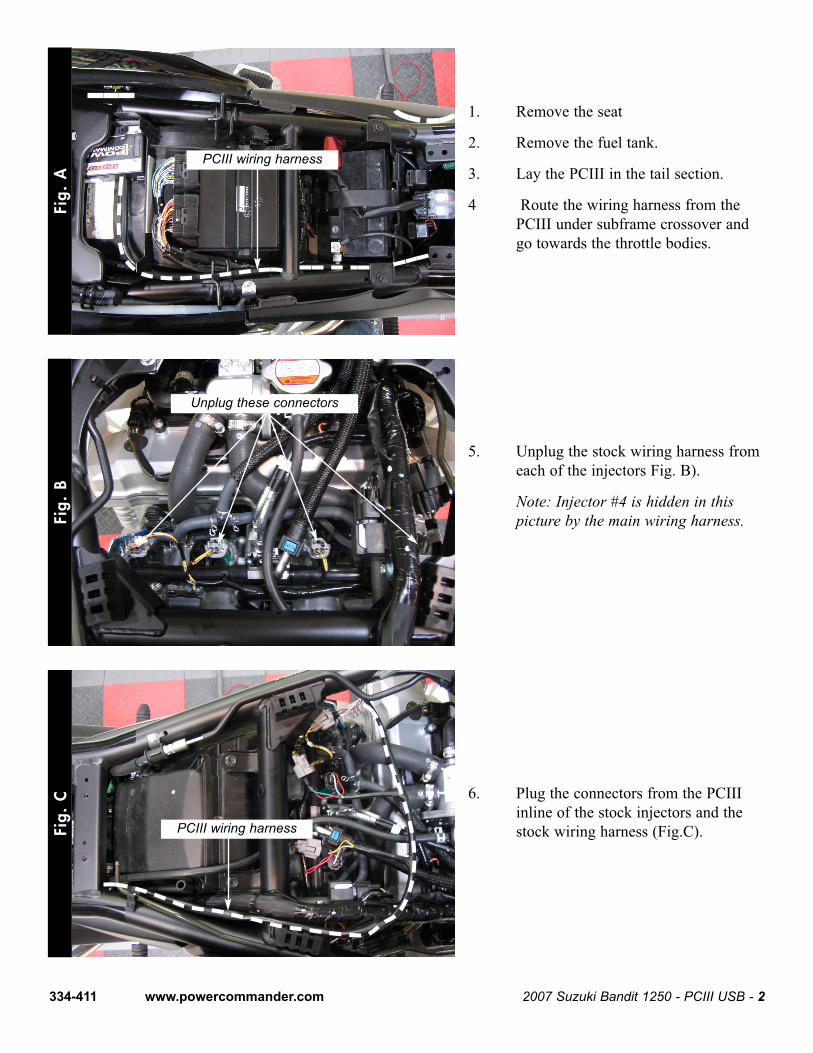
1. Remove the seat
2. Remove the fuel tank.
3. Lay the PCIII in the tail section.
4 Route the wiring harness from thePCIII under subframe crossover andgo towards the throttle bodies.
5. Unplug the stock wiring harness fromeach of the injectors Fig. B).
Note: Injector #4 is hidden in thispicture by the main wiring harness.
6. Plug the connectors from the PCIIIinline of the stock injectors and thestock wiring harness (Fig.C).
Fig.
AFi
g. B
Fig.
C
2007 Suzuki Bandit 1250 - PCIII USB - 2334-411 www.powercommander.com
Unplug these connectors
PCIII wiring harness
PCIII wiring harness
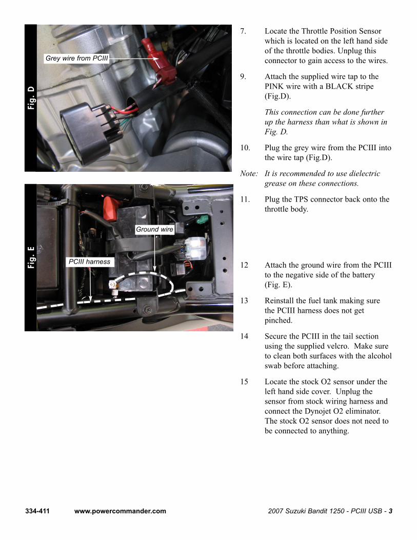
7. Locate the Throttle Position Sensorwhich is located on the left hand sideof the throttle bodies. Unplug thisconnector to gain access to the wires.
9. Attach the supplied wire tap to thePINK wire with a BLACK stripe(Fig.D).
This connection can be done furtherup the harness than what is shown inFig. D.
10. Plug the grey wire from the PCIII intothe wire tap (Fig.D).
Note: It is recommended to use dielectricgrease on these connections.
11. Plug the TPS connector back onto thethrottle body.
12 Attach the ground wire from the PCIIIto the negative side of the battery(Fig. E).
13 Reinstall the fuel tank making surethe PCIII harness does not getpinched.
14 Secure the PCIII in the tail sectionusing the supplied velcro. Make sureto clean both surfaces with the alcoholswab before attaching.
15 Locate the stock O2 sensor under theleft hand side cover. Unplug thesensor from stock wiring harness andconnect the Dynojet O2 eliminator.The stock O2 sensor does not need tobe connected to anything.
Fig.
DFi
g. E
2007 Suzuki Bandit 1250 - PCIII USB - 3334-411 www.powercommander.com
PCIII harness
Grey wire from PCIII
Ground wire