2009 accessibility guidelines - american trails -...
TRANSCRIPT

Revised and updated from California State Parks Accessibility Guidelines, 2005
Accessibility Section Acquisition and Development Division
2009 Edition
Accessibility Guidelines
California State Parks

These guidelines are intended to convey to California State Parks staff general
information regarding accessibility standards and recommendations for complying with laws and regulations related to accessibility. These guidelines are not a substitute for legal advice. Any specific legal issues or problems should be referred to legal counsel.
Furthermore, California State Parks takes NO RESPONSIBILITY for reliance upon
these guidelines by any person or entity. All persons and entities should independently confirm standards, recommendations, laws, and regulations related to accessibility.

2009 Accessibility Guidelines iii
Introduction ----------------------------------------------------------------------vii
Department Policy and Practices------------------------------------------- xi
Building Blocks for an Accessible Park -----------------------------------xv
Project Review Process ----------------------------------------------------- xix
Section 1 Alarm Systems -------------------------------------------------1
Section 2 Assistive Listening Devices ---------------------------------3
Section 3 Audio-Visual Programs---------------------------------------5
Section 4 Bathing Facilities-----------------------------------------------9
Section 5 Beaches and Shores --------------------------------------- 21
Section 6 Boating --------------------------------------------------------- 27
Section 7 Buildings ------------------------------------------------------- 33
Section 8 Campfire Centers & Assembly Areas------------------- 43
Section 9 Camping ------------------------------------------------------- 47
Section 10 Concessions -------------------------------------------------- 57
Section 11 Curb Ramps -------------------------------------------------- 59
Section 12 Dining & Banquet Areas ----------------------------------- 63
Section 13 Doorways------------------------------------------------------ 69
Section 14 Dormitories, Hotels & Seasonal Housing-------------- 75
Section 15 Dressing Rooms --------------------------------------------- 79
Table of Contents

iv 2009 Accessibility Guidelines
Section 16 Drinking Fountains ------------------------------------------ 81
Section 17 Equestrian Facilities ---------------------------------------- 85
Section 18 Exhibits--------------------------------------------------------- 87
Section 19 Fishing --------------------------------------------------------101
Section 20 Fixed Benches ----------------------------------------------107
Section 21 Guided & Self-Guided Programs and Tours ---------109
Section 22 Historic Sites-------------------------------------------------115
Section 23 Kitchens-------------------------------------------------------121
Section 24 Lifts-------------------------------------------------------------125
Section 25 Parking --------------------------------------------------------127
Section 26 Picnic Sites---------------------------------------------------137
Section 27 Play Areas----------------------------------------------------145
Section 28 Portable Toilets ---------------------------------------------153
Section 29 Public Telephones------------------------------------------155
Section 30 Publications --------------------------------------------------159
Section 31 Ramps---------------------------------------------------------167
Section 32 Restrooms----------------------------------------------------173
Section 33 Routes of Travel --------------------------------------------185
Section 34 Service Machines-------------------------------------------193
Table of Contents

2009 Accessibility Guidelines v
Section 35 Signage -------------------------------------------------------195
Section 36 Sinks-----------------------------------------------------------199
Section 37 Special Events ----------------------------------------------203
Section 38 Stairs ----------------------------------------------------------207
Section 39 Storage Areas & Lockers ---------------------------------211
Section 40 Swimming Pools --------------------------------------------215
Section 41 Trails-----------------------------------------------------------223
Section 42 Visitor Information & Sales Areas ----------------------227
Section 43 Vista Points & Overlooks ---------------------------------231
Section 44 Work Areas---------------------------------------------------235
Glossary ------------------------------------------------------------------237
Appendix
Special Events Checklist ------------------------------------------249
Access Compliance Checklist for Exhibits --------------------253
Access Compliance Checklist for Publications---------------255
Index ---------------------------------------------------------------------------257
Table of Contents

vi 2009 Accessibility Guidelines
CALIFORNIA STATE PARKS ACCESSIBILITY SECTION
Guidelines for accessibility design are continually changing as the Federal Access Board incorporates new standards into the Americans With Disabilities Act of 1990 (ADA). California State Parks is fortunate to have the Accessibility Section, headquartered in Sacramento. Established in 1999, this section is at the forefront of other agencies in accessibility design and construction in the outdoor recreation environment. One of the primary goals of the section is to stay abreast of all laws, guidelines and changes that affect our state parks. To accomplish this goal, the Accessibility Section has developed the following vision and mission:
VISION Universal accessibility is integrated into the Department’s culture and embodied in its programs, providing visitors, regardless of their abilities, with high quality recreational opportunities while preserving the integrity of park resources.
MISSION To provide direction, leadership, encouragement and facilitation toward universal accessibility to maximize park visitor opportunities.

2009 Accessibility Guidelines vii
Introduction
The California State Parks Accessibility Guidelines (Guidelines) presents principles for providing accessibility in State Park settings. It is intended for practical use in the field, for use in regular maintenance duties, construction projects, and to understand and review the work of outside contractors. Towards this end, the documents are designed as a reference manual that can be used with flexibility to accommodate unique situations and settings. The Guidelines embody a compilation of accessibility standards, recommendations and regulations for compliance with accessibility laws. California State Parks began the process of developing the California State Park Accessibility Guidelines in the late 1980s. The first edition was published as “Access to Parks Guidelines” in 1994 and subsequent revisions have incorporated more comprehensive and up-to-date material. These guidelines are intended for use throughout California State Parks. Many sections relate to the physical environment and serve as a resource for planners, designers, contractors and maintenance staff.
There are also sections that apply to programs and presentations that serve to inform rangers, interpreters and volunteers. The guidelines are the primary tool provided by the California State Parks Accessibility Program to accomplish its mission of providing guidance in creating universal access to California State Parks.
PARK ACCESSIBILITY Natural settings are different than urban settings. The urban environment is mostly built and can be “controlled” by design, while parks are both built and nature-based. In fact, people come to State Parks primarily to experience nature; consequently the built settings in the parks must be designed to fit into a natural environment without destroying the experience people come to enjoy. For this reason it is not always desirable to create settings that appear too over-built or over-designed. The challenge for park designers, managers, rangers and maintenance staff is to understand what people of all abilities need to use the park without compromising

viii 2009 Accessibility Guidelines
Introduction
the qualities of the natural or cultural resource. The concept of individual choice based on the desired degree of challenge must also be addressed. For example, a trail through a redwood grove may be the desired experience. Some people want a very challenging hike through the redwoods while others just want to stroll through a beautiful natural setting. Therefore, unlike an urban pathway the trail is not merely a means of access to a place or activity; it is the place and type of experience visitors have that creates the “program” of that place. Accessibility, as used throughout these guidelines, is defined as “the combination of various elements in a building or outdoor area, which allows access, circulation and full use of the building, facilities and programs by person with disabilities.” (CBC-202.A) While accessibility is a defined, prescriptive set of standards and measurements that do not change in content from setting to setting, the design challenge in park settings remains – basic services and experiences need to be accessible to all people with disabilities, while maintaining the intrinsic qualities of the place.
PROGRAMS AND FACILITIES These guidelines are intended to ensure that all programs and facilities available to the public shall be accessible for the use and enjoyment of persons with disabilities. In the California State Parks system this shall include, but not be limited to: Amphitheaters & Gathering
Places Audiotapes Beaches & Shores Cabins & Lodgings Camping & Picnicking Drinking Fountains Equestrian Facilities First Aid Stations Fishing Food & Dining Facilities Entrance Stations Historic Sites & Facilities Information Stations Interpretive Programs Living History Programs Marinas Museums Offices, Kiosks & Parking Paths & Trails Public Transportation Restrooms Shops & Stores Swimming Telephones Visitor Centers Volunteer & Docent Programs
2009 Accessibility Guidelines ix
Introduction
SOURCE MATERIALS The guidelines are, in essence, a summary of the Federal and State accessibility regulations set forth by the Americans with Disabilities Act and California’s Title 24 building codes. If questions or clarifications are required beyond this document, refer to the primary source documents listed below and
contact the California State Parks Accessibility Section. The three primary sources for the guidelines are: • California Code of Regulations
(CCR), Title 24 (T24), part of the California building code (CBC), including
→ California Electrical Code
(CEC) → California Plumbing Code
(CPC)
→ California Historic Building Code (CHBC)
• Americans with Disabilities Act
Accessibility “Guidelines for Buildings, Facilities and Outdoor Recreation” (ADAAG) which
includes the “Accessibility Guidelines for Recreation Facilities”, June 2003 (03 AG).
• “Regulatory Negotiation
Committee on Accessibility’s Guidelines for Outdoor Developed Areas (99 AG).
DEVIATION FROM GUIDELINES These guidelines are a summary of the most current regulations and represent the accessibility standards prescribed by the Accessibility Section of California State Parks. For more information on a particular guideline or standard, the source material documents may be consulted. The California State Parks Accessibility Section recognizes that deviations from standards may be necessary from time to time due to the environmental conditions and unique constraints of a particular site. In these cases, the Accessibility Section should be contacted for guidance and direction at (916) 445-8949, or e-mail: [email protected]. For more detailed information about the project review process, refer to the Project Review Process Section on page xix.

x 2009 Accessibility Guidelines
Introduction
UPDATES The Accessibility Section will periodically update these guidelines as regulations change. All users should send written corrections, suggested changes and additional comments to:
California State Parks Accessibility Section One Capitol Mall, Suite 500 Sacramento, CA 95814
The Accessibility Section is available to answer specific questions and provide technical assistance regarding issues at individual sites. For accessibility questions or to receive this publication in an alternate format, contact the Accessibility Section at (916) 445-8949, 711, TTY RELAY SERVICE, or by email at: [email protected].

2009 Accessibility Guidelines xi
Department Policy and Practices
California State Parks has many policies and practices that are mandated to ensure that all citizens have access to park facilities and programs. The Department’s accessibility policies include:
ACCESSIBILITY POLICIES DESCRIPTION
Accessibility Program Policy DAM 1400, DN 1995-32
November 8, 1995
It is the policy of the Department to meet the recreational needs of all the people of California and to provide an accessible environment in which all visitors to the State Park system units are given the opportunity to understand, appreciate and participate in the State’s cultural, historical and natural heritage.
Accessible Campsite Policy DOM 1400, DN 2006-05
May 1, 2006
It is the policy of the Department to establish consistent and uniform statewide guidelines that all park units will follow to ensure that accessible campsites are available for park visitors with disabilities, while maximizing campground occupancy.
Use of Qualified Sign Language
Interpreters DOM 1800, DN 2004-07
November 12, 2004
This policy of the California State Parks requires Departmental staff to provide a qualified Sign Language Interpreter.
Continued on following page

xii 2009 Accessibility Guidelines
Department Policy and Practices
ACCESSIBILITY POLICIES DESCRIPTION
Accessibility and Historic Properties Policy
DOM 1400, DN 2005-03 February 3, 2005
This Departmental Notice establishes a policy to ensure that the public access to the Department’s historic properties complies with the law. Further, this notice provides standards, guidelines and the process to follow throughout the Department in order to provide compliant access while preserving historic fabric.
Accessibility and Publications Policy
DOM 1800, DN 2007-04 October 29, 2007
This Departmental Notice establishes a policy to ensure that the Department’s publications comply with the law and also establishes clear standards to follow in producing accessible publications throughout the Department. In addition to being accessible, publications must provide accurate information about accessible facilities and programs.
Accessibility Comment / Complaint Policy
DAM 1400, DN 2001-07 March 28, 2001
This policy of the California State Parks is to ensure that people with disabilities are treated with dignity and respect and are free from discrimination while visiting California State Parks. The Department has established procedures to give persons with disabilities the opportunity to make comments or file discriminatory complaints against State Park System units that have not complied with ADA.

2009 Accessibility Guidelines xiii
Department Policy and Practices
Following are suggested accessibility references, other than the Guidelines, that can be consulted when needed:
DEPARTMENTAL REFERENCES • “All Visitors Welcome –
Accessibility in Interpretive Programs and Facilities.” California State Parks, 2003 version.
SUGGESTED REFERENCES • “CalDAG – California Disabled
Access Guidelines, 2003.” Michael P. Gibbons. (In revision.)
• “California Access Compliance
Reference Manual; Section 1 – Statutes, Section 2 – Regulations.” State of California, Division of the State Architect, January 1, 2008.
• “California Historical Building
Code – 2007.” California Building Standards Commission.
• “Everyone’s Welcome.” American Association of Museums, 1998.
• Lighthouse International –
www.lighthouse.org/accessibility. • “Means ADA Compliance Pricing
Guide, 2nd Edition.” Adaptive Environments Center, Inc. R.S. Means Engineering Staff, 2004.
• “Preserving the Past and Making
it Accessible for People with Disabilities.” National Park Service, Cultural Resources Preservation Assistance Division, 1992.
• “Smithsonian Guidelines for
Accessible Exhibition Design.” Smithsonian Institution, Office of the Provost, Accessibility Program, 1996.
• “Universal Access to Outdoor
Recreation – A Design Guide.” PLAE, Inc., Berkeley, CA and U.S.F.S., 1993.

xiv 2009 Accessibility Guidelines

2009 Accessibility Guidelines xv
Building Blocks for an Accessible Park
The California State Parks Accessibility Guidelines cover standards for particular features in the park environment. These park features should be integrated into an overall park site plan and be considered as part of a larger planning process for accessibility. Site planning is important to the process of providing access to all programs and services that the park offers. Each site shall be planned as a whole to form a well-integrated, accessible network of facilities and programs. The goal is to provide all visitors optimum experiences through individual choice. For example, if camping or picnic areas provide some sites in the sun and some in the shade or some over-looking a lake, accessible sites should be developed in each location, with a path of travel connecting to them, rather than offering a limited selection. Partial accessibility does not provide for optimum experiences through individual choice.
REMEMBER – It is Department policy (DN 95-32) that all public use facilities, furnishings and equipments (i.e., picnic tables, fire rings, drinking fountains, chemical toilets, etc.) when purchased, leased or rented by the Department must be of the accessible variety. In addition, new development, including modifications to existing facilities, MUST be designed in accordance with these guidelines.
CIRCULATION No program or facility can function independent of its linkage to the natural, social and physical environment to which it belongs. Similarly, no program or facility can be accessible by itself. If a park provides major programs in different areas, accessible circulation must be provided to connect each of these areas, facilities and activities, rather than restricting visitors with disabilities to using only selected areas and programs.

xvi 2009 Accessibility Guidelines
Building Blocks for an Accessible Park
pedestrians, including, but not limited to, walks, hallways, courtyards, stairways and stair landing.
2. Outdoor Recreation Access
Route: Paths that connect and provide access to elements within a picnic area, camping area, or designated trailhead.
3. Trails: Paths that provide
access to a site’s remote settings and recreation activities. Trails enhance the visitor’s experience of natural and cultural features of a site, allowing varied levels of accessibility without negatively impacting the recreational activity or resources.
Parks must provide accessible circulation that connects accessible features within a park so that a visitor with a disability can enter the park, get to and utilize restrooms and facilities, and take part in the programs available (visitor center, picnic area, campgrounds, etc.). The basic dimensions and specifications required for accessibility are provided within these Guidelines.
There are three types of circulation that can provide accessibility: 1. Exterior Route of Travel and
Accessible Route of Travel: These general terms describe a continuous, unobstructed path connecting accessible elements and spaces in a building or between exterior elements of a facility. Exterior and accessible routes are safe and usable by persons with disabilities, including pedestrians and visitors requiring the use of mobility devices. These paths or routes may include walks, sidewalks, ramps, corridors, and other such improved areas.
a. Exterior accessible routes
may include: parking access aisles, curb ramps, crosswalks at vehicular ways, walks, ramps and lifts.
b. Interior accessible routes may
include: corridors, floors, ramps, elevators, lefts and clear floor space at fixtures.
c. An accessible circulation path
may include an exterior or interior way of passage from one place to another for

2009 Accessibility Guidelines xvii
Building Blocks for an Accessible Park
SPACE ALLOWANCES When designing for all people, the spatial requirements are different from those historically used in design. Universal design takes into account the fact that people come in a variety of shapes, sizes, abilities, and ages. When planning and designing, using widths, lengths and dimensions that accommodate a wide range of people assures access to recreational facilities and programs for all visitors. The basic spatial dimensions necessary to accommodate people who use wheelchairs, mobility aids, or who have visual impairments form the basis of these guidelines. Typical space allowances for accessibility that you will find throughout these guidelines include clear ground or floor space, the minimum dimensions required for an adult using a wheelchair and the passing widths and turning requirements for that person.
REACH RANGES The “reach range” refers to the maximum and minimum heights that a person in a wheelchair can reach in the forward and side directions. Objects that can be reached (such as exhibit buttons, telephones, Braille signs, grills, hose bibs, etc.) need to be positioned within the appropriate reach range to be accessible to people in wheelchairs. The two types of reach ranges are in the “forward” and “side” directions. A person has a greater reach range toward the side than in the forward direction so the ranges differ.
OBSTACLES, HAZARDS, AND CLEARANCE In recreational settings it is often desirable to retain the natural features and character of a place through aesthetically appropriate design. This must be done in a way that also provides safe maneuvering and access. To maximize clearances and minimize hazards, projections, protrusions, and gratings or openings in the clear ground or floor space need to be carefully considered.
xviii 2009 Accessibility Guidelines
Building Blocks for an Accessible Park
COMMUNICATION Physical access is only one form of access to parks. Making park programs accessible requires making communications accessible. Parks that offer visitors physical access to programs and facilities cannot be considered fully accessible unless the staff can effectively communicate with visitors with disabilities. Interpretive programs, nature walks, campfire talks, films, and other special programs should also be made available to everyone through alternative formats such as sign language, Braille, oral description, and captioning. These are described in the guidelines that follow.
For additional detailed information about how to make communication accessible refer to the California State Parks document, “All Visitors Welcome – Accessibility in Interpretive Programs & Facilities” and the Department’s Qualified Sign Language Interpreters policy. These basic building blocks for accessibility appear throughout the Guidelines and must be considered when designing or maintaining State Park settings. The following sections outline requirements for specific park features.

2009 Accessibility Guidelines xix
Project Review Process
The Department must ensure that all projects that potentially alter use areas or facilities within State Parks accurately incorporate accessible features. The Department is also mandated to track accessibility improvements. The Accessibility Section is responsible for ensuring compliance with these mandates by reviewing all projects and should be involved in the planning stages of projects that affect accessibility to ensure that access is adequately integrated. Accessibility Section project review will also ensure that California State Parks continues to provide all visitors, regardless of their abilities, with high quality recreational opportunities, while preserving the integrity of park resources. Consequently, all Project Evaluation Forms (PEFs) SHALL be routed to the Accessibility Section for review and approval regardless of the anticipated CEQA compliance determination.
In order to ensure an accurate project description on your PEF and to avoid repetitive reviews it is highly recommended that the accessibility review occur prior to review by other specialists. Do not assume there are no access issues involved in a project unless the Accessibility Section has exempted it because an oversight of access may cause significant delays. If your project does not require a PEF for CEQA purposes, it may still require an accessibility review if it has the potential to alter a facility or use area. To obtain a “Project Evaluation Form” (PEF) and a current copy of the official “Project Review Process Guidelines,” contact the Accessibility Section at:
California State Parks Accessibility Section One Capitol Mall, Suite 500 Sacramento, CA 95814 Telephone: (916) 445-8949 E-mail: [email protected]

xx 2009 Accessibility Guidelines
Project Review Process
topographic maps and photographs are quite valuable in helping to impart the details of your project, and often these same documents can be used as part of the final PEF. Early review will determine if the access features in the project have been adequately addressed and/or if subsequent reviews will be necessary. This stage of review will also identify all issues with physical alterations required for access compliance often associated with qualified historical properties and outdoor environments and will prevent access issues from being overlooked or applied improperly.
II. PRELIMINARY DESIGN AND CONSTRUCTION DOCUMENTS
In addition to conceptual reviews, projects for which plans and specifications are developed will need to be reviewed at the intermediate stages of preliminary plan design, design development and construction document preparation stages. The complexity of the project and schedule will vary. As a result, the level of completeness for the intermediate stages of preliminary plan design review submittal will vary.
It is your responsibility to contact the Accessibility Section when you begin work on any project, including design, planning, interpretive, engineering, trail or construction projects. When you do, Accessibility Section Specialists will help you address legally mandated access compliance issues.
ACCESSIBILITY SECTION PROJECT REVIEW PROCESS
I. PROJECT PLANNING Planning for access for people with disabilities needs to take place at the very early stages of a project. When Project Evaluation Forms (PEF) and Concept Papers are initially drafted, that is the appropriate phase at which to have the project reviewed by the Accessibility Section. A phone call to discuss the project will allow the Accessibility Section to log the project into its database and help project managers determine the specific components that should be included in the project. The more information about the project and existing site conditions that you provide, the better the Accessibility Section specialists will be able to assist you. Site drawings,

2009 Accessibility Guidelines xxi
Project Review Process
IV. POST CONSTRUCTION “Construction Verified Report” forms need to be submitted for all contracted projects. These forms document that contractors have correctly installed the accessible features. During the construction of projects and at the completion of a project the project manager should notify the Accessibility Section so that a verified report can be completed, certified and submitted to complete the project files. This document should also be kept with the official project file.
V. TRAIL PLANNING When planning trail projects, the following steps should be completed in order to coordinate review of a trail project by the Accessibility Section and ensure compliance with current regulations and integration into the statewide accessible trail program. 1) Contact the Accessibility
Section Trail Coordinator to discuss the trail project, determine the potential level of accessibility and evaluate the trails inclusion in the statewide accessible trail program.
In general, design review submittals should take place at each of the following steps:
1) Schematic/preliminary design,
2) Design development / 30%
construction documents, and
3) 70% completed construction documents.
III. Final Plan Review and Certification
Pursuant to the Government Code, contracted construction projects cannot be put out to bid until the plans and specifications have been certified by Accessibility Section Architects. Approved and certified construction documents must demonstrate that the project will comply with current accessibility codes, regulations, and guidelines. To that end, the Accessibility Section of California State Parks must review all final plans and specifications to ensure compliance. All approved plans will receive a certification stamp, dated and signed by an Accessibility Section Project Review architect.

xxii 2009 Accessibility Guidelines
Project Review Process
2) Submit a draft PEF or Notice of Exemption with a detailed project description, maps showing connections to other trails and to trailheads, and photographs to the Accessibility Section Trail Coordinator.
3) If the Accessibility Section Trail
Coordinator determines that the trail qualifies for a departure from the current guidelines, a detailed explanation of the reason for this departure from the guidelines is required. Photographs and topographic maps would be helpful in supporting the reason for departure.
VI. EXHIBIT DESIGN In addition to architectural review of construction documents, interpretive accessibility reviews will evaluate exhibit design specifics. This may include but is not limited to: fonts, contrasts, clarity of content and layout, controls and interactive elements, and mounting and location of details. It is important to initiate the review process prior to the completion of the exhibit design, otherwise additional design costs and delays may occur. Staff should contact the Accessibility section during the initial design planning stage.

2009 Accessibility Guidelines 1
I. CONCEPT A. Alarm systems must be
accessible to people with visual and hearing impairments. The State Fire Marshall must be contacted for all existing, new, and retrofit system requirements.
B. For program accessibility
requirements that may require visual or audible alarms absent any construction, contact the Accessibility Section.
II. GENERAL A. If provided, audible emergency
alarms shall produce a sound that exceeds the prevailing sound level by at least 15 decibels. Sound levels for alarm signals shall not exceed 120 decibels. ADAAG-4.28.2 CBC 907.9.2
B. Where audible alarms are installed, visual alarms must be provided. They are to be flashing white strobe lights located 6” below the ceiling or 80” above the floor (whichever is lower) and must be positioned within 50’ of all locations in rooms, including restrooms (Figure 1-1). ADAAG-4.28.1-3
Figure 1-1
Alarm Systems
SECTION 1

2 2009 Accessibility Guidelines
Section 1 - Alarm Systems
C. Fire alarm pulls are to be a minimum of 42” and a maximum of 48” above the floor to the highest point of the activating handle or lever of the box. CBC-1117B.6 CBC -907.3.2
D. Fire alarm pull stations shall be
accessible and operable without tight grasping, pinching, or twisting. ADAAG-4.27.4

2009 Accessibility Guidelines 3
Assistive Listening Devices (ALDs)
SECTION 2
I. CONCEPT A. Assistive listening devices are
used to help individuals hear the programs that State Parks provides. These devices may be either permanently installed or portable. Permanent systems are generally installed for specific areas while portable systems allow use for walking tours or similar activities. Typical areas in the parks where assistive listening devices will be used are assembly areas, meeting rooms, campfire centers, visitor centers and museums.
B. The type of assistive listening
device should be selected for the appropriate application. For example, in a room where fluorescent lighting is used, the ballasts can cause interference with infrared systems. Infrared may be appropriate for interpretive centers with audio/visual presentations but not functional in outdoor settings without clear lines of sight.
C. With any system, staff must be trained on system use and maintenance.
II. GUIDELINES A. Assembly areas, conference and
meeting rooms shall provide assistive-listening systems for person with hearing impairments. CBC-1104B.2
1. The minimum number of
receivers to be provided shall be equal to 4% of the total number of seats, but in no case less than two.
2. Types of ALDs include, but are
not limited to, audio-induction loops, radio frequency systems and infrared transmission.
3. If the ALD provided is limited to
specific areas or seats, then such areas or seats shall be within a 50’ viewing distance of the performing area.

4 2009 Accessibility Guidelines
Section 2 - Assistive Listening Devices (ALD’s)
4. If portable ALD systems are used for conference or meeting rooms, the system may serve more than one room. However, permanently installed ALD systems are required in areas if (1) they accommodate at least 50 persons or they have audio-amplification systems, and (2) they have fixed seating.
III. SIGNAGE A. A sign shall be posted in a
prominent place indicating the availability of the ALD. The sign shall include the ISA for hearing loss and wording that states “Assistive Listening System Available” (Figure 2-1).
B. Information regarding the
availability of ALDs should also be included on brochures and announcements for special programs.
Figure 2-1
2009 Accessibility Guidelines 5
Audio-Visual Programs
SECTION 3
I. CONCEPT A. Audio-visual programs are
informational, educational, entertaining programs that are transmitted by auditory and/or visual means. This includes, but is not limited to, audiotapes, sound systems, videotapes or DVDs, films, slides and interactive audio/video displays.
B. Audio-visual programs are
required to be presented and available from accessible locations.
C. Audio-visual programs are
required to be accessible to persons with disabilities. Appropriate auxiliary aids and services, such as qualified sign language interpreters, shall be made available to communicate with people who are deaf and hard of hearing. DN 2004-07.
II. ALTERNATE FORMATS A. Alternative means of presenting
audio and visual program information shall be available.
1. Auditory information must also
be provided in print, captioned video, or graphic visual form.
2. Visual information (films,
videos, slides, printed publications, etc.) must have alternatives such as large print descriptive narration, audio description, descriptive audiotapes, and electronic media usable with screen readers, Braille, etc.
B. Audio-Video Program
Alternatives
1. Captions (on-screen text) must be provided for existing videos and other audio-visual programs.

6 2009 Accessibility Guidelines
Section 3 - Audio-Visual Programs
a. Close-captioned video requires a decoding monitor to display text on the screen.
b. Both open-captions and
Computer Assisted Real Time Captions (“CART”) show the dialog on the screen all the time.
c. Until captions are provided, a
written program transcript must be available as a handout. Refer to Section 30, Publications. Electronic transcripts provided for home use should be usable with most screen readers for persons with visual impairment.
d. When existing videos contain
visual elements critical to understanding the material, CD equivalents of videos that include audio description may be created – if feasible – until new synchronized audio described videos are available.
2. All new video programs that contain visual information necessary for the comprehension of the content must include audio description.
a. Key visual elements such as
settings, actions, costumes, scene changes and facial expressions critical to understanding should be described and inserted into pauses in sound-tracks.
b. Audio descriptions of the
above elements must be synchronized to a film as it is projected and then transmitted to an FM receiver headset or other receiver.
III. ACCESS FOR PERSONS WHO ARE DEAF OR HARD OF HEARING
A. Speakers must allow extra time
between slides for visitors with hearing impairments to see the images that have been described. These visitors may be lip reading or watching the sign language interpreter.

2009 Accessibility Guidelines 7
Section 3 - Audio-Visual Programs
B. If a room is too dark, a spotlight on the speaker and/or sign language interpreter may also be necessary.
C. A system for requesting sign
language interpreters with advance notice must be established at all locations and communicated to the public. DN 2004-07
IV. References A. For additional information, refer
to the California State Parks Qualified Sign Language Interpreters Policy and “All Visitors Welcome”, a California State Parks publication.

8 2009 Accessibility Guidelines

2009 Accessibility Guidelines 9
I. CONCEPT A. Where facilities for bathing are
provided, including showers or bathtubs, at least one shower or bathtub and support facilities such as lockers and not less than 1% of all facilities, shall be accessible and conform to the following standards: CBC-1115B.2
1. Showers shall be finished as
specified in CBC Section 1115B.3.1 item 6 to a height of not less than 70” above the drain inlet. Materials other than structural elements used in such walls shall be of a type which is not adversely affected by moisture.
2. Doors and panels of shower
and bathtub enclosures shall be substantially constructed from approved, shatter-resistant materials. Hinged shower doors shall open outward.
3. Glazing used in doors and panels of shower and bathtub enclosures shall be fully tempered, laminated safety glass or approved plastic. When glass is used, it shall have minimum thickness of not less than ⅛” when fully tempered or ¼” when laminated.
4. Plastics used in doors and
panels of showers and bathtub enclosures shall be shatter-resistant.
B. Where, within the same
functional area, two or more accessible showers are provided, there shall be at least one shower constructed opposite hand from the other or others (i.e., one left-hand control versus right-hand controls). CBC-1115B.4.4.3
C. See the California Building Code
for full requirements.
Bathing Facilities
SECTION 4

10 2009 Accessibility Guidelines
Section 4 - Bathing Facilities
II. COMPARTMENT SHOWERS A. Enclosure/Stall
1. The shower stall space shall meet one of the following criteria: CBC-1115B.4.4.1
a. Roll-in shower: 60” minimum width between wall surfaces and 30” minimum depth, with a full opening width on the long side (Figure 4-1).
b. Alternate roll-in shower: 60”
minimum width between wall surfaces and 36” minimum depth with an entrance opening width of 36” minimum (Figure 4-3).
c. Alternate roll-in shower: 60”
minimum width between wall surfaces and 36” minimum depth as long as the entrance opening width is a minimum 36” (Figure 4-4).
2. When a threshold or recessed
drop is permitted, it shall be a maximum of ½” in height and shall comply with CBC-1124B.2. CBC-1115B.4.4.2
3. Enclosures, when provided for shower compartments, shall not obstruct controls or obstruct transfer from wheelchairs onto shower seats. CBC-1115B.4.4.10
B. Shower floor:
1. Drain grate openings shall be a maximum of ¼” wide. Drain shall be flush with the floor. CBC-1115B.4.4.7
2. Maximum slope of the floor
shall be 2% in any direction (Figure 4-2). CBC-1115B.4.4.7
Figure 4-2

2009 Accessibility Guidelines 11
Figure 4-1
Section 4 - Bathing Facilities

12 2009 Accessibility Guidelines
Figure 4-3
Section 4 - Bathing Facilities

2009 Accessibility Guidelines 13
Figure 4-4
Section 4 - Bathing Facilities

14 2009 Accessibility Guidelines
Section 4 - Bathing Facilities
3. Floor surfaces shall be stable, firm and slip resistant. CBC-1124B.1
C. Folding seat:
1. The seat shall extend the full depth of the stall (Figure 4-1). ADAAG-4.21.3
2. The seat shall resist a 250 lb. force in any direction. CBC-1115B.7.2
3. The seat shall be mounted 18”
above the floor (Figures 4-1 & 4-6). CBC-1115B.4.4.8(1)
4. There shall be a minimum of 1”
and a maximum of 1½” space between the edge of the seat and any wall when the seat is down (Figure 4-5). CBC-1115B.4.4.8(1)
5. Water controls shall be of a
single-lever design. The centerline of the controls shall be located at 40” above the shower floor. CBC-1115B.4.4.4
a. Controls in a 60” minimum
by 30” minimum roll-in shower shall be located on the back wall of the
compartment adjacent to the seat and the centerline of the controls shall be within a range of no less than 19” and no more than 27” from the seat wall (Figure 4-1).
b. Controls in a 60” minimum
by 36” alternate roll-in shower shall be located on the side wall of the compartment adjacent to the seat and the centerline of the controls shall be within a range of no less than 19” and no more than 27” from the seat wall (Figure 4-2).
c. Controls in a 60” minimum
by 36” minimum alternate roll-in shower with optional enclosure shall be located on the back wall of the compartment adjacent to the seat and the centerline of the controls shall be within a range of no less than 19” and no more than 27” from the seat wall (Figure 4-3).
6. The seat, when folded, shall
extend a maximum of 6” from the wall. CBC-1115B.4.4.8(1)

2009 Accessibility Guidelines 15
Section 4 - Bathing Facilities
Figure 4-5
Figure 4-6
D. Accessories:
1. Clothes hooks, if provided, should be at a maximum height of 48” without obstructions. CBC-1118B.5
2. Soap dispensers shall be
located on the control wall at a maximum 40” and within reach limits. CBC-1115B.4.4.9
E. Doors and Panels:
1. Doors and panels shall be substantially constructed from approved, shatter-resistant materials. Hinged shower doors shall open outward. CBC-1115B.2(2)
2. Door latches, mounted 30” to
44” above the floor, shall be flip-over, sliding or similar style not requiring grasping or twisting. CBC-1133B.2.5.2
3. The maximum pressure
required to open a door must be 5 lbs. or less. CBC-1133B.2.5.1

16 2009 Accessibility Guidelines
Section 4 - Bathing Facilities
4. If clothes hooks or shelves are provided, they must be within the following reach ranges: CBC-1125B.3 CBC-1118B.5-6
a. 34” to 46” for side reach over
an obstruction.
b. 15” to 48” for forward reach.
c. 20” to 44” for forward reach over an obstruction.
5. The required strike edge
clearance on the pull side of an interior stall door is 18” for front approach, 24” for latch approach and 24” for hinge approach. ADAAG-4.17.5 ADAAG-4.13.6
F. Hand-Held Shower Spray Unit:
1. A hand-held shower spray unit shall be provided, mounted at a maximum height of 48”, above the floor and with a hose at least 60” long (Figures 4-1 & 4-2. CBC-1115B.4.4.5
2. The hand-held shower must be useable in a fixed position. CBC-1115B.4.4.5
3. Where accessible shower
facilities are provided in areas subject to excessive vandalism, in lieu of providing the fixed flexible hose and hand-held showerhead required above, two wall-mounted showerheads shall be installed. Each showerhead shall be controlled so that it can be operated independently of the other and shall have swivel angle adjustments, both vertically and horizontally. One showerhead shall be located at a height of 48” above the floor. The other shall be located at a height of 72” above the floor. CBC-1115B.4.4.6
4. The hand-held shower spray
unit should be located at a maximum of 27” horizontal from the rear of the seat to the centerline of the mounting brackets (Figures 4-1, 4-3 & 4-4). CBC-1115B.4.4.5(1) & (3)

2009 Accessibility Guidelines 17
Section 4 - Bathing Facilities
B. Grab bars shall be mounted 33” to 36” above the shower floor and mounted on the walls adjacent to and opposite of the seat provided in the tub/shower stall (Figure 4-7). CBC-1115B.4.4.8(2)
Figure 4-7 C. An L-shaped grab bar shall be
located on the wall opposite of and adjacent to the front edge of the seat (Figures 4-1 or 4-3). CBC-1115B.4.4.8(2)
D. Grab bars shall be secured so
they do not rotate in their fittings. CBC-1115B.7.2(5)
III. WATER CONTROLS A. Water control valves shall be
located on the wall adjacent to the seat. The centerline of the controls shall be located at 40” above the shower floor. CBC-1115B.4.4.4
B. The maximum effort to operate
controls shall be 5 lbs. ADAAG-4.27.4 CBC-1115B.4.4.4
C. Controls shall be operable with
one hand, not requiring tight grasping, pinching or twisting. ADAAG-4.27.4 CBC-1115B.4.4.4
D. Pay coin slots shall be located at
a maximum of 40” above the floor adjacent to the folding seat (Figures 4-1 & 4-3). ADAAG-4.27 CBC-1115B.4.4.4
IV. GRAB BARS A. Grab bars shall comply with the
diameter, loading and project requirements for toilets. CBC-1115B.7

18 2009 Accessibility Guidelines
E. Grab bars should be 1¼” to 1½” in diameter or width. The space between the wall and the grab bar should be 1½” CBC-1115B.7.1
F. Grab bar edges shall be rounded
a minimum radium of ⅛” and free of sharp or abrasive elements. The wall or other adjacent surfaces shall also be free of any sharp or abrasive elements. CBC-1115B.7.3
G. Grab bars shall be capable of
supporting a 250 lb. load in any direction. CBC-1115B.7.2(1) – (4)
V. OUTDOOR RINSING SHOWERS A. At each location where outdoor
showers are provided, at least one outdoor shower must be accessible. In order to evaluate the accessibility of outdoor showers (e.g. beach showers) the following items will need to be reviewed and measured utilizing the appropriate portions of the restroom survey or as otherwise noted.
1. Path of Travel:
Refer to Section 33, Routes of Travel.
a. A minimum diameter of 60” x
27” high clear space, or “T” turn-around, for a wheelchair to make a 360° turn (Figures 4-8 & 4-10).
99AG-16.19.1.7 CBC-1118B.3
b. The surface must be firm,
stable and slip resistant. CBC-1124B.1
c. The slope shall be 2% (3%, if
necessary for drainage). 99AG-16.19.1.8
Figure 4-8
Section 4 - Bathing Facilities

2009 Accessibility Guidelines 19
Section 4 - Bathing Facilities
Figure 4-9
Figure 4-10
2. Two fixed showerheads shall be provided. One at a minimum is 72” above the ground or floor and the second between 48” and 54” (Figure 4-9). 99AG-16.19.1.1 99AG-16.19.1.2
3. Shower Controls:
a. If valves are self-closing, water
should remain on for a minimum of 10 seconds.
99AG-16.19.2-2.6 ADAAG-4.27.3
b. The maximum effort to operate
controls should be 5 lbs. or less.
ADAAG-4.27 CBC-1117B.6.4
c. Controls must be operable with
one hand, not requiring tight grasping or twisting.
ADAAG-4.27 CBC-1117B.6.4
d. Controls shall be located at a
maximum of 46” above the floor (Figure 4-9).
CBC-1115B.6

20 2009 Accessibility Guidelines
Section 4 - Bathing Facilities
4. Grab bars must be provided as follows, either:
a. A vertical grab bar mounted 33”
maximum above the floor to extend within 3” below the showerhead.
b. A circular bar mounted 33” to
36” above the floor from the centerline of the showerhead shall be provided under the showerhead.
c. A horizontal bar forming an L-
shape 36” x 42”, with the 36” segment of the L-shaped grab bar perpendicular to the shower mounting post in accordance with Part IV, Grab Bars, Item C (Figures 4-8 & 4-9).
99AG-16.19.2.3-5
VI. SIGNAGE A. If the shower is located in a
separate facility, there must be a sign displaying the International Symbol of Accessibility (ISA) on the entry door to identify the accessible shower/bathing facility. ADAAG-4.30.7
B. Accessible outdoor showers shall include the ISA posted at the accessible shower unit.
C. Doorways leading to men’s
shower rooms shall be identified by an equilateral triangle, ¼” thick with edges 12” long and a vertex pointing upward. Women’s shower rooms shall be identified by a circle, ¼” thick and 12” in diameter. Unisex shower rooms shall be identified by a circle, ¼” thick, and 12” in diameter with a ¼” thick triangle superimposed on the circle and within the 12” diameter. These geometric symbols shall be centered on the door at a height of 60” and their color and contrast shall be distinctly different from the color and contrast of the door. CBC-1115B.6

2009 Accessibility Guidelines 21
Beaches and Shores
SECTION 5
I. CONCEPT A. Designated beaches and day-
use areas shall be accessible. CBC-1132B.2.2
B. The major barrier to shore and
beach use by persons with mobility impairments is the difficulty traversing sandy or loose soil. For some water activities, such as fishing or swimming, it is necessary to have direct physical contact with the water from the beach or shore. Access to these activities involves two basic considerations:
1. Access to the edge of the
beach or shore from accessible parking spaces, common use areas and support facilities. These routes must be consistent with the requirements for accessible routes of travel
Refer to Section 33, Routes of Travel.
2. Access across the beach to the activity (the water’s edge). These routes are known as Beach Access Routes.
C. All newly constructed beach,
river, lake and shoreline facilities shall have at least one permanent beach access route for every ½ mile of linear shoreline. 99AG-16.4.1.1
D. For an existing “designated”
beach, when a pedestrian access route is constructed to or along the edge of the beach, a beach access route shall be provided. 99AG-16.4.1.2
For additional assistance regarding beach access,
contact the Accessibility Section.

22 2009 Accessibility Guidelines
Section 5 - Beaches and Shores
II. BEACH ACCESS ROUTES A. The beach access route shall be
located in the same area as the general circulation path, when feasible, and shall extend to the high tide level, mean riverbed level or the normal recreation pool level. 99AG-16.4.1
B. A beach access route is not
required when a pedestrian route, running parallel along the edge of an existing beach, is elevated 6 “or higher above the beach surface. 99AG-16.4.1.2
C. The minimum clear width of the
beach access route shall be 36”; however 48” is preferred (Figure 5-1). 99AG-16.4.3
Figure 5-1 D. The surface of the beach access
route shall be firm and stable. 99AG-16.4.2
E. Edge protection, a minimum of
2” high, shall be provided where drop-offs are 6” or higher (Figure 5-2). 99AG-16.4.10
F. Drop-offs greater than 1”, but
less than 6” shall have a beveled edge (Figure 5-2). 99AG-16.4.10

2009 Accessibility Guidelines 23
Section 5 - Beaches and Shores
G. Openings in the route surface, such as on a boardwalk, shall be ½” or less if perpendicular or diagonal to the route (Figure 5-3). They shall be ¼” or less if parallel to the route (Figure 5-4). 99AG-16.4.4
H. Objects that protrude into the
beach access route with their leading edge between 27” and 80” from the ground shall not protrude more than 4”. Objects mounted below 27” may protrude any amount but shall not reduce the clear width of the accessible route (Figure 5-5). 99AG-16.4.5 ADAAG-4.4.1
Figure 5-3
Figure 5-2

24 2009 Accessibility Guidelines
Section 5 - Beaches and Shores
Figure 5-4
Figure 5-5
I. Vertical clearance on the beach access route shall be 80”. If the vertical clearance of an area adjoining the beach access route is less than 80”, a cane detectable barrier to warn persons who are visually impaired shall be provided. 99AG-16.4.5 ADAAG-4.4.2
J. The slope for beach access
routes must meet one of the following criteria:
1. From 0% to 5% slope for any
length.
2. From 5.1% to 8.33% slope for up to 50’.
3. From 8.34% to 10% slope for a
maximum of 30’. 99AG-16.4.8.2.1-3
K. The installation of resting spaces
is required as shown in the chart in Figure 5-6. 99AG-16.4.8.2

2009 Accessibility Guidelines 25
Section 5 - Beaches and Shores
PERCENT SLOPE
MAXIMUM LENGTH
REST INTERVAL
0% to 5.0%
None required
None required
5.1% to 8.33% 50’ Every 50’
8.34% to 10% 30’ Every 30’
Figure 5-6 L. Resting spaces shall be 60”
minimum in length, shall have a width at least as wide as the route, and have a slope of 3% or less. Exception: the slope of the resting space can be as great as 5% if required for proper drainage. 99AG-16.4.8.2.2-3
M. The cross slope shall be 3% or
less, with a maximum of 5% allowed if necessary for drainage. 99AG-16.4.8.1
N. A maneuvering space measuring
a minimum of 60” x 60” shall be provided at the end of the beach access route. 99AG-16.4.7
O. If the route is less than 60” wide, passing spaces a minimum of 60” x 60” shall be provided at least every 200’. 99AG-16.4.6
P. All obstacles in the beach
access route shall be less than 1” high. 99AG-16.4.9
III. DESIGNATED SWIMMING AREAS A. Depending on safety needs and
local site conditions, designated swimming areas should be clearly defined in the water with highly visible floating devices.
B. Depending on safety needs and
local site conditions, designated swimming areas should also be identified on shore with clearly visible signage.

26 2009 Accessibility Guidelines
Section 5 - Beaches and Shores
IV. ACCESS TO WATER A. When feasible, considering site
conditions at designated swimming areas, a firm and stable surface should provide access into the water. An additional option may be a beach wheelchair. Contact the Accessibility Section to help determine if water access is necessary and/or feasible in your specific area.
B. Beach wheelchairs allow
assisted access to the beach for people who use wheelchairs. If beach wheelchairs are provided, signage shall be posted to indicate their availability.
Refer to Section 35, Signage.
C. Whenever beach access is designated as a program which is or will be made accessible, at least two beach wheelchairs will be provided at such parks unless:
1. There are no staff or facilities at the park available to store and supervise the use of the wheelchairs and/or:
2. The slope conditions at the
park make use of beach wheelchairs hazardous.
D. Additional beach wheelchairs will
be provided at appropriate locations if and when usage indicates that additional beach wheelchairs are needed at such locations.

2009 Accessibility Guidelines 27
Boating
SECTION 6
I. CONCEPT A. Boating facilities include facilities
to launch and moor boats and all associated structures, such as docks, piers, marinas and gangways. If a site presents challenges to meeting the guidelines, such as highly fluctuating water surfaces,
contact the Accessibility Section for assistance with alternative design and/or mechanical devices.
B. Boating facilities, docks, fishing
piers, etc. shall be accessible. CBC-1132B.2.4
II. BOATING FACILITIES CAN CONSIST OF THE FOLLOWING:
A. Boat Launch Ramp: Surface
designed for the launch and retrieval of boats.
B. Boat Slip: Area where boat is tied to a dock or pier for the purpose of embarking and disembarking.
C. Gangway: Variable-sloped
pedestrian walkway linking a fixed structure or land with a floating structure.
D. Pier: Structure at which boats
are intended to moor for the purposes of embarking or disembarking occupants to the structure.
III. GANGWAYS A. Gangways are considered to be
part of the accessible route, shall have slopes no greater than 8.33% (regardless of length) and comply with ADAAG-4.3 (Figure 6-1). ADAAG-15.2.1
B. Transition plates are permitted at
the top and bottom of the gangway (Figure 6-2). ADAAG-15.2.1

28 2009 Accessibility Guidelines
Section 6 - Boating
C. Gangways are not required to
have landings at the end if transition plates of less than 1:20 (5%) slope are provided. If slope is greater than 1:20 (5%), the transition plate must have a landing at the non-gangway end of the transition plate (Figure 6-2). ADAAG-15.2.2
D. Extremes in operating conditions
due to fluctuations in water levels require that some exemptions be allowed. ADAAG-15.2.1
Figure 6-2
1. Maximum rise of 30” shall not apply to gangways. As a result, no intermediate landings on gangways are required and gangways may be any length.
Figure 6-1

2009 Accessibility Guidelines 29
Figure 6-3
Section 6 - Boating
2. Handrail extensions are not required on gangways and landings where they connect to transition plates and shall not be required on transition plates.
3. Where the total length of the
gangway or series of gangways serving as part of a required accessible route is at least 80 ‘, the maximum slope specified, 8.33%, shall not apply to the gangways (Figure 6-3). ADAAG-4.8.2 ADAAG-15.2.2
4. In smaller facilities with less than 25 boat slips, the slope of the gangway may exceed 1:12 (8.33%), if the gangway is a minimum of 30’ long (Figure 6-3). (Maximum length is not applicable.) ADAAG-15.2.2
E. When it is not feasible to provide an accessible gangway due to extremes in operating conditions, other accessible options (including mechanical lifts) will be considered.

30 2009 Accessibility Guidelines
Section 6 - Boating
IV. BOAT SLIPS A. Where boat slips are not
demarcated or identified by length, each 40’ of boat slip edge along the perimeter of a pier will be counted as one boat slip. For example, a 60’ pier with boats moored on either side (120’ total slip length) would equal three boat slips. ADAAG-15.2.3
B. When boat slips are provided,
the number of boat slips required to be accessible must comply with the table in Figure 6-4. ADAAG-15.2.3
C. Accessible boat slips shall be
dispersed throughout the various types of slips that are provided. ADAAG-15.2.3.1
D. Where boat launch ramps are
provided with boarding piers, at least one boarding pier complying with ADAAG-15.2.4 shall be provided adjacent to the ramp. ADAAG-15.2.4
NUMBER OF ACCESSIBLE BOAT
SLIPS REQUIRED TOTAL SLIPS IN
FACILITIES MINIMUM
ACCESSIBLE SLIPS1 – 25 1 26 – 50 2
51 – 100 3 101 – 150 4 151 – 300 5 301 – 400 6 401 – 500 7 501 – 600 8 601 – 700 9 701 – 800 10 801 – 900 11
901 – 1,000 12
1,001 and over
12, plus 1 for each 100, or
fraction thereof, over 1,000
Figure 6-4 E. Accessible boat slip/dock shall
have a clear pier width a minimum 60” wide and as long as the slip. For every 120” (10’) of linear length, the boarding pier/dock will have a clear opening of 60”. ADAAG-15.2.3.1
There are three exceptions:

2009 Accessibility Guidelines 31
Section 6 - Boating
1. Width of clear pier space may be 36” wide for a length of 24”, as long as multiple 36” segments are separated by segments that are 60” x 60” x 60” clear (Figure 6-5).
2. If provided, edge protection
should be 4” high maximum and 2” deep maximum at the clear openings (Figure 6-6).
3. In alterations, facilities with
finger piers must have at least one accessible finger pier, which is the length of the boat slip and a minimum 60” wide. Other accessible slips can be located perpendicular to the end of the pier with the clearance extending the slip width.
V. SAFETY A. Walking surfaces of the facility
shall be made of non-slip materials.
B. Horizontal gaps in walking
surfaces (e.g., gratings and planks) shall be perpendicular and less than ½” wide (Figure 6-7). ADAAG-16.3.3
Figure 6-5
Figure 6-6
Figure 6-7

32 2009 Accessibility Guidelines
Section 6 - Boating
C. Vertical joints in the surface of the facility (including shore connection) shall have a maximum height of ¼” or, if ¼” to ½”, shall be beveled at 50% (Figure 6-8). CBC-1133B.7.4
Figure 6-8
D. The walking surface of docks without guardrails has a recommended maximum height of 24” above the water. Edges should be emphasized by use of a color-contrasting strip that is a minimum 2” wide.
E. The dock/pier with water
fluctuations should post a sign reading:
“CAUTION: DUE TO FLUCTUATION OF WATER ELEVATION, THIS DOCK/PIER IS ONLY ACCESSIBLE BETWEEN THE TIDAL ELEVATIONS OF _____ AND _____. USE WITH CAUTION.”

2009 Accessibility Guidelines 33
Buildings
SECTION 7
I. CONCEPT A. Access to buildings shall comply
with Chapters 11A, 11B, and all subsections of Title 24 of the California Code of Regulations along with the general requirements of ADAAG. The code specifies all requirements relating to parking, accessible routes of travel, doorways, clear spaces, reaches, as well as elevators, lifts, stairs, telephones and similar specialized facilities. 99AG/ADAAG-4.3 CBC-1114B.1.2
B. All buildings, or portions thereof,
when constructed or renovated, must be accessible. The only exceptions are for portions of floors not customarily occupied, including elevator pits, piping chases, equipment catwalks and machinery rooms.
C. In general, if fixed components,
such as cabinets, shelves, closets, drawers, counters, sinks and similar apparatus, plus their operating mechanisms and associated controls, dispensers and receptacles are provided in
a building, then at least one of each type shall comply with this guideline.
D. This section should be used in
conjunction with appropriate sections, including restrooms, kitchens, dining areas, etc.
E. Please note: These are
minimum guidelines only to be used for the purpose of surveying existing buildings and planning for future buildings. The guidelines are incomplete for use in preparing drawings for new or renovated construction. A qualified designer, licensed in the state, knowledgeable in all building codes and the various building occupancy requirements, should be utilized or consulted to ensure compliance with all codes. Access compliance shall also be ensured through consultation with the architects in the Accessibility Section, Acquisition and Development Division. Additionally, State and Federal regulations should be consulted for requirements for all publicly funded buildings.

34 2009 Accessibility Guidelines
Section 7 - Buildings
II. ACCESSIBLE ROUTE OF TRAVEL A. For accessible routes of travel
exterior to the building: Refer to Section 25,
Parking, Section 31, Ramps, and Section 33, Routes of Travel.
B. When only one accessible route
of travel is provided, it shall not pass through kitchens, storage rooms, restrooms, closets or other similar spaces, except within an individual dwelling unit. CBC-1114B.1.2
C. An accessible circulation path is
an exterior or interior way of passage from one place to another for pedestrians, including, but not limited to, walks, hallways, courtyards, stairways and stair landings. ADAAG-3.5
D. The accessible route, to the
maximum extent possible, shall coincide with the route for the general public. Interior accessible routes may include: corridors, floors, ramps, elevators, lefts and clear floor space at fixtures. Vertical access shall include an elevator, lift or ramp. ADAAG-4.3.2
III. DOORWAYS A. Refer to Section 13,
Doorways.
IV. CLEAR SPACES A. In each room, or portion thereof,
dedicated to specific functions, there must be a clear space measuring 60” in diameter or a T-intersection with aisles at least 36” wide and 60” long for turning a wheelchair around (Figures 7-1 & 7-2). These clear spaces must be free of obstructions from the floor surface to a height of 27”. CBC-1118B.2.3
Figure 7-1

2009 Accessibility Guidelines 35
Section 7 - Buildings
Figure 7-2
Figure 7-3
Figure 7-4
B. If a clear space is located in an alcove, there must be an additional clear space provided. CBC-1118B.4.2
C. There must be a clear space at
least 30” x 48” (the 48” measured in the direction of the route of travel) that allows either a forward or parallel approach to building facilities or objects such as cabinets, closets and appliances (Figures 7-3 & 7-4). CBC-1118B.4
V. AISLES AND CORRIDORS A. Every portion of a building shall
provide aisles leading to an emergency exit. CBC-1133B.6.1
B. Aisles serving one side (e.g.,
aisles with a blank wall on one side and exhibits/rooms on the other) must be at least 36” wide. Aisles serving both sides (e.g., aisles with exhibits/rooms on both sides) must be at least 44” wide. CBC-1133B.6.2
C. If the building occupant load is
nine persons or less, the building corridors must be at least 36” wide. CBC-1133B.3.1

36 2009 Accessibility Guidelines
Section 7 - Buildings
Figure 7-5 D. If the building occupant load is
ten persons or more, the building corridors must be at least 44” wide. CBC-1133B.3.1
E. If a corridor is longer than 200’,
there must be a passing area at least every 200’ measuring a minimum of 60” wide or a T-intersection a minimum of 44” wide for two wheelchairs to pass (Figures 7-5 & 7-6). CBC-1133B.3.2
Figure 7-6 F. If the turn space on a 90° turn is
less than 48”, the width of the corridor must be at least 42” on approach and 48” width in the turn (Figures 7-7 & 7-8). ADAAG-4.3.3

2009 Accessibility Guidelines 37
Section 7 - Buildings
G. In a corridor configured with a 180° turn, a 36” wide corridor may be permitted, provided that the run length at the 90° turn is a minimum of 48” in length. A run length less than 48” in length at the 90° turn requires a 48” minimum turn width with a 42” minimum corridor width (Figures 7-7 & 7-8). ADAAG-4.3.3
H. Objects may not protrude into
clear areas with their leading edge between 27” and 80” above the floor for more than 4” into the clear space (Figure 7-9). CBC-1133B.8.6.1
I. Freestanding objects on posts or
pylons may overhang 12” or less into clear spaces from a distance between 27” and 80” above the floor (Figure 7-9). CBC-1133B.8.6.1
Figure 7-7
Figure 7-8

38 2009 Accessibility Guidelines
Section 7 - Buildings
Figure 7-9 J. If the clear space is in an alcove
for a side approach, which is deeper than 15”, there must be an extra 12” of clear space in addition to the standard 48” measurement (Figure 7-10). If the clear space is in an alcove for a front approach, which is deeper than 24”, there must be an extra 6” of clear space width in addition to the standard 30” clear space measurement (Figure 7-11). CBC-1117B.2.4
K. Floors of a single story must be
on a common level or connected by a ramp, elevator or access lift. CBC-1120B.1
Figure 7-10
Figure 7-11 L. If there is less than 80” of clear
headroom next to an accessible route, there must be a cane detectable barrier within 27” of the floor (Figure 7-12). ADAAG-4.4.2

2009 Accessibility Guidelines 39
Section 7 - Buildings
Figure 7-12
VI. REACHES A. Clear Floor Space
1. Clear floor space, at least 30” x 48”, shall be created to allow either forward or parallel approach by a person in a wheelchair (Figures 7-3 & 7-4). CBC-1118B.4.1
2. Clear floor or ground space for wheelchairs may be part of the knee space required under some items (Figure 7-13). ADAAG-4.2.4.1
(Note: X shall be less than or equal to 25”. Z shall be greater than or equal to X. When X is less than 20”, then Y shall be 48” maximum. When X is 20” to 25”, then Y shall be 44” maximum.) Figure 7-13

40 2009 Accessibility Guidelines
Section 7 - Buildings
B. Front (Forward) Reach
1. Front accessible forward approach with forward reach – item must be positioned between 15” and 48” from the floor with the maximum horizontal reach over an obstruction not to exceed 20” (Figure 7-14). CBC-1118B.5
2. A forward reach over an
obstruction not to exceed 25” is allowed if the maximum height of the item is 44” CBC-1118B.5
Figure 7-14
C. Side Reach
1. Parallel approach in a wheelchair with side reach – item must be positioned between 9” and 54” from the floor with the maximum horizontal reach over an obstruction not to exceed 10” (Figure 7-15) CBC-1118B.6
Figure 7-15

2009 Accessibility Guidelines 41
Section 7 - Buildings
2. A side reach over an obstruction not to exceed 24” is allowed if the maximum height of the item does not exceed 46” (Figure 7-16). CBC-1118B.6
VII. FLOORS A. The floor surfaces must be
stable, firm and slip resistant. CBC-1124B.1
B. Changes in level shall be a
maximum of ¼” or, if ¼” to ½”, shall be beveled at 50% (Figure 7-17). CBC-1124B.2
C. If a carpet is provided, it must be
firmly attached to the floor and have a firm pad or no pad. CBC-1124B.3
D. Carpets must be level cut and
have a maximum pile height of ½”. CBC-1124B.3
E. The edges of carpet must be
fastened to the floor with a maximum vertical change from the floor of ¼”. CBC-1124B.2
Figure 7-16
Figure 7-17 F. If gratings are located in walking
surfaces, then they shall be a maximum of ½” in one direction and, if elongated, the long dimension of the grating shall be perpendicular to the dominant direction of travel (Figure 7-18). CBC-1124B.4

42 2009 Accessibility Guidelines
Section 7 - Buildings
Figure 7-18
VIII. OPERATING CONTROLS A. For details on operating controls,
refer to appropriate sections on restrooms, exhibits, etc. CBC-1117B.6
IX. SIGNAGE A. For details on signage see
appropriate sections on signage and restrooms. CBC-1117B.5 CBC-1115B.6
X. ELEVATORS A. All multi-story buildings must
provide access by ramp or elevator. ADAAG-4.1.3(5) CBC-1103B.1
B. Changes in levels along an
accessible route greater than ½” shall comply with the requirements of a curb ramp, ramp, elevator or platform lift as permitted for new construction or alterations. An accessible route does not include stairs, steps or escalators. ADAAG-4.3.8 CBC-1133B.7.4
C. Elevators shall be on an
accessible route and they shall be designed and constructed to be accessible. ADAAG-4.0-4.11 CBC-1116B
2009 Accessibility Guidelines 43
I. CONCEPT A. Campfire centers and other
assembly areas, including theaters, stages and spaces used by performers, are provided to enhance park visitor experiences through education, entertainment or a variety of other needs. Facilities must be fully accessible to visitors and employees. All campfire centers and other assembly areas, as well as facilities therein, shall be constructed or renovated, taking into account the path of travel and any ramp requirements. 99AG/ADAAG-4.3 CBC-1114B.1.2
Refer to Section 33, Routes of Travel.
II. SEATING A. Accessible seating shall be
distributed throughout the area to provide a choice of sight lines. ADAAG-4.33.3 CBC-1104B.3.5
B. Each accessible seating area shall have provisions for companion seating, and shall be located on an accessible route that also serves as an emergency accessible egress. ADAAG-4.33.3 CBC-1104B.3.5
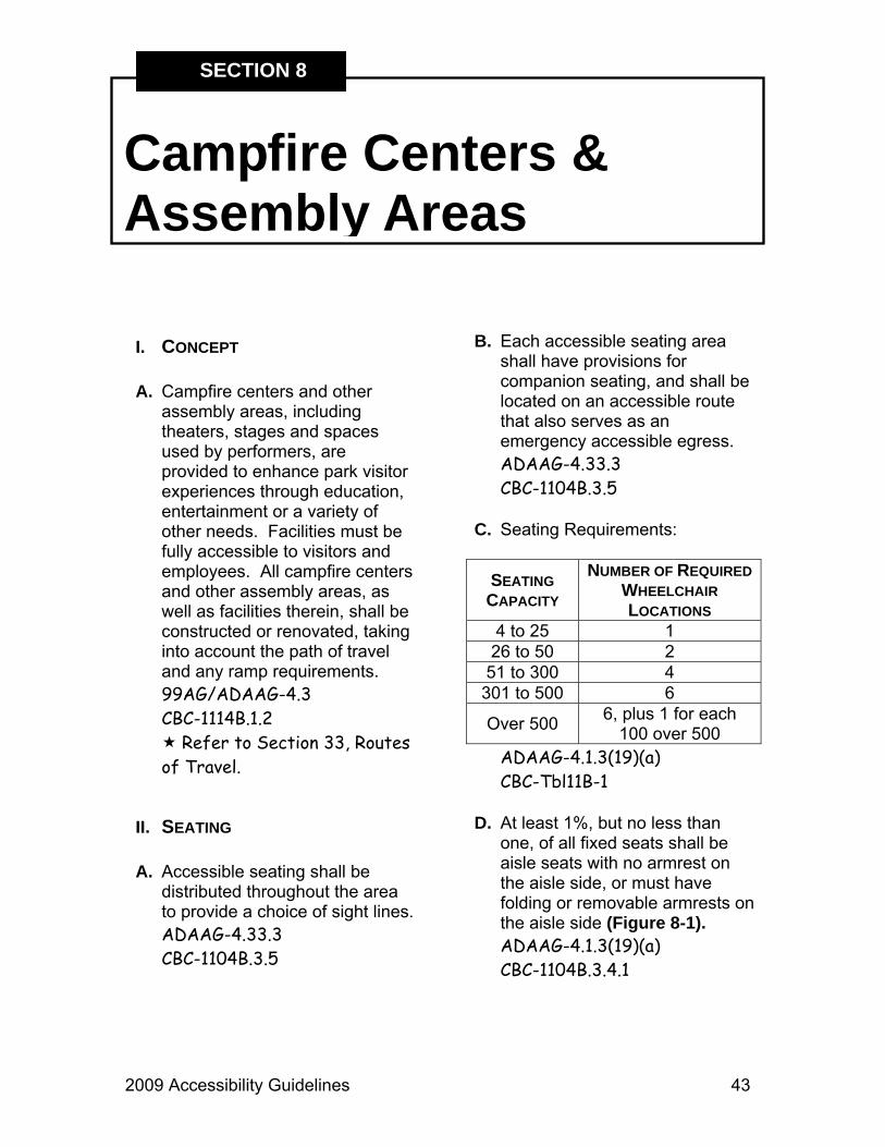
C. Seating Requirements:
SEATING CAPACITY
NUMBER OF REQUIRED WHEELCHAIR LOCATIONS
4 to 25 1 26 to 50 2 51 to 300 4
301 to 500 6
Over 500 6, plus 1 for each 100 over 500
ADAAG-4.1.3(19)(a) CBC-Tbl11B-1
D. At least 1%, but no less than
one, of all fixed seats shall be aisle seats with no armrest on the aisle side, or must have folding or removable armrests on the aisle side (Figure 8-1). ADAAG-4.1.3(19)(a) CBC-1104B.3.4.1
Campfire Centers & Assembly Areas
SECTION 8

44 2009 Accessibility Guidelines
Section 8 - Campfire Centers & Assembly Areas
Figure 8-1
Figure 8-2
E. Accessible aisle seats shall be identified by a sign or marker. ADAAG-4.1.3(19)(a CBC-1104B.3.4.1
F. The wheelchair location shall
have a minimum clear floor or ground space of 48” deep x 66” wide, if a forward or rear approach (Figure 8-2). CBC-1104B.3.6
G. The wheelchair location shall
have a minimum clear floor or ground space of 60” deep x 66” wide, if side approach (Figure 8-3). CBC-1104B.3.6
Figure 8-3

2009 Accessibility Guidelines 45
Section 8 - Campfire Centers & Assembly Areas
H. Readily removable seats may be installed in these wheelchair spaces when such spaces are not required to accommodate wheelchair users. CBC-1104B.3.7
I. Proper signage in the lobby or
ticket booth area shall indicate seating accessibility. CBC-1104B.3.4.1
J. Semi-ambulant seating shall be
provided of up to 1% of the total, but no less than two. Semi-ambulant seats shall have a minimum of 24” of leg clearance measured from the front edge of the seat to the backrest of the seat immediately in front or nearest obstruction (Figure 8-1). CBC-1104B.3.8
K. Armrests and backrests required
with fixed bench seating are not mandatory in a spectator assembly environment.
III. PATH OF TRAVEL A. At least one accessible route
within the boundary of the site shall be provided from public transportation stops, accessible parking and accessible
passenger loading zones, as well as public streets or sidewalks to the accessible entrance they serve. 99AG/ADAAG-4.3 CBC-1114B.1.2
B. The accessible route shall, to the
maximum extent feasible, coincide with the route for the general public. ADAAG-4.3.2
C. The minimum clear width of an
accessible route shall be 36”, except at doorways, which may be 32” (Figure 8-4). ADAAG-4.3.3
Figure 8-4

46 2009 Accessibility Guidelines
Section 8 - Campfire Centers & Assembly Areas
D. If an accessible route has less than 60” clear width, passing spaces at least 60” x 60” shall be located at reasonable intervals not to exceed 200’. A T-intersection of two corridors or walks is an acceptable passing place. CBC-1133B.3.2
E. An accessible route shall
connect wheelchair-seating locations with performing areas, including stages and other spaces used by presenters. CBC-1104B.3.3.0
F. Where it is technically not
feasible to alter all performing areas to be on an accessible route, at least one of each type of performing area should be made accessible.
G. All wheelchair seating shall
adjoin an accessible route that can also serve as a means of egress in case of emergency. ADAAG-4.33.3 CBC-1104B.3.5
IV. LISTENING SYSTEMS A. Refer to Section 2,
Assistive Listening Devices.

2009 Accessibility Guidelines 47
Camping
SECTION 9
I. CONCEPT A. Where camping (tent sites, RV
or trailer sites, cabin, tent platform or other camping shelter sites) is provided, the minimum number of accessible sites to be provided for each type of site shall comply with the guidelines shown in Figure 9-1. ADAAG-4.3 CBC-1132B.1 99AG-16.17.1
B. For the convenience of all users,
Department policy dictates that when replacing campground furnishings such as tables, food lockers and barbeques, these furnishings shall be of an accessible design. DN 95-32
C. All elements of an accessible
site shall be accessibly designed. In addition, there shall be accessible routes from the campsite to its own parking, utilities, site furnishings, an accessible restroom and, if present, a campfire center. 99AG-16.17.1
NUMBER OF CAMP SITES
NUMBER OF ACCESSIBLE CAMP
SITES 1 1
2 to 25 2 26 to 50 3 51 to 75 4 76 to 100 5
101 to 150 7 151 to 200 8 201 to 300 10 301 to 400 12 401 to 500 13
501 to 1,000 2% of total
1,001 and over 20, plus 1 for
each 100 over 1,000
Figure 9-1
II. PARKING SPACES A. Parking spaces shall be 17’ wide
x 18’ long and adjacent to campsite or picnic areas (Figure 9-2). Slope shall not exceed 2% (1:50) except for drainage, where it may be up to 3% (1:33). The surface shall be firm and stable. 99AG-16.17.2.3

48 2009 Accessibility Guidelines
Section 9 - Camping
B. In existing designated RV camping spaces the minimum width shall be 20’ wide with a recommended length of 24’. WHERE POSSIBLE, THE OPTIMUM GOAL IS A 25’ WIDE SPACE. Tucker vs. California State Parks, November 2005.
C. RV spaces in newly constructed
campgrounds shall be a minimum of 23’ wide with a goal of 25’ wide, or the space will be adaptable to create at least a 23’ to 25’ wide space.
D. RV spaces wider than 20’ will
have the specific width designated on the reservation system.
E. The slope of RV spaces shall not
exceed 2% (1:50) except for drainage, where the slope may be up to 3% (1:33). The surface shall be firm and stable. 99AG-16.17.2.3
F. If an accessible pull-through
campsite is provided, then the pull-through area shall be a minimum 20’ wide for the entire length. WHERE POSSIBLE, THE OPTIMUM GOAL IS A 25’ WIDE SPACE. 99AG-16.17.2.1
Figure 9-2
III. RV CAMPING A. Hook-ups and campsite furniture
shall be accessibly designed. Contact the Accessibility
Section for more information.

2009 Accessibility Guidelines 49
Section 9 - Camping
shall not encroach on this space (Figure 9-2). 99AG-16.5.5-6
B. Picnic tables and benches shall
have rounded corners with no sharp edges or protruding hardware, such as bolts.
C. The distance from the ground to
the tabletop work surface shall be between 28” and 34” (32” recommended) Figure 9-3). CBC-1122B.4
D. Tables shall have a 27” minimum
knee clearance from surface grade (29” clearance is recommended) (Figure 9-3). 99AG-16.5.4
Figure 9-3
IV. SITE PLANNING A. Accessible sites shall represent
the range of sites in the campground (e.g., water view, secluded, etc.).
B. If tent sites are provided, they
should have an 18’ x 18’ firm, but not paved, tent/sleeping pad adjacent to table/cooking area. Camp and tent site slope shall not exceed 2%; if needed for proper drainage, 3% is acceptable (Figure 9-2). 99AG-16.17.3
C. If tent sites are provided, the
ground must be firm and stable, and designed to allow the use of tent stakes. 99AG-16.17.3.2
D. If a raised tent platform is
provided, there must be a minimum 3” edge protection. 99AG-16.17.3.6
V. PICNIC TABLES A. Picnic tables shall have a
minimum 36” clear width of firm surface area all around. Trash receptacles, barbecues, etc.
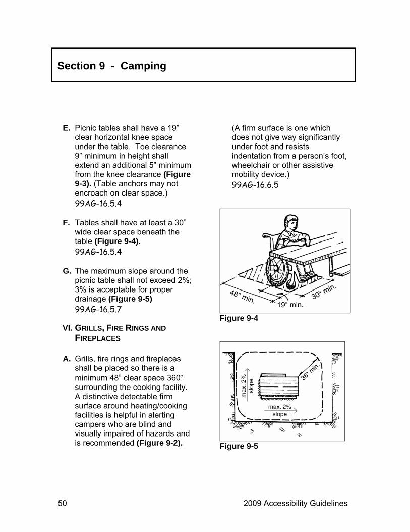
50 2009 Accessibility Guidelines
Section 9 - Camping
E. Picnic tables shall have a 19” clear horizontal knee space under the table. Toe clearance 9” minimum in height shall extend an additional 5” minimum from the knee clearance (Figure 9-3). (Table anchors may not encroach on clear space.) 99AG-16.5.4
F. Tables shall have at least a 30”
wide clear space beneath the table (Figure 9-4). 99AG-16.5.4
G. The maximum slope around the
picnic table shall not exceed 2%; 3% is acceptable for proper drainage (Figure 9-5) 99AG-16.5.7
VI. GRILLS, FIRE RINGS AND FIREPLACES
A. Grills, fire rings and fireplaces
shall be placed so there is a minimum 48” clear space 360° surrounding the cooking facility. A distinctive detectable firm surface around heating/cooking facilities is helpful in alerting campers who are blind and visually impaired of hazards and is recommended (Figure 9-2).
(A firm surface is one which does not give way significantly under foot and resists indentation from a person’s foot, wheelchair or other assistive mobility device.) 99AG-16.6.5
Figure 9-4
Figure 9-5

2009 Accessibility Guidelines 51
Section 9 - Camping
B. It is recommended that grills and fireplaces have an adjacent horizontal surface at least 8” wide on which hot objects may be placed (Figure 9-6).
C. Where a raised edge or curb is
provided on a fire ring, the distance from the outside edge of the fire ring to the fire building surface shall not exceed 24”. 99AG-16.1.5 ADAAG-4.2.6
D. Fire rings shall be 20” to 24” to
the top from the outside ground. 99AG-16.6.5
E. The fire building surface of a
fireplace or fire ring must be at least 9” from the ground (Figure 9-7).
F. The cooking surface of post-
mounted grills shall be between 15” and 34” above adjacent grade, with unobstructed access by horizontal reach from a standing or seated position (Figure 9-8). CBC-118B
Figure 9-6
Figure 9-7

52 2009 Accessibility Guidelines
Section 9 - Camping
Figure 9-8
Figure 9-9 G. When the grill is built into a
fireplace, the cooking surface shall be between 15” and 34” above the adjacent grade. The fire-building surface of the
fireplace must be 9” from the ground (Figure 9-6). 99AG-16.6.4 99AG-16.7.3
H. The cooking facility shall be
surrounded by a firm, stable ground surface. 99AG-16.7.5
I. The maximum slope of the clear
space surrounding the cooking facility shall be 2%, with 3% allowed for drainage (Figure 9-9). 99AG-16.6.6
J. In accessible, developed
campground sites and picnic areas where concrete or other hard surface paving exists or is to be installed, a firm-surfaced warning area shall be provided around the grill, fire ring or fireplace to alert blind and visually impaired persons to the location of the grill, fire ring or fireplace. This warning surface will have a minimum depth of 24” and shall provide clear visual contrast from the immediate adjoining surfaces (Figure 9-10). Re: Tucker vs. California State Parks, November 2005.

2009 Accessibility Guidelines 53
Section 9 - Camping
Figure 9-10
Figure 9-11
VII. WATER FAUCETS A. Faucets shall be located
adjacent to a clear, stable, firm ground surface area at least 60” x 60” in size. Rock surfaces are not allowed. Faucets shall be configured to allow a forward approach (Figure 9-11). 99AG-16.16.3
B. A 2% slope shall be allowed to
drain toward the faucet drain (a 3% slope is allowed when necessary for proper drainage). Drain grating shall have a maximum opening of ½”. 99AG-16.16.4 CBC-1124B.4
C. The faucet lever(s) shall be
located 28” to 36” above the ground (does not apply to hand pumps) and shall be operated by a push button or lever actuator that requires no more than 5 lbs. of pressure (Figure 9-11). 99AG-16.16.2-3 ADAAG-4.27.4

54 2009 Accessibility Guidelines
Section 9 - Camping
VIII. TRASH RECEPTACLES AND FOOD LOCKERS
A. Trash receptacles and food
lockers shall be located on an access route from the campsite (Figure 9-2). 99AG-16.8.1
B. Outdoor trash receptacles shall
have an opening at a height of 9” to 54” above the adjacent grade (Figure 9-12). Where necessary for health and safety reasons, animal exclusion receptacles that do not meet this guideline may be used. 99AG-4.27.3
C. If so equipped, both outdoor and
indoor (e.g., restrooms) trash receptacles shall operate with a single hand manipulation requiring no more than 5 lbs. of pressure. ADAAG-4.27.4
D. Trash receptacle shall be a
maximum of 48” for front approach and 54” for side approach about the adjacent grade. 99AG-4.27.3
Figure 9-12
Figure 9-13 E. There shall be at least 30” x 48”
of stable, firm, clear space to approach the trash receptacle. The maximum slope of the clear space shall be 2%, with 3% acceptable for proper drainage (Figure 9-13). 99AG-16.8.2-4

2009 Accessibility Guidelines 55
Section 9 - Camping
F. Food lockers shall have a clear approach that provides a 30” x 48” clear space. The latching mechanism shall be mounted between 15” and 48”. The latch shall be operable with one hand and not require tight grasping, pinching or twisting.
IX. SIGNAGE A. Accessible camping space shall
be designated by the International Symbol of Accessibility (ISA) (Figure 9-14). 99AG-16.17.1.3
B. Signage is not required where
sites are assigned upon arrival or through a reservation system, or where all sites are accessible. 99AG-16.17.1.3
Figure 9-14

56 2009 Accessibility Guidelines

2009 Accessibility Guidelines 57
Concessions
SECTION 10
I. CONCEPT A. Concessions generally enhance
public services and activities within State Park units. All concessions in State Parks must provide access for visitors with disabilities.
B. In order for all visitors to
participate in park programs and experiences, concessionaires must provide services at accessible locations.
II. GENERAL A. All concessions contracts held
by the Department will be in compliance with accessibility standards established by Federal, State and Department mandates.
B. All new or renewed concession
contracts must include the following paragraphs:
“Without limiting Concessionaire’s responsibility under this contract for compliance with all laws, with regard to all operations and activities that are the responsibility of Concessionaire under this contract, Concessionaire shall be solely responsible for complying with the requirements of the Americans With Disabilities Act of 1990 (ADA) (Public Law 101 – 336, commencing at Section 12101 of Title 42, United States Code; and including Titles I, II, and III of that law) and the Rehabilitation Act of 1973, and all related regulations, guidelines, and amendments to both laws.” “With regard to facilities for which Concessionaire is responsible for operation, maintenance, construction, restoration, or renovation under this contract, Concessionaire shall be responsible for

58 2009 Accessibility Guidelines
Section 10 - Concessions
compliance with Government Code Section 4450, et seq., Access to Public Buildings by Physically Handicapped Persons, and Government Code Section 7250, et seq., Facilities for Handicapped Persons, and any other applicable laws. Written approval from State is required prior to implementation of any plans to comply with accessibility requirements.”
C. Service machines used in
concessions must comply with appropriate standards.
Refer to Section 34, Service Machines for more information.
III. COMPLIANCE A. Districts should contact the
Accessibility Section to ensure that new concessions will meet accessibility standards.
B. Annual concessionaire
evaluations completed by districts will include access compliance criteria.

2009 Accessibility Guidelines 59
Curb Ramps
SECTION 11
I. CONCEPT A. Curb ramps are required to be
located at pedestrian crosswalks, wherever the accessible path of travel requires the pedestrian to transition from, through or onto a raised curb. ADAAG-4.7.1 CBC-1127B.5.1
B. Wherever vehicular surfaces are
marked for a pedestrian crosswalk, the curb ramp must terminate within the crosswalk area. ADAAG-4.7.9 CBC-1127B.5.1
C. Curb ramps shall be located to
prevent obstruction by parked cars. ADAAG-4.7.8 CBC-1127B.5.8
II. GENERAL A. The minimum width of the curb
ramp shall be 48” (Figures 11-1 & 11-2). CBC-1127B.5.2
B. The maximum slope of the curb
ramp shall be 8.33% (Figures 11-1 & 11-3). CBC-1127B.5.3
Figure 11-1

60 2009 Accessibility Guidelines
Section 11 - Curb Ramps
Figure 11-2
Figure 11-3
C. Where fanned or flared sides are installed to adjoin the curb ramp, the maximum slope of the flared sides shall be 10% (Figure 11-1). CBC-1127B.5.3
D. A level landing 48” deep shall be
provided at the upper end of each curb ramp over its full width or the slope of the fanned or flared sides cannot exceed 8.33% (Figures 11-1 & 11-3). CBC-1127B.5.4
E. The slope of the adjoining
gutters, road surfaces and the accessible route at either end of the curb ramp shall have a maximum slope of 5% for a minimum run of 48”. CBC-1127B.5.3
F. The surface of the curb ramp
and its flared sides shall be stable, firm and slip resistant. It shall also be of a contrasting finish from that of the adjacent sidewalk. ADAAG-4.5.1 CBC-1127B.5.6

2009 Accessibility Guidelines 61
Section 11 - Curb Ramps
III. DETAILS A. Curb ramps shall have a
grooved border 12” wide at the level surface of the sidewalk along the top and each side of the ramp with grooves spaced ¾” apart and ¼” deep (Figure 11-4). CBC-1127B.5.6
B. Where required, curb ramps
shall have a detectable warning in the form of truncated domes with an in-line grid pattern that extends the full width and depth of the core ramp. Domes shall be in a color that contrasts with the surrounding surface. For additional information, contact the Accessibility Section. (See also CBC-1133B.8.3.) CBC-1127B.5.7
C. Built up curb ramps shall be
located outside vehicular traffic lanes, parking spaces and access aisles. ADAAG-4.7.6 CBC-1127B.5.9
Figure 11-4
IV. DIAGONAL RAMPS A. Well-defined edges of diagonal
(corner type) ramps shall be parallel to the direction of traffic flow (Figure 11-5). ADAAG-7.7.10 CBC-1127B.5.9
B. There shall be a 48” minimum
clear space at the bottom of diagonal curb ramps. The clear space must be located within the marked crossing, if marked crossings are provided (Figures 11-5, 11-6, & 11-7). CBC-1127B.5.9
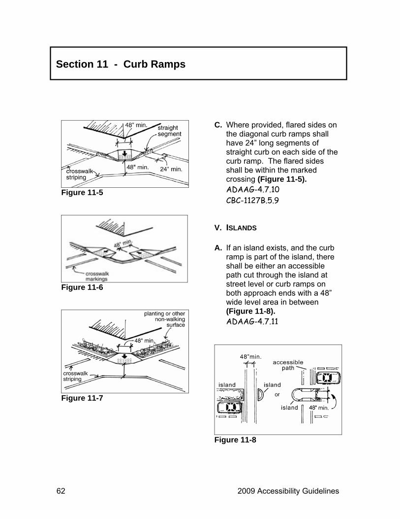
62 2009 Accessibility Guidelines
Section 11 - Curb Ramps
Figure 11-5
Figure 11-6
Figure 11-7
C. Where provided, flared sides on the diagonal curb ramps shall have 24” long segments of straight curb on each side of the curb ramp. The flared sides shall be within the marked crossing (Figure 11-5). ADAAG-4.7.10 CBC-1127B.5.9
V. ISLANDS A. If an island exists, and the curb
ramp is part of the island, there shall be either an accessible path cut through the island at street level or curb ramps on both approach ends with a 48” wide level area in between (Figure 11-8). ADAAG-4.7.11
Figure 11-8

2009 Accessibility Guidelines 63
I. CONCEPT A. Dining and banquet facilities
shall be made accessible to persons with disabilities, including food service and sales counters, with appropriate seating and wheelchair seating integrated throughout.
B. There shall also be an
accessible route of travel to and from the dining/banquet area. ADAAG-4.3 CBC-1114B.1.2
Refer to Section 33, Routes of Travel.
II. SEATING A. Wheelchair access shall be
provided to all areas. Each dining or banquet area shall have one wheelchair seating for every 20 seats where each type of functional activity occurs, with at least one wheelchair seating space per functional area. CBC-1104B.5.4
Refer to Section 7, Buildings.
B. Access to such seating shall be
provided with main aisles no less than 36” in clear width. Accessible seating shall be integrated with general seating to allow a reasonable selection of seating areas and to avoid having one area specifically highlighted as the area for person with disabilities (Figure 12-1). CBC-1104B.5.4
III. KNEE CLEARANCE A. Knee space at tables and
counters shall be a minimum of 27” high (recommended 29”), 30” wide and 19” deep. CBC-1122B.3
B. Knee clearance is not required at a checkout counter or service counter CBC-1122B.3
Dining & Banquet Areas
SECTION 12

64 2009 Accessibility Guidelines
Section 12 - Dining & Banquet Areas
Figure 12-1
Figure 12-2
Figure 12-3

2009 Accessibility Guidelines 65
Section 12 - Dining & Banquet Areas
IV. HEIGHT OF TABLES / COUNTERS A. The tops of accessible tables
and counters shall be 28” to 34” above the floor or ground. Where a single counter contains more than one transaction, at least 5% of those transactions, but not less than one, shall be as shown in (Figure 12-2). CBC-1122B.4
B. Food service aisles shall be a
minimum of 36” of clear width with a preferred width of 42” where passage of stopped wheelchairs by pedestrians is desired. Tray slides shall be mounted no higher than 34” above the floor, if self-service. ADAAG-5.5 CBC-1104B.5.5
V. REACH A. Clear Floor Space
1. Clear floor space, at least 30” x 48”, shall be created to allow either forward or parallel approach by a person in a wheelchair (Figures 12-3 & 12-4). CBC-1118B.4.1
Figure 12-4
Figure 12-5
2. Clear floor or ground space for wheelchairs may be part of the knee space required under some items (Figure 12-5). CBC-1118B.4.1

66 2009 Accessibility Guidelines
Section 12 - Dining & Banquet Areas
Figure 12-6
Figure 12-7
B. Tableware, dishware, condiments, food, beverage shelves and dispensing devices shall be located within accessible reach ranges:
1. Front (Forward) Reach
a. Front accessible forward
approach with forward reach – items must be positioned between 15” and 48” from the floor with the maximum horizontal reach over an obstruction not to exceed 20” (Figure 12-6). CBC-1118B.5
b. A maximum reach over an
obstruction of 25” is allowed if the maximum height of the item is 44” (Figure 12-5). CBC-1118B.5
2. Side Reach
a. Parallel approach in a
wheelchair with side reach – item must be positioned between 9” and 54” from the floor with the maximum horizontal reach over an obstruction not be exceed 10” (Figure 12-7). CBC-1118B.6

2009 Accessibility Guidelines 67
Section 12 - Dining & Banquet Areas
b. A maximum reach over an obstruction of 24” is allowed if the maximum height of the item does not exceed 46” (Figure 12-8). CBC-1118B.6
Figure 12-8

68 2009 Accessibility Guidelines

2009 Accessibility Guidelines 69
Doorways
SECTION 13
I. CONCEPT A. Doorways are an integral part of
the route of travel and should be considered for accessibility whether they are on interior building routes or on exterior routes. Doorways are also used as emergency exits and shall be accessible as part of the evacuation plan for the facility.
II. ACCESS ROUTES A. All entrances and exterior
ground floor exit doors shall be accessible. During periods of partial or restricted use, doorways that are primary entrances shall be accessible. CBC-1133B.1.1.1.1-2
B. An accessible door or gate shall
be made available adjacent to each turnstile exit or entrance. These doors or gates shall remain unlocked during business hours and shall not activate an alarm audible to the general public. CBC-1133B.2.3-4
III. SURFACES A. Doormats that are recessed shall
be adequately anchored to prevent interference with wheelchair traffic. CBC-1133B.1.1.1.3
IV. CLEARANCES A. Doorways shall allow for the
installation of a door 80” high and 36” wide. CBC-1133B.2.2
B. The clear opening of doorways
shall be no less than 32”. Clear width is measured parallel to the threshold, from the inside edge of the doorstop on the strike-side to the door edge, with the door opened perpendicular to the threshold (Figure 13-1). CBC-1133B.1.1.1.1
C. If the depth of the doorway
opening is greater than 24”, there must be a minimum aisle width of 36”. CBC-1133B.1.1.1.1

70 2009 Accessibility Guidelines
Section 13 - Doorways
Figure 13-1 D. There must be a level, clear area
on both sides of the door measuring 60” in the direction of the door swing (swing side) and 48” opposite the direction of the door swing (non-swing side), measured at right angles to the plane of the door when closed (Figure 13-2). The level clear space must be as wide as the door plus a required strike-edge clearance space. Strike-edge clearance is the clear space at the latch side of the door. Strike-edge clearance varies with the type of door and approach as follows: CBC-1133B.2.4.2
Figure 13-2
1. Front approach door on swing side – 18” minimum strike-edge of interior door, 24” exterior door, with 24” preferred.
2. Front approach door on non-
swing side – 12” minimum strike-edge, required if door has a closer and a latch.
3. Latch side approach on swing
side – 24” minimum strike-edge (Figure 13-3).
4. Latch side approach on non-
swing side – 24” minimum strike edge.

2009 Accessibility Guidelines 71
Section 13 - Doorways
Figure 13-3
5. Hinge side approach on swing side – 36” minimum strike-edge (Figure 13-4).
6. Hinge side approach on non-
swing side – 0” minimum strike-edge, but total width must be 54” or greater.
E. For recessed doors, where the
plane of the doorway is offset 8” or more from any obstruction within 18”, measure laterally on latch side, the door shall be provided with maneuvering clearance for front approach (Figure 13-5). CBC-1133B.2.5.3
Figure 13-4
Figure 13-5

72 2009 Accessibility Guidelines
Section 13 - Doorways
V. THRESHOLDS A. Thresholds shall have a
maximum height of ½”. A change in level between ¼” and ½” shall be beveled with a slope no greater than 50%. Changes in level greater than ½” shall be accomplished by means of a ramp (Figure 13-6). CBC-1133B.2.4.1
VI. HARDWARE A. Hand-activated door opening
hardware shall be centered between 30” and 44” above the floor (Figure 13-7). CBC-1133B.2.5.2
B. Openers must not require tight
grasping, pinching or twisting to operate. CBC-1133B.2.5.2
C. When sliding doors are fully
open, operating hardware must be exposed and usable from both sides. ADAAG-4.13.9
Figure 13-6
Figure 13-7 D. Interior and exterior doors must
not require more than 5 lbs. of force to operate. Compensating devices or automatic door operators may be used to meet this standard. CBC-1133B.2.5

2009 Accessibility Guidelines 73
Section 13 - Doorways
E. When fire doors are required, the maximum force to operate the door may be increased from 5 lbs. to the minimum allowable by the appropriate administrative authority not to exceed 15 lbs. CBC-1133B.2.5
F. Automatic or power-assisted
doors shall not open faster than three seconds and shall not require more than 15 lbs. of pressure to stop the door movement. ADAAG-4.13.12
G. If the door has a closer, it must
take at least three seconds to move the door from an open position at 70° to a point 3” from the latch measured to the leading edge of the door. ADAAG-4.13.10 CBC-1133B.2.5.1
VII. KICKPLATES A. The bottom 10” of all doors,
except automatic and sliding, shall have a smooth, uninterrupted surface to allow
the door to be opened by a wheelchair footrest without creating a trap or hazardous condition (Figure 13-8). CBC-1133B.2.6
VIII. SIGNAGE A. Accessible building entrances
shall be identified with the International Symbol of Accessibility (ISA). CBC-1117B.5.8.1
Refer to Section 35, Signage.
Figure 13-8

74 2009 Accessibility Guidelines

2009 Accessibility Guidelines 75
Dormitories, Hotels & Seasonal Housing
SECTION 14
I. CONCEPT A. Dormitories and similar places of
seasonal lodging shall have the following sleeping places accessible together with their sanitary facilities. ADAAG-9.1.1 CBC-1111B.2-4
Refer to Section 32, Restrooms.
B. Accessible sleeping places shall be dispersed among the various classes of sleeping accommodations to provide a range of options applicable to size and amenities provided. CBC-1111B.14
C. Additional accessibility required
in guest rooms or suites:
TOTAL NUMBER OF ROOMS
FULLY ACCESSIBLE
ROOMS
PLUS ADDITIONAL ACCESSIBLE ROOMS
WITH ROLL-IN SHOWERS
ADDITIONAL ROOMS EQUIPPED FOR
HEARING IMPAIRED 1 to 25 0 1 1
26 to 50 1 1 2 51 to 75 3 1 3 76 to 100 4 1 4
101 to 150 5 2 5 151 to 200 6 2 6 201 to 300 7 3 7 301 to 400 8 4 8 401 to 500 9 4 9
501 to 1,000 2% of total 2 % of total
1,001 and over 20, plus 1 for
each 100 over 1,000
4, plus 1 for each additional 100 over
400 20, plus 1 for each
100 over 1,000
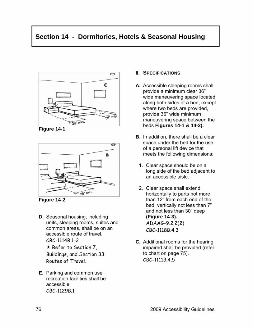
76 2009 Accessibility Guidelines
Section 14 - Dormitories, Hotels & Seasonal Housing
Figure 14-1
Figure 14-2 D. Seasonal housing, including
units, sleeping rooms, suites and common areas, shall be on an accessible route of travel. CBC-1114B.1-2
Refer to Section 7, Buildings, and Section 33. Routes of Travel.
E. Parking and common use
recreation facilities shall be accessible. CBC-1129B.1
II. SPECIFICATIONS A. Accessible sleeping rooms shall
provide a minimum clear 36” wide maneuvering space located along both sides of a bed, except where two beds are provided, provide 36” wide minimum maneuvering space between the beds Figures 14-1 & 14-2).
B. In addition, there shall be a clear
space under the bed for the use of a personal lift device that meets the following dimensions:
1. Clear space should be on a
long side of the bed adjacent to an accessible aisle.
2. Clear space shall extend
horizontally to parts not more than 12” from each end of the bed, vertically not less than 7” and not less than 30” deep (Figure 14-3). ADAAG-9.2.2(2) CBC-1118B.4.3
C. Additional rooms for the hearing
impaired shall be provided (refer to chart on page 75). CBC-1111B.4.5

2009 Accessibility Guidelines 77
Figure 14-3 D. Each additional room shall have
visual fire alarms and notification devices to alert room occupants of incoming telephone calls or a knock or doorbell. ADAAG-9.3.1 CBC-1114B.2.2 CBC-1111B.4.5 CBC-1111B.4.5.2
E. Doors and doorway passages
must be accessible. Refer to Section 13,
Doorways.
F. Bathroom doors must open in a way that does not interfere with clear space required near any fixtures. CBC-1111B.4.6.1
G. Bathrooms must provide a
minimum of 30” x 60” clear floor space. CBC-1111B.4.6.2 ADAAG-9.2.2(6)(e)
III. MISCELLANEOUS A. If provided, telephones in rooms
for persons with hearing impairments shall have volume controls.
B. If provided, there shall be an
accessible shower or bathtub in each accessible sleeping room.
C. As needed, refer to sections
on Storage Areas, Buildings (reaches), Service Machines, Public Telephones, Kitchens and/or Alarms.
Section 14 - Dormitories, Hotels & Seasonal Housing

78 2009 Accessibility Guidelines
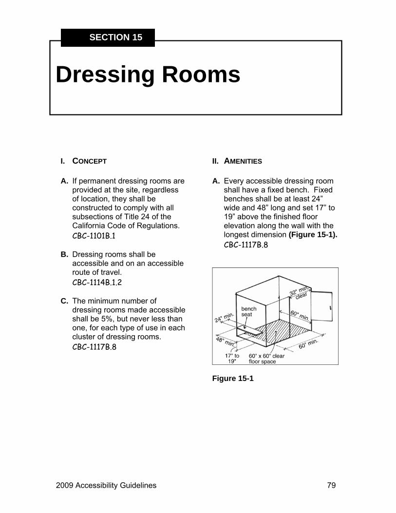
2009 Accessibility Guidelines 79
Dressing Rooms
SECTION 15
II. AMENITIES A. Every accessible dressing room
shall have a fixed bench. Fixed benches shall be at least 24” wide and 48” long and set 17” to 19” above the finished floor elevation along the wall with the longest dimension (Figure 15-1). CBC-1117B.8
Figure 15-1
I. CONCEPT A. If permanent dressing rooms are
provided at the site, regardless of location, they shall be constructed to comply with all subsections of Title 24 of the California Code of Regulations. CBC-1101B.1
B. Dressing rooms shall be
accessible and on an accessible route of travel. CBC-1114B.1.2
C. The minimum number of
dressing rooms made accessible shall be 5%, but never less than one, for each type of use in each cluster of dressing rooms. CBC-1117B.8

80 2009 Accessibility Guidelines
Section 15 - Dressing Rooms
B. Fixed benches shall have a slip resistant surface, not allow water collection and resist 250 lbs. force in any direction. ADAAG-4.35.4 CBC-1115B.7.2
C. Clothing hooks, when provided,
shall be located no greater than 48” above the finished floor elevation (Figure 15-2). CBC-1117B.8
Figure 15-2
D. Mirrors, when provided, shall be located adjacent to and usable from the bench and standing position and measure at least 18” wide and 54” long, with the lower edge within 20” from the finished floor elevation (Figure 15-2). CBC-1117B.8
III. CLEAR SPACES A. Dressing rooms shall have a 60”
x 60” clear space. No door shall encroach into the required space (Figure 15-1). CBC-1117B.8
B. Clear floor space shall be
provided alongside the bench to allow for a parallel transfer from a wheelchair to the bench. CBC-1117B.8
IV. ENTRY A. Refer to Section 13,
Doorways.

2009 Accessibility Guidelines 81
Drinking Fountains
SECTION 16
I. CONCEPT A. Where drinking fountains are
provided, there shall be accessible drinking fountain(s).
B. The drinking fountain must be on
an accessible path of travel Refer to Section 33, Routes
of Travel.
II. WALL MOUNTED UNITS AND POST MOUNTED UNITS
A. Where only one drinking fountain
is provided, the use of a “Hi-Low” fountain can be used for accessibility. CBC-1115B.4.6(1)
B. If more than one drinking
fountain is provided, at least 50% must be accessible. ADAAG-4.1.3(10)
C. The fountain shall not encroach
into an accessible route. CBC-1115B.4.6(3)
D. There shall be a clear, level space of at least 30” x 48” in front of the fountain to allow for a forward approach (Figure 16-1). CBC-1115B.4.6(2)
Figure 16-1 E. The fixture shall be a minimum
18” deep (Figure 16-2). CBC-1115B.4.6(2)
F. Clear knee space beneath the
fountain shall be a minimum of 27” high, 30” wide and 8” deep, with additional minimum toe space of 9” high by 17” deep (Figure 16-2). CBC-1115B.4.6(2)

82 2009 Accessibility Guidelines
Section 16 - Drinking Fountains
G. The water nozzle shall be located a maximum 36” above the ground and a maximum 6” from the front of the unit, with the water flow direction parallel to the front edge of the unit and to a 4” height minimum. If the basin is round or oval, the spout must be within 3” of the front (Figures 16-2 & 16-3). ADAAG-4.15.2-3 CBC-1115B.4.6(4) & (5)
H. Activation shall be by means of
lever controls or a wide, non-recessed press bar located at a maximum of 6” from the front edge of the unit and requiring no more than 5 lbs. of pressure, without tight grasping, pinching or twisting. ADAAG-4.15.3 CBC-1115B.4.6(4) CBC-1117B.6(4)
III. WALL MOUNTED UNITS A. Where provided, wall mounted
units shall be located completely within an alcove, or with wing walls, or so as not to encroach into pedestrian ways (Figure 16-4). CBC-1115B.4.6(3)
Figure 16-2
Figure 16-3
1. Alcove or wing wall of fountain shall be no less than 32” wide and 18” deep. CBC-1115B.4.6(3)
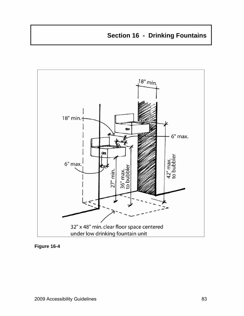
2009 Accessibility Guidelines 83
Figure 16-4
Section 16 - Drinking Fountains

84 2009 Accessibility Guidelines

2009 Accessibility Guidelines 85
Equestrian Facilities
SECTION 17
I. CONCEPT A. Equestrian activities consist of
either the facility to rent and ride or equestrian use that allows the visitor to bring a horse to ride and trailer.
B. Access to equestrian activities
involves two basic considerations:
1. Access to the place where
horses are available.
2. Transfer capabilities onto and off of the horse that are safe and secure. Such transfer shall be accomplished by one of three methods.
a. Raising the level of the rider
to that of the horse’s stirrups – by using a mounting platform.
b. Lowering the level of the
horse in respect to the level of the rider – such as a 2’ deep ground recess for the horse.
c. Providing a combination of (a)
and (b).
II. LOCATION A. Equestrian facilities shall be
located on an accessible path of travel with appropriate support facilities, such as signage, restrooms and parking.
III. MOUNTING PLATFORM A. An accessible mounting platform
should be provided to facilitate movement to and from the horse (Figure 17-1). It shall have:
1. A platform height above grade
24” to 29” as measured at the place of mounting the horse.
2. Access to the platform can be
by means of a route with a maximum slope of 8.33%.
3. A 3” high curb at all edges,
except for the opening on the mounting side.
4. The minimum level surface
area is 60” x 60”.

86 2009 Accessibility Guidelines
Equestrian Facilities
5. Site selection for mounting / dismounting activities could minimize or eliminate the need for a sloped route.
Contact the Accessibility
Section for information on optional types of mounting facilities.
Figure 17-1
IV. AMENITIES A. Amenities, such as fixed
benches, lockers, hitching posts and drinking fountains, should be accessible. Refer to Drinking Fountains, Fixed Benches, Storage Areas / Lockers, etc.

2009 Accessibility Guidelines 87
Exhibits
SECTION 18
I. CONCEPT A. Accessible exhibit design
elements shall include, but not be limited to, font style and size, color contrast between text and/or objects and background, tactile exhibits, interactive exhibits, controls, exhibit mounting heights and positioning of exhibits on path of travel.
The Accessibility Compliance Checklist for Exhibits may be found in the Appendix. This checklist contains the basic elements necessary for accessible exhibit design. Please refer to this checklist when developing or redesigning exhibits. Following the directives in this checklist will help to ensure that exhibits are fully accessible and legally compliant with all statutes and regulations.
B. Exhibits shall be designed to allow people with physical and sensory disabilities to access and experience the material presented.
C. Exhibits shall be designed so
that they do not overwhelm visitors of any ability with large blocks of text. Good exhibit design creates a visual balance between text, graphics and white space.
D. Models, touchable, and hands-
on exhibits may be better teaching tools that reach broader audiences than purely graphical exhibits and should be considered where possible.
E. Where possible and appropriate,
exhibit contents shall include the experiences and “voices” of persons with disabilities.

88 2009 Accessibility Guidelines
Section 18 - Exhibits
II. BASIC ELEMENTS OF ACCESSIBLE EXHIBIT DESIGN
A. Fonts
1. Typeface or font families used for exhibit text and labels shall be easy to read for persons with varied levels of vision. Preferred typefaces include sans serif fonts or fonts with simple, clean serifs. The number of typefaces in a given exhibit should not exceed two or three.
a. Some examples of legible
sans serif fonts include: Arial, Comic Sans, Futura, Optima, Tahoma, Tiresias and Trebuchet.
b. Some examples of legible
serif fonts that work well at large sizes include: Albertus Medium, Bookman, Caslon, Clarendon, Lydian, Novarese, and ITC Tiepolo.
2. Avoid fonts with strokes that
are very heavy, thin, light or decorative and those with letters are either very close together or widely spaced.
3. Spaces between lines of type (also known as “leading”) should make it easy to locate the next line. Leading at least 25% taller than the height of the lowercase font is suggested, and this percentage may increase slightly as the font size increases.
4. Font Styles - Even at panel
size text, italics may be somewhat hard to read and shall be limited to book title, foreign names and short quotes. Boldface text should generally not be used for entire sections. Text that uses upper and lowercase letters in typical sentence style is easier to read than all uppercase letters.
5. Font sizes for the main body of
text shall meet or exceed the minimums required for the horizontal viewing distance from the eyes to the object, according to the following chart. Minimum height of characters shall be measured using the uppercase X. Titles and Headings will be larger.

2009 Accessibility Guidelines 89
Section 18 - Exhibits
Captions may be smaller, but not smaller than 24-point. Captions briefly describe images; text that may be illustrated with an image but can stand alone is sidebar text and should be as close to main body text height as possible. Design credits may be small. See chart of Print Height Minimums.
6. Font Height Minimums -
HORIZONTAL DISTANCE
EYE-TO-OBJECT HEIGHT IN INCHES
Up to 39”
⅜”
Up to 78”
¾”
Up to 118”
1⅛”
(For measurement purposes, there are 72 points per inch. When taking into account spacing above and below a line of type, when set at 72 points, the line of type will take up approximately 1” of vertical space.) B. Text and Labels
1. Words are easier to read in horizontal lines. Artistic word shapes must be kept to a minimum or repeated in linear format, if used.
2. Maintaining a line length between 45 and 60 characters with margins flush left and ragged right is optimal. Where columns of text are used, space between columns must be large enough so viewers do not read across columns.
3. Labels pertaining to pictures or
objects shall be placed consistently throughout an exhibit.
4. Exhibit labels in cases or on
shelves shall be placed at readable heights and angles for persons who are seated or standing. Avoid placing labels flat on horizontal shelf surfaces. Labels placed at 45 degree angles to front plane of case are generally easier to see.
5. Text must be well balanced
with graphics and not overly wordy or technical. It should be straightforward, germane, and easy to comprehend for people of all abilities.
90 2009 Accessibility Guidelines
Section 18 - Exhibits
C. Light Levels
1. When not prohibited from doing so by conservation requirements, provide at least 100 lux (10 foot-candles) of light on an object. This is the minimum light level at which someone with low vision can see an object. If displaying sensitive materials that require a maximum of 50 lux (5 foot-candles), then:
a. Position the items to allow the
visitor to approach them as closely as possible.
b. Light the environment with
even light; do not spotlight an object.
c. Provide the highest
contrasting background possible.
d. Present the object in an
alternate format, such as a reproduction or a brochure that can be viewed in a brighter location.
2. Lighting shall be planned to
coordinate with conditions of exhibits so that glare from shiny objects can be avoided and so adequate lighting (100 – 300
lux or 10 – 30 foot-candles is recommended) is provided for the entire exhibit. ADAAG-4.30.8
B. Glare
1. Finishes shall be non-glare, eggshell or matte. ADAAG-4.30.5
2. Text screened directly onto
clear glass or Plexiglas is very difficult to see and shall not be used.
C. Contrast
1. Characters and symbols shall contrast with their background, either dark characters on a light background or light characters on a dark background. A minimum of 70% contrast is a recommended guideline. Contrast percentage is calculated using the following formula: ([B1-B2]/B1) x 100 = Contrast. B1 = Light Reflective Value (LRV) of the lighter color and B2 = LRV of darker value. ADAAG-4.30.5

2009 Accessibility Guidelines 91
Section 18 - Exhibits
Simply stated, “pure” black is the absence of light or 0% LRV, while white is “all” light or 100% LRV. Black and white have 100% contrast. If the background is white, the text darkness should be nearly ¾ of the way to black. Please contact the Accessibility Section for more information.
Refer also to Section 30, Publications.
2. Placing text over images or
patterns forces readers’ eyes to constantly adjust to varying contrasts. Use screens or place text over solid background with 70% contrast to text.
3. For objects that require a high
mounting position and/or low lighting, laminated, high-contrast photographs located near the individual exhibits or centrally set within the exhibition serve those with low vision as well as those who use wheelchairs.
D. Color
1. When choosing colors for fonts and backgrounds, research suggests that visibility for
persons with low vision will be enhanced by considering the following:
a. Differences between
foreground and background colors on labels or panels should be exaggerated. Lighten the lights and darken the darks to increase to 70% contrast.
b. Avoid using red and green
against each other as text and background, as persons with red-green color deficiencies (the most common color deficiency) are not able to easily distinguish the two.
c. Avoid contrasting colors from
adjacent hue families in the color circle (such as orange and yellow, orange and red, yellow and green, blue and green, blue and violet) as they often lack adequate contrasts.
d. Even if they are from different
hue families, colors of similar lightness (such as gray-blue and gray-brown) are difficult for persons with certain color deficiencies to see.

92 2009 Accessibility Guidelines
Section 18 - Exhibits
e. If colors from the same hue families (blue and light blue, brown and tan, etc.) are used adjacent to each other, contrast should be exaggerated to reach 70%.
III. ALTERNATE FORMATS A. Exhibits that cannot be made
physically accessible shall have alternatives such as captioned films, slide shows or photos.
B. Exhibits shall be able to provide
alternatives such as large print, audio, Braille, or tactile graphics on request. Large print text handouts shall be readily available for main body text located beyond optimal viewing range for its size or for any handouts printed at less than 18-point size. Verbal descriptions of exhibits may also be provided by docents or staff.
C. Audio or verbal descriptions shall
provide concise, objective, critical information the listener needs but cannot see or read.
D. Electronic versions of exhibits in
TXT or PDF format may be offered as a take home alternative to Braille for persons with a screen reader.
F. Availability of alternate formats and contact information shall be included on introductory panel and/or posted in a central area.
IV. HANDS-ON AND INTERACTIVE MATERIALS
A. Provide models, either life-size
or to scale, of rare or fragile objects that may not be touched. If the object is very large, a reproduction of a part of it should be available so that visitors can get an idea of its relative size.
B. Provide magnifiers for visitors to
examine photographs, signs, artifacts, fossils and mounted specimens in the exhibits.
C. In order to be within comfortable
reach ranges, exhibits featuring interactive controls or objects to be picked up and/or manipulated for more than a few seconds shall be located within accessible reach ranges. (Figures 18-1 & 18-3).
Contact the Accessibility Section for details
D. Exhibit controls or other items to
be briefly touched, such as push buttons, shall also be placed at a minimum of 28” and a maximum of 48” and within 18” across.

2009 Accessibility Guidelines 93
Section 18 - Exhibits
1. Earphones or speaking devices shall be mounted no higher than 40” and volume must be adjustable.
2. Knobs, handles, dials, and
controls used on interactive exhibits shall be designed so they can be operated with a closed fist with no tight grasping, pinching or twisting. CBC-1117B.6.4
V. FLAT MOUNTED DISPLAYS A. Flat-mounted or table top
exhibits to be touched or closely approached, such as relief maps and tactile exhibits, shall allow for a clear knee space that is a minimum of 36” wide and 27” clear height above the floor surface. Where it does not create a hazard for persons with low vision, 29” high knee space is recommended for wheelchair users (Figure 18-1).
VI. ANGLE MOUNTED DISPLAYS A. Angle-mounted exhibits featuring
mostly interactive features and/or controls to manipulate must include knee space as described in Part V, Flat-Mounted Displays (Figure 18-2).
Figure 18-1
Figure 18-2

94 2009 Accessibility Guidelines
Section 18 - Exhibits
Figure 18-3
B. Angled exhibit panels on pedestals or supports shall be placed at angles from 30 to 60 degrees to the ground or floor. The lower horizontal edge of the panel must be mounted between 28” and 34” above the ground. The exact distance may vary according to the panel size, and the text size should conform to minimums (Figure 18-3).
Contact the Accessibility Section for more details.
C. Angled exhibits mounted on posts and located along the prevailing path of travel must not protrude into the path of travel more than 12”, as described in Part VIII, Protruding Objects, Item C.

2009 Accessibility Guidelines 95
Section 18 - Exhibits
Figure 18-4
VII. VERTICALLY MOUNTED DISPLAYS
A. To allow both a standing and
seated person to read vertically displayed material, the material shall be mounted in accordance with Figure 18-4, “Text Mounting Height Ranges for Vertical Exhibits” based on the optimal field of vision for sitting and standing adults.
1. The optimal field of vision for standing adults at six feet from a vertical surface varies from 55” to 69”. The median height is 62”. For seated adults in standard wheelchairs at the same distance, the range is 42” to 50”. The median height is 46”.

96 2009 Accessibility Guidelines
Section 18 - Exhibits
B. Vertically mounted exhibits with most text and graphics between the 46” and 62” medians, and with most of the main body text centered around the 54” mid-point of the two medians will be within most viewers’ comfortable range of vision. Actual exhibit panel size may exceed these dimensions.
C. Exhibit shelters that have roofs
must allow vertical clear space of at least 80” between the lowest edge of roof and exhibit viewing surface (Figure 18-4).
Contact the Accessibility Section for more information.
VIII. PROTRUDING OBJECTS A. Objects projecting from walls
(e.g. telephones, display cabinets, etc.) with their leading edges between 27” and 80” above the floor surface shall protrude a maximum of 4” into walks, halls, passageways or aisles (Figure 18-5). CBC-1133B.8.6.1
B. Objects mounted with their
leading edges at or below 27” above the floor surface may protrude any amount. CBC-1133B.8.6.1
Figure 18-5 C. When freestanding objects are
mounted on posts or supports between 27” and 80” above the floor surface, they may overhang 12” but all edges must be rounded. CBC-1133B.8.6.1 – 3
D. Protruding objects shall not
reduce the clear width of an accessible route or maneuvering space.
CBC-1133B.8.6.3

2009 Accessibility Guidelines 97
Section 18 - Exhibits
IX. PATH OF TRAVEL AND CLEAR SPACE
A. Floor and path of travel surfaces
must be firm, stable and slip resistant, along accessible routes, and in accessible rooms and spaces. CBC-1124B.1
B. Exhibits and displays adequately
allow for approaching and viewing from a wheelchair. A stationary wheelchair requires a clear floor space of 30” x 48” (Figures 18-6 & 18-7). CBC-1118B.4.1
C. The clear space in front of any exhibit or display shall be a minimum of 60” wide to allow for both exhibit viewing and visitor circulation (Figure 18-8). CBC-1118B.3
D. All visitors viewing an exhibit shall be given the same opportunity to turn and leave the exhibit. To turn in any direction a wheelchair requires a minimum 60” diameter circle or a T-intersection with T-aisle widths of 36” or wider (Figures 18-8 & 18-9). CBC-1118B.3
E. Exhibit protective railings shall not be higher than 36” and shall not obstruct the line of vision of seated persons.
Figure 18-6
Figure 18-7
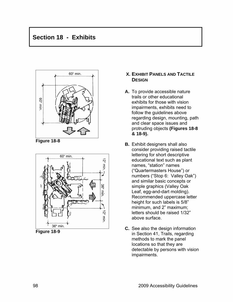
98 2009 Accessibility Guidelines
Section 18 - Exhibits
Figure 18-8
Figure 18-9
X. EXHIBIT PANELS AND TACTILE DESIGN
A. To provide accessible nature
trails or other educational exhibits for those with vision impairments, exhibits need to follow the guidelines above regarding design, mounting, path and clear space issues and protruding objects (Figures 18-8 & 18-9).
B. Exhibit designers shall also
consider providing raised tactile lettering for short descriptive educational text such as plant names, “station” names (“Quartermasters House”) or numbers (“Stop 6: Valley Oak”) and similar basic concepts or simple graphics (Valley Oak Leaf, egg-and-dart molding). Recommended uppercase letter height for such labels is 5/8” minimum, and 2” maximum; letters should be raised 1/32” above surface.
C. See also the design information
in Section 41, Trails, regarding methods to mark the panel locations so that they are detectable by persons with vision impairments.
2009 Accessibility Guidelines 99
Section 18 - Exhibits
XI. REFERENCES A. For additional information, see
the following references:
1. Website and other information from Lighthouse International research publications about accessible contrast and print. See online articles below:
www.lighthouse.org/color_contrast.htm and www.lighthouse.org/print_leg.htm
2. Smithsonian Institute Guidelines for Accessible Exhibit Design, including some information credited to Parks Canada, at:
www.si.edu/opa/accessibility/exdesign/start.htm

100 2009 Accessibility Guidelines
2009 Accessibility Guidelines 101
Fishing
SECTION 19
I. CONCEPT A. Fishing is an activity that can be
universally enjoyed. Every effort should be made to develop fishing opportunities that are fully accessible where fishing is a program or activity offered to the public. CBC-1132B.2
B. Fishing may take place from any
of three types of locations:
1. Fixed or floating pier/dock
2. Bank or shoreline
3. Boat C. The primary issues in the design
of accessible fishing sites are:
1. Locating good fishing sites.
2. Integrating the site with an accessible path of travel and support facilities.
3. Consideration of seasonal
changes in water level.
4. Safety, including safe levels of lighting.
D. Accessible fishing sites shall be
fully integrated with an accessible path of travel offering appropriate support facilities.
1. Accessible fishing sites shall be
appropriately identified with the International Symbol of Accessibility (ISA) at the site and at paths and trails leading to the site (e.g. parking, restrooms, etc.). CBC-1117B.5.1.1
E. Fishing sites may be developed
or undeveloped.
1. Developed sites are firm, level pads provided at the edges of streams, lakes or the seashore (for surf fishing).
2. Undeveloped sites have not
been significantly modified by construction, but are more analogous to rest areas in the pathway and trail system. They are firm, level areas at the water’s edge and of sufficient dimension for wheelchair use.
102 2009 Accessibility Guidelines
Section 19 - Fishing
3. The fishing site surface shall be firm and stable with a maximum slope of 3% in any direction.
II. SAFETY A. All reasonable precautions
should be taken to ensure a safe and comfortable fishing environment appropriate to the site.
B. Floor or grade surfaces of the
site (platforms, piers, etc.) shall be made of non-slip materials. CBC-1124B.1
III. FISHING PIERS A. Fishing sites over water may be
on fixed piers or floating docks. B. Access to the fishing site shall
be by means of an accessible path of travel.
C. The fishing site should extend
over the water for a distance that allows fishing at both high and low water conditions.
D. Floating sites shall have enough stability and flotation to support the additional weight of people and equipment without significantly affecting the equilibrium of occupants.
E. Piers shall have a 2” high edge
protection. F. All gaps in horizontal walking
surfaces shall be less than ½”. CBC-1124B.4
IV. CONNECTION TO SHORE A. Shore connections between the
dock and land shall have a 36” minimum clear width.
B. The surface material of the
gangway or bridge shall be slip-resistant. CBC-1124B.1
C. Gangways must be designed to
provide for a maximum 1:12 (8.33%) slope but are not required to be longer than 80’ in length. No intermediate landings are required. ADAAG-15.2.4

2009 Accessibility Guidelines 103
Section 19 - Fishing
D. Gangways are not required to have landings at the end if transition plates are provided.
Refer to Section 6, Boating. E. If the slope of the transition plate
is greater than 1:20 (5%), transition plates must have a landing at the end of the transition plate that is not connected to the gangway and that complies with ADAAG ramp requirements. ADAAG-15.2.2EXCP2
F. Handrail extensions are not
required where gangways and transition plates connect and both are provided with handrails. ADAAG-15.2.2EXCP6
V. SPACE NEEDED A. There should be provision for a
minimum of five linear feet per person along the water’s edge. These dimensions intentionally exceed minimum wheelchair requirements. General spatial allowances are essential because privacy and solitude are very strong motivational factors for many anglers. ADAAG-15.3.3
B. Fishing site surfaces and railings shall be of non-glare materials.
C. A minimum 30” x 48” clear space
shall be provided at the accessible fishing site and the surface should be firm, stable and slip-resistant (Figures 19-1 & 19-2). ADAAG-15.3.4
Figure 19-1
Figure 19-2

104 2009 Accessibility Guidelines
Section 19 - Fishing
D. A maneuvering space of at least 60” in diameter or a T-intersection at least 36” wide must be provided to allow a person using a mobility device or wheelchair to make a 180-degree turn (Figures 19-3 & 19-4). The space may overlap the accessible route and clear floor or ground space. ADAAG-4.2.1
E. The overhead casting clearance
at fishing sites should be 12’.
VI. HANDRAILS A. Whenever possible, it is
recommended to provide a 4” wide gap at maximum 8’ intervals in the handrail to allow the feel of the unobstructed line playing in the water and the opportunity for multiple castings.
B. Where railings are provided at
accessible fishing stations, rails shall be 34” above the ground or deck (Figure 19-5). Guardrails may be higher than 34” for enhanced safety or if a local building code applies. Accessible railings shall be dispersed in a variety of locations on the fishing pier or platform. ADAAG-15.3.3.2
Figure 19-3
Figure 19-4

2009 Accessibility Guidelines 105
Section 19 - Fishing
Figure 19-5 C. Where railings, guardrails or
handrails are provided, edge protection at a minimum of 2” high above the ground or deck surface shall be provided (Figure 19-6). ADAAG-15.3.3.1
1. Edge protection is not required
when the deck surface extends a minimum of 12” beyond the inside face of the railing, guardrail, or handrail (Figure 19-7). Toe clearance must be at least 30” wide and 9” minimum above the ground or deck surface beyond the railing (Figure 19-5). ADAAG-15.3.3.1
Figure 19-6
Figure 19-7 D. Railings must support 250 lbs. of
force in any direction. ADAAG-4.37.6

106 2009 Accessibility Guidelines
Section 19 - Fishing
VII. CLEANING TABLES A. If fish cleaning tables are
provided for standing persons, there shall be a proportionate section of table at 28” to 34” high, with clear knee space of 29” high, 19” deep and 30” wide underneath available for seated persons. ADAAG-4.32.3
B. Faucet controls must be
operable with a closed fist; the activation force must be 5 lbs. or less and, if self-closing, must stay on at least 10 seconds. ADAAG-4.27.4 CPC-1508.1-2
VIII. Benches A. If fixed benches are provided,
refer to Section 20, Fixed Benches.

2009 Accessibility Guidelines 107
Fixed Benches
SECTION 20
I. CONCEPT A. Fixed benches, where provided,
must be made accessible for users with various types of disabilities. 99AG-16.12.2.1
B. At least 50% of the fixed
benches being provided in a facility or a building shall be accessible and shall be dispersed among the types provided. 99AG-16.12.2
C. Of the number of fixed benches
required to be accessible, at least 40% shall be provided along an accessible route of travel.
Refer to Section 33, Routes of Travel.
II. CLEAR SPACES A. The surface around the
accessible bench shall be firm and stable. 99AG-16.12.6
B. A minimum area of 30” x 48” shall be provided at one end of the fixed bench so that a wheelchair user may be seated shoulder-to-shoulder with an individual seated on the bench (Figure 20-1). 99AG-16.12.4 ADAAG-4.2.4
C. Clear spaces shall have a slope
that does not exceed 2% in any direction (if necessary for proper drainage, 3% maximum is allowed). 99AG-16.12.7
D. It is recommended that benches
be placed 12” off any pathway so that a seated person does not obstruct the path of travel.
III. BENCH DESIGN A. The fixed bench shall be free of
sharp edges or protruding hardware that may be hazardous.

108 2009 Accessibility Guidelines
Section 20 - Fixed Benches
B. The height of the front edge of the seating surface shall be between 17” and 19” above the adjacent grade or floor space. 99AG-16.12.3
C. A back support shall be provided
along the full length of the accessible bench (Figure 20-1). 99AG-16.12.5
D. Accessible benches shall have
seats that are 20” to 24” in depth and 42” minimum in length. The back support shall extend from a point 2” maximum above the bench to 18” minimum above the bench (Figure 20-1). ADAAG-4.37.4
E. Accessible fixed benches shall have at least one armrest that can withstand 250 lbs. of force in any direction (Figure 20-1). 99AG-16.12.2-8 ADAAG-4.26.3
Figure 20-1

2009 Accessibility Guidelines 109
Guided & Self-Guided Programs and Tours
SECTION 21
I. CONCEPT A. Conducted tours and interpretive
walks/talks should be scheduled at locations that are accessible.
B. Tours must be integrated as
much as possible to accommodate visitors with differing abilities. Guides and interpreters must respond to individual differences and adjust the pace accordingly.
C. Hikes or tours requiring the
ability to traverse stairs or difficult terrain should be so described in advance publicity.
D. Qualified Sign Language
Interpreters shall be provided when requested in advance or whenever oral presentations are scheduled for large groups. Interpreters may include ASL, verbal enhancement for individuals with visual impairments, etc. DN 2004-07
E. Upon request, effort shall be made to obtain a Qualified Sign Language Interpreter (QSLI) or another method of communication requested by the person who is deaf or hard of hearing (e.g., written, ASD, CART, etc.), in accordance with the Department’s QSLI Policy (DN 2004-07).
F. Material shall be provided that
describes what information is available and the various means by which it is communicated.
G. Portable assistive listening
devices shall be provided for tours, special events and other activities where oral presentations are the core program.
H. Oral description and/or sighted
guide services must be available for the blind and visually impaired when requested in advance or whenever visual presentations are scheduled for large groups.

110 2009 Accessibility Guidelines
Section 21 - Guided & Self-Guided Programs and Tours
II. SELF-GUIDED PROGRAMS A. Self-guided printed or audio
tours must be designed to be accessible. Interpretive resource material to help guide the tour must be available in a variety of media (e.g., CD’s, large print, Braille, etc.).
B. Educational nature trails must be
designed to be accessible. Refer to Section 41, Trails.
III. VISUAL ACCESS A. Any solid barriers or walls
required along the route or at interpretive trails must be designed so that their height and location will permit clear visual access for a person sitting in a wheelchair.
B. An adult sitting in a wheelchair
has an eye level between 42” and 50” measured vertically from the floor surface. Section 18, Exhibits, provides criteria for the placement of visual displays of various types.
IV. Tour Route A. Before beginning the tour,
describe the route that will be taken, provide a map if available and give a brief overview of the resources that will be interpreted along the way. Describe any obstacles that may be encountered along the route.
V. SPEAKING TO GROUPS A. Adequate lighting of speakers is
essential to facilitate lip reading for persons with hearing impairments.
B. Speakers should face the
audience and enunciate clearly so that persons who are lip reading, signing or interpreting orally may clearly observe the speaker.
C. Speakers should speak clearly,
in a normal tone and volume. Speaking loudly does not help visitors with hearing impairments. Speak louder only if requested to do so. For large groups, use an amplification system or assistive listening system.

2009 Accessibility Guidelines 111
Section 21 - Guided & Self-Guided Programs and Tours
D. Speakers should wait for the audience to settle and be sure to have everyone’s attention before talking. Also, speakers may periodically check to see that everyone appears to have understood before continuing.
E. Try to use short sentences and
avoid using slang or jargon. A subject-verb-object sentence structure is best because it is the same syntax as American Sign Language.
F. Avoid sweeping arm movements
or moving around while speaking; this may be distracting to some visitors.
G. Give an oral description of
objects or features you show the group.
VI. DELIVERING INTERPRETIVE INFORMATION
A. Focus the program around a
theme. Smooth transitions are helpful. Discuss concepts and ideas in basic terms and reinforce through repetition. Too much information may cause confusion.
B. When showing visitors an object and discussing it at the same time, allow extra time for visitors to see what has been described. Some visitors can look at an object during the talk, but visitors with hearing impairments may need to watch the sign language or oral interpreter, or they may be lip-reading.
C. Speakers must try to position
themselves so that visitors can see them and the object of discussion at the same time. When working with a sign language or oral interpreter, the object must be placed between the two speakers.
D. To help visitors better
understand the presentation, point to objects that are being discussed.
E. Reading aloud exhibit or trail
signage can assist visitors with visual impairments.
F. Use photographs, slides, objects
and other visual and tactile examples to illustrate interpretive information.

112 2009 Accessibility Guidelines
Section 21 - Guided & Self-Guided Programs and Tours
G. Use descriptive language during the talk and encourage the entire group to be more aware of their senses.
H. Be familiar with and incorporate
different methods of describing historical and natural settings and objects.
I. Explain new or difficult words
and concepts. Include these words and their definitions in a handout, along with suggestions for additional reading on the subject.
VII. QUESTIONS A. Questions to the audience
should allow sufficient time for a response. Questions from the audience should be repeated before responding so that the audience understands both question and answer. An individual with a hearing impairment may understand the question a few seconds later because the sign language or oral interpreter may be a few words behind the speaker.
B. Look for visitors to indicate that they wish to answer a question before calling on them. A speech impairment or memory problem may interfere with visitors’ abilities to answer questions.
C. Do not automatically dismiss a
question or an answer as being irrelevant. Sometimes communication difficulties confuse what the individual is trying to say. Speakers should attempt to relate the question or answer to the subject.
VIII. INDIVIDUAL NEEDS A. Allow extra time between
exhibits or points of interest. People using assistive mobility devices may require additional time to move about.
B. Some individuals with
developmental disabilities may have difficulty understanding the concept of historical and calendar time. If this information is included in a program, use a variety of techniques to explain or demonstrate it.

2009 Accessibility Guidelines 113
Section 21 - Guided & Self-Guided Programs and Tours
C. Be aware that the low light levels in some areas might create hazardous situations, especially for persons with visual impairments. Some individuals may need extra time when moving from a bright area into a darkened room to allow their eyes to adjust.
D. Meet with visitors with visual
impairments before and/or after the program and ask if there is anything they would like described to them or if they would like additional information.
IX. SERVICE ANIMALS A. Working service animals are
permitted in park facilities and activities. Service animals should be under the control of the owner, generally on a leash, and under voice command. Some exceptions may include persons in wheelchairs who cannot operate the chair and
manage a leash, a service animal pulling the wheelchair, or an animal retrieving a dropped item. Service animals must be under control when around other people, in buildings, and in places where wildlife may be encountered.
B. Self-guided hikes through natural
or cultural areas may be posted as closed to all animals, including service animals, for the protection of the visitors or the resource, or during certain times such as breeding season.
X. REFERENCES A. For additional information, refer
to the Accessibility Section’s resource list; the California State Parks’ Qualified Sign Language Interpreters Policy (DN 2004-07); and “All Visitors Welcome – Accessibility in Interpretive Programs and Facilities”, a California State Parks publication.

114 2009 Accessibility Guidelines

2009 Accessibility Guidelines 115
Historic Sites
SECTION 22
I. CONCEPT A. The Americans with Disabilities
Act requires government agencies to ensure that all of their facilities, services and programs are accessible.
B. All historical buildings and sites
shall be as accessible as non-historical buildings, to the greatest extent possible, so that everyone may enjoy them.
C. The California Historical Building
Code (CHBC), Chapters 8-6, provides alternative solutions for qualified historic buildings while allowing access for disabled persons. CHBC 8-601.2
D. Any changes from the highest
levels of compliance must be decided on a case-by-case basis. Reasons for changes shall be documented and available in public records. CHBC 8-602.2
E. Project planning for historic buildings and properties must include accessibility solutions and be consistent with the park unit’s General Plan.
II. PROCESS / APPROVALS A. All State Park historic sites
should include input from their District Accessibility Resource Group (DARG) whenever possible. Refer to existing departmental policy on DARG requirements.
B. Accessibility issues for historic
sites and properties shall be reviewed by the Accessibility Section, at the onset of the Project Evaluation Form process. All project designs must be approved and certified by the Accessibility Section.
C. District Superintendents should
verify that all proposed projects are consistent with the unit’s General Plan and/or contact the General Planning Section for assistance.

116 2009 Accessibility Guidelines
Section 22 - Historic Sites
D. Issues that arise regarding the level of access for a historic structure that cannot be resolved at the district level, will be resolved with assistance from the Service Center, the Accessibility Section, and the Division Chief, as appropriate.
E. The Department’s Preservation
Officer will provide the final decision on unresolved issues. All decisions must be documented and incorporated into the project file.
III. DEFINITIONS A. Qualified Historic Buildings or
Properties:
Structures, buildings, districts or sites that are listed, or eligible to be listed, on the National Register of Historic Places or the California Register of Historical Resources are known as Qualified Buildings or Properties. Other structures on other official state, county or local inventories and surveys may also have qualifying historic status. CHBC 8-201
B. Character Defining Features:
Physical or visual elements of a structure or property, such as shape, materials, craftsmanship, decorative features, interior spaces and setting, which give it architectural, historical and cultural value. CHBC 8-201
C. Historical Significance:
The importance for which a property has been evaluated and designated historic by an authority with jurisdiction. This includes buildings, structures, districts or sites, generally at least 50 years old that have historical integrity, and are associated with important historic events or persons, have distinctive architectural characteristics or have potential to provide important information about pre-history or history. CHBC 8-201, 39 CFR63

2009 Accessibility Guidelines 117
Section 22 - Historic Sites
D. (Historical) Integrity:
The CHBC defines integrity as the authenticity of a property’s historic identity, evidenced by the survival of physical characteristics that existed during the property’s historic or prehistoric period. Integrity is defined by the National Register as the ability of a property to express its significance. This ability is shown by the survival of those traits and features that exemplify its significance and make the property eligible for the register. The seven aspects of integrity are: location, design, setting, materials, workmanship, feeling and association.
CHBC 8-201, 36 CFR63 E. Restoration:
The act or process and work of accurately depicting the form, features and character of a property, building or structure as it appeared at a particular period of time. CBC Chapter 34, CHBC. 8-201
F. Reconstruction:
1. The act or process and work of depicting, by means of “new
construction,” the form, features, and detailing of a non-surviving site, landscape, building, structure or object for the purposes of replicating its appearance at a specific period of time. CBC Chapter 34, CHBC. 8-201
2. The CHBC DOES NOT apply to
new construction or reconstruction/replicas of historic buildings.
IV. ACCESSIBILITY PROVISIONS CHBC Chapter 8-6
A. Basic Provisions:
The same access code requirements as those for non-historic buildings shall apply to historic structures and properties unless compliance with regular code threatens historical significance or integrity. In other words, the accessibility requirements outlined in other sections on buildings, doorways, elevators, lefts, ramps, restrooms, routes of travel, etc. shall be applied before the options listed below. CHBC 8-602

118 2009 Accessibility Guidelines
Section 22 - Historic Sites
B. Preferred Alternatives:
If using the Basic Provisions would threaten or destroy historic significance or integrity, the Preferred Alternatives may be used as long as they are applied on a case-by-case basis. Alternatives are to be used in priority order as listed below, with the strictest used first. CHBC 8-603
1. Entry Access Route
Alternatives
a. Access shall be from any entrance used by the general public and no further than 200’ from the primary entry.
b. Access to any open and
unlocked entry no further than 200’ from the primary entry.
2. Door Alternatives (Basic
Provisions reguire a 32” clear opening.)
a. A single-leaf door with at least
a 30” clear opening.
b. A single-leaf door with a 29½” clear opening.
c. Double doors where one leaf provides a 29½” clear opening.
d. Double doors with a power-
assist device and a combined clear opening of 29½”. Note: Offset hinges may sometimes be used to increase clear openings by as much as 1½”.
e. Power-Assisted Doors:
Power-assisted doors may be considered acceptable alternatives for level landings, strike side clearances and door opening forces required by regular code.
3. Toilet Room Alternatives
a. Where restrooms are
provided, make at least one men’s restroom and one women’s restroom accessible, or provide an accessible unisex restroom.
4. Exterior and Interior Ramp and
Lift Alternatives
a. A lift or ramp may have slopes up to 10% for distances up to 5’.

2009 Accessibility Guidelines 119
Section 22 - Historic Sites
b. Access may be by ramps sloped up to 16.6% for no more than 13” with signs posting slopes at the top and bottom.
C. Equivalent Facilitation
If using the Preferred Alternatives threatens historical significance or integrity or would require a fundamental change in the program, service or activity, then use of alternative designs or technology is permitted under the following conditions: CHBC 8-602
1. Alternatives must be applied on
a case-by-case basis.
2. Alternatives used must provide substantially equivalent or greater accessibility to the facility.
3. Reasons for the use of Equivalent Facilitation and the effect such alternatives will have on the property must include comments from local groups of peoples with disabilities and must be documented and kept in State Park’s permanent file.
4. Alternatives may include
providing services, videos, virtual reality tours, maps, plans, exhibits or other creative solutions at accessible levels.
D. References:
For additional information, refer to Departmental Notice DN 2005-03, Accessibility and Historic Properties.

120 2009 Accessibility Guidelines
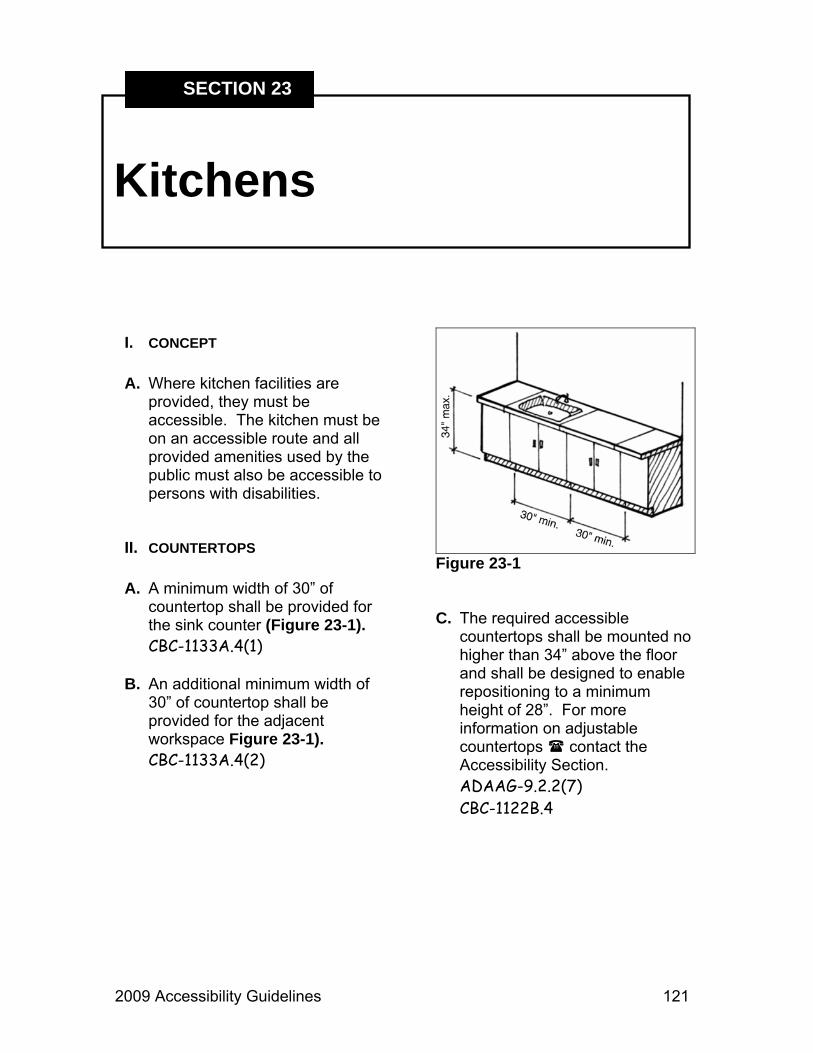
2009 Accessibility Guidelines 121
Kitchens
SECTION 23
I. CONCEPT A. Where kitchen facilities are
provided, they must be accessible. The kitchen must be on an accessible route and all provided amenities used by the public must also be accessible to persons with disabilities.
II. COUNTERTOPS A. A minimum width of 30” of
countertop shall be provided for the sink counter (Figure 23-1). CBC-1133A.4(1)
B. An additional minimum width of
30” of countertop shall be provided for the adjacent workspace Figure 23-1). CBC-1133A.4(2)
Figure 23-1 C. The required accessible
countertops shall be mounted no higher than 34” above the floor and shall be designed to enable repositioning to a minimum height of 28”. For more information on adjustable countertops contact the Accessibility Section. ADAAG-9.2.2(7) CBC-1122B.4

122 2009 Accessibility Guidelines
Section 23 - Kitchens
D. There shall be a 30” x 48” clear space around sinks, appliances and countertops that allows a parallel approach (Figure 23-2). ADAAG-9.2.2(7) CBC-1133A.2
Refer to Section 7, Buildings.
E. Knee space under the sink and
work counter shall be a minimum of 19” deep, 27” high and 30” wide (Figures 23-3 & 23-4). CBC-1115B.4.7
III. CABINETS A. Base cabinets, including toe
board and shelving, directly under the sink and work surface counters shall be removable without the use of specialized tools or knowledge. CBC-1133A.3
B. The flooring underneath
removable cabinets shall be finished and extend to the wall. CBC-1133A.3
Figure 23-2
Figure 23-3
Figure 23-4

2009 Accessibility Guidelines 123
Section 23 - Kitchens
C. The sides and backs of cabinets located adjacent to the sink and workspace countertops shall be constructed of durable, non-absorbent materials to accommodate cabinet exposure to moisture and food handling when the countertop is lowered. CBC-1133A.4.1
D. A minimum of 50% of cabinets,
shelf space and refrigerator/freezer space shall be within reach ranges: 15” to 48” for a front approach, or 9” to 54” for a side approach.
E. Drawer and lower shelf space
shall be provided at a maximum height of 48”. CBC-1133A.5
IV. APPLIANCES A. Appliances and their controls
shall meet applicable Title 24 (CBC) and ADAAG regulations.
Contact the Accessibility Section for questions or more information.
V. SINKS A. Refer to Section 36, Sinks.

124 2009 Accessibility Guidelines

2009 Accessibility Guidelines 125
Lifts
SECTION 24
I. CONCEPT A. Lifts can only be used in lieu of
an elevator in existing buildings. In new buildings the use of a lift is limited as outlined in the following sections.
B. Special access wheelchair lifts
may be provided between levels in lieu of an elevator when the vertical distance between landings, as well as the structural design and safeguards, are as allowed by the State of California, Division of the State Architect, Department of Industrial Relations, Division of Occupational Safety and Health and any applicable safety regulations of other administrative authorities having jurisdiction. CBC-1116B.2
II. USE OF LIFTS A. Changes in levels along an
accessible route greater than ½” shall comply with the requirements of a curb ramp, ramp, elevator or platform lift as permitted for new construction or alterations. An accessible route does not include stairs, steps or escalators. ADAAG-4.3.8
B. Elevators and lifts shall be on an
accessible route and they shall be designed and constructed to be accessible in accordance with appropriate building codes. ADAAG-4.0-4.11 CBC-1116B
C. If lifts are provided, they shall be
designed and constructed to facilitate unassisted entry, operation and exit from the lift and shall comply with the requirements of this section, in conjunction with Sections 3090 to 3094, Part 7 of the California Code of Regulations.

126 2009 Accessibility Guidelines
Section 24 - Lifts
D. Additionally, lifts may be provided as part of an accessible route only for the following conditions:
1. To provide an accessible route
to a performing area or stage, or to a speaking area or similar place in an assembly area. CBC-1116B.2.1
To comply with the wheelchair viewing position line-of-sight and dispersion requirements. CBC-1116B.2.2
Refer to Section 8, Campfire Centers & Assembly Areas.
2. To provide access to incidental
occupiable spaces and rooms which are not open to the general public and which house no more than five persons, including, but not limited to, equipment control rooms and projection booths. CBC-1116B.2.3
3. To provide access where
existing site constraints or other constraints make use of a ramp or an elevator not feasible. CBC-1116B.2.4
E. The minimum landing area outside the entry and exit door to the lift shall be 60” x 60”. Exception: a 30” x 48” landing with existing conditions may be permitted and is subject to review by the Accessibility Section. A person using a wheelchair must be able to enter and operate the lift safely. CBC-1116B.2.4.1

2009 Accessibility Guidelines 127
Parking
SECTION 25
I. CONCEPT A. Where parking is provided,
appropriate accessible spaces shall be provided. This will include the proper number, including van spaces, with appropriate signage and location of spaces with an accessible route of travel to the facilities or activities.
II. LOCATION A. Accessible spaces must be
located as near as possible to a primary entrance or on the shortest accessible route from parking to the facility, activity, etc. CBC-1129B.1
B. Parking spaces shall be located
so visitors do not have to travel behind parked cars other than their own. CBC-1129B.3.3
C. Accessible paths shall be provided from parking spaces to related facilities, including curb cuts or ramps, as needed. Ramps shall not encroach on any parking or access aisle spaces. CBC-1129B.3.3
III. SPACES REQUIRED A. Minimum number of accessible
spaces required (Figure 25-1). CBC-1129B.4.2 (Table 11B-6)
B. A minimum of one in every eight accessible spaces, but no less than one, should be served by a minimum 8’ wide access aisle on the passenger side and be designated with a sign as “Van Accessible.” CBC-1129B.1
C. Additional standard accessible
stalls may be served by a 5’ wide access aisle.

128 2009 Accessibility Guidelines
Section 25 - Parking
TOTAL SPACES TOTAL VAN
ACCESSIBLE SPACES
1 – 25 1 VAS
26 – 50 2 (1 VAS)
51 – 75 3 (1 VAS)
76 – 100 4 (1 VAS)
101 – 150 5 (1 VAS)
151 – 200 6 (1 VAS)
201 – 300 7 (1 VAS)
301 – 400 8 (1 VAS)
401 – 500 9 (1 VAS)
501 – 1,000 2% of total (3 VAS)
1,001 + 20, plus 1 for
each 100 over 1,000
Figure 25-1
IV. TIRE STOPS A. A bumper or curb shall be
provided to serve as a tire stop to prevent encroachment of cars on the required width of walkways. CBC-1129B.3
V. SURFACE A. Accessible parking spaces are
paved. For non-paved parking, contact the Accessibility
Section. CBC-1124B.1
VI. SLOPE A. Surface slopes of accessible
parking spaces shall be kept to a minimum for surface water drainage and shall not exceed 2% in any direction.
CBC-1129B.3.4
VII. SIZE A. Each parking space must be 18’
minimum in length (Figure 25-2). CBC-1129B.3.1
B. If there is only one space, it shall
be 17’ wide, outlined to provide 9’ wide parking space and 8’ wide loading and unloading aisle on the passenger side of the vehicle. CBC-1129B.3.2
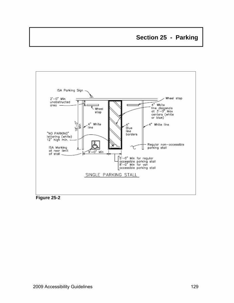
2009 Accessibility Guidelines 129
Section 25 - Parking
Figure 25-2

130 2009 Accessibility Guidelines
Section 25 - Parking
Figure 25-3

2009 Accessibility Guidelines 131
C. If there is more than one space provided, in lieu of providing a 17’ wide space, two spaces can be provided within a 26’ wide area, lined to provide a 9’ wide parking space on each side of an 8’ wide loading and unloading aisle in the center (Figure 25-3).
VIII. IDENTIFICATION A. The surface of each accessible
paved parking space shall have a surface identification, duplicating the International Symbol of Accessibility (ISA), in blue paint at least 36” square in an area located so it can be seen by a parking enforcement official (Figure 25-3). CBC-1129B.4.2
B. A permanently affixed
reflectorized sign displaying the International Symbol of Accessibility (ISA) in white on a blue background shall identify each designated space (Figures 25-4, 25-5 & 25-6). CBC-1129B.4
1. The sign shall be no smaller
than 70” square in area.
2. The sign shall be at a minimum height of 80” centered from parking/walking surface to bottom of the sign, if free standing and in a path of travel.
Figure 25-4
Figure 25-5
Section 25 - Parking
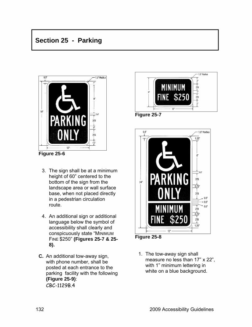
132 2009 Accessibility Guidelines
Section 25 - Parking
Figure 25-6
3. The sign shall be at a minimum height of 60” centered to the bottom of the sign from the landscape area or wall surface base, when not placed directly in a pedestrian circulation route.
4. An additional sign or additional
language below the symbol of accessibility shall clearly and conspicuously state “MINIMUM FINE $250” (Figures 25-7 & 25-8).
C. An additional tow-away sign,
with phone number, shall be posted at each entrance to the parking facility with the following (Figure 25-9): CBC-1129B.4
Figure 25-7
Figure 25-8
1. The tow-away sign shall measure no less than 17” x 22”, with 1” minimum lettering in white on a blue background.

2009 Accessibility Guidelines 133
Section 25 - Parking
Figure 25-9

134 2009 Accessibility Guidelines
Section 25 - Parking
2. The sign shall read, “UNAUTHORIZED VEHICLES PARKED IN DESIGNATED ACCESSIBLE SPACES NOT DISPLAYING DISTINGUISHING PLACARDS OR LICENSE PLATES ISSUED FOR PERSONS WITH DISABILITIES MAY BE TOWED AWAY AT THE OWNER’S EXPENSE. TOWED VEHICLES MAY BE RECLAIMED AT: ______(address)______ OR BY TELEPHONING __(phone number of local law enforcement____ agency)_.” (Figure 25-9)
D. Accessible van spaces shall be
identified with a physically separate “VAN ACCESSIBLE” sign located below the symbol of accessibility. CBC-1129B.4
E. The loading and unloading area
of the pavement adjacent to a parking stall or space designated for disabled person shall be marked by a border and hatched lines. The border shall be painted blue and the hatched lines shall be painted a suitable contrasting color to the parking space. Blue or white paint is preferred. In addition, the words “NO PARKING” shall be painted on the ground within each 5’ or 8’ wide loading and unloading
access aisle. This notice shall be painted in white letters no less than 12” high and located so that it is visible to traffic enforcement officials (Figure 25-2 & 25-10). CBC-1129B.3.1-2
Figure 25-10
IX. PARKING STRUCTURES A. Parking structures shall have a
minimum vertical clearance of 8’2” at entrances and where required for access to accessible parking spaces. CBC-1130B
X. PULL-THROUGH PARKING A. If pull-through parking for
motorhomes, camping trailers or boat trailers is provided, it should meet the following guidelines:

2009 Accessibility Guidelines 135
Section 25 - Parking
1. Width of parking area should be 10’ and, if paved, the International Symbol of Accessibility (ISA) shall be painted at each end.
2. An adjacent loading/unloading
area (on the passenger side if a single parking spot) shall be 8’ wide, blue striped if paved, with a post-mounted accessibility sign on the outside edge of the loading/unloading area.
XI. PASSENGER DROP-OFF AND LOADING ZONES
A. If passenger drop-off and loading
zones are provided, one zone shall have the following: CBC-1131B.2.1
1. An accessible aisle 5’ x 20’
provided adjacent and parallel to the vehicle pull-up space (Figure 25-11).
Figure 25-11
2. Surface slope less than 2% in all directions including vehicle space. CBC-1131B.2.1
3. Stable, firm and slip resistant
surfaces.
4. Identified by the International Symbol of Accessibility (ISA).
B. Vertical clearance of 9’6” shall
be located at the loading zone, site entrance and exit. CBC-1131B.2.2
C. Walk surfaces crossing or joining
the vehicular way not separated by curbs, railings or other elements shall be identified with continuous, detectable warnings. These warnings shall meet the following guidelines:
1. The warnings shall be between
24” and 36” wide.
2. They shall contrast visually with adjoining surfaces with either dark on light or light on dark.
D. A curb ramp shall be provided
for zones where a curb is present between the aisle and vehicular pull-up space. ADAAG-4.6.6

136 2009 Accessibility Guidelines

2009 Accessibility Guidelines 137
Picnic Sites
SECTION 26
I. CONCEPT A. A picnic site exists wherever one
or more fixed picnic tables are located. In general, picnic areas must include accessible parking, restroom, picnic site and routes that connect each of the elements throughout the area. However, for the convenience of all users, Department policy dictates that when replacing picnic site furnishings such as tables, drinking fountains and barbeques, these furnishings shall be of an accessible design.
II. SITE PLANNING A. Where only one fixed picnic table
is provided in a picnic area, it must be accessible and must be connected to an outdoor recreation access route. 99AG-16.5.1.1
B. If there are two or more picnic tables, at least 50%, but never less than two, shall be accessible tables. 99AG-16.5.1.2
C. Of the accessible tables, at least
40%, but never less than two tables, shall be on an accessible route of travel.
Refer to Section 33, Routes of Travel.
D. Accessible picnic tables shall be dispersed throughout the picnic area. 99AG-16.5.2
E. The accessible picnic sites shall
be located on a surface area with no greater than a 2% slope (3% slope when necessary for drainage). 99AG-16.5.7

138 2009 Accessibility Guidelines
Section 26 - Picnic Sites
III. PICNIC TABLES A. Picnic tables and benches shall
be on a firm, stable surface. 99AG-16.5.6
B. An accessible picnic table shall
have at least one wheelchair seating space (Figure 26-1). Where the table top perimeter exceeds 24 linear feet, the number of wheelchair seating spaces shall comply with the following chart: 99AG-16.5.3
TABLE TOP PERIMETER
WHEELCHAIR SPACES
25 lf – 44 lf 2 spaces 45 lf – 64 lf 3 spaces 65 lf – 84 lf 4 spaces
85 lf – 104 lf 5 spaces
Figure 26-1
C. Picnic tables and benches shall have no sharp edges or protruding hardware that may be hazardous.
D. Around the picnic table, a 36”
clear space measured from the seat shall be maintained (Figure 26-2). 99AG-16.5.5
Figure 26-2
E. Distance from the tabletop to the ground shall be between 28” and 34” (Figure 26-3). CBC-1122B.4

2009 Accessibility Guidelines 139
Section 26 - Picnic Sites
Figure 26-3
Figure 26-4
F. Picnic tables shall have a minimum knee clearance of 27” high, 19” deep and 30” wide. Toe clearance shall be a minimum of 9” high and 24” deep (Figures 26-1 & 26-3). (Table anchors may not encroach on clear space.) 99AG-16.5.4
IV. GRILLS, FIRE RINGS AND COOKING SURFACES
A. Where a cooking surface or fire
ring is provided at a picnic site, it must be accessible. 99AG-16.6.1.1 99AG-16.7.1.1
B. In accessible, developed picnic
areas where concrete or other hard surface paving is present or is to be installed, a firm-surfaced warning area shall be provided around the grill, fire ring or fireplace to alert blind and visually impaired persons to the location of the grill, fire ring or fireplace. This warning surface will have a minimum depth of 24” and shall provide clear visual contrast from the immediate adjoining surfaces (Figures 26-4 and 26-5). Re: Tucker vs. California State Parks, November 2005

140 2009 Accessibility Guidelines
Section 26 - Picnic Sites
Figure 26-5
Figure 26-6
C. The slope of the clear space around cooking facilities and fire rings shall be a maximum of 2% (3% slope when necessary for drainage) (Figure 26-4). 99AG-16.6.6 99AG-16.7.6
D. The height of the fire ring’s
raised edge shall be between 20” and 24” above surface level.
E. On fire rings or fire place grills,
the fire building surface height shall be a minimum of 9” above ground level. The distance from the outside edge of the fire ring to the fire building surface shall be a maximum of 24” (Figure 26-6). 99AG-16.6.4-5
F. All cooking surface heights shall
be between 15” minimum and 34” maximum above the ground level Figures 26-7 & 26-8). 99AG-16.7.3

2009 Accessibility Guidelines 141
Section 26 - Picnic Sites
Figure 26-7
Figure 26-8
G. Where two or more cooking surfaces, grills, or pedestal grills are provided in an area, at least 50%, but never less than two, shall comply with the requirements of this section. In addition, at least 40%, but never less than two, of these accessible cooking surfaces shall be connected to an outdoor recreation access route complying with the requirements of an “ERT” or “ORAR”.
See Section 33, Route of Travel.
V. WATER FAUCETS A. Faucets shall be located
adjacent to a clear, stable, firm ground surface area at least 60” x 60” in size. Faucets shall be configured to allow a forward approach (Figure 26-9). 99AG-16.16.3
B. A 2% slope shall be allowed to
drain toward the faucet drain (a 3% slope is allowed when necessary for proper drainage). Drain grating shall have a maximum opening of ½”. 99AG-16.16.4 CBC-1124B.4

142 2009 Accessibility Guidelines
Section 26 - Picnic Sites
Figure 26-9
Figure 26-10
C. The faucet lever(s) shall be located 28” to 36” above the ground (this requirement does not apply to hand pumps) and shall be operated by a push button or lever actuator that requires no more than 5 lbs. of pressure (Figure 26-9). 99AG-16.16.2-3 ADAAG-4.27.4
VI. TRASH AND RECYCLING RECEPTACLES
A. The picnic area shall have a
trash receptacle at the site or on an accessible route to the site. ADAAG-16.8.1
B. The trash and/or recycling
receptacle shall be located on stable, firm ground with a clear space minimum of 30” x 48” and a slope of 2% (3% allowed if necessary for drainage) (Figure 26-10). 99AG-16.8.2-4

2009 Accessibility Guidelines 143
Section 26 - Picnic Sites
C. The trash and or recycling receptacle opening and/or operating mechanism shall be between 15” and 48” above the ground for front approach and between 9” and 54” for side approach (Figure 26-11). ADAAG-4.27.3
D. Receptacle openings shall be
operable with a single hand manipulation and require less than 5 lbs. of pressure to operate. This requirement does not apply to hinged lids and controls designed to exclude animals. 99AG-16.8.5 ADAAG-4.27.4
Figure 26-11

144 2009 Accessibility Guidelines

2009 Accessibility Guidelines 145
Play Areas
SECTION 27
I. CONCEPT A. A park location that has any
number of play components designed and constructed for play, socialization, or learning by children is considered a play area. In play areas it is important that accessible equipment be integrated with non-accessible equipment. While not every piece of play equipment needs to be accessible, when non-accessible components stand alongside accessible ones, it promotes social interaction between children.
B. Play components can be either
elevated or ground level, made of manufactured or natural materials, and may be “stand alone” or part of a composite play structure.
1. Ground level play components are those that are approached and exited at ground level (i.e., swing rockers, swings and stand-alone climbers). Free standing slides are also considered ground level components and an accessible route of travel must connect to the ladder or steps and to the exit of the slide.
2. Elevated components are
approached above or below grade and are part of a composite play structure consisting of two or more play components attached or functionally linked to create an integrated unit providing more than one play activity.
3. Soft, contained play structures
are made up of one or more components where the user enters a fully enclosed play environment that utilizes pliable materials such as plastic, netting or fabric.

146 2009 Accessibility Guidelines
Section 27 - Play Areas
C. Accessible surfaces and routes inside play areas have different criteria than accessible surfaces and routes elsewhere. Certain surfaces must meet stringent safety standards put forth by the American Society for Testing and Materials. To ensure compliance with all codes and standards it is important that park leaders and project managers contact the Accessibility Section for guidance whenever work on a new or existing play area is planned.
II. GENERAL A. All newly constructed play areas
designed for children ages two and over or altered portions of existing play areas shall be accessible. ADAAG-15.6.1
1. Where play components are
relocated in existing play areas for the purpose of creating safe use zones or where play components are altered and the ground surface is not altered, the ground surface inside the play area shall not be
required to be modified for accessibility. ADAAG-15.6.2 – 3
B. Play areas must be located
along an accessible route of travel. Refer to Section 33, Routes of Travel. However, within the boundary of the play area, routes must comply with the guidelines in this section. ADAAG-4.3.2 ADAAG-15.6.4
III. ACCESSIBLE ROUTES INSIDE PLAY AREAS
A. Except as amended in this
section, when required within the boundary of a play area, accessible routes shall meet the requirements for exterior routes of travel (ERT). ADAAG-4.3 ADAAG-15.6.4
B. Accessible routes required within
the boundaries of play areas shall connect ground level play components and elevated components, including entry and exit points. ADAAG-15.6.4.1
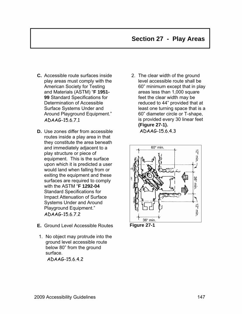
2009 Accessibility Guidelines 147
Section 27 - Play Areas
C. Accessible route surfaces inside play areas must comply with the American Society for Testing and Materials (ASTM) “F 1951-99 Standard Specifications for Determination of Accessible Surface Systems Under and Around Playground Equipment.” ADAAG-15.6.7.1
D. Use zones differ from accessible
routes inside a play area in that they constitute the area beneath and immediately adjacent to a play structure or piece of equipment. This is the surface upon which it is predicted a user would land when falling from or exiting the equipment and these surfaces are required to comply with the ASTM “F 1292-04 Standard Specifications for Impact Attenuation of Surface Systems Under and Around Playground Equipment.” ADAAG-15.6.7.2
E. Ground Level Accessible Routes 1. No object may protrude into the
ground level accessible route below 80” from the ground surface. ADAAG-15.6.4.2
2. The clear width of the ground level accessible route shall be 60” minimum except that in play areas less than 1,000 square feet the clear width may be reduced to 44” provided that at least one turning space that is a 60” diameter circle or T-shape, is provided every 30 linear feet (Figure 27-1). ADAAG-15.6.4.3
Figure 27-1
148 2009 Accessibility Guidelines
Section 27 - Play Areas
3. The clear width of any ground level accessible route in a play area may be reduced to 36” minimum for a distance of 60” maximum provided that multiple reduced width segments are separated by segments that are 60” wide for at least 60” in length. ADAAG-15.6.4.3.1
F. Elevated Accessible Routes 1. At least 50% of the elevated
components must be located on an accessible route. ADAAG-15.6.3
a. Where transfer systems are
provided, an elevated play component shall be permitted to connect to another elevated play component in lieu of an accessible route. However, where 20 or more elevated play components are provided, no more than 25% of the elevated components are permitted to be connected by transfer systems. ADAAG-15.6.4.1
b. Platform lifts in compliance with all other applicable state and local codes shall be permitted to be used as part of an accessible route. ADAAG-15.6.4.3 EXCEPTION 3
2. The clear width of an elevated
accessible route connecting elevated play components shall be 36”. ADAAG-15.6.4.3.2
a. The clear width of any
elevated accessible route in a play area may be reduced to 32” minimum for a distance of 24” maximum, provided that reduced width segments are separated by segments that are 48” in length and 36” minimum width. ADAAG-15.6.4.3.2
b. The clear width of transfer
systems connecting elevated play components shall be 24” minimum. ADAAG-15.6.4.3.2

2009 Accessibility Guidelines 149
Section 27 - Play Areas
IV. RAMPS IN PLAY AREAS A. Any part of an accessible route
with a slope greater than 1:20 (5%) shall be considered a ramp and shall meet the guidelines for ramps, except as modified by this section. Refer to Section 31, Ramps. ADAAG-15.6.4.4
B. The maximum slope on ramps
connecting ground level play components shall be 1:16 (6.24%). ADAAG-15.6.4.4.1
C. Where a ramp connects elevated
components, the maximum rise of any length run shall not exceed 12”. ADAAG-15.6.4.4.2
V. HANDRAILS IN PLAY AREAS A. Except as modified in this
section, handrails shall meet the guidelines for handrails.
Refer to Section 31, Ramps. ADAAG-15.6.4.5
B. Handrails are not required at ramps located within ground level use zones. ADAAG-15.6.4.5
C. Handrail extensions are not
required in play areas. ADAAG-15.6.4.5 EXCEPTION 2
D. The diameter or width of the grip
portion of handrails shall be 0.95” minimum to 1.55” maximum, or the shape shall provide an equivalent gripping surface. ADAAG-15.6.4.5.1
E. The top of the handrail gripping
surface shall be 20” minimum to 28” maximum above the ramp surface. ADAAG-15.6.4.5.2
VI. TRANSFER PLATFORMS IN PLAY AREAS
A. Where transfer is intended to be
from a wheelchair or other mobility device, transfer platforms shall be provided. ADAAG-15.6.5.1

150 2009 Accessibility Guidelines
Section 27 - Play Areas
B. Transfer platforms shall have a level surface, 14” minimum depth and 24” minimum width, located between 11” and 18” above the ground or floor surface. ADAAG-15.6.5.1.1 – 2
C. A clear and level 30” by 48”
transfer space that adjoins or overlaps the accessible route shall be provided at each transfer platform. The 48” long dimension of this clear space must be located so that it is parallel to the 24” unobstructed wide side of the transfer platform. ADAAG-4.2.4 ADAAG-15.6.5.1.3
D. A means of support such as
handrails, handgrips or custom designed handholds shall be provided at each level where transferring is the intended method of access. ADAAG-15.6.5.1.4
VII. TRANSFER STEPS A. Transfer steps shall be provided
where movement is intended from a transfer platform to a level with elevated play components
that is required to be on an accessible route. ADAAG-15.6.5.2
B. Transfer steps shall have a level
surface, 14” minimum depth, 24” minimum width and each step shall have a maximum height of 8”. ADAAG-15.6.5.2.1 ADAAG-15.6.5.2.3
C. A means of support such as
handrails, handgrips or custom designed handholds shall be provided at each level where transferring is the intended method of access. ADAAG-15.6.5.2.3
VIII. PLAY COMPONENTS A. Where ground level play
components are provided, at least one of each type provided shall be located on an accessible route.
B. Where elevated play
components are provided, ground level play components shall be provided in accordance with the chart on the following page:

2009 Accessibility Guidelines 151
Section 27 - Play Areas
NUMBER OF ELEVATED PLAY COMPONENTS
PROVIDED
MINIMUM NUMBER OF GROUND LEVEL PLAY COMPONENTS
REQUIRED TO BE ON ACCESSIBLE ROUTE
MINIMUM NUMBER OF DIFFERENT TYPES OF GROUND
LEVEL PLAY COMPONENTS REQUIRED TO BE ON ACCESSIBLE ROUTE
1 N/A N/A 2 to 4 1 1 5 to 7 2 2
8 to 10 3 3 11 to 13 4 3 14 to 16 5 3 17 to 19 6 3 20 to 22 7 4 23 to 25 8 4
More than 25 8, plus 1 for each additional 3 over 25, or fraction thereof 5
EXCEPTION: If at least 50% of the elevated play components are connected by a ramp, and if at least three of the elevated play components connected by the ramp are different types of play components, the above chart shall not apply.
C. When more than one ground
level play component is required on an accessible route, they shall be integrated in the play area. Grouping all accessible ground level components in one location does not constitute integration. ADAAG-15.6.2
D. Clear space as well as
maneuvering space shall be provided on the same level as all accessible play components and must adjoin or overlap an accessible route. ADAAG-15.6.6
1. Clear space must be 30” by 48”
minimum and shall not exceed 2% slope in any direction. ADAAG-15.6.6.2

152 2009 Accessibility Guidelines
Section 27 - Play Areas
1. Play tables designed or constructed primarily for children ages five and under shall not be required to provide knee clearance if the clear floor or ground space is arranged for a parallel approach and if the table is 31” high maximum. ADAAG-15.6.6.3
F. With the exception of entry
points on slides, where a play component requires transfer to the entry point or seat, the entry point or seat shall be 11” minimum and 24” maximum from the ground or floor surface and a means of support for transferring such as handrails, handgrips or custom designed handholds shall be provided. ADAAG-15.6.6.4 – 5
2. Maneuvering space shall be a 60” diameter circle or T-shape that does not exceed 2% in any direction (Figure 27-1). ADAAG-15.6.6.1
a. Maneuvering space required
for a swing shall be located immediately adjacent to the swing. ADAAG-15.6.6.1
E. Where play tables are provided,
knee clearance, minimum 24” high by 17” deep and 30’ wide, shall be provided and the top of table rims, curbs or other obstructions shall be 31” high maximum. ADAAG-15.6.6.3

2009 Accessibility Guidelines 153
Portable Toilets
SECTION 28
I. CONCEPT A. Portable toilets should only be
used as a temporary facility until an accessible restroom can be repaired/built or as a means to provide additional restrooms for special events.
II. GUIDELINES A. Whenever portable toilets are
required, including for special events and concessions, the minimum number of accessible toilets shall be 5% of the total available, but no less than one. ADAAG-4.1.2(6)
B. At all locations where portable toilets are provided, at least one accessible portable toilet shall be provided. If portable toilets are provided in groups of ten or more at a location, there shall be at least two accessible portables for each ten toilets. ADAAG-4.1.2(6)
C. Refer to Section 32,
Restrooms for applicable specifications.
Contact the Accessibility
Section for current information pertaining to portable toilets.

154 2009 Accessibility Guidelines
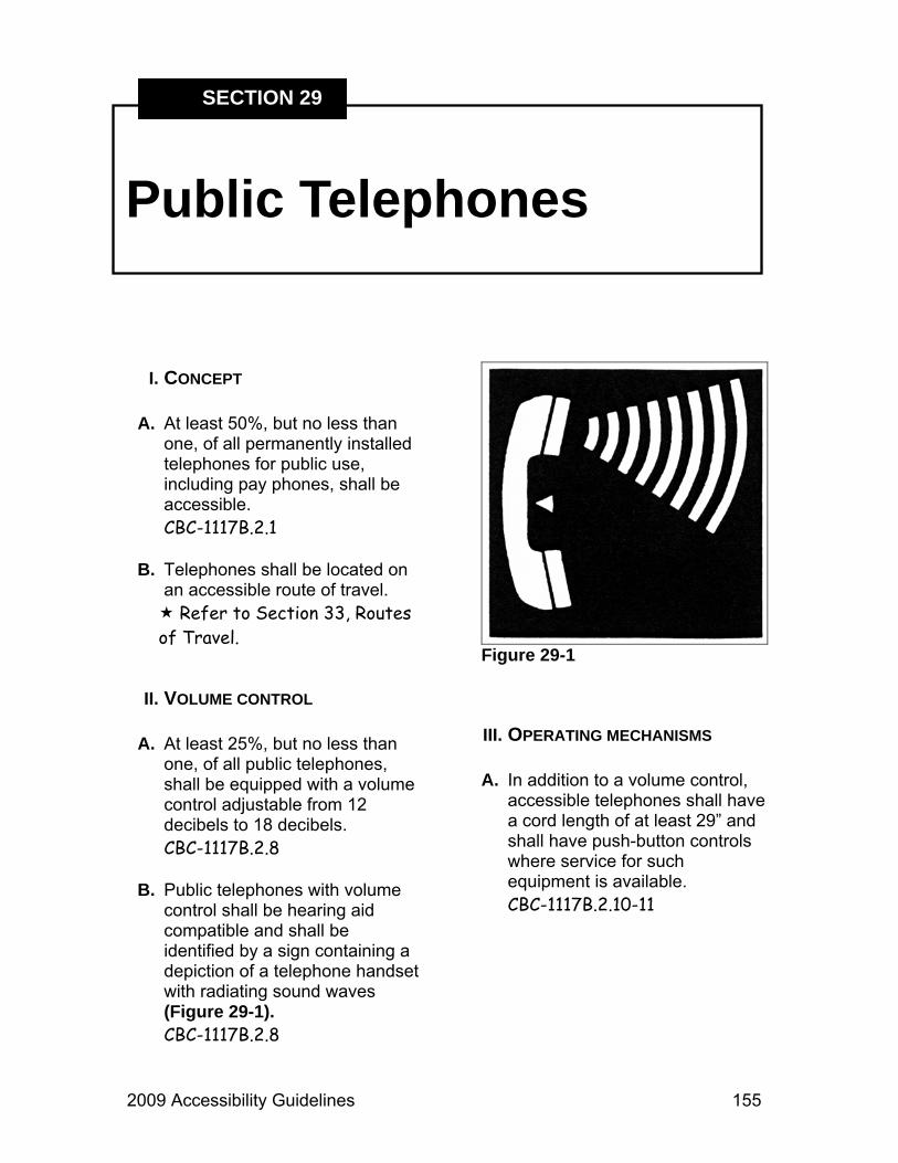
2009 Accessibility Guidelines 155
Public Telephones
SECTION 29
I. CONCEPT A. At least 50%, but no less than
one, of all permanently installed telephones for public use, including pay phones, shall be accessible. CBC-1117B.2.1
B. Telephones shall be located on
an accessible route of travel. Refer to Section 33, Routes
of Travel.
II. VOLUME CONTROL A. At least 25%, but no less than
one, of all public telephones, shall be equipped with a volume control adjustable from 12 decibels to 18 decibels. CBC-1117B.2.8
B. Public telephones with volume
control shall be hearing aid compatible and shall be identified by a sign containing a depiction of a telephone handset with radiating sound waves (Figure 29-1). CBC-1117B.2.8
Figure 29-1
III. OPERATING MECHANISMS A. In addition to a volume control,
accessible telephones shall have a cord length of at least 29” and shall have push-button controls where service for such equipment is available. CBC-1117B.2.10-11

156 2009 Accessibility Guidelines
Section 29 - Public Telephones
B. Telephone controls, including coin slots, shall be located between 9” and 54” above the floor for side approach and between 15” and 48” for forward approach (Figures 29-2 & 29-3). CBC-1117B.6 CBC-1118B.5-6
IV. CLEARANCES A. There must be a clear level
space that measures at least 30” x 48” at the front of the telephone (Figure 29-4). CBC-1117B.2.2
Figure 29-2
Figure 29-3
Figure 29-4
V. TELEPHONE ENCLOSURES A. If the telephone is in an alcove,
there must be an additional maneuvering space provided of 24” deep by 30” wide, or 15” deep by 48” wide. CBC-1117B.2.4

2009 Accessibility Guidelines 157
Section 29 - Public Telephones
B. If the telephone is in a full height enclosure, the minimum width must be 30”. CBC-1117B.2.7.2
C. If the telephone is a side reach
phone in a partial enclosure, the overhang shall be no greater than 19” deep and the height of the lowest overhanging part shall be equal to or greater than 27”. CBC-1117B.2.7.1
D. If the telephone is a front reach
phone and the overhang is greater than 12”, the clear width of the enclosure must be 30” minimum. CBC-1117B.2.7.3
E. If the telephone is a front reach
phone in a partial enclosure and the clear width of the enclosure is less than 30”, the height of the lowest overhanging part must be equal to or greater than 27”. CBC-1117B.2.7.1-3
F. If the telephone is in an enclosure and if the leading edge of the enclosure is between 27” and 80” above the floor, if can only protrude a maximum of 4” into the accessible route. CBC-1133B.8.6.1
VI. REACHES A. The reach to the telephone over
an obstruction must be 25” or less. CBC-1118B.5
B. If the reach over an obstruction
is less than 20”, the maximum height of the telephone controls shall be 48”. CBC-1118B.5
C. If the reach over an obstruction
is 20” to 25”, the maximum height of the telephone controls shall be 44”. CBC-1118B.5
D. If obstructed, leg room shall be
greater than or equal to the depth of the reach. CBC-1118B.5
E. If a telephone directory is
provided, its location shall comply with appropriate reach ranges. CBC-1118B.5 CBC-1118B.6

158 2009 Accessibility Guidelines
Section 29 - Public Telephones
VII. TEXT TELEPHONES A. If a total of four or more public
pay telephones (including both interior and exterior phones) are provided at a site, and if at least one of the total is in an interior location, then at least one interior public text telephone shall be provided. CBC-1117B.2.9.1
B. Telephone typewriters (TTY) or
text telephones (TT) shall be identified by the International TTY Symbol (Figure 29-5). Directional signage to the location of the text telephone shall be provided. CBC-1117B.2.9.3
Figure 29-5

2009 Accessibility Guidelines 159
Publications
SECTION 30
I. CONCEPT A. All new or reprinted publications
shall be prepared using the following guidelines. This policy applies to publications developed at the Headquarters, District or Unit levels, including publications copyrighted to the Department. Staff must ensure that publications produced for the Department by cooperating associations, concessionaires and other external entities follow the attached guidelines or subsequent updates.
The Accessibility Compliance Checklist for Publications may be found in the Appendix. This checklist contains the basic elements necessary for accessible publication design. Please refer to this checklist when developing or redesigning publications. Following the directives in this checklist will help to ensure that publications are fully accessible and legally compliant with all statutes and regulations.
II. PUBLICATION DEFINITION: A. Publications are defined as
brochures, booklets, books, announcements, posters, advertisements, park maps, park program materials, campground maps, departmental plans, reports, newsletters and other items – including those under copyright to California State Parks – that are usually handheld. DN 2007-04
III. PUBLIC INFORMATION Public accessibility information to be included where accessible features are present:
A. Publications must integrate
information about accessible features with general descriptive information regarding park sites and facilities.

160 2009 Accessibility Guidelines
Section 30 - Publications
B. The International Symbol of Accessibility (ISA) is to be used to locate accessible features on maps, and may be used to identify the location of accessibility information in publication text.
C. Publications must include the following standard statement immediately adjacent to the contact phone number: “711, TTY RELAY SERVICE.”
D. Publications need to incorporate
the following standard statement: “CALIFORNIA STATE PARKS SUPPORTS EQUAL ACCESS. PRIOR TO ARRIVAL, VISITORS WITH DISABILITIES WHO NEED ASSISTANCE SHOULD CONTACT [contact office and phone number].”
This statement encourages visitors to request assistance, such as American Sign Language (ASL) interpretation for the deaf, in advance.
Refer to Departmental Notice 2004-07 for more information on sign language interpretation policies and suggestions.
E. Publications must state: “THIS
PUBLICATION IS AVAILABLE IN ALTERNATE FORMATS BY CONTACTING [contact office and phone number].”
Alternate formats for print media include audio, large font print, electronic files, internet information, and Braille.

2009 Accessibility Guidelines 161
Section 30 - Publications
IV. FONTS A. Brochure fonts have to be easy
to read and can either have simple, clean serifs or can be sans serif.
Serifs are short, usually straight, lines angled to the upper or lower ends of the main strokes of a letter, a bit like little feet. Common fonts with serifs include Bookman, Garamond, New Century Schoolbook, and Times Roman. Serif fonts are NOT to be used for large font format materials.
Sans serif fonts (“sans” is French for “without”) lack these little feet but may use curved lines on letters like a, g, l, t, and y to lead the eye along and sometimes to help distinguish t from + and l from uppercase i. These are NOT serifs. Some sans serif fonts include Arial, Century Gothic, Helvetica, Optima, Tiresias and Trebuchet.
B. Minimum type font size for
brochure text is 12-point for many font families. Some fonts do not meet Department standards at 12-point size. (These fonts will meet ADA standards at 13-point size.)
1. Fonts that meet Department standards at 12-point:
Arial Helvetica Comic Sans Trebuchet
2. Fonts that DO NOT meet
Department standards at 12-point (use 13-point minimum):
Garamond Times New Roman Twentieth Century MT Gill Sans MT.
3. How to test if a font meets
Department publication standards:
a. Type out the alphabet for your
proposed font in 12-point lower case, as follows:
abcdefghijklmnopqrstuvwxyz
b. Print the font at the desired scale and measure the line length.
c. If the a – z line length clearly
exceeds 2 inches, the font is acceptable.

162 2009 Accessibility Guidelines
Section 30 - Publications
C. Italics are harder to read than upright fonts for persons with low vision and should not be used. For titles, foreign terms or short quotes, consider using quotation marks or boldface or an alternate font. If space permits, you may use italics as long as you also provide an upright version of the italicized text. DN 2007-04
D. Highly decorative fonts,
condensed fonts, wide fonts, or fonts with very thick or very thin strokes, or a mix of both thick and thin strokes, should not be used.
E. Using upper and lower case
letters (typical sentence style) helps the eye read smoothly. Avoid using all upper or all lowercase text. Short titles and headings may be excepted.
IV. LAYOUT A. Straight lines of text are
generally easiest to read. Curved lines and word art should be avoided.
B. Left justified and ragged right margins are preferred unless full justification can be done without distracting blank spaces between words.
C. Indents should be a standard
size. Left indents that force the eye to find a new starting point for each line (such as centered text with very different line lengths, or text wrapped around objects) should be avoided or rarely used.
V. CONTRAST A. To enhance readability, very
dark print or graphics should be used on a light background. Small areas of reversed text (light text on dark background) may be approved as needed. The difference in contrast between font and background should be at least 70 percent. The chart on the next page shows shades of gray from 0% gray (black) to 100% gray (white), by 10% increments (Figure 30-1).
B. Note that background prints,
photographs, or patterns placed behind text may be distracting or lessen contrast and should be avoided.

2009 Accessibility Guidelines 163
Figure 30-1
Directions for using the Grayscale Chart 1. Print and fold this page so you can place the chart adjacent to your
publication. Find the gray tones equivalent to your text color and background color. It is sometimes easier to begin by comparing the colors to the mid-ranges and then finding which side of the middle each color is on.
2. Subtract the percentage for the darker color from the percentage for the
lighter color to assess whether there is at least 70% contrast (difference) between colors. White and black have a 100% contrast, in theory.
3. Please note that bigger blocks of color (e.g., larger fonts and boldface
fonts) “read” or appear darker than smaller and normal fonts. Using darker hues for smaller fonts to enhance their apparent contrast is suggested, when possible.
0% 10 20 30 40 50 60 70 80 90 100%
Section 30 - Publications

164 2009 Accessibility Guidelines
VI. COLOR COMBINATIONS A. Some color combinations are
especially difficult for persons who have color perception deficits. The inability to distinguish between reds and greens is one of the most common forms of color deficit.
B. Red or green text (or symbols)
must not be contrasted with green or red background colors. Nor should recognition of either of these colors be a sole identifying factor in a publication (e.g., “Green symbols represent spring flowers.”).
VII. LARGE PRINT MATERIAL (AN ALTERNATE FORMAT)
A. Upon request, printed park
visitor information must be provided in large print format in a timely manner. Electronic or print versions may suffice, as the requestor wishes.
B. Large print materials must be in
18-point size and a sans serif font.
Section 30 - Publications
VIII. MAP FONT EXCEPTIONS A. In order to be hand held
comfortably and to include large amounts of land in detail, park maps often use many small fonts. When cartographers create new maps for Department publications, staff shall recommend that 12-point minimums be used where possible for significant park features. For all park features, the map font minimums described below shall apply. Small campground or trail maps created by park staff must also meet or exceed these recommendations and minimums. Otherwise, maps may be viewed with magnifiers or online.
B. Fonts used to label park features
must be at least an 8-point size. Where space permits, larger font sizes are recommended. Non-critical geographic features may be labeled, but fonts used for them do not have to meet minimums.

2009 Accessibility Guidelines 165
Section 30 - Publications
Examples of significant park features for which labels are preferred to be 12-point, but must at least be 8-point fonts include: Big Lodge Visitor Center, Park Entry, Campfire Center, Big Trees Campground, Pretty Nice Trail, etc.
Labels for geographic features such as Ponderosa Reservoir, Mt. Hope, Fair River, Pine Creek, Mucky Marsh, etc. that may be in or near enough to a park to be shown on the map but that are not locations where park programs – such as trails, picnicking, or camping – occur do not require the 8-point font minimums.
IX. LANGUAGE A. Publications must be easy to
read and must not use slang or jargon.
B. Text and captions must be clear
and concise.
X. PUBLICATION REVIEW A. ALL PUBLICATIONS SHALL BE
REVIEWED BY THE ACCESSIBILITY SECTION. Park accessibility information and/or campground maps showing accessible facilities sent to reservations concessionaires must be reviewed for content accuracy before being posted online. Please allow a minimum of two weeks for the review process. Discussing proposed publications at project start-up often speeds the process. Submission for final review must be planned to allow time for any necessary text and/or design changes before printing. A completed review form will recommend any needed changes before printing. Reviews will cover content on accessible features, font, contrast and other standards covered in this section. If you have any questions relating to publications, contact the Accessibility Section.

166 2009 Accessibility Guidelines
Section 30 - Publications
XI. ADDITIONAL PUBLICATION INFORMATION
A. Smithsonian Institution Checklist
for Printed Publications
http://www.si.edu/opa/accessibility/exdesign/sectione.htm
B. Lighthouse International
http://www.lighthouse.org Search within site for “accessibility”.
C. National Center on Accessibility
http://www.ncaonline.org

2009 Accessibility Guidelines 167
Ramps
SECTION 31
I. CONCEPT A. Ramps are only used on Exterior
Routes of Travel (ERT) and Accessible Paths of Travel (POT). Ramps are not required on Outdoor Recreation Access Routes (ORAR) or trails.
Refer to Section 33, Routes of Travel.
B. Not withstanding curb ramps,
whenever the slope on an ERT or POT exceeds 5%, a ramp must be provided. ADAAG-4.8.1 CBC-1133B.5.1
II. WIDTH A. Pedestrian ramps serving
primary entrances to buildings having an occupant load of 300 persons or more shall have a minimum clear width of 60” (Figure 31-1). CBC-1133B.5.2
Figure 31-1 B. All other ramps shall have a
minimum width of 48” (Figure 31-2).
Exception: 36” minimum width is allowed for some Group Residential occupancies. CBC-1133B.5.2

168 2009 Accessibility Guidelines
Section 31 - Ramps
Figure 31-2
III. SLOPES A. The maximum linear slope on
the ramp shall not exceed 8.3%. ADAAG-4.8.2 CBC-1133B.5.3
B. The maximum cross slope on
the ramp shall not exceed 2%. ADAAG-4.8.6 CBC-1133B.5.3.1
C. Outdoor ramps and their approaches shall be designed so that water will not accumulate on walking surfaces. ADAAG-4.8.8
IV. LANDINGS A. Ramps shall have level landings
(2% max. gradient) at top, bottom and each change of direction. Intermediate landings shall be provided at intervals not exceeding 30” of vertical rise (Figure 31-3). ADAAG-4.8.4 CBC-1133B.5.4.1
B. Top landings shall not be less
than 60” wide and shall have a length of at least 60” in the direction of the ramp run (Figure 31-3). ADAAG-4.8.4 CBC-1133B.5.4.2
C. At the bottom and intermediate
landings, the width shall be at least the same as the width of the ramp (Figure 31-3). CBC-1133B.5.4.5

2009 Accessibility Guidelines 169
Section 31 - Ramps
D. Intermediate landings at a change of direction shall be a minimum of 60” x 72”. Bottom landings shall have a dimension of not less than 72” in the direction of ramp run (Figure 31-3). ADAAG-4.8.4 CBC-1133B.5.4.6-7
E. Landings that have a vertical
drop greater than 4” shall have a curb at least 2” high or a wheel guide rail 2” to 4” high. CBC-1133B.5.4.9
F. Doors or gates in any position shall not reduce the minimum dimension of the landing to less than 42” and shall not reduce the required width by more than 3” when fully open. CBC-1133B.5.4.3
G. The width of the landing shall
extend 24” past the strike edge of any door or gate for exterior ramps and 18” past the strike edge for interior ramps. CBC-1133B.5.4.4
Figure 31-3

170 2009 Accessibility Guidelines
Section 31 - Ramps
V. HANDRAILS A. If the linear slope is greater than
5%, handrails are required on both sides of a ramp. On exterior door landings, handrails are not required on ramps with less than 6” rise or 72” length. ADAAG-4.8.5 CBC-1133B.5.5.1
B. Handrails shall be continuous
the full length of the ramp, shall be 34” to 38” above the ramp surface and parallel to it, shall extend a minimum of 12” beyond the top and bottom of the ramp and the ends shall be rounded or returned (Figure 31-4). CBC-1133B.5.5.1
Figure 31-4
C. In existing buildings or facilities where extension of the handrail in the direction of the ramp would create a hazard, the extension of the handrails for ramps shall comply with CBC-1133B.4.2.4, or the extension on the handrail may be turned 90º to the run of the ramp. ADAAG-4.8.5(2) CBC-1133.5.5.1.1
D. The inside handrail on
switchback or dogleg ramps shall be continuous. ADAAG-4.8.5(1)
E. Handrails projecting from a wall
shall have a space of 1½” between the wall and the handrail (Figure 31-5). ADAAG-4.8.5(3) CBC-1133B.5.5.1
F. The grip surface shall be
smooth, continuous, non-slip and have no sharp edges or corners. The diameter of the grip portion of the handrail shall be no less than 1¼” and no greater than 1½” (Figure 31-5). CBC-1133B.5.5.1

2009 Accessibility Guidelines 171
Section 31 - Ramps
Figure 31-5 G. Handrails shall not rotate within
their fittings. The edge of the handrail must have a minimum radius of ⅛”. ADAAG-4.8.5(7) CBC-1133B.5.5.1
H. The structural strength of the
handrail must resist a 250 lb. force in any direction. ADAAG-4.26.3(1)
VI. EDGE PROTECTION A. Where the ramp surface is not
bound by a wall or fence and the ramp has a drop-off, one of the following is required: ADAAG-4.8.7 CBC-1133B.5.6.1-2
1. A 2” guide curb on both sides of the ramp (Figure 31-4).
2. A wheel-guide rail centered 2”
to 4” above the ramp surface. B. Ramps more than 30” above the
adjacent ground shall be equipped with guards that comply with CBC-1013. Such guards shall be continuous from top to bottom. CBC-1133B.5.7
VII. SURFACE A. The surface of the ramp shall be
stable, firm and slip resistant. ADAAG-4.5.1 CBC-1124B.1
B. Surface changes in elevation
shall be ¼” maximum. Surface elevation changes between ¼” and ½” shall be beveled at a 1:2 ratio. ADAAG-4.5.2 CBC-1124B.2

172 2009 Accessibility Guidelines

2009 Accessibility Guidelines 173
Restrooms
SECTION 32
I. CONCEPT A. Access to restrooms shall
comply with all subsections of Title 24 of the California Code of Regulations (CCR). The CCR details and specifies all requirements relating to toilets, showers, lavatories, drinking fountains, fixtures and controls.
B. New restrooms shall be located
on an accessible route of travel. Refer to Section 33, Routes
of Travel. C. Exterior entry doors shall be
accessible. Refer to Section 13,
Doorways.
II. SIGNAGE A. All restroom entrance doors,
both single user and multi-stall, shall have two signs (Figure 32-1).
Figure 32-1
1. Door mounted gender symbols shall identify each sanitation facility or toilet room.
a. Signs shall be at least ¼”
thick and be mounted on the center of the door. The center of the sign shall be 60” above the floor: CBC-1115B.6
i. Women’s: 12” diameter
circle, ¼” thick.
ii. Men’s: 12” equilateral triangle, ¼” thick, vertex facing up.

174 2009 Accessibility Guidelines
Section 32 - Restrooms
iii. Unisex: 12” triangle, ¼” thick, superimposed on a 12” circle, ¼” thick.
b. Color shall contrast with the
color of the door. CBC-1115B.6
c. Gender pictographs may be
included on the sign, but the pictograph field should be at least 6” high and have a color contrasting with the sign.
2. Room identification signs for
permanent rooms, such as restrooms, shower rooms, changing rooms, etc. shall also be provided with a sign to identify the room. The ISA symbol shall be included on this sign to identify that the room provides accessible accommodations (Figure 32-1).
a. Gender pictographs may be
included on the sign, but the pictograph field should be at least 6” high and have a color contrasting with the sign. CBC-1117B.5.5.3
b. Lettering shall be sans serif upper case text with characters ⅝” to 2” high and raised 1/32” minimum. CBC-1117B.5.5.1-2
c. Signs shall be approachable
to within 3” without encountering protruding objects or swinging doors. CBC-1117B.5.7
d. Gender shall also be indicated
on the sign in Grade II Braille immediately below the text. CBC-1117B.5.6
e. Text color shall contrast with
sign background. CBC-1117B.5.2
III. TOILET STALL A. Every restroom shall have at
least one accessible stall. B. If six or more stalls are provided,
at least one shall be side transfer and at least one additional stall should be 36” wide with an outward swinging, self-closing door and have parallel grab bars (Figures 32-2 & 32-3). CBC-1115B.3.1.5

2009 Accessibility Guidelines 175
Section 32 - Restrooms
Figure 32-2 C. The toilet stall shall have a clear,
unobstructed opening width of 32” (34” if side opening instead of end opening) (Figures 32-2, 32-4 & 32-5). CBC-1115B.3.1.4.4
D. The toilet stall shall be equipped
with a self-closing door that can be opened and latched shut with a closed fist. CBC-1115B.3.1.4.5
Figure 32-3 E. The stall door latch, centered 30”
to 44” above the floor, shall be flip-over, sliding or similar style not requiring grasping or twisting. CBC-1115B.3.1.4.4.5
F. A water closet fixture shall have
the following:
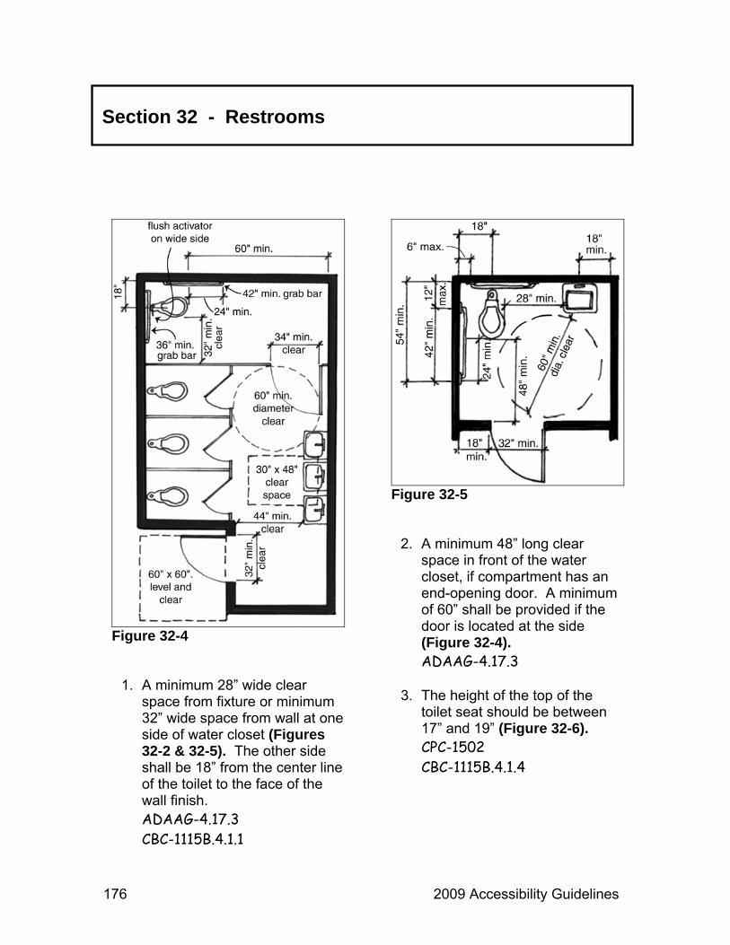
176 2009 Accessibility Guidelines
Section 32 - Restrooms
Figure 32-4
1. A minimum 28” wide clear space from fixture or minimum 32” wide space from wall at one side of water closet (Figures 32-2 & 32-5). The other side shall be 18” from the center line of the toilet to the face of the wall finish. ADAAG-4.17.3 CBC-1115B.4.1.1
Figure 32-5
2. A minimum 48” long clear space in front of the water closet, if compartment has an end-opening door. A minimum of 60” shall be provided if the door is located at the side (Figure 32-4). ADAAG-4.17.3
3. The height of the top of the toilet seat should be between 17” and 19” (Figure 32-6). CPC-1502 CBC-1115B.4.1.4

2009 Accessibility Guidelines 177
Section 32 - Restrooms
Figure 32-6
4. If there is a common area outside the stalls, a clear space should be provided measuring a 60” circle to a height of 27” from the floor (Figure 32-4). CBC-1115B.3.1.1
G. The maximum pressure required
to open the stall door must be 5 lbs. or less. CBC-1133B.2.5
H. If clothes hooks or shelves are
provided, they must be within the following reach ranges: CBC-1118B.5-6 CBC-1125B.3
1. 1.9” – 54” for side reach.
2. 34” – 46” for side reach over an obstruction.
3. 15” – 48” for forward reach.
4. 20” – 44” for forward reach over
an obstruction. I. No door may encroach into the
60” diameter clear space maneuvering area more than 12”, except the standard toilet room compartment doors within a multiple accommodation restroom. CBC-1115B.3.1.1
J. There shall be a 44” minimum
wide access to the accessible stall and a space in front of the accessible stall a minimum of 48” measured at a right angle to the closed door position (Figure 32-2). CBC-1115B.3.1.4.4.5
K. Doors in any position shall not
encroach into the 30” x 48” maneuvering space in front of a fixture. CBC-1115B.3.1.2 CBC-1115B.3.2.2

178 2009 Accessibility Guidelines
Section 32 - Restrooms
IV. GRAB BARS A. Grab bars located on each side,
or on one side and back of a toilet, shall be securely attached, centered 33” above and parallel to the floor (up to 36” for tank type toilets) (Figure 32-6). CBC-1115B.1.3
B. Grab bars at the back shall be
no less than 36” long (42” is the preferred length). CBC-1115B.4.1.3
C. The wall with the grab bars at
the side shall be located 18” from the centerline of the water closet stool, and grab bars shall be at least 42” long (48” is the preferred length), with the front end at 24” in front of the water closet stool and 52” minimum from the back wall if the water closet is located in a stall and 54” minimum if the water closet is not located in a stall (Figures 32-2 & 32-5). CBC-1115B.4
D. Grab bars shall not rotate in their
fittings and shall support a 250 lb. pound load. CBC-1115B.7.2.1
E. Diameter or width of the gripping surface shall be 1¼” to 1½” or the shape shall provide an equivalent gripping surface (Figure 32-7). CBC-1115B.7.1
F. If grab bars are mounted
adjacent to a wall, the space between the wall and grab bars shall be 1½” (Figure 32-7). CBC-1115B.7.1
Figure 32-7 G. Surface of grab bars shall be
free of sharp edges or abrasive elements. CBC-1115B.7.3
H. Minimum radius of all edges
shall be ⅛”. CBC-1115B.7.3
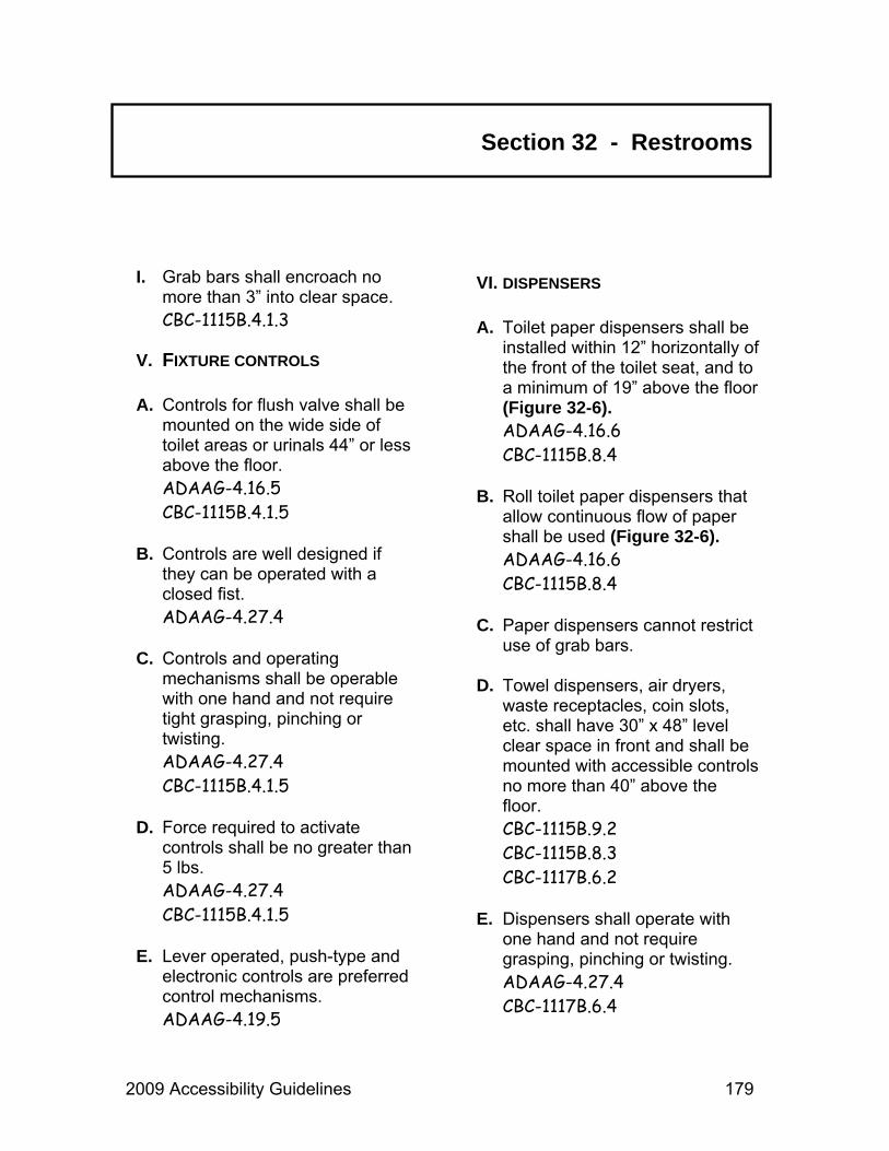
2009 Accessibility Guidelines 179
Section 32 - Restrooms
I. Grab bars shall encroach no more than 3” into clear space. CBC-1115B.4.1.3
V. FIXTURE CONTROLS A. Controls for flush valve shall be
mounted on the wide side of toilet areas or urinals 44” or less above the floor. ADAAG-4.16.5 CBC-1115B.4.1.5
B. Controls are well designed if
they can be operated with a closed fist. ADAAG-4.27.4
C. Controls and operating
mechanisms shall be operable with one hand and not require tight grasping, pinching or twisting. ADAAG-4.27.4 CBC-1115B.4.1.5
D. Force required to activate
controls shall be no greater than 5 lbs. ADAAG-4.27.4 CBC-1115B.4.1.5
E. Lever operated, push-type and
electronic controls are preferred control mechanisms. ADAAG-4.19.5
VI. DISPENSERS A. Toilet paper dispensers shall be
installed within 12” horizontally of the front of the toilet seat, and to a minimum of 19” above the floor (Figure 32-6). ADAAG-4.16.6 CBC-1115B.8.4
B. Roll toilet paper dispensers that
allow continuous flow of paper shall be used (Figure 32-6). ADAAG-4.16.6 CBC-1115B.8.4
C. Paper dispensers cannot restrict use of grab bars.
D. Towel dispensers, air dryers,
waste receptacles, coin slots, etc. shall have 30” x 48” level clear space in front and shall be mounted with accessible controls no more than 40” above the floor. CBC-1115B.9.2 CBC-1115B.8.3 CBC-1117B.6.2
E. Dispensers shall operate with
one hand and not require grasping, pinching or twisting. ADAAG-4.27.4 CBC-1117B.6.4

180 2009 Accessibility Guidelines
Section 32 - Restrooms
F. Shelves, if provided, shall be within the following reach ranges: CBC-1118B.5-6 CBC-1125.3
1. 9” – 54” for side reach.
2. 34” – 46” for side reach over an
obstruction.
3. 15” – 48” for forward reach.
4. 20” – 44” for forward reach over an obstruction.
G. All levers, dispensers, dryers,
etc. must be operable with a maximum pressure of 5 lbs. CBC-1117B.6.4
VII. URINALS A. Where provided, at least one
shall have a clear floor space of 30” x 48” in front of the urinal space to allow forward approach. ADAAG-4.18.3 CBC-1115B.4.2.3
B. Where provided, at least one shall have a rim projecting a minimum of 14” from the wall and a maximum of 17” above the floor. ADAAG-4.18.2 CBC-1115B.4.2.1
VIII. LAVATORIES A. Minimum clear space of 30” x
48” shall be provided in front of the lavatory to allow forward approach (Figure 32-9). CBC-1115B.4.3.3
B. Maximum rim height above the
floor is 34” (Figure 32-8). ADAAG-4.19.2 CBC-1115B.4.3.2
C. Lavatories shall be mounted with
a clearance of at least 29” from the floor to the bottom of the apron (Figure 32-8). ADAAG-4.19.2 CBC-1115B.4.3.2

2009 Accessibility Guidelines 181
Section 32 - Restrooms
Figure 32-8
Figure 32-9
D. Knee clearance is required under the lavatory 27” from the floor at a point located 8” back from the front edge. In addition, a minimum 9” high toe clearance must be provided extending back toward the wall to a distance no more than 6” from the back wall. The toe clearance space must be free of equipment or obstructions. Knee clearance below the lavatory shall extend a minimum of 30” in width by 17” and 19” maximum in depth (Figure 32-8). ADAAG-4.19.2 CBC-1115B.4.3.2
E. Toe clearance shall be the same
width and shall be a minimum of 9” high from the floor and a minimum of 17” deep from the front of the lavatory (Figure 32-8). ADAAG-4.19.2 CBC-1115B.4.3.2
F. Hot water lines and drain pipes
under lavatories shall be insulated or otherwise covered. ADAAG-4.19.4 CBC-1115B.4.3.4

182 2009 Accessibility Guidelines
Section 32 - Restrooms
G. There shall be no sharp or abrasive surfaces under the lavatories. ADAAG-4.19.4 CBC-1115B.4.3.4
H. If the lavatory is adjacent to a
wall, there must be a minimum 18” from the wall to the centerline of the sink (Figure 32-5). CBC-1115B.4.3.2
I. Controls must be operable
without grasping, pinching or twisting (operable with a closed fist). ADAAG-4.27.4 CBC-1115B.4.3.1
J. Controls must be activated with
a force of 5 lbs. or less. ADAAG-4.27.4 CBC-1115B.4.3.1
K. Faucets may be lever type or
self-closing. Self-closing must close after 10 seconds or longer. ADAAG-4.19.5 CBC-1115B.4.3.1
IX. MIRRORS A. Mirrors shall be mounted with
the bottom edge of the reflecting surface no higher than 40” from the floor (Figure 32-8). CBC-1115B.8.1
X. LIGHT SWITCHES A. Light switches should be located
within the following reach ranges: CBC-1117B.6 CBC-1118B.5-6
1. 9” – 54” for side reach.
2. 34” – 46” for side reach over an
obstruction.
3. 15” – 48” for forward reach.
4. 20” – 44” for forward reach over an obstruction.
XI. FLOORS A. The floor of the restroom must
be firm, stable and slip resistant. CBC-1124B.1

2009 Accessibility Guidelines 183
Section 32 - Restrooms
B. Floor slopes shall be 2% (1:50) in all directions. ADAAG-4.3.7
C. Changes in level shall be less
than ¼” or, if ¼” to ½”, they must be beveled at 50%. If over ½” they must be ramped. CBC-1124B.2
D. Openings in drain gratings must
be a maximum of ½” in one direction and, if elongated, must be perpendicular to the dominant direction of travel and flush with the floor. CBC-1124B.4
E. The floor must be smooth, hard, and non-absorbent and extend up the walls a minimum of 5”. CBC-1115B.3.1.6 CBC-1115B.3.2.5
F. Walls within the toilet stalls and
walls within 24” of the front and sides of urinals should be smooth, hard, and non-absorbent and finished to 48” above the floor. CBC-1115B.3.1.6 CBC-1115B.3.2.5

184 2009 Accessibility Guidelines

2009 Accessibility Guidelines 185
Routes of Travel
SECTION 33
I. CONCEPT A. Routes of travel represent the
primary path that a pedestrian would typically use to access a building, facility or activity. In the park setting there are two different types of routes that may be used to connect the elements within a use area. Which type of route to use depends upon the level of development in the area and the elements that are being connected. Trails and Beach Access Routes are also used throughout parks, but they are not appropriate routes for use to connect elements within a specific use area.
Refer to Section 41, Trails, or Section 5, Beaches and Shores, for technical requirements for Trails or Beach Access routes.
B. The most usable route for people with mobility impairments is the Exterior Route of Travel (ERT). The technical requirements for ERTs must be met in highly developed area, such as paved parking lots to offices, visitor centers, museums and restrooms. Since they are the easiest to use, the grade requirements for ERTs should be met whenever possible in the park setting. Exterior accessible routes may include: parking access aisles, curb ramps, crosswalks at vehicular way, walks, ramps and lifts.
C. Outdoor Recreation Access
Routes (ORAR) are used to connect elements within a camping, picnic, or designated trailhead use area. Typical applications of ORARs are from a campsite to the restroom or campfire center, within a picnic area or between the picnic site and an activity area, such as a trailhead.

186 2009 Accessibility Guidelines
Section 33 - Routes of Travel
II. EXTERIOR ROUTES OF TRAVEL (ERT)
A. General:
1. The accessible route shall be the most practical and direct route possible. It shall incorporate the guidelines of curb ramps, ramps, etc. when necessary. CBC-1127B.1
2. A sign displaying the International Symbol of Accessibility (ISA) at the primary entrance and at every major junction of the accessible route shall be installed. The sign shall be displayed to direct
the user to an accessible entrance. CBC-1127B.3
3. The slope in the direction of
travel shall be a maximum of 5%. Where conditions dictate a slope greater than 5%, a ramp shall be provided. ADAAG-4.3.7 CBC-1133B.7.3
Refer to Section 31, Ramps.
4. Walkways with continuous gradients shall have level areas 60” in length at intervals of 400’ (Figure 33-1). CBC-1133B.7.6
Figure 33-1

2009 Accessibility Guidelines 187
Section 33 - Routes of Travel
5. If an accessible route is less than 60” wide, passing spaces at least 60” x 60” shall be located at maximum intervals of 200’ (Figures 33-1). ADAAG-4.3-4 CBC-1133B.7.1
6. The slope perpendicular to the
direction of travel, cross slope, shall be a maximum of 2%. ADAAG-4.3.7 CBC-1133B.7.1.3
7. The surface must be firm,
stable and slip resistant. Surface changes in elevation shall be ¼” maximum. Surface elevation changes between ¼” and ½” shall be beveled at 50%. Surface elevation changes greater than ½” must be ramped. ADAAG-4.3.8 CBC-1124B.1-2
8. Route width shall be 48”,
except where undue hardship based upon right-of-way restriction, natural barriers or other existing conditions occur, in which case a minimum of 36” width is permitted. Surfaces shall be slip resistant (Figure 33-2). CBC-1133B.7.1
B. Details:
1. Grate openings shall have spaces no greater than ½” wide and may be elongated, provided that long direction runs perpendicular to the primary direction of travel (Figure 33-3). ADAAG-4.5.4 CBC-1124B.4
Figure 33-2
Figure 33-3

188 2009 Accessibility Guidelines
Section 33 - Routes of Travel
2. Exterior doormats shall be anchored or recessed to prevent interference with wheelchair traffic. CBC-1133B.1.1.1.3
3. Where wheelchair traffic is
expected to make a U-turn around an obstacle, the route width must be a minimum of 42” on the approach and 48” around the obstacle (Figure 33-4). ADAAG-4.3.3
4. Where the route is less than
60” in width, a 60” x 60” passing space shall be provided at intervals of 200’. ADAAG-4.3.4
5. Objects that protrude into the
accessible route with their leading edge between 27” and 80” from the ground, such as a telephone, shall not protrude more than 4”. Objects mounted below 27” may protrude any amount but shall not reduce the clear width of the accessible route (Figure 33-5). ADAAG-4.4.1 CBC-1133B.8.6
Figure 33-4
Figure 33-5

2009 Accessibility Guidelines 189
Section 33 - Routes of Travel
6. Vertical clearance on the accessible route shall be 80”. If the vertical clearance of an area adjoining the accessible route is less than 80”, a cane detectable barrier to warn the visually impaired shall be provided (Figure 33-6). ADAAG-4.4.2 CBC-1133B.8.6.2
7. Except at walks adjacent to
streets or driveways where changes in level greater than 4” in vertical dimension occur, such as planters or fountains, a 6” high warning curb or a handrail with guide rails centered at 2” to 4” above the ground shall be installed. CBC-1133B.8.1
8. Detectable ground surface or
pavement warnings shall be provided where the access route crosses or adjoins a vehicular travel way, or a transit-boarding platform, that is not separated by a curb, guardrails or handrails. CBC-1133B.8.3-5
Figure 33-6
9. Detectable warnings shall be durable, slip-resistant, truncated domes with an inline grid that extends 24” minimum in the direction of travel. Domes shall have a diameter of 0.9” at the bottom, a diameter of 0.4” at the top, a height of 0.2” and a center-to-center spacing of 2.35”, measured along one side of a square grid. (For acceptable deviations in dome shape, contact the Accessibility Section.) The detectable warnings shall contrast visually from the adjacent surface both in color and in resiliency or sound upon contact with a cane. Additional requirements apply at passenger loading zones on transit boarding platforms. CBC-1121B.8.3.1.8(a)

190 2009 Accessibility Guidelines
Section 33 - Routes of Travel
10. A level area of at least 60” x 60” shall be provided on the pull side of any door or gate and shall extend 24” to the side of the strike edge. A level area of 48” wide x 44” deep shall be located on the push side of any door or gate (Figure 33-7). ADAAG-4.13.6 CBC-1133B.7.5
Figure 33-7
III. OUTDOOR RECREATION ACCESS ROUTES (ORAR)
A. General:
1. Running slopes in the direction of travel shall be as follows: 99AG-16.3.7.2.1-3
a. 5% or less for any distance.
b. From 5.1% to 8.3% for 50’ maximum.
c. From 8.34% to 10% for 30’
maximum.
d. Slopes greater than 10% are not permitted.
2. Resting spaces shall be 60”
minimum in length, shall have a width at least as wide as the route and have a slope of 3% or less. Exception: the slope of the resting space can be as great as 5%, if required for proper drainage. The installation of resting spaces is required as noted in the chart on the following page: 99AG-16.3.8

2009 Accessibility Guidelines 191
Section 33 - Routes of Travel
PERCENT SLOPE
MAXIMUM LENGTH
REST INTERVAL
0% to 5.0%
No restriction
No restriction
5.1% to 8.33% 50’ Every 50’
8.34% to 10% 30’ Every 30’
3. The surface of the ORAR shall be stable and firm. 99AG-16.3.1
4. The clear tread width shall be
36”, except the width may be reduced to 32” for a distance of 24” maximum where existing conditions cannot be mitigated. 99AG-16.3.2
5. The slope perpendicular to the
direction of travel, cross slope, shall be 3% maximum. Exception: the cross slope can be as great as 5%, if necessary for proper drainage. 99AG-16.3.7.1
B. Details:
1. Openings in the surface, such as on a boardwalk, cannot be greater than ½” wide. Elongated openings shall be placed so that the long dimension is perpendicular or diagonal to the dominant direction of travel Figure 33-8). Exception: openings are permitted to run parallel to the direction of travel so long as the opening is no wider than ¼”. 99AG-16.3.3
Figure 33-8

192 2009 Accessibility Guidelines
Section 33 - Routes of Travel
2. Objects that protrude into the route with their leading edge between 27” and 80” from the ground, such as a telephone, shall not protrude more than 4” (Figure 33-5). Objects mounted below 27” may protrude any amount but shall not reduce the clear width of the accessible route. (Figure 33-9). 99AG-16.3.4 ADAAG-4.4.1
Figure 33-9
3. Vertical clearance shall be 80”. If the vertical clearance of an area adjoining the accessible route is less than 80”, a cane detectable barrier to warn the visually impaired shall be provided (Figure 33-6). 99AG-16.3.4 ADAAG-4.4.2
4. Tread obstacles, such as roots
or rocks, shall not be higher than 1”. Exception: obstacles may be up to 2” high if they are beveled at 50% or if environmental conditions prohibit their removal. 99AG-16.3.5
5. Where the width of the route is
less than 60”, passing spaces measuring 60” x 60” shall be provided at intervals of 200’. 99AG-16.3.6
6. Where edge protection is
provided, it shall have a height of 3” minimum. 99AG-16.3.9

2009 Accessibility Guidelines 193
Service Machines
SECTION 34
I. CONCEPT A. Where walk-up service machines
(including lockers, ATMs, ticket, and point of sale machines) are provided, they shall be accessibly designed, be on an accessible route of travel, have accessible clear floor space and follow accessible reach ranges.
B. All new service machines shall
be accessible in accordance with ABA and ADA Accessibility Guidelines for Buildings and Facilities and the California Code of Regulations, Title 24. Contact the Accessibility Section.
II. LOCATION
Service machines shall be located on an accessible route of travel. ADAAG-5.8
Refer to Section 7, Buildings and Section 33, Routes of Travel.
A. One full, unobstructed side of the service machine must adjoin or overlap an accessible route or another clear space.
CBC-1118B.4.2
III. REACH A. In an unobstructed side reach,
the control height shall be between 9” and 54”. The reach depth shall be 10” or less (Figures 34-1 & 34-2). CBC-1117B.7.4.1.3.1
Figure 34-1

194 2009 Accessibility Guidelines
Section 34 - Service Machines
B. In an unobstructed forward reach, the height of the controls shall be between 15” and 48”. The reach depth shall be 10” or less (Figures 34-2 & 34-3). CBC-1117B.7.4.1.2 CBC-1118B.5
Figure 34-2
Figure 34-3
C. If the forward reach over an obstruction is more than 20” deep, the maximum height of the controls should be 44” (Figure 34-4). CBC-1117B.7.4.1.2 CBC-1118B.5
D. If the side reach over an obstruction is no higher than 34” and is 24” deep, the maximum height of the controls shall be 46” (Figure 34-4). CBC-1117B.7.4.1.3.2 CBC-1118B.6
Figure 34-4

2009 Accessibility Guidelines 195
Signage
SECTION 35
I. CONCEPT This section refers to permanent signs. A. An effective information system
is essential for accessibility. There are three general categories of signage:
1. Location or directional
information: All information that indicates direction or location, including signs along outdoor routes indicating direction and distances (e.g., 1.5 miles to waterfall).
a. Trailhead signage should
describe conditions such as average grade, cross slope, width of trail, trail surface and average size of obstacles.
2. Identification and description information: identifies a specific facility (such as an information station or a restroom) and describes the availability and location of facilities. This identity and description information must meet Title 24 and ADA standards for permanent signs.
3. Regulation and safety signage:
information about rules, procedures and regulations. (e.g., restrictive signs such as “NO FISHING, NO CAMPING or NO SMOKING ON TRAIL”; regulatory sign such as “CAMP IN DESIGNATED AREAS ONLY”; and safety signs such as “UNSAFE DRINKING WATER”)

196 2009 Accessibility Guidelines
Section 35 - Signage
II. SIGNAGE A. Signs should be part of a well-
planned system throughout a park or recreational area.
B. Signs must be placed in logical
and visually unobstructed locations, while ensuring that growth of adjacent foliage will not interfere with visibility.
C. The International Symbol of
Accessibility (ISA) sign shall be located at the primary entrance and at junctions between accessible and inaccessible pathways. The sign shall be displayed to direct the user to an accessible route (Figure 35-1). CBC-1127B.3
Figure 35-1
D. All characters, symbols and sign backgrounds must have a non-glare finish with at least a 70% contrast between characters and their backgrounds, either light characters on a dark background or dark characters on a light background. All signs shall have letters and numbers with the ratio of letter width to height of between 3:5 and 1:1, and the stroke width to height ratio of between 1:5 and 1:10 (Figure 35-2). CBC-1117B.5.2-3
Figure 35-2

2009 Accessibility Guidelines 197
Section 35 - Signage
HEIGHT TO FINISH FLOOR
OR GROUND FROM BASELINE OF CHARACTER
HORIZONTAL VIEWING DISTANCE
MINIMUM CHARACTER HEIGHT
Less than 72” ⅝” 40” to less than or equal to 70” 72” & greater ⅝”, plus ⅛” per foot of viewing
distance above 72” Less than 180” 2” Greater than 70” to less
than or equal to 20” 180” & greater 2”, plus ⅛” per foot of viewing distance above 180”
Less than 21’ 3 inches Greater than 120” 21’ and greater 3”, plus ⅛” per foot of viewing
distance above 21’ Figure 35-3
F. Signs identifying permanent uses of rooms and spaces shall have raised letters at a minimum 1/32”, raised characters at a minimum ⅝” to a maximum 2” (Figure 35-4), san serif, uppercase and Grade II Braille, mounted on the latch side of any doors at 60” above the floor to the centerline of the sign. Signs must be approachable to within 3” without obstruction (Figure 35-5). CBC-1117B.5.5-6
E. Characters and numbers shall be sized according to the viewing distance from which they will be read. See visual character height table (Figure 35-3) for various viewing distances. Both upper case and lower case letters should be used, but font size is measured using an upper case X (Figure 35-2). For signs suspended or projected above the finish floor on posts or supports at a height where the bottom edge of the sign is 80” or more above the floor, the minimum character height shall be 3”. ADAAG-703.5.5 CBC-1117B.5.4

198 2009 Accessibility Guidelines
Section 35 - Signage
Figure 35-4
Figure 35-5
G. Pictograms must be accompanied by the equivalent verbal description placed below in raised letters and Grade II Braille when used in a permanently signed room or space. CBC-1117B.5.5.3
H. Signage containing pictograms
should have 6” borders. The International Symbol of Accessibility (ISA) circles and triangles on restroom doors are not considered pictograms. CBC-1117B.5.5.3
I. Buildings that have been
remodeled to provide accessible restrooms and/or elevators shall post this information in the building lobby. CBC-1117B.5.8.1.3
J. The use of alternative signage
forms such as remote directional human voice messages may be explored and used subject to the consent of the Accessibility Section.

2009 Accessibility Guidelines 199
Sinks
SECTION 36
I. CONCEPT A. This section contains the
accessibility requirements for sinks other than lavatories or those found in restrooms. These types of sinks include sinks in picnic and campground areas and sinks for utility purposes, such as washing or cleaning fish. For full requirements for lavatories, please refer to Section 32, Restrooms.
II. CLEARANCES A. The rim of a sink should be 34”
or less above the floor (Figure 36-1). ADAAG-4.24.2
B. Except for utility sinks, there
must be a clearance of at least 27” from the floor to the bottom of the sink apron, with a knee clearance under the front lip extending a minimum 30” in width, with a 19” minimum depth underneath a sink (Figure 36-1). ADAAG-4.24.3
Figure 36-1 C. Except for utility sinks, there
must be a 30” x 48” clear floor space provided in front of a sink to allow for a forward approach. ADAAG-4.24.5
D. The clear floor space must be on
an accessible route and must extend a maximum of 19” under a sink. ADAAG-4.24.5

200 2009 Accessibility Guidelines
Section 36 - Sinks
III. DETAILS A. Except for utility sinks, the bowl
of a sink must be a maximum 6 ½” deep. ADAAG-4.24.2
B. Exposed hot water lines and
drain pipes shall be out of the way or insulated. There shall be no sharp or abrasive surfaces under a sink. ADAAG-4.24.6 CBC-1115B.4.7.1-2
C. Faucet and other controls must
be operable with one hand and not require tight grasping or twisting. The force required to activate controls shall be 5 lbs. maximum. Lever, push type and electronically controlled mechanisms are acceptable. CBC-1115B.4.7.1-2
D. If self-closing faucets are
provided, they must stay on at least 10 seconds.
IV. UTILITY SINKS (DEEP) A. A clear floor space of 30” x 48”
has to be provided in front of a sink to allow for a parallel approach (with a side reach) (Figure 36-2). 99AG-16.13.2
Figure 36-2 B. The clear space in front of a sink
shall have a slope no greater than 2% (3% if necessary for proper drainage). 99AG-16.13.2
C. The bottom of the sink bowl must
be a minimum 15” above the floor. 99AG-16.13.6
2009 Accessibility Guidelines 201
Section 36 - Sinks
D. The counter or rim of a sink must be 34” or less above the floor. 99AG-16.13.5
E. The surface of the clear space must be stable and firm. 99AG-16.13.4
F. If utility sinks are provided, at
least 5%, but no less than one, must be accessible. 99AG-16.13.1

202 2009 Accessibility Guidelines

2009 Accessibility Guidelines 203
Special Events
SECTION 37
I. CONCEPT A. For accessibility purposes, these
guidelines generally refer to events open to the public, not to private events for specific invited groups only. At private events, it is the park’s responsibility to provide accessible parking, building entry, restrooms and other supporting facilities, where possible. Special accommodation requests should be addressed appropriately.
Contact the Accessibility Section for more information, if necessary.
B. Special events often require park
staff to allow the public into areas that normally receive little use or that may not be equipped for large groups. Prior to the special event, these areas must be evaluated for accessibility.
C. All event facilities must generally
be accessible.
D. Private vendors need to be reminded in advance of their responsibilities to provide accessible exhibits, aisles, sales counters, etc.
II. ACCESSIBILITY REQUIREMENTS A. Event Publications
Refer to Section 30, Publications.
1. All advance publications must
list a phone number for those who need special accommodation.
2. All proposed event handouts,
brochures, maps, etc. must be reviewed for legibility by the Accessibility Section at least two weeks in advance of the publication date.
3. Alternative format versions
must be available or able to be provided if requested (large print, transcripts, CDs, etc.).

204 2009 Accessibility Guidelines
Section 37 - Special Events
B. Parking Refer to Section 26,
Parking.
1. When parking is provided, accessible parking, including temporary event parking, shall be provided at legally defined ratios of accessible and van accessible spaces to total spaces provided. CBC-1129B.1
2. Required slopes, surfaces,
routes of travel and signage with the International Symbol of Accessibility (ISA) must be provided for accessible parking.
C. Restrooms
Refer to Section 28, Portable Toilets, and Section 32, Restrooms.
1. In each location where portable
restrooms are added, at least one shall be accessible. When portable toilets are added in groups of ten or more to one location, at least two shall be accessible.
2. Routes to and from restrooms
shall be accessible.
D. Assembly Areas Refer to Section 8,
Campfire Centers/Assembly Areas.
1. If requested in advance, an
American Sign Language (ASL) interpreter MUST be hired for presentations and speakers.
2. In general, if oral presentations
are a significant part of the program, an ASL interpreter is recommended.
3. Assembly areas must have
appropriate ratios of total seats to wheelchair spaces with companion seating. Wheelchair spaces shall measure at least 30” x 60”. ADAAG-4.1.3(19)(a) CBC-1104B.3.4.1
4. If there are more than 300
seats total, wheelchair spaces must be dispersed in several locations, including shaded locations. ADAAG-4.3 CBC-1104B.5

2009 Accessibility Guidelines 205
Section 37 - Special Events
5. Receivers for assistive listening systems shall be provided at a rate of 4% of the total number of seats, but not less than two receivers.
6. Stages routes shall be
accessible. CBC-1104B.3.10-11
E. Exhibits/Visitor Information
Refer to Section 18, Exhibits, and Section 42, Visitor Information/Sales Areas.
1. Park event exhibits must be
accessibly designed and located.
2. Sales counters and reach
ranges shall be accessible. F. Drinking fountains
Refer to Section 16, Drinking Fountains.
1. If more than one additional
drinking fountain is provided, at least 50% of added fountains shall be accessibly designed and located. ADAAG-4.1.3(10)
III. REFERENCES A. For additional information, refer
to the California State Parks Qualified Sign Language Interpreters Policy (DN 2004-7) and “All Visitors Welcome – Accessibility in Interpretive Programs and Facilities,” a California State Parks publication.
B. Please refer to the Accessibility
“Checklist for Special Events” located in the Appendix. This checklist is to be used to plan special events.

206 2009 Accessibility Guidelines

2009 Accessibility Guidelines 207
Stairs
SECTION 38
I. CONCEPT A. Where stairs are provided, in
addition to required elevators, lifts or ramps, they shall be on the building/facility route of travel and shall meet the following guidelines.
II. TREADS AND RISERS A. The heights and widths of the
treads and risers shall be uniform. Stair treads shall be no less than 11” wide measured from riser to riser (Figure 38-1). CBC-1133B.4.5.3
Figure 38-1
B. Stair treads must be self-draining and of a slip-resistant material. ADAAG-4.9.6 CBC-1133B.4.5.1
C. Open risers are not allowed.
CBC-1133B.4.5.3 D. Nosings must be projected, but
not more than 1½” past the face of the riser below. Nosings shall be rounded at a maximum radius of ½” (Figure 38-2). ADAAG-4.9.3 CBC-1133B.4.5.2
Figure 38-2
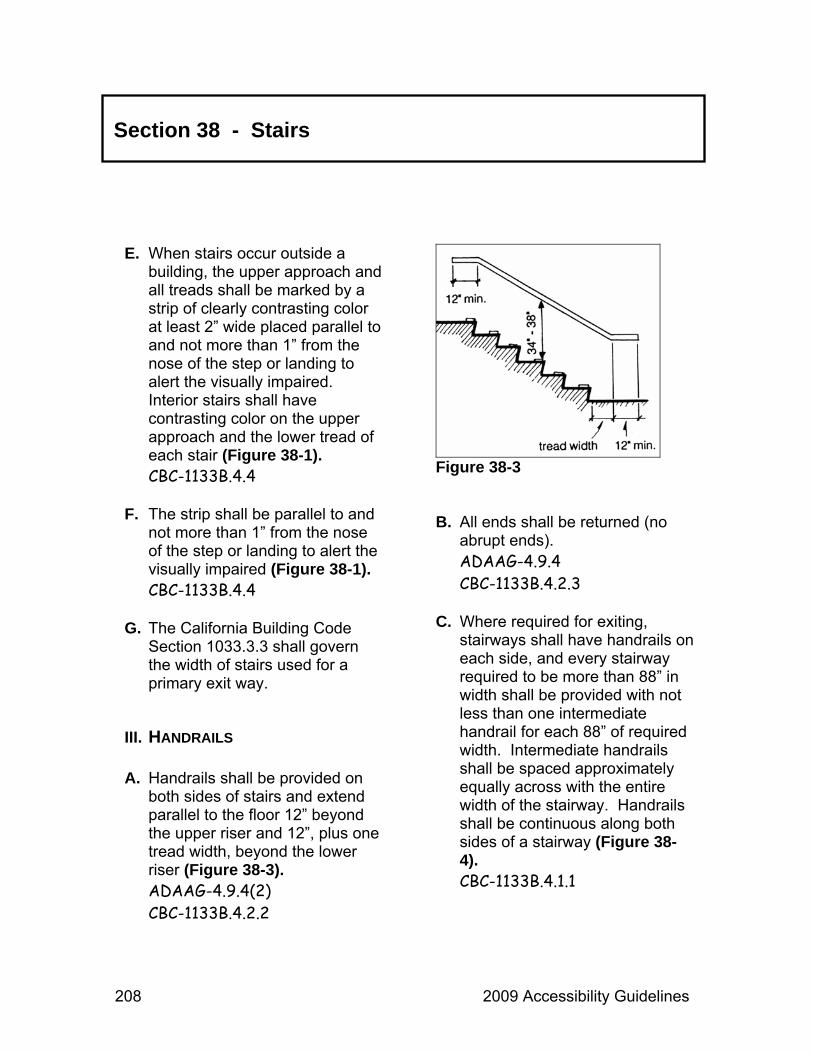
208 2009 Accessibility Guidelines
Section 38 - Stairs
E. When stairs occur outside a building, the upper approach and all treads shall be marked by a strip of clearly contrasting color at least 2” wide placed parallel to and not more than 1” from the nose of the step or landing to alert the visually impaired. Interior stairs shall have contrasting color on the upper approach and the lower tread of each stair (Figure 38-1). CBC-1133B.4.4
F. The strip shall be parallel to and
not more than 1” from the nose of the step or landing to alert the visually impaired (Figure 38-1). CBC-1133B.4.4
G. The California Building Code
Section 1033.3.3 shall govern the width of stairs used for a primary exit way.
III. HANDRAILS A. Handrails shall be provided on
both sides of stairs and extend parallel to the floor 12” beyond the upper riser and 12”, plus one tread width, beyond the lower riser (Figure 38-3). ADAAG-4.9.4(2) CBC-1133B.4.2.2
Figure 38-3 B. All ends shall be returned (no
abrupt ends). ADAAG-4.9.4 CBC-1133B.4.2.3
C. Where required for exiting,
stairways shall have handrails on each side, and every stairway required to be more than 88” in width shall be provided with not less than one intermediate handrail for each 88” of required width. Intermediate handrails shall be spaced approximately equally across with the entire width of the stairway. Handrails shall be continuous along both sides of a stairway (Figure 38-4). CBC-1133B.4.1.1

2009 Accessibility Guidelines 209
Section 38 - Stairs
Figure 38-4
Figure 38-5
D. Handrails shall be 34” to 38” above the nosing of the treads (Figure 38-3). CBC-1133B.4.2.1
E. Railings shall be securely
mounted, not rotate in their fittings, and be mounted to leave a space of 1½” between the wall and the inside edge of the railing (Figure 38-5). CBC-1133B.4.2.5
F. Railings shall have a diameter or
width between 1¼” and 1½” (Figure 38-5). CBC-1133B.4.2.6
G. If railings are recessed into an
adjacent surface, the recess must be at least 18” higher than the top of the railing and a maximum of 3” deep (Figure 38-5). CBC-1133B.4.2.5

210 2009 Accessibility Guidelines
Section 38 - Stairs
H. Railings shall have a smooth surface with no sharp corners. Edges shall have a minimum radius of ⅛”. CBC-1133B.4.2.6
I. Gripping surfaces shall be
uninterrupted by newel posts, other construction elements or obstructions. CBC-1133B.4.2.6
J. On stairs that switch back at
intermediate landings, the interior railings shall be continuous around the turn and not extend out into the intermediate landing. CBC-1133B.4.2.2
K. Handrails shall support 250 lbs.
of pressure in all directions. ADAAG-4.26.3.2-4
IV. STAIRWAY IDENTIFICATION A. In buildings two or more floors in
height with enclosed stairways, a sign shall be located at each floor indicating the floor level. CBC-1133B.4.3
B. The sign shall be located 60”
above the floor in a readily available, visible location. Sign information shall be presented in raised Arabic numerals and Grade II Braille. CBC-1133B.4.3
C. At exit discharge level, the sign
shall include a raised five pointed star located to the left of the floor level, same height as raised numerals.

2009 Accessibility Guidelines 211
Storage Areas & Lockers
SECTION 39
I. CONCEPT A. At least one of each type of
storage facility (cabinets, shelves, closets, drawers, etc.) provided shall be accessible. CBC-1125B.1
B. Where locker rooms provide
dressing areas, refer to Section 15, Dressing Rooms.
II. DOORWAYS A. The entrance door to storage
areas (except shallow closets – those defined as having a reach range of 20” or less) shall have a minimum width opening of 32”. CBC-1110B.2.2
B. Shallow (not walk-in) closet
storage areas shall have a minimum 20” door opening. ADAAG-4.13.5
III. APPROACH SPACE A. Clear space immediately
adjacent to the storage area / locker shall be a minimum of 30” x 48” (Figure 39-1). CBC-1125B.2
B. One full, unobstructed closet
side shall adjoin or overlap an accessible route or another clear space. CBC-1118B.4.2
C. Storage areas located in an
alcove or confined on all, or part of, three sides shall have additional maneuvering clearances provided. CBC-1118B.4.2
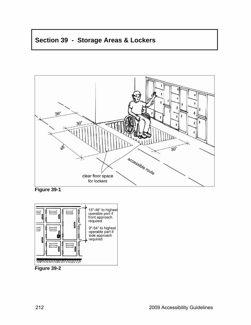
212 2009 Accessibility Guidelines
Section 39 - Storage Areas & Lockers
Figure 39-1
Figure 39-2

2009 Accessibility Guidelines 213
IV. REACHES A. Side accessible storage areas
and lockers positioned between 9” and 54” from the floor shall have a maximum 10” horizontal reach over an obstruction (24” maximum reach if the height does not exceed 46”) (Figure 39-2). CBC-1125B.3 CBC-1118B.5
B. Front accessible storage areas
and lockers positioned between 15” and 48” from the floor shall have a maximum 20” horizontal reach over an obstruction (25” maximum reach if the maximum height does not exceed 44”) (Figure 39-2). CBC-1118B.5
C. Hardware shall be operable with one hand without tight grasping, pinching or twisting and with a force no greater than 5 lbs. Touch latches and u-shaped pulls are acceptable. CBC-1125B.4
D. Lockers and storage facilities
that contain accessibility features shall be identified with the ISA.
Section 39 - Storage Areas & Lockers

214 2009 Accessibility Guidelines

2009 Accessibility Guidelines 215
Swimming Pools
SECTION 40
I. CONCEPT A. Access to swimming is
dependent on getting to the pool area and getting into and out of the water.
B. Swimming pool deck areas must
be accessible and an assistive device must be provided to assist persons with disabilities to enter the pool.
There shall be an unobstructed path of travel from accessible parking to the swimming pool. ADAAG-4.3 CBC-1114B.1.2
Refer to Section 7, Buildings, and/or Section 33, Routes of Travel.
C. Pool gates shall meet the
requirements of Section 13, Doorways.
II. SAFETY FEATURES A. Float dividers, colors, textures
and pavement markings should be used to clearly indicate increasing water depth.
B. Colors and textures that contrast
with the adjoining walking surface should be used to clearly indicate pool and ramp edges and other high-risk areas.
C. Paving shall be non-slip and
non-abrasive to bare feet. CBC-3113B.1
D. Edges of the pool coping should
be rounded ¾” to 1½” radius. E. There shall be a minimum 48”
wide unobstructed path of travel around the pool. CBC-3113B.1

216 2009 Accessibility Guidelines
Section 40 - Swimming Pools
III. POOL ACCESS A. At least two means of entry and
exit shall be provided for each swimming pool. The primary means of access shall be a ramp (sloped entry) or lift (Figure 40-1). ADAAG-15.8.2
B. The secondary means of access shall not duplicate the primary means but may be transfer walls, transfer systems, or stairs. ADAAG-15.8.2
C. Swimming pools with a perimeter
less than 300 linear feet will have one means of access, which must either be a lift or a ramp (sloped entry). ADAAG-15.8.2
Figure 40-1

2009 Accessibility Guidelines 217
Section 40 - Swimming Pools
IV. RAMPS (SLOPED ENTRIES) A. Ramp access into the water shall
be an accessible route. ADAAG-15.8.5.1
B. Ramps into swimming pools
shall meet the following criteria:
1. Ramps shall meet the requirements of ADAAG-4.8 when sloped entry exceeds 5%. The following modifications will be used:
a. Ramps shall extend to a
depth of 24” minimum to 30” maximum below the stationary water level.
b. There shall also be at least
one landing located 24” minimum to 30” maximum below the stationary water level. ADAAG-15.8.5.2
Refer to Section 31, Ramps.
2. Handrails are required on all
sloped entries. ADAAG-15.8.5.3
3. The clear width between handrails must be between 33” and 38”. ADAAG-15.8.5.3
V. BENCHES A. Refer to Section 20, Fixed
Benches.
VI. STEPS A. Pool stairs shall comply with
ADAAG-4.9 ADAAG-15.8.8.1-2
Refer to Section 38, Stairs. B. Handrails shall comply with
ADAAG-15.8.2. C. Stair striping in a contrasting
color is required on all new pool stairs. CBC-1133B.4.4
VII. ADDITIONAL CRITERIA A. If showers, lockers, drinking
fountains or towel racks are provided, refer to the sections on Bathing, Storage Areas, Drinking Fountains or Buildings (reaches).

218 2009 Accessibility Guidelines
Section 40 - Swimming Pools
VIII. POOL LIFTS A. Swimming pool areas must be
accessible and a mechanism to assist persons with disabilities in gaining unassisted operation entry into the pool and exiting from the pool shall be provided.
Such a mechanism may consist of a swimming pool lift device as long as pool lifts meet the following criteria: The seat of the lift has the following specifications:
1. The seat must be rigid (Figure
40-2). CBC-1104B.4.3
2. The seat must have a back
support that is 12” tall (Figure 40-2). CBC-1104B.4.3
3. The lift seat shall be a minimum
of 16” wide (Figure 40-2). ADAAG-15.8.4.4
4. The seat must have two
armrests. The armrest on the side of the seat by which access is gained shall be either removable or fold clear of the
seat. Armrests shall not obstruct with the transfer. ADAAG-15.8.4.5 CBC-1104.B.4.3
5. Footrests shall be provided and
move in conjunction with the seat (Figure 40-2). ADAAG-15.8.5.6
6. The seat must have an
occupant restraint for use by the occupant of the seat that meets the standards for operable controls in compliance with CBC-1117B.6.4 (Figure 40-2).
Figure 40-2

2009 Accessibility Guidelines 219
Section 40 - Swimming Pools
7. The seat must be stable and not permit unintended movement when a person is getting into or out of the seat. CBC-1104.B.4.3
B. The location of the seat/lift has
the following specifications:
1. Lift shall be positioned so that if the pool has water of different depths, it will place the operator into water that is at least 3’ below the surface of the water but not deeper than 48”. CBC-1104.B.4.3
2. In the raised position, the
center-line of the lift seat must be located over the pool deck, at least 16” minimum from the edge of the pool. ADAAG-15.8.5.2
3. A minimum clear deck space
shall be on the side of the seat opposite the water. The space is measured from the seat. It shall be a minimum of 36” wide and 48” long from a line located 12” behind the rear edge of the seat. The space shall be clear and free of deck braces that can interfere with the transfer (Figure 40-2). ADAAG-15.8.5.3
4. The height of the lift seat shall be not less than 16” and no more than 19” inclusive of any cushioned surface that might be provided above the pool deck. The height is to be measured from the deck to the top of the seat surface when the seat is in the raised (loaded) position. An adjustable seat may be used (Figure 40-2). ADAAG-15.8.5.4
C. Pool lifts shall be capable of
unassisted operation from both the deck and water levels. ADAAG-15.8.5.7
1. Controls shall be unobstructed
when a lift is in use. ADAAG-15.8.5.7
2. Controls shall not require tight
grasping, pinching or twisting and no more than 5 lbs. of pressure to operate. ADAAG-4.27.4
3. Pool lift seats shall submerge
to a water depth of 18” minimum (Figure 40-3). ADAAG-15.8.5.8

220 2009 Accessibility Guidelines
Section 40 - Swimming Pools
Figure 40-3
4. Single pool lifts shall provide a minimum live-load weight capacity of no less than 300 lbs. Lifts shall also be capable of sustaining a static load of at least three times the rated load. ADAAG-15.8.5.9
IX. SLOPED ENTRIES A. Sloped entries must comply with
ADAAG accessible route provisions (36” wide, maximum 8.33% slope) except the surface
does not need to be slip resistant. ADAAG-15.8.6
B. Sloped entries must extend to a
depth between 24” and 30” maximum below the stationary water level. ADAAG-15.8.6.2
C. Sloped entry requires a landing
at both the top and bottom if running slope is greater than 1:20 (5%). ADAAG-15.8.6.2
D. Landings must be 36” minimum
in width and 60” in length; 72” is preferred. ADAAG-9.8.4
E. Sloped entries must have
handrails on both sides regardless of slope. Handrails shall meet ADAAG provisions plus the following:
1. Extensions are required at the
top but not the bottom.
2. Clear width between handrails must be between 33” and 38”.
3. Handrail height must be
between 34” and 38”.

2009 Accessibility Guidelines 221
Section 40 - Swimming Pools
X. ACCESSIBLE POOL STAIRS A. All stairs shall have uniform riser
heights and uniform tread widths of not less than 11”, measured from riser to riser. ADAAG-15.8.9
B. Open risers are not permitted. C. Pool stairs must have handrails
with a width of 20” to 24” between rails.
D. The top of the handrail gripping
surface must be 34” to 38” above the stair nosing.
E. The clear space between the
handrail and wall must be 1½”.

222 2009 Accessibility Guidelines

2009 Accessibility Guidelines 223
Trails
SECTION 41
I. CONCEPT A. Unlike Exterior Routes of Travel
(ERT) and Outdoor Recreation Access Routes (ORAR), trails provide the means for the activity of hiking. Trails provide access to remote locations and unique park features. They offer visitors the opportunity to experience various park settings.
B. Whenever hiking is considered
one of the primary activities offered, or where there is a large concentration of trails, every effort should be made to install and maintain accessible trails. The accessible trails should represent the most significant features and environmental experiences unique to the area.
II. SAFETY FEATURES A. General:
1. Running slopes in the direction of travel shall be as follows (Figure 41-1):
a. 5% or less for any distance. 99AG-16.2.7.2.1
b. From 5.1% to 8.33% for 200’
maximum. 99AG-16.2.7.2.2
c. From 8.34% to 10% for 30’
maximum. 99AG-16.2.7.2.3
d. From 10% to 12% for 10’
maximum. 99AG-16.2.7.2.4
Figure 41-1

224 2009 Accessibility Guidelines
Section 41 - Trails
2. Resting spaces shall be 60” minimum in length, shall have a width at least as wide as the trail and have a slope of 5% or less. The installation of resting spaces is required as follows: 99AG-16.2.8
PERCENT SLOPE
MAXIMUM LENGTH
REST INTERVAL
0% to 5.0%
No restriction
No restriction
5.1% to 8.33% 200’ Every 200’
8.34% to 10% 30’ Every 30’
10.1% to 12% 10’ Every 10’
3. The slope perpendicular to the
direction of travel, cross slope, shall be 5% maximum. 99AG-16.2.7.1
Exception: See B, Details, for slope requirements at open drainage structures.
4. The clear tread width shall be
36”, except the width may be reduced to 32” where existing conditions cannot be mitigated. 99AG-16.2.2
5. The surface of the trail shall be stable and firm. 99AG-16.2.1
B. Details:
1. Openings in the surface, such as on a boardwalk, shall not be greater than ½” wide. Elongated openings shall be placed so that the long dimension is perpendicular or diagonal to the dominant direction of travel (Figure 41-2). 99AG-16.2.3
Exception: Openings may run parallel to the direction of travel so long as the opening is no wider than ¼”.
Figure 41-2

2009 Accessibility Guidelines 225
Section 41 - Trails
2. Objects that protrude into the trail between 27” and 80” from the ground shall not protrude more than 4”. Objects mounted below 27” may protrude any amount but shall not reduce the clear width of the trail (Figure 41-3). 99AG-16.2.4
3. Vertical clearance on all trails
shall be 80”. If the 80” vertical clearance of the trail cannot be mitigated, a cane detectable barrier to warn the visually impaired shall be provided (Figure 40-3). 99AG-16.2.4
Figure 41-3
4. For open drainage structures a running slope of 14% is permitted for 5’ maximum with a cross slope of 5% maximum. Cross slope is permitted to be 10% at the bottom of the open drain where the clear tread width is at least 42” wide. 99AG-16.2.7
5. Tread obstacles, such as roots
or rocks, shall not be higher than 2”. 99AG-16.2.5
Exception: Obstacles may be up to 3” high where the running slope and cross slope are 5% or less.
6. Where the width of the trail is
less than 60”, passing spaces measuring 60” x 60” shall be provided at intervals of 1,000’. 99AG-16.2.6
7. Where edge protection is
provided, it shall have a height of 3” minimum. 99AG-16.2.9

226 2009 Accessibility Guidelines
Section 41 - Trails
8. Trails that meet the guidelines shall be designated with a symbol at the trailhead and at designated access points. Signage shall indicate the total distance of the accessible segment and the location of the first point of departure from the guidelines. 99AG-16.2.10
9. Signage at trailheads shall be
accessible to users with vision impairments.
Refer to Section 3, Audio-Visual Programs, and Section 35, Signage.
III. EDUCATIONAL NATURE TRAILS A. An educational nature trail is a
trail in which the designated use is pedestrian only and is planned for the primary purpose of educating the public on the natural or cultural resources of the area. Educational nature trails also contain a series of informational panels or signs and often a printed informational brochure.
B. Educational nature trails which meet federal accessible guidelines should be made accessible to the blind by the provision of a cane detectable edging along at least one side of the trail. This edging should use either elevation change (e.g., raised curb, railing, rope guide, cut bank back slope, elevated trail) and/or texture change (e.g., transition from concrete to grass, transition from gravel to vegetation) capable of providing a clearly detectable trail route for cane use. Distinctive tactile surface textures should call attention to informational displays, panels, site amenities, signs, and related guide and assistance devices. These tactile surface textures should be as wide as the trail and at least 30” long in the direction of travel to ensure sufficient length for detection. Signs, posts, and panels which are sequentially numbered for the purpose of providing site specific written or audio information should use raised Arabic numbers and symbols for identification.
C. Refer to Section 18,
Exhibits, for informational and display panel requirements.

2009 Accessibility Guidelines 227
Visitor Information & Sales Areas
SECTION 42
I. CONCEPT A. Visitor information areas are
primarily located at entrance stations, visitor centers and campground facilities. Visitor information areas shall provide auxiliary aids to ensure effective communication to the public.
II. AUXILIARY AIDS A. The following are examples of
way to provide information using auxiliary aids:
1. Verbal/auditory information
available in written form.
2. Visual/graphic information available in audio form and in large print form.
3. Availability of TTY
(teletypewriter) or a hearing aid-compatible telephone.
4. Availability of Assistive
Listening Devices (ALD).
III. COUNTERS AND SALES AREAS A. Counters/sales areas must be on
an accessible route of travel. Refer to Section 7,
Buildings. B. Information counters/sales areas
shall have a portion of the counter surface accessible to persons who use wheelchairs. Sales areas shall be signed with the International Symbol of Accessibility (ISA). CBC-1110B.1.3-4
C. Such space shall be a minimum
of 3 linear feet for every 12 linear feet, or fraction thereof, of counter length. This section of the counter shall be at least 36” wide and 28” to 34” high from the finished floor elevation (Figure 42-1). CBC-1122B.4

228 2009 Accessibility Guidelines
Section 42 - Visitor Information & Sales Areas
D. This space shall have a 19” minimum deep toe/knee recess space, with 27” minimum vertical clearance from the floor surface (Figure 42-1). CBC-1122B.3
E. Merchandise and sales items
must be placed between 9” and 54” for a side approach and between 15” and 48” for a front approach (Figure 42-2). CBC-1118B.5-6
F. Maximum side reach over an
obstruction shall not exceed 24”. CBC-1118B.6
IV. CHECKOUT AREA A. At least one, but never less than
25% of all service counters with cash registers shall be made accessible by providing a 36” checkout aisle or space on the customer side of the service counter. CBC-1110B.1.3
Figure 42-1
Figure 42-2
V. POINT OF SALE MACHINES A. If provided, all point of sale
machines, except drive-up, shall meet current accessibility requirements.
Refer to Section 34, Service Machines.

2009 Accessibility Guidelines 229
Section 42 - Visitor Information & Sales Areas
VI. TURNSTILES A. Refer to Section 13,
Doorways.
VII. SITE INFORMATION A. The International Symbol of
Accessibility (ISA) shall be the standard used to identify facilities that are accessible. CBC-1117B.5.1.1

230 2009 Accessibility Guidelines

2009 Accessibility Guidelines 231
Vista Points & Overlooks
SECTION 43
I. CONCEPT A. Vista points, roadside pullouts
and/or overlooks, their features, views and the experiences they provide, must be accessible. 99AG-16.10.1
B. Where multiple viewing areas
are provided, a minimum of one of each viewing opportunity for each distinct point of interest shall be accessible. 99AG-16.10.1
C. Vista points and overlooks shall
be located on an accessible route of travel, including an outdoor recreation access route (ORAR) or accessible trail. 99AG-16.10.1
II. VIEWING AREA A. The viewing area shall have at
least one maneuvering space of 60” x 60” or a T-shaped space at least 36” wide and 60” long on each leg (Figures 43-1 & 43-2). 99AG-16.10.2 ADAAG-4.2.3
Figure 43-1
Figure 43-2

232 2009 Accessibility Guidelines
Section 43 - Vista Points & Overlooks
B. The maneuvering space shall be firm, stable and shall not exceed a 2% slope in any direction. 99AG-16.10.4-5
C. Each distinct viewing
opportunity shall allow unrestricted viewing to accommodate eye levels between 32” and 51”. 99AG-16.10.3
D. Descriptive signs provided at
vista points shall meet appropriate standards.
Refer to Section 18, Exhibits, and Section 35, Signage, for more information.
E. Where feasible, provide audible versions of exhibit information, when exhibits are designed or redesigned.
III. FIXED VIEWING DEVICES A. Where telescopes or periscopes
are provided in an area, at least 20%, but never less than one, shall be accessible. 99AG-16.11.1
B. Where only one telescope or
periscope is provided, it must be useable from both a seated and a standing position. 99AG-16.11.1.1
C. Within the vista point or viewing
area accessible telescopes and/or periscopes shall be connected by an outdoor recreation access route (ORAR). 99AG-16.11.1.1
D. A stable and firm clear space
measuring 30” x 48” shall be provided in front of the accessible telescope or periscope to allow for a forward or parallel approach (Figures 43-3 & 43-4). 99AG-16.11.2-3

2009 Accessibility Guidelines 233
Section 43 - Vista Points & Overlooks
Figure 43-3
Figure 43-4
E. The slope of the clear space shall not exceed 2%. 99AG-16.11.5
F. The eyepiece of accessible
telescopes and/or periscopes shall be useable from the seated position. 99AG-16.11.3
G. The force required to activate the
controls shall not be greater than 5 lbs. of pressure. 99AG-16.11.2 ADAAG-4.27.4
H. The operating controls shall be
operable with one hand and shall not require tight grasping, pinching or twisting. 99AG-16.11.2 ADAAG-4.27.4

234 2009 Accessibility Guidelines
Section 43 - Vista Points & Overlooks
I. The operating controls shall be located between 15” and 48” for a forward approach and between 9” and 54” for a parallel approach (Figures 43-5 & 43-6). 99AG-16.11.2 ADAAG-4.27.3
Figure 43-5
Figure 43-6

2009 Accessibility Guidelines 235
Work Areas
SECTION 44
I. CONCEPT A. Work areas shall be accessible
in newly constructed and remodeled facilities. Reasonable accommodations shall be made for individuals with disabilities. Contact the Reasonable Accommodation Coordinator in the Workers’ Compensation & Safety Unit for work related accommodation issues.
II. DIMENSIONS A. The height of seated work
surfaces shall be between 28” and 34” above the floor. CBC-1122B.4
B. There shall be a minimum knee
space of 27” high, 19” deep and 30” wide provided under the bottom of the work surface. CBC-1122B.3
C. Individual workstations shall be
located on an accessible route. The accessible route shall extend to and through the workstation.

236 2009 Accessibility Guidelines

2009 Accessibility Guidelines 237
Glossary
Access Networks A series of accessible, interdependent, related facilities, programs and activities with a continuous path of travel that connects these facilities, programs and activities.
Accessible
Admission, passage, circulation, and full use of buildings, facilities, programs, and the various elements within or the combination of them, to persons with disabilities.
Accessible Route
A continuous unobstructed path connecting all accessible elements and spaces of a building or facility. Interior accessible routes may include: corridors, floors, ramps, elevators, lifts, and clear floor space at fixtures.
Exterior accessible routes may include: parking access aisles, curb ramps, crosswalks at vehicular ways, walks, ramps and lifts. An accessible circulation path is identified as an exterior or interior way of passage from one place to another for pedestrians, including, but not limited to, walks, hallways, courtyards, stairways and stair landings.
Alcove
A small recessed opening off of a larger space.
Alteration
Alter or alteration is any change, addition or modification in construction or occupancy or structural repair or change in primary function to an existing structure other than repair or addition. Modification made to an existing building or facility that goes beyond normal maintenance activities and affects or could affect usability.
238 2009 Accessibility Guidelines
Glossary
American Sign Language (ASL) The sign language used in the United States. Language expressed by visible hand gestures.
Americans with Disabilities Act of 1990 (ADA)
A Federal law prohibiting discrimination against people with disabilities.
Americans with Disabilities Act Accessibility Guidelines (ADAAG)
Provides scoping and technical specifications for new constructions and alterations undertaken by entities covered by the ADA.
Architectural Barriers Act of 1968 (ABA)
A Federal law stating that buildings and facilities designed, constructed or altered with Federal funds, or leased by a Federal agency, must comply with standards for physical accessibility.
Assembly Areas
A room or space accommodating a group for recreational, educational, political, social, civic or amusement purposes.
Assistive Device A device that assists users in accomplishing day-to-day functions. For example, a wheelchair is an assistive device to aid a person who cannot walk. Other assistive devices may not be so obvious. Segways or motorized bicycles may be used by people with a variety of disabilities, none of which may be readily apparent.
Assistive Listening Device
A device used by an individual to amplify an audio presentation.
Audible Warning
A warning consisting of words or sounds indicating a potentially hazardous situation.
Audio Description
(Also audio-described video, tour, or exhibit.) Audio description refers to a specialized type of audio presentation that includes brief explanations of visual items necessary for comprehending content to those who are unable to see them. In a video, audio

2009 Accessibility Guidelines 239
Glossary
description may explain movements or appearances of persons or objects, unexplained sounds, facial or body gestures, scene or setting changes, etc. For tours or exhibits, audio description would provide concise, objective, vivid descriptions, of objects, graphics or other visual elements of the program. Audio description may be delivered by FM receivers, audiotapes, MP3 players, CDs or (for tours and exhibits) by trained staff and volunteers.
Barrier to Access
Any condition that makes it difficult to make progress or to achieve an objective.
Barrier Removal
Removal, rearrangement or modification of objects or built elements positioned or structured in a manner that impedes access.
Bevel
Two surfaces meeting at an angle less than 90º.
Braille A system of writing composed of raised dots in different patterns that represent letters and numbers read with the fingertips by people who are blind.
Buildings Any and all portions of permanent structures occurring on or in support of a state park unit, including concession buildings, dispatch areas, dormitories, employee housing, entrance kiosks/stations, first aid stations, janitorial rooms, kiosks, laboratories, museums, offices, restrooms, storage areas, theaters and visitor centers.
California Relay Service
The service provided for persons with hearing impairments to relay between audio phone calls and text telephone systems.

240 2009 Accessibility Guidelines
Glossary
Captioned Captions consist of a text transcript of the auditory track of a movie or other video presentation. Captions benefit people who can see but cannot hear the audio.
Clear Floor Space
The minimum unobstructed floor space required to accommodate a single, stationary wheelchair and occupant.
Clear Tread Width
The width of the useable surface measured perpendicular to the direction of travel.
Core Area
This area with the greatest concentration of pedestrian traffic (including persons who use wheelchairs), amenities, services and facilities.
Cross Slope
The slope measured perpendicular to the direction of travel.
Decibel
Increments in which sound is measured.
Designated Beach Developed beach day use areas with on-site facilities and services that provide public safety.
Detectable Warnings
A standardized surface feature of raised domes applied to walking surfaces to warn visually impaired people of hazards.
Disability
An individual is defined as having a disability when one or more of the following conditions apply: (1) A physical or mental impairment that limits one or more of the major life activities of an individual, or (2) A record of such an impairment, or (3) Being regarded as having such impairment.
Edge Protection
A curb or wheel-guide rail used to protect an area having a hazardous drop-off.

2009 Accessibility Guidelines 241
Glossary
Egress, Means of A continuous and unobstructed way of exit travel from any point in a building or facility to a public way. An accessible means of egress is one that complies with these guidelines and does not include stairs, steps or escalators.
Element
An architectural or mechanical component of a building facility, space or site (e.g., telephone, curb ramp, door, drinking fountain, seating or water closet).
Exterior Route of Travel (ERT)
An outdoor path of travel connecting major components of facilities (i.e., parking lot to a building).
Facility
All or any portion of buildings, structures, site improvements, complexes, equipment, roads, walks, passageways, or parking lots located on a site.
Firm Surface An outdoor surface which does not give way significantly under foot and resists indentation from a persons foot, wheelchair or other assistive mobility device.
Foot Candles (Light Level)
A unit of illuminance on a surface from a point source of a candle, used to measure light intensity.
Gangway
A moving structure spanning between land and a floating structure.
Grade
The slope parallel to the direction of travel that is calculated by dividing the vertical change in elevation by the horizontal distance covered.
Horizontal Circulation Space
A minimum 60” wide circular space directly in front of an exhibit allowing all visitors the opportunity to approach, turn and leave the exhibit.
242 2009 Accessibility Guidelines
Glossary
International Symbol of Accessibility (ISA)
The symbol adopted by Rehabilitation International for the purpose of indicating facilities that are accessible to persons with disabilities. It is sometimes called the wheelchair symbol.
Landing
A platform between elevation changes in a route of travel (often used when stairs change direction). Normally no less than 36” x 36” square.
Level Area
A surface that does not have a slope in any direction exceeding 2% (1:50) gradient.
Newel
The post at the tope of bottom of a flight of stairs that supports the handrail.
Obstacle An object that protrudes into the circulation route, limits the vertical passage space, or reduces the clearance width of a pathway. On trails, obstacles can include objects such as boulders and tree branches.
Optimal Field of Vision
The most comfortable cone or field of vision appropriate for signs, displays and exhibits covers an arc of approximately 45º, from 15º above the horizontal eye to 30º below it. This applies to both the standing and seated person.
Outdoor Recreation Access Route (ORAR)
A continuous unobstructed path designated for pedestrian use that connects accessible elements within a picnic area, camping area or designated trailhead.
Point Load
The ability of an object to withstand a certain weight at one point.
2009 Accessibility Guidelines 243
Glossary
Prevailing Sound Level The ambient, or background, sound level that audible alarms must exceed.
Protruding Object
Something that juts out or projects into a pathway and may cause injury or block access.
Qualified Sign Language Interpreter
An interpreter who is able to interpret effectively, accurately, and impartially both receptively and expressively, using any necessary specialized vocabulary.
Radiating Sound Wave The sign identifying accessible public telephones with volume control and hearing aid compatibility.
Ramp A firm, inclined surface used to provide connection between elevation changes.
Reach Ranges
The distance limits that allow wheelchair users to access facilities and devices (i.e., electrical switches and alarms).
Reasonable Accommodation
Modifications or adjustments to a program, work environment or job description that enable a person with a disability to participate in the same manner as others.
Rest Area
A level portion of a trail that is wide enough to provide wheelchair users and others a place to rest and gain relief from the prevailing grade and cross slope demands of the path.
Riser
The vertical portion of a step in a staircase that connects the top of a tread to the next higher tread.

244 2009 Accessibility Guidelines
Glossary
Sans Serif A typeface in which characters have no serifs.
Serif
A short line at the ends of the main strokes of a character, which may lead the eye through text, or may make letters run together.
Slip Resistant Surface
Slip resistance is based on the frictional force necessary to permit a person to ambulate without slipping. A slip resistant surface does not allow a shoe heel, wheelchair tires or a crutch tip to slip when ambulating on the surface.
Stable Surface
Stability is the degree to which a surface remains unchanged by contaminants or applied force, so that when the contaminant or force is removed, the surface returns to its original condition. A stable surface is not significantly altered by a person walking or maneuvering a wheelchair.
Stanchion An upright bar, post or support.
Strike Edge Clearance
The clearance from the strike edge of a door to the first protrusion or obstruction.
Tactile
An object that can be perceived using the sense of touch.
Teletypewriter (TTY)
Equipment that employs interactive text based communications through the transmission of coded signals across the standard telephone network. Text telephones can include devices know as TDDs (telecommunication display devices or telecommunication devices for deaf person) or computers with special modems. Text telephones are also called TTYs, an abbreviation for teletypewriter.

2009 Accessibility Guidelines 245
Glossary
Title II of the Americans with Disabilities Act of 1990
The section of the Americans with Disabilities Act of 1990 prohibits state and local governments from discriminating against people with disabilities in programs, services and activities.
Title 24
A section of the California Code of Regulations, also known as the California Building code, that, in part, addresses accessibility in buildings and facilities.
Trail
A route that is designed, designated or constructed for recreational pedestrian use or provided as a pedestrian alternative to vehicular routes within a transportation system.
Transcript
A text representation of sounds in an audio clip or an auditory track of a multimedia presentation. A “collated text transcript” for a video combines (collates) caption text with text descriptions of video information
(descriptions of the actions, body language, graphics and scene changes of the visual track). Collated text transcripts are essential for individuals who are deaf-blind and rely on Braille for access to movies and other content.
Tread Surface
The surface of a pathway or upper horizontal part of a step.
Truncated Domes
Small domes with truncated, or cut-off, tops that are detectable warnings used at transit platforms, curb ramps and hazardous vehicular ways.
Universal Design
The designing of products and environments to be usable by all people, to the greatest extent possible, regardless of age, size or abilities.
Unloading Aisle
The zone adjacent to an accessible parking stall for passenger loading and unloading.

246 2009 Accessibility Guidelines
Glossary
Utility Sink A sink that has a vertical dimension deeper within the confines of the sink than the standard lavatory basin and allows the user of a picnic area or campground setting to clean large pots or equipment. It has the general configuration of a sink found in a custodial maintenance area.
Wing Wall
A wall protrusion at a right angle to another wall.
Zero Depth Entry
Water entry starting level with dry land and gradually sloping into water.

2009 Accessibility Guidelines 247
Appendix

248 2009 Accessibility Guidelines
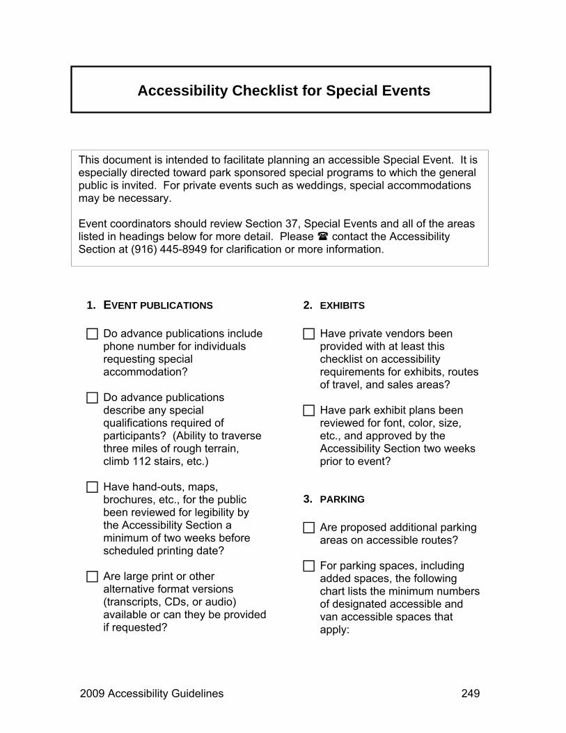
2009 Accessibility Guidelines 249
Accessibility Checklist for Special Events
1. EVENT PUBLICATIONS
Do advance publications include phone number for individuals requesting special accommodation?
Do advance publications describe any special qualifications required of participants? (Ability to traverse three miles of rough terrain, climb 112 stairs, etc.)
Have hand-outs, maps, brochures, etc., for the public been reviewed for legibility by the Accessibility Section a minimum of two weeks before scheduled printing date?
Are large print or other alternative format versions (transcripts, CDs, or audio) available or can they be provided if requested?
2. EXHIBITS
Have private vendors been provided with at least this checklist on accessibility requirements for exhibits, routes of travel, and sales areas?
Have park exhibit plans been reviewed for font, color, size, etc., and approved by the Accessibility Section two weeks prior to event?
3. PARKING
Are proposed additional parking areas on accessible routes?
For parking spaces, including added spaces, the following chart lists the minimum numbers of designated accessible and van accessible spaces that apply:
This document is intended to facilitate planning an accessible Special Event. It is especially directed toward park sponsored special programs to which the general public is invited. For private events such as weddings, special accommodations may be necessary. Event coordinators should review Section 37, Special Events and all of the areas listed in headings below for more detail. Please contact the Accessibility Section at (916) 445-8949 for clarification or more information.

250 2009 Accessibility Guidelines
Accessibility Checklist for Special Events
TOTAL SPACES
PROVIDED
TOTAL ACCESSIBLE
SPACES REQUIRED
TOTAL VAN ACCESSIBLE
SPACES INCLUDED
1 – 25 1 1 26 – 50 2 1 51 – 75 3 1 76 – 100 4 1
101 – 150 5 1 151 – 200 6 1 201 – 300 7 1 301 – 400 8 1 401 – 500 9 2
501 – 1,000
2% of Total 3
4. VISITOR INFORMATION AND/OR SALES AREA
Do at least 25% of all checkout areas have aisles at least 36” wide?
Are counter tops between 28” and 34” high?
Are front reaches (to brochures, souvenirs, books, etc.) between 15” and 48” and side reaches between 9” and 54”?
If these standards cannot be met, is a sign posted stating, “IF YOU NEED ASSISTANCE, PLEASE ASK”?
5. RESTROOMS
If added for the event, is there at least one accessible portable restroom at each location?
If portable restrooms are provided in groups of ten or more at a location, are there at least two portable restrooms for every ten units?
6. ROUTES OF TRAVEL
Are intended routes of travel through the event, exhibits, parking, restrooms, food booths, etc., firm and stable and sloped no more than 5%?
Have obstructions or uneven surface elements (roots, bumps, pavement rises, or gaps) been eliminated or mitigated?
7. ASSEMBLY AREAS
If requested, or if a significant part of the event is a group presentation, will a Certified American Sign Language Interpreter be provided?

2009 Accessibility Guidelines 251
Accessibility Checklist for Special Events
Assembly / presentation area seating requirements are listed on the following chart:
TOTAL
NUMBER OF SEATS
WHEELCHAIR SPACES WITH COMPANION
SEATING 1 – 25 1
26 – 50 2
51 – 300 4
301 – 500 6
Over 500 6, plus 1 per hundred
If there are more than 300 seats, are the wheelchair spaces dispersed in different locations (including shaded locations)?
Are provided wheelchair seating areas a minimum of 30” x 60”?
Are stages and paths of travel to them accessible?
Are assistive listening devices available?
Remember to review all relevant sections in the current “California State Parks Accessibility Guidelines.”

252 2009 Accessibility Guidelines
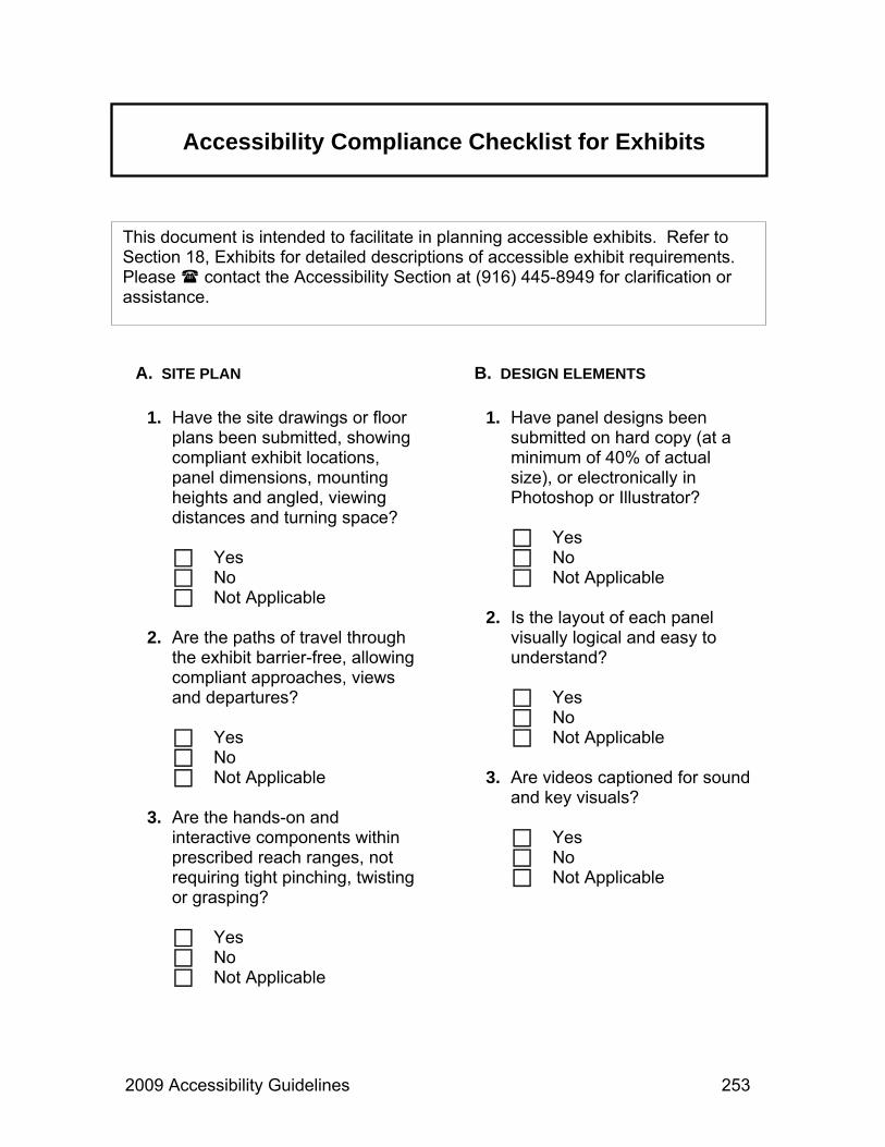
2009 Accessibility Guidelines 253
Accessibility Compliance Checklist for Exhibits
A. SITE PLAN
1. Have the site drawings or floor plans been submitted, showing compliant exhibit locations, panel dimensions, mounting heights and angled, viewing distances and turning space?
Yes No Not Applicable
2. Are the paths of travel through
the exhibit barrier-free, allowing compliant approaches, views and departures?
Yes No Not Applicable
3. Are the hands-on and
interactive components within prescribed reach ranges, not requiring tight pinching, twisting or grasping?
Yes No Not Applicable
This document is intended to facilitate in planning accessible exhibits. Refer to Section 18, Exhibits for detailed descriptions of accessible exhibit requirements. Please contact the Accessibility Section at (916) 445-8949 for clarification or assistance.
B. DESIGN ELEMENTS
1. Have panel designs been submitted on hard copy (at a minimum of 40% of actual size), or electronically in Photoshop or Illustrator?
Yes No Not Applicable
2. Is the layout of each panel
visually logical and easy to understand?
Yes No Not Applicable
3. Are videos captioned for sound
and key visuals?
Yes No Not Applicable

254 2009 Accessibility Guidelines
Accessibility Compliance Checklist for Exhibits
2. Is the contrast between text and background at or near 70%?
Yes No Not Applicable
3. Are graphics and text shown
against a visually uncluttered background?
Yes No Not Applicable
D. TYPEFACES AND TEXT
1. Are text and graphics well balanced, including text content that is clear, concise and germane to the exhibit graphics?
Yes No Not Applicable
2. Is the text layout, including the
size of text blocks and the space between lines and columns, appropriately spaced and visually balanced?
Yes No Not Applicable
4. Are audio components captioned and include adjustable volume?
Yes No Not Applicable
5. Are all caption text font styles and sizes legible? (24 point front is the recommended minimum for captions.)
Yes No Not Applicable
6. Are alternate format resource
materials, including all text and short descriptions of media and key graphics, available upon request?
Yes No Not Applicable
C. LIGHTING AND CONTRAST
1. Exhibit finishes and lighting are free of shadows and glare?
Yes No Not Applicable
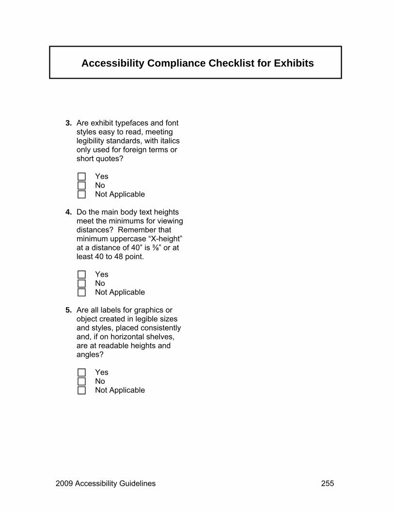
2009 Accessibility Guidelines 255
Accessibility Compliance Checklist for Exhibits
3. Are exhibit typefaces and font styles easy to read, meeting legibility standards, with italics only used for foreign terms or short quotes?
Yes No Not Applicable
4. Do the main body text heights
meet the minimums for viewing distances? Remember that minimum uppercase “X-height” at a distance of 40” is ⅜” or at least 40 to 48 point.
Yes No Not Applicable
5. Are all labels for graphics or
object created in legible sizes and styles, placed consistently and, if on horizontal shelves, are at readable heights and angles?
Yes No Not Applicable

256 2009 Accessibility Guidelines

2009 Accessibility Guidelines 257
Accessibility Compliance Checklist for Publications
1 Does the publication integrate information about accessible features?
Yes No Not Applicable
2 Does the publication state the
availability of a TTY “(000) 000-0000, TY direct connection” and/or include the following statement: “711, TTY RELAY SERVICE”?
Yes No Not Applicable
3 Does the publication incorporate
the following: “California State Parks supports equal access. Prior to arrival, visitors with disabilities who need assistance should contact (contact name and phone number)”?
Yes No Not Applicable
4 Does the publication state: “This publication is available in alternate formats by contacting (contact name and phone number)”?
Yes No Not Applicable
5 Is the font size of body text an
acceptable 12-point typeface?
Yes No Not Applicable
6 Is the type easy to read?
Yes No Not Applicable
7 Are the text and graphics in high
contrast to the background?
Yes No Not Applicable
This document is intended to facilitate in planning accessible publications. Refer to Section 30, Publications for detailed descriptions of accessible publication requirements. Please contact the Accessibility Section at (916) 445-8949 for clarification or assistance.

258 2009 Accessibility Guidelines
Accessibility Compliance Checklist for Publications
8 Are international symbols used on maps to identify areas, facilities or points of interest?
Yes No Not Applicable
9 Is the publication easy to read,
without complex sentences and academic jargon?
Yes No Not Applicable

2009 Accessibility Guidelines 259
Index
Access Routes: xvi, 21-25, 54, 69, 118, 137, 141, 167, 185, 189, 190, 223, 231, 232, 242 (Also see Paths) Aisles and Corridors: xvi, 34-37, 43, 44, 46, 61, 63, 65, 69, 76, 96, 97, 127, 128, 131, 134, 135, 185, 203, 228, 237, 245, 250 (Also see Paths) Alarm Systems: 1, 2 Amenities: 75, 79, 86, 121, 226, 240 Approaches: 16, 35, 36, 38-40, 44, 53-55, 62, 65, 66, 70, 71, 81, 90, 93, 97, 122, 123, 141, 143,145, 152, 156, 168, 174, 180, 188, 197, 199, 200, 208, 211, 228, 232, 234, 241, 253, Assembly Areas: 3, 43-46, 126, 204, 238, 251 (Also see Campfire Centers) Assistive Listening Devices: 3. 4, 109, 237, 238, 251 Audio-Visual Programs: 5-7
Banquet Areas: 63-67 Bathing Facilities: 9-20 Beach Wheelchairs: 26 Beaches and Shores: 21-26 Benches: 45, 49, 79, 80, 86, 106-108, 137, 138 (Also see Amenities) Boating: 27-32, 103 Boat Slips: 27, 29-31 Braille: xvii, xviii, 5, 92, 110, 160, 174, 197, 198, 210, 239, 245 Bridges: 102 (Also see Gangways and Bridges) Brochures: 4, 90, 159, 161, 203, 226, 249, 259 (Also see Publications) Buildings: viii, xvi, 33-42, 107, 113, 115-117, 125, 167, 170, 185, 198, 203, 207, 208, 210, 237-239, 241

260 2009 Accessibility Guidelines
Index
Cabinets: 33. 35, 96, 122, 123, 211 (Also see Amenities) Campfire Centers: 3, 43-47, 165, 185 Camping: viii, xv, xvi, 47-55, 134, 165, 185, 195, 242 Captions: xviii, 5, 6, 89, 92, 165, 240, 245, 253, 254 Clear Spaces: 18, 33-35, 37, 38, 50, 52, 54, 55, 61, 70, 76, 77, 80, 96-98, 103, 107, 122, 138, 140, 142, 150, 151, 176, 177, 179, 180, 193, 200, 201, 211, 221, 232, 233 Circulation: viii, xv, xvi, 22, 34, 97, 132, 237, 241, 242 Clothes Hooks: 15, 16, 177 (Also see Amenities) Concessions: 57, 58, 153, 159, 165, 239 Controls: xxii, 9, 10, 14-17, 19, 33, 42, 77, 82, 87, 92, 93, 106, 123, 126, 143, 155-157, 173, 179, 182, 193, 194, 200, 218, 219, 233, 234, 243, 253 Counters: 33, 63, 65, 121-123, 201, 203, 205, 227, 228, 250
Curb Ramps: xvi, 42, 59-62, 125, 135, 167, 185, 186, 237, 241, 245 (Also see Ramps) Dining: viii, 33, 63-67 Dining Areas: 33, 63-67 Displays: 5, 89, 90, 93, 95-97, 110, 226, 242 (Also see Exhibits) Docks: 27, 30, 32, 101, 102 (See also Piers) Doormats: 69, 188 Doors: 9, 15, 16, 20, 69-73, 77, 80, 118, 126, 169, 170, 173-177, 190, 197, 198, 211, 241, 244 Doorways: 20, 33, 34, 45, 69-73, 77, 117, 211, 215, 229 Dormitories: 75-77, 239 Dressing Rooms: 79, 80, 211 Drinking Fountains: viii, 81-83, 86, 173, 205, 217, 241 Edge Protection: 22, 31, 49, 102, 105, 171, 192, 225, 240 Elevators: xvi, 33, 34, 38, 42, 117, 125, 126, 198, 207, 237

2009 Accessibility Guidelines 261
Index
Entrances: viii, 10, 45, 69, 73, 118, 127, 132, 134, 135, 167, 173, 186, 196, 211, 227, 239 Equestrian: 85 Equestrian Facilities: viii, 85, 86 Exhibits: xvii, xxii, 35, 42, 87-99, 110-112, 119, 203, 205, 206, 232, 238, 239, 241, 242, 249, 250, 253-255 Exterior Routes of Travel: xvi, 141, 146, 167, 185, 186, 223, 241 Fire Rings: 50-52, 139, 140 Fireplaces: 50-52, 139 Fishing: viii, 21, 27, 101-106, 195 Flooring: 14, 41, 97, 102, 122, 182, 183 Gangways and Bridges: 27-29, 102, 103, 241 Grab Bars: 17, 18, 20, 174, 178, 179 Grills: xvii, 50-52, 139, 141 Handrails: 29, 103-105, 149, 150, 152, 170, 171, 189, 208-210, 217, 220, 221, 242
Hands-On Materials: 92, 253 Historic Sites: viii, 115-119 Hotels: 75-77 Interpreters: vii, xi, xviii, 5-7, 109, 111-113, 204, 205, 243, 251 Kitchens: 33, 34, 77, 121-123 Landings: xvi, 28, 29, 34, 60, 102, 103, 118, 125, 126, 168-170, 208, 210, 217, 220, 237, 242 Lavatories: 173, 180-182, 199, 246 Lifts: xvi, 29, 33, 34, 38, 42, 76, 118, 125, 126, 148, 185, 207, 216, 218-220, 237 Light Switches: 182, 243 Lockers: 9, 54, 55, 86, 193, 211-213, 217 (Also see Storage Areas) Mirrors: 80, 182 (Also see Amenities) Mounting Platforms: 85 Museums: viii, 3, 185, 239 Nature Trails: 98, 110, 226

262 2009 Accessibility Guidelines
Index
Parking: viii, xvi, 21, 33, 34, 45, 47, 61, 76, 85, 101, 127-135, 137, 185, 203, 204, 215, 237, 241, 245, 249, 250 Paths: viii, xv, xvi, 18, 22, 34, 43, 45, 59, 62, 81, 85, 87, 94, 97, 98, 101, 102, 107, 127, 131, 167, 185, 196, 215, 237, 241-243, 245, 251, 253 Periscopes: 232, 233 (Also see Telescopes Picnic Sites: 137-143, 185 Piers: 27, 20-32, 101, 102, 104 Play Areas: 145-152 Portable Toilets: 153, 204, 250 Print: 5, 89, 92, 99, 110, 159, 160-166, 203, 226, 227, 249 Programs: vi-viii, xi-xiii, xv-xviii, xxi, 1, 3-7, 26, 57, 101, 109-113, 115, 119, 159, 165, 204, 205, 237, 239, 243, 245, 249 Project Review: xix-xxii, 115, 126, 165, 203, 249 Protruding Objects: 23, 37, 94, 96, 98, 147, 157, 174, 188, 192, 225, 242, 243,
Public Telephones: 77, 155-158, 243 (Also see Telephones) Publications: xi, xii, 5, 7, 91, 99, 159-166, 203, 249, 257, 258 Ramps: xvi, 27, 30, 34, 38, 42, 43, 59-62, 72, 103, 117-119, 125-127, 135, 149, 151, 167-171, 183, 185-187, 207, 215-217, 237, 241, 243, 245 Reaches: xvii, 15, 16, 33, 39-41, 51, 65-67, 92, 123, 157, 177, 180, 182, 193, 194, 200, 205, 211, 213, 217, 228, 243, 250, 253 Restrooms: viii, xvi, 1, 18, 33, 34, 42, 47, 54, 75, 85, 101, 117, 118, 137, 153, 173-183, 185, 195, 198, 199, 203, 204, 239, 250 Routes: xvi, 18, 21-25, 27, 29, 33-35, 38, 42, 43, 45-47, 54, 60, 63, 69, 76, 79, 81, 85, 86, 96, 97, 104, 107, 110, 117, 118, 121, 125-127, 132, 137, 141, 142, 145-151, 155, 157, 167, 173, 185-193, 195, 196, 199, 204, 205, 207, 211, 215, 217, 220, 223, 226, 227, 231, 232, 235, 237, 241, 242, 245, 249, 250 Recreational Vehicles (RVs): 47, 48, 134

2009 Accessibility Guidelines 263
Index
Safety: 9, 25, 31, 54, 101, 102, 104, 125, 146, 195, 215, 223, 235, 240 Sales Areas: 227-229, 249, 250 Seasonal Housing: 75-77 Seating: 3, 4, 10, 14, 16, 17, 43-46, 51, 63, 89, 95, 97, 106-108, 137, 138, 152, 176, 179, 204, 205, 218, 219, 232, 233, 235, 241, 242, 251 Service Machines: 58, 193, 194, 228 Showers: 9, 10, 14-17 Shower Seats: 10 Signage: 4, 20, 25, 26, 42, 45, 55, 73, 85, 111, 127, 158, 173, 195-198, 204, 226, 232 Sign Language: xi, xviii, 5-7, 109-113, 160, 204, 205, 238, 243, 250 Signs: xvii, 4, 20, 32, 44, 92, 119, 127, 131-135, 155, 158, 173, 174, 186, 195-198, 210, 226, 227, 232, 242-244, 250 Sinks: 33, 121-123, 182, 199-201, 246
Site Planning: xv, 49, 137 Special Events: 109, 153, 203-205, 249-251 Stairs: xvi, 33, 34, 42, 109, 125, 207-210, 216, 217, 221, 237, 241-243, 249 Steps: 42, 125, 145, 150, 208, 217, 241, 243, 245 Storage Areas: 77, 86, 211-213, 217, 239 Surfaces: 10, 14, 18, 22, 23, 26, 27, 31, 32, 34, 41, 47-53, 59-61, 69, 73, 80, 85, 89, 93, 95-98, 102, 103, 105, 107, 108, 110, 122, 128, 131, 132, 135, 137, 139-141, 146, 147, 149, 150, 152, 168, 170, 171, 178, 182, 187, 189, 191, 195, 200, 201, 204, 209, 210, 215, 219-221, 224, 226-228, 235, 239-245, 250 Swimming Areas: 25, 26 Swimming Pools: 215-221 Tables: 49, 50, 63, 65, 93, 106, 137, 138, 152 Telephones: viii, xvii, 33, 77, 96, 155-158, 188, 192, 227, 239, 241, 243, 244
264 2009 Accessibility Guidelines
Index
Text Telephones: 158, 239, 244 Telescopes: 282, 233 Teletypewriter: 158, 160, 227, 244, 257 Toilets: 17, 118, 153, 173-179, 183, 204 Tours: 3, 109-113, 119, 238, 239 Trails: viii, xvi, xx-xxii, 98, 101, 110, 111, 164, 165, 167, 185, 195, 223-226, 231, 242, 243, 245 Trash Receptacles: 49, 54, 142
Urinals: 179, 180, 183 Utility Sinks: 199-201, 246 Vending Machines: (See Service Machines) Visitor Centers: viii, xvi, 3, 185, 227, 239 Visitor Information: 164, 205, 227-229, 250 Vista Points: 231-234 Water Faucets: 53, 106, 141, 142, 182, 200 Work Areas: 235