2009 doe hydrogen program merit review
TRANSCRIPT

Copyright © 2009 Concepts ETI, Inc. All rights reserved.
2009 DOE Hydrogen Program Merit Review
Development of a Centrifugal HydrogenPipeline Gas Compressor
Mr. Francis Di Bella, P.E. and Dr. Colin OsborneConcepts NREC (CN)
May 21, 2009Project ID#: pd_35_dibella
This presentation was prepared with support of the U.S. Department of Energy. The Government reserves for itself and others acting on its behalf a royalty-free, nonexclusive, irrevocable, worldwide license for Governmental purposes to publish, distribute, translate, duplicate, exhibit, and perform this copyrighted presentation. This presentation does not contain any proprietary, confidential, or otherwise restricted information.

Copyright © 2009 Concepts ETI, Inc. All rights reserved.
Project OverviewTimeline
• Project Start: June, 1, 2008• Project End: June 1, 2011• Percent Complete: 30%
Budget• Total Project Funding
– DOE Share: $4,202,562– Contractor Share: $850,055
• Funding Received in FY08– $955,000
• Funding for FY09– $1,162,502
Barriers• Improve Pipeline Compression effectiveness to
deliver pure (99.99%) hydrogen at <$1/GGE with 98% hydrogen efficiency
• Reduce Initial Capital Equipment (<$5.4 M) and Operation & Maintenance Cost (<$0.01/kWhr)
• Reduce Compressor Module Footprint
Project Lead• Concepts NREC
Project Partners• Praxair (Industrial User/Engineering Assistance)• Texas A&M University (Materials Testing)• HyGen Industries (Hydrogen Industry Consultant)
Technical Collaboration• Sandia National Lab, Argonne National Lab,
Savannah River National Lab• GE, Cotta Transmission, ABB, KMC, Flowserve,
Tranter, Heatric, Lufkin, Artec Machine Sys.s
This presentation was prepared with support of the U.S. Department of Energy. The Government reserves for itself and others acting on its behalf a royalty-free, nonexclusive, irrevocable, worldwide license for Governmental purposes to publish, distribute, translate, duplicate, exhibit, and perform this copyrighted presentation.

Copyright © 2009 Concepts ETI, Inc. All rights reserved.
Project Objectives - Relevance• Demonstrate Advanced Centrifugal Compressor System for High-
Pressure Hydrogen Pipeline Transport to Support DOE’s StrategicHydrogen Economy Infrastructure Plan– Deliver 1,200 psig and 100,000 to 1,000,000 kg/day of pure hydrogen to
forecourt station at < $1/GGE• Actual design specifications of 1,200 psig and 240,000 kg/day.
– Reduce initial installed system equipment cost to less than $5.4 millionuninstalled based on DOE’s HDSAM 2.0 Economics Model
• Current projected cost at 25% less than DOE’s target cost– Reduce Operating & Maintenance Costs via improved reliability
• DOE’s HDSAM 2.0 Economics Model indicates 4% of installed costper year or $0.01/kWhr
• Improved reliability eliminates the need for system redundancies– Reduce System Footprint
• Small footprint of 175 ft2, 1/3 of conventional machines
This presentation was prepared with support of the U.S. Department of Energy. The Government reserves for itself and others acting on its behalf a royalty-free, nonexclusive, irrevocable, worldwide license for Governmental purposes to publish, distribute, translate, duplicate, exhibit, and perform this copyrighted presentation.

Copyright © 2009 Concepts ETI, Inc. All rights reserved.
Three-phase Program Approach
• Initial design criteria and performance specifications
• Subsystems Modeling: aerodynamic and structural analysis of compressor
• Initial integrated systems analysis
• Initial design and cost analysis
• Final design specifications
• Materials and/or coatings investigated for use in high-pressurehydrogen environment
• Revised Phase II Program Plan
• Detailed subsystems modeling
• Detailed integrated systems analysis
• Critical components design, testing, and development
• Detailed integrated design of full-scale and laboratory validation systems
• Detailed cost analysis of full-scale system
• Component Procurement
• Two-stage centrifugal compressor system assembly
• Performance evaluation test plan
• Lab testing and system maturation
• Final design of full-scale system completed
• Field demonstration program plan prepared
Phase 1. Initial Design
(06/2008 to 07/2009)
Phase 2. Detailed Design
(08/2009 to 04/2010)
Phase 3.SystemValidation Testing
(05/2010 to 06/2011)
This presentation was prepared with support of the U.S. Department of Energy. The Government reserves for itself and others acting on its behalf a royalty-free, nonexclusive, irrevocable, worldwide license for Governmental purposes to publish, distribute, translate, duplicate, exhibit, and perform this copyrighted presentation.
Copyright © 2009 Concepts ETI, Inc. All rights reserved.
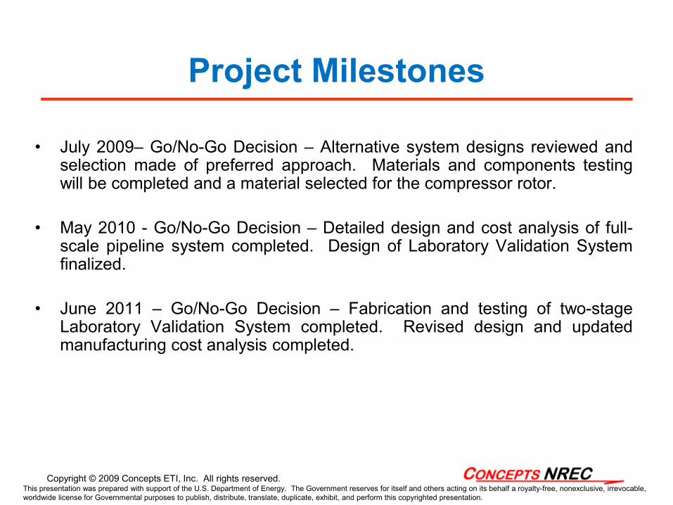
Project Milestones
• July 2009– Go/No-Go Decision – Alternative system designs reviewed andselection made of preferred approach. Materials and components testingwill be completed and a material selected for the compressor rotor.
• May 2010 - Go/No-Go Decision – Detailed design and cost analysis of full-scale pipeline system completed. Design of Laboratory Validation Systemfinalized.
• June 2011 – Go/No-Go Decision – Fabrication and testing of two-stageLaboratory Validation System completed. Revised design and updatedmanufacturing cost analysis completed.
This presentation was prepared with support of the U.S. Department of Energy. The Government reserves for itself and others acting on its behalf a royalty-free, nonexclusive, irrevocable, worldwide license for Governmental purposes to publish, distribute, translate, duplicate, exhibit, and perform this copyrighted presentation.

Copyright © 2009 Concepts ETI, Inc. All rights reserved.
• Technical Approach– Utilize state-of-the-art aerodynamic/structural analyses to develop a high-
performance centrifugal compressor system, able to provide high pressureratios under acceptable material stresses.
– Utilize proven bearings and seal technology to reduce developmental riskand increase system reliability at a competitive cost.
– With project and industrial collaborators, prepare an implementation planthat can provide for near-term industrial pipeline applications.
• Methodology– Investigate and prioritize alternative system configurations using operating
conditions that meet initial capital and operational costs to meet near-termapplications.
– Identify critical engineering constraints of commercially availablecomponents and operational limitations of state-of-the-art materials,compatible with hydrogen to increase the range of safe compressoroperating speeds.
– Design and test critical rotor aerodynamics and material components underdesign conditions and demonstrate full-scale components in an integratedcompressor system.
Project Engineering Approach - 1Innovative Compressor Design
This presentation was prepared with support of the U.S. Department of Energy. The Government reserves for itself and others acting on its behalf a royalty-free, nonexclusive, irrevocable, worldwide license for Governmental purposes to publish, distribute, translate, duplicate, exhibit, and perform this copyrighted presentation.

Copyright © 2009 Concepts ETI, Inc. All rights reserved.
Project Engineering Approach – 2Primary Engineering Challenge
The Engineering Challenge• Design centrifugal compressor with highest acceptable pressure ratio and
thermodynamic efficiency per stage to minimize system size, complexity, cost, andmaximize system performance and reliability.
Solution• Maximize centrifugal compressor tip speed within stress limitations of material.
– Pressure ratio is proportional to rpm2 x radius2, so small increase in tip speed results insignificant increases in pressure.
– Maximum thermodynamic efficiency is typically achieved at high operating tip speeds.• Utilize advanced diffuser systems to maximize recovery of dynamic head into static
pressure.
Constraints• High operating speeds increases impeller material stresses.
– Stress is also proportional to rpm2 x radius2 x material density. Therefore, pressure rise islimited by maximum stress capability of impeller material.
• Need to select materials that are not significantly affected by hydrogen embrittlement.• Limited number of materials that have high strength to material density ratio and
resistant to hydrogen embrittlement.
This presentation was prepared with support of the U.S. Department of Energy. The Government reserves for itself and others acting on its behalf a royalty-free, nonexclusive, irrevocable, worldwide license for Governmental purposes to publish, distribute, translate, duplicate, exhibit, and perform this copyrighted presentation.

Copyright © 2009 Concepts ETI, Inc. All rights reserved.
Project Engineering Approach - 3 Operational Design Envelope
Design Options for Alternative Operating Conditions
This presentation was prepared with support of the U.S. Department of Energy. The Government reserves for itself and others acting on its behalf a royalty-free, nonexclusive, irrevocable, worldwide license for Governmental purposes to publish, distribute, translate, duplicate, exhibit, and perform this copyrighted presentation.

Copyright © 2009 Concepts ETI, Inc. All rights reserved.
Technical Accomplishments and ProgressStatus of Phase 1. Initial Design Investigation
• Task 1. Initial System Design Criteria and Specifications – completed• Task 2. Subsystems Modeling – 90% complete• Task 3. Integrated Systems Analysis – 80% complete• Task 4. Initial Design and Cost Analysis – 80% complete• Task 5. Final Design Specifications – scheduled to be done at the end
of Phase I• Task 6. Bench Top-Scale Materials Selection (completed) & Testing
(in progress)
• Task 7. Revised Phase II program Plan – scheduled to be done at the end of Phase I
• Task 8. Program Management – in progress
This presentation was prepared with support of the U.S. Department of Energy. The Government reserves for itself and others acting on its behalf a royalty-free, nonexclusive, irrevocable, worldwide license for Governmental purposes to publish, distribute, translate, duplicate, exhibit, and perform this copyrighted presentation.

Copyright © 2009 Concepts ETI, Inc. All rights reserved.
Technical Accomplishments and ProgressSummary- 1
• Compressor design conditions confirmed by project collaborators (Pinlet= 350 psig, Poutlet=1,200 psig; Flow rate= 240,000 kg/day)
• Compressor aerodynamic studies culminated in 6-stage, 60,000 rpm, 3.33 pressure ratio compressor.
• Integral gearbox pinions driving individual impellers • Design of compressor’s major mechanical elements completed and
satisfied by two manufacturers per component:– Titling pad radial and thrust bearings designs validated for use.– Face-seals with buffer gas have been validated for use.
• Heat exchanger specifications met by two manufacturers– Tranter Plate-type Heat Exchanger Design– Heatric Heat Exchanger (compact, plate-fin surface core)
This presentation was prepared with support of the U.S. Department of Energy. The Government reserves for itself and others acting on its behalf a royalty-free, nonexclusive, irrevocable, worldwide license for Governmental purposes to publish, distribute, translate, duplicate, exhibit, and perform this copyrighted presentation.

Copyright © 2009 Concepts ETI, Inc. All rights reserved.
Technical Accomplishments and ProgressSummary - 2
• Over 30 alternative compressor-gearbox configurations, materials, andcompressor drive options (including gas turbine drives with heatrecovery for intercooler cooling) studied and evaluated using a RelativeRisk and Relative Cost Optimization Program Developed for the projectculminating in a “Best” choice:
– Six independent, overhung, integrally driven rotor-shafts– A two-speed step gearbox with parallel bull gears– 8,400 hp (6,300 kWe), 1,800 rpm, synchronous motor prime mover– External intercoolers to cool hydrogen gas to 100°F between stages– Intercoolers packaged within base frame
• Compressor Station Performance and Cost Model Developed– Suitable as a Macro for DOE “HDSAM v2.0” Economics Model
• Identifies hydrogen compressor package performance (power, efficiency, component sizes)
• Estimates compressor station cost• Estimates O&M costs
This presentation was prepared with support of the U.S. Department of Energy. The Government reserves for itself and others acting on its behalf a royalty-free, nonexclusive, irrevocable, worldwide license for Governmental purposes to publish, distribute, translate, duplicate, exhibit, and perform this copyrighted presentation.

Copyright © 2009 Concepts ETI, Inc. All rights reserved.
Technical Accomplishments and ProgressCompressor Package Performance and Cost Model
• Compressor Package Performance provides a single point summary ofeach of the components within the package:
• Compressor rotor aerodynamics (pressure ratio, power, speed vs. flow rate and intercooler pressure drop)
• Intercooler size vs. effectiveness (i.e., desired outlet temperature)• Electric motor power • Overall hydrogen efficiency based on compressor power, component efficiencies• Compressor shaft diameter sizing based on fatigue loading• Impeller radial and axial loadings calculated
• Cost Model uses algorithms to determine the relative cost effects of changes in design specifications such as:
• Number of compressor stages, single or back-to-back• Number of volute housings (1 or more stages per housing)• Rotor rpm• Compressor efficiency• Gearbox (1- or 2-speed step), • Driver speed and type • Choice of compressor materials• Rotor materials with or without coatings• Number of intercoolers
This presentation was prepared with support of the U.S. Department of Energy. The Government reserves for itself and others acting on its behalf a royalty-free, nonexclusive, irrevocable, worldwide license for Governmental purposes to publish, distribute, translate, duplicate, exhibit, and perform this copyrighted presentation.

Copyright © 2009 Concepts ETI, Inc. All rights reserved.
Gearbox Configuration: Alpha 1 Beta 1 Gamma 1 Delta 1
Compressor Configurations "A" through "F"Configuration Designation: A B C D E F
Impeller Speeds (rpm):1st and 2nd 70,000 50,000 50,000 50,000 50,000 60,0003rd and 4th 80,000 50,000 60,000 50,000 50,000 60,0005th and 6th 90,000 50,000 70,000 50,000 50,000 60,000
Total Power, hp= 8,360 8,354 8,450 8,610 8,543 8,349
Max. Tip Speeds,ft/s= 2,236 2,178 2,194 2,194 2,101 2,094Avg. Pres. ratio= 1.243 1.243 1.243 1.243 1.2541 1.247
Technical Accomplishments and ProgressCompressor-Gearbox “Best Case” Selection Based
on Relative O&M and Mechanical Risk Analysis
• Driver speed (1800, 3600, and 10,000 rpm)• Number of stages (4, 6, and 7)• Number of intercoolers (3 or 5) for impeller temp. < 140 F• Pressure loss in intercooler and interconnect piping• Number of drive shafts and number of impellers per
shaft drive (1 or 2 impellers per drive shaft)• Compressor aerodynamics and geometry
– Hydrogen flow rate– Compressor impeller speed (50k to 90krpm)– Stage pressure ratio– Effect of forward sweep to reduce tip speed for
same stage pressure ratio – Inlet guide vanes– Use of compressor inlet swirl to increase pressure
ratio BEST CHOICE
This presentation was prepared with support of the U.S. Department of Energy. The Government reserves for itself and others acting on its behalf a royalty-free, nonexclusive, irrevocable, worldwide license for Governmental purposes to publish, distribute, translate, duplicate, exhibit, and perform this copyrighted presentation.

Copyright © 2009 Concepts ETI, Inc. All rights reserved.
Technical Accomplishments and ProgressCompressor Design Specifications
• Compressor Design Details:– Centrifugal Compressor overall efficiency = 80.3%– A nominal shaft speed of 60,000 rpm – Six-stages– Tip speed < 2,100 ft/s (corresponding to a hub stress of less than 60 kpsi)– Power of 1400 hp per wheel, – Suction pressure 350 psig, discharge pressure 1200 psig for an overall pressure ratio of 3.33– 240,000 kg/day hydrogen flow rate (ranging from 200,000 to 250,000 kg/day)
• Geometry Advances- Open passages with two splitter vanes- Forward sweep at vanes exit (not shown)- IGV causing negative swirl
• Boreless Hub Design-Decreases rotor hub stress
• Multiple Patents Pending
This presentation was prepared with support of the U.S. Department of Energy. The Government reserves for itself and others acting on its behalf a royalty-free, nonexclusive, irrevocable, worldwide license for Governmental purposes to publish, distribute, translate, duplicate, exhibit, and perform this copyrighted presentation.

Copyright © 2009 Concepts ETI, Inc. All rights reserved.
Technical Accomplishments and ProgressMaterials Selection and Testing Summary- 1
• A wide-ranging literature search and personal discussions with materialsresearchers (Sandia, Savannah River, Argonne National Laboratories, FailureAnalysis Associates) have been conducted (and continue)
• Most hydrogen embrittlement material studies have focused on steels and titanium alloys• There is agreement that aluminum alloy is protected from hydrogen embrittlement by its
quickly formed oxide layer and the extremely slow diffusion of hydrogen into the metal• From a turbomachinery design focus:
– Aluminum (alloys: 2618-T6, 2918-T81 and 7075) is light but strong (as evidenced by itsrelatively high specific strength), comparable to titanium and thus very suitable forcentrifugal compressor applications
– However, titanium is recognized by most (all?) researchers as affected by hydrogenembrittlement
• Collaboration with Texas A&M (Dr. Hong Liang) and coordinating their tests withtwo National Labs is in progress to conduct relevant tests with aluminum per aTest Protocol derived from discussions with researchers, including:
• Sandia National Labs (Fracture mechanics testing; Dr. Chris San Marchi)• Savannah River National Labs (Specimen “Charging” with Hydrogen plus Tensile
testing with H2; Dr. Andrew Duncan)• Argonne National Labs (Dr. George Fenske)
This presentation was prepared with support of the U.S. Department of Energy. The Government reserves for itself and others acting on its behalf a royalty-free, nonexclusive, irrevocable, worldwide license for Governmental purposes to publish, distribute, translate, duplicate, exhibit, and perform this copyrighted presentation.

Copyright © 2009 Concepts ETI, Inc. All rights reserved.
Design Experience Associating Material Properties with Tip Speed of 2,200 ft/s with Aluminum Alloy - 2
0
500
1000
1500
2000
2500
3000
-100 0 100 200 300 400 500 600 700 800 900
Tip
spee
d, ft
/s
Material operating temperature, F
Max. Tip Speeds for Various Materials with Respect to Operating Temperature
Titanium 6-4 Annealed
Aluminum 7075-T^ alloy
2618-T61 Alloy
Literature Survey (Rocketdyne Lab Tests for NASA) and reviews with materials researchers at national labs and private consultants indicate Aluminum Alloy shows no effect from hydrogen …. AND aluminum is an excellent structural material for high speed impellers based on specific strength (ultimate strength/density)
This presentation was prepared with support of the U.S. Department of Energy. The Government reserves for itself and others acting on its behalf a royalty-free, nonexclusive, irrevocable, worldwide license for Governmental purposes to publish, distribute, translate, duplicate, exhibit, and perform this copyrighted presentation.

Copyright © 2009 Concepts ETI, Inc. All rights reserved.
• Paraphrasing comments made during many interviews with researchers, thequick answer is: “…no known coating materials exist to preventhydrogen diffusion and hence the embrittlement of the base material”
• Texas A&M conducts coating experiments with coatings recommended byCN and others
– Proposed coatings are all aluminum oxide-based (although DLC-Diamond LikeCoating, has also been considered, but discouraged by Texas A&M and others)
• Accuratus (APS Company)• Alodine EC2 ElectroCeramic (Henkel Corp)• Sermalon (Sermatech International)
• Some structural concerns:– Can the coating be applied without affecting compressor material or vane design?– Will it compromise the base material by exposing even a small activation site on
the base material if coating is chipped, cracked, or otherwise broken?– Will it contaminate the hydrogen during long-term use?
Technical Accomplishments and ProgressMaterial Coatings to Inhibit Hydrogen Embrittlement - 3
This presentation was prepared with support of the U.S. Department of Energy. The Government reserves for itself and others acting on its behalf a royalty-free, nonexclusive, irrevocable, worldwide license for Governmental purposes to publish, distribute, translate, duplicate, exhibit, and perform this copyrighted presentation.

Copyright © 2009 Concepts ETI, Inc. All rights reserved.
Overall Layout Drawing of System
This presentation was prepared with support of the U.S. Department of Energy. The Government reserves for itself and others acting on its behalf a royalty-free, nonexclusive, irrevocable, worldwide license for Governmental purposes to publish, distribute, translate, duplicate, exhibit, and perform this copyrighted presentation.

Copyright © 2009 Concepts ETI, Inc. All rights reserved.
Pipeline Compressor System Module
This presentation was prepared with support of the U.S. Department of Energy. The Government reserves for itself and others acting on its behalf a royalty-free, nonexclusive, irrevocable, worldwide license for Governmental purposes to publish, distribute, translate, duplicate, exhibit, and perform this copyrighted presentation.

Copyright © 2009 Concepts ETI, Inc. All rights reserved.
Hydrogen Compressor Package AssemblyCompressor Module Rating: 240,000 kg/day; 6,300 kWe
Compressor-Gearbox(10:1 and 3.33:1, parallel bull gear driving 6 pinions (three per side)
Compressor Drive connection
Intercoolers (cooling hydrogen at compressor inlet to 100 oF )
1,800 rpm Synchronous Motor and Controls
1 of 6 compressor stages (3 per side)
This presentation was prepared with support of the U.S. Department of Energy. The Government reserves for itself and others acting on its behalf a royalty-free, nonexclusive, irrevocable, worldwide license for Governmental purposes to publish, distribute, translate, duplicate, exhibit, and perform this copyrighted presentation.

Copyright © 2009 Concepts ETI, Inc. All rights reserved.
Project Collaborations-Principal Investigator- Concepts NREC:
Capabilities from Aero Design to Manufacturing
This presentation was prepared with support of the U.S. Department of Energy. The Government reserves for itself and others acting on its behalf a royalty-free, nonexclusive, irrevocable, worldwide license for Governmental purposes to publish, distribute, translate, duplicate, exhibit, and perform this copyrighted presentation.

Copyright © 2009 Concepts ETI, Inc. All rights reserved.
Project Collaborations:Strengths & Responsibilities of Partners
• Praxair– Provides industrial user experience, gas industry specification data, and
“hands-on” experience with compressor systems, including hydrogencompression, for industrial gas industry
– Future industrial customer
• Texas A&M University– Provides material science expertise and coordination of materials testing with
Sandia and Savannah River National labs
• HyGen Industries– Provides experience in hydrogen fueling infrastructure: pipeline and refueling
station systems, has a database of customer-user engineering specifications.Assists in developing implementation plan for pipeline applications forhydrogen compressors
This presentation was prepared with support of the U.S. Department of Energy. The Government reserves for itself and others acting on its behalf a royalty-free, nonexclusive, irrevocable, worldwide license for Governmental purposes to publish, distribute, translate, duplicate, exhibit, and perform this copyrighted presentation.

Copyright © 2009 Concepts ETI, Inc. All rights reserved.
Future Project Work• Complete Current Phase 1 Effort
– Continue to update compressor station Performance and Cost Module: • Including Operation & Maintenance Costs ($O&M/kg/day)for centrifugal compressors
working with hydrogen • Sizing and pricing of the compressor station module subsystems: intercoolers, prime
mover, gearbox design, couplings, controls, safety systems, and base frame– Complete mechanical design of integral compressor rotor-shaft with gearbox pinion design– FMEA for compressor-gearbox and station– Outline compressor start-up and shut-down strategy – Review present Hydrogen Safety Standards and Commercial Systems and future requirements– Complete materials testing with Texas A&M– Go/No Go decision (July, 2009)
• Phase 2. Detailed Design (08/2009 to 04/2010)– Detailed subsystems modeling– Detailed integrated systems analysis– Critical components design, testing and development
• Phase 3. System Validation Testing (May 2010 to June 2011)– Component Procurement– Two-stage centrifugal compressor system assembly
This presentation was prepared with support of the U.S. Department of Energy. The Government reserves for itself and others acting on its behalf a royalty-free, nonexclusive, irrevocable, worldwide license for Governmental purposes to publish, distribute, translate, duplicate, exhibit, and perform this copyrighted presentation.

Copyright © 2009 Concepts ETI, Inc. All rights reserved.
Project Summary• Relevance: An advanced pipeline compressor system has been designed that meets DOE’s
performance goals for a reliable 98% hydrogen efficiency compressor system with afootprint one-third the size of existing industrial systems and at a projected less than 75%of DOE’s target.
• Approach: Utilize state-of-the-art aerodynamic/structural analyses to develop a high-performance centrifugal compressor system able to provide high pressure ratios underacceptable material stresses. Utilize proven bearings and seal technology to reducedevelopmental risk and increase system reliability at a competitive cost.
• Tech. Accomplishments & Progress: Aerodynamic analysis and design of a highvolume, cost effective, six-stage centrifugal compressor has been completed tocompress 240,000 kg/day from 350 to 1,200 psig and will be the largest hydrogencentrifugal compressor available for pipeline-grade service.
• Technology Transfer/Collaboration: The collaborative team consists of anindustrial user with engineering experience in pipeline compressors (Praxair), amaterials researcher (Texas A&M) and a hydrogen refueling industry consultant(HyGen) who are all committed to producing the first commercially reliable hydrogencompressor for hydrogen pipeline delivery.
• Proposed Future Research: Complete materials testing to verify materials yield stress;continue with detail design of compressor in Phase 2 culminating in the fabrication andlaboratory testing of prototype compressor-gearbox in Phase 3. Complete thecompressor module Cost and Performance Model that may be suitable for use as a“Macro” to DOE’s HDSAM v.2 economics model.
This presentation was prepared with support of the U.S. Department of Energy. The Government reserves for itself and others acting on its behalf a royalty-free, nonexclusive, irrevocable, worldwide license for Governmental purposes to publish, distribute, translate, duplicate, exhibit, and perform this copyrighted presentation.