2009 international residential code errata · 2009 international residential code errata (portions...
TRANSCRIPT

2009 International Residential Code Errata (Portions of text and tables not shown are unaffected by the errata)
1st through 4th PRINTING (JULY 14, 2011)
CHAPTER 1 SCOPE AND ADMINISTRATION
R105.2 Work exempt from a permit. ….. Building: Item 10. …..serve the exit door required by Section 311.4 311.2 R110.2 Change in Use. Changes in the character or use of an existing structure shall not be made except as specified in Sections 3406 3408 and 3407 3409 of the International Building Code.
2009 International Residential Code Errata (Portions of text and tables not shown are unaffected by the errata)
1st and 2nd PRINTING (JULY 14, 2011)
CHAPTER 1 SCOPE AND ADMINISTRATION
R104.10 Modifications. ….intent and purpose of this code and that such modification does not lessen health, life and fire safety, or structural requirements or structural.

2009 International Residential Code and Commentary Errata (Only errata to Commentary are shown-see International Residential Code Errata for Code Errata)
(Portions of text and tables not shown are unaffected by the errata)
1st and 2nd PRINTING (Posted: 9-26-13)
CHAPTER 2 DEFINITIONS
R202, ATTIC. The unfinished space…..of the top story and the roof assembly. Such a space would be the top story, rather than the attic, if it is finished and occupiable.

2009 International Residential Code Errata (Portions of text and tables not shown are unaffected by the errata)
1st and 2nd PRINTING (SEPTEMBER 14, 2009)
CHAPTER 2 DEFINITIONS
FIRE SEPARATION DISTANCE. ….
3. To an imaginary line between two buildings on the lot. The distance shall be measured at a right angle from the face of the wall.

2009 International Residential Code Errata (Portions of text and tables not shown are unaffected by the errata)
1st through 7th PRINTING (September 26, 2012)
CHAPTER 3
BUILDING PLANNING R301.2.2.2.5, Item 7
7. When stories above grade plane partially or completely braced by wood wall framing in accordance with Section R603 or steel wall framing in accordance with Section R603 include masonry or concrete construction. When this irregularity applies, the entire story shall be designed in accordance with accepted engineering practice Exception: Fireplaces, chimneys and masonry veneer as permitted by this code. When this irregularity applies, the entire story shall be designed in accordance with accepted engineering practice

2009 International Residential Code Errata (Portions of text and tables not shown are unaffected by the errata)
1st through 5th PRINTING (February 28, 2012)
CHAPTER 3 BUILDING PLANNING
R301.2.2.3.3 Masonry construction. Masonry construction in Seismic Design Categories D0 and D1 shall comply with the requirements of Section R606.1112.3. Masonry construction in Seismic Design Category D2 shall comply with the requirements of Section R606. 1112.4. TABLE R308.3.1(1)
R318.1 Subterranean termite control methods. In areas subject to damage from termites as indicated by Table R301.2(1), methods of protection shall be one of the following methods or a combination of these methods: 1. Chemical termiticide treatment, as provided in Section R318.2. 2. Termite baiting system installed and maintained according to the label. 3. Pressure-preservative-treated wood in accordance with the provisions of Section R317.1. 4. Naturally durable termite-resistant wood and used in locations as specified in Section R318.1. 5. Physical barriers as provided in Section R318.3 and used in locations as specified in Section R318.1. 6. Cold-formed steel framing in accordance with Sections R505.2.1 and R603.2.1.

2009 International Residential Code Errata (Portions of text and tables not shown are unaffected by the errata)
1st through 4th PRINTING (Posted: 11-29-2011)
CHAPTER 3 BUILDING PLANNING
Figure R301.2(5) corrections as follows:
1. At the center of the State of North Dakota, the ground snow load shown as 36 should read 35. 2. At the State of Pennsylvania, the elevation shown as 700 (2 places) should read 1700.

2009 International Residential Code Errata (Portions of text and tables not shown are unaffected by the errata)
1st through 4th PRINTING (JULY 14, 2011)
CHAPTER 3 BUILDING PLANNING
FIGURE R301.2(7) COMPONENT AND CLADDING PRESSURE ZONES
R301.2.1.2 Protection of openings. ….. Exception: Wood structural…..Panels shall be precut so that they can be and attached to the framing….

2009 International Residential Code Errata (Portions of text and tables not shown are unaffected by the errata)
TABLE R308.3.1(1) MINIMUM CATEGORY CLASSIFICATION OF GLAZING USING CPSC 16 CFR 1201
EXPOSED SURFACE AREA OF ONE SIDE OF ONE LITE
GLAZING IN STORM OR
COMBINATION DOORS
(Category Class)
GLAZING IN DOORS
(Category Class)
GLAZED PANELS REGULATED BY
ITEM 7 4 OF SECTION R308.4 (Category Class)
GLAZED PANELS REGULATED BY
ITEM 6 2 OF SECTION R308.4 (Category Class)
GLAZING IN DOORS AND ENCLOSURES
REGULATED BY ITEM 5 OF SECTION
R308.4 (Category Class)
SLIDING GLASS DOORS PATIO
TYPE (Category Class)
9 square feet or less I I NR I II II
More than 9 square feet II II II II II II
TABLE R308.3.1(2) MINIMUM CATEGORY CLASSIFICATION OF GLAZING USING ANSI Z97.1
EXPOSED SURFACE AREA OF ONE SIDE OF ONE LITE
GLAZED PANELS REGULATED BY ITEM 7 3 OF SECTION R308.4
(Category Class)
GLAZED PANELS REGULATED BY ITEM 6 2 OF SECTION R308.4
(Category Class)
DOORS AND ENCLOSURES REGULATED BY ITEM 5 OF
SECTION R308.4a (Category Class)
R310.3 Bulkhead enclosures. …..Bulkhead enclosures shall also comply with Section R311.7.8 9.2 R311.7.5 Landings for stairways. ….
Exception: A floor ….over the stairs. A flight of stairs shall not have a vertical rise larger than 12 feet (3658 mm) between floor levels or landings. The width of each landing shall not be less that the width of the stairway served. Every landing shall have a minimum dimension of 36 inches (914 mm) measured in the direction of travel.
A flight of stairs shall not have a vertical rise larger than 12 feet (3658 mm) between floor levels or landings. The width of each landing shall not be less that the width of the stairway served. Every landing shall have a minimum dimension of 36 inches (914 mm) measured in the direction of travel. R316.6 Specific approval. …NFPA 286 with the acceptance criteria of Section R302.9.4, FM4880, UL 723, UL1040 or…..

2009 International Residential Code Errata (Portions of text and tables not shown are unaffected by the errata)
1st and 2nd PRINTING (JULY 14, 2011)
CHAPTER 3 BUILDING PLANNING
FIGURE R301.2.1.5.1(3) ILLUSTRATION OF WHERE ON A TOPOGRAPHIC FEATURE, WIND SPEED INCREASE IS APPLIED
R301.2.2.1.1 Alternate determination of seismic design category. ….and to interpolate between values in Tables R602.10.1 R602.10.1(2), R603.7 R603.9.2(1) and other seismic design requirements of this code. TABLE R301.5 MINIMUM UNIFORMLY DISTRIBUTED LIVE LOADS (in pounds er square foot) ………
Note g. For attics……. 1. The attic area is accessible by a pull down stairway or framed opening in accordance with Section R807.1.
TABLE R302.1 EXTERIOR WALLS EXTERIOR WALL ELEMENT MINIMUM FIRE-RESISTANCE RATING MINIMUM FIRE SEPARATION DISTANCE
Penetrations All Comply with Section R317.3 R302.4 < 5 feet None required 5 feet
R308.4 Hazardous locations. …. 7. Glazing… Exceptions: 2. The side …. complying with Sections R311.7.6 7 and …. 8. Glazing … Exceptions: 1. The side … complying with Sections R311.7.6 7 and …. R317.3.2 Fastenings for wood foundations. Fastenings … in AF&PA Technical Report No. 7 PWF.

2009 International Residential Code Errata (Portions of text and tables not shown are unaffected by the errata)
1st and 2nd PRINTING (SEPTEMBER 14, 2009)
CHAPTER 3 BUILDING PLANNING
FIGURE R301.2.1.5.1(3) ILLUSTRATION OF WHERE ON A TOPOGRAPHIC FEATURE, WIND SPEED INCREASE IS APPLIED UPWIND OBSTRUCTION
TABLE R302.1 EXTERIOR WALLS
EXTERIOR WALL ELEMENT MINIMUM
FIRE-RESISTANCE RATING
MINIMUM FIRE SEPARATION DISTANCES
Walls (Fire-resistance rated)
1 hour –tested in accordance with ASTM E 119 or
UL 263 with exposure form from both sides < 5 feet
(Not fire-resistance rated)
0 hours ≥ 5 feet

2009 International Residential Code Errata (Portions of text and tables not shown are unaffected by the errata)
1st through 7th PRINTING (12-04-2012)
CHAPTER 4
FOUNDATIONS TABLE R403.4
1 plf = 14.6 N/m 1 pounds per square foot = 47.9 N/m2

2009 International Residential Code Errata (Portions of text and tables not shown are unaffected by the errata)
1st through 6th PRINTING (Posted: 06-06-12)
CHAPTER 4 FOUNDATIONS
R404.1.2.2 Reinforcement for foundation walls. Concrete…..Vertical reinforcement for flat basement walls…in accordance with Table R404.1.2(9) (8). For basement walls….

2009 International Residential Code Errata (Portions of text and tables not shown are unaffected by the errata)
1st through 5th PRINTING ( 9-19-2011 )
CHAPTER 4
FOUNDATIONS R403.1.8 Foundations on expansive soils. Foundation and floor slabs for buildings located on expansive soils shall be designed in accordance with Section 1805.8 1808.6 of the International Building Code .

2009 International Residential Code Errata (Portions of text and tables not shown are unaffected by the errata)
1st through 4th PRINTING (JULY 14, 2011)
CHAPTER 4 FOUNDATIONS
TABLE R404.1.1(3) 10-INCH MASONRY FOUNDATION WALLS WITH REINFORCING….

2009 International Residential Code Errata (Portions of text and tables not shown are unaffected by the errata)
1st and 2nd PRINTING (JULY 14, 2011)
CHAPTER 4 FOUNDATIONS
FIGURE R403.1.7.1 FOUNDATION CLEARANCE FROM SLOPES
TABLE R403.4 MINIMUM DEPTH OF CRUSHED STONE FOOTINGS (D), (inches) LOAD BEARING VALUE OF SOIL (psf)
1500 2000 3000 4000 MH, CH, CL, ML SC, GC, SM, GM, SP, SW GP, GW
Wall width (inches) Wall width (inches) Wall width (inches) Wall width (inches) 6 8 10 12 6 8 10 12 6 8 10 12 6 8 10 12
Conventional light-frame construction 1-story 1100 plf 6 4 4 4 6 4 4 4 6 4 4 4 6 4 4 6 2-story 1800 plf 8 6 4 4 6 4 4 4 6 4 4 4 6 4 4 4 3-story 2000
2900 plf 16 14 12 10 10 8 6 6 6 4 4 4 6 4 4 4

2009 International Residential Code Errata (Portions of text and tables not shown are unaffected by the errata)
1st and 2nd PRINTING (SEPTEMBER 14, 2009)
CHAPTER 4 FOUNDATIONS
R404.1.1 Design of masonry foundation walls. Masonry foundation walls ……accordance with the provisions of ACI530/ASCE 5/TMS 402 TMS402/ACI 530/ASCE 5 or NCMA TR68‐A. When ACI530/ASCE 5/TMS 402 TMS 402/ACI 530/ASCE 5, NCMA TR68‐A or the provisions …… R404.1.2.3.7.2 Location of reinforcement in wall. The center of vertical reinforcement in basement walls determined from Tables R404.1.2(3) R404.1.2 (2) through R404.1.2(7) shall be located at the centerline of the wall. Vertical reinforcement in basement walls determined from Tables R404.1.2(2) or R404.1.2(8) shall be located ……

2009 International Residential Code Errata (Portions of text and tables not shown are unaffected by the errata)
1st through 5th PRINTING (Posted: 12-06-2011)
CHAPTER 5 FLOORS
R502.1.1 Preservative-treated lumber. Preservative treated dimension lumber shall also be identified as required by Section R319.1. R317.2.

2009 International Residential Code Errata (Portions of text and tables not shown are unaffected by the errata)
1st and 2nd PRINTING (JULY 14, 2011)
CHAPTER 5 FLOORS
TABLE R503.2.1.1(1) ALLOWABLE SPANS AND LOADS FOR WOOD STRUCTURAL PANELS FOR ROOF AND SUBFLOOR SHEATHING AND COMBINATION SUBFLOOR UNDERLAYMENTa,b,c
SPAN RATING
MINIMUM NOMINAL
PANEL THICKNESS
(Inch)
ALLOWABLE LIVE LOAD (psf)h,l
MAXIMUM SPAN (inches)
LOAD (pounds per square foot, at
maximum span) MAXIMUM
SPAN (inches)
SPAN @ 16” o.c.
SPAN @ 24”
o.c.
With edge
supportd
Without edge
support
Total load
Live load
Sheathinge Rooff Subfloorj
48/24 23/32, 3/48 3/4 - 175 48 36 45 35 24

2009 International Residential Code Errata (Portions of text and tables not shown are unaffected by the errata)
Page 1 of 1
1st through 10th PRINTING (April 15, 2014)
CHAPTER 6 WALLS

2009 International Residential Code Errata (Portions of text and tables not shown are unaffected by the errata)
1st through 7th PRINTING (Posted: October 3, 2012)
CHAPTER 6
WALL CONSTRUCTION
TABLE R611.7(1C)
2009 International Residential Code Errata (Portions of text and tables not shown are unaffected by the errata)
1st through 5th PRINTING (February 28, 2012)
CHAPTER 6
WALL CONSTRUCTION
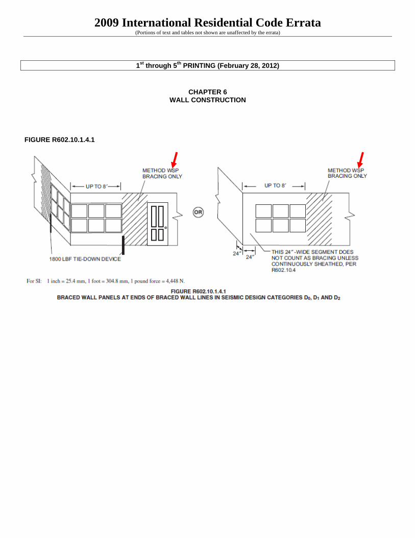
FIGURE R602.10.1.4.1

2009 International Residential Code Errata (Portions of text and tables not shown are unaffected by the errata)
FIGURE R602.10.3.4
24”

2009 International Residential Code Errata (Portions of text and tables not shown are unaffected by the errata)
FIGURE R603.6(2) FIGURE R606.11.2
FIGURE R606.11(3)

2009 International Residential Code Errata (Portions of text and tables not shown are unaffected by the errata)
TABLE R611.8(2)

2009 International Residential Code Errata (Portions of text and tables not shown are unaffected by the errata)
1st through 4th PRINTING (Posted: 11-29-2011)
CHAPTER 6 WALL CONSTRUCTION
TABLE R602.3(1) FASTENER SCHEDULE FOR STRUCTURAL MEMBERS
Other wall sheathingh
34 ½” structural cellulosic fiberboard sheathing
1 ½” galvanized roofing nail, 7/16” crown or 1” crown staple 16 ga., 1 1/4” long
3 6

2009 International Residential Code Errata (Portions of text and tables not shown are unaffected by the errata)
1st through 4th PRINTING ( Posted: August 11, 2011 )
CHAPTER 6 WALL CONSTRUCTION
Table R602.3(1)
TABLE R602.3(1) FASTENER SCHEDULE FOR STRUCTURAL MEMBERS
ITEM DESCRIPTION OF BUILDING MATERIALS
DESCRIPTION OF FASTENERb,c,e
SPACING OF FASTENERS
Edges (inches)i Intermediate supportsc,e
(inches) Wood structural panels, subfloor, roof and interior wall sheathing to framing and particle board wall sheathing to framing
30 3/8” – ½”
6d common (2”x 0.113”) nail (subfloorwall)j
8d common (2 ½” x 0.131”) nail (roof)f
6 12g

2009 International Residential Code Errata (Portions of text and tables not shown are unaffected by the errata)
1st through 4th PRINTING (JULY 14, 2011)
CHAPTER 6 WALL CONSTRUCTION
TABLE R602.3(2)…. Note f. Hardboard underlayment shall conform to CPA/ANSI/AHA A135.4 FIGURE R602.10.3.3 METHOD PFH: PORTAL FRAME WITH HOLD-DOWNS

2009 International Residential Code Errata (Portions of text and tables not shown are unaffected by the errata)
FIGURE R602.10.6.2(2) BRACED WALL PANEL CONNECTION OPTION TO PERPENDICULAR RAFTERS OR ROOF TRUSSES
TABLE R611.8(2) MAXIMUM ALLOWABLE CLEAR SPANS FOR 4-INCH NOMINAL THICK FLAT LINTELS IN LOAD-BEARING WALLSa, b, c, d, e, f, m
ROOF CLEAR SPAN 40 FEET AND FLOOR CLEAR SPAN 32 FEET
LINTEL DEPTH,
Dg
(inches)
NUMBER OF BARS AND BAR
SIZE IN TOP AND BOTTOM
OF LINTEL
STEEL YIELD STRENGTHh, fy(psi)
DESIGN LOADING CONDITION DETERMINED FROM TABLE R611.8(1)
1 2 3 4 5
MAXIMUM GROUND SNOW LOAD (psf)
30 70 30 70 30 70 30 70
Maximum clear span of lintel (feet - inches)

2009 International Residential Code Errata (Portions of text and tables not shown are unaffected by the errata)
1st through 4th PRINTING (SEPTEMBER 14, 2009)
CHAPTER 6 WALL CONSTRUCTION
TABLE R602.3(1) FASTENER SCHEDULE FOR STRUCTURAL MEMBERS
ITEM DESCRIPTION OF BUILDING ELEMENTS
NUMBER AND TYPE OF FASTENERa, b, c
SPACING OF FASTENERS
Wall
13 Double top plates, minimum 48 24-inch offset of end joints, face nail in lapped area
8-16d (3 ½” x 0.135”)
—

2009 International Residential Code Errata (Portions of text and tables not shown are unaffected by the errata)
1st through 3rd PRINTING (JULY 14, 2011)
CHAPTER 6 WALL CONSTRUCTION
TABLE R602.10.1.2(3) ADJUSTMENT FACTORS TO THE LENGTH OF REQUIRED SEISMIC WALL BRACINGa
ADJUSTMENT BASED ON:
MULTIPLY LENGTH OF BRACING PER WALL
LINE BY: APPLIES TO:
Roof/ceiling dead load for wall supportingb
roof only or roof plus one story
≤ 15 psf 1.0
roof only <15 psf ≤ 25 psf 1.1 1.2 roof plus one story <15 psf ≤ 25 psf 1.2 1.1
Walls with stone or masonry veneer in SDC-C-D2 See Section R703.7 Cripple walls See Section R602.10.9

2009 International Residential Code Errata (Portions of text and tables not shown are unaffected by the errata)
1st and 2nd PRINTING (JULY 14, 2011)
CHAPTER 6 WALL CONSTRUCTION
TABLE R602.3(1) FASTENER SCHEDULE FOR STRUCTURAL MEMBERS
ITEM
DESCRIPTION OF BUILDING MATERIALS
DESCRIPTION OF FASTENER SPACING OF FASTENERS Edges
(inches)i Intermediate supportsc,e
(inches)
Wood structural panels. Subfloor, roof and interior wall sheathing to 31 5/16” – ½” 6dcommon (2” x 0.113) nail (subfloor, wall)
8d common (2 ½” – 0.131”) nail (roof)f 6 12g
32 31 33 32 34 33 35 34 36 35 37 36 38 37 39 38 40 39

2009 International Residential Code Errata (Portions of text and tables not shown are unaffected by the errata)
FIGURE R602.3(2) FRAMING DETAILS

2009 International Residential Code Errata (Portions of text and tables not shown are unaffected by the errata)
FIGURER602.6.1 TOP PLATE FRAMING TO ACCOMMODATE PIPING
TABLE R602.10.1.2(1)a,b,c.d,e
BRACING REQUIREMENTS BASED ON WIND SPEED (as a function of braced wall line spacing)
EXPOSURE CATEGORY B, 30 FT MEAN ROOF HEIGHT, 10 FT EAVE TO RIDGE HEIGHT,
10 FT WALL HEIGHT, 2 BRACED WALL LINES
MINIMUM TOTAL LENGTH (feet) OF BRACED WALL PANELS REQUIRED ALONG EACH BRACED WALL LINE
Basic Wind Speed (mph) Story Location
Braced Wall Line Spacing
(feet) Method LIB, h Method GB
(double sided)a
Methods DWB, WSP, SFB, PBS,
PCP, HPSf, Continuous Sheathing
For SI: 1 foot = 304.8 mm, 1 inch = 25.4 mm, 1 mile per hour = 0.447 m/s, 1 pound force = 4.448 N. a. Tabulated bracing lengths are based on Wind Exposure Category B, a 30-ft mean roof height, a 10-ft eave to ridge height, a 10-ft wall height, and
two braced wall lines sharing load in a given plan direction on a given story level. Methods of bracing shall be as described in Sections R602.10.2, R602.10.4 and R602.10.5. Interpolation shall be permitted.
b. For other mean roof heights and exposure categories, the required bracing length shall be multiplied by the appropriate factor from the following table:

2009 International Residential Code Errata (Portions of text and tables not shown are unaffected by the errata)
Figure R602.10.4.1.1 METHOD CS-PF: CONTINUOUS PORTAL FRAME PANEL CONSTRUCTION REPLACE FIGURE IN ITS ENTIRETY WITH THE FOLLOWING:
For SI: 1 inch = 25.4 mm, 1 foot = 304.8 mm, 1 pound force = 4.448 N.

2009 International Residential Code Errata (Portions of text and tables not shown are unaffected by the errata)
FIGURE R602.10.6.2(3) BRACED WALL PANEL CONNECTION OPTION TO PERPENDICULAR RAFTERS OR ROOF TRUSSES
R603.3.3 Stud bracing.…..
3. Sheathing on one side and strapping on the other side fastened in accordance with Figure R603.3.3(2). Sheathing shall be installed in accordance with Item 1. Steel straps shall be installed in accordance with Item 2.
TABLE R603.3.2(30) 40-FOOT-WIDE BUILDING SUPPORTING TWO FLOORS, ROOF AND CEILINGa,b,c
33 ksi STEEL Figure 601.6(2) R603.6(2) BACK-TO-BACK HEADER TABLE R603.6(23) BACK-TO-BACK HEADER Headers Supporting Two Floors, Roof and Ceiling (50 33 ksi steel)a,b
R604.3 Installation. Wood structural….in accordance with Table R602.3(1) or Table R602.3(3). Wood panels…. TABLE R607.1 MORTAR PROPORTIONSa,b ……… Note c. Hydrated lime conforming to the requirements of ASTM C 270.

2009 International Residential Code Errata (Portions of text and tables not shown are unaffected by the errata)
R608.2.2 Masonry laid in stack bond. Where unit masonry is laid with less head joint offset that in Section R607.2.1 R608.2.1. the minimum area…… R613.5 Wall construction. Exterior walls…….Framing shall be attached in accordance with Section Table R602.3(1) unless …… FIGURE R613.5(3) TRUSSED ROOF TO TOP PLATE CONNECTION
TABLE R614.10 R613.10 MAXIMUM SPANS FOR 11-7/8 DEEP SIP HEADERS (feet)

2009 International Residential Code Errata (Portions of text and tables not shown are unaffected by the errata)
1st and 2nd PRINTING (SEPTEMBER 14, 2009)
CHAPTER 6 WALL CONSTRUCTION
FIGURER602.10.4.1.1 METHOD CS-PF: CONTINUOUS PORTAL FRAME PANEL CONSTRUCTION REPLACE FIGURE IN ITS ENTIRETY WITH THE FOLLOWING:

2009 International Residential Code Errata (Portions of text and tables not shown are unaffected by the errata)
R606.1 General. Masonry construction shall be designed and constructed in accordance with the provisions of this section or in accordance with the provisions of ACI 530/ASCE 5/TMS 402 TMS 402/ACI 530/ASCE 5. R606.1.1 Professional registration not required. When the empirical design provisions of ACI 530/ASCE 5/TMS 402 TMS 402/ACI 530/ASCE 5 Chapter 5 or the provisions of this section are used to design masonry, project drawings, typical details and specifications are not required to bear the seal of the architect or engineer responsible for design, unless otherwise required by the state law of the jurisdiction having authority. R606.12.1 General. Masonry structures and masonry elements shall comply with the requirements of Sections R606.12.2 through R606.12.4 based on the seismic design category established in Table R301.2(1). Masonry structures and masonry elements shall comply with the requirements of Section R606.12 and Figures R606.11(1), R606.11(2) and R606.11(3) or shall be designed in accordance with ACI 530/ASCE 5/TMS 402 TMS 402/ACI 530/ASCE 5. R606.12.2.3.1 Connections to masonry shear walls. Connectors shall be provided to transfer forces between masonry walls and horizontal elements in accordance with the requirements of Section 2.1.8 of ACI 530/ASCE 5/TMS 402 Section 1.7.4 of TMS 402/ACI 530/ASCE 5. Connectors shall be designed ….. . R606.12.2.3.2 Connections to masonry columns. Connectors shall be provided to transfer forces between masonry columns and horizontal elements in accordance with the requirements of Section 2.1.8 of ACI 530/ASCE 5/TMS 402 Section 1.7.4 of TMS 402/ACI 530/ASCE 5. Where anchor bolts are used to ….. R606.12.3.1 Design requirements. Masonry elements other than those covered by Section R606.12.2.2.2 shall be designed in accordance with the requirements of Chapter 1 and Sections 2.1 and 2.3 of ACI 530/ASCE 5/TMS 402 TMS 402/ACI 530/ASCE 5 and shall meet the minimum ….
TABLE R614.10 R613.10 MAXIMUM SPANS FOR 11-7/8 INCH DEEP SIP HEADERS (feet)

2009 International Residential Code Errata (Portions of text and tables not shown are unaffected by the errata)
1st PRINTING (SEPTEMBER 14, 2009)
CHAPTER 6 WALL CONSTRUCTION
TABLE R602.10.1.5 ADJUSTMENTS OF BRACING LENGTH FOR BRACED WALL LINES SPACING GREATER THAN 25 FEETa,b TABLE R602.10.4.1.1 TENSION STRAP CAPACITY REQUIRED FOR RESISTING WIND PRESSURES PERPENDICULAR TO 6:1 ASPECT RATIO WALLSa,b
MINIMUM WALL STUD
FRAMING NOMINAL SIZE
AND GRADE
MAXIMUM PONY WALL
HEGHT (feet)
MAXIMUM TOTAL WALL
HEIGHT (feet)
MAXIMUM OPENING
WIDTH (feet)
BASIC WIND SPEED (mph) 85 90 100 85 90 100
Exposure B Exposure C
Tension strap capacity required (lbf)a,b
2x4 No. 2 Grade
4 12 9 1775 2350 500 3500 3550 DR DR
16 4175 DR DR DR DR DR
TABLE R602.12(2) STONE OR MASONRY VENEER WALL BRACING REQUIREMENTS, ONE- AND TWO-FAMILY DETACHED DWELLINGS, SEISMIC DESIGN CATEGORIES D0, D1 and D2
SEISMIC DESIGN
CATEGORY
NUMBER OF
STORIESa STORY
MINIMUM SHEATHING AMOUNT (length percent of
braced wall line length in feet)b
MINIMUM SHEATHING THICKNESS AND
FASTENING
SINGLE STORY HOLD DOWN FORCE (lb)c
CUMULATIVE HOLD DOWN FORCE (lb)d

2009 International Residential Code Errata (Portions of text and tables not shown are unaffected by the errata)
1st through 7th PRINTING (Posted: 09-26-13)
CHAPTER 7
WALL COVERINGS FIGURE 703.2.2
STEEL ANGLE NOT ATTACHED TO STUD WITH FASTENERS

2009 International Residential Code Errata (Portions of text and tables not shown are unaffected by the errata)
1st and 2nd PRINTING (JULY 14, 2011)
CHAPTER 7 WALL COVERING
TABLE R703.4 WEATHER-RESISTANT SIDING ATTACHMENT AND MINIMUM THICKNESS
SIDING MATERIAL
NOMINAL THICKNESSa
(inches) JOINT
TREATMENT
WATER-RESISTIVE BARRIER
REQUIRED
TYPE OF SUPPORTS FOR THE SIDING MATERIAL AND FASTENERSb,c,d
Wood or wood structural
panel sheathing
Fiberboard sheathing into stud
Gypsum sheathing into stud
Foam plastic sheathing into
stud Direct to
studs
Number or spacing of fasteners
Fiber cement panel sidingq
5/16 Note q Yes Note u
6d common corrosion-
resistant nailr
6d common corrosion-
resistant nailr
6d common corrosion-resistant
nailr
6d common corrosion-resistant
(12” x 0.0.113”)nailr,v
4d common corrosion resistant
nailr
6” o.c on edges, 12”
o.c on intermed.
studs Fiber cement
lap sidings 5-16 Note s Yes
Note u 6d common corrosion-
resistant nailr
6d common corrosion-
resistant nailr
6d common corrosion-resistant
nailr
6d common corrosion-resistant
(12” x 0.0.113”)nailr,v
6d common corrosion-resistant nail or 11
gage roofing nailr
Note t
R703.11.2.2 Basic wind speed exceeding 90 miles per hour or Exposure Categories C and D.………adjusted for height and exposure using Section Table R301.2(3). The design…..

2009 International Residential Code Errata (Portions of text and tables not shown are unaffected by the errata)
1st and 2nd PRINTING (SEPTEMBER 14, 2009)
CHAPTER 7 WALL COVERING
TABLE R703.4 WEATHER-RESISTANT SIDING ATTAHCMENT AND MINIMUM THICKNESS ………. Note w. Adhered masonry ……Sections 6.1 and 6.3 of ACI530/ASCE 5/TMS 402 TMS 402/ACI 530/ASC 5.

2009 International Residential Code Errata (Portions of text and tables not shown are unaffected by the errata)
Page 1 of 1
1st through 7th PRINTING (Posted: June 27, 2013)
CHAPTER 8 ROOF-CEILING CONSTRUCTION
TABLE R804.3.1.1(7) CEILING JOIST SPANS
SINGLE SPANS WITHOUT BEARING STIFFENERS 20 PSF LIVE LOAD (LIMITED ATTIC STORAGE)a, b 33 KSI STEEL
MEMBER DESIGNATIO
N
ALLOWABLE SPAN (feet-inches)
Lateral Support of Top (Compression) Flange
Unbraced Mid-span Bracing Third-point Bracing
Ceiling Joist Spacing (inches)
16 24 16 24 16 24
350S162-33 8-2 6-10 9-9 6-10 9-11 6-10
350S162-43 8-10 7-10 11-0 9-5 11-0 9-7
350S162-54 9-6 8-6 11-9 10-3 11-9 10-3
350S162-68 10-4 9-2 12-7 11-0 12-7 11-0
350S162-97 12-10 10-8 13-9 12-0 13-9 12-0
550S162-33 9-2 8-3 12-2 8-5 12-6 8-5
550S162-43 10-1 9-1 13-7 11-8 14-5 12-2
550S162-54 10-9 9-8 14-10 12-10 15-11 13-6
550S162-68 11-7 10-4 16-4 14-0 17-5 14-11
550S162-97 13-4 11-10 18-5 16-2 20-1 17-4
800S162-33 — — — — — —
800S162-43 11-4 10-1 16-5 13-6 18-1 13-6
800S162-54 12-0 10-9 17-4 15-6 19-6 27-0
800S162-68 12-10 11-6 18-5 16-6 20-10 18-3
800S162-97 14-7 12-11 20-5 18-3 22-11 20-5
Portions of table and footnotes not shown remain unchanged.

2009 International Residential Code Errata (Portions of text and tables not shown are unaffected by the errata)
1st through 3rd PRINTING (JULY 14, 2011)
Effective Use of the International Residential Code
Chapter 8 Roof‐ceiling Construction. ….concealed spaces in roofs (e.g., enclosed attics and rafter spaces), unvented attic assemblies, and attic access. and the proper clearance of combustible insulation from heat‐producing devices.

2009 International Residential Code Errata (Portions of text and tables not shown are unaffected by the errata)
1st and 2nd PRINTING (JULY 14, 2011)
CHAPTER 8 ROOF-CEILING CONSTRUCTION
R802.3.2 Ceiling joists overlapped. Ends of ceiling joists………in accordance with Table R602.3(1) R802.5.1(9) and butted joists…… TABLE R804.3 ROOF FRAMING FASTENING SCHEDULEa,b
DESCRIPTION OF BUILDING ELEMENTS NUMBER AND SIZE OF FASTENERS SPACING OF FASTENERS Rafter to ceiling joist Minimum No. 18 screws, per Table R804.3.1
R804.3.1(9) Evenly spaced, not less than ½” from all edges
R804.3.3.4 Hip framing connections. ….. 2. Jack rafters…..hip member in accordance with Figure R804.3.2.1.2 R804.3.2.4 and Table R804.3.2.4. R804.3.8.1 Ceiling diaphragm. At gable endwalls………with Section R803, in accordance with Table R804.6(3) R804.3.8(3) to the bottom….. R806.2 Minimum area. The total net……..may be reduced to 1/300 when a Class I or II vapor barrier retarder is installed……

2009 International Residential Code Errata (Portions of text and tables not shown are unaffected by the errata)
1st PRINTING (SEPTEMBER 14, 2009)
CHAPTER 9 ROOF ASSEMBLIES
R905.14.4 Foam plastics. Foam plastic materials and installation shall comply with Section R314 R316.

2009 International Residential Code Errata (Portions of text and tables not shown are unaffected by the errata)
1st through 7th PRINTING (Posted: 12-13-12)
CHAPTER 10
CHIMNEYS AND FIREPLACES R1002.5 Masonry heater clearance. Combustible materials….with NFPA 211 Section 8-7 12.6 (clearances….

2009 International Residential Code Errata (Portions of text and tables not shown are unaffected by the errata)
1st PRINTING (JULY 14, 2011)
CHAPTER 10 CHIMNEYS AND FIREPLACES
R1003.15.1 Option 1. Round chimney….clay flue linings are shown in Tables R1001.14(1) R1003.14(1) and R1001.14(2) R1003.14 (2) or as provided….

2009 International Residential Code Errata (Portions of text and tables not shown are unaffected by the errata)
1st through 4th PRINTING (SEPTEMBER 14, 2009)
CHAPTER 11 ENERGY EFFICIENCY
TABLE N1102.1 INSULATION AND FENESTRATION REQUIREMENTS BY COMPONENTa
CLIMATE ZONE
FENESTRATION U-FACTOR
SKYLIGHTb
U-FACTOR GLAZED
FENESTRATION SHGC
CEILING R-VALUE
WOOD FRAME
WALL R-VALUE
MASS WALL R-VALUE
FLOOR R-VALUE
BASEMENTc WALL R-VALUE
SLAB R-
VALUE AND
DEPTH
CRAWL SPACEc WALL R-VALUE
5 and Marine 4
0.35 0.60 NR 38 20 or 13 + 5h
13/17 30f
30g 10/13 10, 2
ft 10/13

2009 International Residential Code Errata (Portions of text and tables not shown are unaffected by the errata)
1st and 2nd PRINTING (JULY 14, 2011)
CHAPTER 11 ENERGY EFFICIENCY
N1102.2.2 Ceilings without attic spaces. Where ………requirements of Section 402.1.1 N1102.1 shall be limited…… N1102.4.5 Recessed lighting. Recessed……..when tested at 1.57 psi psf (75 Pa) pressure differential…..
2009 International Residential Code Errata (Portions of text and tables not shown are unaffected by the errata)
1st and 2nd PRINTING (SEPTEMBER 14, 2009)
CHAPTER 13 GENERAL MECHANICAL SYSTEM REQUIREMENTS
M1308.1 Drilling and notching. Wood‐framed ….. altered in accordance with the provisions of Section R612.9 R613.7.

2009 International Residential Code Errata (Portions of text and tables not shown are unaffected by the errata)
1st through 4th PRINTING (SEPTEMBER 14, 2009)
CHAPTER 16 DUCT SYSTEMS
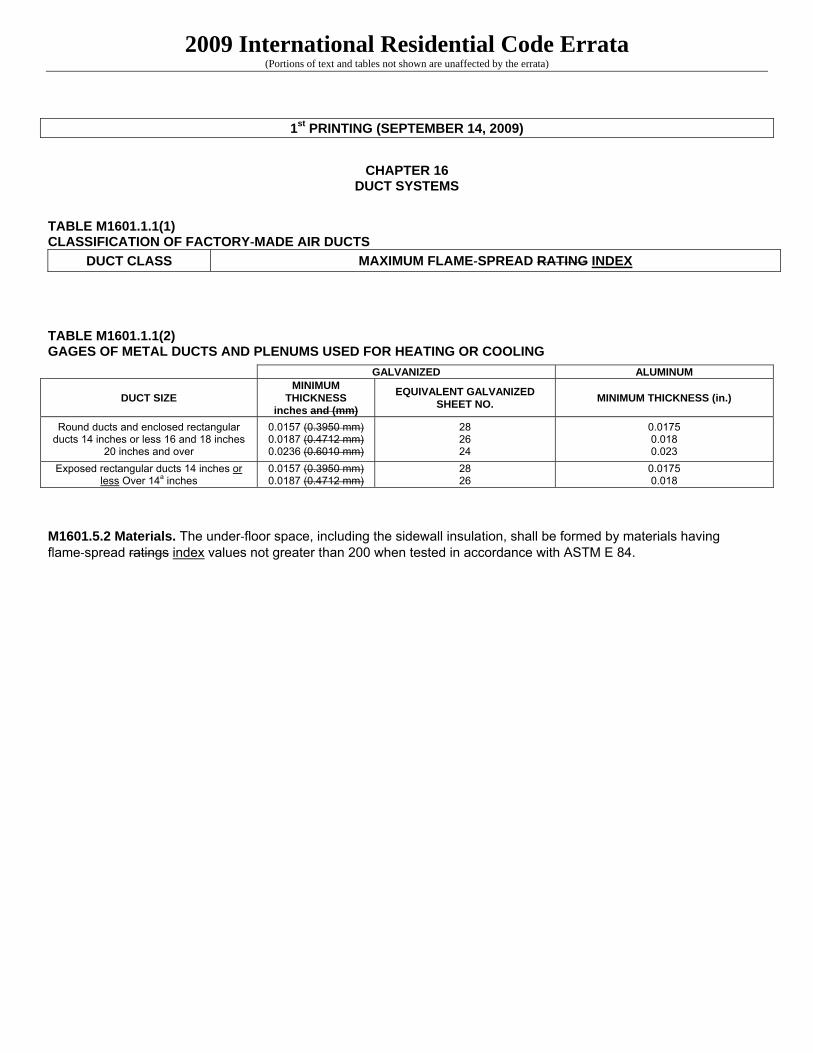
TABLE M1601.1(2) GAGES OF METAL DUCTS AND PLENUMS USED FOR HEATING OR COOLING
DUCT SIZE MINIMUM THICKNESS Inches and (mm)
EQUIVALENT GALVANIZED SHEET NO.
MINIMUM THICKNESS (in.)
Exposed rectangular ducts 14 inches or less Over 14a inches
0.0157 0.0187
28 26
0.0157 0.018
2009 International Residential Code Errata (Portions of text and tables not shown are unaffected by the errata)
1st PRINTING (SEPTEMBER 14, 2009)
CHAPTER 16
DUCT SYSTEMS
TABLE M1601.1.1(1) CLASSIFICATION OF FACTORY‐MADE AIR DUCTS
DUCT CLASS MAXIMUM FLAME‐SPREAD RATING INDEX
TABLE M1601.1.1(2) GAGES OF METAL DUCTS AND PLENUMS USED FOR HEATING OR COOLING
M1601.5.2 Materials. The under‐floor space, including the sidewall insulation, shall be formed by materials having flame‐spread ratings index values not greater than 200 when tested in accordance with ASTM E 84.
GALVANIZED ALUMINUM
DUCT SIZE MINIMUM
THICKNESS inches and (mm)
EQUIVALENT GALVANIZED SHEET NO.
MINIMUM THICKNESS (in.)
Round ducts and enclosed rectangular ducts 14 inches or less 16 and 18 inches
20 inches and over
0.0157 (0.3950 mm) 0.0187 (0.4712 mm) 0.0236 (0.6010 mm)
28 26 24
0.0175 0.018 0.023
Exposed rectangular ducts 14 inches or less Over 14a inches
0.0157 (0.3950 mm) 0.0187 (0.4712 mm)
28 26
0.0175 0.018

2009 International Residential Code Errata (Portions of text and tables not shown are unaffected by the errata)
1st and 2nd PRINTING (SEPTEMBER 14, 2009)
CHAPTER 21 HYDRONIC PIPING
M2101.6 Drilling and notching.Wood‐framed ……….. altered in accordance with the provisions of Section R614 R613.
TABLE M2101.1 HYDRONIC PIPING MATERIALS Note b. Standards as listed in Chapter 43 44.

2009 International Residential Code Errata (Portions of text and tables not shown are unaffected by the errata)
1st PRINTING (SEPTEMBER 14, 2009)
CHAPTER 21
HYDRONIC PIPING
M2103.2 Thermal barrier required. Radiant floor heating systems shall have a thermal barrier in accordance with Sections M2103.2.1 through M2103.2.4.
Exception: Insulation shall not be required in engineered systems where it can be demonstrated that the insulation will decrease the efficiency or have a negative effect on the installation.
M2103.2.4 Thermal barrier material marking. Insulation materials used in thermal barriers shall be installed so that the manufacturer’s R-value mark is readily observable upon inspection.
Exception: Insulation shall not be required in engineered systems where it can be demonstrated that the insulation will decrease the efficiency or have a negative effect on the installation.
2009 International Residential Code Errata (Portions of text and tables not shown are unaffected by the errata)
1st and 2nd PRINTING (JULY 14, 2011)
CHAPTER 23 SOLAR SYSTEMS
M2301.5 Backflow protection. ….shall comply with Section P2902.4.5 P2902.5.5

2009 International Residential Code Errata (Portions of text and tables not shown are unaffected by the errata)
1st and 2nd PRINTING (SEPTEMBER 14, 2009)
CHAPTER 24 FUEL GAS
G2439.5.6 (614.6.5 614.6.6) Length identification. Where the exhaust duct is …… G2439.5.7 (614.6.6 614.6.7) Exhaust duct required. Where space for a clothes dryer….

2009 International Residential Code Errata (Portions of text and tables not shown are unaffected by the errata)
1st PRINTING (SEPTEMBER 14, 2009)
CHAPTER 24
FUEL GAS
G2439.5 (614.6) Domestic clothes dryer exhaust ducts. Exhaust ducts for domestic clothes dryers shall conform to the requirements of Sections G2429.5.1 G2439.5.1 through G2429.5.7 G2439.5.7.

2009 International Residential Code Errata (Portions of text and tables not shown are unaffected by the errata)
1st and 2nd PRINTING (SEPTEMBER 7, 2010)
CHAPTER 27 PLUMBING FIXTURES
P2705.1 General. The installation……
Item 6. The location of…. ….equipment equipment shall not interfere with the operation of windows and doors. shall not interfere with the operation of windows and doors.

2009 International Residential Code Errata (Portions of text and tables not shown are unaffected by the errata)
1st through 4th PRINTING (Posted: August 11, 2011)
CHAPTER 28
WATER HEATERS P2803.6.1 #13….materials listed in Section P2904.5 P2905.5 or materials….

2009 International Residential Code Errata (Portions of text and tables not shown are unaffected by the errata)
1st and 2nd PRINTING (SEPTEMBER 7, 2010)
CHAPTER 28 WATER HEATERS
P2801.1 Required. Each dwelling ………culinary purposes. Storaganks Storage tanks…….

2009 International Residential Code Errata (Portions of text and tables not shown are unaffected by the errata)
1st and 2nd PRINTING (SEPTEMBER 7, 2010)
CHAPTER 29 WATER SUPPLY AND DISTRIBUTION
P2902.3.3 Backflow preventer with intermediate atmospheric vent. Backflow preventers…. …ASSE 1012 or CSA CAN/CSA B64.3…… P2902.5.5 Solar systems. The potable water….. Exception: Where all solar……..protection measures shall not be required. TABLE P2903.1 REQUIRED CAPACITIES AT THE POINT OF DISCHARGE Shower, temperature controlled 3 20
P2904.1 General. Where installed, residential………A backflow flow preventer shall not be required to separate……

2009 International Residential Code Errata (Portions of text and tables not shown are unaffected by the errata)
1st PRINTING (SEPTEMBER 14, 2009)
CHAPTER 34 GENERAL REQUIREMENTS
E3404.6 Unused openings. Unused openings, other than those intended for the operation of equipment, those intended for the operation of equipment, those intended for mounting purposes, and those …..

2009 International Residential Code Errata (Portions of text and tables not shown are unaffected by the errata)
1st PRINTING (SEPTEMBER 14, 2009)
CHAPTER 35
ELECTRICAL DEFINITIONS
KITCHEN. An area with a sink and permanent facilities for food preparation.and cooking.

2009 International Residential Code Errata (Portions of text and tables not shown are unaffected by the errata)
1st and 2nd PRINTING (SEPTEMBER 14, 2009)
CHAPTER 36 SERVICES
E3610.2 Securing and protection against physical damage. Where exposed, a grounding electrode……….or protection where it is and securely fastened …..

2009 International Residential Code Errata (Portions of text and tables not shown are unaffected by the errata)
1st and 2nd PRINTING (SEPTEMBER 14, 2009)
CHAPTER 37 BRANCH CIRCUIT AND FEEDER REQUIREMENTS
E3702.1 Branch‐circuit voltage limitations. The voltage ratings of branch circuits that supply luminaires or receptacles for cord‐and‐plug‐connected loads of up to 1,400 1,440 volt‐amperes or of less than 1/4 horsepower ……

2009 International Residential Code Errata (Portions of text and tables not shown are unaffected by the errata)
Page 1 of 1
1st through 10th PRINTING (04-15-2014)
CHAPTER 39 POWER AND LIGHTING DISTRIBUTION
Section E3908.12 Equipment grounding conductor size. Copper…Where ungrounded connectors conductors are increased in size….

2009 International Residential Code Errata (Portions of text and tables not shown are unaffected by the errata)
1st and 2nd PRINTING (SEPTEMBER 14, 2009)
CHAPTER 39 POWER AND LIGHTING DISTRIBUTION
FIGURE E3901.4

2009 International Residential Code Errata (Portions of text and tables not shown are unaffected by the errata)
1st through 5th PRINTING (February 28, 2012)
CHAPTER 44
REFERENCED STANDARDS
AAMA/WDMA/CSA 101/I.S.2/A440-08 North American Fenestration Standards/Specifications for… AISI S230-07 Standard for Cold-formed Steel Framing-prescriptive Method for One-and Two-family dwellings with
supplement 2 dated 2008. ICC 400-06 -07 Standard on the Design and Construction of Storm Shelters TMS 402-05 Building Code requirements for Masonry Structures…..R606.11.2.2.2

2009 International Residential Code Errata (Portions of text and tables not shown are unaffected by the errata)
1st and 2nd PRINTING ( 10-06-2011 )
CHAPTER 44
REFERENCED STANDARDS AFPA WFCM-08 01 Wood Frame Construction Manual for One- and Two- Family Dwellings

2009 International Residential Code Errata (Portions of text and tables not shown are unaffected by the errata)
1st through 4th PRINTING (JULY 14, 2011)
CHAPTER 44 REFERENCED STANDARDS
ICC ICC 400-06 07 Standard on the Design and Construction of Log Structures…….

2009 International Residential Code Errata (Portions of text and tables not shown are unaffected by the errata)
1st and 2nd PRINTING (JULY 14, 2011)
CHAPTER 44 REFERENCED STANDARDS
ASTM C1396/C1396M—06a Specification for Gypsum Board…………………Table R602.3(1), R702.3.1, R703702.3.8

2009 International Residential Code Errata (Portions of text and tables not shown are unaffected by the errata)
1st and 2nd PRINTING (SEPTEMBER 14, 2009)
CHAPTER 44
REFERENCED STANDARDS
TMS 402‐05 ‐08 Building Code Requirements for Masonry Structures…………. 602‐05 ‐08 Specifications for Masonry Structures…………. R606.12.2.2.1 R606.12.2.3.1 R606.12.2.2.2 R606.12.2.3.2 TPI TPI 1 ‐ 2002 2007 National Design Standard for Metal-plate-connected Wood Truss Construction…….

2009 International Residential Code Errata (Portions of text and tables not shown are unaffected by the errata)
1st and 2nd PRINTING (SEPTEMBER 14, 2009)
APPENDIX F RADON CONTROL METHODS
AF103.11 Building depressurization. Joints in air ducts …….. conservation provisions in Chapter 11. Firestopping Fireblocking shall meet the requirements contained in Section R602.8 R302.11.

2009 International Residential Code Errata (Portions of text and tables not shown are unaffected by the errata)
1st through 4th PRINTING (July 25, 2011)
APPENDIX H PATIO COVER
AH105.1 General….shall be provided with exits conforming to the provisions of Section R310 R311 of this code.

2009 International Residential Code Errata (Portions of text and tables not shown are unaffected by the errata)
1st through 6th PRINTING (07-11-12)
APPENDIX P
SIZING OF WATER PIPING SYSTEM
AP101.1.1 This appendix outlines……source, the head charges changes in the system…. AP103.2.2 Water pipe sizing…. 1. Pressure required…and Section 604.5 3 of the International….. AP103.3 Segmented loss method. 3. Selection of pipe size. 3.1 Pressure required…..and Section 604.5 3 of the International….. FIGURE AP103.3(7) FRICTION LOSS IN FAIRLY ROUGH PIPEa

2009 International Residential Code Errata (Portions of text and tables not shown are unaffected by the errata)
1st and 2nd PRINTING (SEPTEMBER 7, 2010)
APPENDIX P SIZING OF WATER PIPING SYSTEM
TABLE AP201.1 MINIMUM SIZE OF WATER METERS, MAINS AND DISTRIBUTION PIPING BASED ON WATER SUPPLY FIXTURE UNIT VALUES (w.s.f.u)
METER AND SERVICE PIPE
(inches)
DISTRIBUTION PIPE (inches)
MAXIMUM DEVELOPMENT LENGTH (feet) Pressure Range 50 to 60 psi 40 60 80 100 150 200 250 300 400 500
2 2 ½ 533 533 533 533 533 533 533 533 353 533 486

2009 International Residential Code Errata (Portions of text and tables not shown are unaffected by the errata)
1st through 5th PRINTING (February 28, 2012)
INDEX
DOORS Exit Egress................R311.4.1 R311.2