2010 chevrolet tahoe and gmc yukon/ yukon denali two...
TRANSCRIPT

2010 Chevrolet Tahoe and GMC Yukon/Yukon Denali Two-mode Hybrid M
In Brief . . . . . . . . . . . . . . . . . . . . . . . . . . . . . . . . . . . . . . . . . . . . 1-1Initial Drive Information . . . . . . . . . . . . . . . . . . . . . . . . . . . 1-2Hybrid Features . . . . . . . . . . . . . . . . . . . . . . . . . . . . . . . . . . 1-3Performance and Maintenance . . . . . . . . . . . . . . . . . . . 1-6
Seats and Restraint System . . . . . . . . . . . . . . . . . . . . . . 2-1Front Seats . . . . . . . . . . . . . . . . . . . . . . . . . . . . . . . . . . . . . . . 2-2Restraint System Check . . . . . . . . . . . . . . . . . . . . . . . . . . 2-3
Features and Controls . . . . . . . . . . . . . . . . . . . . . . . . . . . . 3-1Storage Areas . . . . . . . . . . . . . . . . . . . . . . . . . . . . . . . . . . . . 3-2Starting and Operating Your Vehicle . . . . . . . . . . . . . . 3-3
Instrument Panel . . . . . . . . . . . . . . . . . . . . . . . . . . . . . . . . . 4-1Climate Controls . . . . . . . . . . . . . . . . . . . . . . . . . . . . . . . . . . 4-2Warning Lights, Gages, and Indicators . . . . . . . . . . . 4-3Driver Information Center (DIC) . . . . . . . . . . . . . . . . . 4-12Audio System(s) . . . . . . . . . . . . . . . . . . . . . . . . . . . . . . . . 4-14
Driving Your Vehicle . . . . . . . . . . . . . . . . . . . . . . . . . . . . . . 5-1Your Driving, the Road, and the Vehicle . . . . . . . . . . 5-2Towing . . . . . . . . . . . . . . . . . . . . . . . . . . . . . . . . . . . . . . . . . . . 5-2
Service and Appearance Care . . . . . . . . . . . . . . . . . . . 6-1Service . . . . . . . . . . . . . . . . . . . . . . . . . . . . . . . . . . . . . . . . . . . 6-2Checking Things Under the Hood . . . . . . . . . . . . . . . . 6-3Bulb Replacement . . . . . . . . . . . . . . . . . . . . . . . . . . . . . . 6-24Electrical System . . . . . . . . . . . . . . . . . . . . . . . . . . . . . . . . 6-25Tires . . . . . . . . . . . . . . . . . . . . . . . . . . . . . . . . . . . . . . . . . . . . 6-28Appearance Care . . . . . . . . . . . . . . . . . . . . . . . . . . . . . . . 6-56Capacities and Specifications . . . . . . . . . . . . . . . . . . . 6-57
Maintenance Schedule . . . . . . . . . . . . . . . . . . . . . . . . . . . 7-1Maintenance Schedule . . . . . . . . . . . . . . . . . . . . . . . . . . . 7-2
Index . . . . . . . . . . . . . . . . . . . . . . . . . . . . . . . . . . . . i-1
Information Provided by:

GENERAL MOTORS, GM and the GM Emblem,CHEVROLET, the CHEVROLET Emblem, GMC, theGMC Emblem, and the names TAHOE and YUKON areregistered trademarks of General Motors.
This manual describes features that may or may notbe on your specific vehicle either because they areoptions that you did not purchase or due to changessubsequent to the printing of this owner manual.Please refer to the purchase documentation relating toyour specific vehicle to confirm each of the featuresfound on your vehicle. For vehicles first sold in Canada,substitute the name “General Motors of CanadaLimited” for Chevrolet Motor Division and/or GMCwherever it appears in this manual.
Keep this manual in the vehicle for quick reference.
Canadian Owners
Propriétaires CanadiensA French language copy of this manual can be obtainedfrom your dealer/retailer or from:
On peut obtenir un exemplaire de ce guide en françaisauprès du concessionnaire ou à l'adresse suivante:
Helm, IncorporatedP.O. Box 07130Detroit, MI 48207
1-800-551-4123
Numéro de poste 6438 de langue française
www.helminc.com
ii
Litho in U.S.A.Part No. 25855012 A First Printing ©2009 General Motors. All Rights Reserved.
Information Provided by:

IntroductionYour hybrid SUV is designed to be more fuel efficientthan the standard SUV, which results in reduced carbondioxide emissions.
Using this SupplementThis supplement contains information specific to thehybrid components of the vehicle. It does not explaineverything you need to know about the vehicle.Read this supplement along with the owner manual tolearn about the vehicle's features and controls.
IndexA good place to look for what you need is the Index inback of this supplement. It is an alphabetical list of whatis in the supplement, and the page number where youwill find it.
iiiInformation Provided by:

2 NOTES
iv Information Provided by:

Section 1 In Brief
Initial Drive Information . . . . . . . . . . . . . . . . . . . . . . . . . . . 1-2Transmission . . . . . . . . . . . . . . . . . . . . . . . . . . . . . . . . . . . . 1-2Four-Wheel Drive . . . . . . . . . . . . . . . . . . . . . . . . . . . . . . . 1-2
Hybrid Features . . . . . . . . . . . . . . . . . . . . . . . . . . . . . . . . . . . . 1-3Hybrid Safety Information . . . . . . . . . . . . . . . . . . . . . . 1-3Fuel Economy Gage . . . . . . . . . . . . . . . . . . . . . . . . . . . . 1-4
Automatic Engine Start/Stop Feature . . . . . . . . . . . . 1-4Regenerative Braking . . . . . . . . . . . . . . . . . . . . . . . . . . . 1-5Battery . . . . . . . . . . . . . . . . . . . . . . . . . . . . . . . . . . . . . . . . . . 1-6Service . . . . . . . . . . . . . . . . . . . . . . . . . . . . . . . . . . . . . . . . . 1-6
Performance and Maintenance . . . . . . . . . . . . . . . . . . . . 1-6Tire Sealant and Compressor Kit . . . . . . . . . . . . . . . . 1-6
1-1Information Provided by:

Initial Drive Information
Transmission
Range Selection Mode
The Range Selection Mode switch is located on theshift lever. To enable the Range Selection feature,move the column shift lever to the M (Manual) position.
The current range will appear next to the M. This is thehighest attainable range with all lower gears accessible.As an example, when 3 (Third) gear is selected, 1 (First)through 3 (Third) gears are available.
Press the plus/minus buttons, located on the steeringcolumn shift lever, to select the desired range ofgears for current driving conditions. See AutomaticTransmission Operation in the owner manual.
Cruise control can be used while the vehicle is inRange Selection Mode.
Four-Wheel DriveIf the vehicle has four-wheel drive, you can sendthe engine's driving power to all four wheels forextra traction. Read the following before usingfour-wheel drive.
1-2 Information Provided by:

Automatic Transfer Case
The transfer case knob is located to the left of theinstrument panel cluster. You can choose amongfive driving settings:
2 m (Two-Wheel Drive High): This setting is used fordriving in most street and highway situations.
AUTO (Automatic Four-Wheel Drive) : This setting isideal for use when road surface traction conditions arevariable.
4 m (Four-Wheel Drive High): Use the four-wheel highposition when you need extra traction, such as onsnowy or icy roads or in most off-road situations.
4 n (Four-Wheel Drive Low) : This setting deliversextra torque. You might choose Four-Wheel Drive Low ifyou are driving off-road in deep sand, deep mud, deepsnow, and while climbing or descending steep hills.
N (Neutral) : Shift the vehicle's transfer case toN (Neutral) only when towing the vehicle. SeeRecreational Vehicle Towing or Towing Your Vehiclein the index of the Owner Manual.
See Four-Wheel Drive on page 3‑10.
Hybrid Features
Hybrid Safety InformationThis vehicle has a standard 12-volt battery and ahigh-voltage hybrid battery. Only a trained servicetechnician with the proper knowledge and tools shouldinspect, test, or replace the hybrid battery. See yourdealer/retailer if the hybrid battery needs service.
The 12-volt battery cables, in the engine compartment,are clearly labeled. In emergency situations, firstresponders can cut those cables to disable thehigh-voltage hybrid battery system.
1-3Information Provided by:

Fuel Economy Gage
United States Canada
This gage shows when the vehicle is operating at a fuelefficient point.
By modifying driving behavior to increase the economytime during driving, fuel mileage will be improved.
See Fuel Economy Gage on page 4‑5.
Automatic Engine Start/Stop FeatureStart the engine as you would any other engine.See “Starting the Engine” in the owner manual for moreinformation on starting. The hybrid system providesvery quiet engine starting. If pulling a trailer with trailerbrakes, see Towing a Trailer on page 5‑8 for moreinformation.
Auto StopThe vehicle has an Auto Stop feature. After asuccessful engine start, the engine may turn off andoperate in the Auto Stop mode.
Keep your foot firmly on the brake pedal until you areready for the vehicle to move.
Engine OFF and AUTO STOP modes are indicated onthe tachometer display. When the tachometer needleindicates OFF, the engine is not running and will remainoff until the ignition key is placed in the START positionor a remote vehicle start is performed. When thetachometer needle indicates AUTO STOP, the hybridsystem is on, the engine is not running, but may AutoStart at any time without notice. See Tachometer onpage 4‑4 for more information.
1-4 Information Provided by:

A chime will sound if the driver door is opened while inAuto Stop as a reminder that the ignition switch is not inthe LOCK/OFF position. Always turn the ignition switchto LOCK/OFF and remove the key from the ignitionswitch when exiting the vehicle.
Auto StartThe vehicle also has an Auto Start feature. The enginewill remain off while in Auto Stop mode until vehicleconditions require the engine to run. The near-instantstarting of the engine from Auto Stop mode is calledAuto Start.
EV ModeThe vehicle also has an EV mode which uses onlythe electric motor to move the vehicle. With lightacceleration, the vehicle will drive in EV mode.EV mode is unavailable when the vehicle is out of fuel.
See Starting the Vehicle in the Two‐Mode Hybridsupplement to the owner manual.
Regenerative BrakingRegenerative braking enables the electric drive motorto operate as a generator when coasting or braking.Energy from the moving vehicle recharges the hybridbattery.
The hydraulic disc brakes work with the regenerativebraking to insure effective braking.
The braking system is computer controlled and blendsthe regenerative braking with the conventional hydraulicdisc brakes to meet any requirements for deceleration.Because the controller applies the hydraulic brakesthrough its high pressure accumulator, you mayoccasionally hear the motor driven pump when itrecharges the system. This is normal. In the event of acontroller problem, the brake pedal may be harder topush and the stopping distance may be longer.
See Regenerative Braking, Warning Lights, Gages, andIndicators and Driver Information Center (DIC) in theowner manual.
1-5Information Provided by:

BatteryThis vehicle has a standard 12-volt battery and ahigh-voltage hybrid battery. When a new standard12-volt battery is needed, see your dealer/retailer forone that has the replacement number shown on theoriginal battery's label.
Only a trained service technician with the properknowledge and tools should inspect, test, or replace thehybrid battery. See your dealer/retailer if the hybridbattery needs service. See Battery on page 6‑16.
ServiceNever try to do your own service on hybrid components.You can be injured and the vehicle can be damaged ifyou try to do your own service work. Service and repairof these hybrid components should only be performedby a trained service technician with the properknowledge and tools. See Doing Your Own ServiceWork on page 6‑2.
Performance and Maintenance
Tire Sealant and Compressor KitThis vehicle has a tire sealant and compressor kit whichcan be used to seal small punctures in the tread area ofthe tire.
See “Tire Sealant and Compressor Kit” for completeoperating information.
1-6 Information Provided by:
Section 2 Seats and Restraint System
Front Seats . . . . . . . . . . . . . . . . . . . . . . . . . . . . . . . . . . . . . . . . . 2-2Power Seats (Tahoe and YukonTwo-Mode Hybrid) . . . . . . . . . . . . . . . . . . . . . . . . . . . . 2-2
Manual Lumbar (Tahoe and YukonTwo-Mode Hybrid) . . . . . . . . . . . . . . . . . . . . . . . . . . . . 2-2
Manual Reclining Seatbacks(Tahoe and Yukon Two-Mode Hybrid) . . . . . . . . . 2-3
Restraint System Check . . . . . . . . . . . . . . . . . . . . . . . . . . . 2-3Replacing Restraint System Parts After aCrash . . . . . . . . . . . . . . . . . . . . . . . . . . . . . . . . . . . . . . . . . 2-3
2-1Information Provided by:

Front Seats
Power Seats (Tahoe and YukonTwo-Mode Hybrid)
A. Power Seat Adjustment Control
B. Manual Lumbar Control
C. Manual Reclining Seatback Lever
Adjust the seat forward or rearward by sliding thecontrol (A) forward or rearward.
Your vehicle may have additional features to adjust thepower seat:. Raise or lower the front part of the seat cushion by
moving the front of the control up or down.. Raise or lower the entire seat by moving the rear
of the control up or down.
Manual Lumbar (Tahoe and YukonTwo-Mode Hybrid)Increase or decrease lumbar support by turning thecontrol (B) forward or rearward.
2-2 Information Provided by:

Manual Reclining Seatbacks(Tahoe and Yukon Two-Mode Hybrid)To recline the seatback:
1. Lift the reclining seatback lever (C).
2. Move the seatback to the desired position, thenrelease the lever to lock the seatback in place.
3. Push and pull on the seatback to make sure it islocked.
To return the seatback to an upright position:
1. Lift the lever fully without applying pressure to theseatback and the seatback will return to the uprightposition.
2. Release the lever to lock the seatback in place.
3. Push and pull on the seatback to make sure it islocked.
Restraint System Check
Replacing Restraint System PartsAfter a CrashIf an airbag inflates or the vehicle has been in acrash, the vehicle's sensing system may commandthe automatic hybrid battery disconnect to open.The battery will disconnect. The hybrid battery will beoff and the vehicle will not start. The airbag readinesslight and/or SERVICE HYBRID SYSTEM warningmessage may come on in the driver information center.See “Airbag Readiness Light” in the owner manual andDriver Information Center (DIC) on page 4‑12 for moreinformation.
To operate the vehicle, the automatic hybrid batterydisconnect must be reconnected by a qualified servicetechnician and sensing system parts will need to bereplaced. Have the vehicle serviced right away.
2-3Information Provided by:

2 NOTES
2-4 Information Provided by:

Section 3 Features and Controls
Storage Areas . . . . . . . . . . . . . . . . . . . . . . . . . . . . . . . . . . . . . . 3-2Power Outlet Alternating Current . . . . . . . . . . . . . . . . 3-2
Starting and Operating Your Vehicle . . . . . . . . . . . . . . 3-3Starting the Vehicle . . . . . . . . . . . . . . . . . . . . . . . . . . . . . 3-3Automatic Transmission Operation . . . . . . . . . . . . . . 3-6
Four-Wheel Drive . . . . . . . . . . . . . . . . . . . . . . . . . . . . . . 3-10Shifting Into Park . . . . . . . . . . . . . . . . . . . . . . . . . . . . . . 3-15Engine Coolant Heater . . . . . . . . . . . . . . . . . . . . . . . . . 3-17Regenerative Braking . . . . . . . . . . . . . . . . . . . . . . . . . . 3-18Running the Vehicle While Parked . . . . . . . . . . . . . 3-18
3-1Information Provided by:

Storage Areas
Power Outlet Alternating CurrentThe vehicle may have a power outlet that can be usedto plug in electrical equipment that uses a maximumlimit of 150 watts.
The power outlet islocated in the rear cargoarea on the driver side.
An indicator light on the outlet turns on to show it is inuse. The light comes on when the ignition is in ON/RUNand equipment requiring less than 150 watts is pluggedinto the outlet, and no system fault is detected.
The indicator light does not come on when the ignitionis in LOCK/OFF or if no equipment is plugged intothe outlet.
If equipment is connected using more than 150 watts,or a system fault is detected, a protection circuit shutsoff the power supply and the indicator light turns off.To reset the circuit, unplug the item and plug it back inor turn the Retained Accessory Power (RAP) off andthen back on. The power restarts when equipmentusing 150 watts or less is plugged into the outlet and asystem fault is not detected.
The power outlet is not designed for the followingelectrical equipment and may not work properly if theseitems are plugged into the power outlet:. Equipment with high initial peak wattage such as:
compressor-driven refrigerators and electricpower tools.
. Other equipment requiring an extremely stablepower supply such as: microcomputer-controlledelectric blankets, touch sensor lamps, etc.
See High Voltage Devices and Wiring on page 6‑3.
3-2 Information Provided by:

Starting and Operating YourVehicle
Starting the Vehicle
{ WARNING:
Exiting the vehicle, without first shifting intoP (Park), may cause the vehicle to move, and youor others can be seriously injured. Because thevehicle has the Automatic Engine Start/Stopfeature, the vehicle’s engine might seem to beshut off when you come to a complete stop.
(Continued)
WARNING: (Continued)
However, once the brake pedal is released,the vehicle can move. The vehicle’s engine canalso restart at any time.
Shift to P (Park) and turn the ignition toLOCK/OFF, before exiting the vehicle.
Start the engine as you would any other engine.See “Starting the Engine” in the owner manual formore information on starting. If pulling a trailer withtrailer brakes, see Towing a Trailer on page 5‑8for more information.
3-3Information Provided by:

Auto StopThe vehicle has an Auto Stop feature. After asuccessful engine start, the engine may turn off andoperate in the Auto Stop mode. Some of the vehicleconditions that allow the engine to stop running andenter the Auto Stop mode are:. Ignition switch is in the ON/RUN position.. The hood is closed.. The gear selector is in P (Park), R (Reverse),
N (Neutral) or D (Drive).. The hybrid battery is at an acceptable state of
charge.. The hybrid battery voltage, temperature or power
limits are not exceeded. In very hot conditions,Auto Stop may be unavailable until the hybridbattery has cooled.
. The engine is at operating temperature.
. The vehicle may enter Auto Stop after a remotevehicle start.
If you are on an incline, the hybrid drive motor can helpkeep the vehicle from rolling backwards, even if theengine is in Auto Stop.
With your foot off the brake and the vehicle on levelground, the hybrid drive motor may cause the vehicleto roll slowly forward, even when the engine is inAuto Stop.
Keep your foot firmly on the brake pedal until you areready for the vehicle to move.
Engine OFF and AUTO STOP modes are indicated onthe tachometer display. When the tachometer needleindicates OFF, the engine is not running and will remainoff until the ignition key is placed in the START positionor a remote vehicle start is performed. When thetachometer needle indicates AUTO STOP, the hybridsystem is on, the engine is not running, but may AutoStart at any time without notice. See Tachometer onpage 4‑4 for more information.
A chime will sound if the driver door is opened while inAuto Stop as a reminder that the ignition switch is not inthe LOCK/OFF position. Always turn the ignition switchto LOCK/OFF and remove the key from the ignitionswitch when exiting the vehicle.
3-4 Information Provided by:

Auto StartThe vehicle also has an Auto Start feature. The enginewill remain off while in Auto Stop mode until vehicleconditions require the engine to run. The near-instantstarting of the engine from Auto Stop mode is calledAuto Start. Some of the vehicle conditions that maycause the engine to Auto Start are:. The hood is opened.. The gear selector is in M (Manual Mode).. The hybrid battery state of charge is too low.. The hybrid battery voltage, temperature or power
limits are exceeded.. A remote vehicle start has been requested.. The engine is not at operating temperature.. Acceleration demands require the use of the
engine.
EV ModeThe vehicle also has an Electric Vehicle (EV) modewhich uses only the electric motor to move the vehicle.With light acceleration, the vehicle will drive in EVmode. EV mode is unavailable when the vehicle isout of fuel.
If increased acceleration is required, or the vehiclereaches approximately 40 km/h (30 mph), the engine willstart automatically. The engine shuts off at speedsbelow 40 km/h (25 mph) unless the transmission is inM (Manual Mode) or Auto Stop is disabled.
During heavy acceleration, both the engine andhybrid electric motors supply power. A sensationsimilar to a transmission gear change can be felt asthe transmission changes modes. Engine RPM mayremain above 4,000 RPM for a longer period duringhard acceleration.
3-5Information Provided by:

Automatic Transmission OperationThe vehicle has an electronic shift position indicatorwithin the instrument panel cluster.
There are several different positions for the shift lever.
See “Range Selection Mode” later in this section.
P (Park) : This position locks the rear wheels. It is thebest position to use when you start the engine becausethe vehicle cannot move easily.
When parked on a hill, especially when the vehicle hasa heavy load, you may notice an increase in the effort toshift out of P (Park). See “Shifting Into P (Park)” in theIndex of vehicle's owner manual for more information.
{ WARNING:
It is dangerous to get out of the vehicle if the shiftlever is not fully in P (Park) with the parking brakefirmly set. The vehicle can roll.
Do not leave the vehicle when the engine isrunning unless you have to. If you have left theengine running, the vehicle can move suddenly.You or others could be injured. To be sure thevehicle will not move, even when you are on fairlylevel ground, always set the parking brake andmove the shift lever to P (Park). See Shifting IntoPark in the Owner Manual. If you are pulling atrailer, see Towing a Trailer on page 5‑8.
3-6 Information Provided by:

{ WARNING:
If you have Four-Wheel Drive, the vehicle willbe free to roll— even if the shift lever is inP (Park)— if the transfer case is in Neutral.So, be sure the transfer case is in a drive gear,Two-Wheel Drive High or Four-Wheel Drive Highor Four-Wheel Drive Low— not in Neutral.See “Shifting Into Park” in the Owner Manual.
R (Reverse) : Use this gear to back up.
Notice: Shifting to R (Reverse) while the vehicle ismoving forward could damage the transmission.The repairs would not be covered by the vehiclewarranty. Shift to R (Reverse) only after the vehicleis stopped.
To rock the vehicle back and forth to get out of snow,ice, or sand without damaging the transmission, see“If Your Vehicle is Stuck in Sand, Mud, Ice, or Snow” inthe Index of the vehicle's owner manual.
N (Neutral) : In this position, the engine andtransmission are not connected with the wheels.To restart the engine when the vehicle is alreadymoving, use N (Neutral) only.
{ WARNING:
Shifting into a drive gear while the engine isrunning at high speed is dangerous. Unless yourfoot is firmly on the brake pedal, the vehicle couldmove very rapidly. You could lose control and hitpeople or objects. Do not shift into a drive gearwhile the engine is running at high speed.
Notice: Shifting out of P (Park) or N (Neutral) withthe engine running at high speed may damage thetransmission. The repairs would not be covered bythe vehicle warranty. Be sure the engine is notrunning at high speed when shifting the vehicle.
3-7Information Provided by:

D (Drive) : This position is for normal driving. It providesthe best fuel economy. If you need more power forpassing, and you are:. Going less than about 35 mph (55 km/h), push the
accelerator pedal about halfway down.. Going about 35 mph (55 km/h) or more, push the
accelerator all the way down.
D (Drive) or M (Manual Mode) can be used whentowing a trailer, carrying a heavy load, driving onsteep hills, or for off-road driving. You may want toshift the transmission to a lower gear selection if thetransmission shifts too often.
Downshifting the transmission in slippery roadconditions could result in skidding. See “Skidding”under “Loss of Control” in the owner manual for moreinformation.
When temperatures are very cold, the transmission'sgear shifting may be delayed, providing more stableshifts until the engine warms up. Shifts may be morenoticeable with a cold transmission. This difference inshifting is normal.
M (Manual Mode) : This position lets drivers selectthe range of gears appropriate for current drivingconditions. If the vehicle has this feature, see “RangeSelection Mode” later in this section.
Notice: Spinning the tires or holding the vehicle inone place on a hill using only the accelerator pedalmay damage the transmission. The repair will not becovered by the vehicle warranty. If you are stuck,do not spin the tires. When stopping on a hill,use the brakes to hold the vehicle in place.
The vehicle has a shift stabilization feature thatadjusts the transmission shifting to the current drivingconditions to reduce rapid upshifts and downshifts.If the shift stabilization feature determines that a currentvehicle speed cannot be maintained, the transmissiondoes not upshift. In some cases, this may appear to bea delayed shift, however the transmission is operatingnormally.
3-8 Information Provided by:

Range Selection Mode
The Range Selection Mode controls the vehicle'stransmission.
To use this feature:
1. Move the shift lever to the M (Manual Mode).
2. Press the plus/minus button to upshift or downshiftselecting the desired range of gears.
A number displays next to the M, indicating the currentgear that has been selected. The number displayed inthe gear indicator is the highest gear that can be used.
The vehicle can automatically shift to lower gearsas it adjusts to driving conditions. When 3 (Third) isselected, 1 (First) through 3 (Third) gears areautomatically shifted by the vehicle, but 4 (Fourth)cannot be used until it is selected.
The Range Selection Mode controls the vehicle andengine speed while driving down a hill or towing atrailer, by allowing you to select a desired range ofgears.
When you move the shift lever into M, the transmissionwill default to M4. In this gear range, effective enginebraking occurs at speeds above 45 mph (72 km/h).
Pushing the minus (−) button on the shift lever reducesthe gear range.
In the M3 gear range, effective engine braking occurs atspeeds above 35 mph (56 km/h).
In the M2 gear range, effective engine braking occurs atspeeds above 25 mph (40 km/h).
In the M1 gear range, effective engine braking occurs atspeeds above 10 mph (16 km/h).
When operating in M (Manual Mode), Auto Stop isdisabled. For better vehicle efficiency, operate thevehicle in D (Drive) not M (Manual Mode).
Cruise control can be used while using the RangeSelection Mode.
3-9Information Provided by:

Four-Wheel DriveIf the vehicle has four-wheel drive, you can send theengine's driving power to all four wheels for extratraction. Read the following before using four-wheeldrive.
Notice: Driving on clean, dry pavement inFour-Wheel-Drive High or Four-Wheel-Drive Low foran extended period of time may cause prematurewear on your vehicle's powertrain. Do not drive onclean, dry pavement in Four-Wheel-Drive High orFour-Wheel-Drive Low for extended periods of time.
While driving on clean dry pavement and during tightturns, you may experience a vibration in the steeringsystem.
The vehicle has StabiliTrak®. Shifting intoFour-Wheel-Drive Low will turn Traction Control andStabiliTrak® off. See StabiliTrak® System in the indexof the Owner Manual for more information.
Front AxleThe front axle engages and disengages automaticallywhen you shift the transfer case. Some delay for theaxle to engage or disengage is normal.
Automatic Transfer CaseThe transfer case knob islocated to the left of theinstrument panel cluster.
Use this dial to shift into and out of four-wheel drive.
You can choose among five driving settings:
Indicator lights in the switches show you which settingyou are in. The indicator lights will come on brieflywhen you turn on the ignition and the last chosensetting will stay on. If the lights do not come on, youshould take the vehicle to your dealer/retailer forservice. An indicator light will flash while shifting. It willstay on when the shift is completed. If for some reasonthe transfer case cannot make a requested shift, it willreturn to the last chosen setting.
3-10 Information Provided by:

2 m (Two-Wheel Drive High): This setting is used fordriving in most street and highway situations. The frontaxle is not engaged in two-wheel drive. This setting alsoprovides the best fuel economy.
AUTO (Automatic Four-Wheel Drive) : This setting isideal for use when road surface traction conditions arevariable. When driving your vehicle in AUTO, the frontaxle is engaged, but the vehicle's power is primarilysent to the rear wheels. When the vehicle's softwaredetermines a need for more traction, the system willtransfer more power to the front wheels. Driving in thismode results in slightly lower fuel economy thanTwo-Wheel Drive High.
4 m (Four-Wheel Drive High): Use the four-wheel highposition when you need extra traction, such as onsnowy or icy roads or in most off-road situations.This setting also engages the front axle to help drivethe vehicle. This is the best setting to use whenplowing snow.
4 n (Four-Wheel Drive Low) : This setting alsoengages the front axle and delivers extra torque.You may never need this setting. It sends maximumpower to all four wheels. You might choose Four-WheelDrive Low if you are driving off-road in deep sand, deepmud, deep snow, and while climbing or descendingsteep hills.
The vehicle has StabiliTrak®. Shifting intoFour-Wheel-Drive Low will turn Traction Control andStabiliTrak® off. See StabiliTrak® System in the indexof the Owner Manual for more information.
{ WARNING:
Shifting the transfer case to N (Neutral) can causethe vehicle to roll even if the transmission is inP (Park). You or someone else could be seriouslyinjured. Be sure to set the parking brake beforeplacing the transfer case in N (Neutral). SeeParking Brake in the index of the Owner Manualfor more information.
N (Neutral) : Shift the vehicle's transfer case toN (Neutral) only when towing the vehicle. SeeRecreational Vehicle Towing or Towing Your Vehicle inthe index of the Owner Manual.
If the SERVICE 4 WHEEL DRIVE message stays on,you should take the vehicle to your dealer/retailer forservice. See DIC Warnings and Messages onpage 4‑12 for more information.
3-11Information Provided by:
Shifting Into Four-Wheel Drive High orAUTO (Automatic Four-Wheel Drive)Turn the knob to the Four-Wheel High or AUTOposition. This can be done at any speed, except whenshifting from Four-Wheel Drive Low. The indicator lightwill flash while shifting. It will remain on when the shift iscompleted.
Shifting Into Two-Wheel Drive HighTurn the knob to the Two-Wheel High position. This canbe done at any speed, except when shifting fromFour-Wheel Drive Low.
See “Shifting Out of Four-Wheel Drive Low” later in thissection for more information.
Shifting Into Four-Wheel Drive LowWhen Four-Wheel Low is engaged, vehicle speedshould be kept below 40mph (64 km/h). Extendedhigh-speed operation in 4L may damage or shorten thelife of the drivetrain.
To shift to the Four-Wheel Drive Low position, theignition must be in ON/RUN and the vehicle must bestopped or moving less than 3 mph (5 km/h) with thetransmission in N (Neutral). The preferred method for
shifting into Four-Wheel Drive Low is to have thevehicle moving 1 to 2 mph (1.6 to 3.2 km/h). Turn theknob to the Four-Wheel Drive Low position. You mustwait for the Four-Wheel Drive Low indicator light to stopflashing and remain on before shifting the transmissioninto gear.
Notice: Shifting the transmission into gear beforethe Four-Wheel Drive Low indicator light hasstopped flashing could damage the transfer case.To help avoid damaging the vehicle, always wait forthe Four-Wheel Drive Low indicator light to stopflashing before shifting the transmission into gear.
The vehicle may have significant engagement noiseand bump when shifting between Four-Wheel Drive Lowand Four-Wheel Drive High ranges or from N (Neutral)while the engine is running.
If the knob is turned to the Four-Wheel Drive Lowposition when the vehicle is in gear and/or moving,the Four-Wheel Drive Low indicator light will flash for30 seconds and not complete the shift unless thevehicle is moving less than 3 mph (5 km/h) and thetransmission is in N (Neutral). After 30 seconds thetransfer case will shift to Four-Wheel Drive High mode.
3-12 Information Provided by:

Shifting Out of Four-Wheel Drive LowTo shift from Four-Wheel Drive Low to Four-Wheel DriveHigh, AUTO, or Two-Wheel Drive High, the vehicle mustbe stopped or moving less than 3 mph (5 km/h) with thetransmission in N (Neutral) and the ignition in ON/RUN.The preferred method for shifting out of Four-WheelDrive Low is to have your vehicle moving 1 to 2 mph(1.6 to 3.2 km/h). Turn the knob to the Four-WheelDrive High, AUTO, or Two-Wheel Drive High position.You must wait for the Four-Wheel Drive High, AUTO,or Two-Wheel Drive High indicator light to stop flashingand remain on before shifting the transmissioninto gear.
Notice: Shifting the transmission into gear beforethe Four-Wheel Drive Low indicator light hasstopped flashing could damage the transfer case.To help avoid damaging the vehicle, always wait forthe Four-Wheel Drive Low indicator light to stopflashing before shifting the transmission into gear.
The vehicle may have significant engagement noiseand bump when shifting between Four-Wheel Drive Lowand Four-Wheel Drive High ranges or from N (Neutral)while the engine is running.
If the knob is turned to the Four-Wheel Drive High,AUTO, or Two-Wheel Drive High switch position whenthe vehicle is in gear and/or moving, the Four-WheelDrive High, AUTO or Two-Wheel Drive High indicatorlight will flash for 30 seconds but will not complete theshift unless the vehicle is moving less than 3 mph(5 km/h) and the transmission is in N (Neutral).
Shifting into NeutralTo shift the transfer case into N (Neutral):
1. Make sure the vehicle is parked so that it willnot roll.
2. Set the parking brake and apply the regular brakepedal. See Parking Brake in the index of theOwner Manual for more information.
3. Start the vehicle or turn the ignition to ON/RUN.
4. Put the transmission in N (Neutral).
5. Shift the transfer case to Two-Wheel Drive High.
6. Turn the transfer case dial clockwise to N (Neutral)until it stops and hold it there until the N (Neutral)light starts blinking. This will take at least10 seconds. Then slowly release the dial to theFour‐Wheel Drive Low position. The N (Neutral)light will come on when the transfer case shift toN (Neutral) is complete.
3-13Information Provided by:

7. If the engine is running, verify that the transfercase is in N (Neutral) by shifting the transmissionto R (Reverse) for one second, then shift thetransmission to D (Drive) for one second.
8. Turn the ignition to ACC/ACCESSORY, which willturn the engine off.
9. Place the transmission shift lever in P (Park).
10. Release the parking brake prior to moving thevehicle.
11. Turn the ignition to LOCK/OFF.
Shifting Out of NeutralTo shift the transfer case out of N (Neutral):
1. Set the parking brake and apply the regular brakepedal.
2. Turn the ignition to ON/RUN with the engine off,and shift the transmission to N (Neutral).
3. Turn the transfer case dial to the desired transfercase shift position (Two-Wheel Drive High,Four-Wheel Drive High, AUTO).
After the transfer case has shifted out ofN (Neutral), the N (Neutral) light will go out.
4. Release the parking brake prior to moving thevehicle.
Notice: Shifting the transmission into gear beforethe Four-Wheel Drive Low indicator light hasstopped flashing could damage the transfer case.To help avoid damaging the vehicle, always wait forthe Four-Wheel Drive Low indicator light to stopflashing before shifting the transmission into gear.
5. Start the engine and shift the transmission to thedesired position.
Excessively shifting the transfer case into or out of thedifferent modes may cause the transfer case to enterthe shift protection mode. This will protect the transfercase from possible damage and will only allow thetransfer case to respond to one shift per 10 seconds.The transfer case may stay in this mode for up tothree minutes.
3-14 Information Provided by:

Shifting Into Park
{ WARNING:
It can be dangerous to get out of the vehicle if theshift lever is not fully in P (Park) with the parkingbrake firmly set. The vehicle can roll. If you haveleft the engine running, the vehicle can movesuddenly. You or others could be injured. To besure the vehicle will not move, even when you areon fairly level ground, use the steps that follow.With four-wheel drive, if the transfer case is inN (Neutral), the vehicle will be free to roll, even ifthe shift lever is in P (Park). So, be sure thetransfer case is in a drive gear— not inN (Neutral). If you are pulling a trailer, see Towinga Trailer on page 5‑8.
1. Hold the brake pedal down, then set the parkingbrake.
See Parking Brake in the index of the OwnerManual for more information.
2. Move the shift lever into the P (Park) position bypulling the shift lever toward you and moving it upas far as it will go.
3. Be sure the transfer case is in a drive gear — notin N (Neutral).
4. Turn the ignition key to LOCK/OFF.
5. Remove the key and take it with you. If you canleave the vehicle with the ignition key in your hand,the vehicle is in P (Park).
3-15Information Provided by:

Leaving the Vehicle With the EngineRunning
{ WARNING:
It can be dangerous to leave the vehicle with theengine running. The vehicle could move suddenlyif the shift lever is not fully in P (Park) with theparking brake firmly set.
If you have four-wheel drive and the transfer caseis in N (Neutral), the vehicle will be free to roll,even if the shift lever is in P (Park). So be surethe transfer case is in a drive gear — not inN (Neutral).
And, if you leave the vehicle with the enginerunning, it could overheat and even catch fire.You or others could be injured. Do not leave thevehicle with the engine running unless youhave to.
If you have to leave the vehicle with the engine running,be sure your vehicle is in P (Park) and the parkingbrake is firmly set before you leave it. After you movethe shift lever into P (Park), hold the regular brake pedaldown. Then, see if you can move the shift lever awayfrom P (Park) without first pulling it toward you. If youcan, it means that the shift lever was not fully lockedinto P (Park).
Torque LockIf parking on a hill and the transmission not shifted intoP (Park) properly, the weight of the vehicle may put toomuch force on the parking pawl in the transmission. Youmay find it difficult to pull the shift lever out of P (Park).This is called torque lock. To prevent torque lock, setthe parking brake and then shift into P (Park) properlybefore you leave the driver seat. To find out how, seeShifting Into Park on page 3‑15.
When you are ready to drive, move the shift lever outof P (Park) before you release the parking brake.
If torque lock does occur, you may need to haveanother vehicle push yours a little uphill to take some ofthe pressure from the parking pawl in the transmission,then you will be able to pull the shift lever out ofP (Park).
3-16 Information Provided by:

Engine Coolant HeaterThe engine coolant heater can provide easier startingand better fuel economy during engine warm-up in coldweather conditions at or below −18°C (0°F). Vehicleswith an engine heater should be plugged in at leastfour hours before starting. An internal thermostat inthe plug-end of the cord may exist which will preventengine coolant heater operation at temperaturesabove −18°C (0°F).
To Use the Engine Coolant Heater1. Turn off the engine.
2. Open the hood and unwrap the electrical cord.The cord is secured to a wiring harness betweenthe engine and the Hybrid Auxiliary UnderhoodFuse Block with a clip. Carefully remove the wiretie which secures the electrical cord. Do not cut theelectrical cord.
3. Plug the cord into a normal, grounded 110-volt ACoutlet.
{ WARNING:
Plugging the cord into an ungrounded outlet couldcause an electrical shock. Also, the wrong kind ofextension cord could overheat and cause a fire.You could be seriously injured. Plug the cord intoa properly grounded three-prong 110-volt ACoutlet. If the cord will not reach, use a heavy-dutythree-prong extension cord rated for at least15 amps.
4. Before starting the engine, be sure to unplug andstore the cord as it was before to keep it away frommoving engine parts. If you do not, it could bedamaged.
The length of time the heater should remain plugged independs on several factors. Ask a dealer/retailer in thearea where you will be parking the vehicle for the bestadvice on this.
3-17Information Provided by:

Regenerative BrakingRegenerative braking is a hybrid technology thatenables the electric drive motor to operate as agenerator when coasting or braking. Energy from themoving vehicle recharges the hybrid battery.
The hydraulic disc brakes work with the regenerativebraking to insure effective braking, such as when a highbraking demand is requested.
The braking system is computer controlled and blendsthe regenerative braking with the conventional hydraulicdisc brakes to meet any requirements for deceleration.The controller interprets the braking request and usesregenerative braking, conventional hydraulic braking ora combination of both as necessary. Because thecontroller applies the hydraulic brakes through its highpressure accumulator, you may occasionally hear themotor driven pump when it recharges the system.This is normal.
In the event of a controller problem, the brake pedalmay be harder to push and the stopping distance maybe longer.
Running the Vehicle While ParkedIt is better not to park with the engine running. But if youever have to, here are some things to know.
{ WARNING:
Exiting the vehicle, without first shifting intoP (Park), may cause the vehicle to move, and youor others can be seriously injured. Because thevehicle has the Automatic Engine Start/Stopfeature, the vehicle’s engine might seem to beshut off when you come to a complete stop.However, once the brake pedal is released,the vehicle can move. The vehicle’s engine canalso restart at any time.
Shift to P (Park) and turn the ignition toLOCK/OFF, before exiting the vehicle.
Follow the proper steps to be sure the vehicle will notmove. See “Shifting Into Park” in the owner manual formore information.
If pulling a trailer, see Towing a Trailer on page 5‑8 formore information.
3-18 Information Provided by:

Section 4 Instrument Panel
Climate Controls . . . . . . . . . . . . . . . . . . . . . . . . . . . . . . . . . . . 4-2
Warning Lights, Gages, and Indicators . . . . . . . . . . . 4-3Instrument Panel Cluster . . . . . . . . . . . . . . . . . . . . . . . . 4-3Tachometer . . . . . . . . . . . . . . . . . . . . . . . . . . . . . . . . . . . . . 4-4Charging System Light . . . . . . . . . . . . . . . . . . . . . . . . . . 4-4Fuel Economy Gage . . . . . . . . . . . . . . . . . . . . . . . . . . . . 4-5Brake System Warning Light . . . . . . . . . . . . . . . . . . . . 4-6Antilock Brake System (ABS) Warning Light . . . . 4-7StabiliTrak® Indicator Light . . . . . . . . . . . . . . . . . . . . . . 4-7
Engine Coolant Temperature Gage . . . . . . . . . . . . . 4-8Oil Pressure Gage . . . . . . . . . . . . . . . . . . . . . . . . . . . . . . 4-8Oil Pressure Light . . . . . . . . . . . . . . . . . . . . . . . . . . . . . 4-10Fuel Gage . . . . . . . . . . . . . . . . . . . . . . . . . . . . . . . . . . . . . 4-11
Driver Information Center (DIC) . . . . . . . . . . . . . . . . . . 4-12DIC Warnings and Messages . . . . . . . . . . . . . . . . . . 4-12
Audio System(s) . . . . . . . . . . . . . . . . . . . . . . . . . . . . . . . . . . 4-14Navigation/Radio System . . . . . . . . . . . . . . . . . . . . . . 4-14
4-1Information Provided by:

Climate ControlsFor more information on the vehicle's climate controlsystem, see “Climate Control System” in the ownermanual.
Electric Air Conditioning CompressorThis hybrid vehicle has a electrically powered airconditioning compressor. This allows for continuousair conditioning operation and passenger comfort,even while the hybrid engine cycles on and off.
When operating the climate control system, select theAUTO mode and the desired temperature setting.The climate control system automatically adjusts the fanspeed and airflow direction. The climate control systemcontinues to adjust the climate control settings chosenfor best use of electrical power.
At mild temperatures, select a warmer air conditionertemperature or turn the air conditioner off to getmaximum fuel economy. Continuous air conditioner usecan cause the vehicle to Auto Start more frequently.During hot weather, driving with the windows closed andthe air conditioner set to Auto mode, will result in betterHybrid system performance.
Some noise may be heard occasionally from thecompressor, especially when air conditioning use ishigh and the engine has turned off.
4-2 Information Provided by:

Warning Lights, Gages, and Indicators
Instrument Panel Cluster
United States version shown, Canada similar
4-3Information Provided by:
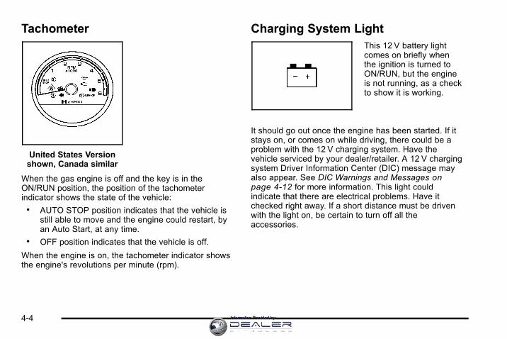
Tachometer
United States Versionshown, Canada similar
When the gas engine is off and the key is in theON/RUN position, the position of the tachometerindicator shows the state of the vehicle:. AUTO STOP position indicates that the vehicle is
still able to move and the engine could restart, byan Auto Start, at any time.
. OFF position indicates that the vehicle is off.
When the engine is on, the tachometer indicator showsthe engine's revolutions per minute (rpm).
Charging System LightThis 12 V battery lightcomes on briefly whenthe ignition is turned toON/RUN, but the engineis not running, as a checkto show it is working.
It should go out once the engine has been started. If itstays on, or comes on while driving, there could be aproblem with the 12 V charging system. Have thevehicle serviced by your dealer/retailer. A 12 V chargingsystem Driver Information Center (DIC) message mayalso appear. See DIC Warnings and Messages onpage 4‑12 for more information. This light couldindicate that there are electrical problems. Have itchecked right away. If a short distance must be drivenwith the light on, be certain to turn off all theaccessories.
4-4 Information Provided by:

Fuel Economy Gage
United States Canada
This gage shows displays how efficiently the vehicle isbeing driven.
There are three zones on the drive efficiency gage.
Green Zone : Fuel efficient driving behavior makes theindicator display in the green zone on the gage.
White Zones : Decreased fuel efficiency drivingbehavior makes the indicator display in the two whitezones. The indicator in the white zone on the left side ofthe gage indicates decreased fuel efficiency with a largeamount of decelerations. The indicator in the white zoneon the right side of the gage indicates decreased fuelefficiency with a large amount of accelerations.
4-5Information Provided by:

Brake System Warning LightWith the ignition in ON/RUN, the brake system warninglight comes on when the parking brake is set. If thevehicle is driven with the parking brake engaged, achime sounds when the vehicle speed is greater than5 mph (8 km/h).
The vehicle's hydraulic brake system is divided intotwo parts. If one part is not working, the other part canstill work and stop the vehicle. For good braking,though, both parts need to be working well.
If the warning light comes on and a chime sounds therecould be a brake problem. Have the brake systeminspected right away.
This light also comes on due to low brake fluid. See theowner manual for more information.
United States Canada
This light should come on briefly when the ignition keyis turned to ON/RUN. If it does not come on then, haveit fixed so it will be ready to warn if there is a problem.
{ WARNING:
The brake system might not be working properly ifthe brake system warning light is on. Driving withthe brake system warning light on can lead to acrash. If the light is still on after the vehicle hasbeen pulled off the road and carefully stopped,have the vehicle towed for service.
If the light comes on while driving, pull off the road andstop carefully. The pedal might be harder to push or cango closer to the floor. It may take longer to stop. If thelight does not go out, have the vehicle towed forservice. See Towing Your Vehicle on page 5‑2.
4-6 Information Provided by:

Antilock Brake System (ABS)Warning Light
For vehicles with theAntilock Brake System(ABS), this light comes onbriefly when the engine isin ON/RUN.
That is normal. If the light does not come on then, haveit fixed so it will be ready to warn if there is a problem.
If the ABS light stays on, turn the ignition off, if the lightcomes on while driving, stop as soon as it is safelypossible and turn the ignition off. Then start the engineagain to reset the system. If the ABS light still stays on,or comes on again while driving, the vehicle needsservice. If the regular brake system warning light is noton, the vehicle still has brakes, but not antilock brakes.If the regular brake system warning light is also on, thevehicle does not have antilock brakes and there is aproblem with the regular brakes. See Brake SystemWarning Light on page 4‑6.
For vehicles with a Driver Information Center (DIC),see DIC Warnings and Messages on page 4‑12 for allbrake related DIC messages.
StabiliTrak® Indicator LightFor vehicles withStabiliTrak, this warninglight comes on brieflywhen the ignition is inON/RUN.
If it does not, have the vehicle serviced by yourdealer/retailer. If the system is working normally theindicator light goes off.
If the light comes on and stays on while driving, therecould be a problem with the StabiliTrak system and thevehicle might need service. When this warning light ison, the StabiliTrak system is off and does not limitwheel spin.
The light flashes if the system is active and is workingto assist the driver with directional control of the vehiclein difficult driving conditions.
See the owner manual for more information.
4-7Information Provided by:

Engine Coolant Temperature Gage
United States Canada
This gage shows the engine coolant temperature.
It also provides an indicator of how hard the vehicle isworking. During a majority of the operation, the gagereads 210° F (100° C) or less. If a load is being pulledor going up hills, it is normal for the temperature tofluctuate and go over the 235° F (113° C) mark.However, if the gage reaches the 260° F (125° C) mark,it indicates that the cooling system is working beyond itscapacity.
Oil Pressure Gage
United States Canada
The oil pressure gage shows the engine oil pressurein psi (pounds per square inch) when the engine isrunning. Canadian vehicles indicate pressure inkPa (kilopascals).
Oil pressure should be 29 to 80 psi (200 to 550 kPa).In certain situations, such as long extended idles onhot days, it could read as low as 15 psi (105 kPa) andstill be considered normal.
4-8 Information Provided by:

A reading in the low pressure zone may be caused bya dangerously low oil level or some other problemcausing low oil pressure. Check the oil as soon aspossible.
{ WARNING:
Do not keep driving if the oil pressure is low.The engine can become so hot that it catches fire.Someone could be burned. Check the oil as soonas possible and have the vehicle serviced.
Notice: Lack of proper engine oil maintenance candamage the engine. The repairs would not becovered by the vehicle warranty. Always follow themaintenance schedule in this manual for changingengine oil.
AUTO STOPWhen the engine goes into Automatic Engine Stop,the oil pressure gage drops to zero when thetachometer is at the AUTO STOP position. This isnormal and oil pressure returns to the normal operatingrange once the engine starts.
See Starting the Vehicle on page 3‑3 for moreinformation.
AUTO STOP displays in the Driver InformationCenter (DIC) when the vehicle speed is zero.See DIC Warnings and Messages on page 4‑12for more information.
4-9Information Provided by:

Oil Pressure Light
{ WARNING:
Do not keep driving if the oil pressure is low.The engine can become so hot that it catches fire.Someone could be burned. Check the oil as soonas possible and have the vehicle serviced.
Notice: Lack of proper engine oil maintenance candamage the engine. The repairs would not becovered by the vehicle warranty. Always follow themaintenance schedule in this manual for changingengine oil.
This light comes onbriefly as a check itworks, when the ignitionis in ON/RUN. If it doesnot, have the vehicleserviced.
If the light comes on and stays on, it means that oil isnot flowing through the engine properly. The vehiclecould be low on oil and might have some other systemproblem.
During an AUTO STOP there is zero oil pressure, butthis light will not come on.
4-10 Information Provided by:

Fuel Gage
United States Canada
When the ignition is on, the fuel gage showsapproximately how much fuel is left in the tank. Thegage will first indicate E (empty) before it is out of fuel,but the vehicle should be refueled as soon as possible.
An arrow on the fuel gage indicates the side of thevehicle the fuel door is on.
Listed are four situations that may occur with the fuelgage, none of these indicate a problem:. At the gas station, the fuel pump shuts off before
the gage reads F (full).. It takes a little more or less fuel to fill up than the
fuel gage indicated. For example, the gage mayhave indicated the tank was half full, but it actuallytook a little more or less than half the tank'scapacity to fill the tank.
. The gage moves a little while turning a corner orspeed up.
. The gage does not go back to E (empty) when theignition is turned off.
4-11Information Provided by:

Driver Information Center (DIC)Trip/Fuel Menu ItemsPress the trip/fuel button to display the Trip/Fuel Menuitems. For more items see “DIC Operation andDisplays” in the owner manual.
BATTERY VOLTAGEThis display shows the current battery voltage. If thevoltage is in the normal range, the value will display.For example, the display may read BATTERYVOLTAGE 13.2 VOLTS. If the voltage is high or low,the display will read HIGH or LOW. Your vehicle'scharging system regulates voltage based on the stateof the battery. The battery voltage may fluctuate whenviewing this information on the DIC. This is normal.See “Charging System Light” in the owner manual formore information. If there is a problem with the batterycharging system, the DIC will display a message.See DIC Warnings and Messages on page 4‑12.
INST ECON (Instantaneous Economy)This display normally shows instantaneous fueleconomy. When the vehicle is in Auto Stop modeAUTO STOP or INST ECON = 99 MPG (l/00km) will bedisplayed. See Starting the Vehicle on page 3‑3 formore information.
DIC Warnings and MessagesWarning messages are displayed on the DIC to notifythe driver that the status of the vehicle has changedand that some action may be needed by the driver tocorrect the condition. If there is more than one messagethat needs to be displayed they will appear one afteranother.
Some messages may not require immediate action, butyou can press any of the DIC buttons on the instrumentpanel or the trip odometer reset stem to acknowledgethat you received the messages and to clear them fromthe display.
Some messages cannot be cleared from the DICdisplay because they are more urgent. Thesemessages require action before they can be cleared.You should take any messages that appear on thedisplay seriously and remember that clearing themessages will only make the messages disappear, notcorrect the problem.
For information on other DIC messages, see “DICWarnings and Messages” in the owner manual Index.
HOOD OPENIf the hood is not fully closed or there is a problem withthe hood switch, this message will be displayed. Closethe hood to clear the message. If the HOOD OPENmessage continues to be displayed after verifying the
4-12 Information Provided by:
hood is closed, you should have the hood switchserviced. Failure to service the hood switch properlycan result in an Auto Start condition.
Auto Stops will be disabled when this message isdisplayed. If the vehicle is in auto stop mode when thismessage appears, the engine will instantly start.
OIL PRESSURE LOW STOP ENGINEIf engine oil pressure is low, this message will bedisplayed on the DIC. Stop the vehicle as soon assafely possible and do not operate it until the cause ofthe low oil pressure has been corrected. Check your oillevel as soon as possible and have your vehicleserviced. See “Engine Oil” in the owner manual Index.
SERVICE 4 WHEEL DRIVEThis message may display if a problem occurs with thefour-wheel-drive system. If this message appears, stopas soon as possible and turn off the vehicle. Make surethe key is in the LOCK/OFF position for at leastone minute and then restart the vehicle and check forthe message on the DIC display. If the message is stilldisplayed or appears again when you begin driving,the four-wheel-drive system needs service. See yourdealer/retailer.
SERVICE BATTERY CHARGINGSYSTEMIf the 12V battery system faults or fails this message willappear on the DIC. The battery/charging system lightwill appear in the instrument panel cluster. See “BatteryWarning Light” in the owner manual Index. Driving withthis message on could drain the battery. Have theelectrical system checked as soon as possible.
SERVICE BRAKE SYSTEMThis message will be displayed if there is a problemwith the brake system. You will still be able to brake, butit will be noticeably more difficult. Pull off the road to asafe location and have your vehicle towed to thenearest dealer/retailer for service. See “Brakes,”“Brake System Warning Light,” and “ABS Brake SystemWarning Light” in the owner manual Index.
SERVICE HYBRID SYSTEMIf this message is displayed on the DIC, the vehicle maycontinue to operate, but you need to have it serviced assoon as possible.
SERVICE POWER STEERINGThis message displays if a problem has been detectedwith the electric power steering. Have your vehicleserviced by your dealer/retailer immediately.
4-13Information Provided by:

Audio System(s)
Navigation/Radio SystemFor vehicles with a navigation radio system, see theNavigation System manual for more information.
To view the hybrid screen, press the MENU button onthe radio. The hybrid screen displays when entering theConfiguration Menu.
The display shows:. Auto Stop. Battery Charging. Engine Idle. 2‐Wheel and 4‐Wheel Drive Modes for:
‐ Engine Power
‐ Battery Power
‐ Hybrid Power
4-14 Information Provided by:

Section 5 Driving Your Vehicle
Your Driving, the Road, and the Vehicle . . . . . . . . . . 5-2Electric Power Steering . . . . . . . . . . . . . . . . . . . . . . . . . 5-2
Towing . . . . . . . . . . . . . . . . . . . . . . . . . . . . . . . . . . . . . . . . . . . . . 5-2Towing Your Vehicle . . . . . . . . . . . . . . . . . . . . . . . . . . . . 5-2Recreational Vehicle Towing . . . . . . . . . . . . . . . . . . . . 5-2Towing a Trailer . . . . . . . . . . . . . . . . . . . . . . . . . . . . . . . . . 5-8
5-1Information Provided by:

Your Driving, the Road, and theVehicle
Electric Power SteeringThis vehicle has On-Demand Electric-Assist PowerSteering instead of conventional full-time hydraulicpower steering. It uses electricity supplied by the samebattery which is re-charged by the regenerative brakingsystem.
Because the system is On-Demand Electric-Assist,energy is used only when the steering wheel is turned,or when the steering gear is used to help isolate theforces of rough roads. This system does not use powersteering fluid, making it maintenance-free.
Towing
Towing Your VehicleConsult your dealer/retailer or a professional towingservice if the disabled vehicle needs to be towed.
Recreational Vehicle TowingRecreational vehicle towing means towing the vehiclebehind another vehicle – such as behind a motorhome.The two most common types of recreational vehicletowing are known as dinghy towing and dolly towing.Dinghy towing is towing the vehicle with all four wheelson the ground. Dolly towing is towing the vehicle withtwo wheels on the ground and two wheels up on adevice known as a dolly.
5-2 Information Provided by:
Here are some important things to consider beforerecreational vehicle towing:. What is the towing capacity of the towing vehicle?
Be sure to read the tow vehicle manufacturer'srecommendations.
. What is the distance that will be travelled? Somevehicles have restrictions on how far and how longthey can tow.
. Is the proper towing equipment going to be used?See your dealer/retailer or trailering professionalfor additional advice and equipmentrecommendations.
. Is the vehicle ready to be towed? Just as preparingthe vehicle for a long trip, make sure the vehicle isprepared to be towed. See “Before Leaving on aLong Trip” in the owner manual index.
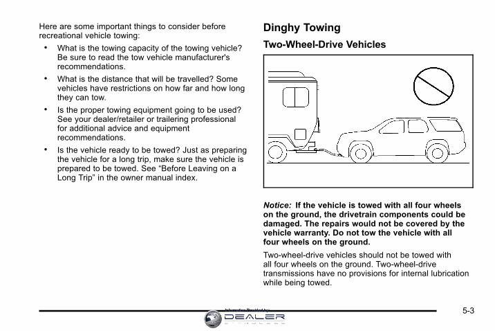
Dinghy Towing
Two-Wheel-Drive Vehicles
Notice: If the vehicle is towed with all four wheelson the ground, the drivetrain components could bedamaged. The repairs would not be covered by thevehicle warranty. Do not tow the vehicle with allfour wheels on the ground.
Two-wheel-drive vehicles should not be towed withall four wheels on the ground. Two-wheel-drivetransmissions have no provisions for internal lubricationwhile being towed.
5-3Information Provided by:

Four-Wheel-Drive Vehicles
Use the following procedure to dinghy tow afour-wheel-drive vehicle:
1. Position the vehicle being towed behind the towvehicle and shift the transmission to P (Park).
2. Turn the engine off and firmly set the parkingbrake. See “Parking Brake” in the owner manualindex.
3. Securely attach the vehicle being towed to thetow vehicle.
{ WARNING:
Shifting a four-wheel-drive vehicle's transfer caseinto N (Neutral) can cause the vehicle to roll evenif the transmission is in P (Park). The driver orothers could be injured. Make sure the parkingbrake is firmly set before the transfer case isshifted to N (Neutral).
4. Shift the transfer case to N (Neutral). See “Shiftinginto N (Neutral)” under Four-Wheel Drive onpage 3‑10 for the proper procedure to select theNeutral position for the vehicle.
5. Release the parking brake only after the vehiclebeing towed is firmly attached to the towingvehicle.
6. Turn the ignition to LOCK/OFF and remove thekey— the steering wheel will still turn.
5-4 Information Provided by:

Dolly Towing
Front Towing (Front Wheels Off theGround)
Two-Wheel-Drive Vehicles
Notice: If a two-wheel-drive vehicle is towed withthe rear wheels on the ground, the transmissioncould be damaged. The repairs would not becovered by the vehicle warranty. Never tow thevehicle with the rear wheels on the ground.
Two-wheel-drive vehicles should not be towed withthe rear wheels on the ground. Two-wheel-drivetransmissions have no provisions for internal lubricationwhile being towed.
To dolly tow a two‐wheel‐drive vehicle, the vehicle mustbe towed with the rear wheels on the dolly. See “RearTowing (Rear Wheels Off the Ground)” later in thissection for more information.
5-5Information Provided by:

Four-Wheel-Drive Vehicles
Use the following procedure to dolly tow afour-wheel-drive vehicle from the front:
1. Attach the dolly to the tow vehicle following thedolly manufacturer's instructions.
2. Drive the front wheels onto the dolly.
3. Shift the transmission to P (Park).
4. Firmly set the parking brake. See “Parking Brake”in the owner manual index.
{ WARNING:
Shifting a four-wheel-drive vehicle's transfer caseinto N (Neutral) can cause the vehicle to roll evenif the transmission is in P (Park). The driver orothers could be injured. Make sure the parkingbrake is firmly set before the transfer case isshifted to N (Neutral).
5. Shift the transfer case to N (Neutral). See “Shiftinginto N (Neutral)” under Four-Wheel Drive onpage 3‑10.
6. Secure the vehicle to the dolly following themanufacturer's instructions.
7. Release the parking brake only after the vehiclebeing towed is firmly attached to the towingvehicle.
8. Turn the ignition to LOCK/OFF.
After towing, see “Shifting Out of N (Neutral)” underFour-Wheel Drive on page 3‑10.
5-6 Information Provided by:

Rear Towing (Rear Wheels Off theGround)
Two‐Wheel‐Drive VehiclesUse the following procedure to dolly tow atwo-wheel-drive vehicle from the rear:
1. Attach the dolly to the tow vehicle following thedolly manufacturer's instructions.
2. Drive the rear wheels onto the dolly.
3. Firmly set the parking brake. See “Parking Brake”in the owner manual index.
4. Put the transmission in P (Park).
5. Secure the vehicle to the dolly following themanufacturer's instructions.
6. Use an adequate clamping device designed fortowing to ensure that the front wheels are lockedinto the straight position.
7. Turn the ignition to LOCK/OFF.
Four‐Wheel‐Drive VehiclesUse the following procedure to dolly tow afour-wheel-drive vehicle from the rear:
1. Attach the dolly to the tow vehicle following thedolly manufacturer's instructions.
2. Drive the rear wheels onto the dolly.
3. Firmly set the parking brake. See “Parking Brake”in the owner manual index.
4. Put the transmission in P (Park).
5. Secure the vehicle to the dolly following themanufacturer's instructions.
5-7Information Provided by:

6. Use an adequate clamping device designed fortowing to ensure that the front wheels are lockedinto the straight position.
{ WARNING:
Shifting a four-wheel-drive vehicle's transfer caseinto N (Neutral) can cause the vehicle to roll evenif the transmission is in P (Park). The driver orothers could be injured. Make sure the parkingbrake is firmly set before the transfer case isshifted to N (Neutral).
7. Shift the transfer case to N (Neutral). See “Shiftinginto N (Neutral)” under Four-Wheel Drive onpage 3‑10
8. Turn the ignition to LOCK/OFF.
After towing, see “Shifting Out of N (Neutral)” underFour-Wheel Drive on page 3‑10.
Towing a TrailerFor more information, see “Towing a Trailer” in theowner manual Index.
Weight of the TrailerHow heavy can a trailer safely be?
It depends on how the rig is used. For example, speed,altitude, road grades, outside temperature and howmuch the vehicle is used to pull a trailer are allimportant. It can depend on any special equipmenton the vehicle, and the amount of tongue weight thevehicle can carry.
Maximum trailer weight is calculated assuming only thedriver is in the tow vehicle and it has all the requiredtrailering equipment. The weight of additional optionalequipment, passengers and cargo in the tow vehiclemust be subtracted from the maximum trailer weight.
Use the following charts to determine how much thevehicle can weigh, based upon the vehicle model andoptions.
5-8 Information Provided by:

Vehicle Axle Ratio Maximum Trailer Weight GCWR*
2WD 6.0L V8 — Tahoe/Yukon
3.08 6,200 lbs (2 812 kg) 12,000 lbs (5 443 kg)
2WD 6.0L V8 — YukonDenali
3.08 6,000 lbs (2 722 kg) 12,000 lbs (5 443 kg)
4WD 6.0L V8 — Tahoe/Yukon
3.08 6,000 lbs (2 722 kg) 12,000 lbs (5 443 kg)
4WD 6.0L V8 — YukonDenali
3.08 5,700 lbs (2 586 kg) 12,000 lbs (5 443 kg)
*The Gross Combination Weight Rating (GCWR) is the total allowable weight of the completely loaded vehicle andtrailer including any passengers, cargo, equipment and conversions. The GCWR for the vehicle should not beexceeded.
Trailer BrakesIf a trailer is being towed that has trailer brakes and thetrailer brakes are manually applied while driving slowerthan 25 mph (40 km/h), the vehicle may go into autostop mode even if the brakes are not being pressed.Using the trailer brake system manually can makethe hybrid vehicle perform as if the brake pedal in the
vehicle is being pressed. The trailer brake operationcheck will still work. If the trailer brakes are manuallyapplied for an extended period of time, the SERVICEBRAKE SYSTEM DIC message comes on. Themessage goes off after the trailer brakes have beenreleased. No other action is necessary. For moreinformation, see “Trailer Brakes” in the Index of thevehicle's owner manual.
5-9Information Provided by:

2 NOTES
5-10 Information Provided by:

Section 6 Service and Appearance Care
Service . . . . . . . . . . . . . . . . . . . . . . . . . . . . . . . . . . . . . . . . . . . . . 6-2Doing Your Own Service Work . . . . . . . . . . . . . . . . . . 6-2
Checking Things Under the Hood . . . . . . . . . . . . . . . . . 6-3High Voltage Devices and Wiring . . . . . . . . . . . . . . . 6-3Engine Compartment Overview . . . . . . . . . . . . . . . . . 6-4Automatic Transmission Fluid . . . . . . . . . . . . . . . . . . . 6-5Drive Motor/Generator Control Module (DMCM)Coolant Surge Tank Pressure Cap . . . . . . . . . . . . 6-8
Drive Motor/Generator Control Module (DMCM)Cooling System . . . . . . . . . . . . . . . . . . . . . . . . . . . . . . . 6-9
Power Steering Fluid . . . . . . . . . . . . . . . . . . . . . . . . . . 6-13Brakes . . . . . . . . . . . . . . . . . . . . . . . . . . . . . . . . . . . . . . . . . 6-13Battery . . . . . . . . . . . . . . . . . . . . . . . . . . . . . . . . . . . . . . . . . 6-16Jump Starting . . . . . . . . . . . . . . . . . . . . . . . . . . . . . . . . . . 6-18
Bulb Replacement . . . . . . . . . . . . . . . . . . . . . . . . . . . . . . . . 6-24Taillamps, Turn Signal, Stoplamps andBack-up Lamps . . . . . . . . . . . . . . . . . . . . . . . . . . . . . . 6-24
Replacement Bulbs . . . . . . . . . . . . . . . . . . . . . . . . . . . . 6-25
Electrical System . . . . . . . . . . . . . . . . . . . . . . . . . . . . . . . . . 6-25High Voltage Devices and Wiring . . . . . . . . . . . . . . 6-25Fuses and Circuit Breakers . . . . . . . . . . . . . . . . . . . . 6-26Underhood Fuse Block . . . . . . . . . . . . . . . . . . . . . . . . 6-26
Tires . . . . . . . . . . . . . . . . . . . . . . . . . . . . . . . . . . . . . . . . . . . . . . . 6-28Inflation - Tire Pressure . . . . . . . . . . . . . . . . . . . . . . . . 6-28Tire Pressure Monitor Operation . . . . . . . . . . . . . . . 6-29Tire Inspection and Rotation . . . . . . . . . . . . . . . . . . . 6-33Tire Chains . . . . . . . . . . . . . . . . . . . . . . . . . . . . . . . . . . . . 6-34If a Tire Goes Flat . . . . . . . . . . . . . . . . . . . . . . . . . . . . . 6-34Tire Sealant and Compressor Kit(Without Selector Switch) . . . . . . . . . . . . . . . . . . . . 6-35
Tire Sealant and Compressor Kit(With Selector Switch) . . . . . . . . . . . . . . . . . . . . . . . 6-45
Tire Sealant and Compressor Kit Storage . . . . . . 6-55
Appearance Care . . . . . . . . . . . . . . . . . . . . . . . . . . . . . . . . . 6-56Vehicle Care/Appearance Materials . . . . . . . . . . . . 6-56
Capacities and Specifications . . . . . . . . . . . . . . . . . . . 6-57
6-1Information Provided by:

Service
Doing Your Own Service Work
{ WARNING:
Never try to do your own service on hybridcomponents. You can be injured and the vehiclecan be damaged if you try to do your own servicework. Service and repair of these hybridcomponents should only be performed by atrained service technician with the properknowledge and tools.
{ WARNING:
You can be injured and the vehicle could bedamaged if you try to do service work on a vehiclewithout knowing enough about it.
. Be sure you have sufficient knowledge,experience, the proper replacement parts,and tools before attempting any vehiclemaintenance task.
. Be sure to use the proper nuts, bolts, andother fasteners. English and metric fastenerscan be easily confused. If the wrong fastenersare used, parts can later break or fall off. Youcould be hurt.
6-2 Information Provided by:

If doing some of your own service work, use the properservice manual. It tells you much more about how toservice the vehicle than this manual can. To order theproper service manual, see “Service PublicationsOrdering Information” in the owner manual.
This vehicle has an airbag system. Before attemptingto do your own service work, see “Servicing YourAirbag‐Equipped Vehicle” in the owner manual.
Keep a record with all parts receipts and list themileage and the date of any service work performed.See “Maintenance Record” in the owner manual.
Checking Things Underthe Hood
High Voltage Devices and Wiring
{ WARNING:
Exposure to high voltage can cause shock, burns,and even death. The high voltage systems in yourvehicle can only be serviced by technicians withspecial training.
High voltage devices are identified by labels.Do not remove, open, take apart, or modify thesedevices. High voltage cable or wiring has orangecovering. Do not probe, tamper with, cut, ormodify high voltage cable or wiring.
6-3Information Provided by:

Engine Compartment OverviewWhen you open the hood on your vehicle, you will see:
6-4 Information Provided by:

A. See “Engine Air Cleaner/Filter” in the ownermanual.
B. Drive Motor/Generator Control Module (DMCM).See Drive Motor/Generator Control Module(DMCM) Cooling System on page 6‑9.
C. Engine Oil Dipstick. See “Engine Oil” in the ownermanual.
D. Automatic Transmission Fluid Dipstick. SeeAutomatic Transmission Fluid on page 6‑5.
E. Brake Fluid Reservoir. See Brakes on page 6‑13.
F. See “Underhood Fuse Block” in the owner manual.
G. See “Windshield Washer Fluid” in the ownermanual.
H. Hybrid Auxiliary Fuse Block. See Underhood FuseBlock on page 6‑26.
I. DMCM Coolant Surge Tank Pressure Cap. SeeDrive Motor/Generator Control Module (DMCM)Coolant Surge Tank Pressure Cap on page 6‑8.
J. See “Coolant Surge Tank Pressure Cap” in theowner manual.
K. Engine Oil Fill Cap. See “Engine Oil” in the ownermanual.
Automatic Transmission Fluid
When to Check and Change AutomaticTransmission FluidIt is usually not necessary to check the transmissionfluid level. The only reason for fluid loss is atransmission leak or overheating the transmission.If you suspect a small leak, then use the followingchecking procedures to check the fluid level. However,if there is a large leak, then it may be necessary to havethe vehicle towed to a dealer/retailer service departmentand have it repaired before driving the vehicle further.
Notice: Use of the incorrect automatic transmissionfluid may damage the vehicle, and the damages maynot be covered by the vehicle's warranty. Alwaysuse the automatic transmission fluid listed inRecommended Fluids and Lubricants on page 7‑2.
Change the fluid and filter at the intervals listed in theMaintenance Schedule. See Scheduled Maintenance inthe owner manual. Be sure to use the transmission fluidlisted in Recommended Fluids and Lubricants onpage 7‑2 .
6-5Information Provided by:

How to Check Automatic TransmissionFluidNotice: Too much or too little fluid can damage yourtransmission. Too much can mean that some of thefluid could come out and fall on hot engine parts orexhaust system parts, starting a fire. Too little fluidcould cause the transmission to overheat. Be sureto get an accurate reading if you check yourtransmission fluid.
Before checking the fluid level, prepare the vehicle asfollows:
1. Start the engine and park the vehicle on a levelsurface. Keep the engine running.
2. Apply the parking brake and place the shift leverin P (Park).
3. With your foot on the brake pedal, move the shiftlever through each gear range, pausing for aboutthree seconds in each range. Then, move the shiftlever back to P (Park).
4. Allow the engine to idle (500 – 800 RPM) for atleast one minute. Slowly release the brake pedal.
5. Keep the engine running and press the Trip/Fuelbutton or trip odometer reset stem until TRANSTEMP (Transmission Temperature) displays on theDriver Information Center (DIC).
6. Using the TRANS TEMP reading, determine andperform the appropriate check procedure. If theTRANS TEMP reading is not within the requiredtemperature ranges, allow the vehicle to cool,or operate the vehicle until the appropriatetransmission fluid temperature is reached.
Cold Check ProcedureUse this procedure only as a reference to determine ifthe transmission has enough fluid to be operated safelyuntil a hot check procedure can be made. The hotcheck procedure is the most accurate method to checkthe fluid level. Perform the hot check procedure at thefirst opportunity. Use this cold check procedure to checkfluid level when the transmission temperature isbetween 24°C and 34°C (75°F and 93°F).
1. Locate thetransmission dipstick atthe rear of the enginecompartment, on thepassenger side of thevehicle.
See Engine Compartment Overview on page 6‑4for more information.
2. Pull out the dipstick and wipe it with a clean rag orpaper towel.
6-6 Information Provided by:

3. Install the dipstick by pushing it back in all the way,wait three seconds, and then pull it back out again.
4. Check both sides of the dipstick and read the lowerlevel. Repeat the check procedure to verify thereading.
5. If the fluid level is below the COLD check band,add only enough fluid as necessary to bring thelevel into the COLD band. It does not take muchfluid, generally less than 0.5 Liter (1 Pint). Do notoverfill.
6. Perform a hot check at the first opportunity afterthe transmission reaches a normal operatingtemperature between 60°C and 75°C (140°Fand 167°F).
7. If the fluid level is in the acceptable range, pushthe dipstick back in all the way.
Hot Check ProcedureUse this procedure to check the transmission fluid levelwhen the transmission fluid temperature is between60°C and 75°C (140°F and 167°F).
The hot check is the most accurate method to checkthe fluid level. The hot check should be performed atthe first opportunity in order to verify the cold check.The fluid level rises as fluid temperature increases, so itis important to ensure the transmission temperature iswithin range.
1. Locate thetransmission dipstick atthe rear of the enginecompartment, on thepassenger side of thevehicle.
See Engine Compartment Overview on page 6‑4for more information.
2. Pull out the dipstick and wipe it with a clean rag orpaper towel.
3. Install the dipstick by pushing it back in all the way,wait three seconds, and then pull it back out again.
4. Check both sides of the dipstick and read the lowerlevel. Repeat the check procedure to verify thereading.
6-7Information Provided by:

5. Safe operating level is within the HOT cross hatchband on the dipstick. If the fluid level is not withinthe HOT band, and the transmission temperatureis between 60°C and 75°C (140°F and 167°F),add or drain fluid as necessary to bring the levelinto the HOT band. If the fluid level is low, add onlyenough fluid to bring the level into the HOT band.It does not take much fluid, generally less than0.5 Liter (1 Pint). Do not overfill.
6. If the fluid level is in the acceptable range, pushthe dipstick back in all the way.
Consistency of ReadingsAlways check the fluid level at least twice using theprocedure described previously. Consistency(repeatable readings) is important to maintaining properfluid level. If readings are still inconsistent, contact yourdealer/retailer.
Drive Motor/Generator ControlModule (DMCM) Coolant Surge TankPressure Cap
See Engine CompartmentOverview on page 6‑4for more information onlocation.
6-8 Information Provided by:

The Drive Motor/Generator Control Module (DMCM)coolant surge tank pressure cap must be fully installedon the hybrid coolant surge tank.
Notice: If the pressure cap is not tightly installed,coolant loss and possible damage to the DriveMotor/Generator Control Module (DMCM) may occur.Be sure the cap is properly and tightly secured.
Drive Motor/Generator ControlModule (DMCM) Cooling SystemIn addition to the regular cooling system, the vehiclealso has a cooling system for the DMCM system.This system is serviced differently than the vehicle'smain cooling system. The DMCM cooling systemincludes the DMCM coolant surge tank, DMCM surgetank pressure cap, DMCM cooling pumps, hybridcooling radiator and the Drive Motor/Generator ControlModule (DMCM). The DMCM cooling system uses a50/50 pre-mixed DEX-COOL™ coolant and deionizedwater available at your dealer/retailer. See “EngineCoolant” and “Cooling System” in the owner manual formore information.
When you decide it is safe to lift the hood, here is whatyou will see:
A. Drive Motor/GeneratorControl Module (DMCM)
B. Engine Coolant SurgeTank Pressure Cap
C. DMCM Coolant SurgeTank/Engine CoolantSurge Tank
D. DMCM CoolingHoses (Out of View)
E. DMCM Coolant TankPressure Cap
6-9Information Provided by:
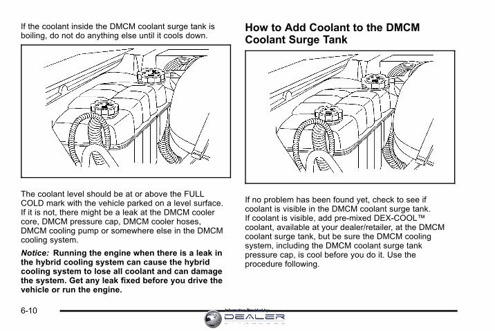
If the coolant inside the DMCM coolant surge tank isboiling, do not do anything else until it cools down.
The coolant level should be at or above the FULLCOLD mark with the vehicle parked on a level surface.If it is not, there might be a leak at the DMCM coolercore, DMCM pressure cap, DMCM cooler hoses,DMCM cooling pump or somewhere else in the DMCMcooling system.
Notice: Running the engine when there is a leak inthe hybrid cooling system can cause the hybridcooling system to lose all coolant and can damagethe system. Get any leak fixed before you drive thevehicle or run the engine.
How to Add Coolant to the DMCMCoolant Surge Tank
If no problem has been found yet, check to see ifcoolant is visible in the DMCM coolant surge tank.If coolant is visible, add pre‐mixed DEX-COOL™coolant, available at your dealer/retailer, at the DMCMcoolant surge tank, but be sure the DMCM coolingsystem, including the DMCM coolant surge tankpressure cap, is cool before you do it. Use theprocedure following.
6-10 Information Provided by:

{ WARNING:
Steam and scalding liquids from a hot coolingsystem can blow out and burn you badly. They areunder pressure, and if you turn the coolant surgetank pressure cap— even a little— they can comeout at high speed. Never turn the cap when thecooling system, including the coolant surge tankpressure cap, is hot. Wait for the cooling systemand coolant surge tank pressure cap to cool if youever have to turn the pressure cap.
Notice: Using coolant other than a pre‐mixedDEX-COOL, available at your dealer/retailer, maydamage your vehicle. Any repairs would not becovered by your warranty. Always use a pre‐mixedDEX-COOL (silicate-free) coolant in your vehicle.
{ WARNING:
You can be burned if you spill coolant on hotengine parts. Coolant contains ethylene glycoland it will burn if the engine parts are hot enough.Do not spill coolant on a hot engine.
If the DMCM coolant is empty , the vehicle must beserviced by your dealer and a special fill proceduremust be followed.
Notice: Attempting to fill the DMCM cooling surgetank yourself when the fluid level is empty candamage your vehicle. Your vehicle must beserviced.
1. Park the vehicle on a level surface and turn thevehicle off. Remove the DMCM coolant surge tankpressure cap when the DMCM cooling system,including the DMCM coolant surge tank pressurecap and DMCM cooling hoses, are no longer hot.
6-11Information Provided by:

Turn the DMCM coolant surge tank pressure capslowly counterclockwise (left) about one full turn.Wait 30 seconds.
2. Then keep turning the DMCM coolant surge tankpressure cap slowly, and remove it.
3. Add the pre‐mixed DEX‐COOL™, available at yourdealer/retailer, to the DMCM coolant surge tankuntil the level reaches the FULL COLD mark.
4. Turn the ignition to ON/RUN without starting theengine. The hybrid cooling pumps will run and anytrapped air will purge to the surge tank.
5. Add the pre‐mixed DEX‐COOL™, available at yourdealer/retailer, until the coolant level is maintainedat the FULL COLD mark. This should take nolonger than two minutes of hybrid cooling pumpoperation.
If the level cannot be kept at the FULL COLDlevel, your vehicle may need service. See yourdealer/retailer.
6. Then replace theDMCM coolant surgetank pressure cap.Be sure the pressurecap is hand-tight andfully seated.
Notice: Using tap water, cooling system sealers orconditioners in an attempt to stop coolant leaks candamage the DMCM and engine cooling systems.Never use tap water, cooling system sealers orconditioners in your cooling system.
6-12 Information Provided by:

Power Steering FluidThe vehicle has electric power steering and does notuse power steering fluid.
Brakes
Brake FluidThe brake master cylinderreservoir is filled withDOT 3 brake fluid. SeeEngine CompartmentOverview on page 6‑4for the location of thereservoir.
There are only two reasons why the brake fluid level inthe reservoir might go down:. The brake fluid level goes down because of normal
brake lining wear. When new linings are installed,the fluid level goes back up.
. A fluid leak in the brake hydraulic system can alsocause a low fluid level. Have the brake hydraulicsystem fixed, since a leak means that sooner orlater the brakes will not work well.
Do not top off the brake fluid. Adding fluid does notcorrect a leak. If fluid is added when the linings areworn, there will be too much fluid when new brakelinings are installed. Add or remove brake fluid, asnecessary, only when work is done on the brakehydraulic system.
{ WARNING:
If too much brake fluid is added, it can spill on theengine and burn, if the engine is hot enough.You or others could be burned, and the vehiclecould be damaged. Add brake fluid only whenwork is done on the brake hydraulic system.See “Checking Brake Fluid” in this section.
When the brake fluid falls to a low level, the brakewarning light comes on. See “Brake System WarningLight” in the owner manual.
Refer to the Maintenance Schedule to determine whento check the brake fluid. See “Scheduled Maintenance”in the owner manual.
6-13Information Provided by:

Checking Brake FluidCheck brake fluid by looking at the brake fluid reservoir.See Engine Compartment Overview on page 6‑4.
With the engine not running for at least one minute, themaximum fluid level (A) is at the top of the reservoirbody. With the engine running, the fluid level should bein the proper operating range (B) between the MIN andMAX marks. If it is not, have the brake hydraulic systemchecked to see if there is a leak.
After work is done on the brake hydraulic system, makesure the level, with the engine running, is in the properoperating range (B) between the MIN and MAX marks.
What to AddUse only new DOT 3 brake fluid from a sealedcontainer. See “Recommended Fluids and Lubricants”in the owner manual.
Always clean the brake fluid reservoir cap and the areaaround the cap before removing it. This helps keep dirtfrom entering the reservoir.
{ WARNING:
With the wrong kind of fluid in the brake hydraulicsystem, the brakes might not work well. This couldcause a crash. Always use the proper brake fluid.
6-14 Information Provided by:

Notice:. Using the wrong fluid can badly damage
brake hydraulic system parts. For example,just a few drops of mineral-based oil, suchas engine oil, in the brake hydraulic systemcan damage brake hydraulic system partsso badly that they will have to be replaced.Do not let someone put in the wrong kindof fluid.
. If brake fluid is spilled on the vehicle'spainted surfaces, the paint finish can bedamaged. Be careful not to spill brake fluidon the vehicle. If you do, wash it offimmediately. See “Washing Your Vehicle”in the owner manual.
Brake WearThis vehicle has disc brakes. Disc brake pads havebuilt-in wear indicators that make a high-pitchedwarning sound when the brake pads are worn and newpads are needed. The sound can come and go or beheard all the time the vehicle is moving, except whenapplying the brake pedal firmly.
{ WARNING:
The brake wear warning sound means that soonthe brakes will not work well. That could lead toan accident. When the brake wear warning soundis heard, have the vehicle serviced.
Notice: Continuing to drive with worn-out brakepads could result in costly brake repair.
Some driving conditions or climates can cause a brakesqueal when the brakes are first applied or lightlyapplied. This does not mean something is wrong withthe brakes.
6-15Information Provided by:

Properly torqued wheel nuts are necessary to helpprevent brake pulsation. When tires are rotated, inspectbrake pads for wear and evenly tighten wheel nuts inthe proper sequence to torque specifications in“Capacities and Specifications” in the owner manual.
Brake linings should always be replaced as completeaxle sets.
Brake Pedal TravelSee your dealer/retailer if the brake pedal does notreturn to normal height, or if there is a rapid increase inpedal travel. This could be a sign that brake servicemight be required.
Brake AdjustmentEvery time the brakes are applied, the disc brakesadjust for wear.
Replacing Brake System PartsThe braking system on a vehicle is complex. Its manyparts have to be of top quality and work well together ifthe vehicle is to have really good braking. The vehiclewas designed and tested with top-quality brake parts.
When parts of the braking system are replaced — forexample, when the brake linings wear down and newones are installed — be sure to get new approvedreplacement parts. If this is not done, the brakes mightnot work properly. For example, if someone puts inbrake linings that are wrong for the vehicle, the balancebetween the front and rear brakes can change — for theworse. The braking performance expected can changein many other ways if the wrong replacement brakeparts are installed.
BatteryThis vehicle has a standard 12‐volt battery and ahigh‐voltage hybrid battery.
Refer to the replacement number on the original batterylabel when a new standard 12‐volt battery is needed.
6-16 Information Provided by:
Only a trained service technician with the properknowledge and tools should inspect, test, or replacethe hybrid battery. See your dealer/retailer if thehybrid battery needs service. The dealer/retailerhas information on how to recycle the hybridbattery. There is also information available athttp://www.recyclemybattery.com.
If an airbag inflates or the vehicle has been in a crash,the vehicle's sensing system might command theautomatic hybrid battery disconnect to open. SeeReplacing Restraint System Parts After a Crash onpage 2‑3 for more information.
{ DANGER:
Battery posts, terminals, and related accessoriescontain lead and lead compounds, chemicalsknown to the State of California to cause cancerand reproductive harm. Wash hands afterhandling.
Vehicle Storage
{ WARNING:
Batteries have acid that can burn you and gasthat can explode. You can be badly hurt if you arenot careful. See Jump Starting on page 6‑18for tips on working around a battery withoutgetting hurt.
Infrequent Usage: Remove the 12‐volt battery black,negative (−) cable from the battery to keep the batteryfrom running down.
Extended Storage: Remove the 12‐volt battery black,negative (−) cable from the battery or use a batterytrickle charger.
Remember to reconnect the battery when ready to drivethe vehicle.
6-17Information Provided by:

Jump Starting
{ WARNING:
Personal injury, death, or damage to the vehiclecan result if you try jump starting or using abattery charger on the high voltage hybrid battery.Use only the 12-volt battery for jump starting andcharging.
If the vehicle's 12‐volt battery has run down, you maywant to use another vehicle and some jumper cables tostart your vehicle. Use the following steps to do it safely.
{ WARNING:
Batteries can hurt you. They can be dangerousbecause:. They contain acid that can burn you.
. They contain gas that can explode or ignite.
. They contain enough electricity to burn you.
If you do not follow these steps exactly, some orall of these things can hurt you.
Notice: Ignoring these steps could result in costlydamage to the vehicle that would not be covered bythe warranty.
Trying to start the vehicle by pushing or pulling itwill not work, and it could damage the vehicle.
1. Check the other vehicle. It must have a 12‐voltbattery with a negative ground system.
Notice: If the other vehicle's system is not a 12-voltsystem with a negative ground, both vehicles canbe damaged. Only use vehicles with 12-volt systemswith negative grounds to jump start your vehicle.
6-18 Information Provided by:
2. Get the vehicles close enough so the jumpercables can reach, but be sure the vehicles are nottouching each other. It could cause a groundconnection you do not want. You would not be ableto start your vehicle, and the bad grounding coulddamage the electrical systems.
To avoid the possibility of the vehicles rolling, setthe parking brake firmly on both vehicles involvedin the jump start procedure. Put the automatictransmission in P (Park) or a manual transmissionin N (Neutral) before setting the parking brake.If you have a four-wheel-drive vehicle, be sure thetransfer case is in a drive gear, not in N (Neutral).
Notice: If you leave the radio or other accessorieson during the jump starting procedure, they couldbe damaged. The repairs would not be covered bythe warranty. Always turn off the radio and otheraccessories when jump starting the vehicle.
3. Turn off the ignition on both vehicles. Unplugunnecessary accessories plugged into thecigarette lighter or the accessory power outlets.Turn off the radio and all the lamps that are notneeded.
This avoids sparks and helps save both batteries.It could save the radio!
4. Open the hood on the other vehicle and locate thepositive (+) and negative (−) terminal locations onthat vehicle.
Your vehicle has a remote positive (+) and aremote negative (−) jump starting terminal.You should always use these remote terminalsinstead of the terminals on the battery.
6-19Information Provided by:

If the vehicle has a remote positive (+), it is locatedunder a red plastic cover at the positive batterypost. To uncover the remote positive (+) terminal,open the red plastic cover.
5. The remote negative (−) is a solid engine ground.
{ WARNING:
An electric fan can start up even when the engineis not running and can injure you. Keep hands,clothing and tools away from any underhoodelectric fan.
{ WARNING:
Using an open flame near a battery can causebattery gas to explode. People have been hurtdoing this, and some have been blinded. Use aflashlight if you need more light.
Be sure the battery has enough water. You do notneed to add water to the battery installed in yournew vehicle. But if a battery has filler caps, besure the right amount of fluid is there. If it is low,add water to take care of that first. If you do not,explosive gas could be present.
(Continued)
6-20 Information Provided by:

WARNING: (Continued)
Battery fluid contains acid that can burn you.Do not get it on you. If you accidentally get it inyour eyes or on your skin, flush the place withwater and get medical help immediately.
{ WARNING:
Fans or other moving engine parts can injure youbadly. Keep your hands away from moving partsonce the engine is running.
6. Check that the jumper cables do not have loose ormissing insulation. If they do, you could get ashock. The vehicles could be damaged too.
Before you connect the cables, here are somebasic things you should know. Positive (+) goes topositive (+) or to a remote positive (+) terminal ifthe vehicle has one. Negative (−) will go to aheavy, unpainted metal engine part or a solidengine ground.
Do not connect positive (+) to negative (−) or youwill get a short that would damage the battery andmaybe other parts too. Do not connect thenegative (−) cable to the negative (−) terminal onthe dead battery because this can cause sparks.
7. Connect the red positive (+) cable to thepositive (+) terminal of the vehicle with the deadbattery. Use a remote positive (+) if the vehiclehas one.
6-21Information Provided by:

8. Do not let the other end touch metal. Connect it tothe positive (+) terminal of the good battery. Use aremote positive (+) if the vehicle has one.
9. Now connect the black negative (−) cable to thenegative (−) terminal of the good battery. Use aremote negative (−) if the vehicle has one.
Do not let the other end touch anything until thenext step. The other end of the negative (−) cabledoes not go to the dead battery. It goes to a heavy,unpainted metal engine part or to the remotenegative (−) terminal on the vehicle with the deadbattery.
10. Connect the other end of the negative (−) cable tothe remote negative (−) terminal, on the vehiclewith the dead battery.
11. Now start the vehicle with the good battery and runthe engine for a while.
12. Try to start the vehicle that had the dead battery.If it will not start after a few tries, it probably needsservice.
Notice: If the jumper cables are connected orremoved in the wrong order, electrical shorting mayoccur and damage the vehicle. The repairs wouldnot be covered by the vehicle warranty. Alwaysconnect and remove the jumper cables in thecorrect order, making sure that the cables do nottouch each other or other metal.
6-22 Information Provided by:

Jumper Cable Removal
A. Heavy, Unpainted Metal Engine Part or RemoteNegative (−) Terminal
B. Good Battery or Remote Positive (+) and RemoteNegative (−) Terminals
C. Dead Battery or Remote Positive (+) Terminal
To disconnect the jumper cables from both vehicles:
1. Disconnect the black negative (−) cable from thevehicle that had the bad battery.
2. Disconnect the black negative (−) cable from thevehicle with the good battery.
3. Disconnect the red positive (+) cable from thevehicle with the good battery.
4. Disconnect the red positive (+) cable from the othervehicle.
5. Return the remote positive (+) terminal cover to itsoriginal position.
6-23Information Provided by:

Bulb Replacement
Taillamps, Turn Signal, Stoplampsand Back-up Lamps
A. Taillamp/Stoplamp
B. Back-up Lamp
C. Turn Signal Lamp
D. Sidemarker Lamp
If the taillamp/stoplamp (A) need to be replaced, seeyour dealer/retailer.
1. Open the liftgate. See “Power Liftgate” in theowner's manual index.
2. Remove the two screws from the taillampassembly.
3. Pull the taillamp assembly rearward until the innerpins on the taillamp assembly are disengaged fromthe vehicle.
6-24 Information Provided by:

4. Press the release tab, if bulb socket has one, andturn the bulb socket counterclockwise to remove itfrom the taillamp assembly.
5. Pull the old bulb straight out from the bulb socket.
6. Press a new bulb into the bulb socket and insert itinto the taillamp assembly. Turn the bulb socketclockwise into the taillamp assembly until it clicks.
7. Reinstall the taillamp assembly. When reinstalling,make sure to line up the pins on the taillampassembly with the vehicle. If this is not done thetaillamp assembly cannot be correctly installed.
Replacement BulbsExterior Lamp Bulb Number
Back-up Lamp and Rear TurnSignal Lamp
3156
Sidemarker Lamp 194
For replacement bulbs not listed here, contact yourdealer/retailer.
Electrical System
High Voltage Devices and Wiring
{ WARNING:
Exposure to high voltage can cause shock, burns,and even death. The high voltage systems in yourvehicle can only be serviced by technicians withspecial training.
High voltage devices are identified by labels.Do not remove, open, take apart, or modifythese devices. High voltage cable or wiring hasorange covering. Do not probe, tamper with, cut,or modify high voltage cable or wiring.
6-25Information Provided by:

Fuses and Circuit BreakersThe wiring circuits in the vehicle are protected fromshort circuits by a combination of fuses, circuit breakersand fusible thermal links. This greatly reduces thechance of fires caused by electrical problems.
Be sure you replace a bad fuse with a new one of theidentical size and rating.
If you ever have a problem on the road and do nothave a spare fuse, you can borrow one that has thesame amperage. Just pick some feature of the vehiclethat you can get along without, like the radio or cigarettelighter, and use its fuse, if it is the correct amperage.Replace it as soon as you can.
The vehicle also has a special fuse in the battery boxfor the 300-volt batteries. If this fuse has failed andneeds to be replaced, the vehicle will be disabled andyou will need to have the vehicle repaired by yourdealer/retailer. Do not attempt to self-service this fuse.
Underhood Fuse Block
Hybrid Auxiliary Underhood Fuse BlockThe hybrid underhood fuse block is located in theengine compartment near the front of the vehicle. Liftthe cover for access to the fuse/relay block. See EngineCompartment Overview on page 6‑4 for moreinformation on its location. For more information on themain underhood fuse block, see “Underhood FuseBlock” in the owner manual.
6-26 Information Provided by:

Fuses Usage
1 ACPO
2 BECM FAN
3 ACCM
4 CAB HTR PMP
5 EMPTY
6 COOL PUMP
7 EPS
8Drive Motor/Generator
Control Module 1
9Drive Motor/Generator
Control Module 2
10 BECM
J‐Case Usage
FAN 1 Cooling Fan 1
TRANS PUMPAuxiliary Transmission
Fluid Pump
FAN 2 Cooling Fan 2
CAB HTR PMP Cab Heater Pump
Relays Usage
FAN LOW Cooling Fan Low Speed Relay
FAN MID 1 Cooling Fan Mid 1
FAN HI Cooling Fan High Speed Relay
FAN MID 2 Cooling Fan Mid 2
FAN CNTRL Cooling Fan Control
6-27Information Provided by:

Tires
Inflation - Tire PressureTires need the correct amount of air pressure to operateeffectively.
Notice: Do not let anyone tell you thatunder‐inflation or over‐inflation is all right.It is not. If your tires do not have enough air(under‐inflation), you can get the following:
. Too much flexing
. Too much heat
. Tire overloading
. Premature or irregular wear
. Poor handling
. Reduced fuel economy
If your tires have too much air (over‐inflation),you can get the following:
. Unusual wear
. Poor handling
. Rough ride
. Needless damage from road hazards
A vehicle specific Tire and Loading Information label isattached to your vehicle. This label shows yourvehicle's original equipment tires and the correctinflation pressures for your tires when they are cold.The recommended cold tire inflation pressure, shownon the label, is the minimum amount of air pressureneeded to support your vehicle's maximum loadcarrying capacity.
For additional information regarding how much weightyour vehicle can carry, and an example of the Tire andLoading Information label, see “Loading Your Vehicle” inthe Index of the owner manual. How you load yourvehicle affects vehicle handling and ride comfort. Neverload your vehicle with more weight than it was designedto carry.
6-28 Information Provided by:

When to CheckCheck your tires once a month or more.
How to CheckUse a good quality pocket-type gage to check tirepressure. You cannot tell if your tires are properlyinflated simply by looking at them. Radial tires may lookproperly inflated even when they're underinflated.Check the tire's inflation pressure when the tires arecold. Cold means your vehicle has been sitting for atleast three hours or driven no more than 1 mile (1.6 km).
Remove the valve cap from the tire valve stem. Pressthe tire gage firmly onto the valve to get a pressuremeasurement. If the cold tire inflation pressure matchesthe recommended pressure on the tire and loadinginformation label, no further adjustment is necessary.If the pressure is low, add air until you reach therecommended amount.
If you overfill the tire, release air by pushing on themetal stem in the center of the tire valve. Recheck thetire pressure with the tire gage.
Be sure to put the valve caps back on the valve stems.They help prevent leaks by keeping out dirt andmoisture.
Tire Pressure Monitor OperationThis vehicle may have a Tire Pressure Monitor System(TPMS). The TPMS is designed to warn the driver whena low tire pressure condition exists. TPMS sensors aremounted onto each tire and wheel assembly. The TPMSsensors monitor the air pressure in the vehicle's tiresand transmit the tire pressure readings to a receiverlocated in the vehicle.
When a low tire pressurecondition is detected, theTPMS will illuminate thelow tire pressure warningsymbol located on theinstrument panel cluster.
At the same time a message to check the pressurein a specific tire appears on the Driver InformationCenter (DIC) display. The low tire pressure warninglight and the DIC warning message come on ateach ignition cycle until the tires are inflated tothe correct inflation pressure. Using the DIC, tirepressure levels can be viewed by the driver. For
6-29Information Provided by:

additional information and details about the DICoperation and displays see DIC Warnings andMessages on page 4‑12. Also, see “DIC Operation andDisplays” in the Index of the owner manual for moreinformation.
The low tire pressure warning light may come on in coolweather when the vehicle is first started, and then turnoff as you start to drive. This could be an early indicatorthat the air pressure in the tire(s) are getting low andneed to be inflated to the proper pressure.
A Tire and Loading Information label, attached to yourvehicle, shows the size of your vehicle's originalequipment tires and the correct inflation pressure foryour vehicle's tires when they are cold. See “LoadingYour Vehicle” for an example of the Tire and LoadingInformation label and its location on your vehicle.Also see Inflation - Tire Pressure on page 6‑28.
Your vehicle's TPMS can warn you about a low tirepressure condition but it does not replace normal tiremaintenance. See “Tire Inspection and Rotation” and“Tires” in the Index of the owner manual for moreinformation.
Notice: Using non‐approved tire sealants coulddamage the Tire Pressure Monitor System (TPMS)sensors. TPMS sensor damage caused by using anincorrect tire sealant is not covered by the vehiclewarranty. Always use the GM approved tire sealantavailable through your dealer/retailer.
Your vehicle, when new, included a factory‐installedTire Sealant and Compressor Kit. This kit uses aGM approved liquid tire sealant. See Tire Sealant andCompressor Kit (Without Selector Switch) onpage 6‑35 or Tire Sealant and Compressor Kit(With Selector Switch) on page 6‑45.
6-30 Information Provided by:
TPMS Malfunction Light and MessageThe TPMS will not function properly if one or more ofthe TPMS sensors are missing or inoperable. When thesystem detects a malfunction, the low tire warning lightflashes for about one minute and then stays on for theremainder of the ignition cycle. A DIC warning messageis also displayed. The low tire warning light and DICwarning message come on at each ignition cycle untilthe problem is corrected. Some of the conditions thatcan cause the malfunction light and DIC message tocome on are:. The TPMS sensor matching process was started
but not completed or not completed successfullyafter rotating the vehicle's tires. The DIC messageand TPMS malfunction light should go off once theTPMS sensor matching process is performedsuccessfully. See “TPMS Sensor MatchingProcess” later in this section.
. One or more TPMS sensors are missing ordamaged. The DIC message and the TPMSmalfunction light should go off when the TPMSsensors are installed and the sensor matchingprocess is performed successfully. See yourdealer/retailer for service.
. Replacement tires or wheels do not match yourvehicle's original equipment tires or wheels.Tires and wheels other than those recommendedfor your vehicle could prevent the TPMS fromfunctioning properly. See “Buying New Tires” inthe Index of the owner manual.
. Operating electronic devices or being near facilitiesusing radio wave frequencies similar to the TPMScould cause the TPMS sensors to malfunction.
If the TPMS is not functioning it cannot detect or signala low tire condition. See your dealer/retailer for serviceif the TPMS malfunction light and DIC message comeson and stays on.
6-31Information Provided by:

TPMS Sensor Matching ProcessEach TPMS sensor has a unique identification code.Any time you rotate your vehicle's tires or replace oneor more of the TPMS sensors, the identification codeswill need to be matched to the new tire/wheel position.The sensors are matched to the tire/wheel positions inthe following order: driver side front tire, passengerside front tire, passenger side rear tire, and driver siderear tire using a TPMS diagnostic tool. See yourdealer/retailer for service.
The TPMS sensors can also be matched to eachtire/wheel position by increasing or decreasing thetire's air pressure. If increasing the tire's air pressure,do not exceed the maximum inflation pressure indicatedon the tire's sidewall.
To decrease air-pressure out of a tire you can use thepointed end of the valve cap, a pencil-style air pressuregage, or a key.
You have two minutes to match the first tire/wheelposition, and five minutes overall to match all fourtire/wheel positions. If it takes longer than two minutes,to match the first tire and wheel, or more thanfive minutes to match all four tire and wheel positionsthe matching process stops and you need to start over.
The TPMS sensor matching process is outlined below:
1. Set the parking brake.
2. Turn the ignition switch to ON/RUN with theengine off.
3. Press Q and K on the Remote Keyless Entry(RKE) transmitter at the same time forapproximately five seconds. The horn soundstwice to signal the receiver is in relearn mode andTIRE LEARNING ACTIVE message displays onthe DIC screen.
4. Start with the driver side front tire.
5. Remove the valve cap from the valve cap stem.Activate the TPMS sensor by increasing ordecreasing the tire's air pressure for five seconds,or until a horn chirp sounds. The horn chirp, whichmay take up to 30 seconds to sound, confirms thatthe sensor identification code has been matched tothis tire and wheel position.
6. Proceed to the passenger side front tire, andrepeat the procedure in Step 5.
7. Proceed to the passenger side rear tire, and repeatthe procedure in Step 5.
6-32 Information Provided by:

8. Proceed to the driver side rear tire, and repeat theprocedure in Step 5. The horn sounds two times toindicate the sensor identification code has beenmatched to the driver side rear tire, and the TPMSsensor matching process is no longer active.The TIRE LEARNING ACTIVE message on theDIC display screen goes off.
9. Turn the ignition switch to LOCK/OFF.
10. Set all four tires to the recommended air pressurelevel as indicated on the Tire and LoadingInformation label.
11. Put the valve caps back on the valve stems.
Tire Inspection and RotationTires should be rotated every 5,000 to 8,000 miles(8 000 to 13 000 km).
Any time you notice unusual wear, rotate your tires assoon as possible and check wheel alignment. Alsocheck for damaged tires or wheels. See “When It IsTime for New Tires” and “Wheel Replacement” in theIndex of the owner manual for more information.
The purpose of regular rotation is to achieve moreuniform wear for all tires on the vehicle. The firstrotation is the most important. See “ScheduledMaintenance” in the Index of the owner manual.
When rotating your tires, always use the correct rotationpattern shown here.
After the tires have been rotated, adjust the front andrear inflation pressures as shown on the Tire andLoading Information label. See “Loading Your Vehicle”in the Index of the owner manual for an example of thelabel and its location on your vehicle.
The Tire Pressure Monitor System (TPMS) sensors willneed to be reset after a tire rotation. See “TPMS SensorIdentification Codes” under “Tire Pressure MonitorOperation”.
Make certain that all wheel nuts are properly tightened.See “Wheel Nut Torque” under “Capacities andSpecifications” in the Index of the owner manual.
6-33Information Provided by:

Tire Chains
{ WARNING:
Do not use tire chains. There is not enoughclearance. Tire chains used on a vehicle withoutthe proper amount of clearance can causedamage to the brakes, suspension, or othervehicle parts. The area damaged by the tirechains could cause you to lose control of thevehicle and you or others may be injured in acrash. Use another type of traction deviceonly if its manufacturer recommends it for useon the vehicle and tire size combination androad conditions. Follow that manufacturer'sinstructions. To help avoid damage to the vehicle,drive slowly, re‐adjust or remove the device if itis contacting the vehicle, and do not spin thewheels. If you do find traction devices that will fit,install them on the rear tires.
If a Tire Goes FlatYour vehicle has a tire inflator kit. There is no spare tire,no tire changing equipment, and no place to store a tire.
It is unusual for a tire to blow out while you are driving,especially if you maintain your tires properly. If air goesout of a tire, it is much more likely to leak out slowly.But, if you should ever have a blow out, here are afew tips about what to expect and what to do:
If a front tire fails, the flat tire creates a drag that pullsthe vehicle toward that side. Take your foot off theaccelerator pedal and grip the steering wheel firmly.Steer to maintain lane position, and then gently brake toa stop well out of the traffic lane.
A rear blow out, particularly on a curve, acts much like askid and may require the same correction you woulduse in a skid. In any rear blow out, remove your footfrom the accelerator pedal. Get the vehicle undercontrol by steering the way you want the vehicle to go.It may be very bumpy and noisy, but you can still steer.Gently brake to a stop, well off the road if possible.
6-34 Information Provided by:

If a tire goes flat, avoid further tire and wheel damageby driving slowly to a level place and stopping.Then do this:
1. Turn on the hazard warning flashers.
2. Park your vehicle. Set the parking brake firmly andput the shift lever in PARK (P).
3. Turn off the engine.
4. Inspect the flat tire.
If the tire has been separated from the wheel or hasdamaged sidewalls or large tears that allow rapid airloss, call a tire repair facility. See “Roadside AssistanceProgram” in the Index of the owner manual.
If the flat tire is due to a slow leak caused by a nail orother similar road hazard, the tire inflator kit may beused to repair the damaged tire temporarily. The kituses a liquid tire sealant to seal small punctures in thetread area of the tire.
After repairing a tire with the tire inflator kit, take yourvehicle to an authorized retailer to have the tireinspected and repaired as soon as possible. The tiresealant is a temporary repair only. See Tire Sealantand Compressor Kit (Without Selector Switch) onpage 6‑35 or Tire Sealant and Compressor Kit(With Selector Switch) on page 6‑45.
Tire Sealant and Compressor Kit(Without Selector Switch)
System Identification
If the vehicle has the tire sealant and compressor kitshown above, see the operating instructions that follow.
6-35Information Provided by:

If the vehicle has the tire sealant and compressor kitshown above, follow the operating instructions under“Tire Sealant and Compressor Kit (With SelectorSwitch).”
{ WARNING:
Idling a vehicle in an enclosed area with poorventilation is dangerous. Engine exhaust mayenter the vehicle. Engine exhaust containsCarbon Monoxide (CO) which cannot be seen orsmelled. It can cause unconsciousness and evendeath. Never run the engine in an enclosed areathat has no fresh air ventilation. For moreinformation, see ”Engine Exhaust” in the ownermanual.
{ WARNING:
Over-inflating a tire could cause the tire to ruptureand you or others could be injured. Be sure toread and follow the tire sealant and compressorkit instructions and inflate the tire to itsrecommended pressure. Do not exceed therecommended pressure.
6-36 Information Provided by:

{ WARNING:
Storing the tire sealant and compressor kit orother equipment in the passenger compartment ofthe vehicle could cause injury. In a sudden stop orcollision, loose equipment could strike someone.Store the tire sealant and compressor kit in itsoriginal location.
If this vehicle has a tire sealant and compressor kit,there may not be a spare tire, tire changing equipment,and on some vehicles there may not be a place tostore a tire.
The tire sealant and compressor can be used totemporarily seal punctures up to ¼ inch (6 mm) in thetread area of the tire. It can also be used to inflate anunder inflated tire.
If the tire has been separated from the wheel, hasdamaged sidewalls, or has a large puncture, the tireis too severely damaged for the tire sealant andcompressor kit to be effective. See “RoadsideAssistance Program” in the owner manual.
Read and follow all of the tire sealant and compressorkit instructions.
The kit includes:
A. Air Compressor
B. Tire Sealant Canister
C. Power Plug
D. On/Off Button
E. Pressure Gage
F. Air Only Hose (Black)
G. Sealant/Air Hose (Clear)
6-37Information Provided by:

Tire SealantRead and follow the safe handling instructions on thelabel adhered to the sealant canister.
Check the tire sealant expiration date on the sealantcanister. The sealant canister should be replaced beforeits expiration date. Replacement sealant canisters areavailable at your local dealer/retailer. See “Removal andInstallation of the Sealant Canister” following.
There is only enough sealant to seal one tire. Afterusage, the sealant canister and sealant/air hoseassembly must be replaced. See “Removal andInstallation of the Sealant Canister” following.
Using the Tire Sealant and CompressorKit to Temporarily Seal and Inflate aPunctured TireFollow the directions closely for correct sealant usage.
When using the tire sealant and compressor kitduring cold temperatures, warm the kit in a heatedenvironment for 5 minutes. This will help to inflate thetire faster.
6-38 Information Provided by:

Always do a safety check first. See If a Tire Goes Flaton page 6‑34.
1. Remove the tire sealant and compressor kit fromits storage location. See Tire Sealant andCompressor Kit Storage on page 6‑55.
Make sure the on/off button (D) is in the off (O)position.
2. Unwrap the sealant/air hose (F) and the powerplug (C).
3. Place the kit on the ground.
Make sure the tire valve stem is positioned close tothe ground so the hose will reach it.
4. Remove the valve stem cap from the flat tire byturning it counterclockwise.
5. Attach the sealant/air hose (F) onto the tire valvestem. Turn it clockwise until it is tight.
6. Plug the power plug (C) into the accessory poweroutlet in the vehicle. Unplug all items from otheraccessory power outlets. See “Accessory PowerOutlet(s) in the owner manual.”
If the vehicle has an accessory power outlet,do not use the cigarette lighter.
If the vehicle only has a cigarette lighter, use thecigarette lighter.
Do not pinch the power plug cord in the door orwindow.
7. Start the vehicle. The vehicle must be runningwhile using the air compressor.
8. Press the on/off (D) button to turn the tire sealantand compressor kit on.
The compressor will inject sealant and air intothe tire.
The pressure gage (E) will initially show a highpressure while the compressor pushes the sealantinto the tire. Once the sealant is completelydispersed into the tire, the pressure will quicklydrop and start to rise again as the tire inflates withair only.
6-39Information Provided by:
9. Inflate the tire to the recommended inflationpressure using the pressure gage (E).The recommended inflation pressure can befound on the Tire and Loading Information label.See Inflation - Tire Pressure on page 6‑28.
The pressure gage (E) may read higher than theactual tire pressure while the compressor is on.Turn the compressor off to get an accuratepressure reading. The compressor may be turnedon/off until the correct pressure is reached.
Notice: If the recommended pressure cannot bereached after approximately 25 minutes, the vehicleshould not be driven farther. The tire is too severelydamaged and the tire sealant and compressor kitcannot inflate the tire. Remove the power plug fromthe accessory power outlet and unscrew theinflating hose from the tire valve. See “RoadsideAssistance Program” in the owner manual.
10. Press the on/off button (D) to turn the tire sealantand compressor kit off.
The tire is not sealed and will continue toleak air until the vehicle is driven and thesealant is distributed in the tire, therefore,Steps 11 through 17 must be done immediatelyafter Step 10.
Be careful while handling the tire sealant andcompressor kit as it could be warm after usage.
11. Unplug the power plug (C) from the accessorypower outlet in the vehicle.
12. Turn the sealant/air hose (F) counterclockwise toremove it from the tire valve stem.
13. Replace the tire valve stem cap.
14. Replace the sealant/air hose (F), and the powerplug (C) back in their original location.
6-40 Information Provided by:

15. If the flat tire was ableto inflate to therecommended inflationpressure, remove themaximum speed labelfrom the sealantcanister (B) and placeit in a highly visiblelocation.
The label is a reminder not to exceed 55 mph(90 km/h) until the damaged tire is repaired orreplaced.
16. Return the equipment to its original storagelocation in the vehicle.
17. Immediately drive the vehicle 5 miles (8 km) todistribute the sealant in the tire.
18. Stop at a safe location and check the tire pressure.Refer to Steps 1 through 11 under “Using the TireSealant and Compressor Kit without Sealant toInflate a Tire (Not Punctured).”
If the tire pressure has fallen more than 10 psi(68 kPa) below the recommended inflationpressure, stop driving the vehicle. The tire is tooseverely damaged and the tire sealant cannot sealthe tire. See “Roadside Assistance Program” in theowner manual.
If the tire pressure has not dropped more than10 psi (68 kPa) from the recommended inflationpressure, inflate the tire to the recommendedinflation pressure.
19. Wipe off any sealant from the wheel, tire orvehicle.
20. Dispose of the used sealant canister (B) andsealant/air hose (F) assembly at a local dealer/retailer or in accordance with local state codesand practices.
21. Replace it with a new canister available from yourdealer/retailer.
22. After temporarily sealing a tire using the tiresealant and compressor kit, take the vehicle toan authorized dealer/retailer within a 100 miles(161 km) of driving to have the tire repaired orreplaced.
6-41Information Provided by:

Using the Tire Sealant and CompressorKit without Sealant to Inflate a Tire(Not Punctured)To use the air compressor to inflate a tire with air onlyand not sealant:
Always do a safety check first. See If a Tire Goes Flaton page 6‑34.
1. Remove the tire sealant and compressor kit fromits storage location. See Tire Sealant andCompressor Kit Storage on page 6‑55.
2. Unlock the air only hose (F) from the sealantcanister (B) by pulling up on the lever.
3. Pull the air only hose (F) from the sealantcanister (B).
4. Remove the power plug (C) from the aircompressor (A).
5. Place the kit on the ground.
Make sure the tire valve stem is positioned close tothe ground so the hose will reach it.
6. Remove the tire valve stem cap by turning itcounterclockwise.
7. Attach the air only hose (F) onto the tire valve stemand press the lever down to secure it.
6-42 Information Provided by:

8. Plug the power plug (C) into the accessory poweroutlet in the vehicle. Unplug all items from otheraccessory power outlets. See “Accessory PowerOutlet(s) in the owner manual.”
If the vehicle has an accessory power outlet,do not use the cigarette lighter.
If the vehicle only has a cigarette lighter, use thecigarette lighter.
Do not pinch the power plug cord in the door orwindow.
9. Start the vehicle. The vehicle must be runningwhile using the air compressor.
10. Press the on/off (D) button to turn thecompressor on.
The compressor will inflate the tire with air only.
11. Inflate the tire to the recommended inflationpressure using the pressure gage (E).The recommended inflation pressure can befound on the Tire and Loading Information label.See Inflation - Tire Pressure on page 6‑28.
The pressure gage (E) may read higher than theactual tire pressure while the compressor is on.Turn the compressor off to get an accuratereading. The compressor may be turned on/off untilthe correct pressure is reached.
12. Press the on/off button (D) to turn the tire sealantand compressor kit off.
Be careful while handling the tire sealant andcompressor kit as it could be warm after usage.
13. Unplug the power plug (C) from the accessorypower outlet in the vehicle.
14. Disconnect the air only hose (C) from the tire valvestem, by turning it counterclockwise, and replacethe tire valve stem cap.
15. Replace the air only hose (F) and the powerplug (C) back in its original location.
16. Place the equipment in the original storage locationin the vehicle.
6-43Information Provided by:

Removal and Installation of the SealantCanisterTo remove the sealant canister:
1. Unlock the air only hose (F) from the sealantcanister (B) by pulling up on the lever.
2. Pull the air only hose (F) from the sealantcanister (B).
3. Unwrap the sealant/air hose (F) from thecompressor (A).
4. Turn the sealant canister (B) so the inflator fillinghose is aligned with the slot in the compressor.
5. Lift the sealant canister (B) from the compressorand replace with a new sealant canister. See yourdealer/retailer for more information.
6-44 Information Provided by:

To install a new sealant canister:
1. Align the sealant/air hose (F) with the slot in theair compressor.
2. Push the sealant canister (B) down and turn itclockwise.
3. Wrap the sealant/air hose (F) around the aircompressor channel to stow it in its originallocation.
4. Push the air compressor inflator hose (F) onto thesealant canister inlet and push the lever down.
Tire Sealant and Compressor Kit(With Selector Switch)
System Identification
If the vehicle has the tire sealant and compressor kitshown above, see the operating instructions that follow.
6-45Information Provided by:

If the vehicle has the tire sealant and compressor kitshown above, follow the operating instructions under“Tire Sealant and Compressor Kit (Without SelectorSwitch).”
{ WARNING:
Idling a vehicle in an enclosed area with poorventilation is dangerous. Engine exhaust mayenter the vehicle. Engine exhaust containsCarbon Monoxide (CO) which cannot be seen orsmelled. It can cause unconsciousness and evendeath. Never run the engine in an enclosed areathat has no fresh air ventilation. For moreinformation, see ”Engine Exhaust” in the ownermanual.
{ WARNING:
Over-inflating a tire could cause the tire to ruptureand you or others could be injured. Be sure toread and follow the tire sealant and compressorkit instructions and inflate the tire to itsrecommended pressure. Do not exceed therecommended pressure.
6-46 Information Provided by:

{ WARNING:
Storing the tire sealant and compressor kit orother equipment in the passenger compartment ofthe vehicle could cause injury. In a sudden stop orcollision, loose equipment could strike someone.Store the tire sealant and compressor kit in itsoriginal location.
If this vehicle has a tire sealant and compressor kit,there may not be a spare tire, tire changing equipment,and on some vehicles there may not be a place tostore a tire.
The tire sealant and compressor can be used totemporarily seal punctures up to ¼ inch (6 mm) in thetread area of the tire. It can also be used to inflate anunder inflated tire.
If the tire has been separated from the wheel, hasdamaged sidewalls, or has a large puncture, the tireis too severely damaged for the tire sealant andcompressor kit to be effective. See “RoadsideAssistance Program” in the owner manual.
Read and follow all of the tire sealant and compressorkit instructions.
The kit includes:
A. Selector Switch(Sealant/Air or Air Only)
B. On/Off Button
C. Pressure Gage
D. Pressure DeflationButton
E. Tire Sealant Canister
F. Sealant/Air Hose(Clear)
G. Air Only Hose(Black)
H. Power Plug
6-47Information Provided by:

Tire SealantRead and follow the safe handling instructions on thelabel adhered to the sealant canister.
Check the tire sealant expiration date on the sealantcanister. The sealant canister should be replaced beforeits expiration date. Replacement sealant canisters areavailable at your local dealer/retailer. See “Removal andInstallation of the Sealant Canister” following.
There is only enough sealant to seal one tire. Afterusage, the sealant canister and sealant/air hoseassembly must be replaced. See “Removal andInstallation of the Sealant Canister” following.
Using the Tire Sealant and CompressorKit to Temporarily Seal and Inflate aPunctured TireFollow the directions closely for correct sealant usage.
When using the tire sealant and compressor kitduring cold temperatures, warm the kit in a heatedenvironment for 5 minutes. This will help to inflate thetire faster.
6-48 Information Provided by:

Always do a safety check first. See If a Tire Goes Flaton page 6‑34. Do not remove any objects that havepenetrated the tire.
1. Remove the tire sealant and compressor kit fromits storage location. See Tire Sealant andCompressor Kit Storage on page 6‑55.
2. Unwrap the sealant/air hose (F) and the powerplug (H).
3. Place the kit on the ground.
4. Remove the valve stem cap from the flat tire byturning it counterclockwise.
5. Attach the sealant/air hose (F) onto the tire valvestem. Turn it clockwise until it is tight.
6. Plug the power plug (H) into the accessory poweroutlet in the vehicle. Unplug all items from otheraccessory power outlets. See “Accessory PowerOutlet(s) in the owner manual.”
If the vehicle has an accessory power outlet,do not use the cigarette lighter.
If the vehicle only has a cigarette lighter, use thecigarette lighter.
Do not pinch the power plug cord in the door orwindow.
7. Start the vehicle. The vehicle must be runningwhile using the air compressor.
8. Turn the selector switch (A) counterclockwise tothe Sealant + Air position.
9. Press the on/off (B) button to turn the tire sealantand compressor kit on.
The compressor will inject sealant and air intothe tire.
The pressure gage (C) will initially show a highpressure while the compressor pushes the sealantinto the tire. Once the sealant is completelydispersed into the tire, the pressure will quicklydrop and start to rise again as the tire inflates withair only.
6-49Information Provided by:

10. Inflate the tire to the recommended inflationpressure using the pressure gage (C).The recommended inflation pressure can befound on the Tire and Loading Information label.See Inflation - Tire Pressure on page 6‑28.
The pressure gage (C) may read higher than theactual tire pressure while the compressor is on.Turn the compressor off to get an accuratepressure reading. The compressor may be turnedon/off until the correct pressure is reached.
Notice: If the recommended pressure cannot bereached after approximately 25 minutes, the vehicleshould not be driven farther. The tire is too severelydamaged and the tire sealant and compressor kitcannot inflate the tire. Remove the power plug fromthe accessory power outlet and unscrew theinflating hose from the tire valve. See “RoadsideAssistance Program” in the owner manual.
11. Press the on/off button (B) to turn the tire sealantand compressor kit off.
The tire is not sealed and will continue toleak air until the vehicle is driven and thesealant is distributed in the tire, therefore,Steps 12 through 18 must be done immediatelyafter Step 11.
Be careful while handling the tire sealant andcompressor kit as it could be warm after usage.
12. Unplug the power plug (H) from the accessorypower outlet in the vehicle.
13. Turn the sealant/air hose (F) counterclockwise toremove it from the tire valve stem.
14. Replace the tire valve stem cap.
15. Replace the sealant/air hose (F), and the powerplug (H) back in their original location.
6-50 Information Provided by:

16. If the flat tire wasable to inflate to therecommended inflationpressure, remove themaximum speed labelfrom the sealantcanister (E) and placeit in a highly visiblelocation.
The label is a reminder not to exceed 55 mph(90 km/h) until the damaged tire is repaired orreplaced.
17. Return the equipment to its original storagelocation in the vehicle.
18. Immediately drive the vehicle 5 miles (8 km) todistribute the sealant in the tire.
19. Stop at a safe location and check the tire pressure.Refer to Steps 1 through 11 under “Using the TireSealant and Compressor Kit without Sealant toInflate a Tire (Not Punctured).”
If the tire pressure has fallen more than 10 psi(68 kPa) below the recommended inflationpressure, stop driving the vehicle. The tire is tooseverely damaged and the tire sealant cannot sealthe tire. See “Roadside Assistance Program” in theowner manual.
If the tire pressure has not dropped more than10 psi (68 kPa) from the recommended inflationpressure, inflate the tire to the recommendedinflation pressure.
20. Wipe off any sealant from the wheel, tire, andvehicle.
21. Dispose of the used sealant canister (E) andsealant/air hose (F) assembly at a local dealer/retailer or in accordance with local state codesand practices.
22. Replace it with a new canister available from yourdealer/retailer.
23. After temporarily sealing a tire using the tiresealant and compressor kit, take the vehicle toan authorized dealer/retailer within a 100 miles(161 km) of driving to have the tire repaired orreplaced.
6-51Information Provided by:
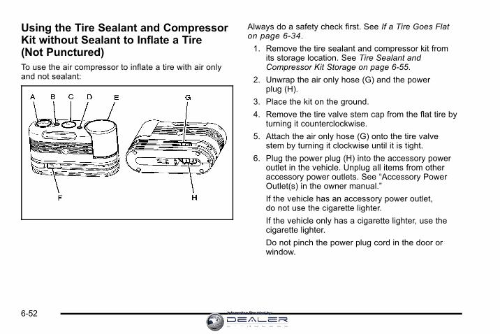
Using the Tire Sealant and CompressorKit without Sealant to Inflate a Tire(Not Punctured)To use the air compressor to inflate a tire with air onlyand not sealant:
Always do a safety check first. See If a Tire Goes Flaton page 6‑34.
1. Remove the tire sealant and compressor kit fromits storage location. See Tire Sealant andCompressor Kit Storage on page 6‑55.
2. Unwrap the air only hose (G) and the powerplug (H).
3. Place the kit on the ground.
4. Remove the tire valve stem cap from the flat tire byturning it counterclockwise.
5. Attach the air only hose (G) onto the tire valvestem by turning it clockwise until it is tight.
6. Plug the power plug (H) into the accessory poweroutlet in the vehicle. Unplug all items from otheraccessory power outlets. See “Accessory PowerOutlet(s) in the owner manual.”
If the vehicle has an accessory power outlet,do not use the cigarette lighter.
If the vehicle only has a cigarette lighter, use thecigarette lighter.
Do not pinch the power plug cord in the door orwindow.
6-52 Information Provided by:

7. Start the vehicle. The vehicle must be runningwhile using the air compressor.
8. Turn the selector switch (A) clockwise to theAir Only position.
9. Press the on/off (B) button to turn thecompressor on.
The compressor will inflate the tire with air only.
10. Inflate the tire to the recommended inflationpressure using the pressure gage (C).The recommended inflation pressure can befound on the Tire and Loading Information label.See Inflation - Tire Pressure on page 6‑28.
The pressure gage (C) may read higher than theactual tire pressure while the compressor is on.Turn the compressor off to get an accuratereading. The compressor may be turned on/offuntil the correct pressure is reached.
If you inflate the tire higher than the recommendedpressure you can adjust the excess pressure bypressing the pressure deflation button (D) until theproper pressure reading is reached. This option isonly functional when using the air only hose (G).
11. Press the on/off button (B) to turn the tire sealantand compressor kit off.
Be careful while handling the tire sealant andcompressor kit as it could be warm after usage.
12. Unplug the power plug (H) from the accessorypower outlet in the vehicle.
13. Disconnect the air only hose (G) from the tire valvestem, by turning it counterclockwise, and replacethe tire valve stem cap.
14. Replace the air only hose (G) and the powerplug (H) and cord back in its original location.
15. Place the equipment in the original storage locationin the vehicle.
6-53Information Provided by:

The tire sealant and compressor kit has an accessoryadapter located in a compartment on the bottom of itshousing that may be used to inflate air mattresses,balls, etc.
Removal and Installation of theSealant CanisterTo remove the sealant canister:
1. Unwrap the sealant hose.
2. Press the canisterrelease button.
3. Pull up and remove the canister.
4. Replace with a new canister which is availablefrom your dealer/retailer.
5. Push the new canister into place.
6-54 Information Provided by:

Tire Sealant and Compressor KitStorageThe tire sealant and compressor kit is located under thestorage tray on the driver side trim panel (over the rearwheelhouse).
To access the tire sealant and compressor kit:
1. Remove the tray by pulling up on the fingerdepression to access the tire sealant andcompressor kit .
2. Locate the tire sealant and compressor kit .
3. Remove the sealant and compressor kit withouta selector switch by pulling the velcro strip upand back.
6-55Information Provided by:

Remove the sealant and compressor kit with aselector switch by lifting upward on the yellow tabto release the unit.
4. Remove the sealant and compressor kit from itsplastic tray assembly.
To store the tire sealant and compressor kit, reverse thesteps.
Appearance Care
Vehicle Care/Appearance MaterialsWhen scraping the windshield glass to remove ice andsnow, stay clear of the hybrid decal.
To have the hybrid decals removed from the vehicle,please see your dealer/retailer.
6-56 Information Provided by:

Capacities and Specifications
ApplicationCapacities
English Metric
Automatic Transmission* (Pan Removal and Filter Replacement) 11.5 qt 10.9 L
Cooling System
Drive Motor Generator Control Module Cooling System 2.9 qt 2.7 L
6.0L V8 Engine Cooling System 18.3 qt 17.3 L
Fuel Tank 24.5 gal 92.7 L
*Transmission fluid capacity is approximate. See Automatic Transmission Fluid on page 6 ‑5 for information onchecking fluid level.
All capacities are approximate. Recheck fluid level after filling.
Engine SpecificationsEngine VIN Code Transmission Spark Plug Gap
6.0LV8 J Automatic 0.040 in (1.02 mm)
6-57Information Provided by:

2 NOTES
6-58 Information Provided by:
Section 7 Maintenance Schedule
Maintenance Schedule . . . . . . . . . . . . . . . . . . . . . . . . . . . . 7-2At Least Once a Year . . . . . . . . . . . . . . . . . . . . . . . . . . . 7-2Recommended Fluids and Lubricants . . . . . . . . . . . 7-2Engine Drive Belt Routing . . . . . . . . . . . . . . . . . . . . . . . 7-2
7-1Information Provided by:

Maintenance Schedule
At Least Once a Year
Tire Sealant and Compressor KitCheck the sealant expiration date printed on theinstruction label of the Tire Sealant and Compressor Kitat least once a year. See your dealer/retailer for areplacement canister.
Recommended Fluids andLubricantsFluids identified below are specific to the hybrid vehicleand can be obtained from your dealer/retailer. See theowner manual for the other fluids and lubricantsrecommended for the vehicle.
Usage Fluid/Lubricant
Drive Motor/Generator
Control Module(DMCM) Cooling
System
Always use the pre-mixed50/50 mixture of de‐ionized waterand DEX-COOL® (silicate-free)coolant available at your dealer/retailer. See Drive Motor/GeneratorControl Module (DMCM) CoolingSystem on page 6‑9.
Engine Drive Belt Routing
7-2 Information Provided by:

AAlternating CurrentPower Outlet . . . . . . . . . . . . . . . . . . . . . . . . . . . . . . . . . . . . . . 3-2
Antilock Brake System (ABS)Warning Light . . . . . . . . . . . . . . . . . . . . . . . . . . . . . . . . . . . . . . 4-7
Audio System(s)Navigation/Radio System . . . . . . . . . . . . . . . . . . . . . . . . . 4-14
Automatic Transmission, Fluid . . . . . . . . . . . . . . . . . . . . . . .6-5
BBattery . . . . . . . . . . . . . . . . . . . . . . . . . . . . . . . . . . . . . . . . . . . . 6-16Belt Routing, Engine . . . . . . . . . . . . . . . . . . . . . . . . . . . . . . . . .7-2Brakes . . . . . . . . . . . . . . . . . . . . . . . . . . . . . . . . . . . . . . . . . . . . . 6-13Regenerative Braking . . . . . . . . . . . . . . . . . . . . . . . . . . . . . 3-18System Warning Light . . . . . . . . . . . . . . . . . . . . . . . . . . . . . 4-6
Bulb ReplacementTaillamps, Turn Signal, Stoplamps andBack-up Lamps . . . . . . . . . . . . . . . . . . . . . . . . . . . . . . . . . 6-24
CCanadian Owners . . . . . . . . . . . . . . . . . . . . . . . . . . . . . . . . . . . . . iiCapacities and Specifications . . . . . . . . . . . . . . . . . . . . . . 6-57Chains, Tire . . . . . . . . . . . . . . . . . . . . . . . . . . . . . . . . . . . . . . . 6-34Charging System Light . . . . . . . . . . . . . . . . . . . . . . . . . . . . . .4-4Climate Controls . . . . . . . . . . . . . . . . . . . . . . . . . . . . . . . . . . . . .4-2Compressor Kit, Tire Sealant . . . . . . . . . . . . . . . . 6-35, 6-45CoolantEngine Temperature Gage . . . . . . . . . . . . . . . . . . . . . . . . . 4-8
Coolant Surge Tank Pressure Cap, (DMCM) . . . . . . . . .6-8Cooling System, (DMCM) . . . . . . . . . . . . . . . . . . . . . . . . . . . .6-9
DDrive Motor/Generator Control Module (DMCM)Coolant Surge Tank Pressure Cap . . . . . . . . . . . . . . . . .6-8
Drive Motor/Generator Control Module (DMCM)Cooling System . . . . . . . . . . . . . . . . . . . . . . . . . . . . . . . . . . . .6-9
Driver Information Center (DIC) . . . . . . . . . . . . . . . . . . . . 4-12Warnings and Messages . . . . . . . . . . . . . . . . . . . . . . . . . 4-12
i - 1Information Provided by:

EEngineCompartment Overview . . . . . . . . . . . . . . . . . . . . . . . . . . . . 6-4Coolant Temperature Gage . . . . . . . . . . . . . . . . . . . . . . . . 4-8Drive Belt Routing . . . . . . . . . . . . . . . . . . . . . . . . . . . . . . . . . 7-2
Engine Coolant Heater . . . . . . . . . . . . . . . . . . . . . . . . . . . . 3-17
FFlat Tire . . . . . . . . . . . . . . . . . . . . . . . . . . . . . . . . . . . . . . . . . . . 6-34FluidPower Steering . . . . . . . . . . . . . . . . . . . . . . . . . . . . . . . . . . . 6-13
Four-Wheel Drive . . . . . . . . . . . . . . . . . . . . . . . . . . . . . . . . . . 3-10FuelGage . . . . . . . . . . . . . . . . . . . . . . . . . . . . . . . . . . . . . . . . . . . . . 4-11
Fuel Economy Gage . . . . . . . . . . . . . . . . . . . . . . . . . . . . . . . . .4-5
GGagesEngine Coolant Temperature . . . . . . . . . . . . . . . . . . . . . . 4-8Fuel . . . . . . . . . . . . . . . . . . . . . . . . . . . . . . . . . . . . . . . . . . . . . . 4-11Fuel Economy . . . . . . . . . . . . . . . . . . . . . . . . . . . . . . . . . . . . . 4-5Oil Pressure . . . . . . . . . . . . . . . . . . . . . . . . . . . . . . . . . . . . . . . 4-8Tachometer . . . . . . . . . . . . . . . . . . . . . . . . . . . . . . . . . . . . . . . . 4-4
HHigh Voltage Devices and Wiring . . . . . . . . . . . . . . . . . . . .6-3
IInflation - Tire Pressure . . . . . . . . . . . . . . . . . . . . . . . . . . . . 6-28Instrument Panel Cluster . . . . . . . . . . . . . . . . . . . . . . . . . . . .4-3Introduction . . . . . . . . . . . . . . . . . . . . . . . . . . . . . . . . . . . . . . . . . . . iii
JJump Starting . . . . . . . . . . . . . . . . . . . . . . . . . . . . . . . . . . . . . . 6-18
LLightsAntilock Brake System (ABS) Warning . . . . . . . . . . . . . 4-7Brake System Warning . . . . . . . . . . . . . . . . . . . . . . . . . . . . 4-6Charging System . . . . . . . . . . . . . . . . . . . . . . . . . . . . . . . . . . 4-4Oil Pressure . . . . . . . . . . . . . . . . . . . . . . . . . . . . . . . . . . . . . . 4-10StabiliTrak® Indicator . . . . . . . . . . . . . . . . . . . . . . . . . . . . . . 4-7
LumbarManual Controls . . . . . . . . . . . . . . . . . . . . . . . . . . . . . . . . . . . 2-2
i - 2 Information Provided by:
MMaintenance ScheduleAt Least Once a Year . . . . . . . . . . . . . . . . . . . . . . . . . . . . . . 7-2Recommended Fluids and Lubricants . . . . . . . . . . . . . 7-2
Manual Lumbar Controls . . . . . . . . . . . . . . . . . . . . . . . . . . . . .2-2Manual Reclining Seatbacks . . . . . . . . . . . . . . . . . . . . . . . . .2-3Manual, How to Use . . . . . . . . . . . . . . . . . . . . . . . . . . . . . . . . . . iii
NNavigation/Radio System . . . . . . . . . . . . . . . . . . . . . . . . . . 4-14
OOilPressure Light . . . . . . . . . . . . . . . . . . . . . . . . . . . . . . . . . . . . 4-10
Oil Pressure Gage . . . . . . . . . . . . . . . . . . . . . . . . . . . . . . . . . . .4-8Owners, Canadian . . . . . . . . . . . . . . . . . . . . . . . . . . . . . . . . . . . . . ii
PPowerSeat . . . . . . . . . . . . . . . . . . . . . . . . . . . . . . . . . . . . . . . . . . . . . . . 2-2Steering Fluid . . . . . . . . . . . . . . . . . . . . . . . . . . . . . . . . . . . . . 6-13
Power Outlet Alternating Current . . . . . . . . . . . . . . . . . . . .3-2
RRadiosNavigation/Radio System . . . . . . . . . . . . . . . . . . . . . . . . . 4-14
Reclining Seatbacks, Manual . . . . . . . . . . . . . . . . . . . . . . . .2-3Recommended Fluids and Lubricants . . . . . . . . . . . . . . .7-2Regenerative Braking . . . . . . . . . . . . . . . . . . . . . . . . . . . . . . 3-18Restraint System CheckReplacing Restraint System Parts After a Crash . . . 2-3
Running the Vehicle While Parked . . . . . . . . . . . . . . . . . 3-18
SSealant Kit, Tire . . . . . . . . . . . . . . . . . . . . . . . . . . . . . 6-35, 6-45SeatsManual Lumbar . . . . . . . . . . . . . . . . . . . . . . . . . . . . . . . . . . . . 2-2Manual Reclining Seatbacks . . . . . . . . . . . . . . . . . . . . . . . 2-3Power Seats . . . . . . . . . . . . . . . . . . . . . . . . . . . . . . . . . . . . . . . 2-2
ServiceDoing Your Own Work . . . . . . . . . . . . . . . . . . . . . . . . . . . . . 6-2
Specifications and Capacities . . . . . . . . . . . . . . . . . . . . . . 6-57StabiliTrak® Indicator Light . . . . . . . . . . . . . . . . . . . . . . . . . .4-7Starting Your Vehicle . . . . . . . . . . . . . . . . . . . . . . . . . . . . . . . .3-3SteeringFluid, Power . . . . . . . . . . . . . . . . . . . . . . . . . . . . . . . . . . . . . . 6-13
Storing the Tire Sealant and Compressor Kit . . . . . . 6-55
i - 3Information Provided by:

TTachometer . . . . . . . . . . . . . . . . . . . . . . . . . . . . . . . . . . . . . . . . . .4-4TaillampsTurn Signal, Stoplamps and Back-up Lamps . . . . . . 6-24
TiresChains . . . . . . . . . . . . . . . . . . . . . . . . . . . . . . . . . . . . . . . . . . . . 6-34If a Tire Goes Flat . . . . . . . . . . . . . . . . . . . . . . . . . . . . . . . . 6-34Inflation, Pressure . . . . . . . . . . . . . . . . . . . . . . . . . . . . . . . . 6-28Inspection and Rotation . . . . . . . . . . . . . . . . . . . . . . . . . . 6-33Sealant and Compressor Kit . . . . . . . . . . 6-35, 6-45, 6-55
TowingTowing Your Vehicle . . . . . . . . . . . . . . . . . . . . . . . . . . . . . . . 5-2Trailer . . . . . . . . . . . . . . . . . . . . . . . . . . . . . . . . . . . . . . . . . . . . . 5-8
Transmission, Automatic Fluid . . . . . . . . . . . . . . . . . . . . . . .6-5
VVehicleRunning While Parked . . . . . . . . . . . . . . . . . . . . . . . . . . . . 3-18
Voltage Devices, and Wiring . . . . . . . . . . . . . . . . . . . . . . . . .6-3
WWiring, High Voltage Devices . . . . . . . . . . . . . . . . . . . . . . . .6-3
i - 4 Information Provided by: