2010 doe vehicle technologies program review€¦ · · 2010-07-092010 doe vehicle technologies ....
TRANSCRIPT
DOE AMR 20101
P.I. Marina YakovlevaCo-P.I. Dr. Yuan Gao
FMCJune 8th, 2010
Project ID # ES011
2010 DOE Vehicle Technologies Program Review
Stabilized Lithium Metal Powder, Enabling Material and Revolutionary Technology for High
Energy Li-ion Batteries
This presentation does not contain any proprietary, confidential, or otherwise restricted information
DOE AMR 20102
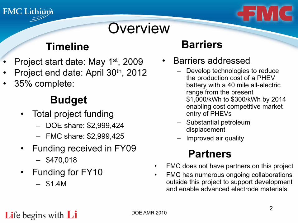
• Project start date: May 1st, 2009• Project end date: April 30th, 2012• 35% complete:
• Barriers addressed– Develop technologies to reduce
the production cost of a PHEV battery with a 40 mile all-electric range from the present $1,000/kWh to $300/kWh by 2014 enabling cost competitive market entry of PHEVs
– Substantial petroleum displacement
– Improved air quality
• Total project funding– DOE share: $2,999,424– FMC share: $2,999,425
• Funding received in FY09– $470,018
• Funding for FY10– $1.4M
Timeline
Budget
Barriers
• FMC does not have partners on this project• FMC has numerous ongoing collaborations
outside this project to support development and enable advanced electrode materials
Partners
Overview
DOE AMR 20103
Relevance
Lithium chemistry provides the best chance for the highest energy density batteries
Recent developments in Li-ion battery technology have advanced its application into the area of large format batteries, for example HEV/PHEV/EV automotive markets
This, in turn, has heightened the need not only for research on higher capacity, safer and less expensive battery materials but also for the development of improved scalable manufacturing processes for the production of battery materials and components to support high volume production of Li-ion batteries

DOE AMR 20104
In the current lithium-ion battery design, the lithium, which is the one that carries the energy, comes in the form of lithium metal oxide in cathode, hence limiting the choice of electrode active materials and the energy density that is possible with lithium chemistry. It has long been desired for lithium to come in the elemental form especially in the powder form to prelithiate the Li-ion anode host material for the most efficient utilization and fastest diffusion, but it was not possible because of lithium’s high reactivity until the advancement of technology brought the stabilized lithium metal powder (SLMP®) to light.
Achieving the DOE technical and cost targets for the PHEV/EV batteries will require development and use of new electrode materials. SLMP Technology provides an independent source of lithium for Li-ion systems, breaks the current limitation that all lithium has to come from the cathode and, thus, allows the use of non-lithium providing cathode materials with potentially larger capacities. These new cathode materials are expected to be more overcharge tolerant and could be used with high capacity advanced anodes having high irreversible capacities.
Relevance
DOE AMR 20105
The objective of this project is to expedite the development of cost-effective manufacturing processes for SLMP to support high volume production of Li-ion batteries and to make available commercial quantities of SLMP, the independent source of lithium that will enable higher energy, safer, environmentally friendlier and lower cost lithium batteries
Objective 1: Develop a process and prototype unit for the commercial production of dry stabilized lithium metal powder (SLMP)
Objective 2: Develop a process and design a commercial unit to scale-up the production of SLMP dispersion
Objective 3: Explore the use of alternative pilot scale unit to produce dry SLMP powder directly from battery-quality lithium metal (cost reduction)
Objective 4: Integrate SLMP Technology into the Li-ion cell for PHEV application
ObjectivesFY09-FY12
DOE AMR 2010
Year 1 Objectives FY09-FY10
Objective 1Develop a process and prototype unit for the commercial production of dry stabilized lithium metal powder (SLMP)
Objective 4/1Integrate SLMP Technology into the MCMB/LiMn2O4system
6
DOE AMR 20107
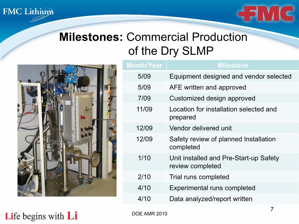
Milestones: Commercial Production of the Dry SLMP
Month/Year Milestone5/09 Equipment designed and vendor selected5/09 AFE written and approved7/09 Customized design approved 11/09 Location for installation selected and
prepared12/09 Vendor delivered unit12/09 Safety review of planned Installation
completed1/10 Unit installed and Pre-Start-up Safety
review completed2/10 Trial runs completed4/10 Experimental runs completed4/10 Data analyzed/report written

DOE AMR 20108
Milestones: Integrate SLMP Technology into the MCMB/LiMn2O4 system
Month/Year Milestone
3/09 Procured electrode materials
6/09 Conducted half cell evaluation
7/09 Selected vendors
10/09 Evaluated selected materials in the full pouch cell design
11/09 Developed specifications for the matched cathode/anode pair
12/09 Received and evaluated the electrodes from the vendor
3/10 Built baseline pouch cells
3/10 Built SLMP-incorporated pouch cells
4/10 Summarized and presented results at the ECS meetingThe Gaston Gazette, by John
Clark, 3/7/2010

DOE AMR 2010
Currently, there is not one cathode/anode system that can satisfy safety, cost and performance requirements for the EV application
As the initial step in SLMP Technology introduction, industry can use commercially available LiMn2O4 or LiFePO4, for example, that are the proven safer and cheaper lithium providing cathodes vs. LiCoO2 or LiNiO2. Currently, systems using these cathodes do not take full advantage of the SLMP Technology
Unfortunately, these cathodes alone are inferior to the energy density of conventional LiCoO2 cathodes and, when paired with advanced anode materials, such as silicon composite material, the resulting cell will still not meet the energy density requirements, unless SLMP®
Technology is used to compensate for the irreversible capacity in the anode and thus improve efficiency of the cathode utilization
9
Approach/Strategy
DOE AMR 2010
The proposed battery system works by adding lithium to the anode of a cell in the form of SLMP. If the anode material is carbon, lithium will intercalate into the carbon to form LiC6 on addition of the electrolyte just as in a standard lithium ion cell. The system is therefore still a Li-ion system. However, the cathode no longer needs to contain lithium and the possibility of using non-lithiated cathode materials based on vanadium oxides, manganese oxides or metal fluorides now becomes feasible.
Performance & Cost• Lower cost through the use of more efficient and less costly cathode materials and the elimination of
cobalt from the system• Greater performance through the ability to compensate for inefficiencies in, hitherto, unsuitable anode
materials with high irreversible capacity• Longer calendar life: SLMP serves as a “getter” of moisture and acidic species
Safety• Improved safety on overcharge. Since the lithium is introduced into the anode, the cell is charged when it
is manufactured. This system, that has non-lithium providing cathode, cannot be overcharged. Safety issues are transferred from the end-user to the factory where they can be fully controlled.
• Non-lithiated cathode materials are inherently more stable than the LiCoO2 used in the majority of Li-ion cells today
• The cell is a Li-ion cell. There is no metallic lithium in the cell after the electrolyte is added during cell assembly and the cell has completed its formation cycle, thereby avoiding the risks associated with ‘conventional’ lithium metal cells.
10
Approach/Strategy
DOE AMR 2010
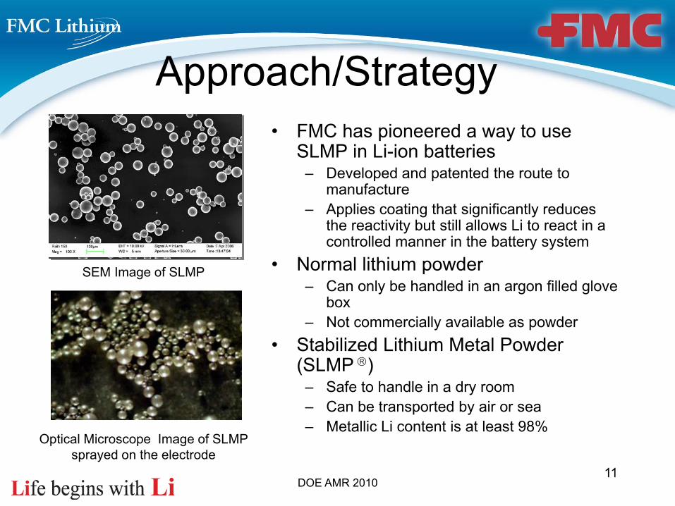
• FMC has pioneered a way to use SLMP in Li-ion batteries
– Developed and patented the route to manufacture
– Applies coating that significantly reduces the reactivity but still allows Li to react in a controlled manner in the battery system
• Normal lithium powder– Can only be handled in an argon filled glove
box– Not commercially available as powder
• Stabilized Lithium Metal Powder (SLMP )
– Safe to handle in a dry room– Can be transported by air or sea– Metallic Li content is at least 98%
SEM Image of SLMP
Optical Microscope Image of SLMP sprayed on the electrode
Approach/Strategy
11

DOE AMR 201012
Technical Accomplishments and Progress (1)All tasks are completed to meet Objective 1 technical targets. The major
challenge was to mitigate 2 months delay in equipment fabrication
• Significant effort was made to identify and select vendors capable of fabricating equipment that meets technical and safety requirements*
• Design and drawings were carefully reviewed and key modifications applied• Factory Acceptance Testing revealed few items that required correction• Unit was delivered on December 11th, 2009• A P&ID (piping and instrumentation drawing) was created to assist the mechanical
installation• Site was prepared for the installation and all safety reviews completed • A custom vessel to collect the dry SLMP powder as it is discharged from this unit has
been designed• Upon successful completion of the trial runs, full study was initiated and implemented• Results are reported in the 1Q10 Progress report
*Lithium metal is a flammable solid that reacts violently with moisture to create flammable hydrogen and corrosive lithium hydroxides. Molten metal is especially reactive and given that the auto ignition point is essentially the same as the melting point, can spontaneously ignite in air. The reactivity of lithium increases with temperature and surface area. Therefore, molten metals ordispersions require special care in handling.

DOE AMR 201013
All tasks are completed to meet Objective 4/1 technical targets.
Technical Accomplishments and Progress (2)
Cycle number
0 10 20 30 40 50 60 70
Dis
char
ge C
apac
ity (m
Ah/
g)
20
40
60
80
100
120
T-6050T-7051L-410Y-800Y-900
FIGURE 1. Comparison of the cycleability tests results for the LiMn2O4 materials at room temperature
Cycle Number0 10 20 30 40 50 60 70
Dis
char
ge C
apac
ity (m
Ah/g
)
20
40
60
80
100
120
T-6050T-7051L-410Y-800Y-900
FIGURE 2. Comparison of the cycleability test results for the LiMn2O4 materials at 60oC
• The major challenge was to procure electrode materials for this study• Material from Supplier T was selected and will be used as a cathode material
for all electrochemical testing• Results for half cells are presented below
Capacity (mAh/g)0 20 40 60 80 100 120
Pot
entia
l vs.
Li (
V)
3.0
3.5
4.0
20C
10C
5C
2CC C/2
C/5
C/10
T-7051
FIGURE 3. Rate capability of LiMn2O4 from supplier T
The cell test protocol : constant current charge at 0.5 mA/cm2 to 4.3 V followed by 4 hours constant voltage charge at 4.3 V and constant current discharge at 0.5 mA/cm2 to 3.0 V.
Electrode composition: LiMn2O4 (90%) + Super P carbon black (5%) + Kynar 761 PVdF (5%). We used Ferro 1M LiPF6 /EC+DEC (1:1) electrolyte.

DOE AMR 2010
Technical Accomplishments and Progress (3)
• MCMB 25-28 was selected as a baseline anode for the demonstration of the SLMP Technology
• The slurry containing MCMB has the following formulation: 90% MCMB, 5% PVdF, 5% Conductive Carbon (Super P)
• The cell testing protocol: – Discharge: constant current at 0.1 mA/cm2
to 0.01 V, constant voltage at 0.01 V until the current reaches 0.01 mA/cm2
– Charge: constant current at 0.1 mA/cm2
to 1.5 V
The irreversible capacity for this material was calculated to be ~9%
14
MCMB-25-28 Baseline Cell
Capacity (mAh/g)0 100 200 300 400
Vol
tage
(V)
0.0
0.5
1.0
1.5
2.0
2.5
3.0
Cell 1Cell 2Cell 3
Figure. Voltage profiles for Li/MCMB 25-28 baseline cells
DOE AMR 201015
Capacity (%) Based on First Charge0 20 40 60 80 100
Volta
ge (V
)
0.0
0.5
1.0
1.5
2.0
2.5
3.0
3.5
4.0
4.5
Baseline First Cycle DischargeGraphite/LiMn2O4Cell
First Cycle DischargeSLMP+Graphite/LiMn2O4Cell
Improvement
Cycle number (n)0 10 20 30 40 50 60
Nor
mal
ized
Cap
acity
(%)
0
20
40
60
80
100
120
Baseline cell: chargeBaseline cell: dischargeSLMP treated: chargeSLMP treated: discharge
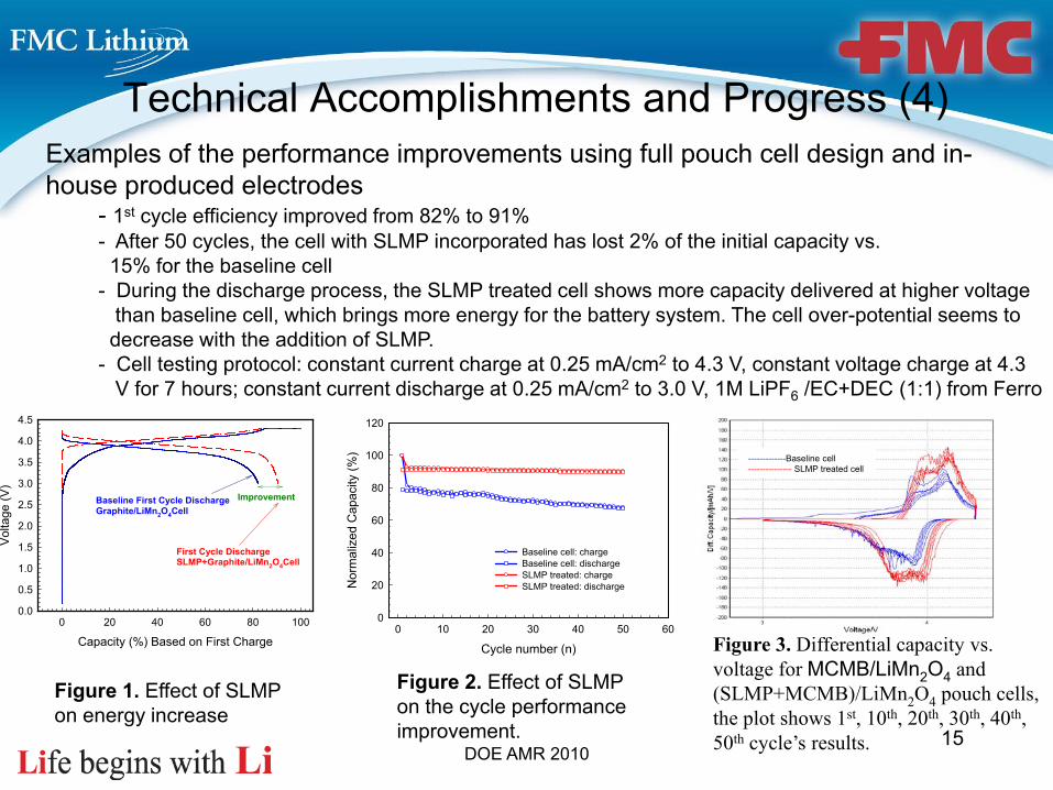
Figure 1. Effect of SLMP on energy increase
Figure 2. Effect of SLMP on the cycle performance improvement.
Figure 3. Differential capacity vs. voltage for MCMB/LiMn2O4 and (SLMP+MCMB)/LiMn2O4 pouch cells, the plot shows 1st, 10th, 20th, 30th, 40th, 50th cycle’s results.
Technical Accomplishments and Progress (4)Examples of the performance improvements using full pouch cell design and in-house produced electrodes
- 1st cycle efficiency improved from 82% to 91%- After 50 cycles, the cell with SLMP incorporated has lost 2% of the initial capacity vs.15% for the baseline cell
- During the discharge process, the SLMP treated cell shows more capacity delivered at higher voltagethan baseline cell, which brings more energy for the battery system. The cell over-potential seems todecrease with the addition of SLMP.
- Cell testing protocol: constant current charge at 0.25 mA/cm2 to 4.3 V, constant voltage charge at 4.3V for 7 hours; constant current discharge at 0.25 mA/cm2 to 3.0 V, 1M LiPF6 /EC+DEC (1:1) from Ferro
-------------Baseline cell--------------- SLMP treated cell
DOE AMR 201016
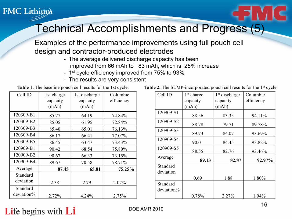
Cell ID 1st charge capacity (mAh)
1st discharge capacity (mAh)
Columbic efficiency
120309-B1 85.77 64.19 74.84%120309-B2 85.05 61.95 72.84%120309-B3 85.40 65.01 76.13%120309-B4 86.17 66.41 77.07%120309-B5 86.45 63.47 73.43%120909-B1 90.42 68.54 75.80%120909-B2 90.67 66.33 73.15%120909-B4 89.67 70.58 78.71%
Average 87.45 65.81 75.25%Standard deviation 2.38 2.79 2.07%Standard
deviation% 2.72% 4.24% 2.75%
Table 1. The baseline pouch cell results for the 1st cycle.Cell ID 1st charge
capacity (mAh)
1st discharge capacity (mAh)
Columbic efficiency
120909-S1 88.56 83.35 94.11%120909-S2 88.78 79.71 89.78%120909-S3 89.73 84.07 93.69%120909-S4 90.01 84.45 93.82%120909-S5 88.55 82.76 93.46%Average 89.13 82.87 92.97%Standard deviation
0.69 1.88 1.80%Standard deviation%
0.78% 2.27% 1.94%
Table 2. The SLMP-incorporated pouch cell results for the 1st cycle.
Technical Accomplishments and Progress (5)Examples of the performance improvements using full pouch cell design and contractor-produced electrodes
- The average delivered discharge capacity has beenimproved from 66 mAh to 83 mAh, which is 25% increase
- 1st cycle efficiency improved from 75% to 93%- The results are very consistent
DOE AMR 201017
Collaboration and Coordination with Other Institutions
The objective of this project is to expedite development of cost-effective manufacturing processes for SLMP to support high volume production of Li-ion Batteries. This Program is covered under Special Protected Data Statutes (10 CFR 600), provision entitled Rights in Data
FMC has extensive program outside of this project focused on• Educating industry in safe handling of SLMP (http://fmclithium.com)• Collaborating with major research institutes and universities
– Development of non-lithium providing cathodes– Enabling advanced anode materials, such as Si/Sn composites and hard carbons– Development of the application technologies
• Engaging in joint development agreements with major Li-ion battery manufacturers
• Providing technical support, including on-site support• Engaging with advanced battery equipment manufacturers: requirements for
SLMP application technology development are in line with the advanced manufacturing technologies targeting increase in line yield
Limited examples of such activities are presented in the supplemental slides
DOE AMR 201018
Activities for the Year 2 of this Program will be focused on executing all the tasks as described for the Objectives #2 and #4/2 in our Program and procuring the equipment to support Objective #3 technical targets
• Objective 2: Develop a process and design commercial unit to scale-up the production ofSLMP dispersion in mineral oil. To accomplish this objective we will use our pilot expertise and conduct full factorial design of experiment to establish the operating parameters that will allow us to produce stabilized lithium metal dispersion meeting the requirements of the battery customers.
• Objective 3: Explore the use of pilot scale alternative unit to produce dry SLMP powder directly from battery quality lithium metal. If successful, this will allow streamlining the production process and offering significant cost benefits.
• Objective 4/2: Integrate SLMP Technology into the Li-ion cell using Hard carbon/LiMn2O4 system. Procure and screen electrode materials to support Objective 4/3.
Proposed Future Work

DOE AMR 201019
• Prototype unit for the commercial production of dry stabilized lithium metal powder was designed, fabricated, tested and used to conduct a design of experiments to determine the process parameters
• In spite of the significant delay in the equipment delivery schedule resulting from the fact that the equipment manufacturers were overwhelmed with orders related to the Prime and sub-recipients of Recovery Act awards, all tasks were completed on time
• Full pouch cell capability was developed
• The benefits of the SLMP Technology have been demonstrated on the electrochemical system MCMB/ LiMn2O4
Summary
DOE AMR 2010
Acknowledgement
Key Technical Contributors:• Brian Fitch• Yangxing Li• Terry Arnold• Scott Petit• Mike Barr• Prakash Palepu• Chris Woltermann
20

DOE AMR 2010
SLMP Technology Background
24

Anode Cathode
Metallic Li
MoS2 or TiS2
Graphite LiCoO2
Anode Cathode
anode cathode
Graphite containing SLMP
Non-Li providing compound
Technology based on SLMP ®
Combining the benefits of the past two systems
Li metal cellin the 1980s
Li-ion cellThe Concept
• Li provided by Li foil anode.• MoS2 and TiS2 are abundant materials.• Simple design.
Safety issues with the design:– Dendrites developed on the Li anode after repeated recharges internal short-circuit and spontaneous thermal runaway!– Safer Li-ion technology emerged, and replaced thisdesign
• Li provided by LiCoO2 cathode• Li stays in graphite when fully charged. No dendrite formation on recharge because it is energetically favorable for Li to stay inside of graphite (host material) than on surface.
Issues– Current technology reaches maturity.– Cobalt expensive and price volatile.– High safety management required (redundant overcharge protection): additional Li coming out of Li0.4CoO2makes CoO2 unstable and Li metal plating on graphite – both unsafe conditions.– Choice of cathode limited.
Graphite + LiCoO2totally discharged.
LiC6 + Li0.4CoO2
totally charged.
SLMP™ (stabilized lithium metal powder) provides an independent source of lithium into the Li-ion system, enabling many possibilities for energy and performance enhancement.
25
DOE AMR 2010
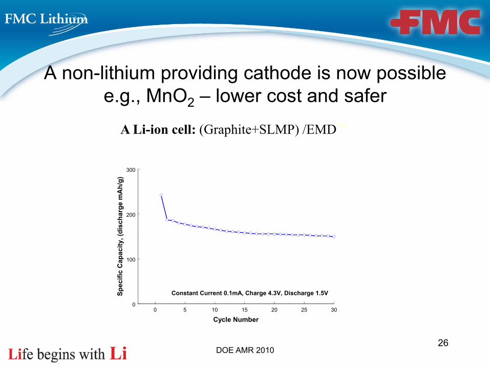
A Li-ion cell: (Graphite+SLMP) /EMD™
A non-lithium providing cathode is now possible e.g., MnO2 – lower cost and safer
26
0 5 10 15 20 25 30
Cycle Number
0
100
200
300
Spec
ific
Cap
acity
, (di
scha
rge
mA
h/g)
Constant Current 0.1mA, Charge 4.3V, Discharge 1.5V
DOE AMR 2010
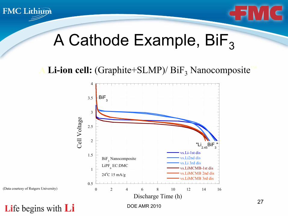
A Li-ion cell: (Graphite+SLMP)/ BiF3 Nanocomposite™
A Cathode Example, BiF3
RUTGERS THE STATE UNIVERSITY OF NEW JERSEY
0.5
1
1.5
2
2.5
3
3.5
4
0 2 4 6 8 10 12 14 16
vs.Li-1st disvs.Li2nd disvs.Li 3rd disvs.LiMCMB-1st disvs.LiMCMB 2nd disvs.LiMCMB 3rd dis
Cel
l Vol
tage
Discharge Time (h)
BiF3 Nanocomposite
LiPF6 EC:DMC
24oC 15 mA/g
"Li2.45
BiF3"
BiF3
27
(Data courtesy of Rutgers University)
DOE AMR 2010
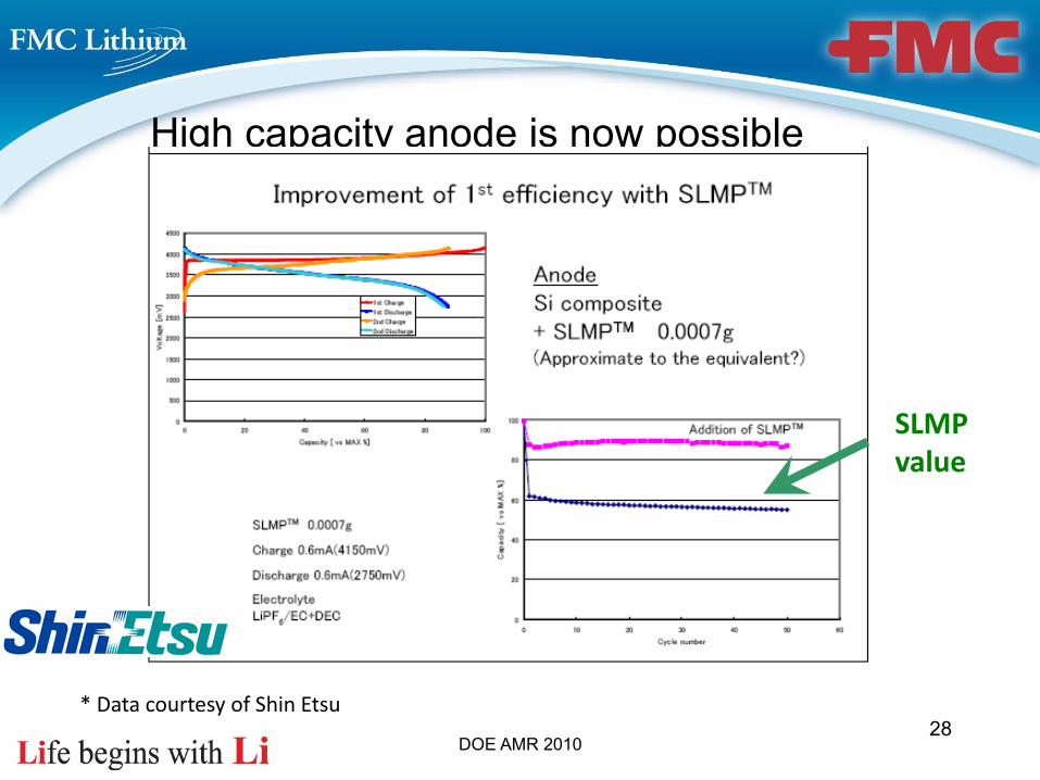
High capacity anode is now possible
* Data courtesy of Shin Etsu
SLMP value
28

DOE AMR 2010
Cell examples
First Cycle Efficiency Improvement in LiCoO2/Graphite System Using SLMP (Data courtesy of MaxPower Corporation)
Capacity0.0% 20.0% 40.0% 60.0% 80.0% 100.0%
Vol
tage
(V)
1.0
1.5
2.0
2.5
3.0
3.5
4.0
4.5
Baseline First Cycle DischargeGraphite/LiCoO2 Cell
First Cycle DischargeSLMP+Graphite/LiCoO2 Cell
Improvement
A Li-ion cell: LiCoO2/Graphite+SLMP ™
29
DOE AMR 2010
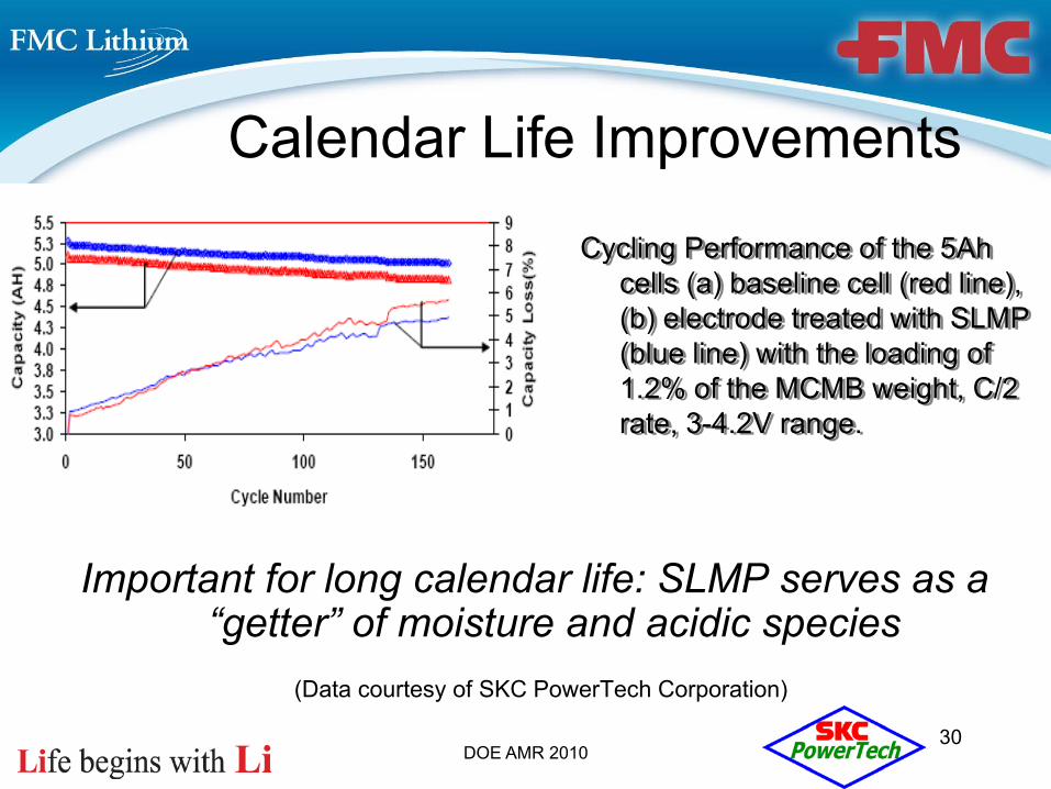
Calendar Life Improvements
Important for long calendar life: SLMP serves as a “getter” of moisture and acidic species
(Data courtesy of SKC PowerTech Corporation)
Cycling Performance of the 5Ah cells (a) baseline cell (red line), (b) electrode treated with SLMP (blue line) with the loading of 1.2% of the MCMB weight, C/2 rate, 3-4.2V range.
30
DOE AMR 201031
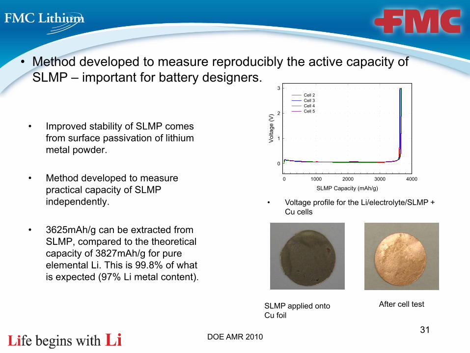
• Method developed to measure reproducibly the active capacity of SLMP – important for battery designers.
• Voltage profile for the Li/electrolyte/SLMP + Cu cells
• Improved stability of SLMP comes from surface passivation of lithium metal powder.
• Method developed to measure practical capacity of SLMP independently.
• 3625mAh/g can be extracted from SLMP, compared to the theoretical capacity of 3827mAh/g for pure elemental Li. This is 99.8% of what is expected (97% Li metal content).
SLMP Capacity (mAh/g)0 1000 2000 3000 4000
Vol
tage
(V)
0
1
2
3Cell 2Cell 3Cell 4Cell 5
SLMP applied onto Cu foil
After cell test
DOE AMR 2010
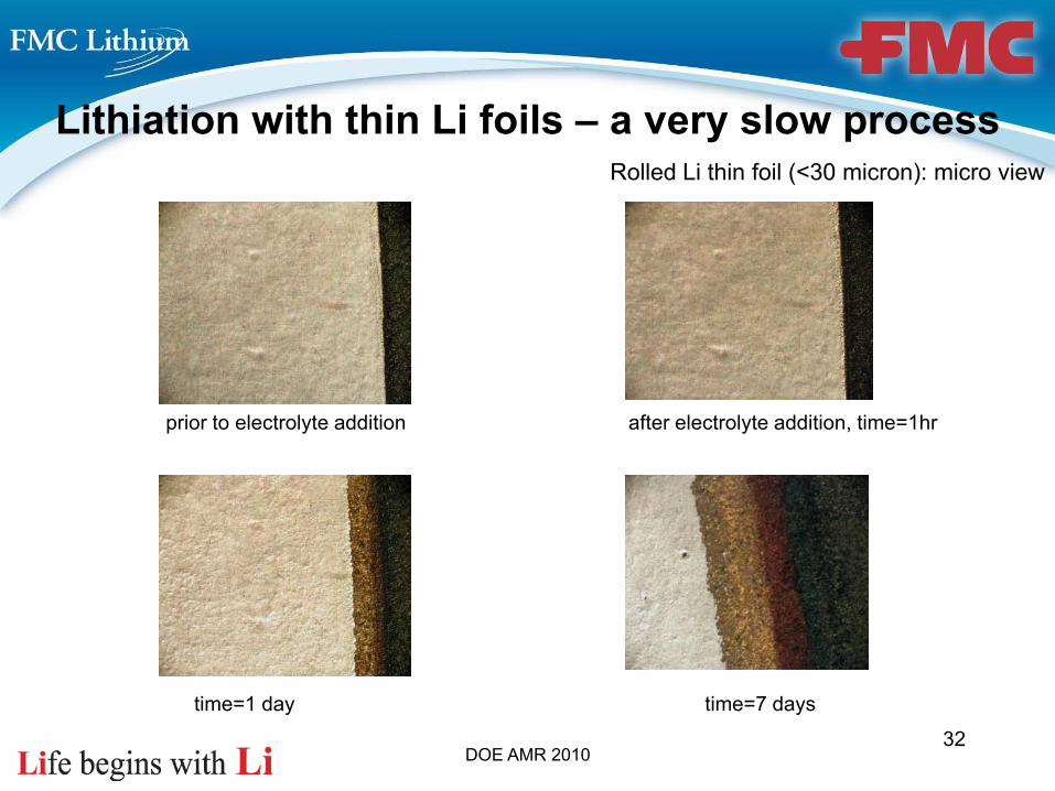
prior to electrolyte addition after electrolyte addition, time=1hr
time=1 day time=7 days
Rolled Li thin foil (<30 micron): micro view
Lithiation with thin Li foils – a very slow process
32
DOE AMR 2010
LiC
6
Li0.
5C6
Li0.
25C
6
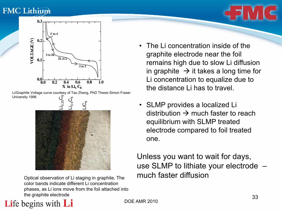
Optical observation of Li staging in graphite. The color bands indicate different Li concentration phases, as Li ions move from the foil attached into the graphite electrode
Li/Graphite Voltage curve courtesy of Tao Zheng, PhD Thesis Simon Fraser University 1996
• The Li concentration inside of the graphite electrode near the foil remains high due to slow Li diffusion in graphite it takes a long time for Li concentration to equalize due to the distance Li has to travel.
• SLMP provides a localized Li distribution much faster to reach equilibrium with SLMP treated electrode compared to foil treated one.
Unless you want to wait for days,use SLMP to lithiate your electrode –much faster diffusion
33

DOE AMR 2010
SLMP Introduction into the Cell
Two general methods to apply SLMP
• Surface application– Coat an SLMP suspension on the surface of pre-fabricated anode
sheet – no need to change the existing anode fabrication process
• Slurry application– Include SLMP in the slurry mix when the anode sheet is being
cast – no additional step but the slurry solvent needs to be compatible with lithium
34
DOE AMR 2010
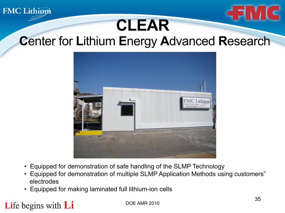
CLEARCenter for Lithium Energy Advanced Research
35
• Equipped for demonstration of safe handling of the SLMP Technology• Equipped for demonstration of multiple SLMP Application Methods using customers”
electrodes• Equipped for making laminated full lithium-ion cells

DOE AMR 2010
Spray Application Study-Demonstration (Anode)
36
DOE AMR 2010
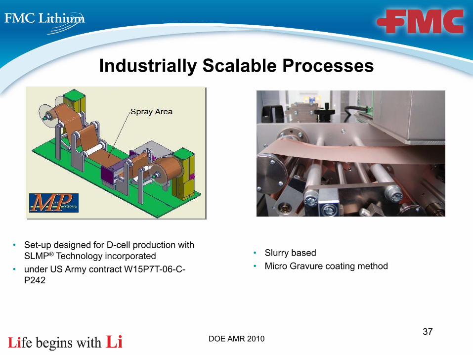
Industrially Scalable Processes
• Set-up designed for D-cell production with SLMP® Technology incorporated
• under US Army contract W15P7T-06-C-P242
• Slurry based• Micro Gravure coating method
37