2010 report on airborne observations required to support ... · 2010 report on airborne...
TRANSCRIPT


2010 Report on Airborne Observations required to support the next generation of NASA Earth science satellite missions
December 2010
National Aeronautics and Space Administration
Airborne Science Program
Susan SchoenungLongitude 122 West, Inc.
Matt FladelandNASA Ames Research Center


1 Executive Summary . . . . . . . . . . . . . . . . . . . . . . . . . . . . . . . . . . . . . . . . . 1
2 Introduction . . . . . . . . . . . . . . . . . . . . . . . . . . . . . . . . . . . . . . . . . . . . . . . 7
2 .1 Purpose . . . . . . . . . . . . . . . . . . . . . . . . . . . . . . . . . . . . . . . . . . . . . . . . . . 7
2 .2 NASA Flight Program . . . . . . . . . . . . . . . . . . . . . . . . . . . . . . . . . . . . . . . . 7
2 .3 NASA Airborne Science Program . . . . . . . . . . . . . . . . . . . . . . . . . . . . . . 8
2 .4 Approach . . . . . . . . . . . . . . . . . . . . . . . . . . . . . . . . . . . . . . . . . . . . . . . . 8
3 Foundational Missions . . . . . . . . . . . . . . . . . . . . . . . . . . . . . . . . . . . . . . . 11
3 .1 Glory . . . . . . . . . . . . . . . . . . . . . . . . . . . . . . . . . . . . . . . . . . . . . . . . . . . . 11
3 .2 Aquarius . . . . . . . . . . . . . . . . . . . . . . . . . . . . . . . . . . . . . . . . . . . . . . . . . 12
3 .3 NPOESS Preparatory Mission (NPP) . . . . . . . . . . . . . . . . . . . . . . . . . . . . 14
3 .4 Landsat Data Continuity Mission (LDCM) . . . . . . . . . . . . . . . . . . . . . . . . . 17
3 .5 OCO 2 . . . . . . . . . . . . . . . . . . . . . . . . . . . . . . . . . . . . . . . . . . . . . . . . . . . 18
3 .6 Global Precipitation Measurement (GPM) . . . . . . . . . . . . . . . . . . . . . . . . . 20
3 .7 SAGE-III . . . . . . . . . . . . . . . . . . . . . . . . . . . . . . . . . . . . . . . . . . . . . . . . . 22
3 .8 GRACE follow-on . . . . . . . . . . . . . . . . . . . . . . . . . . . . . . . . . . . . . . . . . . . 23
3 .9 Geostationary Operational Environmental Satellite (GOES-R) . . . . . . . . . . 25
4 Decadal Survey Tier I Missions . . . . . . . . . . . . . . . . . . . . . . . . . . . . . . . . 27
4 .1 Soil Moisture Active Passive (SMAP) . . . . . . . . . . . . . . . . . . . . . . . . . . . . . 27
4 .2 Ice, Cloud, and Land Elevation Satellite (ICESAT) II . . . . . . . . . . . . . . . . . 29
4 .3 Deformation Ecosystem Structure and Dynamics of Ice (DESDynI) . . . . . 31
4 .4 Climate Absolute Radiance and Refractivity Observatory (CLARREO) . . . 32
5 Decadal Survey Tier II Missions . . . . . . . . . . . . . . . . . . . . . . . . . . . . . . . . 35
5 .1 Surface Water Ocean Topography (SWOT) . . . . . . . . . . . . . . . . . . . . . . . 35
5 .2 Hyperspectral Infrared Imager (HyspIRI) . . . . . . . . . . . . . . . . . . . . . . . . . . 37
5 .3 Active Sensing of CO2 Emissions over Nights, Days, and Seasons (ASCENDS) . . . . . . . . . . . . . . . . . . . . . . . . . . . . . . . . . . . . . . . . . . . . . . . 38
5 .4 Geostationary Coastal and Air Pollution Events (GEO-CAPE) . . . . . . . . . . 39
5 .5 Aerosol - Cloud - Ecosystems (ACE) . . . . . . . . . . . . . . . . . . . . . . . . . . . . 40
TABLE OF CONTENTS
iii

6 Decadal Survey Tier III Mission Support . . . . . . . . . . . . . . . . . . . . . . . . . . 45
6 .1 Lidar Surface Topography (LiST) . . . . . . . . . . . . . . . . . . . . . . . . . . . . . . . 45
6 .2 Precision and All-weather Temperature and Humidity (PATH) . . . . . . . . . . 45
6 .3 Global Atmospheric Composition Mission (GACM) . . . . . . . . . . . . . . . . . 46
6 .4 Snow and Cold Land Processes (SCLP) . . . . . . . . . . . . . . . . . . . . . . . . . 46
6 .5 Gravity Recovery and Climate Experiment (GRACE)-II . . . . . . . . . . . . . . . 47
6 .6 Three Dimensional Tropospheric Winds from Space-based Lidar (3-D Winds) . . . . . . . . . . . . . . . . . . . . . . . . . . . . . . . . . . . . . . . . . . . . . . . 47
6 .7 TIER 3 Missions Summary . . . . . . . . . . . . . . . . . . . . . . . . . . . . . . . . . . . . 48
7 Synthesis and Recommendations . . . . . . . . . . . . . . . . . . . . . . . . . . . . . . 49
7 .1 Cross-cutting requirements and gaps . . . . . . . . . . . . . . . . . . . . . . . . . . . 49
7 .2 Recommendations . . . . . . . . . . . . . . . . . . . . . . . . . . . . . . . . . . . . . . . . . 49
8 References . . . . . . . . . . . . . . . . . . . . . . . . . . . . . . . . . . . . . . . . . . . . . . . 51
Appendix A: The Airborne Science Program . . . . . . . . . . . . . . . . . . . . . . 53
Appendix B: Decadal Survey Missions . . . . . . . . . . . . . . . . . . . . . . . . . . . 59
Appendix C: Acronyms . . . . . . . . . . . . . . . . . . . . . . . . . . . . . . . . . . . . . . 61
Appendix D: Program Executives and Scientists . . . . . . . . . . . . . . . . . . . 63
iv

1 EXECUTIVE SUMMARY
This report presents a snapshot in time of known or projected requirements for support from the NASA Airborne Science Program (ASP) for upcoming Earth Science satellite missions . Those missions begin with Glory, scheduled to launch in early 2011, and proceed through the “Tier 3” Decadal Survey missions, which will launch sometime after 2020 .
The types of support required by NASA Earth observing missions from ASP included instrument flight test and algorithm development before launch, and calibration of instruments and algorithm validation measurements post-launch in support of data product generation . In addition, the Program supports “gap filler” to acquire observations between satellite missions; Operation Ice Bridge is one example. Also, the ASP will continue to support other R&A projects, that may or may not use satellite data from these upcoming missions, to address fundamental science questions on Earth system phenomenon and processes . Figure 1 shows the preliminary platform requirements to support upcoming NASA Earth Science missions .
1
Fig. 1: Preliminary platform requirements.

- IIP-funded instruments- AITT-funded instruments
2
The requirements described in this report were gathered from mission cal/val plans, discussions with instrument developers, science teams, and program and project scientists . Assuming funding is available, the Airborne Science Program is well positioned to meet the needs of these missions in most cases . High demand for several platforms, the G-III carrying UAVSAR in particular, may cause scheduling issues . In some cases, integration of new instruments may also challenge available resources, but should be doable with advance planning . Indeed, the major message of this report is that science teams need to make their plans and needs known as early as possible for a successful outcome .
There are also opportunities for airborne missions to support multiple tasks, where cross-cutting requirements have been identified. This occurs when common instruments are requested for similar types of measurements. Examples include the use of LVIS for ice topography measurements that could benefit both ICESat-2 and DESDynI, or the use of MASTER to support spectral imaging missions such as HyspIRI and NPP . These examples have not been discussed with the science teams . The GEO-CAPE and ACE teams have discussed their mutual interest in coastal ocean measurements .
Figure 2 illustrates the level of aircraft support that may be required over the next five years. Projections beyond such a timeframe are not useful given the lack of data on missions beyond that time horizon . Additionally, the figure provides a representative breakdown by mission. Note that many of the requirements are for flight testing of instruments developed under the Earth Science Technology Office.
Fig. 2: Platform support for future missions. NASA’s Earth Science Technology Office (ESTO) manages the Instrument Incubator Program (IIP) and Airborne Instrument Technology Transition (AITT) programs.
NASA Airborne Science Program supporting Decadal Survey Missions
DC-8
ER-2
WB-57
P-3
G-III / UAVSAR
Lear 25
B-200
Global Hawk
SIERRA
Twin Otter
Glo
ry
Aqu
ariu
s
NP
P
LDC
M
OC
O-2
GP
M
SA
GE
-III
GO
ES
-R
CLA
RE
O
SM
AP
ICE
Sat
-II
DE
SD
yni
Hys
pIR
I
AS
CE
ND
S
SW
OT
GE
O-C
AP
E
AC
E
LIS
T
PATH
GR
AC
E-II
SC
LP
GA
CM
3D-W
inds
3
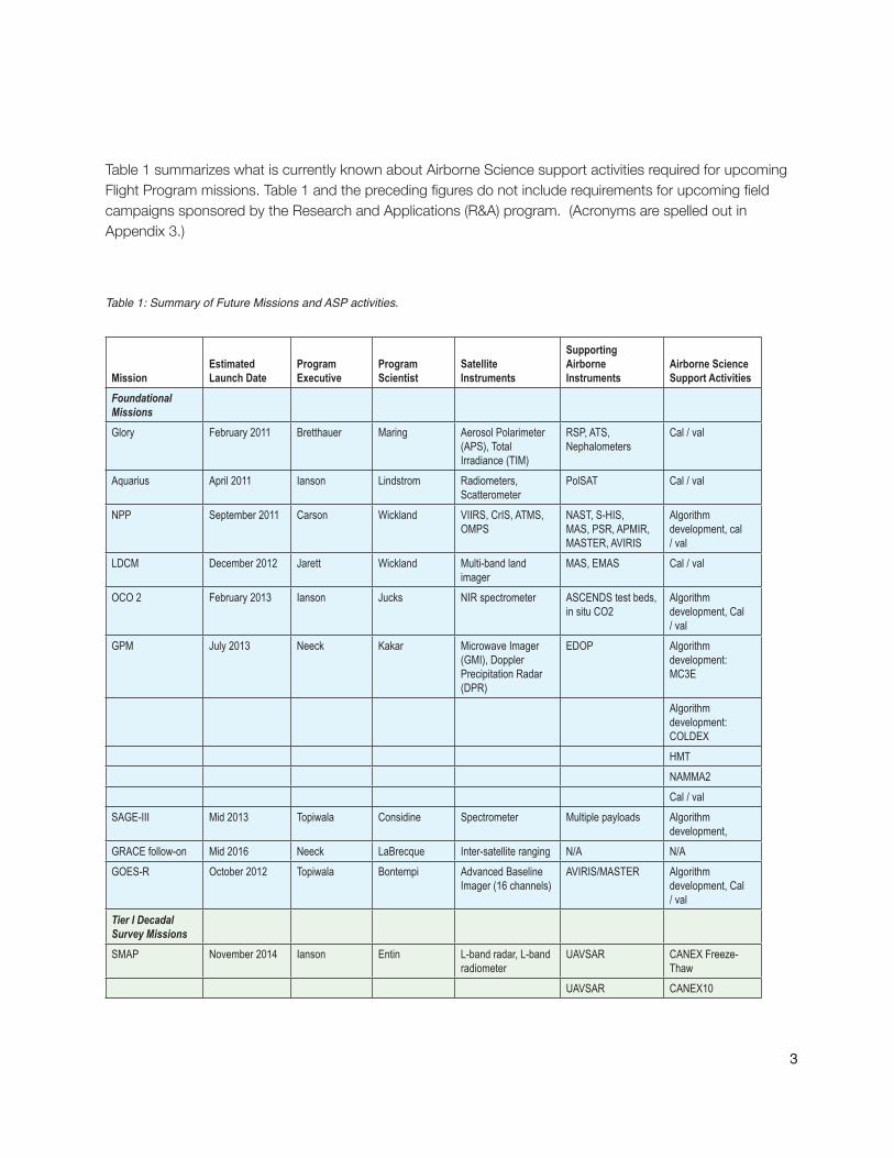
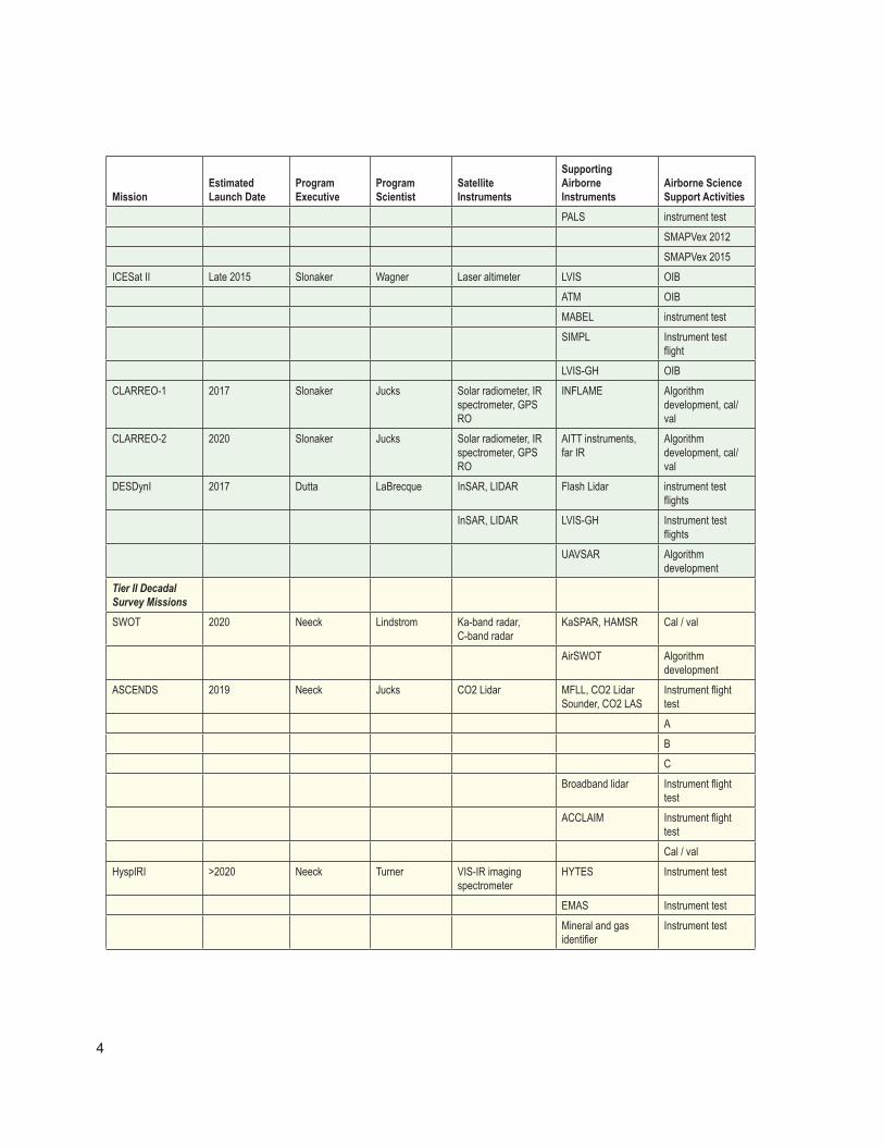
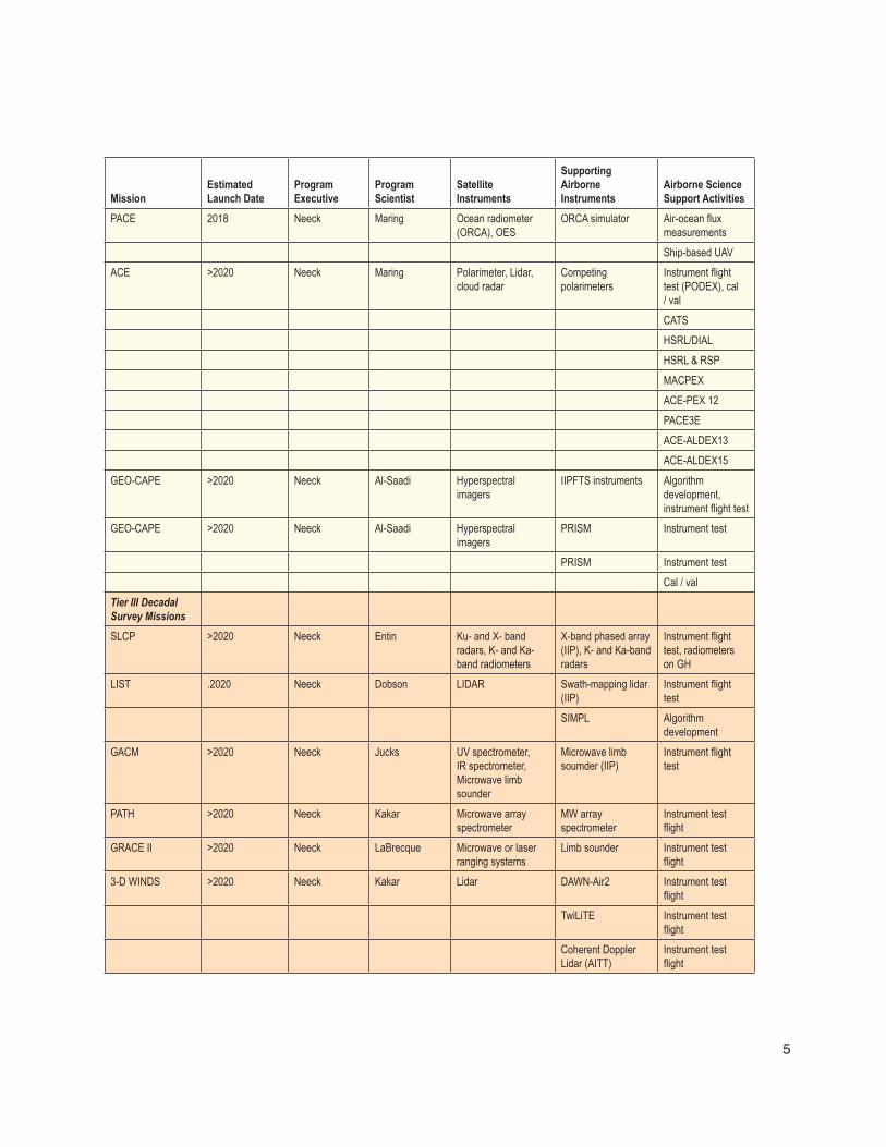
Table 1 summarizes what is currently known about Airborne Science support activities required for upcoming Flight Program missions. Table 1 and the preceding figures do not include requirements for upcoming field campaigns sponsored by the Research and Applications (R&A) program . (Acronyms are spelled out in Appendix 3 .)
MissionEstimated Launch Date
Program Executive
Program Scientist
Satellite Instruments
Supporting Airborne Instruments
Airborne Science Support Activities
Foundational Missions
Glory February 2011 Bretthauer Maring Aerosol Polarimeter (APS), Total Irradiance (TIM)
RSP, ATS, Nephalometers
Cal / val
Aquarius April 2011 Ianson Lindstrom Radiometers,Scatterometer
PolSAT Cal / val
NPP September 2011 Carson Wickland VIIRS, CrIS, ATMS, OMPS
NAST, S-HIS, MAS, PSR, APMIR, MASTER, AVIRIS
Algorithm development, cal / val
LDCM December 2012 Jarett Wickland Multi-band land imager
MAS, EMAS Cal / val
OCO 2 February 2013 Ianson Jucks NIR spectrometer ASCENDS test beds, in situ CO2
Algorithm development, Cal / val
GPM July 2013 Neeck Kakar Microwave Imager (GMI), Doppler Precipitation Radar (DPR)
EDOP Algorithm development: MC3E
Algorithm development: COLDEX
HMT
NAMMA2
Cal / val
SAGE-III Mid 2013 Topiwala Considine Spectrometer Multiple payloads Algorithm development,
GRACE follow-on Mid 2016 Neeck LaBrecque Inter-satellite ranging N/A N/A
GOES-R October 2012 Topiwala Bontempi Advanced Baseline Imager (16 channels)
AVIRIS/MASTER Algorithm development, Cal / val
Tier I Decadal Survey Missions
SMAP November 2014 Ianson Entin L-band radar, L-band radiometer
UAVSAR CANEX Freeze-Thaw
UAVSAR CANEX10
Table 1: Summary of Future Missions and ASP activities.
4
MissionEstimated Launch Date
Program Executive
Program Scientist
Satellite Instruments
Supporting Airborne Instruments
Airborne Science Support Activities
PALS instrument test
SMAPVex 2012
SMAPVex 2015
ICESat II Late 2015 Slonaker Wagner Laser altimeter LVIS OIB
ATM OIB
MABEL instrument test
SIMPL Instrument test flight
LVIS-GH OIB
CLARREO-1 2017 Slonaker Jucks Solar radiometer, IR spectrometer, GPS RO
INFLAME Algorithm development, cal/val
CLARREO-2 2020 Slonaker Jucks Solar radiometer, IR spectrometer, GPS RO
AITT instruments, far IR
Algorithm development, cal/val
DESDynI 2017 Dutta LaBrecque InSAR, LIDAR Flash Lidar instrument test flights
InSAR, LIDAR LVIS-GH Instrument test flights
UAVSAR Algorithm development
Tier II Decadal Survey Missions
SWOT 2020 Neeck Lindstrom Ka-band radar, C-band radar
KaSPAR, HAMSR Cal / val
AirSWOT Algorithm development
ASCENDS 2019 Neeck Jucks CO2 Lidar MFLL, CO2 Lidar Sounder, CO2 LAS
Instrument flight test
A
B
C
Broadband lidar Instrument flight test
ACCLAIM Instrument flight test
Cal / val
HyspIRI >2020 Neeck Turner VIS-IR imaging spectrometer
HYTES Instrument test
EMAS Instrument test
Mineral and gas identifier
Instrument test
5
MissionEstimated Launch Date
Program Executive
Program Scientist
Satellite Instruments
Supporting Airborne Instruments
Airborne Science Support Activities
PACE 2018 Neeck Maring Ocean radiometer (ORCA), OES
ORCA simulator Air-ocean flux measurements
Ship-based UAV
ACE >2020 Neeck Maring Polarimeter, Lidar, cloud radar
Competing polarimeters
Instrument flight test (PODEX), cal / val
CATS
HSRL/DIAL
HSRL & RSP
MACPEX
ACE-PEX 12
PACE3E
ACE-ALDEX13
ACE-ALDEX15
GEO-CAPE >2020 Neeck Al-Saadi Hyperspectral imagers
IIPFTS instruments Algorithm development, instrument flight test
GEO-CAPE >2020 Neeck Al-Saadi Hyperspectral imagers
PRISM Instrument test
PRISM Instrument test
Cal / val
Tier III Decadal Survey Missions
SLCP >2020 Neeck Entin Ku- and X- band radars, K- and Ka-band radiometers
X-band phased array (IIP), K- and Ka-band radars
Instrument flight test, radiometers on GH
LIST .2020 Neeck Dobson LIDAR Swath-mapping lidar (IIP)
Instrument flight test
SIMPL Algorithm development
GACM >2020 Neeck Jucks UV spectrometer, IR spectrometer, Microwave limb sounder
Microwave limb soumder (IIP)
Instrument flight test
PATH >2020 Neeck Kakar Microwave array spectrometer
MW array spectrometer
Instrument test flight
GRACE II >2020 Neeck LaBrecque Microwave or laser ranging systems
Limb sounder Instrument test flight
3-D WINDS >2020 Neeck Kakar Lidar DAWN-Air2 Instrument test flight
TwiLiTE Instrument test flight
Coherent Doppler Lidar (AITT)
Instrument test flight

6
MissionEstimated Launch Date
Program Executive
Program Scientist
Satellite Instruments
Supporting Airborne Instruments
Airborne Science Support Activities
EV-1 Missions
Hurricane Sentinel 2010-2014 Avery Maring GRIP hurricane payload
Field campaign: supports PATH, ACE, 3-D Winds, GPM
DISCOVER-AQ 2010-2014 Avery Maring Column sampling, HSRL, ACAM
Air pollution: supports GEO-CAPE, ACE, GACM
CARVE 2010-2014 Avery Maring Surface carbon sampling; PALS, FTS, gas analyzer
Arctic climate change; supports SMAP, HsypIRI, DESDynI, ASCENDS, OCO reflight.
AirMOSS 2010-2014 Avery Maring Modified UAVSAR Vegetation: supports SMAP, DESDynI
ATTREX 2010-2014 Avery Maring GLOPAC-type sampling payload
Strat/Trop chemistry and aerosols
2.1 Purpose
This report presents the known and projected use of NASA’s Airborne Science Program (ASP) assets to support the development and implementation of upcoming NASA Earth Science satellite missions, including both foundational and Decadal Survey recommended missions [1] . 1
The report is a companion to, “NASA Earth Science Requirements for Suborbital Observations,” a compendium of Airborne Science mission requirements, published in 2007 [2] with the primary objectives to:
• Define major requirements for airborne observations for all upcoming NASA Earth Science Division satellite missions .
• Provide an analysis of areas of common interest among missions and gaps in capabilities that threaten access to needed airborne observations .
• Assess needs against other ASP partners including R&A projects, ESSP EV-1, and ESTO technology development .
2.2 NASA Flight Programs
In order to study the Earth as a system and understand how it is changing, NASA develops and supports a constellation of Earth observing satellite missions that test new instruments and observing techniques and, when necessary, provide continuity of datasets for important environmental and climate data records . These missions provide Earth science researchers the data they require to address NASA’s Earth science questions .
The Flight Programs element of the science mission directorate is responsible for providing engineering support and flight operations across the entire life of an Earth science satellite mission. This includes any airborne support required prior to, and following launch . NASA missions begin with a study phase during which the key science objectives of the mission are defined, requirements are developed and designs for spacecraft and instruments are analyzed . Following the study phase, missions enter a development phase
7
2 INTRODUCTION
1 The“DecadalSurvey”istheNationalResearchCouncilReport“EarthScienceandApplicationsfromSpace:NationalImperativesfortheNextDecadeandBeyond,”released15January2007.Itprovidesscientificgoals,observationneeds,applicabletechnologies,aprogramofrecommendedmissions.

whereby all aspects of the mission are developed and tested to ensure they will meet the mission objectives . Operating missions are those missions that are currently active and providing science data to researchers . Operating missions may be in their primary operational phase or in an extended operational phase .
2.3 NASA Airborne Science Program
TheASPreportstotheEarthScienceFlightProgramsOfficeandservestheResearchandAnalysisprogramoftheEarthScienceDivision,withintheScienceMissionDirectorate(SMD).ASPprovidesflightandairbornemeasurementsinsupportoffieldscience,algorithmdevelopment,instrumenttest,andsatellitecalibrationandvalidation.
ThisreportservestheNASAASPbyhighlightingrequirementsthatemphasizetheneedforsustainedandaugmentedcapabilitieswithintheprogram.TheAirborneScienceProgramhasalwaysprovidedbothpre-andpost-launchsupporttoEarthsciencemissions,mostrecentlytheelementsofEOSand,specifically,theA-Train.Inaddition,ASPassetsareusedtodevelopthenextgenerationofsatelliteinstrumentsthroughESTOandothertechnologyprograms.
Foundationalmissions,thosedevelopedfollowingEOSandpriortotheDecadalSurvey,andscheduledforlaunchwithinthenexttwoyears,willmakeuseofAirborneSciencecapabilitiesforinstrumenttestandalgorithmdevelopment.ThecapabilitiesoftheASP,bothplatformsandsensors,havebeendeveloped/modified,maintainedandoperatedtomeetthoseneeds.
AsthefifteennewDecadalSurveymissionsarenowintheearlystagesofdevelopment,andtheEarthVentureProgrambegins,itisappropriatefortheASPtoevaluatetheupcomingrequirementsforservicesandcapabilitiestosupportthesemissions.Specificquestionsincludetheavailabilityofplatformstomeetincreaseddemandforflighthoursordeploymenttoremotelocations,andthecapabilityoftheplatformstobeadaptedfornewinstrumentsorpayloadsuites.Theinterestinrealtimedataandmultiple,simultaneoussourcesofinformationfeedtheneedforanimprovednetworkingcapability,includingsuborbitalandorbitaldatastreams.
2.4 Approach
TheapproachtocollectingandinterpretingtheneedsforASPassetshasbeenprimarilythroughconversationwithpotentialusers.WithintheNASASMDEarthScienceDivision,eachnewprogramhasaProgramExecutiveandaProgramScientistwhointerfacewiththeProgramExecutive,andthesciencecommunityinterestedinthemission.Thoseinterviewedforthisreportincludedtheaboveplusprogrammanagers,scienceteammembers,andfieldtestplanners.ASPpersonnelhavealsoattendedmanymissionplanningandscienceteammeetingsandworkshops,gatheringinformationfrompresentationsanddiscussions.Forseveralmissions,detailedfieldtestplanshavealreadybeengenerated.Formostofthemissions,thesupportneedsmaynotbeexplicit,butairbornerequirementswerediscoveredamongthescienceplans.
8
9
Foreachmissiondescribedinthisreport,thefollowingarepresented:
• Responsiblepersonnel(ProgramExecutive,ProgramScientist,ProjectScientist)
• Missiondescription,includinglaunchdateandpayload
• Relevantaircraftsimulatororcomplementaryinstrumentation
• KnownorpotentialAirborneSciencesupportactivities
• ScheduleofASPactivities,ifavailable
• Gapassessment
Thefinalsectionofthereportpresentsacross-cuttingviewofthemissionstohighlightpotentialopportunitiesfortechnologyorflightactivityplanning.

11
3 FOUNDATIONAL MISSIONS
“Foundationalmissions”arethoseunderdevelopmentorinimplementationphasewhentheNationalResearchCouncil(NRC)DecadalSurveyrecommendationswerepublishedin2007.SincethesewilllaunchbeforetheDecadalSurveymissions,theAirborneScienceProgramhastoknowandconsiderthemissionsupportrequirements.Atthistime,sincethepayloadinstrumentationisestablished,mostrequirementsareexpectedtoberelatedtopost-launchcal/val.
3.1 Glory
3.1.1 Points of contact
ProgramExecutive:JoyBretthauer,NASAHQProgramScientist:HalMaring,NASAHQProjectScientist:MichaelI.Mishchenko,NASAGSFC
3.1.2 Mission description
3.1.2.1 Objective
Glorywillmeasureglobalaerosolsandcloudliquidpropertiesandtotalsolarirradiance.ThismissionaddressesahighpriorityobjectiveoftheU.S.GlobalChangeResearchProgram.
3.1.2.2 Status and launch date
GloryisintheimplementationphaseandscheduledforlaunchinFebruary2011.
3.1.2.3 Payload instruments
TheGlorypayloadconsistsofanAerosolPolarimetrySensor(APS),whichwillprovidetheretrievalofaerosolparticlemicrophysicalpropertiesbyinvertingmultiangleandmultispectralradianceandpolarizationmeasurements,andaTotalSolarIrradianceMonitor(TIM),whichwillmeasuretheabsorptionandreflectionofsolarradiationbytheEarth’satmosphere,anddeterminetheglobalaveragetemperatureoftheEarth.CloudCameradatawillprovidecrosstrackcoverageoverafiniteswathofaerosolloadandfinemodefractionovertheopenocean.
12
3.1.3 Instrument analogues
LikelyairborneanaloguesincludetheResearchScanningPolarimeter(RSP)andaerosolsamplingnephalometers.
3.1.4 Airborne science support activities
Airbornesupportforcal/valispossible,butnothingiscurrentlyscheduled.
3.1.5 Gap assessment
Nogapsidentified.
3.1.6 Cross-cutting requirements from other missions
Nonecurrentlyidentified
3.2 Aquarius
3.2.1 Points of contact
ProgramExecutive:EricIanson,NASAHQProgramScientist:EricLindstrom,NASAHQProjectScientist:GaryLagerloef,NASAGSFC
3.2.2 Mission description
3.2.2.1 Objective
Aquariuswillmeasureseasurfacesalinityandrelatetheobservationstooceancirculation,globalwatercycle,andclimate.
3.2.2.2 Status and launch date
Aquarius,anEarthSystemSciencePathfinder(ESSP)mission,isintheimplementationphase,andscheduledforlaunchinJune2011.
3.2.2.3 Payload instruments
AquariusisajointprojectwiththeArgentineagencyCONAE.TheformalmissionnameisAquarius/SAC-D.TheprimarypayloadsaredescribedinTable2.Additionalinstrumentsincludeinfraredandvisiblecamerasandaradioocculationsounder.

13
INSTRUMENT OBJECTIVES SPECIFICATIONS RESOLUTION AGENCY
AQUARIUS Radiometer % Scat-
terometer
Sea Surface Salinity Soil Moisture
Integrated L-Band Radiometer
(1.413 Ghz) & Scatterometer (1.26
Ghz) Swath: 390 km
Three beams: 76 x 94,
84 x 120, 96 x 156 km
NASA
MWR Microwave Radiometer
Precipitation, wind speed, sea ice con-
centration
Bands: 23.8 Ghz V Pol. and 36.5 Ghz H
and V Pol. Band width: 0.5 and 1 Ghz swath: 380 km
Sixteen beams< 54 km CONAE
3.2.3 Instrument analogues
PotentialsupportingairborneinstrumentsaretheJPLPolarimetricScatterometer(PolSCAT)andvariousradiometers.
3.2.4 Airborne science support activities
In2009,theAirborneScienceprogramflew“HighWinds09,”amissionontheP-3outofGooseBay,Canada.ThePOLSCATinstrumentwasusedtomeasurescatteringfromtheoceansurface.ThosemeasurementswereusedbytheAquariusscienceteamtodevelopfoundationalalgorithmsfordataproductgeneration.Itisprobablethatsimilarmeasurementsmayberequiredduringthecal/valpost-launchphase(~2011),althoughnothingiscurrentlyscheduled.
3.2.5 Gap assessment
Ifamissionsimilarto“HighWinds09”isrequested,boththeaircraftandinstrumentshouldbeavailablethrougharoutineflightrequest.
3.2.6 Cross-cutting requirements from other missions
Nonecurrentlyidentified,althoughdatacollectedtosupportSMAPmaybenefitAquariuscal/valatsomestage.
Table 2: Payloads for Aquarius.

14
3.3 NPOESS Preparatory Project (NPP)
3.3.1 Points of contact
ProgramExecutive:AndrewCarson,NASAHQProgramScientist:DianeWickland,NASAHQProjectScientist:JamesGleason,NASAHQAtmospherevalidationlead:DavidStarr,NASAGSFC
3.3.2 Mission description
TheNPOESSPreparatoryProject(NPP)isajointmissionwithNOAAandtheU.S.DepartmentofDefensetoextendkeymeasurementsinsupportoflong-termmonitoringofclimatetrendsandglobalbiologicalproductivity.TheoriginalintentwastoextendthemeasurementseriesinitiatedwithEOSTERRAandAQUAbyprovidingabridgebetweenNASA’sEOSmissionsandtheNationalPolar-orbitingOperationalEnvironmentalSatelliteSystem(NPOESS).EventhoughtheNPOESSprogramhasbeenrestructured,splittingtheactivitiesofNASAandtheDefenseDepartment,NPPisstillscheduledtolaunchinOctober2011.Themissionobjectiveremainsthesame:toprovidecontinuitywithNASA’sEarthObservingSystem(EOS)satellitesforclimateobservationsandtoprovidetheoperationalweathercommunitywithriskreductionforthenextgenerationofweathersatellites.
3.3.2.1 Objectives
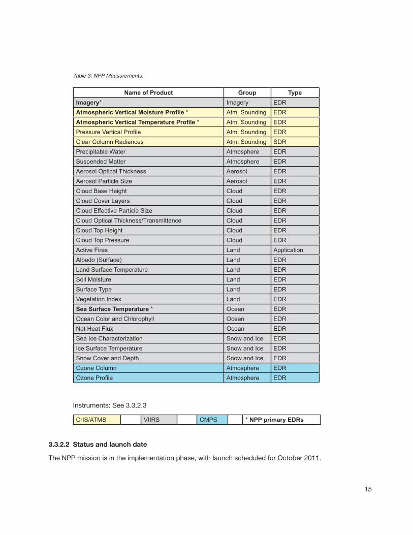
TheoverallobjectiveistoobtainandmaintainthemeasurementslistedinTable3,whereEDR=EnvironmentalDataRecords:
15
Name of Product Group TypeImagery* Imagery EDRAtmospheric Vertical Moisture Profile * Atm. Sounding EDRAtmospheric Vertical Temperature Profile * Atm. Sounding EDRPressure Vertical Profile Atm. Sounding EDRClear Column Radiances Atm. Sounding SDRPrecipitable Water Atmosphere EDRSuspended Matter Atmosphere EDRAerosol Optical Thickness Aerosol EDRAerosol Particle Size Aerosol EDRCloud Base Height Cloud EDRCloud Cover Layers Cloud EDRCloud Effective Particle Size Cloud EDRCloud Optical Thickness/Transmittance Cloud EDRCloud Top Height Cloud EDRCloud Top Pressure Cloud EDRActive Fires Land ApplicationAlbedo (Surface) Land EDRLand Surface Temperature Land EDRSoil Moisture Land EDRSurface Type Land EDRVegetation Index Land EDRSea Surface Temperature * Ocean EDROcean Color and Chlorophyll Ocean EDRNet Heat Flux Ocean EDRSea Ice Characterization Snow and Ice EDRIce Surface Temperature Snow and Ice EDRSnow Cover and Depth Snow and Ice EDROzone Column Atmosphere EDROzone Profile Atmosphere EDR
CrIS/ATMS VIIRS CMPS * NPP primary EDRs
3.3.2.2 Status and launch date
TheNPPmissionisintheimplementationphase,withlaunchscheduledforOctober2011.
Table 3: NPP Measurements.
Instruments:See3.3.2.3

16
3.3.2.3 Payload instruments
Thepayloadsuiteconsistsof:
• TheCross-trackInfraredSounder(CrIS)combinedwiththeAdvancedTechnologyMicrowaveSounder(ATMS)globallyproducesatmospherictemperature,moisture,andpressureprofilesfromspace.
SpectralRange:LWIRBand650-1095cm-1MWIRBand1210-1750cm-1SWIRBand2155-2550cm-1
• OMPS:OzoneMappingandProfilerSuite Collectsdatatopermitthecalculationoftheverticalandhorizontaldistributionofozonein
theEarth’satmosphere.
Specifications:Nadirmapper300-380nmNadirprofiler250–310nm
• VIIRS:Visible/InfraredImager/RadiometerSuiteCollectsvisibleandinfraredradiometricdataoftheEarth’satmosphere,ocean,andlandsurfaces.Datatypesincludeatmospheric,clouds,Earthradiationbudget,land/waterandseasurfacetemperature,oceancolor,andlowlightimagery.
Specifications:MultipleVISandIRchannelsbetween0.3and14micronsImagerySpatialResolution:~400m@NADIR/800m@EOS
3.3.3 Instrument analogues
Airbornesimulatorinstrumentsincludeanumberofimagers,including:NAST-I,ScanningHIS,PSR,APMIR,MAS,eMAS,MASTER,andAMS.3.3.4 Airborne science support activities
Cal/valactivitiesareanticipated.VIIRSsimulatorinstruments,particularlytheeMASandAirborneModularSensor,aresuitableforcomplementaryvalidationandfieldactivities.Noflightrequestsarecurrentlypendingforpost-launchflights,butareanticipated,specificallythroughtheESDCarbonCycleandEcosystems(CCE)program.
Currentdiscussionofvalidationfieldcampaignsincludesthefollowing:
• Fielddata(airbornein-situ&remotesensing)toquantifyerrorcharacteristicsassociatedwithatmosphericcomposition,suchasabsorbingaerosolsandmixtures(aerosolmodels),andaerosolverticaldistribution.
17
• Fielddata(airbornein-situ&remotesensing)toquantifyerrorcharacteristicsassociatedwithhigh-impact,complexcloudscenes,especiallymultilayeredclouds.Complexcloudscenesinheavyaerosolenvironmentmayalsobeachallenge.
Somesuggestedactivitiesinclude:
FY12:
• Identifyrequirementsforspecificfieldcampaignmeasurements
• Participate,highlyleveraged,inPACE(majorNASANRLfieldexperimentinSEAsia)
FY13-15:
• Participateinfurtherfieldactivities(smallhighlyfocusedactivities)
3.3.5 Gap assessment
Noknowngaps.
3.3.6 Cross-cutting requirements from other missions
Becauseofthespectralimagersrequired,itispossiblethattheremaybecollaborationwithLDCMsupportactivities.
3.4 Landsat Data Continuity Mission (LDCM)
3.4.1 Points of contact
ProgramExecutive:DavidJarrett,NASAHQProgramScientist:DianeWickland,NASAHQProjectScientist:JamesIrons,NASAGSFCCalibration/Validationleads:BrianMarkham,NASAGSFC;andJimStorey,USGS
3.4.2 Mission description
3.4.2.1 Objectives
Characterizeandmonitorland-coveruseandchangeovertimeforglobalclimateresearch,polarstudies,landuseandlandcoverchange,andtheimpactsofnaturaleventsaswellashumanactivitiesontheEarth’ssurface.
MaintaindatacontinuitywiththeLandsatsystem.
ExtendtheLandsatrecordofmulti-spectral,globalcoverageofthelandsurfaceatamoderateresolutionandseasonalbasis.
3.4.2.2 Status and launch date
TheLDCMmissionisinimplementationphase,withscheduledlaunchdateofDecember2012.
18
3.4.2.3 Payload instruments
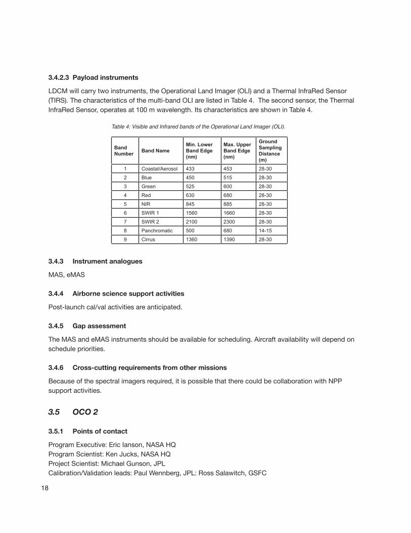
LDCMwillcarrytwoinstruments,theOperationalLandImager(OLI)andaThermalInfraRedSensor(TIRS).Thecharacteristicsofthemulti-bandOLIarelistedinTable4.Thesecondsensor,theThermalInfraRedSensor,operatesat100mwavelength.ItscharacteristicsareshowninTable4.
Band Number Band Name
Min. Lower Band Edge (nm)
Max. Upper Band Edge (nm)
Ground Sampling Distance (m)
1 Coastal/Aerosol 433 453 28-30
2 Blue 450 515 28-30
3 Green 525 600 28-30
4 Red 630 680 28-30
5 NIR 845 885 28-30
6 SWIR 1 1560 1660 28-30
7 SWIR 2 2100 2300 28-30
8 Panchromatic 500 680 14-15
9 Cirrus 1360 1390 28-30
3.4.3 Instrument analogues
MAS,eMAS
3.4.4 Airborne science support activities
Post-launchcal/valactivitiesareanticipated.
3.4.5 Gap assessment
TheMASandeMASinstrumentsshouldbeavailableforscheduling.Aircraftavailabilitywilldependonschedulepriorities.
3.4.6 Cross-cutting requirements from other missions
Becauseofthespectralimagersrequired,itispossiblethattherecouldbecollaborationwithNPPsupportactivities.
3.5 OCO 2
3.5.1 Points of contact
ProgramExecutive:EricIanson,NASAHQProgramScientist:KenJucks,NASAHQProjectScientist:MichaelGunson,JPLCalibration/Validationleads:PaulWennberg,JPL:RossSalawitch,GSFC
Table 4: Visible and Infrared bands of the Operational Land Imager (OLI).
19
3.5.2 Mission description
OCO-2willcollecthighresolutionmeasurementsofCO2,whichinturnwillprovidethedistributionofCO2overtheentireglobe.Thesemeasurementswillbecombinedwithdatafromtheground-basednetworktoprovidescientistswiththeinformationthattheyneedtobetterunderstandtheprocessesthatregulateatmosphericCO2anditsroleinthecarboncycle.Theon-boardinstrumentwillacquirethemostprecisemeasurementsofatmosphericCO2evermadefromspace.
3.5.2.1 Objectives
ImproveourunderstandingofthegeographicdistributionofCO2sourcesandsinks(surfacefluxes)andtheprocessescontrollingtheirvariabilityonseasonaltimescales.
ValidateapassivespectroscopicmeasurementapproachandanalysisconceptthatiswellsuitedforfuturesystematicCO2monitoringmissions.
3.5.2.2 Status and launch date
OCO-2hasenteredthetailoredformulationphase,andwilllaunchbyFebruary2013.
3.5.2.3 Payload instruments
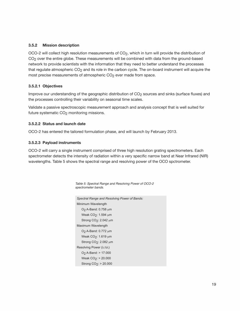
OCO-2willcarryasingleinstrumentcomprisedofthreehighresolutiongratingspectrometers.EachspectrometerdetectstheintensityofradiationwithinaveryspecificnarrowbandatNearInfrared(NIR)wavelengths.Table5showsthespectralrangeandresolvingpoweroftheOCOspctrometer.
Spectral Range and Resolving Power of Bands:
Minimum Wavelength
O2 A-Band: 0.758 mm
Weak CO2: 1.594 mm
Strong CO2: 2.042 mm
Maximum Wavelength
O2 A-Band: 0.772 mm
Weak CO2: 1.619 mm
Strong CO2: 2.082 mm
Resolving Power (l/Dl)
O2 A-Band: > 17.000
Weak CO2: > 20.000
Strong CO2: > 20.000
Table 5: Spectral Range and Resolving Power of OCO-2 spectrometer bands.

20
3.6 Global Precipitation Measurement (GPM)
3.6.1 Points of contact
ProgramExecutive:SteveNeeck,NASAHQProgramScientist:RameshKakar,NASAHQProjectScientist:ArthurHou,NASAGSFCGroundValidationleads:MattSchwallerandWalterPeterson,NASAGSFCAlgorithmteam:EricStocker,NASAGSFC
3.6.2 Mission description
TheGlobalPrecipitationMeasurement(GPM)MissionisaninternationalpartnershipinitiatedbyNASAandJapanAerospaceExplorationAgency(JAXA)toprovidethenext-generationprecipitationobservationsfromspace.TheGPMconceptcentersonthedeploymentofaCoreObservatorycarryingadvancedactiveandpassivemicrowavesensorsinanon-Sun-synchronousorbittoserveasaphysicsobservatorytogaininsightsintoprecipitationsystemsandasacalibrationreferencetounifyandrefineprecipitationestimatesfromaconstellationofresearchandoperationalsatellites.NASA’splanincludesthe“Core”observatoryandflightunit2.
3.6.2.1 Objectives
• Providemeasurementsofmicrophysicalpropertiesandverticalstructureinformationofprecipitatingsystemsusingactiveremote-sensingtechniquesoverabroadspectralrange.
• Combineactiveandpassiveremote-sensingtechniquestoprovideacalibrationstandardforunifyingandimprovingglobalprecipitationmeasurementsbyaconstellationofresearchandoperationalmicrowavesensors.
• Measuresnowandlighterrainratesthroughtheuseofhigh-frequencypassivemicrowaveradiometry.
• Improvepassivemicrowaveretrieval(PWR)algorithmsoverland.
• Improveprecipitationmeasurementsinmid-andhigh-latitudesduringcoldseasons.
3.6.2.2 Status and launch date
TheGPMmissioniscurrentlyinimplementationphase.TheCoreObservatorywilllaunchinJuly2013,andtheflightunit2low-inclinationspacecraftwilllaunchinNovember2014.
3.6.2.3 Payload instruments
GPMwillbepointingtowardEarthtomeasureprecipitation.Itwillbevitaltocontroltheattitude(orphysicalorientation)oftheCoreSpacecraftaccurately,sothatwecanmapexactlywheretheresultingdataoriginatesonEarth.TheCoreobservatoryisuniquelyinstrumentedwithaconically-scanningradiometerandacross-trackscanningradar.

21
+GPMMicrowaveImager(GMI)+Dual-frequencyPrecipitationRadar(DPR)
Thewell-calibratedGPMMicrowaveImager(GMI)measurementsandthewellcharacterizedsceneobtainedfromtheDual-frequencyPrecipitationRadar(DPR)willcombinetoprovideanexcellentreferenceagainstwhichtocalibrateothermicrowaveradiometersintheGPMconstellationwhenoverlappingmeasurementsofthesameEarthscenearemade.
3.6.3 Instrument analogues
ER-2DopplerRadar(EDOP)andsimilar,advancedsystems
3.6.4 Airborne science support activities
TheGPMvalidationteamhasprepareda“GroundValidationScienceImplementationPlan,”whichincludesbothsurfaceandairbornemeasurements.Asuccessfulfieldcampaign,theCanadianCloudSAT/CALIPSOValidationProgramme(C3VP)wascarriedoutin2007.Anupcomingcampaign,theMid-latitudeContinentalConvectiveCloudsExperiment(MC3E),jointwiththeDOEARMprogram,isscheduledfor2011.ThiswillinvolvetheuseofEDOPontheER-2,andinsitusamplingonanadditionalplatform,foralgorithmdevelopment.In2012,additionalmeasurementswillbemadefromtheDC-8inanexperimentstagedinCanadacalledCOLDEX.Insummer2013,theGPMNOAA/NASAteamisplanninganHMTexperimentinNorthCarolina.
Post-launch,in2013-2014,thefirstcal/valfieldcampaignwillflytheDC-8,ER-2andGlobalHawk,carryinginstrumentssimilartothoseusedinNAMMAinAugust2006(seeTable6).Finally,in2015,anothercal/valcampaignusingonlytheDC-8willbelaunched.
NAMMA DC-8 Instruments
2DSstereoprobe
Dual-FrequencyAirbornePreciptationRadar(APR-2)
CloudParticleImager:CPI
CloudAerosolandPrecipitationSpectrometer:CAPS
CarbonmOnoxideByAttenuationofLaserTransmission:COBALT
CounterflowVirtualImpactor:CVI
DiodeLaserHygrometer:DLH
HighAltitudeMonolithicMicrowaveIntegratedCircuitSoundingRadiometer:HAMSR
LangleyAerosolResearchGroupExperiment:LARGE
LidarAtmosphericSensingExperiment:LASE
MeteorologicalMeasurementSystem:MMS
RealTimeMissionMonitor:RTMM
ResearchEnvironmentforVehicle-EmbeddedAnalysisonLinux:REVEAL
Table 6: NAMMA DC-8 Instruments.
22
3.6.5 Gap assessment
TheinstrumentsrequiredforGPM-relatedairbornemeasurementseitherexistorarebeingdevelopedandtestedunderfundedprograms(e.g.,IIP,AITT).Integrationontotheplatformsofchoicemayrunintoscheduleconflictsduringtheproposedtimeframes.
3.6.6 Cross-cutting requirements from other missions
Noneclearlyidentified,althoughsomedatafromGPM-relatedexperimentsmaybeofvaluefor3-DWinds.
3.7 SAGE-III
3.7.1 Points of contact
ProgramExecutive:NandkishoreTopiwala,NASAHQProgramScientist:DavidConsidine,NASAHQProjectScientist:MichaelI.Mishchenko,NASAGSFC
3.7.2 Mission description
ThisinstrumentwillflyonISS.Seehttp://science.nasa.gov/media/medialibrary/2010/07/01/climate_architecture.pdfformoreinformation.
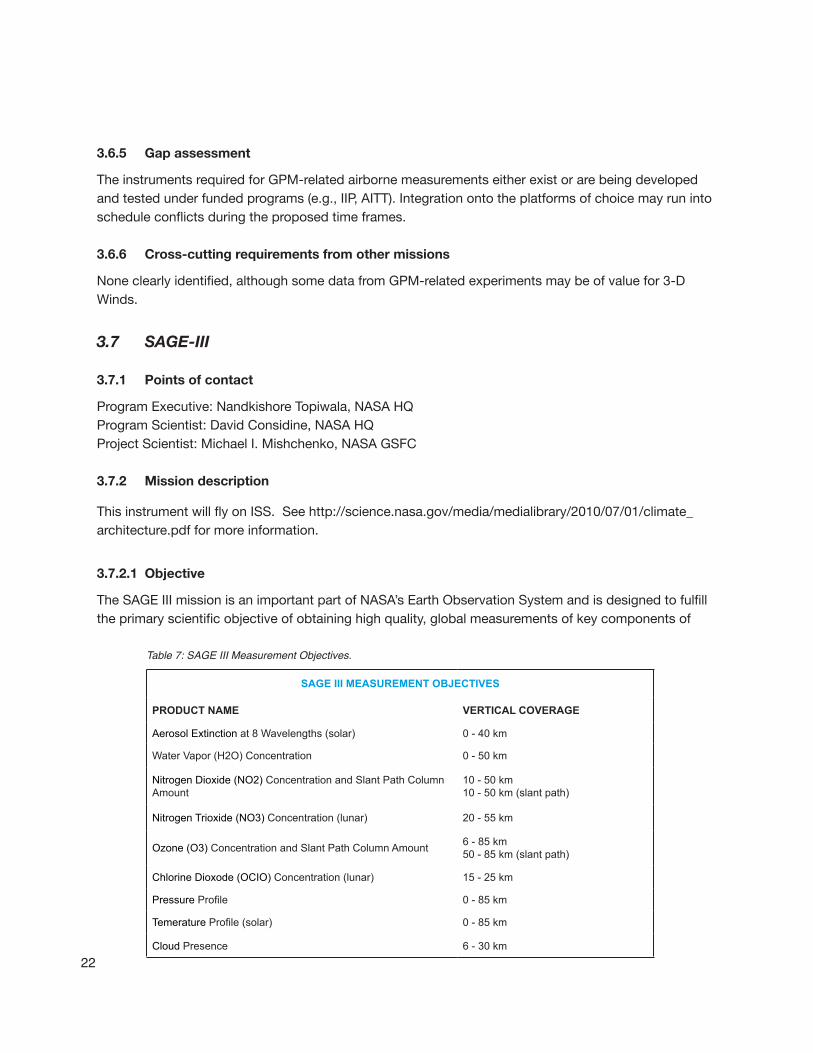
3.7.2.1 Objective
TheSAGEIIImissionisanimportantpartofNASA’sEarthObservationSystemandisdesignedtofulfilltheprimaryscientificobjectiveofobtaininghighquality,globalmeasurementsofkeycomponentsof
SAGE III MEASUREMENT OBJECTIVES
PRODUCT NAME VERTICAL COVERAGE
Aerosol Extinction at 8 Wavelengths (solar) 0 - 40 km
Water Vapor (H2O) Concentration 0 - 50 km
Nitrogen Dioxide (NO2) Concentration and Slant Path Column Amount
10 - 50 km 10 - 50 km (slant path)
Nitrogen Trioxide (NO3) Concentration (lunar) 20 - 55 km
Ozone (O3) Concentration and Slant Path Column Amount 6 - 85 km 50 - 85 km (slant path)
Chlorine Dioxode (OCIO) Concentration (lunar) 15 - 25 km
Pressure Profile 0 - 85 km
Temerature Profile (solar) 0 - 85 km
Cloud Presence 6 - 30 km
Table 7: SAGE III Measurement Objectives.
23
atmosphericcomposition(seeTable7)andtheirlong-termvariability.Thesemeasurementsarevitalinputstotheglobalscientificcommunityforimprovedunderstandingofclimate,climatechange,andhuman-inducedozonetrends.
3.7.2.2 Status and launch date
SAGEIIIisintheimplementationphase,witharecentannouncementofaMid-2013launch.
3.7.2.3 Payload instruments
TheSAGEIIIinstrumentisagratingspectrometerthatmeasuresultraviolet/visibleenergy.Itreliesupontheflight-provendesignsusedintheStratosphericAerosolMeasurement(SAMI)andfirstandsecondSAGEinstruments.
3.7.3 Instrument analogues
VariousAirbornespectrometerscanbeusedtomakesupportingmeasurementsforSAGEIII.
3.7.4 Airborne science support activities
In2000,theASPflewtheSAGEIIIOzoneLossandValidationExperiment(SOLVE)missioninsupportofthecurrentSAGEIIIoperationalsatellite.ThismajormissionmadeuseofboththeDC-8andtheER-2,carryingatotalof34instruments,aslistedinFigures4.aand4.b(page24).
3.7.5 Gap assessment
Nocal/valplansforthenewSAGEIIImissionhavebeenprovidedatthistime,butitispossiblethataSOLVE-likemissionmaybedesiredatsomepointafterlaunch.Theschedulesfortheaircraftwillneedtobeconsidered,aswellasthecurrentavailabilityforbothNASAfacilityandPIinstruments.
3.7.6 Cross-cutting requirements from other missions
Nonecurrentlyidentified.
3.8 GRACE follow-on
3.8.1 Points of contact
ProgramExecutive:SteveNeeck,NASAHQProgramScientist:JohnLaBrecque,NASAHQProjectScientist:TBD3.8.2 Mission description
TheprimarygoaloftheGRACEmissionistomapvariationsintheEarth’sgravityfield.TheGRACEmissionhastwoidenticalspacecraftsflyingabout220kilometersapartinapolarorbit500kilometersabovetheEarth.
GRACEmapstheEarth’sgravityfieldsbymakingaccuratemeasurementsofthedistancebetweenthetwosatellites,usinggeodeticqualityGlobalPositioningSystem(GPS)receiversandamicrowaverangingsystem.

24
Table 8.a: SOLVE payload instruments on the DC-8.
Table 8.b: SOLVE payload instruments on the ER-2.
SOLVE PAYLOAD: DC-8O3 / PMS B. Anderson, LaRCTOTCAP Avallone, ColoradoFACS / NMASS Reeves, DenverLASE Brownell, LaRCUV DIAL Browell, LaRCATHOS Brune, Penn StateOC / Temp. Lidar Burris, GSFCAerosol / Solar cam Hostetler, LaRCNO / NOy Kondo, Nagoya (Japan)ASUR Kunzl, Bremen (Germany)MTP Mahoney, JPLFTTR Mankin, NCARH20 May, JPLDACOM / NDIR Sachse, LaRCSAFS Shetter, NCARCIO / BrO Toohey, ColoradoCIMS Viggiano, Phillips Lab
SOLVE PAYLOAD: ER-2HOx / H2O Anderson, HarvardCIONO2 Anderson, HarvardWAS - ATLAS Atlas, Univ. MiamiMASP Baumgardner, NCARMMS Bui, ARCACATS Elkins, NOAANO / NOy Fahey, NOAAArgus Jost, ARCMTP Mahoney, JPLH2O May, JPLCPFM McElroy, AES (Canada)O3 Richard, NOAAALIAS Webster, JPLCIMS Wennberg, CalTechFCAS / NMASS Wilson, DenverImpactor Wilson, Denver UCO2 Wofsy, Harvard

25
3.8.2.1 Objective
GRACEcontinuity
3.8.2.2 Status and launch date
Mid-2016
3.8.2.3 Payload instruments
ThekeyscienceinstrumentforGRACEistheJPLK-BandRanging(KBR)InstrumentAssembly.ItscomponentsincludetheUltraStableOscillator(USO),themicrowaveassembly,thehorn,andtheInstrumentsProcessingUnit(IPU).
3.8.3 Airborne science support activities
Nonecurrentlyproposedorprojected
3.8.4 Gap assessment and cross-cutting activities
NA
3.9 Geostationary Operational Environmental Satellite (GOES-R)
3.9.1 Points of contact
ProgramExecutive:NandkishoreTopiwala,NASAHQProgramScientist:PaulaBontempi,NASAHQProjectScientist:DennisChesters,NASAGSFC
3.9.2 Mission description
TheGeostationaryOperationalEnvironmentalSatelliteProgram(GOES)isajointeffortofNASAandtheNationalOceanicandAtmosphericAdministration(NOAA).
3.9.2.1 Objective
TheGOES-Rseriesofsatelliteswillbecomprisedofimprovedspacecraftandinstrumenttechnologiesthatwillresultinmoretimelyandaccurateweatherforecasts,andwillimprovesupportforthedetectionandobservationsofmeteorologicalphenomenathatdirectlyaffectpublicsafety,protectionofproperty,andultimately,economichealthanddevelopment.
3.9.2.2 Status and launch date
ThefirstlaunchoftheGOES-Rseriessatelliteisscheduledfor2015.
3.9.2.3 Payload instruments
ThemajorinstrumentsoftheGOES-RSystemare:theAdvancedBaselineImager(ABI);theHyperspectralEnvironmentalSuite(HES);theSpaceEnvironmentIn-SituSuite(SEISS),whichincludesaMagnetosphericParticleSensor(MPS),anEnergeticHeavyIonSensor(EHIS),andaSolarandGalacticProtonSensor(SGPS);theSolarImagingSuite(SIS),whichincludestheSolarX-RayImager(SXI),the

26
Table 9: Imager channels on GOES-R.
Current GOES (5 Channels)
Future GOES-R (16 Channels)
.64 mm 0.47 mm3.8 mm 0.64 mm6.19 mm 0.88 mm
11.3 mm 1.38 mm13.3 mm 1.61 mm
2.26 mm3.9 mm6.19 mm6.95 mm7.34 mm8.5 mm9.61 mm
10.35 mm11.2 mm12.3 mm13.3 mm
SolarX-RaySensor(SXS),andtheExtremeUltravioletSensor(EUVS);theGEOLightningMapper(GLM);andtheMagnetometer.
TheAdvancedbaselineimagerhas16channels,asindicatedinTable9.
3.9.3 Instrument analogues
AVIRIS,MASTER.
3.9.4 Airborne science support activities
Algorithmdevelopmentandcal/valforGOES-Rareanticipated,withflightsscheduledontheER-2beginningin2010.
3.9.5 Gap assessment
Theinstrumentsareavailable,pendingscheduling,andhaveflownontheER-2.
3.9.6 Cross-cutting requirements from other missions
SupportforGOES-Rwillbeonacost-reimbursablebasis,sonocollaborativeactivitiesareforeseen.

27
4.1 SMAP (Soil Moisture Active Passive)
4.1.1 Points of contact
ProgramExecutive:EricIanson,NASAHQProgramScientist:JaredEntin,NASAHQProjectScientists:EniNjoku,JPL,PeggyO’Neill,GSFCCal/valLead:TomJackson,USDA
4.1.2 Mission description: objectives and instruments
SMAPwillmeasuresoilmoistureinsupportofunderstandingofEarth’swaterandenergycycles.Bothactiveandpassiveremotesensorsareincludedinthesatellitepayload.Theinstrumentisdesignedtomakecoincidentmeasurementsofsurfaceemissionandbackscatter,withtheabilitytosensethesoilconditionsthroughmoderatevegetationcover.
Thesciencegoalistocombinetheattributesoftheradarandradiometerobservationsintermsoftheirspatialresolutionandsensitivitytosoilmoisture,surfaceroughness,andvegetation.
TheSMAPinstrumentarchitectureincorporatesanL-bandradarandanL-bandradiometerthatshareasinglefeedhornandparabolicmeshreflector.Thereflectorisoffsetfromnadirandrotatesaboutthenadiraxisat14.6rpm,providingaconicallyscanningantennabeamwithasurfaceincidenceangleofapproximately40°.Thereflectorhasadiameterof6m,providingaradiometerfootprintof40km.Thereal-apertureradarfootprintis30km,definedbythetwo-wayantennabeamwidth.
4.1.3 Mission schedule
SMAPisinPhaseBstatus.Estimatedlaunchdate:November2014
4.1.4 Instrument analogues
TheSMAPscienceteamanticipatesflyingSMAPsimulatorsoverthenext5yearsinsupportofalgorithmdevelopmentcal/valwork.Theflightsincluderadiometersandradars.RepresentativeinstrumentsarePALSandUAVSAR.
TherehasalsobeensomediscussionofCO2measurementsinnorthernlatitudes,butnospecificanalogueinstrumentshavebeenproposed.
4 DECADAL SURVEY TIER I MISSIONS
28
PALSThePassive/ActiveL-/S-band(PALS)microwaveinstrumentwasdevelopedbytheJetPropulsionLaboratory(JPL)toinvestigatethesynergismofradiometerandradarmeasurementsforsoilmoistureremotesensing.IthasflownsuccessfullyonanumberofsciencemissionsandisadesirablepayloadforSMAPfieldexperiments.
UAVSARUAVSAR,areconfigurable,polarimetricL-bandsyntheticapertureradar(SAR),isspecificallydesignedtoacquireairbornerepeattrackSARdatafordifferentialinterferometricmeasurements.Ithasflownsuccessfullyin2009foricemappinginGreenlandandIcelandandintheCANEXmissioninCanada/Alaskainearly2010.ItisalsoadesirablepayloadforSMAPfieldexperiments,althoughtherepeatpasscapabilityoftheG-IIIisnotrequired.
4.1.5 Cal/valandfieldtest
Acal/valplanisbeingdevelopedfortheprojectthataddressesbothpre-andpost-launchrequirementsidentifiedbytheSMAPprojectandScienceDefinitionTeam(SDT).TheobjectiveofSMAPcal/valistocalibrateandvalidateLevel1throughLevel4algorithmsandproductsrelativetothemissionrequirements.Elementsofthecal/valplanwillincludeinsitu,towerandaircraftsimulators,satelliteobservations,modelandsurrogatevariables,andfieldcampaigns.
Pre-launchcal/valisfocusedonvalidatingthattherearemeansinplacetofulfillthemissionobjectives.Inparticular:
• Identifiedactivitiesthatwillimprovealgorithmsandproducts
• Establishinfrastructurenecessaryforpost-launchcalibrationandvalidation
Post-launchcal/valisfocusedonvalidatingthatthescienceproductsmeettheirquantifiedrequirements,andonimprovingthealgorithmsandqualityofproductsoverthemissionlife.
4.1.6 Preliminaryfieldplansandscheduleoverview
FlightofOpportunity–AntarcticaDomeC:radiometermeasurementsfromDC-8aspartofOperationIceBridge.
TheCanEXsoilmoistureexperimentinearly2010wasahighlysuccessfuluseoftheUAV-SAR,whichwillbesoughtagainin2011forCanExfreeze-thaw.PALSisplannedasacal/valsimulatorandwillhaveacheckflightontheP-3inlate2010.
Adetailedfieldcampaignscheduleisindevelopment.DraftplansareshownintheFigure6(page30).Other,complementarylaunches,SMOS,Aquarius,andGCOM-Warealsoindicated.Notethatfocusedcampaignscontinuethrough2015.
4.1.7 Gap assessment
TheaircraftandpayloadsupportrequiredforSMAPexist.UAVSARschedulingisapotentialissue.
4.1.8 Cross-cutting requirements from other missions
Nonecurrentlyidentified,althoughdatacollectedtosupportSMAPmaybenefitthelatermissionsSWOTandSLCP.

29
4.2 ICESAT II (Ice, Cloud, and Land Elevation Satellite II)
4.2.1 Points of contact
ProgramExecutive:RichardSlonaker,NASAHQProgramScientist:TomWagner,NASAHQProjectScientist:ThorstenMarkus,NASAGSFC
4.2.2 Mission description
TheobjectivesofICESatIIare:
• Measuringicesheetmassbalance,cloudandaerosolheights.
• Measurelandtopographyandvegetationcharacteristics.
• Providemulti-yearelevationdataneededtodetermineicesheetmassbalance.
• Providecloudpropertyinformation,especiallyforstratosphericcloudscommonoverpolarareas.
• Providetopographyandvegetationdataaroundtheglobe,inadditiontothepolar-specificcoverageovertheEarth’sicesheets.
4.2.3 Mission schedule
ICESatIIiscurrentlyinPhaseA.
Estimatedlaunchdate:Late2015
4.2.4 Payload Instrument
Laseraltimeter,similartoICESat.However,incontrasttotheICESatdesign,ICESat-2willuseamicro-
Table 10: SMAP Major Field Campaigns.
Year/ Quarter
1 2 3 4
2008 SMAPVEX082009 SMOS2010 SMAPEx SMAPEx
CanEx-SMAquarius SMAPEx PALS Check
2011 GCOM-W CanEx-FT
2012 SAOCOM SMAPVEX12
20132014 SMAP2015 SMAPVEX15 SMAPVEX15 SMAPVEX15Satellite launch in red.
• SMAPVEX08 - High priority design/algorithm issues• SMAPEx (Australia) - 4 one-week campaigns to span four
seasons - Aircraft Radar/Radiometer• CanEx-SM (Canada) - Two-week soil moisture campaign - Aircraft Radar/Radiometer• CanEx-FT (Canada) - Two-week freeze/thaw campaign - Aircraft Radar Radiometer• PALS Check - New configuration tests on P-3 - RFI studies• SMAPVEX12 - Major hydrology campaign - Long duration - Aircraft Radar/Radiometer• SMAPVEX15 - Extended campaign for both SM - and FT - Long duration - Aircraft Radar/Radiometer
30
pulsemulti-beamapproach.Thisprovidesdensecross-tracksamplingtoresolvesurfaceslopeonanorbitbasis.Thesensorwillhaveahighpulserepetitionrateofapproximately10kHz,whichgeneratesdensealong-tracksamplingofabout70cm.ThisconcepthasadvantagesoverICESatofimprovedelevationestimatesoverhighslopeareasandveryrough(e.g.crevassed)areasandimprovedleaddetectionforseaicefreeboardestimates.
4.2.5 Instrument analogues
AirborneanaloguesincludethosebeingusedinOperationIceBridge:
ATM–theAirborneTopographicMapper,thelegacyinstrumentforicemapping.
LVIS–theLaserVegetationImagingSensor,amatureinstrumentcapableofhigheraltitude.
PARIS-PathfinderAirborneRadarIceSounder,anewsystembeingusedinOperationIceBridge.
SIMPL-SlopeImagingMulti-polarizationPhoton-countingLidar,anIIPpathfinderinstrumentsimulatorforICESat-2.
Inaddition,anewinstrumentdevelopedatNASAGoddard,theMultipleAltimeterBeamExperimentalLidar(MABEL)instrument,isperformingasasimulatorinstrument,flyingontheER-2.Preliminaryflightsin2010willbefollowedbyadditionalflightsin2011.
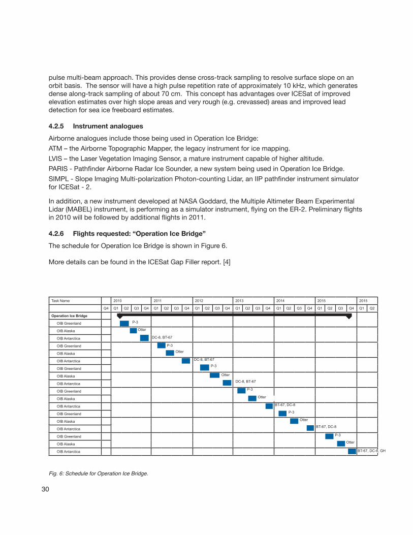
4.2.6 Flights requested: “Operation Ice Bridge”
ThescheduleforOperationIceBridgeisshowninFigure6.
MoredetailscanbefoundintheICESatGapFillerreport.[4]
Fig. 6: Schedule for Operation Ice Bridge.
Task Name 2010 2011 2012 2013 2014 2015 2015
Q4 Q1 Q2 Q3 Q4 Q1 Q2 Q3 Q4 Q1 Q2 Q3 Q4 Q1 Q2 Q3 Q4 Q1 Q2 Q3 Q4 Q1 Q2 Q3 Q4 Q1 Q2
Operation Ice Bridge
OIB Greenland
OIB Alaska
OIB Antarctica
OIB Greenland
OIB Alaska
OIB Antarctica
OIB Greenland
OIB Alaska
OIB Antarctica
OIB Greenland
OIB Alaska
OIB Antarctica
OIB Greenland
OIB Alaska
OIB Antarctica
OIB Greenland
OIB Alaska
OIB Antarctica
P-3
Otter
P-3
BT-67, DC-8
Otter
BT-67, DC-8
P-3
Otter
BT-67, DC-8, GH
Otter
P-3
DC-8, BT-67
DC-8, BT-67
P-3
Otter
DC-8, BT-67
P-3
Otter

31
BesidestheP-3,DC-8andGlobalHawk,currentlyidentifiedforIceBridgemissions,otherairbornesupportforICESatIIcouldbeprovidedusingaTwinOtter,DC-8,orDHC-3.
4.2.7 ASP Gap Assessment
TheaircraftsupportrequiredforICESatIIandIceBridgeexist.Potentialscheduleconflictswillneedtoberesolved.GlobalHawkcapabilitycouldincreaseAntarcticrange.
4.2.8 Cross-cutting requirements from other missions
LidarexperimentsforICESat-2supportcouldbealignedwithexperimentssupportingDESDynI.TheLVISinstrumentisidentifiedforboth,andtherearesomeregionsofcommoninterest.
4.3 DESDynI (Deformation, Ecosystem Structure and Dynamics of Ice)
4.3.1 Points of contact
ProgramExecutive:SanghamittaDutta,NASAHQProgramScientist:JohnLeBrecque,NASAHQChiefScientist:Bo-WenShen,NASAGSFCCal/valLead:ForrestHall,NASAGSFC
4.3.2 Mission description
DESDynIisadedicatedInSARandLIDARmissionoptimizedforstudyinghazardsandglobalenvironmentalchange.
Missionobjectives:
• Determinethelikelihoodofearthquakes,volcaniceruptions,andlandslides.
• Predicttheresponseoficesheetstoclimatechangeandimpactonthesealevel.
• Characterizetheeffectsofchangingclimateandlanduseonspecieshabitatsandcarbonbudget.
• Monitorthemigrationoffluidsassociatedwithhydrocarbonproductionandgroundwaterresources.
4.3.3 Mission schedule
DESDynIiscurrentlyinpre-PhaseA.Estimatedlaunchdate:2017
4.3.3.1 Payload instruments
ThecurrentplanforDESDynIistoflythepayloadontwoseparatesatellites.Thesensorsare:1)anL-bandInterferometricSyntheticApertureRadar(InSAR)systemwithmultiplepolarization;and,2)amultiplebeamlidaroperatingintheinfrared(~1064nm)with~25mspatialresolutionand1mverticalaccuracy.
Separatingthetwosensorsprovidesanopportunityforeachtousethemostoptimumpointingvectorandorbitcharacteristics.

32
4.3.4 Instrument analogues
ForDESDynIfieldcampaigns,thefollowinginstrumentsandactivitiesareanticipated:
LVIShasbeenandwillcontinuetobeusedforvegetationmeasurementsrelatedtoalgorithmdevelopment.
UAVSARhasbeenandwillcontinuetobeusedfortopographymeasurementsneededforcorrectionstothevegetationdataandforsolidearthdeformation
ESFL,thesteerableflashlidar(BallAerospace),isdesignedtosupportDESDynIbymakingforestcarbonmeasurement.WithAITTfunding,itwillbeflighttestedonaTwinOtterin2011.
4.3.5 Preliminaryfieldplansandscheduleoverview
ManyscheduledG-III/UAVSARflighthourssupportdatacollectionforDESDynIalgorithmdevelopment.
4.3.6 ASP Gap Assessment
TheaircraftandpayloadsupportrequiredforDESDynIexist.LVIScanflyonanumberofaircraft;theTwinOtteriscurrentlyidentified.UAVSARfliesonlyontheG-III,althoughthereareplanstomakeUAVSARcompatiblewithotheraircraft,particularlytheGlobalHawk.Hence,UAVSARschedulingisapotentialissue.
4.3.7 Cross-cutting requirements from other missions
MissionsusingtheUAVSARontheG-IIIare,orcouldbe,scheduledtoincludebothrepeat-passEarthsurfaceexperiments,aswellassimplerSARexperiments.ThereisalsopotentialforflightsoftheLVISinstrumenttosupportbothICESat-2andDESDynIobjectives.
4.4 CLARREO (Climate Absolute Radiance and Refractivity Observatory)
4.4.1 Points of contact
ProgramExecutive:RichardSlonaker,NASAHQProgramScientist:KenJucks,NASAHQChiefScientist:DavidYoung,NASALaRC
4.4.2 Mission description
TheCLARREOimperativeisto:
• Initiateanunprecedented,highaccuracyrecordofclimatechangethatistested,trustedandnecessaryforsoundpolicydecisions.
• Establisharecordofdirectobservableswithhighaccuracyandinformationcontentnecessarytodetectlong-termclimatechangetrendsandtotestandsystematicallyimproveclimatepredictions.
• ObserveSystemInternationaletraceable,spectrally-resolvedradianceandatmosphericrefractivitywiththeaccuracyandsamplingrequiredtoassessandpredicttheimpactofchangesinclimateforcingvariablesonclimatechange.
33
4.4.3 Mission schedule
CLARREOiscurrentlyinPre-phaseA.ItpassedMissionConceptReview(MCR),November17,2010.CLARREO-1willlaunchin2017andCLARREO-2in2020.
4.4.3.1 Payload instruments
SpectralreflectedsolarandemittedinfraredradiancesandGlobalPositioningSystem(GPS)RadioOccultationrefractivitiesmeasuredbyCLARREOwillbeusedtodetectclimatetrendsandtotest,validate,andimproveclimatepredictionmodels.
TheCLARREOmissioniscurrentlyenvisionedtoconsistoftwoduplicateobservatorieseachcarryingapayloadofoneinfraredinstrumentsuite,onereflectedsolarinstrumentsuiteandaGlobalNavigationSatelliteSystemRadioOccultation(GNSS-RO)instrumentsystem.
TheCLARREOPayloadElementsinclude:
• A“ReflectedSolar(RS)Suite”consistingofthreepushbroomhyperspectralgratingimagerscovering320-2300nanometerscombinedintoasingleinstrumentpackageandpointedbyatwo-axisgimbal.
• An“Infrared(IR)Suite”consistingofaFourierTransformSpectrometer(FTS)covering5-50microns(2000-200cm-1)andanon-orbitcalibrationandverificationsystem.
• A“GlobalNavigationSatelliteSystem–RadioOccultation(GNSS-RO)”receivercapableofROmeasurementsusingGPS,GLONASS,andGalileonavigationsystems.
4.4.4 Instrument analogues
OneIIP-sponsoredinstrument,MartyMlynczak’sINFLAMEexperimenthasbeenflighttestedandisreadyforfurtherapplicationinalgorithmdevelopment.TheUniversityofColorado/LASPradiometerandUniversityofWisconsinIRcalibrationsystem.
4.4.5 Preliminaryfieldplansandscheduleoverview
Mostoftheproposedsatelliteinstrumentshaveheritageandwillnotneedflighttestsfortechnologyreadinessadvancement.However,theproposedsystemswillneeddemonstration.Suggestionsweremadeforsystemtestsatveryhighaltitude,forexample,onaballoon,oronaaircraft,mostlikelytheDC-8.Thedatacollectionandmanagementportionsofthesystemwillalsoneedtestingonanaircraft.Satelliteoverpassmaybedesiredforcalibration.Alikelydateforsuchtestingwouldbe2011.ThepointsofcontactforoveralldiscussionwouldbeDavidYoungatLaRC.AconceptforCLARREOcalibratedmeasurementsisshowninFigure7.
SpecificPI’swillbe:• MartyMlynczak(LaRC)fortheFar-IRsystem• HankRevercomb(UW)forIRtestingwithcoordinatedoverpasses• KurtThome(GSFC)forthesolarinstrumentsystem• AndrewLacis(GISS),ifapolarimetersuchastheAPSisselectedforthemission
34
4.4.6 ASP Gap Assessment
TheaircraftandpayloadsupportrequiredforCLARREOexist.Sincehighaltitudeisdesired,theremaybesomescheduleconflictswithotherhigh-altitudeaircraft.
4.4.7 Cross-cutting requirements from other missions
Nonecurrentlyidentified.
Note: NMI = National Metrology Institute
Fig. 7: Concept for CLARREO calibrated measurements.

35
5 DECADAL SURVEY TIER II MISSIONS
Fig. 8: Ka-band wide swath radar
5.1 SWOT (Surface Water Ocean Topography)
5.1.1 Points of contact
ProgramScientist:EricLindstrom,NASAHQChiefScientist:ParagVaze,JPLU.S.scienceleadforhydrology:DougAlsdorf,OhioStateUniversity;Airbornesimulatordeveloper:DelwynMoller,RemoteSensingSolutions
5.1.2 Mission description
SWOTwillcombinetheconceptsofWaTER(WaterandTerrestrialElevationRecovery)andtheHydrosphereMappermissionsintoasinglemissiontoaddresstheobjectivesofbothlandhydrologyandoceanography.
5.1.3 Mission schedule
SWOTiscurrentlyinpre-phaseA,withlaunchscheduledfor2020.
5.1.4 Payload instruments
TheKa-bandRadarInterferometer(KaRIN)instrumentmakesthismissionpossible.AsindicatedinFigure8,KaRINcontainstwoKa-bandSARantennaeatoppositeendsofa10-meterboomwithbothantennaetransmittingandreceivingtheemittedradarpulsesalongbothsidesoftheorbitaltrack.Look
36
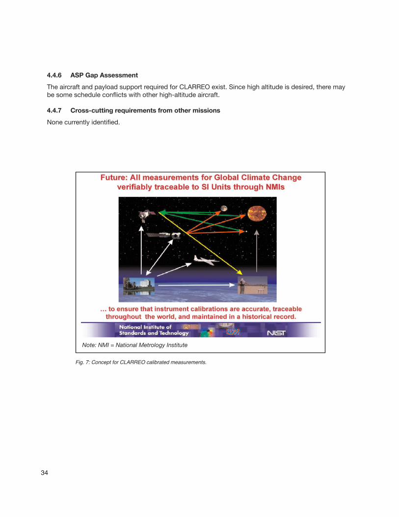
KaSPARwillnotbepod-basedandiscompletelyindependentofUAVSAR.DevelopmentoftheAirSWOTiscurrentlySBIR-fundedanddoesnotincludeflightintegrationandtest.Iffundingisfound,flighttestsoftheAirSWOTinstrumentwouldbeinitiallyontheDFRCB-200inearly2012.
EventuallydeveloperswouldliketoputKaSPARontheGlobalHawkasahigh-altitudesimulatorforalgorithmdevelopmentandcal/val.TheKaSPARobservationconceptisshowninFigure9.
5.1.6 ASP Gap Assessment
TheaircraftsupportrequiredforGLISTIN-AandKaSPAR/AirSWOTrequiresnegotiationforintegrationintothedesiredplatforms.5.1.7 Cross-cutting requirements from other missions
Nonecurrentlyidentified,althoughdatacollectedtosupportSMAP,AquariusortheoceanportionsofACEmaybenefitSWOT.
Fig. 9: Ka-SPAR concept.
anglesarelimitedtolessthan4.5°providinga120-kmwideswath.The200-MHzbandwidthachievescross-trackgroundresolutionsvaryingfromabout10minthefarswathtoabout60minthenearswath.Aresolutionofabout2metersinthealongtrackdirectionisderivedbymeansofsyntheticapertureprocessing.
5.1.5 Instrumentanaloguesandflightplans
TheAirborneGlacierandLandIceSurfaceTopographyInterferometer(GLISTEN-A),recentlyfundedbyanAITTawardisafollow-ontotheKa-bandversionofUAVSARflownontheG-IIItoGreenlandin2009.Flighttestisexpectedinmid-2012.Thispod-basedinstrumentcouldflyoneithertheG-IIIorGlobalHawkforalgorithmdevelopment.
ThemostrelevantsimulatortotheSWOTKa-bandwideswathradar(KaRIN)istheKa-bandSWOTPhenomenologyAirborneRadar(KaSPAR)system.AirSWOTistheKaSPARradaritself(Ka-bandinterferometeralso,butnadirandnear-nadirviewingandwithmorebandwidthandmorebaselines).
37
5.2 HyspIRI (Hyperspectral Infrared Imager)
5.2.1 Points of contact
ProgramExecutive:SteveNeeck,NASAHQProgramScientist:WoodyTurner,NASAHQScienceLeads:RobGreen,SimonHook,JPL
5.2.2 Mission description
TheobjectivesoftheHyspIRImissionareto:
• Studytheprocessesthatindicatevolcaniceruption.
• Analyzethenutrientsandwaterstatusofvegetation.
• Examinesoiltypeandhealth.
• Usespectratoidentifylocationsofnaturalsources.
• Studydeforestationandchangesinvegetationtype.
• Provideearlywarningofdroughts.
• Improveexplorationfornaturalresources.
• Forecastlikelihoodofvolcaniceruptionsandlandslides.
5.2.3 Mission schedule
HyspIRIiscurrentlyinpre-PhaseA.Estimatedlaunchdate:2020
5.2.4 Payload instruments
• Visibleshort-waveinfrared(VSWIR)imagingspectrometer.
• Multispectralthermalinfrared(TIR)scanner.
5.2.5 Instrument analogues and preliminary airborne plans
TheprimaryinstrumenttoflyonHyspIRIisahyperspectralspectrometer.CommonanaloginstrumentspreviouslyflownonaircraftareMASTERandAVIRIS.
Plansincludelate2011:MASTER,AVIRISonER-2.
ESTOhassupportedthedevelopmentofinstrumentssuitableforHyspIRIwithidentifiedinstrumenttestflightsin2011.Theseare:
• HyperspectralThermalEmissionSpectrometer(HyTES).TheairbornehyperspectralthermalimagercalledHyTESwillbeflighttestedinsupportofHyspIRImission.Itisexpectedtobeavailableforroutineusein2011.
• Mineralandgasidentificationspectrometer.
5.2.6 ASP Gap Assessment
TheaircraftandpayloadsupportrequiredforHyspIRIexists,buttherecouldbescheduleissuesforAVIRIS,MASTERandtheaircrafttheyflyon.
38
5.2.7 Cross-cutting requirements from other missions
Becauseofthecommonrequirementsforspectralimagers,itmaybepossibletosupportHyspIRIandNPPorLDCMconcurrently.
5.3 ASCENDS (Active Sensing of CO2 Emissions over Nights, Days, and Seasons)
5.3.1 Points of contact
ProgramExecutive:SteveNeeck,NASAHQProgramScientist:KenJucks,NASAHQScienceLead:TBD
5.3.2 Mission description
Missionobjectives:
• MeasurethenumberdensityofCarbonDioxide(CO2)inthecolumnofairbeneaththeaircraft.
• Measurelengthofthecolumnusingalaseraltimeter.
• Measureambientairpressureandtemperature.
5.3.3 Mission schedule
ASCENDSiscurrentlyinpre-PhaseA.Estimatedlaunch2019.
5.3.4 Payload instruments
Thesatellitewillcarryamultifrequencylaser,withprimaryobjectivetomeasureCO2.Measurementsofoxygenarealsoplanned.
5.3.5 Instrument analogues
Tosupportthedevelopmentofthepayloadandalgorithms,theASCENDSscienceteamhasbeentestflyingseveralcandidateCO2instruments.Theseinclude:
• Browell(LaRC),ModulatedCWFiberLaser-LidarSuite
• Abshire(GSFC),CO2LaserSounder
• Spiers(JPL),Airborne2micronLaserAbsorptionSpectrometer
5.3.6 Preliminaryfieldplansandscheduleoverview
Summer2009:Thethreeinstrumentswereflownonindependentaircraft,butsimultaneouslyovertheOklahomaARMsite.
Summer2010:AllthreeinstrumentswereflowntogetherontheDC-8onlocalflightsfromPalmdaleovervariouslandandoceansurfacesandonalong-rangeflightovertheOklahomaARMsite.

39
Summer2011:Flighttestsareplannedforthethreeinstrumentsovervariouslandandcloudfeaturesnotpreviouslyinvestigated;inthepresenceofsignificantCO2variabilityinthelowertroposphere;andinthepresenceofthincirrusandlow-altitudescatteredclouds.ThereisapossibilitythattheHeapsbroad-bandlidarwillalsobeflownduringthiscampaign.
Anypre-orpost-launchairborneactivitiesinsupportofOCO-2willalsosupportASCENDSeitherdirectlyorindirectly.
5.3.7 ASP Gap Assessment
TheaircraftandpayloadsupportrequiredforASCENDSexist.
5.3.8 Cross-cutting requirements from other missions
AlgorithmdevelopmentandothersupportforASCENDScouldbenefitOCO-2.
5.4 GEO-CAPE (Geostationary Coastal and Air Pollution Events)
5.4.1 Points of contact
ProgramExecutive:SteveNeeck,NASAHQProgramScientist:JayAl-Saadi,NASAHQScienceLeads:AnnemarieElderling,JPL;LauraIraci,NASAARC
5.4.2 Mission description
Missionobjectives:
• Identificationofhumanversusnaturalsourcesofaerosolsandozoneprecursors.
• Dynamicsofcoastalecosystems,riverplumes,andtidalfronts.
• ObservationofairpollutiontransportinNorth,Central,andSouthAmerica.
• Predictionoftrackofoilspills,fires,andreleasesfromnaturaldisasters.
• Detectionandtrackingofwaterbornehazardousmaterials.
• Measurecoastalhealth.
• Forecastsofairquality.
5.4.3 Mission schedule
GEOCAPEiscurrentlyinpre-PhaseA.Estimatedlaunchdate:2013.
5.4.4 Instruments & analogues
Highandlowspatialresolutionhyperspectralimagerswillflyonthesatellite.AnaloguesincludeAVIRISandTIMS.
ESTO-sponsoredinstrumentstobetestedinclude:
40
• PanchromaticFourierTransformSpectrometer(PanFTS)
• TroposphericInfraredMappingSpectrometer(TIMS)
• WideFieldImagingSpectrometer(WIFS)
5.4.5 Preliminaryfieldplansandscheduleoverview
Fall2010:Fouriertransformspectrometer(FTS)simulatortoflyontheWB-57outofHoustontoimagetheshippingareatothecoast.
2010-2011:DC-8atmosphericsamplingfromoceantocoast;possiblejointmissionwithACE.
5.4.6 ASP Gap Assessment
TBD
5.4.7 Cross-cutting requirements from other missions
AjointmissionwithACEtocollectocean/coastdatacouldbenefitbothmissions.
5.5 ACE (Aerosol - Cloud – Ecosystems)
5.5.1 Points of contact
ProgramExexutive:SteveNeeck,NASAHQProgramScientist:HalMaring,NASAHQCal/valLeadforaerosols:JensRedemann,NASAARCCal/valLeadforoceanography:ChuckMcClain,NASAGSFC
5.5.2 Mission description
Missionobjectives:
• Cloudandaerosolheight.
• Organicmaterialinsurfaceoceanlayers.
• Aerosolandcloudtypesandproperties.
• Improvedclimatemodels.
• Predictionoflocalclimatechange.
• Measureoceanproductivityandhealth.
• Air-qualitymodelsandforecasts.
5.5.3 Mission schedule
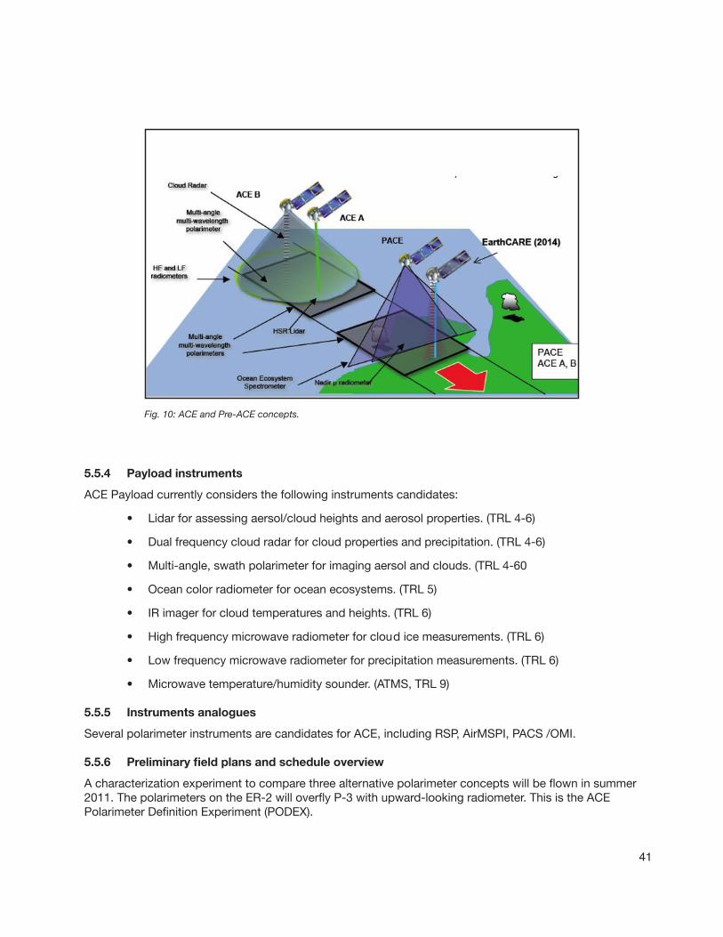
ACEiscurrentlyinpre-PhaseA.Pre-ACE(PACE)isscheduledforlaunchin2017,ACEisscheduledforlaunchinthepost2020time-frameFigure10illustratesthemissionconceptforPre-ACEandACE.
41
Fig. 10: ACE and Pre-ACE concepts.
5.5.4 Payload instruments
ACEPayloadcurrentlyconsidersthefollowinginstrumentscandidates:
• Lidarforassessingaersol/cloudheightsandaerosolproperties.(TRL4-6)
• Dualfrequencycloudradarforcloudpropertiesandprecipitation.(TRL4-6)
• Multi-angle,swathpolarimeterforimagingaersolandclouds.(TRL4-60
• Oceancolorradiometerforoceanecosystems.(TRL5)
• IRimagerforcloudtemperaturesandheights.(TRL6)
• Highfrequencymicrowaveradiometerforcloudicemeasurements.(TRL6)
• Lowfrequencymicrowaveradiometerforprecipitationmeasurements.(TRL6)
• Microwavetemperature/humiditysounder.(ATMS,TRL9)
5.5.5 Instruments analogues
SeveralpolarimeterinstrumentsarecandidatesforACE,includingRSP,AirMSPI,PACS/OMI.
5.5.6 Preliminaryfieldplansandscheduleoverview
Acharacterizationexperimenttocomparethreealternativepolarimeterconceptswillbeflowninsummer2011.ThepolarimetersontheER-2willoverflyP-3withupward-lookingradiometer.ThisistheACEPolarimeterDefinitionExperiment(PODEX).
42
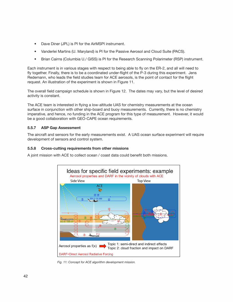
Fig. 11: Concept for ACE algorithm development mission.
• DaveDiner(JPL)isPIfortheAirMSPIinstrument.
• VanderleiMartins(U.Maryland)isPIforthePassiveAerosolandCloudSuite(PACS).
• BrianCairns(ColumbiaU./GISS)isPIfortheResearchScanningPolarimeter(RSP)instrument.
EachinstrumentisinvariousstageswithrespecttobeingabletoflyontheER-2,andallwillneedtoflytogether.Finally,thereistobeacoordinatedunder-flightoftheP-3duringthisexperiment.JensRedemann,wholeadsthefieldstudiesteamforACEaerosols,isthepointofcontactfortheflightrequest.AnillustrationoftheexperimentisshowninFigure11.
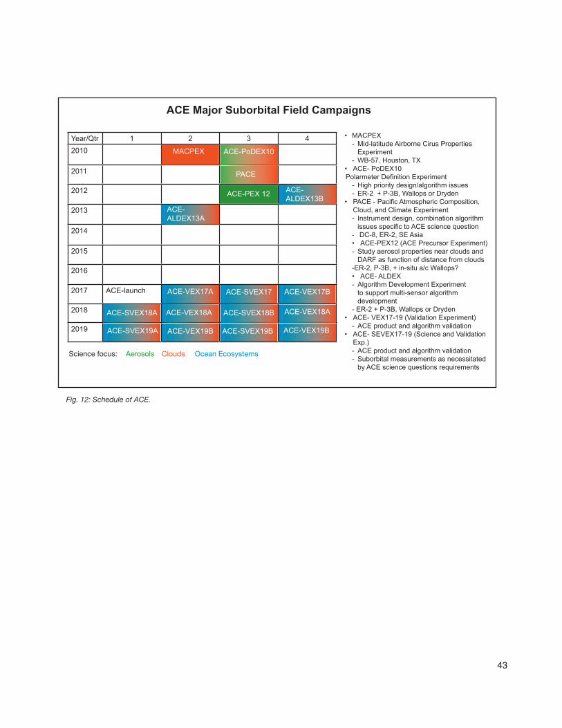
TheoverallfieldcampaignscheduleisshowninFigure12.Thedatesmayvary,butthelevelofdesiredactivityisconstant.
TheACEteamisinterestedinflyingalow-altitudeUASforchemistrymeasurementsattheoceansurfaceinconjunctionwithothership-boardandbuoymeasurements.Currently,thereisnochemistryimperative,andhence,nofundingintheACEprogramforthistypeofmeasurement.However,itwouldbeagoodcollaborationwithGEO-CAPEoceanrequirements.
5.5.7 ASP Gap Assessment
Theaircraftandsensorsfortheearlymeasurementsexist.AUASoceansurfaceexperimentwillrequiredevelopmentofsensorsandcontrolsystem.
5.5.8 Cross-cutting requirements from other missions
AjointmissionwithACEtocollectocean/coastdatacouldbenefitbothmissions.
43
Fig. 12: Schedule of ACE.
Sciencefocus: Aerosols Clouds OceanEcosystems
Year/Qtr 1 2 3 42010 10
2011
2012
2013
2014
2015
2016
2017 ACE-launch
2018
2019
PACE
ACE-PoDEX10
ACE-PEX 12
ACE-ALDEX13A
ACE-VEX17BACE-SVEX17ACE-VEX17A
ACE-SVEX18A ACE-VEX18A ACE-SVEX18B ACE-VEX18A
ACE-VEX19BACE-SVEX19BACE-VEX19BACE-SVEX19A
ACE-ALDEX13B
MACPEX
ACE Major Suborbital Field Campaigns
• MACPEX- Mid-latitude Airborne Cirus Properties
Experiment- WB-57, Houston, TX
• ACE- PoDEX10Polarmeter Definition Experiment
- High priority design/algorithm issues- ER-2 + P-3B, Wallops or Dryden
• PACE - Pacific Atmospheric Composition, Cloud, and Climate Experiment- Instrument design, combination algorithm
issues specific to ACE science question- DC-8, ER-2, SE Asia• ACE-PEX12 (ACE Precursor Experiment)- Study aerosol properties near clouds and
DARF as function of distance from clouds-ER-2, P-3B, + in-situ a/c Wallops?• ACE- ALDEX- Algorithm Development Experiment
to support multi-sensor algorithm development
- ER-2 + P-3B, Wallops or Dryden• ACE- VEX17-19 (Validation Experiment)
- ACE product and algorithm validation• ACE- SEVEX17-19 (Science and Validation
Exp.)- ACE product and algorithm validation- Suborbital measurements as necessitated
by ACE science questions requirements


45
6 DECADAL SURVEY TIER III MISSION SUPPORT
AllTier3missionsareinearlyplanningstages,pre-PhaseA.
Tier 3 Missions launch dates
Mission Launch DateLIST >2020PATH >2020GACM >2020SCLP >2020GRACE-II >20203-D Winds >2020
6.1 LiST (Lidar Surface Topography)
6.1.1 Points of contact
ProgramExecutive:SteveNeeck,NASAHQProgramScientist:CraigDobson,NASAHQProjectScientist:TBD
6.1.2 Mission description
Missionobjectives:Landsurfacetopographyforhazardsandwaterrunoff.
6.1.3 Instrument & analogues
LaserAltimeter.
ESTO-sponsoredinstrumentstobetestedinclude:Swath-mappinglidar(Yu).
6.1.4 Preliminaryflightplansandscheduleoverview
Flighttestoflidarin2012timeframe.
6.2 PATH (Precision and All-weather Temperature and Humidity)
6.2.1 Points of contact
ProgramExecutive:SteveNeeck,NASAHQProgramScientist:RameshKakar,NASAHQProjectScientist:TBD

46
6.2.2 Mission description
Missionobjectives:Highfrequency,all-weathertemperatureandhumiditysoundingsforweatherforecastingandSST.
6.2.3 Instrument & analogues
Microwavearrayspectrometer.
6.2.4 Preliminaryfieldplansandscheduleoverview
TBD.
6.3 GACM (Global Atmospheric Composition Mission)
6.3.1 Points of contact
ProgramExecutive:SteveNeeck,NASAHQProgramScientist:KenJucks,NASAHQScienceLead:L.Watkins,NASAGSFC
6.3.2 Mission description
Missionobjectives:Ozoneandrelatedgasesforintercontinentalairqualityandstratosphericozonelayerprediction.
6.3.3 Instruments & analogues
• UVspectrometer• IRspectrometer• Microwavelimbsounder
ESTO-sponsoredinstrumentstobetestedincludemicrowavelimbsounderforatmosphericcomposition(Stek).
6.3.4 Preliminaryfieldplansandscheduleoverview
Flighttestoflimbsounderin2012timeframe.
6.4 SCLP (Snow and Cold Land Processes)
6.4.1 Points of contact
ProgramExecutive:SteveNeeck,NASAHQProgramScientist:JaredEntin,NASAHQProjectScientist:TBD
6.4.2 Mission description
Missionobjectives:Snowaccumulationforfreshwateravailability.
47
6.4.3 Instruments & analogues
KuandX-bandradarsKandKa-bandradiometers
ESTO-sponsoredinstrumentstobetestedinclude:X-bandphasedarrayforsnow-waterequivalentmeasurements.
6.4.4 Preliminaryflightplansandscheduleoverview
FlighttestofKaSPAR(SWOTinstrument)ispossibleinsupportofSCLP.FlighttestoftheX-bandarrayinthe2013timeframe.BotharebeingdesignedforGlobalHawk.
6.5 GRACE-II (Gravity Recovery and Climate Experiment-II)
6.5.1 Points of contact
ProgramExecutive:SteveNeeck,NASAHQProgramScientist:JohnLebrecque,NASAHQProjectscientist:TBD
6.5.2 Mission description
Missionobjectives:Hightemporalresolutiongravityfieldsfortrackinglarge-scalewatermovement.
6.5.3 Instruments & analogues
Microwaveorlaserrangingsystem.
6.5.4 Preliminaryfieldplansandscheduleoverview
JustastheGRACEfollow-onmaynothaveanyairbornerequirements,GRACE-IImayalsonothaveanyairbornesupportrequirements.
6.6 3-D Winds (Three-Dimensional Tropospheric Winds from Space-based Lidar)
6.6.1 Points of contact
ProgramExecutive:SteveNeeck,NASAHQProgramScientist:RameshKakar,NASAHQProjectScientist:TBD
6.6.2 Mission description
Missionobjectives:Troposphericwindsforweatherforecastingandpollutiontransport.
6.6.3 Instrument analogues
DopplerLidar.
48
ESTO-sponsoredinstrumentstobetestedinclude:• TWiLiTE(Gentry)• CoherentDopplerLidar(Diner)
6.6.4 Preliminaryfieldplansandscheduleoverview
Summer2010:SimultaneousflightoftwoAITTinstrumentsonDC-8.
6.6.5 ASP Gap Assessment
TheDC-8integrationisunderstood.Theschedulemayrequirenegotiation.
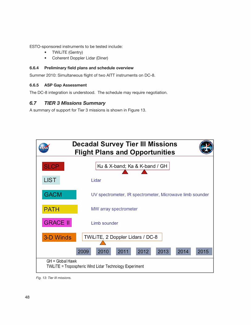
6.7 TIER 3 Missions SummaryAsummaryofsupportforTier3missionsisshowninFigure13.
Fig. 13: Tier III missions.
49
7.1 Cross-cutting requirements and gaps
Atthisearlystageinthedevelopmentoffieldtestandcal/valplansforDecadalSurveymissions,itappearsthattheAirborneScienceProgramiswellpositionedtomeettheneedsofmostmissionteams.BecauseofEV-1requirementsforGlobalHawk,andOperationIceBridgerequirementsfortheP-3andDC-8,schedulingoftheseaircraftmustbeconsideredasfarinadvanceaspossible.
ForthesakeoftheaircraftschedulingandcostsavingstothePIs,itwouldbebeneficial,wherepossible,foranairbornemissiontobedesignedtomeettherequirementsofmorethanoneDSMissionteam.Someoverlapexists,forexample,betweentheneedsoftheACEmissionandtheGEO-CAPEmission.
Thesensorandsciencesupportteamsarealsosufficientlyflexibletomeetthepotentialneeds,exceptforUAVSAR.Forthatinstrumentscheduleconflictsalreadyexist.
7.2 Recommendations
1. ContinueplanstobuildanotherUAVSARandmakeitavailableonanadditionalplatform.
2. Workwiththemissionscienceteamstorefineairbornerequirementsandmissionoverlapstomaximizeuseofairborneresources.
7 Synthesis and Recommendations


8 References
[1] NRCReport,“EarthScienceandApplicationsfromSpace:NationalImperativesfortheNextDecadeandBeyond,”15January2007.
[2] “NASAEarthScienceRequirementsforSuborbitalObservations,”availableathttp://airbornescience.nasa.gov.
[3] NPR7120.5D(NASASpaceFlightProgramandProjectManagementRequirements).
[4] “AsummaryandanalysisofoptionsforcollectingICESat-likedatafromaircraftthrough2014,”NASAinternalreport,April2009.
51

53
Appendix A: The Airborne Science Program
A.1 Airborne Science Program – types of support
TheoverallobjectivesoftheNASA’sAirborneScienceProgramare:
• Satellite Calibration and Validation:ProvideplatformstoenableessentialcalibrationmeasurementsfortheEarthobservingsatellites,andthevalidationofdataretrievalalgorithms.
• NewSensorDevelopment:Providesub-orbitalflightopportunitiestotestandrefinenewinstrumenttechnologies/algorithms,andreduceriskpriortocommittingsensorsforlaunchintospace.
• Process Studies:Obtainhigh-resolutiontemporalandspatialmeasurementsofcomplexlocalprocessesthatcanbecoupledtoglobalsatelliteobservationsforabetterunderstandingofthecompleteEarthsystem.
• Development of Next-Generation Scientists and Engineers:Fosterthedevelopmentofourfutureworkforcewiththehands-oninvolvementofgraduatestudentsandyoungscientists/engineersinallaspectsofongoingEarthscienceinvestigations.
Consideringthoseprogramobjectives,ASPcansupporttheDecadalSurveymissionsinanumberofwaysincludinginstrumentflighttesting,supportforfieldstudiestoaidcollectionofdataforpre-launchalgorithmdevelopment,fieldcampaignstosupportsatellitecalibrationandvalidationactivitiespost-launch,andscientificprocessstudiesbothlargeandsmall.
A.2 Instrument testing
NASA’sAirborneScienceProgramhaslongprovidedtestplatformsforinstrumentsthatsimulatethoseplannedforsatelliteuse.TheseanaloginstrumentsincludetheThematicMapperSimulatorusedinthe1970stoprepareforandvalidateLandsatdatasets,throughtotheMODISandASTERsimulatorsthatcontinuetoflyontheER-2andTwinOtterinsupportoftheAquaandTerramissions.
Highaltitudeaircraft,inparticular,canprovideenvironmentssimilartospaceconditionsfortestingobservationsandalsoinstrumentoutput.
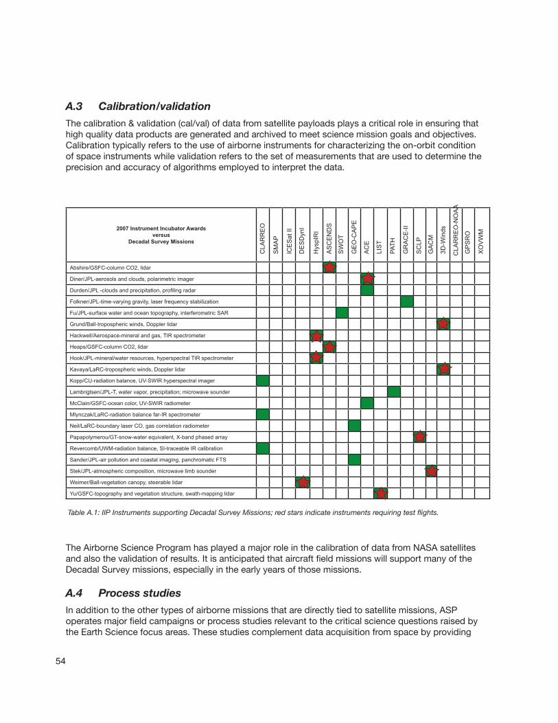
RecentawardsfromtheEarthScienceTechnologyOffice(ESTO)werefocusedontechnologydevelopmentsforDecadalSurveymissions,asindictedbystarsininTableA.1(page54).
54
A.3 Calibration/validation
Thecalibration&validation(cal/val)ofdatafromsatellitepayloadsplaysacriticalroleinensuringthathighqualitydataproductsaregeneratedandarchivedtomeetsciencemissiongoalsandobjectives.Calibrationtypicallyreferstotheuseofairborneinstrumentsforcharacterizingtheon-orbitconditionofspaceinstrumentswhilevalidationreferstothesetofmeasurementsthatareusedtodeterminetheprecisionandaccuracyofalgorithmsemployedtointerpretthedata.
TheAirborneScienceProgramhasplayedamajorroleinthecalibrationofdatafromNASAsatellitesandalsothevalidationofresults.ItisanticipatedthataircraftfieldmissionswillsupportmanyoftheDecadalSurveymissions,especiallyintheearlyyearsofthosemissions.
A.4 Process studies
Inadditiontotheothertypesofairbornemissionsthataredirectlytiedtosatellitemissions,ASPoperatesmajorfieldcampaignsorprocessstudiesrelevanttothecriticalsciencequestionsraisedbytheEarthSciencefocusareas.Thesestudiescomplementdataacquisitionfromspacebyproviding
Table A.1: IIP Instruments supporting Decadal Survey Missions; red stars indicate instruments requiring test flights.
2007 Instrument Incubator Awardsversus
Decadal Survey Missions
Abshire/GSFC-column CO2, lidar
Diner/JPL-aerosols and clouds, polarimetric imager
Durden/JPL -clouds and precipitation, profiling radar
Folkner/JPL-time-varying gravity, laser frequency stabilization
Fu/JPL-surface water and ocean topography, interferometric SAR
Grund/Ball-tropospheric winds, Doppler lidar
Hackwell/Aerospace-mineral and gas, TIR spectrometer
Heaps/GSFC-column CO2, lidar
Hook/JPL-mineral/water resources, hyperspectral TIR spectrometer
Kavaya/LaRC-tropospheric winds, Doppler lidar
Kopp/CU-radiation balance, UV-SWIR hyperspectral imager
Lambrigtsen/JPL-T, water vapor, precipitation; microwave sounder
McClain/GSFC-ocean color, UV-SWIR radiometer
Mlynczak/LaRC-radiation balance far-IR spectrometer
Neil/LaRC-boundary laser CO, gas correlation radiometer
Papapolymerou/GT-snow-water equivalent, X-band phased array
Revercomb/UWM-radiation balance, SI-traceable IR calibration
Sander/JPL-air pollution and coastal imaging, panchromatic FTS
Stek/JPL-atmospheric composition, microwave limb sounder
Weimer/Ball-vegetation canopy, steerable lidar
Yu/GSFC-topography and vegetation structure, swath-mapping lidar
CLA
RR
EO
SM
AP
ICE
Sat
II
DE
SD
ynI
Hys
pIR
I
AS
CE
ND
S
SW
OT
AC
E
LIS
T
PATH
GR
AC
E-II
SC
LP
GA
CM
3D-W
inds
CLA
RR
EO
-NO
AA
GP
SR
O
XO
VW
M
GE
O-C
AP
E

55
measurementsatspatialortemporalscalesnotachievedfromsatellitemeasurements.Inaddition,insitumeasurementsareusedtoprovidemeasurementsthatcannotbemadefromspaceinordertodeveloporvalidatenewmodelsofatmosphericphenomenonandprocesses.
A.5 Airborne Science Program – capabilities to support upcoming satellite missions
Table A.2: ASP Fleet.
Airborne Science Program Resources Platform Name Center
Duration(Hours)
Useful Payload(lbs.)
GTOW(lbs.)
Max Altitude(ft.)
Airspeed(knots)
Range(Nmi)
Internet and Document References
Core Aircraft ER-2 NASA-DFRC 12 2,900 40,000 >70,000 410 >5,000http://www.nasa.gov/centers/dryden/research/AirSci/ER-2/
WB-57 NASA-JSC 6.5 8,000 72,000 65,000 410 2,500http://jsc-aircraft-ops.jsc.nasa.gov/wb57/
DC-8 NASA-DFRC 12 30,000 340,000 41,000 450 5,400http:///.nasa.gov/centers/dryden/research/AirSci/DC-8/
P-3B NASA-WFF 12 16,000 135,000 30,000 330 3,800 http://wacop/wff.nasa.gov
GulfstreamIII (G-III)(mil: C-20A) NASA-DFRC 7 2,610 45,000 45,000 459 3,400
http://airbornescience.nasa.gov/platforms/aircraft/g3.html
NASA CatalogAircraft
King Air B-200 AND UC-12B NASA-LARC 6.2 4,100 12,500 35,000 260 1250
http://airbornescience.nasa.gov/platforms/aircraft/b-200.html
DHC-6 Twin Otter NASA-GRC 3.5 3,600 11,000 25,000 100-140 420
http://www.grc.nasa.gov/WWW/AircraftOps/
Learjet 25 NASA-GRC 3 3,200 15,000 45,000350(.81
Mach) 1,100http://www.grc.nasa.gov/WWW/AircraftOps/
S-3B Viking NASA/GRC 6 12,000 52,500 40,000 120-420 2,300http://www.grc.nasa.gov/WWW/AircraftOps/
Ikhana(Predator-B) NASA-DFRC 30 3,000 10,000 52,000 171 3,500
http://airbornescience.nasa.gov/platforms/aircraft/predator-b.html
New Technology Global Hawk NASA-DFRC 30 1500 26,750 65,000 335 10,000http://airbornescience.nasa.gov/platforms/aircraft/globalhawk.html
SIERRA NASA-ARC 11 100 445 12,000 60 550http://airbornescience.nasa.gov/platforms/aircraft/sierra.html
A.6 Aircraft
NASA’sAirborneScienceProgramoperatesafleetofcoreaircraftandcontractsforadditional“catalog”aircraftservices.TheplatformcapabilitiesarelistedinTableA.2.InformationaboutalltheaircraftcanbefoundontheAirborneScienceProgramwebsiteathttp://airbornescience.nasa.gov.
TheASPfleethasoperatedfrombasesallovertheworld.FigureA.3indicatesmissionlocationsin2008.
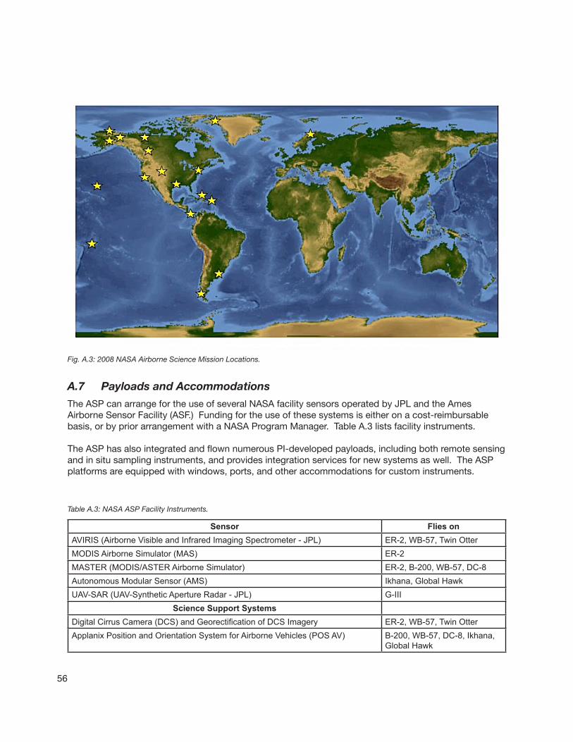
56
Sensor Flies onAVIRIS (Airborne Visible and Infrared Imaging Spectrometer - JPL) ER-2, WB-57, Twin OtterMODIS Airborne Simulator (MAS) ER-2MASTER (MODIS/ASTER Airborne Simulator) ER-2, B-200, WB-57, DC-8Autonomous Modular Sensor (AMS) Ikhana, Global HawkUAV-SAR (UAV-Synthetic Aperture Radar - JPL) G-III
Science Support SystemsDigital Cirrus Camera (DCS) and Georectification of DCS Imagery ER-2, WB-57, Twin OtterApplanix Position and Orientation System for Airborne Vehicles (POS AV) B-200, WB-57, DC-8, Ikhana,
Global Hawk
Fig. A.3: 2008 NASA Airborne Science Mission Locations.
Table A.3: NASA ASP Facility Instruments.
A.7 Payloads and Accommodations
TheASPcanarrangefortheuseofseveralNASAfacilitysensorsoperatedbyJPLandtheAmesAirborneSensorFacility(ASF.)Fundingfortheuseofthesesystemsiseitheronacost-reimbursablebasis,orbypriorarrangementwithaNASAProgramManager.TableA.3listsfacilityinstruments.
TheASPhasalsointegratedandflownnumerousPI-developedpayloads,includingbothremotesensingandinsitusamplinginstruments,andprovidesintegrationservicesfornewsystemsaswell.TheASPplatformsareequippedwithwindows,ports,andotheraccommodationsforcustominstruments.

57
A.8 Data Handling
Generally,payloadsflownonNASAaircrafthavetheirowndatarecordersforstoringsciencedata.Informationonaircraftposition,roll/pitch/yaw,andotheraircraftparametersarestoredonflightdatarecordersthatcanthenbeaccessedbytheinstrumentPIsfordataprocessing.ASPisintheearlystagesofbuildinganewgenerationofflightdatarecordersandexperiementinterfacepanelstostandardizethesesubsystemsacrossthecorefleetofaircraft.Investmentsarealsobeingmadetoenablehighbandwidthtelemetryusingsatellitelinkswherenearrealtimedataisdesirablewhetherforcheckingoninstrumenthealthorforresponsiveflightre-taskingduringagivenflight.
A.9 Mission Planning and Cross-cutting Capabilities
ASPoffersmissionplanningthroughtheplatformproviderteamstheEarthScienceProgramOffice(ESPO).ASPalsooffersvisualizationcapabilitiesformissionscientiststotracktheirexperiments.
ASPmissionshavethecapabilitytomeetmanyadditionalscienceneeds,including:
• Carryingmultiplepayloads.
• Coordinatingmultipleplatforms.
• Flyingverticalprofilesorstackedplatforms.
• Longdistancesorlongduration.
• Under-flightofsatelliteoverpasses.
• Real-timedataaccessibility.
• Portabilityandintegrationofpayloadsbetweenplatforms.


59
Appendix B: Decadal Survey Missions
B.1 Master Schedule
TheTier1andTier2missionsappearonthemasterschedulebelowinTableB.1.
Project Life Cycle
Project Pre-Formulation Project Formulation Project Implementation
Pre-Phase A Phase A Phase B Phase C Phase D Phase E Phase F
NASA:DESDynI CLARREOSWOTASCENDSACEGEO
NASA:ICESat-2SAGE III
NASA:SMAPOCO-2VentureEV-1
NASA:NPPGloryAquarius GPM LDCM
NASA Prime:AuraOSTM
NASA Extended:Aqua Terra TRMM Jason EO-1QuikSCAT SORCE Acrimsat CALIPSO CloudSat GRACE
Approval
TheTier3missionsarenotyetonthemasterschedule.Theseare:• LIST(LidarSurfaceTopography)• PATH(Precisionandall-weathertemperatureandhumidity)• GACM(GlobalAtmosphericCompositionMission)• SCLP(SnowandColdLandProcesses)• GRACE-II(GravityRecoveryandClimateExperiment-II• 3-DWinds(Three-DimensionalTroposphericWindsfromSpace-basedLidar)
B.2 Mission Terminology: Key Decision Points
InpreparingtolaunchtheDecadalSurveymissions,eachmustgothroughallthefollowingstepsoftheNASAprojectlifecycle,showninFigureB.1.(SeeNPR7120.5D[3]).Allthemissionsstartin“pre-Phase
Table B.1: Status of New Generation Missions.

60
A”asconceptstudies.Toreach“PhaseA,”whereformalScienceDefinitionTeams(SDT)areformedandfundingbecomesavailableforactivitiesinadditiontostudies,theprojectmustpassthrough“KeyDecisionPoint–KDP”A.ThismeanspassingaMissionConceptReview(MCR).SMAPpassedMCRin2008isinPhaseA.TheremainingTier1missionsareexpectedtopassMCRin2009.Untilthen,allmissionsare“pre-PhaseA.”
ThemissionstudyprocessleadingtoMCRinvolvesthefollowingactivities:
• ConductstudiesandanalysestoderivetheLevel1requirements(Science,engineering,costandschedule).
• Completeananalysisofalternativesresultinginaconceptualdesign,andconductMissionConceptReview.
• PrepareforapprovalalldocumentsrequiredinNPR7120.5D(NASASpaceFlightProgramandProjectManagementRequirements).
Fig. B.1: NASA project life cycle.
61
Appendix C: Acronyms
ACE: Aerosol–Cloud–Ecosystems
ACCLAIM: AdvancedCO2andClimateLAserInternationalMission
AITT: AirborneInstrumentTechnologyTransition
AMS: AutonomousModularSensor
APMIR: Airbornepolarimetricmicrowaveimagingradiometer
APS: AerosolPolarimetrySensor
ASCENDS: ActiveSensingofCO2EmissionsoverNights,Days,andSeasons
ASTER: AdvancedSpaceborneThermalEmissionandReflectionRadiometer
ATMS: AdvancedTechnologyMicrowaveSounder
ATS: ApplicationsTechnologySatellite
AVIRIS: AirborneVisible/InfraredImagingSpectrometer
CAMEX: ConvectionandMoistureExperiment
CLARREO: ClimateAbsoluteRadianceandRefractivityObservatory
CrIS: Cross-trackInfraredSounder
DESDynI: Deformation,EcosystemStructureandDynamicsofIce
DPR: Dual-frequencyPrecipitationRadar
EOS: EarthObservationSystem
ESTO: EarthScienceandTechnologyOffice
FTS: FourierTransformSpectrometer
GACM: GlobalAtmosphericCompositionMission
GEO-CAPE: GeostationaryCoastalandAirPollutionEvents
GMI: GPMMicrowaveImager
GPM: GlobalPrecipitationMeasurement
GRACE: GravityRecoveryandClimateExperiment
HAMSR: HighAltitudeMMICSoundingRadiometer
HyspIRI: HyperspectralInfraredImager
ICESat: Ice,Cloud,andLandElevationSatelliteII
IIP: InstrumentIncubatorProgram
JAXA: JapaneseAerospaceExplorationAgency
KaSPAR: Ka-bandSWOTPhenomenologyAirborneRadar
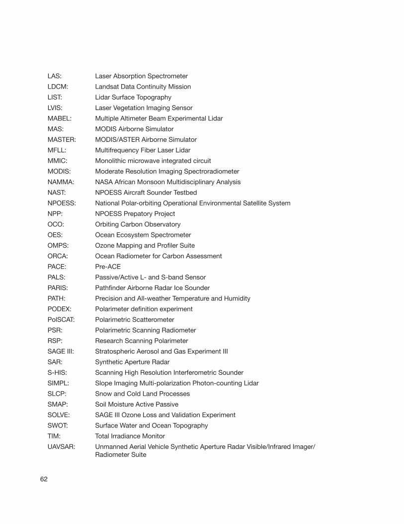
62
LAS: LaserAbsorptionSpectrometer
LDCM: LandsatDataContinuityMission
LIST: LidarSurfaceTopography
LVIS: LaserVegetationImagingSensor
MABEL: MultipleAltimeterBeamExperimentalLidar
MAS: MODISAirborneSimulator
MASTER: MODIS/ASTERAirborneSimulator
MFLL: MultifrequencyFiberLaserLidar
MMIC: Monolithicmicrowaveintegratedcircuit
MODIS: ModerateResolutionImagingSpectroradiometer
NAMMA: NASAAfricanMonsoonMultidisciplinaryAnalysis
NAST: NPOESSAircraftSounderTestbed
NPOESS: NationalPolar-orbitingOperationalEnvironmentalSatelliteSystem
NPP: NPOESSPrepatoryProject
OCO: OrbitingCarbonObservatory
OES: OceanEcosystemSpectrometer
OMPS: OzoneMappingandProfilerSuite
ORCA: OceanRadiometerforCarbonAssessment
PACE: Pre-ACE
PALS: Passive/ActiveL-andS-bandSensor
PARIS: PathfinderAirborneRadarIceSounder
PATH: PrecisionandAll-weatherTemperatureandHumidity
PODEX: Polarimeterdefinitionexperiment
PolSCAT: PolarimetricScatterometer
PSR: PolarimetricScanningRadiometer
RSP: ResearchScanningPolarimeter
SAGEIII: StratosphericAerosolandGasExperimentIII
SAR: SyntheticApertureRadar
S-HIS: ScanningHighResolutionInterferometricSounder
SIMPL: SlopeImagingMulti-polarizationPhoton-countingLidar
SLCP: SnowandColdLandProcesses
SMAP: SoilMoistureActivePassive
SOLVE: SAGEIIIOzoneLossandValidationExperiment
SWOT: SurfaceWaterandOceanTopography
TIM: TotalIrradianceMonitor
UAVSAR: UnmannedAerialVehicleSyntheticApertureRadarVisible/InfraredImager/RadiometerSuite
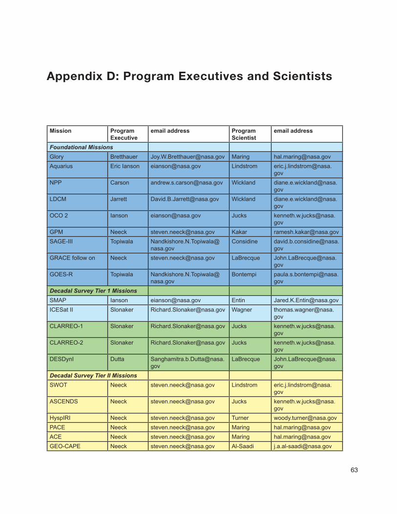
63
Appendix D: Program Executives and Scientists
Mission Program Executive
email address Program Scientist
email address
Foundational MissionsGlory Bretthauer [email protected] Maring [email protected] Eric Ianson [email protected] Lindstrom eric.j.lindstrom@nasa.
govNPP Carson [email protected] Wickland diane.e.wickland@nasa.
govLDCM Jarrett [email protected] Wickland diane.e.wickland@nasa.
govOCO 2 Ianson [email protected] Jucks kenneth.w.jucks@nasa.
govGPM Neeck [email protected] Kakar [email protected] Topiwala Nandkishore.N.Topiwala@
nasa.govConsidine david.b.considine@nasa.
govGRACE follow on Neeck [email protected] LaBrecque John.LaBrecque@nasa.
govGOES-R Topiwala Nandkishore.N.Topiwala@
nasa.govBontempi paula.s.bontempi@nasa.
govDecadal Survey Tier 1 MissionsSMAP Ianson [email protected] Entin [email protected] II Slonaker [email protected] Wagner thomas.wagner@nasa.
govCLARREO-1 Slonaker [email protected] Jucks kenneth.w.jucks@nasa.
govCLARREO-2 Slonaker [email protected] Jucks kenneth.w.jucks@nasa.
govDESDynI Dutta Sanghamitra.b.Dutta@nasa.
govLaBrecque John.LaBrecque@nasa.
govDecadal Survey Tier II MissionsSWOT Neeck [email protected] Lindstrom eric.j.lindstrom@nasa.
govASCENDS Neeck [email protected] Jucks kenneth.w.jucks@nasa.
govHyspIRI Neeck [email protected] Turner [email protected] Neeck [email protected] Maring [email protected] Neeck [email protected] Maring [email protected] Neeck [email protected] Al-Saadi [email protected]

Mission Program Executive
email address Program Scientist
email address
Decadal Survey Tier III MissionsSLCP Neeck [email protected] Entin [email protected] Neeck [email protected] Dobson [email protected] Neeck [email protected] Jucks kenneth.w.jucks@nasa.
govPATH Neeck [email protected] Kakar ramesh.k.kakar@nasa.
govGRACE II Neeck [email protected] LaBrecque John.LaBrecque@nasa.
gov3-D WINDS Neeck [email protected] Maring [email protected] Venture - 1 missions
Avery [email protected] Maring [email protected]
64
