2010rev chapter 6 - water quality · pdf file6.5 design criteria for treatment bmps ......
TRANSCRIPT

CENTRAL OREGON STORMWATER MANUAL
August 2010 Chapter 6 – Water Quality Treatment Design
6-i
CHAPTER 6 – WATER QUALITY TREATMENT DESIGN
Chapter Organization 6.1 Introduction ................................................................................................................ 6 - 1
6.2 Treatment Goals ......................................................................................................... 6 - 1
6.2.1 Surface Water Discharges .................................................................................... 6 - 1
6.2.2 Underground Injection Discharges ...................................................................... 6 - 2
6.3 Applicability .............................................................................................................. 6 - 3
6.3.1 UIC Pretreatment Applicability ........................................................................... 6 - 3
6.3.2 Basic Treatment Applicability ............................................................................. 6 - 5
6.3.3 Oil Control Applicability ..................................................................................... 6 - 5
6.3.4 Metals Treatment Applicability ........................................................................... 6 - 6
6.4 Requirements for All Treatment Facilities ................................................................ 6 - 8
6.4.1 Water Quality Design Volume and Flow............................................................. 6 - 8
6.4.2 Bypass Requirements ........................................................................................... 6 - 9
6.4.3 Sequence of Facilities .......................................................................................... 6 - 9
6.4.4 Siting of Facilities ................................................................................................ 6 - 9
6.5 Design Criteria for Treatment BMPs ....................................................................... 6 - 11
6.5.1 Infiltration Swales .............................................................................................. 6 - 11
6.5.1.1 Infiltration Swale Design ............................................................................ 6 - 12
6.5.1.2 Infiltration Swale Minimum Requirements ................................................ 6 - 14
CENTRAL OREGON STORMWATER MANUAL
August 2010 Chapter 6 – Water Quality Treatment Design
6-ii
6.5.2 Vegetated Filter Strips ....................................................................................... 6 - 15
6.5.2.1 Vegetated Filter Strip Design ..................................................................... 6 - 17
6.5.2.2 Vegetated Filter Strip Minimum Requirements ......................................... 6 - 19
6.5.3 Oil/Water Separators .......................................................................................... 6 - 19
6.5.3.1 Oil/Water Separator Minimum Requirements ............................................ 6 - 20
6.5.4 Wetponds ........................................................................................................... 6 - 23
6.5.4.1 Wetpond Design ......................................................................................... 6 - 24
6.5.4.2 Wetpond Minimum Requirements ............................................................. 6 - 24
6.5.5 Extended Detention Dry Ponds .......................................................................... 6 - 28
6.5.5.1 Extended Detention Dry Pond Design........................................................ 6 - 29
6.5.5.2 Extended Detention Dry Pond Minimum Requirements ............................ 6 - 29
6.5.6 Grassy Swales .................................................................................................... 6 - 30
6.5.7 Sedimentation Manholes .................................................................................... 6 - 32
6.5.8 Emerging Technologies ..................................................................................... 6 - 34
Appendix 6A –Infiltration Swale Calculation ........................................................................ 6A - 1
Appendix 6B –Vegetated Filter Strip Calculation .................................................................. 6B - 1
Appendix 6C – Grassy Swale Calculation .............................................................................. 6C - 1
Appendix 6D – Mosquito Control .......................................................................................... 6D - 1

CENTRAL OREGON STORMWATER MANUAL
August 2010 Chapter 6 – Water Quality Treatment Design
6-1
6.1 INTRODUCTION Water quality treatment facilities are designed to remove pollutants contained in stormwater runoff. The pollutants of concern include gross solids; sand, silt, and other suspended solids; dissolved metals such as copper, lead, and zinc; nutrients such as nitrogen and phosphorus; certain bacteria and viruses; and organics such as petroleum hydrocarbons and pesticides. Methods of pollutant removal include sedimentation/settling, filtration, ion exchange, adsorption, and organic and inorganic decomposition. Plant uptake of pollutants can play a role in stormwater treatment, although normally minor for most systems expected for use in Central Oregon. Floatable pollutants such as oil and debris can be removed with separator structures.
Central Oregon is subject to DEQ regulations for UIC systems. All rule-authorized UIC systems must have a filtration media or BMP in place to treat stormwater prior to discharge into the subsurface. Alternatively, UIC systems may operate under the requirements of a Water Pollution Control Facility (WPCF) Permit specific to the facility.
Many treatment facilities, if designed correctly, can function as both a water quality treatment facility and a flow control facility. In addition, Chapter 11 provides site design and low impact development techniques to reduce the amount of runoff and potential pollutants, which may help minimize the sizing needs of facilities in Chapters 6 and 7. This chapter describes design criteria for water quality treatment facilities and Chapter 7 provides design criteria for flow control facilities.
6.2 TREATMENT GOALS Treatment goals are dependent on whether the ultimate discharge point is to a surface water body, covered under the federal Clean Water Act (CWA), or is infiltrated or injected into the ground towards groundwater, covered under the federal Safe Drinking Water Act (SDWA). There are two significant differences between the CWA and the SDWA. First, the SDWA does not have treatment goals. Instead, it has specific concentration limits. Second, the SDWA does not have adaptive management that allows the use of benchmarks. Treatment must meet the concentrations limits set in rule or by permit. To obtain a general idea of the types of pollutants, permit-specific concentration limits, and background information regarding the establishment of these concentration limits, please refer to the DEQ Fact Sheets at: www.deq.state.or.us/wq/uic/guidance.htm.
6.2.1 SURFACE WATER DISCHARGES The CWA requirements apply to surface water discharges. The goal is to treat the runoff to the maximum extent practicable (MEP). Treating to MEP is accomplished by treating approximately 80% of total runoff volume generated at a project site on an annual basis by designing facilities to treat the full 6 month NRCS Type I 24-hour storm event. Storms larger than the 6 month design storm are assumed to comprise less than 20% of the total volume of runoff generated on an annual basis. Facilities that are designed according to the criteria set forth in this chapter are also assumed to capture and treat nearly all of first flush events (initial runoff during a storm event after a dry period).

CENTRAL OREGON STORMWATER MANUAL
August 2010 Chapter 6 – Water Quality Treatment Design
6-2
The key pollutants of concern are as follows:
• Total Suspended Solids (TSS): The basic treatment facility choices presented in this chapter are intended to achieve 80% removal of suspended solids for typical influent concentrations ranging from 30 mg/l to 100 mg/l.
• Total Petroleum Hydrocarbons (TPH): The oil control facilities introduced in this chapter are intended to achieve the goal of non-visible sheen, and to have a 24-hour average TPH concentration below 15 mg/l for a discrete sample.
• Total Metals: The metals treatment facilities choices presented in this chapter are intended to achieve a goal of 50% removal of total metals on an annual basis1.
The water quality treatment BMPs intended to meet the above goals are listed in Table 6-1.
6.2.2 UNDERGROUND INJECTION DISCHARGES The SDWA guidelines apply to groundwater and proposed UIC facilities. Rather than treatment goals, the SDWA has specific concentration limits that are set in rule or by permit. The treatment requirements for UICs can be more conservative than those for surface water discharges, as the concentration limits for UICs are numerical and based on the naturally existing background groundwater quality to protect human health.
Project proponents should understand the concentration limits and any DEQ non-degradation requirements when discharging to UICs. OAR 340-044-0018(3) provides the minimum pollutant list and sampling requirements by facility type and by traffic volume required for authorization by rule. These requirements are conservative and prescriptive. Treatment under UIC regulations must meet the following criteria:
• The treated discharge must not exceed the Maximum Contaminant Level (MCL) for the pollutant (if an MCL exists) or must not adversely affect the health of humans, or
• The treated discharge must meet the conditions set forth in OAR 340-040.
If a project proponent seeks rule authorization for a UIC, they should review OAR 340-044-0018 and OAR 340-044-0020 regarding Rule Authorization, monitoring requirements, minimum pollutants to address, and any additional information DEQ may need to process the application. The UIC rules provide minimum monitoring requirements and DEQ may require additional monitoring as a condition to Rule Authorization.
The water quality treatment BMPs intended to assist project proponents in meeting the goals of the SDWA for UIC Pretreatment are listed in Table 6-1.
1 Trace metals are a common component of soil minerals. Thus the total metals concentration includes the toxic dissolved fraction as well as the non-toxic solid phase fraction. (The typical fraction of dissolved versus total metals varies by the metal type.) The solid phase fraction is usually part of the sediment load which is of concern for reasons other than toxicity.
CENTRAL OREGON STORMWATER MANUAL
August 2010 Chapter 6 – Water Quality Treatment Design
6-3
6.3 APPLICABILITY Table 6-1 outlines the treatment BMPs intended to provide the appropriate level of treatment to meet the different treatment goals. Not all BMPs are applicable to every site and land use. Restrictions are described in the design guidelines for each facility in Section 6.5. Alternative systems meeting or exceeding the target removal levels may be considered, subject to approval of the local jurisdiction.
Any of the exceptions listed in this section are superceded by any requirement set forth in a local TMDL, water cleanup plan, groundwater cleanup plan, local Surface Water Management Plan (SWMP), the SDWA, UIC permit requirements, and/or OAR 340-040. In addition, local jurisdictions may elect to adopt different thresholds to meet local goals. Applicants should verify the local treatment thresholds prior to selecting or designing treatment BMPs.
6.3.1 UIC PRETREATMENT APPLICABILITY OAR 340-044-0018(3)(a)(C) prohibits DEQ from issuing Rule Authorization for a UIC if other alternatives for stormwater management are available and appropriate. When designing a system with a UIC, the designer must demonstrate to DEQ that they have considered other alternatives and applied other techniques, including LID methodologies, before using a UIC.
When UICs are the only appropriate stormwater management alternative, UIC Pretreatment is required for all pollutant generating surfaces (PGS, See Chapter 2) and non-pollutant generating surfaces (NPGS) that discharge to a UIC. BMPs used for pretreatment must address Maximum Contaminant Levels (MCLs) for hydrocarbons, organics, bacteria, and metals associated with stormwater. The water quality treatment BMPs intended to assist project proponents in meeting the goals of the SDWA for UIC Pretreatment are listed in Table 6-1.
Swales and biofiltration have been found to be up to 85-95% effective in treating all the contaminants in stormwater and are protective of groundwater. By policy, DEQ will approve the use of proprietary systems that have achieved ranking of “conditional” or “general use” from the Washington Department of Ecology (or other similar program accepted by DEQ). Oil/water separators alone do not meet the pretreatment standards for hydrocarbons, organics, or bacteria. However, they may be used as part of a multi-facility treatment train to meet the pretreatment requirements.
In addition, UIC Rule Authorization identifies Large Category Development as those projects that have 1,000 or more ADT for an entire project area, based on the current ITE methodology. Large Category Developments are asked to provide a higher level of pretreatment, maintenance, and annual monitoring and to submit reporting to DEQ. Applicants should have their monitoring plans developed when they submit their Rule Authorization Application, including identifying the UICs where monitoring will occur.

CENTRAL OREGON STORMWATER MANUAL
August 2010 Chapter 6 – Water Quality Treatment Design
6-4
TABLE 6-1 – APPLICABLE TREATMENT BMPS
UIC Pretreatment
Basic Treatment
(TSS)
Oil Control (TPH)
Metals Treatment
Low Impact Development (Chapter 11) X X X X
Infiltration Swale X X X X
Vegetated Filter Strips X X X1 X1
Oil/Water Separator X
Wetponds (basic) X X X
Wetponds (large) X X X
Extended Detention Dry Ponds X X X X
Evaporation Ponds X X2 X
Grassy Swales X X X3
Sedimentation Manholes X4 X X
Emerging Technologies X5 X5 X5 X5
Treatment Trains X X X X 1Vegetated filter strips are only applicable for oil control and metals treatment when installed in series with an above ground flow control facility, such as a detention or evaporation pond. Such designs will be evaluated on a case by case basis by the local jurisdiction. 2Evaporation ponds are only applicable for oil control when the Full Containment Method is utilized, or the “separated” system is used in the Outflow Method. See Chapter 7 for evaporation pond design criteria. 3Grassy swales can be used for metals treatment when preceded by an oil/water separator. 4At the time of this update, Sedimentation Manholes do not have full approval from DEQ for stand alone UIC Pretreatment for large parking lot areas. Project proponents must consider all other alternatives before exploring the use of Sedimentation Manholes. Project proponents are strongly advised to contact DEQ prior to moving forward with a design based on sedimentation manholes for UIC Pretreatment. 5Emerging technologies that have achieved a Conditional or General Use designation from the Washington State Department of Ecology (or other similar program accepted by DEQ) are applicable for UIC Pretreatment. Individual jurisdictions will review the use of emerging technologies for other uses on a case-by-case basis.
The treatment requirements for UICs can be more conservative than those for surface water discharges, as the concentration limits for UICs are numerical and pertain to drinking water standards. Project proponents should understand the concentration limits and any DEQ non-degradation requirements when discharging to UICs.
Applicants pursuing phased projects should include a complete picture of what the whole project will look like, as monitoring requirements and fees are based on the cumulative project impact. Failure to provide DEQ with this data will slow a project’s review and can stop development until this is provided.
CENTRAL OREGON STORMWATER MANUAL
August 2010 Chapter 6 – Water Quality Treatment Design
6-5
UIC Pretreatment Exceptions UIC pretreatment is not required for runoff from non-metal residential roofs that meet the definition of OAR 340-044-0018(2)(b)(F), provided the roof runoff is not mixed with any other runoff source, the UIC is not more than 5 feet deep, and there is a minimum of 5 feet vertical separation between the bottom of the UIC system and the seasonal high groundwater level. This exception does not apply if the discharge is from a metals facility or has a DEQ issued air quality permit.
6.3.2 BASIC TREATMENT APPLICABILITY Basic treatment provides removal of TSS. Basic Treatment is required for all projects that add or replace 5,000 square feet or more PGS unless the disposal method satisfies the requirement for full dispersion (see Chapter 7).
Basic treatment is required for all discharges to surface waters of the state, including perennial and seasonal streams, lakes, and wetlands where the PGS threshold is met. Certain exemptions may exist for wetlands placed in the “development” category by a local jurisdiction’s Wetland Conservation Plan or equivalent (see “Wetlands” discussion in Section 2.2.3).
Refer to Table 6-1 for applicable basic treatment BMPs. When designing BMPs, project designers should also consider the possible impact of additional TSS loading from pervious areas of the project site on the long-term function of the treatment facility.
Basic Treatment Exceptions Basic treatment is not required for NPGS areas unless the runoff is hydraulically connected to a PGS area. That is, treatment is not required unless the runoff from the NPGS area mixes with runoff from a PGS area upstream of the water quality treatment facility. Runoff from NPGS areas does not require treatment if it mixes with the PGS runoff downstream of the water quality treatment facility.
6.3.3 OIL CONTROL APPLICABILITY Oil control is required for land uses where sufficient quantities of free oil are likely to be present such that the oil can be effectively removed with special treatment. The site conditions listed below are subject to oil control when they are part of a project that adds or replaces 5,000 square feet or more PGS.
The following site conditions require oil/water separator technology, such as a coalescing plate or baffle-type oil control mechanism, which removes oil from the stormwater in a separate step from any other pollutant removal BMP. Oil/water separator technology typically involves a “treatment train” of two (or more) BMPs in series to meet the treatment goals of pollutants other than oil:
• Non-employee parking areas of commercial or industrial sites with daily trip end counts greater than 100 vehicles per 1,000 square feet gross building area or greater than 300 total trip ends.
CENTRAL OREGON STORMWATER MANUAL
August 2010 Chapter 6 – Water Quality Treatment Design
6-6
• A commercial or industrial site storing and/or transferring petroleum, not including locations where heating fuel is routinely delivered to end users;
• A commercial or industrial site subject to use, storage, or maintenance of a fleet of 25 or more vehicles that are over 10 tons gross weight (trucks, busses, trains, heavy equipment, etc);
• Fueling stations and facilities;
• Maintenance and repair facilities for vehicles, aircraft, construction equipment, railroad equipment or industrial machinery and equipment; and,
• Road intersections with expected ADT count equal to or greater than 25,000 on the main roadway and equal to or greater than 15,000 on any intersecting roadway.
The following site conditions require only sorptive technology, such as amended soils in an infiltration swale, which physically or chemically binds pollutants to organic particles. These site conditions typically do no require a multi-facility treatment train to address both oil control and other treatment requirements:
• A commercial or industrial site with an expected daily trip end count equal to or greater than 100 vehicles per 1,000 square feet of gross building area;
• A parking lot with an expected daily trip end count equal to or greater than 300 vehicles;
• Commercial on-street parking areas located on streets with an expected total ADT count equal or greater than 7,500;
• Outdoor storage yards and other sites subject to frequent use or storage of forklifts and/or other hydraulic equipment;
• Railroad yards; and,
• Any road with an expected ADT count equal to or greater than 30,000 (assumes a straight stretch of road, where intersecting ADTs are low).
When oil control is required, the oil control BMPs must be applied to the portions of the site that exceed the oil control thresholds listed above. Refer to Table 6-1 for applicable oil control BMPs.
6.3.4 METALS TREATMENT APPLICABILITY Metals treatment is required for land uses that are likely to generate concentrations of metals in quantities that justify additional runoff treatment to protect water quality. Metals treatment is required for all sites that add or replace 5,000 or more square feet of PGS and that meet one or more of the following land use conditions:
• Any road with ADT greater than 7,500 vehicles per day;
• Parking areas with more than 40 trip ends per 1,000 square feet of gross building area or greater than 100 trip ends per day (example: commercial buildings with a frequent turnover of customers and other visitors.);

CENTRAL OREGON STORMWATER MANUAL
August 2010 Chapter 6 – Water Quality Treatment Design
6-7
• A road intersection with an expected ADT of 25,000 vehicles or more on the main roadway and 15,000 vehicles or more on any intersecting roadway, excluding projects proposing primarily pedestrian or bicycle improvements;
• Commercial on-street parking areas on streets with an expected ADT equal to or greater than 7,500;
• Fueling stations or commercial or industrial sites storing and/or transferring petroleum, not including locations where heating fuel is routinely delivered to end users (heating fuel handling and storage facilities are subject to this definition);
• A commercial or industrial site subject to use, storage, or maintenance of a fleet of 25 or more vehicles that are over 10 tons gross weight (trucks, busses, trains, heavy equipment, etc);
• Maintenance and repair facilities for vehicles, aircraft, construction equipment, railroad equipment, or industrial machinery and equipment;
• Outdoor storage yards and other sites subject to frequent use or storage of forklifts and/or other hydraulic equipment;
• Primary access points for high-density residential apartments;
• Railroad yards; or
• Transit center bus stops.
Metals treatment is also required for sites that discharge to a surface water and meet any of the following definitions:
• Industrial sites as defined by EPA (40 CFR 122.26(b)(14)) with benchmark monitoring requirements for metals;
• Industrial sites that handle, store, produce, or dispose of metallic products or other materials, particularly those containing arsenic, cadmium, chromium, copper, lead, mercury, nickel or zinc;
• Highway rest areas; or
• Runoff from metal roofs not coated with an inert, non-leachable material.
Refer to Table 6-1 for applicable metals treatment BMPs.
Metal Treatment Exceptions
Projects are exempt from metal treatment requirements in the following situations, unless a specific water quality problem has been identified:
• Discharges to non-fish-bearing streams that do not drain to fish-bearing streams;
• Restricted residential and employee-only parking areas that are not subject to through traffic; and
• Preservation/Maintenance projects and roadway safety enhancement projects that do not increase motorized vehicular capacities.

CENTRAL OREGON STORMWATER MANUAL
August 2010 Chapter 6 – Water Quality Treatment Design
6-8
6.4 REQUIREMENTS FOR ALL TREATMENT FACILITIES This section addresses general requirements for all water quality treatment facilities. Requirements discussed in this section include design volumes and flows, bypass requirements, sequencing of facilities, and basic siting requirements for treatment facilities. Additional facility design requirements that apply to both water quality and flow control facilities are outlined in Section 7.6.
6.4.1 WATER QUALITY DESIGN VOLUME AND FLOW Water quality treatment facilities shall be sized to treat the 6 month NRCS Type I, 24-hour design storm. The 6-month design storm rainfall depth can be estimated as 2/3 of the 2-year, 24-hour storm depth. When 2/3 of the 2-year, 24-hour rainfall depth is less than 0.5 inches, the rainfall depth shall be set at 0.5 inches.
The computational methods for calculating runoff volumes and flow rates are outlined in Chapter 5. When calculating runoff volumes and flow rates for treatment facilities, designers must account for all the runoff from the PGS areas and any runoff from NPGS areas that co-mingles with runoff from a PGS area upstream of the treatment facility. Note that flow control facilities must be sized based on the total developed site drainage area (both impervious and pervious areas), regardless of pollution generation.
Water Quality Design Volume Volume-based treatment BMPs are sized the same whether located upstream or downstream from detention facilities. The water quality design volume is defined as the volume of runoff predicted for the proposed conditions PGS areas from the SCS Type I, 24-hour storm with a 6-month return frequency.
Water Quality Design Flow Flow rate based treatment BMPs are sized differently depending on whether they are located upstream or downstream from detention facilities. For runoff treatment facilities preceding detention facilities or when detention facilities are not used, the water quality design flow is defined as the peak flow rate predicted for the proposed conditions PGS areas from the NRCS Type I, 24-hour storm with a 6-month return frequency.
For runoff treatment facilities located downstream of detention facilities, the water quality design flow is full 2-year release rate of the detention facility. (Note that the 2-year release rate will be significantly lower than the 2-year inflow rate, as Chapter 7 guidelines require the detention facility to be designed to control the outflow to match pre-developed conditions.)
CENTRAL OREGON STORMWATER MANUAL
August 2010 Chapter 6 – Water Quality Treatment Design
6-9
6.4.2 BYPASS REQUIREMENTS Most treatment facilities can be designed as “on line” systems with flows above the water quality design flow or volume passing through the facility with lesser or no pollutant removal. However, it is generally desirable to only pass the treatment design flow through the facilities and bypass the remaining higher flows around them.
High flow bypasses should be provided for flow based treatment BMPs. A flow splitter manhole or vault is typically located upstream of the facility with an orifice or weir designed to divert only the desired flow into the facility. The splitter should be designed such that the maximum velocity through the treatment facility during the 25-year event is lower than the velocity that would result in damage to the facility or dislodging of pollutants. The bypass conveyance system is sized to handle the peak expected bypass flows.
For a volume based treatment facility, the bypass is typically an elevated outlet or other overflow structure located above the water quality design volume. The bypassed water may flow to another treatment facility or directly into a conveyance or infiltration facility.
6.4.3 SEQUENCE OF FACILITIES In general, all treatment BMPs may be installed upstream or downstream of flow control facilities. However, some BMPs require special consideration before placement downstream of a flow control facility. Vegetated filter strips treat unconcentrated flows, and grassy swales are sensitive to saturation and continuous flow, so neither is generally practical downstream of a detention facility.
Oil/water separators should be located upstream of other treatment BMPs and should be located as close to the source of oil-generating activity as possible. They should be located upstream of flow control facilities wherever possible.
6.4.4 SITING OF FACILITIES Setbacks Local governments and state building codes may require specific setbacks in sites with steep slopes, land-slide areas, open water features, wells, and septic tank drain fields. Setbacks from tract lines are necessary for maintenance access and equipment maneuverability. Adequate room for maintenance equipment should be considered during site design.
In addition to local jurisdiction requirements, the following setbacks apply for water quality treatment facilities:
• UIC systems shall not be located within 500 feet of any water well, or within the 2-year time of travel delineation determined by the Department of Human Services for a public water supply well;
• Stormwater infiltration facilities that are not considered UIC systems shall be set back at least 100 feet from open water features and 200 feet from water supply wells;
CENTRAL OREGON STORMWATER MANUAL
August 2010 Chapter 6 – Water Quality Treatment Design
6-10
• UIC facilities should be setback at least 100 feet from water quality limited streams and at least 200 feet from water quality limited streams with salmonids;
• Stormwater infiltration systems and unlined wetponds and detention ponds shall be located at least 100 feet from septic tanks and drain fields;
• Stormwater facilities should not be located where they may be affected by, or cause negative impact to irrigation canals (See Chapter 4);
• All facilities shall be located away from any steep slope (greater than 15 percent), at a minimum distance equivalent to the height of the slope plus 10 feet. The GSC (see Chapter 4) must address the potential impact of any facilities sited on or near a steep slope; and
• Stormwater infiltration or injection facilities shall not be located where they can impact a soil or groundwater contamination site as identified by DEQ.
Location Treatment facilities must be located within the ROW, within a border easement parallel to the road or within an individual tract. A stormwater facility, as discussed in this section, is meant to imply a swale or pond. It is acceptable for a pipe to be in a drainage easement, for example.
Soil Conditions In most cases, the soils properties of a particular site must be appropriate to achieve effective treatment while not adversely impacting groundwater resources. The location and depth to bedrock, water table, or impermeable layers, and the proximity to wells, foundations, septic tank drain-fields, irrigation canals, and unstable slopes can preclude the use of infiltration. In the event that a lined treatment facility is proposed, the soil properties are less important, as the treatment is meant to occur via containment, plant uptake, and settling of the pollutants within the area of the facility that does not drain.
Separation Distance For all stormwater UICs, including roof drains, the following criteria should apply to the separation distance between the bottom of the UIC and the seasonally high groundwater:
• Any UIC that discharges directly into groundwater is prohibited.
• If the bottom of the UIC is less than 5 feet below the ground surface, the minimum separation distance to seasonally high groundwater is 5 feet.
• If the bottom of the UIC is greater than 5 feet below the ground surface, the minimum separation distance to seasonally high groundwater is 10 feet.
• The separation distance applies to UICs in unconsolidated sediments or sedimentary geologic units such as alluvium deposits, sands and gravels, silts. UICs in fractured rock must be evaluated on a case by case basis to determine the minimum separation distance and type of pretreatment.

CENTRAL OREGON STORMWATER MANUAL
August 2010 Chapter 6 – Water Quality Treatment Design
6-11
The driver for these requirements is bacteria control. Usually there are aerobic soils with biological activity in the upper 10 feet. Below 10 feet, anaerobic conditions exist so one must rely on the geologic structure of the soil to mechanically filter out bacteria at these depths. The applicant will use the best available existing data to interpolate the seasonally high groundwater level or collect new data as part of the geotechnical site characterization. Data sources to determine the seasonally high groundwater may include: published literature of nearby wells and the local geology; site specific data (e.g. when doing a geotechnical review that might show areas of perched groundwater or canal leakage to groundwater); OWRD publication of water well records; and/or USGS reports (such as the Deschutes Basin Report).
6.5 DESIGN CRITERIA FOR TREATMENT BMPS The treatment BMPs outlined in this chapter include:
• Infiltration Swales;
• Vegetated Filter Strips;
• Oil/Water Separators;
• Wetponds;
• Extended Detention Dry Ponds;
• Grassy Swales;
• Sedimentation Manholes; and
• Emerging Technologies (i.e. proprietary devices).
Evaporation ponds may also be used for treatment facilities, though the design requirements are outlined in Chapter 7. For the treatment BMPs in this chapter, refer to Section 7.6 for additional facility requirements including slopes and embankments, fencing, access, planting, and landscaping. Refer to Chapter 12 for inspection and maintenance standards.
Grassy Swales, Sedimentation Ponds, and Emerging Technologies often provide a lower level of pollutant removal and may not be appropriate for use in all areas. These BMPs should only be used in specific cases or in combination with other treatment BMPs as part of a “treatment train”. The limitations and recommended uses for each BMP are described in the detailed sections below.
6.5.1 INFILTRATION SWALES Infiltration swales combine microbial action and soil properties to remove and degrade stormwater pollutants by biological, mechanical filtration, and chemical processes. Soil biological processes include the biodegradation of filtered and adsorbed organic pollutants by micro-organisms and invertebrates. Filtration is the removal of coarse and fine solids by the straining action of soils. The dominant chemical processes include adsorption and cation exchange.

CENTRAL OREGON STORMWATER MANUAL
August 2010 Chapter 6 – Water Quality Treatment Design
6-12
Infiltration swales shall be designed to retain and infiltrate the full water quality design storm volume. This is necessary to ensure that the various physical, chemical, and biological processes active within the soil act on the required volume of runoff.
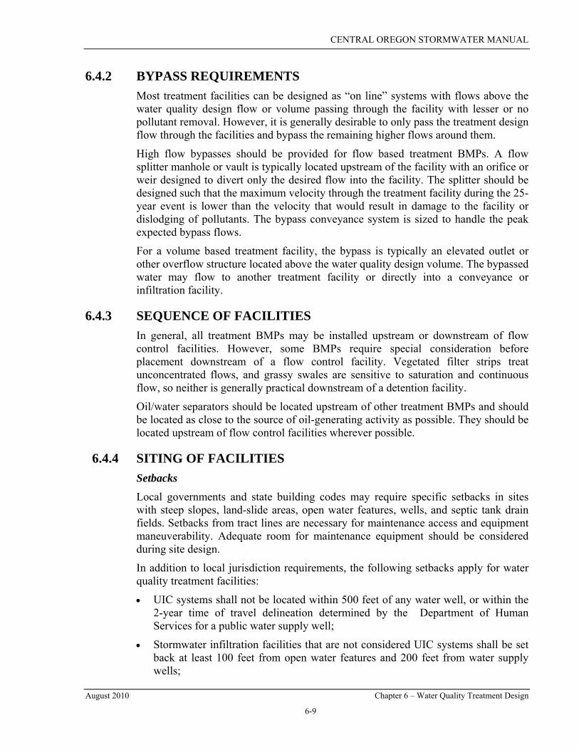
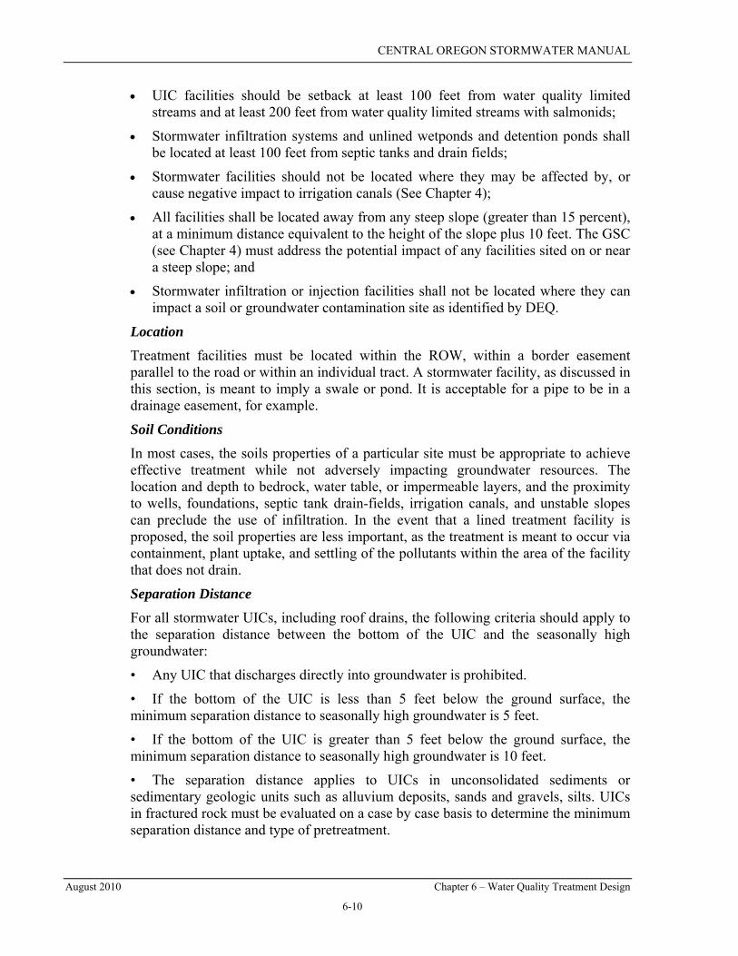
Typical cross sections for infiltration swales are shown in Figures 6-1 and 6-2.
6.5.1.1 INFILTRATION SWALE DESIGN Infiltration swales shall be sized to fully contain the water quality design volume as outlined in Section 6.4.1. No allowance for infiltration during the 6-month storm event is allowed (the volume of the swale below the overflow level must be at least equal to the volume of the 6-month storm event runoff). Storms larger than the water quality design storm should be directed to an overflow drywell or bypass the swale and be disposed of in another manner.
Swales shall have a minimum top width of 6 feet and a maximum water treatment depth (from swale bottom to elevation of first overflow/outflow mechanism) of 6 to 12 inches during the water quality design storm. Flows above the water quality design storm are allowed to exceed the 12-inch water treatment depth, provided the facility has adequate freeboard to accommodate the peak design volume. If designed as a flow control facility as well as a water quality treatment facility, the infiltration swale must have capacity to contain the 25-year design storm event and meet the requirements of Section 7.3.4.
When a drywell is installed for high flow bypass or overflow, the intake must be 12 inches (minimum) above the bottom of the swale if the swale depth is 18 inches or more. If the total swale depth is less than 18 inches, the intake may be 6 inches above the bottom of the swale.
When designed per the requirements shown in Figure 6-1, Infiltration Swales are not considered UICs. However overflow drywells are UICs and must be registered with DEQ. A sample infiltration swale sizing calculation is provided in Appendix 6A.
CENTRAL OREGON STORMWATER MANUAL
August 2010 Chapter 6 – Water Quality Treatment Design
6-13
Source: City of Portland Storm Water Management Manual
Figure 6-1 – Typical Infiltration Swale Cross Section
Source: Adapted from City of Portland Stormwater Management Manual
Figure 6-2 – Typical Infiltration Swale Cross Section
Add vegetation as required (See 6.5.1.2)
Max
Max
6 ft min top width
Vegetation as required (See 6.5.1.2)
Growing Medium
High Flow Bypass 18” Depth
CENTRAL OREGON STORMWATER MANUAL
August 2010 Chapter 6 – Water Quality Treatment Design
6-14
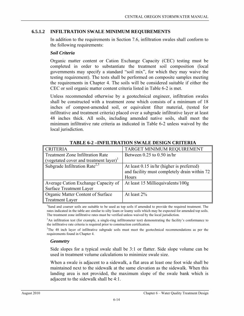
6.5.1.2 INFILTRATION SWALE MINIMUM REQUIREMENTS In addition to the requirements in Section 7.6, infiltration swales shall conform to the following requirements:
Soil Criteria Organic matter content or Cation Exchange Capacity (CEC) testing must be completed in order to substantiate the treatment soil composition (local governments may specify a standard “soil mix”, for which they may waive the testing requirement). The tests shall be performed on composite samples meeting the requirements in Chapter 4. The soils will be considered suitable if either the CEC or soil organic matter content criteria listed in Table 6-2 is met.
Unless recommended otherwise by a geotechnical engineer, infiltration swales shall be constructed with a treatment zone which consists of a minimum of 18 inches of compost-amended soil, or equivalent filter material, (tested for infiltrative and treatment criteria) placed over a subgrade infiltrative layer at least 48 inches thick. All soils, including amended native soils, shall meet the minimum infiltrative rate criteria as indicated in Table 6-2 unless waived by the local jurisdiction.
TABLE 6-2 –INFILTRATION SWALE DESIGN CRITERIA
CRITERIA TARGET MINIMUM REQUIREMENT Treatment Zone Infiltration Rate (vegetated cover and treatment layer)1
Between 0.25 to 0.50 in/hr
Subgrade Infiltration Rate2,3 At least 0.15 in/hr (higher is preferred) and facility must completely drain within 72 Hours
Average Cation Exchange Capacity of Surface Treatment Layer
At least 15 Milliequivalents/100g
Organic Matter Content of Surface Treatment Layer
At least 2%
1Sand and coarser soils are suitable to be used as top soils if amended to provide the required treatment. The rates indicated in the table are similar to silty loam or loamy soils which may be expected for amended top soils. The treatment zone infiltrative rates must be verified unless waived by the local jurisdiction. 2An infiltration test (for example, a single-ring infiltrometer test) demonstrating the facility’s conformance to the infiltrative rate criteria is required prior to construction certification. 3The 48 inch layer of infiltrative subgrade soils must meet the geotechnical recommendations as per the requirements found in Chapter 4.
Geometry Side slopes for a typical swale shall be 3:1 or flatter. Side slope volume can be used in treatment volume calculations to minimize swale size.
When a swale is adjacent to a sidewalk, a flat area at least one foot wide shall be maintained next to the sidewalk at the same elevation as the sidewalk. When this landing area is not provided, the maximum slope of the swale bank which is adjacent to the sidewalk shall be 4:1.
CENTRAL OREGON STORMWATER MANUAL
August 2010 Chapter 6 – Water Quality Treatment Design
6-15
Inlets and Overflow Curb inlets discharging into infiltration swales shall be per the criteria specified in Section 8.6.3. A minimum separation of 3 inches shall be maintained between the gutter curb drop or swale inlet and the top of the overflow drywell grate. Pipe inlet areas must be protected from erosion by rock riprap, concrete, or other non-erodible material.
A bypass or overflow structure must be provided unless the treatment facility is able to accommodate the 25-year design storm as well as the water quality design storm event. As shown in Figure 6-1, the high flow bypass or overflow structure should be located above the water quality treatment depth and at least 6 inches below the top of the swale bank. Overflow drywells shall be located outside the swale bottom area.
Vegetation Vegetation is required for swales that will provide pre-treatment prior to discharge to a UIC or surface water body. For infiltration swales that do not discharge to a UIC or surface water body, vegetation is not required unless directed by DEQ (e.g. around air permitted facilities) or the local jurisdiction. All swales, regardless of vegetation requirements, shall have an 18-inch deep treatment zone of compost-amended soil or equivalent filter material below the vegetation or rock surface.
When vegetation is required, plant materials such as dry-land grass and/or shrubs appropriate to local growing conditions are encouraged. Effective infiltration swales/ponds can be designed to be aesthetically pleasing using an array of natural landscaping approaches, with native vegetation or xeriscaping plants added as an option.
Planting and landscaping requirements are further discussed in Section 7.6.
Construction and Inspection In order to reduce the potential for compaction, construction equipment and vehicles shall be kept off the swale bottom. An infiltration test (per the requirements of Chapter 4) demonstrating the facility’s conformance to the infiltrative rate criteria is required prior to construction certification. The treatment facility must have vegetation established prior to passing final inspection. In addition, if during final inspection, it is found that the constructed infiltration swale does not conform to the accepted design, the system shall be reconstructed so that it does comply or another treatment facility may need to be added.
6.5.2 VEGETATED FILTER STRIPS Vegetated filter strips are primarily used adjacent and parallel to paved areas such as parking lots or driveways, and along rural roadways where sheet flow from the paved area will pass through the filter strip before entering a conveyance system or dispersing into areas where it can be infiltrated or evaporated.
CENTRAL OREGON STORMWATER MANUAL
August 2010 Chapter 6 – Water Quality Treatment Design
6-16
Vegetated filter strips are utilized to intercept overland sheet flow runoff from adjacent impervious areas. They slow runoff velocities, filter out sediment and other pollutants, and provide infiltration into underlying soils. One challenge associated with vegetated filter strips is the difficulty in maintaining sheet flow. Concentrated flows can short circuit the filter strips which can then contribute to eroded rills or flow channels across the strips. This results in little or no treatment of stormwater runoff.
In certain situations, a vegetated filter strip can be combined with a natural dispersion area (see Chapter 7) to provide both water quality treatment and flow control. In such a case, the Engineer must ensure that the minimum requirements in both Chapters 6 and 7 are met.
Vegetated filter strips are acceptable for use on any project that meets the general criteria listed below:
• The flow from the roadway must enter the filter strip as sheet flow. Thus, the vegetated filter strips must not receive concentrated flow discharges;
• A maximum flowpath (paved width) of 30 feet can contribute to a filter strip designed via this method (i.e. vegetated filter strips should typically not be proposed for super-elevated roads, unless the 30 foot width is adhered to);
• The roadway ADT must be less than 30,000 vehicles;
• The longitudinal slope of the contributing drainage area parallel to the edge of the pavement shall be 4 percent or less; and
• The lateral slope (typically the cross-slope of the road) of the contributing drainage area perpendicular to the pavement edge or road cross slope shall be 5 percent or less.
Typical vegetated filter strip details are shown in Figure 6-3.

CENTRAL OREGON STORMWATER MANUAL
August 2010 Chapter 6 – Water Quality Treatment Design
6-17
Figure 6-3 – Typical Vegetated Filter Strip (details)
6.5.2.1 VEGETATED FILTER STRIP DESIGN This procedure is based on the Narrow Area Filter Strips presented in the 1998 King County Surface Water Design Manual. Sample vegetated filter strip calculations are provided in Appendix 6B.
Note: Flow spreader is optional. If used, the gravel must be wider than deep to avoid UIC regulations.

CENTRAL OREGON STORMWATER MANUAL
August 2010 Chapter 6 – Water Quality Treatment Design
6-18
The sizing of the filter strip is based on the flowpath distance draining to the filter strip and the cross slope of the filter strip itself (parallel to the flowpath). The following design steps shall be followed:
1. Determine the flowpath draining to the filter strip. Normally this is the width of the paved area draining to the strip, but if the site is sloped the flow path must be measured at an angle. For crowned roads, the flowpath is the distance from the crown to the edge of pavement;
2. Determine the average lateral or cross slope of the filter strip. Calculate the cross slope of the filter strip (parallel to the flowpath), averaged over the total width of the filter strip. If the slope is less than 2 percent, use 2 percent for sizing purposes. The maximum cross slope allowed is 6H:1V or 17 percent; and,
3. Determine required length of the filter strip. Use Figure 6-4 to size the filter strip. To use the figure, find the curve representing the appropriate flowpath distance (interpolate between curves as necessary). Find the point along the curve where the design cross slope of the filter strip is directly below and read the filter strip length to the left on the y-axis. The filter strip must be designed to provide this minimum length, “L,” parallel to the flow path along the entire stretch of pavement draining to it.
Source: King County Surface Water Design Manual, 1998
Figure 6-4 – Vegetated Filter Strip Design Chart
CENTRAL OREGON STORMWATER MANUAL
August 2010 Chapter 6 – Water Quality Treatment Design
6-19
6.5.2.2 VEGETATED FILTER STRIP MINIMUM REQUIREMENTS Vegetated filter strips shall meet the minimum requirements for planting, and general requirements specified in Section 7.6. In addition, the design of filter strips shall conform to the following requirements:
Geometry Refer to Figure 6-3. The minimum required filter strip width is: 4’ for a 10’ flowpath; 4.5’ for a 25’ flowpath; and 5.5’ for a 30’ flowpath. Flowpath is the distance of the paved surface discharging to the filter strip.
The cross-slope of the filter strip shall be no steeper than 6:1 or 17 percent.
Along roadways, filter strips should be placed at least 1 foot, but preferably 3 to 4 feet from the edge of pavement, to accommodate a vegetation free zone. The separation distance can include the energy dissipating trench described below.
Energy Dissipation A shallow gravel trench shall be installed between the pavement surface and the filter strip to maintain sheet flow. This area serves as a flow spreader and shall consist of a shallow trench filled with crushed aggregate. The gravel area shall be a minimum of 6 inches deep and 12 inches wide.
Landscaping Vegetated filter strips may be planted with turf grasses and native vegetation such as small herbaceous shrubs. This makes the system effective in treating runoff and providing root penetration into subsoils, thereby enhancing infiltration. Additional planting and landscaping information is provided in Section 7.6.
Construction Vegetated filter strips shall be constructed after other portions of the project are completed. Care should be taken to avoid compaction of the area used for a filter strip. If the filter strip area has been compacted during construction, the soil shall be tilled and/or amended with compost prior to installing the filter strip.
6.5.3 OIL/WATER SEPARATORS Oil control shall be provided for all high-use sites. Oil/Water Separators are BMPs used to remove oil and other water-insoluble hydrocarbons from stormwater runoff. Oil/water separators rely on passive mechanisms that take advantage of oil being lighter than water.
Oil/water separators are best located in areas where the drainage area is nearly all impervious and a fairly high load of petroleum hydrocarbons is likely to be generated (greater than 20 mg/L). Oil/water separators are not recommended for areas with very dilute concentrations of petroleum hydrocarbons (less than 20 mg/L) since their performance is not effective at low concentrations. Oil/water separators are required for high use sites, but must precede another water quality treatment BMP to meet basic, metals, or phosphorus treatment goals.
CENTRAL OREGON STORMWATER MANUAL
August 2010 Chapter 6 – Water Quality Treatment Design
6-20
The two types of systems typically used for stormwater treatment are the conventional gravity API (American Petroleum Institute) oil/water separator and the coalescing plate oil/water separator. Oil/water separators typically consist of three bays: forebay, separator section, and the afterbay. Detailed design information for coalescing plate and baffle type OWS can be found in Chapter 5 of the Stormwater Management Manual for Eastern Washington. For certain sites, a T elbow within a catch basin or manhole can be used for oil removal.
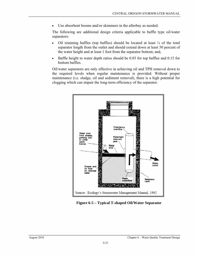
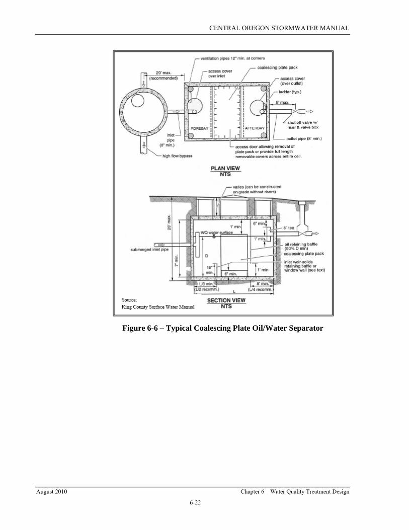
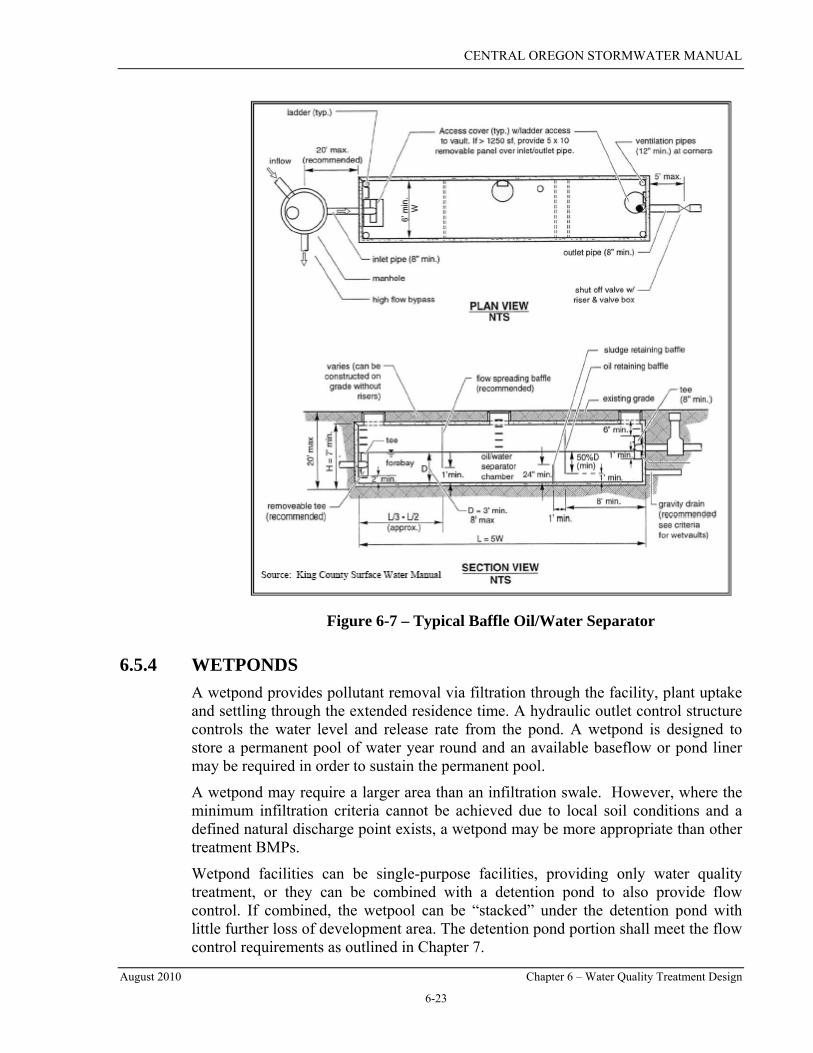
A typical T-shaped oil/water separator structure is shown in Figure 6-5. Figures 6-6 and 6-7 show typical baffle and coalescing plate OWS structures.
6.5.3.1 OIL/WATER SEPARATOR MINIMUM REQUIREMENTS The following design criteria are applicable to all oil/water separators:
• Use only impervious conveyances for oil contaminated stormwater;
• Do not use an oil/water separator for the removal of dissolved or emulsified oils such as coolants, soluble lubricants, glycols, and alcohols;
• “T” or elbow separators within a catchbasin are not allowed as a stand-alone oil control device for high use sites. If used in series with another water quality treatment facility or flow control facility, they can be used to control oil from a high use sites; and
• The oil/water separator shall be located upstream of other water quality treatment or flow control facilities.
The following are design criteria applicable to both coalescing plate and baffle type oil/water separators:
• If possible, determine expected oil/grease (or TPH) and TSS concentrations, lowest temperature, pH, empirical oil rise rates in the runoff, oil viscosity and specific gravity of the oil; and utilize as needed in the design procedure.
• If possible, locate the separator off-line and bypass flows in excess of the water quality design flow rate;
• Consider pretreatment for TSS (i.e. a sedimentation manhole) where clogging is a concern;
• Design the surface area of the forebay at 20 square feet per 10,000 square feet of area draining to the separator;
• The length of the forebay should be 1/3 to ½ the length of the entire separator;
• Include roughing screens for the forebay to remove debris (screen openings should be about ¾ inch;
• Include a submerged inlet pipe with a turned-down elbow in the forebay at least two feet from the bottom; the outlet pipe should be a “T” sized to pass the design peak flow and placed at least 12 inches below the water surface;
• Size the separator bay for the water quality design flow rate;
• Include a shutoff mechanism at the separator outlet pipe; and,
CENTRAL OREGON STORMWATER MANUAL
August 2010 Chapter 6 – Water Quality Treatment Design
6-21
• Use absorbent booms and/or skimmers in the afterbay as needed.
The following are additional design criteria applicable to baffle type oil/water separators:
• Oil retaining baffles (top baffles) should be located at least ¼ of the total separator length from the outlet and should extend down at least 50 percent of the water height and at least 1 foot from the separator bottom; and,
• Baffle height to water depth ratios should be 0.85 for top baffles and 0.15 for bottom baffles.
Oil/water separators are only effective in achieving oil and TPH removal down to the required levels when regular maintenance is provided. Without proper maintenance (i.e. sludge, oil and sediment removal), there is a high potential for clogging which can impair the long-term efficiency of the separator.
Figure 6-5 – Typical T-shaped Oil/Water Separator
CENTRAL OREGON STORMWATER MANUAL
August 2010 Chapter 6 – Water Quality Treatment Design
6-22
Figure 6-6 – Typical Coalescing Plate Oil/Water Separator
CENTRAL OREGON STORMWATER MANUAL
August 2010 Chapter 6 – Water Quality Treatment Design
6-23
Figure 6-7 – Typical Baffle Oil/Water Separator
6.5.4 WETPONDS A wetpond provides pollutant removal via filtration through the facility, plant uptake and settling through the extended residence time. A hydraulic outlet control structure controls the water level and release rate from the pond. A wetpond is designed to store a permanent pool of water year round and an available baseflow or pond liner may be required in order to sustain the permanent pool.
A wetpond may require a larger area than an infiltration swale. However, where the minimum infiltration criteria cannot be achieved due to local soil conditions and a defined natural discharge point exists, a wetpond may be more appropriate than other treatment BMPs.
Wetpond facilities can be single-purpose facilities, providing only water quality treatment, or they can be combined with a detention pond to also provide flow control. If combined, the wetpool can be “stacked” under the detention pond with little further loss of development area. The detention pond portion shall meet the flow control requirements as outlined in Chapter 7.
CENTRAL OREGON STORMWATER MANUAL
August 2010 Chapter 6 – Water Quality Treatment Design
6-24
6.5.4.1 WETPOND DESIGN The treatment storage volume for a “basic wetpond” shall be 2.5 times the 6-month, 24-hour design storm runoff volume. The SCS Type 1 design storm shall be used. The first orifice or outlet device structure shall be placed no lower than the maximum water surface elevation required to store the treatment storage volume.
A “large wetpond” is only required when phosphorus control is applicable and a treatment train of water quality facilities is not desirable (see Table 6-1). A large wetpond shall accommodate a treatment storage volume that is 50 percent greater than that of the basic wetpond. All other design criteria remain the same.
Most wetponds are two celled, with a sediment forebay as the first cell at the inlet to the pond, and a permanent wetpool as the second cell. In porous soils, wetponds may still be used, but seepage from unlined cells could result in a dry pond, particularly in summer months. Lining the first cell with a low permeability liner is one way to deal with this situation (reference Chapter 7 for liner criteria and requirements), though it is not required for treatment effectiveness.
Refer to Figures 6-8 and 6-9 for illustrations of this BMP.
6.5.4.2 WETPOND MINIMUM REQUIREMENTS The primary design factor that determines a wetpond’s treatment efficiency is the volume of the wetpool. Larger wetpool volumes provide greater potential for pollutant removal. In addition to the requirements in Section 7.2, wetponds shall meet the following minimum requirements.
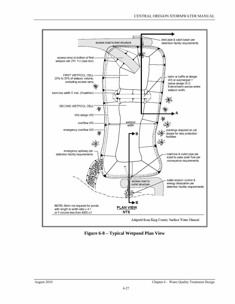
Wetpond Geometry The wetpond shall be divided into two cells, separated by a baffle or berm. The first cell shall contain between 25 and 35 percent of the treatment storage volume. The baffle or berm volume shall not count as part of the total wetpool volume. The berm or baffle shall extend across the full width of the pond.
Sediment storage should be provided in the first cell. The sediment storage should have a minimum depth of 1 foot. This first cell shall have a minimum water quality design depth of 4 feet, exclusive of sediment storage requirements. The depth of the first cell can exceed the depth of the second cell. The first cell may be lined as needed.
The second cell shall have a minimum water depth of 2.5 feet. The maximum depth of either cell should not exceed 8 feet. Pool depths of 3 feet or less (second cell) should be planted with emergent wetland vegetation.
The flow path length-to-width ratio, measured at mid-depth between the inlet and outlet, should be at least 3:1. Internal berms can be used to increase the flow path length. If there are multiple inlets, the length-to-width ratio should be based on the average flow path length for all inlets.

CENTRAL OREGON STORMWATER MANUAL
August 2010 Chapter 6 – Water Quality Treatment Design
6-25
Wetponds with treatment storage volumes less than or equal to 4,000 cubic feet may be single celled (i.e. no baffle or berm is required). For a single celled wetpond, the length-to-width ratio shall be a minimum of 4:1, but preferably 5:1.
To prevent short-circuiting and promote plug flow (where water moves through the facility as a unit, displacing “old” water with incoming flows), the pond should be designed to avoid “dead zones” and maximize the time water stays in the pond. This is achieved by providing proper energy dissipation at the inlet, providing a large length-to-width ratio, maximizing the flow path length, and providing a broad surface for water exchange between the first and second cell (i.e. a berm rather than a pipe).
Inlet and Outlet Criteria Inlets and outlets should be placed to maximize the flow path through the facility. All inlets (pipes or weir) shall enter the first wetpond cell with the pipe invert(s) located a minimum of 1 foot above the top of the sediment storage depth. The top of the inlet pipe should be submerged beneath the water quality design volume surface at least 1 foot, if possible. Inlet erosion protection shall be provided as per detention facility requirements.
An outlet control device is required in order to control the water surface elevation in the pond and prevent floatables from discharging downstream. The outlet control device shall be a manhole or catch basin meeting local jurisdiction standards. The outlet structure receives flow from 12-inch minimum diameter pond outlet pipe. The outlet pipe shall be back-sloped or have a turned-down elbow and extend one foot below the water quality design surface to trap oils and floatables. The outlet pipe shall be sized, at a minimum, to pass the water quality design flow. Note: the highest invert of the outlet pipe controls the water quality design surface elevation and must be set at or above the treatment storage volume.
A grate-type opening shall also be provided in the outlet structure as an emergency overflow route should the pond outlet pipe become clogged. The overflow criteria for single-purpose (treatment only, not combined with flow control) wetponds are as follows:
• The grated opening shall be sized to pass the peak flow draining to the facility. The capacity of the outlet system (out of structure to defined channel) shall be sized to pass the peak flow for the conveyance requirements in Chapter 8;
• The bottom of the grate opening in the outlet structure shall be set at or above the height needed to pass the water quality design flow through the pond outlet pipe. Note: The grate invert elevation sets the overflow water surface elevation; and,
• An emergency spillway shall be provided and shall be designed according to the requirements for detention ponds in Chapter 7.
Seepage collars shall be provided around any penetrations within the wetted perimeter of the pond.

CENTRAL OREGON STORMWATER MANUAL
August 2010 Chapter 6 – Water Quality Treatment Design
6-26
Berms, Baffles, and Slopes The berm that separates the first and second wetpond cells shall be a minimum of 5 feet wide (if earthen). The top of berm elevation shall be no higher than the water quality design surface, but may be a maximum of 1 foot below this same surface (to enhance safety by discouraging pedestrian crossing). The berm shall extend across the entire width of the wetpond. If the interior berm embankment is greater than 4 feet in height, the berm must be constructed by excavating a key equal to 50 percent of the embankment cross-sectional height and width. This requirement may be waived if designed by a Geotechnical Engineer and approved by the local jurisdiction. The interior berm may also be a retaining wall (baffle) provided that the design is prepared, stamped and signed by a qualified Engineer; a retaining wall berm must be submerged 1 foot below the water quality surface.
Interior wetpond side slopes should be no steeper than 3H:1V. Side slopes of 4H:1V are preferable, especially around the sediment forebay. Interior berm side slopes shall be 3H:1V minimum (2H:1V is allowed if the berm will be fully submerged below the permanent pool depth).
Safety Ledges Safety ledges shall be constructed in wetponds where the total water depth (including detention storage, if applicable) exceeds 3 feet. A minimum 4-foot wide safety ledge (or aquatic bench) shall extend around the perimeter of the wetpond, excluding at the inlet where the sediment forebay is. The bench shall be located at or 6 inches below the wetpool water level. The underwater sideslopes should be steep to prevent vegetative growth, and the ledge itself should be flat or inverted toward the outer pond perimeter. An aquatic bench will thrive in depths of water approximately two feet or less. The bench will help promote perimeter vegetation which can enhance sedimentation and biological/chemical uptake.
If the wetpond is also designed as a flow control facility, the peripheral ledges shall be submerged no deeper than 2 feet below the maximum water surface elevation as determined by the detention facility analysis.
Mosquito Control Mosquito control must be considered in any pond design. Refer to Appendix 6D for more information.
CENTRAL OREGON STORMWATER MANUAL
August 2010 Chapter 6 – Water Quality Treatment Design
6-27
Figure 6-8 – Typical Wetpond Plan View
CENTRAL OREGON STORMWATER MANUAL
August 2010 Chapter 6 – Water Quality Treatment Design
6-28
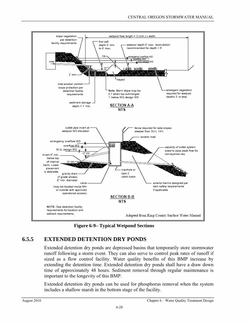
Figure 6-9– Typical Wetpond Sections
6.5.5 EXTENDED DETENTION DRY PONDS Extended detention dry ponds are depressed basins that temporarily store stormwater runoff following a storm event. They can also serve to control peak rates of runoff if sized as a flow control facility. Water quality benefits of this BMP increase by extending the detention time. Extended detention dry ponds shall have a draw down time of approximately 48 hours. Sediment removal through regular maintenance is important to the longevity of this BMP.
Extended detention dry ponds can be used for phosphorus removal when the system includes a shallow marsh in the bottom stage of the facility.
CENTRAL OREGON STORMWATER MANUAL
August 2010 Chapter 6 – Water Quality Treatment Design
6-29
Extended detention dry ponds shall comply with all general facility requirements in Section 7.6. In many ways, these facilities will look like the wetponds depicted in Figures 6-8 and 6-9, though the outlet structure design will be different.
Seepage collars shall be provided around any penetrations within the wetted perimeter of the pond.
6.5.5.1 EXTENDED DETENTION DRY POND DESIGN Extended detention dry ponds shall be designed to store the full water quality design volume outlined in Section 6.4.1. Emergency spillways shall be located above the water quality design volume elevation.
Dry ponds shall be designed as two cell facilities, with the first cell (forebay) composing 25 to 35% of the treatment volume. Where space limits multi-celled design, use one cell with a forebay at the inlet to settle sediments and distribute flow across the second cell.
The outlet orifice shall be located six inches above the bottom of the pond to allow for sediment storage and settling in the second cell (the sediment storage shall not be counted in the total pond volume). The outlet orifice shall be designed to drain the water quality storm from the dry pond in approximately 48 hours. By using orifice control, the top portion of the pond will drain relatively quickly, while the lower portion of the pond will drain at a slower rate, providing increased treatment for smaller storms. Size the outlet orifice using equations 6-4 and 6-5.
60*60*48
VQ = (6-4)
Where: Q = max allowable water quality outflow rate (cfs);
V = water quality design volume (cf);
5.0
5.0 /)2(
*24 ⎥⎦
⎤⎢⎣
⎡= π
gHCQD (6-5)
Where: D = diameter of outlet orifice (in);
Q = max allowable water quality outflow rate (cfs);
C = 0.62 (orifice coefficient);
H = 2/3 * water quality design storage depth (ft).
6.5.5.2 EXTENDED DETENTION DRY POND MINIMUM REQUIREMENTS Extended detention dry pond facilities, if also utilized as a flow control facility, shall meet the flow control requirements as outlined in Chapter 7. This BMP should also consider the impact if placed too near a seasonal or permanent groundwater table.

CENTRAL OREGON STORMWATER MANUAL
August 2010 Chapter 6 – Water Quality Treatment Design
6-30
The maximum depth of the water quality treatment depth (not including the sediment storage) is 4 feet, unless approved otherwise by the local jurisdiction. The water quality treatment storm should drain within 48 hours. If additional storage is included in the pond for larger storm events, the total facility should drain within 72 hours following the peak design storm event.
All other design requirements for inlets and outlets, and berms, baffles, and slopes shall comply with the wetpond requirements in Section 6.6.5. All other design elements should meet the general facility requirements in Section 7.6.
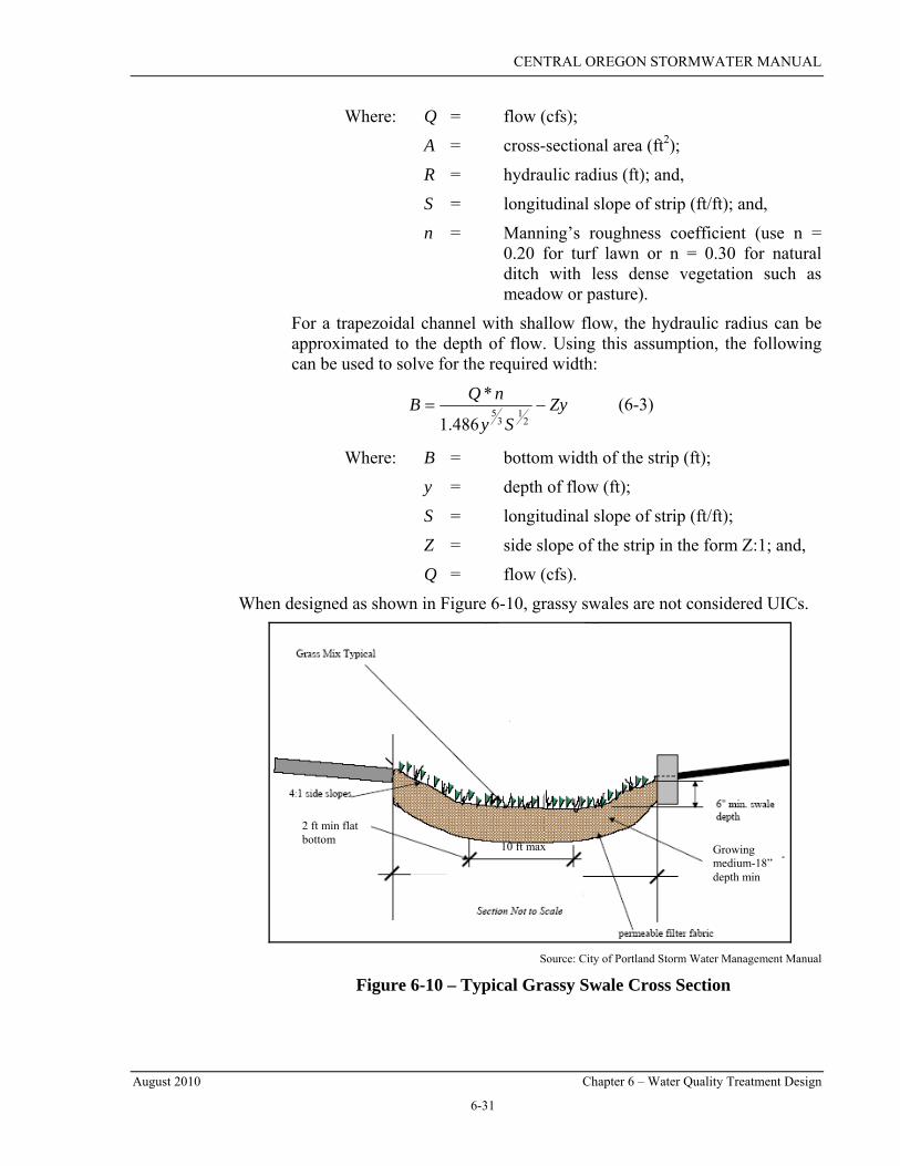
6.5.6 GRASSY SWALES Grassy swales (also called biofiltration channels) use simultaneous processes of filtration, particle settling, adsorption, and very minor biological uptake of pollutants in stormwater that occurs when runoff flows over and through vegetated areas. Grassy swales are sloped, vegetated channels or ditches that both convey and treat stormwater runoff. They are differentiated from infiltration swales (section 6.5.1), in that their primary treatment methods are through filtering and settling as opposed to infiltration. Grassy swales do not provide flow control but can convey runoff to facilities designed for that purpose. A typical grassy swale cross section is shown in Figure 6-10.
Applications and Restrictions Grassy swales can be used for basic treatment, or they can be used for metals treatment when preceded by an oil/water separator. Due to vegetation requirements, grassy swales are challenging to maintain in Central Oregon. Projects proposing to use grassy swales must show how the vegetation will be maintained through long term irrigation or other means. In many areas, an infiltration swale with native landscaping may be more appropriate and easier to maintain than a grassy swale.
Design Guidelines and Calculations The following procedure shall be followed when designing grassy swales.
1. Determine the water quality design flow rate as outlined in Section 6.5.1;
2. Determine the bottom width of the swale using equation 6-2 or 6-3.
3. Calculate the cross sectional area of flow for the given channel and verify that the flow velocity is less than or equal to 1 foot per second; and,
4. Calculate the length of the channel and verify that the residence time is at least 9 minutes. The minimum channel length is 100 feet.
Commercially available software is most commonly used to compute many of the parameters associated with the sizing of a biofiltration channel. Refer to example in Appendix 6C.
Equations:
nSARQ
21
32
486.1= (6-2)
CENTRAL OREGON STORMWATER MANUAL
August 2010 Chapter 6 – Water Quality Treatment Design
6-31
Where: Q = flow (cfs);
A = cross-sectional area (ft2);
R = hydraulic radius (ft); and,
S = longitudinal slope of strip (ft/ft); and,
n = Manning’s roughness coefficient (use n = 0.20 for turf lawn or n = 0.30 for natural ditch with less dense vegetation such as meadow or pasture).
For a trapezoidal channel with shallow flow, the hydraulic radius can be approximated to the depth of flow. Using this assumption, the following can be used to solve for the required width:
ZySy
nQB −=2
13
5486.1
* (6-3)
Where: B = bottom width of the strip (ft);
y = depth of flow (ft);
S = longitudinal slope of strip (ft/ft);
Z = side slope of the strip in the form Z:1; and,
Q = flow (cfs).
When designed as shown in Figure 6-10, grassy swales are not considered UICs.
Source: City of Portland Storm Water Management Manual
Figure 6-10 – Typical Grassy Swale Cross Section
10 ft max
2 ft min flat bottom
Growing medium-18” depth min

CENTRAL OREGON STORMWATER MANUAL
August 2010 Chapter 6 – Water Quality Treatment Design
6-32
Geometry
The ideal cross-section is a trapezoid with sideslopes no steeper than 4:1. However, a rectangular shape can be proposed if there are topographical constraints or other construction concerns.
The channel slope shall be at least 1 percent and no greater than 5 percent. When slopes less than 2 percent are used, evaluate the need for under-drainage. (Underdrains will result in the grassy swale being a UIC unless an impermeable liner is placed below the underdrain and the underdrain has a surface discharge location.)
The bottom width shall be determined based on the desired flow depth. The minimum bottom width is 2 feet for private facilities and 4 feet for public. The depth of flow shall not exceed 4 inches for turf grass or 3 inches for dryland grasses during the design storm.
The maximum bottom width is 10 feet. If the calculated bottom width exceeds 10 feet, parallel biofiltration channels shall be used in conjunction with a flow splitter device.
The grassy swale shall have a minimum residence time of 9 minutes during the water quality design flow. The minimum length, in any case, shall be no less than 100 feet in length.
The flow velocity shall not exceed 1 foot per second during the water quality design flow. Unless a flow splitter is installed upstream to bypass flows greater than the water quality design flow, the swale shall have capacity to carry the 25-year design flow at a velocity not exceeding 3 feet per second.
Vegetation Grassy swales shall be planted with turf grasses, particularly in the treatment area. Side slopes may be planted with native vegetation meeting the planting and landscaping requirements in Section 7.6. The project application must include provisions for long term vegetation maintenance including irrigation and mowing.
6.5.7 SEDIMENTATION MANHOLES Sedimentation manholes are variations on a traditional manhole with the majority of the structure located below the invert of the pipe inlets. This sump provides for sediment, debris, and oil removal.
Applications and Restrictions
Sedimentation manholes provide settling and debris collection, but do not provide adequate treatment as a stand-alone facility. Sedimentation manholes can be used as pretreatment for UICs that are Rule Authorized as part of a treatment train. In traffic areas with an Average Daily Traffic (ADT) volume of 1,000 or more trips per day (as determined by ITE approved methods), DEQ only allows the use of sedimentation manholes under an individual Water Pollution control Facilities (WPCF). Sedimentation manholes are also recommended as a source control measure for several site uses identified in Chapter 10.
CENTRAL OREGON STORMWATER MANUAL
August 2010 Chapter 6 – Water Quality Treatment Design
6-33
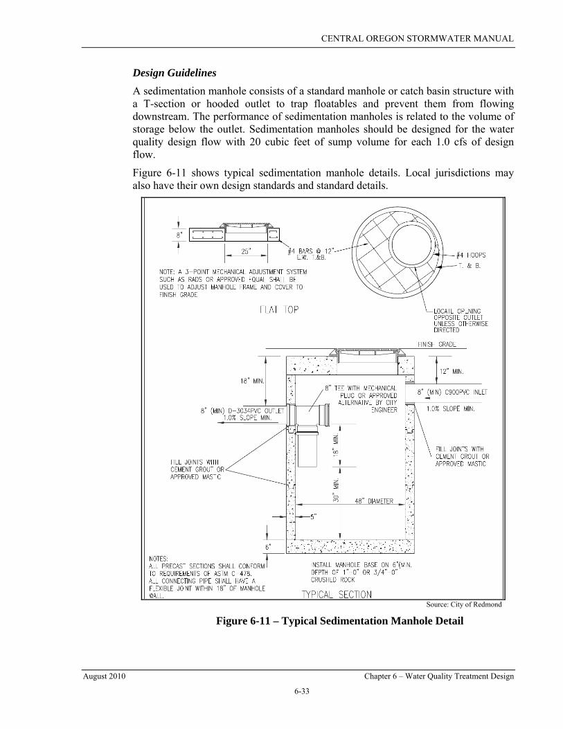
Design Guidelines
A sedimentation manhole consists of a standard manhole or catch basin structure with a T-section or hooded outlet to trap floatables and prevent them from flowing downstream. The performance of sedimentation manholes is related to the volume of storage below the outlet. Sedimentation manholes should be designed for the water quality design flow with 20 cubic feet of sump volume for each 1.0 cfs of design flow.
Figure 6-11 shows typical sedimentation manhole details. Local jurisdictions may also have their own design standards and standard details.
Source: City of Redmond
Figure 6-11 – Typical Sedimentation Manhole Detail
CENTRAL OREGON STORMWATER MANUAL
August 2010 Chapter 6 – Water Quality Treatment Design
6-34
Cleaning and Maintenance
Sedimentation manholes require an enforceable plan and adequate access for long term inspection, cleaning, and maintenance. Annual inspections (at a minimum) are required. For sedimentation manholes installed in areas with ADT of 1,000 or more trips per day, increased inspection and maintenance is necessary.
6.5.8 EMERGING TECHNOLOGIES Emerging technologies are new technologies that have not been fully evaluated using approved protocols, but for which preliminary data indicate that they may provide an adequate level of stormwater pollutant removal.
During the last 10 years, new technologies have been under development to meet the standards of urban stormwater pollutant control. Some examples of these technologies include:
• Media Filters;
• Amended Sand Filters; and
• Catch Basin Inserts (e.g. vortex-enhanced settling, cylindrical screening).
Some emerging technologies have already been installed as parts of treatment trains or stand-alone systems for specific applications. In some cases, emerging technologies are appropriate to remove metals, hydrocarbons, and nutrients. They are often used for retrofits where land is unavailable for larger treatment systems.
DEQ does not have a standardized procedure for evaluating emerging technologies. However, the Washington State Department of Ecology (DOE) has developed protocols to evaluate the performance of emerging technologies and proprietary treatment devices. The Technology Assessment Protocol (TAPE) is intended for ultra-urban treatment technologies and those treatment technologies that do not have a chemical component for treatment. The Chemical Technology Assessment Protocol (CTAPE) is intended for construction site treatment technologies and any technology that uses a chemical component for treatment. Based on testing data, DOE determines a “level of development” for each of the new technologies and posts the information on their website:
http://www.ecy.wa.gov/programs/wq/stormwater/newtech/index.html
Project proponents should use the DOE approvals page as a guide in determining which technologies may be appropriate for use. In general, only those technologies that have received a General Use Level or Conditional Use Level designation should be considered. The Pilot Use Level designation indicates that a technology needs further testing to evaluate the effectiveness.
With any emerging technology, the ultimate review and decision rests with the local government or state agency reviewing and approving the project. Local governments should remember the treatment goals and exercise caution when reviewing applications for emerging technologies. Local governments are encouraged to conduct a monitoring program of emerging technologies to compare their performance with the treatment goals outlined in Section 6.3.

CENTRAL OREGON STORMWATER MANUAL
August 2010 Appendix 6A –Infiltration Swale Calculation
6A-1
APPENDIX 6A –INFILTRATION SWALE CALCULATION
GIVEN
• The developed site consists of 5 total acres between Bend and Redmond:
○ 20 residential lots, approximately 10,000 square foot each
○ 1,500 sq. ft homes with 500 sq ft driveways
○ 0.50 acres of road impervious areas
• The subgrade soil has 10 percent fines and an infiltrative rate of 0.25 inches per hour.
CALCULATIONS 1. Determine the total PGS for the site.
Road PGS: 0.50 acres * 43,560 sq ft/acre = 21,780 sq ft Driveway PGS: 500 sq ft * 20 driveways = 10,000 sq ft Total PGS: 10,000 sq ft + 21,780 sq ft = 31,780 sq ft = 0.73 ac Curve Number for PGS: = 98
2. Categorize the remaining surfaces of the site.
Residential Area: 5.0 acres – 0.73 acres = 4.27 ac
Curve Number: ¼ acre lots with Type B soils = 75
3. Determine the water quality design volume, using SCS Method.
2-year, 24-hour rainfall: 1.2 inches (Appendix 5A)
6-month, 24-hour rainfall: 0.67 * 1.2 = 0.8 inches (Section 6.4.1)
Assuming time of concentration of 6 minutes
Using software program: Water Quality Design Volume = 1,661 cu ft
(Note that the WQ Design volume is fairly low because Type B soils will infiltrate much of the runoff from a 6-month storm event.)
4. Determine the geometry of the infiltration facility
Use a treatment depth of 6 inches (12 inches is allowed if drain-down time is less than 72 hours)
Pond Bottom Area Required* = ..322,31
126
661,1 ftsqftin
incf
⋅=⋅
∗⋅⋅
* For this example, there are no space constraints and sideslope volume has been ignored.
Provide an infiltrative facility with a 3,322 sq ft swale bottom area

CENTRAL OREGON STORMWATER MANUAL
August 2010 Appendix 6A –Infiltration Swale Calculation
6A-2
THIS PAGE IS INTENTIONALLY LEFT BLANK

CENTRAL OREGON STORMWATER MANUAL
August 2010 Appendix 6B – Vegetated Filter Strip Calculation
6B-1
APPENDIX 6B –VEGETATED FILTER STRIP CALCULATION
GIVEN • A typical crowned road, with a 30 foot wide half road
• Road cross slope is 2 percent
• Average longitudinal slope is 4 percent
• The land adjacent to the road (where the filter strip will be located) slopes away at an average slope of 5 percent
CALCULATIONS
5. Determine the flowpath distance draining to the filter strip.
Flow path is 30 feet
6. Determine the average lateral or cross slope of the filter strip:
Filter strip cross slope = slope parallel to the flow path, averaged over the total width of the filter strip. Use 5 percent
7. Determine required width of the filter strip using Figure 6-3 to size the filter strip.
From Figure 6-3: 9 feet
Check that calculated distance meets minimum requirements:
9 > 5.5 feet OK
Provide an 18-inch wide, 12-inch deep (minimum) gravel filled trench along the entire length of pavement to help maintain sheet flow across the filter strip.

CENTRAL OREGON STORMWATER MANUAL
August 2010 Appendix 6B – Vegetated Filter Strip Calculation
6B-2
THIS PAGE IS INTENTIONALLY LEFT BLANK

CENTRAL OREGON STORMWATER MANUAL
August 2010 Appendix 6C – Grassy Swale Calculation
6C-1
APPENDIX 6C – GRASSY SWALE CALCULATION
GIVEN
• Weighted permeable CN = 75
• Permeable area = 4.27 acres
• Impervious CN = 98
• Impervious area = 0.73
• PGS = 31,720 sq ft
• Two-year, 24-hour storm precipitation = 1.2 inches
• Time of concentration = 6 minutes
CALCULATIONS 8. Determine the peak flow rate using the 6-month SCS Type I 24 hr storm and the methods
described in Chapter 5.
6-month precipitation = 0.67 * 1.2 in = 0.8 inches
Using a computer program, the peak flow rate is estimated to be 0.55 cfs.
9. Determine the bottom width of the channel using equation 6-3.
Assume: A trapezoidal channel with 3:1 side slopes;
4 inches for flow depth;
Turf lawn vegetation with Manning’s n = 0.20; and,
3 % longitudinal slope for biofiltration channel.
ZySy
nQB −=2
13
5486.1
*
ftft
inin
ftft
ftinin
cfsB 6.112
4*3
03.012
4486.1
20.0*55.0
213
5 =⎥⎥⎥
⎦
⎤
⎢⎢⎢
⎣
⎡
⎟⎟⎟
⎠
⎞
⎜⎜⎜
⎝
⎛−
⎥⎥⎥⎥⎥⎥⎥⎥
⎦
⎤
⎢⎢⎢⎢⎢⎢⎢⎢
⎣
⎡
⎟⎟⎠
⎞⎜⎜⎝
⎛
⎟⎟⎟
⎠
⎞
⎜⎜⎜
⎝
⎛=

CENTRAL OREGON STORMWATER MANUAL
August 2010 Appendix 6C – Grassy Swale Calculation
6C-2
10. Calculate the cross sectional area of flow for the given channel and verify that the flow velocity is less than or equal to 1 ft/sec;
Area = y (B+ Zy) = ..86.012
436.112
4 ftsqft
ininftft
ftinin
⋅=⎟⎟⎟
⎠
⎞
⎜⎜⎜
⎝
⎛
⎟⎟⎟
⎠
⎞
⎜⎜⎜
⎝
⎛⋅
⋅+⋅∗⎟⎟⎟
⎠
⎞
⎜⎜⎜
⎝
⎛⋅
Velocity = 1sec/64.0.86.0
55.0≤⋅=
⋅⋅
= ftftsq
cfsAQ OK
11. Calculate the length of the channel to meet the 9 minute residence time. The minimum channel length is 100 feet.
ftfttVL 346min1
sec60min*9sec64.0 =⋅
∗=∗=
If the site cannot accommodate the required channel length, the width can be increased. Steps 3 and 4 should be repeated until the channel geometry best fits the existing site conditions.
THE CHANNEL GEOMETRY IS AS FOLLOWS
• Trapezoidal shape with 3:1 side slopes
• 3 percent longitudinal slope
• Channel bottom width is 1.6 feet
• Minimum Channel length is 345 feet

CENTRAL OREGON STORMWATER MANUAL
August 2010 Appendix 6D – Mosquito Control
6D-1
APPENDIX 6D – MOSQUITO CONTROL The following article contains additional information regarding the potential for stormwater facilities to serve as breeding grounds for mosquitoes. Note that applying pesticides to any standing water in a UIC or to a catch basin or sedimentation manhole that discharges to a UIC, to control vectors (e.g. mosquitoes) is prohibited. In addition, drilling holes in the bottom of catch basins for mosquito control effectively makes them UICs.
Due to a recent federal court decision regarding the application of pesticides in water, the US EPA has to come out with new rules that will require vector control maintenance districts to have permits. As of this publication, the applicable permit has not been developed by EPA. Applicants should contact DEQ’s Water Quality Division directly for the latest information on mosquito control and the application of pesticides in water.
Source: US EPA Nonpoint Source News-Notes, May 2003, #71

CENTRAL OREGON STORMWATER MANUAL
August 2010 Appendix 6D – Mosquito Control
6D-2

CENTRAL OREGON STORMWATER MANUAL
August 2010 Appendix 6D – Mosquito Control
6D-3

CENTRAL OREGON STORMWATER MANUAL
August 2010 Appendix 6D – Mosquito Control
6D-4
THIS PAGE IS INTENTIONALLY LEFT BLANK