iacs€¦ · · 2011-11-22rec 47 shipbuilding and repair quality standard rev.5 oct 2010 hf rec...
TRANSCRIPT

IACSINTERNATIONAL ASSOCIATION OF CLASSIFICATION SOCIETIES LTD.
PERMANENT SECRETARIAT: 36 BROADWAY, LONDON, SW1H 0BH, UNITEDKINGDOM
TEL: +44(0)207 976 0660 FAX: +44(0)207 808 1100INTERNET: [email protected] Web Site: www.iacs.org.uk
Nov 2011
History Files (HF) and Technical Background(TB) documents for Recommendations
Res. No. Title Current Rev. HF/TB?
Rec 1 Portable electrical equipment Deleted (Dec 1996) No
Rec 2 Type of hatch cover required if a lowerdeck is designated as the freeboard deck
Deleted (Nov 2010) No
Rec 3 Deleted No
Rec 4 Deleted (1996)Superseded by UR W24
No
Rec 5 Methods of corrosion fatigue testing Deleted (1997) No
Rec 6 Selection of electrical equipment basedon location condition
Deleted (May 2004) No
Rec 7 Guide for the use of hull structural steelsfor prolonged exposure to low servicetemperatures
Deleted (Jul 2003) No
Rec 8 Provisions for the carriage of heated oilsand oils with a flash point above 60ºC upto 100ºC on dry cargo ships
Deleted Nov 2011 No
Rec 9 Guidelines for installation of cargo oildischarge monitoring and control systemon board oil tankers
Deleted (Sept 2005) No
Rec 10 Equipment Rev.2 Jun 2005 No
Rec 11 Materials Selection Guideline for MobileOffshore Drilling Units
Rev.1 1996 No
Rec 12 Guidelines for Surface Finish of HotRolled Steel Plates and Wide Flats
1983 No
Rec 13 Standards for Ship Equipment forMooring at Single Point Moorings
Rev.1 Jul 2004 No
Rec 14 Hatch cover securing and tightness Rev.2, Corr.1 Oct2005
No
Rec 15 Care and survey of hatch covers of drycargo ships - Guidance to owners
Rev.2 1997 No

Res. No. Title Current Rev. HF/TB?
Rec 16 Heading information for emergencysteering position
Rev.1 Dec 2003 No
Rec 17 Guidelines for the Acceptance ofManufacturer's Quality AssuranceSystems for Welding Consumables
1987 No
Rec 18 Fire Prevention in Machinery Spaces ofShips in Service - Guidance to Owners
Rev.1 Jun 1999 No
Rec 19 Deleted (1996) No
Rec 20 Non-destructive testing of ship hull steelwelds
Rev.1 Dec 2007 No
Rec 21 Guidelines on approval procedure foronboard loading computers
Rev.1 Sept 2005 No
Rec 22 Recommendations for the classificationof areas where flammable gas or vapourrisks may arise to permit the properselection of electrical equipment
Deleted (May 2001) No
Rec 23 Earthed distribution systems on tankersSOLAS Chapter II-1 Regulation 45.4.1
Deleted (Dec 1996) No
Rec 24 Intact Stability Rev.5 May 2004 No
Rec 25 Capacity of cargo tank's venting system Deleted (Nov 2010) No
Rec 26 List of minimum recommended spareparts for main internal combustionengines of ships for unrestricted service
Rev.1 Nov 2006 No
Rec 27 List of minimum recommended spareparts for each type of auxiliary internalcombustion engine driving electricgenerators for essential services onboard ships for unrestricted service
Rev.1 Nov 2006 No
Rec 28 List of minimum recommended spareparts for auxiliary steam turbines drivingelectric generators for essential servicesof ships for unrestricted service
Rev.1 Nov 2006 No
Rec 29 List of minimum recommended spareparts for main steam turbines of ships forunrestricted service
Rev.1 Nov 2006 No
Rec 30 List of minimum recommended spareparts for essential auxiliary machinery ofships for unrestricted service
Rev.1 Nov 2006 No
Rec 31 Inclining test unified procedure Rev.2, Corr.1 Jan2004
No
Rec 32 Guidelines on Welding ProcedureQualification tests for hull construction
Deleted (Jun 2005) No
Rec 33 Guidelines for the Construction ofPressure Vessel Type Tanks Intendedfor the Transportation of AnhydrousAmmonia at Ambient Temperatures
Corr. 1992 No
Rec 34 Standard Wave Data Rev.1, Corr. Nov2001
No
Res. No. Title Current Rev. HF/TB?
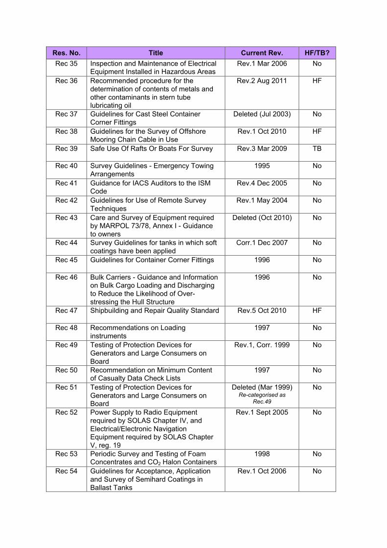
Rec 35 Inspection and Maintenance of ElectricalEquipment Installed in Hazardous Areas
Rev.1 Mar 2006 No
Rec 36 Recommended procedure for thedetermination of contents of metals andother contaminants in stern tubelubricating oil
Rev.2 Aug 2011 HF
Rec 37 Guidelines for Cast Steel ContainerCorner Fittings
Deleted (Jul 2003) No
Rec 38 Guidelines for the Survey of OffshoreMooring Chain Cable in Use
Rev.1 Oct 2010 HF
Rec 39 Safe Use Of Rafts Or Boats For Survey Rev.3 Mar 2009 TB
Rec 40 Survey Guidelines - Emergency TowingArrangements
1995 No
Rec 41 Guidance for IACS Auditors to the ISMCode
Rev.4 Dec 2005 No
Rec 42 Guidelines for Use of Remote SurveyTechniques
Rev.1 May 2004 No
Rec 43 Care and Survey of Equipment requiredby MARPOL 73/78, Annex I - Guidanceto owners
Deleted (Oct 2010) No
Rec 44 Survey Guidelines for tanks in which softcoatings have been applied
Corr.1 Dec 2007 No
Rec 45 Guidelines for Container Corner Fittings 1996 No
Rec 46 Bulk Carriers - Guidance and Informationon Bulk Cargo Loading and Dischargingto Reduce the Likelihood of Over-stressing the Hull Structure
1996 No
Rec 47 Shipbuilding and Repair Quality Standard Rev.5 Oct 2010 HF
Rec 48 Recommendations on Loadinginstruments
1997 No
Rec 49 Testing of Protection Devices forGenerators and Large Consumers onBoard
Rev.1, Corr. 1999 No
Rec 50 Recommendation on Minimum Contentof Casualty Data Check Lists
1997 No
Rec 51 Testing of Protection Devices forGenerators and Large Consumers onBoard
Deleted (Mar 1999)Re-categorised as
Rec.49
No
Rec 52 Power Supply to Radio Equipmentrequired by SOLAS Chapter IV, andElectrical/Electronic NavigationEquipment required by SOLAS ChapterV, reg. 19
Rev.1 Sept 2005 No
Rec 53 Periodic Survey and Testing of FoamConcentrates and CO2 Halon Containers
1998 No
Rec 54 Guidelines for Acceptance, Applicationand Survey of Semihard Coatings inBallast Tanks
Rev.1 Oct 2006 No
Res. No. Title Current Rev. HF/TB?
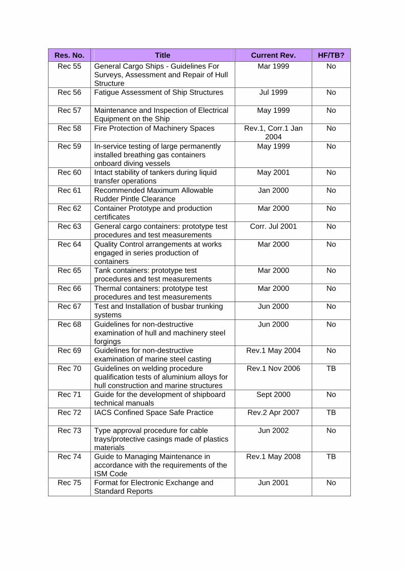
Rec 55 General Cargo Ships - Guidelines For Surveys, Assessment and Repair of Hull Structure
Mar 1999 No
Rec 56 Fatigue Assessment of Ship Structures Jul 1999 No
Rec 57 Maintenance and Inspection of Electrical Equipment on the Ship
May 1999 No
Rec 58 Fire Protection of Machinery Spaces Rev.1, Corr.1 Jan 2004
No
Rec 59 In-service testing of large permanently installed breathing gas containers onboard diving vessels
May 1999 No
Rec 60 Intact stability of tankers during liquid transfer operations
May 2001 No
Rec 61 Recommended Maximum Allowable Rudder Pintle Clearance
Jan 2000 No
Rec 62 Container Prototype and production certificates
Mar 2000 No
Rec 63 General cargo containers: prototype test procedures and test measurements
Corr. Jul 2001 No
Rec 64 Quality Control arrangements at works engaged in series production of containers
Mar 2000 No
Rec 65 Tank containers: prototype test procedures and test measurements
Mar 2000 No
Rec 66 Thermal containers: prototype test procedures and test measurements
Mar 2000 No
Rec 67 Test and Installation of busbar trunking systems
Jun 2000 No
Rec 68 Guidelines for non-destructive examination of hull and machinery steel forgings
Jun 2000 No
Rec 69 Guidelines for non-destructive examination of marine steel casting
Rev.1 May 2004 No
Rec 70 Guidelines on welding procedure qualification tests of aluminium alloys for hull construction and marine structures
Rev.1 Nov 2006 TB
Rec 71 Guide for the development of shipboard technical manuals
Sept 2000 No
Rec 72 IACS Confined Space Safe Practice Rev.2 Apr 2007 TB
Rec 73 Type approval procedure for cable trays/protective casings made of plastics materials
Jun 2002 No
Rec 74 Guide to Managing Maintenance in accordance with the requirements of the ISM Code
Rev.1 May 2008 TB
Rec 75 Format for Electronic Exchange and Standard Reports
Jun 2001 No

Res. No. Title Current Rev. HF/TB?
Rec 76 IACS Guidelines for Surveys,Assessment and Repair of Hull Structure- Bulk Carriers
Rev.2, Corr.1 Sept2007
No
Rec 77 Guidelines for the Surveyor on how toControl the Thickness MeasurementProcess
Rev.2 Apr 2006 No
Rec 78 Safe use of Portable Ladders for Close-up Surveys
Sept 2002 No
Rec 79 Guidelines for Securing by Welding ofChain Cable Studs in Service
Jul 2003 No
Rec 80 Containers “in One Door Off” Operation Jul 2003 No
Rec 81 Guidance on the ISPS Code for MaritimeSecurity Auditors
May 2003 No
Rec 82 Surveyor’s Glossary, Hull Terms and HullSurvey Terms
Jul 2003 No
Rec 83 Notes to Annexes to IACS UnifiedRequirement S1A on Guidance forLoading/Unloading Sequences for BulkCarriers
Aug 2003 No
Rec 84 Container Ships – Guidelines forSurveys, Assessment and Repair of HullStructure
2005 No
Rec 85 Recommendations on Voyage DataRecorder
Jan 2005 No
Rec 86 Applicable Standards for UR P4.7“Requirements for Type Approval ofPlastic Pipes”
Feb 2005 No
Rec 87 Guidelines for Coating Maintenance &Repairs for Ballast Tanks and CombinedCargo/Ballast Tanks on Oil Tankers
Rev.1 Jun 2006 No
Rec 88 Periodical hydrostatic tests of aircylinders of safety equipment
Jun 2005 No
Rec 89 Firms engaged in testing of navigationalequipment and systems
Jul 2005 No
Rec 90 Ship structure access manual Oct 2005 No
Rec 91 Guidelines for Approval / Acceptance ofAlternative Means of Access
Rev.1 Jan 2011 HF
Rec 92 IACS Guidelines for ISM Code and ISMCode aligned audits and SMC and ISSCexpiration dates alignment
Corr.1 Jul 2006 No
Rec 93 Performance Standards for UniversalAutomatic Identification Systems (AIS)(SOLAS Reg.V/18.2)
Dec 2006 No
Rec 94 Guideline for application of UR S31Rev.4
Apr 2007 No
Rec 95 Recommendation for the Application ofSOLAS Regulation V/15 – BridgeDesign, Equipment Arrangement andProcedures (BDEAP)
Corr.2 July 2011 HF

Res. No. Title Current Rev. HF/TB?
Rec 96 Double Hull Oil Tankers - Guidelines forSurveys, Assessment and Repair of HullStructure
Apr 2007 TB
Rec 97 Recommendation for UR S11.2.1.3,Rev.5
Jun 2007 No
Rec 98 Duties of Surveyors under StatutoryConventions and Codes
Sept 2007 No
Rec 99 Recommendations for the Safety ofCargo Vessels of less than ConventionSize
Dec 2007 No
Rec 100 IACS recommended practice on the timerequirement for thoroughly closing seainlets and discharges below the waterlinein case of influx of water
Feb 2008 TB
Rec 101 IACS Model Report for IMO ResolutionMSC.215(82) Annex 1 “Test Proceduresfor Coating Qualification”
Jun 2008 No
Rec 102 IACS Model Report for IMO ResolutionMSC.215(82) Annex 1 “Test Proceduresfor Coating Qualification”, Section 1.7 –Crossover Test
Jun 2008 No
Rec 103 Guidance for the compilation of the IOPPSupplement
Dec 2008 TB
Rec 104 Qualification scheme for welders ofsteels
Mar 2009 TB
Rec 105 Qualification scheme for welders ofaluminium alloys
Mar 2009 TB
Rec 106 IACS Guideline for Rule Development –Ship Structure
Jul 2009 TB
Rec 107 Guidance for Application of VerticalContract Audits
Del Sept 2011 No
Rec 108 Under Development
Rec 109 Acceptance criteria for cargo tank fillinglimits higher than 98%
Oct 2009 TB
Rec 110 Guideline for Scope of Damage StabilityVerification on new oil tankers, chemicaltankers and gas carriers
Rev.1 Nov 2010 HF
Rec 111 Passenger Ships – Guidelines forpreparation of Hull Structural Surveys
Feb 2010 HF
Rec 112
Rec 113 Expert Parties Engaged in Visual and/orSampling Checks for Preparation ofInventory of Hazardous Materials
Aug 2010 HF
Rec 114 Recommendation for the design,construction, operation and survey ofemergency shut down valves and safecargo sampling connections onliquefied gas carriers
June 2010 HF

Res. No. Title Current Rev. HF/TB?
115
116 Performance Standard for ProtectiveCoatings for Cargo Oil Tanks of CrudeOil Tankers – 5 years field exposure testin accordance with MSC.288 (87)
Feb 2011 HF
117 Exchange of Statutory Documentationupon Transfer of Class
Mar 2011 HF
118 Maritime Labour Convention, 2006:Handling of Seafarer Complaints byRecognized Organizations
Feb 2011 HF
119 Uniform application of SOLAS Reg. II-1/3-9 in association withMSC.1/Circ.1331
May 2011 HF

IACS History File + TB Part A
Page 1 of 3
Recommendation No.36 “Recommended procedure for the determination of contents of metals and other
contaminants in stern tube lubricating oil” Part A. Revision History Version no. Approval date Implementation date
when applicable Rev.2 (Aug 2011) 05 August 2011 - Rev.1 (1997) 12 May 1997 - New (1992) No records - • Rev.2 (Aug 2011) .1 Origin for Change:
Other (Task of reviewing Recommendations to be posted on the web) .2 Main Reason for Change: In the course of fulfilling the task of reviewing Recommendations to be posted on the web, the Machinery Panel Chairman submitted the revised Rec.36, which has been agreed by the Machinery Panel Members (PM5901c). .3 List of non-IACS Member classification societies contributing through the TC Forum and/or participating in IACS Working Group: None .4 History of Decisions Made: GPG agreed to the draft Recommendation submitted by the Machinery Panel, as well as to the proposal of a Machinery Panel Member to delete the Note in para.1 “Note :It is recommended to take lubricating oil sample and carry out analysis once in every month” for it's not according with Z21.2(d)”Where a lubricating oil analysis is carried out regularly at intervals not exceeding six months, and the oil consumption and bearing temperature are recorded and considered to be within permissible limits, drawing of the shaft to expose the aft bearing contact area of the shaft may not be required.” .5 Other Resolutions Changes None .6 Dates:
Original Proposal: 11 July 2011, made by Machinery Panel GPG Approval: 05 August 2011 (Ref: 0140bIGi)
Page 2 of 3
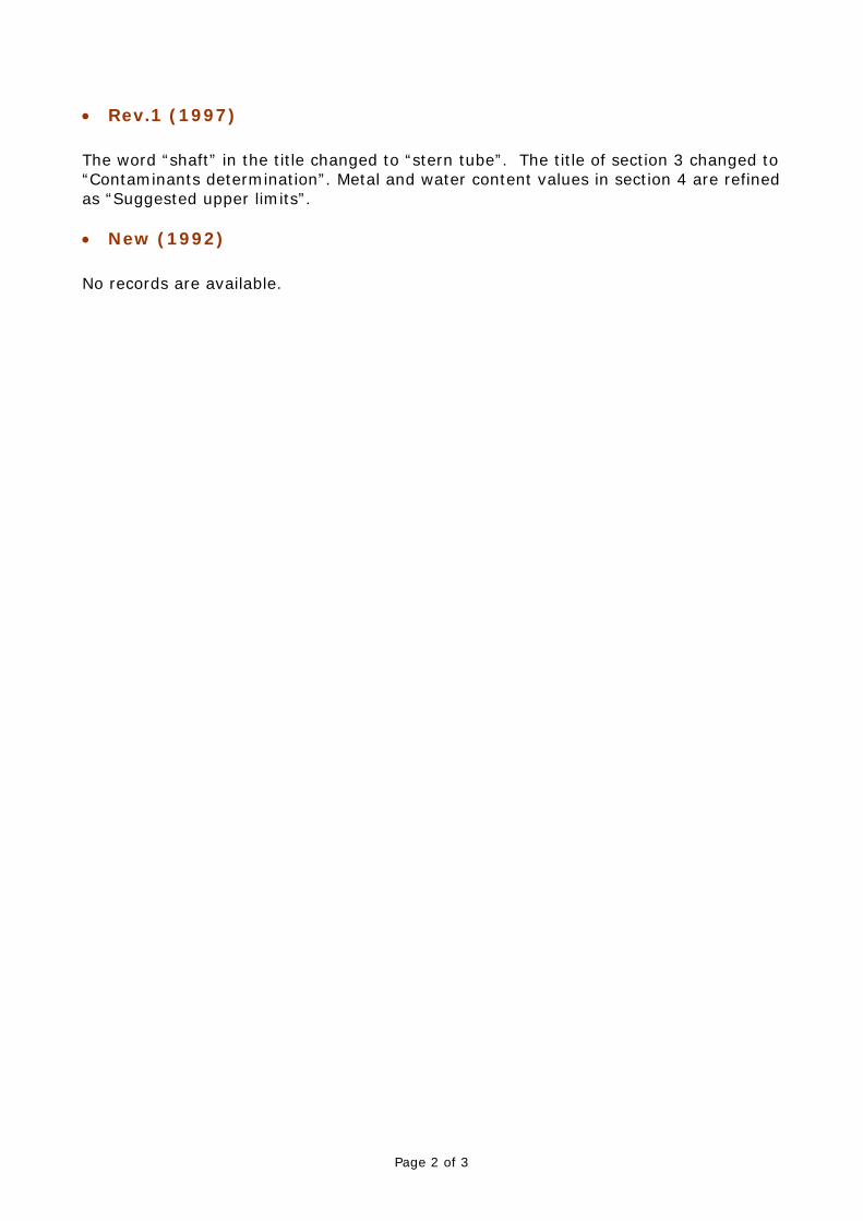
• Rev.1 (1997) The word “shaft” in the title changed to “stern tube”. The title of section 3 changed to “Contaminants determination”. Metal and water content values in section 4 are refined as “Suggested upper limits”. • New (1992) No records are available.

Part B
Page 3 of 3
Part B. Technical Background List of Technical Background (TB) documents for Rec.36:
◄▼► There are no separate Technical Background (TB) documents available for Rec.36 (New 1992), Rev.1 (1997) and Rev.2 (Aug 2011)
IACS History File + TB, Part A
Page 1 of 2
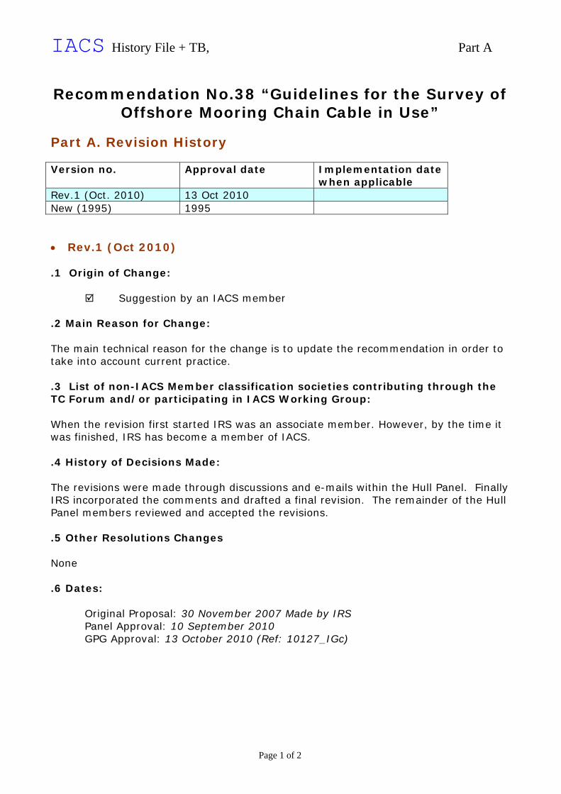
Recommendation No.38 “Guidelines for the Survey of Offshore Mooring Chain Cable in Use”
Part A. Revision History Version no. Approval date Implementation date
when applicable Rev.1 (Oct. 2010) 13 Oct 2010 New (1995) 1995 • Rev.1 (Oct 2010) .1 Origin of Change:
Suggestion by an IACS member
.2 Main Reason for Change: The main technical reason for the change is to update the recommendation in order to take into account current practice. .3 List of non-IACS Member classification societies contributing through the TC Forum and/or participating in IACS Working Group: When the revision first started IRS was an associate member. However, by the time it was finished, IRS has become a member of IACS. .4 History of Decisions Made: The revisions were made through discussions and e-mails within the Hull Panel. Finally IRS incorporated the comments and drafted a final revision. The remainder of the Hull Panel members reviewed and accepted the revisions. .5 Other Resolutions Changes None .6 Dates:
Original Proposal: 30 November 2007 Made by IRS Panel Approval: 10 September 2010 GPG Approval: 13 October 2010 (Ref: 10127_IGc)
Part B
Page 2 of 2
Part B. Technical Background List of Technical Background (TB) documents: Annex 1 TB for Rev.1 (Oct 2010)
See separate TB document in Annex 1.
◄▼► Note: There are no separate Technical Background (TB) document available for New (1995)

Part B, Annex 1
Technical Background for
Recommendation No.38 Rev.1 (Oct 2010)
1. Scope and objectives The revision is made to update the recommendation in order to take into account current practice. It includes specific information on the wear-down and movement of mechanical locking for use while conducting surveys on offshore mooring chain. The intent is to assist with consistent application of the recommendation. 2. Engineering background for technical basis and rationale The main basis for the change is to simply take into account current practice. It is noted that satisfactory in-service performance has been experienced and this changed represents an improvement to the documentation on what is applied. 3. Source/derivation of the proposed IACS Resolution The source of the information was obtained through the input of the Hull Panel members. 4. Summary of Changes intended for the revised Resolution: Editorial changes are made as well as some clarifications to specific information on the number of samples, the wear-down measurements and movement of mechanical locking for use while conducting surveys on offshore mooring chain. 5. Points of discussions or possible discussions The revisions were made through discussions and e-mails within the Hull Panel which involved mainly incorporating individual comments and accepting the consolidated text. 6. Attachments if any None.

Technical Background
Recommendation 39, Rev.3 – March 2009
Survey Panel Task 1: Amendments to Recommendation 39 – Concerns related to Rule changes regarding rafting
1. Objective Amend the Recommendation 39 for removing impracticality and risks in using rafts when surveyors survey cargo tanks. 2. Background One member of IACS Survey Panel received an advice from field staff, which described concerns about an accident which can happen when water level is falling while surveyors are surveying cargo tanks using a raft. The advice from field staffs also introduced accidents which occurred due to air pockets in the water during deballasting operation. Field staff recommended that the level shall be stationary and the ballast system should be isolated to prevent any accidental ingress or outflow of water and pointed out that their rule, which states ‘The surface of water in the tank is to be calm and the water level either stationary or falling’, should be amended. The field staff also pointed out that the water level, which is provided to be allowed within 1 m of the deepest under deck web face flat, should be changed to be allowed within 0.5m. The reason for this is that, if we consider the web is allowed to be maximum 1.5m deep in case of bad coating condition, the distance for close up survey of the under deck structure is too much for most surveyors to reach it by hand. Based on above technical grounds, field staff asked if any amendments to UR Z10.1 and Recommendation No. 39 can be made.
3. Discussion In the 8th Survey Panel meeting, Chairman, explained about the impracticality in using rafts when surveying cargo tanks - i.e., danger of air pockets when de-ballasting, impractical distance for reaching by hand, and height for easy maneuverability of raft. Also the relevant Panel member explained about the correspondence regarding ‘Concerns related to Rule changes regarding rafting’ which was sent by a field staff. Upon discussion, members consented to the first proposal on water level but not to the second part on the distance under deck. At the end, it was concluded that first one can be changed, but second one should remain unchanged. Members agreed to amend IACS Recommendation 39, 1.4 d) by removing “either”…“or falling” from the first sentence.
Submitted by Survey Panel Chairman
25 February 2009 Permanent Secretariat note (March 2009): Rec.39 Rev.3 was approved by GPG on 18 March 2009 (ref. 9528_IGb).

IACS History File + TB, Part A
Page 1 of 3
Recommendation No.47 “Shipbuilding and Repair Quality Standard”
Part A. Revision History Version no. Approval date Implementation date
when applicable Rev.5 (Oct. 2010) 06 Oct 2010 Rev.4 (Aug. 2008) 04 Aug 2008 Rev.3 (Nov. 2006) 01 Nov 2006 Rev.2 (Dec. 2004) 12 Dec 2004 Rev.1 (Aug. 1999) 17 Aug 1999 New (1996) 15 Nov 1996 • Rev.5 (Oct 2010) .1 Origin of Change:
Other (Query from industry - DAEWOO SHIPBUILDING & MARINE ENGINEERING CO.,LTD. )
.2 Main Reason for Change: It was agreed in the Panel that the acceptance criteria for minor imperfections is not clear without the definition of influenced area. The existing text is not in line with international standards which are applied by many shipyards and manufacturers. And the definition of limit gap between plates for butt welding is obscure in the relevant Table. .3 List of non-IACS Member classification societies contributing through the TC Forum and/or participating in IACS Working Group: None .4 History of Decisions Made: Lately some shipyards and manufacturers have received steel plates with pits and there has been discussion regarding how to interpret the extent and acceptance criteria for pitting. It was decided by the Survey Panel that the amendments to Rec.47 are necessary in order to improve the clarity of the document. And, there was a query from shipyards on the obscure definition of limit gap between plates for butt welding .5 Other Resolutions Changes None

Part A
Page 2 of 3
.6 Dates: Original Proposal: 07 April 2010 Made by: Survey Panel Panel Approval: 24 August 2010 GPG Approval: 06 October 2010 (Ref: 10122_IGb)
• Rev.4 (Aug 2008) Revision based on Survey Panel Task 44. Ref: 8626_ See TB in Part B • Rev.3 (Nov 2006) Revision based on comments from SAJ. Ref: 4109a_ No TB document available • Rev.2 (Dec 2004) Revision proposed by WP/MW to GPG 52 (WP/MW Task 41). Ref: 4109_ No TB document available • Rev.1 (Aug 1999) Revision based on the revised SARQS (Table 8.7). Ref: 9139_ No TB document available • New (1996) No TB document available

Part B
Page 3 of 3
Part B. Technical Background List of Technical Background (TB) documents: Annex 1 TB for Rev.4 (Aug 2008)
See separate TB document in Annex 1.
◄▼► Annex 2 TB for Rev.5 (Oct 2010)
See separate TB document in Annex 2.
◄▼►

TECHNICAL BACKGROUND
IACS RECOMMENDATION NO.47 (REV.4, AUG 2008) “Shipbuilding and Repair Quality Standard”
1. Scope and objective PT was formed by Survey Panel (Task No.44) to develop a proposal to amend IACS Rec.47, SARQS (Shipbuilding and Repair Quality Standard) in order to align with major national shipbuilding standards. 2. Background During IACS meeting with JSA (Japan Shipowners Association) and SAJ (Shipbuilders Association of Japan) in Tokyo, September 2005, SAJ made a presentation of areas of concern with IACS Rec.47. IACS agreed to submit the concerns to Survey Panel for action. IACS adopted Rev.3 of Rec.47 in November 2006, which was proposed by PT (Project Team) under the Survey Panel. The amendments in Rev.3 were based on the concern of SAJ that only the construction quality standards should be specified in SARQS and that some impractical recommendations should be revised. Upon the completion of Rev.3, IACS decided to develop a proposal to further amend IACS Rec.47 in order to align it with major national shipbuilding standards. The Technical Background documents of the previous versions 1 and 2 do not exist. 3. Points of discussions PT commenced the work through correspondence. After making considerable progress in the work, one meeting was held in Tokyo on 19th and 20th February, 2008 to finalize the amendments. PT members reviewed Rec.47 Rev.3 from the viewpoint of shipbuilding standards in their territories and their own experiences as well. Initially PM gathered the information and comments from PT members on the results of the comparison of the Rec.47 with major national and certain shipyard standards practiced in China, Germany, India, Japan, Korea and Russia. PT agreed to amend Rec.47 Rev.3 after the following discussion.
Rec.47 should not be conflicted with major national shipbuilding standards to the extent possible
Scope should be defined where Rec.47 applies Standard range and limit range should be listed Welding procedures should be qualified in accordance with IACS UR W28 or other
recognized standard accepted by Classification Society
Upon a comprehensive review of national standards, PT found that there are notable variations among the major national standards in some technical parameters/approaches, maybe due to the differences in their respective technical basis, which would make a complete alignment not feasible. However, PT tried to accommodate the best practices of each of the considered major standards to the extent possible in order to finalize the Rec.47 Rev 4. To improve the clarity of the recommendations, PT introduced necessary editorial changes. Recognizing the importance of short bead welding in remedial work, PT introduced a new Table 9.14 according to JSQS. Table 6.4 was amended to include the ovality of cylindrical structure according to FS (Production standard of the German Shipbuilding Industry). In revision 2, in Table 9.4 and Table 9.5 (Typical Butt Weld Edge Preparation Remedial (Manual Welding and Semi-automatic welding)), the gap value, based on which the remedial standard is decided, was a function of the plate thickness. But in Revision 3 the gap value was modified to absolute value considering the comments from SAJ. During the PT meeting on 19 and 20 Feb 2008, it was agreed that the gap value is to be related to the thickness values, considering the comments from shipyards in Korea and elsewhere, to deal with thinner plates. To avoid duplications and contradictions with other IACS technical requirements, some parts of the Rec.47 are modified. 4. Source and derivation of proposed standards IACS Recommendation No.47 Rev.3 and Rev.4 5. Appendix N.A.
Submitted by Project Team Manager
March 2008 Permanent Secretariat note: PT’s proposed amendments to Rec.47 were unanimously agreed by the Survey Panel and draft Rec.47 Rev.4 was submitted to GPG on 17 July 2008. GPG approved Rec.47 Rev.4 on 4 August 2008 (ref. 8626_IGb).

Part B, Annex 2
Technical Background for
Recommendation No.47 Rev.5, Oct 2010
1. Scope and objectives To revise the Recommendation 47, Par.4.2.1 and 4.2.2 with the aim to eliminate uncertainties related to determining the imperfection surface area ratio and subsequently the acceptance criteria for minor imperfections which do not need to be repaired. And, to clarify the meaning of gap between edges of plates for Butt welding. 2. Engineering background for technical basis and rationale While preparing a reply to the query from Daewoo Shipbuilding & Marine Engineering Co. Ltd. it was noticed that different societies have different interpretation of the acceptance criteria for minor imperfections without remedies. It was felt that including the definition of influenced area would improve the clarity of Recommendation 47 in this respect. 3. Source/derivation of the proposed IACS Resolution The definition of the influenced area was adopted from European Standard EN 10163-1. 4. Summary of Changes intended for the revised Resolution: New text defining the influenced area was added to Par.4.2.2. A clear description on welding the gap with Butt weld plate was added to Table 9.5 5. Points of discussions or possible discussions None 6. Attachments if any None
TECHNICAL BACKGROUND DOCUMENT IACS RECOMMENDATION NO.70 (REV.1, NOV 2006)
1. Scope and objective
To develop a UR or Recommendation for welding procedure qualification tests for aluminium alloys 5383 and 5059.
2. Background
Rec.70 was produced in 2000. In 2004 new important industrial accepted specifications of aluminium alloy 5383 and 5059 were added to UR W25. These should be incorporated into the Recommendation and at the same time it may be upgraded to a UR for welding procedure qualification tests for the alloys based upon elaborate considerations.
3. Points of discussions or possible discussions
• Hull Panel PT2 unanimously agreed that the revised document should be retained as a recommendation.
• It was therefore submitted as a revision to the existing Recommendation No.70 to the Hull Panel on 3 March 2006.
• Accordingly Hull Panel reviewed it and comments made by GL were sent back to the PT2 on 12 April 2006.
• With regard to GL’s comments, having received replies from PT2 on 25 July in addition to comments made by ABS and CCS, the Hull Panel further reviewed them and finally agreed unanimously to the final draft revision to Recommendation No. 70 at the 5th Hull Panel meeting held on 16-18 October 2006.
4. Source/derivation of proposed requirements
• IACS Recommendation No. 70 (Rev.2) 5. Appendix
N.A.
Submitted by Hull Panel Chairman
27 October 2006
Permanent Secretariat Note (December 2006): • Rec.70, Rev.2 was approved by GPG and Council on 15 November 2006 (6187_IGb),
with the request that PermSec update the language to be a non-mandatory style, i.e. replacing terms such “are to be” and “shall” with “should”, etc., to avoid confusing the public domain about the non-mandatory nature of the Recommendation.
• Following approval GL proposed some additional editorial amendments to improve the readability of the document and emphasize the relation of Rec.70 to UR W28 (GLb). However after bilateral communication between GPG Chair and Hull Panel Chair it was proposed to deal with these amendments at the next appropriate revision of Rec.70. This proposal received no objections from GPG members.
Technical Background
IACS Recommendation 72, Rev. 2 (April 2007)
Survey Panel Task 46 – Safe Entry into Tanker Double Hull Spaces
1. Objective Update as necessary IACS recommendation 72 to include Safe Entry Practices for Surveyors into Double Hull Spaces when adjacent cargo tanks are empty but inerted or the cargo tanks are loaded 2. Background ABS Panel member raised this issue to the Survey Panel at the Spring 2006 Panel meeting due to no current guidelines being available. 3. Methodology of Work Survey Panel members through Project Team and correspondence 4. Discussion Survey Panel Project Team members at the spring 2007 meeting discussed the amendments to Recommendation 72 based on the initial draft proposed by DNV PT member. All survey panel members agreed to the amendments which consisted of two parts, i.e., Recommendation 72 and Annex to the Recommendation.
Submitted by Survey Panel Chairman 27 March 2007
Permanent Secretariat note (August 2007): • Amendments agreed by GPG 14 April 2007 (6079_IGh). • Owing to the extent of the amendments, including a change to the document layout, Rev.2 of Rec.72 has
been treated as a complete revision and as such no underlined document is available.

TECHNICAL BACKGROUND
IACS Recommendation 74, Rev.1 (May 2008)
“A Guide to Managing Maintenance in accordance with the Requirements of the ISM Code”
The ISM/ISPS Expert Group has made a number of changes to Recommendation 74. These changes do not alter the document substantially but are intended to emphasise the following two aspects of maintenance management that the Group felt had not been sufficiently addressed in the original version. 1. The need for companies to be concerned not only with the rectification of technical defects and
hazardous situations but also with the identification and resolution of the underlying management systems failures that led to the problems in the first place
2. The importance of a systematic approach to the assessment of risk when planning an effective
maintenance management system At the same time, the opportunity was taken to clarify the wording of the introduction. 17th April 2008 Michael Molloy, LR Øivind N. Bråten Chairman EG-ISM/ISPS
Submitted by Statutory Panel Chairman 4 May 2008
Permanent Secretariat note (June 2008): Rec.74, Rev.1 approved by GPG 30 May 2008 (ref. 8582_IGc)

TECHNICAL BACKGROUND (External)
IACS Recommendation 74, Rev.1 (May 2008)
“A Guide to Managing Maintenance in accordance with the Requirements of the ISM Code”
The ISM/ISPS Expert Group has made a number of changes to Recommendation 74. These changes do not alter the document substantially but are intended to emphasise the following two aspects of maintenance management that the Group felt had not been sufficiently addressed in the original version. 1. The need for companies to be concerned not only with the rectification of technical defects and
hazardous situations but also with the identification and resolution of the underlying management systems failures that led to the problems in the first place
2. The importance of a systematic approach to the assessment of risk when planning an effective
maintenance management system At the same time, the opportunity was taken to clarify the wording of the introduction.
IACS History File + TB Part A
Page 1 of 2
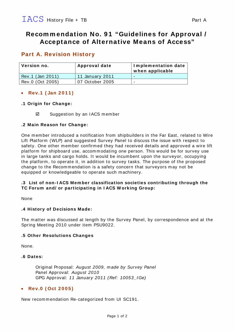
Recommendation No. 91 “Guidelines for Approval / Acceptance of Alternative Means of Access”
Part A. Revision History Version no. Approval date Implementation date
when applicable Rev.1 (Jan 2011) 11 January 2011 - Rev.0 (Oct 2005) 07 October 2005 - • Rev.1 (Jan 2011) .1 Origin for Change:
Suggestion by an IACS member .2 Main Reason for Change: One member introduced a notification from shipbuilders in the Far East, related to Wire Lift Platform (WLP) and suggested Survey Panel to discuss the issue with respect to safety. One other member confirmed they had received details and approved a wire lift platform for shipboard use, accommodating one person. This would be for survey use in large tanks and cargo holds. It would be incumbent upon the surveyor, occupying the platform, to operate it, in addition to survey tasks. The purpose of the proposed change to the Recommendation is a safety concern that surveyors may not be equipped or knowledgeable to operate such machinery. .3 List of non-IACS Member classification societies contributing through the TC Forum and/or participating in IACS Working Group: None .4 History of Decisions Made: The matter was discussed at length by the Survey Panel, by correspondence and at the Spring Meeting 2010 under item PSU9022. .5 Other Resolutions Changes None. .6 Dates:
Original Proposal: August 2009, made by Survey Panel Panel Approval: August 2010 GPG Approval: 11 January 2011 (Ref: 10053_IGe)
• Rev.0 (Oct 2005) New recommendation Re-categorized from UI SC191.
Part B
Page 2 of 2
Part B. Technical Background List of Technical Background (TB) documents for Recommendation No.91: Annex 1. TB for Rev.1 (Jan 2011) See separate TB document in Annex 1.
◄▲► Note: 1) There is no separate Technical Background (TB) document for Recommendation No.91 Rev.0 (Oct 2005).
Part B, Annex 1
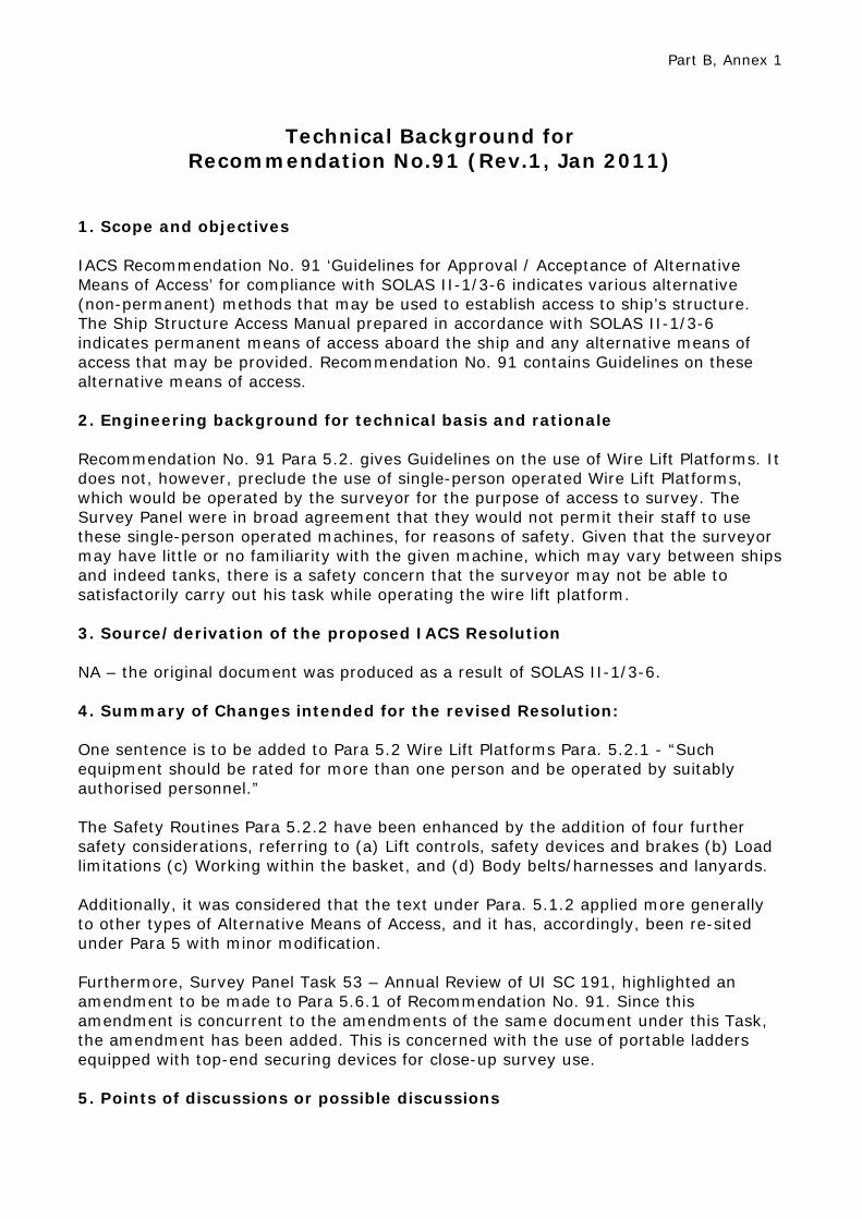
Technical Background for
Recommendation No.91 (Rev.1, Jan 2011)
1. Scope and objectives IACS Recommendation No. 91 ‘Guidelines for Approval / Acceptance of Alternative Means of Access’ for compliance with SOLAS II-1/3-6 indicates various alternative (non-permanent) methods that may be used to establish access to ship’s structure. The Ship Structure Access Manual prepared in accordance with SOLAS II-1/3-6 indicates permanent means of access aboard the ship and any alternative means of access that may be provided. Recommendation No. 91 contains Guidelines on these alternative means of access. 2. Engineering background for technical basis and rationale Recommendation No. 91 Para 5.2. gives Guidelines on the use of Wire Lift Platforms. It does not, however, preclude the use of single-person operated Wire Lift Platforms, which would be operated by the surveyor for the purpose of access to survey. The Survey Panel were in broad agreement that they would not permit their staff to use these single-person operated machines, for reasons of safety. Given that the surveyor may have little or no familiarity with the given machine, which may vary between ships and indeed tanks, there is a safety concern that the surveyor may not be able to satisfactorily carry out his task while operating the wire lift platform. 3. Source/derivation of the proposed IACS Resolution NA – the original document was produced as a result of SOLAS II-1/3-6. 4. Summary of Changes intended for the revised Resolution: One sentence is to be added to Para 5.2 Wire Lift Platforms Para. 5.2.1 - “Such equipment should be rated for more than one person and be operated by suitably authorised personnel.” The Safety Routines Para 5.2.2 have been enhanced by the addition of four further safety considerations, referring to (a) Lift controls, safety devices and brakes (b) Load limitations (c) Working within the basket, and (d) Body belts/harnesses and lanyards. Additionally, it was considered that the text under Para. 5.1.2 applied more generally to other types of Alternative Means of Access, and it has, accordingly, been re-sited under Para 5 with minor modification. Furthermore, Survey Panel Task 53 – Annual Review of UI SC 191, highlighted an amendment to be made to Para 5.6.1 of Recommendation No. 91. Since this amendment is concurrent to the amendments of the same document under this Task, the amendment has been added. This is concerned with the use of portable ladders equipped with top-end securing devices for close-up survey use. 5. Points of discussions or possible discussions

The matter of surveyor-operated single-person Wire Lift Platforms was discussed at length in the Survey Panel, with many concerns being raised about the safety of surveyors operating these in addition to carrying out surveying duties. 6. Attachments if any None

IACS History File + TB Part A
Page 1 of 3
Recommendation No. 95 “Recommendation for the Application of SOLAS Regulation V/15
Bridge Design, Equipment Arrangement and Procedures (BDEAP)”
Part A. Revision History Version no. Approval date Implementation date
when applicable Corr.2 (July 2011) 11 July 2011 - Corr.1 (Mar 2009) 04 March 2009 - New (Oct 2007) 30 October 2007 - • Corr.2 (July 2011) .1 Origin for Change:
Suggestion by an IACS member .2 Main Reason for Change: The reference to 2.6.1, UI V/22 in paragraph B 6.5.1 in REC 095 is a reference to a paragraph in a UI that was never adopted. Therefore the reference was deleted. .3 List of non-IACS Member classification societies contributing through the TC Forum and/or participating in IACS Working Group: None .4 History of Decisions Made: The Statutory agreed with the following detailed explanation offered by DNV: QUOTE The reference to 2.6.1, UI V/22 in paragraph B 6.5.1 in REC 095 is a reference to a paragraph in a UI that was never adopted. Please refer to 6023bIGa of 8 August 2006 to IACS GPG Members from IACS GPG Chairman at the time, Mr. Mo Jianhui, and the subsequent correspondence regarding the same subject. The following is an extract from the document DraftUISOLASV22for GPGapproval300706.doc that was attached to 6023bIGa: UNIFIED INTERPRETATIONS IACS Unified Interpretation of requirements in SOLAS V, Regulation 22, taking into account applicable aims of regulation 15 - Submitted by the International Association of Classification Societies (IACS)

Page 2 of 3
2.6.1 Sunscreens of roller blind type with minimum colour distortion, heavy duty blade type wipers,* fresh water window washing and efficient de-icing and de-misting system or other means shall be installed as required to help maintaining a clear view through windows. A catwalk or other means shall be provided if required to help maintenance of window wipers and manual cleaning of bridge front windows. Note. Clear view screens, if provided, should not be installed in windows in front of the manual steering position and radars, and not more than one to each side of the centre line, available for conning. Paragraph B 6.5.1 in REC 095 is a sheer copy of paragraph 2.6.1 in the dismissed draft UI V/22. The corrective action would simply be to delete the reference to 2.6.1, UI V/22 in paragraph B 6.5.1 in REC 095. At present, as you are well aware, the IMO NAV CG on vague expressions in SOLAS regulation V/22 is working on issues similar to the ones addressed in the dismissed draft UI V/22. This work, though, appears to take a slightly different direction. UNQUOTE .5 Other Resolutions Changes None. .6 Dates:
Original Proposal: April 2011, made by Statutory Panel Panel Approval: 15 April 2011 by Statutory Panel GPG Approval: 11 July 2011 (Ref: 11108_IGb)
• Corr.1 (Mar 2009) Addition of missing labels from Fig B 7.6. GPG reference: 6023b • New (Oct 2007) Previously UI SC181 which was withdrawn. Draft version was submitted to IMO subcommittee Nav in Spring 2007. GPG reference: 6023b

Part B
Page 3 of 3
Part B. Technical Background List of Technical Background (TB) documents for Recommendation No.95: Note: 1) There is no separate Technical Background (TB) document for Recommendation No.95 New (Oct 2007), Corr.1 (Mar 2009) and Corr.2 (July 2011).

Page 1 of 6
Technical Background
Recommendation 96 (NEW, April 2007) “Double Hull Oil Tankers - Guidelines for Surveys, Assessment and
Repair of Hull Structures”
Survey Panel Tasks 8 and 29 PART 1 – TB for Survey Panel Task 8 PSU Task 8: Surveyor Guidance for Assessment of Tanker Structural Conditions 1. Objective To develop surveyor guidance addressing assessment of structural conditions on tankers including identification of defects which may contribute to serious structural failure of a vessel, such as grooving corrosion, loss of throat thickness of fillet welding, fatigue cracking, buckling, uneven corrosion of internal members, pitting in plating, etc. 2. Background GPG 52 originally proposed this, as a result of IACS Ad-Hoc Audit AH 01 objective 3 recommendations following the casualty of the ERIKA. This issue was part of the original Task 94 assigned to WP/SRC which GPG had subsequently added a second part for bulk carriers. WP/SRC subsequently decided to address this task in two parts. Part 2 addressing bulk carriers was completed by WP/SRC in 2004 and resulted in numerous changes being implemented for bulk carriers including the implementation of UR S31, changes to PR19, PR20, Recommendation 76 and Z10.2. The remaining Part 1 of WP/SRC Task 94 was reassigned to the Survey Panel and was listed as Task 8. 3. Methodology of Work The Survey Panel has progressed its work through several meetings as well as a Survey Panel Project Team consisting of ABS (Chair), BV, DNV, LR and NK. The proposed scope of work as well as the draft recommendation by the Project Team was regularly circulated to all Members for comment and agreement. Furthermore as a result of coinciding work on PSU Task 29 the Hull Panel was given an opportunity to review and comment on the draft recommendation in 2006. In addition, the Survey Panel provided an opportunity in October 2006 for the Tanker Structure Co-Operative Forum to review and comment on the draft recommendation. Unfortunately no comments were received from the TSCF.

Page 2 of 6
4. Discussion The Project Team completed a comprehensive review of information and instructions obtained from Survey Panel Members respective Society’s with regards to assessment of structural conditions on tankers. The Project Team took into consideration the current Industry Publication available:
• Guidance Manual for Inspection and Condition Assessment of Tanker Structures, 1986
• Condition Evaluation and maintenance of Tanker Structures, 1992 • Guidance Manual for Tanker Structures – Tanker Structure Co-operative
Forum – Witherby 1997 • Guidelines for Ballast Tank Coating Systems and Surface Preparation – The
Tanker Structure Cooperative Forum • Guidelines for the Inspection and Maintenance of Double Hull Tanker
Structures – Tanker Structure Co-operative Forum, Witherby • Intertanko Corrosion Onboard Crude Oil Tankers – Cargo Tank Corrosion
Awareness Guide Inspection, Repair and Maintenance of Ship Structures – Piero Caridis, Witherby
Project Team also took considered the following information:
• Review Japanese papers 48/3/1-3 submittal to DE with amendments to A.744(18), specifically Guidelines for major repair work of hull girders and guidelines for inspection requirements for fillet weld between deck plates and longitudinals, Guidelines on inspection requirements for fillet weld between deck plates and longituidinals and Guidelines for major repair work of hull girders.
• EMSA Report on Double Hull Tankers High Level Panel of Experts. In the course of the work the Project Team also spent some time considering all of the changes that have already been made with regards to tankers since Task 94 (old WP/SRC Task) was first assigned to the SRC Working Party:
• Z10.1 – Intermediate surveys equivalent to previous Special Survey • Z10.1 – Drydocking required for ESP vessels over 15 years of age • Implementation of Z10.4 • Recommendation 87 - GUIDELINES FOR COATING
MAINTENANCE & REPAIRS FOR BALLAST TANKS AND COMBINED CARGO/BALLAST TANKS ON OIL TANKERS
• Recommendation 82 Surveyor’s Glossary Hull Terms & Hull Survey Terms
• Recommendation 77 Guidelines for the Surveyor on how to Control the Thickness Measurement Process
• PR 20 Procedural Requirement for certain ESP Surveys • PR 19 Procedural Requirement for Thickness Measurements • IMO Permanent Means of Access (PMA for new buildings) • IMO Condition Assessment Scheme (CAS) • Amendments to A.744 (18) which come into effect on 1 Jan 07 (parts
of the CAS Survey Planning to be used for all ships)

Page 3 of 6
Furthermore since this task has been under development for more than two years, several additional Tasks were assigned to the Survey Panel by GPG, which affected the development of Task 8. The additional tasks, which have been taken into account, are the following:
• Survey Panel Task 23: Revise Recommendation 54 ‘Guidelines for acceptance, application and survey of semi-hard coatings in ballast tanks’ to meet current characteristics and effective time period of the semi-hard coatings.
• Survey Panel task 29: Develop guidance for identifying significant failures caused by fatigue and the procedures to be followed when dealing with such cases.
The project team consideration the following aspects prior to proceeding:
• Apply Risk Based Approach • Make additional changes to UR, PR, Rec to include additional text already in
industry publications • Add specific reference to industry publications in URs and/or PRs • Since planning is key to survey, expand planning requirements • Sum up key parts of industry and IACS members publications and issue a
guidance notes • Issue new publication for Double Hull tankers • Is a new publication necessary for Single Hull tankers since no new designs
and will eventually phase out by 2015 Three alternatives were discussed: A. Combined guidance Appendix A: Double Hull Tankers Appendix B: Single Hull tankers B. Separate Guidance for both Single Hull and Double Hull
C. Issue recommendation referring to TSCF Manual on Single Hull tankers and
develop new guidance on Double Hull tankers.
Project Team agreed that team should avoid getting into: • risk based surveys. • Leave out remote inspection techniques, as this was not part of the task.
It was agreed to go with option C and since many members already refer to the TSCF publications no specific recommendation is necessary for the repairs for the single hull tankers. The Project Team agreed that deliverable of this task should be a recommendation on Double Hull Tankers following the same format as that contained in the IACS recommendation 76, “IACS Guidelines for Surveys, Assessment and Repair of Hull Structure - Bulk Carriers”, by using applicable portions of the TSCF books on Double hull and single tankers, IACS publications and information from Members.

Page 4 of 6
It was felt that due to the phase out of single hull tankers and the fact there have been no new designs of same it was not necessary to do anything more on Single Hull tankers other than to refer to the current TSCF publication. A new recommendation was prepared based on the above, submitted to the Hull Panel in August 2006 and submitted to the Survey Panel at the Fall 2006 and Spring 2007 meetings. Comments were addressed as applicable and incorporated into the document.
Submitted by Survey Panel Chairman March 2007
PART 2 – TB for Survey Panel Task 29 PSU Task 29: Develop guidance for identifying significant failures caused by fatigue and the procedures to be followed when dealing with such cases 1. Objective Develop guidance for use by Surveyors to identify significant failures caused by fatigue and the procedures to be followed when dealing with such cases. 2. Background The request for a guidance document was initiated by the EMSA report on Double Hull Tankers by the high level panel of experts. See following references:
1. EMSA Recommendation 6 from the EMSA report on Double Hull Tankers. 2. 3125_IGh:EMSA Panel of Experts on Safety of Double Hull Tankers
3. Methodology of Work The Survey Panel has progressed its work through several meetings as well as a combination Survey and Hull Panel Project Team consisting of ABS (Chair), GL (hull), KR, LR, NK, RINA (hull) and RS. The proposed scope of work as well as the draft recommendations by the Project Team were regularly circulated to all Members for comment and agreement. Furthermore the Hull Panel conducted a review in 2006. In addition, the Survey Panel provided an opportunity in October 2006 for the Tanker Structure Co-Operative Forum to review and comment on the draft recommendation. Unfortunately no comments were received from the TSCF. 4. Discussion The Project Team completed a review of recommendations of the EMSA report on Double Hull Tankers in order to determine type of for development for the tasked guidance document. During this review the Project team also reviewed the draft recommendation being prepared by the Survey Panel under Project Team PSU Task 8, “Double Hull Oil Tankers, Guidelines for Surveys, Assessment and Repair of Hull Structures”.

Page 5 of 6
The project team felt that with some improvements this document being prepared under Task 8 would be suitable to identify typical failures found, including fatigue analysis and assessment, pro-active repairs, recommended repair methods and means of reinforcement. In particular the following sections were of interest to this project team:
3.4.2 – Structural Defects 3.4.3 - Fatigue 3.4.3.a – Typical locations for High Sensitivity to Fatigue Failure 3.4.3.b – The effect of Higher Tensile Steel 3.4.10 – Fractures Section 5 – Structural detail failures and repairs.
The Project Team then proceeded to amend various parts of the text under 3.4.3, 3.4.10 and some areas of text under the different groups in Section 5. The Project Team also amended numerous sketches developed some new ones. The PT reviewed the DNV presentation, “JTP – Double hull tanker damage experience”, Sketches and Photos of hull damages for DNV built double hull oil tankers dated April 2005. From this presentation it was agreed to develop new sketches showing the deck damages associated with the DNV hull damages. The Project team also reviewed the IACS presentation Appendix I, “Summary of Damage Records”. The Project Team noted that the IACS presentation indicated a significant amount of upper deck plating and stiffener fractures but the supporting slides did not reflect significant fractures of the deck plating. Initially it was decided to make this Appendix part of the recommendation but later the majority of the Survey Panel felt that this appendix did not contribute to the overall document. The Project Team spent a considerable amount of time trying to deal with the work specification no. 2 and 3 related to system of formal communications between owners, operators, class societies and builders and procedures to be followed when failures are found, including fatigue analysis and assessment, pro-active repairs and recommended repair methods and means of reinforcement. Project Team developed some guidelines under new section 5.2 of the Recommendation following similar categories identified in the EMSA report. However it was agreed that the procedure for notification and communications be covered under PR2 which at the time was being revised by an expert group. The Project Team considered if there was a need to detail the methodology of the fatigue analysis or structural assessment however it was agreed that each individual Society will have their own comprehensive, though different, methods of assessing fatigue strength of ship structures. The Project Team also considered whether not the guidelines should include some references to fracture mechanics and predicating crack growth but decided against this as in most cases all Societies require fractures to be repaired on trading ships.
Page 6 of 6
The Project Team agreed that as this document will only be a recommendation in IACS there is no need to suggest revisions to IMO Resolution A.774(18). Considerable discussion took place on whether this should also be a requirement in a Unified Requirement or a Procedural Requirement. Work Specification items 2 and 3 indicated the scope of the this task and it would seem that based on item 3 there did not appear to be a need to go beyond a recommendation. Project Team Chairman confirmed this with the Survey Panel. The Project Team for this task then worked very closely with the Project Team on Task 8 to finalize the recommendation. It was submitted to the Hull Panel in August 2006 and submitted to the Survey Panel at the Fall 2006 and Spring 2007 meetings. Comments were addressed as applicable and incorporated into the document.
Submitted by Survey Panel Chairman March 2007
PART 3 – Permanent Secretariat note (June 2007) New Recommendation 96 was approved 28 April 2007 (ref. 7549_IGb).

Technical Background
Rec. 100 (NEW, February 2008) IACS recommended practice on the time requirement for thoroughly
closing sea inlets and discharges below the waterline in case of influx of water
The Statutory Panel received an enquiry from the Finnish Maritime Administration who intends to seek IACS common practice for compliance with International Convention on Load Lines, 1966 Regulation 22 (3) in the amended protocol, MSC.143(77) and SOLAS II-1/48.3. FMA demonstrated its interpretation to this regulation, i.e. require 30 minutes for fulfilling this regulation. The Statutory Panel initiated a discussion on this matter for achieving a common view in application of the regulation. The panel reached a consensus that FMA mixed the requirement set out in ILLC 66 Reg. 22.3 (MSC.143(77)) and in SOLAS Reg. II-1/48.3. The members of the panel rendered their practices in application of the regulation, which revealed that a common position can not be reached by the panel on this matter. As a result, the panel decided to develop a Recommendation rather than a UI, and forward this recommendation to FMA by means of a cover letter. This Recommendation was developed to address the issue related to the application of both ICLL 66 Reg. 22(3) (MSC.143(77)) and SOLAS Reg. 48.3 in order to prepare an IACS recommended practice for applying the requirements set forth in the IMO Instruments above regarding the time requirement for thoroughly closing sea inlets and discharges below the waterline in case of influx of water. The panel considered that it isn't practicable to request a fixed amount of time for the influx of water to reach the control as it is dependant on the ship size and the size and layout of the machinery space. The panel therefore recommends that a calculation should be carried out to show that the time taken from alarm activation plus the time* to reach and fully close manually operated or powered valves, is less than the time taken for the influx of water to reach the control without submergence of the platform on which the person is operating the valve. To achieve similar results of the same ship calculated by all Members, a note regarding the calculation of “the time” is agreed and added with reference to MSC/Circ.1033 and MSC.245(83) as follows:

(* The time it will take to reach and close the sea valves should be determined by multiplying the inverse of the nominal speed of travel of a person onboard (1.0 m/sec based on the values taken from MSC/Circ.1033) times the distance to be traveled from the platform in way of manually operated valves (or the actuator for valves controlled by stored mechanical energy) to either: (i) the highest position of the control room for an ER under continuous manned supervision; or (ii) from the navigation bridge for an unmanned ER. The time it takes for the influx of water into the ER should be determined based on the fluid dynamic principles contained in MSC.245(83) applied to a breach in the largest diameter seawater line in the lowest and highest locations in the ER and the valve associated with that seawater line.)
In the event calculations are not available, 10 minutes shall be regarded as adequate time for operation unless other requirements are specified by the flag Administration.
Submitted by Statutory Panel Chairman 13 March 2008
Permanent Secretariat note (April 2008): New IACS Rec.100 was approved by GPG on 26 February 2008 (ref. 8517_IGc).

Page 1 of 6
Technical Background
Recommendation No.103 (New, Dec 2008)
Preamble: IACS Internal Guideline No.13 (April 2006) provided guidance to surveyors for the compilation of the IOPP Supplement. Following GPG 62 (March 2007) it was decided to update the document and re-categorize it as a recommendation. 1. The Statutory Panel tasked the Project Team SP7005k (PT) with revising IG 13
based on the comments provided by the Statutory Panel (SP) members. For more detail see the section ‘Development History’ below.
2. In an effort to standardize the completion of section 5.8 of the supplement form
B to the International Oil Pollution Prevention Certificate “Double-hull construction”, and to ensure that the different categories of oil tankers described in the regulations of MARPOL Annex I are clearly identified in section 5.8, a document was submitted to IMO Marine Environment Protection Committee 58th session (MEPC 58/6/4) proposing amendments to the section in question.
3. Upon review of the regulations contained in MARPOL Annex I, revisions were
proposed to identify the following categories of oil tankers in section 5.8:
(a) tankers in compliance with MARPOL Annex I Regulation 19.6, (b) tankers not subject to a phase out date based on size, (c) existing tankers not subject to a phase out date because of compliance with
double hull requirements as specified in MARPOL I/19, (d) tankers not subject to a phase out date based on the alternative protection
distances specified in MARPOL I/20.1.3 and I/21.1.2. (e) tankers between 600 and 5000 deadweight tons which comply with double
hull arrangements in accordance with MARPOL I/21.4.2. (f) tankers not carrying heavy grade oil (HGO).
During MEPC58, the proposed revisions were approved by the Committee and
published as an annex to the meeting report (MEPC 58/23 Annex 19). 4. Recognizing that IACS cannot implement such changes before such revisions
to a mandatory instrument enter into force, IACS released the Recommendation which, although it does not accomplish the precision of the proposed amendments mentioned above, it does provide some clarification as to the completion of the Form B. This Recommendation will be withdrawn upon entry into force of the above mentioned amendments.
Development History: 1. The PT reviewed 12 messages from the SP members and identified 13
proposals to revise the IG 13 draft version attached to message SP7005kPCd. The list of messages from the SP members and the proposals have been summarized in Annex 1 "SP7005k PT Proposals Summary". The Summary includes the agreement or disagreement to the proposals by the PT members

Page 2 of 6
and whether the proposal was incorporated to the IG 13 draft version selected as starting point. From the 13 proposals identified in the messages, the PT agreed to incorporate 10 proposals into the IG 13 draft version. We proceed to describe the reasoning to incorporate the 10 proposals: (a) SP Comment 1: MARPOL I/19.2 describes that regulations in column 2 item 5.8.1 are applicable to oil tankers of 5000 DWT and above. (b) SP Comment 2: It is consider a redundancy to label oil tankers in column 2 as “R19 Oil Tankers” when the tankers are required to comply with MARPOL I/19 because of their date of construction as defined in 1.28.6. (c) SP Comment 4: It is consider necessary to maintain the label in column 3 “R19 Oil Tankers” to identify oil tankers that comply with MARPOL I/19, but are not required to. (d) SP Comment 5: Column 3 item 5.8.4 to be marked with a dash “-“ as the vessel complies with MARPOL I/19 and a phase out date is not applicable. (e) SP Comment 6: Column 3 item 5.8.5 to be marked with a “X” as the vessel complies with MARPOL I/19. (f) SP Comment 7: Column 3 item 5.8.6 to be marked with a dash “-“ as the vessel complies with MARPOL I/19 and a phase out date is not applicable. (g) SP Comment 8: Column 3 item 5.8.7 to be marked with a “X“ as the vessel complies with MARPOL I/19 and not subject to MARPOL I/21. (h) SP Comment 9: Column 6: It is consider a redundancy to label oil tankers in column 6 “R19 Oil Tankers” as the heading of the column specifies compliance with MARPOL I/19 already, because of their date of construction. (i) SP Comment 10: It is consider a redundancy to label oil tankers in columns 8 to 10 “R19 Oil Tankers”, as the sub-columns headings and footnote specify the exact type of hull construction. (j) SP Comment 11: Footnote 1 was re-written to clarify the footnote.
2. For the messages from the SP members, the summary table was marked with a "C" to identify the message where the proposal was extracted from, an "A" to identify the message that agreed with the proposal and " " (a check) to identify the proposals that were incorporated into the IG 13 draft.
3. Additionally, the PT generated 6 proposals. The team agreed to incorporate 4 proposals into the IG 13 draft. The summary of these proposals is also in the attached file "SP7005k PT Proposals Summary". The team proposals have been identified with a "TP" before the number.
4. With regard to the 4 PT proposals incorporated into the IG 13 draft, please consider the following comments: (a) TP3: We consider this an editorial revision. (b) TP4: A sentence was added to clarify when footnote 1 is applicable. (c) TP5: Footnote 2 "to be annotated with X if the ship complies" was deleted considering that the heading for the four columns to which the footnote was assigned indicate that the oil tankers comply with MARPOL I/19, even though compliance is not required. Therefore, it is the PT understanding that the phrase "if the ship complies" is redundant for oil tankers which voluntarily comply. (d) TP6: It was noted that the current IG 13 draft version recommends to

Page 3 of 6
complete section 5.8 (same items are "X") in the same manner for (i) oil tankers meeting double bottom requirements not carrying HGO, and (ii) oil tankers meeting the double hull requirements of MARPOL I/21.4.2. Furthermore it was noted that the supplement form B does not have provisions to identify oil tankers in compliance with MARPOL I/21.4.2. As it would not be possible to amend the supplement form B before the IACS Recommendation is published, the PT agreed to incorporate TP6 to make a distinction between oil tankers listed in (i) and (ii) above when section 5.8 of form B is completed.
Submitted by Statutory Panel Chairman 1 December 2008
Permanent Secretariat note (January 2009): New Recommendation No.103 was approved by GPG on 17 December 2008 (ref. 7543aIGf).

ANNEX 1 - Technical Background PT SP7005k - Recategorization of IG 13 to
Recommendation Rev. date: 5 June 2008
MESSAGE PT Members Agreement
(Y/N)
COMMENTS
AB
S
SP
7005
kAB
e
BV
* S
P70
05kP
Ce
CC
S
SP
7005
kCC
d
DN
V
SP
7005
kNV
c
GL
S
P70
05kG
Lc
IRS
S
P70
05kI
Rb
KR
S
P70
05kK
Rd
LR
S
SP
7005
kLR
c
NK
S
P70
05kN
Kc
RIN
A
SP
7005
kRId
RS
S
P70
05kR
Sd
AB
S
SP
7005
kAB
f
AB
S
KR
RS
C Comment in the message to revise the matrix A Agreement with the comment √ Comment incorporated in the draft from message SP7005kPCd
Page 4 of 6
Agreement with draft as per SP7005kPCd, i.e. no comments - - - - A - A - - A - - - - -
(1) √ Column 2 – Heading: The header for the column shall indicate greater than 5000 DWT, i.e. (DWT ≥ 5000 t)
C A A A - A - A A - A - Y Y Y
(2) √ Column 2 – Heading: Delete “R19” before “Oil Tankers” - - - - - - - - C - - A Y Y Y
(3) Column 3 – Heading: Delete “R19” before “Oil Tankers” - - - - - - - - C - - - N N N
(4) √ Column 3 – Heading: Maintain “R19” before “Oil Tankers” - - - - - - - - - - - C Y Y Y
(5) √ Column 3 - Item 5.8.4: Item to be marked with a “-” as the vessel is DH and not subject to MARPOL I/20.
C A A A - A - A - - - - Y Y Y
(6) √ Column 3 – Item 5.8.5: Item to be marked with an “X” as the vessel is DH and not subject to MARPOL I/20.
C A A A - A - A - - - - Y Y Y
(7) √ Column 3 – Item 5.8.6: Item to be marked with a “-” as the vessel is DH and not subject to MARPOL I/21.
C A A A - A - A - - - - Y Y Y
(8) √ Column 3 – Item 5.8.7: Item to be marked with an “X” as the vessel is DH and not subject to MARPOL I/21.
C A A A - A - A - - - - Y Y Y
(9) √ Column 6 – Heading Delete “R19” before “Oil Tankers” - - - - - - - - C - - A Y Y Y
(10) √ Columns 8 to 10 – Heading Delete “R19” before “Oil Tankers”
- - - - - - - - C - - A Y Y Y

ANNEX 1 - Technical Background PT SP7005k - Recategorization of IG 13 to
Recommendation Rev. date: 5 June 2008
MESSAGE PT Members Agreement
(Y/N)
COMMENTS
AB
S
SP
7005
kAB
e
BV
* S
P70
05kP
Ce
CC
S
SP
7005
kCC
d
DN
V
SP
7005
kNV
c
GL
S
P70
05kG
Lc
IRS
S
P70
05kI
Rb
KR
S
P70
05kK
Rd
LR
S
SP
7005
kLR
c
NK
S
P70
05kN
Kc
RIN
A
SP
7005
kRId
RS
S
P70
05kR
Sd
AB
S
SP
7005
kAB
f
AB
S
KR
RS
C Comment in the message to revise the matrix A Agreement with the comment √ Comment incorporated in the draft from message SP7005kPCd
Page 5 of 6
(11) √ Footnote (1): For clarity the following text should replace the current text: “The appropriate sub-item(s) under 5.8.6 is(are) to be annotated with “X” if tanker carries HGO. If the tanker does not carry HGO, item 5.8.7 is to be annotated with “X”.”
C A A - - A - A - - - - Y Y Y
(12) Footnote (1): Delete the footnote based on the proposal to add a proviso to the International Oil Pollution Prevention Certificate to indicate that the ship is prohibited from carrying HGO. Then, only item 5.8.6 should be marked.
- - - C - - - - - - - - N N N
(13) Footnote (2): Delete the footnote based on the proposal to amend items 5.8.5 and 5.8.7 of Form B to explicitly describe the reasons the oil tankers are not subject to MARPOL I/20 and/or 21. The reasons included are:
(i) compliance with MARPOL I/19 (Ref. MARPOL I/21.1.2, 20.4.1 or 20.4.2) (ii) DWT of the oil tanker (iii) compliance with MARPOL I/20.1.3 or 21.1.2 (IBC Code distances)
- - - C - - - - - - - - N N N
ANNEX 1 - Technical Background PT SP7005k - Recategorization of IG 13 to
Recommendation Rev. date: 5 June 2008
MESSAGE PT Members Agreement
(Y/N)
COMMENTS
AB
S
SP
7005
kAB
e
BV
* S
P70
05kP
Ce
CC
S
SP
7005
kCC
d
DN
V
SP
7005
kNV
c
GL
S
P70
05kG
Lc
IRS
S
P70
05kI
Rb
KR
S
P70
05kK
Rd
LR
S
SP
7005
kLR
c
NK
S
P70
05kN
Kc
RIN
A
SP
7005
kRId
RS
S
P70
05kR
Sd
AB
S
SP
7005
kAB
f
AB
S
KR
RS
C Comment in the message to revise the matrix A Agreement with the comment √ Comment incorporated in the draft from message SP7005kPCd
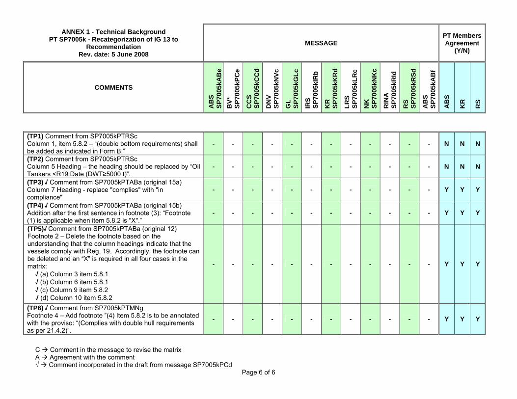
Page 6 of 6
(TP1) Comment from SP7005kPTRSc Column 1, item 5.8.2 – “(double bottom requirements) shall be added as indicated in Form B.”
- - - - - - - - - - - - N N N
(TP2) Comment from SP7005kPTRSc Column 5 Heading – the heading should be replaced by “Oil Tankers <R19 Date (DWT≥5000 t)“.
- - - - - - - - - - - - N N N
(TP3) √ Comment from SP7005kPTABa (original 15a) Column 7 Heading - replace "complies" with "in compliance"
- - - - - - - - - - - - Y Y Y
(TP4) √ Comment from SP7005kPTABa (original 15b) Addition after the first sentence in footnote (3): “Footnote (1) is applicable when item 5.8.2 is "X".”
- - - - - - - - - - - - Y Y Y
(TP5)√ Comment from SP7005kPTABa (original 12) Footnote 2 – Delete the footnote based on the understanding that the column headings indicate that the vessels comply with Reg. 19. Accordingly, the footnote can be deleted and an “X” is required in all four cases in the matrix:
√ (a) Column 3 item 5.8.1 √ (b) Column 6 item 5.8.1 √ (c) Column 9 item 5.8.2 √ (d) Column 10 item 5.8.2
- - - - - - - - - - - - Y Y Y
(TP6) √ Comment from SP7005kPTMNg Footnote 4 – Add footnote ”(4) Item 5.8.2 is to be annotated with the proviso: “(Complies with double hull requirements as per 21.4.2)”.
- - - - - - - - - - - - Y Y Y
Page 1 of 2
TECHNICAL BACKGROUND
Recommendation 104 (New, March 2009) “Qualification scheme for welders of steels”
1. Scope and objective To develop a new requirement for qualification scheme for welders who are engaged in welding works of hull structural steels in a shipyard or a manufacturer.
2. Background No current IACS document exists with regard to welder qualification, today any construction requires that welder qualification tests are necessary and should be monitored. The IACS WP/MW recognised this and also noted that current guidance given to shipyards by individual classification societies often resulted in conflict between shipyards and classification society due to the varying requirements of individual societies. Therefore WP/WM raised the Form A but the work was not initiated until reorganisation of the old IACS working groups occurred. The work item was taken over by Hull Panel as their Task 24 and allocated to Project Team 2 under the chair of LR, the document was drafted by NK.
3. Points of discussions The project team found common ground on the procedures to be followed.
It was unanimously agreed that the document should be developed as a recommendation to give time for experience of the use of the document before consideration of upgrading the document to a UR in the future.
At a very early stage it was also recognized that a single document to cover qualification of both steel and aluminium alloys was not practical and therefore two separate documents were produced.
A review was carried out between the societies to compare actual requirements against actual ship yard practice around the world, there were some obvious differences and a balanced approach was taken to satisfy the requirements appropriate to each society.
A number of points were raised by the Hull Panel on the first draft submitted. These were reviewed by PT2 and where appropriate amendments made or reasons for rejecting the suggestions given. 4. Recommendation. The Hull Panel and its PT2 recommends the adoption of the document “Qualification scheme for welders of steels” as Recommendation 104. 5. Source/Derivation of proposed interpretation N.A. 6. Decision by voting The draft had full agreement of the Hull Panel and PT2.
Submitted by Hull Panel Chairman
27 January 2009

Page 2 of 2
Permanent Secretariat note (March 2009): GPG approved new Rec 104 on 6 March 2009 (ref. 9520_IGc).
During GPG discussion the following comments were made by members:
1) ABS suggested that 6G(pipe) position should be included in Rec 104 as test acceptable for qualifying welder's for plate welding. BV, LR and RINA disagreed with this suggestion mentioning that the proposed draft is about plate welding only.
2) KR suggested that GPG should task Hull Panel to review the possibility or need to include contents about pipe welding and '6G' in the subjected draft recommendations (104 and 105) before the approval of GPG. ABS and RINA disagreed with this suggestion mentioning that they do not see the compelling need. LR added that KR's suggestion can be done later if and when it is considered the Recs should become URs.
3) CCS raised the issue of inconsistencies between the new Recs 104 and 105 and ISO standards. However noting that the recommendations do not have a compulsory nature like URs, GPG Chair proposed that these inconsistencies were not a compelling reason to amend the Recs and proposed to revisit this issue at a later date if and when it is considered that the Recs should become URs. No members disagreed with this proposal.

Page 1 of 2
TECHNICAL BACKGROUND
Recommendation 105 (New, March 2009) “Qualification scheme for welders of aluminium alloys”
1. Scope and objective To develop a new requirement for qualification scheme for welders who are engaged in welding works of aluminium alloys for hull structures in a shipyard or by a manufacturer. 2. Background No current IACS document exists with regard to welder qualification, today any construction requires that welder qualification tests are necessary and should be monitored. The IACS WP/MW recognised this and also noted that current guidance given to shipyards by individual classification societies often resulted in conflict between shipyards and classification society due to the varying requirements of individual societies. Therefore WP/WM raised the Form A but the work was not initiated before reorganisation of the old IACS working groups occurred. The work item was taken over by Hull Panel as their Task 24 and allocated to Project Team 2 under the chair of LR, the document was drafted by NK. 3. Points of discussions The project team found common ground on the procedures to be followed.
It was unanimously agreed that the document should be developed as a recommendation to give time for experience of the use of the document before consideration of upgrading the document to a UR in the future.
At a very early stage it was also recognized that a single document to cover qualification of both steel and aluminium alloys was not practical and therefore two separate documents were produced.
A review was carried out between the societies to compare actual requirements against actual ship yard practice around the world, there were some obvious differences and a balanced approach was taken to satisfy the requirements appropriate to each society.
A number of points were raised by the Hull Panel on the first draft submitted. These were reviewed by PT2 and where appropriate amendments made or reasons for rejecting the suggestions given. 4. Recommendation. The Hull Panel and its PT2 recommends the adoption of the document “Qualification scheme for welders of aluminium alloys” as Recommendation 105. 5. Source/Derivation of proposed interpretation N.A. 6. Decision by voting The draft had full agreement of the Hull Panel and PT2.
Submitted by Hull Panel Chairman 27 January 2009

Page 2 of 2
Permanent Secretariat note (March 2009): GPG approved new Rec 105 on 6 March 2009 (ref. 9520_IGc).
During GPG discussion the following comments were made by members:
1) KR suggested that GPG should task Hull Panel to review the possibility or need to include contents about pipe welding and '6G' in the subjected draft recommendations (104 and 105) before the approval of GPG. ABS and RINA disagreed with this suggestion mentioning that they do not see the compelling need. LR added that KR's suggestion can be done later if and when it is considered the Recs should become URs.
2) CCS raised the issue of inconsistencies between the new Recs 104 and 105 and ISO standards. However noting that the recommendations do not have a compulsory nature like URs, GPG Chair proposed that these inconsistencies were not a compelling reason to amend the Recs and proposed to revisit this issue at a later date if and when it is considered that the Recs should become URs. No members disagreed with this proposal.

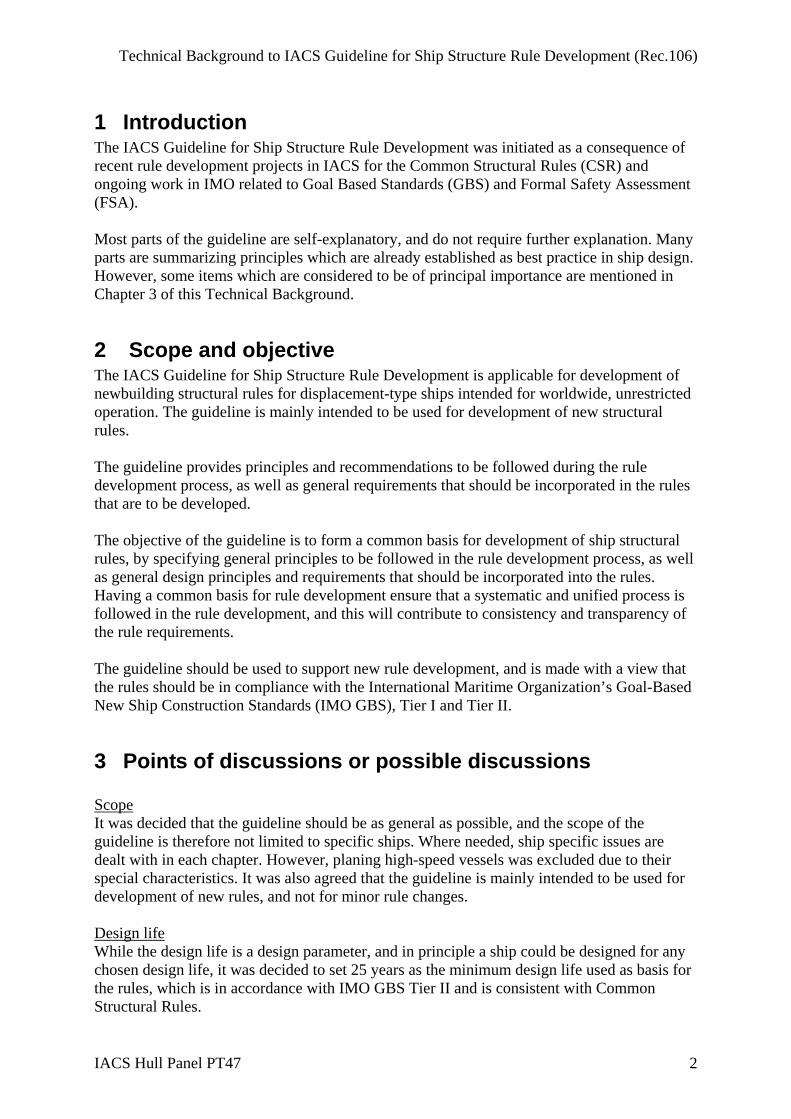
Technical Background to IACS Guideline for Ship Structure Rule Development (Rec.106)
IACS Hull Panel PT47 1
Technical Background
for
Recommendation No.106 (NEW, Jul 2009) “IACS Guideline for Rule Development -
Ship Structure”
IACS Hull Panel Task 47 PT47
TB Draft 0.2 20 April 2009
Technical Background to IACS Guideline for Ship Structure Rule Development (Rec.106)
IACS Hull Panel PT47 2
1 Introduction The IACS Guideline for Ship Structure Rule Development was initiated as a consequence of recent rule development projects in IACS for the Common Structural Rules (CSR) and ongoing work in IMO related to Goal Based Standards (GBS) and Formal Safety Assessment (FSA). Most parts of the guideline are self-explanatory, and do not require further explanation. Many parts are summarizing principles which are already established as best practice in ship design. However, some items which are considered to be of principal importance are mentioned in Chapter 3 of this Technical Background.
2 Scope and objective The IACS Guideline for Ship Structure Rule Development is applicable for development of newbuilding structural rules for displacement-type ships intended for worldwide, unrestricted operation. The guideline is mainly intended to be used for development of new structural rules. The guideline provides principles and recommendations to be followed during the rule development process, as well as general requirements that should be incorporated in the rules that are to be developed. The objective of the guideline is to form a common basis for development of ship structural rules, by specifying general principles to be followed in the rule development process, as well as general design principles and requirements that should be incorporated into the rules. Having a common basis for rule development ensure that a systematic and unified process is followed in the rule development, and this will contribute to consistency and transparency of the rule requirements. The guideline should be used to support new rule development, and is made with a view that the rules should be in compliance with the International Maritime Organization’s Goal-Based New Ship Construction Standards (IMO GBS), Tier I and Tier II.
3 Points of discussions or possible discussions Scope It was decided that the guideline should be as general as possible, and the scope of the guideline is therefore not limited to specific ships. Where needed, ship specific issues are dealt with in each chapter. However, planing high-speed vessels was excluded due to their special characteristics. It was also agreed that the guideline is mainly intended to be used for development of new rules, and not for minor rule changes. Design life While the design life is a design parameter, and in principle a ship could be designed for any chosen design life, it was decided to set 25 years as the minimum design life used as basis for the rules, which is in accordance with IMO GBS Tier II and is consistent with Common Structural Rules.
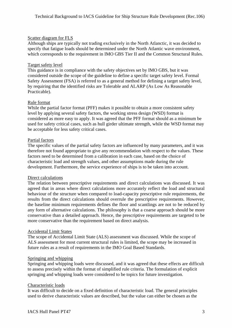
Technical Background to IACS Guideline for Ship Structure Rule Development (Rec.106)
IACS Hull Panel PT47 3
Scatter diagram for FLS Although ships are typically not trading exclusively in the North Atlanctic, it was decided to specify that fatigue loads should be determined under the North Atlantic wave environment, which corresponds to the requirement in IMO GBS Tier II and the Common Structural Rules. Target safety level This guidance is in compliance with the safety objectives set by IMO GBS, but it was considered outside the scope of the guideline to define a specific target safety level. Formal Safety Assessment (FSA) is referred to as a general method for defining a target safety level, by requiring that the identified risks are Tolerable and ALARP (As Low As Reasonable Practicable). Rule format While the partial factor format (PFF) makes it possible to obtain a more consistent safety level by applying several safety factors, the working stress design (WSD) format is considered as more easy to apply. It was agreed that the PFF format should as a minimum be used for safety critical cases, such as hull girder ultimate strength, while the WSD format may be acceptable for less safety critical cases. Partial factors The specific values of the partial safety factors are influenced by many parameters, and it was therefore not found appropriate to give any recommendation with respect to the values. These factors need to be determined from a calibration in each case, based on the choice of characteristic load and strength values, and other assumptions made during the rule development. Furthermore, the service experience of ships is to be taken into account. Direct calculations The relation between prescriptive requirements and direct calculations was discussed. It was agreed that in areas where direct calculations more accurately reflect the load and structural behaviour of the structure when compared to load-capacity prescriptive rule requirements, the results from the direct calculations should overrule the prescriptive requirements. However, the baseline minimum requirements defines the floor and scantlings are not to be reduced by any form of alternative calculations. The philosophy is that a coarse approach should be more conservative than a detailed approach. Hence, the prescriptive requirements are targeted to be more conservative than the requirement based on direct analysis. Accidental Limit States The scope of Accidental Limit State (ALS) assessment was discussed. While the scope of ALS assessment for most current structural rules is limited, the scope may be increased in future rules as a result of requirements in the IMO Goal Based Standards. Springing and whipping Springing and whipping loads were discussed, and it was agreed that these effects are difficult to assess precisely within the format of simplified rule criteria. The formulation of explicit springing and whipping loads were considered to be topics for future investigation. Characteristic loads It was difficult to decide on a fixed definition of characteristic load. The general principles used to derive characteristic values are described, but the value can either be chosen as the

Technical Background to IACS Guideline for Ship Structure Rule Development (Rec.106)
IACS Hull Panel PT47 4
most severe value that can be expected during the design life of the ship, or as a fractile in the probability density function for the load. Both approaches are acceptable, as long as the safety factors are calibrated to take account of the choice. Capacity models The guideline gives an overview of commonly used capacity models for the failure modes relevant to consider, as well as general principles for how to carry out the capacity assessment. The guideline is however not intended to be very specific, since new and improved methods may be developed in the future.
4 Source/derivation of proposed requirements N.A.
5 Decision by Voting N.A.
Submitted by Hull Panel Chairman 24 June 2009
Permanent Secretariat note (July 2009): The Guideline was submitted to IMO as MSC86/INF.3 on 24 February 2009 and in March 2009 GPG agreed that it should be published as an IACS Recommendation. This TB, prepared by the Hull Panel, was approved by GPG on 13 July 2009 (ref. 8646cIGf).

Page 1 of 3
TECHNICAL BACKGROUND
Recommendation No. 109 (New Oct. 2009) “Acceptance Criteria for Increased Cargo Tank Filling Limits Higher than 98%
- IGC Code 15.1.3” INTRODUCTION The IGC Code 15.1.3 permits Administrations to allow higher filling limits than the 98% maximum filling limit permitted by 15.1.1 provided it can be shown that such higher limit will not impair safety of the cargo containment taking into account shape of cargo tanks, location and arrangements of pressure safety relief valves, accuracy of instrumentation and other factors of importance. A working group organized by SIGTTO for developing proposals for revision of the IGC Code decided to amend 15.1.3 so as to more precisely specify criteria under which higher filling limits may be accepted. IACS INVOLVEMENT The IACS Working Party on Gas Tankers did develop a draft interpretation of 15.1.3 giving acceptance criteria for increased filling limits in the mid 1980s. However, this draft was not formally adopted as an UI. The draft acceptance criteria have been used by the industry to some extent as a basis for getting acceptance for higher filling limits by Administrations for some ships. The SIGTTO working group was made aware that an old IACS draft interpretation existed and asked IACS to propose final acceptance criteria for higher filling limits that could be included in a revised IGC Code. IACS Statutory Panel agreed to develop such criteria as input to the SIGTTO working group and established a Project Team to carry out the task. AGREED ACCEPTANCE CRITERIA Compared to the old draft UI the following points may be noted: - ‘Functional requirements’ were developed and included under a ‘General’ introductory
paragraph. - The formulae in the old draft for corrections due to tolerances of temperature gauges was
an expression correlating gauge tolerances and loading temperature vs critical temperature for the product to give a resulting volume expansion. This has been changed into a formulae giving expansion as the product of gauge tolerance and the volumetric expansion factor for the product.

Page 2 of 3
- The correction factor in the original draft for tank calibration error has been omitted since it was found that such error has no significant influence on filling limits expressed as percentage.
- A correction factor accounting for the volume expansion resulting from the pressure rise
from opening pressure of pressure relief valves to full relieving capacity has been added. This pressure rise is taken to be 20% of the set opening pressure of the PRV’s according to IGC Code 8.5.
- Corrections for tolerances on PRV’s set opening pressure (IGC 8.2.5) were found not to
be applicable for pilot operated PRV’s and were consequently not included. - A factor expressing an operational margin to account for operator’s reaction time, valve
closing time and product flow back from cargo piping has been added. This margin has been set to min. 0.1%.
- A specific requirement that under conditions of list and trim given in IGC Code 8.2.17 the
suction funnels of the PRV’s shall be min. 0.4D of funnel diameter above the liquid surface and that no isolated vapour pockets shall be formed.
- After some discussions it was agreed to keep a maximum filling of 99.5% as in the old
draft. POINTS OF DISCUSSIONS The old draft interpretation set a maximum permitted filling limit of 99.5% at reference temperature. With the detailed outline of correction factors in the revised acceptance criteria the necessity of having this upper limit was discussed. After some discussions, and carrying out sensitivity studies which varied the Alpha (α) values, it was recognized that Alpha 4 (α4) (operational margin) had a significant impact on the filling limit, but could not be defined precisely enough to control that limit. Accordingly, it was agreed to keep a maximum filling of 99.5% as in the old draft. The Project Team completed the task by the end of April 2009 with the outcome including a draft UI. Meanwhile, the PT reported to the Statutory Panel that filling limits above 99.5% had been granted for some gas carriers. However, the PM thought that no rationale for this acceptance was given and consequently no discussions took place in the PT. No consensus was reached as to whether the draft UI shall be retrospectively applied to existing gas carriers in the Statutory Panel. Taking into account the PT’s report as mentioned above, and considering that: 1) no consensus was reached as to whether the draft UI shall be retrospectively applied to existing gas carrier in the Statutory Panel; 2) some members suggested that this criteria should be implemented by members on voluntary basis; and
Page 3 of 3
3) the benefit of having an IACS Technical Resolution available for the IGC Code review, in the end, the Statutory Panel agreed that this criteria should be a Recommendation at this stage and may be reinstated as an IACS UI depending on the outcome of the revision of the IGC Code.
Submitted by Statutory Panel Chairman 10 September 2009
Permanent Secretariat note (October 2009): New Recommendation No.109 was approved by GPG on 8 October 2009 (ref. 8671_IGg).

IACS History File + TB, Part A
Page 1 of 3
Recommendation No.110 “Guideline for Scope of Damage Stability Verification on new oil tankers,
chemical tankers and gas carriers” Part A. Revision History Version no. Approval date Implementation date
when applicable Rev.1 (Nov. 2010) 05 Nov 2010 1 January 2011 New (Nov. 2009) 20 Nov 2009 1 January 2010 • Rev.1 (Nov 2010) .1 Origin of Change:
Request by non-IACS entity (UK MCA) Suggestion by an IACS member Based on IMO Regulation (Outcome of SLF 52)
.2 Main Reason for Change: To revise the Recommendation in accordance with the comments and proposals provided by UK MCA and IACS Statutory Panel and submit the revised Recommendation to SLF 53. .3 List of non-IACS Member classification societies contributing through the TC Forum and/or participating in IACS Working Group: None .4 History of Decisions Made: The Recommendation was revised by Project Team PT25 established by IACS Statutory Panel according to the results achieved by correspondence under Statutory Panel subject number SP10006i and the extensive comments made by UK MCA (see Form 1 approved by IACS GPG on 12 August 2010). Majority of work was accomplished by correspondence. Kick-off meeting was held to consider/discuss the results achieved by correspondence under Statutory Panel subject number SP10006i and comments provided by MCA to IACS Rec.110, to consider the need to establish a cooperation with UK MCA, to agree on the scope of work to be carried out by the PT and to divide the agreed scope of work into the equal sets to be assigned to each PT Member.

Part A
Page 2 of 3
PT Status Report was submitted to IACS Statutory Panel on 30th August 2010. The report was considered by the Panel at its 12th meeting. It was also agreed to submit the revised Rec. 110 to SLF 53 separately from the UK paper as an IACS information document. The Recommendation was further revised by the PT as per the output from the 12th Statutory Panel meeting and submitted to the Panel for approval. .5 Other Resolutions Changes None .6 Dates:
Original Proposal: 24 September 2010 Made by the PT25 of the Statutory Panel Panel Approval: 25 October 2010 GPG Approval: 05 November 2010 (Ref: 10038bIGg)
• New (Nov 2009) .1 Origin of Change:
Based on IMO Regulation (Outcome of SLF 51)
.2 Main Reason for Change: To submit the approval procedures used by IACS Members for damage stability calculations to SLF 52. .3 List of non-IACS Member classification societies contributing through the TC Forum and/or participating in IACS Working Group: None .4 History of Decisions Made: This Recommendation was developed by Project Team PT24 established by IACS Statutory Panel. .5 Other Resolutions Changes None .6 Dates:
Original Proposal: 18 September 2009 Made by PT24 of the Statutory Panel Panel Approval: 10 November 2009 GPG Approval: 20 November 2009 (Ref: 9559aIGh)
Part B
Page 3 of 3
Part B. Technical Background List of Technical Background (TB) documents: Annex 1 TB for New (Nov 2009)
See separate TB document in Annex 1.
◄▼► Annex 2 TB for Rev.1 (Nov 2010)
See separate TB document in Annex 2.
◄▼►
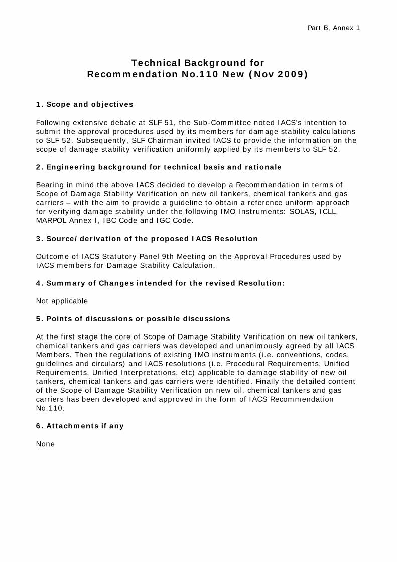
Part B, Annex 1
Technical Background for
Recommendation No.110 New (Nov 2009)
1. Scope and objectives Following extensive debate at SLF 51, the Sub-Committee noted IACS’s intention to submit the approval procedures used by its members for damage stability calculations to SLF 52. Subsequently, SLF Chairman invited IACS to provide the information on the scope of damage stability verification uniformly applied by its members to SLF 52. 2. Engineering background for technical basis and rationale Bearing in mind the above IACS decided to develop a Recommendation in terms of Scope of Damage Stability Verification on new oil tankers, chemical tankers and gas carriers – with the aim to provide a guideline to obtain a reference uniform approach for verifying damage stability under the following IMO Instruments: SOLAS, ICLL, MARPOL Annex I, IBC Code and IGC Code. 3. Source/derivation of the proposed IACS Resolution Outcome of IACS Statutory Panel 9th Meeting on the Approval Procedures used by IACS members for Damage Stability Calculation. 4. Summary of Changes intended for the revised Resolution: Not applicable 5. Points of discussions or possible discussions At the first stage the core of Scope of Damage Stability Verification on new oil tankers, chemical tankers and gas carriers was developed and unanimously agreed by all IACS Members. Then the regulations of existing IMO instruments (i.e. conventions, codes, guidelines and circulars) and IACS resolutions (i.e. Procedural Requirements, Unified Requirements, Unified Interpretations, etc) applicable to damage stability of new oil tankers, chemical tankers and gas carriers were identified. Finally the detailed content of the Scope of Damage Stability Verification on new oil, chemical tankers and gas carriers has been developed and approved in the form of IACS Recommendation No.110. 6. Attachments if any None

Part B, Annex 2
Technical Background for
Recommendation No.110 Rev.1 (Nov 2010)
1. Scope and objectives Following the debate at SLF 52, the Sub-Committee invited interested Parties to provide their comments on the IACS Rec.110 with a view to develop the new IMO Guidelines. IACS’s intention to continue the work on improvement of Rec. 110 and submit the revised Recommendation to SLF 53 was noted by Sub-Committee. 2. Engineering background for technical basis and rationale IACS Rec.110 was amended on the basis of IACS Members practical experience on damage stability verification on new oil tankers, chemical tankers and gas carriers. 3. Source/derivation of the proposed IACS Resolution The results achieved by correspondence under Statutory Panel subject number SP10006i, comments provided by MCA to IACS Rec. 110, existing procedures used by IACS members for damage stability calculation and the outcome of 12th Statutory Panel meeting (Statutory Panel Task No.33). 4. Summary of Changes intended for the revised Resolution: See the attached Summary of discussion on the comments to IACS Rec. 110. 5. Points of discussions or possible discussions See the attached Summary of discussion on the comments to IACS Rec. 110. 6. Attachments if any Summary of discussion on the comments to IACS Rec. 110.
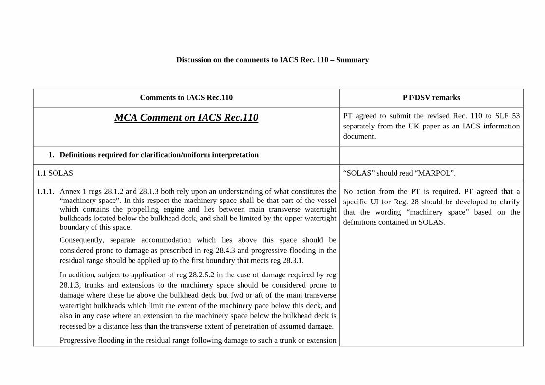
Discussion on the comments to IACS Rec. 110 – Summary
Comments to IACS Rec.110 PT/DSV remarks
MCA Comment on IACS Rec.110 PT agreed to submit the revised Rec. 110 to SLF 53 separately from the UK paper as an IACS information document.
1. Definitions required for clarification/uniform interpretation
1.1 SOLAS “SOLAS” should read “MARPOL”.
1.1.1. Annex 1 regs 28.1.2 and 28.1.3 both rely upon an understanding of what constitutes the “machinery space”. In this respect the machinery space shall be that part of the vessel which contains the propelling engine and lies between main transverse watertight bulkheads located below the bulkhead deck, and shall be limited by the upper watertight boundary of this space.
Consequently, separate accommodation which lies above this space should be considered prone to damage as prescribed in reg 28.4.3 and progressive flooding in the residual range should be applied up to the first boundary that meets reg 28.3.1.
In addition, subject to application of reg 28.2.5.2 in the case of damage required by reg 28.1.3, trunks and extensions to the machinery space should be considered prone to damage where these lie above the bulkhead deck but fwd or aft of the main transverse watertight bulkheads which limit the extent of the machinery pace below this deck, and also in any case where an extension to the machinery space below the bulkhead deck is recessed by a distance less than the transverse extent of penetration of assumed damage.
Progressive flooding in the residual range following damage to such a trunk or extension
No action from the PT is required. PT agreed that a specific UI for Reg. 28 should be developed to clarify that the wording “machinery space” based on the definitions contained in SOLAS.

should be applied up to the first boundary that meets reg 28.3.1.
1.1.2. Annex 1 reg 28.1.2 excludes application of damage to the machinery space of tankers more than 150m but not exceeding 225m where the machinery space is “located aft”. In this context it is considered this means that all parts of the fwd watertight bulkhead bounding the machinery space (as defined above) should lie aft of midships where it bounds the shell.
Furthermore, the restriction on applying damage to a machinery space located aft does not remove the obligation to consider side and bottom damages of a lesser extent which occur within this portion of the vessel.
Reg. 28.1.2 does not exclude application of damage to the machinery space, but we agree with the proposal to define the term “located aft” specifically for the purpose of application of Reg. 28.1.2 and Reg. 28.1.3. The following interpretation could be proposed for the further development:
“machinery space is located aft “ means that all parts of the fwd watertight bulkhead bounding the machinery space should lie aft of midships where it bounds the shell and after of the cargo zone. The step formed by the afterpeak tank shall not be damaged as in accordance with ICLL, Reg.27.12.d) and MARPOL, Reg. 28.2.5.2.
PT agreed that no revision is needed for Rec.110.
1.1.3. Annex 1 reg 28.3.4 requires that residual stability is assessed in the “intermediate stages” of damage and that the stability should be “sufficient” in all such stages.
We are in agreement with your proposals with respect to these issues, that six stages of primary flooding should be considered and that the final stage stability criteria should also be applied during intermediate stages.
PT has no specific comment.
1.1.4. Annex 1 reg 28.3.5 requires that where cross-flooding arrangements are fitted which do not meet the requirement for the flooded compartment to be considered common with the damaged compartment, full compliance with residual criteria should be met in all intermediate stages of flooding and at equilibrium without these being taken into account.
This is commonly interpreted as meaning that cross-flooding fittings are not permitted, so should be ignored completely. We are in agreement with your interpretation, that this
PT has no specific comment.

requires all primary flooding stages to be completed before cross-flooding is evaluated, with all primary and cross-flooding stages required to meet residual criteria.
We also consider 3 stages of cross-flooding to be appropriate for this purpose and that cross-flooded compartments may be considered common if a calculation made in accordance with Resolution MSC.245(83) shows equalisation within 60 seconds.
1.2. IBC/IGC Codes
1.2.1. Regulation 2.8.1 in both Codes relies upon an understanding of what constitutes a “machinery space located aft”.
In this respect the machinery space considered shall be that part of the vessel which contains the propelling engine and lies between main transverse watertight bulkheads located below the bulkhead deck, and shall be limited by the upper watertight boundary of this space. This limited application contradicts the more general definition in reg 1.3.
Separate accommodation which lies above this space should be considered prone to damage and any progressive flooding in the residual range should be applied up to the first boundary that meets reg 2.7.8.
In addition, subject to application of reg 2.7.4 in the case of damage required by regs 2.8.1.3, 2.8.1.5 and 2.8.1.6 of the IBC Code and regs 2.8.1.3 and 2.8.1.6 of the IGC Code, trunks and extensions to the machinery space should be considered prone to damage where these lie above the bulkhead deck but fwd or aft of the main transverse watertight bulkheads which limit the extent of the machinery pace below this deck, and also in any case where an extension to the machinery space below the bulkhead deck is recessed by a distance less than the transverse extent of penetration of assumed damage.
Progressive flooding in the residual range following damage to such a trunk or extension should be applied up to the first boundary that meets reg 2.7.8.
As you are aware, we have had issues with this interpretation where trunks to the
See the comment to 1.1.1.
machinery space have extended beyond the limiting main watertight bulkheads but have not been effectively separated by watertight bulkheads from the accommodation or other ancillary compartments as the openings were closed with fire doors and not weathertight or watertight doors as required.
1.2.2. With respect to the definition of “located aft” in the context of the excluded machinery space damage cases considered at 2.2.1 above, it is considered this means that all parts of the fwd watertight bulkhead bounding the machinery space (as defined above) should lie aft of midships where it bounds the shell.
Furthermore, the restriction on applying damage to a machinery space located aft does not remove the obligation to consider side and bottom damages of a lesser extent which occur within this portion of the vessel.
See our comment to 1.1.2.
1.2.3. Reg 2.9.1.3 of both Codes requires that residual stability is assessed for “intermediate stages” of damage and that the residual stability standard to be applied should not be “significantly less” than that required for compliance in the final stage.
We are in agreement with your proposals with respect to these issues, that six stages of primary flooding should be considered and that the final stage stability criteria should also be applied during intermediate stages.
PT has no specific comment.
1.2.4. Reg 2.7.6 of both Codes require that where cross-flooding arrangements are fitted which do not meet the requirement for the flooded compartment to be considered common with the damaged compartment, full compliance with residual criteria should be met in all intermediate stages of flooding and at equilibrium without these being taken into account.
This is commonly interpreted as meaning that cross-flooding fittings are not permitted, so should be ignored completely. We are in agreement with your interpretation, that this requires all primary flooding stages to be completed before cross-flooding is evaluated, with all primary and cross-flooding stages required to meet residual criteria.
We also consider 3 stages of cross-flooding to be appropriate for this purpose and that
PT has no specific comment.

cross-flooded compartments may be considered common if a calculation made in accordance with Resolution MSC.245(83) shows equalisation within 60 seconds.
2. Items to change
2.1. At section 3.2 we think the wording may be confusing. We suggest the following modifications may clarify the intended meaning.
“…. In general, for non approved loading conditions (by the Administration or RO), approved KG/GM limit curve(s) from stability information or approved loading instrument software satisfying the stability requirements (intact and damage) for the proposed loading condition should be used to verify compliance on board.
Within the scope of the verification determined as per the above, all potential or necessary damage scenarios should be determined and assessed taking into account the damage stability criteria.
Damage stability verification and approval requires a review of submitted calculations and supporting documentation with independent check calculations to confirm damage stability calculation results comply with relevant stability criteria.
Examination and approval of the loading instrument software installed on board and to be used for assessing damage stability should also be carried out. ….”
The following revision have been agreed by the PT:
“…. In general, for non approved loading conditions (by the Administration or RO), approved KG/GM limit curve(s) or approved loading instrument software satisfying the stability requirements (intact and damage) for the draugh range to be covered should be used to verify compliance on board.
Within the scope of the verification determined as per the above, all potential or necessary damage scenarios should be determined and assessed taking into account the damage stability criteria.
Damage stability verification and approval requires a review of submitted calculations and supporting documentation with independent check calculations to confirm damage stability calculation results comply with relevant stability criteria.
Examination and approval of the loading instrument software installed on board (and to be used for assessing intact and damage stability) should also be carried out. ….”
2.2. It would be our understanding that unenclosed superstructures would not be included in KN data except in the case set out at section 3.3, when we would expect flooding points (including windows) incapable of weathertight closure to be included in any list determined in accordance with paragraph 3.4.2.6.
PT agreed that the following should be added to the second paragraph of IACS Rec.110, Section 3.3:
Flooding points (including windows) incapable of weathertight closure to be included in any list
Full compliance with residual stability criteria must be achieved before any such point becomes immersed within the residual range.
determined in accordance with paragraph 3.4.2.6. Full compliance with residual stability criteria must be achieved before any such point becomes immersed.
2.3. With particular reference to any submission which includes critical KG or GM data we suggest there should be an entry at paragraph 3.4.2.11 requiring that any initial conditions or restrictions which have been assumed in the derivation of such data, and which must therefore be met in service, should be stated.
Agreed by the PT.
2.4. At paragraph 3.4.3.2 it is stated that intermediate stages only require to be considered where it is “obvious that there is some risk to achieve critical trim and/or stability parameters in the intermediate stages”.
Consideration of intermediate stages is a requirement of the various international instruments. Whilst its evaluation may prove to be of no significance in the majority of cases it is not an optional consideration and this relaxation/interpretation is open to potential abuse.
To solve the matter it was agreed
to replace the wording “intermediate conditions, as” with “intermediate flooding” in the first sentence of paragraph 3.4.3.2;
to add the reference to paragraphs 6.8 and 9.2 into the first sentence of paragraph 3.4.3.2 after the words: “cross-flooding” and the reference to paragraphs 6.9 after the words “progressive flooding”;
to amend the second sentence of paragraph 3.4.3.2 as follows:
“The intermediate stages for cargo outflow and sea water inflow should be checked. If any stability criteria during intermediate stages shows more severe values than in the final stage of flooding this intermediate stages should also be submitted.”;
to amend paragraphs 4.1.e) as follows:
“Minimum tank filling levels required to achieve compliance with the applicable stability criteria; and”
and to amend the second sentence of paragraph 9.1 as

follows:
“If any stability criteria during intermediate stages shows more severe values than in the final stage of flooding this intermediate stages should also be submitted”.
2.5. We consider that section 4 constitutes advice to Class surveyors on what methods of operation are permissible, and what each one requires to be examined and approved. On this basis we would consider that a better title may be “Permitted Modes of Operation – Descriptions/Assumptions” and the following modifications to the text are offered for consideration :
“In considering the scope of the verification to be conducted, consideration of the intended mode of operation is required.
The following modes of operation are permitted :
a) Adherence to service loading conditions close to the approved loading conditions from the stability booklet (see paragraph[s 4.1 and] 4.2); or
b) Adoption of service loading conditions other than approved loading conditions which have been checked on board to show compliance with the approved [intact and] damage stability limiting curves (where provided) (see paragraph 4.3); or
c) Adoption of service loading conditions other than approved loading conditions which have been checked with an approved on-board stability software capable of [intact and] damage stability verification (Type 2 or 3 of IACS UR L5, Rev. 2, Corr.1 Nov 2006) based upon KG/GM limit curve(s) or direct calculation (see paragraph 4.5).
In the case of vessels which intend to operate by adherence to approved loading conditions only when in service, and for which no means has been submitted or approved in relation to verification of loading conditions other than the approved loading conditions, suitable instructions should be included in the stability booklet/loading manual that adoption of such unapproved loading conditions in service is prohibited unless these are submitted for the
PT agreed to keep the existing text. Because this is the responsibility of IMO to define the allowed deviation from the approved loading conditions.
specific approval of the Administration or RO.”
Note: clauses b) and c) refer to intact stability. As the guidance is supposed to refer to damage stability only, these references should really be deleted along with that at paragraphs 4.3 a), 4.5 a), 4.5 b) and any others identified. However, if the references to intact stability are to be retained the title of the document shall require amendment.
2.6. Section 4.1 reflects the submission and approval of individual fixed loading conditions described in paragraph 4 a). We would suggest that the word displayed in the first line may better be replaced with presented.
Given that the conditions are fixed and all require to be individually verified and approved as meeting damage criteria we would question some of the guidance included.
At 4.1 a) we would question whether “alternate” is required as this is implied in “any intended condition”, and ballast conditions do not need to be considered for damage.
At 4.1 c) a fixed loading condition cannot really apply or convey a restriction, just another alternative “intended condition”.
At 4.1 d) we agree that the full range of operating SG should be covered but safe carriage in between these SGs cannot be inferred, particularly if the wording “identical to” is retained at paragraph 4 a).
At 4.1 e) an approved fixed condition cannot be used to set a general limit, such as minimum filling levels for one or more tanks, as it is not permitted to load alternate conditions based upon this information.
4.1 f) appears to be and extension of 4.1 a) in that it constitutes another set of “intended conditions”.
PT revised Section 4.1 as follows:
“4.1 Specific loading patterns Ship specific design loading patterns and loading restrictions should be clearly presented in the stability booklet. The following items should be included: a) Any required and intended loading conditions
(including the ones corresponding to multiple freeboards when so assigned to the vessel), i.e. symmetrical/unsymmetrical, homogeneous/alternating or ballast/partial/full;
b) Types (e.g. oil, noxious liquid substances and
LNG) of liquid cargo allowed to be carried; c) Restrictions to different liquid loads to be carried
simultaneously; d) Range of permissible densities of liquid loads to
be carried; and e) Minimum tank filling levels required to achieve
compliance with the applicable stability criteria. For the verification of damage stability all loading

conditions presented in the stability booklet except for ballast, light ship and docking conditions are to be examined.”
2.7. We would question whether the “matrix of loading conditions” described in section 4.2 constitutes a legitimate means of verifying damage stability for conditions which are not individually assessed and approved. Paragraph 4.5 a) implies that these conditions are previously approved and may be used as base data for a Type 2 loading program.
We would consider that practical application of such matrices of conditions would prove to be problematic in service as their accuracy depends upon the assumed input conditions, including draught, trim, initial GM, subsidiary tankage in way of the critical cargo tank for damage purposes (particularly for two compartment ships) and the cargo SG.
It is unclear how such conditions would be used in practice, but it is assumed that the closest approved condition to a live loading condition would be that with the same draught and trim, and then the closest tank fillings and intact GM. The problem comes with permitting variation in these items, as for any condition on the KG/GM limit a variation gives a 50% chance of non-compliance.
Selecting conditions in relation to their cargo tank fillings and initial GM, in preference to the displacement/draught and trim is problematic as this may lead to acceptance of conditions which would fail if examined directly for compliance.
Unless such matrices of conditions can be presented in such a manner that it is possible to demonstrate without any doubt to PSCI that a loading condition, which does not correspond with any of them directly, fully meets damage criteria we think this method should be removed.
There is no difference in principle between loading approximately to a matrix condition as there is to a fixed approved condition considered in paragraph 4.1.
“Matrix of Permissible Loading Conditions” in item 4.2 of the current Rec.110 should remain as Option such that it may be used by Member(s).

2.8. To more closely reflect the guidance in MSC/Circ.406/Rev.1, the first line of section 4.3 should refer to “… gas/chemical vessels which operate as parcel tankers, ...”.
PT has no specific objection.
2.9. In section 9.3 there is reference to an alternative method “i)” of considering substitution of initial tank content with sea water. This method refers to Annex 5 but does not follow the guidance in Annex 5, which gives the calculation method proposed for the method which precedes alternative method “i)”. Annex 5 does not propose a linear transition for SG, so this reference and calculation method should be deleted.
PT agreed that the reference should be removed, but the calculation method should be kept.
2.10. It is noted however that the calculation method proposed at alternative method “ii)” solves the issue of treating an empty tank which is initially above the condition waterline, and only floods in the latter damage stages.
We do not generally favour employing two alternate methods of calculation for considering the filling/transitional filling of tanks which lie on or below the waterline and see little purpose in employing one such as this, which only covers empty tanks when tanks may be full, part full or empty in any particular loading case, for this purpose.
However, we do support use of this methodology to address the filling of a tank which immerses only in the last few flooding stages and is intersected by or below the initial waterline.
PT agreed to keep the existing text, i.e. alternative methods should be allowed as they may be equally as valid.
3. Items to Add/Consider
3.1. For the purpose of providing comprehensive guidance it shall be necessary to add a definition for the meaning of “approved loading condition” which should reflect that from the operational guidance presently under preparation by others.
PT agreed that there is no need to develop a new definition for the well understood term, i.e. an approved loading condition is one which has been directly examined and endorsed by Administration/RO. This definition “An approved loading condition is one which has been specifically examined and endorsed by Administration/RO” will be added to the end of

paragraph 4 (before paragraph 4.1).
3.2. For the purpose of operating a vessel which has approved loading conditions alone, it is permitted to transition from the approved departure condition to the approved arrival condition required to be submitted and approved by the various international instruments. If this is not the case then vessels would be inoperable.
Where this transition involves substantial consumption of fuel and other consumables, and/or substitution with ballast on passage, each stage of the voyage should be separately considered and approved with an appropriate allowance made for free surface.
In this respect, no condition is fixed once the voyage commences and it is not expected to check stability throughout a voyage where no means to achieve this is provided. Consequently it is proposed that the wording of paragraph 4 a) is modified to that shown at 2.5 a) above.
PT agreed that this matter is properly covered by paragraph 6.5.
3.3. Paragraph 4.2 introduces an apparent anomaly, as we are advising that vessels must always be loaded closely to an approved condition, otherwise the loading condition is invalid (unverified for damage stability in particular) and has to be submitted to the Administration or RO for prior approval.
Yet we are also indicating that the existing provisions must permit transition between approved departure and arrival conditions, otherwise the existing instruments and approvals make no sense.
To make any sense of this I think we need to differentiate between changes through usage of consumables, provided that significant ballast substitution is covered, and variation from approved loading conditions caused through significant changes to the initial level/distribution of cargo or ballast carried.
We need to provide a definition of the safe (maximum) deviation from an approved loading condition before it becomes invalid and the revised loading condition must be
See the remark to comment 2.7.
considered and approved in its own right.
For this we have previously suggested a variation based upon a variation of cargo or ballast mass of 1% in any individual tank and variation of 2cm in the overall calculated fluid KG or GM.
It may be more flexible to expand these limits to reflect the permitted calculation tolerances (ie the allowed variation in the original condition from what has been calculated) of 2% variation in of cargo or ballast mass in any individual tank and 5cm or 1% x KG variation in the overall calculated KG or GM (whichever is less). It is difficult to justify limits beyond these values.
Overall one would also have to set a maximum variation in total cargo and ballast tank content of 2% by mass, as a means of controlling the overall displacement and draught if tanks other than cargo or ballast are also varied.
3.4. Although it is accepted that critical KG/GM data are an accepted method for determining the stability of loading conditions other than approved loading conditions, and that their use is provided for and promoted in international instruments, their use does present some difficulty.
In particular, we would recommend that their use is only permitted and approved if any initial conditions upon which their results rely can be readily understood and presented in the stability booklet and checked on board, using a calculation sheet or other check off list.
Where on-board loading software is used to check compliance with critical KG/GM data stored for this purpose, the approval of the software should also ensure that all initial conditions (if any) which justify use of the critical KG/GM data are met for the loading condition under consideration, and for this to be confirmed in the printout.
One initial condition to be fulfilled would be the maximum permitted initial heel variation from upright.
PT decided to add the footnote against the title of section 4.3 “To avoid difficulties associated with developing suitable KG/GM limit curves and their restriction on operational capacity it is recommended that an approved Type 3 stability software is fitted on board.”

It is also essential to ensure that critical KG/GM data fully reflect the arrangement of the vessel, particularly if the centreline division is not directly on centreline (which may require port/stbd sets) and in cases where two compartment damage applies (where limiting data must also include one compartment damages and other lesser cases where these may be more severe).
3.5. At section 4.4, reference is made to the necessity of keeping the vessel upright as far as practicable, which is basic good seamanship.
Noting that a 20m beam tanker shall exhibit an additional immersion of 175mm at the deck edge for an initial heel of 1 degree, and the adverse effects such an initial heel shall have on restoring moment and immersion of air pipes after damage, we would prefer to see this limit reduced to no more than 0.5 degrees.
It is our opinion that loading programs of Type 3 should normally be arranged to calculate all damage stability scenarios for both sides of the vessel, to reflect the variations in typical parcel tanker operation, in which case any initial heel shall have an adverse effect on stability compliance to that side.
Accepting that it may not prove feasible to always bring a vessel upright prior to departure, we would suggest that any loading program which is approved to undertake calculations to one side only (on the basis that the loading shall always be symmetrical) should always be arranged to apply damage in the direction of heel where one is recorded, and also to give an error should the heel exceed the maximum permitted value.
The ability to consider vessel truly symmetric shall depend upon the disposition and arrangement of the internal compartments and any progressive flooding points within the poop accommodation and similar areas. Experience shows that these elements are rarely symmetric.
Please be referred to the tolerance indicated in L5 for equilibrium angles. The comments look like amendments to L5 (not to Rec.110).
3.6. Section 6.1 makes a modification to the standard constant displacement damage PT agreed to amend the last sentence of paragraph 6.1
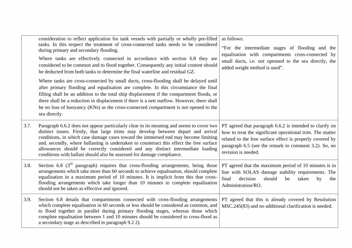
consideration to reflect application for tank vessels with partially or wholly pre-filled tanks. In this respect the treatment of cross-connected tanks needs to be considered during primary and secondary flooding.
Where tanks are effectively connected in accordance with section 6.8 they are considered to be common and to flood together. Consequently any initial content should be deducted from both tanks to determine the final waterline and residual GZ.
Where tanks are cross-connected by small ducts, cross-flooding shall be delayed until after primary flooding and equalisation are complete. In this circumstance the final filling shall be an addition to the total ship displacement if the compartment floods, or there shall be a reduction in displacement if there is a nett outflow. However, there shall be no loss of buoyancy (KNs) as the cross-connected compartment is not opened to the sea directly.
as follows:
“For the intermediate stages of flooding and the equalisation with compartments cross-connected by small ducts, i.e. not openned to the sea directly, the added weight method is used”.
3.7. Paragraph 6.6.2 does not appear particularly clear in its meaning and seems to cover two distinct issues. Firstly, that large trims may develop between depart and arrival conditions, in which case damage cases toward the immersed end may become limiting and, secondly, where ballasting is undertaken to counteract this effect the free surface allowances should be correctly considered and any distinct intermediate loading conditions with ballast should also be assessed for damage compliance.
PT agreed that paragraph 6.6.2 is intended to clarify on how to treat the significant operational trim. The matter related to the free surface effect is properly covered by paragraph 6.5 (see the remark to comment 3.2). So, no revision is needed.
3.8. Section 6.8 (3rd paragraph) requires that cross-flooding arrangements, being those arrangements which take more than 60 seconds to achieve equalisation, should complete equalisation in a maximum period of 10 minutes. It is implicit from this that cross-flooding arrangements which take longer than 10 minutes to complete equalisation should not be taken as effective and ignored.
PT agreed that the maximum period of 10 minutes is in line with SOLAS damage stability requirements. The final decision should be taken by the Administration/RO.
3.9. Section 6.8 details that compartments connected with cross-flooding arrangements which complete equalisation in 60 seconds or less should be considered as common, and to flood together in parallel during primary flooding stages, whereas those which complete equalisation between 1 and 10 minutes should be considered to cross-flood as a secondary stage as described in paragraph 9.2 2).
PT agreed that this is already covered by Resolution MSC.245(83) and no additional clarification is needed.

In making any assessment of cross-flooding time using Resolution MSC.245(83), reference should also be made to the need to ensure that sufficient air pipe area is provided to enable such cross-flooding to complete effectively, and not to be restricted by increased air pressure above the waterline in the equalised tank. In this respect a minimum air pipe sectional area of 10% of the cross-levelling duct should be provided.
3.10. Section 6.9 (2nd paragraph) describes treatment of compartments which are progressively flooded through immersion of a downflooding point which becomes permanently immersed. It is only logical to assume that such a space will flood during those primary stages of flooding up to and including equilibrium which occur after the downflooding point immerses, not over all six stages.
PT agrees with the view expressed by MCA, but sees no real need to amend Rec.110.
3.11. We would suggest rephrasing the wording of paragraph 7.2.1 to advise that all cases of lesser damage should be assessed to ensure they do not result in a more severe residual condition than that determined for a damage of full extent. In particular single compartment cases should be considered for two compartment ships and the possibility of lesser cases becoming critical at elevated trim levels should be assessed.
Where it is apparent that lesser cases of damage are always less severe than a damage of full extent, then consideration may be given to omitting such cases from the standard damage cases run by a loading program of Type 3.
PT agreed to amend paragraph 7.2.1 as follows:
“If any damage of a lesser extent than the maximum damage specified in 7.1 would result in a more severe condition, such damage should be considered (see paragraph 4.5).”
3.12. In relation to section 7.3 we would caution that surveyors are tempted to consider the possible effects of lesser damage cases before the event, as the consequences of individual damages cannot always be foreseen and may reverse with changes in the initial conditions, such as cargo SG or tank filling level, or the omission of deck tanks from a damage case.
It is best practice to always define and evaluate lesser cases rather than to attempt to prejudge which ones may prove to be more severe and therefore worthy of examination.
Just noted. No amendments to Rec. 110 were approved by the IACS Statutory Panel.
3.13. In relation to consideration of homogeneous loading conditions and partial loading conditions described in section 8.1, it must be borne in mind that if there is no logical
See the remark to comment 2.5.

progression in tank fillings as the SG or cargo mass increases, then the master cannot effectively interpolate between such conditions to determine compliance of an intermediate case. Interpolation between loading conditions in this way cannot generally be regarded as sufficient to meet statutory requirements and is not permitted.
3.14. Similarly, the consideration of symmetrical or unsymmetrical loading patterns in section 8.2, and zig zag loading patterns in particular, determined for a narrow range of SG does not imply the ability to carry empty tanks under any circumstance and inferring compliance in this way, although currently seen to be common, should not be permitted.
The new paragraph 8.2 was proposed by the PT:
“In general damage stability calculations should be performed for both ship sides. However, the damage stability calculation for one side of the ship may be accepted for symmetrical load (alternate, homogeneous, full, partial or empty), if the ship and all openings are also symmetrical and initial heel to portside or starboard is zero.
3.15. In relation to section 8.2, particular attention should be paid to the size and type of vessel under consideration when a loading program approval is being undertaken. Any vessel which is likely to undertake parcel operations and for which there is no evidence that it shall operate on a fixed cargo operation on long term contract should not be considered for fitment of an approved loading program only capable of undertaking damage calculations on one side of the vessel.
See the remark to the comment 3.14.
3.16. It is note that the methodology for considering the flooding of cargo and other tanks shall result in multiple free surfaces, and that these may have a significant effect on residual GZ where damaged compartments lie one above the other.
Although we do not see any prohibition to this approach it is not in line with other IMO instruments and the effects of multiple free surface could be reduced if consideration were given to increasing the rate of flooding applied to tanks which lie wholly below the initial waterline. By flooding double bottom tanks in the first stage for example.
PT agreed to keep the text as it is because the requirement of IMO instruments referred by MCA seem to be applicable to the SOLAS probabilistic damage regulations.
3.17. We would exercise a note of caution in relation to the fitment of watertight means of closures to downflooding points. Where a closure is fitted to an underdeck escape it
It was agreed to amend the text of paragraph 10.1 as follows:

must remain clear of the residual waterline irrespective of the means of closure. Fitment of a watertight closure is not a satisfactory means to address permanent immersion of such openings.
In addition, where escapes are fitted with weathertight means of closure particular attention should be paid to the residual freeboard and range to such openings as it may be necessary to return to them to ensure closure if left open after use, and they present a major downflooding risk in the open position in comparison with other progressive flooding points.
“The mandatory instruments referenced in paragraph 2.1 require the final waterline, taking into account sinkage, heel and trim, shall be below the lower edge of any opening through which progressive flooding may take place. Such openings shall include air-pipes (irrespective of closing devices) and those which are closed by means of weathertight doors or hatch covers and may exclude those openings closed by means of watertight manhole covers and flush scuttles, small watertight cargo tank hatch covers which maintain the high integrity of the deck, remotely operated watertight sliding doors, and sidescuttles of the non-opening type. Within the required range of residual stability, the immersion of any of the openings listed above and other openings capable of being closed weathertight may be permitted. ICLL Protocol 88 permits, in the case of doors separating a main machinery space from a steering gear compartment, watertight doors may be of a hinged, quick-acting type kept closed at sea whilst not in use, provided also that the lower sill of such doors is above the summer load waterline. In the final equilibrium condition watertight escape hatches should not be submerged below the equilibrium damage waterline and should be treated as weathertight openings 4).
Footnote: 4) This specification applies only to the escapes from spaces other than tanks.

For emergency generator room the lowest point of the room should remain above the final equilibrium damage waterline. Any opening leading to this room should be treated as unprotected or weathertight, as applicable. The following exceptions may be permitted as per IACS UI SC156, unless indicated otherwise by the Administrationprinciples apply: i) Watertight doors under the final waterline after flooding All watertight doors under the final waterline after flooding should be remotely operated sliding watertight doors. Installation of a hinged watertight door (e.g. between the steering gear compartment and engine room) is subject to acceptance by the AdministrationDoors under the final waterline after flooding should be remotely operated sliding watertight doors with an exception to doors separating a main machinery space from a steering gear compartment. Hinged watertight doors may be acceptable as an alternative subject to lower frequency of passage through the doors, agreement by flag administration concerned and other additional requirements. ii) Progressive flooding due to damage or submersion of air pipes Progressive flooding may be accepted subject to the air pipes leading to relatively small compartments which are progressively flooded in a predictable and sequential manner in which all intermediate stages of flooding
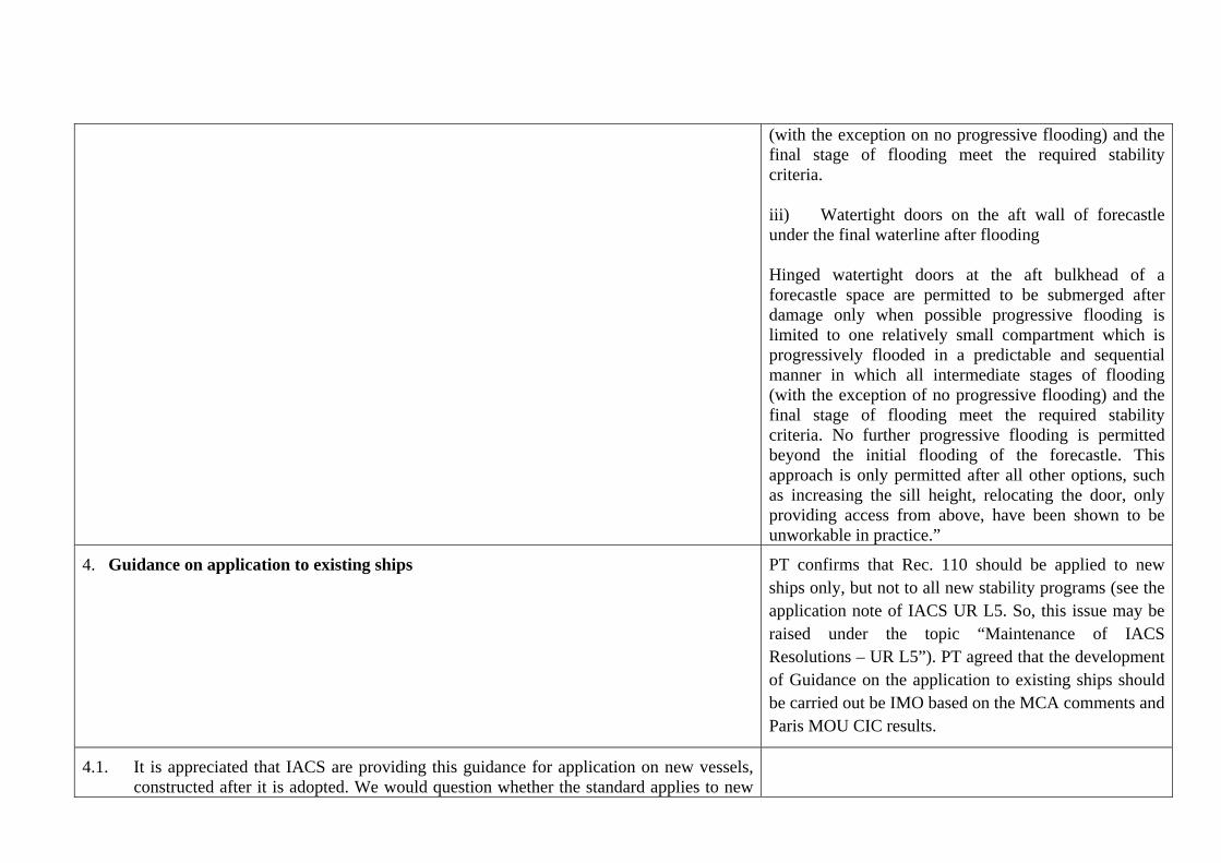
(with the exception on no progressive flooding) and the final stage of flooding meet the required stability criteria. iii) Watertight doors on the aft wall of forecastle under the final waterline after flooding Hinged watertight doors at the aft bulkhead of a forecastle space are permitted to be submerged after damage only when possible progressive flooding is limited to one relatively small compartment which is progressively flooded in a predictable and sequential manner in which all intermediate stages of flooding (with the exception of no progressive flooding) and the final stage of flooding meet the required stability criteria. No further progressive flooding is permitted beyond the initial flooding of the forecastle. This approach is only permitted after all other options, such as increasing the sill height, relocating the door, only providing access from above, have been shown to be unworkable in practice.”
4. Guidance on application to existing ships PT confirms that Rec. 110 should be applied to new ships only, but not to all new stability programs (see the application note of IACS UR L5. So, this issue may be raised under the topic “Maintenance of IACS Resolutions – UR L5”). PT agreed that the development of Guidance on the application to existing ships should be carried out be IMO based on the MCA comments and Paris MOU CIC results.
4.1. It is appreciated that IACS are providing this guidance for application on new vessels, constructed after it is adopted. We would question whether the standard applies to new

ships only or to all new stability or loading program approvals made after this date, including those made for existing ships, and this interpretation would certainly assist any enforcement action taken on existing vessels.
Given that enforcement shall take place, certainly within Paris MoU and/or EC areas, what we are trying to avoid is the prospect that new software provided to show compliance can be approved to previous standards not covered by this guidance and be seen to be ineffectual.
4.2. Given our position at 4.1 above, we would consider it beneficial if the guidance could be expanded to indicate the application dates and criteria for compliance with Marpol Annex 1, IBC and IGC Codes and for additional aspects of damage stability such as the bottom raking damage now applied to some Marpol Annex 1 vessels. This information is essential in the approval of loading programs for existing vessels.
4.3. In terms of enforcement action, we are not seeking any changes to existing international instruments. Consequently there shall be no retrospective changes to legislation, or requirement to re-approve stability information or damage stability calculations or critical KG/GM data where this has previously been unsoundly approved.
Consequently, existing approved stability information shall remain the primary means for demonstrating compliance on existing ships.
Our position remains that the master must demonstrate compliance through one of the following options : Being loaded closely to an approved condition in the stability information; being otherwise loaded with on-board verification record vs critical KG/GM data; being otherwise loaded with on board verification record vs direct calculation by approved loading program; or being otherwise loaded with record of stability approval from the Administration or RO.
In the event that a vessel is loaded closely to a condition from the approved stability information, and dependent upon the quality of the approval of such information, there is a possibility that the vessel would fail if considered against a new approval made to
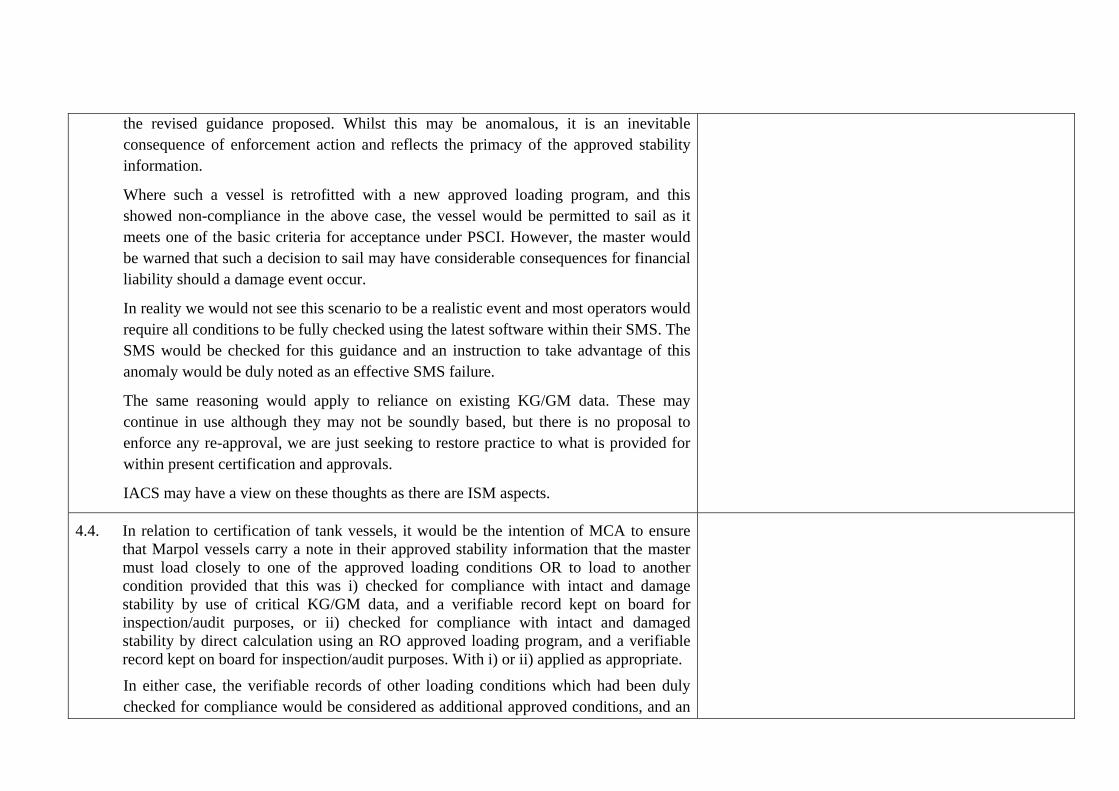
the revised guidance proposed. Whilst this may be anomalous, it is an inevitable consequence of enforcement action and reflects the primacy of the approved stability information.
Where such a vessel is retrofitted with a new approved loading program, and this showed non-compliance in the above case, the vessel would be permitted to sail as it meets one of the basic criteria for acceptance under PSCI. However, the master would be warned that such a decision to sail may have considerable consequences for financial liability should a damage event occur.
In reality we would not see this scenario to be a realistic event and most operators would require all conditions to be fully checked using the latest software within their SMS. The SMS would be checked for this guidance and an instruction to take advantage of this anomaly would be duly noted as an effective SMS failure.
The same reasoning would apply to reliance on existing KG/GM data. These may continue in use although they may not be soundly based, but there is no proposal to enforce any re-approval, we are just seeking to restore practice to what is provided for within present certification and approvals.
IACS may have a view on these thoughts as there are ISM aspects.
4.4. In relation to certification of tank vessels, it would be the intention of MCA to ensure that Marpol vessels carry a note in their approved stability information that the master must load closely to one of the approved loading conditions OR to load to another condition provided that this was i) checked for compliance with intact and damage stability by use of critical KG/GM data, and a verifiable record kept on board for inspection/audit purposes, or ii) checked for compliance with intact and damaged stability by direct calculation using an RO approved loading program, and a verifiable record kept on board for inspection/audit purposes. With i) or ii) applied as appropriate.
In either case, the verifiable records of other loading conditions which had been duly checked for compliance would be considered as additional approved conditions, and an
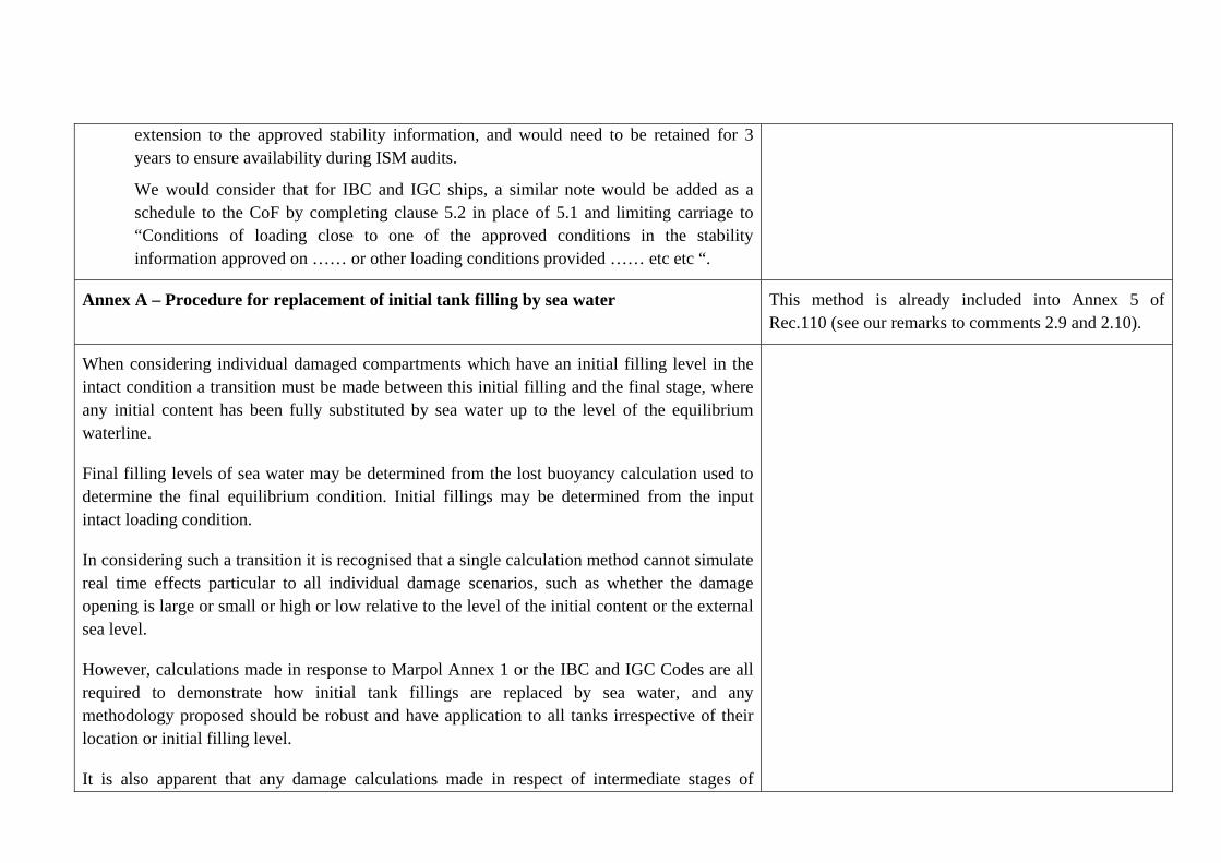
extension to the approved stability information, and would need to be retained for 3 years to ensure availability during ISM audits.
We would consider that for IBC and IGC ships, a similar note would be added as a schedule to the CoF by completing clause 5.2 in place of 5.1 and limiting carriage to “Conditions of loading close to one of the approved conditions in the stability information approved on …… or other loading conditions provided …… etc etc “.
Annex A – Procedure for replacement of initial tank filling by sea water This method is already included into Annex 5 of Rec.110 (see our remarks to comments 2.9 and 2.10).
When considering individual damaged compartments which have an initial filling level in the intact condition a transition must be made between this initial filling and the final stage, where any initial content has been fully substituted by sea water up to the level of the equilibrium waterline.
Final filling levels of sea water may be determined from the lost buoyancy calculation used to determine the final equilibrium condition. Initial fillings may be determined from the input intact loading condition.
In considering such a transition it is recognised that a single calculation method cannot simulate real time effects particular to all individual damage scenarios, such as whether the damage opening is large or small or high or low relative to the level of the initial content or the external sea level.
However, calculations made in response to Marpol Annex 1 or the IBC and IGC Codes are all required to demonstrate how initial tank fillings are replaced by sea water, and any methodology proposed should be robust and have application to all tanks irrespective of their location or initial filling level.
It is also apparent that any damage calculations made in respect of intermediate stages of
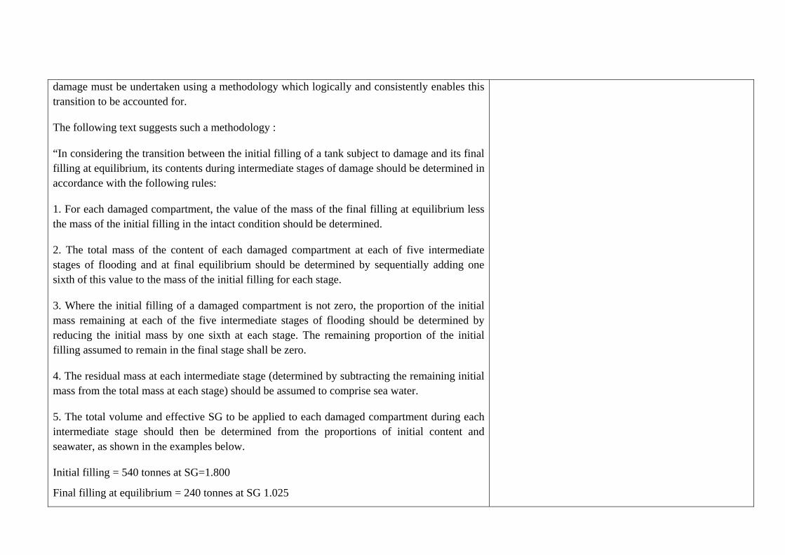
damage must be undertaken using a methodology which logically and consistently enables this transition to be accounted for.
The following text suggests such a methodology :
“In considering the transition between the initial filling of a tank subject to damage and its final filling at equilibrium, its contents during intermediate stages of damage should be determined in accordance with the following rules:
1. For each damaged compartment, the value of the mass of the final filling at equilibrium less the mass of the initial filling in the intact condition should be determined.
2. The total mass of the content of each damaged compartment at each of five intermediate stages of flooding and at final equilibrium should be determined by sequentially adding one sixth of this value to the mass of the initial filling for each stage.
3. Where the initial filling of a damaged compartment is not zero, the proportion of the initial mass remaining at each of the five intermediate stages of flooding should be determined by reducing the initial mass by one sixth at each stage. The remaining proportion of the initial filling assumed to remain in the final stage shall be zero.
4. The residual mass at each intermediate stage (determined by subtracting the remaining initial mass from the total mass at each stage) should be assumed to comprise sea water.
5. The total volume and effective SG to be applied to each damaged compartment during each intermediate stage should then be determined from the proportions of initial content and seawater, as shown in the examples below.
Initial filling = 540 tonnes at SG=1.800
Final filling at equilibrium = 240 tonnes at SG 1.025

Stage Assumed total mass in compartment
Assumed mass at original SG
Assumed Mass of sea water
Total volume assumed in compartment
Effective SG assumed in compartment
0 540 540 0 300.0 1.800 1 490 450 40 289.0 1.695 2 440 360 80 278.0 1.583 3 390 270 120 267.1 1.460 4 340 180 160 256.1 1.328 5 290 90 200 245.1 1.183 6 240 0 240 234.1 1.025
Initial filling = 150 tonnes at SG=0.600
Final filling at equilibrium = 300 tonnes at SG 1.025
Stage Assumed total mass in compartment
Assumed mass at original SG
Assumed mass of sea water
Total volume assumed in compartment
Effective SG assumed in compartment
0 150 150 0 250.0 0.600 1 175 125 50 257.1 0.681 2 200 100 100 264.2 0.757 3 225 75 150 271.3 0.829 4 250 50 200 278.4 0.898 5 275 25 250 285.8 0.962 6 300 0 300 292.7 1.025
“
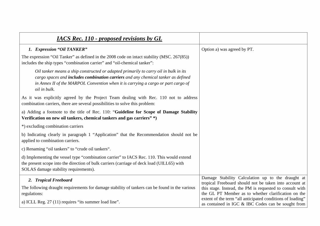
IACS Rec. 110 - proposed revisions by GL
1. Expression “Oil TANKER”
The expression “Oil Tanker” as defined in the 2008 code on intact stability (MSC. 267(85)) includes the ship types “combination carrier” and “oil-chemical tanker”:
Oil tanker means a ship constructed or adapted primarily to carry oil in bulk in its cargo spaces and includes combination carriers and any chemical tanker as defined in Annex II of the MARPOL Convention when it is carrying a cargo or part cargo of oil in bulk.
As it was explicitly agreed by the Project Team dealing with Rec. 110 not to address combination carriers, there are several possibilities to solve this problem:
a) Adding a footnote to the title of Rec. 110: “Guideline for Scope of Damage Stability Verification on new oil tankers, chemical tankers and gas carriers” *)
*) excluding combination carriers
b) Indicating clearly in paragraph 1 “Application” that the Recommendation should not be applied to combination carriers.
c) Renaming “oil tankers” to “crude oil tankers“.
d) Implementing the vessel type “combination carrier” to IACS Rec. 110. This would extend the present scope into the direction of bulk carriers (carriage of deck load (UILL65) with SOLAS damage stability requirements).
Option a) was agreed by PT.
2. Tropical Freeboard
The following draught requirements for damage stability of tankers can be found in the various regulations:
a) ICLL Reg. 27 (11) requires “its summer load line”.
Damage Stability Calculation up to the draught at tropical Freeboard should not be taken into account at this stage. Instead, the PM is requested to consult with the GL PT Member as to whether clarification on the extent of the term “all anticipated conditions of loading” as contained in IGC & IBC Codes can be sought from

b) MARPOL (Reg. 28) requires “any operating draught”.
c) IBC+IGC Code 2.2+2.4 require “all anticipated conditions of loading and variations in draught and trim”.
To show the requirement for damage stability verification up to a draught corresponding to tropical freeboard, if assigned, a paragraph like the following could be added to Rec. 110 paragraph 3.2 “Scope of stability verification”:
“If tropical freeboard is assigned to an oil tanker, chemical tanker or gas carrier the verification of intact and damage stability should cover a draught range up to a draught corresponding to the tropical freeboard.
Damage stability requirements according to ICLL Reg. 27 shall remain unaffected; these should be verified up to the summer load line.”
the SLF S/C by a separate submission.
3. ICLL damage stability calculation
A procedure for correct application of the ICLL damage stability calculations could be displayed in paragraph 6 of IACS Rec. 110 in the following way:
“In case of application of ICLL damage stability requirements to a new oil tanker, chemical tanker or gas carrier a damage stability calculation according regulation 27 should be performed considering the following:
a) Find worst possible VCG with trimmed/untrimmed loading condition acc. ICLL Reg. 27.
b) Create untrimmed initial loading condition with the (above) worst possible VCG considering all compartments empty and perform the damage stability analysis.
c) ICLL Reg. 27 damage stability criteria should not be applied to service loading conditions and need not to be checked by stability computers.”
The practical methods applied by Members will be further considered by the PT.
Paris MOU CIC on Tanker Damage Stability PT agreed that the questionnaire is a good basis for development of the Guidelines on application to existing

ships. The special training program for PSCOs referred in the Press Release should also be considered.

IACS History File + TB Part A
Page 1 of 3
Recommendation No.111 “PASSENGER SHIPS – Guidelines for preparation of Hull Structural
Surveys” Part A. Revision History Version no. Approval date Implementation date
when applicable NEW (Feb 2010) 8 February 2010 N/A NEW (Feb 2010) .1 Origin for Change:
Request by non-IACS entity (Marine Accident Investigation Branch (MAIB))
.2 Main Reason for Change: This IACS Recommendation has been developed as a response to recommendations from the UK Marine Accident Investigation Branch – MAIB given in their Report No. 5/2008 “Report on the investigation of the heavy weather damage to the passenger cruise ship Pacific Star”. .3 History of Decisions Made: The recommendation has been established according to the Work specification given in Form A Rev.2. In addition the draft document was amended by the Survey Panel at the September 2009 meeting. During the development two external reviews have been carried out by Cruise Lines International Association - CLIA with the following comments received. 05 August 2009: The CLIA Technical Committee did not have any areas of concern to add to the listing in your letter and offered no technical advice on the inspection or repair of these areas. We will of course be interested in reviewing any draft guidelines which IACS may prepare. I would hope that our members and/or the Cruise Ship Safety Forum (of which LR, DNV, RINA and GL are members) would be able to provide input to such a draft. 23 November 2009: We have reviewed the document and discussed it with our Technical Committee. Overall, we find this to be very good guidance and have only a couple of small points as indicated below.

Page 2 of 3
First, may we suggest that the cover, if it must have a cruise ship sketch on the cover, have a ship that is not identifiable by brand. Using a sketch clearly showing the Carnival Cruise Line unique funnel is, in our view, not appropriate as it appears to single our and vilify a specific brand. Irrespective of the operator on whose ship incident the guideline is based, a general guideline such as this should not identify these specifics.
May we also suggest to change the wording “each ship” in section 3.2 to “each class of ship” taking into consideration that the design of each ship in the same class is likely be the same.
Finally, current section 3.2 (access and inspection planning): “It is recommended that an accessibility document is developed for each ship containing the relevant information for accessing the structures indicated in 3.3 to 3.10 below.”
Also, some of the items that are to be included in the accessibility document refer to specific safety issues and access procedures without providing further details. This is somewhat ambiguous. CLIA would like to recommend that we include a reference in the accessibility document to the applicable safety procedures as noted in the operator’s Safety Management System and remove any ambiguous wording.
.4 Other Resolutions Changes None .5 Any dissenting views None .6 Dates: Original Proposal: 17 December 2009, made by Survey Panel PT on Task 58
Panel Approval: 27 January 2010 GPG Approval: 8 February 2010 (Ref. 8558dIGm)

Part B
Page 3 of 3
Part B. Technical Background List of Technical Background (TB) documents for Rec.111: Annex 1. TB for Original Resolution (Feb 2010)
See separate TB document in Annex 1.
◄▼►

Part B, Annex 1
Page 1 of 1
Technical Background for Rec. 111 NEW, Feb 2010* 1. Scope and objectives 1) Develop an IACS Recommendation dealing with guidelines regarding the preparation for hull surveys on passenger ships particularly addressing the following items:
Accessibility to all parts of the ship’s structure; Provision of information to the surveyors concerning the normal working level
of the liquid contained in a tank, and any previous problems associated with the space to be surveyed.
2) Each Member Society to use the IACS Recommendation developed as per 1) above to issue instructions to their surveyors, as deemed appropriate. 2. Engineering background for technical basis and rationale N.A. 3. Source/derivation of the proposed IACS Resolution All members of the IACS Survey panel were asked to provide their experiences to serve as a basis for development of the Recommendation. CLIA was also invited to give such input, but no input was received. The Recommendation was established by the Project Team based on the aggregated input from the members and the experience of the societies participating in the project team. During the process the Recommendation was reviewed by the IACS Survey Panel and CLIA, and comments were incorporated in the document. 4. Summary of Changes intended for the revised Resolution: N.A. 5. Points of discussions or possible discussions N.A. 6. Attachments if any N.A. (* Survey Panel Task No. 58)

IACS History File + TB Part A
Page 1 of 2
Recommendation No.113 “Expert Parties Engaged in Visual and/or Sampling Checks for Preparation of
Inventory of Hazardous Materials” Part A. Revision History Version no. Approval date Implementation date
when applicable NEW (Aug 2010) 26 August 2010 - • NEW (Aug 2010) .1 Origin for Change:
Based on IMO Regulation (Hong Kong International Convention for the Safe and Environmentally Sound Recycling of Ships, 2009 & Res. MEPC 179(59))
.2 Main Reason for Change: Entry in to force of the Hong Kong Convention in future. .3 List of non-IACS Member classification societies contributing through the TC Forum and/or participating in IACS Working Group: None .4 History of Decisions Made: A panel member proposed an amendment to UR Z17 for Expert parties engaged in visual and/or sampling checks and testing for testing hazardous materials for the new Ship Recycling Convention. The Survey Panel decided instead to develop a new recommendation for Expert parties engaged in visual and/or sampling checks for preparation of Inventory of Hazardous Materials. .5 Other Resolutions Changes None .6 Dates:
Original Proposal: 05 February 2010, made by Survey Panel GPG Approval: 26 August 2010 (Ref: 9662_IGg)

Part B
Page 2 of 2
Part B. Technical Background List of Technical Background (TB) documents for Rec.113: Annex 1. TB for Original Resolution (Aug 2010)
See separate TB document in Annex 1.
◄▼►

Part B, Annex 1
Page 1 of 2
Technical Background for Rec.113 New, Aug 2010 1. Scope and objectives1 To develop a new IACS Recommendation for ‘Expert parties engaged in visual and/or sampling checks for preparation of Inventory of Hazardous Materials’. The Hong Kong International Convention for the Safe and Environmentally Sound Recycling of Ships, 2009 was adopted on 19th May 2009. A major requirement of the convention is that ships should have onboard an Inventory of Hazardous Materials (Regulation 5.1) and that this shall be verified by the administration or by any person or organisation authorised by the Administration. For existing ships, Regulation 5.2 requires that a plan shall be prepared describing the ‘visual and/or sampling check’ by which the Inventory of Hazardous Materials is developed. The IMO Res. MEPC 179(59) provides recommendations for developing the Inventory of Hazardous Materials to assist compliance with regulation 5 of the Hong Kong Convention. The objective was to develop draft guidelines intended for shipowners, when drawing upon expert assistance for the onboard visual and/or sampling check, including the use of services from laboratories carrying out testing of samples, which reflects the Hong Kong International Convention for the Safe and Environmentally Sound Recycling of Ships, 2009. 2. Engineering background for technical basis and rationale It was foreseen that whilst IACS member societies would verify the inventory and attend onboard for that purpose, they would not sample onboard for hazardous materials, organise the testing of hazardous materials, or prepare the inventory, which would remain under Owner’s responsibility. However, shipowners in general are not experts enough to undertake such work and so would be expected to employ experts to do this work. Both owners and IACS member societies will need confidence that the subcontractor is competent to do this work. It was concluded that Survey Panel should not engage at this stage to mandatory minimum requirements going beyond what is required by the "Ship Recycling Convention" and its associated Guidelines but develop a draft IACS Recommendation for ‘Expert parties engaged in visual and/or sampling checks for hazardous materials.’ 3. Source/derivation of the proposed IACS Resolution • The Hong Kong International Convention for the Safe and Environmentally Sound
Recycling of Ships, 2009 (SR/CONF 45) • IMO Res. MEPC.179(59) 4. Summary of Changes intended for the revised Resolution: New recommendation developed. 5. Points of discussions or possible discussions None 1 Survey Panel Task 66

Page 2 of 2
6. Attachments if any None

IACS History File + TB Part A
Page 1 of 2
Recommendation No.114 “Recommendation for the design, construction, operation and survey of emergency shut down valves and safe cargo
sampling connections on liquefied gas carriers” Part A. Revision History Version no. Approval date Implementation date
when applicable New (June 2010) 30 June 2010 - New (June 2010) .1 Origin of Change:
Request by non-IACS entity (UK Marine Accident Investigation Branch (MAIB))
.2 Main Reason for Change: Following a major leak of liquid propane which occurred alongside a Marine Terminal in the UK after an accident occurred when sampling the cargo, the MAIB investigated and made some Recommendations (MAIB Report No. 10/2007). .3 List of non-IACS Member classification societies contributing through the TC Forum and/or participating in IACS Working Group: None. .4 History of Decisions Made: Following the recommendations from MAIB, the IACS GPG tasked the Machinery Panel to review the case and develop requirements if felt necessary. The Machinery Panel developed a new Recommendation which was reviewed by the Survey Panel. .5 Other Resolutions Changes: None. .6 Dates: Original Proposal: February 2008, made by Machinery Panel Panel submission to GPG: 19 May 2010 (Ref. 7588_PMa) GPG Approval: 30 June 2010 (Ref. 7588_IGe)

Part B
Page 2 of 2
Part B. Technical Background List of Technical Background (TB) documents for Rec.114: Annex 1. TB for Original Resolution (June 2010)
See separate TB document in Annex 1.
◄▼►

Part B, Annex 1
Page 1 of 2
Technical Background for Rec.114, New June 2010 1. Scope and objectives On 17 October 2006, a major leak of liquid propane occurred alongside at the Fawley Marine Terminal in the UK after an accident occurred when sampling the cargo. The MAIB completed a full investigation and provided some recommendations. The IACS GPG tasked the Machinery Panel to evaluate the recommendations and to take appropriate action. The MAIB recommendations were:
1) A proposal to IACS on the development of unified requirements (URs) on sampling arrangements for liquefied gas carriers. The standards should, as a minimum, address the relevant shortfalls identified in this investigation, especially with regard to the provision of two valve separation from the cargo system and the avoidance of screw couplings.
2) A proposal to IACS regarding the operation and design of ESD valves which:
• Stipulates a requirement for ESD valves to be tested and inspected during class surveys to verify effective closure. • Ensures that the IGC Code requirement for local manual closure means the ESD valve can be positively closed by hand. • Requires arrangements for the indication of the status of ESD valves to accurately mimic whether the valve is open or closed.
2. Engineering background for technical basis and rationale The accident happened while cargo sampling operations were being carried out by a cargo surveyor using a sampling cylinder connecting to the sampling point. The sampling point was a drain plug fitted on the bottom of a globe valve in series with an Emergency Shut Down (ESD) valve which was located on the cargo pump discharge line of No.2 cargo tank. When the cargo surveyor turned the sampling connector, the sampling valve assembly fitted on the bottom of the globe valve came off in his hand, and cargo began to leak. He tried to refit the sampling valve assembly, but failed. Although the ESD valve which was in series with the globe valve was activated, it did not completely shut and therefore failed to stop the flow of gas. After several attempts to stop the leak over a 29-hour period, the leak was eventually stopped with the resultant loss of 66 tonnes of gas to the atmosphere. Examination of all ESD valves on board was carried out, the failed ESD valve was found to have internal damage which prevented its operation whilst all the others were found to be in working order. (Additional details: MAIB Report No. 10/2007, May 2007)

Page 2 of 2
3. Source/derivation of the proposed IACS Resolution(s) The IGC code Regulation 5.6 specifies the requirements for cargo system valve arrangements and Regulation 9.1 the requirement for gas sampling points. The recommendations provided by the MAIB report are to provide more clarity to the requirements stipulated. 4. Summary of Changes intended for the revised Resolution(s): N/A 5. Points of discussions or possible discussions It should be noted that the sampling method used was not an approved one in that the sample point in this case was a globe valve drain connection and that no other vessel had suffered the same fate. However, recognising that the IGC code allows for threaded connections for the sampling connection for pipes with a diameter of 25mm or less, the possibility exists for this connector becoming unintentionally detached with the potential to leak gas and/or injure personnel. The additional recommendations proposed by the MAIB were intending to further enhance the reliability of the ESD operation due to the lessons learnt. Since there have not been wide spread reports of ESD valve failures, the Panel concluded that a Unified Requirement would be excessive since it would force the changing of all ESD valves currently in use. The Machinery Panel concluded that an IACS Recommendation would be appropriate and sufficient. 6. Attachments if any N/A

IACS History File + TB Part A
Page 1 of 2
Recommendation No.116 “Performance Standard for Protective Coatings for Cargo Oil Tanks of Crude Oil Tankers - 5 years field exposure test in accordance
with MSC.288 (87)” Part A. Revision History Version no. Approval date Implementation date
when applicable NEW (Feb 2011) 16 February 2011 - • NEW (Feb 2011) .1 Origin for Change:
Based on IMO Regulation (MSC.288 (87)) .2 Main Reason for Change: Imminent need for paint industry to produce approved by 5 year filed exposure test prior to the statutory entry into force of the resolution (1 January 2012), while requirements will be mandatory on 1 January 2013. .3 List of non-IACS Member classification societies contributing through the TC Forum and/or participating in IACS Working Group: None .4 History of Decisions Made: Procedures for the approval of coating system is provided as “Method B” in PR 34 and UI SC 223. Pending the formal conclusion of the relevant Unified Interpretation, this part has been developed as a Recommendation to provide an interim solution. .5 Other Resolutions Changes Under development .6 Dates:
Original Proposal: 30 September 2010 by EG Coating GPG Approval: 16 February 2011 (Ref: 9638dIGc)
Part B
Page 2 of 2
Part B. Technical Background List of Technical Background (TB) documents for Rec.116: Annex 1. TB for Original Resolution (Feb 2011)
See separate TB document in Annex 1.
◄▼►

Part B, Annex 1
Page 1 of 1
Technical Background for Rec.116 New, Feb 2011 1. Scope and objectives To provide a clear test method for the “5 year field exposure test”. 2. Engineering background for technical basis and rationale Some owner/paint manufacturer have already started field exposure test. In order to provide a procedure for the test, using the established test procedure given as “Method B” in the PR 34 and UI SC 234, as a basis of the work, taking into account the unique elements given in MSC.288 (87) for cargo oil tanks of crude oil tankers, a new recommendation has been prepared. 3. Source/derivation of the proposed IACS Resolution IACS PR 34 and UI SC 234, as well as IMO MSC.288 (87). 4. Summary of Changes intended for the revised Resolution: New recommendation developed to meet the requirements of MSC.288 (87). 5. Points of discussions or possible discussions
1. With regard to the test reporting format, the Group noted that Recommendation 87 is no longer available to the public, as well as the fact that the reporting format given in Annex to Recommendation requires modification for the use of field exposure test as per MSC.288 (87), the Group inserted a phrase “in accordance with the principles in section 4 of MSC.1/Circ. 1330” at this stage as an interim solution.
2. Paragraph 2.3 was developed, taking into account the footnotes inserted for the alternative coating system given in MSC.288 (87).
6. Attachments if any None

IACS History File + TB Part A
Page 1 of 2
Recommendation No.117 “Exchange of Statutory Documentation upon Transfer of Class”
Part A. Revision History Version no. Approval date Implementation date
when applicable NEW (Mar 2011) 09 March 2011 - • NEW (March 2011) .1 Origin for Change:
Suggestion by an IACS member .2 Main Reason for Change: To convert the contents of Internal Information No.5 into an IACS Recommendation as it was decided to delete Internal Information No.5. .3 List of non-IACS Member classification societies contributing through the TC Forum and/or participating in IACS Working Group: None .4 History of Decisions Made: GPG decided to delete the category 'Internal Information' and review the contents of Internal Information documents for appropriate relocation (GPG 67 FUA 8). A member proposed to convert the contents of Internal Information No.5 into an IACS Recommendation. PermSec prepared the draft of new Recommendation and circulated it for GPG's review and final approval. Rec. 117 was approved by GPG after discussions with some amendments. .5 Other Resolutions Changes PR 1, PR 8, II 5, II 12. .6 Dates:
Original Proposal: 15 October 2010 by an IACS mMember GPG Approval: 09 March 2011 (Ref: 10115_IGf)
Part B
Page 2 of 2
Part B. Technical Background List of Technical Background (TB) documents for Rec.117: There is no separate technical background document available for Rec 117 (New, March 2011)
◄▼►

IACS History File + TB Part A
Page 1 of 2
Recommendation No.118 “Maritime Labour Convention, 2006: Handling of Seafarer Complaints
by Recognized Organizations” Part A. Revision History Version no. Approval date Implementation date
when applicable NEW (Feb 2011) 25 February 2011 - • NEW (Feb 2011) .1 Origin for Change:
Suggestion by IACS PermSec, in consultation with EG/ILO .2 Main Reason for Change: EG/ILO requested that IACS position on the handling of complaints is to be codified and published as a Recommendation for use in the upcoming discussions with flag Administrations and stakeholders. .3 List of non-IACS Member classification societies contributing through the TC Forum and/or participating in IACS Working Group: None .4 History of Decisions Made: In its 2nd meeting in November 2010, EG/ILO developed a position paper “Handling of Complaints by Recognized Organizations” and submitted it for GPG approval. Following GPG approval of the paper on 20 January 2011, EG/ILO unanimously agreed to develop a recommendation based on the approved IACS position on this. IACS PermSec, in consultation with EG/ILO, prepared the draft of a new recommendation No. 118 and submitted for GPG approval. GPG approved the recommendation with some editorial corrections on 25 February 2011. .5 Other Resolutions Changes None .6 Dates:
Original Proposal: 14 February 2011, made by IACS PermSec/EG/ILO GPG Approval: 25 February 2011 (Ref: 9671cIGg)

Part B
Page 2 of 2
Part B. Technical Background List of Technical Background (TB) documents for Rec.118: Annex 1. TB for Original Resolution (Feb 2011)
See separate TB document in Annex 1.
◄▼►

Part B, Annex 1
Page 1 of 1
Technical Background for Rec.118 New, Feb 2011 1. Scope and objectives A Recognized Organization (RO) may in some circumstances be specifically authorized by the flag State to carry out an inspection following a particular seafarer complaint. Also, when a vessel is inspected under the Maritime Labour Convention (MLC), 2006 by a RO on behalf of the flag State, a seafarer or seafarer representative may contact the RO to register a seafarer complaint. The complaint may be in verbal or written form. This recommendation describes the measures a RO should take subsequent to receiving a complaint from a seafarer. 2. Engineering background for technical basis and rationale The rationale of this recommendation is that ROs should concern themselves only with matters of regulatory compliance that can be substantiated by objective evidence. This includes verifying the existence and satisfactory operation of Onboard Complaints Procedures in accordance with the flag State’s national requirements implementing the MLC. ROs should not discuss or attempt to resolve allegations of harassment, victimization and other complex matters or personal disputes. These should be passed to the flag State for resolution, but only when the complainant has put them in writing. 3. Source/derivation of the proposed IACS Resolution The Maritime Labour Convention, 2006, Regulation 5.1.5 and Guidelines for flag State Inspections, Para 63. 4. Summary of Changes intended for the revised Resolution: New recommendation developed. 5. Points of discussions or possible discussions None 6. Attachments if any None

IACS History File + TB Part A
Page 1 of 2
Recommendation No.119 “Uniform application of SOLAS Reg. II-1/3-9 in association with
MSC.1/Circ.1331” Part A. Revision History Version no. Approval date Implementation date
when applicable NEW (May 2011) 12 May 2011 - • NEW (May 2011) .1 Origin for Change:
Suggestion by IACS Statutory Panel .2 Main Reason for Change: New IACS Recommendation developed by IACS Statutory Panel under the long-standing Task 4 - Interpretation of IMO instruments. .3 List of non-IACS Member classification societies contributing through the TC Forum and/or participating in IACS Working Group: None .4 History of Decisions Made: The draft recommendation was unanimously agreed by all Panel Members. HF&TB documents were not developed as based on the instructions of IACS Procedures, Vol.1, IACS Recommendation should not be treated as IACS Resolution. GPG approved the recommendation with some editorial changes suggested by members. PermSec developed a History File, to record the revision history. .5 Other Resolutions Changes None .6 Dates:
Original Proposal: 20 April 2011 by Statutory Panel GPG Approval: 12 May 2011 (Ref: 11070_IGb)
Part B
Page 2 of 2
Part B. Technical Background List of Technical Background (TB) documents for Rec.119: No Technical Background documents were developed for Rec.119 (New, May 2011)
◄▼►