2011 edition usiflex - us pipe · the centrifugally cast ductile iron usiflex pipe meets the...
TRANSCRIPT

2 0 1 1 E d i t i o n
For WatEr & WastEWatEr, FirE ProtEction & industrial aPPlications
4"-48"
NSF®
Certified toANSI/NSF 61
usiFlEx®
ductilE iron PiPE

usiFlEx®
ductilE iron PiPE
NSF®
Certified toANSI/NSF 61
P 2866.
DIP.
PIPE
2 0 1 1 E d i t i o n
REVISED 8.11u.s. PiPE and FoundrY co. usiFlEx® ductile iron Pipe Bro-011
Overview 3
4"– 48" Pipe 4
Advantages 5
4"– 48" Pipe Assembly 6
Large Diameter Assembly 7
Installation 8
4"– 48" Pipe Calculation 12 of Weight When Submerged
4"– 48" Pipe Standard Wall — 13 Thicknesses, Dimensions and Weights
Test Caps and Test Plugs 14
Products for Water, Wastewater and Fire Protection 15
table of contents

usiFlEx®
ductilE iron PiPE
NSF®
Certified toANSI/NSF 61
P 3866.
DIP.
PIPE
2 0 1 1 E d i t i o n
REVISED 8.11u.s. PiPE and FoundrY co. usiFlEx® ductile iron Pipe Bro-011
USIFLEX® Pipe is a simple, rugged, bottle-tight flexible restrained joint without the use of bolts. USIFLEX Boltless Flexible Joint Pipe is ideally suited for underwater installations where the high cost of equipment and manpower emphasizes the importance of ease and speed of assembly. USIFLEX Pipe may also be used for other types of installations where an appreciable amount of joint deflection and a positive lock against joint separation is required.
USIFLEX Pipe has a design working pressure of 350 psi for sizes 4"–12" and 250 psi for sizes 14"–48". The maximum joint deflection for all USIFLEX Pipe is 15°. For design and installation purposes a 12° limitation is recommended to allow for additional deflection after installation. For higher working pressures consult your U.S. Pipe Representative.
overview
NotE: If specifiers and users believe that corrosive soils will be encountered where our products are to be installed, please refer to ANSI/AWWA C105/A21.5 Polyethylene Encasement for Ductile Iron Pipe Systems for proper external protection procedures.
USIflex® is a Registered Trademark of U.S. Pipe and foundry Company, llC.

usiFlEx®
ductilE iron PiPE
NSF®
Certified toANSI/NSF 61
P 4866.
DIP.
PIPE
2 0 1 1 E d i t i o n
REVISED 8.11u.s. PiPE and FoundrY co. usiFlEx® ductile iron Pipe Bro-011
USIFLEX Pipe furnished in sizes 4"–48" are made with Thickness Class Ductile Iron. The outside pipe diameters are standard making it convenient for tying in with standard pipe and fittings.
The centrifugally cast Ductile Iron USIFLEX Pipe meets the applicable requirements of ANSI/AWWA C151/A21.51. The separately cast Ductile-Iron ball, bell and retainer ring conforms with the requirements of ASTM A 536, Grade 70-50-05. The ball and bell are threaded and screwed onto the threaded ends of the barrel. Critical surfaces of the ball, bell socket and retainer ring are machined.
The maximum nominal laying lengths are 18.5' or 21' for sizes 4" – 24", 19' for sizes 30" – 36", and 22' for 42" – 48".
4"–48" Pipe
The centrifugally cast Ductile Iron USIFLEX Pipe in sizes 4"–48" meets the applicable requirements of ANSI/AWWA C151/A21.51 Standard for Ductile-Iron Pipe, Centrifugally Cast for Water.
The separately cast Ductile Iron bell, ball and retainer ring conforms with the applicable requirements of ANSI/AWWA C110/A21.10, Standard for Ductile-Iron and Gray-Iron fittings for Water.
AStM A536 "Standard Specification for Ductile Iron Castings."
ansi /aWWa standards
Threaded Ball
Threaded Bell Segmental Internal Recesses
Gasket Segmental External Lugs
Retainer Ring
Retainer Ring Lock
Threaded Plain End
Bell
Segmental Internal
RecessesThreaded Retainer
RingSegmental External
Lugs
Ball
Gasket

usiFlEx®
ductilE iron PiPE
NSF®
Certified toANSI/NSF 61
P 5866.
DIP.
PIPE
2 0 1 1 E d i t i o n
REVISED 8.11u.s. PiPE and FoundrY co. usiFlEx® ductile iron Pipe Bro-011
The gasket and the retainer ring lock are the only loose accessories. No bolts, nuts or wrenches are required to make up the joint. Fewer accessories to handle and account for means a substantial savings in time and labor.
The design of the gasket and gasket seat is such that, rather than being dependent on an exterior force from a gland, the gasket is self-sealing.
Only a moderate longitudinal thrust is required to insert the ball into the socket.
Clearances between the machined retainer ring and the bell permit easy entry and rotation of the retainer ring in the bell.
Because of the unique design, when the joint is subjected to end pull, the rugged retainer ring withstands the radial forces and prevents transmittal of these forces to the bell casting.
The inside contour at the end of the ball is shaped so that when the joint is deflected, the ball does not project into the waterway to obstruct the flow.
advantages
42" USIflex pipe fully deflected to 15º at 500 psi test pressure (2 times rated pressure).
The flexibility of the joint permits bottle-tight operation at deflections up to 15º.
usiFlEx®
ductilE iron PiPE
NSF®
Certified toANSI/NSF 61
P 6866.
DIP.
PIPE
2 0 1 1 E d i t i o n
REVISED 8.11u.s. PiPE and FoundrY co. usiFlEx® ductile iron Pipe Bro-011
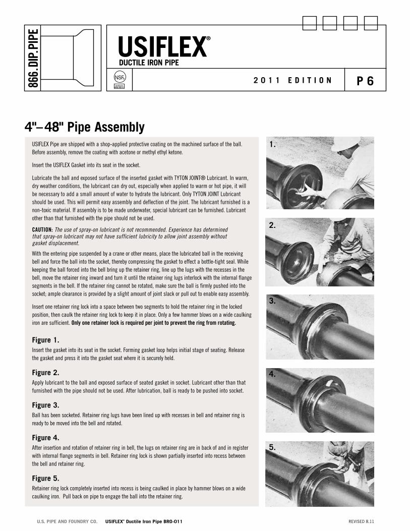
USIFLEX Pipe are shipped with a shop-applied protective coating on the machined surface of the ball. Before assembly, remove the coating with acetone or methyl ethyl ketone.
Insert the USIFLEX Gasket into its seat in the socket.
Lubricate the ball and exposed surface of the inserted gasket with TYTON JOINT® Lubricant. In warm, dry weather conditions, the lubricant can dry out, especially when applied to warm or hot pipe, it will be necessary to add a small amount of water to hydrate the lubricant. Only TYTON JOINT Lubricant should be used. This will permit easy assembly and deflection of the joint. The lubricant furnished is a non-toxic material. If assembly is to be made underwater, special lubricant can be furnished. Lubricant other than that furnished with the pipe should not be used.
CAUtIoN: The use of spray-on lubricant is not recommended. experience has determined that spray-on lubricant may not have sufficient lubricity to allow joint assembly without gasket displacement.
With the entering pipe suspended by a crane or other means, place the lubricated ball in the receiving bell and force the ball into the socket, thereby compressing the gasket to effect a bottle-tight seal. While keeping the ball forced into the bell bring up the retainer ring, line up the lugs with the recesses in the bell, move the retainer ring inward and turn it until the retainer ring lugs interlock with the internal flange segments in the bell. If the retainer ring cannot be rotated, make sure the ball is firmly pushed into the socket; ample clearance is provided by a slight amount of joint slack or pull out to enable easy assembly.
Insert one retainer ring lock into a space between two segments to hold the retainer ring in the locked position, then caulk the retainer ring lock to keep it in place. Only a few hammer blows on a wide caulking iron are sufficient. only one retainer lock is required per joint to prevent the ring from rotating.
Figure 1.Insert the gasket into its seat in the socket. Forming gasket loop helps initial stage of seating. Release the gasket and press it into the gasket seat where it is securely held.
Figure 2.Apply lubricant to the ball and exposed surface of seated gasket in socket. Lubricant other than that furnished with the pipe should not be used. After lubrication, ball is ready to be pushed into socket.
Figure 3.Ball has been socketed. Retainer ring lugs have been lined up with recesses in bell and retainer ring is ready to be moved into the bell and rotated.
Figure 4.After insertion and rotation of retainer ring in bell, the lugs on retainer ring are in back of and in register with internal flange segments in bell. Retainer ring lock is shown partially inserted into recess between the bell and retainer ring.
Figure 5.Retainer ring lock completely inserted into recess is being caulked in place by hammer blows on a wide caulking iron. Pull back on pipe to engage the ball into the retainer ring.
4"–48" Pipe assembly1.
2.
3.
4.
5.

usiFlEx®
ductilE iron PiPE
NSF®
Certified toANSI/NSF 61
P 7866.
DIP.
PIPE
2 0 1 1 E d i t i o n
REVISED 8.11u.s. PiPE and FoundrY co. usiFlEx® ductile iron Pipe Bro-011
Figure 1.Insert the gasket into its seat in the socket. Several gasket loops help the initial stage of seating, particularly in the larger pipe sizes.
Figure 2.Apply lubricant onto the ball of the pipe and the exposed surface of the seated gasket in the socket. Lubricant other than that furnished with the pipe should not be used. After lubrication, the ball is ready to be pushed into the socket.
Figure 3.After the ball has been socketed, line up the retainer ring lugs with the recesses in the bell. The split in the retainer ring should be located near the six o’clock position. The retainer ring should then be moved into the bell and rotated.
Figure 4.Insert a retainer ring lock into one of the recesses between the bell and the retainer ring. Caulk into place with hammer blows. Pull back on pipe to engage the ball into the retainer ring. only one retainer ring lock is required per joint to prevent ring rotation.
large diameter assembly1.
2.
3.
4.

usiFlEx®
ductilE iron PiPE
NSF®
Certified toANSI/NSF 61
P 8866.
DIP.
PIPE
2 0 1 1 E d i t i o n
REVISED 8.11u.s. PiPE and FoundrY co. usiFlEx® ductile iron Pipe Bro-011
installation
8" USIflex Pipe being installed around rock cliff in Rockport, Indiana.
Another illustration of ramp launching.
24" force main being installed across the Passaic River at Garfield, New Jersey.
Submarine installations, the type of service for which USIFLEX Pipe is usually used, are so varied that a specific installation procedure cannot be recommended. Some methods that have been used successfully by installers of flexible joint submarine lines are:
• Assemble two or more sections above water, lower with the aid of a strongback or multiple slings from a derrick barge and have a diver make up connecting joints under water.
• Lay the pipe with a chute or cradle attached to a derrick barge or similar type of floating equipment.
ramp launching and flotation method Assemble the joints on shore, attach empty drums to aid buoyancy, pull into the water by attached cable and lower to the bottom by progressively releasing the drums or allowing them to fill with water. Barrels should be retrieved after installation is complete.
Each joint of USIFLEX Boltless Flexible Joint Pipe provides variable deflection up to 15° and the joint may be deflected to this position without harm to the pipe or joint components. A 12° installation limitation is recommended to provide additional deflection capability to accommodate earth settlement or movement. Care should be taken, however, to ensure that no joint is ever forced beyond the 15º maximum design deflection.
When USIFLEX pipe is installed in areas of water traffic, shallow depths or waterways prone to flood caring debris, the pipe should be laid in a trench or backfill placed over the pipe to reduce the chance of damage to the pipe. All the pipe joints should be supported underneath each bell. A thorough bottom survey in the design stage of a project will reveal if backfill or support is required under the pipe to stay within the deflection limits of the joint.
Ramp launching and flotation method used at Dalecarlia, Indiana.

usiFlEx®
ductilE iron PiPE
NSF®
Certified toANSI/NSF 61
P 9866.
DIP.
PIPE
2 0 1 1 E d i t i o n
REVISED 8.11u.s. PiPE and FoundrY co. usiFlEx® ductile iron Pipe Bro-011
installation (cont.)
suspension from temporary supports This method of installation in Lynbrook, NY involved gradually submerging the 16" pipeline from a pile and timber runway. Lowering of the pipe proceeded by successively easing off on the supporting rope slings (of which there was one at each joint) until the pipe lay in the excavation which had been prepared for it.

usiFlEx®
ductilE iron PiPE
NSF®
Certified toANSI/NSF 61
P 10866.
DIP.
PIPE
2 0 1 1 E d i t i o n
REVISED 8.11u.s. PiPE and FoundrY co. usiFlEx® ductile iron Pipe Bro-011
installation (cont.)
Methods showing chute used on floating equipment24" pipe being installed across Johns Pass near Treasure Island, FL. Pipe installed in a launching ramp which feeds the pipe into the trench. Ramp is attached to the side of the barge.

usiFlEx®
ductilE iron PiPE
NSF®
Certified toANSI/NSF 61
P 11866.
DIP.
PIPE
2 0 1 1 E d i t i o n
REVISED 8.11u.s. PiPE and FoundrY co. usiFlEx® ductile iron Pipe Bro-011
Floating equipment methodOne method of assembly when pipeline is suspended above water by the crane on floating equipment.
One line from crane holds bell of last laid length out of water while second line supports new length as the boltless flexible joint is made up. This method is used only in shallow water. Care must be taken not to exceed allowable joint deflection.
installation (cont.)

usiFlEx®
ductilE iron PiPE
NSF®
Certified toANSI/NSF 61
P 12866.
DIP.
PIPE
2 0 1 1 E d i t i o n
REVISED 8.11u.s. PiPE and FoundrY co. usiFlEx® ductile iron Pipe Bro-011
table 1. nominal lengths in Feet The weight of submerged pipe may be calculated with the aid of the information in Tables 1-3. Preliminary calculations may be made using the nominal weights and lengths shown in the tables. Take into consideration that the actual weights will vary within the scope of manufacturing tolerances. If the pipe are on hand, more accurate weight determination may be made using the actual measurements and marked pipe weights.
Method of calculation:1. Measure the length of the barrel from the bell skirt to the ball or select the
nominal barrel length from Table 1.
2. Multiply the length of the barrel in feet by the displacement volume per foot of barrel from Table 2 or 3 to obtain the barrel displacement volume.
3. Add the barrel displacement to the assembled joint displacement from the appropriate table to obtain the total pipe displacement volume.
4. Multiply the total pipe displacement in cubic feet by the density of the medium in which the pipe is to be installed (approximately 62.4#/cu. ft. for fresh water, 64.0#/cu. ft. for salt water, etc.) to obtain the weight of the displaced medium.
5. Subtract the weight of the displaced medium from the marked pipe weight, or from the nominal pipe weight in the tables, plus the accessory weight to obtain the weight of the submerged pipe. (A negative value indicates that the pipe will float.)
4"–48" Pipe calculation of Weight When submerged
lengths in this table are based on the maximum nominal laying lengths of 18.5' or 21' for 4" – 24", 19' for sizes 30" – 36", 22' for 42 – 48".
* Barrel length as manufactured from nominal 18' lay length pipe.
† Barrel length as manufactured from nominal 20' lay length pipe.
assembled Pipe length
Assembled Joint Barrel
Boundaries for calculation of displacement volume
DIMENSIoNS
ASSEMblED ASSEMblED ASSEMblED JoINt bArrEl PIPE bArrEl PIPE SIzE lENgth lENgth* lENgth* lENgth† lENgth†
4 .62 17.76 18.38 – – 6 .69 17.78 18.47 19.78 20.47 8 .83 17.76 18.59 19.76 20.59 10 .98 17.72 18.70 19.72 20.70 12 1.10 17.72 18.82 19.72 20.82 14 1.29 16.89 18.18 19.46 20.75 16 1.39 16.78 18.17 19.42 20.81 18 1.51 16.66 18.17 19.39 20.90 20 1.69 16.73 18.42 19.35 21.04 24 1.85 16.57 18.42 19.28 21.13 30 2.22 17.08 19.30 – – 36 2.50 17.05 19.55 – – 42 3.71 18.29 22.00 – – 48 4.18 – – 18.07 22.25

usiFlEx®
ductilE iron PiPE
NSF®
Certified toANSI/NSF 61
P 13866.
DIP.
PIPE
2 0 1 1 E d i t i o n
REVISED 8.11u.s. PiPE and FoundrY co. usiFlEx® ductile iron Pipe Bro-011
NotE: Actual component configuration may differ from drawing
table 2. Standard Wall thickness, Dimensions and Weights
15°
TB A
4"–48" Pipe standard Wall —thicknesses, dimensions, and Weights
ANSI t A b
SIzE thICK. NoM. PIPE bEll Inches ClASS thICK. oUt DIA. oUt DIA.
No. (In.) (In.) (In.)
4 54 .35 4.80 10.95
6 54 .37 6.90 13.29
8 55 .42 9.05 16.71
10 55 .44 11.10 20.05
12 56 .49 13.20 23.13
14 56 .51 15.30 25.30
16 56 .52 17.40 27.94
18 56 .53 19.50 31.04
20 56 .54 21.60 34.36
24 56 .56 25.80 39.48
30 56 .63 32.00 46.77
36 56 .73 38.30 54.10
42 56 .83 44.50 64.18
48 56 .93 50.80 73.12
SIzEInches
NoMINAl WEIght*Pounds
WEIght of SUbMErgED PIPE MAy bE CAlCUlAtED froM fIgUrES IN thESE ColUMNS
AC tUAl WEIghtPounds
DISPlACEMENt volUME (CU. ft.) MAxI.SAfE ENDPUllTons
ASSEMblED JoINt bArrEl PEr foot
PEr foot PIPE
ACC.fIllED WIth AIr
fIllED WIth
WAtEr
fIllED WIth AIr
fIllED WIth
WAtEr
4 21.28 1 .26 .19 .13 .05 196 32.26 1 .43 .27 .26 .08 328 48.50 2 .82 .48 .45 .12 4010 65.40 2 1.37 .74 .67 .16 4512 87.50 2 2.07 1.05 .95 .20 5014 107.90 4 3.36 1.42 1.28 .27 9016 125.03 4 4.47 1.76 1.65 .32 10018 146.60 5 5.90 2.27 2.07 .36 11020 172.95 7 7.98 3.03 2.54 .41 11524 218.36 9 11.79 4.07 3.63 .50 12030 290.62 13 20.32 5.60 5.58 .76 22036 393.81 15 31.29 8.06 8.00 .99 25042 577.04 22 63.86 17.95 10.80 1.35 30548 888.58 27 91.90 25.47 14.07 1.50 320
Wei
ght m
arke
d on
pip
e at
fact
ory
* Nominal weights are based on nominal lengths and thicknesses and are subject to manufacturing tolerances. Weight includes pipe, retainer ring, and cement lining.
The maximum nominal laying lengths are 18.5' for 4" – 12", 21' or 18.3' for 14" – 24", 19.5' for 30" – 36", 22' for 42" and 22.25' for 48". Actual laying lengths may vary from published to slightly over nominal. A maximum of 10% of the total number of pipe each size of an order may be fur-nished with laying lengths to 2 ft. shorter.
If more exact lengths are required, pipe may be furnished cut to length at an additional charge. Cut lengths shall not exceed the nominal laying length and will be subject to a tolerance of plus or minus 1/2".
The maximum working pressure rating is U.S. Pipe’s suggested rating based on a conservative factor of safety to allow for laying and service conditions encountered in marine installations. The design engineer must decide whether barrel thicknesses shown are adequate to meet installation and service conditions for a particular project.
Maximum allowable deflection of joint is 15°.

usiFlEx®
ductilE iron PiPE
NSF®
Certified toANSI/NSF 61
P 14866.
DIP.
PIPE
2 0 1 1 E d i t i o n
REVISED 8.11u.s. PiPE and FoundrY co. usiFlEx® ductile iron Pipe Bro-011
USbEll x PEtr tr bEll x USbAll
SIzEInches
WEIghtPounds
WEIghtPounds
lAyINgLengths
4 USBE x PETR 96 TRB x USBA 93 3'- 6"
6 USBE x PETR 141 TRB x USBA 142 3'- 6"
8 USBE x PETR 214 TRB x USBA 211 3'- 6"
10 USBE x PETR 309 TRB x USBA 312 3'- 6"
12 USBE x PETR 426 TRB x USBA 418 3'- 6"
14 USBE x PETR 504 TRB x USBA 574 3'- 6"
16 USBE x PETR 572 TRB x USBA 691 3'- 6"
18 USBE x PETR 677 TRB x USBA 831 3'- 6"
20 USBE x PETR 819 TRB x USBA 1067 3'- 6"
24 USBE x PETR 1097 TRB x USBA 1364 3'- 6"
30 USBE x PEHP 1733 HPB x USBA 1743 5'- 0"
36 USBE x PEHP 2293 HPB x USBA 2526 5'- 0"
42 USBE x PEHP 4918 HPB x USBA 5030 5'- 0"
48 USBE x PEHP 6903 HPB x USBA 7133 5'- 0"
each TR flex® (4-24”) or HP lOK® (30-48”) cap and plug and the USIflex® joint is positively locked to prevent joint separation from internal pressure or external pulling forces. TR flex® or HP lOK® caps and plugs can be used with USI-Bell x TR (or HPl) Pe and TR (or HPl) Bell x USI-Ball to hydrostatically pressure test the pipe assembly and/or pull/float the pipe assembly into place. each cap and plug is provided with a pipe tap and screw plug for filling the assembly with water and orienting the top pipe tap to the 12 o’clock position to bleeding air.
If the pipe assembly is to be pulled or floated into position, the pipe should be pulled with balls or spigot end first. Do not attempt to pull the assembly by attaching to the plug or cap directly. If a cap is used instead of a pull head, a choker cable behind the cap joint placed around the pipe is suggested. A 4" - 36" USP HDD Pulling Head can be used with a USI-Bell x TR (or HPl) Pe to pull the pipe assembled pipe string. The pulling head also serves as a pressure test head and is equipped with pipe taps. Please refer to the USP Trenchless Application brochure for pulling head dimensions.
Please refer to the TR flex® or HP lOK® product brochures for cap and plug details.
TR flex®or HP lOK® plugs and caps, USI-Bell x TR (or HPl) Pe and TR (or HPl) Bell x USI-Ball Test pipe, and pull heads are available for sale or rental.
TRB (or HP) x USBAUSBE x PETR (or HP)
test caps and test Plugs

usiFlEx®
ductilE iron PiPE
NSF®
Certified toANSI/NSF 61
P 15866.
DIP.
PIPE
2 0 1 1 E d i t i o n
REVISED 8.11u.s. PiPE and FoundrY co. usiFlEx® ductile iron Pipe Bro-011
Products for Water, Wastewater and fire Protectionductile iron Pipe siZE ranGE
TYTON JOINT® Pipe 4"-64" Ductile Iron
Mechanical Joint Pipe 4"-12" Ductile Iron
TR FLEX® Pipe 4"-36" Ductile Iron
HP LOK® Pipe 30"-64" Ductile Iron
Flanged Pipe 3"-64" Ductile Iron
Grooved Pipe 4”-36” Ductile Iron
USIFLEX® Boltless Ball Joint Pipe 4"-48" Ductile Iron For Subaqueous Installations
restrained Joints
TR FLEX® Restrained Joint 4"-36" Ductile Iron
HP LOK® Restrained Joint 30"-64" Ductile Iron
MJ FIELD LOK® Gaskets 4"-24"
FIELD LOK 350® Gaskets 4"-24"
FIELD LOK® Gasket 30" & 36"
TR FLEX GRIPPER® Rings 4"-36" Ductile Iron
TR TELE FLEX® Assemblies 4"-24" Ductile Iron
Fittings
TYTON® Fittings 14"-24" Ductile Iron
TRIM TYTON® Fittings 4”-12” Ductile Iron
TR FLEX® Fittings and TR FLEX® Telescoping Sleeves 4"-36" Ductile Iron
HP LOK® Fittings and HP LOK® Telescoping Sleeves 30”-64” Ductile Iron
Mechanical Joint Fittings 30"-48" Ductile Iron
Flanged Fittings 30"-64" Ductile Iron
XTRA FLEX® Couplings 4"-24" Ductile Iron
Miscellaneous Products
PROTECTO 401™ Lined Ductile Iron Pipe for 4"-64" Ductile Iron Domestic Sewage and Industrial Wastes
GLASS Lined Ductile Iron Pipe for Wastewater 4”-30” Ductile Iron Treatment Plants
RING FLANGE-TYTE® Gaskets 4"-36"
FULL FACE FLANGE-TYTE® Gaskets 4"-64"
MJ Harness-Lok 4”-48” Ductile Iron
Saddle Outlets Various Ductile Iron
Welded Outlets Various Ductile Iron
Polyethylene Encasement 4"-64"
Our products are manufactured in conformance with National Standards so that our customers may be assured of getting the performance and longevity they expect. Use of accessories or other appurtenances that do not comply with recognized standards may jeopardize the performance and longevity of the project.

NSF®
Certified toANSI/NSF 61
P.o. box 10406bIrMINghAM, Al 35202
866.DIP.PIPE (866.347.7473)fAx: 205.254.7165
EMAIl: [email protected]
All U.S. Pipe brochures and/or products are subject to change without further notice.