2012 cpi product catalog
DESCRIPTION
The 2012 Product Catalog features comprehensive documentation at a moment’s notice for all of CPI’s most popular solutions, including our full line of Cabinet and Enclosure Systems, Racks, Cable Management, Cable Pathway, Grounding and Bonding, Software and more. New to this year’s edition, the 2012 Product Catalog now includes: Rack System part numbers now cUL Listed GF-Series GlobalFrame® Cabinet System and Accessories HotLok™ Snap-In Filler Panels KoldLok® Raised Floor Grommet featuring the KoldLok Wave™ Universal Cable Runway now UL Classified New KVM Product Line SEMA System - with software pre-installed on serverTRANSCRIPT

2012
Product Catalog

Section 14
Section 13
Section 12
Section 11
Section 10
Section 9
Section 8
Section 6
Section 5
TABLE OF CONTENTS
Introduction to Chatsworth Products, Inc. Pages i - x
Section 1Rack Systems
i
Cable Management Products
Cable Runway & Tray Products
Power Management Products
KVM Systems
Environmental Monitoring & Security Systems
Software Systems
Grounding & Bonding Products
Seismic Protection Systems
Index - Alphabetical
Index - Part Number
Section 2Cabinet & Enclosure Systems
Section 3Zone Cabling & Wireless Enclosures
Section 4Wall-Mount Systems
Section 7

ii
WELCOME FROM CPI
To know Chatsworth Products, Inc. (CPI) is to know ourmotto – “Delight the Customer.” As an employee ownedcompany, it’s important for us to work with you on anindividual basis to deliver quality products and servicefor every IT infrastructure need. Whether you’re placingan order through customer service or clarifying a projectthrough technical support, CPI’s team of experiencedprofessionals will find the perfect solution. It’s thatdedication to solving the needs of customers that led toproviding our most popular products for IT infrastructuresolutions in this catalog. And if there is still somethingyou can’t find, give us a call at 800-834-4969 and we’llbe happy to delight you too.
WHAT WE DOCPI is a global manufacturer of voice, data and securityproducts that Optimize, Store and Secure technologyequipment. Offering quality in-stock products andcustomized solutions, CPI leads the industry ininnovation, configurability and value with an array ofintegrated system components that cover virtually allphysical layer needs. Our organization’s knowledge andexpertise allows us to communicate and collaborate withIT professionals, architects, contractors, engineers, OEMequipment manufacturers, integrators and end users,working in a partnership each step of the way to createcustom-fit IT infrastructure solutions. Headquartered inthe United States, CPI operates global offices within theUS, Mexico, Canada, China, Middle East and the UnitedKingdom.
WHY CHOOSE CPI?
HISTORYTwenty years ago, CPI began when 90 employees joinedtogether and purchased the Dracon Division of HarrisCorporation using an Employee Stock Ownership Plan(ESOP). With deregulation in the telecommunicationsindustry and technological innovation in voice and dataequipment, CPI focused on the explosive needs of theinformation technology market to manage ITinfrastructure equipment. Today, CPI is a leading globalsupplier of integrated solutions that optimize technologyequipment. This pioneering spirit is what motivates CPIto delight the customer by responding rapidly withtailored standard and custom solutions that give them ahigher return on their investment.
WHO WE SERVEAs technology needs evolve, so does CPI. Whether it’sorganizing cable in a network cabinet, securing data in abrand new facility, ensuring security for bankinginstitutions or satisfying HIPAA requirements in a co-location facility, CPI has the experience and know-how toprovide the perfect solution at the perfect time. Some of the markets we have served include:• Banking & Financial Services• Telecommunications• Government (Federal, State and Local)• Pharmaceutical & Biotech• Consulting & Business Services• Healthcare & Medical• Insurance• Media & Entertainment• Retail• Information Technology• Electronics• Education• Security
CPI is committed to being a companyof the highest quality in everyaspect of its business, providingQuality Products, Quality Servicesand most of all – Quality People.

WHY CHOOSE CPI?
CUSTOMIZED SOLUTIONSA great deal of precision and thought goes into thedesign of today’s data center – but plans can change inan instant. Each step comes with its own set ofobstacles, from a need to maintain energy costs throughthermal management solutions, to the deployment ofquality-built cabinets that can withstand high densityloads and earthquakes. As the environment within datacenters continually changes, infrastructure systems mustbe able to change too. That’s why CPI provides themarketplace with a variety of high quality, uniquesolutions that allow for future technology and evolvingstandards.
VALUE-ADDED ONLINE TOOLSThe design and implementation of everything fromnetwork closets to sprawling data centers is literallyfilled with twists and turns. That’s why CPI hasdeveloped a robust support structure atwww.chatsworth.com that can help plan out infinitedesigns and solutions for any IT infrastructure need. Some of the most popular online resources includeBuilding Information Modeling (BIM) drawings, thee-Catalog, our full documentation library and a productConfigurator that has been utilized more than 100,000times.
LEADING THE WAY IN RESEARCH, DEVELOPMENT & TRAININGWith the financial strength to reinvest in the companyand continually improve manufacturing and logisticalprocesses, CPI has become an industry leader in productinnovation and excellence. Complementing our numerousactive patents for groundbreaking product designs, CPIhas its own Research Development and Training (RD&T)Center. Designed with customers in mind, the RD&T
Center is a comprehensive facility complete with aProduct Showroom, Customer Meeting Center and aThermal Test Lab. In addition to giving customers achance to learn and interact directly with CPI Productsand Solutions, the test lab is equipped to model variousheat loads, cabinet configurations and conduct in-houseproduct testing. For more information or to schedule avisit go to www.chatsworth.com/rdt.
INDUSTRY AFFILIATIONSCPI maintains its comprehensive product and industryknowledge with help from the following affiliations andassociations:• Industry Advisory Council (IAC)• Underwriters Laboratories, Inc. (UL)• The Green Grid• US Green Builders Council (USGBC)• AFCOM National and Local Chapters• ASHRAE• TIA• BICSI Platinum Level Prestige Corporate Member(PCM) with one of the largest groups of RCDDs
• BICSI Standards Committee- Data Center Rack and Cabinet Editor- Mechanical Group- Thermal Consultant- BIM Best Practices Subcommittee
• Society of Telecommunications Consultants (STC)• International Organization for Standardization (ISO)• Armed Forces Communications and ElectronicsAssociation (AFCEA)
• ESOP Association
EXPERT SERVICE AND SUPPORTCPI understands that the high-speed world of datamanagement is constantly changing and for this reason,we offer highly trained Technical Support Specialists andCustomer Service Representatives to help solve your ITinfrastructure needs. Based on your specificrequirements, our Technical Support Specialists can helpdesign the precise layout for your data center andprovide a detailed bill of material complete with layoutand assembly drawings. Furthermore, our CustomerService Representatives work closely with distributors tomaintain product availability, ultimately helping preserveyour project’s scheduling requirements.
iii

iv
CONTACT INFORMATION
For answers to your questions or for custom solutions please call Customer Service or Technical Support at 1-800-834-4969 (toll free in the U.S. & Canada) Monday to Friday, 5 a.m. to 5 p.m., Pacific Time;1-818-739-3400 (outside of the U.S. & Canada), or email Technical Support at [email protected]
CPI Global Offices:
Corporate Office - Westlake Village, CA818-735-6100 • 818-735-6199 FAX
Chatsworth, CA Operations818-882-8595 • 818-718-0473 FAX
New Bern, NC Operations 252-514-2779 • 252-514-2977 FAX
Georgetown, TX Operations512-863-7800 • 512-869-1374 FAX
Asia PacificPudong, Shanghai, China+86-21-6880-0266www.chatsworth.com.cn
Latin America Mexico City, Mexico+52-55-5203-7525, toll free: +01-800-201-7592www.chatsworth.com.co
EuropeBuckinghamshire, England UK+44-01628-524-834 www.chatsworth.com.uk
Middle East & AfricaDubai, United Arab Emirates+971-4-2602125
CanadaToronto, Ontario, Canada+905-850-7770
Visit our Global Website at www.chatsworth.com

v
GOVERNMENT BUSINESSHOW TO ORDER
HOW TO ORDERCPI sales are conducted in partnership with a global networkof distributors, contractors and resellers. To obtain a purchaseprice quote and product availability please locate the CPIpartner near you by calling 800-834-4969.
This catalog has been developed according to comprehensiveproduct groups. Each group is presented as a convenientsection within the catalog and contains part numbers,ordering information and detailed illustrations or photographs.
TO ORDER, FOLLOW THESE SIMPLE STEPS:1. Locate desired product(s) within the appropriate section.2. Use the complete part number. Pay close attention to thedigits indicating product variations such as size, finish(refer to Color Finishes information) and hole pattern.
3. Check “Consists Of” information for each product for a listing of all components and hardware included with thepart number.
4. Check to see if product descriptions include “Installation May Require” or “Installation Will Require” the followinghardware. These components are not included with theproduct; however, most of these items are contained in thecatalog and may be ordered. Please see part numberreferences where indicated.
5. Indicate quantity and full part numbers in your purchase orders (POs). The description is not essential but should beincluded when ordering. The product description willappear on your acknowledgment, invoice and packing list.
6. Locate a distributor by calling 800-834-4969 or visiting www.chatsworth.com. Or if you are an authorized CPIdistributor, send POs via mail or fax to one of our CustomerService Department locations listed to the right.
7. Questions? Call CPI toll-free at 800-834-4969 within the United States and Canada or visit www.chatsworth.com.
Note: Prices and quantity breakdowns are not listed in this product guide. For product pricing, please contact ourCustomer Service Department at 800-834-4969.
All orders received are subject to acceptance by CPI and aresubject to a minimum charge of $200.00. CPI must receivewritten confirmation for all orders prior to shipment.
Products listed do not include export packaging, insurance,taxes, tariffs or duties.
All pricing is subject to change. CPI reserves the right to makeadjustments to pricing and product offerings for reasonsincluding, but not limited to, changing market conditions,product discontinuations, product unavailability and pricechanges.
FEDERAL, STATE AND LOCAL GOVERNMENT BUSINESS - GSA CONTRACT NO. GS-35F-0184NCPI is listed with the General Services Administration (GSA)under Federal Supply Schedule 70 for General PurposeCommercial Information Technology Equipment, Software andServices, is a Small Business manufacturer (SB) and isavailable through GSA Advantage, NETCENTS, SEWP III,NITAAC-ECSIII, GSA Connections as well as other channels.For more information visit www.chatsworth.com/gov.
COLOR FINISHESCPI utilizes the powder-coating finishing process to produce adurable, long-lasting finish that is aesthetically superior toother techniques. The majority of CPI Products are availablein three colors and a grained metal finish, referred to as“clear.” For the three colors (white, black and gray), CPI’spowder-coating and curing techniques provide a moreconsistent, uniform finish. Therefore, the color is evenlyapplied (even on angles, die cuts or unique shapes) and doesnot vary among different products. CPI’s TeraFrame® CabinetSystems are available in Black, Signature Blue, Glacier Whiteand Steel Gray.
Note: Due to space limitations, sometimes “Computer White”may be described simply as “White.” These are the samecolors. Both indicate an off-white color designed to coordinatewith typical computer-white products.
Contract GS-35F-0184N
CUSTOMER SERVICE DEPARTMENTSChatsworth, CA Operations9353 Winnetka AvenueChatsworth, CA 91311-5205Ph: 818-882-8595 • Fax: 818-718-0473Georgetown, TX Operations3004 South Austin AvenueGeorgetown, TX 78626Ph: 512-863-7800 • Fax: 512-869-1374New Bern, NC Operations 701 Industrial DriveNew Bern, NC 28562-5447 Ph: 252-514-2779 • Fax: 252-514-2977Europe, United Kingdom Operations Unit L, Bourne EndBuckinghamshire UK SL8 5AS Ph: +44-1628-524-834

vi
WARRANTYTERMS & CONDITIONS
TERMS & CONDITIONSCPI maintains a policy of continuous product improvement;therefore, we reserve the right to make changes withoutnotice.
WARRANTYCPI guarantees manufactured products and each part orcomponent thereof against all defects in material and/orworkmanship. CPI agrees to remedy any manufacturingdefect either through replacement or repair at no chargeprovided that the defective unit is returned, transportationprepaid, to the CPI factory. The warranty extends for a periodof one year from the date of installation or initial use,provided that this period shall not exceed 18 months fromthe original date of shipment from factory.
Any product that has been repaired or replaced shall besimilarly warranted on its repair or replacement for theremaining product warranty period or 90 days from the dateof repair or replacement, whichever expires last.
This warranty does not extend to products that have beensubjected to neglect, accident or improper use, nor to unitsthat have been altered by non-CPI personnel.
No warranties other than those set forth in this section aregiven or implied with respect to the products furnished. CPIshall, in no event, be liable for consequential damages, forloss, damage or expense directly or indirectly arising fromthe use of the products, for any inability to use materials orfrom any other cause.
NON-WARRANTY REPLACEMENTSCPI Products are not serviceable in the field, and customersare encouraged to return them to CPI Customer Service forrepairs.
Some documentation and replacement components areavailable for purchase from CPI. Please contact CPI CustomerService for ordering information and availability.
RETURNS AND REPAIRSNo products or part thereof shall be returned to CPI unlessthe customer first obtains a Customer Return AuthorizationNumber from a CPI Customer Service Representative. Thisnumber must appear clearly and prominently on all shippingcontainers. Containers without the labels will not beaccepted.
Products returned for warranty repair shall be shippedprepaid to CPI. Some products are subject to handlingcharges if no defects are found during inspection. Allproducts returned to CPI shall be packaged to preventdamage during shipment. Any damage that occurs duringshipment is the responsibility of the customer and theshipping company. CPI will send back repaired productsfreight prepaid.
If CPI finds that products returned for repair, whether in orout of warranty, have failed due to misuse or negligence orhave components removed, CPI will repair the product inaccordance with “out-of-warranty” charges. If CPI findsproducts, in or out of warranty, to be damaged beyond repair,the customer can choose to have the product sent back “asis” or scrapped by CPI.

vii
CODES & SYMBOLS
ISO 9001-2008 REGISTRATION
Operation Certificate Registration No.Chatsworth, CA 10002325 QM08
Ref. 10002325 New Bern, NC 10002325 QM08
Ref. 10004453Georgetown, TX 10002325 QM08
Ref. 10004454
The UL Registered Firm symbol indicates that the facility haspassed UL’s evaluation to the international quality standardsof the International Organization for Standardization. Thismeans the facility has been thoroughly monitored and hasparticipated in an audit to determine compliance with astrict and comprehensive set of quality specifications. Anappropriate quality system must be demonstrated to meetthese specifications for quality in the relevant areas ofdesign, development, production, assembly, final inspectionand testing.
The UL Classified symbol indicates thatUnderwriters Laboratories Inc. classifies theproduct as an equipment grounding conductoronly.
The UL Listed symbol indicates the product isListed to applicable UL Standards andrequirements by Underwriters Laboratories Inc.
The cULus indicates compliance with bothCanadian and U.S. requirements byUnderwriters Laboratories Inc.
The UL Component Recognition symbol is usedon components that are part of a larger productor system.
The CE Marking is a European marking ofconformity, indicating a product complies withthe requirements of the applicable Europeanlaws with respect to safety, health environmentand consumer protection.
ENVIRONMENTALLY SAFECPI is committed to recycling as the solution toenvironmental and landfill concerns andcontinues to pursue packaging solutions thatare cost effective and environmentally friendly.
NON-CPI REGISTRATION MARKSAironet® is a registered trademark of Cisco Systems, Inc.AT&T® is a registered trademark of AT &T Intellectual Property, Inc.AutoCAD® is a registered trademark of Autodesk, Inc.Cisco® is a registered trademark of Cisco Systems, Inc. Compaq® is a registered trademark of Hewlett Packard Development Company, L.P.Dell™ is a trademark of Dell Inc.Delrin® is a trademark of E.I duPont de Nemours & Company (DuPont).HP® is a registered trademark of Hewlett-PackardDevelopment Company, L.P.Hilti® is a Registered trademark of Hilti CorporationHubbell® is a registered trademark of Hubbell Inc.IBM® is a registered trademark of IBM Corporation Krone® is a registered trademark of ADC GmbHLexan® is a registered trademark of SABIC Innovative PlasticsSlip-on® is a registered trademark of Slip-on Lock Nut Company CorporationVelcro® is a registered trademark of Velcro Industries B.V.Visio® is a registered trademark of Microsoft Corporation.
All other trademarks belong to their respective companies.

SUPPORT SERVICES
CUSTOMER SERVICE & TECHNICAL SUPPORTCustomer Service is available at 800-834-4969 (Monday toFriday, 5 a.m. to 5 p.m., Pacific Time). Our friendly andprofessional Customer Service Representatives have theexperience and know-how to ensure you get the rightsolutions for your needs. Customer Service Representativesare available to answer questions about CPI Products, directyou to a distributor, help you find what you need on CPI’sWebsite or to provide product information sheets via fax ore-mail.
Technical Support is also available at 800-834-4969 (Mondayto Friday, 5 a.m. to 5 p.m., Pacific Time) or via e-mail [email protected]. CPI’s team of knowledgeablesupport personnel takes pride in getting the right answers toyou quickly to help you meet your project requirements.
FREE LAYOUT SERVICESCPI provides a number of free services that can bedownloaded from www.chatsworth.com, including detaileddrawings using AutoCAD®. Technical Support also providesbills of material, CAD drawings (also available in PDF format)and the support you need to complete your project on budgetand on schedule. The Technical Support staff specializes inworking with value added resellers, contractors, informationsystems teams, schools, government agencies, end users andnew customers who would like a job “done right the firsttime.”
CPI offers free Visio® Shapes to help you plan your nextproject and free CAD Blocks (dwg files) to help you quicklyand accurately develop a room layout.For more informationabout these tools visit www.chatsworth.com/designtools.
CPI RESOURCE CDEach year CPI produces a free CD that contains the entire CPIMini-Catalog in Adobe® Acrobat® PDF format. To request a CDvisit www.chatsworth.com and select “Support andDownloads” and then “Request Printed Literature.”
ONLINE TOOLS To accommodate our customers inevery possible way, CPI providesa variety of value-added onlinetools.
PRODUCT CONFIGURATORThe Product Configurator willguide you through the steps and selections necessary tocreate customized Racks, Cabinets and Enclosure Systems,Wall-Mount Systems and Electronics, Monitoring andSecurity Systems. Once built, the Product Configurator willpresent a total list price, rendered drawings and offer aselection of distributors or global resellers. Access this toolat www.chatsworth.com/configurator.
eCATALOGOur eCatalog is a tool that will allow users to view productsand their descriptions, create project carts, receive MSRPpricing and locate a distributor for a quote. The eCatalogcan be accessed at www.chatsworth.com.
CPI PUE CALCULATORSM
The CPI PUE CalculatorSM will determine your data centercost savings by combining CPI Passive Cooling® Solutionswith today’s most effective cooling strategies. By utilizingyour existing energy consumption and cost data information,the CPI PUE Calculator will identify the efficiency of CPIPassive Cooling Solutions in your exact data centerenvironment. Check out this tool at www.chatsworth.com/pue-calculator.
DOCUMENTATION CENTERCPI’s Documentation Center is a comprehensive onlinereference that will provide you with the ability to searchspecific product and general company information. and is aneasy and quick way to retrieve printable documentation tosupport bids and proposals. Access by selecting Supportsand Downloads, Documentation Center from thewww.chatsworth.com homepage.
Get the latest in CPI product info, industry news, event infoand more at:www.chatsworth.com/About-CPI/The-Source-Newsletteror at www.chatsworth.com/blog.
viii
SUPPORT SERVICES
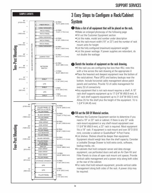
Make a list of all equipment that will be placed on the rack.•Make an enlarged photocopy of the following page•Fill out the Customer Equipment section•List the make, model and number under description•List the rack-mount width (19” or 23”) and the number of rackmount units for height
•List the fully configured (maximum) equipment weight•List the power wattage. If power supplies are redundant, donot double the wattage
Sketch the location of equipment on the rack drawing.•If the rack you are configuring has less than 45U, note thiswith a line across the rack drawing at the appropriate U
•Place the heaviest and deepest equipment near the bottom ofthe rack/cabinet. Place UPS’s and battery backups near thebottom. Include horizontal cable management above patchpanels and switches. Provide 1U of cable management forevery 2U of connectivity
•Any equipment that is not rack-mount requires a shelf. A 19”rack shelf supports equipment up to 17-3/4”W (450.9 mm). A23” rack shelf supports equipment up to 21-3/4”W (552.5 mm).Allow 2U for the shelf plus the height of the equipment. 1U is1-3/4”H (44.45 mm)
Fill out the Bill Of Material section.•Review the Customer Equipment section to determine if youneed a 19” or 23” rack or cabinet. If there is any 23” widerack-mount equipment or any shelf-mount equipment over17-3/4”W (450.9 mm), a 23” rack is required. Most equipmentfits a 19” rack. If equipment is rack-mount and over 20”D (510mm), consider a cabinet or QuadraRack® 4-Post Frame.
•List shelves. Shelves should be deeper than equipment.Equipment should weigh less than the shelf capacity. Considera Lockable Storage Drawer to hold extra cords, software,backup media, etc.
•In cabinets that hold computer server and data storageequipment, use perforated doors and add an Air Dam Kit andFiller Panels to close all open rack mount unit spaces. Providevertical cable management and a power strip along both sidesat the rear of the cabinet.
•For racks that hold network equipment, provide vertical cablemanagement along both sides of the rack. A power strip maybe required.
3
SAMPLE LAYOUTSTw
o-Post Mounting
Four-
Post Mounting
ix
2
1
3 Easy Steps to Configure a Rack/CabinetSystem
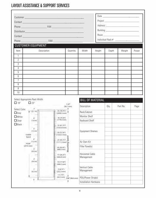
LAYOUT ASSISTANCE & SUPPORT SERVICES
CUSTOMER EQUIPMENT
Item Description Quantity Width Height Depth Weight Power
1
2
3
4
5
6
7
8
9
10
Customer _______________________________________________
Contact _________________________________________________
Phone ____________________ FAX _________________________
Distributor______________________________________________
Contact ________________________________________________
Phone _____________________ FAX _______________________
Date _____________________________
Project ___________________________
Address __________________________
Building __________________________
Room ____________________________
Individual Rack # __________ _________
BILL OF MATERIAL
Description Qty. Part No. Page
Rack/Cabinet
Monitor Shelf
Keyboard Shelf
Equipment Shelves
Air Dam Kit
Filler Panel(s)
Horizontal CableManagement
Vertical CableManagement
PDU/Power Strip(s)
Installation Hardware
x
Select Appropriate Rack Width:o 19” o 23”
Select Color:oGrayoWhiteoClearoBlack

RACK SYSTEMSRacks, Rack Enclosures, Shelves & Accessories
Universal Rack Page 1-3Standard Rack Page 1-7Adjustable Rail, 4-Post Rack Page 1-10Adjustable, 4-Post Rack Page 1-13Fixed 4-Post Rack Page 1-17Shelves for Racks Page 1-20Keyboard Trays Page 1-26Installation Products Page 1-29Additional Accessories Page 1-31High-Density Patching Frame Page 1-39
RACK SYSTEMSAdvances in technology are moving information faster and faster every day. But no matter howadvanced or involved a network becomes, it can all come to a halt if not supported by a sturdyrack. Building a proven record of supporting these complex network configurations through standout products like the cost-effective Adjustable QuardraRack®, CPI’s industry-leading RackSystems deliver the confidence of unsurpassed strength, stability and durability. From multiplepatch panels to cabling and other equipment, CPI Rack Systems keep equipment safe and secure.
Designed and built with a commitment to quality, CPI Rack Systems can also be quickly adaptedfor your changing needs with the addition of shelves or special brackets engineered to hold larger devices and computer hardware, such as servers and switches. Enclosures can be addedto some Rack Systems as well, which improves security for your equipment.
CPI Rack Systems feature:• High-quality construction and design• Fixed mounting rails, most with rack-mount unit markings, ideal for support of patch panels, termination blocks and other equipment
• Standard EIA-310-D hole pattern• Small footprint saves floor space• Unrestricted airflow for maximum ventilation• Easy access to cables for moves, adds and changes• Large variety of styles, sizes and accessories for various configurations• High static load ratings; 750 lb (340.2 kg) to 2200 lb (1000.0 kg)
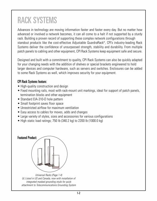
Featured Product:
Universal Racks (Page 1-4)UL Listed in US and Canada, now with installation of
integrated masked grounding studs for quick attachment to Telecommunications Grounding System
1-2
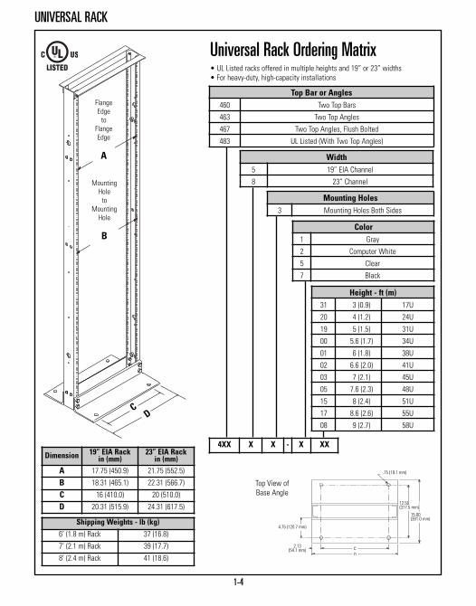
Universal RackFeatures:• High-strength, lightweight aluminum extrusion construction • Two top angles or top bars and heavy-duty assembly hardware for stronger rack to handle heavier loading
• 50 special #12-24 mounting screws with combination Phillips/Straight heads and pilot points to reduce cross threading and installation time
• Unique packaging inserts eliminate damage from components hitting together in the carton during shipping and handling; racks are packedunassembled in individual cartons
• Ease of assembly is enhanced through use of threaded channels; no hex nuts are required
• Universal 5/8”-5/8”-1/2” (15.9 mm-15.9 mm-12.7 mm) alternating hole pattern offers greater mounting flexibility, maximizes usable mountingspace and is compatible with conventional wide 1-1/4”-1/2” (31.8 mm -12.7 mm) alternating hole patterns
• Integrated masked grounding studs on the inside of the rack channel for quick attachment to the Telecommunications Grounding System
• Available in powder coat color finishes (black, white or gray) or grained aluminum finish (clear)
• State-of-the-art manufacturing methods provide the best quality and fastestdelivery in the industry
• Side channels have multiple mounting holes and (4) pem nuts for quickinstallation of cable management
• EIA Channels: 3.0” x 1.265” x .25” (76 mm x 32.13 mm x 6.4 mm) thick flange (pair)
• Base Angles: 3.5” x 6.0” x .375” (89 mm x 152 mm x 9.53 mm) thick (pair) • Top Angles: 1.5” x 1.5” x .25” (38 mm x 38 mm x 6.4 mm) thick (pair)• Top Angles, Flush Bolted: 1.5” x 2.0” x .25 (38 mm x 51 mm x 6.4 mm) thick • Top Bars: 1.5” x .25” (38 mm x 6.4 mm) thick (pair) • Panel Mounting Holes: #12-24 rolled threads in both flanges front and back• Custom configurations and assemblies available by special order • Assembly hardware is included • Select models (P/N 48353-XXX, 48383-XXX) are UL Listed: File E140851; Category DUXR (US), DUXR7 (Canada) – Communications Circuit Accessory
• Weight capacity 1500 lb (680.4 kg) — weight must be evenly distributed and rack must be properly secured to floor
Installation Hint: When mounting equipment, use #3 Phillips tip to assure maximumtorque.
Channel Cross Section and Hole PatternStandardsCPI offers EIA aluminum channel uprights on all Standard and Universal racks.All Standard and Universal racks are threaded to accept industry standard#12-24 mounting screws. Extra care is taken in that the threads are “rolled’’rather than “cut’’ for greater strength and durability. The Universal Rack holepattern is 5/8”-5/8”-1/2” (15.9 mm-15.9 mm-12.7 mm) and is compatible withwide 1 1/4”-1/2” (31.8 mm-12.7 mm) patterns while offering greaterflexibility.
1-3
UNIVERSAL RACK
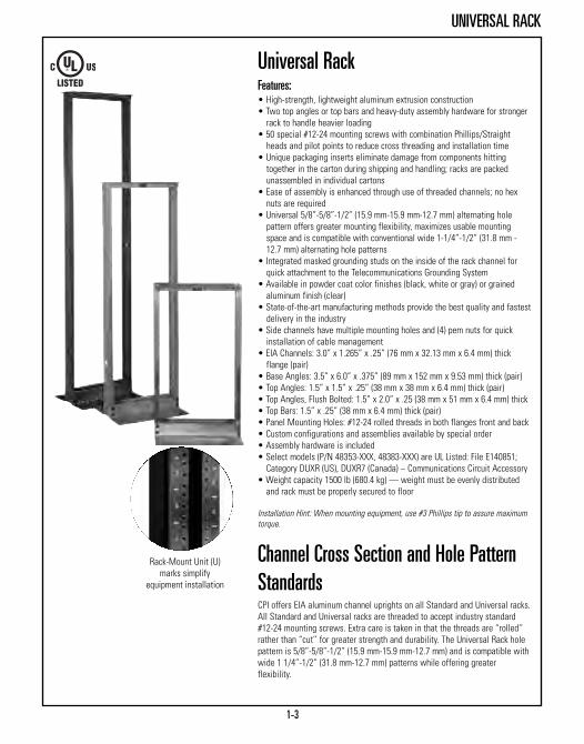
Rack-Mount Unit (U)marks simplify
equipment installation
1-4
UNIVERSAL RACK
Top Bar or Angles460 Two Top Bars
463 Two Top Angles
467 Two Top Angles, Flush Bolted
483 UL Listed (With Two Top Angles)
Width 5 19” EIA Channel
8 23” Channel
Mounting Holes3 Mounting Holes Both Sides
Color1 Gray
2 Computer White
5 Clear
7 Black
Height - ft (m)31 3 (0.9) 17U
20 4 (1.2) 24U
19 5 (1.5) 31U
00 5.6 (1.7) 34U
01 6 (1.8) 38U
02 6.6 (2.0) 41U
03 7 (2.1) 45U
05 7.6 (2.3) 48U
15 8 (2.4) 51U
17 8.6 (2.6) 55U
08 9 (2.7) 58U
4XX X X - X XXDimension 19” EIA Rack
in (mm)23” EIA Rack
in (mm)A 17.75 (450.9) 21.75 (552.5)
B 18.31 (465.1) 22.31 (566.7)
C 16 (410.0) 20 (510.0)
D 20.31 (515.9) 24.31 (617.5)
Shipping Weights - lb (kg)
6’ (1.8 m) Rack 37 (16.8)
7’ (2.1 m) Rack 39 (17.7)
8’ (2.4 m) Rack 41 (18.6)
Top View ofBase Angle
Universal Rack Ordering Matrix• UL Listed racks offered in multiple heights and 19” or 23” widths• For heavy-duty, high-capacity installations
.75 (19.1 mm)
12.50(317.5 mm)
15.00(381.0 mm)
4.75 (120.7 mm)
2.13(54.1 mm)
FlangeEdgeto
FlangeEdge
A
MountingHoleto
MountingHole
B
CD

1-5
UNIVERSAL RACK
Top Bar or Angles463 Two Top Angles
467 Two Top Angles, Flush Bolted
Width - in6 35 EIA Channel
Mounting Holes3 Mounting Holes Both Sides
Color1 Gray
2 Computer White
5 Clear
7 Black
Height - ft (m)01 6 (1.8) 38U
03 7 (2.1) 45U
46X 6 3 - X 0X
35” x 3” (889 mm x 80 mm) Universal RackUniversal Rack in a 35” (889 mm) frame width supports block hardware. • High strength aluminum construction • Supplied with two top angles for maximum strength • EIA-310-D Standard Universal 5/8”-5/8”-1/2” (15.9 mm-15.9 mm-12.7 mm) alternating hole pattern offers greater mounting flexibility and is fully compatible with conventional wide 1-1/4”-1/2” (31.8 mm- 12.7 mm) alternating hole patterns
• Four web channel holes per side allow multiple racks to be firmly mounted together side by side
• High strength roll-formed threaded mounting holes• Rack-mount unit marks simplify equipment installation• Includes 50 pilot point #12-24 mounting screws with combination Phillips/Straight heads
• Integrated masked grounding studs on the inside of the rack channel for quick attachment to the Telecommunications Grounding System.
• Ships unassembled, individually packaged with assembly and installation instructions included; bulk packaging is also available
• Supports up to 1500 lb (680.4 kg)Note: Accessory shelves are not available for this rack.
Flange Edgeto
Flange Edge
33.75(857.3 mm)
MountingHoleto
MountingHole
34.31 (871.5 mm)
36.31
(922.3 m
m)
Shipping Weights - lb (kg)
6’ (1.8 m) Rack 49 (22.2)
7’ (2.1 m) Rack 51(23.1)Rack-Mount Unit (U)marks simplify
equipment installation
See Section 5 for Cable Management Products

3.88”(98.6 mm)
23.0” (584.2 mm)
0.656”(16.66 mm)holes3 PL.
1.125”(28.58 mm)HOLES2 PL.
43.0”(1092.2 mm)
14.0”(355.6 mm)
4.0”(101.6 mm)
12.0”(304.8 mm)
12-24ThreadedMountingHoles12.00”
(304.8 mm)C-C
12-24ThreadedMountingHoles
1/2–20Threaded insert
4 PL.
Front and Rear Flanges(both sides drilled)
Web Surface7’ (2.1 m) Universal Rack
1-6
UNIVERSAL RACK
Rack Height Dimension A
ft (m)Dimension B
in (mm)Dimension C
in (mm)Number of
Mounting HolesNumber of
Mounting Spaces
3 (0.9) N/A 1.75 (44.5) 53 17
4 (1.2) N/A 2.13 (54.1) 72 24
5 (1.5) 43 (1090) 1.88 (47.8) 94 31
5.6 (1.7) 44 (1120) 2.00 (50.8) 104 34
6 (1.8) 56 (1420) 2.12 (53.8) 114 38
6.6 (2.0) 56 (1420) 1.75 (44.5) 125 41
7 (2.1) 56 (1420) 1.87 (47.5) 135 45
7.6 (2.3) 56 (1420) 2.62 (66.5) 144 48
8 (2.4) 72 (1830) 2.25 (57.2) 155 51
8.6 (2.6) 72 (1830) 2.38 (60.5) 165 55
9 (2.7) 72 (1830) 2.00 (50.8) 176 58
Dimensions:
C
B
A

1-7
STANDARD RACK
Standard Rack 3”D (80 mm) The Standard Rack is designed for value conscious, high volume customers,who require the quality and service that sets CPI racks apart from thecompetition. The Standard Rack is a UL Listed communication circuitaccessory designed specifically for use in telecommunications equipmentinstallations where codes require UL Listed equipment racks. For a greaterbreadth of features, we recommend CPI Universal Racks.• High strength aluminum construction• Shipped with (2) top angles, (2) base angles, (2) 3”D (80 mm) equipment channels and installation hardware
• Top angles allow J-bolt attachment without interfering with top rack-mountspaces
• EIA-310-D Standard Universal 5/8”-5/8”-1/2” (15.9 mm-15.9 mm-12.7 mm) alternating hole pattern offers greater mounting flexibility and is fullycompatible with conventional wide 1-1/4”-1/2” (31.8 mm-12.7 mm)alternating hole patterns
• Six web channel holes per side enable multiple racks to be mounted together side by side or attachment of cable managers
• High strength roll-formed threaded mounting holes• Rack-mount unit marks simplify equipment installation• Includes 50 pilot point #12-24 mounting screws with combination Phillips/Straight heads to reduce cross-threading and installation time
• White, black, gray or clear grained finish provides attractive appearance
• Ships unassembled, individually packaged, with assembly hardware and installation instructions; bulk packaging is also available
• Redesigned shipping container saves space and freight costs• Choose from three heights• Weight capacity of 1000 lb (453.6 kg) — weight must be evenly distributed and rack must be properly secured to the floor
• UL Listed; File E140851; Category DUXR (US), DUXR7 (Canada) –Communications Circuit Accessory
7’ ( 2.1 m) Rack ShownPart
NumberDescription
H x WHeight - ft (m)
ShippingWeightlb (kg)
55053-X03 7 (2.1) x 19”, 45U 31 (14.1)
55053-X15 8 (2.4) x 19”, 51U 37 (16.8)
55053-X08 9 (2.7) x 19”, 58U 40 (18.1)
X=color: 1=Gray, 2=White, 5=Clear, 7=Black
See Section 5 for Cable Management Products
Rack-Mount Unit (U)marks simplify
equipment installation

1-8
STANDARD RACK
P/N 66363 (35” W) Shown:The 6”D (150 mm) Standard Rack is thehigh-capacity frame that is designed foruse with cabling sections and is the basicframe around which the XLBET/MDFframes are developed.
Standard Rack 6”D (150 mm)Features 6”D (150 mm) upright mounting channels for MDF, IDF and otherhigh-capacity distribution frame applications. The additional rack depthprovides extra room for high-density equipment and cable needs. • High strength aluminum construction • Supplied with (2) top angles for additional strength• EIA-310-D Standard Universal 5/8”-5/8”-1/2” (15.9 mm-15.9 mm-12.7 mm) alternating hole pattern offers greater mounting flexibility and is fully compatible with conventional wide 1-1/4”-1/2” (31.8 mm-12.7 mm) alternating hole patterns
• Rack-mount unit marks simplify equipment installation • High-strength, roll-formed threaded mounting holes• Ships unassembled and individually packaged • Includes assembly hardware and (50) pilot point #12-24 mounting screws with combination Phillips/Straight heads
• Weight capacity 1,000 lb (453.6 kg) — weight must be evenly distributed and rack must be properly secured to the floor
• UL Listed; File E140851; Category DUXR (US), DUXR7 (Canada) –Communications Circuit Accessory
PartNumber
DescriptionH x W
Height - ft (m)
ShippingWeightlb (kg)
66353-X03 7 (2.1) x 19”, 45U 38 (17.2)
66383-X03 7 (2.1) x 23”, 45U 42 (19.1)
66363-X03 7 (2.1) x 35”, 45U 52 (23.6)
X=color; 1=Gray, 2=White, 5=Clear, 7=Black
Rack Dimensions
Dimension 19” EIA Rackin (mm)
23” EIA Rackin (mm)
35” EIA Rackin (mm)
A 17.79 (451.9) 21.79 (553.5) 33.79 (858.3)
B 18.31 (465.1) 22.31 (566.7) 34.31 (871.5)
C 20.31 (515.9) 24.31 (617.5) 36.31 (922.3)

P/N 11755-001Standard side-mounted enclosure fan kit includes (2) complete fan assemblies with an attached cord with NEMA 5-15P plug.
Fan & Filter Assembly
11755-001Fan Kit for Single Rack Enclosures; 400 CFM, 115 VAC,
50/60 Hz, 0.19 Amp, NEMA 5-15P Plug,Components are UL & ROHS approved
11222-001 Replacement Filter Kit
Rack Height - ft (m)06 6 (1.8) With Side Panels07 7 (2.1) With Side Panels96 6 (1.8) Without Side Panels97 7 (2.1) Without Side Panels
Color2 Computer White7 Black
110 XX - X XX
Rack Width38 19” 48 23”
Single Rack Enclosure110 Plexiglass Doors on Enclosure
1-9
RACK ENCLOSURES
Rack Enclosure
Single Rack Enclosure
11558 - X XX
Rack Height - ft (m)06 6 (1.8) With Side Panels07 7 (2.1) With Side Panels96 6 (1.8) Without Side Panels97 7 (2.1) Without Side Panels
Color2 Computer White7 Black
Metal Door Rack Enclosure11558 For 19” Rack - Metal Enclosure Doors
Single Rack EnclosuresEnclose a single rack while leaving ample room for wire and cable. Thealuminum top panel with six edge-protected punch-out ports provides cablingaccess wherever needed. Run cable through the back panel by removing oneof four cable access plates located along the bottom kick plate.• Convenient cable access with removable sides, rear-kick panel and cut-outtop sections
• Lockable plexiglass or metal doors are easily reversible • Top and side panels can be removed in minutes to provide access to interior• Ships partially assembled in one 14” x 32” x 89” (360 mm x 810 mm x 2260mm) carton to minimize shipping and handling costs
• Shipping weight approximately 135 lb (61.2 kg)
1-10
ADJUSTABLE RAIL 4-POST RACK
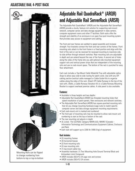
Adjustable Rail QuadraRack® (ARQR)and Adjustable Rail ServerRack (ARSR)The Adjustable Rail QuadraRack® (ARQR) and the Adjustable Rail ServerRack(ARSR) provide a sturdy, feature-rich solution for supporting rack-mountnetwork, computer server and data storage equipment in data centers,computer equipment rooms and other IT facilities. Both racks offer thestrength and stability of an enclosure in an open four-post mounting systemthat provides easy access to equipment and cabling.
The front and rear frames are welded to speed assembly and increasestrength. Four brackets connect the front and rear corners of the frames. Frontmounting rails attach to the front frame in a fixed position and align with thefront of the rack or can be reversed for recessed mounting to maximize side-to-side airflow through network switches. Rear mounting rails are adjustablein depth and can extend beyond the rear of the frame. A second set of holesalong the sides of the frame lets you add optional side-mounted equipmentsupport rails and vertical power strips that are independent of the mountingrails and use no rack-mount space. The bottom of the rack is punched for easyfloor attachment.
Each rack includes a Top-Mount Cable Waterfall Tray with adjustable radiusdrops to allow easy side-to-side routing for patch cords. Use with any CPIcabling section (vertical cable manager) or Cable Guide Kits to organizecables along the sides of the rack. Attach CPI Cable Runway to the top of therack with J-Bolts, a Cable Runway Elevation Kit or a Cable Runway MountingBracket to support overhead premise cables. A side panel is also available.
Features:• Available in three heights and two depths• Adjustable Rail QuadraRack (ARQR) has threaded mounting holes that speed installation of patch panels, fiber enclosures and network switches.
• The Adjustable Rail ServerRack (ARSR) has square-punched mounting railsthat let you change mounting hardware (cage nuts) to match specificcomputer server and data storage equipment mounting requirements.
• Each rack-mount unit is marked and numbered • The front pair of mounting rails may be mounted to allow rack-mount unit numbering to start at the top or bottom of the rack
• The rear mounting rail adjusts in depth• UL Listed; File E227626; Category NWIN (US), NWIN7 (Canada) –Information Technology and Communications Equipment Cabinet, Enclosureand Rack
• Each rack will support up to 2200 lb (1000.0 kg) of equipment.
Rack Includes:• (2) mounting frames• (4) horizontal braces • (2) front mounting rails• (2) rear mounting rails• (1) top-mount cable tray • Assembly hardware: (1) Two Mounting Hole Ground Terminal Block and Antioxidant Joint Compound
• ARSR includes (50) #12-24 cage nuts and screws• ARQR includes (50) #12-24 screws
Mounting Rails can be flippedto change numbering frombottom-to-top or top-to-bottom

1-11
ADJUSTABLE RAIL 4-POST RACK
1525 Adjustable Rail QuadraRack® and ServerRack, 19"
MountingHole Style
Rack Depth (B)in (mm)
Max. Rail Depth (C)in (mm)
1 #12-24 Threaded 23.62 (600) 29.52 (750)
2 #12-24 Threaded 35.43 (900) 41.33 (1050)
3 Square-Punched 23.62 (600) 29.52 (750)
4 Square-Punched 35.43 (900) 41.33 (1050)
Color
1 Gray
2 Computer White
7 Black
Height (A)
U Height - in (mm)
01 38 72 (1800)
03 45 84 (2100)
15 51 96 (2400)
1525 X - X XX
Note: Min. Rail Depth is 15” (380 mm)

1-12
ADJUSTABLE RAIL 4-POST RACK ACCESSORIES
X=Color; 1=Gray, 2=White, 7=Black
Adjustable Rail 4-Post Rack AccessoriesEquipment Support RailProvides additional support for heavy rack-mount equipment, attaches to theside of the Adjustable Rail QuadraRack or ServerRack and provides a .98”W(25 mm) support surface for equipment. Does not interfere with rack-mountunit (U) spaces. Supports 200 lb (90.7 kg) of equipment and includes assemblyand installtion hardware.
Top-Mount Cable Waterfall TrayUse at the top of rack to guide patch cords side-to-side or rack-to-rack. OneTop-Mount Cable Waterfall Tray is included with each rack. 6”W x 5.2”D(152 mm x 132 mm) steel tray with adjustable radius bends.
Cable Guide KitT-shaped cable guides (7U) snap onto the front or rear of the rack to organizecables. The openings align with each rack-mount unit on the rack. Includes cableguides for one side (front or rear) of the rack.
Side PanelSolid, steel side panel used to cover the end of the rack and/or vertical cablemanagers at the end of a row. Matches the height and depth of rack, steel.
Fixed Equipment Mounting RailAdditional pair of equipment mounting rails which attach to the rear rackframe to create a solution with two mounting depths set between 15”D(381 mm) and the rack depth. Includes installation hardware.
PartNumber Description
ShippingWeightlb (kg)
15285-X01 Equipment Rail, for 23.62” (600 mm) Racks 7 (3.2)
15285-X02 Equipment Rail, for 35.43” (900 mm) Racks 11 (5.0)
15275-X01 Top-Mount Cable Waterfall Tray 14 (6.4)
15286-001 Cable Guide, for 38U Racks, Black 5 (2.3)15286-003 Cable Guide, for 45U Racks, Black 6 (2.7)15286-015 Cable Guide, for 51U Racks, Black 7 (3.2)15270-X01 Side Panel, 23.62”D x 72”H 51 (23.1)
15270-X02 Side Panel, 23.62”D x 84”H 57 (25.9)15270-X03 Side Panel, 23.62”D x 96”H 48 (21.8)15270-X04 Side Panel, 35.43”D x 72”H 63 (28.6)15270-X05 Side Panel, 35.43”D x 84”H 71 (32.2)15270-X06 Side Panel, 35.43”D x 96”H 60 (27.2)15259-X01 Fixed Rail, Threaded, for 38U Racks 20 (9.1)15259-X03 Fixed Rail, Threaded, for 45U Racks 23 (10.4)15259-X15 Fixed Rail, Threaded, for 51U Racks 26 (11.8)15260-X01 Fixed Rail, Square-Punched, for 38U Racks 19 (8.6)15260-X03 Fixed Rail, Square-Punched, for 45U Racks 22 (10.0)15260-X15 Fixed Rail, Square-Punched, for 51U Racks 25 (11.3)
Mounting Rails canbe flipped to changenumbering frombottom-to-top ortop-to-bottom
15285-X01
15275-X01
15286-001
15270-X01
15260-X01

ADJUSTABLE 4-POST RACK
1-13
Adjustable QuadraRack® (AQR) andServerRack (ASR)The Adjustable QuadraRack® and the Adjustable ServerRack provide a sturdy,cost-effective solution for supporting rack-mount network, computer serverand data storage equipment in data centers, computer equipment rooms andother IT facilities. Both racks offer the strength and stability of an enclosure inan open four-post frame that provides easy access to equipment and cabling.
Each rack will support up to 2,000 lb (907.2 kg) of equipment. The cornerposts are C-shaped equipment mounting channels that provide front and rearsupport for 19”W rack-mount equipment or shelves. The front and rear framesare welded to reduce assembly time. Four brackets connect the front and rearcorners of the rack. The rack is available in four heights and four depthranges. The front-to-rear depth of the mounting channels can be adjusted upto 5.91” (150 mm) in depth in .98” (25 mm) increments during assembly. Themounting channels are fixed in place once assembled to surround and protectequipment.
The Adjustable QuadraRack has threaded mounting holes that makeinstallation time of patch panels, fiber enclosures and network switchesshorter. Adjustable ServerRack has square-punched holes that let you changemounting hardware (cage nuts) to match specific computer server and datastorage equipment mounting requirements. Each rack-mount unit is marked onthe channels making it easy to locate and position equipment. A second set ofholes along the sides of the channels lets you add optional side-mountedEquipment Support Rails that use no additional rack-mount space.
Features:• Open design for unrestricted airflow and easy access to equipment andcabling
• Self-squaring assembly with welded front and rear frames reduces assemblytime
• Mounting channels adjust in depth to provide front and rear support forequipment
• Maximizes floor space with a minimal rack footprint• Rack components are bonded together during assembly• Includes a Two Mounting Hole Ground Terminal Block for easy attachment tothe Telecommunications Grounding Busbar
• Choose square-punched or threaded equipment mounting holes• Rack-mount unit spaces are marked on the mounting channels• Easy to bay together to create multi-rack configurations• Use with any CPI Cabling Section to manage cables• Support large equipment on heavy-duty shelves or on side-mountedEquipment Support Rails
• UL Listed; File E227626; Category NWIN (US), NWIN7 (Canada) –Information Technology and Communications Equipment Cabinet, Enclosureand Rack
• Supports 2000 lb (907.2 kg) of equipment

ADJUSTABLE 4-POST RACK
1-14
1521 Adjustable QuadraRack® and ServerRack, 19"
MountingHole Style
Mounting Channel Depth Range (C)in (mm)
1 Square-Punched 15.75 to 21.65 (400 to 550)
2 Square-Punched 22.64 to 28.54 (575 to 725)
3 Square-Punched 29.53 to 35.43 (750 to 900)
4 Square-Punched 36.42 to 42.32 (925 to 1075)
5 #12-24 Threaded 15.75 to 21.65 (400 to 550)
6 #12-24 Threaded 22.64 to 28.54 (575 to 725)
7 #12-24 Threaded 29.53 to 35.43 (750 to 900)
8 #12-24 Threaded 36.42 to 42.32 (925 to 1075)
Color1 Gray
2 Computer White
7 Black
HeightU (A) - in (mm) (B) - in (mm)
01 38 72 (1800) 67 (1700)
03 45 84 (2100) 79 (2000)
15 51 96 (2400) 91 (2300)
08 58 108 (2740) 103 (2620)
1521 X - X XX
Note: Mounting channel depth adjusts in .98” (25 mm) increments duringassembly. The mounting depth is fixed once the rack is assembled. See thetable on next page for a list of mounting channel depth settings by part number.
B
17.78”(451.6 mm)Opening
18.31”(465.1 mm)Hole Centers
20.31(515.9 mm)
A
Side View
Front View
A
C
See next page for mounting channel details.
A

ADJUSTABLE 4-POST RACK
1-15
Mounting Channel Depth Settings and Dimensions by Part Number
Part NumbersChannel Depth
(C)Overall Depth
(D)Floor Mounting
Holes (E)in mm in mm in mm
15215-XXX 15211-XXX
15.75 400 15.96 405.4 12.47 316.716.73 425 16.94 430.3 13.45 341.617.72 450 17.93 455.4 14.44 366.818.70 475 18.91 480.3 15.42 391.719.69 500 19.90 505.5 16.41 416.820.67 525 20.88 530.4 17.39 441.721.65 550 21.86 555.2 18.37 466.6
15216-XXX 15212-XXX
22.64 575 22.85 580.4 19.36 491.723.62 600 23.83 605.3 20.34 516.624.61 625 24.82 630.4 21.33 541.825.59 650 25.80 655.3 22.31 566.726.57 675 26.78 680.2 23.29 591.627.56 700 27.77 705.4 24.28 616.728.54 725 28.75 730.3 25.26 641.6
15217-XXX 15213-XXX
29.53 750 29.74 755.4 26.25 666.830.51 775 30.72 780.3 27.23 691.631.50 800 31.71 805.4 28.22 716.832.48 825 32.69 830.3 29.2 741.733.46 850 33.67 855.2 30.18 766.634.45 875 34.66 880.4 31.17 791.735.43 900 35.64 905.3 32.15 816.6
15218-XXX 15214-XXX
36.42 925 36.63 930.4 33.14 841.837.40 950 37.61 955.3 34.12 866.638.39 975 38.60 980.4 35.11 891.839.37 1000 39.58 1005 36.09 916.740.35 1025 40.56 1030 37.07 941.641.34 1050 41.55 1055 38.06 966.742.32 1075 42.53 1080 39.04 991.6
Notes: 1. There are seven depth settings for each part number
as listed in the table.2. Each rack adjusts front-to-rear in depth up to 5.91”
(150 mm) in .98” (25 mm) increments.3. Rack mounting channel depth is fixed once assembled.4. Overall Depth (D) is Channel Depth (C) + .21” (5.3 mm).5. Floor Mounting Holes (E) are Channel Depth (C) - 3.28”
(83.3 mm).
16.00”(406.4 mm)20.31”
(515.9 mm)2.16”(54.7 mm)
1.64”(41.6 mm)
D E C
Bottom View - Section A-A
Solid and Vented ShelvesSupports heavy peripheral equipment. 1U x 19”W steel, shelf with adjustabledepth rear mounting brackets with solid or vented support surface; 17.68”W (449.1 mm) . Supports 200 lb (90.7 kg) of equipment, includes assembly hardware.
Shelves ShelfDepthin (mm)
Mounting Channel Depth
in (mm)
ShippingWeightlb (kg)Solid Vented
15245-X01 15255-X01 13.84 (351.5) 15.75 to 21.65 (400 to 550) 10 (4.5)
15245-X02 15255-X02 20.73 (526.5) 22.64 to 28.54 (575 to 725) 12 (5.4)
15245-X03 15255-X03 27.62 (701.6) 29.53 to 35.43 (750 to 900) 15 (6.8)
15245-X04 15255-X04 34.51 (876.6) 36.42 to 42.32 (925 to 1075) 18 (8.2)
X=Color; 1=Gray, 2=White, 7=Black
15245-X01
15255-X01

ADJUSTABLE 4-POST RACK
1-16
X=Color; 1=Gray, 2=White, 7=Black
Adjustable 4-Post Rack AccessoriesEquipment Support RailProvides additional support for heavy rack-mount equipment. Attaches to the side ofrack and provides a 1.5”W (38 mm) front-to-rear support surface for equipment.Supports 200 lb (90.7 kg) of equipment, includes assemblyand installtion hardware.
Extra Heavy Duty Sliding ShelfThis 2U x 19”W sliding shelf with adjustable depth rear mounting brackets attachesto rack channels set 20.62” to 32.48”D (525 to 825 mm). Solid surface is 15.5”W x26”D (393.7 mm x 660 mm) and extends 24” (609 mm) and locks in the open andclosed positions. Supports 300 lb (136 kg) of equipment.
Cable Runway Mounting BracketAttaches Runway to the top of the Adjustable QuadraRack or ServerRack. Alignswith the front, rear or side of the rack and supports 6”W to 24”W (150 mm to 600mm) CPI Cable Runway. S-shaped, steel bracket measures 1.0”H x 3.3”W x 24.4”L(25 mm x 84 mm x 620 mm) and includes mounting hardware.
Center RailProvides an additional pair of steel mounting rails for rack-mount equipment. Onepair of 19”W mounting rails with square-punched or threaded equipment mountingrails. Adjustable depth - attach the rails at any point along the side of the rack,marked and numbered rack-mount spaces simplify equipment installation. Maximummount depth is 6” (152 mm) less than the channel depth of the rack. 1,000 lb (453.6)equipment load bearing capacity when used as an independent pair or rails; rackload remains 2,000 lb (907.2) when Center Rail is used as the front or rear pair offour-point mounting solution.
PartNumber Description
ShippingWeightlb (kg)
15235-X01 Equipment Rail, 15.75 to 19.69 (400 to 500) D 5 (2.3)
15235-X02 Equipment Rail, 20.67 to 24.61 (525 to 625) D 6 (2.7)
15235-X03 Equipment Rail, 25.59 to 29.53 (650 to 750) D 7 (3.2)
15235-X04 Equipment Rail, 30.51 to 34.45 (775 to 875) D 9 (4.1)
15235-X05 Equipment Rail, 35.43 to 39.37 (900 to 1000) D 10 (4.5)
15235-X06 Equipment Rail, 40.35 to 44.29 (1025 to1125) D 12 (5.4)
12700-X19 Extra Heavy Duty Solid Shelf, 19”W 51 (23.1)
15330-X01 Center Rail, Square Punched, 38U, 72 (1800) H 20 (9.1)
15330-X03 Center Rail, Square Punched, 45U, 84 (2100) H 23 (10.4)
15330-X15 Center Rail, Square Punched, 51U, 96 (2400) H 26 (11.8)
15330-X08 Center Rail, Square Punched, 58U, 108 (2740) H 29 (13.2)
15335-X01 Center Rail, Threaded #12-24, 38U, 72 (1800) H 20 (9.1)
15335-X03 Center Rail, Threaded #12-24, 45U, 84 (2100) H 23 (10.4)
15335-X15 Center Rail, Threaded #12-24, 51U, 96 (2400) H 26 (11.8)
15335-X08 Center Rail, Threaded #12-24, 58U, 108 (2740) H 29 (13.2)
15205-X01 Cable Runway Mounting Bracket,for 6 to 24 (150 to 600) W Cable Runway 5 (2.3)
15235-X01
12700-X19
15205-X01
15330-X01
15335-X01

1-17
FIXED FOUR-POST RACK
Steel Channels with squareholes adapt to servermounting screws
X=color: 1=Gray, 2=White, 7=Black
QuadraRack® Server FrameDesigned specifically for rack-mount servers, the QuadraRack® Server Frameoffers the strength and stability of a cabinet, but in an open mounting system.Providing easy access for simplified installation and cabling, the QuadraRackServer Frame offers unrestricted airflow for improved cooling and heatdissipation. The unique, steel C-shaped channels with square holes andhorizontal braces were designed to provide optimal torsional strength. We'vemade the horizontal braces quick and easy to install with the suppliedcarriage bolts. Since rack-mount servers require various types of mountingscrews, cage nuts provide the flexibility.• 19” EIA width • Manufactured from aluminum and steel• Painted black, gray and white powder coat, textured finish• EIA-310-D Standard Universal 5/8”-5/8”-1/2” (15.9 mm-15.9 mm-12.7 mm)alternating hole pattern
• Square-punched mounting holes adapt with cage nuts (listed below)to match equipment mounting requirements
• Top Extension Pan Set provides two 6” x 16” (150 mm x 410 mm) cable access ports
• Frame depth is 29” (740 mm) with overall depth of 41” (1040 mm) from edge-to-edge of base angles
• Load Rating: 1000 lb (453.6 kg) — weight must be evenly distributed and the rack must be properly secured to the floor
QuadraRack Server Frame Kit includes:• (4) Rack Channels• (2) Base Angles• (2) Top Angles• (1) Extension Pan Set• (8) Plate Nuts and Assembly Hardware• (2) Horizontal Braces
Square-Punched Hardware Kits (sold separately)
PartNumber
NominalSize
PackageOf Finish
ShippingWeightlb (kg)
12637-001 M-6 25 Gold Over Zinc 1 (0.5)
12638-001 10-32 25 Zinc 1 (0.5)
12639-001 12-24 25 Black 1 (0.5)
PartNumber
DescriptionH x W x D
Height - ft (m), Depth - in (mm)
ShippingWeightlb (kg)
15053-X03 7 (2.1) x 19 x 29 (740), 45U 77 (34.9)

1-18
FIXED FOUR-POST RACK
Part Number
DescriptionH x W x D
Height - ft (m), Depth - in (mm)
ShippingWeightlb (kg)
ExpandaRack - Standard Rack50110-X03 7 (2.1) x 19 x 29 (740), 45U 46 (20.9)
50110-X15 8 (2.4) x 19 x 29 (740), 51U 48 (21.8)
50110-X08 9 (2.7) x 19 x 29 (740), 58U 50 (22.7)
ExpandaRack - Universal Rack50130-X03 7 (2.1) x 19 x 29 (740), 45U 52 (23.6)
50130-X15 8 (2.4) x 19 x 29 (740), 51U 55 (24.9)
50130-X08 9 (2.7) x 19 x 29 (740), 58U 58 (26.3)
ExpandaRack - Pan Set (W x D)50150-X99 19 x 29 (740) — Std Rack 18 (8.2)
50160-X99 19 x 29 (740) — Universal Rack 18 (8.2)
X=color: 1=Gray, 2=White, 5=Clear, 7=BlackNot intended for rack-mount servers
QuadraRack® 4-Post FrameThe QuadraRack® 4-Post Frame offers the strength and stability of a cabinet inan open mounting system. Enjoy easy equipment installation along withunrestricted airflow for improved cooling and heat dissipation.• 19” EIA width• Manufactured from aluminum • EIA-310-D Standard Universal 5/8”-5/8”-1/2” (15.9 mm-15.9 mm-12.7 mm)alternating hole pattern, mounting holes are roll-formed #12-24
• Ships unassembled• Load Rating: 2000 lb (907.2 kg) — weight must be evenly distributed andthe rack must be properly secured to the floor
QuadraRack 4-Post Frame Kit includes:• (4) Rack Channels• (2) Base Angles• (2) Top Angles• (1) Extension Pan Set• (1) Bag of 100 Rack mounting screws — Pilot Point #12-24 withcombination Phillips/Straight head
ExpandaRackConvert a CPI two-post rack to a QuadraRack with ExpandaRack.
PartNumber
DescriptionH x W x D
Height - ft (m), Depth - in (mm)
ShippingWeightlb (kg)
50120-X03 7 (2.1) x 19 x 29 (740), 45U 65 (29.5)
50120-X15 8 (2.4) x 19 x 29 (740), 51U 67 (30.4)
50120-X08 9 (2.7) x 19 x 29 (740), 58U 69 (31.3)

1-19
FIXED FOUR-POST RACK ACCESSORIES
PartNumber Description
ShippingWeightlb (kg)
16351-X19 Heavy Duty Fixed Shelf, Solid 11 (5.0)
16350-X19 Heavy Duty Fixed Shelf, Vented 11 (5.0)
12700-X19 Extra Heavy Duty Sliding Shelf* 8 (3.6)
16342-X01 Rack Line-Up Spacer, Universal 1 (0.5)
16342-X02 Rack Line-Up Spacer, Standard 1 (0.5)
16356-X19 Equipment Tie-Down Bracket 4 (1.8)
16341-X19 Rack Base Dust Cover 4 (1.8)
16351-X19
X=color: 1=Gray, 2=White, 5=Clear, 7=Black*12700-X19 not available in Clear
QuadraRack® AccessoriesHeavy Duty Fixed Shelf - SolidSpecially designed for QuadraRack. 1U x 19”W x 29”D (740 mm) shelf.Supports up to 200 lb (90.7 kg).
Heavy Duty Fixed Shelf - VentedSpecially designed for QuadraRack. 1U x 19”W x 29”D (740 mm) vented shelfthat optimizes airflow. Supports up to 200 lb (90.7 kg).
Extra Heavy Duty 4-Point Sliding ShelfSpecially designed to support heavy equipment. 2U x 19”W x 26”D (660 mm)sliding shelf, extends 24” (610 mm), adjusts between 20” and 34” (510 mmand 860 mm) mounting depth. Supports up to 300 lb (136.1 kg).
Equipment Tie-Down BracketPrevents back-and-forth, side-to-side and up-and-down movement of shelf-mount equipment. 3U x 19”W x 23”D (580 mm).
Dust CoverImproves the appearance of QuadraRack 4-Post Frame and prevents theaccumulation of dust and debris at the base.
Power StripsBoth horizontal and vertical power strips can be mounted to the QuadraRack.These solutions can be found in Section 7.
16350-X19
12700-X19
16356-X19
16341-X19

1-20
SHELVES
Small Peripheral ShelfDesigned to hold small peripheral equipment in a central location. Each shelftypically holds two units and allows a convenient cable run down the insideof the rack channel. Mounting hardware not included. 19” rack mountable,holds equipment up to 17.35”W x 9.82”D (440.7 mm x 249.4 mm). Made ofstrong, lightweight aluminum, supports up to 50 lb (22.7 kg).
Single-Sided ShelfA convenient 15”D (380 mm) mounting shelf for miscellaneous equipment,test gear, etc. Mounting hardware not included. 19” version holds equipmentup to 17.25”W x 14.82”D (438.2 mm x 376.4 mm), 23” version holds equipmentup to 21.25”W x 14.82”D (539.8 mm x 376.4 mm). Made of strong, lightweight aluminum, supports up to 50 lb (22.7 kg). 19” version is UL Listed: FileE140851; Category DUXR (US), DUXR7 (Canada) – Communications CircuitAccessory.
Single-Sided Vented ShelfSupports routers, switches, CPUs or any equipment requiring bottomventilation. Mounting hardware not included. 19” version holds equipment upto 17.25”W x 14.82”D (438.2 mm x 376.4 mm), 23” version holds equipment upto 21.25”W x 14.82”D (539.8 mm x 376.4 mm). Wall, backboard or rackmountable. Made of strong, lightweight aluminum with airflow perforations, supports up to 50 lb (22.7 kg).
16”D (410 mm) Low Profile ShelfReduced height design saves on valuable rack space. Center mount design isideal for single sided racks, mounts to either front or back of rack channelface. Mounting hardware not included. 19” version holds equipment up to 17.25”W x 15.82”D (438.2 mm x 401.8 mm), 23” version holds equipment up to21.25”W x 15.82”D (539.8 mm x 401.8 mm). Made of strong, lightweightaluminum, supports up to 40 lb (18.1 kg).
PartNumber Description
ShippingWeightlb (kg)
10758-X01 Small Peripheral Shelf, 19”W 5 (2.3)
40074-X00 Single-Sided Shelf, For 19” Rack 6 (2.7)
40075-X00 Single-Sided Shelf, For 23” Rack 7 (3.2)
40117-X19 Single-Sided Vented Shelf, For 19” Rack 6 (2.7)
40118-X23 Single-Sided Vented Shelf, For 23” Rack 7 (3.2)
11293-X19 Low Profile Shelf, For 19” Rack 4 (1.8)
11293-X23 Low Profile Shelf, For 23” Rack 5 (2.3)
X=color: 1=Gray, 2=White, 5=Clear, 7=Black
10758-X01
40074-X00
40117-X19
11293-X19

SHELVES
1-21
4.25” (108.0 mm)4.80” (121.9 mm)
9.37” (238.0 mm)10.84” (275.3 mm)
Standard Single-Sided Steel ShelfEconomical rack or wall-mounted shelf for miscellaneous equipment. Made ofcold-rolled steel and may be rack or wall-mounted. 19” rack-mountable, holds equipment up to 17.25”W x 14.75”D (438.2 mm x 374.7 mm). Sold two pershipping carton, supports up to 35 lb (15.9 kg).
Standard Double-Sided Steel ShelfAn economical rack or wall-mounted shelf with twice the shelf space forcentered loading and deeper equipment handling. Made of cold-rolled steel,this shelf mounts on double-sided racks only. 19” rack mountable, holds equipment up to 17.25”W x 21.50”D (438.2 mm x 546.1 mm) and supports up to25 lb (11.3 kg) per side or 50 lb (22.7 kg) total.
19”D (480 mm) Low Profile ShelfReduced height design saves on valuable rack space. Mounts to either front or back of rack channel face. Mounting hardware not included. 19” version holds equipment up to 17.25”W x 18.82”D (438.2 mm x 478.0 mm), 23” version holds equipment up to 21.25”W x 18.82”D (539.8 mm x 478.0 mm) Made of strong, lightweight aluminum, supports up to 40 lb (18.1 kg).
26”D (660 mm) ShelfExtra deep design is convenient for mounting large equipment requiringadditional support. Will fit inside most CPI rack enclosures, except P/N 11058or wall enclosure). Mounting hardware not included. 19” version holdsequipment up to 17.75”W x 25.8”D (450.9 mm x 655.8 mm), 23” version holdsequipment up to 21.75”W x 25.8”D (552.5 mm x 655.8 mm). Made of strong,lightweight aluminum, supports up to 150 lb (68.0 kg). 19” version is UL Listed:File E140851; Category DUXR (US), DUXR7 (Canada) – Communications CircuitAccessory.
PartNumber Description
ShippingWeightlb (kg)
40750-719 Standard Single-Sided Steel Shelf, Black 12 (5.4)
40751-719 Standard Double-Sided Steel Shelf, Black 10 (4.5 )
11294-X19 Low Profile Shelf, For 19” Rack 5 (2.3)
11294-X23 Low Profile Shelf, For 23” Rack 6 (2.7)
11054-X19 26”D (660 mm) Shelf, For 19” Rack 10 (4.5)
11054-X23 26”D (660 mm) Shelf, For 23” Rack 10 (4.5)
40750-X19
X=color: 1=Gray, 2=White, 5=Clear, 7=Black
40751-X19
11294-X19
11054-X19

1-22
SHELVES
X=color: 1=Gray, 2=White, 5=Clear, 7=Black
Double-Sided ShelfProvides centered loading for deeper and heavier equipment. Mounts on 3”D(80 mm) double-sided racks only. Mounting hardware not included. 19” versionholds equipment up to 17.75”W x 21.5”D (450.9 mm x 546.0 mm), 23” versionholds equipment up to 21.75”W x 21.5”D (552.5 mm x 546.0 mm). Made ofstrong, lightweight aluminum, supports up to 100 lb (45.4 kg). 19” version isUL Listed: File E140851; Category DUXR (US), DUXR7 (Canada) –Communications Circuit Accessory.
Double-Sided Vented ShelfConvenient for mounting any equipment requiring bottom ventilation, airflowperforations for increased airflow around components. Mounting hardwarenot included. 19” version holds equipment up to 17.75”W x 21.5”D (450.9 mmx 546.0 mm), 23” version holds equipment up to 21.75”W x 21.5”D (552.5 mmx 546.0 mm). Made of strong, lightweight aluminum, supports up to 100 lb(45.4 kg).
Double-Sided Low Profile Vented ShelfReduced height design saves valuable rack space and perforated shelf keepsequipment cool, bottom ventilation for enhanced airflow circulation. Mountinghardware not included. 19” version holds equipment up to 17.75”W x 19.8”D(450.9 mm x 503.4 mm). Mounts on 3”D (80 mm) double-sided racks only.Made of strong, lightweight aluminum, supports up to 60 lb (27.2 kg).
PartNumber Description
ShippingWeightlb (kg)
40108-X19 Double-Side Shelf, For 19” Rack 8 (3.6)
40108-X23 Double-Side Shelf, For 23” Rack 9 (4.1)
11231-X19 Double-Side Vented Shelf, For 19” Rack 8 (3.6)
11232-X23 Double-Side Vented Shelf, For 23” Rack 9 (4.1)
11359-X19 Low Profile Vented Shelf For 19” Rack 8 (3.6)
11359-X23 Low Profile Vented Shelf For 23” Rack 9 (4.1)
40108-X19
11231-X19
11359-X19

1-23
SHELVES
Heavy Duty Equipment Shelf for 3” (80 mm) ChannelConvenient for mounting large equipment requiring additional support.Mounting hardware not included. 19” version holds equipment up to 17.75”Wx 19.8”D (450.9 mm x 503.4 mm), 23” version holds equipment up to 21.75”Wx 19.8”D (552.5 mm x 503.4 mm). Made of strong, lightweight aluminum,supports up to 200 lb (90.7 kg). 19” version is UL Listed: File E140851;Category DUXR (US), DUXR7 (Canada) – Communications Circuit Accessory.
Heavy Duty Equipment Shelf for 6” (150 mm) ChannelThis shelf is designed to hold heavy equipment requiring extra support. FitsStandard Rack 6”D (150 mm) and Seismic Frame® Two Post Rack. Mountinghardware not included. 19” version holds equipment up to 17.75”W x 19.8”D(450.9 mm x 503.4 mm). Made of strong, lightweight aluminum, supports upto 200 lb (90.7 kg).
Sliding Equipment ShelfProvides a sliding shelf for front access to all equipment. Mounting hardwarenot included. 18”D (460 mm) shelf extends out an additional 16” (410 mm) from closed position, lockable in fully extended and fully retracted positions.19” version holds up to 16”W x 17.5”D (410 mm x 445 mm) equipment, 23”version holds up to 20”W x 17.5”D (510 mm x 445 mm) equipment. Mounts on3”D (80 mm) double-sided racks only. Made of sturdy, lightweight aluminum,supports up to 100 lb (45.4 kg).
Extra-Extended Sliding Equipment ShelfProvides a full 25” (640 mm) extension, it is easy to access the back ofnetwork servers (or other large equipment). Mounting hardware not included. 19” holds up to 16”W x 24”D (410 mm x 610 mm) equipment, 23” holds up to20”W x 24”D (510 mm x 610 mm) equipment. Shelf locks in closed or fullyopen position and, ships fully assembled. Strong, lightweight aluminumconstruction, supports up to 150 lb (68 kg).Note: To prevent tipping, rack must be properly attached to floor.
PartNumber Description
ShippingWeightlb (kg)
11164-X19 Heavy Duty Shelf for 3” (80 mm) Channel,For 19” Rack 8 (3.6)
11164-X23 Heavy Duty Shelf for 3” (80 mm) Channel,For 23” Rack 9 (4.1)
12293-X19 Heavy Duty Shelf for 6” (150 mm) Channel,For 19” Rack 10 (4.5)
11415-X19 Sliding Equipment Shelf, For 19” Rack 13 (5.9)
11415-X23 Sliding Equipment Shelf, For 23 Rack 13 (5.9)
12227-X19 Extra-Extended Shelf, For 19” Rack 10 (4.5)
12227-X23 Extra-Extended Shelf, For 23 Rack 10 (4.5)
X=color: 1=Gray, 2=White, 5=Clear, 7=Black
11164-X19
12293-X19
11415-X19
12227-X19
1-24
SPECIALTY SHELVES
PartNumber
DescriptionH x W(in)
ShippingWeightlb (kg)
12751-719 1U x 19, Black Bracket 11 (5.0)
12752-719 2U x 19, Black Bracket 14 (6.4)
12759-701 Supplementary Server Support Arms, Fixed, 1 Pair, 1U, Black 3 (1.4)
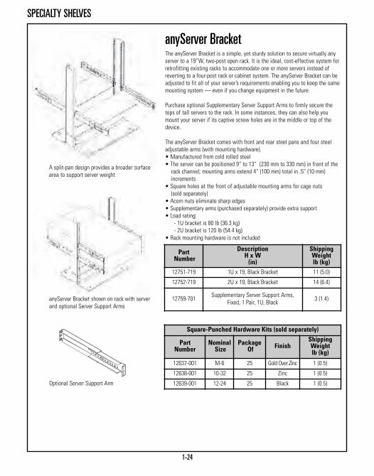
A split-pan design provides a broader surface area to support server weight
Optional Server Support Arm
anyServer Bracket shown on rack with serverand optional Server Support Arms
anyServer BracketThe anyServer Bracket is a simple, yet sturdy solution to secure virtually anyserver to a 19”W, two-post open rack. It is the ideal, cost-effective system forretrofitting existing racks to accommodate one or more servers instead ofreverting to a four-post rack or cabinet system. The anyServer Bracket can beadjusted to fit all of your server’s requirements enabling you to keep the samemounting system — even if you change equipment in the future.
Purchase optional Supplementary Server Support Arms to firmly secure thetops of tall servers to the rack. In some instances, they can also help youmount your server if its captive screw holes are in the middle or top of thedevice.
The anyServer Bracket comes with front and rear steel pans and four steeladjustable arms (with mounting hardware).• Manufactured from cold rolled steel• The server can be positioned 9” to 13” (230 mm to 330 mm) in front of the rack channel; mounting arms extend 4” (100 mm) total in .5” (10 mm) increments
• Square holes at the front of adjustable mounting arms for cage nuts(sold separately)
• Acorn nuts eliminate sharp edges• Supplementary arms (purchased separately) provide extra support• Load rating:
- 1U bracket is 80 lb (36.3 kg)- 2U bracket is 120 lb (54.4 kg)
• Rack mounting hardware is not included
Square-Punched Hardware Kits (sold separately)
PartNumber
NominalSize
PackageOf Finish
ShippingWeightlb (kg)
12637-001 M-6 25 Gold Over Zinc 1 (0.5)
12638-001 10-32 25 Zinc 1 (0.5)
12639-001 12-24 25 Black 1 (0.5)

1-25
DRAWERS
PartNumber Description
ShippingWeightlb (kg)
19” Rack or Cabinet MountDepth - in (mm)
13082-X19 2U Drawer, 20 (510) 18 (8.2)
13083-X19 3U Drawer, 20 (510) 20 (9.1)
13084-X19 4U Drawer, 20 (510) 22 (10.0)
23” Rack or Cabinet MountDepth - in (mm)
13082-X23 2U Drawer, 20 (510) 21 (9.5)
13083-X23 3U Drawer, 20 (510) 23 (10.4)
13084-X23 4U Drawer, 20 (510) 25 (11.3)
PartNumber Description
ShippingWeightlb (kg)
13185-X01 Divider, 3U & 4U Drawers 3 (1.4)
X=color: 1=Gray, 2=White, 5=Clear, 7=Black
X=color: 1=Gray, 2=White, 5=Clear, 7=Black
Drawer with two-post mounting brackets
Drawer with four-post mounting brackets
Lockable Storage DrawerCPI’s improved Lockable Storage Drawer keeps backup media, software,manuals, laptops, test equipment and extra patch cords in close proximity towhere they are typically used within a rack or cabinet.
Lockable Storage Drawer is available for 19”W or 23”W racks and cabinets. Itincludes attachment brackets that allow center mounting on two-post rackswith 3” or 6”D (80 mm or 150 mm) equipment channels or front and rearattachment to four-post racks and cabinet systems with mounting rails thatare adjusted between 24” and 39”D (610 mm and 990 mm).• Attaches to any CPI freestanding 19”W or 23”W rack or cabinet system• Available in three heights: 2U, 3U and 4U• Features 20”D (510 mm) lockable drawer that extends full depth for easy access to stored equipment
• Redesigned to allow for stackable units• Supports a 100 lb (45.4 kg) load (drawer and top surface combined)
Drawer Dividers For Lockable Storage DrawerDivide your Lockable Storage Drawer into three sections, approximately 5”W(130 mm) each, to organize and store CD and tape cases. For use with the 3Uand 4U drawers only.
Redesigned to allowstackable units
2.86”(72.6 mm) 3.27”
(83.1 mm)
7.20” (182.9 mm)
15.88” (403.4 mm)
1-26
MONITOR/KEYBOARD TRAYS
X=color: 1=Gray, 2=White, 5=Clear, 7=Black*Must use small footprint keyboard. Also available, Sliding Double Keyboard Tray(P/N 11227-XXX). Visit www.chatsworth.com for details.
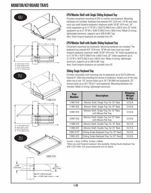
CPU/Monitor Shelf with Single Sliding Keyboard TrayProvides convenient mounting of CPU or monitor and keyboard. Mountinghardware not included. Keyboard tray extends 8.6” (218 mm), 19”W rack traysmust use small footprint keyboard; maximum width 16.30” (414 mm). 19”holds equipment up to 17.75”W x 19.82”D (450.9 mm x 503.4 mm), 23” holdsequipment up to 21.75”W x 19.82”D (552.5 mm x 503.4 mm). Made of strong,lightweight aluminum, supports up to 200 lb (90.7 kg).Note: Small footprint keyboards are available from CPI.
CPU/Monitor Shelf with Double Sliding Keyboard TrayConvenient mounting two keyboards. Mounting hardware not included. Thekeyboard tray extends 8.6” (218 mm). 19”W rack trays must use smallfootprint keyboard; maximum width 16.30” (414 mm). 19” holds equipment upto 17.75”W x 19.8”D (450.9 mm x 503.4 mm), 23” holds equipment up to21.75”W x 19.8”D (552.5 mm x 503.4 mm). Made of strong, lightweightaluminum, supports up to 200 lb (90.7 kg).Note: Small footprint keyboards are available from CPI.
Sliding Single Keyboard TrayProvides retractable rack-mounting tray for keyboards up to 9.8”D (249 mm).Extends 8” (200 mm) providing full access to keyboard, retracts out of the waywhen not in use. 19” version holds up to 16.1”W (409 mm) keyboards, 23”version holds up to 20.1”W (511 mm) keyboards. Mounting hardware notincluded. Made of strong, lightweight aluminum.
PartNumber Description
ShippingWeightlb (kg)
11487-X19 Monitor Shelf, Single Tray, For 19” Rack 12 (5.4)
11487-X23 Monitor Shelf, Single Tray, For 19” Rack 12 (5.4)
12487-X19 Monitor Shelf, Single Tray, For 19” Rack,with Mouse Pad Tray 12 (5.4)
12487-X23 Monitor Shelf, Single Tray, For 23” Rack,with Mouse Pad Tray 12 (5.4)
11488-X19 Monitor Shelf, Double Tray, For 19” Rack 16 (7.3)
11488-X23 Monitor Shelf, Double Tray, For 23” Rack 16 (7.3)
12062-X19* Sliding Single Keyboard Tray, For 19” Rack 10 (4.5)
12062-X23 Sliding Single Keyboard Tray, For 23” Rack 10 (4.5)
11487-X19
11488-X19
12062-X19

1-27
KEYBOARD TRAYS
23” Full Size Sliding Keyboard Tray & MouseConvenient tray for holding keyboard and mouse. Mounting hardware notincluded. Keyboard tray extends 8” (200 mm) for full access to all keys, trayand pad retract when not in use. Holds keyboards up to 20.1”W x 9.8”D (511mm x 249 mm). 9” x 7” (230 mm x 180 mm) mouse pad mounts in a choice offour convenient locations. Made of strong, lightweight aluminum.
Flush Mounted Sliding Keyboard Tray with Wrist RestSpace-saving tray requires only 1U (44.45 mm) providing more space formounting electronics. Ball bearing slides for smooth operation, locks inopen position and retracts when not in use. 19” version holds up to 16.37”Wx 7.67”D (415.8 mm x 194.8 mm) keyboards, 23” version holds up to 20.37”Wx 8.67”D (517.4 mm x 220.2 mm) keyboards. Mounting hardware not included.Keyboard tray extends 11” (280 mm) for full access to all keys. Made of strong, lightweight aluminum.
Flush Mounted Keyboard TrayProvides retractable rack-mounting tray for most keyboards up to 8.5”D (216mm). Mounting hardware not included. Extends 8” (200 mm) giving full accessto keyboard, retracts when not in use. 19” version holds up to 16.1”W (409mm) keyboards. Made of strong, lightweight aluminum, This tray does not support the mouse pad attachment.
PartNumber Description
ShippingWeightlb (kg)
11690-X23 23” Full Size Sliding Keyboard & Mouse 12 (4.5)
15555-X19 Flush Mount Sliding Keyboard with Wrist Rest, For 19” Racks 8.5 (3.9)
15556-X23 Flush Mount Sliding Keyboard with Wrist Rest, For 23” Racks 10 (4.5)
12717-X19* Flush Mount Keyboard Tray, For 19” Racks 8 (3.6)
X=color: 1=Gray, 2=White, 5=Clear, 7=Black*19” rack tray must use small footprint keyboard.
12717-X19
1555-X19
11690-X23

Keyboard withouttray also available
13490-719 2-Post, Keyboard+Tray, Black 13 (5.9)
13490-729 2-Post, Keyboard+Tray, With Gold Contacts 13 (5.9)
13480-719 4-Post, Keyboard+Tray, Black 12 (5.4)
13480-729 4-Post, Keyboard+Tray, With Gold Contacts 12 (5.4)
23480-001 Keyboard Only 3 (1.4)
23480-002 Keyboard With Gold Contacts 3 (1.4)
1-28
KEYBOARD TRAYS
Note: Mouse padon right side only
X=color: 1=Gray, 2=White, 5=Clear, 7=Black*Also available, Mouse Pad Attachment (P/N 11692-XXX) and 23” Wrist RestAttachment (P/N 12306-XXX). Visit www.chatsworth.com for details.
19” Full Size Sliding Keyboard & Mouse TrayHolds full size keyboard and mouse. Slide is mounted under shelf to provide maximum tray width. Mounting hardware not included. Mouse pad tray is 10”W x 8”D (250 mm x 200 mm), retracts out of the way when not in use. Fitsup to 19.25”W x 9”D (489 mm x 230 mm) keyboards. Extends approximately9” (230 mm) for full access to keyboard. Made of strong, lightweight aluminum.
19” Full Size Sliding Keyboard TrayTray holds full size keyboard with slide mounted under shelf to providemaximum tray width. Mounting hardware not included. Extends approximately9” (230 mm) for full access to keyboard. Fits up to 19.25”W x 9”D (489 mm x230 mm) keyboards. Made of strong, lightweight aluminum.Note: Does not support the mouse pad attachment.
Keyboard and TrayThe Keyboard+Tray features a built-in touchpad, two PS/2 standard connectors;one for the keyboard, one for the touchpad (mouse) and requires only 1U ofspace. Slides into the cabinet or rack when not needed. Gold ContactKeyboards provide an extremely clean signal, improving the overall signalintegrity. Mounting hardware not included, ships fully assembled.
Space-Saving Stationary Keyboard ShelfCPI’s Space-Saving Stationary Keyboard Shelf was designed to be used inhigh-density server installations. The shelf incorporates a rigid 10° angledsurface for keyboard support, providing comfortable and convenient keyboardpositioning and operation. Mounting hardware not included. Available in19”W or 23”W x 8.28”D (210.3 mm) Made from strong, lightweight aluminum.
PartNumber Description
ShippingWeightlb (kg)
12193-X01* 19” Sliding Keyboard Tray 9 (4.1)
11546-X01 19” Full Size Keyboard Tray 9 (4.1)
12665-X19 Space-Saving Shelf, For 19” Racks 3 (1.4)
12665-X23 Space-Saving Shelf, For 23” Racks 3 (1.4)
12193-X01
11546-X01
12665-X19
13490-719

1-29
INSTALLATION PRODUCTS
Rack and Frame Installation KitsRequired hardware for securing equipment racks and frames to both concreteand wood floors. Concrete Kit has four 3/8” thread component or four 1/2”thread components. Wood kit has four 3/8” thread components.
Rack Line-Up Spacer KitBolts and spacer securely attach two racks mounted side-by-side. Universal Rack Kit consists of:• (2) spacer plates 1” x 3” x 1/8” (30 mm x 80 mm x 3.18 mm) thick aluminum • (4) 5/16-18 x 2” hex cap screws• (4) 5/16-18 hex nuts• (8) 5/16 plain washersStandard Rack Kit consists of:• (2) spacer plates 1” x 3” x 1/8” (30 mm x 80 mm x 3.18 mm) thick aluminum • (4) 1/2-20 x 1” hex cap screws• (4) 1/2-20 hex nuts• (4) 1/2 plain washers
Rack Base Insulator KitRack Base Insulator Kits electrically isolate the racks from the floor for aneffective grounding and bonding system. Made of .062” (1.57 mm) — thickphenolic insulating material and accepts up to 0.5” (10 mm) diameter screws.Used primarily on concrete floors, not needed for raised-floor applications.Kit consists of:• (2) isolation plates• (4) isolation grommets
X=color: 1=Gray, 2=White, 5=Clear, 7=Black
PartNumber Floor Type Finish
ShippingWeightlb (kg)
40604-001 Concrete Floor, 3/8” Zinc 1 (0.5)
40604-003 Concrete Floor, 1/2” Zinc 1 (0.5)
40607-001 Wood Floor, 3/8” Zinc 1 (0.5)
PartNumber Description
ShippingWeightlb (kg)
10605-019 Insulator Kit, 19” Rack 3 (1.4)
10605-023 Insulator Kit, 23” Rack 3 (1.4)
Kits forUniversal Racks
Kits forStandard Racks
ShippingWeightlb (kg)
40602-X00 40702-X00 1 (0.5)
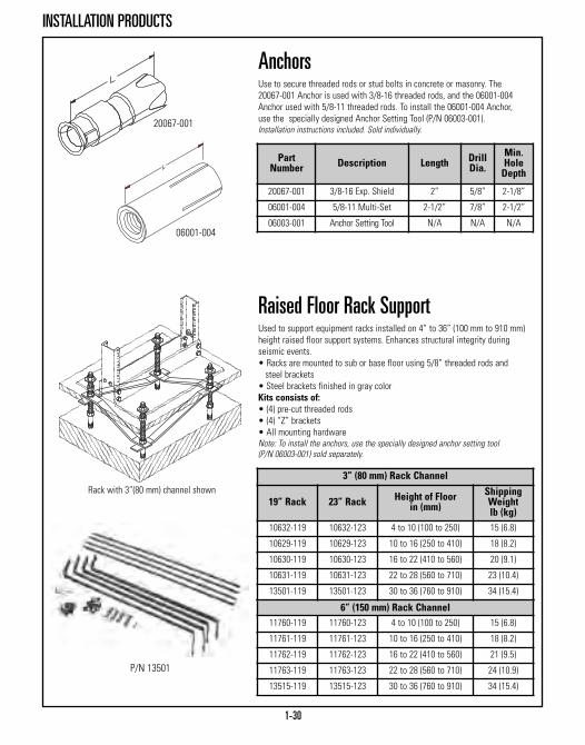
1-30
INSTALLATION PRODUCTS
20067-001
06001-004
Rack with 3”(80 mm) channel shown
AnchorsUse to secure threaded rods or stud bolts in concrete or masonry. The20067-001 Anchor is used with 3/8-16 threaded rods, and the 06001-004Anchor used with 5/8-11 threaded rods. To install the 06001-004 Anchor,use the specially designed Anchor Setting Tool (P/N 06003-001).Installation instructions included. Sold individually.
Raised Floor Rack SupportUsed to support equipment racks installed on 4” to 36” (100 mm to 910 mm)height raised floor support systems. Enhances structural integrity duringseismic events. • Racks are mounted to sub or base floor using 5/8” threaded rods and steel brackets
• Steel brackets finished in gray color Kits consists of:• (4) pre-cut threaded rods• (4) “Z” brackets• All mounting hardwareNote: To install the anchors, use the specially designed anchor setting tool(P/N 06003-001) sold separately.
6” (150 mm) Rack Channel11760-119 11760-123 4 to 10 (100 to 250) 15 (6.8)
11761-119 11761-123 10 to 16 (250 to 410) 18 (8.2)
11762-119 11762-123 16 to 22 (410 to 560) 21 (9.5)
11763-119 11763-123 22 to 28 (560 to 710) 24 (10.9)
13515-119 13515-123 30 to 36 (760 to 910) 34 (15.4)
3” (80 mm) Rack Channel
19” Rack 23” Rack Height of Floorin (mm)
ShippingWeightlb (kg)
10632-119 10632-123 4 to 10 (100 to 250) 15 (6.8)
10629-119 10629-123 10 to 16 (250 to 410) 18 (8.2)
10630-119 10630-123 16 to 22 (410 to 560) 20 (9.1)
10631-119 10631-123 22 to 28 (560 to 710) 23 (10.4)
13501-119 13501-123 30 to 36 (760 to 910) 34 (15.4)
P/N 13501
Part Number Description Length Drill
Dia.Min.HoleDepth
20067-001 3/8-16 Exp. Shield 2” 5/8” 2-1/8”
06001-004 5/8-11 Multi-Set 2-1/2” 7/8” 2-1/2”
06003-001 Anchor Setting Tool N/A N/A N/A

1-31
TOP & BASE ANGLES
Part Number ShippingWeight lb (kg)19” Rack 23” Rack
41021-X01 41021-X02 10 (4.5)
Part Number ShippingWeight lb (kg)19” Rack 23” Rack
10375-X01 10375-X02 3 (1.4)
Rack Width Ain (mm)
19” 14.57 (370.1)
23” 18.57 (471.1)
Heavy Duty Top AngleOptional top angle for CPI Universal, 3”D (80 mm) Standard or 6”D (150 mm)Standard Rack.• Material is aluminum extrusion • Top Angle is L-shaped, 1-1/2” x 2” x 1/4” (38 mm x 51 mm x 6.4 mm) thick• Recommended for use in pairs with 10562-001 Universal Earthquake Bracing Kit
• Sold individually
Top AngleOptional top angles for CPI Universal Rack.• Material is aluminum extrusion 1-1/2” x 1-1/2” x 1/4” (38 mm x 38 mm x 6.4 mm)
• Sold individually
X=color: 1=Gray, 2=White, 5=Clear, 7=Black
X=color: 1=Gray, 2=White, 5=Clear, 7=Black
X=color: 1=Gray, 2=White, 5=Clear, 7=Black
Base AngleOptional base angle for CPI Universal Racks.• Material is aluminum extrusion 3-1/2” x 6” x 3/8” (89 mm x 150 mm x 9.53 mm)
• Sold individually
Part Number ShippingWeight lb (kg)19” Rack 23” Rack
10473-X01 10473-X02 3 (1.4)

1-32
FILLER PANEL
300 XX - X XX
Spaces - in (mm) U01 1.72 (43.7) 102 3.47 (88.1) 203 5.22 (132.6) 304 6.97 (177.0) 405 8.72 (221.5) 506 10.47 (265.9) 607 12.22 (310.4) 708 13.97 (354.8) 809 15.72 (399.3) 910 17.47 (443.7) 1011 19.22 (488.2) 1112 20.97 (532.6) 12
Color1 Gray2 Computer White5 Clear7 Black
Thickness - in (mm) Width24 3/16 (4.763) 19”25 3/16 (4.763) 23”26 1/8 (3.18) 19”27 1/8 (3.18) 23”
300 Filler Panels
Filler PanelsFor airflow control and/or equipment mounting.• Filler Panels fill empty spaces between mounted equipment.
Touch-Up Paint Spray can:Air dry lacquer for touching up finish. Matches color and gloss of CPI’stextured paint. Air dries to hard finish in minutes• 12-ounce (340 g) pressurized canNote: Cannot be shipped via air.Bottle:Air dry waterborne paint for touching up finish. Matches color and gloss ofCPI’s textured paint.• 1-ounce (30 g) bottle with applicator
PartNumber
Descriptionoz (g)
ShippingWeightlb (kg)
25400-X00 12 (340) Can 2 (0.9)
25401-X00 1 (30) Bottle 1 (0.5)
X=color: 1=Gray, 2=White, 7=Black
25401-X00

1-33
RACK DOLLY WHEELS & ROLLERS
Note: Vertical cabling sectionscannot be used on dolly-mountedracks. Can be used with Universal,3”D (80 mm) Standard or 6”D (150mm) Standard Racks.
Note: Vertical cabling sectionscannot be used on dolly-equippedracks. Also, dolly will not fit 6”D (150 mm) Standard Rack.
X=color: 1=Gray, 2=White, 5 = Clear, 7=Black
Mid-Size Rack DollyFull swivel capability allows rack to be easily moved, providing access toequipment. The front wheel locks to prevent unintentional movement. Mountsto most CPI Universal and Standard Racks and adds 1-1/4” (31.8 mm) to rack’sheight. Two-piece construction of 1/4” (6.4 mm) aluminum complete withhardware. Sold in pairs, load capacity 750 lb (340.2 kg).
Rack Universal Dolly WheelsAllows rack to be moved, providing access to equipment. Wheels may belocked to prevent moving during assembly stages. Holds any width CPIUniversal or Standard Rack. Two-piece construction of 3/8” (9.53 mm)aluminum complete with rack-mounting hardware. Supports up to 1000 lb(453.6 kg). Note: Not to be used with enclosures.
Rack Standard RollersMount to CPI Universal and Standard racks, regardless of width. Fixed rollersprevent rack from accidental turning. Adds 2” (50 mm) to rack’s height. Shipscomplete with installation hardware. Supports up to 500 lb (226.8 kg).
PartNumber Description
ShippingWeightlb (kg)
11643-X01 Mid-Size Rack Dolly 24 (10.9)
10175-X00 Universal Dolly Wheels 20 (9.1)
11554-X01 Rack Standard Rollers, For 3”D (80 mm)Rack Channel 8 (3.6)
11554-X03 Rack Standard Rollers, For 6”D (150 mm)Rack Channel 8 (3.6)
11643-X01
10175-X00
11554-X01

X=color: 1=Gray, 2=White, 5=Clear, 7=Black
Rack Base Dust CoverImproves appearance and prevents the accumulation of dust and debris at therack base. Snaps securely in place over the base assembly; no mountinghardware necessary. Made of lightweight aluminum. • For CPI Racks with 3” or 6”D (80 mm or 150 mm) channel
Part Number Descriptionin (mm)19” Rack 23” Rack 35” Rack
41050-X19 41050-X23 N/A 3 (80) Rack Channel
42050-X19 42050-X23 42050-X35 6 (150) Rack Channel
1-34
EXTENSION KITS & GUARD RAILS
400 XX - 6 XX
400 Guard Rails
Rack Extension KitProvides additional height to existing racks. Kit includes one pair of rackchannels, four plates and assembly hardware. • Universal 5/8”-5/8”-1/2” (15.9 mm - 15.9 mm - 12.7 mm) hole pattern• Mounting hardware is included; ships unassembled
Equipment Guard RailProvides protection for equipment in racks from rolling gear or tool boxes.• Made of 1/4” x 2” (6.4 mm x 50 mm) aluminum bar• Mounting hardware is included, sold individually
Width19 19” Rack23 23” Rack
Color1 Gray2 Computer White5 Clear7 Black
Stand Off - in (mm)56 7 (180)57 6.5 (165)58 5.25 (133.4)59 4.25 (108)
Part Number Color
ShippingWeightlb (kg)
10565-X12 12”H (300 mm), 4U 4 (1.8)
10565-X24 24”H (610 mm), 11U 6 (2.7)
X=color: 1=Gray, 2=White, 5=Clear, 7=BlackNote: Not for use withCPI Standard Rack

1-35
PANEL ADAPTERS & SUPPORT BRACKET
Part Number Description
ShippingWeightlb (kg)
12312-X01 Pair of Brackets 2 (0.9)
X=color: 1=Gray,2=White, 5=Clear, 7=Black
Sold in pairs. Attachment hardware not included.
Equipment Support BracketThe Equipment Support Bracket mounts on the rear of the rack channel toprovide safety and additional support for deep or heavy electronic equipmentpanel or rack mounted on CPI Racks. • Supports electronic equipment up to 24”D (610 mm) and weighing up to 60 lb (27.2 kg)
• Made of strong, lightweight aluminum• Overall depth is 13” (330 mm); chassis support lip is 1.5”W (38 mm)• Fits all EIA standard hole pattern rack channels
Rack Panel Adapters (Pair)Allows 19”W equipment to be mounted on a 23”W rack.• Universal 5/8”- 5/8”-1/2” (15.9 mm - 15.9 mm - 12.7 mm)• Joggled so that installed panels fit flush
PartNumber
DescriptionHeight in (mm)
ShippingWeightlb (kg)
31410-X00 Adapter, Pair, 1U, 1.71 (43.4) 1 (0.5)
31420-X00 Adapter, Pair, 2U, 3.46 (87.9) 1 (0.5)
31430-X00 Adapter, Pair, 3U, 5.21 (132.3) 1 (0.5)
31440-X00 Adapter, Pair, 4U, 6.96 (176.8) 1 (0.5)
31450-X00 Adapter, Pair, 5U, 8.71 (221.2) 1 (0.5)
X=color: 1=Gray, 2=White, 5 = Clear, 7=Black
RMU Label KitsEasy-to-read numbers take the guesswork out of aligning components.• Two kits are available: 1-45U for 7’ (2.1 m) racks and cabinets, 1-58U for 8’or 9’ (2.4 m or 2.7 m) racks and cabinets
• Kit contains four individual label packs, enough for four racks or fourcabinets
• Labels are constructed of ½”W (10 mm) durable polyester film with adhesivebacking and are black with rack-mount unit numbers printed in white
PartNumber Description
ShippingWeightlb (kg)
11927-001 1-45U Label 1 (0.5)
11927-002 1-58U Label 1 (0.5)

1-36
RACK CHANNEL STANDOFFS
X=color: 1=Gray, 2=White, 5=Clear, 7=Black
Front of channel tapped with #12-24 threadedholes, EIA 310 Universal holes spacing
Rack Channel StandoffsRack Channel Standoffs offer solutions to many electronic componentpositioning problems including:• Adding deeper electronic components to existing CPI Wall Racks, Heavy Duty Wall Racks, Universal Swing Gate Wall Racks, Standard Swing Gate Wall Rack or Self-Support Racks
• Providing improved patch panel cable transitioning when a double-sided cabling section is used with a 3”(80 mm) Rack Channel; use 1-1/2” (38 mm) Rack Channel Standoff
• Repositioning rack-mounted electronic components to redistribute component weight or to realign component for whatever reason
• Available in three depths and six heights • Packaged one pair per box
Part Number
OverallHeight
MountingHoles
ShippingWeightlb (kg)
3” Depth (80 mm)12309-X01 1U 3 1 (0.5)
12309-X02 2U 6 1 (0.5)
12309-X03 3U 9 2 (0.9)
12309-X04 4U 12 2 (0.9)
12309-X05 5U 15 2 (0.9)
12309-X10 10U 30 4 (1.8)
6” Depth (150 mm)12310-X01 1U 3 1 (0.5)
12310-X02 2U 6 1 (0.5)
12310-X03 3U 9 2 (0.9)
12310-X04 4U 12 2 (0.9)
12310-X05 5U 15 2 (0.9)
12310-X10 10U 30 4 (1.8)
1-1/2” Depth (38 mm)12311-X01 1U 3 1 (0.5)
12311-X02 2U 6 1 (0.5)
12311-X03 3U 9 2 (0.9)
12311-X04 4U 12 2 (0.9)
12311-X05 5U 15 2 (0.9)
12311-X10 10U 30 4 (1.8)

1-37
PANEL ADAPTER
Panel Adapter with Cable Management,Single-Sided, 23” to 19”CPI offers a solution for those who have 7’H (2.1 m) x 23”W racks and need tomount 19” equipment along the entire length of the rack. Existing paneladapters are typically composed of two side panels which reduce themounting width and center the equipment. CPI’s unique design performs thereduction on one side. Not only can you mount 19” equipment, but you alsohave room for cable management on the wide adapter panel.
Eight 2.25” (57.2 mm) oval pass-through ports with edge protectors providecable access from front to rear of the panel. In addition, there are seventhreaded holes along the front surface of the panels for mounting optionalCenter Grommet Buckle Saf-T-Grip® Cable Management Straps to providestrain relief and vertical cable management. • Includes (50) pilot point #12-24 mounting screws with combination Phillips/Straight heads
• Saf-T-Grip straps are optional • Split design allows you to adapt half or all of a 7’H (2.1 m) relay rack • Adapter panels mount on right or left side of rack • Panels are joggled to maintain uniform mounting surface plane• For lightweight applications (patch panels & cable management)
PartNumber Description/Color
ShippingWeightlb (kg)
7’ (2.1 m) Panel Adapters13044-X03 7’H (2.1 m) Panel Adapters 5 (2.3)
OPTIONAL: Saf-T-Grip Center Grommet CableManagement Straps (Pkg. of 25)
W x L - in (mm)
06006-201 3/4 x 6 (19.1 x 150), Black 1 (0.5)
06006-203 3/4 x 6 (19.1 x 150), Royal Blue 1 (0.5)
06009-201 3/4 x 9 (230 x 19.1), Black 1 (0.5)
06009-203 3/4 x 9 (230 x 19.1), Royal Blue 1 (0.5)
06012-201 3/4 x 12 (300 x 19.1), Black 1 (0.5)
06012-203 3/4 x 12 (300 x 19.1) Royal Blue 1 (0.5)
X=color: 1=Gray, 2=White, 5=Clear, 7=Black

1-38
MISCELLANEOUS SCREWS
Combination Pan Head, Pilot Point,Mounting ScrewsThe #12-24 Combination Pan Head, Pilot Point Mounting Screws attachequipment to racks and cabinets. A cutting notch in the thread removes paintin threaded holes to improve metal-to-metal contact. The pilot point reducescross-threading. The combination head can be used with #3 Phillips andslotted screwdrivers. • Available in choice of zinc plated or black finish in packages of50 and 1000
Combination Pan Head, Pilot Point, SemsMounting ScrewsSimilar to 40605 except includes captive lock washer.• Zinc plated finish
Part Number
NominalSize
PackageOf
ShippingWeightlb (kg)
40605-001 12-24 50 1 (0.5)
40605-004 12-24 1000 9 (4.1)
40605-005 12-24 (Black) 50 1 (0.5)
40605-006 12-24 (Black) 1000 9 (4.1)
Part Number
NominalSize
PackageOf
ShippingWeightlb (kg)
40606-001 12-24 50 1 (0.5)

1-39
HIGH DENSITY PATCHING FRAME
Integrated top jumpertrough providessmooth transition
Unique fins supportlarge bundles of cable
High Density Patching FrameDesigned to maximize support of patch panels, the High Density PatchingFrame combines the benefits of CPI’s 2-post open racks and vertical cablemanagement into a single package.• High-density cable management fins provide an integrated vertical pathway for premise cabling and facilitate adherence to bend radius requirements
• Inverted U-shaped tabs formed into the cable management fins provide a quick method for securing premise cabling with Saf-T-Grip®
Cable Management Straps • Cable management rings and integrated upper jumper tray provide slack management for patch cords
• Feed patch cords front-to-rear through edge-protected pass-through ports
• Base angles are pre-punched for direct attachment to building structure and feature a U-shaped cut-out for cable delivered from under a raised floor
• Connect Frames side-by-side into continuous rows with an accessory baying kit
• Attach Cable Runway to the top of the frame with J-bolts in the perpendicular orientation or a Mounting Kit in the parallel orientation
Specifications:• Overall dimensions of 86.0”H x 29.1”W x 18.6”D (2184 mm x 739 mm x 472 mm)
• Provides 45U x 19”W of mounting space• Features EIA-310-D, Universal spacing, threaded #12-24 mounting holes• Frame components are aluminum, while cable rings are an engineered polymer
• UL Listed: File E140851; Category DUXR (US), DUXR7 (Canada) –Communications Circuit Accessory
• Finished with black, powder coat paint• Ships unassembled and individually packaged • Assembly requires one person, a standard ratchet/wrench set, screwdriver and square
• Attach to building structure using one Rack Installation Kit per frame• Supports 750 lb (340.2 kg) of able and equipment; 110 lb (49.9 kg) maximum per cable fin
PartNumber Description
ShippingWeightlb (kg)
55100-703 7’H (2.1 m) x 19”W High Density Patching Frame, Black 63 (28.6)
55104-701 Baying Kit, Black 1 (0.5)
55105-712 12”W (300 mm) Runway Mounting Kit 1 (0.5)
55105-718 18”W (460 mm) Runway Mounting Kit 1 (0.5)
55105-724 24”W (610 mm) Runway Mounting Kit 1 (0.5)
Structured Termination Products are pre-configured frames designed specifically to hold 110-style or 66-style blocksor patch panels. Use Structured Termination Products to support main, intermediate or horizontal cross-connects.

1-40
XLBET 110A BLOCK MOUNTING SYSTEM
Part Number
23” Width 35” Width
3600 Pair 7200 Pair 5400 Pair 10,800 Pair11810-X36 11810-X72 11910-X54 11910-X80
XLBET 110A Block Mounting SystemThe Extra Large Building Entrance Terminal (XLBET) 110A Block MountingSystem is designed for high-density, space-saving style block mounting. The8”W x 6.6”D (200 mm x 168 mm) large wire managers provide distinct verticaland horizontal cable and jumper pathways for efficient space usage. Thebasic frame (23” or 35”), mounting bars and the small and large wiremanagers are available under one part number. The XLBET 110A BlockMounting System ships completely assembled for quick, easy installation.• Supports 300 pair 110A style blocks• 3600 pair in two columns to 5400 pair in three columns can be mounted per side depending on the frame selected
• Double-sided version provides 7200 to 10,800 pair depending on the frame selected
• Horizontal and vertical cable managers provide clearly defined cable routing of large quantities of cross-connect wires
• 6”D (150 mm) rack channel provides extra cable capacity11810-X36 Kit (3600 pair/12 blocks/single sided) consists of:• (1) 23” Standard Rack, 6”D (150 mm) (P/N 66383-X03) • (6) Mounting Bars • (3) Large Wire Managers, (3) Small Wire Managers11810-X72 Kit (7200 pair/24 blocks/double-sided) consists of:• (1) 23” Standard Rack, 6”D (150 mm) (P/N 66383-X03) • (12) Mounting Bars • (6) Large Wire Managers, (6) Small Wire Managers11910-X54 Kit (5400 pair/18 blocks/single-sided) consists of:• (1) 35” Standard Rack, 6”D (150 mm) (P/N 66363-X03) • (6) Mounting Bars • (3) Large Wire Managers, (3) Small Wire Managers11910-X80 Kit (10800 pair/36 blocks/double-sided) consists of:• (1) 35” Standard Rack, 6”D (150 mm) (P/N 66363-X03) • (12) Mounting Bars • (6) Large Wire Managers, (6) Small Wire Managers
Shown with wiring blocks (not included)
Panel HingesVersatile 1.75”H (44.45 mm) rack-mounting hinges provide rear access to patchpanels or other shallow equipment by allowing them to swing outward. Madefrom high strength black composite material.• Sold in pairs with mounting hardware included • Supports up to 30 lb (13.6 kg) per pair
PartNumber Description
ShippingWeightlb (kg)
11520-001 Hinges, Pair 1 (0.5)
X=color: 1=Gray, 2=White, 5=Clear, 7=Black
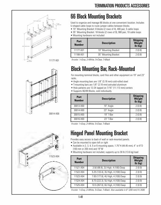
1-41
TERMINATION PRODUCTS ACCESSORIES
66 Block Mounting BracketsUsed to organize and manage 66 blocks at one convenient location. IncludesU-shaped cable loops to route jumper cables between blocks.• 19” Mounting Bracket: 8 blocks (2 rows of 4), 400 pair, 5 cable loops• 35” Mounting Bracket: 18 blocks (2 rows of 9), 900 pair, 10 cable loops• Mounting hardware not included
11177-X01
Block Mounting Bar, Rack-MountedFor mounting terminal blocks, card files and other equipment on 19” and 23”racks.• Angle mounting bars are 1/8” (3.18 mm) cold-rolled steel • T-mounting bars are 1/8” (3.18 mm) extruded aluminum • Hole patterns are 12-24 tapped on 7/16” (11.113 mm) centers• Supports 66/89 Blocks, sold individually
PartNumber Description
ShippingWeightlb (kg)
11177-X01 19” Mounting Bracket 2 (0.9)
11188-X01 35” Mounting Bracket 2 (0.9)
PartNumber Description
ShippingWeightlb (kg)
30013-X00 19” Angle 2 (0.9)
30014-X00 23” Angle 2 (0.9)
30015-X00 19” T-Bar 2 (0.9)
30016-X00 23” T-Bar 2 (0.9)
X=color: 1=Gray, 2=White, 5=Clear, 7=Black
Hinged Panel Mounting BracketProvides easy access to back of wall or rack-mounted panels.• Can be mounted to open left or right • Available in 2, 3, 4, 5 or 6 mounting space, 1.75”H (44.45 mm), 4” or 8”D (100 mm or 200 mm) and 19”W
• Mounting hardware not included, supports up to 30 lb (13.6 kg) load
PartNumber Description
ShippingWeightlb (kg)
11521-X04 3.50 (88.9), 2U High, 4 (100) Deep 2 (0.9)
11522-X04 5.25 (133.4), 3U High, 4 (100) Deep 2 (0.9)
11523-X04 7.00 (177.8), 4U High, 4 (100) Deep 2 (0.9)
11524-X04 8.75 (222.3), 5U High, 4 (100) Deep 2 (0.9)
11525-X04 10.5 (267.0), 6U High, 4 (100) Deep 2 (0.9)
X=color: 1=Gray, 2=White, 5=Clear, 7=Black. Also available in 8” (200 mm) H (-X08)
11523-X04
X=color: 1=Gray, 2=White, 5=Clear, 7=Black
30014-X00

CABINET & ENCLOSURE SYSTEMSCabinets, Thermal Products and Cable Management Accessories
Data Center Overview Page 2-3F-Series TeraFrame® Cabinet System Page 2-7F-Series TeraFrame® HD Cabinet System Page 2-20N-Series TeraFrame® Network Cabinet Page 2-25Fiber Management Accessories Page 2-31GF-Series GlobalFrame® Cabinet System Page 2-34M-Series MegaFrame® Cabinet System Page 2-42
C-Series SlimFrame® Cabinet System Page 2-47E-Series ISP Co Location Cabinet Page 2-50Seimsic Frame Cabinet Page 2-51Thermal Management Accessories Page 2-52Cable Management Accessories Page 2-58Shelves for Cabinets Page 2-60Additional Accessories Page 2-64
CABINET & ENCLOSURE SYSTEMSThe cabinet platform on which your enterprise is built is just as critical as the equipment itstores. Utilizing a properly configured cabinet that is designed to fit your equipment and workwith your data center’s cooling system is crucial. Leading the industry with innovative storagesolutions, CPI Cabinet and Enclosure Systems provide a trusted frame and secure location forstoring multiple servers, switches and various pieces of computer equipment. CPI Cabinet andEnclosure Systems are also designed to promote energy savings and enhanced thermalmanagement solutions that utilize CPI Passive Cooling® through the use of Aisle Containmentand Vertical Exhaust Ducts.
Infinite configurability helps meet your growing enterprise needs through additional featuressuch as remote environmental monitoring, power distribution, seismic accessories, groundingand bonding, locking systems and advanced cable management.
CPI Cabinet and Enclosure Systems feature:• Four vertical mounting rails for four-point attachment• Standard EIA-310-D and EIA/ECA-310-E hole pattern• Industry leading performance standards like high static load ratings and shock pallet options• High static load rating, ranging from 800 lb (362.9 kg) to 3000 lb (1360 kg)• High dynamic load rating of 3000 lb (1360 kg) on some models• Large open base for cable entry and exit• Rack-mount unit markings on most rails and channels for fast equipment mounting• Options and accessories that can be pre-installed, reducing data center installation time• Green energy-saving thermal management options and configurations• Extensive cable management options and features that keep cables organized and make installation changes easy
2-2
New Products:
GF-Series GlobalFrame® Cabinet System (Page 2-34)New easy-to-use, cost-effective computer and
network storage equipment cabinet
KoldLok Wave™ Split Integral Grommet (Page 2-53)Increases sealing effectiveness with a solid, flexiblewave shaped thermoplastic elastomer material

2-3
DATA CENTER SOLUTION OVERVIEW
Air Containment on Every LevelAs an early trailblazer in lowering energy costs through the development of proven concepts such as Passive Cooling, CPI hasearned a solid reputation for reducing energy costs with air containment products and strategies that focus on the aisle, cabinetand cable levels of infrastructure deployment.
Key Benefits:• Higher return air temperature improves chilled water cooling system efficiency
• Allows higher equipment densities and energy cost savings• Isolates hot air, eliminating hot spots and reducing the number of computer room air conditioners or air handlers required
• Allows higher chilled water temperatures and additional “free cooling” hours using economizers
Aisle LevelFrom creating enclosed rows for hot and cold aisle containment toregulatory requirements for specific industries, CPI engineers consultdirectly with each customer to deliver the entire aisle containmentpackage. That also means supplying the pieces and parts of containment– quality cabinets, end-of-row doors, cable runway, blanking panels, floorgrommets, vertical exhaust ducts and more. CPI stands out by offeringstandard and customized parts, professional designs, and sealingsolutions that have been engineered to perform 200 percent better thanthe competition.

2-4
DATA CENTER SOLUTION OVERVIEW
Cabinet LevelCPI's server and network cabinets have been engineered to create aone-way path for airflow that eliminates the mixing of hot and cold air.Optimized even further with the use of filler panels, blanking panels andvertical exhaust ducts, CPI cabinet systems produce a uniform roomtemperature and seal quality of 95 percent and above.
Installed on the top of GlobalFrame® Cabinet Systems and TeraFrame®
Cabinet Systems, the Vertical Exhaust Duct isolates hot air from theroom and returns it to the primary cooling system through the dropceiling plenum or ducted return positioned high above the cabinet. Theresulting lower room temperature eliminates the need for supplementalliquid or active cooling solutions and supports higher heat and powerdensities. For high-density network switches using side-to-side airflow,CPI's Network Switch Exhaust Duct on the N-Series TeraFrame NetworkCabinet supports an isolation strategy of hot and cold air that maximizesthe energy efficiency of any data center.
Getting StartedThe journey toward data center efficiency isalways evolving ... and so is CPI. Find out whatsolutions we can create for you by contactingone of our containment experts today. In theU.S. call 1-800-834-4969, outside the U.S. &Canada, call 1-818-739-3400 or learn more atwww.chatsworth.com.
Cabling LevelIf openings in the access floor environment are not properly sealed,50-80 percent of the valuable cold supply air can bypass criticalequipment. By sealing the openings with products such as KoldLok®
Raised Floor Grommets, a data center can eliminate wasted bypass airand instantly increase cooling capacity by up to 40 percent.

2-5
CABINET & ENCLOSURE SYSTEMS
Cabinet & Enclosure SystemsProduct Description Load Rating
lb (kg)F-Series TeraFrame®
Cabinet SystemPage 2-7
Metric footprint cabinet is available in three widths, 12 heights and 17 depths(612 standard frame sizes). Welded steel and bolted aluminum four-post frameincludes two pairs of sliding, continuously adjustable mounting rails and hasinternal cable management space.
2500 (1134)
F-Series TeraFrame®
HD Cabinet SystemPage 2-19
Metric footprint cabinet is available in a 600 mm width, two depths (6 standardframe sizes). Heavy-duty F-Series TeraFrame Cabinet for systems integratorsincludes heavy-duty casters, high capacity shock pallet and a reusable paddedshipping carton.
3000 (1360)
N-Series TeraFrame®
Network Cabinet Page 2-24
TeraFrame-style network equipment cabinet has extra space along the front, rearand side for cable management. Available with an internal Network SwitchExhaust Duct designed specifically to control side-to-side airflow for networkswitch equipment that guides hot air out the rear of the cabinet.
2500(1134)
GF-Series GlobalFrame®
Cabinet SystemPage 2-34
The GF-Series GlobalFrame Cabinet System is an easy-to-use, cost-effective,computer and network equipment storage cabinet that complies with data center,computer room and premise network equipment room requirements. 30 popularsizes available.
3000(1360)
M-Series MegaFrame®
Cabinet SystemPage 2-42
Wide footprint cabinet with adjustable depth equipment mounting rails and 3”(80 mm) of internal cable management space on both sides. Bolted aluminumconstruction, may be delivered partially assembled.
2000(907.2)
C-Series SlimFrame®
Cabinet SystemPage 2-47
Narrow footprint enclosed cabinet with adjustable depth equipment mounting railsand 1” (30 mm) of internal cable management space on both sides. Minimal 24” (610 mm) overall footprint matches the width of access floor tiles in the United States. Bolted aluminum construction, may be delivered partially assembled.
2000(907.2)
E-Series ISP Co Location CabinetPage 2-50
Special wide footprint MegaFrame Cabinet with three separate compartments for secure multi-user applications. Bolted aluminum construction, may be delivered partially assembled. Used in co-location facilities or on the customer premise when multiple services or tenants share an equipment room.
2000(907.2)
Seismic Frame®
CabinetPage 2-51
Special wide footprint MegaFrame Cabinet internally braced for use in Zone 4areas. Delivers fully assembled. Used in seismic zones to provide added protection for equipment.
800(362.9)
A
B
B
C
D
E
F
G
A B CFDG
E

2-6
CABINET SYSTEMS
Cabinet & Enclosure Systems
Product Overall/Rack-MountWidth - in (mm)
Material &Construction
Key Attribute PartiallyAssembled
F-Series TeraFrame®
Cabinet SystemPage 2-7
23.6 (600)/19” EIA27.6 (700)/19” EIA31.5 (800)/19” EIA
Steel and Aluminum,Welded and Bolted
Metric footprint available in 612standard frame sizes No
F-Series TeraFrame®
HD Cabinet SystemPage 2-19
23.6 (600)/19” EIA Steel and Aluminum,Welded and Bolted
For high-density server and storage applications that require the cabinet tobe re-shipped after up to 3000 lb (1360 kg) of equipment has been installed
No
N-Series TeraFrame®
Network Cabinet Page 2-24
31.5 (800)/ 19” EIA Steel, Welded***Controls side exhaust airflow from switches; Cisco and Juniper compatibleversions available
No
GF-Series GlobalFrame®
Cabinet SystemPage 2-34
23.6 (600)/19” EIA29.5 (750)/19” EIA31.5 (800)/19” EIA
Steel, Welded andBolted
Cost-effective cabinet solution thatsupports 3000 lb (1360 kg) ofequipment. 30 popular frame sizes.
No
M-Series MegaFrame®
Cabinet SystemPage 2-42
27.3 (693)/19” EIA31.3 (795)/23” EIA 31.3 (795)/19” EIA*
Aluminum, Bolted**3” (80 mm) of internal cablemanagement space along both sides of equipment
Yes
M-Series 48” MegaFrame® Cabinet Page 2-46
27.3 (693)/19” EIA31.3 (795)/23” EIA Aluminum, Bolted Secure half a rack (25U) of
equipment Yes
C-Series SlimFrame®
Cabinet SystemPage 2-47
24 (610)/19” EIA Aluminum, Bolted Fits over 24”W (610 mm) access floortile Yes
E-Series ISP Co Location CabinetPage 2-50
27.3 (693)/19” EIA31.3 (795)/23” EIA Aluminum, Bolted Three secure compartments in one
cabinet Yes
Seismic Frame®
CabinetPage 2-51
27.3 (693)/19” EIAAluminum, Boltedwith Inner SteelFrame
Rated for use in Zone 4 seismic areas No
Product Comparison
*Use a 23"-19" Rail Adapter Kit to convert the cabinet. This cabinet has 5” (130 mm) of cable management space along both sides. **Aluminum extrusion with an anodized finish. Doors, top and side panels are painted. ***Steel cabinets are fully welded and painted a single color.
Cabinet SystemsCPI continuously provides flexibility in meeting the challenges ofchanging data and telecommunications technology. To meet thesechanges, CPI develops cabinets that are well-designed, forward-thinking and versatile.
The chart below lists the main style differences of CPI’s cabinetfamilies. Cabinets are available in several styles and sizes with achoice of included equipment mounting rails, side panels anddoors.
When selecting a CPI Cabinet consider:• Overall and usable width and depth• Rack-mount unit required• Aluminum or steel construction• Style of equipment mounting rail (five to choose from)• Door style (five styles including double doors)• Cabinets are available without doors, sides or tops• Color• Fully or partially assembled

2-7
F-SERIES TERAFRAME® CABINET SYSTEM
Choose a solid top panel withtwo (server-style) or four(network-style) large brush-sealed network cableaccess ports or use the VerticalExhaust Duct option with highheat density applications toisolate and remove hot air fromthe room
Metric footprint for international use
Available in three widths, 12 heights and 17 depths
(612 standard sizes)
Includes two pairs of sliding,continuously adjustable equipmentmounting rails to provide front and
rear support for 19” EIA-310-Dcompliant rack-mount equipment
and shelves
Mounting rails have 1.75”H(44.45 mm) rack-mount units and
are available with square-punchedor threaded attachment points;
rack-mount unit spaces aremarked and numbered on each mounting rail
Choose from seven styles oflatch-lock combinations; all doors
have swing handles with asingle-point or two-point slam or
cam latch and keyed,combination or electronic lock
Choose a solid Lexan, solid metalor perforated metal front door;
doors are reversible to open fromthe right or left and can be quickly
removed during equipmentinstallation or service work
Open base for cable entry;includes leveling feet and floor
attachment brackets (casters andbottom panel are available
as accessories)
Welded steel and boltedaluminum frame constructionsupports up to 2500 lb (1134.0 kg)of equipment
Choose solid or vented easy toremove side panels; side panelshave recessed spring-loadedlatches with keyed locks; cabinetscan be bayed (side-by-side) withside panels installed
Organize network cables, powerstrips and power cords along thesides of the cabinet with optionalside-mounted vertical cablepower managers
Use optional CPI Passive Cooling®
Solutions (thermal managementacccessories) to control airflowthrough, over and around thecabinet to eliminate hot spots andimprove equipment cooling
Choose a solid metal, perforatedmetal or double perforated metalrear door
Available in 612 standard sizesStatic load rating up to 2500 lb (1134 kg)
The F-Series TeraFrame® Cabinet System
The mounting rails, top panel,side panels and doors areelectrically bonded to the cabinetframe; a ground terminal block isincluded to attach the frame tothe CBN or TGB

2-8
F-SERIES TERAFRAME® CABINET SYSTEM
F-Series TeraFrame® Cabinet SystemThe F-Series TeraFrame® Cabinet System helps organize, store and securecomputer, data storage and network equipment in the data center, computerroom or network environment. Every cabinet includes two pairs of sliding,continuously adjustable equipment mounting rails to provide critical front andrear support for equipment. Square-punched or tapped EIA-310-D compliantequipment mounting rails guarantee compatibility with most rack-mountequipment. Plus, each rack-mount unit is marked and numbered on allmounting rails making it easy to locate and attach equipment.
Top panels have large brush-covered cable openings that will handle largebundles of cables while preventing undesirable hot air re-circulation. Sidepanels have a recessed locking spring-loaded latch and can be easily removedto access equipment. Cabinets can be bayed with side panels installed oruninstalled. Doors and side panels are either solid or perforated (mesh). Doorsfeature a swing handle for better security. There are seven latch lock styles tochoose from.
Combine F-Series TeraFrame with thermal and cable management accessoriesto create a custom solution that fits your exact needs.
Cabinet Specifications:• Available in 12 heights, three widths and 17 depths• Provides front and rear support for 19”W EIA equipment and shelves with two pairs of adjustable depth rack-mount unit marked and numbered equipment mounting rails
• Includes grounding and bonding kit• Includes leveling feet and floor anchor brackets• Can be ordered with or without top panel, side panels and doors• Choose from seven door latch-lock combinations• Welded steel and bolted aluminum frame construction• Load rating: – 2500 lb (1134 kg) for 23.6” (600 mm) wide cabinets– 2000 lb (907.2 kg) for 27.6” (700 mm) wide cabinets – 2000 lb (907.2 kg) for 31.5” (800 mm) wide cabinets
• UL Listed: File E227626; Category NWIN (US), NWIN7 (Canada) - Information Technology and Communications Equipment Cabinet, Enclosureand Rack Systems
Cabinet Includes:• (1) Four-post frame (painted finish)• (4) Vertical Mounting Rails (square-punched or tapped)• (1) Grounding/Bonding Kit• (2) Locking, Solid or Vented Side Panels (optional)• (1) Front Door (optional)• (1) Rear Door (optional)• (1) Top Panel (optional)• (4) Leveling Feet• (4) Floor Anchor Clamps• (2) Mounting Brackets for CPI Vertical Power Strips/PDUsin 42U and taller cabinets
• (1) Bag of 25 Each M6 Cage Nuts and Screws (square-punched rails)• (1) Bag of 50 Each #12-24 Rack Channel Mounting Screws (tapped rails)See following pages for details.

2-9
F-SERIES TERAFRAME® CABINET SYSTEM
1. HeightCabinet Frame
Uin mm in mm46.8 1189 46.6 1184 24 A67.8 1722 67.6 1717 36 B78.3 1989 78.1 1984 42 C80.0 2032 79.9 2029 43 D81.8 2078 81.6 2073 44 E83.5 2121 83.4 2118 45 F85.3 2167 85.1 2162 46 G87.0 2210 86.9 2207 47 H88.8 2256 88.6 2250 48 J90.5 2299 90.4 2296 49 K92.3 2344 92.1 2339 50 L94.0 2388 93.9 2385 51 M
4. Rail StyleSquare-Punched, 2 Pair 1Tapped, #12-24, 2 Pair 2
10. Side Panel Style0 None1 Solid, 1 each2 Solid, 2 each3 Vented, 1 each4 Vented, 2 each
8. ColorC BlackD Signature BlueE Glacier WhiteF Steel Gray
5. Front Door0 None1 Single, Perforated Metal2 Single, Solid Lexan®
3 Single, Solid Metal
F H W D - R FD RD L - C TP SP
9. Top Panel Style0 None2 Network, 4 Cable Openings4 Server, 2 Cable Openings
5Vertical Exhaust Duct System1, 20”-34”H (508 mm-863 mm)
6Vertical Exhaust Duct System1, 34”-60”H (863 mm-1523 mm)
7. Latches (Door)A Single-Point, Slam Latch, Keyed LockB Single-Point, Cam Latch, Keyed LockC Two-Point, Cam Latch, Keyed LockD Single-Point, Cam Latch, Combo LockE Two-Point, Cam Latch, Combo LockK Single-Point, Slam Latch, Combo LockN None (use when NO DOORS selected)
6. Rear Door0 None1 Single, Solid Metal2 Single, Perforated Metal3 Double, Perforated Metal
3. DepthCabinet Rails Framein mm in mm in mm35.3 897 28.6 726 31.5 800 A36.3 922 29.6 751 32.5 825 B37.3 947 30.6 776 33.5 850 C38.2 972 31.5 801 34.4 875 D39.2 997 32.5 826 35.4 900 E40.2 1022 33.5 851 36.4 925 F41.2 1047 34.5 876 37.4 950 G42.2 1072 35.5 901 38.4 975 H43.2 1097 36.5 926 39.4 1000 J44.2 1122 37.4 951 40.4 1025 K45.1 1147 38.4 976 41.3 1050 L46.1 1172 39.4 1001 42.3 1075 M47.1 1197 40.4 1026 43.3 1100 N48.1 1222 41.4 1051 44.3 1125 P49.1 1247 42.4 1076 45.3 1150 R50.1 1272 43.3 1101 46.3 1175 T51.0 1297 44.3 1126 47.2 1200 U
Note: Double door requires a two-point latch(C) or (E), see latches above.
1Use on 45.1”D (1147 mm) to 50.1”D (1297 mm)cabinets only. Recommend the use of anoptional front air dam. 2. Width
CabinetEIA
Framein mm in mm23.6 600 19” 23.4 594 127.6 700 19” 27.3 694 231.5 800 19” 31.3 794 3
Use the part number configurator below to create a custom TeraFrame. Choose the Height, Width, Depth, Rail Style, Front Door, RearDoor, Latch, Color, Top Panel Style and Side Panel Style. Example part number: FF2J-112A-C22
See notes on next page.
Vertical Exhaust Duct

2-10
F-SERIES TERAFRAME® CABINET SYSTEM
Ordering Notes:1. Height: Twelve heights are available. Frame height is height without the top panel. Cabinet height is height with thetop panel installed. Frames and cabinets include leveling feet which add approximately 1.3” (33 mm) to the height ofthe cabinet. Accessory casters kits add approximately 2.5” (64 mm) to the height of the cabinet.
2. Width: Three widths are available. The 23.6”W (600 mm) cabinet will match 24”W (600 mm) access floor tiles. Allwidths include mounting rails spaced for 19” EIA equipment. Mounting rails are centered by standoff bracketswithin the frame. Wider cabinets have more space along the sides for cable management.
3. Depth: Seventeen depths are available. Frame depth is the outside depth of the frame. Rail depth is the maximumfront-to-rear spacing of equipment mounting rails. Rail depth is reduced when accessories are added. Cabinet depthincludes the front and rear doors. The footprint of the cabinet is frame width by frame depth.
4. Rail Style: Two mounting rail styles are available. Square-punched rails are preferred with rack-mount computerserver and data storage equipment because they use snap-in cage nut hardware that can be changed to matchequipment mounting requirements. Threaded rails speed installation of panel-mount network and cable terminationequipment.
5. Front Door Style: Three front door panel styles are available: Perforated (vented) metal, solid tinted Lexan® and solidmetal. The door matches the color of the cabinet and includes an anodized aluminum center beam. Doors can bereversed to open from the right or the left. The perforated door is preferred with rack-mount computer server anddata storage equipment.
6. Rear Door Style: Three rear door styles are available. The double door reduces the amount of aisle space required toaccess the rear of the cabinet. Double doors must use two-point latches (see Note 7). If you select a double reardoor and a single-point latch, the double door will have a two-point cam latch (C) or (E) with the same type of lockas the front door.
7. Door Latches: Six styles of door latch are available. All doors must have a latch. The (N) option should only beselected if the cabinet has NO doors. Doors have a swing handle on the exterior. Choose a single-point or two-pointlatch. Double doors require a two-point latch. The slam latch is a spring-loaded latch that engages when the door ispushed closed. The cam latch requires the swing handle to be turned to secure the door in the closed position. Thecombination lock uses a 3-digit combination entered on 3-dials that are integrated into the swing handle or a key.The combination lock can be reprogrammed in the field.
8. Color: The frame, doors, side panels and top panel are painted the color of choice. Lexan front door panels aretinted. Mounting rails are zinc plated. Interior brackets are black.
9. Top Panel Style: There are three styles of top panel available. Network Top Panels have four large cable openings.Server Top Panels have two large cable openings. Server Top Panels on cabinets that are 45.1”D (1147 mm) ordeeper have a knockout for the Vertical Exhaust Duct. Vertical Exhaust Duct System is only available for cabinetsthat are 45.1” (1147 mm) to 51.0”D (1297 mm). The system includes a top-mount Vertical Exhaust Duct, a Server TopPanel, an Airflow Director and a Rear Door Sealing Kit (use with solid rear door). Select from two duct heightranges: 20” to 34” (508 mm - 863 mm) or 34” to 60” (863 mm - 1523 mm) high. Vertical Exhaust Duct SystemComponents are also sold separately.
10. Side Panel Style: Solid and vented side panels are available. Cabinets can be bayed with or without side panels installed. Order baying kits separately.
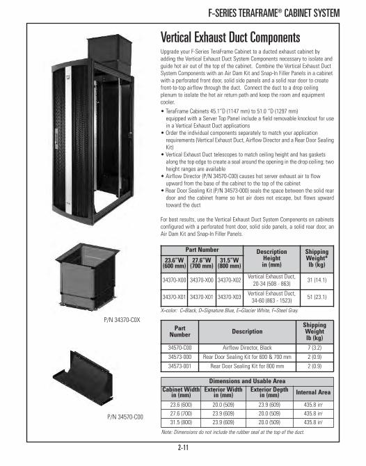
2-11
F-SERIES TERAFRAME® CABINET SYSTEM
Vertical Exhaust Duct Components Upgrade your F-Series TeraFrame Cabinet to a ducted exhaust cabinet byadding the Vertical Exhaust Duct System Components necessary to isolate andguide hot air out of the top of the cabinet. Combine the Vertical Exhaust DuctSystem Components with an Air Dam Kit and Snap-In Filler Panels in a cabinetwith a perforated front door, solid side panels and a solid rear door to createfront-to-top airflow through the duct. Connect the duct to a drop ceilingplenum to isolate the hot air return path and keep the room and equipmentcooler.
Dimensions and Usable AreaCabinet Widthin (mm)
Exterior Widthin (mm)
Exterior Depthin (mm) Internal Area
23.6 (600) 20.0 (509) 23.9 (609) 435.8 in2
27.6 (700) 23.9 (609) 20.0 (509) 435.8 in2
31.5 (800) 23.9 (609) 20.0 (509) 435.8 in2
• TeraFrame Cabinets 45.1”D (1147 mm) to 51.0 “D (1297 mm)equipped with a Server Top Panel include a field removable knockout for usein a Vertical Exhaust Duct applications
• Order the individual components separately to match your applicationrequirements (Vertical Exhaust Duct, Airflow Director and a Rear Door SealingKit)
• Vertical Exhaust Duct telescopes to match ceiling height and has gasketsalong the top edge to create a seal around the opening in the drop ceiling; twoheight ranges are available
• Airflow Director (P/N 34570-C00) causes hot server exhaust air to flowupward from the base of the cabinet to the top of the cabinet
• Rear Door Sealing Kit (P/N 34573-000) seals the space between the solid reardoor and the cabinet frame so hot air does not escape, but flows upwardtoward the duct
For best results, use the Vertical Exhaust Duct System Components on cabinetsconfigured with a perforated front door, solid side panels, a solid rear door, anAir Dam Kit and Snap-In Filler Panels.
P/N 34570-C00
PartNumber Description
ShippingWeightlb (kg)
34570-C00 Airflow Director, Black 7 (3.2)
34573-000 Rear Door Sealing Kit for 600 & 700 mm 2 (0.9)
34573-001 Rear Door Sealing Kit for 800 mm 2 (0.9)
P/N 34370-C0X
Part Number DescriptionHeightin (mm)
ShippingWeight*lb (kg)
23.6”W(600 mm)
27.6”W(700 mm)
31.5”W(800 mm)
34370-X00 34370-X00 34370-X02 Vertical Exhaust Duct,20-34 (508 - 863) 31 (14.1)
34370-X01 34370-X01 34370-X03 Vertical Exhaust Duct,34-60 (863 - 1523) 51 (23.1)
Note: Dimensions do not include the rubber seal at the top of the duct.
X=color: C=Black, D=Signature Blue, E=Glacier White, F=Steel Gray.
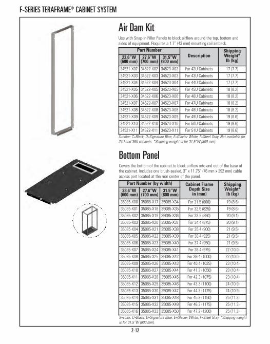
2-12
F-SERIES TERAFRAME® CABINET SYSTEM
Air Dam Kit Use with Snap-In Filler Panels to block airflow around the top, bottom andsides of equipment. Requires a 1.7” (43 mm) mounting rail setback.
X=color: C=Black, D=Signature Blue, E=Glacier White, F=Steel Gray. Not available for24U and 36U cabinets. *Shipping weight is for 31.5”W (800 mm).
Part NumberDescription
ShippingWeight*lb (kg)
23.6”W(600 mm)
27.6”W(700 mm)
31.5”W(800 mm)
34521-X02 34522-X02 34523-X02 For 42U Cabinets 17 (7.7)
34521-X03 34522-X03 34523-X03 For 43U Cabinets 17 (7.7)
34521-X04 34522-X04 34523-X04 For 44U Cabinets 17 (7.7)
34521-X05 34522-X05 34523-X05 For 45U Cabinets 18 (8.2)
34521-X06 34522-X06 34523-X06 For 46U Cabinets 18 (8.2)
34521-X07 34522-X07 34523-X07 For 47U Cabinets 18 (8.2)
34521-X08 34522-X08 34523-X08 For 48U Cabinets 18 (8.2)
34521-X09 34522-X09 34523-X09 For 49U Cabinets 19 (8.6)
34521-X10 34522-X10 34523-X10 For 50U Cabinets 19 (8.6)
34521-X11 34522-X11 34523-X11 For 51U Cabinets 19 (8.6)
Bottom Panel Covers the bottom of the cabinet to block airflow into and out of the base ofthe cabinet. Includes one brush-sealed, 3” x 11.75” (76 mm x 292 mm) cableaccess port located at the rear center of the panel.
Part Number (by width) Cabinet FrameDepth Sizein (mm)
ShippingWeight*lb (kg)
23.6”W(600 mm)
27.6”W(700 mm)
31.5”W(800 mm)
35085-X00 35085-X17 35085-X34 For 31.5 (800) 19 (8.6)
35085-X01 35085-X18 35085-X35 For 32.5 (825) 19 (8.6)
35085-X02 35085-X19 35085-X36 For 33.5 (850) 20 (9.1)
35085-X03 35085-X20 35085-X37 For 34.4 (875) 20 (9.1)
35085-X04 35085-X21 35085-X38 For 35.4 (900) 21 (9.5)
35085-X05 35085-X22 35085-X39 For 36.4 (925) 21 (9.5)
35085-X06 35085-X23 35085-X40 For 37.4 (950) 21 (9.5)
35085-X07 35085-X24 35085-X41 For 38.4 (975) 22 (10.0)
35085-X08 35085-X25 35085-X42 For 39.4 (1000) 22 (10.0)
35085-X09 35085-X26 35085-X43 For 40.4 (1025) 23 (10.4)
35085-X10 35085-X27 35085-X44 For 41.3 (1050) 23 (10.4)
35085-X11 35085-X28 35085-X45 For 42.3 (1075) 23 (10.4)
35085-X12 35085-X29 35085-X46 For 43.3 (1100) 24 (10.9)
35085-X13 35085-X30 35085-X47 For 44.3 (1125) 24 (10.9)
35085-X14 35085-X31 35085-X48 For 45.3 (1150) 25 (11.3)
35085-X15 35085-X32 35085-X49 For 46.3 (1175) 25 (11.3)
35085-X16 35085-X33 35085-X50 For 47.2 (1200) 25 (11.3)X=color: C=Black, D=Signature Blue, E=Glacier White, F=Steel Gray. *Shipping weightis for 31.5”W (800 mm).
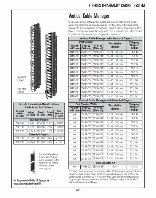
2-13
F-SERIES TERAFRAME® CABINET SYSTEM
Vertical Cable Manager Creates an internal pathway that guides and protects network and signalcables and organizes patch and equipment cords as they enter and exit themanager to make equipment connections.T-Shaped cable management guides(fingers) separate openings that align with each rack-mount unit in the cabinetto guide patch/equipment cords to specific connections.
Outside Dimensions, Usable InternalCable Area, Rail Setback
Cabinet Widthin (mm)
Widthin (mm)
Depthin (mm)
CableArea
RailSetbackin (mm)
Standard Fingers23.6 (600) 1.9 (48) 10.5 (267) 7.1 in2 4.5 (115)
27.6 (700) 3.1 (79) 11.6 (295) 27 in2 4.5 (115)
31.5 (800) 5.0 (127) 11.6 (295) 46 in2 4.5 (115)
Extended Fingers27.6 (700) 3.1 (79) 14.1 (358) 34 in2 7 (178)
31.5 (800) 5.0 (127) 14.1 (358) 58 in2 7 (178)
Part Number DescriptionHeight
ShippingWeight*lb (kg)
23.6”W(600 mm)
27.6”W(700 mm)
31.5”W(800 mm)
34416-C01 35090-C00 35095-C00 For 24U Cabinets 14 (6.4)
34417-C01 35090-C01 35095-C01 For 36U Cabinets 18 (8.2)
34418-C01 35090-C02 35095-C02 For 42U Cabinets 20 (9.1)
34419-C01 35090-C03 35095-C03 For 43U Cabinets 20 (9.1)
34420-C01 35090-C04 35095-C04 For 44U Cabinets 21 (9.5)
34421-C01 35090-C05 35095-C05 For 45U Cabinets 21 (9.5)
34422-C01 35090-C06 35095-C06 For 46U Cabinets 21 (9.5)
34423-C01 35090-C07 35095-C07 For 47U Cabinets 22 (10.0)
34424-C01 35090-C08 35095-C08 For 48U Cabinets 22 (10.0)
34425-C01 35090-C09 35095-C09 For 49U Cabinets 22 (10.0)
34426-C01 35090-C10 35095-C10 For 50U Cabinets 23 (10.4)
34427-C01 35090-C11 35095-C11 For 51U Cabinets 23 (10.4)
The depth of the frame must be a minimum 34.4” (875 mm) when used with AirflowDirector or Quad Vertical Power Strip Manager and side panels. The depth of theframe must be a minimum 39.4” (1000 mm) when used with Wide Vertical PowerCord Manager and side panels. Color is black. *Shipping weight is for the 31.5”(800 mm) Vertical Cable Manager.
Vertical Cable Manager with Standard Fingers
Part Number Width DescriptionHeight
ShippingWeight*lb (kg)23.6”W
(600 mm)27.6”W(700 mm)
31.5”W(800 mm)
N/A 35102-C00 35103-C00 For 24U Cabinets 14 (6.4)
N/A 35102-C01 35103-C01 For 36U Cabinets 18 (8.2)
N/A 35102-C02 35103-C02 For 42U Cabinets 20 (9.1)
N/A 35102-C03 35103-C03 For 43U Cabinets 20 (9.1)
N/A 35102-C04 35103-C04 For 44U Cabinets 21 (9.5)
N/A 35102-C05 35103-C05 For 45U Cabinets 21 (9.5)
N/A 35102-C06 35103-C06 For 46U Cabinets 21 (9.5)
N/A 35102-C07 35103-C07 For 47U Cabinets 22 (10.0)
N/A 35102-C08 35103-C08 For 48U Cabinets 22 (10.0)
N/A 35102-C09 35103-C09 For 49U Cabinets 22 (10.0)
N/A 35102-C10 35103-C10 For 50U Cabinets 23 (10.4)
N/A 35102-C11 35103-C11 For 51U Cabinets 23 (10.4)
Slide Adapter KitN/A 35092-C01 35092-C02 Black 3 (1.4)
Vertical Cable Manager with Extended Fingers
For Recommended Cable Fill Table, go towww.chatsworth.com/cablefill
StandardFingers
ExtendedFingers
Use the Slide AdapterKit to attach VerticalCable Managers to thecabinet frame insteadof the equipmentmounting rails.

2-14
F-SERIES TERAFRAME® CABINET SYSTEM
Front-to-Back Cable Manager Adjustable depth tray connects a front-facing and a rear-facing Vertical CableManager to create a front-to-back cable pathway along the side of the cabinet.The large manager extends between 10" (250 mm) and 17" (430 mm). Thesmall manager extends between 6" (150 mm) and 10" (250 mm). Sold in pairs.- Large Manager, use with rails spaced 26 to 33 (660 to 840) apart- Small Manager, use with rails spaced 22 to 26 (560 to 660) apart
Outside Dimensions and Usable Area Cabinet Widthin (mm)
Heightin (mm)
Widthin (mm)
InternalAreain2 (mm2)
27.6 (700) 2.5 (64 2.4 (61) 4.6 (2970)31.5 (800) 4.0 (102) 4.0 (102) 14 (9000)
Part Number Descriptionin (mm)
ShippingWeight*lb (kg)
23.6”W(600 mm)
27.6”W(700 mm)
31.5”W(800 mm)
N/A 35106-C01 35108-C01 Large 4 (1.9)
N/A 35106-C02 35108-C02 Small 4 (1.9)
Color is black. *Shipping weight is for the 31.5” (800 mm) Front-to-Back CableManager.
Vertical Cable Ring ManagerAttaches to the side of the equipment mounting rails, features plasticC-shaped cable management rings to guide and manage network cables,signal cables, patch and equipment cords. Each manager includes two half-height mounting brackets, cable rings and installation hardware.• The (-C01) 36U manager includes six rings (three per bracket); the (-C11) 51Umanager includes ten rings (five per bracket); all other managers includeeight rings (four per bracket)
• Managers with small rings can be used in the 23.6”W (600 mm) cabinets only; managers with large rings can be used in the 27.6”W (700 mm) and31.5”W (800 mm) cabinets only. Not available for 24U cabinets.- Small rings are 1.5”W x 4.2”D (38 mm x 107 mm), have an interior area of 2.9 in2 (1870 mm2) and require a 4.8” (122 mm) rail setback- Large rings are 3.3”W x 6.5”D (84 mm x 165 mm), have an interior area of 12.4 in2 (8000 mm2) and require a 7.3” (185 mm) rail setback
Part Number DescriptionHeight
ShippingWeightlb (kg)Small Large
35100-C01 35101-C01 For 36U Cabinets 10 (4.5)
35100-C02 35101-C02 For 42U Cabinets 11 (5.0)
35100-C03 35101-C03 For 43U & 44U Cabinets 11 (5.0)
35100-C05 35101-C05 For 45U & 46U Cabinets 12 (5.4)
35100-C07 35101-C07 For 47U & 48U Cabinets 12 (5.4)
35100-C09 35101-C09 For 49U & 50U Cabinets 12 (5.4)
35100-C11 35101-C11 For 51U Cabinets 12 (5.4)
35100-CXX
35101-CXX
Color is black. Large ring managers will not fit 23.6”W (600 mm) F-Series Cabinets.

2-15
F-SERIES TERAFRAME® CABINET SYSTEM
Vertical PDU Mounting Brackets KitUsed to attach Vertical PDUs to the F-Series TeraFrame® Cabinet System. Kitsupports two 2.4”W (61 mm) or narrower PDUs, has tool-less attachmentpoints spaced 64.75” (1645 mm) and 61.25” (1556 mm) apart and requires aminimum 6.7” (170 mm) equipment mounting rail setback. One kit is includedwith each 42U or taller cabinet manufactured after August 1, 2011. The kit isnot compatible with F-Series TeraFrame Cabinets manufactured beforeAugust 1, 2011, F-Series TeraFrame HD Cabinet System or N-Series TeraFrameNetwork Cabinet.13780-C01
PartNumber Description
ShippingWeightlb (kg)
13780-C01 For F-Series TeraFrame Cabinet System 2 (0.9)
PartNumber
DescriptionHeight
ShippingWeightlb (kg)
34595-C01 For 36U Cabinet 14 (6.4)
34595-C02 For 42U Cabinet 14 (6.4)
34595-C03 For 43U Cabinet 15 (6.8)
34595-C04 For 44U Cabinet 15 (6.8)
34595-C05 For 45U Cabinet 15 (6.8)
34595-C06 For 46U Cabinet 15 (6.8)
34595-C07 For 47U Cabinet 16 (7.3)
34595-C08 For 48U Cabinet 16 (7.3)
34595-C09 For 49U Cabinet 16 (7.3)
34595-C10 For 50U Cabinet 16 (7.3)
34595-C11 For 51U Cabinet 17 (7.7)
Color is black. (-C01) manager is only compatible with 38.5”H (978 mm) power strip.(-CO3) or taller Dual Manager is required for 68.5”H (1740 mm) PDU.(-C04) or taller Dual Manager is required for 70.5”H (1791 mm) PDU.
Vertical Power Strip Manager Create a separate pathway specifically for two CPI Vertical Power Strips forcabinets along the side of the cabinet. Attaches to the cabinet frame andadjusts in depth to match equipment. • Supports 1.8”W (45 mm) or narrower CPI PDUs or power strips• Vertical Power Strip Manager is C-shaped, 4.3”W x 1”D (110 mm x 25 mm),
requires a 6.3” (160 mm) rail setback and supports two PDU/power strips

2-16
F-SERIES TERAFRAME® CABINET SYSTEM
PDU/Power Strip Lashing BracketSupports one or two CPI Vertical PDU/Power Strips for Cabinets and providesmultiple attachment points for fastening power cable bundles. Attaches to thecabinet frame behind the rear equipment mounting rails.• Supports two 2.3”W (58 mm) or narrower or one 3.5”W (89 mm) CPI PDUs• The manager is S-shaped, 8.375”W x 1.7”D (213 mm x 42 mm) and requiresa minimum 5” (127 mm) equipment mounting rail setback
PartNumber
DescriptionHeight
ShippingWeightlb (kg)
35086-C01 For 36U Cabinet 14 (6.4)35086-C02 For 42U Cabinet 14 (6.4)35086-C03 For 43U Cabinet 15 (6.8)35086-C04 For 44U Cabinet 15 (6.8)35086-C05 For 45U Cabinet 15 (6.8)35086-C06 For 46U Cabinet 15 (6.8)35086-C07 For 47U Cabinet 16 (7.3)35086-C08 For 48U Cabinet 16 (7.3)35086-C09 For 49U Cabinet 16 (7.3)35086-C10 For 50U Cabinet 16 (7.3)35086-C11 For 51U Cabinet 17 (7.7)
Cable Lashing BracketProvides attachment points to quickly secure cable bundles within the cabinet.• C-shaped bracket, 5.125”W x .7”D (130 mm x 17 mm)• Bracket attaches to the cabinet frame and requires a minimum 5” (127 mm) equipment mounting rail setback when positioned behind the rearequipment mounting rails
PartNumber
DescriptionHeight
ShippingWeightlb (kg)
35087-C00 For 24U Cabinet 8 (3.6)35087-C01 For 36U Cabinet 11 (5.0)35087-C02 For 42U Cabinet 12 (5.4)35087-C03 For 43U Cabinet 13 (5.9)35087-C04 For 44U Cabinet 13 (5.9)35087-C05 For 45U Cabinet 13 (5.9)35087-C06 For 46U Cabinet 14 (6.4)35087-C07 For 47U Cabinet 14 (6.4)35087-C08 For 48U Cabinet 15 (6.8)35087-C09 For 49U Cabinet 15 (6.8)35087-C10 For 50U Cabinet 15 (6.8)35087-C11 For 51U Cabinet 15 (6.8)
Color is black.
Color is black. Not available for 24U cabinets. (-C01) bracket is only compatiblewith 38.5”H (978 mm) power strip. (-C03) or taller bracket is required for 68.5”H(1740 mm) PDU. (–C04) or taller bracket is required for 70.5”H (1791 mm) PDU.

Baying KitsZero Spacing Baying KitIncludes M6 hardware to bay two cabinets (same height and depth) side-by-side with or withoutside panels for simplified installation when no space is required between the cabinets. Each kitincludes four M6 screws, washers and nuts.
24” (610 mm) Baying Bracket KitIncludes brackets and hardware to bay two 23.6” (600 mm) cabinets so that the cabinets arecentered over 24”W (610 mm) raised access floor tiles. Note that there will be a .4” (10 mm) gapbetween the cabinets. Each kits includes two .8”H x 3.6”W x 1.0”D (20 mm x 92 mm x 25 mm)C-shaped brackets attach to the tops of the cabinet frames at the front and rear. Installationhardware allows cabinets of different depths to be bayed together.
Narrow Baying KitIncludes brackets and hardware that bay two cabinets with or without side panels. Each kitincludes two .8”H x 3.2”W x 1.0”D (20 mm x 82 mm x 25 mm) C-shaped brackets that attach tothe tops of the cabinet frames at the front and rear and installation hardware. Allows cabinets ofdifferent depths to be bayed together.
24” (610 mm) Baying & Fascia KitAllows you to bay and center two 23.6”W (600 mm) cabinets over 24”W (610 mm) raised accessfloor tiles. The kits includes two brackets and hardware to space and connect the cabinetstogether and two fascias that cover and hide the 0.4” (10 mm) gap between the cabinets. Eachkit incudes two .8”H x 3.6”W x 2.0”D (20 mm x 92 mm x 50 mm) C-shaped brackets that attachto the tops of the cabinet frames at the front and rear, two 1”W (25 mm) T-shaped fascias andinstallation hardware to bay the cabinets. Cabinets must be the same height and depth.
PartNumber
Descriptionin (mm)
CompatibleSeal Kit
ShippingWeightlb (kg)
35078-001 Zero Spacing Baying Kit 35081-000 1 (0.5)
35079-X01 24 (600) Baying Brackets 35081-001* 1 (0.5)
35079-X02 Narrow Baying Kit 35081-003 1 (0.5)
35080-X00 24 (600) Baying & Fascia Kit, for 24U 35081-001* 9 (4.1)
35080-X01 24 (600) Baying & Fascia Kit, for 36U 35081-001* 11 (5.0)
35080-X02 24 (600) Baying & Fascia Kit, for 42U 35081-001* 12 (5.4)
35080-X03 24 (600) Baying & Fascia Kit, for 43U 35081-001* 12 (5.4)
35080-X04 24 (600) Baying & Fascia Kit, for 44U 35081-001* 12 (5.4)
35080-X05 24 (600) Baying & Fascia Kit, for 45U 35081-001* 13 (5.9)
35080-X06 24 (600) Baying & Fascia Kit, for 46U 35081-001* 13 (5.9)
35080-X07 24 (600) Baying & Fascia Kit, for 47U 35081-001* 13 (5.9)
35080-X08 24 (600) Baying & Fascia Kit, for 48U 35081-001* 13 (5.9)
35080-X09 24 (600) Baying & Fascia Kit, for 49U 35081-001* 13 (5.9)
35080-X10 24 (600) Baying & Fascia Kit, for 50U 35081-001* 14 (6.4)
35080-X11 24 (600) Baying & Fascia Kit, for 51U 35081-001* 14 (6.4)
2-17
F-SERIES TERAFRAME® CABINET SYSTEM
X=color: C=Black, D=Signature Blue, E=Glacier White, F=Steel Gray. Use Seal Kits when side panels areomitted. *Use Seal Kit 35081-001 if one panel is omitted and 35081-002 if both panels are omittedbetween cabinets.
35078-001
35079-C01
35079-C02
35080-C02
35081-001

2-18
F-SERIES TERAFRAME® CABINET SYSTEM
Caster Kit Front casters are full-swivel. Caster Kit adds 2.5” (64 mm) to the overall heightof the cabinet. Includes four non-locking casters and mounting hardware.
Installation Kits and Mounting Hardware TeraFrame can be fitted with threaded or square-punched equipment mountingrails. Use screws to secure equipment to threaded mounting rails. Use cagenuts to secure equipment to square-punched mounting rails. With square-punched rails, you can change the thread (cage nut) to match equipmentmounting hardware requirements.
PartNumber Description
ShippingWeightlb (kg)
35051-C01 Set of 4 Casters, Black 25 (11.8)
PartNumber Description
ShippingWeightlb (kg)
40605-001 Screws, #12-24, Package of 50, Zinc 1 (0.5)
40605-005 Screws, #12-24,Package of 50, Black 1 (0.5)
12637-001 Cage Nuts and Screws, M6, Package of 25, Gold 1 (0.5)
12638-001 Cage Nuts and Screws, #10-32, Package of 25, Zinc 1 (0.5)
12639-001 Cage Nuts and Screws, #12-24, Package of 25, Black 1 (0.5)
35058-001 Hardware Kit, Rail Support, (16) M8 Drop-In Nuts/Bolts, Package of 16, Zinc 3 (1.4)
40604-003 Installation Kit, Concrete Slab 1 (0.5)
12637
12638
40605
12639
PartNumber
DescriptionH x W (in)
ShippingWeightlb (kg)
13517-701 1U x 19, Black 17 (7.7)
Rack-Mount Cable Shelf Use Rack-Mount Cable Shelf in any 19”W CPI Cabinet equipped with an AirDam Kit to provide a front-to-rear pathway for cables. Cables pass throughbrush sealed ports along the front of the shelf. Rack-Mount Cable Shelf uses1U and will fit in cabinets with mounting rails set between 22” (560 mm) and40”D (1020 mm).
Note: Rack-Mount Cable Shelf can be used with all CPI four-post cabinets and racks.

2-19
F-SERIES TERAFRAME® CABINET SYSTEM
Mounting Rails Two mounting rail styles are available. Select square-punched rails for serversand data storage equipment. Square-punched rails let you change threads(cage nuts) at mounting locations to match equipment requirements. Selecttapped rails to speed installation of rack-mount patch panels and networkequipment. The 23.6”W (600 mm) rails attach to the cabinet frame. The 27.6”(700 mm) and 31.5”W (800 mm) rails include standoff brackets that center therails for 19” EIA spacing. Sold in pairs, each rack-mount unit is marked andnumbered on the rails.
Mounting rails and standoff brackets are zinc plated. *Shipping weight is for the31.5”W (800 mm) tapped rail.
Part NumberU
ShippingWeight*lb (kg)23.6”
(600 mm)27.6”(700 mm)
31.5”(800 mm)
Square-Punched Equipment Mounting Rails
35009-000 35009-012 35009-024 24 28 (12.7)
35009-001 35009-013 35009-025 36 35 (15.9)
35009-002 35009-014 35009-026 42 38 (17.2)
35009-003 35009-015 35009-027 43 39 (17.7)
35009-004 35009-016 35009-028 44 40 (18.1)
35009-005 35009-017 35009-029 45 40 (18.1)
35009-006 35009-018 35009-030 46 41 (18.6)
35009-007 35009-019 35009-031 47 41 (18.6)
35009-008 35009-020 35009-032 48 42 (19.1)
35009-009 35009-021 35009-033 49 42 (19.1)
35009-010 35009-022 35009-034 50 43 (19.5)
35009-011 35009-023 35009-035 51 44 (20.0)
#12-24 Tapped Equipment Mounting Rails
35008-000 35008-012 35008-024 24 28 (12.7)
35008-001 35008-013 35008-025 36 35 (15.9)
35008-002 35008-014 35008-026 42 38 (17.2)
35008-003 35008-015 35008-027 43 39 (17.7)
35008-004 35008-016 35008-028 44 40 (18.1)
35008-005 35008-017 35008-029 45 40 (18.1)
35008-006 35008-018 35008-030 46 41 (18.6)
35008-007 35008-019 35008-031 47 41 (18.6)
35008-008 35008-020 35008-032 48 42 (19.1)
35008-009 35008-021 35008-033 49 42 (19.1)
35008-010 35008-022 35008-034 50 43 (19.5)
35008-011 35008-023 35008-035 51 44 (20.0)
For F-Series TeraFrame Cabinets manufactured before February 9, 2009, contact CPITechnical Support for assistance with part numbers at 800-834-4949.

2-20
F-SERIES TERAFRAME® HD CABINET SYSTEM
Choose a solid top panel withtwo (server-style) brush-sealednetwork cable access ports oruse the Vertical Exhaust Ductoption with high heat densityapplications to isolate andremove hot air from the room
Metric footprint for international use
Available in 600 mm width, three heights and two depths
Includes two pairs of sliding,continuously adjustable equipmentmounting rails to provide front andrear support for 19”W (482.6 mm)
EIA/ECA-310-E compliant rack-mount equipment and shelves
Mounting rails have 1.75”H(44.45 mm) rack-mount units and
are available with square-punchedholes that accept cage nuts; rack-mount units are markedand numbered bottom-to-top
on all rails
Includes a single-point cam latch with keyed locks
Includes a single, perforated, curved metal front door (79%
open); reversible to open from theright or left, easy to remove
at 90˚ open position.
Open base for cable entry;includes leveling feet heavy-dutycasters with roller bearings for
superior, long-term performance.
A bottom panel is available as an accesory.
Heavy-Duty, welded steel andbolted aluminum frameconstruction supports up to 3000 lb (1360.0 kg) of equipmentin a dynamic environment.
Easy to remove solid side panelshave recessed spring-loadedlatches with keyed locks; cabinetscan be bayed (side-by-side) withside panels installed
Organize network cables, power distribution units andpower cords along the sides ofthe cabinet with optionalside-mounted vertical cableand power managers
Heavy-duty shock pallet and re-usable cushioned carton allow thecabinet to be reshipped after equipment is installed.
Heavy-duty welded steel ramp provides a safe method forunloading the cabinet from the pallet upon arrival at customer site.
Choose a solid metal, perforatedmetal or double, perforated metalrear door
Static & dynamic load rating of 3000 lb (1360 kg)
The F-Series TeraFrame® HD Cabinet System
The mounting rails, top panel,side panels and doors areelectrically bonded to the cabinetframe; a ground terminal block isincluded to attach the frame tothe CBN or TGB

2-21
F-SERIES TERAFRAME® HD CABINET SYSTEM
F-Series TeraFrame® HD Cabinet SystemThe F-Series TeraFrame® HD Cabinet System is designed for safetransportation of up to 3,000 lb (1360 kg) of electronic equipment from afactory integration site direct to the customer’s datacenter.
Every cabinet includes two pairs of sliding, continuously adjustable equipmentmounting rails with square-punched mounting holes for compatibility withmost rack-mount equipment. In addition, the F-Series TeraFrame HD Cabinetsystem includes heavy duty casters with roller bearings for superior long-termperformance under load, a shock pallet, and a re-usable cushioned carton forprotection during shipment.
The top panel includes large brush-covered cable openings that will handlelarge bundles of cables while preventing undesirable hot air re-circulation.The top panel includes a removable cover plate allowing the use of a VerticalExhaust Duct for high-density applications. Cabinets include solid side panelsto protect equipment.
Heavy-duty steel ramp is an optional accessory designed to simplify unloadingthe populated cabinet from the shock pallet. An optional bolt-down kit allowsthe cabinet to be securely anchored to the floor structure and can be installedprior to the cabinet’s arrival to minimize installation time. Combine the F-Series TeraFrame HD Cabinet with thermal and cable managementaccessories to create a custom solution that fits your exact needs.
Cabinet Specifications:• Available in 600 mm width, 3 heights and 2 depths• Provides front and rear support for 19”W EIA equipment and shelveswith two pairs of adjustable depth rack-mount unit marked and numberedequipment mounting rails
• Includes grounding and bonding kit• Includes leveling feet and casters• Can be ordered with a server top panel or Vertical Exhaust Duct• Choose from three rear door styles• Heavy-duty welded steel and bolted aluminum frame construction• Load rating:– 3000 lb (1360 kg) static– 3000 lb (1360 kg) dynamic
Cabinet Includes:• (1) Four-post frame (painted finish)• (4) Vertical Mounting Rails (square-punched)• (1) Grounding/Bonding Kit• (2) Locking, Solid Side Panels • (1) Front Door • (1) Rear Door • (1) Top Panel• (4) Leveling Feet and casters• (1) Bag of 25 Each M6 Cage Nuts and Screws (square-punched rails)• (1) Shock pallet rated for 3000 lb of equipment (excluding cabinet weight)• (1) Re-usable cushioned carton

2-22
F-SERIES TERAFRAME® HD CABINET SYSTEM
Use the part number matrix below to select a F-Series TeraFrame HD Cabinet. Choose the Height, Width, Depth, Rail Style, Front Door,Rear Door, Latch, Color, Top Panel and Side Panel style to form a part number. To order the cabinet with accessories installed, contactCPI Technical Support. Example Part Number: FHD-F1U-111B-C52
Ordering Notes:1. Height: Three heights are available. The cabinet height is the overall height of the cabinet with a top panel and casters. The frameheight is the height of the internal frame without the top panel or casters. Casters add approximately 4.2 inches (107 mm) to the heightof the frame and cabinet.
2. Width: Overall cabinet width with side panels is 23.6 inches (600 mm). The cabinet includes equipment mounting rails spaced for19”EIA (482.6 mm) rack-mount equipment.
3. Depth: Two depths are available. Cabinet depth is the overall depth of the cabinet including doors. Frame depth is the outside depth ofthe frame excluding doors. Doors add approximately 3.8 inches (97 mm) to overall depth. Rail depth is the maximum front-to-rearspacing of equipment mounting rails. Rail depth is reduced by an equipment mounting rail setback when accessories are added.
4. Rail Style: Square-punched rails use snap-in cage nut hardware that can be changed to match equipment requirements. Orderadditional mounting hardware as required.
5. Front Door Style: The door matches the color of the cabinet and includes an anodized aluminum center beam.6. Rear Door Style: Three rear door styles are available. The double-door reduces the amount of aisle space required to access the rear ofthe cabinet. Double doors have two-point latches. A single solid metal door must be used when the Vertical Exhaust Duct System toppanel style is selected.
7. Latches: All doors have a swing handle. Single doors have a single-point cam latch with keyed lock; the double-door has a two-pointcam latch with keyed lock. The keyed lock includes a physical key which matches the locks on the doors and side panels.
8. Color: The frame, doors, side panels and top panel are painted black. Mounting rails are zinc plated.9. Top Panel Style: There are two styles of top panel available. Server Top Panels have two large brush-sealed cable openings and includea removable cover plate for the Vertical Exhaust Duct. The Vertical Exhaust Duct System includes a Server Top Panel, a top-mountVertical Exhaust Duct, an Airflow Director and a Rear Door Sealing Kit. Select from duct height ranges: 20” to 34” (508 mm – 863 mm)or 34” to 60” (863 mm – 1523 mm) high to match ceiling height. Use with a single solid rear door.
10. Side Panel Style: Side panels are solid. Cabinets are bayed with side panels installed. Order baying kits separately.
1. HeightCabinet Frame
Uin mm in mm82.5 2096 78.1 1984 42 C87.7 2228 83.4 2118 45 F91.2 2316 86.9 2207 47 H
FHD - H W D - R FD RD L - C TP SP
2. WidthCabinet
EIAFrame
in mm in mm23.6 600 19” 23.4 594 1
3. DepthCabinet Rails Framein mm in mm in mm46.1 1172 39.4 1001 42.3 1075 M51.0 1297 44.3 1126 47.2 1200 U
10. Side Panel Style2 Solid, 2 each
9. Top Panel Style4 Server, 2 Cable Openings
5Vertical Exhaust Duct System, 20”-34”H (508 mm-863 mm)
6Vertical Exhaust Duct System, 34”-60”H (863 mm-1523 mm)
8. ColorC Black
7. Latches (Door)B Single-Point, Cam Latch, Keyed Lock
6. Rear Door1 Single, Solid Metal2 Single, Perforated Metal3 Double, Perforated Metal
5. Front Door1 Single, Perforated Metal
4. Rail StyleSquare-Punched, 2 Pair 1
Cabinet height includes casters.
The rear double-door will have a two-point latch.
Use a solid rear dor with Vertical Exhaust Duct.

2-23
F-SERIES TERAFRAME® HD CABINET SYSTEM
PartNumber Description
ShippingWeightlb (kg)
16280-C01 Unloading Ramp, Black 185 (83.9)
16279-C01 Bolt Down Kit, Black 14 (6.4)
16277-C11 Side Skirt, For 42.3 (1075), Black 6 (2.7)
16277-C16 Side Skirt, For 47.2 (1200), Black 6 (2.7)
16271-C02 Baying/Fascia Kit, For 42U Cabinets, Black 10 (4.5)
16271-C05 Baying/Fascia Kit, For 45U Cabinets, Black 10 (4.5)
16271-C07 Baying/Fascia Kit, For 47U Cabinets, Black 10 (4.5)
16270-C02 Air Dam Kit, For 42U Cabinets, Black 12 (5.4)
16270-C05 Air Dam Kit, For 45U Cabinets, Black 13 (5.9)
16270-C07 Air Dam Kit, For 47U Cabinets, Black 13 (5.9)
TeraFrame HD Cabinet AccessoriesUnloading RampSafely remove a loaded cabinet from the shock pallet at the customer site withthis re-usable, heavy-duty steel unloading ramp. The ramp is 78 inches (1981mm) long, provides a 5° incline, has U-shaped narrow width tracks and bolts tothe shock pallet to ensure the ramp and pallet remain connected. Order one percustomer site.
Bolt Down KitSecurely anchors F-Series TeraFrame HD Cabinets to the floor. The kit includestwo heavy-duty two-piece steel brackets that attach to the cabinet frame.Disassemble the brackets and mount the L-shaped floor flanges, roll cabinetsinto place and secure the cabinets to the floor flanges with the remainingbracket. Once installed, the Bolt-Down Kit covers the opening between thecabinet frame and floor at the front and rear of the cabinet concealing thecasters and providing a barrier that minimizes air leakage underneath thecabinet. Order required floor anchor hardware separately.
Side SkirtThe Side Skirt attaches to the Bolt Down Kit (P/N 16279-X01), conceals thecasters and provides a barrier that minimizes air leakage under the cabinet. Useone Side Skirt on each end of multi-cabinet rows. Each kit includes one coverand installation hardware. Select the depth to match the cabinet.
Baying and Fascia KitAllows you to bay and center two F-Series TeraFrame HD Cabinets (same heightand depth) over 24 inch wide (610 mm) raised access floor tiles. The kit includestwo brackets and hardware to space and connect the cabinets together and twofascias that cover and hide the 0.4 inch (10 mm) gap between the cabinets.
Air Dam KitThe Air Dam Kit blocks airflow around the top, bottom and sides of the rack-mount space inside the cabinet. Use Snap-In Filler Panels with Air Dam Kit toseparate hot and cold air inside the cabinet. The kit requires a 1.7 inch (43 mm)to 2.5 inch (63 mm) equipment mounting rail setback. Select the height to matchthe cabinet.
16280-C01
16279-C01
16277-C1X
16271-C0X
16270-C0X

2-24
F-SERIES TERAFRAME® HD CABINET SYSTEM
Bottom PanelCovers the bottom of the cabinet and blocks airflow into and out of the baseof the cabinet. The two-piece telescoping design includes one brush-sealed3 inch by 11.75 inch (76 mm x 292 mm) cable access port located at the rearcenter of the panel and fits all sizes.
Cable Lashing BarSecures a single network or power cable bundle within the cabinet and featuresnotched edges to ensure Saf-T-Grips and cable ties do not slide. The barattaches to the cabinet frame and is only 1.5 inches (38 mm) wide allowingmultiple bars to be placed side-by-side. Requires a minimum 2.5 inch (64 mm)equipment mounting rail setback. Select the bar to match cabinet height.
Cable Lashing BracketSecures multiple network or power cable bundles within the cabinet featuringU-shaped attachment points for Saf-T-Grips or cable ties. The bracket attachesto the cabinet frame and is 5.125 inches (130 mm) wide and requires a minimum5 inch (127 mm) equipment mounting rail setback. Power Strip Lashing BracketSupports one 3.5 inch (89 mm) wide or two 2.3 inch (58 mm) wide CPI VerticalPDU/Power Strips and provides multiple attachment points for fastening powercable bundles with Saf-T-Grip Straps or cable ties. The bracket attaches to thecabinet frame and is 8.375 inches (213 mm) wide. Power strip mounting holesare spaced 64.75 inch (1645 mm) or 36.75 inch (934 mm) apart. The bracketrequires a minimum 5 inch (127 mm) equipment mounting rail setback.
Vertical Cable Ring ManagerAttaches to the side of the cabinet’s equipment mounting rails and has plasticC-shaped cable management rings that guide and manage cables. Rings are 1.4inches (36 mm) wide and 4 inches (100 mm) deep. The manager requires aminimum 4.8 inch (122 mm) equipment mounting rail setback.
PartNumber Description
ShippingWeightlb (kg)
16278-C01 Bottom Panel 19 (8.6)
16272-C02 Cable Lashing Bar, For 42U Cabinets 7 (3.2)
16272-C05 Cable Lashing Bar, For 45U Cabinets 8 (3.6)
16272-C07 Cable Lashing Bar, For 47U Cabinets 8 (3.6)
16273-C02 Cable Lashing Bracket, For 42U Cabinets 12 (5.4)
16273-C05 Cable Lashing Bracket, For 45U Cabinets 13 (5.9)
16273-C07 Cable Lashing Bracket, For 47U Cabinets 14 (6.4)
16274-C02 Power Strip Bracket, For 42U Cabinets 14 (6.4)
16274-C05 Power Strip Bracket, For 45U Cabinets 15 (8.8)
16274-C07 Power Strip Bracket, For 47U Cabinets 16 (7.3)
16275-C02 Cable Ring Manager, For 42U Cabinets 5 (2.3)
16275-C05 Cable Ring Manager, For 45U Cabinets 5 (2.3)
16275-C07 Cable Ring Manager, For 47U Cabinets 6 (2.7)
Color is black. Power Lashing Bracket, (-C05) or taller bracket required for68.5”H (1740 mm) and 70.5”H (1791 mm) PDUs.
16278-C01
16272-C02
16273-C02
16274-C02
16275-C01

2-25
N-SERIES TERAFRAME® NETWORK CABINET
The N-Series TeraFrame® Network Cabinet
Comes with a five-piece toppanel, center panel and fourperimeter panels (front, sides,rear) with cable knockouts
Metric footprint for international use
Available in 10 heights and11 depths (110 standard sizes)
Includes two pairs of equipmentmounting rails to provide front and
rear support for 19” EIA-310-Dcompliant equipment and shelves;
mounting rails have 1.75”H(44.45 mm) rack-mount units and
are available with square-punchedor threaded attachment points
Rack-mount units are marked andnumbered on each mounting rail
Choose keyed orcombination/keyed locks; orderRight Hand Door Latch Kit (P/N
34684-C02) to reverse front door swing
Network Cabinet comes withsingle, perforated front door with handle and two-point
latch swing
Open base for cable entry;includes leveling feet and floor attachment brackets (casters areavailable as an accessory)
Frames are welded steel andsupport up to 2500 lb (1134.0 kg)of equipment
Choose solid or vented easy toremove side panels; side panelshave recessed latches with keyedlocks
Organize fiber trunk cables alongthe sides of the cabinet withoptional side-mounted verticalfiber managers
Standoff Brackets offset doors andside panels to provide extra spacearound equipment for enhanced
side-to-side airflow and additionalcable management
Cabinet comes with a double,perforated rear door with swinghandle and two-point latch
Designed specifically to control side-to-side airflow for network switchequipment deployed in a hot aisle/cold aisle data center environment
The Network Switch Exhaust Ductguides hot exhaust air from the
side of rack-mount switches out the rear door
Cabinets can be bayed (side-by-side) when side panelsare removed

2-26
N-SERIES TERAFRAME® NETWORK CABINET
N-Series TeraFrame® Network CabinetThe N-Series TeraFrame® Network Cabinet provides an engineered solutionfor network switches and cabling in data centers with hot aisle/cold aislelayouts, delivering superior thermal management for high-densityapplications.
Featuring offset doors and side panels, the N-Series TeraFrame NetworkCabinet provides extra interior space around the cabinet frame for cablemanagement and enhanced airflow. Select the Network Switch Exhaust Ductoption when deploying network switches that require side-to-side airflow. TheNetwork Switch Exhaust Duct isolates and re-directs hot exhaust air out therear of the cabinet to help prevent the re-circulation of hot air throughequipment and establishes proper airflow for a hot aisle/cold aisle layout.
The N-Series TeraFrame Network Cabinet includes vertical cable guides andcable management spools to help organize cables. The guides are T-shapedwith openings that align with each rack-mount unit on the rack and attach tothe front of the cabinet frame. The spools attach to the side of the cabinetframe and help guide cables along the side of the cabinet preventing themfrom accidentally blocking air intakes on switch chassis. Use the verticalcable guides and cable management spools to route cables to the sides ofswitches to maintain full access to the switch I/O and fan modules.
Specifications:• Available in 10 heights and 11 depths• Designed to meet third party specifications for specific manufacturer switches
• Matches standard TeraFrame Cabinet system style and sizes• Includes two pairs of 19” EIA equipment mounting rails providing front and rear support for equipment and shelves
• Static load rating:- 2500 lb (1134 kg) on leveler feet
Cabinet Includes:• (1) Welded Steel Four-Post Frame• (4) Equipment Mounting Rails• (1) Single, Perforated Front Door with Swing Handle• (1) Double, Perforated Rear Door with Swing Handle• (1) Five-piece Top Panel• (4) Leveler Feet and Floor Anchor Brackets• (1) Ground Terminal Block• (1) Baying Kit• (1) Bag of 25 Each M6 Cage Nuts and Screws (square-punched rails)• (1) Bag of 50 Each #12-24 Rack Channel Mounting Screws (tapped rails)
Applications:The N-Series TeraFrame Network Cabinet supports Cisco Catalyst, CiscoNexus and Juniper Network switches. Many other switches can alsobenefit from the superior thermal management designed into the N-SeriesTeraFrame Network Cabinet. More information on specific switch models isavailable on page 2-28 or at www.chatsworth.com.The Network Switch Exhaust Duct guides hot
exhaust air from the side of the switch out therear door of the cabinet.

2-27
N-SERIES TERAFRAME® NETWORK CABINET
Use the part number configurator below to create a custom N-Series TeraFrame Network Cabinet. Choose the Height, With or WithoutDuct, Depth, Rail Style, Front Door, Rear Door, Latch, Color, Top Panel Style and Side Panel Style. Example part number: NF1K-113C-C42
10. Side Panel Style0 None1 Solid, 1 each2 Solid, 2 each3 Vented, 1 each4 Vented, 2 each
8. ColorC BlackD Signature BlueE Glacier WhiteF Steel Gray
5. Front Door1 Single, Perforated Metal
N H W D - R FD RD L - C TP SP
9. Top Panel 4 Solid with Knock-Out Ports
7. Latches (Door)C Two-Point, Cam Latch, Keyed LockE Two-Point, Cam Latch, Combination Lock
6. Rear Door3 Double, Perforated Metal
2. Network Switch Exhaust DuctNone - Includes two Cable Finger Kits 0Included - Includes one Cable Finger Kit 1
3. Depth
Cabinet Rail (max) N-SeriesFrame SizeEquiv. F-SeriesFrame Size
in mm in mm in mm in mm41.2 1047 22.6 575 25.6 650 37.4 950 G42.2 1072 23.6 600 26.6 675 38.4 975 H43.2 1097 24.6 625 27.6 700 39.4 1000 J44.2 1122 25.6 650 28.5 725 40.4 1025 K45.2 1147 26.6 675 29.5 750 41.3 1050 L46.1 1172 27.6 700 30.5 775 42.3 1075 M47.1 1197 28.6 725 31.5 800 43.3 1100 N48.1 1222 29.5 750 32.5 825 44.3 1125 P49.1 1247 30.5 775 33.5 850 45.3 1150 R50.1 1272 31.5 800 34.4 875 46.3 1175 T51.1 1297 32.5 825 35.4 900 47.2 1200 U
Note: When sizing to match the N-Series TeraFrameCabinet System, use the same part number digit forcabinet height and depth as the F-Series TeraFrame.
4. Rail Style1 Square Punch, 2 Pair2 Tapped, #12-24, 2 Pair
1. HeightCabinet Frame
Uin mm in mm78.3 1989 78.1 1984 42 C80.0 2033 79.9 2029 43 D81.8 2077 81.6 2073 44 E83.5 2122 83.4 2118 45 F85.3 2166 85.1 2162 46 G87.0 2211 86.9 2207 47 H88.8 2255 88.6 2251 48 J90.5 2300 90.4 2296 49 K92.3 2344 92.1 2340 50 L94.0 2389 93.9 2385 51 M
Note: Use the Network Switch Exhaust Duct withswitches that require side airflow. See Ordering Notes 3& 4 for additional information.
Note: Depths G and H have a maximum rail spacing less than 24”(610 mm) and will not support certain switch mounting brackets.Use CPI P/N 12336-719, 18” D (460 mm) Fixed Shelf, to supportequipment when ordering these cabinet sizes.
The N-Series TeraFrame Network Cabinet supports Cisco Catalyst, Cisco Nexus and Juniper Network switches.
See next page for specific part number information.

2-28
N-SERIES TERAFRAME® NETWORK CABINET
Ordering Notes:1. Height: Ten heights are available. The frame height is the height of the internal frame without the top panel. The cabinetheight is the overall height of the cabinet with a top panel. Leveler feet add approximately 1” (25 mm) to the height of thecabinet. Frame heights match F-Series TeraFrame Cabinet System heights. Accessory Caster Kits adds approximately 2.5”(64 mm) to the height of the cabinet.
2. Width: One width is available. Overall cabinet width with side panels is 31.5” (800 mm). The internal frame width withoutside panels is 23.6” (600 mm). The included mounting rails are 19” EIA-310-D compliant.
3. Network Switch Exhaust Duct: Select [1] to include a Network Switch Exhaust Duct with the cabinet (special configurationsare listed under note 4 below). The duct will be pre-installed into the cabinet and includes removable exhaust panels on theside that faces the equipment. The duct is 2U less than the full height of the cabinet. Select [0] to exclude the duct forpatching applications or switches that have front-to-rear airflow. Cabinets that include the Network Switch Exhaust Ductinclude one Cable Management Fingers Kit (see next page). Cabinets that do not include the Network Switch Exhaust Ductinclude two Cable Management Fingers Kits.
4. Depth: Eleven depths are available. The frame depth is the depth of the internal frame without doors. The cabinet depth isthe overall depth of the cabinet with doors. Rail depth is the maximum rail-to-rail depth within the frame. The N-SeriesTeraFrame Network Cabinet can be used side-by-side with the F-Series TeraFrame Cabinet System. Overall cabinet depthsare the same. Equivalent F-Series TeraFrame frame depths are listed in a separate column in the order table.
5. Rail Style: Square-punched rails use snap-in cage nut hardware (P/N 12637-001, 12628-001 or 12639-001) that can bechanged to match equipment requirements. Tapped rails use screws (P/N 40605-001 or 40605-005). Order additionalmounting hardware as required. (see page 2-16)
6. Front Door: The front door is hinged on the right side. To reverse the swing, order a Right Hand Door Latch Kit (P/N 34684-C02).
7. Latches: All doors have swing handles and a two point cam latch. The keyed lock includes a physical key. The combinationlock has a programmable three-digit combination and is opened with three dials on the handle or with a key.
8. Side Panels: Vented and solid side panels are available. Select a quantity of one or two panels per cabinet. Omit side panelsto bay cabinets.
In addition to the N-Series TeraFrame Network Cabinet Solution in the order table on the previous page, specific N-SeriesTeraFrame Network Cabinet configurations have been developed for the following Manufacturer’s Switches:
For more information on N-Series solutions for Cisco Switches, refer to www.chatsworth.com/ciscoteraframe, and for moreinformation on N-Series solutions for Juniper Network Switches, refer to the www.chatsworth.com/juniperteraframe.
*Cisco 6509-NEBS does not require Network Switch Exhaust Duct.** Dimensions correspond to Equivalent TeraFrame depth in the order matrix on previous page.*** Other sizes avialable to support this switch
Meets Compatibility Guidelines for: Part Number DimensionsH x W x D - in (mm)
Cisco Nexus 7010 switch NF0U-113C-C42 45U x 31.5 x 47.2 (800 x 1200)***
Cisco Catalyst 6500, 6509* and 6513 switchesCisco MDS 9509 director NF2K-113C-C42 45U x 31.5 x 40.4 (800 x 1025)**
Cisco MDS 9513 director NF3K-113C-C42 45U x 31.5 x 40.4 (800 x 1025)**
Juniper EX8208 or EX8216 NF4M-113C-C42 45U x 31.5 x 42.3 (800 x 1075)**
Cisco Nexus 7018 switch NF5U-143C-C42 45U x 40.0 x 47.2 (1016 x 1200)***

2-29
N-SERIES TERAFRAME® NETWORK CABINET
PartNumber
DescriptionHeight
ShippingWeightlb (kg)
34620-C01 Network Exhaust Duct, 2U to 3U Panel, Black 3 (1.4)
34620-C02 Network Exhaust Duct, 4U to 7U Panel, Black 4 (1.8)
34620-C03 Network Exhaust Duct, 8U to 15U Panel, Black 6 (2.7)
34620-C11* Network Exhaust Duct, 2U to 3U Panel, Black 3 (1.4)
34620-C12* Network Exhaust Duct, 4U to 7U Panel, Black 4 (1.8)
34620-C13* Network Exhaust Duct, 8U to 15U Panel, Black 6 (2.7)
34680-002 Cable Fingers Kit, For 42U Cabinets, Black 4 (1.8)
34680-003 Cable Fingers Kit, For 43U Cabinets, Black 4 (1.8)
34680-004 Cable Fingers Kit, For 44U Cabinets, Black 4 (1.8)
34680-005 Cable Fingers Kit, For 45U Cabinets, Black 4 (1.8)
34680-006 Cable Fingers Kit, For 46U Cabinets, Black 4 (1.8)
34680-007 Cable Fingers Kit, For 47U Cabinets, Black 4 (1.8)
34680-008 Cable Fingers Kit, For 48U Cabinets, Black 4 (1.8)
34680-009 Cable Fingers Kit, For 49U Cabinets, Black 4 (1.8)
34680-010 Cable Fingers Kit, For 50U Cabinets, Black 4 (1.8)
34680-011 Cable Fingers Kit, For 51U Cabinets, Black 4 (1.8)
34628-C01 Caster Kit, Set of 4, Black 25 (11.3)
34682-C01 Cabinet Baying Kit 5 (2.3)
34684-C02 Right Hand Door Latch Kit 5 (2.3)
Included with each cabinet.
Included with some cabinets. *Duct only compatible with P/N NF4M-113C-C42.
TeraFrame N-Series Cabinet AccessoriesNetwork Switch Exhaust Duct PanelIncluded with cabinets equipped with the Network Switch Exhaust Duct.Install above and below switches to form a seal between the exhaust grill onthe switch chassis and the exhaust duct. Order additional panels separately.
Cable Management Fingers KitIncludes a set of T-shaped cable guides (with five cable spools) that attach tothe front of the cabinet frame. The openings align with the rack-mount unitspaces on the rack and can pass up to 48 CAT 6a patch cords. The cablespools are approximately 1” (25 mm) in diameter and 4”H (100 mm) and attachto the side of the cabinet frame to maintain cables in the front or rear corners.
Caster KitSet of four full-swivel casters and mounting brackets that attach to the outsidecorners of the cabinet frame and can be removed after the cabinet moved andset. Position the cabinet before loading the cabinet with equipment.
Baying KitConnect two N-series TeraFrame Network Cabinets (same height and depth)side-by-side. Side panels must be removed.
Right Hand Door LatchAllows front door to be reversed to open from the right (hinges on left).
34620-CXX
34680-00X
34628-C01
34682-C01
34684-C02
*Duct only compatible with P/N NF4M-113C-C42.

2-30
N-SERIES TERAFRAME® NETWORK CABINET
Fixed Mounting RailsReplacement pair of mounting rails for the front side of the N-Series TeraFrameNetwork Cabinets equipped with the Network Switch Exhaust Duct. Mountingrails attach to the cabinet frame’s vertical uprights and are not adjustable indepth. The rail minimizes interference with the airflow of the network switch.Match to cabinet height.
Front of cabinet shownwith fixed rails
Part NumberDescriptionHeight
ShippingWeightlb (kg)
Square-Punched
Tapped#12-24
34626-002 34667-002 For 42U Cabinet 13 (5.9)
34626-003 34667-003 For 43U Cabinet 13 (5.9)
34626-004 34667-004 For 44U Cabinet 14 (6.4)
34626-005 34667-005 For 45U Cabinet 14 (6.4)
34626-006 34667-006 For 46U Cabinet 14 (6.4)
34626-007 34667-007 For 47U Cabinet 14 (6.4)
34626-008 34667-008 For 48U Cabinet 14 (6.4)
34626-009 34667-009 For 49U Cabinet 15 (6.8)
34626-010 34667-010 For 50U Cabinet 15 (6.8)
34626-011 34667-011 For 51U Cabinet 15 (6.8)
Part NumberDescriptionHeight
ShippingWeightlb (kg)
Square-Punched
Tapped#12-24
34408-002 34409-002 For 42U Cabinet 27 (12.2)
34408-003 34409-003 For 43U Cabinet 28 (12.7)
34408-004 34409-004 For 44U Cabinet 28 (12.7)
34408-005 34409-005 For 45U Cabinet 29 (13.2)
34408-006 34409-006 For 46U Cabinet 29 (13.2)
34408-007 34409-007 For 47U Cabinet 30 (13.6)
34408-008 34409-008 For 48U Cabinet 30 (13.6)
34408-009 34409-009 For 49U Cabinet 31 (14.1)
34408-010 34409-010 For 50U Cabinet 31 (14.1)
34408-011 34409-011 For 51U Cabinet 32 (14.5)
Mounting rails are plated and silver color. *Shipping weights are for tapped rails.
Rear of cabinet shownwith adjustable rails
Mounting Rails Two mounting rail styles are available.
Adjustable-Depth Mounting RailsReplacement pair of mounting rails for the rear side of the N-Series TeraFrameNetwork Cabinets equipped with the Network Switch Exhaust Duct and for thefront and rear of cabinets that do not have an exhaust duct. Mounting railsattach to the side of the cabinet frame and adjust in depth front-to-rear. Matchto cabinet height.
Additional accessories available, visitwww.chatsworth.com for more information.

2-31
FIBER MANAGEMENT FOR TERAFRAME®
PartNumber
DescriptionHeightin (mm)
ShippingWeightlb (kg)
34719-C02 Fiber Trunk Mgr, For 42U Cabinets, 69.6 (1768) 16 (7.3)
34719-C03 Fiber Trunk Mgr, For 43U Cabinets, 71.4 (1814) 16 (7.3)
34719-C04 Fiber Trunk Mgr, For 44U Cabinets, 73.1 (1857) 17 (7.7)
34719-C05 Fiber Trunk Mgr, For 45U Cabinets, 74.9 (1902) 16 (7.3)
34719-C06 Fiber Trunk Mgr, For 46U Cabinets, 76.6 (1946) 17 (7.7)
34719-C07 Fiber Trunk Mgr, For 47U Cabinets, 78.4 (1991) 17 (7.7)
34719-C08 Fiber Trunk Mgr, For 48U Cabinets, 80.1 (2035) 17 (7.7)
34719-C09 Fiber Trunk Mgr, For 49U Cabinets, 81.9 (2080) 18 (8.2)
34719-C10 Fiber Trunk Mgr, For 50U Cabinets, 83.6 (2123) 18 (8.2)
34719-C11 Fiber Trunk Mgr, For 51U Cabinets, 85.4 (2169) 19 (8.6)
Color is black. Use in CPI N-Series TeraFrame Network Cabinets only. Cannot beinstalled on the left side of a cabinet that has a Network Switch Exhaust Ductinstalled. Cannot be used with a Horizontal Furcation Bracket.
Fiber Management Accessories ForTeraFrame® Cabinet SystemsCPI Fiber Management for the TeraFrame® Family of Cabinets is designed tomanage Corning Cable Systems LANscape® Pretium™ Zero-U System, acompliment to Plug & Play™ Universal Systems products to support FibreChannel connectivity in Storage Area Networks (SANs) and 10-, 40- and 100-Gigabit Ethernet in the data center. Manage large volumes of optical fibercable and patch cords in cabinets that store large modular switches (directors).CPI and Corning Cable Systems provide a solution that maximizes availablecabinet rack space.
The system supports and provides for attachment and strain-relief of the Plug& Play Universal Systems trunk cables, as well as mounting of Plug & PlayUniversal Systems Modules and/or high-density Zero-U System MTP AdapterBrackets in the zero rack-mount unit space between the cabinet frame andside panel. The TeraFrame Cabinet Systems are designed to support high-density cabling and thermal management for modular switches.
Fiber Trunk Cable ManagerAttaches to the the rear frame upright on the N-Series TeraFrame NetworkCabinet and supports and protects Corning Cable Systems Plug & PlayUniversal Systems trunk cables as the cables transition from vertical tohorizontal orientation to make connections inside the cabinet. It is used incombination with the Vertical Furcation Bracket and provides critical strainrelief so that the furcation plug on the trunk cable can mount properly to theVertical Furcation Bracket. Is C-shaped, 9.7”W x 0.5”D (246 mm x 13 mm),made from steel, and includes installation hardware and is sized to supportconnections for two fully populated Cisco 9513 series or Brocade 48000 SANDirectors.
34719-C05

2-32
FIBER MANAGEMENT FOR TERAFRAME®
Universal Accessory RailAttaches to the front vertical frame upright of the N-Series TeraFrame NetworkCabinet and supports Corning Cable Systems high-density Zero-U System MTPAdapter Brackets, Fiber Module Adapters and Swivel Cable Spools in therack-mount space between the cabinet frame and the cabinet side panel andprovides attachment points that align with rack-mount unit. 1.6”W x .8”D (41mm x 19 mm), C-shaped rail, made from steel and includes installationhardware. Use with the Fiber Trunk Cable Manager and Vertical FurcationBracket in high-density installations.
Swivel Cable SpoolThe spools are recommended next to modular SAN switches to manage cable slack where large numbers of harness assemblies are installed in a small number of rack-mount spaces. 1U high, attaches to the Universal Accessory Rail in the zero rack-mount unit space between the cabinet frame and the cabinet side panel. Spool is 1.7”H x 4”W x 5.5”D (44 mm x 102 mm x 140 mm)overall and includes installation hardware. An L-shaped mounting bracket andan L-shaped spool are also included; the spool rotates 360° with stops at 90°increments. Plastic L-shaped spool is 4”W x 3”D (102 mm x 80 mm), 1” (30mm) in diameter; the steel L-shaped standoff mounting bracket is 1.7”H x 2.7”W x 2”D (44 mm x 70 mm x 50 mm).
Fiber Module Adapter4U high adapter mounts to the Universal Accessory Rail in a N-SeriesTeraFrame Network Cabinet for applications with lower cable densities that donot require the Corning Cable Systems high-density Zero-U System MTPAdapter Brackets and harness assembly connectivity. Supports a singleCorning Cable Systems Plug & Play Universal Systems CCH Module in therack-mount space between the cabinet frame and the cabinet side panel. Is S-shaped, 7”H x 2”W x 2.5”D (178 mm x 50 mm x 64 mm), made from steeland includes installation hardware.
PartNumber
DescriptionHeightin (mm)
ShippingWeightlb (kg)
34701-C02 For 42U Cabinets, 63.0 (1600) 5 (2.3)
34701-C03 For 43U Cabinets, 64.8 (1645) 5 (2.3)
34701-C04 For 44U Cabinets, 66.5 (1689) 5 (2.3)
34701-C05 For 45U Cabinets, 68.3 (1734) 5 (2.3)
34701-C06 For 46U Cabinets, 70.0 (1778) 6 (2.7)
34701-C07 For 47U Cabinets, 71.8 (1822) 6 (2.7)
34701-C08 For 48U Cabinets, 73.5 (1867) 6 (2.7)
34701-C09 For 49U Cabinets, 75.3 (1911) 6 (2.7)
34701-C10 For 50U Cabinets, 77.0 (1956) 6 (2.7)
34701-C11 For 51U Cabinets, 78.8 (2000) 6 (2.7)
34716-C01 Swivel Cable Spool, Each, Black 2 (0.9)
34716-C02 Swivel Cable Spool, Kit of 6, Black 3 (1.4)
34713-C01 Fiber Module Adapter 2 (0.9)
Color is black. Use Universal Accessory Rail in N-Series TeraFrame Network Cabinetsonly. 6U (3U top/3U bottom) shorter than the cabinets equipment mounting rails.
34701-C05
34716-C01
34713-C01
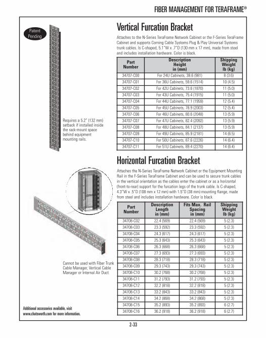
2-33
FIBER MANAGEMENT FOR TERAFRAME®
Horizontal Furcation Bracket Attaches the N-Series TeraFrame Network Cabinet or the Equipment MountingRail in the F-Series TeraFrame Cabinet and can be used to secure trunk cablesin the vertical orientation as the cables enter the cabinet or as a horizontal(front-to-rear) support for the furcation legs of the trunk cable. Is C-shaped,4.3”W x .5”D (108 mm x 12 mm) with 1.5”D (38 mm) mounting flange, madefrom steel and includes installation hardware. Color is black.
PartNumber
DescriptionLengthin (mm)
Fits Max. RailSpacingin (mm)
ShippingWeightlb (kg)
34708-C02 22.4 (569) 22.4 (569) 5 (2.3)34708-C03 23.3 (592) 23.3 (592) 5 (2.3)34708-C04 24.3 (617) 24.3 (617) 5 (2.3)34708-C05 25.3 (643) 25.3 (643) 5 (2.3)34708-C06 26.3 (668) 26.3 (668) 5 (2.3)34708-C07 27.3 (693) 27.3 (693) 5 (2.3)34708-C08 28.3 (718) 28.3 (718) 5 (2.3)34708-C09 29.3 (743) 29.3 (743) 5 (2.3)34708-C10 30.2 (768) 30.2 (768) 5 (2.3)34708-C11 31.2 (793) 31.2 (793) 5 (2.3)34708-C12 32.2 (818) 32.2 (818) 5 (2.3)34708-C13 33.2 (843) 33.2 (843) 5 (2.3)34708-C14 34.2 (868) 34.2 (868) 5 (2.3)34708-C15 35.2 (893) 35.2 (893) 6 (2.7)34708-C16 36.2 (918) 36.2 (918) 6 (2.7)
Vertical Furcation Bracket Attaches to the N-Series TeraFrame Network Cabinet or the F-Series TeraFrameCabinet and supports Corning Cable Systems Plug & Play Universal Systemstrunk cables. Is C-shaped, 5.1”W x .7”D (130 mm x 17 mm), made from steeland includes installation hardware. Color is black.
PartNumber
DescriptionHeightin (mm)
ShippingWeightlb (kg)
34707-C00 For 24U Cabinets, 38.6 (981) 8 (3.6)34707-C01 For 36U Cabinets, 59.6 (1514) 10 (4.5)34707-C02 For 42U Cabinets, 73.6 (1870) 11 (5.0)34707-C03 For 43U Cabinets, 75.4 (1915) 11 (5.0)34707-C04 For 44U Cabinets, 77.1 (1959) 12 (5.4)34707-C05 For 45U Cabinets, 78.9 (2003) 12 (5.4)34707-C06 For 46U Cabinets, 80.6 (2048) 13 (5.9)34707-C07 For 47U Cabinets, 82.4 (2092) 13 (5.9)34707-C08 For 48U Cabinets, 84.1 (2137) 13 (5.9)34707-C09 For 49U Cabinets, 85.9 (2181) 14 (6.5)34707-C10 For 50U Cabinets, 87.6 (2226) 14 (6.4)34707-C11 For 51U Cabinets, 89.4 (2270) 14 (6.4)
Requires a 5.2” (132 mm)setback if installed insidethe rack-mount spacebehind equipmentmounting rails.
Additional accessories available, visitwww.chatsworth.com for more information.
Cannot be used with Fiber TrunkCable Manager, Vertical CableManager or Internal Air Duct.

2-34
GF-SERIES GLOBALFRAME® CABINET SYSTEM
GF-Series GlobalFrame® Cabinet SystemThe GF-Series GlobalFrame® Cabinet System is an easy-to-use, cost effective,computer and network equipment storage cabinet that complies with datacenter, computer room and premise network equipment room requirements.The GlobalFrame is available in 30 popular frame sizes.
The enhanced frame design handles up to 3000 lb (1360 kg) of equipmentload. Equipment mounting rails are easily adjustable by loosening three hexnuts and the markings on the frame provide easy vertical alignment duringadjustment. The rails feature a Z-shaped design and have attachment pointsalong the sides for accessory cable rings that create a vertical pathway forcables.
The GF-Series GlobalFrame is available in Standard and Vertical Exhaust Ductconfigurations. Select the standard configuration with perforated metal frontand rear doors to support front-to-rear airflow in traditional hot aisle/coldaisle or enclosed aisle applications. The standard configuration features asolid top panel with four large knockouts for cable access and a double(vertically split) perforated metal rear door for easy access to equipment.
Select the Vertical Exhaust Duct configuration with perforated metal frontdoor and solid metal rear door to support front-to-top airflow and isolate hotexhaust air as it exits the cabinet using CPI Passive Cooling®. Isolating hotexhaust air from the room creates a more uniform room air temperature,eliminates hot spots, allows higher temperature set points, increased chilledwater temperatures and enables more hours of economizer cooling. TheVertical Exhaust Duct configuration features a top panel with two largeknockouts in the front corners for cable access, an extendable top-mountVertical Exhaust Duct, a seal for the rear door and a Bottom Panel.
Specifications:• Freestanding equipment cabinet provides front and rear support for 19”W(482.6 mm) EIA rack-mount equipment and shelves
• Load Capacity:- 3000 lb (1360 kg), static load on leveling feet- 2250 lb (1020 kg), rolling on casters- 2000 lb (907.2 kg), shipping on shock pallet
Cabinet Includes:• Welded and bolted steel four-post frame• Equipment mounting rails, two pairs• Equipment mounting hardware, (25) M6 cage nuts and screws• Factory installed grounding/bonding system• Leveling feet and casters• Floor attachment brackets• PDU Brackets, one pair, for mounting two vertical CPI PDUs• Baying kit for 600 mm and 24” tile spacing• Standard or Vertical Exhaust Duct top panel with cable access knock-outs• Perforated metal front door• Double perforated metal rear door with standard top panel• Solid metal rear door with Vertical Exhaust Duct top panel• Bottom Panel with Vertical Exhaust Duct top panel• Solid metal side panels (optional)
See following pages for details.

2-35
Dimensions:
1st Digit - Height The GlobalFrame is offered in three overall heights (42U, 45U and48U). Heights are listed as rack-mount unit (U).2nd Digit - Width Three widths available: 23.6” (600 mm), 29.5” (750 mm) and31.5” (800 mm). The cabinet includes equipment mounting railsspaced for 19” EIA (482.6 mm).3rd Digit - Depth Four depths: 31.5” (800 mm), 39.4” (1000 mm), 41.3” (1050 mm)and 47.2” (1200 mm). Doors add approximately 1” (25 mm) todepth.4th Digit - Side PanelsSelect the number of side panels based on your requirements.
Height Dimensions - in (mm)Rail Height 42U 45U 48UOverall Height, Casters included 79.3 (2013) 84.5 (2147) 89.8 (2280)
Frame Opening, Front 73.9 (1876) 79.1 (2010) 84.4 (2143)
Width Dimensions - in (mm)Nominal Width 600 mm 750 mm 800 mmOverall Width 23.6 (600) 29.5 (750) 31.5 (800)
Frame Opening, Front 20.0 (508) 25.9 (658) 27.9 (708)
Panel Width 19” EIA (482.6 mm) 19” EIA (482.6 mm) 19” EIA (482.6 mm)
Depth Dimensions - in (mm)Nominal Depth 800 mm 1000 mm 1050 mm 1200 mmOverall Depth with Doors1 32.7 (831) 40.3 (1024) 42.3 (1074) 48.4 (1229)
Frame Depth, At Base, No Doors2 31.5 (800) 39.4 (1000) 41.3 (1050) 47.2 (1200)
Min./Max. Rail Depth,600 mm Cabinet3 N/A 7.2 (183) / 34.6 (879) 7.2 (183) / 36.6 (929) 7.2 (183) / 42.5 (1079)
Min./Max. Rail Depth,750 / 800 mm Cabinets3 6.8 (173) / 26.3 (668) 6.8 (173) / 34.2 (868) 6.8 (173) / 36.1 (918) 6.8 (173) / 42.0 (1068)
Overall Height dimensions do not include the Vertical Exhaust Duct. The Vertical Exhaust Duct is available in two height ranges; 20”-34”H(508 mm - 863 mm) or 34”-60”H (863 mm - 1523 mm).
1. Doors add approximately 1.0” (25 mm) to the frame depth of the cabinet. The front door is 2.2”D (56 mm) and adds approximately 1” (25 mm) to the frame depth. The rear door is approximately 1.0”D (25 mm) and does not add to the frame depth. See note 2.
2. Depth at the base of the cabinet frame is 2.5” (64 mm) more than depth at the frame uprights. There is a 1.25” (32 mm) threshold onthe front and rear of the cabinet that provides easy access to leveling feet. When installed, the front and rear doors cover thisthreshold. Frame uprights (corner posts) are approximately 2.9” (74 mm) deep.
3. When adjusted to maximum depth, mounting rails wrap around the frame uprights (corner posts). Note: Cable Ring Kits cannot be attached to the rails when they are set to maximum depth.
GF-SERIES GLOBALFRAME® CABINET SYSTEM
5th Digit - ConfigurationThere are two configurations and two pallet options. a. Select standard cabinets when deploying in hot aisle/cold aisle installations or where aisle containment will beemployed.
b. Select the shock pallet when cabinets will be pre-loaded with equipment at a factory integration site prior to finalshipment to the customer site. Note that the cabinet’s loadcapacity is limited to 2000 lb (907.2 kg) when equipment isshipped installed using shock pallet.
c. Select high density cabinets with Vertical Exhaust Ducts when deploying in facilities with isolated return aircontainment.
Part Number Configurator (tables on next page)When ordering GlobalFrame Cabinet, the part number is always preceded by the letters GF. Example Part Number: GF-1A200

2-36
GF-SERIES GLOBALFRAME® CABINET SYSTEM
Standard Cabinets:• Supports front-to-rear airflow for hot aisle/cold aisle or enclosed aisle environments• 30 frame sizes available - three heights, three widths, four depths• Includes a cabinet frame, two pairs of 19”EIA square-punched equipment mounting rails, a top panel, a perforated metal front door,a double perforated metal rear door, swing handle latches, keyed locks, casters, leveling feet, floor attachment brackets and baying kit
• Supports 3000 lb (1360 kg) static load on leveling feet; 2250 lb (1020 kg) “rolling” load on casters• Color is black.
Standard Cabinets with Shock Pallet:• Ship the cabinet with equipment pre-installed for faster equipment deployment• 8 frame sizes available - two heights, two widths, two depths• Includes a cabinet frame, two pairs of 19”EIA square-punched equipment mounting rails, a top panel, a perforated metal front door,a double perforated metal rear door, swing handle latches, keyed locks, casters, leveling feet, floor attachment brackets and baying kit
• Ships on a shock pallet with reusable carton and wood unloading ramp• Supports 2000 lb (907.2 kg) shipping load on shock pallet• Supports 3000 lb (1360 kg) static load on leveling feet; 2250 lb (1020 kg) “rolling” load on casters• Color is black.
GF-
Height Width Depth Side Panels Configurationin mm U in mm in mm Description Description
1 79.3 2013 42U A 23.6 600 2 39.4 1000 0 No Sides 0 Standard Top Panel/Standard Pallet
2 84.5 2147 45U B 29.5 750 3 41.3 1050 1 One Side
3 89.8 2280 48U 4 47.2 1200 2 Two Sides
High-Density Cabinets with Vertical Exhaust Duct:• Isolates hot exhaust air; supports front-to-top airflow with the Vertical Exhaust Duct• 18 frame sizes to choose from - three heights, three widths, two depths• Includes a cabinet frame, two pairs of 19”EIA square-punched equipment mounting rails, a Vertical Exhaust Duct and top panel, a Bottom Panel, a perforated metal front door, a solid metal rear door, a rear door sealing kit, swing handle latches, keyed locks, casters,leveling feet, floor attachment brackets and baying kit
• Supports 3000 lb (1360 kg) static load on leveling feet; 2250 lb (1020 kg) “rolling” load on casters• Color is black.
GF-
Height Width Depth Side Panels Configurationin mm U in mm in mm Description Description
1 79.3 2013 42U C 31.5 800 1 31.5 800 0 No Sides 0 Standard Top Panel/Standard Pallet
2 84.5 2147 45U 2 39.4 1000 1 One Side
3 89.8 2280 48U 3 41.3 1050 2 Two Sides
4 47.2 1200
GF-
Height Width Depth Side Panels Configurationin mm U in mm in mm Description Description
1 79.3 2013 42U A 23.6 600 3 41.3 1050 0 No Sides 3 Standard Top Panel/Shock Pallet
2 84.5 2147 45U B 29.5 750 4 47.2 1200 1 One Side
2 Two Sides
GF-
Height Width Depth Side Panels Configurationin mm U in mm in mm Description Description
1 79.3 2013 42U A 23.6 600 3 41.3 1050 0 No Sides 1 Vertical Exhaust Duct, 20”- 34”H(508 mm - 863 mm)/Standard Pallet
2 84.5 2147 45U B 29.5 750 4 47.2 1200 1 One Side 2 Vertical Exhaust Duct, 34”- 60”H(863 mm - 1523 mm)/Standard Pallet
3 89.8 2280 48U C 31.5 800 2 Two Sides

2-37
GF-SERIES GLOBALFRAME® CABINET SYSTEM
GF-Series GlobalFrame AccessoriesAirflow DirectorAttaches to the cabinet frame and redirects exhaust airflow from serversmounted near the bottom of the cabinet towards the top of the cabinet. Use incabinet with high heat load (>15kW) using a Vertical Exhaust Duct top panel.
Bottom PanelPrevents airflow from entering the bottom of the cabinet. Bottom panel hasone 8.8”W x 3.9”D (224 mm x 99 mm) brush-sealed cable access port locatednear the rear center of the panel. Bottom Panel is included with High-DensityCabinets with Vertical Exhaust Duct.
Rail Seal KitUse on the cabinet’s front pair of equipment mounting rails to create afront/rear (cold/hot) airflow barrier within the cabinet. Each kit includes fourhalf-heights panels, edge seal and installation hardware. Each panel has threeround 2.8” (71 mm) diameter cable grommets that align with cable openings inthe mounting rail.
Brushed Side PanelIncludes two half-height solid side panels to cover one side of a cabinet. Eachhalf-height panel has four 8.8”H x 3.9”W (224 mm x 99 mm) brush-sealedcable access ports, one per corner, a single locking latch and a connectionpoint for a grounding and bonding strap. Select the side panel to match theheight and depth of the cabinet.
Rail Seal Kit (Cabinet Height)N/A 25250-700 25252-700 For 42U Cabinet 21 (9.5)
N/A 25250-701 25252-701 For 45U Cabinet 22 (10.0)
N/A 25250-702 25252-702 For 48U Cabinet 23 (10.4)
Part NumberCabinet Width Description
ShippingWeightlb (kg)600 mm W 750 mm W 800 mm W
25150-701 25150-702 25150-702 Airflow Director 8 (3.6)
Bottom Panel (Cabinet Depth)N/A N/A 25130-708 800 mm Cabinets 19 (8.6)
25130-701 25130-705 25130-709 1000 mm Cabinets 23 (10.4)
25130-702 25130-706 25130-710 1050 mm Cabinets 24 (10.9)
25130-703 25130-707 25130-711 1200 mm Cabinets 27 (12.2)
Color is Black. Shipping Weights are for 800 mm part numbers.
Brushed Side Panel(Cabinet Depth)
42U 45U 48U25037-700 25037-704 25037-708 800 mm Cabinets 38 (17.2)
25037-701 25037-705 25037-709 1000 mm Cabinets 47 (21.3)
25037-702 25037-706 25037-710 1050 mm Cabinets 49 (22.2)
25037-703 25037-707 25037-711 1200 mm Cabinets 55 (24.9)
25130-7XX
25150-702
25250-70X
25037-7XX

25242-701
Color is Black.
2-38
GF-SERIES GLOBALFRAME® CABINET SYSTEM
Cable Port Brush KitUse to cover the large cable knockouts in the cabinet’s top panel. Each kitincludes two 3.9” x 8.8”D (99 mm x 224 mm) brush-sealed grommets that snapinto the opening on the top panel once the large 4.5”W x 9.0”D (114 mm x 228mm) knockout is removed. The split design also allows the grommet to betemporarily removed to pass large power plugs through the knockout whenpower is added or removed.
Cable Port Grommet KitUse kit to cover the round cable knockouts in the cabinet’s top panel. Each kitcontains two 2.8” (71 mm) diameter grommets that snap into the openings inthe top panel once the knockout is removed. The standard and fan top panelshave four round knockouts and four openings that include grommets.
Snap-In Grommet KitKit includes fourteen 5.5”H x 3.25”W (140 mm x 83 mm) grommets that protectcables from the edges of the openings in the equipment mounting rails in 750mm and 800 mm wide cabinets. Each rail has seven openings. The Snap-InGrommet Kit cannot be used with the Rail Seal Kit (P/Ns 25250-70X or 25252-70X).
Snap-In Grommet and Plug KitIncludes 14 individual snap-in grommets with covers that seal the openings in750 mm and 800 mm wide equipment mounting rails. Each rail has sevenopenings. Use one kit to seal all of the openings on the front pair of equipmentmounting rails. The Snap-In Grommet and Plug Kit is an alternative to the RailSeal Kit (P/N 25250-70X or 25252-70X).
Baying Seal KitThe Baying Seal Kit is used to seal the gap between 600 mm cabinets (of thesame height and depth) when they are centered on 24” (610 mm) floor tiles. Thekit includes six snap-in plastic seals; three that seal the front gap and three thatseal the rear gap. Baying Seal Kit works with or without side panels. Nohardware required.
25190-001
35021-000
25107-001
25108-001
PartNumber Description
ShippingWeightlb (kg)
25190-001 Cable Port Brush Kit, Pack of 2 2 (0.9)
35021-000 Cable Port Grommet Kit, Pack of 2 2 (0.9)
25107-001 Snap-In Grommet Kit,For 750 mm & 800 mm Cabinets 2 (0.9)
25108-001 Snap-In Grommet & Plug Kit,For 750 mm & 800 mm Cabinets 2 (0.9)
25242-700 Baying Seal Kit, For 42U Cabinets 5 (2.3)
25242-701 Baying Seal Kit, For 45U Cabinets 5 (2.3)
25242-702 Baying Seal Kit, For 48U Cabinets 5 (2.3)

2-39
GF-SERIES GLOBALFRAME® CABINET SYSTEM
Cable Lashing Bracket KitAttaches to the cabinet frame and provides multiple tie points for cables. Securecables to the bracket using Saf-T-Grip Straps or cable ties. The kit includes twohalf-height brackets with U-shaped cable tie points and installation hardware.Select from two widths. The 5” (125 mm) wide version has two vertical columnsof tie points for cables and requires a 6.75” (172 mm) rail setback. The 10” (250mm) wide version has three vertical columns of tie points for cables and requiresan 11.75” (299 mm) rail setback. The 10”W (250 mm) cannot be used in 800 mmdeep cabinets.
Cable Ring KitThe Cable Ring Kit includes eight plastic D-rings that snap onto the equipmentmounting rails inside the cabinet creating a vertical pathway for cables. Each railcan support eight rings. Select the kit to match cabinet width. There are two ringsizes (depths) for the 750 mm and 800 mm wide cabinets. Mounting rails in the600 mm wide cabinet must be setback a minimum of 5.5” (140 mm) to provideclearance for the cable rings. Mounting rails in the 750 mm and 800 mm widecabinets must be setback a minimum of 5.0" (127 mm) to provide clearance formedium cable rings and 10.0" (254 mm) to provide clearance for large cablerings. Cable Ring Kit cannot be used with Vertical Cable Managers (P/Ns 25110-70X, 25120-70X) or Rail Seal Kit (P/Ns 25250-70X, 25252-70X).
Full Height PDU BracketAttaches to the cabinet frame and provides two attachment points for verticalpower distribution units (PDUs) or power strips for cabinets and multiple tiepoints for power cables. Use with CPI vertical PDUs for cabinets that are 68.5”H(1740 mm) or 70.5”H (1791 mm). Tool-less PDU attachment points are located64.75” (1645 mm) and 61.25” (1556 mm) apart. The bracket supports two 2.4”W(61 mm) or narrower PDUs or power strips side-by-side or one 4.9”W (124 mm)PDU. The bracket is 5.2” (132 mm) wide and requires a 7.5 inch (191 mm) railsetback.
Color is Black. *Cannot be used in 800 mm deep cabinets.
PartNumber Description
ShippingWeightlb (kg)
25221-701 5”W (125 mm) Bracket for 42U Cabinet 16 (7.3)
25221-702* 10”W (250 mm) Bracket for 42U Cabinet 16 (7.3)
25221-703 5”W (125 mm) Bracket for 45U Cabinet 17 (7.7)
25221-704* 10”W (250 mm) Bracket for 45U Cabinet 17 (7.7)
25221-705 5”W (125 mm) Bracket for 48U Cabinet 18 (8.2)
25221-706* 10”W (250 mm) Bracket for 48U Cabinet 18 (8.2)
25104-001 Cable Ring Kit, 600 mm Cabinets 2 (0.9)
25105-002 Medium Cable Ring Kit, 750 mm Cabinets 3 (1.4)
25106-002 Medium Cable Ring Kit, 800 mm Cabinets 3 (1.4)
25105-001 Large Cable Ring Kit, 750 mm Cabinets 5 (2.3)
25106-001 Large Cable Ring Kit, 800 mm Cabinets 8 (2.7)
25141-700 Full Height PDU Bracket, For 42U Cabinets 10 (4.5)
25141-701 Full Height PDU Bracket, For 45U Cabinets 10 (4.5)
25141-702 Full Height PDU Bracket, For 48U Cabinets 11 (5.0)
25104-001
25105-002
25106-001
25221-70X
25141-70X

2-40
GF-SERIES GLOBALFRAME® CABINET SYSTEM
Vertical Cable ManagerAttaches to the cabinet’s equipment mounting rails and provides vertical cablemanagement with plastic T-shaped cable guides and openings that align witheach rack-mount space/unit (U) in the cabinet. The manager for the 600 mmwide cabinet includes fingers only and can be used in any cabinet. The managerfor the 750 mm or 800 mm wide cabinet is available in two depths with standardor extended fingers and also includes a cover that partially encloses cables.Standard Fingers require a 7” (178 mm) rail setback. Extended Fingers require a9.25” (235 mm) rail setback. Cannot be used with Cable Ring Kit.
Color is Black. Shipping Weights are for 800 mm part numbers.
25110-701 25120-703
Cable Ring ManagerA vertical cable manager with plastic D-rings that attaches directly to thecabinet’s frame independent of the equipment mounting rails and is available for750 mm and 800 mm wide cabinets. The manager includes two half-heightpanels, eight plastic D-rings and installation hardware. Each panel for the 750mm wide cabinet includes four 4.5"W x 4.7"D (114 mm x 119 mm) medium or4.5”W x 9.8”D (114 mm x 249 mm) large rectangular plastic D-rings to managecables and three 2.8” (71 mm) diameter round edge protected cable passthrough ports. Each panel for the 800 mm wide cabinet includes four 5.5"W x4.7"D (140 mm x 119 mm) medium or 5.5”W x 9.8”D (140 mm x 249 mm) largerectangular plastic D-rings to manage cables and three 5.5”H x 3.25”W (140 mmx 83 mm) rectangular edge protected cable pass through ports with snap-oncovers. The managers with medium rings are 5.8"D (150 mm) and require aminimum 6" (153 mm) rail setback; the managers with large rings are 10.9”D(277 mm) and require a 11.5" (293 mm) rail setback.
Color is Black. Shipping Weights are for 800 mm part numbers.
25102-70125103-703
Part Number Description
ShippingWeightlb (kg) 750 mm 800 mm
25103-703 25102-703 Medium Rings For 42U Cabinets 13 (5.9)
25103-704 25102-704 Medium Rings For 45U Cabinets 14 (6.4)
25103-705 25102-705 Medium Rings For 48U Cabinets 15 (6.8)
25103-700 25102-700 Large Rings For 42U Cabinets 15 (6.8)
25103-701 25102-701 Large Rings For 45U Cabinets 16 (7.3)
25103-702 25102-702 Large Rings For 48U Cabinets 17 (7.7)
Vertical Cable Manager with Standard Fingers
Part Number Description
ShippingWeightlb (kg) 600 mm 750 mm 800 mm
25110-700 25404-703 25404-706 For 42U Cabinets 15 (6.8)
25110-701 25404-704 25404-707 For 45U Cabinets 16 (7.3)
25110-702 25404-705 25404-708 For 48U Cabinets 16 (7.3)
Vertical Cable Manager with Extended FingersN/A 25120-703 25120-706 For 42U Cabinets 19 (8.6)
N/A 25120-704 25120-707 For 45U Cabinets 20 (9.1)
N/A 25120-705 25120-708 For 48U Cabinets 21 (9.5)
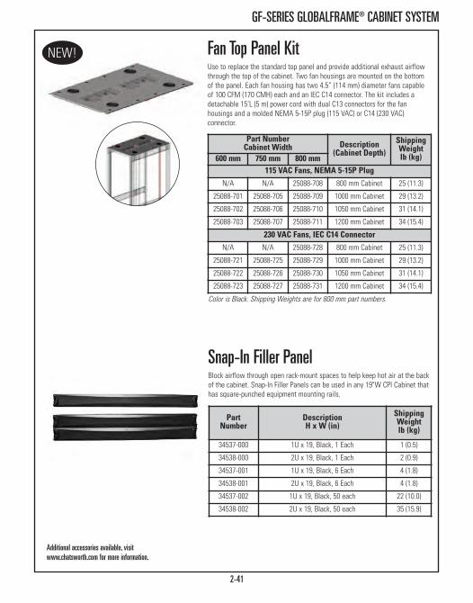
2-41
GF-SERIES GLOBALFRAME® CABINET SYSTEM
Fan Top Panel KitUse to replace the standard top panel and provide additional exhaust airflowthrough the top of the cabinet. Two fan housings are mounted on the bottomof the panel. Each fan housing has two 4.5” (114 mm) diameter fans capableof 100 CFM (170 CMH) each and an IEC C14 connector. The kit includes adetachable 15’L (5 m) power cord with dual C13 connectors for the fanhousings and a molded NEMA 5-15P plug (115 VAC) or C14 (230 VAC)connector.
Part NumberCabinet Width Description
(Cabinet Depth)ShippingWeightlb (kg)600 mm 750 mm 800 mm
115 VAC Fans, NEMA 5-15P PlugN/A N/A 25088-708 800 mm Cabinet 25 (11.3)
25088-701 25088-705 25088-709 1000 mm Cabinet 29 (13.2)
25088-702 25088-706 25088-710 1050 mm Cabinet 31 (14.1)
25088-703 25088-707 25088-711 1200 mm Cabinet 34 (15.4)
230 VAC Fans, IEC C14 Connector N/A N/A 25088-728 800 mm Cabinet 25 (11.3)
25088-721 25088-725 25088-729 1000 mm Cabinet 29 (13.2)
25088-722 25088-726 25088-730 1050 mm Cabinet 31 (14.1)
25088-723 25088-727 25088-731 1200 mm Cabinet 34 (15.4)
Color is Black. Shipping Weights are for 800 mm part numbers.
Additional accessories available, visitwww.chatsworth.com for more information.
Snap-In Filler PanelBlock airflow through open rack-mount spaces to help keep hot air at the backof the cabinet. Snap-In Filler Panels can be used in any 19"W CPI Cabinet thathas square-punched equipment mounting rails.
PartNumber
DescriptionH x W (in)
ShippingWeightlb (kg)
34537-000 1U x 19, Black, 1 Each 1 (0.5)
34538-000 2U x 19, Black, 1 Each 2 (0.9)
34537-001 1U x 19, Black, 6 Each 4 (1.8)
34538-001 2U x 19, Black, 6 Each 4 (1.8)
34537-002 1U x 19, Black, 50 each 22 (10.0)
34538-002 2U x 19, Black, 50 each 35 (15.9)
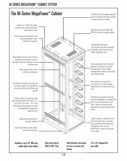
M-SERIES MEGAFRAME® CABINET SYSTEM
2-42
Quick and easy assembly withunique patented corner
attachment bracket
Top Panel with 6 edge-protectedpunch-out ports provides cablingaccess wherever needed
Attach 12” (300 mm) cablerunway easily with pre-drilled
attachment holes
Adjustable (front to rear) verticalmounting rails allow use as a
standard four-post cabinet or twochannel rack
Rack-mount units markssimplify installation
Extruded horizontal mounting railprovides support for equipmentmounting rails and cabling ring
panels
Wide variety of mounting railswith Universal EIA 5/8”-5/8”-1/2”
(15.9 mm -15.9 mm - 12.7 mm)alternating hole pattern to meet
all equipment installationrequirements
Open base allows cable entry,exit and ventilation
Adjustable leveling feetprovide stability
Lightweight aluminumconstruction provides strength,durability, easy handling andlower shipping costs
Optional fan kit provides 400CFM of airflow through cabinet
Fully adjustable side-mountedcabling ring sections provideunsurpassed vertical cablemanagement without protrudinginto usable space
Standard door options includesmoked plexiglass or vented frontdoor and solid aluminum reardoor; options include ventedplexiglass and perforated metaldoors
“Quick release” attachment forfront and rear doors provideseasy assembly and equipmentinstallation; door can bepositioned to open to the rightor left side
19” or 23” Standard EIArack width
Solid aluminum side panelsare easy-to-remove andlocking
Static load rating of2000 lb (907.2 kg)
Inch markers on horizontalmounting rails ensure properalignment of vertical mountingrails
Available in up to 39” (990 mm)usable depth, many heights
The M-Series MegaFrame® Cabinet

2-43
M-SERIES MEGAFRAME® CABINET
M-Series MegaFrame® Cabinet72”, 78” and 84” (1830 mm, 1980 mmand 2130 mm) The M-Series MegaFrame® Cabinet System supports a vast array of potentialapplications. The cabinet is available in a variety of heights, widths anddepths to meet the most stringent demands. Also, the M-Series CabinetSystem allows the user to select mounting rails to accommodate today’svariety of rack-mount equipment.
Specifications:• Available in three heights; 72”, 78” and 84” (1830 mm, 1980 mm and 2130 mm)*
• Available in 19” or 23” EIA standard rack widths• Available in four depths; 24”, 30”, 36” and 39” (610 mm, 760 mm, 910 mm and 990 mm)
• Available with or without top or side panels• Side panels are easy-to-remove and locking• Can be ordered with or without doors in a variety of materials and styles
• Cabinet is available with a choice of tapped 12-24, square-punched, Sun® or IBM® rails
• Rack-mount unit marks simplify equipment installation• Hardware for each rail type is included• All vertical mounting rails are available in half heights (also sold separately)• Manufactured from aluminum custom designed for maximum strength andfunctionality
• Bolted construction, delivers fully or partially assembled• Load Rating: 2000 lb (907.2 kg)• UL Listed: File E212094; Category DUXR (US) - Communications - Circuit Accessory
Cabinet Includes:• (1) Four-Post Frame (anodized aluminum finish)• (4) Vertical Mounting Rails & Mounting Hardware• (2) Locking, Easy-To-Remove Side Panels• (1) “Quick-Release” Front Door• (1) “Quick-Release” Rear Door• (1) Vented Top Panel & Six Cable Access Ports• (2) Vertical Half Height Cable Managers (wide)• (4) Leveling Feet• (1) PDU Mounting Bracket Kit• (1) Multi-Bay Attachment Hardware Kit• (4) Floor Anchor Clamps• (1) Bag of 50 Each #12-24 Rack Channel Mounting Screws with tapped rails• (1) Bag of 16 each M6 Cage Nuts and Screws, and 25 each #12-24 Cage Nuts and Screws with square-punched rails
*Note: Special 8’ (2.4 m) cabinets are available in standard lead times.

2-44
M-SERIES MEGAFRAME® CABINET
MegaFrame® Cabinet System 72”, 78” and 84” (1830 mm, 1980 mm and 2130 mm) Dimensions:
Height Dimensions - in (mm)All Cabinet Styles 72 (1830) 78 (1980) 84 (2130)Usable Vertical Panel Space 38U, 66.50 (1689.1) 42U, 73.50 (1866.9) 45U, 78.75 (2000.3)
Overall Height without Leveling Feet 72.02 (1829.3) 78.02 (1981.7) 84.02 (2130.0)
Overall Height with Leveling Feet 72.92 (1852.2) 78.92 (2004.6) 84.92 (2157.0)
Overall Height with Casters 75.70 (1922.8) 81.70 (2075.2) 87.70 (2230.0)
Frame Vertical Opening 67.90 (1724.7) 73.90 (1877.1) 79.90 (2029.5)
Width Dimensions - in (mm)Usable Equipment Panel Width 19” EIA 23” EIAOverall Width 27.32 (693.9) 31.32 (795.5)
Frame Horizontal Opening 20.20 (513.1) 24.20 (614.7)
Depth Dimension Cabinet Only (With Doors) - in (mm)Nominal Cabinet Depth 24 (61) 30 (760) 36 (910) 39 (990) Maximum Mounting Depth - Rail to Rail 24.00 (609.6) 30.00 (762.0) 36.00 (914.4) 39.00 (990.6)
Overall Depth - Inside Door to Inside Door 27.22 (691.4) 33.22 (843.8) 39.22 (996.2) 42.22 (1072.4)
Overall Depth - Door Face to Door Face 27.62 (701.5) 33.62 (853.9) 39.62 (1006.3) 42.62 (1082.5)
Depth Dimension Frame Only (Without Doors) - in (mm)Nominal Cabinet Depth 24 (610) 30 (760) 36 (910) 39 (990) Maximum Mounting Depth - Rail to Rail 24.00 (609.6) 30.00 (762.0) 36.00 (914.4) 39.00 (990.6)
Overall Depth 26.13 (663.7) 32.13 (816.1) 38.13 (968.5) 41.13 (1044.7)
Shipping Weights - lb (kg)All Cabinet Styles - in (mm) 72 (1830) 78 (1980) 84 (2130)Minimum 152 (68.9) 152 (68.9) 155 (70.3)
Maximum 251 (113.9) 262 (118.8) 287 (130.2)
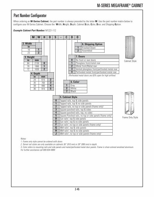
2-45
M-SERIES MEGAFRAME® CABINET
M W H D S - C D O
8. Shipping Option1 Knocked Down2 Assembled
2. Widthin19 123 2
3. Heightin mm84 2130 078 1980 172 1830 2
4. Depthin mm24 610 230 760 339 990 436 910 5
7. Doors0 No front or rear doors1 Plexiglass front/metal rear2 Metal front/Metal rear3 Vented plexiglass front/perforated metal rear4 Perforated metal front/perforated metal rear
(Perforated metal doors are 63% open for high airflow)
6. Color3
1 Gray2 White7 Black
5. Cabinet Style0 Tapped rails, top & side panels1 Tapped rails, top & no side panels2 Tapped rails, no top or side panels (frame only)1
3 Square-punched rails, top & sides4 Square-punched rails, top, no sides5 Square-Punched rails, no top or side panels (frame only)1
D Sun rails2, top & side panelsE Sun rails2, top & no side panelsF Sun rails2, no top or side panels (frame only)1
G IBM rails2, top & side panelsH IBM rails2, top & no side panelsJ IBM rails2, no top or side panels (frame only)1
When ordering an M-Series Cabinet, the part number is always preceded by the letter M. Use the part number matirx below toconfigure your M-Series Cabinet. Choose the Width, Height, Depth, Cabinet Style, Color, Door, and Shipping Option.
Example Cabinet Part Number: M1221-112
Notes:1. Frame only style cannot be ordered with doors2. Server rail styles are only available on cabinets 36” (910 mm) or 39” (990 mm) in depth.3. Color refers to mounting rails and side panels and metal/perforated metal door panels. Frame is silver-colored anodized aluminum.For further assistance call 800-834-4969.
Frame Only Style
Part Number Configurator
Cabinet Style

2-46
M-SERIES MEGAFRAME® CABINET
48” (1220 mm) M-Series MegaFrame®
Cabinet The 48”H (1220 mm) M-Series MegaFrame® Cabinet is designed for spaceconscious customers who demand value. The cabinet is available in a varietyof widths and depths. Multiple cabinets can be mounted side-by-side usingoptional baying hardware. The cabinet is available in white, black or graypowder-coated finish. The cabinet is also available in a frame onlyconfiguration.
Note: When ordering a frame only configuration, the mounting rails have apowder-coated finish based on your color selection. The frame is always silver-colored anodized aluminum.
Specifications:• Provides 25U of rack-mount space• Available in 19” EIA or 23” EIA standard rack widths• Available in three depths; 24”, 30” and 36” (610 mm, 760 mm and 910 mm)• Load Rating: 2000 lb (907.2 kg)
Frame Only Style
Cabinet Style
Notes:1. Frame only style cannot be ordered with doors2. Color refers to mounting rails and side panels and metal/perforated metal door panels.Frame is silver-colored anodized aluminum. For further assistance call 800-834-4969.
M W H D S - C D O
8. Shipping Option1 Knocked Down2 Assembled
2. Widthin19 123 2
3. Heightin mm48 1220 5
4. Depthin mm24 610 230 760 336 910 5
7. Doors0 No front or rear doors1 Plexiglass front/metal rear2 Metal front/Metal rear3 Vented plexiglass front/perforated metal rear4 Perforated metal front/perforated metal rear
(Perforated metal doors are 63% open for high airflow)
6. Color2
1 Gray2 White7 Black
5. Cabinet Style0 Tapped rails, top & side panels1 Tapped rails, top & no side panels2 Tapped rails, no top or side panels (frame only)1
3 Square-punched rails, top & sides4 Square-punched rails, top, no sides5 Square-Punched rails, no top or side panels (frame only)1
Part Number ConfiguratorWhen ordering an M-Series Cabinet, the part number is always preceded by the letter M. Use the part number matirx below toconfigure your M-Series Cabinet. Choose the Width, Height, Depth, Cabinet Style, Color, Door, and Shipping Option.
Example Cabinet Part Number: M2530-112
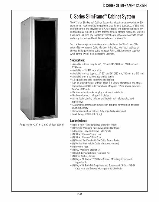
2-47
C-SERIES SLIMFRAME® CABINET
Requires only 24” (610 mm) of floor space!
C-Series SlimFrame® Cabinet SystemThe C-Series SlimFrame® Cabinet System is an ideal storage solution for EIAstandard 19” rack-mountable equipment that fits on a standard, 24” (610 mm)access floor tile and provides up to 43U of space. The cabinet can bay to anyexisting MegaFrame to meet the demand for data storage expansion. MultipleSlimFrame Cabinets bay together by selecting variations without side panelsand using the included Multi-Bay Attachment Hardware Kit.
Two cable management solutions are available for the SlimFrame. CPI'sunique Narrow Vertical Cable Manager is included with each cabinet, orchoose the larger vertical cable manager, P/N 12465, for greater capacitywhen baying two or more SlimFrame Cabinets.
Specifications:• Available in three heights; 72”, 78” and 84” (1830 mm, 1980 mm and 2130 mm)
• Available in 19” EIA rack width• Available in three depths; 22”, 30” and 36” (560 mm, 760 mm and 910 mm)• Available with or without top or side panels• Side panels are easy-to-remove and locking• Can be ordered with or without doors in a variety of materials and styles• Cabinet is available with your choice of tapped 12-24, square-punched,Sun® or IBM® rails
• Rack-mount unit marks simplify equipment installation• Hardware for each rail type is included• All vertical mounting rails are available in half heights (also sold separately)
• Manufactured from aluminum custom designed for maximum strength and functionality
• Bolted construction, delivers fully or partially assembled• Load Rating: 2000 lb (907.2 kg)
Cabinet Includes:• (1) Four-Post Frame (anodized aluminum finish)• (4) Vertical Mounting Rails & Mounting Hardware• (2) Locking, Easy-To-Remove Side Panels• (1) “Quick-Release” Front Door• (1) “Quick-Release” Rear Door• (1) Vented Top Panel with Six Cable Access Ports• (2) Vertical Half Height Cable Managers (narrow)• (4) Leveling Feet• (1) PDU Mounting Bracket Kit• (1) Multi-Bay Attachment Hardware Kit• (4) Floor Anchor Clamps• (1) Bag of 50 Each #12-24 Rack Channel Mounting Screws with
tapped rails• (1) Bag of 16 Each M6 Cage Nuts and Screws and 25 Each #12-24
Cage Nuts and Screws with square-punched rails

2-48
C-SERIES SLIMFRAME® CABINET
Height Dimensions - in (mm)All Cabinet Styles 72 (1830) 78 (1980) 84 (2130)Usable Vertical Panel Space 37U 40U 43U
Overall Height without Leveling Feet 72.00 (1828.8) 78.00 (1981.2) 84.00 (2133.6)
Overall Height with Leveling Feet 72.90 (1851.7) 78.90 (2004.1) 84.90 (2156.5)
Overall Height with Casters 75.38 (1914.7) 81.38 (2067.1) 87.38 (2219.5)
Frame Vertical Opening 64.88 (1648.0) 70.88 (1800.4) 76.88 (1952.8)
Width Dimensions - in (mm)Usable Equipment Panel Width 19” EIAOverall Width 24 (610)
Frame Horizontal Opening 19.84 (500)
Depth Dimension Frame Only ( With Doors) - in (mm)Nominal Cabinet Depth 22 (560) 30 (760) 36 (910) Maximum Mounting Depth - Rail to Rail 21.84 (554.7) 30.00 (762.0) 36.00 (914.4)
Overall Depth - Frame Only 23.96 (608.6) 32.12 (815.8) 38.12 (968.2)
Overall Depth - Door Face to Door Face 25.46 (646.7) 33.62 (853.9) 39.62 (1006.3)
C-Series SlimFrame® Cabinet System
Dimensions
Shipping Weights - lb (kg)All Cabinet Styles - in (mm) 72 (1830) 78 (1980) 84 (2130)Minimum 142 (64.4) 141 (64.0) 149 (67.6)
Maximum 233 (105.7) 249 (112.9) 250 (113.4)

2-49
C-SERIES SLIMFRAME® CABINET
C W H D S - C D O
8. Shipping Option1 Knocked Down2 Assembled
2. Widthin19 1
4. Depthin mm30 760 336 910 522 560 6
7. Doors0 No front or rear doors1 Plexiglass front/metal rear2 Metal front/Metal rear3 Vented plexiglass front/perforated metal rear4 Perforated metal front/perforated metal rear
(Perforated metal doors are 63% open for high airflow)
6. Color3
1 Gray2 White7 Black
5. Cabinet Style0 Tapped rails, top & side panels1 Tapped rails, top & no side panels2 Tapped rails, no top or side panels (frame only)1
3 Square-punched rails, top & sides4 Square-punched rails, top, no sides5 Square-Punched rails, no top or side panels (frame only)1
D Sun rails2, top & side panelsE Sun rails2, top & no side panelsF Sun rails2, no top or side panels (frame only)1
G IBM rails2, top & side panelsH IBM rails2, top & no side panelsJ IBM rails2, no top or side panels (frame only)1
When ordering an C-Series Cabinet, the part number is always preceded by the letter C. Use the part number matirx below to configureyour C-Series Cabinet. Choose the Width, Height, Depth, Cabinet Style, Color, Door, and Shipping Option.
Example Cabinet Part Number: C1133-732
Notes:1. Frame only style cannot be ordered with doors2. Server rail styles are only available on cabinets 36” (910 mm) or 39” (990 mm) in depth.3. Color refers to mounting rails and side panels and metal/perforated metal door panels. Frame is silver-colored anodized aluminum.For further assistance call 800-834-4969.
Frame Only Style
Part Number Configurator
Cabinet Style
3. Heightin mm84 2130 078 1980 172 1830 2

E-Series ISP Co Location CabinetThree separate, secure compartments in 7’ (2.1 m) cabinet provide 14 usablerack-mount space for equipment mounting in each compartment. The E-SeriesISP Co Location Cabinet is available in standard 30” and 36” (760 mm and910 mm) usable mounting depths to accommodate most file server variations.The internal width is 19” or 23”.
The cabinet features patented self-squaring construction to allow shipment inboth fully assembled and partially assembled configurations. A patented,secure, 3-channel vertical cable raceway provides security for both data andpower to each compartment. The cable raceway accommodates eitheroverhead or access floor cable access.
Separate power distribution to each compartment protects each co-locator’sequipment from power surges or outages caused by adjacent co-locators.Front and rear doors are lockable with optional keysets unique for eachcompartment. Each of the three compartments includes a separate verticalpower strip (see bottom of page).
E-Series Cabinets feature an optional door mounted rear fan that draws inambient air and expels heated air for effective temperature maintenance. Foroptimum efficiency when using the fan, the rear door features a solid (ratherthan perforated) design. Load Rating: 2000 lb (907.2 kg)
Optional door-mounted fan keepsequipment cool.
Each compartmentincludes a 125 VAC,15 Amp rated powerstrip.
2-50
E-SERIES ISP CO LOCATION CABINET SYSTEM
E W H D S - C D O
8. Shipping Option1 Knocked Down2 Assembled
2. Width/Railsin
19, Tapped 123, Tapped 2
19, Square-punched 323, Square-punched 4
3. Heightin mm84 2130 0
Perforated metal doors are 63% open for high airflow
(3), 14U compartments
4. Depthin mm30 760 336 910 5
7. Doors3 Vented plexiglass front/perforated metal rear4 Perforated metal front/perforated metal rear
6. Color1
1 Gray2 White7 Black
5. Cabinet Style/Accessories0 Side panels, no fan, standard locks1 Side panels, fan, standard locks2 Side panels, no fan, custom-keyed locks3 Side panels, fan, custom-keyed locks4 Baying, no fan, standard locks5 Baying, fan, standard locks6 Baying, no fan, custom-keyed locks7 Baying, fan, custom-keyed locks
Part Number Configurator
Cabinet Style
Notes:Color refers to mounting rails and side panels andmetal/perforated metal door panels. Frame issilver-colored anodized aluminum. For furtherassistance visit www.chatsworth.com.
When ordering an E-Series Cabinet, the part number is always preceded by the letter E. Use the part number matirx below to configureyour E-Series Cabinet. Choose the Width, Height, Depth, Cabinet Style, Color, Door, and Shipping Option.
Example Cabinet Part Number: E1051-732
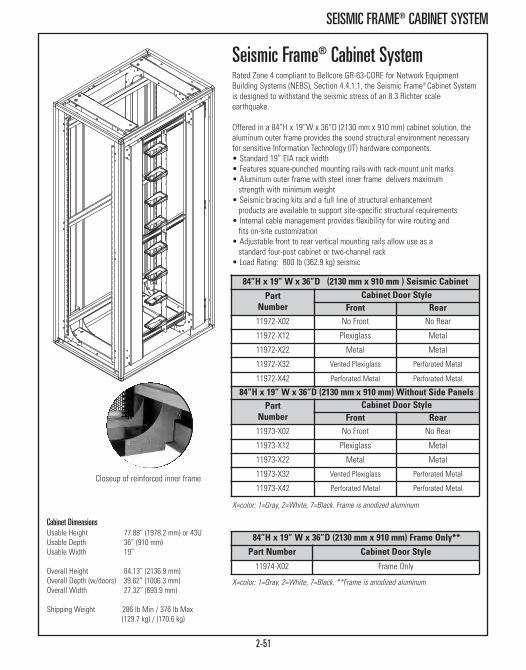
2-51
SEISMIC FRAME® CABINET SYSTEM
Closeup of reinforced inner frame
Cabinet Dimensions Usable Height 77.88” (1978.2 mm) or 43UUsable Depth 36” (910 mm)Usable Width 19”
Overall Height 84.13” (2136.9 mm)Overall Depth (w/doors) 39.62” (1006.3 mm)Overall Width 27.32” (693.9 mm)
Shipping Weight 286 lb Min / 376 lb Max(129.7 kg) / (170.6 kg)
84”H x 19” W x 36”D (2130 mm x 910 mm) Frame Only**Part Number Cabinet Door Style
11974-X02 Frame Only
X=color: 1=Gray, 2=White, 7=Black. **Frame is anodized aluminum
X=color: 1=Gray, 2=White, 7=Black. Frame is anodized aluminum
Seismic Frame® Cabinet SystemRated Zone 4 compliant to Bellcore GR-63-CORE for Network EquipmentBuilding Systems (NEBS), Section 4.4.1.1, the Seismic Frame® Cabinet Systemis designed to withstand the seismic stress of an 8.3 Richter scaleearthquake.
Offered in a 84”H x 19”W x 36”D (2130 mm x 910 mm) cabinet solution, thealuminum outer frame provides the sound structural environment necessaryfor sensitive Information Technology (IT) hardware components. • Standard 19” EIA rack width• Features square-punched mounting rails with rack-mount unit marks• Aluminum outer frame with steel inner frame delivers maximum strength with minimum weight
• Seismic bracing kits and a full line of structural enhancement products are available to support site-specific structural requirements
• Internal cable management provides flexibility for wire routing and fits on-site customization
• Adjustable front to rear vertical mounting rails allow use as a standard four-post cabinet or two-channel rack
• Load Rating: 800 lb (362.9 kg) seismic
84”H x 19” W x 36”D (2130 mm x 910 mm ) Seismic Cabinet
Part Number
Cabinet Door StyleFront Rear
11972-X02 No Front No Rear
11972-X12 Plexiglass Metal
11972-X22 Metal Metal
11972-X32 Vented Plexiglass Perforated Metal
11972-X42 Perforated Metal Perforated Metal
84”H x 19” W x 36”D (2130 mm x 910 mm) Without Side PanelsPart Number
Cabinet Door StyleFront Rear
11973-X02 No Front No Rear
11973-X12 Plexiglass Metal
11973-X22 Metal Metal
11973-X32 Vented Plexiglass Perforated Metal
11973-X42 Perforated Metal Perforated Metal

2-52
THERMAL MANAGEMENT
Thermal Management For Cabinet &Enclosure SystemsThe biggest challenge in today’s data center is thermal management,which is no surprise considering the average heat load generated perequipment cabinet has doubled since 2000. Creating a properlyconfigured cabinet that works with your data center’s cooling system tocontrol airflow and maximize cooling effectiveness is vital to success.Not only is it important to create a properly configured cabinet, butarranging cabinets in a hot aisle/cold aisle layout enhances thermalconditions and establishes one-way airflow thought the cabinet space.
CPI provides a wide range of innovative thermal management solutionsthat are designed to channel cool air to the front of equipment cabinetswhere it is needed most. Our most recent approach to cooling the datacenter involves CPI Passive Cooling® Solutions. This solution allowscustomers to reclaim control over airflow so it can be directed where it isneeded, eliminating bypass and re-circulation of hot exhaust air and theformation of hot spots.
PartNumber
DescriptionH x W (in)
ShippingWeightlb (kg)
14171-310 1U x 19, Black Panel, Pack of 10 3 (1.4)
14172-310 2U x 19, Black Panel, Pack of 5 3 (1.4)
14171-320 1U x 19, Black Panel with Temperature Strip,Pack of 10 4 (1.8)
14172-320 2U x 19, Black Panel with Temperature Strip,Pack of 5 3 (1.4)
HotLok® Snap-In Filler PanelsThe HotLok Snap-In Filler Panels attach to 19” EIA-310-D and EIA/ECA-310-Ecompliant square-punched or threaded equipment mounting rails. Universalpanels fit .375 inch (9.5 mm) square-punched equipment mounting rails orM5/M6/#12-24 tapped equipment mounting rails. The cantilevered sealingvanes and snap-spring design create a 99 percent effective seal betweenadjacent panels and equipment blocking most airflow between panels.Optional built-in temperature strips have a color-coded scale to provide a quickvisual indicator for hot spots. The scale shows the American Society ofHeating, Refrigeration and Air-Conditioning Engineers (ASHRAE) recommendedenvelope range as blue; the allowable environmental envelope range asyellow and hot spots as red.
Identify Temperatures within a particular rangeAccurate within +/- 1°C
1417X-310
1417X-320

2-53
THERMAL MANAGEMENT
KoldLok® Raised Floor GrommetReduce bypass airflow, improve data center cooling and block unsealed cableholes with KoldLok® Raised Floor Grommets. Two styles of grommets areavailable: KoldLok Wave™ or the original KoldLok brush grommets. Wavegrommets use a solid, flexible patent-pending wave shaped thermoplasticelastomer material to form a tight seal around cables which blocks 98 percentto 100 percent of air loss. Brush grommets use layers of brush filaments madeof premium grade Nylon 6, not styrene, ABS or polypropylene, to form a sealaround cables which blocks 92 percent to 100 percent of air loss. Bothsealing materials resist breaking, deformation and wear for repeated use. Easy to install, KoldLok Raised Floor Grommets can be positioned in themiddle or along the edge of floor tiles, allowing large bundles of cables andlarge power connectors to effortlessly pass through the opening.
• KoldLok Wave™ Raised Floor Grommet increases sealing effectiveness with asolid, flexible wave shaped thermoplastic elastomer material that is overmolded to the grommet frame. Offers over 45 in2 of usable cable area,durable, impact-resistant ABS frame with optional cover for increased safety.
• Integral Grommet is a flush-mount design with a sleeve that protects cablesas they pass through the cut in the floor tile. Two styles: Integral Grommet(one-piece) and Split Integral Grommet (two-piece)
• Surface-Mount Grommet is two-piece and covers an existing cable access hole. Three sizes available: Surface-Mount, Large Surface-Mount and Extra-Large Surface-Mount.
• Extended Grommet is three-piece and covers a long, narrow slot like thoseused along the edges of rooms. Available in two sizes: Extended 3” (76 mm)Brush Grommet and Extended 6” (152 mm) Brush Grommet
• Mini Grommet is a smaller flush-mount design with a sleeve that protectscables as they pass through the cut in the floor tile
Grommets are now patented.
13571-001
13675-001
13576-001
Part Number Description
ShippingWeightlb (kg)1 Each 10 Each
13870-001 13870-002 KoldLok Wave™ Split Integral Grommet 11 (5.0)
13873-001 13873-002 Cover, For KoldLok Wave™ Split Integral Grommet 6 (2.7)
13571-001 13571-002 Integral Grommet 18 (8.2)
13671-001 13671-002 Split Integral Grommet 20 (9.1)
13576-001 13576-002 Surface-Mount Grommet 21 (9.5)
13676-001 13676-002 Large Surface-Mount Grommet 43 (19.5)
13677-001 13677-002 Extra-Large Surface-Mount Grommet 43 (19.5)
13674-001 13674-002 Extended 3" (76 mm) Brush Grommet 29 (13.2)
13675-001 13675-002 Extended 6" (152 mm) Brush Grommet 37 (16.8)
13872-001 13872-002 Mini Grommet 5 (2.3)
See next page for dimensions
13676-001
13870-001with
13873-001

2-54
THERMAL MANAGEMENT
Fan Specifications - Each Fan
Operating Voltage Airflow Noise Level
(1 Meter Max) Power
Consumption OperatingFrequency
115 VAC 100 CFM 37 dBA 15 Watts 50/60 Hz
230 VAC 100 CFM 37 dBA 15 Watts 50/60 Hz
Fan Kit For M-Series MegaFrameThe MegaFrame Fan Kit provides optional ventilation and cooling for thecabinet. • Four fans mount on two interchangeable frames to fit cabinet top panel• Grill design and ball-bearing motor offer longer life and quiet operation• Each fan frame has an IEC C-14 power inlet• Includes a detachable 15’L (4.6 m) power cord with a molded plug• Provides up tp 400 CFM of ventilation for cabinet• Can be used on the MegaFrame, SlimFrame and Seismic Frame Cabinets• UL Recognized
Part Number Description / Color
ShippingWeightlb (kg)
Cooling Fan Kit - 400 CFM12480-701 Black, 115 VAC, 50/60 Hz, NEMA 5-15P 6 (2.7)
12480-702 Black, 230 VAC, 50/60 Hz, NEMA 6-15P 6 (2.7)
DimensionsPartNumber Description
Overall Size Cable Opening Hole in Floor
Height Width Depth Width Depth Width Depth
13870-00X KoldLok Wave™ SplitIntegral Grommet
1-7/8"(48 mm)
11"(279 mm)
9"(229 mm)
7-3/4"(197 mm)
5-7/8"(149 mm)
9-1/4"(235 mm)
6-3/4"(172 mm)
13571-00X Integral Grommet 1-5/8"(41 mm)
11"(279 mm)
8-1/4"(210 mm)
8"(203 mm)
4"(102 mm)
9-1/4"(235 mm)
6-3/4"(172 mm)
13671-00X Split Integral Grommet 1-5/8"(41 mm)
11"(279 mm)
8-1/4"(210 mm)
8"(203 mm)
4"(102 mm)
9-1/4"(235 mm)
6-3/4"(172 mm)
13576-00X Surface-Mount Grommet 1-1/8"(29 mm)
11"(279 mm)
8-1/4"(210 mm)
8-1/4"(210 mm)
4"(102 mm)
10"(254 mm)
7-1/4"(184 mm)
13676-00X Large Surface-Mount Grommet
1-15/16"(33 mm)
12"(305 mm)
11-3/4"(298 mm)
8-1/4"(210 mm)
4"(102 mm)
10"(254 mm)
9-3/4"(248 mm)
13677-00X Extra-Large Surface-Mount Grommet
1-15/16"(33 mm)
12"(305 mm)
15"(381 mm)
8-1/4"(210 mm)
4"(102 mm)
10"(254 mm)
13"(330 mm)
13674-00X Extended 3" (76 mm)Brush Grommet
1"(25 mm)
24"(610 mm)
4"(102 mm)
22"(559 mm)
2-1/2"(64 mm)
22"(559 mm)
2-1/2"(64 mm)
13675-00X Extended 6" (152 mm)Brush Grommet
1"(25 mm)
24"(610 mm)
7"(178 mm)
22"(559 mm)
5-1/2"(140 mm)
22"(559 mm)
5-1/2"(140 mm)
13872-00X Mini Grommet 1-1/2”(38 mm)
7-11/16”(195 mm)
5-11/16”(144 mm)
5”(127 mm)
2-1/2”(64 mm)
6”(152 mm)
4”(102 mm)

2-55
THERMAL MANAGEMENT
Air Dam Kit, Cabinet Airflow BafflesThe Air Dam Kit creates a barrier between the cabinet door and the front ofequipment along the top, bottom and sides of the cabinet. When used incombination with perforated front and rear doors, the Air Dam Kit helps tochannel cool air to the front of equipment and also helps to prevent themixing of heated air from the rear of the cabinet with cool air at the front ofthe cabinet. • Use on M-Series MegaFrame and C-Series SlimFrame Cabinets• 5”D (130 mm) bafflesKit consists of:• (1) Top baffle• (1) Bottom baffle• (4) Small side baffles• (4) Large side baffles• Installation hardware
Part Number
DescriptionH x Win (mm)
ShippingWeightlb (kg)
For M-Series MegaFrame Cabinet System13336-X10 84 (2130) x 19 11 (5.0)
13336-X11 78 (1980) x 19 10 (4.5)
13336-X12 72 (1830) x 19 10 (4.5)
13336-X15 48 (1220) x 19 8 (3.6)
13336-X20 84 (2130) x 23 11 (5.0)
13336-X21 78 (1980) x 23 10 (4.5)
13336-X22 72 (1830) x 23 10 (4.5)
13336-X25 48 (1220) x 23 8 (3.6)
For C-Series SlimFrame Cabinet System13336-X10 84 (2130) x 19 11 (5.0)
13336-X11 78 (1980) x 19 10 (4.5)
13336-X12 72 (1830) x 19 10 (4.5)
X=color: 1=Gray, 2=White, 7=Black

2-56
THERMAL MANAGEMENT
Cabinet Height - in (mm)0 84 (2130) Overall
1 78 (1980) Overall
2 72 (1830) Overall
5 48 (1220) Overall*
Cabinet Width
1 19” Rack-Mount
2 23” Rack-Mount
Color1 Gray
2 White
7 Black
MegaFrame & SlimFrame Fan DoorsIntelligent Fan Door
Standard Fan Door
Intelligent & Standard Fan DoorsThe Intelligent Fan Door, when used as the rear door on a cabinet, removesheated air and prevents the build up of heated air inside the cabinet, whichcan cause equipment to overheat and shut down.
Intelligent Fan Door uses a solid-state temperature control to vary fan speedfrom an ultra quiet low speed at low air temperature through increasinglyhigher speeds as temperature rises. Peak exhaust airflow can reach 960 CFM.Intelligence allows this system to deliver cooling when and where it's neededwhile keeping the noise to a minimum.
Standard Fan Door using single-speed fans are also available. They provide100 CFM per fan for a total of 800 CFM.
• Use Intelligent Fan Doors on the rear of CPI M-Series MegaFrame andC-Series SlimFrame Cabinets that support rack-mount computer and datastorage equipment
• Multiple IEC C-14 power connections allow attachment to different circuits for power redundancy (2 connections/4 fans each)
• 115 VAC/60 Hz fans includes two detachable power cords with IEC C-13 to NEMA 5-15P plugs
132XX - X X X
*Only available for M-Series MegaFrame Cabinets. (1) power connection, 480 CFM (Intelligent), 400 CFM (Standard)
Door Type13212 Intelligent Fan Doors for MegaFrame
13222 Standard Fan Doors for MegaFrame
13213 Intelligent Fan Doors for SlimFrame
13223 Standard Fan Doors for SlimFrame

2-57
THERMAL MANAGEMENT
Accessories - in (mm)12507-001 12 X 24 X 3/8 (300 x 610 x 9.53) Filter, 6 Pack 1 (0.5)
12505-001 Foam Insert, 2 Pack (for cable ports) 1 (0.5)
12510-50XAir Filter Kit w/o Fans
12511-50X Air Filter Kit with Fans
Filtered Ventilation System For 30”D(760 mm) MegaFrame® CabinetsThis system has the fans and filters installed at the bottom of the cabinet. Airexhausts through vents in the cabinet top. Equipment may not be mounted inthe 2U at the bottom of the cabinet to allow clearance for cabinet intake air.
The Standard Filter Cabinet Ventilation System is for the retrofitting ofMegaFrame Cabinets with fans already located on the cabinet top.
• For 19” and 23”W x 30”D (760 mm) MegaFrames• Air Filter Kit with 115 VAC fans provides up tp 400 CFM and has an attached 15’L (4.6 m) power cord with a NEMA 5-15P plug
• Air Filter Kit with 230 VAC, 50/60 Hz fans provides up to 400 CFM and has an attached 15’L (4.6 m) power cord with a NEMA 6-15P plug
• Trim-to-fit filter media is readily available from many commercial suppliers or can be ordered from CPI
• 3/8” (9.53 mm) thick filter provides 70-75% dust particle retention• One filter provided with each kit
Note: This product only available for 30”D (760 mm) MegaFrame Cabinets. Unitwill generate 48 db noise level.
Part NumberDescription
ShippingWeightlb (kg)19” 23”
Deluxe Filter Cabinet Ventilation System12511-501 12511-502 Air Filter Kit w/ 115 VAC Fans 22 (10.0)
12511-503 12511-504 Air Filter Kit w/ 230 VAC Fans 22 (10.0)
Standard Filter Cabinet Ventilation System12510-501 12510-502 Air Filter Kit w/o Fans 13 (5.9)

11817-001 8 Narrow Cable Ring Kit, Black 1 (0.5)
X=color: 1=Gray, 2=White, 7=Black (Rings are black.)
Narrow Vertical Cable ManagerThis space-saving manager is ideal in CPI’s SlimFrame C-Series Cabinets. • Rings snap on, making new configurations a simple process• Control radius helps maintain a proper bend radius in cables• Includes (2) vertical mounting brackets, (8) pre-assembled cable rings, (1)control radius and (1) hardware kit
Add additional cable rings to the Narrow Vertical Cable Manager.• Contains (8) black 1.40”H x 1.45”W x 4.13”D (36.8 mm x 104.9 mm x 35.6 mm) plastic U-rings
• U-ring design allows for easy insertion of cables
Part Number
Section DimensionsH x W x Din (mm)
ShippingWeightlb (kg)
11809-X00 For 84”H (2130 mm) Cabinet, 1 Pair34.7 x 1.75 x 4.13 (881 x 44.5 x 104.9) 5 (2.3)
11809-X01 For 78”H (1980 mm) Cabinet, 1 Pair31.7 x 1.75 x 4.13 (44.5 x 104.9 x 805) 5 (2.3)
11809-X02 For 72”H (1830 mm) Cabinet, 1 Pair28.7 x 1.75 x 4.13 (44.5 x 104.9 x 729) 4 (1.8 )Control radius
shown attachedto bracket
2-58
CABLE MANAGEMENT
X=color: 1=Gray, 2=White, 7=Black. Rings are black.Create two cable
pathways using onemanager
Vertical Cable ManagerAvailable for 72”, 78” and 84” (1830 mm, 1980 mm and 2130 mm) cabinets. • Includes one pair of sections and eight rings• Large 3.3”W x 6.5”D (84 mm x 165 mm) heavy duty plastic rings with rounded edges organize and protect cable sheaths
• Position anywhere along horizontal mounting rails• Use with MegaFrame and Seismic Frame cabinets; use with SlimFrame when bayed without side panels, ships pre-assembled
Cable Management For Cabinet & Enclosure SystemsCPI offers a variety of optional Cable Management Products for our Cabinet and Enclosure Systems to manage power andnetwork cables. The MegaFrame and SlimFrame Cabinet Systems contain internal cable management space along both sides ofthe frame. Vertical ring style and enhanced trough style cable managers are available. These cable managers can be attachedto the frame and adjusted from front-to-rear, independently of the mounting rails.
Part Number
ColorHeight (pair)in (mm)
ShippingWeightlb (kg)
12465-X05 Cabling Ring Section, 72 (1830) 7 (3.2)
12465-X06 Cabling Ring Section, 78 (1980) 7 (3.2)
12465-X07 Cabling Ring Section, 84 (2130) 7 (3.2)
14068-701 8 Cable Ring Kit, Black 3 (1.4)

2-59
CABLE MANAGEMENT
Front-to-Back Manager
Narrow EnhancedVertical Cable Manager
Shown:(2) 13171-700(2) 13169-701
Shown:(2) 13170-700(2) 13168-701
Part Number
DescriptionH x W x Din (mm)
ShippingWeightlb (kg)
Enhanced Vertical Manager, Narrow13171-702 72 x 3.50 x 5.23 (1830 x 88.9 x 132.8) 9 (4.1)
13171-701 78 x 3.50 x 5.23 (1980 x 88.9 x 132.8) 10 (4.5)
13171-700 84 x 3.50 x 5.23 (2130 x 88.9 x 132.8) 11 (5.0)
Enhanced Vertical Manager, Wide13170-702 72 x 4.75 x 8.77 (1830 x 120.7 x 222.8) 11 (5.0)
13170-701 78 x 4.75 x 8.77 (1980 x 120.7 x 222.8) 12 (5.4)
13170-700 84 x 4.75 x 8.77 (2130 x 120.7 x 222.8) 13 (5.9)
Front-to-Back Horizontal Manager, Narrow13169-701 2.38 x 1.74 (60.5 x 44.2), 2 each 3 (1.4)
Front-to-Back Horizontal Manager, Wide13168-701 2.38 x 3.77 (60.5 x 95.8), 2 each 2 (0.9)
Enhanced Cable Managers Enhanced Vertical Managers allow cables to be organized by rack-mount unit,making it easier to trace individual cables during moves, adds and changes.Additionally, two Enhanced Vertical Managers can be connected with Front-to-Back Managers (as shown) to create a complete pathway for cables thatconnect network switches and computers within the same or adjacentcabinets.
Enhanced Vertical Managers are available in two sizes for large and extra-large cable capacities. The narrow version can be added to any MegaFrameCabinet. The wide version is used in any 23”W MegaFrame Cabinet that hasbeen converted into a 19” rack solution with CPI's 23”-19” Rail Adapter Kit(P/N 10587, page 2-83). Both models include a lockable, snap-on door toprotect cables. The matching Front-to-Back Managers (sold in pairs) snap ontothe vertical managers and adjust to match the depth of the cable managers. • Cable openings in Enhanced Vertical Manager allow cables to exit by rack-mount unit; openings have rounded edges to protect cable and will not deform or break
• The back side of the Enhanced Vertical Manager has four edge-protected cable pass-through ports for front-to-back cabling
• Cover snaps on and opens to the right or left • Front-to-Back Managers adjust in depth to connect the front and rear Enhanced Vertical Manager
• Constructed of high-strength lightweight aluminum

2-60
SHELVES
Fixed ShelfUse fixed shelves to support equipment without rack-mounted brackets suchas modems, CPUs, small power supplies, monitors, etc. Shelves mount to theUniversal EIA 5/8”-5/8”-1/2” (15.9 mm -15.9 mm -12.7 mm) alternating holepattern of the four vertical mounting rails.
Three depths are offered in 18”, 24” and 29” (460 mm, 610 mm and 740 mm)to provide clearance for cables, ventilation, power strips, etc. Shelves haveadjustable mounting depths of 13” to 24” (330 mm to 610 mm) for the 18”(460 mm) shelf, 17” to 28” (430 mm to 710 mm) for the 24” (610 mm) shelfand 24” to 38” (610 mm to 970 mm) for the 29” (740 mm) shelf. Available invented and non-vented styles. Vented shelves are designed to optimizeairflow through cabinet. Sold individually.• Made of strong, lightweight aluminum• Installs using (8) #12-24 screws (not included)• 19” shelf supports up to 250 lb (113.4 kg)• 23” shelf supports up to 200 lb (90.7 kg)• 19” shelves are UL Listed: File E227626; Category NWIN - Accessories
PartNumber Description
ShippingWeightlb (kg)
12336-X19 19”W x 18”D (460 mm), Non-Vented 7 (3.2)
12337-X19 19”W x 18”D (460 mm), Vented 7 (3.2)
12334-X19 19”W x 24”D (610 mm), Non-Vented 9 (4.1)
12335-X19 19”W x 24”D (610 mm), Vented 9 (4.1)
14070-X19 19”W x 29”D (740 mm), Non-Vented 11 (5.0)
14072-X19 19”W x 29”D (740 mm), Vented 10 (4.5)
12336-X23 23”W x 18”D (460 mm), Non-Vented 8 (3.6)
12337-X23 23”W x 18”D (460 mm), Vented 8 (3.6)
12334-X23 23”W x 24”D (610 mm), Non-Vented 10 (4.5)
12335-X23 23”W x 24”D (610 mm), Vented 10 (4.5)
14070-X23 23”W x 29”D (740 mm), Non-Vented 12 (5.4)
14072-X23 23”W x 29”D (740 mm), Vented 11 (5.0)
X=Color: 1=Gray, 2=White, 7=Black
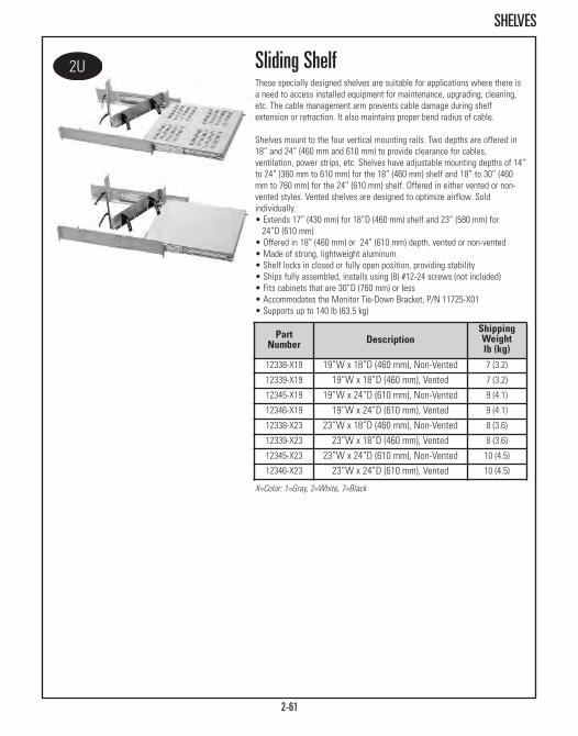
2-61
SHELVES
Sliding ShelfThese specially designed shelves are suitable for applications where there isa need to access installed equipment for maintenance, upgrading, cleaning,etc. The cable management arm prevents cable damage during shelfextension or retraction. It also maintains proper bend radius of cable.
Shelves mount to the four vertical mounting rails. Two depths are offered in18” and 24” (460 mm and 610 mm) to provide clearance for cables,ventilation, power strips, etc. Shelves have adjustable mounting depths of 14”to 24” (360 mm to 610 mm) for the 18” (460 mm) shelf and 18” to 30” (460mm to 760 mm) for the 24” (610 mm) shelf. Offered in either vented or non-vented styles. Vented shelves are designed to optimize airflow. Soldindividually.• Extends 17” (430 mm) for 18”D (460 mm) shelf and 23” (580 mm) for 24”D (610 mm)
• Offered in 18” (460 mm) or 24” (610 mm) depth, vented or non-vented• Made of strong, lightweight aluminum• Shelf locks in closed or fully open position, providing stability• Ships fully assembled, installs using (8) #12-24 screws (not included)• Fits cabinets that are 30”D (760 mm) or less• Accommodates the Monitor Tie-Down Bracket, P/N 11725-X01• Supports up to 140 lb (63.5 kg)
PartNumber Description
ShippingWeightlb (kg)
12338-X19 19”W x 18”D (460 mm), Non-Vented 7 (3.2)
12339-X19 19”W x 18”D (460 mm), Vented 7 (3.2)
12345-X19 19”W x 24”D (610 mm), Non-Vented 9 (4.1)
12346-X19 19”W x 24”D (610 mm), Vented 9 (4.1)
12338-X23 23”W x 18”D (460 mm), Non-Vented 8 (3.6)
12339-X23 23”W x 18”D (460 mm), Vented 8 (3.6)
12345-X23 23”W x 24”D (610 mm), Non-Vented 10 (4.5)
12346-X23 23”W x 24”D (610 mm), Vented 10 (4.5)
X=Color: 1=Gray, 2=White, 7=Black

2-62
SHELVES
23”W x 32”D (810 mm) Sliding Shelf11913-X23 Vented 25 (11.3)
23”W x 32”D (810 mm) Sliding Shelf11914-X23 Non-Vented 25 (11.3)
Patented shelf extends a full 24” (610 mm)
X=Color: 1=Gray, 2=White, 7=Black
X=Color: 1=Gray, 2=White, 7=Black
32” Deep (810 mm) Sliding ShelfUnlike most storage solutions that may cause kinking, twisting and cutting ofcables during shelf extension and retraction, CPI's flexible polycarbonate belt,which fits in the rear undercarriage, solves these problems. This belt easilyattaches to either the left or right side of the vertical bracket and containseight molded releasable clips that accommodate cable bundles measuring upto 1” (25.4 mm) in diameter. • Supports up to 160 lb (72.6 kg) using less than 2U • Locks in the closed position• Open easily with accessible front lock levers providing greater stability while accommodating deep servers
• Maximum usable shelf space of up to 32” (810 mm)• Cable management belt provides greater flexibility in the storage of wire bundles
• Designed for 36” or 39”D (910 mm or 990 mm) cabinets
Extra Heavy Duty Sliding ShelfShelf provides support up to 300 lb (136.1 kg) and uses only 2U, providing 26”(660 mm) usable depth.• Flexible cable management belt eliminates kinking, bending or cutting of cable
• Adjustable mounting depth of 20” to 34” (510 mm to 860 mm)• 19” shelf provides 17.5” (445 mm) usable width• 23” shelf provides 21.5” (546 mm) usable width • Locks in fully closed or open position
Flexible cable manager
Part Number Style
ShippingWeightlb (kg)
19”W x 32”D (810 mm) Sliding Shelf11913-X19 Vented 25 (11.3)
19”W x 32”D (810 mm) Sliding Shelf11914-X19 Non-Vented 25 (11.3)
Part Number Description
ShippingWeightlb (kg)
12700-X19 19”W Solid Shelf 29 (13.2)
12700-X23 23”W Solid Shelf 30 (13.6)

2-63
SHELVES
Monitor Shelf And Sliding Keyboard Tray With Mouse PadProvides a compact solution for storing and accessing components. Installsusing eight #12-24 screws (not included).• Adjustable mounting depth of 23” to 39”D (580 mm to 990 mm)• Tray fits up to 19.1”W x 8.5”D (485 mm x 216 mm) keyboards• Tray and mouse pad store inside the monitor shelf• Keyboard tray locks into position• Mouse pad is 7” x 7” (180 mm x 180 mm)• Monitor shelf supports up to 200 lb (90.7 kg)
X=color: 1=Gray, 2=White, 7=Black
Note: Monitor Tie-Down Kit, see Page2-74, can be usedwith this product tosecurely hold yourmonitor to the shelf.
Part Number Shipping Weightlb (kg)19” Wide 23” Wide
12495-X19 12495-X23 23/24 (10.4/10.9)
PartNumber
DescriptionH x W (in)
ShippingWeightlb (kg)
13517-701 1U x 19, Black 17 (7.7)
Rack-Mount Cable Shelf Use Rack-Mount Cable Shelf in any 19”W CPI cabinet equipped with an AirDam Kit to provide a front-to-rear pathway for cables. Cables pass throughbrush sealed ports along the front of the shelf. Rack-Mount Cable Shelf uses1U and will fit in cabinets with mounting rails set between 22” and 40”D(560 mm and 1020 mm).
Shelf extends from 20”- 36” (510 mm - 910 mm) indepth. Mounting brackets included, but not shown.
Low Profile Fixed ShelfUnique telescoping design delivers between 20” and 36” (510 mm and 910mm) of continuous support for up to 100 lbs (45.4 kg) of equipment in lessthan 1U of rack-mount space. • Shelf bracket provides front and rear support, attaching with single screwto mounting rails
• Available in 19” EIA and 23” EIA widths, providing 17.5” and 21.5” (445 mm & 546 mm) surface space respectively
• Made of steel• Supports up to 100 lb (45.4 kg)• 19” shleves are UL Listed
PartNumber Description
ShippingWeightlb (kg)
12573-X19 19”W Solid Shelf 16 (7.3)
12573-X23 23”W Solid Shelf 18 (8.2)
12610-X19 19”W Vented Shelf 15 (6.8)
12610-X23 23”W Vented Shelf 17 (7.7)
X=color: 1=Gray, 2=White, 7=Black

2-64
ACCESSORIES
X=color: 1=Gray, 2=White, 5=Clear, 7=Black
13185-X01 Drawer Divider, For 3U & 4U Drawers 3 (1.4)
Lockable Storage DrawerDrawer stores backup media, software, manuals, laptops, test equipment, andextra patch cords in close proximity to the cabinet and are now stackable.Drawers are available for 19”W or 23”W racks and cabinets and includesattachment brackets that allow center mounting on two-post racks with 3” or6”D (80 mm or 150 mm) equipment channels, or front and rear attachment tofour-post racks and cabinet systems. (mounting rails must be adjustedbetween 24” and 39” (610 mm and 990 mm) in depth).• Attaches to any CPI freestanding 19”W or 23”W rack or cabinet system• Available in three heights: 2U, 3U and 4U• Features 20”D (510 mm) lockable drawer that extends full depth for easy access to stored equipment
• Supports a 100 lb (45.4 kg) load (drawer and top surface combined)
PartNumber
DescriptionDrawer Depthin (mm)
ShippingWeightlb (kg)
13082-X19 19” x 2U Drawer, 20 (510) 18 (8.2)
13083-X19 19” x 3U Drawer, 20 (510) 20 (9.1)
13084-X19 19” x 4U Drawer, 20 (510) 22 (10.0)
13082-X23 23” x 2U Drawer, 20 (510) 21 (9.5)
13083-X23 23” x 3U Drawer, 20 (510) 23 (10.4)
13084-X23 23” x 4U Drawer, 20 (510) 25 (11.3)
Drawer with two-post mounting brackets
Drawer with four-post mounting brackets
Redesigned to allowstackable units
Universal Cabinet LightFits any 19” EIA or 23” rack or cabinet. It can be mounted in variousorientations to direct additional illumination where it is most needed. • Only 1U; provides 8 Watts of fluorescent light from 115VAC • On/Off switch and 6’ (1.8 m) cord• White lens with white housing; black bracket
PartNumber Description
ShippingWeightlb (kg)
13393-719 19” Cabinet Light, 8 Watt 3 (1.4)
13393-723 23” Cabinet Light, 8 Watt 3 (1.4)
Rack Mount Unit LabelsKits contain four individual label packs, enough for four racks and fourcabinets. Labels are constructed of 1/2”W (10 mm) durable polyester filmwith adhesive backing.
PartNumber Description
ShippingWeightlb (kg)
11927-001 1-45U Labels 1 (0.5)
11927-002 1-58U Labels 1 (0.5)
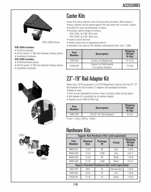
12637
12638
12639
Tapped Rail Hardware Kits (sold separately)
PartNumber
NominalSize
PackageOf Finish
ShippingWeightlb kg)
40605-001 12-24 50 Zinc 1 (0.5)
40605-004 12-24 1,000 Zinc 9 (4.1)
40605-005 12-24 50 Black 1 (0.5)
40605-006 12-24 1,000 Black 9 (4.1)
Square-Punched Hardware Kits (sold separately)12637-001 M-6 25 Gold over Zinc 1 (0.5)
12638-001 10-32 25 Zinc 1 (0.5)
12639-001 12-24 25 Black 1 (0.5)
Hardware Kits
2-65
ACCESSORIES
P/N 13203 includes:• (4) Corner gussets• (4) Full swivel, 3” (80 mm) diameter locking casters• Installation hardwareP/N 13204 includes:• (4) Reinforcement plates• (4) Full swivel, 3” (80 mm) diameter locking casters• Installation hardware
PartNumber Description
ShippingWeightlb (kg)
13203-001 Casters for MegaFrame 27 (12.2)
13204-001 Casters for SlimFrame& Co-Location Cabinets 13 (5.9)
Caster KitsCaster Kits allow cabinets to be moved quickly and easily. When space islimited, cabinets can be placed against the wall when not in service. Castersalso allow for easy reconfiguration of space.• Increases cabinet height as follows:- P/N 13203, by 3.68” (93.5 mm)- P/N 13204, by 3.38” (85.8 mm)
• Casters swivel and lock• Install casters prior to populating cabinet• Intended to be used on CPI Cabinets manufactured after July 1, 2004
P/N 13203 shown
Part Number Description
ShippingWeightlb (kg)
10587-X01 (12) 23”-19” Rail Adapters 5 (2.3)
23”-19” Rail Adapter KitMount your 19”W equipment in a 23”W MegaFrame Cabinet with the 23”-19”Rail Adapter Kit that includes 12 adapters and packaged hardware.• Made of steel • Front to rear adjustability remains intact; increases cable routing space• Rail adapter kit is available for all cabinet heights• Supports up to 1000 lb (453.6 kg)
X=color: 1=Gray, 2=White, 7=Black

ZONE CABLING & WIRELESS ENCLOSURESRaised Floor, Drop Ceiling and Wall-Mount Enclosures
Zone Enclosures - Raised Floor Page 3-4Zone Enclosures - Drop Ceiling Page 3-6Zone Enclosures Service Parts Page 3-9Wireless Enclosures - Drop Ceiling Page 3-10Wireless Enclosures - Wall-Mounted Page 3-12

ZONE CABLING & WIRELESS ENCLOSURESWhen it’s time for a network to extend beyond the traditional telecommunications room, CPIZone Cabling and Wireless Enclosures provide consolidation points that reduce the overall costof adding or moving network cabling. Working in a partnership with American AccessTechnologies, Inc., the leading developer of zone cabling and wireless enclosures, CPI offerssolutions that include standards-recognized zone cabling practices and several NEMA-ratedmodels that can be used in warehouses, industrial environments and outdoors.
Available in several styles of wall-mount and drop ceiling wireless enclosures, end users areable to use CPI Zone Cabling and Wireless Enclosures to pre-wire a work area so connectionsto the rest of the network are closer to network users. Pre-wiring to zone enclosures alsomakes future connection changes within the zone easier and less disruptive because onlycables within the zone are moved, added or changed.
Wireless Enclosures offer added protection and security for wireless access points in anysituation. Several models of Wireless Enclosures include locks and durable seals for exterioruse, while others are able to easily blend into open office environments with dome covers thatlimit access to qualified technicians only.
CPI Zone Cabling and Wireless Enclosures feature: • High-quality construction and design• Small exterior dimensions to save space in tight areas• Secure equipment support outside of the data room• Reduced cost of cable configurations• Enclosed for security and safety• UL Listed• Suitable for low-voltage and active applications• Can be used in air handling spaces
3-2
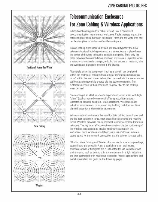
3-3
ZONE CABLING ENCLOSURES
Telecommunication EnclosuresFor Zone Cabling & Wireless ApplicationsIn traditional cabling models, cables extend from a centralizedtelecommunication room to each work area. Cable changes impact theentire length of cable between this central room and the work area andcan be disruptive to workers within the workspace.
In zone cabling, floor space is divided into zones (typically the areabetween structural building columns), and an enclosure is placed nearthe center of the zone to house a consolidation point. Thus, only thecable between the consolidation point and work area is impacted whena network connection is changed, reducing the amount of material, laborand workspace disruption involved in the change.
Alternately, an active component (such as a switch) can be placedwithin the enclosure, essentially creating a “mini-telecommunicationroom” within the workspace. When fiber is routed into the enclosure, aneasily scalable network is created via the active component. Thecustomer’s network is thus positioned to allow fiber to the desktopwhen desired.
Zone cabling is an ideal solution to support networked areas with high“churn” (such as rented commercial office space, data centers, - laboratories, schools, hospitals, retail operations, warehouses andindustrial environments) or for use in any building that does not haveplanned space for a telecommunication room.
Wireless networks eliminate the need for data cabling to each user andare the best solution in large, open areas like classrooms and meetingrooms. Wireless networks can supplement, overlay or replace traditionalnetworks. The key to an effective wireless network is the positioning ofthe wireless access point to provide maximum coverage in theworkspace. Once locations are defined, wireless enclosures create asecure space for the network connection and the wireless access point.
CPI offers Zone Cabling and Wireless Enclosures for use in drop ceilings,access floors and on walls. Also, a special series of wall-mountenclosures made of fiberglass are NEMA rated for use in dusty or wetenvironments, such as outdoors, in a warehouse or in a light industrialsite (not submerged or in hazardous locations). Product applications andmodel information are given on the following pages.
Traditional, Home Run Wiring
Wireless
Zone Cabling

3-4
ZONE CABLING ENCLOSURES - RAISED FLOOR
A0822-RF
PartNumber
DescriptionDepthin (mm)
ShippingWeightlb (kg)
A0222-RF 1U+1U Enclosure for 2 (50) Floor 10 (4.5)
A0422-RF 1U+1U Enclosure for 4 (100) Floor 10 (4.5)
A0622-RF 2U+2U Enclosure for 6 (150) Floor 23 (10.4)
A0822-RF 4U+4U Enclosure for 8 (200) Floor 23 (10.4)
13772-001 4U+4U Enclosure. for 8 (200) Floor, Large Ports 25 (11.3)
A1422-RF 11U Enclosure for 14 (360) Floor 30 (13.6)
13772-002 4U+4U Enclosure for 14 (360) Floor,Large Ports 30 (13.6)
Raised Floor Enclosures Raised Floor Enclosures fit under a single 2’ x 2’ access floor tile. Mostmodels use the access floor tile as a “lid.” Enclosures are UL Listed, suitablefor low voltage and active applications and for use in air handling spaces.
A variety of sizes are available to match floor height. Most models includebrackets for attachment to access floor support pedestals. Enclosures includethreaded equipment mounting rails and have multiple, edge-protected cableaccess ports with foam sealing kits. All enclosures are finished clear.
In enclosures designed for use in low height floors, two facing pairs ofpivoting equipment mounting rails are used to provide easy access to thefront and rear of the patch panel. In deeper enclosures, rails that are parallelto the floor provide higher consolidation point capacity. There is also a modelwith a lift out tray that can support active components. Order #12-24equipment mounting screws (P/N 40605-001) separately.
Raised Floor Enclosures For Patch PanelsThese enclosures use the access floor tile as a “lid.” (All models, exceptA0222-RF, include access floor installation brackets.) • A0222-RF features four cable access ports 6” x 3/4” (152 mm x 19 mm);
19” EIA threaded equipment mounting rails “pivoting”• A0422-RF features four cable access ports 6” x 3/4” (152 mm x 19 mm);
19” EIA threaded equipment mounting rails “pivoting”• A0622-RF features four cable access ports 6-3/4” x 2” (171 mm x 50 mm);
19” EIA threaded equipment mounting rails “pivoting”• A0822-RF features four cable access ports 6-3/4” x 2” (171 mm x 50 mm);
19” EIA threaded equipment mounting rails “pivoting”• 13772-001 features larger cable openings for Cat 6a cables; two ports
14-3/4” x 3-1/4” (374 mm x 8 2mm) and two ports 6-1/4” x 7” (158.8 mm x180 mm); 19” EIA threaded equipment mounting rails “pivoting”
• A1422-RF features four cable access ports 9-3/4” x 2-3/4” (247 mm x 69 mm); 19” EIA threaded equipment mounting rails “fixed”
• 13772-002 features larger cable openings for Cat 6a cables; six ports 14-3/4” x 3-1/4” (374 mm x 82 mm); 19” EIA threaded equipment mountingrails “pivoting”
A1422-RF

3-5
ZONE CABLING ENCLOSURES - RAISED FLOOR
PartNumber
DescriptionDepthin (mm)
ShippingWeightlb (kg)
A0802-RF-DI 4U+4U Enclosure for 9 (230) Floor 25 (11.3)
PartNumber
DescriptionDepthin (mm)
ShippingWeightlb (kg)
A0822-RF-F 4U Fiber Enclosure for 9 (230) Floor 30 (13.6)
A1422-RF-F 6U Fiber Enclosure for 14 (356) Floor 30 (13.6)
Raised Floor Enclosure With LockingCover For Patch Panels “Drop-In” enclosure measures 21-1/4” x 22-1/4” (539.8 mm x 565.2 mm) and includes a locking cover for use completely below access floor tiles.Installation only requires the removal of one floor tile. • Features pivoting mounting rails similar to models above and is perfect
for existing data centers
Raised Floor Enclosure For FiberPrepare your data center for future changes by pre-wiring it with fiberconnections located under an access floor.• Fits under a single 2’ x 2’ access floor tile• A0822-RF-F features two 7” x 2” (180 mm x 50 mm) cable access ports and
19” EIA threaded equipment mounting rails with 4U of rack-mount space• A1422-RF-F features two 10” x 2-1/2” cable access ports and 19” EIA
threaded equipment mounting rails with 6U of rack-mount space • Equipment mounting rails can be centered, or offset in the enclosure to
accomodate angled patch panels or longer electronics• Cable tie points simplify cable management• Includes (4) access floor support bracketsA0822-RF-F
Raised Floor Enclosure For ActiveComponentsFeatures a lift-out tray for 2U x 10-1/4”D (260.4 mm) of active components and5U (divided 2U - 1U - 2U) for passive connectivity.• Includes a junction box for a duplex power outlet• Includes fan to remove heat generated by active components
PartNumber
DescriptionDepthin (mm)
ShippingWeightlb (kg)
A1411-RF-HR 7U Enclosure for 14 (360) Floor 30 (13.6)A1411-RF-HR
A0802-RF-DI

A1222-HR
PartNumber Description
ShippingWeightlb (kg)
A1222-HR 2’ x 2’ Ceiling Enclosure 39 (17.7)
13812-001 2’ x 2’ Ceiling Enclosure, Large Ports 40 (18.1)
A1024-HR 2’ x 4’ Ceiling Enclosure 47 (21.4)
A1224-HR 2’ x 4’ Ceiling Enclosure 45 (20.4)
Ceiling Enclosure For Hubs, Switches AndPatch PanelsTelecommunication enclosure supports a combination of active componentsand patch panels or other panel-mount termination hardware. Enclosuresinclude a junction box for power and a fan to remove heat generated by activecomponents.• A1222-HR provides 5U for patch panels and 2U x 15”D (380 mm)
for active equipment; equipment mounts on the door• 13812-001 provides larger cable openings for Cat 6a; one 3-1/4” x 14-3/4”
(82.6 mm x 374.7 mm) and one 6-1/4” x 6-7/8” (158.8 mm x 174.6 mm) • A1024-HR provides 5U for patch panels and 2U x 15”D (380 mm)
for active equipment; equipment mounts on the door• A1224-HR provides a total of 10U with (3) brackets sized 4U - 2U - 4U to
support a combination of patch panels and 15”D (380 mm) activeequipment; brackets may be mounted on the door or the back of theenclosure
• Order #12-24 equipment mounting screws separately
3-6
ZONE CABLING ENCLOSURES - DROP CEILING
Ceiling Enclosures Ceiling Enclosures fit within a single 2’ x 2’ or 2’ x 4’ space, replacing astandard acoustical ceiling tile. The enclosure’s face and interior are paintedwhite and have recessed panels to support a ceiling tile, so that they blendwith the drop ceiling. A fully hinged door panel with latch closures supportsequipment. The door opens downward so that equipment is facing the servicetechnician. Three door styles are available to support wiring blocks, patchpanels or active components. Door locks are available as an accessory.
Ceiling Enclosures are UL Listed, suitable for low voltage and activeapplications and for use in air handling spaces. • 2’ x 2’ enclosures support 70 lb (31.8 kg) of cables and equipment,
20 lb (9.1 kg) on the access door• 2’ x 4’ enclosures support 80 lb (36.3 kg) of cables and equipment,
50 lb (22.7 kg) on the pneumatic assisted access door• Enclosures fit in 12”H (300 mm) drop ceilings and attach to building
structure with four or six 3/8” threaded rods (ordered separately) • Includes two or four edge-protected cable access ports with fire-rated
foam sealing kits

3-7
ZONE CABLING ENCLOSURES - DROP CEILING
A1222-PP PartNumber Description
ShippingWeightlb (kg)
A1222-PP 2’ x 2’ Ceiling Enclosure 38 (17.2)
13812-002 2’ x 2’ Ceiling Enclosure, Large Ports 39 (17.7)
A1024-PP 2’ x 4’ Ceiling Enclosure 43 (19.6)
A1224-PP 2’ x 4’ Ceiling Enclosure 45 (20.4)
13813-001 Ceiling Enclosure Fan Kit & Junction Box 3 (1.4)
Ceiling Enclosure For Patch PanelsSecure a consolidation point using 19” patch panels or other panel-mounttermination hardware. • A1222-PP provides a total of 5U with (3) brackets sized 2U - 1U - 2U;
brackets mount on the door• 13812-002 provides larger cable openings for Cat 6a; one 3-1/4” x 14-3/4”
(82.6 mm x 374.7 mm) and one 6-1/4” x 6-7/8” (158.8 mm x 174.6 mm)• A1024-PP provides a total of 5U with (3) brackets sized 2U - 1U - 2U;
brackets mount on the door• A1224-PP provides a total of 10U with (3) brackets sized 4U - 2U - 4U;
brackets may be mounted on the door or the back of the enclosure• Order #12-24 equipment mounting screws separately
A1224-LPPart
Number DescriptionShippingWeightlb (kg)
A1222-LP 2’ x 2’ Ceiling Enclosure 38 (17.2)
13812-003 2’ x 2’ Ceiling Enclosure, Large Ports 39 (17.7)
A1024-LP 2’ x 4’ Ceiling Enclosure 43 (19.6)
A1224-LP 2’ x 4’ Ceiling Enclosure 45 (20.4)
Ceiling Enclosure For Wiring BlocksSecure a consolidation point using wiring blocks. Enclosures include removableequipment mounting plates that can be match drilled to accommodate a widevariety of wiring blocks.• A1222-LP has (1) mounting plate, size 13-3/4”W x 19-1/2”L
(349 mm x 495 mm) for (2) 300-pair 110D (without legs) style blocks or (1) 300-pair 110A (with legs) style blocks
• 13812-003 provides larger cable openings for Cat 6a; one 3-1/4” x 14-3/4” (82.6 mm x 374.7 mm) and one 6-1/4” x 6-7/8” (158.8 mmx 174.6 mm)
• A1024-LP has (1) mounting plate, 16”W x 22”L (406 mm x 559 mm) for (2) 300-pair 110A (with legs) style blocks
• A1224-LP has (2) mounting plates, size 13-3/4”W x 19-1/2”L (349 mm x 495mm) for (4) 300-pair 110D (without legs) style blocks or (2) 300-pair 110A(with legs) style blocks
Fan Kit & Junction Box, included with 13812-001, can be installed on either 13812-002 or 13812-003 to better support active components.
13813-001

3-8
ZONE CABLING ENCLOSURES - DROP CEILING
BCE-24-P
BCE-48-P
PartNumber Description
ShippingWeightlb (kg)
BCE-48-P 2U 2-Port Enclosure 12 (5.4)
BCE-48-N 2U Non-Ported Enclosure 12 (5.4)
PartNumber Description
ShippingWeightlb (kg)
BCE-24-P 1U 2-Port Enclosure 7 (3.2)
BCE-24-N 1U Non-Ported Enclosure 7 (3.2)
Basic Consolidation EnclosuresBasic Consolidation Enclosures (BCE) provide a low-cost, low-densityconsolidation point for telecommunication cabling. Both Ported (-P) and Non-Ported (-N) enclosures can be configured to be used either above the drop ceilingor below an access floor. All Ported versions (-P) come with a fire-rated foamsealing kits making them suitable for air handling spaces. Basic ConsolidationEnclosures are UL Listed (2043), plenum rated, come with a sealed door and aclear aluminum finish.
BCE-24-P/NBCE-24-P/N measures 14”W x 3”D x 20”L (360 mm x 80 mm x 510 mm). Itincludes rotating threaded interior mounting brackets for a one rack-mountspace (1U) 19” patch panel. Order #12-24 equipment mounting screwsseparately.
BCE-48-P/NBCE-48-P/N measures 14”W x 6”D x 20”L (360 mm x 150 mm x 510 mm). Itincludes rotating threaded interior mounting brackets for two rack-mountspaces (2U) of 19” patch panels. Order #12-24 equipment mounting screwsseparately.
PartNumber Description
ShippingWeightlb (kg)
BCE-6-P 2-Port Enclosure 7 (3.2)
BCE-6-P
BCE-6-PBCE-6-P measures 14”W x 6”D x 20”L (360 mm x 150 mm x 510 mm) andincludes installation brackets for attachment to building structure with 3/8”threaded rods. (Equipment mounting brackets not included.)
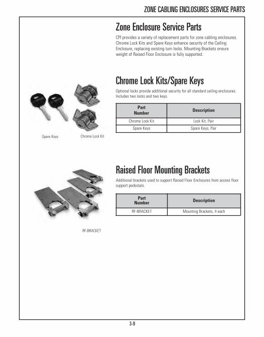
3-9
ZONE CABLING ENCLOSURES SERVICE PARTS
Chrome Lock Kit
RF-BRACKET
Raised Floor Mounting BracketsAdditional brackets used to support Raised Floor Enclosures from access floorsupport pedestals.
Part Number Description
Chrome Lock Kit Lock Kit, Pair
Spare Keys Spare Keys, Pair
Chrome Lock Kits/Spare KeysOptional locks provide additional security for all standard ceiling enclosures.Includes two locks and two keys.
Zone Enclosure Service PartsCPI provides a variety of replacement parts for zone cabling enclosures.Chrome Lock Kits and Spare Keys enhance security of the CeilingEnclosure, replacing existing turn locks. Mounting Brackets ensureweight of Raised Floor Enclosure is fully supported.
Part Number Description
RF-BRACKET Mounting Brackets, 4 each
Spare Keys

3-10
WIRELESS ENCLOSURES - DROP CEILING
AAT-CAP-1232-KIT
Note: AAT-CAP-11 may only be used with AAT-CAP.
Ceiling-Mounted Wireless Access Point EnclosuresCeiling Enclosures create a permanent location for various wireless accesspoints or bridges within drop ceilings. Equipment is supported on the accessdoor. Most access doors are pre-punched with openings for antennas. CeilingEnclosures include support brackets for use with 2’ ceiling “grids”. AAT-CAPfeatures interchangeable door-mounted faceplates with mounting brackets forequipment. Universal Faceplate accepts access points up to 2”H x 10”W x 8”D (50 mm x 250 mm x 200 mm) with antennae(s) up to 10.5” (267 mm) apart.Enclosure is finished in white.
PartNumber
DescriptionW x D x Lin (mm)
ShippingWeightlb (kg)
Wireless Ceiling Enclosures Without FaceplatesAAT-CAP 12 x 10 x 14.5 (305 x 254 x 368) 8 (3.6)
AAT-CAP-10-P 12 x 13 x 14.5 (305 x 330 x 368)with junction box 9 (4.1)
AAT-CAP-S 12 x 5 x 14.5 (305 x 127 x 368) 8 (3.6)
Faceplates For Wireless EnclosuresAAT-CAP-00 Blank (Solid) Faceplate 3 (1.4)
AAT-CAP-UNI Universal Faceplate 3 (1.4)
AAT-CAP-11 For Cisco® Aironet® 1100 3 (1.4)
AAT-CAP-12 For Cisco® Aironet® 1200 3 (1.4)
AAT-CAP-1232 For Cisco® Aironet® 1232 3 (1.4)
AAT-CAP-1242 For Cisco® Aironet® 1242 3 (1.4)
AAT-CAP Enclosures, 10”D (250 mm), With FaceplatesAAT-CAP-00-KIT Blank (Solid) Faceplate 10 (4.5)
AAT-CAP-UNI-KIT Universal Faceplate 10 (4.5)
AAT-CAP-11-KIT Cisco® 1100 Faceplate 10 (4.5)
AAT-CAP-12-KIT Cisco® 1200 Faceplate 10 (4.5)
AAT-CAP-1232-KIT Cisco® 1232 Faceplate 10 (4.5)
AAT-CAP-1242-KIT Cisco® 1242 Faceplate 10 (4.5)
AAT-CAP-S Enclosures, 5”D (130 mm), With FaceplatesAAT-CAP-S-00-KIT Blank (Solid) Faceplate 9 (4.1)
AAT-CAP-S-UNI-KIT Universal Faceplate 9 (4.1)
AAT-CAP-S-12-KIT Cisco® 1200 Faceplate 9 (4.1)
AAT-CAP-S-1232-KIT Cisco® 1232 Faceplate 9 (4.1)
AAT-CAP-S-1242-KIT Cisco® 1242 Faceplate 9 (4.1)
AAT-CAP-00
AAT-CAP-UNI
AAT-CAP-11
AAT-CAP-12
AAT-CAP-1232
AAT-CAP-1242
AAT-CAP

3-11
WIRELESS ENCLOSURES - DROP CEILING
Dome Wireless EnclosureThe AAT-ACE-DOME replaces a single drop ceiling tile to hide wireless accesspoints in open office spaces. The dome is mounted on a fully hinged lockingdoor providing easy access to equipment and cables for authorizedtechnicians only.• (1) 3/4”H x 3”W (19.1 mm x 80 mm) edge-protected cable access port with
approved foam sealing kit • Includes two sets of standoffs to adjust height of back plate within
dome• Enclosure: 23-3/4”W x 3”D x 23-3/4”L (603.3 mm x 80 mm x 603.3 mm)• Dome: 6-1/2”H (165 mm), 14” Diameter (360 mm)• Dome is large enough to accomodate most acccess points including
Cisco’s large 1250 series AP• Product Weight: 10.5 lb (4.76 kg)• Removable mounting plate is 8 7/8”W x 6-7/8”L (225.43 mm x 174.63 mm)• Customer must provide (4) 3/8” threaded rods and installation hardware• Enclosure and dome are finished in white
PartNumber
DescriptionW x D x Lin (mm)
ShippingWeightlb (kg)
13833-001 15.5 x 5 x 16.5 (394 x 127 x 419)Optimized for Cisco® 1250 10 (4.5)
WA064-CAP 10 x 4 x 12.75 (254 x 102 x 324)Optimized for Cisco® Aironet® 350 5 (2.3)
Ceiling-Mounted Wireless EnclosureCeiling Enclosures create a secure and permanent location for variouswireless access points or bridges within drop ceilings. Equipment is supported on the access door. Enclosures are finished in white.
PartNumber
DescriptionW x D x Lin (mm)
ShippingWeightlb (kg)
AAT-ACE-DOME 23.75 x 3 x 23.75 (603 x 80 x 603) Domed Wireless Enclosure 21 (9.5)
13833-001
WA064-CAP

3-12
WIRELESS ENCLOSURES - WALL
NEMA-Rated Wireless Wall-MountEnclosureThe AAT-MWME-P is a wall-mounted wireless acces point enclosuredesigned for warehouse, manufacturing/light industrial and exterior use. Asingle front door provides access to equipment. The door is attached with acontinuous steel hinge and secured by padlock through a stainless steelpadlock hasp. A gasket seals the interior at closure.• Enclosure is completely sealed, customer drills cable entry holes to fit
application• Enclosure: fiberglass reinforced polyester, gray • Enclosure: 11-1/2”H x 9-1/2”W x 4-1/2”D (292 mm x 241 mm x 114 mm)• Product Weight: 5 lb (2.3 kg)• Interior of the enclosure is 3”D (80 mm)• Maximum equipment size is 9” x 7” x 3” (230 mm x 180 mm x 80 mm)• Customer must provide installation and cable access hardware• NEMA 1, 2, 3, 3R, 4, 4X, 12 and 13
PartNumber
DescriptionH x W x Din (mm)
ShippingWeightlb (kg)
AAT-MWME-P 11.5 x 9.5 x 4.5 (292 x 241 x 114) 6 (2.7)
PartNumber
DescriptionH x W x Din (mm)
ShippingWeightlb (kg)
WA064-WAP 8 x 11 x 3 (200 x 280 x 80) 9 (4.1)
Wireless Wall-Mount EnclosureWall-mounted access points provide better wireless coverage in someenvironments. This enclosure is for interior use and provides a secure andpermanent wall-mounted location for various wireless access points andbridges. • Optimized for Cisco® Aironet® 350• Enclosure is finished in beige• UL Listed

3-13
WIRELESS ENCLOSURES - WALL
Large NEMA-Rated Wireless Wall-MountEnclosureThe AAT-WME-P is for warehouse, manufacturing, light industrial and exterioruse. A single front door provides access to equipment. The door is attachedwith a continuous steel hinge and secured by padlock through a stainlesssteel padlock hasp. A gasket seals the interior at closure.• Enclosure is completely sealed, customer drills cable entry holes to fit
application• Removable mounting plate for wireless transmitters• Enclosure: Fiberglass reinforced polyester, gray• Product Weight: 7.5 lb (3.4 kg)• The interior of the enclosure is 5”D (130 mm) • Maximum equipment size: 13.5” x 11.5” x 5” (343 mm x 292 mm x 130 mm)• Customer must provide installation and cable access hardware• NEMA 1, 2, 3, 3R, 4, 4X, 12 and 13
Large NEMA-Rated Wireless Wall-MountEnclosure With WindowThe AAT-WMESG-P is for warehouse, manufacturing, light industrial andexterior use. A single front door provides access to equipment. The door isattached with a continuous steel hinge and secured by padlock through astainless steel padlock hasp. A gasket seals the interior at closure. Largewindow provides viewing of equipment.• Enclosure is completely sealed, customer drills cable entry holes to fit
application• Removable mounting plate for wireless transmitters• Enclosure: Fiberglass reinforced polyester, gray• Product Weight: 7.5 lb (3.4 kg)• The interior of the enclosure is 5”D (130 mm)• Maximum equipment size: 13.5” x 11.5” x 5” (343 mm x 292 mm x 130 mm)• NEMA 1, 2, 3, 3R, 4, 4X, 12 and 13
PartNumber
DescriptionH x W x Din (mm)
ShippingWeightlb (kg)
AAT-WMESG-P 15.5 x 13.5 x 6 (394 x 343 x 150)Large Enclosure with Window 11 (5.0)
PartNumber
DescriptionH x W x Din (mm)
ShippingWeightlb (kg)
AAT-WME-P 15.5 x 13.5 x 6 (394 x 343 x 150) 11 (5.0)

3-14
ZONE CABLING ENCLOSURES - WALL
PartNumber
DescriptionH x W x Din (mm)
ShippingWeightlb (kg)
AAT-AWM-H 24 x 42 x 7.5 (610 x 1070 x 191) 73 (33.1)
Wall-Mount Enclosure The Wall-Mount Enclosure measures 24”H x 42”W x 7.5”D (610 mm x 1070mm x 191 mm). Includes mounting positions for passive and active equipment,a junction box and a fan to remove heat generated by active components.Mounting positions include space for a single 100 pair 110-style terminationblock, a single 6-port fiber optic adapter panel, two 2U x 19” spaces for patchpanels or other panel mount termination hardware and one 3U x 19” space for active components up to 18”D (460 mm).
The enclosure is pre-punched with knockouts for 1/2” or 1-1/2” electricalconduit for cables and has an insulated, locking, fully-hinged double door toreduce noise and provide security. • Enclosure is finished in beige
MUTOA Floor BoxesMulti-User Telecommunications Outlet Assemblies (MUTOA) are typicallysmall, passive devices that do not rack-mount. CPI’s MUTOA Floor Boxes allowconvenient and economical storage of these devices. Available in 24- and 48-port designs.• Lightweight construction• Meets TIA-569-B standards
PartNumber Description
ShippingWeightlb (kg)
13701-024 24-Port MUTOA Floor Box 30 (13.6)
13701-048 48-Port MUTOA Floor Box 35 (15.7)

WALL-MOUNT SYSTEMSWall-Mount Racks, Cabinets & Accessories
Wall-Mount Racks - Hinged Swing Gate Page 4-4Wall-Mount Racks - Fixed Mount Page 4-7Wall-Mount Rack with Enclosure Page 4-9Wall-Mount Rack Accessories Page 4-10Cube-iT PLUS® Cabinet System Page 4-11ThinLine II Wall-Mount Cabinet Page 4-16Silver Frame Wall-Mount Cabinet Page 4-18

WALL-MOUNT SYSTEMS
4-2
As telecommunications needs continue to grow and expand, the physical space in which theyexist doesn't always grow at the same rate. Wall-Mount Systems overcome this hurdle byproviding racks and cabinets that allow you to create locations for cables and equipment wherespace is limited or does not exist. Secure equipment on the wall inside or outside of thetelecommunications room and connect remote groups of users to the network. CPI offersseveral styles and options of fixed and swing gate Wall-Mount Racks and Cabinets available aseither open or enclosed systems.
Wall-Mount Open Systems: • Mountable to wall or backboard• Open architecture for airflow and easy access to cables• Support of patch panels, shelves, trays and network equipment with roll-formed#12-24 tapped mounting holes
• 19”or 23” rack-mount width• High-strength, lightweight aluminum construction (most models)• Standard EIA-310-D hole pattern• Fixed and swing-out designs for easier installation• Offer up to 350 lb (158.8 kg) static load rating
Wall-Mount Enclosed Systems: • Mountable to wall or backboard• Enclosed with lockable doors for security and aesthetic appeal• 19” rack-mount width• Standard EIA-310-D hole pattern• Fixed and swing-out designs for easier installation• Wall-mounted, floor-supported cabinets offer up to 1000 lb (453.6 kg) static load rating

WALL-MOUNT SYSTEMS
4-3
Open Systems
Product Purpose Load Rating - lb (kg)Universal Swing Gate Wall RackPage 4-4
Feature rich, swing frame used to support network equipmentfor a medium size group of users
Up to 150 (68.0)
Standard Swing Gate Wall RackPage 4-5
General use, swing frame used to support network equipmentfor a medium size group of users. UL Listed
Up to 150 (68.0)
EasySwing Wall-Mount RackPage 4-6
Affordable, swing frame used to support network equipment for a small group of users. Ships preassembled
Up to 85 (38.6)
Heavy-Duty Wall-Mount Equipment RackPage 4-7
Strong, fixed frame used to support network equipment for a medium size group of users and other heavy equipment Up to 350 (158.8)
Fixed Wall-Mount Equipment RackPage 4-8
Basic, fixed frame used to support network equipment for asmall group of users. UL Listed
Up to 200 (90.7)
Enclosed Systems
Cube-iT Plus® Wall-Mount CabinetPage 4-11
Feature rich, hinged cabinet used to secure networkconnections for a medium size group of users. Five-inch deeprear panel allows conduit to terminate at back of cabinet.UL Listed
Up to 200 (90.7)
Cube-iT Plus® Floor-Supported CabinetPage 4-13
Feature rich, hinged and floor-supported wall cabinet replacesfloor supported network equipment in small equipment rooms Up to 1000 (453.6)
ThinLine II Wall-Mount CabinetPage 4-16
Space-saving cabinet used to secure network connections fora small group of users. Ideal for high-traffic areas
Up to 100 (45.4)
Silver Frame Wall-Mount CabinetPage 4-18
Mid-level, hinged cabinet used to secure network connectionsfor a medium size group of users
Up to 150 (68.0)
Wall-Mounted ProductsAvailable in open and enclosed systems, wall-mounted racks and cabinets arean excellent choice to support equipment when floor space is limited or wherea small group of users exist.
Open wall-mount racks present easy access to cables and equipment and offerboth fixed and swing frames. Swing frames pivot open on one side to provideaccess to the rear of equipment and are used to support patch panels, whilefixed frames hold more weight and are used for network routers and switches.
Enclosed wall-mount cabinets provide added physical security and areavailable in vertical, hinged and floor-supported designs. Vertical cabinets holdequipment against the wall to minimize the depth of the cabinet. Use verticalcabinets to support a small group of network users. Hinged cabinets provideaccess to the front and the rear of equipment. The cabinet body is hinged nearthe wall and can swing open to access cable terminations and the rear ofequipment. Floor-supported cabinets are also hinged, but the cabinet body issupported from the floor with casters. This type of cabinet can hold moreweight than wall-mounted hinged cabinets and are used to replace afreestanding rack in small rooms where added equipment security is required.
Product Comparison
EnclosedMounting
OpenMounting

4-4
SWING GATE WALL-MOUNT RACKS
Universal Swing Gate RackThis full-featured swing gate rack offers 150 lb (68.0 kg) load handling capacity, easyassembly and built-in cable management capabilities. • Dual locking latches keep gate securely closed • Improved cable management with nine cable pass- through ports and six Saf-T-Grip®
reusable Velcro® strips • Gate opens 180°, made of strong, lightweight aluminum • Easy assembly using included instructions • Universal 5/8”-5/8”-1/2” (15.9 mm -15.9 mm -12.7 mm) alternating mounting hole pattern drilled on both front and back sides
• Rack-mount spaces are marked and numbered • (50) #12-24 mounting screws included; black painted racks ship with black screws, ther racks ship with zinc screws
• Supports 150 lb (68.0 kg) of equipment, when securely mounted to wall
Universal Swing Gate Rack
PartNumber
Usable Dimensions Overall Dimensions - in (mm) ShippingWeightlb (kg)
Height Width Depth Height Width Depth
11347-X19 20U 19"EIA 12 (300) 40.4 (1026) 22.1 (562) 12.8 (325) 24 (10.9)
11348-X19 20U 19"EIA 18 (457) 40.4 (1026) 22.1 (562) 18.8 (478) 29 (13.2)
11347-X23 20U 23" 12 (300) 40.4 (1026) 26.1 (663) 12.8 (325) 25 (11.3)
11348-X23 20U 23" 18 (457) 40.4 (1026) 26.1 (663) 18.8 (478) 30 (13.6)
X=color: 1=Gray, 2=White, , 5=Clear, 7=Black.

4-5
SWING GATE WALL-MOUNT RACKS
• Dual hinges opens to right or left, stopping in 90° position
• EIA-310-D compliant• Universal 5/8”-5/8”-1/2” (15.9 mm -15.9mm -12.7 mm) alternating hole pattern
• Rack-mount spaces are marked and numbered
• Includes (50) #12-24 mounting screws; black painted racks ship with black screws,other racks ship with zinc screws
• Supports 100 lb (45.4 kg) of equipment inthe open and closed position when securelymounted
• Load capacity can be increased to 150 lb(68 kg) with optional Heavy Duty SwingGate Kit
• Supports single-sided and double-side shelves
• Ships partially assembled with installation hardware
Standard Swing Gate Wall RackThe Standard Swing Gate Wall Rack provides easy access to the rear of equipment,making it the ideal choice for supporting patch panels and switches.
X=color: 1=Gray, 2=White, 7=Black. Note: Usable Depth is reduced at the top and bottom U to8” (200 mm) pm -X12; 12” (300 mm on -X18; and 19” (462 mm) on -X25 racks.
X=color: 1=Gray, 2=White, 7=Black
Heavy Duty Swing Gate KitIncreases the load bearing capacity of P/Ns (-X18) and (-X25) Standard Swing Gate WallRacks to 150 lb (68 kg). Hardware included.
PartNumber Description
ShippingWeightlb (kg)
12795-X01 Two Brackets 4 (1.8)
Standard Swing Gate Wall Rack
PartNumber
Usable Dimensions Overall Dimensions - in (mm) ShippingWeightlb (kg)Height Width Depth* Height Width Depth
11790-X12 12U 19"EIA 11 (280) 29.1 (739) 21.7 (551) 12.2 (310) 30 (13.6)
11790-X18 12U 19"EIA 17 (430) 29.1 (739) 21.7 (551) 18.2 (462) 33 (14.9)
11790-X25 12U 19"EIA 24 (610) 29.1 (739) 21.7 (551) 25.2 (640) 46 (20.7)
11791-X12 20U 19"EIA 11 (280) 43.1 (1095) 21.7 (551) 12.2 (310) 33 (15.0)
11791-X18 20U 19"EIA 17 (430) 43.1 (1095) 21.7 (551) 18.2 (462) 36 (16.3)
11791-X25 20U 19"EIA 24 (610) 43.1 (1095) 21.7 (551) 25.2 (640) 50 (22.5)
11807-X12 26U 19"EIA 11 (280) 53.6 (1361) 21.7 (551) 12.2 (310) 35 (15.8)
11807-X18 26U 19"EIA 17 (430) 53.6 (1361) 21.7 (551) 18.2 (462) 37 (16.7)
11807-X25 26U 19"EIA 24 (610) 53.6 (1361) 21.7 (551) 25.2 (640) 54 (24.3)
11792-X12 40U 19"EIA 11 (280) 78.1 (1984) 21.7 (551) 12.2 (310) 43 (19.4)
11792-X18 40U 19"EIA 17 (430) 78.1 (1984) 21.7 (551) 18.2 (462) 45 (20.7)
11792-X25 40U 19"EIA 24 (610) 78.1 (1984) 21.7 (551) 25.2 (640) 64 (28.9)
11793-X12 12U 23" 11 (280) 29.1 (739) 25.7 (653) 12.2 (310) 31 (14.0)
11793-X18 12U 23" 17 (430) 29.1 (739) 25.7 (653) 18.2 (462) 34 (15.3)
11793-X25 12U 23" 24 (610) 29.1 (739) 25.7 (653) 25.2 (640) 47 (21.1)
11794-X12 20U 23" 11 (280) 43.1 (1095) 25.7 (653) 12.2 (310) 34 (15.4)
11794-X18 20U 23" 17 (430) 43.1 (1095) 25.7 (653) 18.2 (462) 37 (16.7)
11794-X25 20U 23" 24 (610) 43.1 (1095) 25.7 (653) 25.2 (640) 51 (23.0)
11808-X12 26U 23" 11 (280) 53.6 (1361) 25.7 (653) 12.2 (310) 36 (16.3)
11808-X18 26U 23" 17 (430) 53.6 (1361) 25.7 (653) 18.2 (462) 38 (17.1)
11808-X25 26U 23" 24 (610) 53.6 (1361) 25.7 (653) 25.2 (640) 55 (24.8)
11795-X12 40U 23" 11 (280) 78.1 (1984) 25.7 (653) 12.2 (310) 44 (19.8)
11795-X18 40U 23" 17 (430) 78.1 (1984) 25.7 (653) 18.2 (462) 46 (21.1)
11795-X25 40U 23" 24 (610) 78.1 (1984) 25.7 (653) 25.2 (640) 65 (29.3)

SWING GATE WALL-MOUNT RACKS
4-6
Ships flat
Easy Swing Wall-Mount Rack
Part Number
Usable Dimensions Overall Dims - in (mm) ShippingWeightlb (kg)Height Width Depth* Height Width Depth
13602-X08 11U 19"EIA 6.5 (165) 24.5 (622) 20.3 (516) 8.0 (204) 22 (10.0)
13602-X12 11U 19"EIA 10.5 (266) 24.5 (622) 20.3 (516) 12.0 (305) 24 (10.9)
13602-X18 11U 19"EIA 16.5 (419) 24.5 (622) 20.3 (516) 18.0 (457) 28 (12.7)
13602-X25 11U 19"EIA 23.5 (596) 24.5 (622) 20.3 (516) 25.0 (635) 34 (15.4)
13604-X08 19U 19"EIA 6.5 (165) 38.5 (978) 20.3 (516) 8.0 (204) 27 (12.2)
13604-X12 19U 19"EIA 10.5 (266) 38.5 (978) 20.3 (516) 12.0 (305) 29 (13.2)
13604-X18 19U 19"EIA 16.5 (419) 38.5 (978) 20.3 (516) 18.0 (457) 33 (15.0)
13604-X25 19U 19"EIA 23.5 (596) 38.5 (978) 20.3 (516) 25.0 (635) 38 (17.2)
13608-X12 26U 19"EIA 10.5 (266) 51.5 (1308) 20.3 (516) 12.0 (305) 33 (15.0)
13608-X18 26U 19"EIA 16.5 (419) 51.5 (1308) 20.3 (516) 18.0 (457) 37 (16.8)
EasySwing Wall-Mount RackThe EasySwingWall-Mount Rack is a cost-effective 19” EIA swing gate rack formounting network, communications and security equipment in a elecommunications orequipment room where floor space is limited. • Opens 180° to right or left, locking latch pin secures gate in closed position. Includes lanyard for attachment to rack
• 19” EIA threaded equipment mounting rails• Includes reusable cable management straps• Durable all-steel construction• Ships fully assembled and flat; simply unfold and mount to wall• Keyhole wall mounting holes with mounting template included on carton• Includes (12) #12-24 equipment mounting screws, Order 1/4” installation hardware separately
• Supports 85 lb (38.6 kg) of equipment
Corner CushionsSince wall racks are elevated above the floor and extend away from the wall, bumpinginto the rack is a safety concern. Corner Cushions cover the exposed leading edges ofracks for added protection.• Flame retardant, non-toxic• Foam design conforms to ASTM standards for safety surfacing material
PartNumber Description
ShippingWeightlb (kg)
12858-001 Corner Cushions, Set of 4 1 (0.5)
Includesdouble-sidedadhesivesquares foreasyinstallation
X=color: 1=Gray, 2=Computer White, 7=Black. Note: Usable Depth is reduced at the topand bottom 2U on -X08 and -X12 models and at the top and bottom 3U on -X18 and -X25models. For planning purposes, reduce Useable Depth by 75% and 50% on the top andbottom 2U of -X08 and -X12 racks. Reduce Usable Depth by 80%, 50% and 25% on thetop and bottom 3U of -X18 and -X25 racks.

4-7
FIXED WALL-MOUNT RACK
Heavy Duty Wall-Mount Equipment RackUse the Heavy Duty Wall-Mount Equipment Rack to hold up to 350 lb (158.8 kg). The 24”(610 mm) depth allows larger equipment to be wall-mounted. Quick and easy assemblyhas been engineered in to save you valuable installation time. Includes assemblyhardware and mounting 1/4” x 2” lag bolts. Sold individually. • 12-24 roll-formed threads on 5/8”-5/8”-1/2” (15.9 mm -15.9 mm -12.7 mm) spacing, both sides
• Rack mount spaces are marked and numbered• Made of high-strength, lightweight aluminum• Includes (50) #12-24 mounting screws; black painted racks ship with black screws, other racks ship with zinc screws
• Holds up to 350 lb (158.8 kg) when securely mounted to wall or backboard
Heavy Duty Wall-Mount Equipment Rack
PartNumber
Usable Dimensions Overall Dims - in (mm) ShippingWeightHeight Width Depth Height Width Depth
15320-X18 20U 19"EIA 18 (457) 41.2 (1046) 23.0 (584) 18.0 (457) 22 (10.0)
15320-X24 20U 19"EIA 24 (610) 41.2 (1046) 23.0 (584) 24.0 (610) 27 (12.2)
15321-X18 40U 19"EIA 18 (457) 76.2 (1935) 23.0 (584) 18.0 (457) 28 (12.7)
15321-X24 40U 19"EIA 24 (610) 76.2 (1935) 23.0 (584) 24.0 (610) 32 (14.5)
15322-X18 20U 23" 18 (457) 41.2 (1046) 27.0 (686) 18.0 (457) 23 (10.4)
15322-X24 20U 23" 24 (610) 41.2 (1046) 27.0 (686) 24.0 (610) 29 (13.2)
15323-X18 40U 23" 18 (457) 76.2 (1935) 27.0 (686) 18.0 (457) 29 (13.2)
15323-X24 40U 23" 24 (610) 76.2 (1935) 27.0 (686) 24.0 (610) 34 (15.4)
X=color: 1=Gray, 2=Computer White, 5=Brushed Aluminum, 7=Black.
Part Number
DescriptionH x W (in)
11754-X19 6U x 19 Wall Bracket
X=color: 1=Gray, 2=White, 5=Clear, 7=Black
Extra-Capacity, Flush Mounted Wall BracketThis rack is used to mount up to 6U of rack-mount equipment flush to the wall. Ideal forsmall or tight spaced installations. Supports 150 lb (68 kg). Mounting hardware notincluded. Made of strong, lightweight aluminum.
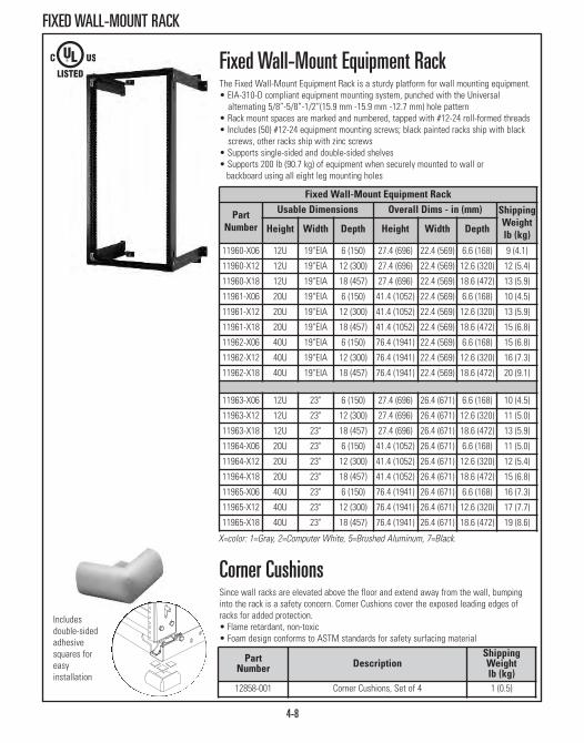
4-8
FIXED WALL-MOUNT RACK
Fixed Wall-Mount Equipment RackThe Fixed Wall-Mount Equipment Rack is a sturdy platform for wall mounting equipment.• EIA-310-D compliant equipment mounting system, punched with the Universal alternating 5/8”-5/8”-1/2”(15.9 mm -15.9 mm -12.7 mm) hole pattern
• Rack mount spaces are marked and numbered, tapped with #12-24 roll-formed threads• Includes (50) #12-24 equipment mounting screws; black painted racks ship with black screws, other racks ship with zinc screws
• Supports single-sided and double-sided shelves• Supports 200 lb (90.7 kg) of equipment when securely mounted to wall or backboard using all eight leg mounting holes
Fixed Wall-Mount Equipment Rack
PartNumber
Usable Dimensions Overall Dims - in (mm) Shipping Weightlb (kg)Height Width Depth Height Width Depth
11960-X06 12U 19"EIA 6 (150) 27.4 (696) 22.4 (569) 6.6 (168) 9 (4.1)
11960-X12 12U 19"EIA 12 (300) 27.4 (696) 22.4 (569) 12.6 (320) 12 (5.4)
11960-X18 12U 19"EIA 18 (457) 27.4 (696) 22.4 (569) 18.6 (472) 13 (5.9)
11961-X06 20U 19"EIA 6 (150) 41.4 (1052) 22.4 (569) 6.6 (168) 10 (4.5)
11961-X12 20U 19"EIA 12 (300) 41.4 (1052) 22.4 (569) 12.6 (320) 13 (5.9)
11961-X18 20U 19"EIA 18 (457) 41.4 (1052) 22.4 (569) 18.6 (472) 15 (6.8)
11962-X06 40U 19"EIA 6 (150) 76.4 (1941) 22.4 (569) 6.6 (168) 15 (6.8)
11962-X12 40U 19"EIA 12 (300) 76.4 (1941) 22.4 (569) 12.6 (320) 16 (7.3)
11962-X18 40U 19"EIA 18 (457) 76.4 (1941) 22.4 (569) 18.6 (472) 20 (9.1)
11963-X06 12U 23" 6 (150) 27.4 (696) 26.4 (671) 6.6 (168) 10 (4.5)
11963-X12 12U 23" 12 (300) 27.4 (696) 26.4 (671) 12.6 (320) 11 (5.0)
11963-X18 12U 23" 18 (457) 27.4 (696) 26.4 (671) 18.6 (472) 13 (5.9)
11964-X06 20U 23" 6 (150) 41.4 (1052) 26.4 (671) 6.6 (168) 11 (5.0)
11964-X12 20U 23" 12 (300) 41.4 (1052) 26.4 (671) 12.6 (320) 12 (5.4)
11964-X18 20U 23" 18 (457) 41.4 (1052) 26.4 (671) 18.6 (472) 15 (6.8)
11965-X06 40U 23" 6 (150) 76.4 (1941) 26.4 (671) 6.6 (168) 16 (7.3)
11965-X12 40U 23" 12 (300) 76.4 (1941) 26.4 (671) 12.6 (320) 17 (7.7)
11965-X18 40U 23" 18 (457) 76.4 (1941) 26.4 (671) 18.6 (472) 19 (8.6)
Corner CushionsSince wall racks are elevated above the floor and extend away from the wall, bumpinginto the rack is a safety concern. Corner Cushions cover the exposed leading edges ofracks for added protection.• Flame retardant, non-toxic• Foam design conforms to ASTM standards for safety surfacing material
PartNumber Description
ShippingWeightlb (kg)
12858-001 Corner Cushions, Set of 4 1 (0.5)
Includesdouble-sidedadhesivesquares foreasyinstallation
X=color: 1=Gray, 2=Computer White, 5=Brushed Aluminum, 7=Black.

4-9
FIXED WALL-MOUNT
Wall-Mount Rack With EnclosureEnjoy the benefits of a wall-mount rack solution with the added protection and security ofan enclosure at an attractive price. As always, CPI quality is built into this attractive,economical product. So, whenever floor space is at a premium and a full size rack is notrequired, use the CPI Wall-Mount Rack with Enclosure. Available in two sizes withaluminum or plexiglass doors. Ships fully assembled with mounting instructions andhardware.
Rack Features:• Strong, lightweight aluminum construction provides maximum strength • Includes wall-mounting 1/4” x 2” lag bolts and 50 #12-24 mounting screws; black painted racks ship with black screws, other racks ship with zinc screws
• 19”EIA, Universal 5/8”-5/8”-1/2” (15.9 mm x 15.9 mm x 12.7 mm) hole pattern allows for a wide variety of mounting options
• Supports up to 200 lb (90.7 kg)
Enclosure Features:• Strong, lightweight aluminum construction • Vented top and bottom for optimum airflow • Convenient cable access via removable two top and two bottom cable pass-through ports, 1.6” x 3.5” (41 mm x 89 mm)
• Lockable door is easily installed to open from left or right• Optional Fan Kit available for 18”D (460 mm) enclosure
Wall-Mount Rack With Enclosure
PartNumber
Usable Dimensions Overall Dims - in (mm) ShippingWeightlb (kg)Height Width Depth Height Width Depth
12264-X16 12U 19"EIA 12 (300) 28.5 (724) 24.5 (622) 16.1 (409) 44 (20.0)
12324-X22 20U 19"EIA 18 (457) 42.1 (1069) 24.5 (622) 22.1 (561) 60 (27.2)
Includes Door With Tinted Plexiglass Window
12265-X16 12U 19"EIA 12 (300) 28.5 (724) 24.5 (622) 16.1 (409) 44 (20.0)
12325-X22 20U 19"EIA 18 (457) 42.1 (1069) 24.5 (622) 22.1 (561) 60 (27.2)
Flush Mounted Wall Bracket This bracket makes it easy to mount up to two 1U or a single 2U piece of rack-mountequipment (1U=1.75”, 44.45 mm) flush to a wall. Ideal for small or tight spacedinstallations. Mounting hardware not included. Made of strong, lightweight aluminum. • Supports up to 75 lb (34 kg)Note: This wall bracket is not rack-mountable.
Part NumberColor
19” Rack 23” Rack11583-119 11583-123 Gray
11583-219 11583-223 White
11583-519 11583-523 Clear
11583-719 11583-723 Black
X=color: 1=Gray, 2=White, 7=Black.

4-10
WALL-MOUNT RACK ACCESSORIES
5.19” (131.8 mm)
12.00” (304.8 mm)15.00” (381.0 mm)
Power Strip Streamlined, durable steel body is fitted with bracket for mounting.• 17”L (430 mm), uses 1U, black• Circuit breaker, eight outlets, 10’ (3 m) cord
PartNumber AMP Surge
ProtectedPlugType
OutletType
12816-701 15A No NEMA 5-15P 15A (5-15R)
12816-702 15A No NEMA L5-15P 15A (5-15R)
12816-703 15A Yes NEMA 5-15P 15A (5-15R)
12816-704 15A Yes NEMA L5-15P 15A (5-15R)
12816-705 20A No NEMA 5-20P 20A (5-20R)
12816-706 20A No NEMA L5-20P 20A (5-20R)
12816-707 20A Yes NEMA 5-20P 20A (5-20R)
12816-708 20A Yes NEMA L5-20P 20A (5-20R)
Shelves • 15” (380 mm) shelf mounts in 18”D (460 mm) racks only
PartNumber Description
ShippingWeightlb (kg)
10”D (250 mm) Shelf,H x W - in (mm)
12291-X01 2U x 17.25 (438.2),Supports 40 lb (18.1 kg) 4 (1.8)
15”D (380 mm) Shelf, H x W - in (mm)
40074-X00 3U x 17.25 (438.2),Supports 50 lb (22.7 kg) 6 (2.7)
Fan/Filter Kit Fan pressurizes enclosure, forcing warmer air out top vents. Fan is rated for200 CFM and has an attached 5’6”L (1.6 m) power cord with NEMA 5-15Pplug. (37 dB noise level)
PartNumber Description
ShippingWeightlb (kg)
11755-003 200 CFM, 115 VAC, 50/60 Hz, NEMA 5-15P 3 (1.4)
11222-001 Replacement Filters, Set of 4 1 (0.5)
X=color: 1=Gray, 2=White, 5=Clear, 7=Black
12291-X01
40074-X00
See Section 1 for additional shelf options.See Section 7 for additional power options.
11755-003

4-11
CUBE-iT PLUS® CABINET SYSTEM
Wall-Mounted Cube-iT Plus
CUBE-iT Wall-Mounted Cabinet Specifications 24”H, 36”H & 48”H Cabinets (610 mm, 910 mm & 1220 mm)
• Patented hinge design allows the installer to remove the rear panel for easy installation
• For indoor use only, not for use in air-handling spaces• Usable heights: 24”H (610 mm) = 12U; 36”H (910mm) = 18U; 48”H (1220 mm) = 26U
• Includes one pair of 19”W adjustable (front-to-rear), mounting rails with Universal 5/8”-5/8”-1/2” (15.9 mm-15.9 mm -12.7 mm) alternating hole pattern. EIA-310-D Compliant; front rails are threaded for #12-24 mounting screws
• Cable knockouts include: (4) 1/2” or 3/4”, two on top, two on bottom; (8) 2-1/2” or 3”, four on top, four on bottom; (4) edge-protection grommets are included for 3” knockouts
• Constructed of riveted and bolted steel with epoxy-polyester hybrid powder coat paint finish. Equipment mounting rails are aluminum
• Ships fully assembled with mounting hardware, 50 each #12-24 screws and installation template
• UL Listed to support up to 200 lb (90.7 kg)
CUBE-iT PLUS® Cabinet SystemThe patented Cube-it Plus Cabinet System is a series of wall-mounted andfloor-supported telecommunications enclosures designed to securecommunications equipment for a cross connect. The cabinets are copper andfiber ready, and feature easy access to the front or rear of the cabinet.
Both the wall-mounted and floor-supported cabinets share these features: • Swing-out cabinet body enables easy access to the rear of installed equipment
• 5”D (130 mm) rear panel is pre-punched with knock-outs for 1/2”, 3/4”, 2-1/2” and 3” conduit, and has cable tie points and attachment points for accessory rack-mount brackets
• Cabinet body includes one pair of adjustable 19” EIA threaded equipment rails
• Cabinet body is vented. Vents will accept accessory fan• Front door design incorporates rounded edges and corners to improve safety in public access spaces
• A l ocking front door and rear panel provide security • Wide variety of accessories are available
Depths for Wall-Mounted Cabinet in (mm)
Cabinet Depth 13 (330) 18 (460) 24 (610) 30 (760) Cabinet Body Depth 7.2 (18) 12.2 (310) 18.2 (462) 24.2 (615)
Maximum Usable Depth 11.8 (300) 16.8 (427) 22.8 (579) 28.8 (732)
Wall-Mounted cabinet specifications located on next page.
Wall-MountedCube-iT Plus
Wall-Mounted, Floor-SupportedCube-iT Plus Cabinet

4-12
CUBE-iT PLUS® CABINET SYSTEM
36”H (910 mm) Cube-iT Plus - Wall MountedPart Number & Color
Door Style Widthin (mm)
Depthin (mm)
Shipping Weightlb (kg)White Black
13265-236 13265-736 Metal Door 24 (610) 13 (330) 89 (40.4)13275-236 13275-736 Plexiglass Door 24 (610) 13 (330) 83 (37.6)11890-236 11890-736 Metal Door 24 (610) 18 (460) 99 (44.9)11901-236 11901-736 Plexiglass Door 24 (610) 18 (460) 93 (42.2)11840-236 11840-736 Metal Door 24 (610) 24 (610) 111 (50.3)11900-236 11900-736 Plexiglass Door 24 (610) 24 (610) 105 (47.6)11996-236 11996-736 Metal Door 24 (610) 30 (760) 124 (56.2)12419-236 12419-736 Plexiglass Door 24 (610) 30 (760) 118 (53.5)
Extra Mounting Rails, 1 Pair12787-536 L-Shaped, Threaded, 18U 4 (1.8)
24”H (610 mm) Cube-iT Plus - Wall MountedPart Number & Color
Door Style Widthin (mm)
Depthin (mm)
Shipping Weightlb (kg)White Black
13265-224 13265-724 Metal Door 24 (610) 13 (330) 70 (31.8)
13275-224 13275-724 Plexiglass Door 24 (610) 13 (330) 67 (30.4)
11890-224 11890-724 Metal Door 24 (610) 18 (460) 78 (35.4)
11901-224 11901-724 Plexiglass Door 24 (610) 18 (460) 75 (34.0)
11840-224 11840-724 Metal Door 24 (610) 24 (610) 87 (39.5)
11900-224 11900-724 Plexiglass Door 24 (610) 24 (610) 84 (38.1)
11996-224 11996-724 Metal Door 24 (610) 30 (760) 97 (44.0)
12419-224 12419-724 Plexiglass Door 24 (610) 30 (760) 94 (42.6)
Extra Mounting Rails, 1 pair12787-524 L-Shaped, Threaded, 12U 3 (1.4)
48”H (1220 mm) Cube-iT Plus - Wall MountedPart Number & Color
Door Style Widthin (mm)
Depthin (mm)
Shipping Weightlb (kg)White Black
13265-248 13265-748 Metal Door 24 (610) 13 (330) 108 (49.0)
13275-248 13275-748 Plexiglass Door 24 (610) 13 (330) 101 (45.8)
11890-248 11890-748 Metal Door 24 (610) 18 (460) 121 (54.9)
11901-248 11901-748 Plexiglass Door 24 (610) 18 (460) 114 (51.7)
11840-248 11840-748 Metal Door 24 (610) 24 (610) 135 (61.2)
11900-248 11900-748 Plexiglass Door 24 (610) 24 (610) 128 (58.1)
11996-248 11996-748 Metal Door 24 (610) 30 (760) 151 (68.5)
12419-248 12419-748 Plexiglass Door 24 (610) 30 (760) 143 (64.9)
Extra Mounting Rails, 1 Pair12787-548 L-Shaped, Threaded, 26U 5 (2.3)
Floor-Mount Foot Kit13483-001 Foot Kit for 24”D (610 mm) & 30”D (760 mm) Cabinets Only 5 (2.3)
Note: Foot Kit allows front door and rear panel to open when cabinet is placed on the floor, shelf or other surface.

4-13
CUBE-iT PLUS® CABINET SYSTEM
60”H (1520 mm) Cube-iT Plus - Wall Mounted & Floor-SupportedPart Number & Color
Door Style Widthin (mm)
Depthin (mm)
Shipping Weightlb (kg)White Black
13491-260 13491-760 Metal Door 27.3 (693) 18 (460) 201 (91.2)13494-260 13494-760 Plexiglass Door 27.3 (693) 18 (460) 192 (87.1)13492-260 13492-760 Metal Door 27.3 (693) 24 (610) 221 (100.2)13495-260 13495-760 Plexiglass Door 27.3 (693) 24 (610) 212 (96.2)13493-260 13493-760 Metal Door 27.3 (693) 30 (760) 246 (111.6)13496-260 13496-760 Plexiglass Door 27.3 (693) 30 (760) 236 (107.0)
Extra Mounting Rails, 1 pair13276-260 13276-760 L-Shaped, Threaded, 33U 12 (5.4)
72”H (1830 mm) Cube-iT Plus - Wall Mounted & Floor-SupportedPart Number & Color
Door Style Widthin (mm)
Depthin (mm)
Shipping Weightlb (kg)White Black
13491-272 13491-772 Metal Door 27.3 (693) 18 (460) 224 (101.6)13494-272 13494-772 Plexiglass Door 27.3 (693) 18 (460) 212 (96.2)13492-272 13492-772 Metal Door 27.3 (693) 24 (610) 247 (112.0)13495-272 13495-772 Plexiglass Door 27.3 (693) 24 (610) 235 (106.6)13493-272 13493-772 Metal Door 27.3 (693) 30 (760) 274 (124.3)13496-272 13496-772 Plexiglass Door 27.3 (693) 30 (760) 262 (118.8)
Extra Mounting Rails, 1 pair13276-272 13276-772 L-Shaped, Threaded, 40U 14 (6.4)
CUBE-iT Wall-Mounted, Floor-Supported Cabinet Specifications 60”H & 72”H Cabinets (1520 mm & 1830 mm)
• Cabinet body features lockable front door and swing-out rear panel for easyequipment access — cabinet body is supported by an attached wheel base
• For indoor use only, not for use in air-handling spaces• Usable heights: 60”H (1520 mm) = 33U; 72”H (1830 mm) = 40U• Wheeled base adds an additional 6” (150 mm) to height• Includes one pair of 19”W adjustable (front-to-rear), mounting rails with Universal 5/8”-5/8”-1/2” (15.9 mm -15.9 mm -12.7 mm) alternatinghole pattern; EIA-310-D Compliant
• Includes cable management space for vertical cable manager accessory • Cable knockouts include: (4) 1/2” or 3/4”, two on top, two on bottom; (10) 2-1/2” or 3”, five on top, five on bottom; (5) edge-protection grommets are included for 3” knockouts
• Constructed of riveted and bolted steel with epoxy-polyester hybrid powder coat paint finish; equipment mounting rails and supports arealuminum
• Ships fully assembled with mounting hardware• Support up to 1000 lb (453.6 kg)
Depths for Wall-Mounted, Floor-Supported Cabinetin (mm)
Cabinet Depth 18 (460) 24 (610) 30 (760) Cabinet Body Depth 12.2 (310) 18.2 (462) 24.2 (615)Maximum Usable Depth 16.8 (427) 22.8 (579) 28.8 (732)
Wall-Mounted, Floor-Supported Cube-iT Plus Cabinet

4-14
CUBE-iT PLUS® CABINET SYSTEM ACCESSORIES
12805-X01
13287-501
13288-501
Cube-iT PLUS® AccessoriesFan KitAttaches over the vents in the side of the Cube-iT Plus Cabinet, draws air into thecabinet, pressurizing the cabinet and forcing warm air out of the side vents. FanFilter Kit reduces dust and can be mounted internally for security or externally forconvenience, filter kit and filters sold separately. Includes mounting hardware &cable ties. Available in 115 VAC, 50/60 Hz, 37 dB Fan with 5’L (1.5 m) attached power cord and NEMA 5-15 plug; and 230 VAC, 50/60 Hz, 37 dB Fan with 5’L (1.5 m) attached power cord and NEMA 6-15P plug.
LightLight attaches to the bottom, top or side of cabinet and provides 8 Watts offluorescent light with on/off switch. 115 VAC with 6’ (1.8 m) attached power cordand NEMA 5-15P plug. 1U rack-mount version also available.
Termination Block PanelAttaches to rear panel of Cube-iT Plus Cabinet. Supports six 110D-style 100-pair blocks or four 66-style blocks/H89D brackets. Clear finish.
Vertical Cable ManagerVertical Cable Managers can be used in 60”H (1520 mm) and 72”H (1830 mm)cabinets only. Openings align with rack-mount units, 2.7”W x 5”D (69 mm x 130 mm) usable interior space. Adjusts front-to-rear within cabinet, fingers managepatch cords. Must be installed before rack-mount equipment.
Horizontal Wire Management BarAttaches to the rear of the equipment mounting rail to secure premise cables aftertermination on patch panels. Includes mounting hardware and 12 cable ties.
PartNumber Description
ShippingWeightlb (kg)
12804-701 Fan Kit, 100 CFM, 115 VAC, 50/60 Hz, NEMA 5-15P 4 (1.8)
12804-702 Fan Kit, 100 CFM, 230 VAC, 50/60 Hz, NEMA 6-15P 4 (1.8)
12805-X01 Filter Kit for Fan 4 (1.8)
12806-001 Filters for Fan, Box of 6 1 (0.5)
12803-701 Light 3 (1.4)
13287-501 Termination Block Panel11.5 x 19 (292 x 480 mm), 66 Block 4 (1.8)
13288-501 Termination Block Panel11.5 x 19 (292 x 480 mm), 110 Block 4 (1.8)
13485-760 Cable Manager for 60 (1520) Cabinet 9 (4.1)
13485-772 Cable Manager for 72 (1830) Cabinet 10 (4.5)
11837-X01 Horizontal Wire Management Bar 2 (0.9)
12804-701
12803-701
Vertical Cable Managers listed hereare for Cube-iT Plus Cabinets only.13485-760; for 60”H (1520 mm) 13485-772; for 72”H (1830 mm)
X=color: 2=White, 7=Black
11837-X01

4-15
CUBE-iT PLUS® CABINET SYSTEM ACCESSORIES
12796-501
Cube-iT PLUS® Accessories45˚ Mounting BracketAttaches to rear panel to create a 3U x 19” EIA rack-mount space for patchpanels. Includes installation hardware.
90˚ Mounting BracketAttaches to rear panel of to create a 2U x 19” EIA vertical rack-mount space.Includes installation hardware.
Vertical Mounting BracketAttaches to the equipment mounting rail and creates a 2U x 19” EIA or 3U x 19”vertical rack-mount space. Includes installation hardware. Supports 75 lb (34 kg).
Power StripAttaches to the bottom, top or side, select straight or locking plug style. 115 VAC 15 Amp or 20 Amp, 8 outlets with 10’L (3 m) power cord and circuit breaker.Includes bracket and installation hardware.
ShelvesShelves mount in Cube-iT cabinets.
PartNumber Description
ShippingWeightlb (kg)
12796-501 45˚ Mounting Bracket, 3U, 1 Pair, Clear 3 (1.4)
13285-501 90˚ Mounting Bracket, 2U, 1 Pair, Clear 3 (1.4)
13286-501 Vertical Mounting Bracket, 2U, 1 Pair, Clear 3 (1.4)
13286-502 Vertical Mounting Bracket, 3U, 1 Pair, Clear 3 (1.4)
12820-701 15 Amp Power Strip, NEMA 5-15P 4 (1.8)
12820-702 15 Amp Power Strip, NEMA L5-15P 4 (1.8)
12820-703 15 Amp Power Strip, Surge-Protected, NEMA 5-15P 4 (1.8)
12820-704 15 Amp Power Strip, Surge-Protected, NEMA L5-20P 4 (1.8)
12820-705 20 Amp Power Strip, NEMA 5-20P 4 (1.8)
12820-706 20 Amp Power Strip, NEMA L5-20P 4 (1.8)
12820-707 20 Amp Power Strip,Surge-Protected, NEMA 5-20P 4 (1.8)
12820-708 20 Amp Power Strip,Surge-Protected, NEMA L5-20P 4 (1.8)
12291-X01 10”D (250 mm) Shelf2U x 17.25 (438.2), Holds 40 lb (18.1 kg) 4 (1.8)
40074-X00 15”D (380 mm) Shelf3U x 17.25 (438.2), Holds 50 lb (22.7 kg) 6 (2.7)
13285-501
13286-501
13286-502
12820-701
12291-701
40074-700

4-16
THINLINE II WALL-MOUNT CABINET
X=color: 1=Gray, 2=White, 7=Black
PartNumber
DescriptionH x W x Din (mm)
ShippingWeightlb (kg)
26”H (660 mm) ThinLine II13050-X11 26 x 26 x 5, 2U, (660 x 660 x 130) 47 (21.3)
13050-X12 26 x 26 x 8.5, 4U, (660 x 660 x 216) 54 (24.5)
13050-X13 26 x 26 x 12, 6U, (660 x 660 x 300) 60 (27.2)
36”H (910 mm) ThinLine II13050-X21 36 x 26 x 5, 2U, (910 x 660 x 130) 60 (27.2)
13050-X22 36 x 26 x 8.5, 4U, (910 x 660 x 216) 68 (30.8)
13050-X23 36 x 26 x 12, 6U, (910 x 660 x 300) 76 (34.5)
ThinLine II Wall-Mount Cabinet The space-saving ThinLine II safely secures 19” rack-mount networkequipment with minimal intrusion into the room — perfect for tight areas andhigh-traffic places such as classrooms and retail stores.
The ThinLine II maximizes interior space using a distinctive equipmentmounting rail system. Individual rails can be easily rotated for horizontal orvertical mounting and then bolted into place, making patch panel punchdowneasier. The cabinet can hold a server, switch, horizontal cable manager, patchpanel, fiber service loop and fiber-optic patch panel — with room toaccommodate additional mounting needs.
An easy-to-remove top panel slides in and out of position (without tools)using a spring button release. In addition, the 26”H (660 mm) cabinet can bemounted so that the removable “top” panel becomes a side panel.
A 4” x 6” (100 mm x 150 mm) opening in the rear of the cabinet andknockouts sized 3/4” and 1-1/2” allow cable entry and exit. Multiple cabletie-down points in rear panel and included Saf-T-Grip® straps secure cablessafely.• Door features rounded edges and corners and can be mounted to open from either right or left
• Removable top panel provides direct access to equipment without disturbing other devices
• Multiple sets of knockouts allow flexibility in cable organization• Louvers and fan accessory provide ventilation• Cabinet includes a 2” x 4” (50 mm x 100 mm) junction box to hold anoptional surge-suppressed duplex outlet, eliminating the need for a power strip
• Made of steel• Ships fully assembled with mounting hardware• Static load rating is 100 lb (45.4 kg)
ThinLine II can hold a server, switch, horizontalcable manager, patch panel, fiber service loop andfiber-optic patch panel — with room toaccommodate additional mounting needs.

4-17
THINLINE II WALL-MOUNT CABINET ACCESSORIES
Minimum Fan Speed(air temp 77° or less)65 CFM (Free Air)34 dB (Noise Level)
Maximum Fan Speed(air temp 104° or greater)120 CFM (Free Air)51 dB (Noise Level)
Minimum Fan Speed(air temp 77° or less)36 CFM (Free Air)28 dB (Noise Level)
Maximum Fan Speed(air temp 113° or greater)49 CFM (Free Air)33 dB (Noise Level)
13051-001 Intelligent Fan Specifications:
13051-002 Intelligent Fan Specifications:
13051-001 PartNumber Description
ShippingWeightlb (kg)
13051-001 115 VAC, 60 Hz, 4U/6U Cabinets 2 (0.9)
13051-002 115 VAC, 60 Hz, 2U Cabinet 2 (0.9)
Fiber Slack Manager Panel The Fiber Slack Manager Panel provides both fiber slack management and amounting surface for a small fiber manager or fiber-optic patch panel.Secured under the outermost mounting units, the panel takes up no mountingspace within the cabinet. It attaches to the cabinet with standard #12-24 rackscrews (included in the ThinLine II Cabinet’s hardware kit).
Surge-Suppressed Duplex Receptacle The cabinet can be easily configured with two surge-suppressed outlets,eliminating the need for a power strip. ThinLine II includes an electricaljunction box that can be mounted on either side of the cabinet. A 1/2” or 3/4”knockout is provided.
Intelligent Fan Kit The ThinLine II Intelligent Fan Kit uses a solid state temperature control tovary fan speed from an ultra quiet low speed at low air temperature throughincreasingly higher speeds as temperature rises.
PartNumber Description
ShippingWeightlb (kg)
12934-001 Receptacle, 125V, 15A 2 (0.9)
PartNumber Description Color
ShippingWeightlb (kg)
12955-219 19” Rack-Mount White 2 (0.9)
12955-719 19” Rack-Mount Black 2 (0.9)

4-18
SILVER FRAME WALL-MOUNT CABINET
X=color: 2=White, 7=Black
Silver Frame Wall-Mount CabinetThe Silver Frame Wall-Mount Cabinet provides an elegant and premiumquality enclosure for protecting and securing your rack-mount equipment.Uses less space than conventional floor racks or enclosures. Unique dual-locking hinge design provides convenient front and rear access. With the 5.5” x 10.3” (140 mm x 262 mm) cable pass-through port in the center of theback panel, it is possible to route cable through the wall directly into themounted cabinet for a more secure installation.
Rack-mounting surface depth is adjustable front to back 7-1/2” (191 mm) for14” (360 mm) depth and 16-1/2” (419 mm) for 24” (610 mm) depth. 36” (910mm) usable mounting height (20U). Universal 5/8”-5/8”-1/2” (15.9 mm -15.9mm -12.7 mm) alternating hole pattern on both front and back sides. • Unique dual locking hinge design • Strong, lightweight aluminum construction • 19” rack width• Vented top and bottom for optimum airflow • Adjustable rack-mounting surface• Includes (50) #12-24 mounting screws; black painted units ship with black screws, white units ship with zinc screws
• Installation hardware included: 1/4” lag screw for backboard or stud mounting and Saf-T-Grip® Cable Management Straps for cable routing
• Ships fully assembled• Supports up to 150 lb (68 kg)
Usable Height: 41” (1040 mm) = 36” (910 mm)/20UUsable Depth: 14” (360 mm) = 10.19” (258.8 mm)
24” (610 mm) = 20.19 (512.8 mm)Usable Width: 24.3” (617.mm) = 19” (480 mm)
PartNumber
DescriptionH x W x Din (mm)
ShippingWeightlb (kg)
Silver Frame Cabinet w/Smoked Plexiglass Doors11680-X19 41 x 24.3 x 14 (1040 x 617 x 360) 61 (27.7)
11685-X19 41 x 24.3 x 24 (1040 x 617 x 610) 71 (32.2)
Silver Frame Cabinet with Solid Metal Doors12680-X19 41 x 24.3 x 14 (1040 x 617 x 360) 61 (27.7)
12685-X19 41 x 24.3 x 24 (1040 x 617 x 610) 71 (32.2)
Fan/Filter Kit Fan pressurizes enclosure, forcing warmer air out top vents. Fan is rated for200 CFM and has an attached 5’6”L (1.6 m) power cord with NEMA 5-15Pplug. (37 dB noise level)
PartNumber Description
ShippingWeightlb (kg)
11755-003 200 CFM, 115 VAC, 50/60 Hz, NEMA 5-15P 3 (1.4)
11222-001 Replacement Filters, Set of 4 1 (0.5)

CABLE MANAGEMENT PRODUCTSCable Managers & Accessories
Evolution® Cable Management Page 5-3Velocity® Cable Management Page 5-8Velocity® Standard Pack Page 5-12Vertical Cable Management Page 5-13Horizontal Cable Management Page 5-26Saf-T-Grip Straps Page 5-32Cable Manager Accessories Page 5-33
CABLE MANAGEMENT PRODUCTSConnecting switches and servers with the right cabling is crucial to maximizing uptime, especially during system changes and updates. That’s why it’s important to keep your systemorganized with CPI Cable Management Products, an end-to-end solution that makes it easier toidentify, access and sort out all the cables and cords in your network. CPI’s Cable ManagementProducts help untangle any configuration and increase cable performance with systems that runwithin, between and around racks and cabinets. Rack-mount cable managers provide additionalsupport for cable bundles by defining cable pathways, a critical step in achieving better cableorganization.
To adapt to your data center needs, CPI Cable Management Products have been designed in alarge variety of widths, heights and depths. They are available in several horizontal and verticalsections of various dimensions, utilizing rack-mount unit finger guides and/or rings, and featuredoor panels to hide and secure cable.
CPI Cable Management Products include:• High-quality construction and design• Proper cable bend radii to ensure maximum performance of data transmission• Decreased potential cable damage• Easy cable moves, adds and changes• Prevention of tangled cords• Meets ANSI/TIA/EIA installation guidelines for Category 5e/6/6a and fiber cables• Provides for a professional, attractive installation
5-2

5-3
EVOLUTION® VERTICAL CABLE MANAGEMENT
Evolution® Cable ManagementCPI Evolution® Cable Management provides an engineered solution for managinghigh-density cabling applications on open two-post and four-post CPI RackSystems, delivering increased performance to match the demands of data centerapplications. Featuring easy-to-use doors with styling that complements the CPITeraFrame® Family of Cabinets; EvolutionCable Management provides innovativeinterior features to help maximize the capacity and utility of vertical andhorizontal cable management.
Evolution Vertical Cable Manager:Use vertical managers on the sides of racks to manage premise cables, patchcords and jumper cords. Vertical managers include plastic T-shaped cable guideswith openings that align with each rack-mount unit space on the rack. Roundededges on the cable guides and the top of the manager protect cables as theyenter or exit the interior storage space. On double-sided managers, Movable Mid-Sections allow personalized placement of Cable Distribution Spools and othercable management accessories to effectively route patch cords. Use accessoryFiber Segregation Kits to create a dedicated internal channel for fiber cabling oraccessory Cable Lashing Bar Kits to anchor premise cables closer to the MovableMid-Sections to increase capacity. The Movable Mid-Sections can also bepositioned for a 50/50, 40/60 or 60/40 front/rear split of the internal cablemanagement space to match cabling requirements. The door is secured by aspring-loaded two-point latch controlled by a single knob; simply turn the knob onthe right or left side of the door and pull to swing the door open or turn bothknobs to remove the door. The door attaches to the base and top of the cablemanager, not the cable guides, and opens wider than previous designs for betteraccess to cables. Vertical managers are available in single-sided, double-sidedand combination configurations in five widths to match cabling requirements.
Features:• Improved T-shaped cable guides decrease deflection when loaded with
cables; especially important when deploying Cat 6a cable • Rounded edges on the cable guides protect cables as they enter and exit the
storage space• Door opens to the right or left with a single knob• Rigid trough minimizes movement when installed on the end of a row of
racks; solid construction with a full rectangular base supports large bundlesof heavy cables
• Openings in the back of the single-sided and middle of the double-sided managers allow cables to pass easily front to rear
• Double-sided managers have Movable Mid-Sections that allow for flexibilityin the volume of cable management space provided in the front and rearportions of the cable manager
• Various cable management accessories are available to divide the interior space and manage cable slack
For Horizontal Evolution Cable Management, see page 5-26.

5-4
EVOLUTION® VERTICAL CABLE MANAGEMENT
Evolution g1 Single-Sided VerticalCable Manager• Rigid cable manager with 1U spaced plastic T-shaped cable guides (fingers)• Three Fixed Accessory Panels at the back of the cable manager• Three large Cable Distribution Spools included with 10”, 12” and 15” (250
mm, 300 mm and 380 mm) wide managers
PartNumber
7’H (2.1 m)W x D - in (mm)
ShippingWeightlb (kg)
35511-703 6 x 13.2 (150 x 335), Black 57 (25.9)
35512-703 8 x 13.2 (200 x 335), Black 61 (27.7)
35513-703 10 x 13.2 (250 x 335), Black 67 (30.4)
35514-703 12 x 13.2 (300 x 335), Black 73 (33.1)
35515-703 15 x 13.2 (380 x 335), Black 83 (37.6)
Evolution g2 Double-Sided VerticalCable Manager• Rigid cable manager with 1U spaced plastic T-shaped cable guides (fingers)• Three Movable Mid-Sections; creates 50/50, 60/40 or 40/60 interior split • Three large Cable Distribution Spools included with 10”, 12” and 15” (250
mm, 300 mm and 380 mm) wide managers
PartNumber
7’H (2.1 m)W x D - in (mm)
ShippingWeightlb (kg)
35521-703 6 x 24.5 (150 x 622), Black 94 (42.6)
35522-703 8 x 24.5 (200 x 622), Black 101 (45.8)
35523-703 10 x 24.5 (250 x 622), Black 110 (49.9)
35524-703 12 x 24.5 (300 x 622), Black 118 (53.5)
35525-703 15 x 24.5 (380 x 622), Black 129 (58.5)
Single-SidedVertical CableManager alsoavailable in 6’H(1.8 m) P/NXXXXX-701 and 8’H (2.4 m) P/NXXXXX-715.
PartNumber
7’H (2.1 m)W x D - in (mm)
ShippingWeightlb (kg)
35571-703 6 x 20.2 (150 x 513), Black 68 (30.8)
35572-703 8 x 20.2 (200 x 513), Black 72 (32.7)
35573-703 10 x 20.2 (250 x 513), Black 78 (35.4)
35574-703 12 x 20.2 (300 x 513), Black 84 (38.1)
35575-703 15 x 20.2 (380 x 513), Black 94 (42.6)
Evolution g3 Combination VerticalCable Manager• Rear Cable Rings with spin-open latches on back (no door/cover)• Three large Cable Distribution Spools included with 10”, 12” and 15” (250
mm, 300 mm and 380 mm) wide managers
Double-SidedVertical CableManager alsoavailable in 6’H(1.8 m) P/NXXXXX-701 and 8’H (2.4 m) P/NXXXXX-715.
CombinationVertical CableManager alsoavailable in 6’H(1.8 m) P/NXXXXX-701 and 8’H (2.4 m) P/NXXXXX-715.

5-5
EVOLUTION® VERTICAL CABLE MANAGEMENT
Evolution® Cable Management AccessoriesFiber Segregation KitCreates a separate pathway for fiber cables and patch cords inside Evolutionvertical managers. The number of kits allowed per manager depends on theposition of the Movable Mid-Section in double-sided managers and the width ofthe vertical cable manager (see table below). Each kit includes two 20.5”H (521mm) J-shaped steel mounting brackets, eight plastic Fiber Segregation Spools andmounting hardware. The Fiber Segregation Spools turn 360° with stops at 90°allowing easy access to fiber cables. The assembled bracket is 3.8”W x 4.3”D(97 mm x 109 mm) and includes mounting hardware.
Cable Lashing Bar KitCable Lashing Bar Kit provides tie points for cables inside Evolution verticalmanagers. Use up to six cable lashing bars (front/rear) in 6”W (150 mm) verticalcable managers and up to ten (front/rear) in the 8”W (200 mm), 10”W (250 mm),12”W (300 mm) and 15”W (300 mm) vertical cable managers. Each kit includesfour round .23” (5.7 mm) diameter 20.6”L (524 mm) steel lashing bars andmounting hardware.
Cable Divider Bar KitProvides tie points for cables inside the Evolution Vertical Cable Manager anddivides the interior of the cable manager to create multiple pathways for cables.Each kit includes four Cable Divider Bars; 5.75”H x 1”W x 20”L (146 mm x 25 mmx 510 mm), and mounting hardware. Divider Bars are welded steel constructionconsisting of a vertical cable lashing bar and two U-shaped cable dividers. Useside-by-side to create multiple pathways in 10”W (250 mm) or wider cablemanagers.
Floor BracketFloor Bracket secures the base of the Evolution vertical managers to the floorwhen located at the end of a row of equipment racks. Light-duty, steel bracketwith attachment hole sized for 1/4” hardware, packs of 12, order separately.
PartNumber Description
ShippingWeightlb (kg)
35475-701 Fiber Segregation Kit, Back 6 (2.7)
35473-001 Cable Lashing Bar Kit, Zinc 2 (0.9)
35503-701 Cable Divider Bar Kit, Black 3 (1.4)
35506-701 Floor Bracket, Black 3 (1.4)
35475-701
35473-001
35503-701
35506-701
Cable ManagerWidth in (mm)
Double-Sided with 60/40Front/Rear Split (60% side)
Single-Sided and allother Double-Sided
positions6 (150) 1 0
8 (200) 1 1
10 (250) 2 1
12 (300) 2 2
15 (380) 2 2
See Cable Fill Tables atwww.chatsworth.com/cablefill
Maximum Number of Fiber Segregation Kits

5-6
EVOLUTION® VERTICAL CABLE MANAGEMENT
Accessories listed on this page are available inboth 6’ (1.8) and 8’ (2.4) heights.
PartNumber
DescriptionHeight - 7’H (2.1 m)Width - in (mm)
ShippingWeightlb (kg)
35501-702 Solid Rear Panel, 6 (150), Each, Black 11 (5.0)
35501-705 Solid Rear Panel, 8 (200), Each, Black 11 (5.0)
35501-708 Solid Rear Panel, 10 (250), Each, Black 11 (5.0)
35501-711 Solid Rear Panel, 12 (300), Each, Black 11 (5.0)
35501-714 Solid Rear Panel, 15 (380), Each, Black 11 (5.0)
35501-752 Solid Rear Panel, 6 (150), Pair, Black 42 (19.1)
35501-755 Solid Rear Panel, 8 (200), Pair, Black 42 (19.1)
35501-758 Solid Rear Panel, 10 (250), Pair, Black 42 (19.1)
35501-761 Solid Rear Panel, 12 (300), Pair, Black 42 (19.1)
35501-764 Solid Rear Panel, 15 (380), Pair, Black 42 (19.1)
35497-702 Solid Mid Panel, 6 (150), Each, Black 16 (7.3)
35497-705 Solid Mid Panel, 8 (200), Each, Black 16 (7.3)
35497-708 Solid Mid Panel, 10 (250), Each, Black 16 (7.3)
35497-711 Solid Mid Panel, 12 (300), Each, Black 16 (7.3)
35497-714 Solid Mid Panel, 15 (380), Each, Black 16 (7.3)
35497-752 Solid Mid Panel, 6 (150), Pack of 4, Black 62 (28.1)
35497-755 Solid Mid Panel, 8 (200), Pack of 4, Black 62 (28.1)
35497-758 Solid Mid Panel, 10 (250), Pack of 4, Black 62 (28.1)
35497-761 Solid Mid Panel, 12 (300), Pack of 4, Black 62 (28.1)
35497-764 Solid Mid Panel, 15 (380) Pack of 4, Black 62 (28.1)
35502-702 Solid Side Panel Manager, Each 19 (8.6)
35502-752 Solid Side Panel Manager, Pair 35 (15.9)
Evolution® Cable Management AccessoriesSolid Rear Panel ManagerEncloses the rear of the Evolution g1 Single-Sided Vertical Cable Manager. Hangsfrom the top of the manager or attaches to the back of the Fixed Accessory Panels.Install Cable Distribution Spools and any additional Fixed Accessory Panels beforeattaching the Solid Rear Panel; does not block attachment of other accessoriesinside the manager. Sold individually or in pairs, includes hardware.
Solid Mid PanelCovers and divides the front and rear of the Evolution g2 Double-Sided VerticalCable Manager. Easy installation; attaches to the back of the Movable Mid-Sections inside the manager. Does not block attachment of additional MovableMid-Sections or other cable management accessories inside the manager. Includesone Moveable Mid-Section for 7’H (2.1m) manager and two for 8’H (1.8 m)manager. Sold individually or in packs of four, includes hardware.
Solid Side Panel ManagerCovers the side of a Evolution g2 Double-Sided Vertical Cable Manager located atthe end of a row of equipment racks. Easy tool-less installation; hangs from thetop of the manager and attaches at the bottom of the manager with included snap-in hardware. Sold individually or in pairs.
355101-702
35497-702
35502-702

5-7
EVOLUTION® VERTICAL CABLE MANAGEMENT
Evolution® Cable Management AccessoriesFixed Accessory Panel Kit for Evolution g1 Single-Sided ManagerKit includes three Fixed Accessory Panels for the Evolution g1 Single-Sided VerticalCable Manager. Select to match the width of the cable manager, includesinstallation hardware.
Movable Mid-Section Kit for Evolution g2 Double-Sided ManagerKit includes three Movable Mid-Sections for the Evolution g2 Double-SidedVertical Cable Manager. Select to match the width, includes installation hardware.
Cable Distribution SpoolsSpools provide slack management and strain relief for patch cords and jumpercables inside Evolution Vertical Cable Managers. Three large cable distributionspools are included with each 10”, 12” and 15” wide (250 mm, 300 mm and 380mm) vertical cable manager (will not fit other sizes). Attaches inside vertical cablemanagers. Spools are 2.75” (69.9 mm) in diameter and 5.9”L (150 mm) and madefrom black plastic, each kit includes four spools and mounting hardware
Cable Distribution Spool Spacer KitSpool Spacer Kit is used with the Cable Distribution Spool to offset the spool sothat the front edge of the spool is close to the front edge of cable managementfingers in the Evolution g2 Double-Sided Cable Managers. Use in 10”, 12” and 15”(250 mm, 300 mm and 380 mm) wide managers; each manager includes threespools and three spacers. Attaches to the Movable Mid-Sections inside double-sided Evolution g2 Vertical Cable Managers. Use one Cable Distribution SpoolSpacer with each Cable Distribution Spool when the Movable Mid-Sections in thecable manager are set for a 50/50 front/rear split. Use two Cable DistributionSpool Spacers with each Cable Distribution Spool when the Movable Mid-Sectionsin the cable manager are set for a 60/40 front/rear split; stack both of the CableDistribution Spool Spacers on the 60% side. Spacers are 2.8” (71 mm) in diameterand 2.5”H (64 mm) and made from black plastic, each kit includes eight spacersand mounting hardware.
PartNumber
DescriptionWidth - in (mm)
ShippingWeightlb (kg)
35492-701 For 6 (150) Evolution g1 Single-Sided 3 (1.4)
35492-702 For 8 (200) Evolution g1 Single-Sided 4 (1.8)
35492-703 For 10 (250) Evolution g1 Single-Sided 5 (2.3)
35492-704 For 12 (300) Evolution g1 Single-Sided 6 (2.7)
35492-705 For 15 (380) Evolution g1 Single-Sided 7 (3.2)
35493-701 For 6 (150) Evolution g2 Double-Sided 4 (1.8)
35493-702 For 8 (200) Evolution g2 Double-Sided 5 (2.3)
35493-703 For 10 (250) Evolution g2 Double-Sided 5 (2.3)
35493-704 For 12 (300) Evolution g2 Double-Sided 7 (3.2)
35493-705 For 15 (380) Evolution g2 Double-Sided 8 (3.6)
15008-001 Cable Distribution Spools, Pack of 4 2 (0.9)
35505-001 Cable Distribtuoin Spool Spacer Kit 1 (0.5)
Color is black.
35492-702
35493-702
15008-001
35505-001

5-8
VELOCITY® CABLE MANAGEMENT
Velocity® Cable Management CPI’s Velocity® Cable Management is an economical cable managementsolution for everyday use in telecommunication rooms, equipment rooms andlab spaces and creates a complete vertical and horizontal pathway forpremise cabling and patch cords on CPI Rack Systems.
Vertical Cable Managers:Velocity Cable Management includes single- and double-sided vertical cablemanagers available in four widths and three heights and can shipunassembled in compact packaging to reduce shipping costs and storagespace, providing easier staging and handling on the job site with lesspackaging to remove. No tools are required to assemble the cable manager.The components simply snap together and the manager bolts to the side ofthe rack with included hardware.
The vertical cable manager features a large cross section to maximize internalcable management space. To simplify cable management, T-shaped cableguides and openings on the sides of the manager align with each rack-mountunit and have rounded edges to protect cables from snags. Snap-on coversare included and swing open to the right or left to provide easy access andprotect cables when closed. The manager has openings in the body whichallow cables to pass easily front-to-rear. Add the accessory Cable Spool Kit tomanage fiber, the Cable Lashing Bar Kit to secure large cable bundles or theCable Ring Kit to create a rear pathway on the back of single-sided managers.
• Vertical managers for open two-post and four-post CPI Rack Systems thathave 3”D (80 mm) mounting channels; do not use with 6” Deep StandardRack or SeismicFrame Two-Post Rack.
• Packaging:- Each vertical cable manager ships unassembled in a single carton- Each horizontal cable manager ships fully assembled in a single carton
• Material:- Vertical cable manager has steel mid panels, splice plates and plastic sides; covers on 3.6”W (91 mm) and 6”W (152 mm) managers are plastic; covers on 10”W (254 mm) and 12”W (305 mm) managers are steel with plastic hinges
- Horizontal cable manager is plastic• Finish: Black epoxy-polyester hybrid powder coat paint on steel parts; black
plasticSnaps together:
For Velocity Horizontal Cable Management, see page 5-26.

5-9
Velocity® Cable Managers are easy to shipand store - compact packaging requiresless storage space, reduces waste and iseasier and more cost-efficient to ship.
VELOCITY® CABLE MANAGEMENT
Velocity® Single-Sided Vertical CableManagers Single-Sided Vertical Cable Managers include:• Four vertical side sections with T-shaped cable guides spaced 1U apart• Four mid panels with attachment points for cable management
accessories• Two splice plates used to assemble the top and bottom side sections • Two half-height covers that snap onto the T-shaped cable guides• Eight M8 hex bolts, washers and hex flange nuts to secure cable
managers to the rack
Velocity Single-Sided Vertical Cable Managers
PartNumber
DescriptionH x W x Din (mm)
ShippingWeightlb (kg)
For 6’H (1.8 m), 38U Racks13901-701 70 x 3.6 x 9.7 (1778 x 91 x 246) 17 (7.7)
13902-701 70 x 6 x 9.8 (1778 x 152 x 249) 18 (8.2)
13904-701 70 x 10 x 10.3 (1778 x 254 x 262) 30 (13.6)
13905-701 70 x 12 x 10.4 (1778 x 305 x 264) 32 (14.5)
For 7’H (2.1 m), 45U Racks13901-703 80.5 x 3.6 x 9.7 (2045 x 91 x 246) 18 (8.2)
13902-703 80.5 x 6 x 9.8 (2045 x 152 x 249) 20 (9.1)
13904-703 80.5 x 10 x 10.3 (2045 x 254 x 262) 32 (14.5)
13905-703 80.5 x 12 x 10.4 (2045 x 305 x 264) 34 (15.4)
For 8’H (2.4 m), 51U Racks13901-715 91 x 3.6 x 9.7 (2311 91 x 246) 19 (8.6)
13902-715 91 x 6 x 9.8 (2311 x 152 x 249) 21 (9.5)
13904-715 91 x 10 x 10.3 (2311x 254 x 262) 34 (15.4)
13905-715 91 x 12 x 10.4 (2311 x 305 x 264) 36 (16.3)
Color is black. Velocity Single-Sided Vertical Cable Managers are 9.5”D (241 mm)without doors. The overall depth listed in the order table varies due to the bevel onthe door which differs slightly with width. Usable depth is 7.5” (191 mm). Usablewidth is 1.3” (33 mm) less than overall width.
See Cable Fill Tables at www.chatsworth.com/cablefill
Note: 3.6”W & 6”W ship with extrudedplastic doors; 10”W & 12”W ship withmetal doors.

5-10
VELOCITY® CABLE MANAGEMENT
Velocity Double-Sided Vertical Cable Managers
PartNumber
DescriptionH x W x Din (mm)
ShippingWeightlb (kg)
For 6’H (1.8 m), 38U Racks13911-701 70 x 3.6 x 16.4 (1778 x 91 x 417) 23 (10.4)
13912-701 70 x 6 x 16.6 (1778 x 152 x 422) 26 (11.8)
13914-701 70 x 10 x 17.5 (1778 x 254 x 445) 37 (16.8)
13915-701 70 x 12 x 17.8 (1778 x 305 x 446) 40 (18.1)
For 7’H (2.1 m), 45U Racks13911-703 80.5 x 3.6 x 16.4 (2045 x 91 x 417) 25 (11.3)
13912-703 80.5 x 6 x 16.6 (2045 x 152 x 422) 28 (12.7)
13914-703 80.5 x 10 x 17.5 ( 2045 x 254 x 445) 40 (18.1)
13915-703 80.5 x 12 x 17.8 (2045 x 305 x 446) 43 (19.5)
For 8’H (2.4 m), 51U Racks13911-715 91 x 3.6 x 16.4 (2311 x 91 x 417) 27 (12.2)
13912-715 91 x 6 x 16.6 (2311 x 152 x 422) 30 (13.6)
13914-715 91 x 10 x 17.5 (2311 x 254 x 445) 44 (20.0)
13915-715 91 x 12 x 17.8 (2311 x 305 x 464) 47 (21.3)
Velocity® Double-Sided Vertical CableManagerDouble-Sided Vertical Cable Manager includes:• Four vertical side sections with T-shaped cable guides spaced 1U apart• Four mid panels with attachment points for cable management accessories• Two splice plates used to assemble the top and bottom side sections • Four half-height covers that snap onto the T-shaped cable guides• Eight M8 hex bolts, washers and hex flange nuts to secure cable managers
to the rack
Color is black. Velocity Double-Sided Vertical Cable Managers are 16 “D (406 mm)without doors. The overall depth listed in the order table varies due to the bevel onthe door which differs slightly with width. Usable depth in the front of the manageris 7.5” (191 mm). Usable depth at the rear of the manager is 5.5” (140 mm). Usablewidth is 1.3” (33 mm) less than overall width.
See Cable Fill Tables at www.chatsworth.com/cablefill
Note: 3.6”W & 6”W ship with extrudedplastic doors; 10”W & 12”W ship withmetal doors.

5-11
VELOCITY® CABLE MANAGEMENT
PartNumber
DescriptionH x W
ft (m) x in (mm)
ShippingWeightlb (kg)
13934-716 Cable Ring Kit for 6 (1.8) x 3.6 (91) Manager 8 (3.6)
13934-717 Cable Ring Kit for 7 (2.1) x 3.6 (91) Manager 9 (4.1)
13934-718 Cable Ring Kit for 8 (2.4) x 3.6 (91) Manager 11 (5.0)
13934-726 Cable Ring Kit for 6 (1.8) x 6 (152) Manager 9 (4.1)
13934-727 Cable Ring Kit for 7 (2.1) x 6 (152) Manager 11 (5.0)
13934-728 Cable Ring Kit for 8 (2.4) x 6 (152) Manager 12 (5.4)
13934-746 Cable Ring Kit for 6 (1.8) x 10 (254) Manager 12 (5.4)
13934-747 Cable Ring Kit for 7 (2.1) x 10 (254) Manager 14 (6.4)
13934-748 Cable Ring Kit for 8 (2.4) x 10 (254) Manager 15 (6.8)
13934-756 Cable Ring Kit for 6 (1.8) x 12 (305) Manager 14 (6.4)
13934-757 Cable Ring Kit for 7 (2.1) x 12 (305) Manager 16 (7.3)
13934-758 Cable Ring Kit for 8 (2.4) x 12 (305) Manager 18 (8.2)
13935-701 Cable Spool Kit, Pack of 4, Zinc 2 (0.9)
13928-001 Cable Lashing Bar Kit, Black 2 (0.9)
Velocity® Cable Management AccessoriesCable Ring KitCreates a separate cable pathway on the back of a Velocity Single-Sided VerticalCable Manager for premise cables. Attaches to the sides with included hardware.Match the kit to the width and height of the vertical cable managers; one kit per manager. Rings are C-shaped, 3.0”H x 7.7”D (76 mm x 196 mm), made from aluminum and painted black; latch is black plastic and spins open to provide access to cables. Cable opening on 3.6”W (91 mm) rings is 1.4”W (36 mm); cableopening on other rings is 3.8”W (97 mm). Each kit includes multiple rings and mounting hardware. The kit for 6’ (1.8 m) include six rings, the kit for 7’ (2.1 m) includes seven rings and the kit for the 8’ (2.4 m) includes eight rings.
Cable Spool KitThe Cable Spool Kit includes four small cable spools to provide slack managementand strain relief for patch cords and jumper cables inside the Velocity VerticalCable Managers. Attaches to the mid panel with included hardware. Use in 6”W(152 mm) or wider vertical cable managers; one kit per side. Spools are 2” (51 mm)in diameter and 6”L (152 mm) and made from aluminum; painted black. Each kitincludes four spools and mounting hardware.
Cable Lashing Bar KitProvides tie points for cables inside Velocity Vertical Cable Managers. Attaches tothe mid panel with included hardware. Use in 6”W (152 mm) or wider verticalcable managers; one kit per side. Bars are .23” (5.7 mm) in diameter; two bars are23.7”L (602 mm); four bars are 16.6”L (422 mm), made from steel; zinc-plated,silver-colored. Each kit includes six lashing bars and mounting hardware.
Cable ring kits are Black.
13934-7XX
13935-701
13928-001

5-12
See Section 1 for rack shelf accessories.
VELOCITY® STANDARD PACK
PartNumber
DescriptionWidthin (mm)
ShippingWeightlb (kg)
57011-703
(1) Standard Rack, 45U x 19”EIA, UL, Black(1) Velocity® Single-Sided Vertical Cable
Manager, 3.6”W (91 mm), Black(1) Rack Installation Kit for concrete floor,
1/2” hardware, Zinc
47 (21.3)
57012-703
(1) Standard Rack, 45U x 19”EIA, UL, Black(1) Velocity® Double-Sided Vertical Cable
Manager, 3.6”W (91 mm), Black(1) Rack Installation Kit for concrete floor,
1/2” hardware, Zinc
60 (27.2)
57013-703
(1) Standard Rack, 45U x 19”EIA, UL, Black(1) Velocity® Single-Sided Vertical Cable
Manager, 6”W (152 mm), Black(1) Rack Installation Kit for concrete floor,
1/2” hardware, Zinc
50 (22.7)
57014-703
(1) Standard Rack, 45U x 19”EIA, UL, Black(1) Velocity® Double-Sided Vertical Cable
Manager, 6”W ( 152mm), Black(1) Rack Installation Kit for concrete floor,
1/2” hardware, Zinc
68 (30.8)
Velocity® Standard PackThe Velocity® Standard Pack is an easy to use solution for managingequipment and cabling at the cross connect. It includes one CPI StandardRack, a concrete floor installation kit and a single or double-sided Velocityvertical cable manager packaged in a single carton.
The Velocity Standard Pack is offered in four variations, with a single-sided ordouble-sided cable manager in either 3.6”W (91 mm) or 6”W (152 mm). Cablemanagers can be mounted on either side of the standard rack.• Numbered rack-mount spaces on the Standard Rack are printed on the
equipment mounting channels providing the installer an easy way ofpositioning equipment in planned spaces.
• Cable openings in Velocity vertical cable managers align with rack-mountunits on the rack allowing cables to exit by rack-mount units.
• Cable openings have rounded edges to protect cable and will not deform orbreak.
• Cover snaps on and opens to the right or left for easy access to cables duringmoves, adds or changes.
Velocity Standard Pack includes:• (1) 45U x 19” Standard Rack• (1) Single or double-sided Velocity® vertical cable manager • (1) Rack installation kit
Rack-mount unitmarks printed on rack
Side cable openingsalign with rack-mountunits on the rack

5-13
VERTICAL CABLE MANAGEMENT
MCS Master Cabling SectionThe MCS Master Cabling Section virtually eliminates the need for horizontalcable managers by providing frequent 1U spacing of the cable guides thataligns precisely with the rack spacing.
Includes innovative, rigid aluminum SwitchGate Door/Cover that hides andconceals cable. A handle is included on the outside of the door/cover makingremoval and installation even easier. • Extra-wide, contoured cable guides provide smooth movement and meet UL 94V-O Flame Resistant standards
• SwitchGate Door/Cover is easily switched from right to left opening and can be removed
• Double-Sided MCS Master Cabling Sections have edge-protected pass through ports and vertical slots for optional Saf-T-Grip® straps
• 10”W (250 mm) version includes (4) Cable Distribution Spools• Mounting hardware and doors are included• Attach to Standard Racks, Universal Racks or QuadraRacks
PartNumber
Heightft (m)
Depthin (mm)
ShippingWeightlb (kg)
4.4”W (112 mm) Double-Sided
30094-X00 5.6 (1.7) 16.15 (410.2) 34 (15.4)
30094-X01 6 (1.8) 16.15 (410.2) 36 (16.3)
30094-X02 6.6 (2.0) 16.15 (410.2) 38 (17.2)
30094-X03 7 (2.1) 16.15 (410.2) 40 (18.1)
30094-X05 7.6 (2.3) 16.15 (410.2) 42(19.1)
30094-X15 8 (2.4) 16.15 (410.2) 45 (20.4)
30094-X08 9 (2.7) 16.15 (410.2) 49 (22.2)
6”W (150 mm) Double-Sided30095-X00 5.6 (1.7) 16.15 (410.2) 38 (17.2)
30095-X01 6 (1.8) 16.15 (410.2) 40 (18.1)
30095-X02 6.6 (2.0) 16.15 (410.2) 43 (19.5)
30095-X03 7 (2.1) 16.15 (410.2) 45 (20.4)
30095-X05 7.6 (2.3) 16.15 (410.2) 48 (21.8)
30095-X15 8 (2.4) 16.15 (410.2) 51 (23.1)
30095-X08 9 (2.7) 16.15 (410.2) 56 (25.4)
10”W (250 mm) Double-Sided30096-X00 5.6 (1.7) 16.15 (410.2) 44 (20.0)
30096-X01 6 (1.8) 16.15 (410.2) 47 (21.3)
30096-X02 6.6 (2.0) 16.15 (410.2) 50 (22.7)
30096-X03 7 (2.1) 16.15 (410.2) 53 (24.0)
30096-X05 7.6 (2.3) 16.15 (410.2) 57 (25.9)
30096-X15 8 (2.4) 16.15 (410.2) 60 (27.2)
30096-X08 9 (2.7) 16.15 (410.2) 67 (30.4)
Shown on rack withJumper Tray
Double-Sided MCSshown with door open
Note: X=color; 5=Clear, 7=Black. 9’ (2.7 m) unit is an 8’ (2.4 m) unit with 1’ (0.3 m) extension. Clear (-5XX) versions have black doors/covers andcable guides.
PartNumber
Heightft (m)
Depthin (mm)
ShippingWeightlb (kg)
4.4”W (112 mm) Single-Sided
30091-X00 5.6 (1.7) 8.08 (205.2) 14 (6.4)
30091-X01 6 (1.8) 8.08 (205.2) 15 (6.8)
30091-X02 6.6 (2.0) 8.08 (205.2) 16 (7.3)
30091-X03 7 (2.1) 8.08 (205.2) 17 (7.7)
30091-X05 7.6 (2.3) 8.08 (205.2) 18 (8.2)
30091-X15 8 (2.4) 8.08 (205.2) 20 (9.1)
30091-X08 9 (2.7) 8.08 (205.2) 22 (10.0)
6”W (150 mm) Single-Sided30092-X00 5.6 (1.7) 8.08 (205.2) 16 (7.3)
30092-X01 6 (1.8) 8.08 (205.2) 17 (7.7)30092-X02 6.6 (2.0) 8.08 (205.2) 19 (8.6)30092-X03 7 (2.1) 8.08 (205.2) 20 (9.1)
30092-X05 7.6 (2.3) 8.08 (205.2) 21 (9.5)
30092-X15 8 (2.4) 8.08 (205.2) 23 (10.4)
30092-X08 9 (2.7) 8.08 (205.2) 25 (11.3)
10”W (250 mm) Single-Sided30093-X00 5.6 (1.7) 8.08 (205.2) 38 (17.2)
30093-X01 6 (1.8) 8.08 (205.2) 40 (18.1)
30093-X02 6.6 (2.0) 8.08 (205.2) 43 (19.5)
30093-X03 7 (2.1) 8.08 (205.2) 45 (20.4)
30093-X05 7.6 (2.3) 8.08 (205.2)) 48 (21.8)
30093-X15 8 (2.4) 8.08 (205.2) 51 (23.1)
30093-X08 9 (2.7) 8.08 (205.2) 56 (25.4)

5-14
VERTICAL CABLE MANAGEMENT
Hinged locking door
Extended fingers ofMCS-EFX
MCS-EFX Master Cabling Section WithExtended FingersThe MCS-EFX is a larger, higher capacity version of CPI’s popular MCS MasterCabling Section vertical cable management solution. It is appropriate fortwo-post and four-post applications and is available in single-sided anddouble-sided configurations.
MCS-EFX is manufactured from a combination of strong, lightweightaluminum sheet and plenum-rated composite materials for maximum strengthat minimal weight. MCS-EFX is packaged in a single carton for easy handlingand includes installation hardware.• Cable openings on the side of MCS-EFX are sized to accommodate 48 patch cords, twice the capacity of the standard MCS; openings have rounded edges to protect cable and will not deform or break
• Patented cable openings on the sides of MCS-EFX align with rack-mount unit space on the rack allowing cables to exit by raack-mount unit
• The door hinges open to the right or left for easy access to cables during moves, adds and changes and locks in the closed position to protect cables from damage
• Plastic Cable Guides meet UL 94V-O Flame Resistant standards• 10”W and 12”W (250 mm and 300 mm) Double-Sided MCS-EFX include (4) Cable Distribution Spools
• Mounting hardware and doors are included• Attach to Standard Racks, Universal Racks or QuadraRacks
PartNumber
Heightft (m)
Depthin (mm)
ShippingWeightlb (kg)
6”W (150 mm) Single-Sided40092-X03 7 (2.1) 10.62 (269.7) 31 (14.1)
40092-X05 7.6 (2.3) 10.62 (269.7) 32 (14.5)
40092-X15 8 (2.4) 10.62 (269.7) 35 (15.9)
10”W (250 mm) Single-Sided40093-X03 7 (2.1) 10.62 (269.7) 40 (18.1)
40093-X05 7.6 (2.3) 10.62 (269.7) 42 (19.1)
40093-X15 8 (2.4) 10.62 (269.7) 45 (20.4)
12”W (300 mm) Single-Sided40094-X03 7 (2.1) 10.62 (269.7) 44 (20.0)
40094-X05 7.6 (2.3) 10.62 (269.7) 47 (21.3)
40094-X15 8 (2.4) 10.62 (269.7) 50 (22.7)
PartNumber
Heightft (m)
Depthin (mm)
ShippingWeightlb (kg)
6”W (150 mm) Double-Sided40095-X03 7 (2.1) 21.23 (539.2) 56 (25.4)
40095-X05 7.6 (2.3) 21.23 (539.2) 59 (26.8
40095-X15 8 (2.4) 21.23 (539.2) 62 (28.1)
10”W (250 mm) Double-Sided40096-X03 7 (2.1) 21.23 (539.2) 69 (31.3)
40096-X05 7.6 (2.3) 21.23 (539.2) 73 (33.1)
40096-X15 8 (2.4) 21.23 (539.2) 76 (34.5)
12”W (300 mm) Double-Sided40097-X03 7 (2.1) 21.23 (539.2) 75 (34.0)
40097-X05 7.6 (2.3) 21.23 (539.2) 79 (35.8)
40097-X15 8 (2.4) 21.23 (539.2) 83 (37.6)
X=color: 5=Clear, 7=Black. Clear (-5XX) versions have black doors/covers and cable guides.
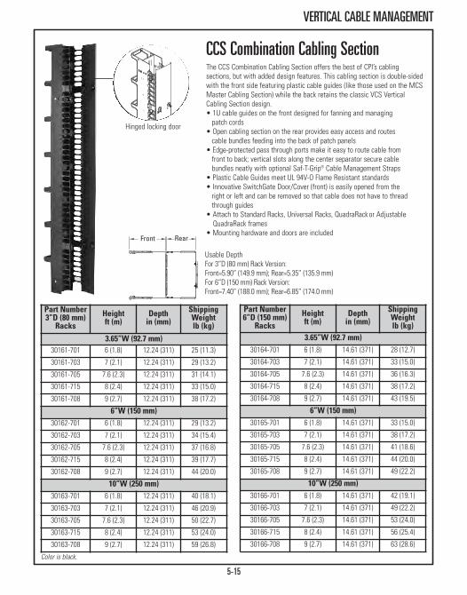
5-15
VERTICAL CABLE MANAGEMENT
CCS Combination Cabling SectionThe CCS Combination Cabling Section offers the best of CPI’s cablingsections, but with added design features. This cabling section is double-sidedwith the front side featuring plastic cable guides (like those used on the MCSMaster Cabling Section) while the back retains the classic VCS VerticalCabling Section design. • 1U cable guides on the front designed for fanning and managing patch cords
• Open cabling section on the rear provides easy access and routes cable bundles feeding into the back of patch panels
• Edge-protected pass through ports make it easy to route cable fromfront to back; vertical slots along the center separator secure cable bundles neatly with optional Saf-T-Grip® Cable Management Straps
• Plastic Cable Guides meet UL 94V-O Flame Resistant standards• Innovative SwitchGate Door/Cover (front) is easily opened from the right or left and can be removed so that cable does not have to thread through guides
• Attach to Standard Racks, Universal Racks, QuadraRackor Adjustable QuadraRack frames
• Mounting hardware and doors are included
Part Number3”D (80 mm)Racks
Heightft (m)
Depthin (mm)
ShippingWeightlb (kg)
3.65”W (92.7 mm)30161-701 6 (1.8) 12.24 (311) 25 (11.3)
30161-703 7 (2.1) 12.24 (311) 29 (13.2)
30161-705 7.6 (2.3) 12.24 (311) 31 (14.1)
30161-715 8 (2.4) 12.24 (311) 33 (15.0)
30161-708 9 (2.7) 12.24 (311) 38 (17.2)
6”W (150 mm)30162-701 6 (1.8) 12.24 (311) 29 (13.2)
30162-703 7 (2.1) 12.24 (311) 34 (15.4)
30162-705 7.6 (2.3) 12.24 (311) 37 (16.8)
30162-715 8 (2.4) 12.24 (311) 39 (17.7)
30162-708 9 (2.7) 12.24 (311) 44 (20.0)
10”W (250 mm) 30163-701 6 (1.8) 12.24 (311) 40 (18.1)
30163-703 7 (2.1) 12.24 (311) 46 (20.9)
30163-705 7.6 (2.3) 12.24 (311) 50 (22.7)
30163-715 8 (2.4) 12.24 (311) 53 (24.0)
30163-708 9 (2.7) 12.24 (311) 59 (26.8)
Part Number6”D (150 mm)
RacksHeightft (m)
Depthin (mm)
ShippingWeightlb (kg)
3.65”W (92.7 mm)30164-701 6 (1.8) 14.61 (371) 28 (12.7)
30164-703 7 (2.1) 14.61 (371) 33 (15.0)
30164-705 7.6 (2.3) 14.61 (371) 36 (16.3)
30164-715 8 (2.4) 14.61 (371) 38 (17.2)
30164-708 9 (2.7) 14.61 (371) 43 (19.5)
6”W (150 mm)30165-701 6 (1.8) 14.61 (371) 33 (15.0)
30165-703 7 (2.1) 14.61 (371) 38 (17.2)
30165-705 7.6 (2.3) 14.61 (371) 41 (18.6)
30165-715 8 (2.4) 14.61 (371) 44 (20.0)
30165-708 9 (2.7) 14.61 (371) 49 (22.2)
10”W (250 mm)30166-701 6 (1.8) 14.61 (371) 42 (19.1)
30166-703 7 (2.1) 14.61 (371) 49 (22.2)
30166-705 7.6 (2.3) 14.61 (371) 53 (24.0)
30166-715 8 (2.4) 14.61 (371) 56 (25.4)
30166-708 9 (2.7) 14.61 (371) 63 (28.6)
Hinged locking door
Usable Depth For 3”D (80 mm) Rack Version: Front=5.90” (149.9 mm); Rear=5.35” (135.9 mm)For 6”D (150 mm) Rack Version: Front=7.40” (188.0 mm); Rear=6.85” (174.0 mm)
Color is black.
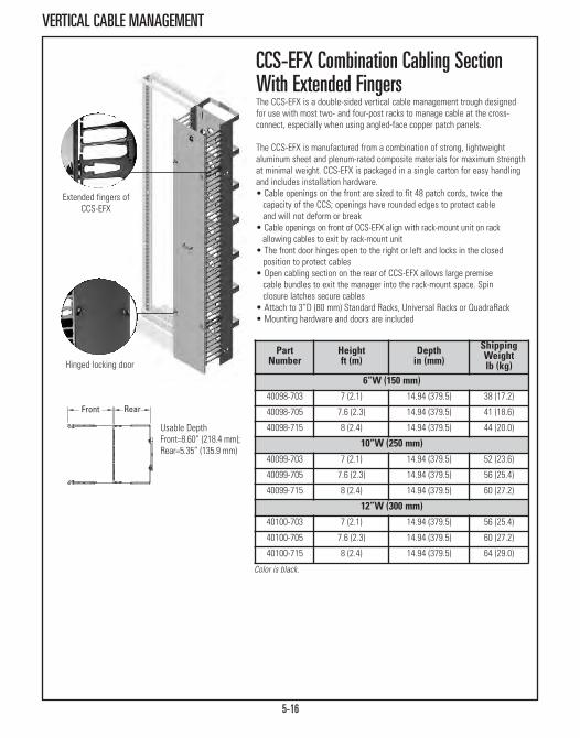
5-16
VERTICAL CABLE MANAGEMENT
Hinged locking door
Extended fingers ofCCS-EFX
CCS-EFX Combination Cabling SectionWith Extended FingersThe CCS-EFX is a double-sided vertical cable management trough designedfor use with most two- and four-post racks to manage cable at the cross-connect, especially when using angled-face copper patch panels.
The CCS-EFX is manufactured from a combination of strong, lightweightaluminum sheet and plenum-rated composite materials for maximum strengthat minimal weight. CCS-EFX is packaged in a single carton for easy handlingand includes installation hardware.• Cable openings on the front are sized to fit 48 patch cords, twice the capacity of the CCS; openings have rounded edges to protect cable and will not deform or break
• Cable openings on front of CCS-EFX align with rack-mount unit on rack allowing cables to exit by rack-mount unit
• The front door hinges open to the right or left and locks in the closed position to protect cables
• Open cabling section on the rear of CCS-EFX allows large premise cable bundles to exit the manager into the rack-mount space. Spin closure latches secure cables
• Attach to 3”D (80 mm) Standard Racks, Universal Racks or QuadraRack• Mounting hardware and doors are included
Part Number
Heightft (m)
Depthin (mm)
ShippingWeightlb (kg)
6”W (150 mm)40098-703 7 (2.1) 14.94 (379.5) 38 (17.2)
40098-705 7.6 (2.3) 14.94 (379.5) 41 (18.6)
40098-715 8 (2.4) 14.94 (379.5) 44 (20.0)
10”W (250 mm)40099-703 7 (2.1) 14.94 (379.5) 52 (23.6)
40099-705 7.6 (2.3) 14.94 (379.5) 56 (25.4)
40099-715 8 (2.4) 14.94 (379.5) 60 (27.2)
12”W (300 mm)40100-703 7 (2.1) 14.94 (379.5) 56 (25.4)
40100-705 7.6 (2.3) 14.94 (379.5) 60 (27.2)
40100-715 8 (2.4) 14.94 (379.5) 64 (29.0)
Usable Depth Front=8.60” (218.4 mm);Rear=5.35” (135.9 mm)
Color is black.
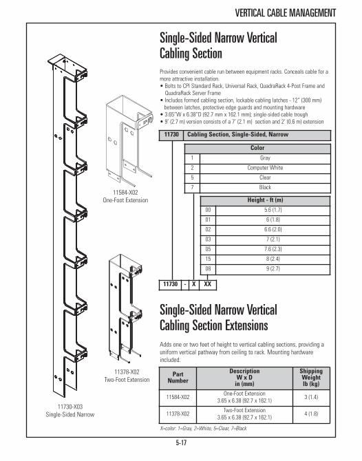
5-17
VERTICAL CABLE MANAGEMENT
X=color: 1=Gray, 2=White, 5=Clear, 7=Black
Height - ft (m)00 5.6 (1.7)
01 6 (1.8)
02 6.6 (2.0)
03 7 (2.1)
05 7.6 (2.3)
15 8 (2.4)
08 9 (2.7)
Color
1 Gray
2 Computer White
5 Clear
7 Black
Single-Sided Narrow VerticalCabling SectionProvides convenient cable run between equipment racks. Conceals cable for amore attractive installation. • Bolts to CPI Standard Rack, Universal Rack, QuadraRack 4-Post Frame and
QuadraRack Server Frame• Includes formed cabling section, lockable cabling latches - 12” (300 mm)between latches, protective edge guards and mounting hardware
• 3.65”W x 6.38”D (92.7 mm x 162.1 mm); single-sided cable trough• 9’ (2.7 m) version consists of a 7’ (2.1 m) section and 2’ (0.6 m) extension
Single-Sided Narrow Vertical Cabling Section ExtensionsAdds one or two feet of height to vertical cabling sections, providing auniform vertical pathway from ceiling to rack. Mounting hardwareincluded.
11730 Cabling Section, Single-Sided, Narrow
PartNumber
DescriptionW x Din (mm)
ShippingWeightlb (kg)
11584-X02 One-Foot Extension 3.65 x 6.38 (92.7 x 162.1) 3 (1.4)
11378-X02 Two-Foot Extension 3.65 x 6.38 (92.7 x 162.1) 4 (1.8)
11584-X02One-Foot Extension
11378-X02Two-Foot Extension
11730-X03Single-Sided Narrow
11730 - X XX
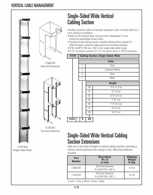
5-18
VERTICAL CABLE MANAGEMENT
11374-503Single-Sided Wide
X=color: 1=Gray, 2=White, 5=Clear, 7=Black
Height00 5’ 6” (1.7 m)
01 6’ (1.8 m)
02 6’ 6” (2.0 m)
03 7’ (2.1 m)
05 7’ 6” (2.3 m)
15 8’ (2.4 m)
08 9’ (2.7 m)
Color1 Gray
2 Computer White
5 Clear
7 Black
Single-Sided Wide VerticalCabling SectionProvides convenient cable run between equipment racks. Conceals cable for amore attractive installation.• Bolts to CPI Standard Rack, Universal Rack, QuadraRack® 4-Post Frame and QuadraRack Server Frame
• Includes formed cabling section, lockable cabling latches spaced 12” (300 mm) apart, protective edge guards and mounting hardware
• 6”W x 6.38”D (150 mm x 162.1 mm); single-sided cable trough• 9’ (2.7 m) version consists of 7’ (2.1 m) section with a 2’ (0.6 m) extension
Single-Sided Wide Vertical CablingSection ExtensionsAdds one or two feet of height to vertical cabling sections, providing auniform vertical pathway from ceiling to rack. Mounting hardwareincluded.
11374 Cabling Section, Single-Sided, Wide
11584-X01One-Foot Extension
11378-X01Two-Foot Extension
11374 - X XX
PartNumber
DescriptionW x Din (mm)
ShippingWeightlb (kg)
11584-X01 One-Foot Extension 6 x 6.38 (150 x 162.1) 3 (1.4)
11378-X01 Two-Foot Extension 6 x 6.38 (150 x 162.1) 4 (1.8)

5-19
VERTICAL CABLE MANAGEMENT
PartNumber
DescriptionW x Din (mm)
ShippingWeightlb (kg)
11781-X02 One-Foot Extension 3.65 x 12.75(92.7 x 323.9) 4 (1.8)
11782-X02 Two-Foot Extension 3.65 x 12.75 (92.7 x 323.9) 7 (3.2)
X=color: 1=Gray, 2=White, 5=Clear, 7=Black
Double-Sided Narrow Vertical CablingSection ExtensionsAdds one or two feet of height to vertical cabling sections, providing auniform vertical pathway from ceiling to rack. Mounting hardware included.
Double-Sided Narrow Vertical CablingSectionProvides double-sided 3.65” (92.7 mm) cable run between equipment racks.Oval ports measuring 1.38” x 2.25” (35.1 mm x 51.2 mm) are spaced at 11.62”(295.1 mm) intervals along center separator for convenient cable and wiringpass through. Vertical slots secure optional Saf-T-Grip® Cable ManagementStraps for neatly bundled cables.• Bolts to CPI Standard Rack, Universal Rack, QuadraRack 4-Post Frame and QuadraRack Server Frame
• Includes formed cabling section, lockable cabling latches spaced 12” (300mm) apart, protective edge guards and mounting hardware
• 3.65”W x 12.75”D (92.7 mm x 323.9 mm); double-sided cable trough• 1.38” x 2.25” (35.1 mm x 57.2 mm) oval pass through ports every 11.62” (295.1 mm)
• 9’ (2.7 m) version consists of 7’ (2.1 m) section with a 2’ (0.6 m) extension• Mounting hardware included
PartNumber
Descriptionft (m)
ShippingWeightlb (kg)
12096-X03 7 (2.1) Double-Sided Narrow 24 (10.9)
12096-X15 8 (2.4) Double-Sided Narrow 27 (12.2)
12096-X08 9 (2.7 ) Double-Sided Narrow 28 (12.7)
X=color: 1=Gray, 2=White, 5=Clear, 7=Black
11781-X02One-Foot Extension
11782-X02Two-Foot Extension
12096-X03Double-Sided Narrow
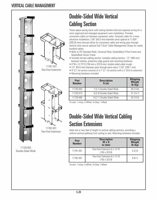
5-20
VERTICAL CABLE MANAGEMENT
Double-Sided Wide Vertical Cabling SectionThese space-saving ducts with locking latches hold and separate wiring for amore organized and managed equipment room installation. Providesconvenient cable run between equipment racks. Conceals cable for a moreattractive installation. 2.50” (63.5 mm) diameter ports spaced at 11.625”(295.28 mm) intervals allow for convenient cable and wiring pass through.Vertical slots secure optional Saf-T-Grip® Cable Management Straps for neatlybundled cables.• Bolts to CPI Standard Rack, Universal Rack, QuadraRack 4-Post Frame and QuadraRack Server Frame
• Includes formed cabling section, lockable cabling latches - 12” (300 mm)between latches, protective edge guards and mounting hardware
• 6”W x 12.75”D (150 mm x 323.9 mm); double-sided cable trough• 2.5” (64.0 mm) diameter pass through ports every 11.62” (295.1 mm)• 9’ (2.7 m) version consists of a 7’ (2.1 m) section with a 2’ (0.6 m) extension• Mounting hardware included
Double-Sided Wide Vertical CablingSection ExtensionsAdds one or two feet of height to vertical cabling sections, providing auniform vertical pathway from ceiling to rack. Mounting hardware included.
PartNumber
Descriptionft (m)
ShippingWeightlb (kg)
11729-X03 7 (2.1) Double-Sided Wide 30 (13.6)
11729-X15 8 (2.4) Double-Sided Wide 31 (14.1)
11729-X08 9 (2.7 ) Double-Sided Wide 32 (14.5)
X=color: 1=Gray, 2=White, 5=Clear, 7=Black
11781-X01One-Foot Extension
11782-X01Two-Foot Extension
11729-503Double-Sided Wide
PartNumber
DescriptionW x Din (mm)
ShippingWeightlb (kg)
11781-X01 One-Foot Extension 6 x 12.75 (150 x 323.9) 5 (2.3)
11782-X01 Two-Foot Extension 6 x 12.75 (150 x 323.9) 9 (4.1)
X=color: 1=Gray, 2=White, 5=Clear, 7=Black

5-21
VERTICAL CABLE MANAGEMENT
PartNumber Description
ShippingWeightlb (kg)
12370-001 2 Finger Snaps, Black 1 (0.5)
12370-002 12 Finger Snaps, Black 2 (0.9)
Cabling Section CoverDesigned to be used on narrow and wide Vertical Cabling Sections to providea clean professional appearance. Available in metal or plexiglass versions -plexiglass for 7’ (2.1 m) only - in sizes to fit your installation.• Hides cables • Provides professional appearance • Quick attachment and removal • For use with vertical cabling sections only
Finger Snaps Cable GuidesAdding Finger Snaps Cable Guides is a snap. The unique, patented designprovides retrofit cable guides in between the latches on VCS Vertical CablingSections or CCS Combination Cabling Sections. • Plastic cable guides that easily retrofit onto CPI VCS Vertical Cabling Sections or CCS Combination Cabling Sections
• Resilient composite material ensures long lasting, quality construction• Extra-wide and contoured guides allow smooth transition of the cable from the horizontal pathway into a CPI cabling section
• 1U cable guides are designed for fanning and managing patch cords orcables
• Meets UL 94V-O Flame Resistant standards
Part Number
Heightft (m) Color/Style
ShippingWeightlb (kg)
3.65”W (92.7 mm)12189-001 7 (2.1) Black, Plexiglass 8 (3.6)
12664-702 7 (2.1) Black, Metal 8 (3.6)
11923-705 7.6 (2.3) Black, Metal 4 (1.8)
11923-715 8 (2.4) Black, Metal 5 (2.3)
11923-708 9 (2.7) Black, Metal 5 (2.3)
6”W (150 mm)12188-001 7 (2.1) Black, Plexiglass 9 (4.1)
12664-701 7 (2.1) Black, Metal 9 (4.1)
11922-705 7.6 (2.3) Black, Metal 7 (3.2)
11922-715 8 (2.4) Black, Metal 7 (3.2)
11922-708 9 (2.7) Black, Metal 8 (3.6)

5-22
VERTICAL CABLE MANAGEMENT
Extended Fingers BracketExtended Fingers Bracket provides extra-deep cable management capacity forapplications that require large cable bundles or thick cable.
Extra space also improves cable bend radius management, meeting orexceeding the needs of the latest Category 5e/6/6a or fiber industrystandards. It is a cost-effective accessory for cable management in specificareas of the rack rather than along its entire height. • It is preassembled in 7U, 9U and 13U heights for mounting directly onto
any industry-standard rack• Patented cable guide fingers at 1U intervals provide an organized cable
pathway• Made of durable, flame-retardant (UL 94V-0) plastic for environmental safety
• Sold individually
Horizontal Cable GuidesRack-Mounted cable guides organize multiple horizontal cable runs. Designedto use with most rack-mounted panels. • Slotted loop design makes cable installation and changes quick and simple
• Made of thick aluminum and black plastic dipped to reduce cable insulation damage
• Sold in matching pairs • Threaded side holes allow mounting of vertical cable loop (P/N 10683-001)
PartNumber Description
ShippingWeightlb (kg)
12891-703 7U, Black 2 (0.9)
12891-701 9U, Black 4 (1.8)
12891-702 13U, Black 4 (1.8)
PartNumber Description Dim. A
in (mm)Dim. Bin (mm)
10419-001 One Loop 3.46 (87.9) 4.25 (108.0)
11157-001 Two Loop 5.25 (133.4) 3.88 (98.6)
11154-001 Four Loop 8.60 (218.4) 3.88 (98.6)
11153-001 Six Loop 15.60 (396.2) 3.88 (98.6)
1U

5-23
VERTICAL CABLE MANAGEMENT
IBM® Style Vertical Cable LoopUsed for vertical cable runs on most rack mounted equipment. Mounts in avariety of ways to equipment rack or connector panels. 1-1/2” (38 mm) holeto hole.• Aluminum construction coated with black plastic to prevent cable scrapes
• Sold individually or in package of 100• Mounting hardware not included
PartNumber Color
ShippingWeightlb (kg)
10683-001 Black 1 (0.5)
10683-101 Black, Package of 100 23 (10.4)
Vertical Wire Management Loop CPI Vertical Wire Management Loops are used to organize patch cords andcabling. Maintains vertical wire management for one or two racks mountedtogether. Mounting hardware not included.• Does not protrude into rack-mounting space • Aluminum construction coated with black plastic to prevent damage to cable jackets
PartNumber Color
ShippingWeightlb (kg)
13079-001 Black 1 (0.5)
Double-Wide Cable Ring Provides vertical cable management space between racks butted side-by-sideby mounting to the hole pattern across two rack channels. Large size, 2.3”H x2.8”W x 4”D (58 mm x 71 mm x 100 mm) accommodates larger cable bundles.Made of thick aluminum with rounded edges to reduce cable insulationdamage. Sold individually or in box of 100. Shipping weight approximately 4 oz (110 g) each and 25 lb (11.3 kg) for box of 100. Mounting hardware notincluded. • Mounts to hole pattern across two rack channels • Provides vertical cable management for larger cable bundles • Use where vertical cabling section is not required
Part NumberDescription
Individually Box of 10012228-X01 12228-X11 Double-Wide Loop
X=color: 1=Gray, 2=White, 5=Clear, 7=Black

5-24
VERTICAL CABLE MANAGEMENT
15002-001
X=color: 1=Gray, 2=White, 5=Clear, 7=Black
Part NumberDescription
Individually Box of 10011228-X01 11228-X11 Narrow Cable Ring
X=color: 1=Gray, 2=White, 5=Clear, 7=Black
Narrow Cable RingAttaches to walls or racks where width is limited. Holds and dresses verticalcable runs. Mounting hardware not included. • Made of aluminum with rounded edges to reduce cable insulation damage
• Narrow Cable Ring is 2.50”H x 1.25”W x 4.00”D(63.5 mm x 31.8 mm x 101.6 mm)
• Sold individually or box of 100
Cable Distribution SpoolsCable Distribution Spools promote a gradual bend for cable runs to aid incomplying with ANSI/TIA/EIA-568B bend radius requirements (typically 4X thecable diameter). Routes all types of cabling from horizontal to vertical or vice-versa. • The kit includes a #12-24 rack screw and a wood screw for use with the 4” (100 mm) spool
• Made of high-impact plastic
Narrow Cable LoopUse these cable loops to hold and dress cable vertically. Attach to walls orracks where width is limited. Mounting hardware not included. • Made of aluminum with rounded edges to reduce cable insulation damage
• Naroow Cable Loop is 2.50”H x 1.25”W x 4.00”D (63.5 mm x 31.8 mm x 101.6 mm)
• Sold individually or box of 100
Part NumberDescription
Individually Box of 10015002-001 15002-002 4” (100 mm) Cable Spool
Part NumberDescription
Individually Box of 10011230-X01 11230-X11 Narrow Cable Loop

5-25
VERTICAL CABLE MANAGEMENT
Spools mounted on a double-sided verticalcabling section
P/N 12766-702
Cable Distribution SpoolsCable Distribution Spools provide slack management and strain relief forpatch cords and jumper cables inside CPI vertical cable managers. Designedfor use inside any CPI double-sided vertical cable manager 10”W and wider,including VCS, MCS, MCS-EFX, CCS, CCS-EFX and Evolution® g2 Double-SidedVertical Cable Manager. Also compatible with Evolution® g1 Single-SidedVertical Cable Manager.• Three large cable distribution spools are included with each 10”, 12” and 15”
wide (250 mm, 300 mm and 380 mm) vertical cable manager (will not fit othersizes)
• Attaches to the fixed adapter panels on the back of single-sided vertical cable managers and the Movable Mid-Sections inside the double-sidedvertical cable managers
• Spools are 2.75” (69.9 mm) in diameter and 5.9”L (150 mm) and made fromblack plastic
• Each kit includes four spools and mounting hardware• Made of high-impact, flame retardant material
2” (50 mm) Diameter Fiber ManagementSpoolsUse the 2” (50 mm) Diameter Fiber Management Spool to support fiber andcopper cables within CPI's extensive line of vertical cabling sections. Thespools meet EIA/TIA bend radius requirements and minimize cable tanglesand tears for more efficient data transmission.• Provides proper cable support and bend radius for more efficient data transmission
• Maintains strength under heavy cable loads• Mounts to all CPI vertical cabling sections 6”W (150 mm) or wider,including MCS, MCS-EFX, CCS, CCS-EFX and VCS
2” (50 mm) Diameter Fiber Management Spools
PartNumber
ApplicationWidthin (mm)
PackageOf
ShippingWeightlb (kg)
12766-702 For 6, 10 or 12 (150, 250 or 300)Double-Sided Cabling Sections 2 2 (0.9)
12766-707 For 6, 10 or 12 (150, 250 or 300)Double-Sided Cabling Sections 7 5 (2.3)
PartNumber Description/Color
ShippingWeightlb (kg)
15008-001 Spool Kit, Black 2 (0.9)
15008-002 Spool Kit, White 2 (0.9)

5-26
HORIZONTAL CABLE MANAGEMENT
Evolution® Horizontal Cable ManagerUse Evolution® Horizontal Cable Managers above and below patch panels andnetwork switches to organize and store cables. Horizontal managers includeplastic T-shaped cable guides to organize patch cords and jumper cords as thecords enter and exit the manager to make individual equipment connections. Thesnap-on cover matches the door styling on the vertical manager. Swing the coverup or down to access cables; the cover stays in the open position while cabling.Three edge-protected, oval-shaped pass-through ports allow patch cords to passfront-to-rear. Horizontal managers are available in three heights.• Contoured front door with snap-hinges and longitudinal center feature
contrasting aluminum finish• Three 1.25”H x 2.12”W (31 mm x 53 mm) edge-protected oval cable
pass-through ports at the rear of the cable manager• Improved T-shaped cable guides decrease deflection when loaded with
cables; especially important when deploying Cat 6a cable • Rounded edges on the cable guides protect cables as they enter and exit the
storage space• Snap-On cover opens up or down and stays in the open position
Part Number
DescriptionH x W x Din (mm)
ShippingWeightlb (kg)
35441-701 1U x 19 x 8.2 (208) 4 (1.8)
35441-702 2U x 19 x 8.2 (208) 5 (2.3)
35441-703 3U x 19 x 8.2 (208) 6 (2.7)
Color is black.
Velocity® Horizontal Cable Manager Use Velocity® Horizontal Cable Manager above and below patch panels andnetwork switches to organize and store cables. Features T-shaped cableguides at the top and bottom of the manager to organize patch cords. Twocable openings in the rear of the manager allow front-to-rear cabling and thesnap-on cover stays in the opened position to provide easy access to cables.The single-sided horizontal cable managers are available in three heights. • Horizontal managers for open two-post and four-post CPI Rack Systems• The Velocity Horizontal Cable Manager includes:
- One 19”W EIA rack-mount cable manager with T-shaped cable guides - One cover that snaps onto the T-shaped cable guides- Four #12-24 x 1” rack-mount screws and four M6 x 25 mm rack-mount screws
Part Number
DescriptionH x W x Din (mm)
ShippingWeightlb (kg)
13930-701 1U x 19 x 5.9 (150) 2 (0.9)
13930-702 2U x 19 x 5.9 (150) 3 (1.4)
13930-703 3U x 19 x 5.9 (150) 3 (1.4)
Color is black. 1U = 1.75” (44.45 mm); the overall height of the manager is .03” (0.16mm) less than the full rack-mount unit height. Usable depth is 3.7” (94 mm). Theusable height of the manager varies but is 1.2” (31 mm) less than the overall heightof the manager at the narrowest point.
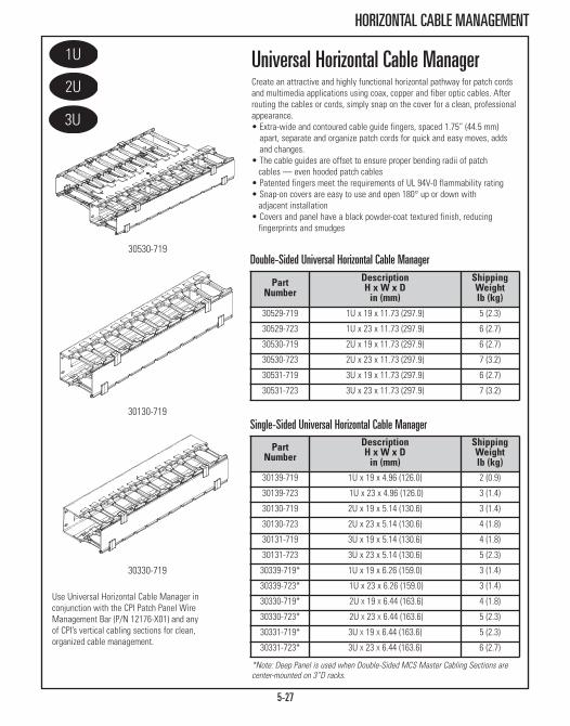
5-27
HORIZONTAL CABLE MANAGEMENT
Use Universal Horizontal Cable Manager in conjunction with the CPI Patch Panel Wire Management Bar (P/N 12176-X01) and any of CPI’s vertical cabling sections for clean, organized cable management.
*Note: Deep Panel is used when Double-Sided MCS Master Cabling Sections arecenter-mounted on 3”D racks.
PartNumber
DescriptionH x W x Din (mm)
ShippingWeightlb (kg)
30139-719 1U x 19 x 4.96 (126.0) 2 (0.9)
30139-723 1U x 23 x 4.96 (126.0) 3 (1.4)
30130-719 2U x 19 x 5.14 (130.6) 3 (1.4)
30130-723 2U x 23 x 5.14 (130.6) 4 (1.8)
30131-719 3U x 19 x 5.14 (130.6) 4 (1.8)
30131-723 3U x 23 x 5.14 (130.6) 5 (2.3)
30339-719* 1U x 19 x 6.26 (159.0) 3 (1.4)
30339-723* 1U x 23 x 6.26 (159.0) 3 (1.4)
30330-719* 2U X 19 X 6.44 (163.6) 4 (1.8)
30330-723* 2U X 23 X 6.44 (163.6) 5 (2.3)
30331-719* 3U X 19 X 6.44 (163.6) 5 (2.3)
30331-723* 3U X 23 X 6.44 (163.6) 6 (2.7)
Universal Horizontal Cable ManagerCreate an attractive and highly functional horizontal pathway for patch cordsand multimedia applications using coax, copper and fiber optic cables. Afterrouting the cables or cords, simply snap on the cover for a clean, professionalappearance.• Extra-wide and contoured cable guide fingers, spaced 1.75” (44.5 mm)
apart, separate and organize patch cords for quick and easy moves, addsand changes.
• The cable guides are offset to ensure proper bending radii of patch cables — even hooded patch cables
• Patented fingers meet the requirements of UL 94V-0 flammability rating• Snap-on covers are easy to use and open 180° up or down with adjacent installation
• Covers and panel have a black powder-coat textured finish, reducing fingerprints and smudges
PartNumber
DescriptionH x W x Din (mm)
ShippingWeightlb (kg)
30529-719 1U x 19 x 11.73 (297.9) 5 (2.3)
30529-723 1U x 23 x 11.73 (297.9) 6 (2.7)
30530-719 2U x 19 x 11.73 (297.9) 6 (2.7)
30530-723 2U x 23 x 11.73 (297.9) 7 (3.2)
30531-719 3U x 19 x 11.73 (297.9) 6 (2.7)
30531-723 3U x 23 x 11.73 (297.9) 7 (3.2)
30530-719
30130-719
30330-719
Double-Sided Universal Horizontal Cable Manager
Single-Sided Universal Horizontal Cable Manager

5-28
HORIZONTAL CABLE MANAGEMENT
PartNumber Description
ShippingWeightlb (kg)
12176-X01 Patch Panel Wire Mangement Bar 1 (0.5)
13070-X19 Horizontal Wire Panel for VCS, 1U 2 (0.9)
13075-X19 Horizontal Wire Panel for VCS, 2U 2 (0.9)
12541-X19 Horizontal Wire Panel for MCS/CCS, 1U 2 (0.9)
12542-X19 Horizontal Wire Panel for MCS/CCS, 2U 2 (0.9)
12663-X01 Cable Cover for 13070-XXX, 1U 2 (0.9)
12663-X02 Cable Cover for 13075-XXX, 2U 2 (0.9)
11764-X19 Slip-On Cover, 19”W, for 11564-X19 2 (0.9)
11764-X23 Slip-On Cover, 23”W, for 11564-X23 2 (0.9)
X=color: 1=Gray, 2=White, 5=Clear, 7=Black
Horizontal Cable Management AccessoriesPatch Panel Wire Management Bar19” rack-mountable bar provides the necessary wire management and strain reliefrequired by ANSI/TIA/EIA-568-B. May be mounted inward for 6” (150 mm) channelor outward to standard 3” (80 mm) rack side channel, attaches to rack withstandard #12-24 rack screws (not included). Wire tie holes maintain wireperpendicular relative to termination point, made of sturdy aluminum, soldindividually.
Horizontal Wire Management Panel for VCS19” Wire Management Panel is offset 1.5” (38 mm) from the rack channel toensure proper bending radii of patch cables — even hooded patch cables. Use incombination with VCS Vertical Cabling Sections. Unique offset design provides patch cable pathway from front-to-back or side-to-side. Available in single 1.75”(44.5 mm) or double 3.5” (89.0 mm) rack-mounting units design. Mounts quicklyand easily using threaded cable distribution spools, cable distribution spoolsmaintain bend radius through the pass-through trough and across the front planeof the horizontal manager.
Horizontal Wire Management Panel for MCS and CCSUse in combination with MCS Master Cabling Section, CCS Combination CablingSection to provide open horizontal management for cables.
Clip-On Cable CoverThe Clip-On Cable Cover is designed for use with the CPI 19” Horizontal WireManagement Panels. Attach to the horizontal wire management panel by simplysliding/clipping it into place.
Slip-On Cover, Ring PanelThe Slip-On Cover is used on the Large Horizontal Ring Panel, P/N 11564-XXX.Sold individually
12176-X01
13070-X1913075-X19
12541X1912542X19
12663-X01
11764-X1911764-X23

5-29
HORIZONTAL CABLE MANAGEMENT
12183 Upper Tray
13183 Deep Upper Tray
12185 Lower Tray, Single
12187 Lower Tray, Double
12186 Transition Plate
Part NumberDescription
ShippingWeightlb (kg)19” 23”
12183-X19 12183-X23 Upper Tray, 3.5”D (89 mm) 3 (1.4)
13183-X19 13183-X23 Upper Tray, 6”D (150 mm) 4 (1.8)
12185-X19 12185-X23 Lower Tray, Single,3.5”D (89 mm) 4 (1.8)
12187-X19 12187-X23 Lower Tray, Double,3.5”D (89 mm) 5 (2.3)
12186-X01 N/A Transition Plate, 15.5”L (394 mm) 2 (0.9)
Jumper And Transition TraysThe Jumper and Transition Trays aid in compliance with ANSI/TIA/EIA-568Bbend radius requirements. Two styles are available to provide upper andlower horizontal/vertical cable management and promote a gradual,controlled bend for both UTP and optical fiber cable. Adjust the position of thebend radius to deliver cables into the vertical cable manager or attach atransition plate between trays to create a solid wire way between racks.Mounting screws not included. Sold individually.• Provides 1-1/2” (38 mm) bend radius for compliant installation of Category 5e/6/6a or fiber cable
• Telescopes to adjust cable entry or exit position• Mounts on 19” or 23” rack; may also be wall-mounted• Strong lightweight aluminum construction
X=color: 1=Gray, 2=White, 5=Clear, 7=Black
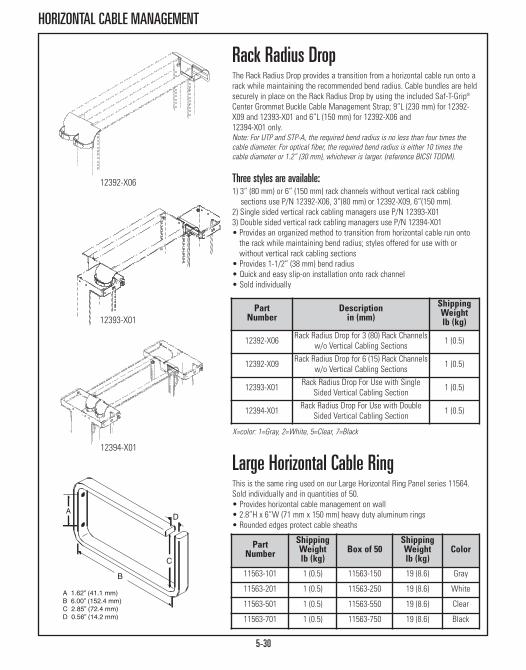
PartNumber
ShippingWeightlb (kg)
Box of 50ShippingWeightlb (kg)
Color
11563-101 1 (0.5) 11563-150 19 (8.6) Gray
11563-201 1 (0.5) 11563-250 19 (8.6) White
11563-501 1 (0.5) 11563-550 19 (8.6) Clear
11563-701 1 (0.5) 11563-750 19 (8.6) Black
Large Horizontal Cable RingThis is the same ring used on our Large Horizontal Ring Panel series 11564.Sold individually and in quantities of 50. • Provides horizontal cable management on wall • 2.8”H x 6”W (71 mm x 150 mm) heavy duty aluminum rings • Rounded edges protect cable sheaths
5-30
HORIZONTAL CABLE MANAGEMENT
12392-X06
12394-X01
12393-X01
X=color: 1=Gray, 2=White, 5=Clear, 7=Black
Rack Radius DropThe Rack Radius Drop provides a transition from a horizontal cable run onto arack while maintaining the recommended bend radius. Cable bundles are heldsecurely in place on the Rack Radius Drop by using the included Saf-T-Grip®
Center Grommet Buckle Cable Management Strap; 9”L (230 mm) for 12392-X09 and 12393-X01 and 6”L (150 mm) for 12392-X06 and12394-X01 only. Note: For UTP and STP-A, the required bend radius is no less than four times thecable diameter. For optical fiber, the required bend radius is either 10 times thecable diameter or 1.2” (30 mm), whichever is larger. (reference BICSI TDDM).
Three styles are available:1) 3” (80 mm) or 6” (150 mm) rack channels without vertical rack cabling
sections use P/N 12392-X06, 3”(80 mm) or 12392-X09, 6”(150 mm).2) Single sided vertical rack cabling managers use P/N 12393-X013) Double sided vertical rack cabling managers use P/N 12394-X01 • Provides an organized method to transition from horizontal cable run onto
the rack while maintaining bend radius; styles offered for use with orwithout vertical rack cabling sections
• Provides 1-1/2” (38 mm) bend radius• Quick and easy slip-on installation onto rack channel• Sold individually
PartNumber
Descriptionin (mm)
ShippingWeightlb (kg)
12392-X06 Rack Radius Drop for 3 (80) Rack Channelsw/o Vertical Cabling Sections 1 (0.5)
12392-X09 Rack Radius Drop for 6 (15) Rack Channelsw/o Vertical Cabling Sections 1 (0.5)
12393-X01 Rack Radius Drop For Use with SingleSided Vertical Cabling Section 1 (0.5)
12394-X01 Rack Radius Drop For Use with DoubleSided Vertical Cabling Section 1 (0.5)

5-31
HORIZONTAL CABLE MANAGEMENT
Large Horizontal Ring PanelUsed to organize horizontal cable runs. Large 2.8”H (71 mm) by 6”W (150 mm)heavy duty aluminum rings with rounded edges protect cable sheaths and willnot bind during installation. Rings are bolted onto panels so they can beadded or removed as needed. 19” and 23” wide rack panel options comepre-assembled with seven equally spaced rings. • 2.8”H x 6”W (71 mm x 150 mm) heavy duty aluminum rings • Rings can be added or removed as needed• Installation hardware not included• Shipping weight approximately 5 lb (2.3 kg)
Part NumberColor
19” 23”11564-119 11564-123 Gray
11564-219 11564-223 White
11564-519 11564-523 Clear
11564-719 11564-723 Black
1175 X - X XX
Color1 Gray
2 Computer White
5 Clear
7 Black
Panel/Ring SizeH x D - in (mm)
2 1U, 1.6 x 1.3 (41 x 33) Rings
3 2U, 3 x 1.6 (80 x 41) Rings
1175 Rack Cabling Managers
Rack Cabling ManagersUsed to organize horizontal cable and wire runs. Two sizes of slotted plasticrings provide ample room to hold all types and sizes of wiring and cabling.• Easy to install on equipment racks• Installation hardware not included
Rack Width19 19”W
23 23”W

5-32
SAF-T-GRIP® STRAPS
Open Loop Series
Center Grommet & Buckle Series
Saf-T-Grip® Open Loop SeriesUsed to strap together free hanging computer cable for a tangle-freeinstallation. Strap is held in place by a loop that adheres to one cable. Simplypeel the hook and loop sides apart to remove strap.
Saf-T-Grip® End Grommet Buckle Series The buckle design provides extra strength for those harder to manage cables.Mounts cable along walls and backboards or wherever horizontal cable runsare required. Wrap this strap around the cable and back through the nylonbuckle. Pull snugly, cinching down the cable for secure fit.
Saf-T-Grip® Center Grommet BuckleSeries The buckle design provides twice the holding strength of ordinary straps.Unique center grommet feature provides a sturdy fixture for attaching strapsin any direction. Simply loop the strap around cables and back through thebuckle. Secure cinch back and down for a secure hold.
0X0 XX - X XX
Strap Colors01 Black
03 Royal Blue
Strap Width - in (mm)2 3/4 (19.1)
Strap Length - in (mm)06 6 (150), for 2 (50) diameter cable bundles
09 9 (230), for 3 (80) diameter cable bundles
12 12 (300), for 4 (100) diameter cable bundles
Saf-T-Grip Strap Series Type020 Open Loop Series (pkg. of 25)
050 End Grommet & Buckle Series (pkg. of 25)
060 Center Grommet & Buckle Series (pkg. of 25)
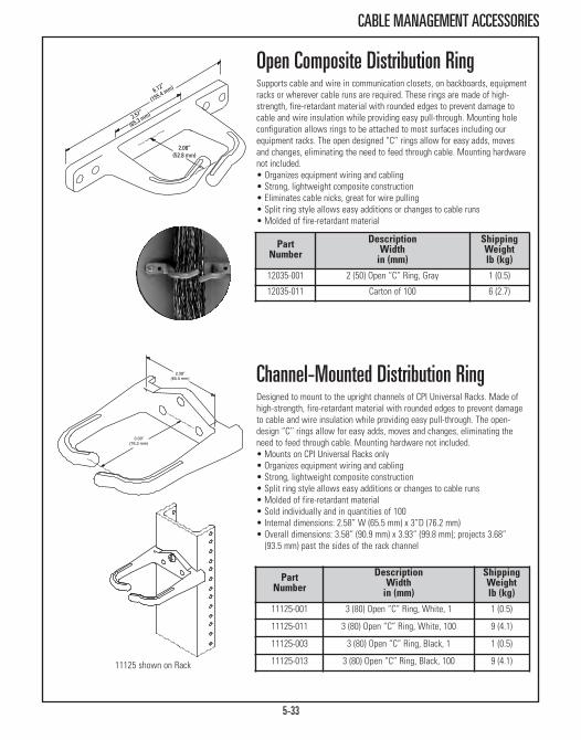
5-33
CABLE MANAGEMENT ACCESSORIES
PartNumber
DescriptionWidthin (mm)
ShippingWeightlb (kg)
12035-001 2 (50) Open “C” Ring, Gray 1 (0.5)
12035-011 Carton of 100 6 (2.7)
Open Composite Distribution RingSupports cable and wire in communication closets, on backboards, equipmentracks or wherever cable runs are required. These rings are made of high-strength, fire-retardant material with rounded edges to prevent damage tocable and wire insulation while providing easy pull-through. Mounting holeconfiguration allows rings to be attached to most surfaces including ourequipment racks. The open designed “C’’ rings allow for easy adds, movesand changes, eliminating the need to feed through cable. Mounting hardwarenot included.• Organizes equipment wiring and cabling • Strong, lightweight composite construction • Eliminates cable nicks, great for wire pulling • Split ring style allows easy additions or changes to cable runs • Molded of fire-retardant material
Channel-Mounted Distribution RingDesigned to mount to the upright channels of CPI Universal Racks. Made ofhigh-strength, fire-retardant material with rounded edges to prevent damageto cable and wire insulation while providing easy pull-through. The open-design “C’’ rings allow for easy adds, moves and changes, eliminating theneed to feed through cable. Mounting hardware not included. • Mounts on CPI Universal Racks only • Organizes equipment wiring and cabling • Strong, lightweight composite construction • Split ring style allows easy additions or changes to cable runs • Molded of fire-retardant material • Sold individually and in quantities of 100 • Internal dimensions: 2.58” W (65.5 mm) x 3”D (76.2 mm)• Overall dimensions: 3.58” (90.9 mm) x 3.93” (99.8 mm); projects 3.68”
(93.5 mm) past the sides of the rack channel
PartNumber
DescriptionWidthin (mm)
ShippingWeightlb (kg)
11125-001 3 (80) Open “C” Ring, White, 1 1 (0.5)
11125-011 3 (80) Open “C” Ring, White, 100 9 (4.1)
11125-003 3 (80) Open “C” Ring, Black, 1 1 (0.5)
11125-013 3 (80) Open “C” Ring, Black, 100 9 (4.1)11125 shown on Rack
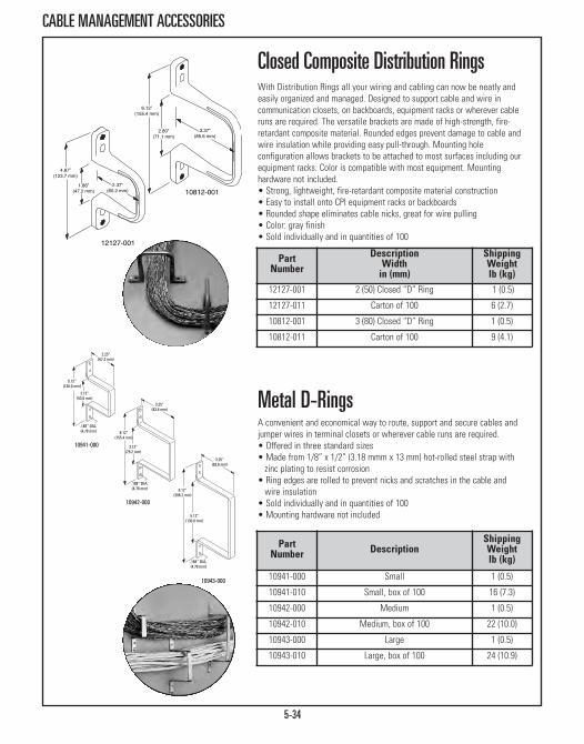
5-34
CABLE MANAGEMENT ACCESSORIES
PartNumber Description
ShippingWeightlb (kg)
10941-000 Small 1 (0.5)
10941-010 Small, box of 100 16 (7.3)
10942-000 Medium 1 (0.5)
10942-010 Medium, box of 100 22 (10.0)
10943-000 Large 1 (0.5)
10943-010 Large, box of 100 24 (10.9)
Closed Composite Distribution RingsWith Distribution Rings all your wiring and cabling can now be neatly andeasily organized and managed. Designed to support cable and wire incommunication closets, on backboards, equipment racks or wherever cableruns are required. The versatile brackets are made of high-strength, fire-retardant composite material. Rounded edges prevent damage to cable andwire insulation while providing easy pull-through. Mounting holeconfiguration allows brackets to be attached to most surfaces including ourequipment racks. Color is compatible with most equipment. Mountinghardware not included.• Strong, lightweight, fire-retardant composite material construction • Easy to install onto CPI equipment racks or backboards • Rounded shape eliminates cable nicks, great for wire pulling • Color: gray finish• Sold individually and in quantities of 100
Metal D-RingsA convenient and economical way to route, support and secure cables andjumper wires in terminal closets or wherever cable runs are required. • Offered in three standard sizes • Made from 1/8” x 1/2” (3.18 mmm x 13 mm) hot-rolled steel strap with zinc plating to resist corrosion
• Ring edges are rolled to prevent nicks and scratches in the cable and wire insulation
• Sold individually and in quantities of 100 • Mounting hardware not included
PartNumber
DescriptionWidthin (mm)
ShippingWeightlb (kg)
12127-001 2 (50) Closed “D” Ring 1 (0.5)
12127-011 Carton of 100 6 (2.7)
10812-001 3 (80) Closed “D” Ring 1 (0.5)
10812-011 Carton of 100 9 (4.1)
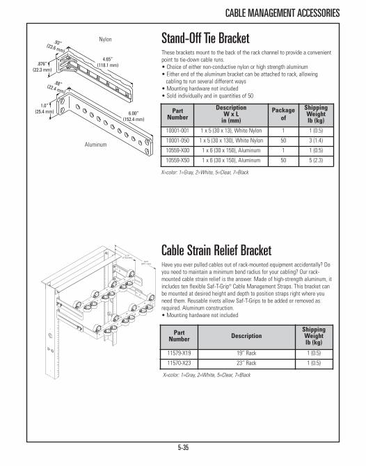
5-35
CABLE MANAGEMENT ACCESSORIES
Nylon
Aluminum
X=color: 1=Gray, 2=White, 5=Clear, 7=Black
Stand-Off Tie BracketThese brackets mount to the back of the rack channel to provide a convenientpoint to tie-down cable runs. • Choice of either non-conductive nylon or high strength aluminum • Either end of the aluminum bracket can be attached to rack, allowing cabling to run several different ways
• Mounting hardware not included• Sold individually and in quantities of 50
Cable Strain Relief BracketHave you ever pulled cables out of rack-mounted equipment accidentally? Doyou need to maintain a minimum bend radius for your cabling? Our rack-mounted cable strain relief is the answer. Made of high-strength aluminum, itincludes ten flexible Saf-T-Grip® Cable Management Straps. This bracket canbe mounted at desired height and depth to position straps right where youneed them. Reusable rivets allow Saf-T-Grips to be added or removed asrequired. Aluminum construction.• Mounting hardware not included
PartNumber
DescriptionW x Lin (mm)
Packageof
ShippingWeightlb (kg)
10001-001 1 x 5 (30 x 13), White Nylon 1 1 (0.5)
10001-050 1 x 5 (30 x 130), White Nylon 50 3 (1.4)
10559-X00 1 x 6 (30 x 150), Aluminum 1 1 (0.5)
10559-X50 1 x 6 (30 x 150), Aluminum 50 5 (2.3)
PartNumber Description
ShippingWeightlb (kg)
11579-X19 19” Rack 1 (0.5)
11570-X23 23” Rack 1 (0.5)
X=color: 1=Gray, 2=White, 5=Clear, 7=Black

5-36
CABLE MANAGEMENT ACCESSORIES
PartNumber Description/Color
17000-000 Clip With Holes, Gray
17000-050 Clip With Holes, Gray, Box of 50
17000-100 Clip With Holes, Beige
17000-150 Clip With Holes, Beige, Box of 50
17100-000 Clip Without Holes, Gray
17100-050 Clip Without Holes, Gray, Box of 50
17100-100 Clip Without Holes, Beige
17100-150 Clip Without Holes, Beige, Box of 50
Jack Plate Wall-Mounting BracketThis innovative flush-mount wall board bracket is designed to hold round stylemodular jack plate assemblies. To install, simply drill a 2-3/8” (60.33 mm)diameter hole into dry wall, insert bracket into hole and using a flat bladescrewdriver, tighten patented sure-grip pads to hold securely in place.Adjustable pads handle most wall sizes up to 1” (25.4 mm) thick.
Clear plastic flush mount design is invisible when installed. Four screws holdpattern to fit round modular jack rings. Includes two #6-32 machine screws.
For AT&T and Regional Bell Operating Co. use with modular jack plateassemblies such as Allen-Tel AT218 or Suttle SE-625B2 (not included).
Mag-Clips, Medium SizedThe medium sized 17000 and 17100 magnetic clips are designed to hold a 25-pair cable or several electrical cords. Keeps cables neat within workstationareas neat and off of the floor to reduce the danger of accidents. Nylon cableties can be laced through the four square holes in the top of the 17000 seriesto secure additional cables.
PartNumber Description
ShippingWeightlb (kg)
20502-002 Jack Plate Wall-Mounting Bracket 1 (0.5)
20502-022 Jack Plate Wall-Mounting Bracketin carton of 200 12 (5.4)
17000-000

5-37
CABLE MANAGEMENT ACCESSORIES
PartNumber Description
ShippingWeightlb (kg)
17250-000 Single Wrap-Around Clip 1 (0.5)
17350-000 Double Wrap-Around Clip 1 (0.5)
17260-001 Extra Clasps, Small 1 (0.5)
17260-002 Extra Clasps, Large 1 (0.5)
PartNumber Description / Color
ShippingWeightlb (kg)
17500-000 Clip, Gray 1 (0.5)
17500-020 Clip, Gray, Box of 25 7 (3.2)
17500-100 Clip, Beige 1 (0.5)
17500-120 Clip, Beige, Box of 25 7 (3.2)
17500-200 Clip, White 1 (0.5)
17500-220 Clip, White, Box of 25 7 (3.2)
Mag-Clips, LargeThis larger clip holds a 100-pair telephone cable or up to 1” (30 mm) diametertubing. There are also holes provided to lace additional cords to the top of theclip. The amount of direct pull required to separate the clips from a paintedsteel surface averages 15 lb (67 kg).
Mag-Clips, Wrap-Around ClaspThe wrap-around clasp easily secures a 25-pair cable,approximately 7/16”(11.113 mm) diameter, or a similar size cable, cord or tubing. The double-magnetic style has extra clasp-mounting screws allowing them to hold twocables with the addition of another clasp. Incorporate either a single ordouble magnet assembly to provide sufficient holding power.• Direct pull required to separate these magnets from a painted surface averages 5 lb (22 kg) for the single magnetic style and 12 lb (53 kg) for the double magnet style
• Finished in Chem Film over zinc plating • Extra clasps may be ordered separately

CABLE RUNWAY & TRAY PRODUCTSCable Runway, Cable Tray & Accessories
Cable Runway Products Page 6-3Cable Runway Junction Products Page 6-10Auxiliary Frame Products Page 6-17Cable Runway Support Products Page 6-22Cable Runway Accessories Page 6-31OnTrac® Wire Mesh Cable Tray System Page 6-35

CABLE RUNWAY & TRAY PRODUCTSAs long-time developers of quality Cable Runway and Tray Products, CPI understands thatinstalling a cable system "goes beyond cable management (Section 5) and connecting twopoints together.” As building designs change and data center needs evolve, Cable Runway andTray Products must be sturdy, dependable and able to meet the latest standards. A vital part ofthe IT infrastructure solution, CPI meets ANSI/TIA/EIA installation guidelines for Category5e/6/6a and fiber cables by providing horizontal, vertical and backbone pathways from the datacenter to workstations. UL Classified versions are also available to meet specific code or jobrequirements.
CPI Runway Products offer complete runway and ladder rack solutions that integrate pathwaysystems within and outside of the equipment room and under access floors. Spanning from thepoint of entry/exit into the telecommunications or equipment room, to cross-connects betweenracks and cabinets, CPI can supply a backbone or horizontal cable solution for any situation.
Overcome structural obstacles with the flexible pathway solutions found among CPI’s CableTray Products. Installed quickly and easily, these cabling solutions can be cut to form smoothcurved transitions that adapt to any obstruction or infrastructure need.
CPI Cable Runway & Tray Products include:• High-quality construction and design• Promotes proper cable bend radii for better data transmission• Decreases cable damage• Simplifies equipment moves, additions and changes • Prevents tangled cords• Meets ANSI/TIA/EIA installation guidelines for Category 5e/6/6a and fiber cables• UL Classified cable runway and tray options available to meet specific job requirements
6-2
Featured Product:
Universal Cable Runway (Page 6-3)Now available UL Classified.

6-3
CABLE RUNWAY PRODUCTS
Runway In A BoxCable runway is individually packaged to simplify shipping. Individualpackaging is utilized for all 10250 Series Universal Cable Runway, 11252Series TELCO-Style Cable Runway and 11275 Series UL Classified CableRunway. Individual pieces of runway are packaged in a custom width box of32 ECT cardboard and banded on our strapping machine. Each box is labeledwith the part number and product description indicating color and width.Pallets are designed to support the full length and width of multiplequantities of runway. Runway is neatly stacked in two or three columns, fullystretch-wrapped and banded to the pallet to eliminate movement duringshipping.
Universal Cable RunwayOur most popular cable runway is designed for value conscious customers.The Universal Cable Runway offers the industry standard features you’vecome to expect. With the runway supported every 5’ (1.5 m), maximum loadwith minimal deflection is 132 lb/ft (59.9 kg). • Made of 3/8” x 1-1/2” x .065” (9.53 mm x 38 mm x 1.65 mm) wall rectangular steel tubing
• Cross members welded at 12” (300 mm) intervals• Individually boxed to prevent scratches and damage• Standard length is 9’-11 1/2”/119.5” (3035 mm)• Underwriters Laboratory Classified for suitability as an equipment grounding conductor only (must remove paint or use ground straps)
• Installation Best Practices includes Runway Elevation Kit
A
Part Number/Color Width (Dim. A)in (mm)
ShippingWeightlb (kg)Gray White Black
10250-104 10250-204 10250-704 4 (100) 18 (8.2)
10250-106 10250-206 10250-706 6 (150) 19 (8.6)
10250-109 10250-209 10250-709 9 (230) 20 (9.1)
10250-112 10250-212 10250-712 12 (300) 25 (11.3)
10250-115 10250-215 10250-715 15 (380) 27 (12.2)
10250-118 10250-218 10250-718 18 (460) 29 (13.2)
10250-124 10250-224 10250-724 24 (610) 32 (14.5)
10250-131 10250-231 10250-731 30 (760) 35 (15.7)
10250-137 10250-237 10250-737 36 (910) 38 (17.2)

6-4
CABLE RUNWAY PRODUCTS
X=color over zinc: 0=Gold, 7=Black
UL Classified Cable Runway Similar in construction to our TELCO Style Cable Runway (11252 series). Theside stringers are 1 1/2” x 3/8” x .065” (38.1 mm x 9.53 mm x 1.65 mm) andthe cross members are 1/2” x 1” x .065” (12.7 mm x 30 mm x 1.65 mm)welded at 9” (230 mm) intervals.• Color is Gold chem film over zinc plating or black chem• Underwriters Laboratory Classified for suitability (as an equipment grounding conductor only)
• The overall length is 9’ 8-1/2”/116.5” (2959 mm) to comply with TELCO-Style standards
• Individually boxed to prevent scratching and damage • Installation Best Practices includes Runway Elevation Kit (page 6-19)
TELCO-Style Cable Runway Similar in construction to our Universal Cable Runway (10250 Series). Theside stringers are 1 1/2” x 3/8” x .065” (38 mm x 9.53 mm x 1.65 mm) and thecross members are 1/2” x 1” x .065” (12.7 mm x 30 mm x 1.65 mm) welded at9” (230 mm) intervals.• The overall length is 9’ 8-1/2”116.5” (2959 mm) or 4’ 5-1/2”/53.5” (1359mm) to comply with TELCO-Style standards
• Individually boxed to prevent scratching and damage • Installation Best Practices includes Runway Elevation Kit (page 6-19)
A
Note: Shown in two sectionsfor illustrative purposes,actual product is one piece.
ANote: Shown in two sectionsfor illustrative purposes,actual product is one piece.
B
Part Number/Color Width (Dim. A)in (mm)
Length (Dim. B)in (mm)Gray White Black
11252-106 11252-206 11252-706 6 (150) 9’ 8-1/2 (2959)
11252-109 11252-209 11252-709 9 (230) 9’ 8-1/2 (2959)
11252-110 11252-210 11252-710 10 (250) 9’ 8-1/2 (2959)
11252-112 11252-212 11252-712 12 (300) 9’ 8-1/2 (2959)
11252-113 11252-213 11252-713 12 (300) 4’ 5-1/2 (1359)
11252-115 11252-215 11252-715 15 (380) 9’ 8-1/2 (2959)
11252-118 11252-218 11252-718 18 (460) 9’ 8-1/2 (2959)
11252-120 11252-220 11252-720 20 (510) 9’ 8-1/2 (2959)
PartNumber
Width (Dim. A)in (mm)
Length (Dim. B)in (mm)
ShippingWeightlb (kg)
11275-X06 6 (150) 9’ 8-1/2 (2959) 19 (8.6)
11275-X09 9 (230) 9’ 8-1/2 (2959) 20 (9.1)
11275-X12 12 (300) 9’ 8-1/2 (2959) 22 (10.0)
11275-X15 15 (380) 9’ 8-1/2 (2959) 26 (11.8)
11275-X18 18 (460) 9’ 8-1/2 (2959) 28 (12.7)
11275-X20 20 (510) 9’ 8-1/2 (2959) 29 (13.2)
11275-X24 24 (610) 9’ 8-1/2 (2959) 31 (14.1)

6-5
CABLE RUNWAY PRODUCTS
Note: When using P/N 10693select a radius drop that is lessthan 7.5”W (191 mm) such asP/N 12101-X03.
Quick Ship Cable Runway KitThe 4’ 6” (1359 mm) length of this cable runway is designed to meet UPSrequirements without additional charges. Packaged one kit per box. Kit consists of:• (2) 4’ 6”/53.5” (1359 mm) cable runway; combined length is 8’ 11 3/8”L/107.38” (2727.5 mm)
• (1) Butt-Splice Kit (P/N 11301-001)
Trough Cable RunwayFeatures rubber-capped vertical members on both sides which form a troughto accommodate larger cable runs. Wall is .065” (1.65 mm) thick.• Use with heavy-duty splice kits (11299-001, 11298-001)
9’ 11-1/2”L/119.5” (3035 mm), 12” (300 mm) Spacing Between Cross Members
9’ 8-1/2”L/116.5” (2959 mm) , 9” (230 mm) Spacing Between Cross Members
A
Part Number/Color Width (Dim. A)in (mm)Gray White Black
10692-109 10692-209 10692-709 9 (230)
10692-110 10692-210 10692-710 10 (250)
10692-112 10692-212 10692-712 12 (300)
10692-115 10692-215 10692-715 15 (380)
10692-118 10692-218 10692-718 18 (460)
Part Number/Color Width (Dim. A)in (mm)
Gray White Black10693-109 10693-209 10693-709 9 (230)
10693-110 10693-210 10693-710 10 (250)
10693-112 10693-212 10693-712 12 (300)
10693-115 10693-215 10693-715 15 (380)
10693-118 10693-218 10693-718 18 (460)
Part Number/Color Width (Dim. A)in (mm)Gray White Black
12170-106 12170-206 12170-706 6 (150)
12170-109 12170-209 12170-709 9 (230)
12170-112 12170-212 12170-712 12 (300)
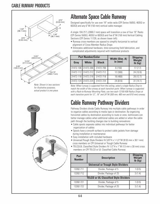
6-6
CABLE RUNWAY PRODUCTS
Note: When runway is supported from the ceiling, select a single Radius Drop tomatch the width of the runway at each transition point. When runway is supportedwith a Rack-to-Runway Mounting Plate, use two each 12100-X06 Radius Drops ateach transition point for 12”, 18” and 24”W (300 mm, 460 mm and 610 mm) runway.
Alternate Space Cable RunwayDesigned specifically for use over 19” wide racks (CPI Series 55053, 46353 or66353) and any 6”W (150 mm) vertical cable manager.
A single 104.75”L (2660.7 mm) space will transition a row of four 19” Racks(CPI Series 55053, 46353 or 66353) and five 6”W (150 mm) Vertical CablingSections (CPI Series 11729, as shown lower left).• Runway cross-members are spaced to simplify horizontal to vertical alignment of Cross Member Radius Drops
• Eliminates additional hardware, time-consuming field fabrication, and complicated adjustments required with traditional products
Part Number/ColorWidth (Dim. A)
in (mm)ShippingWeightlb (kg)Gray White Black
31472-106 31472-206 31472-706 6 (150) 17 (7.7)
31472-112 31472-212 31472-712 12 (300) 24 (10.9)
31472-118 31472-218 31472-718 18 (460) 28 (12.7)
31472-124 31472-224 31472-724 24 (610) 31 (14.1)Note: Shown in two sectionsfor illustrative purposes,actual product is one piece.
Cable Runway Pathway DividersPathway Dividers divide Cable Runway into multiple cable pathways in orderto organize cables according to media type or destination. By organizinghorizontal cables by destination according to route or zone, technicians canbetter manage cables when additional cables are added or when the cablepath through the building changes due to building renovations.• Cable spools separate cables into individual pathways for better organization of cables
• Spools have a smooth surface to protect cable jackets from damage during installation or maintenance
• Easy installation with included hardware• Universal/Trough Style Dividers fit 3/8”H x 1-1/2”W (9.53 mm x 38.1 mm)cross members on CPI Universal or Trough Cable Runway
• TELCO/UL Classified Style Dividers fit 1/2”H x 1”W (13 mm x 30 mm) crossmembers on CPI TELCO or UL Classified Cable Runway
PartNumber Description
ShippingWeightlb (kg)
Universal or Trough Style Dividers13392-711 Divider, Package of 5 1 (0.5)
13392-712 Divider, Package of 25 3 (1.4)
TELCO or UL Classified Style Dividers13392-721 Divider, Package of 5 1 (0.5)
13392-722 Divider, Package of 25 3 (1.4)

6-7
CABLE RUNWAY PRODUCTS
PatchRack For CPI Cable RunwayThe PatchRack is a miniature two-post rack that can be attached to CPI CableRunway to save rack-mount space by placing patch panels or interconnectequipment above the rack or cabinet. Use Patch Rack to create a zonenetwork in the data center. Two versions are available. Racks P/N 13395attach to the Cable Runway side stringer with a 7”D (180 mm) standoffbracket. Racks P/N 13394 attach to a cross member underneath the CableRunway. The position of the rack can be adjusted front-to-back or side-to-side. Racks P/N 13395 can also attach perpendicular to Cable Runway that is12”W (300 mm) or less. Use the Cross Member Hardware Kit P/N 13399-702for perpendicular mounting of all racks on any width of Cable Runway. • Attaches to all CPI Cable Runway, but optimized for 1-1/2”H x 3/8”W(38.1 mm x 9.53 mm) side stringers or cross members to Universal CableRunway
• Supports 19”W rack-mount equipment• Supports up to 60 lb (27.2kg)
Accessories For PatchRackUse Cross Member Hardware Kit for perpendicular mounting on all widths ofCable Runway. The D-Ring Kit provides cable management
X=color: 0=Gold, 1=Gray, 2=White, 7=Black. Gold and white kits include gold colorhardware, Gray and black kits include black color hardware. Does not include SideStringer Brackets. *Attaches to cross-member in parallel orientation only.
Part Number Description
ShippingWeightlb (kg)
13395-X04 With Side Stringer Brackets, 4U 5 (2.3)
13395-X08 With Side Stringer Brackets, 8U 7 (3.2)
13394-X04 With Cross Member Brackets, 4U* 4 (1.8)
13394-X08 With Cross Member Brackets, 8U* 6 (2.7)
PartNumber Description
ShippingWeightlb (kg)
13399-702 Cross Member Hardware Kit, Black 1 (0.5)
13396-204 D-Rings for 4U Rack, 6 Rings, White 1 (0.5)
13396-208 D-Rings for 8U Rack, 10 Rings, White 2 (0.9)
13396-704 D-Rings for 4U Rack, 6 Rings, Black 2 (0.9)
13396-708 D-Rings for 8U Rack, 10 Rings, Black 2 (0.9)
P/N 13394
P/N 13396
P/N 13399
P/N 13395

6-8
CABLE RUNWAY PRODUCTS
PartNumber
RunwayApplication
Product Widthin (mm)
CableSpools
12101-X01 Universal 10-1/4 (260.4) 3 ea.
12101-X02 Telco 7-3/4 (196.9) 2 ea.
12101-X03 Misc. 5 (130) 2 ea.
Runway Radius Drop, Stringer
PartNumber
Cable RunwayWidthin (mm)
Product Widthin (mm)
CableSpools
12100-X06 6 (150) 5 (130) 2 ea.
12100-X09 9 (230) 8 (200) 2 ea.
12100-X12 12 (300) 11 (280) 3 ea.
12100-X18 18 (460) 17 (430) 3 ea.
Cable Runway Radius DropMounts to the side stringer or cross member of CPI Cable Runway to helpmaintain proper Category 5e/6/6a or fiber bend radius.• Quick and easy installation using clevis pin • Fits 6”, 9”, 12” and 18” (150 mm, 230 mm, 300 mm and 460 mm) cross member tubing
• For use only with runs on CPI Universal Runway (Series 10250)• Provides 3” (80 mm) bend radius• Products 5”W (130 mm), 12100-X06, 12101-X03, drop into CPI’s 6”W (150 mm) vertical cabling sections
• Supplied with 1-1/2” (38.1 mm) cable spools (P/N 15003-001) to separate and guide cables
• Sold individually
Runway Radius Drop, Cross Member
X=color: 1=Gray, 2=White, 7=Black.
PartNumber
Cable Runway in (mm)
Use with Radius Drop
12115-X09 9 (230) 12100-X07
12115-X12 12 (300) 12100-X10
12115-X18 18 (460) 12100-X16
Cable Runway Movable Cross MemberPermits the dropping of cables at any point between cross members of 9”,12”or 18”W (230 mm, 300 mm or 460 mm) Cable Runways. Combine with therecommended Cable Runway Radius Drop.• Fits on standard Cable Runway only — 1-1/2” x 3/8” stringer (38.1 mm x 9.53 mm)
• Can be used as an attachment point for the Cable Runway Radius Drops listed below
• Easy installation using provided hardware
X=color: 1=Gray, 2=White, 7=Black. White (-2XX) kits include gold-colored hardware,Gray (-1XX) and Black (-7XX) kits include black color hardware.

6-9
CABLE RUNWAY PRODUCTS
X=color; 1=Gray, 2=White, 7=Black, 0=Gold. Only gold E-Bends are UL Classified
Part Number9” W (230 mm)
Part Number 12”W (300 mm)
Part Number 18”W (460 mm)
10822-X09 10822-X12 10822-X18
Cable Runway E-Bend Creates a 90 degree gradual sweep in horizontal plane for Cable Runwayruns. Designed for cabling in conformance with minimum bend radiusrequirements (typically 4 times the cable diameter). Made of lightweight 1-1/2” x 3/8” (38.1 mm x 9.53 mm) tubular steel to fit standard Cable Runway.Cross members welded at approximately 23 degree increments.• Conforms to Category 5e/6/6a requirements • Easy installation using CPI Butt-Splices (P/N 11301-001, not included)
Cable Runway Radius BendCreates a gradual bend for cascading cable runs.• Made of lightweight 1-1/2” x 3/8” (38.1 mm x 9.53 mm) tubular steel• Three cross members welded at approximately 23 degree increments • Outside/Inside is determined by welding cross members closer to cable side
X=color; 1=Gray, 2=White, 7=Black, 0=Gold. Only gold radius bends are UL Classified.
10723
10724
Part Number
90-DegreeOutside Bend
90-DegreeInside Bend
Width (Dim. A)in (mm)
10723-X06 10724-X06 6 (150)
10723-X09 10724-X09 9 (230)
10723-X12 10724-X12 12 (300)
10723-X15 10724-X15 15 (380)
10723-X18 10724-X18 18 (460)
10723-X20 10724-X20 20 (510)
10723-X24 10724-X24 24 (610)
PartNumber Description
ShippingWeightlb (kg)
31470-X12 Standoff Support Kit 1 (0.5)
Cable Runway Standoff Support KitAllows the attachment of cable runway 12” (300 mm) directly above andeither parallel or perpendicular to existing Cable Runway. Each kit consists ofthe following items: two steel angle pieces, four steel brackets and eight setsof nuts, bolts and washers. The angle pieces are available in gray, white,black or gold finish.
X=color; 1=Gray, 2=White, 5=Black, 0=Gold. Gold (-012) and White (-212) kits includegold-colored hardware, Gray (-112) and Black (-712) kits include black color hardware.
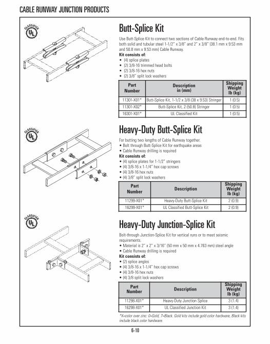
6-10
CABLE RUNWAY JUNCTION PRODUCTS
Heavy-Duty Butt-Splice KitFor butting two lengths of Cable Runway together.• Bolt through Butt-Splice Kit for earthquake areas • Cable Runway drilling is requiredKit consists of:• (4) splice plates for 1-1/2” stringers• (4) 3/8-16 x 1-1/4” hex cap screws• (4) 3/8-16 hex nuts• (4) 3/8” split lock washers
Butt-Splice KitUse Butt-Splice Kit to connect two sections of Cable Runway end-to-end. Fitsboth solid and tubular steel 1-1/2” x 3/8” and 2” x 3/8” (38.1 mm x 9.53 mmand 50.8 mm x 9.53 mm) Cable Runway. Kit consists of:• (4) splice plates• (2) 3/8-16 trimmed head bolts• (2) 3/8-16 hex nuts• (2) 3/8” split lock washers
PartNumber
Descriptionin (mm)
ShippingWeightlb (kg)
11301-X01* Butt-Splice Kit, 1-1/2 x 3/8 (38 x 9.53) Stringer 1 (0.5)
11301-X02* Butt-Splice Kit, 2 (50.8) Stringer 1 (0.5)
16301-X01* UL Classified Kit 1 (0.5)
PartNumber Description
ShippingWeightlb (kg)
11299-X01* Heavy-Duty Butt-Splice Kit 2 (0.9)
16299-X01* UL Classified Butt-Splice Kit 2 (0.9)
*X=color over zinc: 0=Gold, 7=Black. Gold kits include gold color hardware, Black kitsinclude black color hardware.
Heavy-Duty Junction-Splice KitBolt-through Junction-Splice Kit for vertical runs or to meet seismicrequirements.• Material is 2” x 2” x 3/16” (50 mm x 50 mm x 4.763 mm) steel angle • Cable Runway drilling is required Kit consists of:• (2) splice angles• (4) 3/8-16 x 1-1/4” hex cap screws• (4) 3/8-16 hex nuts• (4) 3/8 split lock washers
PartNumber Description
ShippingWeightlb (kg)
11298-X01* Heavy-Duty Junction Splice 3 (1.4)
16298-X01* UL Classified Junction Kit 3 (1.4)

6-11
CABLE RUNWAY JUNCTION PRODUCTS
Dim. 15” W (380 mm)in (mm)
24”W (610 mm)in (mm)
A 15.48 (393.2) 24.13 (612.9)
B 15.48 (393.2) 24.13 (612.9)
Dim A Dim B Cable Runway Corner BracketCreates a radius for L, T or X-shaped intersections of Cable Runway formedwhen two or more pieces of Cable Runway are connected together with theJunction-Splice Kit (P/N 11302 or 16302) or Heavy-Duty Junction-Splice Kit(P/N 11298 or 16298).• Single-piece welded assembly fabricated from 3/8” x 1-1/2” x .065”(9.53 mm x 38.1 mm x 1.65 mm) wall rectangular steel tubing
• Easy installation; brackets/hardware included
X=color over zinc: 0=Gold, 1=Gray, 2=White, 7=Black
Part Number15”W (380 mm)
Part Number24”W (610 mm) Description
11959-X15 11959-X24 Corner Bracket
Junction-Splice KitUsed to create a 90 degree junction splice with all types of 1-1/2” x 3/8” or2” x 3/8” (38.1 mm x 9.53 mm and 50.8 mm x 9.53 mm) Cable Runway.Kit consists of:• (4) corner clamp plates• (2) 3/8-16 x 1 3/8” trimmed head bolts• (2) 3/8-16 hex nuts• (2) 3/8 split lock washers
X=color over zinc: 0=Gold, 7=Black
PartNumber
Descriptionin (mm)
ShippingWeightlb (kg)
11302-X01 Junction-Splice Kit 1-1/2 x 3/8 (38mm x 9.53) Stringer 1 (0.5)
11302-X02 Junction-Splice Kit 2 x 3/8 (50.8 x 9.53) Stringer 1 (0.5)
16302-X01 UL Classified Junction Kit 1 (0.5)
10699-X01
10991-X01
X=color over zinc: 0=Gold, 7=Black
Transition Adapter Butt-Splice KitsEnables 1-1/2” x 3/8” (38.1 mm x 9.53 mm) side stringers to be spliced to 2” x 3/8” (50.8 mm x 9.53 mm) side stringers. P/N 10991-001 allows Swivel-Splice Kits to be used with 2” x 3/8” (50.8 mm x 9.53 mm) side stringers.Kit 10699-X01 consists of:• (1) 2” Butt-Splice Kit (P/N 11301-X02)• (2) steel barsKit 10991-X01 consists of:• (1) 2” Butt-Splice Kit (P/N 11301-X02)• (1) 1-1/2” Butt-Splice Kit (P/N 11301-X01)• (2) Gray or Black finish/color steel transition bars
PartNumber
Descriptionin (mm)
ShippingWeightlb (kg)
10699-X01 Adapter Kit, 1-1/2 to 2 (38.1 to 50.8) 2 (0.9)
10991-X01 Transition Kit, 1-1/2 to 2 (38.1 to 50.8) 2 (0.9)

6-12
CABLE RUNWAY JUNCTION PRODUCTS
X=color over zinc: 0=Gold, 7=Black
Part Number
Descriptionin (mm)
ShippingWeightlb (kg)
11313-X01 45° Runway-Splice Kit, 1-1/2 x 3/8 (38.1 x 9.53) stringer 1 (0.5)
16313-X01 UL Classified Kit 1 (0.5)
45° Runway-Splice KitButt-splices Cable Runway at a 45° angle. Kit consists of:• (2) 45° outside clamps• (2) Inside edge clamps• (2) 3/8-16 trimmed round head, square neck bolts • (2) 3/8-16 hex nuts and lock washers
X=color over zinc: 0=Gold, 7=Black
90° Runway-Splice KitDesigned to butt-splice 1-1/2” (38.1 mm) Cable Runway at a 90° angle.Kit consists of:• (2) 90° outside clamps• (2) Inside edge clamps• (2) 3/8-16 trimmed round head, square neck bolts• (2) 3/8-16 hex nuts and lock washers
Part Number
Descriptionin (mm)
ShippingWeightlb (kg)
11314-X01 90° Runway-Splice Kit, 1-1/2 x 3/8 (38.1 x 9.53) stringer 1 (0.5)
16314-X01 UL Classified Kit 1 (0.5)
Adjustable Junction-Splice KitAdjusts to form any junction angle for cabling that requires a large radiusbend or to route around existing plumbing, electrical, etc. Kit consists of:• (4) adjustable corner plates• (2) 3/8-16 x 2” hex cap screws• (2) 3/8-16 hex nuts• (2) 3/8 lock washersNote: Requires one kit to attach one end of cable runway.
X=color over zinc: 0=Gold, 7=Black
Part Number Description
ShippingWeightlb (kg)
10616-X01 Adjustable Junction Splice Kit 2 (0.9)

6-13
CABLE RUNWAY JUNCTION PRODUCTS
10487-X01
10488-X01Part
Number DescriptionShippingWeightlb (kg)
10487-X01 Butt-Swivel Splice Kit 1 (0.5)
10488-X01 Junction Swivel Splice Kit 1 (0.5)
10489-X01 Vertical Swivel Splice Kit 1 (0.5)
16487-X01 UL Classified Butt Swivel Splice Kit 1 (0.5)
16488-X01 UL Classified JunctionSwivel Splice Kit 1 (0.5)
16489-X01 UL Classified Vertical Swivel Splice Kit 1 (0.5)
X=color over zinc: 0=Gold, 7=Black
Swivel Splice KitsSplices cable runway vertically, horizontally or perpendicularly. Adjusts to anyangle; not limited to 45 or 90 degrees. Flexible swivel design simplifies CableRunway installation by making it easier to route around existing plumbing,electrical, etc. Material is steel. Hardware and instructions are included.Butt Swivel (10487) Kit consists of:• (8) bracket end• (8) 5/16-18 x 3/4” round head square, neck bolts• (2) 5/16-18 x 1” round head square, neck bolts• (10) 5/16-18 hex nuts, split lock washersJunction Swivel (10488) Kit consists of:• (4) bracket end• (2) bracket supports and plate clamps• (2) 5/16-18 x 1” round head square, neck bolts• (8) 5/16-18 x 3/4” round head. square. neck bolts• (10) 5/16-18 hex nuts, split lock washersVertical Swivel (10489) Kit consists of:• (4) bracket end• (2) bracket clamps and plate clamps• (2) 5/16-18 x 1” round head, square neck bolts• (6) 5/16-18 x 3/4” round head, square neck bolts• (8) 5/16-18 hex nuts, split lock washers
10489-X01
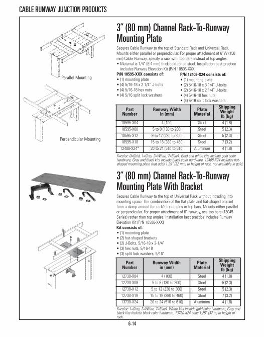
6-14
CABLE RUNWAY JUNCTION PRODUCTS
Parallel Mounting
Perpendicular Mounting
PartNumber
Runway Widthin (mm)
PlateMaterial
ShippingWeightlb (kg)
12730-X04 4 (100) Steel 4 (1.8)12730-X08 5 to 8 (130 to 200) Steel 5 (2.3)12730-X12 9 to 12 (230 to 300) Steel 5 (2.3)12730-X18 15 to 18 (380 to 460) Steel 7 (3.2)13730-X24 20 to 24 (510 to 610) Aluminum 4 (1.8)
X=color: 1=Gray, 2=White, 7=Black. White kits include gold color hardware, Gray andblack kits include black color hardware. 13730-X24 adds 1.25” (32 m) to height ofrack.
3” (80 mm) Channel Rack-To-RunwayMounting Plate With BracketSecures Cable Runway to the top of Universal Rack without intruding intomounting space. The combination of the flat plate and hat-shaped bracketform a clamp around the rack's top angles or top bars. Mounts either parallelor perpendicular. For proper attachment of 6” runway, use top bars (13045Series) rather than top angles. Installation best practice includes Runway Elevation Kit (P/N 10506-XXX)Kit consists of:• (1) mounting plate• (2) hat-shaped brackets• (2) J-Bolts, 5/16-18 x 2-1/4”• (3) hex nuts, 5/16-18• (3) split lock washers, 5/16”
PartNumber
Runway Widthin (mm)
Plate Material
ShippingWeightlb (kg)
10595-X04 4 (100) Steel 4 (1.8)10595-X08 5 to 8 (130 to 200) Steel 5 (2.3)10595-X12 9 to 12 (230 to 300) Steel 5 (2.3)10595-X18 15 to 18 (380 to 460) Steel 7 (3.2)12408-X24* 20 to 24 (510 to 610) Aluminum 4 (1.8)
X=color: 0=Gold, 1=Gray, 2=White, 7=Black. Gold and white kits include gold colorhardware, Gray and black kits include black color hardware. 12408-X24 includes hat-shaped mounting plate that adds 1.25” (32 mm) to height of rack, not available in gold.
3” (80 mm) Channel Rack-To-Runway Mounting PlateSecures Cable Runway to the top of Standard Rack and Universal Rack.Mounts either parallel or perpendicular. For proper attachment of 6”W (150mm) Cable Runway, specify a rack with top bars instead of top angles.• Material is 1/4” (6.4 mm) thick cold-rolled steel. Installation best practiceincludes Runway Elevation Kit (P/N 10506-XXX)
P/N 10595-XXX consists of:• (1) mounting plate• (4) 5/16-18 x 2 1/4” J-bolts • (4) 5/16-18 hex nuts• (4) 5/16 split lock washers
P/N 12408-X24 consists of:• (1) mounting plate• (2) 5/16-18 x 3 1/4” J-bolts• (2) 5/16-18 x 2 1/4” J-bolts • (4) 5/16-18 hex nuts• (4) 5/16 split lock washers

6-15
CABLE RUNWAY JUNCTION PRODUCTS
Parallel Mounting
Perpendicular Mounting
X=color: 1=Gray, 2=White, 7=Black. White kits include gold color hardware, Gray andblack kits include black color hardware.. 13731-X24 adds 1.25” (32 mm) to height ofrack..
6” (150 mm) Channel Rack-To-RunwayMounting Plate With BracketSecures Cable Runway to the top of 6”D (150 mm) Standard Rack withoutintruding into valuable mounting space. The combination of the flat plate andhat-shaped bracket form a clamp around the rack's top angles or top bars.Mounts either parallel or perpendicular. • Installation best practice includes Runway Elevation Kit (P/N 10506-XXX)Kit consists of:• (1) mounting plates• (2) hat-shaped bracket• (2) J-Bolts, 5/16-18 x 2-1/4”• (3) hex nuts, 5/16-18• (3) split lock washers, 5/16”
X=color: 1=Gray, 2=White, 7=Black. White kits include gold color hardware, Gray andblack kits include black color hardware. 12409-X24 adds 1.25” (32 mm) to height ofrack.
6” (150 mm) Channel Rack-To-Runway Mounting PlateSecures Cable Runway to the top of 6”D (150 mm) Standard Rack. Mountseither parallel or perpendicular to runway. • Installation best practice includes Runway Elevation Kit (P/N 10506-XXX)P/N 12121-XXX consists of:• (1) mounting plate• (4) 5/16-18 x 2 1/4” J-bolts • (4) 5/16-18 hex nuts• (4) 5/16 split lock washers
PartNumber
Runway Widthin (mm)
PlateMaterial
ShippingWeightlb (kg)
12121-X09 5 to 9 (130 to 230) Aluminum 5 (2.3)
12121-X12 9 to 12 (230 to 300) Aluminum 5 (2.3)
12121-X18 15 to 18 (380 to 460) Aluminum 7 (3.2)
12409-X24 20 to 24 (510 to 610) Aluminum 5 (2.3)
PartNumber
Runway Widthin (mm)
PlateMaterial
ShippingWeightlb (kg)
12731-X09 5 to 9 (130 to 230) Aluminum 5 (2.3)
12731-X12 9 to 12 (230 to 300) Aluminum 5 (2.3)
12731-X18 15 to 18 (380 to 460) Aluminum 7 (3.2)
13731-X24 20 to 24 (510 to 610) Aluminum 5 (2.3)
P/N 12409-X24 consists of:• (1) mounting plate• (2) 5/16-18 x 3 1/4” J-bolts• (2) 5/16-18 x 2 1/4” J-bolts • (4) 5/16-18 hex nuts• (4) 5/16 split lock washers

6-16
CABLE RUNWAY ELEVATION PRODUCTS
Rack Not Included
Cable Runway Wall To Rack KitThe CPI Cable Runway Wall To Rack Kit is a one part number solution to theproblem of providing support for cable between the rack and the wall. Kit consists of:• (1) 4’ 6”L/54” (1370 mm) Universal Cable Runway • (1) Wall angle support bracket• (1) Rack to runway mounting plate• (1) Pair of end caps• (6) J-boltsNote: The kit is available with runway that is 6”, 9” or 12”W (150 mm, 230 mm or300 mm). Rack is not included.
Part Number Description
ShippingWeightlb (kg)
Standard/Universal Racks with 3”D (80 mm) Mounting ChannelsWidth - in (mm)
11911-X06 6 (150) Cable Runway Wall to Rack Kit 24 (10.9)
11911-X09 9 (230) Cable Runway Wall to Rack Kit 28 (12.7)
11911-X12 12 (300) Cable Runway Wall to Rack Kit 32 (14.5)
Standard Rack with 6”D (150 mm) Mounting ChannelsWidth - in (mm)
31473-X06 6 (150) Cable Runway Wall to Rack Kit 17 (7.7)
31473-X09 9 (230) Cable Runway Wall to Rack Kit 19 (8.6)
31473-X12 12 (300) Cable Runway Wall to Rack Kit 24 (10.9)
X=color: 1=Gray, 2=White, 7=Black. White kits include gold color hardware, Gray andblack kits include black color hardware.
2”, 2.5” or 3”H (50 mm, 64 mm or 80 mm) Elevation
RackShippingWeightlb (kg)
CabinetShippingWeightlb (kg)
10506-X02 2 (0.9) 10506-X12 2 (0.9)
4”, 5” or 6”H (100 mm, 130 mm or 150 mm) Elevation10506-X06 3 (1.4) 10506-16 5 (2.3)
X=color: 1=Gray, 2=White, 7=Black, 0=Gold. Note: Gold and white kits include goldcolor hardware, Gray and black kits include black color hardware.
Cable Runway Elevation KitSupports Cable Runway above a continuous row of CPI Racks or Cabinets ofvarying height and provides additional space between the tops of the racks orcabinets and the cable runway, which can create smoother transition of cables.• Two ranges of incremental elevation• Can be mounted perpendicular or parallel • Rack kit includes a single pair of brackets and assembly hardware• Rack kits attach to the top of the rack with a Rack-To-Runway Mounting Plate (P/N 10595 or 12121, sold separately)
• Cabinet kits include two pairs of brackets and assembly hardware• Cabinet kits attach directly to the top of the cabinet

6-17
CABLE RUNWAY AUXILIARY FRAME PRODUCTS
-001
-002
-003
PartNumber
Descriptionin (mm)
ShippingWeightlb (kg)
5/8” Bolt Size10609-001 For 3/8 (9.53) Bar or Runway Stringer 1 (0.5)
10609-002 For 9/16 (14.288) Channel 1 (0.5)
10609-003 For 1 (30) Channel 1 (0.5)
1/2” Bolt Size10621-001 For 3/8 (9.53) Bar or Runway Stringer 1 (0.5)
10621-002 For 9/16 (14.288) Channel 1 (0.5)
10621-003 For 1 (30) Channel 1 (0.5)
Framing Clip Kit, Cable RunwayCreates a rigid connection between two adjacent grid or cable runwaysections.• Material is steel finished with gold over zinc plating; kit consists of 2brackets only
• Installation will require:- (1) 5/8-11 or 1/2-13 threaded rod (of appropriate length) - (2) 5/8-11 or 1/2-13 hex nuts - (2) 5/8” or 1/2” split lock washers
PartNumber
Descriptionin (mm)
ShippingWeightlb (kg)
11019-001 For 3/8 (9.53) Bar or Runway Stringer,5/8” threaded rod 2 (0.9)
11019-002 For 9/16 (14.288) channel,5/8” threaded rod 2 (0.9)
Slip-On® Framing Clip, Cable RunwayAllows easy installation of additional rack grids to existing grids by slippingclamps around 5/8” threaded rod.• Material is steel finished with gold over zinc plating Kit consists of:• (2) slotted clamps• (2) 5/8” Slip-On® Lock NutsSlip-On® is a registered trademark of Slip-On Lock Nut Co.

6-18
CABLE RUNWAY AUXILIARY FRAME PRODUCTS
PartNumber Color Length
ft (m)ShippingWeightlb (kg)
1” x 2” x 3/16” (25 mm x 50 mm x 4.763 mm) Channel11450-101 Gray 10 (3) 24 (10.9)
Auxiliary Framing Channel, Cable Runway• Steel channel or bar commonly used as auxiliary framing for CableRunways
• Color is Gray (other colors available)
11450
10628
10745 9/16” x 2” x 3/16” (14.288 mm x 50 mm x 4.763 mm) Channel
10628-102 Gray 10 (3) 17 (7.7)
3/8” x 2” (9.53 mm x 50 mm) Bar
10745-106 Gray 6 (1.8) 14 (6.4)
Heavy-Duty, Auxiliary Framing ChannelSplice, Cable RunwayProvides extra strength to butt-splice framing channel.• Drilling the framing channel is required • Color is gray splice bars with gold hardware Kit consists of:• (1) channel splice, 6”L (150 mm)• (1) steel bar splice, 6”L (150 mm)• (4) 1/2-13 hex cap screws• (4) 1/2-13 hex nuts and split lock washers
Part Number
Descriptionin (mm) Figure
ShippingWeightlb (kg)
10746-101 9/16 x 2 (14.288 x 50) Channel A 3 (1.4)
10747-101 1 x 2 (25 x 50) Channel B 3 (1.4)
Auxiliary Framing Bar Splice Kit, CableRunwayButt-splices 3/8” x 2” (9.53 mm x 50 mm) Auxiliary Framing Bar.• Drilling the framing bar is required • Material is steel bar 1/4” x 2” x 6”L (6.4 mm x 50 mm x 150 mm)• Color is gray with gold hardwareKit consists of:• (2) splice bars• (4) 1/2-13 hex cap screws• (4) 1/2-13 hex nuts and split lock washers
Part Number
Descriptionin (mm) Figure
ShippingWeightlb (kg)
10748-101 Bar Splice Kit C 4 (1.8)
Figure AUse with 10628
Figure BUse with 11450
Figure CUse with 10745
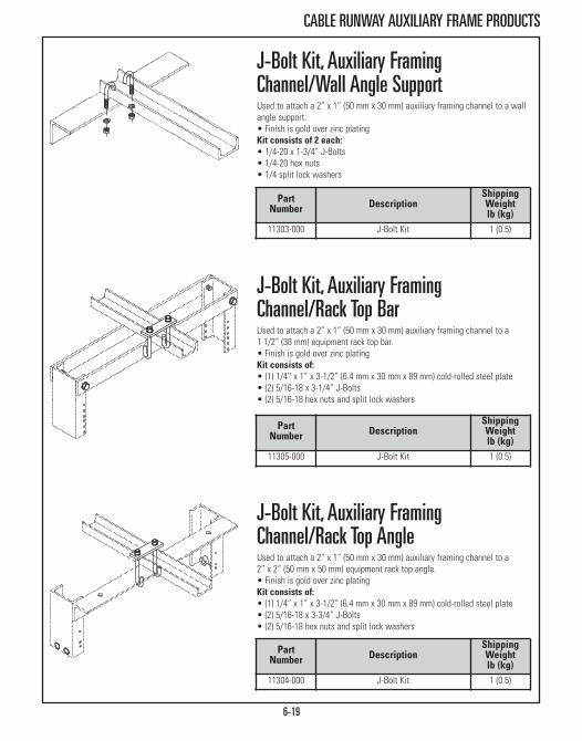
6-19
CABLE RUNWAY AUXILIARY FRAME PRODUCTS
J-Bolt Kit, Auxiliary Framing Channel/Rack Top AngleUsed to attach a 2” x 1” (50 mm x 30 mm) auxiliary framing channel to a 2” x 2” (50 mm x 50 mm) equipment rack top angle.• Finish is gold over zinc plating Kit consists of:• (1) 1/4” x 1” x 3-1/2” (6.4 mm x 30 mm x 89 mm) cold-rolled steel plate• (2) 5/16-18 x 3-3/4” J-Bolts• (2) 5/16-18 hex nuts and split lock washers
J-Bolt Kit, Auxiliary Framing Channel/Rack Top Bar Used to attach a 2” x 1” (50 mm x 30 mm) auxiliary framing channel to a 1 1/2” (38 mm) equipment rack top bar.• Finish is gold over zinc platingKit consists of:• (1) 1/4” x 1” x 3-1/2” (6.4 mm x 30 mm x 89 mm) cold-rolled steel plate• (2) 5/16-18 x 3-1/4” J-Bolts • (2) 5/16-18 hex nuts and split lock washers
J-Bolt Kit, Auxiliary Framing Channel/Wall Angle SupportUsed to attach a 2” x 1” (50 mm x 30 mm) auxiliary framing channel to a wallangle support.• Finish is gold over zinc plating Kit consists of 2 each:• 1/4-20 x 1-3/4” J-Bolts • 1/4-20 hex nuts • 1/4 split lock washers
PartNumber Description
ShippingWeightlb (kg)
11303-000 J-Bolt Kit 1 (0.5)
PartNumber Description
ShippingWeightlb (kg)
11305-000 J-Bolt Kit 1 (0.5)
PartNumber Description
ShippingWeightlb (kg)
11304-000 J-Bolt Kit 1 (0.5)
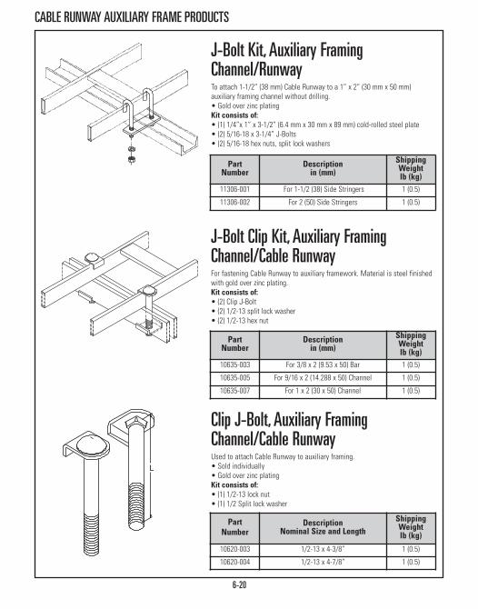
6-20
CABLE RUNWAY AUXILIARY FRAME PRODUCTS
Clip J-Bolt, Auxiliary Framing Channel/Cable RunwayUsed to attach Cable Runway to auxiliary framing.• Sold individually• Gold over zinc platingKit consists of:• (1) 1/2-13 lock nut• (1) 1/2 Split lock washer
J-Bolt Clip Kit, Auxiliary Framing Channel/Cable RunwayFor fastening Cable Runway to auxiliary framework. Material is steel finishedwith gold over zinc plating.Kit consists of:• (2) Clip J-Bolt• (2) 1/2-13 split lock washer• (2) 1/2-13 hex nut
J-Bolt Kit, Auxiliary Framing Channel/RunwayTo attach 1-1/2” (38 mm) Cable Runway to a 1” x 2” (30 mm x 50 mm)auxiliary framing channel without drilling.• Gold over zinc plating Kit consists of:• (1) 1/4”x 1” x 3-1/2” (6.4 mm x 30 mm x 89 mm) cold-rolled steel plate• (2) 5/16-18 x 3-1/4” J-Bolts • (2) 5/16-18 hex nuts, split lock washers
PartNumber
Descriptionin (mm)
ShippingWeightlb (kg)
10635-003 For 3/8 x 2 (9.53 x 50) Bar 1 (0.5)
10635-005 For 9/16 x 2 (14.288 x 50) Channel 1 (0.5)
10635-007 For 1 x 2 (30 x 50) Channel 1 (0.5)
PartNumber
Descriptionin (mm)
ShippingWeightlb (kg)
11306-001 For 1-1/2 (38) Side Stringers 1 (0.5)
11306-002 For 2 (50) Side Stringers 1 (0.5)
PartNumber
DescriptionNominal Size and Length
ShippingWeightlb (kg)
10620-003 1/2-13 x 4-3/8” 1 (0.5)
10620-004 1/2-13 x 4-7/8” 1 (0.5)
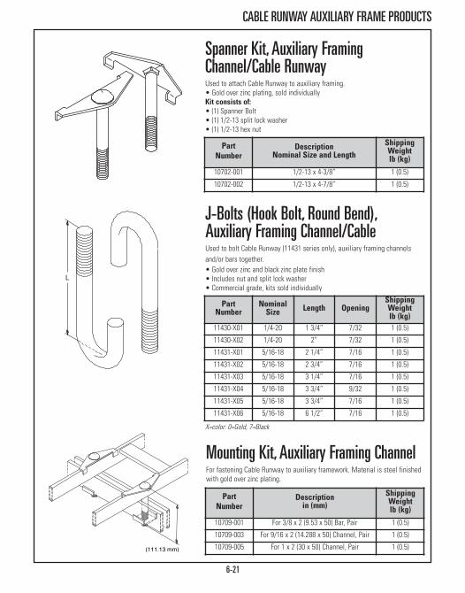
6-21
CABLE RUNWAY AUXILIARY FRAME PRODUCTS
J-Bolts (Hook Bolt, Round Bend), Auxiliary Framing Channel/Cable Used to bolt Cable Runway (11431 series only), auxiliary framing channelsand/or bars together.• Gold over zinc and black zinc plate finish • Includes nut and split lock washer • Commercial grade, kits sold individually
Spanner Kit, Auxiliary Framing Channel/Cable RunwayUsed to attach Cable Runway to auxiliary framing.• Gold over zinc plating, sold individually Kit consists of:• (1) Spanner Bolt• (1) 1/2-13 split lock washer• (1) 1/2-13 hex nut
PartNumber
NominalSize Length Opening
ShippingWeightlb (kg)
11430-X01 1/4-20 1 3/4” 7/32 1 (0.5)
11430-X02 1/4-20 2” 7/32 1 (0.5)
11431-X01 5/16-18 2 1/4” 7/16 1 (0.5)
11431-X02 5/16-18 2 3/4” 7/16 1 (0.5)
11431-X03 5/16-18 3 1/4” 7/16 1 (0.5)
11431-X04 5/16-18 3 3/4” 9/32 1 (0.5)
11431-X05 5/16-18 3 3/4” 7/16 1 (0.5)
11431-X06 5/16-18 6 1/2” 7/16 1 (0.5)
X=color: 0=Gold, 7=Black
PartNumber
DescriptionNominal Size and Length
ShippingWeightlb (kg)
10702-001 1/2-13 x 4-3/8” 1 (0.5)
10702-002 1/2-13 x 4-7/8” 1 (0.5)
Mounting Kit, Auxiliary Framing ChannelFor fastening Cable Runway to auxiliary framework. Material is steel finishedwith gold over zinc plating.
PartNumber
Descriptionin (mm)
ShippingWeightlb (kg)
10709-001 For 3/8 x 2 (9.53 x 50) Bar, Pair 1 (0.5)
10709-003 For 9/16 x 2 (14.288 x 50) Channel, Pair 1 (0.5)
10709-005 For 1 x 2 (30 x 50) Channel, Pair 1 (0.5)

6-22
CABLE RUNWAY SUPPORT PRODUCTS
Triangular Support Bracket, SteelTriangular Support Bracket provides wall support for cable runway. Made ofcold rolled steel. Load rating is 400 lb (181.4 kg).Kit consists of:• (1) vertical wall-mounting bracket• (1) runway support channel • (1) angle support channel• (3) clevis pins (5/16” diameter) & cotter pins• (2) 5/16-18 x 2 1/4” J-bolts• (2) 5/16-18 hex nuts & 5/16 lock washers
Triangular Support Bracket, AluminumTriangular Support Bracket provides wall support for Cable Runway. Made of1/4” x 2” (6.4 mm x 50 mm) aluminum bar. Load rating is 100 lb (45.4 kg).Kit consists of:• (1) triangular bracket• (2) 5/16-18 x 2 1/4” J-bolts • (2) 5/16-18 hex nuts & 5/16 lock washers
PartNumber
RunwayWidthsin (mm)
ColorShippingWeightlb (kg)
11312-106 4-6 (100 - 150) Gray 2 (0.9)11312-112 6-12 (150 - 300) Gray 3 (1.4)11312-118 12-18 (300 - 460) Gray 3 (1.4)11312-206 4-6 (100 - 150) White 2 (0.9)11312-212 6-12 (150 - 300) White 3 (1.4)11312-218 12-18 (300 - 460) White 3 (1.4)11312-706 4-6 (100 - 150) Black 2 (0.9)11312-712 6-12 (150 - 30m) Black 3 (1.4)11312-718 12-18 (300 - 460) Black 3 (1.4)
PartNumber
RunwayWidthsin (mm)
ColorShippingWeightlb (kg)
11746-112 6, 12 (150, 300) Gray 5 (2.3)11746-118 18 (460) Gray 8 (3.6)11746-124 24 (610) Gray 9 (4.1)11746-212 6, 12 (150, 300) White 5 (2.3)11746-218 18 (460) White 8 (3.6)11746-224 24 (610) White 9 (4.1)11746-712 6, 12 (150, 300) Black 5 (2.3)11746-718 18 (460) Black 8 (3.6)11746-724 24 (610) Black 9 (4.1)11746-012 6, 12 (150, 300) Gold 5 (2.3)11746-018 18 (460) Gold 8 (3.6)
11746-024 24 (610) Gold 9 (4.1)
Gold and white kits include gold color hardware, Gray and black kits include blackcolor hardware.

6-23
CABLE RUNWAY SUPPORT PRODUCTS
11421 - X XX
RunwayWidthin (mm)
Dim. Ain (mm)
Dim. Bin (mm)
Dim. Cin (mm)
04 4 (100) 6 (150) 4.31 (109.5) 4.31 (109.5)
06 6 (150) 8 (200) 6.31 (160.3) 4 (100.0)
09 9 (230) 11 (280) 9.31 (236.5) 7 (180.0)
10 10 (250) 12 (300) 10.21 (261.9) 8 (200.0)
12 12 (300) 14 (360) 12.31 (312.7) 10 (250.0)
15 15 (380) 17 (430) 15.31 (388.9) 13 (330.0)
18 18 (460) 20 (510) 18.31 (465.1) 16 (410.0)
20 20 (510) 22 (560) 20.31 (515.9) 18 (460.0)
24 24 (610) 26 (660) 24.31 (617.5) 22 (460.0)
30 30 (760) 32 (810) 30.31 (769.9) 28 (710.0)
Color1 Gray
2 Computer White
7 Black
0 Gold
Wall Angle Support Kit, Cable Runway2” x 2” x .105” (50 mm x 50 mm x 2.67 mm) steel support angle is designedfor wall-mounting specific widths of Cable Runway.Kit consists of:• (1) wall angle • (2) 5/16-18 x 2 1/4” J-bolts • (2) 5/16-18 hex nuts• (2) 5/16 lock washers
11421 Wall Angle Support Kit
AB
C
Note: Gold and white kits include gold color hardware, Gray and blackkits include black color hardware.

6-24
CABLE RUNWAY SUPPORT PRODUCTS
PartNumber Color
ShippingWeightlb (kg)
11309-X01 Foot Kit 4 (1.8)
Foot Kit, Cable RunwayTo attach and secure Cable Runway to a wall or floor. Foot made of 3/8” x 1-1/2” x 6”H (9.53 mm x 38 mm x 150 mm) steel.Kit consists of:• (2) cable rack feet• (4) splice plates• (2) 3/8-16 x 2 1/4” trimmed round head square neck bolts • (2) 3/8-16 hex nuts• (2) 3/8” lock washers
PartNumber Color
ShippingWeightlb (kg)
11308-X01 J-Bolt Kit 1 (0.5)
11308-X05 J-Bolt Kit, MegaFrame 1 (0.5)
J-Bolt Kit, Cable RunwayTo attach Cable Runway to Wall Angle Support, a Wall Support Bracket or to aMegaFrame® Cabinet.Kit (wall angle/support) consists of:• (2) 5/16-18 x 2-1/4” J-bolts (11431-001)• (2) 5/16-18 hex nuts• (2) 5/16 split lock washersMegaFrame kit consists of:• (4) 5/16-18 x 3-1/4” J-bolts• (4) 5/16” split lock washers• (4) 5/16-18 hex nuts
PartNumber
Dim. Aft (m) Color
ShippingWeightlb (kg)
11420-101 1 (0.3) Gray 3 (1.4)
11420-104 4 (1.2) Gray 7 (3.2)
11420-108 8 (2.4) Gray 20 (9.1)
11420-110 10 (3.0) Gray 23 (10.4)
Wall Angle, Cable RunwaySteel angles used as a wall support or as part of earthquake bracing.• Material is 2” x 2” x 3/16” (50 mm x 50 mm x 4.763 mm) steel• Color used is Gray (other colors available)• Wall angle is not pre-drilled
X=color: 0=Gold, 7=Black
X=color: 0=Gold, 1=Gray, 2=White, 7=Black. Gold and white kits include gold colorhardware, Gray and black kits include black color hardware.

6-25
CABLE RUNWAY SUPPORT PRODUCTS
1/2 Pair Shown
Part Number RunwayWidthin (mm)Gray White Black
11241-112 11241-212 11241-712 12 (300)
11241-115 11241-215 11241-715 15 (380)
11241-118 11241-218 11241-718 18 (460)
Note: To install the anchors, use the specially designed anchor setting tool (P/N06003-001) sold separately.
Adjustable Floor Support Channel, CableRunwayUse for floor support of Cable Runway.• Sold in pairs • Cable Runway height adjustable from 3” to 8” (80 mm to 200 mm)• Must be securely fastened to floor with 5/8” rods and anchors (included)
Adjustable Floor Support Stands, Cable RunwayUse for floor support for cable runway grids. • Sold in pairs.• Design allows mounting of any width cable runway • Heights from 5” to 10” (130 mm to 250 mm)• Should be securely fastened to floor Kit consists of:• (2) 2” pipe caps• (2) floor flanges• (2) 2” pipe• (4) grid clamps• (2) spacers, 3/8” x 1.5”• (2) 5/8-11 threaded rod• (2) 5/8 lock washers• (6) 5/8-11 nuts
Part Number Heightin (mm)Gray White Black
11235-101 11235-201 11235-701 5 to 6 (130 to 150)
11236-101 11236-201 11236-701 6 to 8 (150 to 200)
11237-101 11237-201 11237-701 8 to 10 (200 to 300)
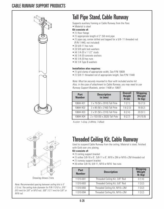
6-26
CABLE RUNWAY SUPPORT PRODUCTS
PartNumber
Descriptionin (mm)
OverallHeightft (m)
ShippingWeightlb (kg)
10684-X01 2 x 79 (50 x 2010) Tall Pole 7 (2.1) 16 (7.3)
10684-X02 2 x 85 (50 x 2160) Tall Pole 7.6 (2.3) 18 (8.2)
10684-X03 2 x 91 (50 x 2310) Tall Pole 8 (2.4) 20 (9.1)
10684-X04 2 x 10³ (50 x 2620) Tall Pole 9 (2.7) 24 (10.9)
X=color: 1=Gray, 2=White, 7=Black
Tall Pipe Stand, Cable RunwaySupports auxiliary framing or Cable Runway from the floor.• Material is steel Kit consists of:• (1) floor flange• (1) appropriate length of 2” (50 mm) pipe• (1) pipe cap, center drilled and tapped for a 5/8- 11 threaded rod (P/N 11440, not included)
• (3) 5/8-11 hex nuts• (3) 5/8 split lock washers• (4) 1/4-20 x 1 1/2” studs• (4) 1/4-20 concrete anchors• (4) 1/4-20 hex nuts• (4) 1/4 Type B washers
Installation also requires:• (1) grid clamp of appropriate width, See P/N 10609• (1) 5/8-11 threaded rod of appropriate length, See P/N 11440
Note: Must be securely mounted to floor with included anchor kit. Also, in the case of attachment to Cable Runway, you may need to useRunway Support Brackets, series 11408 or 10607.
Drawing shows 2 kits
Note: Recommended spacing between ceiling kits is 5’ (1.5 m). The ceiling hole diameter for P/N 11310 is .375”(9.5 mm) for 3/8” or M10 rod; .500” (12.7 mm) for 5/8” orM16 rod.
PartNumber Description
ShippingWeightlb (kg)
11310-001 Threaded Ceiling Kit, 3/8” Rod 3 (1.4)
11310-003 Threaded Ceiling Kit, 5/8” Rod 7 (3.2)
11310-093 Threaded Ceiling Kit, M10 x 2M 7 (3.2)
11310-094 Threaded Ceiling Kit, M16 x 2M 7 (3.2)
Threaded Ceiling Kit, Cable RunwayUsed to suspend Cable Runway from the ceiling. Material is steel, finishedwith Gold over zinc plating.Kit consists of:• (1) ceiling support bracket• (1) either 3/8-16 x 6’, 5/8-11 x 6’, M10 x 2M or M16 x 2M threaded rod• (1) runway support bracket• (4) either 3/8-16, 5/8-11, M10 or M16 hex nuts
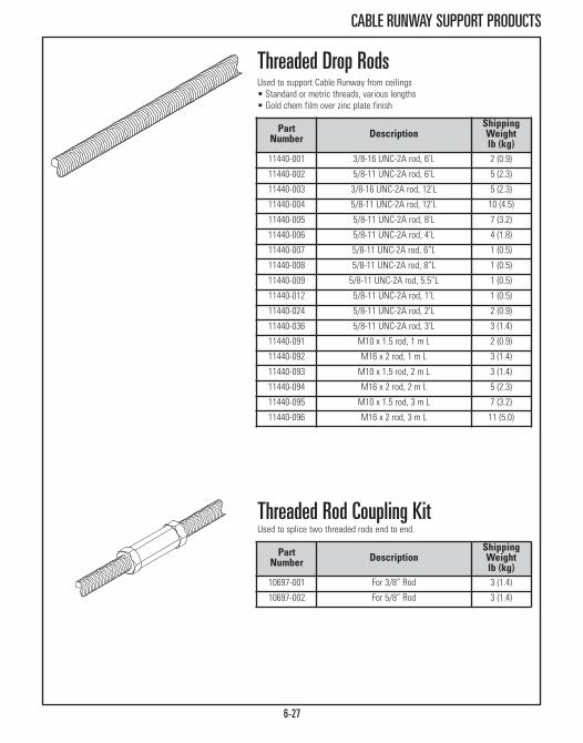
6-27
CABLE RUNWAY SUPPORT PRODUCTS
Threaded Rod Coupling KitUsed to splice two threaded rods end to end.
Threaded Drop RodsUsed to support Cable Runway from ceilings• Standard or metric threads, various lengths• Gold chem film over zinc plate finish
PartNumber Description
ShippingWeightlb (kg)
11440-001 3/8-16 UNC-2A rod, 6’L 2 (0.9)
11440-002 5/8-11 UNC-2A rod, 6’L 5 (2.3)
11440-003 3/8-16 UNC-2A rod, 12’L 5 (2.3)
11440-004 5/8-11 UNC-2A rod, 12’L 10 (4.5)
11440-005 5/8-11 UNC-2A rod, 8’L 7 (3.2)
11440-006 5/8-11 UNC-2A rod, 4’L 4 (1.8)
11440-007 5/8-11 UNC-2A rod, 6”L 1 (0.5)
11440-008 5/8-11 UNC-2A rod, 8”L 1 (0.5)
11440-009 5/8-11 UNC-2A rod, 5.5”L 1 (0.5)
11440-012 5/8-11 UNC-2A rod, 1’L 1 (0.5)
11440-024 5/8-11 UNC-2A rod, 2’L 2 (0.9)
11440-036 5/8-11 UNC-2A rod, 3’L 3 (1.4)
11440-091 M10 x 1.5 rod, 1 m L 2 (0.9)
11440-092 M16 x 2 rod, 1 m L 3 (1.4)
11440-093 M10 x 1.5 rod, 2 m L 3 (1.4)
11440-094 M16 x 2 rod, 2 m L 5 (2.3)
11440-095 M10 x 1.5 rod, 3 m L 7 (3.2)
11440-096 M16 x 2 rod, 3 m L 11 (5.0)
PartNumber Description
ShippingWeightlb (kg)
10697-001 For 3/8” Rod 3 (1.4)
10697-002 For 5/8” Rod 3 (1.4)
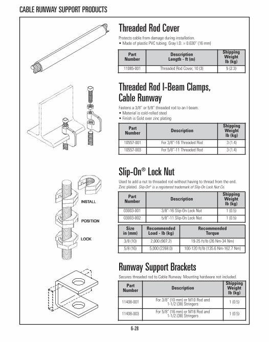
6-28
CABLE RUNWAY SUPPORT PRODUCTS
Runway Support BracketsSecures threaded rod to Cable Runway. Mounting hardware not included.
Sizein (mm)
RecommendedLoad - lb (kg)
RecommendedTorque
3/8 (10) 2,000 (907.2) 19-25 ft/lb (26 Nm-34 Nm)
5/8 (16) 5,000 (2268.0) 100-120 ft/lb (135.6 Nm-162.7 Nm)
Slip-On® Lock NutUsed to add a nut to threaded rod without having to thread from the end.Zinc plated. Slip-On® is a registered trademark of Slip-On Lock Nut Co.
Threaded Rod I-Beam Clamps, Cable RunwayFastens a 3/8” or 5/8” threaded rod to an I-beam.• Material is cold-rolled steel• Finish is Gold over zinc plating
PartNumber
DescriptionLength - ft (m)
ShippingWeightlb (kg)
11085-001 Threaded Rod Cover, 10 (3) 5 (2.3)
Threaded Rod CoverProtects cable from damage during installation. • Made of plastic PVC tubing. Gray I.D. = 0.630” (16 mm)
PartNumber Description
ShippingWeightlb (kg)
10557-001 For 3/8”-16 Threaded Rod 3 (1.4)
10557-003 For 5/8”-11 Threaded Rod 3 (1.4)
PartNumber Description
ShippingWeightlb (kg)
03003-001 3/8”-16 Slip-On Lock Nut 1 (0.5)
03003-002 5/8”-11 Slip-On Lock Nut 1 (0.5)
PartNumber Description
ShippingWeightlb (kg)
11408-001 For 3/8” (10 mm) or M10 Rod and1-1/2 (38) Stringers 1 (0.5)
11408-003 For 5/8” (16 mm) or M16 Rod and1-1/2 (38) Stringers 1 (0.5)
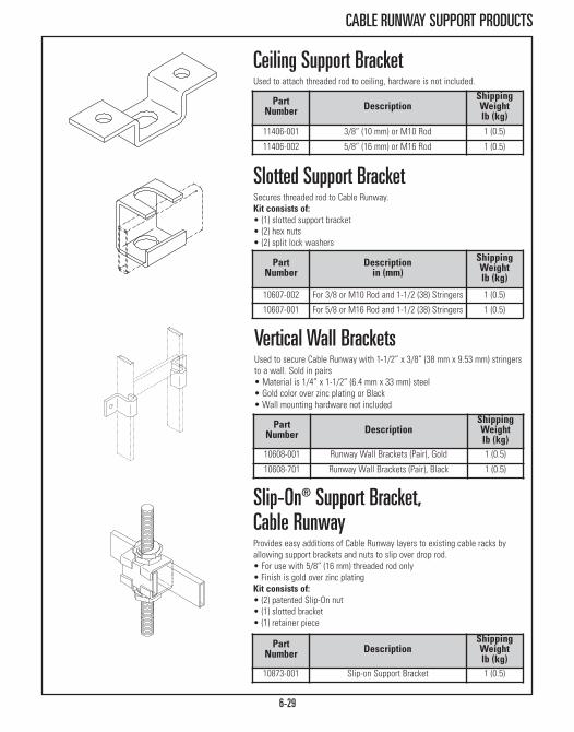
6-29
CABLE RUNWAY SUPPORT PRODUCTS
Slip-On® Support Bracket, Cable RunwayProvides easy additions of Cable Runway layers to existing cable racks byallowing support brackets and nuts to slip over drop rod.• For use with 5/8” (16 mm) threaded rod only• Finish is gold over zinc platingKit consists of:• (2) patented Slip-On nut• (1) slotted bracket• (1) retainer piece
Slotted Support BracketSecures threaded rod to Cable Runway.Kit consists of: • (1) slotted support bracket• (2) hex nuts• (2) split lock washers
Ceiling Support BracketUsed to attach threaded rod to ceiling, hardware is not included.
PartNumber
Descriptionin (mm)
ShippingWeightlb (kg)
10607-002 For 3/8 or M10 Rod and 1-1/2 (38) Stringers 1 (0.5)
10607-001 For 5/8 or M16 Rod and 1-1/2 (38) Stringers 1 (0.5)
Vertical Wall BracketsUsed to secure Cable Runway with 1-1/2” x 3/8” (38 mm x 9.53 mm) stringersto a wall. Sold in pairs • Material is 1/4” x 1-1/2” (6.4 mm x 33 mm) steel • Gold color over zinc plating or Black• Wall mounting hardware not included
PartNumber Description
ShippingWeightlb (kg)
10608-001 Runway Wall Brackets (Pair), Gold 1 (0.5)
10608-701 Runway Wall Brackets (Pair), Black 1 (0.5)
PartNumber Description
ShippingWeightlb (kg)
10873-001 Slip-on Support Bracket 1 (0.5)
PartNumber Description
ShippingWeightlb (kg)
11406-001 3/8” (10 mm) or M10 Rod 1 (0.5)
11406-002 5/8” (16 mm) or M16 Rod 1 (0.5)

6-30
CABLE RUNWAY SUPPORT PRODUCTS
The Cable Runway Center Support Kit is availablein sizes to support 6” to 24”W (150 mm to 610mm) cable runway
PartNumber
DescriptionWidth - in (mm)
Dim. Ain (mm)
ShippingWeightlb (kg)
12362-X06 6 (150) 6.56 (166.6) 2 (0.9)
12362-X12 12 (300) 12.56 (319.0) 2 (0.9)
12362-X15 15 (380) 16.20 (411.5) 3 (1.4)
12362-X18 18 (460) 19.20 (487.7) 4 (1.8)
12362-X24 24 (610) 25.20 (640.1) 5 (2.3)
X=color: 1=Gray, 2=White, 7=Black, 0=Gold, Gold and white kits include gold colorhardware; Gray and black kits include black color hardware.
Cable Runway Center Support KitThis kit has been designed to make installation of cable runway in the ceilingeven easier by using just a single point of attachment. The center attachmentdesign not only makes installation easy but also provides quick and simplecable routing with no need to thread the cable between the runway supports.The support kit securely attaches to the cable runway stringer, eliminatingpossible dislocations. • Not Included: Threaded rod (P/N 11440-002 or -004) and Ceiling Support Bracket (P/N 11406-002).
• Made of steel • Provides an “open” support system with quick and simple cable routing
• Threaded rod cover protects cable insulation from damage Kit consists of:• (1) support bracket• (1) reinforcement bar• (2) 5/8-11 hex nuts• (1) 5/8 split lock washers• (1) 12”L (300 mm) threaded rod cover • (1) J-bolt kit (2 J-bolts; 2 nuts; 2 washers)
Cable Retaining Post Provides extra cable depth to existing 1-1/2” (38 mm) cable runwayinstallation. Mounts onto Cable Runway side stringers.• Post is 1/2” x 1” x .065” (12.7 mm x 25.4 mm x 1.7 mm) wall rectangularsteel tubing; bracket is 1046 steel
Kit consists of:• (1) Post, bracket, and end cap • (1) 1/4-20 x 1-1/4” hex cap screw, split lock washer and hex nut
PartNumber
Height “A”in (mm)
Shipping Weightlb (kg)
10596-X06 6 (150) 1 (0.5) 10596-X08 8 (200) 1 (0.5)10596-X10 10 (250) 1 (0.5)10596-X56 6 (150), Pack of 50 29 (13.2)10596-X58 8 (200), Pack of 50 33 (15.0)10596-X50 10 (250), Pack of 50 38 (17.2)
X=color: 1=Gray, 2=White, 7=Black.
Post and bracket are gold over zincplating or painted gray, black or white.White kits include gold color hardware,Gray and black kits include black colorhardware. End cap is black.
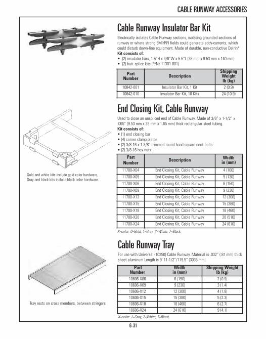
6-31
CABLE RUNWAY ACCESSORIES
X=color: 0=Gold, 1=Gray, 2=White, 7=Black.
End Closing Kit, Cable RunwayUsed to close an unspliced end of Cable Runway. Made of 3/8” x 1-1/2” x.065” (9.53 mm x 38 mm x 1.65 mm) thick rectangular steel tubing.Kit consists of:• (1) end closing bar• (4) corner clamp plates• (2) 3/8-16 x 1 3/8” trimmed round head square neck bolts• (2) 3/8-16 hex nuts
Cable Runway Insulator Bar KitElectrically isolates Cable Runway sections, isolating grounded sections ofrunway or where strong EMI/RFI fields could generate eddy-currents, whichcould disturb down-line equipment. Made of durable, non-conductive Delrin®
Kit consists of:• (2) insulator bars, 1.5”H x 3/8”W x 5.5”L (38 mm x 9.53 mm x 140 mm) • (2) butt-splice kits (P/N/ 11301-001)
PartNumber Description
ShippingWeightlb (kg)
10842-001 Insulator Bar Kit, 1 Kit 2 (0.9)10842-010 Insulator Bar Kit, 10 Kits 24 (10.9)
PartNumber Description Width
in (mm)
11700-X04 End Closing Kit, Cable Runway 4 (100)
11700-X05 End Closing Kit, Cable Runway 5 (130)
11700-X06 End Closing Kit, Cable Runway 6 (150)
11700-X09 End Closing Kit, Cable Runway 9 (230)
11700-X12 End Closing Kit, Cable Runway 12 (300)
11700-X15 End Closing Kit, Cable Runway 15 (380)
11700-X18 End Closing Kit, Cable Runway 18 (460)
11700-X20 End Closing Kit, Cable Runway 20 (510)
11700-X24 End Closing Kit, Cable Runway 24 (610)
PartNumber
Widthin (mm)
Shipping Weightlb (kg)
10606-X06 6 (150) 2 (0.9)10606-X09 9 (230) 3 (1.4)10606-X12 12 (300) 4 (1.8)10606-X15 15 (380) 5 (2.3)10606-X18 18 (460) 6 (2.7)10606-X24 24 (610) 9 (4.1)
X=color: 1=Gray, 2=White, 7=Black
Cable Runway TrayFor use with Universal (10250) Cable Runway. Material is .032” (.81 mm) thicksheet aluminum Length is 9’ 11-1/2”/119.5” (3035 mm).
Tray rests on cross members, between stringers
Gold and white kits include gold color hardware,Gray and black kits include black color hardware.

6-32
CABLE RUNWAY ACCESSORIES
12 oz (340 g)pressurized can
1 oz (30 g) bottle with applicator
Touch-Up Paint In BottleAir dry waterborne paint for touching up finish. Matches color and gloss ofCPI’s textured paint.
Touch-Up Paint In Spray CanAir dry lacquer for touching up finish. Matches color and gloss of CPI’stextured paint; Air dries to hard finish in minutes
PartNumber Description
ShippingWeightlb (kg)
11268-001 “L” Bracket 1 (0.5)
“L” Bracket, Cable RunwayBracket provides a separate facility for running power conductors or othercables that should be physically separated from main cables.• Made of 1/8” x 1” (3.18 mm x 30 mm) steel; gold finish/color over zincplating
Kit consists of (1):• Bracket for 1-1/2” stringer• 1/4-20 x 3/4” hex bolt
PartNumber
Descriptionin (mm)
ShippingWeightlb (kg)
10642-001 For 1-1/2 x 3/8 (38 x 9.53) Stringer 1 (0.5)
10757-001 For 2 x 3/8 (50 x 9.53) Auxiliary Bar 1 (0.5)
Protective End Caps For RunwayCovers and protects exposed ends of cable runway and auxiliary framing barand channel. Reduces chances of personal injury and equipment damage.• Made of fire-retardant flat black colored rubberized material • Sold in pairs
PartNumber
Descriptionoz (g)
ShippingWeightlb (kg)
25400-X 00 12 (340) Spray Can 2 (0.9)
PartNumber
Descriptionoz (g)
ShippingWeightlb (kg)
25401-X00 1 (30) Bottle 2 (0.9)
X=color: 1=Gray, 2=White, 7=Black
X=color: 1=Gray, 2=White, 7=Black
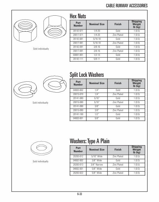
6-33
CABLE RUNWAY ACCESSORIES
Sold individually
Sold individually
Sold individually
PartNumber Nominal Size Finish
ShippingWeightlb (kg)
20283-012 5/16” Wide Zinc Plated 1 (0.5)
04002-002 3/8” Wide Gold 1 (0.5)
20283-013 3/8” Narrow Zinc Plated 1 (0.5)
04002-001 5/8” Wide Gold 1 (0.5)
20283-022 5/8” Wide Zinc Plated 1 (0.5)
Washers: Type A Plain
PartNumber Nominal Size Finish
ShippingWeightlb (kg)
04003-002 1/4” Gold 1 (0.5)
20015-070 1/4” Zinc Plated 1 (0.5)
20141-080 5/16” Gold 1 (0.5)
20015-080 5/16” Zinc Plated 1 (0.5)
20141-090 3/8” Gold 1 (0.5)
20015-090 3/8” Zinc Plated 1 (0.5)
20141-100 1/2” Gold 1 (0.5)
04003-001 5/8” Gold 1 (0.5)
Split Lock Washers
PartNumber Nominal Size Finish
ShippingWeightlb (kg)
20142-071 1/4-20 Gold 1 (0.5)
20017-071 1/4-20 Zinc Plated 1 (0.5)
20142-081 5/16-18 Gold 1 (0.5)
20017-081 5/16-18 Zinc Plated 1 (0.5)
20142-091 3/8-16 Gold 1 (0.5)
20017-091 3/8-16 Zinc Plated 1 (0.5)
03001-001 1/2-13 Gold 1 (0.5)
20142-111 5/8-11 Gold 1 (0.5)
Hex Nuts

6-34
CABLE RUNWAY ACCESSORIES
Sold individually
Hex Cap BoltsAlso called Washer Faced Hex Cap Screws. Commercial grade. Zinc plate orgold finish
PartNumber
NominalSize Finish Length
20290-106 1/4-20 Zinc Plated 3/4”
20290-118 1/4-20 Zinc Plated 2-1/4”
20290-216 5/16-18 Zinc Plated 2”
20290-307 3/8-16 Zinc Plated 7/8”
02004-001 3/8-16 Gold 1-1/4”
02004-002 1/4-20 Gold 1-1/4”
02004-003 1/2-13 Gold 1-1/2”
02004-004 3/8-16 Gold 1-1/2”
02004-005 1/2-13 Gold 1-3/4”
02004-006 5/8-11 Gold 1-1/4”
02004-007 5/8-11 Gold 3-1/4”
Hex Lag ScrewUsed to install racks onto wood or other soft surfaces. Gold over zinc platefinish
PartNumber Nominal Size Length
ShippingWeightlb (kg)
02006-001 1/2-6 2” 1 (0.5)
02006-002 5/8-5 2” 1 (0.5)
02007-004 1/4-10 2” 1 (0.5)
20098-832 3/8-7 2” 1 (0.5)

ONTRAC® WIRE MESH CABLE TRAY SYSTEM
Part Number & Nominal Dimensions Cable Fill Area ShippingWeightlb (kg)Pre-
Galvanized* Black Paint Zinc Plate** Heightin (mm)
Widthin (mm) in2 mm2
34811-604 34811-704 34811-504 2 (50) 4 (100) 7.8 4 999 11 (5.0)34811-606 34811-706 34811-506 2 (50) 6 (150) 11.3 7 258 12 (5.4)34811-608 34811-708 34811-508 2 (50) 8 (200) 15.2 9 798 14 (6.4)34811-612 34811-712 34811-512 2 (50) 12 (300) 23.1 14 879 17 (7.7)34811-616 34811-716 34811-516 2 (50) 16 (400) 31.3 20 161 20 (9.1)34811-618 34811-718 34811-518 2 (50) 18 (450) 35.3 22 741 21 (9.5)34811-620 34811-720 34811-520 2 (50) 20 (500) 38.8 25 040 23 (10.6)34811-624 34811-724 34811-524 2 (50) 24 (600) 47.7 30 766 26 (11.8)34821-604 34821-704 34821-504 4 (100) 4 (100) 14.6 9 419 14 (6.4)34821-606 34821-706 34821-506 4 (100) 6 (150) 22.5 14 516 16 (7.3)34821-608 34821-708 34821-508 4 (100) 8 (200) 30.3 19 548 18 (8.7)34821-612 34821-712 34821-512 4 (100) 12 (300) 46.1 29 741 21 (8.5)34821-616 34821-716 34821-516 4 (100) 16 (400) 61.8 39 870 24 (10.9)34821-618 34821-718 34821-518 4 (100) 18 (450) 69.7 44 967 25 (11.3)34821-620 34821-720 34821-520 4 (100) 20 (500) 78.3 50 516 27 (12.2)34821-624 34821-724 34821-524 4 (100) 24 (600) 95.3 61 483 30 (13.6)34831-608 34831-708 34831-508 6 (150) 8 (200) 45.6 29 395 22 (10.0 34831-612 34831-712 34831-512 6 (150) 12 (300) 69.1 44 580 25 (11.3)34831-616 34831-716 34831-516 6 (150) 16 (400) 92.8 59 870 28 (12.7)34831-618 34831-718 34831-518 6 (150) 18 (450) 104.6 67 483 29 (13.2)34831-620 34831-720 34831-520 6 (150) 20 (500) 116.4 75 096 31 (14.1)34831-624 34831-724 34831-524 6 (150) 24 (600) 143.0 92 257 34 (15.4)
OnTrac® Wire Mesh Cable Tray SystemCPI’s OnTrac® Wire Mesh Cable Tray System creates point-to-point pathwaysfor network cabling in data centers, network equipment rooms and officespaces. The OnTrac Wire Mesh Cable Tray System can be cut and formed intosmooth turns and transitions easily adapting to most locations. The trayprovides excellent load bearing capability and protection for cables and is ULClassified for suitability as an equipment grounding conductor. Choose fromvarious supports to attach the tray to the ceiling, wall or under access floors tocreate a pathway for network cables.
Features:• Constructed from 5 mm and 6 mm diameter steel wires, welded on 2” x 4” (50 mm x 100 mm) intersections
• Available in three heights 2” (50 mm), 4” (100 mm) and 6” (150 mm) andvarious widths in standard 10’L (3 m) sections
• Cut and bend to form smooth curved transitions around obstacles• UL Classified for suitability as an equipment grounding conductor only. • Pre-galvanized, Black powder coat paint finish or Zinc ELectroplate*• Side walls are 2” (50 mm), 4” (100 mm) and 6”H (150 mm) to supportdifferent cable fill capacities
*Pre-galvanized is UL Classified in US only. **Longer lead times when ordering Zinc Electroplate part numbers.
6-35

6-36
ONTRAC® WIRE MESH CABLE TRAY ACCESSORIES
OnTrac® Wire Mesh Tray AccessoriesStandard Splice KitUse to connect sections of cable tray together end-to-end, at intersectionsand turns. Each splice kit includes: a stamped washer with a fixed screw, acontoured splice washer and a flange nut. The two splice halves wrap aroundadjacent wires connecting the tray together.
Splice Washer & Bolt KitUse with Splice Bar (P/N 34739-X01) to connect trays together end-to-end forsecuring to ceiling, wall and access floor supports or to attach accessories.Includes splice washers, carriage bolts and a flange nuts.
Splice BarUse with splices from the Splice Washer & Boklt Kit (P/N 34728-X01) to createsecure end-to-end connection between cable tray sections. Attaches to theside of the tray using three splice washers from the Splice Washer & Bolt Kit(P/N 34728-X01). Recommended for all trays that are 18”W (450 mm) or wider.Manufactured from steel; 10.8”L (274.6 mm).
Clamp WasherSecurely fasten two layers of wire mesh when connecting trays at 90° bendsor intersections or to attach tray to support. Attaches to the tray using acarriage bolt and flange nut from P/N 34728-X02.
Carriage Bolt Hardware Use with Clamp Washer to connect wire mesh trays together. Includescarriage bolt and flange nut. Use to attach dividers and horizontal radiustogether.
90˚ Splice Bar Kit Create a secure 90° T- or L-shaped intersection between two cable traysections. Kit includes all hardware needed to make one 90° intersections (two90° Splice Bars, eight contoured splice washers, four Clamp Washers and ten1/4-20 x 3/4”L carriage bolts and flange nut. 90° T-shaped or two L-shapedsplice bars are manufactured from steel; 5 31/32” (152 mm).
Part Number & FinishDescription
ShippingWeightlb (kg)Black Zinc
34738-701 34738-501 Standard Splice Kit, Pack of 50 11 (5.0)
34728-701 34728-501 Splice Washer & Bolt, Pack of 50 2 (0.9)
34739-701 34739-501 Splice Bar, Pack of 50 12 (5.4)
34746-701 34746-501 Clamp Washer, Pack of 25 2 (0.9)
34728-702 34728-502 Carriage Bolt Washer, Pack of 50 2 (0.9)
34740-701 34740-501 90˚ Splice Bar Kit 2 (0.9)34740-X01
34728-X02
34739-X01
34728-X01
34738-X01
34746-X01
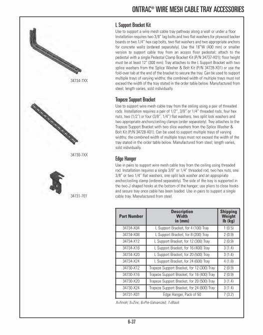
6-37
ONTRAC® WIRE MESH CABLE TRAY ACCESSORIES
L Support Bracket KitUse to support a wire mesh cable tray pathway along a wall or under a floorInstallation requires two 3/8” lag bolts and two flat washers for plywood backerboards or two 1/4” hex cap bolts, two flat washers and two appropriate anchorsfor concrete walls (ordered separately). Use the 16”W (400 mm) or smallerversion to support cable tray from an access floor pedestal; attach to thepedestal with a single Pedestal Clamp Bracket Kit (P/N 34737-X01); floor heightmust be at least 12” (300 mm). Tray attaches to the L Support Bracket with twosplice washers from the Splice Washer & Bolt Kit (P/N 34728-X01) or use thefold-over tab at the end of the bracket to secure the tray. Can be used to supportmultiple trays of varying widths; the combined width of multiple trays must notexceed the width of the tray stated in the order table below. Manufactured fromsteel; length varies, sold individually.
Trapeze Support BracketUse to support wire mesh cable tray from the ceiling using a pair of threadedrods. Installation requires a pair of 1/2”, 3/8” or 1/4” threaded rods, four hexnuts, two (1/2”) or four (3/8”, 1/4”) flat washers, two split lock washers andtwo appropriate anchors/ceiling clamps (order separately). Tray attaches to theTrapeze Support Bracket with two slice washers from the Splice Washer &Bolt Kit (P/N 34728-X01). Can be used to support multiple trays of varyingwidths; the combined width of multiple trays must not exceed the width of thetray stated in the order table below. Manufactured from steel; length varies,sold individually.
Edge HangerUse in pairs to support wire mesh cable tray from the ceiling using threadedrod. Installation requires a single 3/8” or 1/4” threaded rod, two hex nuts, one3/8” or two 1/4” flat washers, one split lock washer and an appropriateanchor/ceiling clamp (ordered separately). The side of the tray is supported inthe two J-shaped hooks at the bottom of the hanger; use pliers to close hooksand secure tray once cable has been loaded. Use in pairs to support a singlecable tray. Manufactured from steel.
Part Number Description
Widthin (mm)
ShippingWeightlb (kg)
34734-X04 L Support Bracket, for 4 (100) Tray 1 (0.5)
34734-X08 L Support Bracket, for 8 (200) Tray 2 (0.9)
34734-X12 L Support Bracket, for 12 (300) Tray 2 (0.9)
34734-X16 L Support Bracket, for 16 (400) Tray 3 (1.4)
34734-X20 L Support Bracket, for 20 (500) Tray 3 (1.4)
34734-X24 L Support Bracket, for 24 (600) Tray 4 (1.8)
34730-X12 Trapeze Support Bracket, for 12 (300) Tray 2 (0.9)
34730-X16 Trapeze Support Bracket, for 16 (400) Tray 2 (0.9)
34730-X20 Trapeze Support Bracket, for 20 (500) Tray 3 (1.4)
34730-X24 Trapeze Support Bracket, for 24 (600) Tray 3 (1.4)
34731-X01 Edge Hanger, Pack of 50 7 (3.2)
X=finish; 5=Zinc, 6=Pre-Galvanized, 7=Black
34734-7XX
34730-7XX
34731-701

6-38
ONTRAC® WIRE MESH CABLE TRAY ACCESSORIES
Center Support BracketUse to support wire mesh cable tray from the ceiling with a single 3/8”threaded rod. Tray attaches to the Center Support Bracket with two splicewashers from the Splice Washer & Bolt Kit (P/N 34728-X01) or use fold-overtabs to secure the tray on all sizes except the 4”W (100 mm) version. Used tosupport a single cable tray. Manufactured from steel; length varies, soldindividually.
Triangle Support BracketUse to support a wire mesh cable tray pathway along a wall. Installationrequires two 3/8” lag bolts and two flat washers for plywood backer boards ortwo 1/4” hex cap bolts, two flat washers and two appropriate anchors forconcrete walls (ordered separately). Tray attaches to the Triangle SupportBracket with two splice washers from the Splice Washer & Bolt Kit (P/N34728-X01) or use the fold-over tab at the end of the bracket to secure thetray. Manufactured from steel; height and length vary, sold individually.
Wall-Mount AngleUse to support the end of wire mesh cable tray against the wall. Installationrequires two 1/4” lag bolts and two flat washers for plywood backer boards ortwo 1/4” hex cap bolts, two flat washers and two appropriate anchors forconcrete walls (ordered separately). Tray attaches to the Wall-Mount Anglewith two splice washers from the Splice Washer & Bolt Kit (P/N 34728-X01).Manufactured from steel; length varies, sold individually.
Part Number Description
Widthin (mm)
ShippingWeightlb (kg)
34729-X04* Center Support Bracket, for 4 (100) Tray 1 (0.5)
34729-X08* Center Support Bracket, for 8 (200) Tray 1 (0.5)
34729-X12* Center Support Bracket, for 12 (300) Tray 2 (0.9)
34729-X16* Center Support Bracket, for 16 (400) Tray 2 (0.9)
34729-X20* Center Support Bracket, for 20 (500) Tray 2 (0.9)
34729-X24* Center Support Bracket, for 24 (600) Tray 3 (1.4)
34733-X04 Triangle Support Bracket, for 4 (100) Tray 1 (0.5)
34733-X08 Triangle Support Bracket, for 8 (200) Tray 1 (0.5)
34733-X12 Triangle Support Bracket, for 12 (300) Tray 2 (0.9)
34733-X16 Triangle Support Bracket, for 16 (400) Tray 2 (0.9)
34733-X20 Triangle Support Bracket, for 20 (500) Tray 3 (1.4)
34733-X24 Triangle Support Bracket, for 24 (600) Tray 4 (1.8)
34735-X08** Wall Mount Angle, for 8 (200) Tray 1 (0.5)
34735-X12** Wall Mount Angle, for 12 (300) Tray 1 (0.5)
34735-X16** Wall Mount Angle, for 16 (400) Tray 1 (0.5)
34735-X20** Wall Mount Angle, for 20 (500) Tray 2 (0.9)
34735-X24** Wall Mount Angle, for 24 (600) Tray 2 (0.9)
X=finish; 5=Zinc, 6=Pre-Galvanized, 7=Black* Available in Zinc & Black Finishes only.**Available in Pre-Galvanized & Black Finishes only.
34729-7XX
34733-7XX
34735-7XX

6-39
ONTRAC® WIRE MESH CABLE TRAY ACCESSORIES
Pedestal Clamp BracketUse with the L Support Bracket to support wire mesh cable tray from accessfloor pedestals under an access floor. Use one Pedestal Clamp Bracket toattach a 16”W (400 mm) or smaller L Support Bracket to an access floorpedestal; floor height must be at least 12” (300 mm). Manufactured from steel;sold individually.
Pedestal Clamp Bracket KitUse to support wire mesh cable tray from adjacent access floor pedestals. Kitincludes two Pedestal Clamp Brackets, a tray support bracket, and installationhardware. Tray attaches to the tray support bracket with two splice washersfrom the Splice Washer & Bolt Kit (P/N 34728-X01). Can be used to supportmultiple trays of varying widths with a combined width up to 20”W Traysupport bracket is manufactured from steel; sold individually.
Rack-Mount HookUse to attach wire mesh cable tray to the top of a two-post or four-post CPIRack System. Includes a Clamp Washer with a hook that attaches to the L-shaped top angle on CPI Rack Systems. Attach tray to the top of the rack inthe parallel (side-to-side) or perpendicular (front-to-back) orientation; parallelalignment may not be centered over the rack. Hook is manufactured fromsteel; sold in packs of 4.
Under Floor Support Use to support wire mesh cable tray from the floor under an access floor.Attaches to the floor with 1/4” hardware or adhesive. Tray attaches to theUnder Floor Support with a splice washer from the Splice Washer & Bolt Kit(P/N 34728-X01). Under Floor Supports can be used in pairs to support widertrays. Manufactured from steel; width, height and depth vary – see the ordertable below, sold individually.
Part Number DescriptionH x W x Din (mm)
ShippingWeightlb (kg)Finish
34737-501 Pedestal Clamp Bracket, Zinc 1 (0.5)
34737-502 Pedestal Clamp Bracket Kit, Zinc 4 (1.8)
34732-701 Rack-Mount Hook, Pack of 4, Black 1 (0.5)
34736-X43Under Floor Support, 3 x 4 x 7
(75 x 100 x 180)1 (0.5)
34736-X46 Under Floor Support, 6 x 4 x 8.6 (150 x 100 x 218) 2 (0.9)
34736-X83 Under Floor Support, 3 x 8 x 7 (75 x 200 x 180) 2 (0.9)
34736-X86 Under Floor Support, 6 x 8 x 8.6 (150 x 200 x 218) 3 (1.4)
34736-X89 Under Floor Support, 9 x 8 x 10.2(225 x 200 x 260) 4 (1.8)
34737-501
34737-502
34732-701
34736-7XX
X=finish; 6=Pre-Galvanized, 7=Black

34839-001
6-40
ONTRAC® WIRE MESH CABLE TRAY ACCESSORIES
Cable Tray DividerUse to divide the internal area of a section of wire mesh cable tray to organizecables by type or zone. Hemmed top edge protects cables. Plain galvanizedfinish (cannot be painted), includes two 5’L (1.5 m) sections.
Cable Tray CoverUse to cover the top of a section of wire mesh cable tray to protect or hidecables. Hemmed edges protect the installer. Attaches to the tray with fold-overtabs formed along the edge of the cover; bend the tabs over the top wire onthe tray using a flat edge screwdriver. Plain galvanized finish (cannot bepainted), includes two 5’L (1.5 m) sections.
Cable Tray Bottom InsertUse to cover the bottom of a section of wire mesh cable tray to protect or hidecables. Plain galvanized finish (cannot be painted), includes two 5’L (1.5 m)sections.
Cable Tray Bolt Style Cutting ToolUse to cut wire mesh cable tray to fit and form pieces to match pathwayrequirements, has angled head to allow clear view while cutting.
PartNumber
DescriptionH x W x Din (mm)
ShippingWeightlb (kg)
34743-502 Cable Tray Divider, for 2 (50) Tray 3 (1.4)
34743-504 Cable Tray Divider, for 4 (100) Tray 5 (2.3)
34743-506 Cable Tray Divider, for 6 (150) Tray 7 (3.2)
34744-5XX* Cable Tray Cover 2 (0.9)
34745-5XX* Cable Tray Bottom Insert 4 (1.8)
34839-001 Cable Tray Bolt Style Cutting Tool 6 (2.7)
*P/Ns 34744-5XX and 34745-5XX available in all tray sizes; -X04 (4”, 100 mm), -X06(6”, 150 mm). -X08 (8”, 200 mm), -X12 (12”, 300 mm), -X16 (16”, 400 mm), -X18 (18”,450 mm), -X20 (20”, 500 mm), -X24 (24”, 600 mm). Shipping Weights for 4” Tray.
34743-50X
34744-5XX
34745-5XX

6-41
ONTRAC® WIRE MESH CABLE TRAY ACCESSORIES
Tool-Less Radius DropUse to properly support cables as they exit or enter cable tray pathways.Provides a wide radius featuring tool-less attachment that requires no cuttingof the tray during installation. Secure cables through slots in the radius dropwith cable straps or ties. Attaches to the bottom of the tray with bendabletabs that lock the radius drop in place. Can also be attached to the bottomof the tray with a splice washer from the Splice Washer & Bolt Kit(P/N 34728-X01). Manufactured from steel; sold individually.
Large Radius DropUse to properly support cables as the cables exit or enter cable tray pathways.Secure cables through slots in the radius drop with cable straps or ties. Attachesto the bottom or side of the tray with two splice washers from the Splice Washer& Bolt Kit (P/N 34728-X01). Manufactured from steel; sold individually.
Split Bolt Grounding ClampUse to attach a ground conductor to wire mesh cable tray. Split bolt attachesover the wires that form the tray. Slot accommodates #6 AWG wire; removepaint from tray for ground contact. Manufactured from bronze alloy and copper1.5”L (38 mm).
Label HolderUse to label a section of wire mesh cable tray to identify the pathway or adrop location. Attaches to the side or bottom of the tray.
PartNumber Description
ShippingWeightlb (kg)
34741-X01 Tool-Less Radius Drop 1 (0.5)
34747-X01 Large Radius Drop 1 (0.5)
34838-001 Split Bolt Grounding Clamp, Pack of 10 1 (0.5)
34749-001 Label Holder, Pack of 10 1 (0.5)
34741-701
34747-701
34838-001
34749-001
X=finish; 5=Zinc, 7=Black

POWER MANAGEMENT PRODUCTSPower Strips & Power Distribution Units for Racks & Cabinets
Overview Page 7-3Vertical Power Strips - Cabinets Page 7-5Vertical Power Strips - Racks Page 7-6Horizontal Power Strips Page 7-7Vertical Power Strips - Basic Page 7-8Power Distribution Units - Vertical Page 7-10Power Distribution Units - Horizontal Page 7-11Mounting Brackets Page 7-13PowerScope In-Line Meter Page 7-14
7-2
POWER MANAGEMENT PRODUCTSPower Management Products are designed to fully integrate into a CPI Rack System (Section 1)or Cabinet and Enclosure System (Section 2), delivering electrical power to support a wide array of active equipment and provide reliable, efficient distribution of power.
CPI has a large variety of sizes and configurations available to meet almost any need. For basicapplications with lower power requirements and where remote monitoring is not required, useCPI’s rack-mount Power Strips to distribute power to equipment. In data center, computer andequipment room applications, use CPI’s rack-mount Power Distribution Units (PDUs) todistribute power to equipment and remotely monitor power, temperature and humidityconditions. To upgrade existing PDUs with remote monitoring, select CPI’s PowerScope In-LinePower Meter.
CPI Power Management Products include:Power Strips – Vertical and Horizontal Rack-Mount Configurations• Optional circuit breakers, surge protection and local meters• Single-Input, Single-Phase models for circuits rated up to 20 Amperes• NEMA-NEMA plug-to-receptacle combinations• UL Listed
Power Distribution Units (PDUs) – Vertical and Horizontal Rack-Mount Configurations• Four progressive feature levels: Basic, Metered, Monitored and Controlled• Optional circuit breakers, local meters, remote monitoring and remote power cycling• Monitored and Controlled models integrate with CPI’s Scalable Enterprise Management Application (SEMA) software (Section 10) which provides simplified web-based, multi-sitemonitoring
• Single-Input models for circuits rated up to 60 Amperes• Single-Phase and Three-Phase plugs• NEMA-NEMA, NEMA-IEC, and IEC-IEC plug-to-receptacle combinations• UL Listed
PowerScope In-Line Power Meter• Upgrade existing basic and metered PDUs with remote monitoring• Remote monitoring of current use, temperature and humidity• Optional local meters• Single-Input and Dual-Input models• Single-Phase and Three-Phase plugs
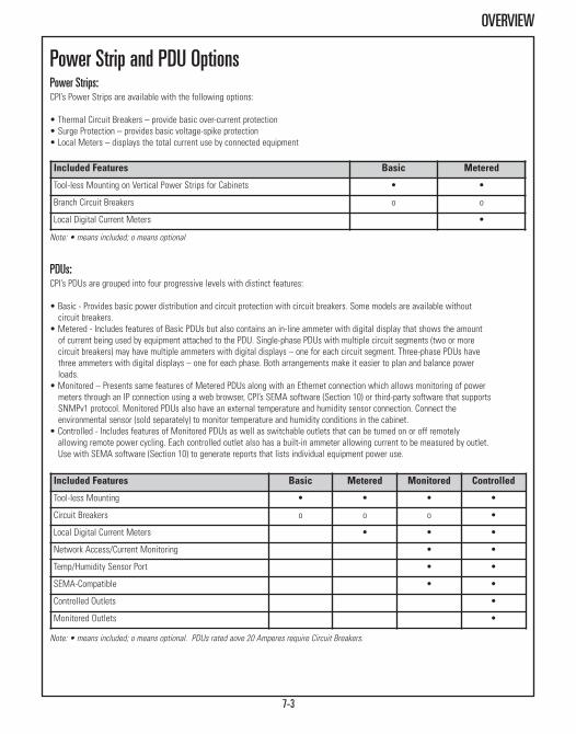
7-3
OVERVIEW
Power Strip and PDU OptionsPower Strips:CPI’s Power Strips are available with the following options:
• Thermal Circuit Breakers – provide basic over-current protection• Surge Protection – provides basic voltage-spike protection• Local Meters – displays the total current use by connected equipment
Included Features Basic Metered
Tool-less Mounting on Vertical Power Strips for Cabinets • •
Branch Circuit Breakers o o
Local Digital Current Meters •
Note: • means included; o means optional
PDUs:CPI’s PDUs are grouped into four progressive levels with distinct features:
• Basic - Provides basic power distribution and circuit protection with circuit breakers. Some models are available without circuit breakers.
• Metered - Includes features of Basic PDUs but also contains an in-line ammeter with digital display that shows the amount of current being used by equipment attached to the PDU. Single-phase PDUs with multiple circuit segments (two or morecircuit breakers) may have multiple ammeters with digital displays – one for each circuit segment. Three-phase PDUs havethree ammeters with digital displays – one for each phase. Both arrangements make it easier to plan and balance powerloads.
• Monitored – Presents same features of Metered PDUs along with an Ethernet connection which allows monitoring of powermeters through an IP connection using a web browser, CPI’s SEMA software (Section 10) or third-party software that supportsSNMPv1 protocol. Monitored PDUs also have an external temperature and humidity sensor connection. Connect theenvironmental sensor (sold separately) to monitor temperature and humidity conditions in the cabinet.
• Controlled - Includes features of Monitored PDUs as well as switchable outlets that can be turned on or off remotelyallowing remote power cycling. Each controlled outlet also has a built-in ammeter allowing current to be measured by outlet.Use with SEMA software (Section 10) to generate reports that lists individual equipment power use.
Included Features Basic Metered Monitored Controlled
Tool-less Mounting • • • •
Circuit Breakers o o o •
Local Digital Current Meters • • •
Network Access/Current Monitoring • •
Temp/Humidity Sensor Port • •
SEMA-Compatible • •
Controlled Outlets •
Monitored Outlets •
Note: • means included; o means optional. PDUs rated aove 20 Amperes require Circuit Breakers.

7-4
ORDERING INFORMATION
Plug/Inlet & Outlet Recognition Table
NEMA L5-15P NEMA L5-20P NEMA L5-30P NEMA L6-20P NEMA L6-30P
125VAC/15A 125VAC/20A 125VAC/30A 250VAC/20A 250VAC/30A
NEMA 5-15P NEMA 5-20P NEMA 6-20P
125VAC/15A 125VAC/20A 250VAC/20A
IEC 60320 C-13/C-14 IEC 60320 C-19/C-20 IEC 60309/3-WIRE
UL-125/250 VAC/15ACE-230 VAC/10A
UL-125/250 VAC/20ACE-230 VAC/16A
250VAC/16-32A
Straight Plugs
Locking Plugs(Single-Phase)
Locking Plugs(Three-Phase)
Power Receptacles
IEC Power Outlet/Inlet
NEMA L21-20P
120/208 VAC/20A
NEMA L15-30P
250VAC/30A
NEMA L21-30P
120/208 VAC/30A
CS 3P/4W
250V/50A
NEMA 5-15R
125VAC/15A
NEMA 5-20R
125VAC/20A
NEMA 6-20R
250VAC/20A
NEMA L15-30R
250 VAC/30A
IEC 60309/4-WIRE
250 VAC/60A
NEMA L6-20R
250 VAC/20A
2 P+E 3 P+E
NEMA L15-20P
250VAC/20A
Please note the following:• PDUs may have one or two styles of outlets; use this diagram of plugs and outlets to aid in product selection• Carefully note circuit breaker configurations on models rated over 20 Amperes; total current available to equipment may be limited by the circuit breaker configuration; outlets are evenly divided between circuit breakers
If you do not see the configuration that you need, please contact CPI Technical Support for assistance.

VERTICAL POWER STRIPS - CABINETS
7-5
See page 7-4 for plug definitions. Continued on next page.
PartNumber
Input Output Dims - in (mm)
Amp kW Plug Breakers Outlets H W D
110-125 Volt, Single-Phase Power Strip12850-701 15 1.4 NEMA 5-15P 1 x 15A (10) 5-15R 38.5 (978) 1.6 (41) 1.6 (41)
12848-701 15 1.4 NEMA 5-15P 1 x 15A (20) 5-15R 66.3 (1683) 1.6 (41) 1.6 (41)
12850-723 20 1.9 NEMA 5-20P No (10) 5-20R 38.5 (978) 1.6 (41) 1.6 (41)
12850-705 20 1.9 NEMA 5-20P 1 x 20A (10) 5-20R 38.5 (978) 1.6 (41) 1.6 (41)
12848-705 20 1.9 NEMA 5-20P 1 x 20A (20) 5-20R 66.3 (1683) 1.6 (41) 1.6 (41)
12850-707 20 1.9 NEMA L5-20P 1 x 20A (10) 5-20R 38.5 (978) 1.6 (41) 1.6 (41)
12848-707 20 1.9 NEMA L5-20P 1 x 20A (20) 5-20R 66.3 (1683) 1.6 (41) 1.6 (41)
110-125 Volt, Single-Phase Power Strip, Surge-Protected12850-702 15 1.4 NEMA 5-15P 1 x 15A (10) 5-15R 38.5 (978) 1.6 (41) 1.6 (41)
12848-702 15 1.4 NEMA 5-15P 1 x 15A (20) 5-15R 66.3 (1683) 1.6 (41) 1.6 (41)
12850-706 20 1.9 NEMA 5-20P 1 x 20A (10) 5-20R 38.5 (978) 1.6 (41) 1.6 (41)
12848-706 20 1.9 NEMA 5-20P 1 x 20A (20) 5-20R 66.3 (1683) 1.6 (41) 1.6 (41)
12850-708 20 1.9 NEMA L5-20P 1 x 20A (10) 5-20R 38.5 (978) 1.6 (41) 1.6 (41)
12848-708 20 1.9 NEMA L5-20P 1 x 20A (20) 5-20R 66.3 (1683) 1.6 (41) 1.6 (41)
Vertical Power Strips• 100-125 Volt, single-phase power strips• Available in two heights:- 66.3”H (1683 mm) with 20 outlets- 38.5”H (978 mm) with 10 outlets
• Thermal circuit breaker, NEMA plug, NEMA outlets• 10’L (3 m) attached power cord• Metered models include an ammeter with digital display• Optional surge protection• Cabinet versions include mounting brackets for M-Series MegaFrame and C-Series SlimFrame Cabinets and tool-less buttons for accessory power strip mounting brackets
• Rack versions include 6.5”D (165 mm) Offset Rack-Mount Brackets for Rack Systems• Other mounting brackets available as separate accessories
Part Number
Input Output Dims - in (mm)
Amp kW Plug Breakers Outlets H W D110-125 Volt, Single-Phase Power Strip
12848-755 20 1.9 NEMA 5-20P 1 x 20A (20) 5-20R 66.3 (1683) 1.6 (41) 1.6 (41)
12848-757 20 1.9 NEMA L5-20P 1 x 20A (20) 5-20R 66.3 (1683) 1.6 (41) 1.6 (41)
110-125 Volt, Single-Phase Power Strip, Surge-Protected12848-756 20 1.9 NEMA 5-20P 1 x 20A (20) 5-20R 66.3 (1683) 1.6 (41) 1.6 (41)
12848-758 20 1.9 NEMA L5-20P 1 x 20A (20) 5-20R 66.3 (1683) 1.6 (41) 1.6 (41)
Basic Power Strips, Vertical Mount for Cabinets
Metered Power Strips, Vertical Mount for Cabinets

VERTICAL POWER STRIPS - RACKS
7-6
See page 7-4 for plug definitions. Continued on next page.
PartNumber
Input Output Dims - in (mm)
Amp kW Plug Breakers Outlets H W D
110-125 Volt, Single-Phase Power Strip
12853-701 15 1.4 NEMA 5-15P 1 x 15A (10) 5-15R 38.5 (978) 1.6 (41) 1.6 (41)
12851-701 15 1.4 NEMA 5-15P 1 x 15A (20) 5-15R 66.3 (1683) 1.6 (41) 1.6 (41)
12853-705 20 1.9 NEMA 5-20P 1 x 20A (10) 5-20R 38.5 (978) 1.6 (41) 1.6 (41)
12851-705 20 1.9 NEMA 5-20P 1 x 20A (20) 5-20R 66.3 (1683) 1.6 (41) 1.6 (41)
12853-707 20 1.9 NEMA L5-20P 1 x 20A (10) 5-20R 38.5 (978) 1.6 (41) 1.6 (41)
12851-707 20 1.9 NEMA L5-20P 1 x 20A (20) 5-20R 66.3 (1683) 1.6 (41) 1.6 (41)
110-125 Volt, Single-Phase Power Strip, Surge-Protected
12853-702 15 1.4 NEMA 5-15P 1 x 15A (10) 5-15R 38.5 (978) 1.6 (41) 1.6 (41)
12851-702 15 1.4 NEMA 5-15P 1 x 15A (20) 5-15R 66.3 (1683) 1.6 (41) 1.6 (41)
12853-706 20 1.9 NEMA 5-20P 1 x 20A (10) 5-20R 38.5 (978) 1.6 (41) 1.6 (41)
12851-706 20 1.9 NEMA 5-20P 1 x 20A (20) 5-20R 66.3 (1683) 1.6 (41) 1.6 (41)
12853-708 20 1.9 NEMA L5-20P 1 x 20A (10) 5-20R 38.5 (978) 1.6 (41) 1.6 (41)
12851-708 20 1.9 NEMA L5-20P 1 x 20A (20) 5-20R 66.3 (1683) 1.6 (41) 1.6 (41)
Basic Power Strips, Vertical Mount for Racks
Metered Power Strips, Vertical Mount for RacksPart
Number
Input Output Dims - in (mm)
Amp kW Plug Breakers Outlets H W D
110-125 Volt, Single-Phase Power Strip
12851-755 20 1.9 NEMA 5-20P 1 x 20A (20) 5-20R 66.3 (1683) 1.6 (41) 1.6 (41)
12851-757 20 1.9 NEMA L5-20P 1 x 20A (20) 5-20R 66.3 (1683) 1.6 (41) 1.6 (41)
110-125 Volt, Single-Phase Power Strip, Surge-Protected
12851-756 20 1.9 NEMA 5-20P 1 x 20A (20) 5-20R 66.3 (1683) 1.6 (41) 1.6 (41)
12851-758 20 1.9 NEMA L5-20P 1 x 20A (20) 5-20R 66.3 (1683) 1.6 (41) 1.6 (41)
12853-701

7-7
HORIZONTAL POWER STRIPS - 19”W EIA
See page 7-4 for plug definitions. Continued on next page.
PartNumber
Input Output Dims - in (mm)
Amp kW Plug Breakers Outlets H W D
110-125 Volt, Single-Phase Power Strip
12816-709 15 1.4 NEMA 5-15P No (8) 5-15R 1U 19"EIA 1.6 (41)
12816-701 15 1.4 NEMA 5-15P 1 x 15A (8) 5-15R 1U 19"EIA 1.6 (41)
12816-705 20 1.9 NEMA 5-20P 1 x 20A (8) 5-20R 1U 19"EIA 1.6 (41)
12816-706 20 1.9 NEMA L5-20P 1 x 20A (8) 5-20R 1U 19"EIA 1.6 (41)
110-125 Volt, Single-Phase Power Strip, Surge-Protected
12816-703 15 1.4 NEMA 5-15P 1 x 15A (8) 5-15R 1U 19"EIA 1.6 (41)
12816-707 20 1.9 NEMA 5-20P 1 x 20A (8) 5-20R 1U 19"EIA 1.6 (41)
12816-708 20 1.9 NEMA L5-20P 1 x 20A (8) 5-20R 1U 19"EIA 1.6 (41)
Basic Power Strips, Horizontal Rack-Mount
Horizontal Power Strips• 100-125 Volt, single-phase power strips• 19”EIA rack-mount, uses 1U of space• NEMA plug, NEMA outlets• 10’L (3 m) attached power cord• Optional thermal circuit breaker• Metered models include an ammeter with digital display• Optional surge protection
PartNumber
Input Output Dims - in (mm)
Amp kW Plug Breakers Outlets H W D
110-125 Volt, Single-Phase Power Strip
13239-756 20 1.9 NEMA L5-20P 1 x 20A (10) 5-20R 1U 19"EIA 4.5 (114)
110-125 Volt, Single-Phase Power Strip, Surge-Protected
13239-753 15 1.4 NEMA 5-15P 1 x 15A (10) 5-15R 1U 19"EIA 4.5 (114)
13239-757 20 1.9 NEMA 5-20P 1 x 20A (10) 5-20R 1U 19"EIA 4.5 (114)
Metered Power Strips, Horizontal Rack-Mount
12816-70713239-757
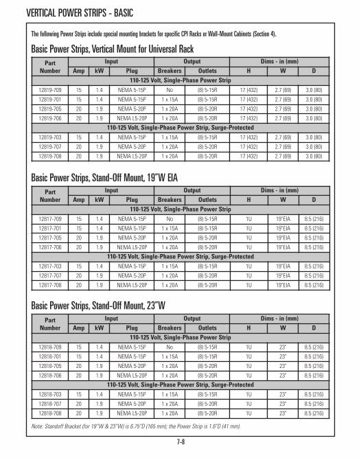
VERTICAL POWER STRIPS - BASIC
7-8
Basic Power Strips, Vertical Mount for Universal RackPart
NumberInput Output Dims - in (mm)
Amp kW Plug Breakers Outlets H W D110-125 Volt, Single-Phase Power Strip
12819-709 15 1.4 NEMA 5-15P No (8) 5-15R 17 (432) 2.7 (69) 3.0 (80)
12819-701 15 1.4 NEMA 5-15P 1 x 15A (8) 5-15R 17 (432) 2.7 (69) 3.0 (80)
12819-705 20 1.9 NEMA 5-20P 1 x 20A (8) 5-20R 17 (432) 2.7 (69) 3.0 (80)
12819-706 20 1.9 NEMA L5-20P 1 x 20A (8) 5-20R 17 (432) 2.7 (69) 3.0 (80)
110-125 Volt, Single-Phase Power Strip, Surge-Protected12819-703 15 1.4 NEMA 5-15P 1 x 15A (8) 5-15R 17 (432) 2.7 (69) 3.0 (80)
12819-707 20 1.9 NEMA 5-20P 1 x 20A (8) 5-20R 17 (432) 2.7 (69) 3.0 (80)
12819-708 20 1.9 NEMA L5-20P 1 x 20A (8) 5-20R 17 (432) 2.7 (69) 3.0 (80)
PartNumber
Input Output Dims - in (mm)Amp kW Plug Breakers Outlets H W D
110-125 Volt, Single-Phase Power Strip12817-709 15 1.4 NEMA 5-15P No (8) 5-15R 1U 19"EIA 8.5 (216)
12817-701 15 1.4 NEMA 5-15P 1 x 15A (8) 5-15R 1U 19"EIA 8.5 (216)
12817-705 20 1.9 NEMA 5-20P 1 x 20A (8) 5-20R 1U 19"EIA 8.5 (216)
12817-706 20 1.9 NEMA L5-20P 1 x 20A (8) 5-20R 1U 19"EIA 8.5 (216)
110-125 Volt, Single-Phase Power Strip, Surge-Protected12817-703 15 1.4 NEMA 5-15P 1 x 15A (8) 5-15R 1U 19"EIA 8.5 (216)
12817-707 20 1.9 NEMA 5-20P 1 x 20A (8) 5-20R 1U 19"EIA 8.5 (216)
12817-708 20 1.9 NEMA L5-20P 1 x 20A (8) 5-20R 1U 19"EIA 8.5 (216)
Basic Power Strips, Stand-Off Mount, 19”W EIA
PartNumber
Input Output Dims - in (mm)Amp kW Plug Breakers Outlets H W D
110-125 Volt, Single-Phase Power Strip12818-709 15 1.4 NEMA 5-15P No (8) 5-15R 1U 23" 8.5 (216)
12818-701 15 1.4 NEMA 5-15P 1 x 15A (8) 5-15R 1U 23" 8.5 (216)
12818-705 20 1.9 NEMA 5-20P 1 x 20A (8) 5-20R 1U 23" 8.5 (216)
12818-706 20 1.9 NEMA L5-20P 1 x 20A (8) 5-20R 1U 23" 8.5 (216)
110-125 Volt, Single-Phase Power Strip, Surge-Protected12818-703 15 1.4 NEMA 5-15P 1 x 15A (8) 5-15R 1U 23" 8.5 (216)
12818-707 20 1.9 NEMA 5-20P 1 x 20A (8) 5-20R 1U 23" 8.5 (216)
12818-708 20 1.9 NEMA L5-20P 1 x 20A (8) 5-20R 1U 23" 8.5 (216)
Basic Power Strips, Stand-Off Mount, 23”W
Note: Standoff Bracket (for 19”W & 23”W) is 6.75"D (165 mm); the Power Strip is 1.6"D (41 mm).
The following Power Strips include special mounting brackets for specific CPI Racks or Wall-Mount Cabinets (Section 4).

VERTICAL POWER STRIPS - BASIC
7-9
PartNumber
Input Output Dims - in (mm)
Amp kW Plug Breakers Outlets H W D
110-125 Volt, Single-Phase Power Strip
12820-709 15 1.4 NEMA 5-15P No (8) 5-15R 17 (432) 1.6 (41) 1.6 (41)
12820-701 15 1.4 NEMA 5-15P 1 x 15A (8) 5-15R 17 (432) 1.6 (41) 1.6 (41)
12820-705 20 1.9 NEMA 5-20P 1 x 20A (8) 5-20R 17 (432) 1.6 (41) 1.6 (41)
12820-706 20 1.9 NEMA L5-20P 1 x 20A (8) 5-20R 17 (432) 1.6 (41) 1.6 (41)
110-125 Volt, Single-Phase Power Strip, Surge-Protected
12820-703 15 1.4 NEMA 5-15P 1 x 15A (8) 5-15R 17 (432) 1.6 (41) 1.6 (41)
12820-707 20 1.9 NEMA 5-20P 1 x 20A (8) 5-20R 17 (432) 1.6 (41) 1.6 (41)
12820-708 20 1.9 NEMA L5-20P 1 x 20A (8) 5-20R 17 (432) 1.6 (41) 1.6 (41)
Basic Power Strips,for CUBE-iT PLUS® Cabinet System
PartNumber
Input Output Dims - in (mm)
Amp kW Plug Breakers Outlets H W D
110-125 Volt, Single-Phase Power Strip
12821-709 15 1.4 NEMA 5-15P No (8) 5-15R 17 (432) 1.6 (41) 1.6 (41)
12821-701 15 1.4 NEMA 5-15P 1 x 15A (8) 5-15R 17 (432) 1.6 (41) 1.6 (41)
12821-705 20 1.9 NEMA 5-20P 1 x 20A (8) 5-20R 17 (432) 1.6 (41) 1.6 (41)
12821-706 20 1.9 NEMA L5-20P 1 x 20A (8) 5-20R 17 (432) 1.6 (41) 1.6 (41)
110-125 Volt, Single-Phase Power Strip, Surge-Protected
12821-703 15 1.4 NEMA 5-15P 1 x 15A (8) 5-15R 17 (432) 1.6 (41) 1.6 (41)
12821-707 20 1.9 NEMA 5-20P 1 x 20A (8) 5-20R 17 (432) 1.6 (41) 1.6 (41)
12821-708 20 1.9 NEMA L5-20P 1 x 20A (8) 5-20R 17 (432) 1.6 (41) 1.6 (41)
Basic Power Strips,for Silver Frame Wall-Mount Cabinet
*Note: Vertical Power Strips for racks include 6.5”D (165 mm) mounting brackets
Two brackets includedin each kit
Illustration shows 9.1”(231 mm) and standard6.5” (165 mm) brackets
Offset Rack-Mount BracketsUse Offset Rack-Mount Brackets where additional depth is required over thestandard 6.5”D (165 mm) Versa-clamp included with vertical power strips forracks.• Allows rotation of power strip into preferred orientation prior to securing inplace
• Allows vertical positioning• Used with CPI Vertical Power Strips for Racks, page 7-6.
PartNumber
Descriptionin (mm)
ShippingWeightlb (kg)
12847-701 6.5 (165) Offset Bracket Kit* 2 (0.9)
12847-702 9.1 (231) Offset Bracket Kit 2 (0.9)
12847-703 11.7 (297) Offset Bracket Kit 2 (0.9)

POWER DISTRIBUTION UNITS (PDUs) - VERTICAL
7-10
Power Distribution Units (PDUs)• Four feature levels: Basic, Metered, Monitored, Controlled• Tool-less mounting on CPI cabinets• Optional circuit breakers and ammeter with local display for branch monitoring• Optional network connection with remote monitoring and power cycling• Monitored and Controlled models integrate with CPI’s Scalable Enterprise Management Application (SEMA) software (Section 10) which provides simplified web-based, multi-site monitoring
• Single-input models for 110-250 VAC circuits rated up to 60 Amperes• Single-phase and three-phase plugs• NEMA-NEMA, NEMA-IEC and IEC-IEC plug-to-receptacle combinations• Other models available not listed in the catalog, please contact Technical Support.
PartNumber
Input Output Dims - in (mm)
Amp kW Plug Breakers Outlets H W D
208 Volt, Three-Phase PDUs
35815-1G3 40 11.5 IEC 60A 3P+E 3 x 20A (42) C13 68.5 (1740) 2.0 (51) 3.5 (89)
35815-1G2 40 11.5 IEC 60A 3P+E 3 x 20A (15) C13, (9) C19 68.5 (1740) 2.0 (51) 3.5 (89)
35616-1A1 60 17.3 IEC 60A 3P+E 6 x 20A (12) C19 68.5 (1740) 2.0 (51) 3.5 (89)
Basic, Vertical PDUs
PartNumber
Input Output Dims - in (mm)
Amp kW Plug Breakers Outlets H W D
208 Volt, Three-Phase PDUs
35815-2G1 40 11.5 IEC 60A 3P+E 3 x 20A (24) C13 68.5 (1740) 2.0 (51) 3.5 (89)
Metered, Vertical PDUs
PartNumber
Input Output Dims - in (mm)
Amp kW Plug Breakers Outlets H W D
208 Volt, Three-Phase PDUs
35815-3G2 40 11.5 IEC 60A 3P+E 3 x 20A (15) C13, (9) C19 68.5 (1740) 2.0 (51) 3.5 (89)
35616-3A1 60 17.3 IEC 60A 3P+E 6 x 20A (12) C19 68.5 (1740) 2.0 (51) 3.5 (89)
Monitored, Vertical PDUs
Note: Order mounting brackets separately.
Note: Order mounting brackets separately.
Note: Order mounting brackets separately.
See page 7-4 for plug definitions. Continued on next page.

POWER DISTRIBUTION UNITS (PDUs) - HORIZONTAL
7-11
PartNumber
Input Output Dims - in (mm)Amp kW Plug Breakers Outlets H W D
110-125 Volt, Single-Phase PDUs35692-111 20 1.9 NEMA 5-20P No (4) C13, (4) C19 1U 19"EIA 1.9 (48)
35692-121 20 1.9 NEMA L5-20P No (4) C13, (4) C19 1U 19"EIA 1.9 (48)
35693-112 30 2.9 NEMA L5-30P 2 x 20A (12) 5-20R 1U 19"EIA 6.5 (165)
35693-113 30 2.9 NEMA L5-30P 2 x 20A (20) 5-20R 2U 19"EIA 6.0 (152)
35693-111 30 2.9 NEMA L5-30P 2 x 20A (12) C13 1U 19"EIA 6.5 (165)
200-240 Volt, Single-Phase PDUs13653-701 20 3.3 NEMA 6-20P 1 x 20A (12) 6-20R 1U 19"EIA 6.5 (165)
35682-111 20 3.3 NEMA 6-20P No (4) C13, (4) C19 1U 19"EIA 1.9 (48)
13653-702 20 3.3 NEMA L6-20P 1 x 20A (12) 6-20R 1U 19"EIA 6.5 (165)
35682-121 20 3.3 NEMA L6-20P No (4) C13, (4) C19 1U 19"EIA 1.9 (48)
35683-111 30 5.0 NEMA L6-30P 2 x 20A (12) C13 1U 19"EIA 6.5 (165)
35662-112 16 2.7 IEC C20* No (10) C13 1U 19"EIA 1.6 (41)
35662-111 16 2.7 IEC C20* No (16) C13 1U 19"EIA 4.5 (114)
35663-111 32 5.3 IEC 32A 2P+E 2 x 16A (12) C13 1U 19"EIA 6.5 (165)
208 Volt, Three-Phase PDUs35676-111 60 17.3 IEC 60A 3P+E 6 x 20A (12) C19 2U 19"EIA 9.0 (230)
Basic, Horizontal Rack-Mount PDUs
PartNumber
Input Output Dims - in (mm)Amp kW Plug Breakers Outlets H W D
110-125 Volt, Single-Phase PDUs35692-211 20 1.9 NEMA 5-20P No (4) C13, (4) C19 1U 19"EIA 1.9 (48)
35692-221 20 1.9 NEMA L5-20P No (4) C13, (4) C19 1U 19"EIA 1.9 (48)
35693-212 30 2.9 NEMA L5-30P 2 x 20A (12) 5-20R 1U 19"EIA 6.5 (165)
35693-213 30 2.9 NEMA L5-30P 2 x 20A (20) 5-20R 2U 19"EIA 6.0 (152)
35693-211 30 2.9 NEMA L5-30P 2 x 20A (12) C13 1U 19"EIA 6.5 (165)
200-240 Volt, Single-Phase PDUs13653-751 20 3.3 NEMA 6-20P 1 x 20A (12) 6-20R 1U 19"EIA 6.5 (165)
35682-211 20 3.3 NEMA 6-20P No (4) C13, (4) C19 1U 19"EIA 1.9 (48)
13653-752 20 3.3 NEMA L6-20P 1 x 20A (12) 6-20R 1U 19"EIA 6.5 (165)
35682-221 20 3.3 NEMA L6-20P No (4) C13, (4) C19 1U 19"EIA 1.9 (48)
35683-211 30 5.0 NEMA L6-30P 2 x 20A (12) C13 1U 19"EIA 6.5 (165)
35882-2A2 30 5.0 NEMA L6-30P 2 x 15A (24) C13 2U 19"EIA 8.0 (203)
35662-212 16 2.7 IEC C20* No (10) C13 1U 19"EIA 1.6 (41)
35662-211 16 2.7 IEC C20* No (16) C13 1U 19"EIA 4.5 (114)
35663-211 32 5.3 IEC 32A 2P+E 2 x 16A (12) C13 1U 19"EIA 6.5 (165)
Metered, Horizontal Rack-Mount PDUs
Note: Includes mounting brackets for 19"EIA rack/cabinet. Order power cord for models with C20 Input separately.
Note: Includes mounting brackets for 19"EIA rack/cabinet. Order power cord for models with C20 Input separately.

POWER DISTRIBUTION UNITS (PDUs) - HORIZONTAL
7-12
Monitored, Horizontal Rack-Mount PDUsPart
Munber
Input Output Dims - in (mm)
Amp kW Plug Breakers Outlet H W D
200-240 Volt, Single-Phase PDUs
35882-3A1 30 5.0 NEMA L6-30P 2 x 15A (24) L6-15R 2U 19"EIA 8.0 (203)
35882-3A2 30 5.0 NEMA L6-30P 2 x 15A (24) C13 2U 19"EIA 8.0 (203)
208 Volt, Three-Phase PDUs
35676-311 60 17.3 IEC 60A 3P+E 6 x 20A (12) C19 2U 19"EIA 9.0 (230)
PartNumber
Input Output Dims - in (mm)
Amp kW Plug Breakers Outlet H W D
200-240 Volt, Single-Phase PDUs
35882-5A2 30 5.0 NEMA L6-30P 2 x 15A (24) C13 1U 19"EIA 28 (711)
35883-5B2 32 5.3 IEC 32A 2P+E 2 x 16A (24) C13 1U 19"EIA 28 (711)
Controlled, Horizontal Rack-Mount PDUs
Note: Includes mounting brackets for 19"EIA rack/cabinet.
Note: Includes mounting brackets for 19"EIA 4-post rack or cabinet. Requires front and rear support.
See page 7-4 for plug definitions. Continued on next page.
PowerWedge35882-5A2
front and rear views

7-13
VERTICAL POWER DISTRIBUTION UNITS (PDUs) BRACKETS
Vertical PDU Mounting Brackets KitUsed to attach Vertical PDUs to CPI Cabinet and Rack Systems. Each MountingBracket Kit includes a pair of mounting brackets to support the PDU. MountingBracket Kits are NOT included with PDUs. Select the kit to match the cabinetor rack model. • The F-Series TeraFrame® Cabinet System kit supports two 2.4”W (61 mm) ornarrower PDUs, has tool-less attachment points spaced 64.75” (1645 mm)and 61.25” (1556 mm) apart and requires a minimum 6.7” (170 mm)equipment mounting rail setback. One kit is included with each 42U or tallercabinet manufactured after August 1, 2011. The kits are not compatible withF-Series TeraFrame Cabinets manufactured before August 1, 2011, F-SeriesTeraFrame HD Cabinet System or N-Series TeraFrame Network Cabinet.
• The GF-Series GlobalFrame® Cabinet System kit supports two 2.0”W(51 mm) or narrower PDUs, has tool-less attachment points spaced 64.75”(1645 mm) or 61.25” (1556 mm) apart depending on mounting location andrequires a minimum 6.75” (172 mm) equipment mounting rail setback. Onekit is included with each 42U or taller cabinet.
• The M-Series MegaFrame® Cabinet System and C-Series SlimFrame®
Cabinet System kit supports two 2.4”W (61 mm) or narrower PDUs, hastool-less attachment points spaced 64.75” (1645 mm) apart and requires aminimum 6.0” (152 mm) equipment mounting rail setback. One kit isincluded with each 37U or taller cabinet manufactured after August 1, 2011.
• The Rack Systems kit supports one PDU and has tool-less attachment pointsspaced 64.75” (1645 mm) apart. The 2U brackets attach to the rack channelspaced 37U apart and extend between 8.5” D (216 mm) and 12” D (300 mm)in .875” (22 mm) increments.
PartNumber Description
ShippingWeightlb (kg)
13780-C01 For F-Series TeraFrame Cabinet System 2 (0.9)
25140-701 For GF-Series GlobalFrame Cabinet System 2 (0.9)
13762-701 For M-Series MegaFrame Cabinet Systemor C-Seres SlimFrame Cabinet System 2 (0.9)
35700-701 For Rack Systems 2 (0.9)
PartNumber Description
ShippingWeightlb (kg)
35941-131 Serial Setup Cable, RJ-45 to DB9 2 (0.9)
35941-132Environmental Probe Assembly
Temperature & Humidity Sensor, RJ11,5’6”L (1.7 m) Cord
2 (0.9)
PDU Accessories • For Monitored and Controlled PDUs and PowerScope In-Line Meter • The Serial Cable is required to use a direct serial connection to configure PDUs/PowerScope for network connection
• Connect an Environmental Sensor (P/N 35941-132) to PDUs/PowerScope toremotely measure temperature and humidity in the cabinet (see next page)
35941-131
13780-C01
25140-701
13762-701
35700-701

7-14
POWERSCOPE IN-LINE METER
PowerScope In-Line MeterUse the PowerScope In-Line Meter in data centers, computer and equipment rooms to upgrade existing basic or metered PDUs withnetwork-based current monitoring. PowerScope attaches between the power connection and PDU and measures total current use byequipment attached to the PDU. It features an Ethernet connection which allows current monitoring through an IP connection using aweb browser, CPI’s SEMA Software (Section10) or third-party software that support SNMPv1 protocol. It also has an externaltemperature and humidity sensor connection. Connect the environmental sensor (sold separately) to monitor temperature and humidityconditions in the cabinet.• Match the Plug/Connector style to the PDU; power cords are 3’L (1 m)• CPI PowerScope In-Line Meter is available in a 1U horizontal rack-mount configuration only, Optional local meters
Note: Includes mounting brackets for 19"EIA rack/cabinet. Input/output cords are 3'L (1 m).
PartNumber
Input Output Dims - in (mm)
Amp kW Plug Local Meter Connectors H W D
For 110-125 Volt, Single-Phase PDUs
35992-100 20 1.9 (2) NEMA L5-20P No (2) L5-20R 1U 19"EIA 9.0 (230)
35992-120 20 1.9 (2) NEMA L5-20P Yes (2) L5-20R 1U 19"EIA 9.0 (230)
35992-200 30 2.9 (2) NEMA L5-30P No (2) L5-30R 1U 19"EIA 9.0 (230)
35992-220 30 2.9 (2) NEMA L5-30P Yes (2) L5-30R 1U 19"EIA 9.0 (230)
For 200-240 Volt, Single-Phase PDUs
35992-301 20 3.3 (2) NEMA L6-20P No (2) L6-20R 1U 19"EIA 9.0 (230)
35991-311 20 3.3 (1) NEMA L6-20P Yes (1) L6-20R 1U 19"EIA 9.0 (230)
35991-312 16 2.7 (1) IEC 16A 2P+E Yes (1) IEC 16A 2P+E 1U 19"EIA 9.0 (230)
35992-321 20 3.3 (2) NEMA L6-20P Yes (2) L6-20R 1U 19"EIA 9.0 (230)
35592-322 16 2.7 (2) IEC 16A 2P+E Yes (2) IEC 16A 2P+E 1U 19"EIA 9.0 (230)
35992-401 30 5.0 (2) NEMA L6-30P No (2) L6-30R 1U 19"EIA 9.0 (230)
35991-411 30 5.0 (1) NEMA L6-30P Yes (1) L6-30R 1U 19"EIA 9.0 (230)
35991-412 32 5.3 (1) IEC 32A 2P+E Yes (1) IEC 32A 2P+E 1U 19"EIA 9.0 (230)
35992-421 30 5.0 (2) NEMA L6-30P Yes (2) L6-30R 1U 19"EIA 9.0 (230)
35992-422 32 5.3 (2) IEC 32A 2P+E Yes (2) IEC 32A 2P+E 1U 19"EIA 9.0 (230)
For 208 Volt, Three-Phase PDUs
35993-405 30 8.6 (1) L21-30P No (1) L21-30R 1U 19"EIA 9.0 (230)
35993-404 30 8.6 (1) L15-30P No (1) L15-30R 1U 19"EIA 9.0 (230)
35993-603 40 11.5 (1) 50A CS8365C No (1) 50A CS8375 1U 19"EIA 9.0 (230)
PowerScope In-Line Meterfront and rear views

KVM SYSTEMSKeyboard, Video, Monitor Systems & Accessories
17” LCD KVM Drawer Page 8-3Analog KVM Switch with DB15 Ports Page 8-5IP KVM Switch with DB15 Ports Page 8-7IP KVM Switch with Cat 5/6 Ports Page 8-9KVM Switch Accessories Page 8-12

KVM SYSTEMSCPI provides space-saving, scalable and fully integrated KVM Systems with optional IP capability. KVM Systems provide convenient console and IP access to servers.
KVM Systems include:Analog KVM• Compact, simple and cost-effective single-user keyboard, video and mouse (KVM) switchingsolutions for small and medium-sized computer rooms
• Access up to 16 computers per switch and 128 with expansion switches• View computers from the rack-mount drawer• Transfer between computers with intuitive, on-screen menu or keyboard hot keys
KVM over IP• Enterprise class, multi-user KVM switches • Access up to 32 computers per switch and 256 with expansion switches• View computers from the rack-mount drawer, a remote computer or over the IP network using a web browser
• Transfer between computers with intuitive, on-screen menu or keyboard hot keys
8-2
New Product:
IP KVM Switch with Cat 5/6 Ports (Page 8-9)Provides multi-user local and remote access for
up to 32 computers

8-3
17” LCD KVM DRAWER
17” LCD KVM DRAWERThe 17” LCD KVM Drawer is a combination LCD flat panel display, keyboardand touchpad console that uses only 1U of rack-mount space. Use the space-saving 17” LCD KVM Drawer in 4-post racks and cabinets to provide easyaccess to rack-mount equipment.
The 17” LCD KVM Drawer includes a 17” TFT LCD color display, a full sizekeyboard with separate number pad and an integrated touchpad. Both US andUK keyboard layouts are available. The drawer has a single HD15 connectorand includes a Combo KVM Cable with connections for VGA video and PS/2,as well as USB keyboard and mouse, allowing one cable to connect all typesof equipment. The display supports a wide range of resolutions to match mostPC, MAC, SUN, IBM, HP and Dell computers. A wide viewing angle and goodcontrast create a crisp, clear image.
Two drawer styles are available: single and dual rail. The single rail modelfeatures a laptop-style design where the keyboard and panel are hinged andthe LCD panel pivots open. On the dual rail model, the keyboard tray and panelare separate, which allows the LCD panel to be left in the open position whenthe keyboard tray is closed.
The 17” LCD KVM Drawer is part of a complete solution that includes KVMSwitches which provide access to multiple computers from a single set ofperipherals.
Features:• Combination rack-mount LCD panel, keyboard and touchpad drawer• For 19”EIA cabinets, uses only 1U of rack-mount space• Single or dual rail models; dual rail model allows the display to remain open
when the keyboard tray is closed• 17” industrial TFT LCD display• US or UK keyboard layouts with integrated touchpad• Supports VGA video connection and PS/2 or USB keyboard and mouse
connections • Three-piece mounting rails allow easy one-person installation• Keyboard locks in the open position to prevent movement when typing• Also available with an integrated KVM Switch
Part NumberDescription
ShippingWeightlb (kg)US
KeyboardUK
Keyboard
37200-111 37200-112 Single Rail LCD KVM Drawer 43 (19.5)
37201-111 37201-112 Dual Rail LCD KVM Drawer 43 (19.5)
37200-111
37201-111
Note: The US and UK keyboards have the same keys but locations of somesymbol keys are different. Additionally, the UK keyboard includes a key for thePound Symbol. The part numbers listed above do not include a KVM switch.

8-4
17” LCD KVM DRAWER
Specifications:• Combination rack-mount LCD flat panel monitor, keyboard and
touchpad console• For indoor use only, in environmentally controlled areas; may
not be used outdoors, in harsh environments or in air-handlingspaces
• Dimensions: 1.73”H x 17.4”W x 25.6”D (44 mm x 442 mm x 650 mm)
• Rack-Mount Size: 1U x 19”EIA x 25.6”D (650 mm)• 17” LCD monitor with TFT color display• US or UK keyboard layout with Integrated touchpad• Compatibility: Multi-platform, PC, MAC, SUN, IBM, HP and Dell• Display specifications:
- Brightness (cd/m²): 250- Color Support: 16.7 M- Contrast Ratio (typ.): 1000:1- Viewing Angle (H/V): 160° x 160°- Display Area (mm): 338 x 270- Tr Response Time (ms): 1.3- LCD Panel MTBF (hrs): 50,000- VGA Signal Input: Analog RGB, 0.7Vp-p- Sync. Type: Separate H/V, Composite, SOG
• Supports Screen Resolutions:- 720 x 400, 70 Hz- 640 x 480, 60/70/72/75 Hz- 800 x 600, 60/70/72/75 Hz- 1024 x 768, 60/70/75 Hz
- 1152 x 864, 60/70/75 Hz- 1280 x 720, 60/70/75 Hz- 1280 x 1024, 60/70/72/75 Hz
• Input Connector: (1) HD15, 15-pin connector
• Electrical:- Power Input: Auto-sensing 100 to 240 VAC, 50/60 Hz- Power Consumption: Max. 48 Watt, Standby 5 Watt- Power Inlet: (1) IEC60320 C-14
• Environmental:- Operation: 32-122°F (0-50°C)- Storage: 23-140°F (-5-60°C)- Relative Humidity: 5%-90%, non-condensing- Shock: 10G acceleration (11 ms duration)- Vibration: 5-500Hz 1G RMS random vibration
• Regulation Approval:- FCC, CE (all)
• Includes Rack/Cabinet Mounting Brackets:- Requires four-point (front/rear) support- Maximum rack/cabinet front/rear rail-to-rail depth is 35.5” (900 mm)
• Includes Cables:- (1) 6’L (1.8 m) IEC60320 C-13 to NEMA 5-15P power cord- (1) 6’L (1.8 m) HD15 to VGA/PS2/USB Combo KVM Cable
• Finish: Black only
Back view: P/N 37200-111, 37200-112, 37201-111 and 37201-112.
Power KVM Port
System Diagram:
Technical Data Sheet and User Manual illustrates cable diagrams.Go to www.chatsworth.com/products/KVM-systems fordownloading.
Front view: 17” LCD KVM Drawer
17” LCD KVM Drawer and Analog Switch

8-5
ANALOG KVM SWITCH with DB15 PORTS
Analog KVM Switch with DB15 PortsThe Analog KVM Switch with DB15 ports provides basic, single-user access to16 computers from a single set of peripherals and uses only 1U of rack-mountspace. The Analog KVM Switch is an excellent solution for small and mediumsingle-site facilities. It features a 16-port analog KVM switch that can beexpanded with up to seven additional standalone switches to connect up to 128computers. Available as a standalone switch or combined with a 17" LCD KVMDrawer.
The Analog KVM Switch supports eight password protected user accounts foradded security and allows the user to easily transfer between computers withan intuitive on-screen menu or keyboard hotkeys. Individual user access can beassigned by port and each port can be named with the computer name,simplifying equipment identification. Additionally, LEDs which indicate portconnection status and buttons that allow manual switching between computersare on the front panel or the keyboard tray.
The 17” LCD KVM Drawer and Analog Switch includes a 17” TFT LCD colordisplay, a full size keyboard with separate number pad and an integratedtouchpad. The display supports a wide range of resolutions to match most PC,MAC, SUN, IBM, HP and Dell computers. The single rail model features alaptop-style design where the keyboard and panel are hinged and the LCDpanel pivots open. On the dual rail model, the keyboard tray and panel areseparate, which allows the LCD panel to be left in the open position when thekeyboard tray is closed.
Features:• Rack-mount Analog KVM (keyboard, video, mouse) switch• For 19”EIA cabinets, uses only 1U of rack-mount space• Connect 16 computers through one set of peripherals• Multi-platform switch, supports VGA video connection and PS/2 or USB
keyboard and mouse connections• Easy switching between computers with buttons, hotkeys or on-screen
display • Password protected access and eight user accounts• LEDs to indicate computer connections• Expand by connecting up to eight switches together to access 128 computers
from a single set of peripherals• Also available with an integrated 17" LCD KVM Drawer• Drawer available in single or dual rail models with US or UK keyboard
layouts
37202-160, AnalogKVM Switch
37203-161, 17” LCDKVM Drawer andAnalog Switch
Note: Connect the Analog KVM Switch to eachcomputer with a Combo KVM Cable or expand thenumber of ports by connecting another switch with aCascade Cable. Each switch has 16 DB15 computerports and one DB15 cascade expansion port.
Combo KVM Cables feature a VGA video connectionand combination PS/2 and USB keyboard and mouseconnections, so one type of cable connects all typesof equipment. Order cables separately: one ComboKVM Cable per computer and one Cascade Cableper expansion switch.
Part NumberDescription
ShippingWeightlb (kg)
USKeyboard
UKKeyboard
37203-161 37203-162Single Rail, 17” LCD KVM Drawer
and Analog Switch, 16 DB15ports, no IP Console
53 (24.1)
37204-161 37204-162Dual Rail, 17” LCD KVM Drawerand Analog Switch, 16 DB15
ports, no IP Console53 (24.1)
Analog KVM Switch
37202-160 Analog KVM Switch, 16 DB15 ports,1 Local, no IP Console 10 (4.5)

8-6
ANALOG KVM SWITCH with DB15 PORTS
Specifications:• Rack-mount 16-port analog KVM switch• For indoor use only, in environmentally controlled areas; may
not be used outdoors, in harsh environments or in air-handlingspaces
• Dimensions:- Switch: 1U x 19"EIA, 1.73"H x 17.6"W x 7.1"D (44 mm x 446mm x 180 mm)- Drawer: 1U x 19"EIA, 1.73"H x 17.4"W x 25.6"D (44 mm x 442mm x 650 mm)
• KVM Ports:- (16) DB-15 combo connector- Requires Combo KVM Cables (P/N 37208-161,-111), orderedseparately
• KVM Management:- Multilingual OSD: English, French, German, Spanish, Italian, Russian, Simplified Chinese, Japanese
- Hotkey combinations: Scroll-lock, Cap-lock, Num-lock, Alt, Ctrl & Win
- Security: Password enable and disable, up to eight user profiles for port access
- PC Selection: Front button, OSD menu, hotkey• KVM Expansion:
- Up to 128 servers by eight level cascade- Requires a Cascade Cable (P/N 37208-162), ordered separately
• KVM Compatibility: - Multi-platform: PC, MAC, SUN, IBM, HP and Dell- Support: Windows Vista/2003/XP/2000, Linux, Netware, Unix
• Drawer- 17” LCD monitor with TFT color display- US or UK keyboard layout- Integrated touchpad- KVM port status LEDs and buttons
• Display specifications- Brightness (cd/m²): 250- Color Support: 16.7 M- Contrast Ratio (typ.): 1000:1- Viewing Angle (H/V): 160° x 160°- Display Area (mm): 338 x 270- Tr Response Time (ms): 1.3 - LCD Panel MTBF (hrs): 50,000- VGA Signal Input: Analog RGB, 0.7Vp-p- Sync. Type: Separate H/V, Composite, SOG
• Supports Screen Resolutions: - 720 x 400, 70 Hz- 640 x 480, 60/70/72/75 Hz- 800 x 600, 60/70/72/75 Hz- 1024 x 768, 60/70/75 Hz- 1152 x 864, 60/70/75 Hz- 1280 x 1024, 60/70/72/75 Hz
• Electrical:- Power Input: Auto-sensing 100 to 240 VAC, 50/60 Hz- Power Consumption: Max. 48 Watt, Standby 5 Watt- Power Inlet: (1) IEC60320 C-14
• Environmental:- Operation: 32-122°F (0-50°C)- Storage: 23-140°F (-5-60°C)
• Regulation Approval:- FCC, CE (all)
• Includes Rack/Cabinet Mounting Brackets:- Switch: Requires front only support- Drawer: Requires front and rear support, maximum rail depthis 35.5" (900 mm)
• Includes Cables:- (1) 6’L (1.8 m) IEC60320 C-13 to NEMA 5-15P power cord
• Finish: Black only
Back view: P/N 37203-161, 37203-162, 37204-161, 37204-162 –no local console (drawer is local console), no remote console, noIP console, 16 DB15 server connections, 1 DB15 cascadeconnection (use Cascade Cable P/N 37208-162)
PowerKVM Ports (16)
Cascade
System Diagram:
Local USBConsole
Cascade
Power KVM Ports (16)
Back view: P/N 37202-160 – 1 local console, no remote console,no IP console, 16 DB15 server connections, 1 DB15 cascadeconnection (use Cascade Cable P/N 37208-162)
Technical Data Sheet and User Manual illustrates cable diagrams.Go to www.chatsworth.com/products/KVM-systems
for downloading.
Front view: 17” LCD KVM Drawer & Switch
LED indicators for connection and active port and buttons tomanually switch port
Front view: Analog KVM Switch

8-7
IP KVM SWITCH-DB15 PORTS
IP KVM Switch with DB15 PortsThe IP KVM Switch with DB15 computer ports provides basic, single-useraccess to 16 computers from a single set of peripherals or a networkconnection and uses only 1U of rack-mount space. The IP KVM Switch withDB15 computer ports is an excellent solution for small and medium single-sitefacilities. Drawer and Switch combination features an LCD flat panel display,keyboard and touchpad console and a 16-port IP KVM switch that can beexpanded with up to seven additional standalone switches to connect up to 128computers.
The IP KVM Switch with DB15 ports features two user interfaces; the localconsole and an IP connection accessed through the network using a Java-enabled web browser. The local console supports eight password protecteduser accounts for added security. Individual user access can be assigned by portand each port can be named with the computer name, simplifying equipmentidentification. Similarily, the IP connection supports one active user and fifteenpassword protected user accounts with user or administrator roles and keepsan event log for added security.
The 17” LCD KVM Drawer includes a 17” TFT LCD color display, a full sizekeyboard with separate number pad and an integrated touchpad. It features alaptop-style design where the keyboard and panel are hinged and the LCDpanel pivots open. Both US and UK keyboard layouts are available. The displaysupports a wide range of resolutions to match most PC, MAC, SUN, IBM, HPand Dell computers.
Features:• Rack-mount IP KVM (keyboard, video, mouse) switch• For 19”EIA cabinets, uses only 1U of rack-mount space• Connect 16 computers through one set of peripherals or IP connection• Multi-platform switch, supports VGA video connection and PS/2 or USB
keyboard and mouse connections• Easy switching between computers with buttons, hotkeys or on-screen
display • Password protected access and eight user accounts• LEDs to indicate computer connections• Expand by connecting up to seven additional standalone KVM expansion
switches to access 128 computers from a single set of peripherals• Also available with an integrated 17" LCD KVM Drawer• Drawer available in single rail model with US or UK keyboard layouts
37209-261, 17” LCDKVM Drawer and IPSwitch
Note: Connect the IP KVM Switch with DB15 portsto each computer with a Combo KVM Cable orexpand the number of ports by connecting anotherswitch with a Cascade Cable. Each switch has 16DB15 computer ports and one DB15 cascadeexpansion port.
Combo KVM Cables feature a VGA video connectionand combination PS/2 or USB keyboard and mouseconnections, so one type of cable connects all typesof equipment. Order cables separately: one ComboKVM Cable per computer and one Cascade Cableper expansion switch.
Part NumberDescription
ShippingWeightlb (kg)
USKeyboard
UKKeyboard
37209-261 37209-262Single Rail, 17” LCD KVM Drawerand IP Switch, 16 DB15 ports,
1 IP Console53 (24.1)
IP KVM Switch
37212-260 IP KVM Switch, 16 DB15 ports,1 Local, 1 IP Console 10 (4.5)
Expansion Switch
37202-160 Analog KVM Switch, 16 DB15 ports,1 Local, no IP Console 10 (4.5)
37212-260, IP KVM Switch with DB15ports

8-8
IP KVM SWITCH-DB15 PORTS
Specifications:• Rack-mount 16-port IP KVM switch• For indoor use only, in environmentally controlled areas; may
not be used outdoors, in harsh environments or in air-handlingspaces
• Dimensions:- Switch: 1U x 19"EIA, 1.73"H x 17.6"W x 7.1"D (44 mm x 446 mm x 180 mm)
- Drawer: 1U x 19"EIA, 1.73"H x 17.4"W x 25.6"D (44 mm x 442 mm x 650 mm)
• KVM Ports:- (16) DB-15 combo connector- Requires Combo KVM Cables (P/N 37208-161,-111), ordered separately
• KVM Management:- Multilingual OSD: English, French, German, Spanish, Italian, Russian, Simplified Chinese, Japanese
- Hotkeys: Scroll-lock, Cap-lock, Num-lock, Alt, Ctrl & Win- Security: Password enable and disable, up to eight user profiles for port access
- PC Selection: Front button, OSD menu, hotkey• IP Console:
- (1) RJ45 (8P8C) Ethernet, 10/100 Mbps- (1) RJ45 serial- (1) USB
• IP Security:- SSL v 3, RSA, AES, CSR, http & https Internet access- Fifteen user profiles (one active user)
• KVM Expansion:- Up to 128 servers by eight level cascade- Requires a Cascade Cable (P/N 37208-162), order separately
• KVM Compatibility: - Multi-platform: PC, MAC, SUN, IBM, HP and Dell- Support: Windows Vista/2003/XP/2000, Linux, Netware, Unix
• Drawer:- 17” LCD monitor with TFT color display
- US or UK keyboard layout, integrated touchpad- KVM port status LEDs and buttons
• Display specifications- Brightness (cd/m²): 250- Color Support: 16.7 M- Contrast Ratio (typ.): 1000:1- Viewing Angle (H/V): 160° x 160°- Display Area (mm): 338 x 270- Tr Response Time (ms): 1.3- LCD Panel MTBF (hrs): 50,000- VGA Signal Input: Analog RGB, 0.7Vp-p- Sync. Type: Separate H/V, Composite, SOG
• Supports Screen Resolutions: - 720 x 400, 70 Hz- 640 x 480, 60/70/72/75 Hz- 800 x 600, 60/70/72/75 Hz- 1024 x 768, 60/70/75 Hz- 1152 x 864, 60/70/75 Hz- 1280 x 1024, 60/70/72/75 Hz
• Electrical:- Power Input: Auto-sensing 100 to 240 VAC, 50/60 Hz- Power Consumption: Max. 24 Watt, Standby 5 Watt- Power Inlet: (1) IEC60320 C-14
• Environmental:- Operation: 32-122°F (0-50°C)- Storage: 23-140°F (-5-60°C)
• Regulation Approval:- FCC, CE (all)
• Includes Rack/Cabinet Mounting Brackets:- Switch: Requires front only support- Drawer: Requires front and rear support, maximum rail depthis 35.5"(900 mm)
• Includes Cables:- (1) 6’L (1.8 m) IEC60320 C-13 to NEMA 5-15P power cord
• Finish: Black only
Back view: P/N 37209-261, 37209-262 – no local console (draweris local console), no remote console, 1 IP console, 16 DB15 serverconnections, 1 DB15 cascade connection (use Cascade Cable P/N37208-162)
PowerKVM Ports (16)
Cascade
IP
System Diagram:
Local USBConsoleIP Console
Power Cascade
KVM Ports (16)
Back view: P/N 37212-260 – 1 local console, no remote console,1 IP console, 16 DB15 server connections, 1 DB15 cascadeconnection (use Cascade Cable P/N 37208-162)
Front view: 17” LCD KVM Drawer & IP Switch
LED indicators for connection and active port and buttons tomanually switch port
Technical Data Sheet and User Manual illustrates cable diagrams.Go to www.chatsworth.com/products/KVM-systems
for downloading.
Front view: IP KVM Switch

8-9
IP KVM SWITCH-CAT 5/6 PORTS
IP KVM Switch with Cat 5/6 PortsThe IP KVM Switch with Cat 5/6 computer ports provides multiuser access to16 or 32 computers from local console, a remote console or over the Ethernetusing a Java-enabled web browser. The IP KVM Switch is an excellent solutionfor IT staff that require both local and remote access to equipment. It featuresa 16-port or 32-port IP switch that can be expanded with up to seven additionalswitches to connect up to 256 computers through the local and remote consoleand a single IP address.
The IP KVM Switch with Cat 5/6 ports features multiple user interfaces: thelocal console, a remote console to connect to another computer located on site,and one or two IP connections accessed through the network using a Java-enabled web browser. Expansion switches are also available without IPconnections. The local and remote consoles support eight password protecteduser accounts for added security. Individual user access can be assigned by portand each port can be named with the computer name, simplifying equipmentidentification. Additionally, LEDs which indicate port connection status andbuttons that allow manual switching between computers are on the front panelor the keyboard tray. Similarly, each IP connection supports one active user andfifteen password protected user accounts with user or administrator roles andkeeps an event log for added security.
The 17” LCD KVM Drawer and IP Switch includes a 17” TFT LCD color display, afull size keyboard with number pad and an integrated touchpad. The displaysupports a wide range of resolutions to match most PC, MAC, SUN, IBM, HPand Dell computers.
Features:• Rack-mount IP KVM (keyboard, video, mouse) switch• For 19”EIA cabinets, uses only 1U of rack-mount space• Access 16 or 32 computers through one set of peripherals, a remote console
or an IP network• Multi-platform switch, supports VGA video connection and PS/2 or USB
keyboard and mouse connections• Easy switching between computers with buttons, hotkeys or on-screen
display • Password protected IP access, 15 user accounts, assign administrator or user
roles, select models support two simultaneous users• LEDs to indicate computer connections• Expand by connecting up to eight switches together to access 128 or 256
computers from a single set of peripherals, a remote console or the IPconnection
• Also available with an integrated 17" LCD KVM Drawer• Drawer available in single or dual rail models with US or UK keyboard
layouts
IP KVM Switch withCat 5/6 ports. Availablein 16-or 32-Port models
37205-361, 17” LCDKVM Drawer and IPSwitch with Cat 5/6ports
Note: The IP KVM Switch with Cat 5/6 computer ports uses Cat 5/6 UTP cablesto connect to servers instead of proprietary signal cables, which means higherport density on the switch and that servers can be located farther away fromthe switch. A dongle, ordered separately, is used on the computer end to makethe keyboard, video and mouse connections.
See next page for ordering information.

8-10
IP KVM SWITCH-CAT 5/6 PORTS
Part NumberDescription
ShippingWeightlb (kg)
USKeyboard
UKKeyboard
37205-361 37205-362Single Rail, 17” LCD KVM Drawerand IP Switch, 16 Cat 5/6 ports,
1 Remote, 1 IP Console50 (22.7)
37205-421 37205-422Single Rail, 17” LCD KVM Drawerrand IP Switch, 32 Cat 5/6 ports,
1 Remote, 2 IP Consoles53 (24.1)
37206-361 37206-362Dual Rail, 17” LCD KVM Drawerand IP Switch, 16 Cat 5/6 ports,
1 Remote, 1 IP Console50 (22.7)
37206-421 37206-422Dual Rail, 17” LCD KVM Drawerand IP Switch, 32 Cat 5/6 ports,
1 Remote, 2 IP Consoles53 (24.1)
IP KVM Switch with CAT 5/6 Ports
37207-360 IP KVM Switch, 16 Cat 5/6 ports,1 Local, 1 Remote, 1 IP Console 9 (4.1)
37207-420 IP KVM Switch, 32 Cat 5/6 ports,1 Local, 1 Remote, 2 IP Consoles 12 (5.5)
Expansion Switch
37210-260 Analog KVM Switch, 16 Cat 5/6 ports,1 Local, 1 Remote, no IP Console 8 (3.6)
37210-220 Analog KVM Switch, 32 Cat 5/6 ports,1 Local, 1 Remote, no IP Console 12 (5.5)
Specifications:• Rack-mount 16-port or 32-port IP KVM (keyboard, video, mouse)
Switch with Cat 5/6 ports• For indoor use only, in environmentally controlled areas; may
not be used outdoors, in harsh environments or in air-handlingspaces
• Dimensions:- Switch: 1U x 19"EIA, 1.73"H x 17.6"W x 7.1"D (44 mm x 446 mm x 180 mm)
- Drawer: 1U x 19"EIA, 1.73"H x 17.4"W x 25.6"D (44 mm x 442 mm x 650 mm)
• KVM Ports:- (16) or (32) RJ45 (8P8C) connectors- Use Cat6 or Cat5 cable for server connections, up to 132 ft (40 m)
- Requires VGA-USB dongle (P/N 37208-103) or VGA-PS/2 dongle (P/N 37208-104) to connect computers
• KVM Management:- Multilingual OSD: English, French, German, Spanish, Italian, Russian, Simplified Chinese, Japanese
- Security: Password enable and disable, up to 8 user profiles for port access
- PC Selection: Front button, OSD menu, hotkey• IP Console:
- (1) or (2) RJ45 Ethernet- (1) or (2) RJ45 serial- (1) or (2) USB
• IP Security:- SSL v3, RSA, AES, CSR, http & https internet access- Fifteen user profiles (one active user) per IP Console
• Remote Console:- (1) RJ45- Use Cat6 or Cat5 UTP cable for server connection, up to 500 ft (150 m)
- Includes remote receiver, Combo KVM Cable for remote computer, and power supply
• KVM Expansion:- 16-port models: up to 128 servers by eight level cascade- 32-port models: up to 256 servers by eight level cascade- Requires Cascade Cable (P/N 37208-165), ordered separately
• KVM Compatibility: - Multi-platform: PC, MAC, SUN, IBM, HP and Dell- Support: Windows Vista/2003/XP/2000, Linux, Netware, Unix
• KVM Drawer- 17” LCD monitor with TFT color display- US or UK keyboard layout, integrated touch pad- KVM port status LEDs and buttons
• Display specifications:- Brightness (cd/m²): 300 (single), 250 (dual)- Color Support: 16.7 M- Contrast Ratio (typ.): 1000:1- Viewing Angle (H/V): 160° x 160°- Display Area (mm): 338 x 270- Tr Response Time (ms): 1.3- LCD Panel MTBF (hrs): 50,000- VGA Signal Input: Analog RGB, 0.7Vp-p- Sync. Type: Separate H/V, Composite, SOG
Specifications continued on next page.
17” LCD KVM Drawer and IP Switch
IP Switch with Cat 5/6 Ports

8-11
IP KVM SWITCH-CAT 5/6 PORTS
System Diagram:Front view: 17” LCD KVM Drawer & IP Switch - 16-Port and 32 Port:
16 Port P/Ns: 37205-361, 37205-362, 37206-361, 37206-36232 Port P/Ns: 37205-421, 37205-422, 37206-421, 37206-422
Technical Data Sheet and User Manual illustrates cable diagrams.Go to www.chatsworth.com/products/KVM-systems fordownloading.
Remote
Cascade
Power KVM Ports (32)
IP 1
IP 2
Back view – P/N 37205-421, 37205-422, 37206-421, 37206-422 –no local console (drawer is local console), 1 remote console, 2 IPconsoles, 32 RJ45 (8P8C) server connections, 1 cascade connection(use Cascade Cable P/N 37208-165)
Back view – P/N 37205-361, 37205-362, 37206-361, 37206-362 –no local console (drawer is local console), 1 remote console, 1 IPconsole, 16 RJ45 (8P8C) server connections, 1 cascade connection(use Cascade Cable P/N 37208-165)
Remote
Cascade
Power KVM Ports (16)
IP
Front view: IP KVM Switch- 16-Port:
1 2 3 4 5 6 7 8 9 10 11 12 13 14 15 16
37207-360, 37210-260 – LED indicators for connection, local andremote active ports and buttons to manually switch ports
Remote
Power
Local console
out Cascade
inIP
Back view : P/N 37207-360 – 1 local console, 1 remote console,1 IP console, 16 RJ45 (8P8C) server connections, 1 cascadeconnection (use Cascade Cable P/N 37208-165)
Local Console Remote
Power
out Cascade
in
Back view: P/N 37210-260 (Expansion switch) – 1 local console, 1remote console, No IP console, 16 RJ45 (8P8C) server connections,1 cascade connection (use Cascade Cable P/N (37208-165).
Front view: IP KVM Switch- 32-Port:
P/N 37207-420, 37210-220 – LED indicators for connection, localand remote active ports and buttons to manually switch ports
RemoteLocal
consoleIP 2
IP 1 out Cascade
in
Back view: P/N 37207-420 – 1 local console, 1 remote console, 2IP consoles, 32 RJ45 (8P8C) server connections, 1 cascadeconnection (use Cascade Cable P/N 37208-165)
RemoteLocal
console
out Cascade
in
Back view: P/N 37210-220 (Expansion switch) – 1 local console, 1remote console, no IP console, 32 RJ45 (8P8C) server connections,1 cascade connection (use Cascade Cable P/N 37208-165).
• Supports Screen Resolutions:- 720 x 400, 70 Hz- 640 x 480, 60/70/72/75 Hz- 800 x 600, 60/70/72/75 Hz- 1024 x 768, 60/70/75 Hz- 1152 x 864, 60/70/75 Hz- 1280 x 1024, 60/70/72/75 Hz
• Electrical:- Power Input: Auto-sensing 100 to 240 VAC, 50/60 Hz- Power Consumption: Max. 24 Watt, Standby 5 Watt- Power Inlet: (1) IEC60320 C-14
• Environmental:- Operation: 32-122°F (0-50°C)
- Storage: 23-140°F (-5-60°C)- Relative Humidity: 90%, non-condensing- Shock: 50G acceleration (11 ms, half-sine wave)- Vibration: 58-100Hz / 0.98G (11 ms / cycle)
• Regulation Approval:- FCC, CE
• Includes Rack/Cabinet Mounting Brackets:- Switch: Requires front only support- Drawer: Requires front and rear support, maximum rail depthis 35.5” (900 mm)
• Included Cables:- (1) 6’L (1.8 m) IEC60320 C-13 to NEMA 5-15P power cord
• Finish: Black only

8-12
KVM SWITCH ACCESSORIES
Combo KVM Cables for KVM Switches with DB15 PortsUse Combo KVM Cables to attach computers to the KVM Switch with DB15ports. Each cable can connect one computer with PS/2 or USB keyboard andmouse connections. The cable has a combination DB-15 connector on the switchend and three breakout cables on the other end for computer connections. Thebreakout side includes one HD-15 connector for VGA video, one PS/2 connectorand one USB connector. The system includes a USB-to-PS/2 converter forsystems with PS/2 keyboard and mouse.
Cascade Cable for KVM Switches with DB15 PortsUse the Cascade Cable to connect two switches together for expansion.Computers connected to both switches will be viewed through one set ofperipherals. Each Cascade Cable has a combination DB-15 connector on eachend.
IP KVM Cable Dongles for KVM Switches with Cat 5/6 PortsUse IP KVM Cable Dongles to connect computers to the IP KVM Switch Cat 5/6ports with Cat 5/6 cables (ordered separately). The dongle has an RJ45 (8P8C)connector for the Cat 5/6 cable from the switch on one end and computer video,keyboard and mouse connectors on the other end. Select the dongle to matchkeyboard and video connection: USB or PS/2.
Cascade Cable for KVM Switches with Cat 5/6 PortsUse the Cascade Cable to connect two switches together for expansion.Computers connected to both switches will be viewed through one set ofperipherals, the remote console or the IP connection on the first switch.
Part Number
DescriptionLengthft (m)
ShippingWeightlb (kg)
KVM with DB15 Ports37208-161 Combo KVM Cable, 6’L (1.8 m) 3 (1.4)37208-111 Combo KVM Cable, 10’L (3.0 m) 3 (1.4)37208-861 Combo KVM Cable, 6’L (1.8 m), Pack of 8 5 (2.3)37208-811 Combo KVM Cable, 10’L (3.0 m), Pack of 8 7 (3.2)37208-661 Combo KVM Cable, 6’L (1.8 m), Pack of 16 8 (3.6)37208-611 Combo KVM Cable, 10’L (3.0 m), Pack of 16 12 (5.4)
37208-621 Combo cables, 10 each 6’L (1.8 m)and 6 each 10’L (3.0 m) 12 (5.4)
37208-162 Cascade Cable, 6’L (1.8 m) 3 (1.4)KVM with Cat 5/6 Ports
37208-103 Cable Dongle, VGA-USB 3 (1.4)37208-803 Cable Dongle, VGA-USB, Pack of 8 4 (1.8)37208-603 Cable Dongle, VGA-USB, Pack of 16 7 (3.2)37208-104 Cable Dongle, VGA-PS/2 3 (1.4)37208-804 Cable Dongle, VGA-PS/2, Pack of 8 4 (1.8)37208-604 Cable Dongle, VGA-PS/2, Pack of 16 7 (3.2)
37208-165 Cascade Cable, 6’L (1.8 m) 3 (1.4)
37208-161
37208-162
37208-103
37208-165
Note: Use the VGA-USB dongle (P/N 37208-103)with server computers that have a VGA video andUSB mouse and keyboard connectors. The VGA-USBdongle is also available in a pack of eight (P/N37208-803) or a pack of 16 (P/N 37208-603).
Use the VGA-PS2 dongle (P/N 37208-104) withserver computers that have a VGA video and PS/2keyboard and mouse connectors. The VGA-PS2dongle is also available in a pack of eight (P/N37208-804) or a pack of 16 (P/N 37208-604).

ENVIRONMENTAL MONITORING & SECURITY SYSTEMS
Remote Infrastructure Management Page 9-3(RIM) Sensors Page 9-5

9-2
ENVIRONMENTAL MONITORING & SECURITYSYSTEMSWith all the attention given to virtual security threats like hacking and viruses, you don’t wantto be concerned about a security breach at the cabinet level as well. CPI’s EnvironmentalMonitoring & Security Systems offer an array of products that keep an eye on everything fromtemperature and moisture to physical movement in the equipment room and unauthorizedaccess to the cabinet door. Many of these products can also be directed into CPI’s RemoteInfrastructure Management System, allowing much of your data center’s security, safety andfunctionality to be monitored remotely at any time of day.
Remote Infrastructure Management (RIM-600) • Remotely monitor, record and analyze environmental conditions in data centers and
equipment rooms• Support up to eight external sensors per Host or Node Module• Monitor all sensors from one user interface using included software• Automatically poll up to 64 IP address from each module
An IP addressable, multi-cabinet Electronic Locking System is also available for the F-SeriesTeraFrame Cabinet System. Contact CPI Technical Support for system configuration assistance.

9-3
REMOTE INFRASTRUCTURE MANAGEMENT
Remote Infrastructure Management (RIM-600) The Remote Infrastructure Management (RIM-600) System gives you theability to remotely monitor, record and analyze environmental security andsafety conditions in your data center and equipment rooms. Each RIM-600Host or Node supports up to eight external sensors and will automatically pollup to 64 IP addresses per module using a scheduled network ping and portservice tests (HTTP, FTP, email, etc.). No special wiring is required.
Connect up to 31 Nodes to each Host through your network and monitor up to256 environmental sensors and 2,048 IP addresses and ports anywhere inyour network. Additionally, one PowerGate Module can be connected to eachHost or Node Module to provide remote reboot capability for up to 256outlets.• Includes Ethernet and phone connection • Includes battery backup and non-volatile data storage so you do not lose
monitoring capability if the power goes out• Sensors are attached using standard Cat5 cable with RJ-45 connectors;
sensors are automatically recognized and configured when connected• Set limits and be notified by voice call (with custom messages), pager,
email, fax or SNMP trap• Supports 64 users with eight contact points each; schedule the method of
contact for each user by time of day• Check status by voice dial-in, Website, network log-in, SNMP get/set and
two-way email• Host is shipped complete with User Manual, ConsoleView Software and
null modem serial cable• UL Listed and CE Approved
PartNumber Description
ShippingWeightlb (kg)
60000-001 Host, 100-250 VAC, 50-60 Hz 14 (6.4g)
60000-102 International Host, 100-250 VAC, 50-60 Hz, shipped without Power Cord 14 (6.4)
60001-001 Node, 120 VAC, 60 Hz 7 (3.2)
60001-002 Node, 100-240 VAC, 50-60 Hz 7 (3.2)
60001-102 International Node, 100-240 VAC, 50-60 Hz, shipped without Power Cord 7 (3.2)
60075-001 Wall-Mount Kit 2 (0.9)
RIM-600 Host Module
RIM-600 Node Module
The RIM-600 has three internal sensors(Power, Sound, Battery) and supports up toeight external sensors that monitor:• Room temperature (F° or C°)• Cabinet temperature (F° or C°)• Presence of water• Humidity• Smoke• Power• Motion• Door open or closed• Normally Open/Normally Closed
Dry Contact Bridge• 4-20 mA Bridge• Dual door sensor for cabinets
See following pages for sensor information.
Note: Host Module includes users manual and configuration software CD. HostModule 60000-001 has IEC-60320, C-14 power inlet and includes a detachable powercord with a NEMA 5-15P plug. Node Module 60001-002 includes an auto sensingpower transformer with an IEC-60320, C-14 power inlet and includes a detachablepower cord with NEMA 5-15P plug.

9-4
RIM-600 MODULES AND BUNDLE SOLUTION
PartNumber
DescriptionLengthft (m)
ShippingWeightlb (kg)
60045-001 PowerGate, (1) Power Input Connection, (8) Outlets, max 12A 14 (6.4)
60046-001
PowerGate 2, (9) IEC C-14 Power InputConnections, (8) Outlets
(channel 1 & 5 rated at 10A max, all other channels rated at 4A max)
14 (6.4)
60078-010 PowerGate2 Power Cord, IEC to NEMA 5-15P, 10 (3) 1 (0.5)
PowerGate ModulesPowerGate Modules allow you to remotely control/reset/recycle individualpower outlets. Input power is rated at 120 VAC, 15A, outputs vary as listedbelow. • Each PowerGate is UL Listed and includes a null modem cable for
connection to a Host/Node Module • Program with RIM-600 to trigger on/off with alarms
60045-001
RIM-600 Remote EnvironmentalMonitoring BundleRemotely monitor, record and analyze environmental conditions in your datacenter and equipment rooms by using this starter bundle kit. • Monitor room and cabinet conditions for up to four cabinets• Includes a RIM-600 Host Module, Temperature and Humidity Sensors,
Patch Cords and Installation Hardware• Supports up to 8 external sensors• Automatically poll up to 64 IP addresses using a scheduled networking
ping and port service tests• Expandable up to 256 external sensors with the addition of
RIM-600 Nodes• Add on with optional sensors; Motion Detector, Smoke Detector, Water
Detector, Door Open/Close and PowerGate Modules.
Part Number DescriptionLength - ft (m)
Shipping Weightlb (kg)
F600-0* Each F600-0 Bundle consists of:(1) 60000-001, RIM-600 Host Module(3) 60012-007, Mini-Temperature Sensors with attached 7 (2.1) cable (1) 60030-001, Humidity Sensor (1) 60011-001, Temperature Sensor with Display (°F) (1) 60075-710, Rack-Mount Bracket(4) 60070-007, Network Patch Cord, RJ-45, 7 (2.1)(1) 60074-001, Coupler Kit, RJ-45(1) User Manual, ConsoleView Software and null modem cable
25 (11.3)
RIM-600 Host Module shown
60046-001
*Order F600-1 for International configurations with °C temperature sensors and shipped without power cord.

9-5
RIM-600 SENSORS
Room Temperature Sensors• Humidity: 5% to 90 % RH• Sensor type: solid state IC• Accuracy: ± 3°• Connection: RJ-45• Housing: white plastic• Mounting: wall, flat surface or
single-gang box• Indoor use only• Display: digital, two-digit (select models)
PartNumber Description
ShippingWeightlb (kg)
60010-001 Range 5°F to 122°F, No Display 1 (0.5)
60010-002 Range -15°C to 50°C, No Display 1 (0.5)
60011-001 Range 32°F to 95°F, With Display 1 (0.5)
60013-001 Range 0°C to 50°C, With Display 1 (0.5)
Miniature Temperature Sensor• Humidity: 5% to 90% RH• Sensor type: solid state IC• Available preset to °F or °C• Accuracy: ± 3°• Connection: RJ-45, includes attached
7’L (2.1 m) cable • Housing: black plastic• Mounting: flat surface• Size: 1.4”H x 2.2”W x .6”D (36 mm x 56 mm x 15 mm)• Indoor use only, no display
PartNumber Description
ShippingWeightlb (kg)
60012-007 Range 5°F to 140°F 1 (0.5)
60012-057 Range -15°C to 60°C 1 (0.5)
Note: Use bracket 60075-710 for rack-mounting.60011-001 shown
Humidity Sensor• Range of measurement: 0-100% RH• Temperature: 32°F to 122°F (0°C to 50°C)• Accuracy: ± 5%• Connector: RJ-45• Housing: white plastic• Mounting: wall, flat surface • Indoor use only, no displayHumidity Sensor, With Display• Range of measurement: 5-95% RH• Temperature: 32°F to 158°F (0°C to 70°C)• Accuracy: ± 3%• Connector: RJ-45• Housing: white plastic• Mounting: wall, flat surface or single-gang box• Indoor use only• Display: digital, two-digit
PartNumber Description
ShippingWeightlb (kg)
60030-001 Humidity Sensor, No Display 1 (0.5)
60031-001 Humidity Sensor with Display 1 (0.5)
Note: Use bracket 60075-710 for rack-mounting.
60031-001 shown
Water Detection Sensor• Sensing method: conductivity• Sensor: polymer core cable with sensing
wire, 10’L (3 m)• Connector: RJ-45 (daisy chain up to three
sensors running off of (1) RIM-600 port)• Housing: black plastic with mounting earsWater Detection Rope, 10’L (3 m)• Extend the reach of the water detection
sensor• Add up to 10 ropes, 100’ (30.5 m) in-line with
each Water Detection Sensor
PartNumber
DescriptionLengthft (m)
ShippingWeightlb (kg)
60032-010 Water Detection Sensor with 10 (3) Water Detection Rope 1 (0.5)
60072-001 Additional 10 (3) Water Detection Rope 1 (0.5)
Note: Use panel 60075-720 for rack-mounting.

9-6
RIM-600 SENSORS
Smoke Detector• Sensitivity: 2.0 ± .37% to .39% /ft• Contact Rating: 2 Amp, 28 VDC or
120 VAC resistive• Heat Sensor rating: Fixed 135°F (57°C)
rate of rise >15°F/min. (8.3°C/min)• Operating voltage: 8.5 VDC to 33 VDC, 10% maximum ripple• Maximum ambient temperature: 100°F (37.8°C)• Power-up time: 15 seconds• Housing: white plastic, 6.1” (155 mm) diameter x 1.9”H (48 mm)• Mounting: wall, flat surface or single-gang box
PartNumber
DescriptionLengthft (m)
ShippingWeightlb (kg)
60061-007 Passive Infrared, with 7 (2.1) Cord 1 (0.5)
Motion Sensor• Sensing method: infrared• Sensor: passive, dual-element• Connector: RJ-45; includes 7’L (2.1 m) cord• Housing: white plastic • Adjustments for sensitivity, LED display
and Pulse count• Indoor use only• Mounting: flat surface
Normally Open/Normally Closed DryContact BridgeMonitor a device equipped with a relay outputthat functions as an alarm. Senses a definiteyes/no input from a normally open or normallyclosed output, and sends an alarm when the yes or no condition is sensed.• Input: normally open or normally closed (switchable)• Source/sense voltage: 14 VDC• Source/sense current: 10 mA• Connector: RJ-45• Temperature: 32°F to 122°F (0°C to 50°C)• Housing: black plastic with mounting ears• Indoor use only, no display
Note: Use panel 60075-720 for rack-mounting.
PartNumber
DescriptionLengthft (m)
ShippingWeightlb (kg)
60062-007 Smoke Detector with 7 (2.1) Cable 3 (1.4)
PartNumber Description
ShippingWeightlb (kg)
60050-001 Dry Contact Bridge (N/O,N/C) 1 (0.5)
Door Open/Closed Sensor• Single and dual door version• Use dual door sensor for equipment
cabinets• Magnetic reed switch• Connects to a Host or Node Module• Single door sensor includes one door sensor,
a 7’L (2.1 m) RJ-45 cable and a 25’L (7.6 m) sensor cable• Dual door sensor includes two door sensors, a 7’L (2.1 m) RJ-45 cable and
(2) 10’L (3 m) sensor cables (for cabinets)
PartNumber Description
ShippingWeightlb (kg)
60052-001 Door Sensor, Magnetic Reed 1 (0.5)
60052-002 Dual-Door Sensor, Magnetic Reed 1 (0.5)
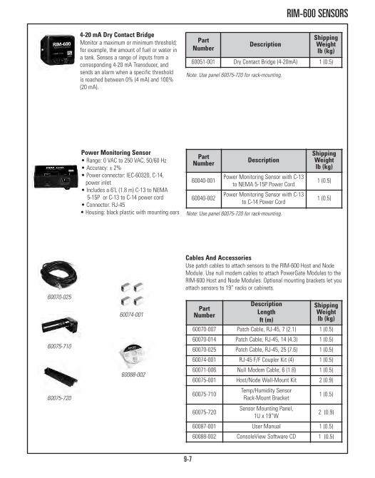
9-7
RIM-600 SENSORS
4-20 mA Dry Contact BridgeMonitor a maximum or minimum threshold;for example, the amount of fuel or water ina tank. Senses a range of inputs from acorresponding 4-20 mA Transducer, andsends an alarm when a specific thresholdis reached between 0% (4 mA) and 100%(20 mA).
PartNumber Description
ShippingWeightlb (kg)
60051-001 Dry Contact Bridge (4-20mA) 1 (0.5)
Note: Use panel 60075-720 for rack-mounting.
PartNumber Description
ShippingWeightlb (kg)
60040-001 Power Monitoring Sensor with C-13to NEMA 5-15P Power Cord 1 (0.5)
60040-002 Power Monitoring Sensor with C-13to C-14 Power Cord 1 (0.5)
Power Monitoring Sensor• Range: 0 VAC to 250 VAC, 50/60 Hz• Accuracy: ± 2%• Power connector: IEC-60320, C-14,
power inlet• Includes a 6’L (1.8 m) C-13 to NEMA
5-15P or C-13 to C-14 power cord• Connector: RJ-45 • Housing: black plastic with mounting ears Note: Use panel 60075-720 for rack-mounting.
PartNumber
DescriptionLengthft (m)
ShippingWeightlb (kg)
60070-007 Patch Cable, RJ-45, 7 (2.1) 1 (0.5)
60070-014 Patch Cable, RJ-45, 14 (4.3) 1 (0.5)
60070-025 Patch Cable, RJ-45, 25 (7.6) 1 (0.5)
60074-001 RJ-45 F/F Coupler Kit (4) 1 (0.5)
60071-006 Null Modem Cable, 6 (1.8) 1 (0.5)
60075-001 Host/Node Wall-Mount Kit 2 (0.9)
60075-710 Temp/Humidity Sensor Rack-Mount Bracket 1 (0.5)
60075-720 Sensor Mounting Panel, 1U x 19”W 2 (0.9)
60087-001 User Manual 1 (0.5)
60088-002 ConsoleView Software CD 1 (0.5)
Cables And AccessoriesUse patch cables to attach sensors to the RIM-600 Host and NodeModule. Use null modem cables to attach PowerGate Modules to theRIM-600 Host and Node Modules. Optional mounting brackets let youattach sensors to 19” racks or cabinets.
60070-025
60075-710
60075-720
60074-001
60088-002

SOFTWARE SYSTEMS
Scalable Enterprise ManagementApplication (SEMA) Software 10-3

SOFTWARE SYSTEMSCPI’s Software Systems provide centralized access across the organization for monitoring andcontrolling PDUs within racks and cabinets. Use CPI’s Software to store critical informationabout each device in a searchable, centralized database, making it easy to locate equipment,measure and record temperature and humidity and provide comprehensive per-outlet powerusage across the enterprise.
Combine CPI Software Systems with KVM Systems, Power Management Products, ThermalManagement and Cabinet and Enclosure Systems to achieve a completely personalizedEnterprise Infrastructure Solution.
CPI Software Systems include:• Automatic measurement and recording of temperatures, humidity and power in each cabinet
• Monitors Controlled CPI PDUs with port metering to provide per-outlet (per-device) power usage
• Capability to set and receive alarms for temperature, humidity and power usage limits• Scalability to meet evolving data center needs
10-2

10-3
SCALABLE ENTERPRISE MANAGEMENT APPLICATION (SEMA)
Scalable Enterprise ManagementApplication (SEMA) SoftwareCPI’s Scalable Enterprise Management Application (SEMA) software is aninfrastructure management application with a web-based interface thatallows enterprise-wide asset management and power monitoring and controlwhen used with CPI’s SEMA-compatible monitored or controlled PDUs andPowerScope In-Line Meter.
Featuring a graphical display with an intuitive interface, the SEMA softwareprovides a map view of your corporate enterprise, data centers, zones in eachdata center, rack/cabinet rows in each data center zone and the equipment ineach rack/cabinet. The software lets you associate the controllable PDUs withindividual racks and devices so you can measure power use by device. Linkmultiple PDU outlets together to easily cycle power for redundant systemsand log current use by specific time intervals or when there is a specificchange in current to track power use and identify power problems. Configurethe PDUs remotely using the Internet Explorer web browser, store informationabout each connected device in the SQL Server database, search records byspecific attributes, set alarm thresholds for current, temperature and humidityand receive warning notifications by email, page or Instant Message.
SEMA supports Microsoft Active Directory, RADIUS and LDAP-based userauthentication and provides password protected access. Administrators cancreate user accounts with three levels of user permissions (view, configure,administrator) and assign user group permissions down to the rack-level. Allconnections between a user and server are secure and use AES-256 bitencryption.
SEMA software is shipped installed on a 1U rack-mount server with MicrosoftServer 2008 and SQL Server Express. SEMA software includes a base license,one year of support and a 50 node activation key. Each PDU or PowerScopeconnection is one node. Order additional activation keys if the system hasmore than 50 nodes. Extended software support plans are also available.
CPI TeraFrame Cabinet controlled PDUs monitoredwith the Scalable Enterprise ManagementApplication (SEMA) software

10-4
SCALABLE ENTERPRISE MANAGEMENT APPLICATION (SEMA)
CPI’s Enterprise Infrastructure Solution combines the Scalable Enterprise ManagementApplication (SEMA) software and Controlled PDUs to create a complete system to control
and manage rack-level equipment in your data center. It is a complete system for enterpriserack-level asset management, power measurement and control to help IT administrators
and facility managers optimize daily data center tasks and energy use.
Top level display of yourdata centers
Row and rack-levellayouts of your cabinets
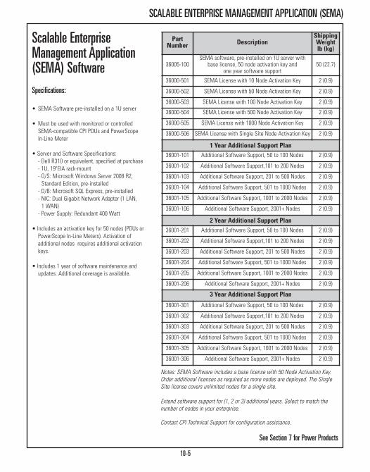
10-5
SCALABLE ENTERPRISE MANAGEMENT APPLICATION (SEMA)
Scalable EnterpriseManagement Application(SEMA) SoftwareSpecifications:
• SEMA Software pre-installed on a 1U server
• Must be used with monitored or controlledSEMA-compatible CPI PDUs and PowerScopeIn-Line Meter
• Server and Software Specifications:- Dell R310 or equivalent, specified at purchase- 1U, 19"EIA rack-mount- O/S: Microsoft Windows Server 2008 R2, Standard Edition, pre-installed- D/B: Microsoft SQL Express, pre-installed- NIC: Dual Gigabit Network Adapter (1 LAN, 1 WAN)- Power Supply: Redundant 400 Watt
• Includes an activation key for 50 nodes (PDUs orPowerScope In-Line Meters). Activation of additional nodes requires additional activationkeys.
• Includes 1 year of software maintenance andupdates. Additional coverage is available.
See Section 7 for Power Products
Part Number Description
ShippingWeightlb (kg)
36005-100SEMA software, pre-installed on 1U server with
base license, 50 node activation key and one year software support
50 (22.7)
36000-501 SEMA License with 10 Node Activation Key 2 (0.9)
36000-502 SEMA License with 50 Node Activation Key 2 (0.9)
36000-503 SEMA License with 100 Node Activation Key 2 (0.9)
36000-504 SEMA License with 500 Node Activation Key 2 (0.9)
36000-505 SEMA License with 1000 Node Activation Key 2 (0.9)
36000-506 SEMA License with Single Site Node Activation Key 2 (0.9)
1 Year Additional Support Plan36001-101 Additional Software Support, 50 to 100 Nodes 2 (0.9)
36001-102 Additional Software Support,101 to 200 Nodes 2 (0.9)
36001-103 Additional Software Support, 201 to 500 Nodes 2 (0.9)
36001-104 Additional Software Support, 501 to 1000 Nodes 2 (0.9)
36001-105 Additional Software Support, 1001 to 2000 Nodes 2 (0.9)
36001-106 Additional Software Support, 2001+ Nodes 2 (0.9)
2 Year Additional Support Plan36001-201 Additional Software Support, 50 to 100 Nodes 2 (0.9)
36001-202 Additional Software Support,101 to 200 Nodes 2 (0.9)
36001-203 Additional Software Support, 201 to 500 Nodes 2 (0.9)
36001-204 Additional Software Support, 501 to 1000 Nodes 2 (0.9)
36001-205 Additional Software Support, 1001 to 2000 Nodes 2 (0.9)
36001-206 Additional Software Support, 2001+ Nodes 2 (0.9)
3 Year Additional Support Plan
36001-301 Additional Software Support, 50 to 100 Nodes 2 (0.9)
36001-302 Additional Software Support,101 to 200 Nodes 2 (0.9)
36001-303 Additional Software Support, 201 to 500 Nodes 2 (0.9)
36001-304 Additional Software Support, 501 to 1000 Nodes 2 (0.9)
36001-305 Additional Software Support, 1001 to 2000 Nodes 2 (0.9)
36001-306 Additional Software Support, 2001+ Nodes 2 (0.9)
Notes: SEMA Software includes a base license with 50 Node Activation Key.Order additional licenses as required as more nodes are deployed. The SingleSite license covers unlimited nodes for a single site.
Extend software support for (1, 2 or 3) additional years. Select to match thenumber of nodes in your enterprise.
Contact CPI Technical Support for configuration assistance.
GROUNDING & BONDING PRODUCTSBusbar, Insulation Products, Tools & Accessories
Busbars Page 11-3Insulators Page 11-7Grounding Products Page 11-9Compression Tools, Lugs & Taps Page 11-14

GROUNDING & BONDING PRODUCTSIn response to the increase in newer, more sensitive, highly sophisticated electronic equipment,CPI offers a comprehensive line of UL® Listed Grounding and Bonding Products. The electricalprotection and grounding of today’s high-speed cabling systems is an essential part of aproperly installed IT infrastructure, which is why CPI’s Grounding and Bonding Products aredesigned to provide protection and help prevent transient voltages from damaging sensitiveelectronic equipment.
Stocked with a wide range of products spanning from grounding busbars and pipe clamps toground terminal blocks and ground strap kits, CPI is equipped to handle a full list of safetycodes and standards.
CPI Grounding and Bonding Products feature:• Comprehensive line of products that promote electrical safety throughout the network• A complete bonding solution with grounding busbars, pipe and floor pedestal clamps, insulators, joint compound, compression tools and lugs/taps, as well as other equipment
• UL Listed and compliant with industry standards
11-2
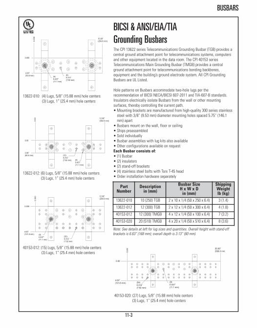
11-3
BUSBARS
13622-010: (4) Lugs, 5/8” (15.88 mm) hole centers(3) Lugs, 1” (25.4 mm) hole centers
13622-012: (6) Lugs, 5/8” (15.88 mm) hole centers(3) Lugs, 1” (25.4 mm) hole centers
40153-020: (27) Lugs, 5/8” (15.88 mm) hole centers(3) Lugs, 1” (25.4 mm) hole centers
40153-012: (15) Lugs, 5/8” (15.88 mm) hole centers(3) Lugs, 1” (25.4 mm) hole centers
BICSI & ANSI/EIA/TIA Grounding BusbarsThe CPI 13622 series Telecommunications Grounding Busbar (TGB) provides acentral ground attachment point for telecommunications systems, computersand other equipment located in the data room. The CPI 40153 seriesTelecommunications Main Grounding Busbar (TMGB) provides a centralground attachment point for telecommunications bonding backbones,equipment and the building’s ground electrode system. All CPI GroundingBusbars are UL Listed.
Hole patterns on Busbars accommodate two-hole lugs per therecommendation of BICSI NECA/BICSI 607-2011 and TIA-607-B standards.Insulators electrically isolate Busbars from the wall or other mountingsurfaces, thereby controlling the current path. • Mounting brackets are manufactured from high-quality 300 series stainlesssteel with 3/8” (9.53 mm) diameter mounting holes spaced 5.75” (146.1mm) apart
• Busbars mount on the wall, floor or ceiling• Ships preassembled• Sold individually• Busbar assemblies with lug kits also available• Other configurations available on requestEach Busbar consists of:• (1) Busbar• (2) insulators• (2) stand-off brackets• (4) stainless steel bolts with Torx T-45 head• Order installation hardware separately
PartNumber
Descriptionin (mm)
Busbar SizeH x W x D in (mm)
ShippingWeightlb (kg)
13622-010 10 (250) TGB 2 x 10 x 1/4 (50 x 250 x 6.4) 3 (1.4)
13622-012 12 (300) TGB 2 x 12 x 1/4 (50 x 300 x 6.4) 4 (1.8)
40153-012 12 (300) TMGB 4 x 12 x 1/4 (50 x 100 x 6.4) 7 (3.2)
40153-020 20 (510) TMGB 4 x 20 x 1/4 (50 x 510 x 6.4) 8 (3.6)
Note: See details at left for lug sizes and quantities. Overall height with stand-offbrackets is 6.63” (168 mm); overall depth is 3.13” (80 mm).
12.00”(304.8 mm)
(8)0.437”(11.1 mm)
(12)0.312”(7.92 mm)
2.00”(50.8 mm)
0.00
0.00
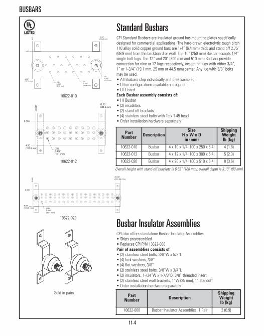
11-4
BUSBARS
10622-010
10622-012
Sold in pairs
20.00”(510.00 mm)
(53)0.437”(11.1 mm)
4.00”(101.6 mm)
0.000
0.00
0
10622-020
Standard BusbarsCPI Standard Busbars are insulated ground bus mounting plates specificallydesigned for commercial applications. The hard-drawn electrolytic tough pitch110 alloy solid copper ground bars are 1/4” (6.4 mm) thick and stand off 2.75”(69.9 mm) from the backboard or wall. The 10” (250 mm) Busbar accepts 1/4”single bolt lugs. The 12” and 20” (300 mm and 510 mm) Busbars provideconnection for nine or 17 lugs respectively, accepting lugs with either 3/4”,1” or 1-3/4” (19.1 mm, 25 mm or 44.5 mm) center. Any lug with 3/8” boltsmay be used.• All Busbars ship individually and preassembled• Other configurations available on request • UL ListedEach Busbar assembly consists of:• (1) Busbar• (2) insulators• (2) stand-off brackets• (4) stainless steel bolts with Torx T-45 head• Order installation hardware separately
Busbar Insulator AssembliesCPI also offers standalone Busbar Insulator Assemblies. • Ships preassembled• Replaces CPI P/N 13622-000Pair of assemblies consists of:• (2) stainless steel bolts, 3/8”W x 5/8”L • (4) lock washers, 3/8”• (4) flat washers, 3/8”• (2) stainless steel bolts, 3/8”W x 3/4”L • (2) insulators, 1-/34”W x 1-7/8”D, 3/8” threaded insert • (2) stainless steel wall brackets, 1”W (25 mm), 1” standoff• Order installation hardware separately
PartNumber Description
ShippingWeightlb (kg)
10622-000 Busbar Insulator Assemblies, 1 Pair 2 (0.9)
PartNumber Description
SizeH x W x D in (mm)
ShippingWeightlb (kg)
10622-010 Busbar 4 x 10 x 1/4 (100 x 250 x 6.4) 4 (1.8)
10622-012 Busbar 4 x 12 x 1/4 (100 x 300 x 6.4) 5 (2.3)
10622-020 Busbar 4 x 20 x 1/4 (100 x 510 x 6.4) 8 (3.6)
Overall height with stand-off brackets is 6.63” (168 mm); overall depth is 3.13” (80 mm).

11-5
BUSBARS
19” rack width Busbar shown
40158-020 Shown
Shown mountedto rack
Busbar Assemblies With Lug KitsBusbar Assemblies with Lug Kits contain the CPI 13622 seriesTelecommunications Grounding Busbar (TGB) or the CPI 40153 seriesTelecommunications Main Grounding Busbar (TMGB) along with requiredstainless steel hardware to fasten the two-hole ground lugs to the Busbar. • #6 lugs are 2-hole lugs with 1/4” hardware• #2, 2/0 and 4/0 lugs are 2-hole lugs with 3/8” hardware• Order installation hardware separately• UL Listed
Horizontal Rack BusbarHorizontal Rack Busbar for consolidating equipment grounds. Constructed of3/16”-thick x 3/4”H (4.763 mm x 19.1 mm) hard-drawn electrolytic tough pitch110 alloy copper bar with eight #6-32 tapped lug mounting holes on 1” (25.4mm) centers and two pairs of 5/16” (7.938 mm) diameter holes spaced 3/4”(19.1 mm) apart for attaching ground jumpers. • Other configurations available on request• UL ListedPart number consists of Busbar and a hardware kit that includes:• (1) splice plate bar, 3”L (80 mm) • (2) #12-24 copper machine screws• (2) #12 copper flat washers• (8) #6-32 copper machine screws• (8) #6 ring terminals• Order installation hardware separately
Part Number Description
Busbar SizeH x W x D in (mm)
#2 Lug #6 Lug 2/0 Lug 4/0 LugShippingWeightlb (kg)
40156-012 TGB Pattern 2 x 12 x 1/4(50 x 300 x 6.4) 3 ea 6 ea 1 ea 0 5 (2.3)
40158-012 TMGB Pattern 4 x 12 x 1/4(100 x 300 x 6.4) 3 ea 6 ea 1 ea 1 ea 8 (3.6)
40158-020 TMGB Pattern 4 x 20 x 1/4(100 x 510 x 6.4) 3 ea 6 ea 1 ea 1 ea 11 (5.0)
PartNumber Description
RackWidth(in)
ShippingWeightlb (kg)
10610-019 Horizontal Rack Busbar 19 2 (0.9)
10610-023 Horizontal Rack Busbar 23 3 (1.4)
10610-035 Horizontal Rack Busbar 35 4 (1.8)
Overall height with stand-off brackets is 6.63” (168 mm); overall depth is 3.13” (80 mm).

11-6
BUSBARS
Vertical Rack BusbarVertical Rack Busbar for consolidating equipment grounds. Constructed of5/8”H x 1/4”W (15.88 mm x 6.4 mm) hard-drawn electrolytic tough pitch 110alloy copper bar with pairs of #1/4-20 tapped mounting holes on 5/8” (15.88mm) centers. The 36”L (910 mm) bar has one set of #5/16 self-clinching studson 1” (25.4 mm) centers at one end for attachment of a ground conductor. The72”L (1830 mm) bar has two sets of #5/16 self-clinching studs on 1” (25.4mm) centers at both ends for attachment of a ground conductor. • Each package contains one Vertical Rack Busbar• Vertical Rack Busbars with insulators and lug kits are also available• Other configurations are available on request• UL Listed
PartNumber
DescriptionH xW x D in (mm)
Numberof Lugs
ShippingWeightlb (kg)
40160-036 5/8 x 1/4 x 36 (15.88 x 6.4 x 910) 8 4 (1.8)
40160-072 5/8 x 1/4 x 72 (15.88 x 6.4 x 1830) 13 5 (2.3)
Vertical Rack Ground Bar KitThe Rack Ground Bar Kit includes a thin strip of tinned copper that attachesto the rack’s equipment mounting rail to provide direct ground contact forrack-mount equipment or a convenient bonding strip. Sized to fit a 7’ (2.1 m)high rack with an EIA-310-D Universal hole pattern and 45U, the ground baris punched with a series of holes that align with each mounting hole on therack. When equipment is mounted to the rack, the rack-mount brackets touchthe ground bar. Alternately, the Equipment Ground Jumper Kit can be used toconnect equipment to the grounding bar. • Each kit includes one ground bar, three #12-24 zinc-plated thread forming hex washer head installation screws, an abrasive pad, joint compound anda ground label
• The ground bar is .05” (1.3 mm) thick tinned copper strip, 78.65”H x .68”W(1997 mm x 17 mm) and is punched with holes that match the EIA-310-DUniversal Hole Pattern
• UL Listed Ground Bar
PartNumber Description
ShippingWeightlb (kg)
40172-001 Rack Ground Bar Kit 2 (0.9)

11-7
BUSBARS/INSULATORS
Shown mounted to rack
Vertical Rack Busbar KitsVertical Rack Busbar Kits isolate the Busbar from the rack to help controlcurrent paths from passing through one piece of equipment to another. • Other configurations are available on request• UL Listed Kit consists of:• (1) Vertical Rack Busbar• (1) #2 AWG two-hole ground compression lug with 3/8” (9.53 mm) holes on 1” (25.4 mm) centers
• (3) white Delrin® insulator blocks• (3) self-tapping screws• (3) #12-24 mounting screws• (2) stainless steel lock washers, 5/16” • (2) nuts
PartNumber
DescriptionH x W x D in (mm)
ShippingWeightlb (kg)
40161-036 5/8 x 1/4 x 36 (15.88 x 6.4 x 910) 6 (2.7)
40161-072 5/8 x 1/4 x 72 (15.88 x 6.4 x 1830) 7 (3.2)
Shown mounted betweenrack and Busbar
Rack Busbar Insulator BlockRack Busbar Insulator Blocks provide rigid support to physically separate RackBusbars from all sources of electrical energy. Its offset design securelyattaches the Busbar using a #12 self-tapping screw while allowingunobstructed access to rack-mounted equipment. The Insulator Block has a#12 clearance hole for mounting to the rack.• Made of durable, nonconductive white Delrin®
• Block measures 3/4”H x 11/16”W x 1-1/4”L (19.1 mm x 17.463 mm x 31.8 mm)
• Available individually or in packages of 50
PartNumber Description
ShippingWeightlb (kg)
40157-001 Insulator Block, Each 1 (0.5)
40157-050 Insulator Block, Box of 50 2 (0.9)

11-8
INSULATORS
Rack Base Insulator KitRack Base Insulator Kits electrically isolate the racks from the floor for aneffective grounding and bonding system. Made of .060” (1.52 mm) thickphenolic insulating material and accepts up to 1/2” diameter screws. Used onconcrete floors, not needed for access floor applications.Kit consists of:• (2) isolation plates• (4) isolation grommets
Cable Runway Insulator Bar KitElectrically isolates Cable Runway sections, isolating grounded sections ofrunway or where strong EMI/RFI fields could generate eddy-currents, whichcould disturb down-line equipment.• Made of durable, nonconductive white Delrin®
• Available individually or in packages of 10Kit consists of:• (2) insulator bars, 1.5”H x 3/8”W x 5.5”L (38 mm x 9.53 mm x 140 mm)• (2) butt-splice kits (P/N/ 11301-001)
PartNumber Description
ShippingWeightlb (kg)
10842-001 Insulator Bar Kit, 1 Kit 3 (1.4)
10842-010 Insulator Bar Kit, 10 Kits 25 (11.3)
PartNumber Description
ShippingWeightlb (kg)
10605-019 Insulator Kit, 19” Rack 3 (1.4)
10605-023 Insulator Kit, 23” Rack 3 (1.4)
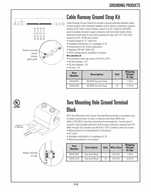
11-9
GROUNDING PRODUCTS
Shown mountedacross runway
splice point
Shown mountedon rack
Cable Runway Ground Strap KitCable Runway Ground Strap Kits provide a ground pathway between cablerunway lengths when fastened together across splices. Installation requiresdrilling 5/16” holes. Ground Straps consist of an 8”L (200 mm) #6 AWGgreen insulated stranded copper conductor with horizontal yellow stripeattached at both ends to two-hole compression lugs with 1/4” bolt holesspaced on 5/8” (15.88 mm) centers. • Overall length of 11” (280 mm)• Available individually or in packages of 25• Constructed of UL Listed components • Replaces CPI P/N 12061-001 • Other configurations available on requestKit consists of:• (4) stainless steel cap screws, #1/4-20 x 3/4”L • (4) flat washers, 1/4”• (4) lock washers, 1/4”• (4) nuts, 1/4”
Two Mounting Hole Ground TerminalBlockCPI's Two Mounting Hole Ground Terminal Block provides a convenient wayto attach ground wires to racks or cabinets and meets BICSI and ANSI-J-STD-607-A two-hole mounting recommendations. Constructed ofextruded, high-strength aluminum and accepts conductors ranging from #14AWG through 2/0. Includes two #3/8-24 x 7/8”L stainless steel set screws. • Manufactured from electroplated tin aluminum• UL Listed • Available individually or in packages of 10 • Mounting hardware not included
PartNumber Description Unit Wire Size
ShippingWeightlb (kg)
40167-001 Two-Hole Block 1 #14-2/0 1 (0.5)
40167-010 Two-Hole Block 10 #14-2/0 10 (4.5)
Part Number Description Unit
ShippingWeightlb (kg)
40164-001 #6 AWG Ground Strap 1 1 (0.5)
40164-025 #6 AWG Ground Strap 25 12 (5.0)

11-10
GROUNDING PRODUCTS
Zinc Plated
One Mounting Hole Ground Terminal BlockCPI's traditional One Mounting Hole Ground Terminal Block provides aconvenient way to attach ground wires to racks or cabinets using one #12-24screw (not supplied). Holds up to two #4 gauge wires.
Part Number Description Unit Wire
SizeShippingWeightlb (kg)
08009-001 One-Hole Block 1 Up to #4 1 (0.5)
08009-010 One-Hole Block 10 Up to #4 10 (4.5)
Equipment Ground Jumper KitUse the Equipment Ground Jumper Kit with the Vertical Rack Busbar Kit orRack Ground Bar Kit to bond rack-mount equipment. The Equipment GroundJumper Kit includes a 24”L (710 mm) insulated green/yellow helical stripe #6AWG ground conductor with a Slotted Compression Lug on one end and a90° Slotted Compression Lug on the other end. The 90° Slotted Lug attachesto the busbar or ground bar allowing easy alignment with equipment. TheSlotted Compression Lug attaches to equipment. The kit includes an abrasivepad, antioxidant joint compound and two installation screws to prepare andsecure the jumper to the busbar or ground bar. The installer must provideinstallation hardware for the lug that attaches to equipment.• Each kit includes one 24”L (710 mm) insulated ground jumper with attached lugs, two plated installation screws, an abrasive pad and joint compound
• The lugs are made from electroplated tinned copper and have two mounting holes spaced .5” to .625” apart that accept 1/4” screws
• UL Listed Components
PartNumber Description
ShippingWeightlb (kg)
40159-010 Equipment Ground Jumper Kit 2 (0.9)
Ground WireUse Ground Wire to create custom-length ground jumpers to bond CPI Racks,Cabinets and Cable Runway to Telecommunications Grounding Busbars.• Ground Wire is a #6 AWG, 133-strand, green insulated MTW conductor with a yellow helical stripe
• Sold in a 100’ (30 m) length on a spool• High strand count requires specific Compression Lugs (40162-913, 40162-963, 4012-914 or 40162-964)
Part Number
DescriptionLengthft (m)
ShippingWeightlb (kg)
40159-001 Ground Wire, #6 AWG, 100 (30) Spool 14 (6.4)

11-11
GROUNDING PRODUCTS
X=color: 1=Gray, 2=White, 5=Clear, 7=Black
Shown mountedon rack
Aluminum
Nylon
Ground JumperGround Jumpers provide common grounding from equipment rack or cabinetto the Telecommunications Equipment Bonding Conductor. Can be used withCPI “L” Brackets (P/N 10001-001 or 10559-500) to attach cable run verticallyalong equipment rack or cabinet. Ground jumpers are constructed of a 9'L(2.7 m) #6 AWG stranded copper conductor insulated green with a horizontalyellow stripe attached to a compression lug with two 1/4” bolt holes spacedon 5/8” centers. • Available individually or in packages of 10• Constructed of UL Listed components• Replaces CPI P/N 41016-00X and 41026-00X• Other configurations available on request
Stand-Off Tie-Down “L” BracketsThese “L” brackets mount to the back of the rack channel to provide aconvenient tie-down point for grounding and bonding cable runs. Available innonconductive nylon or high-strength aluminum construction. Either end of thealuminum bracket can be attached to the rack or cabinet face, allowing cablerun in several different ways.
PartNumber
DescriptionW x L in (mm)
UnitShippingWeightlb (kg)
10001-001 1 x 5 (30 x 130) White Nylon 1 1 (0.5)
10001-050 1 x 5 (30 x 130) White Nylon 50 3 (1.4)
10559-X00 1 x 6 (30 x 150) Aluminum 1 1 (0.5)
10559-X50 1 x 6 (30 x 150) Aluminum 50 5 (1.4)
PartNumber
DescriptionLengthft (m)
UnitShippingWeightlb (kg)
40159-009 9 (2.7) Green Jumper 1 2 (0.9)
40159-019 9 (2.7) Green Jumper 10 20 (9.1)

11-12
GROUNDING PRODUCTS
Pipe Clamp with Ground ConnectorSupport ground wires from metal pipes of various sizes with the Pipe Clampwith Grounding Connector. The connector provides a ground connection forthe pipe and supports up to two wires parallel or perpendicular to the pipe.Select the Pipe Clamp with Grounding Connector to match the size of thepipe. • Attaches to pipes ranging in size from .5” to 6” nominal (.375” to 6.63”outside diameters)
• Supports one or two conductors; conductors must be the same size• Use with conductors ranging in size from #6 up to 250 MCM • Attach conductors parallel or perpendicular to the pipe• Manufactured from electroplated tinned bronze with stainless steel hardware
Pedestal Clamp with Ground ConnectorSupport ground wires from round or square raised floor pedestals using thePedestal Clamp with Grounding Connector. The connector provides a groundconnection for the pedestal and supports up to four wires from the pedestal.Use to create a signal reference grid under the raised access floor using #6AWG or 2/0 bare round wire. Select the Pedestal Clamp with GroundingConnector to match the style and size of the pedestal and size of theconductor. • Use Cross Connectors to create signal reference grid intersections; support up to four conductors, two per side, size #6 AWG or 2/0
• Use Straight Connectors to support the signal reference grid in betweenintersections; support one or two conductors on one side of the pedestalonly, size #6 AWG or 2/0
• Manufactured from electrotin plated copper or bronze (P/N 40169-003) withstainless steel installation hardware
• Part numbers 40169-001 and 40169-002 are UL Listed
Cross Connector
Straight Connector
PartNumber Description
Pedestal Style, Diameterin (mm)
Number and Sizeof Connectors
ShippingWeightlb (kg)
40169-001 Pedestal Clamp,Cross Connector Square, 1-1/8 (28) OD (2) #6 AWG per side 2 (0.9)
40169-002 Pedestal Clamp,Cross Connector
Round, 1-1/8 (28) to1-3/4 (44) OD
(1) #6 AWG and (1) 2/0 per side 2 (0.9)
40169-003 Pedestal Clamp,Straight Connector
Square or Round,1-1/8 (28) OD
(2) #6 AWG or(2) 2/0 one side only 2 (0.9)
Note: P/N 40169-003 can support two conductors that are the same size; conductors can be #6 AWG through 2/0.
PartNumber Description
Pipe Size / Diameter RangesNominal Size / Outside Diameter
in (mm)
ShippingWeightlb (kg)
40170-001 Pipe Clamp 5-.75 (10-19) .375-1 (9.5-30) 2 (0.9)
40170-002 Pipe Clamp 1-1.25 (30-31.8) .75-1.7 (19-43) 2 (0.9)
40170-003 Pipe Clamp 1.5-2 (38-50) 1-2.4 (30-61) 2 (0.9)
40170-004 Pipe Clamp 2.5-3 (64-80) 2.25-3.5 (58-89) 2 (0.9)
40170-005 Pipe Clamp 3.5-4 (89-100) 3.2-4.5 (81-114) 2 (0.9)
40170-006 Pipe Clamp 5-6 (130-150) 5.63-6.63 (143-169) 2 (0.9)
Note: P/N 40170-001supports parallel attachmentof only one conductor orperpendicular attachment oftwo conductors. All otherclamps support parallel orperpendicular attachment oftwo conductors. Conductorsmust be the same size.

11-13
GROUNDING PRODUCTS
• Oxide inhibiting joint compound is used to improve the electrical conductivity andenhance the integrity of any grounding or bonding connection
• Good for all voltages• Assures a high-connectivity joint by sealing outair and moisture to prevent corrosion and reformation of oxide film
• Also used as an anti-seizing thread lubricant andensures continuity of ground on aluminum conduit threads
• Bulk packaging quantities available
8 oz (230 g) .5 oz (14 g)
PartNumber Description Size Unit
ShippingWeightlb (kg)
40168-101 Antioxidant, Copper .5 oz 1 1 (0.5)
40168-801 Antioxidant, Copper 8 oz 1 1 (0.5)
40168-150 Antioxidant, Copper .5 oz 50 2 (0.9)
40168-812 Antioxidant, Copper 8 oz 12 6 (2.7)
PartNumber Description Size
oz (g) UnitShippingWeightlb (kg)
40166-101 Antioxidant, Gray .5 (14) 1 1 (0.5)
40166-801 Antioxidant, Gray 8 (230) 1 1 (0.5)
40166-150 Antioxidant, Gray .5 (14) 50 2 (0.9)
40166-812 Antioxidant, Gray 8 (230) 12 6 (2.7)
Aluminum-To-Aluminum Or Aluminum-To-Copper Antioxidant Joint CompoundRecommended for all aluminum-to-aluminum and aluminum-to-copperconnectors, bare conductors, Busbars, insulated conductors and conduitthreads.
Copper-To-Copper Joint CompoundRecommended for all copper-to-copper connections, copper threads and allmechanical/pressure type grounding connections.
Clean-Thread ScrewsThe #12-24 Combination Pan Head, Pilot Point Mounting Screws attachequipment to racks and cabinets. A cutting notch in the thread removes paintin threaded holes to improve metal-to-metal contact. The pilot point reducescross-threading. The combination head can be used with #3 Phillips andslotted screwdrivers. • Zinc finish • Available in packages of 50 and 1,000
PartNumber Description Unit
ShippingWeightlb (kg)
40605-001 #12-24 Screws 50 1 (0.5)
40605-004 #12-24 Screws 1,000 9 (4.1)

11-14
COMPRESSION TOOLS & LUGS
Compression Tool
Crimp Tool
PartNumber Description Cable Size Hole Spacing
in (mm)Hole Sizein (mm) Color Code Quantity
ShippingWeightlb (kg)
40162-901 Two-Hole Lug #6 .625 (15.9) .250 (6.4) Blue 1 1 (0.5)
40162-951 Two-Hole Lug #6 .625 (15.9) .250 (6.4) Blue 50 2 (0.9)
40162-902 Two-Hole Lug #6 .750 (19.1) .375 (9.5) Blue 1 1 (0.5)
40162-952 Two-Hole Lug #6 .750 (19.1) .375 (9.5) Blue 50 2 (0.9)
40162-903 Two-Hole Lug #6 1.00 (25.4) .375 (9.5) Blue 1 1 (0.5)
40162-953 Two-Hole Lug #6 1.00 (25.4) .375 (9.5) Blue 50 2 (0.9)
40162-904 Two-Hole Lug #2 .625 (15.9) .250 (6.4) Brown 1 1 (0.5)
40162-954 Two-Hole Lug #2 .625 (15.9) .250 (6.4) Brown 25 2 (0.9)
40162-905 Two-Hole Lug #2 .750 (19.1) .375 (9.5) Brown 1 1 (0.5)
40162-955 Two-Hole Lug #2 .750 (19.1) .375 (9.5) Brown 25 2 (0.9)
40162-907 Two-Hole Lug #2 1.00 (25.4) .375 (9.5) Brown 1 1 (0.5)
40162-957 Two-Hole Lug #2 1.00 (25.4) .375 (9.5) Brown 25 2 (0.9)
40162-909 Two-Hole Lug 2/0 1.00 (25.4) .375 (9.5) Black 1 1 (0.5)
40162-959 Two-Hole Lug 2/0 1.00 (25.4) .375 (9.5) Black 10 2 (0.9)
40162-910 Two-Hole Lug 2/0 1.75 (44.5) .500 (12.7) Black 1 2 (0.9)
40162-960 Two-Hole Lug 2/0 1.75 (44.5) .500 (12.7) Black 10 2 (0.9)
40162-911 Two-Hole Lug 4/0 1.00 (25.4) .375 (9.5) Purple 1 1 (0.5)
40162-961 Two-Hole Lug 4/0 1.00 (25.4) .375 (9.5) Purple 10 2 (0.9)
40162-912 Two-Hole Lug 4/0 1.75 (44.5) .500 (12.7) Purple 1 1 (0.5)
40162-962 Two-Hole Lug 4/0 1.75 (44.5) .500 (12.7) Purple 10 3 (1.4)
40162-913 Slotted Lug #6 .500 (12.7)/.625 (15.9) .250 (6.4) Blue 1 1 (0.5)
40162-963 Slotted Lug #6 .500 (12.7)/.625 (15.9) .250 (6.4) Blue 25 2 (0.9)
40162-914 90˚ Slotted Lug #6 .500 (12.7)/.625 (15.9) .250 (6.4) Blue 1 1 (0.5)
40162-964 90˚ Slotted Lug #6 .500 (12.7)/.625 (15.9) .250 (6.4) Blue 25 2 (0.9)
Mechanical Compression ToolsMechanical Compression Tools are used to attach compression lugs and butt splices (notrecommended for use with C-Tap connections). The tools feature long steel handles with comfortablerubber grips. The Dieless Compression Tool works with either copper or aluminum conductors. TheCrimp Tool comes complete with dies and features extra-long handles for two-handed crimping.
Compression LugsConnect copper or tinned copper conductors to Busbars, racks, cabinets or Cable Runway. • Manufactured from electroplated tinned copper conductors• Available individually or in bulk quantities in three styles; Two-Hole, Slotted and 90˚ Slotted• Other configurations available
PartNumber Description Conductor Size Length
in (mm)Shipping Weight
lb (kg)
40165-001 Compression Tool,Dieless
Copper #8-250 MCSAluminum #8-4/0 24 (610) 5 (2.3)
40165-002 Crimp Tool #8-1/0 10.5 (267) 3 (1.4)
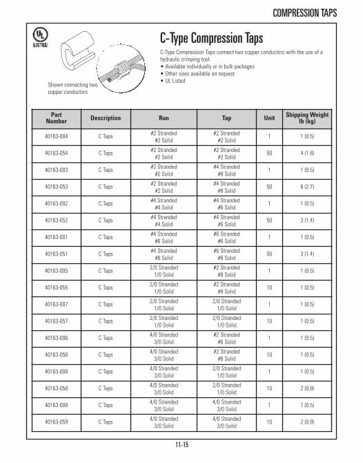
11-15
COMPRESSION TAPS
Shown connecting twocopper conductors
PartNumber Description Run Tap Unit Shipping Weight
lb (kg)
40163-004 C Taps #2 Stranded#2 Solid
#2 Stranded#2 Solid
1 1 (0.5)
40163-054 C Taps #2 Stranded#2 Solid
#2 Stranded#2 Solid
50 4 (1.8)
40163-003 C Taps #2 Stranded#2 Solid
#4 Stranded#8 Solid
1 1 (0.5)
40163-053 C Taps #2 Stranded#2 Solid
#4 Stranded#8 Solid
50 6 (2.7)
40163-002 C Taps #4 Stranded#4 Solid
#4 Stranded#6 Solid
1 1 (0.5)
40163-052 C Taps #4 Stranded#4 Solid
#4 Stranded#6 Solid
50 3 (1.4)
40163-001 C Taps #4 Stranded#6 Solid
#6 Stranded#6 Solid
1 1 (0.5)
40163-051 C Taps #4 Stranded#6 Solid
#6 Stranded#6 Solid
50 3 (1.4)
40163-005 C Taps 2/0 Stranded1/0 Solid
#2 Stranded#8 Solid
1 1 (0.5)
40163-055 C Taps 2/0 Stranded1/0 Solid
#2 Stranded#8 Solid
10 1 (0.5)
40163-007 C Taps 2/0 Stranded1/0 Solid
2/0 Stranded1/0 Solid
1 1 (0.5)
40163-057 C Taps 2/0 Stranded1/0 Solid
2/0 Stranded1/0 Solid
10 1 (0.5)
40163-006 C Taps 4/0 Stranded3/0 Solid
#2 Stranded#6 Solid
1 1 (0.5)
40163-056 C Taps 4/0 Stranded3/0 Solid
#2 Stranded#6 Solid
10 1 (0.5)
40163-008 C Taps 4/0 Stranded3/0 Solid
2/0 Stranded1/0 Solid
1 1 (0.5)
40163-058 C Taps 4/0 Stranded3/0 Solid
2/0 Stranded1/0 Solid
10 2 (0.9)
40163-009 C Taps 4/0 Stranded3/0 Solid
4/0 Stranded3/0 Solid
1 1 (0.5)
40163-059 C Taps 4/0 Stranded3/0 Solid
4/0 Stranded3/0 Solid
10 2 (0.9)
C-Type Compression TapsC-Type Compression Taps connect two copper conductors with the use of ahydraulic crimping tool.• Available individually or in bulk packages• Other sizes available on request• UL Listed

SEISMIC PROTECTION SYSTEMSBracing Products for Racks & Cabinets
Seismic Frame® Two-Post Rack Page 12-3Seismic Protection Products - Racks Page 12-6Seismic Protection Products - Runway Page 12-8Seismic Protection Products - Cabinets Page 12-9Seismic Frame® Cabinet System Page 12-10
SEISMIC PROTECTION SYSTEMSIt’s much easier to prepare for the next seismic event than to predict it. This is especiallyimportant for data centers that can’t afford to be offline or are not backed up at a secondarylocation. To reduce this risk and minimize equipment damage, additional seismic bracing forracks, cabinets, runway and trays is required and used in many parts of the world.
Structural engineers can use CPI Seismic Protection Systems to reduce excessive motion thatmay cause undue strain on cable or conduit interconnection which may help equipmentremain operational.
OSHPD Pre-Approved Products:CPI is also helping customers reduce the Office of Statewide Health Planning andDevelopment (OSHPD) approval cycle as they plan installations in seismically active regionsby obtaining the OSHPD Pre-Approval (OPA) numbers for several CPI products. OSHPD is theregulatory agency for the state of California that oversees the construction of hospitalfacilities. When equipment such as CPI Racks, Cabinets and Enclosure Systems are installedin California hospitals, OSHPD is responsible for reviewing and approving the anchoragedesign, as well as the architectural structure design. Find OSHPD Pre-Approved (OPA) partnumbers and other useful design tools at www.chatsworth.com/designtools.
CPI Seismic Protection Systems include:• Seismic Products for Rack Systems• Seismic Products for Cable Runway and Tray• Seismic Products for Cabinet and Enclosure Systems• Seismic Frame® Cabinet System
12-2
To reduce the risk of equipment damage from seismic events, check all codes, rules and regulations in your area. Utilize theservice of a structural engineer, and follow his/her suggestions. CPI offers an assortment of Seismic Protection Systems tostiffen, brace and stabilize racks and rack-mounted equipment to comply with your structural engineer’s recommendations.

12-3
Seismic Frame® Two-Post RackCPI’s Seismic Frame® Two-Post Rack is designed specifically to supportnetwork equipment in areas with seismic activity. The welded, steel SeismicFrame Two-Post Rack resists the swaying motion caused by earthquakes toreduce the amount of vibration transferred through the rack to equipment andis less likely to be damaged during a seismic event.
The Seismic Frame Two-Post Rack supports 19” EIA-310-D compliant or 23”Wequipment with two pairs of mounting rails that can be spaced 6” (150 mm) or3” (80 mm) apart. The mounting rails are marked and numbered withrack-mount units (U) and are available threaded or square-punched with painted orzinc-plated finish. This rack ships fully assembled and includes a TwoMounting Hole Ground Terminal Block for bonding the rack to the busbar. Therack is rated for a 1,000 lb (453.6 kg) seismic Zone 4 load per Section 4.4 ofthe Telecordia® Technologies, Inc. GR-63-CORE Network Equipment BuildingSystems (NEBS) requirements.
Features:• Welded, steel network equipment rack engineered specifically to protect equipment in areas with seismic activity
• Available in two sizes; 24”W (610 mm) or 28”W (710 mm)• Vertical Powers Strips and T-shaped Cable Management Fingers attach directly to the rack channel to provide power and cable distribution forequipment
• 19”W Rack fits within a 24” (610 mm) access floor tile• Fully bonded rack has (2) masked grounding locations and includes a Two Mounting Hole Ground Terminal Block for easy connection to theTelecommunications Grounding Busbar
• Independently seismic-tested and certified, meets industry recognized Telecordia® Technologies, Inc. GR-63-CORE Network Equipment BuildingSystems (NEBS) Zone 4 requirements
• EIA-310-D Compliant• UL Listed NWIN per UL60950, File E227626• 1000 lb (453.6 kg) load rating for seismic areas
Rack Includes:• (1) welded, steel frame• (4) equipment mounting rails • (50) each equipment mounting screws/cage nuts• (1) Two Mounting Hole Ground Terminal Block
SEISMIC FRAME® TWO-POST RACK
Seismic Frame® Two-Post Rackpopulated with available accessories
Adjustable Depth Mounting Rails
Two Mounting Hole Ground Terminal Block

12-4
SEISMIC FRAME® TWO-POST RACK
Seismic Frame Two-Post RackOpen, two-post, seismic rack supports 19” EIA or 23” wide rack-mountequipment.
Part Number
DescriptionH x Wft (m)
ShippingWeightlb (kg)
13853-X03 7 (2.1) x 19”, 44UTapped #12-24 Zinc Rails 180 (81.6)
13854-X03 7 (2.1) x 19”, 44USquare-Punched Zinc Rails 178 (80.7)
13855-X03 7 (2.1) x 19”, 44UTapped #12-24 Painted Rails 180 (81.6)
13856-X03 7 (2.1) x 19”, 44USquare-Punched Painted Rails 178 (80.7)
13883-X03 7 (2.1) x 23”, 44UTapped #12-24 Zinc Rails 185 (83.9)
13884-X03 7 (2.1) x 23”, 44USquare-Punched Zinc Rails 183 (83.0)
13885-X03 7 (2.1) x 23”, 44UTapped #12-24 Painted Rails 185 (83.9)
13886-X03 7 (2.1) x 23”, 44USquare-Punched Painted Rails 183 (83.0)
X=color; 1=Gray, 2=White, 7=Black. Install using (4) seismic-rated concreteanchors (sold separately).
Description 19 in (mm) 23 in (mm)Overall Width (A) 24.0 (610) 28.0 (710)
Frame Opening (B) 19.3 (490) 23.3 (592)
Rail Clearance (C) 17.75 (450) 21.75 (552)
Cable Management Fingers KitOrganize patch cords and jumper cables by rack-mount unit.• 7U T-shaped plastic cable guides snap onto the front and rear of the rack frame
• Openings between the T-shaped guides align with each rack-mount unit on the rack
• Single-Sided Kit includes 12 cable guides for one side (front or rear) of therack
• Double-Sided Kit includes 24 cable guides for both sides (front and rear) of the rack
Part Number Description
ShippingWeightlb (kg)
13696-001 Cable Management Fingers Kit,Single-Sided 7 (3.2)
13696-002 Cable Management Fingers Kit,Double-Sided 14 (6.4)
Color is Black.
C
BA
9.6”(294 mm)
15.0”(380 mm)

12-5
SEISMIC FRAME® TWO-POST RACK ACCESSORIES
Seismic Frame AccessoriesVCS Vertical Cabling SectionTwo aluminum cable managers, 6”W x 6.38”D (150 mm x 162 mm), attach toalign with the front and rear of the rack. Large cable pass-through ports on theback of each manager align with openings in the side of the frame; spin-openplastic latches secure cables in managers. Attach two CPI Vertical PowerStrips to slots on the back of the manager using the mounting kit listed below.One Single-Sided Cable Management Fingers Kit included to organize cables.
VCS Vertical Cabling Section Offset BracketBrackets attach a Single-Sided Wide VCS (P/N 11374-X03) to the SeismicFrame Two-Post Rack so that it aligns with the front of the rack. Kit includesfour brackets, use two brackets per side to attach the cabling section.
Floor Drilling TemplateDurable 28”W x 15”D (710 mm x 380 mm) aluminum template locates floormounting holes for 19”W and 23”W Seismic Frame Two-Post Racks.
Concrete Floor Anchor KitIncludes four M12 x 5-1/8” Hilti HSL-3-G Heavy Duty Sleeve Anchors to attachSeismic Frame Two-Post Rack to a concrete slab floor. Minimum recommendedthickness of the concrete slab on the ground floor is 5-1/2” (140 mm). Eachrack must be secured to the structural floor. Spacing between racks should bedetermined by a licensed structural engineer familiar with seismic applicationsand codes.
Vertical Power Strip Mounting KitIncludes mounting hardware that allows two CPI Vertical Power Strips toattach to the keyholes on the sides of the Seismic Frame Two-Post Rack or theback of the Vertical Cabling Section listed above. Cannot be used on the sameside as the Vertical Cabling Section or Cable Management Fingers Kit.
Duplex Electrical Outlet BoxProvides a location for a power connection at the base of the rack. Includes asingle-gang box for a single duplex receptacle and two self-tapping Torx headT25 installation screws. Outlet box is welded steel, 3-3/4”H x 1-13/16”W x2-1/2”D (95 mm x 46 mm x 64 mm) with a 15.5 in³ (250 cm³) wiring capacity,has eight (four accessible) concentric knockouts for 1/2” or 3/4” conduit, and iszinc galvanized for corrosion protection. UL Listed.
PartNumber Description
ShippingWeightlb (kg)
13704-X03 VCS Vertical Cabling Section, Black 35 (15.9)
13699-701 VCS Offset Mounting Bracket Kit, Black 2 (0.9)
13703-701 Floor Drilling Template, Black 6 (2.7)
13702-001 Concrete Floor Anchor Kit 3 (1.4)
13697-001 Vertical Power Strip Mounting Kit 1 (0.5)
13698-001 Duplex Electrical Outlet Box, Zinc 1 (0.5)
13704-703
13699-701
13703-701
13702-001
13697-001
13698-001
P/N 13704-X03 available in other colors. X=color; 1=Gray, 2=White, 7=Black.

12-6
SEISMIC PROTECTION PRODUCTS FOR RACKS
Part Number Description
ShippingWeightlb (kg)
10562-001 Universal Earthquake Bracing Kit 3 (1.4)
Universal Earthquake Bracing KitThis adjustable wall/ceiling brace provides a means of securing an equipmentrack or auxiliary frame to meet earthquake safety codes.• Material is 2” x 1/4” (50 mm x 6.35 mm) steel finished with Gold Chem Film over zinc plating
Kit consists of:• (4) brackets (make 2 swivel brackets)• (2) 1/2-13 x 1 1/4” hex bolts• (2) 1/2-13 hex nuts• (2) 1/2” split lock washers
Installation will require (not included):• (1) 5/8-11 threaded rod of appropriate length Rod must be trimmed to proper length during installation
• (2) 5/8-11 hex nuts• (2) 5/8 flat Type A washer, wide• Clip kit and hardware for attachment to channel or bar Installation may also require (not included):For concrete ceiling: • (1) 5/8-11 concrete anchor• (1) 5/8-11 x 3” stud• (2) 5/8-11 hex nuts • (1) 5/8” split lock washer • (1) 5/8” flat, washer, wide, Type A
For rack:• (1) 5/8-11 x 1 1/4” hex cap screw • (1) 5/8-11 hex nut • (1) 5/8” split lock washer For auxiliary frame or grid:• (1) Grid Clamp Kit • (1) 5/8-11 x 3 1/4” hex screw cap • (1) 5/8-11 hex nut • (1) 5/8” split lock washer For plywood backboard:• (1) 5/8” x 2” hex lag screw • (1) 5/8” split lock washer
Note: Seismic installation requirements should be approved by a licensed structuralengineer.Installation drawings:
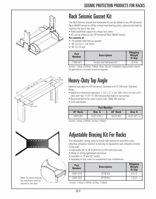
12-7
SEISMIC PROTECTION PRODUCTS FOR RACKS
Part Number
19” Rack Dim. A 23” Rack Dim. A10473-X01 14.57 (370.1) 10473-X02 18.57 (471.7)
Heavy-Duty Top AngleOptional top angle for CPI Universal, Standard or 6”D (150 mm) StandardRacks.• Material is aluminum extrusion, 1 1/2” x 2” x 1/4” (38.1 mm x 51 mm x 6.4 mm) with two 11/16” (17.46 mm) punched holes in top surface
• Recommended to be used in pairs with 10562-001 bracing • Sold individually
Rack Seismic Gusset Kit The Rack Seismic Gusset and Hardware Kit can be added to any CPI UniversalRack (46XXX series) to stiffen critical load bearing joints, reducing the need tostabilize the top of the rack. • Adds additional support to critical rack joints• Kit can be added to any CPI Universal Rack (46XXX series) Kit consists of:• (4) welded steel bolt-on gussets• (8) 1/2-13 x 1-1/4” bolts• (8) 1/2-13 nuts
Part Number Description
ShippingWeightlb (kg)
11592-X01 Gusset and Hardware Kit 10 (4.5)
X=color; 1=Gray, 2=White, 7=Black. Note: Seismic installation requirements shouldbe approved by a licensed structural engineer.
X=color; 1=Gray, 2=White, 5=Clear, 7=Black.
Adjustable Bracing Kit For RacksThis adjustable, strong, easy-to-install rack bracing kit provides a costeffective, attractive solution to bracing for equipment rack. Attaches directlyto the wall.• Adjustable 24” to 36”D (610 mm to 910 mm) from wall • Made of strong lightweight aluminum • Available in 19”and 23” widths • Available in four colors to complement rack installations
X=color: 1=Gray, 2=White, 5=Clear, 7=Black
Note: For secure bracing,the rack/frame must besecured to the floor.
PartNumber Description
ShippingWeightlb (kg)
12407-X19 19”W Kit 6 (2.7)
12407-X23 23”W Kit 7 (3.2)
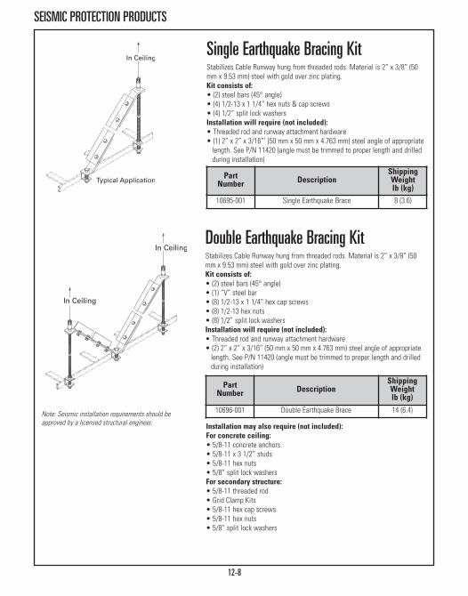
12-8
SEISMIC PROTECTION PRODUCTS
Note: Seismic installation requirements should beapproved by a licensed structural engineer.
PartNumber Description
ShippingWeightlb (kg)
10696-001 Double Earthquake Brace 14 (6.4)
Single Earthquake Bracing Kit Stabilizes Cable Runway hung from threaded rods. Material is 2” x 3/8” (50mm x 9.53 mm) steel with gold over zinc plating.Kit consists of:• (2) steel bars (45° angle)• (4) 1/2-13 x 1 1/4” hex nuts & cap screws• (4) 1/2” split lock washersInstallation will require (not included):• Threaded rod and runway attachment hardware• (1) 2” x 2” x 3/16”’ (50 mm x 50 mm x 4.763 mm) steel angle of appropriatelength. See P/N 11420 (angle must be trimmed to proper length and drilled during installation)
Double Earthquake Bracing KitStabilizes Cable Runway hung from threaded rods. Material is 2” x 3/8” (50mm x 9.53 mm) steel with gold over zinc plating.Kit consists of:• (2) steel bars (45° angle)• (1) “V” steel bar• (8) 1/2-13 x 1 1/4” hex cap screws• (8) 1/2-13 hex nuts• (8) 1/2” split lock washersInstallation will require (not included):• Threaded rod and runway attachment hardware• (2) 2” x 2” x 3/16” (50 mm x 50 mm x 4.763 mm) steel angle of appropriate length. See P/N 11420 (angle must be trimmed to proper length and drilled during installation)
Installation may also require (not included):For concrete ceiling:• 5/8-11 concrete anchors • 5/8-11 x 3 1/2” studs • 5/8-11 hex nuts • 5/8” split lock washers For secondary structure:• 5/8-11 threaded rod• Grid Clamp Kits • 5/8-11 hex cap screws • 5/8-11 hex nuts • 5/8” split lock washers
PartNumber Description
ShippingWeightlb (kg)
10695-001 Single Earthquake Brace 8 (3.6)

12-9
SEISMIC PROTECTION PRODUCTS
Adjustable Bracing Kit for CabinetsAttach bracing kit to cabinet top panel where there is a risk of seismicactivity. Earthquake design criteria specify that equipment remain operationalwhen subjected to earthquakes even though some small amount of repairablesecondary physical damage may occur.• Adjustable 24” to 36” (610 mm to 910 mm) distance from wall • For use with M-Series, E-Series and Seismic Frame Cabinets
Note: For secure bracing,attach the cabinet to thefloor using the proper floorinstallation kit along withCPI floor Anchor Clampprovided with each cabinet.
PartNumber Description
ShippingWeightlb (kg)
12477-X19 19”W Kit 6 (2.7)
12477-X23 23”W Kit 7 (3.2)
X=color: 1=Gray, 2=White, 7=Black
Seismic Equipment Bracket for CabinetsThe Seismic Equipment Bracket prevents back-and-forth, side-to-side and up-and-down movement of shelf-mounted equipment by bracing theequipment's chassis to the cabinet's vertical mounting rails. • Uses 1U of mounting space, securing equipment between 15” and 32” (380mm and 810 mm) in depth
• The bracket easily adjusts into multiple configurations which provides security for shelf-mount equipment of different depth or height
• The bracket will adjust in depth for use in any of CPI’s 24”, 30”, 36” or 39”D(610 mm, 760 mm, 910 mm or 990 mm) MegaFrame®, SlimFrame®, SteelFrame, Seismic Frame® Cabinets and TeraFrame® Cabinets
19” Width 23” Width ColorShippingWeightlb (kg)
14061-119 14061-123 Gray 6 (2.7)
14061-219 14061-223 White 6 (2.7)
14061-719 14061-723 Black 6 (2.7)

12-10
SEISMIC FRAME® CABINET SYSTEM
Closeup of reinforced inner frame
Cabinet Dimensions Usable Height 43UUsable Depth 36” (910 mm)Usable Width 19”EIA
Overall Height 84.13” (2136.9 mm)Overall Depth (w/doors) 39.62” (1006.3 mm)Overall Width 27.32” (693.9 mm)
Shipping Weight 286 lb Min / 376 lb Max(129.7 kg) / (170.6 kg)
84”H x 19” W x 36”D (2130 mm x 910 mm) Frame Only**Part Number Cabinet Door Style
11974-X02 Frame Only
X=color: 1=Gray, 2=White, 7=Black. **Frame is anodized aluminum
X=color: 1=Gray, 2=White, 7=Black. Frame is anodized aluminum
Seismic Frame® Cabinet SystemRated Zone 4 compliant to Bellcore GR-63-CORE for Network EquipmentBuilding Systems (NEBS), Section 4.4.1.1, the Seismic Frame® Cabinet Systemis designed to withstand the seismic stress of an 8.3 Richter scaleearthquake.
Offered in a 84”H x 19”W x 36”D (2130 mm x 910 mm) cabinet solution, thealuminum outer frame provides the sound structural environment necessaryfor sensitive Information Technology (IT) hardware components. • Standard 19” EIA rack width• Features square-punched mounting rails with rack-mount unit marks• Aluminum outer frame with steel inner frame delivers maximum strength with minimum weight
• Seismic bracing kits and a full line of structural enhancement products are available to support site-specific structural requirements
• Internal cable management provides flexibility for wire routing and fits on-site customization
• Adjustable front to rear vertical mounting rails allow use as a standard four-post cabinet or two-channel rack
• Load Rating: 800 lb (362.9 kg) seismic
84”H x 19” W x 36”D (2130 mm x 910 mm ) Seismic Cabinet
Part Number
Cabinet Door StyleFront Rear
11972-X02 No Front No Rear
11972-X12 Plexiglass Metal
11972-X22 Metal Metal
11972-X32 Vented Plexiglass Perforated Metal
11972-X42 Perforated Metal Perforated Metal
84”H x 19” W x 36”D (2130 mm x 910 mm) Without Side PanelsPart
NumberCabinet Door Style
Front Rear11973-X02 No Front No Rear
11973-X12 Plexiglass Metal
11973-X22 Metal Metal
11973-X32 Vented Plexiglass Perforated Metal
11973-X42 Perforated Metal Perforated Metal

ALPHABETICAL INDEX

ALPHABETICAL INDEX
New ProductsRack System part numbers now cUL Listed:
Universal Racks Page 1-3Standard Racks Page 1-7Adjustable Rail QuadraRack/ServerRack Page 1-10Adjustable QuadraRack/ServerRack Page 1-13Single-Sided Shelf Page 1-2026”D (660 mm) Shelf Page 1-21Double-Sided Shelf Page 1-22Heavy Duty Equipment Shelf for 3” (80 mm) Channel Page 1-23High-Density Patching Frame Page 1-39
GF-Series GlobalFrame® Cabinet System Page 2-34Airflow Director Page 2-37Bottom Panel Page 2-37Rail Seal Kit Page 2-37Brushed Side Panel Page 2-37Cable Port Brush Kit Page 2-38Cable Port Grommet Kit Page 2-38Snap-In Grommet Kit Page 2-38Baying Seal Kit Page 2-38Cable Lashing Bracket Kit Page 2-39Cable Ring Kit Page 2-39Full Height PDU Bracket Page 2-39Cable Ring Manager Page 2-40Vertical Cable Manager Page 2-40Fan Top Panel Kit Page 2-41
HotLok® Snap-In Filler Panels Page 2-52KoldLok® Raised Floor Grommet Page 2-53
Universal Cable Runway now UL Classified Page 6-3
17” LCD KVM Drawer Page 8-3Analog KVM Switch with DB15 Ports Page 8-5IP KVM Switch with DB15 Ports Page 8-7IP KVM Switch with Cat 5/6 Ports Page 8-9
Scalable Enterprise Management Application (SEMA) Software now pre-installed on a 1U Server Page 10-3
A
ALPHABETICAL INDEX
Adjustable Bracing Kit, Cabinets 12-9
Adjustable Bracing Kit, Racks 12-7
Adjustable Floor Support Channel, Runway 6-25
Adjustable Junction-Splice Kit 6-12
Adjustable QuadraRack & ServerRack 1-14
Adjustable Rail QuadraRack & ServerRack 1-11
Air Dam Kit, Cabinets 2-55
Air Dam Kit, TeraFrame 2-12
Air Dam Kit, TFHD 2-23
Airflow Director, GlobalFrame 2-37
Airflow Director, TeraFrame 2-11
Alternate Space Runway 6-6
Anchor Setting Tool 1-30
Anchors 1-30
Antioxidant Joint Compound 11-13
anyServer Bracket 1-24
Auxiliary Framing Channel, Runway 6-18
BBase Angle, Rack 1-31
Baying Kit, High Density Patching Frame 1-39
Baying Kit, N-Series TeraFrame 2-29
Baying Kit, TeraFrame 2-17
Baying Kit, TeraFrame HD 2-23
Baying Seal Kit, GlobalFrame 2-38
Block Mounting Bar 1-41
Bottom Panel, GlobalFrame 2-37
Bottom Panel, TeraFrame 2-12
Bottom Panel, TeraFrame HD 2-24
Brackets
66 Mounting Block 1-41
Ceiling Support 6-29
Equipment Support 1-35
Extended Fingers 5-22
Fiber Mgmt, Horizontal Furcation 2-33
Hinged Panel 1-41
Wall-Mount 4-7
Runway Support 6-47
Fiber Mgmt, Swivel Cable Spool 2-32
Busbar
Busbar Assembly 11-5
Busbar Insulator Assembly Kit 11-4
Busbar Kit, Grounding 11-3
Busbar
Busbar, Horizontal Rack 11-5
Busbar, Rack Insulator Block 11-7
Busbar, Standard 11-4
Busbar, Vertical Rack 11-6
Butt-Splice Kit 6-10
Butt Swivel Splice Kit 6-13
CCabinets
C-Series SlimFrame Cabinet 2-49
E-Series ISP Co Location Cabinet 2-50
F-Series TeraFrame Cabinet UL 2-9
F-Series TeraFrame HD Cabinet 2-22
GF-Series GlobalFrame Cabinet UL 2-36
M-Series MegaFrame Cabinet UL 2-45
N-Series TeraFrame Cabinet 2-27
Seismic Frame® Cabinet System 2-51, 12-10
ThinLine II Wall-Mount Cabinet 4-16
Cabinet Accessories
Air Dam Kit, TeraFrame 2-12
Air Dam Kit, TFHD 2-23
Airflow Director, GlobalFrame 2-37
Airflow Director, TeraFrame 2-11
Baying Kit, N-Series TeraFrame 2-29
Baying Kit, TeraFrame 2-17
Baying Kit, TeraFrame HD 2-23
Baying Seal Kit, GlobalFrame 2-38
Bottom Panel, GlobalFrame 2-37
Bottom Panel, TeraFrame 2-12
Cable Lashing Bar, TeraFrame 2-16
Cable Lashing Bracket, GlobalFrame 2-39
Cable Lashing Bracket, TFHD 2-24
Cable Management Kit, N-Series TeraFrame 2-29
Cable Manager, CUBE iT 4-14
Cable Manager, TeraFrame 2-13
Cable Managers, Enhanced Narrow 2-59
Cable Managers, Enhanced,Wide 2-59
Cable Port Brush Kit, GlobalFrame 2-38
Caster Kit 2-65
Caster Kit, N-Series TeraFrame 2-29
Caster Kit, TeraFrame 2-18
Fan Kit, M-Series Cabinet 2-54
BDESCRIPTION PAGE # DESCRIPTION PAGE #
13-3

C CCabinet Accessories
Fan Top Panel Kit, GlobalFrame 2-41
Fan Top Panel Kit, GlobalFrame 2-41
Fiber Mgmt, Horizontal Furcation Bracket 2-33
Fiber Mgmt, Swivel Cable Spool 2-32
Fiber Trunk Cable Mgr, N-Series TeraFrame 2-31
Filtered Ventilation System, M-Series 2-57
Front-to-Back Cable Mgr, TeraFrame 2-14
Full-Height PDU Bracket, GlobalFrame 2-39
Intelligent Fan Door 2-56
KoldLok Grommet 2-53
Lockable Storage Drawer Dividers 2-64
Mounting Rails, N-Series TeraFrame 2-30
Mounting Rails, N-Series TeraFrame 2-30
Network Duct Panel, N-Series TeraFrame 2-29
PowerScope In-Line Meter 7-14
Rail Adapter Kit 2-65
Rail Adapter Kit 2-65
Rail Seal Kit, GlobalFrame 2-37
Ramp, TFHD 2-23
Shelf, Fixed 2-67
Shelf, Fixed, Vented 2-60
Shelf, Monitor & Sliding Keyboard 2-63
Shelf, Rack-Mount Cable 2-18, 2-63
Shelf, Sliding, Solid 2-61
Shelf, Sliding, Vented 2-61
Side Skirt, TFHD 2-23
Standard Fan Door, M-Series 2-56
Universal Cabinet Light 2-64
Vertical Cable Manager , Cabinets 2-58
Vertical Cable Manager, TeraFrame 2-13
Vertical Cable Ring Manager, TFHD 2-24
Vertical Cabling Ring Kit 2-58
Vertical Cabling Ring Kit, Narrow Mgr 2-58
Vertical Exhaust Duct, TeraFrame 2-11
Vertical Exhaust Duct, TeraFrame 2-11
Vertical Power Strip Manager, TeraFrame UL 2-15
Zero Spacing Baying Kit, TeraFrame 2-17
Cable Cover, Clip-On 5-28
Cable Distribution Spool 5-24
Cable Distribution Spool 5-7, 5-25
Cable Divider Bar Kit, Evolution 5-5
Cable Guide Kit, ARQR/ARSR 1-12
Cable Guides, Finger Snaps 5-21
Cable Lashing Bar, Evolution 5-5
Cable Lashing Bar, Velocity 5-11
Cable Loop, Narrow 5-24
Cable Ring, Double-Wide 5-23
Cable Ring, Large Horizontal 5-30
Cable Ring, Narrow 5-24
Cable Runway Wall to Rack Kit 6-16
Cabling Sections
CCS Combination Cabling Section 5-27
CCS-EFX Combination Cabling Sect 5-16
Double-Sided, Narrow Cabling Section 5-19
Double-Sided, Wide Cabling Section 5-20
Evolution Cable Manager, Horizontal 5-26
Evolution Cable Manager, Vertical 5-4
MCS Master Cabling Section 5-13
MCS-EFX Master Cabling Section 5-14
Single-Sided, Narrow Cabling Section 5-17
Single-Sided, Wide Cabling Section 5-18
Velocity Cable Management, Horizontal 5-29
Cabling Accessories
Cable Ring, Double-Wide 5-23
Cable Ring, Large Horizontal 5-30
Cable Ring, Narrow 5-24
Cable Strain Relief Bracket 5-35
Cabling Section Covers 5-21
Ring Panel, Large Horizontal 5-31
Vertical Cable Loop 5-23
Ceiling Enclosure 3-6
Center Rail for AQR/ASR 1-16
Clip J-Bolt Kit 6-20
Compound, Copper-to-Copper Joint 11-13
Compression Lugs UL 11-14
Compression Tools 11-14
Corner Cushions, Wall Rack 4-6
Cube iT PLUS Cabinet System
Cable Manager 4-14
CUBE-iT PLUS 24", 36", 48" UL 4-12
CUBE-iT PLUS Cabinet, 60" & 72" 4-13
Fan Filters 4-14
Fan Kit 4-14
ALPHABETICAL INDEX
DESCRIPTION PAGE # DESCRIPTION PAGE #
13-4

Cube iT PLUS Cabinet System
Foot Kit 4-12
Horizontal Wire Bar 4-14
Light Kit 4-14
Mounting Bracket, 45° 4-15
Mounting Bracket, 90° 4-15
Mounting Rails 4-12
Power Strip 4-15, 7-9
Termination Block Panel 4-14
Vert Mounting Bracket 4-15
DD-Rings for PatchRack, Cable Runway 6-7
D-Rings, Metal 5-34
Distribution Ring, Channel-Mounted 5-33
Distribution Ring, Open 5-33
Distribution Rings, Closed 5-34
Dolly Wheels, Racks 1-33
Dolly, Mid-Size 1-33
Door, Metal for Rack Enclosure 1-9
Duplex Receptacle, Surge-Suppressed 4-17
Dust Cover, QuadraRack 1-19
EEarthquake Bracing Kit, Double 12-8
Earthquake Bracing Kit, Racks 12-6
EasySwing Wall-Mount Rack 4-6
Enclosure Faceplates 3-10
Enclosure, Ceiling 3-6
Enclosure, Ceiling-Mounted Wireless 3-11
Enclosure, Drop Ceiling 3-8
Enclosure, Fiber Raised Floor 3-5
Enclosure, MUTOA Floor Box 3-14
Enclosure, Wireless 3-10
Enclosures Mounting Bracket 3-9
Equipment Ground Jumper Kit UL 11-10
Equipment Guard Rail 1-34
Equipment Rail, ARQR/ARSR 1-12
Equipment Support Bracket 1-35
Equipment Support Rails, AQR/ASR 1-16
Evolution
Cable Manager, Vertical 5-4
Fiber Segregation Kit 5-5
Evolution
Cable Manager, Horizontal 5-26
Cable Divider Bar Kit 5-5
Cable Lashing Bar 5-5
Cable Spool Spacer Kit 5-7
Fixed Accessory Panel 5-7
Floor Bracket 5-5
Movable Mid-Section 5-7
Solid Rear Panel 5-6
Solid Side Panel 5-6
ExpandaRack 1-18
Extended Fingers Bracket 5-22
FF-Series TeraFrame Cabinet 2-9
F-Series TeraFrame HD Cabinet 2-22
Faceplates, Enclosures 3-10
Fan Filters,CUBE-iT PLUS 4-14
Fan Kit, CUBE-iT PLUS 4-14
Fan Kit, M-Series Cabinet 2-54
Fan Top Panel Kit, GlobalFrame 2-41
Fan/Filter Kit 1-9, 4-18
Fiber Management
Fiber Management Spools, 2" 5-25
Fiber Trunk Cable Mgr, N-Series TeraFrame 2-31
Horizontal Furcation Bracket 2-33
Module Adapter 2-32
Raised Floor Enclosure UL 3-5
Segregation Kit, Evolution 5-5
Slack Manager Panel 4-17
Swivel Cable Spool 2-32
Universal Accessory Rail 2-32
Vertical Furcation Bracket 2-33
Filler Panels, HotLok Snap-In 2-52
Filler Panels, Snap-In 2-41
Filter Replacement Kit 1-9, 4-18
Filter Replacement, Filter Ventilation System 2-57
Filtered Ventilation System, M-Series 2-57
GGF-Series GlobalFrame Cabinet 2-36
Airflow Director 2-37
Baying Seal Kit 2-38
C D
ALPHABETICAL INDEX
DESCRIPTION PAGE # DESCRIPTION PAGE #
13-5

GF-Series GlobalFrame Cabinet
Bottom Panel 2-37
Brush Side Panel 2-37
Cable Grommet Kit 2-38
Cable Lashing Bracket 2-39
Cable Port Brush Kit 2-38
Cable Ring Kit 2-39
Cable Ring Manager 2-40
Fan Top Panel Kit 2-41
Full-Height PDU Bracket 2-39
Rail Seal Kit 2-38
Snap-In Grommet & Plug 2-38
Snap-In Grommet Kit 2-38
Vertical Cable Manager 2-40
Grommet, Raised Floor 2-53
Grounding Products
Busbar Assembly 11-5
Busbar Insulator Assembly Kit 11-4
Busbar Kit, Grounding 11-3
Busbar, Horizontal Rack 11-5
Busbar, Vertical Rack 11-6
Compression Taps, C-Type 11-15
Equipment Ground Jumper Kit 11-10
Ground Jumper 11-11
Ground Wire UL 11-10
One Mounting Hole Ground Terminal Block 11-10
Pedestal Clamp with Ground Connector 11-12
Pipe Clamp with Ground Connector 11-12
Rack Busbar Insulator Block 11-7
Stand-Off Tie-Brackets 11-11
Two-Mounting Hole Ground Terminal Block UL 11-9
HHardware 1-38, 2-18, 11-13
Hardware Kit 1-17, 1-24, 2-18, 2-65
Heavy-Duty Butt-Splice Kit 6-10
Heavy-Duty Junction Splice Kit 6-10
Heavy-Duty Junction-Splice Kit 6-10
Heavy-Duty Top Angle for Racks 1-31, 12-7
Hex Cap Bolts 6-34
Hex Lag Screw 6-34
Hex Nut 6-33
High Density Patching Frame UL 1-39
Horizontal Cable Guides 5-22
Horizontal Wire Bar, CUBE-iT PLUS 4-14
Horizontal Wire Management 5-28
HotLok Snap-In Filler Panels 2-52
IInstallation Kits 2-18
Installation Kits 1-29
Insulator Bar Kit, Cable Runway 6-31, 11-8
Insulator Kit, Rack Base 1-29, 11-8
Intelligent Fan Door 2-56
Intelligent Fan Kit, ThinLine 4-17
JJ-Bolt Kit 6-20
J-Bolt Kit, Cable Runway 6-24
J-Bolts 6-21
Jack Plate Wall-Mount Bracket 5-36
Jumper Tray, Upper 5-29
Junction Swivel Splice Kit 6-13
Junction-Splice Kit 6-11
KKeyboard 1-28
Keyboard & Tray, 2-Post Racks 1-28
Keyboard & Tray, 4-Post/Cabinets 1-28
KoldLok Grommet 2-53
KoldLok Wave 2-54
KVM Systems
KVM, 17" LCD Drawer 8-3
KVM, Analog Expansion Switch 8-10
KVM, Analog Switch, DB15 Ports 8-5
KVM, Cable 8-12
KVM, Dongle 8-13
KVM, IP Switch, Cat 5/6 Ports 8-10
KVM, LCD, Analog, DB15 Ports 8-5
KVM, LCD, IP, Cat 5/6 Ports 8-10
LLabels, RMU Kit 1-35, 2-64
Light, CUBE-iT PLUS UL 4-14
Light, Universal Cabinet 2-64
Lock Kit, Zone Enclosures 3-9
Lockable Storage Drawer Dividers 1-25, 2-64
ALPHABETICAL INDEX
HGDESCRIPTION PAGE # DESCRIPTION PAGE #
13-6

M-Series MegaFrame Cabinet 2-45
M-Series MegaFrame Cabinet, 48" 2-46
Mag Clips Large 5-37
Mag Clips, Medium 5-36
Mag Clips, Wrap-Around 5-37
MCS Master Cabling Section 5-13
MCS-EFX Master Cabling Section 5-14
Mechanical Compression Tools 11-14
Mounting Bracket, 45° , CUBE-iT 4-15
Mounting Bracket, 90° , CUBE-iT 4-15
Mounting Bracket, Enclosures 3-9
Mounting Bracket, Hinged Panel 1-41
Mounting Bracket, Hinged Panel 1-41
Mounting Brackets, 66 Block 1-41
MUTOA Floor Box 3-14
NN-Series TeraFrame Cabinet 2-27
N-Series TeraFrame, Cisco® Compatible 2-28
N-Series TeraFrame, Juniper Compatible 2-28
OOffset Rack-Mount Brackets 7-9
One Mounting Hole Ground Terminal Block 11-10
OnTrac® Wire Mesh Tray
Cable Tray Bottom Insert 6-40
Cable Tray Cover 6-40
Cable Tray Cutting Tool 6-40
Center Support Bracket 6-38
Clamp Washer 6-36
Ede Hanger 6-37
L Support Bracket 6-37
Label Holder 6-41
Large Radius Drop 6-41
OnTrac Wire Mesh Cable Tray 6-35
Pedestal Clamp 6-39
Rack-Mount Hook 6-39
Splice Bar Kit,90˚ 6-36
Splice Kit 6-36
Splice Washer & Bolt Kit 6-36
Split Bolt Grounding Clamp 6-41
Tool Less Radius Drop 6-41
Trapeze Support Bracket 6-37
OnTrac® Wire Mesh Tray
Triangle Support Bracket, OnTrac 6-38
Under Floor Support, OnTrac 6-39
Wall Mount Angle, OnTrac 6-38
PPaint, Touch-Up 1-32
Patch Panel Wire Management Bar 5-28
PatchRack , Cable Runway 6-7
Pathway Dividers, Cable Runway 6-6
Pedestal Clamp with Ground Connector 11-12
Pipe Clamp with Ground Connector 11-12
Power Management
Horizontal, Single-Phase 4-10, 7-7
PDU Cables 7-13
PDU Cables/Accessories 7-13
PDU Mounting Brackets 2-15, 7-13
PDU Mounting Brackets 7-13
PDU, Horizontal 7-13
PDU, Vertical 7-10
PDU/Power Strip Lashing Bar, TeraFrame 2-16
Power Strip CUBE-iT Cabinet UL 4-15, 7-9
Power Strip Lashing Bar, TFHD 2-24
PowerScope In-Line Meter 7-14
PowerScope In-Line Meter 7-14
Silver Frame Cabinet 7-9
Stand-Off Mount 7-8
Vertical, Single-Phase 7-5
Vertical, Universal Racks UL 7-8
QQuadraRack & ServerRack (4-Post)
Adjustable QuadraRack & ServerRack 1-14
Adjustable Rail QuadraRack & ServerRack 1-11
Center Rail 1-16
Dust Cover, 1-19
Equipment Support Rails 1-16
Fixed Mounting Rail 1-12
Lockable Storage Drawer Dividers 1-25
QuadraRack 4-Post Frame 1-18
QuadraRack Server Frame, Fixed 1-17
Side Panels 1-12
Solid Shelf 1-19
ALPHABETICAL INDEX
M ODESCRIPTION PAGE # DESCRIPTION PAGE #
13-7

QuadraRack & ServerRack (4-Post)
Tie-Down Bracket, QuadraRack 1-19
Top-Mount Cable Waterfall Tray 1-12
Vented Shelf, QuadraRack 1-19
Vented Shelves 1-15
RRack, 2-Post
Rack Enclosure 1-9
Rack, Universal UL 1-4
Runway Mounting Kit, High Density Frame 1-39
Seismic Frame Two Post Rack 12-3
Rack Accessories
Base Angle 1-31
Dolly Wheels, Racks 1-33
Double-Sided Shelf, Solid UL 1-22
Dust Cover, QuadraRack 1-19
Equipment Support Rails, AQR/ASR 1-16
ExpandaRack 1-18
Panel Adapter for Racks 1-37
Panel Hinges 1-40.
Rack Base Dust Cover 1-34
Rack Base Dust Cover 1-34
Rack Busbar Insulator Block 11-7
Rack Cabling Managers 5-31
Rack Channel Standoffs, 3"D 1-36
Rack Extension Kit 1-34
Rack Filler Panel 1-32
Rack Panel Adapters 1-35
Rack Seismic Gusset Kit 12-7
Rack Standard Rollers 1-33
Rack Support, Raised Floor 1-30
Rack-to-Runway Mounting Plate, 3” 6-14
Rack, Standard, 3"D UL 1-7
Shelf, Heavy-Duty Equipment 1-23
Shelf, Single-Sided UL 1-20
Shelf, Single-Sided Steel 1-21
Shelf, Sliding Equipment 1-23
Top Angle 1-31
Top-Mount Cable Waterfall Tray 1-12
Rack Termination Systems
Mounting Brackets, 66 Block 1-41
High Density Patching Frame 1-39
Rack Channel Standoffs, 6"D 1-36
Rack Enclosure, Single, 19"W 1-9
Rack Enclosure, Single, 23"W 1-9
Rack, Universal Swing Gate 4-4
Rail Adapter Kit 2-65
RIM-600 System
10’L Water Detect Sensor Rope 9-5
4-20 mA Dry Contact Bridge 9-7
ConsoleView Software CD 9-7
Door Open/Closed Sensor 9-6
Humidity Sensor 9-5
Humidity Sensor 9-5
Mini Temperature Sensor 9-5
Motion Sensor 9-6
Null Modem Cable 9-7
Open/Close Contract Bridge 9-6
Power Monitoring Sensor 9-7
PowerGate 2 Module 9-4
PowerGate 2 Power Cord 9-4
PowerGate Module 9-4
RIM-600 Bundle 9-4
RIM-600 Host 9-3
RIM-600 Node UL 9-3
Sensor Panel/Bracket 9-7
Smoke Detector Sensor 9-6
Temperature Sensor 9-5
User Manual 9-7
Wall-Mount Kit 9-7
Water Detection Sensor 9-5
Runway
TELCO-Style Runway 6-4
UL Classified Runway 6-4
Universal Runway 6-3
Runway Accessories
90 Splice Kit° 6-12
45° Splice Kit 6-12
Adjustable Floor Support Stands, Runway 6-25
Adjustable Junction-Splice Kit UL 6-12
Alternate Space Runway 6-6
Auxiliary Framing Channel, Runway 6-18
Butt Swivel Splice Kit 6-13
Butt-Splice Kit 6-10
ALPHABETICAL INDEX
RQDESCRIPTION PAGE # DESCRIPTION PAGE #
13-8

Runway Accessories
Cable Mounting Plate, 3" 6-14
Cable Retaining Post 6-30
Cable Runway Mounting Bracket 1-16
Ceiling Support Bracket 6-29
Center Support Kit 6-30
Channel Mounting Plate, 6" 6-15
Corner Bracket 6-11
Cross Member 6-8
D-Rings, PatchRack 6-7
E-Bend 6-9
Elevation Kit 6-16
End Closing Kit 6-31
Framing Clip Ki 6-17
Ground Strap Kit 11-9
Heavy-Duty Aux Framing Channel 6-18
Heavy-Duty Butt-Splice Kit 6-10
Heavy-Duty Junction-Splice Kit 6-10
High Density Frame Mounting Kit 1-39
L Bracket 6-32
PatchRack 6-7
Pathway Dividers 6-6
Quick Ship Cable Runway Kit 6-5
Radius Bend, Inside 6-9
Radius Bend, Outside 6-9
Radius Drop, Cross-Member 6-8
Radius Drop, Stringer 6-8
Runway Foot Kit 6-24
Runway Support Bracket 6-28
Runway Tray 6-31
Slip-On® Framing Clip 6-17
Slip-On® Lock Nut 6-28
Slip-On® Support Bracket, Runway 6-29
Slotted Support Bracket 6-29
Standoff Support Kit, Cable Runway 6-9
Tall Pipe Stand 6-26
Threaded Ceiling Kit 6-26
Threaded Drop Rods 6-27
Threaded Rod Coupling Kit 6-27
Threaded Rod Cover 6-28
Threaded Rod I-Beam Clamps 6-28
Triangle Support Bracket 6-22
Runway Accessories
Trough Cable Runway 6-5
Wall Angle 6-24
Wall Angle Support Kit 6-23
Wall to Rack Kit 6-16
SSaf-T-Grip® Straps 1-37, 5-32
Scalable Enterprise Mngmt Application (SEMA) 10-3
Seismic
Adjustable Bracing Kit, Cabinets 12-9
Adjustable Bracing Kit, Racks 12-7
Cable Management Kit 12-4
Cabling Section Offset Bracket 12-5
Concrete Floor Anchor Kit 12-5
Duplex Electrical Outlet Box UL 12-5
Earthquake Bracing Kit, Double 12-8
Earthquake Bracing Kit, Racks 12-6
Equipment Bracket, Cabinets 12-9
Floor Drilling Template 12-5
Power Strip Mounting Kit 12-5
Rack Seismic Gusset Kit 12-7
Seismic Frame® Cabinet System 2-51, 12-10
Seismic Frame® Two Post Rack UL 12-4
Vertical Cabling Section 12-5
Shelves
10"D Wall-Mount 4-10
15"D Single-Sided 1-20, 4-10
16"D Low Profile 1-20
19"D Low Profile 1-21
26"D UL 1-21
32"D Sliding, Solid 2-62
32"D Sliding, Vented 2-62
CPU/Monitor, Double Keyboard Trays 1-26
CPU/Monitor, Single Keyboard Tray 1-26
CPU/Monitor, Single Keyboard Tray 1-26
Double-Sided Low Profile 1-22
Double-Sided Steel 1-21
Double-Sided, Vented 1-22
Double-Sided, Vented 1-22
Extra-Extending 1-23
Extra-Heavy-Duty Sliding 1-16, 1-19, 2-62
Fixed, Low Profile for Cabinets 2-63
ALPHABETICAL INDEX
R RDESCRIPTION PAGE # DESCRIPTION PAGE #
13-9

Shelves
Fixed, Low Profile for Cabinets 2-63
Fixed, Solid 2-60
Fixed, Solid UL 2-60
Fixed, Vented 2-60
Fixed, Vented 2-60
Fixed, Vented 2-60
Heavy-Duty Equipment 1-23
Monitor & Sliding Keyboard 2-63
Rack-Mount Cable 2-18, 2-63
Single-Sided 1-20
Single-Sided Shelf, Vented 1-20
Single-Sided Steel 1-21
Sliding Equipment 1-23
Sliding, Solid 2-61
Sliding, Vented 2-61
Small Peripheral Shelf 1-20
Stationary Keyboard 1-28
Vented Shelf, QuadraRack 1-19
Vented Shelves, AQR/ASR 1-15
Snap-In Filler Panels 2-41
Split Lock Washers 6-33
Software, SEMA 10-3
Splices
45° Runway-Splice Kit 6-12
90° Runway Splice Kit 6-12
Butt Swivel Splice Kit, UL 6-13
Butt-Splice Kit, Cable Runway UL 6-10
Heavy-Duty Butt-Splice Kit, UL 6-10
Heavy-Duty Junction Splice Kit, UL 6-10
Heavy-Duty Junction-Splice Kit 6-10
Junction Swivel Splice Kit 6-11
Transition Adapter Butt Splice Kit 6-11
TTeraFrame
Air Dam Kit, TeraFrame 2-12
Air Dam Kit, TFHD 2-23
Airflow Director, TeraFrame 2-11
Baying Kit, N-Series 2-29
Baying Kit, TeraFrame 2-17
Baying Kit, TeraFrame HD 2-23
Bolt Down Kit, TFHD 2-23
TeraFrame
Bottom Panel, TeraFrame 2-12
Cable Lashing Bar, TeraFrame 2-16
Cable Lashing Bar, TeraFrame HD 2-24
Cable Manager, TeraFrame 2-13
Caster Kit, N-Series TeraFrame 2-29
Caster Kit, TeraFrame 2-18
F-Series TeraFrame Cabinet 2-9
F-Series TeraFrame HD Cabinet 2-22
Fiber Trunk Cable Mgr, N-Series TeraFrame 2-31
Front-to-Back Cable Mgr, TeraFrame 2-14
Mounting Hardware Kit, TeraFrame 2-18
Mounting Rails, N-Series TeraFrame 2-30
Mounting Rails, N-Series TeraFrame 2-30
Mounting Rails, TeraFrame 2-19
N-Series TeraFrame Cabinet 2-27
Network Duct Panel, N-Series TeraFrame 2-29
Ramp, TFHD 2-23
Rear Door Sealing Kit, TeraFrame 2-11
Right Hand Latch Kit, N-Series TeraFrame 2-29
Seal Kit, TeraFrame 2-17
Side Skirt, TFHD 2-23
Side Skirt, TFHD 2-23
Slide Adapter Kt, TeraFrame 2-13
Vertical Cable Manager, TeraFrame 2-13
Vertical Cable Ring Manager, TFHD 2-24
Vertical Exhaust Duct, TeraFrame 2-11
Vertical Power Strip Manager, TeraFrame UL 2-15
Zero Spacing Baying Kit, TeraFrame 2-17
Touch-Up Paint 1-32, 6-32
Trays
Flush-Mount Keyboard 1-27
Jumper Tray, Lower 5-29
Keyboard & Mouse 1-28
Keyboard, 19" Full 1-28
Sliding Keyboard & Mouse 1-27
Sliding Keyboard, Wrist Rest 1-27
Sliding Single Keyboard 1-26
Transition Tray 5-29
UUL Listed
45° Runway-Splice Kit 6-12
TDESCRIPTION PAGE # DESCRIPTION PAGE #
ALPHABETICAL INDEX
S
13-10

UL Listed
90° Runway Splice Kit 6-12
Adj QuadraRack & ServerRack 1-14
Adj Rail QuadraRack & ServerRack 1-11
Adjustable Junction-Splice Kit 6-12
Busbar Assembly 11-5
Busbar Kit, Grounding 11-3
Busbar, Horizontal Rack 11-5
Busbar, Vertical Rack 11-6
Busbars, Standard 11-4
Butt Swivel Splice Kit 6-13
Butt-Splice Kit, Cable Runway 6-10
C-Type Compression Taps 11-15
Cable Runway 6-3
Cable Runway Radius Bend, Inside 6-9
Cable Runway Radius Bend, Outside 6-9
Ceiling Enclosure 3-6
Ceiling-Mounted Wireless Enclosure 3-11
Compression Lugs 11-14
CUBE-iT PLUS 24", 36", 48" 4-12
Double-Sided Shelf, Solid 1-22
Duplex Box 12-6
Enclosure, Drop Ceiling 3-8
Enclosure, Fiber Raised Floor 3-5
Equipment Ground Jumper Kit 11-10
F-Series TeraFrame Cabinet 2-9
GF-Series GlobalFrame Cabinet 2-36
Heavy-Duty Butt-Splice Kit 6-10
Heavy-Duty Junction Splice Kit 6-10
Heavy-Duty Swing Gate Kit 4-5
Heavy-Duty, 3" Channel Shelf 1-23
High Density Patching Frame 1-39
Junction Swivel Splice Kit 6-13
M-Series MegaFrame Cabinet 2-45
Offset Rack-Mount Brackets 7-9
One Mounting Hole Ground Terminal Block 11-10
PDU, Horizontal 7-13
PDU, Vertical 7-10
Pedestal Clamp with Ground Connector 11-12
Pipe Clamp with Ground Connector 11-12
Power Strip, CUBE-iT Cabinet 4-15, 7-9
Rack, Universal 1-4
UL Listed
Raised Floor Enclosure 3-4
Runway Splice Kit 90° 6-12
Runway-Splice Ki, 45° 6-12
Runway, UL Classified 6-4
Runway, Universal 6-3
Seismic Frame® Two Post Rack 12-4
Shelf, Fixed, Low Profile for Cabinets 2-63
Shelf, Fixed, Solid 2-60
Shelf, Fixed, Vented 2-60
Swing Gate Wall Rack 4-5
Two-Mounting Hole Ground Terminal Block 11-9
Vertical Power Strip Manager, TeraFrame 2-15
Vertical Rack Busbar Kit 11-7
Vertical Swivel Splice Kit 6-13
Universal Cabinet Light 2-64
Universal Horizontal Cable Manager 5-27
Universal Runway 6-3
Universal Swing Gate Rack 4-4
VVelocity Cable Lashing Bar 5-11
Velocity Cable Ring Manager 5-11
Velocity Cable Spool 5-11
Velocity Horizontal Cable Manager 5-26
Velocity Standard Pack 5-12
Velocity Vertical Cable Manager 5-9
Vertical Cabling Ring Kit 2-58
Vertical Cabling Ring Kit, Narrow Mgr 2-58
Vertical Cabling Section Extensions 5-19
Vertical Exhaust Duct, TeraFrame 2-11
Vertical Power Strip Manager, TeraFrame UL 2-15
Vertical Rack Busbar Kit UL 11-7
Vertical Rack Ground Bar Kit 11-6
Vertical Swivel Splice Kit, UL 6-13
Vertical Wall Bracket 6-29
Vertical Wire Management Loop 5-23
WWall-Mount Cabinets
CUBE-iT PLUS Cabinet 24", 36", 48" 4-12
CUBE-iT PLUS Cabinet 60" & 72" 4-13
Silver Frame Wall-Mount Cabinet 4-18
DESCRIPTION PAGE # DESCRIPTION PAGE #
U U
ALPHABETICAL INDEX
13-11
Wall-Mount Cabinets
ThinLine II Wall-Mount Cabinet 4-16
Wall-Mount Racks
EasySwing Wall-Mount Rack 4-6
Swing Gate Wall Rack UL 4-5
Universal Swing Gate Rack 4-4
Wall-Mount Rack, Fixed UL 4-8
Wall-Rack, Heavy-Duty Equipment 4-7
Heavy-Duty Swing Gate Kit 4-5
Wall Mount Enclosure 3-14
Wall Rack Corner Cushions 4-6
Wall-Mount Bracket, Flush-Mount 4-7
Wall-Mount Rack w/Enclosure 4-9
Washers, Plain "A" Type 6-33
Wireless Enclosures
Wireless Ceiling Enclosure 3-10
Wireless Ceiling Enclosure 3-11
Wireless Enclosure Kits 3-10
Wireless Wall-Mount Enclosure 3-12
Wireless Wall-Mount Enclosure 3-13
Wireless, Dome Enclosure 3-11
XXLBET 110A Block System 1-40
XLBET Mounting Bar 1-53
Zone
Enclosure Faceplates 3-10
Enclosure, Basic Consolidation 3-8
Enclosure, Drop Ceiling 3-6
Enclosure, Wall Mount 3-12
Enclosure, Wireless 3-10
Enclosure, Wireless, Domed 3-11
Lock Kit, Zone Enclosures 3-9
MUTOA Floor Box 3-14
Raised Floor Enclosure 3-4
Spare Key, Zone Enclosures 3-9
WDESCRIPTION PAGE #
ALPHABETICAL INDEX
13-12

PART NUMBER INDEX

PART NUMBER INDEX
New ProductsRack System part numbers now cUL Listed:
Universal Racks Page 1-3Standard Racks Page 1-7Adjustable Rail QuadraRack/ServerRack Page 1-10Adjustable QuadraRack/ServerRack Page 1-13Single-Sided Shelf Page 1-2026”D (660 mm) Shelf Page 1-21Double-Sided Shelf Page 1-22Heavy Duty Equipment Shelf for 3” (80 mm) Channel Page 1-23High-Density Patching Frame Page 1-39
GF-Series GlobalFrame® Cabinet System Page 2-34Airflow Director Page 2-37Bottom Panel Page 2-37Rail Seal Kit Page 2-37Brushed Side Panel Page 2-37Cable Port Brush Kit Page 2-38Cable Port Grommet Kit Page 2-38Snap-In Grommet Kit Page 2-38Baying Seal Kit Page 2-38Cable Lashing Bracket Kit Page 2-39Cable Ring Kit Page 2-39Full Height PDU Bracket Page 2-39Cable Ring Manager Page 2-40Vertical Cable Manager Page 2-40Fan Top Panel Kit Page 2-41
HotLok® Snap-In Filler Panels Page 2-52KoldLok® Raised Floor Grommet Page 2-53
Universal Cable Runway now UL Classified Page 6-3
17” LCD KVM Drawer Page 8-3Analog KVM Switch with DB15 Ports Page 8-5IP KVM Switch with DB15 Ports Page 8-7IP KVM Switch with Cat 5/6 Ports Page 8-9
Scalable Enterprise Management Application (SEMA) Software now pre-installed on a 1U Server Page 10-3

PART NUMBER INDEX
02004 6-34 Hex Cap Bolts02006 5-32 Saf-T-Grip Straps, Center Grommet02006 6-34 Hex Lag Screw02007 6-34 Hex Lag Screw02009 5-32 Saf-T-Grip Straps, Open Loop02012 5-32 Saf-T-Grip Straps, Open Loop03001 6-33 Hex Nut03003 6-28 Slip-On Lock Nut04002 6-33 Washers, Plain "A" Type 04003 6-33 Split Lock Washers05006 5-32 Saf-T-Grip Straps, End Grommet05009 5-32 Saf-T-Grip Straps, End Grommet05012 5-32 Saf-T-Grip Straps, End Grommet06001 1-30 Anchors06003 1-30 Anchor Setting Tool06006 1-37, 5-32 Saf-T-Grip Straps, Center Grommet06009 1-37, 5-32 Saf-T-Grip Straps, Center Grommet06012 1-37, 5-32 Saf-T-GripStraps, Center Grommet08009 11-10 One Mntg Hole Grnd Terminal Block10001 5-35, 11-11 Stand-Off Tie-Brackets10175 1-33 Dolly Wheels for Racks10250 6-3 Universal Runway10375 1-31 Top Angle10419 5-22 Horizontal Cable Guides10473 1-31, 12-7 Heavy-Duty Top Angle for Racks10487 6-13 Butt Swivel Splice Kit 10488 6-13 Junction Swivel Splice Kit 10489 6-13 Vertical Swivel Splice Kit 10506 6-16 Cable Runway Elevation Kit10557 6-28 Threaded Rod Clamps, Runway10559 5-35, 11-11 Stand-Off Tie Bracket10562 12-6 Earthquake Bracing Kit, Racks10565 1-34 Rack Extension Kit10587 2-65 Rail Adapter Kit10595 6-14 3” Rack-to-Runway Mounting Plate10596 6-30 Cable Retaining Post, Runway10605 1-29, 11-8 Insulator Kit, Rack Base10606 6-31 Cable Runway Tray10607 6-29 Slotted Support Bracket10608 6-29 Vertical Wall Bracket10609 6-17 Framing Clip Kit, Cable Runway10610 11-5 Busbar, Horizontal Rack10616 6-12 Adjustable Junction-Splice Kit10620 6-20 Clip J-Bolt Kit10621 6-17 Framing Clip Kit, Cable Runway10622 11-4 Busbars, Standard10622 11-4 Busbar Insulator Assembly Kit10628 6-18 Auxiliary Framing Channel, Runway10629 1-30 Raised Floor Rack Support10630 1-30 Raised Floor Rack Support10631 1-30 Raised Floor Rack Support10632 1-30 Raised Floor Rack Support10635 6-20 J-Bolt Clip Kit10642 6-32 Protective End Caps, Runway
10683 5-23 Vertical Cable Loop, IBM10684 6-26 Tall Pipe Stand, Runway10692 6-5 Trough Cable Runway10693 6-5 Trough Cable Runway10695 12-8 Earthquake Bracing Kit10696 12-8 Earthquake Bracing Kit10697 6-27 Threaded Rod Coupling Kit10699 6-11 Transition Adapter, Splice10702 6-21 Spanner J-Bolt Kit10709 6-21 Spanner Clip, Runway10723 6-9 Radius Bend, Runway10724 6-9 Radius Bend, Runway10745 6-18 Framing Channel, Runway10746 6-18 Heavy-Duty Aux. Channel 10747 6-18 Heavy-Duty Aux. Channel 10748 6-18 Splice Kit, Runway10757 6-32 End Caps, Runway10758 1-20 Small Peripheral Shelf10812 5-34 Distribution Rings, Closed10822 6-9 Cable Runway E-Bend10842 6-31, 11-8 Insulator Bar Kit, Runway10873 6-29 Slip-On Bracket, Runway10941 5-34 Metal D-Rings10942 5-34 Metal D-Rings10943 5-34 Metal D-Rings10991 6-11 Transition Butt Splice Kit11019 6-17 Slip-On Clip, Runway11038 1-9 Rack Enclosure, 19"W11048 1-9 Rack Enclosure, 23"W11054 1-21 Shelf, 26"D11085 6-28 Threaded Rod Cover11125 5-33 Distribution Ring, Mounted11153 5-22 Horizontal Cable Guides11154 5-22 Horizontal Cable Guides11157 5-22 Horizontal Cable Guides11164 1-23 Heavy-Duty, 3" Shelf11177 1-41 66 Block Brackets11188 1-41 66 Block Brackets11222 1-9, 4-18 Filter Replacement Kit11228 5-24 Cable Ring, Narrow11230 5-24 Cable Loop, Narrow11231 1-22 Shelf, Double-Sided11232 1-22 Shelf, Double-Sided11235 6-25 Adj. Floor Support Stands11236 6-25 Adj. Floor Support Stands11237 6-25 Adj. Floor Support Stands11241 6-25 Adj. Floor Support Stands11252 6-4 Runway, TELCO-Style11268 6-32 Cable Runway “L” Bracket11275 6-4 Runway, UL Classified11293 1-20 Shelf, 16"D Low Profile11294 1-21 Shelf, 19"D Low Profile11298 6-10 Heavy-Duty Splice Kit11299 6-10 Heavy-Duty Butt-Splice Kit
PART # PAGE # DESCRIPTION PART # PAGE # DESCRIPTION
14-3

PART NUMBER INDEX
PART # PAGE # DESCRIPTION
11301 6-10 Butt-Splice Kit, Cable Runway11302 6-11 Junction-Splice Kit11303 6-19 J-Bolt Kit11304 6-19 J-Bolt Kit11305 6-19 J-Bolt Kit11306 6-20 J-Bolt Kit11308 6-24 J-Bolt Kit, Cable Runway11309 6-24 Runway Foot Kit, Cable Runway11310 6-26 Threaded Ceiling Kit, Runway11312 6-22 Triangle Support Bracket, Runway11313 6-12 45° Runway-Splice Kit11314 6-12 90° Runway Splice Kit11347 4-4 Universal Swing Gate Rack11348 4-4 Universal Swing Gate Rack11359 1-22 Shelf, Double-Sided Low Profile11374 5-18 Single-Sided, Wide Cabling Section11378 5-17 Vertical Cabling Section Extensions11406 6-29 Ceiling Support Bracket11408 6-28 Runway Support Bracket11415 1-23 Shelf, Sliding Equipment 11420 6-24 Wall Angle, Runway11421 6-23 Wall Angle Support Kit, Runway11430 6-21 J-Bolts11431 6-21 J-Bolts11440 6-27 Threaded Drop Rods11450 6-18 Auxiliary Framing Channel, Runway11487 1-26 CPU/Monitor, Single Keyboard Tray11488 1-26 CPU/Monitor, Double Keyboard Tray11520 1-40. Panel Hinges11521 1-41 Mounting Bracket, Hinged Panel11522 1-41 Mounting Bracket, Hinged Panel11523 1-41 Mounting Bracket, Hinged Panel11524 1-41 Mounting Bracket, Hinged Panel11525 1-41 Mounting Bracket, Hinged Panel11546 1-28 Keyboard Tray, 19" Full11554 1-33 Rack Standard Rollers11558 1-9 Metal for Rack Enclosure Door11563 5-30 Cable Ring, Large Horizontal11564 5-31 Ring Panel, Large Horizontal11570 5-35 Cable Strain Relief Bracket11583 4-9 Flush Wall-Mount Bracket11584 5-17 Vertical Cabling Section Extensions11592 12-7 Rack Seismic Gusset Kit11643 1-33 Dolly, Mid-Size11680 4-18 Silver Frame Wall-Mount Cabinet11685 4-18 Silver Frame Wall-Mount Cabinet11690 1-27 Tray, Sliding Keyboard & Mouse11700 6-31 End Closing Kit, Runway11729 5-20 Double-Sided, Wide Cabling Section11730 5-17 Narrow Cabling Section, S/S11746 6-22 Triangle Support Bracket, Runway11752 5-31 Rack Cabling Managers11753 5-31 Rack Cabling Managers11754 4-7 Wall-Mount Bracket, Flush-Mount
11755 1-9, 4-18 Fan/Filter Kit11760 1-30 Raised Floor Rack Support11761 1-30 Raised Floor Rack Support11762 1-30 Raised Floor Rack Support11763 1-30 Raised Floor Rack Support11764 5-28 Slip-On Cover, Ring Panel11781 5-19 Vertical Cabling Section Extensions11782 5-19 Vertical Cabling Section Extensions11790 4-5 Swing Gate Wall Rack11791 4-5 Swing Gate Wall Rack11792 4-5 Swing Gate Wall Rack11793 4-5 Swing Gate Wall Rack11794 4-5 Swing Gate Wall Rack11795 4-5 Swing Gate Wall Rack11807 4-5 Swing Gate Wall Rack11808 4-5 Swing Gate Wall Rack11809 2-58 Vertical Cable Manager, Narrow11810 1-40 XLBET 110A Block System, 23”W11817 2-58 Vertical Cabling Ring Kit, Narrow 11837 4-14 Horizontal Wire Bar, CUBE-iT PLUS11840 4-12 CUBE-iT PLUS 24", 36", 48"11890 4-12 CUBE-iT PLUS 24", 36", 48"11900 4-12 CUBE-iT PLUS 24", 36", 48"11901 4-12 CUBE-iT PLUS 24", 36", 48"11910 1-40 XLBET 110A Block System, 35”W11911 6-16 Cable Runway Wall to Rack Kit11913 2-62 32"D Sliding Shelf, Vented11914 2-62 32"D Sliding Shelf, Solid11922 5-21 Cabling Section Covers11923 5-21 Cabling Section Covers11927 1-35, 2-64 Labels, Kit11959 6-11 Corner Bracket, Runway11960 4-8 Wall-Mount Rack, Fixed 11961 4-8 Wall-Mount Rack, Fixed 11962 4-8 Wall-Mount Rack, Fixed 11963 4-8 Wall-Mount Rack, Fixed 11964 4-8 Wall-Mount Rack, Fixed 11965 4-8 Wall-Mount Rack, Fixed 11972 2-51, 12-10 Seismic Frame Cabinet System11973 2-51, 12-10 Seismic Frame Cabinet System11974 2-51, 12-10 Seismic Frame Cabinet System11996 4-10 CUBE-iT PLUS 24", 36", 48"12035 5-33 Distribution Ring, Open12062 1-26 Tray, Sliding Single Keyboard12096 5-19 Double-Sided, Narrow Cable Section12100 6-8 Runway Radius Drop, Cross-Member12101 6-8 Runway Radius Drop, Stringer12115 6-8 Cross Member, Cable Runway12121 6-15 Rack-to-Runway Mtng Plate12127 5-34 Distribution Rings, Closed12170 6-5 Cable Runway Kit, Quick Ship12176 5-28 Patch Panel Wire Management Bar12183 5-29 Jumper Tray, Upper12185 5-29 Jumper Tray, Single
PART # PAGE # DESCRIPTION
14-4
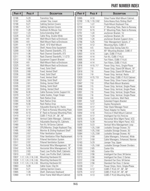
PART NUMBER INDEX
12186 5-29 Transition Tray12187 5-29 Jumper Tray, Lower12188 5-21 Cabling Section Covers12189 5-21 Cabling Section Covers12193 1-28 Keyboard & Mouse Tray12227 1-23 Extra-Extending Shelf12228 5-23 Cable Ring, Double-Wide12264 4-9 Wall-Mount Rack w/Enclosure12265 4-9 Wall-Mount Rack w/Enclosure12291 4-10 Shelf, 10"D Wall-Mount12293 1-23 Shelf, Heavy-Duty Equipment12309 1-36 Rack Channel Standoffs, 3"D12310 1-36 Rack Channel Standoffs, 6"D12311 1-36 Rack Channel Standoffs, 1-1/2"D12312 1-35 Equipment Support Bracket12324 4-9 Wall-Mount Rack w/Enclosure12325 4-9 Wall-Mount Rack w/Enclosure12334 2-60 Fixed, Solid Shelf 12335 2-60 Fixed, Vented Shelf12336 2-60 Fixed, Solid Shelf12337 2-60 Fixed, Vented Shelf12338 2-61 Sliding, Solid Shelf12339 2-61 Sliding, Vented Shelf 12345 2-61 Sliding, Solid Shelf12346 2-61 Sliding, Vented Shelf12362 6-30 Cable Runway Center Support Kit12370 5-21 Cable Guides, Finger Snaps12392 5-30 Rack Radius Drop12393 5-30 Rack Radius Drop12394 5-30 Rack Radius Drop12407 12-7 Adjusable Bracing Kit, Racks12408 6-14 3” Rack-to-Runway Mounting Plate12409 6-15 6” Rack-to-Runway Mounting Plate12419 4-12 CUBE-iT PLUS 24", 36", 48"12465 2-58 Vertical Cable Manager , Cabinets12477 12-9 Adjustable Bracing Kit, Cabinets12480 2-54 Fan Kit, M-Series Cabinet12487 1-26 CPU/Monitor, Single Keyboard Tray12495 2-63 Monitor & Sliding Keyboard Shelf12505 2-57 Filter Ventilation System12507 2-57 Filter Ventilation Filter Replacement12510 2-57 Filtered Ventilation System12511 2-57 Filtered Ventilation System12541 5-28 Horizontal Wire Management, 19"12542 5-28 Horizontal Wire Management, 19" 12573 2-63 Fixed, Low Profile Shelf, Cabinets12610 2-63 Fixed, Low Profile Shelf, Cabinets12637 1-17, 1-24, 2-18, 2-65 Mounting Hardware Kit12638 1-17, 1-24, 2-18, 2-65 Mounting Hardware Kit12639 1-17, 1-24, 2-18, 2-65 Mounting Hardware Kit12663 5-28 Cable Cover, Clip-On12664 5-21 Cabling Section Covers12665 1-28 Shelf, Stationary Keyboard12680 4-18 Silver Frame Wall-Mount Cabinet
12685 4-18 Silver Frame Wall-Mount Cabinet12700 1-16, 1-19, 2-62 Extra-Heavy-Duty Sliding Shelf12717 1-27 Flush-Mount Keyboard Tray12730 6-14 3” Mounting Plate, Rack-to-Runway12731 6-15 6” Mounting Plate, Rack-to-Runway12751 1-24 anyServer Bracket, 1U12752 1-24 anyServer Bracket, 2U12759 1-24 anyServer Bracket Support Arms12766 5-25 Fiber Management Spools, 2"12787 4-12 Mounting Rails, CUBE-iT12795 4-5 Heavy-Duty Swing Gate Kit12796 4-15 45° Mounting Bracket, CUBE-iT 12803 4-14 Light, CUBE-iT PLUS12804 4-14 Fan Kit, CUBE-iT PLUS12805 4-14 Fan Filters, CUBE-iT PLUS12806 4-14 Fan Filters, CUBE-iT PLUS12816 4-10, 7-7 Power Strip, Horiz, Single-Phase12817 7-8 Power Strip, Stand-Off Mount, 19" 12818 7-8 Power Strip, Stand-Off Mount, 23"12819 7-8 Power Strip, Vertical, Racks12820 4-15, 7-9 Power Strip, CUBE-iT PLUS Cabinet12821 7-9 Power Strip, Silver Frame Cabinet12847 7-9 Offset Rack-Mount Brackets12848 7-5 Power Strip, Vertical, Single-Phase12850 7-5 Power Strip, Vertical, Single-Phase12851 7-6 Power Strip, Vertical, Single-Phase12853 7-6 Power Strip, Vertical, Single-Phase12858 4-6 Corner Cushions, Wall Rack12891 5-22 Extended Fingers Bracket12934 4-17 Duplex Receptacle12955 4-17 Fiber Slack Manager Panel13044 1-37 Panel Adapter for Racks13050 4-16 ThinLine II Wall-Mount Cabinet13051 4-17 Intelligent Fan Kit,ThinLine13070 5-28 Horizontal Wire Mgmt Panel, VCS13075 5-28 Horizontal Wire Mgmt Panel, VCS13079 5-23 Vertical Wire Management Loop13082 1-25, 2-64 Lockable Storage Drawer, 2U13083 1-25, 2-64 Lockable Storage Drawer, 3U13084 1-25, 2-64 Lockable Storage Drawer, 4U13170 2-59 Cable Managers, Enhanced, Wide13171 2-59 Cable Managers, Enhanced, Narrow13183 5-29 Jumper Tray, Upper13185 1-25, 2-64 Lockable Storage Drawer Dividers13203 2-65 Caster Kits13204 2-65 Caster Kits13212 2-56 Intelligent Fan Door, M-Series13213 2-56 Intelligent Fan Door, C-Series13222 2-56 Standard Fan Door, M-Series13223 2-56 Standard Fan Door, C-Series13239 7-7 Power Strips, Horiz, Single-Phase13265 4-12 CUBE-iT PLUS 24", 36", 48"13275 4-12 CUBE-iT PLUS 24", 36", 48"13276 4-13 CUBE-iT PLUS Mounting Rails
PART # PAGE # DESCRIPTION PART # PAGE # DESCRIPTION
14-5

PART NUMBER INDEX
PART # PAGE # DESCRIPTION
13285 4-15 90° Mounting Bracket, CUBE-iT 13286 4-15 Vert Mounting Bracket, CUBE-iT13287 4-14 Termination Block Panel, CUBE-iT13288 4-14 Termination Block Panel, CUBE iT13336 2-55 Air Dam Kit13392 6-6 Pathway Dividers, Cable Runway13393 2-64 Universal Cabinet Light13394 6-7 PatchRack , Cable Runway13395 6-7 PatchRack, Cable Runway13396 6-7 D-Rings for PatchRack, Runway 13399 6-7 PatchRack Hardware Kit, Runway13480 1-28 Keyboard & Tray, 4-Post/Cabinets13483 4-12 CUBE-iT PLUS, Foot Kit13485 4-14 Cable Manager, CUBE iT13490 1-28 Keyboard & Tray, 2-Post/Racks13491 4-13 CUBE-iT PLUS Cabinet, 60" & 72"13492 4-13 CUBE-iT PLUS Cabinet, 60" & 72"13493 4-13 CUBE-iT PLUS Cabinet, 60" & 72"13494 4-13 CUBE-iT PLUS Cabinet, 60" & 72"13495 4-13 CUBE-iT PLUS Cabinet, 60" & 72"13496 4-13 CUBE-iT PLUS Cabinet, 60" & 72"13501 1-30 Raised Floor Rack Support13515 1-30 Raised Floor Rack Support13517 2-18, 2-63 Shelf, Rack-Mount Cable13571 2-53 KoldLok Integral Grommet13576 2-53 KoldLok Surface-Mount Grommet13602 4-6 EasySwing Wall-Mount Rack13604 4-6 EasySwing Wall-Mount Rack13608 4-6 EasySwing Wall-Mount Rack13622 11-3 Busbar Kit, Grounding13653 7-11 PDU, Horizontal13671 2-53 KoldLok Split Integral Grommet13674 2-53 KoldLok Extended 3" Grommet13675 2-53 KoldLok Extended 6" Grommet13676 2-53 KoldLok Surface-Mount Grommet13677 2-53 KoldLok Surface-Mount Grommet13696 12-4 Seismic Rack Cable Management13697 12-5 Seismic Rack Power Strip Mounting13698 12-5 Seismic Rack Duplex Outlet Box13699 12-5 Seismic Rack Cable Offset Bracket13701 3-14 MUTOA Floor Box13702 12-5 Seismic Rack Floor Anchor Kit13703 12-5 Seismic Rack Floor Drilling Template13704 12-5 Seismic Rack, Vert Cabling Section13730 6-14 3" Channel Runway Mounting Plate13731 6-15 6" Channel Runway Mounting Plate13762 7-13 PDU Mounting Brackets13772 3-4 Raised Floor Enclosure13780 2-15, 7-13 PDU Mounting Brackets13812 3-6 Ceiling Enclosure13813 3-7 Ceiling Enclosure Fan Kit13833 3-11 Ceiling-Mounted Wireless Enclosure13853 12-4 Seismic Frame Two Post Rack13854 12-4 Seismic Frame Two Post Rack
13855 12-4 Seismic FrameTwo Post Rack13856 12-4 Seismic FrameTwo Post Rack13870 2-53 KoldLok Wave Grommet 13783 2-53 KoldLok Wave Cover13872 2-53 KoldLok Raised Floor, Mini Grommet13883 12-4 Seismic Frame Two Post Rack13884 12-4 Seismic Frame Two Post Rack13885 12-4 Seismic Frame Two Post Rack13886 12-4 Seismic Frame Two Post Rack13901 5-9 Velocity Vertical Cable Manager13902 5-9 Velocity Vertical Cable Manager13904 5-9 Velocity Vertical Cable Manager13905 5-9 Velocity Vertical Cable Manager13911 5-10 Velocity Vertical Cable Manager13912 5-10 Velocity Vertical Cable Manager13914 5-10 Velocity Vertical Cable Manager13915 5-10 Velocity Vertical Cable Manager13928 5-11 Cable Lashing Bar, Velocity13930 5-26 Velocity Horizontal Cable Manager13934 5-11 Cable Ring Manager, Velocity13935 5-11 Cable Spool, Velocity14061 12-9 Seismic Equip Bracket, Cabinets14068 2-58 Vertical Cabling Ring Kit14070 2-60 Fixed Shelf, Solid14072 2-60 Fixed Shelf, Vented14171 2-52 Filler Panels, HotLok Snap-In14172 2-52 Filler Panels, HotLok Snap-In15002 5-24 Cable Distribution Spool15008 5-7, 5-25 Cable Distribution Spool15053 1-17 QuadraRack Server Frame, Fixed15205 1-16 Cable Runway Mounting Bracket15211 1-14 Adj QuadraRack & ServerRack15212 1-14 Adj QuadraRack & ServerRack15213 1-14 Adj QuadraRack & ServerRack15214 1-14 Adj QuadraRack & ServerRack15215 1-14 Adj QuadraRack & ServerRack15216 1-14 Adj QuadraRack & ServerRack15217 1-14 Adj QuadraRack & ServerRack15218 1-14 Adj QuadraRack & ServerRack15235 1-16 Equipment Support Rails, AQR/ASR15245 1-15 Solid Shelves, Adjustable Racks15251 1-11 Adj Rail QuadraRack & ServerRack15252 1-11 Adj Rail QuadraRack & ServerRack15253 1-11 Adj Rail QuadraRack & ServerRack15254 1-11 Adj Rail QuadraRack & ServerRack15255 1-15 Vented Shelves, AQR/ASR15259 1-12 Fixed Mounting Rail, ARQR/ARSR15260 1-12 Fixed Mounting Rail, ARQR/ARSR15270 1-12 Side Panels, ARQR/ARSR15275 1-12 Top-Mount Cable Waterfall Tray15285 1-12 Equipment Rail for ARQR/ARSR15286 1-12 Cable Guide Kit for ARQR/ARSR15320 4-7 Wall-Rack, Heavy-Duty Equipment 15321 4-7 Wall-Rack, Heavy-Duty Equipment
PART # PAGE # DESCRIPTION
14-6
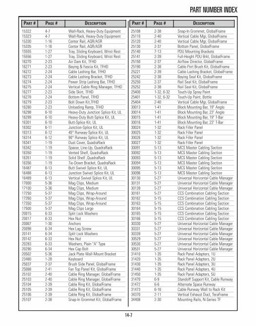
PART NUMBER INDEX
15322 4-7 Wall-Rack, Heavy-Duty Equipment 15323 4-7 Wall-Rack, Heavy-Duty Equipment 15330 1-16 Center Rail, AQR/ASR15335 1-16 Center Rail, AQR/ASR15555 1-27 Tray, Sliding Keyboard, Wrist Rest15556 1-27 Tray, Sliding Keyboard, Wrist Rest16270 2-23 Air Dam Kit, TFHD16271 2-23 Baying & Fascia Kit, TFHD16272 2-24 Cable Lashing Bar, TFHD16273 2-24 Cable Lashing Bracket, TFHD16274 2-24 Power Strip Lashing Bar, TFHD16275 2-24 Vertical Cable Ring Manager, TFHD16277 2-23 Side Skirt, TFHD16278 2-24 Bottom Panel, TFHD16279 2-23 Bolt Down Kit,TFHD16280 2-23 Unloading Ramp, TFHD16298 6-10 Heavy-Duty Junction Splice Kit, UL16299 6-10 Heavy-Duty Butt-Splice Kit, UL16301 6-10 Butt-Splice Kit, UL16302 6-11 Junction-Splice Kit, UL16313 6-12 45° Runway-Splice Kit, UL16314 6-12 90° Runway Splice Kit, UL16341 1-19 Dust Cover, QuadraRack16342 1-19 Spacer, Line-Up, QuadraRack16350 1-19 Vented Shelf, QuadraRack16351 1-19 Solid Shelf ,QuadraRack16356 1-19 Tie-Down Bracket, QuadraRack16487 6-13 Butt Swivel Splice Kit, UL 16488 6-13 Junction Swivel Splice Kit, UL 16489 6-13 Vertical Swivel Splice Kit, UL17000 5-36 Mag Clips, Medium17100 5-36 Mag Clips, Medium17250 5-37 Mag Clips, Wrap-Around17260 5-37 Mag Clips, Wrap-Around17350 5-37 Mag Clips, Wrap-Around17500 5-37 Mag Clips Large20015 6-33 Split Lock Washers20017 6-33 Hex Nut20067 1-30 Anchors20098 6-34 Hex Lag Screw20141 6-34 Split Lock Washers20142 6-33 Hex Nut20283 6-33 Washers, Plain "A" Type 20290 6-34 Hex Cap Bolt20502 5-36 Jack Plate Wall-Mount Bracket23480 1-28 Keyboard 25037 2-37 Brush Side Panel, GlobalFrame25088 2-41 Fan Top Panel Kit, GlobalFrame25102 2-40 Cable Ring Manager, GlobalFrame25103 2-40 Cable Ring Manager, GlobalFrame25104 2-39 Cable Ring Kit, GlobalFrame25105 2-39 Cable Ring Kit, GlobalFrame25106 2-39 Cable Ring Kit, GlobalFrame25107 2-38 Snap-In Grommet Kit, GlobalFrame
25108 2-38 Snap-In Grommet, GlobalFrame25110 2-40 Vertical Cable Mgr, GlobalFrame25120 2-40 Vertical Cable Mgr, GlobalFrame25130 2-37 Bottom Panel, GlobalFrame25140 7-13 PDU Mounting Brackets25141 2-39 Full-Height PDU Brkt, GlobalFrame25150 2-37 Airflow Director, GlobalFrame25190 2-38 Cable Port Brush Kit, GlobalFrame25221 2-39 Cable Lashing Bracket, GlobalFrame25242 2-38 Baying Seal Kit, GlobalFrame25250 2-37 Rail Seal Kit, GlobalFrame25252 2-38 Rail Seal Kit, GlobalFrame25400 1-32, 6-32 Touch-Up Spray Paint25401 1-32, 6-32 Touch-Up Paint, Bottle25404 2-40 Vertical Cable Mgr, GlobalFrame30013 1-41 Block Mounting Bar, 19" Angle30014 1-41 Block Mounting Bar, 23" Angle30015 1-41 Block Mounting Bar, 19" T-Bar30016 1-41 Block Mounting Bar, 23" T-Bar30024 1-32 Rack Filler Panel30025 1-32 Rack Filler Panel30026 1-32 Rack Filler Panel30027 1-32 Rack Filler Panel30091 5-13 MCS Master Cabling Section30092 5-13 MCS Master Cabling Section30093 5-13 MCS Master Cabling Section30094 5-13 MCS Master Cabling Section30095 5-13 MCS Master Cabling Section30096 5-13 MCS Master Cabling Section30130 5-27 Universal Horizontal Cable Manager30131 5-27 Universal Horizontal Cable Manager30139 5-27 Universal Horizontal Cable Manager30161 5-27 CCS Combination Cabling Section30162 5-15 CCS Combination Cabling Section30163 5-15 CCS Combination Cabling Section30164 5-15 CCS Combination Cabling Section30165 5-15 CCS Combination Cabling Section30166 5-15 CCS Combination Cabling Section30330 5-27 Universal Horizontal Cable Manager30331 5-27 Universal Horizontal Cable Manager30339 5-27 Universal Horizontal Cable Manager30529 5-27 Universal Horizontal Cable Manager30530 5-27 Universal Horizontal Cable Manager30531 5-27 Universal Horizontal Cable Manager31410 1-35 Rack Panel Adapters, 1U31420 1-35 Rack Panel Adapters, 2U31430 1-35 Rack Panel Adapters, 3U31440 1-35 Rack Panel Adapters, 4U31450 1-35 Rack Panel Adapters, 5U31470 6-9 Standoff Support Kit, Cable Runway31472 6-6 Alternate Space Runway31473 6-16 Cable Runway Wall to Rack Kit34370 2-11 Vertical Exhaust Duct, TeraFrame34408 2-30 Mounting Rails, N-Series TF
PART # PAGE # DESCRIPTION PART # PAGE # DESCRIPTION
14-7

PART NUMBER INDEX
PART # PAGE # DESCRIPTION PART # PAGE # DESCRIPTION
34409 2-30 Mounting Rails, N-Series TF34416 2-13 Cable Manager, TeraFrame34417 2-13 Cable Manager, TeraFrame34418 2-13 Cable Manager, TeraFrame34419 2-13 Cable Manager, TeraFrame34420 2-13 Cable Manager, TeraFrame34421 2-13 Cable Manager, TeraFrame34422 2-13 Cable Manager, TeraFrame34423 2-13 Cable Manager, TeraFrame34424 2-13 Cable Manager, TeraFrame34425 2-13 Cable Manager, TeraFrame34426 2-13 Cable Manager, TeraFrame34427 2-13 Cable Manager, TeraFrame34521 2-12 Air Dam Kit, TeraFrame34522 2-12 Air Dam Kit, TeraFrame34523 2-12 Air Dam Kit, TeraFrame34537 2-41 Filler Panels, Snap-In34538 2-41 Filler Panels, Snap-In34570 2-11 Airflow Director, TeraFrame34573 2-11 Rear Door Sealing Kit, TeraFrame34595 2-15 Vertical Power Strip Mgr, TeraFrame34620 2-29 Network Duct Panel, N-Series TF34626 2-30 Mounting Rails, N-Series TF34628 2-29 Caster Kit, N-Series TeraFrame34667 2-30 Mounting Rails, N-Series TF34680 2-29 Cable Management Kit, N-Series TF34682 2-29 Baying Kit, N-Series TeraFrame34684 2-29 Right Hand Latch Kit, N-Series TF34701 2-32 Fiber Mgmt, Universal Access. Rail34707 2-33 Fiber Mgmt, Vertical Furcation Brkt34708 2-33 Fiber Mgmt, Horiz Furcation Bracket34713 2-32 Fiber Module Adapter34716 2-32 Fiber Mgmt, Swivel Cable Spool34719 2-31 Fiber Trunk Cable Mgr, N-Series TF34728 6-36 Splice Washer & Bolt, OnTrac34728 6-36 Splice Washer & Bolt Kit, OnTrac34729 6-38 Center Support Bracket, OnTrac34730 6-37 Trapeze Support Bracket, OnTrac34731 6-37 Ede Hanger, OnTrac34732 6-39 Rack-Mount Hook, OnTrac34733 6-38 Triangle Support Bracket, OnTrac34734 6-37 L Support Bracket, OnTrac34735 6-38 Wall Mount Angle, OnTrac34736 6-39 Under Floor Support, OnTrac34737 6-39 Pedestal Clamp, OnTrac34738 6-36 Splice Kit, OnTrac34739 6-36 Splice Bar, OnTrac34740 6-36 90˚ Splice Bar Kit, OnTrac34741 6-41 Tool Less Radius Drop, OnTrac34743 6-40 Cable Tray Divider, OnTrac34744 6-40 Cable Tray Cover, OnTrac34745 6-40 Cable Tray Bottom Insert, OnTrac34746 6-36 Clamp Washer, OnTrac34747 6-41 Large Radius Drop, OnTrac
34749 6-41 Label Holder, OnTrac34811 6-35 OnTrac Wire Mesh Cable Tray34821 6-35 OnTrac Wire Mesh Cable Tray34831 6-35 OnTrac Wire Mesh Cable Tray34838 6-41 Split Bolt Grounding Clamp, OnTrac34839 6-40 Cable Tray Cutting Tool, OnTrac35008 2-19 Mounting Rails, TeraFrame35009 2-19 Mounting Rails, TeraFrame35021 2-38 Cable Grommet Kit, GlobalFrame35051 2-18 Caster Kit, TeraFrame35058 2-18 Mounting Hardware Kit, TeraFrame35078 2-17 Zero Spacing Baying Kit, TeraFrame35079 2-17 Baying Kit, TeraFrame35080 2-17 24" Baying & Fascia Kit, TeraFrame35081 2-17 Seal Kit, TeraFrame35085 2-12 Bottom Panel, TeraFrame35086 2-16 PDU/Power Strip Lashing Bar, TF35087 2-16 Cable Lashing Bar, TeraFrame35090 2-13 Vertical Cable Manager, TeraFrame35092 2-13 Slide Adapter Kt, TeraFrame35095 2-13 Vertical Cable Manager, TeraFrame35100 2-14 Vertical Cable Ring Manager, TF35101 2-14 Vertical Cable Ring Manager, TF35102 2-13 Vertical Cable Manager, TeraFrame35103 2-13 Vertical Cable Manager, TeraFrame35106 2-14 Front-to-Back Cable Mgr, TeraFrame35108 2-14 Front-to-Back Cable Mgr, TeraFrame35441 5-26 Evolution Cable Manager, Horizontal35473 5-5 Cable Lashing Bar, Evolution 35475 5-5 Fiber Segregation Kit, Evolution 35492 5-7 Fixed Accessory Panel, Evolution 35493 5-7 Movable Mid-Section, Evolution 35497 5-6 Solid Mid Panel, Evolution35501 5-6 Solid Rear Panel, Evolution35502 5-6 Solid Side Panel, Evolution35503 5-5 Cable Divider Bar Kit, Evolution35505 5-7 Cable Spool Spacer Kit, Evolution35506 5-5 Floor Bracket, Evolution35511 5-4 Evolution Cable Manager, g1, S/S35512 5-4 Evolution Cable Manager, g1, S/S35513 5-4 Evolution Cable Manager, g1, S/S35514 5-4 Evolution Cable Manager, g1, S/S35515 5-4 Evolution Cable Manager, g1, S/S35521 5-4 Evolution Cable Manager, g2, D/S35522 5-4 Evolution Cable Manager, g2, D/S35523 5-4 Evolution Cable Manager, g2, D/S35524 5-4 Evolution Cable Manager, g2, D/S35525 5-4 Evolution Cable Manager, g2, D/S35571 5-4 Evolution Cable Manager, g335572 5-4 Evolution Cable Manager, g335573 5-4 Evolution Cable Manager, g335574 5-4 Evolution Cable Manager, g335575 5-4 Evolution Cable Manager, g335616 7-10 PDU, Vertical
14-8

PART NUMBER INDEX
35662 7-11 PDU, Horizontal35663 7-11 PDU, Horizontal35676 7-11 PDU, Horizontal35682 7-11 PDU, Horizontal35683 7-11 PDU, Horizontal35692 7-11 PDU, Horizontal35693 7-11 PDU, Horizontal35700 7-13 PDU Mounting Brackets35815 7-10 PDU, Vertical35882 7-12 PDU, Horizontal35883 7-13 PDU, Horizontal35941 7-13 PDU Cables/Accessories35991 7-14 PowerScope In-Line Meter35992 7-14 PowerScope In-Line Meter35993 7-14 PowerScope In-Line Meter36000 10-5 SEMA Software License36001 10-5 SEMA Software License36005 10-5 SEMA Software Package37200 8-3 KVM, 17" LCD Drawer37201 8-3 KVM, 17" LCD Drawer37202 8-5 KVM, Analog Switch, DB15 Ports37203 8-5 KVM, LCD, Analog, DB15 Ports37204 8-5 KVM, LCD, Analog, DB15 Ports37205 8-10 KVM, LCD, IP, Cat 5/6 Ports37206 8-10 KVM, LCD, IP, Cat 5/6 Ports37207 8-10 KVM, IP Switch, Cat 5/6 Ports37208 8-12 KVM Cable37209 8-13 KVM Dongle37209 8-7 KVM, LCD, IP, DB15 Ports37210 8-10 KVM, Analog Expansion Switch37212 8-7 KVM, LCD, IP, DB15 Ports40056 1-34 Equipment Guard Rail40057 1-34 Equipment Guard Rail40058 1-34 Equipment Guard Rail40059 1-34 Equipment Guard Rail40074 1-20, 4-10 Shelf, 15"D Single-Sided40075 1-20 Shelf, Single-Sided 40092 5-14 MCS-EFX Master Cabling Section40093 5-14 MCS-EFX Master Cabling Section40094 5-14 MCS-EFX Master Cabling Section40095 5-14 MCS-EFX Master Cabling Section40096 5-14 MCS-EFX Master Cabling Section40097 5-14 MCS-EFX Master Cabling Section40098 5-16 CCS-EFX Combination Cabling Sect40099 5-16 CCS-EFX Combination Cabling Sect40100 5-16 CCS-EFX Combination Cabling Sect40108 1-22 Double-Sided Shelf, Solid40117 1-20 Single-Sided Shelf, Vented40118 1-20 Single-Sided Shelf, Vented40153 11-3 Busbar Kit, Grounding40156 11-5 Busbar Assembly40157 11-7 Rack Busbar Insulator Block40158 11-5 Busbar Assembly 40159 11-10 Equipment Ground Jumper Kit
40159 11-10 Ground Wire40159 11-11 Ground Jumper40160 11-6 Busbar, Vertical Rack40161 11-7 Vertical Rack Busbar Kit40162 11-14 Compression Lugs40163 11-15 C-Type Compression Taps40164 11-9 Cable Runway Ground Strap Kit40165 11-14 Mechanical Compression Tools40166 11-13 Antioxidant Joint Compound40167 11-9 Two-Mounting Hole Ground Block40168 11-13 Copper-to-Copper Joint Compound40169 11-12 Pedestal Clamp, Ground Connector40170 11-12 Pipe Clamp with Ground Connector40172 11-6 Vertical Rack Ground Bar Kit40602 1-29 Spacer Kit, Univ Racks40604 1-29, 2-18 Installation Kit, Concrete Slab40605 1-38, 2-18, 11-13 Mounting Hardware 40606 1-38 Mounting Hardware 40607 1-29 Installation Kits40750 1-21 Single-Sided Steel Shelf40751 1-21 Double-Sided Steel Shelf41021 1-31 Base Angle41050 1-34 Rack Base Dust Cover42050 1-34 Rack Base Dust Cover46053 1-4 Universal Rack46083 1-4 Universal Rack46353 1-4 Universal Rack46363 1-5 Universal Rack46383 1-4 Universal Rack46753 1-4 Universal Rack46763 1-5 Universal Rack46783 1-4 Universal Rack48353 1-4 Universal Rack48383 1-4 Universal Rack50110 1-18 ExpandaRack, Standard Rack50120 1-18 QuadraRack 4-Post Frame50130 1-18 ExpandaRack, Universal Rack50150 1-18 ExpandaRack Pan Set, Std Rack50160 1-18 ExpandaRack Pan Set, Univ Rack55053 1-7 Rack, Standard, 3"D55100 1-39 High Density Patching Frame55104 1-39 Baying Kit, High Density Frame55105 1-39 Runway Mounting Kit, H-D Frame57011 5-12 Velocity Standard Pack57012 5-12 Velocity Standard Pack57013 5-12 Velocity Standard Pack57014 5-12 Velocity Standard Pack60000 9-3 RIM-600 Host60001 9-3 RIM-600 Node60010 9-5 RIM-600 Temperature Sensor60011 9-5 RIM-600 Temperature Sensor60012 9-5 RIM-600 Mini Temperature Sensor60013 9-5 RIM-600 Temperature Sensor60030 9-5 RIM-600 Humidity Sensor
PART # PAGE # DESCRIPTION PART # PAGE # DESCRIPTION
14-9

PART NUMBER INDEX
PART # PAGE # DESCRIPTION PART # PAGE # DESCRIPTION
60031 9-5 RIM-600 Humidity Sensor60032 9-5 RIM-600 Water Detection Sensor60040 9-7 RIM-600 Power Monitoring Sensor60045 9-4 RIM-600 PowerGate Module60046 9-4 RIM-600 PowerGate 2 Module60050 9-6 RIM-600 Open/Close Contract 60051 9-7 RIM-600 4-20 mA Dry Contact 60052 9-6 RIM-600 Door Open/Closed Sensor60061 9-6 RIM-600 Motion Sensor60062 9-6 RIM-600 Smoke Detector Sensor60071 9-7 Null Modem Cable60072 9-5 10’L Water Detect Sensor Rope60075 9-7 RIM-600 Wall-Mount Kit60075 9-7 RIM-600 Sensor Panel/Bracket60078 9-4 RIM-600 PowerGate 2 Power Cord60087 9-7 RIM-600 User Manual60088 9-7 RIM-600 ConsoleView Software CD66353 1-8 Standard Rack, 6"D66363 1-8 Standard Rack, 6"D66383 1-8 Standard Rack, 6"DA0222-RF 3-4 Raised Floor EnclosureA0422-RF 3-4 Raised Floor EnclosureA0622-RF 3-4 Raised Floor EnclosureA0802-RF-DI 3-5 Raised Floor EnclosureA0822-RF 3-4 Raised Floor EnclosureA0822-RF-F 3-5 Fiber Raised Floor EnclosureA1024-HR 3-6 Ceiling EnclosureA1024-LP 3-7 Ceiling EnclosureA1024-PP 3-7 Ceiling EnclosureA1222-HR 3-6 Ceiling Enclosure A1222-LP 3-7 Ceiling EnclosureA1222-PP 3-7 Ceiling EnclosureA1224-HR 3-6 Ceiling Enclosure A1224-LP 3-7 Ceiling Enclosure A1224-PP 3-7 Ceiling EnclosureA1411-RF-HR 3-5 Raised Floor EnclosureA1422-RF 3-4 Raised Floor EnclosureA1422-RF-F 3-5 Fiber Raised Floor EnclosureAAT-ACE-DOME 3-11 Wireless, Dome EnclosureAAT-AWM-H 3-14 Wall Mount EnclosureAAT-CAP 3-10 Wireless Ceiling EnclosureAAT-CAP-00 3-10 Enclosure Faceplate, SolidAAT-CAP-10-P 3-10 Wireless Ceiling EnclosureAAT-CAP-11 3-10 Enclosure FaceplateAAT-CAP-12 3-10 Enclosure FaceplateAAT-CAP-1232 3-10 Enclosure FaceplateAAT-CAP-1242 3-10 Enclosure FaceplateAAT-CAP-KIT 3-10 Wireless Enclosure KitsAAT-CAP-S 3-10 Wireless Ceiling EnclosureAAT-CAP-UNI 3-10 Enclosure Faceplate, UniversalAAT-MWME-P 3-12 Wireless Wall-Mount EnclosureAAT-WME-P 3-13 Wireless Wall-Mount EnclosureAAT-WMESG 3-13 Wireless Wall-Mount EnclosureBCE-24-N 3-8 Enclosure, Drop Ceiling
BCE-24-P 3-8 Enclosure, Drop CeilingBCE-48-N 3-8 Enclosure, Drop CeilingBCE-48-P 3-8 Enclosure, Drop CeilingBCE-6-P 3-8 Enclosure, Drop CeilingC10XX 2-49 C-Series SlimFrame CabinetC11XX 2-49 C-Series SlimFrame CabinetC12XX 2-49 C-Series SlimFrame CabinetChrome Lock 3-9 Lock Kit, Zone EnclosuresE10XX 2-50 E-Series ISP CoLocation CabinetE20XX 2-50 E-Series ISP CoLocation CabinetE30XX 2-50 E-Series ISP CoLocation CabinetE40XX 2-50 E-Series ISP CoLocation CabinetF-600-0 9-4 RIM-600 BundleFXXX-XXXX-XXX 2-9 F-Series TeraFrame CabinetFHD-XXXX-XXX 2-22 F-Series TeraFrame HD CabinetGF-XXXXX 2-36 GF-Series GlobalFrame CabinetM10XX 2-45 M-Series MegaFrame CabinetM11XX 2-45 M-Series MegaFrame CabinetM12XX 2-45 M-Series MegaFrame CabinetM15XX 2-46 M-Series MegaFrame Cabinet, 48"M20XX 2-45 M-Series MegaFrame CabinetM21XX 2-45 M-Series MegaFrame CabinetM22XX 2-45 M-Series MegaFrame CabinetM25XX 2-46 M-Series MegaFrame Cabinet, 48"NX0X-XXXX-XXX 2-27 N-Series TeraFrame CabinetNX1X-XXXX-XXX 2-27 N-Series TeraFrame CabinetNX2X-XXXX-XXX 2-28 N-Series TeraFrame Cabinet, CiscoNX3X-XXXX-XXX 2-28 N-Series TeraFrame Cabinet, CiscoNX4X-XXXX-XXX 2-28 N-Series TeraFrame CabinetNX5X-XXXX-XXX 2-28 N-Series TeraFrame Cabinet, CiscoRF-Bracket 3-9 Zone Enclosure Mounting BracketSpare Keys 3-9 Zone Enclosure Spare KeyWA064-CAP 3-11 Wireless Ceiling EnclosureWA064-WAP 3-12 Wireless Wall-Mount Enclosure
14-10

©20
12 C
hats
wor
th P
rodu
cts,
Inc.

Catalog Includes:
[email protected] U.S. & Canada
All products quoted are subject to availability based on manufacturing capacity and shipping dates should be considered estimates only. While every effort has been made to ensurethe accuracy of all information, CPI does not accept liability for any errors or omissions and reserves the right to change information and descriptions of listed services and products.
©2012 Chatsworth Products, Inc. All rights reserved. CPI, CPI Passive Cooling, MegaFrame, Saf-T-Grip, Seismic Frame, SlimFrame, TeraFrame, GlobalFrame, Cube-iT Plus, Evolution, Velocity, OnTrac, and QuadraRack are federally registered trademarks of Chatsworth Products, Inc. Simply Efficient is a trademark of Chatsworth Products, Inc.
All other trademarks belong to their respective companies. 01/12 MKT-60020-540
Rack Systems
Cabinet & Enclosure Systems
Zone Cabling & Wireless Enclosures
Wall-Mount Systems
Cable Management Products
Cable Runway & Tray Products
Power Management Products
KVM Systems
Environmental Monitoring & Security Systems
Software
Grounding & Bonding Products
Seismic Protection Systems