20121129 reckmann manual sf en€¦ · 1 inner padeye 1 deckblind 1 rubbercollar 13 din 7991 m5x12...
TRANSCRIPT

RECKMANN
Reckmann Yacht Equipment GmbH - Siemensstr. 37-39 – D-25462 Rellingen Tel. +49(0)4101 3849-0 Fax. +49(0)4101 3849-50
[email protected] – www.reckmann.com
operation manual
SF s/g
hydraulic furling system
RT

<
2
Stand: 29 November 2012
Copyright by Reckmann Yacht Equipment GmbH
Siemensstr. 37-39 D-25462 Rellingen

<
3
1 Introduction ................................................................................................ 5
1.1.1 Packing list .................................................................................. 5 1.1.2 How to use this manual ............................................................... 9 1.1.3 Important remarks ..................................................................... 10
1.2 Maintenance of the furler .................................................................. 11 1.2.1 Maintenance to be carried out by the customer ........................ 11 1.2.2 Maintenance to be carried out by a Reckmann service partner 11 1.2.3 maintenance plan ...................................................................... 12
1.3 Securing the furler against swinging in rough sea conditions .......... 13
1.4 use of soft loops or textile lashings .................................................. 15
2 Product description .................................................................................. 16
2.1 Product description ........................................................................... 16
2.2 Elements of the deck joint ................................................................ 18
2.3 Elements of the stay joint (as an option) .......................................... 21
3 Assembling the furling unit ...................................................................... 22
3.1 Installation of the stainless steel deck flange ................................... 24
3.2 Linking the furler with the deck ring .................................................. 25
3.3 Installation of the aluminium deck flange ......................................... 26
3.4 Installation of the rubber collar ......................................................... 28
3.5 installation of the spherical deck flange............................................ 29
4 Hydraulic connection of the motor ........................................................... 31
4.1 hydraulic connection of motors without brake .................................. 31
4.2 Hydraulic connection of motors with brake ...................................... 33
4.3 Installation of the adjuster ................................................................ 35
4.4 Load control block (optional) ............................................................ 36
4.5 Pressure sensor (as an option) ........................................................ 39
4.6 sensor cables ................................................................................... 42

<
4
5 Operation of the furler .............................................................................. 44
5.1 Joint of stay and sail ......................................................................... 44
5.2 Furling the sail .................................................................................. 46
5.3 Topswivel .......................................................................................... 47
5.4 Technical specifications SF furler ..................................................... 51
5.5 Specification topswivel ..................................................................... 53
6 Dealer network and service stations ........................................................ 54
7 Index ........................................................................................................ 60

Introduction
5
Pos: 1.1 /Handbücher/Überschriften/headline_Einleitung @ 0\mod_1263548887469_26.docx @ 4770 @ @ 1
1 Introduction Pos: 1.2 /Handbücher/Überschriften/headline_Überschrift Packliste @ 0\mod_1233667324349_26.docx @ 150 @ @ 1
1.1.1 Packing list SF s/g Pos: 1.3 /Handbücher/Packlisten/allgemein/text_Packliste Auftragsdaten @ 0\mod_1233667534974_26.docx @ 153 @ @ 1
Date
Customer
Dealer
Order number
Pos: 1.4 /Handbücher/Packlisten/allgemein/text_Anlagen Typ für Packliste @ 0\mod_1233667787601_26.docx @ 156 @ @ 1
Type: SF s/g
Pos: 1.5 /Handbücher/Packlisten/CZ/text_Packliste Staysail furler (CZxts mit TSxt) @ 0\mod_1242287283334_26.docx @ 3289 @ @ 1
1 CZxts- t
With motor / brake
1 Topswivel T- t
2:1 sheave for Topswivel (optional)
1 Pin for topswivel
1 Manual
Pos: 1.6 /Handbücher/Packlisten/CZ/text_Packliste CZxts Decksflansch Edelstahlring @ 0\mod_1242289072917_26.docx @ 3293 @ @ 1
Stainless steel deckjoint consistent of:
1 Cadanic ring with four plain bearing bushes
2 Inner pins
2 Outer pins
2 Locking plates
1 Padeye
1 Upper padeye
1 Spacer
Introduction
6
Pos: 1.7 /Handbücher/Packlisten/CZ/text_Packliste CZxts Snug fit Decksanbindung @ 0\mod_1242289641662_26.docx @ 3299 @ @ 1
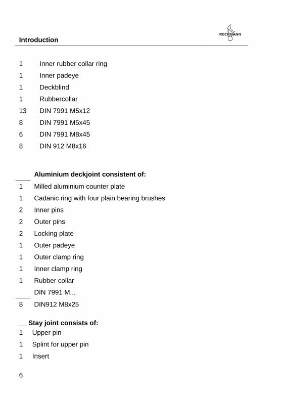
Aluminium deckjoint consistent of:
1 Milled aluminium counter plate
1 Cadanic ring with four plain bearing brushes
2 Inner pins
2 Outer pins
2 Locking plate
1 Outer padeye
1 Outer clamp ring
1 Inner clamp ring
1 Rubber collar
DIN 7991 M...
8 DIN912 M8x25
Pos: 1.8 /Handbücher/Packlisten/CZ/text_CZxts Packliste Staganbindung @ 0\mod_1242289466708_26.docx @ 3296 @ @ 1 Stay
__ Stay joint consists of:
1 Upper pin
1 Splint for upper pin
1 Insert
1 Inner rubber collar ring
1 Inner padeye
1 Deckblind
1 Rubbercollar
13 DIN 7991 M5x12
8 DIN 7991 M5x45
6 DIN 7991 M8x45
8 DIN 912 M8x16
Introduction
7
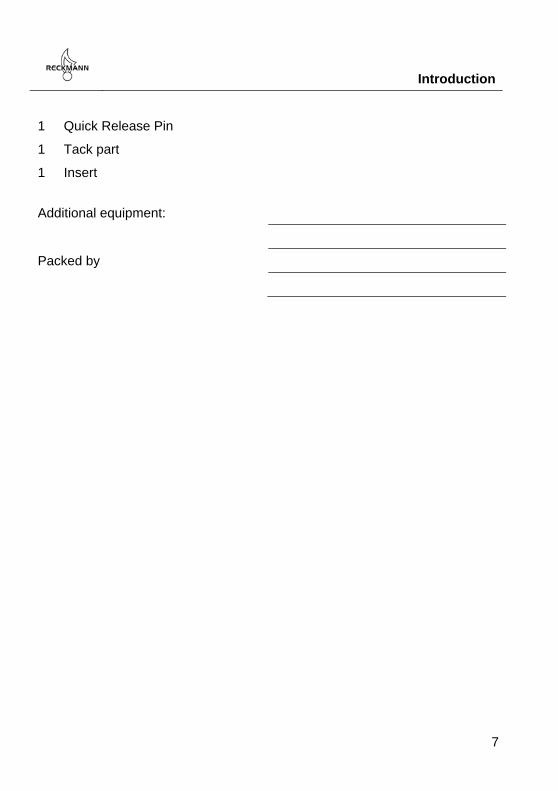
1 Quick Release Pin
1 Tack part
1 Insert
Pos: 1.9 /Handbücher/Packlisten/allgemein/text_Packliste Sonderzubehör @ 0\mod_1233675437501_26.docx @ 179 @ @ 1
Additional equipment:
Packed by
Pos: 2 /Handbücher/-----Seitenumbruch------ @ 0\mod_1233586968379_26.docx @ 101 @ @ 1

Introduction
8
Pos: 3.1 /Handbücher/Allgemeines/text_Einleitung furler @ 0\mod_1233675836284_26.docx @ 182 @ @ 1
Dear Reckmann customer, With the SF s/g reefing system you have purchased the latest reefing system which you can rely on. This unit is manufactured using the latest technical innovations and uses the best materials. It is a successful combination of design, performance and safety. We are confident that the SF s/g reefing system will provide you with enjoyment for many years. Pos: 3.2 /Handbücher/-----Seitenumbruch------ @ 0\mod_1233586968379_26.docx @ 101 @ @ 1

Introduction
9
Pos: 3.3 /Handbücher/Allgemeines/text_Umgang mit dem Handbuch @ 0\mod_1233676171712_26.docx @ 185 @ @ 1
1.1.2 How to use this manual
Read this manual carefully before assembly and operation of your Reckmann gear. Points that need additional attention will be marked in the following way:
Note!
This sign marks points which need special attention.
Warning!
This sign marks the risk of injuries or other significant danger.
Tip
this triangle marks useful tips.
Pos: 3.4 /Handbücher/-----Seitenumbruch------ @ 0\mod_1233586968379_26.docx @ 101 @ @ 1
Introduction
10
Pos: 3.5 /Handbücher/Produktspezifisch/RF90 2 bis 5/text_Hinweise zur Benutzung der Anlage (allgemein) @ 0\mod_1235381412613_26.docx @ 1844 @ @ 1
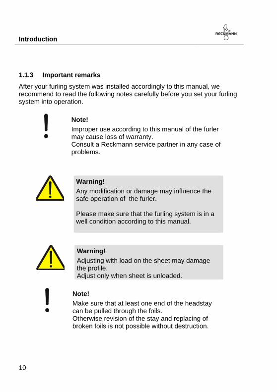
1.1.3 Important remarks
After your furling system was installed accordingly to this manual, we recommend to read the following notes carefully before you set your furling system into operation. Pos: 3.6 /Handbücher/Allgemeines/text_Hinweis Garantieverlust bei unsachgemäßer Handhabung @ 0\mod_1233729770325_26.docx @ 240 @ @ 1
Note!
Improper use according to this manual of the furler may cause loss of warranty. Consult a Reckmann service partner in any case of problems.
Pos: 3.7 /Handbücher/Allgemeines/text_ Warnhinweis: Prüfen auf Beschädigungen @ 0\mod_1233728373847_26.docx @ 230 @ @ 1
Warning!
Any modification or damage may influence the safe operation of the furler. Please make sure that the furling system is in a well condition according to this manual.
Pos: 3.8 /Handbücher/Allgemeines/text_Adjusten nur bei lastfreier Schot @ 0\mod_1259240891708_26.docx @ 4246 @ @ 1
Warning!
Adjusting with load on the sheet may damage the profile. Adjust only when sheet is unloaded.
Pos: 3.9 /Handbücher/Allgemeines/text_Warnhinweis, dass ein Stagende durch das Profil passen muss @ 0\mod_1302845864862_26.docx @ 7498 @ @ 1
Note!
Make sure that at least one end of the headstay can be pulled through the foils. Otherwise revision of the stay and replacing of broken foils is not possible without destruction.
Pos: 4 /Handbücher/-----Seitenumbruch------ @ 0\mod_1233586968379_26.docx @ 101 @ @ 1

Introduction
11
Pos: 5 /Handbücher/Allgemeines/text_Wartung der Anlage @ 0\mod_1233731788860_26.docx @ 250 @ @ 1
1.2 Maintenance of the furler
To keep the furler in a good optical and technical condition, a regular service is required. Maintenance of the furler consists of two basic points:
- Regular maintenance by the customer - Regular Service performed by one of our service partners
Pos: 6 /Handbücher/Allgemeines/text_Wartungsplan Anlagen Allgemein (5-Jahre Service) @ 0\mod_1233732035865_26.docx @ 253 @ 333 @ 1
1.2.1 Maintenance to be carried out by the customer
Clean your furling gear regularly. Wash carefully all salt from the furler. Stainless steel parts can be treated with special care product. Additional for all electric and hydraulic furling units, the function of the manual backup drive and the condition of all hydraulic hoses / electric wires should be checked regular.
1.2.2 Maintenance to be carried out by a Reckmann service partner
To ensure the safe and proper operation of the furler, it has to be serviced every five years by an authorized Reckmann service partner. A table of all authorized Reckmann service partners can be found at the end of this manual or at www.reckmann.com.
Tip
Proper operation can only be ensured by regular service. Make sure that the maintenance plan of your furler is carried out carefully.

Introduction
12
1.2.3 maintenance plan
Please see the following maintenance plan for a detailed schedule:
Pos: 7 /Handbücher/-----Seitenumbruch------ @ 0\mod_1233586968379_26.docx @ 101 @ @ 1

Introduction
13
Pos: 8 /Handbücher/Produktspezifisch/SF/text_Sichern des Furlers in schwerer See bis CZ32ts @ 0\mod_1259246778784_26.docx @ 4270 @ @ 1
1.3 Securing the furler against swinging in rough sea conditions
To secure the furler against swinging in rough sea conditions we recommend a tackle. The tackle is connected to an eyebolt furlerwise. The other part needs to be connected to a sturdy, rigid structure in the ship in alignment with the stay axis. The loose end of the tackle can be redirected to operate it from above deck. A through deck fitting may need to be installed. If the furler should be used or is used the load may be taken from the tackle by easing off the tackle.

Introduction
14
Introduction
15
Pos: 9 /Handbücher/Allgemeines/text_use of soft loops and lashings @ 0\mod_1309352533382_26.docx @ 7818 @ 2 @ 1
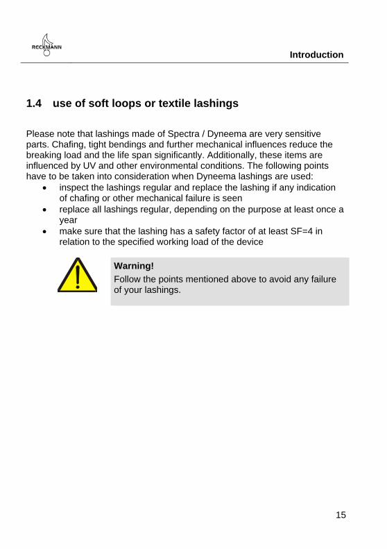
1.4 use of soft loops or textile lashings
Please note that lashings made of Spectra / Dyneema are very sensitive parts. Chafing, tight bendings and further mechanical influences reduce the breaking load and the life span significantly. Additionally, these items are influenced by UV and other environmental conditions. The following points have to be taken into consideration when Dyneema lashings are used:
inspect the lashings regular and replace the lashing if any indication of chafing or other mechanical failure is seen
replace all lashings regular, depending on the purpose at least once a year
make sure that the lashing has a safety factor of at least SF=4 in relation to the specified working load of the device
Warning!
Follow the points mentioned above to avoid any failure of your lashings.

Product description
16
Pos: 10 /Handbücher/Überschriften/headline_Produktbeschreibung @ 0\mod_1234334748004_26.docx @ 1229 @ @ 1
2 Product description
Pos: 11 /Handbücher/Produktspezifisch/SF/text_Produktbeschreibung SF s und g @ 0\mod_1242366663515_26.docx @ 3322 @ 2 @ 1
2.1 Product description
Reckmann staysail furling systems are available with different deck joints, gimbal styled and spherical flanges
1 staysail fork fitting 2 deck joint

Product description
17
3 adjuster unit 4 hydraulic motor with brake
5 worm gear with hyd. motor
SF s/g Pos: 12 /Handbücher/-----Seitenumbruch------ @ 0\mod_1233586968379_26.docx @ 101 @ @ 1

Product description
18
Pos: 13 /Handbücher/Produktspezifisch/SF/text_Produktbeschreibung_CZts_Elemente der Decksanbindung @ 0\mod_1242310911152_26.docx @ 3303 @ @ 1
2.2 Elements of the deck joint
gimbal deck flange made of stainless steel:

Product description
19
gimbal deck flange made of aluminium:
1 Outer deck ring 2 Inner deck ring
3 Inner clamp ring 4 Spacer ring
5 Outer clamp ring 6 Securing plate
7 Outer pin 8 Deck flange
9 Inner pin 10 Cardan ring
11 Friction bearing

Product description
20
spherical deck flange:
1 deck bolts 2 deck ring
3 deck flange 4 friction bearing
5 male part 6 bushing
7 key 8 axial fixing ring
9 securing bolts
Pos: 14 /Handbücher/-----Seitenumbruch------ @ 0\mod_1233586968379_26.docx @ 101 @ @ 1

Product description
21
Pos: 15 /Handbücher/Produktspezifisch/SF/text_Produktbeschreibung CZxts Elemente der Staganbindung @ 0\mod_1242370395488_26.docx @ 3340 @ @ 1
2.3 Elements of the stay joint (as an option)
The stay joint consists of the following components:
1 furler clutch
2 stay fork fitting
3 pin
4 hole for Quick Release Pin
Pos: 16 /Handbücher/-----Seitenumbruch------ @ 0\mod_1233586968379_26.docx @ 101 @ @ 1

Assembling the furling unit
22
Pos: 17 /Handbücher/Überschriften/headline_Montage der Anlage @ 0\mod_1233733221775_26.docx @ 256 @ @ 1
3 Assembling the furling unit Pos: 18 /Handbücher/Allgemeines/text_Warnhinweis das das Deck die Staglast tragen muss @ 0\mod_1240312535455_26.docx @ 2993 @ @ 1
The Reckmann furling unit is installed directly to the deck. The deck has to tolerate the entire stay load.
Warning!
Make sure that the deck is strong enough to carry the entire stay load.
Pos: 19 /Handbücher/Allgemeines/text_Warnhinweis Korrosionsgefahr zwischen Deck und Furler @ 0\mod_1242116178036_26.docx @ 3269 @ @ 1
Note !
Corrosion may occur between the furler and the deck. Tighten the furler and the deck with Sikaflex or a similar sealing product. Between CFK decks and the furler has to be an insulation layer made of GRP
Pos: 20 /Handbücher/Allgemeines/text_Warnhinweis - Decksflansch nicht Wasserdicht @ 0\mod_1241671470823_26.docx @ 3210 @ @ 1
Note!
The deck flange of the furler is not watertight. To avoid flooding of the boat, the furler has to installed in a drained compartment.
Pos: 21 /Handbücher/Produktspezifisch/SF/text_Hinweis auf die richtige Decksflansch Anleitung @ 0\mod_1242382443268_26.docx @ 3360 @ @ 1
Reckmann CZ furlers are available with different deck flanges. Please follow the chapter for your product. Pos: 22 /Handbücher/Produktspezifisch/SF/text_Warnhinweis Furler muss bei Nichtbenutzung gesichert werden, sonst schwingt er @ 0\mod_1247132144139_26.docx @ 3616 @ @ 1
Warning!
Without a tensioned stay the furler will move freely in the deck hinge. There is a risk of being harmed exposed to swell especially. Thoroughly secure and support the furler when not in use.

Assembling the furling unit
23
Pos: 23 /Handbücher/Produktspezifisch/SF/text_Warnhinweis Einbaulage vor - achterlich @ 0\mod_1247131902505_26.docx @ 3613 @ @ 1
Note!
An erring fore/aft alignment can cause damages of the furler. Keep alignment corresponding to description above.
Pos: 24 /Handbücher/Produktspezifisch/UD/text_Warnhinweis UD: Zu großer Stagdurchhang beswchädigt den Furler @ 0\mod_1306907103837_26.docx @ 7571 @ @ 1
Warning!
The maximum stay sag for below deck units is 5% which means approx. 10° of furler deflection. If these values are exceeded, the furler will be damaged immediately.
Pos: 25 /Handbücher/Produktspezifisch/UD/text_Warnhinweis: Der Furler darf unter Deck nirgendwo gegenkommen @ 0\mod_1306906792632_26.docx @ 7568 @ @ 1
Warning!
The furler may not touch the hull or any structures below deck when deflected by stay sag. Otherwise the furler will bent and damaged.
Pos: 26 /Handbücher/Produktspezifisch/SF/text_Warnhinweis furler kann beim Durchschwingen Hydraulikanschluss zuerstören @ 0\mod_1247132265833_26.docx @ 3619 @ @ 1
Note!
If the furler swings forward it may damage the upper hydraulic connection. Secure the furler manually against swinging forward.
Pos: 27 /Handbücher/Allgemeines/text_Warnhinweis Schraube mit Loctite sichern @ 0\mod_1241772320391_26.docx @ 3220 @ @ 1
Note!
To avoid the securing screw from failing, it needs to be secured with a screw securing adhesive (Loctite)
Pos: 28 /Handbücher/Produktspezifisch/SF/text_CZts_Montage des Edelstahldecksflansches @ 0\mod_1242382642365_26.docx @ 3363 @ @ 1

Assembling the furling unit
24
3.1 Installation of the stainless steel deck flange
The furler is mounted cardanicly in the deck. All tensile loads and shearing forces have to be tolerated by the deck. Please make sure that the deck is able to withstand the loads and forces.
Make a circular cut-out in the deck. Drill the mounting holes around the cut-out.
You can use the deck ring on the deck to mark the drilling holes. Adjust the deck ring with the pin drilling amidships exactly
(Bild 1)
After drilling the holes in the deck (1) move the deck ring (3) through the cut-out from underneath. Bolt it together with the outer clamp ring from top side

Assembling the furling unit
25
(Bild 2).
Both the flange- and deck ring surface should now seat solidly on the deck.
3.2 Linking the furler with the deck ring
The furler is linked from above with the cardanic hinge.
Slide the furler with the premounted cardanic ring into the deck ring.
While doing this step use a halyard as aid or support it from underneath.
Put the outer pins (1) through the deck ring in the cardanic ring. Save the bolts with the locking plate (2) and the according screws (3).
The furler has to be secured against motion, due to rough sea conditions when not in use. Furthermore the furler has to be secured agains swinging forwards otherwise the hydraulic connection of the adjuster may be damaged.
Pos: 29 /Handbücher/Produktspezifisch/SF/text_Montage des Aludecksflansches CZxts @ 0\mod_1247131544256_26.docx @ 3610 @ @ 1

Assembling the furling unit
26
3.3 Installation of the aluminium deck flange
Clamp the aluminium backing plate with the deck (4, 5) and glue and or bolt it. Install it from the decks downside. Here it is of importance to keep the right alignment (Forward/ Aft see illustration below)
When the aluminium backing plate (8) is properly bonded with the deck, the furler can be lowered through the deck cut-out from above. Now assemble the ring (10) with the two inner bolts (11). Secure these bolts with the flange screws in the furler. Put the outer bolts (7) in the ring, too. Just now guide the furler while lifting into the backing plate (8). Once the furler is fixed with both locking plates (6) it’s ready to use. Use Loctite or other derivative with every screw to secure it above all

Assembling the furling unit
27

Assembling the furling unit
28
Pos: 30 /Handbücher/Produktspezifisch/SF/text_Montage der Gummimanschette CZxTS @ 0\mod_1242384443976_26.docx @ 3390 @ @ 1
3.4 Installation of the rubber collar
After the furler is linked to the deck ring and all joints are secured, the rubber gasket can be installed. The rubber gasket has to be clamped on the outside between the deck ring and the outer clamp ring and on the inside between inner deck ring and inner clamp ring. Put the inner deck ring aligned with the drillings on top of the rubber and put the screws provided in the holes. Now move the inner clamp ring and the black collar bush over the screws from underneath. Center the package on the ramrodguide. Tighten all screws. Lay the clamp ring onto the rubber collar and bolt it together with the deck ring. Make sure that the outer edge of the rubber gasket (A) fits into the recess in the clamp ring. Tighten these screws firmly criss-crossly, as well. Please notice that the rubber collar won’t be entirely watertight. Furthermore a failure of the collar may result in large quantities of water getting inboards. Install the furler in a self draining compartment of the boat. Pos: 31 /Handbücher/Produktspezifisch/SF/text_Installation furler mit Kugeldecksflansch @ 1\mod_1342160971905_26.docx @ 9008 @ 2 @ 1

Assembling the furling unit
29
3.5 installation of the spherical deck flange
The furler is attached to the deck, it needs to be installed from below deck. Make sure that the mounting surface is perpendicular to the stay direction. The furler can swing 10° to all direction to allow stay sag compensation. Make sure that the furler cannot touch any structure when articulating.

Assembling the furling unit
30
The safest way to install the furler to the deck is to assemble the spherical deck bearing to the furler. Take the deck ring (2) off the furler and bring the furler in position from underneath the deck. Secure the furler with the bolts (1) Pos: 32 /Handbücher/Allgemeines/text_Warnhinweis - Decksflansch nicht Wasserdicht @ 0\mod_1241671470823_26.docx @ 3210 @ @ 1
Note!
The deck flange of the furler is not watertight. To avoid flooding of the boat, the furler has to installed in a drained compartment.

Hydraulic connection of the motor
31
Pos: 33 /Handbücher/Überschriften/headline_Anschluss der Hydraulikschläuche an den Motor @ 0\mod_1234852731877_26.docx @ 1582 @ @ 1
4 Hydraulic connection of the motor Pos: 34 /Handbücher/Überschriften/headline_Anschluss hydromotoren ohne Bremse @ 1\mod_1342162132746_26.docx @ 9018 @ 2 @ 1
4.1 hydraulic connection of motors without brake Pos: 35 /Handbücher/Allgemeines/text_Ventilsteuerung Hydrofurler /RF und UD) @ 0\mod_1234861457576_26.docx @ 1631 @ @ 1
The SF s/g series furlers should be controlled by a 4/3 directional control valve with symbol 4. In dependence of the power pack flow rate, a throttle valve is required in line P. The oil flow should not exceed the number mentioned in the spec sheet at the end of this manual, otherwise the hydraulic drive could be damaged. From SF s/g-4 up, a load control valve is recommended in the line from the directional valve to the hydraulic drive. We recommend to place this valve block close to the hydraulic drive and not directly on the power pack. If you run furlers from SF s/g-4 up without a load control valve, a safe operation is not guaranteed. The required valve block includes two load control valves with a control ratio of i=10 and an adjustable control pressure between 70 bar and 175 bar. We offer this load control valve block with an aluminium housing and two valve cartridges as an option. The thread size for the hydraulic line fittings is G1/2". If you like us to deliver this block, please contact us.
Warning!
Exceeding the maximum values of oil flow and pressure may cause damages of the furler. Make sure the max. values named in the spec. sheet at the end of this manual are not exceeded.

Hydraulic connection of the motor
32
Gears up to SF s/g-3 Gears from SF s/g-4 up
Port sizes of the Reckmann valve block are G1/2", the furler motor has to be connected to ports C1 and C2, the directional valve has to be connected to V1 and V2.

Hydraulic connection of the motor
33
Pos: 36 /Handbücher/Produktspezifisch/SF/text_CZ_Anschluss Bremsmotoren @ 0\mod_1247135445950_26.docx @ 3660 @ @ 1
4.2 Hydraulic connection of motors with brake
The hydraulic motor of the Reckmann furler is equipped with an integrated multiple disc brake. To release the
brake a hydraulic pressure of 30 - 280 bar has to be at the brake release port of the brake.
Note: Higher pressure can cause damages of the brake
For a safe handling of the unit you should meet the following instructions:
The motor has to be controlled by a 4/3 way direction valve. Both directions are possible. To limit the revolution speed a
flow control valve has to installed in the return line of the direction valve.
To avoid overloading of the motor in braking operation, two pressure relief valves may be installed between the direction valve and the motor.
The drain line of the motor has to be connected to the system. The direction valve of the brake should be operated parallel to the direction valve of the motor.
Please see the table in the annex for hydraulic details of the used elements.

Hydraulic connection of the motor
34
Please note that the scheme on the right is meant as example. The plumping and the valves are not Reckmann supply. Hydraulic ports of the motor:
Pos: 37 /Handbücher/Allgemeines/text_Warnhinweis Überschreitender maximalen Anschlußdaten kann furler zertstören @ 0\mod_1247138536818_26.docx @ 3663 @ @ 1
Note!
Operating beyond specifications my cause a sustainable damage of the furling system. Ensure that the furler is not operated beyond its. specifications
Pos: 38 /Handbücher/Produktspezifisch/SF/text_CZxts Anschluss rt Adjuster doppeltwirkend @ 0\mod_1247139034178_26.docx @ 3666 @ @ 1

Hydraulic connection of the motor
35
4.3 Installation of the adjuster
The adjuster works with hydraulic pressure. Maximal stroke and tensile loads can be extracted from the specifications in the annex. The cylinder is controlled by a directional valve (see drawing beside, please note that this scheme is just an example). To avoid overloading of the system while operating it needs to be fitted with a pressure relief valve between directional valve and cylinder. The pressure needed to extend the adjuster has to be limited to 40 bar. Flow control valves in circuits A and B avoid jolty motions of the cylinder. The hose connector is a G1/8“ internal thread adjusterwise. Note that valves and plumbing are not Reckmann supply.

Hydraulic connection of the motor
36
Pos: 39 /Handbücher/Allgemeines/text_Anschluss und Funktion vom Load control Block für RTs @ 0\mod_1274968832340_26.docx @ 5721 @ @ 1
4.4 Load control block (optional)
If your furler is equipped with a load control block, you should take care of this chapter. The block can either be flanged to the furler or it is separated from the furler. In the second case it has to be connected to the adjuster with hoses. Please take care that the block is wired as shown in the diagram below. Make sure that the hoses are capable for the pressures that will occur due to the specified stay load. The T port of the block needs to be connected to the pressure-free tank line. If the block is used together with a single acting ram, the KS port needs to be closed with a cap screw.

Hydraulic connection of the motor
37
components of the valve block:
1 factory set pressure relief 2 mounting screws
3 pressure sensor with adapter 4 anodized valve block

Hydraulic connection of the motor
38
Function of the block: The integrated po check valve makes your PR hose pressure free when the furler is in service with a tensioned stay. To avoid overloading of the furler, the integrated pressure relief opens at a factory set value. The ram can be extended by pumping oil into port PK. The pressure which is needed to open the po-check valve can be determined by the following equation: Pkt=(PRS/10)+2,5
NOTE: Since 2011 the sensor thread is G1/4.

Hydraulic connection of the motor
39
Pos: 40 /Handbücher/Allgemeines/text_Drucksensoreinheiten 0 bis 10V und 4 bis 20 mA @ 0\mod_1239773878442_26.docx @ 2915 @ @ 1
4.5 Pressure sensor (as an option)
As an option we provide a pressure sensing unit to monitor the pressure in the adjuster. This value is corresponding with the load on the stay. The pressure can be measured as long as the adjuster is not in top position. There are two versions of the pressure sensor: one with 0...10V output and one with 4...20mA output. Please find the specs referring to your sensor on the following pages. Hydraulic connection of the sensor:

Hydraulic connection of the motor
40
Note!
The sensor cannot measure the pressure inside the adjuster when it is fully extended. Do not fully extend the adjuster to ensure a proper function of the sensor. .

Hydraulic connection of the motor
41
dimesions of the sensor:
Wiring: PT3540 (mA output)

Hydraulic connection of the motor
42
PT9540 (Voltage output)
Specifications: PT3540 PT9540 Operating Voltage 8,5 … 36V 16V … 36V Reverse polarity protection yes yes Analogue output 4…20mA 0…10V Pressure rating 600 bar 600 bar Bursting pressure 1600 bar 1600 bar Connection M12 M12 Materials 316L / 1.4404 316L / 1.4404
Note!
Make sure that the coupling ring of the sensor plug is fastened properly. Otherwise water could get in the connection and cause corrosion.
Pos: 41 /Handbücher/Allgemeines/text_IFM Sensorkabel @ 0\mod_1302243216923_26.docx @ 7456 @ @ 1
4.6 sensor cables
Reckmann provides special cables with all kind of sensors. The cables are water protected with protection class IP69k, the contacts are gold-coated. The nut ring is made of stainless steel. The plug has integrated LEDs for easy cable function check.

Hydraulic connection of the motor
43
Note!
Make sure that the stainless steel nut of the sensor plug is fastened properly. Otherwise water might enter the plug and destroy the contacts by corrosion.

Operation of the furler
44
Pos: 42 /Handbücher/Überschriften/headline_Betrieb der Anlage @ 0\mod_1233678011693_26.docx @ 197 @ @ 1
5 Operation of the furler Pos: 43 /Handbücher/Produktspezifisch/SF/text_czxts Stag und Segelanbindung @ 0\mod_1247133523256_26.docx @ 3622 @ @ 1
5.1 Joint of stay and sail
The sail is attached with a textile forestay to the furler. Despite the tensile forces of the furler the forestay has to transmit the torque as well. The stay consists of a torsional cable where the thimbles are directly connected to the furler and the swivel. The sail gets lashed with webbings between the ends of the textile forestay.
If your system is equipped with the Reckmann Quickreleasepin you can release the pin by pushing the bronze brad and extract it. The special Reckmann fork fitting remains at the bottom stay end. You disconnect it by using the Quickreleasepin.

Operation of the furler
45
Sail attachment / tensioning To attach the sail the, adjuster needs to be extended to full length. Attach the textile forestay to the furler. Now attach the swivel to the upper end of the textile forestay. Try to hoist it as high as possible in the mast. Begin to put tension on the stay until the adjuster is retracted fully. Pay attention that the furler aligns with the forestay. If it doesn’t align, suspend the tensioning and check the hinge. While operating, the adjuster needs to be fully retracted during the furling process. Otherwise the furler may get damaged. If the adjuster can’t be fully retracted due to workingloads, consult your sailmaker concerning the length of the forestay. Furling / unfurling the sail You can furl or unfurl to both sides either clockwise or counter clockwise. Make sure that the system is properly assembled and connected and the brake is venting during furling. Please note that this furler is a device to roll the sail away. Partially reefed sailing is not allowed.

Operation of the furler
46
Pos: 44 /Handbücher/Produktspezifisch/SF/text_Hinweise zum Furlen des Segels @ 0\mod_1278913505525_26.docx @ 6025 @ @ 1
5.2 Furling the sail
You can furl or unfurl in both directions - either clockwise or counter clockwise. Make sure that the system is properly assembled and connected. If your furler is equipped with a hydraulic operated brake, make sure that the brake is vented while furling. Please note that this furler is a device to roll the sail away. Partially reefed sailing is not allowed.
Operation of the furler
47
Pos: 45 /Handbücher/Produktspezifisch/TS (topswivel)/text_topwirbel @ 0\mod_1240236868319_26.docx @ 2975 @ @ 1
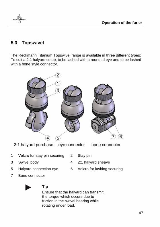
5.3 Topswivel
The Reckmann Titanium Topswivel range is available in three different types: To suit a 2:1 halyard setup, to be lashed with a rounded eye and to be lashed with a bone style connector.
1 Velcro for stay pin securing 2 Stay pin
3 Swivel body 4 2:1 halyard sheave
5 Halyard connection eye 6 Velcro for lashing securing
7 Bone connector
Tip
Ensure that the halyard can transmit the torque which occurs due to friction in the swivel bearing while rotating under load.

Operation of the furler
48
Warning!
Please replace the webbing and the velcro strops regular.
Always make sure that the velcro webbings are tightened properly. Please note that the velcros need to be replaced regular.

Operation of the furler
49
If your siwvel is equipped with a 2:1 sheave, you have to take care that the pin securing screw (2) is secured properly with LocTite or or similar.
The bone-style connector should be used with a lashing in the following style:

Operation of the furler
50
Make sure that all parts of the lashing are lying properly on the sheaves and that the load distributed evenly on all parts of the lashing.
Note!
Seizing of threads. To avoid seizing of threads, all threaded parts need to be coated with anti seizing gel before they are joined.
Pos: 46 /Handbücher/-----Seitenumbruch------ @ 0\mod_1233586968379_26.docx @ 101 @ @ 1

Operation of the furler
51
Pos: 47.1 /Datenblätter/SF/text_technische Daten Staysail Furler @ 0\mod_1247219682922_26.docx @ 3674 @ @ 1
5.4 Technical specifications SF furler

Operation of the furler
52

Operation of the furler
53
Pos: 47.2 /Datenblätter/CZ/text_technische Daten Topwirbel @ 0\mod_1240376432284_26.docx @ 3017 @ @ 1
5.5 Specification topswivel
Pos: 48 /Handbücher/-----Seitenumbruch------ @ 0\mod_1233586968379_26.docx @ 101 @ @ 1

Dealer network and service stations
54
Pos: 49.1 /Handbücher/Überschriften/headline_Händler und Servicestationen @ 0\mod_1233587951296_26.docx @ 119 @ @ 1
6 Dealer network and service stations Pos: 49.2 /Handbücher/Händlerliste/text_Händlerliste Reckmann Nordeuropa @ 0\mod_1233585693028_26.docx @ 81 @ @ 1
Denmark
Southern Spars
Torben Jacobsen
Bergensvej 6
DK–6230 Rödekro
T.: +45 74 620060
F.: +45 74 630543
Norway
With Marine A/S
Leangbutka 31
N - 1392 Vettre
T.: +47 66 79 89 14
F.: +47 66 79 74 83
Quantum Sail Design Group
Jan Hansen Amager Strandvej 50 DK-2300 København
T.:+45 7026 1296
F.: +45 3296 1276
Elvström Sobstad Norge A/S
Sjøsenteret Vallø-PO Box 148
N - 3166 Tolsvrød
T.: +47 3341 4141
F.: +47 3341 4142
Southern Cross Spars A/S
Sandviksvn 120
N - 1363 Høvik
T.: +47 959 77482
F.: +47 9720 18 18
United Kingdom
HYS Rigging
Dennis Fisher
Port Hamble
GB– Hampshire SO31 4NN
T.: +44 2380 454111
F.: +44 2380 455682
Pos: 49.3 /Handbücher/Händlerliste/text_Händlerliste Reckmann Mitteleuropa @ 0\mod_1233586286612_26.docx @ 84 @ @ 1
Netherlands Italy

Dealer network and service stations
55
A+ Rigging Nederland B.V.
Zeldenrust 7
NL-1671 GW Medemblik
T.: +31 227-544096
F.: +31 227-544158
G&G Rigging srl
Walter Giovanelli
Via Mazzini 33
I–20099 Sesto S. Giovanni
T.: +39 02 454 811 90
F.: +39 02 365 138 95
France
Gréement Import
13 Rue du Chéne Lassé - BP
F–44803 Saint - Herblain
T.: +33 2 28 03 01 01
F.: +33 2 28 03 19 91
Spain
Yachttech
Oliver Blume
C /Ca'n Valero 40, Nave
E–07011 Palma de Mallorca
T.: +34 971 200052
F.: +34 971 296504

Dealer network and service stations
56
Croatia
ASPAR Rigging
Luzine bb
CRO-51000 Rijeka
T.: +385 51 674 031
F.: +385 - 51 674 031
Sinera Rigging
Psg. Joan de Borbó 92
E-08039 Barcelona
T.: +34 932 254 934
F.: +34 932 251 949
Slovenia
DNA d.o.o.
Miha Spendal
Kantetova 85
1000 Ljubljana
T.: +386 41 730 970
F.: +386 12776 606
Malta
XS Marine Ltd.
James Xuereb
26, Paul Borg Str.
Attard, Atd 2632
T.: +356 7900 9300
F.: +356 2141 3894
Pos: 49.4 /Handbücher/Händlerliste/text_Händlerliste Reckmann Südeuropa @ 0\mod_1233586613276_26.docx @ 88 @ @ 1
Greece
Kafetzidakis Sails
Kostas Kafetzidakis
90 Tzavella
GR–18533 Piraeus
T.: +30 210 413 74 38
F.: +30 210 413 16 24
Turkey
UTL / Skiper
Muhane cad. Akce sokak no 10/4
Karakoy
Istanbul
T.: +90 212 292 90 98
F.: +90 212 292 91 93

Dealer network and service stations
57
Pos: 49.5 /Handbücher/Händlerliste/text_Händlerliste Reckmann Neuseeland @ 0\mod_1233587020966_26.docx @ 104 @ @ 1
New Zealand
Southern Spars Ltd. 15 Jomac Place Avondale NZ-1026 Auckland
T.: +64 9 8457200
F.: +64 9 3583309
New Zealand Rigging Ltd.
31 Woodside Ave - Northcote
NZ– Auckland
T.: +64 9 480 8090
F.: +64 9 480 9190
Pos: 49.6 /Handbücher/-----Seitenumbruch------ @ 0\mod_1233586968379_26.docx @ 101 @ @ 1
Dealer network and service stations
58
Pos: 49.7 /Handbücher/Händlerliste/text_Händlerliste Reckmann Australien und Karibik und Anfang USA @ 0\mod_1233587251924_26.docx @ 108 @ @ 1
Australia
Riggtech
Phill Bate
Royal Prince Alfred Yacht Club
2/16 Mitala Street,
P.O. Box 812
AUS - 2106 Newport Beach
T.: +61 2 9997 8100
F.: +61 2 9979 6848
USA
Nance and Underwood
262 Southwest 33rd st.
USA - FT Lauderdale, FL 33315
T.: +1 954 764 6001
F.: +1 954 764 5977
Caribbean
Antigua Rigging Ltd.
Stan Pearson
English Harbour
Antigua, West Indies
T.: +1 268 4638575
F.: +1 268 5621294
Euro Marine Trading, Inc.
Siebe Noordzy
62 Halsey Street, Unit M
USA– Newport, RI 02840
T.: +1 401 849 0060
F.: +1 401 849 3230
FKG Marine Rigging
Kevin Gavin
37 Wellington Road
99998 St. Maarten
Netherlands Antilles
Tel. +599 544 4733
Fax. +599 544 2171
Florida Rigging & Hydraulics, Inc.
3905 Investment Lane, Suite 9
USA– Riviera Beach, FL 33404
T.: +1 561 8637444
F.: +1 561 8637711
Pos: 49.8 /Handbücher/-----Seitenumbruch------ @ 0\mod_1233586968379_26.docx @ 101 @ @ 1

Dealer network and service stations
59
Pos: 49.9 /Handbücher/Händlerliste/text_Händlerliste Reckmann Fortsetzung USA @ 0\mod_1233587497734_26.docx @ 112 @ @ 1
Offshore Spars
Mike Feldmann
50200 E.Russell Schmidt Blvd.
USA– Chesterfield, MI 48051
T.: +1 586 598 4700
F.: +1 586 598 4705
Rigworks Inc.
Ray Pope
2540 Shelter Island Drv.
USA - San Diego , CA 92106
T.: +1 619 223 3788
F.: +1 619 223 3099
Rigg Pro
14 Regatta Way
USA - Portsmouth, RI 02871
T.: +1 401 683 2151
F.: +1 401 683 7878
Pos: 50 /Handbücher/-----Seitenumbruch------ @ 0\mod_1233586968379_26.docx @ 101 @ @ 1

Index
60
=== Ende der Liste für Textmarke Inhalt ===
7 Index
Assembling the furling unit 23
Dealer network and service stations 53
Elements of the deck joint 17
Elements of the stayjoint 21
Furling / unfurling the sail 45
Furling the sail 46
How to use this manual 9
Hydraulic connection of motors with brake 33
hydraulic connection of motors without brake 32
Hydraulic connection of the motor 31
Important remarks 10
Installation of the adjuster 36
Installation of the aluminium deck flange 27
Installation of the rubber collar 28
installation of the spherical deck flange 30
Installation of the stainless steel deck flange 25
Introduction 5
Joint of stay and sail 44
Linking the furler with the deck ring 26
Load control block (optional) 36
Maintenance of the furler 11
maintenance plan 12
Maintenance to be carried out by a Reckmann service partner 11
Maintenance to be carried out by the customer 11
Operation of the furler 44
Packing list 5
Pressure sensor (as an option) 39
Product description 15
Sail attachment / tensioning 45
Securing the furler against swinging in rough sea conditions 13
Specification topswivel 52
Technical specifications SF furler 51
Topswivel 47
use of soft loops or textile lashings 14