2013-0036 final report istc 07-7005
TRANSCRIPT
AFRL-AFOSR-UK-TR-2013-0036
Changes in Optical Properties of Spacecraft Materials Due to Combined Effects of Aging Factors in a Space Environment
*Dr. Sergei A. Khatipov *Dr. Oleg Viktorovich
*(1) National Research Nuclear University (MEPhI), 31, Kashirskoye
Shosse, Moscow, 115409, Russia (2) OAO Kompozit , 4, Pionerskaya St., Korolyev, 141070, Russia
(3) Research Institute of Nuclear Physics of Moscow State University (INP MSU), Building of Experimental Installations, Vorobyovy Gory,
Moscow, 119899, Russia
ISTC 07-7005/Project #3806p
Report Date: July 2013
Final Report for 01 November 2007 to 31 October 2012
Air Force Research Laboratory Air Force Office of Scientific Research
European Office of Aerospace Research and Development Unit 4515 Box 14, APO AE 09421
Distribution Statement A: Approved for public release distribution is unlimited.
REPORT DOCUMENTATION PAGE Form Approved OMB No. 0704-0188
Public reporting burden for this collection of information is estimated to average 1 hour per response, including the time for reviewing instructions, searching existing data sources, gathering and maintaining the data needed, and completing and reviewing the collection of information. Send comments regarding this burden estimate or any other aspect of this collection of information, including suggestions for reducing the burden, to Department of Defense, Washington Headquarters Services, Directorate for Information Operations and Reports (0704-0188), 1215 Jefferson Davis Highway, Suite 1204, Arlington, VA 22202-4302. Respondents should be aware that notwithstanding any other provision of law, no person shall be subject to any penalty for failing to comply with a collection of information if it does not display a currently valid OMB control number. PLEASE DO NOT RETURN YOUR FORM TO THE ABOVE ADDRESS. 1. REPORT DATE (DD-MM-YYYY)
16-07-2013 2. REPORT TYPE
Final Report 3. DATES COVERED (From – To)
01 November 2007 – 31 October 2012 4. TITLE AND SUBTITLE
Changes in Optical Properties of Spacecraft Materials Due to Combined Effects of Aging Factors in a Space Environment
5a. CONTRACT NUMBER
FA8655-07-7005 (ISTC Project #3806p) 5b. GRANT NUMBER ISTC 07-7005 5c. PROGRAM ELEMENT NUMBER 3004EF
6. AUTHOR(S)
*Dr. Sergei A. Khatipov *Dr. Oleg Viktorovich
5d. PROJECT NUMBER 5d. TASK NUMBER
5e. WORK UNIT NUMBER
7. PERFORMING ORGANIZATION NAME(S) AND ADDRESS(ES)*(1) National Research Nuclear University (MEPhI), 31, Kashirskoye Shosse, Moscow, 115409, Russia (2) OAO Kompozit , 4, Pionerskaya St., Korolyev, 141070, Russia (3) Research Institute of Nuclear Physics of Moscow State University (INP MSU) Building of Experimental Installations, Vorobyovy Gory, Moscow, 119899, Russia
8. PERFORMING ORGANIZATION REPORT NUMBER
N/A
9. SPONSORING/MONITORING AGENCY NAME(S) AND ADDRESS(ES)
EOARD Unit 4515 APO AE 09421-4515
10. SPONSOR/MONITOR’S ACRONYM(S) AFRL/AFOSR/IOE (EOARD)
11. SPONSOR/MONITOR’S REPORT NUMBER(S)
AFRL-AFOSR-UK-TR-2013-0036
12. DISTRIBUTION/AVAILABILITY STATEMENT Distribution A: Approved for public release; distribution is unlimited. 13. SUPPLEMENTARY NOTES
14. ABSTRACT This project conducted experimental investigations on the degradation of the optical properties of materials used on the external surfaces of spacecraft in conditions of the space environment. What started as an International Science and Technology project (#2342p) titled “Development of a Database on the Changes in the Optical Properties of Materials Used on the External Surfaces of Spacecraft under the Action of the Space Environment Factors,” this project continued for five years to investigate and formulate a comprehensive database of spacecraft material aging properties. The following has been achieved during the course of this effort: 1) Tests were conducted on the Sheldahl films, MAP paints and the Russian materials EKOM-4 and the arimide fabric TTKA-S 56420 under the separate action of protons with the energies 50, 150 и 500 keV, electrons with the energies 50, 100 and 200 keV and UV radiation; 2) Tests were conducted in simulating the combined effects of space environment factors, such as electromagnetic solar radiation (visible, ultraviolet, vacuum ultraviolet and soft X-rays) and charged particles (electrons and protons), at GEO altitudes (conducted on the Russian materials, Sheldahl films, and MAP paints); 3) Laboratory tests were performed in simulating the combined effects of space environment factors, such as atomic oxygen, electromagnetic solar radiation (visible, ultraviolet, vacuum ultraviolet and soft X-ray radiation) at an altitude of 400 km; 4) Bidirectional scattering distribution function (BSDF) and Bidirectional reflectance distribution function (BRDF) measurements were conducted for the wavelengths 532 and 1063 nm; and 5) Measurements were conducted on the Directed Hemispherical Reflectance (DHR) in the range 2.5—10 µm. The results of the experimental studies from the complex impact of the space environment factors on the optical properties of spacecraft materials have been entered into a materials database in both digital and graphical forms. The resulting database is in Microsoft Access 2000 format and contains about 3,500 records.
15. SUBJECT TERMS
EOARD, space environment factors; electrons; protons; atomic oxygen; UV radiation; optical characteristics; thermal control coatings; solar arrays
16. SECURITY CLASSIFICATION OF: 17. LIMITATION OF ABSTRACT
SAR
18, NUMBER OF PAGES
106
19a. NAME OF RESPONSIBLE PERSONKevin Bollino
a. REPORT UNCLAS
b. ABSTRACT UNCLAS
c. THIS PAGE UNCLAS
19b. TELEPHONE NUMBER (Include area code)
+44 (0)1895 616163
Standard Form 298 (Rev. 8/98) Prescribed by ANSI Std. Z39-18
Project # 3806p Final Project Technical Report Page 1 / 104
This work was supported financially by the European Office of Aerospace Research and Development (EOARD, London) and performed under a contract to the International Science and Technology Center (ISTC, Moscow).
Distribution A: Approved for public release; distribution is unlimited.
Project# 3806p Final Project Technical Report
ISTC Project #3806p
Changes in Optical Properties of Spacecraft Materials
Due to Combined Effects of Aging Factors
in a Space Environment
Final Project Technical Report
Page I I 100
of the work performed from November 1, 2007, to October 31, 2012
National Research Nuclear University (MEPhl)
Project Manager
Pro-Rector
Sergei Amerzyanovich KHATIPOV Doctor of Physical and Mathematical Sciences
Oleg Viktorovicb NAGORNOV Doctor of Physical and Mathematical Science
201 3
This work was supported financially by the European Office of Aerospace Research and Development (EOARD, London) and pcrfom1ed under a contract to the International Science and Technology Center (ISTC, Moscow).

Project # 3806p Final Project Technical Report Page 2 / 104
Title of the Project: Changes in Optical Properties of Spacecraft Materials Due to Combined Effects of Aging Factors in a Space Environment
Commencement Date: November 1, 2007
Duration: 5 years
Project Manager: Sergei Amerzyanovich KHATIPOV
phone number: +7(495)916-67-94
fax number: +7(495)916-67-94
e-mail address: khatipov@ nifhi.ru
Leading Institution: National Research Nuclear University (MEPhI) 31, Kashirskoye Shosse Moscow, 115409, Russia +7(495)324-45-41 [email protected]
Participating Institutions:: OAO Kompozit 4, Pionerskaya St. Korolyev, 141070, Russia +7(495)513-22-80 [email protected] Research Institute of Nuclear Physics of Moscow State University (INP MSU) Building of Experimental Installations (Building #19, Rooms 1-51, 2P-01, 2P-02.), Vorobyovy Gory Moscow, 119899, Russia +7(495)939-18-18 [email protected]
Foreign Collaborators: None
Keywords: space environment factors; electrons; protons; atomic oxygen; UV radiation; optical characteristics; thermal control coatings; solar arrays
Distribution A: Approved for public release; distribution is unlimited.
Project # 3806p Final Project Technical Report Page 3 / 104
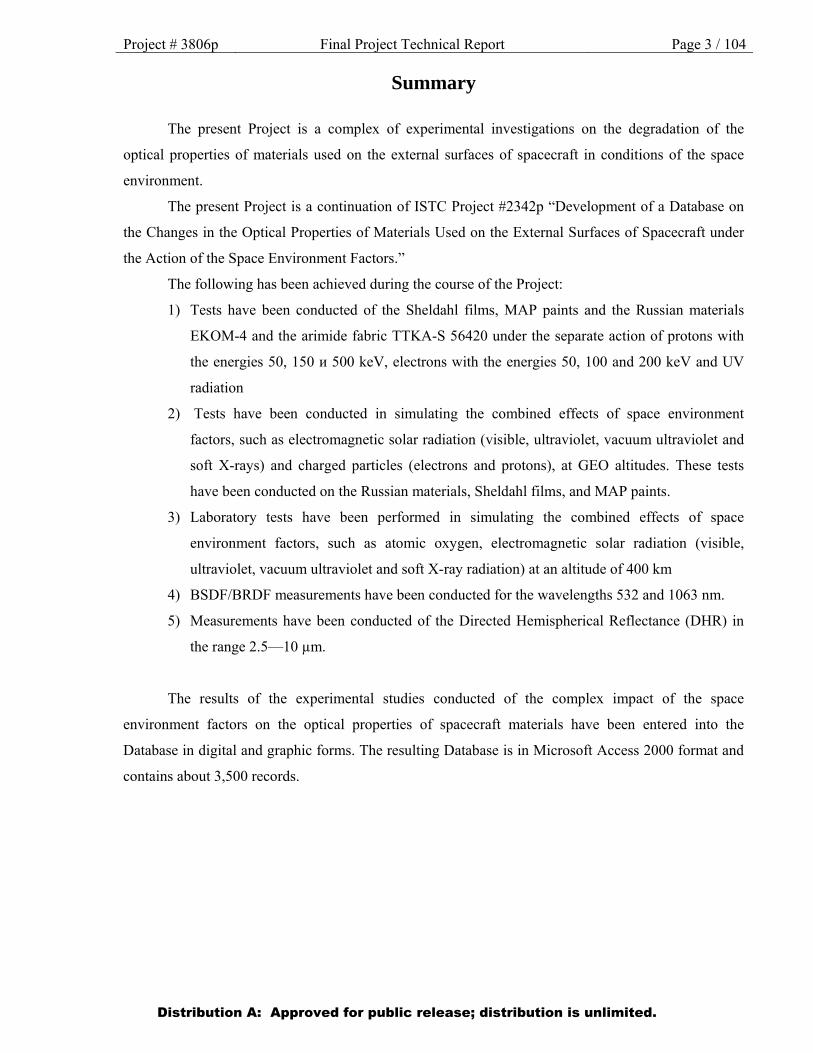
Summary
The present Project is a complex of experimental investigations on the degradation of the
optical properties of materials used on the external surfaces of spacecraft in conditions of the space
environment.
The present Project is a continuation of ISTC Project #2342p “Development of a Database on
the Changes in the Optical Properties of Materials Used on the External Surfaces of Spacecraft under
the Action of the Space Environment Factors.”
The following has been achieved during the course of the Project:
1) Tests have been conducted of the Sheldahl films, MAP paints and the Russian materials
EKOM-4 and the arimide fabric TTKA-S 56420 under the separate action of protons with
the energies 50, 150 и 500 keV, electrons with the energies 50, 100 and 200 keV and UV
radiation
2) Tests have been conducted in simulating the combined effects of space environment
factors, such as electromagnetic solar radiation (visible, ultraviolet, vacuum ultraviolet and
soft X-rays) and charged particles (electrons and protons), at GEO altitudes. These tests
have been conducted on the Russian materials, Sheldahl films, and MAP paints.
3) Laboratory tests have been performed in simulating the combined effects of space
environment factors, such as atomic oxygen, electromagnetic solar radiation (visible,
ultraviolet, vacuum ultraviolet and soft X-ray radiation) at an altitude of 400 km
4) BSDF/BRDF measurements have been conducted for the wavelengths 532 and 1063 nm.
5) Measurements have been conducted of the Directed Hemispherical Reflectance (DHR) in
the range 2.5—10 µm.
The results of the experimental studies conducted of the complex impact of the space
environment factors on the optical properties of spacecraft materials have been entered into the
Database in digital and graphic forms. The resulting Database is in Microsoft Access 2000 format and
contains about 3,500 records.
Distribution A: Approved for public release; distribution is unlimited.
Project # 3806p Final Project Technical Report Page 4 / 104
Contents
List of Figures …………………………………………………………………………………………. 5
List of Tables …………………………………………………………………………………………... 6
List of Symbols, Abbreviations, and Acronyms ………………………………………………………. 6
1. Intoduction. Brief description of the Work Plan …..………………………………………………... 7
1.1. Project goals …………………………………………………..………………………….. 7
1.2. Expected results of the Project ……………………………….………………………….. 9
1.3. Technical approach and methodology ………………………………………………….. 10
2. Techniques of conducting the tests and measurements ………………………………………….. 22
2.1. Technique of conducting tests of materials under combined exposure ……………..… 22
2.2. Technique of conducting tests under separate exposure to electrons and protons ….…… 27
2.3. Testing materials in a plasma flux of atomic oxygen ……………………………..…… 37
2.4. Measuring the spectral and integral optical parameters ………………….……………. 43
2.5. Technique of measuring the BRDF (BSDF) ….………………………………………… 45
3. Results of performing work under the Project …………………………………………………….. 47
4. Conclusion ……………………………………………………………………………………….. 49
5. References ………………………………………………………………………………………… 51
Appendix 1. Examples of the Database structure and interface …………………………………….. 52
Appendix 2. Characteristic test results obtained in the course or realizing the tasks
stipulated under the Project ……….………………………………………………………………….. 75
Appendix 3. Database in MS Access 2000 format
Distribution A: Approved for public release; distribution is unlimited.
Project # 3806p Final Project Technical Report Page 5 / 104
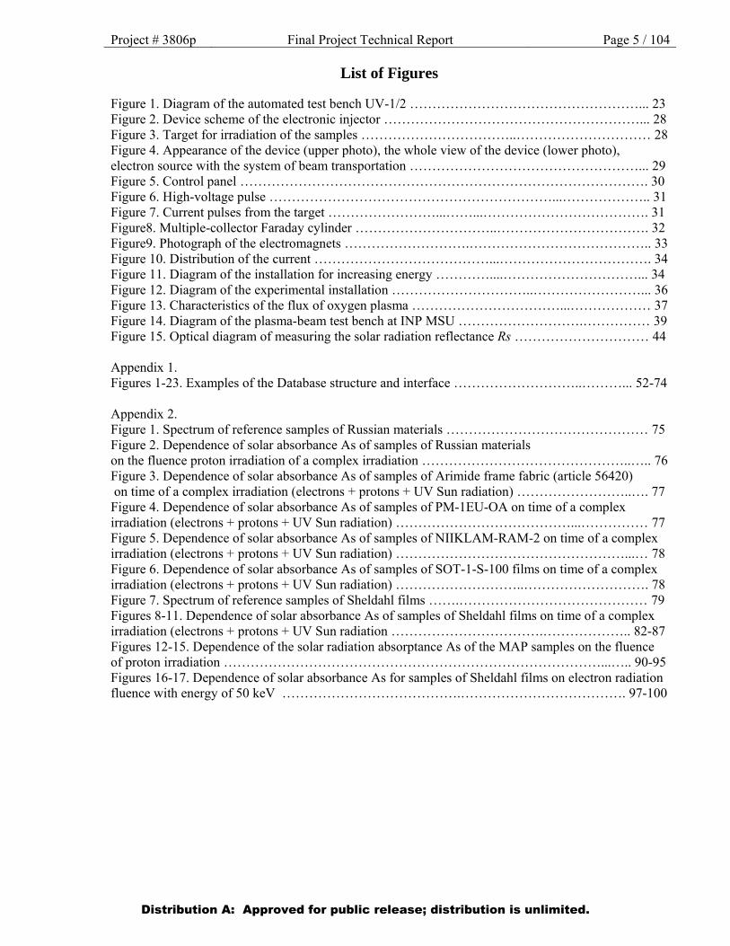
List of Figures
Figure 1. Diagram of the automated test bench UV-1/2 ……………………………………………... 23 Figure 2. Device scheme of the electronic injector …………………………………………………... 28 Figure 3. Target for irradiation of the samples ……………………………..………………………… 28 Figure 4. Appearance of the device (upper photo), the whole view of the device (lower photo), electron source with the system of beam transportation ……………………………………………... 29 Figure 5. Control panel ………………………………………………………………………………. 30 Figure 6. High-voltage pulse ………………………………………………………...……………….. 31 Figure 7. Current pulses from the target ……………………...……...………………………………. 31 Figure8. Multiple-collector Faraday cylinder …………………………..……………………………. 32 Figure9. Photograph of the electromagnets ……………………….………………………………….. 33 Figure 10. Distribution of the current …………………………………...……………………………. 34 Figure 11. Diagram of the installation for increasing energy …………....…………………………... 34 Figure 12. Diagram of the experimental installation …………………………..……………………... 36 Figure 13. Characteristics of the flux of oxygen plasma ……………………………...……………… 37 Figure 14. Diagram of the plasma-beam test bench at INP MSU ……………………….…………… 39 Figure 15. Optical diagram of measuring the solar radiation reflectance Rs ………………………… 44 Appendix 1. Figures 1-23. Examples of the Database structure and interface ………………………..………... 52-74 Appendix 2. Figure 1. Spectrum of reference samples of Russian materials ……………………………………… 75 Figure 2. Dependence of solar absorbance As of samples of Russian materials on the fluence proton irradiation of a complex irradiation ………………………………………..….. 76 Figure 3. Dependence of solar absorbance As of samples of Arimide frame fabric (article 56420) on time of a complex irradiation (electrons + protons + UV Sun radiation) ……………………..…. 77 Figure 4. Dependence of solar absorbance As of samples of PM-1EU-OA on time of a complex irradiation (electrons + protons + UV Sun radiation) …………………………………...…………… 77 Figure 5. Dependence of solar absorbance As of samples of NIIKLAM-RAM-2 on time of a complex irradiation (electrons + protons + UV Sun radiation) ……………………………………………...… 78 Figure 6. Dependence of solar absorbance As of samples of SOT-1-S-100 films on time of a complex irradiation (electrons + protons + UV Sun radiation) ………………………..………………………. 78 Figure 7. Spectrum of reference samples of Sheldahl films …….…………………………………… 79 Figures 8-11. Dependence of solar absorbance As of samples of Sheldahl films on time of a complex irradiation (electrons + protons + UV Sun radiation …………………………….……………….. 82-87 Figures 12-15. Dependence of the solar radiation absorptance As of the MAP samples on the fluence of proton irradiation …………………………………………………………………………...….. 90-95 Figures 16-17. Dependence of solar absorbance As for samples of Sheldahl films on electron radiation fluence with energy of 50 keV ………………………………….………………………………. 97-100
Distribution A: Approved for public release; distribution is unlimited.

Project # 3806p Final Project Technical Report Page 6 / 104
List of Tables
Table 1. List of materials provided by the Project partners for testing …….………………………… 11
Table 2. List of the Russian materials most important from the point of view of their use in spacecraft
that were selected for testing ………………………………………………………………….……… 12
Table 3. The principal technical parameters of the UV-1/2 test bench …………………………...…. 25
Table 4. Parameters of the installation ……………...………………………………………………... 32
Table 5. Parameters of the modernized electron injector …………………………………………….. 35
Table 6. Relative erosion factors of polymer materials ……………………………………………… 42
Appendix 2.
Table 1. Values of the solar radiation reflectance of MAP paints before and after
exposure to protons …………………..………………………………………………………………. 89
Table 2. Influence of factors of the space environment on the integral emission ability
for different materials ……………………………………………………………………………….. 103
List of Symbols, Abbreviations, and Acronyms
LEO – Low Earth orbit
GEO – Geostationary Earth Orbit
BRDF – Bidirectional reflectance distribution function
BSDF – Bidirectional scattering distribution function
DHR – Directed Hemispherical Reflectance
Distribution A: Approved for public release; distribution is unlimited.

Project # 3806p Final Project Technical Report Page 7 / 104
1. Introduction. Brief description of the Work Plan: objective, expected results, technical approach
1.1. Project goals.
Increasing requirements to the stability of materials, as well as the creation of new equipment,
against the background of the general trend towards the extension of the active lifetimes of spacecraft,
call for developing the methods of radiation testing, of predicting radiation stability and a deeper
insight into the peculiarities of the operation conditions of polymers in space.
The project is devoted to the theoretical and experimental study of the degradation of the
optical properties of materials used on the external surfaces of spacecraft, such as solar array cells,
thermal control and thermal insulation materials, in conditions of the space environment on both LEO
and GEO. From the viewpoint of radiation effects, the fundamental distinctive features of operating
polymers in near-Earth space are: the presence of ionizing radiations of different nature; the wide
distribution of the ionizing particles in energy; the composite nature of the impact of particles on the
materials; and the wide range of temperature changes in the latter.
On the external surfaces of spacecraft, polymer materials are directly exposed to the entire
spectrum of the ionizing radiations of the space environment: to protons (with energies 20 — 1,000
MeV), electrons (0.05 MeV), bremsstrahlung (0.05 MeV), solar X-rays (1 — 10 nm) and vacuum UV
radiation; and, for orbits crossing the radiation belts of the Earth, to protons (0.01 — 60 MeV),
electrons (0.02 — 5 MeV) and bremsstrahlung (0.02 — 5 MeV). Large amount of data about physical
and chemical processes interaction of different kinds of radiation with substances including polymers
is contained in [1-11].
The existence of a distribution of space radiation particles in energy results in an
inhomogeneous distribution of the absorbed dose in the depth of the material. Estimates show that the
total surface dose on GEO is extremely high (approx. 107 Gy/year); however, the depth-averaged dose
turns out to be significantly lower, since a considerable share in the total spectrum of radiation is that
of the low-energy part of ionizing radiations (X-rays, vacuum UV radiation, electrons and protons with
energies less than 0.05 and 1 MeV respectively). At a depth of 10 micrometers, the value of the
absorbed dose decreases by more than an order of magnitude.
The bulk of the experimental data on the radiation stability of polymers contained in reference
books and monographs (e. g. [12, 13]) has been obtained under the action of homoenergetic fluxes of
ionizing particles (electrons, gamma-quanta) in conditions of an ionization of the material that is
macroscopically homogenous in volume. In such conditions, the values of the absorbed dose very
seldom cross an upper limit that may be defined at 0.5 107 Gy, which corresponds to a dose absorbed
Distribution A: Approved for public release; distribution is unlimited.
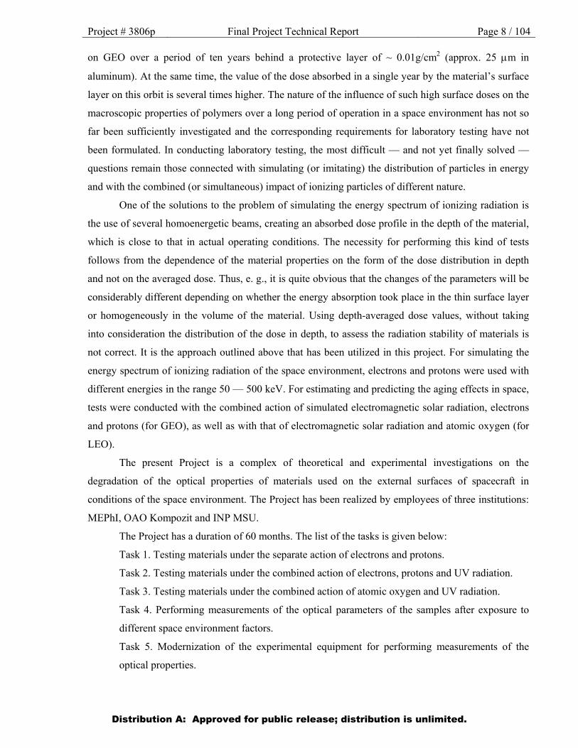
Project # 3806p Final Project Technical Report Page 8 / 104 on GEO over a period of ten years behind a protective layer of ~ 0.01g/cm2 (approx. 25 m in
aluminum). At the same time, the value of the dose absorbed in a single year by the material’s surface
layer on this orbit is several times higher. The nature of the influence of such high surface doses on the
macroscopic properties of polymers over a long period of operation in a space environment has not so
far been sufficiently investigated and the corresponding requirements for laboratory testing have not
been formulated. In conducting laboratory testing, the most difficult — and not yet finally solved —
questions remain those connected with simulating (or imitating) the distribution of particles in energy
and with the combined (or simultaneous) impact of ionizing particles of different nature.
One of the solutions to the problem of simulating the energy spectrum of ionizing radiation is
the use of several homoenergetic beams, creating an absorbed dose profile in the depth of the material,
which is close to that in actual operating conditions. The necessity for performing this kind of tests
follows from the dependence of the material properties on the form of the dose distribution in depth
and not on the averaged dose. Thus, e. g., it is quite obvious that the changes of the parameters will be
considerably different depending on whether the energy absorption took place in the thin surface layer
or homogeneously in the volume of the material. Using depth-averaged dose values, without taking
into consideration the distribution of the dose in depth, to assess the radiation stability of materials is
not correct. It is the approach outlined above that has been utilized in this project. For simulating the
energy spectrum of ionizing radiation of the space environment, electrons and protons were used with
different energies in the range 50 — 500 keV. For estimating and predicting the aging effects in space,
tests were conducted with the combined action of simulated electromagnetic solar radiation, electrons
and protons (for GEO), as well as with that of electromagnetic solar radiation and atomic oxygen (for
LEO).
The present Project is a complex of theoretical and experimental investigations on the
degradation of the optical properties of materials used on the external surfaces of spacecraft in
conditions of the space environment. The Project has been realized by employees of three institutions:
MEPhI, OAO Kompozit and INP MSU.
The Project has a duration of 60 months. The list of the tasks is given below:
Task 1. Testing materials under the separate action of electrons and protons.
Task 2. Testing materials under the combined action of electrons, protons and UV radiation.
Task 3. Testing materials under the combined action of atomic oxygen and UV radiation.
Task 4. Performing measurements of the optical parameters of the samples after exposure to
different space environment factors.
Task 5. Modernization of the experimental equipment for performing measurements of the
optical properties.
Distribution A: Approved for public release; distribution is unlimited.

Project # 3806p Final Project Technical Report Page 9 / 104
1.2. Expected results of the Project:
1. results of the laboratory tests of Sheldahl films and MAP paints, as well as the Russian
materials EKOM-4 and the arimide fabric TTKA-S 56420, under the separate action of
protons (50, 150, 300 and 500 keV), electrons (100 and 200 keV) and UV radiation (all
tests to be conducted with exposures equivalent to one year on GEO);
2. results of the laboratory tests of the Russian materials, Sheldahl films and MAP paints
under the combined action of different types of space radiation (e + p + UV) with an
acceleration factor of three to four for UV radiation and an equivalent fluence
corresponding to 3 years at GEO altitudes;
3. results of the laboratory tests of a limited set of materials (to be agreed upon with the
Partner) under the combined action of atomic oxygen and UV radiation (AO + UV) with
an acceleration factor of one for UV radiation and an equivalent fluence corresponding to 3
years at LEO altitudes (400 km);
4. results of the measurement of the spectral and integral coefficients of reflectance,
transmittance and absorptance in the wavelength range 0.3 — 10 µm for the Russian
materials, Sheldahl films and MAP paints, before and after exposure to different space
environment factors;
5. results of BSDF/BRDF measurements on the wavelengths 532 and 1063 nm for the
Russian materials, Sheldahl films and MAP paints, before and after exposure to different
space environment factors;
The Project falls under the category of applied research. Its results will be used for determining
the endurance of materials used on the external surfaces of spacecraft and having thermal control,
thermal insulation and protective functions, in conditions of their long-term operation in open space.
The results of the theoretical and experimental research carried out under the Project must be
presented in the form of a Database in Microsoft Access 2000 (or later) format.
Experimental research is to be carried out for Russian materials, such as thermal control
enamels: EKOM-1 (white), KO-5191 (white), TR-SO-TsM (white), EKOM-4 (white), EKOM-2
(black); fabrics: the arimide fabric TTKA-S 56420, the metallized glass fabric TSON-SOT-M(bts);
metallized films: the thermal control covering SOT-1S-100, the thermal control covering PM-1EU-
OA; the fabric and film composite material NIIKAM-RAM-2; solar cells: FP-200 and FP-100 (both
with bifacial sensitivity), FP-BSFR-100 and FP-BSFR-200 (both with a reflecting rear surface). The
following foreign materials are also to be tested: US Sheldahl Kapton films (8 brands) and Teflon FEP
films (6 brands), as well as French MAP paints (4 brands).
Distribution A: Approved for public release; distribution is unlimited.
Project # 3806p Final Project Technical Report Page 10 / 104
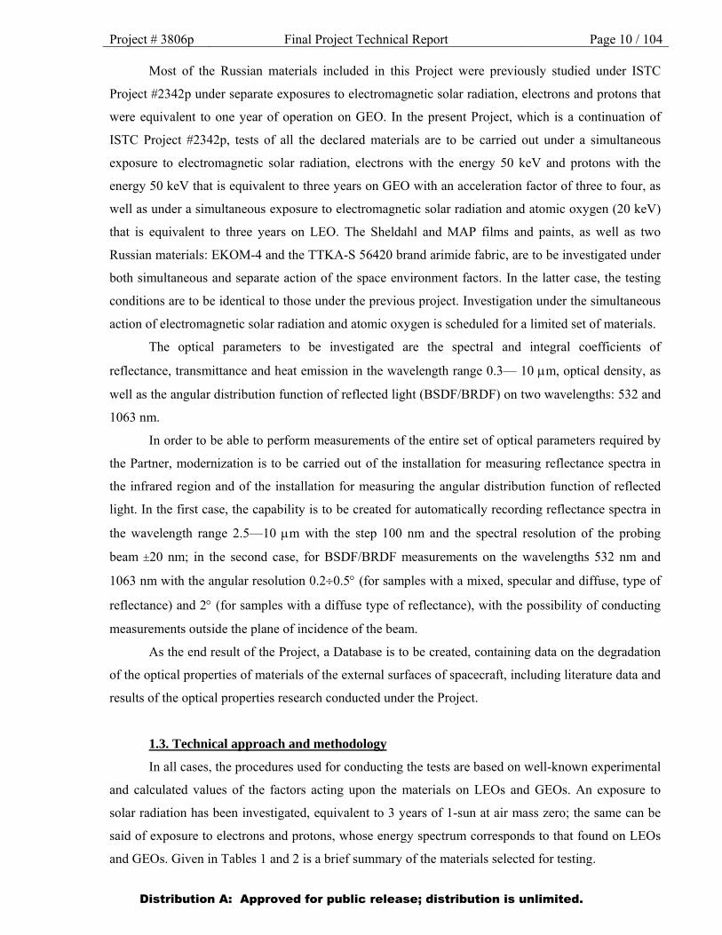
Most of the Russian materials included in this Project were previously studied under ISTC
Project #2342p under separate exposures to electromagnetic solar radiation, electrons and protons that
were equivalent to one year of operation on GEO. In the present Project, which is a continuation of
ISTC Project #2342p, tests of all the declared materials are to be carried out under a simultaneous
exposure to electromagnetic solar radiation, electrons with the energy 50 keV and protons with the
energy 50 keV that is equivalent to three years on GEO with an acceleration factor of three to four, as
well as under a simultaneous exposure to electromagnetic solar radiation and atomic oxygen (20 keV)
that is equivalent to three years on LEO. The Sheldahl and MAP films and paints, as well as two
Russian materials: EKOM-4 and the TTKA-S 56420 brand arimide fabric, are to be investigated under
both simultaneous and separate action of the space environment factors. In the latter case, the testing
conditions are to be identical to those under the previous project. Investigation under the simultaneous
action of electromagnetic solar radiation and atomic oxygen is scheduled for a limited set of materials.
The optical parameters to be investigated are the spectral and integral coefficients of
reflectance, transmittance and heat emission in the wavelength range 0.3— 10 m, optical density, as
well as the angular distribution function of reflected light (BSDF/BRDF) on two wavelengths: 532 and
1063 nm.
In order to be able to perform measurements of the entire set of optical parameters required by
the Partner, modernization is to be carried out of the installation for measuring reflectance spectra in
the infrared region and of the installation for measuring the angular distribution function of reflected
light. In the first case, the capability is to be created for automatically recording reflectance spectra in
the wavelength range 2.5—10 m with the step 100 nm and the spectral resolution of the probing
beam 20 nm; in the second case, for BSDF/BRDF measurements on the wavelengths 532 nm and
1063 nm with the angular resolution 0.20.5 (for samples with a mixed, specular and diffuse, type of
reflectance) and 2 (for samples with a diffuse type of reflectance), with the possibility of conducting
measurements outside the plane of incidence of the beam.
As the end result of the Project, a Database is to be created, containing data on the degradation
of the optical properties of materials of the external surfaces of spacecraft, including literature data and
results of the optical properties research conducted under the Project.
1.3. Technical approach and methodology
In all cases, the procedures used for conducting the tests are based on well-known experimental
and calculated values of the factors acting upon the materials on LEOs and GEOs. An exposure to
solar radiation has been investigated, equivalent to 3 years of 1-sun at air mass zero; the same can be
said of exposure to electrons and protons, whose energy spectrum corresponds to that found on LEOs
and GEOs. Given in Tables 1 and 2 is a brief summary of the materials selected for testing.
Distribution A: Approved for public release; distribution is unlimited.
Project # 3806p Final Project Technical Report Page 11 / 104
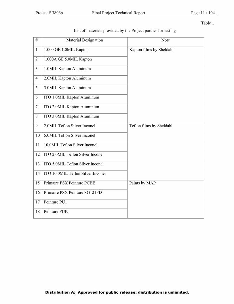
Table 1
List of materials provided by the Project partner for testing
# Material Designation Note
1 1.000 GE 1.0MIL Kapton Kapton films by Sheldahl
2 1.000A GE 5.0MIL Kapton
3 1.0MIL Kapton Aluminum
4 2.0MIL Kapton Aluminum
5 3.0MIL Kapton Aluminum
6 ITO 1.0MIL Kapton Aluminum
7 ITO 2.0MIL Kapton Aluminum
8 ITO 3.0MIL Kapton Aluminum
9 2.0MIL Teflon Silver Inconel Teflon films by Sheldahl
10 5.0MIL Teflon Silver Inconel
11 10.0MIL Teflon Silver Inconel
12 ITO 2.0MIL Teflon Silver Inconel
13 ITO 5.0MIL Teflon Silver Inconel
14 ITO 10.0MIL Teflon Silver Inconel
15 Primaire PSX Peinture PCBE Paints by MAP
16 Primaire PSX Peinture SG121FD
17 Peinture PU1
18 Peinture PUK
Distribution A: Approved for public release; distribution is unlimited.
Project # 3806p Final Project Technical Report Page 12 / 104
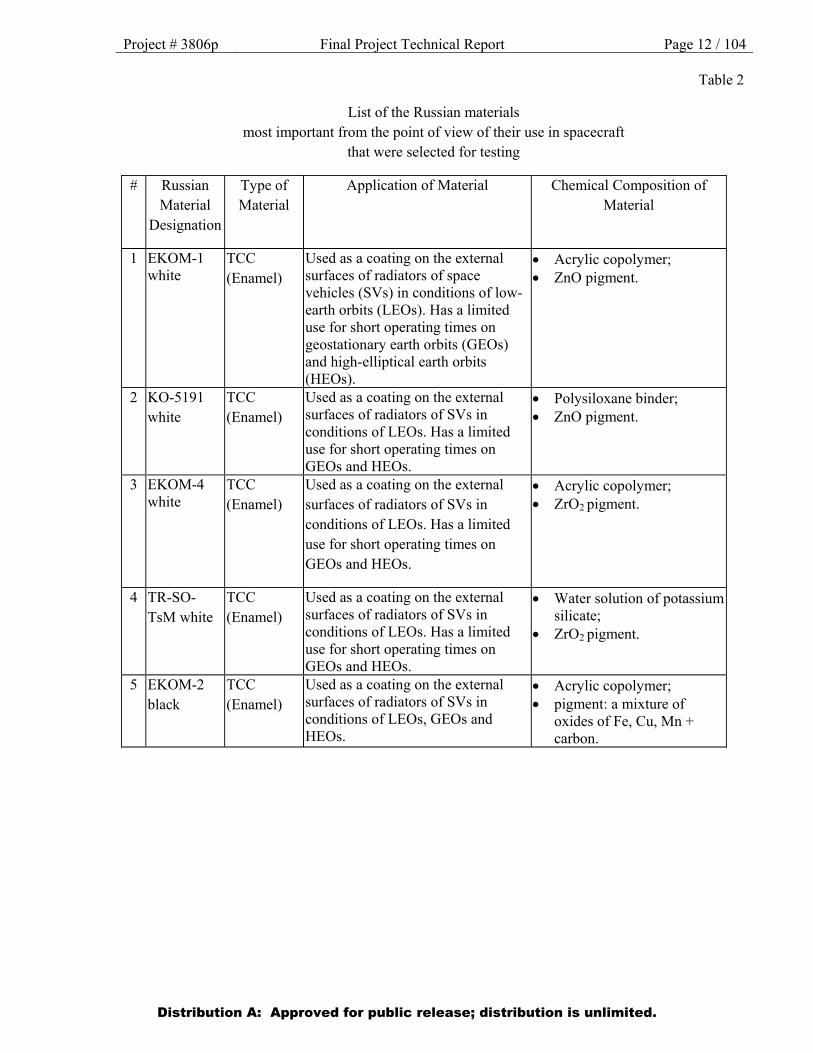
Table 2
List of the Russian materials most important from the point of view of their use in spacecraft
that were selected for testing
# Russian Material
Designation
Type of Material
Application of Material Chemical Composition of Material
1 EKOM-1 white
TCC (Enamel)
Used as a coating on the external surfaces of radiators of space vehicles (SVs) in conditions of low-earth orbits (LEOs). Has a limited use for short operating times on geostationary earth orbits (GEOs) and high-elliptical earth orbits (HEOs).
Acrylic copolymer; ZnO pigment.
2 KO-5191 white
TCC (Enamel)
Used as a coating on the external surfaces of radiators of SVs in conditions of LEOs. Has a limited use for short operating times on GEOs and HEOs.
Polysiloxane binder; ZnO pigment.
3 EKOM-4 white
TCC (Enamel)
Used as a coating on the external surfaces of radiators of SVs in conditions of LEOs. Has a limited use for short operating times on GEOs and HEOs.
Acrylic copolymer; ZrO2 pigment.
4 TR-SO-TsM white
TCC (Enamel)
Used as a coating on the external surfaces of radiators of SVs in conditions of LEOs. Has a limited use for short operating times on GEOs and HEOs.
Water solution of potassium silicate;
ZrO2 pigment.
5 EKOM-2 black
TCC (Enamel)
Used as a coating on the external surfaces of radiators of SVs in conditions of LEOs, GEOs and HEOs.
Acrylic copolymer; pigment: a mixture of
oxides of Fe, Cu, Mn + carbon.
Distribution A: Approved for public release; distribution is unlimited.
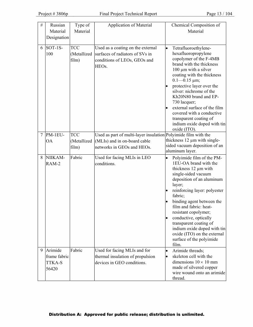
Project # 3806p Final Project Technical Report Page 13 / 104 # Russian
Material Designation
Type of Material
Application of Material Chemical Composition of Material
6 SOT-1S-100
TCC (Metallized film)
Used as a coating on the external surfaces of radiators of SVs in conditions of LEOs, GEOs and HEOs.
Tetrafluoroethylene-hexafluoropropylene copolymer of the F-4MB brand with the thickness 100 µm with a silver coating with the thickness 0.1—0.15 µm;
protective layer over the silver: nichrome of the Kh20N80 brand and EP-730 lacquer;
external surface of the film covered with a conductive transparent coating of indium oxide doped with tin oxide (ITO).
7 PM-1EU-OA
TCC (Metallized film)
Used as part of multi-layer insulation (MLIs) and in on-board cable networks in GEOs and HEOs.
Polyimide film with the thickness 12 µm with single-sided vacuum deposition of an aluminum layer.
8 NIIKAM-RAM-2
Fabric Used for facing MLIs in LEO conditions.
Polyimide film of the PM-1EU-OA brand with the thickness 12 µm with single-sided vacuum deposition of an aluminum layer;
reinforcing layer: polyester fabric;
binding agent between the film and fabric: heat-resistant copolymer;
conductive, optically transparent coating of indium oxide doped with tin oxide (ITO) on the external surface of the polyimide film.
9 Arimide frame fabric TTKA-S 56420
Fabric Used for facing MLIs and for thermal insulation of propulsion devices in GEO conditions.
Arimide threads; skeleton cell with the
dimensions 10 10 mm made of silvered copper wire wound onto an arimide thread.
Distribution A: Approved for public release; distribution is unlimited.
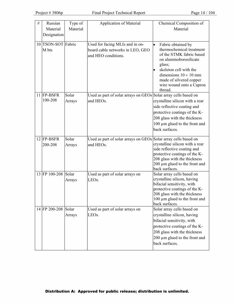
Project # 3806p Final Project Technical Report Page 14 / 104 # Russian
Material Designation
Type of Material
Application of Material Chemical Composition of Material
10 TSON-SOT M bts
Fabric Used for facing MLIs and in on-board cable networks in LEO, GEO and HEO conditions.
Fabric obtained by thermochemical treatment of the STMK fabric based on aluminoborosilicate glass;
skeleton cell with the dimensions 10 10 mm made of silvered copper wire wound onto a Capron thread.
11 FP-BSFR 100-208
Solar Arrays
Used as part of solar arrays on GEOs and HEOs.
Solar array cells based on crystalline silicon with a rear side reflective coating and protective coatings of the K-208 glass with the thickness 100 µm glued to the front and back surfaces.
12 FP-BSFR 200-208
Solar Arrays
Used as part of solar arrays on GEOs and HEOs.
Solar array cells based on crystalline silicon with a rear side reflective coating and protective coatings of the K-208 glass with the thickness 200 µm glued to the front and back surfaces.
13 FP 100-208 Solar Arrays
Used as part of solar arrays on LEOs.
Solar array cells based on crystalline silicon, having bifacial sensitivity, with protective coatings of the K-208 glass with the thickness 100 µm glued to the front and back surfaces.
14 FP 200-208 Solar Arrays
Used as part of solar arrays on LEOs.
Solar array cells based on crystalline silicon, having bifacial sensitivity, with protective coatings of the K-208 glass with the thickness 200 µm glued to the front and back surfaces.
Distribution A: Approved for public release; distribution is unlimited.
Project # 3806p Final Project Technical Report Page 15 / 104
All exposures are made in a good, oil-free vacuum, with dose rates low enough to avoid
excessive heating, expansion or destruction of the sample. After irradiation, the samples are placed
into an inert atmosphere at room temperature to avoid distortion of the results. After testing, the
samples are packed into hermetically sealed containers filled with inert gas and subsequently shipped
to the Partner. Photographs of the samples under testing are made both before and after irradiation.
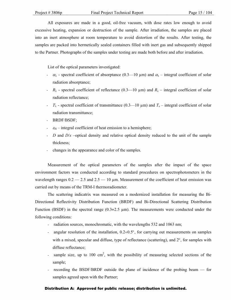
List of the optical parameters investigated:
- - spectral coefficient of absorptance (0.3—10 µm) and s – integral coefficient of solar
radiation absorptance;
- R - spectral coefficient of reflectance (0.3—10 µm) and Rs – integral coefficient of solar
radiation reflectance;
- T - spectral coefficient of transmittance (0.3—10 µm) and Ts – integral coefficient of solar
radiation transmittance;
- BRDF/BSDF;
- H – integral coefficient of heat emission to a hemisphere;
- D and D/x –optical density and relative optical density reduced to the unit of the sample
thickness;
- changes in the appearance and color of the samples.
Measurement of the optical parameters of the samples after the impact of the space
environment factors was conducted according to standard procedures on spectrophotometers in the
wavelength ranges 0.2 — 2.5 and 2.5 — 10 µm. Measurement of the coefficient of heat emission was
carried out by means of the TRM-I thermoradiometer.
The scattering indicatrix was measured on a modernized installation for measuring the Bi-
Directional Reflectivity Distribution Function (BRDF) and Bi-Directional Scattering Distribution
Function (BSDF) in the spectral range (0.32.5 µm). The measurements were conducted under the
following conditions:
- radiation sources, monochromatic, with the wavelengths 532 and 1063 nm;
- angular resolution of the installation, 0.20.5, for carrying out measurements on samples
with a mixed, specular and diffuse, type of reflectance (scattering), and 2, for samples with
diffuse reflectance;
- sample size, up to 100 cm2, with the possibility of measuring selected sections of the
sample;
- recording the BSDF/BRDF outside the plane of incidence of the probing beam — for
samples agreed upon with the Partner;
Distribution A: Approved for public release; distribution is unlimited.
Project # 3806p Final Project Technical Report Page 16 / 104
- angles of incidence of the probing beam, 8, 30 and 60;
- angular range of the measurements, 45 (depending on material type); measurements
conducted every 5 with the purpose of determining the existence of irregular reflection
maxima in certain directions;
- for opaque materials, the BRDF was measured; for a limited selection of semi-transparent
materials, both the BSDF and BRDF were measured.
To provide for the above-mentioned possibilities, modernization has been carried out of the
installation existing at OAO Kompozit. That device is intended for measuring the Bi-Directional
Reflectivity Distribution Function (BRDF) and the Bi-Directional Scattering Distribution Function
(BSDF) and is currently capable of measuring the BSDF/BRDF on samples with high scattering ability
in the spectral range 0.3—2.5 µm. The measurements are only carried out in the plane of incidence of
the beam, with an angular resolution of about 2, at angles of incidence from 0 to 75 and at virtually
any observation angles. A sample with a diameter of 30 mm remains stationary; it is the photodetector
that rotates.
The modernization completed includes:
- equipping the device with monochromatic radiation sources for the wavelengths 532 nm
and 1063 nm;
- increasing the angular resolution of the device to 0.20.5 in order to carry out
measurements on samples with a mixed, specular and diffuse, type of reflectance
(scattering);
- constructional support for measurements of sample surfaces with an area of up to 100 cm2,
with the capability of measuring selected sections of the sample;
- providing for the capability to measure the BSDF/BRDF outside the plane of incidence of
the beam.
Equipment and materials acquired for the modernization:
- rotation platform (by Standa) with a stepper motor for rotating the MR150 type
photodetector; angular resolution, 0.02;
- low-noise photodetector (by Hamamatsu) with an S8785-02 type preamplifier;
- source of continuous monochromatic radiation, 532 nm, LCM-T-111 model (by Laser-
Compact, “Polus”);
- source of continuous monochromatic radiation, 1063 nm, LCM-T-112 model (by Laser-
Compact, “Polus”);
Distribution A: Approved for public release; distribution is unlimited.
Project # 3806p Final Project Technical Report Page 17 / 104
- ATMega-USB type measurement control card (by Argussoft), connectable to PC via USB;
- portable PC;
- synchronous detector of the “Lock-In” type;
- radiation modulator (chopper);
- rotary mounts for fixing the radiation sources;
- telescopic beam expander =532 nm, =1063 nm (1:10);
- angular position sensor (2 items);
- sample-inclination device.
To meet the Partner’s requirements as to measurements in the IR range, modernization has
been carried out of the IR spectrophotometer IKS-31. An installation was created under the Project to
measure the Directed Hemispherical Reflectance (DHR) of material samples in the spectral range
2.510 m. The measurement technique is based on using an integrating sphere, in the center of which
the samples are placed. The sphere is connected to the single-beam IR spectrophotometer IKS-31.
Measurements are carried out every 100 nm in the range 2.510 m, with the spectral resolution of the
probing beam being ±20 nm.
Equipment and materials acquired for the modernization:
- integrating sphere (by Labsphere) with a gold diffuse reflectance coating;
- cooled broadband infrared radiation detector by Hamamatsu;
- comparison standards (by Labsphere) with NIST traceable calibration;
- mirror optics (flat and parabolic mirrors);
- radiation modulator;
- rotary mount for fixing the samples in the center of the integrating sphere;
- motorized rotating platform (by Standa) with a control unit for the stepper motor;
- ATMega-USB type measurement control card (by Argussoft), connectable to PC via USB;
- phase-sensitive voltmeter of the “Lock-In” type;
- PC with an interface unit.
The developed version of the Database includes fifteen tables, thirteen forms and six reports.
The lists of these tables, forms and reports are given in Figures 1—3 of Appendix 1.
The table of materials (tbl_MaterialList) contains the following information fields (Figure 2 of
Appendix 1):
auto-number (unique identifier);
name of the material;
Distribution A: Approved for public release; distribution is unlimited.
Project # 3806p Final Project Technical Report Page 18 / 104
type of the material;
chemical composition of the material;
peculiarities of the fabrication method of the material;
application of the material;
reference to the state standard for the manufacture of the material.
The types of materials are presented in tbl_TypeMaterials (Figure 5, Appendix 1). All the
materials are divided into six types. The materials that do not come under any of the itemized types are
presented in the ‘others’ category:
thermal control coverings,
fabrics,
MLIs,
solar arrays,
structural materials,
optical materials,
others.
TCCs are subdivided into the following classes (Figure 6, Appendix 1):
enamels,
silicate coverings,
galvanochemical coverings,
metallized films,
non-metallized films,
metallized glasses,
non-metallized glasses,
others.
Structural materials (tbl_TypeStructuralMaterial) used on the external surfaces of spacecraft
are subdivided into the following four types (Figure 7, Appendix 1):
glass plastics,
carbon plastics,
thermoplastics,
metals,
alloys,
Distribution A: Approved for public release; distribution is unlimited.
Project # 3806p Final Project Technical Report Page 19 / 104
others.
The table of the type of tests (tbl_TypeTests) includes (Figure 8, Appendix 1):
in-flight tests,
laboratory tests,
prediction results.
The factors of the space environment (tbl_SpaceFactors) are divided into the following classes
(Figure 9, Appendix 1):
electrons,
protons,
ultraviolet solar radiation,
infrared and visible solar radiation,
vacuum ultraviolet,
soft X-ray radiation,
combined action of electrons and protons,
combined action of electrons, protons and ultraviolet solar radiation,
atomic oxygen,
combined action of atomic oxygen and ultraviolet solar radiation,
thermocycling,
contamination,
complex action of the space environment factors,
others,
combined action of electrons and ultraviolet solar radiation,
combined action of protons and ultraviolet solar radiation,
before irradiation.
The list of optical and thermophysical parameters measured is given in tbl_Parameters (Figure
10, Appendix 1):
solar absorption,
spectral absorption coefficient,
solar reflectance,
spectral reflectance coefficient,
solar transmittance,
Distribution A: Approved for public release; distribution is unlimited.

Project # 3806p Final Project Technical Report Page 20 / 104
spectral transmittance coefficient,
coefficient of heat emission,
spectral coefficient of heat emission,
integral coefficient of heat emission,
optical density,
relative optical density reduced to the unit of the sample thickness,
change of material color and appearance,
Bi-directional Reflectance Distribution Function (BRDF),
coefficient of thermal conductivity,
coefficient of thermal diffusivity,
specific heat capacity,
melt temperature,
density,
others.
Orbits (tbl_TypeOrbits), taking into account the operating conditions of spacecraft in them, are
divided into types as follows (Figure 11, Appendix 1):
Low Earth Orbit (LEO, 200—600 km, i = 0—90),
Low Earth Orbit (LEO, 600 —1,000 km, i < 65),
Middle Earth Orbit (MEO, 1000—36,000 km, i < 90),
Polar Orbit (POL, 600—1000 km, i > 65),
Geostationary Earth Orbit (GEO, 36,000 km, i = 0),
Highly-Elliptical Earth Orbit (HEO, 500—40,000 km, i = 65).
The table tbl_References contains a list of the information sources. The imprint of the
publications, such as the author’s name, title and the publisher, is presented in this table (Figure 12,
Appendix 1).
The results of material tests have been distributed into six tables in accordance with the
division of materials into six types. The test results obtained for each of the six material types are
entered into a separate table linked to the other tables. The structure of the data tables is presented in
Figure 13 of Appendix 1 with TCCs as an example. For the other types of materials, the structure of
the tables is similar.
For the presentation of the test results, six forms have been developed, each of them linked to
one of the six data tables which, in turn, correspond to the six types of materials (films, MLIs, TCCs,
Distribution A: Approved for public release; distribution is unlimited.

Project # 3806p Final Project Technical Report Page 21 / 104 solar arrays, optical and structural materials). Figures 14—16 of Appendix 1 show examples of records
from the TCCs, MLIs and structural materials data tables in data forms. The data form has a similar
appearance for the other types of materials.
In the top right corner of each form, there are buttons for print preview of the selected record
and for sending it to print to the operating system’s default printer. Fig. 17 (Appendix 1) shows an
example of a Database record prepared for print.
Fig. 18 (Appendix 1) shows the main form of the Database. The main form allows opening the
forms corresponding to all the six material types, as well as the materials table and the table with the
list of references. Additionally, the main form allows forming search queries (by orbit type, test type,
space environment factor and results of optical and thermophysical measurements). Shown in Figs.
19—21 (Appendix 1) are examples of such queries. For each of the six types of materials, the main
form contains buttons allowing to form queries for printing the required Database records. Shown in
Figs. 22—23 (Appendix 1) are examples of print preview and sending to print of selected Database
records.
A short description of the techniques of conducting the tests and measurements, as well as of
the equipment used, is given below.
Distribution A: Approved for public release; distribution is unlimited.

Project # 3806p Final Project Technical Report Page 22 / 104
2. Techniques of conducting the tests and measurements
2.1. Technique of conducting tests of materials under combined exposure
The UV-1/2 automated test bench (Fig. 1) is intended for studying the physico-chemical
properties of materials and coatings under the combined action of space environment factors (electron
and proton radiation with charged particle energies of up to 50 keV, electromagnetic solar radiation
with intensities of up to 10 e.s.i., vacuum of up to 1 10-6 Pa, temperature T = ± 150C) and for
confirming changes in their properties for long operating lives.
The test bench consists of three main parts:
a vacuum module with an evacuation system and a vacuum control system;
a unit of simulators of the space environment factors;
an automated system of measurement, control and monitoring.
Vacuum module
The vacuum module consists of a vacuum chamber, a two-stage evacuation system and a
vacuum control system (Positions 1 and 4).
The vacuum chamber is a cylinder with a capacity of 1 m3. Located on the front flange are
hermetically sealed connectors for information input and output, as well as connecting pipes for
connecting the thermostat. Attached to the back flange are the space environment factor simulators.
The evacuation system is two-stage and is divided into a fore vacuum evacuation system and a high
vacuum evacuation system. The first stage, fore pumping, is carried out using an NVR-16D pump up
to a pressure of 1 10-1 Pa. The second stage, medium vacuum of up to 1 10-3 Pa, is provided by a
Turbovac-2000 turbomolecular pump (by Leybold Heraeus); high vacuum, up to 1 10-5 Pa, is
provided by an EGIN-5/1 sputter-ion pump. Vacuum control is performed using a thermoelectric
(13VT3-003) and a magnetic (VMB-14) vacuum gauges. Evacuation control may be carried out
remotely.
Distribution A: Approved for public release; distribution is unlimited.
Project # 3806p Final Project Technical Report Page 23 / 104
1 2
3
4
5
7
6
8
9
10
11
12
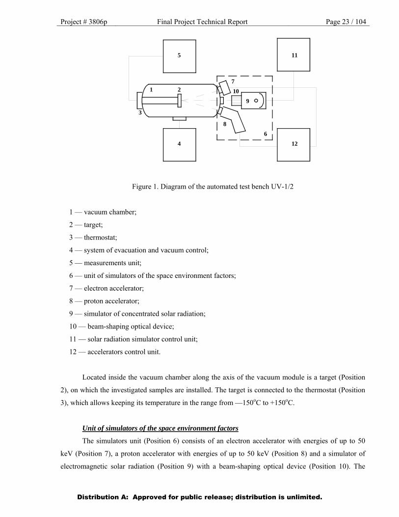
Figure 1. Diagram of the automated test bench UV-1/2
1 — vacuum chamber;
2 — target;
3 — thermostat;
4 — system of evacuation and vacuum control;
5 — measurements unit;
6 — unit of simulators of the space environment factors;
7 — electron accelerator;
8 — proton accelerator;
9 — simulator of concentrated solar radiation;
10 — beam-shaping optical device;
11 — solar radiation simulator control unit;
12 — accelerators control unit.
Located inside the vacuum chamber along the axis of the vacuum module is a target (Position
2), on which the investigated samples are installed. The target is connected to the thermostat (Position
3), which allows keeping its temperature in the range from —150оC to +150оC.
Unit of simulators of the space environment factors
The simulators unit (Position 6) consists of an electron accelerator with energies of up to 50
keV (Position 7), a proton accelerator with energies of up to 50 keV (Position 8) and a simulator of
electromagnetic solar radiation (Position 9) with a beam-shaping optical device (Position 10). The
Distribution A: Approved for public release; distribution is unlimited.
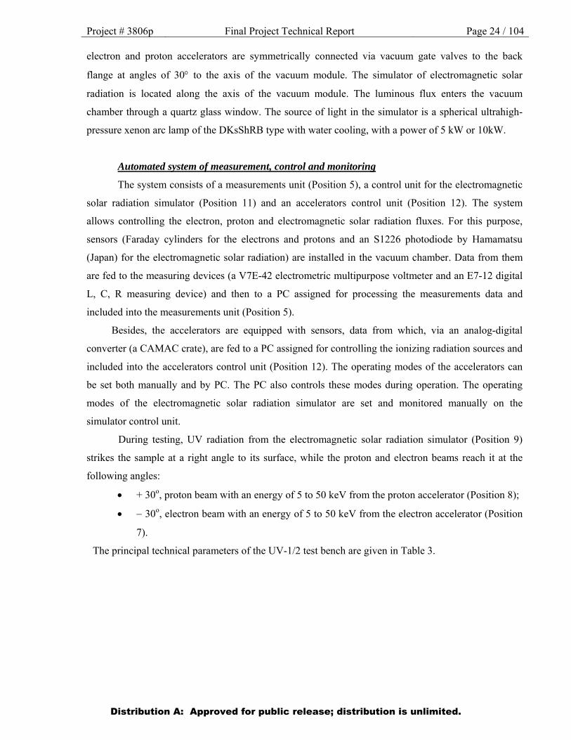
Project # 3806p Final Project Technical Report Page 24 / 104 electron and proton accelerators are symmetrically connected via vacuum gate valves to the back
flange at angles of 30 to the axis of the vacuum module. The simulator of electromagnetic solar
radiation is located along the axis of the vacuum module. The luminous flux enters the vacuum
chamber through a quartz glass window. The source of light in the simulator is a spherical ultrahigh-
pressure xenon arc lamp of the DKsShRB type with water cooling, with a power of 5 kW or 10kW.
Automated system of measurement, control and monitoring
The system consists of a measurements unit (Position 5), a control unit for the electromagnetic
solar radiation simulator (Position 11) and an accelerators control unit (Position 12). The system
allows controlling the electron, proton and electromagnetic solar radiation fluxes. For this purpose,
sensors (Faraday cylinders for the electrons and protons and an S1226 photodiode by Hamamatsu
(Japan) for the electromagnetic solar radiation) are installed in the vacuum chamber. Data from them
are fed to the measuring devices (a V7E-42 electrometric multipurpose voltmeter and an E7-12 digital
L, C, R measuring device) and then to a PC assigned for processing the measurements data and
included into the measurements unit (Position 5).
Besides, the accelerators are equipped with sensors, data from which, via an analog-digital
converter (a CAMAC crate), are fed to a PC assigned for controlling the ionizing radiation sources and
included into the accelerators control unit (Position 12). The operating modes of the accelerators can
be set both manually and by PC. The PC also controls these modes during operation. The operating
modes of the electromagnetic solar radiation simulator are set and monitored manually on the
simulator control unit.
During testing, UV radiation from the electromagnetic solar radiation simulator (Position 9)
strikes the sample at a right angle to its surface, while the proton and electron beams reach it at the
following angles:
+ 30о, proton beam with an energy of 5 to 50 keV from the proton accelerator (Position 8);
30о, electron beam with an energy of 5 to 50 keV from the electron accelerator (Position
7).
The principal technical parameters of the UV-1/2 test bench are given in Table 3.
Distribution A: Approved for public release; distribution is unlimited.
Project # 3806p Final Project Technical Report Page 25 / 104
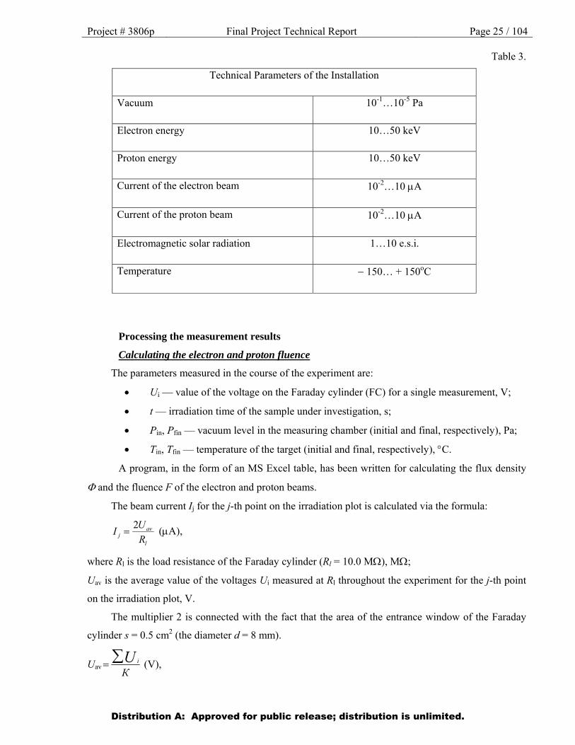
Table 3.
Technical Parameters of the Installation
Vacuum 10-1…10-5 Pa
Electron energy 10…50 keV
Proton energy 10…50 keV
Current of the electron beam 10-2…10 A
Current of the proton beam 10-2…10 A
Electromagnetic solar radiation 1…10 e.s.i.
Temperature 150… + 150оC
Processing the measurement results
Calculating the electron and proton fluence
The parameters measured in the course of the experiment are:
Ui — value of the voltage on the Faraday cylinder (FC) for a single measurement, V;
t — irradiation time of the sample under investigation, s;
Рin, Рfin — vacuum level in the measuring chamber (initial and final, respectively), Pa;
Tin, Тfin — temperature of the target (initial and final, respectively), C.
A program, in the form of an MS Excel table, has been written for calculating the flux density
and the fluence F of the electron and proton beams.
The beam current Ij for the j-th point on the irradiation plot is calculated via the formula:
l
avj R
UI
2 (A),
where Rl is the load resistance of the Faraday cylinder (Rl = 10.0 M), M;
Uav is the average value of the voltages Ui measured at Rl throughout the experiment for the j-th point
on the irradiation plot, V.
The multiplier 2 is connected with the fact that the area of the entrance window of the Faraday
cylinder s = 0.5 cm2 (the diameter d = 8 mm).
UavКU i (V),
Distribution A: Approved for public release; distribution is unlimited.
Project # 3806p Final Project Technical Report Page 26 / 104 where Ui is the voltage on the Faraday cylinder (FC) for a single measurement, V;
К is the number of measurements.
The particle flux density j for the j-th point on the irradiation plot is calculated via the formula:
j = L Ij (particles/cm2 s),
where L is the normalization factor for a current of 1 A. It is known that a charge of 1 coulomb
corresponds to the charge of N particles, i. е. e
QN = 6.24 ·1018 particles (as the elementary charge
e = 1.602 ·10-19 C). A current of 1 A corresponds to the flux of N charged particles through the
cross-section s = 1 cm2 in the time t = 1 s, that is, 1 A = 6.24· 1012 (particles/cm2· s). Hence:
L = 6.24· 1012 (particles/cm2· s).
The fluence Fj of particles for the j-th point on the irradiation plot is calculated via the formula:
Fj = j t (particles/cm2),
where t is the sample irradiation time, s.
The integral fluence F∑ for a single sample is calculated via the formula:
F∑ = ∑Fj (particles/cm2),
where j is the number of points sufficient for creating the irradiation plot of the sample.
Calculating the equivalent solar exposure
The parameters measured in the course of the experiment are:
Iph.d — current of the photodiode, A;
t — irradiation time of the sample under investigation, hrs.
A program, in the form of an MS Excel table, has been written for calculating the equivalent
solar exposure Hs. The calculation table is given in Appendix 3.
The equivalent solar irradiance ESIj for the j-th point on the irradiation plot is calculated via the
formula:
ESIj = L Iph.d,
where L is an empirical coefficient, A-1;
Iph.d. is the average current of the photidiode, A;
Iph.d. КI i (A),
where Ii is the value of the photodiode current for a single measurement, A;
К is the number of measurements.
The equivalent solar exposure Hsj for the j-th point on the irradiation plot is calculated via the
formula:
Distribution A: Approved for public release; distribution is unlimited.
Project # 3806p Final Project Technical Report Page 27 / 104
Hsj = ESIj t (e.s.h.),
where t is the irradiation time of the sample under investigation, hrs;
e.s.h. is the equivalent solar hour.
The integral equivalent solar exposure Hs∑ for a single sample is calculated via the formula:
Hs∑ = ∑Hsj (e.s.h.),
where j is the number of points necessary for creating the irradiation plot of the sample.
The value of the coefficient L was determined through two series of measurements:
1. The total (integral) luminous flux was measured by the calorimetric method using a calorimetric
light detector. Then, using a UV filter, the UV component of the total luminous flux was measured.
2. The UV component of the luminous flux was measured in the range 0.3…0.4 nm using an S1226
photodiode by Hamamatsu (Japan). Then, this figure was approximated for the entire UV range in
accordance with the spectral distribution of the radiation source (DKsShRB xenon lamp) and the
spectral sensitivity of the light detector with the UV filter.
The following value of the coefficient of conversion of the data from the photodiode to the
equivalent solar irradiance has been obtained: L = 1.36 (A-1).
2.2. Technique of conducting tests under separate exposure to electrons and protons
Testing materials under exposure to electrons
Irradiation of materials with accelerated electrons with the energy 50keV was performed on the
UV-1/2 test bench at OAO Kompozit. Intensity of the electron flux equaled 1.0 × 1012 cm-2s-1 (all tests
were performed under exposures equivalent to no less that one year of operating the TCCs on GEO).
Sample temperature during irradiation did not exceed 20С.
Tests of Sheldahl films and MAP enamels under the action of electrons with the energies 85
and 170 keV were conducted at MEPhI. A description of the testing technique is given below.
Setup of the electron injector installation
Shown in Fig. 2 is the diagram of the installation (electron injector), which consists of the
following components: 1 - high-voltage pulse electron gun with an indirectly heated hot cathode, 2 -
focusing coil, 3 - beam transport system in the form of a pipe with magnetic coils, 4 - magnetic screen,
5, 6 - electromagnets, 7 - chamber containing the target (Fig.3) with the samples.
Distribution A: Approved for public release; distribution is unlimited.

Project # 3806p Final Project Technical Report Page 28 / 104
Figure 2. Diagram of the installation (annotated in the text)
Figure 3. Target for irradiation of the samples
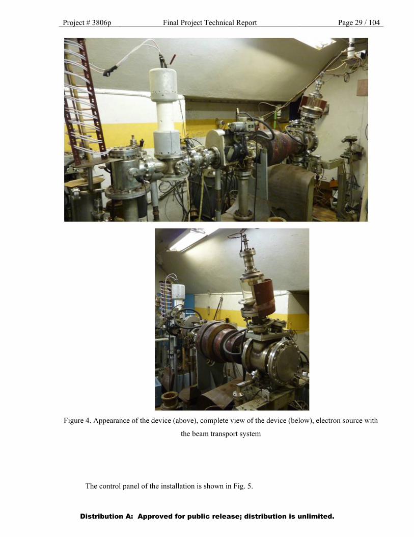
The appearance of the device is shown in Fig. 4.
Distribution A: Approved for public release; distribution is unlimited.
Project # 3806p Final Project Technical Report Page 29 / 104
Figure 4. Appearance of the device (above), complete view of the device (below), electron source with
the beam transport system
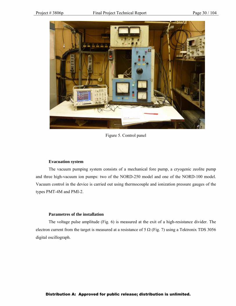
The control panel of the installation is shown in Fig. 5.
Distribution A: Approved for public release; distribution is unlimited.
Project # 3806p Final Project Technical Report Page 30 / 104
Figure 5. Control panel
Evacuation system
The vacuum pumping system consists of a mechanical fore pump, a cryogenic zeolite pump
and three high-vacuum ion pumps: two of the NORD-250 model and one of the NORD-100 model.
Vacuum control in the device is carried out using thermocouple and ionization pressure gauges of the
types PMT-4М and PMI-2.
Parametres of the installation
The voltage pulse amplitude (Fig. 6) is measured at the exit of a high-resistance divider. The
electron current from the target is measured at a resistance of 5 (Fig. 7) using a Tektronix TDS 3056
digital oscillograph.
Distribution A: Approved for public release; distribution is unlimited.
Project # 3806p Final Project Technical Report Page 31 / 104
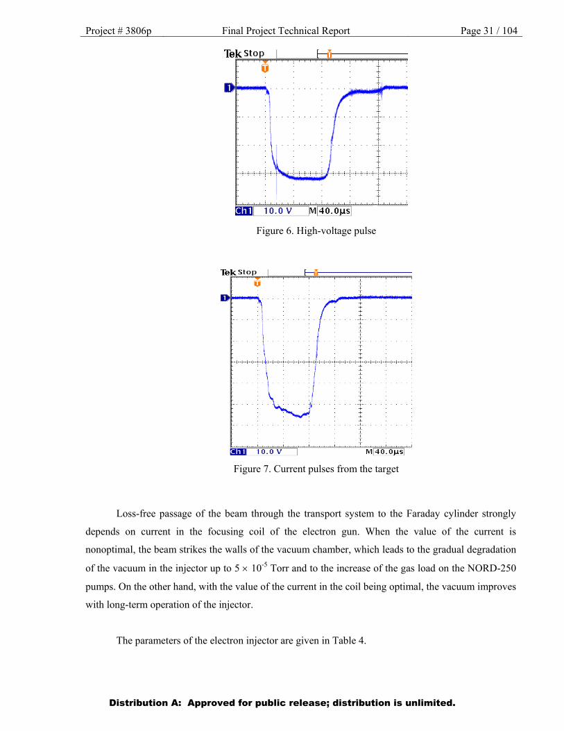
Figure 6. High-voltage pulse
Figure 7. Current pulses from the target
Loss-free passage of the beam through the transport system to the Faraday cylinder strongly
depends on current in the focusing coil of the electron gun. When the value of the current is
nonoptimal, the beam strikes the walls of the vacuum chamber, which leads to the gradual degradation
of the vacuum in the injector up to 5 10-5 Torr and to the increase of the gas load on the NORD-250
pumps. On the other hand, with the value of the current in the coil being optimal, the vacuum improves
with long-term operation of the injector.
The parameters of the electron injector are given in Table 4.
Distribution A: Approved for public release; distribution is unlimited.
Project # 3806p Final Project Technical Report Page 32 / 104
Table 4
Parameters of the installation
№ Parameters of the installation Values
1 high-voltage pulse amplitude 0 100 kV
2 amplitude of the electron beam current pulse (adjustable) 0 20 А
3 diameter of the beam at the exit of the injector (adjustable) 12 mm
4 duration of the high-voltage pulse 100 μs
5 pulse recurrence frequency 1 Hz
6 limit pressure (minimum) 1.5 10-6 Torr
7 power consumption 10 kW
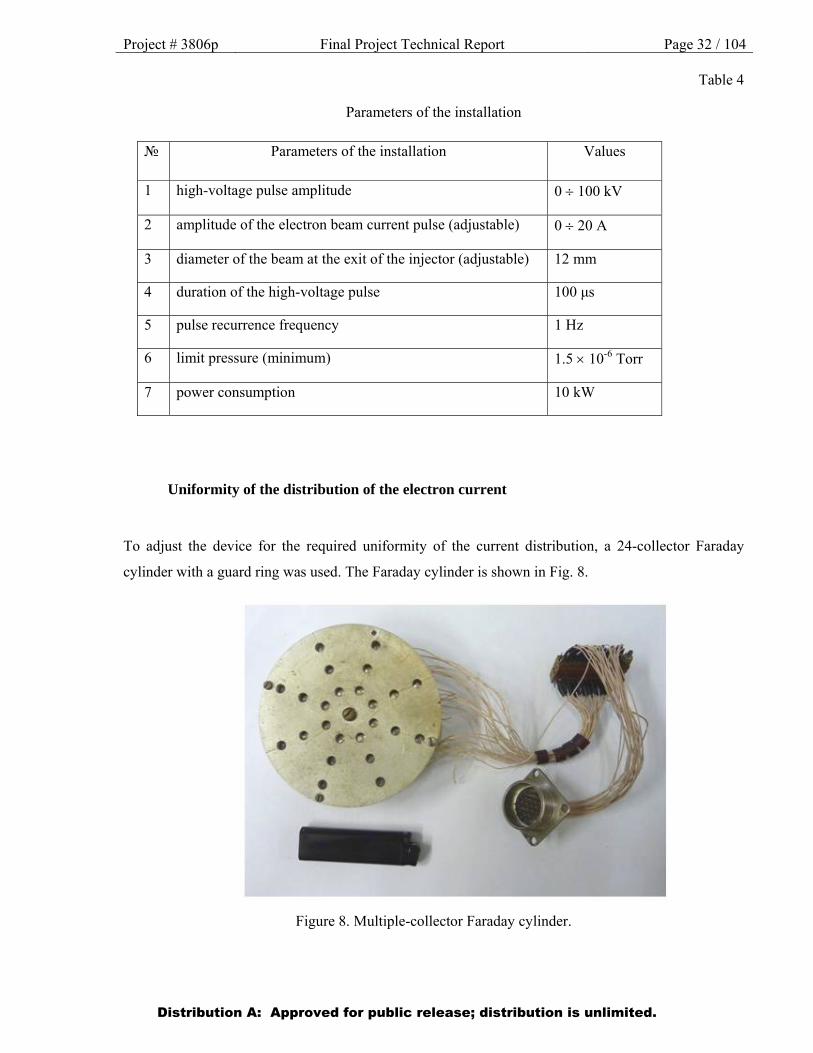
Uniformity of the distribution of the electron current
To adjust the device for the required uniformity of the current distribution, a 24-collector Faraday
cylinder with a guard ring was used. The Faraday cylinder is shown in Fig. 8.
Figure 8. Multiple-collector Faraday cylinder.
Distribution A: Approved for public release; distribution is unlimited.

Project # 3806p Final Project Technical Report Page 33 / 104
The Faraday cylinder is located in the chamber, instead of on the target with the samples, and
signals from each collector are fed, through a vacuum socket, to the oscillograph.
Experimental section
Values of the current of the focusing coil 2 (Fig. 2) and the power voltage of the electromagnets
5 and 6 (Fig. 2) were specially selected to achieve the required uniformity of the current distribution.
The electromagnets 5 and 6 (Fig. 9) are necessary for distributing the current in the vertical and
horizontal planes.
Figure 9. Photograph of the electromagnets
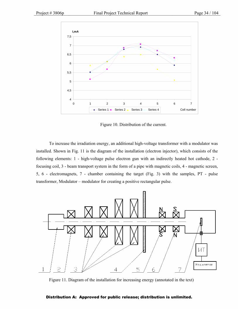
The distribution graph of the current in four directions is shown in Fig. 10.
Distribution A: Approved for public release; distribution is unlimited.
Project # 3806p Final Project Technical Report Page 34 / 104
Figure 10. Distribution of the current.
To increase the irradiation energy, an additional high-voltage transformer with a modulator was
installed. Shown in Fig. 11 is the diagram of the installation (electron injector), which consists of the
following elements: 1 - high-voltage pulse electron gun with an indirectly heated hot cathode, 2 -
focusing coil, 3 - beam transport system in the form of a pipe with magnetic coils, 4 - magnetic screen,
5, 6 - electromagnets, 7 - chamber containing the target (Fig. 3) with the samples, PT - pulse
transformer, Modulator – modulator for creating a positive rectangular pulse.
Figure 11. Diagram of the installation for increasing energy (annotated in the text)
4
4,5
5
5,5
6
6,5
7
7,5
0 1 2 3 4 5 6 7
I,mA
Series 1 Series 2 Series 3 Series 4 Cell number
Distribution A: Approved for public release; distribution is unlimited.
Project # 3806p Final Project Technical Report Page 35 / 104
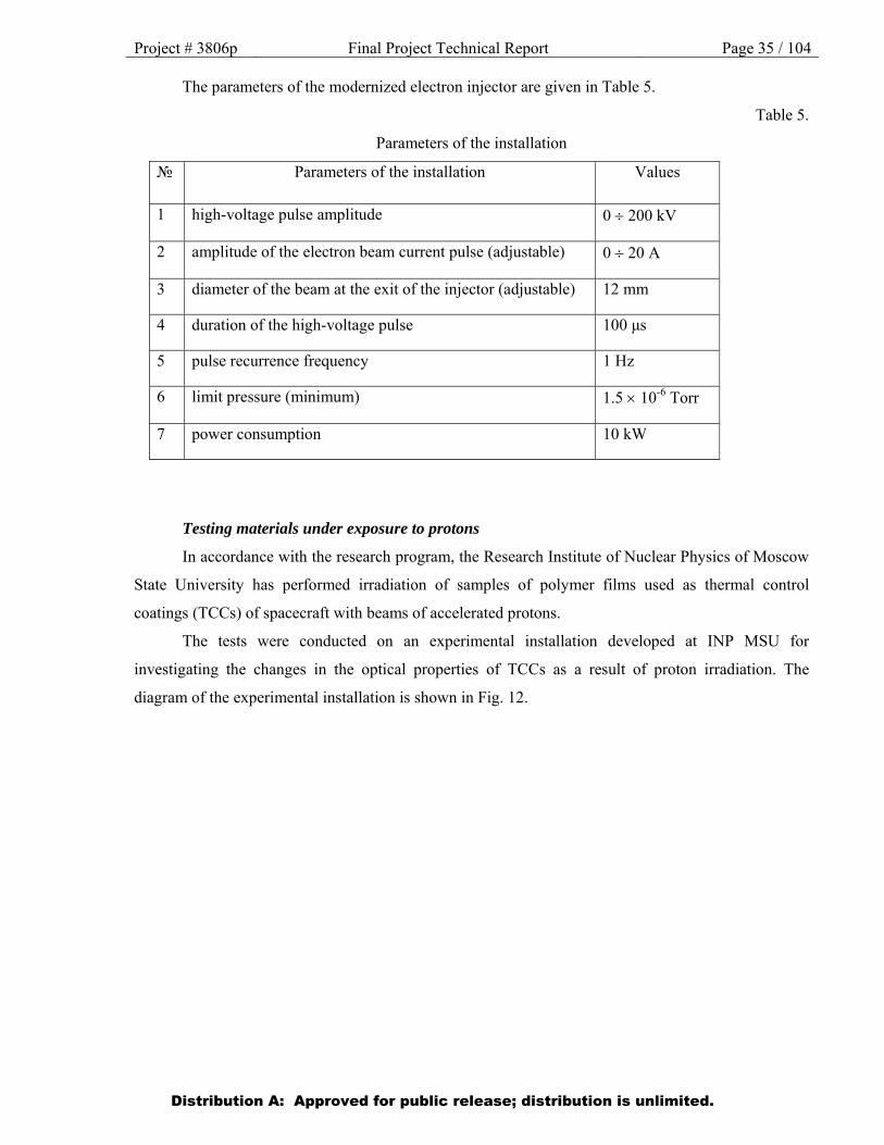
The parameters of the modernized electron injector are given in Table 5.
Table 5.
Parameters of the installation
№ Parameters of the installation Values
1 high-voltage pulse amplitude 0 200 kV
2 amplitude of the electron beam current pulse (adjustable) 0 20 А
3 diameter of the beam at the exit of the injector (adjustable) 12 mm
4 duration of the high-voltage pulse 100 μs
5 pulse recurrence frequency 1 Hz
6 limit pressure (minimum) 1.5 10-6 Torr
7 power consumption 10 kW
Testing materials under exposure to protons
In accordance with the research program, the Research Institute of Nuclear Physics of Moscow
State University has performed irradiation of samples of polymer films used as thermal control
coatings (TCCs) of spacecraft with beams of accelerated protons.
The tests were conducted on an experimental installation developed at INP MSU for
investigating the changes in the optical properties of TCCs as a result of proton irradiation. The
diagram of the experimental installation is shown in Fig. 12.
Distribution A: Approved for public release; distribution is unlimited.
Project # 3806p Final Project Technical Report Page 36 / 104
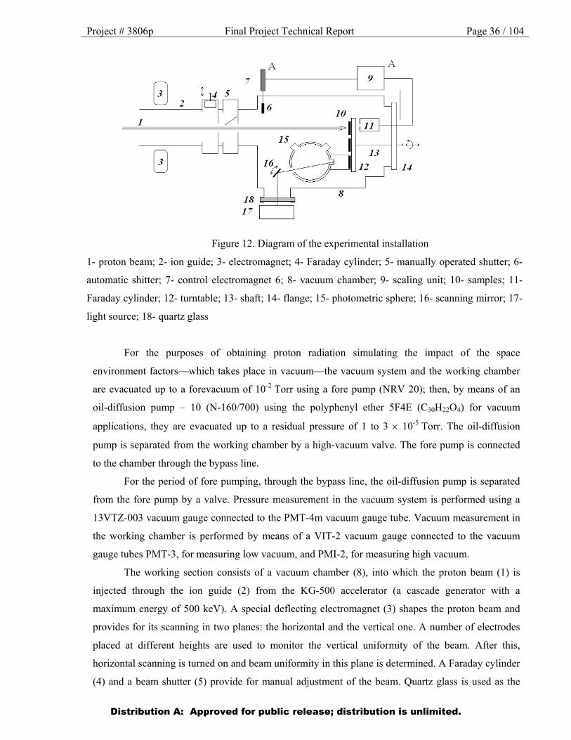
Figure 12. Diagram of the experimental installation
1- proton beam; 2- ion guide; 3- electromagnet; 4- Faraday cylinder; 5- manually operated shutter; 6-
automatic shitter; 7- control electromagnet 6; 8- vacuum chamber; 9- scaling unit; 10- samples; 11-
Faraday cylinder; 12- turntable; 13- shaft; 14- flange; 15- photometric sphere; 16- scanning mirror; 17-
light source; 18- quartz glass
For the purposes of obtaining proton radiation simulating the impact of the space
environment factors—which takes place in vacuum—the vacuum system and the working chamber
are evacuated up to a forevacuum of 10-2 Torr using a fore pump (NRV 20); then, by means of an
oil-diffusion pump – 10 (N-160/700) using the polyphenyl ether 5F4E (C30H22O4) for vacuum
applications, they are evacuated up to a residual pressure of 1 to 3 10-5 Torr. The oil-diffusion
pump is separated from the working chamber by a high-vacuum valve. The fore pump is connected
to the chamber through the bypass line.
For the period of fore pumping, through the bypass line, the oil-diffusion pump is separated
from the fore pump by a valve. Pressure measurement in the vacuum system is performed using a
13VTZ-003 vacuum gauge connected to the PMT-4m vacuum gauge tube. Vacuum measurement in
the working chamber is performed by means of a VIT-2 vacuum gauge connected to the vacuum
gauge tubes PMT-3, for measuring low vacuum, and PMI-2, for measuring high vacuum.
The working section consists of a vacuum chamber (8), into which the proton beam (1) is
injected through the ion guide (2) from the KG-500 accelerator (a cascade generator with a
maximum energy of 500 keV). A special deflecting electromagnet (3) shapes the proton beam and
provides for its scanning in two planes: the horizontal and the vertical one. A number of electrodes
placed at different heights are used to monitor the vertical uniformity of the beam. After this,
horizontal scanning is turned on and beam uniformity in this plane is determined. A Faraday cylinder
(4) and a beam shutter (5) provide for manual adjustment of the beam. Quartz glass is used as the
Distribution A: Approved for public release; distribution is unlimited.
Project # 3806p Final Project Technical Report Page 37 / 104
beam visualizer. The samples under investigation (10) are mounted on a turntable (12) that is rotated
using a shaft (13). Next to each sample on the turntable, there is a slot for the proton beam to pass
into the Faraday cylinder (11) that provides for measuring the fluence. The signal from (11) comes
to the programmable up/down counter (scaling unit) F5007 (9). When the required accumulated
count is reached on it, corresponding to a given fluence value, a signal is applied to the control
electromagnet (7) and the beam is automatically cut off via the shutter (6). The sample holder with
the sample is pressed against the measuring window of the integrating sphere (15) of the FM-59
photometer. The radiation scattered by the sphere reaches the UV and IR photodiodes and the
composite signal from these allows conducting measurement of the reflectance coefficient against
the reference samples.
Film irradiation under the ISTC program was conducted at experimentally determined values of
the flux density of accelerated protons that do not result in a degradation of the vacuum. It should also
be noted that the operation time expenditure of the KG-500 accelerator was determined by the given
fluence values, while taking into account the time required for the preliminary starting procedures at
the beginning of the working day and the time required to finish work of the accelerator.
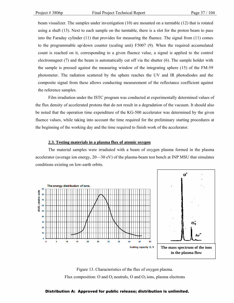
2.3. Testing materials in a plasma flux of atomic oxygen
The material samples were irradiated with a beam of oxygen plasma formed in the plasma
accelerator (average ion energy, 20—30 eV) of the plasma-beam test bench at INP MSU that simulates
conditions existing on low-earth orbits.
Figure 13. Characteristics of the flux of oxygen plasma.
Flux composition: О and О2 neutrals, О and О2 ions, plasma electrons
The mass spectrum of the ions in the plasma flow
Distribution A: Approved for public release; distribution is unlimited.
Project # 3806p Final Project Technical Report Page 38 / 104
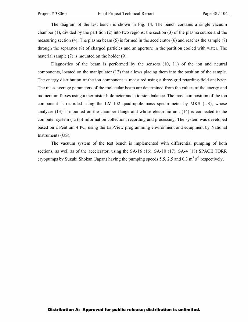
The diagram of the test bench is shown in Fig. 14. The bench contains a single vacuum
chamber (1), divided by the partition (2) into two regions: the section (3) of the plasma source and the
measuring section (4). The plasma beam (5) is formed in the accelerator (6) and reaches the sample (7)
through the separator (8) of charged particles and an aperture in the partition cooled with water. The
material sample (7) is mounted on the holder (9).
Diagnostics of the beam is performed by the sensors (10, 11) of the ion and neutral
components, located on the manipulator (12) that allows placing them into the position of the sample.
The energy distribution of the ion component is measured using a three-grid retarding-field analyzer.
The mass-average parameters of the molecular beam are determined from the values of the energy and
momentum fluxes using a thermistor bolometer and a torsion balance. The mass composition of the ion
component is recorded using the LM-102 quadrupole mass spectrometer by MKS (US), whose
analyzer (13) is mounted on the chamber flange and whose electronic unit (14) is connected to the
computer system (15) of information collection, recording and processing. The system was developed
based on a Pentium 4 PC, using the LabView programming environment and equipment by National
Instruments (US).
The vacuum system of the test bench is implemented with differential pumping of both
sections, as well as of the accelerator, using the SA-16 (16), SA-10 (17), SA-4 (18) SPACE TORR
cryopumps by Suzuki Shokan (Japan) having the pumping speeds 5.5, 2.5 and 0.3 m3 s-1.respectively.
Distribution A: Approved for public release; distribution is unlimited.
Project # 3806p Final Project Technical Report Page 39 / 104
1
2
3
4
5 6
7
8
9
10
11
1
14 13
1
16
17
18
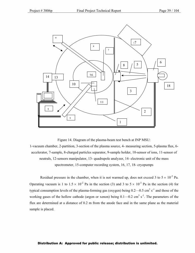
Figure 14. Diagram of the plasma-beam test bench at INP MSU:
1-vacuum chamber, 2-partition, 3-section of the plasma source, 4- measuring section, 5-plasma flux, 6-
accelerator, 7-sample, 8-charged particles separator, 9-sample holder, 10-sensor of ions, 11-sensor of
neutrals, 12-sensors manipulator, 13- quadrupole analyzer, 14- electronic unit of the mass
spectrometer, 15-computer recording system, 16, 17, 18- cryopumps
Residual pressure in the chamber, when it is not warmed up, does not exceed 3 to 5 10-5 Pa.
Operating vacuum is 1 to 1.5 10-2 Pa in the section (3) and 3 to 5 10-3 Pa in the section (4) for
typical consumption levels of the plasma-forming gas (oxygen) being 0.2—0.5 cm3 s-1 and those of the
working gases of the hollow cathode (argon or xenon) being 0.1—0.2 cm3 s-1. The parameters of the
flux are determined at a distance of 0.2 m from the anode face and in the same plane as the material
sample is placed.
Distribution A: Approved for public release; distribution is unlimited.
Project # 3806p Final Project Technical Report Page 40 / 104
Selecting the modes of simulation experiments Simulating the behavior of materials for long flight times calls for the development of
accelerated test techniques that would allow making estimates of probable changes of the key material
properties in time intervals that are practically feasible. In predicting changes over a period of 10—20
years, an acceleration ratio of no less that one hundred has to be provided for.
In the present experiments, the required acceleration degree was achieved by means of
increasing both the flux density and the energy of the particles as compared to their in-flight levels.
The beam of accelerated plasma hitting the samples consisted of ions, atoms and molecules of oxygen
with a mass-average velocity of 16 km/s (average energy of atoms, 20 eV) and a flux density of (2.5—
3.5) 1016cm-2 s-1. In colliding with the surface, the fast molecules in the flux dissociate, the ions are
neutralized and, as a result, the material is impacted by atoms having an average velocity of 16 km/s.
The results of a simulated exposure must be equivalent to the presumed in-flight effects. In the
standard technique of measuring fluence in simulation tests, the equivalence criterion is the value of
the specific mass losses of polyimide. The procedure corresponds to the generally-accepted technique
of determining the equivalent fluence of atomic oxygen (AO) in simulation tests according to the US
standard ASTM E 2089-00 (2006).
According to the accepted technique, in irradiating materials, a witness sample made of
polyimide film is placed next to the sample being tested and the equivalent fluence of AO is
determined from the mass losses of the former. In the present set of experiments, it was the samples of
polyimide film to be investigated that served as witness samples.
In interpreting the results of accelerated tests with increased atom energies, the question arises
as to their conformity with in-flight data. Using beams of AO with increased energy for simulation
tests may be appropriate on condition that the relative reaction efficiency of the material remains
constant with respect to polyimide.
As shown by studies using a laser pulse source, the energy dependence in the range 1—16 eV
is a universal power dependence for many polymers, as well as graphite. For these materials, the
relative reaction efficiency does not change significantly with the growth of the AO energy.
Comparing the data of accelerated tests of various polymers on the plasma-beam installation of INP
MSU, the AO energy levels being in the range 15—30 eV, with those of the NASA PEACE in-flight
experiment on the International Space Station and those of laboratory studies at 5 eV may serve as
experimental confirmation of this
For experimental verification of the hypothesis proposed here—about the invariance of the
energy dependence of erosion in certain classes of polymers under the action of atomic oxygen in the
energy range 2—5 eV, as well as with the energy increased up to 20—30 eV, and about the change of
the charge state of the oxygen atoms— the relative erosion factors were previously determined for a
Distribution A: Approved for public release; distribution is unlimited.
Project # 3806p Final Project Technical Report Page 41 / 104 selected set of polymer and carbon materials. The materials—pyrographite (PG), polystyrene
(Styroflex) (PS), polyimide (PI), low-density polyethylene (LDPE), polyvinyl fluoride (PVF) (Tedlar),
polyethylene terephthalate (PET) (Mylar), polymethyl methacrylate (PMMA)—were studied by the
method of Kapton standard in conditions of irradiating the samples with a beam of oxygen plasma with
the particle energy 20—30 eV, at which the energy dependence of the erosion factor for the polymers
under scrutiny is presumed to be universal. This allows using the properties of materials that are well
studied at 5 eV (polyimide) and the results of accelerated comparative tests at higher energies to
predict changes in the structure of new materials, too, at 5 eV and high fluences.
Presented in a formalized manner, the proposed approach comes to the following: the erosion
factor of a material Ym = dMm/dF can be written in the form of a function of the energy E (eV), i. e.
Ym(E)=Ym(5) fm(E) . Then
Ym(5)=Ym(E) /fm(E) (1)
where fm(E) is the energy dependence, normalized so that fm(E)=1 at E=5 eV,
dMm and dMk are the specific mass losses of the material and of the witness sample of polyimide
(Kapton) respectively,
F is the fluence of AO.
As is usual in the standard technique of in-flight and ground tests, the actuating quantity, the so-called
effective fluence (EF) of AO, is determined from the mass losses of a witness sample of the reference
material, polyimide (Kapton), whose properties are well understood. At E = 5 eV, Yk = Mk/F= 4.3 10-
24 g cm-2. This means that the experiment measures the relative value of the erosion factor for the
given material with respect to polyimide (Kapton) Ym/Yk. Then, the relative erosion factor sought for
the material at 5 eV, taking into account expression (1):
Ym(5)/Yk(5) = [Ym(E)/fm(E)] / [Yk(E)/fk(E)] = [Ym(E)/Yk(E)] × [fk(E)/fm(E)] =
[dMm(E)/dMk(E)] [fk(E)/fm(E)]
Consequently, the relative erosion factor, measured, e. g., at Е = 20 eV, differs from the sought
value at 5 eV by the coefficient q = fk(20) / fm(20).
The value of q = fk(E)/fm(E) was determined from the measurement data for dMm(20)/dMk(20)
and from literary sources for Ym(5)/Yk(5) via the formula q = [Ym(5) / Yk(5)]/[dMm(20) / dMk(20)].
Given in Table 6 are the obtained erosion factors of polymer materials.
Distribution A: Approved for public release; distribution is unlimited.
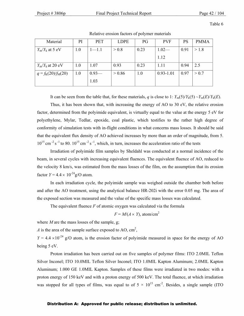
Project # 3806p Final Project Technical Report Page 42 / 104
Table 6
Relative erosion factors of polymer materials
Material PI PET LDPE PG PVF PS PMMA
Ym/Yk at 5 eV 1.0 1—1.1 > 0.8 0.23 1.02—
1.12
0.91 > 1.8
Ym/Yk at 20 eV 1.0 1.07 0.93 0.23 1.11 0.94 2.5
q = fK(20)/fM(20) 1.0 0.93—
1.03
> 0.86 1.0 0.93-1.01 0.97 > 0.7
It can be seen from the table that, for these materials, q is close to 1: Ym(5)/Yk(5) ~Ym(E)/Yk(E).
Thus, it has been shown that, with increasing the energy of AO to 30 eV, the relative erosion
factor, determined from the polyimide equivalent, is virtually equal to the value at the energy 5 eV for
polyethylene, Mylar, Tedlar, epoxide, coal plastic, which testifies to the rather high degree of
conformity of simulation tests with in-flight conditions in what concerns mass losses. It should be said
that the equivalent flux density of AO achieved increases by more than an order of magnitude, from 5.
1015 cm -2 s -1 to 80. 1015 cm -2 s -1, which, in turn, increases the acceleration ratio of the tests
Irradiation of polyimide film samples by Sheldahl was conducted at a normal incidence of the
beam, in several cycles with increasing equivalent fluences. The equivalent fluence of AO, reduced to
the velocity 8 km/s, was estimated from the mass losses of the film, on the assumption that its erosion
factor Y = 4.4 10-24g/O atom.
In each irradiation cycle, the polyimide sample was weighed outside the chamber both before
and after the AO treatment, using the analytical balance HR-202i with the error 0.05 mg. The area of
the exposed section was measured and the value of the specific mass losses was calculated.
The equivalent fluence F of atomic oxygen was calculated via the formula
F = M/(A Y), atom/cm2
where M are the mass losses of the sample, g;
A is the area of the sample surface exposed to AO, cm2,
Y = 4.4 10-24 g/O atom, is the erosion factor of polyimide measured in space for the energy of AO
being 5 eV.
Proton irradiation has been carried out on five samples of polymer films: ITO 2.0MIL Teflon
Silver Inconel; ITO 10.0MIL Teflon Silver Inconel; ITO 1.0MIL Kapton Aluminum; 2.0MIL Kapton
Aluminum; 1.000 GE 1.0MIL Kapton. Samples of these films were irradiated in two modes: with a
proton energy of 150 keV and with a proton energy of 500 keV. The total fluence, at which irradiation
was stopped for all types of films, was equal to of 5 × 1015 cm-2. Besides, a single sample (ITO
Distribution A: Approved for public release; distribution is unlimited.
Project # 3806p Final Project Technical Report Page 43 / 104 10.0MIL Teflon Silver Inconel) was irradiated with protons with the energy 500 keV up to a total
fluence of 5 × 1016 cm-2.
At the initial stage of work, it was necessary to determine experimentally the maximum
possible flux density of accelerated protons that is endured by the above-mentioned films under
irradiation in vacuum. This parameter was determined by monitoring the operating vacuum in the
chamber for different currents of the beam hitting the samples. When the permissible threshold of the
proton flux density was crossed, a drastic increase of residual pressure was observed during the
experiment, due to intense gas release from the films being irradiated. The endurance of the films was
determined at a proton energy of 500 keV. It was established that, for samples of Teflon films (ITO
2.0MIL Teflon Silver Inconel and ITO 10.0MIL Teflon Silver Inconel), the flux density of the proton
beam, at which, in experimental conditions, a drastic degradation of the vacuum was observed, is ~
1011 cm-2 s-1. For Kapton films (ITO 1.0MIL Kapton Aluminum film; 2.0MIL Kapton Aluminum film;
1.000A GE 1.0MIL Kapton film), the maximum flux density amounted to 2 × 1011 cm-2 s-1.
2.4. Measuring the spectral and integral optical parameters
Measurements of the spectral and integral reflectance and absorptance in the wavelength range
0.3 — 2.5 m have been carried out for both pristine and irradiated samples of all the researched
during this year materials (MAP enamels and Kapton and Teflon Sheldahl films). Lambda-9 and
Shimadzu MPS-2000 spectrophotometers were used for the measurements. According to spectral
measurements integrated factors of absorptance and reflectance have been calculated.
In addition to values of integrated factor of absorptance of the sunlight calculated from the
spectral data, measurement of s of the irradiated samples after their carrying out from the vacuum
chamber was performed using photometer FM-59М. Measurements of s were performed for final and
four intermediate values of time of an irradiation. The solar radiation absorptance of the TCC samples
was measured on a FM-59M photometer relative to the reference samples, whose spectra had been
recorded on the Cary 500 spectrophotometer.
Measurements of the diffuse reflectance or the directional-hemispherical reflectance (DHR) are
performed using a special accessory, DRA-CA-55, with which the Cary 500 spectrophotometer is
equipped.
1Description of the samples: rectangular plates with dimensions 70 ·70 mm and disks with
diameters of 30 — 50 mm. The parameter measured is the spectral directional-hemispherical
reflectance R() in the range 200 —2,500 nm; angle of incidence, 8. The parameter calculated is the
solar radiation absorptance As.
Distribution A: Approved for public release; distribution is unlimited.
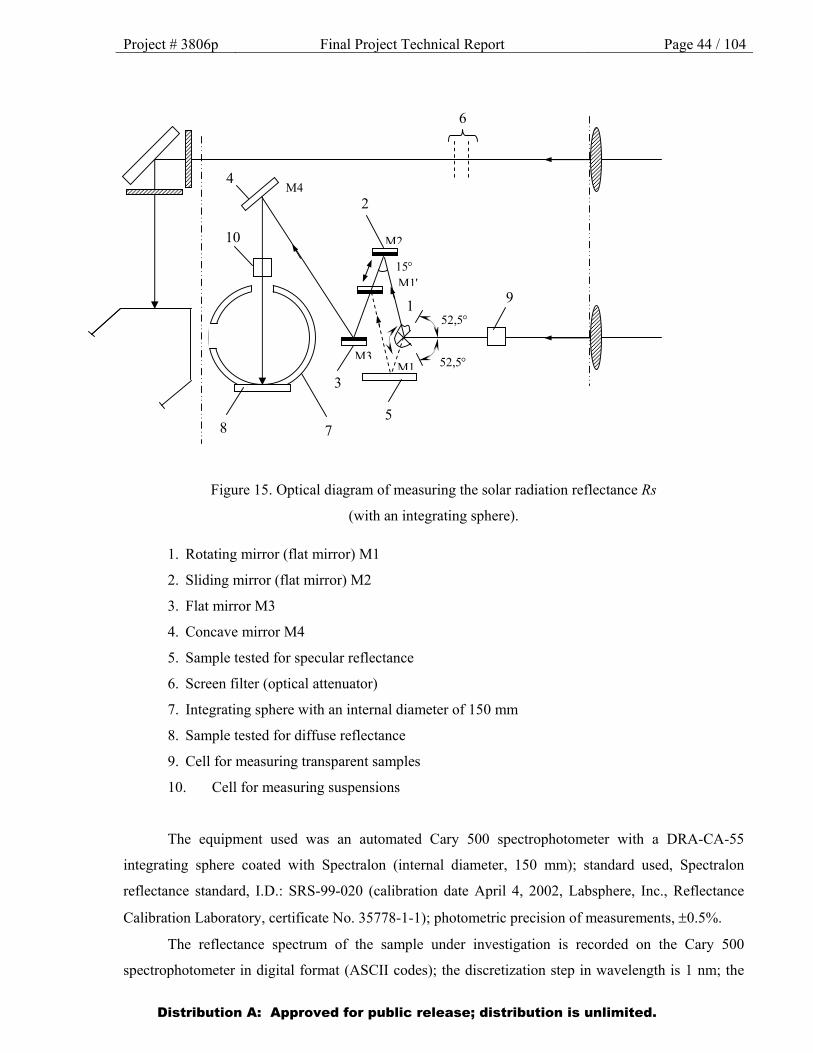
Project # 3806p Final Project Technical Report Page 44 / 104
Figure 15. Optical diagram of measuring the solar radiation reflectance Rs
(with an integrating sphere).
1. Rotating mirror (flat mirror) M1
2. Sliding mirror (flat mirror) M2
3. Flat mirror M3
4. Concave mirror M4
5. Sample tested for specular reflectance
6. Screen filter (optical attenuator)
7. Integrating sphere with an internal diameter of 150 mm
8. Sample tested for diffuse reflectance
9. Cell for measuring transparent samples
10. Cell for measuring suspensions
The equipment used was an automated Cary 500 spectrophotometer with a DRA-CA-55
integrating sphere coated with Spectralon (internal diameter, 150 mm); standard used, Spectralon
reflectance standard, I.D.: SRS-99-020 (calibration date April 4, 2002, Labsphere, Inc., Reflectance
Calibration Laboratory, certificate No. 35778-1-1); photometric precision of measurements, 0.5%.
The reflectance spectrum of the sample under investigation is recorded on the Cary 500
spectrophotometer in digital format (ASCII codes); the discretization step in wavelength is 1 nm; the
4
10
8 7
2
3
5
9
6
1
М1М3
М2
М1
52,5
52,5
15
М4
Distribution A: Approved for public release; distribution is unlimited.
Project # 3806p Final Project Technical Report Page 45 / 104 spectrophotometer setup parameters are standard Processing the spectral data are carried out on the
computer, using the Origin 5 software. In calculation, the spectral reflectance R() is determined while
taking into account the spectral data of the reflectance standard given in the certificate of the SRS-99-
020 standard.
Used for calculating As were the well-known expression and the data on the spectral density S()
of the exoatmospheric Sun:
2500 nm 2500 nm
As = 1-Rs = (1-R())S()d / S()d
200 nm 200 nm
The optical diagram of the measurements is given in Fig. 2
Estimates of the absolute values of the normal degree of blackness were made in air at room
temperature using the TRM-I thermoradiometer.
Shown in Fig. 15 are the reflectance spectra of the reference samples, measured on the Cary 500
spectrophotometer, which were afterwards used in the measurements of the irradiated samples on the
FM-59M photometer.
For all pristine and irradiated samples measurements of integral coefficient of heat radiation in
hemisphere and reflectance spectra in a range of 2.5-10 microns using themoradiometer TRMI and an
add-on device of mirror reflectance on IR-435 spectrophotometer were performed for all pristine and
irradiated samples.
2.5. Technique of measuring the BRDF (BSDF)
Measurements of the BRDF of pristine samples have been carried out on the wavelength 532
nm, at the angles of incidence 8º, 30º and 60º and with the angular resolution 1º without using an
analyzer of the polarization of reflected radiation.
All the works on modernization of installation for measurements BRDF (BSDF) in a plane of
falling and in all 2π - hemisphere- are completely finished. By installation of an additional drive of
rotation which was installed on the main rotating platform, signals from the radiation disseminated by
samples within a 2π -space angle are registered. Thus movement of the receiver of radiation is carried
out by turn of the main rotating platform within azimuthal corners (0-3600 turn of an additional drive
within polar corners (0-900). Thus the sample is placed on a table in a horizontal plane and can have
the sizes exceeding 100 sm2. The modulated radiation of lasers of 532 nanometers and 1064
nanometers goes practically at any angle to a surface of the sample. There are some well known
restrictions - area of shadowing near surface normal line and the corner of sliding limit depending on
Distribution A: Approved for public release; distribution is unlimited.

Project # 3806p Final Project Technical Report Page 46 / 104 the sizes of the sample and section of the falling bunch of radiation. Diameter of a probing bunch is
defined by the installed telescopic dilators and makes 14 mm and 7 mm (1 mm without dilators). Real
angles of falling can be set within (5-800) from a normal to a surface of the sample with accuracy not
worse than 0.10. By the installation of precision step-by-step drives with reducers (1:15) FL57STH56-
2804AG15, the angular permission at movement of drives isn't worse than 0.10.
Along with measurements BRDF within a hemisphere, which are realized in the top semispace
(“the second floor”), divided by a plane of the main rotating platform, measurements in a falling plane
are realized in the bottom part of semispace ("ground floor"). The plane of the sample in this case takes
place in a vertical plane which can turn, changing a radiation falling angle on the sample while a
source of radiation is motionless. The angular permission at measurements in a plane of falling isn't
worse than 0.020. By the special device turning the plane of the sample installation of a falling angle is
set with accuracy not worse than 0.10 is provided. Other device provides an inclination of a plane of
falling of the sample within ±100.
A silicon photo diode S8745-01 (“Hamamatsu”) with an active photosensitive platform 2.4х2.4
mm with sensitivity area in a range of (190 nm-1100 nm) is used as the radiation receiver, and also
photo diode G8370-02 (“Hamamatsu”) on the basis of InGaAs ( 2мм) with sensitivity area in a range
of (0.9-1.7 μ) for measurements on wavelength of 1.064 μ. Special cases which the rotating polarizer
of optical radiation is established on were made for photodetectors. The maximum photodetector angle
of capture of radiation (without a diaphragm) equales 10-4 sr (0,50).
Radiation detecting is carried out with a method called “lock-in”, for which “Optical Chopper”
OCV-4800FD and “DSP Lock-in Amplifier” SR830 are used. Both devices have a communication
channel with the personal computer through RS-232 and USB. The variant of registration a system
with a method of “DSP lock-in” with use of 16-digit ADC (200 kSPS) and "Atmel" microcontroller
has been developed and made in parallel.
Management of two step-by-step drives of device is carried out with use of “Atmel”
microcontrollers and drivers MA335B with step-by-step engines FL57STH56-2804AG15,
communication with the personal computer is carried out through USB port. Measurements has been
completely automated, the software has been realised on C ++ Builder 2006.
To except a flare from external sources of radiation the light-absorbing cover is used. The
optical gages fixing extreme angular positions of turns of a platform and a photodetector were installed
and the corresponding software of processing of interruptions on operation of optical gages is
developed and debugged.
Distribution A: Approved for public release; distribution is unlimited.
Project # 3806p Final Project Technical Report Page 47 / 104
3. Results
of performing work under the Project
During the first phase (first year) of the Project (November 01, 2007—October 31, 2008)
the following activities were carried out:
(1) tests of four brands of MAP enamels under the action of protons with the energy 50 keV
(Task 1, Subtask 1.1);
(2) tests of four brands of Russian materials—EKOM-1 (white), EKOM-2 (black), FP-BSFR-
100-208 and FP-BSFR-200-208—under combined exposure to electrons, protons and UV radiation
(Task 2, Subtasks 3, 5);
(3) measurement of the optical parameters of all materials before and after exposure to protons
(with the energy 50 keV) and combined exposure to electrons, protons and UV radiation (Task 4,
Subtasks 1—4);
(4) part of the work on modernizing the experimental equipment for carrying out measurements
of the optical parameters (Task 5, Subtasks 1 and 2);
(5) processing the tests results and entering them into the Database (Tasks 1, 2, 4).
During the second phase (second year) of the Project (November 01, 2008—October 31,
2009) the following activities were carried out:
(1) tests of four brands of MAP enamels under the action of electrons with the energy 50 keV
(Task 1, Subtask 1.2);
(2) tests of 8 brands of Kapton films and 6 brands of Teflon films by Sheldahl under the action
of electrons with the energy 100 KeV (Task 1, Subtask 1.2);
(3) tests of four brands of MAP enamels under combined exposure to electrons, protons and
UV radiation (Task 2, Subtask 2);
(4) measurement of the optical parameters of all materials before and after exposure to
electrons (with the energies 50 and 100 KeV) and combined exposure to electrons, protons and UV
radiation (Task 4, Subtasks 1—4);
(5) part of the work on modernizing the experimental equipment for carrying out measurements
of the optical parameters (Task 5, Subtasks 1 and 2);
(6) processing the test results and entering them into the Database (Tasks 1, 2, 4).
Distribution A: Approved for public release; distribution is unlimited.
Project # 3806p Final Project Technical Report Page 48 / 104
During the third phase (third year) of the Project (November 1, 2009—October 31, 2010)
the following activities were carried out:
(1) tests of the films by Sheldahl and the enamels by MAP under the action of accelerated
protons with the energies 50, 150, 300 and 500 keV (Task 1, Subtask 1);
(2) tests of four brands of films by Sheldahl under the combined action of simulated
electromagnetic solar radiation, electrons and protons (Task 2, Subtask 1);
(3) measurement of the spectral parameters of the materials before and after exposure to
different types of space radiation (Task 4);
(4) work on modernizing the installations for measuring the BRDF and for measuring the
Directed Hemispherical Reflectance (DHR) (2.5—10 µm) (Task 5, Subtask 1).
(5) processing the test results and entering them into the Database (Tasks 1, 2, 4).
During the fourth phase (fourth and fifth years) of the Project (November 1, 2010 –
October 31, 2012) the following activities were carried out:
(1) tests of the films by Sheldahl under the action of protons with the energies 150 and 500 keV
(Task 1, Subtask 1);
(2) tests of the films and fabrics under combined exposure to electrons, protons and UV
radiation (Task 2);
(3) tests of the films by Sheldahl and the enamels by MAP under combined exposure to atomic
oxygen and UV radiation (Task 3, Subtask 1);
(4) measurements of the optical parameters of the samples after exposure to the space
environment factors (Task 4, Subtasks 1—4);
(5) modernization of the installation for measuring the Directed Hemispherical Reflectance
(DHR) in the range 2.5—10 µm (Task 5, Subtask 2).
6) processing the test results and entering them into the Database (Tasks 1—4).
The results of the experimental studies conducted of the complex impact of the space
environment factors on the optical properties of spacecraft materials have been entered into the
Database in digital and graphic forms. The resulting Database is in Microsoft Access 2000 format and
contains about 3,500 records.
Characteristic test results obtained in the course of realizing the stated tasks of the Project are
presented in Appendix 2 to the present Report.
Distribution A: Approved for public release; distribution is unlimited.
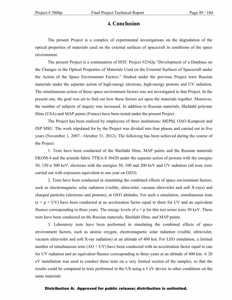
Project # 3806p Final Project Technical Report Page 49 / 104
4. Conclusion
The present Project is a complex of experimental investigations on the degradation of the
optical properties of materials used on the external surfaces of spacecraft in conditions of the space
environment.
The present Project is a continuation of ISTC Project #2342p “Development of a Database on
the Changes in the Optical Properties of Materials Used on the External Surfaces of Spacecraft under
the Action of the Space Environment Factors.” Studied under the previous Project were Russian
materials under the separate action of high-energy electrons, high-energy protons and UV radiation.
The simultaneous action of those space environment factors was not investigated in that Project. In the
present one, the goal was set to find out how these factors act upon the materials together. Moreover,
the number of subjects of inquiry was increased. In addition to Russian materials, Sheldahl polymer
films (USA) and MAP paints (France) have been tested under the present Project.
The Project has been realized by employees of three institutions: MEPhI, OAO Kompozit and
INP MSU. The work stipulated for by the Project was divided into four phases and carried out in five
years (November 1, 2007—October 31, 2012). The following has been achieved during the course of
the Project:
1. Tests have been conducted of the Sheldahl films, MAP paints and the Russian materials
EKOM-4 and the arimide fabric TTKA-S 56420 under the separate action of protons with the energies
50, 150 и 500 keV, electrons with the energies 50, 100 and 200 keV and UV radiation (all tests were
carried out with exposures equivalent to one year on GEO).
2. Tests have been conducted in simulating the combined effects of space environment factors,
such as electromagnetic solar radiation (visible, ultraviolet, vacuum ultraviolet and soft X-rays) and
charged particles (electrons and protons), at GEO altitudes. For such a simulation, simultaneous tests
(e + p + UV) have been conducted at an acceleration factor equal to three for UV and an equivalent
fluence corresponding to three years. The energy levels of e + p for this test series were 50 keV. These
tests have been conducted on the Russian materials, Sheldahl films, and MAP paints.
3. Laboratory tests have been performed in simulating the combined effects of space
environment factors, such as atomic oxygen, electromagnetic solar radiation (visible, ultraviolet,
vacuum ultraviolet and soft X-ray radiation) at an altitude of 400 km. For LEO simulation, a limited
number of simultaneous tests (AO + UV) have been conducted with an acceleration factor equal to one
for UV radiation and an equivalent fluence corresponding to three years at an altitude of 400 km. A 20
eV installation was used to conduct these tests on a very limited section of the samples, so that the
results could be compared to tests performed in the US using a 5 eV device in other conditions on the
same materials
Distribution A: Approved for public release; distribution is unlimited.

Project # 3806p Final Project Technical Report Page 50 / 104
4. BSDF/BRDF measurements have been conducted for the wavelengths 532 and 1063 nm.
With this purpose, a BSDF/BRDF measuring device has been developed.
5. Measurements have been conducted of the Directed Hemispherical Reflectance (DHR) in the
range 2.5—10 µm. With this purpose, modernization has been carried out of the IKS-31
spectrophotometer.
6. The test results have been entered (both in digital and in graphical form) into the Database
developed previously, under ISTC Project #2342p, in Microsoft Access 2000 format.
The data obtained under this Project are the joint property of MEPhI and EOARD. The handing
over of any reports and material samples to the Partner is only to be done with permission from the
bodies responsible for state export control in Russia. The test data on the Sheldahl films and MAP
paints will be also available to the organizations that have delivered these materials, i. e. to the
companies Sheldahl and MAP respectively. Neither MEPhI nor EOARD will distribute or transmit
information about the Sheldahl and MAP materials without their permission.
Distribution A: Approved for public release; distribution is unlimited.
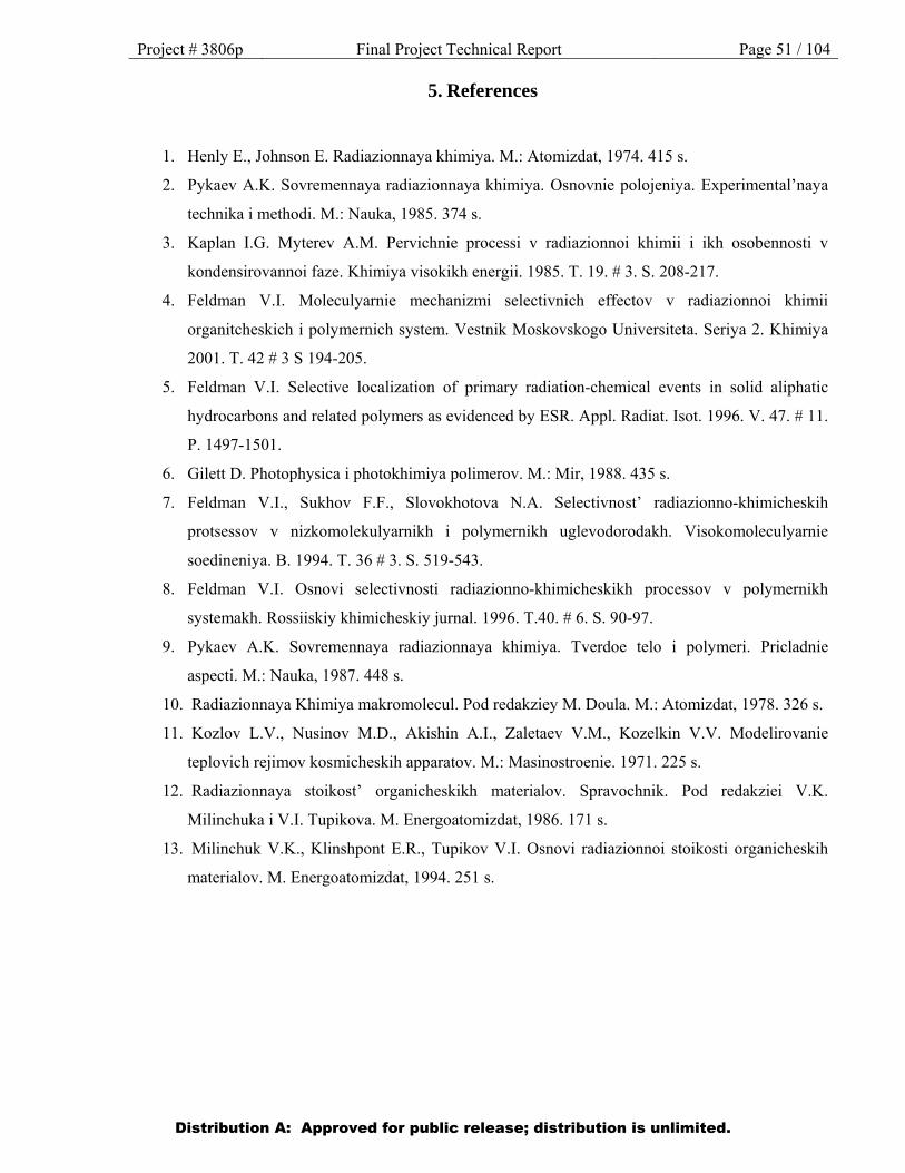
Project # 3806p Final Project Technical Report Page 51 / 104
5. References
1. Henly E., Johnson E. Radiazionnaya khimiya. M.: Atomizdat, 1974. 415 s.
2. Pykaev A.K. Sovremennaya radiazionnaya khimiya. Osnovnie polojeniya. Experimental’naya
technika i methodi. M.: Nauka, 1985. 374 s.
3. Kaplan I.G. Myterev A.M. Pervichnie processi v radiazionnoi khimii i ikh osobennosti v
kondensirovannoi faze. Khimiya visokikh energii. 1985. T. 19. # 3. S. 208-217.
4. Feldman V.I. Moleculyarnie mechanizmi selectivnich effectov v radiazionnoi khimii
organitcheskich i polymernich system. Vestnik Moskovskogo Universiteta. Seriya 2. Khimiya
2001. T. 42 # 3 S 194-205.
5. Feldman V.I. Selective localization of primary radiation-chemical events in solid aliphatic
hydrocarbons and related polymers as evidenced by ESR. Appl. Radiat. Isot. 1996. V. 47. # 11.
P. 1497-1501.
6. Gilett D. Photophysica i photokhimiya polimerov. M.: Mir, 1988. 435 s.
7. Feldman V.I., Sukhov F.F., Slovokhotova N.A. Selectivnost’ radiazionno-khimicheskih
protsessov v nizkomolekulyarnikh i polymernikh uglevodorodakh. Visokomoleculyarnie
soedineniya. B. 1994. T. 36 # 3. S. 519-543.
8. Feldman V.I. Osnovi selectivnosti radiazionno-khimicheskikh processov v polymernikh
systemakh. Rossiiskiy khimicheskiy jurnal. 1996. T.40. # 6. S. 90-97.
9. Pykaev A.K. Sovremennaya radiazionnaya khimiya. Tverdoe telo i polymeri. Pricladnie
aspecti. M.: Nauka, 1987. 448 s.
10. Radiazionnaya Khimiya makromolecul. Pod redakziey M. Doula. M.: Atomizdat, 1978. 326 s.
11. Kozlov L.V., Nusinov M.D., Akishin A.I., Zaletaev V.M., Kozelkin V.V. Modelirovanie
teplovich rejimov kosmicheskih apparatov. M.: Masinostroenie. 1971. 225 s.
12. Radiazionnaya stoikost’ organicheskikh materialov. Spravochnik. Pod redakziei V.K.
Milinchuka i V.I. Tupikova. M. Energoatomizdat, 1986. 171 s.
13. Milinchuk V.K., Klinshpont E.R., Tupikov V.I. Osnovi radiazionnoi stoikosti organicheskih
materialov. M. Energoatomizdat, 1994. 251 s.
Distribution A: Approved for public release; distribution is unlimited.
Project # 3806p Final Project Technical Report Page 52 / 104
Appendix 1
Figure 1
Distribution A: Approved for public release; distribution is unlimited.

Project # 3806p Final Project Technical Report Page 53 / 104
Figure 2
Distribution A: Approved for public release; distribution is unlimited.
Project # 3806p Final Project Technical Report Page 54 / 104
Figure 3
Distribution A: Approved for public release; distribution is unlimited.
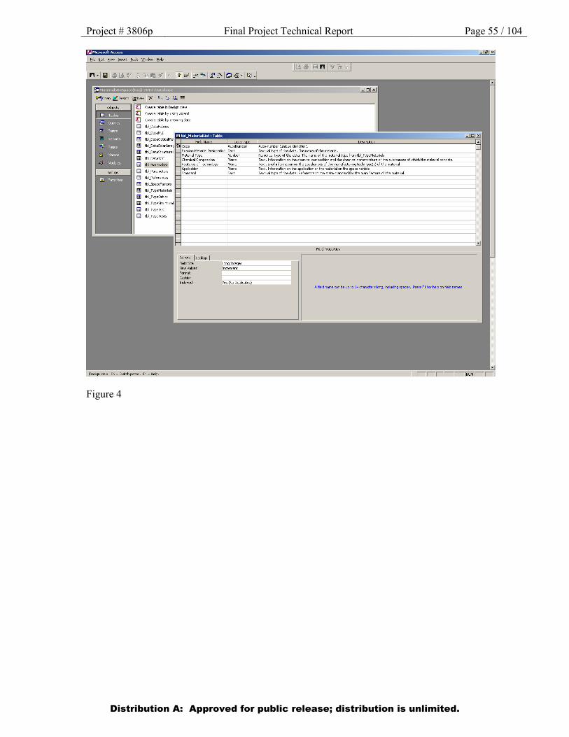
Project # 3806p Final Project Technical Report Page 55 / 104
Figure 4
Distribution A: Approved for public release; distribution is unlimited.

Project # 3806p Final Project Technical Report Page 56 / 104
Figure 5
Distribution A: Approved for public release; distribution is unlimited.
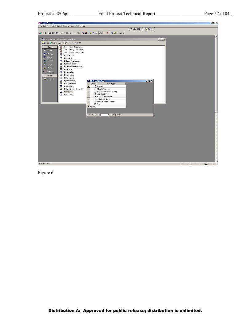
Project # 3806p Final Project Technical Report Page 57 / 104
Figure 6
Distribution A: Approved for public release; distribution is unlimited.
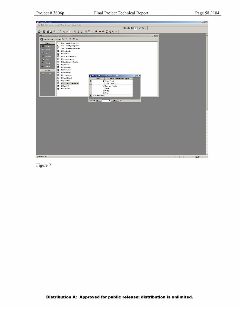
Project # 3806p Final Project Technical Report Page 58 / 104
Figure 7
Distribution A: Approved for public release; distribution is unlimited.
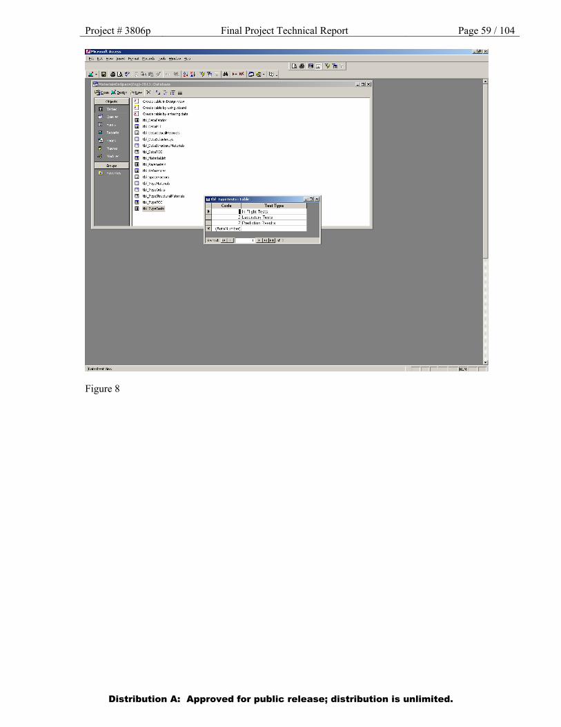
Project # 3806p Final Project Technical Report Page 59 / 104
Figure 8
Distribution A: Approved for public release; distribution is unlimited.
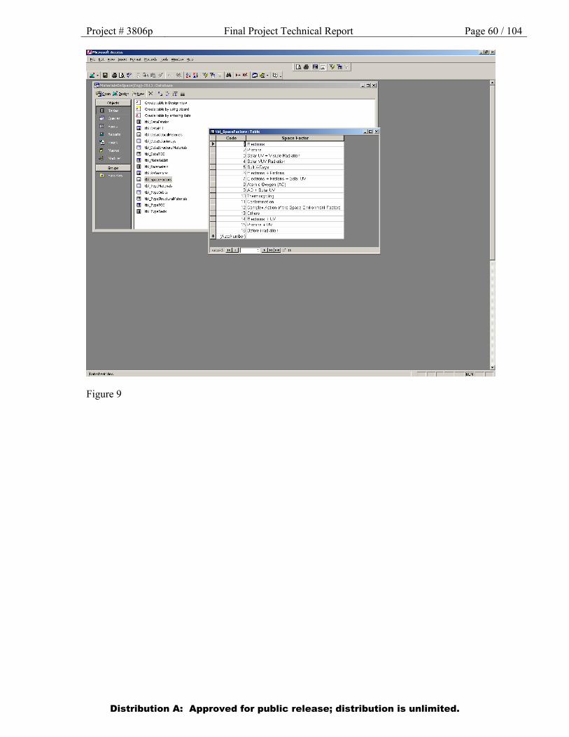
Project # 3806p Final Project Technical Report Page 60 / 104
Figure 9
Distribution A: Approved for public release; distribution is unlimited.

Project # 3806p Final Project Technical Report Page 61 / 104
Figure 10
Distribution A: Approved for public release; distribution is unlimited.

Project # 3806p Final Project Technical Report Page 62 / 104
Figure 11
Distribution A: Approved for public release; distribution is unlimited.
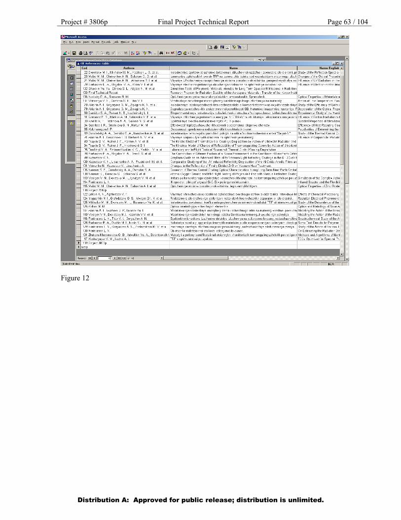
Project # 3806p Final Project Technical Report Page 63 / 104
Figure 12
Distribution A: Approved for public release; distribution is unlimited.
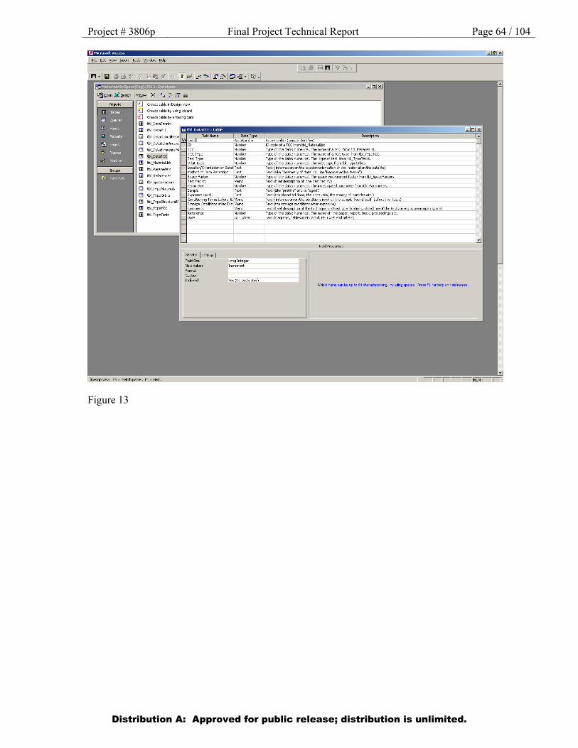
Project # 3806p Final Project Technical Report Page 64 / 104
Figure 13
Distribution A: Approved for public release; distribution is unlimited.
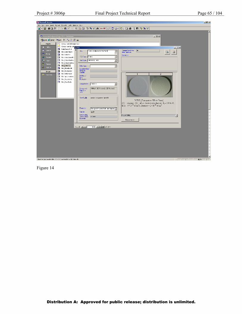
Project # 3806p Final Project Technical Report Page 65 / 104
Figure 14
Distribution A: Approved for public release; distribution is unlimited.
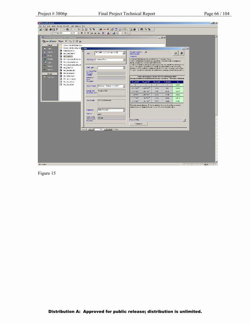
Project # 3806p Final Project Technical Report Page 66 / 104
Figure 15
Distribution A: Approved for public release; distribution is unlimited.
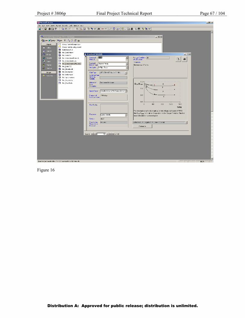
Project # 3806p Final Project Technical Report Page 67 / 104
Figure 16
Distribution A: Approved for public release; distribution is unlimited.
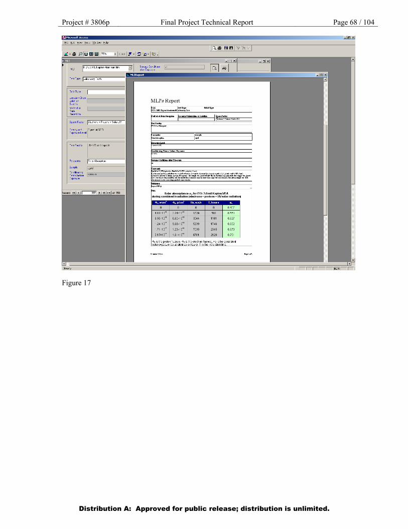
Project # 3806p Final Project Technical Report Page 68 / 104
Figure 17
Distribution A: Approved for public release; distribution is unlimited.
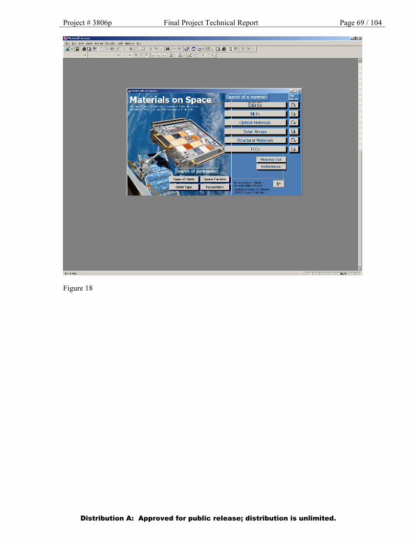
Project # 3806p Final Project Technical Report Page 69 / 104
Figure 18
Distribution A: Approved for public release; distribution is unlimited.
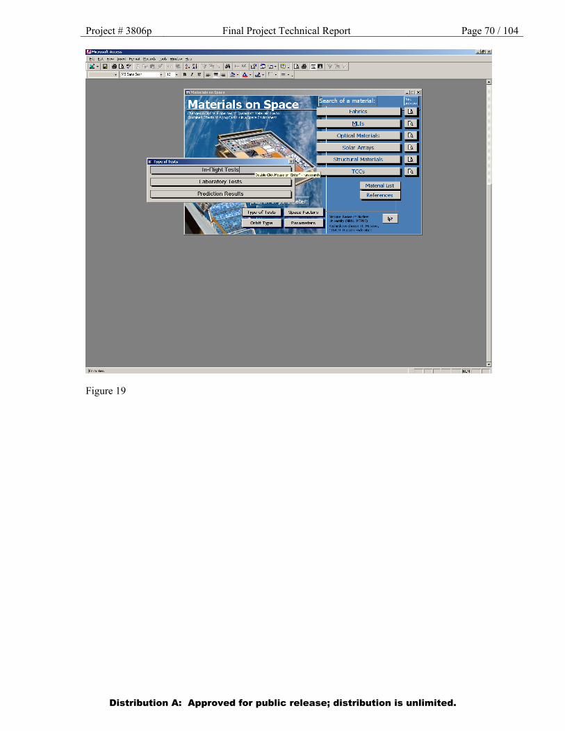
Project # 3806p Final Project Technical Report Page 70 / 104
Figure 19
Distribution A: Approved for public release; distribution is unlimited.
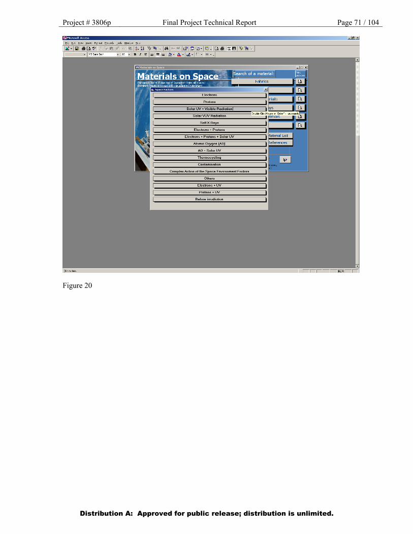
Project # 3806p Final Project Technical Report Page 71 / 104
Figure 20
Distribution A: Approved for public release; distribution is unlimited.
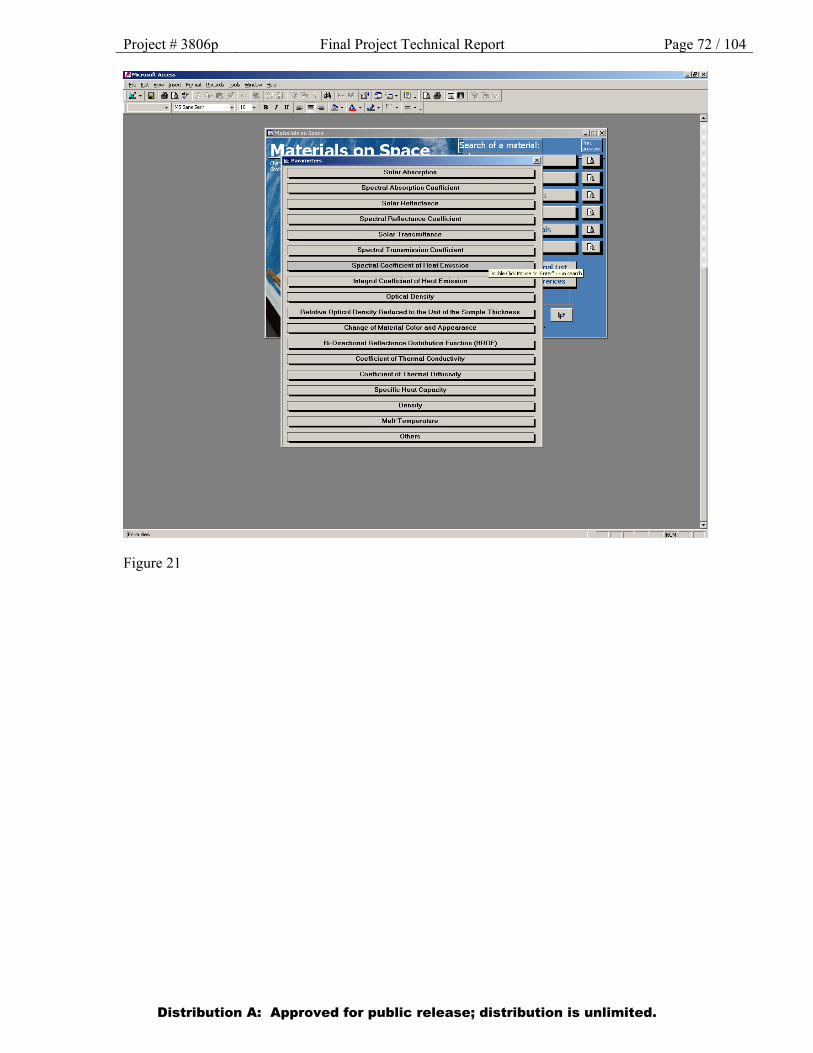
Project # 3806p Final Project Technical Report Page 72 / 104
Figure 21
Distribution A: Approved for public release; distribution is unlimited.
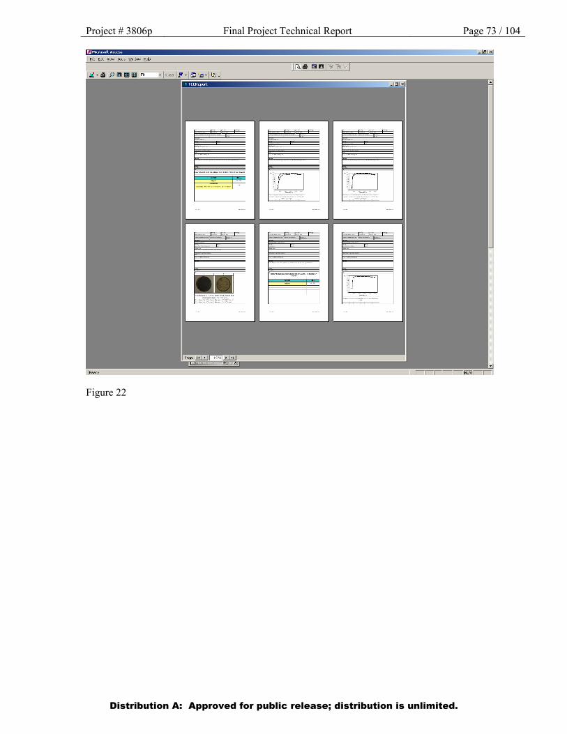
Project # 3806p Final Project Technical Report Page 73 / 104
Figure 22
Distribution A: Approved for public release; distribution is unlimited.
Project # 3806p Final Project Technical Report Page 74 / 104
Figure 23
Distribution A: Approved for public release; distribution is unlimited.
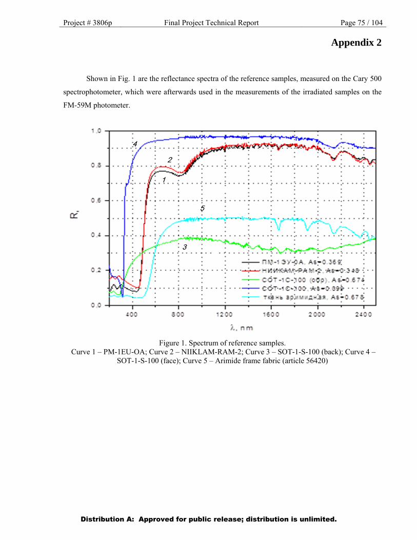
Project # 3806p Final Project Technical Report Page 75 / 104
Appendix 2
Shown in Fig. 1 are the reflectance spectra of the reference samples, measured on the Cary 500
spectrophotometer, which were afterwards used in the measurements of the irradiated samples on the
FM-59M photometer.
Figure 1. Spectrum of reference samples. Curve 1 – PM-1EU-OA; Curve 2 – NIIKLAM-RAM-2; Curve 3 – SOT-1-S-100 (back); Curve 4 –
SOT-1-S-100 (face); Curve 5 – Arimide frame fabric (article 56420)
Distribution A: Approved for public release; distribution is unlimited.
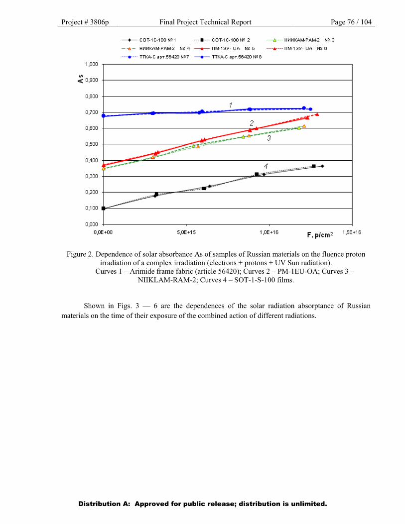
Project # 3806p Final Project Technical Report Page 76 / 104
Figure 2. Dependence of solar absorbance As of samples of Russian materials on the fluence proton irradiation of a complex irradiation (electrons + protons + UV Sun radiation).
Curves 1 – Arimide frame fabric (article 56420); Curves 2 – PM-1EU-OA; Curves 3 – NIIKLAM-RAM-2; Curves 4 – SOT-1-S-100 films.
Shown in Figs. 3 — 6 are the dependences of the solar radiation absorptance of Russian materials on the time of their exposure of the combined action of different radiations.
Distribution A: Approved for public release; distribution is unlimited.
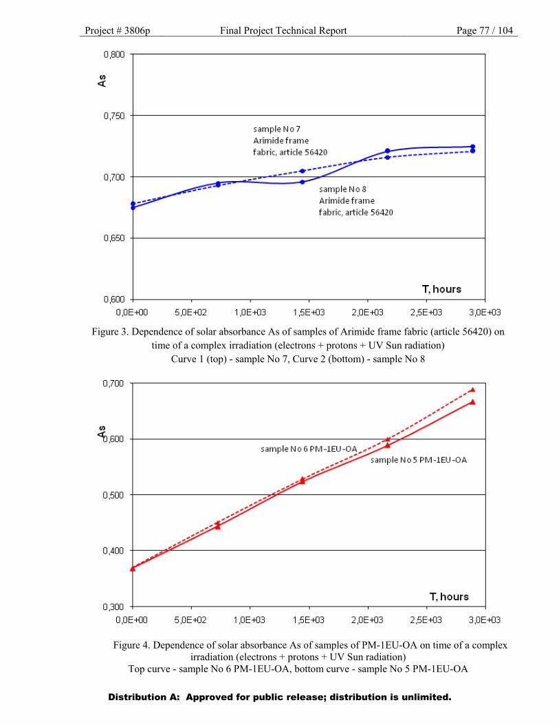
Project # 3806p Final Project Technical Report Page 77 / 104
Figure 3. Dependence of solar absorbance As of samples of Arimide frame fabric (article 56420) on time of a complex irradiation (electrons + protons + UV Sun radiation)
Curve 1 (top) - sample No 7, Curve 2 (bottom) - sample No 8
Figure 4. Dependence of solar absorbance As of samples of PM-1EU-OA on time of a complex irradiation (electrons + protons + UV Sun radiation)
Top curve - sample No 6 PM-1EU-OA, bottom curve - sample No 5 PM-1EU-OA
Distribution A: Approved for public release; distribution is unlimited.
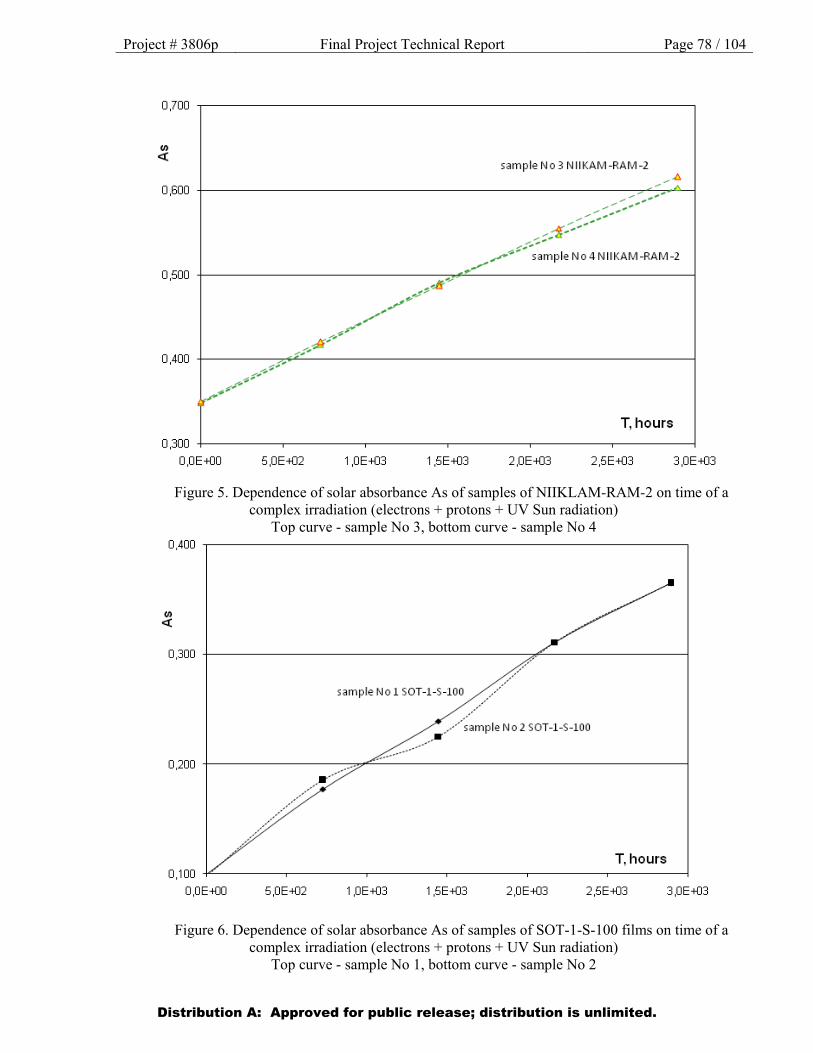
Project # 3806p Final Project Technical Report Page 78 / 104
Figure 5. Dependence of solar absorbance As of samples of NIIKLAM-RAM-2 on time of a complex irradiation (electrons + protons + UV Sun radiation)
Top curve - sample No 3, bottom curve - sample No 4
Figure 6. Dependence of solar absorbance As of samples of SOT-1-S-100 films on time of a complex irradiation (electrons + protons + UV Sun radiation)
Top curve - sample No 1, bottom curve - sample No 2
Distribution A: Approved for public release; distribution is unlimited.
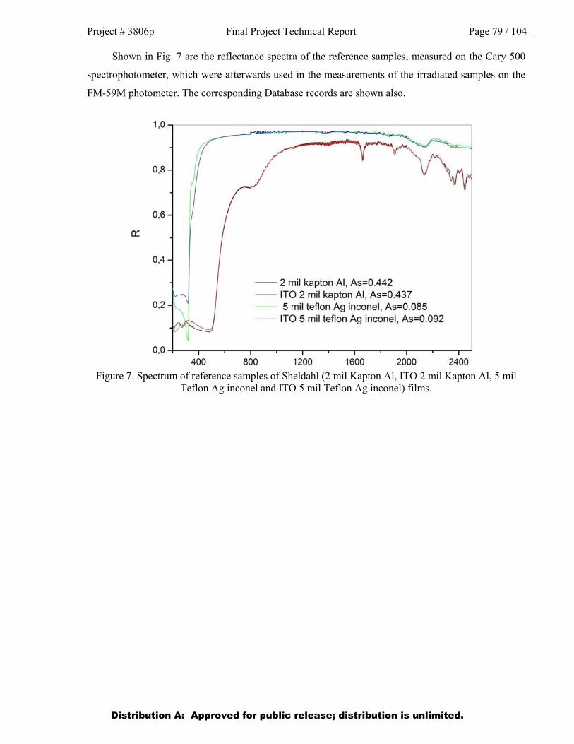
Project # 3806p Final Project Technical Report Page 79 / 104
Shown in Fig. 7 are the reflectance spectra of the reference samples, measured on the Cary 500
spectrophotometer, which were afterwards used in the measurements of the irradiated samples on the
FM-59M photometer. The corresponding Database records are shown also.
Figure 7. Spectrum of reference samples of Sheldahl (2 mil Kapton Al, ITO 2 mil Kapton Al, 5 mil
Teflon Ag inconel and ITO 5 mil Teflon Ag inconel) films.
Distribution A: Approved for public release; distribution is unlimited.
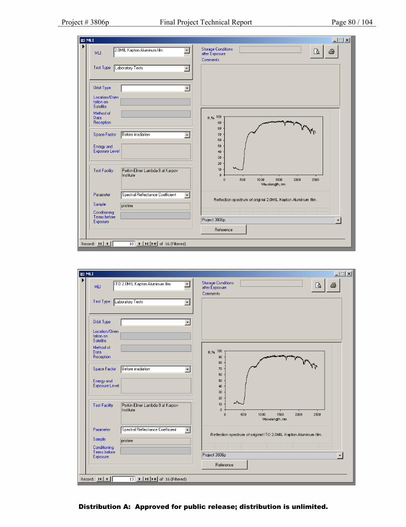
Project # 3806p Final Project Technical Report Page 80 / 104
Distribution A: Approved for public release; distribution is unlimited.
1ffi MLI
MLI 12.0MIL Kapton Aluminum lilm
Test Type jLaboratory Tests
Orbit Type ::::J Location/Jrien ,--------------, tation on Satellite
Method ol Data Reception
Space Fa:tor )Before irradiation
Energy ard I Exposure Level
Test Facilty
Parameter
Sample
Conditioni1g Terms before Exposure
Perkin-Elmer Lambda·9 at Karpov Institute
)Spectral Reflectance Coefficient
I pristine
::::J
::::J
Record: .!!.UJ I 10 • 1•1 1••1 of 16 (Filtered)
MLI l iTO 2.0MIL Kapton Aluminum lilm
Test Type jLaboratory Tests ::::J
Orbit Type ::::J location/Orien ,--------------, tation on Satellite
Methodol Data Reception
Space Factor )Before irradiation
Energy and I Exposure Level
Test Facility Perkin·Eimer Lambda·9 at Karpov Institute
Parameter jSpectral Rellectance Coellicient
Sample
Conditioning Terms before Exposure
I pristine
::::J
::::J
Record: .!!.UJ I 13 • l •1 l• • I of 16 (Filtered)
Storage Co1ditions after E xpos.ue
Comments
R.% 100 ,-------------------,
90
80
70
60
50
40
30
20
10
o+---~--~--~--~--~-' 500 1000 1500 2000 2500
Waveleng:h. rm
Refection spectrum of originai2.0MIL Kapton .AJuminum film.
!Project 38(6p
Relerence
Storage Conditions after E ><posure
Comments
R.% 100 ,-------------------,
90
80
70
60
50
40
30
20
10
o+---~----~----~----~--~--' 500 1000 1500 2000 2500
Waveleng:h. rm
Reflection spectrum of original I TO 2.0MIL KsptonAiuminum film.
!Project 3806p
Reference

Project # 3806p Final Project Technical Report Page 81 / 104
Distribution A: Approved for public release; distribution is unlimited.
TCC: ITO 5.0MIL T ellon Silverlncone
TCC Type jMetallized Film
Test T yJ>e jLaboratory Tests
Orbit Type
::::J ::::J
::::J Location/Orien .---------------, tation on Satellite
Methodol Data Reception
Space Factor )Before irradiation
Energy and Exposure Level
Test Facility
Parameter
Sample
Conditioning Terms before Exposure
Perkin-Elmer Lambda·9 at Karpov Institute
jspectral Rellectance Coellicient
::::J
::::J
Record: .!!..UJ I 58 • 1•• 1••1 of 59 (Filtered)
TCC: 15.0MIL T ellon Silverlnconel
TCC Type jMetallized Film
Test Type jLaboratory Tests
Orbit Type
::::J ::::J
::::J Location/Orien .---------------, tation on Satellite
Method of Data Reception
Space Factor )Before irradiation
Energy and Exposure Level
Test Facility
Parameter
Sample
Conditioning Terms before Exposure
Perkin-Elmer Lambda·9 at Karpov Institute
jspectral Rellectance Coellicient
I pristine
::::J
::::J
Record: .!!..UJ I 55 • I " I• *I of 59 (Filtered)
Storage Conditions after Exposure
Comments
R.% 100 ~----:;;::;:;;;;l';;;;;;;;;;;;o;;;;;;;;;;;;;;;;;;;;;:;;;:=:--~ 90
80
70
60
50
40
30
20
10
0+-----~----~----~----~----~_J
500 1000 1500 2000 2500 WaOJelerglh. nm
Reflection spectrum of original metallized film ITO S.OMIL Te11onSilver lnconel.
I Project 3806p
Reference>>
Storage Conditions after Exposure
Comments
R.% 100 ~----:::;:;o;;;;;;:;;;;;;;o;;;;;;;;y;;;::;;;;;:;:=---~ 90
80
70
00
50
40
30
20
10
o+---~----~----~--~----~_J 500 1000 1500 2000 2500
wavelergth. nm
Reflection spectrum of original metallized film S.OMIL Teflon Silver lncorel.
I Project 3806p
Reference>>
IJ

Project # 3806p Final Project Technical Report Page 82 / 104 In Fig. 8-11 dependence of solar absorbance AS for samples of Sheldahl films on level of influence of complex radiation is presented. The corresponding Database records are shown also.
Figure 8. Dependence of solar absorbance As of samples of Sheldahl films on time of a complex irradiation (electrons + protons + UV Sun radiation)
Curve 1 (top) - sample ITO/5.0 mil Teflon/Ag/Inc №1, Curve 2 (bottom) - sample ITO/5.0 mil Teflon/Ag/Inc №2
Distribution A: Approved for public release; distribution is unlimited.

Project # 3806p Final Project Technical Report Page 83 / 104
Distribution A: Approved for public release; distribution is unlimited.
TCC Type jMetaized Film
Test Type JLabo<aiOI)I Tests
Qr!j, Type :::1 Location/Orien talion on L[ ________ _J] Saleflite
Method of Data Reception
Space Factor j Electrons + Protons + Solar UV
Energy and E~su1e Level
Test F acili!y
Parameter
S~le
Conditioning
Jso~a~ Abso1ption
aged
Terms before facu..m E~sUfe L-------------'
Record: of 61 (Filtered)
TCC: ITO 5.0MIL Teflon Silve1 lncone
TCC Type JMetallized Film
Test Type JLabo•atofy Tests
O•bit Type
~~~~i~~/Orien ,---------------, Satellite
Method of Data Reception
Space Factor )Electrons+ Protons+ Solar UV
Energy and Exposure Level
Test Facility
Parameter
Sample
UV-1/2 at Kompozit
Jsola• Abso1ption
I aged
Conditioning Terms before !vacuum Exposure L-------------'
Record: ..!!.I...!J I 51 .!...l!!...J!!. of 61 (Filtered)
[ail J
Ep=50 keV (5E10 p/cm2sL Ee=50 keV (5E 11 e/cm2s), 3 e.s.i Electron and proton irradalion was carried W in discrete mode. Average flu:.c density equaled 5E7 p/cm2s and 4.6E8 e/cm2. In order to measure a change in solar absorptance, the sample was extracted i'io the ai1. HaW.g been meas .. ect the sample was placed into a vacwm testing cl\on'ber, and the 11adiation contirued until the ne><t vu exposu•e was •eached. The~ sample was used after in .:dation for mea:sU"ng spectral characte~istics.
02
...
•• 1 1.5 2 2.5
Time on GEO. )'Iars
Solar absorpt.Jnce for ITOJ5D mil Teflon/Agllnconel during co~r.ed
in adiation(electrons + proklns + UV solar r.Jdiation). The energy of the protons and electrons amo\l'ted to 50 keV. The average fl~ denstyfor the protons and electrons equah!d • = 5 x 10
7 picm
2x sand IP =4.6x 10
8
t /cm2
x s •• ptottvt ly. The Wtnsl\f of tht sim.Jllttd t lt otrom.agnetio soiJr 11dillon- equJi to3 ts.l
[P•oiect Jln)p
Reference>>
Storage Conditions jinert gas (argon) after Exposure L-----------'
Comments
Ep=50 keV (5E10 p/cm2s), Ee=50 keV (5E11 e/cm2s), 3 e.s.i. Electron and proton inadiation was canied out in discrete mode. Average flux density equaled 5E7 p/cm2s and 4.6E8 e/cm2. In order to measure a change in solar absorptance, the sample was extracted into the air. Having been measured, the sample was placed into a vacuum testing chamber, and the inadiation continued until the next value exposure was reached. After inadiation the given sample was delivered to the partner.
05 1.5 2.5 3.5 Time on GEO,years
Solar absorptance for ITOAS.O mil Teflon/Agl1nconel during combined irradiation (electrons + protons + UV solar radiation). The energy of the protons and electrons amounted to 50 keV. The averagefi~.D< density for the
protons and electrons equaled q1 = 5 x 10⁷ p/cm2 x s and q~ = 4.6 x 10⁸
e/cm2 x s respectively. The intensity of the simulated electromagnetic solar radiation was eoualto3 e.s.i.
I P•oiect 3806p
Reference>>
c:J
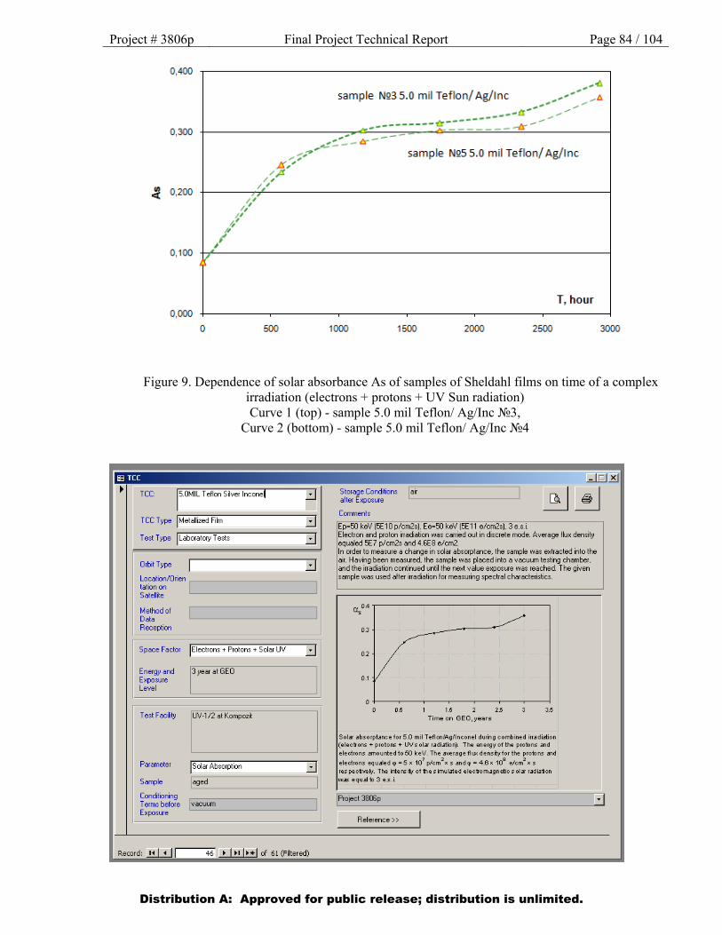
Project # 3806p Final Project Technical Report Page 84 / 104
Figure 9. Dependence of solar absorbance As of samples of Sheldahl films on time of a complex irradiation (electrons + protons + UV Sun radiation) Curve 1 (top) - sample 5.0 mil Teflon/ Ag/Inc №3,
Curve 2 (bottom) - sample 5.0 mil Teflon/ Ag/Inc №4
Distribution A: Approved for public release; distribution is unlimited.
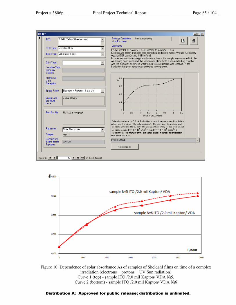
Project # 3806p Final Project Technical Report Page 85 / 104
Figure 10. Dependence of solar absorbance As of samples of Sheldahl films on time of a complex irradiation (electrons + protons + UV Sun radiation)
Curve 1 (top) - sample ITO /2.0 mil Kapton/ VDA №5, Curve 2 (bottom) - sample ITO /2.0 mil Kapton/ VDA №6
Distribution A: Approved for public release; distribution is unlimited.
lffi TCC
TCC: 15.0MIL T ellon Silver lnconel
TCC Type jMetallized Film
Test Type jLaboratory Tests
Orbit Type
::::J ::::J
::::J Location/Orien ,---------------, tation on Satellite
Method of Data Reception
Space Factor )Electrons+ Protons+ Solar UV iJ Energy and Exposure Level
Test Facility
Parameter
Sample
13 year at GEO
UV ·1/2 at Kompozit
jsolar Absorption ::::J I aged
Conditioning Terms before I vacuum Exposure L-------------'
Record: ..!.!.l.!..J I 47 • I " I• *I of 61 (Filtered)
0.100
0.600
0,<00
0 1000
Stcrage Conditions I inert gas (argon) after Exposure L__:__:__:__:_ _____ __J
Conments
Ep•50 keV (5E10 p/cm2s). Ee=50 keV (5E11 e/cm2s). 3 e.s.i. Electron and proton irradiation was carried out in discrete mode. Average flux density equaled 5E7 p/cm2s and 4.6E8 e/cm2. In ader to measure a change in solar absorptance, the sample was extracted into the air. -laving been measured, the sample was placed into a vacuum testing chamber, and the irradiation continued until the next value exposure was reached. After irradiation the given sample was delivered to the partner.
~0.4
03
Ol
0.1
o+---~--~--~--~--~--~--~ 0 05 1.5 25 3.5
Time on GEO,years
Sol.ar absorptance for5.0 mil T eflorv'Agl1 nconel during combined irradiation (electrons + protons + UV solarr adiation). The energy of the protons and
electrons amounted to 50 keV. The average flux dens io/ for the protons and
electrons equaled ql = 5 x 10⁷ p/cm2x s and ql = 4.6 x 10⁸ e/cm2 x s respectively. The intensity of the simulated electromagnetic solar radiation was equalto3 es.i.
!Project 3806p
Reference>>
c:J
sample NQS ITO / 2.0 m il Kapton/ VDA -----------'ll
sample NQ6 1TO / 2.0 m il Kapton/ VDA
T, hour
1500
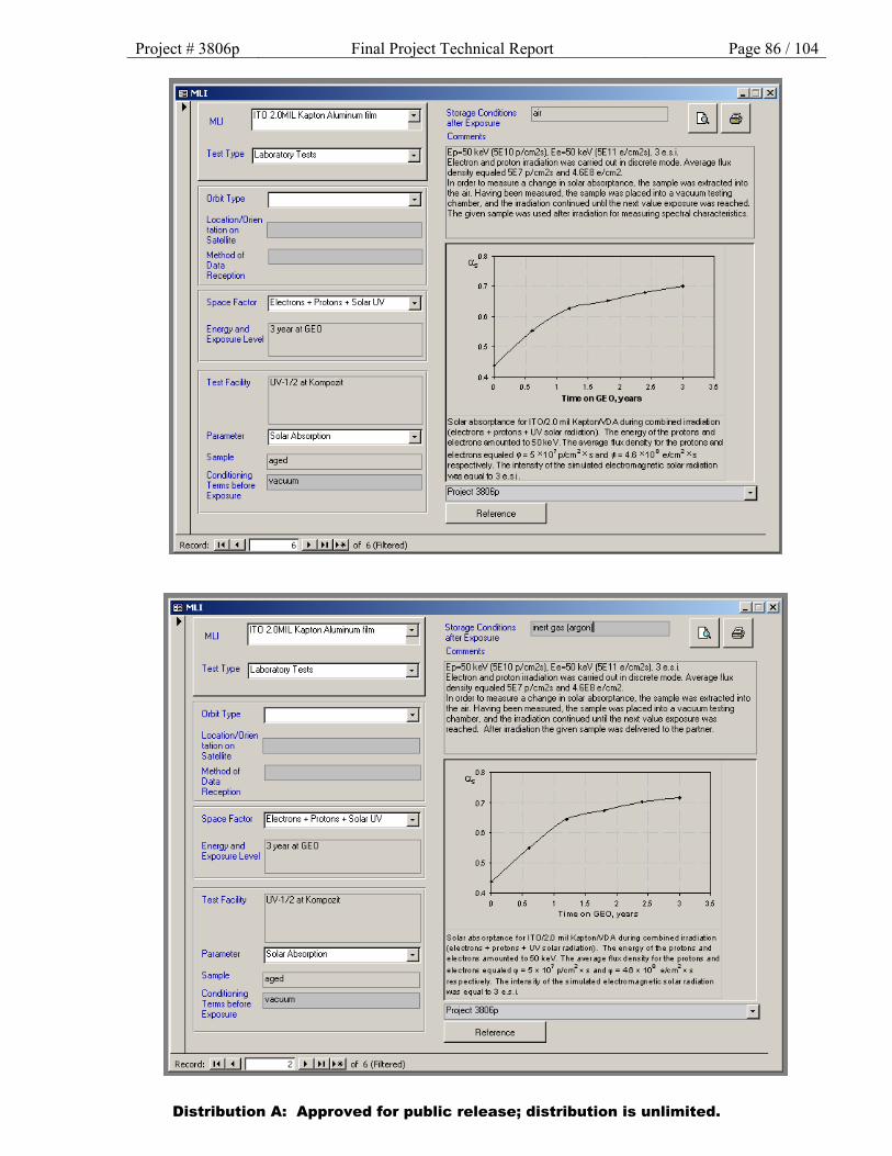
Project # 3806p Final Project Technical Report Page 86 / 104
Distribution A: Approved for public release; distribution is unlimited.
Test Type jLaboratory Tests
Orbit Type ::::J Location/Orien ,--------------, tation on Satellite
Method of Data Reception
Space Factor )Electrons+ Protons+ Solar UV iJ
Energy and 13 year at GEO Exposure Level
Test Facility UV-1/2 at Kompozit
Parameter jsofar Absorption ::::J Sample I aged Conditioning ~=============:; Terms before I vacuum Exposure L ___________ __J
!Laboratory Tests ::::J
OrbHwe ::::J Location/01ien .---------------, tationon Satefie
Methodol Doto Reception
Space Factor jEiectrons +Protons+ Solar UV iJ
Energy Md 13 yea at GEO ExpOSU'e Level
Test F bcility
Parameter
Sample
Condlioning T errns before Expooue
retKompoa
I Solar Ab•orption
J ::::J
l
air
Ep=50 keV (5E10 p/cm2s). Ee=50 keV (5E11 e/cm2s). 3 e.s.i. Electron and proton irradiation was carried out in discrete mode. Average flux density equaled 5E7 p/cm2s and 4.6E8 e/cm2. In order to measure a change in solar absorptance, the sample was extracted into the air. Having been measured, the sample was placed into a vacuum testing chamber, and the irradiation continued until the next value exposure was reached. The given sample was used after irradiation for measuring spectral characteristics.
OS a. 07
~ OS
05
0.4 0 0.5 I 1.5 2 25 3 35
Tirre onGE O, years
Soler absorptarce for IT Of2.0 mil Kaptorv\IDA during comb ired irradiation (electrons+ protons+ UVsolsr ra:tietion). The erergyoftte protons end electrons amolllled to 50 ke V. The average flux density for the protons an:t electrons equaled \0 = 5 x1 07 p/cm2 Xsan:t 1,0 = 4.6 X1Q8 e/cm2 xs respectively. T te intensity of tte simUated electromsgretic solar radiation 'Y\6S equal to 3 e.sj.
IP•oleCt 3806p
Reference
~nert gas (argonj
COIMlent•
Ep=50 keV (5E10 p/cm2s). Ee=50 keV (5E11 elcm2s). 3 e.s.i Electron and proton (radiation was carried out in ciscrete mode. Average flux density equaled 5E7 p/cm2s and 4.6E8 e/cm2.
.:J
In order to meas"'e a change in solar absorptance .. the sample was extracted irio the eir. Hoving been measured. the .. mple w .. pieced into • vec:uum testing chamber. and the itadiation contn..ed until the next value exposue was reached. After irraOation the given sample was deivered to the pcwtner.
a.os
0.7
0~
05
OA 0 0.5
Time o n GEO, years
Solar absorptance for ITOI2D mil KaptonN DA dwing combined irradiation (electrons+ protons+ UV solar radiation). The energy of the protons and ... ctrons amounted to$0 ktV. The aw ragt flu)( dtnsity for tht protons and
•"'ctrons equJitd • • $ x 107
plcmz • 1 Jnd • • 4.0 • 10' t /omz • 1 res pectively. Th e intens ifv of the simulated electromagnetic solar radiation was equal to 3 e .s.i
[Project 3806p
Reference
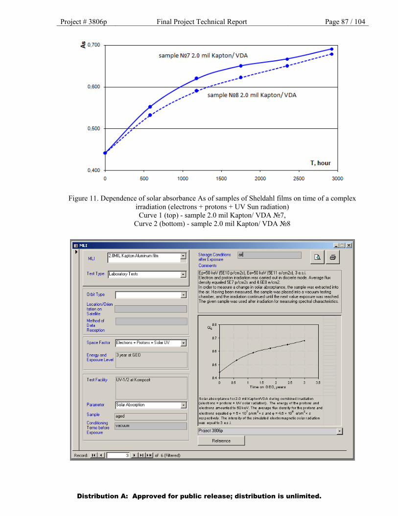
Project # 3806p Final Project Technical Report Page 87 / 104
Figure 11. Dependence of solar absorbance As of samples of Sheldahl films on time of a complex irradiation (electrons + protons + UV Sun radiation) Curve 1 (top) - sample 2.0 mil Kapton/ VDA №7,
Curve 2 (bottom) - sample 2.0 mil Kapton/ VDA №8
Distribution A: Approved for public release; distribution is unlimited.
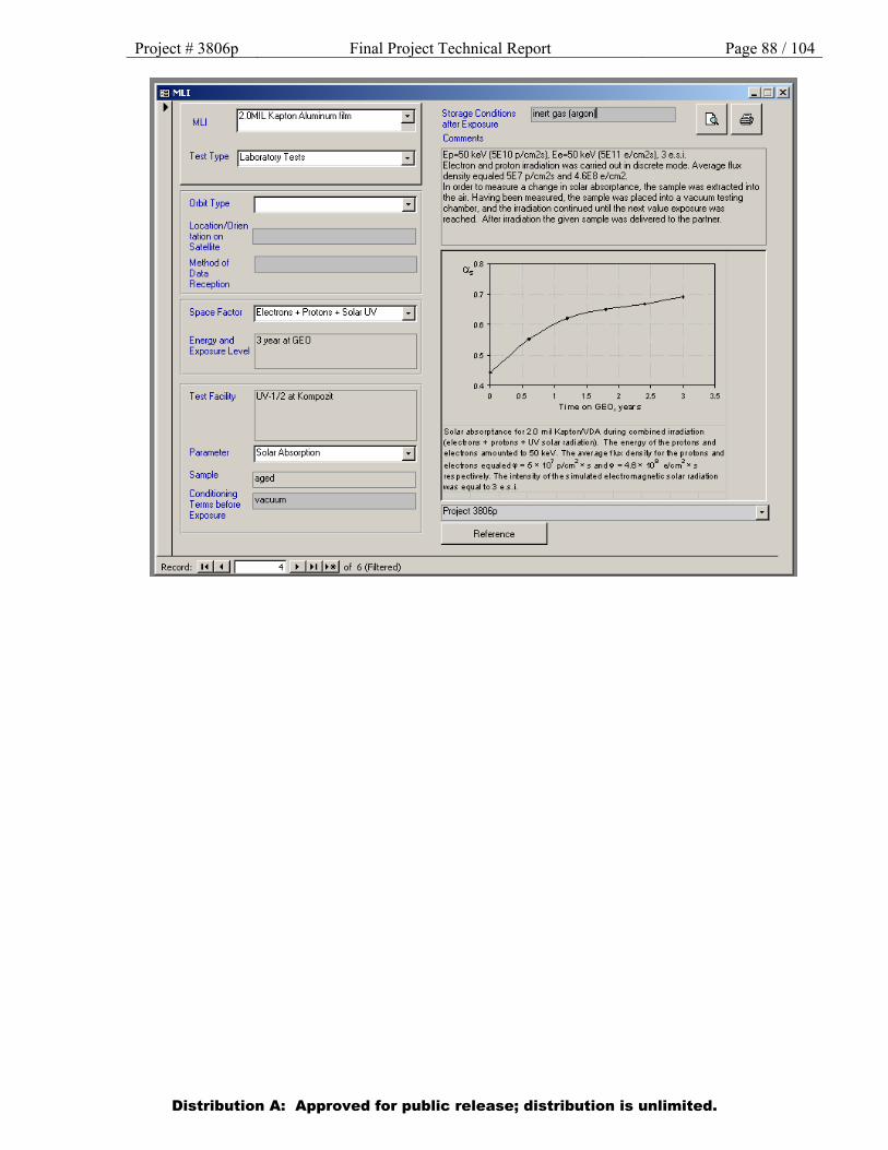
Project # 3806p Final Project Technical Report Page 88 / 104
Distribution A: Approved for public release; distribution is unlimited.
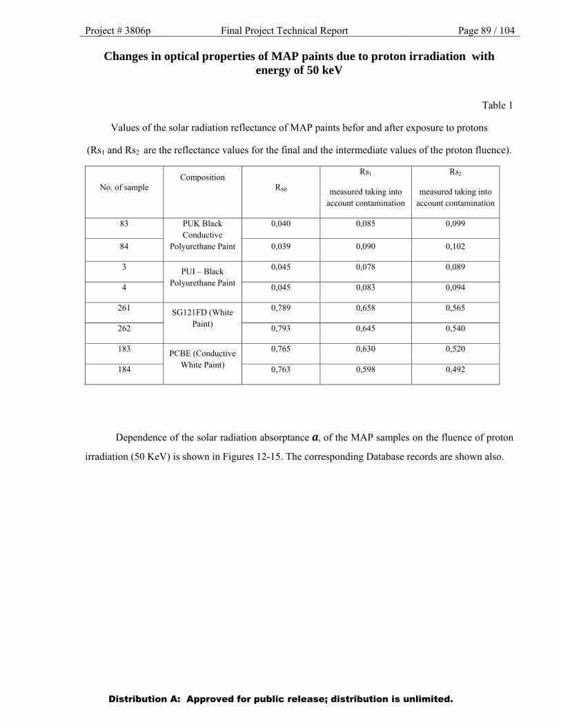
Project # 3806p Final Project Technical Report Page 89 / 104
Changes in optical properties of MAP paints due to proton irradiation with energy of 50 keV
Table 1
Values of the solar radiation reflectance of MAP paints befor and after exposure to protons
(Rs1 and Rs2 are the reflectance values for the final and the intermediate values of the proton fluence).
No. of sample Composition
RS0
Rs1
measured taking into account contamination
Rs2
measured taking into account contamination
83 PUK Black Conductive
Polyurethane Paint
0,040 0,085 0,099
84 0,039 0,090 0,102
3 PUI – Black Polyurethane Paint
0,045 0,078 0,089
4 0,045 0,083 0,094
261 SG121FD (White Paint)
0,789 0,658 0,565
262 0,793 0,645 0,540
183 PCBE (Conductive White Paint)
0,765 0,630 0,520
184 0,763 0,598 0,492
Dependence of the solar radiation absorptance as of the MAP samples on the fluence of proton
irradiation (50 KeV) is shown in Figures 12-15. The corresponding Database records are shown also.
Distribution A: Approved for public release; distribution is unlimited.

Project # 3806p Final Project Technical Report Page 90 / 104
Figure 12. Dependence of the solar radiation absorptance As on the fluence of proton irradiation. Curve 1 (upper) and Curve 2 (lower) correspond to samples of a MAP coating (PUK Black Conductive
Polyurethane Paint) No. 84 and No. 83 respectively
Distribution A: Approved for public release; distribution is unlimited.
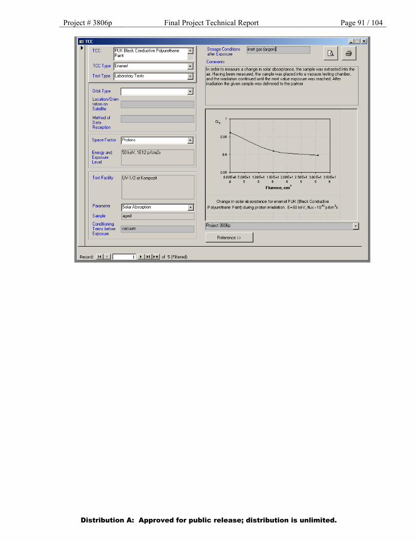
Project # 3806p Final Project Technical Report Page 91 / 104
Distribution A: Approved for public release; distribution is unlimited.
lffi TCC
TCC: PUK Black Conductive Polyurethane Paint
Tee Type jEnamel ::::J
Test T ype j r;L-a,..bo- r-at""o-ry""T,-e-s:-ts--------::::J-.-r
Orbit Type
Location/Orien .---------------, tation on Satellite
Method ol Data Reception
Space Factor )Protons
Energy and Exposure Level
Test Facility
Parameter
Sample
Conditioning
150 keV, 1E12 p/cm2s
UV ·1/2 at Kompozit
jsolar Absorption
I aged
::::J
::::J
Terms before I vacuum Exposure '--------------__J
Record: ..!.!..I.!..J I • 1•• 1••1 of 5 (Filtered)
Storage Conditions I inert gas (argon) after Exposure L__::._.:..._:.._.::..._ _____ ...J
Comments
In order to measure a change in solar absorptance, the sample was extracted into the air. Having been measured, the sample was placed into a vacuum testing chamber, and the irradiation continued until the next value exposure was reached. After irradiation the given sample was delivered to the partner
095
09
OS5 -1----~-~----~-~-~----1 OOOE+O 5DOE+I IDOE+I 1.50E+I 200E+I 2.50E+I 300E+I 3.50E+I
0 56 6 6 6 6 6
Fluence, cm4
Change in solar S::lsorptarce for enamel P UK (Black Cordl.Ciive
Pol·ytuethare Paint) during proton irra:tiation. E=SO keV, flux -1012
p.tm 2s
!Project 3806p
Reference>>
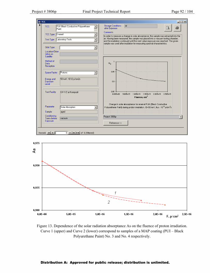
Project # 3806p Final Project Technical Report Page 92 / 104
Figure 13. Dependence of the solar radiation absorptance As on the fluence of proton irradiation. Curve 1 (upper) and Curve 2 (lower) correspond to samples of a MAP coating (PUI – Black
Polyurethane Paint) No. 3 and No. 4 respectively.
Distribution A: Approved for public release; distribution is unlimited.
lffi TCC I
TCC: PUK Black Conductive Polyurethane Paint
TCCType jEnamel ::::J ;,....,.._,........,.....,....-----====-~
Test Type jLaboratory Tests ::::J
Orbit Type ::::J Location/Orien ,--------------, tation on Satellite
Method of Data Reception
Space Factor )Protons
Energy and Exposure Level
Test Facility
Parameter
Sample
Conditioning
150 keV, 1E12 p/cm2s
UV-1/2 at Kompozit
)Solar Absorption
I aged
::::J
::::J
T e1ms befo1e I vacuum Exposu1e '----------------'
Record: ..!!.I..!J I 4 • 1•• 1••1 of 5 (Filtered)
0,975
Storage Conditions lair after Exposure '-------------'
Comments
In order to measure a change in solar absorptance, the sample was extracted into the air. Having been measured, the sample was placed into a vacuum testing chamber, and the irradiation continued until the next value exposure was reached. The given sample was used after irradiation for measuring spectral characteristics.
095
09
OB5+------r----~r-----,-----~----~
OOOE+OO 500E+15 1 OOE+16 1.50E+16 2 OOE+16 2.50E+16
Fluence, cm4
Change in solar S::lsorptarce for enamel P UK (Black Con::h.ctive
P ol'yUrethare Paint) during proton irra:::liation. E=SO keV, flux -10 12 p.tm 2s
!Project 3806p
Reference>>
r---.. 0,950 +--'~~----------------------------------------------------------------------------~ ,,
0,925
0,900
O,OE+OO
........ ..... ........ ...... ......
5,0E+15
...... ...,...,
1 ,0E+16 1,5E+16 2,0E+16 F, llfcm2
2,5E+16
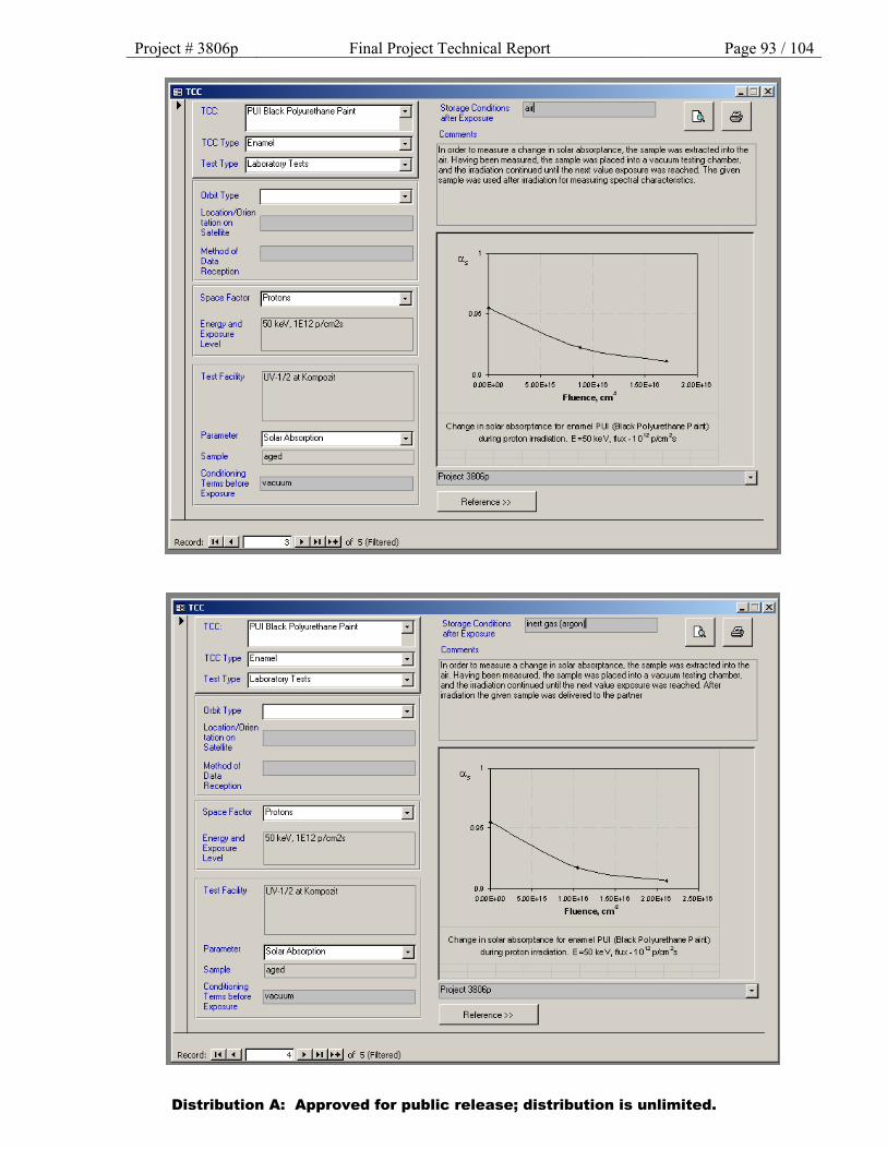
Project # 3806p Final Project Technical Report Page 93 / 104
Distribution A: Approved for public release; distribution is unlimited.
~ TCC: PUI Black Polyurethane Paint
TCC Type jEnamel
Test Type jLaboratory Tests ::::J
Orbit Type ::::J Location/Orien tation on Satellite
Method ol Data Reception
Space Factor )Protons ::::J Energy and 150 keV, 1E12 p/cm2s Exposure Level
Test Facility UV·l/2 at Kompozit
Parameter jsolar Absorption ::::J Sample I aged
Conditioning Terms before I vacuum Exposure '----------------'
Record: .!!.U.J I 3 • 1•• 1••1 of 5 (Filtered)
Storage Conditions lai4 alter Exposure '--'-----------'
Comments
In order to measure a change in solar absorptance, the sample was extracted into the air. Having been measured, the sample was placed into a vacuum testing chamber, and the irradiation continued until the next value exposure was reached. The given sample was used after irradiation for measuring spectral characteristics.
095
09 +-----~------~------~----~ oooe.oo 5.00E+15 1 00E+16 1.50E+16 2.00E+16
Fluence, cm4
Chsnge in solar absorptsnce for enamel PUI (Bleck Poi)'Urethare P sirt)
durirg proton irradiation. E =50 keV, ftux-1 012
p/an 2s
I Project 3BOSp
Reference>>
lffi TCC I ~
TCC: PUI Black Polyurethane Paint
TCC Type jEnamel ::::J Test Type jLaboratory Tests ::::J
Orbit Type ::::J Location/Orien tation on Satellite
Method ol Data Reception
Space Factor )Protons ::::J Energy and 150 keV, 1E12 p/cm2s Exposure Level
Test Facility UV·l/2 at Kompozit
Parameter )Solar Absorption ::::J Sample I aged
Conditioning Terms before !vacuum Exposure '----------------'
Record: .!!.U.J I 4 • 1•• 1••1 of 5 (Filtered)
Storage Conditions !inert gas (argon) after Exposure '--------------'
Comments
In order to measure a change in solar absorptance, the sample was extracted into the air. Having been measured, the sample was placed into a vacuum testing chamber, and the irradiation continued until the next value exposure was reached. After irradiation the given sample was delivered to the partner
095
09+-----~----~----~----~--~ OOOE+OO 500E+15 1 OOE+16 1.506+16 2 OOE+16 2.50E+16
Fluence, cm4
Ch111ge in solar absorpt111ce for enamel PUI (EII~k Poi)"Urelhare P lirt) durirg proton irradiation. E =50 keV, flux-1 0 12 p/an 2s
I Project 3BOSp
Reference>>
IJ
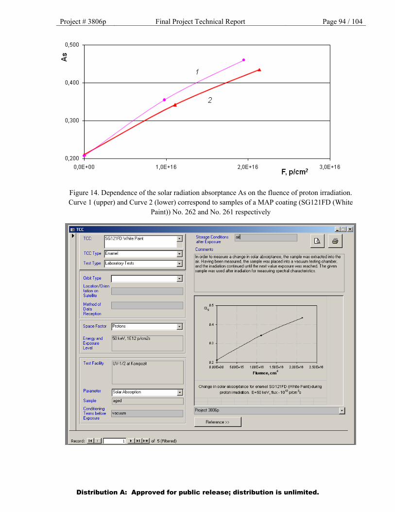
Project # 3806p Final Project Technical Report Page 94 / 104
Figure 14. Dependence of the solar radiation absorptance As on the fluence of proton irradiation. Curve 1 (upper) and Curve 2 (lower) correspond to samples of a MAP coating (SG121FD (White
Paint)) No. 262 and No. 261 respectively
Distribution A: Approved for public release; distribution is unlimited.

Project # 3806p Final Project Technical Report Page 95 / 104
Figure 15. Dependence of the solar radiation absorptance As on the fluence of proton irradiation. Curve 1 (upper) and Curve 2 (lower) correspond to samples of a MAP coating (PCBE (Conductive
White Paint)) No. 184 and No. 183 respectively
Distribution A: Approved for public release; distribution is unlimited.
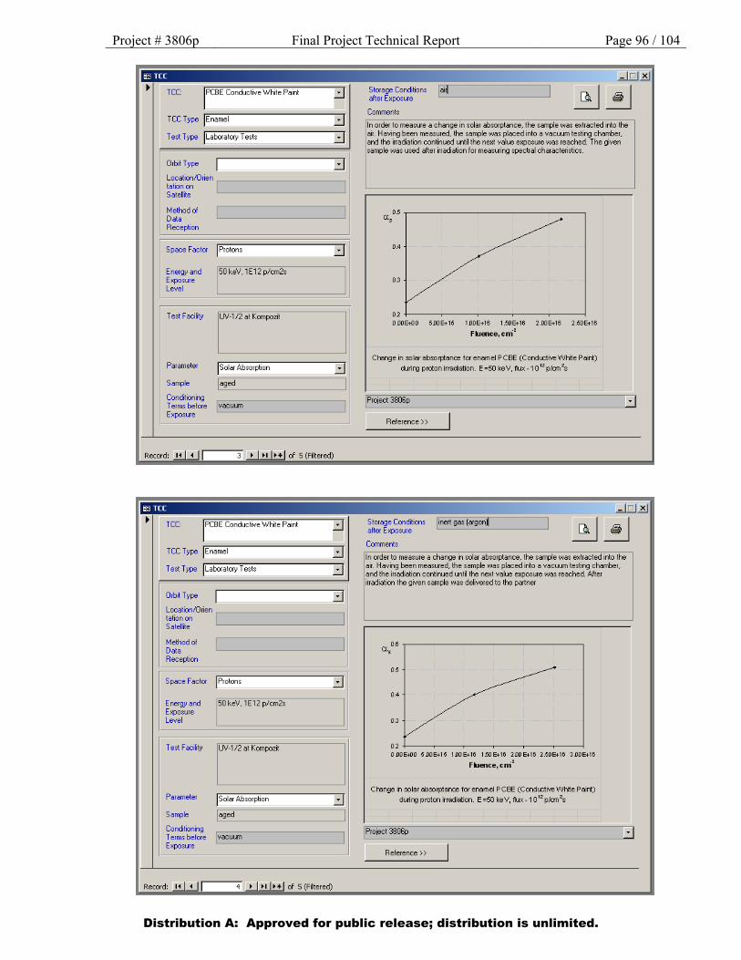
Project # 3806p Final Project Technical Report Page 96 / 104
Distribution A: Approved for public release; distribution is unlimited.
TCC: r CBE Conductive White Paint
TCCType jEnamel ::::J
Test T ype j r;L-a,..bo- r-at""o-ry""T,-e-s""ts--------::::J-."1
Orbit Type
Location/Orien .---------------, tation on Satellite
Method ol Data Reception
Space Factor )Protons
Energy and Exposure Level
Test Facility
Parameter
Sample
Conditioning
150 keV, 1E12 p/cm2s
UV -1/2 at Kompozit
)Solar Absorption
I aged
::::J
::::J
Terms before I vacuum Exposure '----------------'
Record: .!!.U...J I 3 • 1•• 1••1 of 5 (Filtered)
::::J
Test Type jLaboratory Tests ::::J
Orbit Type ::::J Location/Orien ,---------------, tation on Satellite
Method of Data Reception
)pace Factor )Protons
onergy and 150 keV, 1E12 p/cm2s ::xposure _evel
Test Facility UV -1/2 at Kompozit
Parameter )Solar Absorption
Sample I aged
Conditioning
::::J
::::J
Terms before I vacuum Exposure '----------------'
Record: 14
Storage Conditions lai4 after Exposure '--------------'
Comments
In order to measure a change in solar absorptance, the sample was extracted into the air. Having been measured, the sample was placed into a vacuum testing chamber, and the irradiation continued until the next value exposure was reached. The given sample was used after irradiation for measuring spectral characteristics.
0.4
03
02+------r------~----~----~------~
ODOE+OO 500E+15 IDOE+I6 1.50E+16 2.00E+16 2.50E+16
Fklence,crri2
Change in solar absorptance for enamel P CBE (Condl.Ciive White Paint)
durirg proton irradiation. E =50 keV, flux -1 0 12 p/an2s
!Project 3806p
Reference>>
jinert gas (argon)
Comments
In order to measure a change in solar absorptance, the sample was extracted into the air. Having been measured, the sample was placed into a vacuum testing chamber, and the irradiation continued until the nex: value exposure was reached. After irradiation the given sample was deliverec to the partner
oa a..
05
04
03
02 ODOE+OO 5DOE+15 IDOE+16 1.50E+16 200E+16 2.50E+16 3.00E+16
Fklence,crri2
Change in solar absorptance for enamel P CBE (Condl.Ciive White Paint) durirg proton irradiation. E =50 keV, ftux-1 0 12 p/an 2s
1Pro1ect 3806p
Reference>>
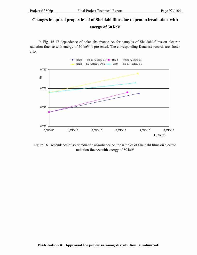
Project # 3806p Final Project Technical Report Page 97 / 104
Changes in optical properties of of Sheldahl films due to proton irradiation with
energy of 50 keV
In Fig. 16-17 dependence of solar absorbance As for samples of Sheldahl films on electron radiation fluence with energy of 50 keV is presented. The corresponding Database records are shown also.
Figure 16. Dependence of solar radiation absorbance As for samples of Sheldahl films on electron radiation fluence with energy of 50 keV
Distribution A: Approved for public release; distribution is unlimited.

Project # 3806p Final Project Technical Report Page 98 / 104
Distribution A: Approved for public release; distribution is unlimited.
1ffi MLI
MLI p .OOU6. GE 1.0MIL Kapton lilm
Test Type jLaboratory Tests
Orbit Type ::::J Location/Orien .---------------, tation on Satellite
Method ol Data Reception
Space Factor )Electrons ::::J Energy and 150 keV. 2E12 e/cm2s Exposure Level
Test Facility UV-1/2 at Kompozit
Parameter jsolar Absorption ::::J Sample I aged
Conditioning ~============::::: Terms before I vacuum Exposure '------------__J
Record: ..!.!.l.!..J I 7 • 1•• 1••1 of 8 (Filtered)
Storage Conditions lai4 after Exposure '--'-------------'
Comments
In order to measure a change in solar absorptance, the sample was extracted into the air. Having been measured, the sample was placed into a vacuum testing chamber, and the irradiation continued until the next value exposure was reached. The given sample was used after irradiation for measuring spectral characteristics.
0.775
0.75
0.725
0.7 +-----~---~--~-----1 OOOE.OO I DOE+16 2 DOE+16
Fluence, cm4
300E+16 4.00E+16
Change in solar absorptsnce for 1.0 mil Kapton/ Ge durirg electron irra:tiation. E=SOkeV, ftux-2>qQ 12 e/an 2s
!Project 3806p
Reference
lffi MLI I
MU 11.00()6. GE 1.0MIL Kapton film
Test Type jLaboratocy Tests ::::J
Or~ Type ::::J Location/Orion .--------------, tation on Sotello
Method ol Data Reception
s~ FactOf IEiecuons ::::J Energy and 150 ke\1, 2E12 e/cm2s Exposure Level .
Test Facility IUV-1/2 at Kompozit
Perarneter !Soler Absorption ..:.J Sarrc>le @led Condlioning
E ci.Ull Terms before Exposure
Re<ord: ..!.!.l.!..J I 8 • I •• 1••1 of 8 (Filered)
Storage Conditions § as (ergon) after Exposure '---='----'--=---'-------~
Commeru
In order to measlle a change in solaf absorptance, the sample was extracted i'io the air. Having been measued, the sample was placed into a vacuum testing chember. and the irediation contir'<led unta the next value exposure was reached. After irradation the given sample was delivered to the partner
ex. 0.8.,------------------, • 0175
0125
1 OOE+ 10 2 OOE+10
Fluence, cm.:z 300E+10 4.00E+10
Ct"enge in solar abself'P:ence t»r 1.0 ml Kapton/Ge durirg electron irndiation. E=SO keV, ftux -2~0 12elanzs
[Project Ja06p
Reference
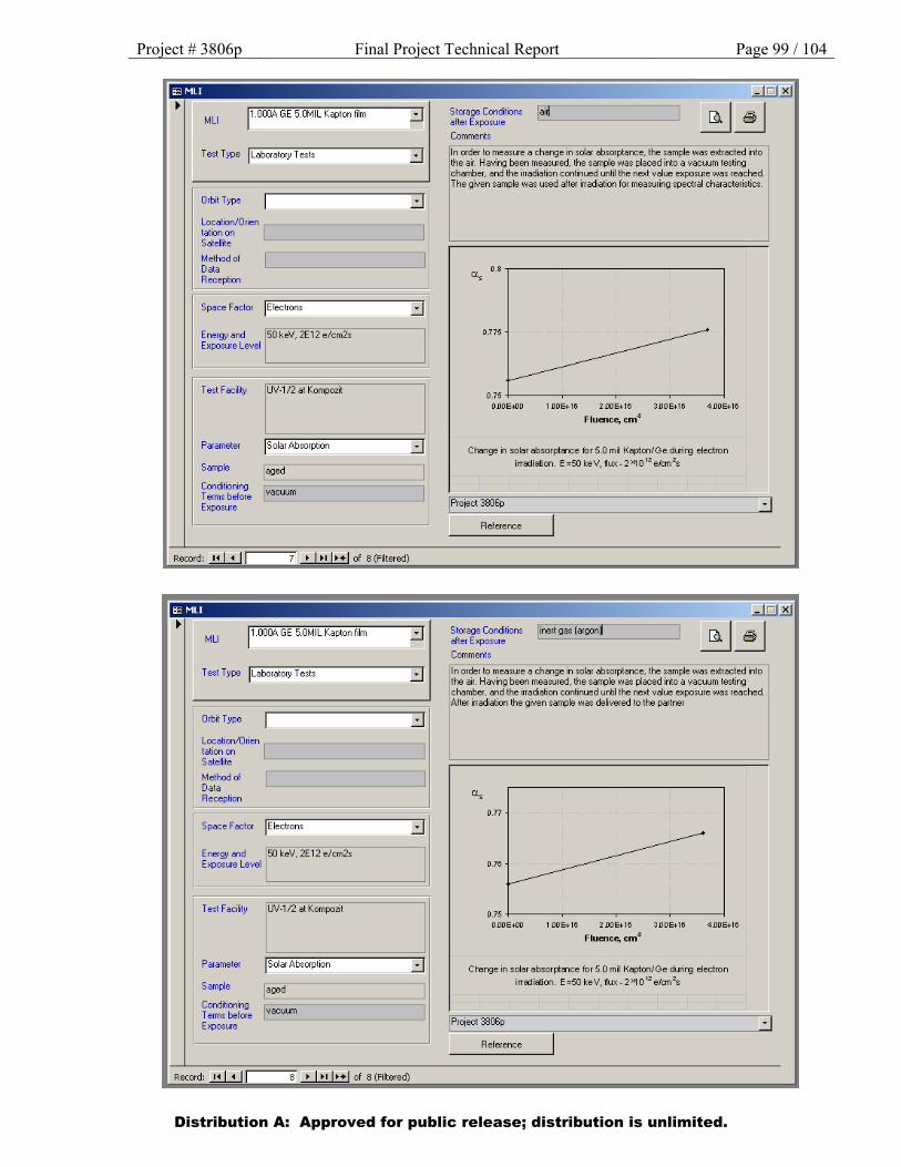
Project # 3806p Final Project Technical Report Page 99 / 104
Distribution A: Approved for public release; distribution is unlimited.
lffi MLI
MLI p .00()6. G E 5.0MIL Kapton lilm
Test Type jLaboratory Tests
Orbit Type ::::J Location/Orien ,---------------, tation on Satellite
Method ol Data Reception
Space Factor )Electrons
Energy and 150 keV. 2E12 e/cm2s Exposure Level
Test Facility UV ·1/2 at Kompozit
Parameter jsolar Absorption
Sample
::::J
::::J I aged
Conditioning ~=============~ Terms before I vacuum Exposure L-------------'
Record: ..!.!.l.!..J I 7 • 1•• 1••1 of 8 (Filtered)
Test Type jLaboratory Tests ::::J
Orbit Type ::::J Location/01ien ,---------------, tation on Satellite
Method ol Data Reception
Space Facto• )Electrons ::::J Energy and 150 keV. 2E12 e/cm2s E xposu1e Level
Test Facility UV-1/2 at Kompozit
Pa1amete1 )Solar Absorption ::::J Sample I aged
Conditioning ~==============~ T e1ms befo1e I vacuum Exposure L------------'
Storage Conditions lai4 after Exposure L_:_ __________ _J
Comments
In order to measure a change in solar absorptance, the sample was extracted into the air. Having been measured, the sample was placed into a vacuum testing chamber, and the irradiation continued until the next value exposure was reached. The given sample was used after irradiation for measuring spectral characteristics.
a. 0.8 .------------------, s
0.775
0.75 +----~---~---~-----l OOOE.OO 1 OOE+16 2 OOE+16
Fluence, cm4 300E+16 4.00E+16
Change in solar absorptsnce for 5.0 mil Kapton/G e durirg electron irra:::liation. E=SOkeV, 11ux-2~0 12 e/an 2s
I Project 3806p
Reference
linerl gas (argon)
Comments
In order to measure a change in solar absorptance, the sample was extracted into the air. Having been measured, the sample was placed into a vacuum testing chamber, and the irradiation continued until the next value exposure was reached. After irradiation the given sample was delivered to the partner
a..
0.77
0.76 ~ 0.75
OOOE.OO 1 OOE+16 2 OOE+16 300E+16 4.00E+16
Fluence, cm4
Change in solar absorptsnce for 5.0 mil Kapton/Ge durirg electron
irra:::liation. E=SOkeV, 11ux-2~0 12 e/an 2s
I Protect 3806p .:J Reference
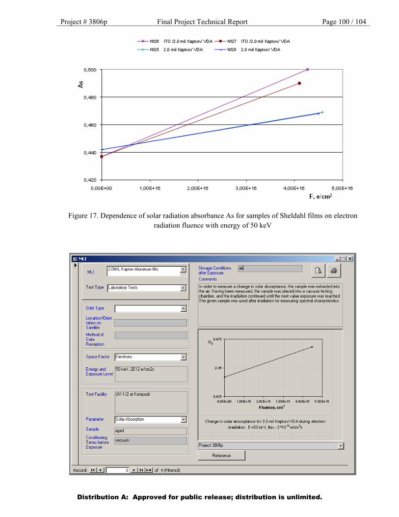
Project # 3806p Final Project Technical Report Page 100 / 104
Figure 17. Dependence of solar radiation absorbance As for samples of Sheldahl films on electron radiation fluence with energy of 50 keV
Distribution A: Approved for public release; distribution is unlimited.

Project # 3806p Final Project Technical Report Page 101 / 104
Distribution A: Approved for public release; distribution is unlimited.
lffi MLI I
MLI 12.0MIL Kaplon Aluminum film
Test Type JLaboratory-ests
Orbit Type ::::J Location/Orien ,---------------, tation on Satellite
Method of Data Reception
Space Factor )Electrons
Energy and 150 keV. 2E12 e/cm2s Exposure Level
I est ~ acll1ty UV·l/~ at Kompozrt
Pa1ameter JSolar Absorption
Sample
::::J
::::J I aged
Conditioning ~=============~ Terms before I vacuum Exposure '---------------'
Record: .!!.UJ I 4 • 1•• 1••1 of 4 (Filtered)
J Labotatory Tests ::J
Orbit Type
Localion/Orien .--------------, tationon SateRe
Method of Data Reception
Space Factor JEiectrons
Ener~&~ ~nd 150 keV, 2E1 2 e/crn2s Exposure Level
Test Facility UV·l /2 at Kotnpoz~
Parameter JSolar Absorption
Sample [aged Concaioning rv. T errns befOJe ~acuLm Exposure
::J
l ::::J
1
Storage Conditions [inert gas (argon) alter Exposure L__::._.:._:::._.:._ _____ ...J
Comments
In order to measure a change in solar absorptance, the sample ~vas extracted into lhP. .=1ir H.:win!J hP.P.n MP.A~IJrP.rt. lhP. ~.=lmpiP. WA~ piAr.P.rl intn .=1 VAI":IIIIM tP.~Iin!J
chamber, and the irradiation continued until the next value exposure was reached. After irradiation the given sample was delivered to the partner
0.46
0.425 +---~---~--~---~---l OOOE+OO 100E+16 200E+16 3.00E+16 4.00E+H 5.00E+16
Fluence, cm4
Chsnge insolarabsorptsnce for2.0 mil Kapton/VOAdurirg electron
irra:::liation. E=SOkeV, ftux-2>qQ12
e/an 2s
!Project 3806p
Reference
Cotnments
In a der to measure a change in solar absorptance, the saf'l1)1e was extracted iio lhe ~ir. Having been me~sured. the s~mple was placed into a v~cwm testing chamber, and the irraciation contirued Lriil the next value ~osl.l'e was reached. The given sample was used after iradiation for meast.mg spectral characteristics.
0.5
0.475
0 .46
0.425+------r------r------r------r-----~ ODOE.OO I DOE+18 200E+1 8 3.00E+18 4.00E+r8 6.00E+18
Fluence, em.:~
Cha'lge i n solS' absorptan:::e for IT Of2 .0 mil KaptoniVDA durirg electron
irra:lierllon. E=SOkeV, t.rx - 2"10 12 eJon 2s
~oject 3806p
Reference
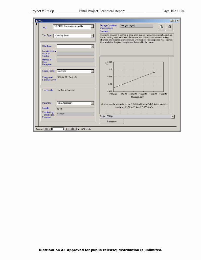
Project # 3806p Final Project Technical Report Page 102 / 104
Distribution A: Approved for public release; distribution is unlimited.
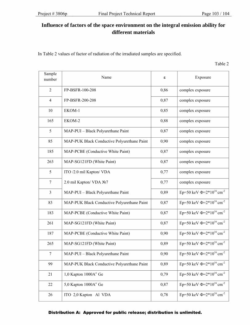
Project # 3806p Final Project Technical Report Page 103 / 104
Influence of factors of the space environment on the integral emission ability for different materials
In Table 2 values of factor of radiation of the irradiated samples are specified.
Table 2
Sample number Name Exposure
2 FP-BSFR-100-208 0,86 complex exposure
4 FP-BSFR-200-208 0,87 complex exposure
10 EKOM-1 0,85 complex exposure
165 EKOM-2 0,88 complex exposure
5 МАР-PUI – Black Polyurethane Paint 0,87 complex exposure
85 MAP-PUK Black Conductive Polyurethane Paint 0,90 complex exposure
185 MAP-PCBE (Conductive White Paint) 0,87 complex exposure
263 МАР-SG121FD (White Paint) 0,87 complex exposure
5 ITO /2.0 mil Kapton/ VDA 0,77 complex exposure
7 2.0 mil Kapton/ VDA №7 0,77 complex exposure
3 МАР-PUI – Black Polyurethane Paint 0,89 Еp=50 keV Ф=2*1016 cm-2
83 MAP-PUK Black Conductive Polyurethane Paint 0,87 Еp=50 keV Ф=2*1016 cm-2
183 MAP-PCBE (Conductive White Paint) 0,87 Еp=50 keV Ф=2*1016 cm-2
261 МАР-SG121FD (White Paint) 0,87 Еp=50 keV Ф=2*1016 cm-2
187 MAP-PCBE (Conductive White Paint) 0,90 Еp=50 keV Ф=2*1016 cm-2
265 МАР-SG121FD (White Paint) 0,89 Еp=50 keV Ф=2*1016 cm-2
7 МАР-PUI – Black Polyurethane Paint 0,90 Еp=50 keV Ф=2*1016 cm-2
99 MAP-PUK Black Conductive Polyurethane Paint 0,89 Еp=50 keV Ф=2*1016 cm-2
21 1,0 Kapton 1000Ao Ge 0,79 Еp=50 keV Ф=2*1016 cm-2
22 5,0 Kapton 1000Ao Ge 0,87 Еp=50 keV Ф=2*1016 cm-2
26 ITO 2,0 Kapton Al VDA 0,78 Еp=50 keV Ф=2*1016 cm-2
Distribution A: Approved for public release; distribution is unlimited.
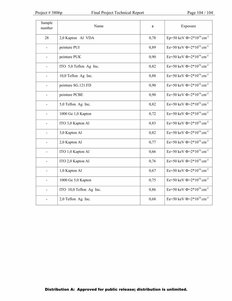
Project # 3806p Final Project Technical Report Page 104 / 104
Sample number Name Exposure
28 2,0 Kapton Al VDA 0,78 Еp=50 keV Ф=2*1016 cm-2
- peinture PUI 0,89 Еe=50 keV Ф=2*1016 cm-2
- peinture PUК 0,90 Еe=50 keV Ф=2*1016 cm-2
- ITO 5,0 Teflon Ag Inc. 0,82 Еe=50 keV Ф=2*1016 cm-2
- 10,0 Teflon Ag Inc. 0,88 Еe=50 keV Ф=2*1016 cm-2
- peinture SG.121.FD 0,90 Еe=50 keV Ф=2*1016 cm-2
- peinture PCBE 0,90 Еe=50 keV Ф=2*1016 cm-2
- 5,0 Teflon Ag Inc. 0,82 Еe=50 keV Ф=2*1016 cm-2
- 1000 Ge 1,0 Kapton 0,72 Еe=50 keV Ф=2*1016 cm-2
- ITO 3,0 Kapton Al 0,83 Еe=50 keV Ф=2*1016 cm-2
- 3,0 Kapton Al 0,82 Еe=50 keV Ф=2*1016 cm-2
- 2,0 Kapton Al 0,77 Еe=50 keV Ф=2*1016 cm-2
- ITO 1,0 Kapton Al 0,66 Еe=50 keV Ф=2*1016 cm-2
- ITO 2,0 Kapton Al 0,76 Еe=50 keV Ф=2*1016 cm-2
- 1,0 Kapton Al 0,67 Еe=50 keV Ф=2*1016 cm-2
- 1000 Ge 5,0 Kapton 0,75 Еe=50 keV Ф=2*1016 cm-2
- ITO 10,0 Teflon Ag Inc. 0,86 Еe=50 keV Ф=2*1016 cm-2
- 2,0 Teflon Ag Inc. 0,68 Еe=50 keV Ф=2*1016 cm-2
Distribution A: Approved for public release; distribution is unlimited.