2013 catalog kabeldon cable accessories 1-420 kv english rev a-6
DESCRIPTION
2013 Catalog Kabeldon Cable Accessories 1-420 kV English REV a-6TRANSCRIPT
Catalog | August 2013
Kabeldon cable accessories 1– 420 kVProduct catalog 2013

Table of contents
Introduction
Cable accessories ≤ 1 kV
Cable accessories for XLPE-insulated cables 7.2–42 kV
Cable accessories 12–52 kV, PILC cables
Other accessories for 12–42 kV
Cable accessories for XLPE-insulated cables 52–420 kV
Universal clamps
List of contents – Alphabetical order
List of contents – by category
ABB Catalog 2013 | Kabeldon cable accessories 1–420 kV | 1
11
5
3
7
2
6
4
8
9
1
1/1 | Kabeldon cable accessories 1–420 kV | Introduction
Introduction
Introduction 1/3
Fundamental technologies 1/4
Reasons for choosing Kabeldon cable accessories 1/5
Standards 1/7
Manufacturing and testing 1/9
Table of contents
Introduction
1
Introduction | Kabeldon cable accessories 1–420 kV | 1/2

Introduction
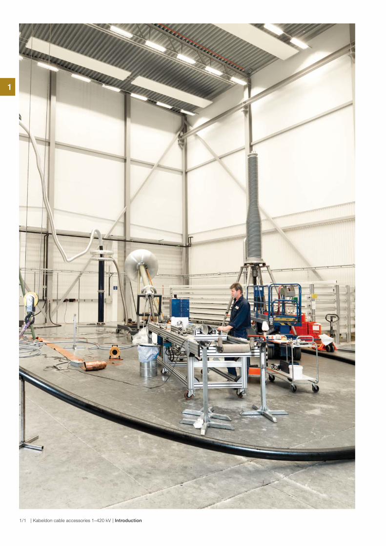
Our factory is situated in Alingsås, Sweden. The production is automated and meets stringent quality and environmental requirements.
We work to create safe electrical distribution via power cable
networks. To achieve this, we develop, manufacture and
market a broad range of cable accessories, switching devices
and enclosures.
Our main groups of customers are power supply companies,
network companies, industrial companies and OEMs.
Our primary areas of expertise are electrical connections in
cable systems and control of electrical fields. Our own testing
plant is an important aid to product development.
Catalog
The entire product range is presented in three main parts
including product facts and ordering information in tabular
form.
− Cable accessories ≤ 1 kV
− Cable accessories 12–42 kV
− Cable accessories 52–420 kV
An alphabetical list of contents and a list of contents by
product category can be found in the end of this catalogue.
The product catalogue can also be downloaded from our
website.
A separate product catalog for Kabeldon low voltage
switchgear system is available on request.
We reserve the right to alter the design and range of our
products without prior notice.
Our business idea
“We provide companies that work with electric power with
solutions which enable them to joint and connect cables
easily and safely, and distribute electricity“.
Quality and the environment are among our top-priorities.
They are important and self-evident parts of the strategic
plan.
We work continuously to improve our processes. Important
foundations for this work are:
ISO 9001 quality standard
ISO 14001 environmental standard.
ABB AB
Kabeldon
Box 531, SE-441 15 Alingsås, Sweden
Tel: +46 322 770 00
e-mail: [email protected]
www.abb.com/cableaccessories
1
1/3 | Kabeldon cable accessories 1–420 kV | Introduction
Fundamental technologies
We work on the basis of four fundamental technologies
within which we have accumulated substantial expertise
over many years.
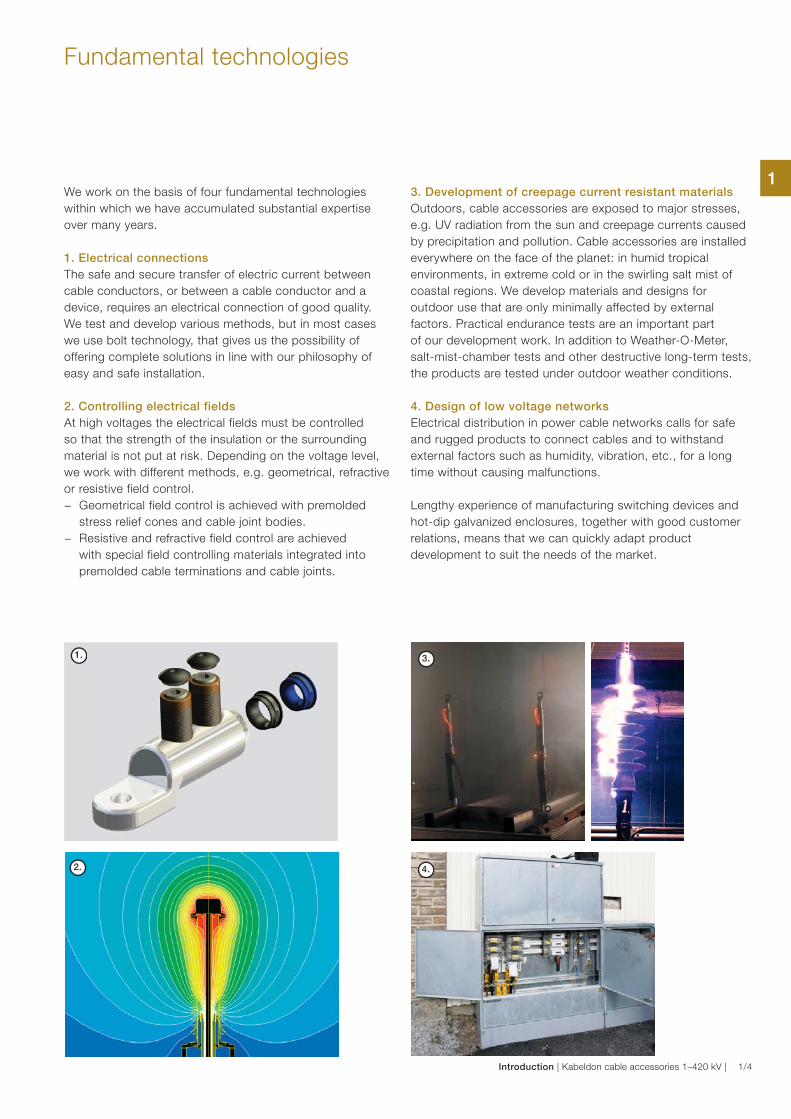
1. Electrical connections
The safe and secure transfer of electric current between
cable conductors, or between a cable conductor and a
device, requires an electrical connection of good quality.
We test and develop various methods, but in most cases
we use bolt technology, that gives us the possibility of
offering complete solutions in line with our philosophy of
easy and safe installation.
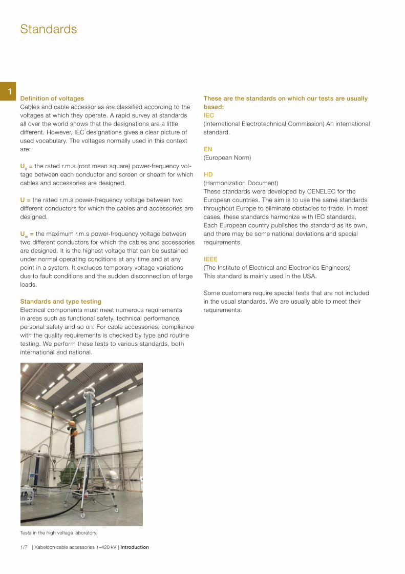
2. Controlling electrical fields
At high voltages the electrical fields must be controlled
so that the strength of the insulation or the surrounding
material is not put at risk. Depending on the voltage level,
we work with different methods, e.g. geometrical, refractive
or resistive field control.
− Geometrical field control is achieved with premolded
stress relief cones and cable joint bodies.
− Resistive and refractive field control are achieved
with special field controlling materials integrated into
premolded cable terminations and cable joints.
3. Development of creepage current resistant materials
Outdoors, cable accessories are exposed to major stresses,
e.g. UV radiation from the sun and creepage currents caused
by precipitation and pollution. Cable accessories are installed
everywhere on the face of the planet: in humid tropical
environments, in extreme cold or in the swirling salt mist of
coastal regions. We develop materials and designs for
outdoor use that are only minimally affected by external
factors. Practical endurance tests are an important part
of our development work. In addition to Weather-O-Meter,
salt-mist-chamber tests and other destructive long-term tests,
the products are tested under outdoor weather conditions.
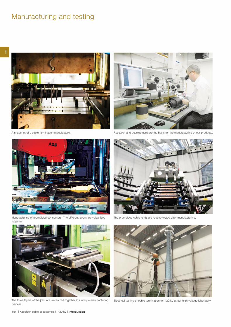
4. Design of low voltage networks
Electrical distribution in power cable networks calls for safe
and rugged products to connect cables and to withstand
external factors such as humidity, vibration, etc., for a long
time without causing malfunctions.
Lengthy experience of manufacturing switching devices and
hot-dip galvanized enclosures, together with good customer
relations, means that we can quickly adapt product
development to suit the needs of the market.
1.
2.
3.
4.
1
Introduction | Kabeldon cable accessories 1–420 kV | 1/4

Reasons for choosing Kabeldon cable accessories
A power cable network must be capable of supplying electric
power without interruption. If a failure does occur, it is usually
the junction points in the network that are at fault, rarely the
cable. So it pays to choose cable accessories with care.
Unique, long experience
Long experience brings great expertise. We have been
manufacturing cable accessories for paper-insulated cables
for about 100 years. When XLPE-insulated cables began to
be used more than 50 years ago, we were involved from the
outset. Since then we have always been in the forefront of
developments.
Leading research and development
Our core competence is our expertise in electrical onnections
in power cable systems. Successful product development
requires proper resources. We have an advanced chemistry
laboratory, a profound expertise in the field of polymers and
well-equipped high voltage and high-current laboratories.
Better economy
Kabeldon cable accessories provide greater safety. This
means major savings in the long term, as well as lower costs
from simplified routines for purchase, delivery and storage.
Manufacturing
outdoor cable
termination for
paper-insulated
cables in 1962.
1
1/5 | Kabeldon cable accessories 1–420 kV | Introduction

Professional training
The technology of cables and their installation is constantly
developing.
We offer a broad range of courses in cable technology and
cable accessories. Our instructors also take part in our
development projects, so you can be sure that they have
access to the latest technology.
We arrange training programmes and practical exercises in
the assembly of cable accessories up to 420 kV.
All course participants will receive a diploma or a training
certificate after passing a theoretical and practical test.
If you would like to know more about the courses, please
contact your ABB representative or our training department
directly.
1
Introduction | Kabeldon cable accessories 1–420 kV | 1/6
Standards
Definition of voltages
Cables and cable accessories are classified according to the
voltages at which they operate. A rapid survey at standards
all over the world shows that the designations are a little
different. However, IEC designations gives a clear picture of
used vocabulary. The voltages normally used in this context
are:
U0 = the rated r.m.s.(root mean square) power-frequency vol-
tage between each conductor and screen or sheath for which
cables and accessories are designed.
U = the rated r.m.s power-frequency voltage between two
different conductors for which the cables and accessories are
designed.
Um = the maximum r.m.s power-frequency voltage between
two different conductors for which the cables and accessories
are designed. It is the highest voltage that can be sustained
under normal operating conditions at any time and at any
point in a system. It excludes temporary voltage variations
due to fault conditions and the sudden disconnection of large
loads.
Standards and type testing
Electrical components must meet numerous requirements
in areas such as functional safety, technical performance,
personal safety and so on. For cable accessories, compliance
with the quality requirements is checked by type and routine
testing. We perform these tests to various standards, both
international and national.
These are the standards on which our tests are usually
based:
IEC
(International Electrotechnical Commission) An international
standard.
EN
(European Norm)
HD
(Harmonization Document)
These standards were developed by CENELEC for the
European countries. The aim is to use the same standards
throughout Europe to eliminate obstacles to trade. In most
cases, these standards harmonize with IEC standards.
Each European country publishes the standard as its own,
and there may be some national deviations and special
requirements.
IEEE
(The Institute of Electrical and Electronics Engineers)
This standard is mainly used in the USA.
Some customers require special tests that are not included
in the usual standards. We are usually able to meet their
requirements.
Tests in the high voltage laboratory.
1
1/7 | Kabeldon cable accessories 1–420 kV | Introduction
Voltage range Um 1.2 kV
In this voltage range, the function of cable accessories is
to provide mechanical protection and insulation. There is
no need for controlling the electrical field.
In the past, there was no international standard, only
national standards. CENELEC therefore produced an
international standard, HD 623 S1, which is equivalent
to Swedish standard, SS 424 14 44.
When the CENELEC standard is adopted in a country, it
can be supplemented with one or more national options,
for example requirements for impact resistance at low
ambient temperature.
Voltage range Um 7.2-42 kV
IEC: Current standards are IEC 61442, which covers test
methods, and IEC 60502-4, which sets out the testing
requirements.
IEC contains Um ≤ 36 kV.
CENELEC: Current standards are EN 61442 which covers
test methods and is identical to IEC 61442.
HD 629.1 S2, which sets out the testing requirements.
The main difference between IEC and CENELEC is that
CENELEC stipulates a longer period of temperature cycling
under voltage.
HD 629.2 S1 applies to accessories for paper-insulated
cables and transition joints. A test conducted in accordance
with CENELEC also satisfies the IEC requirements.
To include the less common voltages which occur in certain
European countries, CENELEC has included more voltage
classes than IEC. In addition, CENELEC runs up to
Um42 kV.
IEEE: The currently applicable standards are Std. 48 for
terminations covering insulation classes 2.5-765 kV, and
Std. 404 for joints rated at 2.5-500 kV. The test voltage for
joints is generally lower than for equivalent terminations.
The voltage classes in IEEE are not identical with those in
IEC. Some of the definitions also differ slightly between
IEEE and IEC. This can make direct comparisons difficult.
Voltage range Um 52–420 kV
IEC standard 60840 covers cable systems with voltages
above 36 kV up to 170 kV. The third edition of the standard
now also treats routine testing of cable accessories.
IEC standard 62067 covers cable systems with voltages
above 170 kV up to 550 kV. The standard also states
methods and requirements for the routine testing of cable
accessories.
Both IEC 60840 and IEC 62067 deal with testing of outer
protection for buried joints and screen separation kits.
These tests are to qualify the electrical performance of the
outer protection with special emphasis on watertightness.
IEC voltage classes
U0
U Um
26 45–47 52
36 60–69 72.5
64 110–115 123
76 132–138 145
87 150–161 170
127 220–230 245
160 275–287 300
190 330–345 362
220 380–400 420
CENELEC voltage classes
U0
U Um
3.6 6 7.2
3.8 6.6 7.2
6 10 12
6.35 11 12
8.7 15 17.5
12 20 24
12.7 22 24
18 30 36
19 33 36
20.8 36 42 We supply cable accessories for various types of cables.
Standards
1
Introduction | Kabeldon cable accessories 1–420 kV | 1/8
Manufacturing and testing
Manufacturing of premolded connectors. The different layers are vulcanized
together.
Electrical testing of cable termination for 420 kV at our high voltage laboratory.The three layers of the joint are vulcanized together in a unique manufacturing
process.
The premolded cable joints are routine tested after manufacturing.
A snapshot of a cable termination manufacture. Research and development are the basis for the manufacturing of our products.
1
1/9 | Kabeldon cable accessories 1–420 kV | Introduction
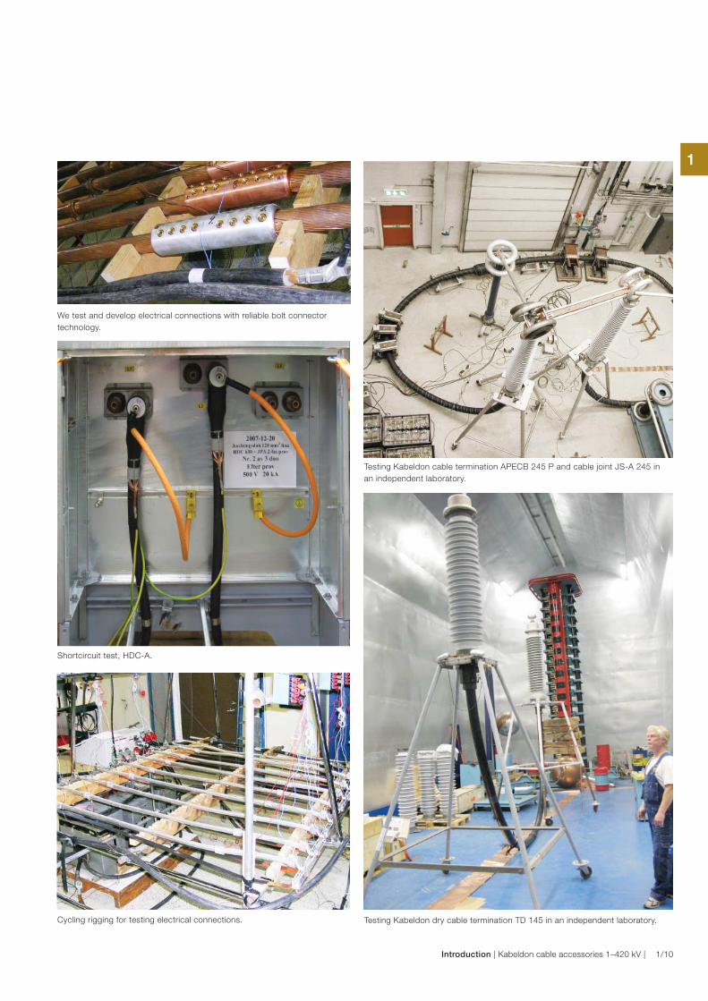
Shortcircuit test, HDC-A.
We test and develop electrical connections with reliable bolt connector
technology.
Cycling rigging for testing electrical connections.
Testing Kabeldon cable termination APECB 245 P and cable joint JS-A 245 in
an independent laboratory.
Testing Kabeldon dry cable termination TD 145 in an independent laboratory.
1
Introduction | Kabeldon cable accessories 1–420 kV | 1/10
2
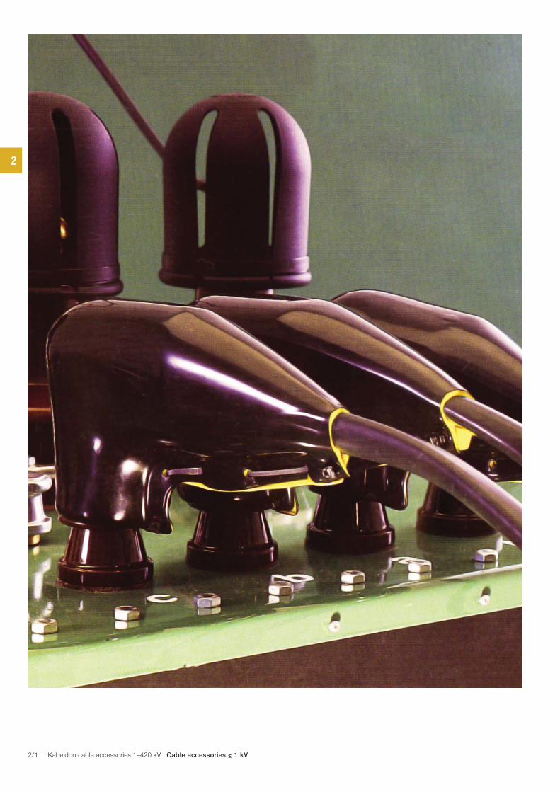
2/1 | Kabeldon cable accessories 1–420 kV | Cable accessories < 1 kV
Introduction
Introduction 2/3
Cable accessories ≤ 1 kV
Cable joint with cast resin for plastic and
paper-insulated cables, and control cables, SMARTA 2/4
Cable joint, branch for plastic-insulated cables, SAGA 11 Y 2/5
Cable joint, heat-shrink for plastic-insulated cables, SMKC 2/6
Cable joint, tape for plastic-insulated cables, SMILA and SMULA 2/7
Protective hood for plastic-insulated cables, LPH 2/8
Protective hood for plastic-insulated cables, LXAC 2/9
Connection protection for plastic-insulated cables, KAL 2/10
Cable connection , prefabricated, AK-ADAS 2/11
Table of contents
Cable accessories < 1 kV
2
Cable accessories < 1 kV | Kabeldon cable accessories 1–420 kV | 2/2
Introduction
Cable accessories ≤ 1 kV
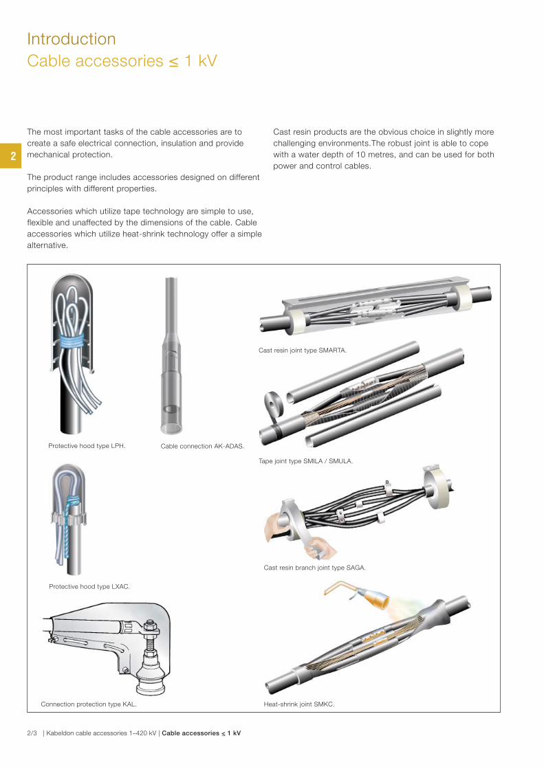
The most important tasks of the cable accessories are to
create a safe electrical connection, insulation and provide
mechanical protection.
The product range includes accessories designed on different
principles with different properties.
Accessories which utilize tape technology are simple to use,
flexible and unaffected by the dimensions of the cable. Cable
accessories which utilize heat-shrink technology offer a simple
alternative.
Cast resin products are the obvious choice in slightly more
challenging environments.The robust joint is able to cope
with a water depth of 10 metres, and can be used for both
power and control cables.
Cast resin joint type SMARTA.
Tape joint type SMILA / SMULA.
Protective hood type LPH.
Heat-shrink joint SMKC.Connection protection type KAL.
Cable connection AK-ADAS.
Cast resin branch joint type SAGA.
Protective hood type LXAC.
2
2/3 | Kabeldon cable accessories 1–420 kV | Cable accessories < 1 kV
Cable joint with cast resin for plastic and
paper-insulated cables, and control cables
SMARTA
Use
For jointing 1 kV plastic and paper-insulated 3–5 core cables
as communication cables and the transition between plastic
and paper-insulated cables.
Standards
Meets the requirements of:
− SS 424 14 44 Edition 1
− EBR KJ 24:89
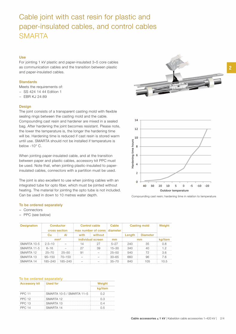
Design
The joint consists of a transparent casting mold with flexible
sealing rings between the casting mold and the cable.
Compounding cast resin and hardener are mixed in a sealed
bag. After hardening the joint becomes resistant. Please note,
the lower the temperature is, the longer the hardening time
will be. Hardening time is reduced if cast resin is stored warm
until use. SMARTA should not be installed if temperature is
below -10° C.
When jointing paper-insulated cable, and at the transition
between paper and plastic cables, accessory kit PPC must
be used. Note that, when jointing plastic-insulated to paper-
insulated cables, connectors with a partition must be used.
The joint is also excellent to use when jointing cables with an
integrated tube for opto fiber, which must be jointed without
heating. The material for jointing the opto tube is not included.
Can be used in down to 10 metres water depth.
To be ordered separately
− Connectors
− PPC (see below)
Designation Conductor
cross section
Control cable
max number of cores
Cable
diameter
Casting mold Weight
Cu Al with without Length Diameter
mm² individual screen mm mm kg/item
SMARTA 10-5 2.5–10 – 14 27 5–27 240 35 0.8
SMARTA 11-5 6–16 – 27 39 15–30 340 40 1.2
SMARTA 12 25–70 25–50 91 – 25–50 540 72 3.6
SMARTA 13 95–150 70–150 – – 30–65 660 96 7.6
SMARTA 14 185–240 185–240 – – 35–70 840 105 10.5
To be ordered separately
Accessory kit Used for Weight
kg/item
PPC 11 SMARTA 10-5 / SMARTA 11–5 0.2
PPC 12 SMARTA 12 0.3
PPC 13 SMARTA 13 0.4
PPC 14 SMARTA 14 0.5
Compounding cast resin; hardening time in relation to temperature
Outdoor temperature
Ha
rde
nin
g t
ime
ho
urs
2
Cable accessories < 1 kV | Kabeldon cable accessories 1–420 kV | 2/4
L
Ø
Cable joint, branch for plastic-insulated cables
SAGA 11 Y
Use
Branching of 1 kV plastic-insulated 3–4 core cables.
Standards
Meets the requirements of:
− SS 424 14 44 Edition 1
− EBR KJ 24:89
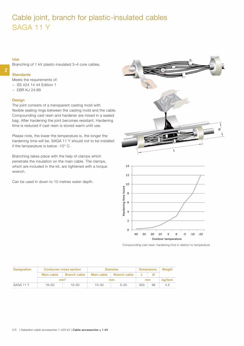
Design
The joint consists of a transparent casting mold with
flexible sealing rings between the casting mold and the cable.
Compounding cast resin and hardener are mixed in a sealed
bag. After hardening the joint becomes resistant. Hardening
time is reduced if cast resin is stored warm until use.
Please note, the lower the temperature is, the longer the
hardening time will be. SAGA 11 Y should not to be installed
if the temperature is below -10° C.
Branching takes place with the help of clamps which
penetrate the insulation on the main cable. The clamps,
which are included in the kit, are tightened with a torque
wrench.
Can be used in down to 10 metres water depth.
Designation Conductor cross section Diameter Dimensions Weight
Main cable Branch cable Main cable Branch cable L Ø
mm² mm mm kg/item
SAGA 11 Y 16–50 10–50 15–30 5–25 500 96 4.5
Compounding cast resin; hardening time in relation to temperature
Outdoor temperature
Ha
rde
nin
g t
ime
ho
urs
2
2/5 | Kabeldon cable accessories 1–420 kV | Cable accessories < 1 kV
Cable joint, heat-shrink for plastic-insulated cables
SMKC
Use
For jointing 1 kV plastic-insulated cables with 3–5 cores, with
or without screen.
Standards
Meets the requirements of:
− SS 424 14 44 Edition 1
− EBR KJ 24:89
Design
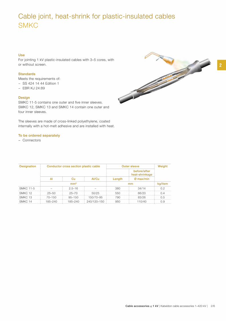
SMKC 11-5 contains one outer and five inner sleeves.
SMKC 12, SMKC 13 and SMKC 14 contain one outer and
four inner sleeves.
The sleeves are made of cross-linked polyethylene, coated
internally with a hot-melt adhesive and are installed with heat.
To be ordered separately
− Connectors
Designation Conductor cross section plastic cable Outer sleeve Weight
before/after heat-shrinkage
Al Cu Al/Cu Length Ø max/min
mm² mm kg/item
SMKC 11-5 – 2.5–16 – 380 34/14 0.2
SMKC 12 25–50 25–70 50/25 550 66/20 0.4
SMKC 13 70–150 95–150 150/70–95 790 83/26 0.5
SMKC 14 185–240 185–240 240/120–150 950 110/40 0.9
2
Cable accessories < 1 kV | Kabeldon cable accessories 1–420 kV | 2/6
Cable joint, tape for plastic-insulated cables
SMILA and SMULA
Use
For jointing 1 kV plastic-insulated cables with 3–5 cores,
with or without screen.
SMILA is used for jointing cables with screen. Otherwise
SMULA is used.
Standards
Meets the requirements of:
− SS 424 14 44 Edition 1
− EBR KJ 24:89
Design
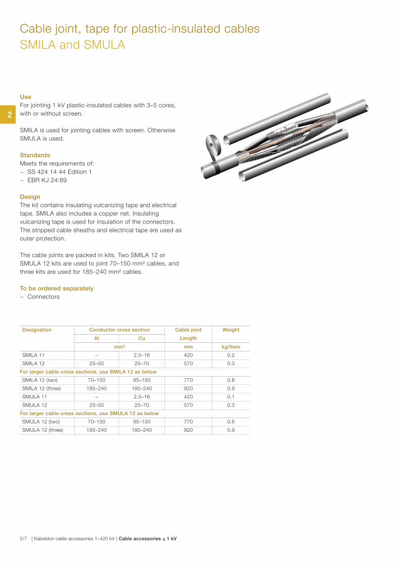
The kit contains insulating vulcanizing tape and electrical
tape. SMILA also includes a copper net. Insulating
vulcanizing tape is used for insulation of the connectors.
The stripped cable sheaths and electrical tape are used as
outer protection.
The cable joints are packed in kits. Two SMILA 12 or
SMULA 12 kits are used to joint 70–150 mm² cables, and
three kits are used for 185–240 mm² cables.
To be ordered separately
− Connectors
Designation Conductor cross section Cable joint
Length
Weight
Al Cu
mm² mm kg/item
SMILA 11 – 2.5–16 420 0.2
SMILA 12 25–50 25–70 570 0.3
For larger cable cross sections, use SMILA 12 as below
SMILA 12 (two) 70–150 95–150 770 0.6
SMILA 12 (three) 185–240 185–240 920 0.9
SMULA 11 – 2.5–16 420 0.1
SMULA 12 25–50 25–70 570 0.3
For larger cable cross sections, use SMULA 12 as below
SMULA 12 (two) 70–150 95–150 770 0.6
SMULA 12 (three) 185–240 185–240 920 0.9
2
2/7 | Kabeldon cable accessories 1–420 kV | Cable accessories < 1 kV
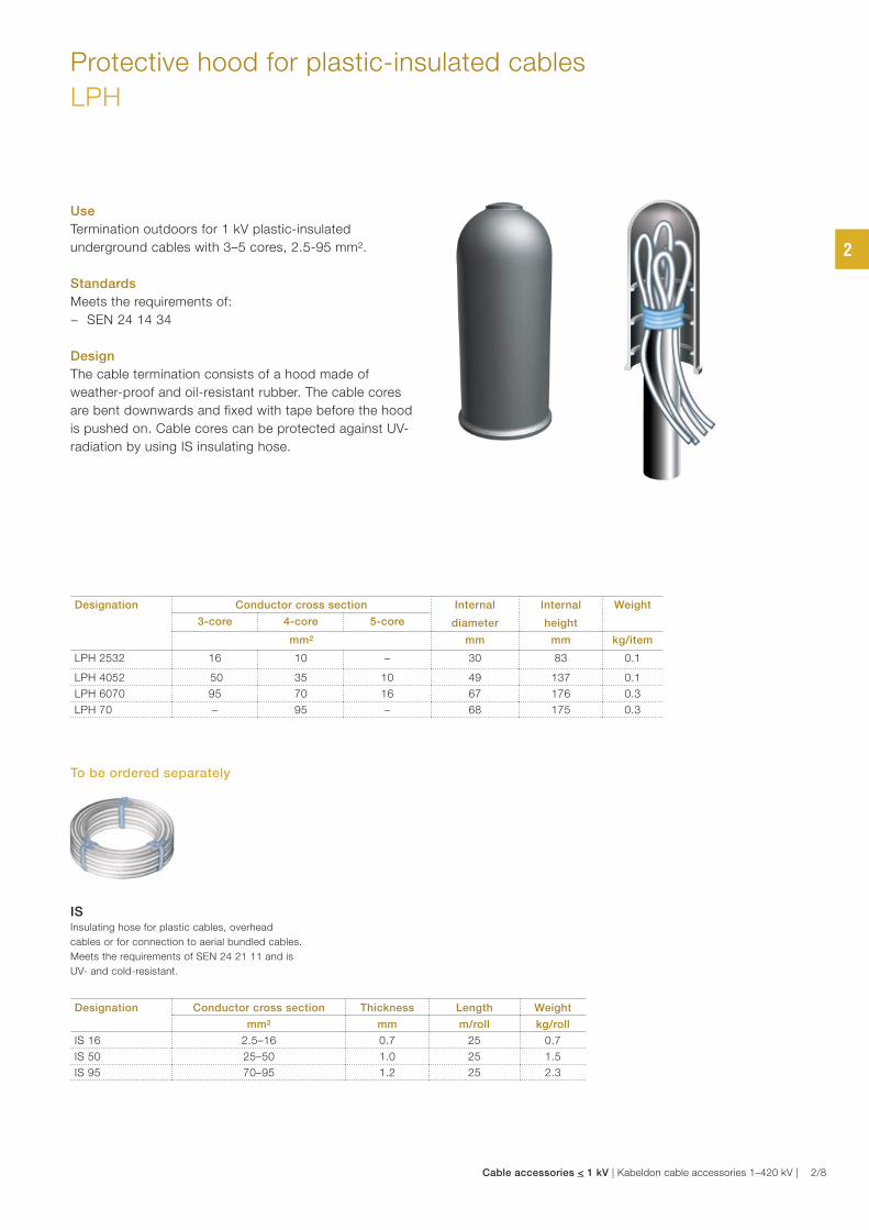
Protective hood for plastic-insulated cables
LPH
Use
Termination outdoors for 1 kV plastic-insulated
underground cables with 3–5 cores, 2.5-95 mm².
Standards
Meets the requirements of:
− SEN 24 14 34
Design
The cable termination consists of a hood made of
weather-proof and oil-resistant rubber. The cable cores
are bent downwards and fixed with tape before the hood
is pushed on. Cable cores can be protected against UV-
radiation by using IS insulating hose.
IS
Insulating hose for plastic cables, overhead
cables or for connection to aerial bundled cables.
Meets the requirements of SEN 24 21 11 and is
UV- and cold-resistant.
Designation Conductor cross section Internal
diameter
Internal
height
Weight
3-core 4-core 5-core
mm² mm mm kg/item
LPH 2532 16 10 – 30 83 0.1
LPH 4052 50 35 10 49 137 0.1
LPH 6070 95 70 16 67 176 0.3
LPH 70 – 95 – 68 175 0.3
Designation Conductor cross section Thickness Length Weight
mm² mm m/roll kg/roll
IS 16 2.5–16 0.7 25 0.7
IS 50 25–50 1.0 25 1.5
IS 95 70–95 1.2 25 2.3
To be ordered separately
2
Cable accessories < 1 kV | Kabeldon cable accessories 1–420 kV | 2/8
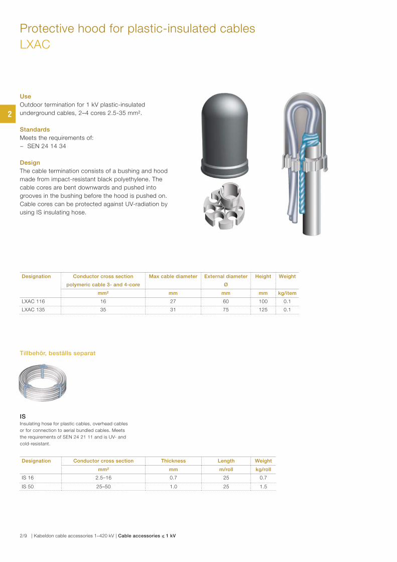
Protective hood for plastic-insulated cables
LXAC
Use
Outdoor termination for 1 kV plastic-insulated
underground cables, 2–4 cores 2.5-35 mm².
Standards
Meets the requirements of:
− SEN 24 14 34
Design
The cable termination consists of a bushing and hood
made from impact-resistant black polyethylene. The
cable cores are bent downwards and pushed into
grooves in the bushing before the hood is pushed on.
Cable cores can be protected against UV-radiation by
using IS insulating hose.
Designation Conductor cross section
polymeric cable 3- and 4-core
Max cable diameter External diameter
Ø
Height Weight
mm² mm mm mm kg/item
LXAC 116 16 27 60 100 0.1
LXAC 135 35 31 75 125 0.1
ISInsulating hose for plastic cables, overhead cables
or for connection to aerial bundled cables. Meets
the requirements of SEN 24 21 11 and is UV- and
cold-resistant.
Designation Conductor cross section Thickness Length Weight
mm² mm m/roll kg/roll
IS 16 2.5–16 0.7 25 0.7
IS 50 25–50 1.0 25 1.5
Tillbehör, beställs separat
2
2/9 | Kabeldon cable accessories 1–420 kV | Cable accessories < 1 kV
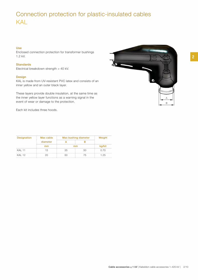
Connection protection for plastic-insulated cables
KAL
Use
Enclosed connection protection for transformer bushings
1.2 kV.
Standards
Electrical breakdown strength > 40 kV.
Design
KAL is made from UV-resistant PVC latex and consists of an
inner yellow and an outer black layer.
These layers provide double insulation, at the same time as
the inner yellow layer functions as a warning signal in the
event of wear or damage to the protection.
Each kit includes three hoods.
Designation Max cable
diameter
Max bushing diameter Weight
A B
mm mm kg/kit
KAL 11 15 35 50 0.70
KAL 12 20 50 75 1.25
A
B
2
Cable accessories < 1 kV | Kabeldon cable accessories 1–420 kV | 2/10
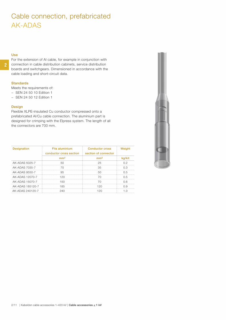
Cable connection, prefabricated
AK-ADAS
Use
For the extension of Al cable, for example in conjunction with
connection in cable distribution cabinets, service distribution
boards and switchgears. Dimensioned in accordance with the
cable loading and short-circuit data.
Standards
Meets the requirements of:
− SEN 24 50 10 Edition 1
− SEN 24 50 12 Edition 1
Design
Flexible XLPE-insulated Cu conductor compressed onto a
prefabricated Al/Cu cable connection. The aluminium part is
designed for crimping with the Elpress system. The length of all
the connectors are 700 mm.
Designation Fits aluminium
conductor cross section
Conductor cross
section of connector
Weight
mm² mm² kg/kit
AK-ADAS 5025-7 50 25 0.2
AK-ADAS 7035-7 70 35 0.3
AK-ADAS 9550-7 95 50 0.5
AK-ADAS 12070-7 120 70 0.5
AK-ADAS 15070-7 150 70 0.6
AK-ADAS 185120-7 185 120 0.9
AK-ADAS 240120-7 240 120 1.0
2
2/11 | Kabeldon cable accessories 1–420 kV | Cable accessories < 1 kV

2
Cable accessories < 1 kV | Kabeldon cable accessories 1–420 kV | 2/12
3
3/1 | Kabeldon cable accessories 1–420 kV | Cable accessories for XLPE-insulated cables 12-42 kV
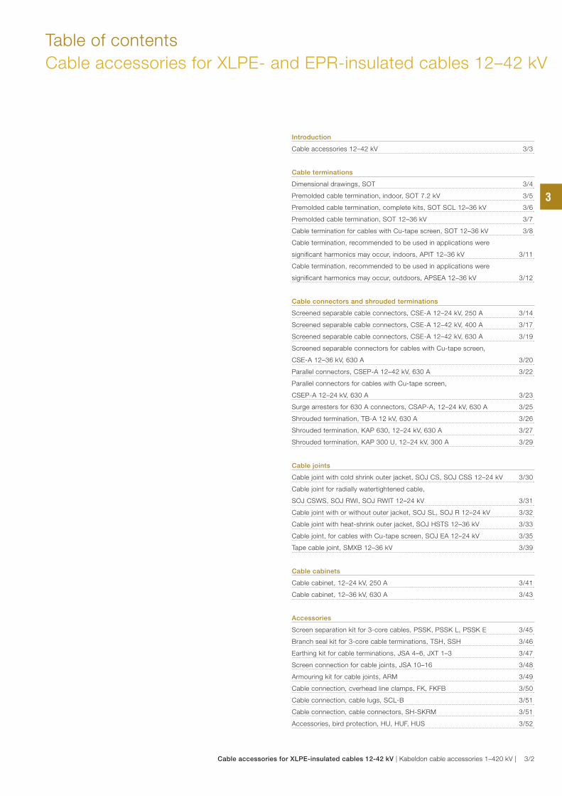
Table of contents
Cable accessories for XLPE- and EPR-insulated cables 12–42 kV
Introduction
Cable accessories 12–42 kV 3/3
Cable terminations
Dimensional drawings, SOT 3/4
Premolded cable termination, indoor, SOT 7.2 kV 3/5
Premolded cable termination, complete kits, SOT SCL 12–36 kV 3/6
Premolded cable termination, SOT 12–36 kV 3/7
Cable termination for cables with Cu-tape screen, SOT 12–36 kV 3/8
Cable termination, recommended to be used in applications were
significant harmonics may occur, indoors, APIT 12–36 kV 3/11
Cable termination, recommended to be used in applications were
significant harmonics may occur, outdoors, APSEA 12–36 kV 3/12
Cable connectors and shrouded terminations
Screened separable cable connectors, CSE-A 12–24 kV, 250 A 3/14
Screened separable cable connectors, CSE-A 12–42 kV, 400 A 3/17
Screened separable cable connectors, CSE-A 12–42 kV, 630 A 3/19
Screened separable connectors for cables with Cu-tape screen,
CSE-A 12–36 kV, 630 A 3/20
Parallel connectors, CSEP-A 12–42 kV, 630 A 3/22
Parallel connectors for cables with Cu-tape screen,
CSEP-A 12–24 kV, 630 A 3/23
Surge arresters for 630 A connectors, CSAP-A, 12–24 kV, 630 A 3/25
Shrouded termination, TB-A 12 kV, 630 A 3/26
Shrouded termination, KAP 630, 12–24 kV, 630 A 3/27
Shrouded termination, KAP 300 U, 12–24 kV, 300 A 3/29
Cable joints
Cable joint with cold shrink outer jacket, SOJ CS, SOJ CSS 12–24 kV 3/30
Cable joint for radially watertightened cable,
SOJ CSWS, SOJ RWI, SOJ RWIT 12–24 kV 3/31
Cable joint with or without outer jacket, SOJ SL, SOJ R 12–24 kV 3/32
Cable joint with heat-shrink outer jacket, SOJ HSTS 12–36 kV 3/33
Cable joint, for cables with Cu-tape screen, SOJ EA 12–24 kV 3/35
Tape cable joint, SMXB 12–36 kV 3/39
Cable cabinets
Cable cabinet, 12–24 kV, 250 A 3/41
Cable cabinet, 12–36 kV, 630 A 3/43
Accessories
Screen separation kit for 3-core cables, PSSK, PSSK L, PSSK E 3/45
Branch seal kit for 3-core cable terminations, TSH, SSH 3/46
Earthing kit for cable terminations, JSA 4–6, JXT 1–3 3/47
Screen connection for cable joints, JSA 10–16 3/48
Armouring kit for cable joints, ARM 3/49
Cable connection, cverhead line clamps, FK, FKFB 3/50
Cable connection, cable lugs, SCL-B 3/51
Cable connection, cable connectors, SH-SKRM 3/51
Accessories, bird protection, HU, HUF, HUS 3/52
3
Cable accessories for XLPE-insulated cables 12-42 kV | Kabeldon cable accessories 1–420 kV | 3/2

Introduction
Cable accessories for XLPE- and EPR-insulated cables 12–42 kV
Kabeldon cable accessories for 12–42 kV are characterized
by simple solutions with a reliable function. Long experience
and continuous product development enable us to offer
products that meet future requirements for reliable and
dependable systems.
At the time when XLPE-insulated cable was introduced in
the beginning of the 1960s, we already appreciated the
importance of the cable accessories having a constant,
active pressure over the cable, in this way following the
physical changes in the cable in service. The solution at the
time was to use tapes with different properties. Our patented
field-control material and the first premolded products were
introduced in the 1970s. The technology has since been a
guiding force for our product development.
Our current range includes cable joints, cable terminations
and screened separable cable connectors in line with this
concept.
The fact that the products are premolded means that they
are manufactured in a single piece including important
functions such as electrical field-control, insulation and
sealing.
The use of flexible materials enables the cable accessory
to follow the variations in the cable under load, thus
ensuring an active pressure for a reliable power
transmission.
Manufacturing the products from soft rubber also means
that fewer sizes covers different cable dimensions. All of
this, in combination with the bolt technology that we use in
our cable connectors and cable lugs, gives a reliable and
dependable system.
More than one million premolded cable joints, cable
terminations and cable connectors have already been
installed by customers in electricity distribution networks
all over the world. Our cable terminations and screened
separable cable connectors are also purchased by
customers who manufacture switchgears and other
installations.
In addition to the products presented in this catalogue, we
offer especially adapted products and solutions for different
markets and cables and a range of cable preparation tools.
Please do not hesitate to contact us if you have any other
needs or queries.
Cable accessories with four important functions: control of electrical
fields, control of creepage currents, moisture barriers and mechanical
protection.
3
3/3 | Kabeldon cable accessories 1–420 kV | Cable accessories for XLPE-insulated cables 12-42 kV
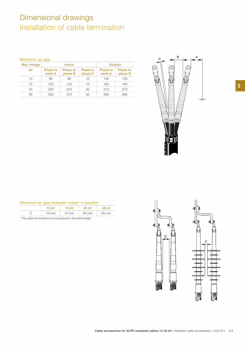
Dimensional drawings
Installation of cable termination
Minimum air gap
Max voltage Indoor Outdoor
kV Phase to earth A
Phase to phase B
Phase to phase C
Phase to earth A
Phase to phase B
10 90 90 10 130 130
12 120 120 10 160 160
24 220 250 30 270 270
36 320 370 50 380 380
Minimum air gap between cores* in parallel
10 kV 12 kV 24 kV 36 kV
C 10 mm 10 mm 30 mm 50 mm
* The cable terminations must be placed in the same height.
B AC
3
Cable accessories for XLPE-insulated cables 12-42 kV | Kabeldon cable accessories 1–420 kV | 3/4
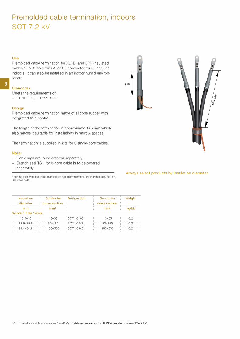
Premolded cable termination, indoors
SOT 7.2 kV
Use
Premolded cable termination for XLPE- and EPR-insulated
cables 1- or 3-core with Al or Cu conductor for 6.6/7.2 kV,
indoors. It can also be installed in an indoor humid environ-
ment*.
Standards
Meets the requirements of:
− CENELEC, HD 629.1 S1
Design
Premolded cable termination made of silicone rubber with
integrated field control.
The length of the termination is approximate 145 mm which
also makes it suitable for installations in narrow spaces.
The termination is supplied in kits for 3 single-core cables.
Note:
− Cable lugs are to be ordered separately.
− Branch seal TSH for 3-core cable is to be ordered
separately.
* For the best watertightness in an indoor humid environment, order branch seal kit TSH.
See page 3/46.
Insulation
diameter
Conductor
cross section
Designation Conductor
cross section
Weight
mm mm² mm² kg/kit
3-core / three 1-core
10.5–15 10–35 SOT 101–3 10–35 0.2
12.9–25.8 50–185 SOT 102-3 50–185 0.2
21.4–34.9 185–500 SOT 103-3 185–500 0.2
Min
20
0
145
Always select products by Insulation diameter.
3
3/5 | Kabeldon cable accessories 1–420 kV | Cable accessories for XLPE-insulated cables 12-42 kV
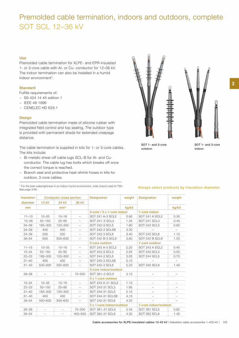
Premolded cable termination, indoors and outdoors, complete
SOT SCL 12–36 kV
Use
Premolded cable termination for XLPE- and EPR-insulated
1- or 3-core cable with Al- or Cu- conductor for 12–36 kV.
The indoor termination can also be installed in a humid
indoor environment*.
Standard
Fulfills requirements of:
− SS 424 14 45 edition 1
− IEEE 48 1996
− CENELEC HD 629.1
Design
Premolded cable termination made of silicone rubber with
integrated field control and top sealing. The outdoor type
is provided with permanent sheds for extended creepage
distance.
The cable termination is supplied in kits for 1- or 3-core cables.
The kits include:
− Bi-metalic shear-off cable lugs SCL-B for Al- and Cu-
conductor. The cable lug has bolts which breaks off once
the correct torque is reached.
− Branch seal and protective heat-shrink hoses in kits for
outdoor, 3-core cables.
* For the best watertightness in an indoor humid environment, order branch seal kit TSH.
See page 3/46.
Insulation
diameter
Conductor cross section Designation weight Designation weight
12 kV 24 kV 36 kV
mm mm² kg/kit kg/kit
3-core / 3 x 1-core indoor 1-core indoor
11–15 10–35 10–16 – SOT 241 A-3 SCL2 0.90 SOT 241 A SCL2 0.30
15–26 50–150 25–95 – SOT 241–3 SCL3 1.35 SOT 241 SCL3 0.45
24–39 185–300 120–300 – SOT 242-3 SCL5 1.80 SOT 242 SCL5 0.60
24–39 400 400 – SOT 242-3 SCL5B 3.30 – –
24–39 500 500 – SOT 242-3 SCL6 3.40 SOT 242 SCL6 1.15
38–54 630 500–630 – SOT 242 B-3 SCL6 3.60 SOT 242 B SCL6 1.20
3-core outdoor 1-core outdoor
11–15 10–35 10–16 – SOT 243 A-3 SCL2 2.20 SOT 243 A SCL2 0.40
15–24 50–150 25–95 – SOT 243-3 SCL3 2.55 SOT 243 SCL3 0.55
22–33 185–300 120–300 – SOT 244-3 SCL5 3.05 SOT 244 SCL5 0.70
31–40 400 400 – SOT 245-3 SCL5B 5,10 – –
31–40 500–630 500–630 – SOT 245-3 SCL6 5.20 SOT 245 SCL6 1.40
3-core indoor/outdoor
26–39 – – 70–300 SOT 361–3 SCL5 3.10 – –
3 x 1-core outdoor
15–24 10–35 10–16 – SOT 243 A-31 SCL2 1.10 – –
22–33 50–150 25–95 – SOT 243-31 SCL3 1.65 – –
31–40 185–300 120–300 – SOT 244-31 SCL5 2.15 – –
31–40 400 400 – SOT 244-31 SCL5B 4,10 – –
38–54 500–630 500–630 – SOT 245-31 SCL6 4.20 – –
3 x 1-core indoor/outdoor 1-core indoor/outdoor
26–39 – – 70–300 SOT 361–31 SCL5 2.45 SOT 361 SCL5 0.82
38–54 – – 400–630 SOT 362-31 SCL6 4.30 SOT 362 SCL6 1.45
SOT 1- and 3-core
indoor.
SOT 1- and 3-core
outdoor.
Always select products by Insulation diameter.
3
Cable accessories for XLPE-insulated cables 12-42 kV | Kabeldon cable accessories 1–420 kV | 3/6
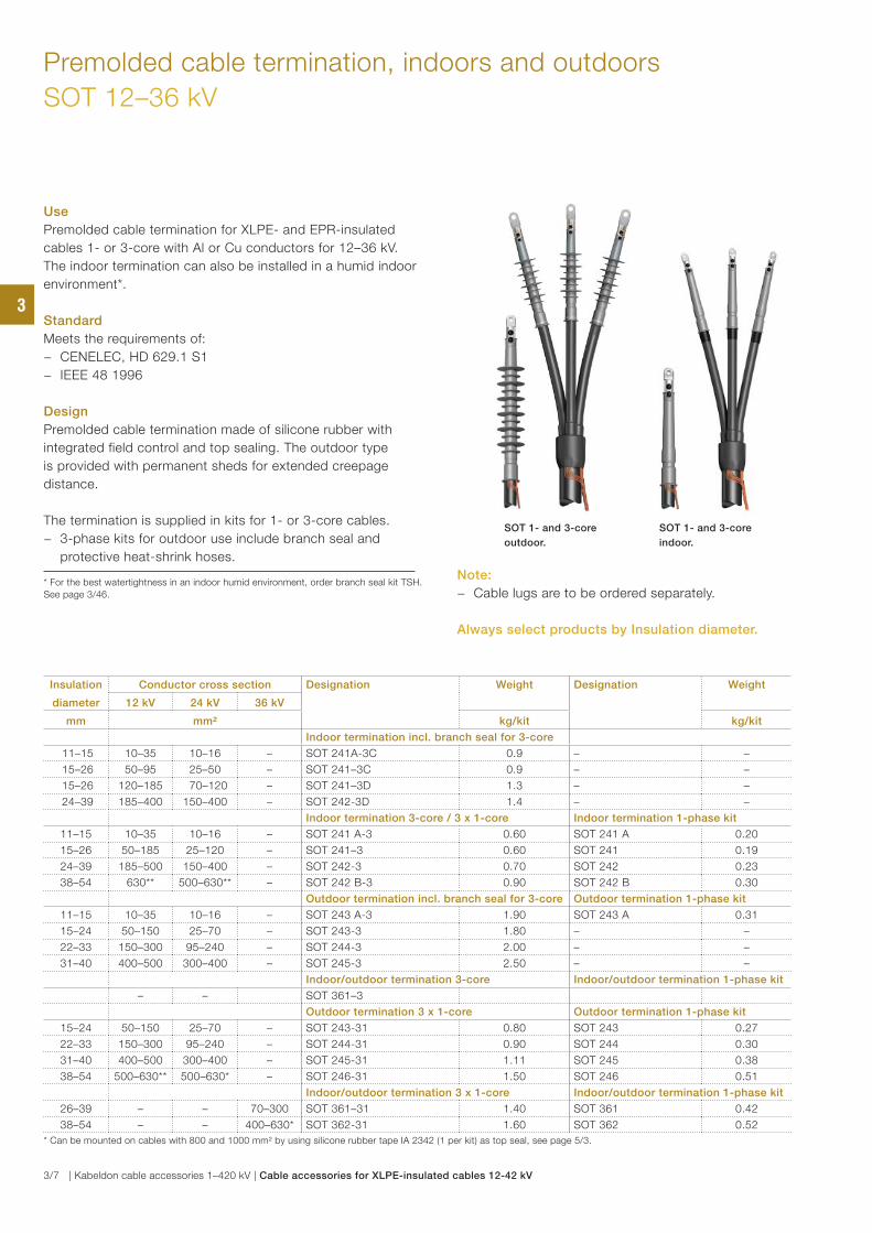
Premolded cable termination, indoors and outdoors
SOT 12–36 kV
Insulation
diameter
Conductor cross section Designation Weight Designation Weight
12 kV 24 kV 36 kV
mm mm² kg/kit kg/kit
Indoor termination incl. branch seal for 3-core
11–15 10–35 10–16 – SOT 241A-3C 0.9 – –
15–26 50–95 25–50 – SOT 241–3C 0.9 – –
15–26 120–185 70–120 – SOT 241–3D 1.3 – –
24–39 185–400 150–400 – SOT 242-3D 1.4 – –
Indoor termination 3-core / 3 x 1-core Indoor termination 1-phase kit
11–15 10–35 10–16 – SOT 241 A-3 0.60 SOT 241 A 0.20
15–26 50–185 25–120 – SOT 241–3 0.60 SOT 241 0.19
24–39 185–500 150–400 – SOT 242-3 0.70 SOT 242 0.23
38–54 630** 500–630** – SOT 242 B-3 0.90 SOT 242 B 0.30
Outdoor termination incl. branch seal for 3-core Outdoor termination 1-phase kit
11–15 10–35 10–16 – SOT 243 A-3 1.90 SOT 243 A 0.31
15–24 50–150 25–70 – SOT 243-3 1.80 – –
22–33 150–300 95–240 – SOT 244-3 2.00 – –
31–40 400–500 300–400 – SOT 245-3 2.50 – –
Indoor/outdoor termination 3-core Indoor/outdoor termination 1-phase kit
– – SOT 361–3
Outdoor termination 3 x 1-core Outdoor termination 1-phase kit
15–24 50–150 25–70 – SOT 243-31 0.80 SOT 243 0.27
22–33 150–300 95–240 – SOT 244-31 0.90 SOT 244 0.30
31–40 400–500 300–400 – SOT 245-31 1.11 SOT 245 0.38
38–54 500–630** 500–630* – SOT 246-31 1.50 SOT 246 0.51
Indoor/outdoor termination 3 x 1-core Indoor/outdoor termination 1-phase kit
26–39 – – 70–300 SOT 361–31 1.40 SOT 361 0.42
38–54 – – 400–630* SOT 362-31 1.60 SOT 362 0.52
* Can be mounted on cables with 800 and 1000 mm² by using silicone rubber tape IA 2342 (1 per kit) as top seal, see page 5/3.
Use
Premolded cable termination for XLPE- and EPR-insulated
cables 1- or 3-core with Al or Cu conductors for 12–36 kV.
The indoor termination can also be installed in a humid indoor
environment*.
Standard
Meets the requirements of:
− CENELEC, HD 629.1 S1
− IEEE 48 1996
Design
Premolded cable termination made of silicone rubber with
integrated field control and top sealing. The outdoor type
is provided with permanent sheds for extended creepage
distance.
The termination is supplied in kits for 1- or 3-core cables.
− 3-phase kits for outdoor use include branch seal and
protective heat-shrink hoses.
* For the best watertightness in an indoor humid environment, order branch seal kit TSH.
See page 3/46.
SOT 1- and 3-core
indoor.
SOT 1- and 3-core
outdoor.
Note:
− Cable lugs are to be ordered separately.
Always select products by Insulation diameter.
3
3/7 | Kabeldon cable accessories 1–420 kV | Cable accessories for XLPE-insulated cables 12-42 kV
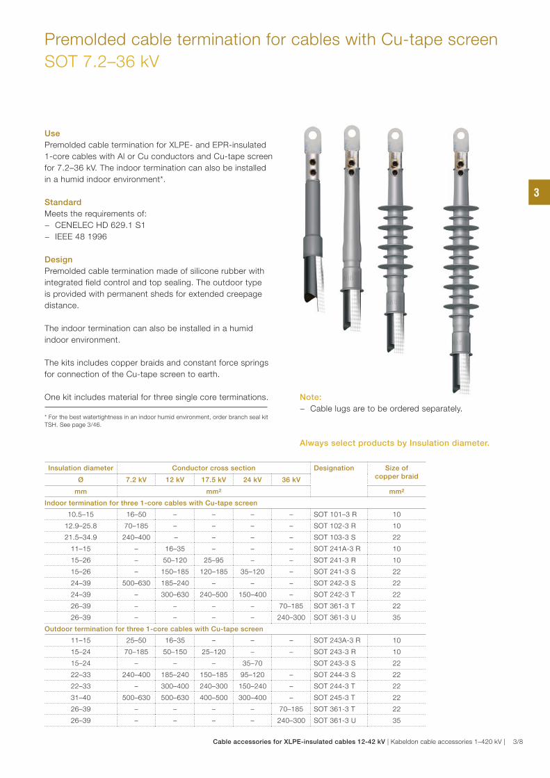
Premolded cable termination for cables with Cu-tape screen
SOT 7.2–36 kV
Use
Premolded cable termination for XLPE- and EPR-insulated
1-core cables with Al or Cu conductors and Cu-tape screen
for 7.2–36 kV. The indoor termination can also be installed
in a humid indoor environment*.
Standard
Meets the requirements of:
− CENELEC HD 629.1 S1
− IEEE 48 1996
Design
Premolded cable termination made of silicone rubber with
integrated field control and top sealing. The outdoor type
is provided with permanent sheds for extended creepage
distance.
The indoor termination can also be installed in a humid
indoor environment.
The kits includes copper braids and constant force springs
for connection of the Cu-tape screen to earth.
One kit includes material for three single core terminations.
* For the best watertightness in an indoor humid environment, order branch seal kit
TSH. See page 3/46.
Insulation diameter Conductor cross section Designation Size of copper braidØ 7.2 kV 12 kV 17.5 kV 24 kV 36 kV
mm mm² mm²
Indoor termination for three 1-core cables with Cu-tape screen
10.5–15 16–50 – – – – SOT 101–3 R 10
12.9–25.8 70–185 – – – – SOT 102-3 R 10
21.5–34.9 240–400 – – – – SOT 103-3 S 22
11–15 – 16–35 – – – SOT 241A-3 R 10
15–26 – 50–120 25–95 – – SOT 241-3 R 10
15–26 – 150–185 120–185 35–120 – SOT 241-3 S 22
24–39 500–630 185–240 – – – SOT 242-3 S 22
24–39 – 300–630 240–500 150–400 – SOT 242-3 T 22
26–39 – – – – 70–185 SOT 361-3 T 22
26–39 – – – – 240–300 SOT 361-3 U 35
Outdoor termination for three 1-core cables with Cu-tape screen
11–15 25–50 16–35 – – – SOT 243A-3 R 10
15–24 70–185 50–150 25–120 – – SOT 243-3 R 10
15–24 – – – 35–70 SOT 243-3 S 22
22–33 240–400 185–240 150–185 95–120 – SOT 244-3 S 22
22–33 – 300–400 240–300 150–240 – SOT 244-3 T 22
31–40 500–630 500–630 400–500 300–400 – SOT 245-3 T 22
26–39 – – – – 70–185 SOT 361-3 T 22
26–39 – – – – 240–300 SOT 361-3 U 35
Note:
− Cable lugs are to be ordered separately.
Always select products by Insulation diameter.
3
Cable accessories for XLPE-insulated cables 12-42 kV | Kabeldon cable accessories 1–420 kV | 3/8
Insulation diameter Conductor cross section Designation Size of Cu-braidØ 7.5 kV 12 kV 17.5 kV 24 kV 36 kV
mm mm² mm²
Indoor termination for 3-core cables with Cu-tape screen
10.5–15 16–50 – – – – SOT 101–3 RC 3 x 10
12.9–25.8 70 – – – – SOT 102-3 RC 3 x 10
12.9–25.8 95–185 – – – – SOT 102-3 RD 3 x 22
21.4–34.9 240–400 – – – – SOT 103-3 SD 3 x 22
11–15 – 16–35 – – – SOT 241A-3 RC 3 x 10
15–26 – 50 25–35 – – SOT 241–3 RC 3 x 10
15–26 – 70–120 50–95 – – SOT 241–3 RD 3 x 10
15–26 – 150–185 120–150 35–120 – SOT 241–3 SD 3 x 22
24–39 – 185–240 185 – – SOT 242-3 SD 3 x 22
24–39 – 300–400 240–400 150–400 SOT 242-3 TD 3 x 22
26–39 – – – – 70–185 SOT 361–3 TB 3 x 22
26–39 – – – – 240–300 SOT 361–3 UB 3 x 35
Outdoor termination for 3-core cables with Cu-tape screen
11–15 25–50 16–35 – – – SOT 243A-3 RA 3 x 10
15–24 70 50 25–35 – – SOT 243-3 RA 3 x 10
15–24 95–185 70–150 50–120 – – SOT 243-3 RB 3 x 10
15–24 – – – 35–70 – SOT 243-3 SB 3 x 22
22–33 240–400 185–240 150–185 95–120 – SOT 244-3 SB 3 x 22
25–33 – 300–400 240–400 150–400 – SOT 244-3 TB 3 x 22
31–40 – – – 300–400 – SOT 245-3 TB 3 x 22
26–39 – – – – 70–185 SOT 361–3 TB 3 x 22
26–39 – – – – 240–300 SOT 361–3 UB 3 x 35
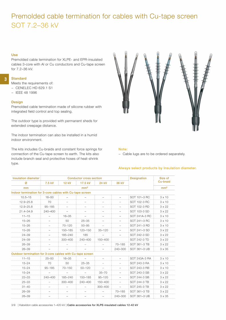
Use
Premolded cable termination for XLPE- and EPR-insulated
cables 3-core with Al or Cu conductors and Cu-tape screen
for 7.2–36 kV.
Standard
Meets the requirements of:
− CENELEC HD 629.1 S1
− IEEE 48 1996
Design
Premolded cable termination made of silicone rubber with
integrated field control and top sealing.
The outdoor type is provided with permanent sheds for
extended creepage distance.
The indoor termination can also be installed in a humid
indoor environment.
The kits includes Cu-braids and constant force springs for
connection of the Cu-tape screen to earth. The kits also
include branch seal and protective hoses of heat-shrink
type.
Premolded cable termination for cables with Cu-tape screen
SOT 7.2–36 kV
Note:
− Cable lugs are to be ordered separately.
Always select products by Insulation diameter.
3
3/9 | Kabeldon cable accessories 1–420 kV | Cable accessories for XLPE-insulated cables 12-42 kV
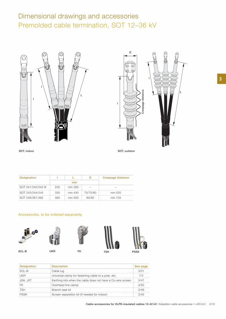
Dimensional drawings and accessories
Premolded cable termination, SOT 12–36 kV
Designation I L D Creepage distance
mm
SOT 241/242/242 B 235 min 300 – –
SOT 243/244/245 330 min 430 70/75/80 min 520
SOT 246/361/362 390 min 500 80/85 min 725
SOT, indoor
I
I
L
SOT, outdoor
I
D
I
L
Cre
ep
ag
e d
ista
nc
e
Designation Description See page
SCL-B Cable lug 3/51
UKR Universal clamp for fastening cable to a pole, etc. 7/2
JSA, JXT Earthing kits when the cable does not have a Cu-wire screen 3/47
FK Overhead line clamp 3/50
TSH Branch seal kit 3/46
PSSK Screen separation kit (if needed for indoor) 3/45
PSSK SCL-B FK TSHUKR
Accessories, to be ordered separately
3
Cable accessories for XLPE-insulated cables 12-42 kV | Kabeldon cable accessories 1–420 kV | 3/10
Premolded cable termination with geometrical field control, indoors
APIT 12–36 kV
Use
Cable termination with geometric field control for XLPE- and
EPR-insulated 1- or 3-core cables. This type of termination
is recommended to be used in applications were significant
harmonics may occur.
Standard
Meets the requirements of:
− CENELEC HD 629.1
− IEEE 48-1975
Design
The cable termination consists of a premolded stress relief cone
with an integrated deflector for geometrical field control. The
cable’s conducting layer is connected to the stress relief cone
for optimal function. The termination is supplied in kits for 3-core
cables.
Note:
− Cable lugs and branch seal for 3-core cables are to be
ordered separately.
Designation Insulation
diameter
12kV 24kV 36kV Diameter Weight
Cable
cross
section
Creepage
distance
Length Cable
cross
section
Creepage
distance
Length Cable
cross
section
Creepage
distance
Length
A A A Ø
mm mm² mm mm mm² mm mm mm² mm mm mm kg/each
APIT 4 25.0–28.0 240 170 160 120–150 310 300 50–95 460 450 96 3.0
APIT 5 27.5–30.5 300 170 160 185–240 310 300 95–120 460 450 96 2.9
APIT 6 30.5–33.6 400 170 160 300 310 300 150–240 460 450 96 2.9
APIT 7 33.0–36.6 500 170 160 400 310 300 240 460 450 96 2.8
APIT 8 35.7–39.7 630 170 160 500 310 300 300 460 450 96 2.8
APIT 9 39.3–43.1 800 170 160 500–630 310 300 400 460 450 96 2.6
APIT 10 42.5–48.1 1000 170 160 630–800 310 300 500 460 450 96 2.5
APIT 11 48.0–54.0 1200 170 160 1000 310 300 630–800 460 450 96 2.5
APIT 12 54.0–60.0 – – – 1200 310 300 1000 460 450 99 2.5
APIT 13 60.0–66.0 – – – – – – 1200 460 450 99 2.5
Designation Description See page
SCL-B Cable lug 3/51
UKR Universal clamp for fastening cable to a pole, etc. 7/2
JSA Earthing kits when the cable does not have a Cu-wire screen 3/47
FK Overhead line clamp 3/50
TSH, SSH Branch seal kit and extension protective hoses 3/46
PSSK Screen separation kit 3/45
PSSK SCL-B FK TSHUKR
Accessories, to be ordered separately
Ø
A
Always select products by Insulation diameter.
3
3/11 | Kabeldon cable accessories 1–420 kV | Cable accessories for XLPE-insulated cables 12-42 kV
Use
Cable termination with geometric field control for XLPE- and
EPR-insulated 1- or 3-core cables. This type of termination
is recommended to be used in applications were significant
harmonics may occur.
It is also suitable for environments where a longer creepage
distance is required.
Standard
Meets the requirements of:
− CENELEC HD 629.1
− IEEE 48-1975
Design
The cable termination is made of rubber with prefabricated
geometrical field control in the stress relief cone. The cable’s
conducting layer is connected to the stress relief cone for
optimal function. The creepage distance is built up with
separate sheds and also a top cap that provides a diffusion
sealed protection against the cable lug. The termination is
supplied in kits for 3-core cables.
Premolded termination with geometrical field control, outdoors
APSEA 12–36 kV
Voltage Insulation diameter Conductor
cross section
Designation Top cap type Creepage
distance
Length Diameter Weight
A Ø
mm mm² mm mm mm kg/kit
12 25.0–28.0 240 APSEA 121–3 THS 300 255 165 4.0
12 27.5–30.5 300 APSEA 122-3 THS 300 255 165 3.9
12 30.5–33.6 400 APSEA 123-3 THS 300 255 165 3.9
12 33.0–36.6 500 APSEA 124-3 THS 300 255 165 3.8
12 35.7–39.7 630 APSEA 125-3 THS 300 255 165 3.8
12 39.3–43.1 800 APSEA 126-3 THS 300 255 165 3.6
12 42.5–48.1 1000 APSEA 127-3 THS 300 255 165 3.5
12 48.0–54.0 1200 APSEA 128-3 THSA 300 255 165 3.5
24 25.0–28.0 120–150 APSEA 241–3 THS 830 470 165 9.0
24 27.5–30.5 185–240 APSEA 242-3 THS 830 470 165 9.0
24 30.5–33.6 300 APSEA 243-3 THS 830 470 165 8.7
24 33.0–36.6 400 APSEA 244-3 THS 830 470 165 8.5
24 35.7–39.7 500 APSEA 245-3 THS 830 470 165 8.3
24 39.3–43.1 500–630 APSEA 246-3 THS 830 470 165 8,0
24 42.5–48.1 630–800 APSEA 247-3 THS 830 470 165 7.8
24 48.0–54.0 1000 APSEA 248-3 THSA 830 470 165 7.5
24 54.0–60.0 1200 APSEA 249-3 THSA 830 470 165 7.5
36 25.0–28.0 50–95 APSEA 361–3 THS 1100 580 165 10.0
36 27.5–30.5 95–120 APSEA 362-3 THS 1100 580 165 10.0
36 30.5–33.6 150–240 APSEA 363-3 THS 1100 580 165 9.8
36 33.0–36.6 240 APSEA 364-3 THS 1100 580 165 9.7
36 35.7–39.7 300 APSEA 365-3 THS 1100 580 165 9.5
36 39.3–43.1 400 APSEA 366-3 THS 1100 580 165 9.5
36 42.5–48.1 500 APSEA 367-3 THS 1100 580 165 9.3
36 48.0–54.0 630–800 APSEA 368-3 THSA 1100 580 165 8.8
36 54.0–60.0 1000 APSEA 369-3 THSA 1100 580 165 8.5
36 60.0–66.0 1200 APSEA 3610-3 THSA 1100 580 165 8.5
APSEA 12 kV APSEA 24 kV APSEA 36 kV
Note:
− Top caps are not included in the kit. Three pieces must
be ordered separately.
− Top bolts, cable lugs and branch seal for 3-core cables
are to be ordered separately.
Ø
A
Always select products by Insulation diameter.
3
Cable accessories for XLPE-insulated cables 12-42 kV | Kabeldon cable accessories 1–420 kV | 3/12
Top bolts and cable lugs
The top cap THS or THSA is selected with regards to the size of the cable
termination (see table at page 3/12) and the outer diameter of thickest part of
the cable lug or top bolt. See dimension B in the table below.
THS, THSA
Top cap.
Premolded termination with geometrical field control, outdoor
APSEA 12–36 kV
Designation Description See page
THS, THSA Top caps for outdoor termination APSEA 3/13
A/K-TBF SKR Top bolt 3/13
SCL-B Cable lug 3/51
UKR Universal clamp for fastening cable to a pole, etc. 7/2
FK Overhead line clamp 3/50
TSH, SSH Branch seal kit and protective hoses 3/46
PSSK Screen separation kit 3/45
JSA Earthing kits when the cable does not have a Cu-wire screen 3/47
Top hole
Max. diameter of cable connection
Top cap Top cap
mm THS THSA
30 THS 28 THSA 28
40 THS 37 THSA 37
50 THS 47 THSA 47
65 THS 60 THSA 60
Top caps, cable lugs and top bolts are supplied in one-piece kits, to be ordered separately.
A/K-TBF SKR
Top bolt. Tightening torque, 45 Nm.
BB
A
125
Accessory Diameter Cable cross section
Designation Top bolts
Cable conductor material
Net weightA B
mm mm² kg/item
Top bolt 30 45 120 A-TBF 30 120 SKR Al 0.5
Top bolt 30 45 150, 185 A-TBF 30 185 SKR Al 0.5
Top bolt 30 50 240 A-TBF 30 240 SKR Al 0.8
Top bolt 30 55 300, 400 A-TBF 30 400 SKR Al 0.8
Top bolt 30 60 500 A-TBF 30 500 SKR Al 0.9
Top bolt 30 60 630 A-TBF 30 630 SKR Al 0.9
Top bolt 40 65 800 A-TBF 40 800 SKR Al 1.2
Top bolt 40 65 1000 A-TBF 40 1000 SKR Al 1.2
Top bolt 40 65 1200 A-TBF 40 1200 SKR Al 1.1
Top bolt 30 45 120 K-TBF 30 120 SKR Cu 1.6
Top bolt 30 45 150, 185 K-TBF 30 185 SKR Cu 1.6
Top bolt 30 50 240 K-TBF 30 240 SKR Cu 2.4
Top bolt 30 55 300, 400 K-TBF 30 400 SKR Cu 2.4
Top bolt 30 60 500 K-TBF 30 500 SKR Cu 2.8
Top bolt 30 60 630 K-TBF 30 630 SKR Cu 2.8
Top bolt 40 65 800 K-TBF 40 800 SKR Cu 4.0
Top bolt 40 65 1000 K-TBF 40 1000 SKR Cu 3.8
Top bolt 40 65 1200 K-TBF 40 1200 SKR Cu 3.5
Cable lug 24 24 10–95 SCL-B 95-12 Al/Cu 0,10
Cable lug 28 28 25–150 SCL-B 150-12 Al/Cu 0,25
Cable lug 33 33 50–240 SCL-B 240-12 Al/Cu 0,30
Cable lug 38 38 70–300 SCL-B 300-16 Al/Cu 0,35
Cable lug 50 52 300–630 SCL-B 630-16 Al/Cu 0,90
UKR
SCL-B
Cable lug with shear-off bolts.
FK TSH PSSK SSH
Accessories, to be ordered separately
SCL-BA/K-TBF SKRTHS, THSA
B
A
3
3/13 | Kabeldon cable accessories 1–420 kV | Cable accessories for XLPE-insulated cables 12-42 kV
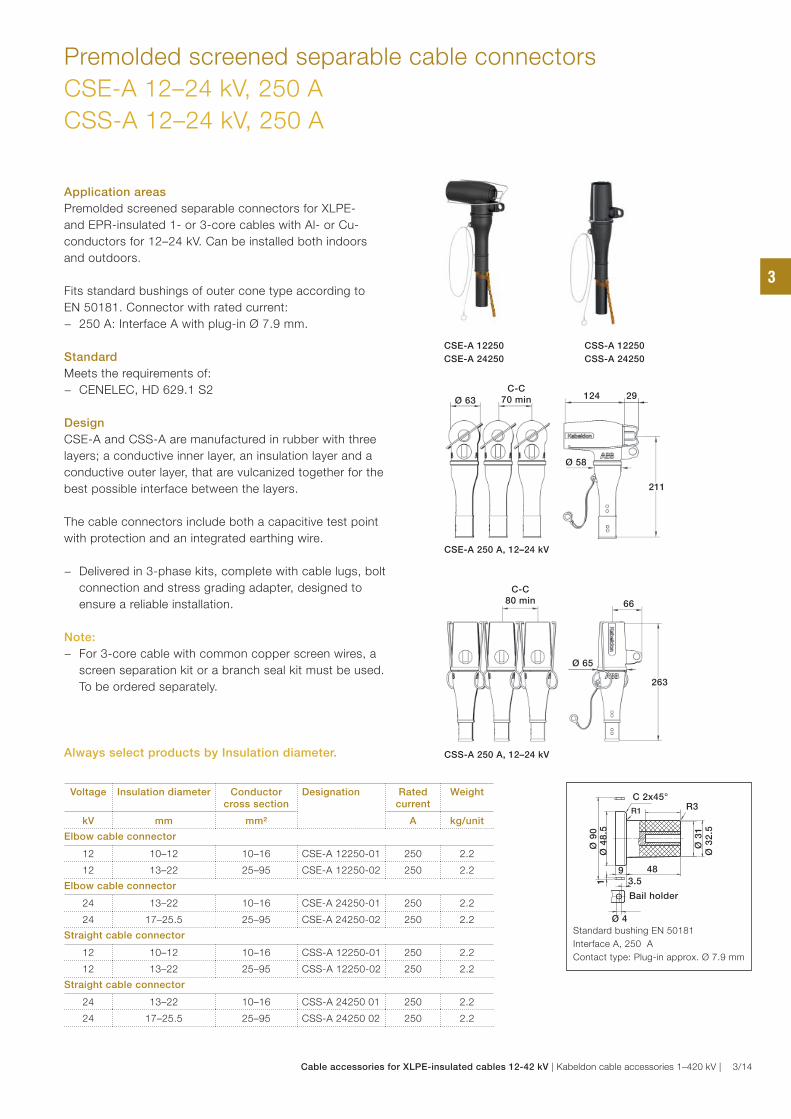
Voltage Insulation diameter Conductor cross section
Designation Rated current
Weight
kV mm mm² A kg/unit
Elbow cable connector
12 10–12 10–16 CSE-A 12250-01 250 2.2
12 13–22 25–95 CSE-A 12250-02 250 2.2
Elbow cable connector
24 13–22 10–16 CSE-A 24250-01 250 2.2
24 17–25.5 25–95 CSE-A 24250-02 250 2.2
Straight cable connector
12 10–12 10–16 CSS-A 12250-01 250 2.2
12 13–22 25–95 CSS-A 12250-02 250 2.2
Straight cable connector
24 13–22 10–16 CSS-A 24250 01 250 2.2
24 17–25.5 25–95 CSS-A 24250 02 250 2.2
Application areas
Premolded screened separable connectors for XLPE-
and EPR-insulated 1- or 3-core cables with Al- or Cu-
conductors for 12–24 kV. Can be installed both indoors
and outdoors.
Fits standard bushings of outer cone type according to
EN 50181. Connector with rated current:
− 250 A: Interface A with plug-in Ø 7.9 mm.
Standard
Meets the requirements of:
− CENELEC, HD 629.1 S2
Design
CSE-A and CSS-A are manufactured in rubber with three
layers; a conductive inner layer, an insulation layer and a
conductive outer layer, that are vulcanized together for the
best possible interface between the layers.
The cable connectors include both a capacitive test point
with protection and an integrated earthing wire.
− Delivered in 3-phase kits, complete with cable lugs, bolt
connection and stress grading adapter, designed to
ensure a reliable installation.
Note:
− For 3-core cable with common copper screen wires, a
screen separation kit or a branch seal kit must be used.
To be ordered separately.
Premolded screened separable cable connectors
CSE-A 12–24 kV, 250 A
CSS-A 12–24 kV, 250 A
CSE-A 12250
CSE-A 24250
CSS-A 12250
CSS-A 24250
Standard bushing EN 50181
Interface A, 250 A
Contact type: Plug-in approx. Ø 7.9 mm
R3R1
C 2x45°
Bail holder
Ø 4
3.5
Ø 4
8.5
Ø 9
0
Ø 3
1
1
Ø 3
2.5
9 48
CSE-A 250 A, 12–24 kV
Ø 63Ø 63
C-CC-C70 min70 min 124124
211211
Ø 58Ø 58
2929
CSS-A 250 A, 12–24 kV
C-CC-C80 min80 min
263263
Ø 65Ø 65
6666
Always select products by Insulation diameter.
3
Cable accessories for XLPE-insulated cables 12-42 kV | Kabeldon cable accessories 1–420 kV | 3/14
Premolded screened separable connector
for cables with Cu-tape screen
CSE-A 12–24 kV, 250 A
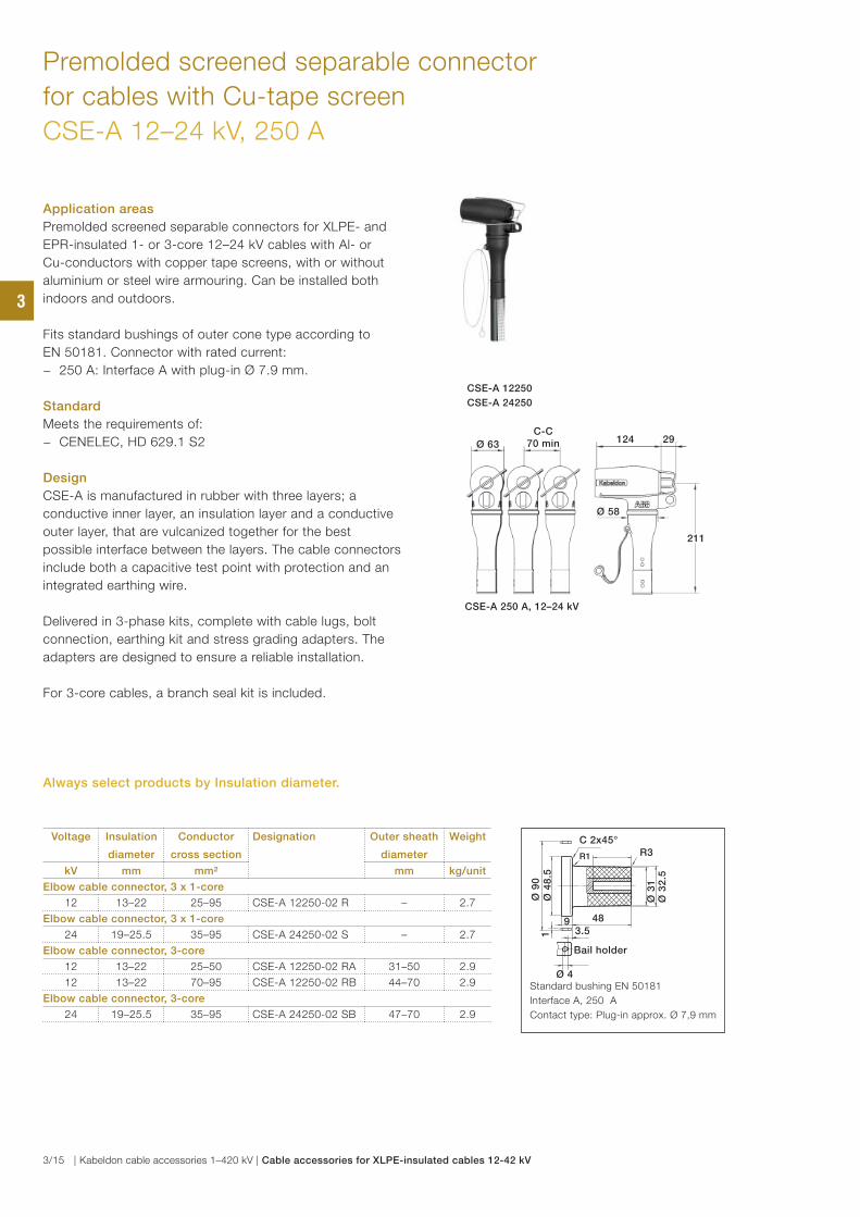
Application areas
Premolded screened separable connectors for XLPE- and
EPR-insulated 1- or 3-core 12–24 kV cables with Al- or
Cu-conductors with copper tape screens, with or without
aluminium or steel wire armouring. Can be installed both
indoors and outdoors.
Fits standard bushings of outer cone type according to
EN 50181. Connector with rated current:
− 250 A: Interface A with plug-in Ø 7.9 mm.
Standard
Meets the requirements of:
− CENELEC, HD 629.1 S2
Design
CSE-A is manufactured in rubber with three layers; a
conductive inner layer, an insulation layer and a conductive
outer layer, that are vulcanized together for the best
possible interface between the layers. The cable connectors
include both a capacitive test point with protection and an
integrated earthing wire.
Delivered in 3-phase kits, complete with cable lugs, bolt
connection, earthing kit and stress grading adapters. The
adapters are designed to ensure a reliable installation.
For 3-core cables, a branch seal kit is included.
CSE-A 12250
CSE-A 24250
Voltage Insulation
diameter
Conductor
cross section
Designation Outer sheath
diameter
Weight
kV mm mm² mm kg/unit
Elbow cable connector, 3 x 1-core
12 13–22 25–95 CSE-A 12250-02 R – 2.7
Elbow cable connector, 3 x 1-core
24 19–25.5 35–95 CSE-A 24250-02 S – 2.7
Elbow cable connector, 3-core
12 13–22 25–50 CSE-A 12250-02 RA 31–50 2.9
12 13–22 70–95 CSE-A 12250-02 RB 44–70 2.9
Elbow cable connector, 3-core
24 19–25.5 35–95 CSE-A 24250-02 SB 47–70 2.9
Standard bushing EN 50181
Interface A, 250 A
Contact type: Plug-in approx. Ø 7,9 mm
R3R1
C 2x45°
Bail holder
Ø 4
3.5
Ø 4
8.5
Ø 9
0
Ø 3
1
1
Ø 3
2.5
9 48
CSE-A 250 A, 12–24 kV
Ø 63Ø 63
C-CC-C70 min70 min 124124
211211
Ø 58Ø 58
2929
Always select products by Insulation diameter.
3
3/15 | Kabeldon cable accessories 1–420 kV | Cable accessories for XLPE-insulated cables 12-42 kV
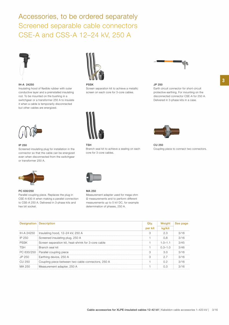
MA 250
Measurement adapter used for mega ohm
Ω measurements and to perform different
measurements up to 5 kV DC, for example
determination of phases, 250 A.
IH-A 24250
Insulating hood of flexible rubber with outer
conductive layer and a preinstalled insulating
rod. To be mounted on the bushing in a
switchgear or a transformer 250 A to insulate
it when a cable is temporarily disconnected
but other cables are energized.
IP 250
Screened insulating plug for installation in the
connector so that the cable can be energized
even when disconnected from the switchgear
or transformer 250 A.
CU 250
Coupling piece to connect two connectors.
JP 250
Earth circuit connector for short-circuit
protective earthing. For mounting on the
disconnected connector CSE-A for 250 A.
Delivered in 3-phase kits in a case.
Accessories, to be ordered separately
Screened separable cable connectors
CSE-A and CSS-A 12–24 kV, 250 A
Designation Description Qty.
per kit
Weight See page
kg/kit
IH-A 24250 Insulating hood, 12–24 kV, 250 A 3 2.3 3/16
IP 250 Screened insulating plug, 250 A 1 0,8 3/16
PSSK Screen separation kit, heat-shrink for 3-core cable 1 1.0–1.1 3/45
TSH Branch seal kit 1 0.3–1.0 3/46
PC 630/250 Parallel coupling piece 3 3.0 3/16
JP 250 Earthing device, 250 A 3 2.7 3/16
CU 250 Coupling piece between two cable connectors, 250 A 1 0.2 3/16
MA 250 Measurement adapter, 250 A 1 0.3 3/16
PSSK
Screen separation kit to achieve a metallic
screen on each core for 3-core cables.
PC 630/250
Parallel coupling piece. Replaces the plug in
CSE-A 630 A when making a parallel connection
to CSE-A 250 A. Delivered in 3-phase kits and
hex bit socket.
TSH
Branch seal kit to achieve a sealing on each
core for 3-core cables.
3
Cable accessories for XLPE-insulated cables 12-42 kV | Kabeldon cable accessories 1–420 kV | 3/16

Voltage Insulation
diameter
Conductor
cross section
Designation Rated
current
Weight
kV mm mm² A kg/unit
12 13–20 25–70 CSE-A 12400-01 400 6.1
12 18.5–30.5 95–300 CSE-A 12400-02 400 6.6
24 17–24 25–70 CSE-A 24400-01 400 6.1
24 22.5–35 95–300 CSE-A 24400-02 400 6.6
36 24.5–34 50-95 CSE-A 36400-01 400 6.1
36 27.5–42 95-300 CSE-A 36400-02 400 6.6
42 24.5–34 50–70 CSE-A 42400-01 400 6.1
42 27.5–42 95–300 CSE-A 42400-02 400 6.6
Application areas
Premolded screened separable connector for XLPE-
and EPR-insulated 1- or 3-core cables with Al- or Cu-
conductors for 12–42 kV. Can be installed both indoors
and outdoors.
Fits standard bushings of outer cone type according to
EN 50181. Connector with rated current:
− 400 A: series 400 interface type B with plug-in
Ø 14 mm.
Standard
Meets the requirements of:
− CENELEC, HD 629.1 S2
Design
CSE-A is manufactured in rubber with three layers; a
conductive inner layer, an insulation layer and a conductive
outer layer, that are vulcanized together for the best
possible interface between the layers.
The cable connector includes both a capacitive test point
with protection and an integrated earthing wire.
− Delivered in 3-phase kits complete with cable lugs, bolt
connection and stress grading adapter, designed to
ensure a reliable installation.
Note:
− For 3-core cables with common Cu-screen wires, a
screen separation kit or a branch seal kit must be used.
To be ordered separately.
Premolded screened separable cable connector
CSE-A 12–42 kV, 400 A
CSE-A 12400
Standard bushing EN 50181
Interface B, 400 A
Contact type: Plug-in Ø14
R3
Ø 4
6
Ø 7
0
Ø 1
02
115.5
Bail holder
40R3
R3
Ø 5
6
90
CSE-A 400 A, 12–24 kV
Ø 80Ø 80
C-CC-C85 min85 min 173173
256256
Ø 72Ø 72
3434
CSE-A 400 A, 36–42 kV
Ø 80Ø 80
C-CC-C85 min85 min 195195
284284
Ø 74Ø 74
3434
Always select products by Insulation diameter.
CSE-A 24400
3
3/17 | Kabeldon cable accessories 1–420 kV | Cable accessories for XLPE-insulated cables 12-42 kV
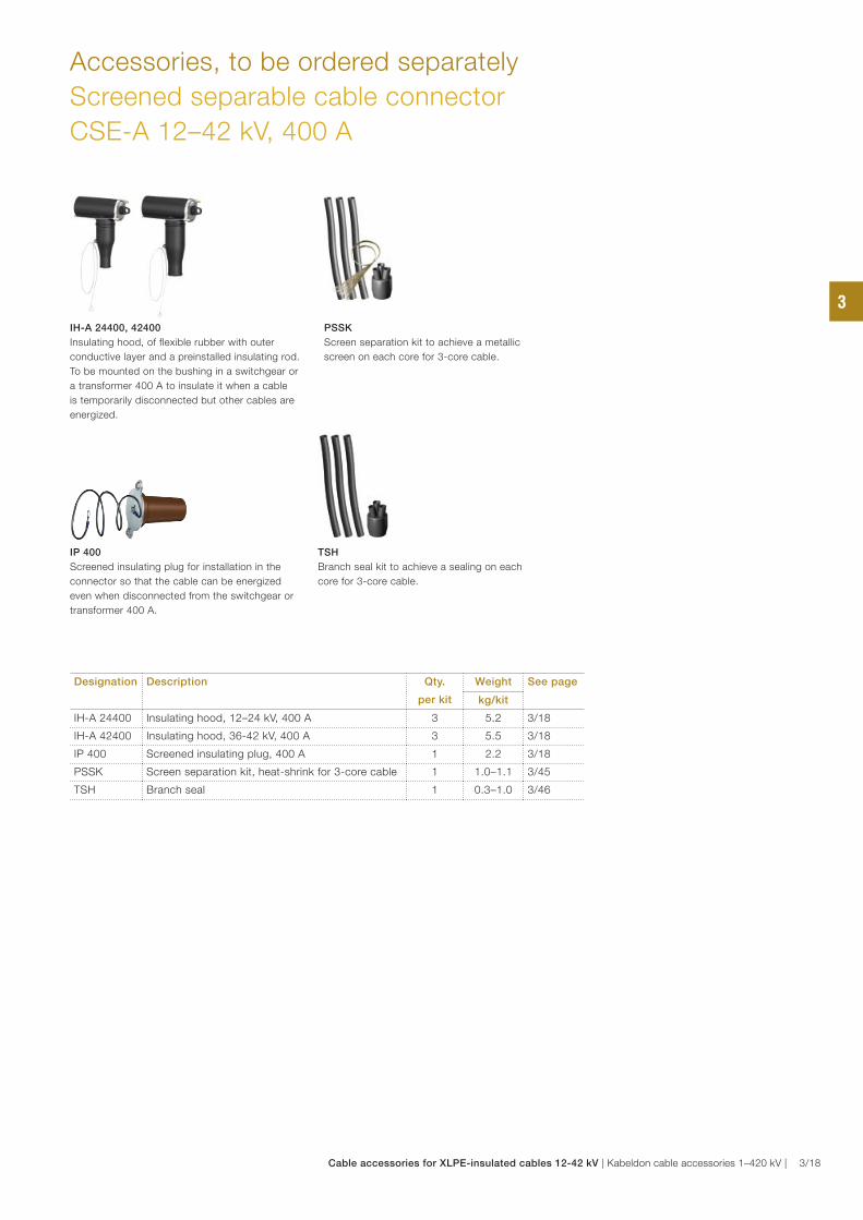
IP 400
Screened insulating plug for installation in the
connector so that the cable can be energized
even when disconnected from the switchgear or
transformer 400 A.
IH-A 24400, 42400
Insulating hood, of flexible rubber with outer
conductive layer and a preinstalled insulating rod.
To be mounted on the bushing in a switchgear or
a transformer 400 A to insulate it when a cable
is temporarily disconnected but other cables are
energized.
Designation Description Qty.
per kit
Weight See page
kg/kit
IH-A 24400 Insulating hood, 12–24 kV, 400 A 3 5.2 3/18
IH-A 42400 Insulating hood, 36-42 kV, 400 A 3 5.5 3/18
IP 400 Screened insulating plug, 400 A 1 2.2 3/18
PSSK Screen separation kit, heat-shrink for 3-core cable 1 1.0–1.1 3/45
TSH Branch seal 1 0.3–1.0 3/46
Accessories, to be ordered separately
Screened separable cable connector
CSE-A 12–42 kV, 400 A
PSSK
Screen separation kit to achieve a metallic
screen on each core for 3-core cable.
TSH
Branch seal kit to achieve a sealing on each
core for 3-core cable.
3
Cable accessories for XLPE-insulated cables 12-42 kV | Kabeldon cable accessories 1–420 kV | 3/18

Voltage Insulation
diameter
Conductor
cross section
Designation Weight
kV mm mm² kg/unit
12 13–20 25–70 CSE-A 12630-01 5.1
12 18.5–30.5 95–300 CSE-A 12630-02 5.5
12 30.5–45 400–630 CSE-A 12630-03 7.7
24 17–24 25–70 CSE-A 24630-01 5.1
24 22.5–35 95–300 CSE-A 24630-02 5.5
24 30.5–45 400–630 CSE-A 24630-03 7.7
36 24.5–34 50-95 CSE-A 36630-01 6.1
36 27.5–42 95-300 CSE-A 36630-02 6.6
36 38.0–55 400-630 CSE-A 36630-03 8.7
42 24.5–34 50–70 CSE-A 42630-01 6.1
42 27.5–42 95–300 CSE-A 42630-02 6.6
42 38–55 400–630 CSE-A 42630-03 8.7
Application areas
Premolded screened separable connector for XLPE-
and EPR-insulated 1- or 3-core cables with Al- or
Cu-conductors for 12–42 kV. Can be installed both
indoors and outdoors.
Fits standard bushings of outer cone type according
to EN 50181. Connector with rated current:
− 630 A: Interface C1 with bolt M16.
− 1250 A: Interface C2 with bolt M16.
Standard
Meets the requirements of:
− CENELEC, HD 629.1 S2
Design
CSE-A is manufactured in rubber with three layers;
a conductive inner layer, an insulation layer and a
conductive outer layer, that are vulcanized together for
the best possible interface between the layers.
The cable connector includes both a capacitive test
point with protection and an integrated earthing wire.
− Delivered in 3-phase kits, complete with cable
lugs, bolt connection and stress grading adapter,
designed to ensure a reliable installation.
Note:
− For 3-core cables with common Cu-screen wires, a
screen separation kit or a branch seal kit must be
used. To be ordered separately.
Premolded screened separable cable connector
CSE-A 12–42 kV, 630 A
CSE-A 12630, CSE-A 24630
Ø 4
6
Ø 5
6
R3
R3
Ø 7
0
11 90
R3 1.5
29
CSE-A 36630, CSE-A 42630
Standard bushing EN 50181
Interface: C1, 630 A
Interface: C2, 1250 A
Contact type: Bolt M16
CSE-A 630 A, 36–42 kV sizes 1–2.
Ø 81Ø 81
C-CC-C85 min85 min 194194
283283
Ø 74Ø 74
99
CSE-A 630 A, 12–24 kV, size 3
Ø 85Ø 85C-CC-C
90 min90 min 180180
314314
9090
99
CSE-A 630 A, 12–24 kV, sizes 1–2
Ø 81Ø 81
C-CC-C85 min85 min 172172
256256
Ø 72Ø 72
99
CSE-A 630 A, 36–42 kV size 3.
99Ø 85Ø 85
C-CC-C90 min90 min 202202
314314
9090
Always select products by Insulation diameter.
3
3/19 | Kabeldon cable accessories 1–420 kV | Cable accessories for XLPE-insulated cables 12-42 kV

Premolded screened separable cable connector
for cables with copper tape screen
CSE-A 12–36 kV, 630 A
Application areas
Premolded screened separable connector for XLPE- and
EPR-insulated 1- or 3-core 12–36 kV cables, with Al- or Cu-
conductors with Cu-tape screens, with or without aluminium
or steel wire armouring. Can be installed both indoors and
outdoors.
Fits standard bushings of outer cone type according to
EN 50181. Connectors with rated current:
− 630 A: interface type C1 with bolt M16.
− 1250 A: interface type C2 with bolt M16.
Standard
Meets the requirements of:
− CENELEC, HD 629.1 S2
Design
CSE-A is manufactured in rubber with three layers; a
conductive inner layer, an insulation layer and a conductive
outer layer, that are vulcanized together for the best
possible interface between the layers. The cable connector
includes both a capacitive test point with protection and an
integrated earthing wire.
− Delivered in 3-phase kits, complete with cable lugs, bolt
connection, earthing kit and stress grading adapters. The
adapters are designed to ensure a reliable installation.
For 3-core cables, a branch seal kit is included.
CSE-A 12630 / CSE-A 24630 CSE-A 36630
Voltage Insulation
diameter
Conductor
cross section
Outer sheath
diameter
Designation Weight
kV mm mm² mm kg/unit
Elbow cble connectors, 3 x 1-core cables
12 13–20 25–70 – CSE-A 12630-01 R 5.6
12 19–29 95–300 – CSE-A 12630-02 S 6.0
12 30.5–37 400 – CSE-A 12630-03 T 8.2
24 19–24 35–70 – CSE-A 24630-01 S 5.6
24 25–35 95–300 – CSE-A 24630-02 T 6.0
24 30.5–37 400 – CSE-A 24630-03 T 8.2
36 19–29 50–70 – CSE-A 36630-01 S 6.8
36 27.5–37 95–300 – CSE-A 36630-02 T 7.3
36 38–50 400 – CSE-A 36630-03 U 9.4
Elbow cable connectors, 3-core cables
12 13–20 25–70 31–50 CSE-A 12630-01 RA 5.8
12 19–29 95–185 47–70 CSE-A 12630-02 SB 6.2
12 25–30.5 240–300 58–94 CSE-A 12630-02 TB 6.2
12 30.5–37 400 58–94 CSE-A 12630-03 TB 8.4
24 19–24 35–70 47–70 CSE-A 24630-01 SB 5.8
24 25–35 95–300 58–94 CSE-A 24630-02 TB 6.2
24 30.5–37 400 65–110 CSE-A 24630-03 TB 8.4
36 19–29 50–95 58–94 CSE-A 36630-01 SB 6.8
36 27.5–37 95–300 65–110 CSE-A 36630-02 TB 7.3
CSE-A 630 A, 36–42 kV sizes 1–2.
Ø 81Ø 81
C-CC-C85 min85 min 194194
283283
Ø 74Ø 74
99
CSE-A 630 A, 12–24 kV, size 3
Ø 85Ø 85C-CC-C
90 min90 min 180180
314314
9090
99
CSE-A 630 A, 12–24 kV, sizes 1–2
Ø 81Ø 81
C-CC-C85 min85 min 172172
256256
Ø 72Ø 72
99
CSE-A 630 A, 36–42 kV size 3.
99Ø 85Ø 85
C-CC-C90 min90 min 202202
314314
9090
Always select products by Insulation diameter.
3
Cable accessories for XLPE-insulated cables 12-42 kV | Kabeldon cable accessories 1–420 kV | 3/20
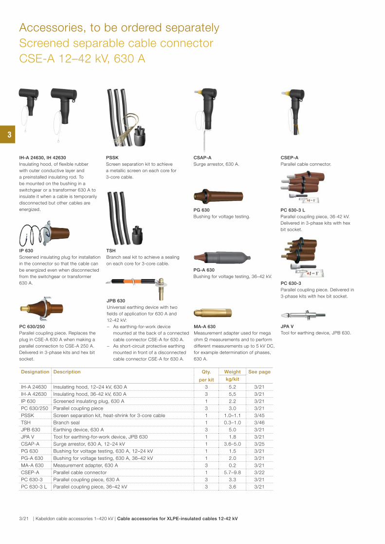
IH-A 24630, IH 42630
Insulating hood, of flexible rubber
with outer conductive layer and
a preinstalled insulating rod. To
be mounted on the bushing in a
switchgear or a transformer 630 A to
insulate it when a cable is temporarily
disconnected but other cables are
energized.
MA-A 630
Measurement adapter used for mega
ohm Ω measurements and to perform
different measurements up to 5 kV DC,
for example determination of phases,
630 A.
PC 630/250
Parallel coupling piece. Replaces the
plug in CSE-A 630 A when making a
parallel connection to CSE-A 250 A.
Delivered in 3-phase kits and hex bit
socket.
PG 630
Bushing for voltage testing.
IP 630
Screened insulating plug for installation
in the connector so that the cable can
be energized even when disconnected
from the switchgear or transformer
630 A.
PG-A 630
Bushing for voltage testing, 36–42 kV.
JPB 630
Universal earthing device with two
fields of application for 630 A and
12-42 kV:
− As earthing-for-work device
mounted at the back of a connected
cable connector CSE-A for 630 A.
− As short-circuit protective earthing
mounted in front of a disconnected
cable connector CSE-A for 630 A.
JPA V
Tool for earthing device, JPB 630.
PC 630-3
Parallel coupling piece. Delivered in
3-phase kits with hex bit socket.
PC 630-3 L
Parallel coupling piece, 36-42 kV.
Delivered in 3-phase kits with hex
bit socket.
Designation Description Qty.
per kit
Weight See page
kg/kit
IH-A 24630 Insulating hood, 12–24 kV, 630 A 3 5.2 3/21
IH-A 42630 Insulating hood, 36-42 kV, 630 A 3 5,5 3/21
IP 630 Screened insulating plug, 630 A 1 2.2 3/21
PC 630/250 Parallel coupling piece 3 3.0 3/21
PSSK Screen separation kit, heat-shrink for 3-core cable 1 1.0–1.1 3/45
TSH Branch seal 1 0.3–1.0 3/46
JPB 630 Earthing device, 630 A 3 5.0 3/21
JPA V Tool for earthing-for-work device, JPB 630 1 1.8 3/21
CSAP-A Surge arrestor, 630 A, 12–24 kV 1 3.6–5.0 3/25
PG 630 Bushing for voltage testing, 630 A, 12–24 kV 1 1.5 3/21
PG-A 630 Bushing for voltage testing, 630 A, 36–42 kV 1 2.0 3/21
MA-A 630 Measurement adapter, 630 A 3 0.2 3/21
CSEP-A Parallel cable connector 1 5.7–9.8 3/22
PC 630-3 Parallel coupling piece, 630 A 3 3.3 3/21
PC 630-3 L Parallel coupling piece, 36–42 kV 3 3.6 3/21
CSAP-A
Surge arrestor, 630 A.
CSEP-A
Parallel cable connector.
Accessories, to be ordered separately
Screened separable cable connector
CSE-A 12–42 kV, 630 A
PSSK
Screen separation kit to achieve
a metallic screen on each core for
3-core cable.
TSH
Branch seal kit to achieve a sealing
on each core for 3-core cable.
3
3/21 | Kabeldon cable accessories 1–420 kV | Cable accessories for XLPE-insulated cables 12-42 kV

Parallel separable connector for 630 A cable connector
CSEP-A 12–42 kV
Application area
CSEP-A is a screened separable parallel cable connector
designed to be connected to a screened separable cable
connector type CSE-A 630. Used with XLPE- och EPR-
insulated 1- or 3-core cables with Al- or Cu-conductor for
12–42 kV.
Standard
− Fulfills the requirements of CENELEC HD 629.1 S2.
Design
CSEP-A is manufactured in rubber with three layers; a
conductive inner layer, an insulation layer and a conductive
outer layer that are vulcanized together for the best possible
interface between the layers.
When installing CSEP-A on the CSE-A the plug and the
protective cap must be moved from CSE-A to parallel
connector CSEP-A. In that way the capacitive test point
is re-established.
− Delivered in 3-phase kits complete with cable lugs, bolt
connections, stress grading adapters and also an integrated
earthing wire.
Note:
− For 3-core cables with common Cu-screen wires, a screen
separation kit or a branch seal kit must be used. For screen
separation kit see table at page 3/45.
Voltage Conductor
cross section
Insulation
diameter
Designation Weight
kV mm² mm kg/kit
12 25–70 13–20 CSEP-A 12630-01 5.7
12 95–300 18.5–30.5 CSEP-A 12630-02 6.1
12 400–630 30.5–45 CSEP-A 12630-03 8.6
24 25–70 17–24 CSEP-A 24630-01 5.7
24 95–300 22.5–35 CSEP-A 24630-02 6.1
24 400–630 30.5–45 CSEP-A 24630-03 8.6
36 50–95 24.5–34 CSEP-A 36630-01 6.7
36 95–300 27.5–42 CSEP-A 36630-02 7.1
36 400–630 38–55 CSEP-A 36630-03 9.8
42 50–70 24.5–34 CSEP-A 42630-01 6.7
42 95–300 27.5–42 CSEP-A 42630-02 7.1
42 400–630 38–55 CSEP-A 42630-03 9.8
CSEP-A, 12–24 kV sizes 1–2
256
72
81 min 85100 9
CSEP-A, 12–24 kV size 3
314
90
85 min 90114 9
283
74
81 min 85122 9
CSEP-A, 36–42 kV sizes 1–2
314
90
85 min 90136 9
CSEP-A, 36–42 kV size 3
Always select products by Insulation diameter.
CSEP-A
3
Cable accessories for XLPE-insulated cables 12-42 kV | Kabeldon cable accessories 1–420 kV | 3/22

Parallel screened separable connector
for cable with copper tape screen, 630 A
CSEP-A 12–36 kV
Application area
CSEP-A is a screened separable parallel connector designed
to be connected to a screened separable connector type
CSE-A 630. Used with XLPE- and EPR-insulated 1- or 3-core
12–36 kV cables, with Al- or Cu-conductors with copper tape
screens, with or without aluminium or steel wire armouring.
Standard
− Fulfills the requirements of CENELEC HD 629.1 S2.
Design
CSEP-A is manufactured in rubber with three layers; a
conductive inner layer, an insulation layer and a conductive outer
layer that are vulcanized together for the best possible interface
between the layers.
When installing CSEP-A on the CSE-A, the plug and the
protective cap must be moved from CSE-A to the parallel
connector CSEP-A. In that way the capacitive test point is
re-established.
− Delivered in 3-phase kits complete with cable lugs, bolt
connections, stress grading adapters and also an integrated
earthing wire.
Note:
− For 3-core cables with common Cu-tape screen, a screen
separation kit or a branch seal kit must be used. See table
at page 3/45.
Voltage Insulation
diameter
Conductor
cross section
Designation Weight
kV mm mm² kg/kit
Parallel connector for 3 x 1-core cables
12 13–20 25–70 CSEP-A 12630-01 R 5.8
12 18.5–30.5 95–300 CSEP-A 12630-02 S 6.2
12 30.5–45 400 CSEP-A 12630-03 T 8.7
24 17–24 35–70 CSEP-A 24630-01 S 5.8
24 22.5–35 95–300 CSEP-A 24630-02 T 6.2
24 30.5–45 400 CSEP-A 24630-03 T 8.7
36 24.5–34 50–70 CSEP-A 36630-01 S 6.8
36 27.5–42 95–300 CSEP-A 36630-02 T 7.2
36 38–55 400 CSEP-A 36630-03 U 9.9
Parallel connector for 3-core cables
12 13–20 25–70 CSEP-A 12630-01 RA 5.8
12 18.5–30.5 95–185 CSEP-A 12630-02 SB 6.2
12 18.5–30.5 240–300 CSEP-A 12630-02 TB 6.2
12 30.5–45 400 CSEP-A 12630-03 TB 8.7
24 17–24 35–70 CSEP-A 24630-01 SB 5.8
24 22.5–35 95–300 CSEP-A 24630-02 TB 6.2
24 30.5–45 400 CSEP-A 24630-03 TB 8.7
36 24.5–34 50–95 CSEP-A 36630-01 SB 6.8
36 27.5–42 95–300 CSEP-A 36630-02 TB 7.2
CSEP-A, 12–24 kV sizes 1–2
256
72
81 min 85100 9
CSEP-A, 12–24 kV size 3
314
90
85 min 90114 9
283
74
81 min 85122 9
CSEP-A, 36–42 kV sizes 1–2
314
90
85 min 90136 9
CSEP-A, 36–42 kV size 3
Always select products by Insulation diameter.
CSEP-A
3
3/23 | Kabeldon cable accessories 1–420 kV | Cable accessories for XLPE-insulated cables 12-42 kV
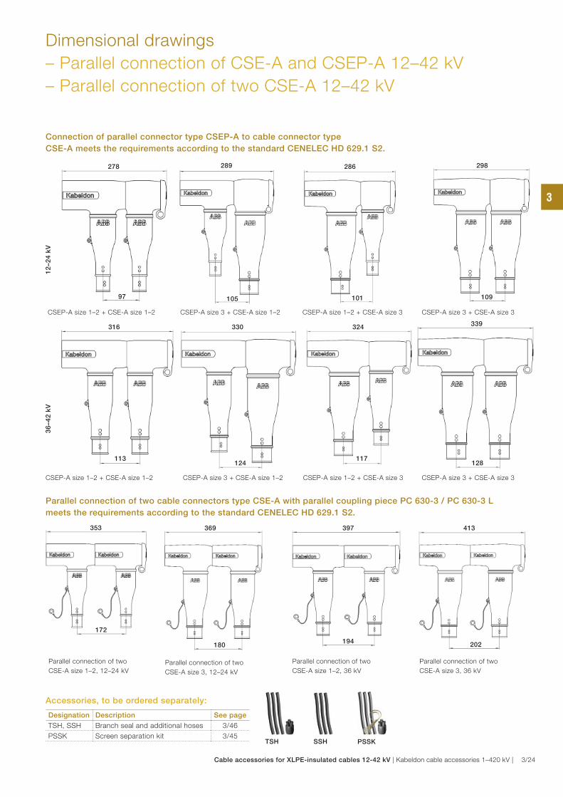
Dimensional drawings
– Parallel connection of CSE-A and CSEP-A 12–42 kV
– Parallel connection of two CSE-A 12–42 kV
Connection of parallel connector type CSEP-A to cable connector type
CSE-A meets the requirements according to the standard CENELEC HD 629.1 S2.
CSEP-A size 1–2 + CSE-A size 1–2 CSEP-A size 3 + CSE-A size 1–2 CSEP-A size 1–2 + CSE-A size 3 CSEP-A size 3 + CSE-A size 3
CSEP-A size 3 + CSE-A size 1–2CSEP-A size 1–2 + CSE-A size 1–2 CSEP-A size 1–2 + CSE-A size 3 CSEP-A size 3 + CSE-A size 3
Parallel connection of two cable connectors type CSE-A with parallel coupling piece PC 630-3 / PC 630-3 L
meets the requirements according to the standard CENELEC HD 629.1 S2.
Parallel connection of two
CSE-A size 1–2, 12–24 kV
353 369
Parallel connection of two
CSE-A size 3, 12–24 kV
397
Parallel connection of two
CSE-A size 1–2, 36 kV
413
Parallel connection of two
CSE-A size 3, 36 kV
36
–4
2 k
V1
2–2
4 k
V
278278
9797
289289
105105
286286
101101 109109
298298
339339
128128
324324
117117
330330
124124
316316
113113
202194
180
172
Designation Description See page
TSH, SSH Branch seal and additional hoses 3/46
PSSK Screen separation kit 3/45PSSK
Accessories, to be ordered separately:
TSH SSH
3
Cable accessories for XLPE-insulated cables 12-42 kV | Kabeldon cable accessories 1–420 kV | 3/24
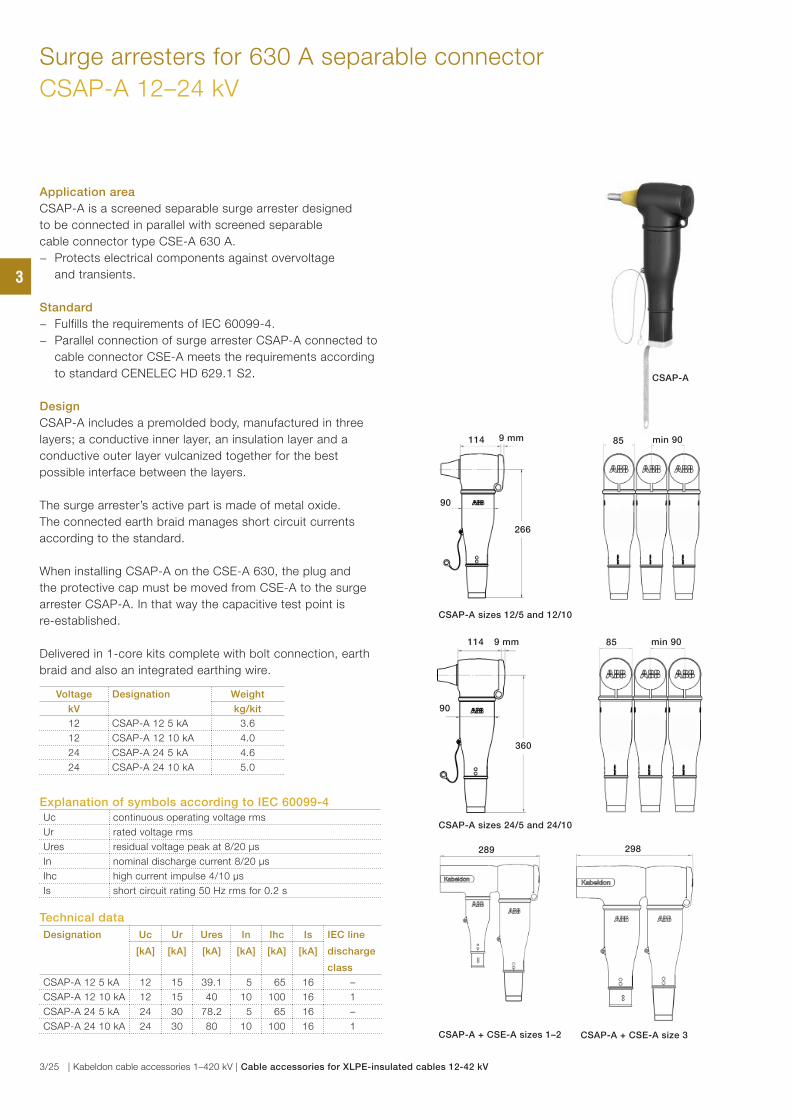
Surge arresters for 630 A separable connector
CSAP-A 12–24 kV
Application area
CSAP-A is a screened separable surge arrester designed
to be connected in parallel with screened separable
cable connector type CSE-A 630 A.
− Protects electrical components against overvoltage
and transients.
Standard
− Fulfills the requirements of IEC 60099-4.
− Parallel connection of surge arrester CSAP-A connected to
cable connector CSE-A meets the requirements according
to standard CENELEC HD 629.1 S2.
Design
CSAP-A includes a premolded body, manufactured in three
layers; a conductive inner layer, an insulation layer and a
conductive outer layer vulcanized together for the best
possible interface between the layers.
The surge arrester’s active part is made of metal oxide.
The connected earth braid manages short circuit currents
according to the standard.
When installing CSAP-A on the CSE-A 630, the plug and
the protective cap must be moved from CSE-A to the surge
arrester CSAP-A. In that way the capacitive test point is
re-established.
Delivered in 1-core kits complete with bolt connection, earth
braid and also an integrated earthing wire.
Voltage Designation Weight
kV kg/kit
12 CSAP-A 12 5 kA 3.6
12 CSAP-A 12 10 kA 4.0
24 CSAP-A 24 5 kA 4.6
24 CSAP-A 24 10 kA 5.0
Technical data
Designation Uc Ur Ures In Ihc Is IEC line
discharge
class
[kA] [kA] [kA] [kA] [kA] [kA]
CSAP-A 12 5 kA 12 15 39.1 5 65 16 –
CSAP-A 12 10 kA 12 15 40 10 100 16 1
CSAP-A 24 5 kA 24 30 78.2 5 65 16 –
CSAP-A 24 10 kA 24 30 80 10 100 16 1
Explanation of symbols according to IEC 60099-4Uc continuous operating voltage rms
Ur rated voltage rms
Ures residual voltage peak at 8/20 μs
In nominal discharge current 8/20 μs
Ihc high current impulse 4/10 μs
Is short circuit rating 50 Hz rms for 0.2 s
CSAP-A + CSE-A sizes 1–2 CSAP-A + CSE-A size 3
289289 298298
114114
9090
9 mm9 mm 8585 min 90min 90
266266
114114
9090
9 mm9 mm 8585 min 90min 90
360360
CSAP-A sizes 24/5 and 24/10
CSAP-A sizes 12/5 and 12/10
CSAP-A
3
3/25 | Kabeldon cable accessories 1–420 kV | Cable accessories for XLPE-insulated cables 12-42 kV
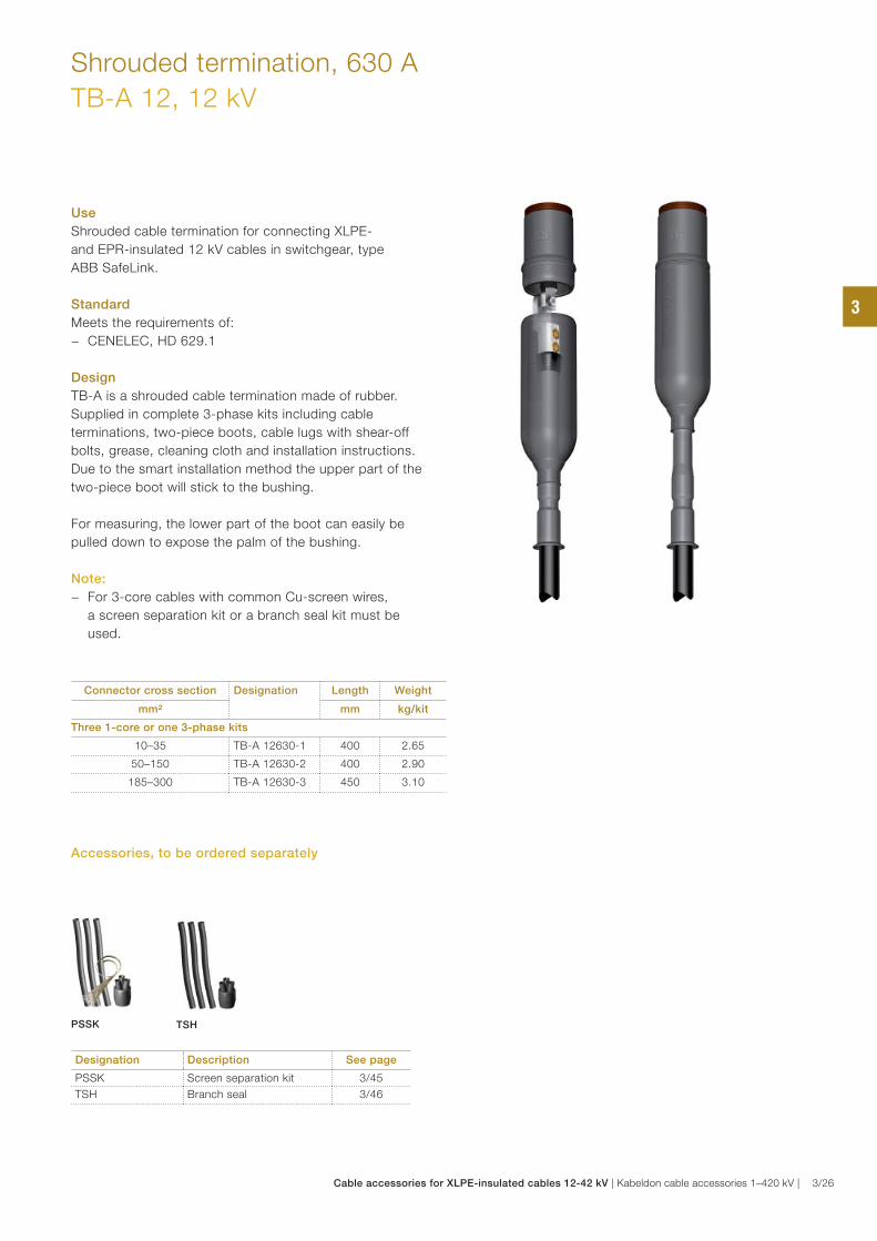
Shrouded termination, 630 A
TB-A 12, 12 kV
Use
Shrouded cable termination for connecting XLPE-
and EPR-insulated 12 kV cables in switchgear, type
ABB SafeLink.
Standard
Meets the requirements of:
− CENELEC, HD 629.1
Design
TB-A is a shrouded cable termination made of rubber.
Supplied in complete 3-phase kits including cable
terminations, two-piece boots, cable lugs with shear-off
bolts, grease, cleaning cloth and installation instructions.
Due to the smart installation method the upper part of the
two-piece boot will stick to the bushing.
For measuring, the lower part of the boot can easily be
pulled down to expose the palm of the bushing.
Note:
− For 3-core cables with common Cu-screen wires,
a screen separation kit or a branch seal kit must be
used.
Connector cross section Designation Length Weight
mm² mm kg/kit
Three 1-core or one 3-phase kits
10–35 TB-A 12630-1 400 2.65
50–150 TB-A 12630-2 400 2.90
185–300 TB-A 12630-3 450 3.10
Designation Description See page
PSSK Screen separation kit 3/45
TSH Branch seal 3/46
PSSK TSH
Accessories, to be ordered separately
3
Cable accessories for XLPE-insulated cables 12-42 kV | Kabeldon cable accessories 1–420 kV | 3/26
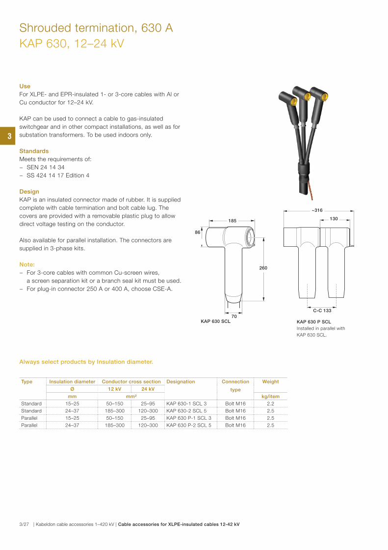
Use
For XLPE- and EPR-insulated 1- or 3-core cables with Al or
Cu conductor for 12–24 kV.
KAP can be used to connect a cable to gas-insulated
switchgear and in other compact installations, as well as for
substation transformers. To be used indoors only.
Standards
Meets the requirements of:
− SEN 24 14 34
− SS 424 14 17 Edition 4
Design
KAP is an insulated connector made of rubber. It is supplied
complete with cable termination and bolt cable lug. The
covers are provided with a removable plastic plug to allow
direct voltage testing on the conductor.
Also available for parallel installation. The connectors are
supplied in 3-phase kits.
Note:
− For 3-core cables with common Cu-screen wires,
a screen separation kit or a branch seal kit must be used.
− For plug-in connector 250 A or 400 A, choose CSE-A.
Shrouded termination, 630 A
KAP 630, 12–24 kV
Type Insulation diameter Conductor cross section Designation Connection
type
Weight
Ø 12 kV 24 kV
mm mm² kg/item
Standard 15–25 50–150 25–95 KAP 630-1 SCL 3 Bolt M16 2.2
Standard 24–37 185–300 120–300 KAP 630-2 SCL 5 Bolt M16 2.5
Parallel 15–25 50–150 25–95 KAP 630 P-1 SCL 3 Bolt M16 2.5
Parallel 24–37 185–300 120–300 KAP 630 P-2 SCL 5 Bolt M16 2.5
~316
130
C-C 133
KAP 630 P SCL
Installed in parallel with
KAP 630 SCL.
70KAP 630 SCL
86
260
185
Always select products by Insulation diameter.
3
3/27 | Kabeldon cable accessories 1–420 kV | Cable accessories for XLPE-insulated cables 12-42 kV
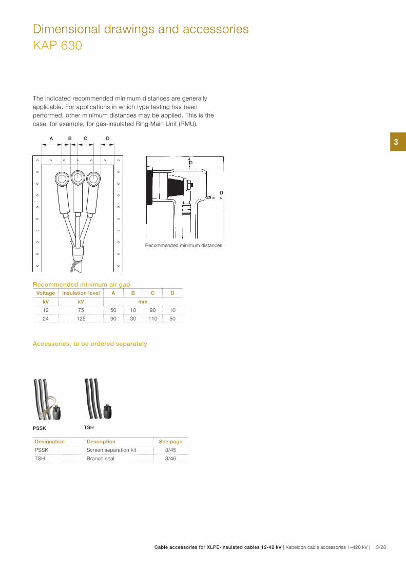
Designation Description See page
PSSK Screen separation kit 3/45
TSH Branch seal 3/46
Dimensional drawings and accessories
KAP 630
Recommended minimum air gap
Voltage Insulation level A B C D
kV kV mm
12 75 50 10 90 10
24 125 90 30 110 50
A B C D
D
D
The indicated recommended minimum distances are generally
applicable. For applications in which type testing has been
performed, other minimum distances may be applied. This is the
case, for example, for gas-insulated Ring Main Unit (RMU).
Recommended minimum distances
PSSK TSH
Accessories, to be ordered separately
3
Cable accessories for XLPE-insulated cables 12-42 kV | Kabeldon cable accessories 1–420 kV | 3/28
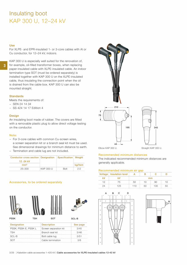
Use
For XLPE- and EPR-insulated 1- or 3-core cables with Al or
Cu conductor, for 12–24 kV, indoors.
KAP 300 U is especially well suited for the renovation of,
for example, oil-filled transformer boxes, when replacing
paper-insulated cable with XLPE-insulated cable. An indoor
termination type SOT (must be ordered separately) is
installed together with KAP 300 U on the XLPE-insulated
cable, thus insulating the connection point when the oil
is drained from the cable box. KAP 300 U can also be
mounted straight.
Standards
Meets the requirements of:
− SEN 24 14 34
− SS 424 14 17 Edition 4
Design
An insulating boot made of rubber. The covers are fitted
with a removable plastic plug to allow direct voltage testing
on the conductor.
Note:
− For 3-core cables with common Cu-screen wires,
a screen separation kit or a branch seal kit must be used.
See dimensional drawings for minimum distance to earth.
− Termination and cable lug are not included.
Insulating boot
KAP 300 U, 12–24 kV
Conductor cross section
12 -24 kV
Designation Specification Weight
mm² kg/item
25–300 KAP 300-U Bolt 2.0
Designation Description See page
PSSK, PSSK-E, PSSK L Screen separation kit 3/45
TSH Branch seal kit 3/46
SCL-B Bolt cable lug 3/51
SOT Cable termination 3/6
Recommended minimum air gap
Voltage Insulation level A B C D
kV kV mm
12 75 50 10 90 10
24 125 110 50 130 50
Recommended minimum distances
The indicated recommended minimum distances are
generally applicable.
Straight KAP 300 U.
44
195
78
210
345
B
CA DB
Elbow KAP 300 U.
PSSK SCL-BSOT
Accessories, to be ordered separately
TSH
3
3/29 | Kabeldon cable accessories 1–420 kV | Cable accessories for XLPE-insulated cables 12-42 kV
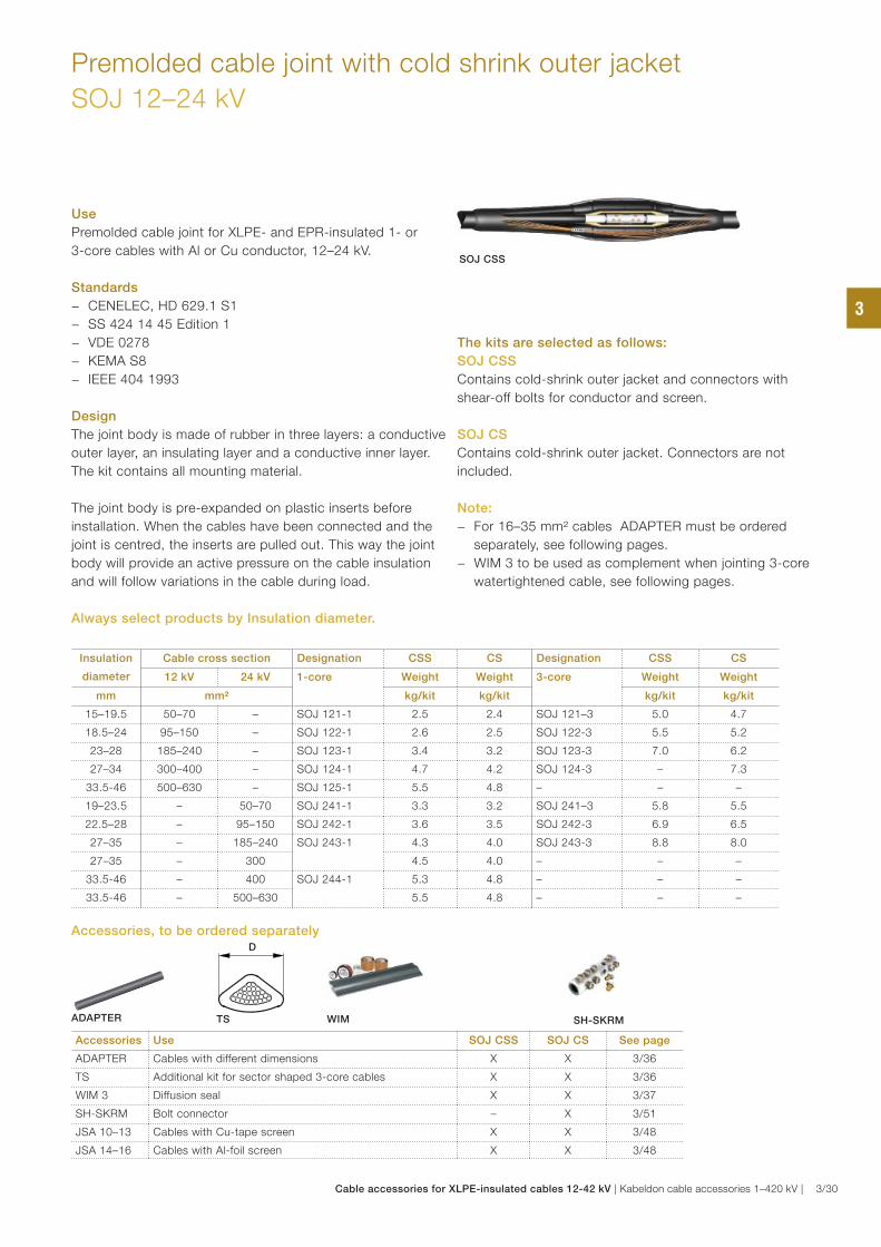
Premolded cable joint with cold shrink outer jacket
SOJ 12–24 kV
Use
Premolded cable joint for XLPE- and EPR-insulated 1- or
3-core cables with Al or Cu conductor, 12–24 kV.
Standards
− CENELEC, HD 629.1 S1
− SS 424 14 45 Edition 1
− VDE 0278
− KEMA S8
− IEEE 404 1993
Design
The joint body is made of rubber in three layers: a conductive
outer layer, an insulating layer and a conductive inner layer.
The kit contains all mounting material.
The joint body is pre-expanded on plastic inserts before
installation. When the cables have been connected and the
joint is centred, the inserts are pulled out. This way the joint
body will provide an active pressure on the cable insulation
and will follow variations in the cable during load.
The kits are selected as follows:
SOJ CSS
Contains cold-shrink outer jacket and connectors with
shear-off bolts for conductor and screen.
SOJ CS
Contains cold-shrink outer jacket. Connectors are not
included.
Note:
− For 16–35 mm² cables ADAPTER must be ordered
separately, see following pages.
− WIM 3 to be used as complement when jointing 3-core
watertightened cable, see following pages.
Accessories Use SOJ CSS SOJ CS See page
ADAPTER Cables with different dimensions X X 3/36
TS Additional kit for sector shaped 3-core cables X X 3/36
WIM 3 Diffusion seal X X 3/37
SH-SKRM Bolt connector – X 3/51
JSA 10–13 Cables with Cu-tape screen X X 3/48
JSA 14–16 Cables with Al-foil screen X X 3/48
Insulation
diameter
Cable cross section Designation CSS CS Designation CSS CS
12 kV 24 kV 1-core Weight Weight 3-core Weight Weight
mm mm² kg/kit kg/kit kg/kit kg/kit
15–19.5 50–70 – SOJ 121-1 2.5 2.4 SOJ 121–3 5.0 4.7
18.5–24 95–150 – SOJ 122-1 2.6 2.5 SOJ 122-3 5.5 5.2
23–28 185–240 – SOJ 123-1 3.4 3.2 SOJ 123-3 7.0 6.2
27–34 300–400 – SOJ 124-1 4.7 4.2 SOJ 124-3 – 7.3
33.5-46 500–630 – SOJ 125-1 5.5 4.8 – – –
19–23.5 – 50–70 SOJ 241-1 3.3 3.2 SOJ 241–3 5.8 5.5
22.5–28 – 95–150 SOJ 242-1 3.6 3.5 SOJ 242-3 6.9 6.5
27–35 – 185–240 SOJ 243-1 4.3 4.0 SOJ 243-3 8.8 8.0
27–35 – 300 4.5 4.0 – – –
33.5-46 – 400 SOJ 244-1 5.3 4.8 – – –
33.5-46 – 500–630 5.5 4.8 – – –
SOJ CSS
D
ADAPTER WIM SH-SKRM
Accessories, to be ordered separately
TS
Always select products by Insulation diameter.
3
Cable accessories for XLPE-insulated cables 12-42 kV | Kabeldon cable accessories 1–420 kV | 3/30
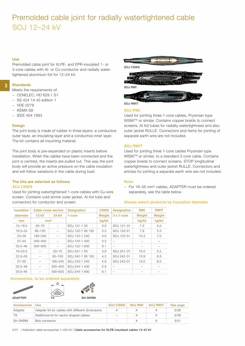
Premolded cable joint for radially watertightened cable
SOJ 12–24 kV
Insulation Cable cross section Designation CSWS Designation RWI RWIT
diameter 12 kV 24 kV 1-core Weight 3 x 1-core Weight Weight
mm mm² kg/kit kg/kit kg/kit
15–19.5 50–70 – SOJ 121-1 50 3.0 SOJ 121–31 7.3 5.0
18.5–24 95–150 – SOJ 122-1 95 150 3.2 SOJ 122-31 7.9 5.5
23–28 185–240 – SOJ 123-1 240 4.0 SOJ 123-31 10.3 7.0
27–34 300–400 – SOJ 124-1 400 5.3 – – –
33.5–46 500–630 – SOJ 125-1 630 6.1 – – –
19–23.5 – 50–70 SOJ 241-1 50 3.9 SOJ 241–31 10.0 5.5
22.5–28 – 95–150 SOJ 242-1 95 150 4.2 SOJ 242-31 10.9 6.5
27–35 – 185–240 SOJ 243-1 240 4.9 SOJ 243-31 13.0 8.0
33.5–46 – 300–400 SOJ 244-1 400 5.9 – – –
33.5–46 – 500–630 SOJ 244-1 630 6.1 – – –
Accessories Use SOJ CSWS SOJ RWI SOJ RWIT See page
Adapter Adapter kit for cables with different dimensions X X X 3/36
TS Additional kit for sector shaped cables – X X 3/36
SH-SKRM Bolt connector – X X 3/51
Use
Premolded cable joint for XLPE- and EPR-insulated 1- or
3-core cables with Al- or Cu-conductor and radially water-
tightened aluminium foil for 12–24 kV.
Standards
Meets the requirements of:
− CENELEC, HD 629.1 S1
− SS 424 14 45 edition 1
− VDE 0278
− KEMA S8
− IEEE 404 1993
Design
The joint body is made of rubber in three layers: a conductive
outer layer, an insulating layer and a conductive inner layer.
The kit contains all mounting material.
The joint body is pre-expanded on plastic inserts before
installation. When the cables have been connected and the
joint is centred, the inserts are pulled out. This way the joint
body will provide an active pressure on the cable insulation
and will follow variations in the cable during load.
The kits are selected as follows:
SOJ CSWS
Used for jointing watertightened 1-core cables with Cu-wire
screen. Contains cold-shrink outer jacket, Al-foil tube and
connectors for conductor and screen.
SOJ RWI
Used for jointing three 1-core cables, Prysmian type
WISKITM or similar. Contains copper braids to connect
screens, Al foil tubes for radially watertightness and also
outer jacket RULLE. Connectors and items for jointing of
separate earth wire are not included.
SOJ RWIT
Used for jointing three 1-core cables Prysmian type
WISKITM or similar, to a standard 3-core cable. Contains
copper braids to connect screens, STOP longitudinal
watertightness and outer jacket RULLE. Connectors and
articles for jointing a separate earth wire are not included.
Note:
− For 16–35 mm² cables, ADAPTER must be ordered
separately, see the table below.
SOJ RWIT
SOJ CSWS
SOJ RWI
D
ADAPTER TS SH-SKRM
Accessories, to be ordered separately
Always select products by Insulation diameter.
3
3/31 | Kabeldon cable accessories 1–420 kV | Cable accessories for XLPE-insulated cables 12-42 kV
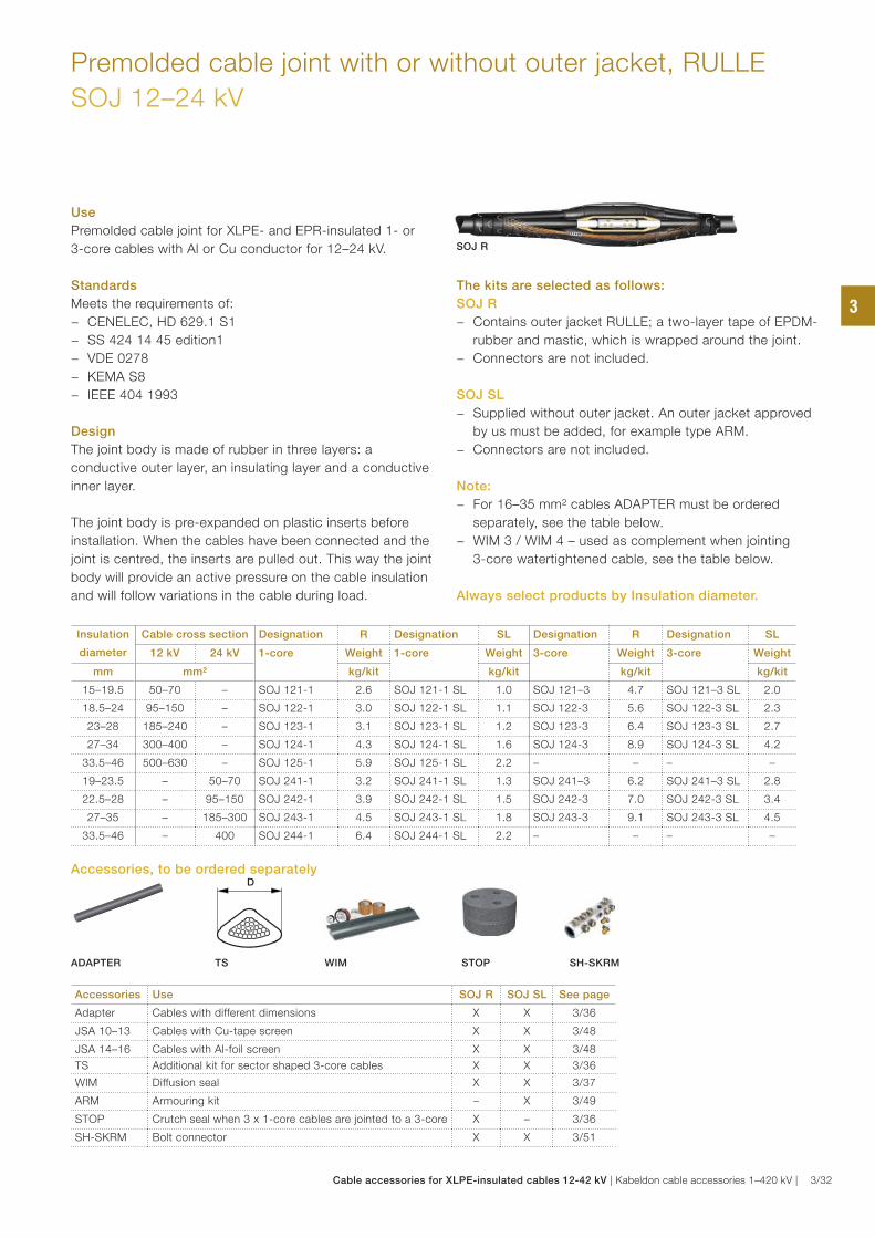
Premolded cable joint with or without outer jacket, RULLE
SOJ 12–24 kV
Use
Premolded cable joint for XLPE- and EPR-insulated 1- or
3-core cables with Al or Cu conductor for 12–24 kV.
Standards
Meets the requirements of:
− CENELEC, HD 629.1 S1
− SS 424 14 45 edition1
− VDE 0278
− KEMA S8
− IEEE 404 1993
Design
The joint body is made of rubber in three layers: a
conductive outer layer, an insulating layer and a conductive
inner layer.
The joint body is pre-expanded on plastic inserts before
installation. When the cables have been connected and the
joint is centred, the inserts are pulled out. This way the joint
body will provide an active pressure on the cable insulation
and will follow variations in the cable during load.
The kits are selected as follows:
SOJ R
− Contains outer jacket RULLE; a two-layer tape of EPDM-
rubber and mastic, which is wrapped around the joint.
− Connectors are not included.
SOJ SL
− Supplied without outer jacket. An outer jacket approved
by us must be added, for example type ARM.
− Connectors are not included.
Note:
− For 16–35 mm² cables ADAPTER must be ordered
separately, see the table below.
− WIM 3 / WIM 4 – used as complement when jointing
3-core watertightened cable, see the table below.
Accessories Use SOJ R SOJ SL See page
Adapter Cables with different dimensions X X 3/36
JSA 10–13 Cables with Cu-tape screen X X 3/48
JSA 14–16 Cables with Al-foil screen X X 3/48
TS Additional kit for sector shaped 3-core cables X X 3/36
WIM Diffusion seal X X 3/37
ARM Armouring kit – X 3/49
STOP Crutch seal when 3 x 1-core cables are jointed to a 3-core X – 3/36
SH-SKRM Bolt connector X X 3/51
Insulation
diameter
Cable cross section Designation R Designation SL Designation R Designation SL
12 kV 24 kV 1-core Weight 1-core Weight 3-core Weight 3-core Weight
mm mm² kg/kit kg/kit kg/kit kg/kit
15–19.5 50–70 – SOJ 121-1 2.6 SOJ 121-1 SL 1.0 SOJ 121–3 4.7 SOJ 121–3 SL 2.0
18.5–24 95–150 – SOJ 122-1 3.0 SOJ 122-1 SL 1.1 SOJ 122-3 5.6 SOJ 122-3 SL 2.3
23–28 185–240 – SOJ 123-1 3.1 SOJ 123-1 SL 1.2 SOJ 123-3 6.4 SOJ 123-3 SL 2.7
27–34 300–400 – SOJ 124-1 4.3 SOJ 124-1 SL 1.6 SOJ 124-3 8.9 SOJ 124-3 SL 4.2
33.5–46 500–630 – SOJ 125-1 5.9 SOJ 125-1 SL 2.2 – – – –
19–23.5 – 50–70 SOJ 241-1 3.2 SOJ 241-1 SL 1.3 SOJ 241–3 6.2 SOJ 241–3 SL 2.8
22.5–28 – 95–150 SOJ 242-1 3.9 SOJ 242-1 SL 1.5 SOJ 242-3 7.0 SOJ 242-3 SL 3.4
27–35 – 185–300 SOJ 243-1 4.5 SOJ 243-1 SL 1.8 SOJ 243-3 9.1 SOJ 243-3 SL 4.5
33.5–46 – 400 SOJ 244-1 6.4 SOJ 244-1 SL 2.2 – – – –
D
ADAPTER TS WIM STOP SH-SKRM
Accessories, to be ordered separately
SOJ R
Always select products by Insulation diameter.
3
Cable accessories for XLPE-insulated cables 12-42 kV | Kabeldon cable accessories 1–420 kV | 3/32
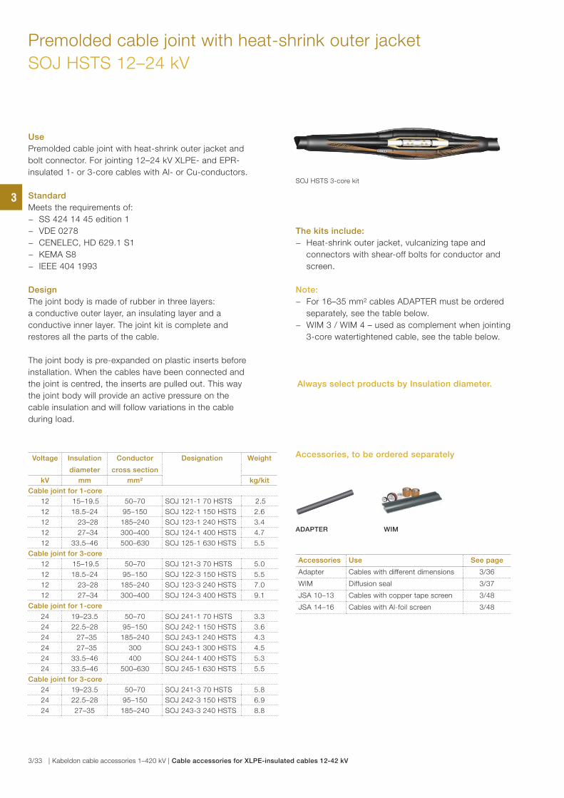
Premolded cable joint with heat-shrink outer jacket
SOJ HSTS 12–24 kV
Use
Premolded cable joint with heat-shrink outer jacket and
bolt connector. For jointing 12–24 kV XLPE- and EPR-
insulated 1- or 3-core cables with Al- or Cu-conductors.
Standard
Meets the requirements of:
− SS 424 14 45 edition 1
− VDE 0278
− CENELEC, HD 629.1 S1
− KEMA S8
− IEEE 404 1993
Design
The joint body is made of rubber in three layers:
a conductive outer layer, an insulating layer and a
conductive inner layer. The joint kit is complete and
restores all the parts of the cable.
The joint body is pre-expanded on plastic inserts before
installation. When the cables have been connected and
the joint is centred, the inserts are pulled out. This way
the joint body will provide an active pressure on the
cable insulation and will follow variations in the cable
during load.
The kits include:
− Heat-shrink outer jacket, vulcanizing tape and
connectors with shear-off bolts for conductor and
screen.
Note:
− For 16–35 mm² cables ADAPTER must be ordered
separately, see the table below.
− WIM 3 / WIM 4 – used as complement when jointing
3-core watertightened cable, see the table below.
Voltage Insulation
diameter
Conductor
cross section
Designation Weight
kV mm mm² kg/kit
Cable joint for 1-core
12 15–19.5 50–70 SOJ 121-1 70 HSTS 2.5
12 18.5–24 95–150 SOJ 122-1 150 HSTS 2.6
12 23–28 185–240 SOJ 123-1 240 HSTS 3.4
12 27–34 300–400 SOJ 124-1 400 HSTS 4.7
12 33.5–46 500–630 SOJ 125-1 630 HSTS 5.5
Cable joint for 3-core
12 15–19.5 50–70 SOJ 121-3 70 HSTS 5.0
12 18.5–24 95–150 SOJ 122-3 150 HSTS 5.5
12 23–28 185–240 SOJ 123-3 240 HSTS 7.0
12 27–34 300–400 SOJ 124-3 400 HSTS 9.1
Cable joint for 1-core
24 19–23.5 50–70 SOJ 241-1 70 HSTS 3.3
24 22.5–28 95–150 SOJ 242-1 150 HSTS 3.6
24 27–35 185–240 SOJ 243-1 240 HSTS 4.3
24 27–35 300 SOJ 243-1 300 HSTS 4.5
24 33.5–46 400 SOJ 244-1 400 HSTS 5.3
24 33.5–46 500–630 SOJ 245-1 630 HSTS 5.5
Cable joint for 3-core
24 19–23.5 50–70 SOJ 241-3 70 HSTS 5.8
24 22.5–28 95–150 SOJ 242-3 150 HSTS 6.9
24 27–35 185–240 SOJ 243-3 240 HSTS 8.8
SOJ HSTS 3-core kit
Accessories Use See page
Adapter Cables with different dimensions 3/36
WIM Diffusion seal 3/37
JSA 10–13 Cables with copper tape screen 3/48
JSA 14–16 Cables with Al-foil screen 3/48
ADAPTER WIM
Accessories, to be ordered separately
Always select products by Insulation diameter.
3
3/33 | Kabeldon cable accessories 1–420 kV | Cable accessories for XLPE-insulated cables 12-42 kV
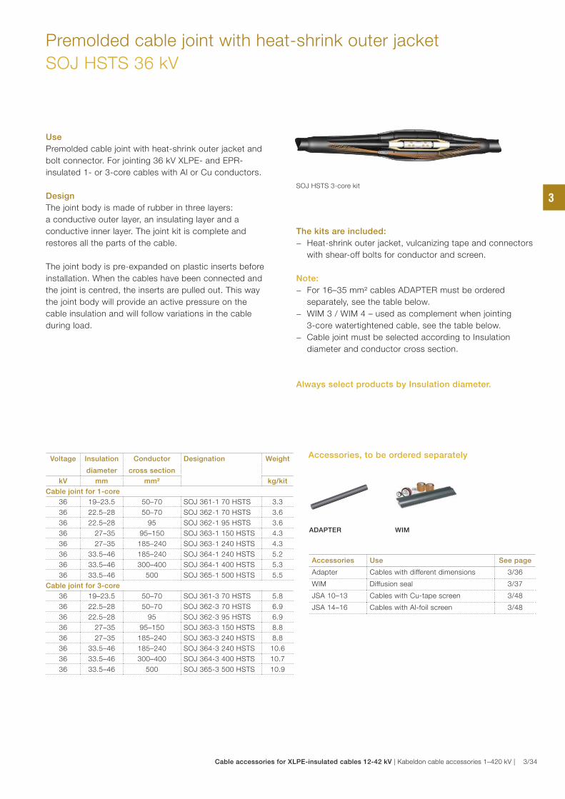
Premolded cable joint with heat-shrink outer jacket
SOJ HSTS 36 kV
Use
Premolded cable joint with heat-shrink outer jacket and
bolt connector. For jointing 36 kV XLPE- and EPR-
insulated 1- or 3-core cables with Al or Cu conductors.
Design
The joint body is made of rubber in three layers:
a conductive outer layer, an insulating layer and a
conductive inner layer. The joint kit is complete and
restores all the parts of the cable.
The joint body is pre-expanded on plastic inserts before
installation. When the cables have been connected and
the joint is centred, the inserts are pulled out. This way
the joint body will provide an active pressure on the
cable insulation and will follow variations in the cable
during load.
The kits are included:
− Heat-shrink outer jacket, vulcanizing tape and connectors
with shear-off bolts for conductor and screen.
Note:
− For 16–35 mm² cables ADAPTER must be ordered
separately, see the table below.
− WIM 3 / WIM 4 – used as complement when jointing
3-core watertightened cable, see the table below.
− Cable joint must be selected according to Insulation
diameter and conductor cross section.
Voltage Insulation
diameter
Conductor
cross section
Designation Weight
kV mm mm² kg/kit
Cable joint for 1-core
36 19–23.5 50–70 SOJ 361-1 70 HSTS 3.3
36 22.5–28 50–70 SOJ 362-1 70 HSTS 3.6
36 22.5–28 95 SOJ 362-1 95 HSTS 3.6
36 27–35 95–150 SOJ 363-1 150 HSTS 4.3
36 27–35 185–240 SOJ 363-1 240 HSTS 4.3
36 33.5–46 185–240 SOJ 364-1 240 HSTS 5.2
36 33.5–46 300–400 SOJ 364-1 400 HSTS 5.3
36 33.5–46 500 SOJ 365-1 500 HSTS 5.5
Cable joint for 3-core
36 19–23.5 50–70 SOJ 361-3 70 HSTS 5.8
36 22.5–28 50–70 SOJ 362-3 70 HSTS 6.9
36 22.5–28 95 SOJ 362-3 95 HSTS 6.9
36 27–35 95–150 SOJ 363-3 150 HSTS 8.8
36 27–35 185–240 SOJ 363-3 240 HSTS 8.8
36 33.5–46 185–240 SOJ 364-3 240 HSTS 10.6
36 33.5–46 300–400 SOJ 364-3 400 HSTS 10.7
36 33.5–46 500 SOJ 365-3 500 HSTS 10.9
SOJ HSTS 3-core kit
Accessories Use See page
Adapter Cables with different dimensions 3/36
WIM Diffusion seal 3/37
JSA 10–13 Cables with Cu-tape screen 3/48
JSA 14–16 Cables with Al-foil screen 3/48
ADAPTER WIM
Accessories, to be ordered separately
Always select products by Insulation diameter.
3
Cable accessories for XLPE-insulated cables 12-42 kV | Kabeldon cable accessories 1–420 kV | 3/34
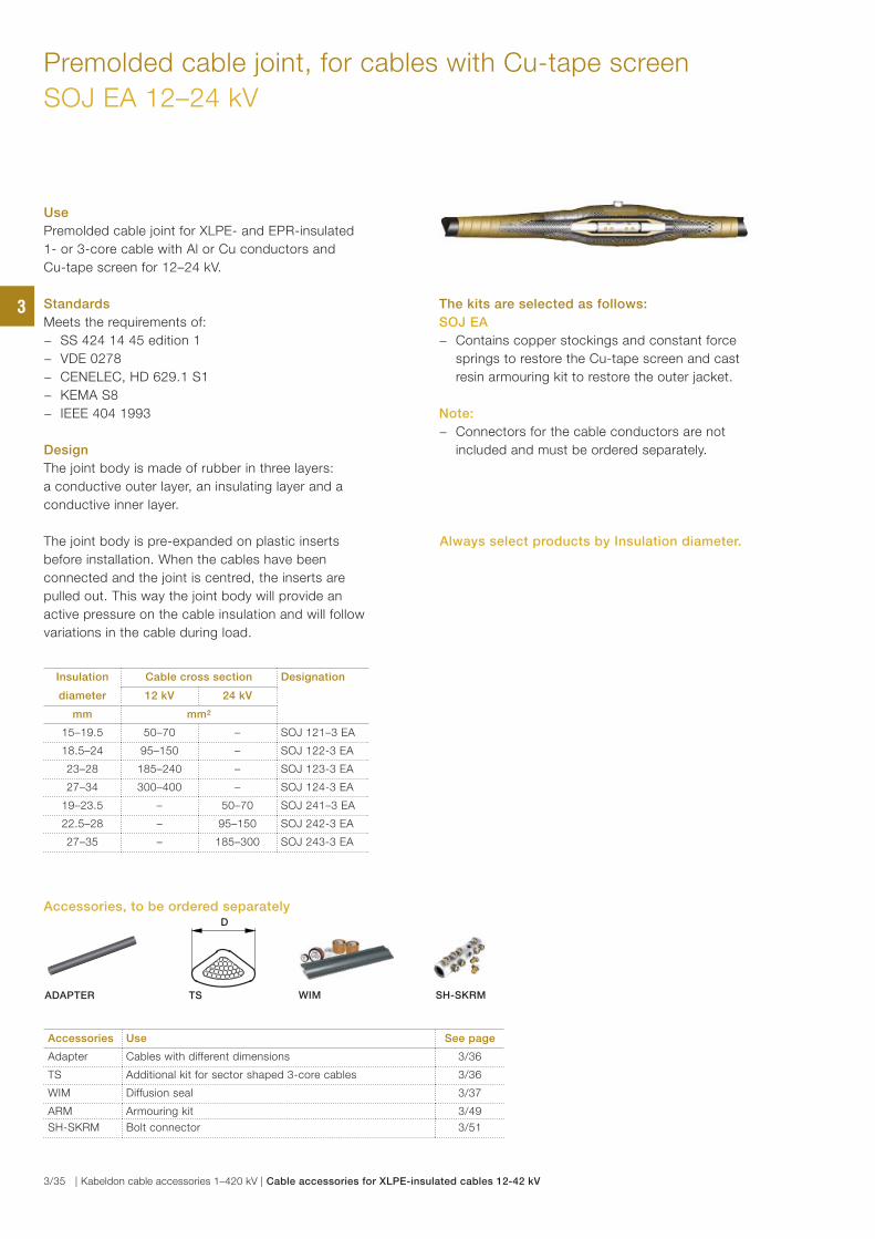
Premolded cable joint, for cables with Cu-tape screen
SOJ EA 12–24 kV
Use
Premolded cable joint for XLPE- and EPR-insulated
1- or 3-core cable with Al or Cu conductors and
Cu-tape screen for 12–24 kV.
Standards
Meets the requirements of:
− SS 424 14 45 edition 1
− VDE 0278
− CENELEC, HD 629.1 S1
− KEMA S8
− IEEE 404 1993
Design
The joint body is made of rubber in three layers:
a conductive outer layer, an insulating layer and a
conductive inner layer.
The joint body is pre-expanded on plastic inserts
before installation. When the cables have been
connected and the joint is centred, the inserts are
pulled out. This way the joint body will provide an
active pressure on the cable insulation and will follow
variations in the cable during load.
The kits are selected as follows:
SOJ EA
− Contains copper stockings and constant force
springs to restore the Cu-tape screen and cast
resin armouring kit to restore the outer jacket.
Note:
− Connectors for the cable conductors are not
included and must be ordered separately.
Accessories Use See page
Adapter Cables with different dimensions 3/36
TS Additional kit for sector shaped 3-core cables 3/36
WIM Diffusion seal 3/37
ARM Armouring kit 3/49
SH-SKRM Bolt connector 3/51
Insulation Cable cross section Designation
diameter 12 kV 24 kV
mm mm²
15–19.5 50–70 – SOJ 121–3 EA
18.5–24 95–150 – SOJ 122-3 EA
23–28 185–240 – SOJ 123-3 EA
27–34 300–400 – SOJ 124-3 EA
19–23.5 – 50–70 SOJ 241–3 EA
22.5–28 – 95–150 SOJ 242-3 EA
27–35 – 185–300 SOJ 243-3 EA
D
ADAPTER TS WIM SH-SKRM
Accessories, to be ordered separately
Always select products by Insulation diameter.
3
3/35 | Kabeldon cable accessories 1–420 kV | Cable accessories for XLPE-insulated cables 12-42 kV
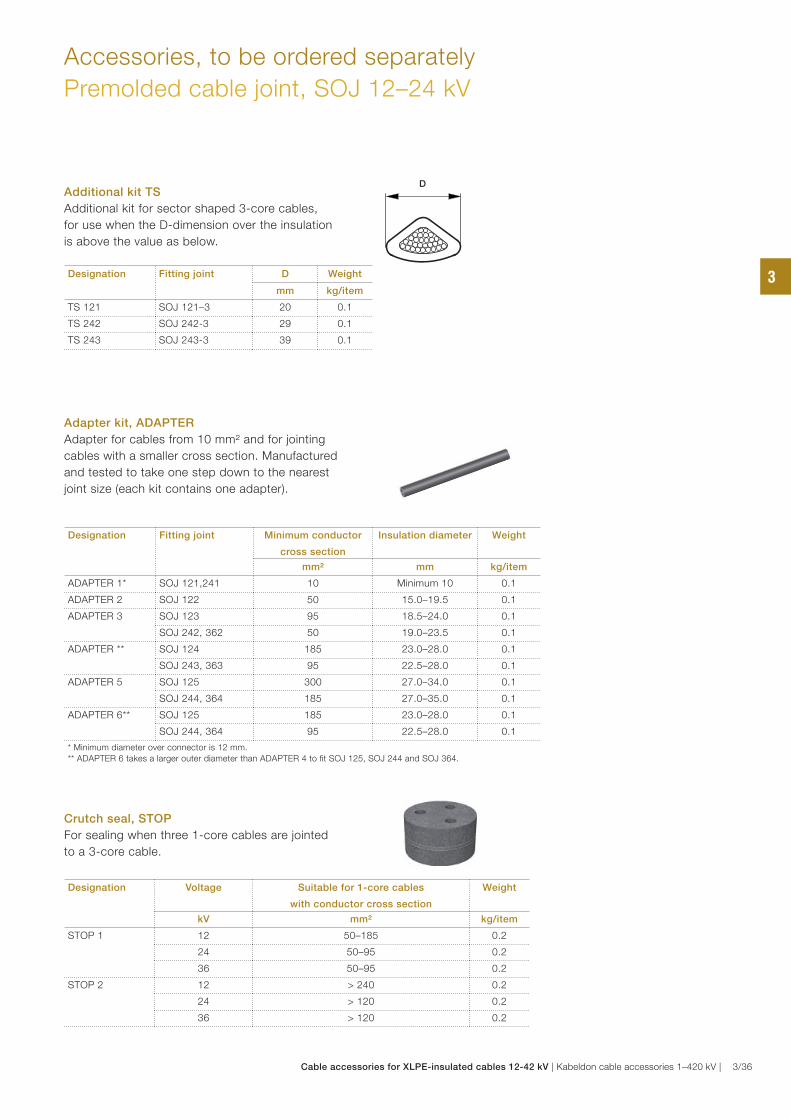
Accessories, to be ordered separately
Premolded cable joint, SOJ 12–24 kV
Additional kit TS
Additional kit for sector shaped 3-core cables,
for use when the D-dimension over the insulation
is above the value as below.
Designation Fitting joint D Weight
mm kg/item
TS 121 SOJ 121–3 20 0.1
TS 242 SOJ 242-3 29 0.1
TS 243 SOJ 243-3 39 0.1
D
Adapter kit, ADAPTER
Adapter for cables from 10 mm² and for jointing
cables with a smaller cross section. Manufactured
and tested to take one step down to the nearest
joint size (each kit contains one adapter).
Crutch seal, STOP
For sealing when three 1-core cables are jointed
to a 3-core cable.
Designation Fitting joint Minimum conductor
cross section
Insulation diameter Weight
mm² mm kg/item
ADAPTER 1* SOJ 121,241 10 Minimum 10 0.1
ADAPTER 2 SOJ 122 50 15.0–19.5 0.1
ADAPTER 3 SOJ 123 95 18.5–24.0 0.1
SOJ 242, 362 50 19.0–23.5 0.1
ADAPTER ** SOJ 124 185 23.0–28.0 0.1
SOJ 243, 363 95 22.5–28.0 0.1
ADAPTER 5 SOJ 125 300 27.0–34.0 0.1
SOJ 244, 364 185 27.0–35.0 0.1
ADAPTER 6** SOJ 125 185 23.0–28.0 0.1
SOJ 244, 364 95 22.5–28.0 0.1
* Minimum diameter over connector is 12 mm.
** ADAPTER 6 takes a larger outer diameter than ADAPTER 4 to fi t SOJ 125, SOJ 244 and SOJ 364.
Designation Voltage Suitable for 1-core cables
with conductor cross section
Weight
kV mm² kg/item
STOP 1 12 50–185 0.2
24 50–95 0.2
36 50–95 0.2
STOP 2 12 > 240 0.2
24 > 120 0.2
36 > 120 0.2
3
Cable accessories for XLPE-insulated cables 12-42 kV | Kabeldon cable accessories 1–420 kV | 3/36
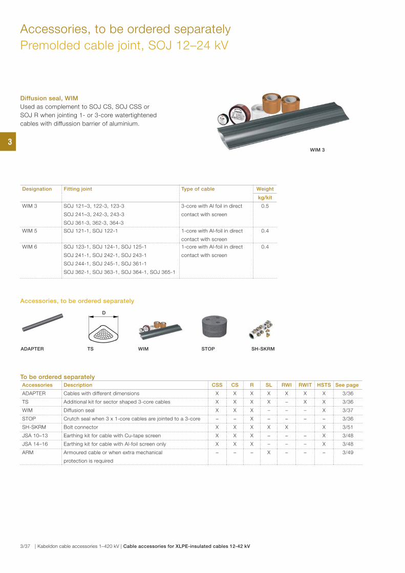
Accessories, to be ordered separately
Premolded cable joint, SOJ 12–24 kV
Diffusion seal, WIM
Used as complement to SOJ CS, SOJ CSS or
SOJ R when jointing 1- or 3-core watertightened
cables with diffussion barrier of aluminium.
Designation Fitting joint Type of cable Weight
kg/kit
WIM 3 SOJ 121–3, 122-3, 123-3
SOJ 241–3, 242-3, 243-3
SOJ 361-3, 362-3, 364-3
3-core with Al foil in direct
contact with screen
0.5
WIM 5 SOJ 121-1, SOJ 122-1 1-core with Al-foil in direct
contact with screen
0.4
WIM 6 SOJ 123-1, SOJ 124-1, SOJ 125-1
SOJ 241-1, SOJ 242-1, SOJ 243-1
SOJ 244-1, SOJ 245-1, SOJ 361-1
SOJ 362-1, SOJ 363-1, SOJ 364-1, SOJ 365-1
1-core with Al-foil in direct
contact with screen
0.4
WIM 3
To be ordered separately
Accessories Description CSS CS R SL RWI RWIT HSTS See page
ADAPTER Cables with different dimensions X X X X X X X 3/36
TS Additional kit for sector shaped 3-core cables X X X X – X X 3/36
WIM Diffusion seal X X X – – – X 3/37
STOP Crutch seal when 3 x 1-core cables are jointed to a 3-core – – X – – – – 3/36
SH-SKRM Bolt connector X X X X X X 3/51
JSA 10–13 Earthing kit for cable with Cu-tape screen X X X – – – X 3/48
JSA 14–16 Earthing kit for cable with Al-foil screen only X X X – – – X 3/48
ARM Armoured cable or when extra mechanical
protection is required
– – – X – – – 3/49
D
ADAPTER TS WIM STOP SH-SKRM
Accessories, to be ordered separately
3
3/37 | Kabeldon cable accessories 1–420 kV | Cable accessories for XLPE-insulated cables 12-42 kV
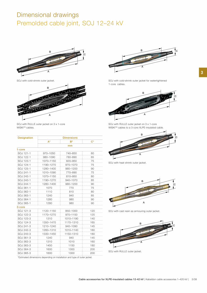
Dimensional drawings
Premolded cable joint, SOJ 12–24 kV
SOJ with cold-shrink outer jacket.
SOJ with RULLE outer jacket on 3 x 1-core
WISKITM cables.
SOJ with RULLE outer jacket.
SOJ with cold-shrink outer jacket for watertightened
1-core cables.
SOJ with RULLE outer jacket on 3 x 1-core
WISKITM cables to a 3-core XLPE-insulated cable.
SOJ with cast resin as armouring outer jacket.
B
A
C
B
A
C
B
A
B
C
A
B
A
C
B
C
A
Designation Dimensions
A* B* C*
mm
1-core
SOJ 121-1 970–1050 740–850 60
SOJ 122-1 980–1090 780–890 65
SOJ 123-1 1070–1150 820–950 75
SOJ 124-1 1190–1270 970–1070 75
SOJ 125-1 1280–1400 980–1200 90
SOJ 241-1 1010–1090 770–890 75
SOJ 242-1 1070–1150 810–950 80
SOJ 243-1 1190–1270 940–1070 85
SOJ 244-1 1280–1400 980–1200 90
SOJ 361-1 1070 770 75
SOJ 362-1 1110 810 80
SOJ 363-1 1240 940 85
SOJ 364-1 1280 980 90
SOJ 365-1 1280 980 90
3-core
SOJ 121-3 1120–1150 850–1000 120
SOJ 122-3 1170–1270 970–1150 125
SOJ 123-3 1310 1010–1190 140
SOJ 124-3 1350–1470 1170–1310 165
SOJ 241-3 1210–1240 940–1090 145
SOJ 242-3 1260–1310 1010–1140 160
SOJ 243-3 1330–1450 1150–1310 180
SOJ 361-3 1240 940 145
SOJ 362-3 1310 1010 160
SOJ 363-3 1450 1150 180
SOJ 364-3 1600 1300 200
SOJ 365-3 1600 1300 200
*Estimated dimensions depending on installation and type of outer jacket.
SOJ with heat-shrink outer jacket.
B
A
C
3
Cable accessories for XLPE-insulated cables 12-42 kV | Kabeldon cable accessories 1–420 kV | 3/38
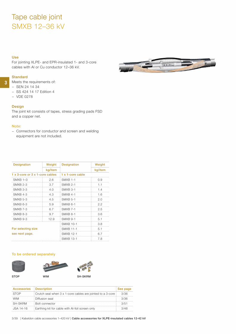
Tape cable joint
SMXB 12–36 kV
Use
For jointing XLPE- and EPR-insulated 1- and 3-core
cables with Al or Cu conductor 12–36 kV.
Standard
Meets the requirements of:
− SEN 24 14 34
− SS 424 14 17 Edition 4
− VDE 0278
Design
The joint kit consists of tapes, stress grading pads FSD
and a copper net.
Note:
− Connectors for conductor and screen and welding
equipment are not included.
Designation Weight Designation Weight
kg/item kg/item
1 x 3-core or 3 x 1-core cables 1 x 1-core cable
SMXB 1–3 2.6 SMXB 1-1 0.9
SMXB 2-3 3.7 SMXB 2-1 1.1
SMXB 3-3 4.0 SMXB 3-1 1.4
SMXB 4-3 4.3 SMXB 4-1 1.6
SMXB 5-3 4.5 SMXB 5-1 2.0
SMXB 6-3 5.9 SMXB 6-1 2.2
SMXB 7-3 6.7 SMXB 7-1 2.5
SMXB 8-3 9.7 SMXB 8-1 3.6
SMXB 9-3 12.9 SMXB 9-1 5.1
For selecting size
see next page.
SMXB 10-1 3.8
SMXB 11-1 5.1
SMXB 12-1 6.7
SMXB 13-1 7.8
Accessories Description See page
STOP Crutch seal when 3 x 1-core cables are jointed to a 3-core 3/36
WIM Diffusion seal 3/36
SH-SKRM Bolt connector 3/51
JSA 14-16 Earthing kit for cable with Al-foil screen only 3/48
To be ordered separately
STOP WIM SH-SKRM
3
3/39 | Kabeldon cable accessories 1–420 kV | Cable accessories for XLPE-insulated cables 12-42 kV
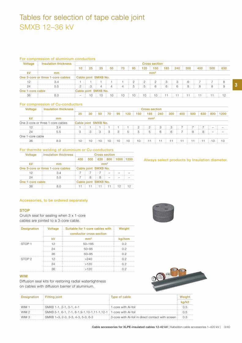
Tables for selection of tape cable joint
SMXB 12–36 kV
For compression of aluminium conductors
Voltage Insulation thickness Cross section
10 25 35 50 70 95 120 150 185 240 300 400 500 630
kV mm mm²
One 3-core or three 1-core cables Cable joint SMXB No.
12 3.4 1 1 1 1 1 2 2 2 3 3 6 7 7 8
24 5.5 2 3 4 4 4 5 5 6 6 6 8 8 8 9
One 1-core cable Cable joint SMXB No.
36 8.0 – 10 10 10 10 10 10 10 11 11 11 11 11 12
For compression of Cu-conductors
Voltage Insulation thickness Cross section
25 30 50 70 95 120 150 185 240 300 400 500 630 800 1200
kV mm mm²
One 3-core or three 1-core cables Cable joint SMXB No.
12 3.4 1 1 1 1 1 1 2 2 3 3 7 7 7 – –
24 5.5 3 3 3 3 3 5 5 5 6 6 7 8 8 – –
One 1-core cable
36 8.0 10 10 10 10 10 10 10 11 11 11 11 11 11 13 13
For thermite welding of aluminium or Cu-conductors
Voltage Insulation thickness Cross section
400 500 630 800 1000 1200
kV mm mm²
One 3-core or three 1-core cables Cable joint SMXB No.
12 3.4 7 7 7 – – –
24 5.5 7 8 8 – – –
One 1-core cable Cable joint SMXB No.
36 8.0 11 11 11 11 12 12
STOP
Crutch seal for sealing when 3 x 1-core
cables are jointed to a 3-core cable.
Designation Voltage Suitable for 1-core cables with
conductor cross section
Weight
kV mm² kg/item
STOP 1 12 50–185 0.2
24 50–95 0.2
36 50–95 0.2
STOP 2 12 >240 0.2
24 >120 0.2
36 >120 0.2
WIM
Diffusion seal kits for restoring radial watertightness
on cables with diffusion barrier of aluminium.
Designation Fitting joint Type of cable Weight
kg/kit
WIM 1 SMXB 1-1, 2-1, 3-1, 4-1 1-core with Al-foil 0.5
WIM 2 SMXB 5-1, 6-1, 7-1, 8-1,9-1,10-1,11-1,12-1 1-core with Al-foil 0.5
WIM 3 SMXB 1–3, 2-3, 3-3, 4-3, 5-3, 6-3 3-core with Al-foil in direct contact with screen 0.3
Accessories, to be ordered separately
Always select products by Insulation diameter.
3
Cable accessories for XLPE-insulated cables 12-42 kV | Kabeldon cable accessories 1–420 kV | 3/40
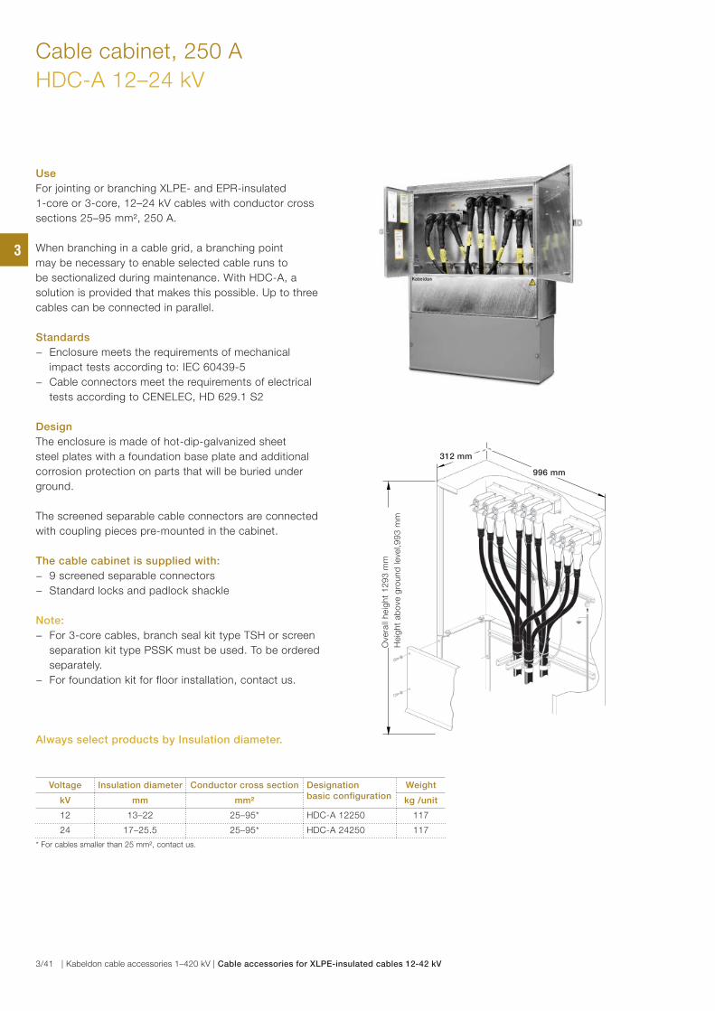
Cable cabinet, 250 A
HDC-A 12–24 kV
Use
For jointing or branching XLPE- and EPR-insulated
1-core or 3-core, 12–24 kV cables with conductor cross
sections 25–95 mm², 250 A.
When branching in a cable grid, a branching point
may be necessary to enable selected cable runs to
be sectionalized during maintenance. With HDC-A, a
solution is provided that makes this possible. Up to three
cables can be connected in parallel.
Standards
− Enclosure meets the requirements of mechanical
impact tests according to: IEC 60439-5
− Cable connectors meet the requirements of electrical
tests according to CENELEC, HD 629.1 S2
Design
The enclosure is made of hot-dip-galvanized sheet
steel plates with a foundation base plate and additional
corrosion protection on parts that will be buried under
ground.
The screened separable cable connectors are connected
with coupling pieces pre-mounted in the cabinet.
The cable cabinet is supplied with:
− 9 screened separable connectors
− Standard locks and padlock shackle
Note:
− For 3-core cables, branch seal kit type TSH or screen
separation kit type PSSK must be used. To be ordered
separately.
− For foundation kit for floor installation, contact us.
Voltage Insulation diameter Conductor cross section Designation basic configuration
Weight
kV mm mm² kg /unit
12 13–22 25–95* HDC-A 12250 117
24 17–25.5 25–95* HDC-A 24250 117
* For cables smaller than 25 mm², contact us.
Ove
rall
heig
ht
12
93
mm
Heig
ht
ab
ove
gro
un
d leve
l,9
93
mm
312 mm
996 mm
Always select products by Insulation diameter.
3
3/41 | Kabeldon cable accessories 1–420 kV | Cable accessories for XLPE-insulated cables 12-42 kV
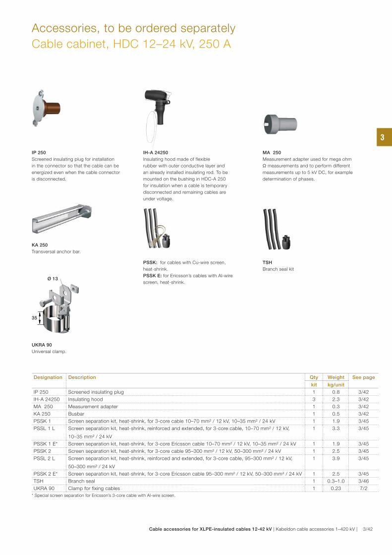
Accessories, to be ordered separately
Cable cabinet, HDC 12–24 kV, 250 A
Designation Description Qty Weight See page
kit kg/unit
IP 250 Screened insulating plug 1 0.8 3/42
IH-A 24250 Insulating hood 3 2.3 3/42
MA 250 Measurement adapter 1 0.3 3/42
KA 250 Busbar 1 0.5 3/42
PSSK 1 Screen separation kit, heat-shrink, for 3-core cable 10–70 mm² / 12 kV, 10–35 mm² / 24 kV 1 1.9 3/45
PSSL 1 L Screen separation kit, heat-shrink, reinforced and extended, for 3-core cable, 10–70 mm² / 12 kV,
10–35 mm² / 24 kV
1 3.3 3/45
PSSK 1 E* Screen separation kit, heat-shrink, for 3-core Ericsson cable 10–70 mm² / 12 kV, 10–35 mm² / 24 kV 1 1.9 3/45
PSSK 2 Screen separation kit, heat-shrink, for 3-core cable 95–300 mm² / 12 kV, 50–300 mm² / 24 kV 1 2.5 3/45
PSSL 2 L Screen separation kit, heat-shrink, reinforced and extended, for 3-core cable, 95–300 mm² / 12 kV,
50–300 mm² / 24 kV
1 3.9 3/45
PSSK 2 E* Screen separation kit, heat-shrink, for 3-core Ericsson cable 95–300 mm² / 12 kV, 50–300 mm² / 24 kV 1 2.5 3/45
TSH Branch seal 1 0.3–1.0 3/46
UKRA 90 Clamp for fixing cables 1 0.23 7/2
* Special screen separation for Ericsson’s 3-core cable with Al-wire screen.
IP 250
Screened insulating plug for installation
in the connector so that the cable can be
energized even when the cable connector
is disconnected.
IH-A 24250
Insulating hood made of flexible
rubber with outer conductive layer and
an already installed insulating rod. To be
mounted on the bushing in HDC-A 250
for insulation when a cable is temporary
disconnected and remaining cables are
under voltage.
MA 250
Measurement adapter used for mega ohm
Ω measurements and to perform different
measurements up to 5 kV DC, for example
determination of phases.
UKRA 90 Universal clamp.
KA 250
Transversal anchor bar.
Ø 13
35
PSSK: for cables with Cu-wire screen,
heat-shrink.
PSSK E: for Ericsson’s cables with Al-wire
screen, heat-shrink.
TSH
Branch seal kit
3
Cable accessories for XLPE-insulated cables 12-42 kV | Kabeldon cable accessories 1–420 kV | 3/42
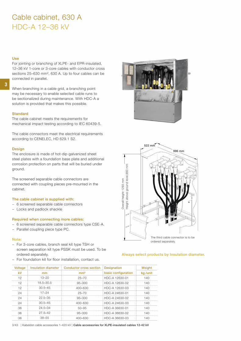
Cable cabinet, 630 A
HDC-A 12–36 kV
Use
For jointing or branching of XLPE- and EPR-insulated,
12–36 kV 1-core or 3-core cables with conductor cross
sections 25–630 mm², 630 A. Up to four cables can be
connected in parallel.
When branching in a cable grid, a branching point
may be necessary to enable selected cable runs to
be sectionalized during maintenance. With HDC-A a
solution is provided that makes this possible.
Standard
The cable cabinet meets the requirements for
mechanical impact testing according to IEC 60439-5.
The cable connectors meet the electrical requirements
according to CENELEC, HD 629.1 S2.
Design
The enclosure is made of hot-dip-galvanized sheet
steel plates with a foundation base plate and additional
corrosion protection on parts that will be buried under
ground.
The screened separable cable connectors are
connected with coupling pieces pre-mounted in the
cabinet.
The cable cabinet is supplied with:
− 6 screened separable cable connectors
− Locks and padlock shackle
Required when connecting more cables:
− 6 screened separable cable connectors type CSE-A.
− Parallel coupling piece type PC.
Note:
− For 3-core cables, branch seal kit type TSH or
screen separation kit type PSSK must be used. To be
ordered separately.
− For foundation kit for floor installation, contact us.
Voltage Insulation diameter Conductor cross section Designation
basic configuration
Weight
kV mm mm² kg /unit
12 13–20 25–70 HDC-A 12630-01 140
12 18.5–30.5 95–300 HDC-A 12630-02 140
12 30.5–45 400–630 HDC-A 12630-03 140
24 17–24 25–70 HDC-A 24630-01 140
24 22.5–35 95–300 HDC-A 24630-02 140
24 30.5–45 400–630 HDC-A 24630-03 140
36 24.5–34 50–95 HDC-A 36630-01 140
36 27.5–42 95–300 HDC-A 36630-02 140
36 38–55 400–630 HDC-A 36630-03 140
Ove
rall
heig
ht
12
93
mm
Heig
ht
ab
ove
gro
un
d leve
l,9
93
mm
522 mm
996 mm
The third cable connector is to be
ordered separately.
Always select products by Insulation diameter.
3
3/43 | Kabeldon cable accessories 1–420 kV | Cable accessories for XLPE-insulated cables 12-42 kV
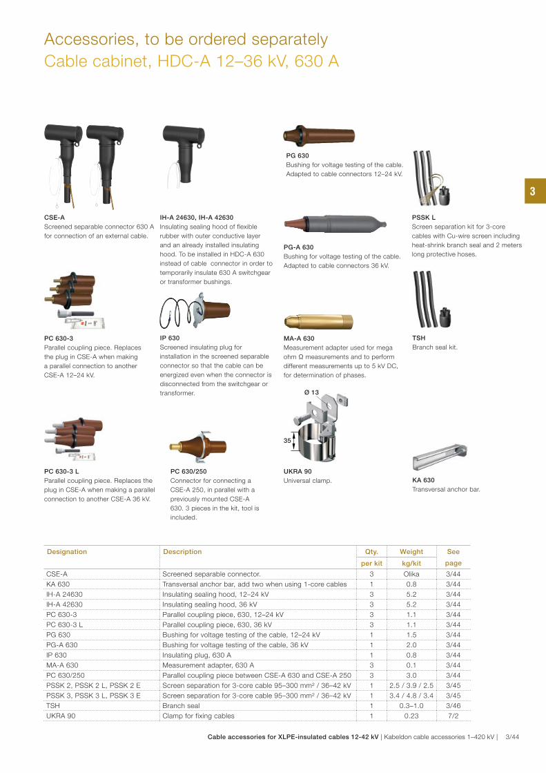
Accessories, to be ordered separately
Cable cabinet, HDC-A 12–36 kV, 630 A
CSE-A
Screened separable connector 630 A
for connection of an external cable.
PC 630-3
Parallel coupling piece. Replaces
the plug in CSE-A when making
a parallel connection to another
CSE-A 12–24 kV.
PC 630-3 L
Parallel coupling piece. Replaces the
plug in CSE-A when making a parallel
connection to another CSE-A 36 kV.
PC 630/250
Connector for connecting a
CSE-A 250, in parallel with a
previously mounted CSE-A
630. 3 pieces in the kit, tool is
included.
MA-A 630
Measurement adapter used for mega
ohm Ω measurements and to perform
different measurements up to 5 kV DC,
for determination of phases.
IH-A 24630, IH-A 42630
Insulating sealing hood of flexible
rubber with outer conductive layer
and an already installed insulating
hood. To be installed in HDC-A 630
instead of cable connector in order to
temporarily insulate 630 A switchgear
or transformer bushings.
Designation Description Qty. Weight See
pageper kit kg/kit
CSE-A Screened separable connector. 3 Olika 3/44
KA 630 Transversal anchor bar, add two when using 1-core cables 1 0.8 3/44
IH-A 24630 Insulating sealing hood, 12–24 kV 3 5.2 3/44
IH-A 42630 Insulating sealing hood, 36 kV 3 5.2 3/44
PC 630-3 Parallel coupling piece, 630, 12–24 kV 3 1.1 3/44
PC 630-3 L Parallel coupling piece, 630, 36 kV 3 1.1 3/44
PG 630 Bushing for voltage testing of the cable, 12–24 kV 1 1.5 3/44
PG-A 630 Bushing for voltage testing of the cable, 36 kV 1 2.0 3/44
IP 630 Insulating plug, 630 A 1 0.8 3/44
MA-A 630 Measurement adapter, 630 A 3 0.1 3/44
PC 630/250 Parallel coupling piece between CSE-A 630 and CSE-A 250 3 3.0 3/44
PSSK 2, PSSK 2 L, PSSK 2 E Screen separation for 3-core cable 95–300 mm² / 36–42 kV 1 2.5 / 3.9 / 2.5 3/45
PSSK 3, PSSK 3 L, PSSK 3 E Screen separation for 3-core cable 95–300 mm² / 36–42 kV 1 3.4 / 4.8 / 3.4 3/45
TSH Branch seal 1 0.3–1.0 3/46
UKRA 90 Clamp for fixing cables 1 0.23 7/2
Ø 13
35
KA 630
Transversal anchor bar.
PG 630
Bushing for voltage testing of the cable.
Adapted to cable connectors 12–24 kV.
IP 630
Screened insulating plug for
installation in the screened separable
connector so that the cable can be
energized even when the connector is
disconnected from the switchgear or
transformer.
UKRA 90
Universal clamp.
TSH
Branch seal kit.
PG-A 630
Bushing for voltage testing of the cable.
Adapted to cable connectors 36 kV.
PSSK L
Screen separation kit for 3-core
cables with Cu-wire screen including
heat-shrink branch seal and 2 meters
long protective hoses.
3
Cable accessories for XLPE-insulated cables 12-42 kV | Kabeldon cable accessories 1–420 kV | 3/44
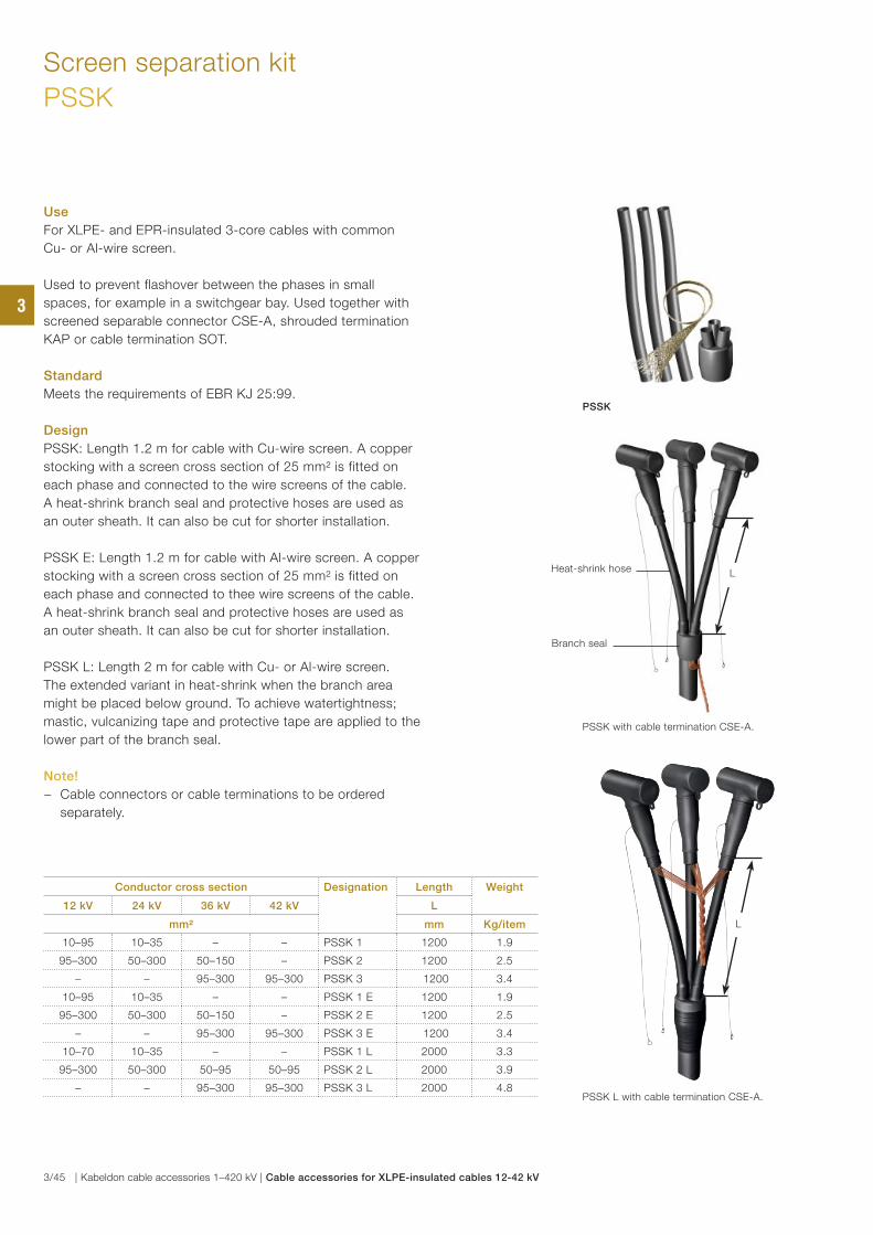
Screen separation kit
PSSK
Use
For XLPE- and EPR-insulated 3-core cables with common
Cu- or Al-wire screen.
Used to prevent flashover between the phases in small
spaces, for example in a switchgear bay. Used together with
screened separable connector CSE-A, shrouded termination
KAP or cable termination SOT.
Standard
Meets the requirements of EBR KJ 25:99.
Design
PSSK: Length 1.2 m for cable with Cu-wire screen. A copper
stocking with a screen cross section of 25 mm² is fitted on
each phase and connected to the wire screens of the cable.
A heat-shrink branch seal and protective hoses are used as
an outer sheath. It can also be cut for shorter installation.
PSSK E: Length 1.2 m for cable with Al-wire screen. A copper
stocking with a screen cross section of 25 mm² is fitted on
each phase and connected to thee wire screens of the cable.
A heat-shrink branch seal and protective hoses are used as
an outer sheath. It can also be cut for shorter installation.
PSSK L: Length 2 m for cable with Cu- or Al-wire screen.
The extended variant in heat-shrink when the branch area might be placed below ground. To achieve watertightness;
mastic, vulcanizing tape and protective tape are applied to the
lower part of the branch seal.
Note!
− Cable connectors or cable terminations to be ordered
separately.
Conductor cross section Designation Length Weight
12 kV 24 kV 36 kV 42 kV L
mm² mm Kg/item
10–95 10–35 – – PSSK 1 1200 1.9
95–300 50–300 50–150 – PSSK 2 1200 2.5
– – 95–300 95–300 PSSK 3 1200 3.4
10–95 10–35 – – PSSK 1 E 1200 1.9
95–300 50–300 50–150 – PSSK 2 E 1200 2.5
– – 95–300 95–300 PSSK 3 E 1200 3.4
10–70 10–35 – – PSSK 1 L 2000 3.3
95–300 50–300 50–95 50–95 PSSK 2 L 2000 3.9
– – 95–300 95–300 PSSK 3 L 2000 4.8
L
PSSK L with cable termination CSE-A.
PSSK with cable termination CSE-A.
PSSK
L
Branch seal
Heat-shrink hose
3
3/45 | Kabeldon cable accessories 1–420 kV | Cable accessories for XLPE-insulated cables 12-42 kV
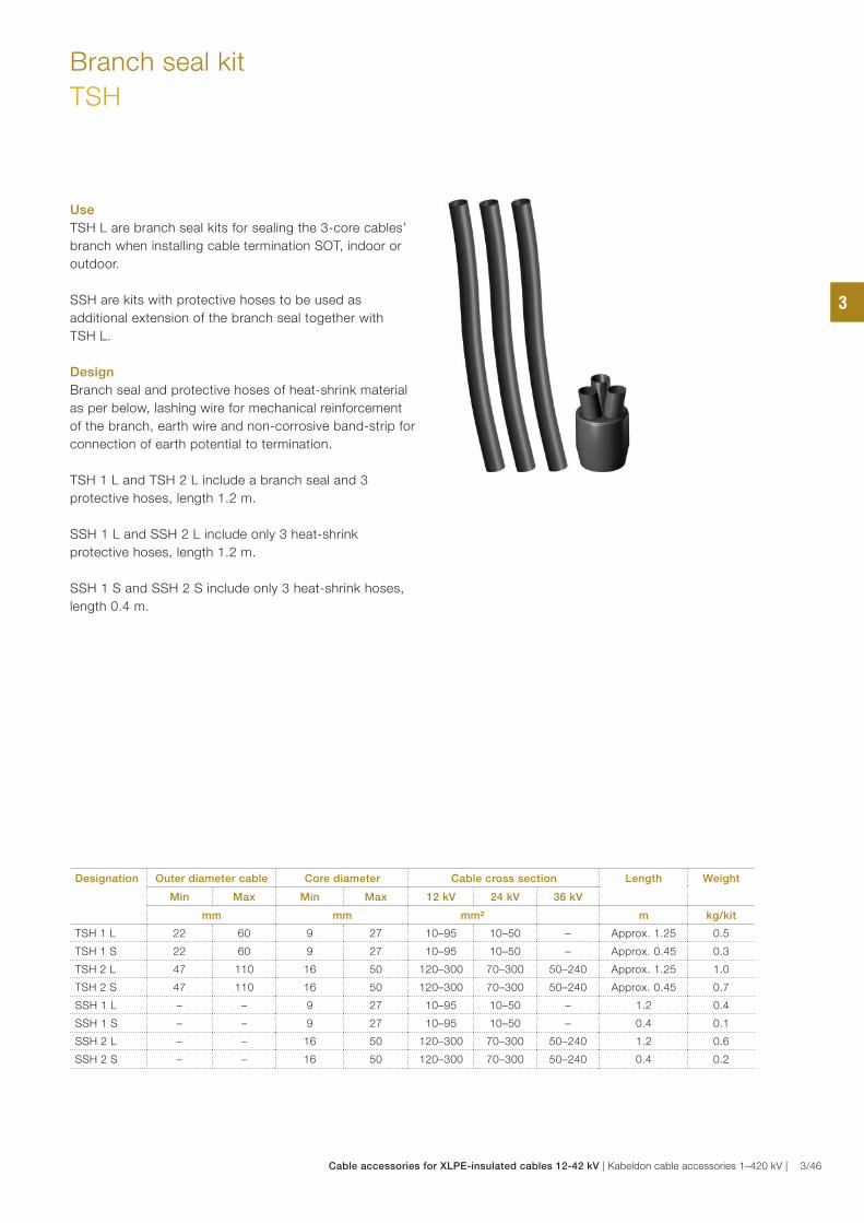
Use
TSH L are branch seal kits for sealing the 3-core cables’
branch when installing cable termination SOT, indoor or
outdoor.
SSH are kits with protective hoses to be used as
additional extension of the branch seal together with
TSH L.
Design
Branch seal and protective hoses of heat-shrink material
as per below, lashing wire for mechanical reinforcement
of the branch, earth wire and non-corrosive band-strip for
connection of earth potential to termination.
TSH 1 L and TSH 2 L include a branch seal and 3
protective hoses, length 1.2 m.
SSH 1 L and SSH 2 L include only 3 heat-shrink
protective hoses, length 1.2 m.
SSH 1 S and SSH 2 S include only 3 heat-shrink hoses,
length 0.4 m.
Branch seal kit
TSH
Designation Outer diameter cable Core diameter Cable cross section Length Weight
Min Max Min Max 12 kV 24 kV 36 kV
mm mm mm² m kg/kit
TSH 1 L 22 60 9 27 10–95 10–50 – Approx. 1.25 0.5
TSH 1 S 22 60 9 27 10–95 10–50 – Approx. 0.45 0.3
TSH 2 L 47 110 16 50 120–300 70–300 50–240 Approx. 1.25 1.0
TSH 2 S 47 110 16 50 120–300 70–300 50–240 Approx. 0.45 0.7
SSH 1 L – – 9 27 10–95 10–50 – 1.2 0.4
SSH 1 S – – 9 27 10–95 10–50 – 0.4 0.1
SSH 2 L – – 16 50 120–300 70–300 50–240 1.2 0.6
SSH 2 S – – 16 50 120–300 70–300 50–240 0.4 0.2
3
Cable accessories for XLPE-insulated cables 12-42 kV | Kabeldon cable accessories 1–420 kV | 3/46
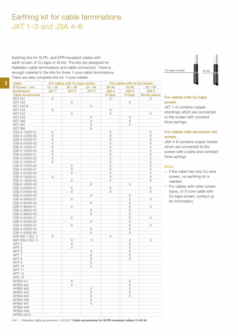
Earthing kit for cable terminations
JXT 1–3 and JSA 4–6
Earthing kits for XLPE- and EPR-insulated cables with
earth screen of Cu-tape or Al-foil. The kits are designed for
Kabeldon cable terminations and cable connectors. There is
enough material in the kits for three 1-core cable terminations.
There are also complete kits for 1-core cables.
Cable For cables with Cu-tape screen For cables with Al-foil screen
Ø Screen mm 15 – 25 20 – 30 31 – 50 20-30 25-40 20 – 30
Earthing kit JXT 1 JXT 2 JXT 3 JSA 4 JSA 5 JSA 6
Cable accessories IV-tape IV-tape Shrink sleeveSOT 241 X X XSOT 242 X XSOT 242 B XSOT 243 X XSOT 244 X X XSOT 245 X XSOT 246 X XSOT 361 X XSOT 362 X CSS-A 12250-01 X X XCSS-A 12250-02 X X XCSS-A 24250-01 X X XCSS-A 24250-02 X X XCSE-A 12250-01 X X XCSE-A 12250-02 X X XCSE-A 24250-01 X X XCSE-A 24250-02 X X XCSE-A 12400-01 X X XCSE-A 12400-02 X X XCSE-A 24400-01 X X XCSE-A 24400-02 X X XCSE-A 12630-01 X X XCSE-A 12630-02 X X XCSE-A 12630-03 X XCSE-A 24630-01 X X XCSE-A 24630-02 X X XCSE-A 24630-03 X XCSE-A 36400-01 X X XCSE-A 36400-02 X XCSE-A 36630-01 X X XCSE-A 36630-02 X XCSE-A 36630-03 X XCSE-A 42400-01 X X XCSE-A 42400-02 X XCSE-A 42630-01 X X XCSE-A 42630-02 X XCSE-A 42630-03 X XKAP 630-1 SCL 3 X XKAP 630-2 SCL 5 X X X XAPIT 4 X XAPIT 5 X XAPIT 6 X XAPIT 7 X XAPIT 8 X XAPIT 9 XAPIT 10 XAPIT 11APIT 12APIT 13APSEA xx1 X X
APSEA xx2 X XAPSEA XX3 X XAPSEA XX4 X XAPSEA XX5 X XAPSEA XX6 XAPSEA XX7 XAPSEA XX8APSEA XX9APSEA XX10
Al-foilCu-tape screen
For cables with Cu-tape
screen
JXT 1–3 contains copper
stockings which are connected
to the screen with constant
force springs.
For cables with aluminium foil
screen
JSA 4–6 contains copper braids
which are connected to the
screen with a plate and constant
force springs.
Note:
− If the cable has only Cu-wire
screen, no earthing kit is
needed.
− For cables with other screen
types, or 3-core cable with
Cu-tape screen, contact us
for information.
3
3/47 | Kabeldon cable accessories 1–420 kV | Cable accessories for XLPE-insulated cables 12-42 kV
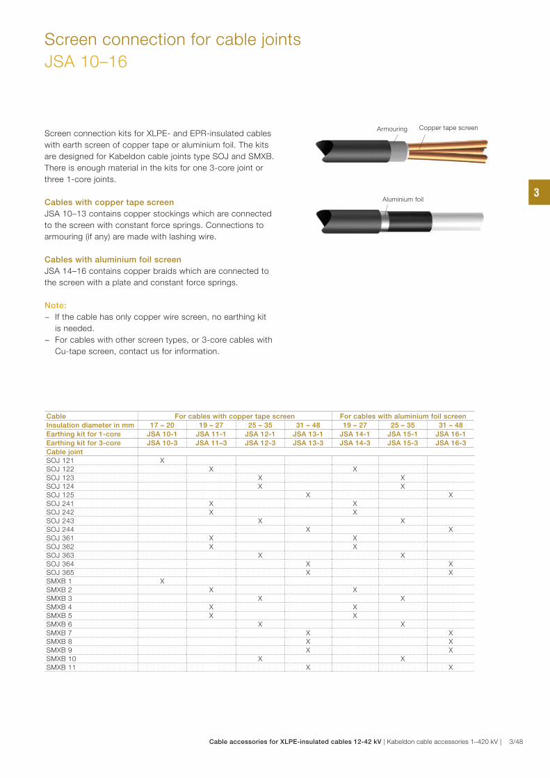
Screen connection for cable joints
JSA 10–16
Screen connection kits for XLPE- and EPR-insulated cables
with earth screen of copper tape or aluminium foil. The kits
are designed for Kabeldon cable joints type SOJ and SMXB.
There is enough material in the kits for one 3-core joint or
three 1-core joints.
Cables with copper tape screen
JSA 10–13 contains copper stockings which are connected
to the screen with constant force springs. Connections to
armouring (if any) are made with lashing wire.
Cables with aluminium foil screen
JSA 14–16 contains copper braids which are connected to
the screen with a plate and constant force springs.
Note:
− If the cable has only copper wire screen, no earthing kit
is needed.
− For cables with other screen types, or 3-core cables with
Cu-tape screen, contact us for information.
Cable For cables with copper tape screen For cables with aluminium foil screen
Insulation diameter in mm 17 – 20 19 – 27 25 – 35 31 – 48 19 – 27 25 – 35 31 – 48
Earthing kit for 1-core JSA 10-1 JSA 11-1 JSA 12-1 JSA 13-1 JSA 14-1 JSA 15-1 JSA 16-1
Earthing kit for 3-core JSA 10-3 JSA 11–3 JSA 12-3 JSA 13-3 JSA 14-3 JSA 15-3 JSA 16-3
Cable jointSOJ 121 XSOJ 122 X XSOJ 123 X XSOJ 124 X XSOJ 125 X XSOJ 241 X XSOJ 242 X XSOJ 243 X XSOJ 244 X XSOJ 361 X XSOJ 362 X XSOJ 363 X XSOJ 364 X XSOJ 365 X XSMXB 1 XSMXB 2 X XSMXB 3 X XSMXB 4 X XSMXB 5 X XSMXB 6 X XSMXB 7 X XSMXB 8 X XSMXB 9 X XSMXB 10 X XSMXB 11 X X
Armouring Copper tape screen
Aluminium foil3
Cable accessories for XLPE-insulated cables 12-42 kV | Kabeldon cable accessories 1–420 kV | 3/48
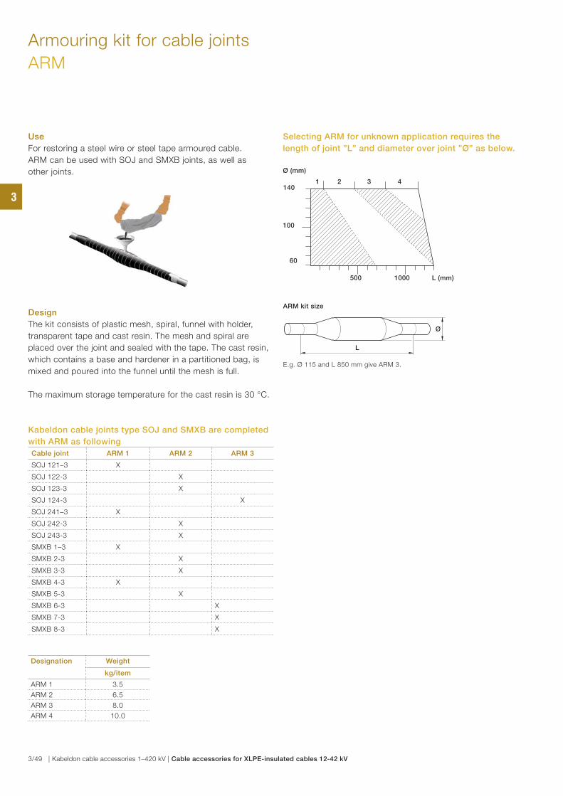
Armouring kit for cable joints
ARM
Kabeldon cable joints type SOJ and SMXB are completed
with ARM as following
Cable joint ARM 1 ARM 2 ARM 3
SOJ 121–3 X
SOJ 122-3 X
SOJ 123-3 X
SOJ 124-3 X
SOJ 241–3 X
SOJ 242-3 X
SOJ 243-3 X
SMXB 1–3 X
SMXB 2-3 X
SMXB 3-3 X
SMXB 4-3 X
SMXB 5-3 X
SMXB 6-3 X
SMXB 7-3 X
SMXB 8-3 X
Designation Weight
kg/item
ARM 1 3.5
ARM 2 6.5
ARM 3 8.0
ARM 4 10.0
Use
For restoring a steel wire or steel tape armoured cable.
ARM can be used with SOJ and SMXB joints, as well as
other joints.
Design
The kit consists of plastic mesh, spiral, funnel with holder,
transparent tape and cast resin. The mesh and spiral are
placed over the joint and sealed with the tape. The cast resin,
which contains a base and hardener in a partitioned bag, is
mixed and poured into the funnel until the mesh is full.
The maximum storage temperature for the cast resin is 30 °C.
Selecting ARM for unknown application requires the
length of joint ”L” and diameter over joint ”Ø” as below.
500 1000 L (mm)
60
100
1401 2 3 4
Ø (mm)
E.g. Ø 115 and L 850 mm give ARM 3.
ARM kit size
Ø
L
3
3/49 | Kabeldon cable accessories 1–420 kV | Cable accessories for XLPE-insulated cables 12-42 kV
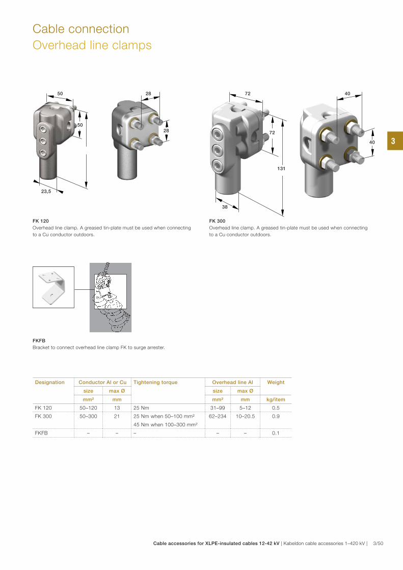
Cable connection
Overhead line clamps
FK 120
Overhead line clamp. A greased tin-plate must be used when connecting
to a Cu conductor outdoors.
FKFB
Bracket to connect overhead line clamp FK to surge arrester.
FK 300
Overhead line clamp. A greased tin-plate must be used when connecting
to a Cu conductor outdoors.
Designation Conductor Al or Cu Tightening torque Overhead line Al Weight
size max Ø size max Ø
mm² mm mm² mm kg/item
FK 120 50–120 13 25 Nm 31–99 5–12 0.5
FK 300 50–300 21 25 Nm when 50–100 mm²
45 Nm when 100–300 mm²
62–234 10–20.5 0.9
FKFB – – – – – 0.1
50
23,5
50
28
28
72
38
131
72
40
40 3
Cable accessories for XLPE-insulated cables 12-42 kV | Kabeldon cable accessories 1–420 kV | 3/50
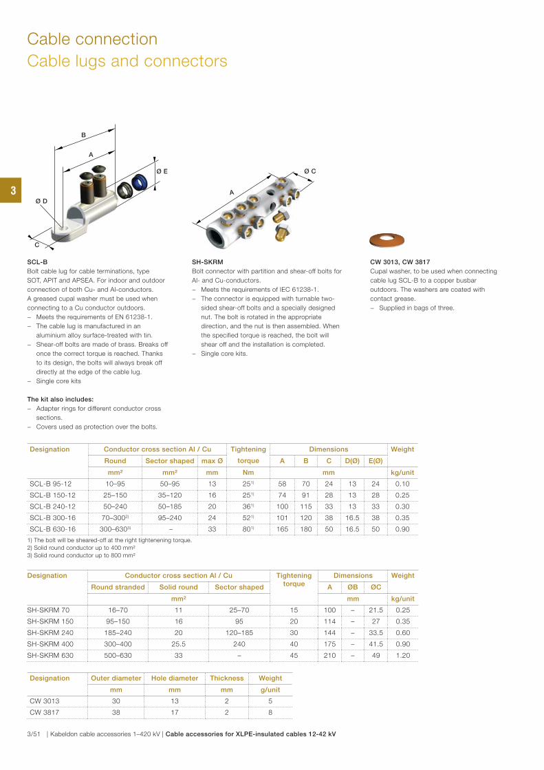
Cable connection
Cable lugs and connectors
Designation Conductor cross section Al / Cu Tightening
torque
Dimensions Weight
Round Sector shaped max Ø A B C D(Ø) E(Ø)
mm² mm² mm Nm mm kg/unit
SCL-B 95-12 10–95 50–95 13 251) 58 70 24 13 24 0.10
SCL-B 150-12 25–150 35–120 16 251) 74 91 28 13 28 0.25
SCL-B 240-12 50–240 50–185 20 361) 100 115 33 13 33 0.30
SCL-B 300-16 70–3002) 95–240 24 521) 101 120 38 16.5 38 0.35
SCL-B 630-16 300–6303) – 33 801) 165 180 50 16.5 50 0.90
1) The bolt will be sheared-off at the right tightenening torque.
2) Solid round conductor up to 400 mm²
3) Solid round conductor up to 800 mm²
CW 3013, CW 3817
Cupal washer, to be used when connecting
cable lug SCL-B to a copper busbar
outdoors. The washers are coated with
contact grease.
− Supplied in bags of three.
SCL-B
Bolt cable lug for cable terminations, type
SOT, APIT and APSEA. For indoor and outdoor
connection of both Cu- and Al-conductors.
A greased cupal washer must be used when
connecting to a Cu conductor outdoors.
− Meets the requirements of EN 61238-1.
− The cable lug is manufactured in an
aluminium alloy surface-treated with tin.
− Shear-off bolts are made of brass. Breaks off
once the correct torque is reached. Thanks
to its design, the bolts will always break off
directly at the edge of the cable lug.
− Single core kits
The kit also includes:
− Adapter rings for different conductor cross
sections.
− Covers used as protection over the bolts.
Ø D
Ø E
B
A
C
Designation Outer diameter Hole diameter Thickness Weight
mm mm mm g/unit
CW 3013 30 13 2 5
CW 3817 38 17 2 8
Designation Conductor cross section Al / Cu Tightening torque
Dimensions Weight
Round stranded Solid round Sector shaped A ØB ØC
mm² mm kg/unit
SH-SKRM 70 16–70 11 25–70 15 100 – 21.5 0.25
SH-SKRM 150 95–150 16 95 20 114 – 27 0.35
SH-SKRM 240 185–240 20 120–185 30 144 – 33.5 0.60
SH-SKRM 400 300–400 25.5 240 40 175 – 41.5 0.90
SH-SKRM 630 500–630 33 – 45 210 – 49 1.20
SH-SKRM
Bolt connector with partition and shear-off bolts for
Al- and Cu-conductors.
− Meets the requirements of IEC 61238-1.
− The connector is equipped with turnable two-
sided shear-off bolts and a specially designed
nut. The bolt is rotated in the appropriate
direction, and the nut is then assembled. When
the specified torque is reached, the bolt will
shear off and the installation is completed.
− Single core kits.
A
Ø C
3
3/51 | Kabeldon cable accessories 1–420 kV | Cable accessories for XLPE-insulated cables 12-42 kV
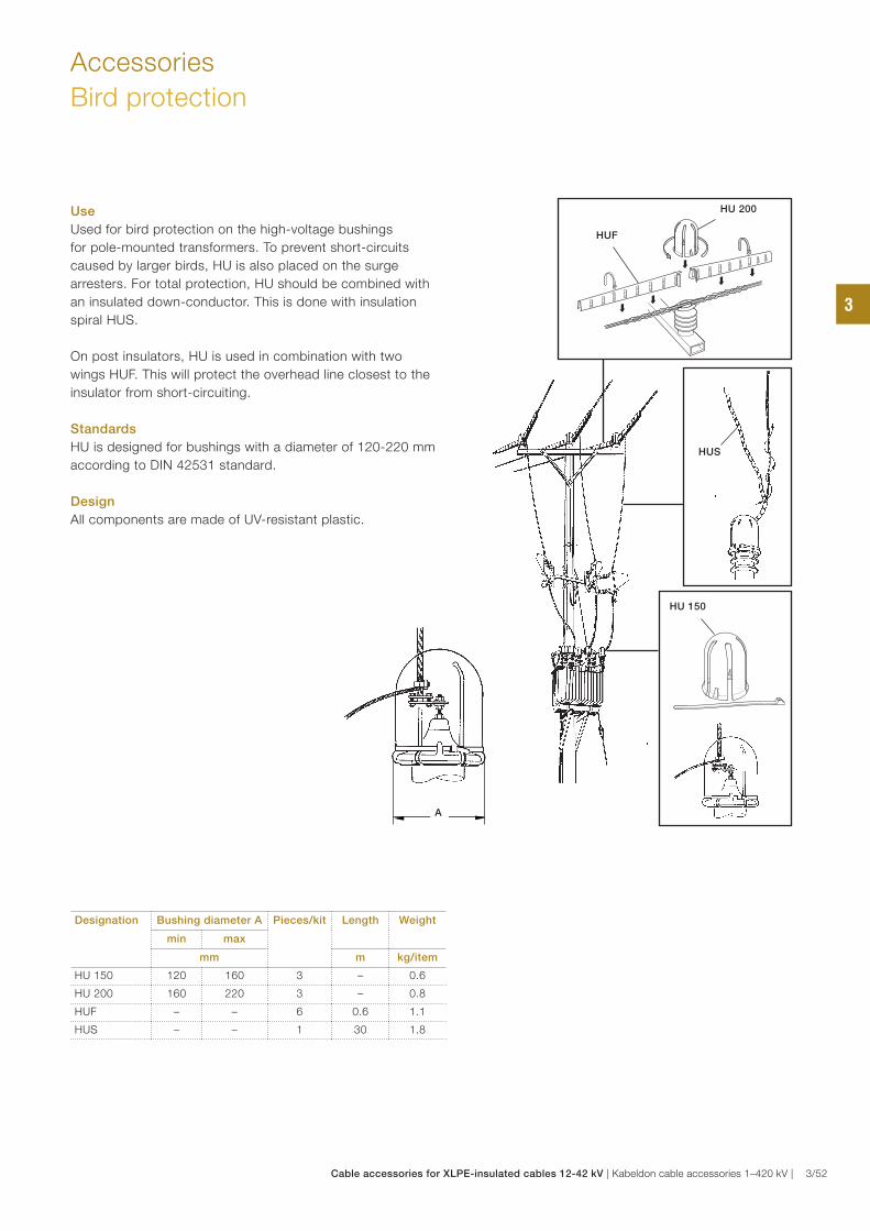
Accessories
Bird protection
Designation Bushing diameter A Pieces/kit Length Weight
min max
mm m kg/item
HU 150 120 160 3 – 0.6
HU 200 160 220 3 – 0.8
HUF – – 6 0.6 1.1
HUS – – 1 30 1.8
Use
Used for bird protection on the high-voltage bushings
for pole-mounted transformers. To prevent short-circuits
caused by larger birds, HU is also placed on the surge
arresters. For total protection, HU should be combined with
an insulated down-conductor. This is done with insulation
spiral HUS.
On post insulators, HU is used in combination with two
wings HUF. This will protect the overhead line closest to the
insulator from short-circuiting.
Standards
HU is designed for bushings with a diameter of 120-220 mm
according to DIN 42531 standard.
Design
All components are made of UV-resistant plastic.
HU 150
HU 200
HUS
HUF
A
3
Cable accessories for XLPE-insulated cables 12-42 kV | Kabeldon cable accessories 1–420 kV | 3/52
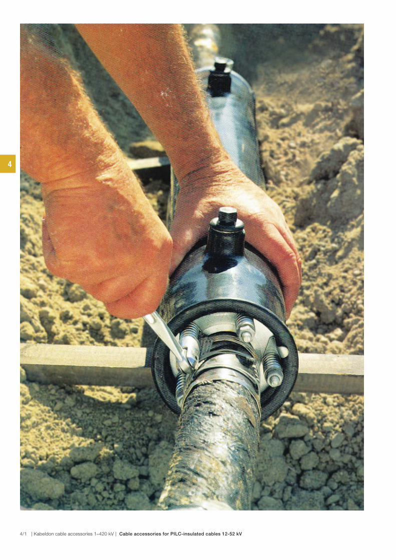
4
4/1 | Kabeldon cable accessories 1–420 kV | Cable accessories for PILC-insulated cables 12-52 kV

Table of contents
Cable accessories for paper-insulated cables (PILC), 12–52 kV
Cable accessories for PILC cables 12–52 kV
Cable termination, indoor for paper-insulated cable, OTIA 12 kV 4/3
Cable joint and repair cable joint for paper-insulated cable, SMTD 12 kV 4/5
Transition cable joint for paper-insulated cable, SMTXB 12 kV 4/7
Transition cable joint, SMTXD 24–36 kV 4/8
Cable joint for paper-insulated cable, SMTA and SMTPA 24–52 kV 4/9
Dimensional drawings, SMT 4/10
Spring-loaded gaskets for paper-insulated cables, FPA, FP, FPMP 4/11
Accessories for paper-insulated cable joints and transition joints 4/12 4
Cable accessories for PILC-insulated cables 12-52 kV | Kabeldon cable accessories 1–420 kV | 4/2
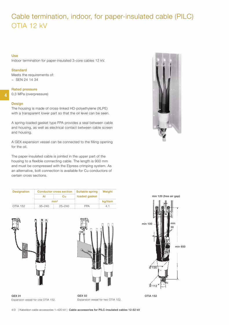
GEX 02
Expansion vessel for two OTIA 152.
GEX 01
Expansion vessel for one OTIA 152.
OTIA 152
Ø 112
Ø 135
min 120 (free air gap)
min 650
min
30
min 100
Cable termination, indoor, for paper-insulated cable (PILC)
OTIA 12 kV
Designation Conductor cross section Suitable spring
loaded gasket
Weight
Al Cu
mm² kg/item
OTIA 152 35–240 25–240 FPA 4.1
Use
Indoor termination for paper-insulated 3-core cables 12 kV.
Standard
Meets the requirements of:
− SEN 24 14 34
Rated pressure
0,3 MPa (overpressure)
Design
The housing is made of cross-linked HD-polyethylene (XLPE)
with a transparent lower part so that the oil level can be seen.
A spring-loaded gasket type FPA provides a seal between cable
and housing, as well as electrical contact between cable screen
and housing.
A GEX expansion vessel can be connected to the filling opening
for the oil.
The paper-insulated cable is jointed in the upper part of the
housing to a flexible connecting cable. The length is 900 mm
and must be compressed with the Elpress crimping system. As
an alternative, bolt connection is available for Cu conductors of
certain cross sections.
4
4/3 | Kabeldon cable accessories 1–420 kV | Cable accessories for PILC-insulated cables 12-52 kV
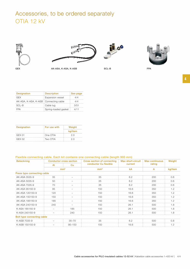
Accessories, to be ordered separately
OTIA 12 kV
Flexible connecting cable. Each kit contains one connecting cable (length 900 mm)
Beteckning Conductor cross section Cross section of connecting conductor Cu flexible
Max short-circuit current
Max continuous rating
Weight
Al Cu
mm² mm² kA A kg/item
Press type connecting cable
AK-ASA 3535-9 35 – 35 6.2 200 0.6
AK-ASA 5035-9 50 – 35 6.2 200 0.6
AK-ASA 7035-9 70 – 35 6.2 200 0.6
AK-ASA 95150-9 95 – 150 16.6 350 1.2
AK-ASA 120150-9 120 – 150 16.6 350 1.2
AK-ASA 150150-9 150 – 150 16.6 350 1.2
AK-ASA 185150-9 185 – 150 16.6 350 1.2
AK-ASA 240150-9 240 – 150 26.1 500 1.8
K-ASA 185150-9 – 185 150 26.1 500 1.8
K-ASA 240150-9 – 240 150 26.1 500 1.8
Bolt type connecting cable
K-ASB 7035-9 – 35–70 35 6.2 500 0.8
K-ASB 150150-9 – 95–150 150 16.6 500 1.2
Designation For use with Weight
kg/item
GEX 01 One OTIA 2.0
GEX 02 Two OTIA 2.0
Designation Description See page
GEX Expansion vessel 4/4
AK-ASA, K-ASA, K-ASB Connecting cable 4/4
SCL-B Cable lug 3/51
FPA Spring-loaded gasket 4/11
SCL-B FPAGEX AK-ASA, K-ASA, K-ASB
4
Cable accessories for PILC-insulated cables 12-52 kV | Kabeldon cable accessories 1–420 kV | 4/4
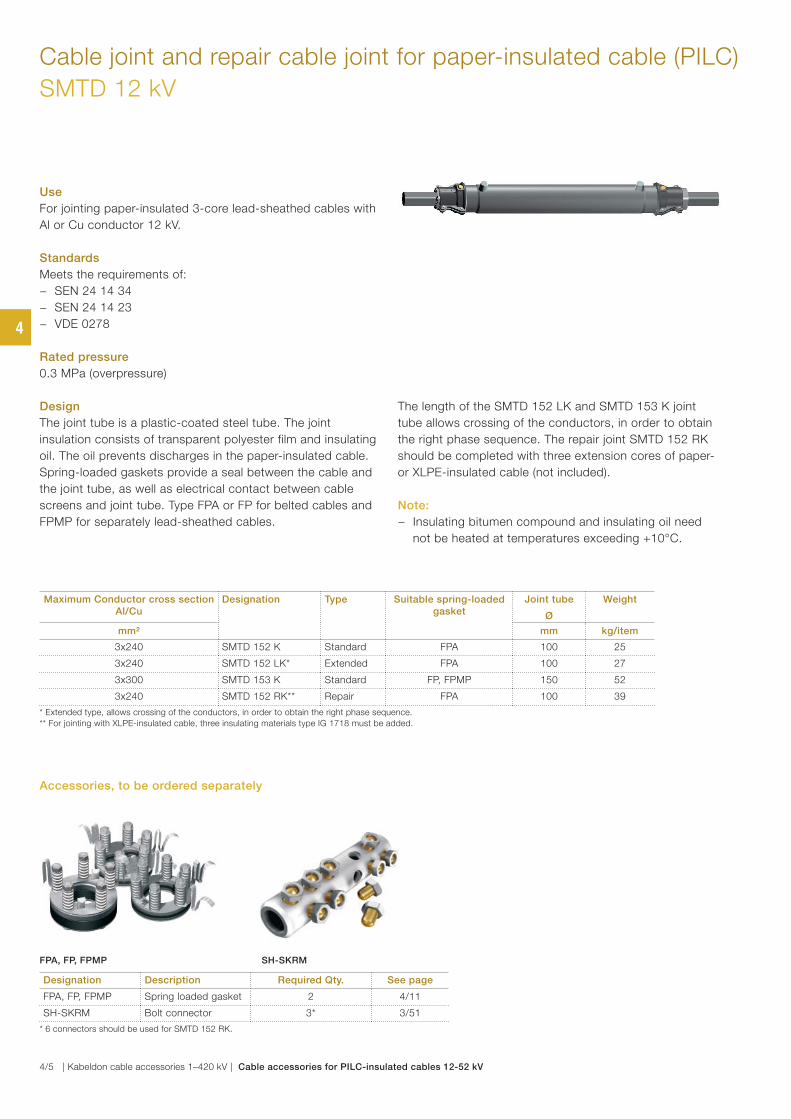
Cable joint and repair cable joint for paper-insulated cable (PILC)
SMTD 12 kV
Use
For jointing paper-insulated 3-core lead-sheathed cables with
Al or Cu conductor 12 kV.
Standards
Meets the requirements of:
− SEN 24 14 34
− SEN 24 14 23
− VDE 0278
Rated pressure
0.3 MPa (overpressure)
Design
The joint tube is a plastic-coated steel tube. The joint
insulation consists of transparent polyester film and insulating
oil. The oil prevents discharges in the paper-insulated cable.
Spring-loaded gaskets provide a seal between the cable and
the joint tube, as well as electrical contact between cable
screens and joint tube. Type FPA or FP for belted cables and
FPMP for separately lead-sheathed cables.
The length of the SMTD 152 LK and SMTD 153 K joint
tube allows crossing of the conductors, in order to obtain
the right phase sequence. The repair joint SMTD 152 RK
should be completed with three extension cores of paper-
or XLPE-insulated cable (not included).
Note:
− Insulating bitumen compound and insulating oil need
not be heated at temperatures exceeding +10°C.
Maximum Conductor cross section Al/Cu
Designation Type Suitable spring-loaded gasket
Joint tube
Ø
Weight
mm² mm kg/item
3x240 SMTD 152 K Standard FPA 100 25
3x240 SMTD 152 LK* Extended FPA 100 27
3x300 SMTD 153 K Standard FP, FPMP 150 52
3x240 SMTD 152 RK** Repair FPA 100 39
* Extended type, allows crossing of the conductors, in order to obtain the right phase sequence.
** For jointing with XLPE-insulated cable, three insulating materials type IG 1718 must be added.
Designation Description Required Qty. See page
FPA, FP, FPMP Spring loaded gasket 2 4/11
SH-SKRM Bolt connector 3* 3/51
* 6 connectors should be used for SMTD 152 RK.
FPA, FP, FPMP SH-SKRM
Accessories, to be ordered separately
4
4/5 | Kabeldon cable accessories 1–420 kV | Cable accessories for PILC-insulated cables 12-52 kV
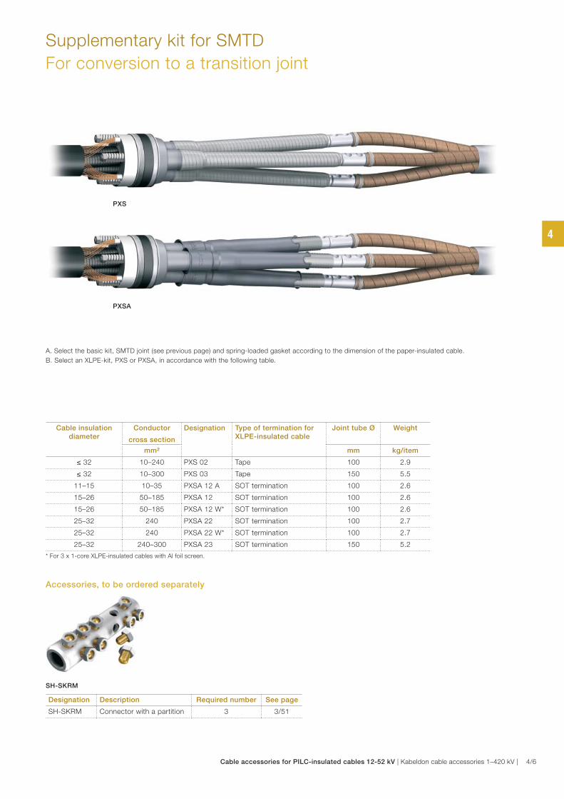
Supplementary kit for SMTD
For conversion to a transition joint
A. Select the basic kit, SMTD joint (see previous page) and spring-loaded gasket according to the dimension of the paper-insulated cable.
B. Select an XLPE-kit, PXS or PXSA, in accordance with the following table.
PXS
PXSA
Cable insulation diameter
Conductor
cross section
Designation Type of termination for XLPE-insulated cable
Joint tube Ø Weight
mm² mm kg/item
≤ 32 10–240 PXS 02 Tape 100 2.9
≤ 32 10–300 PXS 03 Tape 150 5.5
11–15 10–35 PXSA 12 A SOT termination 100 2.6
15–26 50–185 PXSA 12 SOT termination 100 2.6
15–26 50–185 PXSA 12 W* SOT termination 100 2.6
25–32 240 PXSA 22 SOT termination 100 2.7
25–32 240 PXSA 22 W* SOT termination 100 2.7
25–32 240–300 PXSA 23 SOT termination 150 5.2
* For 3 x 1-core XLPE-insulated cables with Al foil screen.
Designation Description Required number See page
SH-SKRM Connector with a partition 3 3/51
SH-SKRM
Accessories, to be ordered separately
4
Cable accessories for PILC-insulated cables 12-52 kV | Kabeldon cable accessories 1–420 kV | 4/6
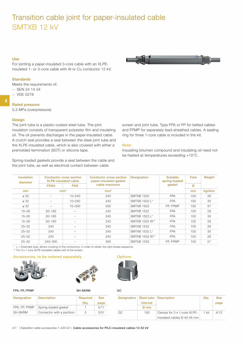
Transition cable joint for paper-insulated cable
SMTXB 12 kV
Use
For jointing a paper-insulated 3-core cable with an XLPE-
insulated 1- or 3-core cable with Al or Cu conductor 12 kV.
Standards
Meets the requirements of:
− SEN 24 14 34
− VDE 0278
Rated pressure
0,3 MPa (overpressure)
Design
The joint tube is a plastic-coated steel tube. The joint
insulation consists of transparent polyester film and insulating
oil. The oil prevents discharges in the paper-insulated cable.
A crutch seal provides a seal between the steel joint tube and
the XLPE-insulated cable, which is also covered with either a
premolded termination (SOT) or silicone tape.
Spring-loaded gaskets provide a seal between the cable and
the joint tube, as well as electrical contact between cable
screen and joint tube. Type FPA or FP for belted cables
and FPMP for separately lead-sheathed cables. A sealing
ring for three 1-core cable is included in the kit.
Note:
Insulating bitumen compound and insulating oil need not
be heated at temperatures exceeding +10°C.
Insulation
diameter
Conductor cross section XLPE-insulated cable
Conductor cross section paper-insulated gasket
cable maximum
Designation Suitable spring-loaded
gasket
Tube Weight
PXSA PXS Ø
mm mm² mm² mm kg/item
≤ 32 – 10–240 240 SMTXB 1502 FPA 100 28
≤ 32 – 10–240 240 SMTXB 1502 L* FPA 100 30
≤ 32 – 10–300 300 SMTXB 1503 FP, FPMP 150 57
15–26 50–185 – 240 SMTXB 1522 FPA 100 28
15–26 50–185 – 240 SMTXB 1522 L* FPA 100 30
15–26 50–185 – 240 SMTXB 1522 W** FPA 100 28
25–32 240 – 240 SMTXB 1532 FPA 100 28
25–32 240 – 240 SMTXB 1532 L* FPA 100 30
25–32 240 – 240 SMTXB 1532 W** FPA 100 28
25–32 240–300 – 300 SMTXB 1533 FP, FPMP 150 57
* L = Extended type, allows crossing of the conductors, in order to obtain the right phase sequence.
** For 3 x 1-core XLPE-insulated cables with Al foil screen.
Designation Description Required
Qty.
See
page
FPA, FP, FPMP Spring-loaded gasket 1 4/11
SH-SKRM Connector with a partition 3 3/51
Designation Steel tube
internal
Description Qty. See
page
Ø mm
GC 100 Clamps for 3 x 1-core XLPE-
insulated cables Ø 40-45 mm
1 kit 4/12
FPA, FP, FPMP SH-SKRM
Accessories, to be ordered separately Options
GC
4
4/7 | Kabeldon cable accessories 1–420 kV | Cable accessories for PILC-insulated cables 12-52 kV
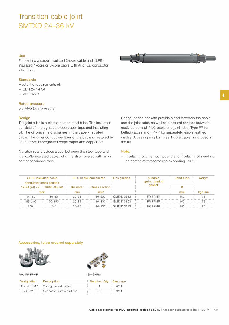
Transition cable joint
SMTXD 24–36 kV
Use
For jointing a paper-insulated 3-core cable and XLPE-
insulated 1-core or 3-core cable with Al or Cu conductor
24–36 kV.
Standards
Meets the requirements of:
− SEN 24 14 34
− VDE 0278
Rated pressure
0,3 MPa (overpressure)
Design
The joint tube is a plastic-coated steel tube. The insulation
consists of impregnated crepe paper tape and insulating
oil. The oil prevents discharges in the paper-insulated
cable. The outer conductive layer of the cable is restored by
conductive, impregnated crepe paper and copper net.
A crutch seal provides a seal between the steel tube and
the XLPE-insulated cable, which is also covered with an oil
barrier of silicone tape.
Spring-loaded gaskets provide a seal between the cable
and the joint tube, as well as electrical contact between
cable screens of PILC cable and joint tube. Type FP for
belted cables and FPMP for separately lead-sheathed
cables. A sealing ring for three 1-core cable is included in
the kit.
Note:
− Insulating bitumen compound and insulating oil need not
be heated at temperatures exceeding +10°C.
XLPE-insulated cable
conductor cross section
PILC cable lead sheath Designation Suitable spring-loaded
gasket
Joint tube Weight
12/20 (24) kV 18/30 (36) kV Diameter Cross section Ø
mm² mm mm² mm kg/item
10–150 10–50 20–85 10–300 SMTXD 3613 FP, FPMP 150 76
185–240 70–150 20–85 10–300 SMTXD 3623 FP, FPMP 150 76
300 240 20–85 10–300 SMTXD 3633 FP, FPMP 150 76
Designation Description Required Qty. See page
FP and FPMP Spring-loaded gasket 1 4/11
SH-SKRM Connector with a partition 3 3/51
Accessories, to be ordered separately
FPA, FP, FPMP SH-SKRM
4
Cable accessories for PILC-insulated cables 12-52 kV | Kabeldon cable accessories 1–420 kV | 4/8
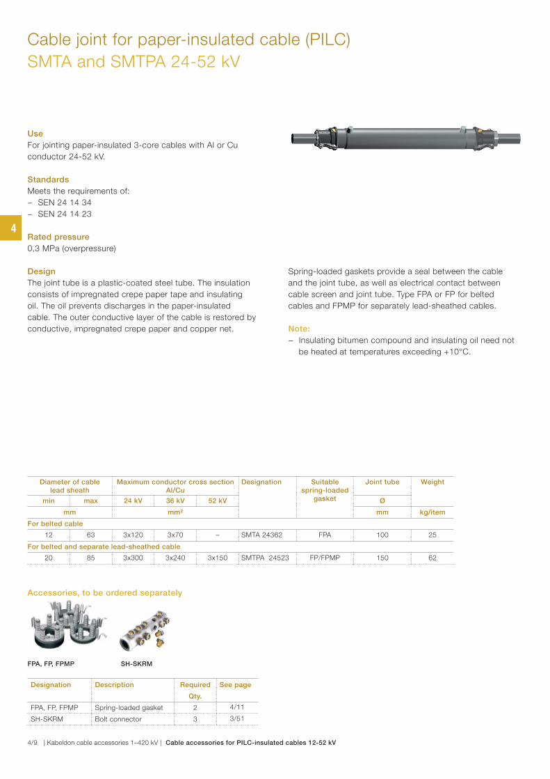
Cable joint for paper-insulated cable (PILC)
SMTA and SMTPA 24-52 kV
Use
For jointing paper-insulated 3-core cables with Al or Cu
conductor 24-52 kV.
Standards
Meets the requirements of:
− SEN 24 14 34
− SEN 24 14 23
Rated pressure
0,3 MPa (overpressure)
Design
The joint tube is a plastic-coated steel tube. The insulation
consists of impregnated crepe paper tape and insulating
oil. The oil prevents discharges in the paper-insulated
cable. The outer conductive layer of the cable is restored by
conductive, impregnated crepe paper and copper net.
Spring-loaded gaskets provide a seal between the cable
and the joint tube, as well as electrical contact between
cable screen and joint tube. Type FPA or FP for belted
cables and FPMP for separately lead-sheathed cables.
Note:
− Insulating bitumen compound and insulating oil need not
be heated at temperatures exceeding +10°C.
Diameter of cable lead sheath
Maximum conductor cross section Al/Cu
Designation Suitable spring-loaded
gasket
Joint tube Weight
min max 24 kV 36 kV 52 kV Ø
mm mm² mm kg/item
For belted cable
12 63 3x120 3x70 – SMTA 24362 FPA 100 25
For belted and separate lead-sheathed cable
20 85 3x300 3x240 3x150 SMTPA 24523 FP/FPMP 150 62
Designation Description Required
Qty.
See page
FPA, FP, FPMP Spring-loaded gasket 2 4/11
SH-SKRM Bolt connector 3 3/51
FPA, FP, FPMP SH-SKRM
Accessories, to be ordered separately
4
4/9 | Kabeldon cable accessories 1–420 kV | Cable accessories for PILC-insulated cables 12-52 kV
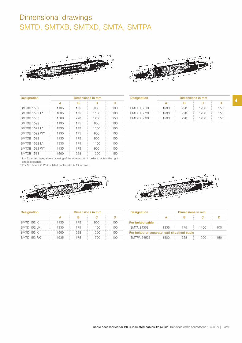
Dimensional drawings
SMTD, SMTXB, SMTXD, SMTA, SMTPA
A
CD
B
A
B
CD
AB
D C
A
CD
B
Designation Dimensions in mm
A B C D
For belted cable
SMTA 24362 1335 175 1100 100
For belted or separate lead-sheathed cable
SMTPA 24523 1500 228 1200 150
Designation Dimensions in mm
A B C D
SMTD 152 K 1135 175 900 100
SMTD 152 LK 1335 175 1100 100
SMTD 153 K 1500 228 1200 150
SMTD 152 RK 1935 175 1700 100
Designation Dimensions in mm
A B C D
SMTXB 1502 1135 175 900 100
SMTXB 1502 L* 1335 175 1100 100
SMTXB 1503 1500 228 1200 150
SMTXB 1522 1135 175 900 100
SMTXB 1522 L* 1335 175 1100 100
SMTXB 1522 W** 1135 175 900 100
SMTXB 1532 1135 175 900 100
SMTXB 1532 L* 1335 175 1100 100
SMTXB 1532 W** 1135 175 900 100
SMTXB 1533 1500 228 1200 150
* L = Extended type, allows crossing of the conductors, in order to obtain the right
phase sequence.
** For 3 x 1-core XLPE-insulated cables with Al foil screen.
Designation Dimensions in mm
A B C D
SMTXD 3613 1500 228 1200 150
SMTXD 3623 1500 228 1200 150
SMTXD 3633 1500 228 1200 150
4
Cable accessories for PILC-insulated cables 12-52 kV | Kabeldon cable accessories 1–420 kV | 4/10
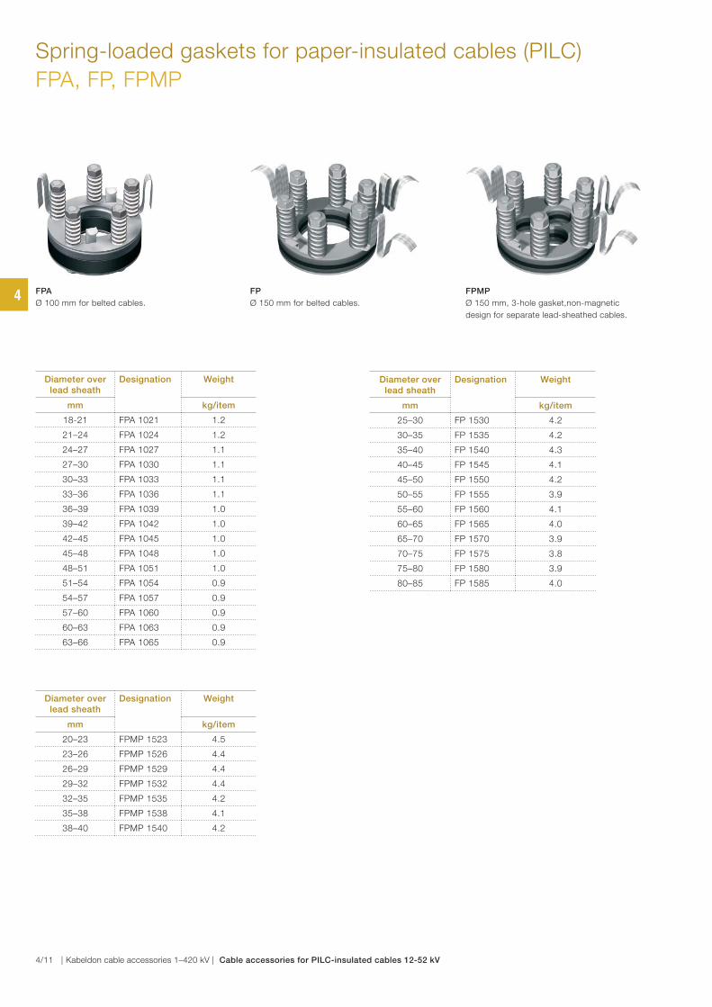
Diameter over lead sheath
Designation Weight
mm kg/item
18-21 FPA 1021 1.2
21–24 FPA 1024 1.2
24–27 FPA 1027 1.1
27–30 FPA 1030 1.1
30–33 FPA 1033 1.1
33–36 FPA 1036 1.1
36–39 FPA 1039 1.0
39–42 FPA 1042 1.0
42–45 FPA 1045 1.0
45–48 FPA 1048 1.0
48–51 FPA 1051 1.0
51–54 FPA 1054 0.9
54–57 FPA 1057 0.9
57–60 FPA 1060 0.9
60–63 FPA 1063 0.9
63–66 FPA 1065 0.9
Diameter over lead sheath
Designation Weight
mm kg/item
25–30 FP 1530 4.2
30–35 FP 1535 4.2
35–40 FP 1540 4.3
40–45 FP 1545 4.1
45–50 FP 1550 4.2
50–55 FP 1555 3.9
55–60 FP 1560 4.1
60–65 FP 1565 4.0
65–70 FP 1570 3.9
70–75 FP 1575 3.8
75–80 FP 1580 3.9
80–85 FP 1585 4.0
Diameter over lead sheath
Designation Weight
mm kg/item
20–23 FPMP 1523 4.5
23–26 FPMP 1526 4.4
26–29 FPMP 1529 4.4
29–32 FPMP 1532 4.4
32–35 FPMP 1535 4.2
35–38 FPMP 1538 4.1
38–40 FPMP 1540 4.2
FPA
Ø 100 mm for belted cables.
FP
Ø 150 mm for belted cables.
FPMP
Ø 150 mm, 3-hole gasket,non-magnetic
design for separate lead-sheathed cables.
Spring-loaded gaskets for paper-insulated cables (PILC)
FPA, FP, FPMP
4
4/11 | Kabeldon cable accessories 1–420 kV | Cable accessories for PILC-insulated cables 12-52 kV
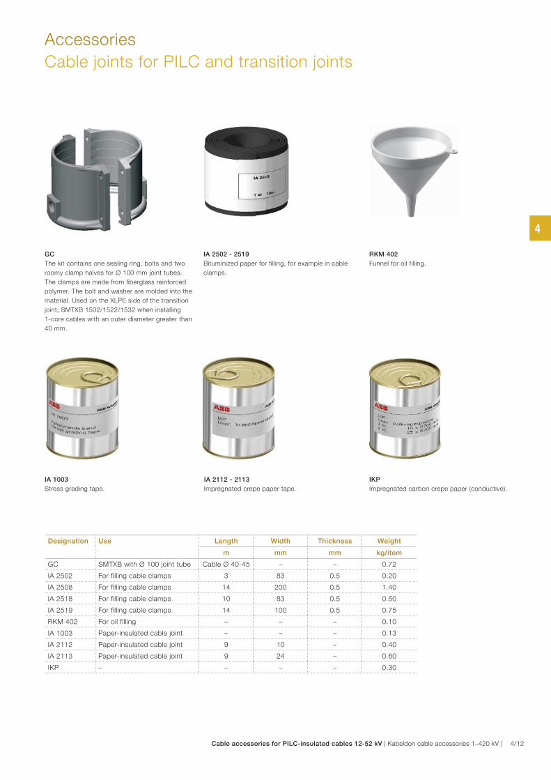
Accessories
Cable joints for PILC and transition joints
Designation Use Length Width Thickness Weight
m mm mm kg/item
GC SMTXB with Ø 100 joint tube Cable Ø 40-45 – – 0.72
IA 2502 For filling cable clamps 3 83 0.5 0.20
IA 2508 For filling cable clamps 14 200 0.5 1.40
IA 2518 For filling cable clamps 10 83 0.5 0.50
IA 2519 For filling cable clamps 14 100 0.5 0.75
RKM 402 For oil filling – – – 0.10
IA 1003 Paper-insulated cable joint – – – 0.13
IA 2112 Paper-insulated cable joint 9 10 – 0.40
IA 2113 Paper-insulated cable joint 9 24 – 0.60
IKP – – – – 0.30
IA 2502 - 2519
Bituminized paper for filling, for example in cable
clamps.
GC
The kit contains one sealing ring, bolts and two
roomy clamp halves for Ø 100 mm joint tubes.
The clamps are made from fiberglass reinforced
polymer. The bolt and washer are molded into the
material. Used on the XLPE side of the transition
joint; SMTXB 1502/1522/1532 when installing
1-core cables with an outer diameter greater than
40 mm.
RKM 402
Funnel for oil filling.
IA 1003
Stress grading tape.
IA 2112 - 2113
Impregnated crepe paper tape.
IKP
Impregnated carbon crepe paper (conductive).
4
Cable accessories for PILC-insulated cables 12-52 kV | Kabeldon cable accessories 1–420 kV | 4/12
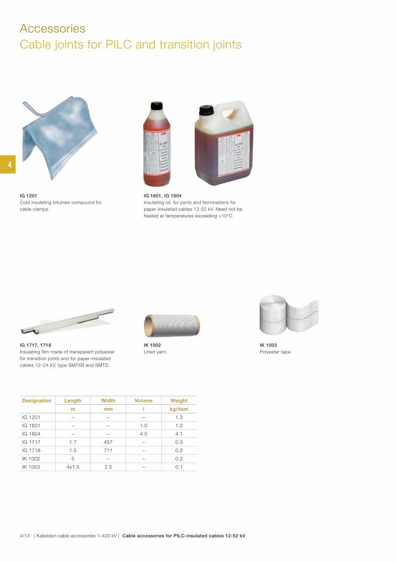
Accessories
Cable joints for PILC and transition joints
Designation Length Width Volume Weight
m mm l kg/item
IG 1201 – – – 1.3
IG 1601 – – 1.0 1.0
IG 1604 – – 4.0 4.1
IG 1717 1.7 457 – 0.3
IG 1718 1.5 711 – 0.2
IK 1002 5 – – 0.2
IK 1003 4x1.5 2.5 – 0.1
IG 1201
Cold insulating bitumen compound for
cable clamps.
IG 1717, 1718
Insulating film made of transparent polyester
for transition joints and for paper-insulated
cables 12–24 kV, type SMTXB and SMTD.
IG 1601, IG 1604
Insulating oil, for joints and terminations for
paper-insulated cables 12-52 kV. Need not be
heated at temperatures exceeding +10°C.
IK 1002
Linen yarn.
IK 1003
Polyester tape.
4
4/13 | Kabeldon cable accessories 1–420 kV | Cable accessories for PILC-insulated cables 12-52 kV
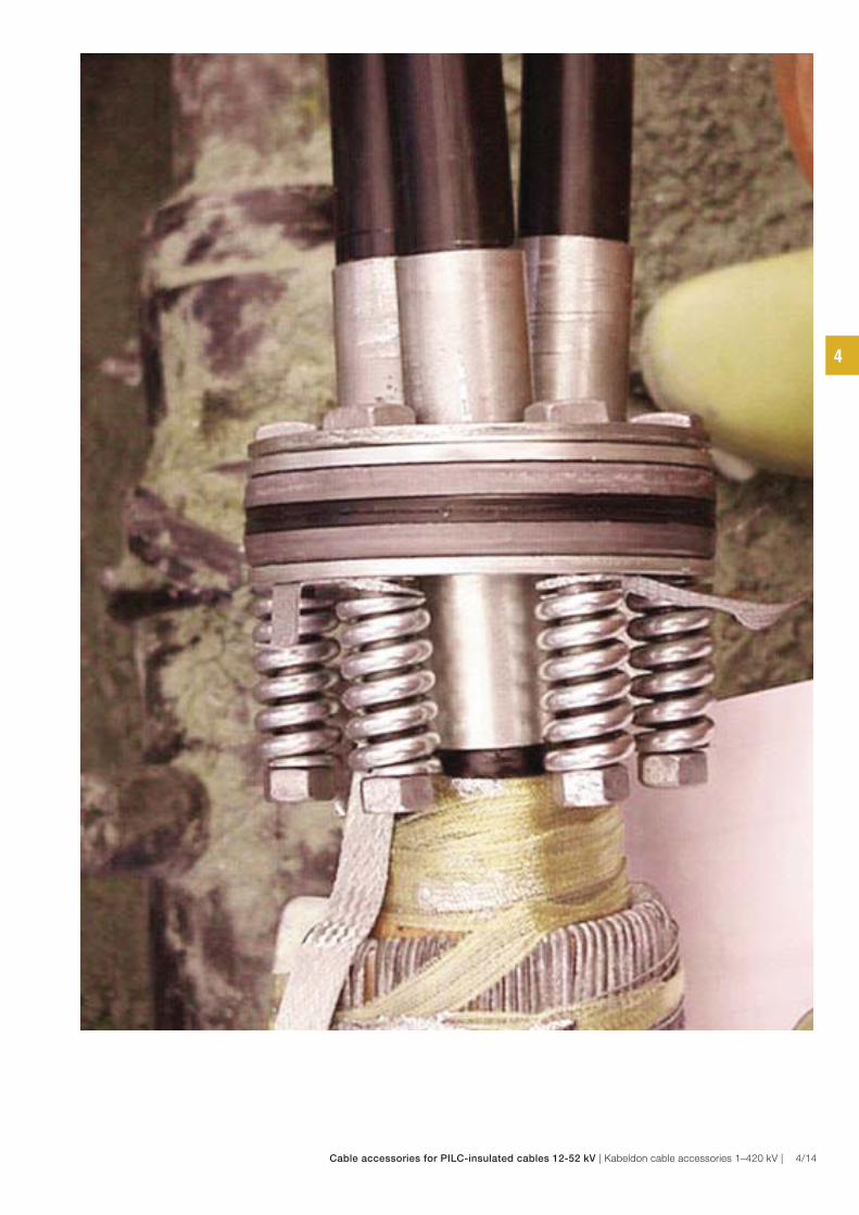
4
Cable accessories for PILC-insulated cables 12-52 kV | Kabeldon cable accessories 1–420 kV | 4/14
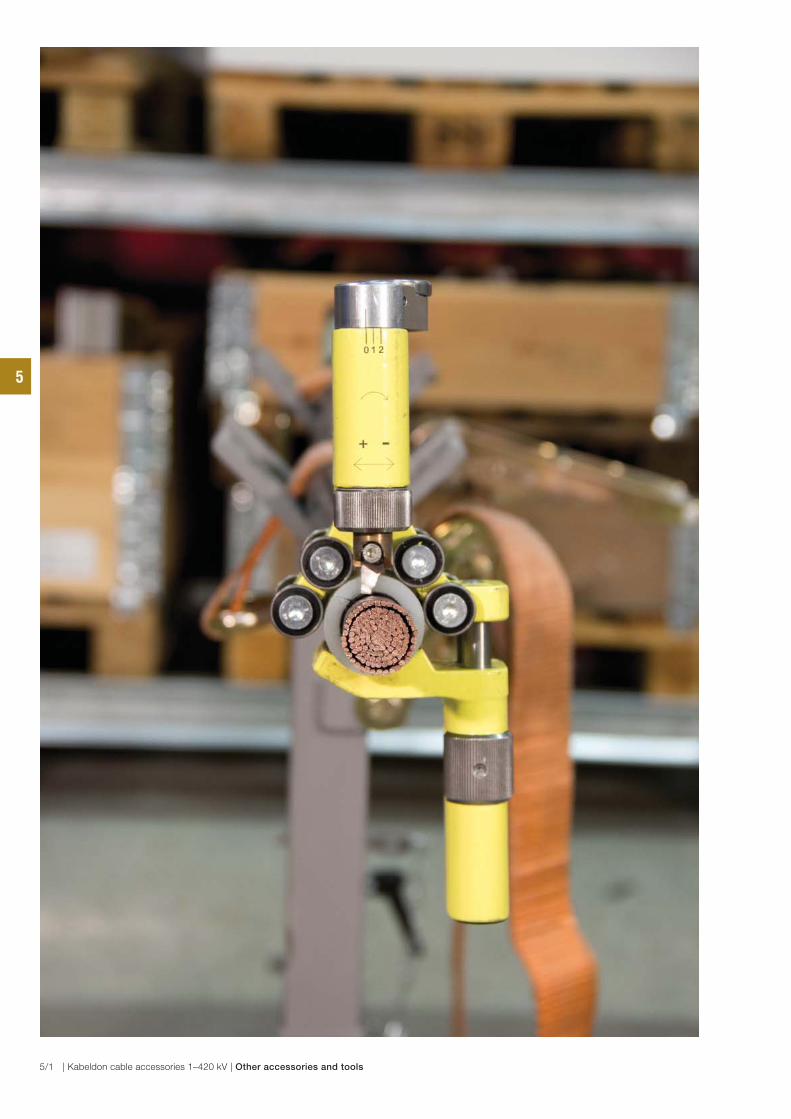
5
5/1 | Kabeldon cable accessories 1–420 kV | Other accessories and tools
General accessories and tools
Other accessories, tapes 5/3
Other accessories 5/4
Tools 5/6
Table of contents
General accessories and tools, 12–52 kV
5
Other accessories and tools | Kabeldon cable accessories 1–420 kV | 5/2
5
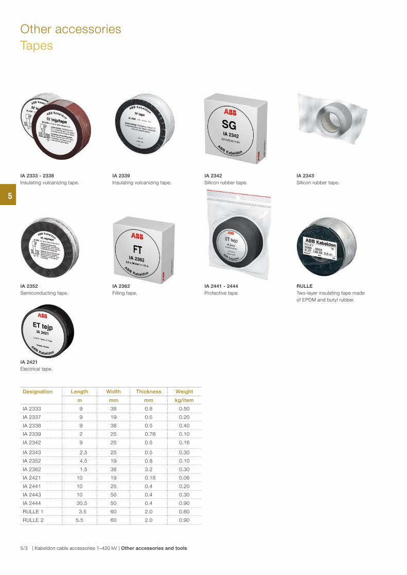
Other accessories
Tapes
Designation Length Width Thickness Weight
m mm mm kg/item
IA 2333 9 38 0.8 0.50
IA 2337 9 19 0.5 0.20
IA 2338 9 38 0.5 0.40
IA 2339 2 25 0.76 0.10
IA 2342 9 25 0.5 0.16
IA 2343 2.5 25 0.5 0.30
IA 2352 4.5 19 0.8 0.10
IA 2362 1.5 38 3.2 0.30
IA 2421 10 19 0.18 0.06
IA 2441 10 25 0.4 0.20
IA 2443 10 50 0.4 0.30
IA 2444 30.5 50 0.4 0.90
RULLE 1 3.5 60 2.0 0.60
RULLE 2 5.5 60 2.0 0.90
IA 2333 - 2338
Insulating vulcanizing tape.
IA 2342
Silicon rubber tape.
IA 2343
Silicon rubber tape.
IA 2421
Electrical tape.
IA 2352
Semiconducting tape.
IA 2441 - 2444
Protective tape.
RULLE
Two-layer insulating tape made
of EPDM and butyl rubber.
IA 2339
Insulating vulcanizing tape.
IA 2362
Filling tape.
5
5/3 | Kabeldon cable accessories 1–420 kV | Other accessories and tools
5
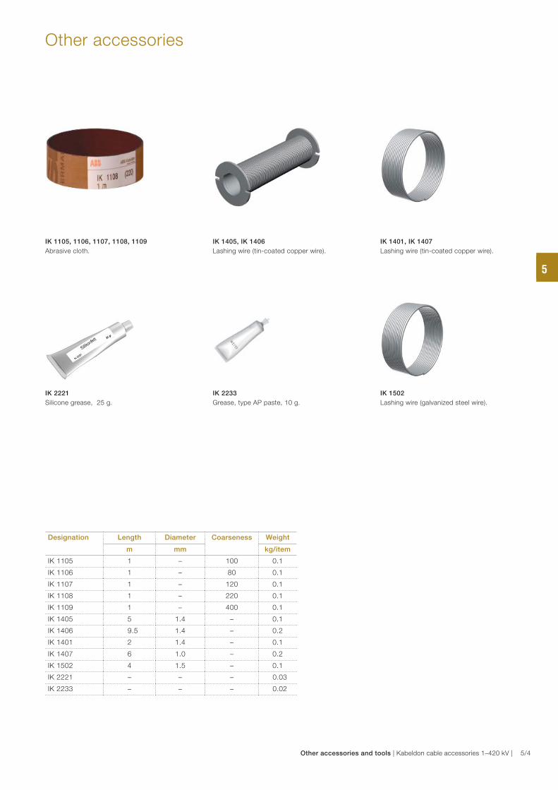
Other accessories
Designation Length Diameter Coarseness Weight
m mm kg/item
IK 1105 1 – 100 0.1
IK 1106 1 – 80 0.1
IK 1107 1 – 120 0.1
IK 1108 1 – 220 0.1
IK 1109 1 – 400 0.1
IK 1405 5 1.4 – 0.1
IK 1406 9.5 1.4 – 0.2
IK 1401 2 1.4 – 0.1
IK 1407 6 1.0 – 0.2
IK 1502 4 1.5 – 0.1
IK 2221 – – – 0.03
IK 2233 – – – 0.02
IK 1105, 1106, 1107, 1108, 1109
Abrasive cloth.
IK 1405, IK 1406
Lashing wire (tin-coated copper wire).
IK 1401, IK 1407
Lashing wire (tin-coated copper wire).
IK 1502
Lashing wire (galvanized steel wire).
IK 2221
Silicone grease, 25 g.
IK 2233
Grease, type AP paste, 10 g.
5
Other accessories and tools | Kabeldon cable accessories 1–420 kV | 5/4
5
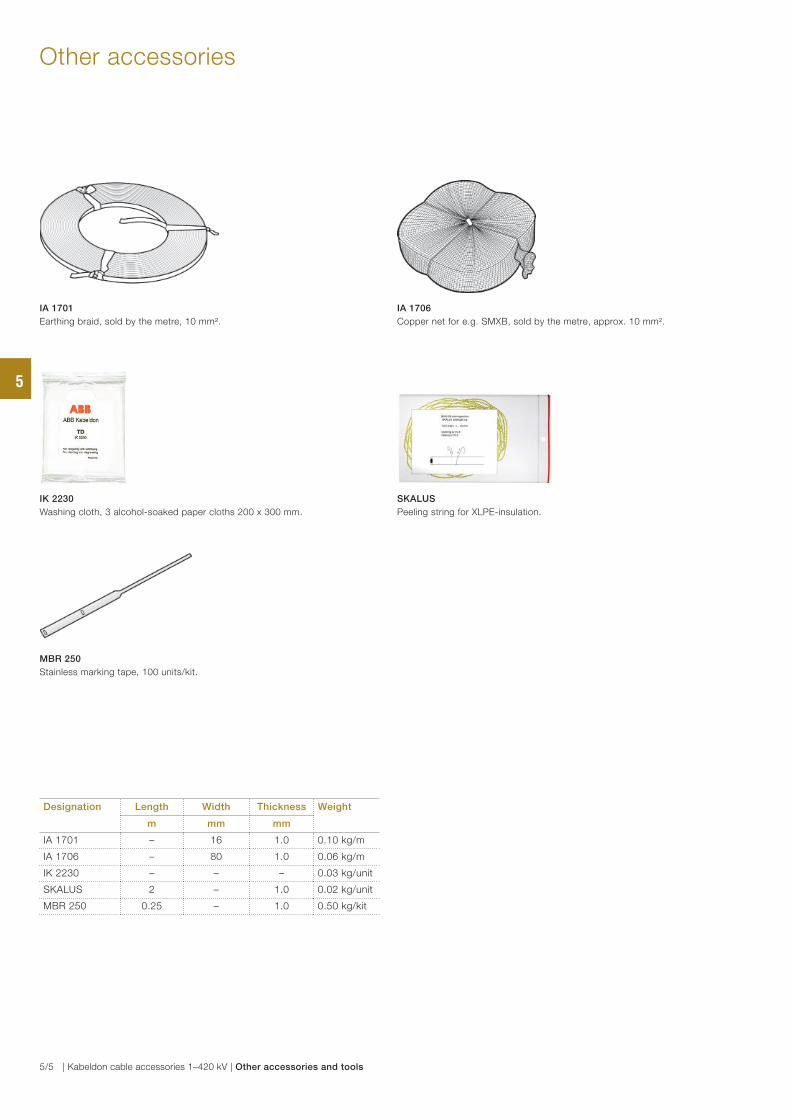
Other accessories
Designation Length Width Thickness Weight
m mm mm
IA 1701 – 16 1.0 0.10 kg/m
IA 1706 – 80 1.0 0.06 kg/m
IK 2230 – – – 0.03 kg/unit
SKALUS 2 – 1.0 0.02 kg/unit
MBR 250 0.25 – 1.0 0.50 kg/kit
IA 1701
Earthing braid, sold by the metre, 10 mm².
IA 1706
Copper net for e.g. SMXB, sold by the metre, approx. 10 mm².
IK 2230
Washing cloth, 3 alcohol-soaked paper cloths 200 x 300 mm.
SKALUS
Peeling string for XLPE-insulation.
MBR 250
Stainless marking tape, 100 units/kit.
5
5/5 | Kabeldon cable accessories 1–420 kV | Other accessories and tools
5
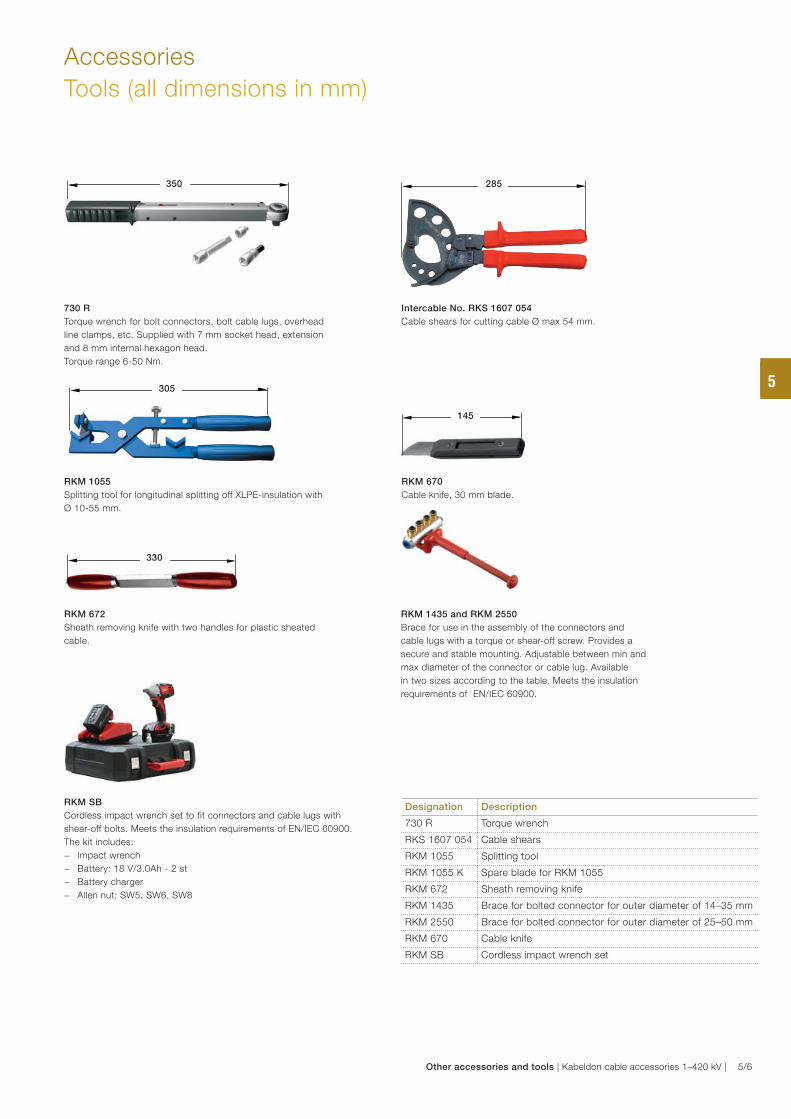
Accessories
Tools (all dimensions in mm)
Designation Description
730 R Torque wrench
RKS 1607 054 Cable shears
RKM 1055 Splitting tool
RKM 1055 K Spare blade for RKM 1055
RKM 672 Sheath removing knife
RKM 1435 Brace for bolted connector for outer diameter of 14–35 mm
RKM 2550 Brace for bolted connector for outer diameter of 25–50 mm
RKM 670 Cable knife
RKM SB Cordless impact wrench set
730 R
Torque wrench for bolt connectors, bolt cable lugs, overhead
line clamps, etc. Supplied with 7 mm socket head, extension
and 8 mm internal hexagon head.
Torque range 6-50 Nm.
RKM 1055
Splitting tool for longitudinal splitting off XLPE-insulation with
Ø 10-55 mm.
RKM 670
Cable knife, 30 mm blade.
350
305
145
RKM 672
Sheath removing knife with two handles for plastic sheated
cable.
Intercable No. RKS 1607 054
Cable shears for cutting cable Ø max 54 mm.
330
285
RKM 1435 and RKM 2550
Brace for use in the assembly of the connectors and
cable lugs with a torque or shear-off screw. Provides a
secure and stable mounting. Adjustable between min and
max diameter of the connector or cable lug. Available
in two sizes according to the table. Meets the insulation
requirements of EN/IEC 60900.
RKM SB
Cordless impact wrench set to fit connectors and cable lugs with
shear-off bolts. Meets the insulation requirements of EN/IEC 60900.
The kit includes:
− Impact wrench
− Battery: 18 V/3.0Ah - 2 st
− Battery charger
− Allen nut: SW5, SW6, SW8
5
Other accessories and tools | Kabeldon cable accessories 1–420 kV | 5/6
5
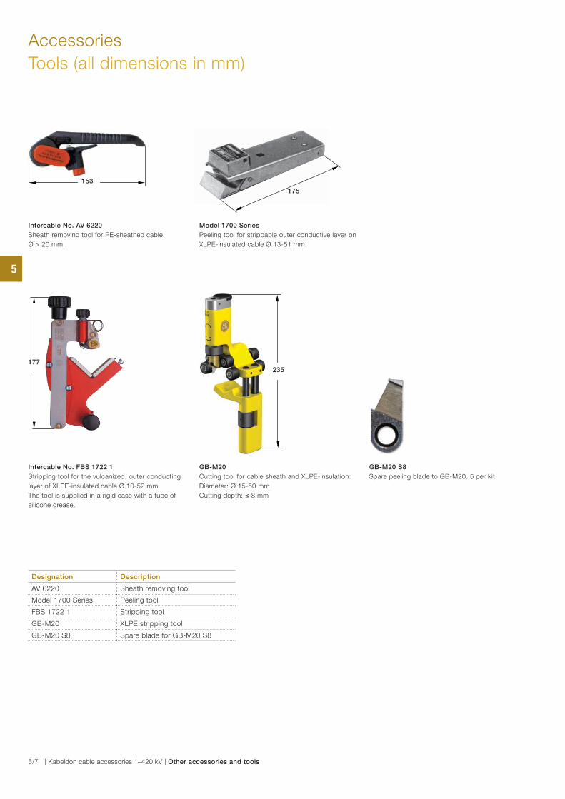
Accessories
Tools (all dimensions in mm)
Designation Description
AV 6220 Sheath removing tool
Model 1700 Series Peeling tool
FBS 1722 1 Stripping tool
GB-M20 XLPE stripping tool
GB-M20 S8 Spare blade for GB-M20 S8
GB-M20
Cutting tool for cable sheath and XLPE-insulation:
Diameter: Ø 15-50 mm
Cutting depth: ≤ 8 mm
Intercable No. AV 6220
Sheath removing tool for PE-sheathed cable
Ø > 20 mm.
Model 1700 Series
Peeling tool for strippable outer conductive layer on
XLPE-insulated cable Ø 13-51 mm.
Intercable No. FBS 1722 1
Stripping tool for the vulcanized, outer conducting
layer of XLPE-insulated cable Ø 10-52 mm.
The tool is supplied in a rigid case with a tube of
silicone grease.
153
235177
175
GB-M20 S8
Spare peeling blade to GB-M20. 5 per kit.
5
5/7 | Kabeldon cable accessories 1–420 kV | Other accessories and tools

5
Other accessories and tools | Kabeldon cable accessories 1–420 kV | 5/8
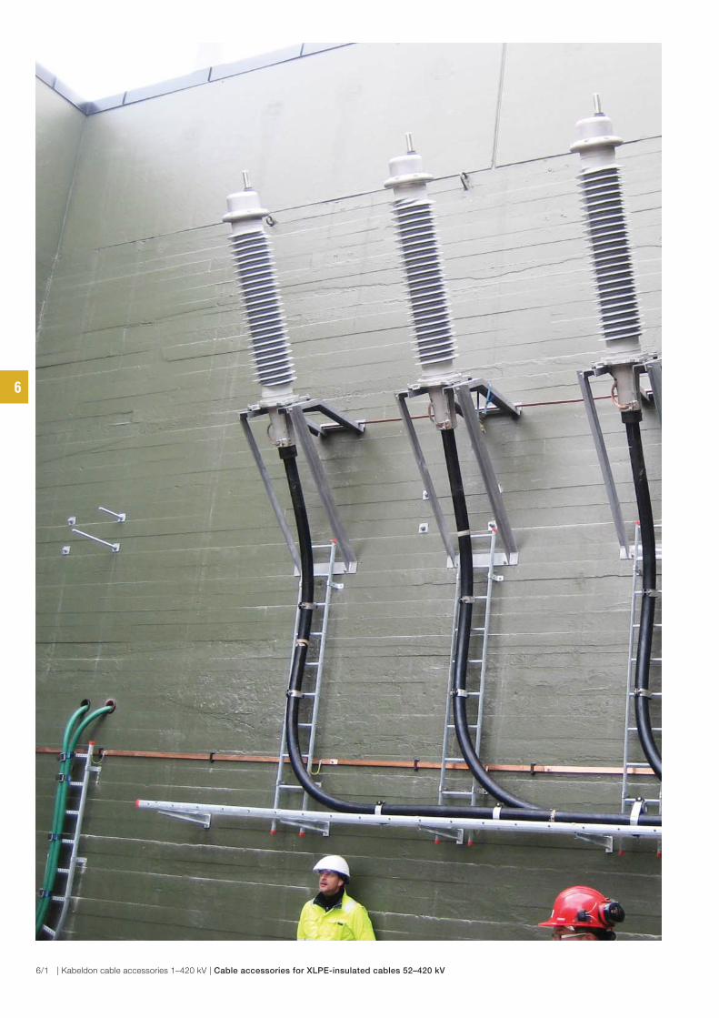
6
6/1 | Kabeldon cable accessories 1–420 kV | Cable accessories for XLPE-insulated cables 52–420 kV
Table of contents
Cable accessories 52–420 kV
Introduction
Cable accessories 52–420 kV 6/3
Cable terminations
Outdoor cable termination
APED 36–84 kV 6/4
Outdoor flexible cable termination, APSEA 52–72 kV 6/7
Outdoor cable termination, APECB 84–420 kV 6/10
Dry outdoor pre-assembled cable termination, TD 145 kV 6/13
Dry plug-in indoor cable termination, CD 145 kV for connection to:
– gas-insulated switchgear (GIS) 6/15
– transformers (TRF) 6/15
Cable termination, APEGA 84–420 kV for connection to:
– gas-insulated switchgear (GIS) 6/17
– transformers (TRF) 6/17
Earthing kits for cable terminations, JSA, SCK 6/21
Cable joints
Premolded one-piece cable joint
– without screen interruption JS 52–123 kV 6/22
– with screen interruption JX 52–123 kV 6/22
Premolded one-piece cable joint
– without screen interruption JS 245 kV 6/26
– with screen interruption JX 245 kV 6/26
Premolded cable joint
– without screen interruption SMPGB 145–170 kV 6/28
– with screen interruption SMPGB-C 145–170 kV 6/28
Premolded cable joint
– without screen interruption SMPGB 420 kV 6/31
– with screen interruption SMPGB-C 420 kV 6/31
Accessories, ARM, SKKB 6/33
Accessories
Tools and oil 6/34
6
Cable accessories for XLPE-insulated cables 52–420 kV | Kabeldon cable accessories 1–420 kV | 6/2

Introduction
Cable accessories 52–420 kV
ABB in Alingsås has long experience in the area of
52–420 kV and has always led the field in research and
development. We were among the first in the world to use
stress cone technology to control electrical fields.
One reason for our success is that we have constantly
developed cable accessories for all types of cables. This
has given us an experience base that is both broad and
deep. We have also developed our accessories to facilitate
for optical fiber in power cables, and even integrated cross
bonding in cable joints. This involves system designers to
improve their systems.
One feature that sets our range of cable accessories for this
voltage range apart, is their modular design. This makes the
accessories exeptionally easy to install. The installers become
familiar with the components, and this reduces the risk of
mistakes.
Another advantage is that our cable terminations can be
assembled on the ground under controlled conditions and
then lifted into place – simple and safe!
Unless otherwise specified, the cable accessories are
supplied as standard with bolt connections for conductors.
We offer training courses for installers and supervisors.
For information, please contact your ABB-representative or
our training department directly.
Installation of composite cable termination, APECB.
We develop accessories for
most cable designs, including
cables with optical fiber.
Installation of Kabeldon cable joint with screen interruption, JX 245.
Cable termination APEGA are installed in a gas-insulated switchgear. Installation of dry cable termination, TD 145 kV.
6
6/3 | Kabeldon cable accessories 1–420 kV | Cable accessories for XLPE-insulated cables 52–420 kV
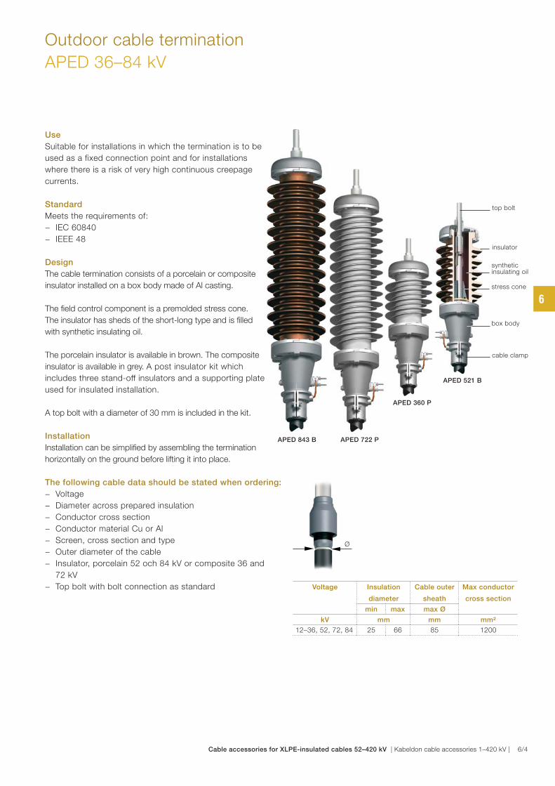
Use
Suitable for installations in which the termination is to be
used as a fixed connection point and for installations
where there is a risk of very high continuous creepage
currents.
Standard
Meets the requirements of:
− IEC 60840
− IEEE 48
Design
The cable termination consists of a porcelain or composite
insulator installed on a box body made of Al casting.
The fi eld control component is a premolded stress cone.
The insulator has sheds of the short-long type and is fi lled
with synthetic insulating oil.
The porcelain insulator is available in brown. The composite
insulator is available in grey. A post insulator kit which
includes three stand-off insulators and a supporting plate is
used for insulated installation.
A top bolt with a diameter of 30 mm is included in the kit.
Installation
Installation can be simplifi ed by assembling the termination
horizontally on the ground before lifting it into place.
The following cable data should be stated when ordering:
− Voltage
− Diameter across prepared insulation
− Conductor cross section
− Conductor material Cu or Al
− Screen, cross section and type
− Outer diameter of the cable
− Insulator, porcelain 52 och 84 kV or composite 36 and
72 kV
− Top bolt with bolt connection as standard
Outdoor cable termination
APED 36–84 kV
Voltage Insulation
diameter
Cable outer
sheath
Max conductor
cross section
min max max Ø
kV mm mm mm²
12–36, 52, 72, 84 25 66 85 1200
stress cone
box body
cable clamp
APED 843 B
APED 521 B
APED 360 P
APED 722 P
top bolt
synthetic insulating oil
insulator
Ø
6
Cable accessories for XLPE-insulated cables 52–420 kV | Kabeldon cable accessories 1–420 kV | 6/4
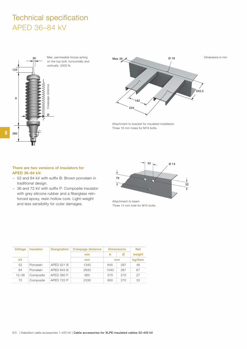
Technical specification
APED 36–84 kV
Max. permissible forces acting
on the top bolt, horizontally and
vertically: 2000 N.
Attachment to bracket for insulated installation
Three 18 mm holes for M16 bolts.
Attachment to beam
Three 14 mm hole for M10 bolts.
202,5
182
234
Max 35 Ø 18
32
76
52 Ø 14
There are two versions of insulators for
APED 36–84 kV:
− 52 and 84 kV with suffix B: Brown porcelain in
traditional design.
− 36 and 72 kV with suffix P: Composite insulator
with grey silicone rubber and a fiberglass rein-
forced epoxy, resin hollow core. Light-weight
and less sensibility for outer damages.
Voltage Insulator Designation Creepage distance Dimensions Net
weightmin A Ø
kV mm mm kg/item
52 Porcelain APED 521 B 1340 645 267 48
84 Porcelain APED 843 B 2635 1040 267 67
12–36 Composite APED 360 P 950 570 270 27
72 Composite APED 722 P 2330 950 270 33
Dimensions in mm
Cre
ep
ag
e d
ista
nce
280
125
A
30
Ø
6
6/5 | Kabeldon cable accessories 1–420 kV | Cable accessories for XLPE-insulated cables 52–420 kV
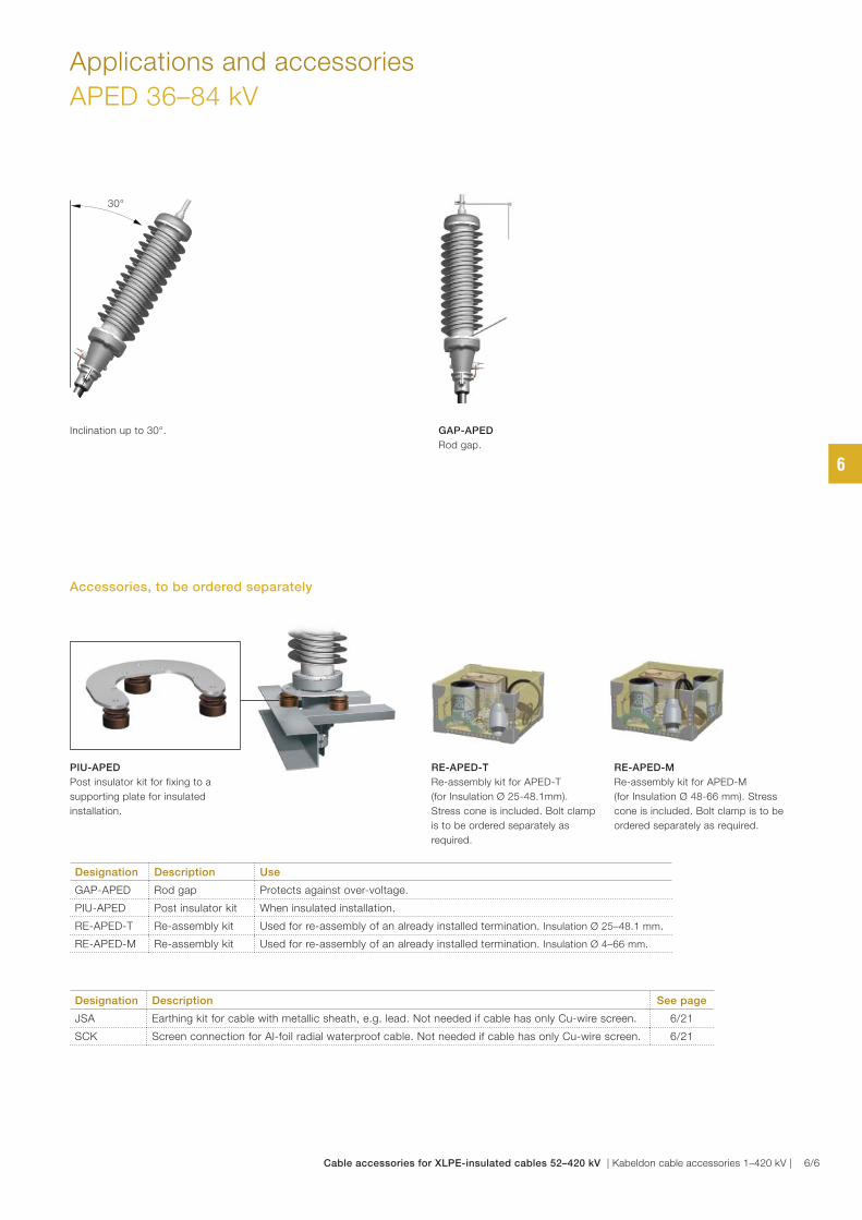
Inclination up to 30°.
Applications and accessories
APED 36–84 kV
GAP-APED
Rod gap.
PIU-APED
Post insulator kit for fixing to a
supporting plate for insulated
installation.
RE-APED-T
Re-assembly kit for APED-T
(for Insulation Ø 25-48.1mm).
Stress cone is included. Bolt clamp
is to be ordered separately as
required.
RE-APED-M
Re-assembly kit for APED-M
(for Insulation Ø 48-66 mm). Stress
cone is included. Bolt clamp is to be
ordered separately as required.
Designation Description Use
GAP-APED Rod gap Protects against over-voltage.
PIU-APED Post insulator kit When insulated installation.
RE-APED-T Re-assembly kit Used for re-assembly of an already installed termination. Insulation Ø 25–48.1 mm.
RE-APED-M Re-assembly kit Used for re-assembly of an already installed termination. Insulation Ø 4–66 mm.
30°
Designation Description See page
JSA Earthing kit for cable with metallic sheath, e.g. lead. Not needed if cable has only Cu-wire screen. 6/21
SCK Screen connection for Al-foil radial waterproof cable. Not needed if cable has only Cu-wire screen. 6/21
Accessories, to be ordered separately
6
Cable accessories for XLPE-insulated cables 52–420 kV | Kabeldon cable accessories 1–420 kV | 6/6
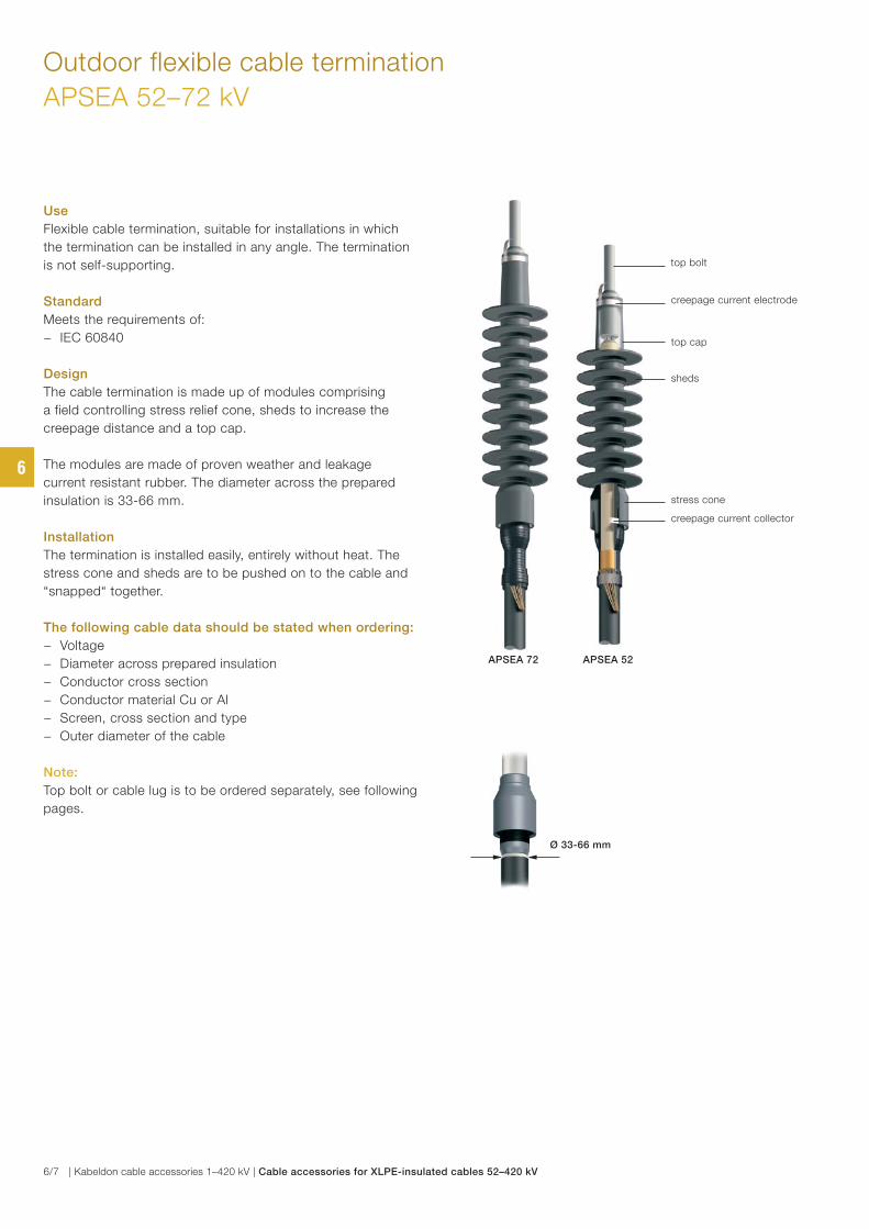
Use
Flexible cable termination, suitable for installations in which
the termination can be installed in any angle. The termination
is not self-supporting.
Standard
Meets the requirements of:
− IEC 60840
Design
The cable termination is made up of modules comprising
a field controlling stress relief cone, sheds to increase the
creepage distance and a top cap.
The modules are made of proven weather and leakage
current resistant rubber. The diameter across the prepared
insulation is 33-66 mm.
Installation
The termination is installed easily, entirely without heat. The
stress cone and sheds are to be pushed on to the cable and
“snapped“ together.
The following cable data should be stated when ordering:
− Voltage
− Diameter across prepared insulation
− Conductor cross section
− Conductor material Cu or Al
− Screen, cross section and type
− Outer diameter of the cable
Note:
Top bolt or cable lug is to be ordered separately, see following
pages.
Outdoor flexible cable termination
APSEA 52–72 kV
stress cone
sheds
creepage current electrode
creepage current collector
top bolt
top cap
APSEA 72 APSEA 52
Ø 33-66 mm
6
6/7 | Kabeldon cable accessories 1–420 kV | Cable accessories for XLPE-insulated cables 52–420 kV
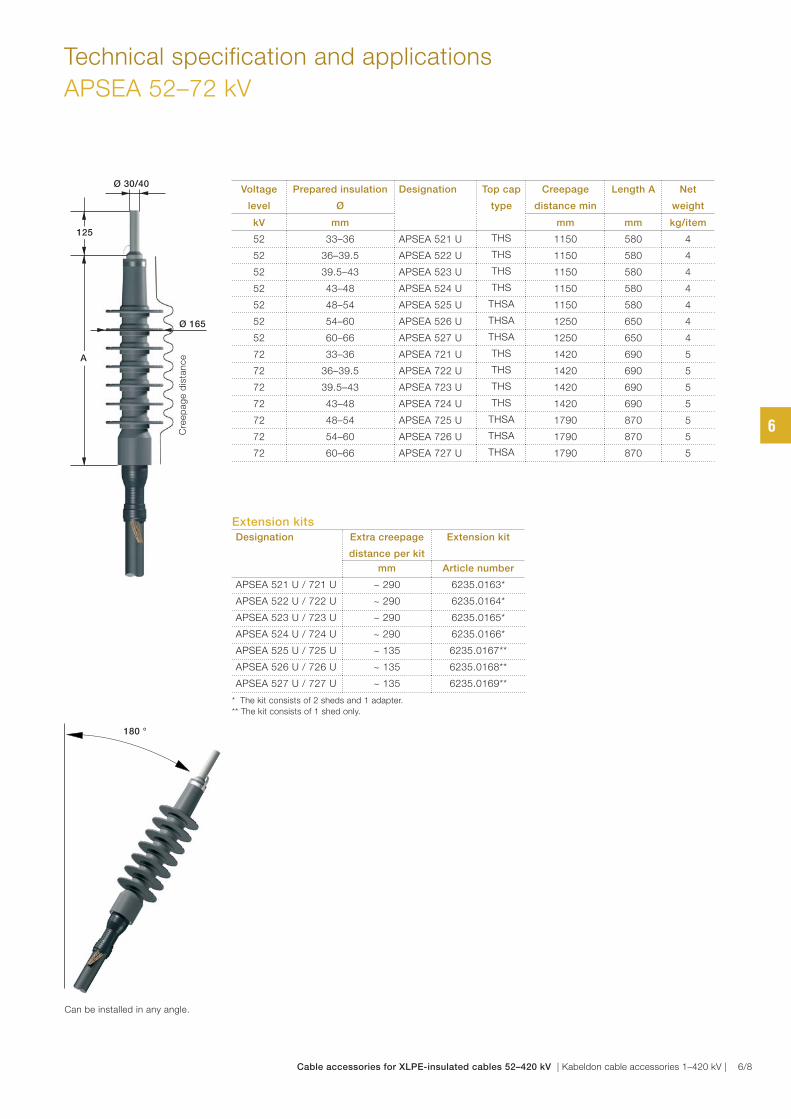
Technical specification and applications
APSEA 52–72 kV
Voltage
level
Prepared insulation
Ø
Designation Top cap
type
Creepage
distance min
Length A Net
weight
kV mm mm mm kg/item
52 33–36 APSEA 521 U THS 1150 580 4
52 36–39.5 APSEA 522 U THS 1150 580 4
52 39.5–43 APSEA 523 U THS 1150 580 4
52 43–48 APSEA 524 U THS 1150 580 4
52 48–54 APSEA 525 U THSA 1150 580 4
52 54–60 APSEA 526 U THSA 1250 650 4
52 60–66 APSEA 527 U THSA 1250 650 4
72 33–36 APSEA 721 U THS 1420 690 5
72 36–39.5 APSEA 722 U THS 1420 690 5
72 39.5–43 APSEA 723 U THS 1420 690 5
72 43–48 APSEA 724 U THS 1420 690 5
72 48–54 APSEA 725 U THSA 1790 870 5
72 54–60 APSEA 726 U THSA 1790 870 5
72 60–66 APSEA 727 U THSA 1790 870 5
180 °
Can be installed in any angle.
Extension kitsDesignation Extra creepage
distance per kit
Extension kit
mm Article number
APSEA 521 U / 721 U ~ 290 6235.0163*
APSEA 522 U / 722 U ~ 290 6235.0164*
APSEA 523 U / 723 U ~ 290 6235.0165*
APSEA 524 U / 724 U ~ 290 6235.0166*
APSEA 525 U / 725 U ~ 135 6235.0167**
APSEA 526 U / 726 U ~ 135 6235.0168**
APSEA 527 U / 727 U ~ 135 6235.0169**
* The kit consists of 2 sheds and 1 adapter.
** The kit consists of 1 shed only.
Ø 30/40
Ø 165
Cre
ep
ag
e d
ista
nceA
125
6
Cable accessories for XLPE-insulated cables 52–420 kV | Kabeldon cable accessories 1–420 kV | 6/8
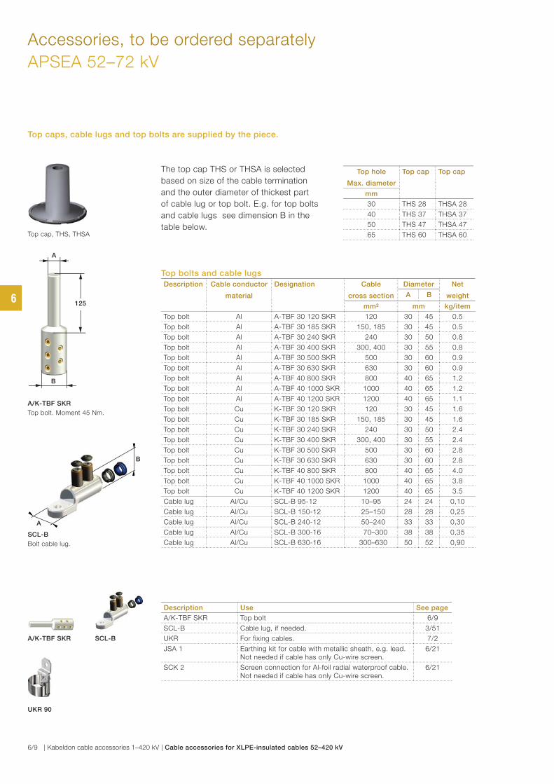
Accessories, to be ordered separately
APSEA 52–72 kV
Top cap, THS, THSA
Top bolts and cable lugs
Description Cable conductor
material
Designation Cable
cross section
Diameter Net
weightA B
mm² mm kg/item
Top bolt Al A-TBF 30 120 SKR 120 30 45 0.5
Top bolt Al A-TBF 30 185 SKR 150, 185 30 45 0.5
Top bolt Al A-TBF 30 240 SKR 240 30 50 0.8
Top bolt Al A-TBF 30 400 SKR 300, 400 30 55 0.8
Top bolt Al A-TBF 30 500 SKR 500 30 60 0.9
Top bolt Al A-TBF 30 630 SKR 630 30 60 0.9
Top bolt Al A-TBF 40 800 SKR 800 40 65 1.2
Top bolt Al A-TBF 40 1000 SKR 1000 40 65 1.2
Top bolt Al A-TBF 40 1200 SKR 1200 40 65 1.1
Top bolt Cu K-TBF 30 120 SKR 120 30 45 1.6
Top bolt Cu K-TBF 30 185 SKR 150, 185 30 45 1.6
Top bolt Cu K-TBF 30 240 SKR 240 30 50 2.4
Top bolt Cu K-TBF 30 400 SKR 300, 400 30 55 2.4
Top bolt Cu K-TBF 30 500 SKR 500 30 60 2.8
Top bolt Cu K-TBF 30 630 SKR 630 30 60 2.8
Top bolt Cu K-TBF 40 800 SKR 800 40 65 4.0
Top bolt Cu K-TBF 40 1000 SKR 1000 40 65 3.8
Top bolt Cu K-TBF 40 1200 SKR 1200 40 65 3.5
Cable lug Al/Cu SCL-B 95-12 10–95 24 24 0,10
Cable lug Al/Cu SCL-B 150-12 25–150 28 28 0,25
Cable lug Al/Cu SCL-B 240-12 50–240 33 33 0,30
Cable lug Al/Cu SCL-B 300-16 70–300 38 38 0,35
Cable lug Al/Cu SCL-B 630-16 300–630 50 52 0,90
Description Use See page
A/K-TBF SKR Top bolt 6/9
SCL-B Cable lug, if needed. 3/51
UKR For fixing cables. 7/2
JSA 1 Earthing kit for cable with metallic sheath, e.g. lead. Not needed if cable has only Cu-wire screen.
6/21
SCK 2 Screen connection for Al-foil radial waterproof cable. Not needed if cable has only Cu-wire screen.
6/21
Top hole
Max. diameter
Top cap Top cap
mm
30 THS 28 THSA 28
40 THS 37 THSA 37
50 THS 47 THSA 47
65 THS 60 THSA 60
The top cap THS or THSA is selected
based on size of the cable termination
and the outer diameter of thickest part
of cable lug or top bolt. E.g. for top bolts
and cable lugs see dimension B in the
table below.
SCL-B
UKR 90
A/K-TBF SKR
Top caps, cable lugs and top bolts are supplied by the piece.
B
A
125
A/K-TBF SKR
Top bolt. Moment 45 Nm.
B
A
SCL-B
Bolt cable lug.
6
6/9 | Kabeldon cable accessories 1–420 kV | Cable accessories for XLPE-insulated cables 52–420 kV
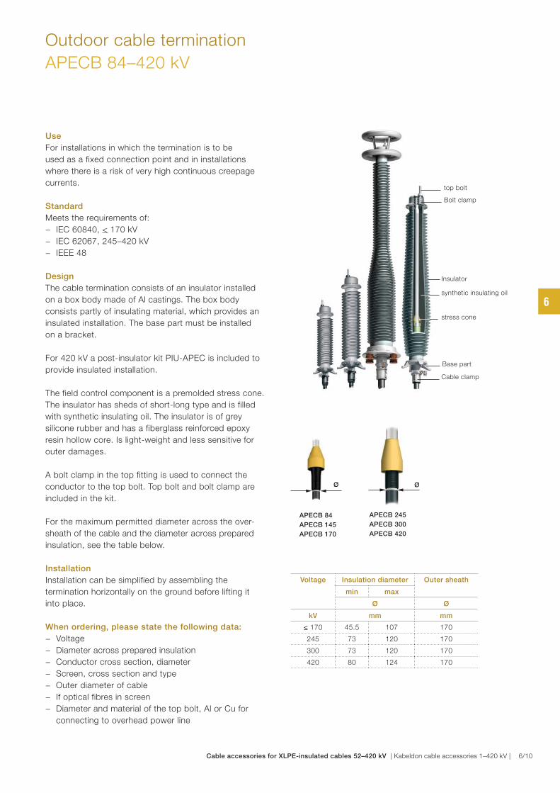
Use
For installations in which the termination is to be
used as a fixed connection point and in installations
where there is a risk of very high continuous creepage
currents.
Standard
Meets the requirements of:
− IEC 60840, < 170 kV
− IEC 62067, 245–420 kV
− IEEE 48
Design
The cable termination consists of an insulator installed
on a box body made of Al castings. The box body
consists partly of insulating material, which provides an
insulated installation. The base part must be installed
on a bracket.
For 420 kV a post-insulator kit PIU-APEC is included to
provide insulated installation.
The field control component is a premolded stress cone.
The insulator has sheds of short-long type and is filled
with synthetic insulating oil. The insulator is of grey
silicone rubber and has a fiberglass reinforced epoxy
resin hollow core. Is light-weight and less sensitive for
outer damages.
A bolt clamp in the top fitting is used to connect the
conductor to the top bolt. Top bolt and bolt clamp are
included in the kit.
For the maximum permitted diameter across the over-
sheath of the cable and the diameter across prepared
insulation, see the table below.
Installation
Installation can be simplified by assembling the
termination horizontally on the ground before lifting it
into place.
When ordering, please state the following data:
− Voltage
− Diameter across prepared insulation
− Conductor cross section, diameter
− Screen, cross section and type
− Outer diameter of cable
− If optical fibres in screen
− Diameter and material of the top bolt, Al or Cu for
connecting to overhead power line
Outdoor cable termination
APECB 84–420 kV
Voltage Insulation diameter Outer sheath
min max
Ø Ø
kV mm mm
≤ 170 45.5 107 170
245 73 120 170
300 73 120 170
420 80 124 170
synthetic insulating oil
top bolt
stress cone
Cable clamp
Insulator
Base part
Bolt clamp
Ø
APECB 84
APECB 145
APECB 170
Ø
APECB 245
APECB 300
APECB 420
6
Cable accessories for XLPE-insulated cables 52–420 kV | Kabeldon cable accessories 1–420 kV | 6/10
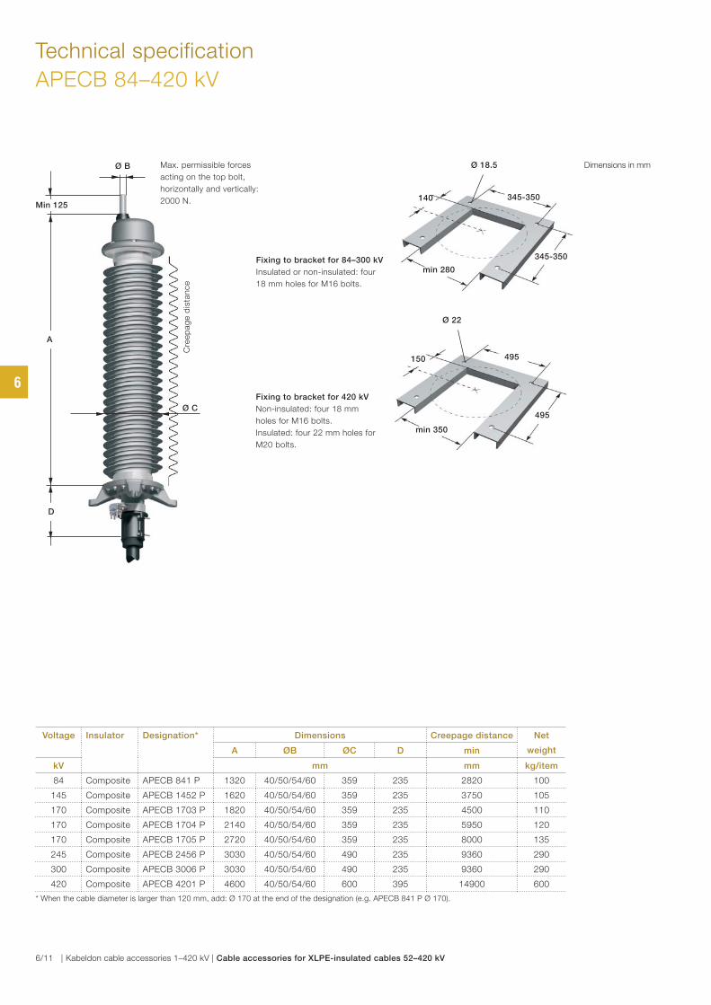
Technical specification
APECB 84–420 kV
495
Ø 22
min 350
495150
345-350
Ø 18.5
min 280
345-350140
Fixing to bracket for 84–300 kV
Insulated or non-insulated: four
18 mm holes for M16 bolts.
Fixing to bracket for 420 kV
Non-insulated: four 18 mm
holes for M16 bolts.
Insulated: four 22 mm holes for
M20 bolts.
Voltage Insulator Designation* Dimensions Creepage distance Net
weightA ØB ØC D min
kV mm mm kg/item
84 Composite APECB 841 P 1320 40/50/54/60 359 235 2820 100
145 Composite APECB 1452 P 1620 40/50/54/60 359 235 3750 105
170 Composite APECB 1703 P 1820 40/50/54/60 359 235 4500 110
170 Composite APECB 1704 P 2140 40/50/54/60 359 235 5950 120
170 Composite APECB 1705 P 2720 40/50/54/60 359 235 8000 135
245 Composite APECB 2456 P 3030 40/50/54/60 490 235 9360 290
300 Composite APECB 3006 P 3030 40/50/54/60 490 235 9360 290
420 Composite APECB 4201 P 4600 40/50/54/60 600 395 14900 600
* When the cable diameter is larger than 120 mm, add: Ø 170 at the end of the designation (e.g. APECB 841 P Ø 170).
Dimensions in mmØ B
Min 125
Cre
ep
ag
e d
ista
nce
Max. permissible forces
acting on the top bolt,
horizontally and vertically:
2000 N.
Ø C
A
D
6
6/11 | Kabeldon cable accessories 1–420 kV | Cable accessories for XLPE-insulated cables 52–420 kV
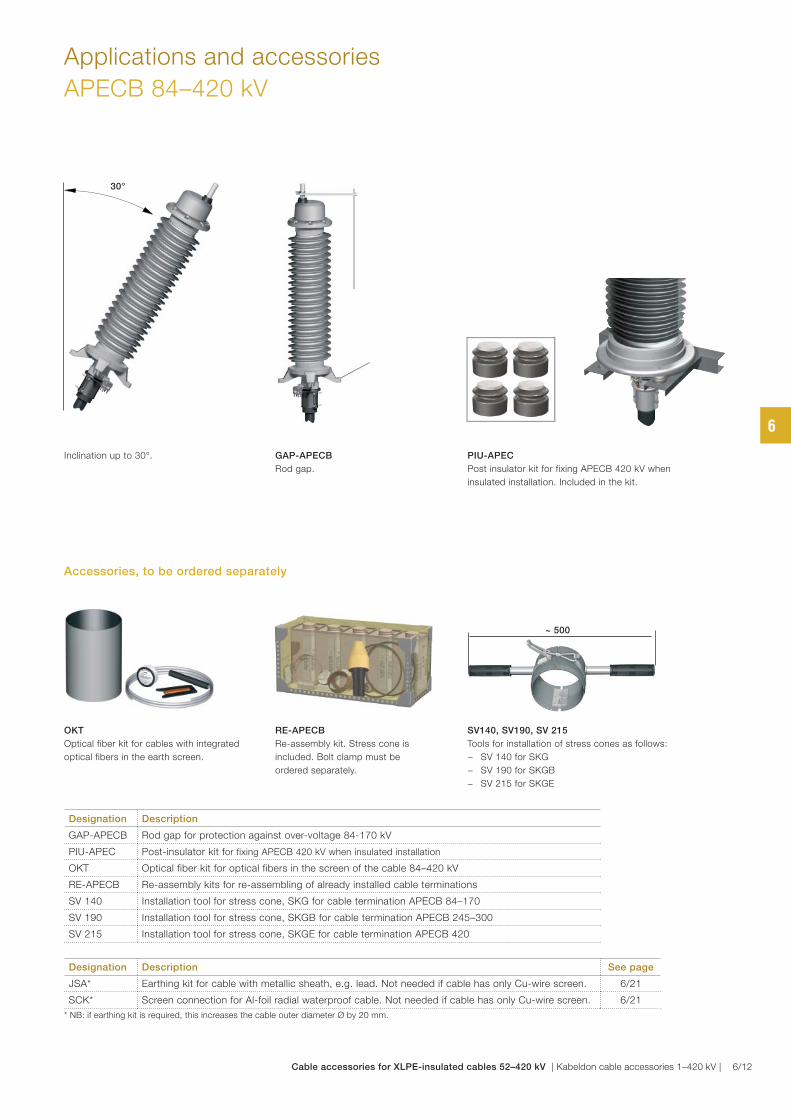
Applications and accessories
APECB 84–420 kV
GAP-APECB
Rod gap.
OKT
Optical fiber kit for cables with integrated
optical fibers in the earth screen.
PIU-APEC
Post insulator kit for fixing APECB 420 kV when
insulated installation. Included in the kit.
Designation Description
GAP-APECB Rod gap for protection against over-voltage 84-170 kV
PIU-APEC Post-insulator kit for fixing APECB 420 kV when insulated installation
OKT Optical fiber kit for optical fibers in the screen of the cable 84–420 kV
RE-APECB Re-assembly kits for re-assembling of already installed cable terminations
SV 140 Installation tool for stress cone, SKG for cable termination APECB 84–170
SV 190 Installation tool for stress cone, SKGB for cable termination APECB 245–300
SV 215 Installation tool for stress cone, SKGE for cable termination APECB 420
30°
Inclination up to 30°.
RE-APECB
Re-assembly kit. Stress cone is
included. Bolt clamp must be
ordered separately.
SV140, SV190, SV 215
Tools for installation of stress cones as follows:
− SV 140 for SKG
− SV 190 for SKGB
− SV 215 for SKGE
Designation Description See page
JSA* Earthing kit for cable with metallic sheath, e.g. lead. Not needed if cable has only Cu-wire screen. 6/21
SCK* Screen connection for Al-foil radial waterproof cable. Not needed if cable has only Cu-wire screen. 6/21
* NB: if earthing kit is required, this increases the cable outer diameter Ø by 20 mm.
Accessories, to be ordered separately
~ 500
6
Cable accessories for XLPE-insulated cables 52–420 kV | Kabeldon cable accessories 1–420 kV | 6/12
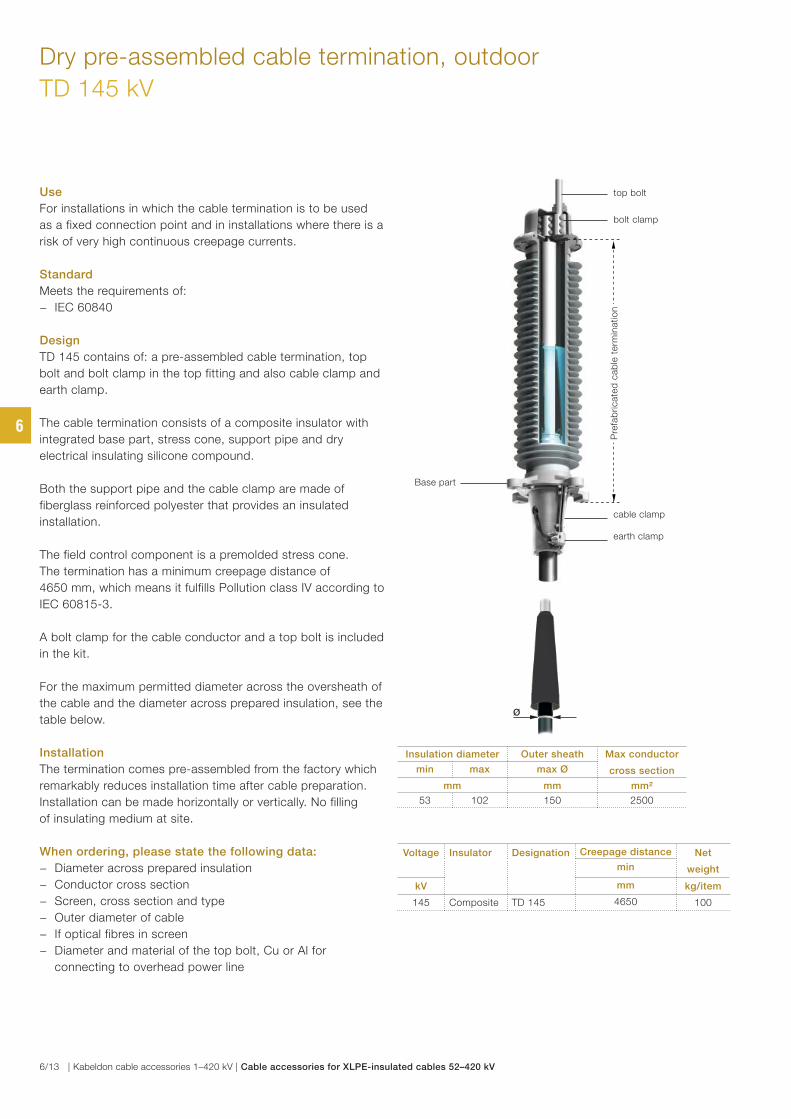
Use
For installations in which the cable termination is to be used
as a fixed connection point and in installations where there is a
risk of very high continuous creepage currents.
Standard
Meets the requirements of:
− IEC 60840
Design
TD 145 contains of: a pre-assembled cable termination, top
bolt and bolt clamp in the top fitting and also cable clamp and
earth clamp.
The cable termination consists of a composite insulator with
integrated base part, stress cone, support pipe and dry
electrical insulating silicone compound.
Both the support pipe and the cable clamp are made of
fiberglass reinforced polyester that provides an insulated
installation.
The field control component is a premolded stress cone.
The termination has a minimum creepage distance of
4650 mm, which means it fulfills Pollution class IV according to
IEC 60815-3.
A bolt clamp for the cable conductor and a top bolt is included
in the kit.
For the maximum permitted diameter across the oversheath of
the cable and the diameter across prepared insulation, see the
table below.
Installation
The termination comes pre-assembled from the factory which
remarkably reduces installation time after cable preparation.
Installation can be made horizontally or vertically. No filling
of insulating medium at site.
When ordering, please state the following data:
− Diameter across prepared insulation
− Conductor cross section
− Screen, cross section and type
− Outer diameter of cable
− If optical fibres in screen
− Diameter and material of the top bolt, Cu or Al for
connecting to overhead power line
Dry pre-assembled cable termination, outdoor
TD 145 kV
top bolt
earth clamp
cable clamp
Voltage Insulator Designation Creepage distance Net
weightmin
kV mm kg/item
145 Composite TD 145 4650 100
bolt clamp
Insulation diameter Outer sheath Max conductor
cross sectionmin max max Ø
mm mm mm²
53 102 150 2500
Pre
fab
ricate
d c
ab
le t
erm
inatio
nP
refa
bri
cate
d c
ab
le t
erm
inatio
n
Base part
Ø
6
6/13 | Kabeldon cable accessories 1–420 kV | Cable accessories for XLPE-insulated cables 52–420 kV
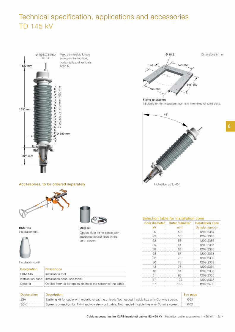
Technical specification, applications and accessories
TD 145 kV
345-350
Ø 18.5
min 280
345-350140
Fixing to bracket
Insulated or non-insulated: four 18.5 mm holes for M16 bolts.
Opto kit
Optical fiber kit for cables with
integrated optical fibers in the
earth screen.
Designation Description
RKM 145 Installation tool
Installation cone Installation cone, see table.
Opto kit Optical fiber kit for optical fibers in the screen of the cable
45°
Inclination up to 45°.
Selection table for installation cone
Inner diameter Outer diameter Installation cone
kV mm Article number
20 53 4209.2384
22 55 4209.2385
22 58 4209.2386
29 61 4209.2387
38 64 4209.2388
28 67 4209.2331
32 70 4209.2332
36 73 4209.2333
43 78 4209.2334
48 84 4209.2335
51 93 4209.2336
57 102 4209.2337
57 105 4209.2400
Accessories, to be ordered separately
Installation cone.
RKM 145
Installation tool.
Designation Description See page
JSA Earthing kit for cable with metallic sheath, e.g. lead. Not needed if cable has only Cu-wire screen. 6/21
SCK Screen connection for Al-foil radial waterproof cable. Not needed if cable has only Cu-wire screen. 6/21
Dimensions in mmMax. permissible forces
acting on the top bolt,
horizontally and vertically:
2000 N.
Ø 40/50/54/60
~ 130 mm
325 mm325 mm
1630 mm
Cre
ep
ag
e d
ista
nce m
in 4
65
0 m
m
Ø 380 mm
6
Cable accessories for XLPE-insulated cables 52–420 kV | Kabeldon cable accessories 1–420 kV | 6/14
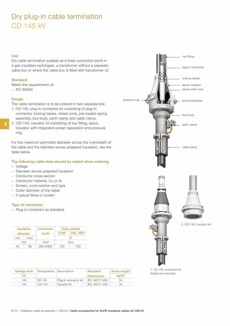
Use
Dry cable termination suitable as a fixed connection point in
a gas-insulated switchgear, a transformer without a separate
cable box or where the cable box is filled with transformer oil.
Standard
Meets the requirements of:
− IEC 60840
Design
The cable termination is to be ordered in two separate kits:
1. CD 145; plug-in connector kit consisting of plug-in
connector, locking halves, stress cone, pre-loaded spring
assembly, box body, earth clamp and cable clamp.
2. CDI 145; insulator kit consisting of top fitting, epoxy
insulator with integrated screen separation and pressure
ring.
For the maximum permitted diameter across the oversheath of
the cable and the diameter across prepared insulation, see the
table below.
The following cable data should be stated when ordering:
− Voltage
− Diameter across prepared insulation
− Conductor cross section
− Conductor material, Cu or Al
− Screen, cross section and type
− Outer diameter of the cable
− If optical fibres in screen
Type of connector:
− Plug-in connector as standard
Dry plug-in cable termination
CD 145 kV
Voltage level Designation Description Standard
dimensions
Gross weight
kV kg/kit
145 CD 145 Plug-in connector kit IEC 62271-209 33
145 CDI 145 Insulator kit IEC 62271-209 30
top fitting
plug-in connector
epoxy insulator
box body
earth clamp
cable clamp
locking halves
spring assembly
stress relief cone
pressure ring
2. CDI 145, Insulator kit.
1. CD 145, connector kit.
(Cable not included)
Insulation
diameter
Conductor
Cu/Al
Outer sheath
CUW PAL, MET
min max Ø
mm mm² mm
44 96 300–2000 150 130
6
6/15 | Kabeldon cable accessories 1–420 kV | Cable accessories for XLPE-insulated cables 52–420 kV
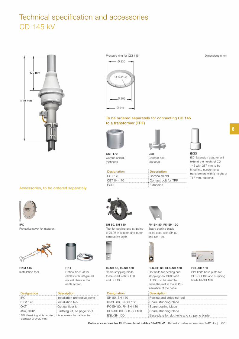
Technical specification and accessories
CD 145 kV
OKT
Optical fiber kit for
cables with integrated
optical fibers in the
earth screen.
CBT
Contact bolt.
(optional)
SH 80, SH 130
Tool for peeling and stripping
of XLPE-insulation and outer
conductive layer.
CST 170
Corona shield.
(optional)
FK-SH 80, FK-SH 130
Spare peeling blade
to be used with SH 80
and SH 130.
IK-SH 80, IK-SH 130
Spare stripping blade
to be used with SH 80
and SH 130.
RKM 145
Installation tool.
IPC
Protective cover for Insulator.
SLK-SH 80, SLK-SH 130
Slot knife for peeling and
stripping tool SH80 and
SH130. To be used to
make the slot in the XLPE-
insulation of the cable.
Dimensions in mm
BSL-SH 130
Slot knife base plate for
SLK-SH 130 and stripping
blade IK-SH 130.
Designation Description
IPC Installation protective cover
RKM 145 Installation tool
OKT Optical fiber kit
JSA, SCK* Earthing kit, se page 6/21
* NB: if earthing kit is required, this increases the cable outer
diameter Ø by 20 mm.
To be ordered separately for connecting CD 145
to a transformer (TRF)
Designation Description
CST 170 Corona shield
CBT 84-170 Contact bolt for TRF
ECDI Extension
Designation Description
SH 80, SH 130 Peeling and stripping tool
IK-SH 80, IN-SH 130 Spare stripping blade
FK-SH 80, FK-SH 130 Spare peeling blade
SLK-SH 80, SLK-SH 130 Spare stripping blade
BSL-SH 130 Base plate for slot knife and stripping blade
Accessories, to be ordered separately
Pressure ring for CDI 145.
ECDI
IEC Extension adapter will
extend the height of CD
145 with 287 mm to be
fitted into conventional
transformers with a height of
757 mm. (optional)
470 mm470 mm
1149 mm1149 mm
Ø 14 (12x)
Ø 320
Ø 283
Ø 345
6
Cable accessories for XLPE-insulated cables 52–420 kV | Kabeldon cable accessories 1–420 kV | 6/16
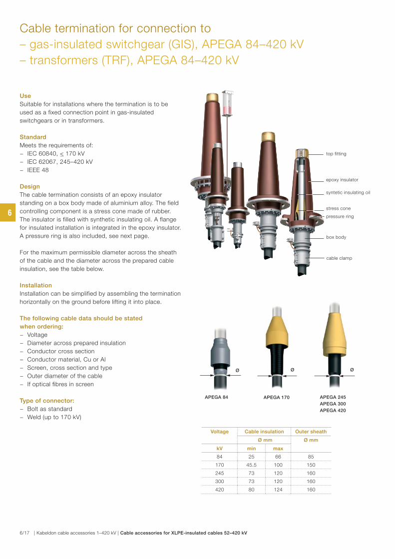
Cable termination for connection to
– gas-insulated switchgear (GIS), APEGA 84–420 kV
– transformers (TRF), APEGA 84–420 kV
Use
Suitable for installations where the termination is to be
used as a fixed connection point in gas-insulated
switchgears or in transformers.
Standard
Meets the requirements of:
− IEC 60840, < 170 kV
− IEC 62067, 245–420 kV
− IEEE 48
Design
The cable termination consists of an epoxy insulator
standing on a box body made of aluminium alloy. The field
controlling component is a stress cone made of rubber.
The insulator is filled with synthetic insulating oil. A flange
for insulated installation is integrated in the epoxy insulator.
A pressure ring is also included, see next page.
For the maximum permissible diameter across the sheath
of the cable and the diameter across the prepared cable
insulation, see the table below.
Installation
Installation can be simplified by assembling the termination
horizontally on the ground before lifting it into place.
The following cable data should be stated
when ordering:
− Voltage
− Diameter across prepared insulation
− Conductor cross section
− Conductor material, Cu or Al
− Screen, cross section and type
− Outer diameter of the cable
− If optical fibres in screen
Type of connector:
− Bolt as standard
− Weld (up to 170 kV)
epoxy insulator
stress cone
box body
cable clamp
pressure ring
syntetic insulating oil
top fitting
Voltage Cable insulation Outer sheath
Ø mm Ø mm
kV min max
84 25 66 85
170 45.5 100 150
245 73 120 160
300 73 120 160
420 80 124 160
Ø
APEGA 84
Ø
APEGA 170
Ø
APEGA 245
APEGA 300
APEGA 420
6
6/17 | Kabeldon cable accessories 1–420 kV | Cable accessories for XLPE-insulated cables 52–420 kV
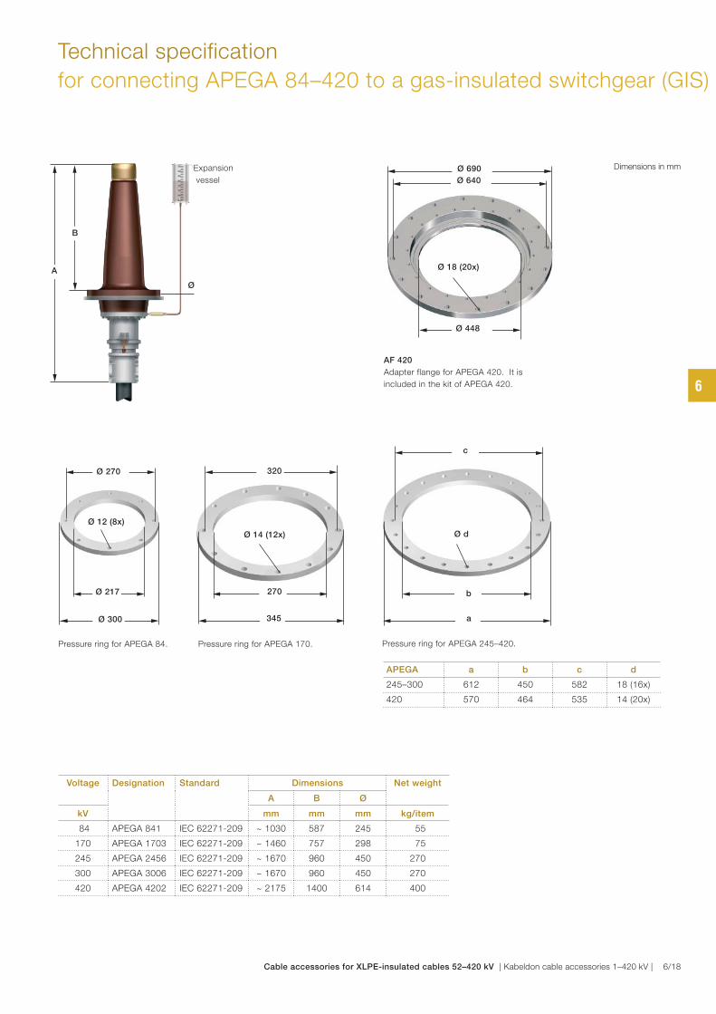
Technical specification
for connecting APEGA 84–420 to a gas-insulated switchgear (GIS)
Dimensions in mm
APEGA a b c d
245–300 612 450 582 18 (16x)
420 570 464 535 14 (20x)
AF 420
Adapter flange for APEGA 420. It is
included in the kit of APEGA 420.
Voltage Designation Standard Dimensions Net weight
A B Ø
kV mm mm mm kg/item
84 APEGA 841 IEC 62271-209 ~ 1030 587 245 55
170 APEGA 1703 IEC 62271-209 ~ 1460 757 298 75
245 APEGA 2456 IEC 62271-209 ~ 1670 960 450 270
300 APEGA 3006 IEC 62271-209 ~ 1670 960 450 270
420 APEGA 4202 IEC 62271-209 ~ 2175 1400 614 400
Ø
Expansion
vessel
A
BB
Pressure ring for APEGA 245–420.Pressure ring for APEGA 84. Pressure ring for APEGA 170.
Ø 12 (8x)
Ø 270
Ø 217
Ø 300
Ø 14 (12x)
320
270
345
Ø d
c
b
a
Ø 18 (20x)
Ø 640
Ø 690
Ø 448
6
Cable accessories for XLPE-insulated cables 52–420 kV | Kabeldon cable accessories 1–420 kV | 6/18
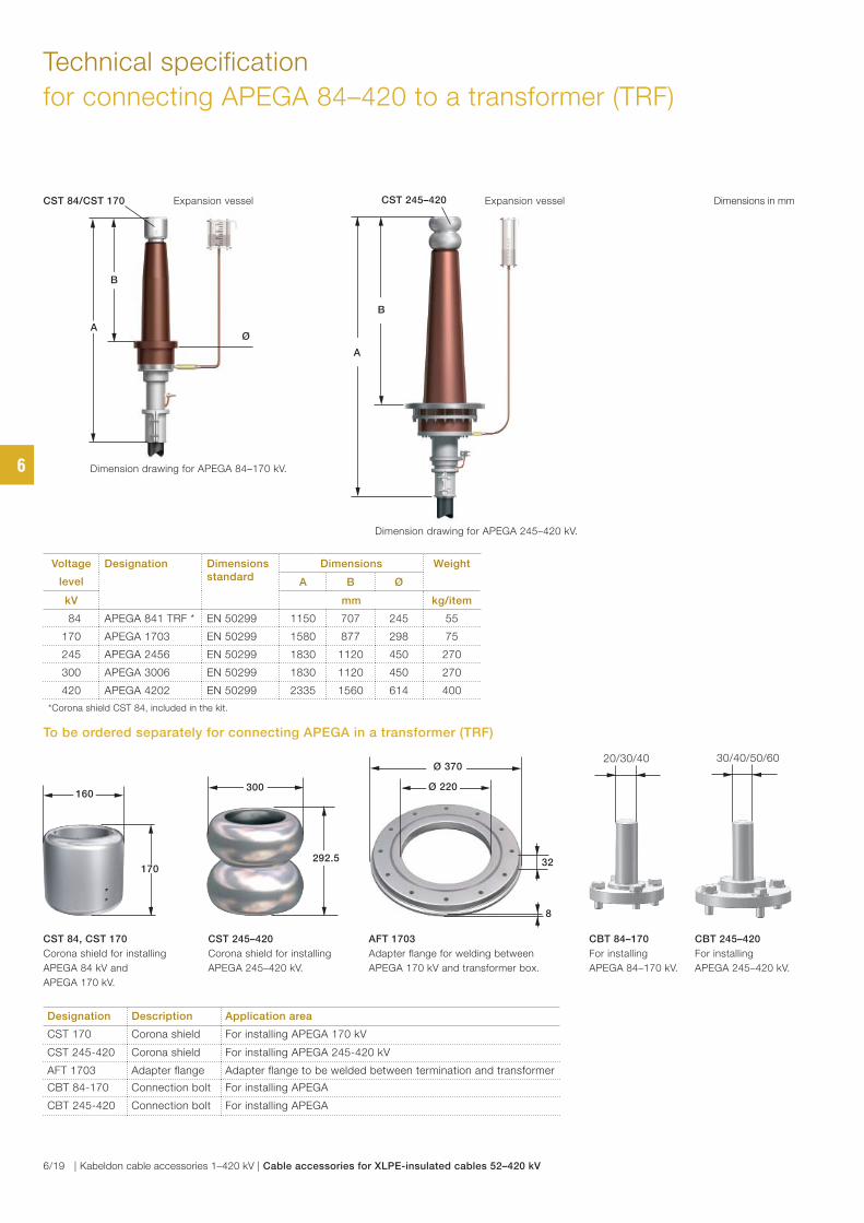
Technical specification
for connecting APEGA 84–420 to a transformer (TRF)
Dimension drawing for APEGA 245–420 kV.
Dimension drawing for APEGA 84–170 kV.
CBT 84–170
For installing
APEGA 84–170 kV.
CST 245–420
Corona shield for installing
APEGA 245–420 kV.
CST 84, CST 170
Corona shield for installing
APEGA 84 kV and
APEGA 170 kV.
AFT 1703
Adapter flange for welding between
APEGA 170 kV and transformer box.
CBT 245–420
For installing
APEGA 245–420 kV.
Voltage
level
Designation Dimensions standard
Dimensions Weight
A B Ø
kV mm kg/item
84 APEGA 841 TRF * EN 50299 1150 707 245 55
170 APEGA 1703 EN 50299 1580 877 298 75
245 APEGA 2456 EN 50299 1830 1120 450 270
300 APEGA 3006 EN 50299 1830 1120 450 270
420 APEGA 4202 EN 50299 2335 1560 614 400
*Corona shield CST 84, included in the kit.
Designation Description Application area
CST 170 Corona shield For installing APEGA 170 kV
CST 245-420 Corona shield For installing APEGA 245-420 kV
AFT 1703 Adapter flange Adapter flange to be welded between termination and transformer
CBT 84-170 Connection bolt For installing APEGA
CBT 245-420 Connection bolt For installing APEGA
To be ordered separately for connecting APEGA in a transformer (TRF)
Dimensions in mm
30/40/50/6020/30/40
300
292.5
160
17032
Ø 370
8
Ø 220
Expansion vessel
Ø
CST 84/CST 170
A
BB
Expansion vesselCST 245–420
A
BB
6
6/19 | Kabeldon cable accessories 1–420 kV | Cable accessories for XLPE-insulated cables 52–420 kV
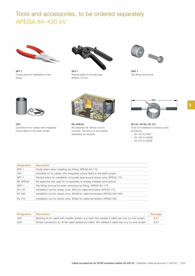
Tools and accessories, to be ordered separately
APEGA 84–420 kV
Designation Description
SPT 1 Circlip pliers when installing top fitting, APEGA 84–170.
OKT Optofiber kit for cables with integrated optical fibers in the earth screen.
SPV 1 Panduit pliers for installation of bundle tape around stress cone, APEGA 170.
RE-APEGA Re-assembly kits used for re-assembly of already installed terminations.
DMT 1 Top fitting removal kit when removing top fitting, APEGA 84–170.
SV 140 Installation tool for stress cone, SKG for cable termination APEGA 170.
SV 190 Installation tool for stress cone, SKGB for cable termination APEGA 245–300.
SV 215 Installation tool for stress cone, SKGE for cable termination APEGA 420.
SPT 1
Circlip pliers for installation of top
fitting.
RE-APEGA
Re-assembly kit. Stress cone is
included. Top bolt is to be ordered
separately as required.
OKT
Optofiber kit for cables with integrated
optical fibers in the earth screen.
DMT 1
Top fitting removal kit.
SV140, SV190, SV 215
Tools for installation of stress cones
as follows:
− SV 140 for SKG
− SV 190 for SKGB
− SV 215 for SKGE
Designation Description See page
JSA Earthing kit for cable with metallic sheath, e.g. lead. Not needed if cable has only Cu-wire screen. 6/21
SCK Screen connection for Al-foil radial waterproof cable. Not needed if cable has only Cu-wire screen. 6/21
SPV 1
Panduit pliers for bundle tape
APEGA 170 kV.
~ 500
6
Cable accessories for XLPE-insulated cables 52–420 kV | Kabeldon cable accessories 1–420 kV | 6/20
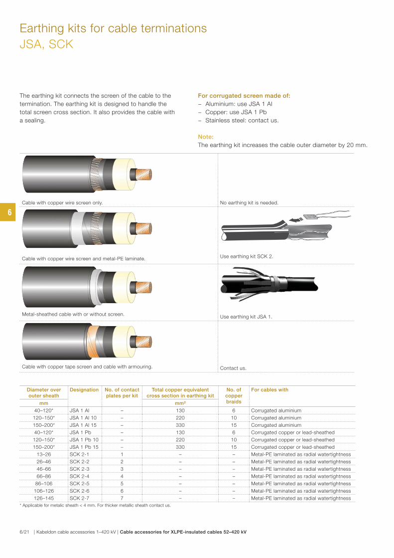
Earthing kits for cable terminations
JSA, SCK
The earthing kit connects the screen of the cable to the
termination. The earthing kit is designed to handle the
total screen cross section. It also provides the cable with
a sealing.
For corrugated screen made of:
− Aluminium: use JSA 1 Al
− Copper: use JSA 1 Pb
− Stainless steel: contact us.
Note:
The earthing kit increases the cable outer diameter by 20 mm.
Diameter over outer sheath
Designation No. of contact plates per kit
Total copper equivalent cross section in earthing kit
No. of copper braids
For cables with
mm mm²
40–120* JSA 1 Al – 130 6 Corrugated aluminium
120–150* JSA 1 Al 10 – 220 10 Corrugated aluminium
150–200* JSA 1 Al 15 – 330 15 Corrugated aluminium
40–120* JSA 1 Pb – 130 6 Corrugated copper or lead-sheathed
120–150* JSA 1 Pb 10 – 220 10 Corrugated copper or lead-sheathed
150–200* JSA 1 Pb 15 – 330 15 Corrugated copper or lead-sheathed
13–26 SCK 2-1 1 – – Metal-PE laminated as radial watertightness
26–46 SCK 2-2 2 – – Metal-PE laminated as radial watertightness
46–66 SCK 2-3 3 – – Metal-PE laminated as radial watertightness
66–86 SCK 2-4 4 – – Metal-PE laminated as radial watertightness
86–106 SCK 2-5 5 – – Metal-PE laminated as radial watertightness
106–126 SCK 2-6 6 – – Metal-PE laminated as radial watertightness
126–145 SCK 2-7 7 – – Metal-PE laminated as radial watertightness
* Applicable for metalic sheath < 4 mm. For thicker metallic sheath contact us.
Cable with copper wire screen only. No earthing kit is needed.
Cable with copper wire screen and metal-PE laminate. Use earthing kit SCK 2.
Metal-sheathed cable with or without screen.Use earthing kit JSA 1.
Cable with copper tape screen and cable with armouring. Contact us.
6
6/21 | Kabeldon cable accessories 1–420 kV | Cable accessories for XLPE-insulated cables 52–420 kV
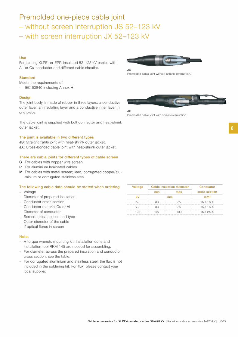
JS
Premolded cable joint without screen interruption.
JX
Premolded cable joint with screen interruption.
Premolded one-piece cable joint
– without screen interruption JS 52–123 kV
– with screen interruption JX 52–123 kV
Voltage Cable insulation diameter Conductor
cross sectionmin max
kV mm mm²
52 33 75 150–1600
72 33 75 150–1600
123 46 100 150–2500
Use
For jointing XLPE- or EPR-insulated 52–123 kV cables with
Al- or Cu-conductor and different cable sheaths.
Standard
Meets the requirements of:
− IEC 60840 including Annex H
Design
The joint body is made of rubber in three layers: a conductive
outer layer, an insulating layer and a conductive inner layer in
one piece.
The cable joint is supplied with bolt connector and heat-shrink
outer jacket.
The joint is available in two different types
JS: Straight cable joint with heat-shrink outer jacket.
JX: Cross-bonded cable joint with heat-shrink outer jacket.
There are cable joints for different types of cable screen
C For cables with copper wire screen.
P For aluminium laminated cables.
M For cables with metal screen; lead, corrugated copper/alu-
minium or corrugated stainless steel.
The following cable data should be stated when ordering:
− Voltage
− Diameter of prepared insulation
− Conductor cross section
− Conductor material Cu or Al
− Diameter of conductor
− Screen, cross section and type
− Outer diameter of the cable
− If optical fibres in screen
Note:
− A torque wrench, mounting kit, installation cone and
installation tool RKM 145 are needed for assembling.
− For diameter across the prepared insulation and conductor
cross section, see the table.
− For corrugated aluminium and stainless steel, the flux is not
included in the soldering kit. For flux, please contact your
local supplier.
6
Cable accessories for XLPE-insulated cables 52–420 kV | Kabeldon cable accessories 1–420 kV | 6/22
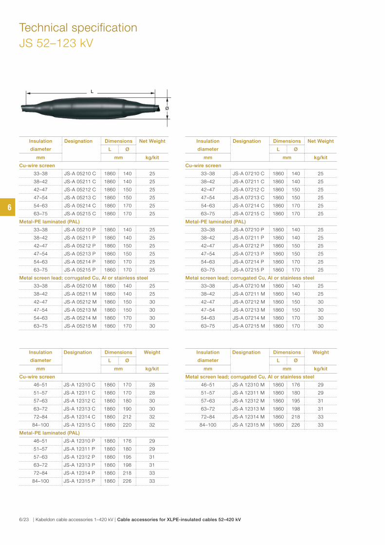
Technical specification
JS 52–123 kV
Insulation
diameter
Designation Dimensions Net Weight
L Ø
mm mm kg/kit
Cu-wire screen
33–38 JS-A 05210 C 1860 140 25
38–42 JS-A 05211 C 1860 140 25
42–47 JS-A 05212 C 1860 150 25
47–54 JS-A 05213 C 1860 150 25
54–63 JS-A 05214 C 1860 170 25
63–75 JS-A 05215 C 1860 170 25
Metal-PE laminated (PAL)
33–38 JS-A 05210 P 1860 140 25
38–42 JS-A 05211 P 1860 140 25
42–47 JS-A 05212 P 1860 150 25
47–54 JS-A 05213 P 1860 150 25
54–63 JS-A 05214 P 1860 170 25
63–75 JS-A 05215 P 1860 170 25
Metal screen lead; corrugated Cu, Al or stainless steel
33–38 JS-A 05210 M 1860 140 25
38–42 JS-A 05211 M 1860 140 25
42–47 JS-A 05212 M 1860 150 30
47–54 JS-A 05213 M 1860 150 30
54–63 JS-A 05214 M 1860 170 30
63–75 JS-A 05215 M 1860 170 30
Insulation
diameter
Designation Dimensions Weight
L Ø
mm mm kg/kit
Cu-wire screen
46–51 JS-A 12310 C 1860 170 28
51–57 JS-A 12311 C 1860 170 28
57–63 JS-A 12312 C 1860 180 30
63–72 JS-A 12313 C 1860 190 30
72–84 JS-A 12314 C 1860 212 32
84–100 JS-A 12315 C 1860 220 32
Metal-PE laminated (PAL)
46–51 JS-A 12310 P 1860 176 29
51–57 JS-A 12311 P 1860 180 29
57–63 JS-A 12312 P 1860 195 31
63–72 JS-A 12313 P 1860 198 31
72–84 JS-A 12314 P 1860 218 33
84–100 JS-A 12315 P 1860 226 33
Insulation
diameter
Designation Dimensions Net Weight
L Ø
mm mm kg/kit
Cu-wire screen
33–38 JS-A 07210 C 1860 140 25
38–42 JS-A 07211 C 1860 140 25
42–47 JS-A 07212 C 1860 150 25
47–54 JS-A 07213 C 1860 150 25
54–63 JS-A 07214 C 1860 170 25
63–75 JS-A 07215 C 1860 170 25
Metal-PE laminated (PAL)
33–38 JS-A 07210 P 1860 140 25
38–42 JS-A 07211 P 1860 140 25
42–47 JS-A 07212 P 1860 150 25
47–54 JS-A 07213 P 1860 150 25
54–63 JS-A 07214 P 1860 170 25
63–75 JS-A 07215 P 1860 170 25
Metal screen lead; corrugated Cu, Al or stainless steel
33–38 JS-A 07210 M 1860 140 25
38–42 JS-A 07211 M 1860 140 25
42–47 JS-A 07212 M 1860 150 30
47–54 JS-A 07213 M 1860 150 30
54–63 JS-A 07214 M 1860 170 30
63–75 JS-A 07215 M 1860 170 30
Insulation
diameter
Designation Dimensions Weight
L Ø
mm mm kg/kit
Metal screen lead; corrugated Cu, Al or stainless steel
46–51 JS-A 12310 M 1860 176 29
51–57 JS-A 12311 M 1860 180 29
57–63 JS-A 12312 M 1860 195 31
63–72 JS-A 12313 M 1860 198 31
72–84 JS-A 12314 M 1860 218 33
84–100 JS-A 12315 M 1860 226 33
L
Ø
6
6/23 | Kabeldon cable accessories 1–420 kV | Cable accessories for XLPE-insulated cables 52–420 kV
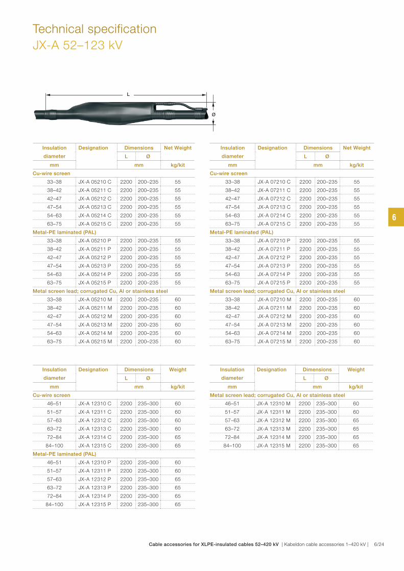
Technical specification
JX-A 52–123 kV
Insulation
diameter
Designation Dimensions Net Weight
L Ø
mm mm kg/kit
Cu-wire screen
33–38 JX-A 05210 C 2200 200–235 55
38–42 JX-A 05211 C 2200 200–235 55
42–47 JX-A 05212 C 2200 200–235 55
47–54 JX-A 05213 C 2200 200–235 55
54–63 JX-A 05214 C 2200 200–235 55
63–75 JX-A 05215 C 2200 200–235 55
Metal-PE laminated (PAL)
33–38 JX-A 05210 P 2200 200–235 55
38–42 JX-A 05211 P 2200 200–235 55
42–47 JX-A 05212 P 2200 200–235 55
47–54 JX-A 05213 P 2200 200–235 55
54–63 JX-A 05214 P 2200 200–235 55
63–75 JX-A 05215 P 2200 200–235 55
Metal screen lead; corrugated Cu, Al or stainless steel
33–38 JX-A 05210 M 2200 200–235 60
38–42 JX-A 05211 M 2200 200–235 60
42–47 JX-A 05212 M 2200 200–235 60
47–54 JX-A 05213 M 2200 200–235 60
54–63 JX-A 05214 M 2200 200–235 60
63–75 JX-A 05215 M 2200 200–235 60
Insulation
diameter
Designation Dimensions Weight
L Ø
mm mm kg/kit
Cu-wire screen
46–51 JX-A 12310 C 2200 235–300 60
51–57 JX-A 12311 C 2200 235–300 60
57–63 JX-A 12312 C 2200 235–300 60
63–72 JX-A 12313 C 2200 235–300 60
72–84 JX-A 12314 C 2200 235–300 65
84–100 JX-A 12315 C 2200 235–300 65
Metal-PE laminated (PAL)
46–51 JX-A 12310 P 2200 235–300 60
51–57 JX-A 12311 P 2200 235–300 60
57–63 JX-A 12312 P 2200 235–300 65
63–72 JX-A 12313 P 2200 235–300 65
72–84 JX-A 12314 P 2200 235–300 65
84–100 JX-A 12315 P 2200 235–300 65
Insulation
diameter
Designation Dimensions Net Weight
L Ø
mm mm kg/kit
Cu-wire screen
33–38 JX-A 07210 C 2200 200–235 55
38–42 JX-A 07211 C 2200 200–235 55
42–47 JX-A 07212 C 2200 200–235 55
47–54 JX-A 07213 C 2200 200–235 55
54–63 JX-A 07214 C 2200 200–235 55
63–75 JX-A 07215 C 2200 200–235 55
Metal-PE laminated (PAL)
33–38 JX-A 07210 P 2200 200–235 55
38–42 JX-A 07211 P 2200 200–235 55
42–47 JX-A 07212 P 2200 200–235 55
47–54 JX-A 07213 P 2200 200–235 55
54–63 JX-A 07214 P 2200 200–235 55
63–75 JX-A 07215 P 2200 200–235 55
Metal screen lead; corrugated Cu, Al or stainless steel
33–38 JX-A 07210 M 2200 200–235 60
38–42 JX-A 07211 M 2200 200–235 60
42–47 JX-A 07212 M 2200 200–235 60
47–54 JX-A 07213 M 2200 200–235 60
54–63 JX-A 07214 M 2200 200–235 60
63–75 JX-A 07215 M 2200 200–235 60
Insulation
diameter
Designation Dimensions Weight
L Ø
mm mm kg/kit
Metal screen lead; corrugated Cu, Al or stainless steel
46–51 JX-A 12310 M 2200 235–300 60
51–57 JX-A 12311 M 2200 235–300 60
57–63 JX-A 12312 M 2200 235–300 65
63–72 JX-A 12313 M 2200 235–300 65
72–84 JX-A 12314 M 2200 235–300 65
84–100 JX-A 12315 M 2200 235–300 65
Ø
L
6
Cable accessories for XLPE-insulated cables 52–420 kV | Kabeldon cable accessories 1–420 kV | 6/24
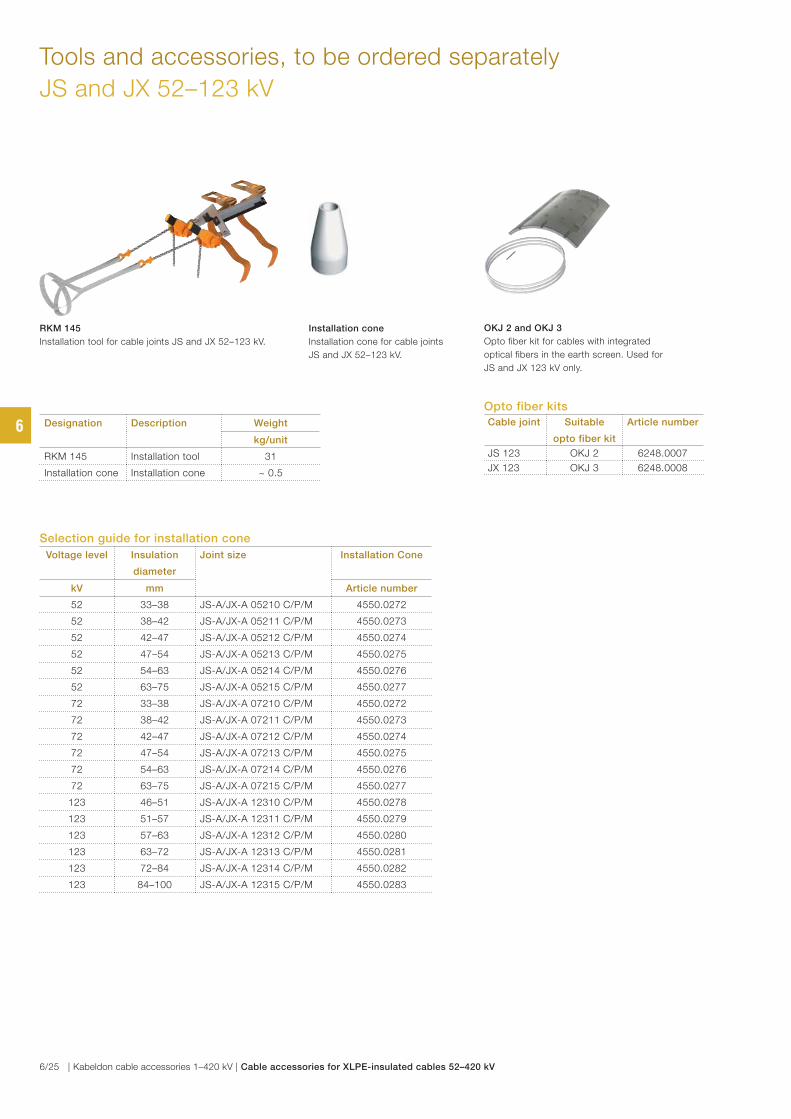
Tools and accessories, to be ordered separately
JS and JX 52–123 kV
Selection guide for installation cone
Voltage level Insulation
diameter
Joint size Installation Cone
kV mm Article number
52 33–38 JS-A/JX-A 05210 C/P/M 4550.0272
52 38–42 JS-A/JX-A 05211 C/P/M 4550.0273
52 42–47 JS-A/JX-A 05212 C/P/M 4550.0274
52 47–54 JS-A/JX-A 05213 C/P/M 4550.0275
52 54–63 JS-A/JX-A 05214 C/P/M 4550.0276
52 63–75 JS-A/JX-A 05215 C/P/M 4550.0277
72 33–38 JS-A/JX-A 07210 C/P/M 4550.0272
72 38–42 JS-A/JX-A 07211 C/P/M 4550.0273
72 42–47 JS-A/JX-A 07212 C/P/M 4550.0274
72 47–54 JS-A/JX-A 07213 C/P/M 4550.0275
72 54–63 JS-A/JX-A 07214 C/P/M 4550.0276
72 63–75 JS-A/JX-A 07215 C/P/M 4550.0277
123 46–51 JS-A/JX-A 12310 C/P/M 4550.0278
123 51–57 JS-A/JX-A 12311 C/P/M 4550.0279
123 57–63 JS-A/JX-A 12312 C/P/M 4550.0280
123 63–72 JS-A/JX-A 12313 C/P/M 4550.0281
123 72–84 JS-A/JX-A 12314 C/P/M 4550.0282
123 84–100 JS-A/JX-A 12315 C/P/M 4550.0283
RKM 145
Installation tool for cable joints JS and JX 52–123 kV.
Installation cone
Installation cone for cable joints
JS and JX 52–123 kV.
Designation Description Weight
kg/unit
RKM 145 Installation tool 31
Installation cone Installation cone ~ 0.5
OKJ 2 and OKJ 3
Opto fiber kit for cables with integrated
optical fibers in the earth screen. Used for
JS and JX 123 kV only.
Opto fiber kits
Cable joint Suitable
opto fiber kit
Article number
JS 123 OKJ 2 6248.0007
JX 123 OKJ 3 6248.0008
6
6/25 | Kabeldon cable accessories 1–420 kV | Cable accessories for XLPE-insulated cables 52–420 kV
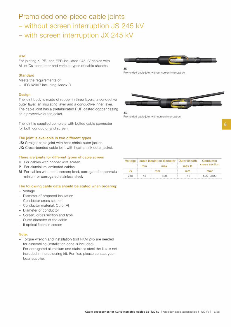
Premolded one-piece cable joints
– without screen interruption JS 245 kV
– with screen interruption JX 245 kV
Voltage cable insulation diameter Outer sheath Conductor cross section
min max max Ø
kV mm mm mm²
245 74 120 143 500–2500
Use
For jointing XLPE- and EPR-insulated 245 kV cables with
Al- or Cu-conductor and various types of cable sheaths.
Standard
Meets the requirements of:
− IEC 62067 including Annex D
Design
The joint body is made of rubber in three layers: a conductive
outer layer, an insulating layer and a conductive inner layer.
The cable joint has a prefabricated PUR casted copper casing
as a protective outer jacket.
The joint is supplied complete with bolted cable connector
for both conductor and screen.
The joint is available in two different types
JS: Straight cable joint with heat-shrink outer jacket.
JX: Cross-bonded cable joint with heat-shrink outer jacket.
There are joints for different types of cable screen
C For cables with copper wire screen.
P For aluminium laminated cables.
M For cables with metal screen; lead, corrugated copper/alu-
minium or corrugated stainless steel.
The following cable data should be stated when ordering:
− Voltage
− Diameter of prepared insulation
− Conductor cross section
− Conductor material, Cu or Al
− Diameter of conductor
− Screen, cross section and type
− Outer diameter of the cable
− If optical fibers in screen
Note:
− Torque wrench and installation tool RKM 245 are needed
for assembling (installation cone is included).
− For corrugated aluminium and stainless steel the flux is not
included in the soldering kit. For flux, please contact your
local supplier.
JX
Premolded cable joint with screen interruption.
JS
Premolded cable joint without screen interruption.
6
Cable accessories for XLPE-insulated cables 52–420 kV | Kabeldon cable accessories 1–420 kV | 6/26
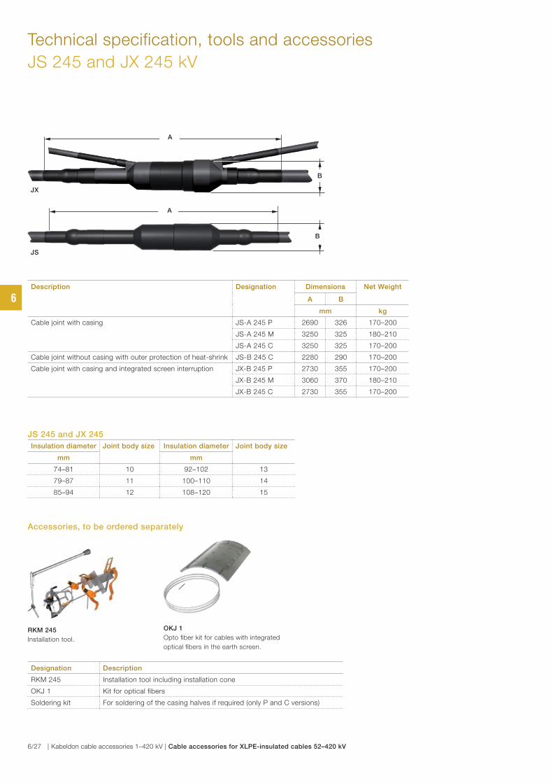
Technical specification, tools and accessories
JS 245 and JX 245 kV
JS 245 and JX 245
Insulation diameter Joint body size Insulation diameter Joint body size
mm mm
74–81 10 92–102 13
79–87 11 100–110 14
85–94 12 108–120 15
Description Designation Dimensions Net Weight
A B
mm kg
Cable joint with casing JS-A 245 P 2690 326 170–200
JS-A 245 M 3250 325 180–210
JS-A 245 C 3250 325 170–200
Cable joint without casing with outer protection of heat-shrink JS-B 245 C 2280 290 170–200
Cable joint with casing and integrated screen interruption JX-B 245 P 2730 355 170–200
JX-B 245 M 3060 370 180–210
JX-B 245 C 2730 355 170–200
Designation Description
RKM 245 Installation tool including installation cone
OKJ 1 Kit for optical fibers
Soldering kit For soldering of the casing halves if required (only P and C versions)
RKM 245
Installation tool.
OKJ 1
Opto fiber kit for cables with integrated
optical fibers in the earth screen.
Accessories, to be ordered separately
B
A
JX
A
B
JS
6
6/27 | Kabeldon cable accessories 1–420 kV | Cable accessories for XLPE-insulated cables 52–420 kV
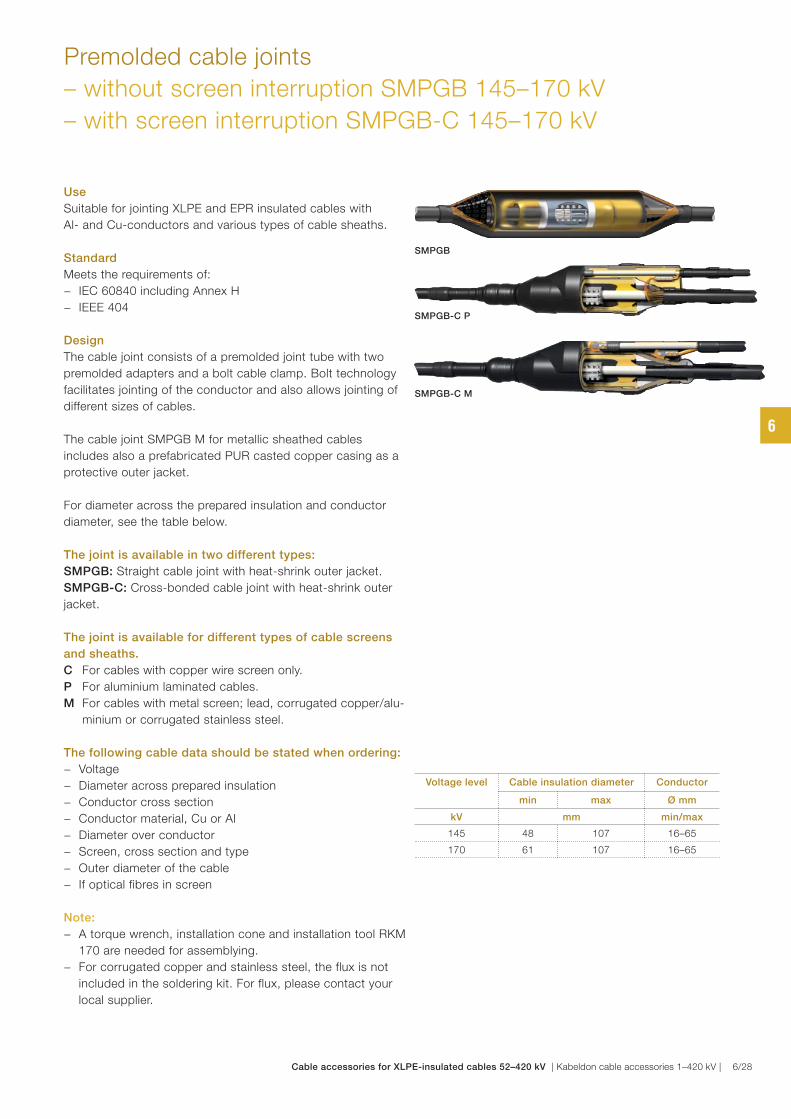
Premolded cable joints
– without screen interruption SMPGB 145–170 kV
– with screen interruption SMPGB-C 145–170 kV
SMPGB
Voltage level Cable insulation diameter Conductor
min max Ø mm
kV mm min/max
145 48 107 16–65
170 61 107 16–65
Use
Suitable for jointing XLPE and EPR insulated cables with
Al- and Cu-conductors and various types of cable sheaths.
Standard
Meets the requirements of:
− IEC 60840 including Annex H
− IEEE 404
Design
The cable joint consists of a premolded joint tube with two
premolded adapters and a bolt cable clamp. Bolt technology
facilitates jointing of the conductor and also allows jointing of
different sizes of cables.
The cable joint SMPGB M for metallic sheathed cables
includes also a prefabricated PUR casted copper casing as a
protective outer jacket.
For diameter across the prepared insulation and conductor
diameter, see the table below.
The joint is available in two different types:
SMPGB: Straight cable joint with heat-shrink outer jacket.
SMPGB-C: Cross-bonded cable joint with heat-shrink outer
jacket.
The joint is available for different types of cable screens
and sheaths.
C For cables with copper wire screen only.
P For aluminium laminated cables.
M For cables with metal screen; lead, corrugated copper/alu-
minium or corrugated stainless steel.
The following cable data should be stated when ordering:
− Voltage
− Diameter across prepared insulation
− Conductor cross section
− Conductor material, Cu or Al
− Diameter over conductor
− Screen, cross section and type
− Outer diameter of the cable
− If optical fibres in screen
Note:
− A torque wrench, installation cone and installation tool RKM
170 are needed for assemblying.
− For corrugated copper and stainless steel, the flux is not
included in the soldering kit. For flux, please contact your
local supplier.
SMPGB-C M
SMPGB-C P
6
Cable accessories for XLPE-insulated cables 52–420 kV | Kabeldon cable accessories 1–420 kV | 6/28
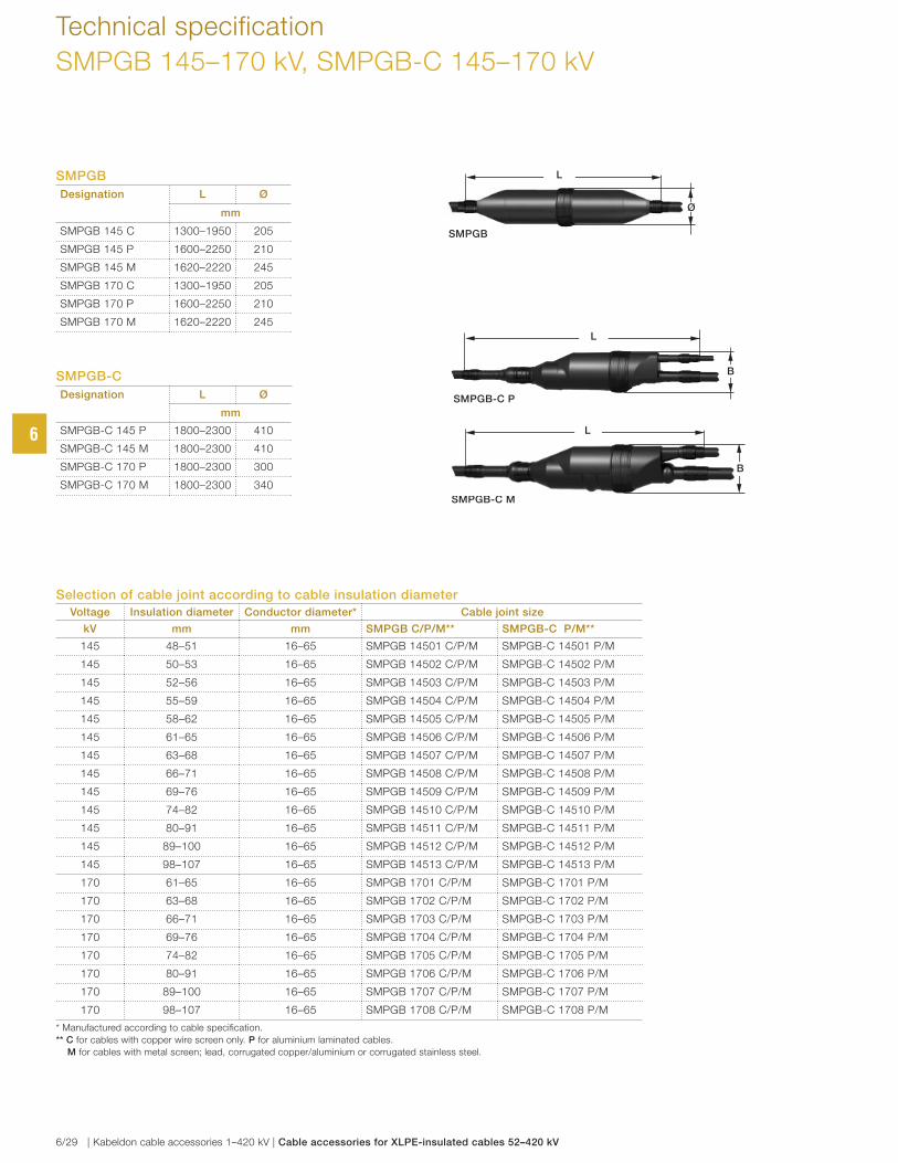
Technical specification
SMPGB 145–170 kV, SMPGB-C 145–170 kV
SMPGB
Designation L Ø
mm
SMPGB 145 C 1300–1950 205
SMPGB 145 P 1600–2250 210
SMPGB 145 M 1620–2220 245
SMPGB 170 C 1300–1950 205
SMPGB 170 P 1600–2250 210
SMPGB 170 M 1620–2220 245
SMPGB-C M
SMPGB-C P
SMPGB
SMPGB-C
Designation L Ø
mm
SMPGB-C 145 P 1800–2300 410
SMPGB-C 145 M 1800–2300 410
SMPGB-C 170 P 1800–2300 300
SMPGB-C 170 M 1800–2300 340
B
L
B
L
L
Ø
Selection of cable joint according to cable insulation diameter
Voltage Insulation diameter Conductor diameter* Cable joint size
kV mm mm SMPGB C/P/M** SMPGB-C P/M**
145 48–51 16–65 SMPGB 14501 C/P/M SMPGB-C 14501 P/M
145 50–53 16–65 SMPGB 14502 C/P/M SMPGB-C 14502 P/M
145 52–56 16–65 SMPGB 14503 C/P/M SMPGB-C 14503 P/M
145 55–59 16–65 SMPGB 14504 C/P/M SMPGB-C 14504 P/M
145 58–62 16–65 SMPGB 14505 C/P/M SMPGB-C 14505 P/M
145 61–65 16–65 SMPGB 14506 C/P/M SMPGB-C 14506 P/M
145 63–68 16–65 SMPGB 14507 C/P/M SMPGB-C 14507 P/M
145 66–71 16–65 SMPGB 14508 C/P/M SMPGB-C 14508 P/M
145 69–76 16–65 SMPGB 14509 C/P/M SMPGB-C 14509 P/M
145 74–82 16–65 SMPGB 14510 C/P/M SMPGB-C 14510 P/M
145 80–91 16–65 SMPGB 14511 C/P/M SMPGB-C 14511 P/M
145 89–100 16–65 SMPGB 14512 C/P/M SMPGB-C 14512 P/M
145 98–107 16–65 SMPGB 14513 C/P/M SMPGB-C 14513 P/M
170 61–65 16–65 SMPGB 1701 C/P/M SMPGB-C 1701 P/M
170 63–68 16–65 SMPGB 1702 C/P/M SMPGB-C 1702 P/M
170 66–71 16–65 SMPGB 1703 C/P/M SMPGB-C 1703 P/M
170 69–76 16–65 SMPGB 1704 C/P/M SMPGB-C 1704 P/M
170 74–82 16–65 SMPGB 1705 C/P/M SMPGB-C 1705 P/M
170 80–91 16–65 SMPGB 1706 C/P/M SMPGB-C 1706 P/M
170 89–100 16–65 SMPGB 1707 C/P/M SMPGB-C 1707 P/M
170 98–107 16–65 SMPGB 1708 C/P/M SMPGB-C 1708 P/M
* Manufactured according to cable specifi cation.
** C for cables with copper wire screen only. P for aluminium laminated cables.
M for cables with metal screen; lead, corrugated copper/aluminium or corrugated stainless steel.
6
6/29 | Kabeldon cable accessories 1–420 kV | Cable accessories for XLPE-insulated cables 52–420 kV

Tools and accessories
SMPGB 145–170 kV, SMPGB-C 145–170 kV
Selection of installation cone and adapters
according to cable insulation diameter
Voltage Cable Insulation diameter Cable joint size Installation cone
kV mm Article number
145 48–51 14501 4209.2384
145 50–53 14502 4209.2385
145 52–56 14503 4209.2386
145 55–59 14504 4209.2387
145 58–62 14505 4209.2388
145 61–65 14506 4209.2331
145 63–68 14507 4209.2332
145 66–71 14508 4209.2333
145 69–76 14509 4209.2334
145 74–82 14510 4209.2335
145 80–91 14511 4209.2336
145 89–100 14512 4209.2337
145 98–107 14513 4209.2400
170 61–65 1701 4209.2331
170 63–68 1702 4209.2332
170 66–71 1703 4209.2333
170 69–76 1704 4209.2334
170 74–82 1705 4209.2335
170 80–91 1706 4209.2336
170 89–100 1707 4209.2337
170 98–107 1708 4209.2338
Max 4 m
Installation cone
For installing the adapter.
RKM 170
Installation tool for SMPGB joint
145–170 kV.
Designation Description Weight
kg/item
RKM 170 Installation tool 42
Installation cone Installation cone ~ 0.5
Tools and accessories, to be ordered separately
OKJ 4 and OKJ 5
Opto fiber kit for cables with integrated
optical fibers in the earth screen.
Opto fiber kits
Cable joint Suitable
opto fiber kit
Article
number
SMPGB 145–170 P OKJ 4 6248.0009
SMPGB-C 145–170 P OKJ 4 6248.0009
SMPGB 145–170 M OKJ 5 6248.0010
SMPGB-C 145–170 M OKJ 5 6248.0010
SMPGB 145–170 OKJ 4 6248.0009
6
Cable accessories for XLPE-insulated cables 52–420 kV | Kabeldon cable accessories 1–420 kV | 6/30
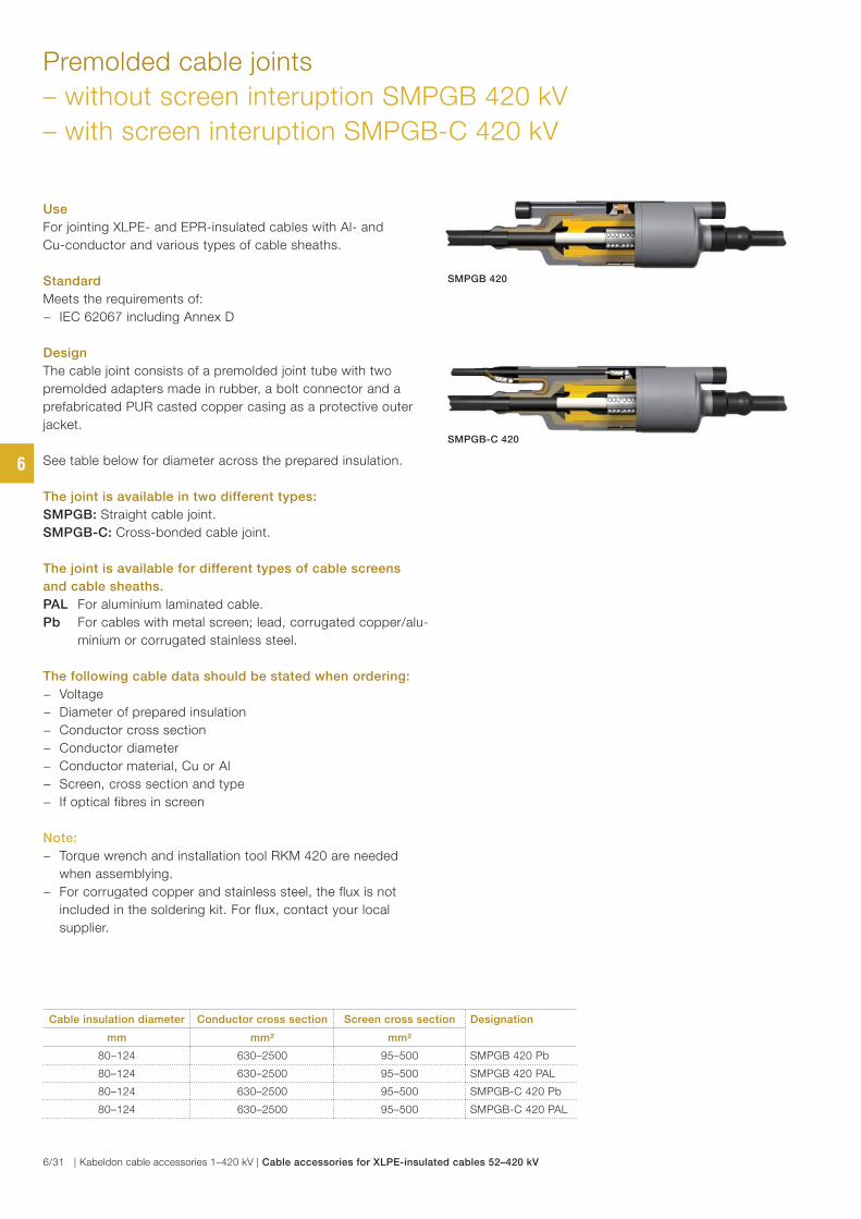
Premolded cable joints
– without screen interuption SMPGB 420 kV
– with screen interuption SMPGB-C 420 kV
Use
For jointing XLPE- and EPR-insulated cables with Al- and
Cu-conductor and various types of cable sheaths.
Standard
Meets the requirements of:
− IEC 62067 including Annex D
Design
The cable joint consists of a premolded joint tube with two
premolded adapters made in rubber, a bolt connector and a
prefabricated PUR casted copper casing as a protective outer
jacket.
See table below for diameter across the prepared insulation.
The joint is available in two different types:
SMPGB: Straight cable joint.
SMPGB-C: Cross-bonded cable joint.
The joint is available for different types of cable screens
and cable sheaths.
PAL For aluminium laminated cable.
Pb For cables with metal screen; lead, corrugated copper/alu-
minium or corrugated stainless steel.
The following cable data should be stated when ordering:
− Voltage
− Diameter of prepared insulation
− Conductor cross section
− Conductor diameter
− Conductor material, Cu or Al
− Screen, cross section and type
− If optical fibres in screen
Note:
− Torque wrench and installation tool RKM 420 are needed
when assemblying.
− For corrugated copper and stainless steel, the flux is not
included in the soldering kit. For flux, contact your local
supplier.
Cable insulation diameter Conductor cross section Screen cross section Designation
mm mm² mm²
80–124 630–2500 95–500 SMPGB 420 Pb
80–124 630–2500 95–500 SMPGB 420 PAL
80–124 630–2500 95–500 SMPGB-C 420 Pb
80–124 630–2500 95–500 SMPGB-C 420 PAL
SMPGB 420
SMPGB-C 420
6
6/31 | Kabeldon cable accessories 1–420 kV | Cable accessories for XLPE-insulated cables 52–420 kV
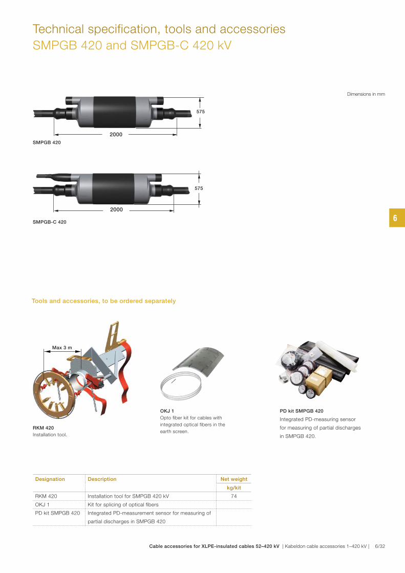
Technical specification, tools and accessories
SMPGB 420 and SMPGB-C 420 kV
Designation Description Net weight
kg/kit
RKM 420 Installation tool for SMPGB 420 kV 74
OKJ 1 Kit for splicing of optical fibers
PD kit SMPGB 420 Integrated PD-measurement sensor for measuring of
partial discharges in SMPGB 420
Max 3 m
RKM 420
Installation tool.
OKJ 1
Opto fiber kit for cables with
integrated optical fibers in the
earth screen.
PD kit SMPGB 420
Integrated PD-measuring sensor
for measuring of partial discharges
in SMPGB 420.
Tools and accessories, to be ordered separately
Dimensions in mm
SMPGB 420
SMPGB-C 420
2000
575
2000
575
6
Cable accessories for XLPE-insulated cables 52–420 kV | Kabeldon cable accessories 1–420 kV | 6/32
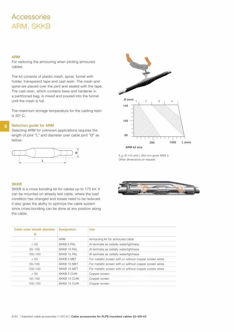
Cable outer sheath diameter
Ø
Designation Use
– ARM Armouring kit for armoured cable
< 50 SKKB 5 PAL Al laminate as radially watertightness
50–100 SKKB 10 PAL Al laminate as radially watertightness
100–150 SKKB 15 PAL Al laminate as radially watertightness
< 50 SKKB 5 MET For metallic screen with or without copper screen wires
50–100 SKKB 10 MET For metallic screen with or without copper screen wires
100–140 SKKB 15 MET For metallic screen with or without copper screen wires
< 50 SKKB 5 CUW Copper screen
50–100 SKKB 10 CUW Copper screen
100–150 SKKB 15 CUW Copper screen
Accessories
ARM, SKKB
ARM
For restoring the armouring when jointing armoured
cables.
The kit consists of plastic mesh, spiral, funnel with
holder, transparent tape and cast resin. The mesh and
spiral are placed over the joint and sealed with the tape.
The cast resin, which contains base and hardener in
a partitioned bag, is mixed and poured into the funnel
until the mesh is full.
The maximum storage temperature for the casting resin
is 30° C.
Selection guide for ARM
Selecting ARM for unknown applications requires the
length of joint “L” and diameter over cable joint “Ø” as
below:
SKKB
SKKB is a cross bonding kit for cables up to 170 kV. It
can be mounted on already laid cable, where the load
condition has changed and losses need to be reduced.
It also gives the ability to optimize the cable system
since cross-bonding can be done at any position along
the cable.
Ø
L
ARM kit size
500 1000 L (mm)
60
100
Ø (mm)
140
E.g. Ø 115 and L 850 mm gives ARM 3.
Other dimensions on request.
1 2 3 4
6
6/33 | Kabeldon cable accessories 1–420 kV | Cable accessories for XLPE-insulated cables 52–420 kV
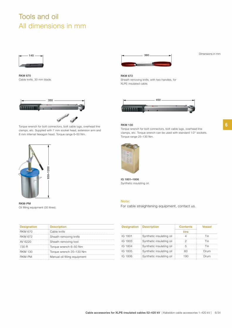
Tools and oil
All dimensions in mm
Designation Description
RKM 670 Cable knife
RKM 672 Sheath removing knife
AV 6220 Sheath removing tool
730 R Torque wrench 6–50 Nm
RKM 130 Torque wrench 25–130 Nm
RKM-PM Manual oil filling equipment
Designation Description Contents Vessel
litre
IG 1801 Synthetic insulating oil 4 Tin
IG 1803 Synthetic insulating oil 2 Tin
IG 1804 Synthetic insulating oil 5 Tin
IG 1805 Synthetic insulating oil 60 Drum
IG 1806 Synthetic insulating oil 190 Drum
RKM 670
Cable knife, 30 mm blade.
RKM-PM
Oil filling equipment (30 litres).
RKM 130
Torque wrench for bolt connectors, bolt cable lugs, overhead line
clamps, etc. Torque wrench can be used with standard 1/2“ sockets.
Torque range 25–130 Nm.
RKM 672
Sheath removing knife, with two handles, for
XLPE-insulated cable.
IG 1801–1806
Synthetic insulating oil.
730R
Torque wrench for bolt connectors, bolt cable lugs, overhead line
clamps, etc. Supplied with 7 mm socket head, extension arm and
8 mm internal hexagon head. Torque range 6–50 Nm.
Note:
For cable straightening equipment, contact us.
Dimensions in mm
450
360
350
65
0–1
20
0
140
6
Cable accessories for XLPE-insulated cables 52–420 kV | Kabeldon cable accessories 1–420 kV | 6/34
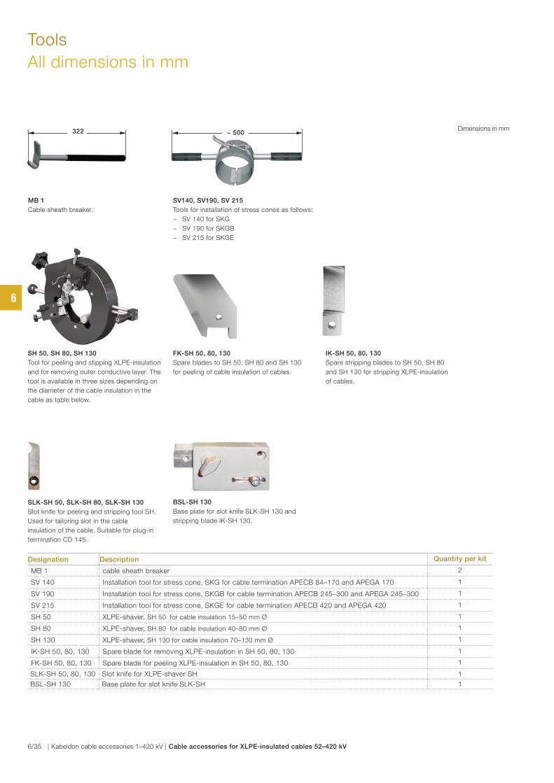
Tools
All dimensions in mm
Designation Description Quantity per kit
MB 1 cable sheath breaker 2
SV 140 Installation tool for stress cone, SKG for cable termination APECB 84–170 and APEGA 170 1
SV 190 Installation tool for stress cone, SKGB for cable termination APECB 245–300 and APEGA 245–300 1
SV 215 Installation tool for stress cone, SKGE for cable termination APECB 420 and APEGA 420 1
SH 50 XLPE-shaver, SH 50 for cable insulation 15–50 mm Ø 1
SH 80 XLPE-shaver, SH 80 for cable insulation 40–80 mm Ø 1
SH 130 XLPE-shaver, SH 130 for cable insulation 70–130 mm Ø 1
IK-SH 50, 80, 130 Spare blade for removing XLPE-insulation in SH 50, 80, 130 1
FK-SH 50, 80, 130 Spare blade for peeling XLPE-insulation in SH 50, 80, 130 1
SLK-SH 50, 80, 130 Slot knife for XLPE-shaver SH 1
BSL-SH 130 Base plate for slot knife SLK-SH 1
MB 1
Cable sheath breaker.
SH 50, SH 80, SH 130
Tool for peeling and stipping XLPE-insulation
and for removing outer conductive layer. The
tool is available in three sizes depending on
the diameter of the cable insulation in the
cable as table below.
IK-SH 50, 80, 130
Spare stripping blades to SH 50, SH 80
and SH 130 for stripping XLPE-insulation
of cables.
FK-SH 50, 80, 130
Spare blades to SH 50, SH 80 and SH 130
for peeling of cable insulation of cables.
SV140, SV190, SV 215
Tools for installation of stress cones as follows:
− SV 140 for SKG
− SV 190 for SKGB
− SV 215 for SKGE
BSL-SH 130
Base plate for slot knife SLK-SH 130 and
stripping blade IK-SH 130.
SLK-SH 50, SLK-SH 80, SLK-SH 130
Slot knife for peeling and stripping tool SH.
Used for tailoring slot in the cable
insulation of the cable. Suitable for plug-in
termination CD 145.
Dimensions in mm~ 500322
6
6/35 | Kabeldon cable accessories 1–420 kV | Cable accessories for XLPE-insulated cables 52–420 kV
Universal clamps
UKR 90, UKRA 90 7/2
UKR 200, UKRA 200 7/3
Typical applications, UKR 200,UKRA 200 7/4
Table of contents
Universal clamps
7
Universal clamps | Kabeldon cable accessories 1–420 kV | 7/1
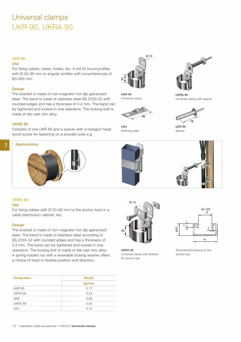
78
Universal clamps
UKR 90, UKRA 90
Designation Weight
kg/item
UKR 90 0.17
UKRA 90 0.23
UKS 0.28
UKRS 90 0.45
UKJ 0.14
UKR 90
Use
For fixing cables, tubes, hoses, etc. It will fix round profiles
with Ø 20–90 mm or angular profiles with circumferences of
60–300 mm.
Design
The bracket is made of non-magnetic hot-dip galvanized
steel. The band is made of stainless steel SS 2333-02 with
rounded edges and has a thickness of 0.2 mm. The band can
be tightened and locked in one operation. The locking bolt is
made of die-cast zinc alloy.
UKRS 90
Consists of one UKR 90 and a spacer with a hexagon head
wood screw for fastening on a wooden pole e.g.
Ø 13
35
90
UKR 90
Universal clamp.UKRS 90
Universal clamp with spacer.
UKJ
Earthing plate.
UKS 90
Spacer.
UKRA 90
Use
For fixing cables with Ø 20–90 mm to the anchor bars in a
cable distribution cabinet, etc.
Design
The bracket is made of non-magnetic hot-dip galvanized
steel. The band is made of stainless steel according to
SS 2333-02 with rounded edges and has a thickness of
0.2 mm. The band can be tightened and locked in one
operation. The locking bolt is made of die-cast zinc alloy.
A spring-loaded nut with a reversible locking washer offers
a choice of fixed or flexible position and direction.
UKRA 90
Universal clamp with bracket
for anchor bar.
Dimensional drawing of the
anchor bar.
Applications:
Ø 13
35
7
7/2 | Kabeldon cable accessories 1–420 kV | Universal clamps
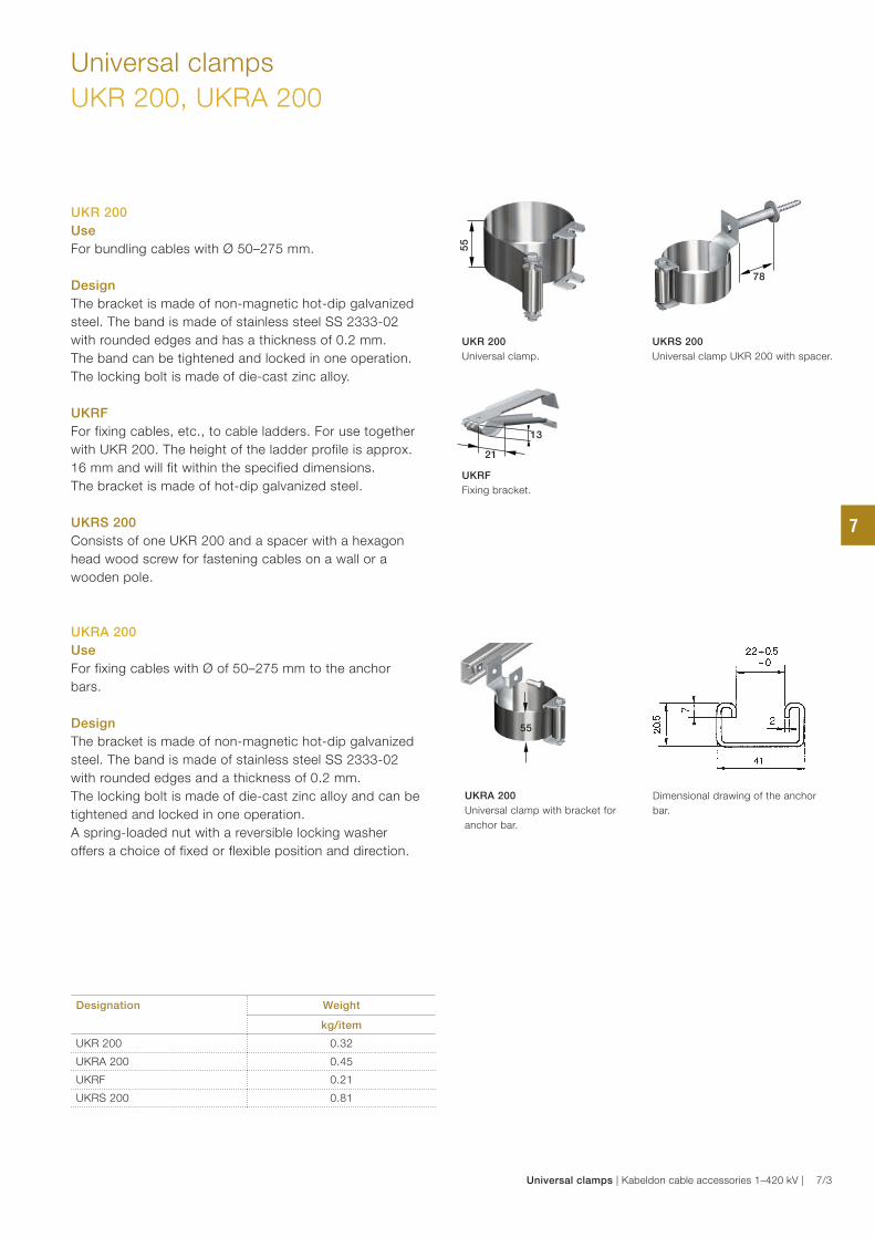
Universal clamps
UKR 200, UKRA 200
Designation Weight
kg/item
UKR 200 0.32
UKRA 200 0.45
UKRF 0.21
UKRS 200 0.81
UKR 200
Use
For bundling cables with Ø 50–275 mm.
Design
The bracket is made of non-magnetic hot-dip galvanized
steel. The band is made of stainless steel SS 2333-02
with rounded edges and has a thickness of 0.2 mm.
The band can be tightened and locked in one operation.
The locking bolt is made of die-cast zinc alloy.
UKRF
For fixing cables, etc., to cable ladders. For use together
with UKR 200. The height of the ladder profile is approx.
16 mm and will fit within the specified dimensions.
The bracket is made of hot-dip galvanized steel.
UKRS 200
Consists of one UKR 200 and a spacer with a hexagon
head wood screw for fastening cables on a wall or a
wooden pole.
UKRA 200
Use
For fixing cables with Ø of 50–275 mm to the anchor
bars.
Design
The bracket is made of non-magnetic hot-dip galvanized
steel. The band is made of stainless steel SS 2333-02
with rounded edges and a thickness of 0.2 mm.
The locking bolt is made of die-cast zinc alloy and can be
tightened and locked in one operation.
A spring-loaded nut with a reversible locking washer
offers a choice of fixed or flexible position and direction.
UKRA 200
Universal clamp with bracket for
anchor bar.
UKRF
Fixing bracket.
Dimensional drawing of the anchor
bar.
UKR 200
Universal clamp.
UKRS 200
Universal clamp UKR 200 with spacer.
55
21
13
55
78
7
Universal clamps | Kabeldon cable accessories 1–420 kV | 7/3
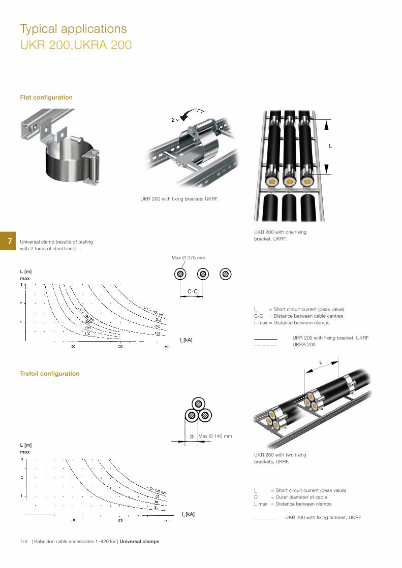
Typical applications
UKR 200,UKRA 200
Universal clamp (results of testing
with 2 turns of steel band).
UKR 200 with fixing brackets UKRF.
UKR 200 with one fixing
bracket, UKRF.
Flat configuration
L
Max Ø 275 mm
L [m]
max
îs [kA]
îs = Short circuit current (peak value)
C-C = Distance between cable centres
L max = Distance between clamps
UKR 200 with fixing bracket, UKRF
UKRA 200
Trefoil configuration
îs
= Short circuit current (peak value)
D = Outer diameter of cable
L max = Distance between clamps
UKR 200 with fixing bracket, UKRF
L
UKR 200 with two fixing
brackets, UKRF.
Max Ø 140 mm
L [m]
max
îs [kA]
7
7/4 | Kabeldon cable accessories 1–420 kV | Universal clamps
List of contents – Alphabetical order 8/2
List of contents
Alphabetical order
8
List of contents – alphabetical order | Kabeldon cable accessories 1–420 kV | 8/1

List of contents
Alphabetical order
A
A-TBF SKR 3/13, 6/9
AF 420 6/18
AFT 1703 6/19
ADAPTER 3/36
AK-ADAS 2/11
AK-ASA 4/4
APECB-P 84–420 kV 6/10–6/12
APED B 52, 84 kV 6/4–6/6
APED P 12–36, 72 kV 6/4–6/6
APEGA GIS 84–420 kV 6/17–6/20
APEGA TRF 84–420 kV 6/17–6/20
APIT 12–36 kV 3/11
APSEA 12–36 kV 3/12–3/13
APSEA 52–72 kV 6/7–6/9
ARM 3/49, 6/33
AV 6220 5/7, 6/34
B
BSL-SH 130 6/16, 6/35
C
CBT 84–170 6/16, 6/19
CBT 245–420 6/19
CD 145 kV 6/15–6/16
CSAP-A 12–24 kV 3/25
CSE-A 12–24 kV, 250 A 3/14–3/16
CSE-A 36–42 kV, 400 A 3/17-3/18
CSE-A 36–42 kV, 630 A 3/19-3/21
CSEP-A 12–42 kV 3/22-3/24
CST 170 6/16
CST 84–420 6/19
CU 250 3/16
CW 3/51
D
DMT1 6/20
F
FBS-1722 1 5/7
FK 3/50
FKFB 3/50
FK-SH 6/16, 6/35
FP 4/11
FPA 4/11
FPMP 4/11
G
GAP-APECB 6/12
GAP-APED 6/6
Designation Page No. Designation Page No.
G
GB-M20 5/7
GC 4/12
GB-M20 S8 5/7
GEX 4/4
H
HDC-A 250 A, 12–24 kV 3/41–3/42
HDC-A 630 A, 12–36 kV 3/43–3/44
HU 150 3/52
HU 200 3/52
HUF 3/52
HUS 3/52
I
IA 1003 4/12
IA 1701 5/5
IA 1706 5/5
IA 2112 4/12
IA 2113 4/12
IA 2333 5/3
IA 2337 5/3
IA 2338 5/3
IA 2339 5/3
IA 2342 5/3
IA 2343 5/3
IA 2352 5/3
IA 2362 5/3
IA 2421 5/3
IA 2441 5/3
IA 2443 5/3
IA 2444 5/3
IA 2502 4/12
IA 2508 4/12
IA 2518 4/12
IA 2519 4/12
IG 1201 4/13
IG 1601 4/13
IG 1604 4/13
IG 1717 4/13
IG 1718 4/13
IG 1801-1807 6/34
IH-A 24250 3/16, 3/42
IH-A 24400 3/18
IH-A 24630 3/21, 3/44
IH-A 42400 3/18
IH-A 42630 3/21, 3/44
IK 1002 4/13
IK 1003 4/13
IK 1105, 1106, 1107, 1108, 1109 5/4
8
8/2 | Kabeldon cable accessories 1–420 kV | List of contents – alphabetical order
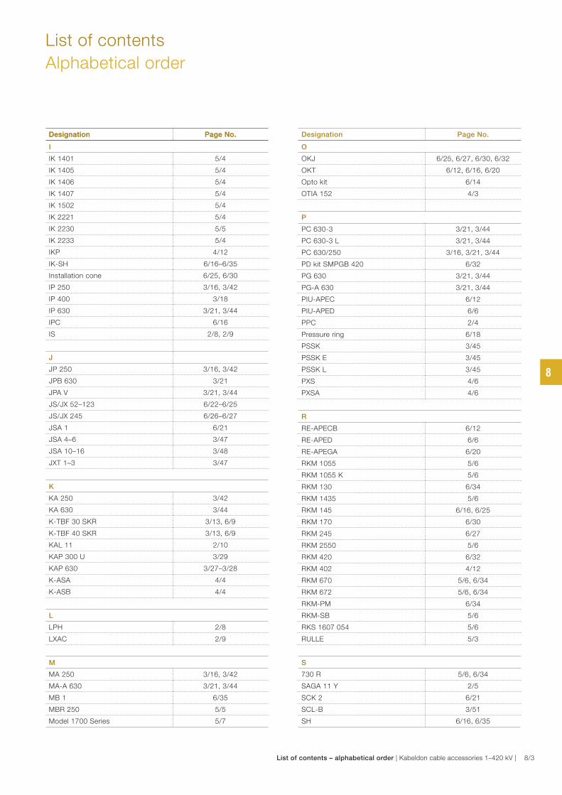
I
IK 1401 5/4
IK 1405 5/4
IK 1406 5/4
IK 1407 5/4
IK 1502 5/4
IK 2221 5/4
IK 2230 5/5
IK 2233 5/4
IKP 4/12
IK-SH 6/16–6/35
Installation cone 6/25, 6/30
IP 250 3/16, 3/42
IP 400 3/18
IP 630 3/21, 3/44
IPC 6/16
IS 2/8, 2/9
J
JP 250 3/16, 3/42
JPB 630 3/21
JPA V 3/21, 3/44
JS/JX 52–123 6/22–6/25
JS/JX 245 6/26–6/27
JSA 1 6/21
JSA 4–6 3/47
JSA 10–16 3/48
JXT 1–3 3/47
K
KA 250 3/42
KA 630 3/44
K-TBF 30 SKR 3/13, 6/9
K-TBF 40 SKR 3/13, 6/9
KAL 11 2/10
KAP 300 U 3/29
KAP 630 3/27–3/28
K-ASA 4/4
K-ASB 4/4
L
LPH 2/8
LXAC 2/9
M
MA 250 3/16, 3/42
MA-A 630 3/21, 3/44
MB 1 6/35
MBR 250 5/5
Model 1700 Series 5/7
List of contents
Alphabetical order
Designation Page No. Designation Page No.Designation Page No.
O
OKJ 6/25, 6/27, 6/30, 6/32
OKT 6/12, 6/16, 6/20
Opto kit 6/14
OTIA 152 4/3
P
PC 630-3 3/21, 3/44
PC 630-3 L 3/21, 3/44
PC 630/250 3/16, 3/21, 3/44
PD kit SMPGB 420 6/32
PG 630 3/21, 3/44
PG-A 630 3/21, 3/44
PIU-APEC 6/12
PIU-APED 6/6
PPC 2/4
Pressure ring 6/18
PSSK 3/45
PSSK E 3/45
PSSK L 3/45
PXS 4/6
PXSA 4/6
R
RE-APECB 6/12
RE-APED 6/6
RE-APEGA 6/20
RKM 1055 5/6
RKM 1055 K 5/6
RKM 130 6/34
RKM 1435 5/6
RKM 145 6/16, 6/25
RKM 170 6/30
RKM 245 6/27
RKM 2550 5/6
RKM 420 6/32
RKM 402 4/12
RKM 670 5/6, 6/34
RKM 672 5/6, 6/34
RKM-PM 6/34
RKM-SB 5/6
RKS 1607 054 5/6
RULLE 5/3
S
730 R 5/6, 6/34
SAGA 11 Y 2/5
SCK 2 6/21
SCL-B 3/51
SH 6/16, 6/35
8
List of contents – alphabetical order | Kabeldon cable accessories 1–420 kV | 8/3
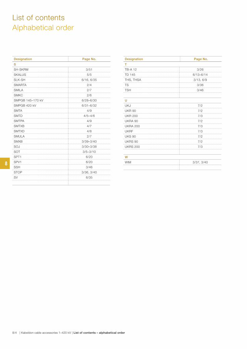
List of contents
Alphabetical order
S
SH-SKRM 3/51
SKALUS 5/5
SLK-SH 6/16, 6/35
SMARTA 2/4
SMILA 2/7
SMKC 2/6
SMPGB 145–170 kV 6/28–6/30
SMPGB 420 kV 6/31–6/32
SMTA 4/9
SMTD 4/5–4/6
SMTPA 4/9
SMTXB 4/7
SMTXD 4/8
SMULA 2/7
SMXB 3/39–3/40
SOJ 3/30–3/38
SOT 3/5–3/10
SPT1 6/20
SPV1 6/20
SSH 3/46
STOP 3/36, 3/40
SV 6/35
Designation Page No. Designation Page No.
T
TB-A 12 3/26
TD 145 6/13–6/14
THS, THSA 3/13, 6/9
TS 3/36
TSH 3/46
U
UKJ 7/2
UKR 90 7/2
UKR 200 7/3
UKRA 90 7/2
UKRA 200 7/3
UKRF 7/3
UKS 90 7/2
UKRS 90 7/2
UKRS 200 7/3
W
WIM 3/37, 3/408
8/4 | Kabeldon cable accessories 1–420 kV | List of contents – alphabetical order

List of contents by category 9/2
List of contents
By category
9
List of contents – by category | Kabeldon cable accessories 1–420 kV | 9/1
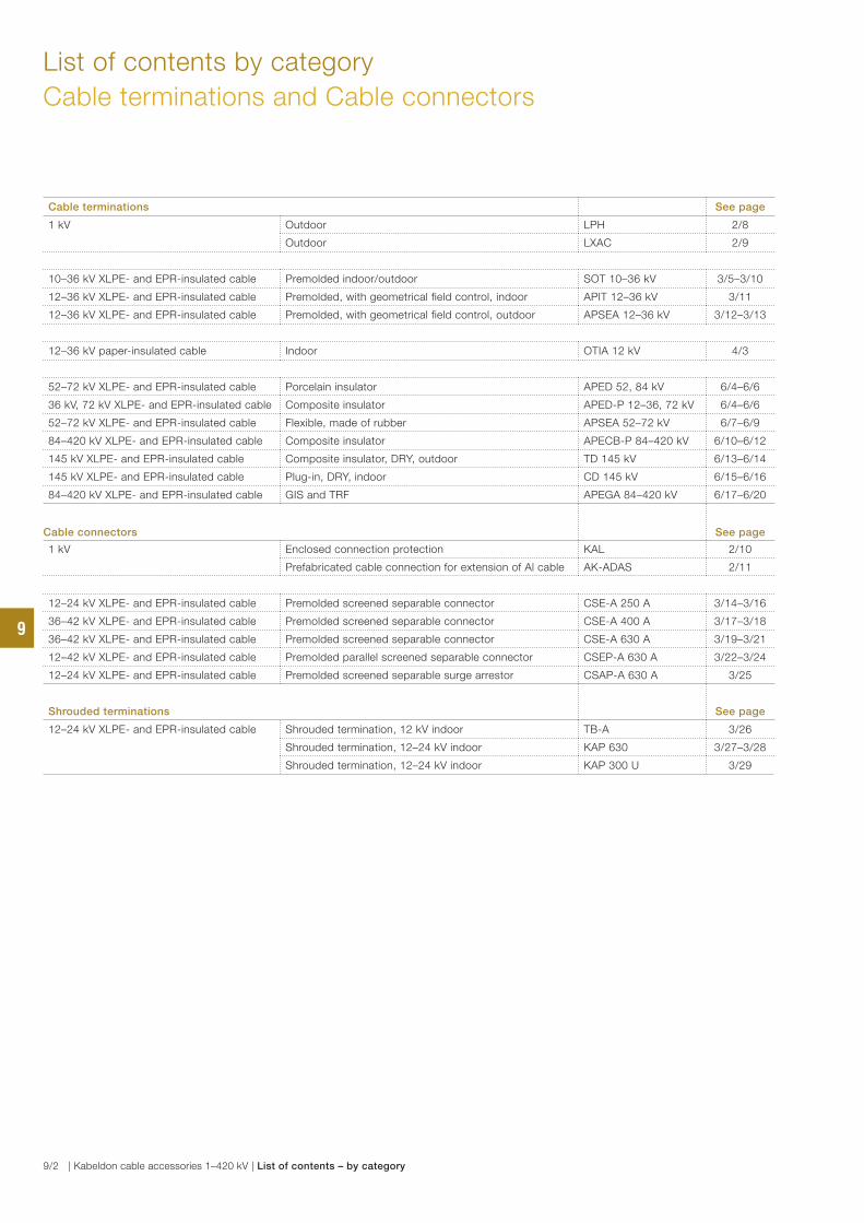
List of contents by category
Cable terminations and Cable connectors
Cable terminations See page
1 kV Outdoor LPH 2/8
Outdoor LXAC 2/9
10–36 kV XLPE- and EPR-insulated cable Premolded indoor/outdoor SOT 10–36 kV 3/5–3/10
12–36 kV XLPE- and EPR-insulated cable Premolded, with geometrical field control, indoor APIT 12–36 kV 3/11
12–36 kV XLPE- and EPR-insulated cable Premolded, with geometrical field control, outdoor APSEA 12–36 kV 3/12–3/13
12–36 kV paper-insulated cable Indoor OTIA 12 kV 4/3
52–72 kV XLPE- and EPR-insulated cable Porcelain insulator APED 52, 84 kV 6/4–6/6
36 kV, 72 kV XLPE- and EPR-insulated cable Composite insulator APED-P 12–36, 72 kV 6/4–6/6
52–72 kV XLPE- and EPR-insulated cable Flexible, made of rubber APSEA 52–72 kV 6/7–6/9
84–420 kV XLPE- and EPR-insulated cable Composite insulator APECB-P 84–420 kV 6/10–6/12
145 kV XLPE- and EPR-insulated cable Composite insulator, DRY, outdoor TD 145 kV 6/13–6/14
145 kV XLPE- and EPR-insulated cable Plug-in, DRY, indoor CD 145 kV 6/15–6/16
84–420 kV XLPE- and EPR-insulated cable GIS and TRF APEGA 84–420 kV 6/17–6/20
Cable connectors See page
1 kV Enclosed connection protection KAL 2/10
Prefabricated cable connection for extension of Al cable AK-ADAS 2/11
12–24 kV XLPE- and EPR-insulated cable Premolded screened separable connector CSE-A 250 A 3/14–3/16
36–42 kV XLPE- and EPR-insulated cable Premolded screened separable connector CSE-A 400 A 3/17–3/18
36–42 kV XLPE- and EPR-insulated cable Premolded screened separable connector CSE-A 630 A 3/19–3/21
12–42 kV XLPE- and EPR-insulated cable Premolded parallel screened separable connector CSEP-A 630 A 3/22–3/24
12–24 kV XLPE- and EPR-insulated cable Premolded screened separable surge arrestor CSAP-A 630 A 3/25
Shrouded terminations See page
12–24 kV XLPE- and EPR-insulated cable Shrouded termination, 12 kV indoor TB-A 3/26
Shrouded termination, 12–24 kV indoor KAP 630 3/27–3/28
Shrouded termination, 12–24 kV indoor KAP 300 U 3/29
9
9/2 | Kabeldon cable accessories 1–420 kV | List of contents – by category
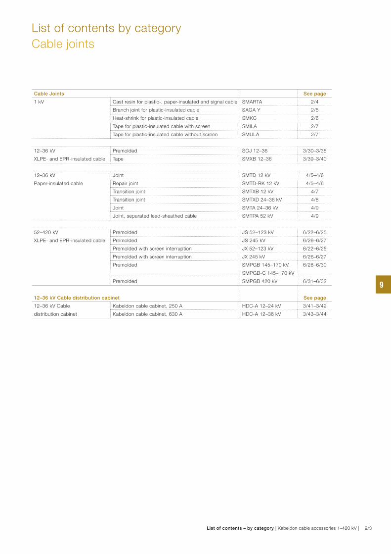
List of contents by category
Cable joints
Cable Joints See page
1 kV Cast resin for plastic-, paper-insulated and signal cable SMARTA 2/4
Branch joint for plastic-insulated cable SAGA Y 2/5
Heat-shrink for plastic-insulated cable SMKC 2/6
Tape for plastic-insulated cable with screen SMILA 2/7
Tape for plastic-insulated cable without screen SMULA 2/7
12–36 kV
XLPE- and EPR-insulated cable
Premolded SOJ 12–36 3/30–3/38
Tape SMXB 12–36 3/39–3/40
12–36 kV
Paper-insulated cable
Joint SMTD 12 kV 4/5–4/6
Repair joint SMTD-RK 12 kV 4/5–4/6
Transition joint SMTXB 12 kV 4/7
Transition joint SMTXD 24–36 kV 4/8
Joint SMTA 24–36 kV 4/9
Joint, separated lead-sheathed cable SMTPA 52 kV 4/9
52–420 kV
XLPE- and EPR-insulated cable
Premolded JS 52–123 kV 6/22–6/25
Premolded JS 245 kV 6/26–6/27
Premolded with screen interruption JX 52–123 kV 6/22–6/25
Premolded with screen interruption JX 245 kV 6/26–6/27
Premolded SMPGB 145–170 kV,
SMPGB-C 145–170 kV
6/28–6/30
Premolded SMPGB 420 kV 6/31–6/32
12–36 kV Cable distribution cabinet See page
12–36 kV Cable
distribution cabinet
Kabeldon cable cabinet, 250 A HDC-A 12–24 kV 3/41–3/42
Kabeldon cable cabinet, 630 A HDC-A 12–36 kV 3/43–3/44
9
List of contents – by category | Kabeldon cable accessories 1–420 kV | 9/3
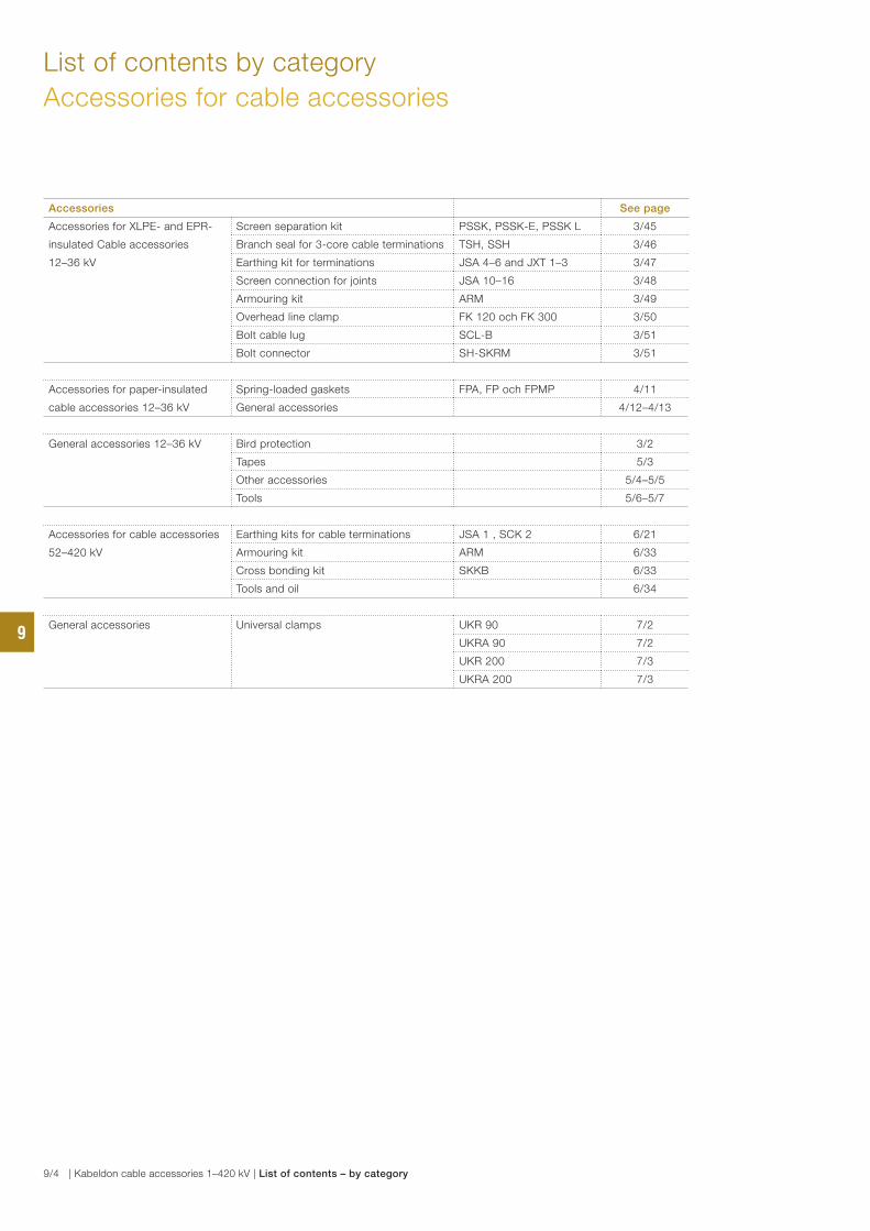
Accessories See page
Accessories for XLPE- and EPR-
insulated Cable accessories
12–36 kV
Screen separation kit PSSK, PSSK-E, PSSK L 3/45
Branch seal for 3-core cable terminations TSH, SSH 3/46
Earthing kit for terminations JSA 4–6 and JXT 1–3 3/47
Screen connection for joints JSA 10–16 3/48
Armouring kit ARM 3/49
Overhead line clamp FK 120 och FK 300 3/50
Bolt cable lug SCL-B 3/51
Bolt connector SH-SKRM 3/51
Accessories for paper-insulated
cable accessories 12–36 kV
Spring-loaded gaskets FPA, FP och FPMP 4/11
General accessories 4/12–4/13
General accessories 12–36 kV Bird protection 3/2
Tapes 5/3
Other accessories 5/4–5/5
Tools 5/6–5/7
Accessories for cable accessories
52–420 kV
Earthing kits for cable terminations JSA 1 , SCK 2 6/21
Armouring kit ARM 6/33
Cross bonding kit SKKB 6/33
Tools and oil 6/34
General accessories Universal clamps UKR 90 7/2
UKRA 90 7/2
UKR 200 7/3
UKRA 200 7/3
List of contents by category
Accessories for cable accessories
9
9/4 | Kabeldon cable accessories 1–420 kV | List of contents – by category

Contact us
Do
cu
men
t ID
: 7
AB
A1
02
36
6ABB AB
Kabeldon
BOX 531
SE-441 15 Alingsås, Sweden
Tel: + 46 322 770 00
Fax: +46 322 770 01
e-mail: [email protected]
www.abb.com/cableaccessories
Note: We reserve the right to make technical changes or
modify the contents of this document without prior notice.
With regard to purchase orders, the agreed particulars shal l
prevai l. ABB does not accept any responsibility whatsoever for
potential errors or possible lack of information in this document.
We reserve all rights in this document and in the subject matter
and illustrations contained therein. Any reproduction, disclosure
to third parties or utilization of its contents – in whole or in parts –
is forbidden without prior written consent of ABB.
Copyright © 2013 ABB
All rights reserved