2014 catalogue eng
TRANSCRIPT

Contents
Introduction 5About KMB systems . . . . . . . . . . . . . . . . . . . . . . . . . . . . . . . . . . . . . . . . . . . . 6
Built-In Meters and Analysers 7ARTIQ 144 - Precise compact power quality analyzer, class A [NEW!] . . . . . . . . . . . . . . . . 11SMV, SMP and SMVQ, SMPQ - Class S power quality analysers, EN 50160 . . . . . . . . . . . . . 15SML 133 - Multifunctional panel meter with segment LCD [NEW!] . . . . . . . . . . . . . . . . . . . 21SMY 133 - Power monitor & data logger with color LCD [NEW!] . . . . . . . . . . . . . . . . . . . . 25SMZ 133 - Power monitor & data logger with extended IO options [NEW!] . . . . . . . . . . . . . . 29PA 144, SMC 144 - Meters, analysers and data loggers for energy management . . . . . . . . . . 33SMD 118 - DC analyser and data logger for energy management . . . . . . . . . . . . . . . . . . . 37SML, SMM and SMN - Multifunctional 3-phase meters . . . . . . . . . . . . . . . . . . . . . . . . . 41SMY and SMZ - Power monitors and data loggers . . . . . . . . . . . . . . . . . . . . . . . . . . . 45Distributed measurement and remote data collection . . . . . . . . . . . . . . . . . . . . . . . . . . 49AFR 111 - Smart Load for reduction of ferroresonance [NEW!] . . . . . . . . . . . . . . . . . . . . 51
Portable Analysers 53NEMO 332 - Multi-channel power quality analyser [NEW!] . . . . . . . . . . . . . . . . . . . . . . . 55NEMO 104 - Compact power quality analyser [NEW!] . . . . . . . . . . . . . . . . . . . . . . . . . 59SMP-BX - Fully equipped embedded compact analyser . . . . . . . . . . . . . . . . . . . . . . . . 63SMP-CA - Fully equipped embedded analyser . . . . . . . . . . . . . . . . . . . . . . . . . . . . . 67NEMO 101 - Single phase power quality analyser . . . . . . . . . . . . . . . . . . . . . . . . . . . . 71NEMO 304 - Power Quality Analyser . . . . . . . . . . . . . . . . . . . . . . . . . . . . . . . . . . . 73
Power Factor Controllers 77NOVAR 2618 Three phase PFC, power analyzer and data logger [NEW!] . . . . . . . . . . . . . . 79NOVAR 2418 Three phase PFC and multimeter [NEW!] . . . . . . . . . . . . . . . . . . . . . . . . 81NOVAR 1106/1114 & NOVAR 1206/1214 . . . . . . . . . . . . . . . . . . . . . . . . . . . . . . . . 83NOVAR 1005/1007 & NOVAR 1005D/1007D . . . . . . . . . . . . . . . . . . . . . . . . . . . . . . 85NOVAR 1414 PFC with three phase measurement . . . . . . . . . . . . . . . . . . . . . . . . . . . 87NOVAR 1312 Real-time power factor controller . . . . . . . . . . . . . . . . . . . . . . . . . . . . . 89KATKA - Thyristor switching modules . . . . . . . . . . . . . . . . . . . . . . . . . . . . . . . . . . . 91ENVIS application for NOVAR power factor controllers . . . . . . . . . . . . . . . . . . . . . . . . . 93
ENVIS Software Suite: Tools for energy management and power quality evaluation 95Content of ENVIS Application Suite . . . . . . . . . . . . . . . . . . . . . . . . . . . . . . . 96
3

4
Introduction
Power quality analysers and energy efficiency monitors
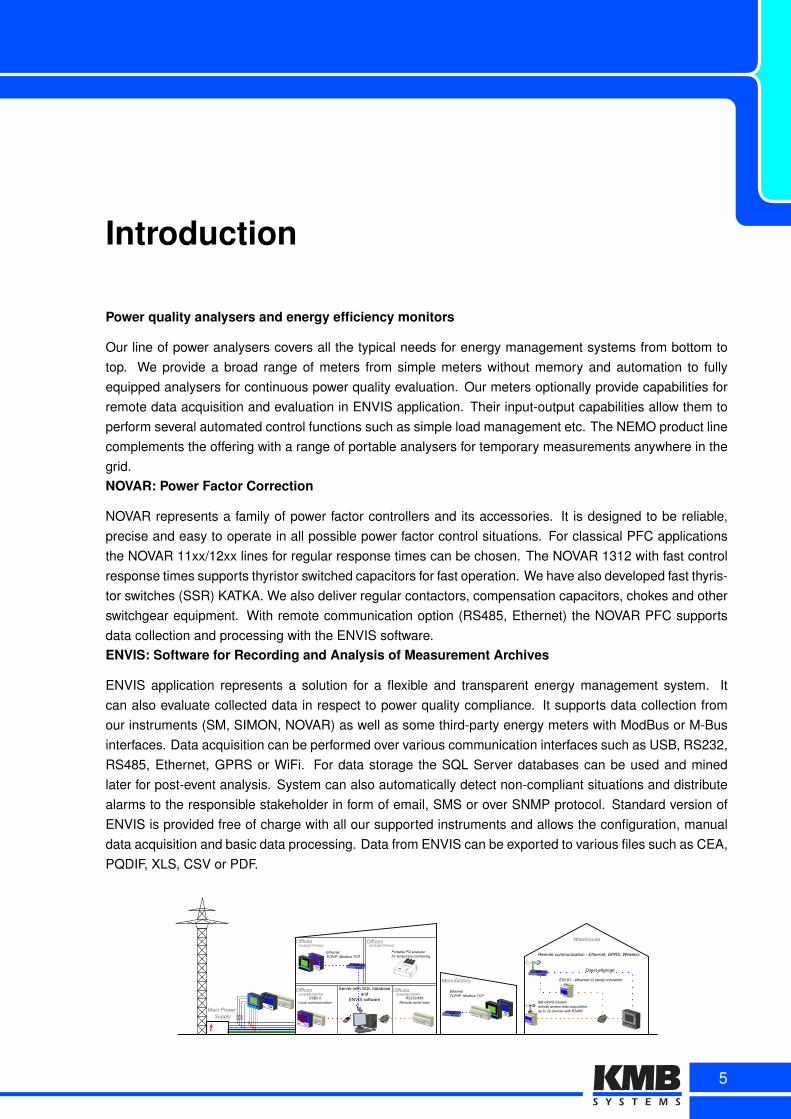
Our line of power analysers covers all the typical needs for energy management systems from bottom totop. We provide a broad range of meters from simple meters without memory and automation to fullyequipped analysers for continuous power quality evaluation. Our meters optionally provide capabilities forremote data acquisition and evaluation in ENVIS application. Their input-output capabilities allow them toperform several automated control functions such as simple load management etc. The NEMO product linecomplements the offering with a range of portable analysers for temporary measurements anywhere in thegrid.NOVAR: Power Factor Correction
NOVAR represents a family of power factor controllers and its accessories. It is designed to be reliable,precise and easy to operate in all possible power factor control situations. For classical PFC applicationsthe NOVAR 11xx/12xx lines for regular response times can be chosen. The NOVAR 1312 with fast controlresponse times supports thyristor switched capacitors for fast operation. We have also developed fast thyris-tor switches (SSR) KATKA. We also deliver regular contactors, compensation capacitors, chokes and otherswitchgear equipment. With remote communication option (RS485, Ethernet) the NOVAR PFC supportsdata collection and processing with the ENVIS software.ENVIS: Software for Recording and Analysis of Measurement Archives
ENVIS application represents a solution for a flexible and transparent energy management system. Itcan also evaluate collected data in respect to power quality compliance. It supports data collection fromour instruments (SM, SIMON, NOVAR) as well as some third-party energy meters with ModBus or M-Businterfaces. Data acquisition can be performed over various communication interfaces such as USB, RS232,RS485, Ethernet, GPRS or WiFi. For data storage the SQL Server databases can be used and minedlater for post-event analysis. System can also automatically detect non-compliant situations and distributealarms to the responsible stakeholder in form of email, SMS or over SNMP protocol. Standard version ofENVIS is provided free of charge with all our supported instruments and allows the configuration, manualdata acquisition and basic data processing. Data from ENVIS can be exported to various files such as CEA,PQDIF, XLS, CSV or PDF.
NOVAR 1114IND.
KAP.
ManualExportAlarm
cos
A
V
1 2 3 4 5 6
13 12 11 10 9 8
14
7
REGULÁTOR JALOVÉHO VÝKONU
POWER FACTOR CONTROLLER
PM
STATIC ENERGY METER
KWZ
NOVAR 1114IND.
KAP.
ManualExportAlarm
cos
A
V
1 2 3 4 5 6
13 12 11 10 9 8
14
7
REGULÁTOR JALOVÉHO VÝKONU
POWER FACTOR CONTROLLER
PM
SMPQ 44Power Quality Analyzer
micro SD
USB
A1A2
Server with SQL database and
ENVIS software
Offices Offices
Offices Offices
SMV 44multifunctional panel meter
USB
M
k
Inst.avg.
max.min.time
I/O Err.
A1
A2
M
k
V
V
A
W
var
VA
PF
Hz, a.i.
LL
LN
En1p
PavgE
En3p
harm
THD
cos
SMP 33Power Quality Analyzer
micro SD
USB
A1A2 ETHERNET
RS232/RS485
Manufactory
Warehouse
KM GPRS 101
MODEM
GPRS modem
RX
TX
LINK
RS232/RS485
Main Power Supply
USB2.0Local communication
RS232/485Remote serial lines
Ethernet TCP/IP, Modbus TCP
KM GPRS modemremote wireles data acquistitionup to 32 devices with RS485
(SUB)METERING (SUB)METERING
(SUB)METERING (SUB)METERING
ES 101
ETH
Ethernet - serial converter
RX
TX
LINK
Remote communication - Ethernet, GPRS, Wireless
ES101 - ethernet to serial converter
ETHERNET
Direct ethernet
ETHERNET
Ethernet TCP/IP, Modbus TCP
STATIC ENERGY METER
KWZ
STATIC ENERGY METER
KWZ
STATIC ENERGY METER
KWZ
SMV 44multifunctional panel meter
USB
M
k
Inst.avg.
max.min.time
I/O Err.
A1
A2
M
k
V
V
A
W
var
VA
PF
Hz, a.i.
LL
LN
En1p
PavgE
En3p
harm
THD
cos
Simon PQ
A1A2
A3A4 R
BW
Portable PQ analyzer for temporary monitoring
5
About KMB systems
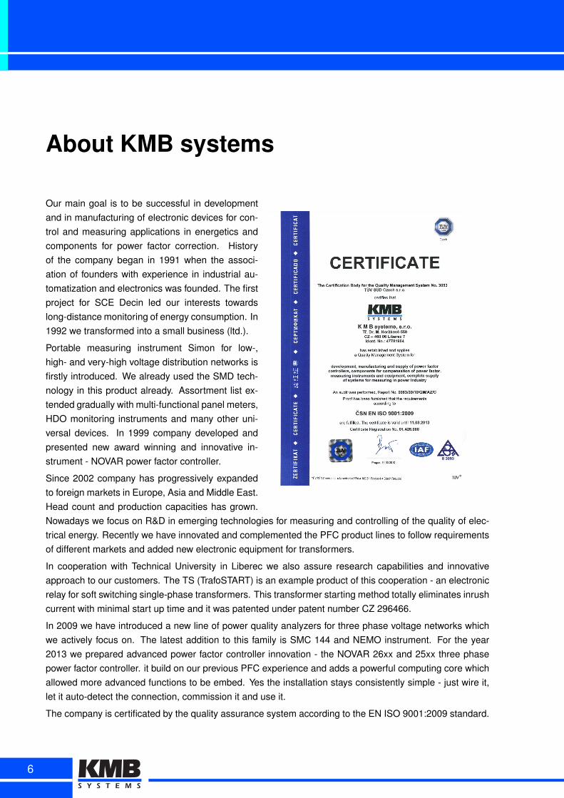
Our main goal is to be successful in developmentand in manufacturing of electronic devices for con-trol and measuring applications in energetics andcomponents for power factor correction. Historyof the company began in 1991 when the associ-ation of founders with experience in industrial au-tomatization and electronics was founded. The firstproject for SCE Decin led our interests towardslong-distance monitoring of energy consumption. In1992 we transformed into a small business (ltd.).
Portable measuring instrument Simon for low-,high- and very-high voltage distribution networks isfirstly introduced. We already used the SMD tech-nology in this product already. Assortment list ex-tended gradually with multi-functional panel meters,HDO monitoring instruments and many other uni-versal devices. In 1999 company developed andpresented new award winning and innovative in-strument - NOVAR power factor controller.
Since 2002 company has progressively expandedto foreign markets in Europe, Asia and Middle East.Head count and production capacities has grown.Nowadays we focus on R&D in emerging technologies for measuring and controlling of the quality of elec-trical energy. Recently we have innovated and complemented the PFC product lines to follow requirementsof different markets and added new electronic equipment for transformers.
In cooperation with Technical University in Liberec we also assure research capabilities and innovativeapproach to our customers. The TS (TrafoSTART) is an example product of this cooperation - an electronicrelay for soft switching single-phase transformers. This transformer starting method totally eliminates inrushcurrent with minimal start up time and it was patented under patent number CZ 296466.
In 2009 we have introduced a new line of power quality analyzers for three phase voltage networks whichwe actively focus on. The latest addition to this family is SMC 144 and NEMO instrument. For the year2013 we prepared advanced power factor controller innovation - the NOVAR 26xx and 25xx three phasepower factor controller. it build on our previous PFC experience and adds a powerful computing core whichallowed more advanced functions to be embed. Yes the installation stays consistently simple - just wire it,let it auto-detect the connection, commission it and use it.
The company is certificated by the quality assurance system according to the EN ISO 9001:2009 standard.
6
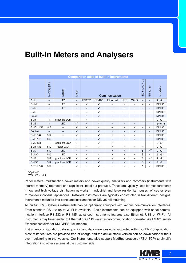
Built-In Meters and Analysers
Comparison table of built-in instruments
Mem
ory
[MB
]
Dis
play
Met
er
Communication IEC
6100
0-4-
30
EN
5016
0
Inst
alla
tion
SML – LED – RS232 RS485 Ethernet USB Wi-Fi – – 91x91
SMM – LED – ✓ ✓ – – – – – DIN-35
SMN – LED – ✓ ✓ – – – – – DIN-35
SMD – – – ✓ ✓ – – – – – DIN-35
PA33 – – – ✓ ✓ – – – – – DIN-35
SMY 1 graphical LCD – ✓ ✓ – – – – – 91x91
SMZ 1 LED ✓a ✓ ✓ – – – – – 138x138
SMC 11/33 0.5 – ✓ ✓ ✓ – – ✓ – – DIN-35
PA 144 – – ✓ – ✓ ✓ ✓ ✓ – – DIN-35
SMC 144 512 – ✓ – ✓ ✓ ✓ ✓ – – DIN-35
SMD 118 512 – ✓ – ✓ ✓ ✓ ✓ – – DIN-35
SML 133 – segment LCD ✓ – ✓ ✓ – – – – 91x91
SMY 133 512 color LCD ✓ – ✓ ✓ ✓ – – – 91x91
SMV 512 LED ✓ ✓ ✓ ✓ ✓ – S ✓b 91x91
SMVQ 512 LED ✓ ✓ ✓ ✓ ✓ – S ✓ 91x91
SMP 512 graphical LCD ✓ ✓ ✓ ✓ ✓ – S ✓b 91x91
SMPQ 512 graphical LCD ✓ ✓ ✓ ✓ ✓ – S ✓ 91x91
ARTIQ 144 512 – ✓ – ✓ ✓ ✓ ✓ A ✓ DIN-35
aOption EbWith VE modul
Panel meters, multifunction power meters and power quality analyzers and recorders (instruments withinternal memory) represent one significant line of our products. These are typically used for measurementsin low and high voltage distribution networks in industrial and large residential houses, offices or evento monitor individual appliances. Installed instruments are typically constructed in two different designs.Instruments mounted into panel and instruments for DIN-35 rail mounting.
All built-in KMB systems instruments can be optionally equipped with various communication interfaces.From standard RS-232 up to Wi-Fi is available. Basic instruments can be equipped with serial commu-nication interface RS-232 or RS-485, advanced instruments features also Ethernet, USB or Wi-Fi. Allinstruments may be extended to Ethernet or GPRS via external communication converter like ES 101 serial-Ethernet converter or KM GPRS 101 modem.
Instrument configuration, data acquisition and data warehousing is supported within our ENVIS application.Most of its features are provided free of charge and the actual stable version can be downloaded withouteven registering to the website. Our instruments also support ModBus protocols (RTU, TCP) to simplifyintegration into other systems at the customer side.
7
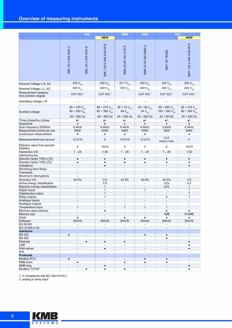
Overview of measuring instruments
SML SMM SMN SMYNEW NEW
SM
L 3
3 U
23
0 X
/5A
2
SM
L 3
3 U
23
0 X
/5A
E
SM
L 1
33
U 4
00
X/5
A R
I E
SM
N 3
3 4
8 1
00
X/1
A E
SM
N 3
3 2
4 2
30
S6
00
2
SM
Y 3
3+
R/4
85
SM
Y 1
33
U 4
00
X/5
A R
I E
Nominal Voltage L-N, AC
Nominal Voltage L-L, AC
Operating voltage L-N - - - - - -
Auxiliary voltage
45 ÷ 450 Hz 45 ÷ 450 Hz 45 ÷ 450 Hz 45 ÷ 450 Hz 42 ÷ 80 HZ 45 ÷ 450 HzThree phase/four phase ●/- ●/- ●/- ●/- ●/- ●/-Quadrants 4 6 4 4 4 6Scan frequency 50/60Hz 6.4kHz 6.4kHz 6.4kHz 6.4kHz 3.2kHz 6.4kHzMeasurement points per sec. 6400 6400 6400 6400 3200 6400Continuous measurement ● ● ● ● - ●
Measuerements per second 12.5/15 5 12.5/15 12.5/15 5
4 10/12 4 4 4 10/12
Harmonics V/A 1 – 25 1-50 1 – 25 1 – 25 1 – 25 1-50Interharmonics - - - - - -Disortion factor THD-U [%] ● ● ● ● ● ●Disortion factor THD-I [%] ● ● ● ● ● ●Unbalance - ● - - - ●Short/long-term flicker - - - - - -Transients - - - - - -Short-term interruptions - - - - - -Accuracy V/A ±0.5% 0.5 ±0.5% ±0.5% ±0.5% 0.5Active energy classification - 0.5 - - ±2% 0.5Reactive energy classification - 1 - - ±2% 1Digital inputs - 1 - 1 - 1Digital/pulse output - 1 - - - 1Relay outputs - 1 - - 2 1Analogue inputs - - - - - -Analogue outputs - - - - - -Temperature input 1 - 1 1 1 -Min/max value memory - ● - - ● ●Memory size - - - - 1MB 512MBClock ● - ● ● ● ●Software ENVIS ENVIS ENVIS ENVIS ENVIS ENVISEN 50160 - - - - - -IEC 61000-4-30 - - - - - -InterfacesRS 232 ● - - - ● ● -RS 485 - - - - ● -Ethernet - ● ● ● - - ●USB - - - - - ●Web server - ● - - - ●Wifi - - - - - -ProtocolsModbus RTU ● - - - ● ● -KMB short ● - ● ● ● -KMB long - ● - - - ●ModBus TCP/IP - ● ● ● - - ●
1. in compliance with IEC EN 61010-12. analog or temp input
230 VAC
230 VAC
57,7 VAC
230 VAC
230 VAC
230 VAC
400 VAC
400 VAC
100 VAC
400 VAC
400 VAC
400 VAC
Measurement categoryAnd pollution degree
CAT III/2 1 CAT III/2 1 CAT III/2 1 CAT III/2 1 CAT III/2 1
85 ÷ 275 VAC
80 ÷ 350 VDC
85 ÷ 275 VAC
80 ÷ 350 VDC
36 ÷ 72 VDC
48 VAC
18 ÷ 36 VDC
24 VAC
80 ÷ 260 VAC
100 ÷ 350 VDC
85 ÷ 275 VAC
80 ÷ 350 VDC
12.5 every 3 sec
Effective value from periods 50/60Hz
8
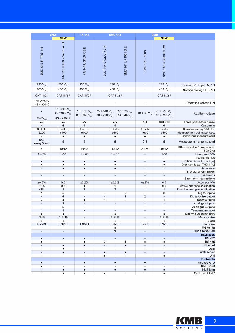
SMZ PA 144 SMC 144 SMDNEW NEW
SM
Z 3
3 E
R T
/RS
-48
5
SM
Z 1
33
U 4
00
X/5
A R
I A
ET
PA
14
4 U
S1
00
R B
E
SM
C 1
44
U S
20
0 R
B N
SM
C 1
44
L P
10
0 I
D E
SM
D 1
01
– 1
00
/4
SM
D 1
18
U D
50
0 R
D W
- Nominal Voltage L-N, AC
- Nominal Voltage L-L, AC
- - - - - Operating voltage L-N
-Auxiliary voltage
45 ÷ 450 Hz●/- ●/- ●/● ●/● 1×I 1×U, 8×I Three phase/four phase4 6 4 4 - 6 Quadrants
3.2kHz 6.4kHz 6.4kHz 6.4kHz 1.6kHz 6.4kHz Scan frequency 50/60Hz3200 6400 6400 6400 1600 6400 Measurement points per sec.
- ● ● ● ● ● Continuous measurement
5 5 5 2,5 5 Measuerements per second
4 10/12 10/12 10/12 20/24 10/12
1 – 25 1-50 1 – 63 1 – 63 - 1-50 Harmonics V/A- - - - - - Interharmonics● ● ● ● - ● Disortion factor THD-U [%]● ● ● ● - ● Disortion factor THD-I [%]- ● ● ● - - Unbalance- - - - - - Short/long-term flicker- - - - - - Transients- - - - - - Short-term interruptions
±0.5% 0.5 ±0.2% ±0.2% -/±1% 0.5 Accuracy V/A±2% 0.5 1 1 - 0.5 Active energy classification±2% 1 2 2 - 1 Reactive energy classification
1 5 - - 2 - 2 Digital inputs- 4 - - 1 2 - Digital/pulse output2 4 1 1 - - 1 Relay outputs- 2 - - - - Analogue inputs- 2 - - - - Analogue outputs1 1 - - - - Temperature input● ● - ● - ● Min/max value memory
1MB 512MB - 512MB - 512MB Memory size● ● - ● - ● Clock
ENVIS ENVIS ENVIS ENVIS ENVIS ENVIS Software- - - ● - - EN 50160- - S - - IEC 61000-4-30
Interfaces● - - - - - RS 232● - ● 2 1 ● ● RS 485- ● ● - ● - - Ethernet- ● - - - - USB- ● - ● ● - - Web server- - - ● - ● Wifi
Protocols● - ● ● ● - Modbus RTU● - - - - - KMB short- ● ● ● ● ● KMB long- ● ● ● - - ● ModBus TCP/IP
230 VAC
230 VAC
230 VAC
230 VAC
230 VAC
400 VAC
400 VAC
400 VAC
400 VAC
400 VAC
CAT III/2 1 CAT III/2 1 CAT III/2 1 CAT III/2 1 CAT III/2 1
115 V/230V 42 ÷ 80 HZ
75 ÷ 500 VAC
90 ÷ 600 VDC
75 ÷ 510 VAC
80 ÷ 350 VDC
75 ÷ 510 VAC
80 ÷ 250 VDC
20 ÷ 75 VDC
24 ÷ 48 VAC
18 ÷ 36 VDC
75 ÷ 510 VAC
80 ÷ 250 VDC
400 VAC
12.5 every 3 sec
Effective value from periods 50/60Hz
9
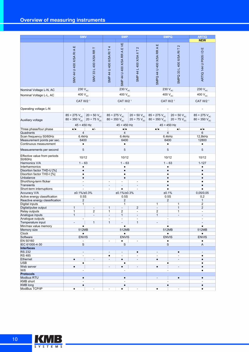
Overview of measuring instruments
SMV SMP SMPQ ARTIQNEW
SM
V 4
4 U
40
0 X
/5A
RI A
E
SM
V 3
3 L
40
0 X
/5A
RR
T
SM
P 4
4 U
40
0 X
/5A
RI T
4
SM
P 4
4 U
40
0 X
/5A
RR
A E
VE
SM
P 4
4 L
40
0 X
/5A
II T
2
SM
PQ
44
U 4
00
X/5
A R
R A
E
SM
PQ
33
L 4
00
X/5
A R
I T 2
AR
TIQ
14
4 U
P0
05
I D
E
Nominal Voltage L-N, AC
Nominal Voltage L-L, AC
Operating voltage L-N - - - -
Auxiliary voltage
45 ÷ 450 Hz 45 ÷ 450 Hz 45 ÷ 450 HzThree phase/four phase ●/● ●/- ●/● ●/● ●/- ●/●Quadrants 4 4 4 6Scan frequency 50/60Hz 6.4kHz 6.4kHz 6.4kHz 12,8kHzMeasurement points per sec. 6400 6400 6400 12800Continuous measurement ● ● ● ●
Measuerements per second 5 5 5 5
10/12 10/12 10/12 10/12
Harmonics V/A 1 – 63 1 – 63 1 – 63 1-127Interharmonics ● ● ● ●Disortion factor THD-U [%] ● ● ● ●Disortion factor THD-I [%] ● ● ● ●Unbalance ● ● ● ●Short/long-term flicker - - - - ● ●Transients - - - - ● ●Short-term interruptions - - ● - ● ●Accuracy V/A ±0.1%/±0.3% ±0.1%/±0.3% ±0.1% 0,05/0,05Active energy classification 0.5S 0.5S 0.5S 0,2Reactive energy classification 2 2 2 1Digital inputs 1 1 1 1 2Digital/pulse output 1 - 1 - 2 - 1 2Relay outputs 1 2 1 2 - 2 1 -Analogue inputs 1 - - 1 - 1 - -Analogue outputs - - - - - -Temperature input - 1 1 - 1 - -Min/max value memory ● ● ● ●Memory size 512MB 512MB 512MB 512MBClock ● ● ● ●Software ENVIS ENVIS ENVIS ENVISEN 50160 - - ● - ● ●IEC 61000-4-30 S S S AInterfacesRS 232 - - - ● - ● -RS 485 - ● - - - - ●Ethernet ● - - ● - ● - ●USB ● ● ● ●Web server ● - ● - ● - ●Wifi - - - ●ProtocolsModbus RTU ● ● - ● ●KMB short - - - -KMB long ● ● ● ●ModBus TCP/IP ● - - ● - ● - ●
230 VAC
230 VAC
230 VAC
230 VAC
400 VAC
400 VAC
400 VAC
400 VAC
CAT III/2 1 CAT III/2 1 CAT III/2 1 CAT III/2 1
85 ÷ 275 VAC
80 ÷ 350 VDC
20 ÷ 50 V
AC
20 ÷ 75 VDC
85 ÷ 275 VAC
80 ÷ 350 VDC
20 ÷ 50 VAC
20 ÷ 75 VDC
85 ÷ 275 VAC
80 ÷ 350 VDC
20 ÷ 50 VAC
20 ÷ 75 VDC
85 ÷ 275 VAC
80 ÷ 350 VDC
Effective value from periods 50/60Hz
10
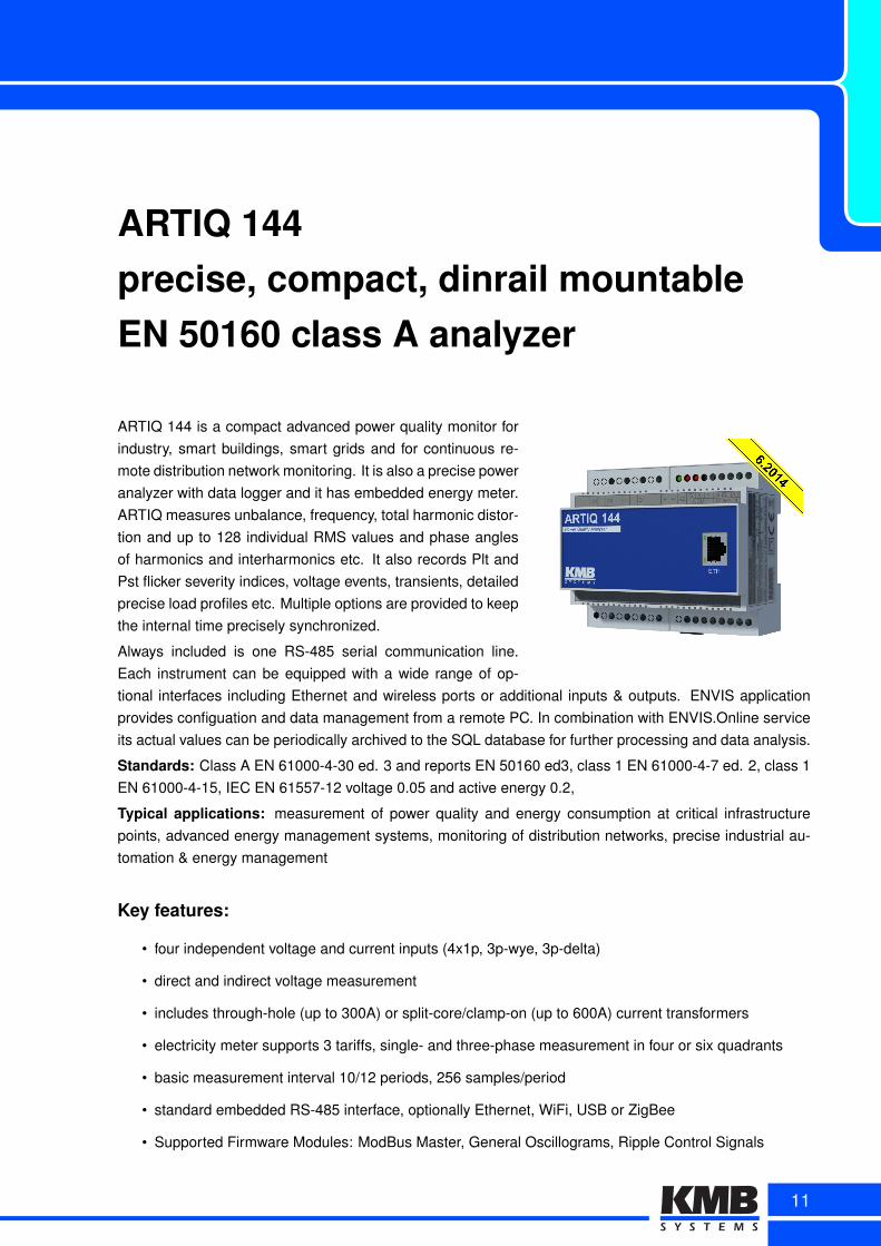
ARTIQ 144precise, compact, dinrail mountableEN 50160 class A analyzer
ARTIQ 144 is a compact advanced power quality monitor forindustry, smart buildings, smart grids and for continuous re-mote distribution network monitoring. It is also a precise poweranalyzer with data logger and it has embedded energy meter.ARTIQ measures unbalance, frequency, total harmonic distor-tion and up to 128 individual RMS values and phase anglesof harmonics and interharmonics etc. It also records Plt andPst flicker severity indices, voltage events, transients, detailedprecise load profiles etc. Multiple options are provided to keepthe internal time precisely synchronized.
Always included is one RS-485 serial communication line.Each instrument can be equipped with a wide range of op-tional interfaces including Ethernet and wireless ports or additional inputs & outputs. ENVIS applicationprovides configuation and data management from a remote PC. In combination with ENVIS.Online serviceits actual values can be periodically archived to the SQL database for further processing and data analysis.
Standards: Class A EN 61000-4-30 ed. 3 and reports EN 50160 ed3, class 1 EN 61000-4-7 ed. 2, class 1EN 61000-4-15, IEC EN 61557-12 voltage 0.05 and active energy 0.2,
Typical applications: measurement of power quality and energy consumption at critical infrastructurepoints, advanced energy management systems, monitoring of distribution networks, precise industrial au-tomation & energy management
Key features:
• four independent voltage and current inputs (4x1p, 3p-wye, 3p-delta)
• direct and indirect voltage measurement
• includes through-hole (up to 300A) or split-core/clamp-on (up to 600A) current transformers
• electricity meter supports 3 tariffs, single- and three-phase measurement in four or six quadrants
• basic measurement interval 10/12 periods, 256 samples/period
• standard embedded RS-485 interface, optionally Ethernet, WiFi, USB or ZigBee
• Supported Firmware Modules: ModBus Master, General Oscillograms, Ripple Control Signals
11
Class A Power Quality Analyzer
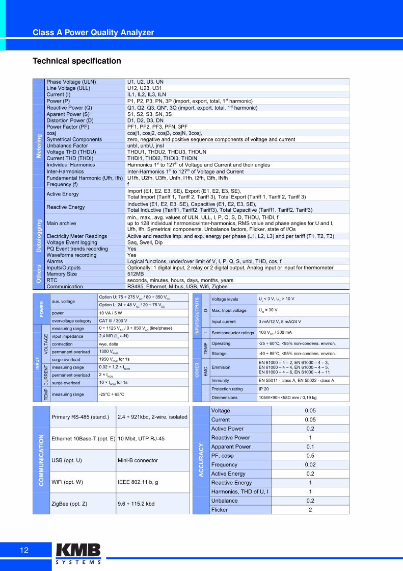
Technical specification
Metering
Phase Voltage (ULN) U1, U2, U3, UNLine Voltage (ULL) U12, U23, U31Current (I) IL1, IL2, IL3, ILNPower (P)Reactive Power (Q)Aparent Power (S) S1, S2, S3, SN, 3SDistortion Power (D) D1, D2, D3, DNPower Factor (PF) PF1, PF2, PF3, PFN, 3PFcosj cosj1, cosj2, cosj3, cosjN, 3cosj, Symetrical Components zero, negative and positive sequence components of voltage and currentUnbalance Factor unbI, unbU, jnsIVoltage THD (THDU) THDU1, THDU2, THDU3, THDUNCurrent THD (THDI) THDI1, THDI2, THDI3, THDINIndividual HarmonicsInter-HarmonicsFundamental Harmonic (Ufh, Ifh) U1fh, U2fh, U3fh, Unfh, I1fh, I2fh, I3fh, INfhFrequency (f) f
Active Energy
Reactive Energy
Datalogging Main archive
Electricity Meter Readings Active and reactive imp. and exp. energy per phase (L1, L2, L3) and per tariff (T1, T2, T3)Voltage Event logging Saq, Swell, DipPQ Event trends recording YesWaveforms recording Yes
Others
Alarms Logical functions, under/over limit of V, I, P, Q, S, unbl, THD, cos, fInputs/Outputs Optionally: 1 digital input, 2 relay or 2 digital output, Analog input or input for thermometerMemory Size 512MBRTC seconds, minutes, hours, days, months, yearsCommunication RS485, Ethernet, M-bus, USB, Wifi, Zigbee
P1, P2, P3, PN, 3P (import, export, total, 1st harmonic)Q1, Q2, Q3, QN*, 3Q (import, export, total, 1st harmonic)
Harmonics 1st to 127th of Voltage and Current and their anglesInter-Harmonics 1st to 127th of Voltage and Current
Import (E1, E2, E3, SE), Export (E1, E2, E3, SE),Total Import (Tariff 1, Tariff 2, Tariff 3), Total Export (Tariff 1, Tariff 2, Tariff 3)Inductive (E1, E2, E3, SE), Capacitive (E1, E2, E3, SE),Total Inductive (Tariff1, Tariff2, Tariff3), Total Capacitive (Tariff1, Tariff2, Tariff3)
min., max., avg. values of ULN, ULL, I, P, Q, S, D, THDU, THDI, fup to 128 individual harmonics/inter-harmonics, RMS value and phase angles for U and I,Ufh, Ifh, Symetrical components, Unbalance factors, Flicker, state of I/Os
POWER aux. voltage
power 10 VA / 5 W
overvoltage category CAT III / 300 V
INPUT
VO
LT
AG
E
measuring range
input impedance
connection wye, delta
permanent overload
surge overload
CU
RR
EN
T measuring range
permanent overload
surge overload
TE
MP
measuring range -25°C ÷ 65°C
Option U: 75 ÷ 275 VAC
/ 80 ÷ 350 VDC
Option L: 24 ÷ 48 VAC
/ 20 ÷ 75 VDC
0 ÷ 1125 VAC
/ 0 ÷ 850 VAC
(line/phase)
2,4 MΩ (Li ↔N)
1300 VRMS
1950 VRMS for 1s
0,02 ÷ 1,2 × INOM
2 × INOM
10 × INOM
for 1s
INPUTS/OUTPUTS
D
Voltage levels
Max. Input voltage
Input current 3 mA/12 V, 8 mA/24 V
I Semiconductor ratings
OTHER
TE
MP Operating -25 ÷ 60°C, <95% non-condens. environ.
Storage -40 ÷ 85°C, <95% non-condens. environ.
EM
C Emmision
Immunity EN 55011 - class A, EN 55022 - class A
Protection rating IP 20
Dimmensions 105W×90H×58D mm / 0,19 kg
UL < 3 V, U
H > 10 V
UM = 30 V
100 VDC
/ 300 mA
EN 61000 – 4 – 2, EN 61000 – 4 – 3,EN 61000 – 4 – 4, EN 61000 – 4 – 5,EN 61000 – 4 – 6, EN 61000 – 4 – 11
COMMUNICATION
Primary RS-485 (stand.) 2.4 ÷ 921kbd, 2-wire, isolated
Ethernet 10Base-T (opt. E) 10 Mbit, UTP RJ-45
USB (opt. U) Mini-B connector
WiFi (opt. W) IEEE 802.11 b, g
ZigBee (opt. Z) 9.6 ÷ 115.2 kbd
ACCURACY
Voltage 0.05
Current 0.05
Active Power 0.2
Reactive Power 1
Apparent Power 0.1
PF, cosφ 0.5
Frequency 0.02
Active Energy 0.2
Reactive Energy 1
Harmonics, THD of U, I 1
Unbalance 0.2
Flicker 2
12
ARTIQ 144
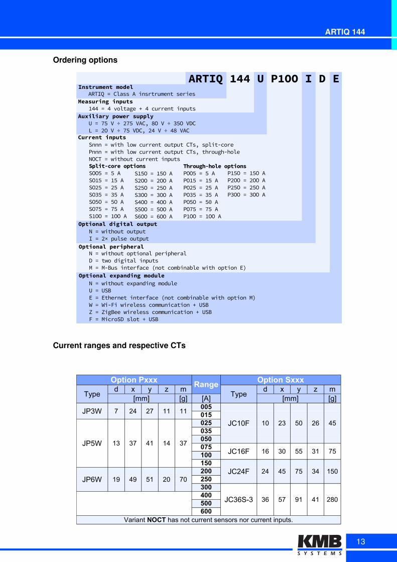
Ordering options
Optional-digital-output
Optional-peripheral
Optional-expanding-module
N)=)without)outputI)=)v×)pulse)output
N)=)without)optional)peripheralD)=)two)digital)inputsM)=)MABus)interface)Cnot)combinable)with)option)ET
N)=)without)expanding)moduleU)=)USBE)=)Ethernet)interface)Cnot)combinable)with)option)MTW)=)WiAFi)wireless)communication)P)USBZ)=)ZigBee)wireless)communication)P)USBF)=)MicroSD)slot)P)USB)
Current-inputsSnnn)=)with)low)current)output)CTsO)splitAcore)Pnnn)=)with)low)current)output)CTsO)throughAholeNOCT)=)without)current)inputs
ARTIQ-144-U-P1OO-I-D-EInstrument-model
Measuring-inputsARTIQ)=)Class)A)insrtrument)series
433)=)3)voltage)P)3)current)inputs
Through-hole-optionsPOO0)=)0)APO40)=)40)APOv0)=)v0)APO50)=)50)APO0O)=)01)APO60)=)60)AP4OO)=)4OO)A
Split-core-optionsSOO0)=)0)ASO40)=)40)ASOv0)=)v0)ASO50)=)50)ASO0O)=)0O)ASO60)=)60)AS4OO)=)4OO)A
S40O)=)40O)ASvOO)=)vOO)ASv0O)=)v0O)AS5OO)=)5OO)AS3OO)=)3OO)AS0OO)=)0OO)AS7OO)=)7OO)A
P40O)=)40O)APvOO)=)vOO)APv0O)=)v0O)AP5OO)=)5OO)A
Auxiliary-power-supplyU)=)60)V)÷)v60)VACO)VO)V)÷)50O)VDCL)=)vO)V)÷)60)VDCO)v3)V)÷)3V)VAC
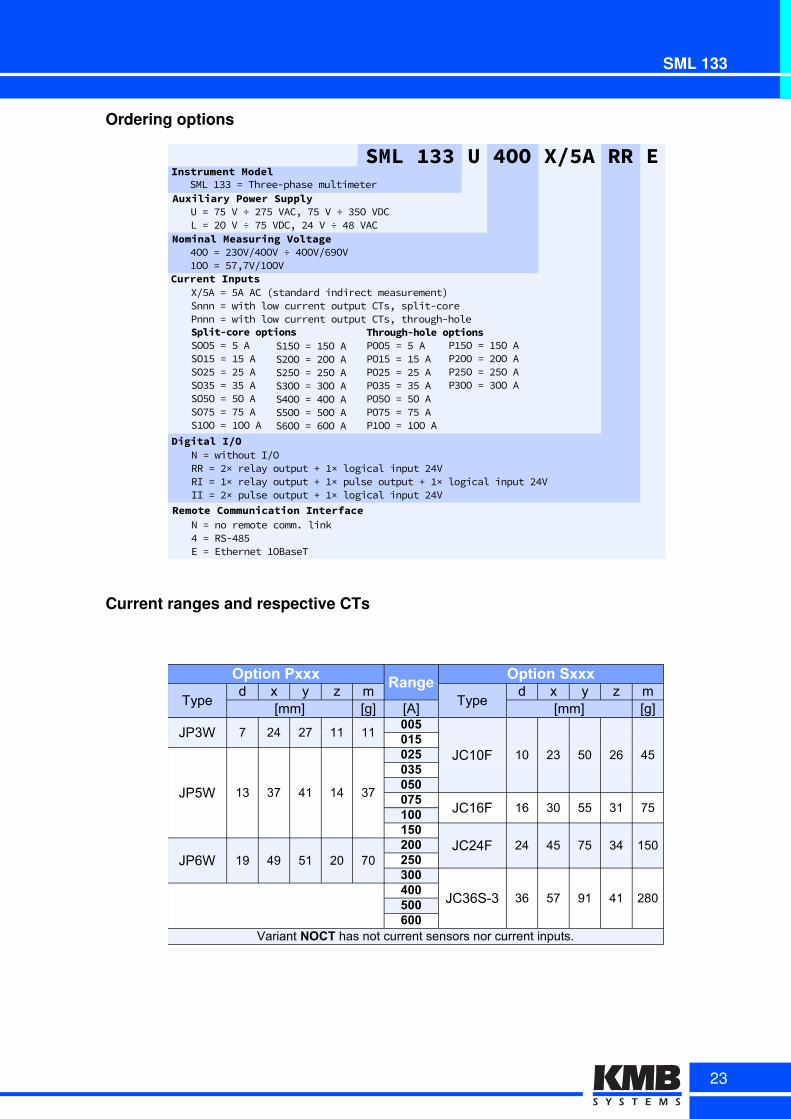
Current ranges and respective CTs
Option PxxxRange
Option Sxxx
Typed x y z m
Typed x y z m
[mm] [g] [A] [mm] [g]
JP3W 7 24 27 11 11005
JC10F 10 23 50 26 45015
JP5W 13 37 41 14 37
025035050075
JC16F 16 30 55 31 75100150
JC24F 24 45 75 34 150JP6W 19 49 51 20 70
200250300
JC36S-3 36 57 91 41 280400500600
Variant NOCT has not current sensors nor current inputs.
13
Class A Power Quality Analyzer
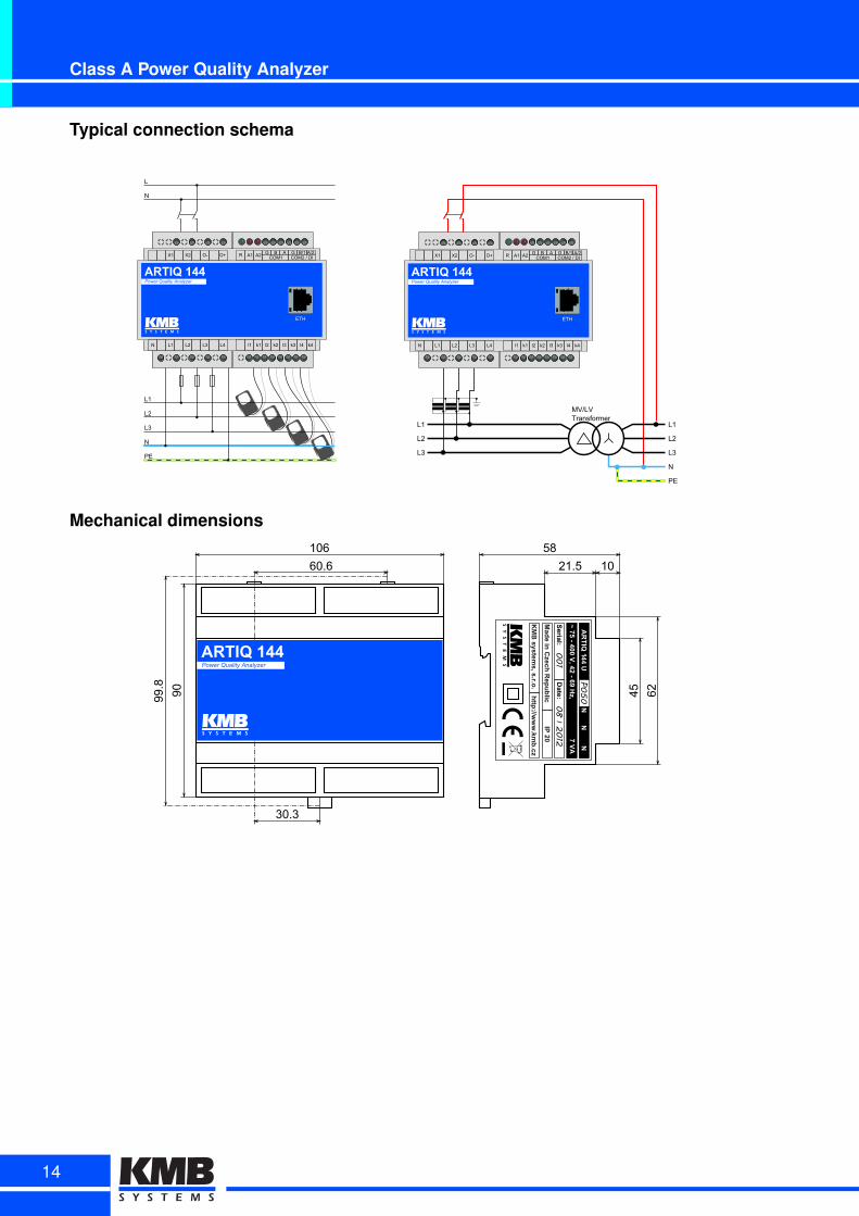
Typical connection schema
L1
L2
L3
N
PE
L
N
ARTIQ 144Power Quality Analyzer
ETH
N L1 L2 L3 L4 l1 k1 l2 k2 l3 k3 l4 k4
X1 X2 O- O+ R A1 A2 G B A G B/1 A/2COM1 COM2f/fDI
ARTIQ 144Power Quality Analyzer
ETH
N L1 L2 L3 L4 l1 k1 l2 k2 l3 k3 l4 k4
X1 X2 O- O+ R A1 A2 G B A G B/1 A/2COM1 COM2f/fDI
MV/LVTransformer
L1
L2
L3
Mechanical dimensions
60.6
90
21.5 10
45 62
58106
99.8
30.3
ARTIQ 144Power Quality Analyzer
001
082012
P050
AR
TIQ
1
14

SMV, SMP and SMVQ, SMPQClass S power quality analysers
These advanced panel meters are designed to monitor the quality of electric energy in a three- to five-wire electrical networks. They are characterized by continuous measurement of up to four voltages andcurrents. The instrument is also capable to evaluate other variables such as active, reactive, apparent anddistortion power, energy consumption (kWh/kvarh, three tariffs, four quadrants), power factor, harmonicdistortion etc. All three variants share the core features and functions and its other characteristics varywith advanced optional services and display features. SMPQ offers increased accuracy and precision ofenergy measurement. It also extends the list of measured variables such as flicker (Pst, Plt), inter-harmonicsubgroups etc. It also allows assessment of power quality indices according to the EN 50160.
Key features:
• advanced panel meters to monitor quality of electric energy in a three- to five- wire electrical networks.
• continuous measurement of up to four voltages and currents
• class S power monitoring according to the international standard IEC 61000-4-30, ed. 2.
• embedded four quadrant three phase three tariff electricity meter
• continuous power quality evaluation according EN 50160 (SMPQ)
• built-in USB 2.0 communication port with optional remote interface like RS 232, RS 485 or Ethernet
• standard MODBUS protocol support for SCADA systems
15
Compact power quality analyzers
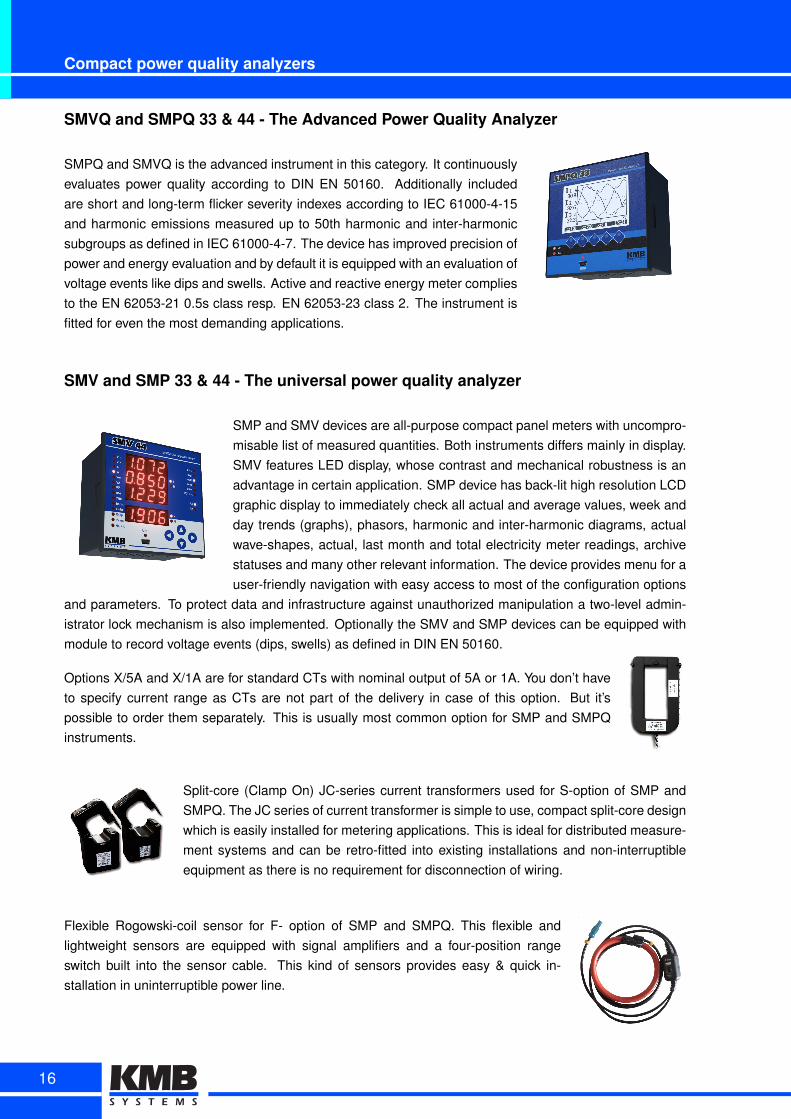
SMVQ and SMPQ 33 & 44 - The Advanced Power Quality Analyzer
SMPQ and SMVQ is the advanced instrument in this category. It continuouslyevaluates power quality according to DIN EN 50160. Additionally includedare short and long-term flicker severity indexes according to IEC 61000-4-15and harmonic emissions measured up to 50th harmonic and inter-harmonicsubgroups as defined in IEC 61000-4-7. The device has improved precision ofpower and energy evaluation and by default it is equipped with an evaluation ofvoltage events like dips and swells. Active and reactive energy meter compliesto the EN 62053-21 0.5s class resp. EN 62053-23 class 2. The instrument isfitted for even the most demanding applications.
SMV and SMP 33 & 44 - The universal power quality analyzer
SMP and SMV devices are all-purpose compact panel meters with uncompro-misable list of measured quantities. Both instruments differs mainly in display.SMV features LED display, whose contrast and mechanical robustness is anadvantage in certain application. SMP device has back-lit high resolution LCDgraphic display to immediately check all actual and average values, week andday trends (graphs), phasors, harmonic and inter-harmonic diagrams, actualwave-shapes, actual, last month and total electricity meter readings, archivestatuses and many other relevant information. The device provides menu for auser-friendly navigation with easy access to most of the configuration options
and parameters. To protect data and infrastructure against unauthorized manipulation a two-level admin-istrator lock mechanism is also implemented. Optionally the SMV and SMP devices can be equipped withmodule to record voltage events (dips, swells) as defined in DIN EN 50160.
Options X/5A and X/1A are for standard CTs with nominal output of 5A or 1A. You don’t haveto specify current range as CTs are not part of the delivery in case of this option. But it’spossible to order them separately. This is usually most common option for SMP and SMPQinstruments.
Split-core (Clamp On) JC-series current transformers used for S-option of SMP andSMPQ. The JC series of current transformer is simple to use, compact split-core designwhich is easily installed for metering applications. This is ideal for distributed measure-ment systems and can be retro-fitted into existing installations and non-interruptibleequipment as there is no requirement for disconnection of wiring.
Flexible Rogowski-coil sensor for F- option of SMP and SMPQ. This flexible andlightweight sensors are equipped with signal amplifiers and a four-position rangeswitch built into the sensor cable. This kind of sensors provides easy & quick in-stallation in uninterruptible power line.
16
SMV, SMP and SMVQ, SMPQ
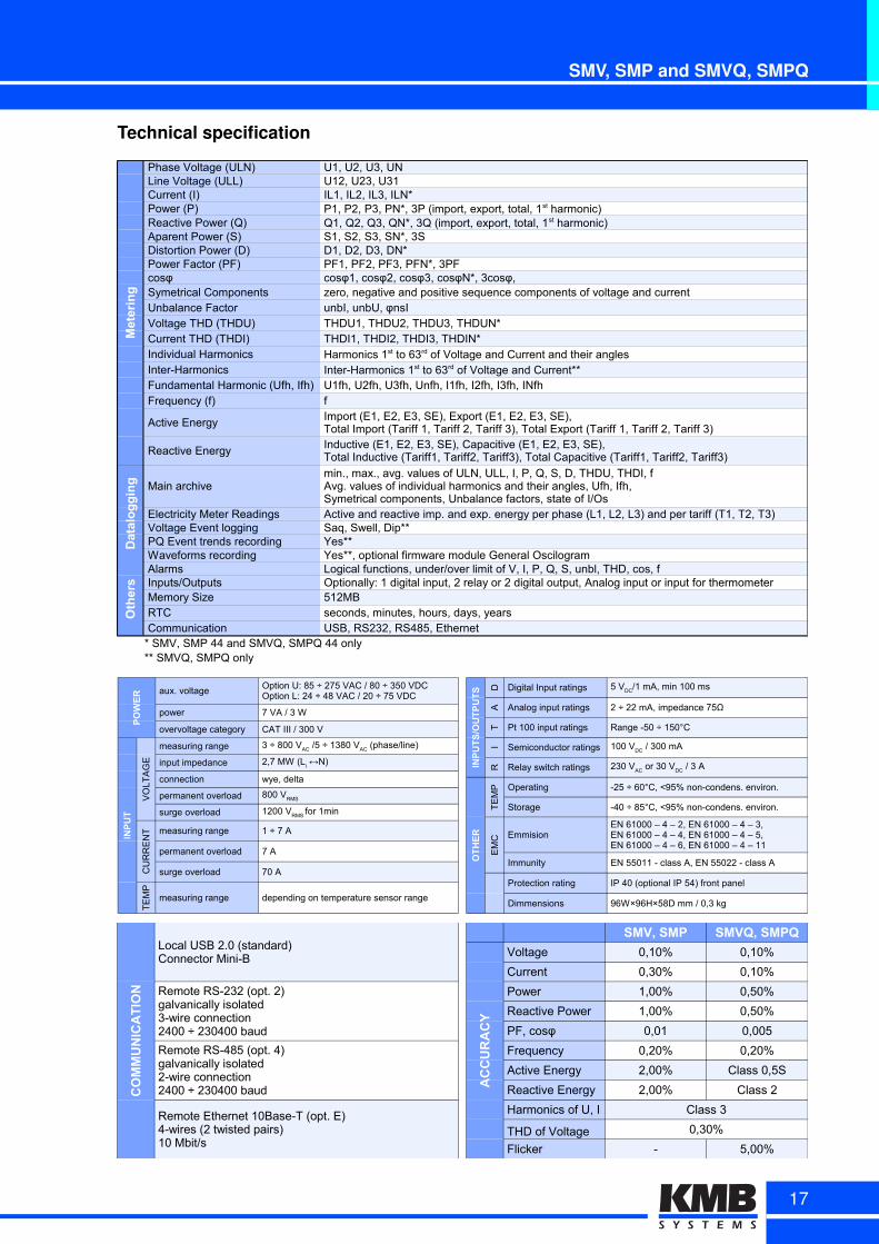
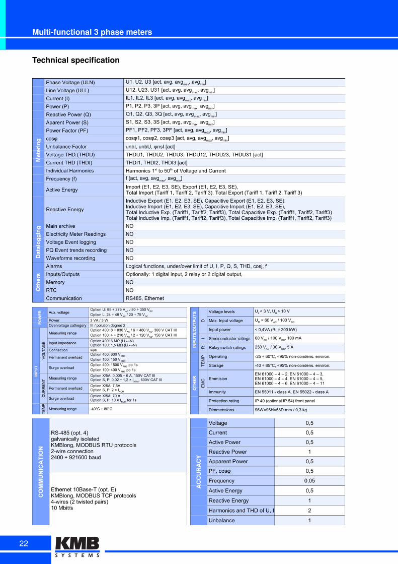
Technical specificationMetering
Phase Voltage (ULN) U1, U2, U3, UNLine Voltage (ULL) U12, U23, U31Current (I) IL1, IL2, IL3, ILN*Power (P)Reactive Power (Q)Aparent Power (S) S1, S2, S3, SN*, 3SDistortion Power (D) D1, D2, D3, DN*Power Factor (PF) PF1, PF2, PF3, PFN*, 3PFcosφ cosφ1, cosφ2, cosφ3, cosφN*, 3cosφ, Symetrical Components zero, negative and positive sequence components of voltage and currentUnbalance Factor unbI, unbU, φnsIVoltage THD (THDU) THDU1, THDU2, THDU3, THDUN*Current THD (THDI) THDI1, THDI2, THDI3, THDIN*Individual HarmonicsInter-HarmonicsFundamental Harmonic (Ufh, Ifh) U1fh, U2fh, U3fh, Unfh, I1fh, I2fh, I3fh, INfhFrequency (f) f
Active Energy
Reactive Energy
Datalogging Main archive
Electricity Meter Readings Active and reactive imp. and exp. energy per phase (L1, L2, L3) and per tariff (T1, T2, T3)Voltage Event logging Saq, Swell, Dip**PQ Event trends recording Yes**Waveforms recording Yes**, optional firmware module General Oscilogram
Others
Alarms Logical functions, under/over limit of V, I, P, Q, S, unbl, THD, cos, fInputs/Outputs Optionally: 1 digital input, 2 relay or 2 digital output, Analog input or input for thermometerMemory Size 512MBRTC seconds, minutes, hours, days, yearsCommunication USB, RS232, RS485, Ethernet
* SMV, SMP 44 and SMVQ, SMPQ 44 only** SMVQ, SMPQ only
P1, P2, P3, PN*, 3P (import, export, total, 1st harmonic)Q1, Q2, Q3, QN*, 3Q (import, export, total, 1st harmonic)
Harmonics 1st to 63rd of Voltage and Current and their anglesInter-Harmonics 1st to 63rd of Voltage and Current**
Import (E1, E2, E3, SE), Export (E1, E2, E3, SE),Total Import (Tariff 1, Tariff 2, Tariff 3), Total Export (Tariff 1, Tariff 2, Tariff 3)Inductive (E1, E2, E3, SE), Capacitive (E1, E2, E3, SE),Total Inductive (Tariff1, Tariff2, Tariff3), Total Capacitive (Tariff1, Tariff2, Tariff3)
min., max., avg. values of ULN, ULL, I, P, Q, S, D, THDU, THDI, fAvg. values of individual harmonics and their angles, Ufh, Ifh,Symetrical components, Unbalance factors, state of I/Os
POWER aux. voltage
power 7 VA / 3 W
overvoltage category CAT III / 300 V
INPUT
VO
LT
AG
E
measuring range
input impedance
connection wye, delta
permanent overload
surge overload
CU
RR
EN
T measuring range 1 ÷ 7 A
permanent overload 7 A
surge overload 70 A
TE
MP
measuring range depending on temperature sensor range
Option U: 85 ÷ 275 VAC / 80 ÷ 350 VDCOption L: 24 ÷ 48 VAC / 20 ÷ 75 VDC
3 ÷ 800 VAC /5 ÷ 1380 VAC (phase/line)
2,7 MW (Li ↔N)
800 VRMS
1200 VRMS
for 1min
INPUTS/OUTPUTS D Digital Input ratings
A Analog input ratings 2 ÷ 22 mA, impedance 75Ω
T Pt 100 input ratings Range -50 ÷ 150°C
I Semiconductor ratings
R Relay switch ratings
OTHER
TE
MP Operating -25 ÷ 60°C, <95% non-condens. environ.
Storage -40 ÷ 85°C, <95% non-condens. environ.
EM
C Emmision
Immunity EN 55011 - class A, EN 55022 - class A
Protection rating IP 40 (optional IP 54) front panel
Dimmensions 96W×96H×58D mm / 0,3 kg
5 VDC/1 mA, min 100 ms
100 VDC
/ 300 mA
230 VAC
or 30 VDC
/ 3 A
EN 61000 – 4 – 2, EN 61000 – 4 – 3,EN 61000 – 4 – 4, EN 61000 – 4 – 5,EN 61000 – 4 – 6, EN 61000 – 4 – 11
COMMUNICATION
Local USB 2.0 (standard)Connector Mini-B
Remote RS-232 (opt. 2)galvanically isolated3-wire connection2400 ÷ 230400 baud
Remote RS-485 (opt. 4)galvanically isolated2-wire connection2400 ÷ 230400 baud
Remote Ethernet 10Base-T (opt. E)4-wires (2 twisted pairs)10 Mbit/s
SMV, SMP SMVQ, SMPQ
AC
CU
RA
CY
Voltage 0,10% 0,10%
Current 0,30% 0,10%
Power 1,00% 0,50%
Reactive Power 1,00% 0,50%
PF, cosφ 0,01 0,005
Frequency 0,20% 0,20%
Active Energy 2,00% Class 0,5S
Reactive Energy 2,00% Class 2
Harmonics of U, I Class 3
THD of Voltage 0,30%
Flicker - 5,00%
17
Compact power quality analyzers
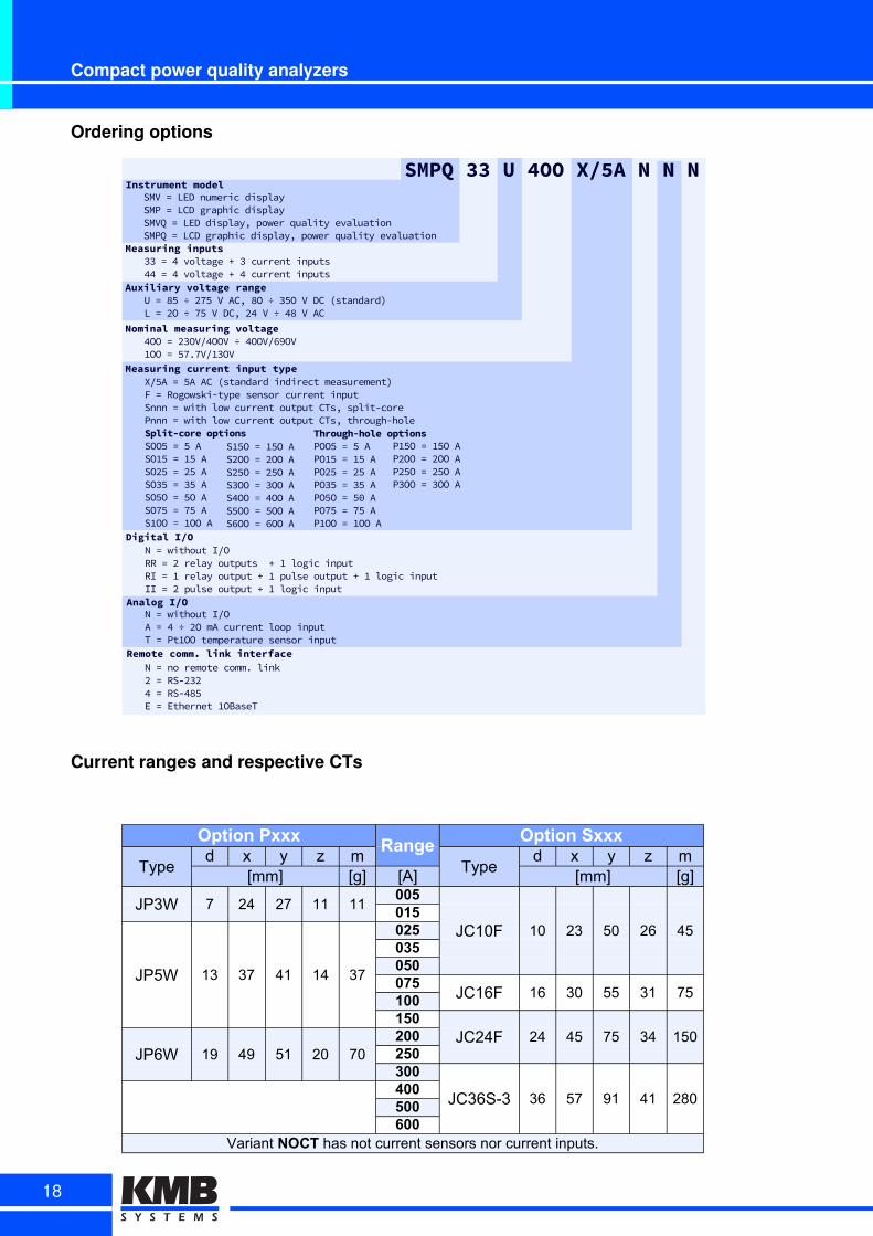
Ordering options
Digital4I/O
Analog4I/O
Remote4comm.4link4interface
NP=PwithoutPIFORRP=PVPrelayPoutputsPPCPMPlogicPinputRIP=PMPrelayPoutputPCPMPpulsePoutputPCPMPlogicPinputIIP=PVPpulsePoutputPCPMPlogicPinput
NP=PwithoutPIFOAP=PDP÷PVOPmAPcurrentPloopPinputTP=PPtMOOPtemperaturePsensorPinput
NP=PnoPremotePcomm)PlinkVP=PRSdVLVDP=PRSdD0QEP=PEthernetPMOBaseT
Measuring4current4input4typeXFQAP=PQAPACPEstandardPindirectPmeasurementBFP=PRogowskidtypePsensorPcurrentPinputSnnnP=PwithPlowPcurrentPoutputPCTs(PsplitdcorePPnnnP=PwithPlowPcurrentPoutputPCTs(Pthroughdhole
SMPQ4334U44OO4X/5A4N4N4NInstrument4model
Measuring4inputs
SMVP=PLEDPnumericPdisplaySMPP=PLCDPgraphicPdisplaySMVQP=PLEDPdisplay(PpowerPqualityPevaluationSMPQP=PLCDPgraphicPdisplay(PpowerPqualityPevaluationPPP
LLP=PDPvoltagePCPLPcurrentPinputsDDP=PDPvoltagePCPDPcurrentPinputs
Through-hole4optionsPOOQP=PQPAPOMQP=PMQPAPOVQP=PVQPAPOLQP=PLQPAPOQOP=PQ,PAPOvQP=PvQPAPMOOP=PMOOPA
Split-core4optionsSOOQP=PQPASOMQP=PMQPASOVQP=PVQPASOLQP=PLQPASOQOP=PQOPASOvQP=PvQPASMOOP=PMOOPA
SMQOP=PMQOPASVOOP=PVOOPASVQOP=PVQOPASLOOP=PLOOPASDOOP=PDOOPASQOOP=PQOOPASqOOP=PqOOPA
PMQOP=PMQOPAPVOOP=PVOOPAPVQOP=PVQOPAPLOOP=PLOOPA
Auxiliary4voltage4rangeUP=P0QP÷PVvQPVPAC(P0OP÷PLQOPVPDCPEstandardBPLP=PVOP÷PvQPVPDC(PVDPVP÷PD0PVPAC
Nominal4measuring4voltageDOOP=PVLOVFDOOVP÷PDOOVFq7OVMOOP=PQv)vVFMLOV
Current ranges and respective CTs
Option PxxxRange
Option Sxxx
Typed x y z m
Typed x y z m
[mm] [g] [A] [mm] [g]
JP3W 7 24 27 11 11005
JC10F 10 23 50 26 45015
JP5W 13 37 41 14 37
025035050075
JC16F 16 30 55 31 75100150
JC24F 24 45 75 34 150JP6W 19 49 51 20 70
200250300
JC36S-3 36 57 91 41 280400500600
Variant NOCT has not current sensors nor current inputs.
18
SMV, SMP and SMVQ, SMPQ
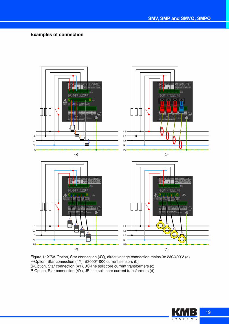
Examples of connection
L1
L2
L3
N
PE
k l
k l
k l
k l
(a)
L1
L2
L3
N
PE
(b)
L1
L2
L3
N
PE
(c)
L1
L2
L3
N
PE
(d)
Figure 1: X/5A-Option, Star connection (4Y), direct voltage connection,mains 3x 230/400 V (a)F-Option, Star connection (4Y), B3000/1000 current sensors (b)S-Option, Star connection (4Y), JC-line split core current transformers (c)P-Option, Star connection (4Y), JP-line split core current transformers (d)
19
Compact power quality analyzers
L1
L2
L3
110 VDC
(a)
MV/LVTransformer
L1
L2
L3
k l
k l
k l
(b)
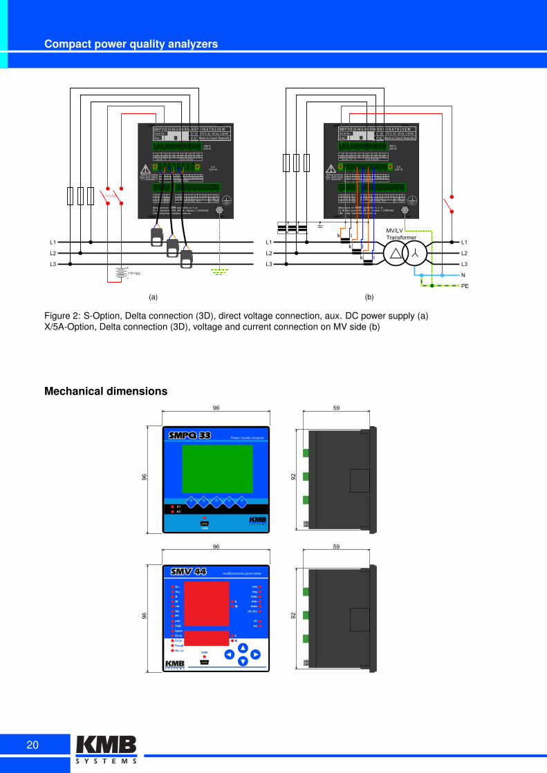
Figure 2: S-Option, Delta connection (3D), direct voltage connection, aux. DC power supply (a)X/5A-Option, Delta connection (3D), voltage and current connection on MV side (b)
Mechanical dimensions
20

SML 133Multifunctional panel meter
SML 133 is a basic 3-phase multimeter with large bright seg-ment LCD display. Instrument is designed for load or genera-tion monitoring in single-phase and three-phase low, mediumand high voltage networks. It monitors actual value of fre-quency, line and phase voltages, currents, unbalances, activeand reactive powers, power factors and up to 50 voltage andcurrent harmonics as well as the total harmonic distortions.Measurement of actual temperature within a control panel isalso supported with an in-built temperature sensor.Optional relay or impulse outputs can be programmed to con-trol other equipment based on measured values (fan control,overvoltage/overcurrent etc). Impulse outputs can also workas an S0 pulse output for the embedded electricity meter. Op-tional communication interface allows it to be simply config-ured and managed via ENVIS application from a remote PC. In combination with ENVIS.Online service itsactual values can be also periodically downloaded and stored to the SQL database for further processing.
Typical applications: replacement of analog instrument, energy management, sub-metering, remote on-line energy and power monitoring, industrial automation.
Key features:
• measuring multimeter of actual network data
• three-phase energy meter (kWh, kVARh, +,-) measures in 4 or 6 quadrants
• alternatively registers apparent energy also in kVAh (bivector electricity meter function)
• pulse outputs and programmable alarm relays (option RR, RI, II)
• single-phase, three-phase or Aron connection, direct & indirect measuremnt (with VT and CT)
• precise continuous measurement, 128 samples/period, independent 6.4 kHz sampling
• voltage and current: class 0.5 / 0.5 according to 61557-12
• energy: active 0.5, reactive class 1 according to 61557-12, 62053-22 resp. -23
• built-in PT100 temperature sensor, binary input
• optional remote RS 485 or 10/100Mbit Ethernet communication
21
Multi-functional 3 phase meters
Technical specification
Metering
Phase Voltage (ULN)
Line Voltage (ULL)
Current (I)
Power (P)
Reactive Power (Q)
Aparent Power (S)
Power Factor (PF)
cosφ
Unbalance Factor unbI, unbU, φnsI [act]
Voltage THD (THDU) THDU1, THDU2, THDU3, THDU12, THDU23, THDU31 [act]
Current THD (THDI) THDI1, THDI2, THDI3 [act]
Individual Harmonics
Frequency (f)
Active Energy
Reactive Energy
Datalogging Main archive NO
Electricity Meter Readings NO
Voltage Event logging NO
PQ Event trends recording NO
Waveforms recording NO
Others
Alarms Logical functions, under/over limit of U, I, P, Q, S, THD, cosj, f
Inputs/Outputs Optionally: 1 digital input, 2 relay or 2 digital output,
Memory NO
RTC NO
Communication RS485, Ethernet
U1, U2, U3 [act, avg, avgmax
, avgmin
]
U12, U23, U31 [act, avg, avgmax
, avgmin
]
IL1, IL2, IL3 [act, avg, avgmax
, avgmin
]
P1, P2, P3, 3P [act, avg, avgmax
, avgmin
]
Q1, Q2, Q3, 3Q [act, avg, avgmax
, avgmin
]
S1, S2, S3, 3S [act, avg, avgmax, avgmin]
PF1, PF2, PF3, 3PF [act, avg, avgmax
, avgmin
]
cosφ1, cosφ2, cosφ3 [act, avg, avgmax
, avgmin
]
Harmonics 1st to 50th of Voltage and Current
f [act, avg, avgmax
, avgmin
]
Import (E1, E2, E3, SE), Export (E1, E2, E3, SE),Total Import (Tariff 1, Tariff 2, Tariff 3), Total Export (Tariff 1, Tariff 2, Tariff 3)
Inductive Export (E1, E2, E3, SE), Capacitive Export (E1, E2, E3, SE),Inductive Import (E1, E2, E3, SE), Capacitive Import (E1, E2, E3, SE),Total Inductive Exp. (Tariff1, Tariff2, Tariff3), Total Capacitive Exp. (Tariff1, Tariff2, Tariff3)Total Inductive Imp. (Tariff1, Tariff2, Tariff3), Total Capacitive Imp. (Tariff1, Tariff2, Tariff3)
POWER Aux. voltage
Power 3 VA / 3 WOvervoltage cathegory III / polution degree 2
INPUT
VO
LT
AG
E
Measuring range
Input impedance
Connection wye
Permanent overload
Surge overload
CU
RR
EN
T Measuring range
Permanent overload
Surge overload
TE
MP
Measuring range -40°C ÷ 80°C
Option U: 85 ÷ 275 VAC
/ 80 ÷ 350 VDC
Option L: 24 ÷ 48 VAC
/ 20 ÷ 75 VDC
Option 400: 8 ÷ 830 VAC
/ 6 ÷ 480 VAC
, 300 V CAT IIIOption 100: 4 ÷ 210 V
AC / 2 ÷ 120 V
AC, 150 V CAT III
Option 400: 6 MΩ (Li ↔N)Option 100: 1,5 MΩ (Li ↔N)
Option 400: 600 VRMS
Option 100: 150 VRMS
Option 400: 1500 VRMS
po 1sOption 100: 400 V
RMS po 1s
Option X/5A: 0,005 ÷ 6 A, 150V CAT IIIOption S, P: 0,02 ÷ 1,2 × I
NOM, 600V CAT III
Option X/5A: 7,5AOption S, P: 2 × I
NOM
Option X/5A: 70 AOption S, P: 10 × I
NOM for 1s
INPUTS/OUTPUTS
D
Voltage levels
Max. Input voltage
Input power
I Semiconductor ratings
R Relay switch ratings
OTHER
TE
MP Operating -25 ÷ 60°C, <95% non-condens. environ.
Storage -40 ÷ 85°C, <95% non-condens. environ.
EM
C Emmision
Immunity EN 55011 - class A, EN 55022 - class A
Protection rating IP 40 (optional IP 54) front panel
Dimmensions 96W×96H×58D mm / 0,3 kg
UL < 3 V, U
H > 10 V
UM = 60 V
AC / 100 V
DC
< 0,4VA (Ri = 200 kW)
60 VAC
/ 100 VDC
, 100 mA
250 VAC
/ 30 VDC
, 5 A
EN 61000 – 4 – 2, EN 61000 – 4 – 3,EN 61000 – 4 – 4, EN 61000 – 4 – 5,EN 61000 – 4 – 6, EN 61000 – 4 – 11
COMMUNICATION
RS-485 (opt. 4)galvanically isolatedKMBlong, MODBUS RTU protocols2-wire connection2400 ÷ 921600 baud
Ethernet 10Base-T (opt. E)KMBlong, MODBUS TCP protocols4-wires (2 twisted pairs)10 Mbit/s
ACCURACY
Voltage 0,5
Current 0,5
Active Power 0,5
Reactive Power 1
Apparent Power 0,5
PF, cosφ 0,5
Frequency 0,05
Active Energy 0,5
Reactive Energy 1
Harmonics and THD of U, I 2
Unbalance 1
22
SML 133
Ordering options
DigitalAI/O
RemoteACommunicationAInterfaceNC=CnoCremoteCcomm7Clink9C=CRSU9+IEC=CEthernetC2OBaseT
CurrentAInputsXVIAC=CIACACCPstandardCindirectCmeasurementgCSnnnC=CwithClowCcurrentCoutputCCTs3CsplitUcoreCPnnnC=CwithClowCcurrentCoutputCCTs3CthroughUhole
SMLA133AUA4OOAX/5AARRAEInstrumentAModel
AuxiliaryAPowerASupplySMLC266C=CThreeUphaseCmultimeter
UC=CyICVC÷CDyICVAC3CyICVC÷C6IOCVDCLC=CDOCVC÷CyICVDC3CD9CVC÷C9+CVAC
Through-holeAoptionsPOOIC=CICAPO2IC=C2ICAPODIC=CDICAPO6IC=C6ICAPOIOC=CIOCAPOyIC=CyICAP2OOC=C2OOCA
Split-coreAoptionsSOOIC=CICASO2IC=C2ICASODIC=CDICASO6IC=C6ICASOIOC=CIOCASOyIC=CyICAS2OOC=C2OOCA
S2IOC=C2IOCASDOOC=CDOOCASDIOC=CDIOCAS6OOC=C6OOCAS9OOC=C9OOCASIOOC=CIOOCAS×OOC=C×OOCA
P2IOC=C2IOCAPDOOC=CDOOCAPDIOC=CDIOCAP6OOC=C6OOCA
NominalAMeasuringAVoltage9OOC=CD6OVV9OOVC÷C9OOVV×9OV2OOC=CIy3yVV2OOV
NC=CwithoutCIVORRC=CD×CrelayCoutputCLC2×ClogicalCinputCD9VRIC=C2×CrelayCoutputCLC2×CpulseCoutputCLC2×ClogicalCinputCD9VIIC=CD×CpulseCoutputCLC2×ClogicalCinputCD9V
Current ranges and respective CTs
Option PxxxRange
Option Sxxx
Typed x y z m
Typed x y z m
[mm] [g] [A] [mm] [g]
JP3W 7 24 27 11 11005
JC10F 10 23 50 26 45015
JP5W 13 37 41 14 37
025035050075
JC16F 16 30 55 31 75100150
JC24F 24 45 75 34 150JP6W 19 49 51 20 70
200250300
JC36S-3 36 57 91 41 280400500600
Variant NOCT has not current sensors nor current inputs.
23
Multi-functional 3 phase meters
Typical connection schema
SML 133/ 485
L1
L2
L3
N
PE
k l
k l
k l
SML 133/ 485
MV/LVTransformer
L1
L2
L3
k l
k l
k l
Mechanical dimensions96
96 92
59
SML 133 multifunctional panel meter
MP
24
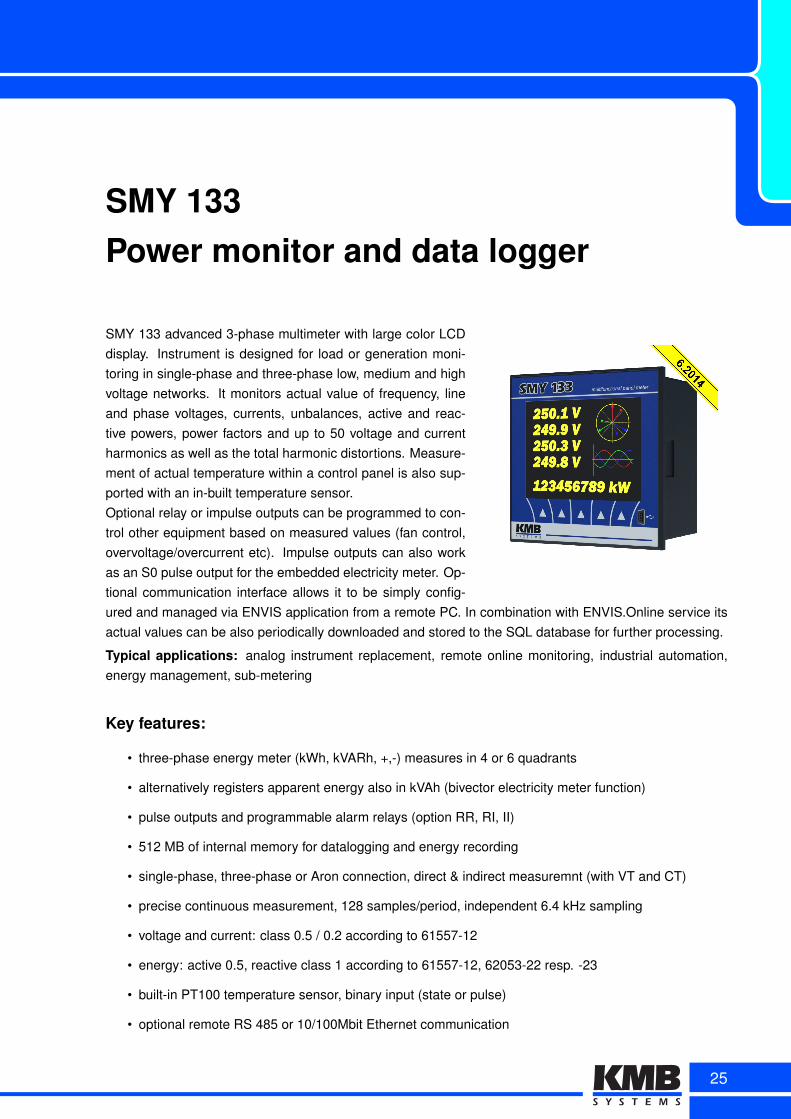
SMY 133Power monitor and data logger
SMY 133 advanced 3-phase multimeter with large color LCDdisplay. Instrument is designed for load or generation moni-toring in single-phase and three-phase low, medium and highvoltage networks. It monitors actual value of frequency, lineand phase voltages, currents, unbalances, active and reac-tive powers, power factors and up to 50 voltage and currentharmonics as well as the total harmonic distortions. Measure-ment of actual temperature within a control panel is also sup-ported with an in-built temperature sensor.Optional relay or impulse outputs can be programmed to con-trol other equipment based on measured values (fan control,overvoltage/overcurrent etc). Impulse outputs can also workas an S0 pulse output for the embedded electricity meter. Op-tional communication interface allows it to be simply config-ured and managed via ENVIS application from a remote PC. In combination with ENVIS.Online service itsactual values can be also periodically downloaded and stored to the SQL database for further processing.
Typical applications: analog instrument replacement, remote online monitoring, industrial automation,energy management, sub-metering
Key features:
• three-phase energy meter (kWh, kVARh, +,-) measures in 4 or 6 quadrants
• alternatively registers apparent energy also in kVAh (bivector electricity meter function)
• pulse outputs and programmable alarm relays (option RR, RI, II)
• 512 MB of internal memory for datalogging and energy recording
• single-phase, three-phase or Aron connection, direct & indirect measuremnt (with VT and CT)
• precise continuous measurement, 128 samples/period, independent 6.4 kHz sampling
• voltage and current: class 0.5 / 0.2 according to 61557-12
• energy: active 0.5, reactive class 1 according to 61557-12, 62053-22 resp. -23
• built-in PT100 temperature sensor, binary input (state or pulse)
• optional remote RS 485 or 10/100Mbit Ethernet communication
25
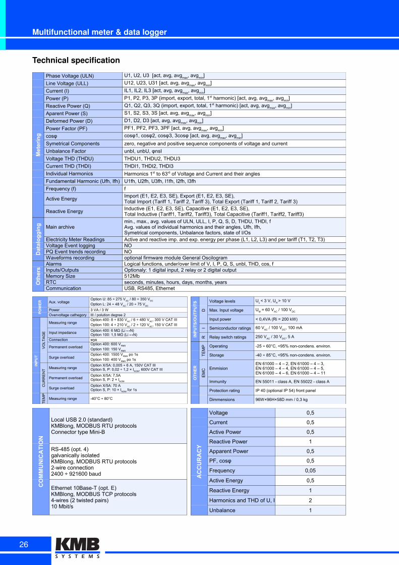
Multifunctional meter & data logger
Technical specification
Metering
Phase Voltage (ULN)
Line Voltage (ULL)
Current (I)
Power (P)
Reactive Power (Q)
Aparent Power (S)
Deformed Power (D)
Power Factor (PF)
cosφ
Symetrical Components zero, negative and positive sequence components of voltage and current
Unbalance Factor unbI, unbU, φnsI
Voltage THD (THDU) THDU1, THDU2, THDU3
Current THD (THDI) THDI1, THDI2, THDI3
Individual Harmonics
Fundamental Harmonic (Ufh, Ifh) U1fh, U2fh, U3fh, I1fh, I2fh, I3fh
Frequency (f) f
Active Energy
Reactive Energy
Datalogging Main archive
Electricity Meter Readings Active and reactive imp. and exp. energy per phase (L1, L2, L3) and per tariff (T1, T2, T3)Voltage Event logging NOPQ Event trends recording NOWaveforms recording optional firmware module General Oscilogram
Others
Alarms Logical functions, under/over limit of V, I, P, Q, S, unbl, THD, cos, fInputs/Outputs Optionaly: 1 digital input, 2 relay or 2 digital outputMemory Size 512MbRTC seconds, minutes, hours, days, months, yearsCommunication USB, RS485, Ethernet
U1, U2, U3 [act, avg, avgmax
, avgmin
]
U12, U23, U31 [act, avg, avgmax
, avgmin
]
IL1, IL2, IL3 [act, avg, avgmax
, avgmin
]
P1, P2, P3, 3P (import, export, total, 1st harmonic) [act, avg, avgmax
, avgmin
]
Q1, Q2, Q3, 3Q (import, export, total, 1st harmonic) [act, avg, avgmax
, avgmin
]
S1, S2, S3, 3S [act, avg, avgmax
, avgmin
]
D1, D2, D3 [act, avg, avgmax
, avgmin
]
PF1, PF2, PF3, 3PF [act, avg, avgmax
, avgmin
]
cosφ1, cosφ2, cosφ3, 3cosφ [act, avg, avgmax
, avgmin
]
Harmonics 1st to 63rd of Voltage and Current and their angles
Import (E1, E2, E3, SE), Export (E1, E2, E3, SE),Total Import (Tariff 1, Tariff 2, Tariff 3), Total Export (Tariff 1, Tariff 2, Tariff 3)Inductive (E1, E2, E3, SE), Capacitive (E1, E2, E3, SE),Total Inductive (Tariff1, Tariff2, Tariff3), Total Capacitive (Tariff1, Tariff2, Tariff3)
min., max., avg. values of ULN, ULL, I, P, Q, S, D, THDU, THDI, fAvg. values of individual harmonics and their angles, Ufh, Ifh,Symetrical components, Unbalance factors, state of I/Os
POWER Aux. voltage
Power 3 VA / 3 WOvervoltage cathegory III / polution degree 2
INPUT
VO
LT
AG
E
Measuring range
Input impedance
Connection wye
Permanent overload
Surge overload
CU
RR
EN
T Measuring range
Permanent overload
Surge overload
TE
MP
Measuring range -40°C ÷ 80°C
Option U: 85 ÷ 275 VAC
/ 80 ÷ 350 VDC
Option L: 24 ÷ 48 VAC
/ 20 ÷ 75 VDC
Option 400: 8 ÷ 830 VAC
/ 6 ÷ 480 VAC
, 300 V CAT IIIOption 100: 4 ÷ 210 V
AC / 2 ÷ 120 V
AC, 150 V CAT III
Option 400: 6 MΩ (Li ↔N)Option 100: 1,5 MΩ (Li ↔N)
Option 400: 600 VRMS
Option 100: 150 VRMS
Option 400: 1500 VRMS
po 1sOption 100: 400 V
RMS po 1s
Option X/5A: 0,005 ÷ 6 A, 150V CAT IIIOption S, P: 0,02 ÷ 1,2 × I
NOM, 600V CAT III
Option X/5A: 7,5AOption S, P: 2 × I
NOM
Option X/5A: 70 AOption S, P: 10 × I
NOM for 1s
INPUTS/OUTPUTS
D
Voltage levels
Max. Input voltage
Input power
I Semiconductor ratings
R Relay switch ratings
OTHER
TE
MP Operating -25 ÷ 60°C, <95% non-condens. environ.
Storage -40 ÷ 85°C, <95% non-condens. environ.
EM
C Emmision
Immunity EN 55011 - class A, EN 55022 - class A
Protection rating IP 40 (optional IP 54) front panel
Dimmensions 96W×96H×58D mm / 0,3 kg
UL < 3 V, U
H > 10 V
UM = 60 V
AC / 100 V
DC
< 0,4VA (Ri = 200 kW)
60 VAC
/ 100 VDC
, 100 mA
250 VAC
/ 30 VDC
, 5 A
EN 61000 – 4 – 2, EN 61000 – 4 – 3,EN 61000 – 4 – 4, EN 61000 – 4 – 5,EN 61000 – 4 – 6, EN 61000 – 4 – 11
COMMUNICATION
Local USB 2.0 (standard)KMBlong, MODBUS RTU protocolsConnector type Mini-B
RS-485 (opt. 4)galvanically isolatedKMBlong, MODBUS RTU protocols2-wire connection2400 ÷ 921600 baud
Ethernet 10Base-T (opt. E)KMBlong, MODBUS TCP protocols4-wires (2 twisted pairs)10 Mbit/s
ACCURACY
Voltage 0,5
Current 0,5
Active Power 0,5
Reactive Power 1
Apparent Power 0,5
PF, cosφ 0,5
Frequency 0,05
Active Energy 0,5
Reactive Energy 1
Harmonics and THD of U, I 2
Unbalance 1
26
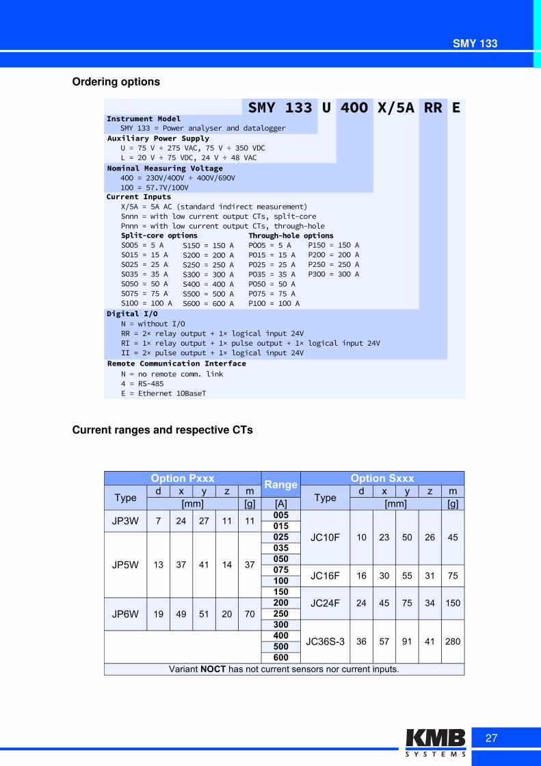
SMY 133
Ordering options
DigitalAI/O
RemoteACommunicationAInterface
Nk=kwithoutkIPORRk=k3×krelaykoutputk(kY×klogicalkinputk37VRIk=kY×krelaykoutputk(kY×kpulsekoutputk(kY×klogicalkinputk37VIIk=k3×kpulsekoutputk(kY×klogicalkinputk37V
Nk=knokremotekcomm,klink7k=kRS)76÷Ek=kEthernetkYOBaseT
CurrentAInputsXP÷Ak=k÷AkACkXstandardkindirectkmeasurementAkSnnnk=kwithklowkcurrentkoutputkCTsdksplit)corekPnnnk=kwithklowkcurrentkoutputkCTsdkthrough)hole
SMYA133AUA4OOAX/5AARRAEInstrumentAModel
AuxiliaryAPowerASupplySMYkYUUk=kPowerkanalyserkandkdatalogger
Uk=kL÷kVk÷k3L÷kVACdkL÷kVk÷kU÷OkVDCLk=k3OkVk÷kL÷kVDCdk37kVk÷k76kVAC
Through-holeAoptionsPOO÷k=k÷kAPOY÷k=kY÷kAPO3÷k=k3÷kAPOU÷k=kU÷kAPO÷Ok=k÷OkAPOL÷k=kL÷kAPYOOk=kYOOkA
Split-coreAoptionsSOO÷k=k÷kASOY÷k=kY÷kASO3÷k=k3÷kASOU÷k=kU÷kASO÷Ok=k÷OkASOL÷k=kL÷kASYOOk=kYOOkA
SY÷Ok=kY÷OkAS3OOk=k3OOkAS3÷Ok=k3÷OkASUOOk=kUOOkAS7OOk=k7OOkAS÷OOk=k÷OOkASDOOk=kDOOkA
PY÷Ok=kY÷OkAP3OOk=k3OOkAP3÷Ok=k3÷OkAPUOOk=kUOOkA
NominalAMeasuringAVoltage7OOk=k3UOVP7OOVk÷k7OOVPD9OVYOOk=k÷L,LVPYOOVk
Current ranges and respective CTs
Option PxxxRange
Option Sxxx
Typed x y z m
Typed x y z m
[mm] [g] [A] [mm] [g]
JP3W 7 24 27 11 11005
JC10F 10 23 50 26 45015
JP5W 13 37 41 14 37
025035050075
JC16F 16 30 55 31 75100150
JC24F 24 45 75 34 150JP6W 19 49 51 20 70
200250300
JC36S-3 36 57 91 41 280400500600
Variant NOCT has not current sensors nor current inputs.
27
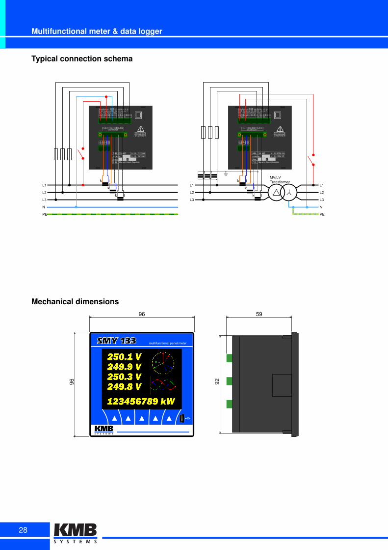
Multifunctional meter & data logger
Typical connection schema
SML 133/ 485
L1
L2
L3
N
PE
k l
k l
k l
SML 133/ 485
MV/LVTransformer
L1
L2
L3
k l
k l
k l
Mechanical dimensions96
96 92
59
multifunctional panel meterSMY 133 multifunctional panel meter
28
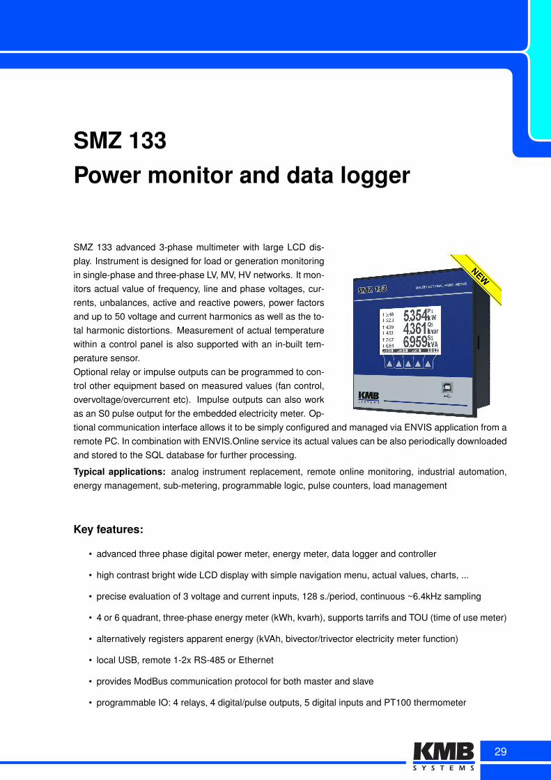
SMZ 133Power monitor and data logger
SMZ 133 advanced 3-phase multimeter with large LCD dis-play. Instrument is designed for load or generation monitoringin single-phase and three-phase LV, MV, HV networks. It mon-itors actual value of frequency, line and phase voltages, cur-rents, unbalances, active and reactive powers, power factorsand up to 50 voltage and current harmonics as well as the to-tal harmonic distortions. Measurement of actual temperaturewithin a control panel is also supported with an in-built tem-perature sensor.Optional relay or impulse outputs can be programmed to con-trol other equipment based on measured values (fan control,overvoltage/overcurrent etc). Impulse outputs can also workas an S0 pulse output for the embedded electricity meter. Op-tional communication interface allows it to be simply configured and managed via ENVIS application from aremote PC. In combination with ENVIS.Online service its actual values can be also periodically downloadedand stored to the SQL database for further processing.
Typical applications: analog instrument replacement, remote online monitoring, industrial automation,energy management, sub-metering, programmable logic, pulse counters, load management
Key features:
• advanced three phase digital power meter, energy meter, data logger and controller
• high contrast bright wide LCD display with simple navigation menu, actual values, charts, ...
• precise evaluation of 3 voltage and current inputs, 128 s./period, continuous ~6.4kHz sampling
• 4 or 6 quadrant, three-phase energy meter (kWh, kvarh), supports tarrifs and TOU (time of use meter)
• alternatively registers apparent energy (kVAh, bivector/trivector electricity meter function)
• local USB, remote 1-2x RS-485 or Ethernet
• provides ModBus communication protocol for both master and slave
• programmable IO: 4 relays, 4 digital/pulse outputs, 5 digital inputs and PT100 thermometer
29
Multimeter & data logger
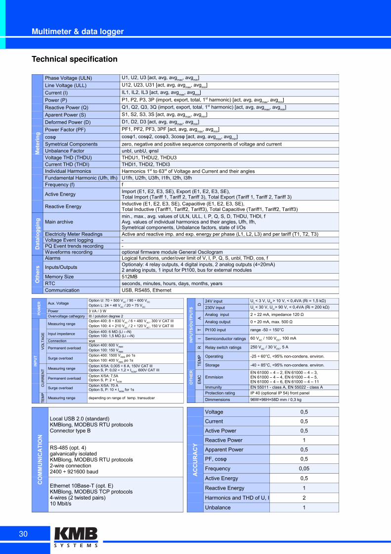
Technical specification
Metering
Phase Voltage (ULN)
Line Voltage (ULL)
Current (I)
Power (P)
Reactive Power (Q)
Aparent Power (S)
Deformed Power (D)
Power Factor (PF)
cosφ
Symetrical Components zero, negative and positive sequence components of voltage and currentUnbalance FactorVoltage THD (THDU) THDU1, THDU2, THDU3Current THD (THDI) THDI1, THDI2, THDI3Individual HarmonicsFundamental Harmonic (Ufh, Ifh) U1fh, U2fh, U3fh, I1fh, I2fh, I3fhFrequency (f) f
Active Energy
Reactive Energy
Datalogging Main archive
Electricity Meter Readings Active and reactive imp. and exp. energy per phase (L1, L2, L3) and per tariff (T1, T2, T3)Voltage Event logging -PQ Event trends recording -Waveforms recording optional firmware module General Oscilogram
Others
Alarms Logical functions, under/over limit of V, I, P, Q, S, unbl, THD, cos, f
Inputs/Outputs
Memory Size 512MBRTC seconds, minutes, hours, days, months, yearsCommunication USB, RS485, Ethernet
U1, U2, U3 [act, avg, avgmax
, avgmin
]
U12, U23, U31 [act, avg, avgmax
, avgmin
]
IL1, IL2, IL3 [act, avg, avgmax
, avgmin
]
P1, P2, P3, 3P (import, export, total, 1st harmonic) [act, avg, avgmax
, avgmin
]
Q1, Q2, Q3, 3Q (import, export, total, 1st harmonic) [act, avg, avgmax
, avgmin
]
S1, S2, S3, 3S [act, avg, avgmax
, avgmin
]
D1, D2, D3 [act, avg, avgmax
, avgmin
]
PF1, PF2, PF3, 3PF [act, avg, avgmax
, avgmin
]
cosφ1, cosφ2, cosφ3, 3cosφ [act, avg, avgmax
, avgmin
]
unbI, unbU, φnsI
Harmonics 1st to 63rd of Voltage and Current and their angles
Import (E1, E2, E3, SE), Export (E1, E2, E3, SE),Total Import (Tariff 1, Tariff 2, Tariff 3), Total Export (Tariff 1, Tariff 2, Tariff 3)Inductive (E1, E2, E3, SE), Capacitive (E1, E2, E3, SE),Total Inductive (Tariff1, Tariff2, Tariff3), Total Capacitive (Tariff1, Tariff2, Tariff3)
min., max., avg. values of ULN, ULL, I, P, Q, S, D, THDU, THDI, fAvg. values of individual harmonics and their angles, Ufh, Ifh,Symetrical components, Unbalance factors, state of I/Os
Optionaly: 4 relay outputs, 4 digital inputs, 2 analog outputs (4÷20mA)2 analog inputs, 1 input for Pt100, bus for external modules
POWER Aux. Voltage
Power 3 VA / 3 WOvervoltage cathegory III / polution degree 2
INPUT
VO
LT
AG
E
Measuring range
Input impedance
Connection wye
Permanent overload
Surge overload
CU
RR
EN
T Measuring range
Permanent overload
Surge overload
TE
MP
Measuring range depending on range of temp. transudcer
Option U: 70 ÷ 500 VAC
/ 90 ÷ 600 VDC
Option L: 24 ÷ 48 VAC
/ 20 ÷ 75 VDC
Option 400: 8 ÷ 830 VAC
/ 6 ÷ 480 VAC
, 300 V CAT IIIOption 100: 4 ÷ 210 V
AC / 2 ÷ 120 V
AC, 150 V CAT III
Option 400: 6 MΩ (Li ↔N)Option 100: 1,5 MΩ (Li ↔N)
Option 400: 600 VRMS
Option 100: 150 VRMS
Option 400: 1500 VRMS
po 1sOption 100: 400 V
RMS po 1s
Option X/5A: 0,005 ÷ 6 A, 150V CAT IIIOption S, P: 0,02 ÷ 1,2 × I
NOM, 600V CAT III
Option X/5A: 7,5AOption S, P: 2 × I
NOM
Option X/5A: 70 AOption S, P: 10 × I
NOM for 1s
INPUTS/OUTPUTS
D
24V input
230V input
A
Analog input 2 ÷ 22 mA, impedance 120 Ω
Analog output 0 ÷ 20 mA, max. 500 Ω
T Pt100 input range -50 ÷ 150°C
I Semiconductor ratings
R Relay switch ratings
OTHER
TE
MP Operating -25 ÷ 60°C, <95% non-condens. environ.
Storage -40 ÷ 85°C, <95% non-condens. environ.
EM
C Emmision
Immunity EN 55011 - class A, EN 55022 - class A
Protection rating IP 40 (optional IP 54) front panel
Dimmensions 96W×96H×58D mm / 0,3 kg
UL < 3 V, U
H > 10 V, < 0,4VA (Ri = 1,5 kΩ)
UL < 30 V, U
H > 90 V, < 0,4VA (Ri = 200 kΩ)
60 VAC
/ 100 VDC
, 100 mA
250 VAC
/ 30 VDC
, 5 A
EN 61000 – 4 – 2, EN 61000 – 4 – 3,EN 61000 – 4 – 4, EN 61000 – 4 – 5,EN 61000 – 4 – 6, EN 61000 – 4 – 11
COMMUNICATION
Local USB 2.0 (standard)KMBlong, MODBUS RTU protocolsConnector type B
RS-485 (opt. 4)galvanically isolatedKMBlong, MODBUS RTU protocols2-wire connection2400 ÷ 921600 baud
Ethernet 10Base-T (opt. E)KMBlong, MODBUS TCP protocols4-wires (2 twisted pairs)10 Mbit/s
ACCURACY
Voltage 0,5
Current 0,5
Active Power 0,5
Reactive Power 1
Apparent Power 0,5
PF, cosφ 0,5
Frequency 0,05
Active Energy 0,5
Reactive Energy 1
Harmonics and THD of U, I 2
Unbalance 1
30
SMZ 133
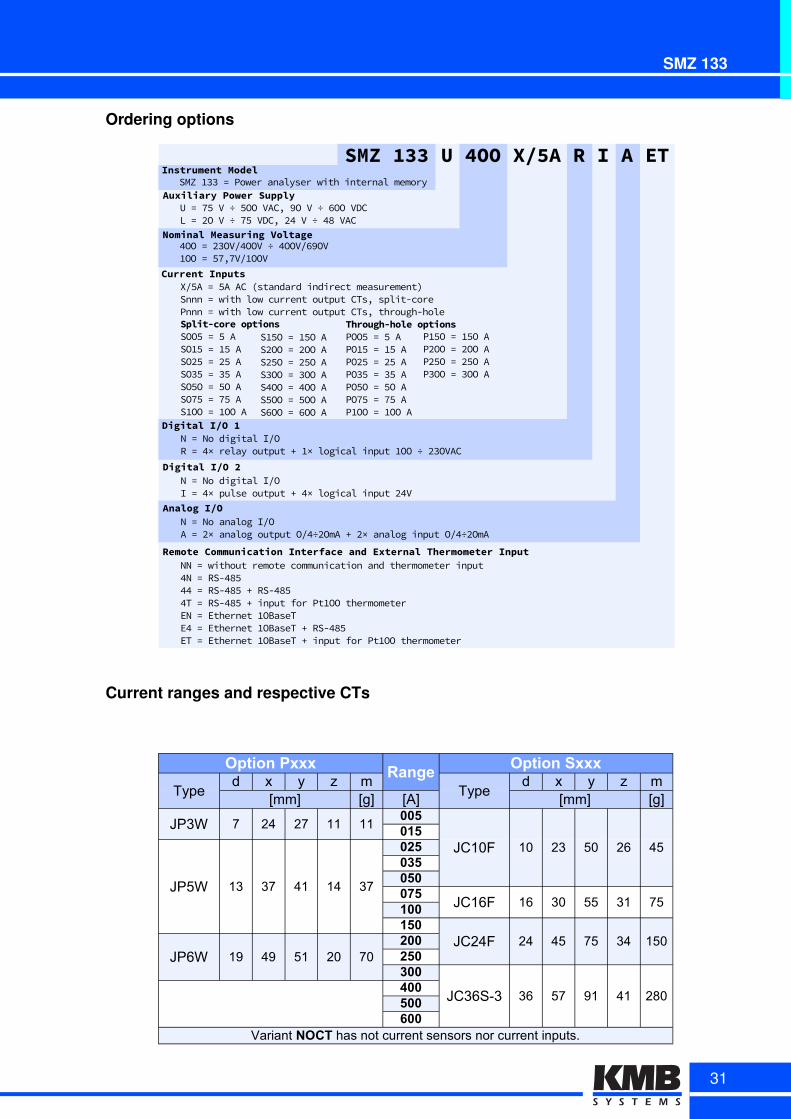
Ordering options
DigitalmI/Om1
DigitalmI/Om2
Ns=sNosdigitalsIUORs=sL×srelaysoutputs-s9×slogicalsinputs9OOs÷s6DOVAC
Ns=sNosdigitalsIUOIs=sL×spulsesoutputs-sL×slogicalsinputs6LV
CurrentmInputsXU8As=s8AsACshstandardsindirectsmeasurementTsSnnns=swithslowscurrentsoutputsCTsPssplitMcoresPnnns=swithslowscurrentsoutputsCTsPsthroughMhole
SMZm133mUm4OOmX/5AmRmImAmETInstrumentmModel
AuxiliarymPowermSupplySMZs9DDs=sPowersanalyserswithsinternalsmemory
Us=sE8sVs÷s8OOsVACPs9OsVs÷sfOOsVDCLs=s6OsVs÷sE8sVDCPs6LsVs÷sLBsVAC
Through-holemoptionsPOO8s=s8sAPO98s=s98sAPO68s=s68sAPOD8s=sD8sAPO8Os=s8OsAPOE8s=sE8sAP9OOs=s9OOsA
Split-coremoptionsSOO8s=s8sASO98s=s98sASO68s=s68sASOD8s=sD8sASO8Os=s8OsASOE8s=sE8sAS9OOs=s9OOsA
S98Os=s98OsAS6OOs=s6OOsAS68Os=s68OsASDOOs=sDOOsASLOOs=sLOOsAS8OOs=s8OOsASfOOs=sfOOsA
P98Os=s98OsAP6OOs=s6OOsAP68Os=s68OsAPDOOs=sDOOsA
NominalmMeasuringmVoltageLOOs=s6DOVULOOVs÷sLOOVUf9OV9OOs=s8EPEVU9OOV
AnalogmI/ONs=sNosanalogsIUOAs=s6×sanalogsoutputsOUL÷6OmAs-s6×sanalogsinputsOUL÷6OmAs
RemotemCommunicationmInterfacemandmExternalmThermometermInputNNs=swithoutsremotescommunicationsandsthermometersinputLNs=sRSMLB8LLs=sRSMLB8s-sRSMLB8sLTs=sRSMLB8s-sinputsforsPt9OOsthermometerENs=sEthernets9OBaseTELs=sEthernets9OBaseTs-sRSMLB8ETs=sEthernets9OBaseTs-sinputsforsPt9OOsthermometer
Current ranges and respective CTs
Option PxxxRange
Option Sxxx
Typed x y z m
Typed x y z m
[mm] [g] [A] [mm] [g]
JP3W 7 24 27 11 11005
JC10F 10 23 50 26 45015
JP5W 13 37 41 14 37
025035050075
JC16F 16 30 55 31 75100150
JC24F 24 45 75 34 150JP6W 19 49 51 20 70
200250300
JC36S-3 36 57 91 41 280400500600
Variant NOCT has not current sensors nor current inputs.
31
Multimeter & data logger
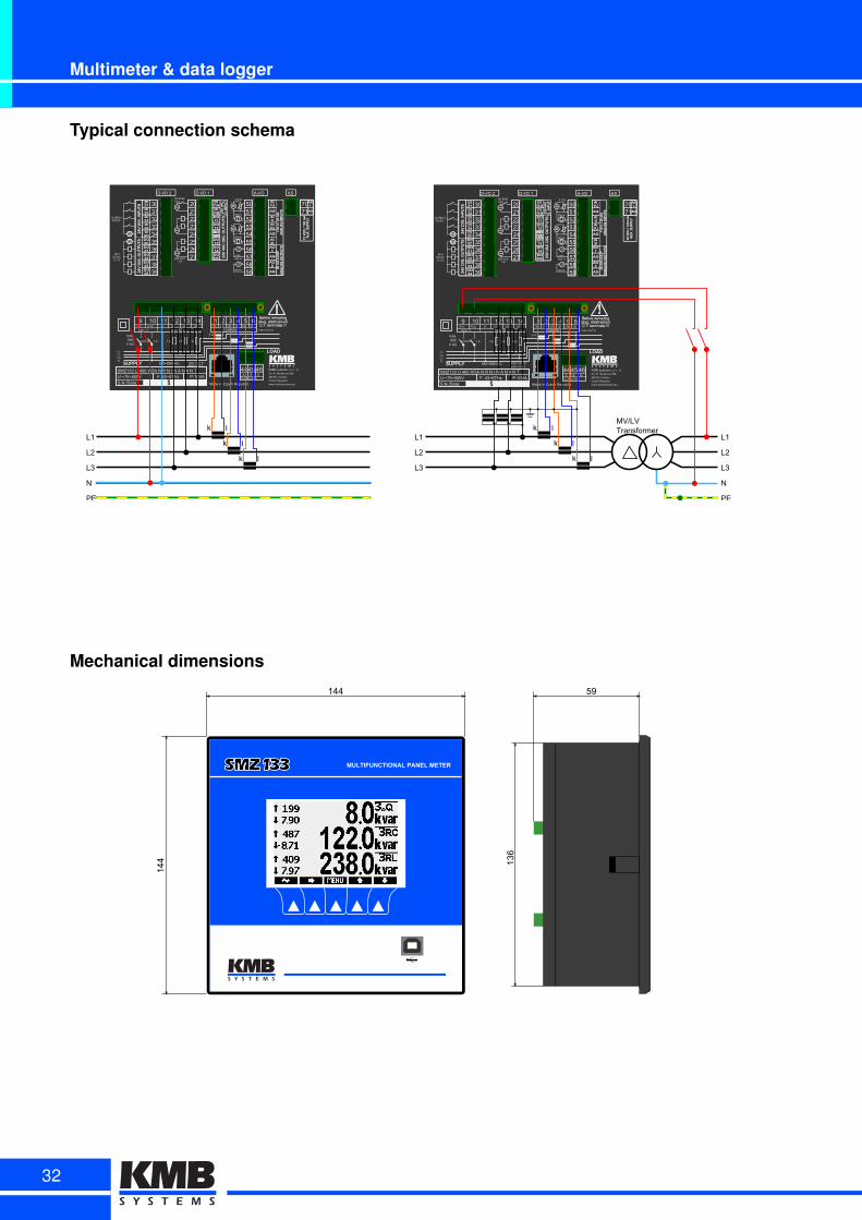
Typical connection schema
B s y m , rIBl Isk Isl Iyk IylIBk
CURRENT
v BK BB Bs By BmUs UyN UB
fUXu/Vu VOLTfGEfVB fVs
COMBpETH
mrmmm,G
COMspmá,
B/f B/f B/fB/f
,/f
LBLsLyN
SMZByy/U/mKK/Xb,f/N/R/N/I/N/f/N/m/N/T
SuNubDateé IP/é/mXb Made/in/Czech/Republic
KMB/systemsh/su/ru/ouDru/Mu/Horákové/,,vmrK/Kr/ LiberecCzech/Republicwwwukmbsystemsueu
maxu,KK
V/fC
Bf
,áK÷rvKVfC yKKV/CfT/IIIrKKV/CfT/II
B,KV/CfT/III
Ué~o,÷,KKV/////////////Fé/my÷roHz/////////PéBKVf
LB
Ls
Ly
N
PE
k l
k l
k l
B s y m , rIBl Isk Isl Iyk IylIBk
CURRENT
v BK BB Bs By BmUs UyN UB
fUXu/Vu VOLTfGEfVB fVs
COMBpETH
mrmmm,G
COMspmá,
B/f B/f B/fB/f
,/f
LBLsLyN
Made/in/Czech/Republic
KMB/systemsh/su/ru/ouDru/Mu/Horákové/,,vmrK/Kr/ LiberecCzech/Republicwwwukmbsystemsueu
maxu,KK
V/fC
Bf
,áK÷rvKVfC yKKV/CfT/III
B,KV/CfT/III
MVbLVTransformer
LB
Ls
Ly
k l
k l
k l
SMZByy/U/mKK/Xb,f/N/R/N/I/N/f/N/m/N/T
SuNubDateé IP/é/mXb
rKKV/CfT/II
Ué~o,÷,KKV/////////////Fé/my÷roHz/////////PéBKVf
Mechanical dimensions
59
136
144
144
MULTIFUNCTIONAL PANEL METERSMZ 133
32
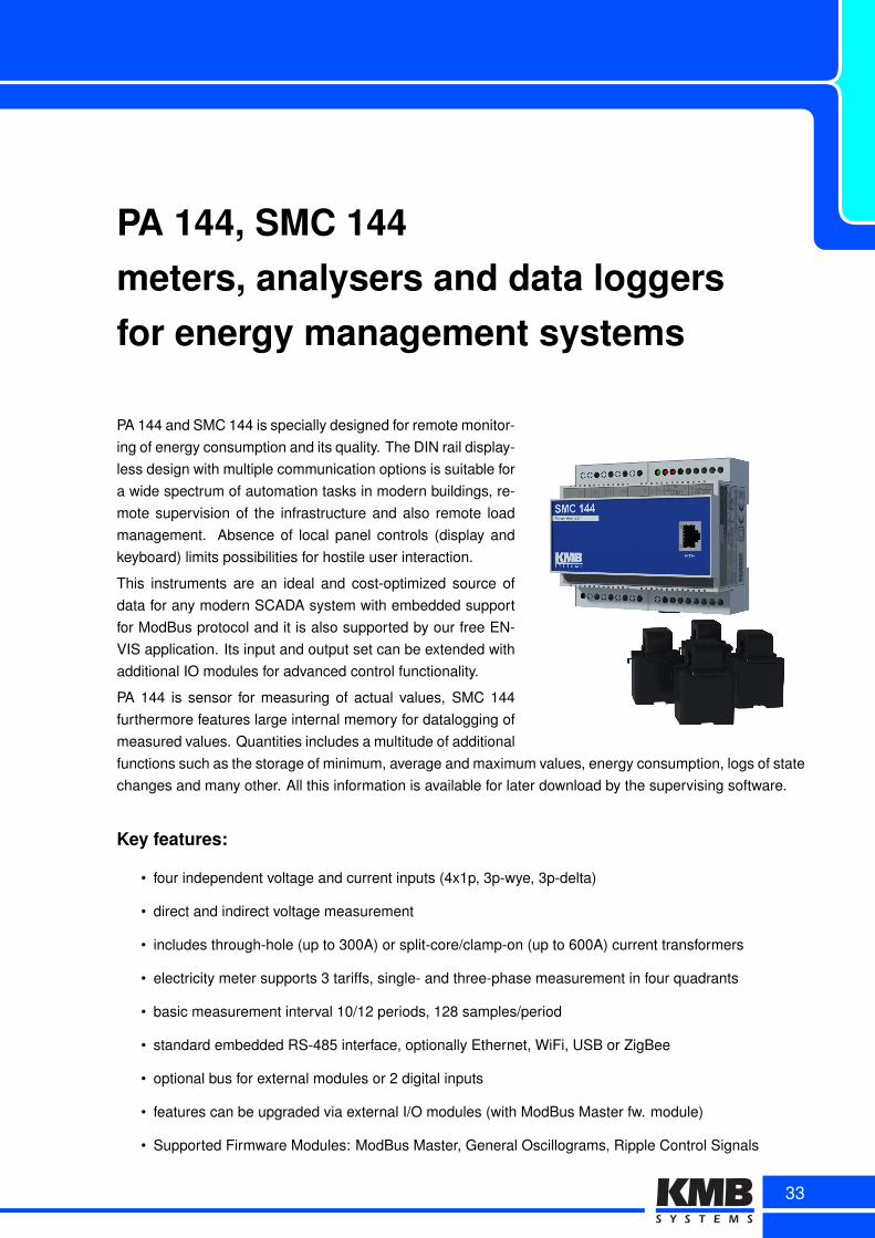
PA 144, SMC 144meters, analysers and data loggersfor energy management systems
PA 144 and SMC 144 is specially designed for remote monitor-ing of energy consumption and its quality. The DIN rail display-less design with multiple communication options is suitable fora wide spectrum of automation tasks in modern buildings, re-mote supervision of the infrastructure and also remote loadmanagement. Absence of local panel controls (display andkeyboard) limits possibilities for hostile user interaction.
This instruments are an ideal and cost-optimized source ofdata for any modern SCADA system with embedded supportfor ModBus protocol and it is also supported by our free EN-VIS application. Its input and output set can be extended withadditional IO modules for advanced control functionality.
PA 144 is sensor for measuring of actual values, SMC 144furthermore features large internal memory for datalogging ofmeasured values. Quantities includes a multitude of additionalfunctions such as the storage of minimum, average and maximum values, energy consumption, logs of statechanges and many other. All this information is available for later download by the supervising software.
Key features:
• four independent voltage and current inputs (4x1p, 3p-wye, 3p-delta)
• direct and indirect voltage measurement
• includes through-hole (up to 300A) or split-core/clamp-on (up to 600A) current transformers
• electricity meter supports 3 tariffs, single- and three-phase measurement in four quadrants
• basic measurement interval 10/12 periods, 128 samples/period
• standard embedded RS-485 interface, optionally Ethernet, WiFi, USB or ZigBee
• optional bus for external modules or 2 digital inputs
• features can be upgraded via external I/O modules (with ModBus Master fw. module)
• Supported Firmware Modules: ModBus Master, General Oscillograms, Ripple Control Signals
33
Multimeter & data logger
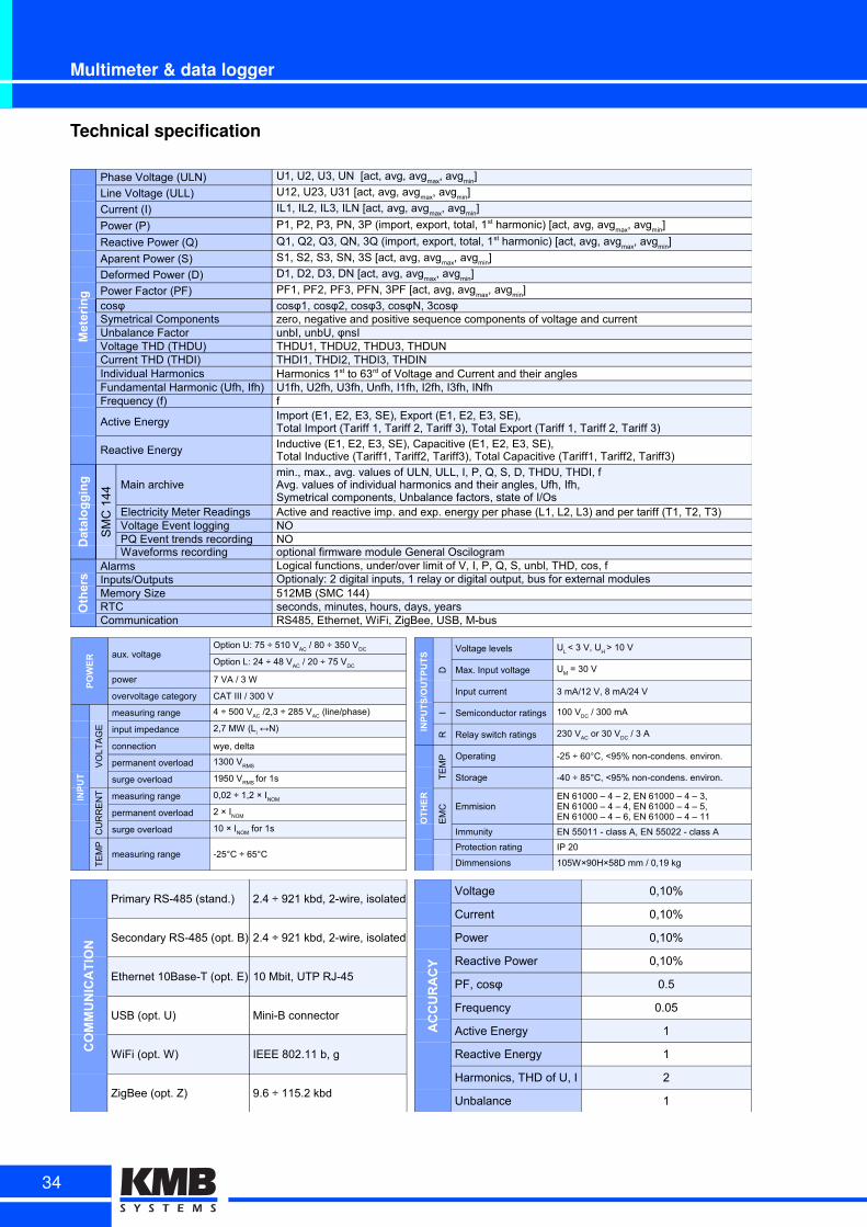
Technical specification
Metering
Phase Voltage (ULN)
Line Voltage (ULL)
Current (I)
Power (P)
Reactive Power (Q)
Aparent Power (S)
Deformed Power (D)
Power Factor (PF)cosφ cosφ1, cosφ2, cosφ3, cosφN, 3cosφSymetrical Components zero, negative and positive sequence components of voltage and currentUnbalance Factor unbI, unbU, φnsIVoltage THD (THDU) THDU1, THDU2, THDU3, THDUNCurrent THD (THDI) THDI1, THDI2, THDI3, THDINIndividual HarmonicsFundamental Harmonic (Ufh, Ifh) U1fh, U2fh, U3fh, Unfh, I1fh, I2fh, I3fh, INfhFrequency (f) f
Active Energy
Reactive Energy
Datalogging
SM
C 1
44
Main archive
Electricity Meter Readings Active and reactive imp. and exp. energy per phase (L1, L2, L3) and per tariff (T1, T2, T3)Voltage Event logging NOPQ Event trends recording NOWaveforms recording optional firmware module General Oscilogram
Others
Alarms Logical functions, under/over limit of V, I, P, Q, S, unbl, THD, cos, fInputs/Outputs Optionaly: 2 digital inputs, 1 relay or digital output, bus for external modulesMemory Size 512MB (SMC 144)RTC seconds, minutes, hours, days, yearsCommunication RS485, Ethernet, WiFi, ZigBee, USB, M-bus
U1, U2, U3, UN [act, avg, avgmax
, avgmin
]
U12, U23, U31 [act, avg, avgmax
, avgmin
]
IL1, IL2, IL3, ILN [act, avg, avgmax
, avgmin
]
P1, P2, P3, PN, 3P (import, export, total, 1st harmonic) [act, avg, avgmax
, avgmin
]
Q1, Q2, Q3, QN, 3Q (import, export, total, 1st harmonic) [act, avg, avgmax
, avgmin
]
S1, S2, S3, SN, 3S [act, avg, avgmax
, avgmin
]
D1, D2, D3, DN [act, avg, avgmax
, avgmin
]
PF1, PF2, PF3, PFN, 3PF [act, avg, avgmax
, avgmin
]
Harmonics 1st to 63rd of Voltage and Current and their angles
Import (E1, E2, E3, SE), Export (E1, E2, E3, SE),Total Import (Tariff 1, Tariff 2, Tariff 3), Total Export (Tariff 1, Tariff 2, Tariff 3)
Inductive (E1, E2, E3, SE), Capacitive (E1, E2, E3, SE),Total Inductive (Tariff1, Tariff2, Tariff3), Total Capacitive (Tariff1, Tariff2, Tariff3)
min., max., avg. values of ULN, ULL, I, P, Q, S, D, THDU, THDI, fAvg. values of individual harmonics and their angles, Ufh, Ifh,Symetrical components, Unbalance factors, state of I/Os
POWER aux. voltage
power 7 VA / 3 W
overvoltage category CAT III / 300 V
INPUT
VO
LT
AG
E
measuring range
input impedance
connection wye, delta
permanent overload
surge overload
CU
RR
EN
T measuring range
permanent overload
surge overload
TE
MP
measuring range -25°C ÷ 65°C
Option U: 75 ÷ 510 VAC
/ 80 ÷ 350 VDC
Option L: 24 ÷ 48 VAC
/ 20 ÷ 75 VDC
4 ÷ 500 VAC
/2,3 ÷ 285 VAC
(line/phase)
2,7 MW (Li ↔N)
1300 VRMS
1950 VRMS for 1s
0,02 ÷ 1,2 × INOM
2 × INOM
10 × INOM
for 1s
INPUTS/OUTPUTS
D
Voltage levels
Max. Input voltage
Input current 3 mA/12 V, 8 mA/24 V
I Semiconductor ratings
R Relay switch ratings
OTHER
TE
MP Operating -25 ÷ 60°C, <95% non-condens. environ.
Storage -40 ÷ 85°C, <95% non-condens. environ.
EM
C Emmision
Immunity EN 55011 - class A, EN 55022 - class A
Protection rating IP 20
Dimmensions 105W×90H×58D mm / 0,19 kg
UL < 3 V, U
H > 10 V
UM = 30 V
100 VDC / 300 mA
230 VAC
or 30 VDC
/ 3 A
EN 61000 – 4 – 2, EN 61000 – 4 – 3,EN 61000 – 4 – 4, EN 61000 – 4 – 5,EN 61000 – 4 – 6, EN 61000 – 4 – 11
COMMUNICATION
Primary RS-485 (stand.) 2.4 ÷ 921 kbd, 2-wire, isolated
Secondary RS-485 (opt. B) 2.4 ÷ 921 kbd, 2-wire, isolated
Ethernet 10Base-T (opt. E) 10 Mbit, UTP RJ-45
USB (opt. U) Mini-B connector
WiFi (opt. W) IEEE 802.11 b, g
ZigBee (opt. Z) 9.6 ÷ 115.2 kbd
ACCURACY
Voltage 0,10%
Current 0,10%
Power 0,10%
Reactive Power 0,10%
PF, cosφ 0.5
Frequency 0.05
Active Energy 1
Reactive Energy 1
Harmonics, THD of U, I 2
Unbalance 1
34
SMC 144
Ordering options
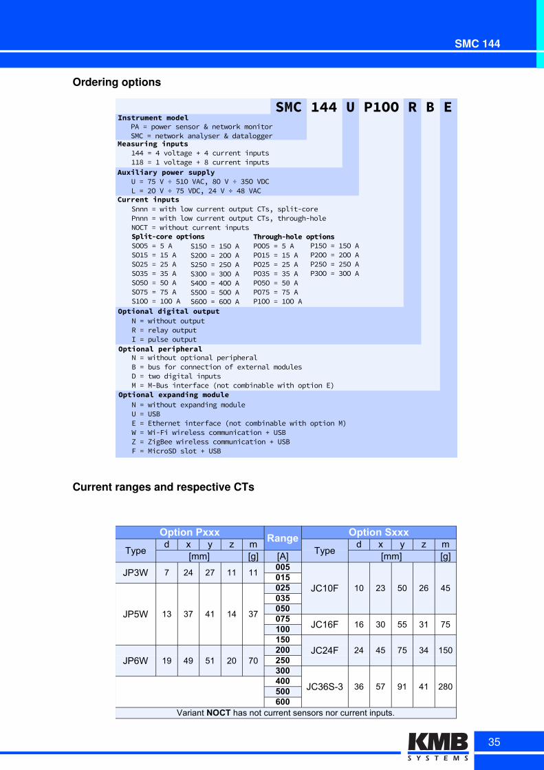
Optionalcdigitalcoutput
Optionalcperipheral
Optionalcexpandingcmodule
NE=EwithoutEoutputRE=ErelayEoutputIE=EpulseEoutput
NE=EwithoutEoptionalEperipheralBE=EbusEforEconnectionEofEexternalEmodulesDE=EtwoEdigitalEinputsME=EMABusEinterfaceECnotEcombinableEwithEoptionEET
NE=EwithoutEexpandingEmoduleUE=EUSBEE=EEthernetEinterfaceECnotEcombinableEwithEoptionEMTWE=EWiAFiEwirelessEcommunicationEPEUSBZE=EZigBeeEwirelessEcommunicationEPEUSBFE=EMicroSDEslotEPEUSBE
CurrentcinputsSnnnE=EwithElowEcurrentEoutputECTsOEsplitAcoreEPnnnE=EwithElowEcurrentEoutputECTsOEthroughAholeNOCTE=EwithoutEcurrentEinputs
SMCc144cUcP1OOcRcBcEInstrumentcmodel
Measuringcinputs
PAE=EpowerEsensorE+EnetworkEmonitorSMCE=EnetworkEanalyserE+Edatalogger
455E=E5EvoltageEPE5EcurrentEinputs447E=E4EvoltageEPE7EcurrentEinputs
Through-holecoptionsPOO2E=E2EAPO42E=E42EAPOv2E=Ev2EAPO82E=E82EAPO2OE=E21EAPO02E=E02EAP4OOE=E4OOEA
Split-corecoptionsSOO2E=E2EASO42E=E42EASOv2E=Ev2EASO82E=E82EASO2OE=E2OEASO02E=E02EAS4OOE=E4OOEA
S42OE=E42OEASvOOE=EvOOEASv2OE=Ev2OEAS8OOE=E8OOEAS5OOE=E5OOEAS2OOE=E2OOEAS3OOE=E3OOEA
P42OE=E42OEAPvOOE=EvOOEAPv2OE=Ev2OEAP8OOE=E8OOEA
AuxiliarycpowercsupplyUE=E02EVE÷E24OEVACOE7OEVE÷E82OEVDCLE=EvOEVE÷E02EVDCOEv5EVE÷E57EVAC
Current ranges and respective CTs
Option PxxxRange
Option Sxxx
Typed x y z m
Typed x y z m
[mm] [g] [A] [mm] [g]
JP3W 7 24 27 11 11005
JC10F 10 23 50 26 45015
JP5W 13 37 41 14 37
025035050075
JC16F 16 30 55 31 75100150
JC24F 24 45 75 34 150JP6W 19 49 51 20 70
200250300
JC36S-3 36 57 91 41 280400500600
Variant NOCT has not current sensors nor current inputs.
35
Multifunctional power analyzer
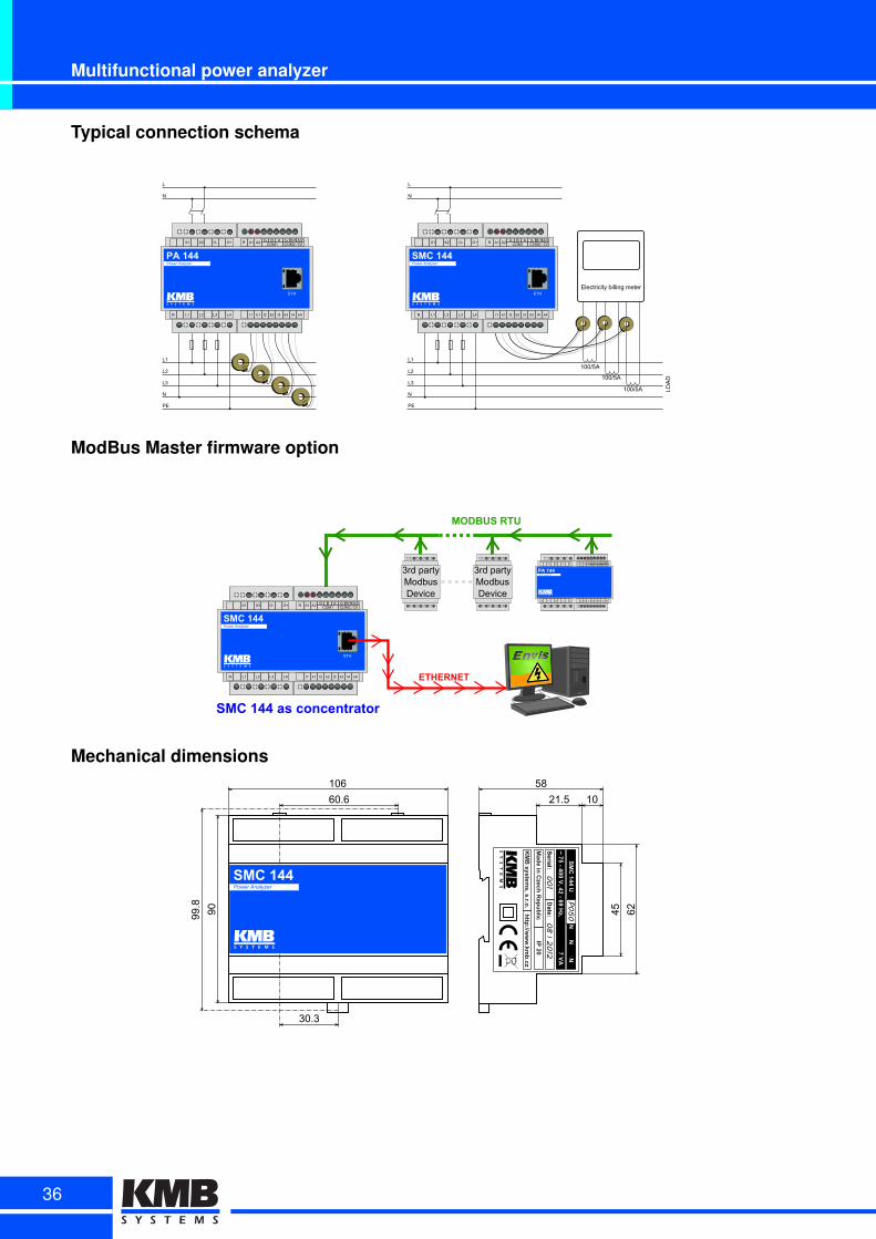
Typical connection schema
L1
L2
L3
N
PE
L
N
PA 144Power Analyzer
ETH
N L1 L2 L3 L4 l1 k1 l2 k2 l3 k3 l4 k4
X1 X2 O- O+ R A1 A2 G B A G B/1 A/2COM1 COM2 / DI
JP5W
JP5W
JP5W
JP5W
Electricity billing meter
JP3WJP3W JP3W
100/5A
100/5A
100/5A LOA
D
L1
L2
L3
N
PE
L
N
SMC 144Power Analyzer
ETH
N L1 L2 L3 L4 l1 k1 l2 k2 l3 k3 l4 k4
X1 X2 O- O+ R A1 A2 G B A G B/1 A/2COM1 COM2 / DI
ModBus Master firmware option
SMC 144Power Analyzer
ETH
N L1 L2 L3 L4 l1 k1 l2 k2 l3 k3 l4 k4
X1 X2 O- O+ R A1 A2 G B A G B/1 A/2COM1 COM2 / DI
MODBUS RTU
ETHERNET
SMC 144 as concentrator
3rd partyModbusDevice
3rd partyModbusDevice
PA 144Power Analyzer
N L1 L2 L3 L4 l1 k1 l2 k2 l3 k3 l4 k4
X1 X2 O- O+ R A1 A2 G B A G B/1 A/2COM1 COM2 / DI
Mechanical dimensions
60.6
90
21.5 10
45 62
58106
99.8
30.3
SMC 144Power Analyzer
001
082012
P050
36

SMD 118DC analyser and data loggerfor energy management systems
SMD 118 is designed for remote or standalone supervision ofloads and sources such as DC motors, convertors and charg-ers, photovoltaic systems etc. It supports measurement of 1voltage and up to 8 AC or DC currents/powers. It is developedwith fast and simple installation on din rail in mind. With splitcore CT Hall sensors the installation can be performed withoutnecessary system decommissioning. Broad range of commu-nication interfaces and protocols allows simple integration intothe supervisor systems. Displayless design minimizes the at-tention in places with general public access.
Inputs, outputs and communication interfaces can be ex-tended by optional expansion modules. SMD analyser sup-portd M-Bus and Modbus protocols, Ethernet, WiFi, ZigBee,USB and the traditional RS 485 interface. SMD is a great component for any modern SCADA system. EN-VIS v1.2+ supports configuration, data acquisition, archival and reporting of all the measurements collectedwith SMD 11x.
In complex energy management and automation systems the instrument can be well accompanied by othercomponents like SMC 144 and PA 144.
Key features:
• 1 voltage and up to 8 current inputs (8×1 line)
• AC and DC measurement of current and voltage
• fully programmable digital output (relay or impulse)
• standard embedded RS-485 interface, optionally Ethernet, WiFi, USB, ZigBee
• optional second BUS for external modules or 2 additional digital inputs
• features can be upgraded via external I/O modules (with ModBus Master fw. module)
37
Multifunctional power analyzer
Technical specification
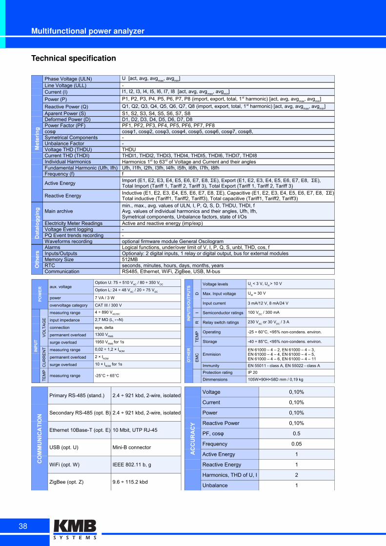
Metering
Phase Voltage (ULN)Line Voltage (ULL) -Current (I)
Power (P)
Reactive Power (Q)Aparent Power (S) S1, S2, S3, S4, S5, S6, S7, S8Deformed Power (D) D1, D2, D3, D4, D5, D6, D7, D8Power Factor (PF) PF1, PF2, PF3, PF4, PF5, PF6, PF7, PF8cosφ cosφ1, cosφ2, cosφ3, cosφ4, cosφ5, cosφ6, cosφ7, cosφ8,Symetrical Components -Unbalance Factor -Voltage THD (THDU) THDUCurrent THD (THDI) THDI1, THDI2, THDI3, THDI4, THDI5, THDI6, THDI7, THDI8Individual HarmonicsFundamental Harmonic (Ufh, Ifh) Ufh, I1fh, I2fh, I3fh, I4fh, I5fh, I6fh, I7fh, I8fhFrequency (f) f
Active Energy
Reactive Energy
Datalogging Main archive
Electricity Meter Readings Active and reactive energy (imp/exp)Voltage Event logging -PQ Event trends recording -Waveforms recording optional firmware module General Oscilogram
Others
Alarms Logical functions, under/over limit of V, I, P, Q, S, unbl, THD, cos, fInputs/Outputs Optionaly: 2 digital inputs, 1 relay or digital output, bus for external modulesMemory Size 512MBRTC seconds, minutes, hours, days, months, yearsCommunication RS485, Ethernet, WiFi, ZigBee, USB, M-bus
U [act, avg, avgmax
, avgmin
]
I1, I2, I3, I4, I5, I6, I7, I8 [act, avg, avgmax
, avgmin
]
P1, P2, P3, P4, P5, P6, P7, P8 (import, export, total, 1st harmonic) [act, avg, avgmax, avgmin]
Q1, Q2, Q3, Q4, Q5, Q6, Q7, Q8 (import, export, total, 1st harmonic) [act, avg, avgmax, avgmin]
Harmonics 1st to 63rd of Voltage and Current and their angles
Import (E1, E2, E3, E4, E5, E6, E7, E8, ΣE), Export (E1, E2, E3, E4, E5, E6, E7, E8, ΣE),Total Import (Tariff 1, Tariff 2, Tariff 3), Total Export (Tariff 1, Tariff 2, Tariff 3)
Inductive (E1, E2, E3, E4, E5, E6, E7, E8, ΣE), Capacitive (E1, E2, E3, E4, E5, E6, E7, E8, ΣE),Total inductive (Tariff1, Tariff2, Tariff3), Total capacitive (Tariff1, Tariff2, Tariff3)
min., max., avg. values of ULN, I, P, Q, S, D, THDU, THDI, fAvg. values of individual harmonics and their angles, Ufh, Ifh,Symetrical components, Unbalance factors, state of I/Os
POWER aux. voltage
power 7 VA / 3 W
overvoltage category CAT III / 300 V
INPUT
VO
LT
AG
E
measuring range
input impedance
connection wye, delta
permanent overload
surge overload
CU
RR
EN
T measuring range
permanent overload
surge overload
TE
MP
measuring range -25°C ÷ 65°C
Option U: 75 ÷ 510 VAC
/ 80 ÷ 350 VDC
Option L: 24 ÷ 48 VAC
/ 20 ÷ 75 VDC
4 ÷ 890 VAC/DC
2,7 MΩ (Li ↔N)
1300 VRMS
1950 VRMS for 1s
0,02 ÷ 1,2 × INOM
2 × INOM
10 × INOM
for 1s
INPUTS/OUTPUTS
D
Voltage levels
Max. Input voltage
Input current 3 mA/12 V, 8 mA/24 V
I Semiconductor ratings
R Relay switch ratings
OTHER
TE
MP Operating -25 ÷ 60°C, <95% non-condens. environ.
Storage -40 ÷ 85°C, <95% non-condens. environ.
EM
C Emmision
Immunity EN 55011 - class A, EN 55022 - class A
Protection rating IP 20
Dimmensions 105W×90H×58D mm / 0,19 kg
UL < 3 V, U
H > 10 V
UM = 30 V
100 VDC / 300 mA
230 VAC
or 30 VDC
/ 3 A
EN 61000 – 4 – 2, EN 61000 – 4 – 3,EN 61000 – 4 – 4, EN 61000 – 4 – 5,EN 61000 – 4 – 6, EN 61000 – 4 – 11
COMMUNICATION
Primary RS-485 (stand.) 2.4 ÷ 921 kbd, 2-wire, isolated
Secondary RS-485 (opt. B) 2.4 ÷ 921 kbd, 2-wire, isolated
Ethernet 10Base-T (opt. E) 10 Mbit, UTP RJ-45
USB (opt. U) Mini-B connector
WiFi (opt. W) IEEE 802.11 b, g
ZigBee (opt. Z) 9.6 ÷ 115.2 kbd
ACCURACY
Voltage 0,10%
Current 0,10%
Power 0,10%
Reactive Power 0,10%
PF, cosφ 0.5
Frequency 0.05
Active Energy 1
Reactive Energy 1
Harmonics, THD of U, I 2
Unbalance 1
38
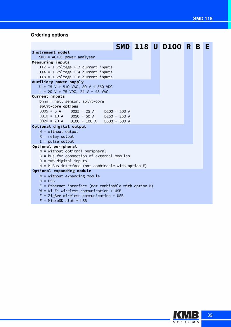
SMD 118
Ordering options
OptionalAdigitalAoutput
OptionalAperipheral
OptionalAexpandingAmodule
NE=EwithoutEoutputRE=ErelayEoutputIE=EpulseEoutput
NE=EwithoutEoptionalEperipheralBE=EbusEforEconnectionEofEexternalEmodulesDE=EtwoEdigitalEinputsME=EM2BusEinterfaceE,notEcombinableEwithEoptionEEA
NE=EwithoutEexpandingEmoduleUE=EUSBEE=EEthernetEinterfaceE,notEcombinableEwithEoptionEMAWE=EWi2FiEwirelessEcommunicationE/EUSBZE=EZigBeeEwirelessEcommunicationE/EUSBFE=EMicroSDEslotE/EUSBE
CurrentAinputsDnnnE=EhallEsensor1Esplit2core
SMDA118AUAD1OOARABAEInstrumentAmodel
MeasuringAinputsSMDE=EAC4DCEpowerEanalyserE
OO5E=EOEvoltageE/E5EcurrentEinputsOOVE=EOEvoltageE/EVEcurrentEinputsEOO8E=EOEvoltageE/E8EcurrentEinputs
Split-coreAoptionsDOO÷E=E÷EADOOOE=EOOEADO5OE=E5OEA
DO5÷E=E5÷EADO÷OE=E÷OEADOOOE=EOOOEA
AuxiliaryApowerAsupplyUE=EL÷EVE÷E÷OOEVAC1E8OEVE÷E7÷OEVDCLE=E5OEVE÷EL÷EVDC1E5VEVE÷EV8EVAC
D5OOE=E5OOEAD5÷OE=E5÷OEAD÷OOE=E÷OOEA
39
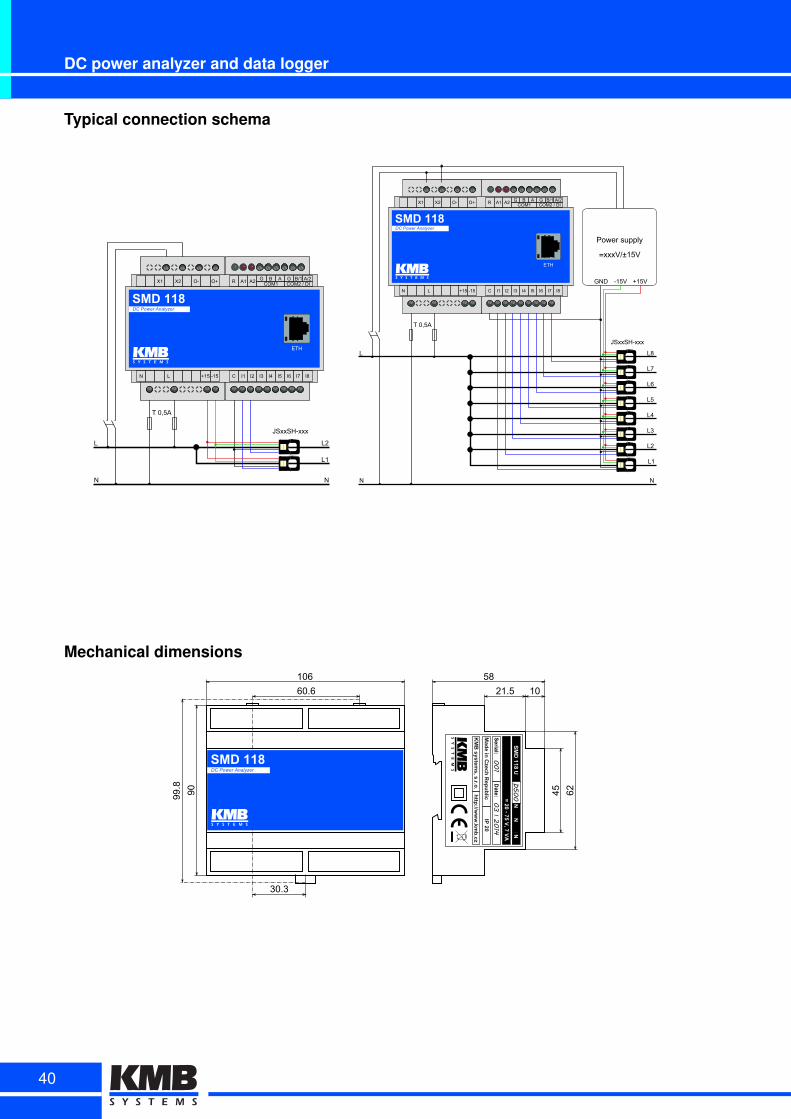
DC power analyzer and data logger
Typical connection schema
L
N
L2
JSxxSH-xxx
TD0,5A
L1
JSxxH
S-xxx
JSxxH
S-xxx
N
SMD 118DC Power Analyzer
ETH
N L +15 -15 I1 I2 I3 I4 I5 I6 I7 I8
X1 X2 O- O+ R A1 A2 G B A G B/1 A/2COM1 COM2D/DDI
C
L
N
L8
JSxxSHDxxx
T40M5A
Power4supply
~xxxV/±15V
L7
L6
L5
L4
L3
L2
L1
JSxxH
SDxxx
JSxxH
SDxxx
JSxxH
SDxxx
JSxxH
SDxxx
JSxxH
SDxxx
JSxxH
SDxxx
JSxxH
SDxxx
JSxxH
SDxxx
SMD 118DC Power Analyzer
ETH
N L C15 D15 I1 I2 I3 I4 I5 I6 I7 I8
X1 X2 OD OC R A1 A2 G B A G B/1 A/2COM1 COM24/4DI
C
GND D15V C15V
N
Mechanical dimensions
60.6
90
21.5 10
45 62
58106
99.8
30.3
SMD 118DC Power Analyzer
001
032014
D500
SM
D 11
8
40
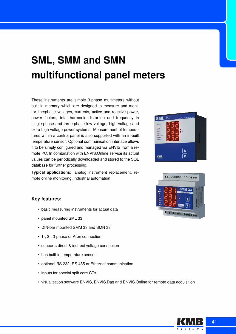
SML, SMM and SMNmultifunctional panel meters
These instruments are simple 3-phase multimeters withoutbuilt in memory which are designed to measure and moni-tor line/phase voltages, currents, active and reactive power,power factors, total harmonic distortion and frequency insingle-phase and three-phase low voltage, high voltage andextra high voltage power systems. Measurement of tempera-tures within a control panel is also supported with an in-builttemperature sensor. Optional communication interface allowsit to be simply configured and managed via ENVIS from a re-mote PC. In combination with ENVIS.Online service its actualvalues can be periodically downloaded and stored to the SQLdatabase for further processing.
Typical applications: analog instrument replacement, re-mote online monitoring, industrial automation
Key features:
• basic measuring instruments for actual data
• panel mounted SML 33
• DIN-bar mounted SMM 33 and SMN 33
• 1-, 2-, 3-phase or Aron connection
• supports direct & indirect voltage connection
• has built-in temperature sensor
• optional RS 232, RS 485 or Ethernet communication
• inputs for special split core CTs
• visualization software ENVIS, ENVIS.Daq and ENVIS.Online for remote data acquisition
41
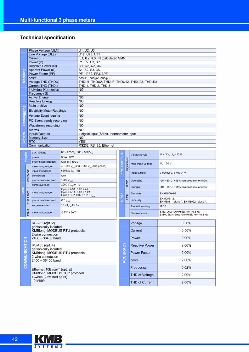
Multi-functional 3 phase meters
Technical specification
Metering
Phase Voltage (ULN) U1, U2, U3Line Voltage (ULL) U12, U23, U31Current (I) IL1, IL2, IL3, IN (calculated SMN)Power (P) P1, P2, P3, 3PReactive Power (Q) Q1, Q2, Q3, 3QAparent Power (S) S1, S2, S3, 3SPower Factor (PF) PF1, PF2, PF3, 3PF
Voltage THD (THDU) THDU1, THDU2, THDU3, THDU12, THDU23, THDU31Current THD (THDI) THDI1, THDI2, THDI3Individual Harmonics NOFrequency (f) fActive Energy NOReactive Energy NO
Datalogging Main archive NO
Electricity Meter Readings NO
Voltage Event logging NO
PQ Event trends recording NO
Waveforms recording NO
Others
Alarms NOInputs/Outputs 1 digital input (SMN), thermometer inputMemory Size NORTC YES*Communication RS232, RS485, Ethernet
cosφ cosφ1, cosφ2, cosφ3
POWER aux. voltage
power 3 VA / 3 W
overvoltage category CAT III / 300 V
INPUT
VO
LT
AG
E
measuring range
input impedance
connection wye
permanent overload
surge overload
CU
RR
EN
T measuring range
permanent overload
surge overload
TE
MP
measuring range -25°C ÷ 60°C
85 ÷ 275 VAC
/ 80 ÷ 350 VDC
4 ÷ 500 VAC
/2,3 ÷ 285 VAC
(line/phase)
660 kW (Li ↔N)
1000 VRMS
2000 VRMS
for 1s
Option X/5A: 0,02 ÷ 7AOption X/1A: 0,02 ÷ 1,2AOption S, P: 0,02 ÷ 1,2 × I
NOM
2 × INOM
10 × INOM
for 1s
INPUTS/OUTPUTS
Dig
ital I
np
ut
Voltage levels
Max. Input voltage
Input current 3 mA/12 V, 8 mA/24 V
OTHER
TE
MP Operating -25 ÷ 60°C, <95% non-condens. environ.
Storage -40 ÷ 85°C, <95% non-condens. environ.
EM
C
Emmision EN 61000-6-2
Immunity
Protection rating IP 20
Dimmensions
UL < 3 V, U
H > 10 V
UM = 30 V
EN 50081-2, EN 55011 - class A, EN 55022 - class A
SML: 96W×96H×51D mm / 0,3 kgSMM, SMN: 89W×90H×58D mm / 0,3 kg
COMMUNICATION
RS-232 (opt. 2)galvanically isolatedKMBlong, MODBUS RTU protocols2-wire connection2400 ÷ 38400 baud
RS-485 (opt. 4)galvanically isolatedKMBlong, MODBUS RTU protocols2-wire connection2400 ÷ 38400 baud
Ethernet 10Base-T (opt. E)KMBlong, MODBUS TCP protocols4-wires (2 twisted pairs)10 Mbit/s
ACCURACY
Voltage 0,50%
Current 0,50%
Power 2,00%
Reactive Power 2,00%
Power Factor 2,00%
cosφ 2,00%
Frequency 0,02%
THD of Voltage 2,00%
THD of Current 2,00%
42
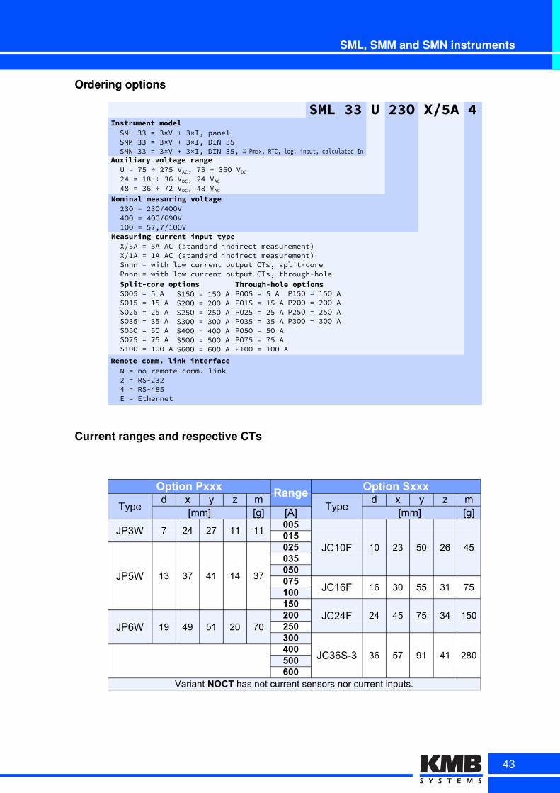
SML, SMM and SMN instruments
Ordering options
Measuring4current4input4type
Remote4comm.4link4interfaceNd=dnodremotedcomm+dlink6d=dRSV6967d=dRSV7xUEd=dEthernet
XIUAd=dUAdACdPstandarddindirectdmeasurementgXIOAd=dOAdACdPstandarddindirectdmeasurementgSnnnd=dwithdlowdcurrentdoutputdCTs×dsplitVcoredPnnnd=dwithdlowdcurrentdoutputdCTs×dthroughVholed
SML4334U423O4X/5A44Instrument4model
SMLd99d=d9×VdLd9×I×dpanelSMMd99d=d9×VdLd9×I×dDINd9UdSMNd99d=d9×VdLd9×I×dDINd9U×d
Nominal4measuring4voltage69Od=d69OI7OOV7OOd=d7OOI÷9OVOOOd=dU¼×¼IOOOVd
Auxiliary4voltage4rangeUd=d¼Ud÷d6¼UdVAC×d¼Ud÷d9UOdVDC67d=dOxd÷d9÷dVDC×d67dVAC7xd=d9÷d÷d¼6dVDC×d7xdVAC
Through-hole4optionsPOOUd=dUdAPOOUd=dOUdAPO6Ud=d6UdAPO9Ud=d9UdAPOUOd=dUOdAPO¼Ud=d¼UdAPOOOd=dOOOdA
Split-core4optionsSOOUd=dUdASOOUd=dOUdASO6Ud=d6UdASO9Ud=d9UdASOUOd=dUOdASO¼Ud=d¼UdASOOOd=dOOOdA
SOUOd=dOUOdAS6OOd=d6OOdAS6UOd=d6UOdAS9OOd=d9OOdAS7OOd=d7OOdASUOOd=dUOOdAS÷OOd=d÷OOdA
POUOd=dOUOdAP6OOd=d6OOdAP6UOd=d6UOdAP9OOd=d9OOdA
d¼dPmax×dRTC×dlog+dinput×dcalculateddIn
Current ranges and respective CTs
Option PxxxRange
Option Sxxx
Typed x y z m
Typed x y z m
[mm] [g] [A] [mm] [g]
JP3W 7 24 27 11 11005
JC10F 10 23 50 26 45015
JP5W 13 37 41 14 37
025035050075
JC16F 16 30 55 31 75100150
JC24F 24 45 75 34 150JP6W 19 49 51 20 70
200250300
JC36S-3 36 57 91 41 280400500600
Variant NOCT has not current sensors nor current inputs.
43
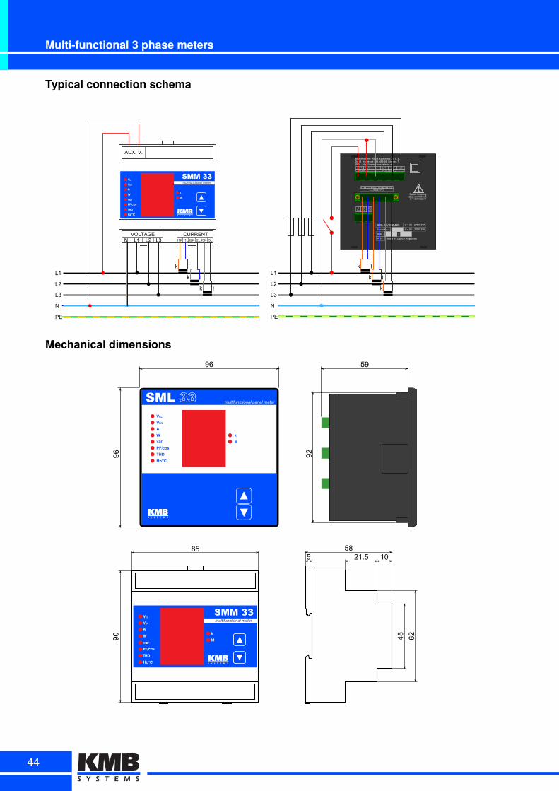
Multi-functional 3 phase meters
Typical connection schema
I1K
VOLTAGE CURRENT
AUX. V.
N L1 L2 L3 I1L I2K I2L I3K I3L
k l
k l
k l
SML 33/232 485
L1
L2
L3
N
PE
k l
k l
k l
Mechanical dimensions
96
96 92
59
90
8521.5 10
45 62
585
44
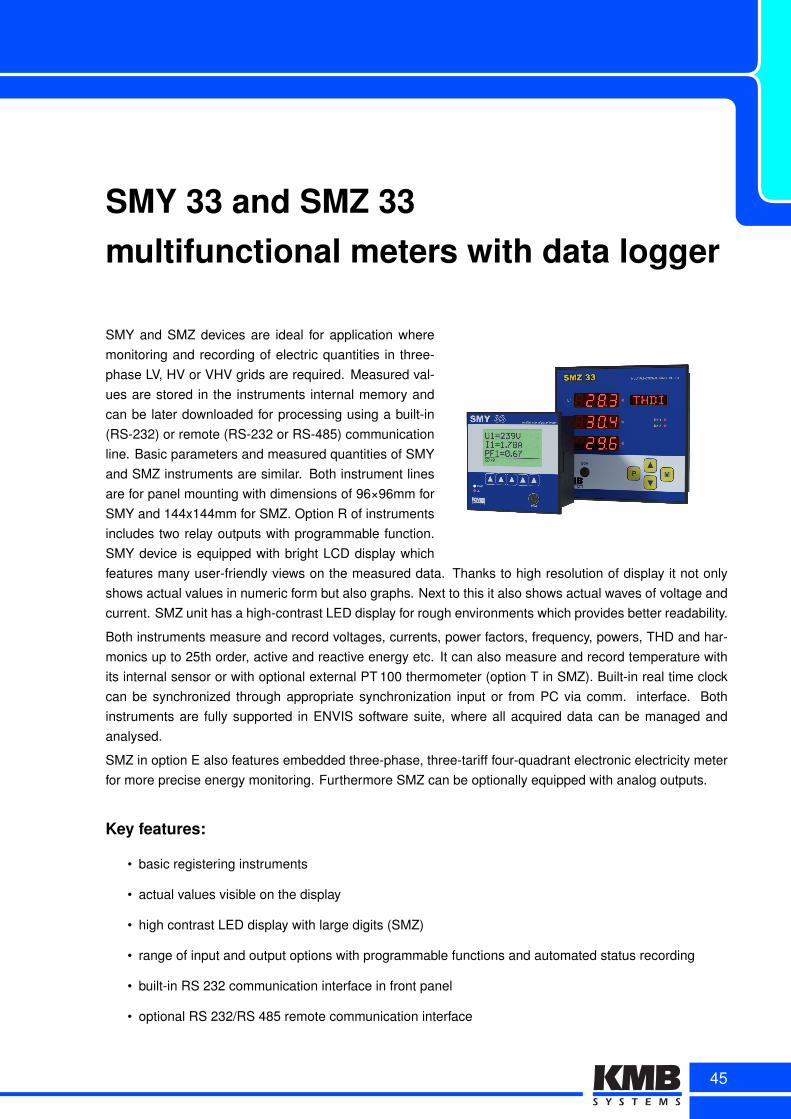
SMY 33 and SMZ 33multifunctional meters with data logger
SMY and SMZ devices are ideal for application wheremonitoring and recording of electric quantities in three-phase LV, HV or VHV grids are required. Measured val-ues are stored in the instruments internal memory andcan be later downloaded for processing using a built-in(RS-232) or remote (RS-232 or RS-485) communicationline. Basic parameters and measured quantities of SMYand SMZ instruments are similar. Both instrument linesare for panel mounting with dimensions of 96×96mm forSMY and 144x144mm for SMZ. Option R of instrumentsincludes two relay outputs with programmable function.SMY device is equipped with bright LCD display whichfeatures many user-friendly views on the measured data. Thanks to high resolution of display it not onlyshows actual values in numeric form but also graphs. Next to this it also shows actual waves of voltage andcurrent. SMZ unit has a high-contrast LED display for rough environments which provides better readability.
Both instruments measure and record voltages, currents, power factors, frequency, powers, THD and har-monics up to 25th order, active and reactive energy etc. It can also measure and record temperature withits internal sensor or with optional external PT 100 thermometer (option T in SMZ). Built-in real time clockcan be synchronized through appropriate synchronization input or from PC via comm. interface. Bothinstruments are fully supported in ENVIS software suite, where all acquired data can be managed andanalysed.
SMZ in option E also features embedded three-phase, three-tariff four-quadrant electronic electricity meterfor more precise energy monitoring. Furthermore SMZ can be optionally equipped with analog outputs.
Key features:
• basic registering instruments
• actual values visible on the display
• high contrast LED display with large digits (SMZ)
• range of input and output options with programmable functions and automated status recording
• built-in RS 232 communication interface in front panel
• optional RS 232/RS 485 remote communication interface
45
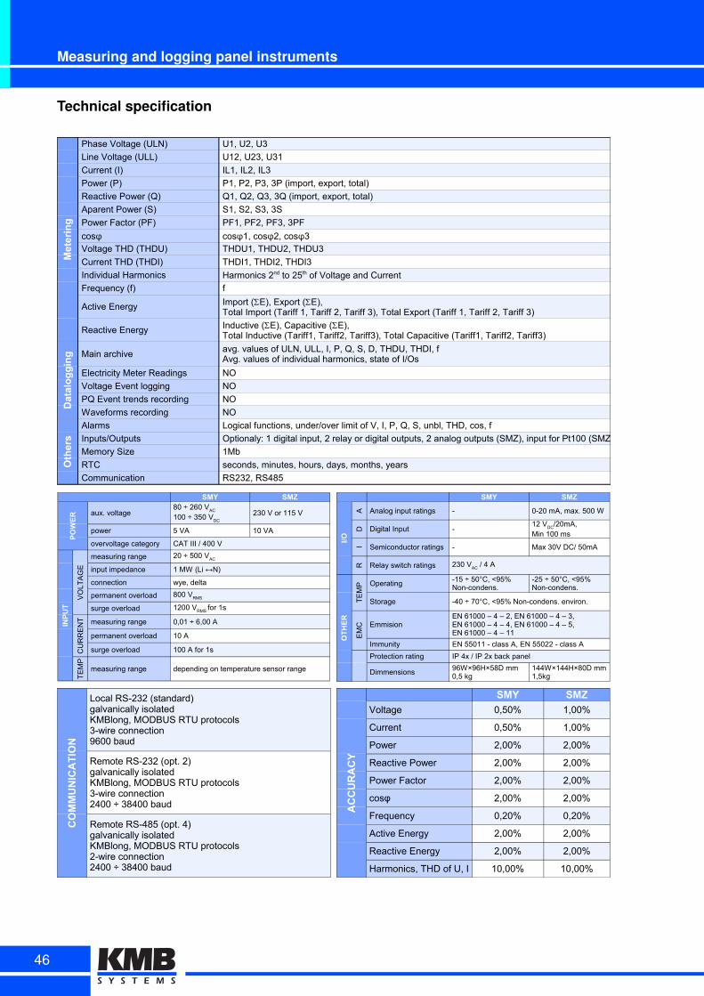
Measuring and logging panel instruments
Technical specification
Metering
Phase Voltage (ULN) U1, U2, U3
Line Voltage (ULL) U12, U23, U31
Current (I) IL1, IL2, IL3
Power (P) P1, P2, P3, 3P (import, export, total)
Reactive Power (Q) Q1, Q2, Q3, 3Q (import, export, total)
Aparent Power (S) S1, S2, S3, 3S
Power Factor (PF) PF1, PF2, PF3, 3PF
Voltage THD (THDU) THDU1, THDU2, THDU3
Current THD (THDI) THDI1, THDI2, THDI3
Individual Harmonics
Frequency (f) f
Active Energy
Reactive Energy
Datalogging Main archive
Electricity Meter Readings NO
Voltage Event logging NO
PQ Event trends recording NO
Waveforms recording NO
Others
Alarms Logical functions, under/over limit of V, I, P, Q, S, unbl, THD, cos, f
Inputs/Outputs Optionaly: 1 digital input, 2 relay or digital outputs, 2 analog outputs (SMZ), input for Pt100 (SMZ)
Memory Size 1Mb
RTC seconds, minutes, hours, days, months, years
Communication RS232, RS485
cosφ cosφ1, cosφ2, cosφ3
Harmonics 2nd to 25th of Voltage and Current
Import (SE), Export (SE),Total Import (Tariff 1, Tariff 2, Tariff 3), Total Export (Tariff 1, Tariff 2, Tariff 3)
Inductive (SE), Capacitive (SE),Total Inductive (Tariff1, Tariff2, Tariff3), Total Capacitive (Tariff1, Tariff2, Tariff3)
avg. values of ULN, ULL, I, P, Q, S, D, THDU, THDI, fAvg. values of individual harmonics, state of I/Os
SMY SMZ
POWER aux. voltage 230 V or 115 V
power 5 VA 10 VA
overvoltage category CAT III / 400 V
INPUT
VO
LT
AG
E
measuring range
input impedance
connection wye, delta
permanent overload
surge overload
CU
RR
EN
T measuring range 0,01 ÷ 6,00 A
permanent overload 10 A
surge overload 100 A for 1s
TE
MP
measuring range depending on temperature sensor range
80 ÷ 260 VAC
100 ÷ 350 VDC
20 ÷ 500 VAC
1 MW (Li ↔N)
800 VRMS
1200 VRMS
for 1s
SMY SMZ
I/O
A Analog input ratings -
D Digital Input -
I Semiconductor ratings - Max 30V DC/ 50mA
R Relay switch ratings
OTHER
TE
MP Operating
Storage -40 ÷ 70°C, <95% Non-condens. environ.
EM
C Emmision
Immunity EN 55011 - class A, EN 55022 - class A
Protection rating IP 4x / IP 2x back panel
Dimmensions
0-20 mA, max. 500 W
12 VDC
/20mA,Min 100 ms
230 VAC
/ 4 A
-15 ÷ 50°C, <95%Non-condens.
-25 ÷ 50°C, <95%Non-condens.
EN 61000 – 4 – 2, EN 61000 – 4 – 3,EN 61000 – 4 – 4, EN 61000 – 4 – 5,EN 61000 – 4 – 11
96W×96H×58D mm0,5 kg
144W×144H×80D mm1,5kg
COMMUNICATION
Local RS-232 (standard)galvanically isolatedKMBlong, MODBUS RTU protocols3-wire connection9600 baud
Remote RS-232 (opt. 2)galvanically isolatedKMBlong, MODBUS RTU protocols3-wire connection2400 ÷ 38400 baud
Remote RS-485 (opt. 4)galvanically isolatedKMBlong, MODBUS RTU protocols2-wire connection2400 ÷ 38400 baud
ACCURACY
SMY SMZ
Voltage 0,50% 1,00%
Current 0,50% 1,00%
Power 2,00% 2,00%
Reactive Power 2,00% 2,00%
Power Factor 2,00% 2,00%
cosφ 2,00% 2,00%
Frequency 0,20% 0,20%
Active Energy 2,00% 2,00%
Reactive Energy 2,00% 2,00%
Harmonics, THD of U, I 10,00% 10,00%
46
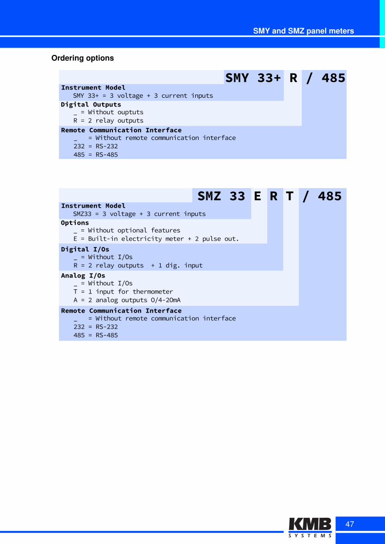
SMY and SMZ panel meters
Ordering options
Remote Communication Interface_sss=sWithoutsremotescommunicationsinterface232s=sRS-232485s=sRS-485
SMY 33+ R / 485Instrument Model
Digital OutputsSMYs33+s=s3svoltages+s3scurrentsinputs
_s=sWithoutsouptutsRs=s2srelaysoutputs
DigitalcI/Os_v=vWithoutvI/OsRv=v2vrelayvoutputsvv5v1vdig.vinput
SMZc33cEcRcTc/c485InstrumentcModel
OptionsSMZ33v=v3vvoltagev5v3vcurrentvinputsvv
_v=vWithoutvoptionalvfeaturesEv=vBuilt-invelectricityvmeterv5v2vpulsevout.
AnalogcI/Os_v=vWithoutvI/OsTv=v1vinputvforvthermometerAv=v2vanalogvoutputsvO/4-2OmA
RemotecCommunicationcInterface_vvv=vWithoutvremotevcommunicationvinterface232v=vRS-232485v=vRS-485
47
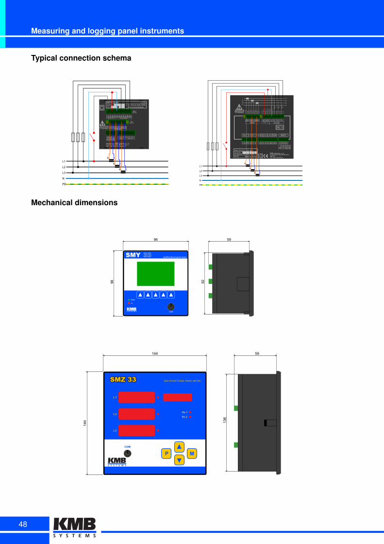
Measuring and logging panel instruments
Typical connection schema
RELAY 1 RELAY 2
L UN
Y R 232 485
L1
L2
L3
N
PE
k l
k l
k l
SMZo33
RELAYo1 RELAYo2 SYNC PULSE PULSEOUTPUTo1 OUTPUTo2 TEMP REMOTE
13 14 15 16 17 18 19 20 21 22 23 24 25 26 27 28 29 30
KMBIsystems,Is.r.o.Dr.IM.IHorákovéI559,I460I06ILiberecCZECHIAURL:Ihttp://www.kmb.cz
SMZo33oEoRoTo/o232o485SerialoNok:U:oo230oVACoo/o42~80oHzGo10VAIPo4X Made in Czechia
RxD TxD GND 232A B GND 485TR
LOAD
L1
L2
L3
N1A 1A 1A
k l k l k l
L1
L2
L3
N
PE
k l
k l
k l
Mechanical dimensions
59
136
144
144
48
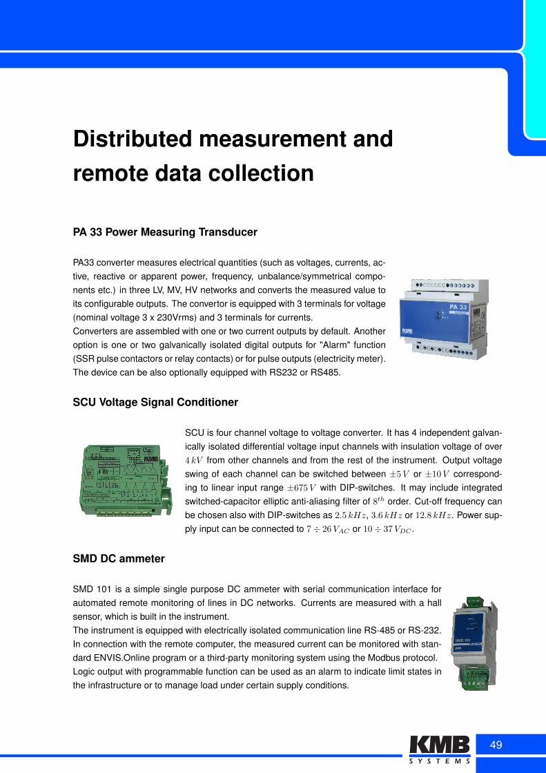
Distributed measurement andremote data collection
PA 33 Power Measuring Transducer
PA33 converter measures electrical quantities (such as voltages, currents, ac-tive, reactive or apparent power, frequency, unbalance/symmetrical compo-nents etc.) in three LV, MV, HV networks and converts the measured value toits configurable outputs. The convertor is equipped with 3 terminals for voltage(nominal voltage 3 x 230Vrms) and 3 terminals for currents.Converters are assembled with one or two current outputs by default. Anotheroption is one or two galvanically isolated digital outputs for "Alarm" function(SSR pulse contactors or relay contacts) or for pulse outputs (electricity meter).The device can be also optionally equipped with RS232 or RS485.
SCU Voltage Signal Conditioner
SCU is four channel voltage to voltage converter. It has 4 independent galvan-ically isolated differential voltage input channels with insulation voltage of over4 kV from other channels and from the rest of the instrument. Output voltageswing of each channel can be switched between ±5V or ±10V correspond-ing to linear input range ±675V with DIP-switches. It may include integratedswitched-capacitor elliptic anti-aliasing filter of 8th order. Cut-off frequency canbe chosen also with DIP-switches as 2.5 kHz, 3.6 kHz or 12.8 kHz. Power sup-ply input can be connected to 7÷ 26VAC or 10÷ 37VDC .
SMD DC ammeter
SMD 101 is a simple single purpose DC ammeter with serial communication interface forautomated remote monitoring of lines in DC networks. Currents are measured with a hallsensor, which is built in the instrument.The instrument is equipped with electrically isolated communication line RS-485 or RS-232.In connection with the remote computer, the measured current can be monitored with stan-dard ENVIS.Online program or a third-party monitoring system using the Modbus protocol.Logic output with programmable function can be used as an alarm to indicate limit states inthe infrastructure or to manage load under certain supply conditions.
49
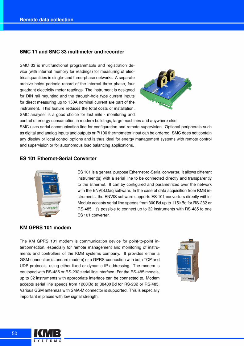
Remote data collection
SMC 11 and SMC 33 multimeter and recorder
SMC 33 is multifunctional programmable and registration de-vice (with internal memory for readings) for measuring of elec-trical quantities in single- and three-phase networks. A separatearchive holds periodic record of the internal three phase, fourquadrant electricity meter readings. The instrument is designedfor DIN rail mounting and the through-hole type current inputsfor direct measuring up to 150A nominal current are part of theinstrument. This feature reduces the total costs of installation.SMC analyser is a good choice for last mile - monitoring andcontrol of energy consumption in modern buildings, large machines and anywhere else.SMC uses serial communication line for configuration and remote supervision. Optional peripherals suchas digital and analog inputs and outputs or Pt100 thermometer input can be ordered. SMC does not containany display or local control options and is thus ideal for energy management systems with remote controland supervision or for autonomous load balancing applications.
ES 101 Ethernet-Serial Converter
ES 101 is a general purpose Ethernet-to-Serial converter. It allows differentinstrument(s) with a serial line to be connected directly and transparentlyto the Ethernet. It can by configured and parametrized over the networkwith the ENVIS.Daq software. In the case of data acquisition from KMB in-struments, the ENVIS software supports ES 101 converters directly within.Module accepts serial line speeds from 300 Bd up to 115 kBd for RS-232 orRS-485. It’s possible to connect up to 32 instruments with RS-485 to oneES 101 converter.
KM GPRS 101 modem
The KM GPRS 101 modem is communication device for point-to-point in-terconnection, especially for remote management and monitoring of instru-ments and controllers of the KMB systems company. It provides either aGSM-connection (standard modem) or a GPRS-connection with both TCP andUDP protocols, using either fixed or dynamic IP-addressing. The modem isequipped with RS-485 or RS-232 serial line interface. For the RS-485 models,up to 32 instruments with appropriate interface can be connected to. Modemaccepts serial line speeds from 1200 Bd to 38400 Bd for RS-232 or RS-485.Various GSM antennas with SMA-M connector is supported. This is especiallyimportant in places with low signal strength.
50
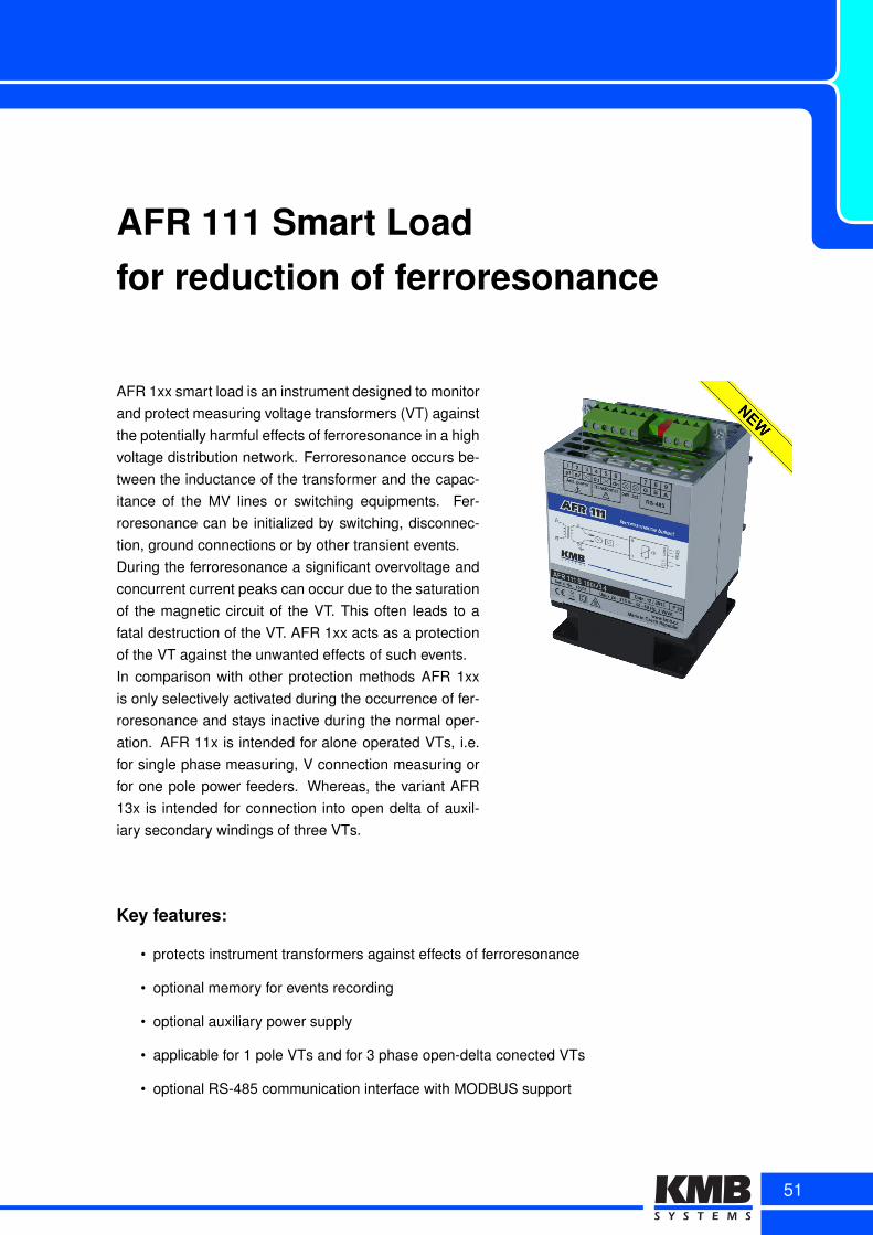
AFR 111 Smart Loadfor reduction of ferroresonance
AFR 1xx smart load is an instrument designed to monitorand protect measuring voltage transformers (VT) againstthe potentially harmful effects of ferroresonance in a highvoltage distribution network. Ferroresonance occurs be-tween the inductance of the transformer and the capac-itance of the MV lines or switching equipments. Fer-roresonance can be initialized by switching, disconnec-tion, ground connections or by other transient events.During the ferroresonance a significant overvoltage andconcurrent current peaks can occur due to the saturationof the magnetic circuit of the VT. This often leads to afatal destruction of the VT. AFR 1xx acts as a protectionof the VT against the unwanted effects of such events.In comparison with other protection methods AFR 1xxis only selectively activated during the occurrence of fer-roresonance and stays inactive during the normal oper-ation. AFR 11x is intended for alone operated VTs, i.e.for single phase measuring, V connection measuring orfor one pole power feeders. Whereas, the variant AFR13x is intended for connection into open delta of auxil-iary secondary windings of three VTs.
Key features:
• protects instrument transformers against effects of ferroresonance
• optional memory for events recording
• optional auxiliary power supply
• applicable for 1 pole VTs and for 3 phase open-delta conected VTs
• optional RS-485 communication interface with MODBUS support
51
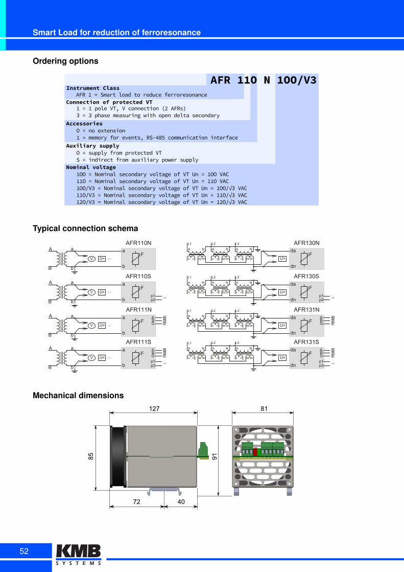
Smart Load for reduction of ferroresonance
Ordering options
AFRg11OgNg1OO/V3InstrumentgClass
ConnectiongofgprotectedgVTAFRw1w=wSmartwloadwtowreducewferroresonance
1w=w1wpolewVT/wVwconnectionw52wAFRsN3w=w3wphasewmeasuringwwithwopenwdeltawsecondary
AccessoriesOw=wnowextension1w=wmemorywforwevents/wRS-485wcommunicationwinterface
AuxiliarygsupplyOw=wsupplywfromwprotectedwVTSw=windirectwfromwauxiliarywpowerwsupply
Nominalgvoltage1OOw=wNominalwsecondarywvoltagewofwVTwUnw=w1OOwVACw11Ow=wNominalwsecondarywvoltagewofwVTwUnw=w11OwVAC1OO/V3w=wNominalwsecondarywvoltagewofwVTwUnw=w1OO/√3wVACw11O/V3w=wNominalwsecondarywvoltagewofwVTwUnw=w11O/√3wVACw12O/V3w=wNominalwsecondarywvoltagewofwVTwUnw=w12O/√3wVACw
Typical connection schema
FA
L1
a
da
dn
U>
ABG RS
485N
n da dn
A
a
N
n da dn
A
a
N
n da dn
L2 L3
p1p2
AFR131S
FA
L1
a
da
dn
U>
ABG RS
485N
n da dn
A
a
N
n da dn
A
a
N
n da dn
L2 L3 AFR131N
FA
L1
a
da
dn
U>
p1p2
N
n da dn
A
a
N
n da dn
A
a
N
n da dn
L2 L3 AFR130S
FA
L1
a
da
dn
U>
N
n da dn
A
a
N
n da dn
A
a
N
n da dn
L2 L3 AFR130N
FA
B
a
b
a
b
V U> ...p1p2
ABG RS
485
AFR111S
FA
B
a
b
a
b
V U> ...
ABG RS
485
AFR111N
FA
B
a
b
a
b
V U> ...p1p2
AFR110S
FA
B
a
b
a
b
V U> ...
AFR110N
Mechanical dimensions
127 81
9185
72 40
52
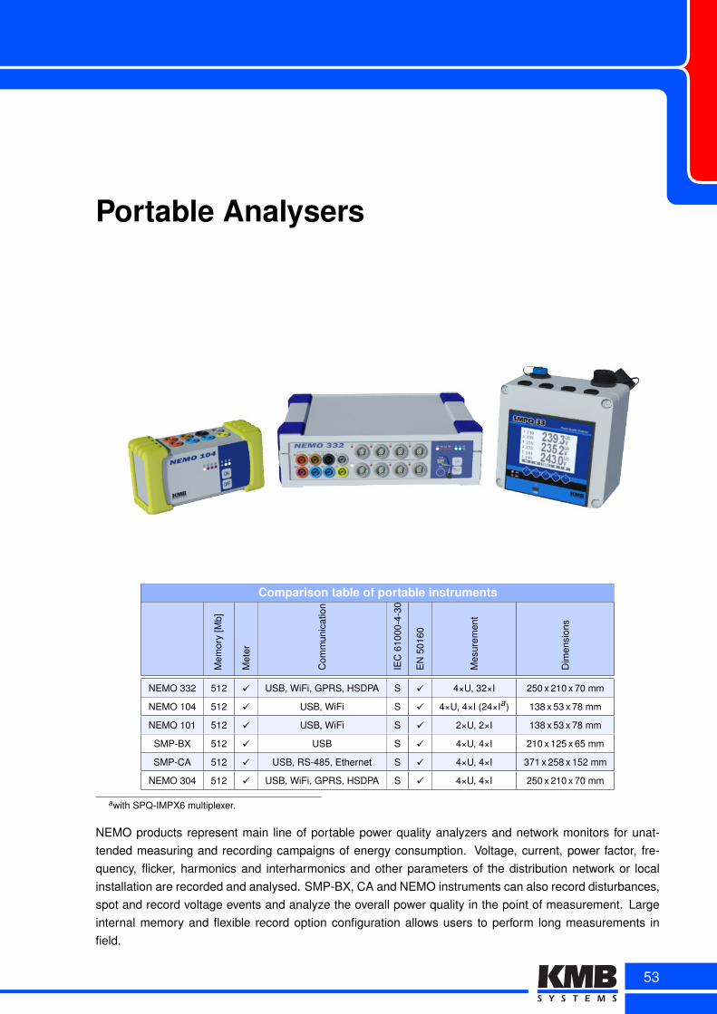
Portable Analysers
Comparison table of portable instruments
Mem
ory
[Mb]
Met
er
Com
mun
icat
ion
IEC
6100
0-4-
30
EN
5016
0
Mes
urem
ent
Dim
ensi
ons
NEMO 332 512 ✓ USB, WiFi, GPRS, HSDPA S ✓ 4×U, 32×I 250 x 210 x 70 mm
NEMO 104 512 ✓ USB, WiFi S ✓ 4×U, 4×I (24×Ia) 138 x 53 x 78 mm
NEMO 101 512 ✓ USB, WiFi S ✓ 2×U, 2×I 138 x 53 x 78 mm
SMP-BX 512 ✓ USB S ✓ 4×U, 4×I 210 x 125 x 65 mm
SMP-CA 512 ✓ USB, RS-485, Ethernet S ✓ 4×U, 4×I 371 x 258 x 152 mm
NEMO 304 512 ✓ USB, WiFi, GPRS, HSDPA S ✓ 4×U, 4×I 250 x 210 x 70 mm
awith SPQ-IMPX6 multiplexer.
NEMO products represent main line of portable power quality analyzers and network monitors for unat-tended measuring and recording campaigns of energy consumption. Voltage, current, power factor, fre-quency, flicker, harmonics and interharmonics and other parameters of the distribution network or localinstallation are recorded and analysed. SMP-BX, CA and NEMO instruments can also record disturbances,spot and record voltage events and analyze the overall power quality in the point of measurement. Largeinternal memory and flexible record option configuration allows users to perform long measurements infield.
53
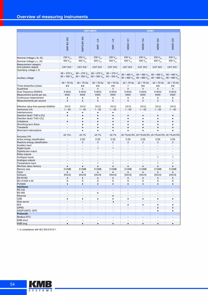
Overview of measuring instruments
SMP/SMPQ NEMO
SM
P-B
X 3
00
SM
PQ
-BX
36
0
SM
P –
CA
SM
P –
CA
NE
MO
10
1
NE
MO
10
4
NE
MO
30
4
NE
MO
33
2
Nominal Voltage L-N, AC
Nominal Voltage L-L, AC
Operating voltage L-N - - - - - - - -
Auxiliary voltage
45 ÷ 70 Hz 45 ÷ 70 Hz 45 ÷ 70 Hz 45 ÷ 70 Hz 42 ÷ 70 Hz 42 ÷ 70 Hz 42 ÷ 70 Hz 42 ÷ 70 HzThree phase/four phase ●/● ●/● ●/● ●/● -/- ●/● ●/● ●/●Quadrants - 4 4 4 4 4 4 4Scan frequency 50/60Hz 6.4kHz 6.4kHz 6.4kHz 6.4kHz 6.4kHz 6.4kHz 6.4kHz 6.4kHzMeasurement points per sec. 6400 6400 6400 6400 6400 6400 6400 6400Continuous measurement ● ● ● ● ● ● ● ●Measuerements per second 5 5 5 5 5 5 5 5
Effective value from periods 50/60Hz 10/12 10/12 10/12 10/12 10/12 10/12 10/12 10/12Harmonics V/A 1 – 63 1 – 63 1 – 63 1 – 63 1 – 63 1 – 63 1 – 63 1 – 63Interharmonics ● ● ● ● - - - -Disortion factor THD-U [%] ● ● ● ● ● ● ● ●DIsortion factor THD-I [%] - ● ● ● ● ● ● ●Unbalance ● ● ● ● ● ● ● ●Short/long-term flicker - ● ● ● ● ● ● ●Transients - ● ● ● ● ● ● ●Short-term interruptions - ● ● ● ● ● ● ●
Accuracy V/A±0.1%/- ±0.1% ±0.1% ±0.1% ±0.1%/±0.5% ±0.1%/±0.5% ±0.1%/±0.5% ±0.1%/±0.5%
Active energy classification - 0.5S 0.5S 0.5S 0.5S 0.5S 0.5S 0.5SReactive energy classification - 2 2 2 2 2 2 2Auxiliary input - - - - - - - -Digital inputs - - 1 1 - - - -Digital/pulse output - - - - - - - -Relay outputs - - - - - - - -Analogue inputs - - - - - - 1 1Analogue outputs - - - - - - - -Temperature input - - 1 1 - - 1 1Min/max value memory ● ● ● ● ● ● ● ●Memory size 512MB 512MB 512MB 512MB 512MB 512MB 512MB 512MBClock ● ● ● ● ● ● ● ●Software ENVIS ENVIS ENVIS ENVIS ENVIS ENVIS ENVIS ENVISEN 50160 ● ● ● ● ● ● ● ●IEC 61000-4-30 S S S S S S S SPortable ● ● ● ● ● ● ● ●InterfacesRS 232 - - - - - - - -RS 485 - - ● - - - - -Ethernet - - - ● - - - -USB ● ● ● ● ● ● ● ●Web server - - - ● - - - -Wifi - - - - ● ● ● ●GPRS - - - - - - ● ●HSDP/UMTS. GPS - - - - - - ● ●Protocols
Modbus RTU - - - - - - - -
KMB short - - - - - - - -
KMB long ● ● ● ● ● ● ● ●
1. in compliance with IEC EN 61010-1
230 VAC
230 VAC
230 VAC
230 VAC
230 VAC
230 VAC
230 VAC
230 VAC
400 VAC
400 VAC
400 VAC
400 VAC
400 VAC
400 VAC
400 VAC
400 VAC
Measurement categoryAnd pollution degree CAT III/2 1 CAT III/2 1 CAT III/2 1 CAT III/2 1 CAT III/2 1 CAT III/2 1 CAT III/2 1 CAT III/2 1
85 ÷ 275 VAC
80 ÷ 350 VDC
85 ÷ 275 VAC
80 ÷ 350 VDC
85 ÷ 275 VAC
80 ÷ 350 VDC
85 ÷ 275 VAC
80 ÷ 350 VDC
85 ÷ 480 VAC
80 ÷ 680 VDC
85 ÷ 480 VAC
80 ÷ 680 VDC
85 ÷ 480 VAC
80 ÷ 680 VDC
85 ÷ 480 VAC
80 ÷ 680 VDC
54
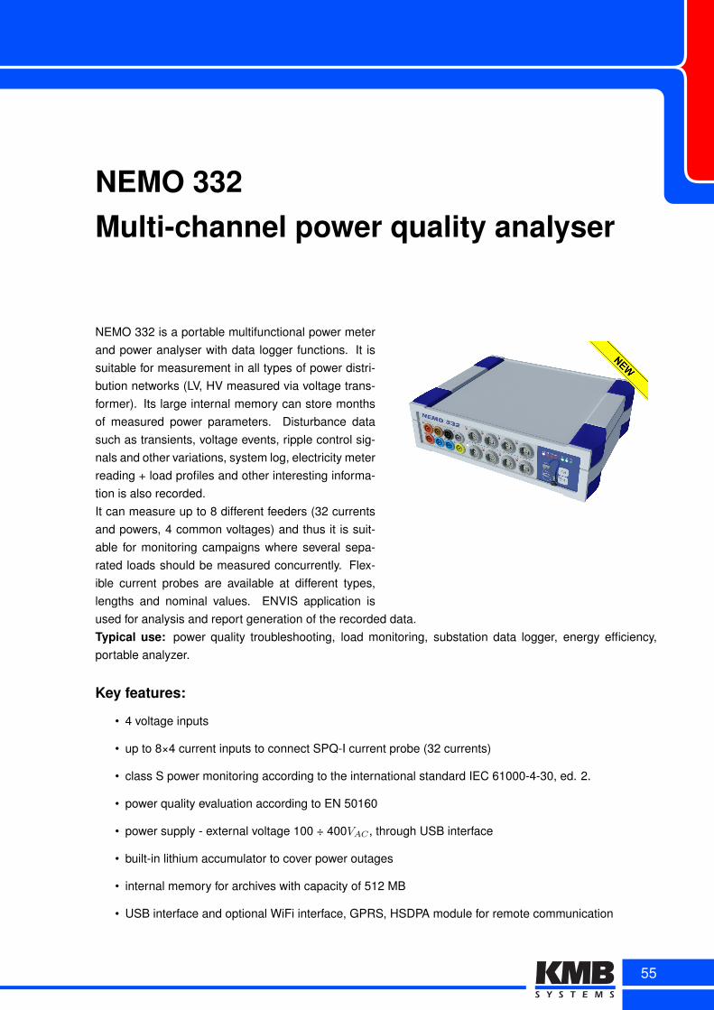
NEMO 332Multi-channel power quality analyser
NEMO 332 is a portable multifunctional power meterand power analyser with data logger functions. It issuitable for measurement in all types of power distri-bution networks (LV, HV measured via voltage trans-former). Its large internal memory can store monthsof measured power parameters. Disturbance datasuch as transients, voltage events, ripple control sig-nals and other variations, system log, electricity meterreading + load profiles and other interesting informa-tion is also recorded.It can measure up to 8 different feeders (32 currentsand powers, 4 common voltages) and thus it is suit-able for monitoring campaigns where several sepa-rated loads should be measured concurrently. Flex-ible current probes are available at different types,lengths and nominal values. ENVIS application isused for analysis and report generation of the recorded data.Typical use: power quality troubleshooting, load monitoring, substation data logger, energy efficiency,portable analyzer.
Key features:
• 4 voltage inputs
• up to 8×4 current inputs to connect SPQ-I current probe (32 currents)
• class S power monitoring according to the international standard IEC 61000-4-30, ed. 2.
• power quality evaluation according to EN 50160
• power supply - external voltage 100 ÷ 400VAC , through USB interface
• built-in lithium accumulator to cover power outages
• internal memory for archives with capacity of 512 MB
• USB interface and optional WiFi interface, GPRS, HSDPA module for remote communication
55
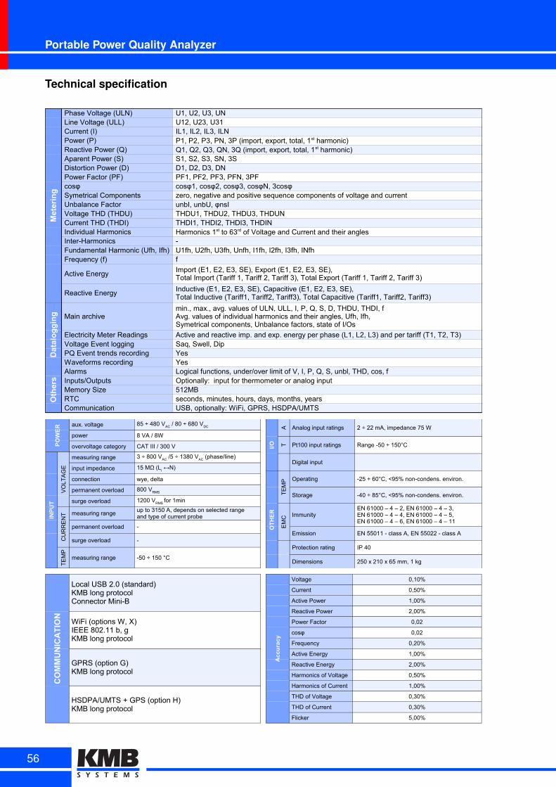
Portable Power Quality Analyzer
Technical specification
Metering
Phase Voltage (ULN) U1, U2, U3, UNLine Voltage (ULL) U12, U23, U31Current (I) IL1, IL2, IL3, ILNPower (P)Reactive Power (Q)Aparent Power (S) S1, S2, S3, SN, 3SDistortion Power (D) D1, D2, D3, DNPower Factor (PF) PF1, PF2, PF3, PFN, 3PF
Symetrical Components zero, negative and positive sequence components of voltage and currentUnbalance FactorVoltage THD (THDU) THDU1, THDU2, THDU3, THDUNCurrent THD (THDI) THDI1, THDI2, THDI3, THDINIndividual HarmonicsInter-Harmonics -Fundamental Harmonic (Ufh, Ifh) U1fh, U2fh, U3fh, Unfh, I1fh, I2fh, I3fh, INfhFrequency (f) f
Active Energy
Reactive Energy
Datalogging Main archive
Electricity Meter Readings Active and reactive imp. and exp. energy per phase (L1, L2, L3) and per tariff (T1, T2, T3)Voltage Event logging Saq, Swell, DipPQ Event trends recording YesWaveforms recording Yes
Others
Alarms Logical functions, under/over limit of V, I, P, Q, S, unbl, THD, cos, fInputs/Outputs Optionally: input for thermometer or analog inputMemory Size 512MBRTC seconds, minutes, hours, days, months, yearsCommunication USB, optionally: WiFi, GPRS, HSDPA/UMTS
P1, P2, P3, PN, 3P (import, export, total, 1st harmonic)Q1, Q2, Q3, QN, 3Q (import, export, total, 1st harmonic)
cosφ cosφ1, cosφ2, cosφ3, cosφN, 3cosφ
unbI, unbU, φnsI
Harmonics 1st to 63rd of Voltage and Current and their angles
Import (E1, E2, E3, SE), Export (E1, E2, E3, SE),Total Import (Tariff 1, Tariff 2, Tariff 3), Total Export (Tariff 1, Tariff 2, Tariff 3)
Inductive (E1, E2, E3, SE), Capacitive (E1, E2, E3, SE),Total Inductive (Tariff1, Tariff2, Tariff3), Total Capacitive (Tariff1, Tariff2, Tariff3)
min., max., avg. values of ULN, ULL, I, P, Q, S, D, THDU, THDI, fAvg. values of individual harmonics and their angles, Ufh, Ifh,Symetrical components, Unbalance factors, state of I/Os
POWER aux. voltage
power 8 VA / 8W
overvoltage category CAT III / 300 V
INPUT
VO
LT
AG
E
measuring range
input impedance
connection wye, delta
permanent overload
surge overload
CU
RR
EN
T measuring range
permanent overload -
surge overload -
TE
MP
measuring range -50 ÷ 150 °C
85 ÷ 480 VAC
/ 80 ÷ 680 VDC
3 ÷ 800 VAC
/5 ÷ 1380 VAC
(phase/line)
15 MΩ (Li ↔N)
800 VRMS
1200 VRMS
for 1min
up to 3150 A, depends on selected rangeand type of current probe
I/O
A Analog input ratings
T Pt100 input ratings Range -50 ÷ 150°C
Digital input
OTHER
TE
MP Operating -25 ÷ 60°C, <95% non-condens. environ.
Storage -40 ÷ 85°C, <95% non-condens. environ.
EM
C Immunity
Emission EN 55011 - class A, EN 55022 - class A
Protection rating IP 40
Dimensions 250 x 210 x 65 mm, 1 kg
2 ÷ 22 mA, impedance 75 W
EN 61000 – 4 – 2, EN 61000 – 4 – 3,EN 61000 – 4 – 4, EN 61000 – 4 – 5,EN 61000 – 4 – 6, EN 61000 – 4 – 11
COMMUNICATION
Local USB 2.0 (standard)KMB long protocolConnector Mini-B
WiFi (options W, X)IEEE 802.11 b, gKMB long protocol
GPRS (option G)KMB long protocol
HSDPA/UMTS + GPS (option H)KMB long protocol
Accuracy
Voltage 0,10%
Current 0,50%
Active Power 1,00%
Reactive Power 2,00%
Power Factor 0,02
cosφ 0,02
Frequency 0,20%
Active Energy 1,00%
Reactive Energy 2,00%
Harmonics of Voltage 0,50%
Harmonics of Current 1,00%
THD of Voltage 0,30%
THD of Current 0,30%
Flicker 5,00%
56
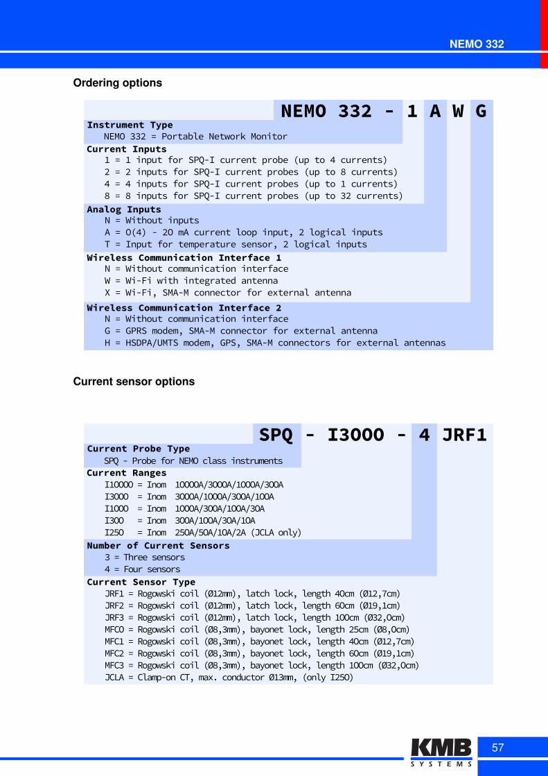
NEMO 332
Ordering options
Analog InputsNM=MWithoutMinputsAM=MOQ48MxM/OMmAMcurrentMloopMinputXM/MlogicalMinputsTM=MInputMforMtemperatureMsensorXM/MlogicalMinputs
NEMO 332 - 1 A W GInstrument Type
Current InputsNEMOMUU/M=MPortableMNetworkMMonitor
DM=MDMinputMforMSPQxIMcurrentMprobeMQupMtoM4Mcurrents8/M=M/MinputsMforMSPQxIMcurrentMprobesMQupMtoM8Mcurrents84M=M4MinputsMforMSPQxIMcurrentMprobesMQupMtoMDMcurrents88M=M8MinputsMforMSPQxIMcurrentMprobesMQupMtoMU/Mcurrents8
Wireless Communication Interface 1NM=MWithoutMcommunicationMinterfaceWM=MWixFiMwithMintegratedMantennaXM=MWixFiXMSMAxMMconnectorMforMexternalMantenna
Wireless Communication Interface 2NM=MWithoutMcommunicationMinterfaceGM=MGPRSMmodemXMSMAxMMconnectorMforMexternalMantennaHM=MHSDPARUMTSMmodemXMGPSXMSMAxMMconnectorsMforMexternalMantennas
Current sensor options
SPQ - I3OOO - 4 JRF1Current Probe Type
Current RangesSPQ(k(Probe(for(NEMO(class(instruments
I6OOOO(=(Inom((6OOOOA,8OOOA,6OOOA,8OOAI8OOO((=(Inom((8OOOA,6OOOA,8OOA,6OOAI6OOO((=(Inom((6OOOA,8OOA,6OOA,8OAI8OO(((=(Inom((8OOA,6OOA,8OA,6OAI9xO(((=(Inom((9xOA,xOA,6OA,9A(4JCLA(onlyF
Number of Current Sensors8(=(Three(sensorsp(=(Four(sensors
Current Sensor TypeJRF6(=(Rogowski(coil(4Ø69mmFw(latch(lockw(length(pOcm(4Ø69wdcmFJRF9(=(Rogowski(coil(4Ø69mmFw(latch(lockw(length(.Ocm(4Ø69w6cmF(JRF8(=(Rogowski(coil(4Ø69mmFw(latch(lockw(length(6OOcm(4Ø89wOcmF(MFCO(=(Rogowski(coil(4Ø8w8mmFw(bayonet(lockw(length(9xcm(4Ø8wOcmF(MFC6(=(Rogowski(coil(4Ø8w8mmFw(bayonet(lockw(length(pOcm(4Ø69wdcmF(MFC9(=(Rogowski(coil(4Ø8w8mmFw(bayonet(lockw(length(.Ocm(4Ø69w6cmFMFC8(=(Rogowski(coil(4Ø8w8mmFw(bayonet(lockw(length(6OOcm(4Ø89wOcmFJCLA(=(Clampkon(CTw(maxØ(conductor(Ø68mmw(4only(I9xOF(
57
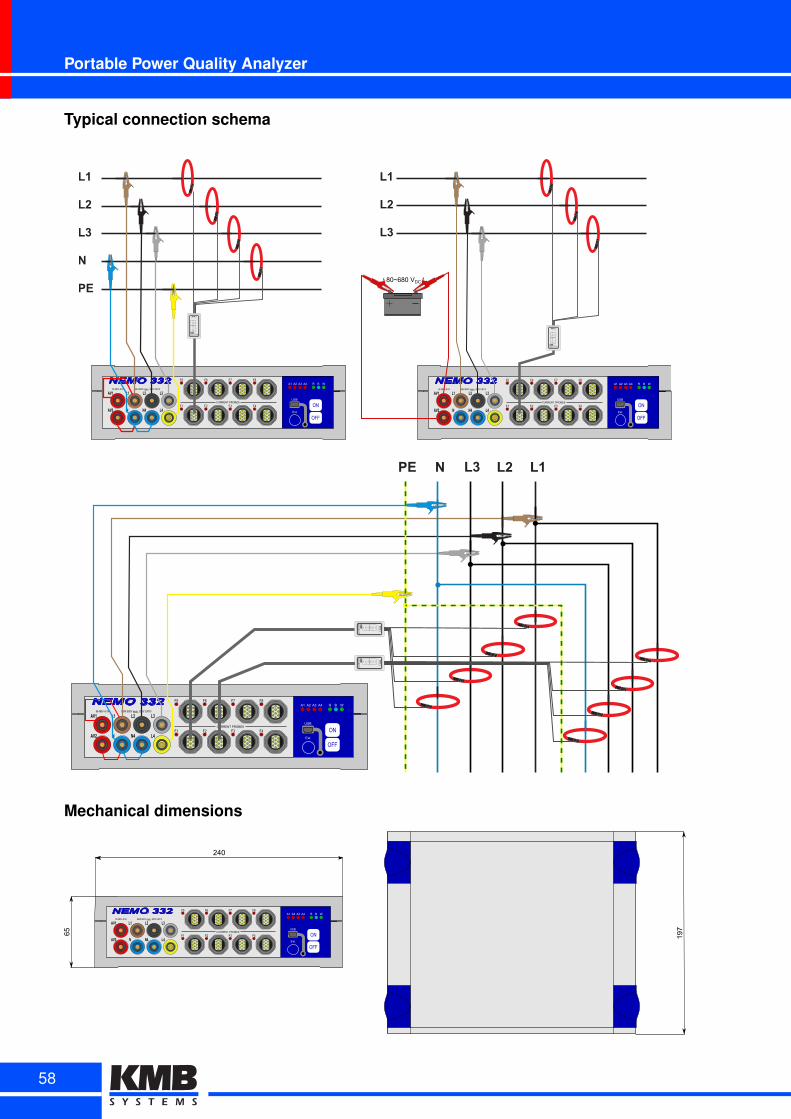
Portable Power Quality Analyzer
Typical connection schema
NEMO 332
ON
OFF
AV1 L1 L2 L3
AV2 N N4 L4
85-480V~87VA MAX7800V7RMS,7300V7CATIII
A1 A2 A3 A4 R B W
USB
Ext.
F1 F4F2 F3
F5 F8F6 F7
CURRENT7PROBES
100
300
1000
3000
NEMO 332
ON
OFF
AV1 L1 L2 L3
AV2 N N4 L4
85-480V~87VA MAX7800V7RMS,7300V7CATIII
A1 A2 A3 A4 R B W
USB
Ext.
F1 F4F2 F3
F5 F8F6 F7
CURRENT7PROBES
80~6807VDC
NEMO 332
ON
OFF
AV1 L1 L2 L3
AV2 N N4 L4
85-480V~87VA MAX7800V7RMS,7300V7CATIII
A1 A2 A3 A4 R B W
USB
Ext.
F1 F4F2 F3
F5 F8F6 F7
CURRENT7PROBES
100
300
1000
3000
Mechanical dimensions
NEMO 332
ON
OFF
AV1 L1 L2 L3
AV2 N N4 L4
85-480V~89VA MAX9800V9RMS,9300V9CATIII
A1 A2 A3 A4 R B W
USB
Ext.
240
65 197
F1 F4F2 F3
F5 F8F6 F7
CURRENT9PROBES
58

NEMO 104Compact power quality analyser
NEMO 104 is a modular analyzer of power quality. In the basic package it is intended for continuousmonitoring of four voltages and currents (in three phase AC networks). The device shares many featuresand parameters with its built-in predecessor SMPQ.Compared to the basic SIMON 341 line of analysers it can additionally evaluate flicker severity indexes,inter-harmonics and handles voltage measurement fully according to IEC EN 61000-4-30 ed. 2. The powerquality in NEMO 104 is evaluated according to EN 50160. It also records voltage events and other pre-defined phenomena. Its ultra compact case and IP50 case is making this monitor an ideal choice formeasurements in rough space limited environments.
Key features:
• 4 voltage inputs, 4 current inputs
• ultra compact housing with silicone protectors
• class S power monitoring according to the international standard IEC 61000-4-30, ed. 2.
• power quality evaluation according to EN 50160
• supply voltage separated from measured
• built-in lithium accumulator to cover power outages
• internal memory for archives with capacity of 512 MB
• USB communication interface and optional WiFi interface
59
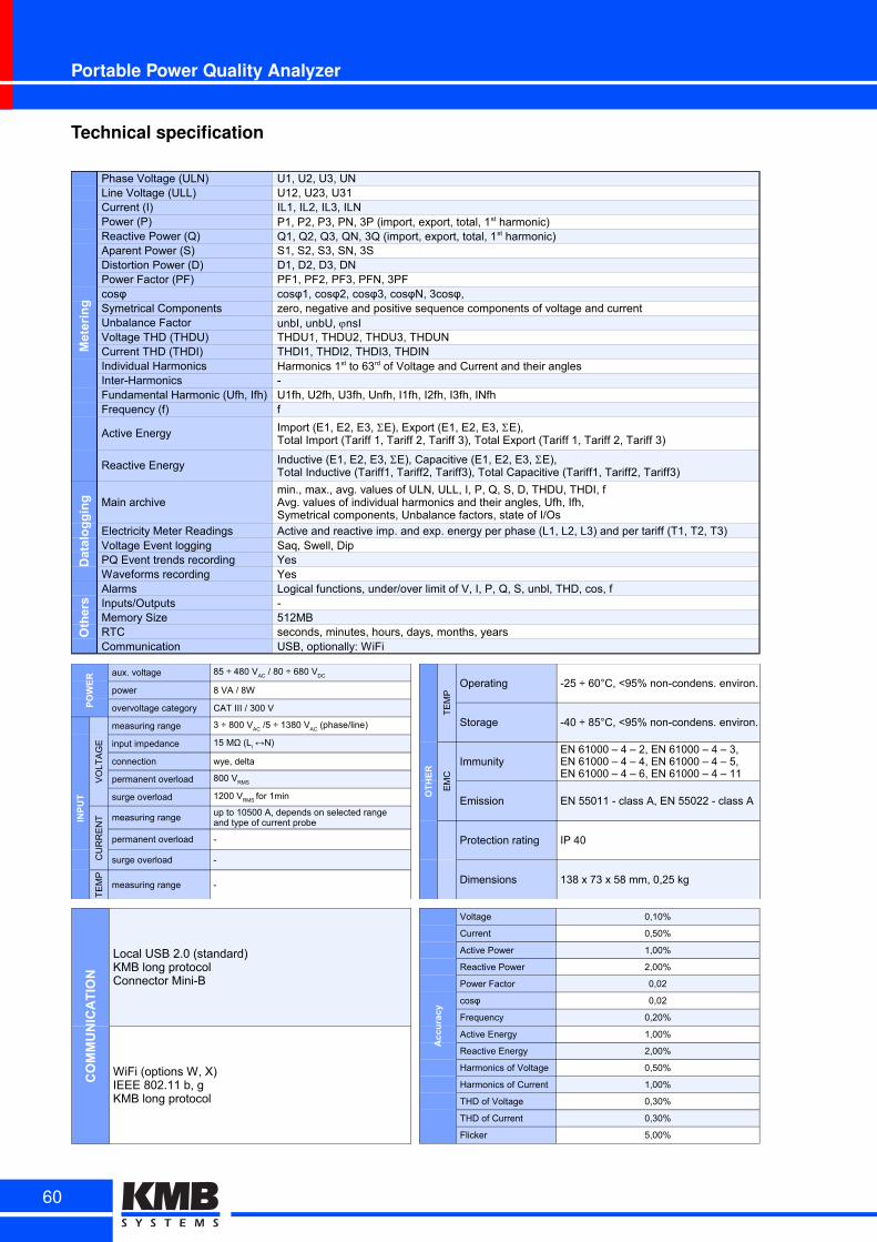
Portable Power Quality Analyzer
Technical specification
Metering
Phase Voltage (ULN) U1, U2, U3, UNLine Voltage (ULL) U12, U23, U31Current (I) IL1, IL2, IL3, ILNPower (P)Reactive Power (Q)Aparent Power (S) S1, S2, S3, SN, 3SDistortion Power (D) D1, D2, D3, DNPower Factor (PF) PF1, PF2, PF3, PFN, 3PFcosφ cosφ1, cosφ2, cosφ3, cosφN, 3cosφ, Symetrical Components zero, negative and positive sequence components of voltage and currentUnbalance FactorVoltage THD (THDU) THDU1, THDU2, THDU3, THDUNCurrent THD (THDI) THDI1, THDI2, THDI3, THDINIndividual HarmonicsInter-Harmonics -Fundamental Harmonic (Ufh, Ifh) U1fh, U2fh, U3fh, Unfh, I1fh, I2fh, I3fh, INfhFrequency (f) f
Active Energy
Reactive Energy
Datalogging Main archive
Electricity Meter Readings Active and reactive imp. and exp. energy per phase (L1, L2, L3) and per tariff (T1, T2, T3)Voltage Event logging Saq, Swell, DipPQ Event trends recording YesWaveforms recording Yes
Others
Alarms Logical functions, under/over limit of V, I, P, Q, S, unbl, THD, cos, fInputs/Outputs -Memory Size 512MBRTC seconds, minutes, hours, days, months, yearsCommunication USB, optionally: WiFi
P1, P2, P3, PN, 3P (import, export, total, 1st harmonic)Q1, Q2, Q3, QN, 3Q (import, export, total, 1st harmonic)
unbI, unbU, jnsI
Harmonics 1st to 63rd of Voltage and Current and their angles
Import (E1, E2, E3, SE), Export (E1, E2, E3, SE),Total Import (Tariff 1, Tariff 2, Tariff 3), Total Export (Tariff 1, Tariff 2, Tariff 3)
Inductive (E1, E2, E3, SE), Capacitive (E1, E2, E3, SE),Total Inductive (Tariff1, Tariff2, Tariff3), Total Capacitive (Tariff1, Tariff2, Tariff3)
min., max., avg. values of ULN, ULL, I, P, Q, S, D, THDU, THDI, fAvg. values of individual harmonics and their angles, Ufh, Ifh,Symetrical components, Unbalance factors, state of I/Os
POWER aux. voltage
power 8 VA / 8W
overvoltage category CAT III / 300 V
INPUT
VO
LTA
GE
measuring range
input impedance
connection wye, delta
permanent overload
surge overload
CU
RR
EN
T measuring range
permanent overload -
surge overload -
TE
MP
measuring range -
85 ÷ 480 VAC
/ 80 ÷ 680 VDC
3 ÷ 800 VAC
/5 ÷ 1380 VAC
(phase/line)
15 MΩ (Li ↔N)
800 VRMS
1200 VRMS
for 1min
up to 10500 A, depends on selected rangeand type of current probe
OTHER
TE
MP
Operating -25 ÷ 60°C, <95% non-condens. environ.
Storage -40 ÷ 85°C, <95% non-condens. environ.
EM
C
Immunity
Emission EN 55011 - class A, EN 55022 - class A
Protection rating IP 40
Dimensions 138 x 73 x 58 mm, 0,25 kg
EN 61000 – 4 – 2, EN 61000 – 4 – 3,EN 61000 – 4 – 4, EN 61000 – 4 – 5,EN 61000 – 4 – 6, EN 61000 – 4 – 11
COMMUNICATION
Local USB 2.0 (standard)KMB long protocolConnector Mini-B
WiFi (options W, X)IEEE 802.11 b, gKMB long protocol
Accuracy
Voltage 0,10%
Current 0,50%
Active Power 1,00%
Reactive Power 2,00%
Power Factor 0,02
cosφ 0,02
Frequency 0,20%
Active Energy 1,00%
Reactive Energy 2,00%
Harmonics of Voltage 0,50%
Harmonics of Current 1,00%
THD of Voltage 0,30%
THD of Current 0,30%
Flicker 5,00%
60
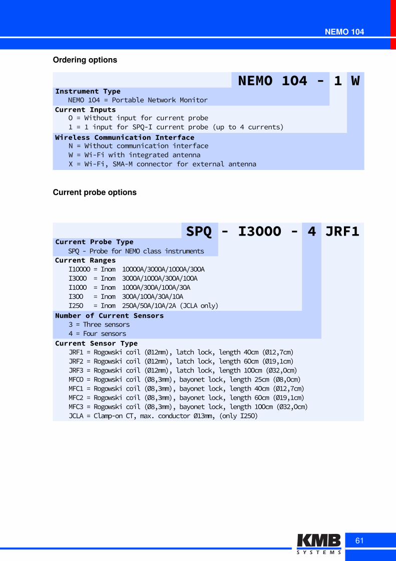
NEMO 104
Ordering options
Wireless Communication InterfaceN4=4Without4communication4interfaceW4=4Wi-Fi4with4integrated4antennaX4=4Wi-Fi,4SMA-M4connector4for4external4antenna
NEMO 1O4 - 1 WInstrument Type
Current InputsNEMO41O44=4Portable4Network4Monitor
O4=4Without4input4for4current4probe14=414input4for4SPQ-I4current4probe4sup4to444currents)
Current probe options
SPQ - I3OOO - 4 JRF1Current Probe Type
Current RangesSPQ(k(Probe(for(NEMO(class(instruments
I6OOOO(=(Inom((6OOOOA,8OOOA,6OOOA,8OOAI8OOO((=(Inom((8OOOA,6OOOA,8OOA,6OOAI6OOO((=(Inom((6OOOA,8OOA,6OOA,8OAI8OO(((=(Inom((8OOA,6OOA,8OA,6OAI9xO(((=(Inom((9xOA,xOA,6OA,9A(4JCLA(onlyF
Number of Current Sensors8(=(Three(sensorsp(=(Four(sensors
Current Sensor TypeJRF6(=(Rogowski(coil(4Ø69mmFw(latch(lockw(length(pOcm(4Ø69wdcmFJRF9(=(Rogowski(coil(4Ø69mmFw(latch(lockw(length(.Ocm(4Ø69w6cmF(JRF8(=(Rogowski(coil(4Ø69mmFw(latch(lockw(length(6OOcm(4Ø89wOcmF(MFCO(=(Rogowski(coil(4Ø8w8mmFw(bayonet(lockw(length(9xcm(4Ø8wOcmF(MFC6(=(Rogowski(coil(4Ø8w8mmFw(bayonet(lockw(length(pOcm(4Ø69wdcmF(MFC9(=(Rogowski(coil(4Ø8w8mmFw(bayonet(lockw(length(.Ocm(4Ø69w6cmFMFC8(=(Rogowski(coil(4Ø8w8mmFw(bayonet(lockw(length(6OOcm(4Ø89wOcmFJCLA(=(Clampkon(CTw(maxØ(conductor(Ø68mmw(4only(I9xOF(
61
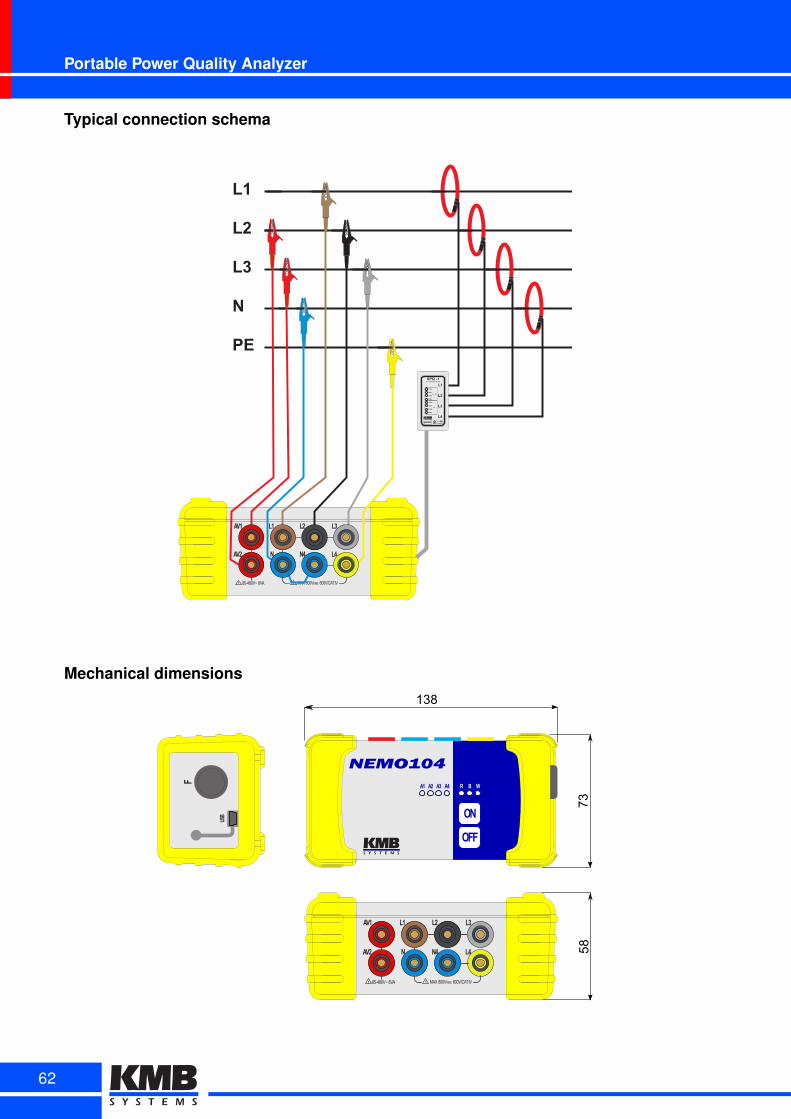
Portable Power Quality Analyzer
Typical connection schema
L4
L3
N4
L2
N
L1
AV2
AV1
MAX 800V 600V/CAT.IVRMS,!85-480V 8VA~!
Mechanical dimensions
L4
L3
N4
L2
N
L1
AV2
AV1
MAX 800V 600V/CAT.IVRMS,!85-480V 8VA~!
NEMO104
OFF
ON
A1 A2 A3 A4 R B W
USB
F
138
7358
62
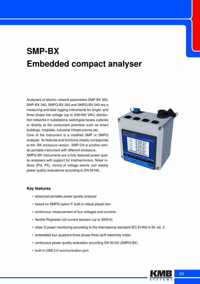
SMP-BXEmbedded compact analyser
Analysers of electric network parameters SMP-BX 300,SMP-BX 340, SMPQ-BX 300 and SMPQ-BX 340 are ameasuring and data logging instruments for single- andthree phase low voltage (up to 230/400 VAC) distribu-tion networks in substations, switchgear boxes, cubiclesor directly at the consumers premises such as smartbuildings, hospitals, industrial infrastructures etc.Core of the instrument is a modified SMP or SMPQanalyser. Its features and functions closely correspondsto the -BX enclosure version. SMP-CA is another simi-lar portable instrument with different enclosure.SMPQ-BX instruments are a fully featured power qual-ity analysers with support for interharmonics, flicker in-dices (Pst, Plt), record of voltage events and weeklypower quality evaluations according to EN 50160.
Key features
• advanced portable power quality analyzer
• based on SMPQ option F. built-in robust plastic box
• continuous measurement of four voltages and currents
• flexible Rogowski coil current sensors (up to 3000 A)
• class S power monitoring according to the international standard IEC 61000-4-30, ed. 2.
• embedded four quadrant three phase three tariff electricity meter
• continuous power quality evaluation according EN 50160 (SMPQ-BX)
• built-in USB 2.0 communication port
63
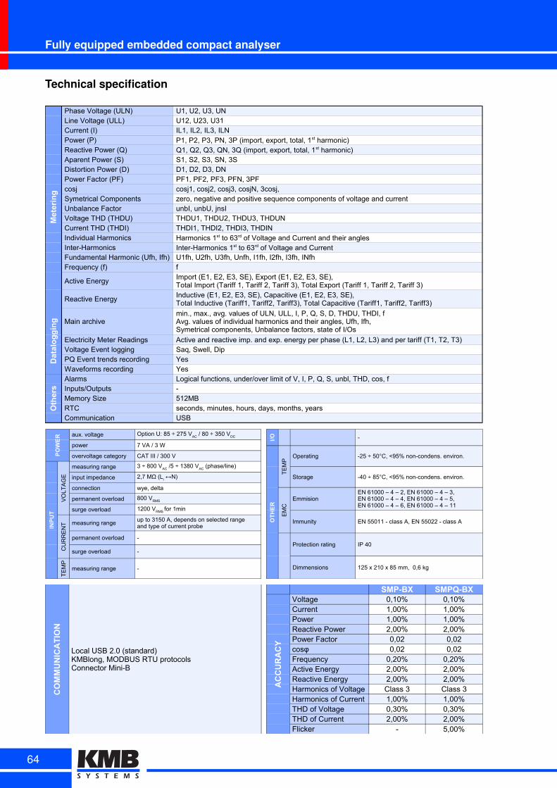
Fully equipped embedded compact analyser
Technical specification
Metering
Phase Voltage (ULN) U1, U2, U3, UNLine Voltage (ULL) U12, U23, U31Current (I) IL1, IL2, IL3, ILNPower (P)Reactive Power (Q)Aparent Power (S) S1, S2, S3, SN, 3SDistortion Power (D) D1, D2, D3, DNPower Factor (PF) PF1, PF2, PF3, PFN, 3PFcosj cosj1, cosj2, cosj3, cosjN, 3cosj, Symetrical Components zero, negative and positive sequence components of voltage and currentUnbalance Factor unbI, unbU, jnsIVoltage THD (THDU) THDU1, THDU2, THDU3, THDUNCurrent THD (THDI) THDI1, THDI2, THDI3, THDINIndividual HarmonicsInter-HarmonicsFundamental Harmonic (Ufh, Ifh) U1fh, U2fh, U3fh, Unfh, I1fh, I2fh, I3fh, INfhFrequency (f) f
Active Energy
Reactive Energy
Datalogging Main archive
Electricity Meter Readings Active and reactive imp. and exp. energy per phase (L1, L2, L3) and per tariff (T1, T2, T3)Voltage Event logging Saq, Swell, DipPQ Event trends recording YesWaveforms recording Yes
Others
Alarms Logical functions, under/over limit of V, I, P, Q, S, unbl, THD, cos, fInputs/Outputs -Memory Size 512MBRTC seconds, minutes, hours, days, months, yearsCommunication USB
P1, P2, P3, PN, 3P (import, export, total, 1st harmonic)Q1, Q2, Q3, QN, 3Q (import, export, total, 1st harmonic)
Harmonics 1st to 63rd of Voltage and Current and their anglesInter-Harmonics 1st to 63rd of Voltage and Current
Import (E1, E2, E3, SE), Export (E1, E2, E3, SE),Total Import (Tariff 1, Tariff 2, Tariff 3), Total Export (Tariff 1, Tariff 2, Tariff 3)Inductive (E1, E2, E3, SE), Capacitive (E1, E2, E3, SE),Total Inductive (Tariff1, Tariff2, Tariff3), Total Capacitive (Tariff1, Tariff2, Tariff3)
min., max., avg. values of ULN, ULL, I, P, Q, S, D, THDU, THDI, fAvg. values of individual harmonics and their angles, Ufh, Ifh,Symetrical components, Unbalance factors, state of I/Os
POWER aux. voltage
power 7 VA / 3 W
overvoltage category CAT III / 300 V
INPUT
VO
LT
AG
E
measuring range
input impedance
connection wye, delta
permanent overload
surge overload
CU
RR
EN
T measuring range
permanent overload -
surge overload -
TE
MP
measuring range -
Option U: 85 ÷ 275 VAC
/ 80 ÷ 350 VDC
3 ÷ 800 VAC
/5 ÷ 1380 VAC
(phase/line)
2,7 MΩ (Li ↔N)
800 VRMS
1200 VRMS
for 1min
up to 3150 A, depends on selected rangeand type of current probe
I/O -
OTHER
TE
MP
Operating -25 ÷ 50°C, <95% non-condens. environ.
Storage -40 ÷ 85°C, <95% non-condens. environ.
EM
C
Emmision
Immunity EN 55011 - class A, EN 55022 - class A
Protection rating IP 40
Dimmensions 125 x 210 x 85 mm, 0,6 kg
EN 61000 – 4 – 2, EN 61000 – 4 – 3,EN 61000 – 4 – 4, EN 61000 – 4 – 5,EN 61000 – 4 – 6, EN 61000 – 4 – 11
COMMUNICATION
Local USB 2.0 (standard)KMBlong, MODBUS RTU protocolsConnector Mini-B
SMP-BX SMPQ-BX
ACCURACY
Voltage 0,10% 0,10%Current 1,00% 1,00%Power 1,00% 1,00%Reactive Power 2,00% 2,00%Power Factor 0,02 0,02cosφ 0,02 0,02Frequency 0,20% 0,20%Active Energy 2,00% 2,00%Reactive Energy 2,00% 2,00%Harmonics of Voltage Class 3 Class 3Harmonics of Current 1,00% 1,00%THD of Voltage 0,30% 0,30%THD of Current 2,00% 2,00%Flicker - 5,00%
64
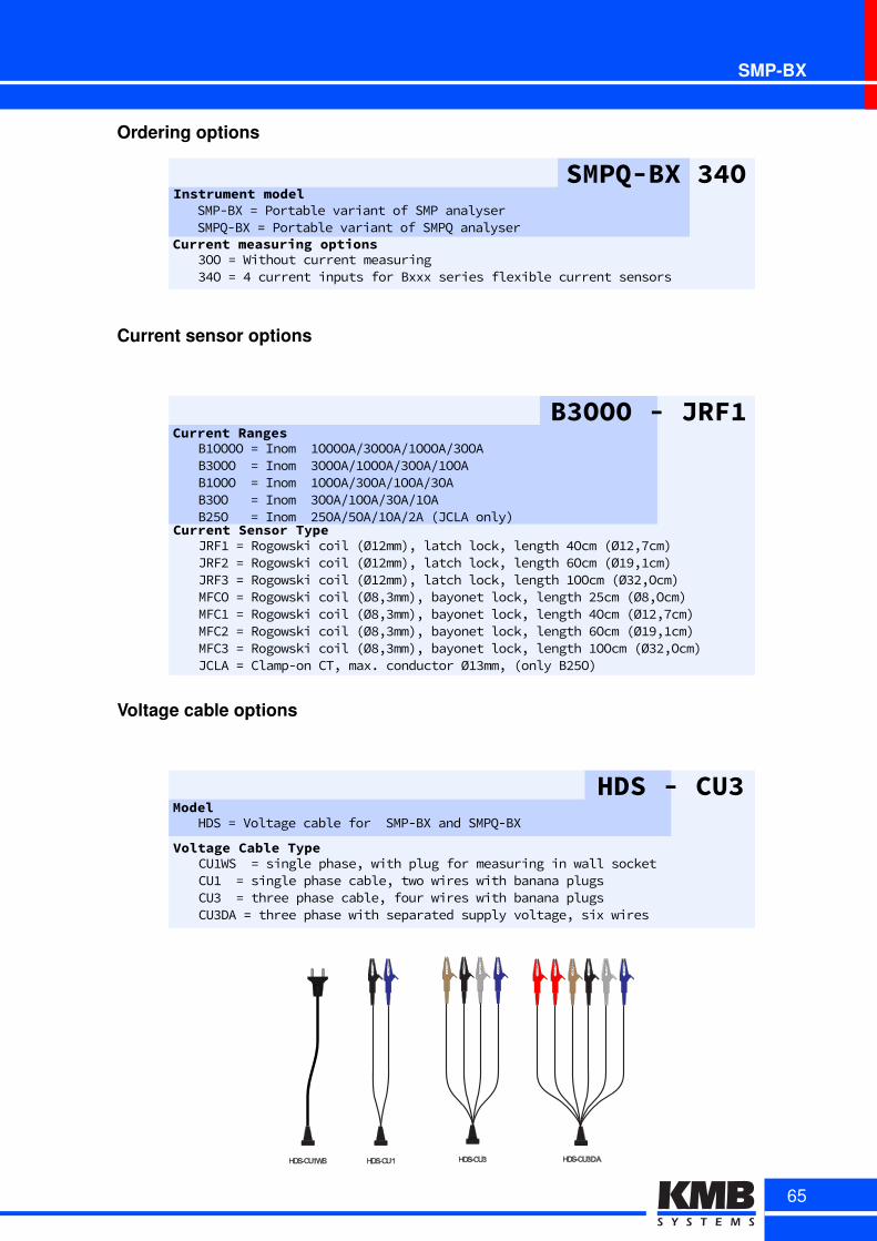
SMP-BX
Ordering options
SMPQ-BX 34OInstrument model
Current measuring options
SMP-BXp=pPortablepvariantpofpSMPpanalyserSMPQ-BXp=pPortablepvariantpofpSMPQpanalyser
3OOp=pWithoutpcurrentpmeasuring34Op=p4pcurrentpinputspforpBxxxpseriespflexiblepcurrentpsensors
Current sensor options
B3OOO - JRF1Current Ranges
BuOOOOa=aInomaauOOOOA.3OOOA.uOOOA.3OOAB3OOOaa=aInomaa3OOOA.uOOOA.3OOA.uOOABuOOOaa=aInomaauOOOA.3OOA.uOOA.3OAB3OOaaa=aInomaa3OOA.uOOA.3OA.uOABr5Oaaa=aInomaar5OA.5OA.uOA.rAaMJCLAaonly8
Current Sensor TypeJRFua=aRogowskiacoilaMØurmm8-alatchalock-alengtha4OcmaMØur-7cm8JRFra=aRogowskiacoilaMØurmm8-alatchalock-alengtha6OcmaMØu9-ucm8aJRF3a=aRogowskiacoilaMØurmm8-alatchalock-alengthauOOcmaMØ3r-Ocm8aMFCOa=aRogowskiacoilaMØ8-3mm8-abayonetalock-alengthar5cmaMØ8-Ocm8aMFCua=aRogowskiacoilaMØ8-3mm8-abayonetalock-alengtha4OcmaMØur-7cm8aMFCra=aRogowskiacoilaMØ8-3mm8-abayonetalock-alengtha6OcmaMØu9-ucm8MFC3a=aRogowskiacoilaMØ8-3mm8-abayonetalock-alengthauOOcmaMØ3r-Ocm8JCLAa=aClampTonaCT-amaxxaconductoraØu3mm-aMonlyaBr5O8a
Voltage cable options
HDS - CU3Model
HDSh=hVoltagehcablehforhhSMP-BXhandhSMPQ-BX
Voltage Cable TypeCU1WShh=hsinglehphase,hwithhplughforhmeasuringhinhwallhsockethCU1hh=hsinglehphasehcable,htwohwireshwithhbananahplugshCU3hh=hthreehphasehcable,hfourhwireshwithhbananahplugsCU3DAh=hthreehphasehwithhseparatedhsupplyhvoltage,hsixhwires
HDS-CU3 HDS-CU3DAHDS-CU1HDS-CU1WS
65
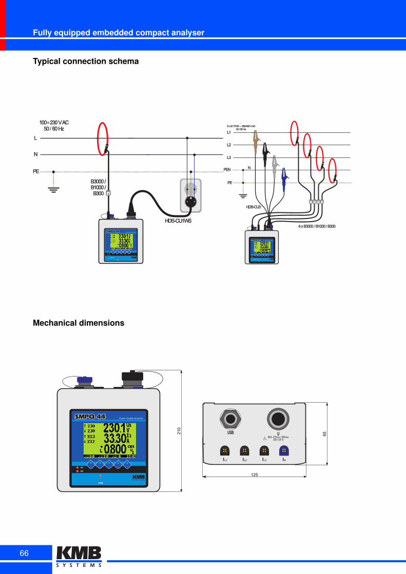
Fully equipped embedded compact analyser
Typical connection schema
B3000
L
PE
N
100 230 V AC50 / 60 Hz÷
HDS-CU1WS
B3000 /B1000 /B300
B3000 B3000 B3000 B3000
L1
L2
L3
PE
PEN N
3 x 57.7/100 230/400 V AC50 / 60 Hz÷
HDS-CU3
4 x B3000 / B1000 / B300
Mechanical dimensions
MAX. 275VRMS / 800VRMS300V CAT III
L1I L2I L3I NI
USB
RMS
U
125
65210
66

SMP-CAPortable analyser in case
SMP-CA power quality analyzer is a programmable measuringand data logging set for measurement in LV distribution grids.It can be used in transformer stations, low voltage switchgearboxes or directly at consumers. SMPQ44-FT/4 panel instru-ment built in a plastic case is heart of the set. The SMP-CAanalyser uses SMP line as a core instrument base and sharesmost of its functionality.Standard set contains voltage cables with croco-clips, powercord and USB communication cable. Optional accessoriescomprise current sensors, temperature sensor, connectionadapters etc.
Key features
• advanced portable power quality analyzer
• based on SMPQ option F built-in robust plastic case
• continuous measurement of four voltages and currents
• flexible Rogowski coil current sensors (up to 3000 A)
• class S power monitoring according to the international standard IEC 61000-4-30, ed. 2.
• embedded four quadrant three phase three tariff electricity meter
• continuous power quality evaluation according EN 50160 (SMPQ)
• fully configurable inputs and outputs
• built-in USB 2.0 port with optional remote communication interface like RS 485 or Ethernet
67
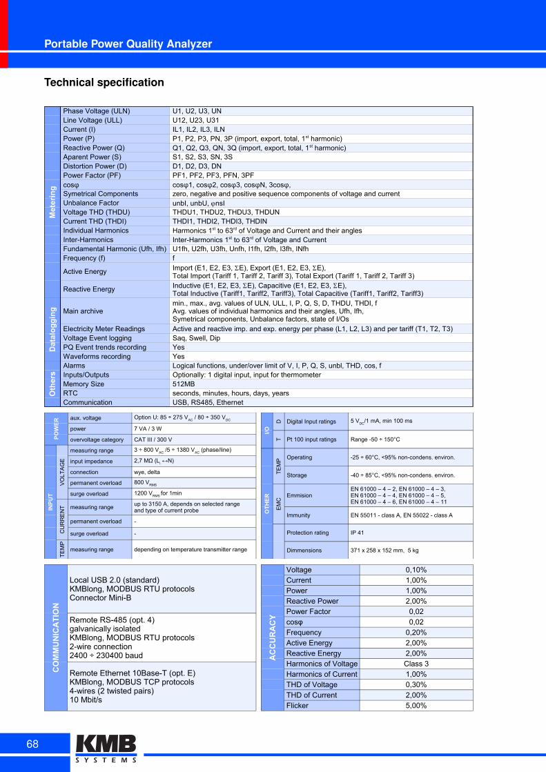
Portable Power Quality Analyzer
Technical specification
Metering
Phase Voltage (ULN) U1, U2, U3, UNLine Voltage (ULL) U12, U23, U31Current (I) IL1, IL2, IL3, ILNPower (P)Reactive Power (Q)Aparent Power (S) S1, S2, S3, SN, 3SDistortion Power (D) D1, D2, D3, DNPower Factor (PF) PF1, PF2, PF3, PFN, 3PF
Symetrical Components zero, negative and positive sequence components of voltage and currentUnbalance FactorVoltage THD (THDU) THDU1, THDU2, THDU3, THDUNCurrent THD (THDI) THDI1, THDI2, THDI3, THDINIndividual HarmonicsInter-HarmonicsFundamental Harmonic (Ufh, Ifh) U1fh, U2fh, U3fh, Unfh, I1fh, I2fh, I3fh, INfhFrequency (f) f
Active Energy
Reactive Energy
Datalogging Main archive
Electricity Meter Readings Active and reactive imp. and exp. energy per phase (L1, L2, L3) and per tariff (T1, T2, T3)Voltage Event logging Saq, Swell, DipPQ Event trends recording YesWaveforms recording Yes
Others
Alarms Logical functions, under/over limit of V, I, P, Q, S, unbl, THD, cos, fInputs/Outputs Optionally: 1 digital input, input for thermometerMemory Size 512MBRTC seconds, minutes, hours, days, yearsCommunication USB, RS485, Ethernet
P1, P2, P3, PN, 3P (import, export, total, 1st harmonic)Q1, Q2, Q3, QN, 3Q (import, export, total, 1st harmonic)
cosφ cosφ1, cosφ2, cosφ3, cosφN, 3cosφ,
unbI, unbU, jnsI
Harmonics 1st to 63rd of Voltage and Current and their anglesInter-Harmonics 1st to 63rd of Voltage and Current
Import (E1, E2, E3, SE), Export (E1, E2, E3, SE),Total Import (Tariff 1, Tariff 2, Tariff 3), Total Export (Tariff 1, Tariff 2, Tariff 3)Inductive (E1, E2, E3, SE), Capacitive (E1, E2, E3, SE),Total Inductive (Tariff1, Tariff2, Tariff3), Total Capacitive (Tariff1, Tariff2, Tariff3)min., max., avg. values of ULN, ULL, I, P, Q, S, D, THDU, THDI, fAvg. values of individual harmonics and their angles, Ufh, Ifh,Symetrical components, Unbalance factors, state of I/Os
POWER aux. voltage
power 7 VA / 3 W
overvoltage category CAT III / 300 V
INPUT
VO
LT
AG
E
measuring range
input impedance
connection wye, delta
permanent overload
surge overload
CU
RR
EN
T measuring range
permanent overload -
surge overload -
TE
MP
measuring range depending on temperature transmitter range
Option U: 85 ÷ 275 VAC
/ 80 ÷ 350 VDC
3 ÷ 800 VAC
/5 ÷ 1380 VAC
(phase/line)
2,7 MΩ (Li ↔N)
800 VRMS
1200 VRMS
for 1min
up to 3150 A, depends on selected rangeand type of current probe
I/O
D Digital Input ratings
T Pt 100 input ratings Range -50 ÷ 150°C
OTHER
TE
MP Operating -25 ÷ 60°C, <95% non-condens. environ.
Storage -40 ÷ 85°C, <95% non-condens. environ.
EM
C
Emmision
Immunity EN 55011 - class A, EN 55022 - class A
Protection rating IP 41
Dimmensions 371 x 258 x 152 mm, 5 kg
5 VDC
/1 mA, min 100 ms
EN 61000 – 4 – 2, EN 61000 – 4 – 3,EN 61000 – 4 – 4, EN 61000 – 4 – 5,EN 61000 – 4 – 6, EN 61000 – 4 – 11
COMMUNICATION
Local USB 2.0 (standard)KMBlong, MODBUS RTU protocolsConnector Mini-B
Remote RS-485 (opt. 4)galvanically isolatedKMBlong, MODBUS RTU protocols2-wire connection2400 ÷ 230400 baud
Remote Ethernet 10Base-T (opt. E)KMBlong, MODBUS TCP protocols4-wires (2 twisted pairs)10 Mbit/s
ACCURACY
Voltage 0,10%Current 1,00%Power 1,00%
Reactive Power 2,00%Power Factor 0,02
cosφ 0,02Frequency 0,20%
Active Energy 2,00%Reactive Energy 2,00%Harmonics of Voltage Class 3
Harmonics of Current 1,00%THD of Voltage 0,30%
THD of Current 2,00%Flicker 5,00%
68
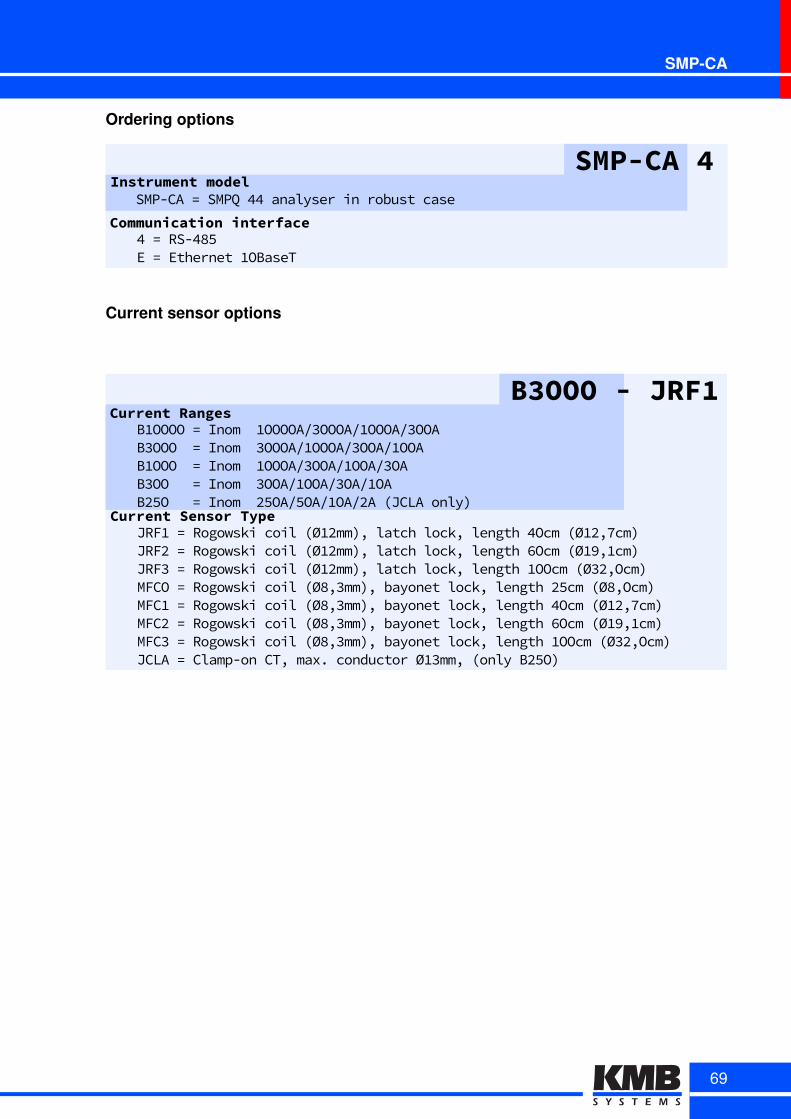
SMP-CA
Ordering options
SMP-CA 4Instrument model
Communication interface
SMP-CAT=TSMPQT44TanalyserTinTrobustTcase
4T=TRS-485ET=TEthernetT1OBaseT
Current sensor options
B3OOO - JRF1Current Ranges
BuOOOOa=aInomaauOOOOA.3OOOA.uOOOA.3OOAB3OOOaa=aInomaa3OOOA.uOOOA.3OOA.uOOABuOOOaa=aInomaauOOOA.3OOA.uOOA.3OAB3OOaaa=aInomaa3OOA.uOOA.3OA.uOABr5Oaaa=aInomaar5OA.5OA.uOA.rAaMJCLAaonly8
Current Sensor TypeJRFua=aRogowskiacoilaMØurmm8-alatchalock-alengtha4OcmaMØur-7cm8JRFra=aRogowskiacoilaMØurmm8-alatchalock-alengtha6OcmaMØu9-ucm8aJRF3a=aRogowskiacoilaMØurmm8-alatchalock-alengthauOOcmaMØ3r-Ocm8aMFCOa=aRogowskiacoilaMØ8-3mm8-abayonetalock-alengthar5cmaMØ8-Ocm8aMFCua=aRogowskiacoilaMØ8-3mm8-abayonetalock-alengtha4OcmaMØur-7cm8aMFCra=aRogowskiacoilaMØ8-3mm8-abayonetalock-alengtha6OcmaMØu9-ucm8MFC3a=aRogowskiacoilaMØ8-3mm8-abayonetalock-alengthauOOcmaMØ3r-Ocm8JCLAa=aClampTonaCT-amaxxaconductoraØu3mm-aMonlyaBr5O8a
69
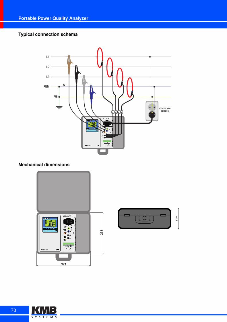
Portable Power Quality Analyzer
Typical connection schema
B3000 B3000 B3000 B3000
L1
L2
L3
PE
PEN N
100 230 V AC50 / 60 Hz÷
Mechanical dimensions
371
258
152
70

NEMO 101Single phase power quality data logger
NEMO 101 is a modular analyzer of power quality. Itsprimary purpose is easy measuring, monitoring anddatalogging of power quality directly in wall socket. Thedevice shares many features and parameters with itsbuilt-in predecessor SMPQ.Instrument may be connected directly between powersupply and measured device, Compared to the basicSIMON 341 line of analysers it can additionally evaluateflicker severity indexes, inter-harmonics and handlesvoltage measurement fully according to IEC EN 61000-4-30 ed. 2. The power quality in NEMO 101 is evaluatedaccording to EN 50160. It also records voltage eventsand other predefined phenomena.
Key features:
• 1 voltage and 1 current input, measures accroding to EN 61000-4-30 ed.2
• ultra compact housing with silicone protectors
• power quality evaluation according to EN 50160
• supply voltage separated from measured
• built-in lithium accumulator to cover power outages
• internal memory for archives with capacity of 512 MB
• USB communication interface and optional WiFi interface
71
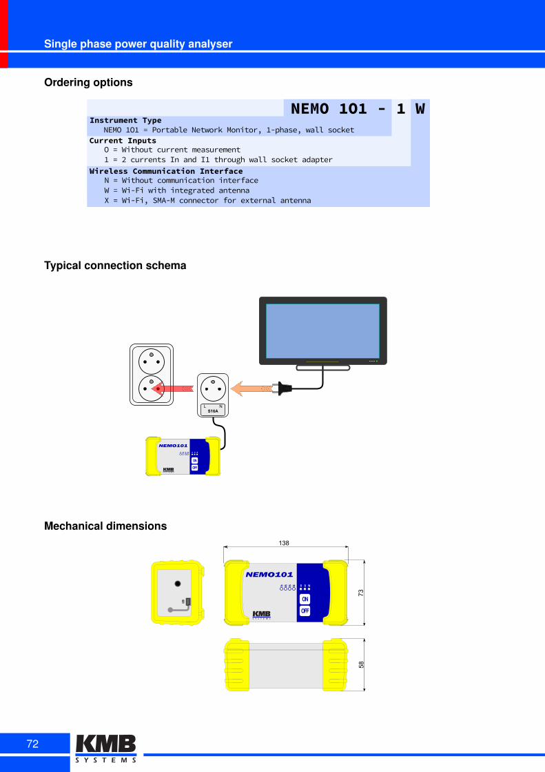
Single phase power quality analyser
Ordering options
Wireless Communication InterfaceNP=PWithoutPcommunicationPinterfaceWP=PWi-FiPwithPintegratedPantennaXP=PWi-Fi,PSMA-MPconnectorPforPexternalPantenna
NEMO 1O1 - 1 WInstrument Type
Current InputsNEMOP1O1P=PPortablePNetworkPMonitor,P1-phase,PwallPsocket
OP=PWithoutPcurrentPmeasurement1P=P2PcurrentsPInPandPI1PthroughPwallPsocketPadapter
Typical connection schema
NEMO101
OFF
ON
A1 A2 A3 A4 R B W
S16AL N
Mechanical dimensions
NEMO101
OFF
ON
A1 A2 A3 A4 R B W
USB
138
7358
72
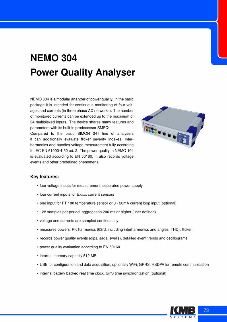
NEMO 304Power Quality Analyser
NEMO 304 is a modular analyzer of power quality. In the basicpackage it is intended for continuous monitoring of four volt-ages and currents (in three phase AC networks). The numberof monitored currents can be extended up to the maximum of24 multiplexed inputs. The device shares many features andparameters with its built-in predecessor SMPQ.Compared to the basic SIMON 341 line of analysersit can additionally evaluate flicker severity indexes, inter-harmonics and handles voltage measurement fully accordingto IEC EN 61000-4-30 ed. 2. The power quality in NEMO 104is evaluated according to EN 50160. it also records voltageevents and other predefined phenomena.
Key features:
• four voltage inputs for measurement, separated power supply
• four current inputs for Bxxxx current sensors
• one input for PT 100 temperature sensor or 0 - 20mA current loop input (optional)
• 128 samples per period, aggregation 200 ms or higher (user defined)
• voltage and currents are sampled continuously
• measures powers, PF, harmonics (63rd, including interharmonics and angles, THD), flicker...
• records power quality events (dips, sags, swells), detailed event trends and oscillograms
• power quality evaluation according to EN 50160
• internal memory capacity 512 MB
• USB for configuration and data acquisition, optionally WiFi, GPRS, HSDPA for remote communication
• internal battery backed real time clock, GPS time synchronization (optional)
73

Fully equipped embedded analyser
Technical specification
Metering
Phase Voltage (ULN) U1, U2, U3, UNLine Voltage (ULL) U12, U23, U31Current (I) IL1, IL2, IL3, ILNPower (P)Reactive Power (Q)Aparent Power (S) S1, S2, S3, SN, 3SDistortion Power (D) D1, D2, D3, DNPower Factor (PF) PF1, PF2, PF3, PFN, 3PF
Symetrical Components zero, negative and positive sequence components of voltage and currentUnbalance FactorVoltage THD (THDU) THDU1, THDU2, THDU3, THDUNCurrent THD (THDI) THDI1, THDI2, THDI3, THDINIndividual HarmonicsInter-Harmonics -Fundamental Harmonic (Ufh, Ifh) U1fh, U2fh, U3fh, Unfh, I1fh, I2fh, I3fh, INfhFrequency (f) f
Active Energy
Reactive Energy
Datalogging Main archive
Electricity Meter Readings Active and reactive imp. and exp. energy per phase (L1, L2, L3) and per tariff (T1, T2, T3)Voltage Event logging Saq, Swell, DipPQ Event trends recording YesWaveforms recording Yes
Others
Alarms Logical functions, under/over limit of V, I, P, Q, S, unbl, THD, cos, fInputs/Outputs Optionally: input for thermometer or analog inputMemory Size 512MBRTC seconds, minutes, hours, days, months, yearsCommunication USB, optionally: WiFi, GPRS, HSDPA/UMTS
P1, P2, P3, PN, 3P (import, export, total, 1st harmonic)Q1, Q2, Q3, QN, 3Q (import, export, total, 1st harmonic)
cosφ cosφ1, cosφ2, cosφ3, cosφN, 3cosφ
unbI, unbU, φnsI
Harmonics 1st to 63rd of Voltage and Current and their angles
Import (E1, E2, E3, SE), Export (E1, E2, E3, SE),Total Import (Tariff 1, Tariff 2, Tariff 3), Total Export (Tariff 1, Tariff 2, Tariff 3)
Inductive (E1, E2, E3, SE), Capacitive (E1, E2, E3, SE),Total Inductive (Tariff1, Tariff2, Tariff3), Total Capacitive (Tariff1, Tariff2, Tariff3)
min., max., avg. values of ULN, ULL, I, P, Q, S, D, THDU, THDI, fAvg. values of individual harmonics and their angles, Ufh, Ifh,Symetrical components, Unbalance factors, state of I/Os
POWER aux. voltage
power 8 VA / 8W
overvoltage category CAT III / 300 V
INPUT
VO
LT
AG
E
measuring range
input impedance
connection wye, delta
permanent overload
surge overload
CU
RR
EN
T measuring range
permanent overload -
surge overload -
TE
MP
measuring range -50 ÷ 150 °C
85 ÷ 480 VAC
/ 80 ÷ 680 VDC
3 ÷ 800 VAC
/5 ÷ 1380 VAC
(phase/line)
15 MΩ (Li ↔N)
800 VRMS
1200 VRMS
for 1min
up to 3150 A, depends on selected rangeand type of current probe
I/O
A Analog input ratings
T Pt100 input ratings Range -50 ÷ 150°C
Digital input
OTHER
TE
MP Operating -25 ÷ 60°C, <95% non-condens. environ.
Storage -40 ÷ 85°C, <95% non-condens. environ.
EM
C Immunity
Emission EN 55011 - class A, EN 55022 - class A
Protection rating IP 40
Dimensions 250 x 210 x 65 mm, 1 kg
2 ÷ 22 mA, impedance 75 W
EN 61000 – 4 – 2, EN 61000 – 4 – 3,EN 61000 – 4 – 4, EN 61000 – 4 – 5,EN 61000 – 4 – 6, EN 61000 – 4 – 11
COMMUNICATION
Local USB 2.0 (standard)KMB long protocolConnector Mini-B
WiFi (options W, X)IEEE 802.11 b, gKMB long protocol
GPRS (option G)KMB long protocol
HSDPA/UMTS + GPS (option H)KMB long protocol
Accuracy
Voltage 0,10%
Current 0,50%
Active Power 1,00%
Reactive Power 2,00%
Power Factor 0,02
cosφ 0,02
Frequency 0,20%
Active Energy 1,00%
Reactive Energy 2,00%
Harmonics of Voltage 0,50%
Harmonics of Current 1,00%
THD of Voltage 0,30%
THD of Current 0,30%
Flicker 5,00%
74
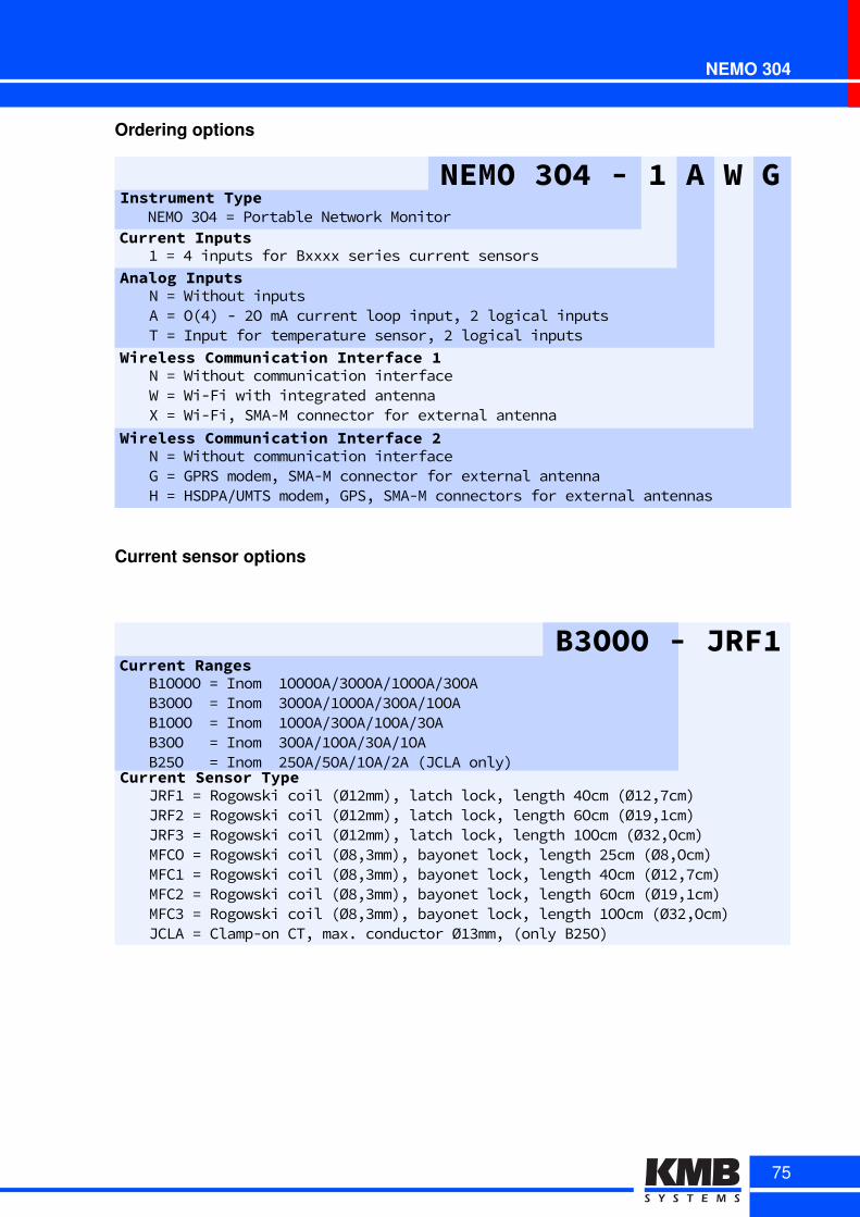
NEMO 304
Ordering options
Analog2InputsNM=MWithoutMinputsAM=MOx4FMGMUOMmAMcurrentMloopMinputSMUMlogicalMinputsTM=MInputMforMtemperatureMsensorSMUMlogicalMinputs
NEMO23O42-212A2W2GInstrument2Type
Current2InputsNEMOM3O4M=MPortableMNetworkMMonitor
/M=M4MinputsMforMBxxxxMseriesMcurrentMsensors
Wireless2Communication2Interface21NM=MWithoutMcommunicationMinterfaceWM=MWiGFiMwithMintegratedMantennaXM=MWiGFiSMSMAGMMconnectorMforMexternalMantenna
Wireless2Communication2Interface22NM=MWithoutMcommunicationMinterfaceGM=MGPRSMmodemSMSMAGMMconnectorMforMexternalMantennaHM=MHSDPAHUMTSMmodemSMGPSSMSMAGMMconnectorsMforMexternalMantennas
Current sensor options
B3OOO - JRF1Current Ranges
BuOOOOa=aInomaauOOOOA.3OOOA.uOOOA.3OOAB3OOOaa=aInomaa3OOOA.uOOOA.3OOA.uOOABuOOOaa=aInomaauOOOA.3OOA.uOOA.3OAB3OOaaa=aInomaa3OOA.uOOA.3OA.uOABr5Oaaa=aInomaar5OA.5OA.uOA.rAaMJCLAaonly8
Current Sensor TypeJRFua=aRogowskiacoilaMØurmm8-alatchalock-alengtha4OcmaMØur-7cm8JRFra=aRogowskiacoilaMØurmm8-alatchalock-alengtha6OcmaMØu9-ucm8aJRF3a=aRogowskiacoilaMØurmm8-alatchalock-alengthauOOcmaMØ3r-Ocm8aMFCOa=aRogowskiacoilaMØ8-3mm8-abayonetalock-alengthar5cmaMØ8-Ocm8aMFCua=aRogowskiacoilaMØ8-3mm8-abayonetalock-alengtha4OcmaMØur-7cm8aMFCra=aRogowskiacoilaMØ8-3mm8-abayonetalock-alengtha6OcmaMØu9-ucm8MFC3a=aRogowskiacoilaMØ8-3mm8-abayonetalock-alengthauOOcmaMØ3r-Ocm8JCLAa=aClampTonaCT-amaxxaconductoraØu3mm-aMonlyaBr5O8a
75
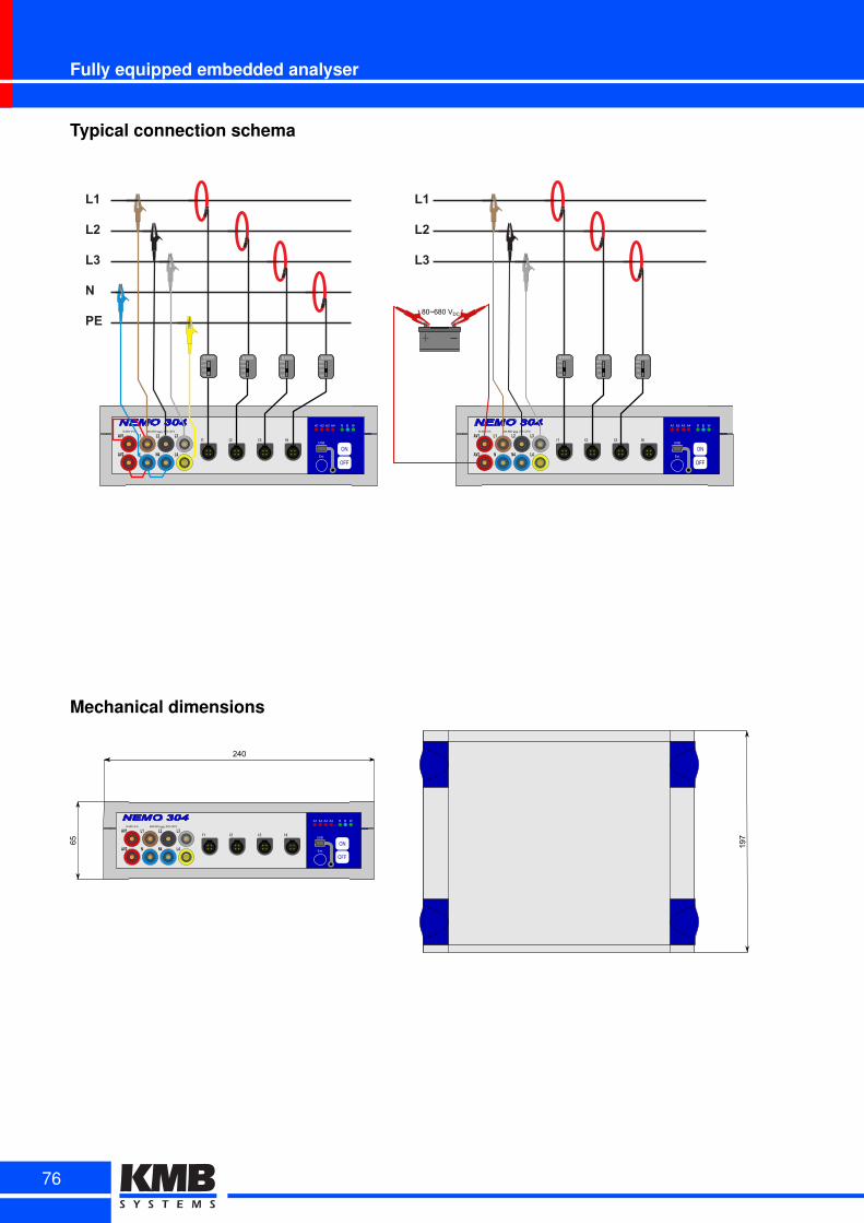
Fully equipped embedded analyser
Typical connection schema
NEMO 304
ON
OFF
AV1 L1 L2 L3
AV2 N N4 L4
85-480V~8 VA MAX 800V RMS, 300V CATIII
A1 A2 A3 A4 R B W
USB
Ext.
I1 I2 I3 I4
B3000
100
300
1000
3000B3000
100
300
1000
3000B3000
100
300
1000
3000B3000
100
300
1000
3000
NEMO 304
ON
OFF
AV1 L1 L2 L3
AV2 N N4 L4
85-480V~8DVA MAXD800VDRMS,D300VDCATIII
A1 A2 A3 A4 R B W
USB
Ext.
I1 I2 I3 I4
B3000
100
300
1000
3000B3000
100
300
1000
3000B3000
100
300
1000
3000
80~680DVDC
Mechanical dimensions
NEMO 304
ON
OFF
AV1 L1 L2 L3
AV2 N N4 L4
85-480V~89VA MAX9800V9RMS,9300V9CATIII
A1 A2 A3 A4 R B W
USB
Ext.
I1 I2 I3 I4
240
65 197
76
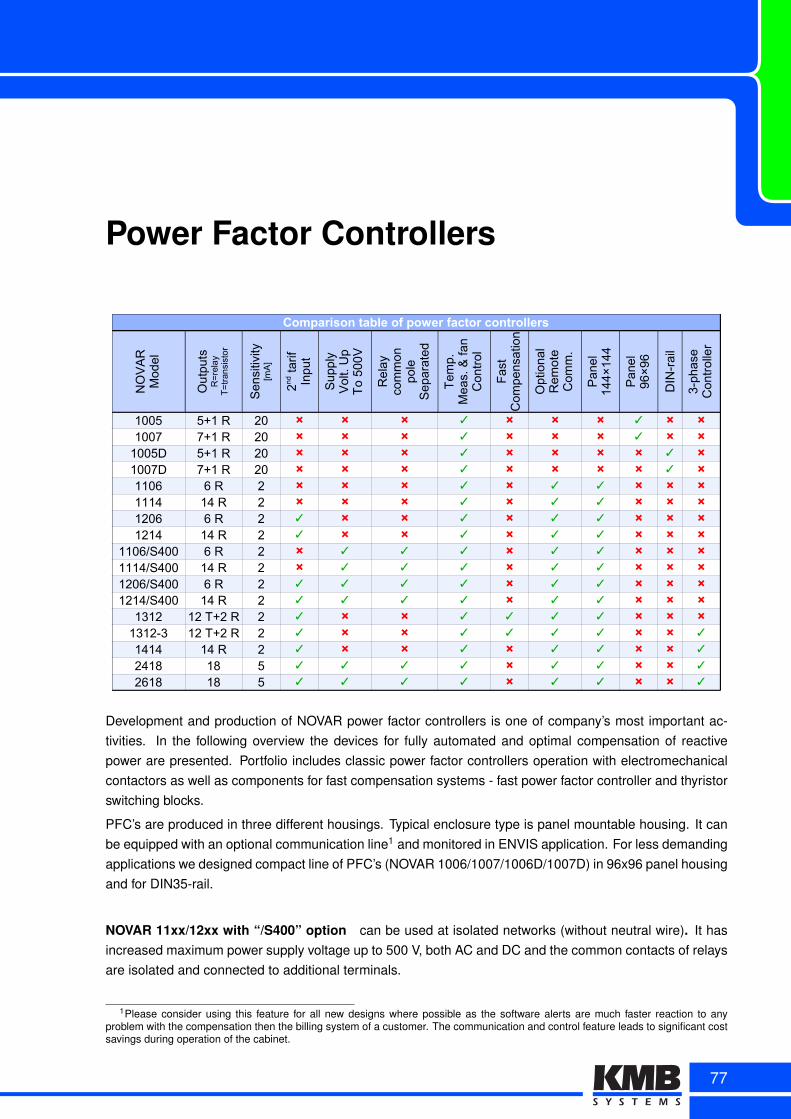
Power Factor Controllers
Comparison table of power factor controllers
DIN
-rai
l
1005 5+1 R 20 × × × ✓ × × × ✓ × ×1007 7+1 R 20 × × × ✓ × × × ✓ × ×
1005D 5+1 R 20 × × × ✓ × × × × ✓ ×1007D 7+1 R 20 × × × ✓ × × × × ✓ ×1106 6 R 2 × × × ✓ × ✓ ✓ × × ×1114 14 R 2 × × × ✓ × ✓ ✓ × × ×1206 6 R 2 ✓ × × ✓ × ✓ ✓ × × ×1214 14 R 2 ✓ × × ✓ × ✓ ✓ × × ×
1106/S400 6 R 2 × ✓ ✓ ✓ × ✓ ✓ × × ×1114/S400 14 R 2 × ✓ ✓ ✓ × ✓ ✓ × × ×1206/S400 6 R 2 ✓ ✓ ✓ ✓ × ✓ ✓ × × ×1214/S400 14 R 2 ✓ ✓ ✓ ✓ × ✓ ✓ × × ×
1312 12 T+2 R 2 ✓ × × ✓ ✓ ✓ ✓ × × ×1312-3 12 T+2 R 2 ✓ × × ✓ ✓ ✓ ✓ × × ✓1414 14 R 2 ✓ × × ✓ × ✓ ✓ × × ✓2418 18 5 ✓ ✓ ✓ ✓ × ✓ ✓ × × ✓2618 18 5 ✓ ✓ ✓ ✓ × ✓ ✓ × × ✓
NO
VA
RM
odel
Ou
tput
sR
=re
lay
T=
tran
sist
or
Sen
sitiv
ity[m
A]
2nd t
arif
Inpu
t
Sup
ply
Vol
t. U
pT
o 50
0V
Rel
ayco
mm
onpo
leS
epar
ated
Tem
p.M
eas.
& f
anC
ontr
ol
Fas
tC
ompe
nsat
ion
Opt
iona
lR
emot
eC
omm
.
Pan
el14
4×14
4
Pan
el96
×96
3-ph
ase
Con
trol
ler
Development and production of NOVAR power factor controllers is one of company’s most important ac-tivities. In the following overview the devices for fully automated and optimal compensation of reactivepower are presented. Portfolio includes classic power factor controllers operation with electromechanicalcontactors as well as components for fast compensation systems - fast power factor controller and thyristorswitching blocks.
PFC’s are produced in three different housings. Typical enclosure type is panel mountable housing. It canbe equipped with an optional communication line1 and monitored in ENVIS application. For less demandingapplications we designed compact line of PFC’s (NOVAR 1006/1007/1006D/1007D) in 96x96 panel housingand for DIN35-rail.
NOVAR 11xx/12xx with “/S400” option can be used at isolated networks (without neutral wire). It hasincreased maximum power supply voltage up to 500 V, both AC and DC and the common contacts of relaysare isolated and connected to additional terminals.
1Please consider using this feature for all new designs where possible as the software alerts are much faster reaction to anyproblem with the compensation then the billing system of a customer. The communication and control feature leads to significant costsavings during operation of the cabinet.
77

Overview of power factor controllers
Measurement Principles
• high current and power factor measurement accuracy are achieved by utilizing precise converter anddigital signal processing using a microprocessor and FFT algorithm
• precise measurement and control functions even under conditions of voltage or current waveformdistortion by higher harmonic components
• evaluation of total harmonic distortion (THD) level by up to the nineteenth harmonic component
• evaluation of current harmonic load of capacitors
Control Principles
• governor’s speed of response independently programmable for conditions of under-compensation andovercompensation, respectively
• adjustable control range to reduce the number of control interventions in systems with a wide controlrange at high loads
• mains decompensation option
• two-rate operation controlled by energy flow direction
• any output can be set as fixed, heating, cooling or alarm can also be controlled via relays
Automatic Connection Detection
• any combination of measuring voltage and current
• automatic detection of connection and compensation systems, nominal voltage on governor setup
Automatic Control Section Recognition
• when switching it on, the governor automatically recognizes the sections power ratings
• it is possible to connect any combination of the control sections
Specifying Section Value, Disabling Faulty Sections
• continuous specification of section value recognized in the control process
• continuous checking of control sections in the control process and in case of repeated failure detec-tion, temporary disablement of the faulty section and possibly concurrent alarm actuation
• periodic recheck of the temporarily disabled sections in five days and on positive test results (forexample when replacing a section’s burnt fuse link), enabling them again
Programmable Alarm
• independently settable alarm’s warning and actuation functions
78
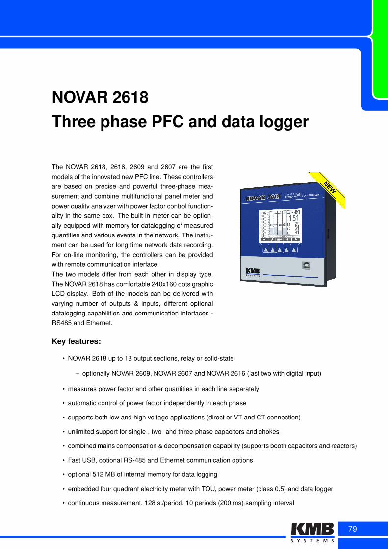
NOVAR 2618Three phase PFC and data logger
The NOVAR 2618, 2616, 2609 and 2607 are the firstmodels of the innovated new PFC line. These controllersare based on precise and powerful three-phase mea-surement and combine multifunctional panel meter andpower quality analyzer with power factor control function-ality in the same box. The built-in meter can be option-ally equipped with memory for datalogging of measuredquantities and various events in the network. The instru-ment can be used for long time network data recording.For on-line monitoring, the controllers can be providedwith remote communication interface.The two models differ from each other in display type.The NOVAR 2618 has comfortable 240x160 dots graphicLCD-display. Both of the models can be delivered withvarying number of outputs & inputs, different optionaldatalogging capabilities and communication interfaces -RS485 and Ethernet.
Key features:
• NOVAR 2618 up to 18 output sections, relay or solid-state
– optionally NOVAR 2609, NOVAR 2607 and NOVAR 2616 (last two with digital input)
• measures power factor and other quantities in each line separately
• automatic control of power factor independently in each phase
• supports both low and high voltage applications (direct or VT and CT connection)
• unlimited support for single-, two- and three-phase capacitors and chokes
• combined mains compensation & decompensation capability (supports booth capacitors and reactors)
• Fast USB, optional RS-485 and Ethernet communication options
• optional 512 MB of internal memory for data logging
• embedded four quadrant electricity meter with TOU, power meter (class 0.5) and data logger
• continuous measurement, 128 s./period, 10 periods (200 ms) sampling interval
79
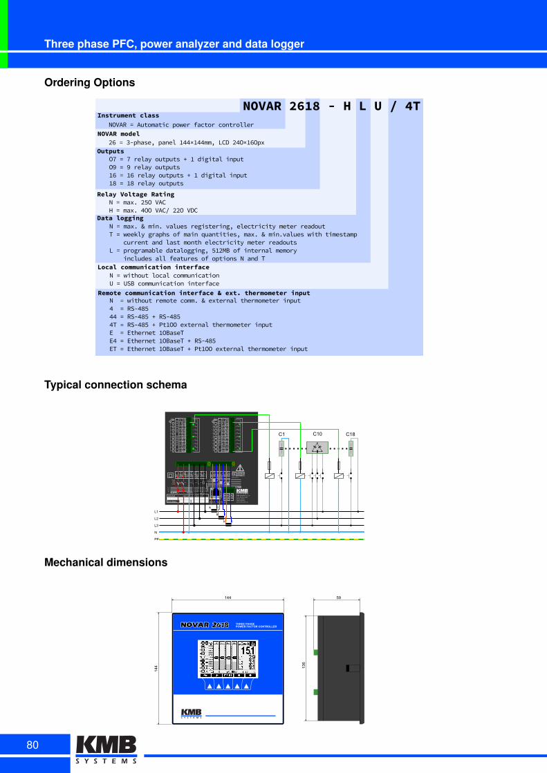
Three phase PFC, power analyzer and data logger
Ordering Options
LocalHcommunicationHinterface
RemoteHcommunicationHinterfaceHsHext.HthermometerHinput
NP=PwithoutPlocalPcommunicationUP=PUSBPcommunicationPinterface
NPP=PwithoutPremotePcomm2PgPexternalPthermometerPinput6PP=PRSb6DC66P=PRSb6DCPqPRSb6DC6TP=PRSb6DCPqPPtAOOPexternalPthermometerPinputEPP=PEthernetPAOBaseTE6P=PEthernetPAOBaseTPqPRSb6DCETP=PEthernetPAOBaseTPqPPtAOOPexternalPthermometerPinput
DataHloggingNP=Pmax2PgPmin2PvaluesPregisteringLPelectricityPmeterPreadoutTP=PweeklyPgraphsPofPmainPquantitiesLPmax2PgPmin2valuesPwithPtimestampPPPPcurrentPandPlastPmonthPelectricityPmeterPreadoutsLP=PprogramablePdataloggingLPCA7MBPofPinternalPmemoryPPPPincludesPallPfeaturesPofPoptionsPNPandPTP
NOVARH2618H-HHHLHUH/H4TInstrumentHclass
Outputs
NOVARP=PAutomaticPpowerPfactorPcontroller
O/P=P/PrelayPoutputsPqPAPdigitalPinputO3P=P3PrelayPoutputsAHP=PAHPrelayPoutputsPqPAPdigitalPinputADP=PADPrelayPoutputs
RelayHVoltageHRatingNP=Pmax2P7COPVACHP=Pmax2P6OOPVACMP77OPVDC
NOVARHmodel7HP=P9bphaseLPpanelPA66×A66mmLPLCDP76O×AHOpx
Typical connection schema
b K B s y mIbl IKk IKl IBk IBlIbk
CURRENT
o bu bb bK bB bsUK UBN Ub
AUXh:Vh VOLTAGEAVb AVK
KyKmK,KrKoBu
BBBs
BbBK
bybmb,brboKu
KBKs
KbKK
COMbcETH
bu:A
smsssyG
COMKcsry
b:A b:A b:Ab:A
bu:A
y:A
LbLKLBN
NOVARFásB÷m,Hz Pábu:VA
ShNhpDateá IP:á:sXp
Uá::,y:÷:yuuV
Made:in:Czech:Republic
KMB:systemsn:sh:rh:ohDrh:Mh:Horákové:yyosmu:um: LiberecCzech:Republicwwwhkmbsystemsheu
maxhyuu
V:AC
BAc:N:H:N:T:L:N:U:p:N:s:E:s:T
yru÷mouVAC BuuV:CAT:IIImuuV:CAT:II
byuV:CAT:III
Cb Cbu
Lb
LK
LB
N
PE
k l
k l
k l
Cbr
Mechanical dimensions
59
136
144
144
THREE PHASEPOWER FACTOR CONTROLLER2618
80

NOVAR 2418Three phase PFC and multimeter
NOVAR 2418 (and NOVAR 2407, 2409, 2416) repre-sents basic type of a new product line of three phaseAPFCR with advanced functions and parameters. It hascompact enclosure and large segment LCD display. Allimportant control and compensation information is avail-able in real time on its screen.This controller builds on an innovated hardware andfirmware platform with continual high accuracy measure-ment of all network parameters and energy. It also in-cludes complete digital power monitor and precisefour-quadrant electricity meter. It is fully automaticand it has a simple installation. Up to 18 relay outputscan control combinations of single-, two and three-phasecompensation steps with booth compensation capacitorsand de-compensation reactors.Optional remote communication line offers RS-485 or Ethernet. These interfaces allows the controller to befully supervised and managed from remote ENVIS application. It also supports ModBus RTU and ModBusTCP for simple integration with available SCADA systems.Typical applications: power factor correction in three phase unbalanced networks, for systems with higherprecision requirements, to compensate frequent load changes (18 steps) also in single phase applications
Key features:
• NOVAR 2418 up to 18 output sections, relay or solid-state
– optionally NOVAR 2409, NOVAR 2407 and NOVAR 2416, last two with digital input
• measures power factor and other quantities in each line separately
• automatic control of power factor independently in each phase
• unlimited support for single-, two- and three-phase capacitors and reactors
• combined mains compensation & decompensation capability (supports booth capacitors and reactors)
• RS-485 and Ethernet communication options
• embedded four quadrant electricity meter with TOU and power meter (class 0.5)
• continuous measurement, 128 s./period, 10 periods (200 ms) sampling interval
81
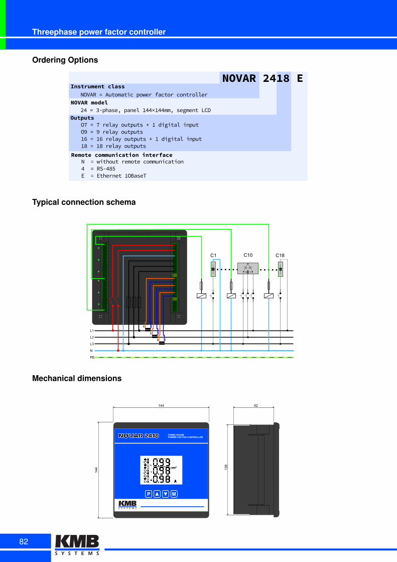
Threephase power factor controller
Ordering Options
Remote communication interfaceNll=lwithoutlremotelcommunication4ll=lRSC485Ell=lEthernetl1OBaseT
NOVAR 2418 EInstrument class
Outputs
NOVARl=lAutomaticlpowerlfactorlcontroller
O7l=l7lrelayloutputsl×l1ldigitallinputO9l=l9lrelayloutputs16l=l16lrelayloutputsl×l1ldigitallinput18l=l18lrelayloutputs
NOVAR model24l=l3CphaseLlpanell144×144mmLlsegmentlLCD
Typical connection schema
C1 C10
L1
L2
L3
N
PE
k l
k l
k l
C18
Mechanical dimensions
62
136
144
144
2618
MP
NOVAR 2418 THREE PHASEPOWER FACTOR CONTROLLER
82

NOVAR 1106/1114 &NOVAR 1206/1214
NOVAR 1xxx reactive power controllers are fully automatic in-struments that allow optimum control of reactive power com-pensation. They take their design concepts from the NOVAR1xx/2xx line of instruments, bringing up a number of improve-ments and new features while keeping the way of operation.The instruments features precise voltage and current mea-surement circuits, and the digital processing of valuesmeasured provides high evaluation accuracy of both trueroot–mean–square values of voltage, current and power factorvalues. The built-in temperature sensor measures the temper-ature inside the distribution board cabinet.The instrument’s installation is fully automatic. The controllerautomatically detects both the connection configuration andthe value of each compensation section connected. Enteringthese parameters manually is also possible.
Key features:
• up to 14 outputs (1114/1214) and 1 alarm relay
• current measurement sensitivity 2 mA
• optional RS485 or Ethernet remote communication interface
• input for 2nd tariff (1206/1214)
• optional supply voltage up to 500 V (/S400 models)
• separated common pole of relays on additional terminals (/S400 models)
83
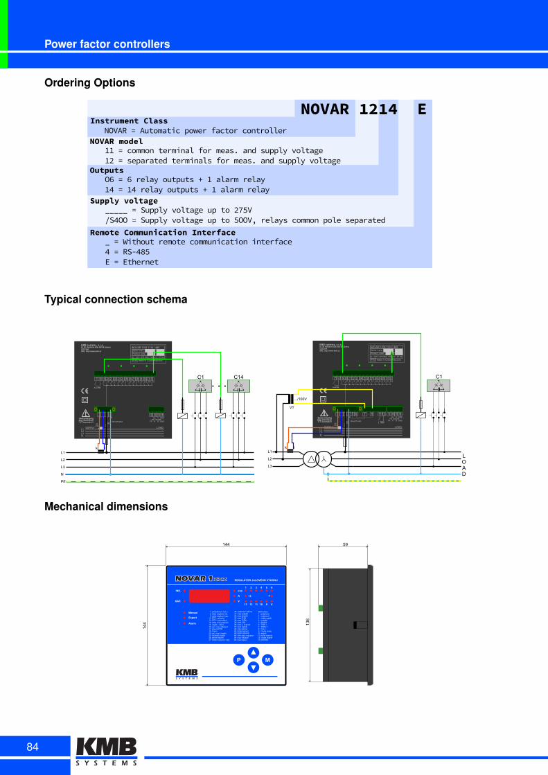
Power factor controllers
Ordering Options
Supply voltage_____i=iSupplyivoltageiupitoi275Vi/S4OOi=iSupplyivoltageiupitoi5OOV,irelaysicommonipoleiseparated
NOVAR 1214 EInstrument Class
NOVAR modelNOVARi=iAutomaticipowerifactoricontroller
11i=icommoniterminaliforimeas.iandisupplyivoltage12i=iseparatediterminalsiforimeas.iandisupplyivoltage
Remote Communication Interface_i=iWithoutiremoteicommunicationiinterface4i=iRS-485Ei=iEthernet
OutputsO6i=i6irelayioutputsi+i1ialarmirelay14i=i14irelayioutputsi+i1ialarmirelay
Typical connection schema
LU
L,
LH
N
PE
k l
KMBIsystems,Is.r.o.Dr.IM.IHorákovéI559,I460I06ILiberecCZECHIAURL:Ihttp://www.kmb.cz
LUL,LHN
U , H z O n h p b UX UU U, UH Uz
ALARM
OAsUA:
maxtUXA
UXX÷,hOGVAC
k l L NRSG,H,IzpO
Rx
TR A B GND
Tx GND
MadeGinGCzechGRepublic
II
NOVARGUUXnGUUUzGIGzpOSerialGIGverstY
ProducttGdateGY
IPGzX
UG UXXG ,hOGVACuGhVAu÷ ÷zHG nhGHz
SUPPLY LOAD
CU CUz
L,
LH
Lz
KMBIsystems,Is.r.o.Dr.IM.IHorákovéI559,I460I06ILiberecCZECHIAURL:Ihttp://www.kmb.cz
L,LHLzN
, H z O ~ F n h p ,U ,, ,H ,z ,O
ALARM
~AP,Ao
maxI,UA
,UU÷Hn~/VAC
k l L NRS/HzHXOh~
Rx
TR A B GND
Tx GND
Made/in/Czech/Republic
XX
NOVAR/,HUF/,H,O/X/Oh~Serial/X/versIb
ProductI/date/b
IP/OX
U/ ,UU/ Hn~/VACc/nVAc÷ ÷Oz/ Fn/Hz
SUPPLY LOAD
C,
~ F n p ,, ,H
k l
VT
IIIX,UUV
~
HI/TARIF
LOAD
Mechanical dimensions
59
136
144
144
xxx
84

NOVAR 1005/1007 &NOVAR 1005D/1007D
NOVAR 1005 and NOVAR 1007 power factor con-trollers are enhanced successors of very popular com-pact NOVAR 5 controller. These models are primarilyintended for smaller and less demanding applicationswith budgetary constraints. The current sensitivity wasincreased in this innovated line. The NOVAR 1005controller if fully backward compatible with the NOVAR5 model (terminal, wiring). Furthermore, the NOVAR1007 has 8 output relays.Both models are produced in two different housings.Standard model is determined for panel mounting.Models marked with D, such as NOVAR 1005D or NO-VAR 1007D features different housing which is deter-mined for DIN-rail installation.
Key features:
• compact 96 x 96 mm panel footprint (NOVAR 1005/1007)
• DIN-rail mountable box (NOVAR 1005D/1007D)
• 6 (NOVAR 1005) or 8 (NOVAR 1007) control outputs
• current measurement sensitivity 0.02 A
• aimed for smaller less demanding applications
• features Automatic Control Section Recognition
• independent alarm warnings
• precise measurement and control even under conditions of voltage or current waveform distortion
85
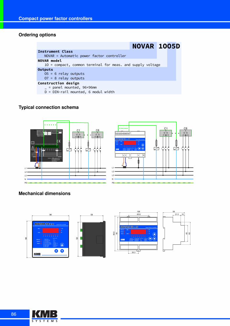
Compact power factor controllers
Ordering options
Construction design_1=1panel1mounted,196×96mmD1=1DIN-rail1mounted,161modul1width
NOVAR 1OO5DInstrument Class
NOVAR modelNOVAR1=1Automatic1power1factor1controller
1O1=1compact,1common1terminal1for1meas.1and1supply1voltageOutputs
O51=161relay1outputsO71=181relay1outputs
Typical connection schema
U~R80÷275VAC,43÷67Hz
(1007)(7) (8)
NOVARR1005R 1007PříkonR5RVA
L1
L2
L3
N
PE
k l
C1 C8
L1
L2
L3
N
PE
k l
C1 C8
NOVAR 1005xx
Ik Il L N
RC R1 R2 R3 R4 R5 R6 R7 R8
Mechanical dimensions
xx
60.6
90
21.5 10
45 62
58106
99.8
30.3
NOVAR 1005xx
86
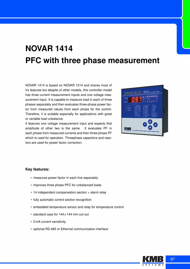
NOVAR 1414PFC with three phase measurement
NOVAR 1414 is based on NOVAR 1214 and shares most ofit’s features but despite of other models, this controller modelhas three current measurement inputs and one voltage mea-surement input. It is capable to measure load in each of threephases separately and then evaluates three-phase power fac-tor from measured values from each phase for the control.Therefore, it is suitable especially for applications with greator variable load unbalance.It features one voltage measurement input and expects thatamplitude of other two is the same. It evaluates PF ineach phase from measured currents and then three-phase PFwhich is used for operation. Threephase capactiors and reac-tors are used for power factor correction.
Key features:
• measures power factor in each line separately
• improves three phase PFC for unbalanced loads
• 14 independent compensation section + alarm relay
• fully automatic control section recognition
• embedded temperature sensor and relay for temperature control
• standard case for 144 x 144 mm cut-out
• 2 mA current sensitivity
• optional RS-485 or Ethernet communication interface
87
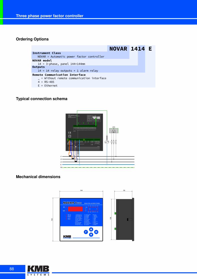
Three phase power factor controller
Ordering Options
NOVAR 1414 EInstrument Class
NOVAR modelNOVARS=SAutomaticSpowerSfactorScontroller
14S=S3-phase,SpanelS144×144mm
Remote Communication Interface_S=SWithoutSremoteScommunicationSinterface4S=SRS-485ES=SEthernet
Outputs14S=S14SrelaySoutputsS+S1SalarmSrelayS
Typical connection schema
KMBIsystems,Is.r.o.Dr.IM.IHorákovéI559,I460I06ILiberecCZECHIAURL:Ihttp://www.kmb.cz
L,LHLzN
, H z O ~ F E n h ,U ,, ,H ,z ,O
ALARM
~AP,Ao
maxI,UA
,UU÷HE~/VAC
k l L NRS/HzHXOn~
Rx
TR A B GND
Tx GND
Made/in/Czech/Republic
XX
NOVAR/,O,O/X//On~/Serial/X/versIp
ProductI/date/p
IP/OX
U/ ,UU/ HE~/VACc/EVAc÷ ÷Oz/ FE/Hz
SUPPLY LOAD
C,
~ F E h ,, ,H
~
HI/TARIF
L,
LH
Lz
N
PE
Mechanical dimensions
59
136
144
144
xxx
88
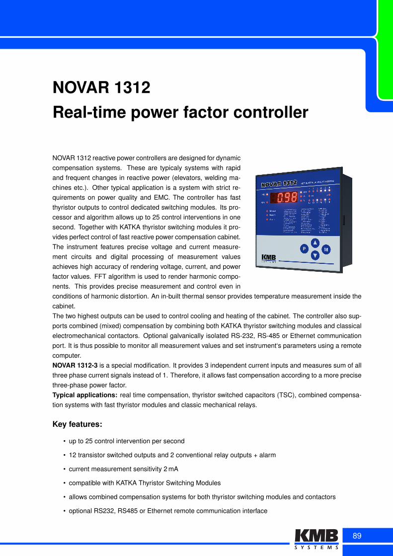
NOVAR 1312Real-time power factor controller
NOVAR 1312 reactive power controllers are designed for dynamiccompensation systems. These are typicaly systems with rapidand frequent changes in reactive power (elevators, welding ma-chines etc.). Other typical application is a system with strict re-quirements on power quality and EMC. The controller has fastthyristor outputs to control dedicated switching modules. Its pro-cessor and algorithm allows up to 25 control interventions in onesecond. Together with KATKA thyristor switching modules it pro-vides perfect control of fast reactive power compensation cabinet.The instrument features precise voltage and current measure-ment circuits and digital processing of measurement valuesachieves high accuracy of rendering voltage, current, and powerfactor values. FFT algorithm is used to render harmonic compo-nents. This provides precise measurement and control even inconditions of harmonic distortion. An in-built thermal sensor provides temperature measurement inside thecabinet.The two highest outputs can be used to control cooling and heating of the cabinet. The controller also sup-ports combined (mixed) compensation by combining both KATKA thyristor switching modules and classicalelectromechanical contactors. Optional galvanically isolated RS-232, RS-485 or Ethernet communicationport. It is thus possible to monitor all measurement values and set instrument‘s parameters using a remotecomputer.NOVAR 1312-3 is a special modification. It provides 3 independent current inputs and measures sum of allthree phase current signals instead of 1. Therefore, it allows fast compensation according to a more precisethree-phase power factor.Typical applications: real time compensation, thyristor switched capacitors (TSC), combined compensa-tion systems with fast thyristor modules and classic mechanical relays.
Key features:
• up to 25 control intervention per second
• 12 transistor switched outputs and 2 conventional relay outputs + alarm
• current measurement sensitivity 2 mA
• compatible with KATKA Thyristor Switching Modules
• allows combined compensation systems for both thyristor switching modules and contactors
• optional RS232, RS485 or Ethernet remote communication interface
89
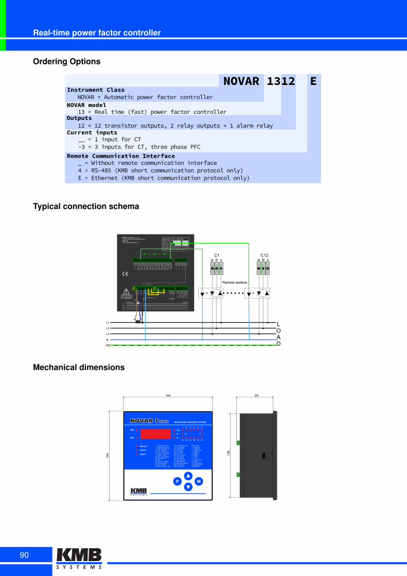
Real-time power factor controller
Ordering Options
Current inputs__l=l1linputlforlCTl23l=l3linputslforlCTElthreelphaselPFC
NOVAR 1312 EInstrument Class
NOVAR modelNOVARl=lAutomaticlpowerlfactorlcontroller
13l=lRealltimelKfastMlpowerlfactorlcontroller
Remote Communication Interface_l=lWithoutlremotelcommunicationlinterface4l=lRS2485lKKMBlshortlcommunicationlprotocollonlyMEl=lEthernetlKKMBlshortlcommunicationlprotocollonlyM
Outputs12l=l12ltransistorloutputsEl2lrelayloutputslyl1lalarmlrelayl
Typical connection schema
KMBIsystems,Is.r.o.Dr.IM.IHorákovéI559,I460I06ILiberecCZECHIAURL:Ihttp://www.kmb.cz
LOL9L~N
EAtOAI
max6OzA
Ozz÷98EvVAC
k l L NRSv9~9HFME
Rx
TR A B GND
Tx GND
MadevinvCzechvRepublic
HH
NOVARvO~O9vHv9~9vFME
O 9 ~ F E b 8 M n Oz OO O9
SerialvHvvers6h
Product6vdatevh
IPvFX
Uv Ozzv 98EvVACUv8VAU÷ ÷F~v b8vHz
SUPPLY LOAD
CO
E b 8 n OO O9
~
96vTARIF
O 9 ~ F E b 8 M n Oz OO O9 OFO~
LO
L9
L~
N
PE
k l
Thyristor sections
LOAD
avvbvvcCO9
avvbvvc
Mechanical dimensions
59
136
144
144
xxx
90
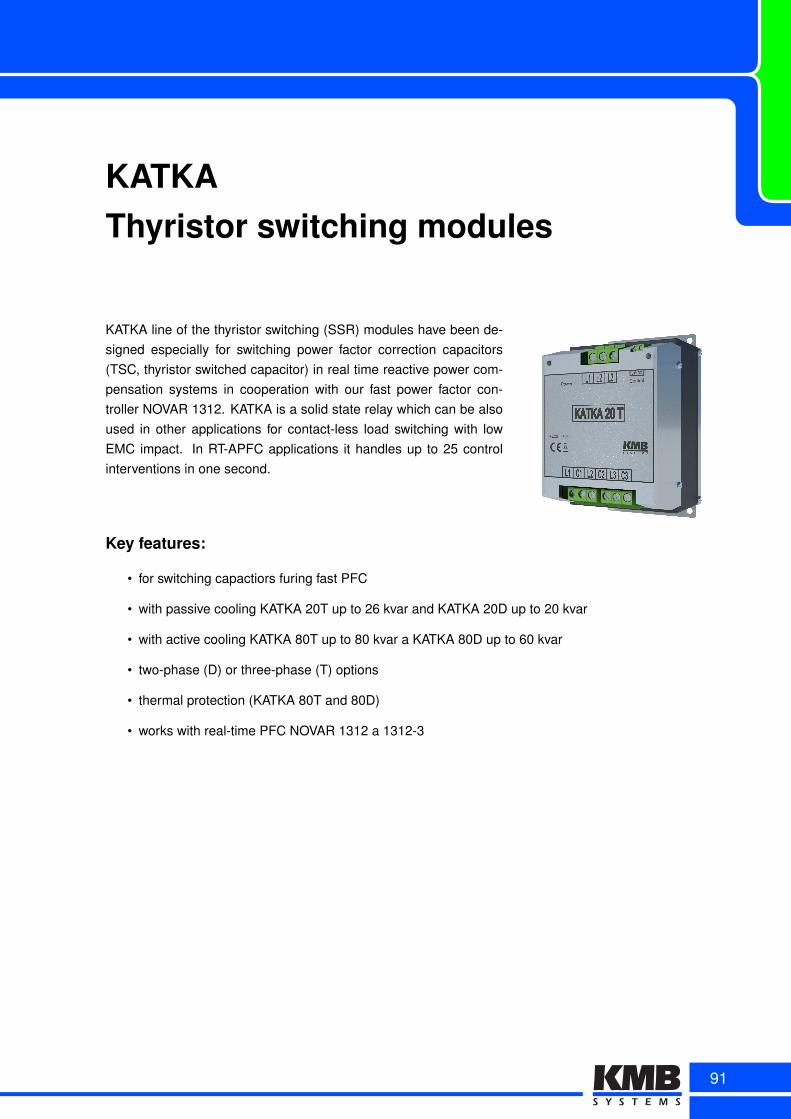
KATKAThyristor switching modules
KATKA line of the thyristor switching (SSR) modules have been de-signed especially for switching power factor correction capacitors(TSC, thyristor switched capacitor) in real time reactive power com-pensation systems in cooperation with our fast power factor con-troller NOVAR 1312. KATKA is a solid state relay which can be alsoused in other applications for contact-less load switching with lowEMC impact. In RT-APFC applications it handles up to 25 controlinterventions in one second.
Key features:
• for switching capactiors furing fast PFC
• with passive cooling KATKA 20T up to 26 kvar and KATKA 20D up to 20 kvar
• with active cooling KATKA 80T up to 80 kvar a KATKA 80D up to 60 kvar
• two-phase (D) or three-phase (T) options
• thermal protection (KATKA 80T and 80D)
• works with real-time PFC NOVAR 1312 a 1312-3
91
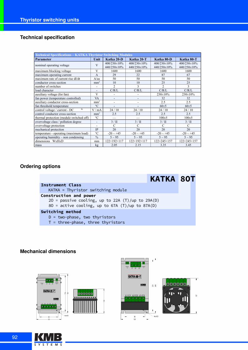
Thyristor switching units
Technical specification
Technical Specifications – KATKA Thyristor Switching ModulesParameter Unit Katka 20-D Katka 20-T Katka 80-D Katka 80-T
nominal operating voltage V400/230±10%440/250±10%
400/230±10%440/250±10%
400/230±10%440/250±10%
400/230±10%440/250±10%
maximum blocking voltage V 1600 1600 1600 1600maximum operating current A 29 22 87 67maximum rate of current rise dI/dt A/us 50 50 50 50conductor cross-section mm2 10 10 25 25number of switches - 2 3 2 3load character - C/R/L C/R/L C/R/L C/R/Lauxiliary voltage (for fan) V - - 230±10% 230±10%fan power (temperature controlled) VA - - 32 32auxiliary conductor cross-section mm2 - - 2.5 2.5fan threshold temperature °C - - 60±5 60±5control voltage / current - DC 1) V / mA 24 / 10 24 / 10 24 / 10 24 / 10control conductor cross-section mm2 2.5 2.5 2.5 2.5thermal protection (module switched off) °C — — 100±5 100±5overvoltage class / pollution degree - 3 / II 3 / II 3 / II 3 / IIovervoltage protection - C C C Cmechanical protection IP 20 20 20 20temperature - operating (maximum load) °C -20 ~ +45 -20 ~ +45 -20 ~ +45 -20 ~ +45operating humidity – non condensing % 5 ~ 95 5 ~ 95 5 ~ 95 5 ~ 95dimensions WxHxD mm 122×192×117 122×192×117 122×245×157 122×245×157mass kg 2.05 2.15 3.35 3.45
Ordering options
KATKA 8OTInstrument Class
Construction and powerKATKAD=DThyristorDswitchingDmodule
2OD=DpassiveDcooling,DupDtoD22AD(T)/upDtoD29A(D)D8OD=DactiveDcooling,DupDtoD67AD(T)/upDtoD87A(D)
Switching methodDD=Dtwo-phase,DtwoDthyristorsTD=Dthree-phase,DthreeDthyristors
Mechanical dimensions
L1 L2 L3
L1 C1 L2 C2 L3 C3
24VDC
KATKA 20 -T
Power Control
178
192
90
122
4x ø 6,5
120
KATKA 80 -T
Power Control
L1 L2 L3
L1 C1 L2 C2 L3 C3
90
122
245
231
157
4x ø 6,5
92
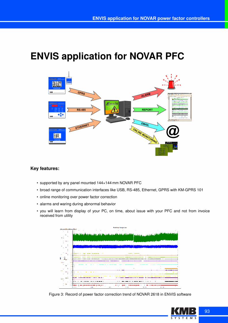
ENVIS application for NOVAR power factor controllers
ENVIS application for NOVAR PFC
2618
MP
NOVAR 2418 THREE PHASEPOWER FACTOR CONTROLLER
THREE PHASEPOWER FACTOR CONTROLLER2618
1114
KM GPRS 101
MODEM
GPRS modem
RX
TXLINK
ETHERNET
RS-485
GPRSALARM
REPORT
@ONLINE MONITORING
Key features:
• supported by any panel mounted 144×144 mm NOVAR PFC
• broad range of communication interfaces like USB, RS-485, Ethernet, GPRS with KM-GPRS 101
• online monitoring over power factor correction
• alarms and waring during abnormal behavior
• you will learn from display of your PC, on time, about issue with your PFC and not from invoicereceived from utility
Figure 3: Record of power factor correction trend of NOVAR 2618 in ENVIS software
93

Components for Power Factor Correction
Distribution of Power Factor Correction components
We are not only developing and manufacturing measuring instruments and power factor controllers. We aresupplementing mainly our line of PFC NOVAR for other components necessary for power factor correction.Our portfolio contains detuned filter reactors, isolation transformers, shunt reactors, PFC capacitors, PFCcontactors etc.
Detuned Filter Reactors• 2,5 to 100 kVAr• detuning factor p = 5.6%, 7%, 14%• voltage 400V, 440V, 480V, 525V
LV Isolation Transformers• up to900 kVA• also for medical applications, according to IEC 61558-2-15
Shunt Reactors• all parameters of ELEKTRA products can be custom adjusted according to customer needs
PFC LV Capacitors• MKP• filled with ecological gel or gas• voltage 130V to 1000V, 0,5-50 kVAr
PFC Contactors• power 12,5 kVAr to 100 kVAr• switching voltage 400 V až 690 V• control voltage 24V -400 V
Fuse switches• vertical and horizontal design• 160A to 1600A• fuse check without switching off
Power factor controller NOVAR• up to 18 outputs• designed for panel or DIN-rail mounting• fully automatic setup• 1p and 3p measurement, relay and thyristor control
Thyristor switching modules KATKA• up to 87 kVAr
KMB HARD & SOFTTř. Dr. M. Horákové 559, 460 06 Liberec 7
+420 485 130 314 [email protected] www.kmb.cz
94
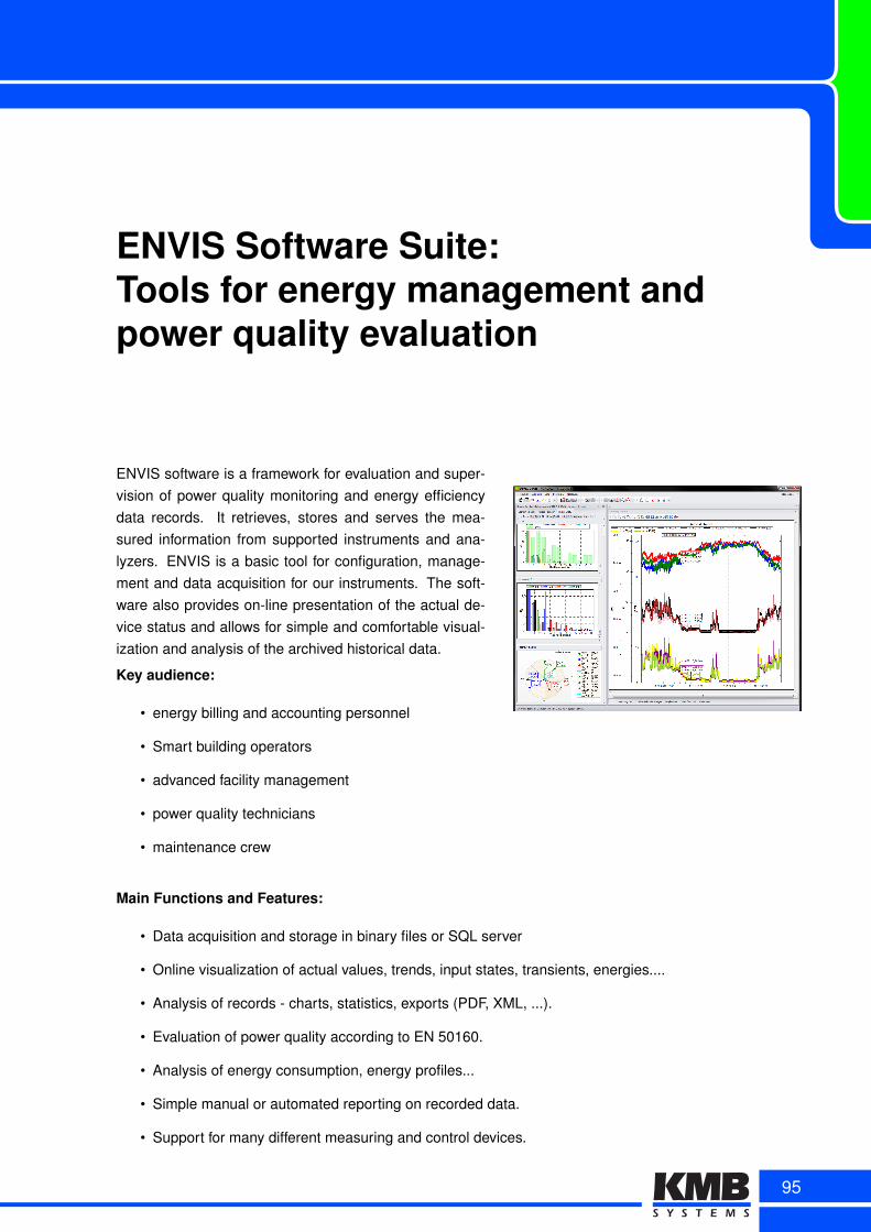
ENVIS Software Suite:Tools for energy management andpower quality evaluation
ENVIS software is a framework for evaluation and super-vision of power quality monitoring and energy efficiencydata records. It retrieves, stores and serves the mea-sured information from supported instruments and ana-lyzers. ENVIS is a basic tool for configuration, manage-ment and data acquisition for our instruments. The soft-ware also provides on-line presentation of the actual de-vice status and allows for simple and comfortable visual-ization and analysis of the archived historical data.
Key audience:
• energy billing and accounting personnel
• Smart building operators
• advanced facility management
• power quality technicians
• maintenance crew
Main Functions and Features:
• Data acquisition and storage in binary files or SQL server
• Online visualization of actual values, trends, input states, transients, energies....
• Analysis of records - charts, statistics, exports (PDF, XML, ...).
• Evaluation of power quality according to EN 50160.
• Analysis of energy consumption, energy profiles...
• Simple manual or automated reporting on recorded data.
• Support for many different measuring and control devices.
95
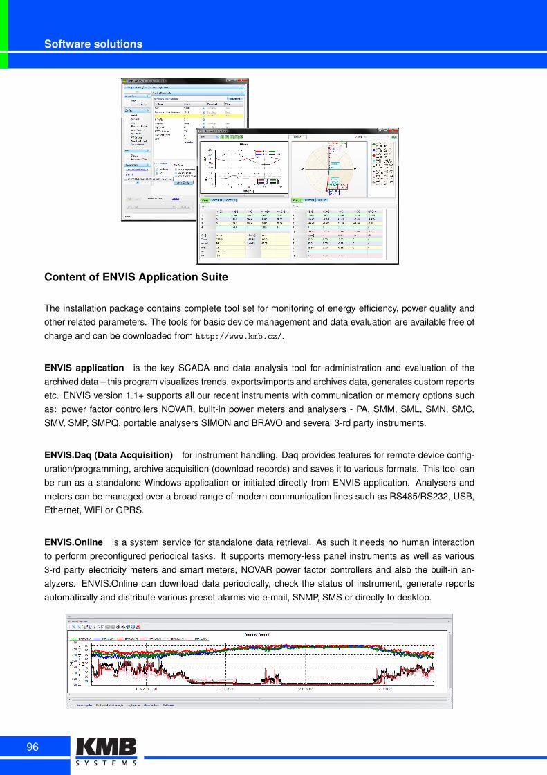
Software solutions
Content of ENVIS Application Suite
The installation package contains complete tool set for monitoring of energy efficiency, power quality andother related parameters. The tools for basic device management and data evaluation are available free ofcharge and can be downloaded from http://www.kmb.cz/.
ENVIS application is the key SCADA and data analysis tool for administration and evaluation of thearchived data – this program visualizes trends, exports/imports and archives data, generates custom reportsetc. ENVIS version 1.1+ supports all our recent instruments with communication or memory options suchas: power factor controllers NOVAR, built-in power meters and analysers - PA, SMM, SML, SMN, SMC,SMV, SMP, SMPQ, portable analysers SIMON and BRAVO and several 3-rd party instruments.
ENVIS.Daq (Data Acquisition) for instrument handling. Daq provides features for remote device config-uration/programming, archive acquisition (download records) and saves it to various formats. This tool canbe run as a standalone Windows application or initiated directly from ENVIS application. Analysers andmeters can be managed over a broad range of modern communication lines such as RS485/RS232, USB,Ethernet, WiFi or GPRS.
ENVIS.Online is a system service for standalone data retrieval. As such it needs no human interactionto perform preconfigured periodical tasks. It supports memory-less panel instruments as well as various3-rd party electricity meters and smart meters, NOVAR power factor controllers and also the built-in an-alyzers. ENVIS.Online can download data periodically, check the status of instrument, generate reportsautomatically and distribute various preset alarms vie e-mail, SNMP, SMS or directly to desktop.
96
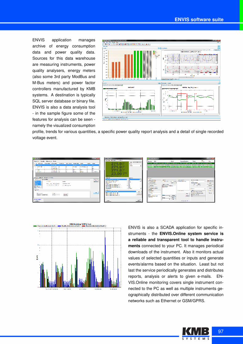
ENVIS software suite
ENVIS application managesarchive of energy consumptiondata and power quality data.Sources for this data warehouseare measuring instruments, powerquality analysers, energy meters(also some 3rd party ModBus andM-Bus meters) and power factorcontrollers manufactured by KMBsystems. A destination is typicallySQL server database or binary file.ENVIS is also a data analysis tool- in the sample figure some of thefeatures for analysis can be seen -namely the visualized consumptionprofile, trends for various quantities, a specific power quality report analysis and a detail of single recordedvoltage event.
ENVIS is also a SCADA application for specific in-struments - the ENVIS.Online system service isa reliable and transparent tool to handle instru-ments connected to your PC. It manages periodicaldownloads of the instrument. Also it monitors actualvalues of selected quantities or inputs and generateevents/alarms based on the situation. Least but notlast the service periodically generates and distributesreports, analysis or alerts to given e-mails. EN-VIS.Online monitoring covers single instrument con-nected to the PC as well as multiple instruments ge-ographically distributed over different communicationnetworks such as Ethernet or GSM/GPRS.
97
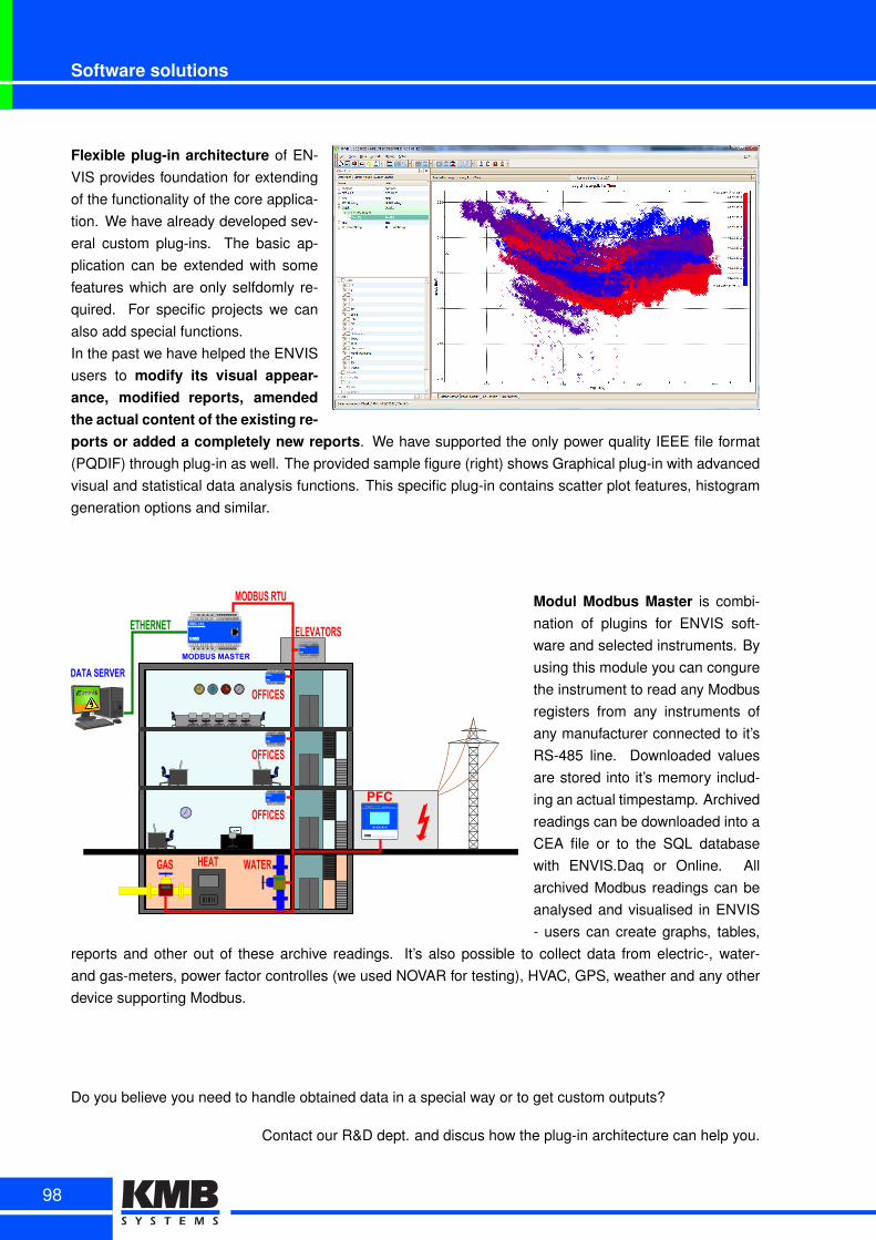
Software solutions
Flexible plug-in architecture of EN-VIS provides foundation for extendingof the functionality of the core applica-tion. We have already developed sev-eral custom plug-ins. The basic ap-plication can be extended with somefeatures which are only selfdomly re-quired. For specific projects we canalso add special functions.In the past we have helped the ENVISusers to modify its visual appear-ance, modified reports, amendedthe actual content of the existing re-ports or added a completely new reports. We have supported the only power quality IEEE file format(PQDIF) through plug-in as well. The provided sample figure (right) shows Graphical plug-in with advancedvisual and statistical data analysis functions. This specific plug-in contains scatter plot features, histogramgeneration options and similar.
SMC 144Power Analyzer
ETH
N L1 L2 L3 L4 l1 k1 l2 k2 l3 k3 l4 k4
X1 X2 O- O+ R A1 A2 G B A G B/1 A/2COM1 COM2 / DI
PA 144Power Analyzer
N L1 L2 L3 L4 l1 k1 l2 k2 l3 k3 l4 k4
X1 X2 O- O+ R A1 A2 G B A G B/1 A/2COM1 COM2 / DI
PA 144Power Analyzer
N L1 L2 L3 L4 l1 k1 l2 k2 l3 k3 l4 k4
X1 X2 O- O+ R A1 A2 G B A G B/1 A/2COM1 COM2 / DI
PA 144Power Analyzer
N L1 L2 L3 L4 l1 k1 l2 k2 l3 k3 l4 k4
X1 X2 O- O+ R A1 A2 G B A G B/1 A/2COM1 COM2 / DI
PA 144Power Analyzer
N L1 L2 L3 L4 l1 k1 l2 k2 l3 k3 l4 k4
X1 X2 O- O+ R A1 A2 G B A G B/1 A/2COM1 COM2 / DI
THREE PHASEPOWER FACTOR CONTROLLER26xx
PFC
ELEVATORS
OFFICES
OFFICES
OFFICES
GAS WATERHEAT
MODBUS RTU
ETHERNET
MODBUS MASTER
DATA SERVER
Modul Modbus Master is combi-nation of plugins for ENVIS soft-ware and selected instruments. Byusing this module you can congurethe instrument to read any Modbusregisters from any instruments ofany manufacturer connected to it’sRS-485 line. Downloaded valuesare stored into it’s memory includ-ing an actual timpestamp. Archivedreadings can be downloaded into aCEA file or to the SQL databasewith ENVIS.Daq or Online. Allarchived Modbus readings can beanalysed and visualised in ENVIS- users can create graphs, tables,
reports and other out of these archive readings. It’s also possible to collect data from electric-, water-and gas-meters, power factor controlles (we used NOVAR for testing), HVAC, GPS, weather and any otherdevice supporting Modbus.
Do you believe you need to handle obtained data in a special way or to get custom outputs?
Contact our R&D dept. and discus how the plug-in architecture can help you.
98