2014 jeep grand cherokee owner's manual - fca · pdf filegrand cherokee chrysler group...
TRANSCRIPT

Grand CherokeeChrysler Group LLC
OW N E R ’ S M A N UA L
20
14 G
ran
d C
he
rok
ee
14WK741-126-AC Fourth Edition Printed in U.S.A.
2 0 1 4

TABLE OF CONTENTSSECTION PAGE
1 INTRODUCTION . . . . . . . . . . . . . . . . . . . . . . . . . . . . . . . . . . . . . . . . . . . . . . . . . . . . . . . . . . . . . 3
2 THINGS TO KNOW BEFORE STARTING YOUR VEHICLE . . . . . . . . . . . . . . . . . . . . . . . . . . . . 11
3 UNDERSTANDING THE FEATURES OF YOUR VEHICLE . . . . . . . . . . . . . . . . . . . . . . . . . . . . 119
4 UNDERSTANDING YOUR INSTRUMENT PANEL . . . . . . . . . . . . . . . . . . . . . . . . . . . . . . . . . . 287
5 STARTING AND OPERATING . . . . . . . . . . . . . . . . . . . . . . . . . . . . . . . . . . . . . . . . . . . . . . . . . 379
6 WHAT TO DO IN EMERGENCIES . . . . . . . . . . . . . . . . . . . . . . . . . . . . . . . . . . . . . . . . . . . . . . 523
7 MAINTAINING YOUR VEHICLE . . . . . . . . . . . . . . . . . . . . . . . . . . . . . . . . . . . . . . . . . . . . . . . 551
8 MAINTENANCE SCHEDULES . . . . . . . . . . . . . . . . . . . . . . . . . . . . . . . . . . . . . . . . . . . . . . . . . 611
9 IF YOU NEED CONSUMER ASSISTANCE . . . . . . . . . . . . . . . . . . . . . . . . . . . . . . . . . . . . . . . . 619
10 INDEX . . . . . . . . . . . . . . . . . . . . . . . . . . . . . . . . . . . . . . . . . . . . . . . . . . . . . . . . . . . . . . . . . . . . 631
1
2
3
4
5
6
7
8
9
10


INTRODUCTION
CONTENTS� INTRODUCTION . . . . . . . . . . . . . . . . . . . . . . . .4
� ROLLOVER WARNING . . . . . . . . . . . . . . . . . . .5
� HOW TO USE THIS MANUAL . . . . . . . . . . . . . .6
� WARNINGS AND CAUTIONS . . . . . . . . . . . . . .8
� VEHICLE IDENTIFICATION NUMBER . . . . . . . .8
� VEHICLE MODIFICATIONS/ALTERATIONS . . . .9
1

INTRODUCTION
Congratulations on selecting your new Chrysler GroupLLC vehicle. Be assured that it represents precisionworkmanship, distinctive styling, and high quality - allessentials that are traditional to our vehicles.
This is a specialized utility vehicle. It can go places andperform tasks that conventional passenger cars are notintended. It handles and maneuvers differently frommany passenger cars both on-road and off-road, so taketime to become familiar with your vehicle.
The two-wheel drive version of this vehicle was designedfor on-road use only. It is not intended for off-roaddriving or use in other severe conditions suited for afour-wheel drive vehicle.
Before you start to drive this vehicle, read the Owner’sManual. Be sure you are familiar with all vehicle controls,particularly those used for braking, steering, transmis-sion, and transfer case shifting. Learn how your vehiclehandles on different road surfaces. Your driving skillswill improve with experience. When driving off-road orworking the vehicle, don’t overload the vehicle or expectthe vehicle to overcome the natural laws of physics.Always observe federal, state, provincial and local lawswherever you drive.
As with other vehicles of this type, failure to operate thisvehicle correctly may result in loss of control or acollision. Refer to “On-Road/Off-Road Driving Tips” in“Starting And Operating” for further information.
4 INTRODUCTION

This Owner’s Manual has been prepared with the assis-tance of service and engineering specialists to acquaintyou with the operation and maintenance of your vehicle.It is supplemented by Warranty Information, and variouscustomer-oriented documents. Please take the time toread these publications carefully. Following the instruc-tions and recommendations in this manual will helpassure safe and enjoyable operation of your vehicle.
NOTE: After reviewing the owner information, itshould be stored in the vehicle for convenient referenc-ing and remain with the vehicle when sold.
When it comes to service, remember that your authorizeddealer knows your vehicle best, has factory-trained tech-nicians and genuine MOPAR® parts, and cares aboutyour satisfaction.
ROLLOVER WARNING
Utility vehicles have a significantly higher rollover ratethan other types of vehicles. This vehicle has a higherground clearance and a higher center of gravity thanmany passenger cars. It is capable of performing better ina wide variety of off-road applications. Driven in anunsafe manner, all vehicles can go out of control. Becauseof the higher center of gravity, if this vehicle is out ofcontrol it may roll over when some other vehicles maynot.
Do not attempt sharp turns, abrupt maneuvers, or otherunsafe driving actions that can cause loss of vehiclecontrol. Failure to operate this vehicle safely may resultin a collision, rollover of the vehicle, and severe or fatalinjury. Drive carefully.
1
INTRODUCTION 5

Failure to use the driver and passenger seat belts pro-vided is a major cause of severe or fatal injury. In fact, theU.S. government notes that the universal use of existingseat belts could cut the highway death toll by 10,000 ormore each year and could reduce disabling injuries by
two million annually. In a rollover crash, an unbeltedperson is significantly more likely to die than a personwearing a seat belt. Always buckle up.
HOW TO USE THIS MANUAL
Consult the Table of Contents to determine which sectioncontains the information you desire.
Since the specification of your vehicle depends on theitems of equipment ordered, certain descriptions andillustrations may differ from your vehicle’s equipment.
The detailed index at the back of this Owner’s Manualcontains a complete listing of all subjects.
Consult the following table for a description of thesymbols that may be used on your vehicle or throughoutthis Owner’s Manual:
Rollover Warning Label
6 INTRODUCTION

1
INTRODUCTION 7

WARNINGS AND CAUTIONS
This Owners Manual contains WARNINGS against op-erating procedures that could result in a collision orbodily injury. It also contains CAUTIONS against proce-dures that could result in damage to your vehicle. If youdo not read this entire Owners Manual, you may missimportant information. Observe all Warnings and Cau-tions.
VEHICLE IDENTIFICATION NUMBER
The Vehicle Identification Number (VIN) is found on aplate located on the left front corner of the instrumentpanel pad, visible from outside of the vehicle through thewindshield. This number also is stamped into the rightfront body, behind the right front seat. Move the rightfront seat forward to allow better viewing of the stamped
VIN. This number also appears on the Automobile Infor-mation Disclosure Label affixed to a window on yourvehicle. Save this label for a convenient record of yourvehicle identification number and optional equipment.
VIN Location
8 INTRODUCTION

NOTE: It is illegal to remove or alter the VIN.
VEHICLE MODIFICATIONS/ALTERATIONS
WARNING!
Any modifications or alterations to this vehicle couldseriously affect its roadworthiness and safety andmay lead to a collision resulting in serious injury ordeath.
Right Front Body VIN Location
1
INTRODUCTION 9

THINGS TO KNOW BEFORE STARTING YOUR VEHICLE
CONTENTS� A WORD ABOUT YOUR KEYS . . . . . . . . . . . . .14
▫ Keyless Ignition Node (KIN) . . . . . . . . . . . . . .14
▫ Key Fob . . . . . . . . . . . . . . . . . . . . . . . . . . . . .15
▫ Ignition Or Accessory On Message . . . . . . . . . .16
� SENTRY KEY® . . . . . . . . . . . . . . . . . . . . . . . . .17
▫ Replacement Keys . . . . . . . . . . . . . . . . . . . . .18
▫ Customer Key Programming . . . . . . . . . . . . . .19
▫ General Information . . . . . . . . . . . . . . . . . . . .19
� VEHICLE SECURITY ALARM — IF EQUIPPED . . .20
▫ Rearming The System . . . . . . . . . . . . . . . . . . .20
▫ To Arm The System. . . . . . . . . . . . . . . . . . . . .21
▫ To Disarm The System . . . . . . . . . . . . . . . . . . .21
▫ Tamper Alert . . . . . . . . . . . . . . . . . . . . . . . . .22
� ILLUMINATED ENTRY — IF EQUIPPED . . . . . .23
� REMOTE KEYLESS ENTRY (RKE) . . . . . . . . . . .23
▫ To Unlock The Doors And Liftgate . . . . . . . . . .24
▫ To Lock The Doors And Liftgate . . . . . . . . . . . .25
▫ Using The Panic Alarm . . . . . . . . . . . . . . . . . .25
▫ Programming Additional Transmitters . . . . . . . .26
▫ Transmitter Battery Replacement . . . . . . . . . . .26
2

▫ General Information . . . . . . . . . . . . . . . . . . . .27
� REMOTE STARTING SYSTEM — IF EQUIPPED . .28
▫ How To Use Remote Start . . . . . . . . . . . . . . . .29
� DOOR LOCKS . . . . . . . . . . . . . . . . . . . . . . . . .32
▫ Power Door Locks . . . . . . . . . . . . . . . . . . . . .34
▫ Child-Protection Door Lock System — RearDoors. . . . . . . . . . . . . . . . . . . . . . . . . . . . . . .34
� KEYLESS ENTER-N-GO™ . . . . . . . . . . . . . . . . .36
� WINDOWS . . . . . . . . . . . . . . . . . . . . . . . . . . .41
▫ Power Windows . . . . . . . . . . . . . . . . . . . . . . .41
▫ Wind Buffeting . . . . . . . . . . . . . . . . . . . . . . .46
� LIFTGATE . . . . . . . . . . . . . . . . . . . . . . . . . . . .46
▫ Power Liftgate — If Equipped . . . . . . . . . . . . .47
� OCCUPANT RESTRAINTS . . . . . . . . . . . . . . . .50
▫ Lap/Shoulder Belts . . . . . . . . . . . . . . . . . . . .54
▫ Lap/Shoulder Belt Operating Instructions . . . . .55
▫ Lap/Shoulder Belt Untwisting Procedure . . . . .59
▫ Adjustable Upper Shoulder Belt Anchorage . . .60
▫ Seat Belts In Passenger Seating Positions . . . . . .61
▫ Automatic Locking Retractor Mode (ALR) —If Equipped . . . . . . . . . . . . . . . . . . . . . . . . . .61
▫ Energy Management Feature . . . . . . . . . . . . . .62
▫ Seat Belt Pretensioners . . . . . . . . . . . . . . . . . .63
▫ Supplemental Active Head Restraints (AHR) . . .63
▫ Enhanced Seat Belt Use Reminder System(BeltAlert®) . . . . . . . . . . . . . . . . . . . . . . . . . .68
▫ Seat Belt Lock Out. . . . . . . . . . . . . . . . . . . . . .69
12 THINGS TO KNOW BEFORE STARTING YOUR VEHICLE

▫ Seat Belts And Pregnant Women . . . . . . . . . . .69
▫ Seat Belt Extender . . . . . . . . . . . . . . . . . . . . .69
▫ Supplemental Restraint System (SRS) —Air Bags . . . . . . . . . . . . . . . . . . . . . . . . . . . .70
▫ Advanced Front Air Bag Features . . . . . . . . . . .72
▫ Air Bag Deployment Sensors And Controls . . . .76
▫ Event Data Recorder (EDR) . . . . . . . . . . . . . . .85
▫ Child Restraints . . . . . . . . . . . . . . . . . . . . . . .86
� ENGINE BREAK-IN RECOMMENDATIONS . . .112
� SAFETY TIPS . . . . . . . . . . . . . . . . . . . . . . . . .113
▫ Transporting Passengers . . . . . . . . . . . . . . . . .113
▫ Exhaust Gas . . . . . . . . . . . . . . . . . . . . . . . . .114
▫ Safety Checks You Should Make Inside TheVehicle . . . . . . . . . . . . . . . . . . . . . . . . . . . . .115
▫ Periodic Safety Checks You Should MakeOutside The Vehicle . . . . . . . . . . . . . . . . . . .118
2
THINGS TO KNOW BEFORE STARTING YOUR VEHICLE 13

A WORD ABOUT YOUR KEYS
Your vehicle uses a keyless ignition system. This systemconsists of a Key Fob with Remote Keyless Entry (RKE)transmitter and a Keyless Ignition Node (KIN).
Keyless Enter-N-Go™ Feature
This vehicle is equipped with the Keyless Enter-N-Go™feature, (refer to �Keyless Enter-N-Go™� in �Things ToKnow Before Starting Your Vehicle� for further informa-tion).
Keyless Ignition Node (KIN)
This feature allows the driver to operate the ignitionswitch with the push of a button, as long as the RemoteKeyless Entry (RKE) transmitter is in the passengercompartment.
The Keyless Ignition Node (KIN) has four operatingpositions, three of which are labeled and will illuminatewhen in position. The three positions are OFF, ACC, andON/RUN. The fourth position is START, during startRUN will illuminate.
NOTE: In case the ignition switch does not change withthe push of a button, the RKE transmitter (Key Fob) mayhave a low or dead battery. In this situation a back upmethod can be used to operate the ignition switch. Putthe nose side (side opposite of the emergency key) of theKey Fob against the ENGINE START/STOP button andpush to operate the ignition switch.
14 THINGS TO KNOW BEFORE STARTING YOUR VEHICLE

Key Fob
The Key Fob also contains the Remote Keyless Entry(RKE) transmitter and an emergency key, which stores inthe rear of the Key Fob.
The emergency key allows for entry into the vehicleshould the battery in the vehicle or the Key Fob go dead.The emergency key is also for locking the glove box. Youcan keep the emergency key with you when valet park-ing.
To remove the emergency key, slide the mechanical latchat the top of the Key Fob sideways with your thumb andthen pull the key out with your other hand.Keyless Ignition Node (KIN)
2
THINGS TO KNOW BEFORE STARTING YOUR VEHICLE 15

NOTE: You can insert the double-sided emergency keyinto the lock cylinders with either side up.
Ignition Or Accessory On Message
Opening the driver’s door when the ignition is in ACC orON (engine not running), a chime will sound to remind
you to cycle the ignition to OFF. In addition to the chime,the ignition or accessory on message will display in thecluster.
NOTE: With the Uconnect® system, the power windowswitches, radio, power sunroof (if equipped), and poweroutlets will remain active for up to 10 minutes after theignition is cycled to the OFF position. Opening eitherfront door will cancel this feature. The time for thisfeature is programmable. Refer to “Uconnect® Settings”in “Understanding Your Instrument Panel” for furtherinformation.
WARNING!
• When leaving the vehicle, always remove the KeyFob from the vehicle and lock your vehicle.
• Never leave children alone in a vehicle, or withaccess to an unlocked vehicle.
(Continued)
Emergency Key Removal
16 THINGS TO KNOW BEFORE STARTING YOUR VEHICLE

WARNING! (Continued)• Allowing children to be in a vehicle unattended is
dangerous for a number of reasons. A child orothers could be seriously or fatally injured. Chil-dren should be warned not to touch the parkingbrake, brake pedal or the shift lever.
• Do not leave the Key Fob in or near the vehicle, orin a location accessible to children, and do notleave the ignition of a vehicle equipped withKeyless Enter-N-Go™ in the ACC or ON/RUNmode. A child could operate power windows, othercontrols, or move the vehicle.
• Do not leave children or animals inside parkedvehicles in hot weather. Interior heat build-up maycause serious injury or death.
CAUTION!
An unlocked car is an invitation to thieves. Alwaysremove the Key Fob from vehicle, cycle the ignitionOFF and lock all doors when leaving the vehicleunattended.
SENTRY KEY®
The Sentry Key® Immobilizer system prevents unauthor-ized vehicle operation by disabling the engine. Thesystem does not need to be armed or activated. Operationis automatic, regardless of whether the vehicle is lockedor unlocked.
The system uses a Key Fob with Remote Keyless Entry(RKE) transmitter, a Keyless Ignition Node (KIN) and aRF receiver to prevent unauthorized vehicle operation.Therefore, only Key Fobs that are programmed to thevehicle can be used to start and operate the vehicle.
2
THINGS TO KNOW BEFORE STARTING YOUR VEHICLE 17
After cycling the ignition to the ON/RUN position, theVehicle Security Light will turn on for three seconds for abulb check. If the light remains on after the bulb check, itindicates that there is a problem with the electronics. Inaddition, if the light begins to flash after the bulb check,it indicates that someone used an invalid Key Fob to startthe engine. Either of these conditions will result in theengine being shut off after two seconds.
If the Vehicle Security Light turns on during normalvehicle operation (vehicle running for longer than 10seconds), it indicates that there is a fault in the electron-ics. Should this occur, have the vehicle serviced as soonas possible by an authorized dealer.
CAUTION!
The Sentry Key® Immobilizer system is not compat-ible with some aftermarket remote starting systems.Use of these systems may result in vehicle startingproblems and loss of security protection.
All of the Key Fobs provided with your new vehicle havebeen programmed to the vehicle electronics.
Replacement Keys
NOTE: Only Key Fobs that are programmed to thevehicle electronics can be used to start and operate thevehicle. Once a Key Fob is programmed to a vehicle, itcannot be programmed to any other vehicle.
18 THINGS TO KNOW BEFORE STARTING YOUR VEHICLE

CAUTION!
• Always remove the Key Fobs from the vehicle andlock all doors when leaving the vehicle unat-tended.
• For vehicles equipped with Keyless Enter-N-Go™,always remember to place the ignition in the OFFposition.
At the time of purchase, the original owner is providedwith a four-digit Personal Identification Number (PIN).Keep the PIN in a secure location. This number isrequired for authorized dealer replacement of Key Fobs.Duplication of Key Fobs may be performed at an autho-rized dealer, this procedure consists of programming ablank Key Fob to the vehicle electronics. A blank Key Fobis one that has never been programmed.
NOTE: When having the Sentry Key® Immobilizer Sys-tem serviced, bring all vehicle keys with you to anauthorized dealer.
Customer Key Programming
Programming Key Fobs or RKE transmitters may beperformed at an authorized dealer.
General Information
The Sentry Key® system complies with FCC rules Part 15and with RSS-210 of Industry Canada. Operation issubject to the following conditions:
• This device may not cause harmful interference.
• This device must accept any interference that may bereceived, including interference that may cause unde-sired operation.
2
THINGS TO KNOW BEFORE STARTING YOUR VEHICLE 19
VEHICLE SECURITY ALARM — IF EQUIPPED
This Vehicle Security Alarm monitors the vehicle doors,liftgate, and ignition for unauthorized operation. Whenthe alarm is activated, the interior switches for doorlocks, and power liftgate are disabled. The Vehicle Secu-rity Alarm provides both audio and visual signals, thehorn will sound, the headlights will turn on, park lampsand/or turn signals will flash repeatedly for three min-utes. If the disturbance is still present (driver’s door,passenger door, other doors, ignition) after three minutes,the headlights, park lamps and/or turn signals will flashfor an additional 15 minutes.
NOTE: The Panic and Security alarms are quite differ-ent. Please take a moment to activate the Panic and theSecurity modes to hear the differences in the horn. In caseone should go off in the future, you will need to knowwhich mode has been activated in order to deactivate it.
Rearming The System
If something triggers the alarm, and no action is taken todisarm it, the Vehicle Security Alarm will turn off thehorn after three minutes, turn off all of the visual signalsafter 15 minutes, and then the Vehicle Security Alarm willrearm itself.
20 THINGS TO KNOW BEFORE STARTING YOUR VEHICLE

To Arm The System
Follow these steps to arm the Vehicle Security Alarm:
1. Remove the key from the ignition system (refer to�Starting Procedures� in �Starting And Operating� forfurther information).
• For vehicles equipped with Keyless Enter-N-Go™,make sure the vehicle ignition system is �OFF�.
• For vehicles not equipped with Keyless Enter-N-Go™,make sure the vehicle ignition system is �OFF� and thekey is physically removed from the ignition.
2. Perform one of the following methods to lock thevehicle:
• Press LOCK on the interior power door lock switchwith the driver and/or passenger door open.
• Press the LOCK button on the exterior Passive EntryDoor Handle with a valid Key Fob available in the
same exterior zone (refer to �Keyless Enter-N-Go™� in�Things To Know Before Starting Your Vehicle� forfurther information).
• Press the LOCK button on the Remote Keyless Entry(RKE) transmitter.
3. If any doors are open, close them.
To Disarm The System
The Vehicle Security Alarm can be disarmed using any ofthe following methods:
• Press the UNLOCK button on the Remote KeylessEntry (RKE) transmitter.
• Grasp the Passive Entry Unlock Door Handle (refer to�Keyless Enter-N-Go™� in �Things To Know BeforeStarting Your Vehicle� for further information).
• Cycle the vehicle ignition system out of the OFFposition.
2
THINGS TO KNOW BEFORE STARTING YOUR VEHICLE 21

NOTE:
• The driver’s door key cylinder and the liftgate buttonon the RKE transmitter cannot arm or disarm theVehicle Security Alarm.
• The Vehicle Security Alarm remains armed duringpower liftgate entry. Pressing the liftgate button willnot disarm the Vehicle Security Alarm. If someoneenters the vehicle through the liftgate and opens anydoor the alarm will sound.
• When the Vehicle Security Alarm is armed, the interiorpower door lock switches will not unlock the doors.
The Vehicle Security Alarm is designed to protect yourvehicle; however, you can create conditions where thesystem will give you a false alarm. If one of the previ-ously described arming sequences has occurred, the
Vehicle Security Alarm will arm regardless of whetheryou are in the vehicle or not. If you remain in the vehicleand open a door, the alarm will sound. If this occurs,disarm the Vehicle Security Alarm.
If the Vehicle Security Alarm is armed and the batterybecomes disconnected, the Vehicle Security Alarm willremain armed when the battery is reconnected; theexterior lights will flash, the horn will sound. If thisoccurs, disarm the Vehicle Security Alarm.
Tamper Alert
If something has triggered the Vehicle Security Alarm inyour absence, the horn will sound three times and theexterior lights blink three times when you unlock thedoors. Check the vehicle for tampering.
22 THINGS TO KNOW BEFORE STARTING YOUR VEHICLE

ILLUMINATED ENTRY — IF EQUIPPED
The courtesy lights will turn on when you use theRemote Keyless Entry (RKE) transmitter to unlock thedoors or open any door.
This feature also turns on the approach lighting in theoutside mirrors (if equipped). Refer to “Mirrors” in“Understanding The Features Of Your Vehicle” for fur-ther information.
The lights will fade to off after approximately 30 secondsor they will immediately fade to off once the ignition iscycled to the ON/RUN position from the OFF position.
NOTE:
• The front courtesy overhead console and door cour-tesy lights will turn on if the dimmer control is in the“Dome ON” position (extreme top position).
• The Illuminated Entry system will not operate if thedimmer control is in the “Dome defeat” position(extreme bottom position).
REMOTE KEYLESS ENTRY (RKE)
The RKE system allows you to lock or unlock the doors,open the power liftgate, or activate the Panic Alarm fromdistances up to approximately 66 ft (20 m) using ahand-held Key Fob with RKE transmitter. The RKEtransmitter does not need to be pointed at the vehicle toactivate the system.
NOTE: Driving at speeds 5 mph (8 km/h) and abovedisables the system from responding to all RKE transmit-ter buttons for all RKE transmitters.
2
THINGS TO KNOW BEFORE STARTING YOUR VEHICLE 23

To Unlock The Doors And Liftgate
Press and release the UNLOCK button on the RKEtransmitter once to unlock the driver’s door or twicewithin five seconds to unlock all doors and liftgate. Theturn signal lights will flash to acknowledge the unlocksignal. The illuminated entry system will also turn on.
If the vehicle is equipped with Passive Entry, refer to“Keyless Enter-N-Go™” under “Things To Know BeforeStarting Your Vehicle” for further information.
1st Press Of Key Fob Unlocks
This feature lets you program the system to unlock eitherthe driver’s door or all doors on the first press of theUNLOCK button on the RKE transmitter. To change thecurrent setting, refer to “Uconnect® Settings” in “Under-standing Your Instrument Panel” for further information.
Flash Lights With Remote Key
This feature will cause the turn signal lights to flash whenthe doors are locked or unlocked with the RKE transmit-ter. This feature can be turned on or turned off. To changethe current setting, refer to “Uconnect® Settings” in“Understanding Your Instrument Panel” for further in-formation.
Keyless Enter-N-Go™ Fob
24 THINGS TO KNOW BEFORE STARTING YOUR VEHICLE

Headlight Illumination On Approach
This feature activates the headlights for up to 90 secondswhen the doors are unlocked with the RKE transmitter.The time for this feature is programmable on vehiclesequipped through Uconnect®. To change the currentsetting, refer to “Uconnect® Settings” in “UnderstandingYour Instrument Panel” for further information.
To Lock The Doors And Liftgate
Press and release the LOCK button on the RKE transmit-ter to lock all doors and liftgate. The turn signal lightswill flash and the horn will chirp to acknowledge thesignal.
If the vehicle is equipped with Passive Entry, refer to“Keyless Enter-N-Go™” under “Things To Know BeforeStarting Your Vehicle” for further information.
Sound Horn With Remote Key Lock
This feature will cause the horn to chirp when the doorsare locked with the RKE transmitter. This feature can beturned on or turned off. To change the current setting,refer to “Uconnect® Settings” in “Understanding YourInstrument Panel” for further information.
Using The Panic Alarm
To turn the Panic Alarm feature on or off, press and holdthe PANIC button on the RKE transmitter for at least onesecond and release. When the Panic Alarm is on, theheadlights will turn on, the park lights will flash, thehorn will pulse on and off, and the interior lights willturn on.
The Panic Alarm will stay on for three minutes unlessyou turn it off by either pressing the PANIC button asecond time or drive the vehicle at a speed of 15 mph(24 km/h) or greater.
2
THINGS TO KNOW BEFORE STARTING YOUR VEHICLE 25

NOTE:
• The interior lights will turn off if you cycle the ignitionswitch to the ACC or ON/RUN position while thePanic Alarm is activated. However, the exterior lightsand horn will remain on.
• You may need to be less than 35 ft (11 m) from thevehicle when using the RKE transmitter to turn off thePanic Alarm due to the radio frequency noises emittedby the system.
Programming Additional Transmitters
Programming Key Fobs or RKE transmitters may beperformed at an authorized dealer.
Transmitter Battery Replacement
The recommended replacement battery is one CR2032battery.
NOTE:
• Perchlorate Material — special handling may apply.Batteries could contain dangerous materials. Pleasedispose of them according to respect for environmentand local laws.
• Used batteries are harmful to the environment. Youcan dispose of them either in the correct containers asspecified by law or by taking them to a Dealership,which will deal with their disposal.
• Do not touch the battery terminals that are on the backhousing or the printed circuit board.
1. Remove the emergency key by sliding the mechanicallatch on the back of the RKE transmitter sidewayswith your thumb and then pull the key out with yourother hand.
26 THINGS TO KNOW BEFORE STARTING YOUR VEHICLE

2. Insert the tip of the emergency key or a #2 flat bladescrewdriver into the slot and gently pry the two halvesof the RKE transmitter apart. Make sure not to damagethe seal during removal.
3. Remove the battery by turning the back cover over(battery facing downward) and tapping it lightly on asolid surface such as a table or similar, then replace thebattery. When replacing the battery, match the + signon the battery to the + sign on the inside of the batteryclip, located on the back cover. Avoid touching thenew battery with your fingers. Skin oils may causebattery deterioration. If you touch a battery, clean itwith rubbing alcohol.
4. To assemble the RKE transmitter case, snap the twohalves together.
General Information
This device complies with Part 15 of the FCC rules andRSS 210 of Industry Canada. Operation is subject to thefollowing conditions:
• This device may not cause harmful interference.Separating RKE Transmitter Case
2
THINGS TO KNOW BEFORE STARTING YOUR VEHICLE 27

• This device must accept any interference received,including interference that may cause undesired op-eration.
NOTE: Changes or modifications not expressly approvedby the party responsible for compliance could void theuser’s authority to operate the equipment.
If your RKE transmitter fails to operate from a normaldistance, check for these two conditions:
1. A weak battery in the RKE transmitter. The expectedlife of the battery is a minimum of three years.
2. Closeness to a radio transmitter such as a radio stationtower, airport transmitter, and some mobile or CBradios.
REMOTE STARTING SYSTEM — IF EQUIPPED
This system uses the Remote Keyless Entry(RKE) transmitter to start the engine conve-niently from outside the vehicle while stillmaintaining security. The system has a range of
approximately 300 ft (91 m).
NOTE:
• The vehicle must be equipped with an automatictransmission to be equipped with Remote Start.
• Obstructions between the vehicle and the RKE trans-mitter may reduce this range.
28 THINGS TO KNOW BEFORE STARTING YOUR VEHICLE

How To Use Remote Start
All of the following conditions must be met before theengine will remote start:
• Shift lever in PARK
• Doors closed
• Hood closed
• HAZARD switch off
• BRAKE switch inactive (brake pedal not pressed)
• Battery at an acceptable charge level
• RKE PANIC button not pressed
• Fuel meets minimum requirement
• System not disabled from previous remote start event
• Vehicle theft alarm not active
WARNING!
• Do not start or run an engine in a closed garage orconfined area. Exhaust gas contains Carbon Mon-oxide (CO) which is odorless and colorless. CarbonMonoxide is poisonous and can cause serious in-jury or death when inhaled.
• Keep Remote Keyless Entry (RKE) transmittersaway from children. Operation of the Remote StartSystem, windows, door locks or other controlscould cause serious injury or death.
2
THINGS TO KNOW BEFORE STARTING YOUR VEHICLE 29

Remote Start Abort Message On Electronic VehicleInformation Center (EVIC) — If Equipped
The following messages will display in the EVIC if thevehicle fails to remote start or exits remote start prema-turely:
• Remote Start Aborted — Door Ajar
• Remote Start Aborted — Hood Ajar
• Remote Start Aborted — Fuel Low
• Remote Start Aborted — System Fault
• Remote Start Disabled — Start Vehicle to Reset
The EVIC message stays active until the ignition is turnedto the ON/RUN position.
To Enter Remote Start Mode
Press and release the REMOTE START buttonon the RKE transmitter twice within five sec-onds. The parking lights will flash vehicledoors will lock, and the horn will chirp twice (if
programmed). Once the vehicle has started, the enginewill run for 15 minutes.
NOTE:
• If your power door locks were unlocked, Remote Startwill automatically lock the doors.
• If an engine fault is present or fuel level is low, thevehicle will start and then shut down in 10 seconds.
• The park lamps will turn on and remain on duringRemote Start mode.
30 THINGS TO KNOW BEFORE STARTING YOUR VEHICLE

• For security, power window and power sunroof op-eration (if equipped) are disabled when the vehicle isin the Remote Start mode.
• The engine can be started two consecutive times (two15-minute cycles) with the RKE transmitter. However,the ignition switch must be cycled to the ON/RUNposition before you can repeat the start sequence for athird cycle.
To Exit Remote Start Mode Without Driving TheVehicle
Press and release the REMOTE START button one time orallow the engine to run for the entire 15-minute cycle.
NOTE: To avoid unintentional shut downs, the systemwill disable the one time press of the REMOTE STARTbutton for two seconds after receiving a valid RemoteStart request.
To Exit Remote Start Mode And Drive The Vehicle
Before the end of the 15-minute cycle, press and releasethe UNLOCK button on the RKE transmitter to unlockthe doors and disarm the Vehicle Security Alarm System(if equipped). Then, prior to the end of the 15 minutecycle, press and release the START/STOP button.
NOTE:
• The message “Push Start Button” will display in theEVIC until you push the START button.
• “Remote Start Active — Push Start Button” will dis-play in the EVIC until you press the start button. Referto “Electronic Vehicle Information Center (EVIC)” forfurther information.
2
THINGS TO KNOW BEFORE STARTING YOUR VEHICLE 31

Remote Start Comfort Systems — If Equipped
When remote start is activated, the heated steeringwheel, and driver heated seat features will automaticallyturn on in cold weather. In warm weather, the drivervented seat feature will automatically turn on when theremote start is activated. These features will stay onthrough the duration of remote start or until the ignitionswitch is turned to the ON/RUN position.
The Remote Start Comfort System can be activated anddeactivated through the Uconnect® system. For moreinformation on Remote Start Comfort System operationrefer to “Uconnect®” in “Understanding Your Instru-ment Panel”.
DOOR LOCKS
The power door locks can be manually locked frominside the vehicle by using the door lock knob. To lockeach door, push the door lock knob on each door trimpanel downward. To unlock the front doors, pull theinside door handle to the first detent. To unlock the reardoors, pull the door lock knob on the door trim panelupward. If the lock knob is down when the door isclosed, the door will lock. Therefore, make sure the key isnot inside the vehicle before closing the door.
32 THINGS TO KNOW BEFORE STARTING YOUR VEHICLE

WARNING!
• For personal security and safety in the event of acollision, lock the vehicle doors before you drive aswell as when you park and leave the vehicle.
(Continued)
WARNING! (Continued)• When leaving the vehicle, always remove the Key
Fob from the vehicle and lock your vehicle. Unsu-pervised use of vehicle equipment may cause se-vere personal injuries or death.
• Never leave children alone in a vehicle, or withaccess to an unlocked vehicle. Allowing children tobe in a vehicle unattended is dangerous for anumber of reasons. A child or others could beseriously or fatally injured. Children should bewarned not to touch the parking brake, brake pedalor the shift lever.
• Do not leave the Key Fob in or near the vehicle, orin a location accessible to children, and do notleave a vehicle equipped with Keyless Enter-N-Go™ in the ACC or ON/RUN mode. A child couldoperate power windows, other controls, or movethe vehicle.
Manual Door Lock Knob
2
THINGS TO KNOW BEFORE STARTING YOUR VEHICLE 33

Power Door Locks
The power door lock switch is located on each front doorpanel. Press the switch to lock or unlock the doors.
If the lock knob is down when the door is closed, the doorwill lock. Therefore, make sure the Key Fob is not insidethe vehicle before closing the door.
If you press the door lock switch while the Key Fob is inthe vehicle and the driver’s door is open, the doors willnot lock.
If a rear door is locked, it cannot be opened from insidethe vehicle without first unlocking the door. The doormay be unlocked manually by raising the lock knob.
Child-Protection Door Lock System — Rear Doors
To provide a safer environment for small children ridingin the rear seats, the rear doors are equipped withChild-Protection Door Lock system.
To Engage Or Disengage The Child-ProtectionDoor Lock System
1. Open the rear door.
2. Insert the tip of the emergency key into the lock androtate to the LOCK or UNLOCK position.
3. Repeat steps 1 and 2 for the opposite rear door.
Power Door Lock Switch
34 THINGS TO KNOW BEFORE STARTING YOUR VEHICLE
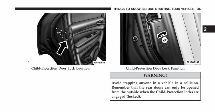
WARNING!
Avoid trapping anyone in a vehicle in a collision.Remember that the rear doors can only be openedfrom the outside when the Child-Protection locks areengaged (locked).
Child-Protection Door Lock Location Child-Protection Door Lock Function
2
THINGS TO KNOW BEFORE STARTING YOUR VEHICLE 35

NOTE: For emergency exit from the rear seats when theChild-Protection Door Lock System is engaged, manuallyraise the door lock knob to the unlocked position, rolldown the window, and open the door using the outsidedoor handle.
KEYLESS ENTER-N-GO™
The Passive Entry system is an enhancement to thevehicle’s Remote Keyless Entry (RKE) system and afeature of Keyless Enter-N-Go™. This feature allows youto lock and unlock the vehicle’s door(s) without having topress the RKE transmitter lock or unlock buttons.
NOTE:
• Passive Entry may be programmed ON/OFF; refer to“Uconnect®” in “Understanding Your InstrumentPanel” for further information.
• If the vehicle is unlocked by Passive Entry and no doorgoes ajar within 60 seconds, the vehicle will re-lockand if equipped will arm the theft alarm.
• If wearing gloves on your hands, or if it has beenraining on the Passive Entry door handle, the unlocksensitivity can be affected, resulting in a slower re-sponse time.
To Unlock From The Driver’s Side:
With a valid Passive Entry RKE transmitter within 5 ft(1.5 m) of the driver’s door handle, grab the driver’s frontdoor handle to unlock the driver’s door automatically.The interior door panel lock knob will raise when thedoor is unlocked.
36 THINGS TO KNOW BEFORE STARTING YOUR VEHICLE
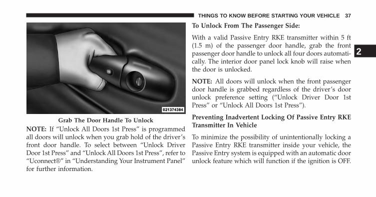
NOTE: If “Unlock All Doors 1st Press” is programmedall doors will unlock when you grab hold of the driver’sfront door handle. To select between “Unlock DriverDoor 1st Press” and “Unlock All Doors 1st Press”, refer to“Uconnect®” in “Understanding Your Instrument Panel”for further information.
To Unlock From The Passenger Side:
With a valid Passive Entry RKE transmitter within 5 ft(1.5 m) of the passenger door handle, grab the frontpassenger door handle to unlock all four doors automati-cally. The interior door panel lock knob will raise whenthe door is unlocked.
NOTE: All doors will unlock when the front passengerdoor handle is grabbed regardless of the driver’s doorunlock preference setting (“Unlock Driver Door 1stPress” or “Unlock All Doors 1st Press”).
Preventing Inadvertent Locking Of Passive Entry RKETransmitter In Vehicle
To minimize the possibility of unintentionally locking aPassive Entry RKE transmitter inside your vehicle, thePassive Entry system is equipped with an automatic doorunlock feature which will function if the ignition is OFF.
Grab The Door Handle To Unlock
2
THINGS TO KNOW BEFORE STARTING YOUR VEHICLE 37

If one of the vehicle doors is open and the door panelswitch is used to lock the vehicle, once all open doorshave been closed the vehicle checks the inside andoutside of the vehicle for any valid Passive Entry RKEtransmitters. If one of the vehicle’s Passive Entry RKEtransmitters is detected inside the vehicle, and no othervalid Passive Entry RKE transmitters are detected out-side the vehicle, the Passive Entry System automaticallyunlocks all vehicle doors and chirps the horn three times(on the third attempt ALL doors will lock and the PassiveEntry RKE transmitter can be locked in the vehicle).
To Unlock/Enter The Liftgate
The liftgate passive entry unlock feature is built into theelectronic liftgate handle. With a valid Passive Entry RKEtransmitter within 3 ft (1.0 m) of the liftgate, press theelectronic liftgate handle for a power open on vehiclesequipped with Power Liftgate. Press the electronic lift-gate handle and lift for Manual Liftgate vehicles.
NOTE: If the vehicle is unlocked then the liftgate willopen with the handle and no RKE Transmitter is re-quired.
38 THINGS TO KNOW BEFORE STARTING YOUR VEHICLE

To Lock The Liftgate
With a valid Passive Entry RKE transmitter within 3 ft(1.0 m) of the liftgate, press the passive entry lock buttonlocated to the right of electronic liftgate handle.
NOTE: If “Unlock All Doors 1st Press” is programmedin EVIC, all doors will unlock when you push the buttonon the liftgate. If �Unlock Driver Door 1st press� isprogrammed in Uconnect®, the liftgate will unlock whenyou press the button on the liftgate For further informa-tion, refer to “Uconnect®” in “Understanding Your In-strument Panel”.
To Lock The Vehicle’s Doors
With one of the vehicle’s Passive Entry RKE transmitterswithin 5 ft (1.5 m) of the driver or passenger front doorhandle, press the door handle LOCK button to lock allfour doors and liftgate.
Passive entry/Lock Button Location
1 — Electronic Release Switch 2 — Lock Button Location
2
THINGS TO KNOW BEFORE STARTING YOUR VEHICLE 39

NOTE: The key must be within 5 ft (1.5 m) of the handlebeing used to lock the vehicle.
Do NOT grab the door handle, when pressing the doorhandle lock button. This could unlock the door(s).
Press The Door Handle Button To Lock Do NOT Grab The Door Handle When Locking
40 THINGS TO KNOW BEFORE STARTING YOUR VEHICLE

NOTE:
• After pressing the door handle LOCK button, youmust wait two seconds before you can lock or unlockthe doors, using either Passive Entry door handle. Thisis done to allow you to check if the vehicle is locked bypulling the door handle, without the vehicle reactingand unlocking.
• The Passive Entry system will not operate if the RKEtransmitter battery is dead.
The vehicle doors can also be locked by using the RKEtransmitter lock button or the lock button located on thevehicle’s interior door panel.
WINDOWS
Power Windows
The power window controls are located on the driver’sdoor trim panel. There is a single switch on the frontpassenger door and rear doors which operate the frontpassenger and rear passenger door windows. The win-dow controls will operate only when the ignition switchis in the ON/RUN or ACC position.
2
THINGS TO KNOW BEFORE STARTING YOUR VEHICLE 41
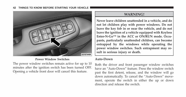
The power window switches remain active for up to 10minutes after the ignition switch has been turned OFF.Opening a vehicle front door will cancel this feature.
WARNING!
Never leave children unattended in a vehicle, and donot let children play with power windows. Do notleave the key fob in or near the vehicle, and do notleave the ignition of a vehicle equipped with KeylessEnter-N-Go™ in the ACC or ON/RUN mode. Occu-pants, particularly unattended children, can becomeentrapped by the windows while operating thepower window switches. Such entrapment may re-sult in serious injury or death.
Auto-Down
Both the driver and front passenger window switcheshave an “Auto-Down” feature. Press the window switchpast the first detent, release, and the window will godown automatically. To cancel the “Auto-Down” move-ment, operate the switch in either the up or downdirection and release the switch.
Power Window Switches
42 THINGS TO KNOW BEFORE STARTING YOUR VEHICLE

To open the window part way, press to the first detentand release it when you want the window to stop.
Auto Up Feature With Anti-Pinch Protection —Driver And Front Passenger Door Only
Lift the window switch fully upward to the seconddetent, release, and the window will go up automatically.
To stop the window from going all the way up during theAuto Up operation, push down on the switch briefly.
To close the window part way, lift the window switch tothe first detent and release when you want the window tostop.
Auto Down Window Switches
2
THINGS TO KNOW BEFORE STARTING YOUR VEHICLE 43

NOTE: If the window runs into any obstacle duringAuto Up it will reverse direction and then go back down.Remove the obstacle and use the window switch again toclose the window. Any impact due to rough road condi-tions may trigger the auto reverse function unexpectedlyduring Auto Up. If this happens, pull the switch lightly tothe first detent and hold it to close the window manually.
WARNING!
There is no anti-pinch protection when the windowis almost closed. Be sure to clear all objects from thewindow before closing.Auto Up Window Switches
44 THINGS TO KNOW BEFORE STARTING YOUR VEHICLE

Resetting The Auto Up Feature
Should the Auto Up feature stop working, the windowprobably needs to be reset. To reset Auto Up:
1. Pull the window switch up to close the windowcompletely and continue to hold the switch up for anadditional two seconds after the window is closed.
2. Push the window switch down firmly to the seconddetent to open the window completely and continueto hold the switch down for an additional two secondsafter the window is fully open.
Window Lockout Button
The Window Lockout button on the driver’s door allowsyou to disable the window controls on the rear doors. Todisable the window controls on the rear doors, press theWindow Lockout button. To enable the window controls,press the Window Lockout button again.
Window Lockout Button
2
THINGS TO KNOW BEFORE STARTING YOUR VEHICLE 45

Wind Buffeting
Wind buffeting can be described as the perception ofpressure on the ears or a helicopter-type sound in theears. Your vehicle may exhibit wind buffeting with thewindows down, or the sunroof (if equipped) in certainopen or partially open positions. This is a normal occur-rence and can be minimized. If the buffeting occurs withthe rear windows open, then open the front and rearwindows together to minimize the buffeting. If thebuffeting occurs with the sunroof open, adjust the sun-roof opening to minimize the buffeting.
LIFTGATE
To Unlock/Enter The Liftgate
The liftgate passive entry unlock feature is built into theelectronic liftgate handle. With a valid Passive Entry RKEtransmitter within 3 ft (1.0 m) of the liftgate, press theelectronic liftgate handle to open with one fluid motion.
NOTE: If “Unlock All Doors 1st Press” is programmed inEVIC, all doors will unlock when you push the button onthe liftgate. If �Unlock Driver Door 1st press� is pro-grammed in Uconnect®, the liftgate will unlock whenyou press the button on the liftgate For further informa-tion, refer to “Uconnect®” in “Understanding Your In-strument Panel”.
To Lock The Liftgate
With a valid Passive Entry RKE transmitter within 3 ft(1.0 m) of the liftgate, press the passive entry lock buttonlocated to the right of electronic liftgate handle.
NOTE: The liftgate passive entry lock button will onlylock the liftgate, the liftgate unlock feature is built intothe electronic liftgate handle.
46 THINGS TO KNOW BEFORE STARTING YOUR VEHICLE

WARNING!
Driving with the liftgate open can allow poisonousexhaust gases into your vehicle. You and your pas-sengers could be injured by these fumes. Keep theliftgate closed when you are operating the vehicle.
Power Liftgate — If Equipped
The power liftgate may be opened by pressingthe electronic liftgate handle (refer to KeylessEnter-N-Go located in Things To Know BeforeStarting) or by pressing the LIFTGATE button
on the Remote Keyless Entry (RKE) transmitter. Press theLIFTGATE button on the RKE transmitter twice withinfive seconds, to open the power liftgate. Once the liftgateis open, pressing the button twice within five seconds asecond time will close the liftgate.
Passive Entry/Lock Button Location
1 — Electronic Release Switch 2 — Lock Button Location
2
THINGS TO KNOW BEFORE STARTING YOUR VEHICLE 47

The power liftgate may also be opened or closed bypressing the LIFTGATE button located on the frontoverhead console, or closed by pressing the LIFTGATEbutton located on left rear trim panel, near the liftgateopening. Pressing the LIFTGATE button located on leftrear trim panel once will close the liftgate only, thisbutton cannot be used to open the liftgate.
When the LIFTGATE button on the RKE transmitter ispressed two times, the turn signals will flash twice tosignal that the liftgate is opening or closing (if FlashLamps with Lock is enabled in the EVIC) and the liftgatechime will be audible. For further information, refer to�Uconnect®� in �Understanding Your Instrument Panel�.
NOTE:
• In the event of a power malfunction to the liftgate, anemergency liftgate latch release can be used to openthe liftgate. The emergency liftgate latch release can beaccessed through a snap-in cover located on the lift-gate trim panel.
• If liftgate is left open for an extended period of time,the liftgate may need to be closed manually to resetpower liftgate functionality.
WARNING!
During power operation, personal injury or cargodamage may occur. Ensure the liftgate travel path isclear. Make sure the liftgate is closed and latchedbefore driving away.
48 THINGS TO KNOW BEFORE STARTING YOUR VEHICLE

NOTE:
• The power liftgate buttons will not operate if thevehicle is in gear or the vehicle speed is above 0 mph(0 km/h).
• The power liftgate will not operate in temperaturesbelow −22°F (−30°C) or temperatures above 150°F(65°C). Be sure to remove any buildup of snow or icefrom the liftgate before pressing any of the powerliftgate switches.
• If anything obstructs the power liftgate while it isclosing or opening, the liftgate will automaticallyreverse to the closed or open position, provided itmeets sufficient resistance.
• There are also pinch sensors attached to the side of theliftgate. Light pressure anywhere along these stripswill cause the liftgate to return to the open position.
• The power liftgate must be in the full open position forrear liftgate close button on the left rear trim, near theliftgate opening to operate. If the liftgate is not fullyopen, press the Liftgate button on the Key Fob to fullyopen the liftgate, and then press it again to close.
• If the liftgate handle is pulled while the power liftgate isclosing, the liftgate will reverse to the full open position.
• If the liftgate handle is pulled while the power liftgateis opening, the liftgate motor will disengage to allowmanual operation.
• If the power liftgate encounters multiple obstructionswithin the same cycle, the system will automaticallystop and the liftgate must be opened or closed manually.
• If your liftgate is power closing and you put thevehicle in gear, the liftgate will continue to powerclose. However, vehicle movement may result in adetection of an obstruction.
2
THINGS TO KNOW BEFORE STARTING YOUR VEHICLE 49

WARNING!
• Driving with the liftgate open can allow poisonousexhaust gases into your vehicle. You and yourpassengers could be injured by these fumes. Keepthe liftgate closed when you are operating thevehicle.
• If you are required to drive with the liftgate open,make sure that all windows are closed, and theclimate control blower switch is set at high speed.Do not use the recirculation mode.
OCCUPANT RESTRAINTS
Some of the most important safety features in yourvehicle are the restraint systems:
• Three-point lap and shoulder belts for the driver andall passengers
• Advanced Front Air Bags for driver and front passenger
• Supplemental Active Head Restraints (AHR) locatedon top of the front seats (integrated into the headrestraint)
• Supplemental Driver Side Knee Air Bag
• Supplemental Side Air Bag Inflatable Curtains (SABIC)for the driver and passengers seated next to a window
• Supplemental Seat-Mounted Side Air Bags (SAB)
50 THINGS TO KNOW BEFORE STARTING YOUR VEHICLE

• An energy-absorbing steering column and steeringwheel
• Knee bolsters for front seat occupants
• Front seat belts incorporate pretensioners that mayenhance occupant protection by managing occupantenergy during an impact event
• All seat belt systems (except the driver’s and secondrow center) include Automatic Locking Retractors(ALRs), which lock the seat belt webbing into positionby extending the belt all the way out and then adjust-ing the belt to the desired length to restrain a child seator secure a large item in a seat — if equipped
Please pay close attention to the information in thissection. It tells you how to use your restraint systemproperly, to keep you and your passengers as safe aspossible.
If you will be carrying children too small for adult-sizedseat belts, the seat belts or the Lower Anchors and Tetherfor CHildren (LATCH) feature also can be used to holdinfant and child restraint systems. For more informationon LATCH, refer to Lower Anchors and Tether forCHildren (LATCH).
NOTE: The Advanced Front Air Bags have a multistageinflator design. This allows the air bag to have differentrates of inflation based on several factors, including theseverity and type of collision.
Here are some simple steps you can take to minimize therisk of harm from a deploying air bag:
1. Children 12 years old and under should always ridebuckled up in a rear seat.
2
THINGS TO KNOW BEFORE STARTING YOUR VEHICLE 51

WARNING!
• Never place a rear facing infant seat in front of anair bag. A deploying passenger Advanced Front AirBag can cause death or serious injury to a child 12years or younger, including a child in a rearwardfacing infant seat.
• Only use a rearward-facing child restraint in a rearseat.
Children that are not big enough to wear the vehicle seatbelt properly (see section on Child Restraints) should besecured in the rear seat in child restraints or belt-positioning booster seats. Older children who do not usechild restraints or belt-positioning booster seats shouldride properly buckled up in the rear seat. Never allowchildren to slide the shoulder belt behind them or undertheir arm.
If a child from 2 to 12 years old (not in a rear facing childseat) must ride in the front passenger seat, move the seatas far back as possible and use the proper child restraint.(Refer to “Child Restraints”)
You should read the instructions provided with yourchild restraint to make sure that you are using it properly.
2. All occupants should always wear their lap andshoulder belts properly.
3. The driver and front passenger seats should bemoved back as far as practical to allow the AdvancedFront Air Bags room to inflate.
4. Do not lean against the door or window. If yourvehicle has side air bags, and deployment occurs, theside air bags will inflate forcefully into the spacebetween you and the door.
52 THINGS TO KNOW BEFORE STARTING YOUR VEHICLE

5. If the air bag system in this vehicle needs to bemodified to accommodate a disabled person, contactthe Customer Center. Phone numbers are providedunder �If You Need Assistance�.
WARNING!
• Relying on the air bags alone could lead to moresevere injuries in a collision. The air bags workwith your seat belt to restrain you properly. Insome collisions, the air bags won’t deploy at all.Always wear your seat belts even though you haveair bags.
(Continued)
WARNING! (Continued)• Being too close to the steering wheel or instrument
panel during Advanced Front Air Bag deploymentcould cause serious injury, including death. Airbags need room to inflate. Sit back, comfortablyextending your arms to reach the steering wheel orinstrument panel.
• Supplemental Side Air Bag Inflatable Curtain(SABIC) — if equipped and Seat-Mounted Side AirBags (SAB) also need room to inflate. Do not leanagainst the door or window. Sit upright in thecenter of the seat.
(Continued)
2
THINGS TO KNOW BEFORE STARTING YOUR VEHICLE 53
WARNING! (Continued)• In a collision, you and your passengers can suffer
much greater injuries if you are not properly buck-led up. You can strike the interior of your vehicle orother passengers, or you can be thrown out of thevehicle. Always be sure you and others in yourvehicle are buckled up properly.
• Being too close to the Supplemental Side Air BagInflatable Curtain (SABIC) — if equipped and/orSeat-Mounted Side Air Bag (SAB) during deploy-ment could cause you to be severely injured orkilled.
Buckle up even though you are an excellent driver, evenon short trips. Someone on the road may be a poor driverand cause a collision that includes you. This can happenfar away from home or on your own street.
Research has shown that seat belts save lives, and theycan reduce the seriousness of injuries in a collision. Someof the worst injuries happen when people are thrownfrom the vehicle. Seat belts reduce the possibility ofejection and the risk of injury caused by striking theinside of the vehicle. Everyone in a motor vehicle shouldbe belted at all times.
Lap/Shoulder Belts
All seating positions in your vehicle are equipped withlap/shoulder belts. The belt webbing retractor is de-signed to lock during very sudden stops or collisions.This feature allows the shoulder part of the belt to movefreely with you under normal conditions. However, in ancollision the belt will lock and reduce the risk of youstriking the inside of the vehicle or being thrown out.
54 THINGS TO KNOW BEFORE STARTING YOUR VEHICLE

WARNING!
• Wearing a seat belt incorrectly is dangerous. Seatbelts are designed to go around the large bones ofyour body. These are the strongest parts of yourbody and can take the forces of a collision the best.Wearing your belt in the wrong place could makeyour injuries in a collision much worse. You mightsuffer internal injuries, or you could even slide outof part of the belt. Follow these instructions to wearyour seat belt safely and to keep your passengerssafe, too.
• Two people should never be belted into a singleseat belt. People belted together can crash into oneanother in a collision, hurting one another badly.Never use a lap/shoulder belt or a lap belt for morethan one person, no matter what their size.
(Continued)
WARNING! (Continued)• It is dangerous to ride in a cargo area, inside or
outside of a vehicle. In a collision, people riding inthese areas are more likely to be seriously injuredor killed.
• Do not allow people to ride in any area of yourvehicle that is not equipped with seats and seatbelts.
• Be sure everyone in your vehicle is in a seat andusing a seat belt properly.
Lap/Shoulder Belt Operating Instructions
1. Enter the vehicle and close the door. Sit back andadjust the seat.
2. The seat belt latch plate is above the back of your seat.Grasp the latch plate and pull out the belt. Slide thelatch plate up the webbing as far as necessary to makethe belt go around your lap.
2
THINGS TO KNOW BEFORE STARTING YOUR VEHICLE 55

3. When the belt is long enough to fit, insert the latchplate into the buckle until you hear a “click.”
Latch Plate Latch Plate To Buckle
56 THINGS TO KNOW BEFORE STARTING YOUR VEHICLE

WARNING!
• A belt that is buckled into the wrong buckle willnot protect you properly. The lap portion could ridetoo high on your body, possibly causing internalinjuries. Always buckle your belt into the bucklenearest you.
• A belt that is too loose will not protect you prop-erly. In a sudden stop you could move too farforward, increasing the possibility of injury. Wearyour seat belt snugly.
(Continued)
WARNING! (Continued)• A belt that is worn under your arm is dangerous.
Your body could strike the inside surfaces of thevehicle in a collision, increasing head and neckinjury. A belt worn under the arm can cause inter-nal injuries. Ribs aren’t as strong as shoulderbones. Wear the belt over your shoulder so thatyour strongest bones will take the force in a colli-sion.
• A shoulder belt placed behind you will not protectyou from injury during a collision. You are morelikely to hit your head in a collision if you do notwear your shoulder belt. The lap and shoulder beltare meant to be used together.
2
THINGS TO KNOW BEFORE STARTING YOUR VEHICLE 57

4. Position the lap belt across your thighs, below yourabdomen. To remove slack in the lap portion, pull upa bit on the shoulder belt. To loosen the lap belt if it istoo tight, tilt the latch plate and pull on the lap belt. Asnug belt reduces the risk of sliding under the belt ina collision.
WARNING!
• A lap belt worn too high can increase the risk ofinjury in a collision. The belt forces won’t be at thestrong hip and pelvic bones, but across your abdo-men. Always wear the lap part of your seat belt aslow as possible and keep it snug.
• A twisted belt may not protect you properly. In acollision, it could even cut into you. Be sure the beltis straight. If you can’t straighten a belt in yourvehicle, take it to your authorized dealer immedi-ately and have it fixed.
5. Position the shoulder belt on your chest so that it iscomfortable and not resting on your neck. The retrac-tor will withdraw any slack in the belt.
Removing Slack From Belt
58 THINGS TO KNOW BEFORE STARTING YOUR VEHICLE

6. To release the belt, push the red button on the buckle.The belt will automatically retract to its stowed posi-tion. If necessary, slide the latch plate down thewebbing to allow it to retract fully.
WARNING!
A frayed or torn belt could rip apart in a collision andleave you with no protection. Inspect the belt systemperiodically, checking for cuts, frays, or loose parts.Damaged parts must be replaced immediately. Donot disassemble or modify the system. Seat beltassemblies must be replaced after a collision if theyhave been damaged (bent retractor, torn webbing,etc.).
Lap/Shoulder Belt Untwisting Procedure
Use the following procedure to untwist a twisted lap/shoulder belt.
1. Position the latch plate as close as possible to theanchor point.
2. At about 6 to 12 in (15 to 30 cm) above the latch plate,grasp and twist the belt webbing 180 degrees to createa fold that begins immediately above the latch plate.
3. Slide the latch plate upward over the folded webbing.The folded webbing must enter the slot at the top ofthe latch plate.
4. Continue to slide the latch plate up until it clears thefolded webbing.
2
THINGS TO KNOW BEFORE STARTING YOUR VEHICLE 59

Adjustable Upper Shoulder Belt Anchorage
In the front seating positions, the shoulder belt can beadjusted upward or downward to position the belt awayfrom your neck. Press the release button to release theanchorage, and then move it up or down to the positionthat fits you best.
As a guide, if you are shorter than average, you willprefer a lower position, and if you are taller than average,you will prefer a higher position. When you release thebutton, verify the shoulder belt anchorage is latched bypulling downward on the shoulder belt anchorage until itis locked into position.
NOTE: The adjustable upper shoulder belt anchorage isequipped with an Easy Up feature. This feature allowsthe shoulder belt anchorage to be adjusted in the upwardposition without pushing the release button. To verify theshoulder belt anchorage is latched, pull downward onthe shoulder belt anchorage until it is locked into posi-tion.
Adjusting Upper Shoulder Belt
60 THINGS TO KNOW BEFORE STARTING YOUR VEHICLE
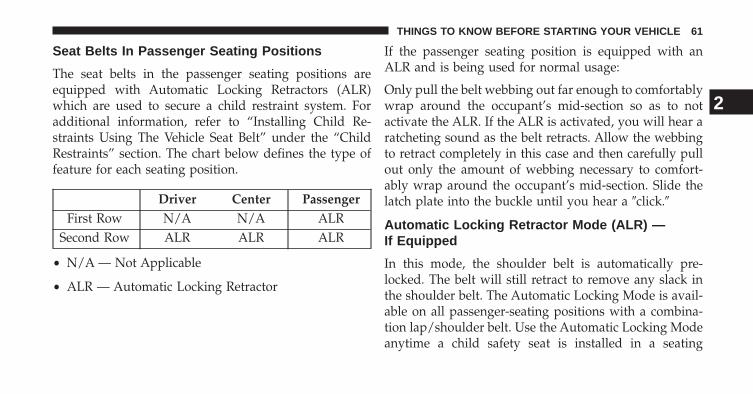
Seat Belts In Passenger Seating Positions
The seat belts in the passenger seating positions areequipped with Automatic Locking Retractors (ALR)which are used to secure a child restraint system. Foradditional information, refer to “Installing Child Re-straints Using The Vehicle Seat Belt” under the “ChildRestraints” section. The chart below defines the type offeature for each seating position.
Driver Center PassengerFirst Row N/A N/A ALR
Second Row ALR ALR ALR
• N/A — Not Applicable
• ALR — Automatic Locking Retractor
If the passenger seating position is equipped with anALR and is being used for normal usage:
Only pull the belt webbing out far enough to comfortablywrap around the occupant’s mid-section so as to notactivate the ALR. If the ALR is activated, you will hear aratcheting sound as the belt retracts. Allow the webbingto retract completely in this case and then carefully pullout only the amount of webbing necessary to comfort-ably wrap around the occupant’s mid-section. Slide thelatch plate into the buckle until you hear a �click.�
Automatic Locking Retractor Mode (ALR) —If Equipped
In this mode, the shoulder belt is automatically pre-locked. The belt will still retract to remove any slack inthe shoulder belt. The Automatic Locking Mode is avail-able on all passenger-seating positions with a combina-tion lap/shoulder belt. Use the Automatic Locking Modeanytime a child safety seat is installed in a seating
2
THINGS TO KNOW BEFORE STARTING YOUR VEHICLE 61

position that has a belt with this feature. Children 12years old and under should always be properly re-strained in the rear seat.
How To Engage The Automatic Locking Mode
1. Buckle the combination lap and shoulder belt.
2. Grasp the shoulder portion and pull downward untilthe entire belt is extracted.
3. Allow the belt to retract. As the belt retracts, you willhear a clicking sound. This indicates the safety belt isnow in the Automatic Locking Mode.
How To Disengage The Automatic Locking Mode
Unbuckle the combination lap/shoulder belt and allow itto retract completely to disengage the Automatic LockingMode and activate the vehicle sensitive (emergency)locking mode.
WARNING!
• The belt and retractor assembly must be replaced ifthe seat belt assembly Automatic Locking Retractor(ALR) feature or any other seat belt function is notworking properly when checked according to theprocedures in the Service Manual.
• Failure to replace the belt and retractor assemblycould increase the risk of injury in collisions.
Energy Management Feature
This vehicle has a safety belt system with an EnergyManagement feature in the front seating positions to helpfurther reduce the risk of injury in the event of a head-oncollision.
This safety belt system has a retractor assembly that isdesigned to release webbing in a controlled manner. Thisfeature is designed to help reduce the belt force acting onthe occupant’s chest.
62 THINGS TO KNOW BEFORE STARTING YOUR VEHICLE
Seat Belt Pretensioners
The seat belts for both front seating positions areequipped with pretensioning devices that are designed toremove slack from the seat belt in the event of a collision.These devices may improve the performance of the seatbelt by assuring that the belt is tight about the occupantearly in a collision. Pretensioners work for all size occu-pants, including those in child restraints.
NOTE: These devices are not a substitute for proper seatbelt placement by the occupant. The seat belt still must beworn snugly and positioned properly.
The pretensioners are triggered by the Occupant Re-straint Controller (ORC). Like the air bags, the preten-sioners are single use items. A deployed pretensioner ora deployed air bag must be replaced immediately.
Supplemental Active Head Restraints (AHR)
These head restraints are passive, deployable compo-nents, and vehicles with this equipment cannot be readilyidentified by any markings, only through visual inspec-tion of the head restraint. The head restraint will be splitin two halves, with the front half being soft foam andtrim, the back half being decorative plastic.
How The Active Head Restraints (AHR) Work
The Occupant Restraint Controller (ORC) determineswhether the severity, or type of rear impact will requirethe Active Head Restraints (AHR) to deploy. If a rearimpact requires deployment, both the driver and frontpassenger seat AHRs will be deployed.
2
THINGS TO KNOW BEFORE STARTING YOUR VEHICLE 63

When AHRs deploy during a rear impact, the front halfof the head restraint extends forward to minimize the gapbetween the back of the occupant’s head and the AHR.This system is designed to help prevent or reduce theextent of injuries to the driver and front passenger incertain types of rear impacts.
NOTE: The Active Head Restraints (AHR) may or maynot deploy in the event of a front or side impact.However if during a front impact, a secondary rearimpact occurs, the AHR may deploy based on the sever-ity and type of the impact.
Active Head Restraint (AHR) Components
1 — Head Restraint Front Half(Soft Foam and Trim)
3 — Head Restraint Back Half(Decorative Plastic Rear Cover)
2 — Seatback 4 — Head Restraint GuideTubes
64 THINGS TO KNOW BEFORE STARTING YOUR VEHICLE

CAUTION!
All occupants, including the driver, should not oper-ate a vehicle or sit in a vehicle’s seat until the headrestraints are placed in their proper positions in orderto minimize the risk of neck injury in the event of acollision.
NOTE: For more information on properly adjusting andpositioning the head restraint, refer to “Adjusting ActiveHead Restraints” in “Understanding The Features OfYour Vehicle”.
Resetting Active Head Restraints (AHR)
If the Active Head Restraints are triggered in a collision,you must reset the head restraint on the driver’s andfront passenger seat. You can recognize when the ActiveHead Restraint has been triggered by the fact that theyhave moved forward (as shown in step three of theresetting procedure).
1. Grasp the deployed AHR from the rear seat.
2
THINGS TO KNOW BEFORE STARTING YOUR VEHICLE 65

2. Position the hands on the top of the deployed AHR ata comfortable position.
3. Pull down then rearward towards the rear of thevehicle then down to engage the locking mechanism.
Hand Positioning Points On AHR 1 — Downward Movement2 — Rearward Movement
66 THINGS TO KNOW BEFORE STARTING YOUR VEHICLE

4. The AHR front soft foam and trim half should lockinto the back decorative plastic half.
NOTE:
• If you have difficulties or problems resetting the ActiveHead Restraints, see an authorized dealer.
• For safety reasons, have the Active Head Restraintschecked by a qualified specialist at an authorized dealer.
3 — Final Downward Movement To Engage Locking Mechanism AHR In Reset Position
2
THINGS TO KNOW BEFORE STARTING YOUR VEHICLE 67

Enhanced Seat Belt Use Reminder System(BeltAlert®)
BeltAlert® is a feature intended to remind the driver andfront passenger (if equipped with front passengerBeltAlert®) to fasten their seat belts. The feature is activewhenever the ignition is on. If the driver or front seatpassenger is unbelted, the Seat Belt Reminder Light willturn on and remain on until both front seat belts arefastened.
The BeltAlert® warning sequence begins after the vehiclespeed is over 5 mph (8 km/h), by blinking the Seat BeltReminder Light and sounding an intermittent chime.Once the sequence starts, it will continue for the entireduration or until the respective seatbelts are fastened.After the sequence completes, the Seat Belt ReminderLight remains illuminated until the respective seat beltsare fastened. The driver should instruct all other occu-pants to fasten their seat belts. If a front seat belt is
unbuckled while traveling at speeds greater than 5 mph(8 km/h), BeltAlert® will provide both audio and visualnotification.
The front passenger seat BeltAlert® is not active whenthe front passenger seat is unoccupied. BeltAlert® maybe triggered when an animal or heavy object is on thefront passenger seat or when the seat is folded flat (ifequipped). It is recommended that pets be restrained inthe rear seat in pet harnesses or pet carriers that aresecured by seat belts, and cargo is properly stowed.
BeltAlert® can be enabled or disabled by your autho-rized dealer. Chrysler Group LLC does not recommenddeactivating BeltAlert®.
NOTE: Although BeltAlert® has been deactivated, theSeat Belt Reminder Light will continue to illuminatewhile the driver’s or front passenger (if equipped withBeltAlert®) seat belt remains unfastened.
68 THINGS TO KNOW BEFORE STARTING YOUR VEHICLE

Seat Belt Lock Out
The center rear seat belt system has a lock out feature thatwill not allow you to extract the center webbing unlessthe rear seat upper latch is engaged.
Seat Belts And Pregnant Women
We recommend that pregnant women use the seat beltsthroughout their pregnancy. Keeping the mother safe isthe best way to keep the baby safe.
Pregnant women should wear the lap part of the beltacross the thighs and as snug across the hips as possible.Keep the belt low so that it does not come across theabdomen. That way the strong bones of the hips will takethe force if there is a collision.
Seat Belt Extender
If a seat belt is too short even when fully extended andwhen the adjustable upper shoulder belt anchorage (ifequipped) is in its lowest position, your authorizeddealer can provide you with a seat belt extender. Thisextender should be used only if the existing belt is notlong enough. When it is not required, remove the ex-tender and store it.
WARNING!
Using a seat belt extender when not needed canincrease the risk of injury in a collision. Only usewhen the seat belt is not long enough when it is wornlow and snug and in the recommended seating posi-tions. Remove and store the extender when notneeded.
2
THINGS TO KNOW BEFORE STARTING YOUR VEHICLE 69

Supplemental Restraint System (SRS) — Air Bags
This vehicle has Advanced Front Air Bags for both thedriver and front passenger as a supplement to the seatbelt restraint systems. The driver’s Advanced Front AirBag is mounted in the center of the steering wheel. Thepassenger’s Advanced Front Air Bag is mounted in theinstrument panel, above the glove compartment. Thewords SRS AIRBAG are embossed on the air bag covers.In addition, the vehicle is equipped with SupplementalDriver Side Knee Air Bag mounted in the instrumentpanel below the steering column and a Knee Bolsterbelow the glove compartment.
Advanced Front Air Bag And Knee Bolster Locations
1 — Driver And Passenger Ad-vanced Front Air Bags
3 — Supplemental Driver SideKnee Air Bag/Knee Bolster
2 — Knee Bolster
70 THINGS TO KNOW BEFORE STARTING YOUR VEHICLE

NOTE: The Driver and Front Passenger Advanced FrontAir Bags are certified to the new Federal regulations forAdvanced Air Bags.
The Advanced Front Air Bags have a multistage inflatordesign. This allows the air bag to have different rates ofinflation based on several factors, including the severityand type of collision.
This vehicle may be equipped with driver and/or frontpassenger seat track position sensors that may adjust theinflation rate of the Advanced Front Air Bags based uponseat position.
This vehicle may be equipped with a driver and/or frontpassenger seat belt buckle switch that detects whetherthe driver or front passenger seat belt is fastened. Theseat belt buckle switch may adjust the inflation rate of theAdvanced Front Air Bags.
This vehicle is equipped with Supplemental Side Air BagInflatable Curtains (SABIC) to protect the driver, front,
and rear passengers sitting next to a window. The SABICair bags are located above the side windows and theircovers are labeled: SRS AIRBAG.
This vehicle is equipped with Supplemental Seat-Mounted Side Air Bags (SAB) to provide enhancedprotection for an occupant during a side impact. TheSupplemental Seat-Mounted Side Air Bags are located inthe outboard side of the front seats.
This vehicle is equipped with Supplemental Driver SideKnee Air Bag mounted in the instrument panel below thesteering column and a Knee Bolster mounted below theglove compartment.
NOTE:
• Air Bag covers may not be obvious in the interior trim,but they will open during air bag deployment.
• After any collision, the vehicle should be taken to anauthorized dealer immediately.
2
THINGS TO KNOW BEFORE STARTING YOUR VEHICLE 71

Air Bag System Components
Your vehicle may be equipped with the following air bagsystem components:
• Occupant Restraint Controller (ORC)
• Air Bag Warning Light
• Steering Wheel and Column
• Instrument Panel
• Knee Impact Bolsters
• Driver Advanced Front Air Bag
• Passenger Advanced Front Air Bag
• Supplemental Seat-Mounted Side Air Bags (SAB)
• Supplemental Side Air Bag Inflatable Curtains (SABIC)
• Supplemental Driver Side Knee Air Bag
• Front and Side Impact Sensors
• Front Seat Belt Pretensioners, Seat Belt Buckle Switch,and Seat Track Position Sensors
Advanced Front Air Bag Features
The Advanced Front Air Bag system has multistagedriver and front passenger air bags. This system providesoutput appropriate to the severity and type of collision asdetermined by the Occupant Restraint Controller (ORC),which may receive information from the front impactsensors.
The first stage inflator is triggered immediately during animpact that requires air bag deployment. This low outputis used in less severe collisions. A higher energy output isused for more severe collisions.
72 THINGS TO KNOW BEFORE STARTING YOUR VEHICLE

WARNING!
• No objects should be placed over or near the airbag on the instrument panel, because any suchobjects could cause harm if the vehicle is in acollision severe enough to cause the air bag toinflate.
• Do not put anything on or around the air bagcovers or attempt to open them manually. You maydamage the air bags and you could be injuredbecause the air bags may no longer be functional.The protective covers for the air bag cushions aredesigned to open only when the air bags areinflating.
• Do not drill, cut or tamper with the knee bolster inany way.
• Do not mount any accessories to the knee bolstersuch as alarm lights, stereos, citizen band radios, etc.
Supplemental Seat-Mounted Side Air Bags (SAB)
Supplemental Seat-Mounted Side Air Bags (SAB) mayprovide enhanced protection to help protect an occupantduring a side impact. The SAB is marked with an air baglabel sewn into the outboard side of the front seats.
Supplemental Seat-Mounted Side Air Bag Label
2
THINGS TO KNOW BEFORE STARTING YOUR VEHICLE 73

When the air bag deploys, it opens the seam between thefront and side of the seat’s trim cover. Each air bagdeploys independently; a left side impact deploys the leftair bag only and a right-side impact deploys the right airbag only.
Supplemental Side Air Bag Inflatable Curtain(SABIC)
SABIC air bags may offer side-impact and vehicle roll-over protection to front and rear seat outboard occupantsin addition to that provided by the body structure. Eachair bag features inflated chambers placed adjacent to thehead of each outboard occupant that reduce the potentialfor side-impact head injuries. The SABIC deploy down-ward, covering both windows on the impact side. Supplemental Side Air Bag Inflatable Curtain (SABIC)
Label Location
74 THINGS TO KNOW BEFORE STARTING YOUR VEHICLE
NOTE:
• Air Bag covers may not be obvious in the interior trim,but they will open during air bag deployment.
• Being too close to the SAB and SABIC air bags duringdeployment could cause you to be severely injured orkilled.
• Should a vehicle rollover occur, the pretensionersand/or SAB and SABIC air bags on both sides of thevehicle may deploy.
The system includes side impact sensors that are cali-brated to deploy the Supplemental SAB and SABIC airbags during impacts that require side air bag occupantprotection.
WARNING!
• Your vehicle is equipped with left and rightSABIC, do not stack luggage or other cargo up highenough to block the location of the SABIC. Thearea where the side curtain air bag is locatedshould remain free from any obstructions.
• Do not use accessory seat covers or place objectsbetween you and the SAB; the performance couldbe adversely affected and/or objects could bepushed into you, causing serious injury.
• Your vehicle is equipped with SABIC air bags, donot have any accessory items installed which willalter the roof, including adding a sunroof to yourvehicle. Do not add roof racks that require perma-nent attachments (bolts or screws) for installationon the vehicle roof. Do not drill into the roof of thevehicle for any reason.
2
THINGS TO KNOW BEFORE STARTING YOUR VEHICLE 75

Always sit upright as possible with your back against theseat back, use the seat belts properly, and use theappropriate sized child restraint, infant restraint orbooster seat recommended for the size and weight of thechild.
SAB and SABIC air bags are a supplement to the seat beltrestraint system. Occupants, including children who areup against or very close to SAB or SABIC air bags can beseriously injured or killed. Occupants, especially chil-dren, should not lean on or sleep against the door, sidewindows, or area where the SAB or SABIC air bagsinflate, even if they are in an infant or child restraint.
Knee Impact Bolsters
The Knee Impact Bolsters help protect the knees of thedriver and the front passenger, and position front occu-pants for the best interaction with the Advanced FrontAir Bag.
Along with seat belts and pretensioners, Advanced FrontAir Bags work with the knee bolsters to provide im-proved protection for the driver and front passenger. Sideair bags also work with seat belts to improve occupantprotection.
Supplemental Driver Knee Air Bag
The Supplemental Driver Side Knee Air Bag providesenhanced protection and works together with the DriverAdvanced Front Air Bag during a frontal impact.
Air Bag Deployment Sensors And Controls
Occupant Restraint Controller (ORC)
The ORC is part of a Federally regulated safety systemrequired for this vehicle.
The ORC determines if deployment of the front and/orside air bags in a frontal or side collision is required.Based on the impact sensor’s signals, a central electronic
76 THINGS TO KNOW BEFORE STARTING YOUR VEHICLE

ORC deploys the Advanced Front Air Bags, Supplemen-tal Driver Side Knee Air Bag, SABIC air bags, SAB airbags, and front seat belt pretensioners, as required,depending on several factors, including the severity andtype of impact.
Advanced Front Air Bags and Supplemental Driver SideKnee Air Bag are designed to provide additional protec-tion by supplementing the seat belts in certain frontalcollisions depending on several factors, including theseverity and type of collision. Advanced Front Air Bagsand Supplemental Driver Side Knee Air Bag are notexpected to reduce the risk of injury in rear, side, orrollover collisions.
The Advanced Front Air Bags and Supplemental DriverSide Knee Air Bag will not deploy in all frontal collisions,including some that may produce substantial vehicledamage — for example, some pole collisions, truck
underrides, and angle offset collisions. On the otherhand, depending on the type and location of impact,Advanced Front Air Bags and Supplemental Driver SideKnee Air Bag may deploy in crashes with little vehiclefront-end damage but that produce a severe initial decel-eration.
The side air bags will not deploy in all side collisions.Side air bag deployment will depend on the severity andtype of collision.
Because air bag sensors measure vehicle decelerationover time, vehicle speed and damage by themselves arenot good indicators of whether or not an air bag shouldhave deployed.
Seat belts are necessary for your protection in all colli-sions, and also are needed to help keep you in position,away from an inflating air bag.
2
THINGS TO KNOW BEFORE STARTING YOUR VEHICLE 77

The ORC monitors the readiness of the electronic parts ofthe air bag system whenever the ignition switch is in theSTART or ON/RUN position. If the key is in the OFFposition, in the ACC position, or not in the ignition, theair bag system is not on and the air bags will not inflate.
The ORC contains a backup power supply system thatmay deploy the air bags even if the battery loses power orit becomes disconnected prior to deployment.
Also, the ORC turns on the Air Bag WarningLight in the instrument panel for approxi-mately four to eight seconds for a self-checkwhen the ignition is first turned on. After the
self-check, the Air Bag Warning Light will turn off. If theORC detects a malfunction in any part of the system, itturns on the Air Bag Warning Light, either momentarilyor continuously. A single chime will sound if the lightcomes on again after initial startup.
It also includes diagnostics that will illuminate the instru-ment cluster Air Bag Warning Light if a malfunction isnoted that could affect the air bag system. The diagnos-tics also record the nature of the malfunction.
WARNING!
Ignoring the Air Bag Warning Light in your instru-ment panel could mean you won’t have the air bagsto protect you in a collision. If the light does not comeon as a bulb check when the ignition is first turnedon, stays on after you start the vehicle, or if it comeson as you drive, have an authorized dealer service theair bag system immediately.
78 THINGS TO KNOW BEFORE STARTING YOUR VEHICLE

Driver And Passenger Advanced Front Air BagInflator Units
The Driver and Passenger Advanced Front Air Bag InflatorUnits are located in the center of the steering wheel and onthe right side of the instrument panel. When the ORC detectsa collision requiring the Advanced Front Air Bags, it signalsthe inflator units. A large quantity of non-toxic gas isgenerated to inflate the Advanced Front Air Bags. Differentair bag inflation rates are possible, based on several factors,including the collision type and severity. The steering wheelhub trim cover and the upper right side of the instrumentpanel separate and fold out of the way as the air bags inflateto their full size. The air bags fully inflate in about 50 to 70milliseconds. This is about half of the time it takes to blinkyour eyes. The air bags then quickly deflate while helping torestrain the driver and front passenger.
The Advanced Front Air Bag gas is vented through thevent holes in the sides of the air bag. In this way, the airbags do not interfere with your control of the vehicle.
Supplemental Seat-Mounted Side Air Bag (SAB)Inflator Units
The Supplemental Seat-Mounted Side Air Bags are de-signed to activate only in certain side collisions.
The ORC determines if a side collision requires the sideair bags to inflate, based on the severity and type ofcollision.
Based on the severity and type of collision, the side airbag inflator on the crash side of the vehicle may betriggered, releasing a quantity of non-toxic gas. Theinflating SAB exits through the seat seam into the spacebetween the occupant and the door. The SAB fully inflatein about 10 milliseconds. The side air bag moves at a veryhigh speed and with such a high force that it could injureyou if you are not seated properly, or if items arepositioned in the area where the side air bag inflates. Thisespecially applies to children.
2
THINGS TO KNOW BEFORE STARTING YOUR VEHICLE 79

Supplemental Driver Side Knee Air Bag InflatorUnit
The Supplemental Driver Side Knee Air Bag unit islocated in the instrument panel trim beneath the steeringcolumn. When the ORC detects a collision requiring theair bag, it signals the inflator units. A large quantity ofnon-toxic gas is generated to inflate the SupplementalDriver Side Knee Air Bag. The trim cover separates andfolds out of the way allowing the air bag to inflate to thefull size. The air bag fully inflates in about 15 to 20 mil-liseconds.
Supplemental Side Air Bag Inflatable Curtain(SABIC) Inflator Units
During collisions where the impact is confined to aparticular area of the side of the vehicle, the ORC maydeploy the SABIC air bags, depending on the severityand type of collision. In these events, the ORC willdeploy the SABIC only on the impact side of the vehicle.
A quantity of non-toxic gas is generated to inflate theSABIC. The inflating SABIC pushes the outside edge ofthe headliner out of the way and covers the window. TheSABIC inflates in about 30 milliseconds (about one-quarter of the time that it takes to blink your eyes) withenough force to injure you if you are not belted andseated properly, or if items are positioned in the areawhere the SABIC inflates. This especially applies tochildren. The SABIC is only about 3-1/2 in (9 cm) thickwhen it is inflated.
80 THINGS TO KNOW BEFORE STARTING YOUR VEHICLE

Because air bag sensors estimate deceleration over time,vehicle speed and damage are not good indicators ofwhether or not an air bag should have deployed.
NOTE: In a rollover the pretensioners and/or SAB andSABIC air bags, and driver/passenger knee air bags maydeploy on both sides of the vehicle.
Front And Side Impact Sensors
In front and side impacts, impact sensors can aid theORC in determining appropriate response to impactevents.
Enhanced Accident Response System
In the event of an impact causing air bag deployment, ifthe communication network remains intact, and thepower remains intact, depending on the nature of the
event the ORC will determine whether to have theEnhanced Accident Response System perform the follow-ing functions:
• Cut off fuel to the engine.
• Flash hazard lights as long as the battery has power oruntil the ignition key is turned off.
• Turn on the interior lights, which remain on as long asthe battery has power or until the ignition key isremoved.
• Unlock the doors automatically.
In order to reset the Enhanced Accident Response Systemfunctions after an event, the ignition switch must bechanged from IGN ON to IGN OFF.
2
THINGS TO KNOW BEFORE STARTING YOUR VEHICLE 81

If A Deployment Occurs
The Advanced Front Air Bags are designed to deflateimmediately after deployment.
NOTE: Front and/or side air bags will not deploy in allcollisions. This does not mean something is wrong withthe air bag system.
If you do have a collision which deploys the air bags, anyor all of the following may occur:
• The nylon air bag material may sometimes causeabrasions and/or skin reddening to the driver andfront passenger as the air bags deploy and unfold. Theabrasions are similar to friction rope burns or thoseyou might get sliding along a carpet or gymnasiumfloor. They are not caused by contact with chemicals.
They are not permanent and normally heal quickly.However, if you haven’t healed significantly within afew days, or if you have any blistering, see your doctorimmediately.
• As the air bags deflate, you may see some smoke-likeparticles. The particles are a normal by-product of theprocess that generates the non-toxic gas used for airbag inflation. These airborne particles may irritate theskin, eyes, nose, or throat. If you have skin or eyeirritation, rinse the area with cool water. For nose orthroat irritation, move to fresh air. If the irritationcontinues, see your doctor. If these particles settle onyour clothing, follow the garment manufacturer’s in-structions for cleaning.
82 THINGS TO KNOW BEFORE STARTING YOUR VEHICLE

Do not drive your vehicle after the air bags have de-ployed. If you are involved in another collision, the airbags will not be in place to protect you.
WARNING!
Deployed air bags and seat belt pretensioners cannotprotect you in another collision. Have the air bags,seat belt pretensioners, and the front seat belt retrac-tor assemblies replaced by an authorized dealer im-mediately. Also, have the Occupant Restraint Con-troller (ORC) system serviced as well.
Maintaining Your Air Bag System
WARNING!
• Modifications to any part of the air bag systemcould cause it to fail when you need it. You couldbe injured if the air bag system is not there toprotect you. Do not modify the components orwiring, including adding any kind of badges orstickers to the steering wheel hub trim cover or theupper right side of the instrument panel. Do notmodify the front bumper, vehicle body structure, oradd aftermarket side steps or running boards.
• It is dangerous to try to repair any part of the airbag system yourself. Be sure to tell anyone whoworks on your vehicle that it has an air bag system.
(Continued)
2
THINGS TO KNOW BEFORE STARTING YOUR VEHICLE 83

WARNING! (Continued)• Do not attempt to modify any part of your air bag
system. The air bag may inflate accidentally or maynot function properly if modifications are made.Take your vehicle to an authorized dealer for anyair bag system service. If your seat, including yourtrim cover and cushion, needs to be serviced in anyway (including removal or loosening/tightening ofseat attachment bolts), take the vehicle to yourauthorized dealer. Only manufacturer approvedseat accessories may be used. If it is necessary tomodify the air bag system for persons with dis-abilities, contact your authorized dealer.
Air Bag Warning Light
You will want to have the air bags ready toinflate for your protection in a collision. TheAir Bag Warning Light monitors the internalcircuits and interconnecting wiring associated
with air bag system electrical components. While the airbag system is designed to be maintenance free. If any ofthe following occurs, have an authorized dealer servicethe air bag system immediately.
• The Air Bag Warning Light does not come on duringthe four to eight seconds when the ignition is firstcycled to the ON/RUN.
• The Air Bag Warning Light remains on after the four toeight-second interval.
• The Air Bag Warning Light comes on intermittently orremains on while driving.
84 THINGS TO KNOW BEFORE STARTING YOUR VEHICLE

NOTE: If the speedometer, tachometer, or any enginerelated gauges are not working, the Occupant RestraintController (ORC) may also be disabled. The air bags maynot be ready to inflate for your protection. Promptlycheck the fuse block for blown fuses. Refer to “Fuses” in“Maintaining Your Vehicle” for the proper air bag fuses.See your authorized dealer if the fuse is good.
Event Data Recorder (EDR)
This vehicle is equipped with an event data recorder(EDR). The main purpose of an EDR is to record, incertain crash or near crash-like situations, such as an airbag deployment or hitting a road obstacle, data that willassist in understanding how a vehicle’s systems per-formed. The EDR is designed to record data related to
vehicle dynamics and safety systems for a short period oftime, typically 30 seconds or less. The EDR in this vehicleis designed to record such data as:
• How various systems in your vehicle were operating;
• Whether or not the driver and passenger safety beltswere buckled/fastened;
• How far (if at all) the driver was depressing theaccelerator and/or brake pedal; and,
• How fast the vehicle was traveling.
These data can help provide a better understanding ofthe circumstances in which crashes and injuries occur.
2
THINGS TO KNOW BEFORE STARTING YOUR VEHICLE 85

NOTE: EDR data are recorded by your vehicle only if anon-trivial crash situation occurs; no data are recorded bythe EDR under normal driving conditions and no per-sonal data (e.g., name, gender, age, and crash location)are recorded. However, other parties, such as law en-forcement, could combine the EDR data with the type ofpersonally identifying data routinely acquired during acrash investigation.
To read data recorded by an EDR, special equipment isrequired, and access to the vehicle or the EDR is needed.In addition to the vehicle manufacturer, other parties,such as law enforcement, that have the special equip-ment, can read the information if they have access to thevehicle or the EDR.
Child Restraints
Everyone in your vehicle needs to be buckled up at alltimes, including babies and children. Every state in theUnited States, and every Canadian province, requiresthat small children ride in proper restraint systems. Thisis the law, and you can be prosecuted for ignoring it.
Children 12 years or younger should ride properlybuckled up in a rear seat, if available. According to crashstatistics, children are safer when properly restrained inthe rear seats rather than in the front.
There are different sizes and types of restraints forchildren from newborn size to the child almost largeenough for an adult safety belt. Always check the childseat Owner’s Manual to make sure you have the correctseat for your child.
86 THINGS TO KNOW BEFORE STARTING YOUR VEHICLE

Before buying any restraint system, make sure that it hasa label certifying that it meets all applicable SafetyStandards. You should also make sure that you can installit in the vehicle where you will use it.
NOTE: For additional information, refer towww.seatcheck.org or call 1–866–SEATCHECK. Cana-dian residents should refer to Transport Canada’s web-site for additional information: http://www.tc.gc.ca/eng/roadsafety/safedrivers-childsafety-index-53.htm
WARNING!
In a collision, an unrestrained child can become aprojectile inside the vehicle. The force required tohold even an infant on your lap could become sogreat that you could not hold the child, no matterhow strong you are. The child and others could bebadly injured. Any child riding in your vehicleshould be in a proper restraint for the child’s size.
2
THINGS TO KNOW BEFORE STARTING YOUR VEHICLE 87

Summary Of Recommendations For Restraining Children In Vehicles
Child Size, Height, Weight or Age Recommended Type of Child RestraintInfants and
ToddlersChildren who are two years old or
younger and who have not reached theheight or weight limits of their child
restraint
Either an Infant Carrier or a ConvertibleChild Restraint, facing rearward in the rear
seat of the vehicle
Small Children Children who are at least two years old orwho have out-grown the height or weight
limit of their rear-facing child restraint
Forward-Facing Child Restraint with afive-point Harness, facing forward in the
rear seat of the vehicleLarger Children Children who have out-grown their
forward-facing child restraint, but are toosmall to properly fit the vehicle’s seat belt
Belt Positioning Booster Seat and the ve-hicle seat belt, seated in the rear seat of the
vehicleChildren Too Largefor Child Restraints
Children 12 years old or younger, whohave out-grown the height or weight limit
of their booster seat
Vehicle Seat Belt, seated in the rear seat ofthe vehicle
88 THINGS TO KNOW BEFORE STARTING YOUR VEHICLE

Infants And Child Restraints
Safety experts recommend that children ride rearward-facing in the vehicle until they are two years old or untilthey reach either the height or weight limit of their rearfacing child safety seat. Two types of child restraints canbe used rearward-facing: infant carriers and convertiblechild seats.
The infant carrier is only used rearward-facing in thevehicle. It is recommended for children from birth untilthey reach the weight or height limit of the infant carrier.Convertible child seats can be used either rearward-facingor forward-facing in the vehicle. Convertible child seatsoften have a higher weight limit in the rearward-facingdirection than infant carriers do, so they can be usedrearward-facing by children who have outgrown theirinfant carrier but are still less than at least two years old.Children should remain rearward-facing until they reachthe highest weight or height allowed by their convertiblechild seat.
WARNING!
• Never place a rear facing infant seat in front of anair bag. A deploying passenger Advanced Front AirBag can cause death or serious injury to a child 12years or younger, including a child in a rearwardfacing infant seat.
• Only use a rearward-facing child restraint in a rearseat.
Older Children And Child Restraints
Children who are two years old or who have outgrowntheir rear-facing convertible child seat can ride forward-facing in the vehicle. Forward-facing child seats andconvertible child seats used in the forward-facing direc-tion are for children who are over two years old or who
2
THINGS TO KNOW BEFORE STARTING YOUR VEHICLE 89
have outgrown the rear-facing weight or height limit oftheir rear-facing convertible child seat. Children shouldremain in a forward-facing child seat with a harness foras long as possible, up to the highest weight or heightallowed by the child seat.
All children whose weight or height is above theforward-facing limit for the child seat should use abelt-positioning booster seat until the vehicle’s seat beltsfit properly. If the child cannot sit with knees bent overthe vehicle’s seat cushion while the child’s back is againstthe seatback, they should use a belt-positioning boosterseat. The child and belt-positioning booster seat are heldin the vehicle by the seat belt.
WARNING!
• Improper installation can lead to failure of aninfant or child restraint. It could come loose in acollision. The child could be badly injured orkilled. Follow the child restraint manufacturer’sdirections exactly when installing an infant orchild restraint.
• When your child restraint is not in use, secure it inthe vehicle with the seat belt or LATCH anchor-ages, or remove it from the vehicle. Do not leave itloose in the vehicle. In a sudden stop or accident, itcould strike the occupants or seatbacks and causeserious personal injury.
90 THINGS TO KNOW BEFORE STARTING YOUR VEHICLE

Children Too Large For Booster Seats
Children who are large enough to wear the shoulder beltcomfortably, and whose legs are long enough to bendover the front of the seat when their back is against theseatback, should use the seat belt in a rear seat. Use thissimple 5-step test to decide whether the child can use thevehicle’s seat belt alone:
1. Can the child sit all the way back against the back ofthe vehicle seat?
2. Do the child’s knees bend comfortably over the frontof the vehicle seat – while they are still sitting all theway back?
3. Does the shoulder belt cross the child’s shoulderbetween their neck and arm?
4. Is the lap part of the belt as low as possible, touchingthe child’s thighs and not their stomach?
5. Can the child stay seated like this for the whole trip?
If the answer to any of these questions was “no,” then thechild still needs to use a booster seat in this vehicle. If thechild is using the lap/shoulder belt, check belt fit peri-odically. A child’s squirming or slouching can move thebelt out of position. If the shoulder belt contacts the faceor neck, move the child closer to the center of the vehicle.Never allow a child to put the shoulder belt under an armor behind their back.
2
THINGS TO KNOW BEFORE STARTING YOUR VEHICLE 91

Recommendations For Attaching Child Restraints
Restraint Type CombinedWeight of theChild + Child
Restraint
Use any attachment method shown with an “X” Below
LATCH –Lower Anchors
OnlySeat Belt Only
LATCH –Lower Anchors
+ Top TetherAnchor
Seat Belt + TopTether Anchor
Rear-FacingChild Restraint
Up to 65 lbs(29.5 kg)
X X
Rear-FacingChild Restraint
More than65 lbs (29.5 kg)
X
Forward-FacingChild Restraint
Up to 65 lbs(29.5 kg)
X X
Forward-FacingChild Restraint
More than65 lbs (29.5 kg)
X
92 THINGS TO KNOW BEFORE STARTING YOUR VEHICLE

Lower Anchors and Tethers for Children (LATCH)Restraint System
Your vehicle is equipped with the child restraint anchor-age system called LATCH, which stands for LowerAnchors and Tethers for CHildren. The LATCH systemhas three vehicle anchor points for installing LATCH-equipped child seats. There are two lower anchorageslocated at the back of the seat cushion where it meets theseatback and one top tether anchorage located behind theseating position. These anchorages are used to install
2
THINGS TO KNOW BEFORE STARTING YOUR VEHICLE 93

LATCH-equipped child seats without using the vehicle’sseat belts. Some seating positions may have a top tetheranchorage but no lower anchorages. In these seatingpositions, the seat belt must be used with the top tetheranchorage to install the child restraint. Please see thefollowing table for more information.
LATCH Positions For Installing Child Restraints InThis Vehicle
Lower Anchor / Top Tether Locations
Lower Anchorage Symbol 2 anchorages per seatingposition
Top Tether Anchorage Symbol
94 THINGS TO KNOW BEFORE STARTING YOUR VEHICLE

Child Restraint LATCH Positions
What is the weight limit (child’sweight + weight of the child
restraint) for using the LATCHanchorage system to attach the
child restraint?
65 lbs (29.5 kg) Use the LATCH anchorage systemuntil the combined weight of the
child and the child restraint is65 lbs (29.5 kg). Use the seat beltand tether anchor instead of the
LATCH system once the combinedweight is more than 65 lbs
(29.5 kg).Can the LATCH anchorages andthe seat belt be used together toattach a rear-facing or forward-
facing child restraint?
No Do not use the seat belt when youuse the LATCH anchorage systemto attach a rear-facing or forward-
facing child restraint.Can a child seat be installed in the
center position using the innerLATCH lower anchorages?
No Use the seat belt and tether anchorto install a child seat in the center
seating position.
2
THINGS TO KNOW BEFORE STARTING YOUR VEHICLE 95

Can two child restraints be at-tached using a common lower
LATCH anchorage?
No Never “share” a LATCH anchoragewith two or more child restraints.
If the center position does not havededicated LATCH lower anchor-ages, use the seat belt to install achild seat in the center position
next to a child seat using theLATCH anchorages in an outboard
position.Can the rear-facing child restraint
touch the back of the front passen-ger seat?
Yes The child seat may touch the backof the front passenger seat if thechild restraint manufacturer alsoallows contact. See your child re-straint owner’s manual for more
information.Can the head restraints be
removed?Yes, center position only.
96 THINGS TO KNOW BEFORE STARTING YOUR VEHICLE
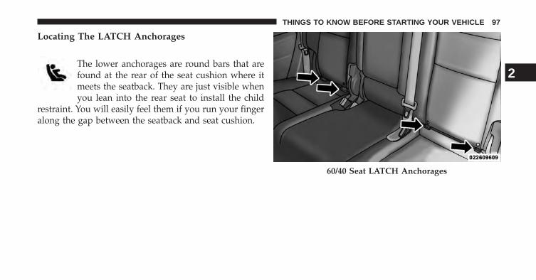
Locating The LATCH Anchorages
The lower anchorages are round bars that arefound at the rear of the seat cushion where itmeets the seatback. They are just visible whenyou lean into the rear seat to install the child
restraint. You will easily feel them if you run your fingeralong the gap between the seatback and seat cushion.
60/40 Seat LATCH Anchorages
2
THINGS TO KNOW BEFORE STARTING YOUR VEHICLE 97

Locating The LATCH Anchorages
The lower anchorages are round bars that arefound at the rear of the seat cushion where itmeets the seatback, below the anchorage sym-bols on the seatback. They are just visible when
you lean into the rear seat to install the child restraint.You will easily feel them if you run your finger along gapbetween the seatback and seat cushion.
Locating The LATCH Anchorages
In addition, there are tether strap anchoragesbehind each rear seating position located onthe back of the seat. To access the top tetherstrap anchorages behind the rear seat, pull the
carpeted floor panel away from the seat back, this willexpose the top tether strap anchorages.
Pulling Down The Carpet Floor Panel To Access TopTether Strap
98 THINGS TO KNOW BEFORE STARTING YOUR VEHICLE

LATCH-compatible child restraint systems will beequipped with a rigid bar or a flexible strap on each side.Each will have a hook or connector to attach to the loweranchorage and a way to tighten the connection to theanchorage. Forward-facing child restraints and somerear-facing infant restraints will also be equipped with atether strap. The tether strap will have a hook at the endto attach to the top tether anchorage and a way to tightenthe strap after it is attached to the anchorage.
Pulling Down The Carpet Floor Panel To Access TopTether Strap
2
THINGS TO KNOW BEFORE STARTING YOUR VEHICLE 99

Center Seat LATCH — Second Row 60/40
Do not install a child restraint in the center position usingthe LATCH system. Use the seat belt and tether anchor toinstall a child seat in the center seating position.
WARNING!
Never use the same lower anchorage to attach morethan one child restraint. Please refer to “InstallingThe LATCH-Compatible Child Restraint System” fortypical installation instructions.
Always follow the directions of the child restraint manu-facturer when installing your child restraint. Not all childrestraint systems will be installed as described here.
Vehicles With A Center Arm Rest Tether
For rearward facing infant seats secured in the center seatposition with the vehicle seat belts, the rear center seatposition has an armrest tether that secures the arm rest inthe upward position.
1. To access the center seat arm rest tether, first lower thearm rest. The tether is located behind the armrest andhooked onto the plastic seat backing.
100 THINGS TO KNOW BEFORE STARTING YOUR VEHICLE
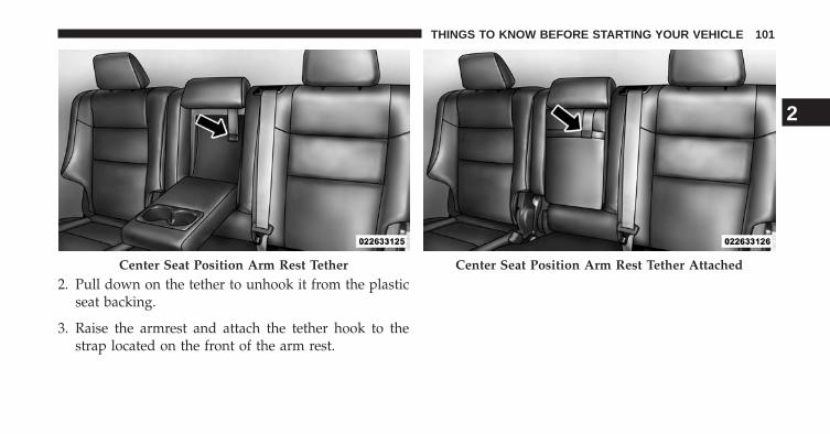
2. Pull down on the tether to unhook it from the plasticseat backing.
3. Raise the armrest and attach the tether hook to thestrap located on the front of the arm rest.
Center Seat Position Arm Rest Tether Center Seat Position Arm Rest Tether Attached
2
THINGS TO KNOW BEFORE STARTING YOUR VEHICLE 101

To Install A LATCH-compatible Child Restraint
1. If the selected seating position has a Switchable Auto-matic Locking Retractor (ALR) seat belt, stow the seatbelt, following the instructions below. See the section“Installing Child Restraints Using the Vehicle SeatBelt” to check what type of seat belt each seatingposition has.
2. Loosen the adjusters on the lower straps and on thetether strap of the child seat so that you can moreeasily attach the hooks or connectors to the vehicleanchorages.
3. Place the child seat between the lower anchorages forthat seating position. For some second row seats, youmay need to recline the seat and / or raise the headrestraint to get a better fit.
4. Attach the lower hooks or connectors of the childrestraint to the lower anchorages in the selected seat-ing position.
5. If the child restraint has a tether strap, connect it to thetop tether anchorage. See the section “Installing ChildRestraints Using the Top Tether Anchorage” for direc-tions to attach a tether anchor.
6. Tighten all of the straps as you push the child restraintrearward and downward into the seat. Remove slackin the straps according to the child restraint manufac-turer’s instructions.
7. Test that the child restraint is installed tightly bypulling back and forth on the child seat at the beltpath. It should not move more than 1 inch (25.4 mm)in any direction.
102 THINGS TO KNOW BEFORE STARTING YOUR VEHICLE
How To Stow An Unused ALR Seatbelt
When using the LATCH attaching system to install achild restraint, stow all ALR seat belts that are not beingused by other occupants or being used to secure childrestraints. An unused belt could injure a child if they playwith it and accidentally lock the seatbelt retractor. Beforeinstalling a child restraint using the LATCH system,buckle the seat belt behind the child restraint and out ofthe child’s reach. If the buckled seat belt interferes withthe child restraint installation, instead of buckling itbehind the child restraint, route the seat belt through thechild restraint belt path and then buckle it. Do not lockthe seatbelt. Remind all children in the vehicle that theseat belts are not toys and that they should not play withthem.
WARNING!
Improper installation of a child restraint to theLATCH anchorages can lead to failure of the re-straint. The child could be badly injured or killed.Follow the child restraint manufacturer’s directionsexactly when installing an infant or child restraint.
Installing Child Restraints Using The Vehicle SeatBelt
The seat belts in the passenger seating positions areequipped with either a Switchable Automatic LockingRetractor (ALR) or a cinching latch plate or both. Bothtypes of seat belts are designed to keep the lap portion ofthe seat belt tight around the child restraint so that it is
2
THINGS TO KNOW BEFORE STARTING YOUR VEHICLE 103
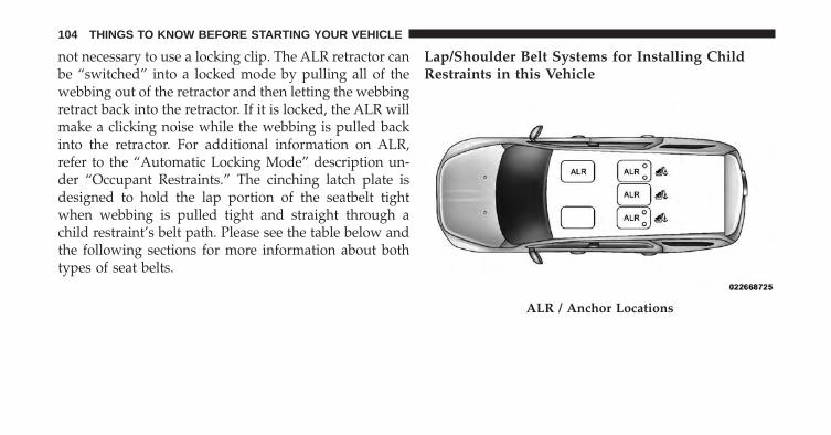
not necessary to use a locking clip. The ALR retractor canbe “switched” into a locked mode by pulling all of thewebbing out of the retractor and then letting the webbingretract back into the retractor. If it is locked, the ALR willmake a clicking noise while the webbing is pulled backinto the retractor. For additional information on ALR,refer to the “Automatic Locking Mode” description un-der “Occupant Restraints.” The cinching latch plate isdesigned to hold the lap portion of the seatbelt tightwhen webbing is pulled tight and straight through achild restraint’s belt path. Please see the table below andthe following sections for more information about bothtypes of seat belts.
Lap/Shoulder Belt Systems for Installing ChildRestraints in this Vehicle
ALR / Anchor Locations
104 THINGS TO KNOW BEFORE STARTING YOUR VEHICLE
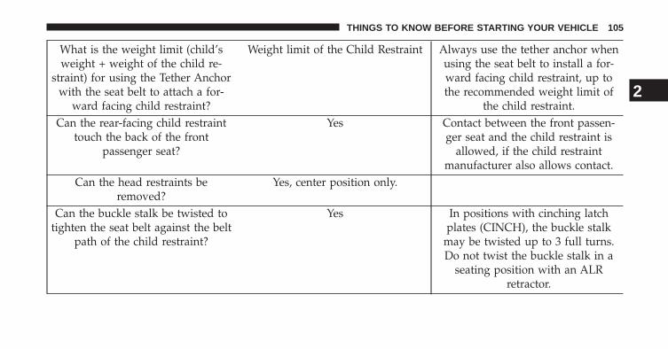
What is the weight limit (child’sweight + weight of the child re-
straint) for using the Tether Anchorwith the seat belt to attach a for-
ward facing child restraint?
Weight limit of the Child Restraint Always use the tether anchor whenusing the seat belt to install a for-ward facing child restraint, up tothe recommended weight limit of
the child restraint.Can the rear-facing child restraint
touch the back of the frontpassenger seat?
Yes Contact between the front passen-ger seat and the child restraint is
allowed, if the child restraintmanufacturer also allows contact.
Can the head restraints beremoved?
Yes, center position only.
Can the buckle stalk be twisted totighten the seat belt against the belt
path of the child restraint?
Yes In positions with cinching latchplates (CINCH), the buckle stalk
may be twisted up to 3 full turns.Do not twist the buckle stalk in a
seating position with an ALRretractor.
2
THINGS TO KNOW BEFORE STARTING YOUR VEHICLE 105

Installing A Child Restraint with a SwitchableAutomatic Locking Retractor (ALR)
1. Place the child seat in the center of the seatingposition. For some second row seats, you may need torecline the seat and/or raise the head restraint to get abetter fit.
2. Pull enough of the seat belt webbing from the retractorto pass it through the belt path of the child restraint.Do not twist the belt webbing in the belt path.
3. Slide the latch plate into the buckle until you hear a“click.”
4. Pull on the webbing to make the lap portion tightagainst the child seat.
5. To lock the seat belt, pull down on the shoulder part ofthe belt until you have pulled all the seat belt webbingout of the retractor. Then, allow the webbing to retractback into the retractor. As the webbing retracts, youwill hear a clicking sound. This means the seat belt isnow in the Automatic Locking mode.
6. Try to pull the webbing out of the retractor. If it islocked, you should not be able to pull out any web-bing. If the retractor is not locked, repeat step 5.
7. Finally, pull up on any excess webbing to tighten thelap portion around the child restraint while you pushthe child restraint rearward and downward into thevehicle seat.
106 THINGS TO KNOW BEFORE STARTING YOUR VEHICLE

8. If the child restraint has a top tether strap and theseating position has a top tether anchorage, connectthe tether strap to the anchorage and tighten the tetherstrap. Refer to “Lower Anchors and Tethers for Chil-dren (LATCH) Restraint System” for directions toattach a tether anchor.
9. Test that the child restraint is installed tightly bypulling back and forth on the child seat at the beltpath. It should not move more than 1 inch (25.4 mm)in any direction.
Any seat belt system will loosen with time, so check thebelt occasionally, and pull it tight if necessary.
Installing A Child Restraint With A CinchingLatch Plate (CINCH) — If Equipped
1. Place the child seat in the center of the seatingposition. For some second row seats, you may need torecline the seat and / or raise the head restraint to geta better fit.
2. Next, pull enough of the seat belt webbing from theretractor to pass it through the belt path of the childrestraint. Do not twist the belt webbing in the beltpath.
3. Slide the latch plate into the buckle until you hear a“click.”
2
THINGS TO KNOW BEFORE STARTING YOUR VEHICLE 107
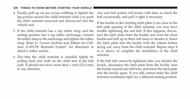
4. Finally, pull up on any excess webbing to tighten thelap portion around the child restraint while you pushthe child restraint rearward and downward into thevehicle seat.
5. If the child restraint has a top tether strap and theseating position has a top tether anchorage, connectthe tether strap to the anchorage and tighten the tetherstrap. Refer to “Lower Anchors and Tethers for Chil-dren (LATCH) Restraint System” for directions toattach a tether anchor.
6. Test that the child restraint is installed tightly bypulling back and forth on the child seat at the beltpath. It should not move more than 1 inch (25.4 mm)in any direction.
Any seat belt system will loosen with time, so check thebelt occasionally, and pull it tight if necessary.
If the buckle or the cinching latch plate is too close to thebelt path opening of the child restraint, you may havetrouble tightening the seat belt. If this happens, discon-nect the latch plate from the buckle and twist the shortbuckle-end belt up to three full turns to shorten it. Insertthe latch plate into the buckle with the release buttonfacing out, away from the child restraint. Repeat steps 4to 6, above, to complete the installation of the childrestraint.
If the belt still cannot be tightened after you shorten thebuckle, disconnect the latch plate from the buckle, turnthe buckle around one half turn, and insert the latch plateinto the buckle again. If you still cannot make the childrestraint installation tight, try a different seating position.
108 THINGS TO KNOW BEFORE STARTING YOUR VEHICLE

Installing Child Restraints Using The Top TetherAnchorage
1. Look behind the seating position where youplan to install the child restraint to find thetether anchorage. You may need to move theseat forward to provide better access to the
tether anchorage. If there is no top tether anchorage forthat seating position (see the charts above), move thechild restraint to another position in the vehicle if one isavailable.
2. To access the top tether strap anchorages behind therear seat, pull the carpeted floor panel away from theseat back, this will expose the top tether strap anchor-ages.
Pulling Down The Carpet Floor Panel To Access TopTether Strap
2
THINGS TO KNOW BEFORE STARTING YOUR VEHICLE 109

3. Route the tether strap to provide the most direct pathfor the strap between the anchor and the child seat. Ifyour vehicle is equipped with adjustable rear headrestraints, raise the head restraint, and where possible,route the tether strap under the head restraint andbetween the two posts. If not possible, lower the headrestraint and pass the tether strap around the outboardside of the head restraint.
4. For the center seating position, route the tether strapover the seatback and headrest then attach the hook tothe tether anchor located on the back of the seat.
5. Attach the tether strap hook of the child restraint tothe top tether anchorage as shown in the diagram.
Top Tether Strap Anchorage (Located on Seatback)
110 THINGS TO KNOW BEFORE STARTING YOUR VEHICLE

6. Remove slack in the tether strap according to the childrestraint manufacturer’s instructions.
WARNING!
The top tether anchorages are not visible until thegap panel is folded down. Do not use the visiblecargo tie down hooks, located on the floor behind theseats, to attach a child restraint tether anchor.
Top Tether Strap Mounting
2
THINGS TO KNOW BEFORE STARTING YOUR VEHICLE 111

Installing Child Restraints Using The Top TetherAnchorage — Center Seating Position
For center seating position route the tether strap over theseatback and headrest then attach the hook to the tetheranchor located on the back of the seat.
Transporting Pets
Air Bags deploying in the front seat could harm your pet.An unrestrained pet will be thrown about and possiblyinjured, or injure a passenger during panic braking or ina collision.
Pets should be restrained in the rear seat in pet harnessesor pet carriers that are secured by seat belts.
ENGINE BREAK-IN RECOMMENDATIONS
A long break-in period is not required for the engine anddrivetrain (transmission and axle) in your vehicle.
Drive moderately during the first 300 miles (500 km).After the initial 60 miles (100 km), speeds up to 50 or55 mph (80 or 90 km/h) are desirable.
While cruising, brief full-throttle acceleration within thelimits of local traffic laws contributes to a good break-in.Wide-open throttle acceleration in low gear can be detri-mental and should be avoided.
112 THINGS TO KNOW BEFORE STARTING YOUR VEHICLE

The engine oil installed in the engine at the factory is ahigh-quality energy conserving type lubricant. Oilchanges should be consistent with anticipated climateconditions under which vehicle operations will occur. Forthe recommended viscosity and quality grades, refer to“Maintenance Procedures” in “Maintaining Your Ve-hicle”.
CAUTION!
Never use Non-Detergent Oil or Straight Mineral Oilin the engine or damage may result.
NOTE: A new engine may consume some oil during itsfirst few thousand miles (kilometers) of operation. Thisshould be considered a normal part of the break-in andnot interpreted as an indication of difficulty.
SAFETY TIPS
Transporting Passengers
NEVER TRANSPORT PASSENGERS IN THE CARGOAREA.
WARNING!
• Do not leave children or animals inside parkedvehicles in hot weather. Interior heat build-up maycause serious injury or death.
• It is extremely dangerous to ride in a cargo area,inside or outside of a vehicle. In a collision, peopleriding in these areas are more likely to be seriouslyinjured or killed.
• Do not allow people to ride in any area of yourvehicle that is not equipped with seats and seatbelts.
(Continued)
2
THINGS TO KNOW BEFORE STARTING YOUR VEHICLE 113

WARNING! (Continued)• Be sure everyone in your vehicle is in a seat and
using a seat belt properly.
Exhaust Gas
WARNING!
Exhaust gases can injure or kill. They contain carbonmonoxide (CO), which is colorless and odorless.Breathing it can make you unconscious and caneventually poison you. To avoid breathing (CO),follow these safety tips:• Do not run the engine in a closed garage or in
confined areas any longer than needed to moveyour vehicle in or out of the area.
(Continued)
WARNING! (Continued)• If you are required to drive with the trunk/liftgate
open, make sure that all windows are closed and theclimate control BLOWER switch is set at high speed.DO NOT use the recirculation mode.
• If it is necessary to sit in a parked vehicle with theengine running, adjust your heating or coolingcontrols to force outside air into the vehicle. Set theblower at high speed.
The best protection against carbon monoxide entry intothe vehicle body is a properly maintained engine exhaustsystem.
114 THINGS TO KNOW BEFORE STARTING YOUR VEHICLE

Whenever a change is noticed in the sound of the exhaustsystem, when exhaust fumes can be detected inside thevehicle, or when the underside or rear of the vehicle isdamaged, have a competent mechanic inspect the com-plete exhaust system and adjacent body areas for broken,damaged, deteriorated, or mispositioned parts. Openseams or loose connections could permit exhaust fumesto seep into the passenger compartment. In addition,inspect the exhaust system each time the vehicle is raisedfor lubrication or oil change. Replace as required.
Safety Checks You Should Make Inside TheVehicle
Seat Belts
Inspect the belt system periodically, checking for cuts,frays, and loose parts. Damaged parts must be replacedimmediately. Do not disassemble or modify the system.
Front seat belt assemblies must be replaced after acollision. Rear seat belt assemblies must be replaced aftera collision if they have been damaged (i.e., bent retractor,torn webbing, etc.). If there is any question regarding beltor retractor condition, replace the belt.
2
THINGS TO KNOW BEFORE STARTING YOUR VEHICLE 115

Air Bag Warning Light
The light should come on and remain on forfour to eight seconds as a bulb check when theignition switch is first turned ON. If the light isnot lit during starting, see your authorized
dealer. If the light stays on, flickers, or comes on whiledriving, have the system checked by an authorizeddealer.
Defroster
Check operation by selecting the defrost mode and placethe blower control on high speed. You should be able tofeel the air directed against the windshield. See yourauthorized dealer for service if your defroster is inoper-able.
Floor Mat Safety Information
Always use floor mats designed to fit the footwell of yourvehicle. Use only floor mats that leave the pedal areaunobstructed and that are firmly secured so that theycannot slip out of position and interfere with the pedalsor impair safe operation of your vehicle in other ways.
WARNING!
Pedals that cannot move freely can cause loss ofvehicle control and increase the risk of serious per-sonal injury.• Always make sure that floor mats are properly
attached to the floor mat fasteners.
(Continued)
116 THINGS TO KNOW BEFORE STARTING YOUR VEHICLE

WARNING! (Continued)• Never place or install floor mats or other floor
coverings in the vehicle that cannot be properlysecured to prevent them from moving and interfer-ing with the pedals or the ability to control thevehicle.
• Never put floor mats or other floor coverings on topof already installed floor mats. Additional floormats and other coverings will reduce the size of thepedal area and interfere with the pedals.
• Check mounting of mats on a regular basis. Alwaysproperly reinstall and secure floor mats that havebeen removed for cleaning.
(Continued)
WARNING! (Continued)• Always make sure that objects cannot fall into the
driver footwell while the vehicle is moving. Ob-jects can become trapped under the brake pedaland accelerator pedal causing a loss of vehiclecontrol.
• If required, mounting posts must be properly in-stalled, if not equipped from the factory.
Failure to properly follow floor mat installation ormounting can cause interference with the brakepedal and accelerator pedal operation causing loss ofcontrol of the vehicle.
2
THINGS TO KNOW BEFORE STARTING YOUR VEHICLE 117

Periodic Safety Checks You Should Make OutsideThe Vehicle
Tires
Examine tires for excessive tread wear and uneven wearpatterns. Check for stones, nails, glass, or other objectslodged in the tread or sidewall. Inspect the tread for cutsand cracks. Inspect sidewalls for cuts, cracks and bulges.Check the wheel nuts for tightness. Check the tires(including spare) for proper cold inflation pressure.
Lights
Have someone observe the operation of brake lights andexterior lights while you work the controls. Check turnsignal and high beam indicator lights on the instrumentpanel.
Door Latches
Check for positive closing, latching, and locking.
Fluid Leaks
Check area under vehicle after overnight parking for fuel,engine coolant, oil, or other fluid leaks. Also, if gasolinefumes are detected or if fuel, power steering fluid (ifequipped), or brake fluid leaks are suspected, the causeshould be located and corrected immediately.
118 THINGS TO KNOW BEFORE STARTING YOUR VEHICLE

UNDERSTANDING THE FEATURES OF YOUR VEHICLE
CONTENTS� MIRRORS . . . . . . . . . . . . . . . . . . . . . . . . . . . .127
▫ Inside Day/Night Mirror . . . . . . . . . . . . . . . .127
▫ Automatic Dimming Mirror — If Equipped . . .128
▫ Outside Mirrors . . . . . . . . . . . . . . . . . . . . . .129
▫ Outside Mirrors Folding Feature . . . . . . . . . .130
▫ Power Folding Outside Mirrors —If Equipped. . . . . . . . . . . . . . . . . . . . . . . . . .130
▫ Power Mirrors . . . . . . . . . . . . . . . . . . . . . . .131
▫ Outside Automatic Dimming Mirrors —If Equipped. . . . . . . . . . . . . . . . . . . . . . . . . .132
▫ Heated Mirrors — If Equipped . . . . . . . . . . .133
▫ Tilt Mirrors In Reverse (Available WithMemory Seat Only) — If Equipped . . . . . . . . .133
▫ Illuminated Vanity Mirrors . . . . . . . . . . . . . .133
▫ Sun Visor “Slide-On-Rod” Feature —If Equipped . . . . . . . . . . . . . . . . . . . . . . . . .134
� BLIND SPOT MONITORING (BSM) —IF EQUIPPED . . . . . . . . . . . . . . . . . . . . . . . . .135
▫ Rear Cross Path . . . . . . . . . . . . . . . . . . . . . .141
▫ Modes Of Operation . . . . . . . . . . . . . . . . . . .142
3

� SEATS . . . . . . . . . . . . . . . . . . . . . . . . . . . . . .144
▫ Power Seats — If Equipped . . . . . . . . . . . . . .144
▫ Passenger’s Power Seat . . . . . . . . . . . . . . . . .146
▫ Power Lumbar — If Equipped . . . . . . . . . . . .147
▫ Manual Front Seats Forward/RearwardAdjustment . . . . . . . . . . . . . . . . . . . . . . . . .148
▫ Manual Front Passenger SeatbackAdjustment — Recline . . . . . . . . . . . . . . . . .149
▫ Front Passenger Seat Fold-Flat Feature —If Equipped. . . . . . . . . . . . . . . . . . . . . . . . . .149
▫ Heated Seats — If Equipped . . . . . . . . . . . . . .150
▫ Front Ventilated Seats WithUconnect® 8.4A/8.4AN — If Equipped . . . . . .154
▫ Head Restraints . . . . . . . . . . . . . . . . . . . . . . .155
▫ 60/40 Split Rear Seat . . . . . . . . . . . . . . . . . .160
▫ Reclining Rear Seat . . . . . . . . . . . . . . . . . . . .162
� DRIVER MEMORY SEAT — IF EQUIPPED . . . .163
▫ Programming The Memory Feature . . . . . . . . .164
▫ Linking And Unlinking The RemoteKeyless Entry Transmitter To Memory . . . . . . .165
▫ Memory Position Recall . . . . . . . . . . . . . . . . .166
▫ Easy Entry/Exit Seat . . . . . . . . . . . . . . . . . . .167
� TO OPEN AND CLOSE THE HOOD . . . . . . . . .168
� LIGHTS . . . . . . . . . . . . . . . . . . . . . . . . . . . . .169
▫ Headlight Switch . . . . . . . . . . . . . . . . . . . . .169
▫ Automatic Headlights — If Equipped . . . . . . .171
▫ Headlights On Automatically With Wipers . . .171
120 UNDERSTANDING THE FEATURES OF YOUR VEHICLE

▫ Automatic High Beam — If Equipped . . . . . .172
▫ Daytime Running Lights — If Equipped . . . . .173
▫ Automatic Headlight Leveling —HID Headlights Only. . . . . . . . . . . . . . . . . . .173
▫ Adaptive Bi-Xenon High IntensityDischarge Headlights — If Equipped. . . . . . . .174
▫ Headlight Delay . . . . . . . . . . . . . . . . . . . . . .174
▫ Parking Lights And Panel Lights. . . . . . . . . . .175
▫ Fog Lights — If Equipped . . . . . . . . . . . . . . .175
▫ Interior Lights . . . . . . . . . . . . . . . . . . . . . . . .176
▫ Lights-On Reminder . . . . . . . . . . . . . . . . . . .177
▫ Battery Saver. . . . . . . . . . . . . . . . . . . . . . . . .177
▫ Front Map/Reading Lights . . . . . . . . . . . . . .177
▫ Courtesy Lights . . . . . . . . . . . . . . . . . . . . . . .178
▫ Ambient Light. . . . . . . . . . . . . . . . . . . . . . . .179
▫ Multifunction Lever . . . . . . . . . . . . . . . . . . . .179
▫ Turn Signals . . . . . . . . . . . . . . . . . . . . . . . . .180
▫ Lane Change Assist . . . . . . . . . . . . . . . . . . .180
▫ Flash-To-Pass . . . . . . . . . . . . . . . . . . . . . . . .180
▫ High/Low Beam Switch. . . . . . . . . . . . . . . . .180
� WINDSHIELD WIPERS AND WASHERS . . . . . .180
▫ Windshield Wiper Operation . . . . . . . . . . . . .181
▫ Intermittent Wiper System . . . . . . . . . . . . . . .182
▫ Windshield Washer Operation. . . . . . . . . . . . .182
▫ Mist . . . . . . . . . . . . . . . . . . . . . . . . . . . . . . .183
▫ Rain Sensing Wipers — If Equipped . . . . . . . .184
� TILT/TELESCOPING STEERING COLUMN . . .186
3
UNDERSTANDING THE FEATURES OF YOUR VEHICLE 121

� POWER TILT/TELESCOPING STEERINGCOLUMN — IF EQUIPPED . . . . . . . . . . . . . . .187
� HEATED STEERING WHEEL —IF EQUIPPED . . . . . . . . . . . . . . . . . . . . . . . . .188
� ELECTRONIC SPEED CONTROL —IF EQUIPPED . . . . . . . . . . . . . . . . . . . . . . . . .190
▫ To Activate . . . . . . . . . . . . . . . . . . . . . . . . . .191
▫ To Set A Desired Speed . . . . . . . . . . . . . . . . .192
▫ To Deactivate . . . . . . . . . . . . . . . . . . . . . . . .192
▫ To Resume Speed . . . . . . . . . . . . . . . . . . . . .192
▫ To Vary The Speed Setting . . . . . . . . . . . . . . .192
▫ To Accelerate For Passing . . . . . . . . . . . . . . . .193
� ADAPTIVE CRUISE CONTROL (ACC) —IF EQUIPPED . . . . . . . . . . . . . . . . . . . . . . . . .194
▫ Adaptive Cruise Control (ACC) Operation . . . .196
▫ Activating Adaptive Cruise Control (ACC). . . .197
▫ To Activate . . . . . . . . . . . . . . . . . . . . . . . . . .198
▫ To Set A Desired ACC Speed . . . . . . . . . . . . .199
▫ To Cancel . . . . . . . . . . . . . . . . . . . . . . . . . . .200
▫ To Turn Off . . . . . . . . . . . . . . . . . . . . . . . . . .200
▫ To Resume . . . . . . . . . . . . . . . . . . . . . . . . . .201
▫ To Vary The Speed Setting . . . . . . . . . . . . . . .201
▫ Setting The Following Distance In ACC . . . . . .202
▫ Overtake Aid . . . . . . . . . . . . . . . . . . . . . . . .206
▫ Adaptive Cruise Control (ACC) Menu . . . . . . .207
▫ Display Warnings And Maintenance . . . . . . . .208
▫ Precautions While Driving With ACC . . . . . . .212
122 UNDERSTANDING THE FEATURES OF YOUR VEHICLE

▫ General Information . . . . . . . . . . . . . . . . . . .215
▫ Normal (Fixed Speed) Cruise Control Mode . . .216
▫ FORWARD COLLISION WARNING (FCW)WITH MITIGATION — IF EQUIPPED . . . . . .218
� PARKSENSE® REAR PARK ASSIST —IF EQUIPPED . . . . . . . . . . . . . . . . . . . . . . . . .223
▫ ParkSense® Sensors . . . . . . . . . . . . . . . . . . . .224
▫ ParkSense® Warning Display . . . . . . . . . . . . .224
▫ ParkSense® Display . . . . . . . . . . . . . . . . . . . .224
▫ Enabling And Disabling ParkSense® . . . . . . . .229
▫ Service The ParkSense® Rear Park AssistSystem . . . . . . . . . . . . . . . . . . . . . . . . . . . . .229
▫ Cleaning The ParkSense® System . . . . . . . . . .230
▫ ParkSense® System Usage Precautions. . . . . . .230
� PARKSENSE® FRONT AND REAR PARKASSIST — IF EQUIPPED . . . . . . . . . . . . . . . . .232
▫ ParkSense® Sensors . . . . . . . . . . . . . . . . . . . .233
▫ ParkSense® Warning Display . . . . . . . . . . . . .234
▫ ParkSense® Display . . . . . . . . . . . . . . . . . . . .234
▫ Enabling And Disabling ParkSense® . . . . . . . .238
▫ Service The ParkSense® Park Assist System . . .239
▫ Cleaning The ParkSense® System . . . . . . . . . .240
▫ ParkSense® System Usage Precautions. . . . . . .240
� PARKVIEW® REAR BACK UP CAMERA —IF EQUIPPED . . . . . . . . . . . . . . . . . . . . . . . . .243
▫ Turning ParkView® On Or Off — WithUconnect® 5.0 . . . . . . . . . . . . . . . . . . . . . . . .245
3
UNDERSTANDING THE FEATURES OF YOUR VEHICLE 123

▫ Turning ParkView® On Or Off — WithUconnect® 8.4A/8.4AN . . . . . . . . . . . . . . . . .245
� OVERHEAD CONSOLE . . . . . . . . . . . . . . . . . .246
▫ Front Map/Reading Lights . . . . . . . . . . . . . .246
▫ Courtesy Lights . . . . . . . . . . . . . . . . . . . . . . .247
▫ Sunglasses Bin Door . . . . . . . . . . . . . . . . . . .248
� GARAGE DOOR OPENER — IF EQUIPPED . . .248
▫ Before You Begin Programming HomeLink® . .250
▫ Programming A Rolling Code . . . . . . . . . . . . .250
▫ Programming A Non-Rolling Code . . . . . . . . .253
▫ Canadian/Gate Operator Programming . . . . . .254
▫ Using HomeLink®. . . . . . . . . . . . . . . . . . . . .255
▫ Security . . . . . . . . . . . . . . . . . . . . . . . . . . . .256
▫ Troubleshooting Tips . . . . . . . . . . . . . . . . . . .256
▫ General Information. . . . . . . . . . . . . . . . . . . .257
� POWER SUNROOF — IF EQUIPPED . . . . . . . .258
▫ Opening Sunroof — Express . . . . . . . . . . . . . .259
▫ Opening Sunroof — Manual Mode . . . . . . . . .259
▫ Closing Sunroof — Express. . . . . . . . . . . . . . .259
▫ Closing Sunroof — Manual Mode . . . . . . . . . .259
▫ Pinch Protect Feature . . . . . . . . . . . . . . . . . . .259
▫ Venting Sunroof — Express . . . . . . . . . . . . . .260
▫ Sunshade Operation. . . . . . . . . . . . . . . . . . . .260
▫ Wind Buffeting . . . . . . . . . . . . . . . . . . . . . . .260
▫ Sunroof Maintenance . . . . . . . . . . . . . . . . . . .260
▫ Ignition OFF Operation . . . . . . . . . . . . . . . . .260
124 UNDERSTANDING THE FEATURES OF YOUR VEHICLE

� COMMANDVIEW® SUNROOF WITH POWERSHADE — IF EQUIPPED . . . . . . . . . . . . . . . . .261
▫ Opening Sunroof — Express . . . . . . . . . . . . . .262
▫ Opening Sunroof — Manual Mode . . . . . . . . .262
▫ Closing Sunroof — Express. . . . . . . . . . . . . . .263
▫ Closing Sunroof — Manual Mode . . . . . . . . . .263
▫ Opening Power Shade — Express . . . . . . . . . .263
▫ Opening Power Shade — Manual Mode . . . . .263
▫ Closing Power Shade — Express . . . . . . . . . . .264
▫ Closing Power Shade — Manual Mode . . . . . .264
▫ Pinch Protect Feature . . . . . . . . . . . . . . . . . . .264
▫ Wind Buffeting . . . . . . . . . . . . . . . . . . . . . . .264
▫ Sunroof Maintenance . . . . . . . . . . . . . . . . . . .265
▫ Ignition OFF Operation . . . . . . . . . . . . . . . . .265
▫ Sunroof Fully Closed . . . . . . . . . . . . . . . . . . .265
� ELECTRICAL POWER OUTLETS . . . . . . . . . . .265
� POWER INVERTER — IF EQUIPPED . . . . . . . .270
� CUPHOLDERS . . . . . . . . . . . . . . . . . . . . . . . .271
� STORAGE . . . . . . . . . . . . . . . . . . . . . . . . . . . .272
▫ Glove Compartment . . . . . . . . . . . . . . . . . . .272
▫ Door Storage . . . . . . . . . . . . . . . . . . . . . . . . .273
▫ Console Features . . . . . . . . . . . . . . . . . . . . .273
� CARGO AREA FEATURES . . . . . . . . . . . . . . . .276
▫ Rechargeable Flashlight . . . . . . . . . . . . . . . . .276
▫ Cargo Storage Bins . . . . . . . . . . . . . . . . . . . .277
▫ Retractable Cargo Area Cover — If Equipped . .279
3
UNDERSTANDING THE FEATURES OF YOUR VEHICLE 125

▫ Rear Cargo Tie-Downs . . . . . . . . . . . . . . . . .280
� REAR WINDOW FEATURES . . . . . . . . . . . . . .282
▫ Rear Window Wiper/Washer . . . . . . . . . . . . .282
▫ Rear Window Defroster . . . . . . . . . . . . . . . . .283
� ROOF LUGGAGE RACK — IF EQUIPPED . . . . .284
126 UNDERSTANDING THE FEATURES OF YOUR VEHICLE
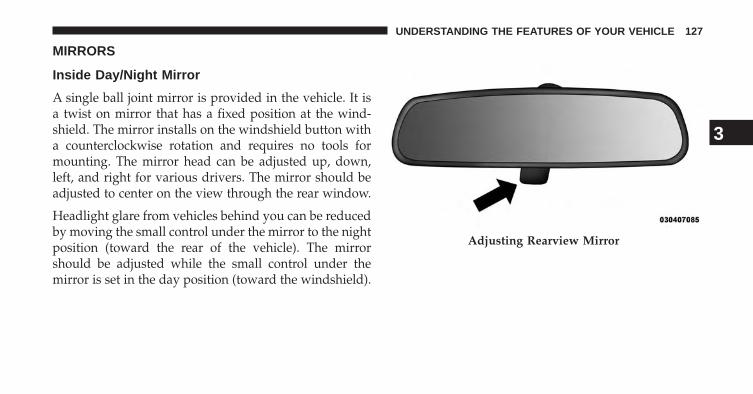
MIRRORS
Inside Day/Night Mirror
A single ball joint mirror is provided in the vehicle. It isa twist on mirror that has a fixed position at the wind-shield. The mirror installs on the windshield button witha counterclockwise rotation and requires no tools formounting. The mirror head can be adjusted up, down,left, and right for various drivers. The mirror should beadjusted to center on the view through the rear window.
Headlight glare from vehicles behind you can be reducedby moving the small control under the mirror to the nightposition (toward the rear of the vehicle). The mirrorshould be adjusted while the small control under themirror is set in the day position (toward the windshield).
Adjusting Rearview Mirror
3
UNDERSTANDING THE FEATURES OF YOUR VEHICLE 127

Automatic Dimming Mirror — If Equipped
A single ball joint mirror is provided in the vehicle. It isa twist on mirror that has a fixed position at the wind-shield. The mirror installs on the windshield button witha counterclockwise rotation and requires no tools formounting. The mirror head can be adjusted up, down,left, and right for various drivers. The mirror should beadjusted to center on the view through the rear window.
This mirror automatically adjusts for headlight glarefrom vehicles behind you.
NOTE:
• The Automatic Dimming Mirror feature is disabled whenthe vehicle is in reverse gear to improve rear viewviewing.
• The Automatic Dimming Mirror feature can be turned onor off using the Uconnect® System, refer to “Uconnect®Settings” in “Understanding Your Instrument Panel” forfurther information.
NOTE: The mirror contains an Assist button and a 9–1–1button located on the bottom of the mirror.
Automatic Dimming Mirror
128 UNDERSTANDING THE FEATURES OF YOUR VEHICLE

Assist Call
The rear view mirror contains an ASSIST push buttonwhich automatically connects the vehicle occupants toone of several predefined locations for immediate sup-port:
• Roadside Assistance – If you get a flat tire, or need atow, just press the Assist button and you’ll be con-nected to someone who can help. Roadside Assistancewill know what vehicle you’re driving and its location.Additional fees may apply for roadside Assistance.
• Uconnect® Access Customer Care – In-vehicle supportfor Uconnect® Access and Uconnect® Access via Mo-bile features.
• Vehicle Customer Care – Total support for all othervehicle issues.
9-1-1 Call
Report an accident without taking your eyes off the road.Just press 9-1-1 on your mirror and connect.
CAUTION!
To avoid damage to the mirror during cleaning, neverspray any cleaning solution directly onto the mirror.Apply the solution onto a clean cloth and wipe themirror clean.
Outside Mirrors
To receive maximum benefit, adjust the outside mirrorsto center on the adjacent lane of traffic with a slightoverlap of the view obtained on the inside mirror.
3
UNDERSTANDING THE FEATURES OF YOUR VEHICLE 129
WARNING!
Vehicles and other objects seen in the passenger sideconvex mirror will look smaller and farther away thanthey really are. Relying too much on your passengerside convex mirror could cause you to collide withanother vehicle or other object. Use your inside mirrorwhen judging the size or distance of a vehicle seen inthe passenger side convex mirror. Some vehicles willnot have a convex passenger side mirror.
Outside Mirrors Folding Feature
All outside mirrors are hinged and may be moved eitherforward or rearward to resist damage. The hinges havethree detent positions:
• full forward
• full rearward and
• normal.
Power Folding Outside Mirrors — If Equipped
If equipped with power folding mirrors, they can beelectrically folded rearward and unfolded into the driveposition.
The switch for the power folding mirrors is locatedbetween the power mirror switches L (left) and R (right).Press the switch once and the mirrors will fold in, pressthe switch a second time and the mirrors will return tothe normal driving position.
If the mirror is manually folded after electrically cycled,a potential extra button push is required to get themirrors back to the home position. If the mirror does notelectrically fold check for ice or dirt build up at the pivotarea which can cause excessive drag.
130 UNDERSTANDING THE FEATURES OF YOUR VEHICLE

Power Mirrors
The power mirror switch is located on the driver’s sidedoor trim panel.
The power mirror controls consist of mirror select but-tons and a four-way mirror control switch. To adjust amirror, press the mirror select button for the mirror thatyou want to adjust. Using the mirror control switch, presson any of the four arrows for the direction that you wantthe mirror to move.
Power Folding Mirror Switch
3
UNDERSTANDING THE FEATURES OF YOUR VEHICLE 131

Power mirror preselected positions can be controlled bythe optional Memory Seat Feature. Refer to “DriverMemory Seat” in “Understanding The Features Of YourVehicle” for further information.
Outside Automatic Dimming Mirrors — If Equipped
The drivers outside mirror will automatically adjust forglare from vehicles behind you. This feature is controlledby the inside automatic dimming mirror. The mirrors willautomatically adjust for headlight glare when the insidemirror adjusts.
Power Mirror Switch
1 — Mirror Direction Control2 — Mirror Selection
132 UNDERSTANDING THE FEATURES OF YOUR VEHICLE
Heated Mirrors — If Equipped
These mirrors are heated to melt frost or ice. Thisfeature can be activated whenever you turn on the
rear window defroster (if equipped). Some vehicles maynot be equipped with rear window defroster, in this casethe heated mirrors will still function as intended. Refer to“Rear Window Features” in “Understanding The Fea-tures Of Your Vehicle” for further information.
Tilt Mirrors In Reverse (Available With MemorySeat Only) — If Equipped
Tilt Mirrors in Reverse provides automatic outside mirrorpositioning which will aid the drivers view of the groundrearward of the front doors. Outside mirrors will moveslightly downward from the present position when thevehicle is shifted into REVERSE. Outside mirrors willthen return to the original position when the vehicle is
shifted out of REVERSE position. Each stored memorysetting will have an associated Tilt Mirrors in Reverseposition.
NOTE: The Tilt Mirrors in Reverse feature is not enabledwhen delivered from the factory. The Tilt Mirrors inReverse feature can be enabled or disabled in theUconnect® system screen. Refer to “Customer- Program-mable Features — Uconnect® Access 8.4 Settings ” in“Understanding Your Instrument Panel” for further in-formation.
Illuminated Vanity Mirrors
To access an illuminated vanity mirror, flip down one ofthe visors.
Lift the cover to reveal the mirror. The light will turn onautomatically.
3
UNDERSTANDING THE FEATURES OF YOUR VEHICLE 133
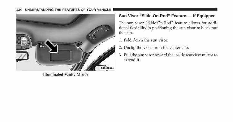
Sun Visor “Slide-On-Rod” Feature — If Equipped
The sun visor “Slide-On-Rod” feature allows for addi-tional flexibility in positioning the sun visor to block outthe sun.
1. Fold down the sun visor.
2. Unclip the visor from the center clip.
3. Pull the sun visor toward the inside rearview mirror toextend it.
Illuminated Vanity Mirror
134 UNDERSTANDING THE FEATURES OF YOUR VEHICLE

BLIND SPOT MONITORING (BSM) — IF EQUIPPED
The Blind Spot Monitoring (BSM) system uses two radar-based sensors, located inside the rear bumper fascia, todetect highway licensable vehicles (automobiles, trucks,motorcycles, etc.) that enter the blind spot zones from therear/front/side of the vehicle.
When the vehicle is started, the BSM warning light willmomentarily illuminate in both outside rear view mirrorsto let the driver know that the system is operational. TheBSM system sensors operate when the vehicle is in anyforward gear or REVERSE and enters stand-by modewhen the vehicle is in PARK.
The BSM detection zone covers approximately one laneon both sides of the vehicle (12 ft or 3.8 m). The zonestarts at the outside rear view mirror and extends ap-proximately 23 ft (7 m) to the rear of the vehicle. The BSMsystem monitors the detection zones on both sides of thevehicle when the vehicle speed has reached approxi-mately 6 mph (10 km/h) or higher and will alert thedriver of vehicles in these areas.
Rear Detection Zones
3
UNDERSTANDING THE FEATURES OF YOUR VEHICLE 135
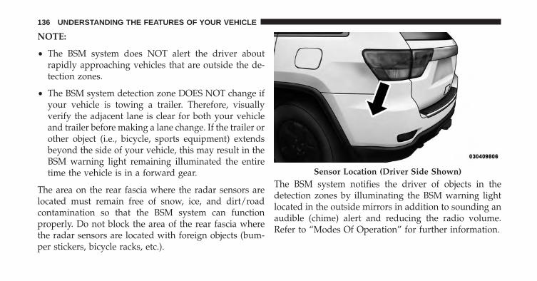
NOTE:
• The BSM system does NOT alert the driver aboutrapidly approaching vehicles that are outside the de-tection zones.
• The BSM system detection zone DOES NOT change ifyour vehicle is towing a trailer. Therefore, visuallyverify the adjacent lane is clear for both your vehicleand trailer before making a lane change. If the trailer orother object (i.e., bicycle, sports equipment) extendsbeyond the side of your vehicle, this may result in theBSM warning light remaining illuminated the entiretime the vehicle is in a forward gear.
The area on the rear fascia where the radar sensors arelocated must remain free of snow, ice, and dirt/roadcontamination so that the BSM system can functionproperly. Do not block the area of the rear fascia wherethe radar sensors are located with foreign objects (bum-per stickers, bicycle racks, etc.).
The BSM system notifies the driver of objects in thedetection zones by illuminating the BSM warning lightlocated in the outside mirrors in addition to sounding anaudible (chime) alert and reducing the radio volume.Refer to “Modes Of Operation” for further information.
Sensor Location (Driver Side Shown)
136 UNDERSTANDING THE FEATURES OF YOUR VEHICLE

The BSM system monitors the detection zone from threedifferent entry points (side, rear, front) while driving tosee if an alert is necessary. The BSM system will issue analert during these types of zone entries.
Entering From The Side
Vehicles that move into your adjacent lanes from eitherside of the vehicle.
Warning Light Location
Side Monitoring
3
UNDERSTANDING THE FEATURES OF YOUR VEHICLE 137

Entering From The Rear
Vehicles that come up from behind your vehicle on eitherside and enter the rear detection zone with a relativespeed of less than 30 mph (48 km/h).
Overtaking Traffic
If you pass another vehicle slowly (with a relative speedless than 15 mph (24 km/h) and the vehicle remains inthe blind spot for approximately 1.5 seconds, the warninglight will be illuminated. If the difference in speedbetween the two vehicles is greater than 15 mph(24 km/h), the warning light will not illuminate.
Rear Monitoring
138 UNDERSTANDING THE FEATURES OF YOUR VEHICLE

The BSM system is designed not to issue an alert onstationary objects such as guardrails, posts, walls, foliage,berms, etc. However, occasionally the system may alerton such objects. This is normal operation and yourvehicle does not require service.
Overtaking/Approaching Overtaking/Passing
3
UNDERSTANDING THE FEATURES OF YOUR VEHICLE 139
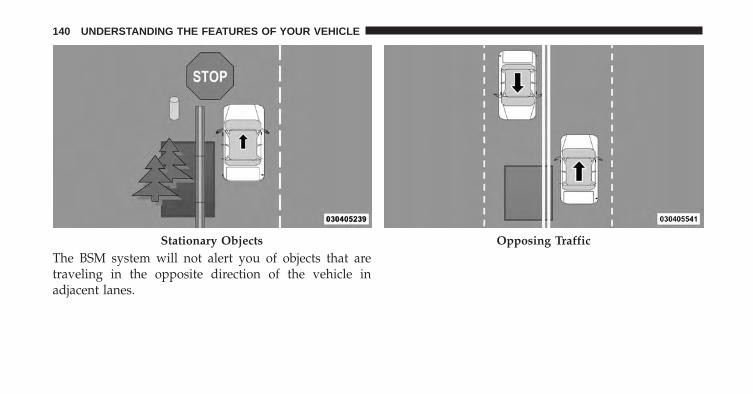
The BSM system will not alert you of objects that aretraveling in the opposite direction of the vehicle inadjacent lanes.
Stationary Objects Opposing Traffic
140 UNDERSTANDING THE FEATURES OF YOUR VEHICLE
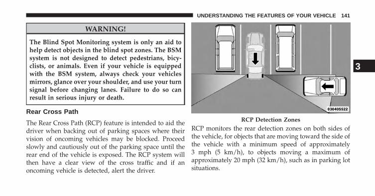
WARNING!
The Blind Spot Monitoring system is only an aid tohelp detect objects in the blind spot zones. The BSMsystem is not designed to detect pedestrians, bicy-clists, or animals. Even if your vehicle is equippedwith the BSM system, always check your vehiclesmirrors, glance over your shoulder, and use your turnsignal before changing lanes. Failure to do so canresult in serious injury or death.
Rear Cross Path
The Rear Cross Path (RCP) feature is intended to aid thedriver when backing out of parking spaces where theirvision of oncoming vehicles may be blocked. Proceedslowly and cautiously out of the parking space until therear end of the vehicle is exposed. The RCP system willthen have a clear view of the cross traffic and if anoncoming vehicle is detected, alert the driver.
RCP monitors the rear detection zones on both sides ofthe vehicle, for objects that are moving toward the side ofthe vehicle with a minimum speed of approximately3 mph (5 km/h), to objects moving a maximum ofapproximately 20 mph (32 km/h), such as in parking lotsituations.
RCP Detection Zones
3
UNDERSTANDING THE FEATURES OF YOUR VEHICLE 141

NOTE: In a parking lot situation, oncoming vehicles canbe obscured by vehicles parked on either side. If thesensors are blocked by other structures or vehicles, thesystem will not be able to alert the driver.
When RCP is on and the vehicle is in REVERSE, thedriver is alerted using both the visual and audiblealarms, including reducing the radio volume.
WARNING!
RCP is not a Back Up Aid system. It is intended to beused to help a driver detect an oncoming vehicle in aparking lot situation. Drivers must be careful whenbacking up, even when using RCP. Always checkcarefully behind your vehicle, look behind you, andbe sure to check for pedestrians, animals, othervehicles, obstructions, and blind spots before back-ing up. Failure to do so can result in serious injury ordeath.
Modes Of Operation
Modes Of Operation With EVIC
Three selectable modes of operation are available in theElectronic Vehicle Information Center (EVIC). Refer to“Electronic Vehicle Information Center (EVIC)/PersonalSettings (Customer-Programmable Features)” in “Under-standing Your Instrument Panel” for further information.
Modes Of Operation With Uconnect® System — IfEquipped
Three selectable modes of operation are available in theUconnect® system screen. Refer to “Customer- Program-mable Features — Uconnect® Access 8.4 Settings ” in“Understanding Your Instrument Panel” for further in-formation.
142 UNDERSTANDING THE FEATURES OF YOUR VEHICLE

Blind Spot Alert
When operating in Blind Spot Alert mode, the BSMsystem will provide a visual alert in the appropriate sideview mirror based on a detected object. However, whenthe system is operating in RCP, the system will respondwith both visual and audible alerts when a detectedobject is present. Whenever an audible alert is requested,the radio is muted.
Blind Spot Alert Lights/Chime
When operating in Blind Spot Alert Lights/Chime mode,the BSM system will provide a visual alert in the appro-priate side view mirror based on a detected object. If theturn signal is then activated, and it corresponds to analert present on that side of the vehicle, an audible chimewill also be sounded. Whenever a turn signal and de-tected object are present on the same side at the sametime, both the visual and audio alerts will be issued. Inaddition to the audible alert the radio (if on) will also bemuted.
NOTE:
• Whenever an audible alert is requested by the BSMsystem, the radio is also muted.
• If the hazard flashers are on, the system will requestthe appropriate visual alert only.
When the system is in RCP, the system shall respond withboth visual and audible alerts when a detected object ispresent. Whenever an audible alert is requested, the radiois also muted. Turn/hazard signal status is ignored; theRCP state always requests the chime.
Blind Spot Alert Off
When the BSM system is turned off there will be novisual or audible alerts from either the BSM or RCPsystems.
3
UNDERSTANDING THE FEATURES OF YOUR VEHICLE 143

NOTE: The BSM system will store the current operatingmode when the vehicle is shut off. Each time the vehicleis started the previously stored mode will be recalled andused
SEATS
Seats are part of the Occupant Restraint System of thevehicle.
WARNING!
• It is dangerous to ride in a cargo area, inside oroutside of a vehicle. In a collision, people riding inthese areas are more likely to be seriously injuredor killed.
(Continued)
WARNING! (Continued)• Do not allow people to ride in any area of your
vehicle that is not equipped with seats and seatbelts. In a collision, people riding in these areas aremore likely to be seriously injured or killed.
• Be sure everyone in your vehicle is in a seat andusing a seat belt properly.
Power Seats — If Equipped
Some models may be equipped with eight-way powerdriver and front passenger seats. The power seat switchesare located on the outboard side of the seat. There are twoswitches that control the movement of the seat cushionand the seatback.
144 UNDERSTANDING THE FEATURES OF YOUR VEHICLE

Adjusting The Seat Forward Or Rearward
The seat can be adjusted both forward and rearward.Push the seat switch forward or rearward, the seat will
move in the direction of the switch. Release the switchwhen the desired position has been reached.
Adjusting The Seat Up Or Down
The height of the seats can be adjusted up or down. Pullupward or push downward on the seat switch, the seatwill move in the direction of the switch. Release theswitch when the desired position has been reached.
Tilting The Seat Up Or Down
The angle of the seat cushion can be adjusted up ordown. Pull upward or push downward on the front ofthe seat switch, the front of the seat cushion will move inthe direction of the switch. Release the switch when thedesired position has been reached.
Reclining The Seatback
The angle of the seatback can be adjusted forward orrearward. Push the seatback switch forward or rearward,
Power Seat Switches
1 — Seatback Switch2 — Seat Switch
3
UNDERSTANDING THE FEATURES OF YOUR VEHICLE 145

the seat will move in the direction of the switch. Releasethe switch when the desired position is reached.
WARNING!
• Adjusting a seat while driving may be dangerous.Moving a seat while driving could result in loss ofcontrol which could cause a collision and seriousinjury or death.
• Seats should be adjusted before fastening the seatbelts and while the vehicle is parked. Seriousinjury or death could result from a poorly adjustedseat belt.
• Do not ride with the seatback reclined so that theshoulder belt is no longer resting against your chest.In a collision you could slide under the seat belt,which could result in serious injury or death.
CAUTION!
Do not place any article under a power seat orimpede its ability to move as it may cause damage tothe seat controls. Seat travel may become limited ifmovement is stopped by an obstruction in the seat’spath.
Passenger’s Power Seat
Some models are equipped with a six-way power pas-senger seat. The power seat switch is located on theoutboard side of the seat. The switch is used to controlthe movement of the seat and seat cushion.
Adjusting The Seat Forward Or Rearward
The seat can be adjusted both forward and rearward.Push the seat switch forward or rearward, the seat willmove in the direction of the switch. Release the switchwhen the desired position has been reached.
146 UNDERSTANDING THE FEATURES OF YOUR VEHICLE

Adjusting The Seat Up Or Down
The height of the seats can be adjusted up or down. Pullupward or push downward on the seat switch, the seatwill move in the direction of the switch. Release theswitch when the desired position is reached.
Tilting The Seat Up Or Down
The angle of the seat cushion can be adjusted up ordown. Pull upward or push downward on the front ofthe seat switch, the front of the seat cushion will move inthe direction of the switch. Release the switch when youhave reached the desired position.
Power Lumbar — If Equipped
Vehicles equipped with power driver or passenger seatsmay also be equipped with power lumbar. The powerlumbar switch is located on the outboard side of thepower seat. Push the switch forward to increase the
lumbar support. Push the switch rearward to decreasethe lumbar support. Pushing upward or downward onthe switch will raise and lower the position of thesupport.
Power Lumbar Switch
3
UNDERSTANDING THE FEATURES OF YOUR VEHICLE 147

Manual Front Seats Forward/RearwardAdjustment
Some models may be equipped with manual front driveror passenger seats. The seats can be adjusted forward orrearward by using a bar located by the front of the seatcushion, near the floor.
While sitting in the seat, lift up on the bar located underthe seat cushion and move the seat forward or rearward.Release the bar once you have reached the desiredposition. Then, using body pressure, move forward andrearward on the seat to be sure that the seat adjustershave latched.
WARNING!
• Adjusting a seat while driving may be dangerous.Moving a seat while driving could result in loss ofcontrol which could cause a collision and seriousinjury or death.
• Seats should be adjusted before fastening the seatbelts and while the vehicle is parked. Seriousinjury or death could result from a poorly adjustedseat belt.
Adjustment Bar
148 UNDERSTANDING THE FEATURES OF YOUR VEHICLE

Manual Front Passenger Seatback Adjustment —Recline
To adjust the seatback, lift the lever located on theoutboard side of the seat, lean back to the desiredposition and release the lever. To return the seatback, liftthe lever, lean forward and release the lever.
WARNING!
Do not ride with the seatback reclined so that theshoulder belt is no longer resting against your chest.In a collision you could slide under the seat belt,which could result in serious injury or death.
Front Passenger Seat Fold-Flat Feature — IfEquipped
To fold the seatback to the flat load-floor position, lift therecline lever and push the seatback forward. To return tothe seating position, raise the seatback and lock it intoplace.
Recline Lever
3
UNDERSTANDING THE FEATURES OF YOUR VEHICLE 149
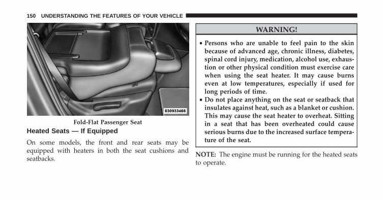
Heated Seats — If Equipped
On some models, the front and rear seats may beequipped with heaters in both the seat cushions andseatbacks.
WARNING!
• Persons who are unable to feel pain to the skinbecause of advanced age, chronic illness, diabetes,spinal cord injury, medication, alcohol use, exhaus-tion or other physical condition must exercise carewhen using the seat heater. It may cause burnseven at low temperatures, especially if used forlong periods of time.
• Do not place anything on the seat or seatback thatinsulates against heat, such as a blanket or cushion.This may cause the seat heater to overheat. Sittingin a seat that has been overheated could causeserious burns due to the increased surface tempera-ture of the seat.
NOTE: The engine must be running for the heated seatsto operate.
Fold-Flat Passenger Seat
150 UNDERSTANDING THE FEATURES OF YOUR VEHICLE

Vehicles Equipped with Remote Start
On models that are equipped with remote start, thedriver’s heated seat and heated steering wheel can beprogrammed to come on during a remote start. Refer to“Remote Starting System — If Equipped” in “Things ToKnow Before Starting Your Vehicle” for further informa-tion.
Front Heated Seats With Uconnect® 5.0 — IfEquipped
There are two heated seat switches that allow the driverand passenger to operate the seats independently. Thecontrols for each heater are located in the Uconnect®system screen.
You can choose from HIGH, LOW or OFF heat settings.
Press the “Climate” hard-key located on the right side ofthe Uconnect® display.
Press the “Driver” or “Passenger” seat soft-key once toselect HI-level heating. Press the soft-key a second timeto select LO-level heating. Press the soft-key a third timeto shut the heating elements OFF.
NOTE: Once a heat setting is selected, heat will be feltwithin two to five minutes.
Heated Seats Soft-Keys
3
UNDERSTANDING THE FEATURES OF YOUR VEHICLE 151

When the HI-level setting is selected, the heater willprovide a boosted heat level during the first four minutesof operation. Then, the heat output will drop to thenormal HI-level. If the HI-level setting is selected, thesystem will automatically switch to LO-level after amaximum of 60 minutes of continuous operation. At thattime, the display will change from HI to LO, indicatingthe change. The LO-level setting will turn OFF automati-cally after a maximum of 45 minutes.
Front Heated Seats With Uconnect® 8.4A/8.4AN —If Equipped
There are two heated seat soft-keys that allow the driverand passenger to operate the seats independently. Thecontrols for each heater are located in the Uconnect®system screen.
Press the “Controls” soft-key located on the bottom of theUconnect® display.
Press the “Driver” or “Passenger” seat soft-key once toselect HI-level heating. Press the soft-key a second timeto select LO-level heating. Press the soft-key a third timeto shut the heating elements OFF.
NOTE: Once a heat setting is selected, heat will be feltwithin two to five minutes.
Heated Seats Soft-Keys
152 UNDERSTANDING THE FEATURES OF YOUR VEHICLE

When the HI-level setting is selected, the heater willprovide a boosted heat level during the first four minutesof operation. Then, the heat output will drop to thenormal HI-level. If the HI-level setting is selected, thesystem will automatically switch to LO-level after amaximum of 60 minutes of continuous operation. At thattime, the display will change from HI to LO, indicatingthe change. The LO-level setting will turn OFF automati-cally after a maximum of 45 minutes.
Rear Heated Seats
On some models, the two outboard seats are equippedwith heated seats. There are two heated seat switches thatallow the rear passengers to operate the seats indepen-dently. The heated seat switches for each heater arelocated on the rear of the center console.
Rear Heated Seat Switches
3
UNDERSTANDING THE FEATURES OF YOUR VEHICLE 153

You can choose from HIGH, LOW or OFF heat settings.Amber indicator lights in each switch indicate the level ofheat in use. Two indicator lights will illuminate forHIGH, one for LOW and none for OFF.
Press the switch once to select HIGH-levelheating. Press the switch a second time to selectLOW-level heating. Press the switch a thirdtime to shut the heating elements OFF.
NOTE: Once a heat setting is selected, heat will be feltwithin two to five minutes.
When the HIGH-level setting is selected, the heater willprovide a boosted heat level during the first four minutesof operation. Then, the heat output will drop to the normalHIGH-level. If the HIGH-level setting is selected, thesystem will automatically switch to LOW-level after ap-proximately 60 minutes of continuous operation. At thattime, the number of illuminated LEDs changes from two to
one, indicating the change. The LOW-level setting will turnOFF automatically after approximately 45 minutes.
Front Ventilated Seats WithUconnect® 8.4A/8.4AN — If Equipped
On some models, both the driver and passenger seats areventilated. Located in the seat cushion and seatback aresmall fans that draw the air from the passenger compart-ment and pull air through fine perforations in the seatcover to help keep the driver and front passenger coolerin higher ambient temperatures.
To operate the system, press the “Controls” soft-keylocated on the bottom of the Uconnect® display.
Press the “Driver” or “Passenger” vented seat soft-keyonce to select HI-level ventilation. Press the ventedsoft-key a second time to select LO-level ventilation.Press the vented soft-key a third time to shut off the seatventilation.
154 UNDERSTANDING THE FEATURES OF YOUR VEHICLE

NOTE: The engine must be running for the ventilatedseats to operate.
Vehicles Equipped With Remote Start
On models that are equipped with remote start, the driver’sventilated seat can be programmed to come on during aremote start. Refer to “Remote Starting System — IfEquipped” in “Things To Know Before Starting YourVehicle” for further information.
Head Restraints
Head restraints are designed to reduce the risk of injuryby restricting head movement in the event of a rear-impact. Head restraints should be adjusted so that the topof the head restraint is located above the top of your ear.
Ventilated Seats Soft-Keys
3
UNDERSTANDING THE FEATURES OF YOUR VEHICLE 155

WARNING!
The head restraints for all occupants must be prop-erly adjusted prior to operating the vehicle or occu-pying a seat. Head restraints should never be ad-justed while the vehicle is in motion. Driving avehicle with the head restraints improperly adjustedor removed could cause serious injury or death in theevent of a collision.
Active Head Restraints — Front Seats
Active Head Restraints are passive, deployable compo-nents, and vehicles with this equipment cannot be readilyidentified by any markings, only through visual inspec-tion of the head restraint. The head restraint will be splitin two halves, with the front half being soft foam andtrim, the back half being decorative plastic.
When AHRs deploy during a rear impact, the front halfof the head restraint extends forward to minimize the gapbetween the back of the occupant’s head and the AHR.This system is designed to help prevent or reduce theextent of injuries to the driver and front passenger incertain types of rear impacts. Refer to “Occupant Re-straints” in “Things To Know Before Starting Your Ve-hicle” for further information
To raise the head restraint, pull upward on the headrestraint. To lower the head restraint, press the pushbutton, located at the base of the head restraint, and pushdownward on the head restraint.
156 UNDERSTANDING THE FEATURES OF YOUR VEHICLE

For comfort the Active Head Restraints can be tiltedforward and rearward. To tilt the head restraint closer tothe back of your head, pull forward on the bottom of thehead restraint. Push rearward on the bottom of the headrestraint to move the head restraint away from yourhead.
Push Button Active Head Restraint (Normal Position)
3
UNDERSTANDING THE FEATURES OF YOUR VEHICLE 157

NOTE:
• The head restraints should only be removed by quali-fied technicians, for service purposes only. If either ofthe head restraints require removal, see your autho-rized dealer.
• In the event of deployment of an Active Head Re-straint, refer to “Occupant Restraints/Resetting ActiveHead Restraints (AHR)” in “Things To Know BeforeStarting Your Vehicle” for further information.
WARNING!
• Do not place items over the top of the Active HeadRestraint, such as coats, seat covers or portableDVD players. These items may interfere with theoperation of the Active Head Restraint in the eventof a collision and could result in serious injury ordeath.
(Continued)
Active Head Restraint (Tilted)
158 UNDERSTANDING THE FEATURES OF YOUR VEHICLE

WARNING! (Continued)• Active Head Restraints may be deployed if they are
struck by an object such as a hand, foot or loosecargo. To avoid accidental deployment of the Ac-tive Head Restraint ensure that all cargo is secured,as loose cargo could contact the Active Head Re-straint during sudden stops. Failure to follow thiswarning could cause personal injury if the ActiveHead Restraint is deployed.
Head Restraints — Rear Seats
The head restraints on the outboard seats are not adjust-able. They automatically fold forward when the rear seatis folded to a load floor position but do not return to theirnormal position when the rear seat is raised. Afterreturning either seat to its upright position, raise the headrestraint until it locks in place. The outboard headrestsare not removable.
The center head restraint has limited adjustment. Liftupward on the head restraint to raise it, or push down-ward on the head restraint to lower it.
Rear Head Restraint
3
UNDERSTANDING THE FEATURES OF YOUR VEHICLE 159

WARNING!
Sitting in a seat with the head restraint in its loweredposition could result in serious injury or death in acollision. Always make sure the outboard head re-straints are in their upright positions when the seat isto be occupied.
NOTE: For proper routing of a Child Seat Tether refer to“Occupant Restraints” in “Things to Know Before Start-ing Your Vehicle” for further information.
60/40 Split Rear Seat
To Lower Rear Seat
Either side of the rear seat can be lowered to allow forextended cargo space and still maintain some rear seatingroom.
NOTE: Be sure that the front seats are fully upright andpositioned forward. This will allow the rear seatback tofold down easily.
1. Pull upward on the release lever to release the seat.
Rear Seat Release
160 UNDERSTANDING THE FEATURES OF YOUR VEHICLE

NOTE:
• Do not fold the 60% rear seat down with the leftoutboard or rear center seat belt buckled.
• Do not fold the 40% rear seat down with the rightoutboard seat belt buckled.
2. Fold the rear seat completely forward.
To Raise Rear Seat
Raise the rear seatback and lock it into place. If interfer-ence from the cargo area prevents the seatback from fullylocking, you will have difficulty returning the seat to itsproper position.
Rear Seat Folded
3
UNDERSTANDING THE FEATURES OF YOUR VEHICLE 161

WARNING!
• Be certain that the seatback is securely locked intoposition. If the seatback is not securely locked intoposition the seat will not provide the proper stabil-ity for child seats and/or passengers. An improp-erly latched seat could cause serious injury.
• The cargo area in the rear of the vehicle (with therear seatbacks in the locked-up or folded downposition) should not be used as a play area bychildren when the vehicle is in motion. They couldbe seriously injured in a collision. Children shouldbe seated and using the proper restraint system.
Reclining Rear Seat
To recline the seatback, lift the lever located on theoutboard side of the seat, lean back and release the leverat the desired position. To return the seatback, lift thelever, lean forward and release the lever.
WARNING!
Do not ride with the seatback reclined so that theshoulder belt is no longer resting against your chest.In a collision you could slide under the seat belt,which could result in serious injury or death.
Rear Seat Release
162 UNDERSTANDING THE FEATURES OF YOUR VEHICLE

DRIVER MEMORY SEAT — IF EQUIPPED
This feature allows the driver to store up to two differentmemory profiles for easy recall through a memoryswitch. Each memory profile contains desired positionsettings for the driver seat, side mirrors, and power tiltand telescopic steering column (if equipped) and a set ofdesired radio station presets. Your Remote Keyless Entry(RKE) transmitter can also be programmed to recall thesame positions when the UNLOCK button is pressed.
NOTE: Your vehicle is equipped with two RKE trans-mitters. One RKE transmitter can be linked to memoryposition 1 and the other transmitter can be linked tomemory position 2.
The memory seat switch is located on the driver’s doortrim panel. The switch consists of three buttons:
• The (S) button, which is used to activate the memorysave function
• The (1) and (2) buttons which are used to recall eitherof two pre-programmed memory profiles.
Memory Seat Switch
3
UNDERSTANDING THE FEATURES OF YOUR VEHICLE 163

Programming The Memory Feature
NOTE: To create a new memory profile, perform thefollowing:
Vehicles Equipped With Keyless Enter-N-Go
1. Without pressing the brake pedal, push the ENGINESTART/STOP button and cycle the ignition to theON/RUN position (Do not start the engine).
2. Adjust all memory profile settings to desired preferences(i.e., seat, side mirror, power tilt and telescopic steeringcolumn [if equipped], and radio station presets).
3. Press and release the S (Set) button on the memoryswitch.
4. Within 5 seconds, press and release either of thememory buttons (1) or (2). The Electronic Vehicle Infor-mation Center (EVIC) will display which memory posi-tion has been set.
Vehicles Not Equipped With Keyless Enter-N-Go
1. Insert the ignition key fob, and turn the ignition switchto the ON/RUN position.
2. Adjust all memory profile settings to desired prefer-ences (i.e., seat, side mirror, adjustable pedals [ifequipped], power tilt and telescopic steering column[if equipped], and radio station presets).
3. Press and release the S (Set) button on the memoryswitch.
4. Within 5 seconds, press and release either of thememory buttons (1) or (2). The Electronic Vehicle Infor-mation Center (EVIC) will display which memory posi-tion has been set.
164 UNDERSTANDING THE FEATURES OF YOUR VEHICLE

NOTE:
• Memory profiles can be set without the vehicle inPARK, but the vehicle must be in PARK to recall amemory profile.
• The Recall Memory with Remote Linked to Memoryfeature can be enabled through the Uconnect® systemscreen. Refer to “Customer- Programmable Features —Uconnect® Access 8.4 Settings ” in “UnderstandingYour Instrument Panel” for further information.
Linking And Unlinking The Remote Keyless EntryTransmitter To Memory
Your RKE transmitters can be programmed to recall oneof two pre-programmed memory profiles by pressing theUNLOCK button on the RKE transmitter.
NOTE: Before programming your RKE transmitters youmust select the “Memory To FOB” feature through theUconnect® system screen. Refer to “Customer- Program-mable Features — Uconnect® Access 8.4 Settings ” in“Understanding Your Instrument Panel” for further in-formation.
To program your RKE transmitters, perform the follow-ing:
1. Remove the Key Fob from the ignition (or change theignition to OFF, for vehicles equipped with KeylessEnter-N-Go).
2. Select desired memory profile (1) or (2).
NOTE: If a memory profile has not already been set,refer to �Programming The Memory Feature� for instruc-tions on how to set a memory profile.
3
UNDERSTANDING THE FEATURES OF YOUR VEHICLE 165

3. Once the profile has been recalled, press and releasethe SET (S) button on the memory switch, then pressand release button (1) or (2) accordingly. “MemoryProfile Set” (1 or 2) will display in the instrumentcluster on vehicles equipped with the EVIC.
4. Press and release the LOCK button on the RKEtransmitter within 10 seconds.
NOTE: Your RKE transmitters can be unlinked to yourmemory settings by following steps 1-4 above and press-ing the UNLOCK button (instead of LOCK) on the RKEtransmitter in Step 4.
Memory Position Recall
NOTE: The vehicle must be in PARK to recall memorypositions. If a recall is attempted when the vehicle is notin PARK, a message will be displayed in the ElectronicVehicle Information Center (EVIC).
Driver One Memory Position Recall
• To recall the memory settings for driver one using thememory switch , press MEMORY button number 1 onthe memory switch.
• To recall the memory settings for driver one using theRKE transmitter, press the UNLOCK button on theRKE transmitter linked to memory position 1.
Driver Two Memory Position Recall
• To recall the memory setting for driver two using thememory switch, press MEMORY button number 2 onthe memory switch.
• To recall the memory settings for driver two using theRKE transmitter, press the UNLOCK button on theRKE transmitter linked to memory position 2.
166 UNDERSTANDING THE FEATURES OF YOUR VEHICLE

A recall can be cancelled by pressing any of theMEMORY buttons during a recall (S, 1, or 2). When arecall is cancelled, the driver’s seat, driver’s mirror andthe steering column stop moving. A delay of one secondwill occur before another recall can be selected.
Easy Entry/Exit Seat
This feature provides automatic driver seat positioning toenhance driver mobility when entering and exiting thevehicle.
The distance the driver seat moves depends on whereyou have the driver seat positioned when you remove theKey Fob from the ignition (or change the ignition to OFF,for vehicles equipped with Keyless Enter-N-Go).
• When you remove the Key Fob from the ignition (orchange the ignition to OFF, for vehicles equipped withKeyless Enter-N-Go), the driver seat will move about2.4 in (60 mm) rearward if the driver seat position isgreater than or equal to 2.7 in (67.7 mm) forward of the
rear stop. The seat will return to its previously setposition when you place the ignition into the ACC orRUN position.
• When you remove the Key Fob from the ignition (orchange the ignition to OFF, for vehicles equipped withKeyless Enter-N-Go), the driver seat will move to aposition 0.3 in (7.7 mm) forward of the rear stop if thedriver seat position is between 0.9 in and 2.7 in(22.7 mm and 67.7 mm) forward of the rear stop. Theseat will return to its previously set position when youplace the ignition to the ACC or RUN position.
• The Easy Entry/Easy Exit feature is disabled when thedriver seat position is less than 0.9 in (22.7 mm)forward of the rear stop. At this position, there is nobenefit to the driver by moving the seat for Easy Exitor Easy Entry.
Each stored memory setting will have an associated EasyEntry and Easy Exit position.
3
UNDERSTANDING THE FEATURES OF YOUR VEHICLE 167

NOTE: The Easy Entry/Exit feature is not enabled whenthe vehicle is delivered from the factory. The EasyEntry/Exit feature is enabled (or later disabled) throughthe Uconnect® system screen. Refer to “Customer- Pro-grammable Features — Uconnect® Access 8.4 Settings ”in “Understanding Your Instrument Panel” for furtherinformation.
TO OPEN AND CLOSE THE HOOD
To open the hood, two latches must be released.
1. Pull the release lever located below the instrumentpanel and in front of the driver’s door.
2. Reach under the hood, move safety latch to the leftand lift the hood.
Hood Release
168 UNDERSTANDING THE FEATURES OF YOUR VEHICLE

CAUTION!
To prevent possible damage, do not slam the hood toclose it. Use a firm downward push at the center ofthe hood to ensure that both latches engage.
WARNING!
Be sure the hood is fully latched before driving yourvehicle. If the hood is not fully latched, it could openwhen the vehicle is in motion and block your vision.Failure to follow this warning could result in seriousinjury or death.
LIGHTS
Headlight Switch
The headlight switch is located on the left side of theinstrument panel, next to the steering wheel. The head-light switch controls the operation of the headlights,parking lights, instrument panel lights, cargo lights andfog lights (if equipped).
Safety Latch Location
3
UNDERSTANDING THE FEATURES OF YOUR VEHICLE 169

To turn on the headlights, rotate the headlightswitch clockwise. When the headlight switch ison the parking lights, taillights, license platelight and instrument panel lights are also
turned on. To turn off the headlights, rotate the headlightswitch back to the O (Off) position.
NOTE:
• Your vehicle is equipped with plastic headlight andfog light (if equipped) lenses that are lighter and lesssusceptible to stone breakage than glass lights. Plasticis not as scratch resistant as glass and therefore differ-ent lens cleaning procedures must be followed.
• To minimize the possibility of scratching the lensesand reducing light output, avoid wiping with a drycloth. To remove road dirt, wash with a mild soapsolution followed by rinsing.
CAUTION!
Do not use abrasive cleaning components, solvents,steel wool or other abrasive materials to clean thelenses.
Headlight Switch
170 UNDERSTANDING THE FEATURES OF YOUR VEHICLE

Automatic Headlights — If Equipped
This system automatically turns the headlights on or offaccording to ambient light levels. To turn the system on,rotate the headlight switch to the A (AUTO) position.
When the system is on, the Headlight Delay feature isalso on. This means the headlights will stay on for up to90 seconds after you turn the ignition switch to the OFFposition. To turn the automatic headlights off, turn theheadlight switch out of the AUTO position.
NOTE: The engine must be running before the head-lights will turn on in the Automatic Mode.
Headlights On Automatically With Wipers
If your vehicle is equipped with Automatic Headlights, italso has this customer-programmable feature. Whenyour headlights are in the automatic mode and theengine is running, they will automatically turn on when
the wiper system is on. The programmable settings areavailable in the in the Uconnect® system screen. Refer to“Customer- Programmable Features — Uconnect® Ac-cess 8.4 Settings ” in “Understanding Your InstrumentPanel” for further information.
If your vehicle is equipped with a “Rain Sensitive WiperSystem” and it is activated, the headlights will automati-cally turn on after the wipers complete five wipe cycleswithin approximately one minute, and they will turn offapproximately four minutes after the wipers completelystop. Refer to “Windshield Wipers And Washers” in thissection for further information.
NOTE: When your headlights come on during the day-time, the instrument panel lights will automatically dimto the lower nighttime intensity. Refer to “Lights” in thissection for further information.
3
UNDERSTANDING THE FEATURES OF YOUR VEHICLE 171

Automatic High Beam — If Equipped
The automatic high beam system provides increasedforward lighting at night by automating high beamcontrol through the use of a digital camera mounted onthe inside rearview mirror. This camera detects vehiclespecific light and automatically switches from highbeams to low beams until the approaching vehicle is outof view.
NOTE:
• If the windshield or automatic high beam mirror isreplaced, the automatic high beam mirror must bere-aimed to ensure proper performance. See your localauthorized dealer.
• Broken, muddy, or obstructed headlights and taillightsof vehicles in the field of view will cause headlights toremain on longer (closer to the vehicle). Also, dirt, film,
and other obstructions (sticker, toll box, etc.) on thewindshield or camera lens will cause the system tofunction improperly.
To Activate
1. Enable the Automatic High Beams through theUconnect® system screen. Refer to “Customer- Pro-grammable Features — Uconnect® Access 8.4 Settings ”in “Understanding Your Instrument Panel” for furtherinformation.
2. Turn the headlight switch to the AUTO headlightposition.
3. Push the multifunction lever away from you (towardfront of vehicle) to engage the high beam mode.
NOTE: This system will not activate until the vehicle isat or above 20 mph (32 km/h).
172 UNDERSTANDING THE FEATURES OF YOUR VEHICLE

To Deactivate
1. Pull the multifunction lever toward you (or rearwardin car) to manually deactivate the system (normaloperation of low beams).
2. Push back on the multifunction lever once again toreactivate the system.
Daytime Running Lights — If Equipped
The Daytime Running Lights (low intensity) come onwhenever the engine is running, and the transmission isnot in the PARK position. The lights will remain on untilthe ignition is switched to the OFF or ACC position or theparking brake is engaged.
NOTE: If a turn signal is activated, the DRL lamp on thesame side of the vehicle will turn off for the duration ofthe turn signal activation. Once the turn signal is nolonger active, the DRL lamp will illuminate.
The headlight switch must be used for normal nighttimedriving.
Automatic Headlight Leveling — HID HeadlightsOnly
This feature prevents the headlights from interferingwith the vision of oncoming drivers. Headlight levelingautomatically adjusts the height of the headlight beam inreaction to changes in vehicle pitch.
3
UNDERSTANDING THE FEATURES OF YOUR VEHICLE 173

Adaptive Bi-Xenon High Intensity DischargeHeadlights — If Equipped
This system automatically swivels the headlight beampattern horizontally to provide increased illumination inthe direction the vehicle is steering.
NOTE:
• Each time the Adaptive Headlight System is turned on,the headlights will initialize by performing a briefsequence of rotations.
• The Adaptive Headlight System is active only whenthe vehicle is moving forward.
The Adaptive Headlight System can be turned On or Offusing the Uconnect® System, refer to “Uconnect® Set-tings” in “Understanding Your Instrument Panel” forfurther information.
Headlight Delay
To aid in your exit, your vehicle is equipped with aheadlight delay that will leave the headlights on forapproximately 90 seconds. This delay is initiated whenthe ignition is turned OFF while the headlight switch ison, and then the headlight switch is cycled off. Headlightdelay can be cancelled by either turning the headlightswitch on then off, or by turning the ignition ON.
The headlight delay time is programmable in theUconnect® system screen. Refer to “Customer- Program-mable Features — Uconnect® Access 8.4 Settings ” in“Understanding Your Instrument Panel” for further in-formation.
174 UNDERSTANDING THE FEATURES OF YOUR VEHICLE

Parking Lights And Panel Lights
To turn on the parking lights and instrumentpanel lights, rotate the headlight switch clockwise.
To turn off the parking lights, rotate the headlight switchback to the O (Off) position.
Fog Lights — If Equipped
The fog lights are turned on by rotating the headlightswitch to the parking light or headlight position andpushing in the headlight rotary control.
The fog lights will operate only when the parking lightsare on or when the vehicle headlights are on low beam.An indicator light located in the instrument cluster willilluminate when the fog lights are on. The fog lights willturn off when the switch is pushed a second time, whenthe headlight switch is rotated to the off position, or thehigh beam is selected.
Fog Light Operation
3
UNDERSTANDING THE FEATURES OF YOUR VEHICLE 175

Interior Lights
Courtesy and dome lights are turned on when the frontdoors are opened, when the dimmer control (rotatingwheel on the right side of the headlight switch) is rotatedto the its farthest upward position, or if equipped, whenthe UNLOCK button is pressed on the Remote KeylessEntry (RKE) transmitter. When a door is open and theinterior lights are on, rotating the dimmer control all theway down, to the OFF detent, will cause all the interiorlights to go out. This is also known as the “Party” modebecause it allows the doors to stay open for extendedperiods of time without discharging the vehicle’s battery.
The brightness of the instrument panel lighting can beregulated by rotating the dimmer control up (brighter) ordown (dimmer). When the headlights are on you cansupplement the brightness of the odometer, trip odom-eter, radio and overhead console by rotating the control
to its farthest position up until you hear a click. Thisfeature is termed the “Parade” mode and is useful whenheadlights are required during the day.
Dimmer Control
176 UNDERSTANDING THE FEATURES OF YOUR VEHICLE

Lights-On Reminder
If the headlights, parking lights, or cargo lights are left onafter the ignition is turned OFF, a chime will sound whenthe driver’s door is opened.
Battery Saver
To protect the life of your vehicle’s battery, load sheddingis provided for both the interior and exterior lights.
If the ignition is OFF and any door is left ajar for 10minutes or the dimmer control is rotated all the way upto the dome ON position for 10 minutes, the interiorlights will automatically turn off.
If the headlights remain on while the ignition is cycledOFF, the exterior lights will automatically turn off aftereight minutes. If the headlights are turned on and left onfor eight minutes while the ignition is OFF, the exteriorlights will automatically turn off.
NOTE: Battery saver mode is cancelled if the ignition isON.
Front Map/Reading Lights
The front map/reading lights are mounted in the over-head console.
Front Map/Reading Lights
3
UNDERSTANDING THE FEATURES OF YOUR VEHICLE 177

Each light can be turned on by pressing a switch on eitherside of the console. These buttons are backlit for nighttime visibility. To turn the lights off, press the switch asecond time. The lights will also turn on when theUNLOCK button on the Remote Keyless Entry (RKE) ispressed.
Courtesy Lights
The courtesy lights can be turned on by pressing the topcorner of the lens. To turn the lights off, press the lens asecond time.
Front Map/Reading Light Switches
Courtesy Lights
178 UNDERSTANDING THE FEATURES OF YOUR VEHICLE

Ambient Light
The overhead console is equipped with an ambient lightfeature. This light casts illumination for improved visibil-ity of the floor center console and PRNDL area.
Multifunction Lever
The multifunction lever is located on the left side of thesteering column.
Ambient LightMultifunction Lever
3
UNDERSTANDING THE FEATURES OF YOUR VEHICLE 179

Turn Signals
Move the multifunction lever up or down and the arrowson each side of the instrument cluster flash to showproper operation of the front and rear turn signal lights.
NOTE: If either light remains on and does not flash, orthere is a very fast flash rate, check for a defective outsidelight bulb. If an indicator fails to light when the lever ismoved, it would suggest that the indicator bulb isdefective.
Lane Change Assist
Tap the lever up or down once, without moving beyondthe detent, and the turn signal (right or left) will flashthree times then automatically turn off.
Flash-To-Pass
You can signal another vehicle with your headlights bypartially pulling the multifunction lever toward the steer-ing wheel. This will cause the high beam headlights toturn on until the lever is released.
High/Low Beam Switch
Push the multifunction lever toward the instrumentpanel to switch the headlights to high beam. Pulling themultifunction back toward the steering wheel will turnthe low beams back on, or shut the high beams off.
WINDSHIELD WIPERS AND WASHERS
The windshield wiper/washer controls are located on themultifunction lever on the left side of the steering col-umn. The front wipers are operated by rotating a switch,located on the end of the lever. For information on therear wiper/washer, refer to “Rear Window Features” in“Understanding The Features Of Your Vehicle”.
180 UNDERSTANDING THE FEATURES OF YOUR VEHICLE

Windshield Wiper Operation
Rotate the end of the lever to one of the first four detentpositions for intermittent settings, the fifth detent for lowwiper operation and the sixth detent for high wiperoperation.
Multifunction Lever
Windshield Wiper Operation
3
UNDERSTANDING THE FEATURES OF YOUR VEHICLE 181

CAUTION!
Always remove any buildup of snow that preventsthe windshield wiper blades from returning to the“park” position. If the windshield wiper switch isturned off, and the blades cannot return to the “park”position, damage to the wiper motor may occur.
Intermittent Wiper System
Use one of the four intermittent wiper settings whenweather conditions make a single wiping cycle, with avariable delay between cycles, desirable. At drivingspeeds above 10 mph (16 km/h), the delay can beregulated from a maximum of approximately 18 secondsbetween cycles (first detent), to a cycle every one second(fourth detent).
NOTE: If the vehicle is moving less than 10 mph(16 km/h), delay times will be doubled.
Windshield Washer Operation
To use the washer, push on the end of the lever (towardthe steering wheel) and hold while spray is desired. If the
Intermittent Wiper Operation
182 UNDERSTANDING THE FEATURES OF YOUR VEHICLE

lever is pushed while in the intermittent setting, thewipers will turn on and operate for several wipe cyclesafter the end of the lever is released, and then resume theintermittent interval previously selected.
If the end of the lever is pushed while the wipers are inthe off position, the wipers will operate for several wipecycles, then turn off.
WARNING!
Sudden loss of visibility through the windshieldcould lead to a collision. You might not see othervehicles or other obstacles. To avoid sudden icing ofthe windshield during freezing weather, warm thewindshield with the defroster before and duringwindshield washer use.
Mist
Use the Mist feature when weather conditions makeoccasional usage of the wipers necessary. Rotate the endof the lever downward to the Mist position and releasefor a single wiping cycle.
Windshield Washer Operation
3
UNDERSTANDING THE FEATURES OF YOUR VEHICLE 183
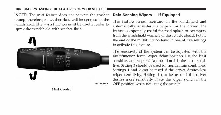
NOTE: The mist feature does not activate the washerpump; therefore, no washer fluid will be sprayed on thewindshield. The wash function must be used in order tospray the windshield with washer fluid.
Rain Sensing Wipers — If Equipped
This feature senses moisture on the windshield andautomatically activates the wipers for the driver. Thefeature is especially useful for road splash or oversprayfrom the windshield washers of the vehicle ahead. Rotatethe end of the multifunction lever to one of five settingsto activate this feature.
The sensitivity of the system can be adjusted with themultifunction lever. Wiper delay position 1 is the leastsensitive, and wiper delay position 4 is the most sensi-tive. Setting 3 should be used for normal rain conditions.Settings 1 and 2 can be used if the driver desires lesswiper sensitivity. Setting 4 can be used if the driverdesires more sensitivity. Place the wiper switch in theOFF position when not using the system.
Mist Control
184 UNDERSTANDING THE FEATURES OF YOUR VEHICLE

NOTE:
• The Rain Sensing feature will not operate when thewiper switch is in the low or high-speed position.
• The Rain Sensing feature may not function properlywhen ice, or dried salt water is present on the wind-shield.
• Use of Rain-X® or products containing wax or siliconemay reduce Rain Sensing performance.
• A customer programmable feature in the ElectronicVehicle Information Center (EVIC) allows the RainSensing feature to be turned off. Refer to “ElectronicVehicle Information Center (EVIC)/Personal Settings(Customer-Programmable Features)” in “Understand-ing Your Instrument Panel” for further information.
The Rain Sensing system has protection features for thewiper blades and arms, and will not operate under thefollowing conditions:
• Low Ambient Temperature — When the ignition isfirst turned ON, the Rain Sensing system will notoperate until the wiper switch is moved, vehicle speedis greater than 0 mph (0 km/h), or the outside tem-perature is greater than 32°F (0°C).
• Transmission In NEUTRAL Position — When theignition is ON, and the transmission is in the NEU-TRAL position, the Rain Sensing system will notoperate until the wiper switch is moved, vehicle speedis greater than 5 mph (8 km/h), or the shift lever ismoved out of the NEUTRAL position.
3
UNDERSTANDING THE FEATURES OF YOUR VEHICLE 185

Remote Start Mode Inhibit — On vehicles equippedwith Remote Starting system, Rain Sensing wipers arenot operational when the vehicle is in the remote startmode. Once the operator is in the vehicle and has placedthe ignition switch in the RUN position, rain sensingwiper operation can resume, if it has been selected, andno other inhibit conditions (mentioned previously) exist.
TILT/TELESCOPING STEERING COLUMN
This feature allows you to tilt the steering columnupward or downward. It also allows you to lengthen orshorten the steering column. The tilt/telescoping lever islocated below the steering wheel at the end of thesteering column. To unlock the steering column, push the lever downward
(toward the floor). To tilt the steering column, move thesteering wheel upward or downward as desired. Tolengthen or shorten the steering column, pull the steeringwheel outward or push it inward as desired. To lock thesteering column in position, push the lever upward untilfully engaged.
Tilt/Telescoping Lever
186 UNDERSTANDING THE FEATURES OF YOUR VEHICLE

WARNING!
Do not adjust the steering column while driving.Adjusting the steering column while driving or driv-ing with the steering column unlocked, could causethe driver to lose control of the vehicle. Failure tofollow this warning may result in serious injury ordeath.
POWER TILT/TELESCOPING STEERING COLUMN— IF EQUIPPED
This feature allows you to tilt the steering columnupward or downward. It also allows you to lengthen orshorten the steering column. The power tilt/telescopingsteering column lever is located below the multifunctionlever on the steering column.
To tilt the steering column, move the lever up or down asdesired. To lengthen or shorten the steering column, pullthe lever toward you or push the lever away from you asdesired.
Power Tilt/Telescoping Steering Column
3
UNDERSTANDING THE FEATURES OF YOUR VEHICLE 187
NOTE: For vehicles equipped with Driver Memory Seat,you can use your Remote Keyless Entry (RKE) transmit-ter or the memory switch on the driver’s door trim panelto return the tilt/telescopic steering column to pre-programmed positions. Refer to “Driver Memory Seat”in this section for further information.
WARNING!
Do not adjust the steering column while driving.Adjusting the steering column while driving or driv-ing with the steering column unlocked, could causethe driver to lose control of the vehicle. Failure tofollow this warning may result in serious injury ordeath.
HEATED STEERING WHEEL — IF EQUIPPED
The steering wheel contains a heating element that helpswarm your hands in cold weather. The heated steeringwheel has only one temperature setting. Once the heatedsteering wheel has been turned on it will operate for upto 80 minutes before automatically shutting off. Theheated steering wheel can shut off early or may not turnon when the steering wheel is already warm.
The heated steering wheel can be turned on and off usingthe Uconnect® System.
Touch the “Controls” soft-key then touch the “HeatedWheel” soft-key to turn on the heated steering wheel.Press the “Heated Wheel” soft-key a second time to turnthe heated steering wheel off.
188 UNDERSTANDING THE FEATURES OF YOUR VEHICLE

NOTE: The engine must be running for the heatedsteering wheel to operate.
Controls Soft-Key Heated Steering Wheel Soft-Key
3
UNDERSTANDING THE FEATURES OF YOUR VEHICLE 189

Vehicles Equipped With Remote Start
On models that are equipped with remote start, the heatedsteering wheel can be programmed to come on during aremote start. Refer to “Remote Starting System — IfEquipped” in “Things To Know Before Starting YourVehicle” for further information.
WARNING!
• Persons who are unable to feel pain to the skinbecause of advanced age, chronic illness, diabetes,spinal cord injury, medication, alcohol use, exhaus-tion, or other physical conditions must exercisecare when using the steering wheel heater. It maycause burns even at low temperatures, especially ifused for long periods.
(Continued)
WARNING! (Continued)• Do not place anything on the steering wheel that
insulates against heat, such as a blanket or steeringwheel covers of any type and material. This maycause the steering wheel heater to overheat.
ELECTRONIC SPEED CONTROL — IF EQUIPPED
When engaged, the Electronic Speed Control takes overaccelerator operations at speeds greater than 25 mph(40 km/h).
The Electronic Speed Control buttons are located on theright side of the steering wheel.
190 UNDERSTANDING THE FEATURES OF YOUR VEHICLE

NOTE: In order to ensure proper operation, the Elec-tronic Speed Control System has been designed to shutdown if multiple Speed Control functions are operated atthe same time. If this occurs, the Electronic Speed ControlSystem can be reactivated by pushing the ElectronicSpeed Control ON/OFF button and resetting the desiredvehicle set speed.
To Activate
Push the ON/OFF button to activate the electronic speedcontrol. CRUISE CONTROL READY will appear on theinstrument cluster to indicate the electronic speed controlis on. To turn the system off, push the ON/OFF button asecond time. CRUISE CONTROL OFF will appear on theinstrument cluster to indicate the electronic speed controlis off. The system should be turned off when not in use.
Electronic Speed Control Buttons
1 — ON/OFF 4 — SET-/DECEL2 — SET+/ACCEL 5 — CANCEL3 — RESUME
3
UNDERSTANDING THE FEATURES OF YOUR VEHICLE 191

WARNING!
Leaving the Electronic Speed Control system onwhen not in use is dangerous. You could accidentallyset the system or cause it to go faster than you want.You could lose control and have an accident. Alwaysleave the system OFF when you are not using it.
To Set A Desired Speed
Turn the Electronic Speed Control ON. When the vehiclehas reached the desired speed, press the SET (+) or SET(-) button and release. Release the accelerator and thevehicle will operate at the selected speed. Once a speedhas been set a message CRUISE CONTROL SET TOMPH/KM will appear indicating what speed was set. Anindicator CRUISE will also appear and stay on in theinstrument cluster when the speed is set.
To Deactivate
A soft tap on the brake pedal, pushing the CANCELbutton, or normal brake pressure while slowing thevehicle will deactivate Electronic Speed Control withouterasing the set speed memory. Pressing the ON/OFFbutton or turning the ignition switch OFF erases the setspeed memory.
To Resume Speed
To resume a previously set speed, push the RES buttonand release. Resume can be used at any speed above20 mph (32 km/h).
To Vary The Speed Setting
When the Electronic Speed Control is set, you can in-crease speed by pushing the SET (+) button. If the buttonis continually pressed, the set speed will continue toincrease until the button is released, then the new setspeed will be established.
192 UNDERSTANDING THE FEATURES OF YOUR VEHICLE

Pressing the SET (+) button once will result in a 1 mph(1 km/h) increase in set speed. Each subsequent tap ofthe button results in an increase of 1 mph (1 km/h).
NOTE: Tap results of 1 mph or 1 km/h depends onselection of US or METRIC units in the EVIC displaysettings menu, or the RADIO settings menu (dependenton vehicle configuration).
To decrease speed while the Electronic Speed Control isset, push the SET (-) button. If the button is continuallyheld in the SET (-) position, the set speed will continue todecrease until the button is released. Release the buttonwhen the desired speed is reached, and the new set speedwill be established.
Pressing the SET (-) button once will result in a 1 mph(1 km/h) decrease in set speed. Each subsequent tap ofthe button results in a decrease of 1 mph (1 km/h).
NOTE: Tap results of 1 mph or 1 km/h depends onselection of US or METRIC units in the EVIC displaysettings menu, or the RADIO settings menu (dependenton vehicle configuration).
To Accelerate For Passing
Press the accelerator as you would normally. When thepedal is released, the vehicle will return to the set speed.
Using Electronic Speed Control On Hills
The transmission may downshift on hills to maintain thevehicle set speed.
NOTE: The Electronic Speed Control system maintainsspeed up and down hills. A slight speed change onmoderate hills is normal.
On steep hills, a greater speed loss or gain may occur soit may be preferable to drive without Electronic SpeedControl.
3
UNDERSTANDING THE FEATURES OF YOUR VEHICLE 193
WARNING!
Electronic Speed Control can be dangerous where thesystem cannot maintain a constant speed. Your ve-hicle could go too fast for the conditions, and youcould lose control and have an accident. Do not useElectronic Speed Control in heavy traffic or on roadsthat are winding, icy, snow-covered or slippery.
ADAPTIVE CRUISE CONTROL (ACC) — IFEQUIPPED
Adaptive Cruise Control (ACC) increases the drivingconvenience provided by cruise control while travelingon highways and major roadways. However, it is not asafety system and not designed to prevent collisions.
ACC will allow you to keep cruise control engaged inlight to moderate traffic conditions without the constantneed to reset your cruise control. ACC utilizes a radarsensor and a forward facing camera designed to detect avehicle directly ahead of you.
NOTE:
• If the sensor does not detect a vehicle ahead of you,ACC will maintain a fixed set speed.
• If the ACC sensor detects a vehicle ahead, ACC willapply limited braking or acceleration (not to exceedthe original set speed) automatically to maintain apreset following distance, while matching the speed ofthe vehicle ahead.
194 UNDERSTANDING THE FEATURES OF YOUR VEHICLE

WARNING!
• Adaptive Cruise Control (ACC) is a conveniencesystem. It is not a substitute for active drivinginvolvement. It is always the driver’s responsibil-ity to be attentive of road, traffic, and weatherconditions, vehicle speed, distance to the vehicleahead; and, most importantly, brake operation toensure safe operation of the vehicle under all roadconditions. Your complete attention is always re-quired while driving to maintain safe control ofyour vehicle. Failure to follow these warnings canresult in a collision and death or serious personalinjury.
• The ACC system:• Does not react to pedestrians, oncoming vehicles,
and stationary objects (e.g., a stopped vehicle in atraffic jam or a disabled vehicle).
(Continued)
WARNING! (Continued)• Cannot take street, traffic, and weather condi-
tions into account, and may be limited uponadverse sight distance conditions.
• Does not always fully recognize complex drivingconditions, which can result in wrong or missingdistance warnings.
• Can only apply a maximum of 40% of the vehi-cle’s braking capability, and will not bring thevehicle to a complete stop.
WARNING!
You should switch off the ACC system:• When driving in fog, heavy rain, heavy snow, sleet,
heavy traffic, and complex driving situations (i.e.,in highway construction zones).
(Continued)
3
UNDERSTANDING THE FEATURES OF YOUR VEHICLE 195

WARNING! (Continued)• When entering a turn lane or highway off ramp;
when driving on roads that are winding, icy, snow-covered, slippery, or have steep uphill or downhillslopes.
• When towing a trailer up or down steep slopes.• When circumstances do not allow safe driving at a
constant speed.Failure to follow these warnings can result in acollision and death or serious personal injury.
The Cruise Control system has two control modes:
• Adaptive Cruise Control mode for maintaining anappropriate distance between vehicles.
• Normal (fixed speed) cruise control mode for cruisingat a constant preset speed. For additional information,refer to “Normal (Fixed Speed) Cruise Control Mode”in this section.
NOTE: Normal (fixed speed) cruise control will not reactto preceding vehicles. Always be aware of the modeselected.
You can change the mode by using the Cruise Controlbuttons. The two control modes function differently.Always confirm which mode is selected.
Adaptive Cruise Control (ACC) Operation
The speed control buttons (located on the right side of thesteering wheel) operates the ACC system.
196 UNDERSTANDING THE FEATURES OF YOUR VEHICLE

NOTE: Any chassis/suspension or tire size modifica-tions to the vehicle will effect the performance of theAdaptive Cruise Control.
Activating Adaptive Cruise Control (ACC)
You can only activate ACC if the vehicle speed is above20 mph (32 km/h).
When the system is turned on and in the READY state,the Electronic Vehicle Information Center (EVIC) dis-plays “ACC Ready.”
When the system is OFF, the EVIC displays “AdaptiveCruise Control (ACC) Off.”Adaptive Cruise Control Buttons
1 — NORMAL (FIXED SPEED) CRUISE CONTROL ON/OFF2 — SET+/ACCEL3 — RESUME4 — SET-/DECEL5 — DISTANCE SETTING — INCREASE6 — ADAPTIVE CRUISE CONTROL (ACC) ON/OFF7 — DISTANCE SETTING — DECREASE8 — CANCEL
3
UNDERSTANDING THE FEATURES OF YOUR VEHICLE 197
NOTE: You cannot enable ACC under the followingconditions:
• When in Four-Wheel Drive Low.
• When you apply the brakes.
• When the parking brake is set.
• When the automatic transmission is in PARK, RE-VERSE or NEUTRAL.
• When the Vehicle speed is outside of the speed range.
• When the brakes are overheated.
To Activate
Push and release the Adaptive Cruise Control (ACC)ON/OFF button. The ACC menu in the EVIC displays“ACC Ready.”
To turn the system OFF, push and release the AdaptiveCruise Control (ACC) ON/OFF button again. At thistime, the system will turn off and the EVIC will display“Adaptive Cruise Control (ACC) Off.”
Adaptive Cruise Control Ready
198 UNDERSTANDING THE FEATURES OF YOUR VEHICLE

WARNING!
Leaving the Adaptive Cruise Control (ACC) system onwhen not in use is dangerous. You could accidentallyset the system or cause it to go faster than you want.
(Continued)
WARNING! (Continued)You could lose control and have a collision. Alwaysleave the system off when you are not using it.
To Set A Desired ACC Speed
When the vehicle reaches the speed desired, push theSET + button and release. The EVIC will display the setspeed.
Remove your foot from the accelerator pedal. If you donot, the vehicle may continue to accelerate beyond the setspeed. If this occurs:
• The message “ACC DRIVER OVERRIDE” will displayin the EVIC.
• The system will not be controlling the distance be-tween your vehicle and the vehicle ahead. The vehiclespeed will only be determined by the position of theaccelerator pedal.
Adaptive Cruise Control Off
3
UNDERSTANDING THE FEATURES OF YOUR VEHICLE 199

When you remove your foot from the accelerator pedal ;the vehicle speed will go back to the set speed, or to thespeed of the target vehicle whose speed is less than theset speed.
To Cancel
The following conditions cancel the system:
• The brake pedal is applied.
• You depress the brake pedal.
• You press the CANCEL switch.
• An Anti-Lock Brake System (ABS) event occurs.
• A Trailer Sway Control (TSC) event occurs.
• The transmission is shifted into NEUTRAL.
• The Electronic Stability Control/Traction Control Sys-tem (ESC/TCS) activates.
• The vehicle parking brake is applied.
• The driver switches ESC to full-off mode.
NOTE: If ACC is resumed or set with the ESC/TCS off,ESC will automatically be re-engaged.
To Turn Off
The system will turn off and clear the set speed inmemory if:
• You push the Adaptive Cruise Control (ACC) ON/OFF button.
• You push the Normal (Fixed Speed) Cruise ControlON/OFF button.
• You turn OFF the ignition.
• You switch to Four-Wheel Drive Low.
200 UNDERSTANDING THE FEATURES OF YOUR VEHICLE

To Resume
If there is a set speed in memory press the RES (resume)button and then remove your foot from the acceleratorpedal. The EVIC will display the last set speed.
NOTE: You can resume ACC from a minimum of20 mph (32 km/h).
WARNING!
The Resume function should only be used if trafficand road conditions permit. Resuming a set speedthat is too high or too low for prevailing traffic androad conditions could cause the vehicle to accelerateor decelerate too sharply for safe operation. Failure tofollow these warnings can result in a collision anddeath or serious personal injury.
To Vary The Speed Setting
While ACC is set, you can increase the set speed bypressing the SET + button.
Pressing the SET + button once will result in a 1 mph(1 km/h) increase in set speed. Each subsequent tap ofthe button results in an increase of 1 mph (1 km/h).
If the SET + button is continually pressed, the set speedwill continue to increase in 5 mph (5 km/h) incrementsuntil the button is released. The increase in set speed isreflected in the EVIC display.
While ACC is set, the set speed can be decreased bypressing the SET - button.
Pressing the SET - button once will result in a 1 mph(1 km/h) decrease in set speed. Each subsequent tap ofthe button results in a decrease of 1 mph (1 km/h).
3
UNDERSTANDING THE FEATURES OF YOUR VEHICLE 201

If the SET - button is continually pressed, the set speedwill continue to decrease in 5 mph (10 km/h) incrementsuntil the button is released. The decrease in set speed isreflected in the EVIC display.
NOTE:
• When you override and push the SET + button or SET -button, the new speed vehicle is traveling will secure thenew set speed.
• When you use the SET - button to decelerate, if theengine’s braking power does not slow the vehiclesufficiently to reach the set speed, the brake systemwill automatically slow the vehicle.
• The ACC system can only apply limited brakingcapability and will not bring the vehicle to a completestop.
• The ACC system maintains set speed when driving uphill and down hill. However, a slight speed change onmoderate hills is normal. In addition, downshiftingmay occur while climbing uphill or descending down-hill. This is normal operation and necessary to main-tain set speed. When driving up hill and down hill, theACC system will cancel if the braking temperatureexceeds normal range (overheated).
Setting The Following Distance In ACC
The specified following distance for ACC can be set byvarying the distance setting between four bars (longest),three bars (long), two bars (medium) and one bar (short).Using this distance setting and the vehicle speed, ACCcalculates and sets the distance to the vehicle ahead. Thisdistance setting displays in the EVIC.
202 UNDERSTANDING THE FEATURES OF YOUR VEHICLE

Distance Setting 4 Bars (Longest) Distance Setting 3 Bars (Long)
3
UNDERSTANDING THE FEATURES OF YOUR VEHICLE 203

To increase the distance setting, press the Distance Set-ting —Increase button and release. Each time the buttonis pressed, the distance setting increases by one bar(longer).
Distance Setting 2 Bars (Medium) Distance Setting 1 Bar (Short)
204 UNDERSTANDING THE FEATURES OF YOUR VEHICLE
To decrease the distance setting, press the DistanceSetting —Decrease button and release. Each time thebutton is pressed, the distance setting decreases by onebar (shorter).
If there is no vehicle ahead, the vehicle will maintain theset speed. If a slower moving vehicle is detected in thesame lane, the EVIC displays the “Sensed Vehicle Indi-cator” icon, and the system adjusts vehicle speed auto-matically to maintain the distance setting, regardless ofthe set speed.
The vehicle will then maintain the set distance until:
• The vehicle ahead accelerates to a speed above the setspeed.
• The vehicle ahead moves out of your lane or view ofthe sensor.
• The vehicle ahead slows to a speed below 15 mph(24 km/h) and the system automatically disengagesitself.
• The distance setting is changed.
• The system disengages. (Refer to the information onACC Activation).
The maximum braking applied by ACC is limited; how-ever, the driver can always apply the brakes manually, ifnecessary.
NOTE: The brake lights will illuminate whenever theACC system applies the brakes.
A Proximity Warning will alert the driver if ACC predictsthat its maximum braking level is not sufficient tomaintain the set distance. If this occurs, a visual alert“BRAKE” will flash in the EVIC and a chime will soundwhile ACC continues to apply its maximum brakingcapacity.
3
UNDERSTANDING THE FEATURES OF YOUR VEHICLE 205

When this occurs, you should immediately apply thebrakes as needed to maintain a safe distance from thevehicle ahead.
Overtake Aid
When driving with ACC engaged and following a targetvehicle, the system will provide an additional accelera-tion to assist in passing vehicles in front. This additionalacceleration is triggered when the driver utilizes the leftturn signal. In locations with left hand drive traffic,Overtake Aid is active only when passing on the lefthand side of the Target vehicles.
When a vehicle goes from a location with left hand drivetraffic to a location with right hand drive traffic, the ACCsystem will automatically detect traffic direction. In thiscondition, Overtake Aid is active only when passing onthe right side of the Target vehicle. This additionalacceleration is triggered when the driver utilizes the rightturn signal. In this condition the ACC system will nolonger provide Overtake Aid on the left side until itdetermines that the vehicle has moved back to a locationwith left hand drive traffic.
Brake Alert
206 UNDERSTANDING THE FEATURES OF YOUR VEHICLE

Adaptive Cruise Control (ACC) Menu
The EVIC displays the current ACC system settings. TheEVIC is located in the center of the instrument cluster. Theinformation it displays depends on ACC system status.
Press the ADAPTIVE CRUISE CONTROL (ACC) ON/OFF button (located on the steering wheel) until one ofthe following displays in the EVIC:
Adaptive Cruise Control Off
When ACC is deactivated, the display will read “Adap-tive Cruise Control Off.”
Adaptive Cruise Control Ready
When ACC is activated but the vehicle speed setting hasnot been selected, the display will read “Adaptive CruiseControl Ready.”
Press the SET + or the SET- button (located on the steeringwheel) and the following will display in the EVIC:
ACC SET
When ACC is set, the set speed will continue to display inthe lower right hand corner of the cluster.
The ACC screen will display once again if any ACCactivity occurs, which may include any of the following:
• Distance Setting Change
• System Cancel
• Driver Override
• System Off
• ACC Proximity Warning
• ACC Unavailable Warning
• The EVIC will return to the last display selected afterfive seconds of no ACC display activity.
3
UNDERSTANDING THE FEATURES OF YOUR VEHICLE 207

Display Warnings And Maintenance
“Wipe Front Radar Sensor In Front Of Vehicle”Warning
The “ACC / FCW Unavailable Wipe Front Radar Sensor”warning will display and also a chime will indicate whenconditions temporarily limit system performance.
This most often occurs at times of poor visibility, such asin snow or heavy rain. The ACC system may also becometemporarily blinded due to obstructions, such as mud,dirt or ice. In these cases, the EVIC will display “ACC /FCW Unavailable Wipe Front Radar Sensor” and thesystem will deactivate.
The “ACC / FCW Unavailable Wipe Front Radar Sensor”message can sometimes be displayed while driving in
highly reflective areas (i.e. tunnels with reflective tiles, orice and snow). The ACC system will recover after thevehicle has left these areas. Under rare conditions, whenthe radar is not tracking any vehicles or objects in its paththis warning may temporarily occur.
NOTE: If the “ACC / FCW Unavailable Wipe FrontRadar Sensor” warning is active Normal (Fixed Speed)Cruise Control is still available. For additional informa-tion refer to “Normal (Fixed Speed) Cruise ControlMode” in this section.
If weather conditions are not a factor, the driver shouldexamine the sensor. It may require cleaning or removal ofan obstruction. The sensor is located in the center of thevehicle behind the lower grille.
208 UNDERSTANDING THE FEATURES OF YOUR VEHICLE
To keep the ACC System operating properly, it is impor-tant to note the following maintenance items:
• Always keep the sensor clean. Carefully wipe thesensor lens with a soft cloth. Be cautious not to damagethe sensor lens.
• Do not remove any screws from the sensor. Doing socould cause an ACC system malfunction or failure andrequire a sensor realignment.
• If the sensor or front end of the vehicle is damaged dueto a collision, see your authorized dealer for service.
• Do not attach or install any accessories near the sensor,including transparent material or aftermarket grilles.Doing so could cause an ACC system failure ormalfunction.
When the condition that deactivated the system is nolonger present, the system will return to the “AdaptiveCruise Control Off” state and will resume function bysimply reactivating it.
NOTE:
• If the “ACC / FCW Unavailable Wipe Front RadarSensor” message occurs frequently (e.g. more thanonce on every trip) without any snow, rain, mud, orother obstruction, have the radar sensor realigned atyour authorized dealer.
• Installing a snow plow, front-end protector, an after-market grille or modifying the grille is not recom-mended. Doing so may block the sensor and inhibitACC / FCW operation.
3
UNDERSTANDING THE FEATURES OF YOUR VEHICLE 209

“Clean Front Windshield” Warning
The “ACC / FCW Limited Functionality Clean FrontWindshield” warning will display and also a chime willindicate when conditions temporarily limit system per-formance. This most often occurs at times of poor visibil-ity, such as in snow or heavy rain and fog. The ACCsystem may also become temporarily blinded due toobstructions, such as mud, dirt, or ice on windshield andfog on the inside of glass. In these cases, the EVIC willdisplay “ACC / FCW Limited Functionality Clean FrontWindshield” and the system will have degraded perfor-mance.
The “ACC / FCW Limited Functionality Clean FrontWindshield” message can sometimes be displayed whiledriving in highly reflective areas (i.e. tunnels with reflec-tive tiles, or ice and snow). The ACC / FCW system willrecover after the vehicle has left these areas. Under rare
conditions, when the camera is not tracking any vehiclesor objects in its path this warning may temporarily occur.
If weather conditions are not a factor, the driver shouldexamine the windshield and the camera located on theback side of the inside rear view mirror. They mayrequire cleaning or removal of an obstruction.
When the condition that created limited functionality isno longer present, the system will return to full function-ality.
NOTE: If the “ACC / FCW Limited Functionality CleanFront Windshield” message occurs frequently (e.g. morethan once on every trip) without any snow, rain, mud, orother obstruction, have the windshield and forwardfacing camera inspected at your authorized dealer.
210 UNDERSTANDING THE FEATURES OF YOUR VEHICLE

Removing ACC Sensor For Off-Roading
NOTE: When off-roading, it may be advisable to removethe ACC sensor. The sensor is located behind the frontlower grille in the center of the vehicle. After removingthe lower fascia, you may remove the lower sensor andbracket assembly.
To remove the sensor follow these instructions:
1. Unplug the connector by depressing the two tabs onthe connector and pulling it out. Do not pull by thewiring or use any tools to remove the connector.
2. Remove the wiring christmas tree attachment from theback of the bracket.
3. Remove the two M6 fasteners that connect the bracketto the bumper.
NOTE: Do not change the adjustment fasteners or pullthe sensor off of the bracket. Doing so may misalign thesensor.
Store the sensor and bracket assembly in a safe location.The wiring and connector must be stowed properly afterthe sensor and bracket assembly is removed.
A connector plug is stowed on top of the bumper beam.Insert the wiring connector into the connector plug.
NOTE: When the sensor is removed, Adaptive CruiseControl, Normal Cruise Control, and Forward CollisionWarning will not be available and the forward collisionwarning On/Off button will stay illuminated. Once thevehicles ignition has been cycled the system will re-setand resume to full functionality.
To reinstall the sensor and bracket assembly reverse theprocess above. The fastener torque required to assemblythe bracket back to the beam is 6.6 ft lbs (9 N·m).
3
UNDERSTANDING THE FEATURES OF YOUR VEHICLE 211

Service ACC/FCW Warning
If the system turns off, and the EVIC displays “ACC/FCW Unavailable Service Required”or “Cruise/FCWUnavailable Service Required”, there may be an internalsystem fault or a temporary malfunction that limits ACCfunctionality. Although the vehicle is still drivable undernormal conditions, ACC will be temporarily unavailable.If this occurs, try activating ACC again later, following akey cycle. If the problem persists, see your authorizeddealer.
Precautions While Driving With ACC
In certain driving situations, ACC may have detectionissues. In these cases, ACC may brake late or unexpect-edly. The driver needs to stay alert and may need tointervene.
Towing A Trailer
NOTE: Towing a trailer is not advised when using ACC.
Offset Driving
ACC may not detect a vehicle in the same lane that isoffset from your direct line of travel, or a vehicle mergingin from a side lane. There may not be sufficient distanceto the vehicle ahead. The offset vehicle may move in andout of the line of travel, which can cause your vehicle tobrake or accelerate unexpectedly.
212 UNDERSTANDING THE FEATURES OF YOUR VEHICLE

Turns And Bends
When driving on a curve with ACC engaged, the systemmay decrease the vehicle speed and acceleration forstability reasons, with no target vehicle detected. Oncethe vehicle is out of the curve the system will resumeyour original Set Speed. This is a part of normal ACCsystem functionality.
NOTE: On tight turns ACC performance may be limited.
Using ACC On Hills
When driving on hills, ACC may not detect a vehicle inyour lane. Depending on the speed, vehicle load, trafficconditions, and the steepness of the hills, ACC perfor-mance may be limited.
3
UNDERSTANDING THE FEATURES OF YOUR VEHICLE 213

Lane Changing
ACC may not detect a vehicle until it is completely in thelane in which you are traveling. In the illustration shown,ACC has not yet detected the vehicle changing lanes andit may not detect the vehicle until it’s too late for the ACCsystem to take action. ACC may not detect a vehicle untilit is completely in the lane. There may not be sufficient
distance to the lane-changing vehicle. Always be atten-tive and ready to apply the brakes if necessary.
Narrow Vehicles
Some narrow vehicles traveling near the outer edges ofthe lane or edging into the lane are not detected until theyhave moved fully into the lane. There may not besufficient distance to the vehicle ahead.
214 UNDERSTANDING THE FEATURES OF YOUR VEHICLE

Stationary Objects And Vehicles
ACC does not react to stationary objects and stationaryvehicles. For example, ACC will not react in situationswhere the vehicle you are following exits your lane andthe vehicle ahead is stopped in your lane. Always beattentive and ready to apply the brakes if necessary.
General Information
FCC Requirements For Vehicular Radar SystemsClassification Specifications:
47 C.F.R. Part 1547 C.F.R Part 15.515
3
UNDERSTANDING THE FEATURES OF YOUR VEHICLE 215

Normal (Fixed Speed) Cruise Control Mode
In addition to Adaptive Cruise Control mode, a Normal(Fixed Speed) Cruise Control mode is available for cruis-ing at fixed speeds. The Normal (Fixed Speed) CruiseControl mode is designed to maintain a set cruisingspeed without requiring the driver to operate the accel-erator. Cruise Control can only be operated if the vehiclespeed is above 20 mph (32 km/h).
To change between the different cruise control modes,press the ADAPTIVE CRUISE CONTROL (ACC) ON/OFF button which turns the ACC and the NORMAL(Fixed Speed) CONTROL OFF. Pressing of the NORMAL(Fixed Speed) CRUISE CONTROL ON/OFF button willresult in turning ON (changing to) the Normal (FixedSpeed) Cruise Control mode.
WARNING!
In the Normal (Fixed Speed) Cruise Control mode,the system will not react to vehicles ahead. Be sure tomaintain a safe distance between your vehicle andthe vehicle ahead. Always be aware which mode isselected. Failure to follow these warnings can resultin a collision and death or serious personal injury.
To Set A Desired Speed
Turn the Normal (Fixed Speed) Cruise Control ON.When the vehicle has reached the desired speed, pressthe SET (+) or SET (-) button and release. Release theaccelerator and the vehicle will operate at the selectedspeed. Once a speed has been set a message CRUISECONTROL SET TO MPH/KM will appear indicatingwhat speed was set. An indicator CRUISE will alsoappear and stay on in the instrument cluster when thespeed is set.
216 UNDERSTANDING THE FEATURES OF YOUR VEHICLE

To Vary The Speed Setting
When the Normal (Fixed Speed) Cruise Control is set,you can increase speed by pushing the SET (+) button. Ifthe button is continually pressed, the set speed willcontinue to increase until the button is released, then thenew set speed will be established.
Pressing the SET (+) button once will result in a 1 mph(1 km/h) increase in set speed. Each subsequent tap ofthe button results in an increase of 1 mph (1 km/h).
While the Normal (Fixed Speed) Cruise Control is set,you can increase the set speed by pressing and holdingthe SET + button. If the button is continually pressed, theset speed will continue to increase in 5 mph (5 km/h)increments until the button is released. The increase in setspeed is reflected in the EVIC display.
To decrease speed while the Normal (Fixed Speed) CruiseControl is set, push the SET (-) button. If the button iscontinually held in the SET (-) position, the set speed willcontinue to decrease until the button is released. Releasethe button when the desired speed is reached, and thenew set speed will be established.
Pressing the SET (-) button once will result in a 1 mph(1 km/h) decrease in set speed. Each subsequent tap ofthe button results in a decrease of 1 mph (1 km/h).
While the Normal (Fixed Speed) Cruise Control is set, theset speed can be decreased by pressing and holding theSET - button. If the button is continually pressed, the setspeed will continue to decrease in 5 mph (5 km/h)increments until the button is released. The decrease inset speed is reflected in the EVIC display.
3
UNDERSTANDING THE FEATURES OF YOUR VEHICLE 217
To Cancel
The following conditions will cancel the Normal (FixedSpeed) Cruise Control without clearing the memory:
• You softly tap or depress the brake pedal.
• You press the CANCEL button.
• The Electronic Stability Control/Traction Control Sys-tem (ESC/TCS) activates.
• The vehicle parking brake is applied.
• The braking temperature exceeds normal range (over-heated).
• The shift lever is removed from the Drive position.
To Resume Speed
To resume a previously set speed, push the RES buttonand release. Resume can be used at any speed above20 mph (32 km/h).
To Turn Off
The system will turn off and erase the set speed inmemory if:
• You push the Normal Fixed Speed ON/OFF button.
• You turn off the ignition.
• You engage Four-Wheel Drive Low.
FORWARD COLLISION WARNING (FCW) WITHMITIGATION — IF EQUIPPED
Forward Collision Warning (FCW) With MitigationOperation
The Forward Collision Warning (FCW) system withmitigation provides the driver with audible warnings,visual warnings (within the EVIC), and may apply abrake jerk to warn the driver when it detects a potential
218 UNDERSTANDING THE FEATURES OF YOUR VEHICLE

frontal collision. The warnings and limited braking areintended to provide the driver with enough time to react,avoid or mitigate the potential collision.
NOTE: FCW monitors the information from the forwardlooking sensors as well as the Electronic Brake Controller(EBC), to calculate the probability of a forward collision.When the system determines that a forward collision isprobable, the driver will be provided with audible andvisual warnings and may provide a brake jerk warning. Ifthe driver does not take action based upon these progres-sive warnings, then the system will provide a limitedlevel of active braking to help slow the vehicle andmitigate the potential forward collision. If the driverreacts to the warnings by braking and the system deter-mines that the driver intends to avoid the collision bybraking but has not applied sufficient brake force, thesystem will compensate and provide additional brakeforce as required.
When the system determines a collision with the vehiclein front of you is no longer probable, the warningmessage will be deactivated.
FCW Message
3
UNDERSTANDING THE FEATURES OF YOUR VEHICLE 219

NOTE:
• The minimum speed for FCW activation is 5 mph(10 km/h).
• The FCW alerts may be triggered on objects other thanvehicles such as guard rails or sign posts based on thecourse prediction. This is expected and is a part ofnormal FCW activation and functionality.
• It is unsafe to test the FCW system. To prevent suchmisuse of the system, after 4 Active Braking eventswithin a key cycle, the Active Braking portion of FCWwill be deactivated until the next key cycle.
• The FCW system is intended for on-road use only. Ifthe vehicle is taken off-road, the FCW system shouldbe deactivated to prevent unnecessary warnings to thesurroundings. If the vehicle enters 4WD Low Range,the FCW system will be automatically deactivated.
WARNING!
Forward Collision Warning (FCW) is not intended toavoid a collision on its own, nor can FCW detectevery type of potential collision. The driver has theresponsibility to avoid a collision by controlling thevehicle via braking and steering. Failure to followthis warning could lead to serious injury or death.
Turning FCW ON Or OFF
NOTE: The default status of FCW is “On”, this allowsthe system to warn you of a possible collision with thevehicle in front of you.
The forward collision button is located on the switchpanel below the Uconnect® display.
220 UNDERSTANDING THE FEATURES OF YOUR VEHICLE

To turn the FCW system OFF, press the forward collisionbutton once to turn the system OFF (led turns on).
To turn the FCW system back ON, press the forwardcollision button again to turn the system ON (led turnsoff).
Changing the FCW status to “Off” prevents the systemfrom warning you of a possible collision with the vehiclein front of you.
Changing the Active Braking status to “Off” prevents thesystem from providing limited autonomous braking, oradditional brake support if the driver is not brakingadequately in the event of a potential frontal collision.
NOTE: The FCW system state is kept in memory fromone key cycle to the next. If the system is turned OFF, itwill remain off when the vehicle is restarted.
Changing FCW And Active Braking Status
To change the FCW and Active Braking settings withUconnect® 8.4/8.4A System Screen — if equipped.
NOTE: The settings can only be changed when thevehicle is in PARK.
Follow these steps to set the FCW and Active Braking:
1. Press the “Controls” soft-key located on the bottom ofthe Uconnect® display.
2. Press the “Settings” soft-key.
3. Press the “Safety & Driving Assistance” soft-key.
4. Press the “FWD Collision Warning”, Far or Nearsoft-key for your desired preference.
5. Press the “Active Braking” On or Off soft-key.
NOTE: A check mark will appear in the selection box toindicate the setting.
3
UNDERSTANDING THE FEATURES OF YOUR VEHICLE 221
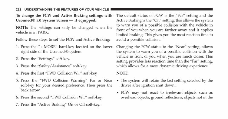
To change the FCW and Active Braking settings withUconnect® 5.0 System Screen — if equipped.
NOTE: The settings can only be changed when thevehicle is in PARK.
Follow these steps to set the FCW and Active Braking:
1. Press the “+ MORE” hard-key located on the lowerright side of the Uconnect® system.
2. Press the “Settings” soft-key.
3. Press the “Safety/Assistance” soft-key.
4. Press the first “FWD Collision W...” soft-key.
5. Press the “FWD Collision Warning” Far or Nearsoft-key for your desired preference. Then press theback arrow.
6. Press the second “FWD Collision W...” soft-key.
7. Press the “Active Braking” On or Off soft-key.
The default status of FCW is the “Far” setting and theActive Braking is the “On” setting, this allows the systemto warn you of a possible collision with the vehicle infront of you when you are farther away and it applieslimited braking. This gives you the most reaction time toavoid a possible collision.
Changing the FCW status to the “Near” setting, allowsthe system to warn you of a possible collision with thevehicle in front of you when you are much closer. Thissetting provides less reaction time than the “Far” setting,which allows for a more dynamic driving experience.
NOTE:
• The system will retain the last setting selected by thedriver after ignition shut down.
• FCW may not react to irrelevant objects such asoverhead objects, ground reflections, objects not in the
222 UNDERSTANDING THE FEATURES OF YOUR VEHICLE

path of the car, stationary objects that are far away,oncoming traffic, or leading vehicles with the same orhigher rate of speed.
• FCW will be disabled like ACC, with the unavailablescreens.
FCW Limited Warning
If the system turns off, and the EVIC displays “ACC/FCW Limited Functionality” or “ACC/FCW LimitedFunctionality Clean Front Windshield” momentarily,there may be a condition that limits FCW functionality.Although the vehicle is still drivable under normalconditions, the active braking may not be fully available.Once the condition that limited the system performanceis no longer present, the system will return to its fullperformance state. If the problem persists, see yourauthorized dealer.
Service FCW Warning
If the system turns off, and the EVIC displays:
• ACC/FCW Unavailable Service Required
• Cruise/FCW Unavailable Service Required
This indicates there is an internal system fault. Althoughthe vehicle is still drivable under normal conditions, havethe system checked by an authorized dealer.
PARKSENSE® REAR PARK ASSIST —IF EQUIPPED
The ParkSense® Rear Park Assist system provides visualand audible indications of the distance between the rearfascia and a detected obstacle when backing up, e.g.during a parking maneuver. Refer to ParkSense® SystemUsage Precautions for limitations of this system andrecommendations.
3
UNDERSTANDING THE FEATURES OF YOUR VEHICLE 223

ParkSense® will retain the last system state (enabled ordisabled) from the last ignition cycle when the ignition ischanged to the ON/RUN position.
ParkSense® can be active only when the shift lever is inREVERSE. If ParkSense® is enabled at this shift leverposition, the system will remain active until the vehiclespeed is increased to approximately 7 mph (11 km/h) orabove. The system will become active again if the vehiclespeed is decreased to speeds less than approximately6 mph (9 km/h).
ParkSense® Sensors
The four ParkSense® sensors, located in the rear fascia/bumper, monitor the area behind the vehicle that iswithin the sensors’ field of view. The sensors can detectobstacles from approximately 12 in (30 cm) up to 79 in(200 cm) from the rear fascia/bumper in the horizontaldirection, depending on the location, type and orienta-tion of the obstacle.
ParkSense® Warning Display
The ParkSense® Warning screen will only be displayed ifSound and Display is selected from the Customer - Pro-grammable Features section of the Uconnect® System.Refer to �Uconnect® Settings” in “Understanding YourInstrument Panel” for further information.
The ParkSense® Warning screen is located within theElectronic Vehicle Information Center (EVIC). It providesvisual warnings to indicate the distance between the rearfascia/bumper and the detected obstacle. Refer to “Elec-tronic Vehicle Information Center (EVIC)/Settings” inUnderstanding Your Instrument Panel” for further infor-mation.
ParkSense® Display
When the vehicle is in REVERSE, the EVIC will displaythe park assist ready system status.
224 UNDERSTANDING THE FEATURES OF YOUR VEHICLE

The system will indicate a detected obstacle by showinga single arc in the left and/or right rear regions based onthe obstacle’s distance and location relative to the vehicle.
If an obstacle is detected in the left and/or right rearregion, the display will show a single arc in the leftand/or right rear region and the system will produce a
tone. As the vehicle moves closer to the obstacle, thedisplay will show the single arc moving closer to thevehicle and the tone will change from a single 1/2 secondtone to slow, to fast, to continuous.
Park Assist Ready
Single 1/2 Second Tone
3
UNDERSTANDING THE FEATURES OF YOUR VEHICLE 225

Slow Tone Fast Tone
226 UNDERSTANDING THE FEATURES OF YOUR VEHICLE

The vehicle is close to the obstacle when the warningdisplay shows one flashing arc and sounds a continuoustone. The following chart shows the warning alert opera-tion when the system is detecting an obstacle:
Continuous Tone
3
UNDERSTANDING THE FEATURES OF YOUR VEHICLE 227

WARNING ALERTSRear Distance
(in/cm)Greater than
79 in (200 cm)79-39 in
(200-100 cm)39-25 in
(100-65 cm)25-12 in
(65-30 cm)Less than
12 in (30 cm)Audible Alert
ChimeNone Single 1/2
Second ToneSlow Fast Continuous
Arc None 4th Solid 3rdSolid
2ndFlashing
1stFlashing
Radio VolumeReduced
No Yes Yes Yes Yes
NOTE: ParkSense® will reduce the volume of the radio,if on, when the system is sounding an audio tone.
228 UNDERSTANDING THE FEATURES OF YOUR VEHICLE
Enabling And Disabling ParkSense®
ParkSense® can be enabled and disabled with theParkSense® switch.
When the ParkSense® switch is pressed todisable the system, the instrument cluster willdisplay the “PARKSENSE OFF” message forapproximately five seconds. Refer to “Elec-
tronic Vehicle Information Center (EVIC)” in “Under-standing Your Instrument Panel” for further information.When the shift lever is moved to REVERSE and thesystem is disabled, the EVIC will display the“PARKSENSE OFF” message for as long as the vehicle isin REVERSE.
The ParkSense® switch LED will be ON when ParkSense®is disabled or requires service. The ParkSense® switch LEDwill be OFF when the system is enabled. If the ParkSense®switch is pressed, and the system requires service, theParkSense® switch LED will blink momentarily, and thenthe LED will be ON.
Service The ParkSense® Rear Park Assist System
During vehicle start up, when the ParkSense® Rear ParkAssist System has detected a faulted condition, theinstrument cluster will actuate a single chime, once perignition cycle, and it will display the “PARKSENSEUNAVAILABLE WIPE REAR SENSORS” or the“PARKSENSE UNAVAILABLE SERVICE REQUIRED”message. Refer to “Electronic Vehicle Information Center(EVIC)” in “Understanding Your Instrument Panel” forfurther information. When the shift lever is moved to
3
UNDERSTANDING THE FEATURES OF YOUR VEHICLE 229
REVERSE and the system has detected a faulted condi-tion, the EVIC will display the �PARKSENSE UNAVAIL-ABLE WIPE REAR SENSORS� or �PARKSENSE UN-AVAILABLE SERVICE REQUIRED� message for as longas the vehicle is in REVERSE. Under this condition,ParkSense will not operate.
If “PARKSENSE UNAVAILABLE WIPE REAR SEN-SORS” appears in the Electronic Vehicle InformationCenter (EVIC) make sure the outer surface and theunderside of the rear fascia/bumper is clean and clear ofsnow, ice, mud, dirt or other obstruction and then cyclethe ignition. If the message continues to appear, see anauthorized dealer.
If “PARKSENSE UNAVAILABLE SERVICE REQUIRED”appears in the EVIC, see an authorized dealer.
Cleaning The ParkSense® System
Clean the ParkSense® sensors with water, car wash soapand a soft cloth. Do not use rough or hard cloths. Do notscratch or poke the sensors. Otherwise, you could dam-age the sensors.
ParkSense® System Usage Precautions
NOTE:
• Ensure that the rear bumper is free of snow, ice, mud,dirt and debris to keep the ParkSense® system oper-ating properly.
• Jackhammers, large trucks, and other vibrations couldaffect the performance of ParkSense®.
• When you turn ParkSense® OFF, the instrument clus-ter will display “PARKSENSE OFF” Furthermore, onceyou turn ParkSense® off, it remains off until you turnit on again, even if you cycle the ignition key.
230 UNDERSTANDING THE FEATURES OF YOUR VEHICLE

• When you move the shift lever to the REVERSEposition and ParkSense® is turned OFF, the EVIC willdisplay “PARKSENSE OFF” message for as long as thevehicle is in REVERSE.
• ParkSense®, when on, will reduce the volume of theradio when it is sounding a tone.
• Clean the ParkSense® sensors regularly, taking carenot to scratch or damage them. The sensors must notbe covered with ice, snow, slush, mud, dirt or debris.Failure to do so can result in the system not workingproperly. The ParkSense® system might not detect anobstacle behind the fascia/bumper, or it could providea false indication that an obstacle is behind the fascia/bumper.
• Use the ParkSense® switch to turn the ParkSense®system OFF if obstacles such as bicycle carriers, trailerhitches, etc. are placed within 12 in (30 cm) from therear fascia/bumper. Failure to do so can result in the
system misinterpreting a close obstacle as a sensorproblem, causing the “PARKSENSE UNAVAILABLESERVICE REQUIRED” message to be displayed in theEVIC .
• On vehicles equipped with a tailgate, ParkSense®should be disabled when the tailgate is in the loweredor open position and the vehicle is in REVERSE. Alowered tailgate could provide a false indication thatan obstacle is behind the vehicle.
CAUTION!
• ParkSense® is only a parking aid and it is unable torecognize every obstacle, including small obstacles.Parking curbs might be temporarily detected or notdetected at all. Obstacles located above or belowthe sensors will not be detected when they are inclose proximity.
(Continued)
3
UNDERSTANDING THE FEATURES OF YOUR VEHICLE 231

CAUTION! (Continued)• The vehicle must be driven slowly when using
ParkSense® in order to be able to stop in timewhen an obstacle is detected. It is recommendedthat the driver looks over his/her shoulder whenusing ParkSense®.
WARNING!
• Drivers must be careful when backing up evenwhen using ParkSense®. Always check carefullybehind your vehicle, look behind you, and be sureto check for pedestrians, animals, other vehicles,obstructions, and blind spots before backing up.You are responsible for safety and must continue topay attention to your surroundings. Failure to do socan result in serious injury or death.
(Continued)
WARNING! (Continued)• Before using ParkSense®, it is strongly recom-
mended that the ball mount and hitch ball assem-bly is disconnected from the vehicle when thevehicle is not used for towing. Failure to do so canresult in injury or damage to vehicles or obstaclesbecause the hitch ball will be much closer to theobstacle than the rear fascia when the loudspeakersounds the continuous tone. Also, the sensorscould detect the ball mount and hitch ball assem-bly, depending on its size and shape, giving a falseindication that an obstacle is behind the vehicle.
PARKSENSE® FRONT AND REAR PARK ASSIST —IF EQUIPPED
The ParkSense® Park Assist system provides visual andaudible indications of the distance between the rearand/or front fascia and a detected obstacle when backing
232 UNDERSTANDING THE FEATURES OF YOUR VEHICLE

up or moving forward, e.g. during a parking maneuver.Refer to ParkSense® System Usage Precautions for limi-tations of this system and recommendations.
ParkSense® will retain the last system state (enabled ordisabled) from the last ignition cycle when the ignition ischanged to the ON/RUN position.
ParkSense® can be active only when the shift lever is inREVERSE or DRIVE. If ParkSense® is enabled at one ofthese shift lever positions, the system will remain activeuntil the vehicle speed is increased to approximately7 mph (11 km/h) or above. A display warning willappear in the EVIC indicating the vehicle is aboveParkSense® operating speed. The system will becomeactive again if the vehicle speed is decreased to speedsless than approximately 6 mph (9 km/h).
ParkSense® Sensors
The four ParkSense® sensors, located in the rear fascia/bumper, monitor the area behind the vehicle that iswithin the sensors’ field of view. The sensors can detectobstacles from approximately 12 in (30 cm) up to 79 in(200 cm) from the rear fascia/bumper in the horizontaldirection, depending on the location, type and orienta-tion of the obstacle.
The six ParkSense® sensors, located in the front fascia/bumper, monitor the area in front of the vehicle that iswithin the sensors’ field of view. The sensors can detectobstacles from approximately 12 in (30 cm) up to 47 in(120 cm) from the front fascia/bumper in the horizontaldirection, depending on the location, type and orienta-tion of the obstacle.
3
UNDERSTANDING THE FEATURES OF YOUR VEHICLE 233
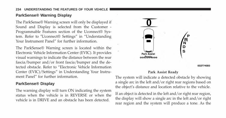
ParkSense® Warning Display
The ParkSense® Warning screen will only be displayed ifSound and Display is selected from the Customer -Programmable Features section of the Uconnect® Sys-tem. Refer to �Uconnect® Settings” in “UnderstandingYour Instrument Panel” for further information.
The ParkSense® Warning screen is located within theElectronic Vehicle Information Center (EVIC). It providesvisual warnings to indicate the distance between the rearfascia/bumper and/or front fascia/bumper and the de-tected obstacle. Refer to “Electronic Vehicle InformationCenter (EVIC)/Settings” in Understanding Your Instru-ment Panel” for further information.
ParkSense® Display
The warning display will turn ON indicating the systemstatus when the vehicle is in REVERSE or when thevehicle is in DRIVE and an obstacle has been detected.
The system will indicate a detected obstacle by showinga single arc in the left and/or right rear regions based onthe object’s distance and location relative to the vehicle.
If an object is detected in the left and/or right rear region,the display will show a single arc in the left and/or rightrear region and the system will produce a tone. As the
Park Assist Ready
234 UNDERSTANDING THE FEATURES OF YOUR VEHICLE

vehicle moves closer to the object, the display will showthe single arc moving closer to the vehicle and the tonewill change from a single 1/2 second tone to slow, to fast,to continuous.
Single 1/2 Second Tone
Slow Tone
3
UNDERSTANDING THE FEATURES OF YOUR VEHICLE 235

The vehicle is close to the obstacle when the EVIC displayshows one flashing arc and sounds a continuous tone.The following chart shows the warning alert operationwhen the system is detecting an obstacle:
Fast Tone Continuous Tone
236 UNDERSTANDING THE FEATURES OF YOUR VEHICLE

WARNING ALERTSRear Distance
(in/cm)Greater than
79 in (200 cm)79-39 in
(200-100 cm)39-25 in
(100-65 cm)25-12 in
(65-30 cm)Less than 12 in
(30 cm)Front Distance
(in/cm)Greater than
47 in (120 cm)47-39 in
(120-100 cm)39-25 in
(100-65 cm)25-12 in
(65-30 cm)Less than 12 in
(30 cm)Audible Alert
(Chime)None Single 1/2
Second Tone(for rear only)
Slow (for rearonly)
Fast Continuous
Arcs None 4th Solid 3rd Solid 2nd Flashing 1st FlashingRadio Volume
ReducedNo Yes Yes Yes Yes
NOTE: ParkSense® will reduce the volume of the radio,if on, when the system is sounding an audio tone.
3
UNDERSTANDING THE FEATURES OF YOUR VEHICLE 237

Front Park Assist Audible Alerts
ParkSense® will turn off the Front Park Assist audiblealert (chime) after approximately 3 seconds when anobstacle has been detected, the vehicle is stationary, andbrake pedal is applied.
Adjustable Chime Volume Settings
Front and Rear chime volume settings can be selectedfrom the EVIC or Uconnect® System — if equipped.
If Uconnect® System is equipped, chime volume settingswill not be accessible from the EVIC.
The chime volume settings include LOW, MEDIUM, andHIGH. The factory default volume setting is MEDIUM.
ParkSense® will retain its last known configuration statethrough ignition cycles.
Enabling And Disabling ParkSense®
ParkSense® can be enabled and disabled with theParkSense® switch.
When the ParkSense® switch is pressed to dis-able the system, the instrument cluster will dis-play the “PARKSENSE OFF” message for ap-proximately five seconds. Refer to “Electronic
Vehicle Information Center (EVIC)” in “UnderstandingYour Instrument Panel” for further information. When theshift lever is moved to REVERSE and the system isdisabled, the EVIC will display the “PARKSENSE OFF”message for as long as the vehicle is in REVERSE.
The ParkSense® switch LED will be ON when ParkSense®is disabled or requires service. The ParkSense® switch LEDwill be OFF when the system is enabled. If the ParkSense®switch is pressed, and the system requires service, theParkSense® switch LED will blink momentarily, and thenthe LED will be ON.
238 UNDERSTANDING THE FEATURES OF YOUR VEHICLE

Service The ParkSense® Park Assist System
During vehicle start up, when the ParkSense® Systemhas detected a faulted condition, the instrument clusterwill actuate a single chime, once per ignition cycle, and itwill display the �PARKSENSE UNAVAILABLE WIPEREAR SENSORS�, �PARKSENSE UNAVAILABLE WIPEFRONT SENSORS�, or the �PARKSENSE UNAVAIL-ABLE SERVICE REQUIRED� message for five seconds.When the shift lever is moved to Reverse and the systemhas detected a faulted condition, the EVIC will display a�PARKSENSE UNAVAILABLE WIPE REAR SENSORS�,�PARKSENSE UNAVAILABLE WIPE FRONT SENSORS�or �PARKSENSE UNAVAILABLE SERVICE REQUIRED�pop up message for five seconds. After five seconds, a cargraphic will be displayed with �UNAVAILABLE� at ei-ther the front or rear sensor location depending on wherethe fault is detected. The system will continue to providearc alerts for the side that is functioning properly. These
arc alerts will interrupt the �PARKSENSE UNAVAIL-ABLE WIPE REAR SENSORS�, �PARKSENSE UNAVAIL-ABLE WIPE FRONT SENSORS�, or �PARKSENSE UN-AVAILABLE SERVICE REQUIRED� messages if an objectis detected within the five second pop-up duration. Thecar graphic will remain displayed for as long as thevehicle is in REVERSE. Refer to “Electronic VehicleInformation Center (EVIC)” in “Understanding YourInstrument Panel” for further information.
If �PARKSENSE UNAVAILABLE WIPE REAR SENSORS�or �PARKSENSE UNAVAILABLE WIPE FRONT SEN-SORS� appears in the Electronic Vehicle InformationCenter (EVIC) make sure the outer surface and theunderside of the rear fascia/bumper and/or front fascia/bumper is clean and clear of snow, ice, mud, dirt or otherobstruction and then cycle the ignition. If the messagecontinues to appear see an authorized dealer.
3
UNDERSTANDING THE FEATURES OF YOUR VEHICLE 239
If the �PARKSENSE UNAVAILABLE SERVICE RE-QUIRED� message appears in the EVIC, see an authorizeddealer.
Cleaning The ParkSense® System
Clean the ParkSense® sensors with water, car wash soapand a soft cloth. Do not use rough or hard cloths. Do notscratch or poke the sensors. Otherwise, you could dam-age the sensors.
ParkSense® System Usage Precautions
NOTE:
• Ensure that the front and rear bumper are free of snow,ice, mud, dirt and debris to keep the ParkSense®system operating properly.
• Jackhammers, large trucks, and other vibrations couldaffect the performance of ParkSense®.
• When you turn ParkSense® off, the instrument clusterwill display “PARKSENSE OFF.” Furthermore, onceyou turn ParkSense® off, it remains off until you turnit on again, even if you cycle the ignition key.
• When you move the shift lever to the REVERSEposition and ParkSense® is turned off, the instrumentcluster will display “PARKSENSE OFF” for as long asthe vehicle is in REVERSE.
• ParkSense®, when on, will reduce the volume of theradio when it is sounding a tone.
• Clean the ParkSense® sensors regularly, taking carenot to scratch or damage them. The sensors must notbe covered with ice, snow, slush, mud, dirt or debris.Failure to do so can result in the system not workingproperly. The ParkSense® system might not detect anobstacle behind or in front of the fascia/bumper, or itcould provide a false indication that an obstacle isbehind or in front of the fascia/bumper.
240 UNDERSTANDING THE FEATURES OF YOUR VEHICLE

• Use the ParkSense® switch to turn the ParkSense®system off if obstacles such as bicycle carriers, trailerhitches, etc. are placed within 12 in (30 cm) from therear fascia/bumper. Failure to do so can result in thesystem misinterpreting a close obstacle as a sensorproblem, causing the “PARKSENSE UNAVAILABLESERVICE REQUIRED” message to be displayed in theinstrument cluster.
• On vehicles equipped with a tailgate, ParkSense®should be disabled when the tailgate is in the loweredor open position. A lowered tailgate could provide afalse indication that an obstacle is behind the vehicle.
• There may be a delay in the object detection rate if theobject is moving. This will cause the automatic brakingapplication to be delayed.
CAUTION!
• ParkSense® is only a parking aid and it is unable torecognize every obstacle, including small obstacles.Parking curbs might be temporarily detected or notdetected at all. Obstacles located above or belowthe sensors will not be detected when they are inclose proximity.
• The vehicle must be driven slowly when usingParkSense® in order to be able to stop in timewhen an obstacle is detected. It is recommendedthat the driver looks over his/her shoulder whenusing ParkSense®.
3
UNDERSTANDING THE FEATURES OF YOUR VEHICLE 241

WARNING!
• Drivers must be careful when backing up evenwhen using ParkSense®. Always check carefullybehind your vehicle, look behind you, and be sureto check for pedestrians, animals, other vehicles,obstructions, and blind spots before backing up.You are responsible for safety and must continue topay attention to your surroundings. Failure to do socan result in serious injury or death.
(Continued)
WARNING! (Continued)• Before using ParkSense®, it is strongly recom-
mended that the ball mount and hitch ball assem-bly is disconnected from the vehicle when thevehicle is not used for towing. Failure to do so canresult in injury or damage to vehicles or obstaclesbecause the hitch ball will be much closer to theobstacle than the rear fascia when the loudspeakersounds the continuous tone. Also, the sensorscould detect the ball mount and hitch ball assem-bly, depending on its size and shape, giving a falseindication that an obstacle is behind the vehicle.
242 UNDERSTANDING THE FEATURES OF YOUR VEHICLE

PARKVIEW® REAR BACK UP CAMERA — IFEQUIPPED
Your vehicle may be equipped with the ParkView® RearBack Up Camera that allows you to see an on-screenimage of the rear surroundings of your vehicle wheneverthe shift lever is put into REVERSE. The image will bedisplayed on the Navigation/Multimedia radio displayscreen along with a caution note to “check entire sur-roundings” across the top of the screen. After five sec-onds this note will disappear. The ParkView® camera islocated on the rear of the vehicle above the rear Licenseplate.
When the vehicle is shifted out of REVERSE (with cameradelay turned OFF), the rear camera mode is exited andthe navigation or audio screen appears again.
When the vehicle is shifted out of REVERSE (with cameradelay turned ON), The rear view image with dynamicgrid lines will be displayed for up to 10 seconds aftershifting out of �REVERSE� unless the forward vehiclespeed exceeds 8 MPH, the transmission is shifted into�PARK� or the ignition is switched to the OFF position.
Active guide lines are overlaid on the image to illustratethe width of the vehicle and its projected backup pathbased on the steering wheel position. The active guidelines will show separate zones that will help indicate thedistance to the rear of the vehicle while a dashed center-line will indicate the center of the vehicle to assist withaligning to a hitch/receiver. The following table showsthe approximate distances for each zone:
3
UNDERSTANDING THE FEATURES OF YOUR VEHICLE 243

Zone Distance to the rear of the vehicleRed 0 - 1 ft (0 - 30 cm)
Yellow 1 ft - 3 ft (30 cm - 1 m)Green 3 ft or greater (1 m or greater)
WARNING!
Drivers must be careful when backing up even whenusing the ParkView® Rear Back Up Camera. Alwayscheck carefully behind your vehicle, and be sure tocheck for pedestrians, animals, other vehicles, ob-structions, or blind spots before backing up. You areresponsible for the safety of your surroundings andmust continue to pay attention while backing up.Failure to do so can result in serious injury or death.
CAUTION!
• To avoid vehicle damage, ParkView® should onlybe used as a parking aid. The ParkView® camera isunable to view every obstacle or object in yourdrive path.
• To avoid vehicle damage, the vehicle must bedriven slowly when using ParkView® to be able tostop in time when an obstacle is seen. It is recom-mended that the driver look frequently over his/hershoulder when using ParkView®.
244 UNDERSTANDING THE FEATURES OF YOUR VEHICLE

NOTE: If snow, ice, mud, or any foreign substancebuilds up on the camera lens, clean the lens, rinse withwater, and dry with a soft cloth. Do not cover the lens.
Turning ParkView® On Or Off — WithUconnect® 5.0
1. Turn the Radio on.
2. Press the “Settings” button.
3. Press the “Safety & Assistance” soft-key.
4. Press the check box soft key next to “Parkview®Backup Camera” to enable/disable.
NOTE: A check mark will appear in the selection box toindicate the system is turned ON.
Turning ParkView® On Or Off — WithUconnect® 8.4A/8.4AN
1. Press the “Controls” soft-key located on the bottom ofthe Uconnect® display.
2. Press the “Settings” soft-key.
3. Press the “Safety & Driving Assistance” soft-key.
4. Press the “Parkview Backup camera” soft-key to turnthe ParkView® system ON or OFF.
NOTE: A check mark will appear in the selection box toindicate the system is turned ON.
3
UNDERSTANDING THE FEATURES OF YOUR VEHICLE 245
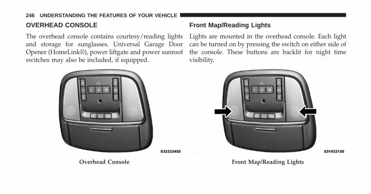
OVERHEAD CONSOLE
The overhead console contains courtesy/reading lightsand storage for sunglasses. Universal Garage DoorOpener (HomeLink®), power liftgate and power sunroofswitches may also be included, if equipped.
Front Map/Reading Lights
Lights are mounted in the overhead console. Each lightcan be turned on by pressing the switch on either side ofthe console. These buttons are backlit for night timevisibility.
Overhead Console Front Map/Reading Lights
246 UNDERSTANDING THE FEATURES OF YOUR VEHICLE

To turn the lights off, press the switch a second time. Thelights also turn on when a door is opened. The lights willalso turn on when the UNLOCK button on the RKE ispressed.
Courtesy Lights
The courtesy lights can be turned on by pressing the topcorner of the lens. To turn the lights off, press the lens asecond time.
Front Map/Reading Light Switches Courtesy Lights
3
UNDERSTANDING THE FEATURES OF YOUR VEHICLE 247

Sunglasses Bin Door
At the front of the console a compartment is provided forthe storage of a pair of sunglasses. The storage compart-ment access is a “push/push” design. Push the chromepad on the door to open. Push the chrome pad on thedoor to close.
GARAGE DOOR OPENER — IF EQUIPPED
HomeLink® replaces up to three hand-held transmittersthat operate devices such as garage door openers, motor-ized gates, lighting or home security systems. TheHomeLink® unit is powered by your vehicles 12 Voltbattery.
The HomeLink® buttons, located on either the overheadconsole, headliner or sunvisor, designate the three differ-ent HomeLink® channels. The HomeLink® indicator islocated above the center button.
Sunglasses Bin Door
248 UNDERSTANDING THE FEATURES OF YOUR VEHICLE

NOTE: HomeLink® is disabled when the Vehicle Secu-rity Alarm is active.
HomeLink® Buttons/Overhead Consoles HomeLink® Buttons/Sunvisor/Headliner
3
UNDERSTANDING THE FEATURES OF YOUR VEHICLE 249

Before You Begin Programming HomeLink®
Be sure that your vehicle is parked outside of the garagebefore you begin programming.
For more efficient programming and accurate transmis-sion of the radio-frequency signal it is recommended thata new battery be placed in the hand-held transmitter ofthe device that is being programmed to the HomeLink®system.
Erase all channels before you begin programming. Toerase the channels place the ignition in the ON/RUNposition and press and hold the two outside HomeLink®buttons (I and III) for up 20 seconds or until the redindicator flashes.
NOTE:
• Erasing all channels should only be performed whenprogramming HomeLink® for the first time. Do noterase channels when programming additional buttons.
• If you have any problems, or require assistance, pleasecall toll-free 1–800–355–3515 or, on the Internet atwww.HomeLink.com for information or assistance.
Programming A Rolling Code
For programming garage door openers that were manu-factured after 1995. These garage door openers can beidentified by the “LEARN” or “TRAIN” button locatedwhere the hanging antenna is attached to the garage dooropener. It is NOT the button that is normally used toopen and close the door. The name and color of thebutton may vary by manufacturer.
250 UNDERSTANDING THE FEATURES OF YOUR VEHICLE

1. Cycle the ignition to the ON/RUN position.
2. Place the hand-held transmitter 1 to 3 in (3 to 8 cm)away from the HomeLink® button you wish to programwhile keeping the HomeLink® indicator light in view.
3. Simultaneously press and hold both the HomeLink®button you want to program and the hand-held trans-mitter button.
4. Continue to hold both buttons and observe the indi-cator light. The HomeLink® indicator will flash slowlyand then rapidly after HomeLink® has received thefrequency signal from the hand-held transmitter. Re-lease both buttons after the indicator light changesfrom slow to rapid.
Training The Garage Door Opener
1 — Door Opener2 — Training Button
3
UNDERSTANDING THE FEATURES OF YOUR VEHICLE 251

5. At the garage door opener motor (in the garage),locate the “LEARN” or “TRAINING” button. This canusually be found where the hanging antenna wire isattached to the garage door opener/device motor.Firmly press and release the “LEARN” or “TRAIN-ING” button. On some garage door openers/devicesthere may be a light that blinks when the garage dooropener/device is in the LEARN/TRAIN mode.
NOTE: You have 30 seconds in which to initiate the nextstep after the LEARN button has been pressed.
6. Return to the vehicle and press the programmedHomeLink® button twice (holding the button for twoseconds each time). If the garage door opener/deviceactivates, programming is complete.
NOTE: If the garage door opener/device does not acti-vate, press the button a third time (for two seconds) tocomplete the training.
To program the remaining two HomeLink® buttons,repeat each step for each remaining button. DO NOTerase the channels.
Reprogramming A Single HomeLink® Button
To reprogram a channel that has been previously trained,follow these steps:
1. Cycle the ignition to the ON/RUN position.
2. Press and hold the desired HomeLink® button untilthe indicator light begins to flash after 20 seconds.Do not release the button.
3. Without releasing the button proceed with “Program-ming A Rolling Code” Step 2 and follow all remainingsteps.
252 UNDERSTANDING THE FEATURES OF YOUR VEHICLE

Programming A Non-Rolling Code
For programming Garage Door Openers manufacturedbefore 1995.
1. Cycle the ignition to the ON/RUN position.
2. Place the hand-held transmitter 1 to 3 in (3 to 8 cm)away from the HomeLink® button you wish to pro-gram while keeping the HomeLink® indicator light inview.
3. Simultaneously press and hold both the HomeLink®button you want to program and the hand-held trans-mitter button.
4. Continue to hold both buttons and observe the indi-cator light. HomeLink® indicator will flash slowlyand then rapidly after HomeLink® has received thefrequency signal from the hand-held transmitter. Re-lease both buttons after the indicator light changesfrom slow to rapid.
5. Press and hold the programmed HomeLink® buttonand observe the indicator light.• If the indicator light stays on constantly, program-
ming is complete and the garage door/device shouldactivate when the HomeLink® button is pressed.
• To program the remaining two HomeLink® buttons,repeat each step for each remaining button. DO NOTerase the channels.
Reprogramming A Single HomeLink® Button
To reprogram a channel that has been previously trained,follow these steps:
1. Cycle the ignition to the ON/RUN position.
2. Press and hold the desired HomeLink® button untilthe indicator light begins to flash after 20 seconds.Do not release the button.
3
UNDERSTANDING THE FEATURES OF YOUR VEHICLE 253

3. Without releasing the button proceed with “Program-ming A Non-Rolling Code” Step 2 and follow allremaining steps.
Canadian/Gate Operator Programming
For programming transmitters in Canada/United Statesthat require the transmitter signals to “time-out” afterseveral seconds of transmission.
Canadian radio frequency laws require transmitter sig-nals to time-out (or quit) after several seconds of trans-mission – which may not be long enough for HomeLink®to pick up the signal during programming. Similar to thisCanadian law, some U.S. gate operators are designed totime-out in the same manner.
It may be helpful to unplug the device during the cyclingprocess to prevent possible overheating of the garagedoor or gate motor.
1. Cycle the ignition to the ON/RUN position.
2. Place the hand-held transmitter 1 to 3 in (3 to 8 cm)away from the HomeLink® button you wish to pro-gram while keeping the HomeLink® indicator light inview.
3. Continue to press and hold the HomeLink® button,while you press and release (“cycle”), your hand-heldtransmitter every two seconds until HomeLink® hassuccessfully accepted the frequency signal. The indi-cator light will flash slowly and then rapidly whenfully trained.
254 UNDERSTANDING THE FEATURES OF YOUR VEHICLE

4. Watch for the HomeLink® indicator to change flashrates. When it changes, it is programmed. It may takeup to 30 seconds or longer in rare cases. The garagedoor may open and close while you are programming.
5. Press and hold the programmed HomeLink® buttonand observe the indicator light.• If the indicator light stays on constantly, program-
ming is complete and the garage door/device shouldactivate when the HomeLink® button is pressed.
• To program the two remaining HomeLink® buttons,repeat each step for each remaining button. DO NOTerase the channels.
If you unplugged the garage door opener/device forprogramming, plug it back in at this time.
Reprogramming A Single HomeLink® Button
To reprogram a channel that has been previously trained,follow these steps:
1. Cycle the ignition to the ON/RUN position.
2. Press and hold the desired HomeLink® button untilthe indicator light begins to flash after 20 seconds.Do not release the button.
3. Without releasing the button proceed with “Canadian/Gate Operator Programming” Step 2 and follow allremaining steps.
Using HomeLink®
To operate, press and release the programmed HomeLink®button. Activation will now occur for the programmeddevice (i.e., garage door opener, gate operator, securitysystem, entry door lock, home/office lighting, etc.,). Thehand-held transmitter of the device may also be used atany time.
3
UNDERSTANDING THE FEATURES OF YOUR VEHICLE 255
Security
It is advised to erase all channels before you sell or turnin your vehicle.
To do this, press and hold the two outside buttons for 20seconds until the red indicator flashes. Note that allchannels will be erased. Individual channels cannot beerased.
The HomeLink® Universal Transceiver is disabled whenthe Vehicle Security Alarm is active.
Troubleshooting Tips
If you are having trouble programming HomeLink®,here are some of the most common solutions:
• Replace the battery in the original hand-held transmitter.
• Press the LEARN button on the Garage Door Openerto complete the training for a Rolling Code.
• Did you unplug the device for programming andremember to plug it back in?
If you have any problems, or require assistance, pleasecall toll-free 1–800–355–3515 or, on the Internet atwww.HomeLink.com for information or assistance.
256 UNDERSTANDING THE FEATURES OF YOUR VEHICLE
WARNING!
• Your motorized door or gate will open and closewhile you are programming the universal trans-ceiver. Do not program the transceiver if people,pets or other objects are in the path of the door orgate. Only use this transceiver with a garage dooropener that has a “stop and reverse” feature asrequired by Federal safety standards. This includesmost garage door opener models manufacturedafter 1982. Do not use a garage door opener withoutthese safety features. Call toll-free 1–800–355–3515or, on the Internet at www.HomeLink.com forsafety information or assistance.
• Vehicle exhaust contains carbon monoxide, a dan-gerous gas. Do not run your vehicle in the garagewhile programming the transceiver. Exhaust gascan cause serious injury or death.
General Information
This device complies with FCC rules Part 15 and IndustryCanada RSS-210. Operation is subject to the followingtwo conditions:
1. This device may not cause harmful interference.
2. This device must accept any interference that may bereceived including interference that may cause unde-sired operation.
NOTE:
• The transmitter has been tested and it complies withFCC and IC rules. Changes or modifications not ex-pressly approved by the party responsible for compli-ance could void the user’s authority to operate thedevice.
• The term IC before the certification/registration num-ber only signifies that Industry Canada technical speci-fications were met.
3
UNDERSTANDING THE FEATURES OF YOUR VEHICLE 257

POWER SUNROOF — IF EQUIPPED
The power sunroof switch is located between the sunvisors on the overhead console.
WARNING!
• Never leave children unattended in a vehicle, anddo not leave the key fob in or near the vehicle. Donot leave the ignition of a vehicle equipped withKeyless Enter-N-Go™ in the ACC or ON/Runmode. Occupants, particularly unattended chil-dren, can become entrapped by the power sunroofwhile operating the power sunroof switch. Suchentrapment may result in serious injury or death.
• In a collision, there is a greater risk of being thrownfrom a vehicle with an open sunroof. You couldalso be seriously injured or killed. Always fastenyour seat belt properly and make sure all passen-gers are also properly secured.
• Do not allow small children to operate the sunroof.Never allow your fingers, other body parts, or anyobject, to project through the sunroof opening.Injury may result.
Power Sunroof Switch
258 UNDERSTANDING THE FEATURES OF YOUR VEHICLE

Opening Sunroof — Express
Press the switch rearward and release it within one-halfsecond and the sunroof will open automatically from anyposition. The sunroof will open fully and stop automati-cally. This is called “Express Open”. During ExpressOpen operation, any movement of the sunroof switchwill stop the sunroof.
Opening Sunroof — Manual Mode
To open the sunroof, press and hold the switch rearwardto full open. Any release of the switch will stop themovement. The sunroof and sunshade will remain in apartially opened condition until the switch is pushed andheld rearward again.
Closing Sunroof — Express
Press the switch forward and release it within one-halfsecond and the sunroof will close automatically from any
position. The sunroof will close fully and stop automati-cally. This is called “Express Close”. During ExpressClose operation, any movement of the switch will stopthe sunroof.
Closing Sunroof — Manual Mode
To close the sunroof, press and hold the switch in theforward position. Any release of the switch will stop themovement and the sunroof will remain in a partiallyclosed condition until the switch is pushed and heldforward again.
Pinch Protect Feature
This feature will detect an obstruction in the opening ofthe sunroof during Express Close operation. If an ob-struction in the path of the sunroof is detected, thesunroof will automatically retract. Remove the obstruc-tion if this occurs. Next, press the switch forward andrelease to Express Close.
3
UNDERSTANDING THE FEATURES OF YOUR VEHICLE 259

Venting Sunroof — Express
Press and release the Vent button within one half secondand the sunroof will open to the vent position. This iscalled “Express Vent”, and it will occur regardless ofsunroof position. During Express Vent operation, anymovement of the switch will stop the sunroof.
Sunshade Operation
The sunshade can be opened manually. However, thesunshade will open automatically as the sunroof opens.
NOTE: The sunshade cannot be closed if the sunroof isopen.
Wind Buffeting
Wind buffeting can be described as the perception ofpressure on the ears or a helicopter-type sound in theears. Your vehicle may exhibit wind buffeting with thewindows down, or the sunroof (if equipped) in certain
open or partially open positions. This is a normal occur-rence and can be minimized. If the buffeting occurs withthe rear windows open, open the front and rear windowstogether to minimize the buffeting. If the buffeting occurswith the sunroof open, adjust the sunroof opening tominimize the buffeting or open any window.
Sunroof Maintenance
Use only a nonabrasive cleaner and a soft cloth to cleanthe glass panel.
Ignition OFF Operation
The power sunroof switches remain active for up toapproximately ten minutes after the ignition switch hasbeen turned OFF. Opening either front door will cancelthis feature. The time is programmable. Refer to “Elec-tronic Vehicle Information Center (EVIC)/Personal Set-tings (Customer-Programmable Features)” in “Under-standing Your Instrument Panel” for further information.
260 UNDERSTANDING THE FEATURES OF YOUR VEHICLE

COMMANDVIEW® SUNROOF WITH POWERSHADE — IF EQUIPPED
The CommandView® sunroof switch is located to the leftbetween the sun visors on the overhead console.
The power shade switch is located to the right betweenthe sun visors on the overhead console.
CommandView® Sunroof and Power Shade Switches
3
UNDERSTANDING THE FEATURES OF YOUR VEHICLE 261

WARNING!
• Never leave children unattended in a vehicle, anddo not leave the key fob in or near the vehicle. Donot leave the ignition of a vehicle equipped withKeyless Enter-N-Go™ in the ACC or ON/Runmode. Occupants, particularly unattended chil-dren, can become entrapped by the power sunroofwhile operating the power sunroof switch. Suchentrapment may result in serious injury or death.
• In a collision, there is a greater risk of being thrownfrom a vehicle with an open sunroof. You couldalso be seriously injured or killed. Always fastenyour seat belt properly and make sure all passen-gers are also properly secured.
• Do not allow small children to operate the sunroof.Never allow your fingers, other body parts, or anyobject, to project through the sunroof opening.Injury may result.
Opening Sunroof — Express
Press the switch rearward and release it within one-halfsecond. The sunroof and sunshade will open automati-cally from any position. The sunroof and sunshade willopen fully and stop automatically. This is called “ExpressOpen”. During Express Open operation, any movementof the sunroof switch will stop the sunroof.
Opening Sunroof — Manual Mode
To open the sunroof, press and hold the switch rearwardto full open. Any release of the switch will stop themovement. The sunroof and sunshade will remain in apartially opened condition until the switch is pushed andheld rearward again.
262 UNDERSTANDING THE FEATURES OF YOUR VEHICLE

Closing Sunroof — Express
Press the switch forward and release it within one-halfsecond and the sunroof will close automatically from anyposition. The sunroof will close fully and stop automati-cally. This is called “Express Close”. During ExpressClose operation, any movement of the switch will stopthe sunroof.
Closing Sunroof — Manual Mode
To close the sunroof, press and hold the switch in theforward position. Any release of the switch will stop themovement and the sunroof will remain in a partiallyclosed condition until the switch is pushed and heldforward again.
Opening Power Shade — Express
Press the shade switch rearward and release it withinone-half second and the shade will open automatically
from any position. The shade will open and stop auto-matically at the half-open position. Press the shadeswitch rearward again and release it within one-halfsecond and the shade will open automatically to thefull-open position. This is called “Express Open”. DuringExpress Open operation, any movement of the shadeswitch will stop the shade.
Opening Power Shade — Manual Mode
To open the shade, press and hold the switch rearward.The shade will open and stop automatically at thehalf-open position. Press and hold the shade switchrearward again and the shade will open automatically tothe full-open position. Any release of the switch will stopthe movement and the shade will remain in a partiallyopened condition until the switch is pushed and heldrearward again.
3
UNDERSTANDING THE FEATURES OF YOUR VEHICLE 263

Closing Power Shade — Express
Press the switch forward and release it within one-halfsecond and the shade will close automatically from anyposition. If the sunroof is completely closed the shadewill close fully and stop automatically. This is called“Express Close”. During Express Close operation, anymovement of the switch will stop the shade.
NOTE: If the sunroof is open, the shade will close to thehalf-open position. Pressing the shade close button againwill automatically close both the sunroof and shadecompletely.
Closing Power Shade — Manual Mode
To close the shade, press and hold the switch in theforward position. Any release of the switch will stop themovement and the shade will remain in a partially closedcondition until the switch is pushed and held forwardagain.
Pinch Protect Feature
This feature will detect an obstruction in the opening ofthe sunroof during Express Close operation. If an ob-struction in the path of the sunroof is detected, thesunroof will automatically retract. Remove the obstruc-tion if this occurs. Next, press the switch forward andrelease to Express Close.
Wind Buffeting
Wind buffeting can be described as the perception ofpressure on the ears or a helicopter-type sound in theears. Your vehicle may exhibit wind buffeting with thewindows down, or the sunroof (if equipped) in certainopen or partially open positions. This is a normal occur-rence and can be minimized. If the buffeting occurs withthe rear windows open, open the front and rear windowstogether to minimize the buffeting. If the buffeting occurswith the sunroof open, adjust the sunroof opening tominimize the buffeting or open any window.
264 UNDERSTANDING THE FEATURES OF YOUR VEHICLE

Sunroof Maintenance
Use only a non-abrasive cleaner and a soft cloth to cleanthe glass panel.
Ignition OFF Operation
The power sunroof switches can be programmed toremain active for up to approximately ten minutes afterthe ignition switch has been turned OFF. Refer to “Elec-tronic Vehicle Information Center (EVIC)/Customer-Programmable Features (System Setup)” in “Under-standing Your Instrument Panel” for further information.
NOTE: Opening either front door will cancel this fea-ture.
Sunroof Fully Closed
Press the switch forward and release to ensure that thesunroof is fully closed.
ELECTRICAL POWER OUTLETS
Your vehicle is equipped with 12 Volt (13 Amp) poweroutlets that can be used to power cellular phones, smallelectronics and other low powered electrical accessories.The power outlets are labeled with either a “key” or a“battery” symbol to indicate how the outlet is powered.Power outlets labeled with a “key” are powered whenthe ignition switch is in the ON or ACC position, whilethe outlets labeled with a “battery” are connected directlyto the battery and powered at all times.
NOTE:
• All accessories connected to the “battery” poweredoutlets should be removed or turned off when thevehicle is not in use to protect the battery againstdischarge.
• To ensure proper cigar lighter operation, a MOPAR®knob and element must be used.
3
UNDERSTANDING THE FEATURES OF YOUR VEHICLE 265

CAUTION!
Power outlets are designed for accessory plugs only.Do not insert any other object in the power outlets asthis will damage the outlet and blow the fuse.Improper use of the power outlet can cause damagenot covered by your New Vehicle Limited Warranty.
The front power outlet is located inside the storage areaon the center stack of the instrument panel. Push inwardon the storage lid to open the compartment and gainaccess to this power outlet.
In addition to the front power outlet, there is also a poweroutlet located in the storage area of the center console.
Front Power Outlet
266 UNDERSTANDING THE FEATURES OF YOUR VEHICLE

The rear power outlet is located in the right rear cargoarea.
NOTE: The rear power outlet can be switched to “bat-tery” powered all the time by switching the power outletright rear quarter panel fuse in the fuse panel.
Center Console Outlet Rear Power Outlet
3
UNDERSTANDING THE FEATURES OF YOUR VEHICLE 267

Power Outlet Right Rear Quarter Panel Fuse Power Outlet Fuse Locations
1 — F104 Fuse 20 A Yellow Power Outlet Console Bin2 — F90–F91 Fuse 20 A Yellow Power Outlet Right Rear QuarterPanel3 — F93 Fuse 20 A Yellow Cigar Lighter Instrument Panel
268 UNDERSTANDING THE FEATURES OF YOUR VEHICLE

WARNING!
To avoid serious injury or death:• Only devices designed for use in this type of outlet
should be inserted into any 12 Volt outlet.• Do not touch with wet hands.• Close the lid when not in use and while driving the
vehicle.• If this outlet is mishandled, it may cause an electric
shock and failure.
CAUTION!
• Many accessories that can be plugged in drawpower from the vehicle’s battery, even when not inuse (i.e., cellular phones, etc.). Eventually, ifplugged in long enough, the vehicle’s battery willdischarge sufficiently to degrade battery life and/orprevent the engine from starting.
• Accessories that draw higher power (i.e., coolers,vacuum cleaners, lights, etc.) will degrade the bat-tery even more quickly. Only use these intermit-tently and with greater caution.
• After the use of high power draw accessories, orlong periods of the vehicle not being started (withaccessories still plugged in), the vehicle must bedriven a sufficient length of time to allow thegenerator to recharge the vehicle’s battery.
3
UNDERSTANDING THE FEATURES OF YOUR VEHICLE 269

POWER INVERTER — IF EQUIPPED
There is a 115 Volt, 150 Watt inverter outlet located on theback of the center console to convert DC current to ACcurrent. This outlet can power cellular phones, electron-ics and other low power devices requiring power up to150 Watts. Certain high-end video games, such as Play-station3 and XBox360 will exceed this power limit, as willmost power tools.
Power Inverter
270 UNDERSTANDING THE FEATURES OF YOUR VEHICLE

The power inverter is designed with built-in overloadprotection. If the power rating of 150 Watts is exceeded,the power inverter will automatically shut down. Oncethe electrical device has been removed from the outlet theinverter should automatically reset. To avoid overloadingthe circuit, check the power ratings on electrical devicesprior to using the inverter.
WARNING!
To avoid serious injury or death:• Do not insert any objects into the receptacles.• Do not touch with wet hands.• Close the lid when not in use.• If this outlet is mishandled, it may cause an electric
shock and failure.
CUPHOLDERS
There are two cupholders for the front seat passengerslocated in the center console.
There are two cupholders for the rear seat passengerslocated in the fold-down center armrest.
Front Cupholders
3
UNDERSTANDING THE FEATURES OF YOUR VEHICLE 271

STORAGE
Glove Compartment
The glove compartment is located on the right side of theinstrument panel.
To open the glove compartment, pull outward on thelatch and lower the glove box door.
Rear Cupholders Glove Compartment
272 UNDERSTANDING THE FEATURES OF YOUR VEHICLE

Door Storage
Large storage areas are built into the door panels for easyaccess.
Console Features
The center console contains both an upper and a lowerstorage area.
Opened Glove Compartment Door Panel Storage
3
UNDERSTANDING THE FEATURES OF YOUR VEHICLE 273
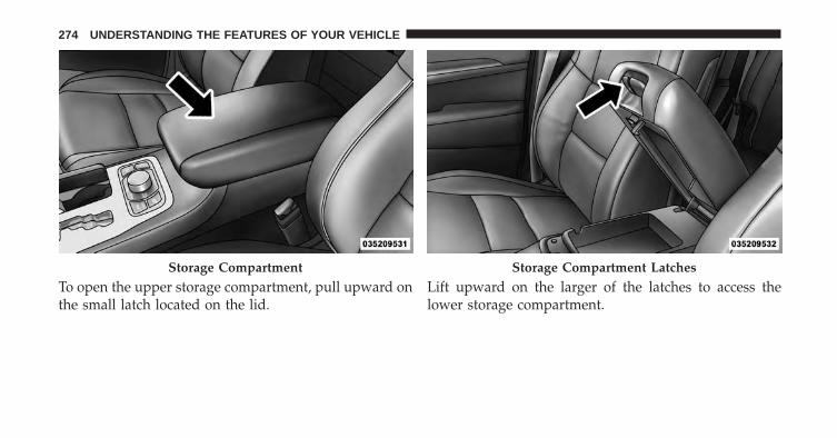
To open the upper storage compartment, pull upward onthe small latch located on the lid.
Lift upward on the larger of the latches to access thelower storage compartment.
Storage Compartment Storage Compartment Latches
274 UNDERSTANDING THE FEATURES OF YOUR VEHICLE

Your vehicle may have an optional CD or DVD playerlocated in the center console.
Lower Storage Compartment Lower Storage Compartment CD/DVD Player-IfEquipped
3
UNDERSTANDING THE FEATURES OF YOUR VEHICLE 275

WARNING!
Do not operate this vehicle with a console compart-ment lid in the open position. Cellular phones, musicplayers, and other handheld electronic devicesshould be stowed while driving. Use of these deviceswhile driving can cause an accident due to distrac-tion, resulting in death or injury.
CARGO AREA FEATURES
Rechargeable Flashlight
The rechargeable flashlight is mounted on the left side ofthe cargo area. The flashlight snaps out of the bezel whenneeded. The flashlight features two bright LED lightbulbs and is powered by rechargeable lithium batteriesthat recharge when snapped back into place.
Press in on the flashlight to release it.
To operate the flashlight, press the switch once for high,twice for low, and a third time to return to off.
Press And Release
276 UNDERSTANDING THE FEATURES OF YOUR VEHICLE

Cargo Storage Bins
There are four removable storage bins located in the rearcargo area. There are two storage bins located on eitherside of the cargo area.
NOTE: If your vehicle is equipped with a rear sub-woofer, the passenger side cargo area will not be avail-able.
Three-Press Switch
Rear Storage Bin
3
UNDERSTANDING THE FEATURES OF YOUR VEHICLE 277

Two additional storage bins are located under the loadfloor. To access the lower storage bins, raise the load floorand attach the tether hook (attached to the bottom of theload floor) to the liftgate opening.
Tether Strap
Lower Storage Bins
278 UNDERSTANDING THE FEATURES OF YOUR VEHICLE

Retractable Cargo Area Cover — If Equipped
NOTE: The purpose of this cover is for privacy, not tosecure loads. It will not prevent cargo from shifting orprotect passengers from loose cargo.
To cover the cargo area:
1. Grasp the cover at the center handle. Pull it over thecargo area.
2. Insert the pins on the ends of the cover into the slots inthe pillar trim cover.
3. The liftgate may be opened with the cargo cover inplace.
Rear Cargo Cover
3
UNDERSTANDING THE FEATURES OF YOUR VEHICLE 279

WARNING!
In a collision, a loose cargo cover in the vehicle couldcause injury. It could fly around in a sudden stop andstrike someone in the vehicle. Do not store the cargocover on the cargo floor or in the passenger compart-ment. Remove the cover from the vehicle when takenfrom its mounting. Do not store it in the vehicle.
Rear Cargo Tie-Downs
The rear cargo tie-downs, located on the cargo area floor,should be used to safely secure loads when the vehicle ismoving. Rear Cargo Tie-Downs
280 UNDERSTANDING THE FEATURES OF YOUR VEHICLE

WARNING!
• To help protect against personal injury, passengersshould not be seated in the rear cargo area. The rearcargo space is intended for load carrying purposesonly, not for passengers, who should sit in seatsand use seat belts.
• Cargo tie-down hooks are not safe anchors for achild seat tether strap. In a sudden stop or accident,a hook could pull loose and allow the child seat tocome loose. A child could be badly injured. Useonly the anchors provided for child seat tethers.
The weight and position of cargo and passengers canchange the vehicle center of gravity and vehiclehandling. To avoid loss of control resulting in per-sonal injury, follow these guidelines for loading yourvehicle:
(Continued)
WARNING! (Continued)• Do not carry loads which exceed the load limits
described on the label attached to the left door orleft door center pillar.
• Always place cargo evenly on the cargo floor. Putheavier objects as low and as far forward as pos-sible.
• Place as much cargo as possible in front of the rearaxle. Too much weight or improperly placed weightover or behind the rear axle can cause the rear ofthe vehicle to sway.
• Do not pile luggage or cargo higher than the top ofthe seatback. This could impair visibility or be-come a dangerous projectile in a sudden stop oraccident.
3
UNDERSTANDING THE FEATURES OF YOUR VEHICLE 281

REAR WINDOW FEATURES
Rear Window Wiper/Washer
The rear wiper/washer controls are located on the mul-tifunction lever on the left side of the steering column.The rear wiper/washer is operated by rotating a switch,located at the middle of the lever.
Rotate the center portion of the lever upward tothe first detent for intermittent operation and to
the second detent for continuous rear wiper operation.
Rotating the center portion upward once morewill activate the washer pump which will con-
tinue to operate as long as the switch is held. Upon
Rear Wiper/Washer Control
282 UNDERSTANDING THE FEATURES OF YOUR VEHICLE

release of the switch, the wipers will resume the continu-ous rear wiper operation. When this rotary control is inthe OFF position, rotating it downward will activate therear washer pump which will continue to operate as longas the switch is held. Once the switch is released it willreturn to the OFF position and the wipers will cycleseveral times before returning to the parked position.
NOTE: As a protective measure, the pump will stop ifthe switch is held for more than 20 seconds. Once theswitch is released the pump will resume normal opera-tion.
If the rear wiper is operating when the ignition is turnedOFF, the wiper will automatically return to the “park”position.
If the flipper glass is open, the rear window wiper/washer functionality is interrupted and the wiper stops at
that “park” position. When the flipper glass is closed, therear wiper will resume wiper/washer functionality afterfive seconds.
Rear Window Defroster
The rear window defroster button is located onthe climate control panel. Press this button to turn
on the rear window defroster and the heated outsidemirrors (if equipped). An indicator in the button willilluminate when the rear window defroster is on. Therear window defroster automatically turns off after ap-proximately 10 minutes. For an additional five minutes ofoperation, press the button a second time.
NOTE: To prevent excessive battery drain, use the rearwindow defroster only when the engine is operating.
3
UNDERSTANDING THE FEATURES OF YOUR VEHICLE 283

CAUTION!
Failure to follow these cautions can cause damage tothe heating elements:• Use care when washing the inside of the rear
window. Do not use abrasive window cleaners onthe interior surface of the window. Use a soft clothand a mild washing solution, wiping parallel to theheating elements. Labels can be peeled off aftersoaking with warm water.
• Do not use scrapers, sharp instruments, or abrasivewindow cleaners on the interior surface of thewindow.
• Keep all objects a safe distance from the window.
ROOF LUGGAGE RACK — IF EQUIPPED
The crossbars and siderails are designed to carry theweight on vehicles equipped with a luggage rack. Theload must not exceed 150 lbs (68 kg), and should beuniformly distributed over the luggage rack crossbars.
NOTE: If not equipped with crossbars, your authorizeddealer can order and install MOPAR® crossbars builtspecifically for this roof rack system.
Distribute cargo weight evenly on the roof rack crossbars.The roof rack does not increase the total load carryingcapacity of the vehicle. Be sure the total load of cargoinside the vehicle plus that on the external rack does notexceed the maximum vehicle load capacity.
284 UNDERSTANDING THE FEATURES OF YOUR VEHICLE

To move the crossbars, loosen the attachments, located atthe upper edge of each crossbar, approximately eightturns using the anti-theft wrench provided with theMOPAR® crossbars. Then, move the crossbar to thedesired position, keeping the crossbars parallel to therack frame. Once the crossbar is in the desired position,retighten the with the wrench to lock the crossbar intoposition.
NOTE:
• To help control wind noise when the crossbars are notin use, place the front and rear crossbars approxi-mately 24 in (61 cm) apart. Optimal noise reductioncan then be achieved by adjusting the front crossbarforward or aft using increments of 1 in (2.5 cm).
• If the rear crossbar (or any metallic object) is placedover the satellite radio antenna (if equipped), you mayexperience interruption of satellite radio reception. Forimproved satellite radio reception, avoid placing therear crossbar over the satellite radio antenna.
• The grab handles on the back of the vehicle (if equipped)are not to be used as a towing feature.
CAUTION!
• To prevent damage to the roof of your vehicle, donot carry any loads on the roof rack without thecrossbars installed. The load should be secured andplaced on top of the crossbars, not directly on theroof. If it is necessary to place the load on the roof,place a blanket or some other protection betweenthe load and the roof surface.
(Continued)
3
UNDERSTANDING THE FEATURES OF YOUR VEHICLE 285

CAUTION! (Continued)• To avoid damage to the roof rack and vehicle, do
not exceed the maximum roof rack load capacity of150 lb (68 kg). Always distribute heavy loads asevenly as possible and secure the load appropri-ately.
• Long loads which extend over the windshield, suchas wood panels or surfboards, or loads with largefrontal area should be secured to both the front andrear of the vehicle.
• Travel at reduced speeds and turn corners carefullywhen carrying large or heavy loads on the roofrack. Wind forces, due to natural causes or nearbytruck traffic, can add sudden upward lift to a load.This is especially true on large flat loads and mayresult in damage to the cargo or your vehicle.
WARNING!
Cargo must be securely tied before driving yourvehicle. Improperly secured loads can fly off thevehicle, particularly at high speeds, resulting in per-sonal injury or property damage. Follow the roof rackcautions when carrying cargo on your roof rack.
286 UNDERSTANDING THE FEATURES OF YOUR VEHICLE

UNDERSTANDING YOUR INSTRUMENT PANEL
CONTENTS� INSTRUMENT PANEL FEATURES . . . . . . . . . .289
� INSTRUMENT CLUSTER . . . . . . . . . . . . . . . . .290
� INSTRUMENT CLUSTER DESCRIPTIONS . . . . .291
� ELECTRONIC VEHICLE INFORMATIONCENTER (EVIC) . . . . . . . . . . . . . . . . . . . . . . . .301
▫ Electronic Vehicle Information Center (EVIC)Displays . . . . . . . . . . . . . . . . . . . . . . . . . . . .303
▫ Engine Oil Change Indicator System . . . . . . . .305
▫ Electronic Vehicle Information Center (EVIC)Messages . . . . . . . . . . . . . . . . . . . . . . . . . . .306
▫ EVIC Amber Telltales . . . . . . . . . . . . . . . . . . .309
▫ EVIC Red Telltales . . . . . . . . . . . . . . . . . . . . .310
▫ EVIC Green Telltales . . . . . . . . . . . . . . . . . . .312
▫ EVIC Selectable Menu Items . . . . . . . . . . . . . .313
▫ Screen Setup Driver Selectable Items . . . . . . . .317
� Uconnect® SETTINGS. . . . . . . . . . . . . . . . . . . .318
▫ Hard-Keys . . . . . . . . . . . . . . . . . . . . . . . . . .320
▫ Soft-Keys . . . . . . . . . . . . . . . . . . . . . . . . . . .320
▫ Customer Programmable Features —Uconnect® 5.0 Settings. . . . . . . . . . . . . . . . . .320
4

▫ Customer Programmable Features —Uconnect® Access 8.4 Settings . . . . . . . . . . . .341
� Uconnect® RADIOS — IF EQUIPPED . . . . . . . .363
� iPod®/USB/MP3 CONTROL —IF EQUIPPED. . . . . . . . . . . . . . . . . . . . . . . . . .363
� STEERING WHEEL AUDIO CONTROLS —IF EQUIPPED . . . . . . . . . . . . . . . . . . . . . . . . .363
▫ Radio Operation . . . . . . . . . . . . . . . . . . . . . .364
▫ CD Player . . . . . . . . . . . . . . . . . . . . . . . . . . .365
� CD/DVD/BLU-RAY DISC MAINTENANCE . . .365
� RADIO OPERATION AND MOBILE PHONES . .366
� CLIMATE CONTROLS . . . . . . . . . . . . . . . . . . .366
▫ General Overview . . . . . . . . . . . . . . . . . . . . .367
▫ Climate Control Functions . . . . . . . . . . . . . . .373
▫ Automatic Temperature Control (ATC) . . . . . .375
▫ Operating Tips . . . . . . . . . . . . . . . . . . . . . . .376
288 UNDERSTANDING YOUR INSTRUMENT PANEL

INSTRUMENT PANEL FEATURES
1 — Air Outlet 6 — Lower Switch Bank 11 — Hood Release2 — Instrument Cluster 7 — Hazard Switch 12 — Fuel Door Release3 — Radio 8 — Storage Bin (SD Card, AUX, USB Media Hub) 13 — Headlight Switch4 — Glove Compartment 9 — ESC Button 14 — Dimmer Control5 — Climate Controls 10 — Ignition Switch
4
UNDERSTANDING YOUR INSTRUMENT PANEL 289

INSTRUMENT CLUSTER
290 UNDERSTANDING YOUR INSTRUMENT PANEL

INSTRUMENT CLUSTER DESCRIPTIONS
1. Tachometer
Indicates the engine speed in revolutions per minute(RPM x 1000).
2. Seat Belt Reminder Light
When the ignition switch is first turned to theON/RUN position, this light will turn on for fourto eight seconds as a bulb check. During the bulb
check, if the driver’s seat belt is unbuckled, a chime willsound. After the bulb check or when driving, if the driveror front passenger seat belt remains unbuckled, the SeatBelt Indicator Light will flash or remain on continuously.Refer to “Occupant Restraints” in “Things To KnowBefore Starting Your Vehicle” for further information.
3. Anti-Lock Brake (ABS) Light
This light monitors the Anti-Lock Brake System(ABS). The light will turn on when the ignitionswitch is turned to the ON/RUN position andmay stay on for as long as four seconds.
If the ABS light remains on or turns on while driving, itindicates that the Anti-Lock portion of the brake systemis not functioning and that service is required. However,the conventional brake system will continue to operatenormally if the BRAKE warning light is not on.
If the ABS light is on, the brake system should be servicedas soon as possible to restore the benefits of Anti-Lockbrakes. If the ABS light does not turn on when theignition switch is turned to the ON/RUN position, havethe light inspected by an authorized dealer.
4
UNDERSTANDING YOUR INSTRUMENT PANEL 291

4. High Beam Indicator
Indicates that headlights are on high beam.
5. Front Fog Light Indicator — If Equipped
This indicator will illuminate when the front foglights are on.
6. Selectable EVIC Information
This area of the cluster will display selectable informa-tion such as compass, outside temperature, etc. Forfurther information, refer to “Electronic Vehicle Informa-tion Center (EVIC) — If Equipped” of your ownersmanual for more information.
7. Turn Signal Indicator
The arrows will flash with the exterior turn sig-nals when the turn signal lever is operated. A tone
will chime, and an EVIC message will appear if eitherturn signal is left on for more than 1 mile (1.6 km).
NOTE: If either indicator flashes at a rapid rate, checkfor a defective outside light bulb.
8. Speedometer
Indicates vehicle speed.
9. Selectable EVIC Information
This area of the cluster will display selectable informa-tion such as compass, outside temperature, etc. Forfurther information, refer to “Electronic Vehicle Informa-tion Center (EVIC) — If Equipped” of your ownersmanual for more information.
292 UNDERSTANDING YOUR INSTRUMENT PANEL

10. Malfunction Indicator Light (MIL)
The Malfunction Indicator Light (MIL) is part ofan onboard diagnostic system called OBD II thatmonitors engine and automatic transmission con-
trol systems. The light will illuminate when the key is inthe ON/RUN position before engine start. If the bulbdoes not come on when turning the key from OFF toON/RUN, have the condition checked promptly.
Certain conditions, poor fuel quality, etc., may illuminatethe light after engine start. The vehicle should be servicedif the light stays on through several of your typicaldriving cycles. In most situations, the vehicle will drivenormally and will not require towing.
CAUTION!
Prolonged driving with the Malfunction IndicatorLight (MIL) on could cause damage to the enginecontrol system. It also could affect fuel economy anddriveability. If the MIL is flashing, severe catalyticconverter damage and power loss will soon occur.Immediate service is required.
WARNING!
A malfunctioning catalytic converter, as referencedabove, can reach higher temperatures than in normaloperating conditions. This can cause a fire if you driveslowly or park over flammable substances such as dryplants, wood, cardboard, etc. This could result in deathor serious injury to the driver, occupants or others.
4
UNDERSTANDING YOUR INSTRUMENT PANEL 293

11. Electronic Park Brake Failure Indicator —If Equipped
This light indicates the Electronic ParkingBrake system requires service.
12. Temperature Gauge
The temperature gauge shows engine coolant tempera-ture. Any reading within the normal range indicates thatthe engine cooling system is operating satisfactorily.
The gauge pointer will likely indicate a higher tempera-ture when driving in hot weather, up mountain grades,or when towing a trailer. It should not be allowed toexceed the upper limits of the normal operating range.
CAUTION!
Driving with a hot engine cooling system coulddamage your vehicle. If the temperature gauge reads“H” pull over and stop the vehicle. Idle the vehiclewith the air conditioner turned off until the pointerdrops back into the normal range. If the pointerremains on the “H” and you hear continuous chimes,turn the engine off immediately and call an autho-rized dealer for service.
294 UNDERSTANDING YOUR INSTRUMENT PANEL

WARNING!
A hot engine cooling system is dangerous. You orothers could be badly burned by steam or boilingcoolant. You may want to call an authorized dealerfor service if your vehicle overheats. If you decide tolook under the hood yourself, see “Maintaining YourVehicle”. Follow the warnings under the CoolingSystem Pressure Cap paragraph.
13. Brake Warning Light
This light monitors various brake functions,including brake fluid level and parking brakeapplication. If the brake light turns on it mayindicate that the parking brake is applied, that
the brake fluid level is low, or that there is a problem withthe anti-lock brake system reservoir.
If the light remains on when the parking brake has beendisengaged, and the fluid level is at the full mark on themaster cylinder reservoir, it indicates a possible brakehydraulic system malfunction or that a problem with theBrake Booster has been detected by the Anti-Lock BrakeSystem (ABS) / Electronic Stability Control (ESC) system.In this case, the light will remain on until the conditionhas been corrected. If the problem is related to the brakebooster, the ABS pump will run when applying the brakeand a brake pedal pulsation may be felt during each stop.
The dual brake system provides a reserve braking capac-ity in the event of a failure to a portion of the hydraulicsystem. A leak in either half of the dual brake system isindicated by the Brake Warning Light, which will turn onwhen the brake fluid level in the master cylinder hasdropped below a specified level.
The light will remain on until the cause is corrected.
4
UNDERSTANDING YOUR INSTRUMENT PANEL 295

NOTE: The light may flash momentarily during sharpcornering maneuvers, which change fluid level condi-tions. The vehicle should have service performed, andthe brake fluid level checked.
If brake failure is indicated, immediate repair is neces-sary.
WARNING!
Driving a vehicle with the red brake light on isdangerous. Part of the brake system may have failed.It will take longer to stop the vehicle. You could havea collision. Have the vehicle checked immediately.
Vehicles equipped with the Anti-Lock Brake System(ABS), are also equipped with Electronic Brake ForceDistribution (EBD). In the event of an EBD failure, theBrake Warning Light will turn on along with the ABSLight. Immediate repair to the ABS system is required.
Operation of the Brake Warning Light can be checked byturning the ignition switch from the OFF position to theON/RUN position. The light should illuminate for ap-proximately two seconds. The light should then turn offunless the parking brake is applied or a brake fault isdetected. If the light does not illuminate, have the lightinspected by an authorized dealer.
The light also will turn on when the parking brake isapplied with the ignition switch in the ON/RUN posi-tion.
NOTE: This light shows only that the parking brake isapplied. It does not show the degree of brake application.
14. Fuel Gauge/Fuel Door Reminder
The fuel pump symbol points to the side of the vehiclewhere the fuel door is located. The pointer shows thelevel of fuel in the fuel tank when the ignition switch is inthe ON/RUN position.
296 UNDERSTANDING YOUR INSTRUMENT PANEL

15. Tire Pressure Monitoring Telltale Light
Each tire, including the spare (if provided),should be checked monthly when cold andinflated to the inflation pressure recommendedby the vehicle manufacturer on the vehicle
placard or tire inflation pressure label. (If your vehiclehas tires of a different size than the size indicated on thevehicle placard or tire inflation pressure label, you shoulddetermine the proper tire inflation pressure for thosetires.)
As an added safety feature, your vehicle has beenequipped with a Tire Pressure Monitoring System(TPMS) that illuminates a low tire pressure telltale whenone or more of your tires is significantly under-inflated.Accordingly, when the low tire pressure telltale illumi-nates, you should stop and check your tires as soon aspossible, and inflate them to the proper pressure. Drivingon a significantly under-inflated tire causes the tire tooverheat and can lead to tire failure. Under-inflation also
reduces fuel efficiency and tire tread life, and may affectthe vehicle’s handling and stopping ability.
Please note that the TPMS is not a substitute for propertire maintenance, and it is the driver’s responsibility tomaintain correct tire pressure, even if under-inflation hasnot reached the level to trigger illumination of the TPMSlow tire pressure telltale.
Your vehicle has also been equipped with a TPMSmalfunction indicator to indicate when the system is notoperating properly. The TPMS malfunction indicator iscombined with the low tire pressure telltale. When thesystem detects a malfunction, the telltale will flash forapproximately one minute and then remain continuouslyilluminated. This sequence will continue upon subse-quent vehicle start-ups as long as the malfunction exists.When the malfunction indicator is illuminated, the sys-tem may not be able to detect or signal low tire pressureas intended. TPMS malfunctions may occur for a varietyof reasons, including the installation of replacement or
4
UNDERSTANDING YOUR INSTRUMENT PANEL 297

alternate tires or wheels on the vehicle that prevent theTPMS from functioning properly. Always check theTPMS malfunction telltale after replacing one or moretires or wheels on your vehicle, to ensure that thereplacement or alternate tires and wheels allow the TPMSto continue to function properly.
CAUTION!
The TPMS has been optimized for the originalequipment tires and wheels. TPMS pressures andwarning have been established for the tire sizeequipped on your vehicle. Undesirable system opera-tion or sensor damage may result when using re-placement equipment that is not of the same size,type, and/or style. Aftermarket wheels can causesensor damage. Do not use tire sealant from a can orbalance beads if your vehicle is equipped with aTPMS, as damage to the sensors may result.
16. Electronic Vehicle Information Center (EVIC)Display/Odometer Display
The odometer display shows the total distance the ve-hicle has been driven.
U.S. Federal regulations require that upon transfer ofvehicle ownership, the seller certify to the purchaser thecorrect mileage that the vehicle has been driven. If yourodometer needs to be repaired or serviced, the repairtechnician should leave the odometer reading the sameas it was before the repair or service. If s/he cannot do so,then the odometer must be set at zero, and a sticker mustbe placed in the door jamb stating what the mileage wasbefore the repair or service. It is a good idea for you tomake a record of the odometer reading before the repair/service, so that you can be sure that it is properly reset, orthat the door jamb sticker is accurate if the odometermust be reset at zero.
298 UNDERSTANDING YOUR INSTRUMENT PANEL

When the appropriate conditions exist, this displayshows the Electronic Vehicle Information Center (EVIC)messages. Refer to “Electronic Vehicle Information Cen-ter” of your owners manual for more information.
17. Selectable EVIC Menu
This area of the cluster will display the EVIC selectablemenu. For further information, refer to “Electronic Ve-hicle Information Center (EVIC) — If Equipped” of yourowners manual for more information.
18. Air Bag Warning Light
This light will turn on for four to eight secondsas a bulb check when the ignition switch is firstturned to the ON/RUN position. If the light iseither not on during starting, stays on, or turns
on while driving, have the system inspected at an autho-rized dealer as soon as possible. Refer to “OccupantRestraints” in “Things To Know Before Starting YourVehicle” of your owners manual for further information.
19. Vehicle Security Light
This light will flash rapidly for approximately15 seconds when the vehicle theft alarm isarming. The light will flash at a slower speedcontinuously after the alarm is set. The security
light will also come on for about three seconds when theignition is first turned on.
20. Electronic Stability Control (ESC) OFF IndicatorLight — If Equipped
This light indicates the Electronic Stability Con-trol (ESC) is off.
4
UNDERSTANDING YOUR INSTRUMENT PANEL 299

21. Electronic Stability Control (ESC) Activation/Malfunction Indicator Light — If Equipped
The “ESC Activation/Malfunction IndicatorLight” in the instrument cluster will come onwhen the ignition switch is turned to theON/RUN position. It should go out with the
engine running. If the “ESC Activation/Malfunction In-dicator Light” comes on continuously with the enginerunning, a malfunction has been detected in the ESCsystem. If this light remains on after several ignitioncycles, and the vehicle has been driven several miles(kilometers) at speeds greater than 30 mph (48 km/h), seeyour authorized dealer as soon as possible to have theproblem diagnosed and corrected.
NOTE:
• The “ESC Off Indicator Light” and the “ESCActivation/Malfunction Indicator Light” come on mo-mentarily each time the ignition switch is turned toON/RUN.
• Each time the ignition is turned to ON/RUN, the ESCsystem will be ON, even if it was turned off previously.
• The ESC system will make buzzing or clicking soundswhen it is active. This is normal; the sounds will stopwhen ESC becomes inactive following the maneuverthat caused the ESC activation.
22. Park/Headlight ON Indicator — If Equipped
This indicator will illuminate when the parklights or headlights are turned on.
300 UNDERSTANDING YOUR INSTRUMENT PANEL

ELECTRONIC VEHICLE INFORMATION CENTER(EVIC)
The Electronic Vehicle Information Center (EVIC) fea-tures a driver-interactive display that is located in theinstrument cluster.
This system allows the driver to select a variety of usefulinformation by pressing the switches mounted on thesteering wheel. The EVIC consists of the following:
• Main Gauge
• MPH to km/h
• Vehicle Info
• Terrain — If Equipped
• Driver Assist
• Fuel Economy
• Trip
• Audio
• Stored Messages
• Screen SetupElectronic Vehicle Information Center (EVIC) Location
4
UNDERSTANDING YOUR INSTRUMENT PANEL 301

• Speed Warning
• Diagnostic Codes
The system allows the driver to select information bypressing the following buttons mounted on the steeringwheel:
• UP Arrow Button
Press and release the UP arrow button to scrollupward through the main menu and sub-menus (Main Gauge, MPH/km/h, VehicleInfo, Terrain, Driver Assist, Fuel Economy, Trip
A, Trip B, Audio, Stored Messages, Screen Set Up).
• DOWN Arrow Button
Press and release the DOWN arrow button toscroll downward through the main menu andsubmenus (Main Gauge, MPH/km/h, VehicleInfo, Terrain, Driver Assist, Fuel Economy, Trip
A, Trip B, Audio, Stored Messages, Screen Set Up).
EVIC Buttons
302 UNDERSTANDING YOUR INSTRUMENT PANEL
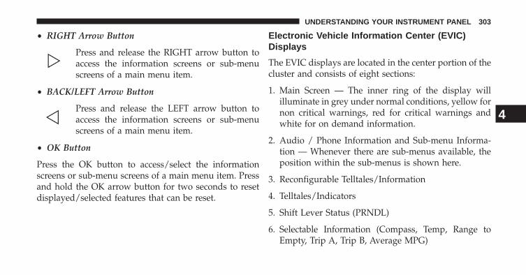
• RIGHT Arrow Button
Press and release the RIGHT arrow button toaccess the information screens or sub-menuscreens of a main menu item.
• BACK/LEFT Arrow Button
Press and release the LEFT arrow button toaccess the information screens or sub-menuscreens of a main menu item.
• OK Button
Press the OK button to access/select the informationscreens or sub-menu screens of a main menu item. Pressand hold the OK arrow button for two seconds to resetdisplayed/selected features that can be reset.
Electronic Vehicle Information Center (EVIC)Displays
The EVIC displays are located in the center portion of thecluster and consists of eight sections:
1. Main Screen — The inner ring of the display willilluminate in grey under normal conditions, yellow fornon critical warnings, red for critical warnings andwhite for on demand information.
2. Audio / Phone Information and Sub-menu Informa-tion — Whenever there are sub-menus available, theposition within the sub-menus is shown here.
3. Reconfigurable Telltales/Information
4. Telltales/Indicators
5. Shift Lever Status (PRNDL)
6. Selectable Information (Compass, Temp, Range toEmpty, Trip A, Trip B, Average MPG)
4
UNDERSTANDING YOUR INSTRUMENT PANEL 303

7. Air Suspension Status
8. 4WD Status
9. Selectable Gauge 2
10. Selectable Gauge 1
The main display area will normally display the mainmenu or the screens of a selected feature of the mainmenu. The main display area also displays “pop up”messages that consist of approximately 60 possible warn-ing or information messages. These pop up messages fallinto several categories:
• Five Second Stored Messages
When the appropriate conditions occur, this type ofmessage takes control of the main display area for fiveseconds and then returns to the previous screen. Most ofthe messages of this type are then stored (as long as thecondition that activated it remains active) and can be
reviewed from the “Messages” main menu item. As longas there is a stored message, an “i” will be displayed inthe EVIC’s compass/outside temp line. Examples of thismessage type are “Right Front Turn Signal Lamp Out”and “Low Tire Pressure”.
• Unstored Messages
This message type is displayed indefinitely or until thecondition that activated the message is cleared. Examplesof this message type are “Turn Signal On” (if a turn signalis left on) and “Lights On” (if driver leaves the vehicle).
• Unstored Messages Until RUN
These messages deal primarily with the Remote Startfeature. This message type is displayed until the ignitionis in the RUN state. Examples of this message type are“Remote Start Aborted - Door Ajar” and “Press BrakePedal and Push Button to Start”.
304 UNDERSTANDING YOUR INSTRUMENT PANEL

• Five Second Unstored Messages
When the appropriate conditions occur, this type ofmessage takes control of the main display area for fiveseconds and then returns to the previous screen. Anexample of this message type is “Automatic High BeamsOn”.
Engine Oil Change Indicator System
Oil Change Required
Your vehicle is equipped with an engine oil changeindicator system. The “Oil Change Required” messagewill flash in the EVIC display for approximately 10seconds after a single chime has sounded, to indicate thenext scheduled oil change interval. The engine oil changeindicator system is duty cycle based, which means theengine oil change interval may fluctuate, dependentupon your personal driving style.
Unless reset, this message will continue to display eachtime you turn the ignition switch to the ON/RUNposition or cycle the ignition to the ON/RUN position ifequipped with Keyless Enter-N-Go™. To turn off themessage temporarily, press and release the MENU but-ton. To reset the oil change indicator system (afterperforming the scheduled maintenance) refer to the fol-lowing procedure.
Vehicles Equipped With Keyless Enter-N-Go™
1. Without pressing the brake pedal, press the ENGINESTART/STOP button and cycle the ignition to theON/ RUN position (Do not start the engine.)
2. Fully depress the accelerator pedal, slowly, three timeswithin 10 seconds.
3. Without pressing the brake pedal, press the ENGINESTART/STOP button once to return the ignition to theOFF/LOCK position.
4
UNDERSTANDING YOUR INSTRUMENT PANEL 305
NOTE: If the indicator message illuminates when youstart the vehicle, the oil change indicator system did notreset. If necessary, repeat this procedure.
Electronic Vehicle Information Center (EVIC)Messages
• Front Seatbelts Unbuckled
• Driver Seatbelt Unbuckled
• Passenger Seatbelt Unbuckled
• Service Airbag System
• Traction Control Off
• Washer Fluid Low
• Oil Pressure Low
• Oil Change Due
• Fuel Low
• Service Antilock Brake System
• Service Electronic Throttle Control
• Service Power Steering
• Cruise Off
• Cruise Ready
• Cruise Set To XXX MPH
• Tire Pressure Screen With Low Tire(s) “Inflate Tire to XX”
• Service Tire Pressure System
• Parking Brake Engaged
• Brake Fluid Low
• Service Electronic Braking System
• Engine Temperature Hot
306 UNDERSTANDING YOUR INSTRUMENT PANEL
• Battery Voltage Low
• Service Electronic Throttle Control
• Lights On
• Right Turn Signal Light Out
• Left Turn Signal Light Out
• Turn Signal On
• Vehicle Not in Park
• Key in Ignition
• Key in Ignition Lights On
• Remote Start Active Key to Run
• Remote Start Active Push Start Button
• Remote Start Aborted Fuel Low
• Remote Start Aborted Too Cold
• Remote Start Aborted Door Open
• Remote Start Aborted Hood Open
• Remote Start Aborted Tailgate Open
• Remote Start Aborted Time Expired
• Remote Start Disabled Start to Reset
• Service Airbag System
• Service Airbag Warning Light
• Door Open
• Doors Open
• Liftgate Open
• Gear Not Available
• Shift Not Allowed
• Shift to Neutral then Drive or Reverse
4
UNDERSTANDING YOUR INSTRUMENT PANEL 307
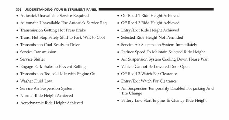
• Autostick Unavailable Service Required
• Automatic Unavailable Use Autostick Service Req.
• Transmission Getting Hot Press Brake
• Trans. Hot Stop Safely Shift to Park Wait to Cool
• Transmission Cool Ready to Drive
• Service Transmission
• Service Shifter
• Engage Park Brake to Prevent Rolling
• Transmission Too cold Idle with Engine On
• Washer Fluid Low
• Service Air Suspension System
• Normal Ride Height Achieved
• Aerodynamic Ride Height Achieved
• Off Road 1 Ride Height Achieved
• Off Road 2 Ride Height Achieved
• Entry/Exit Ride Height Achieved
• Selected Ride Height Not Permitted
• Service Air Suspension System Immediately
• Reduce Speed To Maintain Selected Ride Height
• Air Suspension System Cooling Down Please Wait
• Vehicle Cannot Be Lowered Door Open
• Off Road 2 Watch For Clearance
• Entry/Exit Watch For Clearance
• Air Suspension Temporarily Disabled For jacking AndTire Change
• Battery Low Start Engine To Change Ride Height
308 UNDERSTANDING YOUR INSTRUMENT PANEL

The Reconfigurable Telltales section is divided into thewhite telltales area on the right, amber telltales in themiddle, and red telltales on the left.
EVIC Amber Telltales
This area will show reconfigurable amber caution tell-tales. These telltales include:
• Low Fuel Telltale
When the fuel level reaches approximately 3.0 gal(11.0 L) this light will turn on, and remain on until
fuel is added.
• Windshield Washer Fluid Low Indicator
This telltale will turn on to indicate the wind-shield washer fluid is low.
• Transmission Temperature Warning Telltale
This telltale indicates that the transmissionfluid temperature is running hot. This mayoccur with severe usage, such as trailer towing.If this telltale turns on, safely pull over and
stop the vehicle. Then, shift the transmission into NEU-TRAL and run the engine at idle or faster until the lightturns off.
• Service Forward Collision Warming
This light warns the driver of a potential collision withthe vehicle in front and prompts the driver to take actionin order to avoid the collision. For further information,refer to “Adaptive Cruise Control (ACC)” in “Under-standing The Features Of Your Vehicle.”
4
UNDERSTANDING YOUR INSTRUMENT PANEL 309

• Service Adaptive Cruise Control
This light will turn on when a ACC is notoperating and needs service. For further infor-mation, refer to “Adaptive Cruise Control(ACC)” in “Understanding The Features Of
Your Vehicle.”
• Electronic Park Brake Failure
This telltale indicates that there is an ElectronicPark Brake Fault. Please see your authorizeddealer for assistance.
EVIC Red Telltales
This area will show reconfigurable red telltales. Thesetelltales include:
• Door Ajar
This light will turn on to indicate that one ormore doors may be ajar.
• Oil Pressure Warning Light
This telltale indicates low engine oil pressure. Ifthe light turns on while driving, stop the vehicle and shutoff the engine as soon as possible. A chime will sound forfour minutes when this light turns on.
Do not operate the vehicle until the cause is corrected.This light does not show how much oil is in the engine.The engine oil level must be checked under the hood.
310 UNDERSTANDING YOUR INSTRUMENT PANEL

• Oil Temperature Warning Light
This telltale indicates engine oil temperature ishigh. If the light turns on while driving, stopthe vehicle and shut off the engine as soon aspossible.
• Charging System Light
This light shows the status of the electrical charg-ing system. If the light stays on or comes on while
driving, turn off some of the vehicle’s non-essentialelectrical devices or increase engine speed (if at idle). Ifthe charging system light remains on, it means that thevehicle is experiencing a problem with the chargingsystem. Obtain SERVICE IMMEDIATELY. See an autho-rized dealer.
If jump starting is required, refer to “Jump StartingProcedures” in “What To Do In Emergencies”.
• Electronic Throttle Control (ETC) Light
This light informs you of a problem with theElectronic Throttle Control (ETC) system. Thelight will come on when the ignition is firstturned ON and remain on briefly as a bulb
check. If the light does not come on during starting, havethe system checked by an authorized dealer.
If a problem is detected, the light will come on while theengine is running. Cycle the ignition key when thevehicle has completely stopped and the shift lever isplaced in the PARK position. The light should turn off.
If the light remains lit with the engine running, yourvehicle will usually be drivable. However, see an autho-rized dealer for service as soon as possible. If the light isflashing when the engine is running, immediate service isrequired. You may experience reduced performance, anelevated/rough idle or engine stall and your vehicle mayrequire towing.
4
UNDERSTANDING YOUR INSTRUMENT PANEL 311
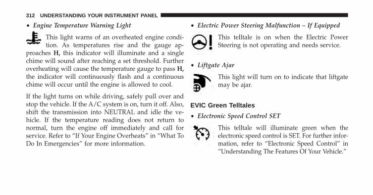
• Engine Temperature Warning Light
This light warns of an overheated engine condi-tion. As temperatures rise and the gauge ap-
proaches H, this indicator will illuminate and a singlechime will sound after reaching a set threshold. Furtheroverheating will cause the temperature gauge to pass H,the indicator will continuously flash and a continuouschime will occur until the engine is allowed to cool.
If the light turns on while driving, safely pull over andstop the vehicle. If the A/C system is on, turn it off. Also,shift the transmission into NEUTRAL and idle the ve-hicle. If the temperature reading does not return tonormal, turn the engine off immediately and call forservice. Refer to “If Your Engine Overheats” in “What ToDo In Emergencies” for more information.
• Electric Power Steering Malfunction – If Equipped
This telltale is on when the Electric PowerSteering is not operating and needs service.
• Liftgate Ajar
This light will turn on to indicate that liftgatemay be ajar.
EVIC Green Telltales
• Electronic Speed Control SET
This telltale will illuminate green when theelectronic speed control is SET. For further infor-mation, refer to “Electronic Speed Control” in“Understanding The Features Of Your Vehicle.”
312 UNDERSTANDING YOUR INSTRUMENT PANEL

EVIC Selectable Menu Items
Press and release the UP or DOWN arrow buttons untilthe desired Selectable Menu icon is highlighted in theEVIC.
Digital Speedometer
Press and release the UP or DOWN arrowbutton until the Digital display icon is high-lighted in the EVIC. Press and release theRIGHT arrow button to scroll through the
sub-menus and press the OK button to change thedisplay between km/h and mph.
Vehicle Info (Customer Information Features)
Press and release the UP or DOWN arrow but-ton until the Vehicle Info icon is highlighted inthe EVIC. Press and release the RIGHT arrowbutton and Coolant Temp will be displayed.
Press the LEFT or RIGHT arrow button to scroll throughthe information sub-menus and press the OK button toselect or reset the following resettable sub-menus:
Air Suspension – If Equipped
Transmission Temperature – Automatic TransmissionOnly
Oil Temp
Oil Life
Battery Voltage
Tire Pressure
4
UNDERSTANDING YOUR INSTRUMENT PANEL 313

Press and release the UP or DOWN arrow button until“Tire Pressure” is highlighted in the EVIC. Press andrelease the RIGHT arrow button and one of the followingwill be displayed:
If tire pressure is OK for all tires a vehicle ICON isdisplayed with tire pressure values in each corner of theICON.
If one or more tires have low pressure, “Inflate Tire ToXX” is displayed with the vehicle ICON and the tirepressure values in each corner of the ICON with thepressure value of the low tire displayed in a differentcolor than the other tire pressure value.
If the Tire Pressure system requires service, “Service TirePressure System” is displayed.
Tire PSI is an information only function and cannot bereset. Press and release the LEFT arrow button to returnto the main menu.
Refer to “Tire Pressure Monitoring System (TPMS)”under “Starting and Operating” for further information.
Trip A
Press and release the UP or DOWN arrowbutton until the Trip A icon is highlighted inthe EVIC (Toggle left or right to select Trip A orTrip B). The Trip A information will display the
following:
• Distance
• Average Fuel Economy
• Elapsed Time
Hold the OK button to reset all the information.
314 UNDERSTANDING YOUR INSTRUMENT PANEL

Trip B
Press and release the Left or Right arrow but-ton until the Trip B icon is highlighted in theEVIC (Toggle left or right to select Trip A orTrip B). The Trip B information will display the
following:
• Distance
• Average Fuel Economy
• Elapsed Time
Hold the OK button to reset all the information.
Fuel Economy
Press and release the UP or DOWN arrow buttonuntil the Fuel Economy icon is highlighted.
• Average Fuel Economy/Miles Per Gallon (MPG orL/100 km with Bargraph)
• Range To Empty (RTE)
• Current Miles Per Gallon (MPG)
Stored Messages
Press and release the UP arrow button until theMessages display icon is highlighted in theEVIC. This feature shows the number of storedwarning messages. Pressing the RIGHT arrow
button will allow you to see what the stored messages are.
4
UNDERSTANDING YOUR INSTRUMENT PANEL 315

Audio
Press and release the UP or DOWN arrowbutton until the Audio display icon is high-lighted in the EVIC. Press and release theRIGHT arrow button to scroll through the
sub-menus and press the OK button display the activesource.
Screen Setup
Press and release the UP or DOWN arrowbutton until the Screen Setup display icon ishighlighted in the EVIC. Press and release theRIGHT arrow button to enter the Screen Setup
sub-menu. The Screen Setup feature allows you to changewhat information is displayed in the instrument clusteras well as the location that information is displayed.
Driver Assist
Press and release the UP or DOWN arrowbutton until the Driver Assist display icon ishighlighted in the EVIC. Press and release theRIGHT arrow button to display the Adaptive
Cruise Control sub-menu. For further information, referto “Adaptive Cruise Control (ACC) — If Equipped” in“Understanding The Features Of Your Vehicle”.
Terrain
Press and release the UP or DOWN arrowbutton until the Terrain display icon is high-lighted in the EVIC. Press and release theRIGHT arrow button to display the Selec-
Terrain, Air Suspension, Drivetrain, Vehicle Pitch, VehicleRoll, Vehicle Altitude and Wheel Articulation.
316 UNDERSTANDING YOUR INSTRUMENT PANEL

Diagnostics — If Equipped
Press and release the UP or DOWN arrowbutton until the Diagnostics display icon ishighlighted in the EVIC. Press and release theRIGHT arrow button to display the diagnostic
trouble codes and descriptions.
Screen Setup Driver Selectable Items
Odometer
• Standard (PRND) Gear Indicator
• Single Character (D) Gear Indicator
Upper Left
• None
• Compass
• Outside Temp (default setting)
• Current Gear: ON/OFF
• Current Gear
• Gear Display
• Time
• Range To Empty (RTE)
• Average MPG/L/100km
• Current MPG/L/100km
• Trip A
• Trip B
4
UNDERSTANDING YOUR INSTRUMENT PANEL 317

Upper Right
• None
• Compass (default setting)
• Outside Temp
• Time
• Range To Empty (RTE)
• Average MPG/L/100km
• Current MPG/L/100km
• Trip A
• Trip B
Restore To Defaults (Restores All Settings To DefaultSettings)
• Cancel
• Okay
Uconnect® SETTINGS
The Uconnect® system uses a combination of soft andhard keys located on the center of the instrument panelthat allows you to access and change the customerprogrammable features.
318 UNDERSTANDING YOUR INSTRUMENT PANEL

Uconnect® 5.0 soft-keys and hard-keys
1 — Uconnect® Soft-Keys2 — Uconnect® Hard-Keys
Uconnect® 8.4 soft-keys and hard-keys
1 — Uconnect® Soft-Keys2 — Uconnect® Hard-Keys
4
UNDERSTANDING YOUR INSTRUMENT PANEL 319

Hard-Keys
Hard-Keys are located below the Uconnect® system inthe center of the instrument panel. In addition, there is aScroll/Enter control knob located on the right side of theClimate Controls in the center of the instrument panel.Turn the control knob to scroll through menus andchange settings (i.e., 30, 60, 90), press the center of thecontrol knob one or more times to select or change asetting (i.e., ON, OFF).
Your Uconnect® system may also have a Screen Off andBack hard-keys located below the system.
Press the Screen Off hard-key to turn off the Uconnect®screen. Press the Screen Off hard-key a second time toturn the screen on.
Press the Back hard-key to exit out of a Menu or certainoption on the Uconnect® system.
Soft-Keys
Soft-Keys are accessible on the Uconnect® display.
Customer Programmable Features —Uconnect® 5.0 Settings
Press the Settings hard-key to display the menu settingscreen. In this mode the Uconnect® system allows you toaccess programmable features that may be equipped such asDisplay, Clock, Safety/Assistance, Lights, Doors & Locks,Auto-On Comfort & Remote Start, Engine Off Operation,Compass Settings, Audio and Phone/Bluetooth.
NOTE: Only one touchscreen area may be selected at atime.
When making a selection, press the soft-key to enter thedesired mode. Once in the desired mode, press andrelease the preferred setting until a check-mark appears
320 UNDERSTANDING YOUR INSTRUMENT PANEL

next to the setting, showing that setting has been se-lected. Once the setting is complete, either press the BackArrow soft-key or the Back hard-key to return to theprevious menu or press the X soft-key to close out of thesettings screen. Pressing the Up or Down Arrow soft-keyson the right side of the screen will allow you to toggle upor down through the available settings.
Display
After pressing the Display soft-key the following settingswill be available:
• Display Mode
When in this display you may select the Auto or Manualdisplay settings. To change Mode status, touch andrelease the Auto or Manual soft-key. Then touch thearrow back soft-key.
• Display Brightness With Headlights ON
When in this display, you may select the overall screenbrightness with the headlights on. Adjust the brightnesswith the + and – setting soft-keys or by selecting anypoint on the scale between the + and – soft-keys. Thentouch the arrow back soft-key.
• Display Brightness With Headlights OFF
When in this display, you may select the overall screenbrightness with the headlights off. Adjust the brightnesswith the + and – setting soft-keys or by selecting anypoint on the scale between the + and – soft-keys. Thentouch the arrow back soft-key.
4
UNDERSTANDING YOUR INSTRUMENT PANEL 321
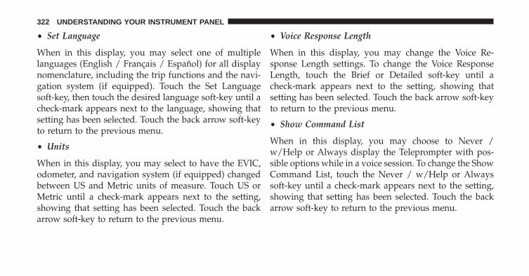
• Set Language
When in this display, you may select one of multiplelanguages (English / Français / Español) for all displaynomenclature, including the trip functions and the navi-gation system (if equipped). Touch the Set Languagesoft-key, then touch the desired language soft-key until acheck-mark appears next to the language, showing thatsetting has been selected. Touch the back arrow soft-keyto return to the previous menu.
• Units
When in this display, you may select to have the EVIC,odometer, and navigation system (if equipped) changedbetween US and Metric units of measure. Touch US orMetric until a check-mark appears next to the setting,showing that setting has been selected. Touch the backarrow soft-key to return to the previous menu.
• Voice Response Length
When in this display, you may change the Voice Re-sponse Length settings. To change the Voice ResponseLength, touch the Brief or Detailed soft-key until acheck-mark appears next to the setting, showing thatsetting has been selected. Touch the back arrow soft-keyto return to the previous menu.
• Show Command List
When in this display, you may choose to Never /w/Help or Always display the Teleprompter with pos-sible options while in a voice session. To change the ShowCommand List, touch the Never / w/Help or Alwayssoft-key until a check-mark appears next to the setting,showing that setting has been selected. Touch the backarrow soft-key to return to the previous menu.
322 UNDERSTANDING YOUR INSTRUMENT PANEL

• Touchscreen Beep
When in this display, you may turn on or shut off thesound heard when a touch screen button (soft-key) ispressed. Touch the Touchscreen Beep soft-key until acheck-mark appears next to the setting, showing thatsetting has been selected. Touch the back arrow soft-keyto return to the previous menu.
• Navigation Turn-By-Turn In Cluster — If Equipped
When this feature is selected, the turn-by-turn directionswill appear in the display as the vehicle approaches adesignated turn within a programmed route. To makeyour selection, touch the Navigation Turn-By-Turn InCluster soft-key, until a check-mark appears next to thesetting, showing that setting has been selected. Touch theback arrow soft-key to return to the previous menu.
Clock
After pressing the Clock soft-key the following settingswill be available:
• Time and Format
When in this display, you may set the time and choosethe format to display the time. Touch the 12h / 24h / AMand/or PM soft-key until a check-mark appears next tothe setting, showing that setting has been selected. Touchthe back arrow soft-key to return to the previous menu. If24h is selected, AM/PM soft-keys will be greyed out(unavailable).
• Sync Date
When in this display, you may choose to set the dateautomatically. Touch the Sync Date soft-key until acheck-mark appears next to the setting, showing thatsetting has been selected. Touch the back arrow soft-keyto return to the previous menu.
4
UNDERSTANDING YOUR INSTRUMENT PANEL 323

• Set Date
When in this display, you may set the date manually.Touch the Set Date soft-key until a check-mark appearsnext to the setting, showing that setting has been se-lected. Touch the back arrow soft-key to return to theprevious menu.
Safety / Assistance
After pressing the Safety / Assistance soft-key the fol-lowing settings will be available:
• Front Collision Sensitivity- If Equipped
The Front Collision Warning (FCW) feature provides anaudible and/or visual warning to potential forwardcollisions. The feature can be can be set to Far, or set toNear. The default status of FCW is the Far setting. Thismeans the system will warn you of a possible collisionwith the vehicle in front of you when you are fartheraway. This gives you the most reaction time. To change
the setting for more dynamic driving, select the Nearsetting. This warns you of a possible collision when youare much closer to the vehicle in front of you. To changethe FCW status, touch and release the Near or Far button.Then touch the arrow back soft-key.
For further information, refer to “Adaptive Cruise Con-trol (ACC)” in “Understanding The Features Of YourVehicle”.
• Forward Collision Warning (FCW) - Active Braking
The FCW system includes Advanced Brake Assist (ABA).When this feature is selected, the ABA applies additionalbrake pressure when the driver requests insufficientbrake pressure to avoid a potential frontal collision. TheABA system becomes active at 5 mph (8 km/h). To makeyour selection, touch the Forward Collision Warning(FCW) with Mitigation - Active Braking soft-key, until acheck-mark appears next to setting, indicating that thesetting had been selected. Touch the back arrow soft-key
324 UNDERSTANDING YOUR INSTRUMENT PANEL

to return to the previous menu. For further information,refer to “Forward Collision Warning (FCW) With Mitiga-tion” in “Understanding The Features Of Your Vehicle.”
• ParkSense®
The ParkSense® system will scan for objects behind thevehicle when the transmission shift lever is in REVERSEand the vehicle speed is less than 11 mph (18 km/h). Itwill provide an alert (audible and/or visual) to indicatethe proximity to other objects. The system can be enabledwith Sound Only, or Sound and Display. To change theParkSense® status, touch and release the Sound Only orSounds and Display button. Then touch the arrow backsoft-key. Refer to “ParkSense®” in “Understanding TheFeatures Of Your Vehicle” for system function and oper-ating information.
• Front ParkSense® Chime Volume
The Front ParkSense® Chime Volume settings can beselected from the EVIC or Uconnect® System — ifequipped. The chime volume settings include LOW,MEDIUM, and HIGH. The factory default volume settingis MEDIUM. To make your selection, touch theParkSense® Front Chime Volume soft-key, until a check-mark appears next to setting, indicating that the settinghad been selected. Touch the back arrow soft-key toreturn to the previous menu. ParkSense® will retain itslast known configuration state through ignition cycles.
• Rear ParkSense® Chime Volume
The Rear ParkSense® Chime Volume settings can be se-lected from the EVIC or Uconnect® System — if equipped.The chime volume settings include LOW, MEDIUM, andHIGH. The factory default volume setting is MEDIUM. To
4
UNDERSTANDING YOUR INSTRUMENT PANEL 325

make your selection, touch the ParkSense® Rear ChimeVolume soft-key, until a check-mark appears next to set-ting, indicating that the setting had been selected. Touchthe back arrow soft-key to return to the previous menu.ParkSense® will retain its last known configuration statethrough ignition cycles.
• ParkSense® Park Assist Braking
When this feature is selected, the park assist system willdetect objects located behind the vehicle and utilizeautonomous braking to stop the vehicle. To make yourselection, touch the ParkSense® Park Assist Brakingsoft-key, until a check-mark appears next to setting,indicating that the setting had been selected. Touch theback arrow soft-key to return to the previous menu. Referto “ParkSense® Rear Park Assist” in “Understanding TheFeatures Of Your Vehicle” for system function and oper-ating information.
• Lane Departure Warning (LDW) — If Equipped
The Lane Departure Warning (LDW) sets the distance atwhich the steering wheel will provide feedback forpotential lane departures. The LDW sensitivity can be setto provide either an early, medium or late warning zonestart point. To make your selection, touch the LaneDeparture Warning soft-key, until a check-mark appearsnext to setting, indicating that the setting had beenselected. Touch the back arrow soft-key to return to theprevious menu.
• Lane Departure Warning (LDW) Strength — IfEquipped
When this feature is selected, it sets the strength of thesteering wheel feedback for potential lane departures.The amount of directional torque the steering system canapply to the steering wheel to correct for vehicle lanedeparture can be set at Low, Medium or High. To make
326 UNDERSTANDING YOUR INSTRUMENT PANEL

your selection, touch the Lane Departure Warning soft-key until a check-mark appears next to setting, indicatingthat the setting had been selected. Touch the back arrowsoft-key to return to the previous menu.
• Tilt Mirrors In Reverse
When this feature is selected, the exterior sideviewmirrors will tilt downward when the ignition is in theRUN position and the transmission shift lever is in theREVERSE position. The mirrors will move back to theirprevious position when the transmission is shifted out ofREVERSE. To make your selection, touch the Tilt MirrorsIn Reverse soft-key, until a check-mark appears next tosetting, indicating that the setting had been selected.Touch the back arrow soft-key to return to the previousmenu.
• Paddle Shifting
Selecting this feature enables the use of steering wheelpaddle switches for shifting in manual mode. To make
your selection, touch the Paddle Shifting soft-key, until acheck-mark appears next to setting, indicating that thesetting had been selected. Touch the back arrow soft-keyto return to the previous menu.
• Blind Spot Alert
When this feature is selected, the Blind Spot Alert featureProvides alerts, visual and/or audible, to indicate objectsin your blind spot. The Blind Spot Alert feature can beactivated in “Lights” mode. When this mode is selected,the Blind Spot Monitor (BSM) system is activated andwill only show a visual alert in the exterior mirrors.When “Lights & Chime” mode is activated, the BlindSpot Monitor (BSM) will show a visual alert in theexterior mirrors as well as an audible alert when the turnsignal is on. When “Off” is selected, the Blind SpotMonitor (BSM) system is deactivated. To change theBlind Spot Alert status, touch the Off, Lights or Lights &Chime soft-key. Then touch the arrow back soft-key.
4
UNDERSTANDING YOUR INSTRUMENT PANEL 327
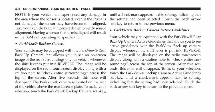
NOTE: If your vehicle has experienced any damage inthe area where the sensor is located, even if the fascia isnot damaged, the sensor may have become misaligned.Take your vehicle to an authorized dealer to verify sensoralignment. Having a sensor that is misaligned will resultin the BSM not operating to specification.
• ParkView® Backup Camera
Your vehicle may be equipped with the ParkView® RearBack Up Camera that allows you to see an on-screenimage of the rear surroundings of your vehicle wheneverthe shift lever is put into REVERSE. The image will bedisplayed on the radio touchscreen display along with acaution note to “check entire surroundings” across thetop of the screen. After five seconds, this note willdisappear. The ParkView® camera is located on the rearof the vehicle above the rear License plate. To make yourselection, touch the ParkView® Backup Camera soft-key,
until a check-mark appears next to setting, indicating thatthe setting had been selected. Touch the back arrowsoft-key to return to the previous menu.
• ParkView® Backup Camera Active Guidelines
Your vehicle may be equipped with the ParkView® RearBack Up Camera Active Guidelines that allows you to seeactive guidelines over the ParkView Back up cameradisplay whenever the shift lever is put into REVERSE.The image will be displayed on the radio touchscreendisplay along with a caution note to “check entire sur-roundings” across the top of the screen. After five sec-onds, this note will disappear. To make your selection,touch the ParkView® Backup Camera Active Guidelinessoft-key, until a check-mark appears next to setting,indicating that the setting had been selected. Touch theback arrow soft-key to return to the previous menu.
328 UNDERSTANDING YOUR INSTRUMENT PANEL

• ParkView® Backup Camera Static Gridlines
Your vehicle may be equipped with the ParkView® RearBack Up Camera Static Guidelines that allows you to seestraight grid line overlay over the ParkView Back upcamera display whenever the shift lever is put into RE-VERSE. The image will be displayed on the radio touch-screen display along with a caution note to “check entiresurroundings” across the top of the screen. After fiveseconds, this note will disappear. To make your selection,touch the ParkView® Backup Camera Static Gridlinessoft-key, until a check-mark appears next to setting, indi-cating that the setting had been selected. Touch the backarrow soft-key to return to the previous menu.
• ParkView® Backup Camera Fixed Guidelines
Your vehicle may be equipped with the ParkView® RearBack Up Camera Fixed Guidelines that allows you to seeFixed Guidelines over the ParkView Back up Cameradisplay whenever the shift lever is put into REVERSE.
The image will be displayed on the radio touchscreendisplay along with a caution note to “check entire sur-roundings” across the top of the screen. After five sec-onds, this note will disappear. To make your selection,touch the ParkView® Backup Camera Fixed Guidelinessoft-key, until a check-mark appears next to setting,indicating that the setting had been selected. Touch theback arrow soft-key to return to the previous menu.
• ParkView® Backup Camera Delay
When the vehicle is shifted out of REVERSE (with cameradelay turned OFF), the rear camera mode is exited andthe navigation or audio screen appears again. When thevehicle is shifted out of REVERSE (with camera delayturned ON), the rear view image with dynamic grid lineswill be displayed for up to 10 seconds after shifting out of“REVERSE” unless the forward vehicle speed exceeds8 mph (12 km/h), the transmission is shifted into“PARK” or the ignition is switched to the OFF position.
4
UNDERSTANDING YOUR INSTRUMENT PANEL 329

To set the ParkView® Backup Camera Delay press the“Controls” soft-key, the “settings” soft-key, then the“Safety & Driving Assistance” soft-key. Press the“Parkview Backup camera Delay” soft-key to turn theParkView® Delay ON or OFF.
• Rain Sensing Auto Wipers
When this feature is selected, the system will automaticallyactivate the windshield wipers if it senses moisture on thewindshield. To make your selection, touch the Rain Sensingsoft-key, until a check-mark appears next to setting, indi-cating that the setting had been selected. Touch the backarrow soft-key to return to the previous menu.
• Hill Start Assist — If Equipped
When this feature is selected, the Hill Start Assist (HSA)system is active. Refer to “Electronic Brake ControlSystem” in “Starting And Operating” for system functionand operating information. To make your selection, touchthe Hill Start Assist soft-key, until a check-mark appears
next to setting, indicating that the setting had beenselected. Touch the back arrow soft-key to return to theprevious menu.
• Brake Service
This feature will be grayed out while vehicle is in motion.When this feature is selected, it will allow the service ofthe rear brake components. To make your selection touchthe Brake Service soft-key, until a check-mark appearsnext to setting, indicating that the setting had beenselected. Touch the back arrow soft-key to return to theprevious menu.
• Auto Park Brake (automatic vehicles)
When this feature is selected, the vehicle will automati-cally set the Park Brake when the vehicle is shifted topark. To make your selection, touch the Auto Park Brakesoft-key, until a check-mark appears next to setting,indicating that the setting had been selected. Touch theback arrow soft-key to return to the previous menu.
330 UNDERSTANDING YOUR INSTRUMENT PANEL

• Auto Park Brake (manual vehicles)
When this feature is selected, the vehicle will automati-cally set the Park Brake at key off. To make your selection,touch the Auto Park Brake soft-key, until a check-markappears next to setting, indicating that the setting hadbeen selected. Touch the back arrow soft-key to return tothe previous menu.
• Hold ’n Go™
When this feature is selected, the vehicle will automati-cally hold its position when it comes to a stop. To makeyour selection, touch the Hold ’n Go™ soft-key until acheck-mark appears next to setting, indicating that thesetting had been selected. Touch the back arrow soft-keyto return to the previous menu.
Lights
After pressing the Lights soft-key the following settingswill be available.
• Interior Ambient Lights
When this feature is selected, it allows the adjustment ofthe brightness of the interior ambient lighting. To changethe Interior Ambient Lights setting, touch the + or -soft-key to select your desired Interior Ambient Lightlevel. Touch the back arrow soft-key to return to theprevious menu.
• Headlights Off Delay
When this feature is selected, it allows the adjustment ofthe amount of time the headlights remain on after theengine is shut off. To change the Headlights Off Delaysetting, touch the Headlights Off Delay soft-key, andchoose either 0, 30, 60 or 90 seconds. A check-markappears next to setting indicating that the setting hasbeen selected. Touch the back arrow soft-key to return tothe previous menu.
4
UNDERSTANDING YOUR INSTRUMENT PANEL 331

• Headlight Illumination On Approach
When this feature is selected, the headlights will activateand remain on for 0, 30, 60, or 90 seconds when the doorsare unlocked with the Remote Keyless Entry (RKE)transmitter. To change the Illuminated Approach status,touch the + or - soft-key to select your desired timeinterval. Touch the back arrow soft-key to return to theprevious menu.
• Headlights With Wipers — If Equipped
When this feature is selected, and the headlight switch isin the AUTO position, the headlights will turn on ap-proximately 10 seconds after the wipers are turned on.The headlights will also turn off when the wipers areturned off if they were turned on by this feature. To makeyour selection, touch the Headlights With Wipers soft-key, until a check-mark appears next to setting, indicatingthat the setting has been selected. Touch the back arrowsoft-key to return to the previous menu.
• Auto High Beams “SmartBeam™” — If Equipped
When this feature is selected, the high beam headlightswill activate/deactivate automatically under certain con-ditions. To make your selection, touch the Auto HighBeams soft-key, until a check-mark appears next tosetting, indicating that the setting has been selected.Touch the back arrow soft-key to return to the previousmenu. Refer to “Lights / SmartBeam™ — If Equipped”in “Understanding The Features Of Your Vehicle” forfurther information.
• Daytime Running Lights – If Equipped
When this feature is selected, the headlights will turn onwhenever the engine is running. To make your selection,touch the Daytime Running Lights soft-key, until acheck-mark appears next to setting, indicating that thesetting has been selected. Touch the back arrow soft-keyto return to the previous menu.
332 UNDERSTANDING YOUR INSTRUMENT PANEL

• Flash Headlights With Lock
When this feature is selected, the headlights will flashwhen the doors are locked or unlocked with the RemoteKeyless Entry (RKE) transmitter. This feature may beselected with or without the sound horn on lock featureselected. To make your selection, touch the Flash Head-lights with Lock soft-key, until a check-mark appearsnext to setting, indicating that the setting has beenselected. Touch the back arrow soft-key to return to theprevious menu.
Doors & Locks
After pressing the Doors & Locks soft-key the followingsettings will be available:
• Auto Unlock On Exit
When this feature is selected, all doors will unlock whenthe vehicle is stopped and the transmission is in thePARK or NEUTRAL position and the driver’s door is
opened. To make your selection, touch the Auto UnlockOn Exit soft-key, until a check-mark appears next tosetting, showing that setting has been selected. Touch theback arrow soft-key to return to the previous menu.
• Sound Horn With Lock
When this feature is selected, the horn will sound whenthe door locks are activated. To make your selection,touch the Sound Horn With Lock soft-key, until a check-mark appears next to setting, showing that setting hasbeen selected. Touch the back arrow soft-key to return tothe previous menu.
• Sound Horn With Remote Start
When this feature is selected, the horn will sound whenthe remote start is activated. To make your selection,touch the Sound Horn With Remote Start soft-key, until acheck-mark appears next to setting, showing that settinghas been selected. Touch the back arrow soft-key toreturn to the previous menu.
4
UNDERSTANDING YOUR INSTRUMENT PANEL 333

• 1st Press Of Key Fob Unlocks
When 1st Press Of Key Fob Unlocks is selected, only thedriver’s door will unlock on the first press of the RemoteKeyless Entry (RKE) transmitter UNLOCK button. When1st Press Of Key Fob Unlocks is selected, you must pressthe RKE transmitter UNLOCK button twice to unlock thepassenger’s doors. When Unlock All Doors On 1st Pressis selected, all of the doors will unlock on the first pressof the RKE transmitter UNLOCK button.
NOTE: If the vehicle is programmed 1st Press Of Key FobUnlocks, all doors will unlock no matter which PassiveEntry equipped door handle is grasped. If 1st Press OfKey Fob Unlocks is programmed, only the driver’s doorwill unlock when the driver’s door is grasped. WithPassive Entry, if 1st Press Of Key Fob Unlocks is pro-grammed, touching the handle more than once will onlyresult in the driver’s door opening. If driver door first isselected, once the driver door is opened, the interior door
lock/unlock switch can be used to unlock all doors (oruse RKE transmitter).
• Passive Entry
This feature allows you to lock and unlock the vehicle’sdoor(s) without having to press the Remote KeylessEntry (RKE) transmitter lock or unlock buttons. It auto-matically unlocks the doors when the outside doorhandle is grabbed. To make your selection, touch thePassive Entry soft-key until a check-mark appears next tosetting, showing that setting has been selected. Touch theback arrow soft-key to return to the previous menu. Referto “Keyless Enter-N-Go™” in “Things To Know BeforeStarting Your Vehicle” for further information.
• Memory To FOB — If Equipped
This feature provides automatic driver seat positioning toenhance driver mobility when entering and exiting thevehicle. To make your selection, touch the MemoryLinked To FOB soft-key, until a check-mark appears next
334 UNDERSTANDING YOUR INSTRUMENT PANEL

to setting, showing that setting has been selected. Touchthe back arrow soft-key to return to the previous menu.
NOTE: The seat will return to the memorized seatlocation (if Recall Memory with Remote Key Unlock is setto ON) when the Remote Keyless Entry (RKE) transmitteris used to unlock the door. Refer to “Driver MemorySeat” in “Understanding The Features Of Your Vehicle”for further information.
• Power Lift Gate Alert
This feature plays an alert when the power lift gate israising or lowering. To make your selection, touch thePower Lift Gate Alert soft-key until a check-mark ap-pears next to setting, showing that setting has beenselected. Touch the back arrow soft-key to return to theprevious menu. Refer to “Keyless Enter-N-Go™” in“Things To Know Before Starting Your Vehicle” forfurther information.
Auto-On Comfort & Remote Start
After pressing the Auto-On Comfort & Remote Startsoft-key the following settings will be available:
• Auto-On Driver Heated/Ventilated Seat & SteeringWheel With Vehicle Start — If Equipped
When this feature is selected the driver’s heated seat andheated steering wheel will automatically turn ON whentemperatures are below 40° F (4.4° C). When tempera-tures are above 80° F (26.7° C) the driver vented seat willturn ON. To make your selection, touch the Auto HeatedSeats soft-key, then select either Off, Remote Start or AllStarts until a check-mark appears next to setting, show-ing that setting has been selected. Touch the back arrowsoft-key to return to the previous menu.
4
UNDERSTANDING YOUR INSTRUMENT PANEL 335
Engine Off Options
After pressing the Engine Off Options soft-key the fol-lowing settings will be available:
• Engine Off Power Delay
When this feature is selected, the power windowswitches, radio, Uconnect® phone system (if equipped),DVD video system (if equipped), power sunroof (ifequipped), and power outlets will remain active for up to10 minutes after the ignition is cycled to OFF. Openingeither front door will cancel this feature. To change theEngine Off Power Delay status touch the 0 seconds, 45seconds, 5 minutes or 10 minutes soft-key. Then touch thearrow back soft-key.
• Headlight Off Delay
When this feature is selected, the driver can choose tohave the headlights remain on for 0, 30, 60, or 90 secondswhen exiting the vehicle. To change the Headlight Off
Delay status touch the + or - soft-key to select yourdesired time interval. Touch the back arrow soft-key toreturn to the previous menu.
Compass Settings – If Equipped
After pressing the Compass Settings soft-key the follow-ing settings will be available:
• Variance
Compass Variance is the difference between MagneticNorth and Geographic North. To compensate for thedifferences the variance should be set for the zone wherethe vehicle is driven, per the zone map. Once properlyset, the compass will automatically compensate for thedifferences, and provide the most accurate compassheading.
336 UNDERSTANDING YOUR INSTRUMENT PANEL

NOTE: Keep magnetic materials away from the top of theinstrument panel, such as iPod’s, Mobile Phones, Lap-tops and Radar Detectors. This is where the compassmodule is located, and it can cause interference with thecompass sensor, and it may give false readings.
• Perform Compass Calibration
Touch the Calibration soft-key to change this setting. Thiscompass is self-calibrating, which eliminates the need tomanually reset the compass. When the vehicle is new, thecompass may appear erratic and the EVIC will displayCAL until the compass is calibrated. You may alsocalibrate the compass by pressing the ON soft-key andcompleting one or more 360-degree turns (in an area freefrom large metal or metallic objects) until the CALindicator displayed in the EVIC turns off. The compasswill now function normally.
Audio
After pressing the Audio soft-key the following settingswill be available:
• Balance/Fade
When in this display you may adjust the Balance andFade settings.Compass Variance Map
4
UNDERSTANDING YOUR INSTRUMENT PANEL 337
• Equalizer
When in this display you may adjust the Bass, Mid andTreble settings. Adjust the settings with the + and –setting soft-keys or by selecting any point on the scalebetween the + and – soft-keys. Then touch the arrow backsoft-key.
NOTE: Bass/Mid/Treble allow you to simply slide yourfinger up or down to change the setting as well as touchdirectly on the desired setting.
• Speed Adjusted Volume
This feature increases or decreases volume relative tovehicle speed. To change the Speed Adjusted Volumetouch the Off, 1, 2 or 3 soft-key. Then touch the arrowback soft-key.
• Surround Sound
This feature provides simulated surround sound mode.To make your selection, touch the Surround Soundsoft-key, select On or Off followed by pressing the arrowback soft-key.
• AUX Volume Match — If Equipped
This feature provides the ability to tune the audio levelfor portable devices connected through the AUX input.To make your selection, touch the AUX Volume Matchsoft-key, select On or Off followed by pressing the arrowback soft-key.
• Loudness — If Equipped
The Radio automatically turns on when vehicle is in runor will recall whether it was on or off at last ignition off.To make your selection, touch the Loudness soft-key,select On or Off followed by pressing the arrow backsoft-key.
338 UNDERSTANDING YOUR INSTRUMENT PANEL

Phone/Bluetooth®
After pressing the Phone/Bluetooth® soft-key the fol-lowing settings will be available:
• Paired Devices
This feature shows which phones are paired to the Phone/ Bluetooth® system. For further information, refer toyour Uconnect® Supplement Manual.
Air Suspension – If Equipped
After pressing the Suspension soft-key the followingsettings will be available:
• Auto Entry/Exit Suspension
When this feature is selected, the vehicle automaticallylowers from ride height position when vehicle shifted topark for easy entry/exit. Touch the box next to your
selection and a check-mark appears next to the featureshowing the system has been activated or the check-markis removed showing the system has been deactivated.
• Suspension Display Messages
When All is selected, all the Air Suspension Alerts will bedisplayed. When Warnings Only is selected only the AirSuspension Warnings will be displayed.
• Tire Jack Mode
When this feature is selected the air suspension system isdisabled to prevent auto leveling of the suspension, whilethe vehicle is on a jack changing a tire. Touch the box nextto your selection and a check-mark appears next to thefeature showing the system has been activated or thecheck-mark is removed showing the system has beendeactivated.
4
UNDERSTANDING YOUR INSTRUMENT PANEL 339
• Transport Mode
When this feature is selected the air suspension system isdisabled to assist with flat bed towing. Touch the boxnext to your selection and a check-mark appears next tothe feature showing the system has been activated or thecheck-mark is removed showing the system has beendeactivated.
• Wheel Alignment Mode
This feature prevents auto leveling of the air suspensionwhile performing a wheel alignment service. Beforeperforming a wheel alignment this mode must be en-abled. Refer to your authorized dealer for further infor-mation.
SiriusXM Setup
After pressing the SIRIUS Setup soft-key the followingsettings will be available:
• Channel Skip
SiriusXM can be programmed to designate a group ofchannels that are the most desirable to listen to or toexclude undesirable channels while scanning. To makeyour selection, touch the Channel Skip soft-key, select thechannels you would like to skip followed by pressing thearrow back soft-key.
• Subscription Information
New vehicle purchasers or lessees will receive a freelimited time subscription to SiriusXM Satellite Radiowith your radio. Following the expiration of the freeservices, it will be necessary to access the information onthe Subscription Information screen in order to re-subscribe.
340 UNDERSTANDING YOUR INSTRUMENT PANEL

Touch the Subscription Info soft-key to access the Sub-scription Information screen.
Write down the SIRIUS ID numbers for your receiver. Toreactivate your service, either call the number listed onthe screen or visit the provider online.
NOTE: SiriusXM Travel Link is a separate subscriptionand is available for U.S. residents only.
Restore Settings
After pressing the Restore Settings soft-key the followingsettings will be available:
• Restore Settings
When this feature is selected it will reset Display, Clock,Audio, and Radio Settings to their default. To restore thesettings to their default setting touch the Yes or Nosoft-key. A check mark will appear in the box whenselected. Then touch the arrow back soft-key.
Clear Personal Data
After pressing the Clear Personal Data Settings soft-keythe following settings will be available:
• Clear Personal Data
When this feature is selected it will remove personal dataincluding Bluetooth® devices and presets. To Clear Per-sonal Data touch the Yes or No soft-key. A check markwill appear in the box when selected. Then touch thearrow back soft-key.
Customer Programmable Features — Uconnect®Access 8.4 Settings
Press the Apps soft-key, then press the Settings soft-key todisplay the menu setting screen. In this mode the Uconnect®Access system allows you to access programmable featuresthat may be equipped such as Display, Clock, Safety/Assistance, Lights, Doors & Locks, Auto-On Comfort &
4
UNDERSTANDING YOUR INSTRUMENT PANEL 341

Remote Start, Engine Off Operation, Compass Settings,Audio, Phone/Bluetooth and SiriusXM Setup.
NOTE: Only one touchscreen area may be selected at atime.
When making a selection, press the soft-key to enter thedesired mode. Once in the desired mode press andrelease the preferred setting until a check-mark appearsnext to the setting, showing that setting has been se-lected. Once the setting is complete either press the BackArrow soft-key or the Back hard-key to return to theprevious menu or press the X soft-key to close out of thesettings screen. Pressing the Up or Down Arrow soft-keyson the right side of the screen will allow you to toggle upor down through the available settings.
Display
After pressing the Display soft-key the following settingswill be available.
• Display Mode
When in this display you may select one of the autodisplay settings. To change Mode status, touch andrelease the Day, Night or Auto soft-key. Then touch thearrow back soft-key.
• Display Brightness With Headlights ON
When in this display, you may select the brightness withthe headlights on. Adjust the brightness with the + and –setting soft-keys or by selecting any point on the scalebetween the + and – soft-keys. Then touch the arrow backsoft-key.
342 UNDERSTANDING YOUR INSTRUMENT PANEL

• Display Brightness With Headlights OFF
When in this display, you may select the brightness withthe headlights off. Adjust the brightness with the + and –setting soft-keys or by selecting any point on the scalebetween the + and – soft-keys. Then touch the arrow backsoft-key.
• Set Theme
When in this display, you may select the theme displayedon the Uconnect® radio touch-screen. Themes availablefor selection are defined by the vehicle configuration.Touch the Set Theme soft-key then touch the desiredTheme soft-key until a check-mark appears next to thetheme, showing that setting has been selected. Touch thearrow back soft-key.
• Set Language
When in this display, you may select one of threelanguages for all display nomenclature, including the tripfunctions and the navigation system (if equipped). Touchthe Set Language soft-key and then touch the desiredlanguage soft-key until a check-mark appears next to thelanguage, showing that setting has been selected. Touchthe back arrow soft-key to return to the previous menu.
• Units
When in this display, you may select to have the EVIC,odometer, and navigation system (if equipped) changedbetween US and Metric units of measure. Touch US orMetric until a check-mark appears next to the setting,showing that setting has been selected. Touch the backarrow soft-key to return to the previous menu.
4
UNDERSTANDING YOUR INSTRUMENT PANEL 343
• Voice Response Length
When in this display, you may change the Voice Re-sponse Length settings. To change the Voice ResponseLength, touch the Brief or Detailed soft-key until acheck-mark appears next to the setting, showing thatsetting has been selected. Touch the back arrow soft-keyto return to the previous menu.
• Touchscreen Beep
When in this display, you may turn on or shut off thesound heard when a touch screen button (soft-key) ispressed. Touch the Touchscreen Beep soft-key until acheck-mark appears next to the setting, showing thatsetting has been selected. Touch the back arrow soft-keyto return to the previous menu.
• Navigation Turn-By-Turn In Cluster — If Equipped
When this feature is selected, the turn-by-turn directionswill appear in the display as the vehicle approaches adesignated turn within a programmed route. To makeyour selection, touch the Navigation Turn-By-Turn InCluster soft-key, until a check-mark appears next to thesetting, showing that setting has been selected. Touch theback arrow soft-key to return to the previous menu.
Clock
After pressing the Clock soft-key the following settingswill be available.
• Sync Time With GPS
When in this display, you may automatically have theradio set the time. To change the Sync Time setting touchthe Sync with GPS Time soft-key until a check-mark
344 UNDERSTANDING YOUR INSTRUMENT PANEL
appears next to the setting, showing that setting has beenselected. Touch the back arrow soft-key to return to theprevious menu.
• Set Time Hours
When in this display, you may adjust the hours. The Syncwith GPS Time soft-key must be unchecked. To makeyour selection touch the + or - soft-keys to adjust thehours up or down. Touch the back arrow soft-key toreturn to the previous menu or touch the X soft-key toclose out of the settings screen.
• Set Time Minutes
When in this display, you may adjust the minutes. TheSync with GPS Time soft-key must be unchecked. Tomake your selection touch the + or - soft-keys to adjustthe minutes up or down. Touch the back arrow soft-keyto return to the previous menu or touch the X soft-key toclose out of the settings screen.
• Time Format
When in this display, you may select the time formatdisplay setting. Touch the Time Format soft-key until acheck-mark appears next to the 12hrs or 24hrs setting,showing that setting has been selected. Touch the backarrow soft-key to return to the previous menu.
Safety / Assistance
After pressing the Safety / Assistance soft-key the fol-lowing settings will be available:
• Front Collision Sensitivity — If Equipped
The Front Collision Warning (FCW) feature provides anaudible and/or visual warning to potential forwardcollisions. The feature can be can be set to Far, or set toNear. The default status of FCW is the Far setting. Thismeans the system will warn you of a possible collisionwith the vehicle in front of you when you are fartheraway. This gives you the most reaction time. To change
4
UNDERSTANDING YOUR INSTRUMENT PANEL 345
the setting for more dynamic driving, select the Nearsetting. This warns you of a possible collision when youare much closer to the vehicle in front of you. To changethe FCW status, touch and release the Near or Far button.Then touch the arrow back soft-key.
For further information, refer to “Adaptive Cruise Con-trol (ACC)” in “Understanding The Features Of YourVehicle”.
• Forward Collision Warning (FCW) - Active Braking
The FCW system includes Advanced Brake Assist (ABA).When this feature is selected, the ABA applies additionalbrake pressure when the driver requests insufficientbrake pressure to avoid a potential frontal collision. TheABA system becomes active at 5 mph (8 km/h). To makeyour selection, touch the Forward Collision Warning(FCW) with Mitigation - Active Braking soft-key, until acheck-mark appears next to setting, indicating that thesetting had been selected. Touch the back arrow soft-key
to return to the previous menu. For further information,refer to “Forward Collision Warning (FCW) With Mitiga-tion” in “Understanding The Features Of Your Vehicle
• Lane Departure Warning (LDW) — If Equipped
The Lane Departure Warning (LDW) sets the distance atwhich the steering wheel will provide feedback forpotential lane departures. The LDW sensitivity can be setto provide either an early, medium or late warning zonestart point. To make your selection, touch the LaneDeparture Warning soft-key, until a check-mark appearsnext to setting, indicating that the setting had beenselected. Touch the back arrow soft-key to return to theprevious menu.
• Lane Departure Warning (LDW) Strength —If Equipped
When this feature is selected, it sets the strength of thesteering wheel feedback for potential lane departures.The amount of directional torque the steering system can
346 UNDERSTANDING YOUR INSTRUMENT PANEL

apply to the steering wheel to correct for vehicle lanedeparture can be set at Low, Medium or High. To makeyour selection, touch the Lane Departure Warning soft-key until a check-mark appears next to setting, indicatingthat the setting had been selected. Touch the back arrowsoft-key to return to the previous menu.
• ParkSense®
The ParkSense® system will scan for objects behind thevehicle when the transmission shift lever is in REVERSEand the vehicle speed is less than 11 mph (18 km/h). Itwill provide an alert (audible and/or visual) to indicatethe proximity to other objects. The system can be enabledwith Sound Only, or Sound and Display. To change theParkSense® status, touch and release the Sound Only orSounds and Display button. Then touch the arrow backsoft-key. Refer to “ParkSense®” in “Understanding TheFeatures Of Your Vehicle” for system function and oper-ating information.
• Front ParkSense® Chime Volume
The Front ParkSense® Chime Volume settings can beselected from the EVIC or Uconnect® System — ifequipped. The chime volume settings include LOW,MEDIUM, and HIGH. The factory default volume settingis MEDIUM. To make your selection, touch theParkSense® Front Chime Volume soft-key, until a check-mark appears next to setting, indicating that the settinghad been selected. Touch the back arrow soft-key toreturn to the previous menu. ParkSense® will retain itslast known configuration state through ignition cycles.
• Rear ParkSense® Chime Volume
The Rear ParkSense® Chime Volume settings can be se-lected from the EVIC or Uconnect® System — if equipped.The chime volume settings include LOW, MEDIUM, andHIGH. The factory default volume setting is MEDIUM. Tomake your selection, touch the ParkSense® Rear Chime
4
UNDERSTANDING YOUR INSTRUMENT PANEL 347

Volume soft-key, until a check-mark appears next to set-ting, indicating that the setting had been selected. Touchthe back arrow soft-key to return to the previous menu.ParkSense® will retain its last known configuration statethrough ignition cycles.
• ParkSense® Park Assist Braking
When this feature is selected, the park assist system willdetect objects located behind the vehicle and utilizeautonomous braking to stop the vehicle. To make yourselection, touch the ParkSense® Park Assist Brakingsoft-key, until a check-mark appears next to setting,indicating that the setting had been selected. Touch theback arrow soft-key to return to the previous menu. Referto “ParkSense® Rear Park Assist” in “Understanding TheFeatures Of Your Vehicle” for system function and oper-ating information.
• Tilt Mirrors In Reverse
When this feature is selected, the exterior sideviewmirrors will tilt downward when the ignition is in theRUN position and the transmission shift lever is in theREVERSE position. The mirrors will move back to theirprevious position when the transmission is shifted out ofREVERSE. To make your selection, touch the Tilt MirrorsIn Reverse soft-key, until a check-mark appears next tosetting, indicating that the setting had been selected.Touch the back arrow soft-key to return to the previousmenu.
• Paddle Shifting
Selecting this feature enables the use of steering wheelpaddle switches for shifting in manual mode. To makeyour selection, touch the Paddle Shifting soft-key, until acheck-mark appears next to setting, indicating that thesetting had been selected. Touch the back arrow soft-keyto return to the previous menu.
348 UNDERSTANDING YOUR INSTRUMENT PANEL

• Blind Spot Alert
When this feature is selected, the Blind Spot Alert featureProvides alerts, visual and/or audible, to indicate objectsin your blind spot. The Blind Spot Alert feature can beactivated in “Lights” mode. When this mode is selected,the Blind Spot Monitor (BSM) system is activated andwill only show a visual alert in the exterior mirrors.When “Lights & Chime” mode is activated, the BlindSpot Monitor (BSM) will show a visual alert in theexterior mirrors as well as an audible alert when the turnsignal is on. When “Off” is selected, the Blind SpotMonitor (BSM) system is deactivated. To change theBlind Spot Alert status, touch the Off, Lights or Lights &Chime soft-key. Then touch the arrow back soft-key.
NOTE: If your vehicle has experienced any damage inthe area where the sensor is located, even if the fascia isnot damaged, the sensor may have become misaligned.Take your vehicle to an authorized dealer to verify sensoralignment. Having a sensor that is misaligned will resultin the BSM not operating to specification.
• ParkView® Backup Camera
Your vehicle may be equipped with the ParkView® RearBack Up Camera that allows you to see an on-screenimage of the rear surroundings of your vehicle wheneverthe shift lever is put into REVERSE. The image will bedisplayed on the radio touchscreen display along with acaution note to “check entire surroundings” across thetop of the screen. After five seconds, this note willdisappear. The ParkView® camera is located on the rearof the vehicle above the rear License plate. To make yourselection, touch the ParkView® Backup Camera soft-key,
4
UNDERSTANDING YOUR INSTRUMENT PANEL 349

until a check-mark appears next to setting, indicating thatthe setting had been selected. Touch the back arrowsoft-key to return to the previous menu.
• ParkView® Backup Camera Active Guidelines
Your vehicle may be equipped with the ParkView® RearBack Up Camera Active Guidelines that allows you to seeactive guidelines over the ParkView Back up cameradisplay whenever the shift lever is put into REVERSE.The image will be displayed on the radio touchscreendisplay along with a caution note to “check entire sur-roundings” across the top of the screen. After five sec-onds, this note will disappear. To make your selection,touch the ParkView® Backup Camera Active Guidelinessoft-key, until a check-mark appears next to setting,indicating that the setting had been selected. Touch theback arrow soft-key to return to the previous menu.
• ParkView® Backup Camera Static Gridlines
Your vehicle may be equipped with the ParkView® RearBack Up Camera Static Guidelines that allows you to seestraight grid line overlay over the ParkView Back upcamera display whenever the shift lever is put intoREVERSE. The image will be displayed on the radiotouchscreen display along with a caution note to “checkentire surroundings” across the top of the screen. Afterfive seconds, this note will disappear. To make yourselection, touch the ParkView® Backup Camera StaticGridlines soft-key, until a check-mark appears next tosetting, indicating that the setting had been selected.Touch the back arrow soft-key to return to the previousmenu.
350 UNDERSTANDING YOUR INSTRUMENT PANEL

• ParkView® Backup Camera Fixed Guidelines
Your vehicle may be equipped with the ParkView® RearBack Up Camera Fixed Guidelines that allows you to seeFixed Guidelines over the ParkView Back up Cameradisplay whenever the shift lever is put into REVERSE.The image will be displayed on the radio touchscreendisplay along with a caution note to “check entire sur-roundings” across the top of the screen. After five sec-onds, this note will disappear. To make your selection,touch the ParkView® Backup Camera Fixed Guidelinessoft-key, until a check-mark appears next to setting,indicating that the setting had been selected. Touch theback arrow soft-key to return to the previous menu.
• ParkView® Backup Camera Delay
When the vehicle is shifted out of REVERSE (with cameradelay turned OFF), the rear camera mode is exited andthe navigation or audio screen appears again. When thevehicle is shifted out of REVERSE (with camera delay
turned ON), the rear view image with dynamic grid lineswill be displayed for up to 10 seconds after shifting out of“REVERSE” unless the forward vehicle speed exceeds8 mph (12 km/h), the transmission is shifted into“PARK” or the ignition is switched to the OFF position.To set the ParkView® Backup Camera Delay press the“Controls” soft-key, the “settings” soft-key, then the“Safety & Driving Assistance” soft-key. Press the“Parkview Backup camera Delay” soft-key to turn theParkView® Delay ON or OFF.
• Rain Sensing Auto Wipers
When this feature is selected, the system will automati-cally activate the windshield wipers if it senses moistureon the windshield. To make your selection, touch theRain Sensing soft-key, until a check-mark appears next tosetting, indicating that the setting had been selected.Touch the back arrow soft-key to return to the previousmenu.
4
UNDERSTANDING YOUR INSTRUMENT PANEL 351

• Hill Start Assist — If Equipped
When this feature is selected, the Hill Start Assist (HSA)system is active. Refer to “Electronic Brake ControlSystem” in “Starting And Operating” for system functionand operating information. To make your selection, touchthe Hill Start Assist soft-key, until a check-mark appearsnext to setting, indicating that the setting had beenselected. Touch the back arrow soft-key to return to theprevious menu.
• Brake Service
This feature will be grayed out while vehicle is in motion.When this feature is selected, it will allow the service ofthe rear brake components. To make your selection touchthe Brake Service soft-key, until a check-mark appearsnext to setting, indicating that the setting had beenselected. Touch the back arrow soft-key to return to theprevious menu.
• Auto Park Brake
When this feature is selected, the vehicle will automati-cally set the Park Brake when the vehicle is shifted topark. To make your selection, touch the Auto Park Brakesoft-key, until a check-mark appears next to setting,indicating that the setting had been selected. Touch theback arrow soft-key to return to the previous menu.
• Hold ’n Go™
When this feature is selected, the vehicle will automati-cally hold its position when it comes to a stop To makeyour selection, touch the Hold ’n Go™ soft-key, until acheck-mark appears next to setting, indicating that thesetting had been selected. Touch the back rrow soft-key toreturn to the previous menu.
352 UNDERSTANDING YOUR INSTRUMENT PANEL

Lights
After pressing the Lights soft-key the following settingswill be available.
• Headlight Illumination On Approach
When this feature is selected, the headlights will activateand remain on for 0, 30, 60, or 90 seconds when the doorsare unlocked with the Remote Keyless Entry (RKE)transmitter. To change the Illuminated Approach status,touch the + or - soft-key to select your desired timeinterval. Touch the back arrow soft-key to return to theprevious menu.
• Headlights With Wipers — If Equipped
When this feature is selected, and the headlight switch isin the AUTO position, the headlights will turn on ap-proximately 10 seconds after the wipers are turned on.The headlights will also turn off when the wipers areturned off if they were turned on by this feature. To make
your selection, touch the Headlights With Wipers soft-key, until a check-mark appears next to setting, showingthat setting has been selected. Touch the back arrowsoft-key to return to the previous menu.
• Auto Dim High Beams “SmartBeam™” — If Equipped
When this feature is selected, the high beam headlights willdeactivate automatically under certain conditions. To makeyour selection, touch the Auto High Beams soft-key, until acheck-mark appears next to setting, showing that settinghas been selected. Touch the back arrow soft-key to returnto the previous menu. Refer to “Lights / SmartBeam™ —If Equipped” in “Understanding The Features Of YourVehicle” for further information.
• Daytime Running Lights — If Equipped
When this feature is selected, the headlights will turn onwhenever the engine is running. To make your selection,touch the Daytime Running Lights soft-key, until a
4
UNDERSTANDING YOUR INSTRUMENT PANEL 353

check-mark appears next to setting, showing that settinghas been selected. Touch the back arrow soft-key toreturn to the previous menu.
• Flash Headlights With Lock
When this feature is selected, the headlights will flashwhen the doors are locked or unlocked with the RemoteKeyless Entry (RKE) transmitter. This feature may beselected with or without the sound horn on lock featureselected. To make your selection, touch the Flash Head-lights with Lock soft-key, until a check-mark appearsnext to setting, showing that setting has been selected.Touch the back arrow soft-key to return to the previousmenu.
Doors & Locks
After pressing the Doors & Locks soft-key the followingsettings will be available.
• Auto Unlock On Exit
When this feature is selected, all doors will unlock whenthe vehicle is stopped and the transmission is in thePARK or NEUTRAL position and the driver’s door isopened. To make your selection, touch the Auto UnlockOn Exit soft-key, until a check-mark appears next tosetting, showing that setting has been selected. Touch theback arrow soft-key to return to the previous menu.
• Sound Horn With Lock
When this feature is selected, the horn will sound whenthe door locks are activated. To make your selection,touch the Sound Horn With Lock soft-key, until a check-mark appears next to setting, showing that setting hasbeen selected. Touch the back arrow soft-key to return tothe previous menu.
354 UNDERSTANDING YOUR INSTRUMENT PANEL

• Sound Horn With Remote Start
When this feature is selected, the horn will sound whenthe remote start is activated. To make your selection,touch the Sound Horn With Remote Start soft-key, until acheck-mark appears next to setting, showing that settinghas been selected. Touch the back arrow soft-key toreturn to the previous menu.
• 1st Press Of Key Fob Unlocks
When 1st Press Of Key Fob Unlocks is selected, only thedriver’s door will unlock on the first press of the RemoteKeyless Entry (RKE) transmitter UNLOCK button. When1st Press Of Key Fob Unlocks is selected, you must pressthe RKE transmitter UNLOCK button twice to unlock thepassenger’s doors. When Unlock All Doors On 1st Pressis selected, all of the doors will unlock on the first pressof the RKE transmitter UNLOCK button.
NOTE: If the vehicle is programmed 1st Press Of Key FobUnlocks, all doors will unlock no matter which PassiveEntry equipped door handle is grasped. If 1st Press OfKey Fob Unlocks is programmed, only the driver’s doorwill unlock when the driver’s door is grasped. WithPassive Entry, if 1st Press Of Key Fob Unlocks is pro-grammed touching the handle more than once will onlyresult in the driver’s door opening. If driver door first isselected, once the driver door is opened, the interior doorlock/unlock switch can be used to unlock all doors (oruse RKE transmitter).
• Passive Entry
This feature allows you to lock and unlock the vehiclesdoor(s) without having to press the Remote KeylessEntry (RKE) transmitter lock or unlock buttons. To makeyour selection, touch the Passive Entry soft-key, until a
4
UNDERSTANDING YOUR INSTRUMENT PANEL 355

check-mark appears next to setting, showing that settinghas been selected. Touch the back arrow soft-key toreturn to the previous menu. Refer to “Keyless Enter-N-Go™” in “Things To Know Before Starting Your Vehicle”.
• Memory To FOB — If Equipped
This feature provides automatic driver seat positioning toenhance driver mobility when entering and exiting thevehicle. To make your selection, touch the MemoryLinked To FOB soft-key, until a check-mark appears nextto setting, showing that setting has been selected. Touchthe back arrow soft-key to return to the previous menu.
NOTE: The seat will return to the memorized seatlocation (if Recall Memory with Remote Key Unlock is setto ON) when the Remote Keyless Entry (RKE) transmitteris used to unlock the door. Refer to “Driver MemorySeat” in “Understanding The Features Of Your Vehicle”for further information.
Auto-On Comfort & Remote Start
After pressing the Auto-On Comfort & Remote Startsoft-key the following settings will be available.
• Horn With Remote Start
When this feature is selected, the horn will sound whenthe remote start is activated. To make your selection,touch the Sound Horn With Remote Start soft-key, until acheck-mark appears next to setting, showing that settinghas been selected. Touch the back arrow soft-key toreturn to the previous menu.
• Auto-On Driver Heated/Ventilated Seat & SteeringWheel With Vehicle Start — If Equipped
When this feature is selected the driver’s heated seat andheated steering wheel will automatically turn on whentemperatures are below 40° F (4.4° C). When tempera-tures are above 80° F (26.7° C) the driver vented seat willturn on. To make your selection, touch the Auto Heated
356 UNDERSTANDING YOUR INSTRUMENT PANEL

Seats soft-key, until a check-mark appears next to setting,showing that setting has been selected. Touch the backarrow soft-key to return to the previous menu.
Engine Off Options
After pressing the Engine Off Options soft-key the fol-lowing settings will be available.
• Engine Off Power Delay
When this feature is selected, the power window switches,radio, Uconnect® phone system (if equipped), DVD videosystem (if equipped), power sunroof (if equipped), andpower outlets will remain active for up to 10 minutes afterthe ignition is cycled to OFF. Opening either front door willcancel this feature. To change the Engine Off Power Delaystatus touch the 0 seconds, 45 seconds, 5 minutes or 10minutes soft-key. Then touch the arrow back soft-key.
• Headlight Off Delay
When this feature is selected, the driver can choose tohave the headlights remain on for 0, 30, 60, or 90 secondswhen exiting the vehicle. To change the Headlight OffDelay status touch the + or - soft-key to select yourdesired time interval. Touch the back arrow soft-key toreturn to the previous menu.
Compass Settings — If Equipped
After pressing the Compass Settings soft-key the follow-ing settings will be available.
• Variance
Compass Variance is the difference between MagneticNorth and Geographic North. To compensate for thedifferences the variance should be set for the zone wherethe vehicle is driven, per the zone map. Once properly set,the compass will automatically compensate for the differ-ences, and provide the most accurate compass heading.
4
UNDERSTANDING YOUR INSTRUMENT PANEL 357

NOTE: Keep magnetic materials away from the top ofthe instrument panel, such as iPod’s, Mobile Phones,Laptops and Radar Detectors. This is where the compassmodule is located, and it can cause interference with thecompass sensor, and it may give false readings.
• Perform Compass Calibration
Touch the Calibration soft-key to change this setting. Thiscompass is self-calibrating, which eliminates the need tomanually reset the compass. When the vehicle is new, thecompass may appear erratic and the EVIC will displayCAL until the compass is calibrated. You may alsocalibrate the compass by pressing the ON soft-key andcompleting one or more 360-degree turns (in an area freefrom large metal or metallic objects) until the CALindicator displayed in the EVIC turns off. The compasswill now function normally.
Audio
After pressing the Audio soft-key the following settingswill be available.
• Balance/Fade
When in this display you may adjust the Balance andFade settings.Compass Variance Map
358 UNDERSTANDING YOUR INSTRUMENT PANEL

• Equalizer
When in this display you may adjust the Bass, Mid andTreble settings. Adjust the settings with the + and –setting soft-keys or by selecting any point on the scalebetween the + and – soft-keys. Then touch the arrow backsoft-key.
NOTE: Bass/Mid/Treble allow you to simply slide yourfinger up or down to change the setting as well as touchdirectly on the desired setting.
• Speed Adjusted Volume
This feature increases or decreases volume relative tovehicle speed. To change the Speed Adjusted Volumetouch the Off, 1, 2 or 3 soft-key. Then touch the arrowback soft-key.
• Surround Sound — If Equipped
This feature provides simulated surround sound mode.To make your selection, touch the Surround Soundsoft-key, select On or Off followed by pressing the arrowback soft-key.
• AUX Volume Match — If Equipped
This feature provides the ability to tune the audio levelfor portable devices connected through the AUX input.To make your selection, touch the AUX Volume Matchsoft-key, select On or Off followed by pressing the arrowback soft-key.
4
UNDERSTANDING YOUR INSTRUMENT PANEL 359

• Loudness — If Equipped
The Radio automatically turns on when vehicle is in runor will recall whether it was on or off at last ignition off.To make your selection, touch the Loudness soft-key,select On or Off followed by pressing the arrow backsoft-key.
Phone/Bluetooth
After pressing the Phone/Bluetooth soft-key the follow-ing settings will be available:
• Paired Devices
This feature shows which phones are paired to thePhone/Bluetooth system. For further information, referto the Uconnect® Supplement Manual.
Air Suspension – If Equipped
After pressing the Suspension soft-key the followingsettings will be available.
• Auto Entry/Exit Suspension
When this feature is selected, the vehicle lowers thesuspension for easy entry/exit. Touch the box next toyour selection and a check-mark appears next to thefeature showing the system has been activated or thecheck-mark is removed showing the system has beendeactivated.
• Suspension Display Messages
When All is selected, all the Air Suspension Alerts will bedisplayed. When Warnings Only is selected only the AirSuspension Warnings will be displayed.
360 UNDERSTANDING YOUR INSTRUMENT PANEL

• Tire Jack Mode
When this feature is selected the air suspension system isdisabled to assist with changing a spare tire. Touch thebox next to your selection and a check-mark appears nextto the feature showing the system has been activated orthe check-mark is removed showing the system has beendeactivated.
• Transport Mode
When this feature is selected the air suspension system isdisabled to assist with flat bed towing. Touch the boxnext to your selection and a check-mark appears next tothe feature showing the system has been activated or thecheck-mark is removed showing the system has beendeactivated.
• Wheel Alignment Mode
Before performing a wheel alignment this mode must beenabled. Refer to your authorized dealer for furtherinformation.
SiriusXM Setup
After pressing the SIRIUS Setup soft-key the followingsettings will be available:
• Channel Skip
SiriusXM can be programmed to designate a group ofchannels that are the most desirable to listen to or toexclude undesirable channels while scanning. To makeyour selection, touch the Channel Skip soft-key, select thechannels you would like to skip followed by pressing thearrow back soft-key.
4
UNDERSTANDING YOUR INSTRUMENT PANEL 361

• Subscription Information
New vehicle purchasers or lessees will receive a freelimited time subscription to SiriusXM Satellite Radiowith your radio. Following the expiration of the freeservices, it will be necessary to access the information onthe Subscription Information screen in order to re-subscribe.
Touch the Subscription Info soft-key to access the Sub-scription Information screen.
Write down the SIRIUS ID numbers for your receiver. Toreactivate your service, either call the number listed onthe screen or visit the provider online.
NOTE: SiriusXM Travel Link is a separate subscriptionand is available for U.S. residents only.
Restore Settings
After pressing the Restore Settings soft-key the followingsettings will be available:
• Restore Settings
When this feature is selected it will reset Display, Clock,Audio, and Radio Settings to their default. To restore thesettings to their default setting touch the Yes or Nosoft-key. A check mark will appear in the box whenselected. Then touch the arrow back soft-key.
362 UNDERSTANDING YOUR INSTRUMENT PANEL

Clear Personal Data
After pressing the Clear Personal Data Settings soft-keythe following settings will be available:
• Clear Personal Data
When this feature is selected it will remove personal dataincluding Bluetooth® devices and presets. To Clear Per-sonal Data touch the Yes or No soft-key. A check markwill appear in the box when selected. Then touch thearrow back soft-key.
Uconnect® RADIOS — IF EQUIPPED
For detailed information about your Uconnect® radiorefer to your Uconnect® Supplement Manual.
iPod®/USB/MP3 CONTROL — IF EQUIPPED
Located inside the center console upper lid, this featureallows an iPod® or external USB device to be pluggedinto the USB port.
iPod® control supports Mini, 4G, Photo, Nano, 5G iPod®and iPhone® devices. Some iPod® software versionsmay not fully support the iPod® control features. Pleasevisit Apple’s website for software updates.
For further information, refer to the Uconnect® User’sManual.
STEERING WHEEL AUDIO CONTROLS —IF EQUIPPED
The remote sound system controls are located on the rearsurface of the steering wheel. Reach behind the wheel toaccess the switches.
4
UNDERSTANDING YOUR INSTRUMENT PANEL 363
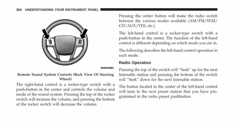
The right-hand control is a rocker-type switch with apush-button in the center and controls the volume andmode of the sound system. Pressing the top of the rockerswitch will increase the volume, and pressing the bottomof the rocker switch will decrease the volume.
Pressing the center button will make the radio switchbetween the various modes available (AM/FM/SXM/CD/AUX/VES, etc.).
The left-hand control is a rocker-type switch with apush-button in the center. The function of the left-handcontrol is different depending on which mode you are in.
The following describes the left-hand control operation ineach mode.
Radio Operation
Pressing the top of the switch will “Seek” up for the nextlistenable station and pressing the bottom of the switchwill “Seek” down for the next listenable station.
The button located in the center of the left-hand controlwill tune to the next preset station that you have pro-grammed in the radio preset pushbutton.
Remote Sound System Controls (Back View Of SteeringWheel)
364 UNDERSTANDING YOUR INSTRUMENT PANEL
CD Player
Pressing the top of the switch once will go to the nexttrack on the CD. Pressing the bottom of the switch oncewill go to the beginning of the current track, or to thebeginning of the previous track if it is within one secondafter the current track begins to play.
If you press the switch up or down twice, it plays thesecond track; three times, it will play the third, etc.
CD/DVD/BLU-RAY DISC MAINTENANCE
To keep a CD/DVD/Blu-ray disc in good condition, takethe following precautions:
1. Handle the disc by its edge; avoid touching thesurface.
2. If the disc is stained, clean the surface with a soft cloth,wiping from center to edge.
3. Do not apply paper or tape to the disc; avoid scratch-ing the disc.
4. Do not use solvents such as benzene, thinner, cleaners,or anti-static sprays.
5. Store the disc in its case after playing.
6. Do not expose the disc to direct sunlight.
7. Do not store the disc where temperatures may becometoo high.
NOTE: If you experience difficulty in playing a particulardisc, it may be damaged (i.e., scratched, reflective coatingremoved, a hair, moisture or dew on the disc) oversized,or have protection encoding. Try a known good discbefore considering disc player service.
4
UNDERSTANDING YOUR INSTRUMENT PANEL 365

RADIO OPERATION AND MOBILE PHONES
Under certain conditions, the mobile phone being on inyour vehicle can cause erratic or noisy performance fromyour radio. This condition may be lessened or eliminatedby relocating the mobile phone antenna. This condition isnot harmful to the radio. If your radio performance doesnot satisfactorily “clear” by the repositioning of theantenna, it is recommended that the radio volume beturned down or off during mobile phone operation whennot using Uconnect® (if equipped).
CLIMATE CONTROLS
The air conditioning and heating system is designed tomake you comfortable in all types of weather. Thissystem can be operated through either the controls on theinstrument panel or through the Uconnect® system dis-play.
When the Uconnect® system is in different modes (Ra-dio, Player, Settings, More, etc.) the driver and passengertemperature settings will be indicated at the top of thedisplay.
366 UNDERSTANDING YOUR INSTRUMENT PANEL

General Overview
Hard-Keys
The hard-keys are located below the Uconnect® screen.
Soft-Keys
Soft-keys are accessible on the Uconnect® system screen.
Automatic Climate Controls — Hard-keys
Uconnect® 5.0 Automatic Temperature Controls —Soft-keys
4
UNDERSTANDING YOUR INSTRUMENT PANEL 367

Button Descriptions (Applies To Both Hard-keys AndSoft-keys)
1. MAX A/C Button
Press and release to change the current setting, theindicator illuminates when MAX A/C is ON. Performingthis function again will cause the MAX A/C operation toswitch into manual mode and the MAX A/C indicatorwill turn off.
2. A/C Button
Press and release to change the current setting, theindicator illuminates when A/C is ON. Performing thisfunction again will cause the A/C operation to switchinto manual mode and the A/C indicator will turn off.
3. Recirculation Button
Press and release to change the current setting, theindicator illuminates when ON.
Uconnect® 8.4 Automatic Temperature Controls —Soft-keys
368 UNDERSTANDING YOUR INSTRUMENT PANEL

4. AUTO Operation Button
Automatically controls the interior cabin temperature byadjusting airflow distribution and amount. Performingthis function will cause the ATC to switch betweenmanual mode and automatic modes. Refer to “AutomaticOperation” for more information.
5. Front Defrost Button
Press and release to change the current airflow setting toDefrost mode. The indicator illuminates when this fea-ture is ON. Performing this function will cause the ATCto switch into manual mode. The blower speed mayincrease when Defrost mode is selected. If the frontdefrost mode is turned off the climate system will returnthe previous setting.
6. Rear Defrost Button
Press and release this button to turn on the rear windowdefroster and the heated outside mirrors (if equipped).An indicator will illuminate when the rear windowdefroster is on. The rear window defroster automaticallyturns off after 10 minutes.
CAUTION!
Failure to follow these cautions can cause damage tothe heating elements:• Use care when washing the inside of the rear
window. Do not use abrasive window cleaners onthe interior surface of the window. Use a soft clothand a mild washing solution, wiping parallel to theheating elements. Labels can be peeled off aftersoaking with warm water.
(Continued)
4
UNDERSTANDING YOUR INSTRUMENT PANEL 369

CAUTION! (Continued)• Do not use scrapers, sharp instruments, or abrasive
window cleaners on the interior surface of thewindow.
• Keep all objects a safe distance from the window.
7. Passenger Temperature Control Up Button
Provides the passenger with independent temperaturecontrol. Push the hard-key button for warmer tempera-ture settings or on the touch-screen, press and slide thesoft-key temperature bar towards the red arrow soft-keyfor warmer temperature settings.
NOTE: Pressing this button while in Sync mode willautomatically exit Sync.
8. Passenger Temperature Control Down Button
Provides the passenger with independent temperaturecontrol. Push the hard-key button for cooler temperaturesettings or on the touch-screen, press and slide thesoft-key temperature bar towards the blue arrow soft-keyfor cooler temperature settings.
NOTE: Pressing this button while in Sync mode willautomatically exit Sync.
9. SYNC
Press the Sync soft-key to toggle the Sync feature On/Off.The Sync indicator is illuminated when this feature isenabled. Sync is used to synchronize the passengertemperature setting with the driver temperature setting.Changing the passenger temperature setting while inSync will automatically exit this feature.
370 UNDERSTANDING YOUR INSTRUMENT PANEL

10. Blower Control
Blower control is used to regulate the amount of airforced through the climate system. There are sevenblower speeds available. Adjusting the blower will causeautomatic mode to switch to manual operation. Thespeeds can be selected using either hard-keys or soft-keysas follows:
Hard-key
The blower speed increases as you turn the controlclockwise from the lowest blower setting. The blowerspeed decreases as you turn the knob counter-clockwise.
Soft-key
Use the small blower icon to reduce the blower settingand the large blower icon to increase the blower setting.Blower can also be selected by pressing the blower bararea between the icons.
11. Modes
The airflow distribution mode can be adjusted so aircomes from the instrument panel outlets, floor outlets,demist outlets and defrost outlets. The Mode settings areas follows:Panel Mode
Air comes from the outlets in the instrumentpanel. Each of these outlets can be individually
adjusted to direct the flow of air. The air vanes of thecenter outlets and outboard outlets can be moved up anddown or side to side to regulate airflow direction. Thereis a shut off wheel located below the air vanes to shut offor adjust the amount of airflow from these outlets.
4
UNDERSTANDING YOUR INSTRUMENT PANEL 371

Bi-Level Mode
Air comes from the instrument panel outlets andfloor outlets. A slight amount of air is directed
through the defrost and side window demister outlets.
NOTE: BI-LEVEL mode is designed under comfort con-ditions to provide cooler air out of the panel outlets andwarmer air from the floor outlets.Floor Mode
Air comes from the floor outlets. A slight amountof air is directed through the defrost and side
window demister outlets.Mix Mode
Air comes from the floor, defrost and side windowdemist outlets. This mode works best in cold orsnowy conditions.
Defrost Mode
Air comes from the windshield and side windowdemist outlets. Use Defrost mode with maximum
temperature settings for best windshield and side win-dow defrosting and defogging. When the defrost mode isselected, the blower level may will increase.
12. Climate Control OFF Button
Press and release this button to turn the Climate ControlON/OFF.
13. Driver Temperature Control Down Button
Provides the driver with independent temperature con-trol. Push the hard-key button for cooler temperaturesettings or on the touch-screen, press and slide thesoft-key temperature bar towards the blue arrow soft-keyfor cooler temperature settings.
372 UNDERSTANDING YOUR INSTRUMENT PANEL

NOTE: In Sync mode, this button will also automaticallyadjust the passenger temperature setting at the sametime.
14. Driver Temperature Control Up Button
Provides the driver with independent temperature con-trol. Push the hard-key button for warmer temperaturesettings or on the touch-screen, press and slide thesoft-key temperature bar towards the red arrow soft-keyfor warmer temperature settings.
NOTE: In Sync mode, this button will also automaticallyadjust the passenger temperature setting at the sametime.
15. Temperature Control (5.0 Radio Only)
Press the temperature soft-key to regulate the tempera-ture of the air inside the passenger compartment. Movingthe temperature bar into the red area, indicates warmertemperatures. Moving the temperature bar into the bluearea indicates cooler temperatures.
Climate Control Functions
A/C (Air Conditioning)
The Air Conditioning (A/C) button allows the operatorto manually activate or deactivate the air conditioningsystem. When the air conditioning system is turned on,cool dehumidified air will flow through the outlets intothe cabin. For improved fuel economy, press the A/Cbutton to turn off the air conditioning and manuallyadjust the blower and airflow mode settings. Also, makesure to select only Panel, Bi-Level or Floor modes.
4
UNDERSTANDING YOUR INSTRUMENT PANEL 373

NOTE:
• If fog or mist appears on the windshield or side glass,select Defrost mode and increase blower speed.
• If your air conditioning performance seems lower thanexpected, check the front of the A/C condenser (lo-cated in front of the radiator), for an accumulation ofdirt or insects. Clean with a gentle water spray frombehind the radiator and through the condenser. Fabricfront fascia protectors may reduce airflow to thecondenser, reducing air conditioning performance.
MAX A/C
MAX A/C sets the control for maximum cooling perfor-mance.
Press and release to toggle between MAX A/C and theprior settings. The soft-key illuminates when MAX A/Cis ON.
In MAX A/C, the blower level and mode position can beadjusted to desired user settings. Pressing other settingswill cause the MAX A/C operation to switch to the priorsettings and the MAX A/C indicator will turn off.
Recirculation
When outside air contains smoke, odors, orhigh humidity, or if rapid cooling is desired,you may wish to recirculate interior air bypressing the Recirculation control button. The
recirculation indicator will illuminate when this button isselected. Push the button a second time to turn off theRecirculation mode and allow outside air into the vehicle.
374 UNDERSTANDING YOUR INSTRUMENT PANEL

NOTE: In cold weather, use of Recirculation mode maylead to excessive window fogging. The recirculation featuremay be unavailable (soft button greyed out). The Recircu-lation mode is not allowed in Defrost mode to improvewindow clearing operation. Recirculation will be disabledautomatically if this mode is selected. Attempting to useRecirculation while in this mode will cause the LED in thecontrol button to blink and then turn off.
Automatic Temperature Control (ATC)
Automatic Operation
1. Press the AUTO hard-key or soft-key button (4) on theAutomatic Temperature Control (ATC) Panel.
2. Next, adjust the temperature you would like thesystem to maintain by adjusting the driver and pas-senger temperature hard or soft control buttons (7, 8,13, 14). Once the desired temperature is displayed, thesystem will achieve and automatically maintain thatcomfort level.
3. When the system is set up for your comfort level, it isnot necessary to change the settings. You will experi-ence the greatest efficiency by simply allowing thesystem to function automatically.
NOTE:
• It is not necessary to move the temperature settings forcold or hot vehicles. The system automatically adjuststhe temperature, mode, and blower speed to providecomfort as quickly as possible.
• The temperature can be displayed in U.S. or Metric unitsby selecting the Uconnect® customer-programmablefeature. Refer to the “Uconnect® System Settings” in thissection of the manual.
To provide you with maximum comfort in the Automaticmode, during cold start-ups the blower fan will remainon low until the engine warms up. The blower willincrease in speed and transition into Auto mode.
4
UNDERSTANDING YOUR INSTRUMENT PANEL 375

Manual Operation
The system allows for manual selection of blower speed,air distribution mode, A/C status and recirculation con-trol.
The blower fan speed can be set to any fixed speed byadjusting the blower control. The fan will now operate ata fixed speed until additional speeds are selected. Thisallows the front occupants to control the volume of aircirculated in the vehicle and cancel the Auto mode.
The operator can also select the direction of the airflowby selecting one of the available mode settings. A/Coperation and Recirculation control can also be manuallyselected in Manual operation.
Operating Tips
NOTE: Refer to the chart at the end of this section forsuggested control settings for various weather condi-tions.
Summer Operation
The engine cooling system must be protected with ahigh-quality antifreeze coolant to provide proper corro-sion protection and to protect against engine overheating.A solution of 50% OAT (Organic Additive Technology)coolant that meets the requirements of Chrysler MaterialStandard MS-12106 and 50% water is recommended.Refer to “Maintenance Procedures” in “Maintaining YourVehicle” for proper coolant selection.
Winter Operation
Use of the air Recirculation mode during Winter months isnot recommended because it may cause window fogging.
Vacation Storage
Any time you store your vehicle or keep it out of service(i.e., vacation) for two weeks or more, run the airconditioning system at idle for about five minutes in thefresh air and high blower setting. This will ensure
376 UNDERSTANDING YOUR INSTRUMENT PANEL

adequate system lubrication to minimize the possibilityof compressor damage when the system is started again.
Window Fogging
Interior fogging on the windshield can be quickly re-moved by turning the mode selector to Defrost. TheDefrost/Floor mode can be used to maintain a clearwindshield and provide sufficient heating. If side win-dow fogging becomes a problem increase blower speed.Vehicle windows tend to fog on the inside in mild butrainy or humid weather.
NOTE:
• Recirculate without A/C should not be used for longperiods, as fogging may occur.
• Automatic Temperature Controls (ATC) will automati-cally adjust the climate control settings to reduce oreliminate window fogging on the front windshield.When this occurs, recirculation will be unavailable.
Outside Air Intake
Make sure the air intake, located directly in front of thewindshield, is free of obstructions such as leaves. Leavescollected in the air intake may reduce airflow, and if theyenter the plenum, they could plug the water drains. InWinter months, make sure the air intake is clear of ice,slush, and snow.
A/C Air Filter
The climate control system filters outside air containingdust, pollen and some odors. Strong odors cannot betotally filtered out. Refer to “Maintenance Procedures” in“Maintaining Your Vehicle” for filter replacement instruc-tions.
4
UNDERSTANDING YOUR INSTRUMENT PANEL 377

Control Setting Suggestions for Various Weather Conditions
378 UNDERSTANDING YOUR INSTRUMENT PANEL

STARTING AND OPERATING
CONTENTS� STARTING PROCEDURES . . . . . . . . . . . . . . . .385
▫ Automatic Transmission . . . . . . . . . . . . . . . .385
▫ Keyless Enter-N-Go™ . . . . . . . . . . . . . . . . . .386
▫ Normal Starting. . . . . . . . . . . . . . . . . . . . . . .387
▫ Extreme Cold Weather(Below –20°F Or −29°C) . . . . . . . . . . . . . . . .388
▫ If Engine Fails To Start . . . . . . . . . . . . . . . . .389
▫ After Starting . . . . . . . . . . . . . . . . . . . . . . . .390
� ENGINE BLOCK HEATER — IF EQUIPPED . . .390
� AUTOMATIC TRANSMISSION . . . . . . . . . . . .391
▫ Key Ignition Park Interlock. . . . . . . . . . . . . . .392
▫ Brake/Transmission Shift Interlock System . . .393
▫ Fuel Economy (ECO) Mode . . . . . . . . . . . . . .393
▫ Eight–Speed Automatic Transmission . . . . . . .394
� FOUR-WHEEL DRIVE OPERATION . . . . . . . . .404
▫ Quadra-Trac I® Operating Instructions/Precautions – If Equipped . . . . . . . . . . . . . . .404
▫ Quadra-Trac II® Operating Instructions/Precautions – If Equipped . . . . . . . . . . . . . . .405
▫ Shift Positions . . . . . . . . . . . . . . . . . . . . . . . .406
5

▫ Shifting Procedures . . . . . . . . . . . . . . . . . . . .407
▫ Quadra-Drive® II System – If Equipped. . . . . .412
� SELEC-TERRAIN™ — IF EQUIPPED . . . . . . . .412
▫ Description . . . . . . . . . . . . . . . . . . . . . . . . . .412
▫ Electronic Vehicle Information Center (EVIC)Display Messages . . . . . . . . . . . . . . . . . . . . .414
� QUADRA-LIFT™ — IF EQUIPPED . . . . . . . . . .414
▫ Description . . . . . . . . . . . . . . . . . . . . . . . . . .414
▫ Air Suspension Modes . . . . . . . . . . . . . . . . . .419
▫ Electronic Vehicle Information Center (EVIC)Display Messages . . . . . . . . . . . . . . . . . . . . .420
▫ Operation . . . . . . . . . . . . . . . . . . . . . . . . . . .420
� ON-ROAD DRIVING TIPS . . . . . . . . . . . . . . . .422
� OFF-ROAD DRIVING TIPS . . . . . . . . . . . . . . .422
▫ Quadra-Lift™ – If Equipped . . . . . . . . . . . . . .423
▫ When To Use 4WD LOW Range –If Equipped. . . . . . . . . . . . . . . . . . . . . . . . . .423
▫ Driving Through Water . . . . . . . . . . . . . . . . .424
▫ Driving In Snow, Mud And Sand . . . . . . . . . .425
▫ Hill Climbing . . . . . . . . . . . . . . . . . . . . . . . .426
▫ Traction Downhill . . . . . . . . . . . . . . . . . . . . .427
▫ After Driving Off-Road . . . . . . . . . . . . . . . . .427
� POWER STEERING . . . . . . . . . . . . . . . . . . . . .428
▫ 3.6L Engine . . . . . . . . . . . . . . . . . . . . . . . . . .428
▫ 5.7L Engine . . . . . . . . . . . . . . . . . . . . . . . . . .430
▫ Power Steering Fluid Check . . . . . . . . . . . . . .431
380 STARTING AND OPERATING

� FUEL SAVER TECHNOLOGY 5.7L ENGINEONLY – IF EQUIPPED . . . . . . . . . . . . . . . . . . .432
� PARKING BRAKE . . . . . . . . . . . . . . . . . . . . . .432
� ELECTRONIC BRAKE CONTROL SYSTEM . . . .434
▫ Anti-Lock Brake System (ABS) . . . . . . . . . . . .435
▫ Traction Control System (TCS) . . . . . . . . . . . .435
▫ Brake Assist System (BAS) . . . . . . . . . . . . . . .436
▫ Electronic Roll Mitigation (ERM) . . . . . . . . . .437
▫ Electronic Stability Control (ESC) . . . . . . . . . .438
▫ Trailer Sway Control (TSC) . . . . . . . . . . . . . .441
▫ Hill Start Assist (HSA) . . . . . . . . . . . . . . . . .441
▫ Ready Alert Braking – If Equipped . . . . . . . . .444
▫ Rain Brake Support – If Equipped . . . . . . . . . .444
▫ Hill Descent Control (HDC) — If Equipped(Four-Wheel Drive Models With MP3023Two-Speed Transfer Case Only) . . . . . . . . . . .445
▫ Select Speed Control (SSC) — If Equipped(Four-Wheel Drive Models With MP3023Two-Speed Transfer Case Only) . . . . . . . . . . .449
▫ ESC Activation/Malfunction IndicatorLight And ESC OFF Indicator Light . . . . . . . .453
� TIRE SAFETY INFORMATION . . . . . . . . . . . . .454
▫ Tire Markings . . . . . . . . . . . . . . . . . . . . . . . .454
▫ Tire Identification Number (TIN). . . . . . . . . . .458
▫ Tire Terminology And Definitions . . . . . . . . . .459
▫ Tire Loading And Tire Pressure . . . . . . . . . . .460
� TIRES — GENERAL INFORMATION . . . . . . . .465
▫ Tire Pressure . . . . . . . . . . . . . . . . . . . . . . . .465
5
STARTING AND OPERATING 381
▫ Tire Inflation Pressures . . . . . . . . . . . . . . . . .466
▫ Tire Pressures For High Speed Operation . . . .468
▫ Radial Ply Tires . . . . . . . . . . . . . . . . . . . . . .468
▫ All Season Tires – If Equipped . . . . . . . . . . . .469
▫ Summer Or Three Season Tires – If Equipped. . .469
▫ Snow Tires . . . . . . . . . . . . . . . . . . . . . . . . . .469
▫ Spare Tire Matching Original Equipped TireAnd Wheel – If Equipped. . . . . . . . . . . . . . . .470
▫ Compact Spare Tire – If Equipped . . . . . . . . .470
▫ Full Size Spare – If Equipped . . . . . . . . . . . . .471
▫ Limited-Use Spare – If Equipped . . . . . . . . . .471
▫ Tire Spinning . . . . . . . . . . . . . . . . . . . . . . . .472
▫ Tread Wear Indicators . . . . . . . . . . . . . . . . . .472
▫ Life Of Tire . . . . . . . . . . . . . . . . . . . . . . . . .473
▫ Replacement Tires . . . . . . . . . . . . . . . . . . . . .474
� TIRE CHAINS (TRACTION DEVICES) . . . . . . .475
� TIRE ROTATION RECOMMENDATIONS . . . . .477
� TIRE PRESSURE MONITOR SYSTEM (TPMS) . . .478
▫ Tire Pressure Monitoring Low PressureWarnings . . . . . . . . . . . . . . . . . . . . . . . . . . .481
▫ SERVICE TPM SYSTEM Warning . . . . . . . . . .483
▫ General Information . . . . . . . . . . . . . . . . . . .485
� FUEL REQUIREMENTS . . . . . . . . . . . . . . . . . .486
▫ 3.6L Engine – If Equipped . . . . . . . . . . . . . . .486
▫ 5.7L Engine – If Equipped . . . . . . . . . . . . . . .486
▫ Reformulated Gasoline . . . . . . . . . . . . . . . . .487
382 STARTING AND OPERATING

▫ Gasoline/Oxygenate Blends . . . . . . . . . . . . . .487
▫ E-85 Usage In Non-Flex Fuel Vehicles . . . . . . .488
▫ MMT In Gasoline . . . . . . . . . . . . . . . . . . . . .489
▫ Materials Added To Fuel . . . . . . . . . . . . . . . .489
▫ Fuel System Cautions. . . . . . . . . . . . . . . . . . .490
▫ Carbon Monoxide Warnings . . . . . . . . . . . . .491
� FLEXIBLE FUEL (3.6L ENGINE ONLY) —IF EQUIPPED . . . . . . . . . . . . . . . . . . . . . . . . .491
▫ E-85 General Information . . . . . . . . . . . . . . .491
▫ Ethanol Fuel (E-85) . . . . . . . . . . . . . . . . . . . .492
▫ Fuel Requirements . . . . . . . . . . . . . . . . . . . .492
▫ Selection Of Engine Oil For Flexible FuelVehicles (E-85) And Gasoline Vehicles . . . . . . .493
▫ Starting . . . . . . . . . . . . . . . . . . . . . . . . . . . .494
▫ Cruising Range . . . . . . . . . . . . . . . . . . . . . . .494
▫ Replacement Parts . . . . . . . . . . . . . . . . . . . .494
▫ Maintenance . . . . . . . . . . . . . . . . . . . . . . . .494
� ADDING FUEL . . . . . . . . . . . . . . . . . . . . . . . .495
▫ Emergency Fuel Filler Door Release. . . . . . . . .497
� VEHICLE LOADING . . . . . . . . . . . . . . . . . . . .498
▫ Certification Label . . . . . . . . . . . . . . . . . . . .498
� TRAILER TOWING . . . . . . . . . . . . . . . . . . . . .501
▫ Common Towing Definitions . . . . . . . . . . . . .501
▫ Trailer Hitch Classification . . . . . . . . . . . . . . .504
▫ Trailer Towing Weights (Maximum TrailerWeight Ratings) . . . . . . . . . . . . . . . . . . . . . .505
▫ Trailer And Tongue Weight . . . . . . . . . . . . . .506
5
STARTING AND OPERATING 383
▫ Towing Requirements . . . . . . . . . . . . . . . . . .507
▫ Towing Tips . . . . . . . . . . . . . . . . . . . . . . . . .512
� SNOW PLOW . . . . . . . . . . . . . . . . . . . . . . . . .514
� RECREATIONAL TOWING (BEHINDMOTORHOME, ETC.) . . . . . . . . . . . . . . . . . . .515
▫ Towing This Vehicle Behind Another Vehicle . .515
▫ Recreational Towing – Two-Wheel DriveModels . . . . . . . . . . . . . . . . . . . . . . . . . . . . .516
▫ Recreational Towing – Quadra–Trac II® /Quadra–Drive® II Four-Wheel DriveModels . . . . . . . . . . . . . . . . . . . . . . . . . . . . .517
384 STARTING AND OPERATING

STARTING PROCEDURES
Before starting your vehicle, adjust your seat, adjust theinside and outside mirrors, fasten your seat belt, and ifpresent, instruct all other occupants to buckle their seat belts.
WARNING!
Never leave children alone in a vehicle, or with access toan unlocked vehicle. Leaving children in a vehicleunattended is dangerous for a number of reasons. Achild or others could be seriously or fatally injured.Children should be warned not to touch the parkingbrake, brake pedal or the shift lever. Do not leave thekey fob in or near the vehicle (or in a location accessibleto children), and do not leave the ignition of a vehicleequipped with Keyless Enter-N-Go™ ACC or RUNmode. A child could operate power windows, othercontrols, or move the vehicle.
Automatic Transmission
The shift lever must be in the NEUTRAL or PARKposition before you can start the engine. Apply the brakesbefore shifting into any driving gear.
CAUTION!
Damage to the transmission may occur if the follow-ing precautions are not observed:• Do not shift from REVERSE, PARK, or NEUTRAL
into any forward gear when the engine is aboveidle speed.
• Shift into PARK only after the vehicle has come toa complete stop.
• Shift into or out of REVERSE only after the vehiclehas come to a complete stop and the engine is atidle speed.
• Before shifting into any gear, make sure your footis firmly on the brake pedal.
5
STARTING AND OPERATING 385

Using Fob With Integrated Key (Tip Start)
NOTE: Normal starting of either a cold or a warmengine is obtained without pumping or pressing theaccelerator pedal.
Do not press the accelerator. Use the Fob with IntegratedKey to briefly turn the ignition switch to the STARTposition and release it as soon as the starter engages. Thestarter motor will continue to run, and it will disengageautomatically when the engine is running. If the enginefails to start, the starter will disengage automatically in 10seconds. If this occurs, turn the ignition switch to theLOCK position, wait 10 to 15 seconds, then repeat the“Normal Starting” procedure.
Keyless Enter-N-Go™
This feature allows the driver to oper-ate the ignition switch with the pushof a button, as long as the RemoteStart/Keyless Enter-N-Go™ Key Fobis in the passenger compartment.
386 STARTING AND OPERATING

Normal Starting
Using The ENGINE START/STOP Button
1. The transmission must be in PARK or NEUTRAL.
2. Press and hold the brake pedal while pressing theENGINE START/STOP button once.
3. The system takes over and attempts to start thevehicle. If the vehicle fails to start, the starter willdisengage automatically after 10 seconds.
4. If you wish to stop the cranking of the engine prior tothe engine starting, press the button again.
NOTE: Normal starting of either a cold or a warmengine is obtained without pumping or pressing theaccelerator pedal.
To Turn Off The Engine Using ENGINESTART/STOP Button
1. Place the shift lever/shift selector in PARK, then pressand release the ENGINE START/STOP button.
2. The ignition switch will return to the OFF position.
3. If the shift lever/shift selector is not in PARK, theENGINE START/STOP button must be held for twoseconds and vehicle speed must be above 5 mph(8 km/h) before the engine will shut off. The ignitionswitch position will remain in the ACC position untilthe shift lever/shift selector is in PARK and the buttonis pressed twice to the OFF position. If the shiftlever/shift selector is not in PARK and the ENGINESTART/STOP button is pressed once, the EVIC (ifequipped) will display a “Vehicle Not In Park” mes-sage and the engine will remain running. Never leavea vehicle out of the PARK position, or it could roll.
5
STARTING AND OPERATING 387

NOTE: If the ignition switch is left in the ACC or RUN(engine not running) position and the transmission is inPARK, the system will automatically time out after 30minutes of inactivity and the ignition will switch to theOFF position.
ENGINE START/STOP Button Functions – WithDriver’s Foot OFF The Brake Pedal (In PARK OrNEUTRAL Position)
The ENGINE START/STOP button operates similar to anignition switch. It has four positions, OFF, ACC, RUNand START. To change the ignition switch positionswithout starting the vehicle and use the accessoriesfollow these steps.
• Starting with the ignition switch in the OFF position:
• Press the ENGINE START/STOP button once tochange the ignition switch to the ACC position (EVICwill display “ACC”),
• Press the ENGINE START/STOP button a second timeto change the ignition switch to the RUN position(EVIC will display “ON/RUN”),
• Press the ENGINE START/STOP button a third time toreturn the ignition switch to the OFF position (EVICwill display “OFF”).
Extreme Cold Weather (Below –20°F Or −29°C)
To ensure reliable starting at these temperatures, use ofan externally powered electric engine block heater (avail-able from your authorized dealer) is recommended.
388 STARTING AND OPERATING

If Engine Fails To Start
WARNING!
• Never pour fuel or other flammable liquid into thethrottle body air inlet opening in an attempt to startthe vehicle. This could result in flash fire causingserious personal injury.
• Do not attempt to push or tow your vehicle to get itstarted. Vehicles equipped with an automatic trans-mission cannot be started this way. Unburned fuelcould enter the catalytic converter and once theengine has started, ignite and damage the converterand vehicle.
(Continued)
WARNING! (Continued)• If the vehicle has a discharged battery, booster
cables may be used to obtain a start from a boosterbattery or the battery in another vehicle. This typeof start can be dangerous if done improperly. Referto “Jump Starting” in “What To Do In Emergen-cies” for further information.
Clearing A Flooded Engine (Using ENGINESTART/STOP Button)
If the engine fails to start after you have followed the“Normal Starting” or “Extreme Cold Weather� proce-dures, it may be flooded. To clear any excess fuel:
1. Press and hold the brake pedal.
2. Press the accelerator pedal all the way to the floor andhold it.
5
STARTING AND OPERATING 389

3. Press and release the ENGINE START/STOP buttononce.
The starter motor will engage automatically, run for 10seconds, and then disengage. Once this occurs, releasethe accelerator pedal and the brake pedal, wait 10 to 15seconds, then repeat the “Normal Starting” procedure.
After Starting
The idle speed is controlled automatically and it willdecrease as the engine warms up.
ENGINE BLOCK HEATER — IF EQUIPPED
The engine block heater warms the engine, and permitsquicker starts in cold weather. Connect the cord to astandard 110-115 Volt AC electrical outlet with agrounded, three-wire extension cord.
The engine block heater must be plugged in at least onehour to have an adequate warming effect on the engine.
The engine block heater cord is located:
• 3.6L Engine – coiled and strapped to the engine oildipstick tube.
• 5.7L Engine – bundled and fastened to the injectorharness.
WARNING!
Remember to disconnect the engine block heatercord before driving. Damage to the 110-115 Voltelectrical cord could cause electrocution.
390 STARTING AND OPERATING

AUTOMATIC TRANSMISSION
CAUTION!
Damage to the transmission may occur if the follow-ing precautions are not observed:• Shift into PARK only after the vehicle has come to
a complete stop.• Shift into or out of REVERSE only after the vehicle
has come to a complete stop and the engine is atidle speed.
• Do not shift between PARK, REVERSE, NEU-TRAL, or DRIVE when the engine is above idlespeed.
• Before shifting into any gear, make sure your footis firmly pressing the brake pedal.
NOTE: You must press and hold the brake pedal whileshifting out of PARK.
WARNING!
• Unintended movement of a vehicle could injurethose in or near the vehicle. As with all vehicles,you should never exit a vehicle while the engine isrunning. Before exiting a vehicle, always apply theparking brake, shift the transmission into PARK,turn the engine OFF, and remove the key fob. Whenthe ignition is in the OFF position, the transmis-sion is locked in PARK, securing the vehicleagainst unwanted movement.
(Continued)
5
STARTING AND OPERATING 391

WARNING! (Continued)• It is dangerous to shift out of PARK or NEUTRAL
if the engine speed is higher than idle speed. Ifyour foot is not firmly pressing the brake pedal, thevehicle could accelerate quickly forward or in re-verse. You could lose control of the vehicle and hitsomeone or something. Only shift into gear whenthe engine is idling normally and your foot isfirmly pressing the brake pedal.
• When leaving the vehicle, always remove the keyfob and lock your vehicle.
• Never leave children alone in a vehicle, or withaccess to an unlocked vehicle. Allowing children tobe in a vehicle unattended is dangerous for anumber of reasons. A child or others could beseriously or fatally injured.
(Continued)
WARNING! (Continued)• Children should be warned not to touch the park-
ing brake, brake pedal or the shift lever.• Do not leave the key fob in or near the vehicle (or
in a location accessible to children), and do notleave the ignition of a vehicle equipped withKeyless Enter-N-Go in the ACC or ON/RUN posi-tion. A child could operate power windows, othercontrols, or move the vehicle.
Key Ignition Park Interlock
This vehicle is equipped with a Key Ignition Park Inter-lock which requires the transmission to be in PARKbefore the engine can be turned off. This helps the driveravoid inadvertently leaving the vehicle without placingthe transmission in PARK.
This system also locks the transmission in PARK when-ever the ignition switch is in the OFF position.
392 STARTING AND OPERATING

Brake/Transmission Shift Interlock System
This vehicle is equipped with a Brake Transmission ShiftInterlock System (BTSI) that holds the shift lever in PARKunless the brakes are applied. To shift the transmissionout of PARK, the engine must be running and the brakepedal must be pressed.
The brake pedal must also be pressed to shift fromNEUTRAL into DRIVE or REVERSE when the vehicle isstopped or moving at low speeds.
Fuel Economy (ECO) Mode
The Fuel Economy (ECO) mode can improve the vehi-cle’s overall fuel economy during normal driving condi-tions. Press the “eco” switch in the center stack of theinstrument panel and a green light will indicate the ECOmode is engaged.
When the Fuel Economy (ECO) Mode is engaged, thevehicle control systems will change the following:
• The transmission will upshift sooner and downshiftlater.
Fuel Economy Mode Switch
5
STARTING AND OPERATING 393

• The overall driving performance will be more conser-vative.
• Some ECO mode functions may be temporarily inhib-ited based on temperature and other factors.
NOTE: When Sport Mode is enabled, the vehicle’s airsuspension system will operate in “Aero” Mode. Pleaserefer to “Quadra Lift” within this section for furtherinformation.
Eight–Speed Automatic Transmission
Your vehicle is equipped with a state of the art, fuelefficient eight-speed transmission. The electronic shiftlever in this vehicle does not slide like a conventionalshifter. Instead, the shift lever is spring loaded and movesforward and rearward, always returning to the centerposition after each gear is selected. The transmission gear(PRND) is displayed both on the shift lever and in theElectronic Vehicle Information Center (EVIC). To select a
gear range, press the lock button on the shift lever andmove the lever rearward or forward. You must press thebrake pedal to shift the transmission out of PARK, or toshift from NEUTRAL into DRIVE or REVERSE when thevehicle is stopped or moving at low speeds (refer to“Brake/Transmission Shift Interlock System” in this sec-tion). To shift past multiple gear ranges at once (such asPARK to DRIVE), move the lever past the first (or second)detent. Select the DRIVE range for normal driving.
The electronically-controlled transmission provides aprecise shift schedule. The transmission electronics areself-calibrating; therefore, the first few shifts on a newvehicle may be somewhat abrupt. This is a normalcondition, and precision shifts will develop within a fewhundred miles (kilometers).
Only shift from DRIVE to PARK or REVERSE when theaccelerator pedal is released and the vehicle is stopped.Be sure to keep your foot on the brake pedal whenshifting between these gears.
394 STARTING AND OPERATING

The transmission shift lever provides PARK, REVERSE,NEUTRAL, DRIVE and SPORT shift positions. Once inthe DRIVE range, tapping the shift lever rearward willtoggle between SPORT mode and DRIVE mode. You donot need to press the shift lever button when togglingbetween DRIVE and SPORT modes. Manual shifts can bemade using the shift paddles mounted on the steeringwheel. Pressing the shift paddles (-/+) while in theDRIVE or SPORT position will manually select the trans-mission gear, and will display the current gear in theinstrument cluster. Refer to �Paddle Shift Mode� in thissection for further information.
Gear Ranges
DO NOT race the engine when shifting from PARK orNEUTRAL into another gear range.
Shift Lever
5
STARTING AND OPERATING 395

NOTE: After selecting any gear range, wait a moment toallow the selected gear to engage before accelerating.This is especially important when the engine is cold.
PARK
This range supplements the parking brake by locking thetransmission. The engine can be started in this range.Never attempt to use PARK while the vehicle is inmotion. Apply the parking brake when leaving thevehicle in this range.
When parking on a level surface, you may shift thetransmission into PARK first, and then apply the parkingbrake.
When parking on a hill, apply the parking brake beforeshifting the transmission to PARK. As an added precau-tion, turn the front wheels toward the curb on a downhillgrade and away from the curb on an uphill grade.
NOTE: On four-wheel drive vehicles be sure that thetransfer case is in a drive position.
WARNING!
• Never use the PARK position as a substitute for theparking brake. Always apply the parking brakefully when parked to guard against vehicle move-ment and possible injury or damage.
• Your vehicle could move and injure you and othersif it is not in PARK. Make sure the transmission isin PARK before leaving the vehicle.
(Continued)
396 STARTING AND OPERATING

WARNING! (Continued)• It is dangerous to shift out of PARK or NEUTRAL
if the engine speed is higher than idle speed. Ifyour foot is not firmly pressing the brake pedal, thevehicle could accelerate quickly forward or in re-verse. You could lose control of the vehicle and hitsomeone or something. Only shift into gear whenthe engine is idling normally and your foot isfirmly pressing the brake pedal.
(Continued)
WARNING! (Continued)• Unintended movement of a vehicle could injure
those in or near the vehicle. As with all vehicles,you should never exit a vehicle while the engine isrunning. Before exiting a vehicle, always apply theparking brake, shift the transmission into PARK,turn the engine OFF, and remove the key fob. Whenthe ignition is in the OFF position, the transmis-sion is locked in PARK, securing the vehicleagainst unwanted movement.
• When leaving the vehicle, always remove the keyfob and lock your vehicle.
(Continued)
5
STARTING AND OPERATING 397

WARNING! (Continued)• Never leave children alone in a vehicle, or with
access to an unlocked vehicle. Allowing children tobe in a vehicle unattended is dangerous for anumber of reasons. A child or others could beseriously or fatally injured. Children should bewarned not to touch the parking brake, brake pedalor the transmission shifter. Do not leave the keyfob in or near the vehicle (or in a location accessibleto children), and do not leave the ignition (in avehicle equipped with Keyless Enter-N-Go™) inthe ACC or ON/RUN position. A child could oper-ate power windows, other controls, or move thevehicle.
(Continued)
WARNING! (Continued)• Do not leave the key fob in or near the vehicle (or
in a location accessible to children), and do notleave the ignition (of a vehicle equipped withKeyless Enter-N-Go™) in the ACC or ON/RUNposition. A child could operate power windows,other controls, or move the vehicle.
• Before moving the shift lever out of PARK, youmust start the engine, and also press the brakepedal. Otherwise, damage to the shift lever couldresult.
CAUTION!
• DO NOT race the engine when shifting fromPARK or NEUTRAL into another gear range, as thiscan damage the drivetrain.
(Continued)
398 STARTING AND OPERATING

CAUTION! (Continued)• Before moving the shift lever out of PARK, you
must start the engine, and also press the brakepedal. Otherwise, damage to the shift lever couldresult.
The following indicators should be used to ensure thatyou have engaged the transmission into the PARK posi-tion:
• When shifting into PARK, press the lock button on theshift lever and push the lever all the way forward untilit stops. When released, the lever will return to itshome position.
• With brake pedal released, look at the transmissiongear position display and verify that it indicates thePARK position.
REVERSE
This range is for moving the vehicle backward. Shift intoREVERSE only after the vehicle has come to a completestop.
NEUTRAL
Use this range when the vehicle is standing for prolongedperiods with the engine running. The engine may bestarted in this range. Apply the parking brake and shiftthe transmission into PARK if you must leave the vehicle.
WARNING!
Do not coast in NEUTRAL and never turn off theignition to coast down a hill. These are unsafepractices that limit your response to changing trafficor road conditions. You might lose control of thevehicle and have a collision.
5
STARTING AND OPERATING 399

CAUTION!
Towing the vehicle, coasting, or driving for any otherreason with the transmission in NEUTRAL can causesevere transmission damage. Refer to “RecreationalTowing” in “Starting And Operating” and “Towing ADisabled Vehicle” in “What To Do In Emergencies”for further information.
DRIVE
This range should be used for most city and highwaydriving. It provides the smoothest upshifts and down-shifts, and the best fuel economy. The transmissionautomatically upshifts through all forward gears. TheDRIVE position provides optimum driving characteris-tics under all normal operating conditions.
When frequent transmission shifting occurs (such aswhen operating the vehicle under heavy loading condi-tions, in hilly terrain, traveling into strong head winds, orwhile towing heavy trailers), use the Paddle Shiftswitches (refer to �Paddle Shift Mode� in this section) toselect a lower gear. Under these conditions, using a lowergear will improve performance and extend transmissionlife by reducing excessive shifting and heat buildup.
During extremely cold temperatures (-22°F [-30°C] orbelow), transmission operation may be modified depend-ing on engine and transmission temperature as well asvehicle speed. Normal operation will resume once thetransmission temperature has risen to a suitable level.
SPORT
This mode alters the transmission’s automatic shiftschedule for sportier driving. Upshift speeds are in-creased to make full use of available engine power. To
400 STARTING AND OPERATING

switch between DRIVE and SPORT modes, tap the shiftlever rearward. SPORT mode is only accessible fromDRIVE.
NOTE: When Sport Mode is enabled, the vehicle’s airsuspension system will operate in “Aero” Mode. Pleaserefer to “Quadra Lift” within this section for furtherinformation.
Transmission Limp Home Mode
Transmission function is monitored electronically forabnormal conditions. If a condition is detected that couldresult in transmission damage, Transmission Limp HomeMode is activated. In this mode, the transmission mayoperate only in certain gears, or may not shift at all.Vehicle performance may be severely degraded and theengine may stall. In some situations, the transmissionmay not re-engage if the engine is turned off andrestarted. The Malfunction Indicator Light (MIL) may be
illuminated. A message in the instrument cluster willinform the driver of the more serious conditions, andindicate what actions may be necessary.
In the event of a momentary problem, the transmissioncan be reset to regain all forward gears by performing thefollowing steps:
NOTE: In cases where the instrument cluster messageindicates the transmission may not re-engage after en-gine shutdown, perform this procedure only in a desiredlocation (preferably, at your authorized dealer).
1. Stop the vehicle.
2. Shift the transmission into PARK, if possible. If not,shift the transmission to NEUTRAL.
3. Turn the ignition switch to the OFF position. Onvehicles with Keyless Enter-N-Go™, press and holdthe ignition switch until the engine turns OFF.
5
STARTING AND OPERATING 401
4. Wait approximately 30 seconds.
5. Restart the engine.
6. Shift into the desired gear range. If the problem is nolonger detected, the transmission will return to normaloperation.
NOTE: Even if the transmission can be reset, we recom-mend that you visit your authorized dealer at your earliestpossible convenience. Your authorized dealer has diagnos-tic equipment to determine if the problem could recur.
If the transmission cannot be reset, authorized dealerservice is required.
Paddle Shift Mode
Paddle Shift mode is a driver-interactive transmissionfeature providing manual shift control, giving you morecontrol of the vehicle. Paddle Shift allows you to maxi-mize engine braking, eliminate undesirable upshifts and
downshifts, and improve overall vehicle performance.This system can also provide you with more controlduring passing, city driving, cold slippery conditions,mountain driving, trailer towing, and many other situa-tions.
Operation
When the transmission is in DRIVE or SPORT mode, itwill operate automatically, shifting between the eightavailable gears. To engage Paddle Shift mode, simply tapone of the steering wheel-mounted shift paddles (+/-)while in DRIVE or SPORT mode. Tapping (-) to enterPaddle Shift mode will downshift the transmission to thenext lower gear, while using (+) to enter Paddle Shiftmode will retain the current gear. When Paddle Shiftmode is active, the current transmission gear is displayedin the instrument cluster.
402 STARTING AND OPERATING

In Paddle Shift mode, the transmission will shift up ordown when (+/-) is manually selected by the driver,unless an engine lugging or overspeed condition wouldresult. It will remain in the selected gear until anotherupshift or downshift is chosen, except as describedbelow.
• The transmission will automatically downshift as thevehicle slows (to prevent engine lugging) and willdisplay the current gear.
• The transmission will automatically downshift to firstgear when coming to a stop. After a stop, the drivershould manually upshift (+) the transmission as thevehicle is accelerated.
• You can start out, from a stop, in first or second gear(or third gear, in 4LO range, Snow mode, or Sandmode). Tapping (+) at a stop will allow starting insecond gear. Starting out in second gear is helpful insnowy or icy conditions.
• If a requested downshift would cause the engine toover-speed, that shift will not occur.
• The system will ignore attempts to upshift at too lowof a vehicle speed.
• Holding the (-) paddle depressed will progressivelydownshift the transmission to the lowest gear possibleat the current speed.
• Transmission shifting will be more noticeable whenPaddle Shift mode is enabled.
• The system may revert to automatic shift mode if afault or overheat condition is detected.
NOTE: When Selec-Speed or Hill Descent Control isenabled, Paddle Shift mode is not active. Pressing the(+/-) shift paddles in Selec-Speed or Hill Descent Controlsimply limits the highest allowed gear. Shifts below andup to that gear will occur automatically.
5
STARTING AND OPERATING 403

To disengage Paddle Shift mode, press and hold the (+)shift paddle until �D� or �S� is once again displayed in theinstrument cluster. You can shift in or out of Paddle Shiftmode at any time without taking your foot off theaccelerator pedal.
WARNING!
Do not downshift for additional engine braking on aslippery surface. The drive wheels could lose theirgrip and the vehicle could skid, causing a collision orpersonal injury.
FOUR-WHEEL DRIVE OPERATION
Quadra-Trac I® Operating Instructions/Precautions – If Equipped
The Quadra-Trac I® is a single-speed (HI range only)transfer case, which provides convenient full-time four-wheel drive. No driver interaction is required. The BrakeTraction Control (BTC) System, which combines standardABS and Traction Control, provides resistance to anywheel that is slipping to allow additional torque transferto wheels with traction.
NOTE: The Quadra-Trac I® system is not appropriatefor conditions where 4WD LOW range is recommended.Refer to “Off-Road Driving Tips” in “Starting and Oper-ating” for further information.
404 STARTING AND OPERATING

Quadra-Trac II® Operating Instructions/Precautions – If Equipped
The Quadra-Trac II® transfer case is fully automatic inthe normal driving 4WD AUTO mode. The Quadra-TracII® transfer case provides three mode positions:
• 4WD HI
• NEUTRAL
• 4WD LOW
This transfer case is fully automatic in the 4WD HI mode.
When additional traction is required, the 4WD LOWposition can be used to lock the front and rear driveshaftstogether and force the front and rear wheels to rotate atthe same speed. The 4WD LOW position is intended forloose, slippery road surfaces only. Driving in the 4WDLOW position on dry, hard-surfaced roads may causeincreased tire wear and damage to driveline components.
When operating your vehicle in 4WD LOW, the enginespeed is approximately three times that of the 4WD HIposition at a given road speed. Take care not to overspeedthe engine and do not exceed 25 mph (40 km/h).
Proper operation of four-wheel drive vehicles dependson tires of equal size, type, and circumference on eachwheel. Any difference will adversely affect shifting andcause damage to the transfer case.
Because four-wheel drive provides improved traction,there is a tendency to exceed safe turning and stoppingspeeds. Do not go faster than road conditions permit.
WARNING!
You or others could be injured if you leave thevehicle unattended with the transfer case in theNEUTRAL (N) position without first fully engaging
(Continued)
5
STARTING AND OPERATING 405

WARNING! (Continued)the parking brake. The transfer case NEUTRAL (N)position disengages both the front and rear driveshafts from the powertrain and will allow the vehicleto move regardless of the transmission position. Theparking brake should always be applied when thedriver is not in the vehicle.
Shift Positions
For additional information on the appropriate use of each4WD system mode position, see the information below:
4WD AUTO
This range is used on surfaces such as ice, snow, gravel,sand, and dry hard pavement.
NOTE: Refer to “Selec-Terrain® – If Equipped” in “Start-ing and Operating” for further information on the vari-ous positions and their intended usages.
NEUTRAL
This range disengages the driveline from the powertrain.It is to be used for flat towing behind another vehicle.Refer to “Recreational Towing” in “Starting and Operat-ing” for further information.
4WD LOW
This range is for low speed four-wheel drive. It forces thefront and rear wheels to rotate at the same speed. Itprovides additional traction and maximum pullingpower for loose, slippery road surfaces only. Do notexceed 25 mph (40 km/h).
NOTE: Refer to “Selec-Terrain® – If Equipped” for fur-ther information on the various positions and theirintended usages.
406 STARTING AND OPERATING

Shifting Procedures
4WD HI To 4WD LOW
With the vehicle at speeds of 0 to 3 mph (0 to 5 km/h), theignition switch in the ON position or the engine running,shift the transmission into NEUTRAL, and press the“4WD LOW” button once on the transfer case switch. The“4WD LOW” indicator light in the instrument clusterwill begin to flash and remain on solid when the shift iscomplete.
Transfer Case Switch
5
STARTING AND OPERATING 407

NOTE: If shift conditions/interlocks are not met, or atransfer case motor temperature protection conditionexists, a “For 4x4 Low Slow Below 3 mph (5 km/h) PutTrans in N Press 4 Low” message will flash from theElectronic Vehicle Information Center (EVIC). Refer to“Electronic Vehicle Information Center (EVIC)” in “Un-derstanding Your Instrument Panel” for further informa-tion.
4WD LOW To 4WD HI
With the vehicle at speeds of 0 to 3 mph (0 to 5 km/h), theignition switch in the ON position or the engine running,shift the transmission into NEUTRAL, and press the“4WD LOW” button once on the transfer case switch. The“4WD LOW” indicator light in the instrument clusterwill flash and go out when the shift is complete.
NOTE:
• If shift conditions/interlocks are not met, or a transfercase motor temperature protection condition exists, a“For 4x4 High Slow Below 3 mph (5 km/h) Put Transin N Press 4 Low” message will flash from the Elec-tronic Vehicle Information Center (EVIC). Refer to“Electronic Vehicle Information Center (EVIC)” in“Understanding Your Instrument Panel” for furtherinformation.
• Shifting into or out of 4WD LOW is possible with thevehicle completely stopped; however, difficulty mayoccur due to the mating clutch teeth not being prop-erly aligned. Several attempts may be required forclutch teeth alignment and shift completion to occur.The preferred method is with the vehicle rolling 0 to3 mph (0 to 5 km/h). If the vehicle is moving fasterthan 3 mph (5 km/h), the transfer case will not allowthe shift.
408 STARTING AND OPERATING

Shifting Into NEUTRAL (N)
WARNING!
You or others could be injured or killed if you leavethe vehicle unattended with the transfer case in theNEUTRAL position without first fully engaging theparking brake. The transfer case NEUTRAL positiondisengages both the front and rear drive shafts fromthe powertrain and will allow the vehicle to moveregardless of the transmission position. The parkingbrake should always be applied when the driver isnot in the vehicle.
1. Bring the vehicle to a complete stop, with the enginerunning.
2. Press and hold the brake pedal.
3. Shift the transmission into NEUTRAL.
4. If vehicle is equipped with Quadra-Lift™ air suspen-sion, ensure the vehicle is set to Normal Ride Height.
5. Using a ballpoint pen or similar object, press and holdthe recessed transfer case NEUTRAL (N) button (locatedby the selector switch) for four seconds. The lightbehind the N symbol will blink, indicating shift inprogress. The light will stop blinking (stay on solid)when the shift to NEUTRAL (N) is complete. A “FOURWHEEL DRIVE SYSTEM IN NEUTRAL” message willdisplay on the EVIC (Electronic Vehicle InformationCenter). Refer to “Electronic Vehicle Information Center(EVIC)” in “Understanding Your Instrument Panel” forfurther information.
5
STARTING AND OPERATING 409

6. After the shift is completed and the NEUTRAL (N)light stays on, release the NEUTRAL (N) button.
7. Shift the transmission into REVERSE.
8. Release the brake pedal for five seconds and ensurethat there is no vehicle movement.
NOTE: If shift conditions/interlocks are not met, a “ToTow Vehicle Safely, Read Neutral Shift Procedure inOwners Manual” message will flash from the ElectronicVehicle Information Center (EVIC). Refer to “ElectronicVehicle Information Center (EVIC)” in “UnderstandingYour Instrument Panel” for further information.
Shifting Out Of NEUTRAL (N)
Use the following procedure to prepare your vehicle fornormal usage.
1. Bring the vehicle to a complete stop.
2. Firmly apply the parking brake.
3. Start the engine.
4. Press and hold the brake pedal.
5. Shift the transmission into NEUTRAL.
NEUTRAL (N) Switch
410 STARTING AND OPERATING

6. Using a ballpoint pen or similar object, press and holdthe recessed transfer case NEUTRAL (N) button (lo-cated by the selector switch) for one second.
7. When the NEUTRAL (N) indicator light turns off,release the NEUTRAL (N) button.
8. After the NEUTRAL (N) button has been released, thetransfer case will shift to the position indicated by theselector switch.
9. Shift the transmission into PARK. Turn the engineOFF.
10. Release the brake pedal.
11. Disconnect vehicle from the tow vehicle.
NOTE:
• Steps 1 through 5 are requirements that must be metprior to pressing the NEUTRAL (N) button, and mustcontinue to be met until the shift has been completed.If any of these requirements are not met prior topressing the NEUTRAL (N) button or are no longermet during the shift, the NEUTRAL (N) indicator lightwill flash continuously until all requirements are metor until the NEUTRAL (N) button is released.
NEUTRAL (N) Switch
5
STARTING AND OPERATING 411

• The ignition switch must be in the ON/RUN positionfor a shift to take place and for the position indicatorlights to be operable. If the ignition switch is not in theON/RUN position, the shift will not take place and noposition indicator lights will be on or flashing.
• A flashing NEUTRAL (N) position indicator lightindicates that shift requirements have not been met.
Quadra-Drive® II System – If Equipped
The optional Quadra-Drive® II System features twotorque transfer couplings. The couplings include anElectronic Limited-Slip Differential (ELSD) rear axle andthe Quadra-Trac II® transfer case. The optional ELSDaxle is fully automatic and requires no driver input tooperate. Under normal driving conditions, the unit func-tions as a standard axle, balancing torque evenly between
left and right wheels. With a traction difference betweenleft and right wheels, the coupling will sense a speeddifference. As one wheel begins to spin faster than theother, torque will automatically transfer from the wheelthat has less traction, to the wheel that has traction. Whilethe transfer case and axle coupling differ in design, theiroperation is similar. Follow the Quadra-Trac II® transfercase shifting information, preceding this section, forshifting this system.
SELEC-TERRAIN™ — IF EQUIPPED
Description
Selec-Terrain™ combines the capabilities of the vehiclecontrol systems, along with driver input, to provide thebest performance for all terrains.
412 STARTING AND OPERATING

Selec-Terrain™ consists of the following positions:
• Snow – Tuning set for additional stability in inclementweather. Use on and off road on loose traction surfacessuch as snow. When in Snow mode (depending oncertain operating conditions), the transmission mayuse second gear (rather than first gear) during
launches, to minimize wheel slippage. If equippedwith air suspension, the level will change to NormalRide Height (NRH) if the transfer case is in high range.The level will change to Off-Road 1 if the transfer caseis in Low range.
• Auto – Fully automatic full time four-wheel driveoperation can be used on and off road. Balancestraction with seamless steering feel to provide im-proved handling and acceleration over two-wheeldrive vehicles. If equipped with air suspension, thelevel will change to NRH.
• Sand – Off road calibration for use on low tractionsurfaces such as sand or wet grass. Driveline is maxi-mized for traction. Some binding may be felt on lessforgiving surfaces. The electronic brake controls are setto limit traction control management of throttle andwheel spin. If equipped with air suspension, the levelwill change to Off-Road 1.
Selec-Terrain™ Switch
5
STARTING AND OPERATING 413
• Mud – Off road calibration for use on low tractionsurfaces such as mud. Driveline is maximized fortraction. Some binding may be felt on less forgivingsurfaces. The electronic brake controls are set to limittraction control management of throttle and wheelspin. If equipped with air suspension, the level willchange to Off-Road 1.
• Rock – Off-road calibration only available in 4WDLow range. The vehicle is raised (if equipped with AirSuspension) for improved ground clearance. Tractionbased tuning with improved steer-ability for use onhigh traction off-road surfaces. Activate the Hill De-scent Control for steep downhill control. Use for lowspeed obstacles such as large rocks, deep ruts, etc. Ifequipped with air suspension, the vehicle level willchange to Off-Road 2. If the Selec-Terrain™ switch is inROCK mode, and the transfer case is switched from4WD Low to 4WD High, the Selec-Terrain™ systemwill return to AUTO.
Electronic Vehicle Information Center (EVIC)Display Messages
When the appropriate conditions exist, a message willappear in the EVIC display. Refer to “Electronic VehicleInformation Center (EVIC)” in “Understanding YourInstrument Panel” for further information.
QUADRA-LIFT™ — IF EQUIPPED
Description
The Quadra-Lift™ air suspension system provides fulltime load leveling capability along with the benefit ofvehicle height adjustment by the push of a button.
414 STARTING AND OPERATING

• Normal Ride Height (NRH) – This is the standardposition of the suspension and is meant for normaldriving.
• Off-Road 1 (OR1) (Raises the vehicle approximately1.3 in (33 mm) – This is the primary position for alloff-road driving until OR2 is needed. A smoother andmore comfortable ride will result. Press the “Up”button once from the NRH position while the vehiclespeed is below 38 mph (61 km/h). When in the OR1position, if the vehicle speed remains between 40 mph(64 km/h) and 50 mph (80 km/h) for greater than 20seconds or if the vehicle speed exceeds 50 mph(80 km/h), the vehicle will be automatically lowered toNRH. Refer to “Off-Road Driving Tips” in “Startingand Operating” for further information.
Selec-Terrain™ Switch
1 — Up Button2 — Down Button3 — Entry/Exit Mode Indicator Lamp (Customer Selectable)4 — Normal Ride Height Indicator Lamp (Customer Selectable)5 — Off-Road 1 Indicator Lamp (Customer Selectable)6 — Off-Road 2 Indicator Lamp (Customer Selectable)
5
STARTING AND OPERATING 415
• Off-Road 2 (OR2) (Raises the vehicle approximately2.6 in (65 mm) – This position is intended for off-roading use only where maximum ground clearance isrequired. To enter OR2, press the “Up” button twicefrom the NRH position or once from the OR1 positionwhile vehicle speed is below 20 mph (32 km/h). Whilein OR2, if the vehicle speed exceeds 25 mph (40 km/h)the vehicle height will be automatically lowered toOR1. Refer to “Off-Road Driving Tips” in “Startingand Operating” for further information.
• Aero Mode (Lowers the vehicle approximately 0.5 in(13 mm) – This position provides improved aerody-namics by lowering the vehicle. The vehicle willautomatically enter Aero Mode when the vehiclespeed remains between 62 mph (99 km/h) and 66 mph(106 km/h) for greater than 20 seconds or if the vehicle
speed exceeds 66 mph (106 km/h). The vehicle willreturn to NRH from Aero Mode if the vehicle speedremains between 30 mph (48 km/h) and 35 mph(56 km/h) for greater than 20 seconds or if the vehiclespeed falls below 30 mph (48 km/h). The vehicle willenter Aero Mode, regardless of vehicle speed if theshift lever is in the “SPORT” position.
NOTE: When ECO Mode is enabled the air suspensionsystem lowers the vehicle to Aero mode when the vehiclespeed is between 52 mph (84 km/h) and 56 mph(90 km/h) for 20 seconds or goes above 56 mph(90 km/h). The vehicle will exit Aero mode if the vehiclespeed remains between 20 mph (32 km/h) and 25 mph(40 km/h) for 20 seconds or if the vehicle speed fallsbelow 20 mph (32 km/h).
416 STARTING AND OPERATING

• Entry/Exit Mode (Lowers the vehicle approximately1.5 in (38 mm) – This position lowers the vehicle foreasier passenger entry and exit as well as lowering therear of the vehicle for easier loading and unloading ofcargo. To enter Entry/Exit Mode, press the “Down”button once from (NRH) while the vehicle speed isbelow 25 mph (40 km/h). Once the vehicle speed goesbelow 15 mph (24 km/h) the vehicle height will beginto lower. If the vehicle speed remains between 15 mph(24 km/h) and 25 mph (40 km/h) for greater than 60seconds, or the vehicle speed exceeds 25 mph(40 km/h) the Entry/Exit Mode change will be can-celled. To exit Entry/Exit Mode, press the “Up” buttononce while in Entry/Exit Mode or drive the vehicleover 15 mph (24 km/h).
NOTE: Automatic lowering of the vehicle into Entry/Exit Mode can be enabled through the Uconnect® Touch-Screen Radio. If this feature is enabled, the vehicle willonly lower if the shift lever is in �PARK�, the terrainswitch is in �AUTO�, the transfer-case is in �AUTO” andthe vehicle level should be either in Normal or AeroMode. The Vehicle will not automatically lower if the airsuspension level is in Off Rd 2 or Off Rd 1. If the vehicleis equipped with Intrusion Theft Module (ITM), thelowering will be suppressed when the ignition isswitched Off and the Door is Open to prevent setting thealarm Off.
The Selec-Terrain™ switch will automatically change thevehicle to the proper height based on the position of theSelec-Terrain™ switch. The height can be changed fromthe default Selec-Terrain™ setting by normal use of theair suspension buttons. Refer to “Selec-Terrain™” in“Starting and Operating” for further information.
5
STARTING AND OPERATING 417

The system requires that the engine be running for allchanges. When lowering the vehicle all of the doors,including the liftgate, must be closed. If a door is openedat any time while the vehicle is lowering the change willnot be completed until the open door(s) is closed.
The Quadra-Lift™ air suspension system uses a liftingand lowering pattern which keeps the headlights fromincorrectly shining into oncoming traffic. When raisingthe vehicle, the rear of the vehicle will move up first andthen the front. When lowering the vehicle, the front willmove down first and then the rear.
After the engine is turned off, it may be noticed that theair suspension system operates briefly, this is normal. Thesystem is correcting the position of the vehicle to ensurea proper appearance.
To assist with changing a spare tire, the Quadra-Lift™ airsuspension system has a feature which allows the auto-matic leveling to be disabled. Refer to “Electronic VehicleInformation Center (EVIC)” in “Understanding YourInstrument Panel” for further information.
NOTE: If equipped with a touch screen radio allenabling/disabling of air suspension features must bedone through the radio. Refer to “Uconnect® AccessSettings” in “Understanding Your Instrument Panel” forfurther information.
WARNING!
The air suspension system uses a high pressurevolume of air to operate the system. To avoid per-sonal injury or damage to the system, see yourauthorized dealer for service.
418 STARTING AND OPERATING
Air Suspension Modes
The Air Suspension system has multiple modes to protectthe system in unique situations:
Tire/Jack Mode
To assist with changing a spare tire, the air suspensionsystem has a feature which allows the automatic levelingto be disabled. Refer to “Uconnect® Access Settings” in“Understanding Your Instrument Panel” for further in-formation.
NOTE: This mode is intended to be enabled with enginerunning.
Transport Mode
To assist with flat bed towing, the air suspension systemhas a feature which will put the vehicle into Entry/Exitheight and disable the automatic load leveling system.
Refer to “Electronic Vehicle Information Center (EVIC)”in “Understanding Your Instrument Panel” for furtherinformation.
NOTE: This mode is intended to be enabled with enginerunning.
Wheel Alignment Mode
Before performing a wheel alignment this mode must beenabled. Refer to “Uconnect® Access Settings” in “Un-derstanding Your Instrument Panel” for further informa-tion.
NOTE: This mode is intended to be enabled with enginerunning.
If equipped with a touch screen radio all enabling/disabling of air suspension features must be done throughthe radio. Refer to “Uconnect® Access Settings” in “Under-standing Your Instrument Panel” for further information.
5
STARTING AND OPERATING 419

Electronic Vehicle Information Center (EVIC)Display Messages
When the appropriate conditions exist, a message willappear in the EVIC display. Refer to “Electronic VehicleInformation Center (EVIC)” in “Understanding YourInstrument Panel” for further information.
An audible chime will be heard whenever a system errorhas been detected.
Operation
The indicator lamps 3 through 6 will illuminate to showthe current position of the vehicle. Flashing indicatorlamps will show a position which the system is workingto achieve. When raising, if multiple indicator lamps areflashing on the “Up” button, the highest flashing indica-tor lamp is the position the system is working to achieve.When lowering, if multiple indicators are flashing on the�Up� button the lowest solid indicator lamp is the posi-tion the system is working to achieve.
Pressing the “UP” button once will move the suspensionone position higher from the current position, assumingall conditions are met (i.e. engine running, speed belowthreshold, etc). The “UP” button can be pressed multipletimes, each press will raise the requested level by oneposition up to a maximum position of OR2 or the highestposition allowed based on current conditions (i.e. vehiclespeed, etc).
Pressing the “DOWN” button once will move the sus-pension one position lower from the current level, as-suming all conditions are met (i.e. engine running, doorsclosed, speed below threshold, etc). The “DOWN” buttoncan be pressed multiple times. Each press will lower therequested level by one position down to a minimum ofPark Mode or the lowest position allowed based oncurrent conditions (i.e. vehicle speed, etc.)
420 STARTING AND OPERATING
Automatic height changes will occur based on vehiclespeed and the current vehicle height. The indicator lampsand EVIC messages will operate the same for automaticchanges and user requested changes.
• Off-Road 2 (OR2) – Indicator lamps 4, 5, and 6 will beilluminated when the vehicle is in OR2.
• Off-Road 1 (OR1) – Indicator lamps 4 and 5 will beilluminated when the vehicle is in OR1.
• Normal Ride Height (NRH) – Indicator lamp 4 will beilluminated when the vehicle is in this position.
• Entry/Exit Mode – Indicator lamp 3 will be illumi-nated when the vehicle is in Entry/Exit Mode. IfEntry/Exit Mode is requested while vehicle speed isbetween 15 mph (24 km/h) and 25 mph (40 km/h),
indicator lamp 4 will remain on solid and indicatorlamp 3 will flash as the system waits for the vehicle toreduce speed. If vehicle speed is reduced to, and keptbelow, 15 mph (24 km/h) indicator lamp 4 will turn offand indicator lamp 3 will flash until Entry/Exit Modeis achieved at which point indicator lamp 3 will gosolid. If during the height change to Entry/Exit Mode,the vehicle speed exceeds 15 mph (24 km/h), theheight change will be paused until the vehicle speedeither goes below 15 mph (24 km/h) and the heightchange continues to Entry/Exit Mode, or exceeds25 mph (40 km/h) and the vehicle height will return toNRH. Entry/Exit Mode may be selected while thevehicle is not moving provided that the engine is stillrunning and all doors remain closed.
5
STARTING AND OPERATING 421

• Transport Mode - No indicator lamps will be illumi-nated. Customer driving will disable Transport Mode.
• Tire/Jack Mode - indicator lamps 3 and 6 will beilluminated. Customer driving will disable Tire/JackMode.
• Wheel Alignment Mode - indicator lamps 3 and 4 willbe illuminated. Customer driving will disable WheelAlignment Mode.
ON-ROAD DRIVING TIPS
Utility vehicles have higher ground clearance and anarrower track to make them capable of performing in awide variety of off-road applications. Specific designcharacteristics give them a higher center of gravity thanordinary cars.
An advantage of the higher ground clearance is a betterview of the road, allowing you to anticipate problems.They are not designed for cornering at the same speeds asconventional two-wheel drive vehicles any more thanlow-slung sports cars are designed to perform satisfacto-rily in off-road conditions. If at all possible, avoid sharpturns or abrupt maneuvers. As with other vehicles of thistype, failure to operate this vehicle correctly may result inloss of control or vehicle rollover.
OFF-ROAD DRIVING TIPS
NOTE: Prior to off-road driving, remove the front airdam to prevent damage. The front air dam is attached tothe lower front fascia with seven quarter turn fastenersand can be removed by hand. The front license platebracket must be removed first if equipped.
422 STARTING AND OPERATING

Quadra-Lift™ – If Equipped
When off-roading, it is recommended that the lowestuseable vehicle height that will clear the current obstacleor terrain be selected. The vehicle height should then beraised as required by the changes in terrain.
The Selec-Terrain™ switch will automatically change thevehicle to the optimized height based on the Selec-Terrain™ switch position. The vehicle height can bechanged from the default height for each Selec-Terrain™mode by normal use of the air suspension switches. Referto “Quadra-Lift™ – If Equipped” in “Starting and Oper-ating” for further information.
When To Use 4WD LOW Range – If Equipped
When off-road driving, shift to 4WD LOW for additionaltraction. This range should be limited to extreme situa-tions such as deep snow, mud, or sand where additional
Front Air Dam
1 — Front Bumper2 — Front Air Dam Fasteners
5
STARTING AND OPERATING 423

low speed pulling power is needed. Vehicle speeds inexcess of 25 mph (40 km/h) should be avoided when in4WD LOW range.
WARNING!
Do not drive in 4WD-LOW Range on dry pavement;driveline damage may result. 4WD-LOW Rangelocks front and rear drivelines together and does notallow for differential action between the front to reardriveshafts. Driving in 4WD-LOW on pavement willcause driveline binding and �crow-hop�; use only onwet or slippery surfaces.
Driving Through Water
Although your vehicle is capable of driving throughwater, there are a number of precautions that must beconsidered before entering the water.
NOTE: Your vehicle is capable of water fording in up to20 inches (51 cm) of water, while crossing small rivers orstreams. To maintain optimal performance of your vehi-cle’s heating and ventilation system it is recommended toswitch the system into recirculation mode during waterfording.
CAUTION!
When driving through water, do not exceed 5 mph(8 km/h). Always check water depth before entering,as a precaution, and check all fluids afterward. Driv-ing through water may cause damage that may not becovered by the new vehicle limited warranty.
Driving through water more than a few inches/centimetersdeep will require extra caution to ensure safety and preventdamage to your vehicle. If you must drive through water,
424 STARTING AND OPERATING

try to determine the depth and the bottom condition (andlocation of any obstacles) prior to entering. Proceed withcaution and maintain a steady controlled speed less than5 mph (8 km/h) in deep water to minimize wave effects.
Flowing Water
If the water is swift flowing and rising (as in stormrun-off), avoid crossing until the water level recedesand/or the flow rate is reduced. If you must crossflowing water avoid depths in excess of 9 inches (23 cm).The flowing water can erode the streambed, causing yourvehicle to sink into deeper water. Determine exit point(s)that are downstream of your entry point to allow fordrifting.
Standing Water
Avoid driving in standing water deeper than 20 inches(51 cm), and reduce speed appropriately to minimizewave effects. Maximum speed in 20 inches (51 cm) ofwater is less than 5 mph (8 km/h).
Maintenance
After driving through deep water, inspect your vehiclefluids and lubricants (engine oil, transmission oil, axle,transfer case) to assure the fluids have not been contami-nated. Contaminated fluid (milky, foamy in appearance)should be flushed/changed as soon as possible to pre-vent component damage.
Driving In Snow, Mud And Sand
In heavy snow, when pulling a load, or for additionalcontrol at slower speeds, shift the transmission to a lowgear and shift the transfer case to 4WD LOW if necessary.Refer to “Four-Wheel Drive Operation” in “Starting andOperating” for further information. Do not shift to alower gear than necessary to maintain forward motion.Over-revving the engine can spin the wheels and tractionwill be lost.
5
STARTING AND OPERATING 425

Avoid abrupt downshifts on icy or slippery roads, be-cause engine braking may cause skidding and loss ofcontrol.
Hill Climbing
NOTE: Before attempting to climb a hill, determine theconditions at the crest and/or on the other side.
Before climbing a steep hill, shift the transmission to alower gear and shift the transfer case to 4WD LOW. Usefirst gear and 4WD LOW for very steep hills.
If you stall or begin to lose forward motion whileclimbing a steep hill, allow your vehicle to come to a stopand immediately apply the brakes. Restart the engine,and shift into REVERSE. Back slowly down the hill,allowing the compression braking of the engine to helpregulate your speed. If the brakes are required to controlvehicle speed, apply them lightly and avoid locking orskidding the tires.
WARNING!
If the engine stalls, you lose forward motion, orcannot make it to the top of a steep hill or grade,never attempt to turn around. To do so may result intipping and rolling the vehicle. Always back care-fully straight down a hill in REVERSE gear. Neverback down a hill in NEUTRAL using only the brake.
Remember, never drive diagonally across a hill alwaysdrive straight up or down.
If the wheels start to slip as you approach the crest of ahill, ease off the accelerator and maintain forward motionby turning the front wheels slowly. This may provide afresh “bite” into the surface and will usually providetraction to complete the climb.
426 STARTING AND OPERATING

Traction Downhill
Shift the transmission into a low gear, and the transfercase into 4WD LOW range. Let the vehicle go slowlydown the hill with all four wheels turning against enginecompression drag. This will permit you to control thevehicle speed and direction.
When descending mountains or hills, repeated brakingcan cause brake fade with loss of braking control. Avoidrepeated heavy braking by downshifting the transmis-sion whenever possible.
After Driving Off-Road
Off-road operation puts more stress on your vehicle thandoes most on-road driving. After going off-road, it isalways a good idea to check for damage. That way youcan get any problems taken care of right away and haveyour vehicle ready when you need it.
• Completely inspect the underbody of your vehicle.Check tires, body structure, steering, suspension, andexhaust system for damage.
• Inspect the radiator for mud and debris and clean asrequired.
• Check threaded fasteners for looseness, particularly onthe chassis, drivetrain components, steering, and sus-pension. Retighten them, if required, and torque to thevalues specified in the Service Manual.
5
STARTING AND OPERATING 427
• Check for accumulations of plants or brush. Thesethings could be a fire hazard. They might hide damageto fuel lines, brake hoses, axle pinion seals, andpropeller shafts.
• After extended operation in mud, sand, water, orsimilar dirty conditions, have the radiator, fan, brakerotors, wheels, brake linings, and axle yokes inspectedand cleaned as soon as possible.
WARNING!
Abrasive material in any part of the brakes may causeexcessive wear or unpredictable braking. You mightnot have full braking power when you need it toprevent a collision. If you have been operating yourvehicle in dirty conditions, get your brakes checkedand cleaned as necessary.
• If you experience unusual vibration after driving inmud, slush or similar conditions, check the wheels forimpacted material. Impacted material can cause awheel imbalance and freeing the wheels of it willcorrect the situation.
POWER STEERING
3.6L Engine
Your vehicle is equipped with an electro-hydraulic powersteering system that will give you good vehicle responseand increased ease of maneuverability in tight spaces.The system will vary its assist to provide light effortswhile parking and good feel while driving. If the electro-hydraulic power steering system experiences a fault thatprevents it from providing power steering assist, then thesystem will provide mechanical steering capability.
428 STARTING AND OPERATING

CAUTION!
Extreme steering maneuvers may cause the electri-cally driven pump to reduce or stop power steeringassistance in order to prevent damage to the system.Normal operation will resume once the system isallowed to cool.
If the “SERVICE POWER STEERING” messageand a flashing icon are displayed on the EVICscreen, it indicates that the vehicle needs to betaken to the dealer for service. It is likely the
vehicle has lost power steering assistance. Refer to “Elec-tronic Vehicle Information (EVIC)” in “UnderstandingYour Instrument Panel” for further information.
If the “POWER STEERING HOT” message and an iconare displayed on the EVIC screen, it indicates thatextreme steering maneuvers may have occurred, which
caused an over temperature condition in the powersteering system. You will lose power steering assistancemomentarily until the over temperature condition nolonger exists. Once driving conditions are safe, then pullover and let vehicle idle for a few moments until the lightturns off. Refer to “Electronic Vehicle Information(EVIC)” in “Understanding Your Instrument Panel” forfurther information.
NOTE:
• Even if power steering assistance is no longer opera-tional, it is still possible to steer the vehicle. Underthese conditions there will be a substantial increase insteering effort, especially at very low vehicle speedsand during parking maneuvers.
• If the condition persists, see your authorized dealer forservice.
5
STARTING AND OPERATING 429

5.7L Engine
The standard power steering system will give you goodvehicle response and increased ease of maneuverabilityin tight spaces. The system will provide mechanicalsteering capability if power assist is lost.
If for some reason the power assist is interrupted, it willstill be possible to steer your vehicle. Under these condi-tions, you will observe a substantial increase in steeringeffort, especially at very low vehicle speeds and duringparking maneuvers.
NOTE:
• Increased noise levels at the end of the steering wheeltravel are considered normal and do not indicate thatthere is a problem with the power steering system.
• Upon initial start-up in cold weather, the power steer-ing pump may make noise for a short amount of time.This is due to the cold, thick fluid in the steeringsystem. This noise should be considered normal, and itdoes not in any way damage the steering system.
WARNING!
Continued operation with reduced power steeringassist could pose a safety risk to yourself and others.Service should be obtained as soon as possible.
CAUTION!
Prolonged operation of the steering system at the endof the steering wheel travel will increase the steeringfluid temperature and it should be avoided whenpossible. Damage to the power steering pump mayoccur.
430 STARTING AND OPERATING

Power Steering Fluid Check
Checking the power steering fluid level at a definedservice interval is not required. The fluid should only bechecked if a leak is suspected, abnormal noises areapparent, and/or the system is not functioning as antici-pated. Coordinate inspection efforts through an autho-rized dealer.
CAUTION!
Do not use chemical flushes in your power steeringsystem as the chemicals can damage your powersteering components. Such damage is not covered bythe New Vehicle Limited Warranty.
WARNING!
Fluid level should be checked on a level surface andwith the engine off to prevent injury from movingparts and to ensure accurate fluid level reading. Donot overfill. Use only manufacturer’s recommendedpower steering fluid.
If necessary, add fluid to restore to the proper indicatedlevel. With a clean cloth, wipe any spilled fluid from allsurfaces. Refer to “Fluids, Lubricants, and GenuineParts” in “Maintaining Your Vehicle” for further informa-tion.
5
STARTING AND OPERATING 431

FUEL SAVER TECHNOLOGY 5.7L ENGINE ONLY –IF EQUIPPED
This feature offers improved fuel economy by shuttingoff four of the engine’s eight cylinders during light loadand cruise conditions. The system is automatic with nodriver inputs or additional driving skills required.
NOTE: This system may take some time to return to fullfunctionality after a battery disconnect.
PARKING BRAKE
Before leaving the vehicle, make sure that the parkingbrake is fully applied and place the shift lever in thePARK position.
The foot operated parking brake is located below the lowerleft corner of the instrument panel. To apply the parkbrake, firmly push the park brake pedal fully. To release theparking brake, press the park brake pedal a second timeand let your foot up as you feel the brake disengage.
When the parking brake is applied with the ignitionswitch in the ON position, the “Brake Warning Light” inthe instrument cluster will illuminate.
Parking Brake
432 STARTING AND OPERATING

NOTE:
• When the parking brake is applied and the transmis-sion is placed in gear, the “Brake Warning Light” willflash. If vehicle speed is detected, a chime will soundto alert the driver. Fully release the parking brakebefore attempting to move the vehicle.
• This light only shows that the parking brake is ap-plied. It does not show the degree of brake application.
When parking on a hill, it is important to turn the frontwheels toward the curb on a downhill grade and awayfrom the curb on an uphill grade. Apply the parkingbrake before placing the shift lever in PARK, otherwisethe load on the transmission locking mechanism maymake it difficult to move the shift lever out of PARK. Theparking brake should always be applied whenever thedriver is not in the vehicle.
WARNING!
• Never use the PARK position as a substitute for theparking brake. Always apply the parking brakefully when parked to guard against vehicle move-ment and possible injury or damage.
• When leaving the vehicle, always remove the keyfob from the ignition and lock your vehicle. Neverleave children alone in a vehicle, or with access toan unlocked vehicle. Allowing children to be in avehicle unattended is dangerous for a number ofreasons. A child or others could be seriously orfatally injured. Children should be warned not totouch the parking brake, brake pedal or the shiftlever.
(Continued)
5
STARTING AND OPERATING 433

WARNING! (Continued)• Do not leave the key fob in or near the vehicle or in
a location accessible to children, and do not leavethe ignition of a vehicle equipped with KeylessEnter-N-Go™ in the ACC or ON/RUN position. Achild could operate power windows, other controls,or move the vehicle.
• Be sure the parking brake is fully disengagedbefore driving; failure to do so can lead to brakefailure and a collision.
• Always fully apply the parking brake when leav-ing your vehicle, or it may roll and cause damage orinjury. Also be certain to leave the transmission inPARK. Failure to do so may allow the vehicle to rolland cause damage or injury.
CAUTION!
If the “Brake Warning Light” remains on with theparking brake released, a brake system malfunctionis indicated. Have the brake system serviced by anauthorized dealer immediately.
ELECTRONIC BRAKE CONTROL SYSTEM
Your vehicle is equipped with an advanced electronicbrake control system that includes the Anti-Lock BrakeSystem (ABS), Traction Control System (TCS), BrakeAssist System (BAS), Electronic Roll Mitigation (ERM),and Electronic Stability Control (ESC). All five of thesesystems work together to enhance vehicle stability andcontrol in various driving conditions.
Also, your vehicle may be equipped with Trailer SwayControl (TSC), Hill Start Assist (HSA), Ready AlertBraking (RAB), Rain Brake Support (RBS) and, if it has
434 STARTING AND OPERATING

four-wheel drive with the MP 3023 two-speed transfercase, Hill Descent Control (HDC), Selec Speed Control(SSC).
Anti-Lock Brake System (ABS)
This system aids the driver in maintaining vehicle controlunder adverse braking conditions. The system controlshydraulic brake pressure to prevent wheel lock-up andhelp avoid skidding on slippery surfaces during braking.
WARNING!
The ABS cannot prevent the natural laws of physicsfrom acting on the vehicle, nor can it increase thetraction afforded by prevailing road conditions. TheABS cannot prevent collisions, including those re-sulting from excessive speed in turns, driving on
(Continued)
WARNING! (Continued)very slippery surfaces, or hydroplaning. The capa-bilities of an ABS-equipped vehicle must never beexploited in a reckless or dangerous manner whichcould jeopardize the user’s safety or the safety ofothers.
Traction Control System (TCS)
This system monitors the amount of wheel spin of each ofthe driven wheels. If wheel spin is detected, brakepressure is applied to the slipping wheel(s) and enginepower is reduced to provide enhanced acceleration andstability.
A feature of the TCS system, Brake Lock Differential(BLD), functions similar to a limited-slip differential andcontrols the wheel spin across a driven axle. If one wheel
5
STARTING AND OPERATING 435

on a driven axle is spinning faster than the other, thesystem will apply the brake of the spinning wheel. Thiswill allow more engine torque to be applied to the wheelthat is not spinning. This feature remains active even ifESC system is in the “Partial Off” mode. Refer to “Elec-tronic Stability Control (ESC)” in this section for furtherinformation.
Brake Assist System (BAS)
The BAS is designed to optimize the vehicle’s brakingcapability during emergency braking maneuvers. Thesystem detects an emergency braking situation by sens-ing the rate and amount of brake application and thenapplies optimum pressure to the brakes. This can helpreduce braking distances. The BAS complements theanti-lock brake system (ABS). Applying the brakes veryquickly results in the best BAS assistance. To receive thebenefit of the system, you must apply continuous brak-ing pressure during the stopping sequence (do not
“pump” the brakes). Do not reduce brake pedal pressureunless braking is no longer desired. Once the brake pedalis released, the BAS is deactivated.
WARNING!
• The BAS cannot prevent the natural laws of phys-ics from acting on the vehicle, nor can it increasethe traction afforded by prevailing road conditions.
• The BAS cannot prevent collisions, including thoseresulting from excessive speed in turns, driving onvery slippery surfaces, or hydroplaning.
• The capabilities of a BAS-equipped vehicle mustnever be exploited in a reckless or dangerousmanner which could jeopardize the user’s safety orthe safety of others.
436 STARTING AND OPERATING

Electronic Roll Mitigation (ERM)
This system anticipates the potential for wheel lift bymonitoring the driver’s steering wheel input and thespeed of the vehicle. When ERM determines that the rateof change of the steering wheel angle and vehicle’s speedare sufficient to potentially cause wheel lift, it thenapplies the appropriate brake and may also reduceengine power to lessen the chance that wheel lift willoccur. ERM will only intervene during very severe orevasive driving maneuvers.
ERM can only reduce the chance of wheel lift occurringduring severe or evasive driving maneuvers. It cannotprevent wheel lift due to other factors, such as roadconditions, leaving the roadway, or striking objects orother vehicles.
WARNING!
Many factors, such as vehicle loading, road condi-tions, and driving conditions, influence the chancethat wheel lift or rollover may occur. ERM cannotprevent all wheel lift or rollovers, especially thosethat involve leaving the roadway or striking objectsor other vehicles. The capabilities of an ERM-equipped vehicle must never be exploited in a reck-less or dangerous manner, which could jeopardizethe user’s safety or the safety of others.
5
STARTING AND OPERATING 437

Electronic Stability Control (ESC)
This system enhances directional control and stability ofthe vehicle under various driving conditions. ESC cor-rects for oversteering or understeering of the vehicle byapplying the brake of the appropriate wheel to assist incounteracting the oversteer or understeer condition. En-gine power may also be reduced to help the vehiclemaintain the desired path.
ESC uses sensors in the vehicle to determine the vehiclepath intended by the driver and compares it to the actualpath of the vehicle. When the actual path does not matchthe intended path, ESC applies the brake of the appro-priate wheel to assist in counteracting the oversteer orundersteer condition.
• Oversteer - when the vehicle is turning more thanappropriate for the steering wheel position.
• Understeer - when the vehicle is turning less thanappropriate for the steering wheel position.
The “ESC Activation/Malfunction Indicator Light” lo-cated in the instrument cluster will start to flash as soonas the tires lose traction and the ESC system becomesactive. The “ESC Activation/Malfunction IndicatorLight” also flashes when the TCS is active. If the “ESCActivation/Malfunction Indicator Light” begins to flashduring acceleration, ease up on the accelerator and applyas little throttle as possible. Be sure to adapt your speedand driving to the prevailing road conditions.
WARNING!
The Electronic Stability Control (ESC) cannot pre-vent the natural laws of physics from acting on thevehicle, nor can it increase the traction afforded byprevailing road conditions. ESC cannot prevent col-lisions, including those resulting from excessivespeed in turns, driving on very slippery surfaces, or
(Continued)
438 STARTING AND OPERATING

WARNING! (Continued)hydroplaning. ESC also cannot prevent collisionsresulting from loss of vehicle control due to inappro-priate driver input for the conditions. Only a safe,attentive, and skillful driver can prevent collisions.The capabilities of an ESC equipped vehicle mustnever be exploited in a reckless or dangerous mannerwhich could jeopardize the user’s safety or the safetyof others.
The ESC system has two available operating modes in4WD HIGH range and two-wheel drive vehicles, and oneoperating mode in 4WD LOW range.
High Range (Four-Wheel Drive Models) OrTwo-Wheel Drive Models
On
This is the normal operating mode for ESC in 4WD HIGHrange and in two-wheel drive vehicles. Whenever thevehicle is started or the transfer case (if equipped) isshifted from 4WD LOW range or NEUTRAL back to4WD HIGH range, the ESC system will be in this “On”mode. This mode should be used for most drivingsituations. ESC should only be turned to “Partial Off”mode for specific reasons as noted below.
Partial Off
This mode is entered by momentarily pressing the “ESCOFF” switch. When in “Partial Off” mode, the TCSportion of ESC, except for the BLD feature described inthe TCS section, has been disabled and the “ESC OffIndicator Light” will be illuminated. All other stability
5
STARTING AND OPERATING 439

features of ESC function normally. This mode is intendedto be used if the vehicle is in deep snow, sand, or gravelconditions and more wheel spin than ESC would nor-mally allow is required to gain traction. To turn ESC onagain, momentarily press the “ESC OFF” switch. Thiswill restore the normal “ESC On” mode of operation.
NOTE: To improve the vehicle’s traction when drivingwith snow chains, or starting off in deep snow, sand, orgravel, it may be desirable to switch to the “Partial Off”mode by pressing the “ESC OFF” switch. Once thesituation requiring ESC to be switched to the “PartialOff” mode is overcome, turn ESC back on by momen-tarily pressing the “ESC OFF” switch. This may be donewhile the vehicle is in motion.
WARNING!
• When in “Partial Off” mode, the TCS functionalityof ESC, (except for the limited slip feature de-scribed in the TCS section), has been disabled andthe “ESC Off Indicator Light” will be illuminated.When in “Partial Off” mode, the engine powerreduction feature of TCS is disabled, and theenhanced vehicle stability offered by the ESC sys-tem is reduced.
• Trailer Sway control (TSC) is disabled when theESC system is in the �Partial Off� mode.
4WD Low Range
Partial Off
This is the normal operating mode for ESC in 4WD LOWrange. Whenever the vehicle is started in 4WD LOWrange, or the transfer case (if equipped) is shifted from
440 STARTING AND OPERATING
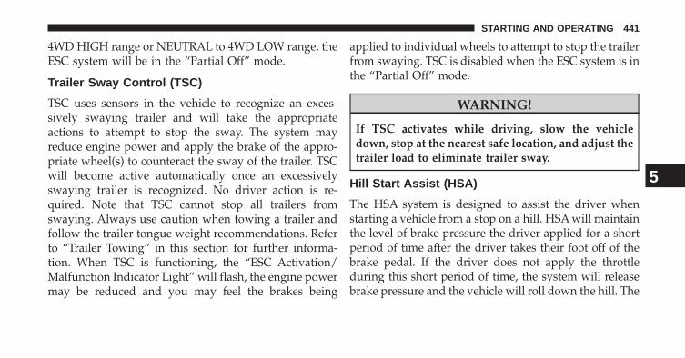
4WD HIGH range or NEUTRAL to 4WD LOW range, theESC system will be in the “Partial Off” mode.
Trailer Sway Control (TSC)
TSC uses sensors in the vehicle to recognize an exces-sively swaying trailer and will take the appropriateactions to attempt to stop the sway. The system mayreduce engine power and apply the brake of the appro-priate wheel(s) to counteract the sway of the trailer. TSCwill become active automatically once an excessivelyswaying trailer is recognized. No driver action is re-quired. Note that TSC cannot stop all trailers fromswaying. Always use caution when towing a trailer andfollow the trailer tongue weight recommendations. Referto “Trailer Towing” in this section for further informa-tion. When TSC is functioning, the “ESC Activation/Malfunction Indicator Light” will flash, the engine powermay be reduced and you may feel the brakes being
applied to individual wheels to attempt to stop the trailerfrom swaying. TSC is disabled when the ESC system is inthe “Partial Off” mode.
WARNING!
If TSC activates while driving, slow the vehicledown, stop at the nearest safe location, and adjust thetrailer load to eliminate trailer sway.
Hill Start Assist (HSA)
The HSA system is designed to assist the driver whenstarting a vehicle from a stop on a hill. HSA will maintainthe level of brake pressure the driver applied for a shortperiod of time after the driver takes their foot off of thebrake pedal. If the driver does not apply the throttleduring this short period of time, the system will releasebrake pressure and the vehicle will roll down the hill. The
5
STARTING AND OPERATING 441

system will release brake pressure in proportion to theamount of throttle applied as the vehicle starts to move inthe intended direction of travel.
HSA Activation Criteria
The following criteria must be met in order for HSA toactivate:
• Vehicle must be stopped.
• Vehicle must be on a 6% (approximate) grade orgreater hill.
• Gear selection matches vehicle uphill direction (i.e.,vehicle facing uphill is in forward gear; vehicle back-ing uphill is in REVERSE gear).
HSA will work in REVERSE and all forward gears whenthe activation criteria have been met. The system will notactivate if the vehicle is placed in NEUTRAL or PARK.
WARNING!
There may be situations on minor hills (i.e., less than8%), with a loaded vehicle, or while pulling a trailer,when the system will not activate and slight rollingmay occur. This could cause a collision with anothervehicle or object. Always remember the driver isresponsible for braking the vehicle.
Towing With HSA
HSA will provide assistance when starting on a gradewhen pulling a trailer.
442 STARTING AND OPERATING

WARNING!
• If you use a trailer brake controller with yourtrailer, your trailer brakes may be activated anddeactivated with the brake switch. If so, when thebrake pedal is released, there may not be enoughbrake pressure to hold the vehicle and trailer on ahill and this could cause a collision with anothervehicle or object behind you. In order to avoidrolling down the hill while resuming acceleration,manually activate the trailer brake prior to releas-ing the brake pedal. Always remember the driver isresponsible for braking the vehicle.
(Continued)
WARNING! (Continued)• HSA is not a parking brake. If you stop the vehicle
on a hill without putting the transmission in PARKand using the parking brake, it will roll down thehill and could cause a collision with another ve-hicle or object. Always remember to use the park-ing brake while parking on a hill, and that thedriver is responsible for braking the vehicle.
HSA Off
If you wish to turn off the HSA system, it can be done usingthe Uconnect® Access Settings. Refer to “Uconnect® Ac-cess Settings” in “Understanding Your Instrument Panel”for further information.
5
STARTING AND OPERATING 443

Ready Alert Braking – If Equipped
Ready Alert Braking may reduce the time required toreach full braking during emergency braking situations.It anticipates when an emergency braking situation mayoccur by monitoring how fast the throttle is released bythe driver. When the throttle is released very quickly,Ready Alert Braking applies a small amount of brakepressure. This brake pressure will not be noticed by thedriver. The brake system uses this brake pressure to allowa fast brake response if the driver applies the brakes.
Rain Brake Support – If Equipped
Rain Brake Support may improve braking performancein wet conditions. It will periodically apply a smallamount of brake pressure to remove any water buildupon the front brake rotors. It only functions when thewindshield wipers are in the LO or HI mode, it does notfunction in the intermittent mode. When Rain BrakeSupport is active, there is no notification to the driver andno driver interaction is required.
444 STARTING AND OPERATING

Hill Descent Control (HDC) — If Equipped(Four-Wheel Drive Models With MP3023Two-Speed Transfer Case Only)
HDC is intended for low speed off road driving while in4WD Low Range. HDC maintains vehicle speed while
descending hills during various driving situations. HDCcontrols vehicle speed by actively controlling the brakes.
HDC has three states:
1. Off (feature is not enabled and will not activate).
2. Enabled (feature is enabled and ready but activationconditions are not met, or driver is actively overridingwith brake or throttle application).
3. Active (feature is enabled and actively controllingvehicle speed).
Enabling HDC
HDC is enabled by pressing the HDC switch, but thefollowing conditions must also be met to enable HDC:
• Driveline is in 4WD Low Range
• Vehicle speed is below 5mph
• Parking brake is released
• Driver door is closed
Hill Descent Control Switch
5
STARTING AND OPERATING 445

Activating HDC
Once HDC is enabled it will activate automatically ifdriven down a grade of sufficient magnitude (greaterthan approximately 8%). The set speed for HDC isselectable by the driver, and can be adjusted by using thepaddle shifter. The following summarizes the HDC setspeeds:
• P = No set speed. HDC may be enabled but will notactivate.
• R = 0.6 mph (1 km/h)
• N = 1.2 mph (2 km/h)
• 1st = 0.6 mph (1 km/h)
• 2nd = 1.2 mph (2 km/h)
• 3rd = 1.8 mph (3 km/h)
• 4th = 2.5 mph (4 km/h)
• 5th = 3.1 mph (5 km/h)
• 6th = 3.7 mph (6 km/h)
• 7th = 4.3 mph (7 km/h)
• 8th = 5.0 mph (8 km/h)
NOTE: During HDC the +/- paddle shifter input is usedfor HDC target speed selection and will put the trans-mission into ERS but will not affect the gear chosen bythe transmission unless in Driver Override. During HDCthe transmission will shift appropriately for the driver-selected set speed and corresponding driving conditions.
Driver Override:
The driver may override HDC activation with throttle orbrake application at any time. While in driver overridethe transmission will be in ERS which is a top gear limiterand the vehicle will shift from 1st through the gear that isbeing displayed.
446 STARTING AND OPERATING

Deactivating HDC
HDC will be deactivated but remain available if any ofthe following conditions occur:
• Driver overrides HDC set speed with throttle or brakeapplication.
• Vehicle speed exceeds 20 mph (32 km/h) but remainsbelow 40 mph (64 km/h).
• Vehicle is on a downhill grade of insufficient magni-tude (less than approximately 8%), is on level ground,or is on an uphill grade.
• Vehicle is shifted to park.
Disabling HDC
HDC will deactivate and be disabled if any of thefollowing conditions occur:
• The driver presses the HDC switch.
• The driveline is shifted out of 4WD Low Range.
• The parking brake is applied.
• Driver door opens.
• The vehicle is driven greater than 20 mph (32 km/h)for greater than 70 seconds.
• The vehicle is driven greater than 40 mph (64 km/h)(HDC exits immediately).
5
STARTING AND OPERATING 447

Feedback to the driver:
The instrument cluster has a HDC icon and a HDCswitch which has an LED which offers feedback to thedriver about the state HDC is in.
• The cluster icon and switch lamp will illuminate andremain on solid when HDC is enabled or activated.This is the normal operating condition for HDC.
• The cluster icon and switch lamp will flash for severalseconds then extinguish when the driver presses theHDC switch but enable conditions are not met.
• The cluster icon and switch lamp will flash for severalseconds then extinguish when HDC deactivates due toexcess speed.
• The cluster icon and switch lamp will flash when HDCdeactivates due to overheated brakes. The flashing willstop and HDC will activate again once the brakes havecooled sufficiently.
WARNING!
HDC is only intended to assist the driver in control-ling vehicle speed when descending hills. The drivermust remain attentive to the driving conditions andis responsible for maintaining a safe vehicle speed.
448 STARTING AND OPERATING

Select Speed Control (SSC) — If Equipped(Four-Wheel Drive Models With MP3023Two-Speed Transfer Case Only)
SSC is intended for off road driving in 4WD Low Rangeonly. SSC maintains vehicle speed by actively controllingengine torque and brakes.
SSC has three states:
1. Off (feature is not enabled and will not activate)
2. Enabled (feature is enabled and ready but activationconditions are not met, or driver is actively overridingwith brake or throttle application)
3. Active (feature is enabled and actively controllingvehicle speed)
Select Speed Control Switch
5
STARTING AND OPERATING 449

Enabling SSC
SSC is enabled by pressing the SSC switch, but thefollowing conditions must also be met to enable SSC:
• Driveline is in 4WD Low Range
• Vehicle speed is below 5mph
• Parking brake is released
• Driver door is closed
• Driver is not applying throttle
Activating SSC
Once SSC is enabled it will activate automatically oncethe following conditions are met:
• Driver releases throttle
• Driver releases brake
• Transmission is in any selection other than P
• Vehicle speed is below 20 mph (32 km/h)
The set speed for SSC is selectable by the driver, and canbe adjusted by using the paddle shifter’s. Additionally,the SSC set speed is automatically reduced when climb-ing a grade and the level of set speed reduction dependson the magnitude of grade. The following summarizesthe SSC set speeds:
• P = No set speed. SSC may be enabled but will notactivate.
• R = 0.6 mph (1 km/h)
• N = 1.2 mph (2 km/h)
• 1st = 0.6 mph (1 km/h)
• 2nd = 1.2 mph (2 km/h)
• 3rd = 1.8 mph (3 km/h)
450 STARTING AND OPERATING

• 4th = 2.5 mph (4 km/h)
• 5th = 3.1 mph (5 km/h)
• 6th = 3.7 mph (6 km/h)
• 7th = 4.3 mph (7 km/h)
• 8th = 5.0 mph (8 km/h)
NOTE: During SSC the +/- paddle shifter input is usedfor SSC target speed selection and will put the transmis-sion into ERS but will not affect the gear chosen by thetransmission unless in Driver Override. During SSC thetransmission will shift appropriately for the driver-selected set speed and corresponding driving conditions.
Driver Override:
The driver may override SSC activation with throttle orbrake application at any time. While in driver overridethe transmission will be in ERS which is a top gear limiterand the vehicle will shift from 1st through whichevergear is displayed.
Deactivating SSC
SSC will be deactivated but remain available if any of thefollowing conditions occur:
• Driver overrides SSC set speed with throttle or brakeapplication.
• Vehicle speed exceeds 20 mph (32 km/h) but remainsbelow 40 mph (64 km/h).
• Vehicle is shifted to park.
5
STARTING AND OPERATING 451

Disabling SSC
SSC will deactivate and be disabled if any of the follow-ing conditions occur:
• The driver presses the SSC switch
• The driveline is shifted out of 4WD Low Range.
• The parking brake is applied.
• Driver door opens.
• The vehicle is driven faster than 20 mph (32 km/h) forlonger than 70 seconds.
• The vehicle is driven greater than 40 mph (64 km/h)(SSC exits immediately)
Feedback to the driver:
The instrument cluster has an SSC icon and the SSCswitch has an LED which offers feedback to the driverabout the state SSC is in.
• The cluster icon and switch lamp will illuminate andremain on solid when SSC is enabled or activated. Thisis the normal operating condition for SSC.
• The cluster icon and switch lamp will flash for severalseconds then extinguish when the driver presses theSSC switch but enable conditions are not met.
• The cluster icon and switch lamp will flash for severalseconds then extinguish when SSC deactivates due toexcess speed.
• The cluster icon and switch lamp will flash for severalseconds then extinguish when SSC deactivates due toexcess speed.
452 STARTING AND OPERATING
WARNING!
SSC is only intended to assist the driver in control-ling vehicle speed when driving in off road condi-tions. The driver must remain attentive to the drivingconditions and is responsible for maintaining a safevehicle speed.
ESC Activation/Malfunction Indicator Light AndESC OFF Indicator Light
The “ESC Activation/Malfunction IndicatorLight” in the instrument cluster will come onwhen the ignition switch is cycled to the ONposition. It should go out with the engine
running. If the “ESC Activation/Malfunction Indicator
Light” comes on continuously with the engine running, amalfunction has been detected in the ESC system. If thislight remains on after several ignition cycles, and thevehicle has been driven several miles (kilometers) atspeeds greater than 30 mph (48 km/h), see your autho-rized dealer as soon as possible to have the problemdiagnosed and corrected.
The “ESC Activation/Malfunction Indicator Light” (lo-cated in the instrument cluster) starts to flash as soon asthe tires lose traction and the ESC system becomes active.The “ESC Activation/Malfunction Indicator Light” alsoflashes when TCS is active. If the “ESC Activation/Malfunction Indicator Light” begins to flash during ac-celeration, ease up on the accelerator and apply as littlethrottle as possible. Be sure to adapt your speed anddriving to the prevailing road conditions.
5
STARTING AND OPERATING 453

NOTE:
• The “ESC Off Indicator Light” and the “ESCActivation/Malfunction Indicator Light” come on mo-mentarily each time the ignition switch is turned ON.
• Each time the ignition is cycled ON, the ESC systemwill be ON even if it was cycled off previously.
• The ESC system will make buzzing or clicking soundswhen it is active. This is normal; the sounds will stopwhen ESC becomes inactive following the maneuverthat caused the ESC activation.
The “ESC OFF Indicator Light” indicates theElectronic Stability Control (ESC) is partiallyoff or full off.
TIRE SAFETY INFORMATION
Tire Markings
1 — U.S. DOT Safety StandardsCode (TIN)
4 — Maximum Load
2 — Size Designation 5 — Maximum Pressure3 — Service Description 6 — Treadwear, Traction and
Temperature Grades
454 STARTING AND OPERATING

NOTE:
• P (Passenger) - Metric tire sizing is based on U.S.design standards. P-Metric tires have the letter “P”molded into the sidewall preceding the size designa-tion. Example: P215/65R15 95H.
• European-Metric tire sizing is based on Europeandesign standards. Tires designed to this standard havethe tire size molded into the sidewall beginning withthe section width. The letter �P� is absent from this tiresize designation. Example: 215/65R15 96H.
• LT (Light Truck) - Metric tire sizing is based on U.S.design standards. The size designation for LT-Metrictires is the same as for P-Metric tires except for theletters “LT” that are molded into the sidewall preced-ing the size designation. Example: LT235/85R16.
• Temporary spare tires are spares designed for tempo-rary emergency use only. Temporary high pressurecompact spare tires have the letter “T” or “S” moldedinto the sidewall preceding the size designation. Ex-ample: T145/80D18 103M.
• High flotation tire sizing is based on U.S. designstandards and it begins with the tire diameter moldedinto the sidewall. Example: 31x10.5 R15 LT.
5
STARTING AND OPERATING 455

Tire Sizing Chart
EXAMPLE:Size Designation:
P = Passenger car tire size based on U.S. design standards�....blank....� = Passenger car tire based on European design standardsLT = Light truck tire based on U.S. design standardsT or S = Temporary spare tire31 = Overall diameter in inches (in)215 = Section width in millimeters (mm)65 = Aspect ratio in percent (%)
— Ratio of section height to section width of tire10.5 = Section width in inches (in)R = Construction code
— �R� means radial construction— �D� means diagonal or bias construction
15 = Rim diameter in inches (in)
456 STARTING AND OPERATING

EXAMPLE:Service Description:
95 = Load Index— A numerical code associated with the maximum load a tire can carry
H = Speed Symbol— A symbol indicating the range of speeds at which a tire can carry a load corresponding toits load index under certain operating conditions— The maximum speed corresponding to the speed symbol should only be achieved underspecified operating conditions (i.e., tire pressure, vehicle loading, road conditions, andposted speed limits)
Load Identification:�....blank....� = Absence of any text on the sidewall of the tire indicates a Standard Load (SL) tireExtra Load (XL) = Extra load (or reinforced) tireLight Load (LL) = Light load tireC, D, E, F, G = Load range associated with the maximum load a tire can carry at a specified pressure
Maximum Load— Maximum load indicates the maximum load this tire is designed to carryMaximum Pressure— Maximum pressure indicates the maximum permissible cold tire inflation pressure forthis tire
5
STARTING AND OPERATING 457

Tire Identification Number (TIN)
The TIN may be found on one or both sides of the tire,however, the date code may only be on one side. Tireswith white sidewalls will have the full TIN, including thedate code, located on the white sidewall side of the tire.
Look for the TIN on the outboard side of black sidewalltires as mounted on the vehicle. If the TIN is not found onthe outboard side, then you will find it on the inboardside of the tire.
EXAMPLE:DOT MA L9 ABCD 0301
DOT = Department of Transportation— This symbol certifies that the tire is in compliance with the U.S. Department of Transportation tiresafety standards and is approved for highway use
MA = Code representing the tire manufacturing location (two digits)L9 = Code representing the tire size (two digits)ABCD = Code used by the tire manufacturer (one to four digits)03 = Number representing the week in which the tire was manufactured (two digits)
— 03 means the 3rd week
458 STARTING AND OPERATING
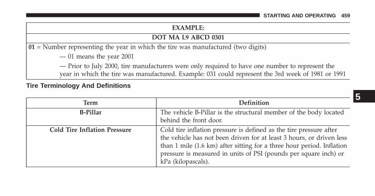
EXAMPLE:DOT MA L9 ABCD 0301
01 = Number representing the year in which the tire was manufactured (two digits)— 01 means the year 2001— Prior to July 2000, tire manufacturers were only required to have one number to represent theyear in which the tire was manufactured. Example: 031 could represent the 3rd week of 1981 or 1991
Tire Terminology And Definitions
Term DefinitionB-Pillar The vehicle B-Pillar is the structural member of the body located
behind the front door.Cold Tire Inflation Pressure Cold tire inflation pressure is defined as the tire pressure after
the vehicle has not been driven for at least 3 hours, or driven lessthan 1 mile (1.6 km) after sitting for a three hour period. Inflationpressure is measured in units of PSI (pounds per square inch) orkPa (kilopascals).
5
STARTING AND OPERATING 459

Term DefinitionMaximum Inflation Pressure The maximum inflation pressure is the maximum permissible
cold tire inflation pressure for this tire. The maximum inflationpressure is molded into the sidewall.
Recommended Cold Tire InflationPressure
Vehicle manufacturer’s recommended cold tire inflation pressureas shown on the tire placard.
Tire Placard A paper label permanently attached to the vehicle describing thevehicle’s loading capacity, the original equipment tire sizes andthe recommended cold tire inflation pressures.
Tire Loading And Tire Pressure
Tire And Loading Information Placard Location
NOTE: The proper cold tire inflation pressure is listed onthe driver’s side B-Pillar or the rear edge of the driver’sside door.
460 STARTING AND OPERATING

Tire And Loading Information Placard
This placard tells you important information about the:
1) number of people that can be carried in the vehicle2) total weight your vehicle can carry
B-Pillar Location for Tire And Loading InformationPlacard Tire and Loading Information Placard
5
STARTING AND OPERATING 461

3) tire size designed for your vehicle4) cold tire inflation pressures for the front, rear, andspare tires.
Loading
The vehicle maximum load on the tire must not exceedthe load carrying capacity of the tire on your vehicle. Youwill not exceed the tire’s load carrying capacity if youadhere to the loading conditions, tire size, and cold tireinflation pressures specified on the Tire and LoadingInformation placard and in the “Vehicle Loading” sectionof this manual.
NOTE: Under a maximum loaded vehicle condition,gross axle weight ratings (GAWRs) for the front and rearaxles must not be exceeded. For further information onGAWRs, vehicle loading, and trailer towing, refer to“Vehicle Loading” in this section.
To determine the maximum loading conditions of yourvehicle, locate the statement “The combined weight ofoccupants and cargo should never exceed XXX lbs orXXX kg” on the Tire and Loading Information placard.The combined weight of occupants, cargo/luggage andtrailer tongue weight (if applicable) should never exceedthe weight referenced here.
Steps For Determining Correct Load Limit
1. Locate the statement “The combined weight of occu-pants and cargo should never exceed XXX lbs orXXX kg” on your vehicle’s placard.
2. Determine the combined weight of the driver andpassengers that will be riding in your vehicle.
3. Subtract the combined weight of the driver and pas-sengers from XXX lbs or XXX kg.
462 STARTING AND OPERATING

4. The resulting figure equals the available amount ofcargo and luggage load capacity. For example, if “XXX”amount equals 1,400 lbs (635 kg) and there will be five150 lb (68 kg) passengers in your vehicle, the amount ofavailable cargo and luggage load capacity is 650 lbs(295 kg) (since 5 x 150 = 750, and 1400 – 750 = 650 lbs[295 kg]).
5. Determine the combined weight of luggage and cargobeing loaded on the vehicle. That weight may notsafely exceed the available cargo and luggage loadcapacity calculated in Step 4.
6. If your vehicle will be towing a trailer, load from yourtrailer will be transferred to your vehicle. Consult thismanual to determine how this reduces the availablecargo and luggage load capacity of your vehicle.
NOTE:
• The following table shows examples on how to calcu-late total load, cargo/luggage, and towing capacitiesof your vehicle with varying seating configurationsand number and size of occupants. This table is forillustration purposes only and may not be accurate forthe seating and load carry capacity of your vehicle.
• For the following example, the combined weight ofoccupants and cargo should never exceed 865 lbs(392 kg).
5
STARTING AND OPERATING 463
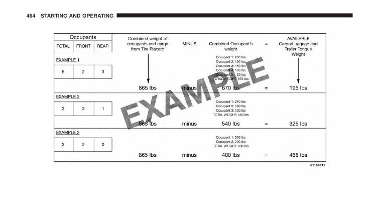
464 STARTING AND OPERATING

WARNING!
Overloading of your tires is dangerous. Overloadingcan cause tire failure, affect vehicle handling, andincrease your stopping distance. Use tires of therecommended load capacity for your vehicle. Neveroverload them.
TIRES — GENERAL INFORMATION
Tire Pressure
Proper tire inflation pressure is essential to the safe andsatisfactory operation of your vehicle. Three primaryareas are affected by improper tire pressure:
Safety
WARNING!
• Improperly inflated tires are dangerous and cancause collisions.
• Under-inflation increases tire flexing and can re-sult in over-heating and tire failure.
• Over-inflation reduces a tire’s ability to cushionshock. Objects on the road and chuckholes cancause damage that result in tire failure.
• Over-inflated or under-inflated tires can affect ve-hicle handling and can fail suddenly, resulting inloss of vehicle control.
• Unequal tire pressures can cause steering prob-lems. You could lose control of your vehicle.
(Continued)
5
STARTING AND OPERATING 465

WARNING! (Continued)• Unequal tire pressures from one side of the vehicle
to the other can cause the vehicle to drift to theright or left.
• Always drive with each tire inflated to the recom-mended cold tire inflation pressure.
Economy
Improper inflation pressures can cause uneven wearpatterns to develop across the tire tread. These abnormalwear patterns will reduce tread life resulting in a need forearlier tire replacement. Under-inflation also increasestire rolling resistance resulting in higher fuel consump-tion.
Ride Comfort And Vehicle Stability
Proper tire inflation contributes to a comfortable ride.Over-inflation produces a jarring and uncomfortableride. Both under-inflation and over-inflation affect the
stability of the vehicle and can produce a feeling ofsluggish response or over responsiveness in the steering.
Unequal tire pressures from side to side may cause erraticand unpredictable steering response.
Unequal tire pressure from side to side may cause thevehicle to drift left or right.
Tire Inflation Pressures
The proper cold tire inflation pressure is listed on thedriver’s side “B” Pillar or rear edge of the driver’s sidedoor.
At least once a month:
• Check and adjust tire pressure with a good qualitypocket-type pressure gauge. Do not make a visual judge-ment when determining proper inflation. Tires may lookproperly inflated even when they are under-inflated.
• Inspect tires for signs of tire wear or visible damage.
466 STARTING AND OPERATING

CAUTION!
After inspecting or adjusting the tire pressure, al-ways reinstall the valve stem cap. This will preventmoisture and dirt from entering the valve stem,which could damage the valve stem.
Inflation pressures specified on the placard are always“cold tire inflation pressure”. Cold tire inflation pressureis defined as the tire pressure after the vehicle has notbeen driven for at least three hours, or driven less than1 mile (1.6 km) after a three hour period. The cold tireinflation pressure must not exceed the maximum infla-tion pressure molded into the tire sidewall.
Check tire pressures more often if subject to a wide rangeof outdoor temperatures, as tire pressures vary withtemperature changes.
Tire pressures change by approximately 1 psi (7 kPa) per12°F (7°C) of air temperature change. Keep this in mindwhen checking tire pressure inside a garage, especially inthe winter.
Example: If garage temperature = 68°F (20°C) and theoutside temperature = 32°F (0°C) then the cold tireinflation pressure should be increased by 3 psi (21 kPa),which equals 1 psi (7 kPa) for every 12°F (7°C) for thisoutside temperature condition.
Tire pressure may increase from 2 to 6 psi (13 to 40 kPa)during operation. DO NOT reduce this normal pressurebuild up or your tire pressure will be too low.
5
STARTING AND OPERATING 467

Tire Pressures For High Speed Operation
The manufacturer advocates driving at safe speeds andwithin posted speed limits. Where speed limits or condi-tions are such that the vehicle can be driven at highspeeds, maintaining correct tire inflation pressure is veryimportant. Increased tire pressure and reduced vehicleloading may be required for high-speed vehicle opera-tion. Refer to your authorized tire or original equipmentvehicle dealer for recommended safe operating speeds,loading and cold tire inflation pressures.
WARNING!
High speed driving with your vehicle under maxi-mum load is dangerous. The added strain on yourtires could cause them to fail. You could have aserious collision. Do not drive a vehicle loaded to themaximum capacity at continuous speeds above75 mph (120 km/h).
Radial Ply Tires
WARNING!
Combining radial ply tires with other types of tireson your vehicle will cause your vehicle to handlepoorly. The instability could cause a collision. Al-ways use radial ply tires in sets of four. Nevercombine them with other types of tires.
Tire Repair
If your tire becomes damaged, it may be repaired if itmeets the following criteria:
• The tire has not been driven on when flat,
• The damage is only on the tread section of your tire(sidewall damage is not repairable) and
• The puncture is no greater than ¼� (6 mm)
468 STARTING AND OPERATING

Consult an authorized tire dealer for tire repairs andadditional information.
Damaged Run Flat tires, or Run Flat tires that haveexperienced a loss of pressure should be replaced imme-diately with another Run Flat tire of identical size andservice description (Load Index and Speed Code).
All Season Tires – If Equipped
All Season tires provide traction for all seasons (spring,summer, fall and winter). Traction levels may vary be-tween different all season tires. All season tires can beidentified by the M+S, M&S, M/S or MS designation onthe tire sidewall. Use all season tires only in sets of four;failure to do so may adversely affect the safety andhandling of your vehicle.
Summer Or Three Season Tires – If Equipped
Summer tires provide traction in both wet and dryconditions, and are not intended to be driven in snow or
on ice. Summer tires will not contain the all seasondesignation or mountain/snowflake symbol on the tiresidewall. Use summer tires only in sets of four; failure todo so may adversely affect the safety and handling ofyour vehicle.
Snow Tires
Some areas of the country require the use of snow tiresduring the winter. Snow tires can be identified by amountain/snowflake symbol on the tire sidewall.
If you need snow tires, select tires equivalent in size andtype to the original equipment tires. Use snow tires onlyin sets of four; failure to do so may adversely affect thesafety and handling of your vehicle.
Snow tires generally have lower speed ratings than whatwas originally equipped with your vehicle and shouldnot be operated at sustained speeds over 75 mph(120 km/h). For speeds above 75 mph (120 km/h) refer to
5
STARTING AND OPERATING 469

original equipment or an authorized tire dealer forrecommended safe operating speeds, loading and coldtire inflation pressures.
While studded tires improve performance on ice, skidand traction capability on wet or dry surfaces may bepoorer than that of non-studded tires. Some states pro-hibit studded tires; therefore, local laws should bechecked before using these tire types.
Spare Tire Matching Original Equipped Tire AndWheel – If Equipped
Your vehicle may be equipped with a spare tire andwheel equivalent in look and function to the originalequipment tire and wheel found on the front or rear axleof your vehicle. This spare tire may be used in the tirerotation for your vehicle. If your vehicle has this optionrefer to an authorized tire dealer for the recommendedtire rotation pattern.
Compact Spare Tire – If Equipped
The compact spare is for temporary emergency use only.You can identify if your vehicle is equipped with acompact spare by looking at the spare tire description onthe Tire and Loading Information Placard located on thedriver’s side door opening or on the sidewall of the tire.Compact spare tire descriptions begin with the letter “T”or “S” preceding the size designation. Example: T145/80D18 103M.
T, S = Temporary Spare Tire
Since this tire has limited tread life the original equip-ment tire should be repaired (or replaced) and reinstalledon your vehicle at the first opportunity.
Do not install a wheel cover or attempt to mount aconventional tire on the compact spare wheel, since thewheel is designed specifically for the compact spare tire.
470 STARTING AND OPERATING
Do not install more than one compact spare tire andwheel on the vehicle at any given time.
WARNING!
Compact spares are for temporary emergency useonly. With these spares, do not drive more than50 mph (80 km/h). Temporary use spares have limitedtread life. When the tread is worn to the tread wearindicators, the temporary use spare tire needs to bereplaced. Be sure to follow the warnings, whichapply to your spare. Failure to do so could result inspare tire failure and loss of vehicle control.
Full Size Spare – If Equipped
The full size spare is for temporary emergency use only.This tire may look like the originally equipped tire on thefront or rear axle of your vehicle, but it is not. This spare
tire may have limited tread life. When the tread is wornto the tread wear indicators, the temporary use full sizespare tire needs to be replaced. Since it is not the same asyour original equipment tire, replace (or repair) theoriginal equipment tire and reinstall on the vehicle at thefirst opportunity.
Limited-Use Spare – If Equipped
The limited-use spare tire is for temporary emergencyuse only. This tire is identified by a label located on thelimited-use spare wheel. This label contains the drivinglimitations for this spare. This tire may look like theoriginal equipped tire on the front or rear axle of yourvehicle, but it is not. Installation of this limited-use sparetire affects vehicle handling. Since it is not the same asyour original equipment tire, replace (or repair) theoriginal equipment tire and reinstall on the vehicle at thefirst opportunity.
5
STARTING AND OPERATING 471

WARNING!
Limited-use spares are for emergency use only. In-stallation of this limited-use spare tire affects vehiclehandling. With this tire, do not drive more than thespeed listed on the limit-use spare wheel. Keepinflated to the cold tire inflation pressures listed onyour Tire and Loading Information Placard locatedon the driver’s side B-Pillar or the rear edge of thedriver’s side door. Replace (or repair) the originalequipment tire at the first opportunity and reinstall iton your vehicle. Failure to do so could result in lossof vehicle control.
Tire Spinning
When stuck in mud, sand, snow, or ice conditions, do notspin your vehicle’s wheels above 30 mph (48 km/h) orfor longer than 30 seconds continuously without stop-ping when you are stuck.
Refer to “Freeing A Stuck Vehicle” in “What To Do InEmergencies” for further information.
WARNING!
Fast spinning tires can be dangerous. Forces gener-ated by excessive wheel speeds may cause tire dam-age or failure. A tire could explode and injure some-one. Do not spin your vehicle’s wheels faster than30 mph (48 km/h) for more than 30 seconds continu-ously when you are stuck, and do not let anyone neara spinning wheel, no matter what the speed.
Tread Wear Indicators
Tread wear indicators are in the original equipment tiresto help you in determining when your tires should bereplaced.
472 STARTING AND OPERATING
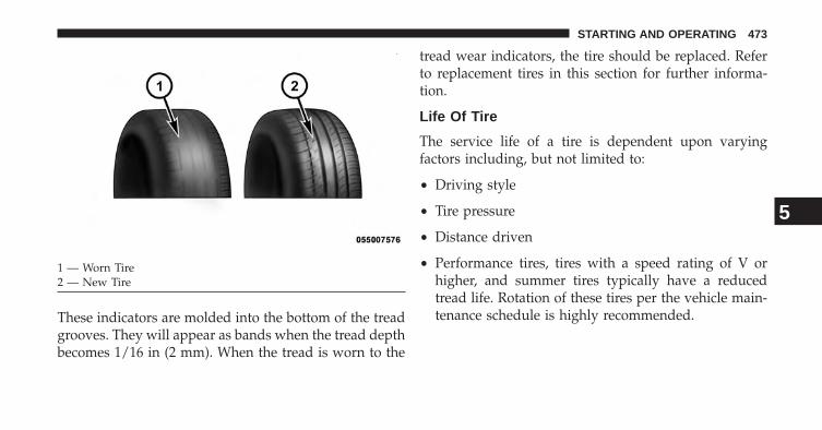
These indicators are molded into the bottom of the treadgrooves. They will appear as bands when the tread depthbecomes 1/16 in (2 mm). When the tread is worn to the
tread wear indicators, the tire should be replaced. Referto replacement tires in this section for further informa-tion.
Life Of Tire
The service life of a tire is dependent upon varyingfactors including, but not limited to:
• Driving style
• Tire pressure
• Distance driven
• Performance tires, tires with a speed rating of V orhigher, and summer tires typically have a reducedtread life. Rotation of these tires per the vehicle main-tenance schedule is highly recommended.
1 — Worn Tire2 — New Tire
5
STARTING AND OPERATING 473

WARNING!
Tires and the spare tire should be replaced after sixyears, regardless of the remaining tread. Failure tofollow this warning can result in sudden tire failure.You could lose control and have a collision resultingin serious injury or death.
Keep dismounted tires in a cool, dry place with as littleexposure to light as possible. Protect tires from contactwith oil, grease, and gasoline.
Replacement Tires
The tires on your new vehicle provide a balance of manycharacteristics. They should be inspected regularly forwear and correct cold tire inflation pressure. The manu-facturer strongly recommends that you use tires equiva-lent to the originals in size, quality and performancewhen replacement is needed. Refer to the paragraph on“Tread Wear Indicators”. Refer to the Tire and Loading
Information placard or the Vehicle Certification Label forthe size designation of your tire. The Load Index andSpeed Symbol for your tire will be found on the originalequipment tire sidewall. See the Tire Sizing Chart ex-ample found in the Tire Safety Information section of thismanual for more information relating to the Load Indexand Speed Symbol of a tire.
It is recommended to replace the two front tires or tworear tires as a pair. Replacing just one tire can seriouslyaffect your vehicle’s handling. If you ever replace awheel, make sure that the wheel’s specifications matchthose of the original wheels.
It is recommended you contact your authorized tire ororiginal equipment dealer with any questions you mayhave on tire specifications or capability. Failure to useequivalent replacement tires may adversely affect thesafety, handling, and ride of your vehicle.
474 STARTING AND OPERATING

WARNING!
• Do not use a tire, wheel size or rating other thanthat specified for your vehicle. Some combinationsof unapproved tires and wheels may change sus-pension dimensions and performance characteris-tics, resulting in changes to steering, handling, andbraking of your vehicle. This can cause unpredict-able handling and stress to steering and suspen-sion components. You could lose control and havea collision resulting in serious injury or death. Useonly the tire and wheel sizes with load ratingsapproved for your vehicle.
• Never use a tire with a smaller load index orcapacity, other than what was originally equippedon your vehicle. Using a tire with a smaller loadindex could result in tire overloading and failure.You could lose control and have a collision.
(Continued)
WARNING! (Continued)• Failure to equip your vehicle with tires having
adequate speed capability can result in sudden tirefailure and loss of vehicle control.
CAUTION!
Replacing original tires with tires of a different sizemay result in false speedometer and odometer read-ings.
TIRE CHAINS (TRACTION DEVICES)
Use of traction devices require sufficient tire-to-bodyclearance. Follow these recommendations to guardagainst damage.
• Traction device must be of proper size for the tire, asrecommended by the traction device manufacturer.
5
STARTING AND OPERATING 475

• Install on Rear Tires Only
• Due to limited clearance, the Security Chain Company(SCC) Super Z6 low profile traction device or equiva-lent is recommended on P265/60R18 or 265/50R20tires.
WARNING!
Using tires of different size and type (M+S, Snow)between front and rear axles can cause unpredictablehandling. You could lose control and have a collision.
CAUTION!
To avoid damage to your vehicle or tires, observe thefollowing precautions:• Because of restricted traction device clearance be-
tween tires and other suspension components, it isimportant that only traction devices in good condi-tion are used. Broken devices can cause seriousdamage. Stop the vehicle immediately if noiseoccurs that could indicate device breakage. Removethe damaged parts of the device before further use.
• Install device as tightly as possible and then re-tighten after driving about ½ mile (0.8 km).
• Do not exceed 30 mph (48 km/h).• Drive cautiously and avoid severe turns and large
bumps, especially with a loaded vehicle.• Do not drive for prolonged period on dry pave-
ment.
(Continued)
476 STARTING AND OPERATING

CAUTION! (Continued)• Observe the traction device manufacturer’s instruc-
tions on the method of installation, operatingspeed, and conditions for use. Always use thesuggested operating speed of the device manufac-turer’s if it is less than 30 mph (48 km/h).
• Do not use traction devices on a compact spare tire.
TIRE ROTATION RECOMMENDATIONS
The tires on the front and rear of your vehicle operate atdifferent loads and perform different steering, handling,and braking functions. For these reasons, they wear atunequal rates.
These effects can be reduced by timely rotation of tires.The benefits of rotation are especially worthwhile withaggressive tread designs such as those on On/Off-Road
type tires. Rotation will increase tread life, help to main-tain mud, snow, and wet traction levels, and contribute toa smooth, quiet ride.
Refer to the “Maintenance Schedule” for the propermaintenance intervals. More frequent rotation is permis-sible if desired. The reasons for any rapid or unusualwear should be corrected prior to rotation being per-formed.
NOTE: The premium Tire Pressure Monitor System willautomatically locate the pressure values displayed in thecorrect vehicle position following a tire rotation.
The suggested rotation method is the “forward-cross”shown in the following diagram.
5
STARTING AND OPERATING 477

TIRE PRESSURE MONITOR SYSTEM (TPMS)
The Tire Pressure Monitor System (TPMS) uses wirelesstechnology with wheel rim-mounted electronic sensors tomonitor tire pressure levels. Sensors, mounted to eachwheel as part of the valve stem, transmit tire pressurereadings to the Receiver Module.
NOTE: It is particularly important, for you to regularlycheck the tire pressure in all of your tires and to maintainthe proper pressure.
The Tire Pressure Monitor System (TPMS) consists of thefollowing components:
• Receiver Module
• Four Tire Pressure Monitoring Sensors
• Various Tire Pressure Monitoring System Messages,which display in the Electronic Vehicle InformationCenter (EVIC), and a graphic displaying tire pressures
• Tire Pressure Monitoring Telltale Light
The Tire Pressure Monitoring System (TPMS) will warnthe driver of a low tire pressure based on the vehiclerecommended cold tire placard pressure.
The tire pressure will vary with temperature by about1 psi (7 kPa) for every 12°F (6.5°C). This means that when
Tire Rotation
478 STARTING AND OPERATING

the outside temperature decreases, the tire pressure willdecrease. Tire pressure should always be set based oncold inflation tire pressure. This is defined as the tirepressure after the vehicle has not been driven for at leastthree hours, or driven less than 1 mile (1.6 km) after athree-hour period. Refer to “Tires – General Informa-tion” in “Starting and Operating” for information onhow to properly inflate the vehicle’s tires. The tirepressure will also increase as the vehicle is driven - this isnormal and there should be no adjustment for thisincreased pressure.
The TPMS will warn the driver of a low tire pressure ifthe tire pressure falls below the low pressure warningthreshold for any reason, including low temperatureeffects, or natural pressure loss through the tire.
The TPMS will continue to warn the driver of low tirepressure as long as the condition exists, and will not turnoff until the tire pressure is at or above recommended
cold tire placard pressure. Once the low tire pressurewarning has been illuminated, the tire pressure must beincreased to the recommended cold tire pressure in orderfor the Tire Pressure Monitoring Telltale Light to beturned off. The system will automatically update and theTire Pressure Monitoring Telltale Light will extinguishonce the updated tire pressures have been received. Thevehicle may need to be driven for up to 20 minutes above15 mph (24 km/h) to receive this information.
For example, your vehicle has a recommended cold(parked for more than three hours) tire placard pressureof 33 psi (227 kPa). If the ambient temperature is 68°F(20°C) and the measured tire pressure is 28 psi (193 kPa),a temperature drop to 20°F (-7°C) will decrease the tirepressure to approximately 24 psi (165 kPa). This tirepressure is sufficiently low enough to turn ON the TirePressure Monitoring Telltale Light. Driving the vehiclemay cause the tire pressure to rise to approximately28 psi (193 kPa), but the Tire Pressure Monitoring Telltale
5
STARTING AND OPERATING 479

Light will still be ON. In this situation, the Tire PressureMonitoring Telltale Light will turn OFF only after thetires have been inflated to the vehicle’s recommendedcold tire pressure value.
CAUTION!
• The TPMS has been optimized for the originalequipment tires and wheels. TPMS pressures havebeen established for the tire size equipped on yourvehicle. Undesirable system operation or sensordamage may result when using replacement equip-ment that is not of the same size, type, and/or style.Aftermarket wheels can cause sensor damage. Donot use aftermarket tire sealants or balance beads ifyour vehicle is equipped with a TPMS, as damageto the sensors may result.
(Continued)
CAUTION! (Continued)• After inspecting or adjusting the tire pressure al-
ways reinstall the valve stem cap. This will preventmoisture and dirt from entering the valve stem,which could damage the Tire Pressure MonitoringSensor.
NOTE:
• The TPMS is not intended to replace normal tire careand maintenance, or to provide warning of a tirefailure or condition.
• The TPMS should not be used as a tire pressure gaugewhile adjusting your tire pressure.
480 STARTING AND OPERATING

• Driving on a significantly under-inflated tire causesthe tire to overheat and can lead to tire failure.Under-inflation also reduces fuel efficiency and tiretread life, and may affect the vehicle’s handling andstopping ability.
• The TPMS is not a substitute for proper tire mainte-nance, and it is the driver’s responsibility to maintaincorrect tire pressure using an accurate tire gauge, evenif under-inflation has not reached the level to triggerillumination of the Tire Pressure Monitoring TelltaleLight.
• Seasonal temperature changes will affect tire pressure,and the TPMS will monitor the actual tire pressure inthe tire.
Tire Pressure Monitoring Low Pressure Warnings
The Tire Pressure Monitoring Telltale Light willilluminate in the instrument cluster, and an audible
chime will be activated, when one or more of the fouractive road tire pressures are low. In addition, the EVIC willdisplay a “LOW TIRE PRESSURE” message for a minimumof five seconds, an �Inflate Tire to XXX� message and agraphic display of the pressure value(s) with the low tire(s)displayed in a different color. Refer to “Electronic VehicleInformation Center (EVIC)” in “Understanding Your In-strument Panel” for further information.
NOTE: Your system can be set to display pressure unitsin PSI or kPa.
5
STARTING AND OPERATING 481

Should a low tire condition occur on any of the fouractive road tire(s), you should stop as soon as possible,and inflate the low tire(s) that is in a different color on thegraphic display to the vehicle’s recommended cold tirepressure displayed in the �Inflate Tire to XXX� message.The system will automatically update, the graphic dis-play of the pressure value(s) will return to its originalcolor and the Tire Pressure Monitoring Telltale Light willextinguish once the updated tire pressure(s) have beenreceived. The vehicle may need to be driven for up to 20minutes above 15 mph (24 km/h) to receive this infor-mation.
482 STARTING AND OPERATING

SERVICE TPM SYSTEM Warning
The Tire Pressure Monitoring Telltale Light will flash onand off for 75 seconds, and remain on solid when asystem fault is detected. The system fault will also sounda chime. The EVIC will display a “SERVICE TPM SYS-TEM” message for a minimum of five seconds. Thismessage is then followed by a graphic display, with “- -“in place of the pressure value(s), indicating which TirePressure Monitoring Sensor(s) is not being received.
NOTE: Your system can be set to display pressure unitsin PSI or kPa.
5
STARTING AND OPERATING 483

If the ignition switch is cycled, this sequence will repeat,providing the system fault still exists. If the system faultno longer exists, the Tire Pressure Monitoring TelltaleLight will no longer flash, the �SERVICE TPM SYSTEM�message will not be present, and a pressure value will bedisplayed instead of dashes. A system fault can occur byany of the following:
1. Jamming due to electronic devices or driving next tofacilities emitting the same Radio Frequencies as theTPM sensors.
2. Installing some form of aftermarket window tintingthat affects radio wave signals.
3. Lots of snow or ice around the wheels or wheelhousings.
4. Using tire chains on the vehicle.
5. Using wheels/tires not equipped with TPM sensors.
The EVIC will also display a �SERVICE TPM SYSTEM�message for a minimum of five seconds when a systemfault is detected possibly related to an incorrect sensorlocation fault. In this case, the �SERVICE TPM SYSTEM�message is then followed by a graphic display, withpressure values still shown. This indicates the pressurevalues are still being received from the TPM Sensors butthey may not be located in the correct vehicle position.However, the system still needs to be serviced as long asthe �SERVICE TPM SYSTEM� message exists.
484 STARTING AND OPERATING
NOTE: There is no tire pressure monitoring sensor in thespare tire. The TPMS will not be able to monitor the tirepressure. If you install the spare tire in place of a road tirethat has a pressure below the low-pressure warning limit,upon the next ignition switch cycle, the Tire PressureMonitoring Telltale Light will remain ON, a chime willsound, and the EVIC will still display a pressure value inthe different color graphic display and an �Inflate toXXX kPa� message will be displayed. After driving thevehicle for up to 20 minutes above 15 mph (24 km/h), theTire Pressure Monitoring Telltale Light will flash on and offfor 75 seconds and then remain on solid. In addition, theEVIC will display a “SERVICE TPM SYSTEM� message forfive seconds and then display dashes (- -) in place of thepressure value. For each subsequent ignition switch cycle,a chime will sound, the Tire Pressure Monitoring TelltaleLight will flash on and off for 75 seconds and then remainon solid, and the EVIC will display a �SERVICE TPMSYSTEM� message for five seconds and then display
dashes (- -) in place of the pressure value. Once you repairor replace the original road tire, and reinstall it on thevehicle in place of the spare tire, the TPMS will updateautomatically.
In addition, the Tire Pressure Monitoring Telltale Lightwill turn OFF and the graphic in the EVIC will display anew pressure value instead of dashes (- -), as long as notire pressure is below the low-pressure warning limit inany of the four active road tires. The vehicle may need tobe driven for up to 20 minutes above 15 mph (24 km/h)in order for the TPMS to receive this information.
General Information
This device complies with Part 15 of the FCC rules andRSS 210 of Industry Canada. Operation is subject to thefollowing conditions:
• This device may not cause harmful interference.
5
STARTING AND OPERATING 485

• This device must accept any interference received,including interference that may cause undesired op-eration.
The TPM sensors are regulated under one of the follow-ing licenses:
United States MRXMERCTX1Canada 2546A-MERCTX1
FUEL REQUIREMENTS
3.6L Engine – If Equipped
This engine is designed to meet all emis-sions regulations and provide excellentfuel economy and performance when us-ing high-quality unleaded “regular” gaso-line having an octane rating of 87. The use
of premium gasoline is not recommended, as it will notprovide any benefit over regular gasoline in theseengines.
5.7L Engine – If Equipped
This engine is designed to meet all emis-sions regulations and provide satisfactoryfuel economy and performance when us-ing high-quality unleaded gasoline havingan octane range of 87 to 89. The manufac-
turer recommends the use of 89 octane for optimumperformance. The use of premium gasoline is not recom-mended, as it will not provide any benefit over regulargasoline in these engines.
486 STARTING AND OPERATING

Light spark knock at low engine speeds is not harmful toyour engine. However, continued heavy spark knock athigh speeds can cause damage and immediate service isrequired. Poor quality gasoline can cause problems suchas hard starting, stalling, and hesitations. If you experi-ence these symptoms, try another brand of gasolinebefore considering service for the vehicle.
Over 40 auto manufacturers worldwide have issued andendorsed consistent gasoline specifications (the World-wide Fuel Charter, WWFC) which define fuel propertiesnecessary to deliver enhanced emissions, performance,and durability for your vehicle. The manufacturer recom-mends the use of gasolines that meet the WWFC speci-fications if they are available.
Reformulated Gasoline
Many areas of the country require the use of cleanerburning gasoline referred to as “Reformulated Gasoline.”Reformulated gasolines contain oxygenates and are spe-cifically blended to reduce vehicle emissions and im-prove air quality.
The manufacturer supports the use of reformulated gaso-lines. Properly blended reformulated gasolines will pro-vide excellent performance and durability of engine andfuel system components.
Gasoline/Oxygenate Blends
Some fuel suppliers blend unleaded gasoline with oxy-genates such as Ethanol. Fuels blended with oxygenatesmay be used in your vehicle.
5
STARTING AND OPERATING 487
CAUTION!
DO NOT use gasoline containing Methanol or gaso-line containing more than 10% Ethanol. Use of theseblends may result in starting and drivability prob-lems, damage critical fuel system components, causeemissions to exceed the applicable standard, and/orcause the “Malfunction Indicator Light” to illumi-nate. Pump labels should clearly communicate if afuel contains greater than 10% Ethanol.
Problems that result from using gasoline containingMethanol or gasoline containing more than 10% Ethanolare not the responsibility of the manufacturer and maynot be covered under New Vehicle Limited Warranty.
E-85 Usage In Non-Flex Fuel Vehicles
Non-FFV vehicles are compatible with gasoline contain-ing 10% ethanol (E10). Gasoline with higher ethanolcontent may void the New Vehicle Limited Warranty.
If a Non-FFV vehicle is inadvertently fueled with E-85fuel, the engine will have some or all of these symptoms:
• operate in a lean mode
• OBD II “Malfunction Indicator Light” on
• poor engine performance
• poor cold start and cold drivability
• increased risk for fuel system component corrosion
488 STARTING AND OPERATING
To fix a Non-FFV vehicle inadvertently fueled once withE-85 perform the following:
• drain the fuel tank (see your authorized dealer)
• change the engine oil and oil filter
• disconnect and reconnect the battery to reset theengine controller memory
More extensive repairs will be required for prolongedexposure to E-85 fuel.
MMT In Gasoline
MMT (Methylcyclopentadienyl Manganese Tricarbonyl)is a manganese-containing metallic additive that isblended into some gasoline to increase octane. Gasolineblended with MMT provides no performance advantagebeyond gasoline of the same octane number without
MMT. Gasoline blended with MMT reduces spark pluglife and reduces emissions system performance in somevehicles. The manufacturer recommends that gasolinewithout MMT be used in your vehicle. The MMT contentof gasoline may not be indicated on the gasoline pump,therefore, you should ask your gasoline retailer whetherthe gasoline contains MMT. MMT is prohibited in Federaland California reformulated gasoline.
Materials Added To Fuel
All gasoline sold in the United States is required tocontain effective detergent additives. Use of additionaldetergents or other additives is not needed under normalconditions and they would result in additional cost.Therefore, you should not have to add anything to thefuel.
5
STARTING AND OPERATING 489

Fuel System Cautions
CAUTION!
Follow these guidelines to maintain your vehicle’sperformance:• The use of leaded gas is prohibited by Federal law.
Using leaded gasoline can impair engine perfor-mance and damage the emissions control system.
• An out-of-tune engine or certain fuel or ignitionmalfunctions can cause the catalytic converter tooverheat. If you notice a pungent burning odor orsome light smoke, your engine may be out of tuneor malfunctioning and may require immediate ser-vice. Contact your authorized dealer for serviceassistance.
(Continued)
CAUTION! (Continued)• The use of fuel additives, which are now being
sold as octane enhancers, is not recommended.Most of these products contain high concentrationsof methanol. Fuel system damage or vehicle perfor-mance problems resulting from the use of suchfuels or additives is not the responsibility of themanufacturer.
NOTE: Intentional tampering with the emissions controlsystem can result in civil penalties being assessed againstyou.
490 STARTING AND OPERATING

Carbon Monoxide Warnings
WARNING!
Carbon monoxide (CO) in exhaust gases is deadly.Follow the precautions below to prevent carbonmonoxide poisoning:• Do not inhale exhaust gases. They contain carbon
monoxide, a colorless and odorless gas, which cankill. Never run the engine in a closed area, such asa garage, and never sit in a parked vehicle with theengine running for an extended period. If thevehicle is stopped in an open area with the enginerunning for more than a short period, adjust theventilation system to force fresh, outside air intothe vehicle.
(Continued)
WARNING! (Continued)• Guard against carbon monoxide with proper main-
tenance. Have the exhaust system inspected everytime the vehicle is raised. Have any abnormalconditions repaired promptly. Until repaired, drivewith all side windows fully open.
FLEXIBLE FUEL (3.6L ENGINE ONLY) —IF EQUIPPED
E-85 General Information
The information in this section is for Flexible Fuel ve-hicles only. These vehicles can be identified by a uniquefuel filler door label that states Ethanol (E-85) or Un-leaded Gasoline Only. This section only covers thosesubjects that are unique to these vehicles. Please refer tothe other sections of this manual for information onfeatures that are common between Flexible Fuel andgasoline-only powered vehicles.
5
STARTING AND OPERATING 491

CAUTION!
Only vehicles with the E-85 fuel filler door label canoperate on E-85.
Ethanol Fuel (E-85)
E-85 is a mixture of approximately 85% fuel ethanol and15% unleaded gasoline.
WARNING!
Ethanol vapors are extremely flammable and couldcause serious personal injury. Never have any smok-ing materials lit in or near the vehicle when remov-ing the fuel filler tube cap (gas cap) or filling thetank. Do not use E-85 as a cleaning agent and neveruse it near an open flame.
Fuel Requirements
If your vehicle is E-85 compatible, it will operate onunleaded gasoline with an octane rating of 87, or E-85fuel, or any mixture of these two fuels.
E-85 Badge
492 STARTING AND OPERATING

For best results, a refueling pattern that avoids alternat-ing between E-85 and unleaded gasoline is recom-mended.
When you do switch fuel types it is recommended that:
• you do not add less than 5 gallons (19 Liters) whenrefueling
• you drive the vehicle immediately after refueling for atleast 5 miles (8 km)
Observing these precautions will avoid possible hardstarting and/or significant deterioration in driveabilityduring warm up.
NOTE:
• Use seasonally adjusted E-85 fuel (ASTM D5798). Withnon-seasonally adjusted E-85 fuel, you may experiencehard starting and rough idle following start up even ifthe above recommendations are followed, especiallywhen the ambient temperature is below 32°F (0°C).
• Some additives used in regular gasoline are not fullycompatible with E-85 and may form deposits in yourengine. To eliminate driveability issues that may becaused by these deposits, a supplemental gasolineadditive, such as MOPAR® Injector Cleanup orTechron may be used.
Selection Of Engine Oil For Flexible Fuel Vehicles(E-85) And Gasoline Vehicles
FFV vehicles operated on E-85 require specially formu-lated engine oils. These special requirements are includedin MOPAR® engine oils, and in equivalent oils meetingChrysler Specification MS-6395. The manufacturer onlyrecommends engine oils that are API Certified and meetthe requirements of Material Standard MS-6395. MS-6395contains additional requirements, developed during ex-tensive fleet testing, to provide additional protection toChrysler Group LLC engines. Use MOPAR® or anequivalent oil meeting the specification MS-6395.
5
STARTING AND OPERATING 493

Starting
The characteristics of E-85 fuel make it unsuitable for usewhen ambient temperatures fall below 0°F (-18°C). In therange of 0°F (-18°C) to 32°F (0°C), you may experience anincrease in the time it takes for your engine to start, anda deterioration in driveability (sags and/or hesitations)until the engine is fully warmed up.
NOTE: Use of the engine block heater (if equipped) isbeneficial for E-85 startability when the ambient tempera-ture is less than 32°F (0°C).
Cruising Range
Because E-85 fuel contains less energy per gallon/literthan gasoline, you will experience an increase in fuelconsumption. You can expect your miles per gallon(mpg)/miles per liter and your driving range to decreaseby about 30%, compared to gasoline operation.
Replacement Parts
Many components in your Flexible Fuel Vehicle (FFV) aredesigned to be compatible with ethanol. Always be surethat your vehicle is serviced with correct ethanol com-patible parts.
CAUTION!
Replacing fuel system components with non-ethanolcompatible components can damage your vehicle.
Maintenance
CAUTION!
Do not use ethanol mixture greater than 85% in yourvehicle. It will cause difficulty in cold starting andmay affect drivability.
494 STARTING AND OPERATING

ADDING FUEL
1. Press the fuel filler door release switch (located underthe headlamp switch).
2. Open the fuel filler door.
NOTE: In certain cold conditions, ice may prevent thefuel door from opening. If this occurs, lightly push on thefuel door to break the ice buildup and re-release the fueldoor using the inside release button. Do not pry on thedoor.
Fuel Filler Door Release Switch
Fuel Filler Door
5
STARTING AND OPERATING 495

3. There is no fuel filler cap. A flapper door inside thepipe seals the system.
4. Insert the fuel nozzle fully into the filler pipe – thenozzle opens and holds the flapper door while refuel-ing.
NOTE: Only the correct size nozzle opens the latchesallowing the flapper door to open.
5. Fill the vehicle with fuel – when the fuel nozzle“clicks” or shuts off the fuel tank is full.
6. Remove the fuel nozzle and close the fuel door.
Emergency Gas Can Refueling
• Most gas cans will not open the flapper door.
• A funnel is provided to open the flapper door to allowemergency refueling with a gas can.
• Retrieve funnel from the spare tire storage area.
• Insert funnel into same filler pipe opening as the fuelnozzle.
• Ensure funnel is inserted fully to hold flapper dooropen.
• Pour fuel into funnel opening.
• Remove funnel from filler pipe, clean off prior toputting back in the spare tire storage area.
CAUTION!
To avoid fuel spillage and overfilling, do not “topoff” the fuel tank after filling.
496 STARTING AND OPERATING

WARNING!
• Never have any smoking materials lit in or near thevehicle when the fuel door is open or the tank isbeing filled.
• Never add fuel when the engine is running. This isin violation of most state and federal fire regula-tions and may cause the “Malfunction IndicatorLight” to turn on.
• A fire may result if fuel is pumped into a portablecontainer that is inside of a vehicle. You could beburned. Always place fuel containers on theground while filling.
Emergency Fuel Filler Door Release
If you are unable to open the fuel filler door, use the fuelfiller door emergency release.
1. Open the liftgate.
2. Push down on the inboard edge of the left storage bin,this will pop up the outboard edge.
3. Grab popped up outboard edge with other hand todisengage snaps.
4. Remove the storage bin.
5. Pull the release cable to open the fuel door, push therelease cable back to the home position to re-seat thefuel door latch to the closed position.
5
STARTING AND OPERATING 497

NOTE: If the fuel door does not latch after the manualrelease cable has been activated, the actuator latch shouldbe manually returned to the closed position.
VEHICLE LOADING
Certification Label
As required by National Highway Traffic Safety Admin-istration regulations, your vehicle has a certification labelaffixed to the driver’s side door or pillar.
This label contains the month and year of manufacture,Gross Vehicle Weight Rating (GVWR), Gross Axle WeightRating (GAWR) front and rear, and Vehicle IdentificationNumber (VIN). A Month-Day-Hour (MDH) number isincluded on this label and indicates the Month, Day andHour of manufacture. The bar code that appears on thebottom of the label is your VIN.
Gross Vehicle Weight Rating (GVWR)
The GVWR is the total permissible weight of your vehicleincluding driver, passengers, vehicle, options and cargo.The label also specifies maximum capacities of front and
Release Cable
498 STARTING AND OPERATING

rear axle systems (GAWR). Total load must be limited soGVWR and front and rear GAWR are not exceeded.
Payload
The payload of a vehicle is defined as the allowable loadweight a truck can carry, including the weight of thedriver, all passengers, options and cargo.
Gross Axle Weight Rating (GAWR)
The GAWR is the maximum permissible load on the frontand rear axles. The load must be distributed in the cargoarea so that the GAWR of each axle is not exceeded.
Each axle GAWR is determined by the components in thesystem with the lowest load carrying capacity (axle,springs, tires or wheels). Heavier axles or suspensioncomponents sometimes specified by purchasers for in-creased durability does not necessarily increase the vehi-cle’s GVWR.
Tire Size
The tire size on the Vehicle Certification Label representsthe actual tire size on your vehicle. Replacement tiresmust be equal to the load capacity of this tire size.
Rim Size
This is the rim size that is appropriate for the tire sizelisted.
Inflation Pressure
This is the cold tire inflation pressure for your vehicle forall loading conditions up to full GAWR.
Curb Weight
The curb weight of a vehicle is defined as the total weightof the vehicle with all fluids, including vehicle fuel, at fullcapacity conditions, and with no occupants or cargoloaded into the vehicle. The front and rear curb weight
5
STARTING AND OPERATING 499

values are determined by weighing your vehicle on acommercial scale before any occupants or cargo areadded.
Loading
The actual total weight and the weight of the front andrear of your vehicle at the ground can best be determinedby weighing it when it is loaded and ready for operation.
The entire vehicle should first be weighed on a commer-cial scale to insure that the GVWR has not been exceeded.The weight on the front and rear of the vehicle shouldthen be determined separately to be sure that the load isproperly distributed over the front and rear axle. Weigh-ing the vehicle may show that the GAWR of either thefront or rear axles has been exceeded but the total load iswithin the specified GVWR. If so, weight must be shiftedfrom front to rear or rear to front as appropriate until the
specified weight limitations are met. Store the heavieritems down low and be sure that the weight is distributedequally. Stow all loose items securely before driving.
Improper weight distributions can have an adverse effecton the way your vehicle steers and handles and the waythe brakes operate.
CAUTION!
Do not load your vehicle any heavier than the GVWRor the maximum front and rear GAWR. If you do,parts on your vehicle can break, or it can change theway your vehicle handles. This could cause you tolose control. Also overloading can shorten the life ofyour vehicle.
500 STARTING AND OPERATING

TRAILER TOWING
In this section you will find safety tips and informationon limits to the type of towing you can reasonably dowith your vehicle. Before towing a trailer, carefullyreview this information to tow your load as efficientlyand safely as possible.
To maintain the New Vehicle Limited Warranty coverage,follow the requirements and recommendations in thismanual concerning vehicles used for trailer towing.
Common Towing Definitions
The following trailer towing related definitions will assistyou in understanding the following information:
Gross Vehicle Weight Rating (GVWR)
The GVWR is the total allowable weight of your vehicle.This includes driver, passengers, cargo and tongueweight. The total load must be limited so that you do not
exceed the GVWR. Refer to “Vehicle Loading/VehicleCertification Label” in “Starting and Operating” forfurther information.
Gross Trailer Weight (GTW)
The GTW is the weight of the trailer plus the weight of allcargo, consumables and equipment (permanent or tem-porary) loaded in or on the trailer in its �loaded andready for operation� condition.
The recommended way to measure GTW is to put yourfully loaded trailer on a vehicle scale. The entire weightof the trailer must be supported by the scale.
WARNING!
If the gross trailer weight is 3,500 lbs (1 587 kg) ormore, it is mandatory to use a weight-distributinghitch to ensure stable handling of your vehicle. If
(Continued)
5
STARTING AND OPERATING 501

WARNING! (Continued)you use a standard weight-carrying hitch, you couldlose control of your vehicle and cause a collision.
Gross Combination Weight Rating (GCWR)
The GCWR is the total permissible weight of your vehicleand trailer when weighed in combination.
Gross Axle Weight Rating (GAWR)
The GAWR is the maximum capacity of the front and rearaxles. Distribute the load over the front and rear axlesevenly. Make sure that you do not exceed either front orrear GAWR. Refer to “Vehicle Loading/Vehicle Certifica-tion Label” in “Starting and Operating” for furtherinformation.
WARNING!
It is important that you do not exceed the maximumfront or rear GAWR. A dangerous driving conditioncan result if either rating is exceeded. You could losecontrol of the vehicle and have a collision.
Tongue Weight (TW)
The tongue weight is the downward force exerted on thehitch ball by the trailer. In most cases it should not be lessthan 10% of the trailer load. You must consider this aspart of the load on your vehicle.
Frontal Area
The frontal area is the maximum height multiplied by themaximum width of the front of a trailer.
502 STARTING AND OPERATING

Trailer Sway Control
The trailer sway control can be a mechanical telescopinglink that can be installed between the hitch receiver andthe trailer tongue that typically provides adjustable fric-tion associated with the telescoping motion to dampenany unwanted trailer swaying motions while traveling.
If equipped, the electronic Trailer Sway Control (TSC)recognizes a swaying trailer and automatically appliesindividual wheel brakes and/or reduces engine power toattempt to eliminate the trailer sway.
Weight-Carrying Hitch
A weight-carrying hitch supports the trailer tongueweight, just as if it were luggage located at a hitch ball orsome other connecting point of the vehicle. These kindsof hitches are the most popular on the market today andthey are commonly used to tow small and medium sizedtrailers.
Weight-Distributing Hitch
A weight-distributing system works by applying lever-age through spring (load) bars. They are typically usedfor heavier loads to distribute trailer tongue weight to thetow vehicle’s front axle and the trailer axle(s). When usedin accordance with the manufacturer’s directions, it pro-vides for a more level ride, offering more consistentsteering and brake control thereby enhancing towingsafety. The addition of a friction / hydraulic sway controlalso dampens sway caused by traffic and crosswinds andcontributes positively to tow vehicle and trailer stability.Trailer sway control and a weight distributing (loadequalizing) hitch are recommended for heavier TongueWeights (TW) and may be required depending on vehicleand trailer configuration / loading to comply with GrossAxle Weight Rating (GAWR) requirements.
5
STARTING AND OPERATING 503

WARNING!
• An improperly adjusted Weight Distributing Hitchsystem may reduce handling, stability, brakingperformance, and could result in a collision.
• Weight Distributing Systems may not be compatiblewith Surge Brake Couplers. Consult with your hitchand trailer manufacturer or a reputable RecreationalVehicle dealer for additional information.
Trailer Hitch Classification
The following chart provides the industry standard forthe maximum trailer weight a given trailer hitch class cantow and should be used to assist you in selecting thecorrect trailer hitch for your intended towing condition.
Trailer Hitch Classification DefinitionsClass Max. Trailer Hitch
Industry StandardsClass I - Light Duty 2,000 lbs (907 kg)Class II - Medium Duty 3,500 lbs (1 587 kg)Class III - Heavy Duty 5,000 lbs (2 268 kg)Class IV - Extra HeavyDuty
10,000 lbs (4 540 kg)
Refer to the “Trailer Towing Weights (MaximumTrailer Weight Ratings)” chart for the MaximumGross Trailer Weight (GTW) towable for your givendrivetrain.All trailer hitches should be professionally installedon your vehicle.
504 STARTING AND OPERATING
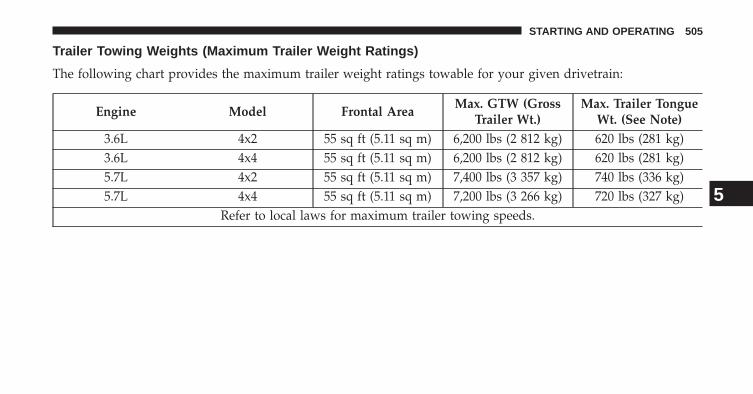
Trailer Towing Weights (Maximum Trailer Weight Ratings)
The following chart provides the maximum trailer weight ratings towable for your given drivetrain:
Engine Model Frontal AreaMax. GTW (Gross
Trailer Wt.)Max. Trailer Tongue
Wt. (See Note)3.6L 4x2 55 sq ft (5.11 sq m) 6,200 lbs (2 812 kg) 620 lbs (281 kg)3.6L 4x4 55 sq ft (5.11 sq m) 6,200 lbs (2 812 kg) 620 lbs (281 kg)5.7L 4x2 55 sq ft (5.11 sq m) 7,400 lbs (3 357 kg) 740 lbs (336 kg)5.7L 4x4 55 sq ft (5.11 sq m) 7,200 lbs (3 266 kg) 720 lbs (327 kg)
Refer to local laws for maximum trailer towing speeds.5
STARTING AND OPERATING 505

NOTE: The trailer tongue weight must be considered aspart of the combined weight of occupants and cargo, andshould never exceed the weight referenced on the Tireand Loading Information placard. Refer to “Tire SafetyInformation” in “Starting and Operating” for furtherinformation. The addition of passengers and cargo mayrequire reducing trailer tongue load and Gross TrailerWeight (GTW). Redistributing cargo (to the trailer) maybe necessary to avoid exceeding Rear Gross Axle WeightRating (GAWR) of 3,700 lbs (1 678 kg).
Trailer And Tongue Weight
Always load a trailer with 60% to 65% of the weight inthe front of the trailer. This places 10% to 15% of the GTWon the tow hitch of your vehicle. Loads balanced over thewheels or heavier in the rear can cause the trailer to swayseverely side to side which will cause loss of control of
the vehicle and trailer. Failure to load trailers heavier infront is the cause of many trailer collisions. Never exceedthe maximum tongue weight stamped on your trailerhitch.
506 STARTING AND OPERATING

Consider the following items when computing theweight on the rear axle of the vehicle:
• The tongue weight of the trailer
• The weight of any other type of cargo or equipmentput in or on your vehicle
• The weight of the driver and all passengers.
NOTE: Remember that everything put into or on thetrailer adds to the load on your vehicle. Also, additionalfactory-installed options or dealer-installed options mustbe considered as part of the total load on your vehicle.Refer to “Tire Safety Information/Tire and Loading In-formation Placard” in “Starting and Operating” for fur-ther information.
Towing Requirements
To promote proper break-in of your new vehicle drivetraincomponents, the following guidelines are recommended.
CAUTION!
• Do not tow a trailer at all during the first 500 miles(805 km) the new vehicle is driven. The engine, axleor other parts could be damaged.
• Then, during the first 500 miles (805 km) that atrailer is towed, do not drive over 50 mph (80 km/h)and do not make starts at full throttle. This helpsthe engine and other parts of the vehicle wear in atthe heavier loads.
Perform the maintenance listed in the “Maintenance Sched-ule.” Refer to “Maintenance Schedule” for the propermaintenance intervals. When towing a trailer, never exceedthe GAWR or GCWR ratings.
5
STARTING AND OPERATING 507
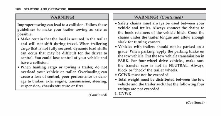
WARNING!
Improper towing can lead to a collision. Follow theseguidelines to make your trailer towing as safe aspossible:• Make certain that the load is secured in the trailer
and will not shift during travel. When traileringcargo that is not fully secured, dynamic load shiftscan occur that may be difficult for the driver tocontrol. You could lose control of your vehicle andhave a collision.
• When hauling cargo or towing a trailer, do notoverload your vehicle or trailer. Overloading cancause a loss of control, poor performance or dam-age to brakes, axle, engine, transmission, steering,suspension, chassis structure or tires.
(Continued)
WARNING! (Continued)• Safety chains must always be used between your
vehicle and trailer. Always connect the chains tothe hook retainers of the vehicle hitch. Cross thechains under the trailer tongue and allow enoughslack for turning corners.
• Vehicles with trailers should not be parked on agrade. When parking, apply the parking brake onthe tow vehicle. Put the tow vehicle transmission inPARK. For four-wheel drive vehicles, make surethe transfer case is not in NEUTRAL. Always,block or �chock� the trailer wheels.
• GCWR must not be exceeded.• Total weight must be distributed between the tow
vehicle and the trailer such that the following fourratings are not exceeded:
1. GVWR
(Continued)
508 STARTING AND OPERATING

WARNING! (Continued)2. GTW3. GAWR4. Tongue weight rating for the trailer hitch utilized.
Towing Requirements – Tires
• Do not attempt to tow a trailer while using a compactspare tire.
• Proper tire inflation pressures are essential to the safeand satisfactory operation of your vehicle. Refer to“Tires – General Information” in “Starting and Oper-ating” for proper tire inflation procedures.
• Check the trailer tires for proper tire inflation pres-sures before trailer usage.
• Check for signs of tire wear or visible tire damagebefore towing a trailer. Refer to “Tires – GeneralInformation” in “Starting and Operating” for theproper inspection procedure.
• When replacing tires, refer to “Tires – General Infor-mation” in “Starting and Operating” for the proper tirereplacement procedures. Replacing tires with a higherload carrying capacity will not increase the vehicle’sGVWR and GAWR limits.
Towing Requirements – Trailer Brakes
• Do not interconnect the hydraulic brake system orvacuum system of your vehicle with that of the trailer.This could cause inadequate braking and possiblepersonal injury.
5
STARTING AND OPERATING 509

• An electronically actuated trailer brake controller isrequired when towing a trailer with electronicallyactuated brakes. When towing a trailer equipped witha hydraulic surge actuated brake system, an electronicbrake controller is not required.
• Trailer brakes are recommended for trailers over1,000 lbs (454 kg) and required for trailers in excess of1,653 lbs (750 kg).
CAUTION!
If the trailer weighs more than 1,000 lbs (454 kg)loaded, it should have its own brakes and theyshould be of adequate capacity. Failure to do thiscould lead to accelerated brake lining wear, higherbrake pedal effort, and longer stopping distances.
WARNING!
• Do not connect trailer brakes to your vehicle’shydraulic brake lines. It can overload your brakesystem and cause it to fail. You might not havebrakes when you need them and could have anaccident.
• Towing any trailer will increase your stoppingdistance. When towing you should allow for addi-tional space between your vehicle and the vehiclein front of you. Failure to do so could result in anaccident.
510 STARTING AND OPERATING

Towing Requirements – Trailer Lights And Wiring
Whenever you pull a trailer, regardless of the trailer size,stoplights and turn signals on the trailer are required formotoring safety.
The Trailer Tow Package may include a four- and seven-pin wiring harness. Use a factory approved trailer har-ness and connector.
NOTE: Do not cut or splice wiring into the vehicleswiring harness.
The electrical connections are all complete to the vehiclebut you must mate the harness to a trailer connector.Refer to the following illustrations.
Four-Pin Connector
1 — Female Pins 4 — Park2 — Male Pin 5 — Left Stop/Turn3 — Ground 6 — Right Stop/Turn
5
STARTING AND OPERATING 511

Towing Tips
Before setting out on a trip, practice turning, stoppingand backing the trailer up in an area away from heavytraffic.
Automatic Transmission
The DRIVE range can be selected when towing. Thetransmission controls include a strategy to avoid frequentshifting when towing. However, if frequent shifting doesoccur while in DRIVE, you can use the Paddle Shiftswitches to manually select a lower gear.
Seven-Pin Connector
1 — Battery 5 — Ground2 — Backup Lamps 6 — Left Stop/Turn3 — Right Stop/Turn 7 — Running Lamps4 — Electric Brakes
512 STARTING AND OPERATING

NOTE: Using a lower gear while operating the vehicleunder heavy loading conditions, will improve perfor-mance and extend transmission life by reducing exces-sive shifting and heat buildup. This action will alsoprovide better engine braking.
Paddle Shift Mode
• When using the Paddle Shift switches, select thehighest gear that allows for adequate performance andavoids frequent downshifts. For example, choose “5” ifthe desired speed can be maintained. Choose “4” or“3” if needed to maintain the desired speed.
• To prevent excess heat generation, avoid continuousdriving at high RPM. Reduce vehicle speed as neces-sary to avoid extended driving at high RPM. Return toa higher gear or vehicle speed when grade and roadconditions allow.
Electronic Speed Control – If Equipped
• Do not use in hilly terrain or with heavy loads.
• When using the speed control, if you experience speeddrops greater than 10 mph (16 km/h), disengage untilyou can get back to cruising speed.
• Use speed control in flat terrain and with light loads tomaximize fuel efficiency.
5
STARTING AND OPERATING 513

Cooling System
To reduce potential for engine and transmission over-heating, take the following actions:
City Driving
When stopped for short periods of time, shift the trans-mission into NEUTRAL and increase engine idle speed.
Highway Driving
Reduce speed.
Air Conditioning
Turn off temporarily.
SNOW PLOW
Snow plows, winches, and other aftermarket equipmentshould not be added to the front end of your vehicle. Theairbag crash sensors may be affected by the change in thefront end structure. The airbags could deploy unexpect-edly or could fail to deploy during a collision.
WARNING!
Do not add a snow plow, winches, or any otheraftermarket equipment to the front of your vehicle.This could adversely affect the functioning of theairbag system and you could be injured.
514 STARTING AND OPERATING

RECREATIONAL TOWING (BEHIND MOTORHOME, ETC.)
Towing This Vehicle Behind Another Vehicle
Towing Condition Wheel OFF the GroundTwo-Wheel Drive
ModelsFour-Wheel Drive
ModelsFlat Tow NONE NOT ALLOWED See Instructions
• Transmission in PARK• Transfer case in
NEUTRAL (N)• Tow in forward
directionDolly Tow Front NOT ALLOWED NOT ALLOWED
Rear OK NOT ALLOWEDOn Trailer ALL OK OK
5
STARTING AND OPERATING 515

NOTE: Vehicles equipped with Quadra-Lift™ must beplaced in Transport Mode before tying them down (fromthe body) on a trailer or flatbed truck. Refer to “Quadra-Lift™ – If Equipped” in “Starting and Operating” formore information. If the vehicle cannot be placed inTransport mode (for example, engine will not run),tie-downs must be fastened to the axles (not to the body).Failure to follow these instructions may cause fault codesto be set and/or cause loss of proper tie-down tension.
Recreational Towing – Two-Wheel Drive Models
DO NOT flat tow this vehicle. Damage to the drivetrainwill result.
Recreational towing (for two-wheel drive models) isallowed ONLY if the rear wheels are OFF the ground.This may be accomplished using a tow dolly or vehicletrailer. If using a tow dolly, follow this procedure:
1. Properly secure the dolly to the tow vehicle, followingthe dolly manufacturer’s instructions.
2. Drive the rear wheels onto the tow dolly.
3. Firmly apply the parking brake. Shift the transmissioninto PARK.
4. Turn the ignition switch to the OFF position.
5. Properly secure the rear wheels to the dolly, followingthe dolly manufacturer’s instructions.
6. Install a suitable clamping device, designed for tow-ing, to secure the front wheels in the straight position.
CAUTION!
Towing with the rear wheels on the ground willcause severe transmission damage. Damage fromimproper towing is not covered under the NewVehicle Limited Warranty.
516 STARTING AND OPERATING
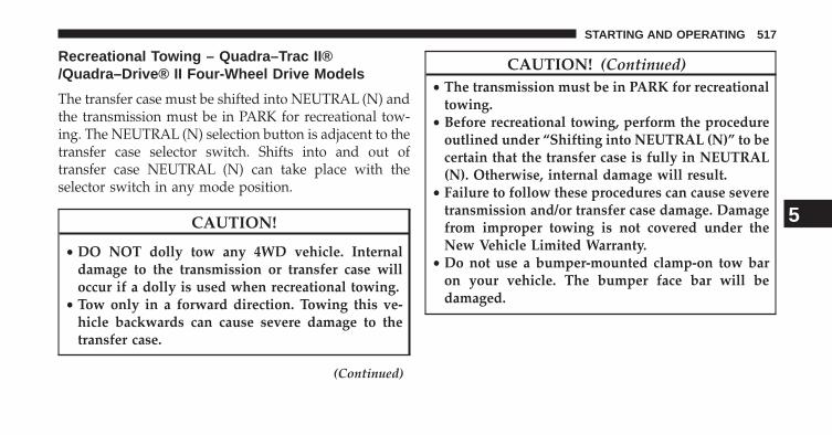
Recreational Towing – Quadra–Trac II®/Quadra–Drive® II Four-Wheel Drive Models
The transfer case must be shifted into NEUTRAL (N) andthe transmission must be in PARK for recreational tow-ing. The NEUTRAL (N) selection button is adjacent to thetransfer case selector switch. Shifts into and out oftransfer case NEUTRAL (N) can take place with theselector switch in any mode position.
CAUTION!
• DO NOT dolly tow any 4WD vehicle. Internaldamage to the transmission or transfer case willoccur if a dolly is used when recreational towing.
• Tow only in a forward direction. Towing this ve-hicle backwards can cause severe damage to thetransfer case.
(Continued)
CAUTION! (Continued)• The transmission must be in PARK for recreational
towing.• Before recreational towing, perform the procedure
outlined under “Shifting into NEUTRAL (N)” to becertain that the transfer case is fully in NEUTRAL(N). Otherwise, internal damage will result.
• Failure to follow these procedures can cause severetransmission and/or transfer case damage. Damagefrom improper towing is not covered under theNew Vehicle Limited Warranty.
• Do not use a bumper-mounted clamp-on tow baron your vehicle. The bumper face bar will bedamaged.
5
STARTING AND OPERATING 517

Shifting Into NEUTRAL (N)
WARNING!
You or others could be injured or killed if you leavethe vehicle unattended with the transfer case in theNEUTRAL (N) position without first fully engagingthe parking brake. The transfer case NEUTRAL (N)position disengages both the front and rear drive-shafts from the powertrain and will allow the vehicleto move, even if the transmission is in PARK. Theparking brake should always be applied when thedriver is not in the vehicle.
Use the following procedure to prepare your vehicle forrecreational towing.
CAUTION!
It is necessary to follow these steps to be certain thatthe transfer case is fully in NEUTRAL (N) beforerecreational towing to prevent damage to internalparts.
1. Bring the vehicle to a complete stop, with the enginerunning.
2. Press and hold the brake pedal.
3. Shift the transmission into NEUTRAL.
4. If vehicle is equipped with Quadra-Lift™ air suspen-sion, ensure the vehicle is set to Normal Ride Height.
518 STARTING AND OPERATING

5. Using a ballpoint pen or similar object, press and holdthe recessed transfer case NEUTRAL (N) button (locatedby the selector switch) for four seconds. The lightbehind the N symbol will blink, indicating shift inprogress. The light will stop blinking (stay on solid)when the shift to NEUTRAL (N) is complete. A “FOURWHEEL DRIVE SYSTEM IN NEUTRAL” message willdisplay on the EVIC (Electronic Vehicle InformationCenter). Refer to “Electronic Vehicle Information Center(EVIC)” in “Understanding Your Instrument Panel” forfurther information.
6. After the shift is completed and the NEUTRAL (N)light stays on, release the NEUTRAL (N) button.
7. Shift the transmission into REVERSE.
8. Release the brake pedal for five seconds and ensurethat there is no vehicle movement.
NEUTRAL (N) Switch
5
STARTING AND OPERATING 519

9. Shift the transmission back into NEUTRAL
10. With the transmission and transfer case in NEU-TRAL, press and hold the ENGINE START/STOPbutton until the engine turns off. Turning the engineoff will automatically place the transmission inPARK.
11. Press the ENGINE STOP/START button again (with-out pressing the brake pedal), if needed, to turn theignition switch to the OFF position.
12. Firmly apply the parking brake.
13. Attach the vehicle to the tow vehicle using a suitabletow bar.
14. Release the parking brake.
NOTE:
• Steps 1 through 4 are requirements that must be metbefore pressing the NEUTRAL (N) button, and mustcontinue to be met until the shift has been completed.If any of these requirements are not met before press-ing the NEUTRAL (N) button or are no longer metduring the shift, then the NEUTRAL (N) indicator lightwill flash continuously until all requirements are metor until the NEUTRAL (N) button is released.
• The ignition switch must be in the ON/RUN positionfor a shift to take place and for the position indicatorlights to be operable. If the ignition switch is not in theON/RUN position, the shift will not take place and noposition indicator lights will be on or flashing.
• A flashing NEUTRAL (N) position indicator lightindicates that shift requirements have not been met.
520 STARTING AND OPERATING

• If the vehicle is equipped with Quadra-Lift™ airsuspension, the engine should be started and leftrunning for a minimum of 60 seconds (with all thedoors closed) at least once every 24 hours. This processallows the air suspension to adjust the vehicle’s rideheight to compensate for temperature effects.
Shifting Out Of NEUTRAL (N)
Use the following procedure to prepare your vehicle fornormal usage.
1. Bring the vehicle to a complete stop, leaving it con-nected to the tow vehicle.
2. Firmly apply the parking brake.
3. Start the engine.
4. Press and hold the brake pedal.
5. Shift the transmission into NEUTRAL.
6. Using a ballpoint pen or similar object, press and holdthe recessed transfer case NEUTRAL (N) button (lo-cated by the selector switch) for one second.
NEUTRAL (N) Switch
5
STARTING AND OPERATING 521
7. When the NEUTRAL (N) indicator light turns off,release the NEUTRAL (N) button. After the NEU-TRAL (N) button has been released, the transfer casewill shift to the position indicated by the selectorswitch.
8. Shift the transmission into PARK. Turn the engineOFF.
9. Release the brake pedal.
10. Disconnect vehicle from the tow vehicle.
11. Start the engine.
12. Press and hold the brake pedal.
13. Release the parking brake.
14. Shift the transmission into DRIVE, release the brakepedal, and check that the vehicle operates normally.
NOTE:
• Steps 1 through 5 are requirements that must be metprior to pressing the NEUTRAL (N) button, and mustcontinue to be met until the shift has been completed.If any of these requirements are not met prior topressing the NEUTRAL (N) button or are no longermet during the shift, the NEUTRAL (N) indicator lightwill flash continuously until all requirements are metor until the NEUTRAL (N) button is released.
• The ignition switch must be in the ON/RUN positionfor a shift to take place and for the position indicatorlights to be operable. If the ignition switch is not in theON/RUN position, the shift will not take place and noposition indicator lights will be on or flashing.
• A flashing NEUTRAL (N) position indicator lightindicates that shift requirements have not been met.
522 STARTING AND OPERATING

WHAT TO DO IN EMERGENCIES
CONTENTS� HAZARD WARNING FLASHERS . . . . . . . . . . .524
� IF YOUR ENGINE OVERHEATS . . . . . . . . . . . .524
� JACKING AND TIRE CHANGING . . . . . . . . . .525
▫ Jack Location . . . . . . . . . . . . . . . . . . . . . . . .526
▫ Spare Tire Stowage . . . . . . . . . . . . . . . . . . . .527
▫ Preparations For Jacking . . . . . . . . . . . . . . . .527
▫ Jacking Instructions . . . . . . . . . . . . . . . . . . .528
▫ Road Tire Installation . . . . . . . . . . . . . . . . . . .535
� JUMP-STARTING . . . . . . . . . . . . . . . . . . . . . .536
▫ Preparations For Jump-Start . . . . . . . . . . . . . .536
▫ Jump-Starting Procedure . . . . . . . . . . . . . . . .538
� FREEING A STUCK VEHICLE . . . . . . . . . . . . .540
� EMERGENCY TOW HOOKS — IF EQUIPPED . .542
� MANUAL PARK RELEASE . . . . . . . . . . . . . . . .542
� TOWING A DISABLED VEHICLE . . . . . . . . . . .546
▫ Two-Wheel Drive Models . . . . . . . . . . . . . . . .548
▫ Four-Wheel Drive Models. . . . . . . . . . . . . . . .549
6

HAZARD WARNING FLASHERS
The Hazard Warning flasher switch is located on theswitch bank just above the climate controls.
Press the switch to turn on the Hazard Warningflasher. When the switch is activated, all direc-
tional turn signals will flash on and off to warn oncomingtraffic of an emergency. Press the switch a second time toturn off the Hazard Warning flashers.
This is an emergency warning system and it should notbe used when the vehicle is in motion. Use it when yourvehicle is disabled and it is creating a safety hazard forother motorists.
When you must leave the vehicle to seek assistance, theHazard Warning flashers will continue to operate eventhough the ignition is placed in the OFF position.
NOTE: With extended use the Hazard Warning flashersmay wear down your battery.
IF YOUR ENGINE OVERHEATS
In any of the following situations, you can reduce thepotential for overheating by taking the appropriate action.
• On the highways — slow down.
• In city traffic — while stopped, place the transmission inNEUTRAL, but do not increase the engine idle speed.
NOTE: There are steps that you can take to slow downan impending overheat condition:
• If your air conditioner (A/C) is on, turn it off. The A/Csystem adds heat to the engine cooling system andturning the A/C off can help remove this heat.
• You can also turn the temperature control to maximumheat, the mode control to floor and the blower controlto high. This allows the heater core to act as asupplement to the radiator and aids in removing heatfrom the engine cooling system.
524 WHAT TO DO IN EMERGENCIES

CAUTION!
Driving with a hot cooling system could damageyour vehicle. If the temperature gauge reads HOT(H), pull over and stop the vehicle. Idle the vehiclewith the air conditioner turned off until the pointerdrops back into the normal range. If the pointerremains on HOT (H), and you hear continuouschimes, turn the engine off immediately and call forservice.
WARNING!
You or others can be badly burned by hot enginecoolant (antifreeze) or steam from your radiator. Ifyou see or hear steam coming from under the hood,do not open the hood until the radiator has had timeto cool. Never try to open a cooling system pressurecap when the radiator or coolant bottle is hot.
JACKING AND TIRE CHANGING
WARNING!
• Do not attempt to change a tire on the side of thevehicle close to moving traffic. Pull far enough offthe road to avoid the danger of being hit whenoperating the jack or changing the wheel.
• Being under a jacked-up vehicle is dangerous. Thevehicle could slip off the jack and fall on you. Youcould be crushed. Never put any part of your bodyunder a vehicle that is on a jack. If you need to getunder a raised vehicle, take it to a service centerwhere it can be raised on a lift.
• Never start or run the engine while the vehicle ison a jack.
(Continued)
6
WHAT TO DO IN EMERGENCIES 525

WARNING! (Continued)• The jack is designed to be used as a tool for
changing tires only. The jack should not be used tolift the vehicle for service purposes. The vehicleshould be jacked on a firm level surface only.Avoid ice or slippery areas.
Jack Location
The scissor-type jack and tire changing tools are locatedin rear cargo area, below the load floor.
Jack Storage Location
526 WHAT TO DO IN EMERGENCIES

NOTE: The funnel for the Cap-Less Fuel System is locatedon top of the spare tire. If your vehicle is out of fuel and anauxiliary fuel can is needed, insert the funnel into the fillerneck and proceed to fill the vehicle. For more informationon the Cap-Less Fuel System refer to “Adding Fuel” in“Starting And Operating” in this manual.
Spare Tire Stowage
The spare tire is stowed under the load floor in the rearcargo area and is secured to the body with a special wingnut.
Preparations For Jacking
CAUTION!
Always lift or jack the vehicle from the correctjacking points. Failure to follow this informationcould cause damage to the vehicle or underbodycomponents.
NOTE: To assist with changing a spare tire, the airsuspension system has a feature which allows the auto-matic leveling to be disabled.
1. Park the vehicle on a firm, level surface. Avoid ice orslippery surfaces.
WARNING!
Do not attempt to change a tire on the side of thevehicle closest to moving traffic, pull far enough offthe road to avoid being hit when operating the jackor changing the wheel.
2. Turn on the Hazard Warning flasher.
3. Set the parking brake.
4. Place the shift lever into PARK.
6
WHAT TO DO IN EMERGENCIES 527

5. Turn the ignition OFF.
6. Block both the front and rear of the wheel diagonallyopposite of the jacking position. Forexample, if changing the right fronttire, block the left rear wheel.
NOTE: Passengers should not remainin the vehicle when the vehicle isbeing jacked.
7. For vehicles equipped with Quadra-Lift® refer to“Quadra-Lift® — If Equipped” in “Starting And Op-erating” for further information on disabling auto-matic leveling.
Jacking Instructions
WARNING!
Carefully follow these tire changing warnings tohelp prevent personal injury or damage to yourvehicle:• Always park on a firm, level surface as far from the
edge of the roadway as possible before raising thevehicle.
• Turn on the Hazard Warning flasher.• Block the wheel diagonally opposite the wheel to
be raised.• Set the parking brake firmly and set an automatic
transmission in PARK.• Never start or run the engine with the vehicle on a
jack.
(Continued)
528 WHAT TO DO IN EMERGENCIES
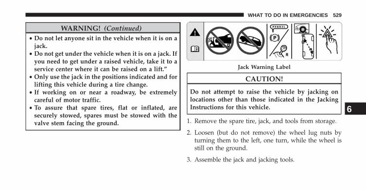
WARNING! (Continued)• Do not let anyone sit in the vehicle when it is on a
jack.• Do not get under the vehicle when it is on a jack. If
you need to get under a raised vehicle, take it to aservice center where it can be raised on a lift.”
• Only use the jack in the positions indicated and forlifting this vehicle during a tire change.
• If working on or near a roadway, be extremelycareful of motor traffic.
• To assure that spare tires, flat or inflated, aresecurely stowed, spares must be stowed with thevalve stem facing the ground.
CAUTION!
Do not attempt to raise the vehicle by jacking onlocations other than those indicated in the JackingInstructions for this vehicle.
1. Remove the spare tire, jack, and tools from storage.
2. Loosen (but do not remove) the wheel lug nuts byturning them to the left, one turn, while the wheel isstill on the ground.
3. Assemble the jack and jacking tools.
Jack Warning Label
6
WHAT TO DO IN EMERGENCIES 529

4. For the front axle, place the jack on the body flangejust behind the front tire as indicated by the triangularlift point symbol on the sill molding. Do not raise thevehicle until you are sure the jack is fully engaged.
Jack and Tool Assembly Jacking Locations
530 WHAT TO DO IN EMERGENCIES

5. For a rear tire, place the jack in the slot on the reartie-down bracket, just forward of the rear tire (asindicated by the triangular lift point symbol on the sillmolding). Do not raise the vehicle until you are surethe jack is fully engaged.
Lift Point Symbol On Sill Molding Front Jacking Location6
WHAT TO DO IN EMERGENCIES 531

6. Raise the vehicle by turning the jack screw clockwise.Raise the vehicle only until the tire just clears thesurface and enough clearance is obtained to install thespare tire. Minimum tire lift provides maximum sta-bility.
Lift Point Symbol On Sill Molding Rear Jacking Location
532 WHAT TO DO IN EMERGENCIES

WARNING!
Raising the vehicle higher than necessary can makethe vehicle less stable. It could slip off the jack andhurt someone near it. Raise the vehicle only enoughto remove the tire.
7. Remove the lug nuts and wheel.
8. Position the spare wheel/tire on the vehicle and installthe lug nuts with the cone-shaped end toward thewheel. Lightly tighten the nuts.
CAUTION!
Be sure to mount the spare tire with the valve stemfacing outward. The vehicle could be damaged if thespare tire is mounted incorrectly.
WARNING!
To avoid the risk of forcing the vehicle off the jack,do not tighten the lug nuts fully until the vehicle hasbeen lowered. Failure to follow this warning mayresult in personal injury.
Mounting Spare Tire6
WHAT TO DO IN EMERGENCIES 533
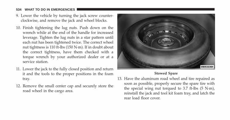
9. Lower the vehicle by turning the jack screw counter-clockwise, and remove the jack and wheel blocks.
10. Finish tightening the lug nuts. Push down on thewrench while at the end of the handle for increasedleverage. Tighten the lug nuts in a star pattern untileach nut has been tightened twice. The correct wheelnut tightness is 110 ft-lbs (150 N·m). If in doubt aboutthe correct tightness, have them checked with atorque wrench by your authorized dealer or at aservice station.
11. Lower the jack to the fully closed position and returnit and the tools to the proper positions in the foamtray.
12. Remove the small center cap and securely store theroad wheel in the cargo area.
13. Have the aluminum road wheel and tire repaired assoon as possible, properly secure the spare tire withthe special wing nut torqued to 3.7 ft-lbs (5 N·m),reinstall the jack and tool kit foam tray, and latch therear load floor cover.
Stowed Spare
534 WHAT TO DO IN EMERGENCIES

WARNING!
A loose tire or jack thrown forward in a collision orhard stop could endanger the occupants of the ve-hicle. Always stow the jack parts and the spare tire inthe places provided. Have the deflated (flat) tirerepaired or replaced immediately.
Road Tire Installation
1. Mount the road tire on the axle.
2. Install the remaining lug nuts with the cone shapedend of the nut toward the wheel. Lightly tighten thelug nuts.
WARNING!
To avoid the risk of forcing the vehicle off the jack,do not tighten the lug nuts fully until the vehicle hasbeen lowered. Failure to follow this warning mayresult in personal injury.
3. Lower the vehicle to the ground by turning the jackhandle counterclockwise.
4. Refer to Torque Table for proper lug nut torque.
5. After 25 miles (40 km) check the lug nut torque with atorque wrench to ensure that all lug nuts are properlyseated against the wheel.
6
WHAT TO DO IN EMERGENCIES 535

JUMP-STARTING
If your vehicle has a discharged battery it can be jump-started using a set of jumper cables and a battery inanother vehicle or by using a portable battery boosterpack. Jump-starting can be dangerous if done improperlyso please follow the procedures in this section carefully.
NOTE: When using a portable battery booster packfollow the manufacturer’s operating instructions andprecautions.
CAUTION!
Do not use a portable battery booster pack or anyother booster source with a system voltage greaterthan 12 Volts or damage to the battery, starter motor,alternator or electrical system may occur.
WARNING!
Do not attempt jump-starting if the battery is frozen.It could rupture or explode and cause personal injury.
Preparations For Jump-Start
The battery in your vehicle is located under the passen-ger’s front seat. There are remote locations located underthe hood to assist in jump-starting.
536 WHAT TO DO IN EMERGENCIES

WARNING!
• Take care to avoid the radiator cooling fan when-ever the hood is raised. It can start anytime theignition switch is ON. You can be injured bymoving fan blades.
• Remove any metal jewelry such as rings, watchbands and bracelets that could make an inadvertentelectrical contact. You could be seriously injured.
• Batteries contain sulfuric acid that can burn yourskin or eyes and generate hydrogen gas which isflammable and explosive. Keep open flames orsparks away from the battery.
NOTE: Be sure that the disconnected ends of the cablesdo not touch while still connected to the other vehicle.
1. Set the parking brake, shift the automatic transmissioninto PARK and turn the ignition to LOCK.
Remote Battery Posts
1 — Remote Positive (+) Post (covered with protective cap)2 — Remote Negative (-) Post
6
WHAT TO DO IN EMERGENCIES 537
2. Turn off the heater, radio, and all unnecessary electri-cal accessories.
3. Remove the protective cover over the remote posi-tive (+) battery post. Pull upward on the cover toremove it.
4. If using another vehicle to jump-start the battery, parkthe vehicle within the jumper cables reach, set theparking brake and make sure the ignition is OFF.
WARNING!
Do not allow vehicles to touch each other as thiscould establish a ground connection and personalinjury could result.
Jump-Starting Procedure
WARNING!
Failure to follow this procedure could result in per-sonal injury or property damage due to battery ex-plosion.
CAUTION!
Failure to follow these procedures could result indamage to the charging system of the booster vehicleor the discharged vehicle.
NOTE: Make sure at all times that unused ends ofjumper cables are not contacting each other or eithervehicle while making connections.
1. Connect the positive (+) end of the jumper cable to theremote positive (+) post of the discharged vehicle.
538 WHAT TO DO IN EMERGENCIES

2. Connect the opposite end of the positive (+) jumpercable to the positive (+) post of the booster battery.
3. Connect the negative end (-) of the jumper cable to thenegative (-) post of the booster battery.
4. Connect the opposite end of the negative (-) jumpercable to the remote negative (-) post of the vehicle withthe discharged battery.
WARNING!
Do not connect the cable to the negative post (-) of thedischarged battery. The resulting electrical sparkcould cause the battery to explode and could result inpersonal injury.
5. Start the engine in the vehicle that has the boosterbattery, let the engine idle a few minutes, and thenstart the engine in the vehicle with the dischargedbattery.
Once the engine is started, remove the jumper cables inthe reverse sequence:
6. Disconnect the negative (-) jumper cable from theremote negative (-) post of the discharged vehicle.
7. Disconnect the negative end (-) of the jumper cablefrom the negative (-) post of the booster battery.
8. Disconnect the opposite end of the positive (+) jumpercable from the positive (+) post of the booster battery.
9. Disconnect the positive (+) end of the jumper cablefrom the remote positive (+) post of the dischargedvehicle.
10. Reinstall the protective cover over the remote posi-tive (+) battery post of the discharged vehicle.
If frequent jump-starting is required to start your vehicleyou should have the battery and charging system testedat your authorized dealer.
6
WHAT TO DO IN EMERGENCIES 539

CAUTION!
Accessories plugged into the vehicle power outletsdraw power from the vehicle’s battery, even when notin use (i.e., cellular phones, etc.). Eventually, ifplugged in long enough without engine operation,the vehicle’s battery will discharge sufficiently todegrade battery life and/or prevent the engine fromstarting.
FREEING A STUCK VEHICLE
If your vehicle becomes stuck in mud, sand or snow, itcan often be moved using a rocking motion. Turn thesteering wheel right and left to clear the area around thefront wheels. Then shift back and forth between DRIVEand REVERSE while gently pressing the accelerator.
NOTE: Shifts between DRIVE and REVERSE can only beachieved at wheel speeds of 5 mph (8 km/h) or less.Whenever the transmission remains in NEUTRAL formore than 2 seconds, you must press the brake pedal toengage DRIVE or REVERSE.
Use the least amount of accelerator pedal pressure thatwill maintain the rocking motion without spinning thewheels or racing the engine.
NOTE: Press the �ESC Off� switch (if necessary), to placethe Electronic Stability Control (ESC) system in �PartialOff� mode, before rocking the vehicle. Refer to “Elec-tronic Brake Control” in “Starting And Operating” forfurther information. Once the vehicle has been freed,press the �ESC Off� switch again to restore �ESC On�mode.
540 WHAT TO DO IN EMERGENCIES

CAUTION!
Racing the engine or spinning the wheels may lead totransmission overheating and failure. Allow the en-gine to idle with the transmission in NEUTRAL for atleast one minute after every five rocking-motioncycles. This will minimize overheating and reducethe risk of transmission failure during prolongedefforts to free a stuck vehicle.
CAUTION!
• When “rocking” a stuck vehicle by shifting be-tween DRIVE and REVERSE, do not spin thewheels faster than 15 mph (24 km/h), or drivetraindamage may result.
(Continued)
CAUTION! (Continued)• Revving the engine or spinning the wheels too fast
may lead to transmission overheating and failure.It can also damage the tires. Do not spin the wheelsabove 30 mph (48 km/h) while in gear (no trans-mission shifting occurring).
WARNING!
Fast spinning tires can be dangerous. Forces gener-ated by excessive wheel speeds may cause damage, oreven failure, of the axle and tires. A tire couldexplode and injure someone. Do not spin your vehi-cle’s wheels faster than 30 mph (48 km/h) or forlonger than 30 seconds continuously without stop-ping when you are stuck and do not let anyone neara spinning wheel, no matter what the speed.
6
WHAT TO DO IN EMERGENCIES 541

EMERGENCY TOW HOOKS — IF EQUIPPED
If your vehicle is equipped with tow hooks, there will beone in the rear and two mounted on the front of thevehicle. The rear hook will be located on the driver’s sideof the vehicle.
NOTE: For off-road recovery, it is recommended to useboth of the front tow hooks to minimize the risk ofdamage to the vehicle.
WARNING!
• Do not use a chain for freeing a stuck vehicle.Chains may break, causing serious injury or death.
• Stand clear of vehicles when pulling with towhooks. Tow straps may become disengaged, caus-ing serious injury.
CAUTION!
Tow hooks are for emergency use only, to rescue avehicle stranded off road. Do not use tow hooks fortow truck hookup or highway towing. You coulddamage your vehicle.
MANUAL PARK RELEASE
WARNING!
Always secure your vehicle by fully applying theparking brake, before activating the Manual ParkRelease. Activating the Manual Park Release willallow your vehicle to roll away if it is not secured bythe parking brake or by proper connection to a towvehicle. Activating the Manual Park Release on anunsecured vehicle could lead to serious injury ordeath for those in or around the vehicle.
542 WHAT TO DO IN EMERGENCIES
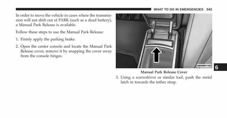
In order to move the vehicle in cases where the transmis-sion will not shift out of PARK (such as a dead battery),a Manual Park Release is available.
Follow these steps to use the Manual Park Release:
1. Firmly apply the parking brake.
2. Open the center console and locate the Manual ParkRelease cover, remove it by snapping the cover awayfrom the console hinges.
3. Using a screwdriver or similar tool, push the metallatch in towards the tether strap.
Manual Park Release Cover6
WHAT TO DO IN EMERGENCIES 543

4. While the metal latch is the open position, simultane-ously pull upwards on the tether strap until it clicksand releases out of the park position.
NOTE: To prevent the vehicle from rolling unintention-ally, firmly apply the parking brake.
Release Latch Released Position
544 WHAT TO DO IN EMERGENCIES

To Disengage the Manual Park Release Lever:
1. To disengage the Manual Park Release apply tensionupward while pushing the release latch towards thetether to unlock the lever.
2. Once the tension has been released and the lever hasbeen unlocked be sure it is stowed properly and locksinto position.
NOTE: Be sure to replace the cover by snapping it backin place.
Release Latch
Stowed Position
6
WHAT TO DO IN EMERGENCIES 545

TOWING A DISABLED VEHICLE
This section describes procedures for towing a disabledvehicle using a commercial wrecker service. If the trans-mission and drivetrain are operable, disabled vehiclesmay also be towed as described under “RecreationalTowing” in the “Starting and Operating” section.
NOTE: Vehicles equipped with Quadra-Lift™ must beplaced in Transport mode, before tying them down (fromthe body) on a trailer or flatbed truck. Refer to the sectionon Quadra-Lift™ for more information. If the vehiclecannot be lowered to the Park level (for example, enginewill not run), tie-downs must be fastened to the axles (notto the body). Failure to follow these instructions maycause fault codes to be set and/or cause loss of propertie-down tension.
546 WHAT TO DO IN EMERGENCIES

Towing Condi-tion
Wheels OFFthe Ground
2WD Models 4WD Models
Flat Tow NONE If transmission is operable:• Transmission in NEUTRAL• 30 mph (48 km/h) max speed• 30 miles (48 km) max distance
See instructions in “Recreational Tow-ing” under “Starting and Operating”
• Transmission in PARK• Transfer Case in NEUTRAL• Tow in forward direction
Wheel Lift orDolly Tow
Front NOT ALLOWEDRear OK NOT ALLOWED
Flatbed ALL BEST METHOD BEST METHOD
Proper towing or lifting equipment is required to preventdamage to your vehicle. Use only tow bars and otherequipment designed for this purpose, following equip-ment manufacturer’s instructions. Use of safety chains ismandatory. Attach a tow bar or other towing device tomain structural members of the vehicle, not to bumpersor associated brackets. State and local laws regardingvehicles under tow must be observed.
If you must use the accessories (wipers, defrosters, etc.)while being towed, the ignition must be in the ON/RUNposition, not the ACC position.
If the vehicle’s battery is discharged, refer to “ManualPark Release” in this section for instructions on shiftingthe transmission out of PARK for towing.
6
WHAT TO DO IN EMERGENCIES 547

CAUTION!
Do not use sling type equipment when towing.When securing the vehicle to a flat bed truck, do notattach to front or rear suspension components. Dam-age to your vehicle may result from improper towing.
Two-Wheel Drive Models
The manufacturer recommends towing your vehicle withall four wheels OFF the ground using a flatbed.
If flatbed equipment is not available, and the transmis-sion is operable, the vehicle may be towed (with rearwheels on the ground) under the following conditions:
• The transmission must be in NEUTRAL see “ManualPark Release” in this section for more information.
• The towing speed must not exceed 30 mph (48 km/h).See “Manual Park Release” in this section for informa-tion on shifting the transmission to NEUTRAL.
• The towing distance must not exceed 30 miles (48 km).
If the transmission is not operable, or the vehicle must betowed faster than 30 mph (48 km/h) or farther than30 miles (48 km), tow with the rear wheels OFF theground. Acceptable methods are to tow the vehicle on aflatbed, or with the front wheels raised and the rearwheels on a towing dolly, or (when using a suitablesteering wheel stabilizer to hold the front wheels in thestraight position) with the rear wheels raised and thefront wheels on the ground.
CAUTION!
Towing this vehicle in violation of the above require-ments can cause severe transmission damage. Dam-age from improper towing is not covered under theNew Vehicle Limited Warranty.
548 WHAT TO DO IN EMERGENCIES

Four-Wheel Drive Models
The manufacturer recommends towing with all wheelsOFF the ground. Acceptable methods are to tow thevehicle on a flatbed or with one end of vehicle raised andthe opposite end on a towing dolly.
If flatbed equipment is not available, and the transfercase is operable, vehicles with a two-speed transfer casemay be towed (in the forward direction, with ALL wheelson the ground), IF the transfer case is in NEUTRAL (N)and the transmission is in PARK. Refer to “RecreationalTowing” in “Starting And Operating” for detailed in-structions.
Vehicles equipped with a single-speed transfer case haveno NEUTRAL position, and therefore must be towedwith all four wheels OFF the ground.
CAUTION!
• Front or rear wheel lifts must not be used. Internaldamage to the transmission or transfer case willoccur if a front or rear wheel lift is used whentowing.
• Towing this vehicle in violation of the above re-quirements can cause severe transmission and/ortransfer case damage. Damage from improper tow-ing is not covered under the New Vehicle LimitedWarranty.
6
WHAT TO DO IN EMERGENCIES 549

MAINTAINING YOUR VEHICLE
CONTENTS� ENGINE COMPARTMENT — 3.6L . . . . . . . . . .553
� ENGINE COMPARTMENT — 5.7L . . . . . . . . . .554
� ONBOARD DIAGNOSTIC SYSTEM (OBD II) . . .555
� EMISSIONS INSPECTION ANDMAINTENANCE PROGRAMS . . . . . . . . . . . . .555
� REPLACEMENT PARTS . . . . . . . . . . . . . . . . . .557
� DEALER SERVICE . . . . . . . . . . . . . . . . . . . . . .557
� MAINTENANCE PROCEDURES . . . . . . . . . . .558
▫ Engine Oil . . . . . . . . . . . . . . . . . . . . . . . . . .559
▫ Engine Oil Filter . . . . . . . . . . . . . . . . . . . . . .562
▫ Engine Air Cleaner Filter . . . . . . . . . . . . . . . .562
▫ Maintenance-Free Battery . . . . . . . . . . . . . . .563
▫ Air Conditioner Maintenance . . . . . . . . . . . . .564
▫ Body Lubrication . . . . . . . . . . . . . . . . . . . . .567
▫ Windshield Wiper Blades . . . . . . . . . . . . . . .567
▫ Adding Washer Fluid . . . . . . . . . . . . . . . . . .569
▫ Exhaust System . . . . . . . . . . . . . . . . . . . . . .570
▫ Cooling System . . . . . . . . . . . . . . . . . . . . . .573
▫ Brake System . . . . . . . . . . . . . . . . . . . . . . . .578
▫ Front/Rear Axle Fluid . . . . . . . . . . . . . . . . . .580
7

▫ Transfer Case . . . . . . . . . . . . . . . . . . . . . . . .581
▫ Automatic Transmission . . . . . . . . . . . . . . . .582
▫ Appearance Care And Protection FromCorrosion . . . . . . . . . . . . . . . . . . . . . . . . . . .584
� FUSES . . . . . . . . . . . . . . . . . . . . . . . . . . . . . .590
▫ Power Distribution Center . . . . . . . . . . . . . . .590
� VEHICLE STORAGE . . . . . . . . . . . . . . . . . . . .598
� REPLACEMENT BULBS . . . . . . . . . . . . . . . . .598
� BULB REPLACEMENT . . . . . . . . . . . . . . . . . .600
▫ High Intensity Discharge Headlamps(HID) – If Equipped . . . . . . . . . . . . . . . . . . .600
▫ Halogen Headlamps – If Equipped . . . . . . . . .601
▫ Front Turn Signal . . . . . . . . . . . . . . . . . . . . .601
▫ Front Fog Lamps . . . . . . . . . . . . . . . . . . . . .601
▫ Rear Tail, Stop, and Turn Signal Lamps . . . . . .602
▫ Rear Liftgate Mounted Tail Lamp . . . . . . . . . .604
▫ Center High-Mounted Stop Lamp (CHMSL) . .605
▫ Rear License Lamp . . . . . . . . . . . . . . . . . . . .605
� FLUID CAPACITIES . . . . . . . . . . . . . . . . . . . .606
� FLUIDS, LUBRICANTS AND GENUINEPARTS . . . . . . . . . . . . . . . . . . . . . . . . . . . . . .607
▫ Engine . . . . . . . . . . . . . . . . . . . . . . . . . . . . .607
▫ Chassis . . . . . . . . . . . . . . . . . . . . . . . . . . . . .608
552 MAINTAINING YOUR VEHICLE

ENGINE COMPARTMENT — 3.6L
1 — Power Distribution Center (Fuses) 6 — Air Cleaner Filter2 — Engine Oil Dipstick 7 — Washer Fluid Reservoir3 — Engine Oil Fill 8 — Coolant Pressure Cap (Radiator)4 — Brake Fluid Reservoir 9 — Engine Coolant Reservoir5 — Power Steering Fluid Reservoir
7
MAINTAINING YOUR VEHICLE 553

ENGINE COMPARTMENT — 5.7L
1 — Power Distribution Center 5 — Washer Fluid Reservoir2 — Engine Oil Fill 6 — Engine Oil Dipstick3 — Brake Fluid Reservoir 7 — Coolant Pressure Cap (Radiator)4 — Air Cleaner Filter 8 — Engine Coolant Reservoir
554 MAINTAINING YOUR VEHICLE

ONBOARD DIAGNOSTIC SYSTEM (OBD II)
Your vehicle is equipped with a sophisticated onboarddiagnostic system called OBD II. This system monitorsthe performance of the emissions, engine, and automatictransmission control systems. When these systems areoperating properly, your vehicle will provide excellentperformance and fuel economy, as well as engine emis-sions well within current government regulations.
If any of these systems require service, the OBD II systemwill turn on the “Malfunction Indicator Light (MIL).” Itwill also store diagnostic codes and other information toassist your service technician in making repairs. Al-though your vehicle will usually be drivable and notneed towing, see your authorized dealer for service assoon as possible.
CAUTION!
• Prolonged driving with the MIL on could causefurther damage to the emission control system. Itcould also affect fuel economy and driveability.The vehicle must be serviced before any emissionstests can be performed.
• If the MIL is flashing, while the engine is running,severe catalytic converter damage and power losswill soon occur. Immediate service is required.
EMISSIONS INSPECTION AND MAINTENANCEPROGRAMS
In some localities, it may be a legal requirement to passan inspection of your vehicle’s emissions control system.Failure to pass could prevent vehicle registration.
For states that require an Inspection and Mainte-nance (I/M), this check verifies the “Malfunction
7
MAINTAINING YOUR VEHICLE 555

Indicator Light (MIL)” is functioning and is not on whenthe engine is running, and that the OBD II system isready for testing.
Normally, the OBD II system will be ready. The OBD IIsystem may not be ready if your vehicle was recentlyserviced, recently had a dead battery or a battery replace-ment. If the OBD II system should be determined notready for the I/M test, your vehicle may fail the test.
Your vehicle has a simple ignition key-actuated test,which you can use prior to going to the test station. Tocheck if your vehicle’s OBD II system is ready, you mustdo the following:
1. Cycle the ignition switch to the ON position, but donot crank or start the engine.
2. If you crank or start the engine, you will have to startthis test over.
3. As soon as you cycle the ignition switch to the ONposition, you will see the MIL symbol come on as partof a normal bulb check.
4. Approximately 15 seconds later, one of two things willhappen:
• The MIL will flash for about 10 seconds and thenreturn to being fully illuminated until you turn OFFthe ignition or start the engine. This means that yourvehicle’s OBD II system is not ready and you shouldnot proceed to the I/M station.
• The MIL will not flash at all and will remain fullyilluminated until you turn OFF the ignition or start theengine. This means that your vehicle’s OBD II systemis ready and you can proceed to the I/M station.
556 MAINTAINING YOUR VEHICLE

If your OBD II system is not ready, you should see yourauthorized dealer or repair facility. If your vehicle wasrecently serviced or had a battery failure or replacement,you may need to do nothing more than drive yourvehicle as you normally would in order for your OBD IIsystem to update. A recheck with the above test routinemay then indicate that the system is now ready.
Regardless of whether your vehicle’s OBD II system isready or not, if the MIL is illuminated during normalvehicle operation you should have your vehicle servicedbefore going to the I/M station. The I/M station can failyour vehicle because the MIL is on with the enginerunning.
REPLACEMENT PARTS
Use of genuine MOPAR® parts for normal/scheduledmaintenance and repairs is highly recommended to ensurethe designed performance. Damage or failures caused by
the use of non-MOPAR® parts for maintenance and repairswill not be covered by the New Vehicle Limited Warranty.
DEALER SERVICE
Your authorized dealer has the qualified service person-nel, special tools, and equipment to perform all serviceoperations in an expert manner. Service Manuals areavailable which include detailed service information foryour vehicle. Refer to these Service Manuals beforeattempting any procedure yourself.
NOTE: Intentional tampering with emissions controlsystems may void your warranty and could result in civilpenalties being assessed against you. 7
MAINTAINING YOUR VEHICLE 557

WARNING!
You can be badly injured working on or around amotor vehicle. Only do service work for which youhave the knowledge and the proper equipment. Ifyou have any doubt about your ability to perform aservice job, take your vehicle to a competent me-chanic.
MAINTENANCE PROCEDURES
The pages that follow contain the required maintenanceservices determined by the engineers who designed yourvehicle.
Besides those maintenance items specified in the fixedmaintenance schedule, there are other components whichmay require servicing or replacement in the future.
CAUTION!
• Failure to properly maintain your vehicle or per-form repairs and service when necessary couldresult in more costly repairs, damage to othercomponents or negatively impact vehicle perfor-mance. Immediately have potential malfunctionsexamined by an authorized dealer or qualifiedrepair center.
• Your vehicle has been built with improved fluidsthat protect the performance and durability of yourvehicle and also allow extended maintenance inter-vals. Do not use chemical flushes in these compo-nents as the chemicals can damage your engine,transmission, power steering or air conditioning.Such damage is not covered by the New VehicleLimited Warranty. If a flush is needed because ofcomponent malfunction, use only the specifiedfluid for the flushing procedure.
558 MAINTAINING YOUR VEHICLE

Engine Oil
Checking Oil Level
To assure proper lubrication of your vehicle’s engine, theengine oil must be maintained at the correct level. Checkthe oil level at regular intervals, such as every fuel stop.The best time to check the engine oil level is about fiveminutes after a fully warmed up engine is shut off.
Checking the oil while the vehicle is on level ground willimprove the accuracy of the oil level readings. Alwaysmaintain the oil level within the SAFE zone on thedipstick. Adding one quart of oil when the reading is atthe bottom of the SAFE zone will result in a reading at thetop of the safe zone on these engines.
CAUTION!
Overfilling or underfilling the crankcase will causeaeration or loss of oil pressure. This could damageyour engine.
Change Engine Oil
The oil change indicator system will remind you that it istime to take your vehicle in for scheduled maintenance.Refer to the “Maintenance Schedule” for further informa-tion.
NOTE: Under no circumstances should oil change in-tervals exceed 10,000 miles (16,000 km) or twelvemonths, whichever occurs first.
7
MAINTAINING YOUR VEHICLE 559

Engine Oil Selection
For best performance and maximum protection under alltypes of operating conditions, the manufacturer onlyrecommends engine oils that are API Certified and meetthe requirements of Chrysler Material Standard MS-6395.
American Petroleum Institute (API) Engine OilIdentification Symbol
This symbol means that the oil hasbeen certified by the AmericanPetroleum Institute (API). Themanufacturer only recommendsAPI Certified engine oils.
CAUTION!
Do not use chemical flushes in your engine oil as thechemicals can damage your engine. Such damage isnot covered by the New Vehicle Limited Warranty.
Engine Oil Viscosity – 3.6L Engine
MOPAR® SAE 5W-20 engine oil or equivalent Pennzoil®or Shell Helix® is recommended for all operating tem-peratures. This engine oil improves low temperaturestarting and vehicle fuel economy.
The engine oil filler cap also shows the recommendedengine oil viscosity for your engine. For information onengine oil filler cap location, refer to the “Engine Com-partment” illustration in this section.
NOTE: SAE 5W-30 engine oil may be used when SAE5W-20 engine oil meeting MS- 6395 is not available.
560 MAINTAINING YOUR VEHICLE

Engine Oil Viscosity – 5.7L Engine
MOPAR® SAE 5W-20 engine oil or equivalent Pennzoil®or Shell Helix® is recommended for all operating tem-peratures. This engine oil improves low temperaturestarting and vehicle fuel economy.
The engine oil filler cap also shows the recommendedengine oil viscosity for your engine. For information onengine oil filler cap location, refer to “Engine Compart-ment” in “Maintaining Your Vehicle” for further informa-tion.
NOTE: Vehicles equipped with a 5.7L engine must useSAE 5W-20 oil. Failure to do so may result in improperoperation of the Fuel Saver Technology. Refer to “FuelSaver Technology – If Equipped” in “Starting and Oper-ating” for further information.
Lubricants that do not have both, the engine oil certifi-cation mark and the correct SAE viscosity grade numbershould not be used.
Synthetic Engine Oils
You may use synthetic engine oils provided the recom-mended oil quality requirements are met, and the recom-mended maintenance intervals for oil and filter changesare followed.
Materials Added To Engine Oil
The manufacturer strongly recommends against the ad-dition of any additives (other than leak detection dyes) tothe engine oil. Engine oil is an engineered product and itsperformance may be impaired by supplemental addi-tives.
7
MAINTAINING YOUR VEHICLE 561

Disposing Of Used Engine Oil And Oil Filters
Care should be taken in disposing of used engine oil andoil filters from your vehicle. Used oil and oil filters,indiscriminately discarded, can present a problem to theenvironment. Contact your authorized dealer, servicestation or governmental agency for advice on how andwhere used oil and oil filters can be safely discarded inyour area.
Engine Oil Filter
The engine oil filter should be replaced with a new filterat every engine oil change.
Engine Oil Filter Selection
This manufacturer’s engines have a full-flow type oilfilter. Use a filter of this type for replacement. The qualityof replacement filters varies considerably. Only high
quality filters should be used to assure most efficientservice. MOPAR® engine oil filters are a high quality oilfilter and are recommended.
Engine Air Cleaner Filter
Refer to the “Maintenance Schedule” for the propermaintenance intervals.
WARNING!
The air induction system (air cleaner, hoses, etc.) canprovide a measure of protection in the case of enginebackfire. Do not remove the air induction system (aircleaner, hoses, etc.) unless such removal is necessaryfor repair or maintenance. Make sure that no one isnear the engine compartment before starting thevehicle with the air induction system (air cleaner,hoses, etc.) removed. Failure to do so can result inserious personal injury.
562 MAINTAINING YOUR VEHICLE

Engine Air Cleaner Filter Selection
The quality of replacement engine air cleaner filtersvaries considerably. Only high quality filters should beused to assure most efficient service. MOPAR® engine aircleaner filters are a high quality filter and are recom-mended.
Maintenance-Free Battery
Your vehicle is equipped with a maintenance-free battery.You will never have to add water, nor is periodic main-tenance required.
WARNING!
• Battery fluid is a corrosive acid solution and canburn or even blind you. Do not allow battery fluidto contact your eyes, skin, or clothing. Do not leanover a battery when attaching clamps. If acidsplashes in eyes or on skin, flush the area imme-diately with large amounts of water. Refer to“Jump-Starting Procedures” in “What To Do InEmergencies” for further information.
• Battery gas is flammable and explosive. Keepflame or sparks away from the battery. Do not usea booster battery or any other booster source withan output greater than 12 Volts. Do not allow cableclamps to touch each other.
• Battery posts, terminals, and related accessoriescontain lead and lead compounds. Wash handsafter handling.
7
MAINTAINING YOUR VEHICLE 563

CAUTION!
• It is essential when replacing the cables on thebattery that the positive cable is attached to thepositive post and the negative cable is attached tothe negative post. Battery posts are marked posi-tive (+) and negative (-) and are identified on thebattery case. Cable clamps should be tight on theterminal posts and free of corrosion.
• If a “fast charger” is used while the battery is in thevehicle, disconnect both vehicle battery cables be-fore connecting the charger to the battery. Do notuse a “fast charger” to provide starting voltage.
Air Conditioner Maintenance
For best possible performance, your air conditionershould be checked and serviced by an authorized dealerat the start of each warm season. This service shouldinclude cleaning of the condenser fins and a performancetest. Drive belt tension should also be checked at thistime.
CAUTION!
Do not use chemical flushes in your air conditioningsystem as the chemicals can damage your air condi-tioning components. Such damage is not covered bythe New Vehicle Limited Warranty.
564 MAINTAINING YOUR VEHICLE
WARNING!
• Use only refrigerants and compressor lubricantsapproved by the manufacturer for your air condi-tioning system. Some unapproved refrigerants areflammable and can explode, injuring you. Otherunapproved refrigerants or lubricants can cause thesystem to fail, requiring costly repairs. Refer toWarranty Information Book, located on the DVD,for further warranty information.
• The air conditioning system contains refrigerantunder high pressure. To avoid risk of personalinjury or damage to the system, adding refrigerantor any repair requiring lines to be disconnectedshould be done by an experienced technician.
Refrigerant Recovery And Recycling
R-134a Air Conditioning Refrigerant is a hydrofluoro-carbon (HFC) that is endorsed by the EnvironmentalProtection Agency and is an ozone-saving product. How-ever, the manufacturer recommends that air conditioningservice be performed by authorized dealer or otherservice facilities using recovery and recycling equipment.
NOTE: Use only manufacturer approved A/C systemsealers, stop leak products, seal conditioners, compressoroil, and refrigerants.
7
MAINTAINING YOUR VEHICLE 565

A/C Air Filter
Refer to the “Maintenance Schedule” for the propermaintenance intervals.
WARNING!
Do not remove the A/C air filter while the blower isoperating or personal injury may result.
The A/C air filter is located in the fresh air inlet behindthe glove box. Perform the following procedure to re-place the filter:
1. Open the glove compartment and remove all contents.
2. Push in on the sides of the glove compartment andlower the door.
3. Pivot the glove compartment downward.
4. Disengage the two retaining tabs that secure the filtercover to the HVAC housing, and remove the cover.
5. Remove the A/C air filter by pulling it straight out ofthe housing.
A/C Air Filter Replacement
566 MAINTAINING YOUR VEHICLE

6. Install the A/C air filter with the arrow on the filterpointing toward the floor. When installing the filtercover, make sure the retaining tabs fully engage thecover.
CAUTION!
The A/C air filter is identified with an arrow toindicate airflow direction through the filter. Failureto properly install the filter will result in the need toreplace it more often.
7. Rotate the glove compartment door back into position.
Body Lubrication
Locks and all body pivot points, including such items asseat tracks, door hinge pivot points and rollers, liftgate,tailgate, sliding doors and hood hinges, should be lubri-cated periodically with a lithium based grease, such as
MOPAR® Spray White Lube to assure quiet, easy opera-tion and to protect against rust and wear. Prior to theapplication of any lubricant, the parts concerned shouldbe wiped clean to remove dust and grit; after lubricatingexcess oil and grease should be removed. Particularattention should also be given to hood latching compo-nents to ensure proper function. When performing otherunderhood services, the hood latch, release mechanismand safety catch should be cleaned and lubricated.
The external lock cylinders should be lubricated twice ayear, preferably in the Fall and Spring. Apply a smallamount of a high quality lubricant, such as MOPAR®Lock Cylinder Lubricant directly into the lock cylinder.
Windshield Wiper Blades
Clean the rubber edges of the wiper blades and thewindshield periodically with a sponge or soft cloth and amild nonabrasive cleaner. This will remove accumula-tions of salt or road film.
7
MAINTAINING YOUR VEHICLE 567

Operation of the wipers on dry glass for long periodsmay cause deterioration of the wiper blades. Always usewasher fluid when using the wipers to remove salt or dirtfrom a dry windshield.
Avoid using the wiper blades to remove frost or ice fromthe windshield. Keep the blade rubber out of contact withpetroleum products such as engine oil, gasoline, etc.
NOTE: Life expectancy of wiper blades varies depend-ing on geographical area and frequency of use. Poorperformance of blades may be present with chattering,marks, water lines or wet spots. If any of these conditionsare present, clean the wiper blades or replace as neces-sary.
Rear Wiper Blade Removal/Installation
1. Lift the pivot cap on the rear wiper arm upward, thiswill allow the rear wiper blade to be raised off of theliftgate glass.
NOTE: The rear wiper arm cannot be raised fully up-ward unless the pivot cap is raised first.
2. Lift the rear wiper arm upward to raise the wiperblade off of the liftgate glass.
1 — Wiper Arm2 — Pivot Cap
568 MAINTAINING YOUR VEHICLE

3. Grab the bottom of the wiper blade and rotate itforward to unsnap the blade pivot pin from the wiperblade holder.
4. Install the wiper blade pivot pin into the wiper bladeholder at the end of the wiper arm, and firmly pressthe wiper blade until it snaps into place.
5. Lower the wiper blade and snap the pivot cap intoplace.
Adding Washer Fluid
On vehicles equipped with a Electronic Vehicle Informa-tion Center (EVIC), the low washer fluid level will beindicated. When the sensor detects a low fluid level, thewindshield will light on the vehicle graphic outline andthe “WASHER FLUID LOW” message will be displayed.
The fluid reservoir for the windshield washers and therear window washer is shared. The fluid reservoir islocated in the engine compartment, be sure to check thefluid level at regular intervals. Fill the reservoir withwindshield washer solvent only (not radiator antifreeze).
1 — Wiper Blade2 — Blade Pivot Pin3 — Wiper Arm4 — Wiper Blade Holder
7
MAINTAINING YOUR VEHICLE 569

When refilling the washer fluid reservoir, take somewasher fluid and apply it to a cloth or towel and wipeclean the wiper blades, this will help blade performance.To prevent freeze-up of your windshield washer systemin cold weather, select a solution or mixture that meets orexceeds the temperature range of your climate. Thisrating information can be found on most washer fluidcontainers.
WARNING!
Commercially available windshield washer solventsare flammable. They could ignite and burn you. Caremust be exercised when filling or working aroundthe washer solution.
Exhaust System
The best protection against carbon monoxide entry intothe vehicle body is a properly maintained engine exhaustsystem.
If you notice a change in the sound of the exhaust system;or if the exhaust fumes can be detected inside the vehicle;or when the underside or rear of the vehicle is damaged;have an authorized technician inspect the complete ex-haust system and adjacent body areas for broken, dam-aged, deteriorated, or mispositioned parts. Open seamsor loose connections could permit exhaust fumes to seepinto the passenger compartment. In addition, have theexhaust system inspected each time the vehicle is raisedfor lubrication or oil change. Replace as required.
570 MAINTAINING YOUR VEHICLE
WARNING!
• Exhaust gases can injure or kill. They containcarbon monoxide (CO), which is colorless andodorless. Breathing it can make you unconsciousand can eventually poison you. To avoid breathingCO, refer to “Safety Tips/Exhaust Gas” in “ThingsTo Know Before Starting Your Vehicle” for furtherinformation.
• A hot exhaust system can start a fire if you parkover materials that can burn. Such materials mightbe grass or leaves coming into contact with yourexhaust system. Do not park or operate your ve-hicle in areas where your exhaust system can con-tact anything that can burn.
CAUTION!
• The catalytic converter requires the use of un-leaded fuel only. Leaded gasoline will destroy theeffectiveness of the catalyst as an emissions controldevice and may seriously reduce engine perfor-mance and cause serious damage to the engine.
• Damage to the catalytic converter can result if yourvehicle is not kept in proper operating condition.In the event of engine malfunction, particularlyinvolving engine misfire or other apparent loss ofperformance, have your vehicle serviced promptly.Continued operation of your vehicle with a severemalfunction could cause the converter to overheat,resulting in possible damage to the converter andvehicle.
7
MAINTAINING YOUR VEHICLE 571

Under normal operating conditions, the catalytic con-verter will not require maintenance. However, it is im-portant to keep the engine properly tuned to assureproper catalyst operation and prevent possible catalystdamage.
NOTE: Intentional tampering with emissions controlsystems can result in civil penalties being assessedagainst you.
In unusual situations involving grossly malfunctioningengine operation, a scorching odor may suggest severeand abnormal catalyst overheating. If this occurs, stopthe vehicle, turn off the engine and allow it to cool.Service, including a tune-up to manufacturer’s specifica-tions, should be obtained immediately.
To minimize the possibility of catalytic converter dam-age:
• Do not shut off the engine or interrupt the ignition,when the transmission is in gear and the vehicle is inmotion.
• Do not try to start the engine by pushing or towing thevehicle.
• Do not idle the engine with any spark plug wiresdisconnected or removed, such as when diagnostictesting, or for prolonged periods during very roughidle or malfunctioning operating conditions.
572 MAINTAINING YOUR VEHICLE

Cooling System
WARNING!
You or others can be badly burned by hot enginecoolant (antifreeze) or steam from your radiator. Ifyou see or hear steam coming from under the hood,do not open the hood until the radiator has had timeto cool. Never try to open a cooling system pressurecap when the radiator or coolant bottle is hot.
Engine Coolant Checks
Check the engine coolant (antifreeze) protection every 12months (before the onset of freezing weather, whereapplicable). If the engine coolant (antifreeze) is dirty, thesystem should be drained, flushed, and refilled withfresh OAT coolant (conforming to MS-12106) by anauthorized dealer. Check the front of the A/C condenser
for any accumulation of bugs, leaves, etc. If dirty, clean bygently spraying water from a garden hose verticallydown the face of the condenser.
Check the engine cooling system hoses for brittle rubber,cracking, tears, cuts, and tightness of the connection atthe coolant recovery bottle and radiator. Inspect theentire system for leaks.
With the engine at normal operating temperature (butnot running), check the cooling system pressure cap forproper vacuum sealing by draining a small amount ofengine coolant (antifreeze) from the radiator drain cock.If the cap is sealing properly, the engine coolant (anti-freeze) will begin to drain from the coolant recoverybottle. DO NOT REMOVE THE COOLANT PRESSURECAP WHEN THE COOLING SYSTEM IS HOT.
7
MAINTAINING YOUR VEHICLE 573

Cooling System – Drain, Flush, And Refill
If the engine coolant (antifreeze) is dirty or containsvisible sediment, have an authorized dealer clean andflush with OAT coolant (antifreeze) (conforming toMS-12106).
Refer to the “Maintenance Schedule” for the propermaintenance intervals.
Selection Of Coolant
Refer to “Fluids, Lubricants, and Genuine Parts” in“Maintaining Your Vehicle” for further information.
CAUTION!
• Mixing of engine coolant (antifreeze) other thanspecified Organic Additive Technology (OAT) en-gine coolant (antifreeze), may result in enginedamage and may decrease corrosion protection.Organic Additive Technology (OAT) engine cool-ant is different and should not be mixed withHybrid Organic Additive Technology (HOAT) en-gine coolant (antifreeze) or any “globally compat-ible” coolant (antifreeze). If a non-OAT enginecoolant (antifreeze) is introduced into the coolingsystem in an emergency, the cooling system willneed to be drained, flushed, and refilled with freshOAT coolant (conforming to MS-12106), by anauthorized dealer as soon as possible.
(Continued)
574 MAINTAINING YOUR VEHICLE

CAUTION! (Continued)• Do not use water alone or alcohol-based engine
coolant (antifreeze) products. Do not use additionalrust inhibitors or antirust products, as they may notbe compatible with the radiator engine coolant andmay plug the radiator.
• This vehicle has not been designed for use withpropylene glycol-based engine coolant (antifreeze).Use of propylene glycol-based engine coolant (an-tifreeze) is not recommended.
Adding Coolant
Your vehicle has been built with an improved enginecoolant (OAT coolant conforming to MS-12106) that allowsextended maintenance intervals. This engine coolant (anti-freeze) can be used up to ten years or 150,000 miles(240,000 km) before replacement. To prevent reducing thisextended maintenance period, it is important that you use
the same engine coolant (OAT coolant conforming toMS-12106) throughout the life of your vehicle.
Please review these recommendations for using OrganicAdditive Technology (OAT) engine coolant (antifreeze)that meets the requirements of Chrysler Material Stan-dard MS-12106. When adding engine coolant (antifreeze):
• We recommend using MOPAR® Antifreeze/Coolant10 Year/150,000 Mile Formula OAT (Organic AdditiveTechnology) that meets the requirements of ChryslerMaterial Standard MS-12106.
• Mix a minimum solution of 50% OAT engine coolantthat meets the requirements of Chrysler Material Stan-dard MS-12106 and distilled water. Use higher concen-trations (not to exceed 70%) if temperatures below−34° F (−37° C) are anticipated.
• Use only high purity water such as distilled or deion-ized water when mixing the water/engine coolant
7
MAINTAINING YOUR VEHICLE 575

(antifreeze) solution. The use of lower quality waterwill reduce the amount of corrosion protection in theengine cooling system.
Please note that it is the owner’s responsibility to main-tain the proper level of protection against freezing ac-cording to the temperatures occurring in the area wherethe vehicle is operated.
NOTE: Mixing engine coolant (antifreeze) types is notrecommended and can result in cooling system damage.If HOAT and OAT coolant are mixed in an emergency,have a authorized dealer drain, flush, and refill with OATcoolant (conforming to MS-12106) as soon as possible.
Cooling System Pressure Cap
The cap must be fully tightened to prevent loss of enginecoolant (antifreeze), and to ensure that engine coolant(antifreeze) will return to the radiator from the coolantrecovery tank.
The cap should be inspected and cleaned if there is anyaccumulation of foreign material on the sealing surfaces.
WARNING!
• The warning words “DO NOT OPEN HOT” on thecooling system pressure cap are a safety precaution.Never add engine coolant (antifreeze) when theengine is overheated. Do not loosen or remove thecap to cool an overheated engine. Heat causespressure to build up in the cooling system. Toprevent scalding or injury, do not remove thepressure cap while the system is hot or underpressure.
• Do not use a pressure cap other than the onespecified for your vehicle. Personal injury or en-gine damage may result.
576 MAINTAINING YOUR VEHICLE

Disposal Of Used Engine Coolant
Used ethylene glycol-based engine coolant (antifreeze) isa regulated substance requiring proper disposal. Checkwith your local authorities to determine the disposalrules for your community. To prevent ingestion by ani-mals or children, do not store ethylene glycol-basedengine coolant in open containers or allow it to remain inpuddles on the ground. If ingested by a child or pet, seekemergency assistance immediately. Clean up any groundspills immediately.
Coolant Level
The coolant bottle provides a quick visual method fordetermining that the coolant level is adequate. With theengine OFF and cold, the level of the engine coolant(antifreeze) in the bottle should be between the rangesindicated on the bottle.
The radiator normally remains completely full, so there isno need to remove the radiator cap unless checking for
engine coolant (antifreeze) freeze point or replacing cool-ant. Advise your service attendant of this. As long as theengine operating temperature is satisfactory, the coolantbottle need only be checked once a month.
When additional engine coolant (antifreeze) is needed tomaintain the proper level, only OAT coolant that meetsthe requirements of Chrysler Material Standard MS-12106 should be added to the coolant bottle. Do notoverfill.
Points To Remember
NOTE: When the vehicle is stopped after a few miles/kilometers of operation, you may observe vapor comingfrom the front of the engine compartment. This is nor-mally a result of moisture from rain, snow, or highhumidity accumulating on the radiator and being vapor-ized when the thermostat opens, allowing hot enginecoolant (antifreeze) to enter the radiator.
7
MAINTAINING YOUR VEHICLE 577

If an examination of your engine compartment shows noevidence of radiator or hose leaks, the vehicle may besafely driven. The vapor will soon dissipate.
• Do not overfill the coolant expansion bottle.
• Check the coolant freeze point in the radiator and inthe coolant expansion bottle. If engine coolant (anti-freeze) needs to be added, the contents of the coolantexpansion bottle must also be protected against freez-ing.
• If frequent engine coolant (antifreeze) additions arerequired, the cooling system should be pressure testedfor leaks.
• Maintain engine coolant (antifreeze) concentration at aminimum of 50% OAT coolant (conforming toMS-12106) and distilled water for proper corrosionprotection of your engine which contains aluminumcomponents.
• Make sure that the coolant expansion bottle overflowhoses are not kinked or obstructed.
• Keep the front of the radiator clean. If your vehicle isequipped with air conditioning, keep the front of thecondenser clean.
• Do not change the thermostat for Summer or Winteroperation. If replacement is ever necessary, installONLY the correct type thermostat. Other designs mayresult in unsatisfactory engine coolant (antifreeze)performance, poor gas mileage, and increased emis-sions.
Brake System
In order to assure brake system performance, all brakesystem components should be inspected periodically.Refer to the “Maintenance Schedule” for the propermaintenance intervals.
578 MAINTAINING YOUR VEHICLE

WARNING!
Riding the brakes can lead to brake failure andpossibly a collision. Driving with your foot resting orriding on the brake pedal can result in abnormallyhigh brake temperatures, excessive lining wear, andpossible brake damage. You would not have your fullbraking capacity in an emergency.
Fluid Level Check – Brake Master Cylinder
The fluid level of the master cylinder should be checkedwhen performing under the hood service, or immedi-ately if the brake system warning lamp indicates systemfailure.
The brake master cylinder has a plastic reservoir. On theoutboard side of the reservoir, there is a “MAX” dot anda “MIN” dot. The fluid level must be kept within thesetwo dots. Do not add fluid above the MAX mark, becauseleakage may occur at the cap.
With disc brakes, the fluid level can be expected to fall asthe brake linings wear. However, an unexpected drop influid level may be caused by a leak and a system checkshould be conducted.
Refer to “Fluids, Lubricants, and Genuine Parts” in“Maintaining Your Vehicle” for further information.
WARNING!
• Use only manufacturer’s recommended brakefluid. Refer to “Fluids, Lubricants, and GenuineParts” in “Maintaining Your Vehicle” for furtherinformation. Using the wrong type of brake fluidcan severely damage your brake system and/orimpair its performance. The proper type of brakefluid for your vehicle is also identified on theoriginal factory installed hydraulic master cylinderreservoir.
(Continued)
7
MAINTAINING YOUR VEHICLE 579
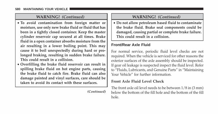
WARNING! (Continued)• To avoid contamination from foreign matter or
moisture, use only new brake fluid or fluid that hasbeen in a tightly closed container. Keep the mastercylinder reservoir cap secured at all times. Brakefluid in a open container absorbs moisture from theair resulting in a lower boiling point. This maycause it to boil unexpectedly during hard or pro-longed braking, resulting in sudden brake failure.This could result in a collision.
• Overfilling the brake fluid reservoir can result inspilling brake fluid on hot engine parts, causingthe brake fluid to catch fire. Brake fluid can alsodamage painted and vinyl surfaces, care should betaken to avoid its contact with these surfaces.
(Continued)
WARNING! (Continued)• Do not allow petroleum based fluid to contaminate
the brake fluid. Brake seal components could bedamaged, causing partial or complete brake failure.This could result in a collision.
Front/Rear Axle Fluid
For normal service, periodic fluid level checks are notrequired. When the vehicle is serviced for other reasons theexterior surfaces of the axle assembly should be inspected.If gear oil leakage is suspected inspect the fluid level. Referto “Fluids, Lubricants, and Genuine Parts” in “MaintainingYour Vehicle” for further information.
Front Axle Fluid Level Check
The front axle oil level needs to be between 1/8 in (3 mm)below the bottom of the fill hole and the bottom of the fillhole.
580 MAINTAINING YOUR VEHICLE

The front axle fill and drain plugs should be tightened to22 to 29 ft lbs (30 to 40 N·m).
CAUTION!
Do not overtighten the plugs as it could damage themand cause them to leak.
Rear Axle Fluid Level Check
The rear axle oil level needs to be between 1/8 in (3 mm)below the bottom of the fill hole and the bottom of the fillhole.
The rear axle fill and drain plugs should be tightened to22 to 29 ft lbs (30 to 40 N·m) on axles with aluminumhousings. The rear axle fill and drain plugs should betightened to 22 to 52 ft lbs (30 to 70 N·m) on axles withcast iron housings.
CAUTION!
Do not overtighten the plugs as it could damage themand cause them to leak.
Selection Of Lubricant
Use only the manufacturer’s recommended fluid. Referto “Fluids, Lubricants, and Genuine Parts” in “Maintain-ing Your Vehicle” for further information.
Transfer Case
Fluid Level Check
For normal service, periodic fluid level checks are notrequired. When the vehicle is serviced for other reasonsthe exterior surfaces of the transfer case assembly shouldbe inspected. If oil leakage is suspected inspect the fluidlevel. Refer to “Fluids, Lubricants, and Genuine Parts” in“Maintaining Your Vehicle” for further information.
7
MAINTAINING YOUR VEHICLE 581

Adding Fluid
Add fluid at the filler hole, until it runs out of the hole,when the vehicle is in a level position.
Drain
First remove fill plug, then remove drain plug. Recom-mended tightening torque for drain and fill plugs is 15 to25 ft lbs (20 to 34 N·m).
CAUTION!
When installing plugs, do not overtighten. You coulddamage them and cause them to leak.
Selection Of Lubricant
Use only the manufacturer’s recommended fluid. Referto “Fluids, Lubricants, and Genuine Parts” in “Maintain-ing Your Vehicle” for further information.
Automatic Transmission
Selection Of Lubricant
It is important to use the proper transmission fluid toensure optimum transmission performance and life. Useonly the manufacturer’s specified transmission fluid.Refer to “Fluids, Lubricants, and Genuine Parts” in thissection for fluid specifications. It is important to maintainthe transmission fluid at the correct level using therecommended fluid.
NOTE: No chemical flushes should be used in anytransmission; only the approved lubricant should beused.
CAUTION!
Using a transmission fluid other than the manufac-turer’s recommended fluid may cause deterioration
(Continued)
582 MAINTAINING YOUR VEHICLE

CAUTION! (Continued)in transmission shift quality and/or torque convertershudder, and will require more frequent fluid andfilter changes. Refer to “Fluids, Lubricants, andGenuine Parts” in this section for fluid specifica-tions.
Special Additives
The manufacturer strongly recommends against usingany special additives in the transmission.
Automatic Transmission Fluid (ATF) is an engineeredproduct and its performance may be impaired by supple-mental additives. Therefore, do not add any fluid addi-tives to the transmission. The only exception to thispolicy is the use of special dyes for diagnosing fluidleaks. Avoid using transmission sealers as they mayadversely affect seals.
CAUTION!
Do not use chemical flushes in your transmission asthe chemicals can damage your transmission compo-nents. Such damage is not covered by the NewVehicle Limited Warranty.
Fluid Level Check
The fluid level is preset at the factory and does notrequire adjustment under normal operating conditions.Routine fluid level checks are not required, therefore thetransmission has no dipstick. Your authorized dealer cancheck your transmission fluid level using special servicetools.
If you notice fluid leakage or transmission malfunction,visit your authorized dealer immediately to have thetransmission fluid level checked. Operating the vehicle
7
MAINTAINING YOUR VEHICLE 583

with an improper fluid level can cause severe transmis-sion damage.
CAUTION!
• If a transmission fluid leak occurs, visit your au-thorized dealer immediately. Severe transmissiondamage may occur. Your authorized dealer has theproper tools to adjust the fluid level accurately.
Fluid And Filter Changes
Under normal operating conditions, the fluid installed atthe factory will provide satisfactory lubrication for thelife of the vehicle.
Routine fluid and filter changes are not required. How-ever, change the fluid and filter if the fluid becomescontaminated (with water, etc.), or if the transmission isdisassembled for any reason.
Appearance Care And Protection From Corrosion
Protection Of Body And Paint From Corrosion
Vehicle body care requirements vary according to geo-graphic locations and usage. Chemicals that make roadspassable in snow and ice, and chemicals that are sprayedon trees and road surfaces during other seasons, arehighly corrosive to the metal in your vehicle. Outsideparking, which exposes your vehicle to airborne contami-nants, road surfaces on which the vehicle is operated,extreme hot or cold weather and other extreme condi-tions will have an adverse effect on paint, metal trim, andunderbody protection.
The following maintenance recommendations will enableyou to obtain maximum benefit from the corrosionresistance built into your vehicle.
584 MAINTAINING YOUR VEHICLE

What Causes Corrosion?
Corrosion is the result of deterioration or removal ofpaint and protective coatings from your vehicle.
The most common causes are:
• Road salt, dirt and moisture accumulation.
• Stone and gravel impact.
• Insects, tree sap and tar.
• Salt in the air near seacoast localities.
• Atmospheric fallout/industrial pollutants.
Washing
• Wash your vehicle regularly. Always wash your ve-hicle in the shade using MOPAR® Car Wash, or a mildcar wash soap, and rinse the panels completely withclear water.
• If insects, tar, or other similar deposits have accumu-lated on your vehicle, use MOPAR® Super Kleen Bugand Tar Remover to remove.
• Use a high quality cleaner wax, such as MOPAR®Cleaner Wax to remove road film, stains and to protectyour paint finish. Take care never to scratch the paint.
• Avoid using abrasive compounds and power buffing thatmay diminish the gloss or thin out the paint finish.
CAUTION!
• Do not use abrasive or strong cleaning materialssuch as steel wool or scouring powder that willscratch metal and painted surfaces.
• Use of power washers exceeding 1,200 psi (8 274 kPa)can result in damage or removal of paint and decals.
7
MAINTAINING YOUR VEHICLE 585

Special Care
• If you drive on salted or dusty roads or if you drivenear the ocean, hose off the undercarriage at least oncea month.
• It is important that the drain holes in the lower edgesof the doors, rocker panels, and trunk be kept clear andopen.
• If you detect any stone chips or scratches in the paint,touch them up immediately. The cost of such repairs isconsidered the responsibility of the owner.
• If your vehicle is damaged due to a collision or similarcause that destroys the paint and protective coating,have your vehicle repaired as soon as possible. Thecost of such repairs is considered the responsibility ofthe owner.
• If you carry special cargo such as chemicals, fertilizers,de-icer salt, etc., be sure that such materials are wellpackaged and sealed.
• If a lot of driving is done on gravel roads, considermud or stone shields behind each wheel.
• Use MOPAR® Touch Up Paint on scratches as soon aspossible. Your authorized dealer has touch up paint tomatch the color of your vehicle.
Wheel And Wheel Trim Care
• All wheels and wheel trim, especially aluminum andchrome plated wheels, should be cleaned regularlywith a mild soap and water to prevent corrosion.
• To remove heavy soil and/or excessive brake dust, useMOPAR® Wheel Cleaner.
586 MAINTAINING YOUR VEHICLE

CAUTION!
Do not use scouring pads, steel wool, a bristle brush,or metal polishes. Do not use oven cleaner. Theseproducts may damage the wheel’s protective finish.Avoid automatic car washes that use acidic solutionsor harsh brushes that may damage the wheel’s pro-tective finish. Only MOPAR® Wheel Cleaner orequivalent is recommended.
Stain Repel Fabric Cleaning Procedure –If Equipped
Stain Repel seats may be cleaned in the following man-ner:
• Remove as much of the stain as possible by blottingwith a clean, dry towel.
• Blot any remaining stain with a clean, damp towel.
• For tough stains, apply MOPAR® Total Clean, or amild soap solution to a clean, damp cloth and removestain. Use a fresh, damp towel to remove soap residue.
• For grease stains, apply MOPAR® Multi-PurposeCleaner to a clean, damp cloth and remove stain. Usea fresh, damp towel to remove soap residue.
• Do not use any harsh solvents or any other form ofprotectants on Stain Repel products.
Interior Care
Use MOPAR® Total Clean to clean fabric upholstery andcarpeting.
Use MOPAR® Total Clean to clean vinyl upholstery.
MOPAR® Total Clean is specifically recommended forleather upholstery.
7
MAINTAINING YOUR VEHICLE 587

Your leather upholstery can be best preserved by regularcleaning with a damp soft cloth. Small particles of dirtcan act as an abrasive and damage the leather upholsteryand should be removed promptly with a damp cloth.Stubborn soils can be removed easily with a soft clothand MOPAR® Total Clean. Care should be taken to avoidsoaking your leather upholstery with any liquid. Pleasedo not use polishes, oils, cleaning fluids, solvents, deter-gents, or ammonia-based cleaners to clean your leatherupholstery. Application of a leather conditioner is notrequired to maintain the original condition.
WARNING!
Do not use volatile solvents for cleaning purposes.Many are potentially flammable, and if used inclosed areas they may cause respiratory harm.
CAUTION!
Do not use Alcohol and Alcohol-based and/or Ketonbased cleaning products to clean leather seats, asdamage to the seat may result.
Cleaning Headlights
Your vehicle is equipped with plastic headlights and foglights (if equipped) that are lighter and less susceptible tostone breakage than glass headlights.
Plastic is not as scratch resistant as glass and thereforedifferent lens cleaning procedures must be followed.
To minimize the possibility of scratching the lenses andreducing light output, avoid wiping with a dry cloth. Toremove road dirt, wash with a mild soap solution fol-lowed by rinsing.
Do not use abrasive cleaning components, solvents, steelwool or other aggressive material to clean the lenses.
588 MAINTAINING YOUR VEHICLE

Glass Surfaces
All glass surfaces should be cleaned on a regular basiswith MOPAR® Glass Cleaner, or any commercialhousehold-type glass cleaner. Never use an abrasive typecleaner. Use caution when cleaning the inside rear win-dow equipped with electric defrosters or the right rearquarter window equipped with the radio antenna. Donot use scrapers or other sharp instrument that mayscratch the elements.
When cleaning the rear view mirror, spray cleaner on thetowel or rag that you are using. Do not spray cleanerdirectly on the mirror.
Cleaning Plastic Instrument Cluster Lenses
The lenses in front of the instruments in this vehicle aremolded in clear plastic. When cleaning the lenses, caremust be taken to avoid scratching the plastic.
1. Clean with a wet soft rag. A mild soap solution may beused, but do not use high alcohol content or abrasivecleaners. If soap is used, wipe clean with a clean damprag.
2. Dry with a soft cloth.
Seat Belt Maintenance
Do not bleach, dye, or clean the belts with chemicalsolvents or abrasive cleaners. This will weaken the fabric.Sun damage can also weaken the fabric.
If the belts need cleaning, use MOPAR® Total Clean, amild soap solution, or lukewarm water. Do not removethe belts from the vehicle to wash them. Dry with a softcloth.
Replace the belts if they appear frayed or worn or if thebuckles do not work properly.
7
MAINTAINING YOUR VEHICLE 589

FUSES
Power Distribution Center
The Power Distribution Center is located in the enginecompartment near the battery. This center contains car-tridge fuses, micro fuses, relays, and circuit breakers. Adescription of each fuse and component may be stampedon the inside cover, otherwise the cavity number of eachfuse is stamped on the inside cover that corresponds tothe following chart.
Power Distribution Center
590 MAINTAINING YOUR VEHICLE
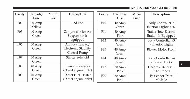
Cavity CartridgeFuse
MicroFuse
Description
F03 60 AmpYellow
Rad Fan
F05 40 AmpGreen
Compressor for AirSuspension if
equippedF06 40 Amp
GreenAntilock Brakes/
Electronic StabilityControl Pump
F07 40 AmpGreen
Starter Solenoid
F08 40 AmpGreen
Emission sensors(Diesel engine only)
F09 40 AmpGreen
Diesel Fuel Heater(Diesel engine only)
Cavity CartridgeFuse
MicroFuse
Description
F10 40 AmpGreen
Body Controller /Exterior Lighting #2
F11 30 AmpPink
Trailer Tow ElectricBrake - If Equipped
F12 40 AmpGreen
Body Controller #3/ Interior Lights
F13 40 AmpGreen
Blower Motor Front
F14 40 AmpGreen
Body Controller #4/ Power Locks
F17 30 AmpPink
Headrest Release -If Equipped
F20 30 AmpPink
Passenger DoorModule
7
MAINTAINING YOUR VEHICLE 591

Cavity CartridgeFuse
MicroFuse
Description
F22 20 AmpYellow
Engine ControlModule
F23 30 AmpPink
Body Controller #1
F24 30 AmpPink
Driver Door Module
F25 30 AmpPink
Front Wipers
F26 30 AmpPink
Antilock Brakes/Stability ControlModule/Valves
F28 20 AmpYellow
Trailer Tow BackupLights - If Equipped
F29 20 AmpYellow
Trailer Tow ParkingLights - If Equipped
Cavity CartridgeFuse
MicroFuse
Description
F30 30 AmpPink
Trailer Tow Recep-tacle - If Equipped
F32 30 AmpPink
Drive Train ControlModule
F34 30 AmpPink
Slip DifferentialControl
F35 30 AmpPink
Sunroof -If Equipped
F36 30 AmpPink
Rear Defroster
F37 30 AmpPink
Rear Blower -If Equipped
F38 30 AmpPink
Power Inverter115V AC -
If Equipped
592 MAINTAINING YOUR VEHICLE

Cavity CartridgeFuse
MicroFuse
Description
F39 30 AmpPink
Power Liftgate -If Equipped
F40 10 AmpRed
Daytime RunningLights
F42 20 AmpYellow
Horn
F44 10 AmpRed
Diagnostic Port
F46 10 AmpRed
Tire PressureMonitor
F49 10 AmpRed
Integrated CentralStack / Climate
Control
Cavity CartridgeFuse
MicroFuse
Description
F50 20 AmpYellow
Air Suspension Con-trol Module -If Equipped
F51 10 AmpRed
Ignition Node Mod-ule / Keyless Igni-tion / Steering Col-
umn LockF52 5 Amp
TanBattery Sensor
F53 20 AmpYellow
Trailer Tow – LeftTurn/Stop Lights -
If EquippedF56 15 Amp
BlueAdditional Content(Diesel engine only)
7
MAINTAINING YOUR VEHICLE 593

Cavity CartridgeFuse
MicroFuse
Description
F57 15 AmpBlue
Transmission
F59 10 AmpRed
Purging Pump (Die-sel engine only)
F60 15 AmpBlue
Transmission Con-trol Module
F62 10 AmpRed
Air ConditioningClutch
F63 20 AmpYellow
Ignition Coils (Gas),Urea Heater (Diesel)
F64 25 AmpNatural
Fuel Injectors /Powertrain
F66 10 AmpRed
Sunroof / PassengerWindow Switches /
Rain Sensor
Cavity CartridgeFuse
MicroFuse
Description
F67 15 AmpBlue
CD / DVD /Bluetooth Hands-
free Module -If Equipped
F68 20 AmpYellow
Rear Wiper Motor
F70 20 AmpYellow
Fuel Pump Motor
F71 30 AmpGreen
Audio Amplifier
F73 15 AmpBlue
HID HeadlampsRight
F74 20 AmpYellow
Brake VacuumPump - If Equipped
594 MAINTAINING YOUR VEHICLE

Cavity CartridgeFuse
MicroFuse
Description
F76 10 AmpRed
Antilock Brakes/Electronic Stability
ControlF77 10 Amp
RedDrivetrain Control
Module/Front AxleDisconnect Module
F78 10 AmpRed
Engine ControlModule / ElectricPower Steering -
If EquippedF80 10 Amp
RedUniversal GarageDoor Opener /
Compass / Anti-Intrusion Module
F81 20 AmpYellow
Trailer Tow RightTurn/Stop Lights
Cavity CartridgeFuse
MicroFuse
Description
F82 10 AmpRed
Steering ColumnControl Module/
Cruise ControlF83 10 Amp
RedFuel Door
F84 15 AmpBlue
Switch Bank/Instrument Cluster
F85 10 AmpRed
Airbag Module
F86 10 AmpRed
Airbag Module
F87 10 AmpRed
Air Suspension /Trailer Tow / Steer-ing Column Control
Module
7
MAINTAINING YOUR VEHICLE 595

Cavity CartridgeFuse
MicroFuse
Description
F88 15 AmpBlue
Instrument PanelCluster
F90/F91
20 AmpYellow
Power Outlet (Rearseats) Selectable
F92 10 AmpRed
Rear Console Lamp -If Equipped
F93 20 AmpYellow
Cigar Lighter
F94 10 AmpRed
Shifter / TransferCase Module
F95 10 AmpRed
Rear Camera / ParkAssist
Cavity CartridgeFuse
MicroFuse
Description
F96 10 AmpRed
Rear Seat HeaterSwitch / Flashlamp
Charger -If Equipped
F97 25 AmpNatural
Rear Heated Seats &Heated Steering
Wheel - If EquippedF98 25 Amp
NaturalFront Heated Seats -
If EquippedF99 10 Amp
RedClimate Control /Driver AssistanceSystems Module
F100 10 AmpRed
Active Damping -If Equipped
596 MAINTAINING YOUR VEHICLE

Cavity CartridgeFuse
MicroFuse
Description
F101 15 AmpBlue
ElectrochromaticMirror/Smart HighBeams - If Equipped
F103 10 AmpRed
Cabin Heater(Diesel engine only)
F104 20 AmpYellow
Power Outlets (In-strument Panel/Center Console)
CAUTION!
• When installing the power distribution centercover, it is important to ensure the cover is properlypositioned and fully latched. Failure to do so mayallow water to get into the power distributioncenter and possibly result in an electrical systemfailure.
• When replacing a blown fuse, it is important to useonly a fuse having the correct amperage rating. Theuse of a fuse with a rating other than indicated mayresult in a dangerous electrical system overload. Ifa properly rated fuse continues to blow, it indicatesa problem in the circuit that must be corrected. 7
MAINTAINING YOUR VEHICLE 597

VEHICLE STORAGE
If you are leaving your vehicle dormant for more than 21days you may want to take steps to protect your battery.You may:
• Disconnect the negative cable from the battery.
• Anytime you store your vehicle, or keep it out ofservice (i.e. vacation) for two weeks or more, run theair conditioning system at idle for about five minutesin the fresh air and high blower setting. This willensure adequate system lubrication to minimize thepossibility of compressor damage when the system isstarted again.
REPLACEMENT BULBS
Interior Bulbs
Bulb NumberGlove Box Lamp 194Grab Handle Lamp L002825W5WOverhead ConsoleReading Lamps
VT4976
Rear Cargo Lamp 214–2Visor Vanity Lamp V26377Underpanel CourtesyLamps
906
Instrument Cluster(General Illumination)
103
Telltale/Hazard Lamp 74
598 MAINTAINING YOUR VEHICLE

Exterior Bulbs
Bulb NumberHeadlamps (Low Beam) H11Premium Headlamps(Low/High Beam)
D3S (Serviced atAuthorized Dealer)
Headlamps (High Beam) 9005Premium Park/TurnSignal Lamp
LED - (Service atAuthorized Dealer)
Daytime Running Lamp(DRL)
3157K
Premium DaytimeRunning Lamp (DRL)
LED - (Service atAuthorized Dealer)
Front Fog Lamps H11Front Side Marker W5W
Bulb NumberPremium Front SideMarker - If Equipped
LED - (Service atAuthorized Dealer)
Front Park/Turn Lamp T20Rear Body Side TurnSignal Lamps
7440NA (WY21W)
Auxiliary Liftgate TailLamps
LED - (Service atAuthorized Dealer)
Liftgate Backup Lamps 921 (W16W)Rear License Lamps LED - (Service at
Authorized Dealer)Rear Body Side StopLamps
P27/7W 7
MAINTAINING YOUR VEHICLE 599

Bulb NumberRear Body Side TailLamps
LED - (Service atAuthorized Dealer)
CHMSL - Center HighMounted Stop Lamp
LED - (Service at Autho-rized Dealer)
NOTE:Numbers refer to commercial bulb types that can bepurchased from your authorized dealer.If a bulb needs to be replaced, visit your authorizeddealer or refer to the applicable Service Manual.
BULB REPLACEMENT
NOTE: Lens fogging can occur under certain atmo-spheric conditions. This will usually clear as atmosphericconditions change to allow the condensation to changeback into a vapor. Turning the lamps on will usuallyaccelerate the clearing process.
High Intensity Discharge Headlamps (HID) –If Equipped
The headlamps are a type of high voltage discharge tube.High voltage can remain in the circuit even with theheadlamp switch off and the key removed. Because ofthis, you should not attempt to service a headlamp bulbyourself. If a headlamp bulb fails, take your vehicle toan authorized dealer for service.
WARNING!
A transient high voltage occurs at the bulb sockets ofHigh Intensity Discharge (HID) headlamps when theheadlamp switch is turned ON. It may cause seriouselectrical shock or electrocution if not serviced prop-erly. See your authorized dealer for service.
600 MAINTAINING YOUR VEHICLE

NOTE: On vehicles equipped with High Intensity Dis-charge (HID) headlamps, when the headlamps areturned on, there is a blue hue to the lamps. This dimin-ishes and becomes more white after approximately 10seconds, as the system charges.
Halogen Headlamps – If Equipped
1. Open the hood.
2. Turn the low or high beam bulb one–quarter turncounterclockwise to remove from housing.
3. Disconnect the electrical connector and replace thebulb.
CAUTION!
Do not touch the new bulb with your fingers. Oilcontamination will severely shorten bulb life. If thebulb comes in contact with any oily surface, clean thebulb with rubbing alcohol.
Front Turn Signal
1. Open the hood.
2. Turn the turn signal bulb one–quarter turn counter-clockwise to remove from housing.
3. Disconnect the electrical connector and replace thebulb.
CAUTION!
Do not touch the new bulb with your fingers. Oilcontamination will severely shorten bulb life. If thebulb comes in contact with any oily surface, clean thebulb with rubbing alcohol.
Front Fog Lamps
1. Reach through the cutout in the splash shield anddisconnect the wiring harness from the fog lampconnector.
7
MAINTAINING YOUR VEHICLE 601

2. Firmly grasp the bulb by the two latches and squeezethem together to unlock the bulb from the back of thefront fog lamp housing.
3. Pull the bulb straight out from the keyed opening inthe housing.
CAUTION!
• Do not touch the new bulb with your fingers. Oilcontamination will severely shorten bulb life. Ifthe bulb comes in contact with any oily surface,clean the bulb with rubbing alcohol.
• Always use the correct bulb size and type forreplacement. An incorrect bulb size or type mayoverheat and cause damage to the lamp, the socketor the lamp wiring.
4. Align the index tabs of the front fog lamp bulb withthe slots in the collar of the bulb opening on the backof the front fog lamp housing.
5. Insert the bulb into the housing until the index tabs areengaged in the slots of the collar.
6. Firmly and evenly push the bulb straight into the lamphousing until both tabs snap firmly into place and arefully engaged.
7. Connect the wiring harness to the front fog lampconnector.
Rear Tail, Stop, and Turn Signal Lamps
1. Raise the liftgate.
2. Remove the two push-pins from the tail lamp housing.
3. Grasp the tail lamp and pull firmly rearward todisengage the lamp from the aperture panel.
602 MAINTAINING YOUR VEHICLE

4. Twist socket counter clockwise and remove fromlamp.
5. Pull the bulb to remove it from the socket.
6. Replace the bulb, reinstall the socket, and reattach thelamp assembly.
1 — Rear Stop Lamp Bulb Socket2 — LED Tail Connector – Do Not Remove3 — Rear Turn Signal Bulb Socket
7
MAINTAINING YOUR VEHICLE 603

Rear Liftgate Mounted Tail Lamp
1. Raise the liftgate.
2. Use a fiber stick or flat blade screw driver to pry thelower trim from the liftgate.
3. Continue removing the trim.
4. Disconnect the two trim panel lights.
5. Tail lamps are now visible. Rotate socket(s) counterclockwise.
Rear Liftgate Tail Lamps
604 MAINTAINING YOUR VEHICLE

6. Remove/replace bulb(s).
7. Reinstall the socket(s)
8. Reverse process to reinstall the liftgate trim.
Center High-Mounted Stop Lamp (CHMSL)
The center high mounted stop lamp is LED. Service atAuthorized Dealer.
Rear License Lamp
1. The rear license lamps are LED. Service at AuthorizedDealer
1 — Auxiliary LED Tail Connector – Do Not Remove2 — Backup Bulb Socket
Center High-Mounted Stop Lamp
7
MAINTAINING YOUR VEHICLE 605

FLUID CAPACITIES
U.S. MetricFuel (Approximate)3.6L and 5.7L Engines 25 Gallons 94 LitersEngine Oil With Filter3.6L Engine (SAE 5W-20, API Certified) 6 Quarts 5.6 Liters5.7L Engine (SAE 5W-20, API Certified) 7 Quarts 6.6 LitersCooling System*3.6L Engine (MOPAR® Antifreeze/Engine Coolant 10 Year/150,000 Mile Formula or equivalent)
10.4 Quarts 9.9 Liters
5.7 Liter Engine (MOPAR® Antifreeze/Engine Coolant 10 Year/150,000 Mile Formula or equivalent) – Without Trailer Tow Package
15.4 Quarts 14.6 Liters
5.7 Liter Engine (MOPAR® Antifreeze/Engine Coolant 10 Year/150,000 Mile Formula or equivalent) – With Trailer Tow Package
16 Quarts 15.2 Liters
* Includes heater and coolant recovery bottle filled to MAX level.
606 MAINTAINING YOUR VEHICLE

FLUIDS, LUBRICANTS AND GENUINE PARTS
Engine
Component Fluid, Lubricant, or Genuine PartEngine Coolant We recommend you use MOPAR® Antifreeze/Coolant
10 Year/150,000 Mile Formula OAT (Organic AdditiveTechnology).
Engine Oil – 3.6L Engine We recommend you use API Certified SAE 5W-20Engine Oil, meeting the requirements of Chrysler Ma-terial Standard MS-6395 such as MOPAR, Pennzoil®,and Shell Helix®. Refer to your engine oil filler cap forcorrect SAE grade.
Engine Oil – 5.7L Engine We recommend you use API Certified SAE 5W-20Engine Oil, meeting the requirements of Chrysler Ma-terial Standard MS-6395 such as MOPAR, Pennzoil®,and Shell Helix®. Refer to your engine oil filler cap forcorrect SAE grade.
7
MAINTAINING YOUR VEHICLE 607
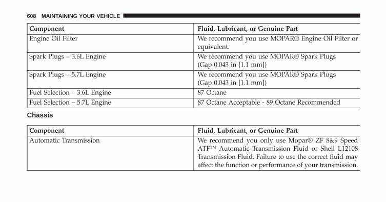
Component Fluid, Lubricant, or Genuine PartEngine Oil Filter We recommend you use MOPAR® Engine Oil Filter or
equivalent.Spark Plugs – 3.6L Engine We recommend you use MOPAR® Spark Plugs
(Gap 0.043 in [1.1 mm])Spark Plugs – 5.7L Engine We recommend you use MOPAR® Spark Plugs
(Gap 0.043 in [1.1 mm])Fuel Selection – 3.6L Engine 87 OctaneFuel Selection – 5.7L Engine 87 Octane Acceptable - 89 Octane Recommended
Chassis
Component Fluid, Lubricant, or Genuine PartAutomatic Transmission We recommend you only use Mopar® ZF 8&9 Speed
ATF™ Automatic Transmission Fluid or Shell L12108Transmission Fluid. Failure to use the correct fluid mayaffect the function or performance of your transmission.
608 MAINTAINING YOUR VEHICLE

Component Fluid, Lubricant, or Genuine PartTransfer Case – Single-Speed (Quadra-Trac I®) We recommend you use Shell Automatic Transmission
Fluid 3353.Transfer Case – Two-Speed (Quadra-Trac II®) We recommend you use MOPAR® ATF+4® Automatic
Transmission Fluid.Axle Differential (Front) We recommend you use MOPAR® GL-5 Synthetic Axle
Lubricant SAE 75W-85.Axle Differential (Rear) – With Electronic Limited-SlipDifferential (ELSD)
We recommend you use MOPAR® GL-5 Synthetic AxleLubricant SAE 75W-85 with friction modifier additive.
Axle Differential (Rear) – Without Electronic Limited-Slip Differential (ELSD)
We recommend you use MOPAR® GL-5 Synthetic AxleLubricant SAE 75W-85.
Brake Master Cylinder We recommend you use MOPAR® DOT 3 Brake Fluid,SAE J1703 should be used. If DOT 3, SAE J1703 brakefluid is not available, then DOT 4 is acceptable.
Power Steering Reservoir – 3.6L Engine We recommend you use MOPAR® Hydraulic Fluid.Power Steering Reservoir – 5.7L Engine We recommend you use MOPAR® Power Steering Fluid
+4 or MOPAR® ATF+4® Automatic Transmission Fluid.
7
MAINTAINING YOUR VEHICLE 609


MAINTENANCE SCHEDULES
CONTENTS� MAINTENANCE SCHEDULE . . . . . . . . . . . . .612
▫ Maintenance Chart. . . . . . . . . . . . . . . . . . . . .614
8
MAINTENANCE
SCHEDULES

MAINTENANCE SCHEDULE
Your vehicle is equipped with an automatic oil changeindicator system. The oil change indicator system willremind you that it is time to take your vehicle in forscheduled maintenance.
Based on engine operation conditions, the oil changeindicator message will illuminate. This means that ser-vice is required for your vehicle. Operating conditionssuch as frequent short-trips, trailer tow, extremely hot orcold ambient temperatures, and E85 fuel usage willinfluence when the “Oil Change Required” message isdisplayed. Severe Operating Conditions can cause thechange oil message to illuminate as early as 3,500 miles(5 600 km) since last reset. Have your vehicle serviced assoon as possible, within the next 500 miles (805 km).
Your authorized dealer will reset the oil change indicatormessage after completing the scheduled oil change. If ascheduled oil change is performed by someone otherthan your authorized dealer, the message can be reset by
referring to the steps described under “Electronic VehicleInformation Center (EVIC)/Oil Change Required” in“Understanding Your Instrument Panel” for further in-formation
NOTE: Under no circumstances should oil change inter-vals exceed 10,000 miles (16 000 km) or twelve months,whichever comes first.
Once A Month Or Before A Long Trip:
• Check engine oil level
• Check windshield washer fluid level
• Check the tire inflation pressures and look for unusualwear or damage
• Check the fluid levels of the coolant reservoir, brakemaster cylinder, power steering and transmission asneeded
• Check function of all interior and exterior lights
8
MAINTENANCE
SCHEDULES
612 MAINTENANCE SCHEDULES

Required Maintenance
Refer to the Maintenance Schedules on the followingpages for required maintenance.
At Every Oil Change Interval As Indicated By OilChange Indicator System:
• Change oil and filter.• Rotate the tires. Rotate at the first sign of irregu-
lar wear, even if it occurs before the oil indicatorsystem turns on.
• Inspect battery and clean and tighten terminals asrequired.
At Every Oil Change Interval As Indicated By OilChange Indicator System:
• Inspect automatic transmission fluid if equippedwith dipstick.
• Inspect brake pads, shoes, rotors, drums, hosesand park brake.
• Inspect engine cooling system protection andhoses.
• Inspect exhaust system.• Inspect engine air cleaner if using in dusty or
off-road conditions.
8
MAINTENANCE
SCHEDULES
MAINTENANCE SCHEDULES 613

Maintenance Chart
Mileage or time passed(whichever comes first)
20,0
00
30,0
00
40,0
00
50,0
00
60,0
00
70,0
00
80,0
00
90,0
00
100,
000
110,
000
120,
000
130,
000
140,
000
150,
000
Or Years: 2 3 4 5 6 7 8 9 10 11 12 13 14 15Or Kilometers:
32,0
00
48,0
00
64,0
00
80,0
00
96,0
00
112,
000
128,
000
144,
000
160,
000
176,
000
192,
000
208,
000
224,
000
240,
000
Additional InspectionsInspect the CV joints. X X X X XInspect front suspension, tie rodends, and replace if necessary. X X X X X X X
Inspect the front and rear axlefluid, change if using your ve-hicle for police, taxi, fleet, off-road or frequent trailer towing.
X X X X X X X
Inspect the brake linings, parkingbrake function. X X X X X X X
8
MAINTENANCE
SCHEDULES
614 MAINTENANCE SCHEDULES

Mileage or time passed(whichever comes first)
20,0
00
30,0
00
40,0
00
50,0
00
60,0
00
70,0
00
80,0
00
90,0
00
100,
000
110,
000
120,
000
130,
000
140,
000
150,
000
Or Years: 2 3 4 5 6 7 8 9 10 11 12 13 14 15Or Kilometers:
32,0
00
48,0
00
64,0
00
80,0
00
96,0
00
112,
000
128,
000
144,
000
160,
000
176,
000
192,
000
208,
000
224,
000
240,
000
Inspect transfer case fluid. X X X X XAdditional MaintenanceReplace engine air filter. X X X X XReplace the air conditioning filter. X X X X X X XReplace spark plugs(3.6L engine).** X
Replace spark plugs(5.7L engine).** X
Flush and replace the enginecoolant at 10 years or150,000 miles (240,000 km)whichever comes first.
X X
8
MAINTENANCE
SCHEDULES
MAINTENANCE SCHEDULES 615

Mileage or time passed(whichever comes first)
20,0
00
30,0
00
40,0
00
50,0
00
60,0
00
70,0
00
80,0
00
90,0
00
100,
000
110,
000
120,
000
130,
000
140,
000
150,
000
Or Years: 2 3 4 5 6 7 8 9 10 11 12 13 14 15Or Kilometers:
32,0
00
48,0
00
64,0
00
80,0
00
96,0
00
112,
000
128,
000
144,
000
160,
000
176,
000
192,
000
208,
000
224,
000
240,
000
Change transfer case fluid. XInspect and replace PCV valve ifnecessary. X
** The spark plug change interval is mileage based only,yearly intervals do not apply.
8
MAINTENANCE
SCHEDULES
616 MAINTENANCE SCHEDULES

WARNING!
• You can be badly injured working on or around amotor vehicle. Do only service work for which youhave the knowledge and the right equipment. Ifyou have any doubt about your ability to perform aservice job, take your vehicle to a competent me-chanic.
• Failure to properly inspect and maintain your ve-hicle could result in a component malfunction andeffect vehicle handling and performance. Thiscould cause an accident.
8
MAINTENANCE
SCHEDULES
MAINTENANCE SCHEDULES 617


IF YOU NEED CONSUMER ASSISTANCE
CONTENTS� SUGGESTIONS FOR OBTAINING SERVICE
FOR YOUR VEHICLE . . . . . . . . . . . . . . . . . . .621
▫ Prepare For The Appointment. . . . . . . . . . . . .621
▫ Prepare A List . . . . . . . . . . . . . . . . . . . . . . . .621
▫ Be Reasonable With Requests . . . . . . . . . . . . .621
� IF YOU NEED ASSISTANCE . . . . . . . . . . . . . .621
▫ Chrysler Group LLC Customer Center. . . . . . .622
▫ Chrysler Canada Inc. Customer Center . . . . . .623
▫ In Mexico contact: . . . . . . . . . . . . . . . . . . . . .623
▫ Customer Assistance For The Hearing OrSpeech Impaired (TDD/TTY) . . . . . . . . . . . . .623
▫ Service Contract . . . . . . . . . . . . . . . . . . . . . .624
� WARRANTY INFORMATION . . . . . . . . . . . . .625
� MOPAR® PARTS . . . . . . . . . . . . . . . . . . . . . . .625
� REPORTING SAFETY DEFECTS . . . . . . . . . . . .625
▫ In The 50 United States AndWashington, D.C.. . . . . . . . . . . . . . . . . . . . . .625
▫ In Canada . . . . . . . . . . . . . . . . . . . . . . . . . . .6269

� PUBLICATION ORDER FORMS . . . . . . . . . . . .626
� DEPARTMENT OF TRANSPORTATIONUNIFORM TIRE QUALITY GRADES . . . . . . . . .627
▫ Treadwear. . . . . . . . . . . . . . . . . . . . . . . . . . .628
▫ Traction Grades . . . . . . . . . . . . . . . . . . . . . . .628
▫ Temperature Grades. . . . . . . . . . . . . . . . . . . .629
620 IF YOU NEED CONSUMER ASSISTANCE

SUGGESTIONS FOR OBTAINING SERVICE FORYOUR VEHICLE
Prepare For The Appointment
If you are having warranty work done, be sure to havethe right papers with you. Take your warranty folder. Allwork to be performed may not be covered by thewarranty. Discuss additional charges with the servicemanager. Keep a maintenance log of your vehicle’sservice history. This can often provide a clue to thecurrent problem.
Prepare A List
Make a written list of your vehicle’s problems or thespecific work you want done. If you’ve had an accidentor work done that is not on your maintenance log, let theservice advisor know.
Be Reasonable With Requests
If you list a number of items and you must have yourvehicle by the end of the day, discuss the situation withthe service advisor and list the items in order of priority.At many authorized dealer, you may obtain a rentalvehicle at a minimal daily charge. If you need a rental, itis advisable to make these arrangements when you callfor an appointment.
IF YOU NEED ASSISTANCE
The manufacturer and its authorized dealer are vitallyinterested in your satisfaction. We want you to be happywith our products and services.
Warranty service must be done by an authorized dealer.We strongly recommend that you take the vehicle to anauthorized dealer. They know your vehicle the best, andare most concerned that you get prompt and high qualityservice. The manufacturer’s authorized dealer have the
9
IF YOU NEED CONSUMER ASSISTANCE 621

facilities, factory-trained technicians, special tools, andthe latest information to ensure the vehicle is fixedcorrectly and in a timely manner.
This is why you should always talk to an authorizeddealer service manager first. Most matters can be re-solved with this process.
• If for some reason you are still not satisfied, talk to thegeneral manager or owner of the authorized dealer.They want to know if you need assistance.
• If an authorized dealer is unable to resolve the con-cern, you may contact the manufacturer’s customercenter.
Any communication to the manufacturer’s customer cen-ter should include the following information:
• Owner’s name and address
• Owner’s telephone number (home and office)
• Authorized dealer name
• Vehicle Identification Number (VIN)
• Vehicle delivery date and mileage
Chrysler Group LLC Customer Center
P.O. Box 21–8004
Auburn Hills, MI 48321–8004
Phone: (877) 426–5337
622 IF YOU NEED CONSUMER ASSISTANCE

Chrysler Canada Inc. Customer Center
P.O. Box 1621
Windsor, Ontario N9A 4H6
Phone: (800) 465–2001 English / (800) 387–9983 French
In Mexico contact:
Av. Prolongacion Paseo de la Reforma, 1240
Sante Fe C.P. 05109
Mexico, D. F.
In Mexico City: 5081-7568
Outside Mexico City: 1-800-505-1300
Customer Assistance For The Hearing Or SpeechImpaired (TDD/TTY)
To assist customers who have hearing difficulties, themanufacturer has installed special TDD (Telecommuni-cation Devices for the Deaf) equipment at its customercenter. Any hearing or speech impaired customer, whohas access to a TDD or a conventional teletypewriter(TTY) in the United States, can communicate with themanufacturer by dialing 1–800–380–CHRY.
Canadian residents with hearing difficulties that requireassistance can use the special needs relay service offeredby Bell Canada. For TTY teletypewriter users, dial 711and for Voice callers, dial 1 800 855-0511 to connect witha Bell Relay Service operator.
9
IF YOU NEED CONSUMER ASSISTANCE 623

Service Contract
You may have purchased a service contract for a vehicleto help protect you from the high cost of unexpectedrepairs after the manufacturer’s New Vehicle LimitedWarranty expires. The manufacturer stands behind onlythe manufacturer’s service contracts. If you purchased amanufacturer’s service contract, you will receive PlanProvisions and an Owner Identification Card in the mailwithin three weeks of the vehicle delivery date. If youhave any questions about the service contract, call themanufacturer’s Service Contract National CustomerHotline at 1-800-521-9922 (Canadian residents, call (800)465–2001 English / (800) 387–9983 French).
The manufacturer will not stand behind any servicecontract that is not the manufacturer’s service contract. Itis not responsible for any service contract other than themanufacturer’s service contract. If you purchased a ser-vice contract that is not a manufacturer’s service contract,and you require service after the manufacturer’s New
Vehicle Limited Warranty expires, please refer to thecontract documents, and contact the person listed inthose documents.
We appreciate that you have made a major investmentwhen you purchased the vehicle. An authorized dealerhas also made a major investment in facilities, tools, andtraining to assure that you are absolutely delighted withthe ownership experience. You will be pleased with theirsincere efforts to resolve any warranty issues or relatedconcerns.
WARNING!
Engine exhaust, some of its constituents, and certainvehicle components contain, or emit, chemicalsknown to the State of California to cause cancer andbirth defects, or other reproductive harm. In addi-tion, certain fluids contained in vehicles and certain
(Continued)
624 IF YOU NEED CONSUMER ASSISTANCE

WARNING! (Continued)products of component wear contain, or emit, chemi-cals known to the State of California to cause cancerand birth defects, or other reproductive harm.
WARRANTY INFORMATION
See the Warranty Information Booklet, located on theDVD, for the terms and provisions of Chrysler GroupLLC warranties applicable to this vehicle and market.
MOPAR® PARTS
MOPAR® fluids, lubricants, parts, and accessories areavailable from an authorized dealer. They are recom-mended for your vehicle in order to help keep the vehicleoperating at its best.
REPORTING SAFETY DEFECTS
In The 50 United States And Washington, D.C.
If you believe that your vehicle has a defect that couldcause a crash or cause injury or death, you shouldimmediately inform the National Highway Traffic SafetyAdministration (NHTSA) in addition to notifying themanufacturer.
If NHTSA receives similar complaints, it may open aninvestigation, and if it finds that a safety defect exists ina group of vehicles, it may order a recall and remedycampaign. However, NHTSA cannot become involved inindividual problems between you, your authorizeddealer, and the manufacturer.
9
IF YOU NEED CONSUMER ASSISTANCE 625

To contact NHTSA, you may either call the Auto SafetyHotline toll free at 1–888–327–4236 (TTY: 1–800–424–9153), or go to http://www.safercar.gov; or write to:Administrator, NHTSA, 1200 New Jersey Avenue, SE.,West Building, Washington, D.C. 20590. You can alsoobtain other information about motor vehicle safety fromhttp://www.safercar.gov.
In Canada
If you believe that your vehicle has a safety defect, youshould contact the Customer Service Department imme-diately. Canadian customers who wish to report a safetydefect to the Canadian government should contact Trans-port Canada, Motor Vehicle Defect Investigations andRecalls at 1-800-333-0510 or go to http://www.tc.gc.ca/roadsafety/
PUBLICATION ORDER FORMS
To order the following manuals, you may use either thewebsite or the phone numbers listed below. Visa, Mas-tercard, American Express, and Discover orders are ac-cepted. If you prefer mailing your payment, please callfor an order form.
NOTE: A street address is required when orderingmanuals (no P.O. Boxes).
Service Manuals
These comprehensive Service Manuals provide the infor-mation that students and professional technicians need indiagnosing/troubleshooting, problem solving, maintain-ing, servicing, and repairing Chrysler Group LLC ve-hicles. A complete working knowledge of the vehicle,system, and/or components is written in straightforwardlanguage with illustrations, diagrams, and charts.
626 IF YOU NEED CONSUMER ASSISTANCE

Diagnostic Procedure Manuals
Diagnostic Procedure Manuals are filled with diagrams,charts and detailed illustrations. These practical manualsmake it easy for students and technicians to find and fixproblems on computer-controlled vehicle systems andfeatures. They show exactly how to find and correctproblems the first time, using step-by-step troubleshoot-ing and drivability procedures, proven diagnostic testsand a complete list of all tools and equipment.
Owner’s Manuals
These Owner’s Manuals have been prepared with theassistance of service and engineering specialists to ac-quaint you with specific Chrysler Group LLC vehicles.Included are starting, operating, emergency and mainte-nance procedures as well as specifications, capabilitiesand safety tips.
Call toll free at:
• 1–800–890–4038 (U.S.)
• 1–800–387–1143 (Canada)
Or
Visit us on the Worldwide Web at:
• www.techauthority.com
DEPARTMENT OF TRANSPORTATION UNIFORMTIRE QUALITY GRADES
The following tire grading categories were established bythe National Highway Traffic Safety Administration. Thespecific grade rating assigned by the tire’s manufacturerin each category is shown on the sidewall of the tires onyour vehicle.
All passenger car tires must conform to Federal safetyrequirements in addition to these grades.
9
IF YOU NEED CONSUMER ASSISTANCE 627

Treadwear
The Treadwear grade is a comparative rating, based onthe wear rate of the tire when tested under controlledconditions on a specified government test course. Forexample, a tire graded 150 would wear one and one-halftimes as well on the government course as a tire graded100. The relative performance of tires depends upon theactual conditions of their use, however, and may departsignificantly from the norm due to variations in drivinghabits, service practices, and differences in road charac-teristics and climate.
Traction Grades
The Traction grades, from highest to lowest, are AA, A, B,and C. These grades represent the tire’s ability to stop onwet pavement, as measured under controlled conditionson specified government test surfaces of asphalt andconcrete. A tire marked C may have poor traction perfor-mance.
WARNING!
The traction grade assigned to this tire is based onstraight-ahead braking traction tests, and does notinclude acceleration, cornering, hydroplaning, orpeak traction characteristics.
628 IF YOU NEED CONSUMER ASSISTANCE

Temperature Grades
The temperature grades are A (the highest), B, and C,representing the tire’s resistance to the generation of heatand its ability to dissipate heat, when tested undercontrolled conditions on a specified indoor laboratorytest wheel. Sustained high temperature can cause thematerial of the tire to degenerate and reduce tire life, andexcessive temperature can lead to sudden tire failure. Thegrade C corresponds to a level of performance, which allpassenger car tires must meet under the Federal MotorVehicle Safety Standard No. 109. Grades B and A repre-sent higher levels of performance on the laboratory testwheel, than the minimum required by law.
WARNING!
The temperature grade for this tire is established fora tire that is properly inflated and not overloaded.Excessive speed, under-inflation, or excessive load-ing, either separately or in combination, can causeheat buildup and possible tire failure.
9
IF YOU NEED CONSUMER ASSISTANCE 629


INDEX
10

Adaptive Cruise Control (ACC) (Cruise Control) . . .194Adding Engine Coolant (Antifreeze) . . . . . . . . . . . .575Adding Fuel . . . . . . . . . . . . . . . . . . . . . . . . . . . . .495Additives, Fuel . . . . . . . . . . . . . . . . . . . . . . . . . . .489Airbag. . . . . . . . . . . . . . . . . . . . . . . . . . . . . . . . . .70Airbag Deployment . . . . . . . . . . . . . . . . . . . . . . . .82Airbag Light . . . . . . . . . . . . . . . . . . . . . . . . . . . . .78Airbag Maintenance . . . . . . . . . . . . . . . . . . . . . . . .83Airbag, Side . . . . . . . . . . . . . . . . . . . . . . . . . . . . . .73Airbag, Window (Side Curtain) . . . . . . . . . . . . . . . .74Air Cleaner, Engine (Engine Air Cleaner Filter) . . . .562Air Conditioner Maintenance . . . . . . . . . . . . . . . . .564Air Conditioning Filter . . . . . . . . . . . . . . . . . . . . .377Air Conditioning, Operating Tips . . . . . . . . . . . . . .378Air Conditioning Refrigerant . . . . . . . . . . . . . . . . .564Air Conditioning System . . . . . . . . . . . . . . . . . . . .375Air Pressure, Tires. . . . . . . . . . . . . . . . . . . . . . . . .466Air Suspension . . . . . . . . . . . . . . . . . . . . . . . . . . .414
Alarm, Panic . . . . . . . . . . . . . . . . . . . . . . . . . . . . .25Alarm (Security Alarm) . . . . . . . . . . . . . . . . . . . . . .20Alterations/Modifications, Vehicle . . . . . . . . . . . . . . .9Antifreeze (Engine Coolant) . . . . . . . . . . . . . . . . . .574
Disposal . . . . . . . . . . . . . . . . . . . . . . . . . . . . . .577Anti-Lock Brake System (ABS) . . . . . . . . . . . . . . . .435Anti-Lock Warning Light . . . . . . . . . . . . . . . . . . . .291Anti-Theft System . . . . . . . . . . . . . . . . . . . . . . . . .299Appearance Care . . . . . . . . . . . . . . . . . . . . . . . . .584Assist, Hill Start . . . . . . . . . . . . . . . . . . . . . . . . . .441Auto Down Power Windows . . . . . . . . . . . . . . . . . .42Automatic Headlights . . . . . . . . . . . . . . . . . . . . . .171Automatic Temperature Control (ATC) . . . . . . . . . .375Automatic Transmission . . . . . . . . . . . . . . . . . . . .394
Adding Fluid . . . . . . . . . . . . . . . . . . . . . . . . . .584Fluid and Filter Changes . . . . . . . . . . . . . . . . . .584Fluid Change . . . . . . . . . . . . . . . . . . . . . . . . . .584Fluid Level Check . . . . . . . . . . . . . . . . . . . . . . .582
632 INDEX

Fluid Type . . . . . . . . . . . . . . . . . . . . . . . . . . . .582Gear Ranges . . . . . . . . . . . . . . . . . . . . . . . . . . .395Special Additives . . . . . . . . . . . . . . . . . . . . . . .583
Auxiliary Electrical Outlet (Power Outlet) . . . . . . . .265Auxiliary Power Outlet . . . . . . . . . . . . . . . . . . . . .265
Battery . . . . . . . . . . . . . . . . . . . . . . . . . . . . . . . . .563Keyless Transmitter Replacement (RKE) . . . . . . . .26
Belts, Seat . . . . . . . . . . . . . . . . . . . . . . . . . . . . . . .54Blind Spot Monitoring . . . . . . . . . . . . . . . . . . . . . .135Body Mechanism Lubrication . . . . . . . . . . . . . . . . .567B-Pillar Location . . . . . . . . . . . . . . . . . . . . . . . . . .460Brake Assist System . . . . . . . . . . . . . . . . . . . . . . .436Brake Control System, Electronic . . . . . . . . . . . . . .434Brake Fluid . . . . . . . . . . . . . . . . . . . . . . . . . . . . .579Brake System . . . . . . . . . . . . . . . . . . . . . . . . . . . .578
Anti-Lock (ABS) . . . . . . . . . . . . . . . . . . . . . . . .435Fluid Check . . . . . . . . . . . . . . . . . . . . . . . . . . .579Master Cylinder . . . . . . . . . . . . . . . . . . . . . . . .579
Parking . . . . . . . . . . . . . . . . . . . . . . . . . . . . . .432Warning Light . . . . . . . . . . . . . . . . . . . . . . . . .295
Brake/Transmission Interlock. . . . . . . . . . . . . . . . .393Bulb Replacement . . . . . . . . . . . . . . . . . . . . . . . . .598Bulbs, Light . . . . . . . . . . . . . . . . . . . . . . . . . . . . .118
Camera, Rear . . . . . . . . . . . . . . . . . . . . . . . . . . . .243Capacities, Fluid . . . . . . . . . . . . . . . . . . . . . . . . . .606Caps, Filler
Oil (Engine) . . . . . . . . . . . . . . . . . . . . . . . . . . .561Power Steering . . . . . . . . . . . . . . . . . . . . . . . . .431Radiator (Coolant Pressure) . . . . . . . . . . . . . . . .576
Carbon Monoxide Warning . . . . . . . . . . . . . . . . . .114Cargo Area Cover . . . . . . . . . . . . . . . . . . . . . . . . .279Cargo Area Features . . . . . . . . . . . . . . . . . . . . . . .276Cargo Compartment . . . . . . . . . . . . . . . . . . . . . . .276
Light . . . . . . . . . . . . . . . . . . . . . . . . . . . . . . . .277Cargo Light . . . . . . . . . . . . . . . . . . . . . . . . . . . . .277Cargo Tie-Downs . . . . . . . . . . . . . . . . . . . . . . . . .280 10
INDEX 633
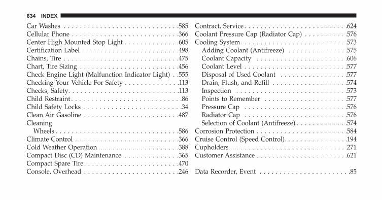
Car Washes . . . . . . . . . . . . . . . . . . . . . . . . . . . . .585Cellular Phone . . . . . . . . . . . . . . . . . . . . . . . . . . .366Center High Mounted Stop Light . . . . . . . . . . . . . .605Certification Label. . . . . . . . . . . . . . . . . . . . . . . . .498Chains, Tire . . . . . . . . . . . . . . . . . . . . . . . . . . . . .475Chart, Tire Sizing . . . . . . . . . . . . . . . . . . . . . . . . .456Check Engine Light (Malfunction Indicator Light) . .555Checking Your Vehicle For Safety . . . . . . . . . . . . . .113Checks, Safety. . . . . . . . . . . . . . . . . . . . . . . . . . . .113Child Restraint . . . . . . . . . . . . . . . . . . . . . . . . . . . .86Child Safety Locks . . . . . . . . . . . . . . . . . . . . . . . . .34Clean Air Gasoline . . . . . . . . . . . . . . . . . . . . . . . .487Cleaning
Wheels . . . . . . . . . . . . . . . . . . . . . . . . . . . . . . .586Climate Control . . . . . . . . . . . . . . . . . . . . . . . . . .366Cold Weather Operation . . . . . . . . . . . . . . . . . . . .388Compact Disc (CD) Maintenance . . . . . . . . . . . . . .365Compact Spare Tire . . . . . . . . . . . . . . . . . . . . . . . .470Console, Overhead . . . . . . . . . . . . . . . . . . . . . . . .246
Contract, Service . . . . . . . . . . . . . . . . . . . . . . . . . .624Coolant Pressure Cap (Radiator Cap) . . . . . . . . . . .576Cooling System. . . . . . . . . . . . . . . . . . . . . . . . . . .573
Adding Coolant (Antifreeze) . . . . . . . . . . . . . . .575Coolant Capacity . . . . . . . . . . . . . . . . . . . . . . .606Coolant Level . . . . . . . . . . . . . . . . . . . . . . . . . .577Disposal of Used Coolant . . . . . . . . . . . . . . . . .577Drain, Flush, and Refill . . . . . . . . . . . . . . . . . . .574Inspection . . . . . . . . . . . . . . . . . . . . . . . . . . . .573Points to Remember . . . . . . . . . . . . . . . . . . . . .577Pressure Cap . . . . . . . . . . . . . . . . . . . . . . . . . .576Radiator Cap . . . . . . . . . . . . . . . . . . . . . . . . . .576Selection of Coolant (Antifreeze) . . . . . . . . . . . . .574
Corrosion Protection . . . . . . . . . . . . . . . . . . . . . . .584Cruise Control (Speed Control). . . . . . . . . . . . . . . .194Cupholders . . . . . . . . . . . . . . . . . . . . . . . . . . . . .271Customer Assistance . . . . . . . . . . . . . . . . . . . . . . .621
Data Recorder, Event . . . . . . . . . . . . . . . . . . . . . . .85
634 INDEX

Daytime Running Lights . . . . . . . . . . . . . . . . . . . .173Dealer Service. . . . . . . . . . . . . . . . . . . . . . . . . . . .557Defroster, Rear Window. . . . . . . . . . . . . . . . . . . . .283Defroster, Windshield . . . . . . . . . . . . . . . . . . . . . .116Dipsticks
Oil (Engine) . . . . . . . . . . . . . . . . . . . . . . . . . . .559Power Steering . . . . . . . . . . . . . . . . . . . . . . . . .431
DisposalAntifreeze (Engine Coolant) . . . . . . . . . . . . . . . .577
Door Locks . . . . . . . . . . . . . . . . . . . . . . . . . . . . . .32Door Opener, Garage. . . . . . . . . . . . . . . . . . . . . . .248Driving . . . . . . . . . . . . . . . . . . . . . . . . . . . . . . . .422
Off-Pavement . . . . . . . . . . . . . . . . . . . . . . . . . .422Off-Road . . . . . . . . . . . . . . . . . . . . . . . . . . . . .422
E-85 Fuel . . . . . . . . . . . . . . . . . . . . . . . . . . . . . . .491Economy (Fuel) Mode . . . . . . . . . . . . . . . . . . . . . .393Electrical Outlet, Auxiliary (Power Outlet) . . . . . . . .265Electric Rear Window Defrost. . . . . . . . . . . . . . . . .283
Electric Remote Mirrors . . . . . . . . . . . . . . . . . . . . .131Electronic Brake Control System . . . . . . . . . . . . . . .434
Brake Assist System . . . . . . . . . . . . . . . . . . . . .436Electronic Roll Mitigation (ERM) . . . . . . . . . . . . . .437Electronic Speed Control (Cruise Control) . . . . . . . .190Electronic Stability Control (ESC) . . . . . . . . . . . . . .438Electronic Vehicle Information Center (EVIC) . . . . . .298Emergency, In Case of
Freeing Vehicle When Stuck . . . . . . . . . . . . . . . .540Hazard Warning Flasher . . . . . . . . . . . . . . . . . .524Jump Starting . . . . . . . . . . . . . . . . . . . . . . . . . .536Tow Hooks . . . . . . . . . . . . . . . . . . . . . . . . . . . .542
Emission Control System Maintenance . . . . . . . . . .555Engine
Air Cleaner . . . . . . . . . . . . . . . . . . . . . . . . . . .562Block Heater . . . . . . . . . . . . . . . . . . . . . . . . . .390Break-In Recommendations . . . . . . . . . . . . . . . .112Compartment . . . . . . . . . . . . . . . . . . . . . . . . . .553Compartment Identification . . . . . . . . . . . . . . . .553 10
INDEX 635

Cooling . . . . . . . . . . . . . . . . . . . . . . . . . . . . . .573Exhaust Gas Caution . . . . . . . . . . . . . . . . . . . . .50Fails to Start . . . . . . . . . . . . . . . . . . . . . . . . . . .389Flooded, Starting . . . . . . . . . . . . . . . . . . . . . . .389Fuel Requirements . . . . . . . . . . . . . . . . . . . . . .486Jump Starting . . . . . . . . . . . . . . . . . . . . . . . . . .536Oil . . . . . . . . . . . . . . . . . . . . . . . . . . . . . . . . . .559Oil Filler Cap . . . . . . . . . . . . . . . . . . . . . . . . . .561Oil Selection . . . . . . . . . . . . . . . . . . . . . . . . . . .560Oil Synthetic . . . . . . . . . . . . . . . . . . . . . . . . . .561Overheating . . . . . . . . . . . . . . . . . . . . . . . . . . .524Starting . . . . . . . . . . . . . . . . . . . . . . . . . . . . . .385Temperature Gauge . . . . . . . . . . . . . . . . . . . . . .294
Engine Oil Viscosity . . . . . . . . . . . . . . . . . . . . . . .560Engine Oil Viscosity Chart . . . . . . . . . . . . . . . . . . .560Enhanced Accident Response Feature . . . . . . . . . . . .81Entry System, Illuminated . . . . . . . . . . . . . . . . . . . .23Ethanol . . . . . . . . . . . . . . . . . . . . . . . . . . . . . . . .487Event Data Recorder . . . . . . . . . . . . . . . . . . . . . . . .85
Exhaust Gas Caution. . . . . . . . . . . . . . . . . . . . . . . .50Exhaust System. . . . . . . . . . . . . . . . . . . . . . . . . . .114Exterior Lights . . . . . . . . . . . . . . . . . . . . . . . . . . .118
FiltersAir Cleaner . . . . . . . . . . . . . . . . . . . . . . . . . . .562Air Conditioning . . . . . . . . . . . . . . . . . . . . . . .377Engine Oil . . . . . . . . . . . . . . . . . . . . . . . . . . . .562Engine Oil Disposal . . . . . . . . . . . . . . . . . . . . .562
Flashers . . . . . . . . . . . . . . . . . . . . . . . . . . . . . . . .524Hazard Warning . . . . . . . . . . . . . . . . . . . . . . . .524Turn Signal . . . . . . . . . . . . . . . . . . . . . . . . . . . .118
Flexible Fuel VehiclesCruising Range . . . . . . . . . . . . . . . . . . . . . . . . .494Engine Oil . . . . . . . . . . . . . . . . . . . . . . . . . . . .493Fuel Requirements . . . . . . . . . . . . . . . . . . . . . .491Maintenance . . . . . . . . . . . . . . . . . . . . . . . . . . .494Replacement Parts . . . . . . . . . . . . . . . . . . . . . . .494Starting . . . . . . . . . . . . . . . . . . . . . . . . . . . . . .494
636 INDEX

Flooded Engine Starting . . . . . . . . . . . . . . . . . . . .389Fluid Capacities . . . . . . . . . . . . . . . . . . . . . . . . . .606Fluid Leaks . . . . . . . . . . . . . . . . . . . . . . . . . . . . .118Fluid Level Checks
Automatic Transmission . . . . . . . . . . . . . . . . . .583Brake . . . . . . . . . . . . . . . . . . . . . . . . . . . . . . . .579Engine Oil . . . . . . . . . . . . . . . . . . . . . . . . . . . .559Power Steering . . . . . . . . . . . . . . . . . . . . . . . . .431
Fluids, Lubricants and Genuine Parts . . . . . . . . . . .607Fog Lights . . . . . . . . . . . . . . . . . . . . . . . . . . . . . .292Fog Light Service . . . . . . . . . . . . . . . . . . . . . . . . .601Folding Rear Seat . . . . . . . . . . . . . . . . . . . . . . . . .160Forward Collision Warning . . . . . . . . . . . . . . . . . .218Four-Way Hazard Flasher . . . . . . . . . . . . . . . . . . .524Four Wheel Drive . . . . . . . . . . . . . . . . . . . . . . . . .404
Operation . . . . . . . . . . . . . . . . . . . . . . . . . . . . .404Systems . . . . . . . . . . . . . . . . . . . . . . . . . . . . . .404
Four Wheel Drive Operation . . . . . . . . . . . . . . . . .404Freeing A Stuck Vehicle . . . . . . . . . . . . . . . . . . . . .540
Front Axle (Differential) . . . . . . . . . . . . . . . . . . . . .580Fuel . . . . . . . . . . . . . . . . . . . . . . . . . . . . . . . . . . .486
Adding . . . . . . . . . . . . . . . . . . . . . . . . . . . . . .495Additives . . . . . . . . . . . . . . . . . . . . . . . . . . . . .489Clean Air . . . . . . . . . . . . . . . . . . . . . . . . . . . . .487Economy Mode . . . . . . . . . . . . . . . . . . . . . . . .393Ethanol . . . . . . . . . . . . . . . . . . . . . . . . . . . . . .487Gasoline . . . . . . . . . . . . . . . . . . . . . . . . . . . . . .486Gauge . . . . . . . . . . . . . . . . . . . . . . . . . . . . . . .296Materials Added . . . . . . . . . . . . . . . . . . . . . . . .489Methanol . . . . . . . . . . . . . . . . . . . . . . . . . . . . .487Octane Rating . . . . . . . . . . . . . . . . . . . . . . . . . .486Requirements . . . . . . . . . . . . . . . . . . . . . . . . . .486Tank Capacity . . . . . . . . . . . . . . . . . . . . . . . . . .606
Fuel, Flexible . . . . . . . . . . . . . . . . . . . . . . . . . . . .491Fueling . . . . . . . . . . . . . . . . . . . . . . . . . . . . . . . .495Fuses . . . . . . . . . . . . . . . . . . . . . . . . . . . . . . . . . .590
Garage Door Opener (HomeLink®) . . . . . . . . . . . .248 10
INDEX 637

Gasoline, Clean Air . . . . . . . . . . . . . . . . . . . . . . . .487Gasoline (Fuel) . . . . . . . . . . . . . . . . . . . . . . . . . . .486Gasoline, Reformulated . . . . . . . . . . . . . . . . . . . . .487Gauges
Coolant Temperature . . . . . . . . . . . . . . . . . . . . .294Fuel . . . . . . . . . . . . . . . . . . . . . . . . . . . . . . . . .296Speedometer . . . . . . . . . . . . . . . . . . . . . . . . . .292Tachometer . . . . . . . . . . . . . . . . . . . . . . . . . . . .291
Gear Ranges . . . . . . . . . . . . . . . . . . . . . . . . . . . . .395General Information . . . . . . . . . . . . . . . . . . . . . . . .19Glass Cleaning . . . . . . . . . . . . . . . . . . . . . . . . . . .589Gross Axle Weight Rating . . . . . . . . . . . . . . . . . . .502Gross Vehicle Weight Rating. . . . . . . . . . . . . . . . . .501GVWR . . . . . . . . . . . . . . . . . . . . . . . . . . . . . . . . .498
Hazard Warning Flasher . . . . . . . . . . . . . . . . . . . .524Headlights . . . . . . . . . . . . . . . . . . . . . . . . . . . . . .600
Bulb Replacement . . . . . . . . . . . . . . . . . . . . . . .601Cleaning . . . . . . . . . . . . . . . . . . . . . . . . . . . . .588
On With Wipers . . . . . . . . . . . . . . . . . . . . . . . .171Passing . . . . . . . . . . . . . . . . . . . . . . . . . . . . . .180Replacing . . . . . . . . . . . . . . . . . . . . . . . . . . . . .601
Heated Mirrors . . . . . . . . . . . . . . . . . . . . . . . . . . .133Heater, Engine Block . . . . . . . . . . . . . . . . . . . . . . .390High Beam Indicator . . . . . . . . . . . . . . . . . . . . . . .292Hill Descent Control . . . . . . . . . . . . . . . . . . . . . . .445Hill Start Assist. . . . . . . . . . . . . . . . . . . . . . . . . . .441Hitches
Trailer Towing . . . . . . . . . . . . . . . . . . . . . . . . .504HomeLink® (Garage Door Opener) . . . . . . . . . . . .248Hood Release . . . . . . . . . . . . . . . . . . . . . . . . . . . .168
IgnitionKey . . . . . . . . . . . . . . . . . . . . . . . . . . . . . . . . . .14
Illuminated Entry . . . . . . . . . . . . . . . . . . . . . . . . . .23Immobilizer (Sentry Key) . . . . . . . . . . . . . . . . . . . .17Infant Restraint . . . . . . . . . . . . . . . . . . . . . . . . . . .86Inside Rearview Mirror . . . . . . . . . . . . . . . . . . . . .127
638 INDEX

Instrument Cluster . . . . . . . . . . . . . . . . . . . . . . . .291Instrument Panel and Controls . . . . . . . . . . . . . . . .289Instrument Panel Lens Cleaning . . . . . . . . . . . . . . .589Interior Appearance Care . . . . . . . . . . . . . . . . . . . .587Intermittent Wipers (Delay Wipers). . . . . . . . . . . . .182Introduction . . . . . . . . . . . . . . . . . . . . . . . . . . . . . .4Inverter, Power . . . . . . . . . . . . . . . . . . . . . . . . . . .270
Jacking Instructions . . . . . . . . . . . . . . . . . . . . . . . .528Jack Location . . . . . . . . . . . . . . . . . . . . . . . . . . . .525Jack Operation . . . . . . . . . . . . . . . . . . . . . . . . . . .528Jump Starting . . . . . . . . . . . . . . . . . . . . . . . . . . . .536
Key-In Reminder . . . . . . . . . . . . . . . . . . . . . . . . . .16Keyless Enter-N-Go . . . . . . . . . . . . . . . . . . . . . . . .36Keyless Entry System . . . . . . . . . . . . . . . . . . . . . . .23Keyless Go. . . . . . . . . . . . . . . . . . . . . . . . . . . . . . .14Key, Programming . . . . . . . . . . . . . . . . . . . . . . . . .19Key, Replacement . . . . . . . . . . . . . . . . . . . . . . . . . .18
Keys . . . . . . . . . . . . . . . . . . . . . . . . . . . . . . . . . . .14Key, Sentry (Immobilizer) . . . . . . . . . . . . . . . . . . . .17
Lane Change Assist . . . . . . . . . . . . . . . . . . . . . . . .180Lap/Shoulder Belts. . . . . . . . . . . . . . . . . . . . . . . . .54Latches . . . . . . . . . . . . . . . . . . . . . . . . . . . . . . . .118Lead Free Gasoline . . . . . . . . . . . . . . . . . . . . . . . .486Leaks, Fluid . . . . . . . . . . . . . . . . . . . . . . . . . . . . .118Life of Tires . . . . . . . . . . . . . . . . . . . . . . . . . . . . .473Liftgate . . . . . . . . . . . . . . . . . . . . . . . . . . . . . . . . .46Liftgate Window Wiper/Washer . . . . . . . . . . . . . . .282Light Bulbs. . . . . . . . . . . . . . . . . . . . . . . . . . . . . .118Lights . . . . . . . . . . . . . . . . . . . . . . . . . . . . . . . . .118
Airbag . . . . . . . . . . . . . . . . . . . . . . . . . . . . . . . .78Anti-Lock . . . . . . . . . . . . . . . . . . . . . . . . . . . . .291Automatic Headlights . . . . . . . . . . . . . . . . . . . .171Back-Up . . . . . . . . . . . . . . . . . . . . . . . . . . . . . .602Brake Assist Warning . . . . . . . . . . . . . . . . . . . .453Brake Warning . . . . . . . . . . . . . . . . . . . . . . . . .295 10
INDEX 639

Bulb Replacement . . . . . . . . . . . . . . . . . . . . . . .600Cargo . . . . . . . . . . . . . . . . . . . . . . . . . . . . . . .277Center Mounted Stop . . . . . . . . . . . . . . . . . . . .605Daytime Running . . . . . . . . . . . . . . . . . . . . . . .173Dimmer Switch, Headlight . . . . . . . . . . . . . . . . .169Electronic Stability Program (ESP) Indicator . . . . .453Exterior . . . . . . . . . . . . . . . . . . . . . . . . . . . . . .118Fog . . . . . . . . . . . . . . . . . . . . . . . . . . . . . . . . .292Hazard Warning Flasher . . . . . . . . . . . . . . . . . .524Headlights . . . . . . . . . . . . . . . . . . . . . . . . . . . .600Headlights On With Wipers . . . . . . . . . . . . . . . .171High Beam Indicator . . . . . . . . . . . . . . . . . . . . .292Illuminated Entry . . . . . . . . . . . . . . . . . . . . . . . .23Malfunction Indicator (Check Engine) . . . . . . . . .293Map Reading . . . . . . . . . . . . . . . . . . . . . . . . . .177Passing . . . . . . . . . . . . . . . . . . . . . . . . . . . . . .180Reading . . . . . . . . . . . . . . . . . . . . . . . . . . . . . .177Rear Servicing . . . . . . . . . . . . . . . . . . . . . . . . .602Rear Tail . . . . . . . . . . . . . . . . . . . . . . . . . . . . .602
Seat Belt Reminder . . . . . . . . . . . . . . . . . . . . . .291Security Alarm (Theft Alarm) . . . . . . . . . . . . . . .299Service . . . . . . . . . . . . . . . . . . . . . . . . . . . . . . .600Service Engine Soon (Malfunction Indicator) . . . .293Side Marker . . . . . . . . . . . . . . . . . . . . . . . . . . .602SmartBeams . . . . . . . . . . . . . . . . . . . . . . . . . . .172Tire Pressure Monitoring (TPMS) . . . . . . . . . . . .297Traction Control . . . . . . . . . . . . . . . . . . . . . . . .453Turn Signal . . . . . . . . . . . . . . . . . . . . . . . . . . . .118Vanity Mirror . . . . . . . . . . . . . . . . . . . . . . . . . .133
Loading Vehicle . . . . . . . . . . . . . . . . . . . . . . . . . .498Tires . . . . . . . . . . . . . . . . . . . . . . . . . . . . . . . .460
Locks . . . . . . . . . . . . . . . . . . . . . . . . . . . . . . . . . .32Child Protection . . . . . . . . . . . . . . . . . . . . . . . . .34Door . . . . . . . . . . . . . . . . . . . . . . . . . . . . . . . . .32Power Door . . . . . . . . . . . . . . . . . . . . . . . . . . . .34
Lubrication, Body . . . . . . . . . . . . . . . . . . . . . . . . .567
Maintenance Free Battery. . . . . . . . . . . . . . . . . . . .563
640 INDEX

Maintenance Procedures . . . . . . . . . . . . . . . . . . . .558Maintenance Schedule . . . . . . . . . . . . . . . . . . . . . .612Malfunction Indicator Light (Check Engine). . . . . . .293Manual, Service . . . . . . . . . . . . . . . . . . . . . . . . . .626Memory Feature (Memory Seat) . . . . . . . . . . . . . . .163Memory Seat . . . . . . . . . . . . . . . . . . . . . . . . . . . .163Memory Seats and Radio . . . . . . . . . . . . . . . . . . . .163Methanol . . . . . . . . . . . . . . . . . . . . . . . . . . . . . . .487Mirrors . . . . . . . . . . . . . . . . . . . . . . . . . . . . . . . .127
Electric Powered . . . . . . . . . . . . . . . . . . . . . . . .131Electric Remote . . . . . . . . . . . . . . . . . . . . . . . . .131Exterior Folding . . . . . . . . . . . . . . . . . . . . . . . .130Heated . . . . . . . . . . . . . . . . . . . . . . . . . . . . . . .133Outside . . . . . . . . . . . . . . . . . . . . . . . . . . . . . .129Rearview . . . . . . . . . . . . . . . . . . . . . . . . . . . . .127Vanity . . . . . . . . . . . . . . . . . . . . . . . . . . . . . . .133
Modifications/Alterations, Vehicle . . . . . . . . . . . . . . .9Monitor, Tire Pressure System . . . . . . . . . . . . . . . .478Mopar Parts . . . . . . . . . . . . . . . . . . . . . . . . . . . . .557
MTBE/ETBE . . . . . . . . . . . . . . . . . . . . . . . . . . . .487Multi-Function Control Lever . . . . . . . . . . . . . . . . .169
New Vehicle Break-In Period . . . . . . . . . . . . . . . . .112
Occupant Restraints . . . . . . . . . . . . . . . . . . . . . . . .50Occupant Restraints (Sedan) . . . . . . . . . . . . . . . . . .73Octane Rating, Gasoline (Fuel) . . . . . . . . . . . . . . . .486Odometer. . . . . . . . . . . . . . . . . . . . . . . . . . . . . . .298
Trip . . . . . . . . . . . . . . . . . . . . . . . . . . . . . . . . .298Off-Pavement Driving (Off-Road) . . . . . . . . . . . . . .422Off-Road Driving (Off-Pavement) . . . . . . . . . . . . . .422Oil, Engine . . . . . . . . . . . . . . . . . . . . . . . . . . . . . .559
Capacity . . . . . . . . . . . . . . . . . . . . . . . . . . . . .606Change Interval . . . . . . . . . . . . . . . . . . . . . . . .559Dipstick . . . . . . . . . . . . . . . . . . . . . . . . . . . . . .559Disposal . . . . . . . . . . . . . . . . . . . . . . . . . . . . . .562Filter . . . . . . . . . . . . . . . . . . . . . . . . . . . . . . . .562Filter Disposal . . . . . . . . . . . . . . . . . . . . . . . . .562 10
INDEX 641

Identification Logo . . . . . . . . . . . . . . . . . . . . . .560Materials Added to . . . . . . . . . . . . . . . . . . . . . .561Recommendation . . . . . . . . . . . . . . . . . . . . . . .560Synthetic . . . . . . . . . . . . . . . . . . . . . . . . . . . . .561Viscosity . . . . . . . . . . . . . . . . . . . . . . . . . . . . .560
Oil Filter, Selection . . . . . . . . . . . . . . . . . . . . . . . .562Onboard Diagnostic System . . . . . . . . . . . . . . . . . .555Opener, Garage Door (HomeLink®) . . . . . . . . . . . .248Operating Precautions . . . . . . . . . . . . . . . . . . . . . .555Operator Manual (Owner’s Manual) . . . . . . . . . . . . .6Outside Rearview Mirrors . . . . . . . . . . . . . . . . . . .129Overhead Console. . . . . . . . . . . . . . . . . . . . . . . . .246Overheating, Engine . . . . . . . . . . . . . . . . . . . . . . .294Owner’s Manual (Operator Manual) . . . . . . . . . . . . .6
Paint Care . . . . . . . . . . . . . . . . . . . . . . . . . . . . . .584Panic Alarm . . . . . . . . . . . . . . . . . . . . . . . . . . . . . .25Parking Brake. . . . . . . . . . . . . . . . . . . . . . . . . . . .432
Park Sense System, Rear . . . . . . . . . . . . . . . . . . . .223Passing Light . . . . . . . . . . . . . . . . . . . . . . . . . . . .180Pets . . . . . . . . . . . . . . . . . . . . . . . . . . . . . . . . . . .112Pets, Transporting . . . . . . . . . . . . . . . . . . . . . . . . .112Placard, Tire and Loading Information . . . . . . . . . .461Power
Distribution Center (Fuses) . . . . . . . . . . . . . . . .590Door Locks . . . . . . . . . . . . . . . . . . . . . . . . . . . .34Inverter . . . . . . . . . . . . . . . . . . . . . . . . . . . . . .270Lift Gate . . . . . . . . . . . . . . . . . . . . . . . . . . . . . .47Mirrors . . . . . . . . . . . . . . . . . . . . . . . . . . . . . .131Outlet (Auxiliary Electrical Outlet) . . . . . . . . . . .265Seats . . . . . . . . . . . . . . . . . . . . . . . . . . . . . . . .144Steering . . . . . . . . . . . . . . . . . . . . . . . . . . . . . .428Sunroof . . . . . . . . . . . . . . . . . . . . . . . . . . . . . .258Tilt/Telescoping Steering Column . . . . . . . . . . . .187Windows . . . . . . . . . . . . . . . . . . . . . . . . . . . . . .41
Pregnant Women and Seat Belts . . . . . . . . . . . . . . . .69
642 INDEX

Preparation for Jacking . . . . . . . . . . . . . . . . . . . . .527Pretensioners
Seat Belts . . . . . . . . . . . . . . . . . . . . . . . . . . . . . .63Programming Transmitters (Remote Keyless Entry) . .23
Quadra-Lift . . . . . . . . . . . . . . . . . . . . . . . . . . . . .414Quadra-Trac . . . . . . . . . . . . . . . . . . . . . . . . . . . . .404
Radial Ply Tires . . . . . . . . . . . . . . . . . . . . . . . . . .468Radiator Cap (Coolant Pressure Cap) . . . . . . . . . . .576Radio Operation . . . . . . . . . . . . . . . . . . . . . . . . . .366Radio Remote Controls . . . . . . . . . . . . . . . . . . . . .363Rain Sensitive Wiper System . . . . . . . . . . . . . . . . .184Rear Axle (Differential) . . . . . . . . . . . . . . . . . . . . .580Rear Camera . . . . . . . . . . . . . . . . . . . . . . . . . . . .243Rear Cross Path . . . . . . . . . . . . . . . . . . . . . . . . . .141Rear Cupholder . . . . . . . . . . . . . . . . . . . . . . . . . .271Rear Park Sense System. . . . . . . . . . . . . . . . . . . . .223Rear Seat, Folding . . . . . . . . . . . . . . . . . . . . . . . . .160
Rear Window Features . . . . . . . . . . . . . . . . . . . . .282Rear Wiper/Washer. . . . . . . . . . . . . . . . . . . . . . . .282Reclining Front Seats . . . . . . . . . . . . . . . . . . . . . . .149Recorder, Event Data . . . . . . . . . . . . . . . . . . . . . . .85Recreational Towing . . . . . . . . . . . . . . . . . . . . . . .515
Shifting into Transfer Case Neutral (N) . . . . . . . .518Shifting out of Transfer Case Neutral (N) . . . . . .410
Reformulated Gasoline . . . . . . . . . . . . . . . . . . . . .487Refrigerant . . . . . . . . . . . . . . . . . . . . . . . . . . . . . .565Reminder, Seat Belt. . . . . . . . . . . . . . . . . . . . . . . . .68Remote Control
Starting System . . . . . . . . . . . . . . . . . . . . . . . . .28Remote Keyless Entry (RKE) . . . . . . . . . . . . . . . . . .23Remote Sound System (Radio) Controls . . . . . . . . .363Remote Starting System. . . . . . . . . . . . . . . . . . . . . .28Replacement Bulbs . . . . . . . . . . . . . . . . . . . . . . . .598Replacement Keys . . . . . . . . . . . . . . . . . . . . . . . . .18Replacement Parts. . . . . . . . . . . . . . . . . . . . . . . . .557Replacement Tires . . . . . . . . . . . . . . . . . . . . . . . . .474 10
INDEX 643

Reporting Safety Defects . . . . . . . . . . . . . . . . . . . .625Restraints, Child . . . . . . . . . . . . . . . . . . . . . . . . . . .86Restraints, Occupant . . . . . . . . . . . . . . . . . . . . . . . .50Retractable Cargo Area Cover . . . . . . . . . . . . . . . .279Roll Over Warning . . . . . . . . . . . . . . . . . . . . . . . . . .5Rotation, Tires . . . . . . . . . . . . . . . . . . . . . . . . . . .477
Safety Checks Inside Vehicle. . . . . . . . . . . . . . . . . .115Safety Checks Outside Vehicle . . . . . . . . . . . . . . . .118Safety Defects, Reporting . . . . . . . . . . . . . . . . . . . .625Safety, Exhaust Gas. . . . . . . . . . . . . . . . . . . . . . . . .50Safety Information, Tire . . . . . . . . . . . . . . . . . . . . .454Safety Tips . . . . . . . . . . . . . . . . . . . . . . . . . . . . . .113Schedule, Maintenance . . . . . . . . . . . . . . . . . . . . .612Seat Belt Maintenance . . . . . . . . . . . . . . . . . . . . . .589Seat Belt Reminder . . . . . . . . . . . . . . . . . . . . . . . . .68Seat Belts . . . . . . . . . . . . . . . . . . . . . . . . . . . . . . . .54
Adjustable Upper Shoulder Anchorage . . . . . . . . .60And Pregnant Women . . . . . . . . . . . . . . . . . . . . .69
Child Restraint . . . . . . . . . . . . . . . . . . . . . . . . . .86Extender . . . . . . . . . . . . . . . . . . . . . . . . . . . . . .69Front Seat . . . . . . . . . . . . . . . . . . . . . . . . . . . . .54Inspection . . . . . . . . . . . . . . . . . . . . . . . . . . . .115Pretensioners . . . . . . . . . . . . . . . . . . . . . . . . . . .63Reminder . . . . . . . . . . . . . . . . . . . . . . . . . . . . .291Shoulder Belt Anchorage . . . . . . . . . . . . . . . . . . .60Untwisting Procedure . . . . . . . . . . . . . . . . . . . . .59
Seats . . . . . . . . . . . . . . . . . . . . . . . . . . . . . . . . . .144Adjustment . . . . . . . . . . . . . . . . . . . . . . . . . . .148Easy Entry . . . . . . . . . . . . . . . . . . . . . . . . . . . .167Memory . . . . . . . . . . . . . . . . . . . . . . . . . . . . . .163Power . . . . . . . . . . . . . . . . . . . . . . . . . . . . . . .146Rear Folding . . . . . . . . . . . . . . . . . . . . . . . . . .160Reclining . . . . . . . . . . . . . . . . . . . . . . . . . . . . .149
Security Against Theft. . . . . . . . . . . . . . . . . . . . . . .20Security Alarm (Theft Alarm). . . . . . . . . . . . . . . . . .20Selec-Terrain . . . . . . . . . . . . . . . . . . . . . . . . . . . . .412Sentry Key (Immobilizer) . . . . . . . . . . . . . . . . . . . .17
644 INDEX

Sentry Key Programming . . . . . . . . . . . . . . . . . . . .19Sentry Key Replacement . . . . . . . . . . . . . . . . . . . . .18Service Assistance . . . . . . . . . . . . . . . . . . . . . . . . .621Service Contract . . . . . . . . . . . . . . . . . . . . . . . . . .624Service Manuals . . . . . . . . . . . . . . . . . . . . . . . . . .626Shifting . . . . . . . . . . . . . . . . . . . . . . . . . . . . . . . .391
Automatic Transmission . . . . . . . . . . . . . . . . . .391Shoulder Belts . . . . . . . . . . . . . . . . . . . . . . . . . . . .54Side Airbag . . . . . . . . . . . . . . . . . . . . . . . . . . . . . .79Signals, Turn. . . . . . . . . . . . . . . . . . . . . . . . . . . . .118SmartBeams . . . . . . . . . . . . . . . . . . . . . . . . . . . . .172Snow Chains (Tire Chains) . . . . . . . . . . . . . . . . . . .475Snow Plow. . . . . . . . . . . . . . . . . . . . . . . . . . . . . .514Snow Tires . . . . . . . . . . . . . . . . . . . . . . . . . . . . . .469Spare Tire. . . . . . . . . . . . . . . . . . . . . . . . . . . . . . .470Speed Control (Cruise Control). . . . . . . . . . . . . . . .190Speedometer. . . . . . . . . . . . . . . . . . . . . . . . . . . . .292Starting . . . . . . . . . . . . . . . . . . . . . . . . . . . . . . . . .28
Automatic Transmission . . . . . . . . . . . . . . . . . .385
Cold Weather . . . . . . . . . . . . . . . . . . . . . . . . . .388Engine Block Heater . . . . . . . . . . . . . . . . . . . . .390Engine Fails to Start . . . . . . . . . . . . . . . . . . . . .389Remote . . . . . . . . . . . . . . . . . . . . . . . . . . . . . . .28
Starting and Operating . . . . . . . . . . . . . . . . . . . . .385Starting Procedures . . . . . . . . . . . . . . . . . . . . . . . .385Steering
Power . . . . . . . . . . . . . . . . . . . . . . . . . . . . . . .428Tilt Column . . . . . . . . . . . . . . . . . . . . . . . . . . .186Wheel, Heated . . . . . . . . . . . . . . . . . . . . . . . . .188Wheel, Tilt . . . . . . . . . . . . . . . . . . . . . . . . . . . .186
Steering Wheel Audio Controls . . . . . . . . . . . . . . .363Steering Wheel Mounted Sound System Controls . . .363Storage . . . . . . . . . . . . . . . . . . . . . . . . . . . . . . . .273Storage, Vehicle. . . . . . . . . . . . . . . . . . . . . . . . . . .376Storing Your Vehicle . . . . . . . . . . . . . . . . . . . . . . .598Sunglasses Storage . . . . . . . . . . . . . . . . . . . . . . . .248Sun Roof . . . . . . . . . . . . . . . . . . . . . . . . . . . . . . .258Sun Visor Extension . . . . . . . . . . . . . . . . . . . . . . .134 10
INDEX 645

Supplemental Restraint System - Airbag . . . . . . . . . .70Suspension, Air. . . . . . . . . . . . . . . . . . . . . . . . . . .414Sway Control, Trailer. . . . . . . . . . . . . . . . . . . . . . .441Synthetic Engine Oil . . . . . . . . . . . . . . . . . . . . . . .561System, Remote Starting . . . . . . . . . . . . . . . . . . . . .28
Tachometer. . . . . . . . . . . . . . . . . . . . . . . . . . . . . .291Telescoping Steering Column . . . . . . . . . . . . . . . . .186Temperature Control, Automatic (ATC) . . . . . . . . . .375Temperature Gauge, Engine Coolant . . . . . . . . . . . .294Tie Down Hooks, Cargo . . . . . . . . . . . . . . . . . . . .280Tilt Steering Column . . . . . . . . . . . . . . . . . . . . . . .186Tire and Loading Information Placard . . . . . . . . . . .460Tire Markings . . . . . . . . . . . . . . . . . . . . . . . . . . . .454Tires . . . . . . . . . . . . . . . . . . . . . . . . . . . . . . . . . .118
Aging (Life of Tires) . . . . . . . . . . . . . . . . . . . . .473Air Pressure . . . . . . . . . . . . . . . . . . . . . . . . . . .465Chains . . . . . . . . . . . . . . . . . . . . . . . . . . . . . . .475Compact Spare . . . . . . . . . . . . . . . . . . . . . . . . .470
General Information . . . . . . . . . . . . . . . . . . . . .465High Speed . . . . . . . . . . . . . . . . . . . . . . . . . . .468Inflation Pressures . . . . . . . . . . . . . . . . . . . . . . .466Life of Tires . . . . . . . . . . . . . . . . . . . . . . . . . . .473Load Capacity . . . . . . . . . . . . . . . . . . . . . . . . .460Pressure Monitor System (TPMS) . . . . . . . . . . . .478Pressure Warning Light . . . . . . . . . . . . . . . . . . .297Quality Grading . . . . . . . . . . . . . . . . . . . . . . . .627Radial . . . . . . . . . . . . . . . . . . . . . . . . . . . . . . .468Replacement . . . . . . . . . . . . . . . . . . . . . . . . . . .474Rotation . . . . . . . . . . . . . . . . . . . . . . . . . . . . . .477Safety . . . . . . . . . . . . . . . . . . . . . . . . . . . . . . .454Sizes . . . . . . . . . . . . . . . . . . . . . . . . . . . . . . . .456Snow Tires . . . . . . . . . . . . . . . . . . . . . . . . . . . .469Spare Tire . . . . . . . . . . . . . . . . . . . . . . . . . . . . .527Spinning . . . . . . . . . . . . . . . . . . . . . . . . . . . . .472Trailer Towing . . . . . . . . . . . . . . . . . . . . . . . . .509Tread Wear Indicators . . . . . . . . . . . . . . . . . . . .472
Tire Safety Information . . . . . . . . . . . . . . . . . . . . .454
646 INDEX
Tongue Weight/Trailer Weight . . . . . . . . . . . . . . . .506Tow Hooks, Emergency . . . . . . . . . . . . . . . . . . . . .542Towing . . . . . . . . . . . . . . . . . . . . . . . . . . . . . . . .501
Guide . . . . . . . . . . . . . . . . . . . . . . . . . . . . . . .505Recreational . . . . . . . . . . . . . . . . . . . . . . . . . . .515Weight . . . . . . . . . . . . . . . . . . . . . . . . . . . . . . .505
Traction Control . . . . . . . . . . . . . . . . . . . . . . . . . .435Trailer Sway Control (TSC) . . . . . . . . . . . . . . . . . .441Trailer Towing . . . . . . . . . . . . . . . . . . . . . . . . . . .501
Cooling System Tips . . . . . . . . . . . . . . . . . . . . .514Hitches . . . . . . . . . . . . . . . . . . . . . . . . . . . . . .504Minimum Requirements . . . . . . . . . . . . . . . . . .507Trailer and Tongue Weight . . . . . . . . . . . . . . . . .506Wiring . . . . . . . . . . . . . . . . . . . . . . . . . . . . . . .511
Trailer Towing Guide. . . . . . . . . . . . . . . . . . . . . . .505Trailer Weight . . . . . . . . . . . . . . . . . . . . . . . . . . . .505Transfer Case . . . . . . . . . . . . . . . . . . . . . . . . . . . .581
Maintenance . . . . . . . . . . . . . . . . . . . . . . . . . . .581
Transmission . . . . . . . . . . . . . . . . . . . . . . . . . . . .394Automatic . . . . . . . . . . . . . . . . . . . . . . . . . . . .394Maintenance . . . . . . . . . . . . . . . . . . . . . . . . . . .582Shifting . . . . . . . . . . . . . . . . . . . . . . . . . . . . . .391
Transmitter Battery Service (Remote Keyless Entry) . .26Transmitter, Garage Door Opener (HomeLink®). . . .248Transmitter Programming (Remote Keyless Entry) . . .23Transmitter, Remote Keyless Entry (RKE) . . . . . . . . .23Tread Wear Indicators . . . . . . . . . . . . . . . . . . . . . .472Turn Signals . . . . . . . . . . . . . . . . . . . . . . . . . . . . .292
Uniform Tire Quality Grades . . . . . . . . . . . . . . . . .627Universal Transmitter . . . . . . . . . . . . . . . . . . . . . .248Unleaded Gasoline . . . . . . . . . . . . . . . . . . . . . . . .486Untwisting Procedure, Seat Belt . . . . . . . . . . . . . . . .59
Vanity Mirrors . . . . . . . . . . . . . . . . . . . . . . . . . . .133Vehicle Identification Number (VIN) . . . . . . . . . . . . .8
10
INDEX 647

Vehicle Loading . . . . . . . . . . . . . . . . . . . . . . . . . .462Vehicle Modifications/Alterations . . . . . . . . . . . . . . .9Vehicle Storage . . . . . . . . . . . . . . . . . . . . . . . . . . .376Viscosity, Engine Oil . . . . . . . . . . . . . . . . . . . . . . .560
Warning Flasher, Hazard . . . . . . . . . . . . . . . . . . . .524Warning, Roll Over . . . . . . . . . . . . . . . . . . . . . . . . .5Warnings and Cautions. . . . . . . . . . . . . . . . . . . . . . .8Warranty Information . . . . . . . . . . . . . . . . . . . . . .625Washers, Windshield . . . . . . . . . . . . . . . . . . . . . . .180Washing Vehicle . . . . . . . . . . . . . . . . . . . . . . . . . .585Wheel and Wheel Trim . . . . . . . . . . . . . . . . . . . . .586Wheel and Wheel Trim Care . . . . . . . . . . . . . . . . .586
Wind Buffeting. . . . . . . . . . . . . . . . . . . . . . . . . . . .46Window Fogging . . . . . . . . . . . . . . . . . . . . . . . . .377Windows . . . . . . . . . . . . . . . . . . . . . . . . . . . . . . . .41
Power . . . . . . . . . . . . . . . . . . . . . . . . . . . . . . . .41Windshield Defroster . . . . . . . . . . . . . . . . . . . . . . .116Windshield Washers . . . . . . . . . . . . . . . . . . . . . . .180
Fluid . . . . . . . . . . . . . . . . . . . . . . . . . . . . . . . .569Windshield Wiper Blades . . . . . . . . . . . . . . . . . . . .567Windshield Wipers . . . . . . . . . . . . . . . . . . . . . . . .180Wiper Blade Replacement . . . . . . . . . . . . . . . . . . .567Wipers, Intermittent . . . . . . . . . . . . . . . . . . . . . . .182Wipers, Rain Sensitive . . . . . . . . . . . . . . . . . . . . . .184
648 INDEX

Grand CherokeeChrysler Group LLC
OW N E R ’ S M A N UA L
20
14 G
ran
d C
he
rok
ee
14WK741-126-AC Fourth Edition Printed in U.S.A.
2 0 1 4