2015 10-07 - additive manufacturing software 2
TRANSCRIPT

+ Question #1 08/10/2015
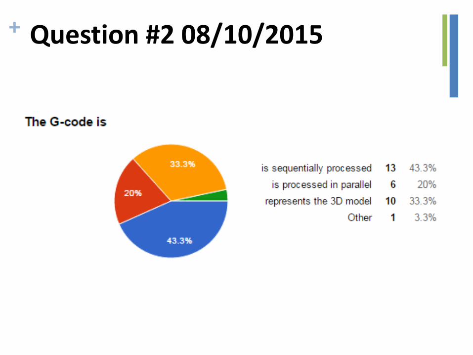
+ Question #2 08/10/2015
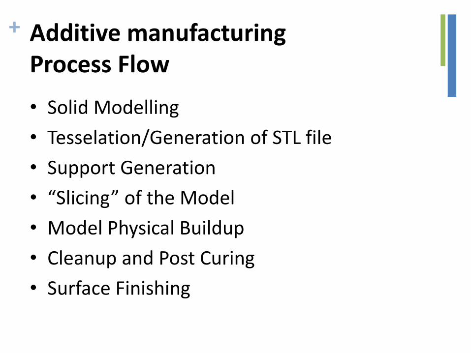
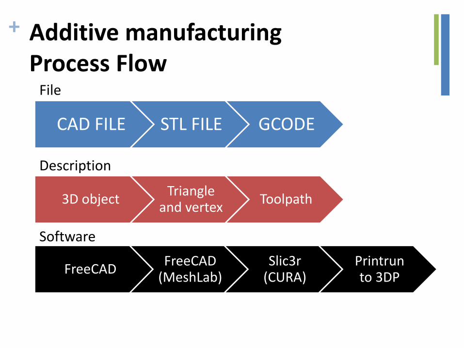
+ Additive manufacturing Process Flow
• Solid Modelling
• Tesselation/Generation of STL file
• Support Generation
• “Slicing” of the Model
• Model Physical Buildup
• Cleanup and Post Curing
• Surface Finishing
+
CAD FILE STL FILE GCODE
3D object Triangle
and vertex Toolpath
FreeCAD FreeCAD
(MeshLab) Slic3r
(CURA) Printrun to 3DP
File
Description
Software
Additive manufacturing Process Flow

EXCHANGE FORMATS

+ Example of *.stl Representation
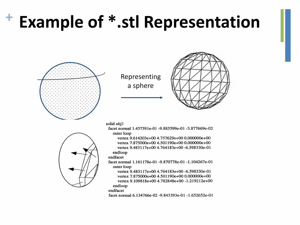
+ Example of *.stl Representation
Representing a sphere

+ Additive manufacturing file format
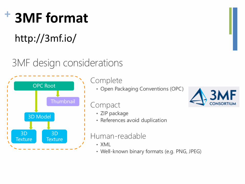
+ 3MF format
http://3mf.io/
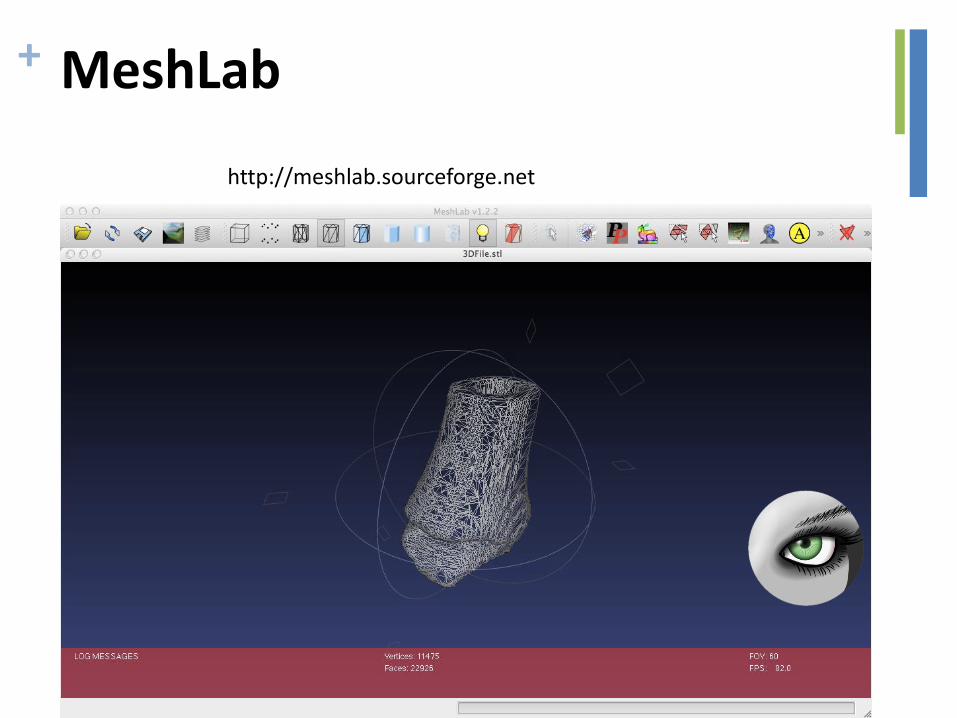
+ MeshLab
http://meshlab.sourceforge.net
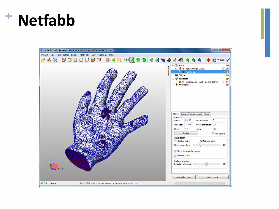
+ Netfabb
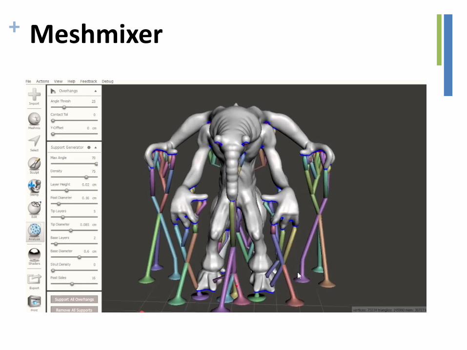
+ Meshmixer
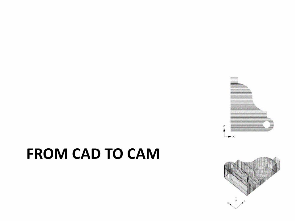
FROM CAD TO CAM

+ Processing of *.stl Files
• After the CAD system has generated *.stl file, it can be passed to the SFM machine
• Machine then processes the *.stl file, slicing it into many thin layers stacked on one another. The resulting files are called slice files.
• The shapes of the slices represent cross sections
• In SFM processes thick solid sections of material are often removed and replaced with cross hatching
• Thus SFM parts are usually hollow, with cross hatching on the inside to add strength/stability
+ Support material
• Some solid freeform fabrication techniques use two materials in the course of constructing parts.
• The first material is the part material and the second is the support material (to support overhanging features during construction).
• The support material is later removed by heat or dissolved away with a solvent or water.
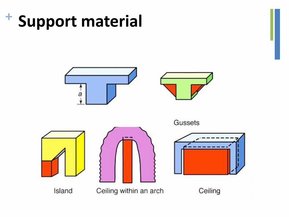
+ Support material
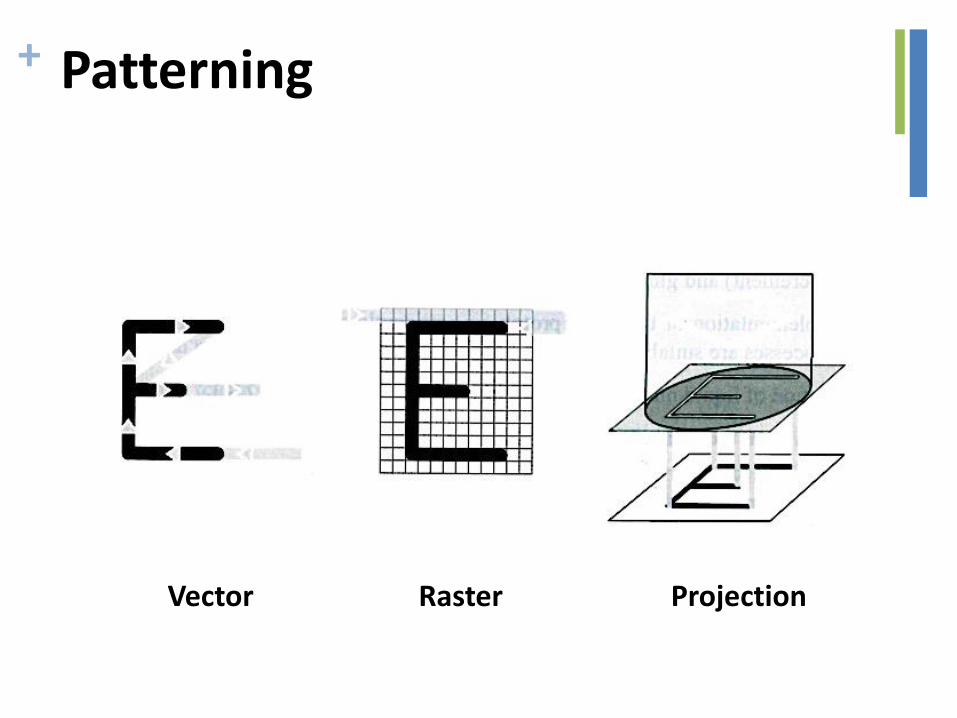
+ Patterning
Vector Raster Projection
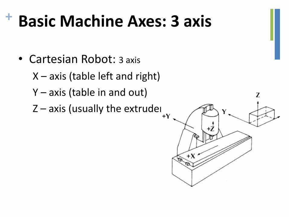
+ Basic Machine Axes: 3 axis
• Cartesian Robot: 3 axis
X – axis (table left and right)
Y – axis (table in and out)
Z – axis (usually the extruder axis)

+ G-CODE
• G – Code Programming
• Originally called the “Word Address” programming format.
• Processed one line at a time sequentially.
+ Word address format
• Word address was developed as a tape programming format. – Another name for “word address” is “variable block” format, so
named because the program lines (blocks) may vary in length according to the information contained in them.
– Earlier tape formats required an entry for all possible machine registers. In these earlier formats, a zero was programmed as a null input if the register values were to be unaffected, but in work address, the blocks need only contain necessary information. Although developed as a tape format, word address is used as the format for manual data input on many CNC machines.
• Addresses
– The block format for word address is as follows: – N … G … X … Y … Z … I … J … K … F … H … H … S … T … M … – Only the information needed on a line need be given. Each of the
letters is called an address (or word)
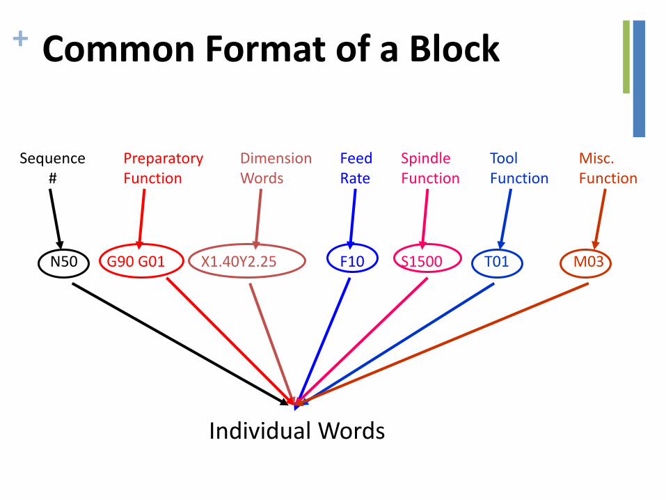
+ Common Format of a Block
Sequence #
Preparatory Function
Dimension Words
Feed Rate
Spindle Function
Tool Function
Misc. Function
N50 G90 G01 X1.40Y2.25 F10 S1500 T01 M03
Individual Words

+ Word address
• Reserved Code Words Worksheet – N – Sequence or line number
– G – Preparatory function
– ...
• Dimension Words: – X
– Y
– Z
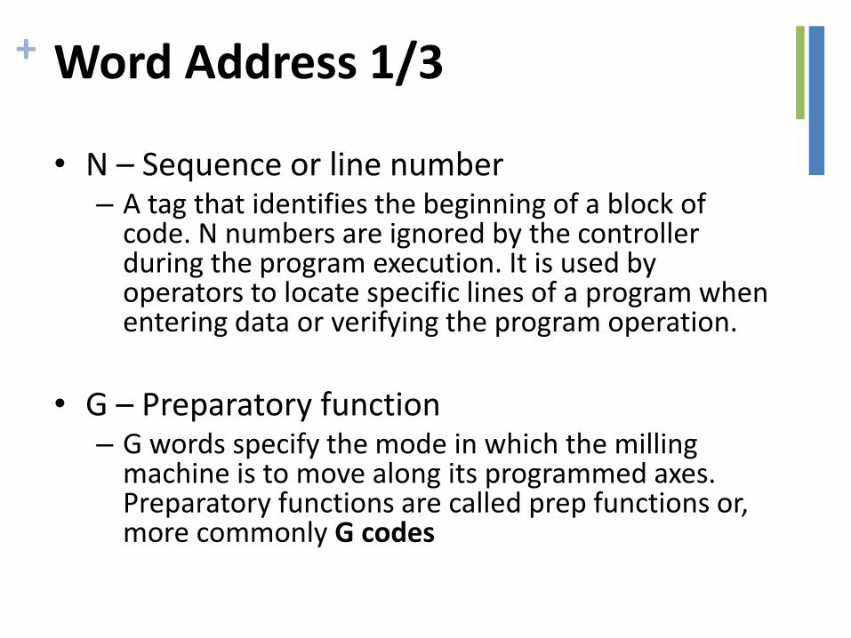
+ Word Address 1/3
• N – Sequence or line number – A tag that identifies the beginning of a block of
code. N numbers are ignored by the controller during the program execution. It is used by operators to locate specific lines of a program when entering data or verifying the program operation.
• G – Preparatory function
– G words specify the mode in which the milling machine is to move along its programmed axes. Preparatory functions are called prep functions or, more commonly G codes
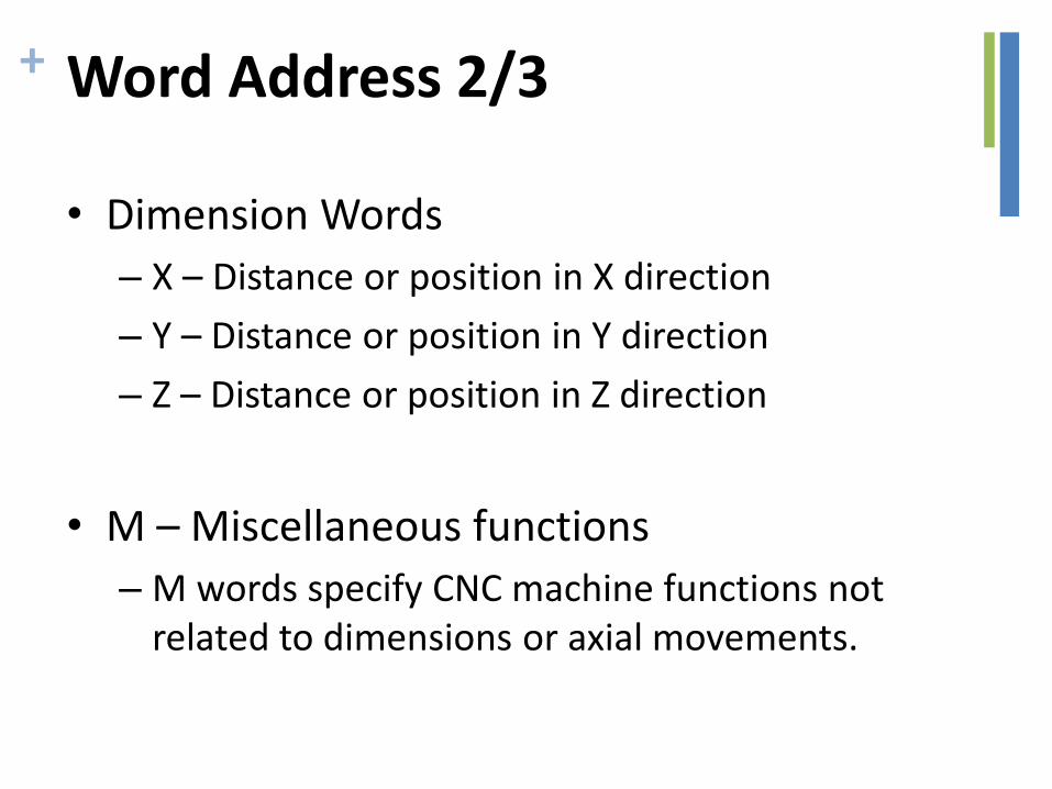
+ Word Address 2/3
• Dimension Words
– X – Distance or position in X direction
– Y – Distance or position in Y direction
– Z – Distance or position in Z direction
• M – Miscellaneous functions
– M words specify CNC machine functions not related to dimensions or axial movements.
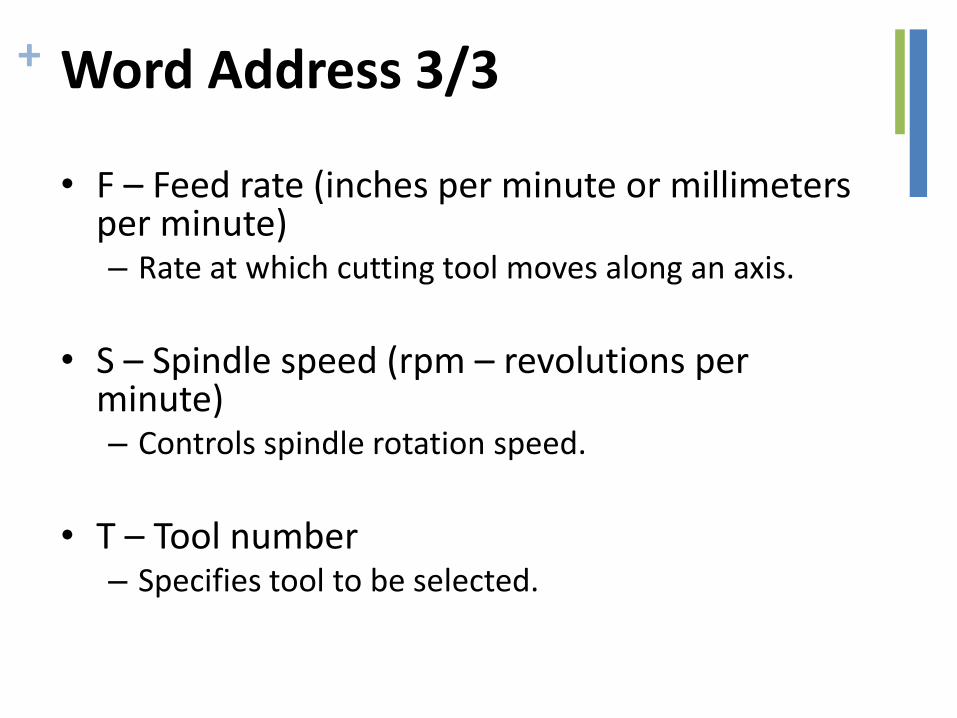
+ Word Address 3/3
• F – Feed rate (inches per minute or millimeters per minute) – Rate at which cutting tool moves along an axis.
• S – Spindle speed (rpm – revolutions per
minute) – Controls spindle rotation speed.
• T – Tool number
– Specifies tool to be selected.
+ G Word
• G words or codes tell the machine to perform certain functions. Most G words are modal which means they remain in effect until replaced by another modal G code.
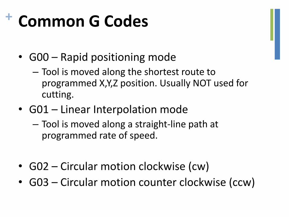
+ Common G Codes
• G00 – Rapid positioning mode – Tool is moved along the shortest route to
programmed X,Y,Z position. Usually NOT used for cutting.
• G01 – Linear Interpolation mode – Tool is moved along a straight-line path at
programmed rate of speed.
• G02 – Circular motion clockwise (cw)
• G03 – Circular motion counter clockwise (ccw)
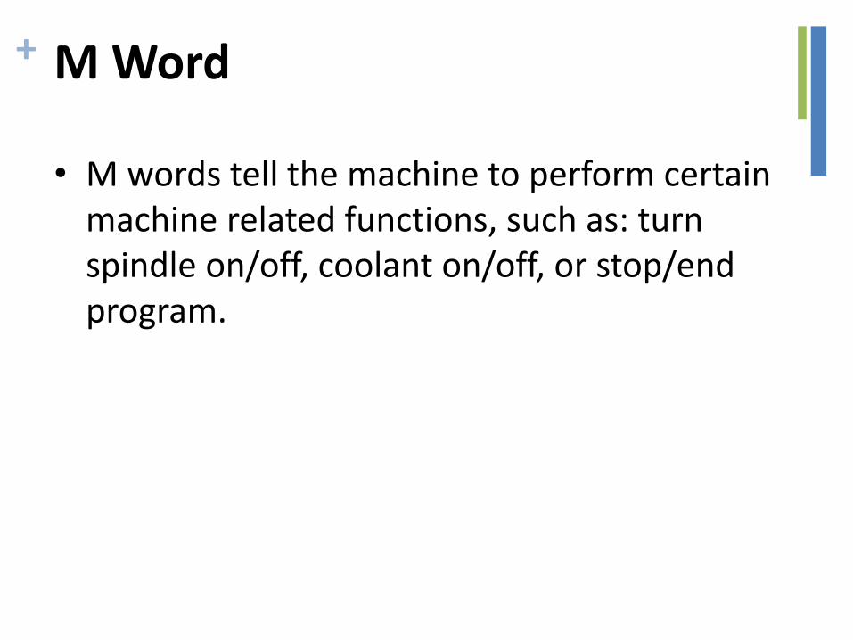
+ M Word
• M words tell the machine to perform certain machine related functions, such as: turn spindle on/off, coolant on/off, or stop/end program.
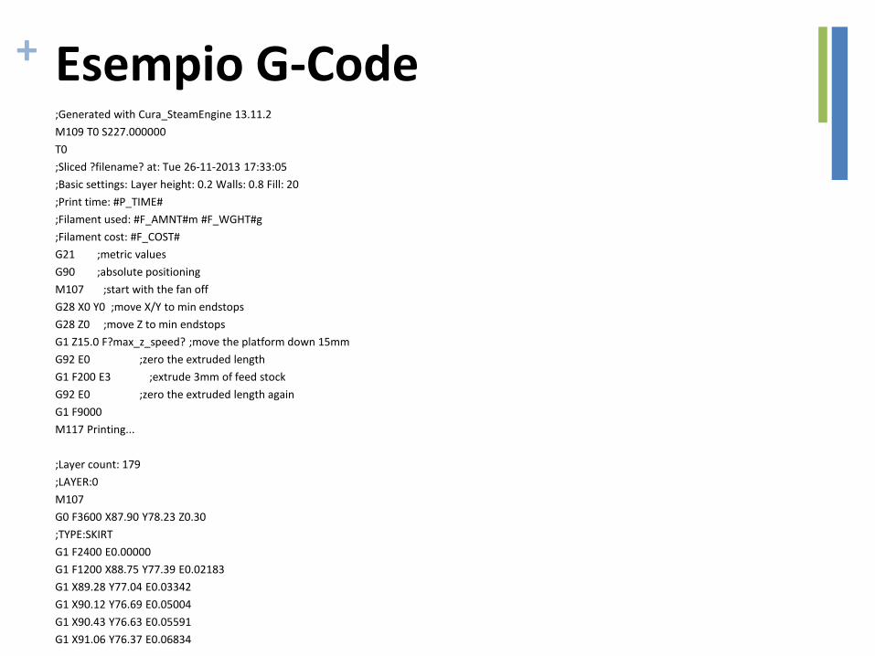
+ Esempio G-Code ;Generated with Cura_SteamEngine 13.11.2
M109 T0 S227.000000
T0
;Sliced ?filename? at: Tue 26-11-2013 17:33:05
;Basic settings: Layer height: 0.2 Walls: 0.8 Fill: 20
;Print time: #P_TIME#
;Filament used: #F_AMNT#m #F_WGHT#g
;Filament cost: #F_COST#
G21 ;metric values
G90 ;absolute positioning
M107 ;start with the fan off
G28 X0 Y0 ;move X/Y to min endstops
G28 Z0 ;move Z to min endstops
G1 Z15.0 F?max_z_speed? ;move the platform down 15mm
G92 E0 ;zero the extruded length
G1 F200 E3 ;extrude 3mm of feed stock
G92 E0 ;zero the extruded length again
G1 F9000
M117 Printing...
;Layer count: 179
;LAYER:0
M107
G0 F3600 X87.90 Y78.23 Z0.30
;TYPE:SKIRT
G1 F2400 E0.00000
G1 F1200 X88.75 Y77.39 E0.02183
G1 X89.28 Y77.04 E0.03342
G1 X90.12 Y76.69 E0.05004
G1 X90.43 Y76.63 E0.05591
G1 X91.06 Y76.37 E0.06834
...

+ Question time!
http://goo.gl/forms/Jjm4uLd53j