2015 work plan for advanced site investigation of the riverton, wyoming ... · u.s. department of...
TRANSCRIPT
2015 Work Plan for Advanced Site Investigation of the Riverton, Wyoming, Processing Site April 2015
LMS/RVT/S12697

This page intentionally left blank
U.S. Department of Energy 2015 Work Plan for Advanced Site Investigation of the Riverton, Wyoming, Processing Site April 2015 Doc. No. S12697 Page i
Contents Abbreviations ................................................................................................................................. iii 1.0 Introduction ............................................................................................................................1
1.1 Background ..................................................................................................................1 2.0 Purpose and Scope .................................................................................................................2 3.0 Direct-Push Drilling ...............................................................................................................3
3.1 Installation and Sampling of Temporary Boreholes ....................................................3 3.2 Groundwater Sampling of Boreholes ..........................................................................6
4.0 Backhoe Trenching ................................................................................................................7 4.1 Backhoe Trenching and Soil Sampling .......................................................................7
5.0 Sonic Drilling .........................................................................................................................8 5.1 Sonic Coring and Soil Sampling .................................................................................8 5.2 Monitoring Well Installation .....................................................................................10
6.0 Hand-Driven Temporary Well Points ..................................................................................12 7.0 Continuous Groundwater-Elevation Monitoring .................................................................12 8.0 Surface Water Measurements ...............................................................................................13
8.1 Surface Water Discharge Measurements ...................................................................13 8.2 Stilling Well Installation ............................................................................................13 8.3 Wind River Elevations ..............................................................................................14
9.0 Analytical Program and Laboratory Tests............................................................................15 9.1 Groundwater ..............................................................................................................15 9.2 Soils ...........................................................................................................................16
9.2.1 Solid-Phase Analyses of Core Material .....................................................16 9.2.2 Laboratory Studies of Core Material .........................................................17
9.2.2.1 Batch Testing ............................................................................17 9.2.2.2 Column Testing .........................................................................17
10.0 Quality Assurance ................................................................................................................17 11.0 Health and Safety .................................................................................................................17 12.0 Environmental Compliance ..................................................................................................18
12.1 Environmental Management System .........................................................................18 12.2 Waste Management ...................................................................................................18 12.3 Spills ..........................................................................................................................18 12.4 Land Disturbance .......................................................................................................19 12.5 Dust Control ..............................................................................................................19 12.6 Suspected Wetlands and Dry Washes .......................................................................19 12.7 Cultural Resources .....................................................................................................20 12.8 Migratory Birds .........................................................................................................20 12.9 Threatened and Endangered Species .........................................................................21 12.10 Refueling ...................................................................................................................21 12.11 Well or Borehole Permits and Abandonment Notifications and Reports ..................21 12.12 Miscellaneous Compliance Activities .......................................................................21 12.13 Access ........................................................................................................................22
13.0 Reporting ..............................................................................................................................22 14.0 References ............................................................................................................................23
2015 Work Plan for Advanced Site Investigation of the Riverton, Wyoming, Processing Site U.S. Department of Energy Doc. No. S12697 April 2015 Page ii
Figures Figure 1. Example of CMT Well Construction ............................................................................ 11 Figure 2. Example of Stilling Well Construction ......................................................................... 14
Tables Table 1. Summary of Work Plan Activities and Objectives ........................................................... 4 Table 2. Additional Analyses for Groundwater Sampling ............................................................ 15
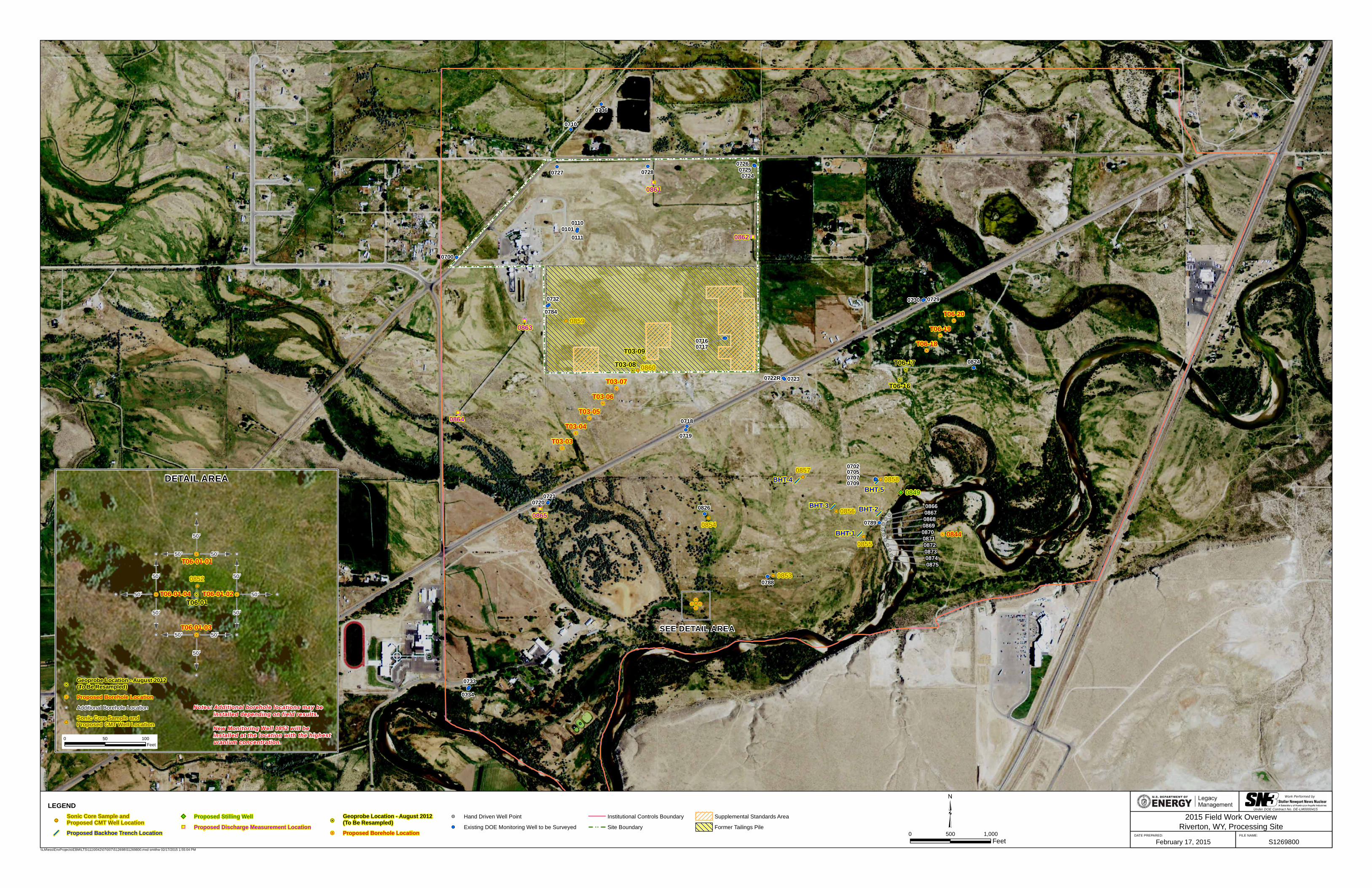
Plate Plate 1. 2015 Field Work Overview – Riverton, WY, Processing Site
U.S. Department of Energy 2015 Work Plan for Advanced Site Investigation of the Riverton, Wyoming, Processing Site April 2015 Doc. No. S12697 Page iii
Abbreviations 14C carbon-14
CFR Code of Federal Regulations
CMT continuous multichannel tubing
COC contaminant of concern
CSM conceptual site model
DOE U.S. Department of Energy
DOECAP DOE Consolidated Audit Program
ESL Environmental Sciences Laboratory
ft feet (foot)
GCAP Ground Water Compliance Action Plan
GPS global positioning system
GV Groundwater Vistas
IDW investigation-derived waste
JSA Job Safety Analysis
LM Office of Legacy Management
MBTA Migratory Bird Treaty Act
mg/L milligram(s) per liter
NEPA National Environmental Policy Act
NRC U.S. Nuclear Regulatory Commission
NRZ naturally reduced zones 18O oxygen-18
ORP oxygen reduction potential 34S sulfur-34
SAP Sampling and Analysis Plan for U.S. Department of Energy Office of Legacy Management Sites
SLAC Stanford Linear Accelerator Center
SOWP Site Observational Work Plan
U uranium
UMTRCA Uranium Mill Tailings Radiation Control Act
USFWS U.S. Fish and Wildlife Service
USGS U.S. Geological Survey
WREQC Wind River Environmental Quality Commission

2015 Work Plan for Advanced Site Investigation of the Riverton, Wyoming, Processing Site U.S. Department of Energy Doc. No. S12697 April 2015 Page iv
This page intentionally left blank
U.S. Department of Energy 2015 Work Plan for Advanced Site Investigation of the Riverton, Wyoming, Processing Site April 2015 Doc. No. S12697 Page 1
1.0 Introduction A flood at the Uranium Mill Tailings Radiation Control Act (UMTRCA) Title I Riverton, Wyoming, Processing Site in 2010 produced increases in groundwater concentrations of uranium and other contaminants, resulting in the need for new investigations of soil/water interactions to determine additional contaminant sources that could influence compliance strategy decisions (Shafer et al. 2014). New data collected at the Riverton site and other Legacy Management (LM) sites provide additional evidence that the complexity of the sites is greater than originally conceptualized and that additional data are needed to make informed decisions regarding aquifer restoration and viable compliance strategies. This work plan reflects this changing view of LM sites—from a relatively simplistic groundwater-aquifer matrix interaction to a more complex, multimedia and process-driven approach—by laying the foundation to develop a new vision for the Riverton site. This plan describes the objectives, rationale, field work, sampling and analysis activities, information gathering, and specific quality assurance and quality control measures necessary to gain new insights into site conditions and processes. These new insights will be used to refine the conceptual site model (CSM) and to further assess the viability of the natural flushing compliance strategy at the Riverton site. This plan addresses all non-routine field work scheduled for 2015. 1.1 Background A uranium and vanadium ore processing mill operated from 1958 to 1963 at the Riverton site. A tailings pile covered about 72 acres of the 140-acre site. The tailings and associated slurry water were the primary, original source of groundwater contamination of the surficial aquifer. In 1988 and 1989, the tailings pile was excavated down to an average depth of 4 feet (ft) below ground surface based on a radium-226 soil standard in Title 40 Code of Federal Regulations Part 192 (40 CFR 192). Surface remediation activities resulted in removal of about 1.8 million cubic yards of tailings and associated materials from the site, which were encapsulated at the Gas Hills East, Wyoming, Disposal Site (DOE 1998a). Soils at and below the water table with elevated thorium-230 concentrations were left in place (DOE 1991) on portions of the former mill site by applying supplemental standards. Additional details about the Riverton site, along with links to site documents and data, can be found at http://www.lm.doe.gov/riverton/Sites.aspx. Initial groundwater characterization of the Riverton site was conducted in the 1990s, culminating in a Site Observational Work Plan (SOWP) in 1998, which contained a recommendation for a natural flushing compliance strategy (DOE 1998a). The U.S. Nuclear Regulatory Commission (NRC) concurred with the natural flushing compliance strategy in the Ground Water Compliance Action Plan (GCAP) (DOE 1998b). Since 1998, verification monitoring has been conducted by the U.S. Department of Energy (DOE) to document site conditions and assess the progress of natural flushing; data collected during verification monitoring are reported annually in verification monitoring reports. In addition, the Wind River Environmental Quality Commission (WREQC) has conducted studies and provided verification monitoring support during the verification monitoring period. Results of the verification monitoring indicated that natural flushing was generally progressing as expected until June 2010, when significant increases in contaminant concentrations were
2015 Work Plan for Advanced Site Investigation of the Riverton, Wyoming, Processing Site U.S. Department of Energy Doc. No. S12697 April 2015 Page 2
measured in several wells downgradient of the site after the area flooded. In response to the unexpected results following the flood, an enhanced characterization of the surficial aquifer was conducted in 2012, which included installation of 103 boreholes along nine transects with a Geoprobe, collection of 103 water samples and 65 soil samples, laboratory tests on the soil samples, and additional groundwater modeling. Results and analysis of the enhanced characterization were reported in the 2012 Enhanced Characterization and Monitoring Report Riverton, Wyoming, Processing Site (DOE 2013). A better understanding of the Riverton site was gained from the enhanced characterization work, including:
A better definition of the size and shape of contaminant plumes;
Verification that leachable uranium was present in the unsaturated zone soils; and,
An indication that the groundwater compliance strategy of natural flushing may not be viable.
The enhanced characterization also raised additional questions related to the CSM of the site. These included:
The concentration of uranium leached from unsaturated zone samples (0 to 5 ft) alone did not appear to be high enough to have caused the spikes observed in the groundwater after the 2010 flood. Where was the contamination coming from to cause the observed concentration spikes in groundwater after the flood?
Are there secondary sources (redistributed from the primary source) of contamination and where are they?
What was the mechanism that caused contaminant concentrations in the groundwater to spike?
Why do high uranium concentrations in the groundwater remain on the former mill site?
Why is there uranium in groundwater above the standard at the farthest southwest portion of the characterized area and away from the contaminant plume? What is the extent of this anomalous uranium concentration?
Why do contaminant plumes appear to stagnate adjacent to the Little Wind River?
2.0 Purpose and Scope This work plan identifies non-routine field work scope for 2015. The purpose of this plan is to identify field-work required to contribute to the overall objectives for the site as listed below. The major site objectives are to:
Assess the viability of the natural flushing compliance strategy.
Obtain a better understanding of groundwater flow conditions and geochemical processes that control contaminant transport.
Review the technical approach to the site and continue to refine a comprehensive CSM with alternative CSMs, if needed.
U.S. Department of Energy 2015 Work Plan for Advanced Site Investigation of the Riverton, Wyoming, Processing Site April 2015 Doc. No. S12697 Page 3
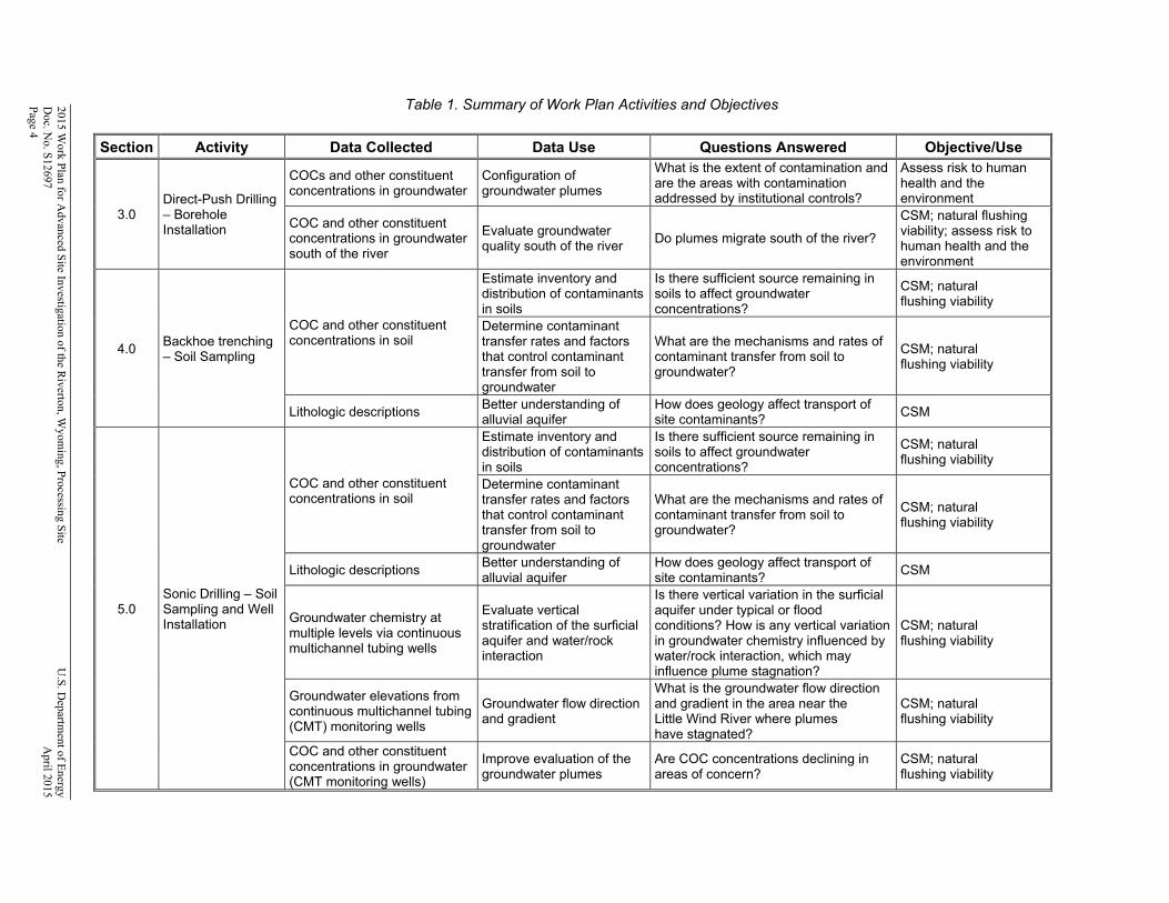
This work plan specifies the activities necessary to contribute to these overall objectives. Table 1 displays the rationale for each activity, including data collected, use of the data, the primary question being addressed, and the overall objective. This work plan is organized according to the major categories in Table 1, which include Direct-Push Drilling (Section 3.0), Backhoe Trenching (Section 4.0), Sonic Drilling (Section 5.0), Hand-Driven Temporary Well Points (Section 6.0), Continuous Groundwater Elevation Monitoring (Section 7.0), Surface Water Measurements (Section 8.0), and Analytical Program and Laboratory Tests (Section 9.0).
3.0 Direct-Push Drilling Drilling and sampling will be conducted to further evaluate groundwater conditions in areas where boreholes were planned during the 2012 field investigation (DOE 2013) but not installed because of access issues. Drilling and sampling also will be conducted in a portion of the surficial aquifer where elevated uranium concentrations were measured during the 2012 field investigation. This phase of field work will be self-performed using a direct-push technology to minimize cost. A Geoprobe Systems direct-push machine (Geoprobe Model 7720DT) will be used to install a minimum of 17 boreholes as shown in Plate 1. Procedures for operation, maintenance, and safe use of the Geoprobe are specified in the Procedure for Operation of the Geoprobe Model 7720DT (LMS/PRO/S08578). 3.1 Installation and Sampling of Temporary Boreholes Temporary boreholes (Plate 1) will be installed and groundwater will be sampled in areas where transects could not be completed during the field investigation in 2012, which will provide data to better define contaminant plumes and to further delineate the extent of groundwater contamination. These locations include boreholes T03-03 to T03-07 to complete Transect 3, and boreholes T06-18 to T06-20 to complete Transect 6. In addition, boreholes will be installed at locations T03-08 and T03-09, and groundwater will be sampled to confirm the high uranium concentration measured in 2012; the sampling also will provide a basis for comparison to data from locations T03-03 to T03-07. Boreholes also will be installed at locations T06-16 and T06-17 to confirm contaminant of concern (COC) concentrations measured in 2012 and to provide a basis for comparison to data from locations T06-18 to T06-20. Several other locations at each end of Transect 4 (i.e., T04-01, T04-02, T04-20, and T04-21) were not sampled in 2012 (DOE 2013) because of inaccessibility due to thick vegetation; these locations will not be considered in this work plan for the same reason. A temporary borehole will be installed, and groundwater will be sampled at location 0844 to assess water quality on the south side of the Little Wind River. Temporary boreholes also will be installed and groundwater will be sampled at location T06-01 and in the area around location T06-01 (see inset in Plate 1), which will provide data to define the extent of anomalous uranium concentrations measured in that borehole from the 2012 field investigation (DOE 2013). The number of boreholes installed will be based on uranium concentrations measured in the field and analyzed by the Environmental Sciences Laboratory (ESL) personnel via a mobile laboratory.
2015 Work P
lan for Advanced S
ite Investigation of the Riverton, W
yoming, P
rocessing Site
U.S
. Departm
ent of Energy
Doc. N
o. S12697
A
pril 2015 P
age 4
Table 1. Summary of Work Plan Activities and Objectives Section Activity Data Collected Data Use Questions Answered Objective/Use
3.0 Direct-Push Drilling – Borehole Installation
COCs and other constituent concentrations in groundwater
Configuration of groundwater plumes
What is the extent of contamination and are the areas with contamination addressed by institutional controls?
Assess risk to human health and the environment
COC and other constituent concentrations in groundwater south of the river
Evaluate groundwater quality south of the river
Do plumes migrate south of the river?
CSM; natural flushing viability; assess risk to human health and the environment
4.0 Backhoe trenching – Soil Sampling
COC and other constituent concentrations in soil
Estimate inventory and distribution of contaminants in soils
Is there sufficient source remaining in soils to affect groundwater concentrations?
CSM; natural flushing viability
Determine contaminant transfer rates and factors that control contaminant transfer from soil to groundwater
What are the mechanisms and rates of contaminant transfer from soil to groundwater?
CSM; natural flushing viability
Lithologic descriptions Better understanding of alluvial aquifer
How does geology affect transport of site contaminants?
CSM
5.0 Sonic Drilling – Soil Sampling and Well Installation
COC and other constituent concentrations in soil
Estimate inventory and distribution of contaminants in soils
Is there sufficient source remaining in soils to affect groundwater concentrations?
CSM; natural flushing viability
Determine contaminant transfer rates and factors that control contaminant transfer from soil to groundwater
What are the mechanisms and rates of contaminant transfer from soil to groundwater?
CSM; natural flushing viability
Lithologic descriptions Better understanding of alluvial aquifer
How does geology affect transport of site contaminants?
CSM
Groundwater chemistry at multiple levels via continuous multichannel tubing wells
Evaluate vertical stratification of the surficial aquifer and water/rock interaction
Is there vertical variation in the surficial aquifer under typical or flood conditions? How is any vertical variation in groundwater chemistry influenced by water/rock interaction, which may influence plume stagnation?
CSM; natural flushing viability
Groundwater elevations from continuous multichannel tubing (CMT) monitoring wells
Groundwater flow direction and gradient
What is the groundwater flow direction and gradient in the area near the Little Wind River where plumes have stagnated?
CSM; natural flushing viability
COC and other constituent concentrations in groundwater (CMT monitoring wells)
Improve evaluation of the groundwater plumes
Are COC concentrations declining in areas of concern?
CSM; natural flushing viability
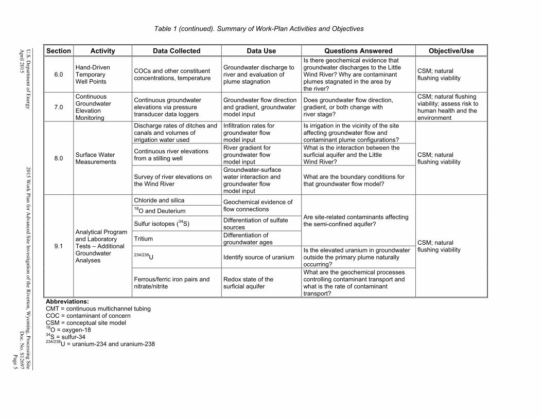
Table 1 (continued). Summary of Work-Plan Activities and Objectives
U.S
. Departm
ent of Energy
2015 Work P
lan for Advanced S
ite Investigation of the Riverton, W
yoming, P
rocessing Site
April 2015
D
oc. No. S
12697
P
age 5
Section Activity Data Collected Data Use Questions Answered Objective/Use
6.0 Hand-Driven Temporary Well Points
COCs and other constituent concentrations, temperature
Groundwater discharge to river and evaluation of plume stagnation
Is there geochemical evidence that groundwater discharges to the Little Wind River? Why are contaminant plumes stagnated in the area by the river?
CSM; natural flushing viability
7.0
Continuous Groundwater Elevation Monitoring
Continuous groundwater elevations via pressure transducer data loggers
Groundwater flow direction and gradient, groundwater model input
Does groundwater flow direction, gradient, or both change with river stage?
CSM; natural flushing viability; assess risk to human health and the environment
8.0 Surface Water Measurements
Discharge rates of ditches and canals and volumes of irrigation water used
Infiltration rates for groundwater flow model input
Is irrigation in the vicinity of the site affecting groundwater flow and contaminant plume configurations?
CSM; natural flushing viability
Continuous river elevations from a stilling well
River gradient for groundwater flow model input
What is the interaction between the surficial aquifer and the Little Wind River?
Survey of river elevations on the Wind River
Groundwater-surface water interaction and groundwater flow model input
What are the boundary conditions for that groundwater flow model?
9.1
Analytical Program and Laboratory Tests – Additional Groundwater Analyses
Chloride and silica Geochemical evidence of flow connections
Are site-related contaminants affecting the semi-confined aquifer?
CSM; natural flushing viability
18O and Deuterium
Sulfur isotopes (34S) Differentiation of sulfate sources
Tritium Differentiation of groundwater ages
234/238U Identify source of uranium Is the elevated uranium in groundwater outside the primary plume naturally occurring?
Ferrous/ferric iron pairs and nitrate/nitrite
Redox state of the surficial aquifer
What are the geochemical processes controlling contaminant transport and what is the rate of contaminant transport?
Abbreviations: CMT = continuous multichannel tubing COC = contaminant of concern CSM = conceptual site model 18O = oxygen-18 34S = sulfur-34 234/238U = uranium-234 and uranium-238
2015 Work Plan for Advanced Site Investigation of the Riverton, Wyoming, Processing Site U.S. Department of Energy Doc. No. S12697 April 2015 Page 6
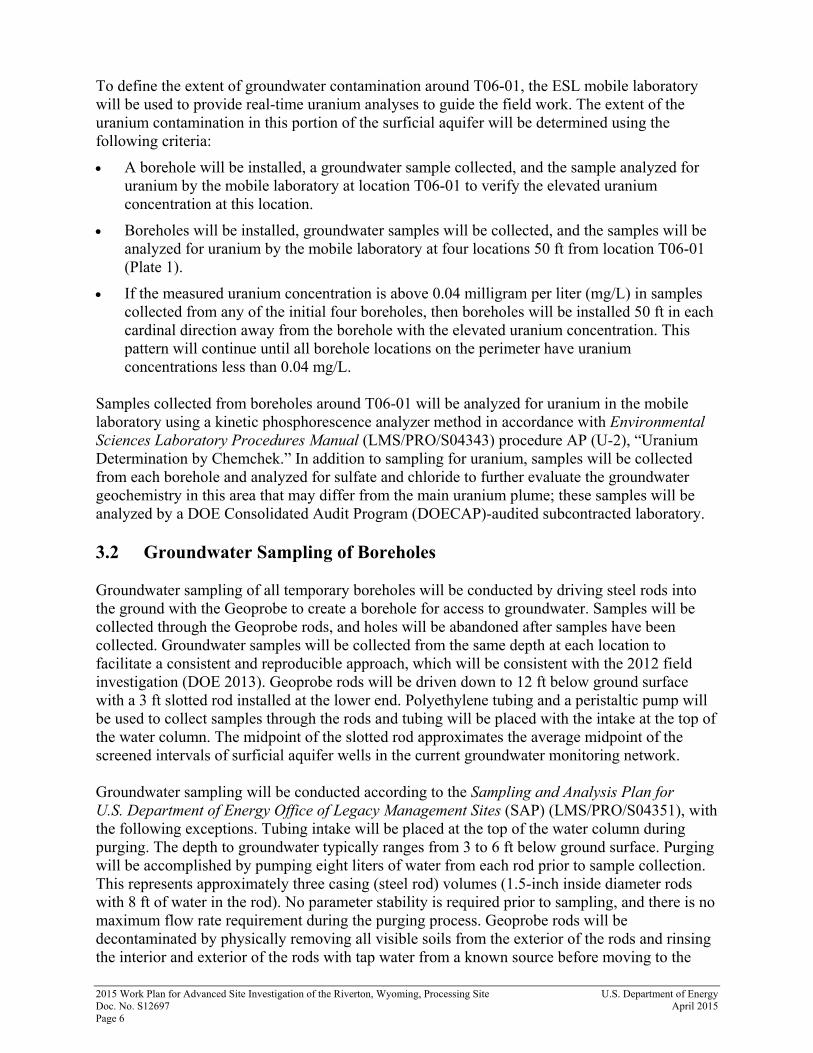
To define the extent of groundwater contamination around T06-01, the ESL mobile laboratory will be used to provide real-time uranium analyses to guide the field work. The extent of the uranium contamination in this portion of the surficial aquifer will be determined using the following criteria:
A borehole will be installed, a groundwater sample collected, and the sample analyzed for uranium by the mobile laboratory at location T06-01 to verify the elevated uranium concentration at this location.
Boreholes will be installed, groundwater samples will be collected, and the samples will be analyzed for uranium by the mobile laboratory at four locations 50 ft from location T06-01 (Plate 1).
If the measured uranium concentration is above 0.04 milligram per liter (mg/L) in samples collected from any of the initial four boreholes, then boreholes will be installed 50 ft in each cardinal direction away from the borehole with the elevated uranium concentration. This pattern will continue until all borehole locations on the perimeter have uranium concentrations less than 0.04 mg/L.
Samples collected from boreholes around T06-01 will be analyzed for uranium in the mobile laboratory using a kinetic phosphorescence analyzer method in accordance with Environmental Sciences Laboratory Procedures Manual (LMS/PRO/S04343) procedure AP (U-2), “Uranium Determination by Chemchek.” In addition to sampling for uranium, samples will be collected from each borehole and analyzed for sulfate and chloride to further evaluate the groundwater geochemistry in this area that may differ from the main uranium plume; these samples will be analyzed by a DOE Consolidated Audit Program (DOECAP)-audited subcontracted laboratory. 3.2 Groundwater Sampling of Boreholes Groundwater sampling of all temporary boreholes will be conducted by driving steel rods into the ground with the Geoprobe to create a borehole for access to groundwater. Samples will be collected through the Geoprobe rods, and holes will be abandoned after samples have been collected. Groundwater samples will be collected from the same depth at each location to facilitate a consistent and reproducible approach, which will be consistent with the 2012 field investigation (DOE 2013). Geoprobe rods will be driven down to 12 ft below ground surface with a 3 ft slotted rod installed at the lower end. Polyethylene tubing and a peristaltic pump will be used to collect samples through the rods and tubing will be placed with the intake at the top of the water column. The midpoint of the slotted rod approximates the average midpoint of the screened intervals of surficial aquifer wells in the current groundwater monitoring network. Groundwater sampling will be conducted according to the Sampling and Analysis Plan for U.S. Department of Energy Office of Legacy Management Sites (SAP) (LMS/PRO/S04351), with the following exceptions. Tubing intake will be placed at the top of the water column during purging. The depth to groundwater typically ranges from 3 to 6 ft below ground surface. Purging will be accomplished by pumping eight liters of water from each rod prior to sample collection. This represents approximately three casing (steel rod) volumes (1.5-inch inside diameter rods with 8 ft of water in the rod). No parameter stability is required prior to sampling, and there is no maximum flow rate requirement during the purging process. Geoprobe rods will be decontaminated by physically removing all visible soils from the exterior of the rods and rinsing the interior and exterior of the rods with tap water from a known source before moving to the
U.S. Department of Energy 2015 Work Plan for Advanced Site Investigation of the Riverton, Wyoming, Processing Site April 2015 Doc. No. S12697 Page 7
next location. If sample tubing is reused, decontamination will be accomplished as specified in the SAP (i.e., a detergent/deionized water rinse followed by a deionized water rinse). After completion of sampling, steel rods will be pulled, the depth to the top of the collapsed material in the hole will be measured, and the borehole will be abandoned by slowly filling the hole with bentonite pellets or chips to the ground surface. If it appears that bridging of the bentonite is occurring during filling of the hole, the bentonite will be slowly poured into the hole in 2 ft lifts. After completion of each lift, the bentonite will be tamped to help eliminate any potential bridging and to ensure that a good seal is obtained. The total volume of bentonite used at each hole will be recorded. All boreholes will be abandoned as soon as possible after removing the steel rods. GPS data will be collected to document the actual sample location. Samples will be collected from each borehole and analyzed by a DOECAP-approved laboratory for NRC-approved COCs (manganese, molybdenum, sulfate, and uranium), major cations (calcium, magnesium, potassium, and sodium), and additional major anions (chloride). In addition, field measurements of pH, specific conductance, temperature, oxidation-reduction potential (ORP), total alkalinity, turbidity, and dissolved oxygen will be taken at the time of sampling.
4.0 Backhoe Trenching 4.1 Backhoe Trenching and Soil Sampling Five trenches within the highest concentration portions of the groundwater plume are proposed as indicated in Plate 1. These trenches will allow for a quick, easy, and cost effective approach for getting visual descriptions of the subsurface lithology. These trenches will be approximately 4 ft wide by 10–12 ft long, and up to 10 ft deep. Sediment from the trenches will be placed at least 2 ft away from the trench to maintain slope stability and safety for sample collection. Based on the bottom material visibility, these trenches may be stair-stepped along the side walls to allow for better lithologic identification, without entering the trench, up to a maximum width of 10 ft. The main reason for these trenches is the visual identification and sampling of any naturally reduced zones (NRZs). These NRZs will be sampled by Stanford personnel. As such, these trenches are focused on areas near the Little Wind River (Plate 1). NRZs are potential controls for plume persistence, as they can act as sources and/or sinks for uranium in groundwater. While Stanford personnel will do the majority of the sample collecting, up to 10 separate samples will be collected in each trench by DOE based on visual identification of NRZs or changes in geology, and will be analyzed by a DOECAP-approved laboratory using an acid digestion for NRC-approved COCs (manganese, molybdenum, and uranium), and major cations (calcium, magnesium, potassium, and sodium), and iron. Additional analyses from the DOECAP-approved laboratory will include analyses for chloride and sulfate (water leach), total organic carbon, and total inorganic carbon. In addition, a split of each soil sample will be sent the Environmental Sciences Laboratory to perform a 5 percent nitric acid leach for uranium content to determine the easily leachable uranium. These additional samples will be used for general characterization of soil material and the potential for uranium sorption and/or release.
2015 Work Plan for Advanced Site Investigation of the Riverton, Wyoming, Processing Site U.S. Department of Energy Doc. No. S12697 April 2015 Page 8
5.0 Sonic Drilling 5.1 Sonic Coring and Soil Sampling Previous work sampled the unsaturated zone with a Geoprobe rig down to approximately 5 ft, with samples homogenized at 0 to 2.5 ft and 2.5 to 5 ft (DOE 2013). This work identified some labile uranium, but mass balance calculations did not appear to account for all of the uranium that was added to the groundwater after the June 2010 flooding event. Due to the small coring diameter and percussion hammering approach, the core recovery from the Geoprobe rig was sometimes limited, especially in more gravelly sediments. Sonic drilling is the industry standard for the collection of high quality core samples in unconsolidated sediments, especially when gravel is encountered. This drilling method will allow collection of representative samples to better characterize the distribution and concentration of COCs in the subsurface. Details on sonic drilling can be found in Barrow (1994). This drilling will obtain continuous core from ground surface to the top of the first confining zone (approximately 20 ft). Care will be taken to not penetrate the confining zone. Core diameter will be approximately 6 inches. The proposed locations, their justification, and procedures for core collection are listed in this section. These core data and analyses will be used to better define the total mass and potential mobility of uranium at various depths with the objective of improving the CSM. The following nine locations are proposed for sonic drilling (Plate 1):
1. Location 0852 near the borehole T06-01 investigation area where uranium was slightly above 0.044 mg/L, but outside of the main plume. This sonic borehole will be drilled in the location with the highest uranium concentration measured during the direct-push drilling and will provide information on uranium concentrations, source, and mobility that may or may not be related to the main plume.
2. Location 0853 on the lateral side of the plume and near well 0788 that showed an increase in uranium after the June 2010 flooding event. Information here will help identify any potential uranium sources at the lateral edge of the plume and will be compared with 0855, 0856, and 0857 for differences in uranium concentrations and sorption potential.
3. Location 0854 on the lateral side of the plume near well 0826 that showed a slight increase in uranium after the June 2010 flooding event. Information here will help identify any potential uranium sources at the lateral edge of the plume and will be compared with 0855, 0856, and 0857 for differences in uranium concentrations and sorption potential.
4. Location 0855 near the plume centerline in an area where the highest concentrations have been measured. This location is close to the river and south of well 0789. Information on carbon content, uranium concentration, and sorption potential near the river is critical. This location is especially important for modeling input for future flushing along the center of the plume.
5. Location 0856 upgradient of 0855 along the centerline of the plume. Sorption and uranium concentration data at this location will be used for modeling inputs along the groundwater flow-line on future uranium flushing in the central plume area.
6. Location 0857 upgradient of 0856 along the plume center line. Sorption and uranium concentration data at this location will be used for modeling inputs along the groundwater flow-line on future uranium flushing in the central plume area.
U.S. Department of Energy 2015 Work Plan for Advanced Site Investigation of the Riverton, Wyoming, Processing Site April 2015 Doc. No. S12697 Page 9
7. Location 0858 near well 0707 in the area with plume persistence that showed an increase in uranium after the June 2010 flooding event. COC concentrations and sorption information from this location will be used in modeling future uranium transport.
8. Location 0859 on the former mill site in an area of elevated sulfate concentrations, but uranium concentrations near background levels. Data from this area may provide information on the sulfate signature from the sulfuric acid plant. Sorption and uranium concentration data at this location will be used for modeling inputs upgradient along the groundwater flow-line for future uranium flushing.
9. Location 0860 on the former mill site near the potential remaining source area and/or the plume retardation area in the vicinity of borehole T03-06 where additional Geoprobe boreholes T03-03 through T03-07 will be installed. Information on whether or not a uranium source still exists below the old tailings area and whether or not uranium is still desorbing from the solid phase will be provided by this location.
Core from the sonic drilling will be placed in a plastic core sleeve as the core is extruded from the drilling barrel. The core will be cut in half with one-half retained as an archive and the other half designated for use in soil analyses. After the core is cut in half, it will be visually logged with a detailed lithologic description and photographed. Lithologic data from the sonic drilling cores will provide valuable information on the thickness and continuity of finer-grained, lower hydraulic conductivity material in the surficial aquifer with depth. These materials can slow groundwater flow, create less mobile zones that can slowly bleed off contaminants, or both, which creates plume persistence issues. For all samples, the archive half will be labeled and dried for future laboratory testing. Special handling of some of the core material may be initiated by Stanford Linear Accelerator Center (SLAC) personnel as part of their regional study of naturally reduced zones. A soil sample will be collected from each 1-foot interval to obtain a detailed vertical inventory of COCs and geochemical parameters. Within each 1-foot interval, the soil will be selectively sampled for organic layers or evaporite minerals based on visual observations by the onsite geologist and geochemist. Each hole should average 15 to 17 samples for a total of no more than 161 samples (including duplicates). At least some of these samples should include the top of the confining zone below the surficial aquifer. For consistency, sample preparation will follow the same procedures outlined in the Environmental Procedures Catalog (LMS/POL/S04325) (i.e., sieving to less than 2 millimeters, drying, and measuring the loss on drying). Samples will be analyzed by a DOECAP-approved laboratory using a total digestion for NRC-approved COCs (manganese, molybdenum, sulfate (as sulfur), and uranium), and major cations (calcium, magnesium, potassium, and sodium). Additional analyses will include a total digestion and analysis for iron, a 5 percent nitric acid leach for easily leachable uranium, total organic carbon, and total inorganic carbon analyses. These analyses will provide information for potential uranium sorption on iron and/or organic carbon along with water/rock interaction through similar analyses on the solid-phase material in conjunction with groundwater samples (Section 5.2).
2015 Work Plan for Advanced Site Investigation of the Riverton, Wyoming, Processing Site U.S. Department of Energy Doc. No. S12697 April 2015 Page 10
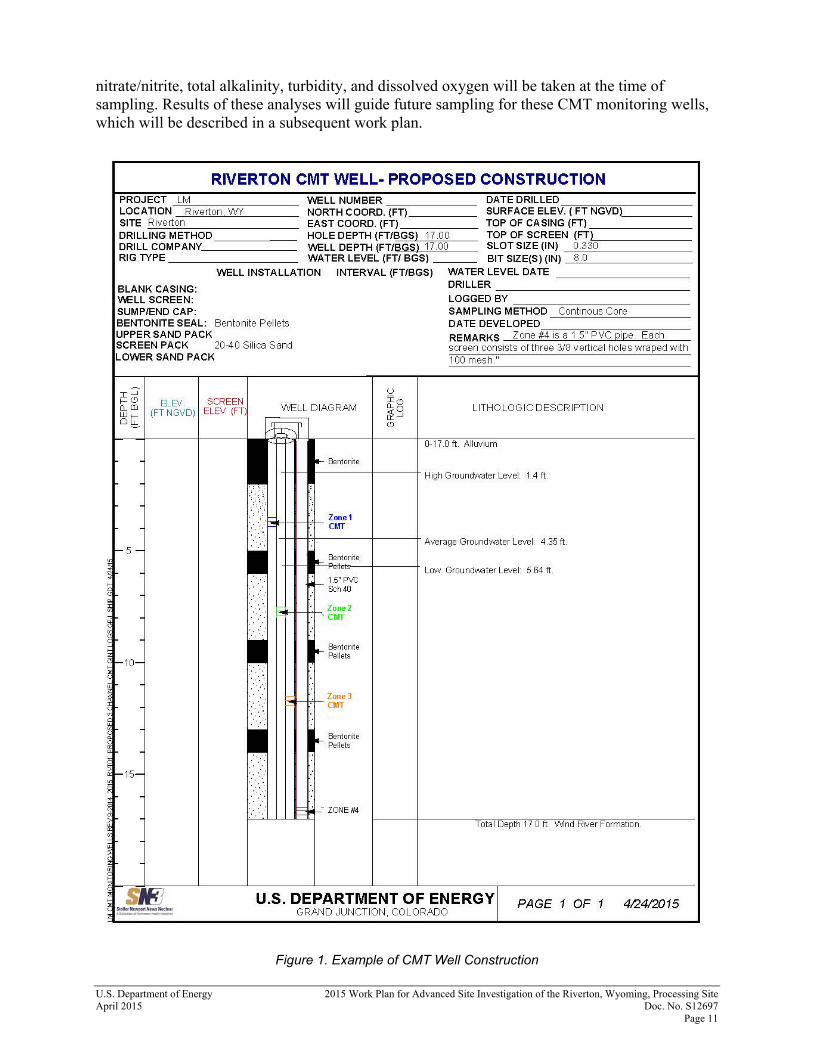
5.2 Monitoring Well Installation At all of the nine sonic drilling locations, discrete-zone multilevel groundwater monitoring wells will be installed using CMT that has three different monitoring ports available with depth (https://www.solinst.com/products/multilevel-systems-and-remediation/403-cmt-multilevel-system/). In addition, the CMT material will be secured to a 1.5 inch schedule 40 PVC pipe to allow vertical installation of the CMT well and to provide an additional monitoring port. This configuration will allow monitoring of four zones to determine vertical variation in the surficial aquifer, and to determine contaminant contributions from rising water levels and/or flood water inundating typically unsaturated sediments above the seasonal water table. The four zones will include: the base of the surficial aquifer (16 to 17 ft below ground surface [with the1.5 inch PVC]); at the approximate mid-point of the typical saturated thickness (11.5 to 12 ft below ground surface), near the top of the saturated zone during low water (7.5 to 8 ft below ground surface), and in the area of the aquifer that is only saturated during high water (3.5 to 4 ft below ground surface). The screen for the lower zone will be one foot in length, and the screen for the upper three zones will be 0.5 ft in length. The upper zone will be screened into the typically unsaturated alluvium to allow monitoring of the alluvium that is saturated only during high-water levels. Exact screen depths will be determined by the onsite field geologist based on the geology from the sonic drilling core. Sand pack will be placed across the monitoring port zones and bentonite will be placed between the intervals via a tremie pipe to avoid bentonite contamination of any upper zones. All wells will be finished with above ground protective casing and a concrete pad surrounding the well. Details of well construction will be specified in the statement of work prepared to procure a sonic drilling subcontractor. Figure 1 shows the proposed CMT well construction. These wells will be sampled during the routine annual September sampling event and as needed after significant flood events. All new monitoring wells installed under this work plan and all existing wells in the long-term monitoring well network will have horizontal coordinates, average ground elevation, and top-of-casing elevations surveyed. Resurveying of existing monitoring wells will be conducted to ensure elevations have not changed over time because of well alterations, and to verify that groundwater elevations, groundwater elevation contours, and groundwater flow direction are accurate. The accuracy of the horizontal coordinates and average ground elevation will be less than or equal to ±0.1 ft; the accuracy of the top-of-casing elevation will be less than or equal to ±0.01 ft. The top-of-casing “measuring point” is on the innermost PVC well casing. If a protective cap/lid is present, it should be removed prior to the survey. On some wells there may be an existing top-of-casing marking that indicates the “measuring point”; this mark indicates where water levels are measured from and where the top-of-casing survey point should be made. If there is no mark present, the north side of the top-of-casing shall be designated for the measuring point location and that survey point should be permanently marked by the surveyor. Groundwater sampling will be conducted according to the SAP. A program directive appended to the SAP will specify protocols for sampling the CMT monitoring wells. Samples will be collected from each sampling port and analyzed by a DOECAP-approved laboratory for NRC-approved COCs (manganese, molybdenum, sulfate, and uranium), major cations (calcium, magnesium, potassium, and sodium), and additional major anions (chloride). In addition, field measurements of pH, specific conductance, temperature, ORP, ferrous iron/total iron,
U.S. Department of Energy 2015 Work Plan for Advanced Site Investigation of the Riverton, Wyoming, Processing Site April 2015 Doc. No. S12697 Page 11
nitrate/nitrite, total alkalinity, turbidity, and dissolved oxygen will be taken at the time of sampling. Results of these analyses will guide future sampling for these CMT monitoring wells, which will be described in a subsequent work plan.
Figure 1. Example of CMT Well Construction
2015 Work Plan for Advanced Site Investigation of the Riverton, Wyoming, Processing Site U.S. Department of Energy Doc. No. S12697 April 2015 Page 12
6.0 Hand-Driven Temporary Well Points Temporary well points will be hand-driven at 10 locations (0866 to 0875) into the dry channel of the river bed in the vicinity of monitoring well 0789 (Plate 1). These well points will be hand-driven into groundwater (approximately 4 ft), the water levels will be measured, and groundwater samples will be collected. These well points will be left in place temporarily, but removed before the spring of the following year (before mountain snow melt and high river stage). Any well point resampling will be discussed in a separate work plan. Data from these wells will be used to confirm areas of groundwater discharge to the Little Wind River based on geochemistry and temperature, and to evaluate plume stagnation in this area based on any differences from nearby monitoring wells. In addition, this information will be used to target high-concentration areas for additional biota sampling to support the human health and ecological risk assessments. Groundwater sampling will be conducted according to the SAP, with the following exceptions. Tubing intake will be placed at the top of the water column during purging. Purging will be accomplished by pumping water from each well point with a peristaltic pump and polyethylene tubing until the water is reasonably clear (turbidity less than 200 nephelometric turbidity units) and field parameters are measured. All well points will be constructed using new materials. Samples will be collected from each well point and analyzed by a DOECAP-approved laboratory for NRC-approved COCs (manganese, molybdenum, sulfate, and uranium), major cations (calcium, magnesium, potassium, and sodium), and additional major anions (chloride). In addition, field measurements of pH, specific conductance, temperature, ORP, ferrous iron/total iron, nitrate/nitrite, total alkalinity, turbidity, and dissolved oxygen will be taken at the time of sampling. After completion of sampling, the elevation of the top of the well point will be determined using a survey level and staff and the top-of-casing of monitoring well 0789 as a benchmark. Determination of the elevation of the top well point will be used in conjunction with the depth-to-water measurement to calculate the groundwater elevation. When the well point is removed, it will be pulled by hand, and the remaining borehole will be abandoned by slowly filling the hole with native material from the vicinity of the well point. GPS data will be collected to document the actual well-point location.
7.0 Continuous Groundwater-Elevation Monitoring Continuous groundwater elevation monitoring will be conducted at selected wells using data logging pressure transducers. Pressure transducers are currently installed in monitoring wells 0101, 0707, 0710, 0716, and 0789, and additional pressure transducers will be installed in monitoring wells 0722R, 0724, 0729, 0824, and 0826. Data will be downloaded on a semiannual basis (at a minimum). Data will be used to evaluate flow direction, gradient changes, or both throughout the year and also will function as input into the groundwater flow model. Procedures for installation and setup of pressure transducers, and for downloading and managing data from these instruments, are specified in the Environmental Procedures Catalog, Section 27.0, “Standard Practice for Data Logger System Field Measurements.”
U.S. Department of Energy 2015 Work Plan for Advanced Site Investigation of the Riverton, Wyoming, Processing Site April 2015 Doc. No. S12697 Page 13
8.0 Surface Water Measurements 8.1 Surface Water Discharge Measurements Discharge in irrigation ditches and the Chemtrade effluent ditch will be measured at five locations (Plate 1) for potential inputs into any groundwater flow, contaminant transport, and reactive transport models. Measurements will be made according to the Environmental Procedures Catalog, Section 26.0, “ASTM D3858-95 (Reapproved 2008)—Standard Test Method for Open-Channel Flow Measurement of Water by Velocity-Area Method.” Because the location of the discharge measurement may be moved slightly to find the most ideal ditch geometry, coordinates of the actual location of discharge measurements will be collected using a GPS unit. Discharge data from the Chemtrade effluent ditch will be obtained from Chemtrade and used to supplement the discharge measurements. The velocity/area method consists of measuring the representative current velocity in each of the multiple cross-sections traversing the width of the flow channel. Total discharge at a given location is the sum of the area/velocity products of the individual cross-sections. As a general guideline, one velocity and water depth measurement will be taken per 0.5 ft of ditch width. The water depth at the ditch banks also will be measured. Ditch width and depth measurements will be recorded to the nearest 0.1 ft and 0.025 ft, respectively. Within each partial cross-section, the velocity will be measured at a depth that is six-tenths of the total depth from the upper surface of the ditch. For example, the velocity will be measured at 0.6 ft below the water surface or 0.4 ft above the ditch bed where the ditch is 1 ft deep. Water velocity will be measured with a Swoffer Model 2100 Series Current Velocity Meter (rotating element type), or the equivalent. Features of the Swoffer meter include scales for the true depth and six-tenths depth for rapid depth placement of the rotating element. Velocities should be measured over a 20-second averaging period. Unstable flow may require longer averaging periods. Calibration and operation of the current meter will proceed according to manufacturer recommendations and the general guidelines. The instrument calibration setting will be documented in the field. Additional information to be recorded by field personnel includes recent and current weather conditions, crop irrigation (location, point of withdrawal, number of sprinkler heads, etc.), presence or absence of water in tributary streams, bank seepage, other surface water withdrawals or returns, and the duration of the irrigation season. The accuracy of ditch-discharge measurements by the velocity/area method is a function of meter accuracy, area and depth measurement accuracy, and representativeness of the measured velocity. To minimize the effects of natural variation on measurement accuracy, the following factors will be considered prior to measurement:
Straight ditch reaches are preferred
Uniform flow within a single, well-defined, smooth channel is preferred with no overbank or underbank flow
Avoid overhanging brush and submerged vegetation 8.2 Stilling Well Installation A stilling well will be installed at location 0849 (Plate 1) on the Little Wind River to measure river elevations for assessment of groundwater and surface water interaction and to provide input into a groundwater flow model with transient river stages. The exact location and construction of
2015 Work Plan for Advanced Site Investigation of the Riverton, Wyoming, Processing Site U.S. Department of Energy Doc. No. S12697 April 2015 Page 14
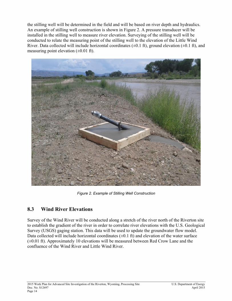
the stilling well will be determined in the field and will be based on river depth and hydraulics. An example of stilling well construction is shown in Figure 2. A pressure transducer will be installed in the stilling well to measure river elevation. Surveying of the stilling well will be conducted to relate the measuring point of the stilling well to the elevation of the Little Wind River. Data collected will include horizontal coordinates (±0.1 ft), ground elevation (±0.1 ft), and measuring point elevation (±0.01 ft).
Figure 2. Example of Stilling Well Construction 8.3 Wind River Elevations Survey of the Wind River will be conducted along a stretch of the river north of the Riverton site to establish the gradient of the river in order to correlate river elevations with the U.S. Geological Survey (USGS) gaging station. This data will be used to update the groundwater flow model. Data collected will include horizontal coordinates (±0.1 ft) and elevation of the water surface (±0.01 ft). Approximately 10 elevations will be measured between Red Crow Lane and the confluence of the Wind River and Little Wind River.
U.S. Department of Energy 2015 Work Plan for Advanced Site Investigation of the Riverton, Wyoming, Processing Site April 2015 Doc. No. S12697 Page 15
9.0 Analytical Program and Laboratory Tests 9.1 Groundwater A number of additional analyses for groundwater sampling will be added to the routine groundwater sampling events. The following discussion mirrors Tables 1 and 2, with detailed descriptions on the purpose of each addition. Silica has been added for ongoing monitoring to provide a complete geochemical analysis of major elements and provide possible evidence on flow connections between the surficial aquifer and the semi-confined aquifer.
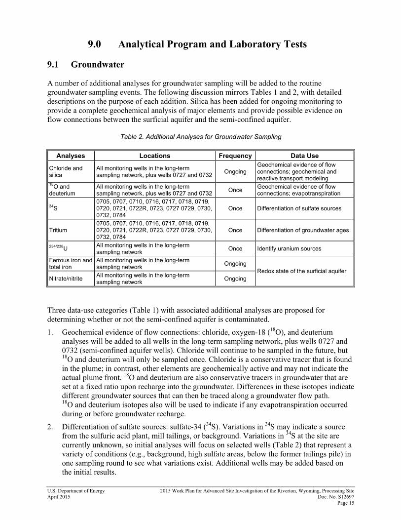
Table 2. Additional Analyses for Groundwater Sampling
Analyses Locations Frequency Data Use
Chloride and silica
All monitoring wells in the long-term sampling network, plus wells 0727 and 0732
Ongoing Geochemical evidence of flow connections; geochemical and reactive transport modeling
18O and deuterium
All monitoring wells in the long-term sampling network, plus wells 0727 and 0732
Once Geochemical evidence of flow connections; evapotranspiration
34S 0705, 0707, 0710, 0716, 0717, 0718, 0719, 0720, 0721, 0722R, 0723, 0727 0729, 0730, 0732, 0784
Once Differentiation of sulfate sources
Tritium 0705, 0707, 0710, 0716, 0717, 0718, 0719, 0720, 0721, 0722R, 0723, 0727 0729, 0730, 0732, 0784
Once Differentiation of groundwater ages
234/238U All monitoring wells in the long-term sampling network
Once Identify uranium sources
Ferrous iron and total iron
All monitoring wells in the long-term sampling network
Ongoing Redox state of the surficial aquifer
Nitrate/nitrite All monitoring wells in the long-term sampling network
Ongoing
Three data-use categories (Table 1) with associated additional analyses are proposed for determining whether or not the semi-confined aquifer is contaminated.
1. Geochemical evidence of flow connections: chloride, oxygen-18 (18O), and deuterium analyses will be added to all wells in the long-term sampling network, plus wells 0727 and 0732 (semi-confined aquifer wells). Chloride will continue to be sampled in the future, but 18O and deuterium will only be sampled once. Chloride is a conservative tracer that is found in the plume; in contrast, other elements are geochemically active and may not indicate the actual plume front. 18O and deuterium are also conservative tracers in groundwater that are set at a fixed ratio upon recharge into the groundwater. Differences in these isotopes indicate different groundwater sources that can then be traced along a groundwater flow path. 18O and deuterium isotopes also will be used to indicate if any evapotranspiration occurred during or before groundwater recharge.
2. Differentiation of sulfate sources: sulfate-34 (34S). Variations in 34S may indicate a source from the sulfuric acid plant, mill tailings, or background. Variations in 34S at the site are currently unknown, so initial analyses will focus on selected wells (Table 2) that represent a variety of conditions (e.g., background, high sulfate areas, below the former tailings pile) in one sampling round to see what variations exist. Additional wells may be added based on the initial results.
2015 Work Plan for Advanced Site Investigation of the Riverton, Wyoming, Processing Site U.S. Department of Energy Doc. No. S12697 April 2015 Page 16
3. Differentiation of groundwater ages: tritium. Tritium is a conservative tracer that is naturally added to atmospheric recharge, but was added in higher amounts during nuclear bomb testing (1950s and 1960s). Any detections of tritium will indicate if groundwater is less than 60 years old. Variations in tritium at the site are currently unknown, so initial analyses will focus on selected wells (Table 2) in one sampling round to see what variations exist. Additional wells may be added based on the initial results. If tritium concentrations are very low, then carbon-14 (14C) can be used for dating older groundwater. 14C will be added in a later phase (after tritium) if tritium is not detected.
Under the data-use category of identifying the source of uranium (Table 1), uranium isotopes, uranium-234 and uranium-238 (234/238U) will be measured at all wells in at least one sampling round. Values near one are typical of uranium derived from a mine or mill source and values greater than one are typical of uranium derived from non-anthropogenic sources. Groundwater results should mirror the contaminant plume, but also will be evaluated by comparing the groundwater 234/238U ratios with the 234/238U ratios in the solid phase to better understand uranium sources, sinks, or both. Measurement of 234/238U ratios on solid-phase material will be part of a separate work plan based on initial measurements of total uranium content. Under the data-use category of redox conditions, iron and nitrogen measurements will provide input into geochemical models on the redox state of each groundwater sample. The redox state of the groundwater is a key controlling parameter for the sorption, precipitation, or both of uranium and other COCs.
Ferrous iron/total iron: Ferrous iron concentrations will be measured with a field test kit and total iron will be measured in the laboratory for all wells. Ferric iron will be determined by subtraction. The ratio of ferrous to ferric iron is an indicator of the redox state of the groundwater and will assist in determining the potential mobility of uranium. These measurements will be a direct input into the geochemical models.
Nitrate/nitrite: Nitrate/nitrite measurement will be added to all wells. Nitrite will be measured with a field test kit and nitrate will be measured in the laboratory. After oxygen is consumed, nitrate is the next redox sensitive species and has the potential to oxidize reduced uranium, if it is present. Nitrite is the reduced nitrogen species that may be present if full denitrification does not occur. Nitrate/nitrite concentrations are an important indicator of the redox state of the groundwater. These concentrations will be used in combination with the presence or absence of oxygen and iron to determine redox conditions for input into geochemical models.
9.2 Soils 9.2.1 Solid-Phase Analyses of Core Material Initial analyses of solid-phase material from backhoe trenches and sonic drilling are listed in Sections 4.1 and 5.1, respectively. The results of this initial screening will guide additional future analyses of solid-phase material at select intervals. Any future analyses will be discussed in a separate work plan.
U.S. Department of Energy 2015 Work Plan for Advanced Site Investigation of the Riverton, Wyoming, Processing Site April 2015 Doc. No. S12697 Page 17
9.2.2 Laboratory Studies of Core Material 9.2.2.1 Batch Testing Laboratory studies of the core material will eventually include batch testing for potential uranium sorption/desorption, precipitation, or both that will be included in geochemical modeling. The results of the initial core analyses will guide additional future analyses of solid-phase material for batch testing at select intervals. Any future analyses will be discussed in a separate work plan. 9.2.2.2 Column Testing The batch testing discussed above is designed to simulate equilibrium conditions. Flow through a column is designed to provide a better test of real world conditions in which groundwater is moving through an aquifer. In a column test, equilibrium conditions may or may not be reached and the added water will undergo reactions throughout the column. Column testing will eventually be done to determine possible kinetic limitations and better understand reactions that might occur in the column through time, similar to plume migration. The results of the initial core analyses will guide additional future analyses of solid-phase material for column testing at select intervals. Any future analyses will be discussed in a separate work plan.
10.0 Quality Assurance Quality assurance and quality control requirements, which are specified in the SAP, apply to this plan. These include procedures for sample collection, calibration and operational checks of field instrumentation, collection of quality control samples, documentation of sampling activities, decontamination of sampling equipment, training, use of approved laboratories and analytical methods, and data validation and qualification.
11.0 Health and Safety Field activities will be conducted in compliance with the health and safety requirements specified in the Health and Safety Manual (LMS/POL/S04321). Task-specific health and safety requirements for the sampling activities are specified in the Job Safety Analysis (JSA) entitled Water Sampling and Minor Maintenance at Office of Legacy Management Sites. Safety requirements for operation of the Geoprobe are specified in the Procedure for Operation of the Geoprobe Model 7720DT (LMS/PRO/S08578). Health and safety requirements for sonic drilling activities are specified in Drilling Health and Safety Requirements (LMS/POL/S04331). The Plan of the Day will be discussed at daily tailgate safety meetings to highlight both the safety hazards that may be encountered during each day’s work and the associated precautions that will be taken to mitigate the potential hazards.
2015 Work Plan for Advanced Site Investigation of the Riverton, Wyoming, Processing Site U.S. Department of Energy Doc. No. S12697 April 2015 Page 18
12.0 Environmental Compliance 12.1 Environmental Management System In accordance with LM’s Environment, Safety, and Health Policy and Environmental Management System, all contractors and subcontractors performing work for LM will follow safe and environmentally sound work practices. Work will be conducted in a manner that protects workers and the public, complies with DOE directives, and complies with all applicable federal, state, local, and tribal regulatory requirements, and agreements and permits under the LM contract. In addition, work will be conducted in a manner that prevents pollution, minimizes wastes, and conserves natural and cultural resources to the extent that such activities are technically and economically feasible. 12.2 Waste Management Investigation-derived waste (IDW) includes purge water, equipment calibration waste, excess sample material (both water and soil), decontamination rinsate, and solid waste (tubing, soil sampling liners, disposable gloves, disposable pipettes, paper towels, Visqueen, etc.). Excess soil will be spread out evenly around the borehole. Excess soil removed from boreholes on the former mill site will be scanned with radiological instrumentation prior to spreading of the material. All excess liquid IDW will be dispersed broadly to the ground surface in the vicinity of the borehole. IDW may not be discharged to the ground surface in suspected wetland areas nor may it be discharged to places where it could be washed away, such as in dry washes (see discussion below). Solid waste will be collected and disposed of at a municipal landfill. Waste samples generated by the ESL may be sent to the Grand Junction, Colorado, Disposal Site for disposal provided that the waste meets the site’s waste acceptance criteria. 12.3 Spills If there are any reportable spills from equipment operations or maintenance (fuel, hydraulic fluids, coolant, lubricants, cleaning solvents, used oil, etc.), the spill will be immediately contained and the spilled materials removed and containerized. Equipment leaks and other types of spills will be diapered, contained, absorbed, or otherwise blocked to prevent ground surface contamination until the leak is repaired or the equipment is replaced. Cleanup of spills or leaks includes managing the spilled materials and associated wastes (e.g., contaminated soils) and the storage, transport, and offsite disposal of the materials in compliance with applicable federal, state, and local regulations. An approved spill kit will be onsite while drilling or refueling activities take place. This kit will include (at a minimum) basic personal protective equipment, a shovel, plastic bags, plastic sheeting, absorbent pads, bulk absorbent (kitty litter), cloth or paper towels, liquid soap, a scrub brush, a bucket, and a metal or plastic storage container (larger than 10 gallons).
U.S. Department of Energy 2015 Work Plan for Advanced Site Investigation of the Riverton, Wyoming, Processing Site April 2015 Doc. No. S12697 Page 19
12.4 Land Disturbance Efforts must be taken by all members of the field crew to minimize impacts and disturbances to the land surface caused by project-related activities. Specifically:
Unnecessary use of vehicles in the field will be avoided. Vehicle travel, including that of the Geoprobe, sonic drill rig, and support vehicles, will occur on paved or established roadways to the maximum extent possible. This will require pre-planning of travel routes and may entail traveling extra distances to avoid crossing undisturbed land areas. When off-road travel is necessary, all vehicles will travel along the same path to minimize the total area of land impacted. Vehicles will park along the road or path when working at a sample location to minimize impacts to the land surface.
Storage and equipment lay-down areas will be minimized to the extent practicable. Work on wet ground surfaces caused by rain will not be allowed if doing so causes unnecessary disturbance to the land surface. If wet ground conditions occur, work should be shifted to areas where land disturbances cannot occur, or activities must be delayed until the ground surface is dry.
The project supervisor is responsible for assessing land disturbances to determine if possible sediment is mobilizing offsite or into a wash during a storm event. If this occurs, storm-water control measures, such as the installation of straw bales or silt fencing, must be installed by the end of the work day at the latest.
The Environmental Compliance project lead must be contacted if storm-water management controls are installed, or if it appears that excessive amounts of land disturbance are occurring.
Trenches will be backfilled with the material removed from the trench and the area will be contoured back to the original grade.
12.5 Dust Control To minimize the potential for dust generation, all vehicles will adhere to a maximum travel speed of 15 miles per hour when traveling off-road or on dirt roads. 12.6 Suspected Wetlands and Dry Washes Work restrictions, as described below, apply to suspected wetland areas and dry washes. Wetland areas are not expected to be encountered during the project activities; however, this section is included as a protective measure. For the purpose of this work plan, the term “suspected wetlands area” is generically defined as an area having any of the following characteristics:
The presence of surface water (including channels with surface water).
The presence of saturated or inundated soils, including muddy soils.
The presence of vegetation that is substantially different from that in the surrounding area (such as more dense or greener vegetation that may include cattails, willows).
2015 Work Plan for Advanced Site Investigation of the Riverton, Wyoming, Processing Site U.S. Department of Energy Doc. No. S12697 April 2015 Page 20
All suspected wetland areas will be avoided and left undisturbed during field activities under this work plan. Specifically:
Vehicles, including the Geoprobe, will not be allowed to drive through any portion of a suspected wetland area (unless on a developed road).
Work in a suspected wetland area is prohibited (including the staging of equipment and supplies and refueling of equipment and vehicles).
IDW may not be discharged to the ground surface in a suspected wetland area.
Extra care will be taken by the occupants of the lead vehicle when driving into lower-lying areas that could be muddy, areas near the Little Wind River, and dry washes to ensure that suspected wetland areas are identified and avoided. It may be helpful to scout a suspect area on foot before bringing in a vehicle.
Vehicles can be driven into and across dry washes and field work can be conducted in these areas. However, IDW may not be discharged to the ground surface in such places or where it could be washed away.
12.7 Cultural Resources A qualified archaeological services company (ACR Consultants Inc.) completed a Class III cultural resource inventory of a 143-acre block within the area of proposed work. No cultural resource sites or isolated artifacts were identified as a result of this inventory. DOE determined that no adverse effect would result from the proposed activities and provided a copy of the results of the inventory with the DOE-proposed determination of ‘No Effect’ to the Wyoming State Historic Preservation Office in March; concurrence from the historic preservation office is pending. Any proposed work on the former mill-site and areas where surface remediation was conducted does not require a cultural resources inventory. During the field activities, if any unanticipated cultural resource discoveries are identified, the following protocol will be followed and the following language, called a “discovery clause,” will be included in any field documents (e.g., Plan of the Day, Plan of the Week).
If cultural artifacts or skeletal remains are unearthed or uncovered during construction operations, activities in the vicinity of the cultural resources shall cease, and the LM Environmental Program Manager shall be notified. The onsite manager shall protect the items discovered and allow no further site-disturbing activities until LM makes a decision concerning the disposition of the items and provides written notification to the onsite manager to proceed with work.
In addition to notification of LM and Legacy Management Support, the appropriate tribal members must also be contacted. The Environmental Compliance project lead must be notified if any unanticipated discoveries are made. 12.8 Migratory Birds All applicable requirements under the Migratory Bird Treaty Act (MBTA) will be adhered to regarding disturbances of migratory birds. Work in 2015 is scheduled after the end of the
U.S. Department of Energy 2015 Work Plan for Advanced Site Investigation of the Riverton, Wyoming, Processing Site April 2015 Doc. No. S12697 Page 21
breeding and nesting season and it is unlikely that MBTA requirements will affect the project work schedule. 12.9 Threatened and Endangered Species In 2012, the U.S. Fish and Wildlife Service (USFWS) was contacted for information related to the potential presence of federally listed plants or wildlife species. At that time, there was no tribal wildlife division and both tribes deferred to USFWS for listed species. In 2012, USFWS did not report any species that would be potentially affected by the proposed field activities. Information related to listed species will be updated prior to work activities planned for 2015. All applicable requirements will be identified and adhered to prior to initiating field work. Although not a federally listed species, in 2008 the Wyoming Game and Fish Department classified the sauger—a fish native to the stretch of the Little Wind River near Riverton, Wyoming—as a sensitive species. Additional information related to activities in the Little Wind River and the potential effect on the fish will be obtained prior to conducting field work. 12.10 Refueling Refueling of the diesel engine that drives the Geoprobe will be primarily conducted at a gas station in Riverton. Some refueling of the Geoprobe will take place in the field by using a portable gas can. No refueling will be allowed in the Supplemental Standards areas located on the former processing site (Plate 1). Precautions for refueling the Geoprobe are specified in the Water Sampling and Minor Well Maintenance at LM Sites JSA. All other vehicles and equipment, besides the Geoprobe, will be refueled at a gas station in Riverton. 12.11 Well or Borehole Permits and Abandonment Notifications and Reports Monitoring well or borehole permits, abandonment pre-notifications, and abandonment reports are not required for this field activity on private land because permits are not required by the Wyoming State Engineer’s Office. The borehole abandonment method presented in this work plan is considered a best management practice. However, for boreholes on tribal land, a Tribal Drilling License will be required. The stilling well may require a permit from the Wyoming State Engineer’s Office due to the requirements of the Clean Water Act. Any permits related to the stilling well will be obtained prior to field activities. 12.12 Miscellaneous Compliance Activities Prior to conducting any field activities, any other required compliance actions—such as completion of National Environmental Policy Act (NEPA) documentation or obtaining any other permits related to work in the potential wetland areas or on tribal lands—will be completed or notifications will be made, as applicable.
2015 Work Plan for Advanced Site Investigation of the Riverton, Wyoming, Processing Site U.S. Department of Energy Doc. No. S12697 April 2015 Page 22
12.13 Access Access to tribal land is granted through a cooperative agreement with the Northern Arapaho Business Council, which is currently being finalized and will begin in late April for the remainder of fiscal year 2015. Prior to any field activity on tribal land, the tribe will be contacted and notified of the upcoming work. An Annual Agreement and tribal business license from the Tribal Rights Employment Office was obtained; a copy of the current agreement and business license shall be kept with field personnel. Access to the former mill site is granted through a quitclaim deed that was associated with the sale of the property to Chemtrade Refinery Services Inc. Access to private land will be granted through access agreements established with each property owner.
13.0 Reporting At the end of each field event, a trip report will be prepared to document the field activities conducted during the event. Items that will be documented in the trip report may include:
Dates of the event
Team members
Activities conducted
Data collected
Field observations
Issues encountered
Follow-up work required At the end of the year, a report will be prepared that will present and interpret all data collected during the year. This report will focus on reporting the progress toward the three overall objectives stated in Section 3.0. Specifically, the report will:
Assess the viability of the natural flushing compliance strategy.
Provide an updated description of groundwater flow conditions and geochemical processes that control contaminant transport.
Review the technical approach to the site and continue to refine a comprehensive CSM with alternative CSMs, if needed.
In addition, the site evaluation and monitoring reports will present numerous approaches to analyzing and presenting data, which may include one or more of the following:
Three-dimensional depictions of soil and groundwater contaminants
Estimation of the mass of contaminants remaining in soil and groundwater
Statistical analysis of soil concentrations
U.S. Department of Energy 2015 Work Plan for Advanced Site Investigation of the Riverton, Wyoming, Processing Site April 2015 Doc. No. S12697 Page 23
Time versus concentration plots
Piper diagrams
Spot plots of stable isotope ratios
Fence diagrams of stable isotopes
Statistical analysis of uranium isotopes—background versus plume
Spot plots of uranium isotope ratios In addition to the trip report(s) and site evaluation and annual report, data will be validated after each field event according to the Environmental Procedures Catalog, Section 8.0, “Standard Practice for Validation of Environmental Data” and results will be reported in a data validation report.
14.0 References 40 CFR 192. U.S. Environmental Protection Agency, “Health and Environmental Protection Standards for Uranium and Thorium Mill Tailings,” Code of Federal Regulations. Barrow, J.C., 1994. “The Resonant Sonic Drilling Method: an Innovative Technology for Environmental Restoration Programs,” Groundwater Monitoring and Remediation, 14 (2): 153–160. DOE (U.S. Department of Energy), 1991. Riverton Wyoming Final Completion Report, Albuquerque Operations Office, Albuquerque, New Mexico, December. DOE (U.S. Department of Energy), 1998a. Final Site Observational Work Plan for the UMTRA Project Site at Riverton, Wyoming, U0013801, Grand Junction Office, February. DOE (U.S. Department of Energy), 1998b. Final Ground Water Compliance Action Plan for the Riverton, Wyoming, Title I UMTRA Project Site, attached to letter from DOE to NRC, Grand Junction Office, September. DOE (U.S. Department of Energy), 2013. 2012 Enhanced Characterization and Monitoring Report Riverton, Wyoming, Processing Site, LMS/RVT/S09799, Office of Legacy Management, June. Drilling Health and Safety Requirements, LMS/POL/S04331, prepared by Stoller Newport News Nuclear, Inc., a wholly owned subsidiary of Huntington Ingalls Industries, Inc., for the U.S. Department of Energy Office of Legacy Management. Environmental Procedures Catalog, LMS/POL/S04325, continually updated, prepared by Stoller Newport News Nuclear, Inc., a wholly owned subsidiary of Huntington Ingalls Industries, Inc., for the U.S. Department of Energy Office of Legacy Management.
2015 Work Plan for Advanced Site Investigation of the Riverton, Wyoming, Processing Site U.S. Department of Energy Doc. No. S12697 April 2015 Page 24
Environmental Sciences Laboratory Procedures Manual, LMS/PRO/S04343, continually updated, prepared by Stoller Newport News Nuclear, Inc., a wholly owned subsidiary of Huntington Ingalls Industries, Inc., for the U.S. Department of Energy Office of Legacy Management. Health and Safety Manual, LMS/POL/S04321, continually updated, prepared by Stoller Newport News Nuclear, Inc., a wholly owned subsidiary of Huntington Ingalls Industries, Inc., for the U.S. Department of Energy Office of Legacy Management. Procedure for Operation of the Geoprobe Model 7720DT, LMS/PRO/S08578, continually updated, prepared by Stoller Newport News Nuclear, Inc., a wholly owned subsidiary of Huntington Ingalls Industries, Inc., for the U.S. Department of Energy Office of Legacy Management. Sampling and Analysis Plan for U.S. Department of Energy Office of Legacy Management Sites, LMS/PRO/S04351, continually updated, prepared by Stoller Newport News Nuclear, Inc., a wholly owned subsidiary of Huntington Ingalls Industries, Inc., for the U.S. Department of Energy Office of Legacy Management. Shafer, D., R. Bush, W. Dam, and T. Pauling, 2014. The Future is Now: Experience with Remediating and Managing Groundwater Contamination at Uranium Mill Tailings Sites – 14587, Waste Management 2014 Conference, Phoenix, Arizona, March.
0700
07050707
07160717
0718
0719
0721
072407250727 0728
07290732
0733
0734
0784
0789
01010110
0710
0726
0824
0826
0709
0723
0736
0111
0722R
0702
0720
0730
0788
0861
0862
0863
0864
0865
T03-08
T03-09
T06-16
T06-17
0854
0855
0856
08570858
0860
0853
0859
0849
0866086708680869087008710872087308740875
BHT-1
BHT-2BHT-3
BHT-4BHT-5
T06-19
T06-20
T03-06
T06-18
T03-03
T03-05
T03-07
T03-04
0844
\\LM\ess\EnvProjects\EBM\LTS\111\0042\07\007\S12698\S1269800.mxd smithw 02/17/2015 1:55:04 PM
0 500 1,000Feet
LEGENDSonic Core Sample andProposed CMT Well Location
Proposed Backhoe Trench Location
Proposed Stilling Well
Proposed Discharge Measurement Location
Geoprobe Location - August 2012(To Be Resampled)
Proposed Borehole Location
Hand Driven Well Point
Existing DOE Monitoring Well to be Surveyed
Institutional Controls Boundary
Site Boundary
Supplemental Standards Area
Former Tailings Pile
T06-01-01
T06-01-04
T06-01-03
T06-01-02T06-01
085250’
50’
50’
50’
50’
50’
50’
50’
50’50’
50’
50’
0 50 100Feet
SEE DETAIL AREA
DETAIL AREA
Geoprobe Location - August 2012(To Be Resampled)
Proposed Borehole Location
Additional Borehole Location
Sonic Core Sample andProposed CMT Well Location
Notes: Additional borehole locations may be installed depending on field results.
New Monitoring Well 0852 will be installed at the location with the highest uranium concentration.
February 17, 2015DATE PREPARED: FILE NAME:
S1269800
2015 Field Work OverviewRiverton, WY, Processing Site
Work Performed by
Under DOE Contract No. DE-LM0000415