2016 acpa qcast plant certification manual...acpa qcast plant certification manual sections i common...
TRANSCRIPT

2016 ACPA QCAST
Plant Certification Manual

American Concrete Pipe Association ii
ACPA QCAST PLANT CERTIFICATION
The American Concrete Pipe Association (www.concrete-pipe.org) offers QCast Plant Certification (qcast.org) as a voluntary program to continue the advancement of quality in the precast concrete pipe and products industry.
The purpose of this manual is to establish the ACPA’s Certification Program require-ments. This manual shall form a basis by which ACPA’s third party audit agency will au-dit participating Pipe, Manhole, Box Culvert, Three-Sided Structure and Precast Manu-facturers' plants. The manual includes:
• Requirements for calibration and certification of production, testing, and inspection equipment and instrumentation,
• Requirements for ongoing plant (internal) inspection and test documentation,• Requirements for product tests and documentation,• Requirements for raw material certification documentation,• Requirements for third party audit verification,• Requirements for product design documentation,• Requirements for product storage, handling, and repair.
Plant Management is ultimately responsible for the quality of the product made in their plant. They shall ensure that the supervisory and production personnel immedi-ately responsible for product quality are properly trained.
MANUAL ORGANIZATION
This Manual is organized into “common” and “product specific” sections for the easy retrieval of applicable requirements. Section I details the requirements that are common to all product categories. Sections II through V contain product-specific certification requirements. All Sections of this Manual reference Appendix A. Appendix B contains Audit Expectations to be performed, checked or witnessed during the annual audit.
ACPA QCAST PLANT CERTIFICATION
© ACPA 2016 2016 Version (01-2016)
American Concrete Pipe Association 3
ACPA QCAST PLANT CERTIFICATION
Manual Sections
I Common Program Requirements II Pipe Requirements III Manhole Requirements IV Engineered Precast Products V Box Culvert and Three-sided Structures Requirements VI Appendix A: Procedures & Forms VII Appendix B: Audit Expectations
Plants may elect any single or multiple product specific certification or full Plant Certifi-cation to meet local or state requirements. Current certifications offered include: Storm Sewer and Culvert Pipe, Sanitary Sewer pipe, Manholes, Sanitary Sewer Manholes, Box Culvert and Three-Sided Structure,Engineered Precast Products, and full plant Cer-tification. If full Plant Certification is chosen, then all products covered by this Manual will be audited to the requirements of this Manual. For each product specific certifica-tion, the QCast requirements shall apply for all products made under that certification, regardless of the project.
In order to receive certification, plants shall meet the requirements of the ACPA’s Plant Certification Manual and demonstrate compliance to a third party audit. The process begins when the plant submits an application and an application fee to the ACPA. The ACPA’s third party certification auditing firm then schedules the audit. Upon receiving a passing score, the plant is sent a certificate by the ACPA.
For more information regarding the QCast Program, contact the ACPA offices at [email protected].
© American Concrete Pipe Association 2016, All Rights Reserved. No part of this publication may be reproduced, stored, copied or transmitted in any form or by any means without the prior written permission the American Concrete Pipe Association. For information,
contact the American Concrete Pipe Association, 8445 Freeport Parkway, Suite 350, Irving, TX 75063

Table of Contents American Concrete Pipe Associationiv
PLANT CERTIFICATION
TABLE OF CONTENTSCERTIFICATION BYLAWS
Introduction 1Scope of Application 1Initial Certification of Manufacturers 1Recertification of Manufacturers' Plant(s) 3Re-Audits 4Appeal of Audit Results 4New Process Notification 5Compliance Audit Conditions 5Plant Certification Application 6
SECTION ICOMMON PROGRAM REQUIREMENTS
Quality Documentation, Specifications and Information 9Materials 11Calibration 12Mix Designs 12Joints 13Equipment 13Reinforcing 14Pre-Pour Inspection 14Concrete Testing 14Curing 16Post-Pour Inspection 17Product Marking 17Product Testing 17Storage, Handling, Shipping and Final Inspection 17
SECTION IIPIPE REQUIREMENTS
Joints 19Equipment 20Reinforcing 22Pre-Pour Inspection 22Post-Pour Inspection 23Testing 24
SECTION IIIMANHOLE REQUIREMENTS
Joints 27Equipment 28Reinforcing 30Pre-Pour Inspection 30Post-Pour Inspection 31Product Testing 32
SECTION IVENGINEERED PRECAST PRODUCTS
Production Drawings 33Joints 33Equipment 33Reinforcing 33Pre-Pour Inspection 34Post-Pour Inspection 35
© ACPA 2016 2016 Version (01-2016)

v
PLANT CERTIFICATION
American Concrete Pipe Association Table of Contents
SECTION VBOX CULVERT AND THREE-SIDED STRUCTURE REQUIREMENTS
Joints 36Equipment 36Reinforcing 36Pre-Pour Inspection 37Post-Pour Inspection 38
APPENDIX A: Procedures and FormsRequired ASTM/AASHTO Standards 46Recommended Standards and Documents 49ACPA Technical Management Structure 51Compensating for Aggregate Moisture 52To Confirm the Water/Cement Ratio of a Mix 53Gasketed Pipe & Manhole Joint Data Form 54Non Gasketed Pipe, Manhole, Box Culvert and Three-Sided Structures Joint Data Form 55Joint Design - Sanitary Sewer Pipe Only 56Spigot Go/No-Go Gage - Sanitary Sewer Pipe Only 62Gasket Testing Procedures (ASTM C497) 63Gasket Test Report 64Header, Pallet and Truing-Ring Inspection Form 65Confined Gasket Header Inspection Report 66Header Inspection Drawing 67Pallet Inspection Report 68Pallet Inspection Location 69Truing Ring Inspection Report 70Inside Truing Ring Inspection Location 71Reinforcing Inspection Worksheet 72Reinforcing Inspection Worksheet 73Box Culvert Reinforcement Inspection - Single Cell 74Box Culvert Reinforcement Inspection - Double Cell 76Three-sided Structure - Flat Deck Reinforcement Inspection 78Three-sided Structure - Arch Deck Reinforcement Inspection 80Box Culvert Form Pre-Pour/In-Process Pour Inspection - Single Cell 82Box Culvert Form Pre-Pour/In-Process Pour Inspection - Double Cell 83Three-sided Structure - Flat Deck Pre-Pour/Pour Inspection 84Three-sided Structure - Arch Deck Pre-Pour/Pour Inspection 85Entrained Air and Slump/Flow Report 86Concrete Quality Control Report 87Pipe and Manhole Post-Pour Dimension Inspection Instructions 88Pipe and Manhole Post-Pour Dimension Inspection Form 89Box Culvert Post-Pour Dimension Inspection - Single Cell 90Box Culvert Post-Pour Dimension Inspection - Double Cell 91Three-sided Structure - Flat Deck Post-Pour/Pour Dimension Inspection 92Three-sided Structure - Arch Deck Post-Pour/Pour Dimension Inspection 93Vacuum Test on Pipe and Manholes With Gasketed Joints 94Vacuum Test Table 95Modified Vacuum Test 96Hydrostatic Testing 98Certification of Three-Edge-Bearing Test Results of Reinforced Concrete Pipe 99Off Center Joint Test Combined Certification Only 100Off Center Joint Test Calculations 101Joint Shear Test 102Joint Shear Test Calculations 103Storm Sewer and Culvert Joint Test 104
APPENDIX B: Audit ExpectationsQuality Documentation, Specifications and Information 106Materials 106
Table of Contents American Concrete Pipe Associationvi
PLANT CERTIFICATION
Calibration 106Mix Designs 106Joints 106Equipment 107Reinforcing 107Pre-Pour Inspection 107Concrete Testing 108Curing 108Post-Pour Inspection 108Product Marking 109Product Testing - Pipe and Manhole Only 109Storage, Handling, Shipping and Final Inspection 110ACPA Audits 111Audit Manual Score Summary Sheet Pipe Requirements 113Audit Manual Score Summary Sheet Manhole Requirements 114Audit Manual Score Summary Sheet Engineered Precast Requirements 115Audit Manual Score Summary Sheet Box Culvert and Three-Sided Structure Requirements 116
APPENDIX C: Suggested Practice for State Highway Agency Quality Review of Producers of Precast Concrete Drainage Products Certified by the American Concrete Pipe Association
Scope 118Referenced Documents 119Audit 120Closure 124

1
PLANT CERTIFICATION
American Concrete Pipe Association Bylaws
Bylaws
CERTIFICATION BYLAWS
Introduction
The procedures are implemented to ensure that ACPA’s QCast Certification Program is administered properly and consistently.
The ACPA’s QCast Certification Program consists of three elements:
1. Procedures: Each participating manufacturer of concrete storm sewer and culvert pipe, manholes, sanitary sewer pipe, precast products, box culverts and three-sid-ed precast structures (herein after referred to as the manufacturer) shall maintain sufficient procedures and documentation to assure that these types of products are consistently manufactured and tested in accordance with guidelines of this manual.
2. Initial and Recertification Audits: The plant shall be audited in accordance with the ACPA Plant Certification Manual and the elements specified therein. Audits shall be performed by a recognized professional audit firm with knowledge of the products covered in the manual. A resume of each auditor shall be retained in the auditing firm's files and provided to participating manufacturers upon request. The auditors shall be trained in the requirements of this program prior to performing an audit. Should a participating manufacturer have doubts as to the qualifications or competence of an auditor, the participating manufacturer may petition the ACPA for relief, following appeal procedures outlined in this document.
3. Enforcement: Achievement and maintenance of the ACPA certificate of compli-ance is contingent on full compliance with these procedures. No participating manufacturer may use or reference an expired certificate. Legal action may be taken against manufacturers for violating this precept.
Scope of Application
The ACPA Audit and Certification Program applies to participating manufacturers of con-crete pipe, manholes, engineered precast products, box culverts and three-sided struc-tures. The requirements of this program are designed to demonstrate, that at the time of the audit, the certified manufacturing plant was manufacturing in compliance with ACPA guidelines, and that production operations and procedures are in place to facilitate con-tinued compliance with the guidelines of this manual.
Initial Certification of Manufacturers
• Manufacturers, who voluntarily desire to obtain certification that their manufactur-ing plant is producing precast concrete products in compliance with this program,
© ACPA 2016 2016 Version (01-2016)

Bylaws American Concrete Pipe Association2
PLANT CERTIFICATIONBylaws
shall submit an application to the ACPA. In the application, the manufacturer shall specify the plant to be audited and the certification sought. If more than one plant is to be audited, a separate application shall be submitted for each plant. Applica-tions are available on the ACPA website at www.concretepipe.org. The manufac-turer shall submit a copy of their Plant Quality Control Manual with the initial ap-plication. The manual should address each aspect of the certification being audited for. Based on the review, revisions to the plant’s manual and procedures may be necessary prior to scheduling the initial audit. It is the manufacturer’s responsibility to ensure that adequate product, required documentation, and tests are available for the third-party audit agency to perform a complete audit.
• Within 20 working days of receipt of the certification application, the ACPA will ar-range the auditor assignment and audit schedule with the applicant manufacturer. Applicants shall be notified of the audit date a minimum of 2 weeks prior to the audit. The applicant shall have all elements available for inspection.
• Upon receipt of a satisfactory audit, the ACPA shall award the applicant a certifi-cate of compliance, valid until the following
• January 1st (hereinafter referred to as 1st Quarter) if initially audited be-tween January 1- March 31,
• April 1st (hereinafter referred to as 2nd Quarter) if initially audited between April 1-June 30,
• July 1st (hereinafter referred to as 3rd Quarter) if initially audited between July 1-September 31,
• October 1st (hereinafter referred to as 4th Quarter) if initially audited be-tween October 1-December 31
when another application shall be due to the ACPA to remain in compliance. Com-
pliance certification shall be awarded on the basis of:
1. Acceptable compliance with product requirements specified in this plant certifi-cation manual, and
2. Maintenance of sufficient documentation to demonstrate continued compliance with this plant certification manual.
• A manufacturer’s plant must pass the audit under two guidelines: 1) by receiving an overall audit score of 80 or more and, 2) by receiving a score of 75 percent or more on each of the identified critical audit elements.

3
PLANT CERTIFICATION
American Concrete Pipe Association Bylaws
Bylaws
• Plants that fail a Combined Storm Sewer and Culvert, and Sanitary Sewer Pipe Certification may still gain Storm Sewer and Culvert Pipe Certification or condi-tional certification if the plant passes all Storm Sewer and Culvert Pipe Certification achieves an overall score greater than 80, and a score greater than 75 on critical items.
• The successful manufacturer’s plant shall also be awarded a certificate of compli-ance. The certificate shall identify the plant as being certified and may be displayed for customers and employees. An electronic logo shall also be available to the plant to create a QCast stencil. The stencil may be used to mark product as being produced by an ACPA certified plant.
Recertification of Manufacturers' Plant(s)
• In order to maintain certification for the subsequent year, a plant must re-apply and make payment by their quarterly anniversary date as shown in the bylaws of the QCast Manual. Upon receipt of the application and payment, the ACPA acknowledgesthe plants intent to continue in the program, and the plant is placed in the auditingqueue and issued a certificate.The certificate is valid until the following anniversarydate, unless the annual audit is not passed. If the audit is not passed, the plant isremoved from the certified list until they complete a successful audit.
• The auditor shall conduct an unannounced audit within 12 months of the plant's anniversary date.
1. If a manufacturer adds Box Culvert, Sanitary Sewer Pipe or Sanitary Manhole Certification to an existing Storm Sewer Pipe, Precast or Manhole Certification an announced audit will occur.
2. Plants having Box Culvert certification must demonstrate box production at least every other audit year to remain Box certified. Plants that do not dem-onstrate box production during an audit, shall inform the audit agency of box production within the following 3 months of the subsequent anniversary date so the audit can be conducted during box production. If no box production can be witnessed within this time period, an unannounced audit of any other certified products shall be conducted and the manufacturer must pay for an additional one day audit when box culvert production commences to retain certification.
3. A plant is awarded a conditional certification if receiving an overall score be-tween 75 and 79.9. Plants receiving conditional certification remain certified for the period between their recent audit and next regular audit if the conditions explained under "Initial Certification" are met.
4. Plants shall not be allowed to remain certified if it scores less than 80 overall or on any individual Critical criterion in two consecutive audit years.

Bylaws American Concrete Pipe Association4
PLANT CERTIFICATIONBylaws
• Recertification of a manufacturer shall be accomplished by the same process and with equal rigor as the initial certification program. The manufacturer’s plant must be found in acceptable compliance with this manual. The manufacturer must be found to maintain sufficient documentation to demonstrate compliance with guide-lines. If the manufacturer’s plant is again satisfactory, the manufacturer may retain the plaque and certificate of compliance. If the manufacturer receives a failing score during the audit, the manufacturer shall submit an application, including pay-ment, in US currency, for a re-audit within 30 days of receiving the audit report. The auditor shall schedule and conduct a reaudit within 60 days from the application date. If the manufacturer is unable to complete the reaudit satisfactorily, the plaque and certificate of compliance shall be returned to ACPA within 30 days.
Re-Audits
• Re-audits, due to audit deficiencies or incomplete elements. When notified of fail-ing to pass an audit, the Manufacturer may request a re-audit. A request for re-audit shall be submitted, in writing, to ACPA and shall include a statement outlining the remedial action taken to correct previously reported deficiencies.
1. An auditor performing a re-audit due to audit deficiencies or incomplete ele-ments shall re-audit all products that are to be certified at that plant, regardless of previous scores.
2. A manufacturer’s plant may fail the audit in two ways: 1) by receiving an overall audit score of less than 80, or 2) by receiving a score of less than 75 percent on any one of the identified critical audit elements.
3. Plants shall not be allowed to remain certified if it scores less than 80 overall or on any individual critical criterion in two consecutive audit years.
4. The manufacturer’s plant shall not be granted certification until a re-audit has been completed successfully, and the manufacturer’s plant has received a passing score. The date of the re-audit does not affect the plant's renewal date.
5. Expenses for the re-audit shall be borne wholly by the manufacturer.
• Re-audits due to complaints.
1. If the ACPA receives a complaint, regarding suspected ACPA certification viola-tions, a special Plant Certification Adjudication Task Group appointed by the ACPA Board of Directors shall take the complaint under consideration for possi-ble action and re-audit. The need for actions and re-audits shall be determined on a case-by-case basis. Costs of re-audits due to justified complaints shall be borne by the ACPA.
5
PLANT CERTIFICATION
American Concrete Pipe Association Bylaws
Bylaws
Appeal of Audit Results
The appeal process has two stages for resolving disagreements. The first stage re-quires that the participating manufacturer submit a written appeal including substantiat-ing information to ACPA within twenty (20) working days of receiving the audit report in question. The ACPA and Audit Agency shall review the submittal and re-evaluate the audit findings. ACPA shall report, in writing, the results of the appeal within fifteen (15) working days of its receipt.
The second stage provides that an appellant, not satisfied with stage one resolutions, may appeal to the ACPA for relief. The appeal shall be referred to the Plant Certifica-tion Adjudication Task Group for action. An appeal must be made within 5 working days of receiving stage 1 appeal findings. The certification date of expiration shall extend through the appeal process. If a conflict of interest exists with a member or members of the special committee, alternates shall be appointed. The appointments shall be by the ACPA Chairman of the Board or the Vice-Chairman, in the Chairman’s absence. The alternates shall be sitting members of an ACPA committee (e.g., technical or marketing). Decisions by the Plant Certification Committee Adjudication Task Group are final.
New Process Notification
When a Manufacturer installs a new or different production process or makes a sub-stantial change to existing production, the Manufacturer shall notify the ACPA, in writing, detailing the extent of the modification, within 30 days of installation.
Compliance Audit Conditions
By applying for QCast Certification, the Manufacturer enters into a contract with the ACPA for compliance with the production of quality precast concrete products. The infor-mation derived from the audits shall be reported to the Manufacturer to assist in continu-ous product improvement, and, if appropriate, to the ACPA for award of a compliance certificate.
Participation by the Manufacturer is wholly voluntary and has not been mandated to or forced on the Manufacturer in any manner by the ACPA. Certification shall indicate that, at the time of the audit, products were manufactured in compliance with this Manual's guidelines, and that sufficient documentation, tests, QA/QC procedures, and manu-facturing controls existed to indicate continued compliance. The program makes no representations or warranties as to the quality of the products produced by the certified plant(s). The word “plant” describes any facility regularly engaged in the manufacture of products covered by this Manual.

Bylaws American Concrete Pipe Association6
PLANT CERTIFICATIONBylaws
The ACPA reserves the right to certify any manufacturer of precast concrete products who is located in North America, regardless of the Manufacturer’s ACPA membership status. The ACPA in no way intends to restrict competition between ACPA members and non-members, and offers participation in this program to any manufacturer.
Plant Certification Application
Visit www.concretepipe.org for a QCast application and a list of fees.
MANUFACTURER shall, for certified plants:• Establish and maintain a high standard of integrity, skill and practice in order to
produce products of sufficient quality to meet the Product Requirements of the ACPA QCast Plant Certification Manual and to comply with referenced ASTM stan-dards for the production of those products.
• Establish and maintain product and material performance documentation and manufacturing practices that assure product is being produced in compliance with standards and guidelines.
• Supply only certified products from a certified plant to jobs requiring ACPA certified products.
In consideration of the mutual undertakings hereinafter set forth, and of ACPA entering into similar contracts with others, it is agreed between parties hereto as follows:
Eligibility. The Manufacturer’s plant shall be engaged in the manufacturing of concrete products of the type for which the plant is being certified. The production pro-cess shall be available for audit by the third-party audit agency during the certification process.Under no circumstances is a Manufacturer allowed to sell products manufactured in an uncertified plant as being from an ACPA certified plant. Any products received from a non-certified plant shall be segregated from ACPA certified inventory. Misuse of the ACPA certification in this manner shall be grounds for immediate remission of certifica-tion of the Manufacturer’s certified plant. The Manufacturer has the option of appealing the remission of certification or re-application.
Audit Agency. Audits shall be conducted by a third-party Audit Agency selected and appointed by the ACPA. The ACPA retains sole authority for selection and appointment of the Audit Agency.
Audit. The ACPA shall arrange for all audits.1. The Manufacturer shall pay for audit services for each plant according to the
fees established by the ACPA.2. The initial audit shall be scheduled on a mutually agreed upon date between
the auditor and the manufacturer. The Manufacturer shall arrange for all ele-ments requiring certification to be audited. Audits shall be conducted on dates

7
PLANT CERTIFICATION
American Concrete Pipe Association Bylaws
Bylaws
established by the Audit Agency, except in the case of re-audit of a plant. Re-audit dates shall be established at the request of the Manufacturer with consid-eration of the Audit Agency’s availability.
3. The applicant shall have all elements available for the auditor’s inspection. The plant shall notify the ACPA of any scheduled shutdowns on the application form. Failure to notify both agencies of shutdowns which may affect the audit will may result in a re-audit of the plant at the expense of the Manufacturer.
4. The Manufacturer agrees to provide full cooperation with the Audit Agency, ACPA, and their employees or agents. If in the course of performing the audit it is discovered that the Manufacturer is withholding information, falsifying docu-mentation, operating in an unsafe manner or obstructing the audit in any way, the Audit Agency, at its discretion, may terminate the audit and notify the Manu-facturer that it is recommending to the ACPA, that the Manufacturer be disquali-fied.
5. Additional audits or re-audits are available on request of the Manufacturer on a cost as billed basis.
• Notification Procedure. At the conclusion of the plant audit, the auditor will pro-vide immediate feedback of the audit findings during an exit meeting with plant staff. Plants should arrange for available management and quality staff responsi-ble for QCast to attend the exit meeting. The auditor will discuss the findings of the audit with plant staff and allow plant staff to provide any clarifications or additional supporting documentation. The exit meeting allows for plant staff to immediately address any needed improvements. Subsequently, the audit findings will also be provided in a written report to the ACPA and plant that will include the plant grad-ing score. Only those directly involved in the certification and appeals process shall have access to the auditor’s report. Audit reports shall not be released or pub-lished by the ACPA or the Audit Agency, and shall be kept confidential to the extent allowed by the law. Any questions or correspondence by the Manufacturer relating to the report shall be directed in writing to the ACPA. The ACPA shall keep on file a copy of the three (3) most recent audit reports.
• Response to Deficiencies. The auditing agency will review all audit responses to Deficiencies received by the plant and determine if response verifies conformance to QCast requirements. If the response conforms, the agency will issue a letter stating receipt and conformance. If plant reply does not verify conformance, the agency will issue an email stating the remaining areas of non-conformance. The plant has additional 15 days to respond to remaining nonconformances. Plants unable to verify conformance to Deficiencies within the additional 15 days or within 45 days of the audit report will not remain certified by QCast. The Agency will send email letter indicating QCast certification is forfeited.
Bylaws American Concrete Pipe Association8
PLANT CERTIFICATIONBylaws
• Certification Symbols. Upon certification, the Manufacturer shall receive a certifi-cate of certification for display, and a reproduction proof of the certification emblem for use on stationary and in advertising.1. The certification certificate and reproduction proofs shall remain the property
of the ACPA and shall be surrendered by the Manufacturer immediately in the event of loss of certification or voluntary withdrawal from the program. In such event, the Manufacturer agrees to immediately cease using all stationary and advertising literature bearing the certification symbol.
2. Because of legal implications and the danger that the intent, scope, and appli-cation of the Compliance Audit Program may be inadvertently misrepresented, the Manufacturer shall obtain PRIOR WRITTEN APPROVAL FROM THE ACPA FOR ALL ADVERTISEMENTS OR PRINTED ANNOUNCEMENTS PERTAIN-ING TO THE MANUFACTURER’S CERTIFICATION, OR THE ACPA CERTIFI-CATION PROGRAM.
• Effective Date. This contract shall become effective on the first day of the month following payment of the initial fees. The initial contract is written for a period of one (1) year.
• Contract Renewal. All renewal contracts shall be written for a one-year period. Contracts for renewal shall be mailed approximately sixty (60) days prior to expira-tion of current contract. No inspections shall be made without a completed con-tract, and the certification of a plant not under contract shall expire on the Manufac-turer’s respective quarter date.
• Contract Cancellation. Failure to comply with all provisions herein recorded shall result in this contract being subject to cancellation upon sixty (60) days written no-tice.
• Ineligibility. Failure to meet all contractual obligations, financial or otherwise, prior to the expiration of this contract, may result in Manufacturer’s ineligibility to partici-pate for a one (1) year period. Ineligibility shall start on the de-certification date. During this period, the Manufacturer shall not be considered for participation in the ACPA Compliance Audit Program. Payment of all contractual obligations to the ACPA under this contract shall be mandatory before application for re-certification may be made.
9
PLANT CERTIFICATION
American Concrete Pipe Association Common Program Requirements
Section I
SECTION ICOMMON PROGRAM REQUIREMENTS
The ACPA Concrete Pipe, Manhole, Box Culvert and Engineered Precast Products Certification Program requires that documentation files be maintained in each plant, as described in this section. A plant is allowed to have testing required by this Manual to be performed at a central plant of the same company as long as that plant is QCast certified. The individual plant shall receive the same score that the central test plant received on their audit for any requirements met by that central plant. These documen-tation files shall be retained for the previous three calendar years plus year-to-date, unless otherwise specified. For initial certification, a minimum of two months of docu-mentation is required. Documentation may be paper or electronic files.
1 Quality Documentation, Specifications and Information
The file shall contain a current copy of the following:
1.1 Company/Plant Quality Control Manual
Maintain a quality manual which describes in detail the policy on quality and the quality management structure. Describe or refer to standard industry pro-cedures which constitute the working quality system. The manual documenta-tion must either contain all necessary technical information for carrying out the plants quality systems or must make clear where the relevant information is to be found. Describe the document control system in the quality manual. The manual's emphasis must be as a source of reference to enable all staff to work properly and consistently. Maintain all plant quality records in such a way that they can be easily retrieved. The manual and standard QC documentation (control documents) shall have a version number and/or the date of the current version so that the most recent version can be clearly distinguished.
1.2 Current ACPA QCast Plant Certification Manual
1.3 Current Applicable ASTM Standards
1.3.1 Required ASTM Standards
1.3.2 Recommended Standards and Documents (As required by local specifi-cations or product mix)
A list of Recommended Standards and Documents is included in Appen-dix A, starting page 49.
© ACPA 2016 2016 Version (01-2016)

10 Common Program Requirements American Concrete Pipe Association
PLANT CERTIFICATIONSection I
1.4 Documentation for Special Project Specifications
These documents shall contain specifications for projects which have different test methods or criteria than those required by this program.
1.5 Management Structure and Quality Control Coordinator
Identify a management structure that oversees the areas of accountability relat-ing to quality control. The plant’s management has the obligation to ensure that activities are conducted in accordance with the requirements of the plant’s qual-ity system. Each plant shall designate a Quality Control Coordinator and Back-up QC Coordinator who are responsible for the plant's quality control program. Each plant shall have a chart that identifies the areas of accountability relating to quality control and that lists the name of the individual(s) responsible for each QC function including final product inspection. A sample chart is shown in Appendix A, page 51. This chart should be modified as needed to properly align with plant QC operations. It shall be reviewed and updated at a minimum of annually, or whenever personnel changes are made.
1.6 Quality Authority / Hold Production Policy
The plant shall have on file a statement describing the authority of personnel to correct and/or stop production when quality issues arise, and to reject products not meeting requirements. This shall include a description of the authority to prevent product from being poured until after action has been taken to correct issues found during the pre-pour inspection process described in paragraph 8 of each product-specific requirement Section.
1.7 QC Personnel Training
Each plant shall have at least one individual who is currently accredited in one or more of the following: ACPA Quality School, or ACI Concrete Field Testing Technician Grade 1, or ACI Concrete Laboratory Testing Technician Level 1 or equivalent, (such as DOT Certified Concrete Quality Technician) on staff during all production hours. It is also advised that a second individual be certified as a backup (such as Plant QC Director). These certifications shall be renewed every five years from the date of accreditation. Each plant shall hold a quality control meeting at a minimum of once every six (6) months. Attendees shall include supervisory, quality control and production personnel. Each plant shall maintain personnel training records, including the minutes from training meetings and training given to quality control personnel.
11
PLANT CERTIFICATION
American Concrete Pipe Association Common Program Requirements
Section I
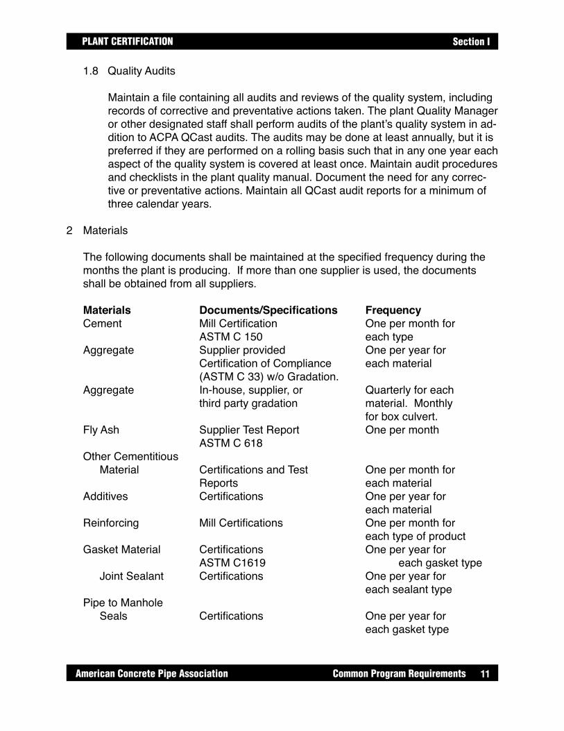
1.8 Quality Audits
Maintain a file containing all audits and reviews of the quality system, including records of corrective and preventative actions taken. The plant Quality Manager or other designated staff shall perform audits of the plant’s quality system in ad-dition to ACPA QCast audits. The audits may be done at least annually, but it is preferred if they are performed on a rolling basis such that in any one year each aspect of the quality system is covered at least once. Maintain audit procedures and checklists in the plant quality manual. Document the need for any correc-tive or preventative actions. Maintain all QCast audit reports for a minimum of three calendar years.
2 Materials
The following documents shall be maintained at the specified frequency during the months the plant is producing. If more than one supplier is used, the documents shall be obtained from all suppliers.
Materials Documents/Specifications FrequencyCement Mill Certification One per month for ASTM C 150 each type Aggregate Supplier provided One per year for Certification of Compliance each material (ASTM C 33) w/o Gradation. Aggregate In-house, supplier, or Quarterly for each third party gradation material. Monthly for box culvert. Fly Ash Supplier Test Report One per month ASTM C 618 Other Cementitious Material Certifications and Test One per month for Reports each material Additives Certifications One per year for each material Reinforcing Mill Certifications One per month for each type of product Gasket Material Certifications One per year for ASTM C1619 each gasket type Joint Sealant Certifications One per year for each sealant type Pipe to Manhole Seals Certifications One per year for each gasket type

12 Common Program Requirements American Concrete Pipe Association
PLANT CERTIFICATIONSection I
3 Calibration
Maintain documentation verifying that production and testing equipment has been properly and accurately calibrated in accordance with local standards, with the following minimum frequency:
Equipment CalibrationDocument FrequencyBatch Plant Scales* Independent One per year Water Meter* In-house One per year Additive Dispensing Equip.* In-house or Supplier One per year Concrete Compression Tester Independent Cert. One per year Three-Edge-BearingTester Independent Cert One per year Go/No-Go Gauges In-house One per year Laboratory Scales* In-house One per year Micrometers In-house One per year Calipers In-house One per yearVacuum Test Equip. In-house One per year Hydrostatic Test Equip. In-house One per year Air Content Test Equip. In-house One per year Quarterly for BoxCuring Temperature Logging Equipment In-house Verification One per year
* Calibrate in excess of maximum batch quantities. Calibrate batching scales in accordance with ASTM C94 through the full working range with at least one calibration increment within each quarter of the scale service range. Document procedures for all non-standard calibration procedures used.
Calibration stickers shall be attached to each piece of equipment showing date of most recent calibration and date when the next calibration is due, including in-house calibrations.
4 Mix Designs
Maintain file copies of all mix designs. Designs shall be current and the same as those being used in production. Designs shall confirm a maximum water/cementi-tious material ratio in accordance with current ASTM requirements. With the excep-tion, concrete used shall confirm a maximum 0.45 W/C ratio for box culverts and 0.50 W/C ratio for pipe for severe weathering regions as defined by ASTM C33 Figure 1.
13
PLANT CERTIFICATION
American Concrete Pipe Association Common Program Requirements
Section I
4.1 Water
Water used in the production of concrete and for concrete curing shall be po-table or non-potable water that meets the requirements of ASTM C 1602 Stan-dard Specifications for Mixing Water Used in the Production of Hydraulic Ce-ment Concrete.
4.2 Water/Cementitious Material Confirmation
For each concrete mix design produced, the water/cementitious ratio (w/c) shall be confirmed on actual batch weights a minimum of once per month. Aggregate moisture shall be determined according to ASTM C566. A discussion of this procedure and sample calculations are included in Appendix A, page 52 and page 53.
4.3 Concrete Batch Reports
4.3.1 In-Plant Batching
A minimum of one batch report showing the quantities of all ingredients for one batch shall be documented and maintained on file for each mix design produced each day.
4.3.2 Ready Mix Concrete
Truck delivery receipts listing mix proportions and quantities of all materi-als, including total water at time of placing, shall be received with each load and maintained on file. The supplier of ready mix concrete shall be local DOT or NRMCA certified. A current supplier certificate shall be maintained on file for each year that supplier delivered product to the plant.
4.4 Self-Consolidating Concrete (SCC)
The plant shall have on file a written quality control plan for SCC. The plan shall include a description of the test methods as well as the frequency and requirements for the results of those tests.
5 Joints (see applicable product certification requirements in Sections II through V.)
6 Equipment (see applicable product certification requirements in Sections II through V.)
14 Common Program Requirements American Concrete Pipe Association
PLANT CERTIFICATIONSection I
7 Reinforcing(see applicable product certification requirements in Sections II through V.)
8 Pre-Pour Inspection(see applicable product certification requirements in Sections II through V.)
9 Concrete Testing
Fresh concrete shall meet all required specifications. Concrete not meeting specifi-cations shall not be used in production of certified products.
9.1 Slump/Slump Flow Test of Concrete
9.1.1 Slump Tests of Wet Cast Concrete (ASTM C 143)
Slump tests shall be performed daily at a minimum, on each wet cast mix design being used that day. Additional slump tests shall be run if results are outside the desired range, or if any mix component is adjusted. Main-tain results on file. A sample report is shown in Appendix A, page 86.
9.1.2 Slump Flow Tests of SCC Concrete (ASTM C 1611)
Slump Flow tests for self-consolidating concrete shall be performed daily at a minimum, on the first two batches and every fourth batch thereaf-ter for each continuing pour, for each SCC mix design used. Additional slump flow tests shall be run if results are outside the desired range, or if any mix component is adjusted. Maintain results on file. A sample reports is shown in Appendix A, page 86.
9.1.2.1 Relative Measure of Flow Rate and Viscosity – (ASTM C 1611)
For each slump flow test, the time it takes for the outer edge of the concrete to reach a diameter of 20 inches shall be timed with a stopwatch and recorded. A sample report is shown in Appen-dix A, page 86.
9.1.2.2 VSI Index (ASTM C 1611)
For each slump flow test, VSI Index shall be estimated and re-corded. A sample is shown in Appendix A, page 86.
9.2 Air Content Tests of Fresh Wet Cast Concrete (ASTM C 231)
When required by specification of local climate conditions, air content test
15
PLANT CERTIFICATION
American Concrete Pipe Association Common Program Requirements
Section I
reports shall be maintained for each concrete mix being used in production each day that mix is used. Test frequency shall be performed at a minimum of one air test on the first batch of the day and on subsequent batches as neces-sary until acceptable batches are produced. The test location shall be at the point of placement.
Additional air tests shall be performed at a minimum frequency of one test per 50 continuous yards of concrete poured. A continuous pour is defined as suc-cession of batches where less than one hour elapses between consecutive batches of a single mix design. If batching and mixing is interrupted by a batch of concrete (with a different mix design) being mixed between consecutive batches. This is considered a new pour and an air test shall be taken on the first batch following the different batch, unless documentation exists that switching batches does not affect air content beyond specified limits. A sample report is shown in Appendix A, page 86.
9.3 Unit Weight Tests of Fresh Wet Cast Concrete (ASTM C 138)
Maintain a copy of unit weight test results at a minimum of one test per week on each wet cast mix used that week.
9.4 Concrete Absorption Test Results
Maintain a copy of absorption test results at a minimum of one test per year on the lowest cementitious content mix for each production method. Tests shall be performed according to ASTM C 497, Absorption Test Method A. Absorption shall not exceed 9%, except for sanitary sewer pipe and sanitary sewer man-holes which shall not exceed 7.5%.
9.5 Temperature Tests (ASTM C 1064)
Temperature tests shall be taken at the same frequency that cylinders in Sec-tion 9.4 of this Manual are taken for dry cast methods, and at the same fre-quency as the slump test in Section 9.1.1 of this Manual for wet cast methods. Additional temperature tests shall be run if results are outside the desired range, or if any component is adjusted. Maintain results on file. A sample report is shown in Appendix A, page 86.
9.6 For plants utilizing out-sourced concrete, the concrete shall confirm the require-ments in Section 4 and Section 9 of Section I of this Manual.

16 Common Program Requirements American Concrete Pipe Association
PLANT CERTIFICATIONSection I
9.7 Concrete Compression Tests (ASTM C 39)
Maintain copies of compression test results for all mixes used in production. For pipe that are three-edge bearing tested per Section 13 of this Manual, a minimum of 5 cylinders per week for each mix design used that week shall be prepared and tested. For pipe not required to be three-edge-bearing tested per Section 13 of this Manual, and all other products, a minimum of 5 cylinders per day per mix design used shall be prepared and tested. For box culvert produc-tion, an additional minimum of 2 cylinders per week shall be cast and tested to verify adequate stripping/handling strengths are being achieved. Stripping strength cylinders shall be cured with the product, or in a like manner. A sam-ple report is shown in Appendix A, page 87.
9.7.1 Compression Test Specimen for Machine Cast (ASTM C 497)
Compression tests determining concrete compressive strength for dry cast methods may be made on concrete cylinders compacted accord-ing to ASTM C 497 and cured in like manner as the product, or on cores drilled from the product. The manufacturer shall have a written test pro-cedure for casting dry cast cylinders.
9.7.2 Compression Test Specimen for Wet Cast Methods (ASTM C 31)
Compression tests determining concrete compressive strength of wet cast concrete shall be made, according to ASTM C31, on standard rod-ded or vibrated concrete cylinders and cured in like manner as the prod-uct (unless otherwise specified by local or project specifications), or on cores drilled from the product. The Manufacturer shall have a written procedure for casting wet-cast cylinders.
9.7.3 Compression Tests on Concrete Cores
The method of obtaining cores, the number of cores, and acceptability of core compression test results shall be in accordance with ASTM C497 or C 42, or as determined by product or specification requirements.
10 Curing
Plants shall cure the product in accordance with the applicable ASTM product speci-fication or other superseding requirements. Acceptable methods include steam cur-ing, water curing (curing in an enclosed environment with an excess of 90% relative humidity), membrane curing, a combination of these methods, or another method approved by the project owner. Accelerated curing shall commence only after con-crete reaches its initial set. Maximum concrete temperature shall be 160 degrees F

17
PLANT CERTIFICATION
American Concrete Pipe Association Common Program Requirements
Section I
with a maximum temperature rise of 40 degrees F per hour during heat curing. Each plant shall have a written procedure to ensure that the product is adequately cured prior to stripping and handling. If the procedure does not include the continuous temperature monitoring of each piece, it shall include the test data used to develop the policy. Also included in this procedure shall be specified minimum compressive strength for stripping and handling. Curing temperature and cycle shall be monitored at a minimum of one product or kiln each day or curing cycle.
11 Post-Pour Inspection(see applicable product certification requirements in Sections II through V.)
12 Product Marking
Pipe, manholes, box culverts, engineered precast products, and three-sided struc-tures shall be marked in accordance with the requirements of the applicable ASTM, ASCE, CSA, Project or local specification and with the “QCast” emblem signifying compliance with the ACPA program.
13 Product Testing(Pipe and Manhole only - see applicable product certification requirements in Sec-tions II and Section III.)
14 Storage, Handling, Shipping and Final Inspection
Products meeting the requirements of this Manual shall be referred to in this section as “acceptable products”. Products failing to meet the requirements shall be referred to as “reject”.
14.1 Handling and Storage
Acceptable products shall be handled and stored to prevent damage. Reject products that cannot be repaired shall be marked and stored separately.
ForPipe: The plant shall have a documented maximum stack height for each pipe, size and class produced.ForBox: The plant shall have a documented maximum stack height for each box and size produced.
14.2 Shipping Policy
The plant shall have a written Shipping Policy that describes the criteria that shall be met, including compressive strength (and/or three-edge-bearing strength for pipe), before products can be shipped. The criteria stated in the Policy shall meet or exceed the requirements of the specifying agency.
18 Common Program Requirements American Concrete Pipe Association
PLANT CERTIFICATIONSection I
14.3 Final Inspection
The plant shall have a written Final Inspection Procedure in place to inspect products before shipping. Included in this procedure shall be the position(s) of the person responsible for final inspection and a means of documenting that the inspection has been done. The designated personnel shall be knowledgeable in recognizing product deficiencies and have the authority to prevent shipping of products not meeting project requirements.

19
PLANT CERTIFICATION
American Concrete Pipe Association Pipe Requirements
Section II
SECTION IIPIPE REQUIREMENTS
In addition to the Common Requirements in Section I of the ACPA’s QCast Plant Certi-fication Manual, the following requirements are required for Pipe Certification. A plant undergoing Pipe Certification should refer to both Section I and this section to fulfill cer-tification requirements. A plant undergoing Sanitary Sewer certification shall be subject to the additional requirements for sanitary sewer as listed in this section. Sanitary Sewer certification shall apply to field tested pipe intended for a variety of applications includ-ing: sanitary, storm, dams, levies, irrigation, siphons etc.
5 Joints
5.1 Joint Design Drawings
5.1.1 Gasketed Sanitary Sewer Pipe and Storm Sewer and Culvert Pipe
For gasketed joint designs, maintain on file a set of drawings with critical joint dimensions and tolerances. A sample joint data form showing re-quired information is included in Appendix A, page 54.
5.1.2 Non-Gasketed Storm Sewer and Culvert Pipe
For non-gasketed joint designs, maintain on file a set of drawings with critical dimensions and tolerances. A sample Joint Data Form showing required information is included in Appendix A, page 55.
5.2 Joint Design Calculations - Sanitary Sewer Pipe
For each joint and gasket, maintain on file a set of design calculations showing critical data and allowable tolerances. A discussion of joint design and sample calculations are included in Appendix A, starting on page 56.
5.3 Spigot Go/No-Go Gauge (or optional measuring system) - Sanitary Sewer Pipe
For each different gasketed joint and size, maintain a drawing showing the de-sign and dimensions of a gauging system for the gasket sealing surface of pipe spigots. A drawing of a sample gauge is included in Appendix A, page 62.
5.4 Gasket Quality
Maintain in-house reports verifying critical dimensions of gaskets.
© ACPA 2016 2016 Version (01-2016)

20 Pipe Requirements American Concrete Pipe Association
PLANT CERTIFICATIONSection II
5.4.1 Testing FrequencyAll gasket shipments shall be sampled and tested at the following mini-mum frequency: Pipe Size Frequency12" - 33" 1/300 36" and larger 1/100
5.4.2 Gasket Q.C. Test Procedures
Testing procedures and a sample form are included in Appendix A, start-ing on page 63.
5.4.2.1 O-Ring Gaskets
All sampled o-ring gaskets shall be tested for splice strength, gasket volume, cord diameter, gasket length and gasket hard-ness (gasket volume should only apply to confined gaskets).
5.4.2.2 Profile Gasket
All sampled solid, profile gaskets shall be tested for splice strength, hardness (durometer), length, height, cut length and width. Gasket volume shall be tested for gaskets used in a con-fined recess or groove only.
5.4.2.3 Pre-lubricated Gaskets and Gaskets With Non-solid Cross Sec-tions
All sampled pre-lubricated gaskets and gaskets with non- solid cross sections shall be tested for splice strength, cut length, height and width.
6 Equipment
6.1 Forms
New and repaired equipment shall be inspected prior to pouring to ensure proper dimensions and function.
Forms shall be kept clean of concrete build-up and inspected after each use.
6.2 Joint Forming Equipment Inspection

21
PLANT CERTIFICATION
American Concrete Pipe Association Pipe Requirements
Section II
6.2.1 Gasketed Pipe Headers and Tongue Formers Inspection
Maintain incoming* and annual inspection reports on headers and tongue formers used in the production of sanitary sewer pipe, and incoming inspection reports on headers and tongue formers used in the production of gasketed storm sewer pipe. Incoming inspections shall be a detailed report on the entire header or tongue former. Annual inspections shall be a minimum of the sloped surface adjacent to or behind the snap ring for confined gasket joints, and the sloped surface which forms the gasket sealing surface for single offset joints. Incoming inspection reports shall be kept on file as long as the headers and tongue formers are in use. Sample forms are included in Appendix A, starting on page 65.
* Incoming shall hereafter be defined as the date of original purchase.
6.2.2 Non-Gasketed Pipe Headers and Tongue Formers Inspection
Maintain incoming inspection reports on headers and tongue formers used in the production of non-gasketed pipe. Incoming inspections shall be a detailed report on the entire header or tongue former, and kept on file as long as the headers and tongue formers are in use. Sample forms are included in Appendix A, starting on page 65.
6.2.3 Gasketed Pipe Pallet Inspection
Maintain incoming and annual inspection reports on pallets used in the production of sanitary sewer pipe, and incoming inspection reports on pallets used in the production of gasketed storm sewer pipe. Incoming inspections shall be a detailed report of the entire pallet, and annual in-spection shall be a minimum of the surface that forms the gasket-sealing surface. Incoming inspection reports shall be kept on file as long as the pallets are in use. Sample forms are included in Appendix A, page 65, page 68 and page 69.
6.2.4 Non-Gasketed Pipe Pallets and Groove Formers Inspection
Maintain incoming inspection reports on pallets and groove formers used in the production of non-gasketed pipe. Incoming inspections shall be a detailed report on the entire pallet or groove former, and kept on file as long as the pallets and groove formers are in use. Sample forms are included in Appendix A, page 65, page 68 and page 69.
6.2.5 Truing Ring Inspection Reports - Sanitary Pipe
22 Pipe Requirements American Concrete Pipe Association
PLANT CERTIFICATIONSection II
Maintain incoming and annual inspection reports on truing rings used in the production of sanitary sewer pipe, and incoming inspection reports on truing rings used in the production of gasketed storm sewer pipe. Incom-ing inspection shall be a detailed report of the entire truing ring and annu-al inspection shall be a minimum of the surface that maintains the gasket sealing surface. Incoming inspection reports shall be kept on file as long as the truing rings are in use. Sample forms are included in Appendix A, page 65, page 68 and page 69.
7 Reinforcing
Detailed design information, including cage diameter tolerances and minimum lap, shall be available in the reinforcing fabrication area for cages/reinforcement being fabricated. Steel reinforcing shall comply with the requirements of the project specifi-cations. Plants shall maintain on file the following reinforcing design information:
Mesh Style Cage Diameter Cage Length Steel Area - specified Cage Location in the Product Wall Cage Lap (welded or tied) Cage Diameter Bell Shear Steel
8 Pre-Pour Inspection
8.1 Reinforcing Inspection
Maintain reports documenting the inspection of reinforcing used for each size and class produced. At a minimum, measure and document one cage at the start of each production run, one cage at the start of each new shift after that, and one cage if any component or setting is changed. A sample form of the Reinforcing Inspection Sheet for Pipe is included in Appendix A, page 72. All information shown on the sample form is considered minimum requirements.
8.2 Pre-Pour Visual Inspection
For each pipe produced, visually inspect the following applicable items prior to pouring:
Reinforcing Placement Handling Holes / Lifting Devices Tie-pin Holes

23
PLANT CERTIFICATION
American Concrete Pipe Association Pipe Requirements
Section II
Release Agent Application Form Cleanliness and Condition Step Holes / Plugs
8.3 Pre-Pour Dimensional Inspection
For each pipe produced inspect and document the following applicable items by a minimum of initialing the shop drawings.
Embedded items - location Blockouts - size and location
11 Post-Pour Inspection
The individual responsible for product quality shall personally check a portion of each day's production before and after patching or "finishing". This inspection shall show that the correct production and patching techniques are being used. 11.1 Finishing and Repairs
After tip-out, pipe products shall be repaired or "finished" as required, to ensure that they shall perform as designed. The plant shall have written procedures on file describing repair materials and repair procedures.
11.2 Pipe Barrel Visual Inspection
Criteria for inspection shall include, at a minimum, inspection for barrel cracks, slumping, voids, bleeding, exposed steel, cage twist, segregation, swedging, slabbing, and flashing. Refer to local specifications.
11.3 Dimensional Test Reports on Pipe Barrels
Measure and record the pipe length, diameter and wall thickness; and calculate and record the difference in length of two opposite sides when new equipment is put into production at a minimum frequency of one per size per shift, except on low production wet cast there the minimum frequency shall be a minimum of 1/100 pieces or once every 6 months. The file shall also contain dimen-sional reports from each pipe section on which a three-edge-bearing test has been performed. Pipe measured as a part of three-edge-bearing tests can be included to meet frequency requirements. Product Dimensional Inspection Instructions and Sample Product Dimensional Reports are included in Appendix A, page 88 and page 89.Inspect the size and location of all embedded items and blockouts as required on shop drawings.

24 Pipe Requirements American Concrete Pipe Association
PLANT CERTIFICATIONSection II
11.4 Pipe Joint Visual Inspection
Inspection shall include, at a minimum, the following:Before patching, inspect joints for cracks, smoothness of the bell and spigot, and snap ring positioning and a uniform step in single offset joints.
After patching, inspect joints for patching technique and quality, smoothness of bell and spigot, and a uniform snap ring width and depth.
11.5 Dimensional Test Reports on Pipe Spigots - Sanitary Sewer
Maintain reports verifying dimensional checks of all gasketed sanitary sewer pipe spigot gasket-sealing surfaces. These reports may be results of Go/No-Go gauging, or other measuring method that indicates the number of pipe passing the inspection. Label results by date of manufacture.
13 Testing
Maintain results of tests and inspections on the finished product as described below:
13.1 Water Tightness of Pipe – Sanitary Sewer
Sanitary sewer pipe shall be tested as described below. Where pipe sizes and test methods overlap, either test method may be used.
Size Frequency Method Test Criteria12 – 36” Pipe 100% Vacuum Test See Appendix A, page 94 & 9512 – 36” Pipe 100% Hydrostatic Test See Appendix A, page 98 42” and Larger 1/100 Vacuum Test See Appendix A, page 94 & 95 (min. of 2) Or42” and Larger 1/100 Hydrostatic Test See Appendix A, page 98 (min. of 2)
13.2 Three-Edge-Bearing Testing of Pipe
Pipe shall be three-edge-bearing tested as described below. All three-edge- bearing tests shall be performed according to ASTM C 497.
A sample form showing required information is included in Appendix A, page 99.
13.2.1 Reinforced Round Pipe Three-Edge-Bearing Tests
Pipe shall be tested at the following minimum frequencies:

25
PLANT CERTIFICATION
American Concrete Pipe Association Pipe Requirements
Section II
Pipe Size Class Minimum Frequency*12 - 15" Class V and below 1/1000 pieces 18 - 36" Class IV and below 1/800 pieces 18 - 36" Class V 1/400 pieces 42 - 60" Class III and below 1/400 pieces 42 - 60" Class IV and V 1/200 pieces 66" and larger All Classes As required by project specs
*Minimum testing frequency as listed above, or 1 piece of pipe per year for each size and class of pipe manufactured during that year, whichever is more frequent. Three-edge-bearing tests are not required on sizes pro-duced that are less than 100 pieces production per year, as long as the plant has proof of design testing and cylinders are cast and tested as per Section 9.7 (Compression Strength Testing). All tested pipe shall be tested to a minimum of 100% of the 0.01" speci-fied D-Load requirement, or 0.01" crack width, whichever occurs first, except that at least once per year, one piece of each size and class up to 60" tested shall be tested to the ultimate D-Load.
13.2.2 Non-reinforced Round Concrete Pipe Three-Edge-Bearing Tests
Non-reinforced concrete pipe shall be tested to the required ultimate loads as specified in Table I of ASTM C14 or in ASTM C 985, whichever standard is applicable, at frequencies required by job or local specifica-tions.
13.2.3 Arch and Elliptical Three-Edge-Bearing Tests
Three-edge-bearing tests shall be performed according to ASTM C497 at frequencies required by job or local specifications.
13.2.4 Direct Design Concrete Pipe Three-Edge-Bearing Tests
Direct design concrete pipe is designed for an installed condition with soil-pipe interaction and need not be tested for three-edge-bearing strength. Concrete cylinder compression test frequencies shall meet the requirements of 9.4 of this Manual.
13.3 Off-Center Joint Test - Sanitary Sewer
Maintain a proof of design test result for all pipe sizes and joint designs used for sanitary sewer pipe. The test records shall, at a minimum, record results on joints for each size pipe for the lowest class pipe produced. The test shall be

26 Pipe Requirements American Concrete Pipe Association
PLANT CERTIFICATIONSection II
run according to Appendix A, page 100 and page 101. These reports shall be retained as a permanent record, and updated as reinforcing designs and joint configurations are changed.
13.4 Differential Joint Shear Test - Sanitary Sewer
For each pipe size and joint design, maintain a proof of design test result for the lowest concrete strength and lowest class of pipe produced. The test records shall at minimum, record results on joints for each size pipe for the lowest class pipe produced. These reports shall be retained for permanent record, and up-dated as reinforcing designs and joint configurations are changed. Test proce-dures and test criteria are included in Appendix A, page 102 and page 103.
13.5 Storm Sewer and Culvert Joint Test - Storm and Culvert
For all sizes of gasketed storm sewer and culvert pipe manufactured at the participating plant, the pipe manufacturer shall maintain proof of design test results. The reports shall be retained for permanent record, and updated as joint design or gaskets are changed. Test procedures and test criteria are included in Appendix A, page 104.
27
PLANT CERTIFICATION
American Concrete Pipe Association Manhole Requirements
Section III
SECTION IIIMANHOLE REQUIREMENTS
In addition to the Common Requirements in Section I of the ACPA’s QCast Plant Cer-tification Manual, the following requirements are required for Manhole Certification. A plant undergoing Manhole Certification should refer to both Section I and this section to fulfill certification requirements.
5 Joints
5.1 Joint Design Drawings
5.1.1 Sanitary Manholes
For each joint design, maintain on file a set of drawings with critical joint dimensions and tolerances. A sample joint data form showing required information is included in Appendix A, page 54.
5.1.2 Storm Sewer and Culvert Manholes
For both gasketed and non-gasketed joint designs, maintain on file a set of drawings with critical dimensions and tolerances. A sample Joint Data Form showing required information is included in Appendix A, page 54 and page 55.
5.2 Joint Design Calculations - Sanitary Manholes
For each gasketed joint and gasket, maintain on file a set of design calculations showing critical data and allowable tolerances. A discussion of joint design and sample calculations are included in Appendix A, page 56 thru page 61.
5.3 Spigot Go/No-Go Gauge (or optional measuring system) - Sanitary Manholes
For each different gasketed joint and size, maintain a drawing showing the design and dimensions of a gauging system for the gasket sealing surface of manhole spigots. A drawing of a sample gauge is included in Appendix A, page 62.
5.4 Gasket Quality
Maintain in-house reports verifying critical dimensions of gaskets.
© ACPA 2016 2016 Version (01-2016)

28 Manhole Requirements American Concrete Pipe Association
PLANT CERTIFICATIONSection III
5.4.1 Testing Frequency
All gasket shipments shall be sampled and tested at a minimum frequen-cy of one per 100.
5.4.2 Gasket Q.C. Test Procedures
Testing procedures and a sample form are included in Appendix A, page 63 and page 64.
5.4.2.1 O-Ring Gaskets
All sampled o-ring gaskets shall be tested for splice strength, gasket volume, cord diameter, gasket length and gasket hard-ness (durometer).
5.4.2.2 Profile Gasket
All sampled profile gaskets shall be tested for splice strength, gasket hardness (durometer),gasket length, height and width.
5.4.2.3 Pre-lubricated Gaskets
All sampled pre-lubricated gaskets shall be tested for splice strength, gasket length, height and width.
6 Equipment
6.1 Forms
New and repaired equipment shall be inspected prior to pouring to ensure proper dimensions and function.Forms shall be kept clean of concrete build-up, and inspected after each use.
6.2 Joint Forming Equipment Inspection
6.2.1 Gasketed Manhole Headers and Tongue Formers
Maintain incoming* and annual inspection reports on headers and tongue formers used in the production of sanitary manholes and incoming in-spection reports on headers and tongue formers used in the production of non-sanitary manholes. Incoming inspections shall be a detailed report on the entire header or tongue former. Annual inspections shall be a mini-mum of the sloped surface adjacent to or behind the snap ring for con-

29
PLANT CERTIFICATION
American Concrete Pipe Association Manhole Requirements
Section III
fined gasket joints, and the sloped surface which forms the gasket sealing surface for single offset joints. Incoming inspection reports shall be kept on file as long as the headers and tongue formers are in use. Sample forms are included in Appendix A, page 65 thru page 67.
* Incoming shall hereafter refer to the date of original purchase.
6.2.2 Non-gasketed Manhole Headers and Tongue Formers
Maintain incoming inspection reports on headers and tongue formers used in the production of non-gasketed manholes. Incoming inspection shall be a detailed report on the entire header or tongue former, and kept on file as long as the headers and tongue formers are in use. Sample forms are included in Appendix A, page 65 and page 66.
6.2.3 Gasketed Manhole Pallet Inspection
Maintain incoming and annual inspection reports on pallets used in the production of gasketed sanitary sewer manholes, and incoming inspec-tion reports on pallets used in the production of non-sanitary sewer man-holes. Incoming inspections shall be a detailed report of the entire pallet, and periodic inspections shall be a minimum of the sloped surface that forms the gasket-sealing surface. Incoming inspection reports shall be kept on file as long as the pallets are in use. Sample forms are included in Appendix A, page 65, page 68 and page 69.
6.2.4 Non-gasketed Manhole Pallets and Groove Formers Inspection
Maintain incoming inspection reports on pallets and groove formers used in the production of non-gasketed manholes. Incoming inspection shall be a detailed report on the entire pallet or groove former, and kept on file as long as the pallets and groove formers are in use. Sample forms are included in Appendix A, page 65, page 68 and page 69.
6.2.5 Truing Ring Inspection Reports - Sanitary Sewer Manholes
Maintain incoming and annual inspection reports on truing rings used in the production of sanitary manholes, and incoming inspection reports on truing rings used in the production of gasketed storm sewer pipe. Incom-ing inspection shall be a detailed report of the entire truing ring and annu-al inspection shall be a minimum of the surface that maintains the gasket sealing surface. Incoming inspection reports shall be kept on file as long as the truing rings are in use. Sample forms are included in Appendix A, page 70 and page 71.
30 Manhole Requirements American Concrete Pipe Association
PLANT CERTIFICATIONSection III
7 Reinforcing
Detailed design information, including cage diameter tolerances and minimum lap, shall be available in the reinforcing fabrication area for cages/reinforcement being fabricated. Steel reinforcing shall comply with the requirements of the project specifi-cations. Plants shall maintain, on file, the following reinforcing design Information:
Mesh Style Cage Diameter Cage Length Steel Area - specified Cage Location In the Product Wall Cage Lap (welded or tied) Bell Reinforcing (convoluted or hoop)
8 Pre-Pour Inspection
8.1 Reinforcing Inspection
Maintain reports documenting the inspection of reinforcing used for each size produced. At a minimum, measure and document one cage at the start of each production run, one cage at the start of each new shift after that, and one cage If any component or setting is changed. A sample form of the Reinforcing Inspection Sheet for Manhole is included in Appendix A, page 72. All informa-tion shown on the sample form are considered minimum requirements.
8.2 Pre-Pour Visual Inspection
For each manhole produced, visually inspect the following applicable items prior to pouring:
Reinforcing Placement Handling Holes / Lifting Devices Release Agent Application Form Cleanliness and Condition Step Holes / Plugs
8.3 Pre-Pour Dimensional Inspection
For each manhole produced, inspect and document the following applicable items by a minimum of initialing the shop drawings.
Embedded items - location Blockouts - size and location

31
PLANT CERTIFICATION
American Concrete Pipe Association Manhole Requirements
Section III
11 Post-Pour Inspection
The individual responsible for product quality shall personally check a portion of each day's production before and after patching of "finishing". This inspection shall show that the correct production and patching techniques are being used.
11.1 Finishing and Repairs
After tip-out, manhole products shall be repaired or "finished" as required, to ensure that they shall perform as designed. The plant shall have written proce-dures on file describing repair materials and repair procedures.
11.2 Manhole Visual Inspection
Criteria for inspection shall include, at a minimum, inspection for barrel cracks, slumping, voids, bleeding, exposed steel, cage twist, segregation, swedging, slabbing, and flashing. Refer to local specifications.
11.3 Dimensional Test Reports on Manholes
Measure and record the manhole length, diameter and wall thickness; and calculate and record the difference in length of two opposite sides when new equipment is put into production at a minimum frequency of one per size per shift, except on low production wet cast there the minimum frequency shall be a minimum of 1/100 pieces or once every 6 months. Product Dimensional In-spection Instructions and Sample Product Dimensional Reports are included in Appendix A, page 88 and page 89.
Inspect the size and location of all embedded items and blockouts as required on shop drawings.
11.4 Manhole Joint Visual Inspection
Inspection shall include, at a minimum, the following:Before patching, inspect joints for cracks, smoothness of the bell and spigot, and snap ring positioning and a uniform step in single offset joints.
After patching, inspect joints for patching technique and quality, smoothness of bell and spigot, and a uniform snap ring width and depth.
11.5 Dimensional Test Reports on Manhole Spigots - Sanitary Sewer
Maintain reports verifying dimensional checks of all gasketed sanitary sewer manhole spigot gasket-sealing surfaces. These reports may be results of Go/
32 Manhole Requirements American Concrete Pipe Association
PLANT CERTIFICATIONSection III
No- Go gauging, or other measuring method that indicates the number of man-holes passing the inspection. Label results by date of manufacture.
13 Product Testing
13.1 Water Tightness of Sanitary Sewer Manholes
Sanitary sewer manholes shall be tested as described below.
Size Frequency Method Test Criteria42” and Larger 1/100 (min. of 2) Vacuum Test See Appendix A, page 94 & 95 Or42” and Larger 1/100 (min. of 2) Hydrostatic Test See Appendix A, page 98
13.2 Manhole Step Testing
Maintain proof of design testing for manhole steps. Testing shall include pull out and load testing per the “Manhole Step Testing Methods” section of ASTM C497. Proof of design testing shall be completed and documented for each step design used in production. Tests shall be conducted on steps installed in manholes produced at the plant. If there is a change in production process or equipment, new tests shall be completed. Documentation shall include step identification, test results including maximum load applied, resulting vertical deflection, and minimum required loads, load cell or gage calibration, and a description of the testing procedures.
In addition to proof of design tests on plant installed steps, maintain either:
1. Manufacturers certified test results performed within the past 3 years or2. In-house test results every 3 years.
33
PLANT CERTIFICATION
American Concrete Pipe Association Precast
Section IV
SECTION IVENGINEERED PRECAST PRODUCTS
In addition to the Common Requirements in Section I of the ACPA’s QCast Plant Certifi-cation Manual, the following requirements are required for Engineered Precast Products Certification. A plant undergoing Engineered Precast Products Certification should refer to both Section I and this section to fulfill certification requirements.
1.9 Production Drawings
1.9.1 Standard Products
Standard product drawings, including reinforcing, critical dimensions and tolerances shall be maintained on file.
1.9.2 Non-Standard/Special Products
For products that vary from standard designs (including but not limited to, variations in hole size, embedment and/or reinforcement style/location, in-fall/outfall elevations, etc.), unique drawings including reinforcing, critical dimensions and tolerances shall be maintained on file.
5 Joints
Maintain detailed information on the joint and joint forming equipment.
6 Equipment
New and repaired equipment shall be inspected prior to pouring to ensure proper dimensions and function.Forms shall be kept clean of concrete build-up, and inspected after each use.
7 Reinforcing
Detailed design information, including cage dimensional tolerances and minimum lap, shall be available in the reinforcing fabrication area for cages/reinforcement being fabricated. Steel reinforcing shall comply with the requirements of the project specifications. Plants shall maintain, on file, the following reinforcing design informa-tion;
Reinforcing Style Reinforcing Dimensions
© ACPA 2016 2016 Version (01-2016)

34 Precast American Concrete Pipe Association
PLANT CERTIFICATIONSection IV
Steel Area - specifiedReinforcing Location in the Product Wall Reinforcing Lap Length (welded or tied) Fiber Reinforcing - if fiber reinforcing is used, design information shall include fiber specification, size and quantity per cubic yard Embedded steel location and connections
8 Pre-Pour Inspection
8.1 Pre-Pour Reinforcing Inspection
Initialing product shop drawings shall be the minimum documentation report. A sample form of the Reinforcing Inspection Sheet for Precast is included in Ap-pendix A, page 73.
8.1.1 Standard Products
Maintain reports documenting the inspection of reinforcing used for each specific design produced. At a minimum, measure and document one cage at the start of each production run, one cage at the start of each new shift after that, and one cage if any component or setting is changed.
8.1.2 Non-Standard Products
Maintain reports documenting the inspection of reinforcing used for each product being produced.
8.2 Pre-Pour Visual Inspection
For each product produced, inspect the following applicable items prior to pour-ing: Form Release Embedded Items Form Cleanliness Reinforcing Cover
8.3 Pre-Pour Dimensional Inspections
8.3.1 Standard Products
Maintain inspection records of all standard precast products form dimen-sion at initial set-up for each production run. Documentation shall be a minimum of initialing product shop drawings.

35
PLANT CERTIFICATION
American Concrete Pipe Association Precast
Section IV
8.3.2 Non-Standard Products
Maintain inspection records of all non-standard precast products form dimensions and blockout size and locations. Documentation shall be a minimum of initialing product shop drawings.
11 Post-Pour Inspection
The individual responsible for product quality shall personally check a portion of each day's production before and after patching or "finishing". This inspection shall show that the correct production and patching techniques are being used. 11.1 Finishing and Repairs
After stripping precast products shall be repaired or "finished" as required, to ensure that they shall perform as designed. The plant shall have a written repair procedure on file describing repair materials and repair procedure.
11.2 Visual Inspection
Criteria for inspection shall include, at a minimum, inspection for cracks, slump-ing, voids, bleeding, exposed steel, cage twist, segregation, swedging, slabbing and flashing.
11.3 Dimensional Test Reports
Inspect the size and location of all embedded items and blockouts as required on product drawings. Maintain a Post-Pour Dimensional Inspection Record of blockout and embedment dimensions on all precast products produced each day.
11.4 Joint Visual Inspection Inspection shall include, at a minimum, the following:
Before patching, inspect joints for cracks, smoothness of the joint, and snap ring positioning and a uniform step in single offset joints. After finishing, inspect joints for finishing technique and quality.
36 Box Culvert & Three-Sided Structures American Concrete Pipe Association
PLANT CERTIFICATIONSection V
SECTION VBOX CULVERT AND THREE-SIDED
STRUCTURE REQUIREMENTSIn addition to the Common Requirements in Section I of the ACPA’s QCast Plant Certifi-cation Manual, the following requirements are required for Box Culvert and Three-sided Structures Certification. A plant undergoing Box Culvert and Three-sided Certification should refer to both Section I and this section to fulfill certification requirements.
5 Joints
Maintain detailed information on the joint and joint forming equipment. For each joint design, maintain on file a set of drawings showing critical joint dimensions and tolerances. A sample joint data form is included in Appendix A, page 55 for box culverts and three-sided structures.
6 Equipment
New and repaired equipment shall be inspected prior to pouring to ensure proper dimensions and function.
Forms shall be kept clean of concrete build-up, and inspected after each use.
7 Reinforcing
Detailed design information including cage dimensional tolerances and minimum lap, shall be available in the reinforcing fabrication area for cages being fabricated. Steel reinforcing shall comply with the requirements of the project specifications.
7.1 Design
Reinforcing design information shall include: Reinforced Areas Required Reinforcing Design Area Mesh Style or Rebar Size and Spacing Reinforcing Lengths Reinforcing Location in the Box Slab or Wall Reinforcing Cover Shear Steel Laps
© ACPA 2016 2016 Version (01-2016)
37
PLANT CERTIFICATION
American Concrete Pipe Association Box Culvert & Three-Sided Structures
Section V
8 Pre-Pour Inspection
8.1 Reinforcing Inspection
Maintain reports documenting the inspection of reinforcing used for each spe-cific design produced. At a minimum, measure and document one cage at the start of each production run, one cage at the start of each new shift after that, and one cage if any component or setting is changed. A sample form for Rein-forcing Inspection Sheet is included in Appendix A, page 72 and page 73 for single cell box culverts, page 74 and page 75 for double cell box cul-verts, page 76 and page 77 for Three-Sided Structures with a flat deck, and page 78 and page 79 for Three-Sided Structures with an arch deck.
All information shown on the sample forms are considered minimum require-ments.
8.2 Pre-Pour Visual Inspection
8.2.1 For each wet cast box culvert or three-sided structure produced, inspect and document the following applicable items prior to pouring.
Reinforcing orientation and spacing (top slab reinforcing shall be located in the top slab)Form release Embedded items Form cleanliness Reinforcing cover
8.2.2 For each dry cast box produced, a visual inspection of items listed under Section 8.2.1 is required. At a minimum, these inspections shall be documented on a once per shift basis.
8.3 Pre-Pour Form Dimensional Inspection
Maintain inspection records of all box culvert and three-sided structure section forms at initial setup for each product run. Required measurements include:
Thickness of top and bottom slab and both side walls Core Rise Core Span Both core diagonal measurements Skew of three-sided structure if applicable Legs of three-sided structure, if applicable

38 Box Culvert & Three-Sided Structures American Concrete Pipe Association
PLANT CERTIFICATIONSection V
Record measurements on "Box Culvert or Three-Sided Structure Pre-Pour/Pour Inspection" form. A sample of this form is included in Appendix A, page <?> for single cell box culverts, page <?> for double cell box culverts, page <?> for Three-Sided Structures with a flat deck, and page <?> for Three-Sided Structures with an arch deck.
11 Post-Pour Inspection
The individual responsible for product quality shall personally check a portion of each day’s production before and after patching or “finishing”. This inspection shall show that the correct production and patching techniques are being used.
11.1 Finishing and Repairs
After stripping, boxes and three-sided structures shall be repaired or "finished" as required, to ensure that they shall perform as designed. The plant shall have written procedures on file describing repair materials and repair procedures.
11.2 Visual Appearance
All box culverts and three-sided structure shall be visually inspected for the fol-lowing prior to yarding:
Cracks Voids/bleeding Flashing Slumping Exposed Steel Surface Voids
Record results on "Box Culvert or Three-Sided Structures Post-Pour Inspec-tion" form. Samples of these forms are included in Appendix A, page 90 for single cell box culverts, page 91 for double cell box culverts, page 92 for Three-Sided Structures with a flat deck, and page 93 for Three-Sided Struc-tures with an arch deck. Refer to local specifications.
11.3 Dimensional Inspection
Maintain a Post-Pour Inspection Record on 20% of all boxes and 100% of all three-sided structures produced each day from each form used that day (mini-mum one per form per day). Required measurements include: Box Culverts:Thickness of top and bottom slab and both side walls on both ends

39
PLANT CERTIFICATION
American Concrete Pipe Association Box Culvert & Three-Sided Structures
Section V
Inside rise on both ends Inside span on both ends Inside length; top, bottom, both side walls, center wall for double-cell boxes Three-Sided Structures: Thickness of Deck and Precast Legs Span of Precast Structure Rise of Precast Structure Width of Precast Structure Section
Record measurements on "Box Culvert or Three-Sided Structures Post-Pour Product Inspection" form. Samples of these forms are included in Appendix A, page 90 for single cell box culverts, page 91 for double cell box cul-verts, page 92 for Three-Sided Structures with a flat deck, and page 93 for Three-Sided Structures with an arch deck.
Inspect the size and location of all embedded items and blockouts as required on shop drawings.

45
PLANT CERTIFICATION
American Concrete Pipe Association Appendix A
Section VI
APPENDIX A:Procedures and Forms
© ACPA 2016 2016 Version (01-2016)

Appendix A American Concrete Pipe Association46
PLANT CERTIFICATIONSection VI
Required ASTM/AASHTO Standards
For ACPA Pipe, Manhole, Precast Products, Box Culverts, and Three-sided Structures
A 615/ M 31 Specification for Deformed and Plain Billet-Steel Bars for Concrete Reinforcement A 706 Specification for Low-Alloy Steel Deformed and Plain Bars for Concrete Reinforcement A 767 Specification for Zinc-Coated (Galvanized) Steel Bars for Concrete Reinforcement A 775/ M 284 Specification for Epoxy-Coated Reinforcing Steel Bars A 884 Specification for Epoxy-Coated Steel Wire and Welded Wire Fabric for Reinforcement A 1064 Specification for Steel Wire and Welded Wire Reinforcement, Plain and Deformed, for Concrete C 31 Practice for Making and Curing Concrete Test Specimens in the Field C 33 Specification for Concrete Aggregates C 39 Test Method for Compressive Strength of Cylindrical Concrete Specimens C 40 Test Method for Organic Impurities in Fine Aggregates for Concrete C 42 Test Method for Obtaining and Testing Drilled Cores and Sawed Beams of Concrete C 94 Specification for Ready-Mixed Concrete C 136 Test Method for Sieve Analysis of Fine and Coarse Aggregates C 138 Test Method for Unit Weight, Yield, and Air Content (Gravimetric) of Concrete C 143 Test Method for Slump of Hydraulic-Cement Concrete C 150/ M 85 Specification for Portland Cement C 172 Practice for Sampling Freshly Mixed Concrete C 173 Test Method for Air Content of Freshly Mixed Concrete by the Volumetric Method C 231 Test Method for Air Content of Freshly Mixed Concrete by the Pressure Method C 403 Test Method for Time of Setting of Concrete Mixtures by Penetration Resistance C 494/ M 194 Specification for Chemical Admixtures for Concrete C 497 Test Methods for Concrete Pipe, Manhole Sections, or Tile C 595/ M 240 Specification for Blended Hydraulic Cement C566 Standard Test Method for Total Evaporable Moisture Content of Aggregate by Drying C 618/ M 295 Specification for Coal Fly Ash and Raw or Calcined Natural Pozzolan or Use as a Mineral Admixture in Portland Cement Concrete
47
PLANT CERTIFICATION
American Concrete Pipe Association Appendix A
Section VI
C 805 Test method for Rebound Number of Hardened Concrete C 822/ M 262 Terminology Relating to Concrete Pipe and Related Products
C 877 External Sealing Bands for Non-Circular Concrete Sewer, Storm Drain and Culvert Pipe C 923 Specification for Resilient Connectors Between Reinforced Concrete Manhole Structures, Pipes, and Laterals C 989/ M 302 Specification for Ground Granulated Blast-Furnace Slag for Use in Concrete and Mortars C 990/ M 198 Specification for Joints for Concrete Pipe, Manholes, and Precast Box Sections using Preformed Flexible Joints Sealants C 1064 Test Method for Temperature of Freshly Mixed Portland Cement Concrete C 1116 Specification for Fiber-Reinforced Concrete and Shotcrete C 1131 Practice for Least Cost (Life Cycle) Analysis of Concrete Culvert, Storm Sewer, and Sanitary Sewer Systems C 1240/ M 307 Specification for Silica Fume Used in Cementitious Mixtures C 1478 Specification for Storm Drain Resilient Connectors Between Reinforced Concrete Storm Sewer Structures, Pipe, and Laterals C 1602 Standard Specification for Mixing Water Used in the Production of Hydraulic Cement Concrete D 2240 Test Method for Rubber Property - Durometer Hardness
Required ASTM/AASHTO Standards for Pipe(In addition to the required ASTM Standards shown above, the following are also required for Pipe Certification.)
C 14/ M 86 Specification for Concrete Sewer, Storm Drain and Culvert Pipe C 76/ M 170 Specification for Reinforced Concrete Culvert, Storm Drain and Sewer Pipe C 118 Specification for Concrete Pipe for Irrigation or Drainage C 361 Specification for Reinforced Concrete Low-Head Pressure Pipe C 412/ M 178 Specification for Concrete Drain Tileection VI C 443/ M 315 Specification for Joints for Concrete Pipe and Manholes, Using Rubber Gaskets C 444/ M 175 Specification for Perforated Concrete Pipe C 505 Specification for Non-reinforced Concrete Irrigation Pipe with Rubber Gasket Joints C 506/ M 206 Specification for Reinforced Concrete Arch Culvert, Storm Drain and Sewer Pipe C 507/ M 207 Specification for Reinforced Concrete Elliptical Culvert, Storm Drain and Sewer Pipe C 654/ M 176 Specification for Porous Concrete Pipe
Appendix A American Concrete Pipe Association48
PLANT CERTIFICATIONSection VI
C 655/ M 242 Specification for Reinforced Concrete D-Load Culvert, Storm Drain and Sewer Pipe C 969 Practice for Infiltration and Exfiltration Acceptance Testing of Installed Precast Concrete Pipe Sewer Lines C 985 Specification for Non-reinforced Concrete Specified Strength Culvert, Storm Drain and Sewer Pipe C 1103 Practice for Joint Acceptance Testing of Installed Precast Concrete Pipe Sewer Lines C 1214 Test Method for Concrete Pipe Sewer Lines by Negative Air Pressure (Vacuum) Test Method C 1417 Specification for Manufacture of Reinforced Concrete Sewer, Storm Drain, and Culvert Pipe for Direct Design C 1479 Practice for Installation of Precast Concrete Sewer, Storm Drain, and Culvert Pipe Using Standard Installations
Required ASTM Standards for Manhole(In addition to the required ASTM Standards shown above, the following are also required for Manhole Certification.)
C 478/ M 199 Specification for Precast Reinforced Concrete Manhole Sections C 1244 Test Method for Concrete Sewer Manholes by the Negative Air Pressure (Vacuum) Test
Required ASTM Standards for Precast
(In addition to the required ASTM Standards shown above, the following are also required for Precast Certification.)
C 1227 Specification for Precast Concrete Septic Tanks
Required ASTM/AASHTO Standards for Box Culverts
(In addition to the required ASTM Standards shown above, the following are also required for Box Culverts Certification.)
C 1433 Specification for Precast Reinforced Concrete Box Culvert Section for Culverts, Storm Drains and Sewers C 1504 Specification for Manufacture of Precast Reinforced Concrete Three-Sided Structures for Culverts, and Storm Drains C 1577 Specification for Precast Reinforced Concrete Box Sections for Culverts, Storm Drains, and Sewers Designed According to AASHTO LRFD
49
PLANT CERTIFICATION
American Concrete Pipe Association Appendix A
Section VI
Recommended Standards and Documents
For ACPA Pipe, Manhole, Precast Products, Box Culverts, and Three-sided Structures
(As required by Local Specifications or Product Mix)
PCA Manual for Design and Control of Concrete Mixtures ACI 116 Cement and Concrete Terminology ACI 211.1 Practice for Selecting Proportions for Normal, Heavyweight, and Mass Concrete ACI 211.2 Practice for Selecting Proportions for Structural Lightweight Concrete ACI 211.3 Practice for Selecting Proportions for No-Slump Concrete ACI 302 Guide for Concrete Floor and Slab Construction ACI 304 Guide for Measuring, Mixing, Transporting, and Placing Concrete A 36 Specification for Structural Steel A 108/ M 169 Specification for Steel Bars, Carbon, Cold-Finished, Standard Quality A 184/ M 54 Specification for Fabricated Deformed Steel Bar Mats for Concrete Reinforcement A 615/ M 31 Specification for Deformed and Plain Billet-Steel Bars for Concrete Reinforcement A 616 Specification for Rail-Steel Deformed and Plain Bars for Concrete Reinforcement A 617 Specification for Axle-Steel Deformed and Plain Bars for Concrete Reinforcement C 70 Test Method for Surface Moisture in Fine Aggregate C 117 Test Method for Materials Finer than 75 -um (No. 200) Sieve in Mineral Aggregates by Washing C 123 Test Method for Lightweight Particles in Aggregate C 142 Test Method for Clay Lumps and Friable Particles in Aggregates C 192/ R 39 Practice for Making and Curing Concrete Test Specimens in the Laboratory C 231 Test Method for Air Content of Freshly Mixed Concrete by the Pressure Method C 260/ M 154 Specification for Air-Entrained Admixtures for Concrete C 330/ M 195 Specification for Lightweight Aggregates for Structural Concrete C 566 Test Method for Total Evaporable Moisture Content of Aggregate by Drying C 666 Test Method for Resistance of Concrete to Rapid Freezing and Thawing
49

Appendix A American Concrete Pipe Association50
PLANT CERTIFICATIONSection VI
C 685/ M 241 Specification for Concrete Made by Volumetric Batching and Continuous Mixing C 857 Practice for Minimum Structural Design Loading for Underground Precast Concrete Utility Structures C 858 Specification for Underground Precast Concrete Utility Structures C 890 Practice for Minimum Structural Design Loading for Monolithic or Sectional Precast Concrete Water and Wastewater Structures C 913 Specification for Precast Concrete Water and Wastewater Structures C 915 Specification for Precast Reinforced Concrete Crib Wall Members C 936 Specification for Solid Concrete Interlocking Paving Units C 979 Specification for Pigments for Integrally Colored Concrete G 109 Test Method for Determining the Effects of Chemical Admixtures of the Corrosion of Embedded Steel Reinforcement in Concrete Exposed to Chloride Environments C 1227 Specification for Precast Concrete Septic Tanks C 1478 Specification for Storm Drain Resilient Connectors Between Reinforced Concrete Storm Sewer Structures, Pipes and Laterals C 1610 Test Method for Static Segregation of Self-Consolidating Concrete Using Column Technique C 1611 Test Method for Slump Flow of Self-Consolidating Concrete C 1618 Test Method for Concrete Sanitary Sewer Pipe by Negative (Vacuum) or Positive Air Pressure C 1619 Specification for Elastomeric Seals for Joining Concrete Structures C 1621 Test Method for Passing Ability of Self-Consolidating Concrete by J-Ring C 1628 Specification for Joints for Concrete Gravity Flow Sewer Pipe, Using Rubber Gaskets C 1677 Standard Specification for Joints for Concrete Box, Using Rubber Gaskets
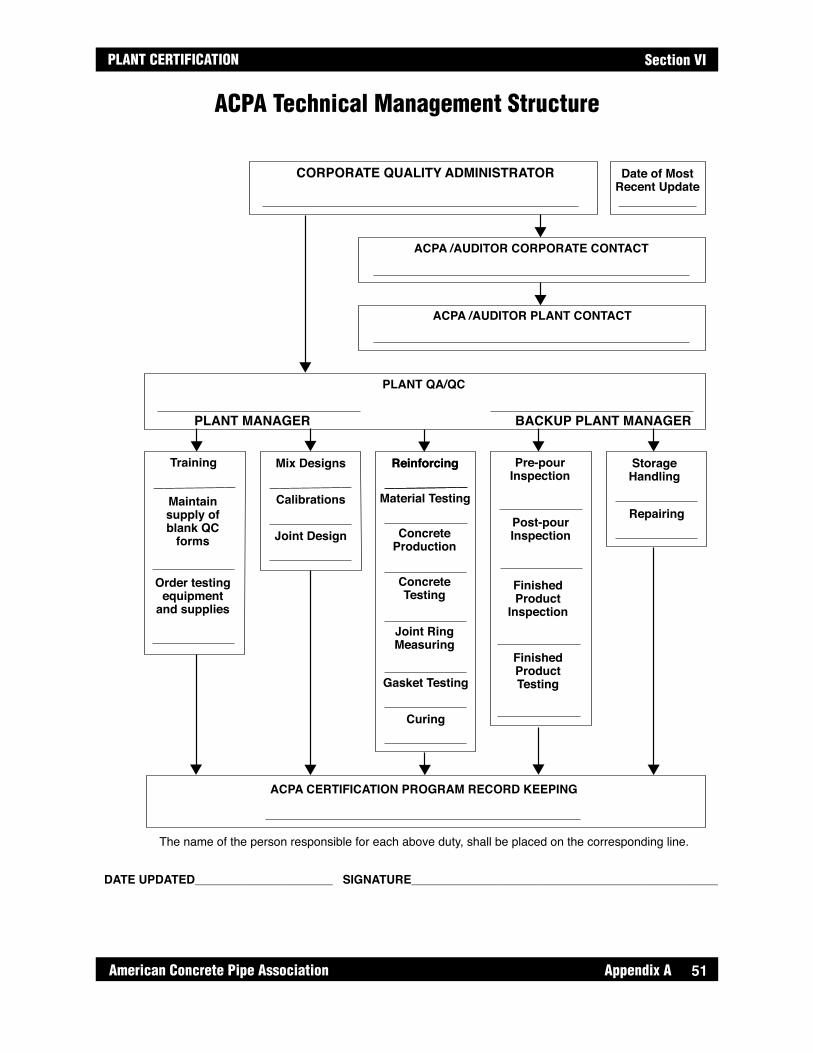
51
PLANT CERTIFICATION
American Concrete Pipe Association Appendix A
Section VI
ACPA Technical Management Structure
CORPORATE QUALITY ADMINISTRATOR
PLANT QA/QC
Training
Maintainsupply ofblank QC
forms
Order testingequipment
and supplies
Mix Designs
Calibrations
Reinforcing
Material Testing
Gasket Testing
Pre-pourInspection
Post-pourInspection
FinishedProduct
Inspection
FinishedProductTesting
StorageHandling
ACPA CERTIFICATION PROGRAM RECORD KEEPING
ACPA /AUDITOR CORPORATE CONTACT
ACPA /AUDITOR PLANT CONTACT
Joint Design
Reinforcing
ConcreteProduction
ConcreteTesting
Joint RingMeasuring
Curing
Repairing
Date of MostRecent Update
PLANT MANAGER BACKUP PLANT MANAGER
The name of the person responsible for each above duty, shall be placed on the corresponding line.
DATE UPDATED_____________________ SIGNATURE_____________________________________________________
51

Appendix A American Concrete Pipe Association52
PLANT CERTIFICATIONSection VI
In the batching of concrete, it is important to compensate for moisture present the aggregates that are used. All aggregates naturally hold a certain percentage of water inside of them, called their absorption. This water is unavailable to react with the cement in a mix. Aggregate particles that are internally saturated, but dry on the outside are referred to as saturated surface dry (SSD). Scale weights for a batch are seldom aggregate SSD weights, and are usually more or less depending on the actual moisture content of the aggregate. If the aggregate is not internally saturated, extra water shall be added to the batch. If there is excess moisture coming in with the aggregate, we shall take water out of the batch. This excess moisture is called Free Moisture, because it reacts in the mix. The Total Moisture of an aggregate can be found by the procedure outlined below, and if the material's absorption is known, the Free Moisture can be calculated from this test as well.
To Calculate % Moisture of Aggregates:
Gather a representative sample of all aggregates as a batch is being weighed up. Record weights and quantities of all ingredients from that same batch, using a copy of the batch printout if available.
Calculate the Total Moisture % using the following steps:
1. Samples shall be stored in a zip-Ioc bag or otherwise air tight container to prevent drying out before weighing. 2. The sample size shall be a minimum of 500 grams 3. Tare the scale so that it reads zero when an empty pan is placed on it, then add the aggregate sample and record weight of "wet" sample to nearest tenth (.1) of a gram. 4. Transfer sample to a different pan and place on a hot plate, making sure to get all the aggregate into the pan. 5. Completely dry the sample on the hot plate. When reweighing the sample, it shall be transferred into the pan on the scale, because the hot pan would damage the scale. 6. The sample is completely dry when successive weights 5 minutes apart agree within one tenth (.1) of a gram. Take care not to lose any of the sample.
Total Moisture is calculated as follows:
% Total Moisture - % absorption = % Free Moisture
Ex: 5.15% Total moisture - 1.45% absorption = 3.70% Free Moisture
Compensating for Aggregate Moisture
Ex: 510.0 - 485.0 x 100 = 5.15% Total Moisture 485.0
wet weight - dry weight x 100 = Total Moisture of sample dry weight
52

53
PLANT CERTIFICATION
American Concrete Pipe Association Appendix A
Section VI
To Confirm the Water/Cement Ratio of a Mix
Determine the Total Amount of water in the mix, including that due to aggregate moisture, by using the aggregate % moistures as calculated above and the amount of mix ingredients from the same batch.
Ex: There is 1478 pounds of an aggregate that has 3.70% Free Moisture, so:
*This can be a negative number if the Free Moisture % is less than zero
This calculation shall be done for all aggregate types in the mix. Other metered water or temper water added shall be converted to pounds. One gallon of water equals 8.33 pounds.
* Total cementitious includes Slag and Fly Ash if used in the mix
Batch Ticket Information
CementFly AshFine AggregateCoarse AggregateWater Added
Trim Water
488. lbs. 162. lbs.1800. lbs.1350. lbs. 134. lbs.
4. gal.
Sample Burn Information
Fine Agg wet weight: 517 gFine Agg dry weight: 494 g
Coarse Agg wet weight: 532 gCoarse Agg dry weight: 514 g
Fine Agg. % Total Moisture 517 - 494 494
x 100 = 4.66%
Coarse Agg. % Total Moisture532 - 514 514 x 100 = 3.50%
Absorption = 1.73%
Free Moisture = 4.66% - 1.73% = 2.93%
Absorption = 1.14%
Free Moisture = 3.50% - 1.14% = 2.36%
Water due to fine aggregate:
= 51.24 lbs. water
Water due to coarse aggregate:
1800 1800
1 + .0293
13501350
1 + . 0236= 31.13 lbs. water
Water added: = 134 lbs. water
Trim water:4 gallons x 8.33 = 33.32 lbs. water
Total Water = 249.69 lbs.
Total Cementitious = lbs. Cement + lbs. Fly Ash = 488 + 162 = 650 lbs.
W/C Ratio =Total lbs. Water 249.69
Total lbs. Cementitious 650== .384
Weight of batched aggregate - = water in aggregateWeight of batch aggregate1 + (%Free Moisture/100)
1478 - = pounds of water 1478 - 1425.27 = 52.73 pounds of water14781 + .037
Water/Cement Ratio = Total lbs. WaterTotal lbs. Cementitious
53

Appendix A American Concrete Pipe Association54
PLANT CERTIFICATIONSection VI
Pipe Joint Dimensions Dia. Type
Nom. Min. Max. Nom. Min. Max. Nom. Min. Max. Nom. Min. Max.
Gasket Recess Width (W) R d M (Diameter) N (Diameter)
GW
Hd
M D
ia.
S1
S3 S5
LA
B
K
A
B
K
F
GW
GW/2
T
T
X
d
Pipe
Dia
.M
Dia
.N
Dia
.
S1
StraightWall Pipe
S2S5
L
F
WWR
W/2
T
T
X
d
d
Pipe
Dia
.
M D
ia.
M D
ia.
N D
ia.
S1
S1
StraightWall Pipe
S2
S4S3
Single Offset Joint Detail
Single Offset Gasket Joint
Confined Gasket Recess Detail
Confined Gasket Joint
Notes:Supplier shall submit all information required by the above tables, unless a dimension shown in the tables is not applicable to the specific type of pipe joint furnished, in which case it shall be left blank. All dimensions shall be given in inches, unless otherwise noted.
American Concrete Pipe AssociationAdopted from the United States Department of the
Interior Bureau of Reclamation
Joint Data Form
Pipe Manufacturer
Specifications No
Date
Manufacturer Dwg No
Gasketed Pipe & Manhole Joint Data Form
SlopeDegrees
S1 S2 S3 S4 S5
Rubber Gasket F L T X A B K
Unstretched Diameter (D)
Nom.
% Stretch (S)
Design
Durometer
Nom.
SIngle Offset Gasket Width
(GW)
Nom.
Stretched Height of Single Offset
Gasket (H)
Nom.
54
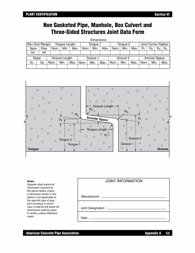
55
PLANT CERTIFICATION
American Concrete Pipe Association Appendix A
Section VI
JOINT INFORMATION
Joint Designation
Manufacturer
Date
DimensionsTongue Length Tongue 2 Joint Corner RadiusTongue 1
Groove 2 Annular SpaceGroove 1Groove LengthSlope
Box Size RangeSpan Rise Nom. Min. Max. Nom. Min. Max. Nom. Min. Max. R1 R2 R3 R4
Nom. Min. Max.Nom. Min. Max.Nom. Min. Max.Nom. Min.S1 S2 Max.
NA NA
S2
R2
R4
R1
R3
Tongue 2
Tongue
Tongue 1
Groove 2
Groove
Groove 1
Tongue Length
Groove Length
Annular Space S1
Non Gasketed Pipe, Manhole, Box Culvert and Three-Sided Structures Joint Data Form
Notes:Supplier shall submit all information required by the above tables, unless a dimension shown in the tables is not applicable to the specific type of pipe joint furnished, in which case it shall be left blank. All dimensions shall be given in inches, unless otherwise noted.
55

Appendix A American Concrete Pipe Association56
PLANT CERTIFICATIONSection VI
Joint Design - Sanitary Sewer Pipe OnlyAdequate gasket compression is critical to concrete pipe joint performance. The following discussion describes the requirements and rationale to be used in calculating gasket compression.
NOTATION - See Drawing Appendix A, page 58 thru page 61.
Annular Space – The distance between the spigot and bell when the completed joint is on a centered position.
DGP- Design gasket pack.
d- Design depth of gasket recess.
Design dimensions- Theoretical joint dimensions.
DGRA- Design gasket recess area.
DGRV- Design gasket recess volume.
DGV- Design gasket volume.
DSGA- Design stretched gasket area of a circular gasket.
DSGD- Design stretched gasket diameter of a circular gasket.
Ellipticity- Difference in maximum or minimum diameters and the design diameter of the joint or the joint forming equipment.
GW- Width of single offset gasket.
M- Design joint diameter at base of the gasket recess.
MnGC- Minimum gasket compression.
MxGC- Maximum gasket compression.
N- Design joint diameter of the groove at center of gasket contact area.
Nominal dimensions- Theoretical joint dimensions, used in the same context as design dimensions.
Profile Gasket- Gasket with non-circular cross section.
Single Offset Joint- Joint with gasket positioned in a notch shaped recess at the end of the spigot and seated against the inside of the bell.
S- Stretch in gasket in the installed position, in percent.
S1- Slope of spigot sealing surface, in degrees.
S2- Slope of bell sealing surface, in degrees.
S3 and S4- Side slopes of gasket recess, in degrees.
56
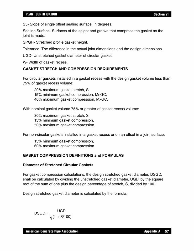
57
PLANT CERTIFICATION
American Concrete Pipe Association Appendix A
Section VI
S5- Slope of single offset sealing surface, in degrees.
Sealing Surface- Surfaces of the spigot and groove that compress the gasket as the joint is made.
SPGH- Stretched profile gasket height.
Tolerance- The difference in the actual joint dimensions and the design dimensions.
UGD- Unstretched gasket diameter of circular gasket.
W- Width of gasket recess.
GASKET STRETCH AND COMPRESSION REQUIREMENTS
For circular gaskets installed in a gasket recess with the design gasket volume less than 75% of gasket recess volume:
20% maximum gasket stretch, S 15% minimum gasket compression, MnGC, 40% maximum gasket compression, MxGC.
With nominal gasket volume 75% or greater of gasket recess volume:
30% maximum gasket stretch, S 15% minimum gasket compression, 50% maximum gasket compression.
For non-circular gaskets installed in a gasket recess or on an offset in a joint surface:
15% minimum gasket compression, 60% maximum gasket compression.
GASKET COMPRESSION DEFINITIONS and FORMULAS
Diameter of Stretched Circular Gaskets
For gasket compression calculations, the design stretched gasket diameter, DSGD, shall be calculated by dividing the unstretched gasket diameter, UGD, by the square root of the sum of one plus the design percentage of stretch, S, divided by 100.
Design stretched gasket diameter is calculated by the formula:
DSGD =(1 + S/100)
UGD

Appendix A American Concrete Pipe Association58
PLANT CERTIFICATIONSection VI
Design Gasket Pack
When evaluating gasket compression limits for confined circular gaskets, the design gasket volume, DGV, is compared to the design gasket recess volume, DGRV, This comparison is called the design gasket pack, DGP. The gasket recess volume is calculated using design values with the spigot located concentrically within the groove. Because the length of the stretched gasket and the gasket recess of the joint is identical, only the design stretched gasket area, DSGA, and designed gasket recess area, DGRA, need be compared for this calculation.
Design stretched gasket cross-sectional area, DSGA, is calculated by the formula:
The design gasket recess area, DGRA, is calculated by taking the design recess depth, d, at the midpoint of the gasket recess plus the design annular space times the recess width, W. Design gasket recess area is calculated using nomenclature found on the Joint Data Form illustration and the following formula:
* To simplify this calculation, the area outside the radii at the base of the gasket recess is not excluded from the gasket recess area.
DGP = DSGADGRA x 100%
DSGA = ≠4 x (DSGD)2
N
W/2W
M
d
S3 S4
S2S1
Design Gasket Recess Area
DGRA* = - - d22N M W - +2
d2 tanS32
(d - W tanS1)2 tanS4
58

59
PLANT CERTIFICATION
American Concrete Pipe Association Appendix A
Section VI
Maximum Gasket Compression
Maximum gasket compression, MxGC, occurs at a point where the outer surface of the spigot contacts the inner surface of the bell. The nominal depth of the gasket recess, d, shall be reduced by the tolerance for manufacturing and positioning the gasket recess formers or the shape and position of a ground recess. Maximum gasket compression shall be determined at the center of the gasket recess or for a single offset joint, the center of the gasket.
Maximum gasket compression, in percent, can be calculated using the following formulas:
Confined Circular Gasket Joint:
Concrete to Concrete Contact
W
d min. S2
Maximum Gasket Compression in a Confined Gasket Joint
MxGC = 2d min - W tan S21
1 - x 100%DSGD
59

Appendix A American Concrete Pipe Association60
PLANT CERTIFICATIONSection VI
Single Offset Gasket Joint:
Minimum Gasket Compression
Minimum gasket compression, MnGC, is determined when the maximum diameter of the inside surface of the bell, and minimum diameter of the gasket recess occur at the same location that is opposite a point where the bell and spigot are in contact. The maximum bell diameter shall be calculated by adding the tolerance in fabricating joint formers, and the added ellipticity caused by repeated use of the formers, to the nominal inside diameter of the bell. The minimum diameter of the base of the gasket recess shall be calculated by subtracting the tolerance in fabricating the joint formers and gasket recess formers, the negative value of added ellipticity caused by repeated use of the formers, and the maximum depth of the gasket recess from the nominal spigot diameter.
Minimum gasket compression, MnGC, in percent, can be calculated using the following formulas:
Concrete toConcrete
Contact
GW
d min. S2S1
S5
Maximum Gasket Compressionin a Single Offset Gasket Joint
dmin GW tan(S2)+ GW tan(S5)1- 100SPGH
21
21
MxGCParallel =Dmin1- 100
SPGHMxGC =
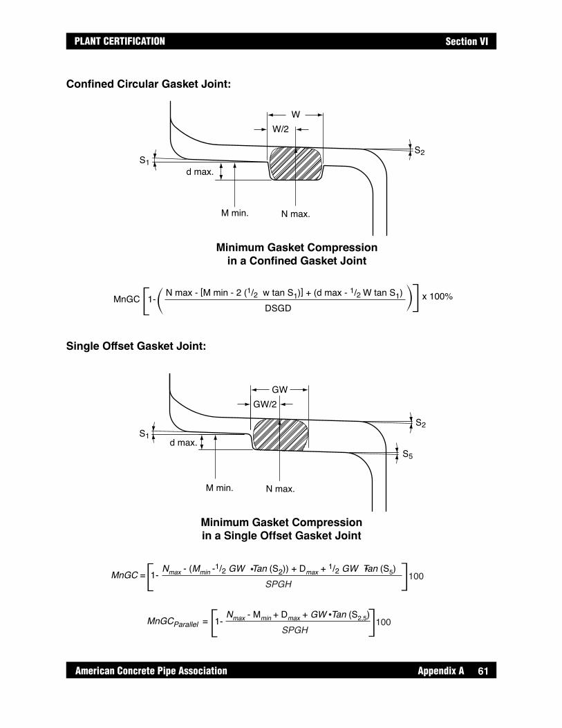
61
PLANT CERTIFICATION
American Concrete Pipe Association Appendix A
Section VI
Confined Circular Gasket Joint:
Single Offset Gasket Joint:
W/2W
M min. N max.
d max.S1
S2
Minimum Gasket Compressionin a Confined Gasket Joint
MnGC 1-N max - [M min - 2 (1/2 w tan S1)] + (d max - 1/2 W tan S1)
DSGDx 100%
GW/2GW
M min. N max.
d max.S1
S2
S5
Minimum Gasket Compressionin a Single Offset Gasket Joint
MnGC = 1- Nmax - (Mmin -1/2 GW Tan (S2)) + Dmax + 1/2 GW Tan (S5)SPGH
100
MnGCParallel = Nmax - Mmin + Dmax + GW Tan (S2,5)SPGH
1001-
61
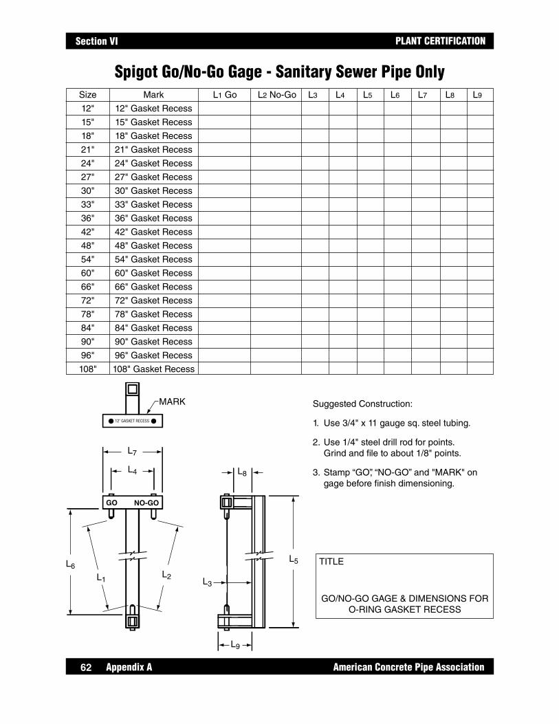
Appendix A American Concrete Pipe Association62
PLANT CERTIFICATIONSection VI
Spigot Go/No-Go Gage - Sanitary Sewer Pipe Only Size Mark L1 Go L2 No-Go L3 L4 L5 L6 L7 L8 L9
12" 12" Gasket Recess
15" 15" Gasket Recess
18" 18" Gasket Recess
21" 21" Gasket Recess
24" 24" Gasket Recess
27" 27" Gasket Recess
30" 30" Gasket Recess
33" 33" Gasket Recess
36" 36" Gasket Recess
42" 42" Gasket Recess
48" 48" Gasket Recess
54" 54" Gasket Recess
60" 60" Gasket Recess
66" 66" Gasket Recess
72" 72" Gasket Recess
78" 78" Gasket Recess
84" 84" Gasket Recess
90" 90" Gasket Recess
96" 96" Gasket Recess
108" 108" Gasket Recess
Suggested Construction:
1. Use 3/4" x 11 gauge sq. steel tubing.
2. Use 1/4" steel drill rod for points. Grind and file to about 1/8" points.
3. Stamp “GO”, “NO-GO” and "MARK" on gage before finish dimensioning.
TITLE
GO/NO-GO GAGE & DIMENSIONS FOR O-RING GASKET RECESS
GO
MARK
12" GASKET RECESS
NO-GO
L7
L8
L5
L3L2L1
L6
L9
L4
62

63
PLANT CERTIFICATION
American Concrete Pipe Association Appendix A
Section VI
A gasket report shall be filled out for each gasket inspected. The report shall include all required dimensions and the manufacturers printing on gaskets. A reference sheet showing allowable gasket tolerances shall also be available to compare to test results.
Height and Width of Pre-lubricated and Profile GasketsMeasure the height and width on either side of gasket splice staying outside the area affected by the splice die. Record the average of both dimensions.
Cord Diameter – Circular Cross-sectionsMeasure the cord diameter at 0° and 90° on both sides of the gasket splice taking care to measure beyond the area affected by the splice die. The cord diameter is an average of these four readings.
Gasket LengthConstruct a flat, straight calibrated measuring scale such as a measuring tape attached to a table or the floor. Make an index mark on the gasket cross-section. Place the gasket index mark at the zero point of the measuring scale and carefully roll the uncut gasket loop along the measuring scale without slipping or stretching. The gasket length is the distance measured at the point where the index mark retouches the scale.
Gasket DurometerMeasure gasket material hardness using a durometer according to ASTM D 2240.Measure hardness on both sides of the splice staying outside the area affected by the splice die. The hardness is the average of these two readings.
Splice StrengthPlace two index marks 2 inches apart, 1" either side of gasket splice. Apply an axial force until the marks are 4" apart. While stretched, the gasket shall be visually inspected for tears, cracks or separation.
Gasket Volume (non pre-lubricated)Determine the weight of the gasket in grams by weighing it on a gram scale to the nearest gram. Next determine the weight of same gasket by weighing it totally immersed in water. A surfactant shall be added to the water to thoroughly wet the gasket surface and prevent air bubbles from clinging to the gasket. The difference in the dry weight and the immersed weight, measured in grams, is the volume of the gasket in cubic centimeters.As an alternate to the above, the gasket may be placed in a water tank and the volume of water displaced recorded. The displaced volume of water may be measured directly in cubic centimeters by pouring into a calibrated tube, or it may be weighed. One gram of water equals one cubic centimeter.
Gasket Testing Procedures (ASTM C497)
63

Appendix A American Concrete Pipe Association64
PLANT CERTIFICATIONSection VI
Gasket Test Report
Company/Location:
PO # Vendor Order # Vender BOL#
Date Shipped: Quantities Shipped:
Size
(in)
Vendor Job # Dia
O-Ring
(in)
Volume
(cm3)
Splice
(Go-
No-Go)
Cut
Length
(in)
Duro-
meter
Height
(in)
Width
(in)
Gasket ASTM Standard: C443 C361
Signature:
Date:
64

65
PLANT CERTIFICATION
American Concrete Pipe Association Appendix A
Section VI
Header, Pallet and Truing-Ring Inspection FormIncoming Inspection No.
Vendor Item
Order No. Qty. Order Qty. Inspected
Date Received Date Inspected
Drawing No's.
Page Cont. on Page
Signed
65
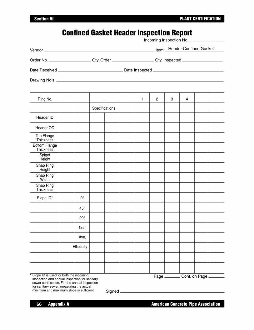
Appendix A American Concrete Pipe Association66
PLANT CERTIFICATIONSection VI
Ring No. 1 2 3 4
Specifications
Header ID
Header OD
Top Flange Thickness Bottom Flange Thickness Spigot Height
Snap Ring Height Snap Ring Width Snap Ring Thickness
Slope ID* 0°
45°
90°
135°
Ave.
Ellipticity
Confined Gasket Header Inspection ReportIncoming Inspection No.
Vendor Item
Order No. Qty. Order Qty. Inspected
Date Received Date Inspected
Drawing No's.
Page Cont. on Page
Signed
* Slope ID is used for both the incoming inspection and annual inspection for sanitary sewer certification. For the annual inspection for sanitary sewer, measuring the actual minimum and maximum slope is sufficient.
Header-Confined Gasket
66

67
PLANT CERTIFICATION
American Concrete Pipe Association Appendix A
Section VI
Header Inspection Drawing
Incoming inspection shall include all inspection locations.
* Annual inspections for Sanitary Sewer Tested Pipe and Sanitary Sewer Manhole certification need only include slope ID inspection for confined gasket header or gasket sealing surface slope ID for single offset header.
Top FlangeThickness
ID
OD
Width
Bottom FlangeThickness
Thickness
SpigotLength
Snap RingHeightReference
Height forSlope ID
Measurement
Top FlangeThickness
ID
OD
Bottom FlangeThickness
*Gasket SealingSurface Slope ID
Annular Space Slope IDSpigotLength
OffsetHeight
ReferenceHeight forSlope ID
Measurement
ReferenceHeight forSlope ID
Measurement
Confined Gasket
Snap Ring
Single - Offset
67

Appendix A American Concrete Pipe Association68
PLANT CERTIFICATIONSection VI
Page Cont. on Page
Signed
Pallet Inspection ReportIncoming Inspection No.
Vendor Item
Order No. Qty. Order Qty. Inspected
Date Received Date Inspected
Drawing No's.
* Slope OD is used for the both incoming inspection and annual inspection for sanitary sewer certification. For the annual inspection for sanitary sewer, measuring the actual minimum and maximum slope is sufficient.
Pallet
Ring No. 1 2 3 4
Specifications
Pallet ID
Pallet OD
Top Flange Thickness Bottom Flange Thickness Pallet Height
Leg. Location
Slope OD* 0°
45°
90°
135°
Ave.
Ellipticity
68

69
PLANT CERTIFICATION
American Concrete Pipe Association Appendix A
Section VI
Pallet Inspection Location
Incoming inspection shall include all inspection locations.
* Annual inspections for Sanitary Sewer Pipe and Sanitary Sewer Manhole certification need only include slope OD inspection.
Top FlangeThickness
ID
OD
PalletHeight
Leg Location
Bottom FlangeThickness
*Slope OD
ReferenceHeight forSlope OD
Measurement
69
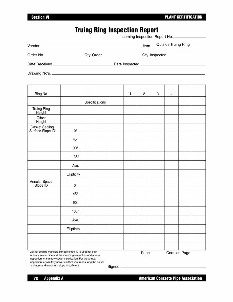
Appendix A American Concrete Pipe Association70
PLANT CERTIFICATIONSection VI
Truing Ring Inspection ReportIncoming Inspection Report No.
Vendor Item
Order No. Qty. Order Qty. Inspected
Date Received Date Inspected
Drawing No's.
Page Cont. on Page
Signed
* Gasket sealing manhole surface slope ID is used for both sanitary sewer pipe and the incoming inspection and annual inspection for sanitary sewer certification. For the annual inspection for sanitary sewer certification, measuring the actual minimum and maximum slope is sufficient.
Outside Truing Ring
Ring No. 1 2 3 4
Specifications
Truing Ring Height Offset Height Gasket Sealing Surface Slope ID* 0°
45°
90°
135°
Ave.
Ellipticity
Annular Space Slope ID 0°
45°
90°
135°
Ave.
Ellipticity
70
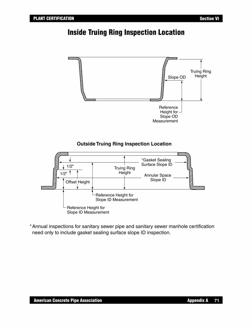
71
PLANT CERTIFICATION
American Concrete Pipe Association Appendix A
Section VI
Slope OD
*Gasket Sealing Surface Slope ID
Annular Space Slope ID
Reference Height forSlope ID Measurement
Reference Height forSlope ID Measurement
Truing RingHeight
Offset Height
1/2"
1/2"
Truing RingHeight
ReferenceHeight forSlope OD
Measurement
Inside Truing Ring Inspection Location
Outside Truing Ring Inspection Location
* Annual inspections for sanitary sewer pipe and sanitary sewer manhole certification need only to include gasket sealing surface slope ID inspection.
Inside Truing Ring Inspection Location
71
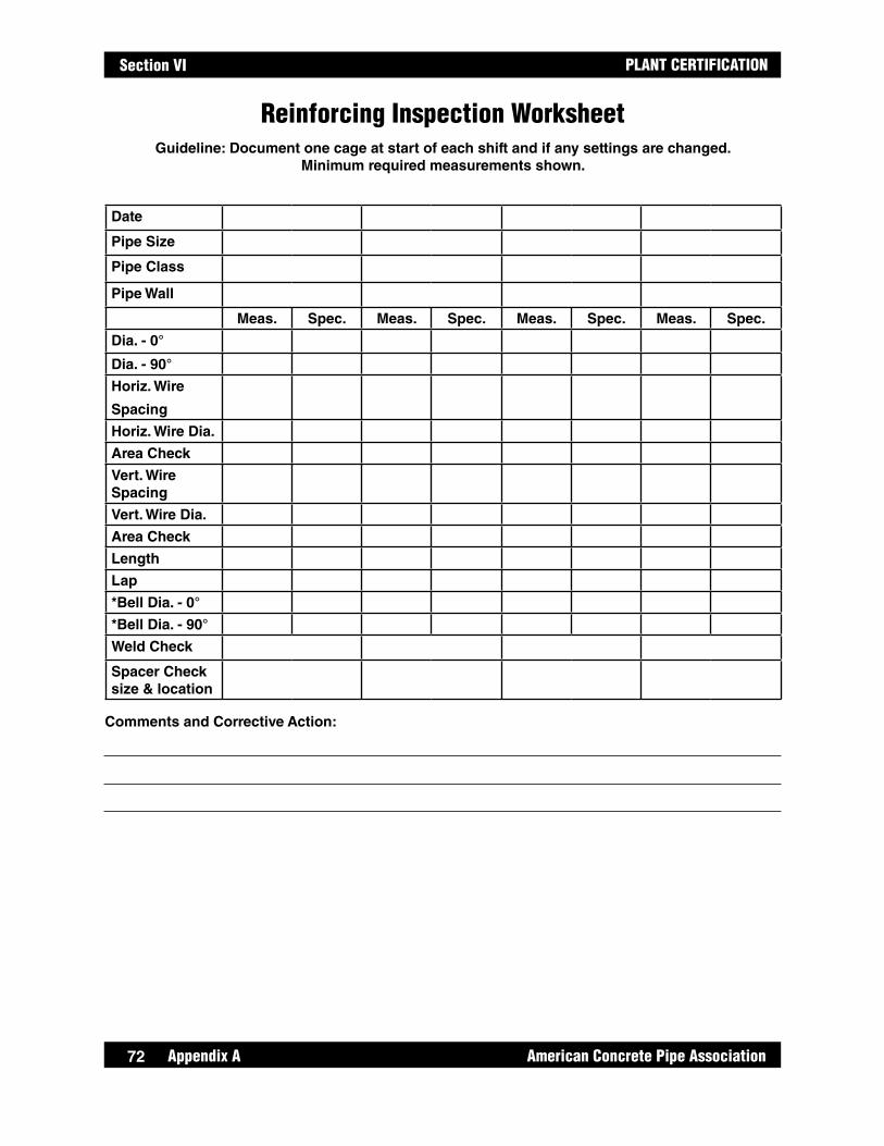
Appendix A American Concrete Pipe Association72
PLANT CERTIFICATIONSection VI
Reinforcing Inspection WorksheetGuideline: Document one cage at start of each shift and if any settings are changed.
Minimum required measurements shown.
Date
Pipe Size
Pipe Class
Pipe Wall
Meas. Spec. Meas. Spec. Meas. Spec. Meas. Spec.
Dia. - 0°
Dia. - 90°
Horiz. Wire
Spacing
Horiz. Wire Dia.
Area Check
Vert. Wire Spacing
Vert. Wire Dia.
Area Check
Length
Lap
*Bell Dia. - 0°
*Bell Dia. - 90°
Weld Check
Spacer Check size & location
Comments and Corrective Action:
72
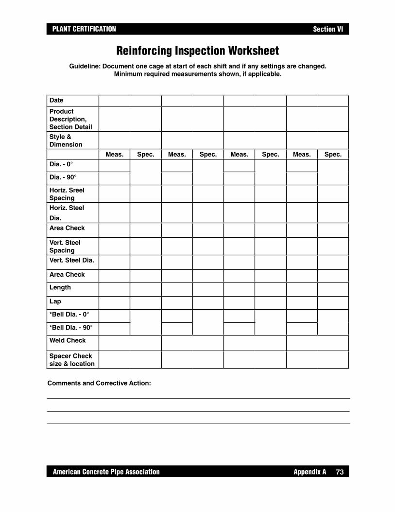
73
PLANT CERTIFICATION
American Concrete Pipe Association Appendix A
Section VI
Reinforcing Inspection WorksheetGuideline: Document one cage at start of each shift and if any settings are changed.
Minimum required measurements shown, if applicable.
Date
Product Description, Section Detail
Style & Dimension
Meas. Spec. Meas. Spec. Meas. Spec. Meas. Spec.
Dia. - 0°
Dia. - 90°
Horiz. Sreel Spacing
Horiz. Steel
Dia.
Area Check
Vert. Steel Spacing
Vert. Steel Dia.
Area Check
Length
Lap
*Bell Dia. - 0°
*Bell Dia. - 90°
Weld Check
Spacer Check size & location
Comments and Corrective Action:
73
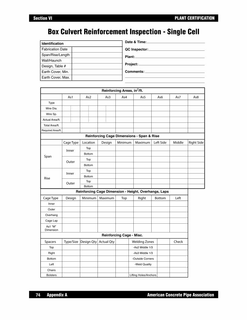
Appendix A American Concrete Pipe Association74
PLANT CERTIFICATIONSection VI
Box Culvert Reinforcement Inspection - Single Cell
Reinforcing Areas, in2/ft.
IdentificationFabrication DateSpan/Rise/LengthWall/HaunchDesign, Table #Earth Cover, Min.Earth Cover, Max.
Date & Time:
QC Inspector:
Plant:
Project:
Comments:
As1 As2 As3 As4 As5 As6 As7 As8
Reinforcing Cage Dimensions - Span & Rise
Cage Type Location Design Minimum Maximum Left Side Middle Right Side
Top
Bottom
Top
Bottom
Top
BottomTop
Bottom
Inner
Outer
Inner
Outer
Span
Rise
Type
Wire Dia.
Wire Sp.
Actual Area/ft.
Total Area/ft.Required Area/ft.
Reinforcing Cage Dimension - Height, Overhangs, Laps
Inner
Outer
Overhang
Cage Lap
As1 “M” Dimension
Cage Type Design Minimum Maximum Top Right Bottom Left
Reinforcing Cage - Misc.
Top
Right
Bottom
Left
ChairsBolsters
Spacers Type/Size Design Qty Actual Qty Welding Zones Check
-As2 Middle 1/3
-As3 Middle 1/3
-Outside Corners
-Weld Quality
Lifting Holes/Anchors
74
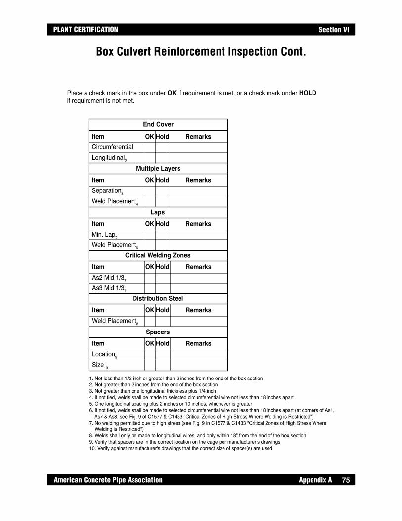
75
PLANT CERTIFICATION
American Concrete Pipe Association Appendix A
Section VI
Box Culvert Reinforcement Inspection Cont.
End Cover
ItemCircumferential1Longitudinal2
OK Hold Remarks
Multiple LayersItemSeparation3
Weld Placement4
OK Hold Remarks
LapsItemMin. Lap5
Weld Placement6
OK Hold Remarks
Critical Welding ZonesItemAs2 Mid 1/37
As3 Mid 1/37
OK Hold Remarks
Distribution SteelItemWeld Placement8
OK Hold Remarks
SpacersItemLocation9
Size10
OK Hold Remarks
Place a check mark in the box under OK if requirement is met, or a check mark under HOLD if requirement is not met.
1. Not less than 1/2 inch or greater than 2 inches from the end of the box section2. Not greater than 2 inches from the end of the box section3. Not greater than one longitudinal thickness plus 1/4 inch4. If not tied, welds shall be made to selected circumferential wire not less than 18 inches apart5. One longitudinal spacing plus 2 inches or 10 inches, whichever is greater6. If not tied, welds shall be made to selected circumferential wire not less than 18 inches apart (at corners of As1, As7 & As8, see Fig. 9 of C1577 & C1433 "Critical Zones of High Stress Where Welding is Restricted")7. No welding permitted due to high stress (see Fig. 9 in C1577 & C1433 "Critical Zones of High Stress Where Welding is Restricted")8. Welds shall only be made to longitudinal wires, and only within 18" from the end of the box section9. Verify that spacers are in the correct location on the cage per manufacturer's drawings10. Verify against manufacturer's drawings that the correct size of spacer(s) are used
75

Appendix A American Concrete Pipe Association76
PLANT CERTIFICATIONSection VI
Box Culvert Reinforcement Inspection - Double Cell
Circumferential and Longitudinal Reinforcing Areas, in2/ft.
IdentificationFabrication DateSpanRiseDesign, Table #Earth Cover, Min.Earth Cover, Max.
Date:
Inspector:
Comments:
MarkAs1As2As3As4As5As6As7As8As9As10
InsertsSpacers
*Lap
N/AN/AN/AN/AN/AN/AN/AN/AN/AN/AN/AN/A
N/AN/AN/A
N/AN/AN/A
Required Used Mesh Style
*Where reinforcing cages are overlapped, lap splices for WWR must equal 1 longitudinal wire spacing plus 2 in. and greater than or equal to 10 in.**M only applies as a design option for boxes with a fill height of 2 ft. and great.
Length “L” “M”**
As9As7As2As1
Span
Rise
Distribution SteelAs6As5
“M”
As4As3As8As9
Reinforcing Placement
As10 As4
Distribution SteelAs6As5
Top Slab
76
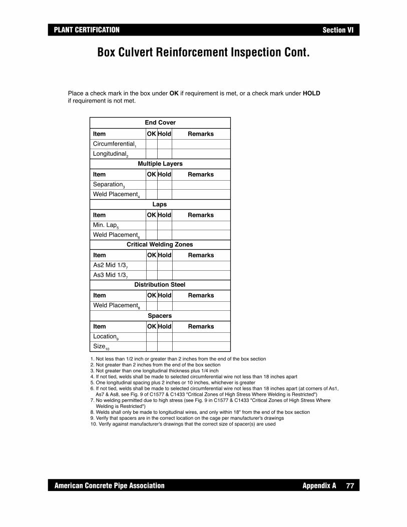
77
PLANT CERTIFICATION
American Concrete Pipe Association Appendix A
Section VI
Box Culvert Reinforcement Inspection Cont.
End Cover
ItemCircumferential1Longitudinal2
OK Hold Remarks
Multiple LayersItemSeparation3
Weld Placement4
OK Hold Remarks
LapsItemMin. Lap5
Weld Placement6
OK Hold Remarks
Critical Welding ZonesItemAs2 Mid 1/37
As3 Mid 1/37
OK Hold Remarks
Distribution SteelItemWeld Placement8
OK Hold Remarks
SpacersItemLocation9
Size10
OK Hold Remarks
Place a check mark in the box under OK if requirement is met, or a check mark under HOLD if requirement is not met.
1. Not less than 1/2 inch or greater than 2 inches from the end of the box section2. Not greater than 2 inches from the end of the box section3. Not greater than one longitudinal thickness plus 1/4 inch4. If not tied, welds shall be made to selected circumferential wire not less than 18 inches apart5. One longitudinal spacing plus 2 inches or 10 inches, whichever is greater6. If not tied, welds shall be made to selected circumferential wire not less than 18 inches apart (at corners of As1, As7 & As8, see Fig. 9 of C1577 & C1433 "Critical Zones of High Stress Where Welding is Restricted")7. No welding permitted due to high stress (see Fig. 9 in C1577 & C1433 "Critical Zones of High Stress Where Welding is Restricted")8. Welds shall only be made to longitudinal wires, and only within 18" from the end of the box section9. Verify that spacers are in the correct location on the cage per manufacturer's drawings10. Verify against manufacturer's drawings that the correct size of spacer(s) are used
77

Appendix A American Concrete Pipe Association78
PLANT CERTIFICATIONSection VI
Three-sided Structure - Flat Deck Reinforcement Inspection
Circumferential Reinforcing Areas, in2/ft.
IdentificationDate CastSpanRiseEarth Cover, Min.Earth Cover, Max.
Date:
Inspector:
Comments:
MarkAs1As2As3As4As5As6As7As8
InsertsSpacers
Required Used Mesh Style Length “L”
N/AN/A
N/AN/A
As3
78
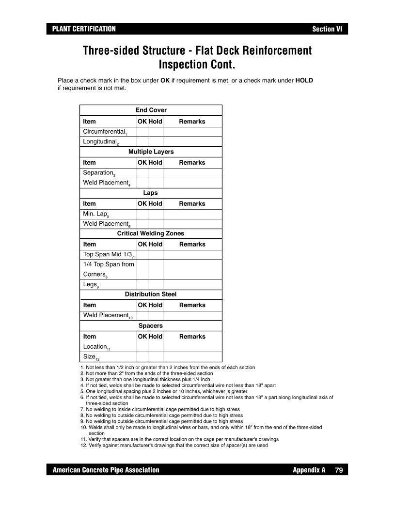
79
PLANT CERTIFICATION
American Concrete Pipe Association Appendix A
Section VI
End Cover
ItemCircumferential1Longitudinal2
OK Hold Remarks
Multiple LayersItemSeparation3
Weld Placement4
OK Hold Remarks
LapsItemMin. Lap5
Weld Placement6
OK Hold Remarks
Critical Welding ZonesItemTop Span Mid 1/37
1/4 Top Span fromCorners8
Legs9
OK Hold Remarks
Distribution SteelItemWeld Placement10
OK Hold Remarks
SpacersItemLocation11
Size12
OK Hold Remarks
Place a check mark in the box under OK if requirement is met, or a check mark under HOLD if requirement is not met.
1. Not less than 1/2 inch or greater than 2 inches from the ends of each section2. Not more than 2" from the ends of the three-sided section3. Not greater than one longitudinal thickness plus 1/4 inch4. If not tied, welds shall be made to selected circumferential wire not less than 18" apart5. One longitudinal spacing plus 2 inches or 10 inches, whichever is greater6. If not tied, welds shall be made to selected circumferential wire not less than 18" a part along longitudinal axis of three-sided section7. No welding to inside circumferential cage permitted due to high stress8. No welding to outside circumferential cage permitted due to high stress 9. No welding to outside circumferential cage permitted due to high stress 10. Welds shall only be made to longitudinal wires or bars, and only within 18" from the end of the three-sided section11. Verify that spacers are in the correct location on the cage per manufacturer's drawings12. Verify against manufacturer's drawings that the correct size of spacer(s) are used
Three-sided Structure - Flat Deck Reinforcement Inspection Cont.
79

Appendix A American Concrete Pipe Association80
PLANT CERTIFICATIONSection VI
Three-sided Structure - Arch Deck Reinforcement Inspection
Circumferential Reinforcing Areas, in2/ft.
IdentificationDate CastSpanRiseEarth Cover, Min.Earth Cover, Max.
Date:
Inspector:
Comments:
MarkAs1As2As3As4As5As6As7As8
InsertsSpacers
Required Used Mesh Style Length “L”
N/AN/A
N/AN/A

81
PLANT CERTIFICATION
American Concrete Pipe Association Appendix A
Section VI
End Cover
ItemCircumferential1Longitudinal2
OK Hold Remarks
Multiple LayersItemSeparation3
Weld Placement4
OK Hold Remarks
LapsItemMin. Lap5
Weld Placement6
OK Hold Remarks
Critical Welding ZonesItemTop Span Mid 1/37
1/4 Top Span fromCorners8
Legs9
OK Hold Remarks
Distribution SteelItemWeld Placement10
OK Hold Remarks
SpacersItemLocation11
Size12
OK Hold Remarks
Place a check mark in the box under OK if requirement is met, or a check mark under HOLD if requirement is not met.
1. Not less than 1/2 inch or greater than 2 inches from the ends of each section2. Not more than 2" from the ends of the three-sided section3. Not greater than one longitudinal thickness plus 1/4 inch4. If not tied, welds shall be made to selected circumferential wire not less than 18" apart5. One longitudinal spacing plus 2 inches or 10 inches, whichever is greater6. If not tied, welds shall be made to selected circumferential wire not less than 18" a part along longitudinal axis of three-sided section7. No welding to inside circumferential cage permitted due to high stress8. No welding to outside circumferential cage permitted due to high stress 9. No welding to outside circumferential cage permitted due to high stress 10. Welds shall only be made to longitudinal wires or bars, and only within 18" from the end of the three-sided section11. Verify that spacers are in the correct location on the cage per manufacturer's drawings12. Verify against manufacturer's drawings that the correct size of spacer(s) are used
Three-sided Structure - Arch Deck Reinforcement Inspection Cont.

Appendix A American Concrete Pipe Association82
PLANT CERTIFICATIONSection VI
Box Culvert Form Pre-Pour/In-Process Pour Inspection - Single Cell
Form Dimensional Inspection****
**** Required at initial set-up for each production run only.
IdentificationDate CastSpanRiseDesign, Table #Earth Cover, Min.Earth Cover, Max.
LocationTt
Tb
Ts1
Ts2
D1
D2
CovertCover
Haunch Size, HSpanRise
Required Measured
Visual Inspection*
ItemCage OrientationForm ReleaseEmbedded ItemsForm CleanlinessReinforcing Cover*Initial Appropriate Box
OK
Date:
Inspector:
Hold
Concrete InspectionItemSlumpEntrained Air**TemperatureUnit WeightSpecified Design Strength
** If additional tests are taken, they shall be recorded on aseparate sheet referencing the respective product information.
MeasuredSpec.
N/A
Remarks
Tt, Top SlabThickness
Cover-Typical(Except Top Slab)
Covert, (Outside Top Slab)
Cage Orientation(Top Slab Reinforcing
Shall Be Located InThe Top Slab)
Tb, Bottom SlabThickness
Ts2, Side WallThickness
Ts1, Side WallThickness
H
HCore Diagonal - D
1
Core Diagonal - D2 ***
Top View Of Box Form(Ready To Pour)
*** Measure in center of haunch ± 1"
82

83
PLANT CERTIFICATION
American Concrete Pipe Association Appendix A
Section VI
Box Culvert Form Pre-Pour/In-Process Pour Inspection - Double Cell
Form Dimensional Inspection****Visual Inspection*
IdentificationDate CastSpanRiseDesign, Table #Earth Cover, Min.Earth Cover, Max.
ItemCage OrientationForm ReleaseEmbedded ItemsForm CleanlinessReinforcing Cover*Initial Appropriate Box
OK
Date:
Inspector:
Hold
Concrete Inspection
ItemSlumpEntrained Air**TemperatureUnit WeightSpecified Design Strength
** If additional tests are taken, they shall be recorded on aseparate sheet referencing the respective product information.
MeasuredSpec.
LocationTt
Tb
Ts1
Ts2
Ts3
D1
D2
D3
D4
CovertCover
Haunch Size, HSpanRise
Required MeasuredRemarks
Tt, Top SlabThickness
Cover-Typical(Except Top Slab)
*** Measure in center of haunch ± 1"
Covert, (Outside Top Slab)Cage Orientation (Top Slab ReinforcingShall Be Located In The Top Slab)
Tb, Bottom SlabThickness
Ts2, Side WallThickness
Ts1, Side WallThickness
H
HCore Diagonal - D
1***
Core Diagonal - D2
Core Diagonal - D3**
*
Core Diagonal - D4
Top View Of Box Form(Ready To Pour)
Ts3, Side WallThickness
**** Required at initial set-up for each production run only.
NA
83

Appendix A American Concrete Pipe Association84
PLANT CERTIFICATIONSection VI
Three-sided Structure - Flat Deck Pre-Pour/Pour Inspection
Form Dimensional Inspection**** Visual Inspection*
IdentificationDate CastSpanRiseEarth Cover, Min.Earth Cover, Max.
ItemCage OrientationForm ReleaseEmbedded ItemsForm CleanlinessReinforcing Cover*Initial Appropriate Box
OK
Date:
Inspector:
Hold
Concrete Inspection
ItemSlumpEntrained Air**TemperatureUnit WeightSpecified Design Strength
** If additional tests are taken, they shall be recorded on aseparate sheet referencing the respective product information.
MeasuredSpec.
LocationTopt
Ts1
Ts2
H1s1
H2s1
H1s2
H2s2
Hs1
Hs2
Wt
Wb
Cover
Span
Rise
Required Measured
**** Required at initial set-up for each production run only.
NA
84
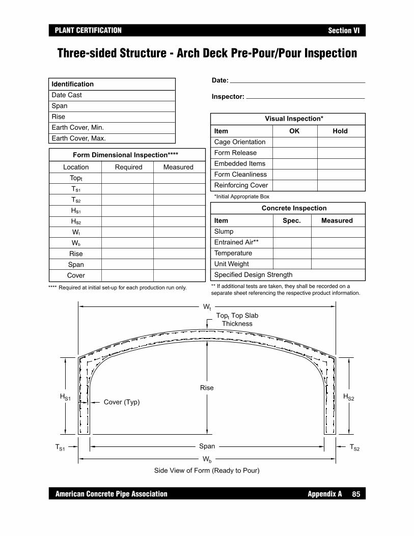
85
PLANT CERTIFICATION
American Concrete Pipe Association Appendix A
Section VI
Three-sided Structure - Arch Deck Pre-Pour/Pour Inspection
Form Dimensional Inspection****
Visual Inspection*
Identification
Date CastSpanRiseEarth Cover, Min.Earth Cover, Max.
ItemCage OrientationForm ReleaseEmbedded ItemsForm CleanlinessReinforcing Cover*Initial Appropriate Box
OK
Date:
Inspector:
Hold
Concrete Inspection
ItemSlumpEntrained Air**TemperatureUnit WeightSpecified Design Strength
** If additional tests are taken, they shall be recorded on aseparate sheet referencing the respective product information.
MeasuredSpec.
LocationTopt
Ts1
Ts2
Hs1
Hs2
Wt
Wb
Rise
Span
Cover
Required Measured
**** Required at initial set-up for each production run only.
85

Appendix A American Concrete Pipe Association86
PLANT CERTIFICATIONSection VI
Entrained Air and Slump/Flow Report
Product Air Date Air Content Slump/Flow Temp. Description Added/Batch Entraining T20 VSI
Mix Information PSI
Target Mix Design: Cement lbs Pozzolan lbs 3/4 Rock lbs Sand lbs Super oz/cwt Air Entraining oz/cwt Water Reducer oz/cwtMonth Year
86
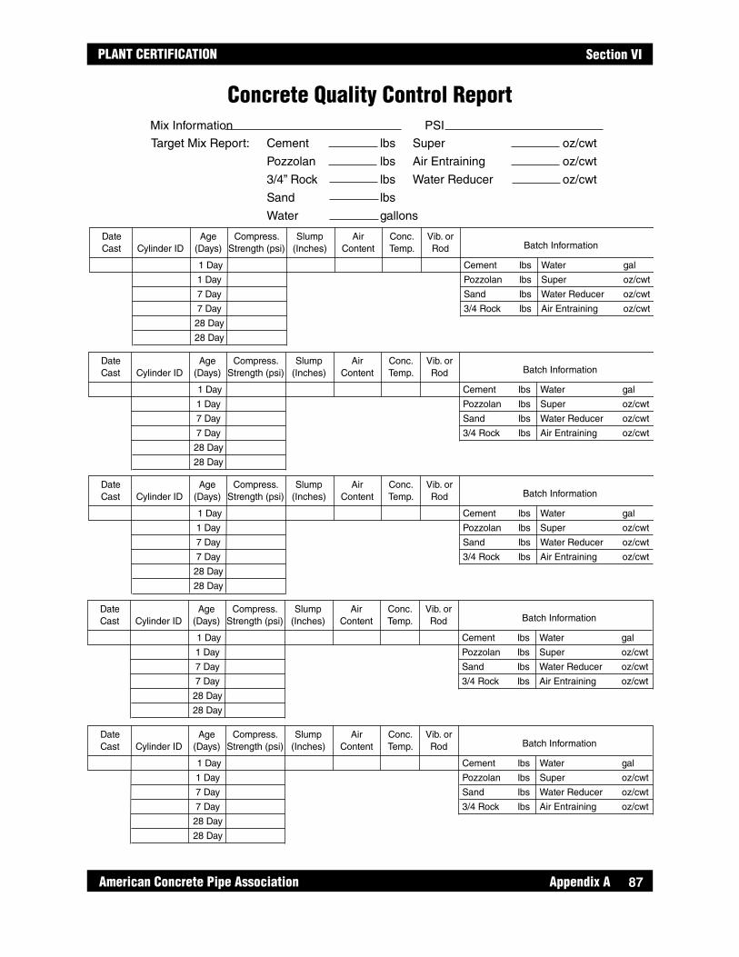
87
PLANT CERTIFICATION
American Concrete Pipe Association Appendix A
Section VI
Concrete Quality Control Report
Date Age Compress. Slump Air Conc. Vib. orCast Cylinder ID (Days) Strength (psi) (Inches) Content Temp. Rod Batch Information
Cement lbs Water gal
Pozzolan lbs Super oz/cwt
Sand lbs Water Reducer oz/cwt
3/4 Rock lbs Air Entraining oz/cwt
1 Day
1 Day
7 Day
7 Day
28 Day
28 Day
Mix Information PSI
Target Mix Report: Cement lbs Super oz/cwt
Pozzolan lbs Air Entraining oz/cwt
3/4” Rock lbs Water Reducer oz/cwt
Sand lbs
Water gallons
Date Age Compress. Slump Air Conc. Vib. orCast Cylinder ID (Days) Strength (psi) (Inches) Content Temp. Rod Batch Information
Cement lbs Water gal
Pozzolan lbs Super oz/cwt
Sand lbs Water Reducer oz/cwt
3/4 Rock lbs Air Entraining oz/cwt
1 Day
1 Day
7 Day
7 Day
28 Day
28 Day
Date Age Compress. Slump Air Conc. Vib. orCast Cylinder ID (Days) Strength (psi) (Inches) Content Temp. Rod Batch Information
Cement lbs Water gal
Pozzolan lbs Super oz/cwt
Sand lbs Water Reducer oz/cwt
3/4 Rock lbs Air Entraining oz/cwt
1 Day
1 Day
7 Day
7 Day
28 Day
28 Day
Date Age Compress. Slump Air Conc. Vib. orCast Cylinder ID (Days) Strength (psi) (Inches) Content Temp. Rod Batch Information
Cement lbs Water gal
Pozzolan lbs Super oz/cwt
Sand lbs Water Reducer oz/cwt
3/4 Rock lbs Air Entraining oz/cwt
1 Day
1 Day
7 Day
7 Day
28 Day
28 Day
Date Age Compress. Slump Air Conc. Vib. orCast Cylinder ID (Days) Strength (psi) (Inches) Content Temp. Rod Batch Information
Cement lbs Water gal
Pozzolan lbs Super oz/cwt
Sand lbs Water Reducer oz/cwt
3/4 Rock lbs Air Entraining oz/cwt
1 Day
1 Day
7 Day
7 Day
28 Day
28 Day
87

Appendix A American Concrete Pipe Association88
PLANT CERTIFICATIONSection VI
Pipe and Manhole Post-Pour Dimension Inspection InstructionsLength of Pipe & Length of Two Opposite Side Measurements
The length of pipe, and the length of two opposite sides, are determined by measuring along the inside of the pipe. Any flashing present at the bell and spigot faces shall be removed. With the aid of a second person, four measurements are to be recorded at 90-degree increments around the inside circumference. The longest and shortest measurements are recorded as the length of two opposite sides. The difference between these two measurements indicates the variation in laying length of two opposite sides.
Internal Diameter
The internal diameter is determined by placing the end of a measuring device at a point on the inside of the pipe and recording the longest measurement to the opposite inside edge of the pipe. Two measurements shall be taken at 90-degree increments on both ends of the pipe.
Wall Thickness
The wall thickness is to be measured at the spigot end. If the bell does not interfere, this measurement shall also be measured and recorded for the bell end. Wall thickness is determined by projecting along the outside of the pipe with a straight edge beyond the spigot face. The measurement taken from the inside of wall, across the spigot face to the projecting straight edge, is the wall thickness. Wall thickness shall be determined at four points around the pipe circumference, at 90-degree increments.
Specification
Specification requirements shall be recorded and compared to product measurements. Failing dimensions shall be circled.
88

89
PLANT CERTIFICATION
American Concrete Pipe Association Appendix A
Section VI
Pipe and Manhole Post-Pour Dimension Inspection Form
Pipe Size Pipe #
Pipe Class
Pipe Wall
Method/Date of Manufacture
Length Measurements
Position Measured Specification
0° Max Length
90° Min Length
180° Variation
270°
Internal Diameter
Position Spigot End Bell End Specification
0°
90°
Wall Thickness
Position Spigot End Bell End Specification
0°
90°
180°
270°
89
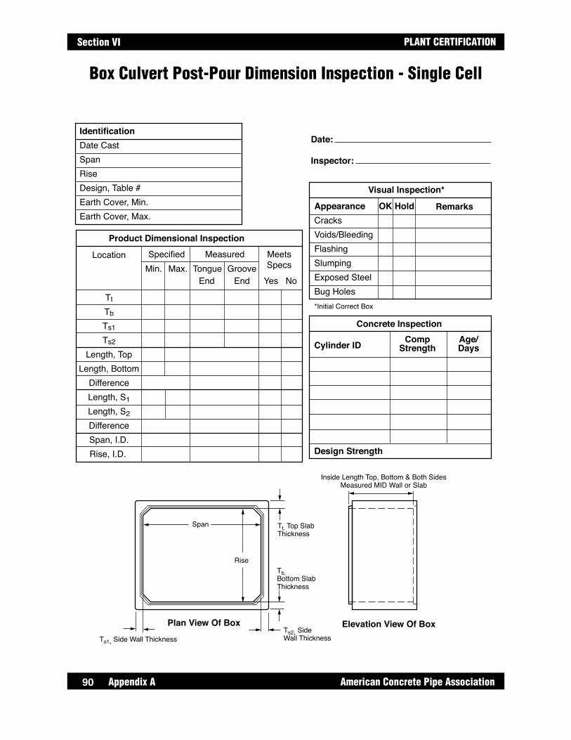
Appendix A American Concrete Pipe Association90
PLANT CERTIFICATIONSection VI
Box Culvert Post-Pour Dimension Inspection - Single Cell
Product Dimensional Inspection
IdentificationDate CastSpanRiseDesign, Table #Earth Cover, Min.Earth Cover, Max.
Date:
Inspector:
Concrete Inspection
Cylinder ID
Design Strength
CompStrength
Age/Days
Location
Tt
Tb
Ts1
Ts2
Length, TopLength, Bottom
DifferenceLength, S1Length, S2DifferenceSpan, I.D.Rise, I.D.
SpecifiedMin. Max. Tongue
End End Yes NoGroove
Measured MeetsSpecs
Visual Inspection*
AppearanceCracksVoids/BleedingFlashingSlumpingExposed SteelBug Holes*Initial Correct Box
OK Hold Remarks
Tt, Top SlabThickness
Tb, Bottom SlabThickness
Ts2, Side Wall Thickness
Span
Rise
Inside Length Top, Bottom & Both SidesMeasured MID Wall or Slab
Ts1, Side Wall Thickness
Plan View Of Box Elevation View Of Box
90
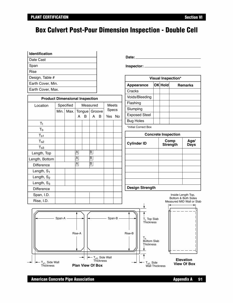
91
PLANT CERTIFICATION
American Concrete Pipe Association Appendix A
Section VI
Box Culvert Post-Pour Dimension Inspection - Double Cell
Product Dimensional Inspection
Visual Inspection*
IdentificationDate CastSpanRiseDesign, Table #Earth Cover, Min.Earth Cover, Max.
AppearanceCracksVoids/BleedingFlashingSlumpingExposed SteelBug Holes*Initial Correct Box
OK
Date:
Inspector:
Hold
Concrete Inspection
Cylinder ID
Design Strength
CompStrength
Age/Days
Location
Tt
Tb
Ts1
Ts2
Ts3
Length, TopLength, Bottom
DifferenceLength, S1Length, S2Length, S3DifferenceSpan, I.D.Rise, I.D.
SpecifiedMin. Max. Tongue
A B A B Yes NoGroove
Measured MeetsSpecs
Remarks
Tt, Top SlabThickness
Tb, Bottom SlabThickness
Ts2, Side Wall Thickness
Span-A
Rise-A
Span-B
Rise-B
Inside Length Top, Bottom & Both Sides
Measured MID Wall or Slab
Ts1, Side Wall Thickness
Ts3, Side Wall Thickness
Plan View Of BoxElevation
View Of Box
A B
A
A
B
B
91

Appendix A American Concrete Pipe Association92
PLANT CERTIFICATIONSection VI
Three-sided Structure - Flat Deck Post-Pour/Pour Dimension Inspection
92

93
PLANT CERTIFICATION
American Concrete Pipe Association Appendix A
Section VI
Three-sided Structure - Arch Deck Post-Pour/Pour Dimension Inspection
93

Appendix A American Concrete Pipe Association94
PLANT CERTIFICATIONSection VI
Vacuum Test on Pipe and Manholes With Gasketed Joints
CAUTION: The vacuum test may be dangerous if the pipe or manhole is not prepared properly and proper procedures are not followed.
This procedure covers in-plant testing of concrete sanitary sewer pipe and manholes using the negative air pressure (vacuum) test method. It shall be understood that no exact correlation has been found between air loss and water leakage. Recently cured product shall be allowed to cool to the ambient air temperature for greater test reliability.
If the test criteria is different from this Manual, the plant shall have a written policy that establishes a criteria that meets or exceeds the requirements of the Vacuum Test Table, The plant shall have calculations (theory) that prove their criteria.
Use a vacuum pump to remove air from the bulkheaded pipe. A manometer is recommended to accurately measure the pressure change in a small enough increment to keep test times to a reasonable length. The rate of vacuum loss is used to determine the acceptability of the pipe and manholes.
It shall be noted that relatively inexpensive digital pressure gauges have been recently developed. While they are not as accurate as manometers, they will work for the purpose of this test. The plant shall have a written procedure on file describing calibration and use of digital pressure gauges.
Remove air until the internal air pressure is lowered to approximately 8 inches of mercury. Allow the air pressure and temperature to stabilize, generally 30 seconds to two minutes.
When the pressure and temperature have stabilized, and the pressure is at or below the starting test pressure equivalent to 7 inches of mercury, begin the test by allowing the pressure to increase to the equivalent of 7 inches of mercury, at which point the time recording is initiated. If the pressure increase is less than or equal to 0.1083" Hg* in the test time specified in the table on next page, accept the test specimen.
If the specimen does not pass, either repair and retest or reject it.
* A pressure increase of 0.1083" Hg was chosen because it corresponds to a change in water column height of approximately 11/2" and a change in manometer oil column height (specific gravity 2.945) of 1/2".
94

95
PLANT CERTIFICATION
American Concrete Pipe Association Appendix A
Section VI
Vacuum Test TableTest Time, Seconds (1)
Pipe Size 0.0017 CFM/ft2 (2) 0.003 CFM/ft2 (2) 12" 32 18 15" 41 23 18" 49 28 21" 57 32 24" 64 36 27" 73 41 30" 81 46 33" 90 51 36" 97 55 42" 114 64 48" 128 72 54" 146 82 60" 162 92 66" 180 102 72" 194 110 78" 209 118 84" 226 128 90" 243 138 96" 256 144
(1) If a larger pressure increase is desired, test times can be increased proportionately.
(2) Two leakage rates are used in calculating test times because field air and vacuum tests vary by location. The 0.003 CFM/ft2 is the ACPA Plant Certification minimum requirement.
95
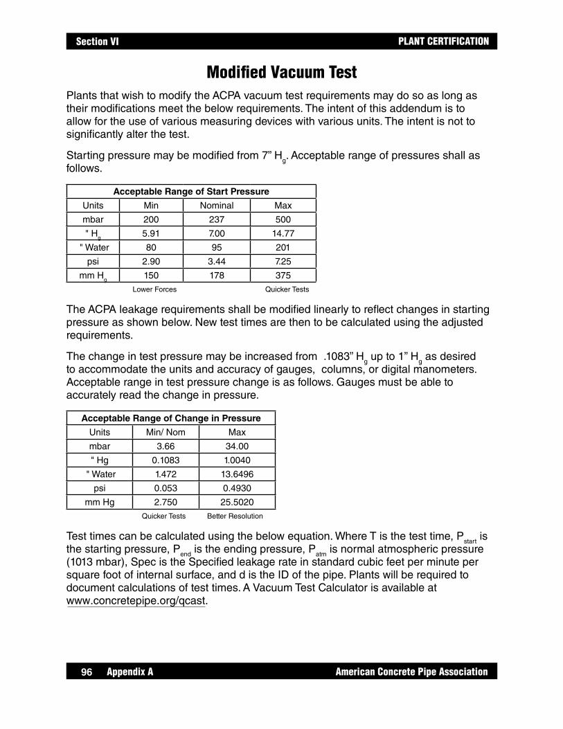
Appendix A American Concrete Pipe Association96
PLANT CERTIFICATIONSection VI
Modified Vacuum TestPlants that wish to modify the ACPA vacuum test requirements may do so as long as their modifications meet the below requirements. The intent of this addendum is to allow for the use of various measuring devices with various units. The intent is not to significantly alter the test.
Starting pressure may be modified from 7” Hg. Acceptable range of pressures shall as follows.
Acceptable Range of Start Pressure
Units Min Nominal Max
mbar 200 237 500
" Hg 5.91 7.00 14.77
" Water 80 95 201
psi 2.90 3.44 7.25
mm Hg 150 178 375
Lower Forces Quicker Tests
The ACPA leakage requirements shall be modified linearly to reflect changes in starting pressure as shown below. New test times are then to be calculated using the adjusted requirements.
The change in test pressure may be increased from .1083” Hg up to 1” Hg as desired to accommodate the units and accuracy of gauges, columns, or digital manometers. Acceptable range in test pressure change is as follows. Gauges must be able to accurately read the change in pressure.
Acceptable Range of Change in Pressure
Units Min/ Nom Max
mbar 3.66 34.00
" Hg 0.1083 1.0040
" Water 1.472 13.6496
psi 0.053 0.4930
mm Hg 2.750 25.5020
Quicker Tests Better Resolution
Test times can be calculated using the below equation. Where T is the test time, Pstart is the starting pressure, Pend is the ending pressure, Patm is normal atmospheric pressure (1013 mbar), Spec is the Specified leakage rate in standard cubic feet per minute per square foot of internal surface, and d is the ID of the pipe. Plants will be required to document calculations of test times. A Vacuum Test Calculator is available at www.concretepipe.org/qcast.

97
PLANT CERTIFICATION
American Concrete Pipe Association Appendix A
Section VI
EXAMPLE
A manufacturer was concerned about the condition of fiberglass bulkheads used in production. The manufacturer wanted to reduce the total vacuum on the bulkheads and use units of mbar for his test. A starting test pressure of 200 mbar gauge and a pressure drop of 4 mbar were chosen.
The manufacturer first established an equivalent leakage rate for his desired starting pressure.
200mbar / 237mbar = .84
The test time was then calculated as shown below

Appendix A American Concrete Pipe Association98
PLANT CERTIFICATIONSection VI
Hydrostatic TestingHydrostatic tests shall be run according to the procedure outlined below. Pipe shall be tested to 13 psi for 2-1/2 minutes for Sanitary Sewer (3 psi for 10 minutes for Storm Sewer and Culverts) with no visible leakage. Moisture appearing on the exterior surface of the pipe that does not drip is not considered failing. Up to a 24-hour soak is allowed prior to testing.
Summary of the test method The section of pipe is subjected to hydrostatic pressure and observed for leakage at the joint or on the surface of the wall. The joint is defined as a connection between adjacent sections of concrete pipe and the watertight seal achieved using rubber gaskets.
1. Determine whether one or two pipe shall be tested. To test the joint, two pipes shall be tested.
2. Clean the joints and inspect them for proper finishing.
3. It is recommended that when two or more pipe are being tested at the same time, the joint shall be opened 1/2". Attach 1/2" spacer blocks to the inside face of the bell.
4. Lubricate the pipe and gaskets if required. Install gaskets and equalize stretch.
5. Assemble pipe on timbers on a level area. Inspect pipe to make sure spacer blocks are still in place.
6. Assemble and restrain bulkheads using an adequate and safe system to resist internal pressure.
7. Fill pipe with water and bleed out all excess air. A bleed tube shall be installed on the top of one of the bulkheads. The bleed tube shall extend above the top of the pipe.
8. Connect pressurizing assembly including a regulator, valve and pressure gauge. Increase internal water pressure to the specified pressure. Observe test assembly during pressurization to make sure that all components are functioning as intended. The assembly shall remain pressurized for the specified duration of the test.
9. Extreme care shall be taken when testing pipe below 33 degrees F. Test results may be affected by freezing temperatures. The assembly shall be drained before water freezes. Gauges, valves and regulators shall also be protected from freezing temperatures.
NOTE: When the test set-up is unattended for a long period of time, such as overnight, the water supply to the regulator shall be shut off to prevent a possible excess pressure situation due to changes in water supply pressure.
98

99
PLANT CERTIFICATION
American Concrete Pipe Association Appendix A
Section VI
Certification of Three-Edge-Bearing Test Results of Reinforced Concrete Pipe
Pipe Description Size Class Wall Joint
Pipe Information Test Number:
Test Location:
Date of Manufacture:
Date Tested:
Age of Pipe (in days):
Method of Fabrication:
Reinforcing
Cage Reinforcing Description Area Specified Area
Inside:
Outside:
Elliptical:
Shear Steel Description and Area:
Three-Edge-Bearing Test Results
Actual Load Required Load Actual D-Load** Required D-Load**
1st Crack
.01 Crack
Ultimate
If Pipe was not tested to Ultimate:
Load when test was stopped: lbs.
D-Load when test was stopped: lbs/ft
Condition of pipe when
test was stopped:
Distribution:
I hereby certify that the pipe was three-edge bearing tested in accordance with the provisions of ASTM designation C-497.
Signature:
Date:
Plant Location:
** D-Load is measured in pounds per linear foot of inside diameter.
Pipe Length
Measured Allowable
Min.
Max.
Diff. in Length of Opposite Sides
Wall Thickness
Measured Allowable
Min.
Max. N/A
Nominal Thickness
Inside Diameter
Measured Allowable
Min.
Max.
NOTE: Allowable dimensions are specified dimensions either increased or decreased by the specified tolerance. All dimensions are in inches.
99

Appendix A American Concrete Pipe Association100
PLANT CERTIFICATIONSection VI
Off Center Joint Test Combined Certification OnlyThe Off Center Joint test is an evaluation of the capacity of a pipe joint to remain sealed under pressure, with the spigot installed into the bell in the maximum off center position. The test medium may be hydrostatic, vacuum or low-pressure air. To perform the test, two test pipes shall be assembled with one pipe fully supported and the spigot end of the second pipe installed in the bell end of the first pipe as illustrated in Figure 2, Appen-dix A, page 101, and Figure 5, page, Appendix A, page 103. The test joint shall not be open over 3/4 inch from the design-assembled position. The bell end of the second pipe shall be supported by a block. The supports for the pipes shall maintain a uniform invert elevation for both pipes.
The outer ends of the test pipe assembly shall be closed with bulkheads. For hydrostatic, the bulkheads shall be restrained longitudinally. The longitudinal restraints and bulkheads shall be designed so they do not exert beneficial axial or lateral forces on the test joint assembly. Flat plate bulkheads shall not be used for hydrostatic.
A vertical test load, F, shall be applied to the suspended portion of the test joint until the total differential load, including the weight of the pipe filled with water (hydrostatic testing only) shall be either a minimum 1,800 pounds per foot of pipe diameter or until there is concrete-to-concrete contact within the joint. A method for calculating the test load is shown on Figure 1 and Figure 2, Appendix A, page 101.
The assemblies shall be subjected to one of the following test criteria:
Vacuum Testing Appendix A, page 94 and page 95
Hydrostatic Testing Appendix A, page 98
The pipe support blocks are not required to be contoured, but for safety reasons they shall be constructed to prevent the pipes from rolling from the test position.
CAUTION: The hydrostatic test requires internal pressure to be applied over a large cross-sectional area of pipe bulkheads, creating large axial forces on longitudinal tie rods. Tie rods, bulkheads, and fasteners shall be selected for adequate strength and minimum elongation.
100
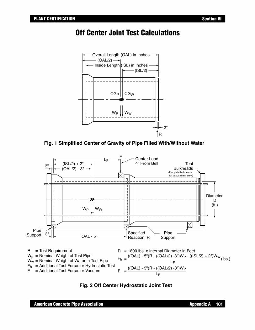
101
PLANT CERTIFICATION
American Concrete Pipe Association Appendix A
Section VI
Off Center Joint Test Calculations
Diameter,D
(ft.)
(ISL/2) + 2"
(ISL/2)
(OAL/2)Inside Length (ISL) in Inches
Overall Length (OAL) in Inches
(OAL/2) - 3"
LFF
3"
2"R
OAL - 5"
WWWP
WWWP
CGWCGp
3" PipeSupport
Center Load4" From Bell Test
Bulkheads(Flat plate bulkheads
for vacuum test only.)
SpecifiedReaction, R
R = Test RequirementWp = Nominal Weight of Test PipeWw = Nominal Weight of Water in Test PipeFh = Additional Test Force for Hydrostatic TestF = Additional Test Force for Vacuum
R = 1800 lbs. x Internal Diameter in Feet
= ((OAL) - 5")R - ((OAL/2) -3")WP - ((ISL/2) + 2")WW
PipeSupport
Fig. 1 Simplified Center of Gravity of Pipe Filled With/Without Water
Fig. 2 Off Center Hydrostatic Joint Test
LF (lbs.)
F = ((OAL) - 5")R - ((OAL/2) -3")WPLF
Fh
101

Appendix A American Concrete Pipe Association102
PLANT CERTIFICATIONSection VI
Joint Shear Test
The Joint Shear test is an evaluation of the capability of a pipe joint to maintain structural strength when subjected to a differential load. To perform the test, two test pipes shall be assembled with one pipe fully supported and the spigot end of the second pipe installed in the bell end of the first pipe as illustrated in Figure 5, Appendix A, page 103. Both pipes shall be supported so a uniform invert elevation is maintained. It is recommended for safety reasons that the pipe supports be constructed as shown on Figure 3 below.
The joint shear test shall be run without water in the pipe or bulkheads installed on the pipe. A vertical test load, F, shall be applied to the suspended portion of the test joint until the total differential load, including the weight of a pipe, is 4,000 pounds per foot of pipe diameter. A method for calculating the test load is shown on Figures 4 and 5, Appendix A, page 103.
The test load shall be applied to the suspended pipe and the assembled joint shall then be inspected for structural integrity. Cracks that occur during the test load are not considered failure, provided those cracks close to 0.01 inch or less on release of the load.
75ϒ
75ϒ
1" ThickRubber Stop
Fig. 3 Support Block Configuration
102

103
PLANT CERTIFICATION
American Concrete Pipe Association Appendix A
Section VI
Joint Shear Test Calculations
Diameter,D
(ft.)
(OAL/2)
Overall Length (OAL) in Inches
ApproximateCenter ofGravity
((OAL/2) - 3"
LFF
3"
2"R
OAL - 5"
WP
WP
3" PipeSupport
6" Wide Timber Cradle BlockLocate Within 1" of Bell
6" WideTimber CradleBlock Located1" From Bell
SpecifiedReaction, R
R = Test RequirementWp = Nominal Weight of Test PipeF = Additional Test Force
R = 4000 lbs. x Internal Diameter in Feet
F = [(OAL) - 5"]R - [(OAL/2) - 3"]WP
PipeSupport
Fig. 4 Simplified Center of Gravity of Pipe
Fig. 5 Joint Shear Test
LF(lbs.)
103

Appendix A American Concrete Pipe Association104
PLANT CERTIFICATIONSection VI
Storm Sewer and Culvert Joint TestThe Storm Sewer and Culvert Joint Test is an evaluation of the pipe joint. The test medium may be hydrostatic, vacuum or low-pressure air. To perform this test, two pipes shall be assembled in straight and in deflected alignment as defined by the joint being open 1/2" more on one side, than on the opposite side. Hydrostatic testing may be performed using either conventional bulkheads for hydrostatic testing, the bulkheads shall be restrained longitudinally.
Both the straight alignment and deflected assemblies shall be subjected to one of the following test criteria:
Vacuum Test Appendix A, page 94 and page 95
Hydrostatic Test 3 psi for 10 minutes and shall have an allowable leakage rate of 200 gallons/(inch of internal diameter) (mile of pipe) (24 hours). The manufacturer shall have the option of allowing the assemblies to stand under 3 psi for up to 24 hours prior to the test. The test shall be performed according to the summary found in Appendix A, page 98. For internal joint test, follow equipment manufacturers recommended procedure.
CAUTION: The Hydrostatic Test requires internal pressure to be applied over a cross-sectional area of pipe bulkheads, creating large axial forces on longitudinal tie rods. Tie rods, bulkheads, and fasteners shall be selected for adequate strength and minimum elongation.
104

105
PLANT CERTIFICATION
American Concrete Pipe Association Appendix B
Section VII
APPENDIX B:Audit Expectations
© ACPA 2016 2016 Version (01-2016)
Appendix B American Concrete Pipe Association106
PLANT CERTIFICATIONSection VII
Audit Expectations1. Quality Documentation, Specifications and Information
The auditors shall verify that specifications, documentation, and other information is current and satisfies the requirements for content and frequency.
2. Materials
The auditor shall verify that all material documentation on file is current and obtained at the required frequency.
3. Calibration
The auditor shall verify that production and testing equipment has been properly and accurately calibrated at the required frequencies. Written procedures for these calibrations shall also be reviewed. The auditor shall verify that the batching equipment has been calibrated through the maximum working range.
4. Mix Designs
The auditor shall review required documentation, including water/cement ratio confirmation, and verify that concrete being produced is the same proportion as mix designs on file.
5. Joints
Pipe and Manholes:
5.1-5.3 Joint/Spigot Gauging Design Drawings and Calculations The auditor shall review joint design drawings and calculations.
5.4 Gasket Quality Control
The plant shall demonstrate the equipment and procedures for measuring sanitary sewer pipe and sanitary sewer manhole gaskets, except when they are measured by personnel from outside the plant. In the latter case, the procedure and inspection location shall be documented and filed with the Inspection Test Reports.
Precast, Box, and Three-Sided Structures:
The auditor shall review joint design drawings.

107
PLANT CERTIFICATION
American Concrete Pipe Association Appendix B
Section VII
6. Equipment
Pipe and Manholes:
6.1 Forms The auditor shall review plant procedures and required documentation. The auditor shall verify that the equipment is clean and in good operational condition.
6.2 Joint Forming Equipment
The auditor shall witness the equipment and procedures for measuring sanitary sewer pipe and sanitary sewer manhole headers, pallets and truing rings (if used), except when they are measured by personnel from outside the plant. In the latter case, the procedure and inspection location shall be documented and filed with the Inspection Test Reports.
Precast, Box, and Three-Sided Structures:
The auditor shall review plant procedures and required documentation. The auditor shall verify that the equipment is clean and in good operational condition.
7. Reinforcing
7.1 Reinforcing Design
The auditor shall verify that detailed design information for all cages/reinforcement being fabricated is available in the fabrication area.
8. Pre-Pour Inspection
8.1 Reinforcing Inspection
During the audit, inspection shall be performed on reinforcing produced on the day of the audit. The auditor shall witness reinforcing measuring techniques and verify that cages/reinforcement being produced meet design requirements.
8.2 Pre-Pour Visual Inspection
The auditor shall review the pre-pour visual inspection procedures and documentation.
8.3 Pre-Pour Dimensional Inspection
Appendix B American Concrete Pipe Association108
PLANT CERTIFICATIONSection VII
The auditor shall review the pre-pour dimensional inspection procedures and documentation.
9. Concrete Testing
The auditor shall review required documentation for content and frequency. Plant personnel shall demonstrate quality assurance/quality control competency during the audit by performing all applicable concrete tests.
In-house TestsFor tests that are in-house, but run at a site other than the one being audited, a written procedure shall be on file with the appropriate test results. Tests that are performed by independent labs need not be accompanied by procedural documentation.
Tests to be witnessed include:Slump or slump flow (wet cast concrete)Air content (wet cast concrete)Concrete temperatureConcrete compression Concrete absorption Unit weight testing and calculation
10. Curing
The auditor shall review curing documentation and curing practices.
11. Post-Pour Inspection
11.1 Finishing and Repairs
The auditor shall review written repair and finishing procedures and inspect yarded product for the quality of repairs.
11.2 Finished Product Inspection
The auditor shall verify that the plant has functioning procedures in place for the visual inspecting of product. During the audit, the auditor shall inspect the appearance of product in the yard as well as those being prepared or loaded for shipment in order to ensure the product meets the appropriate specification.
11.3 Dimensional Test of Product
The auditor shall witness the technique for measuring product randomly selected by the auditor, and documentation of required ongoing inspections.
109
PLANT CERTIFICATION
American Concrete Pipe Association Appendix B
Section VII
11.4 Joint Visual Inspection
Pipe and Manholes:The auditor shall witness the plant’s procedure and equipment for gauging pipe spigots by watching plant personnel gauge pipe or manhole spigots.
Box Culverts and Three-Sided Structures:The auditor shall witness the assembly of three box culvert sections into one assembly or two box culvert sections for larger boxes having a span greater than 10 feet. The assembly shall fit so that the maximum joint opening at any one point is 1".
12. Product Marking
The auditor shall inspect yarded product for required marking.
13 Product Testing - Pipe and Manhole Only
This Manual includes an audit of inspection and tests performed by the plant on finished product. Since the set-up of finished product tests requires considerable time and effort, the auditor shall randomly select pipe to be tested on the onset of the audit. This shall allow adequate time for plant personnel to set up for afternoon testing.
13.1 Water Tightness of Pipe – Sanitary Sewer
For each test procedure, the auditor shall witness the plant’s procedure, equipment and reporting for measuring the water tightness of product selected for test by the inspector.
The plant shall also demonstrate through documentation, that pressure change measuring equipment and testing time meet the minimum requirements of the this Manual.
13.2 Three-Edge-Bearing Testing of Pipe
The auditor shall witness the plant’s procedures, equipment and reporting for measuring the three-edge-bearing strength up to a 0.01-in. crack width of one pipe selected for test by the auditor. Prior to performing the test, the auditor shall witness dimensional measurements of the pipe section being tested.
13.3 Off-Center Joint Test - Sanitary Sewer
The auditor shall witness the plant’s procedure, equipment and reporting for
Appendix B American Concrete Pipe Association110
PLANT CERTIFICATIONSection VII
the off-center joint test of a single set-up consisting of two pipe selected by the auditor. Test medium may be hydrostatic, low-pressure air or vacuum.
13.4 Differential Joint Shear Test - Sanitary Sewer
The auditor shall witness the plant’s procedure, equipment and reporting for the differential joint shear test of a single set-up consisting of two pipe selected by the auditor.
13.5 Storm Sewer and Culvert Joint Test - Storm and Culvert
The auditor shall witness the plant’s procedure, equipment and reporting for the storm sewer and culvert joint test of a single set-up consisting of two gasketed pipe selected by the auditor.
14. Storage, Handling, Shipping and Final Inspection
14.1 Handling and Storage
The auditor shall inspect product handling operations, to ensure that they meet the requirements of this Manual.
14.2 Shipping Policy
The auditor shall review the plants shipping policy and verify that product being shipped meets the requirements of that policy.
14.3 Final Inspection
The auditor shall verify that the plant has a policy and functioning procedure in place for final inspection of product.

111
PLANT CERTIFICATION
American Concrete Pipe Association Appendix B
Section VII
ACPA audits are conducted to verify conformance with applicable specification including QCast requirements and to provide meaningful feedback on current quality practices of a plant. Audits are an important piece of the QCast program and plant quality control systems. However, plants are ultimately responsible for the quality of the product that they produce and adherence to applicable specification including the QCast program. The ACPA does not presume the authority to alter plant quality systems only to verify conformance to applicable standards. Audit Feedback and Report:ACPA auditors are tasked with providing meaning full feedback to member plants. There are several opportunities for the auditing agency to provide feedback during the audit, during the report out meeting, and in the audit report. Feedback and discussion are ongoing during the audit. Auditors will answer all questions to the best of their ability and explain in detail the expectations of relevant specifications. At the conclusion of every audit there is an exit interview in which the auditor, plant management and plant quality staff, go through the auditors observations in detail. This process allows plants to receive immediate feedback on the state of their quality functions. After the audit, a detailed written report is sent to the plant. The report will indicate whether the plant met the requirements of QCast certification, provide a written account of the auditors observations, and it will contain the certification score(s). The Audit Report:The first page of the audit report is a cover letter indicating whether or not the plant met the requirements of QCast certification. For plants not meeting the requirements the letter will describe a plants options for continuing certification as outlined in the bylaws. The first section of the audit report deals with Deficiencies. Deficiencies as defined below are serous nonconformance’s that may be affecting the quality of the product. Deficiency’s must be corrected and a response must be sent to the ACPA within 30 days for a plant to maintain certification. Critical Items - Program elements that must be in place to ensure product quality. They include concrete strength, reinforcing, certain proof of manufacture, and proof of design testing. Critical items are specifically listed in the audit grade sheets in Appendix B of the QCast manual. The plant must pass all critical items with a grade of 75 or higher to pass the audit. If a plant is not doing an adequate job on a critical item (scores less than 75), the plant fails the audit, even if the total combined score of the audit is satisfactory. Failure of critical items are not related to the Deficiencies or Improvements cited in the
ACPA Audits

Appendix B American Concrete Pipe Association112
PLANT CERTIFICATIONSection VII
audit report. Deficiencies and Improvements can occur for critical items without failing that critical item. This would result in a grade decrease, but the plant would not fail the audit unless the critical item evaluation fell below a score of 75.
Deficiency - Failure to adequately implement or maintain a requirement(s) of QCast certification that raises significant doubt as to the effectiveness of the producers quality system.
The next section of the audit report includes all improvements. Improvements as defined below are minor nonconformance’s that do not have a direct impact on product quality. Items cited under the improvements section affect the audit score, but do not need to be corrected to maintain certification. Improvement - Any failure to meet the QCast requirements that seems to be an isolated occurrence and does not qualify as a breakdown in the quality system or have a direct impact on the product quality. The third section of the audit report is a transcript of the auditors comments. At the end of the audit are score summary sheets. Plants receiving deficiencies or improvements in a particular area will see reductions in scores. Plant certification is dependent on the audit score of 80% as described in the bylaws.
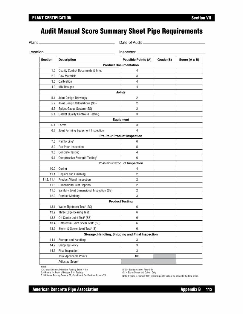
113
PLANT CERTIFICATION
American Concrete Pipe Association Appendix B
Section VII
Audit Manual Score Summary Sheet Pipe RequirementsPlant Date of Audit
Location Inspector
Section Description Possible Points (A) Grade (B) Score (A x B)
Product Documentation
1.0 Quality Control Documents & Info. 4
2.0 Raw Materials 3
3.0 Calibration 4
4.0 Mix Designs 4
Joints
5.1 Joint Design Drawings 2
5.2 Joint Design Calculations (SS) 2
5.3 Spigot Gauge System (SS) 2
5.4 Gasket Quality Control & Testing 3
Equipment
6.1 Forms 3
6.2 Joint Forming Equipment Inspection 4
Pre-Pour Product Inspection
7.0 Reinforcing1 6
8.0 Pre-Pour Inspection 5
9.0 Concrete Testing 4
9.7 Compressive Strength Testing1 6
Post-Pour Product Inspection
10.0 Curing 4
11.1 Repairs and Finishing 2
11.2, 11.4 Product Visual Inspection 2
11.3 Dimensional Test Reports 2
11.5 Sanitary Joint Dimensional Inspection (SS) 2
12.0 Product Marking 3
Product Testing
13.1 Water Tightness Test1 (SS) 6
13.2 Three Edge Bearing Test1 6
13.3 Off Center Joint Test1 (SS) 6
13.4 Differential Joint Shear Test1 (SS) 6
13.5 Storm & Sewer Joint Test3 (S) 6
Storage, Handling, Shipping and Final Inspection
14.1 Storage and Handling 3
14.2 Shipping Policy 3
14.3 Final Inspection 3
Total Applicable Points 106
Adjusted Score3
Notes: 1. Critical Element: Minimum Passing Score = 4.52. 4 Points for Proof of Design, 2 for Testing3. Minimum Passing Score = 80, Conditional Certification Score = 75
(SS) = Sanitary Sewer Pipe Only(S) = Storm Sewer and Culvert OnlyNote: If grade is marked "NA", possible points will not be added to the total score.

Appendix B American Concrete Pipe Association114
PLANT CERTIFICATIONSection VII
Audit Manual Score Summary Sheet Manhole RequirementsPlant Date of Audit
Location Inspector
Section Description Possible Points (A) Grade (B) Score (A x B)
Product Documentation
1.0 Quality Control Documents & Info. 4
2.0 Raw Materials 3
3.0 Calibration 4
4.0 Mix Designs 4
Joints
5.1 Joint Design Drawings 2
5.2 Joint Design Calculations (SS) 2
5.3 Spigot Gauge System (SS) 2
5.4 Gasket Quality Control & Testing 3
Forming Equipment
6.1 Forms 3
6.2 Joint Forming Equipment Inspection 4
Pre-Pour Product Inspection
7.0 Reinforcing1 6
8.0 Pre-Pour Inspection 5
9.0 Concrete Testing 4
9.7 Compressive Strength Testing1 6
Post-Pour Product Inspection
10.0 Curing 4
11.1 Repairs and Finishing 2
11.2, 11.4 Product Visual Inspection 2
11.3 Product Dimensional Inspection 2
12.0 Product Marking 3
Product Testing
13.1 Water Tightness Test1 (SS) 6
13.2 Manhole Step Test 2
Storage, Handling, Shipping and Final Inspection
14.1 Storage and Handling 3
14.2 Shipping Policy 3
14.3 Final Inspection 3
Total Applicable Points 82
Adjusted Score3
Notes: 1. Critical Element: Minimum Passing Score = 4.52. Minimum Passing Score = 80, Conditional Certification Score = 75
(SS) = Sanitary Sewer Pipe and Sanitary Sewer Manhole OnlyNote: If grade is marked "NA", possible points will not be added to the total score.

115
PLANT CERTIFICATION
American Concrete Pipe Association Appendix B
Section VII
Audit Manual Score Summary Sheet Engineered Precast Requirements
Plant Date of Audit
Location Inspector
Section Description Possible Points (A) Grade (B) Score (A x B)
Product Documentation
1.0 Quality Control Documents & Info. 4
1.8 Production Drawings 2
2.0 Raw Materials 3
3.0 Calibration 4
4.0 Mix Designs 4
Joints
5.0 Joints 3
6.0 Equipment 2
Pre-Pour Product Inspection
7.0 Reinforcing1 6
8.1 Pre-Pour Reinforcing Inspection 4
8.2 Pre-Pour Visual Inspection 4
8.3 Pre-Pour Dimensional Inspection 4
9.0 Concrete Testing 4
9.7 Compressive Strength Testing1 6
Post-Pour Product Inspection
10.0 Curing 4
11.1 Repairs and Finishing 2
11.2, 11.4 Product Visual Inspection 2
11.3 Dimensional Test Reports 2
12.0 Product Marking 3
Storage, Handling, Shipping and Final Inspection
14.1 Storage and Handling 3
14.2 Shipping Policy 3
14.3 Final Inspection 3
Total Applicable Points 72
Adjusted Score2
Notes: 1. Critical Element: Minimum Passing Score = 4.52. Minimum Passing Score = 80, Conditional Certification Score = 75
Note: If grade is marked "NA", possible points will not be added to the total score.

Appendix B American Concrete Pipe Association116
PLANT CERTIFICATIONSection VII
Audit Manual Score Summary Sheet Box Culvert and Three-Sided Structure Requirements
Plant Date of Audit
Location Inspector
Section Description Possible Points (A) Grade (B) Score (A x B)
Product Documentation
1.0 Quality Control Documents & Info. 4
2.0 Raw Materials 3
3.0 Calibration 4
4.0 Mix Designs 4
Joints
5.4 Gasket Quality Control and Testing 3
Forming Equipment
5.0 Joints 3
6.0 Equipment 2
Pre-Pour Product Inspection
7.0 Reinforcing1 6
8.1 Pre-Pour Reinforcing Inspection 6
8.2 Pre-Pour Visual Inspection 4
8.3 Pre-Pour Dimensional Inspection 4
9.0 Concrete Testing 4
9.7 Compressive Strength Testing1 6
Post-Pour Product Inspection
10.0 Curing 4
11.1 Repairs and Finishing 2
11.2, 11.4 Product Visual Inspection 2
11.3 Dimensional Inspection and Fit Test 6
12.0 Product Marking 3
Storage, Handling, Shipping and Final Inspection
14.1 Storage and Handling 3
14.2 Shipping Policy 3
14.3 Final Inspection 3
Total Applicable Points 79
Adjusted Score2
Notes: 1. Critical Element: Minimum Passing Score = 4.52. Minimum Passing Score = 80, Conditional Certification Score = 75
Note: If grade is marked "NA", possible points will not be added to the total score.
117
PLANT CERTIFICATION
American Concrete Pipe Association Appendix C
Section VII
APPENDIX C:Suggested Practice for State Highway Agency
Quality Review of Producers of Precast Concrete Drainage Products Certified by the
American Concrete Pipe Association
© ACPA 2016 2016 Version (01-2016)

Appendix C American Concrete Pipe Association118
PLANT CERTIFICATIONSection VII
Suggested Practice for State Highway Agency Quality Review of Producers of Precast Concrete Drainage Products Certified
by the American Concrete Pipe Association
1. SCOPEThis guideline provides recommended procedures that State Highway Agency (SHA) or their representative can follow when shadowing the American Concrete Pipe Association (ACPA) QCast Program plant audits. It is understood that each SHA may have special local requirements based on their unique situation and resources. This guide is intended to form a baseline review that can be applied nationally.
1.1 The ACPA certifies pipe and precast facilities through a quality program that requires the plants to conform to the industry standard ACPA QCast Plant Certification Manual. Plants are subject to annual third-party audits as part of this certification program.
1.2 The SHA is encouraged to contact the ACPA at [email protected] for any of the following:
1.2.1 Questions concerning the ACPA QCast quality process certification program.
1.2.2 The quality of products produced at an ACPA QCast certified plant is in question.
1.2.3 To shadow QCast plant audits to better understand the comprehensive nature of the ACPA QCast program. Once the request is initiated by the SHA, the third-party auditing firm will notify the SHA prior to subsequent plant audits until informed otherwise.
1.2.4 State specific requirements, in writing, that must be added to a facilities audit.
1.2.5 QCast reports of plants supplying product to the SHA. The ACPA holds confidentiality of these reports in high regard, but with permission of the plant, the ACPA will issue reports to the SHA on an annual basis.
1.2.6 To become a member of the QCast Users Group which discusses national improvements to the QCast program.
1.2.7 Questions for the ACPA Quality Advisory Group in regards to specific quality requirements and how they affect the quality of the product.

119
PLANT CERTIFICATION
American Concrete Pipe Association Appendix C
Section VII
1.3 The purpose of the ACPA QCast certification is to establish that certified plant have the proper equipment, trained staff, and quality procedures in place to consistently produce quality products. The ACPA certification describes the product types that the plant is certified to produce under the QCast quality program.
1.4 The ACPA certification program covers all areas of quality control processes in its QCast-certified facilities, but it does not certify that any particular product meets a specific standard.
1.4.1 Unannounced plant audits by an independent audit agency are routinely performed once per year. This audit intentionally varies over the year so that plant staff do not know when audits will occur. Therefore, it may be more or less than 12 months between ACPA audits; however, the plant is still certified.
1.4.1.1 In order to maintain certification for the subsequent year, a plant will re-apply and make payment by their quarterly anniversary date as shown in the bylaws of the QCast Manual. Upon receipt of the application and payment, the ACPA acknowledges the plants intent to continue in the program, and the plant is placed in the auditing queue and issued a certificate. The certificate is valid until the following anniversary date, unless the unannounced audit is not passed. If the audit is not passed, the plant is removed from the certification until they complete a successful audit.
1.4.1.2 Since all plant audits except initial audits are unannounced, the SHA should contact the ACPA to arrange the shadow audit with the third party auditor.
1.5 The ACPA QCast program manual, list of certified plants, and additional information is available from the ACPA website at www.concretepipe.org.
2. REFERENCED DOCUMENTS
2.1 American Concrete Pipe Association QCast Plant Certification Manual
2.2 AASHTO/ASTM Standards:
• AASHTO M170 / ASTM C76 (reinforced concrete pipe),• AASHTO M206 / ASTM C506 (reinforced concrete arch pipe)• AASHTO M207/ ASTM C507 (reinforced elliptical pipe)• AASHTO M259 / ASTM C1577 (precast box culverts)• ASTM C655 (circular pipe)• ASTM C1504 (three-sided-structures)• Other standards as applicable

Appendix C American Concrete Pipe Association120
PLANT CERTIFICATIONSection VII
3. AUDIT
The ACPA QCast program assesses the conformance of the manufacturing facility to the QCast Manual requirements. The following items are assessed by the third party auditor and are provided here as a guide for the SHA staff or their representative to follow during the shadow audit.
3.1 Quality Documentation, Specifications and Information
The auditors shall verify that specifications, documentation, and other information is current and satisfies the requirements for content and frequency.
3.2 Materials
The auditor shall verify that all material documentation on file is current and obtained at the required frequency.
3.3 Calibration
The auditor shall verify that production and testing equipment has been properly and accurately calibrated at the required frequencies. Written procedures for these calibrations shall also be reviewed. The auditor shall verify that the batching equipment has been calibrated through the maximum working range.
3.4 Mix Designs
The auditor shall review required documentation, including water/cement ratio confirmation, and verify that concrete being produced is the same proportion as
mix designs on file. Plants shall not be required to submit mix designs for public record as many designs contain proprietary information.
3.5 Joints – Pipe and Manholes
3.5.1 Joint/Spigot Gauging Design Drawings and Calculations
The auditor shall review joint design drawings and calculations.
3.5.2 Gasket Quality Control – Sanitary Sewer Only
The plant shall demonstrate the equipment and procedures for measuring sanitary sewer pipe and manhole gaskets, except when they are measured by personnel from outside the plant. In the latter case, the procedure and inspection location shall be documented and filed with the Inspection Test Reports.

121
PLANT CERTIFICATION
American Concrete Pipe Association Appendix C
Section VII
3.6 Joints - Precast, Box, and Three-Sided Structures:
The auditor shall review joint design drawings.
3.7 Equipment – Pipe and Manholes
3.7.1 Forms
The auditor shall review plant procedures and required documentation. The auditor shall verify that the equipment is clean and in good operational condition.
3.7.2 Joint Forming Equipment
The auditor shall witness the equipment and procedures for measuring sanitary sewer pipe and manhole headers, pallets and truing rings (if used), except when they are measured by personnel from outside the plant. In the latter case, the procedure and inspection location shall be documented and filed with the Inspection Test Reports.
3.8 Equipment - Precast, Box, and Three-Sided Structures:
The auditor shall review plant procedures and required documentation. The auditor shall verify that the equipment is clean and in good operational condition.
3.9 Reinforcing Design
The auditor shall verify that detailed design information for all cages/reinforcement being fabricated is available in the fabrication area.
3.10 Pre-Pour Inspection
3.10.1 Reinforcing Inspection During the audit, inspection shall be performed on reinforcing produced
on the day of the audit. The auditor shall witness reinforcing measuring techniques and verify that cages/reinforcement being produced meet design requirements.
3.10.2 Pre-Pour Visual Inspection
The auditor shall review the pre-pour visual inspection procedures and documentation.
3.10.3 Pre-Pour Dimensional Inspection

Appendix C American Concrete Pipe Association122
PLANT CERTIFICATIONSection VII
The auditor shall review the pre-pour dimensional inspection procedures and documentation.
3.11 Concrete Testing
The auditor shall review required documentation for content and frequency. Plant personnel shall demonstrate quality assurance/quality control competency during the audit by performing all applicable concrete tests.
3.11.1 In-house Tests
For tests that are in-house, but run at a site other than the one being audited, a written procedure shall be on file with the appropriate test results. Tests that are performed by independent labs need not be accompanied by procedural documentation. In-house tests to be witnessed include:
Slump or slump flow (wet cast concrete)Air content (wet cast concrete)Concrete temperatureConcrete compressionConcrete absorptionUnit weight testing and calculation
3.12 Curing
The auditor shall review curing documentation and curing practices.
3.13 Post-Pour Inspection
3.13.1 Finishing and Repairs
The auditor shall review written repair and finishing procedures and inspect yarded product for the quality of repairs.
3.13.2 Finished Product Inspection
The auditor shall verify that the plant has functioning procedures in place for the visual inspecting of product. During the audit, the auditor shall inspect the appearance of product in the yard as well as those being prepared or loaded for shipment in order to ensure the product meets the appropriate specification.
3.13.3 Dimensional Test of Product
123
PLANT CERTIFICATION
American Concrete Pipe Association Appendix C
Section VII
The auditor shall witness the technique for measuring product randomly selected by the auditor, and documentation of required ongoing inspections.
3.13.4 Joint Visual Inspection
3.13.4.1 Joint Dimension Measurement - Sanitary Pipe and Manholes Only
The auditor shall witness the plant’s procedure and equipment for gauging pipe spigots by watching plant personnel gauge pipe or manhole spigots.
3.13.4.2 Box Culverts and Three-Sided Structures:
The auditor shall witness the assembly of three box culvert sections into one assembly, or 2 box culvert sections for boxes with spans greater than 10’. The assembly shall fit so that the maximum joint opening at any one point is 1".
3.14 Product Marking
The auditor shall inspect yarded product for required marking.
3.15 Product Testing - Pipe and Manhole Only
This Manual includes an audit of inspection and tests performed by the plant on finished product. Since the set-up of finished product tests requires considerable time and effort, the auditor shall randomly select pipe to be tested on the onset of the audit. This shall allow adequate time for plant personnel to set up for afternoon testing.
3.15.1 Water Tightness of Pipe – Sanitary Sewer Only
For each test procedure, the auditor shall witness the plant’s procedure, equipment and reporting for measuring the water tightness of product selected for test by the inspector.
The plant shall also demonstrate through documentation, that pressure change measuring equipment and testing time meet the minimum requirements of the this Manual.
3.15.2 Three-Edge-Bearing Testing of Pipe
The auditor shall witness the plant’s procedures, equipment and reporting for measuring the three-edge-bearing strength up to a 0.01-in.
Appendix C American Concrete Pipe Association124
PLANT CERTIFICATIONSection VII
crack width of one pipe selected for test by the auditor. Prior to performing the test, the auditor shall witness dimensional measurements of the pipe section being tested.
3.15.3 Off-Center Joint Test - Sanitary Sewer Only
The auditor shall witness the plant’s procedure, equipment and reporting for the offcenter joint test of a single set-up consisting of two pipe selected by the auditor. Test medium may be hydrostatic, low-pressure air or vacuum.
3.15.4 Differential Joint Shear Test - Sanitary Sewer Only
The auditor shall witness the plant’s procedure, equipment and reporting for the differential joint shear test of a single set-up consisting of two pipe selected by the auditor.
3.15.5 Storm Sewer and Culvert Joint Test - Storm and Culvert
The auditor shall witness the plant’s procedure, equipment and reporting for the storm sewer and culvert joint test of a single set-up consisting of two gasketed pipe selected by the auditor.
3.16 Storage, Handling, Shipping and Final Inspection
3.16.1 Handling and Storage
The auditor shall inspect product handling operations, to ensure that they meet the requirements of this Manual.
3.16.2 Shipping Policy
The auditor shall review the plants shipping policy and verify that product being shipped meets the requirements of that policy.
3.17 Final Inspection
The auditor shall verify that the plant has a policy and functioning procedure in place for final inspection of product.
4. CLOSURE
Most questions related to the ACPA QCast requirements should be able to be answered by the plant’s QC Inspector. However, ACPA staff are available to answer questions and address any concerns related to QCast certified plants.